US11142442B2 - System and method for dynamically controlling the stability of an industrial vehicle - Google Patents
System and method for dynamically controlling the stability of an industrial vehicleDownload PDFInfo
- Publication number
- US11142442B2 US11142442B2US15/893,996US201815893996AUS11142442B2US 11142442 B2US11142442 B2US 11142442B2US 201815893996 AUS201815893996 AUS 201815893996AUS 11142442 B2US11142442 B2US 11142442B2
- Authority
- US
- United States
- Prior art keywords
- vehicle
- load
- acceleration
- lifting device
- cargo
- Prior art date
- Legal status (The legal status is an assumption and is not a legal conclusion. Google has not performed a legal analysis and makes no representation as to the accuracy of the status listed.)
- Active, expires
Links
Images


Classifications
- B—PERFORMING OPERATIONS; TRANSPORTING
- B66—HOISTING; LIFTING; HAULING
- B66F—HOISTING, LIFTING, HAULING OR PUSHING, NOT OTHERWISE PROVIDED FOR, e.g. DEVICES WHICH APPLY A LIFTING OR PUSHING FORCE DIRECTLY TO THE SURFACE OF A LOAD
- B66F17/00—Safety devices, e.g. for limiting or indicating lifting force
- B66F17/003—Safety devices, e.g. for limiting or indicating lifting force for fork-lift trucks
- B—PERFORMING OPERATIONS; TRANSPORTING
- B66—HOISTING; LIFTING; HAULING
- B66F—HOISTING, LIFTING, HAULING OR PUSHING, NOT OTHERWISE PROVIDED FOR, e.g. DEVICES WHICH APPLY A LIFTING OR PUSHING FORCE DIRECTLY TO THE SURFACE OF A LOAD
- B66F9/00—Devices for lifting or lowering bulky or heavy goods for loading or unloading purposes
- B66F9/06—Devices for lifting or lowering bulky or heavy goods for loading or unloading purposes movable, with their loads, on wheels or the like, e.g. fork-lift trucks
- B66F9/075—Constructional features or details
- B66F9/20—Means for actuating or controlling masts, platforms, or forks
- B66F9/24—Electrical devices or systems
- E—FIXED CONSTRUCTIONS
- E02—HYDRAULIC ENGINEERING; FOUNDATIONS; SOIL SHIFTING
- E02F—DREDGING; SOIL-SHIFTING
- E02F9/00—Component parts of dredgers or soil-shifting machines, not restricted to one of the kinds covered by groups E02F3/00 - E02F7/00
- E02F9/24—Safety devices, e.g. for preventing overload
- E—FIXED CONSTRUCTIONS
- E02—HYDRAULIC ENGINEERING; FOUNDATIONS; SOIL SHIFTING
- E02F—DREDGING; SOIL-SHIFTING
- E02F9/00—Component parts of dredgers or soil-shifting machines, not restricted to one of the kinds covered by groups E02F3/00 - E02F7/00
- E02F9/26—Indicating devices
- E—FIXED CONSTRUCTIONS
- E02—HYDRAULIC ENGINEERING; FOUNDATIONS; SOIL SHIFTING
- E02F—DREDGING; SOIL-SHIFTING
- E02F9/00—Component parts of dredgers or soil-shifting machines, not restricted to one of the kinds covered by groups E02F3/00 - E02F7/00
- E02F9/26—Indicating devices
- E02F9/261—Surveying the work-site to be treated
- E—FIXED CONSTRUCTIONS
- E02—HYDRAULIC ENGINEERING; FOUNDATIONS; SOIL SHIFTING
- E02F—DREDGING; SOIL-SHIFTING
- E02F9/00—Component parts of dredgers or soil-shifting machines, not restricted to one of the kinds covered by groups E02F3/00 - E02F7/00
- E02F9/26—Indicating devices
- E02F9/264—Sensors and their calibration for indicating the position of the work tool
Definitions
- the present inventionrelates generally to safety and monitoring systems, and in particular, safety and monitoring systems for industrial vehicles and machines such as forklifts, skid steers, telehandlers, excavators, Marina BullsTM, wheel loaders, backhoes and other items for lifting, moving and transporting loads.
- industrial vehicles and machinessuch as forklifts, skid steers, telehandlers, excavators, Marina BullsTM, wheel loaders, backhoes and other items for lifting, moving and transporting loads.
- Safety systems for industrial vehicles and machines, particularly forklift machines, as commonly known in the artare configured to determine the weight and center of gravity of a cargo load. By using the cargo weight and center of gravity, these safety systems can alert an operator about possible tip-over events or other safety situations.
- the present inventionis directed to a system and method that can be configured to monitor the dynamic load moment and stabilization of a lifting vehicle (e.g., forklift, telehandler, marina bull, wheel loader, backhoe, and other types of equipment for lifting, moving and transporting loads) and provide real-time information to the vehicle's operator. More specifically, the system and method can determine the load and center of gravity of cargo on the vehicle and calculate the overall load moment of the vehicle/cargo combination in order to aid an operator in preventing instability and/or tipping of the vehicle. In the case of a forklift, this could be a forward tipping through the lifting up of the rear wheels.
- a lifting vehiclee.g., forklift, telehandler, marina bull, wheel loader, backhoe, and other types of equipment for lifting, moving and transporting loads
- the system and methodcan determine the load and center of gravity of cargo on the vehicle and calculate the overall load moment of the vehicle/cargo combination in order to aid an operator in preventing instability and/or tip
- the systemcan include a plurality of sensors that monitor several different components, positions and states of the lifting vehicle and its cargo load.
- the collected sensor datacan be received by an electronic control unit and pushed through to a graphical user interface of a mobile device by an on-board network.
- the interface device and/or the electronic control unitcan include an application or program having a dynamics model and/or algorithm configured for incorporating the sensor data to determine the load moment applied to the vehicle/cargo combination in real time. This information can be conveyed and/or displayed to the vehicle operator through a display provided on the interface device.
- One aspect of the present inventionis directed to a method for calibrating the system.
- This calibration methodmay be employed any time an attachment is replaced, added or removed from the vehicle, any time there are changes made to the vehicle that may impact its operating characteristics, or any time an existing vehicle is retrofitted with a safety system, for example.
- a no-load acceleration routinemay be performed that includes the steps of accelerating the vehicle with its lifting device at a first position, accelerating the vehicle again with its lifting device at a second position, and accelerating the vehicle yet again with its lifting device at a third position.
- the no-load acceleration routineis typically performed without any cargo placed on the lifting device.
- a first-load acceleration routinemay be performed that also includes the steps of accelerating the vehicle with its lifting device at a first position, accelerating the vehicle with its lifting device at a second position, and accelerating the vehicle with its lifting device at a third position.
- the first-load acceleration routineis performed with a first cargo load having a known mass placed on the lifting device.
- a second-load acceleration routinemay be performed wherein the same steps are undertaken with a second cargo load having a different known mass placed on the lifting device.
- the acceleration of the vehicle and a force on the tilt cylinder of the lifting devicecan be measured during one or more instances of each acceleration routine.
- the force on the tilt cylindermay be determined by measuring a pressure within the tilt cylinder and multiplying that pressure by an effective surface area of the cylinder's piston, for example.
- the calibration methodmay also include the steps of inputting configuration information of the vehicle into the system, measuring a slope of the ground floor beneath the vehicle and inputting the slope into the system, measuring an angle of a mast of the lifting device and inputting the mast angle into the system, and measuring an angle of the tilt cylinder of the lifting device and inputting the tilt cylinder angle into the system.
- the calibration methodmay further include the steps of determining a location of a center of gravity of the vehicle during the no-load acceleration routine, determining a load moment of the vehicle during the no-load acceleration routine, determining a location of a center of gravity of the vehicle and the first cargo load combination during the first-load acceleration routine, and determining a load moment of the vehicle and the first cargo load combination during the first-load acceleration routine.
- the center of gravity and load momentmay also be calculated for the second-load acceleration routine.
- the data collected during the acceleration routinesis used to calculate at least one coefficient associated with the vehicle.
- the coefficient(s)may be calculated based on certain variables, such as a mass of the vehicle, an acceleration of the vehicle, a force on the tilt cylinder, and/or a position of the lifting device.
- the coefficient(s)may be determined by a linear regression of the data collected during the acceleration routines. Once calculated, the coefficient(s) can be stored within the system and used by the mathematical formulas, algorithms and routines employed when dynamically monitoring the stability of the vehicle.
- Another aspect of the present inventionis directed to providing a user interface that includes a continuous scale for displaying the real-time dynamic load moment of the vehicle/cargo combination.
- the dynamic load momentis presented in the form of a vertical bar having a gradient from one end to the other end. The color or shade of the gradient can provide the operator with an easy to understand visualization.
- the dynamic load momentcan also be displayed as a percentage of used load moment capacity of the vehicle.
- a further aspect of the present inventionis directed to a system for detecting drop-offs in the floor surface surrounding the vehicle.
- the systemcan include at least one object detection device oriented to detect a presence or absence of a floor surface within a specified distance from the vehicle.
- the object detection devicecan be adapted for detecting a drop-off in the surface of the floor and, more specifically, a drop-off in the surface of the floor that exceeds a specified threshold.
- the object detection devicemay be any suitable device, such as an optical sensor or a 3D sensor.
- the systemmay include a device for alerting the operator if a floor surface is not present in the projected path of travel of the vehicle.
- This alert devicemay take the form of a visual alert device, an audible alert device, or a haptic alert device, for example.
- the systemis adapted for overtaking control of at least one of the vehicle's speed, throttle, brakes and steering when a drop-off within a specified distance from the vehicle is detected.
- FIG. 1is a front perspective view of a forklift machine in accordance with one embodiment of the present invention
- FIG. 2is a side view of a forklift machine in accordance with one embodiment of the present invention.
- FIG. 3is a diagram of an industrial vehicle safety device system in accordance with one embodiment of the present invention.
- FIG. 4is a schematic view of a forklift machine equipped with an industrial vehicle safety device system in accordance with one embodiment of the present invention
- FIG. 5is a schematic view of a forklift machine illustrating examples of two different positions at which a load may be carried by the forklift machine and also illustrating resulting center of gravity locations for each position;
- FIG. 6is a flowchart of the operation processes of an industrial vehicle safety device system in accordance with one embodiment of the present invention.
- FIG. 7is a flow chart of a calibration process for use with an industrial vehicle safety device system in accordance with one embodiment of the present invention.
- FIG. 8is a schematic view of a display on a user interface device for use with an industrial vehicle safety device system in accordance with one embodiment of the present invention.
- FIG. 9is a schematic view of a display on a user interface device for use with an industrial vehicle safety device system in accordance with another embodiment of the present invention.
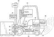
- System 10can be used in connection with an industrial vehicle 12 , such as a forklift machine, a telehandler, marina bull, wheel loader, backhoe, vehicle or other machine for lifting, moving and transporting material, cargo or other loads.
- Vehicle 12may have a lifting device or apparatus that can include an attachment such as one or more forks, a bucket, a shovel, a grapple, or other attachment adapted for lifting, moving or transporting material, cargo or other loads.
- system 10can be configured as a forklift safety device system for use with a forklift 12 .
- forklift 12can be any type of forklift commonly known in the art and can include an implement or attachment 14 (such as forks or a bucket) that can be used to lift and/or transport a cargo load 16 .
- Forklift 12can additionally include a mast assembly 18 , front wheels 20 a and rear wheels 20 b .
- forklift 12can further include a mast lift cylinder 22 for raising/lowering attachment 14 and a mast tilt cylinder 24 for tilting the mast assembly 18 and attachment 14 .
- System 10can be configured to monitor the status of forklift 12 and cargo load 16 in order to alert the vehicle operator (or others) of potential hazards, such as operational environment hazards (e.g., ramps, docks, stairs, and other obstacles), pedestrian hazards, and vehicle operation hazards (e.g., tipping events, visibility, and enclosed environments).
- system 10can be configured to calculate and monitor the center of gravity and dynamic load moment of the forklift 12 and cargo load 16 combination as described in greater detail below.
- system 10can be configured to monitor and display the current status of the dynamic load moment in real time to the vehicle operator, alert the vehicle operator when the load moment goes beyond a specified threshold and/or override the controls of forklift 12 in the event of an imminent tip-over event.
- System 10can additionally monitor, display and alert the vehicle operator regarding other conditions or factors of forklift 12 , such as vehicle speed, pedestrian and/or hazard presence, and drop-offs.
- system 10can include a plurality of sensors, including sensors 26 , 28 , 30 , 32 , 34 and 36 for monitoring the position, acceleration, speed, orientation and other dynamic states of vehicle 12 and cargo load 16 during operation of vehicle 12 .
- system 10can optionally include many other types of sensors for monitoring the surrounding areas of the vehicle 12 , such as proximity sensors, pedestrian sensors and working sensors.
- ECU 40can manage on-board network 38 , CAN 42 and sensors 26 - 36 and can process the sensor data before sending it to a processor, central processing unit (“CPU”) and/or user interface device 44 , such as a mobile tablet or other onboard device.
- CPUcentral processing unit
- user interface device 44such as a mobile tablet or other onboard device.
- the processor or user interface device 44can execute an application or program software 45 configured to use the sensor data or other information from the ECU, CPU or other processor to determine and display the dynamic conditions of vehicle 12 on a real-time, semi-continuous or time-interval basis. It will be appreciated that, in one embodiment, one or more of the ECU, control module, CPU or other processor, and user interface may be incorporated into a single on-board electronic device. As also shown in FIGS. 3 and 4 , system 10 can further include one or more obstacle sensors 46 and a video camera 48 , as will be described in greater detail below.
- Sensor 26can be a pressure transducer sensor located in tilt cylinder 24 and can collect data relating to the dynamics of vehicle 12 via mast assembly 18 , including but not limited to pressure and force used in identifying and calculating the load center of the vehicle 12 /cargo load 16 combination.
- sensor 26is adapted for measuring the pressure of the hydraulic fluid in the rod end of tilt cylinder 24 .
- sensor 26may comprise a load cell, force transducer or any other suitable force-measuring sensor that is that is connected, directly or indirectly, to the tilt cylinder 24 such as at a clevis, yoke, pinned joint, or other connection point.
- Sensor 28can be a pressure transducer sensor located in lift cylinder 22 that can collect data relating to the dynamics of vehicle 12 and the weight of the lifted cargo load 16 via mast assembly 18 , including but not limited to weight, pressure and force.
- sensor 28is adapted for measuring the pressure of the hydraulic fluid in the base end of lift cylinder 22 .
- sensor 28may comprise a load cell, force transducer or any other suitable force-measuring sensor that is that is connected, directly or indirectly, to the lift cylinder 22 , such as at a clevis, yoke, pinned joint, or other connection point.
- Sensor 30can be a sensor located at or near the mast assembly 18 for determining the height or vertical position of mast assembly 18 and attachment 14 in order to determine the height of cargo load 16 .
- Lift height sensor 30may be any suitable type of sensor, such as an electronic, magnetic, optical, radio frequency, mechanical, proximity, or contact sensor or any other suitable height reference sensor.
- Sensor 32can be a sensor for sensing the angle of mast assembly 18 .
- Sensor 32may be an inclinometer, rotary, potentiometer, encoder, Hall effect, electronic, magnetic, optical, radio frequency, mechanical, proximity, or contact sensor or any other suitable angle reference sensor.
- Sensor 34can be an accelerometer sensor located on vehicle 12 for determining accelerations, decelerations, movements and orientation angles associated with vehicle 12 .
- Sensor 34may be any suitable type of sensor, such as a potentiometric, Hall effect, capacitive, piezoresistive accelerometer, micro-electro mechanical system, single-axis, multiple-axis, sensor or any other suitable acceleration-measuring or accelerometer sensor.
- Sensor 36can be a speed sensor and may be located in the drive train for sensing the speed of vehicle 12 .
- Speed datacan also or alternatively be acquired from the CAN 42 .
- Sensor 36may be any suitable type of sensor, such as a wheel speed, drivetrain, rotary, encoder, radar, GPS, electronic, or mechanical sensor or any other suitable speed-measuring sensor.
- Gyroscope sensorstilt sensors, GPS receivers, brake sensors, and other sensors and devices suitable for determining the tilt, angle, pitch, roll, yaw, direction, location, speed, acceleration or other orientation of the vehicle 12 or any component thereof may also be utilized in connection with the present invention.
- sensors 26 - 36can be used to derive the load moment of the vehicle 12 /cargo load 16 combination by collecting any number of different measurements and data, including but not limited to: the pressure of the hydraulic fluid in rod end of tilt cylinder 24 , the force on tilt cylinder 24 , the pressure of the hydraulic fluid in the base end of lift cylinder 22 , the force on lift cylinder 22 , the height of the forks or other attachment 14 above the ground or other reference point, the angle of mast assembly 18 , the mass of mast assembly 18 , the location of the center of gravity of mast assembly 18 , the mass of vehicle 12 , the location of the center of gravity of vehicle 12 , the speed of vehicle 12 and/or acceleration and deceleration of vehicle 12 , the fore-aft slope of vehicle 12 , and the side-to-side angle of vehicle 12 , and the steering angle, among other measurements and data.
- CAN 42can be provided to convert analog sensor measurements to digital form suitable for further processing, where applicable.
- Sensors 26 - 36can measure the various data relating to the real-time vehicle state continuously or at pre-specified time intervals.
- One or more of sensors 26 - 36can be CAN-enabled sensors containing on-sensor electronics for analog to digital conversion (“ADC”). These CAN-enabled sensors can act as a CAN node and transmit sensor data over the CAN 42 or other communication network.
- ADCanalog to digital conversion
- sensors 26 - 36can also be analog sensors that continuously monitor the sensed input and transmit an analog signal over dedicated lines to the ECU 40 . This monitoring and transmission can also be performed on a selected time interval basis.
- ECU 40can include firmware that causes it to act as a CAN node and/or as an ADC for analog inputs. ECU 40 can further transmit CAN messages containing scaled and filtered sensor data over network 42 for use in an application within the user interface 44 . The ECU 40 can transmit these CAN messages at time intervals appropriate to the time scale of the events being measured.
- a network bridge embedded device 50can be provided with firmware that allows it to act as a USB device and/or a CAN node. Device 50 can further be configured for translating the CAN messages from ECU 40 into serial messages and transmitting these messages over a USB connection to the user interface device 44 .
- the network bridge device 50can alternatively or additionally transmit the information via Wi-Fi, Bluetooth, or other wireless configuration.
- the user interface device 44can store, read, and display the transmitted sensor data and calculations through software and/or an application. According to one embodiment, the application can perform a plurality of mathematical and/or physics-based calculations and display the output to the user. These calculations are described in greater detail below.
- system 10can be configured to use the sensor data collected by ECU 40 to determine and monitor in real-time the load center of cargo load 16 and the equivalent center of gravity (“CG”) and dynamic load moment of the vehicle 12 /cargo load 16 combination created by the load center of cargo load 16 and the current dynamic condition of vehicle 12 .
- CGcenter of gravity
- the load center and weight of cargo load 16can generally be used to define the risk of a tip-over event; however even a below-capacity load can create a tip-over risk when non-static (dynamic) conditions of vehicle 12 are present. As shown in FIG.
- a safe load moment and center of gravity CG 1 for the vehicle 12 /cargo load 16 combinationis located behind the center of the front wheels 20 a of forklift 12 and generally at a relatively low height.
- an unsafe load moment and center of gravity CG 2 for the vehicle 12 /cargo load 16 combinationis located in front of the center of the front wheels 20 a of forklift 12 and generally at an increased height compared to forklift 12 .
- the positioning of the center of gravity CG in front of the center of front wheels 20 acreates a risk of a tip-over event.
- System 10can operate by determining (through data obtained by sensors 26 - 36 ) the weight and load center of cargo load 16 , accounting for the weight and center of gravity of vehicle 12 , and then calculating the overall load moment of the vehicle 12 /cargo load 16 combination.
- the application executed on the processor or user interface device 44can contain software programming for determining this overall load moment using known statics and dynamics mathematical equations and algorithms.
- the applicationcan use the sensor data to determine the magnitude of cargo load 16 , the fore-aft position of cargo load's 16 center of gravity, calculation adjustments that are necessary due to the tilt angle of mast assembly 18 , the lift height of mast assembly 18 , the ground slope below vehicle 12 and the vehicle 12 accelerations or decelerations, and insert these calculations into a physics model and/or one or more defined algorithms or formulas.
- This model, algorithm or formulacan also incorporate coefficients to account for the specific vehicle 12 and/or attachment 14 .
- the coefficientscan be determined through a calibration process 66 as described in greater detail below.
- System 10may be adapted for detecting drop-off hazards and other obstacles.
- System 10can be configured to identify and alert a vehicle operator to drop-off hazards and other hazards through the use of one or more obstacle or drop-off sensors 46 .
- Obstacle sensors 46can monitor the surrounding environment and ground location of vehicle 12 to determine if there is an immediate obstruction or significant change in ground floor slope or elevation.
- a sudden detection eventmay be determined utilizing or analyzing one or more Boolean conditions (e.g., comparison of thresholds or values, true or false values, etc.) based on, for example, whether or not the floor is present or whether an obstacle is within a pre-defined distance from the vehicle 12 .
- system 10can be configured with drop-off sensors 46 in the front, back and/or sides of vehicle 12 depending on the specific embodiment of the present invention.
- sensors 46can be configured as 3D sensors; however, it is recognized that other types of suitable sensors can be used, including without limitation, optical sensors, ultrasonic sensors, radio frequency sensors, UT/RF hybrid sensors and magnetic field devices.
- the sensor(s) 46should each be directed to a location that provides a suitable buffer zone relative to the vehicle 12 to accommodate for operator reaction time in applying the brakes and vehicle 12 deceleration time and/or distance.
- the vehicle operatorcan be alerted via device 44 , display 52 , an obstacle proximity bar 62 , visual lights, haptic feedback, seat vibration, and/or an audible signal such as a horn or siren.
- a visual alertis presented on the display 52 .
- the display 52may include a dedicated zone (e.g., near a bottom edge or other suitable location) for alerting the operator of a condition (e.g., a floor drop off near the rear of the vehicle 12 when it is backing up).
- the entire display 52may be used to present a warning to the operator.
- the entire display 52may be turned red with the work “STOP!” located in the middle of the display 52 .
- Other means for alerting the vehicle operatorare also within the scope of the present invention.
- the vehicle 12may be adapted such that, when a drop-off, obstacle or hazard event is detected, an automatic intervention may occur wherein the system 10 overtakes control of the vehicle 12 and carries out one or more actions such as reducing the throttle or driving speed, applying the brakes, cutting off power to the wheels, altering the steering and/or other similar processes that override the operator's input.
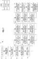
- FIG. 6A flowchart illustrating the methods and processes of system 10 , including load moment and dynamic condition calculations and drop-off and hazard detection, according to one embodiment of the present invention is illustrated in FIG. 6 .
- system 10may calibrated for use.
- system 10can include a calibration system and procedure 66 for determining the proper coefficients for system's 10 physics and mathematical models, algorithms and formulas as applied to the specific vehicle 12 and/or attachment 14 .
- system 10can be calibrated for each specific vehicle 12 and each attachment 14 for the specific vehicle 12 .
- the system 10may be recalibrated any time a different attachment 14 is added to the vehicle 12 and/or any time there are changes made to the vehicle 12 that may impact its operating characteristics.
- an existing vehicle 12can be retrofitted with a system 10 and that the system 10 would be calibrated upon installation on the vehicle 12 .
- calibration system and process 66can use a series of static and dynamic tests and regression data from these tests to determine the proper coefficients for a base vehicle 12 configuration and each vehicle 12 /attachment 14 combination intended for use with system 10 .
- sensors 26 - 36can collect data for the vehicle 12 /attachment combination without a load and with a load and ECU 40 can interpret the collected sensor data and transmit it to device 44 .
- the application on device 44can contain programming to (i) store the raw sensor data until a sufficient amount has been collected, (ii) solve systems of equations for the coefficients of the applicable physics model, and (iii) store the coefficients under a user-selectable vehicle 12 configuration heading. As a result, each time a specific vehicle 12 /attachment 14 combination is used with system 10 , the application can identify the correct coefficients.
- One embodiment of the calibration routineuses published general vehicle 12 data, specifications and dimensions to infer vehicle parameters, such as the vehicle's 12 no-load CG location (i.e., the CG of the vehicle 12 when it is not carrying a cargo load 16 ). Some or all of this information may be pre-loaded and stored in the system 10 . Additionally or alternatively, a user or operator may input various vehicle 12 data, specifications and dimensions. In that manner, the calibration routine may be adapted for calibrating or configuring the system 10 for vehicles for which accurate engineering data is not known, such as a field installation on an older vehicle. This information can include distances, weights and other parameters that can be measured or otherwise obtained by the user.
- Non-limiting examples of such informationmay include the overall weight of vehicle 12 , the distance between front and rear wheels 20 a and 20 b , the amount of weight on front wheels 20 a , the amount of weight on rear wheels 20 b , the surface area of lift cylinder's 22 piston, the maximum possible stroke of the lift cylinder 22 , the maximum possible vertical displacement of attachment 14 , the surface area of tilt cylinder's 24 piston less the cross-sectional area of tilt cylinder's 24 rod, the maximum possible stroke of the tilt cylinder 24 , the maximum possible angular displacement of mast 18 , the distance between the tilt cylinder 24 and the mast pivot, the maximum speed of vehicle 12 , and other various data, specifications and dimensions of the vehicle 12 that may be obtained by a user. It will be appreciated that calibration routine of the present invention may utilize the methodology described above in determining the location of the CG for the vehicle 12 and the location of the CG for the vehicle 12 /cargo load 16 combination.
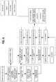
- FIG. 7illustrates one embodiment of the calibration process 66 . It will be appreciated that the steps 80 - 116 shown in FIG. 7 may be undertaken in various orders and sequences. It will be further understood that, in some instances, not all of the steps provided in FIG. 7 need be employed and that additional steps, as discussed herein, may also be undertaken.
- the userpowers up the interface device 44 along with other applicable components of the system 10 .
- the usermay then optionally enter in one or more pieces of vehicle configuration information at block 82 .
- the vehicle 12is placed on a generally level floor surface and, at block 86 , the slope of the floor may be measured and recorded using components of the system 10 (e.g., a gyroscope or tilt sensor) or other measuring devices.
- the displacement of the tilt cylinder 24 and/or angle of the mast 18may be measured and recorded at block 88 .
- one or more vertical raise testsmay be undertaken. In one embodiment, these tests are performed while the vehicle 12 is static, although additionally or alternatively, the vertical raise tests may be performed while the vehicle 12 is moving. It will be appreciated that the raise tests can be undertaken with no load located on the attachment 14 , although additionally or alternatively, the vertical raise tests may be performed with one or more loads of known masses located on the attachment 14 .
- One or more dynamic tests or routinesmay be performed at blocks 92 - 108 .
- the data, results and information from each of these testsmay be recorded and stored by the system 10 .
- an acceleration and/or deceleration testcan be performed with the attachment 14 located at a first position (e.g., a lowered positon just above the floor) and with no load placed on the attachment 14 .
- an acceleration and/or deceleration testcan be performed with the attachment 14 located at a second position (e.g., an intermediately raised position, such as a position about half way between a fully lowered and fully raised position) and with no load placed on the attachment 14 .
- an acceleration and/or deceleration testcan be performed with the attachment 14 located at a third position (e.g., a higher raised position, such as a fully raised position) and with no load placed on the attachment 14 .
- the dynamic testingmay then continue with a first load of a known mass placed on the attachment 14 .
- an acceleration and/or deceleration testcan be performed with the attachment 14 located at a first position and with the first known load placed on the attachment 14 .
- an acceleration and/or deceleration testcan be performed with the attachment 14 located at a second position and with the first known load placed on the attachment 14 .
- an acceleration and/or deceleration testcan be performed with the attachment 14 located at a third position and with the first known load placed on the attachment 14 .
- the dynamic testingcan then continue with a second load of a known mass placed on the attachment 14 .
- the second known loadmay have a mass that is either greater than or less than the mass of the first known load.
- an acceleration and/or deceleration testcan be performed with the attachment 14 located at a first position and with the second known load placed on the attachment 14 .
- an acceleration and/or deceleration testcan be performed with the attachment 14 located at a second position and with the second known load placed on the attachment 14 .
- an acceleration and/or deceleration testcan be performed with the attachment 14 located at a third position and with the second known load placed on the attachment 14 .
- no-load testing described abovecan be undertaken to establish baseline parameters throughout the range of motion of vehicle's 12 lifting apparatus. These no-load tests can be suitable for characterizing the frictions within the vehicle 12 , and may also be used to calibrate and set baselines or zero points for the sensors.
- the loaded testing described abovecan be undertaken to calculate sensor data and load moments throughout a range of motion of the vehicle's lifting apparatus.
- the load testscan be suitable for establishing correction factors for load-dependent effects, such as increased friction, stretching of chains, hoses, and other spring-style effects, among others.
- System 10can be included with a guided calibration routine by which the user or operator is instructed to undertake certain actions via the user interface device 44 or otherwise. These actions may include, but are not limited to, those steps illustrated by blocks 80 - 116 in FIG. 7 .
- the user or operatormay be instructed to raise the attachment 14 to specified heights, both with and without a load placed thereon.
- the user or operatormay also be instructed to place certain weighted loads on the attachment 14 , as well as to accelerate the vehicle 12 with a load at one or more various specified heights, and also to apply the brakes to decelerate the vehicle 12 at a specified speed or time.
- System 10can be configured to display the status of the dynamic load moment of the vehicle 12 /cargo load 16 combination in real time on the user interface device 44 .
- This device 44can allow the vehicle operator view the safety condition of vehicle 12 and identify the weight, load, load moment, and speed capacity of vehicle 12 while taking into account its dynamic conditions.
- system 10 and display 52can be configured to display the dynamic conditions of vehicle 12 on a real-time basis or, alternatively, some or all of the conditions may be updated and displayed on a semi-continuous or time-interval basis.
- FIG. 8illustrates the display 52 of device 44 according to one embodiment of the present invention.
- display 52can include a scale 54 a and a numeric percentage 54 b representing a percentage of used load moment capacity of the vehicle 12 .
- numeric value 54 bmay be expressed as the actual dynamic load moment instead of as a percentage.
- Display 52may also include a scale 56 a representing the current speed relative to a threshold maximum speed based on the current conditions and a numeric value 56 b representing the current speed of the vehicle 12 .
- the scales 54 a and 56 amay be of any suitable visual configuration including, but not limited to, a vertically- or horizontally-oriented thermometer-style scale, a linear gradient scale, a circular or semi-circular scale, or any other suitable geometric or graphical configuration.
- the scale 54 a representing the percentage of the load moment capacity being usedcan be a color-coded continuous or sliding scale that includes a continuum of colors, from blue to green to yellow to orange to red, that transition in color from bottom to top (or left to right in the case of a horizontal scale, for example).
- the numeric percentage 54 b alongside the scale 54 awhich again displays the load moment in terms of percentage of maximum capacity used, may similarly be a continuous or sliding scale that transitions in color (from blue to green to yellow to orange to red) corresponding to its position relative to scale 54 a . This can enable the operator to gain instant and real-time information regarding the fore-aft stability of vehicle 12 .
- the capacity indication number 54 bcan also move up and down the scale 54 a not only when loads are lifted, but also when other conditions occur that would affect the load moment, such as when vehicle 12 is driven up or down a slope, when the mast assembly 18 is tilted forward or backward, and when vehicle 12 is accelerated or decelerated when speeding up or slowing down.
- scale 56 amay also be similarly color-coded and, like the numeric percentage 54 b , number 56 b can also be color-coded and can move up and down relative to scale 56 a .
- the color-coded speed scale 56 acan be adapted to not only display the speed of vehicle 12 , but it can also optionally display an indication of the used portion of the context sensitive speed limit that is corrected for: (i) the lifted load and load moment; (ii) the lift height; (iii) the ground slope; and (iv) any user-inputted limits.
- its associated speed number 56 bmay transition in color as it moves up and down relative to the scale 56 a.
- display 52may be a monochromatic, black and white or other type of display that does not include color.
- the scales 54 a and 56 aneed not be in color and can alternatively include a monochromatic continuous gradient from bottom to top. For example, such the gradient may become increasing darker from bottom to top. The same may also apply to numbers 54 b and 56 b.
- the scales 54 a and 56 b , numbers 54 b and 56 b and/or other portions of the display 52may begin to flash as the load moment or speed reaches a maximum threshold (e.g., near 100%) to draw the operator's attention.
- a maximum thresholde.g., near 100%
- display 52can further include information relating to the cargo load's 16 weight 58 a and the location 58 b of the CG of the cargo load 16 .
- the displayed weight 58 amay be that of the overall weight of the vehicle 12 /cargo load 16 combination
- the displayed location 58 bmay be that of the overall CG of the vehicle 12 /cargo load 16 combination.
- the location 58 b of the CGmay be presented in terms of its fore-aft distance from (either in front or behind) the center of the front wheels 20 a .
- the display 52conveys to the operator that 61% of the vehicle's 12 load moment capacity is used, the current speed of the vehicle is 2 miles per hour, the load is 4451 pounds, and the CG is located 28.5 inches from the center of the center of the front wheels 20 a.
- display 52may include a portion for showing a camera view 60 (e.g., a view from behind the vehicle 12 ), a color-coded obstacle proximity bar 62 that may change color to indicate to the operator how close the vehicle 12 is relative to an obstacle, and various control or menu fields 64 of buttons.
- Camera view 60can provide an optional video feed on device 44 from camera 48 .
- Camera 48can be equipped with attachment means to allow the vehicle operator to attach camera 48 anywhere on vehicle 12 (or cargo load 16 ) to provide for additional visibility in the direction (e.g., front, rear or a side) of the operator's choosing.
- FIG. 9illustrates a display 52 according to another embodiment of the present invention. Aspects of the display 52 shown in FIG. 9 can be similar to those described above relative to the display 52 shown in FIG. 8 . Accordingly, display 52 illustrated in FIG. 9 can include a color-coded continuous sliding scale bar 54 a representative of the percentage of the load moment capacity of vehicle 12 and a color-coded sliding scale bar 56 a representative of the speed of vehicle 12 similar to the embodiment shown in FIG. 8 . Scales 54 a and 56 a can be adapted to progressively fill from bottom to top as the load moment or speed increases.
- scale 54 acan additionally include a percentage display 54 b of the used load moment capacity.
- scale 56 acan include a numerical display 56 b of the speed of vehicle 12 .
- Display 52according to this embodiment can also include numerical display of load data 58 a and load center data 58 b , a camera view 60 and various menu fields 65 similar to the embodiment illustrated in FIG. 8 .
- display 52can additionally include a warning indicator zone 74 that can provide various warnings to the operator, such as speed warnings, tip-warnings, obstacle and drop-off hazards, and other safety concerns. This display zone 74 can also color coordinated based on the severity of the hazard or condition.
- system 10can be configured to display and alert through display 52 , augment operator commands and decision making, and even override the vehicle operator when certain warning conditions are present.
- the application executed on the processor or user interface device 44can include database of set points and thresholds, which can be specific to vehicle 12 and/or attachment 14 , that can be used to alert the vehicle operator of unsafe tip-over conditions. If a set point or threshold is exceeded, the device 44 can notify the operator via display 52 or otherwise.
- This warning systemcan also be configured to be based on the severity level of the possible tip-over event and/or the type of tip-over (i.e., forward or lateral).
- system 10may be adapted to override manual controls of vehicle 12 in certain instances.
- An automatic interventionmay occur wherein the system 10 overtakes control of the vehicle 12 and carries out one or more actions, such as reducing the throttle or driving speed, applying the brakes, cutting off power to the wheels, altering the steering and/or other similar processes that override the operator's input.
- an override featurefor reducing the throttle and/or applying the brakes when (a) a risk of tip-over is high or exceeds a certain threshold, (b) a set speed point or threshold is reached (e.g., using a selectable percentage of context sensitive speed allowance), (c) a drop-off or other obstacle or hazard is detected and the operator ignores the warning, or (d) an imminent collision is detected and the operator ignores the warning.
- a risk of tip-overis high or exceeds a certain threshold
- a set speed point or thresholde.g., using a selectable percentage of context sensitive speed allowance
- a drop-off or other obstacle or hazardis detected and the operator ignores the warning
- an imminent collisionis detected and the operator ignores the warning.
- the steering of the vehicle 12may also be overridden in one or more of instances, for example to avoid a drop-off, obstacle, hazard or collision.
- the vehicle 12may be automatically shut down or prevented from starting when (a) the operator's license is no longer current, (b) an inspection checklist has not been completed, (c) the operator is not in the seat, or (d) the seat belt is not worn and the operator ignores the warning.
- the upward lift of the attachment 14can be automatically prevented and/or the height of the attachment 14 may be automatically reduced in certain instances, such as when the current load moment would create a tipping hazard if the attachment 14 and cargo load 16 were lifted upward and/or allowed to remain at its current height.
- the forward tilt of the mast assembly 18can be automatically prevented and/or the tilt of the mast assembly 18 may be automatically reduced in certain instances, such as when the current load moment or lift height would create a tipping hazard if the mast assembly 18 were tilted forward and/or allowed to remain at its current tilt angle.
Landscapes
- Engineering & Computer Science (AREA)
- Structural Engineering (AREA)
- Transportation (AREA)
- Life Sciences & Earth Sciences (AREA)
- Geology (AREA)
- Mechanical Engineering (AREA)
- Civil Engineering (AREA)
- Chemical & Material Sciences (AREA)
- Combustion & Propulsion (AREA)
- Forklifts And Lifting Vehicles (AREA)
Abstract
Description
Claims (9)
Priority Applications (1)
| Application Number | Priority Date | Filing Date | Title |
|---|---|---|---|
| US15/893,996US11142442B2 (en) | 2017-02-10 | 2018-02-12 | System and method for dynamically controlling the stability of an industrial vehicle |
Applications Claiming Priority (2)
| Application Number | Priority Date | Filing Date | Title |
|---|---|---|---|
| US201762457664P | 2017-02-10 | 2017-02-10 | |
| US15/893,996US11142442B2 (en) | 2017-02-10 | 2018-02-12 | System and method for dynamically controlling the stability of an industrial vehicle |
Publications (2)
| Publication Number | Publication Date |
|---|---|
| US20180229988A1 US20180229988A1 (en) | 2018-08-16 |
| US11142442B2true US11142442B2 (en) | 2021-10-12 |
Family
ID=63105820
Family Applications (1)
| Application Number | Title | Priority Date | Filing Date |
|---|---|---|---|
| US15/893,996Active2040-02-20US11142442B2 (en) | 2017-02-10 | 2018-02-12 | System and method for dynamically controlling the stability of an industrial vehicle |
Country Status (1)
| Country | Link |
|---|---|
| US (1) | US11142442B2 (en) |
Cited By (5)
| Publication number | Priority date | Publication date | Assignee | Title |
|---|---|---|---|---|
| US20210395063A1 (en)* | 2018-12-14 | 2021-12-23 | Kabushiki Kaisha Toyota Jidoshokki | Device for estimating center of gravity of cargo vehicle |
| US20220107238A1 (en)* | 2020-10-01 | 2022-04-07 | Hyster-Yale Group, Inc. | Dynamic load center-of-gravity detection |
| US11319695B2 (en)* | 2017-09-07 | 2022-05-03 | Sumitomo Construction Machinery Co., Ltd. | Shovel |
| US20220411246A1 (en)* | 2019-12-03 | 2022-12-29 | Kabushiki Kaisha Toyota Jidoshokki | Industrial vehicle |
| WO2023215954A1 (en)* | 2022-05-12 | 2023-11-16 | De Oliveira Matheus Santetti | Weighing system and method for use in material moving equipment and the like |
Families Citing this family (28)
| Publication number | Priority date | Publication date | Assignee | Title |
|---|---|---|---|---|
| US11319193B2 (en) | 2017-07-28 | 2022-05-03 | Brandt Industries Canada Ltd. | Monitoring system and method |
| US10782202B2 (en) | 2017-07-28 | 2020-09-22 | Brandt Industries Canada Ltd. | Load moment indicator system and method |
| US12020517B2 (en)* | 2018-01-26 | 2024-06-25 | Tadano Ltd. | Wireless communication device, work vehicle, and work vehicle wireless communication system |
| CN108381509B (en)* | 2018-03-19 | 2021-03-02 | 京东方科技集团股份有限公司 | Intelligent grasping device and control method thereof, and intelligent grasping control system |
| WO2019180843A1 (en)* | 2018-03-20 | 2019-09-26 | 日立建機株式会社 | Work vehicle |
| US11807508B2 (en) | 2018-08-31 | 2023-11-07 | Hyster-Yale Group, Inc. | Dynamic stability determination system for lift trucks |
| CA3109297A1 (en) | 2018-09-13 | 2020-03-19 | Crown Equipment Corporation | System and method for controlling a maximum vehicle speed for an industrial vehicle based on a calculated load |
| US10843700B2 (en)* | 2018-10-17 | 2020-11-24 | Aptiv Technologies Limited | Vehicle system and method for steep slope site avoidance |
| US11511732B2 (en)* | 2018-11-29 | 2022-11-29 | Intsite Ltd. | System and method for preventing rolling-over of vehicles |
| CN109704249B (en)* | 2018-12-10 | 2021-07-30 | 中国矿业大学 | A forklift overload protection device and method |
| CN109879206A (en)* | 2019-03-13 | 2019-06-14 | 南京实邦智能科技有限公司 | The detection method and device of fork truck center of gravity and transport vehicle center of gravity |
| US20200308803A1 (en)* | 2019-03-25 | 2020-10-01 | Cnh Industrial America Llc | System and method for automatic weight monitoring and control during a material moving operation |
| US11325531B2 (en)* | 2019-04-19 | 2022-05-10 | GM Global Technology Operations LLC | System for promoting passenger trust and mitigating motion sickness in a vehicle |
| US12259724B2 (en) | 2019-08-27 | 2025-03-25 | Crown Equipment Corporation | Adaptive acceleration for materials handling vehicle |
| JP7341878B2 (en)* | 2019-12-18 | 2023-09-11 | 株式会社クボタ | work equipment |
| JP7401303B2 (en)* | 2019-12-27 | 2023-12-19 | 矢崎エナジーシステム株式会社 | Work vehicle operation evaluation system |
| US11919761B2 (en) | 2020-03-18 | 2024-03-05 | Crown Equipment Corporation | Based on detected start of picking operation, resetting stored data related to monitored drive parameter |
| CN113734973A (en)* | 2020-05-28 | 2021-12-03 | 中强光电股份有限公司 | Control system and control method for forklift |
| JP7359102B2 (en)* | 2020-08-04 | 2023-10-11 | 株式会社豊田自動織機 | Control device for cargo handling vehicles |
| US11518368B2 (en)* | 2020-08-04 | 2022-12-06 | International Business Machines Corporation | Dynamic center of gravity monitoring and tilt prevention |
| US12066844B2 (en) | 2020-11-03 | 2024-08-20 | Crown Equipment Corporation | Adaptive acceleration for materials handling vehicle |
| US11941228B2 (en)* | 2021-08-31 | 2024-03-26 | Savant Systems, Inc. | Guidance set-up for companion module graphical display |
| JP7639636B2 (en)* | 2021-09-24 | 2025-03-05 | 株式会社豊田自動織機 | Center of gravity estimation device for industrial vehicles |
| CN114357615B (en)* | 2021-12-29 | 2025-09-05 | 东风汽车集团股份有限公司 | Method for calculating the center of mass position of vehicles, modified models, and platform models |
| JP2023116203A (en)* | 2022-02-09 | 2023-08-22 | 株式会社アイチコーポレーション | Safety device for aerial work platform |
| JP2024073039A (en)* | 2022-11-17 | 2024-05-29 | 三菱重工業株式会社 | Driving control device |
| JP7623096B1 (en)* | 2024-08-22 | 2025-01-28 | 三菱ロジスネクスト株式会社 | Alert System |
| JP7708525B1 (en)* | 2025-04-18 | 2025-07-15 | 三菱ロジスネクスト株式会社 | Loading vehicle |
Citations (72)
| Publication number | Priority date | Publication date | Assignee | Title |
|---|---|---|---|---|
| US4265337A (en) | 1979-07-16 | 1981-05-05 | Crown Controls Corporation | Fork lift truck speed control dependent upon fork elevation |
| US4511974A (en) | 1981-02-04 | 1985-04-16 | Kabushiki Kaisha Toyoda Jidoshokki Seisakusho | Load condition indicating method and apparatus for forklift truck |
| US4516116A (en) | 1981-12-16 | 1985-05-07 | Safety Devices (Engineering) Limited | Apparatus for visually displaying the load-moment, axle-load, or payload of a vehicle |
| US4852674A (en) | 1987-07-30 | 1989-08-01 | Caterpillar Inc. | Method for displaying load distribution by monitoring a work vehicle suspension |
| EP0353099A2 (en) | 1988-07-29 | 1990-01-31 | Scimitar Instrumentation Limited | Monitoring system for load carriers |
| EP0360870A1 (en) | 1988-02-19 | 1990-04-04 | Kabushiki Kaisha Toyoda Jidoshokki Seisakusho | Control and display device for a battery powered forklift truck |
| US4942529A (en) | 1988-05-26 | 1990-07-17 | The Raymond Corporation | Lift truck control systems |
| US4949263A (en) | 1987-06-01 | 1990-08-14 | Alert-O-Brake Systems Inc. | Load handling vehicle monitoring system |
| US5011358A (en) | 1988-10-25 | 1991-04-30 | Andersen Eric T | Height indicator for a fork lift truck |
| US5067572A (en) | 1990-08-20 | 1991-11-26 | Caterpillar Inc. | Dynamic payload monitor |
| US5113344A (en) | 1990-07-27 | 1992-05-12 | Raymond Corporation | Material handling vehicle identification tag |
| US5160055A (en) | 1991-10-02 | 1992-11-03 | Jlg Industries, Inc. | Load moment indicator system |
| US5208753A (en) | 1991-03-28 | 1993-05-04 | Acuff Dallas W | Forklift alignment system |
| US5586620A (en) | 1995-05-12 | 1996-12-24 | Crown Equipment Corporation | Remote viewing apparatus for fork lift trucks |
| US5652486A (en) | 1995-04-14 | 1997-07-29 | S.L.O.W. Corporation | Travel speed limiting system for forklift trucks |
| EP0800129A1 (en) | 1996-04-03 | 1997-10-08 | FIAT OM CARRELLI ELEVATORI S.p.A. | Industrial truck with manual or automatic mode |
| US5687081A (en) | 1994-12-30 | 1997-11-11 | Crown Equipment Corporation | Lift truck control system |
| EP0959038A2 (en) | 1998-05-19 | 1999-11-24 | Still Wagner GmbH & Co. KG | Video apparatus for industrial truck |
| US6025563A (en) | 1997-10-01 | 2000-02-15 | Vehicle Enhancement Systems, Inc. | Apparatus and method for indicating load weight of a vehicle |
| US6170681B1 (en) | 1998-07-21 | 2001-01-09 | Kabushiki Kaisha Kobe Seiko Sho (Kobe Steel, Ltd.) Steel | Swing type machine and method for setting a safe work area and a rated load in same |
| US6194860B1 (en) | 1999-11-01 | 2001-02-27 | Yoder Software, Inc. | Mobile camera-space manipulation |
| US6286629B1 (en) | 1999-02-03 | 2001-09-11 | David N. Saunders | Lift-positioning system |
| US6592230B2 (en) | 1997-10-16 | 2003-07-15 | Holland Hitch Company | Truck rearview mirror assembly having a display for displaying trailer coupling status information |
| US6611746B1 (en) | 2000-03-22 | 2003-08-26 | Kabushiki Kaisha Toyoda Jidoshokki Seisakusho | Industrial vehicle with a device for measuring load weight moment and a method therefor |
| EP1361190A1 (en) | 2001-02-16 | 2003-11-12 | Kabushiki Kaisha Toyoda Jidoshokki | Camera lifting device and load handling support device of industrial vehicle, and industrial vehicle |
| WO2004069568A1 (en) | 2003-02-05 | 2004-08-19 | Bosch Rexroth Ag | System for safeguarding the driving stability of an industrial truck |
| US6785597B1 (en) | 2003-02-07 | 2004-08-31 | Wiggins Lift Co., Inc. | Hydraulic stabilizer system and process for monitoring load conditions |
| US20040200644A1 (en) | 2003-04-08 | 2004-10-14 | Alan Paine | Safe load lifting measurement device |
| DE10323642A1 (en) | 2003-05-26 | 2005-01-05 | Daimlerchrysler Ag | Image and surroundings sensor for an autonomous industrial truck, floor conveyer or forklift truck, can be controlled independently of the movement of the truck or its load |
| US6855894B1 (en) | 1999-07-12 | 2005-02-15 | Ravas Europe B.V. | Mobile lifting device and weighing device therefor |
| EP1512575A2 (en) | 2003-09-06 | 2005-03-09 | DaimlerChrysler AG | Loading indicator of a vehicle |
| EP1522830A1 (en) | 2003-10-07 | 2005-04-13 | EMILCAMION S.r.l. | A tipper truck load checking system |
| US20050102081A1 (en) | 2003-09-23 | 2005-05-12 | Patterson Mark A. | Lift truck active load stabilizer |
| US6954150B2 (en) | 2001-06-28 | 2005-10-11 | Komatsu, Ltd. | Hydraulic shovel concurrently used for crane operations |
| US6965823B2 (en) | 2001-02-13 | 2005-11-15 | Siemens Aktiengesellschaft | Operating method and device for operating automated container quay cranes |
| US6985795B2 (en) | 2001-09-21 | 2006-01-10 | Schlage Lock Company | Material handler with center of gravity monitoring system |
| US7010404B2 (en) | 2002-01-23 | 2006-03-07 | Kabushiki Kaisha Toyota Jidoshokki | Position control apparatus and position control method for cargo carrying apparatus in industrial vehicle |
| US7165643B2 (en)* | 2004-04-07 | 2007-01-23 | Linde Aktiengesellchaft | Industrial truck having increased static/quasi-static and dynamic tipping stability |
| US7216024B1 (en)* | 1999-07-27 | 2007-05-08 | Linde Aktiengesellschaft | Industrial truck with a stabilizing device |
| US7219769B2 (en) | 2001-07-17 | 2007-05-22 | Kabushiki Kaisha Toyota Jidoshokki | Industrial vehicle equipped with load handling operation control apparatus |
| US7252203B2 (en) | 2001-11-06 | 2007-08-07 | Terex-Demag Gmbh & Co. Kg | Mobile crane having a superlift device |
| GB2437629A (en) | 2006-04-25 | 2007-10-31 | Jyri Mr Vaherto | Display for assisting lift truck operator |
| US20080011554A1 (en) | 2003-05-26 | 2008-01-17 | Ralf Broesel | Movable sensor device on the loading means of a forklift |
| US7366600B2 (en) | 2003-05-29 | 2008-04-29 | Mitsubishi Heavy Industries, Ltd. | Distributed control system for forklift |
| WO2008057504A2 (en) | 2006-11-06 | 2008-05-15 | Aman James A | Load tracking system based on self- tracking forklift |
| US7380375B2 (en) | 2004-12-14 | 2008-06-03 | Rite-Hite Holding Corporation | Alarm system for a loading dock |
| US20090059004A1 (en) | 2007-08-31 | 2009-03-05 | Speed Trac Technologies, Inc. | System and Method for Monitoring the Handling of a Shipment of Freight |
| US7599762B2 (en) | 2005-08-24 | 2009-10-06 | Rockwell Automatino Technologies, Inc. | Model-based control for crane control and underway replenishment |
| US20100049398A1 (en) | 2006-11-15 | 2010-02-25 | Radio Terminal Systems Pty Ltd. | Vehicle movement processing system |
| US7992686B2 (en) | 2008-07-10 | 2011-08-09 | The Raymond Corporation | Pallet counter for lift truck |
| US20110196623A1 (en) | 2008-06-24 | 2011-08-11 | Haekkinen Seppo | Load monitoring system |
| US20110203059A1 (en) | 2010-02-22 | 2011-08-25 | 4Front Engineered Solutions, Inc. | Loading dock lighting systems having warning features |
| US8055405B2 (en) | 2006-03-03 | 2011-11-08 | Jungheinrich Atiengesellschaft | Industrial truck with acquirement of utilization data |
| US20110286007A1 (en) | 2010-05-21 | 2011-11-24 | John Gregory Pangrazio | Dimensional Detection System and Associated Method |
| US8094035B2 (en) | 2009-09-24 | 2012-01-10 | Autoliv Asp, Inc. | Storage rack safety device |
| US8140228B2 (en) | 2009-03-27 | 2012-03-20 | The Raymond Corporation | System and method for dynamically maintaining the stability of a material handling vehicle having a vertical lift |
| US8146813B2 (en) | 2007-10-30 | 2012-04-03 | Paceco Corp. | Methods and apparatus processing container images and/or identifying codes for front end loaders or container handlers servicing rail cars |
| US8265836B2 (en) | 2008-05-26 | 2012-09-11 | Kabushiki Kaisha Toyota Jidoshokki | Load weight measuring device for a multi-stage mast forklift truck |
| DE102012101500A1 (en) | 2012-02-24 | 2013-08-29 | Dr. Schniz GmbH | Method for detecting data describing charging, movement and local position states of forklift truck, involves detecting data describing charging state, movement state and local position of vehicle by module |
| US8731785B2 (en) | 2011-03-18 | 2014-05-20 | The Raymond Corporation | Dynamic stability control systems and methods for industrial lift trucks |
| US8751084B2 (en) | 2012-05-08 | 2014-06-10 | Curtis Instruments, Inc. | Vehicle component recognition and adjustment for energy efficiency |
| US8768581B2 (en) | 2010-05-24 | 2014-07-01 | Hitachi Construction Machinery Co., Ltd. | Work machine safety device |
| US8793054B2 (en) | 2005-06-22 | 2014-07-29 | Volvo Construction Equipment Ab | System and a method of controlling the tilting of a loadcarrying implement of a movable work machine, and a movable work machine |
| US20140277871A1 (en) | 2013-03-14 | 2014-09-18 | Fernando D. Goncalves | Systems and methods for maintaining an industrial lift truck within defined bounds |
| US20140277691A1 (en) | 2013-03-15 | 2014-09-18 | Cybernet Systems Corporation | Automated warehousing using robotic forklifts |
| US20140267362A1 (en) | 2013-03-15 | 2014-09-18 | Apple Inc. | Device, Method, and Graphical User Interface for Adjusting the Appearance of a Control |
| US8909426B2 (en) | 2011-04-19 | 2014-12-09 | Ford Global Technologies | Trailer path curvature control for trailer backup assist |
| US20150002303A1 (en) | 2014-09-15 | 2015-01-01 | Caterpillar Inc. | System to display remaining payload weight for a truck |
| US20150029017A1 (en) | 2013-07-24 | 2015-01-29 | Caterpillar Inc. | Attitude display system for remotely operated machine |
| US8947251B2 (en) | 2010-06-11 | 2015-02-03 | Gerhard Finkbeiner | Lifting apparatus for lifting and lowering loads, in particular vehicles |
| WO2017078518A1 (en) | 2015-11-03 | 2017-05-11 | Ravas Europe B.V. | Forklift truck |
| US20180029849A1 (en)* | 2015-04-08 | 2018-02-01 | Hans Kunz GmbH | Transport unit |
- 2018
- 2018-02-12USUS15/893,996patent/US11142442B2/enactiveActive
Patent Citations (73)
| Publication number | Priority date | Publication date | Assignee | Title |
|---|---|---|---|---|
| US4265337A (en) | 1979-07-16 | 1981-05-05 | Crown Controls Corporation | Fork lift truck speed control dependent upon fork elevation |
| US4511974A (en) | 1981-02-04 | 1985-04-16 | Kabushiki Kaisha Toyoda Jidoshokki Seisakusho | Load condition indicating method and apparatus for forklift truck |
| US4516116A (en) | 1981-12-16 | 1985-05-07 | Safety Devices (Engineering) Limited | Apparatus for visually displaying the load-moment, axle-load, or payload of a vehicle |
| US4949263A (en) | 1987-06-01 | 1990-08-14 | Alert-O-Brake Systems Inc. | Load handling vehicle monitoring system |
| US4852674A (en) | 1987-07-30 | 1989-08-01 | Caterpillar Inc. | Method for displaying load distribution by monitoring a work vehicle suspension |
| EP0360870A1 (en) | 1988-02-19 | 1990-04-04 | Kabushiki Kaisha Toyoda Jidoshokki Seisakusho | Control and display device for a battery powered forklift truck |
| US4942529A (en) | 1988-05-26 | 1990-07-17 | The Raymond Corporation | Lift truck control systems |
| EP0353099A2 (en) | 1988-07-29 | 1990-01-31 | Scimitar Instrumentation Limited | Monitoring system for load carriers |
| US5011358A (en) | 1988-10-25 | 1991-04-30 | Andersen Eric T | Height indicator for a fork lift truck |
| US5113344A (en) | 1990-07-27 | 1992-05-12 | Raymond Corporation | Material handling vehicle identification tag |
| US5067572A (en) | 1990-08-20 | 1991-11-26 | Caterpillar Inc. | Dynamic payload monitor |
| US5208753A (en) | 1991-03-28 | 1993-05-04 | Acuff Dallas W | Forklift alignment system |
| US5160055A (en) | 1991-10-02 | 1992-11-03 | Jlg Industries, Inc. | Load moment indicator system |
| US5687081A (en) | 1994-12-30 | 1997-11-11 | Crown Equipment Corporation | Lift truck control system |
| US5652486A (en) | 1995-04-14 | 1997-07-29 | S.L.O.W. Corporation | Travel speed limiting system for forklift trucks |
| US5586620A (en) | 1995-05-12 | 1996-12-24 | Crown Equipment Corporation | Remote viewing apparatus for fork lift trucks |
| EP0800129A1 (en) | 1996-04-03 | 1997-10-08 | FIAT OM CARRELLI ELEVATORI S.p.A. | Industrial truck with manual or automatic mode |
| US6025563A (en) | 1997-10-01 | 2000-02-15 | Vehicle Enhancement Systems, Inc. | Apparatus and method for indicating load weight of a vehicle |
| US6592230B2 (en) | 1997-10-16 | 2003-07-15 | Holland Hitch Company | Truck rearview mirror assembly having a display for displaying trailer coupling status information |
| EP0959038A2 (en) | 1998-05-19 | 1999-11-24 | Still Wagner GmbH & Co. KG | Video apparatus for industrial truck |
| US6170681B1 (en) | 1998-07-21 | 2001-01-09 | Kabushiki Kaisha Kobe Seiko Sho (Kobe Steel, Ltd.) Steel | Swing type machine and method for setting a safe work area and a rated load in same |
| US6286629B1 (en) | 1999-02-03 | 2001-09-11 | David N. Saunders | Lift-positioning system |
| US6855894B1 (en) | 1999-07-12 | 2005-02-15 | Ravas Europe B.V. | Mobile lifting device and weighing device therefor |
| US7216024B1 (en)* | 1999-07-27 | 2007-05-08 | Linde Aktiengesellschaft | Industrial truck with a stabilizing device |
| US6194860B1 (en) | 1999-11-01 | 2001-02-27 | Yoder Software, Inc. | Mobile camera-space manipulation |
| US6611746B1 (en) | 2000-03-22 | 2003-08-26 | Kabushiki Kaisha Toyoda Jidoshokki Seisakusho | Industrial vehicle with a device for measuring load weight moment and a method therefor |
| US6965823B2 (en) | 2001-02-13 | 2005-11-15 | Siemens Aktiengesellschaft | Operating method and device for operating automated container quay cranes |
| EP1361190A1 (en) | 2001-02-16 | 2003-11-12 | Kabushiki Kaisha Toyoda Jidoshokki | Camera lifting device and load handling support device of industrial vehicle, and industrial vehicle |
| US7320385B2 (en) | 2001-02-16 | 2008-01-22 | Kabushiki Kaisha Toyota Jidoshokki | Camera lifting apparatus and cargo handling operation aiding apparatus in industrial vehicle and industrial vehicle |
| US6954150B2 (en) | 2001-06-28 | 2005-10-11 | Komatsu, Ltd. | Hydraulic shovel concurrently used for crane operations |
| US7219769B2 (en) | 2001-07-17 | 2007-05-22 | Kabushiki Kaisha Toyota Jidoshokki | Industrial vehicle equipped with load handling operation control apparatus |
| US6985795B2 (en) | 2001-09-21 | 2006-01-10 | Schlage Lock Company | Material handler with center of gravity monitoring system |
| US7252203B2 (en) | 2001-11-06 | 2007-08-07 | Terex-Demag Gmbh & Co. Kg | Mobile crane having a superlift device |
| US7010404B2 (en) | 2002-01-23 | 2006-03-07 | Kabushiki Kaisha Toyota Jidoshokki | Position control apparatus and position control method for cargo carrying apparatus in industrial vehicle |
| WO2004069568A1 (en) | 2003-02-05 | 2004-08-19 | Bosch Rexroth Ag | System for safeguarding the driving stability of an industrial truck |
| US6785597B1 (en) | 2003-02-07 | 2004-08-31 | Wiggins Lift Co., Inc. | Hydraulic stabilizer system and process for monitoring load conditions |
| US20040200644A1 (en) | 2003-04-08 | 2004-10-14 | Alan Paine | Safe load lifting measurement device |
| US20080011554A1 (en) | 2003-05-26 | 2008-01-17 | Ralf Broesel | Movable sensor device on the loading means of a forklift |
| DE10323642A1 (en) | 2003-05-26 | 2005-01-05 | Daimlerchrysler Ag | Image and surroundings sensor for an autonomous industrial truck, floor conveyer or forklift truck, can be controlled independently of the movement of the truck or its load |
| US7366600B2 (en) | 2003-05-29 | 2008-04-29 | Mitsubishi Heavy Industries, Ltd. | Distributed control system for forklift |
| EP1512575A2 (en) | 2003-09-06 | 2005-03-09 | DaimlerChrysler AG | Loading indicator of a vehicle |
| US20050102081A1 (en) | 2003-09-23 | 2005-05-12 | Patterson Mark A. | Lift truck active load stabilizer |
| EP1522830A1 (en) | 2003-10-07 | 2005-04-13 | EMILCAMION S.r.l. | A tipper truck load checking system |
| US7165643B2 (en)* | 2004-04-07 | 2007-01-23 | Linde Aktiengesellchaft | Industrial truck having increased static/quasi-static and dynamic tipping stability |
| US7380375B2 (en) | 2004-12-14 | 2008-06-03 | Rite-Hite Holding Corporation | Alarm system for a loading dock |
| US8793054B2 (en) | 2005-06-22 | 2014-07-29 | Volvo Construction Equipment Ab | System and a method of controlling the tilting of a loadcarrying implement of a movable work machine, and a movable work machine |
| US7599762B2 (en) | 2005-08-24 | 2009-10-06 | Rockwell Automatino Technologies, Inc. | Model-based control for crane control and underway replenishment |
| US8055405B2 (en) | 2006-03-03 | 2011-11-08 | Jungheinrich Atiengesellschaft | Industrial truck with acquirement of utilization data |
| GB2437629A (en) | 2006-04-25 | 2007-10-31 | Jyri Mr Vaherto | Display for assisting lift truck operator |
| WO2008057504A2 (en) | 2006-11-06 | 2008-05-15 | Aman James A | Load tracking system based on self- tracking forklift |
| US20100049398A1 (en) | 2006-11-15 | 2010-02-25 | Radio Terminal Systems Pty Ltd. | Vehicle movement processing system |
| US20090059004A1 (en) | 2007-08-31 | 2009-03-05 | Speed Trac Technologies, Inc. | System and Method for Monitoring the Handling of a Shipment of Freight |
| US8146813B2 (en) | 2007-10-30 | 2012-04-03 | Paceco Corp. | Methods and apparatus processing container images and/or identifying codes for front end loaders or container handlers servicing rail cars |
| US8265836B2 (en) | 2008-05-26 | 2012-09-11 | Kabushiki Kaisha Toyota Jidoshokki | Load weight measuring device for a multi-stage mast forklift truck |
| US20110196623A1 (en) | 2008-06-24 | 2011-08-11 | Haekkinen Seppo | Load monitoring system |
| US7992686B2 (en) | 2008-07-10 | 2011-08-09 | The Raymond Corporation | Pallet counter for lift truck |
| US8140228B2 (en) | 2009-03-27 | 2012-03-20 | The Raymond Corporation | System and method for dynamically maintaining the stability of a material handling vehicle having a vertical lift |
| US8094035B2 (en) | 2009-09-24 | 2012-01-10 | Autoliv Asp, Inc. | Storage rack safety device |
| US20110203059A1 (en) | 2010-02-22 | 2011-08-25 | 4Front Engineered Solutions, Inc. | Loading dock lighting systems having warning features |
| US20110286007A1 (en) | 2010-05-21 | 2011-11-24 | John Gregory Pangrazio | Dimensional Detection System and Associated Method |
| US8768581B2 (en) | 2010-05-24 | 2014-07-01 | Hitachi Construction Machinery Co., Ltd. | Work machine safety device |
| US8947251B2 (en) | 2010-06-11 | 2015-02-03 | Gerhard Finkbeiner | Lifting apparatus for lifting and lowering loads, in particular vehicles |
| US8731785B2 (en) | 2011-03-18 | 2014-05-20 | The Raymond Corporation | Dynamic stability control systems and methods for industrial lift trucks |
| US8909426B2 (en) | 2011-04-19 | 2014-12-09 | Ford Global Technologies | Trailer path curvature control for trailer backup assist |
| DE102012101500A1 (en) | 2012-02-24 | 2013-08-29 | Dr. Schniz GmbH | Method for detecting data describing charging, movement and local position states of forklift truck, involves detecting data describing charging state, movement state and local position of vehicle by module |
| US8751084B2 (en) | 2012-05-08 | 2014-06-10 | Curtis Instruments, Inc. | Vehicle component recognition and adjustment for energy efficiency |
| US20140277871A1 (en) | 2013-03-14 | 2014-09-18 | Fernando D. Goncalves | Systems and methods for maintaining an industrial lift truck within defined bounds |
| US20140277691A1 (en) | 2013-03-15 | 2014-09-18 | Cybernet Systems Corporation | Automated warehousing using robotic forklifts |
| US20140267362A1 (en) | 2013-03-15 | 2014-09-18 | Apple Inc. | Device, Method, and Graphical User Interface for Adjusting the Appearance of a Control |
| US20150029017A1 (en) | 2013-07-24 | 2015-01-29 | Caterpillar Inc. | Attitude display system for remotely operated machine |
| US20150002303A1 (en) | 2014-09-15 | 2015-01-01 | Caterpillar Inc. | System to display remaining payload weight for a truck |
| US20180029849A1 (en)* | 2015-04-08 | 2018-02-01 | Hans Kunz GmbH | Transport unit |
| WO2017078518A1 (en) | 2015-11-03 | 2017-05-11 | Ravas Europe B.V. | Forklift truck |
Non-Patent Citations (7)
| Title |
|---|
| MH&L Material Handeling & Logistics, Hydraulic Scale for Forklift Trucks, http://mhlnews.com/new-products/hydraulic-scale-forklift-trucks-new-products, Dec. 21, 2015. |
| RDS Technology Ltd., Liftlog 1000, www.rdstec.com, p. 2-4, RDS Technology Ltd, Cirencester Road, Minchinhampton, Stroud, Glos, GL6 9BH, UK, 2014. |
| Roger Bostelman, Towards Improved Forklift Safety, Mobility and Manipulation Project Intelligent Systems Division, Manufacturing Engineering Laboratory, National Institute of Standards and Technology, Department of Commerce, Gaithersburg, MD, Oct. 16, 2009. |
| Skidweigh Technology, ED6, http://www.skidweight.com/ed6-skidfleet-series.html, p. 2-3, Jan. 28, 2016. |
| Touch Screen Console Controls Mobile Column Lifts, Smart Control System, http://www.truckinginfo.com/channel/products/product/detail/2015/01/touch-screen-console-controls-mobile-column-lifts.aspx, Jan. 12, 2015. |
| VEGA Italian Style for Lifts, Display TFT, http://www.vegalift.it/documents/TFT%205.7%20%20%5BENG-VEGA%5D%20rev%2005.pdf, 2010. |
| Wheel Loader Scales, Weighlog 3030 and Weighlog Vue, http://loupelectronics.com/industrial-products/wheel-loader-scales.html, 2016. |
Cited By (7)
| Publication number | Priority date | Publication date | Assignee | Title |
|---|---|---|---|---|
| US11319695B2 (en)* | 2017-09-07 | 2022-05-03 | Sumitomo Construction Machinery Co., Ltd. | Shovel |
| US20210395063A1 (en)* | 2018-12-14 | 2021-12-23 | Kabushiki Kaisha Toyota Jidoshokki | Device for estimating center of gravity of cargo vehicle |
| US11772946B2 (en)* | 2018-12-14 | 2023-10-03 | Kabushiki Kaisha Toyota Jidoshokki | Device for estimating center of gravity of cargo vehicle |
| US20220411246A1 (en)* | 2019-12-03 | 2022-12-29 | Kabushiki Kaisha Toyota Jidoshokki | Industrial vehicle |
| US12180047B2 (en)* | 2019-12-03 | 2024-12-31 | Kabushiki Kaisha Toyota Jidoshokki | Industrial vehicle |
| US20220107238A1 (en)* | 2020-10-01 | 2022-04-07 | Hyster-Yale Group, Inc. | Dynamic load center-of-gravity detection |
| WO2023215954A1 (en)* | 2022-05-12 | 2023-11-16 | De Oliveira Matheus Santetti | Weighing system and method for use in material moving equipment and the like |
Also Published As
| Publication number | Publication date |
|---|---|
| US20180229988A1 (en) | 2018-08-16 |
Similar Documents
| Publication | Publication Date | Title |
|---|---|---|
| US11142442B2 (en) | System and method for dynamically controlling the stability of an industrial vehicle | |
| AU2008219810B2 (en) | Automated rollover prevention system | |
| US9221659B2 (en) | Loading system and transporter | |
| AU2013206698B2 (en) | System and method for operating a machine | |
| AU2013206697B2 (en) | System and method for detecting a crest | |
| EP2646283B1 (en) | Loading analysis system and method | |
| AU2013206696B2 (en) | System and method for adjusting a boundary for a machine | |
| US10829901B2 (en) | System for determining compaction of a terrain based on rolling resistance | |
| CA2125375C (en) | Tactile control for automated bucket loading | |
| US11225777B2 (en) | Work machine | |
| US20170113591A1 (en) | System and method for controlling movement of implement | |
| US11788258B2 (en) | Systems and methods for determining a locational value of a load associated with an implement | |
| US11885102B2 (en) | Visual overlays for indicating stopping distances of remote controlled machines | |
| EP3907336A1 (en) | Monitoring device and construction machine | |
| EP2910912A1 (en) | Improved monitoring system | |
| KR20190093055A (en) | Rollover Warning Method and Same Apparatus for Tractore | |
| US20170113608A1 (en) | System and method for operating a machine | |
| US20220389688A1 (en) | Work machine, weighing method, and system including work machine | |
| CN116902835A (en) | Landing leg leveling method, landing leg leveling device, landing leg leveling system and vehicle | |
| US20240376693A1 (en) | Work machine | |
| KR20120036114A (en) | Display unit comprising an intuitive bucket interface | |
| CN116552470A (en) | Unmanned mining truck and braking method thereof | |
| KR20210155459A (en) | excavator for roll-over preventing and method using the same |
Legal Events
| Date | Code | Title | Description |
|---|---|---|---|
| AS | Assignment | Owner name:ARROW ACQUISITION, LLC, KANSAS Free format text:ASSIGNMENT OF ASSIGNORS INTEREST;ASSIGNORS:GAULT, ROSS T.;MELVIN, TERRENCE S.;REEL/FRAME:044895/0591 Effective date:20170213 | |
| FEPP | Fee payment procedure | Free format text:ENTITY STATUS SET TO UNDISCOUNTED (ORIGINAL EVENT CODE: BIG.); ENTITY STATUS OF PATENT OWNER: SMALL ENTITY | |
| FEPP | Fee payment procedure | Free format text:ENTITY STATUS SET TO SMALL (ORIGINAL EVENT CODE: SMAL); ENTITY STATUS OF PATENT OWNER: SMALL ENTITY | |
| STPP | Information on status: patent application and granting procedure in general | Free format text:DOCKETED NEW CASE - READY FOR EXAMINATION | |
| STPP | Information on status: patent application and granting procedure in general | Free format text:NON FINAL ACTION MAILED | |
| STPP | Information on status: patent application and granting procedure in general | Free format text:NON FINAL ACTION MAILED | |
| STPP | Information on status: patent application and granting procedure in general | Free format text:RESPONSE TO NON-FINAL OFFICE ACTION ENTERED AND FORWARDED TO EXAMINER | |
| STPP | Information on status: patent application and granting procedure in general | Free format text:FINAL REJECTION MAILED | |
| STPP | Information on status: patent application and granting procedure in general | Free format text:RESPONSE AFTER FINAL ACTION FORWARDED TO EXAMINER | |
| STPP | Information on status: patent application and granting procedure in general | Free format text:NOTICE OF ALLOWANCE MAILED -- APPLICATION RECEIVED IN OFFICE OF PUBLICATIONS | |
| STPP | Information on status: patent application and granting procedure in general | Free format text:PUBLICATIONS -- ISSUE FEE PAYMENT VERIFIED | |
| STCF | Information on status: patent grant | Free format text:PATENTED CASE | |
| AS | Assignment | Owner name:MARANON CAPITAL, L.P., AS ADMINISTRATIVE AGENT, ILLINOIS Free format text:SECURITY INTEREST;ASSIGNOR:ARROW ACQUISITION, LLC;REEL/FRAME:061991/0100 Effective date:20221205 | |
| AS | Assignment | Owner name:ELDRIDGE CREDIT ADVISERS, LLC, AS ADMINISTRATIVE AGENT, NEW YORK Free format text:SECURED PARTY CONVERSION AND NAME CHANGE;ASSIGNOR:MARANON CAPITAL, L.P., AS ADMINISTRATIVE AGENT;REEL/FRAME:070647/0063 Effective date:20250103 | |
| FEPP | Fee payment procedure | Free format text:MAINTENANCE FEE REMINDER MAILED (ORIGINAL EVENT CODE: REM.); ENTITY STATUS OF PATENT OWNER: SMALL ENTITY |