US11141834B2 - Polycrystalline diamond compacts and related methods - Google Patents
Polycrystalline diamond compacts and related methodsDownload PDFInfo
- Publication number
- US11141834B2 US11141834B2US15/861,294US201815861294AUS11141834B2US 11141834 B2US11141834 B2US 11141834B2US 201815861294 AUS201815861294 AUS 201815861294AUS 11141834 B2US11141834 B2US 11141834B2
- Authority
- US
- United States
- Prior art keywords
- volume
- metal
- solvent catalyst
- drill bit
- polycrystalline diamond
- Prior art date
- Legal status (The legal status is an assumption and is not a legal conclusion. Google has not performed a legal analysis and makes no representation as to the accuracy of the status listed.)
- Active
Links
Images


Classifications
- B—PERFORMING OPERATIONS; TRANSPORTING
- B22—CASTING; POWDER METALLURGY
- B22F—WORKING METALLIC POWDER; MANUFACTURE OF ARTICLES FROM METALLIC POWDER; MAKING METALLIC POWDER; APPARATUS OR DEVICES SPECIALLY ADAPTED FOR METALLIC POWDER
- B22F3/00—Manufacture of workpieces or articles from metallic powder characterised by the manner of compacting or sintering; Apparatus specially adapted therefor ; Presses and furnaces
- B22F3/24—After-treatment of workpieces or articles
- B—PERFORMING OPERATIONS; TRANSPORTING
- B22—CASTING; POWDER METALLURGY
- B22F—WORKING METALLIC POWDER; MANUFACTURE OF ARTICLES FROM METALLIC POWDER; MAKING METALLIC POWDER; APPARATUS OR DEVICES SPECIALLY ADAPTED FOR METALLIC POWDER
- B22F5/00—Manufacture of workpieces or articles from metallic powder characterised by the special shape of the product
- B—PERFORMING OPERATIONS; TRANSPORTING
- B22—CASTING; POWDER METALLURGY
- B22F—WORKING METALLIC POWDER; MANUFACTURE OF ARTICLES FROM METALLIC POWDER; MAKING METALLIC POWDER; APPARATUS OR DEVICES SPECIALLY ADAPTED FOR METALLIC POWDER
- B22F7/00—Manufacture of composite layers, workpieces, or articles, comprising metallic powder, by sintering the powder, with or without compacting wherein at least one part is obtained by sintering or compression
- B22F7/06—Manufacture of composite layers, workpieces, or articles, comprising metallic powder, by sintering the powder, with or without compacting wherein at least one part is obtained by sintering or compression of composite workpieces or articles from parts, e.g. to form tipped tools
- B—PERFORMING OPERATIONS; TRANSPORTING
- B24—GRINDING; POLISHING
- B24D—TOOLS FOR GRINDING, BUFFING OR SHARPENING
- B24D18/00—Manufacture of grinding tools or other grinding devices, e.g. wheels, not otherwise provided for
- B24D18/0009—Manufacture of grinding tools or other grinding devices, e.g. wheels, not otherwise provided for using moulds or presses
- B—PERFORMING OPERATIONS; TRANSPORTING
- B24—GRINDING; POLISHING
- B24D—TOOLS FOR GRINDING, BUFFING OR SHARPENING
- B24D18/00—Manufacture of grinding tools or other grinding devices, e.g. wheels, not otherwise provided for
- B24D18/0027—Manufacture of grinding tools or other grinding devices, e.g. wheels, not otherwise provided for by impregnation
- B—PERFORMING OPERATIONS; TRANSPORTING
- B24—GRINDING; POLISHING
- B24D—TOOLS FOR GRINDING, BUFFING OR SHARPENING
- B24D3/00—Physical features of abrasive bodies, or sheets, e.g. abrasive surfaces of special nature; Abrasive bodies or sheets characterised by their constituents
- B24D3/02—Physical features of abrasive bodies, or sheets, e.g. abrasive surfaces of special nature; Abrasive bodies or sheets characterised by their constituents the constituent being used as bonding agent
- B24D3/04—Physical features of abrasive bodies, or sheets, e.g. abrasive surfaces of special nature; Abrasive bodies or sheets characterised by their constituents the constituent being used as bonding agent and being essentially inorganic
- B24D3/06—Physical features of abrasive bodies, or sheets, e.g. abrasive surfaces of special nature; Abrasive bodies or sheets characterised by their constituents the constituent being used as bonding agent and being essentially inorganic metallic or mixture of metals with ceramic materials, e.g. hard metals, "cermets", cements
- B24D3/10—Physical features of abrasive bodies, or sheets, e.g. abrasive surfaces of special nature; Abrasive bodies or sheets characterised by their constituents the constituent being used as bonding agent and being essentially inorganic metallic or mixture of metals with ceramic materials, e.g. hard metals, "cermets", cements for porous or cellular structure, e.g. for use with diamonds as abrasives
- C—CHEMISTRY; METALLURGY
- C04—CEMENTS; CONCRETE; ARTIFICIAL STONE; CERAMICS; REFRACTORIES
- C04B—LIME, MAGNESIA; SLAG; CEMENTS; COMPOSITIONS THEREOF, e.g. MORTARS, CONCRETE OR LIKE BUILDING MATERIALS; ARTIFICIAL STONE; CERAMICS; REFRACTORIES; TREATMENT OF NATURAL STONE
- C04B35/00—Shaped ceramic products characterised by their composition; Ceramics compositions; Processing powders of inorganic compounds preparatory to the manufacturing of ceramic products
- C04B35/515—Shaped ceramic products characterised by their composition; Ceramics compositions; Processing powders of inorganic compounds preparatory to the manufacturing of ceramic products based on non-oxide ceramics
- C04B35/52—Shaped ceramic products characterised by their composition; Ceramics compositions; Processing powders of inorganic compounds preparatory to the manufacturing of ceramic products based on non-oxide ceramics based on carbon, e.g. graphite
- C04B35/528—Shaped ceramic products characterised by their composition; Ceramics compositions; Processing powders of inorganic compounds preparatory to the manufacturing of ceramic products based on non-oxide ceramics based on carbon, e.g. graphite obtained from carbonaceous particles with or without other non-organic components
- C—CHEMISTRY; METALLURGY
- C04—CEMENTS; CONCRETE; ARTIFICIAL STONE; CERAMICS; REFRACTORIES
- C04B—LIME, MAGNESIA; SLAG; CEMENTS; COMPOSITIONS THEREOF, e.g. MORTARS, CONCRETE OR LIKE BUILDING MATERIALS; ARTIFICIAL STONE; CERAMICS; REFRACTORIES; TREATMENT OF NATURAL STONE
- C04B35/00—Shaped ceramic products characterised by their composition; Ceramics compositions; Processing powders of inorganic compounds preparatory to the manufacturing of ceramic products
- C04B35/622—Forming processes; Processing powders of inorganic compounds preparatory to the manufacturing of ceramic products
- C04B35/64—Burning or sintering processes
- C04B35/645—Pressure sintering
- C—CHEMISTRY; METALLURGY
- C22—METALLURGY; FERROUS OR NON-FERROUS ALLOYS; TREATMENT OF ALLOYS OR NON-FERROUS METALS
- C22C—ALLOYS
- C22C26/00—Alloys containing diamond or cubic or wurtzitic boron nitride, fullerenes or carbon nanotubes
- C—CHEMISTRY; METALLURGY
- C23—COATING METALLIC MATERIAL; COATING MATERIAL WITH METALLIC MATERIAL; CHEMICAL SURFACE TREATMENT; DIFFUSION TREATMENT OF METALLIC MATERIAL; COATING BY VACUUM EVAPORATION, BY SPUTTERING, BY ION IMPLANTATION OR BY CHEMICAL VAPOUR DEPOSITION, IN GENERAL; INHIBITING CORROSION OF METALLIC MATERIAL OR INCRUSTATION IN GENERAL
- C23F—NON-MECHANICAL REMOVAL OF METALLIC MATERIAL FROM SURFACE; INHIBITING CORROSION OF METALLIC MATERIAL OR INCRUSTATION IN GENERAL; MULTI-STEP PROCESSES FOR SURFACE TREATMENT OF METALLIC MATERIAL INVOLVING AT LEAST ONE PROCESS PROVIDED FOR IN CLASS C23 AND AT LEAST ONE PROCESS COVERED BY SUBCLASS C21D OR C22F OR CLASS C25
- C23F1/00—Etching metallic material by chemical means
- C23F1/02—Local etching
- C—CHEMISTRY; METALLURGY
- C23—COATING METALLIC MATERIAL; COATING MATERIAL WITH METALLIC MATERIAL; CHEMICAL SURFACE TREATMENT; DIFFUSION TREATMENT OF METALLIC MATERIAL; COATING BY VACUUM EVAPORATION, BY SPUTTERING, BY ION IMPLANTATION OR BY CHEMICAL VAPOUR DEPOSITION, IN GENERAL; INHIBITING CORROSION OF METALLIC MATERIAL OR INCRUSTATION IN GENERAL
- C23F—NON-MECHANICAL REMOVAL OF METALLIC MATERIAL FROM SURFACE; INHIBITING CORROSION OF METALLIC MATERIAL OR INCRUSTATION IN GENERAL; MULTI-STEP PROCESSES FOR SURFACE TREATMENT OF METALLIC MATERIAL INVOLVING AT LEAST ONE PROCESS PROVIDED FOR IN CLASS C23 AND AT LEAST ONE PROCESS COVERED BY SUBCLASS C21D OR C22F OR CLASS C25
- C23F1/00—Etching metallic material by chemical means
- C23F1/10—Etching compositions
- C23F1/14—Aqueous compositions
- C23F1/16—Acidic compositions
- C23F1/28—Acidic compositions for etching iron group metals
- C—CHEMISTRY; METALLURGY
- C04—CEMENTS; CONCRETE; ARTIFICIAL STONE; CERAMICS; REFRACTORIES
- C04B—LIME, MAGNESIA; SLAG; CEMENTS; COMPOSITIONS THEREOF, e.g. MORTARS, CONCRETE OR LIKE BUILDING MATERIALS; ARTIFICIAL STONE; CERAMICS; REFRACTORIES; TREATMENT OF NATURAL STONE
- C04B2235/00—Aspects relating to ceramic starting mixtures or sintered ceramic products
- C04B2235/02—Composition of constituents of the starting material or of secondary phases of the final product
- C04B2235/30—Constituents and secondary phases not being of a fibrous nature
- C04B2235/38—Non-oxide ceramic constituents or additives
- C04B2235/3817—Carbides
- C04B2235/3839—Refractory metal carbides
- C04B2235/3847—Tungsten carbides
- C—CHEMISTRY; METALLURGY
- C04—CEMENTS; CONCRETE; ARTIFICIAL STONE; CERAMICS; REFRACTORIES
- C04B—LIME, MAGNESIA; SLAG; CEMENTS; COMPOSITIONS THEREOF, e.g. MORTARS, CONCRETE OR LIKE BUILDING MATERIALS; ARTIFICIAL STONE; CERAMICS; REFRACTORIES; TREATMENT OF NATURAL STONE
- C04B2235/00—Aspects relating to ceramic starting mixtures or sintered ceramic products
- C04B2235/02—Composition of constituents of the starting material or of secondary phases of the final product
- C04B2235/30—Constituents and secondary phases not being of a fibrous nature
- C04B2235/42—Non metallic elements added as constituents or additives, e.g. sulfur, phosphor, selenium or tellurium
- C04B2235/422—Carbon
- C04B2235/427—Diamond
- C—CHEMISTRY; METALLURGY
- C04—CEMENTS; CONCRETE; ARTIFICIAL STONE; CERAMICS; REFRACTORIES
- C04B—LIME, MAGNESIA; SLAG; CEMENTS; COMPOSITIONS THEREOF, e.g. MORTARS, CONCRETE OR LIKE BUILDING MATERIALS; ARTIFICIAL STONE; CERAMICS; REFRACTORIES; TREATMENT OF NATURAL STONE
- C04B2235/00—Aspects relating to ceramic starting mixtures or sintered ceramic products
- C04B2235/02—Composition of constituents of the starting material or of secondary phases of the final product
- C04B2235/50—Constituents or additives of the starting mixture chosen for their shape or used because of their shape or their physical appearance
- C04B2235/54—Particle size related information
- C04B2235/5418—Particle size related information expressed by the size of the particles or aggregates thereof
- C04B2235/5436—Particle size related information expressed by the size of the particles or aggregates thereof micrometer sized, i.e. from 1 to 100 micron
- C—CHEMISTRY; METALLURGY
- C04—CEMENTS; CONCRETE; ARTIFICIAL STONE; CERAMICS; REFRACTORIES
- C04B—LIME, MAGNESIA; SLAG; CEMENTS; COMPOSITIONS THEREOF, e.g. MORTARS, CONCRETE OR LIKE BUILDING MATERIALS; ARTIFICIAL STONE; CERAMICS; REFRACTORIES; TREATMENT OF NATURAL STONE
- C04B2235/00—Aspects relating to ceramic starting mixtures or sintered ceramic products
- C04B2235/02—Composition of constituents of the starting material or of secondary phases of the final product
- C04B2235/50—Constituents or additives of the starting mixture chosen for their shape or used because of their shape or their physical appearance
- C04B2235/54—Particle size related information
- C04B2235/5418—Particle size related information expressed by the size of the particles or aggregates thereof
- C04B2235/5445—Particle size related information expressed by the size of the particles or aggregates thereof submicron sized, i.e. from 0,1 to 1 micron
- C—CHEMISTRY; METALLURGY
- C04—CEMENTS; CONCRETE; ARTIFICIAL STONE; CERAMICS; REFRACTORIES
- C04B—LIME, MAGNESIA; SLAG; CEMENTS; COMPOSITIONS THEREOF, e.g. MORTARS, CONCRETE OR LIKE BUILDING MATERIALS; ARTIFICIAL STONE; CERAMICS; REFRACTORIES; TREATMENT OF NATURAL STONE
- C04B2235/00—Aspects relating to ceramic starting mixtures or sintered ceramic products
- C04B2235/02—Composition of constituents of the starting material or of secondary phases of the final product
- C04B2235/50—Constituents or additives of the starting mixture chosen for their shape or used because of their shape or their physical appearance
- C04B2235/54—Particle size related information
- C04B2235/5463—Particle size distributions
- C04B2235/5472—Bimodal, multi-modal or multi-fraction
- Y—GENERAL TAGGING OF NEW TECHNOLOGICAL DEVELOPMENTS; GENERAL TAGGING OF CROSS-SECTIONAL TECHNOLOGIES SPANNING OVER SEVERAL SECTIONS OF THE IPC; TECHNICAL SUBJECTS COVERED BY FORMER USPC CROSS-REFERENCE ART COLLECTIONS [XRACs] AND DIGESTS
- Y10—TECHNICAL SUBJECTS COVERED BY FORMER USPC
- Y10T—TECHNICAL SUBJECTS COVERED BY FORMER US CLASSIFICATION
- Y10T428/00—Stock material or miscellaneous articles
- Y10T428/12—All metal or with adjacent metals
- Y10T428/12014—All metal or with adjacent metals having metal particles
- Y10T428/12028—Composite; i.e., plural, adjacent, spatially distinct metal components [e.g., layers, etc.]
- Y10T428/12049—Nonmetal component
- Y10T428/12056—Entirely inorganic
- Y—GENERAL TAGGING OF NEW TECHNOLOGICAL DEVELOPMENTS; GENERAL TAGGING OF CROSS-SECTIONAL TECHNOLOGIES SPANNING OVER SEVERAL SECTIONS OF THE IPC; TECHNICAL SUBJECTS COVERED BY FORMER USPC CROSS-REFERENCE ART COLLECTIONS [XRACs] AND DIGESTS
- Y10—TECHNICAL SUBJECTS COVERED BY FORMER USPC
- Y10T—TECHNICAL SUBJECTS COVERED BY FORMER US CLASSIFICATION
- Y10T428/00—Stock material or miscellaneous articles
- Y10T428/24—Structurally defined web or sheet [e.g., overall dimension, etc.]
- Y10T428/24355—Continuous and nonuniform or irregular surface on layer or component [e.g., roofing, etc.]
- Y—GENERAL TAGGING OF NEW TECHNOLOGICAL DEVELOPMENTS; GENERAL TAGGING OF CROSS-SECTIONAL TECHNOLOGIES SPANNING OVER SEVERAL SECTIONS OF THE IPC; TECHNICAL SUBJECTS COVERED BY FORMER USPC CROSS-REFERENCE ART COLLECTIONS [XRACs] AND DIGESTS
- Y10—TECHNICAL SUBJECTS COVERED BY FORMER USPC
- Y10T—TECHNICAL SUBJECTS COVERED BY FORMER US CLASSIFICATION
- Y10T428/00—Stock material or miscellaneous articles
- Y10T428/30—Self-sustaining carbon mass or layer with impregnant or other layer
Definitions
- PDCspolycrystalline diamond compacts
- drilling toolse.g., cutting elements, gage trimmers, etc.
- machining equipmente.g., machining tools, bearing apparatuses, wire-drawing machinery, and in other mechanical apparatuses.
- a PDC cutting elementtypically includes a superabrasive diamond layer commonly referred to as a diamond table.
- the diamond tableis formed and bonded to a substrate using a high-pressure/high-temperature (“HPHT”) process.
- HPHThigh-pressure/high-temperature
- the PDC cutting elementmay also be brazed directly into a preformed pocket, socket, or other receptacle formed in a bit body.
- the substratemay often be brazed or otherwise joined to an attachment member, such as a cylindrical backing.
- a rotary drill bittypically includes a number of PDC cutting elements affixed to the bit body.
- a stud carrying the PDCmay be used as a PDC cutting element when mounted to a bit body of a rotary drill bit by press-fitting, brazing, or otherwise securing the stud into a receptacle formed in the bit body.
- PDCsare normally fabricated by placing a cemented carbide substrate into a container with a volume of diamond particles positioned adjacent to the cemented-carbide substrate.
- a number of such containersmay be loaded into a HPHT press.
- the substrates and volume(s) of diamond particlesare then processed under HPHT conditions in the presence of a catalyst material that causes the diamond particles to bond to one another to form a matrix of bonded-together diamond grains defining a polycrystalline diamond (“PCD”) table that is bonded to the substrate.
- the catalyst materialis often a metal-solvent catalyst (e.g., cobalt, nickel, iron, or alloys thereof) that is used for promoting intergrowth of the diamond particles.
- a constituent of the cemented carbide substratesuch as cobalt from a cobalt-cemented tungsten carbide substrate, liquefies and sweeps from a region adjacent to the volume of diamond particles into interstitial regions between the diamond particles during the HPHT process.
- the cobaltacts as a catalyst to promote intergrowth between the diamond particles, which results in formation of bonded-together diamond grains exhibiting diamond-to-diamond bonding therebetween.
- a solvent catalystmay be mixed with the diamond particles prior to subjecting the diamond particles and substrate to the HPHT process.
- the presence of the metal-solvent catalyst in the PCD tableis believed to reduce the thermal stability of the PCD table at elevated temperatures.
- the difference in thermal expansion coefficient between the diamond grains and the metal-solvent catalystis believed to lead to chipping or cracking of the PCD table during drilling or cutting operations, which can degrade the mechanical properties of the PCD table or cause failure.
- some of the diamond grainscan undergo a chemical breakdown or back-conversion to graphite via interaction with the metal-solvent catalyst.
- portions of diamond grainsmay transform to carbon monoxide, carbon dioxide, graphite, or combinations thereof, thereby degrading the mechanical properties of the PCD table.
- One conventional approach for improving the thermal stability of a PCD table of a PDCis to at least partially remove the metal-solvent catalyst from the PCD table by acid leaching.
- Another conventional approach for forming a PDCincludes separately forming a sintered PCD table that is subsequently leached to remove solvent catalyst from interstitial regions between bonded-together diamond grains.
- the leached PCD tablemay be bonded to a substrate and infiltrated with a non-catalyst material, such as silicon, in a separate HPHT process.
- the siliconmay infiltrate the interstitial regions of the leached PCD table from which the solvent catalyst has been leached and react with the diamond grains to form silicon carbide.
- a PDCincludes a substrate and a PCD table including a working surface and an opposing interfacial surface bonded to the substrate.
- the PCD tableincludes a plurality of bonded diamond grains defining interstitial regions.
- the PCD tablefurther includes a leached first volume extending inwardly from the working surface and including a metallic infiltrant disposed in at least a portion of the interstitial regions thereof.
- the metallic infiltrant of the leached first volumemay be present in a concentration of less than 0.85 weight % (“wt %”).
- the PCD tablealso includes a second volume extending inwardly from the interfacial surface.
- the interstitial regions of the second volumeinclude the metallic infiltrant disposed therein.
- a method of fabricating a leached PCD tableincludes mixing a plurality of diamond particles with a plurality of sacrificial particles to form a mixture.
- the methodfurther includes sintering the mixture in the presence of a metal-solvent catalyst to form a PCD table.
- the PCD tablecomprises a sacrificial material including the plurality of sacrificial particles, at least one reaction product of the plurality of diamond particles and the plurality of sacrificial particles, or combinations thereof.
- the methodadditionally includes leaching at least a portion of the metal-solvent catalyst and at least a portion of the sacrificial material from the PCD table.
- a method of fabricating a leached PDCincludes disposing a mixture adjacent to a substrate.
- the mixtureincludes a plurality of diamond particles and a plurality of sacrificial particles.
- the methodalso includes subjecting the mixture and the substrate to an HPHT process to sinter the plurality of diamond particles in the presence of a metal-solvent catalyst to form a PCD table over the substrate.
- the PCD tablecomprises a sacrificial material including the plurality of sacrificial particles, at least one reaction product of the plurality of diamond particles and the plurality of sacrificial particles, or combinations thereof.
- the methodfurther includes leaching at least a portion of the metal-solvent catalyst and at least a portion of the sacrificial material from a volume of the PCD table.
- another method of fabricating a leached PDCincludes mixing a plurality of diamond particles with a plurality of sacrificial particles to form a mixture.
- the methodalso includes sintering the mixture in the presence of a metal-solvent catalyst to form a PCD table.
- the PCD tablecomprises a sacrificial material including the plurality of sacrificial particles, at least one reaction product of the plurality of diamond particles and the plurality of sacrificial particles, or combinations thereof.
- the methodadditionally includes leaching at least a portion of the metal-solvent catalyst and at least a portion of the sacrificial material from the PCD table so that the metal-solvent catalyst is present therein in a concentration of less than 0.85 wt %.
- the methodalso includes positioning the leached PCD table adjacent to the substrate to form an assembly.
- the methodfurther includes subjecting the assembly to an HPHT process to infiltrate the leached PCD table with a metallic infiltrant.
- a PDCincludes a cemented tungsten carbide substrate and a pre-sintered PCD table bonded to the cemented tungsten carbide substrate.
- the pre-sintered PCD tableincludes a working surface and an opposing interfacial surface bonded to the cemented tungsten carbide substrate.
- the pre-sintered PCD tableincludes a plurality of bonded diamond grains defining a plurality of interstitial regions.
- the pre-sintered PCD tableincludes a first volume extending inwardly from the working surface that is substantially free of metal-solvent catalyst and at least one of tungsten or tungsten carbide.
- the pre-sintered PCD tablefurther includes a second volume extending inwardly from the interfacial surface that comprises at least one of tungsten or tungsten carbide interstitially disposed between the bonded diamond grains thereof.
- a method of fabricating a PDCincludes positioning a metallic infiltrant layer between a cemented carbide tungsten substrate and an at least partially leached PCD table including a plurality of interstitial regions therein to form an assembly.
- the metallic infiltrant layeris substantially free of tungsten, tungsten carbide, or combinations thereof.
- the methodfurther includes subjecting the assembly to an HPHT process to infiltrate a first portion of the interstitial regions with a first metallic infiltrant from the metallic infiltrant layer and a second portion of the interstitial regions with a second metallic infiltrant from the cemented tungsten carbide substrate that includes tungsten, tungsten carbide, or combinations thereof.
- a method of fabricating a PDCincludes positioning an at least partially leached PCD table including a plurality of interstitial regions therein between a metallic infiltrant layer and a cemented tungsten carbide substrate to form an assembly.
- the metallic infiltrant layeris substantially free of tungsten, tungsten carbide, or combinations thereof.
- the methodfurther includes subjecting the assembly to an HPHT process to infiltrate a first portion of the interstitial regions with a first metallic infiltrant from the metallic infiltrant layer and a second portion of the interstitial regions with a second metallic infiltrant from the cemented tungsten carbide substrate that includes tungsten, tungsten carbide, or combinations thereof.
- a method of fabricating a PDCincludes forming an assembly having a PCD table including a plurality of interstitial regions therein, a substrate, a metallic infiltrant layer positioned between the substrate and PCD table, and a dump region positioned adjacent to the PCD table. At least a portion of the interstitial regions of the PCD table includes a metal-solvent catalyst and a tungsten-containing material.
- the methodfurther includes subjecting the assembly to an HPHT process to infiltrate a first portion of the interstitial regions with a first metallic infiltrant from the metallic infiltrant layer and a second portion of the interstitial regions with a second metallic infiltrant from the substrate, thereby displacing substantially all of the tungsten-containing material into the dump region.
- the methodalso includes removing the dump region including the displaced tungsten-containing material therein.
- a method of fabricating a PDCincludes placing a mass of diamond particles at least proximate to a substrate. The method further includes infiltrating a first portion of a mass of diamond particles with a first metal-solvent catalyst material to sinter the first portion and form a first PCD volume. The method also includes infiltrating a second portion of the mass of diamond particles with a second metal-solvent catalyst that is less leachable than the first metal-solvent catalyst to sinter the second portion and form a second PCD volume. The first and second PCD volumes define a PCD table. The method also includes bonding the PCD table to the substrate. The method further includes leaching the first metal-solvent catalyst material from the PCD table to form a leached region. In some embodiments, the method further includes infiltrating the leached region with an infiltrant, such as silicon, a silicon alloy, or at least one alkali metal carbonate.
- an infiltrantsuch as silicon, a silicon alloy, or at least one alkal
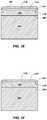
- FIGS. 1A, 1B, 1D, 1E, and 1Fare cross-sectional views illustrating different stages in various embodiments of a method for fabricating a PDC and the PDC so formed.
- FIG. 1Cis an isometric view of the PDC shown in FIG. 1B .
- FIGS. 2A-2Fare cross-sectional views illustrating different stages in various embodiments of a method for fabricating a PDC and the PDC so formed.
- FIGS. 3A-3Care cross-sectional views illustrating different stages in various embodiments of a method for fabricating a PDC and the PDC so formed.
- FIGS. 4A-4Dare cross-sectional views illustrating different stages in various embodiments of a method for fabricating a PDC and the PDC so formed.
- FIGS. 5A-5Care cross-sectional views illustrating different stages in various embodiments of a method for fabricating a PDC and the PDC so formed.
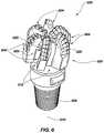
- FIG. 6is an isometric view of an embodiment of a rotary drill bit that may employ one or more of the disclosed PDC embodiments.
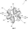
- FIG. 7is a top elevation view of the rotary drill bit shown in FIG. 6 .
- Embodiments of the inventionrelate to PDCs and methods of fabricating PDCs and PCD tables in a manner that facilitates removal of metal-solvent catalyst used in the manufacture of PCD tables of such PDCs.
- the PDC embodiments disclosed hereinmay be used in a variety of applications, such as rotary drill bits, bearing apparatuses, wire-drawing dies, machining equipment, and other articles and apparatuses.
- FIGS. 1A-1Fillustrate different stages in various embodiments of a method for fabricating a PDC and the PDC so formed.
- a PCD table of a PDCis formed by sintering the diamond particles with sacrificial particles, which facilitates removal of the metal-solvent catalyst from the PCD table so formed.
- an assembly 100may be formed by positioning a mixture 102 adjacent to an interfacial surface 104 of a substrate 106 .
- the mixture 102may include a plurality of diamond particles and a plurality of sacrificial particles. As discussed in further detail below, the sacrificial particles facilitate removal metal-solvent catalyst used to catalyze formation of a PCD table from the mixture 102 .
- the sacrificial particlesmay be present in the mixture in a concentration of greater than 0 wt % to about 15 wt %, about 1.0 wt % to about 10 wt %, about 1.0 wt % to about 5 wt %, about 1.5 wt % to about 2.5 wt %, about 1.0 wt % to about 2.0 wt %, or about 2.0 wt %, with the balance being the diamond particles.
- the sacrificial particlesmay exhibit an average particle size (e.g., an average diameter) of about submicron to about 10 ⁇ m, about submicron to about 5 ⁇ m, less than about 5 ⁇ m, about submicron to about 2 ⁇ m, about submicron to about 1 ⁇ m, less than about 1 ⁇ m, or nanometer in dimensions such as about 10 nm to about 100 nm.
- the sacrificial particlesmay be made from any material that exhibits a melting temperature greater than that of a melting temperature of the metal-solvent catalyst used to catalyze formation of PCD from the diamond particles and that is leachable from the PCD so formed via a leaching process.
- the sacrificial particlesmay be selected from particles made from metals, alloys, carbides, and combinations thereof that exhibit a melting temperature greater than that of a melting temperature of the metal-solvent catalyst used to catalyze formation of PCD from the diamond particles and that is leachable from the PCD so formed via a leaching process.
- the sacrificial particlesmay be selected from particles made of refractory metals (e.g., niobium, molybdenum, tantalum, tungsten, rhenium, hafnium, and alloys thereof), other metals or alloys exhibiting a melting temperature greater than that of a melting temperature of the metal-solvent catalyst used to catalyze formation of PCD from the diamond particles and that is leachable from the PCD so formed via a leaching process, and combinations thereof.
- refractory metalse.g., niobium, molybdenum, tantalum, tungsten, rhenium, hafnium, and alloys thereof
- other metals or alloysexhibiting a melting temperature greater than that of a melting temperature of the metal-solvent catalyst used to catalyze formation of PCD from the diamond particles and that is leachable from the PCD so formed via a leaching process, and combinations thereof.
- the sacrificial particlesmay be selected from particles of titanium, vanadium, chromium, iron, zirconium, niobium, molybdenum, hafnium, tantalum, tungsten, rhenium, any other metal or alloy that exhibits a melting temperature greater than that of a melting temperature of the metal-solvent catalyst used to catalyze formation of PCD from the diamond particles and that is leachable from the PCD so formed via a leaching process, alloys of any of the foregoing metals, carbides of any of the foregoing metals or alloys, and combinations of the foregoing.
- the sacrificial particlesmay be selected from tungsten particles and/or tungsten carbide particles.
- the metal-solvent catalyst used to catalyze formation of the PCDmay be diffusible and/or interdiffusible into the sacrificial particles during the HPHT process used to form the PCD.
- the above-mentioned sacrificial particlesare inorganic (e.g., metal, alloys, or carbides)
- an organic sacrificial materialmay be employed.
- the organic sacrificial materialmay be wax, polyethylene glycol, mixtures thereof, combinations thereof, or other suitable sacrificial material.
- the diamond particles of the mixture 102may exhibit a relatively larger size and at least one relatively smaller size.
- the phrases “relatively larger” and “relatively smaller”refer to particle sizes (by any suitable method) that differ by at least a factor of two (e.g., 30 ⁇ m and 15 ⁇ m).
- the diamond particlesmay include a portion exhibiting a relatively larger size (e.g., 30 ⁇ m, 20 ⁇ m, 15 ⁇ m, 12 ⁇ m, 10 ⁇ m, 8 ⁇ m) and another portion exhibiting at least one relatively smaller size (e.g., 6 ⁇ m, 5 ⁇ m, 4 ⁇ m, 3 ⁇ m, 2 ⁇ m, 1 ⁇ m, 0.5 ⁇ m, less than 0.5 ⁇ m, 0.1 ⁇ m, less than 0.1 ⁇ m).
- the diamond particlesmay include a portion exhibiting a relatively larger size between about 10 ⁇ m and about 40 ⁇ m and another portion exhibiting a relatively smaller size between about 1 ⁇ m and 4 ⁇ m.
- the diamond particlesmay comprise three or more different sizes (e.g., one relatively larger size and two or more relatively smaller sizes), without limitation.
- the substrate 106may include, without limitation, cemented carbides, such as tungsten carbide, titanium carbide, chromium carbide, niobium carbide, tantalum carbide, vanadium carbide, or combinations thereof cemented with iron, nickel, cobalt, or alloys thereof.
- the substrate 106comprises cobalt-cemented tungsten carbide.
- the interfacial surface 104 of the substrate 106is illustrated as being substantially planar, the interfacial surface 104 may exhibit a selected nonplanar topography.
- the assembly 100may be placed in a pressure transmitting medium, such as a refractory metal can, graphite structure, pyrophyllite, or other pressure transmitting structure.
- the pressure transmitting medium, including the assembly 100may be subjected to an HPHT process using an HPHT press to create temperature and pressure conditions at which diamond is stable.
- the temperature of the HPHT processmay be at least about 1000° C. (e.g., about 1300° C.
- the pressure of the HPHT processmay be at least 4.0 GPa (e.g., about 5.0 GPa to about 10.0 GPa, about 6.0 GPA to about 8.5 GPa, etc.) for a time sufficient to infiltrate the mixture 106 with a metal-solvent catalyst (i.e., a metallic infiltrant) from the substrate 106 to form a PDC 108 .
- a metal-solvent catalysti.e., a metallic infiltrant
- the infiltrated metal-solvent catalystcatalyzes formation of PCD from the diamond particles to form a PCD table 110 shown in FIGS. 1B and 1C .
- cobalt from a cobalt-cemented tungsten carbide substratemay infiltrate into the mixture 102 to catalyze formation of the PCD table 110 .
- the PCD table 110is integrally formed with the substrate 106 (i.e., formed by sintering the precursor materials on the substrate 106 ).
- the PCD table 110includes a plurality of directly bonded-together diamond grains exhibiting diamond-to-diamond bonding (e.g., sp 3 bonding) therebetween.
- the PCD table 110is bonded to the interfacial surface 104 of the substrate 102 by a strong bond, such as a metallurgical bond, as a result of the metal-solvent catalyst infiltration.
- the PCD table 110includes an upper working surface 112 , a side surface 114 , and a chamfer 116 extending therebetween.
- the chamfer 116may be machined into the PCD table 110 after being formed or may be pre-formed in the PCD table 110 .
- the smaller the average particle size of the sacrificial particles used in the mixture 102the greater the concentration of metal-solvent catalyst incorporated into the PCD table 110 .
- the bonded-together diamond grains of the PCD table 110defines a plurality of interstitial regions.
- the interstitial regionsinclude a sacrificial material (e.g., tungsten carbide grains) and/or the infiltrated metal-solvent catalyst disposed therein.
- the sacrificial materialmay include at least one reaction product formed from sacrificial particles that at least partially react with the diamond particles during HPHT processing and/or the sacrificial particles that are present in the mixture 102 .
- tungsten sacrificial particlesat least partially react with the diamond particles to form tungsten carbide grains.
- the concentration of the metal-solvent catalyst incorporated into the PCD table 110may be greater than if the PCD table 110 was formed without using the sacrificial particles.
- a cobalt alloyinfiltrates into the mixture 102 and is disposed interstitially between the bonded-together diamond grains.
- the cobalt alloymay include tungsten in solid solution with cobalt and may include tungsten carbide precipitates.
- the PCD table 110 of the PDC 108 shown in FIGS. 1B and 1Cis exposed to an acid to leach at least a portion of the metal-solvent catalyst and at least a portion of the sacrificial material from the interstitial regions to form a leached first volume 118 , with the relatively unaffected underlying PCD table 110 referenced as second volume 120 .
- Suitable acidsinclude, but are not limited to, dilute nitric acid (e.g., about 0.5 M to about 1.5 M), concentrated nitric acid (e.g., about 4 M to about 5 M), hydrofluoric acid, or mixtures thereof.
- the PCD table 110may be exposed to any of such acids for about 2 to about 7 days (e.g., about 3, 5, or 7 days) or even for a few weeks (e.g., about 2 to about 4 weeks).
- Hydrofluoric acidmay enhance removal of the tungsten carbide grains because tungsten oxide may be formed as a reaction product between water, and tungsten carbide is soluble in hydrofluoric acid.
- the leached first volume 118extends inwardly from the working surface 112 , the side surface 114 , and the chamfer 116 to a leach depth d.
- the leach depth dis illustrated as being uniform throughout the leached first volume 118 , in some embodiments, the leach d may decrease in a peripheral volume at and near the chamfer 116 and side surface 114 of the PCD table 110 .
- the concentration of the metal-solvent catalyst remaining in the leached first volume 118may be less than 0.85 wt %, about greater than 0 wt % to about 0.80 wt %, about greater than 0 wt % to about 0.75 wt %, about 0.20 wt % to about 0.75 wt %, about 0.20 wt % to about 0.65 wt %, about 0.20 wt % to about 0.55 wt %, about 0.3 wt % to about 0.55 wt %, or about 0.50 wt % to about 0.78 wt %.
- the leach depth d of the leached first volume 118may be about 250 ⁇ m to about 400 ⁇ m, about 250 ⁇ m to about 350 ⁇ m, about 250 ⁇ m to about 300 ⁇ m, or about 250 ⁇ m to about 275 ⁇ m. It is currently believed by the inventors that the presence of a sacrificial material (e.g., tungsten carbide grains) in the PCD table 110 may increase the volume of the interstitial regions between the bonded-together diamond grains, thereby increasing the leaching efficiency of the acid.
- a sacrificial materiale.g., tungsten carbide grains
- the acidhas better access to the metal-solvent catalyst interstitially disposed between the bonded-together diamond grains, thereby allowing an increased amount of the metal-solvent catalyst to be leached/removed compared to if the PCD table 110 was not fabricated using the sacrificial particles of the mixture 102 .
- the smaller the average particle size of the sacrificial particles used in the mixture 102the greater the volume of interstitial regions in the PCD table 110 .
- the substrate 102may include cobalt-cemented tungsten carbide particles.
- the increased interstitial region volume or accessibility as a result of the sacrificial material previously occupying some of the interstitial regionsstill allows for efficient removal of the metal-solvent catalyst from the PCD table 110 .
- the concentration of the remaining metal-solvent catalyst in the leached first volume 118may be determined using a number of different analytical techniques. For example, energy dispersive spectroscopy (e.g., EDAX), wavelength dispersive x-ray spectroscopy (e.g., WDX), and/or Rutherford backscattering spectroscopy may be employed to determine the amount of metal-solvent catalyst in the leached first volume 118 .
- EDAXenergy dispersive spectroscopy
- wavelength dispersive x-ray spectroscopye.g., WDX
- Rutherford backscattering spectroscopymay be employed to determine the amount of metal-solvent catalyst in the leached first volume 118 .
- the concentration of the metal-solvent catalyst in the leached first volume 118may also be determined based on the magnetic properties of the leached first volume 118 .
- the substrate 106 and the second volume 120may be removed via electro-discharge machining, grinding, or combinations thereof to form a PCD sample.
- a specific magnetic saturation constant of the metal-solvent catalyst in the PCD samplemay be determined using an iterative approach.
- a value for the specific magnetic saturation constant of the metal-solvent catalyst in the PCD samplemay be iteratively chosen until a metal-solvent catalyst concentration calculated by the analysis software of a commercially available KOERZIMAT CS 1.096 instrument using the chosen value substantially matches the metal-solvent catalyst concentration determined via another analytical technique, such as energy dispersive spectroscopy, wavelength dispersive x-ray spectroscopy, Rutherford backscattering spectroscopy, or combinations thereof.
- an infiltrant/replacement materialmay fill the interstitial regions of the first leached volume 118 in order to enhance wear resistance of the PDC 308 .
- a layer 122 of infiltrant materialmay be positioned adjacent to the working surface 112 .
- the layer 122may comprise silicon particles or a thin disc of silicon.
- the layer 122may comprise silicon and another constituent such as, cobalt, iron, nickel, or alloys thereof so that a silicon alloy is formed upon infiltration into the interstitial regions of the leached first volume 118 .
- the layer 122may comprise a silicon alloy alloyed with cobalt, iron, nickel, or combinations thereof.
- the layer 122may comprise an alkali metal carbonate, such as at least one alkali carbonate of Li, Na, or K.
- alkali metal carbonatesuch as at least one alkali carbonate of Li, Na, or K.
- Various alkali carbonate materialsare disclosed in U.S. patent application Ser. No. 12/185,457, the disclosure of which is incorporated herein, in its entirety, by this reference.
- the in-process structure shown in FIG. 1Emay be subjected to an HPHT process sufficient to melt the layer 122 so that infiltrant/replacement material infiltrates into the interstitial regions of the leached first volume 118 to form an infiltrated first volume 118 ′ as shown in FIG. 1F .
- the silicon infiltrated into the leached first volume 118 during the HPHT infiltration processreacts with the diamond grains to form silicon carbide that is interstitially disposed between the bonded-together diamond grains.
- the infiltrated interstitial regionsmay include one or more alkali metal carbonates, one or more alkali metal oxides, or combinations thereof.
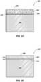
- FIGS. 2A-2Fare cross-sectional views illustrating different stages in various embodiments of a method for fabricating a “two-step” PDC and the PDC so formed.
- a PCD tableis formed by sintering the diamond particles with sacrificial particles in a first HPHT process, the PCD table so formed is leached, and the leached PCD table may be bonded to a substrate in a second HPHT process.
- a mixture 200that includes a plurality of diamond particles and a plurality of sacrificial particles.
- the sacrificial particlesmay be present in the mixture in a concentration of greater than 0 wt % to about 15 wt %, about 1.0 wt % to about 10 wt %, about 1.0 wt % to about 5 wt %, about 1.5 wt % to about 2.5 wt %, about 1.0 wt % to about 2.0 wt %, or about 2.0 wt %, with the balance being the diamond particles.
- the sacrificial particlesmay be selected from any of the sacrificial particles and/or materials disclosed herein and may exhibit any of the average particle sizes disclosed hereinabove for sacrificial particles.
- the diamond particlesmay exhibit any of the diamond particle sizes and distributions disclosed herein.
- the sacrificial particlesmay have an average particle size that is less than an average particle size of the diamond particles.
- the mixture 200may be positioned adjacent to a metal-solvent catalyst, such as a layer 202 of metal-solvent catalyst.
- a metal-solvent catalystsuch as a layer 202 of metal-solvent catalyst.
- the layer 202 of metal-solvent catalystmay comprise iron, nickel, cobalt, or alloys thereof.
- the metal-solvent catalystmay be provided by mixing metal-solvent catalyst particles with the diamond particles and sacrificial particles, infiltrating metal-solvent catalyst from a cemented carbide substrate (e.g., cobalt from a cobalt-cemented tungsten carbide substrate), or combinations of the foregoing.
- the mixture 200 and the layer 202may be placed in a suitable pressure transmitting medium, and subjected to a first HPHT process using an HPHT press using the same or similar HPHT process conditions used to process the assembly 100 shown in FIG. 1A .
- the mixture 200is infiltrated with a metal-solvent catalyst (i.e., a metallic infiltrant) from the layer 202 to form a PCD table.
- the metal-solvent catalystcatalyzes formation of PCD from the diamond particles to form the PCD table.
- the PCD tableincludes a plurality of directly bonded-together diamond grains exhibiting diamond-to-diamond bonding (e.g., sp 3 bonding) therebetween.
- the bonded-together diamond grains of the PCD tabledefines a plurality of interstitial regions.
- the interstitial regionsinclude a sacrificial material (e.g., tungsten carbide grains) and/or the infiltrated metal-solvent catalyst disposed therein.
- the sacrificial materialmay include at least one reaction product formed from the sacrificial particles that at least partially react with the diamond particles during HPHT processing and/or the sacrificial particles that are present in the mixture 200 .
- tungsten sacrificial particlesmay at least partially react with the diamond particles to form tungsten carbide grains.
- the PCD table so formedmay exhibit a diamond grain size distribution that is the same or similar to any of the diamond particle size distributions disclosed herein.
- the diamond grainsmay be less than about 30 ⁇ m, less than about 20 ⁇ m, less than about 15 ⁇ m, less than about 12 ⁇ m, less than about 10 ⁇ m, less than about 8 ⁇ m, about 10 ⁇ m to about 30 ⁇ m, or about 15 ⁇ m to about 19 ⁇ m.
- the diamond grainsmay include a portion exhibiting a relatively larger average grain size (e.g., 30 ⁇ m, 20 ⁇ m, 15 ⁇ m, 12 ⁇ m, 10 ⁇ m, 8 ⁇ m) and another portion exhibiting at least one relatively smaller average grain size (e.g., 6 ⁇ m, 5 ⁇ m, 4 ⁇ m, 3 ⁇ m, 2 ⁇ m, 1 ⁇ m, 0.5 ⁇ m, less than 0.5 ⁇ m, 0.1 ⁇ m, less than 0.1 ⁇ m).
- a relatively larger average grain sizee.g., 30 ⁇ m, 20 ⁇ m, 15 ⁇ m, 12 ⁇ m, 10 ⁇ m, 8 ⁇ m
- at least one relatively smaller average grain sizee.g., 6 ⁇ m, 5 ⁇ m, 4 ⁇ m, 3 ⁇ m, 2 ⁇ m, 1 ⁇ m, 0.5 ⁇ m, less than 0.5 ⁇ m, 0.1 ⁇ m, less than 0.1 ⁇ m.
- the PCD tableis exposed to an acid to leach at least a portion of the metal-solvent catalyst and at least a portion of the sacrificial material from the interstitial regions to form an at least partially leached PCD table 204 .
- Suitable acidsinclude, but are not limited to, dilute nitric acid (e.g., about 0.5 M to about 1.5 M), concentrated nitric acid (e.g., about 4 M to about 5 M), hydrofluoric acid, or mixtures thereof.
- the at least partially leached PCD table 204includes a first surface 206 and an opposing second surface 208 , with the interstitial regions having been leached of the metal-solvent catalyst and the sacrificial material so that the interstitial regions form a network of at least partially interconnected pores configured to allow fluid to flow between and through the first and second surfaces 206 and 208 .
- a side surface 210extends between the first and second surfaces 206 and 208 .
- the concentration of the metal-solvent catalyst remaining in the leached PCD table 204 after leachingmay be less than 0.85 wt %, about greater than 0 wt % to about 0.80 wt %, about greater than 0 wt % to about 0.75 wt %, about 0.20 wt % to about 0.75 wt %, about 0.20 wt % to about 0.65 wt %, about 0.20 wt % to about 0.55 wt %, about 0.3 wt % to about 0.55 wt %, or about 0.50 wt % to about 0.78 wt %.
- an assembly 212may be formed by positioning the second surface 208 of the at least partially leached PCD table 204 adjacent to the interfacial surface 104 of the substrate 106 .
- the interfacial surface 104 of the substrate 106is illustrated as being substantially planar, the interfacial surface 104 may exhibit a nonplanar topography and the second surface 208 of the at least partially leached PCD table 204 may exhibit a correspondingly configured nonplanar topography.
- the assembly 212may be enclosed in a suitable pressure transmitting medium and subjected to a second HPHT process using the same or similar conditions as the first HPHT process.
- the at least partially leached PCD table 106is infiltrated with a metallic infiltrant from the substrate 106 to form an infiltrated PCD table 204 ′ (i.e., a pre-sintered PCD table) as shown in FIG. 2D .
- a metallic infiltrantfrom the substrate 106 to form an infiltrated PCD table 204 ′ (i.e., a pre-sintered PCD table) as shown in FIG. 2D .
- cobalt from a cobalt-cemented tungsten carbide substratemay infiltrate the at least partially leached PCD table 204 during the second HPHT process.
- the substrate 106bonds to the infiltrated PCD table 204 ′ upon cooling to form a PDC 214 also shown in FIG. 2D .
- PDC 214also shown in FIG. 2D .
- the infiltrated PCD table 204 ′may be machined by, for example, grinding to form a chamfer 216 that extends between the first surface 206 (i.e., a working surface) and the side surface 210 .
- the chamfer 116may be formed in the at least partially leached PCD table 204 prior to infiltration thereof.
- the infiltrated PCD table 204 ′ shown in FIG. 2Dmay exhibit a thermal stability superior to that of a conventionally formed PCD table that is integrally formed on a cemented carbide substrate and leached to a depth of about 80 ⁇ m to about 100 ⁇ m.
- the infiltrated PCD table 204 ′may be able to cut a granite workpiece in a lathe test (e.g., a vertical turret lathe test) a distance of at least about 600 m without failing, such as about 900 m to about 2300 m, about 1500 m to about 2000 m, or about 2000 m to about 2300 m.
- An example of suitable parameters for a vertical turret lathe testwhich may be used to determine thermal stability of the infiltrated PCD table 204 ′, are a depth of cut for the PDC of about 1.27 mm, a back rake angle for the PDC of about 20 degrees, an in-feed for the PDC of about 1.524 mm/rev, a cutting speed of the workpiece to be cut of about 1.78 m/sec, and the workpiece may be made from Barre granite having a 914 mm outer diameter and a 254 mm inner diameter.
- the infiltrated PCD table 204 ′may be leached to a selected depth d to further improve the thermal stability of the PDC 214 .
- the infiltrated PCD table 204 ′ shown in FIG. 2Dmay be exposed to any of the acids disclosed herein to leach the metallic infiltrant from the interstitial regions to form a leached first volume 218 .
- the relatively unaffected underlying infiltrated PCD table 204 ′is labeled as second volume 220 .
- the leached first volume 118extends inwardly from the working surface 208 , the side surface 210 , and the chamfer 216 to a leach depth d.
- the leach depth dmay decrease in a peripheral volume at and near the chamfer 216 and side surface 210 of the infiltrated PCD table 204 ′.
- the concentration of the metallic infiltrant remaining in the leached first volume 218 after leachingmay be less than 0.8 wt %, about greater than 0 wt % to about 0.75 wt %, about 0.20 wt % to about 0.75 wt %, about 0.20 wt % to about 0.65 wt %, about 0.20 wt % to about 0.55 wt %, about 0.3 wt % to about 0.55 wt %, or about 0.50 wt % to about 0.78 wt %.
- the leach depth d of the leached first volume 218may be about 250 ⁇ m to about 400 ⁇ m, about 250 ⁇ m to about 350 ⁇ m, about 250 ⁇ m to about 300 ⁇ m, or about 250 ⁇ m to about 275 ⁇ m. It is currently believed that use of sacrificial particles in the fabrication of the at least partially leached PCD table 204 increases the volume of the interstitial regions between the bonded-together diamond grains in the at least partially leached PCD table 204 . The increased volume in the at least partially leached PCD table 204 also helps remove the metallic infiltrant therefrom after the second HPHT process.
- the substrate 102may include cobalt-cemented tungsten carbide particles.
- the substrate 102may include cobalt-cemented tungsten carbide particles.
- forming the at least partially leached PCD table 204 with the sacrificial particles incorporated thereinstill enhances removal of the metal-solvent catalyst from the infiltrated PCD table 204 ′ even after the sacrificial material has been removed because of the increased interstitial region volume between the bonded-together diamond grains.
- an infiltrant/replacement materialmay fill the interstitial regions of the leached first volume 218 to form an infiltrated first volume 218 ′ in order to enhance wear resistance of the leached first volume 218 .
- Any of the infiltrant/replacement materials and process described with respect to FIGS. 1E and 1Fmay be employed for infiltrating the leached first volume 218 .
- FIGS. 3A-3Care cross-sectional views illustrating different stages in various embodiments of a method for fabricating a PDC and the PDC so formed.
- a PCD table of a PDC so formedmay include a region that is substantially free of tungsten and/or tungsten carbide to facilitate removal of a metallic infiltrant therefrom.
- an assembly 300may be formed by positioning a metallic infiltrant layer 302 between a cemented tungsten carbide substrate 304 and an at least partially leached PCD table 306 .
- the at least partially leached PCD table 306includes a working surface 308 , an opposing interfacial surface 310 positioned adjacent to the metal-solvent catalyst layer 302 , and a side surface 311 extending between the working surface 308 and the interfacial surface 310 .
- the at least partially leached PCD table 306also includes a plurality of interstitial regions that were previously occupied by a metal-solvent catalyst that was used to initially catalyze formation of the at least partially leached PCD table 306 and form a network of at least partially interconnected pores that extend between the working surface 308 and interfacial surface 310 .
- the at least partially leached PCD table 306may be formed using sacrificial particles in the same manner as the at least partially leached PCD table 204 shown in FIG. 2B or may be formed without using sacrificial particles. It should be noted that the at least partially leached PCD table 306 may include a chamfer extending between the working surface 306 and the side surface 311 . The chamfer and/or a portion of the side surface 311 may also function as a working surface or region.
- the metallic infiltrant layer 302may comprise cobalt, nickel, iron, or alloys thereof and may also be substantially free of tungsten and/or tungsten carbide.
- the metallic infiltrant layer 302may comprise substantially pure cobalt (e.g. a cobalt-based material including greater than about 95 wt % cobalt) or a cobalt alloy that is substantially free of tungsten and/or tungsten carbide.
- the metallic infiltrant layer 302may comprise a thin disc of substantially pure cobalt or a cobalt alloy that is substantially free of tungsten and/or tungsten carbide.
- the substantially pure cobaltmay be commercially pure cobalt.
- the metallic infiltrant layer 302may comprise cobalt particles held together by an organic binder to form a green layer of cobalt particles, with the cobalt particles being substantially free of tungsten and/or tungsten carbide.
- the cemented tungsten carbide substrate 304may comprise a cobalt-cemented tungsten carbide material.
- the cemented tungsten carbide substrate 304may also include cemented carbides other than tungsten carbide including, without limitation, titanium carbide, niobium carbide, chromium carbide, tantalum carbide, vanadium carbide, or combinations of any of the preceding carbides cemented with cobalt, iron, nickel, or alloys thereof.
- the assembly 300may be placed in a suitable pressure transmitting medium, and subjected to an HPHT process using an HPHT press to create temperature and pressure conditions at which diamond is stable.
- the process conditions of the HPHT processmay be the same or similar as employed to form the PDC 108 shown in FIG. 1B .
- the at least partially leached PCD table 306is infiltrated to form an infiltrated PCD table 306 ′, and bonds to the cemented tungsten carbide substrate 304 upon cooling to form a PDC 312 .
- a first metallic infiltrant(e.g., commercially pure cobalt substantially free of tungsten and/or tungsten carbide) infiltrates from the metallic infiltrant layer 302 and occupies a substantial portion of the interstitial regions in a first volume 314 of the PCD table 306 ′ that extends inwardly from the working surface 308 .
- the temperature of the HPHT processis also sufficient to melt a second metallic infiltrant of the substrate 304 (e.g., cobalt from a cobalt-cemented tungsten carbide substrate) that carries tungsten and/or tungsten carbide therewith.
- a second volume 316 of the PCD table 306 ′extends inwardly from the interfacial surface 310 and the interstitial regions thereof are infiltrated by a liquefied second metallic infiltrant from the substrate 304 that contains tungsten and/or tungsten carbide.
- the second metallic infiltrantmay be present in the substrate 304 as a cementing constituent and may comprise cobalt, nickel, iron, or alloys thereof, which sweeps in tungsten and/or tungsten carbide from the substrate 304 during infiltration of the second volume 316 .
- the volume of the metallic infiltrant layer 302may be selected so that first volume 314 is relatively thicker compared to the second volume 316 , and the first metallic infiltrant from the metallic infiltrant layer 302 occupies at least a majority of the interstitial regions of the PCD table 306 ′.
- a number of different phasesmay be present in the interstitial regions of the second volume 316 of the PCD table 306 ′.
- one or more of the following phasesmay be present in the interstitial regions of the second volume 316 : a metal alloy (e.g., a cobalt-tungsten alloy) including tungsten as an alloying element formed from the second metallic infiltrant being alloyed with tungsten from the substrate 304 , substantially pure tungsten, or tungsten carbide (e.g., WC and/or W 2 C).
- the substrate 304includes chromium carbide and/or tantalum carbide
- one or more of the following phasesmay also be present in the interstitial regions of the second volume 316 : chromium, chromium carbide, tantalum, or tantalum carbide.
- the first metallic infiltrant occupying the interstitial regions in the first volume 314may be leached to a leach depth d from the working surface 308 .
- the leaching processmay be performed for at least about 2 to about 7 days to remove substantially all of the first metallic infiltrant from the first volume 314 . Because the first metallic infiltrant in the first volume 314 is substantially free of tungsten and/or tungsten carbide, the leaching may be performed relatively quicker and more effectively than if the at least partially leached PCD table 306 was completely infiltrated with a metallic infiltrant material including tungsten and/or tungsten carbide.
- any of the acids disclosed hereinmay be used to leach the first metallic infiltrant in the first volume 314 . Despite leaching the first metallic infiltrant from the first volume 314 , residual amounts of the first metallic infiltrant may still be present. Further, the first volume may be identifiable as being substantially free of tungsten and/or tungsten carbide. In an embodiment, a portion of the second metallic infiltrant may be removed from the second volume 316 for enhancing thermal stability.
- the leach depth dmay extend approximately the entire thickness of the first volume 314 , which may be greater than about 200 ⁇ m. In another embodiment, the leach depth d may be about 50 ⁇ m to about 500 ⁇ m. In some embodiments, the leach depth d may extend partially into the second volume 316 and a portion of the second metallic infiltrant may be removed.
- an infiltrant/replacement materialmay fill the interstitial regions of the leached first volume 314 in order to enhance wear resistance of the leached first volume 218 .
- Any of the infiltrant/replacement materials and processes described with respect to FIGS. 1E and 1Fmay be employed for infiltrating the leached first volume 314 .
- a PDC having a PCD table exhibiting the same or similar construction as the PCD table 306 ′may be formed by subjecting an assembly to an HPHT process in which the at least partially leached PCD table 306 is positioned between the metallic infiltrant layer 302 and the cemented tungsten carbide substrate 304 .
- the HPHT conditions employed in such an embodimentmay be the same or similar to the HPHT conditions used to HPHT process the assembly 300 shown in FIG. 3A .
- the PDC so formedmay be leached as described above with respect to FIG. 3C .
- FIGS. 4A-4Dare cross-sectional views illustrating different stages in various embodiments of a method for fabricating a PDC and the PDC so formed.
- a PCD table of a PDC so formedincludes one or more metallic infiltrants that replaced a metal-solvent catalyst that previously occupied and was used to form the PCD table.
- an assembly 400may be formed by positioning a metallic infiltrant layer 302 between a substrate 402 and a PCD table 404 , and further positioning a catalyst dump region 406 adjacent to the PCD table 404 .
- the PCD table 404includes a plurality of interstitial regions that are occupied by a metal-solvent catalyst including tungsten and/or tungsten carbide due to forming the PCD table 404 by sintering diamond particles in the presence of tungsten and/or tungsten carbide.
- the PCD table 404may be formed by infiltrating cobalt, along with tungsten and/or tungsten carbide, from a cobalt-cemented tungsten carbide substrate into a mass of diamond particles under suitable HPHT conditions in which diamond is stable and, subsequently, removing the cobalt-cemented tungsten carbide substrate from the PCD table 404 so formed by grinding, lapping, electro-discharge machining, combinations thereof, or another suitable removal process.
- the PCD table 404comprises directly bonded-together diamond grains that exhibit diamond-to-diamond bonding (e.g., sp 3 bonding) therebetween.
- the bonded-together diamond grainsdefine interstitial regions with the metal-solvent catalyst used to promote sintering of the diamond particles disposed within the interstitial regions.
- the substrate 402may include, without limitation, cemented carbides including titanium carbide, niobium carbide, chromium carbide, tantalum carbide, vanadium carbide, or combinations of any of the preceding carbides cemented with iron, nickel, cobalt, or alloys thereof.
- the substrate 402may comprise a cobalt-cemented tungsten carbide material.
- the dump region 406may comprise a mass of ceramic particles.
- the dump region 406may comprise un-sintered silicon carbide particles, un-sintered aluminum oxide particles, or combinations thereof.
- the assembly 400may be subjected to an HPHT process using the same or similar HPHT conditions used to HPHT process the assembly 100 shown in FIG. 1A .
- the HPHT processliquefies the metal infiltrant layer 302 , a second metallic infiltrant in the substrate 402 , and the metal-solvent catalyst in the PCD table 404 .
- a first metallic infiltrant from the first metallic infiltrant layer 302infiltrates into the PCD table 404 and a second metallic infiltrant from the substrate 402 infiltrates into the PCD table 404 following the first metallic infiltrant.
- the first and second metallic infiltrantsdisplace the metal-solvent catalyst previously occupying the interstitial regions of the PCD table 404 into the dump region 406 .
- the infiltrated PCD tableis represented as PCD table 408 .
- the PCD table 408includes a first volume 410 having a first portion of the interstitial regions thereof occupied by the first metallic infiltrant and a second volume 412 adjacent to the substrate 402 having a second portion of the interstitial regions thereof occupied by the second metallic infiltrant.
- the substrate 402comprises a cemented tungsten carbide substrate
- the second metallic infiltrantmay sweep-in tungsten and/or tungsten carbide when it infiltrates into the PCD table 404 .
- the metal-solvent catalyst previously occupying the interstitial regions of the PCD table 404may be substantially displaced into the dump region 406 along with substantially all of the tungsten and/or tungsten carbide that was previously in the PCD table 404 .
- the dump region 406 bonded to the PCD table 408 and the ceramic particles of the dump region 406may be bonded together with the infiltrated metal-solvent catalyst that previously occupied the interstitial regions of the PCD table 404 .
- the dump region 406may be separated from the PCD table 408 using a suitable material removal process.
- the dump region 406may be removed using a lapping process, a grinding process, electro-discharge machining, or combinations thereof.
- a portion of the PCD table 408may also be removed.
- some of the PCD table 408may be removed.
- the first metallic infiltrant occupying the interstitial regions in the first volume 410may be leached to a leach depth d from a working surface 414 of the PCD table 408 .
- the leaching processmay be performed for about 2 to about 7 days to remove substantially all of the first metallic infiltrant from the first volume 410 .
- the leachingmay be performed relatively quicker than if the at least partially leached PCD table 408 was completely infiltrated with metallic infiltrant material including tungsten and/or tungsten carbide.
- any of the disclosed acidsmay be used to leach the first metallic infiltrant in the first volume 410 .
- a portion of the second metallic infiltrant from the second volume 412may be removed in the leaching process.
- the leach depth dmay extend approximately the entire thickness of the first volume 410 , which may be greater than about 200 ⁇ m. In another embodiment, the leach depth d may be about 50 ⁇ m to about 500 ⁇ m. In some embodiments, the leach depth d may extend partially into the second volume 412 and a portion of the second metallic infiltrant may be removed.
- an infiltrant/replacement materialmay fill the interstitial regions of the leached first volume 410 in order to enhance wear resistance of the leached first volume 410 .
- Any of the infiltrant/replacement materials and processes described with respect to FIGS. 1E and 1Fmay be employed for infiltrating the leached first volume 218 .
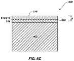
- FIGS. 5A-5Care cross-sectional views illustrating different stages in various embodiments of a method for fabricating a PDC and the PDC so formed.
- a PCD table of a PDC so formedmay be formed using two different metal-solvent catalysts, one of which is more leachable than the other.
- an assembly 500may be formed by positioning a first metal-solvent-catalyst layer 502 between the substrate 502 and a mass of un-sintered diamond particles 504 , and further positioning a second metal-solvent catalyst layer 506 adjacent to the diamond particles 504 (e.g., diamond powder).
- the diamond particles 504may exhibit any of the diamond particle sizes and diamond particle size distributions disclosed herein.
- the first metal-solvent catalyst layer 502comprises a first metal-solvent catalyst material and the second metal-solvent catalyst layer 506 comprises a second metal-solvent catalyst material that is less leachable than the first metal-solvent catalyst material.
- the first metal-solvent catalyst materialmay comprise a cobalt-based material (e.g., at least about 50 wt % cobalt) and the second metal-solvent catalyst material may comprise a cobalt-tungsten alloy.
- the first metal-solvent catalyst materialmay comprise a cobalt-based material and the second metal-solvent catalyst material may comprise a nickel-based material (e.g., at least about 50 wt % nickel).
- the cobalt-based materialmay be commercially pure cobalt and the nickel-based material may be commercially pure nickel or a nickel alloy.
- the first metal-solvent catalyst materialmay comprise a cobalt-based material and the second metal-solvent catalyst material may comprise an iron-based material (e.g., at least about 50 wt % iron).
- the iron-based materialmay be commercially pure iron or an iron alloy.
- each of the layers 502 and 506may be in the form of a green layer of particles or a thin disc of a selected composition.
- the assembly 500may be subjected to an HPHT process using the same or similar HPHT conditions used to HPHT process the assembly 100 shown in FIG. 1A .
- the temperature of the HPHT processis sufficient to liquefy the first metal-solvent catalyst layer 502 and the second metal-solvent catalyst layer 506 .
- a PDC 508may be formed from the first and second metal-solvent catalyst materials infiltrating into the diamond particles 504 to sinter the diamond particles 504 and catalyze formation of a PCD table 510 .
- the PCD table 510is bonded to the substrate 402 upon cooling from the HPHT process.
- the first metal-solvent catalyst materialinfiltrates into the diamond particles 504 to effect sintering of a first portion of the diamond particles 504 and form a first PCD volume 512 of the PCD table 510 comprising bonded-together diamond grains (e.g., sp 3 diamond-to-diamond bonding) defining interstitial regions, with the interstitial regions occupied by the first metal-solvent catalyst material.
- a first PCD volume 512 of the PCD table 510comprising bonded-together diamond grains (e.g., sp 3 diamond-to-diamond bonding) defining interstitial regions, with the interstitial regions occupied by the first metal-solvent catalyst material.
- the second metal-solvent catalystinfiltrates into the diamond particles 504 to effect sintering of a second portion of the diamond particles 504 and form a second PCD volume 514 of the PCD table 510 comprising bonded-together diamond grains (e.g., sp 3 diamond-to-diamond bonding) defining interstitial regions, with the interstitial regions occupied by the second metal-solvent catalyst material.
- An interfacial regionmay be present between the first and second PCD volumes 512 and 514 .
- a bonding region (not shown) having an indeterminate thicknessprovides a strong bond (e.g., metallurgical bond) between the PCD table 510 and the substrate 402 .
- the bonding regionincludes an infiltrant provided from the substrate 402 (e.g., a metal-solvent catalyst cementing constituent) that sweeps into the PCD table 510 or the diamond particles 504 following infiltration by the second metal-solvent catalyst material during the HPHT process.
- an infiltrantprovided from the substrate 402 (e.g., a metal-solvent catalyst cementing constituent) that sweeps into the PCD table 510 or the diamond particles 504 following infiltration by the second metal-solvent catalyst material during the HPHT process.
- the second metal-solvent catalyst layer 506may be omitted.
- the second metal-solvent catalyst materialmay be swept in from the substrate 402 during the HPHT process.
- the substrate 402may comprise a cobalt-cemented tungsten carbide substrate in which cobalt sweeps-in to the second portion of the diamond particles 504 carrying tungsten and/or tungsten carbide therewith and the first metal-solvent catalyst material may comprise cobalt that is substantially free of tungsten and/or tungsten carbide.
- the first metal-solvent catalyst material interstitially disposed between bonded-together diamond grains in the first PCD volume 512may be leached from the PCD table 510 to form a leached region 515 that is substantially free of the first metal-solvent catalyst material.
- residual amounts of the first metal-solvent catalyst materialmay be present in the first PCD volume 512 .
- Such residual first metal-solvent catalyst materialmay be identifiable and distinguishable from the second metal-solvent catalyst material in the second PCD volume 514 .
- the leached region 515has a leach depth d measured from working surface 516 so that substantially all of the first metal-solvent catalyst material is removed. In the illustrated embodiment shown in FIG.
- the leach depth dmay extend approximately the entire thickness of the first PCD volume 512 , which may be greater than about 200 ⁇ m. In another embodiment, the leach depth d may be about 50 ⁇ m to about 500 ⁇ m. In some embodiments, the leach depth d may extend partially into the second PCD volume 514 and a portion of the second metal-solvent catalyst may be removed.
- an infiltrant/replacement materialmay fill the interstitial regions of the leached first PCD volume 512 in order to enhance wear resistance of the leached first volume 410 .
- Any of the infiltrant/replacement materials, reaction products, and processes described with respect to FIGS. 1E and 1Fmay be employed for infiltrating the leached first PCD volume 512 .
- the disclosed PDC embodimentsmay be used in a number of different applications including, but not limited to, use in a rotary drill bit ( FIGS. 6 and 7 ), a thrust-bearing apparatus, a radial bearing apparatus, a subterranean drilling system, and a wire-drawing die, an artificial joint, a machining element, and a heat sink. It should be emphasized that the various applications discussed above are merely some examples of applications in which the PDC embodiments may be used. Other applications are contemplated, such as employing the disclosed PDC embodiments in friction stir welding tools.
- FIG. 6is an isometric view and FIG. 7 is a top elevation view of an embodiment of a rotary drill bit 600 .
- the rotary drill bit 600includes at least one PDC configured according to any of the previously described PDC embodiments.
- the rotary drill bit 600comprises a bit body 602 that includes radially and longitudinally extending blades 604 with leading faces 606 , and a threaded pin connection 608 for connecting the bit body 602 to a drilling string.
- the bit body 602defines a leading end structure for drilling into a subterranean formation by rotation about a longitudinal axis 610 and application of weight-on-bit.
- At least one PDC cutting elementconfigured according to any of the previously described PDC embodiments (e.g., the PDC shown in FIG.
- each PDC 612may include a PCD table 614 bonded to a substrate 616 .
- the PDCs 612may comprise any PDC disclosed herein, without limitation.
- a number of the PDCs 612may be conventional in construction.
- circumferentially adjacent blades 604define so-called junk slots 618 therebetween, as known in the art.
- the rotary drill bit 600may include a plurality of nozzle cavities 620 for communicating drilling fluid from the interior of the rotary drill bit 600 to the PDCs 612 .
- FIGS. 6 and 7merely depict one embodiment of a rotary drill bit that employs at least one cutting element that comprises a PDC fabricated and structured in accordance with the disclosed embodiments, without limitation.
- the rotary drill bit 600is used to represent any number of earth-boring tools or drilling tools, including, for example, core bits, roller-cone bits, fixed-cutter bits, eccentric bits, bicenter bits, reamers, reamer wings, or any other downhole tool including PDCs, without limitation.
- the PDCs disclosed hereinmay also be utilized in applications other than cutting technology.
- the disclosed PDC embodimentsmay be used in wire dies, bearings, artificial joints, inserts, cutting elements, and heat sinks.
- any of the PDCs disclosed hereinmay be employed in an article of manufacture including at least one superabrasive element or compact.
- a rotor and a stator, assembled to form a thrust-bearing apparatusmay each include one or more PDCs configured according to any of the embodiments disclosed herein and may be operably assembled to a downhole drilling assembly.
- U.S. Pat. Nos. 4,410,054; 4,560,014; 5,364,192; 5,368,398; and 5,480,233disclose subterranean drilling systems within which bearing apparatuses utilizing superabrasive compacts disclosed herein may be incorporated.
- non-cylindrical PDCs disclosed hereinmay also form all or part of heat sinks, wire dies, bearing elements, cutting elements, cutting inserts (e.g., on a roller-cone-type drill bit), machining inserts, or any other article of manufacture as known in the art.
- Other examples of articles of manufacture that may use any of the non-cylindrical PDCs disclosed hereinare disclosed in U.S. Pat. Nos.
- Two hundred leached PCD tableswere formed according to the following process.
- a mixture of diamond particles having an average particle size of about 19 ⁇ mwas placed adjacent to a cobalt-cemented tungsten carbide substrate.
- the mixture and substratewere positioned within a pyrophyllite cube, and HPHT processed at a temperature of about 1400° C. and a pressure of about 5 GPa to about 7 GPa in a high-pressure cubic press to form a PCD table.
- the substratewas removed from the PCD table so formed after HPHT processing by grinding.
- the separated PCD tablewas immersed in a mixture of hydrofluoric and nitric acid to leach the cobalt therefrom.
- the amount of cobalt remaining in the leached PCD tablewas determined using coercivity measurements made with a KOERZIMAT CS 1.096 instrument.
- the minimum amount of cobalt remaining in the leached PCD diskswas 0.8720 wt %.
- Two hundred leached PCD tableswere formed according to the following process.
- a mixture of diamond particles having an average particle size of about 19 ⁇ m and tungsten particleswas formed.
- the tungsten particleswere about 2 wt % of the mixture.
- the mixturewas placed adjacent to a cobalt-cemented tungsten carbide substrate.
- the mixture and substratepositioned within a pyrophyllite cube, and HPHT processed at a temperature of about 1400° C. and a pressure of about 5 GPa to about 7 GPa in a high-pressure cubic press to form a PCD table.
- the substratewas removed from the PCD table so formed after HPHT processing by grinding.
- the separated PCD tablewas immersed in a mixture of hydrofluoric and nitric acid to leach the cobalt therefrom.
- the amount of cobalt remaining in the leached PCD tablewas determined using coercivity measurements made with a KOERZIMAT CS 1.096 instrument.
- the minimum amount of cobalt remaining in the leached PCD diskswas 0.7381 wt %.
- the use of tungsten particles in Working Example 2was found to promote leaching the infiltrated cobalt in the PCD tables compared to Comparative Working Example 1.
Landscapes
- Engineering & Computer Science (AREA)
- Chemical & Material Sciences (AREA)
- Mechanical Engineering (AREA)
- Manufacturing & Machinery (AREA)
- Materials Engineering (AREA)
- Ceramic Engineering (AREA)
- Organic Chemistry (AREA)
- Metallurgy (AREA)
- Inorganic Chemistry (AREA)
- Structural Engineering (AREA)
- General Chemical & Material Sciences (AREA)
- Chemical Kinetics & Catalysis (AREA)
- Composite Materials (AREA)
- Earth Drilling (AREA)
- Catalysts (AREA)
- Carbon And Carbon Compounds (AREA)
- Powder Metallurgy (AREA)
Abstract
Description
Claims (22)
Priority Applications (1)
| Application Number | Priority Date | Filing Date | Title |
|---|---|---|---|
| US15/861,294US11141834B2 (en) | 2008-10-30 | 2018-01-03 | Polycrystalline diamond compacts and related methods |
Applications Claiming Priority (4)
| Application Number | Priority Date | Filing Date | Title |
|---|---|---|---|
| US10975208P | 2008-10-30 | 2008-10-30 | |
| US12/608,155US8663349B2 (en) | 2008-10-30 | 2009-10-29 | Polycrystalline diamond compacts, and related methods and applications |
| US14/147,241US9889541B2 (en) | 2008-10-30 | 2014-01-03 | Polycrystalline diamond compacts and related methods |
| US15/861,294US11141834B2 (en) | 2008-10-30 | 2018-01-03 | Polycrystalline diamond compacts and related methods |
Related Parent Applications (1)
| Application Number | Title | Priority Date | Filing Date |
|---|---|---|---|
| US14/147,241ContinuationUS9889541B2 (en) | 2008-10-30 | 2014-01-03 | Polycrystalline diamond compacts and related methods |
Publications (2)
| Publication Number | Publication Date |
|---|---|
| US20180141185A1 US20180141185A1 (en) | 2018-05-24 |
| US11141834B2true US11141834B2 (en) | 2021-10-12 |
Family
ID=43567757
Family Applications (3)
| Application Number | Title | Priority Date | Filing Date |
|---|---|---|---|
| US12/608,155Active2030-11-30US8663349B2 (en) | 2008-10-30 | 2009-10-29 | Polycrystalline diamond compacts, and related methods and applications |
| US14/147,241Expired - Fee RelatedUS9889541B2 (en) | 2008-10-30 | 2014-01-03 | Polycrystalline diamond compacts and related methods |
| US15/861,294ActiveUS11141834B2 (en) | 2008-10-30 | 2018-01-03 | Polycrystalline diamond compacts and related methods |
Family Applications Before (2)
| Application Number | Title | Priority Date | Filing Date |
|---|---|---|---|
| US12/608,155Active2030-11-30US8663349B2 (en) | 2008-10-30 | 2009-10-29 | Polycrystalline diamond compacts, and related methods and applications |
| US14/147,241Expired - Fee RelatedUS9889541B2 (en) | 2008-10-30 | 2014-01-03 | Polycrystalline diamond compacts and related methods |
Country Status (6)
| Country | Link |
|---|---|
| US (3) | US8663349B2 (en) |
| EP (1) | EP2493645A2 (en) |
| KR (1) | KR101753431B1 (en) |
| CN (1) | CN102844135B (en) |
| WO (1) | WO2011059648A2 (en) |
| ZA (1) | ZA201203150B (en) |
Families Citing this family (94)
| Publication number | Priority date | Publication date | Assignee | Title |
|---|---|---|---|---|
| US8328891B2 (en)* | 2006-05-09 | 2012-12-11 | Smith International, Inc. | Methods of forming thermally stable polycrystalline diamond cutters |
| US8236074B1 (en) | 2006-10-10 | 2012-08-07 | Us Synthetic Corporation | Superabrasive elements, methods of manufacturing, and drill bits including same |
| US8080071B1 (en) | 2008-03-03 | 2011-12-20 | Us Synthetic Corporation | Polycrystalline diamond compact, methods of fabricating same, and applications therefor |
| US9017438B1 (en) | 2006-10-10 | 2015-04-28 | Us Synthetic Corporation | Polycrystalline diamond compact including a polycrystalline diamond table with a thermally-stable region having at least one low-carbon-solubility material and applications therefor |
| US8034136B2 (en) | 2006-11-20 | 2011-10-11 | Us Synthetic Corporation | Methods of fabricating superabrasive articles |
| US8080074B2 (en) | 2006-11-20 | 2011-12-20 | Us Synthetic Corporation | Polycrystalline diamond compacts, and related methods and applications |
| US8821604B2 (en)* | 2006-11-20 | 2014-09-02 | Us Synthetic Corporation | Polycrystalline diamond compact and method of making same |
| US8028771B2 (en) | 2007-02-06 | 2011-10-04 | Smith International, Inc. | Polycrystalline diamond constructions having improved thermal stability |
| US7942219B2 (en) | 2007-03-21 | 2011-05-17 | Smith International, Inc. | Polycrystalline diamond constructions having improved thermal stability |
| US9297211B2 (en) | 2007-12-17 | 2016-03-29 | Smith International, Inc. | Polycrystalline diamond construction with controlled gradient metal content |
| US8911521B1 (en) | 2008-03-03 | 2014-12-16 | Us Synthetic Corporation | Methods of fabricating a polycrystalline diamond body with a sintering aid/infiltrant at least saturated with non-diamond carbon and resultant products such as compacts |
| US8999025B1 (en) | 2008-03-03 | 2015-04-07 | Us Synthetic Corporation | Methods of fabricating a polycrystalline diamond body with a sintering aid/infiltrant at least saturated with non-diamond carbon and resultant products such as compacts |
| US20100012389A1 (en)* | 2008-07-17 | 2010-01-21 | Smith International, Inc. | Methods of forming polycrystalline diamond cutters |
| US8297382B2 (en) | 2008-10-03 | 2012-10-30 | Us Synthetic Corporation | Polycrystalline diamond compacts, method of fabricating same, and various applications |
| US7866418B2 (en) | 2008-10-03 | 2011-01-11 | Us Synthetic Corporation | Rotary drill bit including polycrystalline diamond cutting elements |
| US9315881B2 (en) | 2008-10-03 | 2016-04-19 | Us Synthetic Corporation | Polycrystalline diamond, polycrystalline diamond compacts, methods of making same, and applications |
| US8663349B2 (en) | 2008-10-30 | 2014-03-04 | Us Synthetic Corporation | Polycrystalline diamond compacts, and related methods and applications |
| US8071173B1 (en) | 2009-01-30 | 2011-12-06 | Us Synthetic Corporation | Methods of fabricating a polycrystalline diamond compact including a pre-sintered polycrystalline diamond table having a thermally-stable region |
| US8783389B2 (en)* | 2009-06-18 | 2014-07-22 | Smith International, Inc. | Polycrystalline diamond cutting elements with engineered porosity and method for manufacturing such cutting elements |
| US8727042B2 (en) | 2009-09-11 | 2014-05-20 | Baker Hughes Incorporated | Polycrystalline compacts having material disposed in interstitial spaces therein, and cutting elements including such compacts |
| WO2011017649A2 (en)* | 2009-08-07 | 2011-02-10 | Baker Hughes Incorporated | Polycrystalline compacts including in-situ nucleated grains earth-boring tools including such compacts, and methods of forming such compacts and tools |
| CA2770847A1 (en)* | 2009-08-18 | 2011-02-24 | Baker Hughes Incorporated | Methods of forming polycrystalline diamond elements, polycrystalline diamond elements, and earth-boring tools carrying such polycrystalline diamond elements |
| US9352447B2 (en) | 2009-09-08 | 2016-05-31 | Us Synthetic Corporation | Superabrasive elements and methods for processing and manufacturing the same using protective layers |
| US8277722B2 (en)* | 2009-09-29 | 2012-10-02 | Baker Hughes Incorporated | Production of reduced catalyst PDC via gradient driven reactivity |
| EP2488719B8 (en) | 2009-10-15 | 2019-06-26 | Baker Hughes, a GE company, LLC | Polycrystalline compacts including nanoparticulate inclusions, cutting elements and earth-boring tools including such compacts, and methods of forming such compacts |
| US20110171414A1 (en)* | 2010-01-14 | 2011-07-14 | National Oilwell DHT, L.P. | Sacrificial Catalyst Polycrystalline Diamond Element |
| US8778132B2 (en) | 2010-02-19 | 2014-07-15 | Stingray Group, Llc | Support fixture for acid etching of PCD inserts |
| JP5500508B2 (en)* | 2010-03-31 | 2014-05-21 | 三菱マテリアル株式会社 | Manufacturing method of fine polycrystalline diamond sintered body |
| SA111320374B1 (en) | 2010-04-14 | 2015-08-10 | بيكر هوغيس انكوبوريتد | Method Of Forming Polycrystalline Diamond From Derivatized Nanodiamond |
| CA2797618C (en) | 2010-04-27 | 2016-04-12 | Baker Hugues Incorporated | Methods of forming polycrystalline compacts |
| CN102933784B (en) | 2010-04-28 | 2016-02-17 | 贝克休斯公司 | Composite polycrystal-diamond, the cutting element comprising this composite sheet and earth-boring tools and form the method for this composite sheet and earth-boring tools |
| WO2011162999A2 (en) | 2010-06-24 | 2011-12-29 | Baker Hughes Incorporated | Cutting elements for earth-boring tools, earth-boring tools including such cutting elements, and methods of forming cutting elements for earth-boring tools |
| CN103261564A (en)* | 2010-07-14 | 2013-08-21 | 威达国际工业有限合伙公司 | Alloys with low coefficient of thermal expansion as pdc catalysts and binders |
| CN103069098A (en) | 2010-08-13 | 2013-04-24 | 贝克休斯公司 | Cutting elements including nanoparticles in at least one portion thereof, earth-boring tools including such cutting elements, and related methods |
| EP2638234B1 (en) | 2010-11-08 | 2019-03-06 | Baker Hughes, a GE company, LLC | Polycrystalline compacts including nanoparticulate inclusions, cutting elements and earth-boring tools including such compacts, and methods of forming same |
| US10309158B2 (en) | 2010-12-07 | 2019-06-04 | Us Synthetic Corporation | Method of partially infiltrating an at least partially leached polycrystalline diamond table and resultant polycrystalline diamond compacts |
| US8435324B2 (en) | 2010-12-21 | 2013-05-07 | Halliburton Energy Sevices, Inc. | Chemical agents for leaching polycrystalline diamond elements |
| US9027675B1 (en) | 2011-02-15 | 2015-05-12 | Us Synthetic Corporation | Polycrystalline diamond compact including a polycrystalline diamond table containing aluminum carbide therein and applications therefor |
| US8771391B2 (en) | 2011-02-22 | 2014-07-08 | Baker Hughes Incorporated | Methods of forming polycrystalline compacts |
| US8882869B2 (en) | 2011-03-04 | 2014-11-11 | Baker Hughes Incorporated | Methods of forming polycrystalline elements and structures formed by such methods |
| US8858662B2 (en) | 2011-03-04 | 2014-10-14 | Baker Hughes Incorporated | Methods of forming polycrystalline tables and polycrystalline elements |
| US10099347B2 (en)* | 2011-03-04 | 2018-10-16 | Baker Hughes Incorporated | Polycrystalline tables, polycrystalline elements, and related methods |
| GB2490480A (en) | 2011-04-20 | 2012-11-07 | Halliburton Energy Serv Inc | Selectively leached cutter and methods of manufacture |
| US9868099B2 (en) | 2011-04-21 | 2018-01-16 | Baker Hughes Incorporated | Methods for forming polycrystalline materials including providing material with superabrasive grains prior to HPHT processing |
| US9194189B2 (en) | 2011-09-19 | 2015-11-24 | Baker Hughes Incorporated | Methods of forming a cutting element for an earth-boring tool, a related cutting element, and an earth-boring tool including such a cutting element |
| US9272392B2 (en) | 2011-10-18 | 2016-03-01 | Us Synthetic Corporation | Polycrystalline diamond compacts and related products |
| GB201122415D0 (en)* | 2011-12-29 | 2012-02-08 | Element Six Abrasives Sa | Method of processing a body of polycrystalline diamond material |
| US9422770B2 (en) | 2011-12-30 | 2016-08-23 | Smith International, Inc. | Method for braze joining of carbonate PCD |
| US9423370B2 (en)* | 2012-02-21 | 2016-08-23 | Varel International Ind., L.P | Use of capacitance to analyze polycrystalline diamond |
| CN102729006A (en)* | 2012-06-13 | 2012-10-17 | 张志文 | Method for producing diamond reamer by adopting soldering process |
| US9284980B1 (en)* | 2012-11-06 | 2016-03-15 | Us Synthetic Corporation | Heavy load bearings and related methods |
| US9475176B2 (en)* | 2012-11-15 | 2016-10-25 | Smith International, Inc. | Sintering of thick solid carbonate-based PCD for drilling application |
| US10315175B2 (en)* | 2012-11-15 | 2019-06-11 | Smith International, Inc. | Method of making carbonate PCD and sintering carbonate PCD on carbide substrate |
| GB2510465A (en) | 2012-12-04 | 2014-08-06 | Element Six Abrasives Sa | Super-hard polycrystalline diamond material |
| US9346149B1 (en) | 2013-01-04 | 2016-05-24 | Us Synthetic Corporation | Polycrystalline diamond compacts and applications therefor |
| US10501998B1 (en) | 2013-01-04 | 2019-12-10 | Us Synthetic Corporation | Polycrystalline diamond compacts and applications therefor |
| US9140072B2 (en) | 2013-02-28 | 2015-09-22 | Baker Hughes Incorporated | Cutting elements including non-planar interfaces, earth-boring tools including such cutting elements, and methods of forming cutting elements |
| US10280687B1 (en)* | 2013-03-12 | 2019-05-07 | Us Synthetic Corporation | Polycrystalline diamond compacts including infiltrated polycrystalline diamond table and methods of making same |
| US9297212B1 (en) | 2013-03-12 | 2016-03-29 | Us Synthetic Corporation | Polycrystalline diamond compact including a substrate having a convexly-curved interfacial surface bonded to a polycrystalline diamond table, and related methods and applications |
| US9539703B2 (en) | 2013-03-15 | 2017-01-10 | Smith International, Inc. | Carbonate PCD with a distribution of Si and/or Al |
| US9108301B2 (en)* | 2013-03-15 | 2015-08-18 | Diamond Innovations, Inc. | Delayed diffusion of novel species from the back side of carbide |
| US9539704B2 (en) | 2013-03-15 | 2017-01-10 | Smith International, Inc. | Carbonate PCD and methods of making the same |
| AR096578A1 (en)* | 2013-06-11 | 2016-01-20 | Ulterra Drilling Tech Lp | PCD ELEMENTS AND PROCESS TO ELABORATE THEM |
| USD744068S1 (en) | 2013-09-05 | 2015-11-24 | Stingray Group Llc | Etching fixture cap |
| USD744069S1 (en) | 2013-09-05 | 2015-11-24 | Stingray Group Llc | Etching fixture cap |
| US20150075252A1 (en)* | 2013-09-16 | 2015-03-19 | Varel International Ind., L.P. | Method Of Determining Wear Abrasion Resistance Of Polycrystalline Diamond Compact (PDC) Cutters |
| US9534298B2 (en) | 2013-10-16 | 2017-01-03 | Stingray Group, Llc | Etching tray and lid for acid etching PCD cutting inserts |
| US10105824B2 (en)* | 2013-12-30 | 2018-10-23 | Smith International, Inc. | Chemical leaching/thermal decomposing carbonate in carbonate PCD |
| GB201323169D0 (en) | 2013-12-31 | 2014-02-12 | Element Six Abrasives Sa | Superhard constructions & methods of making same |
| KR101690516B1 (en) | 2014-02-04 | 2016-12-28 | 일진다이아몬드(주) | Polycrystalline diamond compact having multiplex sintered polycrystalline diamond and the manufacturing method thereof |
| KR101651664B1 (en) | 2014-02-04 | 2016-08-29 | 일진다이아몬드(주) | Polycrystalline diamond compat with improved thermal stability |
| US10807913B1 (en) | 2014-02-11 | 2020-10-20 | Us Synthetic Corporation | Leached superabrasive elements and leaching systems methods and assemblies for processing superabrasive elements |
| US9421611B2 (en)* | 2014-03-07 | 2016-08-23 | Kennametal Inc. | Composite cutting insert and method of making same |
| US9963348B2 (en) | 2014-06-04 | 2018-05-08 | Halliburton Energy Services, Inc. | High pressure jets for leaching catalysts from a polycrystalline diamond compact |
| US9908215B1 (en) | 2014-08-12 | 2018-03-06 | Us Synthetic Corporation | Systems, methods and assemblies for processing superabrasive materials |
| US11766761B1 (en)* | 2014-10-10 | 2023-09-26 | Us Synthetic Corporation | Group II metal salts in electrolytic leaching of superabrasive materials |
| US10011000B1 (en) | 2014-10-10 | 2018-07-03 | Us Synthetic Corporation | Leached superabrasive elements and systems, methods and assemblies for processing superabrasive materials |
| US10444167B2 (en) | 2014-11-24 | 2019-10-15 | Halliburton Energy Services, Inc. | Determining the leaching profile of a cutter on a drilling tool |
| CN107206496B (en) | 2014-12-17 | 2020-12-15 | 史密斯国际有限公司 | Polycrystalline diamond sintered/rebonded on cemented carbide substrates containing low tungsten |
| CN104690274B (en)* | 2014-12-31 | 2017-11-17 | 中石化石油机械股份有限公司 | A kind of polycrystal diamond hard alloy complex sheet and preparation method thereof |
| US10107043B1 (en) | 2015-02-11 | 2018-10-23 | Us Synthetic Corporation | Superabrasive elements, drill bits, and bearing apparatuses |
| US10350734B1 (en) | 2015-04-21 | 2019-07-16 | Us Synthetic Corporation | Methods of forming a liquid metal embrittlement resistant superabrasive compact, and superabrasive compacts and apparatuses using the same |
| KR20170119716A (en) | 2015-04-28 | 2017-10-27 | 핼리버튼 에너지 서비시즈 인코퍼레이티드 | Polycrystalline diamond compact with gradient interfacial layer |
| US10723626B1 (en) | 2015-05-31 | 2020-07-28 | Us Synthetic Corporation | Leached superabrasive elements and systems, methods and assemblies for processing superabrasive materials |
| CN104962793B (en)* | 2015-06-23 | 2017-04-26 | 中南钻石有限公司 | Polycrystalline diamond compact with excellent electric conductivity and method for manufacturing polycrystalline diamond compact |
| US10213835B2 (en)* | 2016-02-10 | 2019-02-26 | Diamond Innovations, Inc. | Polycrystalline diamond compacts having parting compound and methods of making the same |
| CN106244845B (en)* | 2016-08-18 | 2019-01-15 | 中南钻石有限公司 | It is a kind of can laser welding diamond compact and preparation method thereof |
| US10619422B2 (en) | 2017-02-16 | 2020-04-14 | Baker Hughes, A Ge Company, Llc | Cutting tables including rhenium-containing structures, and related cutting elements, earth-boring tools, and methods |
| US10900291B2 (en) | 2017-09-18 | 2021-01-26 | Us Synthetic Corporation | Polycrystalline diamond elements and systems and methods for fabricating the same |
| EP3743630B1 (en)* | 2018-01-23 | 2024-06-19 | US Synthetic Corporation | Corrosion resistant bearing elements, bearing assemblies, and method for manufacturing a bearing assembly |
| CN110504160A (en)* | 2018-05-16 | 2019-11-26 | 梁剑波 | The manufacturing method and semiconductor devices of semiconductor devices |
| CN110094163B (en)* | 2019-05-14 | 2024-04-02 | 河南四方达超硬材料股份有限公司 | High wear-resisting polycrystalline diamond compact |
| CN111850334B (en)* | 2020-07-17 | 2022-03-08 | 苏州思珀利尔工业技术有限公司 | Preparation method of polycrystalline diamond micro powder, polycrystalline diamond micro powder and application |
| CN113061765B (en)* | 2021-03-18 | 2022-06-07 | 郑州益奇超硬材料有限公司 | Polycrystalline resin diamond abrasive and preparation method thereof |
Citations (75)
| Publication number | Priority date | Publication date | Assignee | Title |
|---|---|---|---|---|
| US2947609A (en) | 1958-01-06 | 1960-08-02 | Gen Electric | Diamond synthesis |
| US4042673A (en) | 1973-11-02 | 1977-08-16 | General Electric Company | Novel diamond products and the manufacture thereof |
| US4082185A (en) | 1973-11-02 | 1978-04-04 | General Electric Company | Manufacture of diamond products |
| US4224380A (en) | 1978-03-28 | 1980-09-23 | General Electric Company | Temperature resistant abrasive compact and method for making same |
| US4268276A (en) | 1978-04-24 | 1981-05-19 | General Electric Company | Compact of boron-doped diamond and method for making same |
| US4274900A (en) | 1978-08-30 | 1981-06-23 | W. R. Grace & Co. | Multi-layer polyester/polyolefin shrink film |
| US4301134A (en) | 1973-11-02 | 1981-11-17 | General Electric Company | Novel diamond products and the manufacture thereof |
| US4410054A (en) | 1981-12-03 | 1983-10-18 | Maurer Engineering Inc. | Well drilling tool with diamond radial/thrust bearings |
| US4468138A (en) | 1981-09-28 | 1984-08-28 | Maurer Engineering Inc. | Manufacture of diamond bearings |
| US4560014A (en) | 1982-04-05 | 1985-12-24 | Smith International, Inc. | Thrust bearing assembly for a downhole drill motor |
| US4572722A (en) | 1982-10-21 | 1986-02-25 | Dyer Henry B | Abrasive compacts |
| US4738322A (en) | 1984-12-21 | 1988-04-19 | Smith International Inc. | Polycrystalline diamond bearing system for a roller cone rock bit |
| US4811801A (en) | 1988-03-16 | 1989-03-14 | Smith International, Inc. | Rock bits and inserts therefor |
| US4907377A (en) | 1988-06-16 | 1990-03-13 | General Electric Company | Directional catalyst alloy sweep through process for preparing diamond compacts |
| US4913247A (en) | 1988-06-09 | 1990-04-03 | Eastman Christensen Company | Drill bit having improved cutter configuration |
| US5009673A (en) | 1988-11-30 | 1991-04-23 | The General Electric Company | Method for making polycrystalline sandwich compacts |
| US5016718A (en) | 1989-01-26 | 1991-05-21 | Geir Tandberg | Combination drill bit |
| US5022894A (en) | 1989-10-12 | 1991-06-11 | General Electric Company | Diamond compacts for rock drilling and machining |
| US5092687A (en) | 1991-06-04 | 1992-03-03 | Anadrill, Inc. | Diamond thrust bearing and method for manufacturing same |
| US5120327A (en) | 1991-03-05 | 1992-06-09 | Diamant-Boart Stratabit (Usa) Inc. | Cutting composite formed of cemented carbide substrate and diamond layer |
| US5135061A (en) | 1989-08-04 | 1992-08-04 | Newton Jr Thomas A | Cutting elements for rotary drill bits |
| US5154245A (en) | 1990-04-19 | 1992-10-13 | Sandvik Ab | Diamond rock tools for percussive and rotary crushing rock drilling |
| US5180022A (en) | 1991-05-23 | 1993-01-19 | Brady William J | Rotary mining tools |
| US5304342A (en) | 1992-06-11 | 1994-04-19 | Hall Jr H Tracy | Carbide/metal composite material and a process therefor |
| US5364192A (en) | 1992-10-28 | 1994-11-15 | Damm Oliver F R A | Diamond bearing assembly |
| US5368398A (en) | 1992-10-28 | 1994-11-29 | Csir | Diamond bearing assembly |
| US5370195A (en) | 1993-09-20 | 1994-12-06 | Smith International, Inc. | Drill bit inserts enhanced with polycrystalline diamond |
| US5460233A (en) | 1993-03-30 | 1995-10-24 | Baker Hughes Incorporated | Diamond cutting structure for drilling hard subterranean formations |
| US5480233A (en) | 1994-10-14 | 1996-01-02 | Cunningham; James K. | Thrust bearing for use in downhole drilling systems |
| US5544713A (en) | 1993-08-17 | 1996-08-13 | Dennis Tool Company | Cutting element for drill bits |
| US5560754A (en) | 1995-06-13 | 1996-10-01 | General Electric Company | Reduction of stresses in the polycrystalline abrasive layer of a composite compact with in situ bonded carbide/carbide support |
| US5601477A (en) | 1994-03-16 | 1997-02-11 | U.S. Synthetic Corporation | Polycrystalline abrasive compact with honed edge |
| US5980982A (en) | 1995-04-13 | 1999-11-09 | Sunitomo Electric Industries, Ltd. | Coated particles for synthesizing diamond and process for production of diamond abrasive for sawing |
| US6056911A (en) | 1998-05-27 | 2000-05-02 | Camco International (Uk) Limited | Methods of treating preform elements including polycrystalline diamond bonded to a substrate |
| US6220375B1 (en) | 1999-01-13 | 2001-04-24 | Baker Hughes Incorporated | Polycrystalline diamond cutters having modified residual stresses |
| US6344149B1 (en) | 1998-11-10 | 2002-02-05 | Kennametal Pc Inc. | Polycrystalline diamond member and method of making the same |
| US20020034632A1 (en) | 2000-09-20 | 2002-03-21 | Griffin Nigel Dennis | Polycrystalline diamond partially depleted of catalyzing material |
| US20020037200A1 (en) | 2000-08-04 | 2002-03-28 | Boyce James E. | Shaped cutting-grade inserts with transitionless diamond-enhanced surface layer |
| US20020043407A1 (en) | 1998-12-07 | 2002-04-18 | Dan Belnap | Toughness optimized insert for rock and hammer bits |
| US6601662B2 (en) | 2000-09-20 | 2003-08-05 | Grant Prideco, L.P. | Polycrystalline diamond cutters with working surfaces having varied wear resistance while maintaining impact strength |
| CN1474791A (en) | 2000-09-20 | 2004-02-11 | ��ķ�ƹ���(Ӣ��)����˾ | High bulk density polycrystalline diamond with reduced catalytic material working surface |
| US20040140132A1 (en) | 2003-01-21 | 2004-07-22 | Stewart Middlemiss | Polycrystalline diamond with improved abrasion resistance |
| US6793681B1 (en) | 1994-08-12 | 2004-09-21 | Diamicron, Inc. | Prosthetic hip joint having a polycrystalline diamond articulation surface and a plurality of substrate layers |
| US6846341B2 (en) | 2002-02-26 | 2005-01-25 | Smith International, Inc. | Method of forming cutting elements |
| US20050050801A1 (en) | 2003-09-05 | 2005-03-10 | Cho Hyun Sam | Doubled-sided and multi-layered PCD and PCBN abrasive articles |
| US20050210755A1 (en)* | 2003-09-05 | 2005-09-29 | Cho Hyun S | Doubled-sided and multi-layered PCBN and PCD abrasive articles |
| US20060060390A1 (en) | 2004-09-21 | 2006-03-23 | Smith International, Inc. | Thermally stable diamond polycrystalline diamond constructions |
| US20060157285A1 (en) | 2005-01-17 | 2006-07-20 | Us Synthetic Corporation | Polycrystalline diamond insert, drill bit including same, and method of operation |
| US20060180354A1 (en) | 2005-02-15 | 2006-08-17 | Smith International, Inc. | Stress-relieved diamond inserts |
| US20060191723A1 (en) | 2005-02-23 | 2006-08-31 | Keshavan Madapusi K | Thermally stable polycrystalline diamond materials, cutting elements incorporating the same and bits incorporating such cutting elements |
| US20070034416A1 (en) | 2005-08-09 | 2007-02-15 | Cho Hyun S | Weldable ultrahard materials and associated methods of manufacture |
| US20070079994A1 (en) | 2005-10-12 | 2007-04-12 | Smith International, Inc. | Diamond-bonded bodies and compacts with improved thermal stability and mechanical strength |
| CN2906032Y (en) | 2005-11-24 | 2007-05-30 | 江汉石油钻头股份有限公司 | Polycrystalline diamond composite sheet with granular gradient |
| US20070151769A1 (en) | 2005-11-23 | 2007-07-05 | Smith International, Inc. | Microwave sintering |
| US20070186483A1 (en) | 2002-01-30 | 2007-08-16 | Klaus Tank | Composite abrasive compact |
| US20070187155A1 (en) | 2006-02-09 | 2007-08-16 | Smith International, Inc. | Thermally stable ultra-hard polycrystalline materials and compacts |
| US20080073127A1 (en) | 2006-09-21 | 2008-03-27 | Smith International, Inc. | Atomic layer deposition nanocoatings on cutting tool powder materials |
| WO2008053430A1 (en) | 2006-10-31 | 2008-05-08 | Element Six (Production) (Pty) Ltd | Polycrystalline diamond abrasive compacts |
| US20080115421A1 (en) | 2006-11-20 | 2008-05-22 | Us Synthetic Corporation | Methods of fabricating superabrasive articles |
| US20080206576A1 (en) | 2006-12-21 | 2008-08-28 | Us Synthetic Corporation | Superabrasive compact including diamond-silicon carbide composite, methods of fabrication thereof, and applications therefor |
| US20080223623A1 (en) | 2007-02-06 | 2008-09-18 | Smith International, Inc. | Polycrystalline diamond constructions having improved thermal stability |
| US20080230280A1 (en) | 2007-03-21 | 2008-09-25 | Smith International, Inc. | Polycrystalline diamond having improved thermal stability |
| CN101275213A (en) | 2007-03-27 | 2008-10-01 | 瓦雷尔欧洲公司 | Method of manufacturing a part comprising at least one block made from a dense material |
| WO2008135949A2 (en) | 2007-05-07 | 2008-11-13 | Element Six (Production) (Pty) Ltd | Polycrystalline diamond composites |
| US20090090563A1 (en) | 2007-10-04 | 2009-04-09 | Smith International, Inc. | Diamond-bonded constrcutions with improved thermal and mechanical properties |
| US7517589B2 (en) | 2004-09-21 | 2009-04-14 | Smith International, Inc. | Thermally stable diamond polycrystalline diamond constructions |
| US20090152018A1 (en) | 2006-11-20 | 2009-06-18 | Us Synthetic Corporation | Polycrystalline diamond compacts, and related methods and applications |
| US20090152017A1 (en) | 2007-12-17 | 2009-06-18 | Smith International, Inc. | Polycrystalline diamond construction with controlled gradient metal content |
| US7575805B2 (en) | 2003-12-11 | 2009-08-18 | Roy Derrick Achilles | Polycrystalline diamond abrasive elements |
| US20090313908A1 (en) | 2006-05-09 | 2009-12-24 | Smith International, Inc. | Methods of forming thermally stable polycrystalline diamond cutters |
| US20100095602A1 (en) | 2008-10-20 | 2010-04-22 | Smith International, Inc. | Techniques and materials for the accelerated removal of catalyst material from diamond bodies |
| US7757792B2 (en) | 2008-07-18 | 2010-07-20 | Omni Ip Ltd | Method and apparatus for selectively leaching portions of PDC cutters already mounted in drill bits |
| US20100212971A1 (en) | 2009-02-26 | 2010-08-26 | Us Synthetic Corporation | Polycrystalline Diamond Compact Including A Cemented Tungsten Carbide Substrate That Is Substantially Free Of Tungsten Carbide Grains Exhibiting Abnormal Grain Growth And Applications Therefor |
| US20110017519A1 (en) | 2008-10-03 | 2011-01-27 | Us Synthetic Corporation | Polycrystalline diamond compacts, method of fabricating same, and various applications |
| US20110023375A1 (en) | 2008-10-30 | 2011-02-03 | Us Synthetic Corporation | Polycrystalline diamond compacts, and related methods and applications |
Family Cites Families (1)
| Publication number | Priority date | Publication date | Assignee | Title |
|---|---|---|---|---|
| US7418860B2 (en) | 2004-10-05 | 2008-09-02 | Parker-Hannifan Corporation | Ultrasonic fluid level sensor |
- 2009
- 2009-10-29USUS12/608,155patent/US8663349B2/enactiveActive
- 2010
- 2010-10-20KRKR1020127013914Apatent/KR101753431B1/ennot_activeExpired - Fee Related
- 2010-10-20CNCN201080059095.4Apatent/CN102844135B/ennot_activeExpired - Fee Related
- 2010-10-20WOPCT/US2010/053393patent/WO2011059648A2/enactiveApplication Filing
- 2010-10-20EPEP10770690Apatent/EP2493645A2/ennot_activeWithdrawn
- 2012
- 2012-05-02ZAZA2012/03150Apatent/ZA201203150B/enunknown
- 2014
- 2014-01-03USUS14/147,241patent/US9889541B2/ennot_activeExpired - Fee Related
- 2018
- 2018-01-03USUS15/861,294patent/US11141834B2/enactiveActive
Patent Citations (85)
| Publication number | Priority date | Publication date | Assignee | Title |
|---|---|---|---|---|
| US2947609A (en) | 1958-01-06 | 1960-08-02 | Gen Electric | Diamond synthesis |
| US4042673A (en) | 1973-11-02 | 1977-08-16 | General Electric Company | Novel diamond products and the manufacture thereof |
| US4082185A (en) | 1973-11-02 | 1978-04-04 | General Electric Company | Manufacture of diamond products |
| US4301134A (en) | 1973-11-02 | 1981-11-17 | General Electric Company | Novel diamond products and the manufacture thereof |
| US4224380A (en) | 1978-03-28 | 1980-09-23 | General Electric Company | Temperature resistant abrasive compact and method for making same |
| US4268276A (en) | 1978-04-24 | 1981-05-19 | General Electric Company | Compact of boron-doped diamond and method for making same |
| US4274900A (en) | 1978-08-30 | 1981-06-23 | W. R. Grace & Co. | Multi-layer polyester/polyolefin shrink film |
| US4468138A (en) | 1981-09-28 | 1984-08-28 | Maurer Engineering Inc. | Manufacture of diamond bearings |
| US4410054A (en) | 1981-12-03 | 1983-10-18 | Maurer Engineering Inc. | Well drilling tool with diamond radial/thrust bearings |
| US4560014A (en) | 1982-04-05 | 1985-12-24 | Smith International, Inc. | Thrust bearing assembly for a downhole drill motor |
| US4572722A (en) | 1982-10-21 | 1986-02-25 | Dyer Henry B | Abrasive compacts |
| US4738322A (en) | 1984-12-21 | 1988-04-19 | Smith International Inc. | Polycrystalline diamond bearing system for a roller cone rock bit |
| US4811801A (en) | 1988-03-16 | 1989-03-14 | Smith International, Inc. | Rock bits and inserts therefor |
| US4913247A (en) | 1988-06-09 | 1990-04-03 | Eastman Christensen Company | Drill bit having improved cutter configuration |
| US4907377A (en) | 1988-06-16 | 1990-03-13 | General Electric Company | Directional catalyst alloy sweep through process for preparing diamond compacts |
| US5009673A (en) | 1988-11-30 | 1991-04-23 | The General Electric Company | Method for making polycrystalline sandwich compacts |
| US5016718A (en) | 1989-01-26 | 1991-05-21 | Geir Tandberg | Combination drill bit |
| US5135061A (en) | 1989-08-04 | 1992-08-04 | Newton Jr Thomas A | Cutting elements for rotary drill bits |
| US5022894A (en) | 1989-10-12 | 1991-06-11 | General Electric Company | Diamond compacts for rock drilling and machining |
| US5154245A (en) | 1990-04-19 | 1992-10-13 | Sandvik Ab | Diamond rock tools for percussive and rotary crushing rock drilling |
| US5120327A (en) | 1991-03-05 | 1992-06-09 | Diamant-Boart Stratabit (Usa) Inc. | Cutting composite formed of cemented carbide substrate and diamond layer |
| US5180022A (en) | 1991-05-23 | 1993-01-19 | Brady William J | Rotary mining tools |
| US5092687A (en) | 1991-06-04 | 1992-03-03 | Anadrill, Inc. | Diamond thrust bearing and method for manufacturing same |
| US5304342A (en) | 1992-06-11 | 1994-04-19 | Hall Jr H Tracy | Carbide/metal composite material and a process therefor |
| US5364192A (en) | 1992-10-28 | 1994-11-15 | Damm Oliver F R A | Diamond bearing assembly |
| US5368398A (en) | 1992-10-28 | 1994-11-29 | Csir | Diamond bearing assembly |
| US5460233A (en) | 1993-03-30 | 1995-10-24 | Baker Hughes Incorporated | Diamond cutting structure for drilling hard subterranean formations |
| US5544713A (en) | 1993-08-17 | 1996-08-13 | Dennis Tool Company | Cutting element for drill bits |
| US5370195A (en) | 1993-09-20 | 1994-12-06 | Smith International, Inc. | Drill bit inserts enhanced with polycrystalline diamond |
| US5601477A (en) | 1994-03-16 | 1997-02-11 | U.S. Synthetic Corporation | Polycrystalline abrasive compact with honed edge |
| US6793681B1 (en) | 1994-08-12 | 2004-09-21 | Diamicron, Inc. | Prosthetic hip joint having a polycrystalline diamond articulation surface and a plurality of substrate layers |
| US5480233A (en) | 1994-10-14 | 1996-01-02 | Cunningham; James K. | Thrust bearing for use in downhole drilling systems |
| US5980982A (en) | 1995-04-13 | 1999-11-09 | Sunitomo Electric Industries, Ltd. | Coated particles for synthesizing diamond and process for production of diamond abrasive for sawing |
| US5560754A (en) | 1995-06-13 | 1996-10-01 | General Electric Company | Reduction of stresses in the polycrystalline abrasive layer of a composite compact with in situ bonded carbide/carbide support |
| US6056911A (en) | 1998-05-27 | 2000-05-02 | Camco International (Uk) Limited | Methods of treating preform elements including polycrystalline diamond bonded to a substrate |
| US6344149B1 (en) | 1998-11-10 | 2002-02-05 | Kennametal Pc Inc. | Polycrystalline diamond member and method of making the same |
| US20020043407A1 (en) | 1998-12-07 | 2002-04-18 | Dan Belnap | Toughness optimized insert for rock and hammer bits |
| US6220375B1 (en) | 1999-01-13 | 2001-04-24 | Baker Hughes Incorporated | Polycrystalline diamond cutters having modified residual stresses |
| US20020037200A1 (en) | 2000-08-04 | 2002-03-28 | Boyce James E. | Shaped cutting-grade inserts with transitionless diamond-enhanced surface layer |
| CN1474791A (en) | 2000-09-20 | 2004-02-11 | ��ķ�ƹ���(Ӣ��)����˾ | High bulk density polycrystalline diamond with reduced catalytic material working surface |
| US6601662B2 (en) | 2000-09-20 | 2003-08-05 | Grant Prideco, L.P. | Polycrystalline diamond cutters with working surfaces having varied wear resistance while maintaining impact strength |
| US20020034631A1 (en) | 2000-09-20 | 2002-03-21 | Griffin Nigel Dennis | High volume density polycrystalline diamond with working surfaces depleted of catalyzing material |
| US20020034632A1 (en) | 2000-09-20 | 2002-03-21 | Griffin Nigel Dennis | Polycrystalline diamond partially depleted of catalyzing material |
| US6544308B2 (en) | 2000-09-20 | 2003-04-08 | Camco International (Uk) Limited | High volume density polycrystalline diamond with working surfaces depleted of catalyzing material |
| US20070186483A1 (en) | 2002-01-30 | 2007-08-16 | Klaus Tank | Composite abrasive compact |
| US6846341B2 (en) | 2002-02-26 | 2005-01-25 | Smith International, Inc. | Method of forming cutting elements |
| US20040140132A1 (en) | 2003-01-21 | 2004-07-22 | Stewart Middlemiss | Polycrystalline diamond with improved abrasion resistance |
| US6915866B2 (en) | 2003-01-21 | 2005-07-12 | Smith International, Inc. | Polycrystalline diamond with improved abrasion resistance |
| US20050050801A1 (en) | 2003-09-05 | 2005-03-10 | Cho Hyun Sam | Doubled-sided and multi-layered PCD and PCBN abrasive articles |
| US20050210755A1 (en)* | 2003-09-05 | 2005-09-29 | Cho Hyun S | Doubled-sided and multi-layered PCBN and PCD abrasive articles |
| US7575805B2 (en) | 2003-12-11 | 2009-08-18 | Roy Derrick Achilles | Polycrystalline diamond abrasive elements |
| US20060060390A1 (en) | 2004-09-21 | 2006-03-23 | Smith International, Inc. | Thermally stable diamond polycrystalline diamond constructions |
| US7517589B2 (en) | 2004-09-21 | 2009-04-14 | Smith International, Inc. | Thermally stable diamond polycrystalline diamond constructions |
| US7754333B2 (en) | 2004-09-21 | 2010-07-13 | Smith International, Inc. | Thermally stable diamond polycrystalline diamond constructions |
| US20060157285A1 (en) | 2005-01-17 | 2006-07-20 | Us Synthetic Corporation | Polycrystalline diamond insert, drill bit including same, and method of operation |
| US7681669B2 (en) | 2005-01-17 | 2010-03-23 | Us Synthetic Corporation | Polycrystalline diamond insert, drill bit including same, and method of operation |
| GB2423320A (en) | 2005-02-15 | 2006-08-23 | Smith International | Stress-relieved cutting elements |
| US20060180354A1 (en) | 2005-02-15 | 2006-08-17 | Smith International, Inc. | Stress-relieved diamond inserts |
| US20060191723A1 (en) | 2005-02-23 | 2006-08-31 | Keshavan Madapusi K | Thermally stable polycrystalline diamond materials, cutting elements incorporating the same and bits incorporating such cutting elements |
| US20070034416A1 (en) | 2005-08-09 | 2007-02-15 | Cho Hyun S | Weldable ultrahard materials and associated methods of manufacture |
| US20070079994A1 (en) | 2005-10-12 | 2007-04-12 | Smith International, Inc. | Diamond-bonded bodies and compacts with improved thermal stability and mechanical strength |
| US20070151769A1 (en) | 2005-11-23 | 2007-07-05 | Smith International, Inc. | Microwave sintering |
| CN2906032Y (en) | 2005-11-24 | 2007-05-30 | 江汉石油钻头股份有限公司 | Polycrystalline diamond composite sheet with granular gradient |
| US20070187155A1 (en) | 2006-02-09 | 2007-08-16 | Smith International, Inc. | Thermally stable ultra-hard polycrystalline materials and compacts |
| US20090313908A1 (en) | 2006-05-09 | 2009-12-24 | Smith International, Inc. | Methods of forming thermally stable polycrystalline diamond cutters |
| US20080073127A1 (en) | 2006-09-21 | 2008-03-27 | Smith International, Inc. | Atomic layer deposition nanocoatings on cutting tool powder materials |
| WO2008053430A1 (en) | 2006-10-31 | 2008-05-08 | Element Six (Production) (Pty) Ltd | Polycrystalline diamond abrasive compacts |
| US20090152018A1 (en) | 2006-11-20 | 2009-06-18 | Us Synthetic Corporation | Polycrystalline diamond compacts, and related methods and applications |
| US20080115421A1 (en) | 2006-11-20 | 2008-05-22 | Us Synthetic Corporation | Methods of fabricating superabrasive articles |
| US20080206576A1 (en) | 2006-12-21 | 2008-08-28 | Us Synthetic Corporation | Superabrasive compact including diamond-silicon carbide composite, methods of fabrication thereof, and applications therefor |
| US20080223623A1 (en) | 2007-02-06 | 2008-09-18 | Smith International, Inc. | Polycrystalline diamond constructions having improved thermal stability |
| US20080230280A1 (en) | 2007-03-21 | 2008-09-25 | Smith International, Inc. | Polycrystalline diamond having improved thermal stability |
| CN101275213A (en) | 2007-03-27 | 2008-10-01 | 瓦雷尔欧洲公司 | Method of manufacturing a part comprising at least one block made from a dense material |
| WO2008135949A2 (en) | 2007-05-07 | 2008-11-13 | Element Six (Production) (Pty) Ltd | Polycrystalline diamond composites |
| US20090090563A1 (en) | 2007-10-04 | 2009-04-09 | Smith International, Inc. | Diamond-bonded constrcutions with improved thermal and mechanical properties |
| US20090152017A1 (en) | 2007-12-17 | 2009-06-18 | Smith International, Inc. | Polycrystalline diamond construction with controlled gradient metal content |
| US7757792B2 (en) | 2008-07-18 | 2010-07-20 | Omni Ip Ltd | Method and apparatus for selectively leaching portions of PDC cutters already mounted in drill bits |
| US20110017519A1 (en) | 2008-10-03 | 2011-01-27 | Us Synthetic Corporation | Polycrystalline diamond compacts, method of fabricating same, and various applications |
| US20100095602A1 (en) | 2008-10-20 | 2010-04-22 | Smith International, Inc. | Techniques and materials for the accelerated removal of catalyst material from diamond bodies |
| US20110023375A1 (en) | 2008-10-30 | 2011-02-03 | Us Synthetic Corporation | Polycrystalline diamond compacts, and related methods and applications |
| US20140115971A1 (en) | 2008-10-30 | 2014-05-01 | Us Synthetic Corporation | Polycrystalline diamond compacts and related methods |
| US9889541B2 (en)* | 2008-10-30 | 2018-02-13 | Us Synthetic Corporation | Polycrystalline diamond compacts and related methods |
| US20100212971A1 (en) | 2009-02-26 | 2010-08-26 | Us Synthetic Corporation | Polycrystalline Diamond Compact Including A Cemented Tungsten Carbide Substrate That Is Substantially Free Of Tungsten Carbide Grains Exhibiting Abnormal Grain Growth And Applications Therefor |
| WO2010098978A1 (en) | 2009-02-26 | 2010-09-02 | Us Synthetic Corporation | Polycrystalline diamond compact including a cemented tungsten carbide substrate that is substantially free of tungsten carbide grains exhibiting abnormal grain growth and applications therefor |
| WO2011059648A2 (en) | 2009-10-29 | 2011-05-19 | Us Synthetic Corporation | Polycrystalline diamond compacts, and related methods and applications |
Non-Patent Citations (19)
| Title |
|---|
| International Search Report and Written Opinion from International Application No. PCT/US2010/053393 dated Jul. 6, 2011. |
| Invitation to Pay Additional Fees and Partial Search Report from International Application No. PCT/US2010/053393 dated Feb. 25, 2011. |
| U.S. Appl. No. 12/185,457, filed Aug. 4, 2008, Vail. |
| U.S. Appl. No. 12/608,155, Apr. 22, 2011, Office Action. |
| U.S. Appl. No. 12/608,155, Apr. 26, 2013, Office Action. |
| U.S. Appl. No. 12/608,155, Feb. 12, 2014, Issue Notification. |
| U.S. Appl. No. 12/608,155, filed Oct. 29, 2009, Sani et al. |
| U.S. Appl. No. 12/608,155, Jan. 11, 2012, Office Action. |
| U.S. Appl. No. 12/608,155, Nov. 8, 2011, Office Action. |
| U.S. Appl. No. 12/608,155, Oct. 12, 2012, Office Action. |
| U.S. Appl. No. 12/608,155, Oct. 8, 2013, Notice of Allowance. |
| U.S. Appl. No. 14/147,241, Aug. 6, 2015, Office Action. |
| U.S. Appl. No. 14/147,241, Feb. 19, 2016, Office Action. |
| U.S. Appl. No. 14/147,241, filed Jan. 3, 2014, Sani et al. |
| U.S. Appl. No. 14/147,241, Jan. 20, 2017, Office Action. |
| U.S. Appl. No. 14/147,241, Jun. 29, 2016, Office Action. |
| U.S. Appl. No. 14/147,241, May 4, 2017, Office Action. |
| U.S. Appl. No. 14/147,241, Oct. 5, 2017, Notice of Allowance. |
| U.S. Appl. No. 61/109,752, filed Oct. 30, 2008, Sani et al. |
Also Published As
| Publication number | Publication date |
|---|---|
| US8663349B2 (en) | 2014-03-04 |
| EP2493645A2 (en) | 2012-09-05 |
| US20180141185A1 (en) | 2018-05-24 |
| US9889541B2 (en) | 2018-02-13 |
| US20110023375A1 (en) | 2011-02-03 |
| WO2011059648A2 (en) | 2011-05-19 |
| US20140115971A1 (en) | 2014-05-01 |
| ZA201203150B (en) | 2024-10-30 |
| KR101753431B1 (en) | 2017-07-19 |
| WO2011059648A3 (en) | 2011-09-01 |
| KR20120114240A (en) | 2012-10-16 |
| CN102844135B (en) | 2016-01-27 |
| CN102844135A (en) | 2012-12-26 |
Similar Documents
| Publication | Publication Date | Title |
|---|---|---|
| US11141834B2 (en) | Polycrystalline diamond compacts and related methods | |
| US10179390B2 (en) | Methods of fabricating a polycrystalline diamond compact | |
| US9376868B1 (en) | Polycrystalline diamond compact including pre-sintered polycrystalline diamond table having a thermally-stable region and applications therefor | |
| US9657529B1 (en) | Polycrystalline diamond compact including a pre-sintered polycrystalline diamond table including a nonmetallic catalyst that limits infiltration of a metallic-catalyst infiltrant therein and applications therefor | |
| US20190242193A1 (en) | Polycrystalline diamond compacts | |
| US11773654B1 (en) | Polycrystalline diamond compacts, methods of making same, and applications therefor | |
| US9663994B2 (en) | Polycrystalline diamond compact | |
| US8662210B2 (en) | Rotary drill bit including polycrystalline diamond cutting elements | |
| US10155301B1 (en) | Methods of manufacturing a polycrystalline diamond compact including a polycrystalline diamond table containing aluminum carbide therein | |
| US9273381B2 (en) | Polycrystalline diamond compact including a carbonate-catalyzed polycrystalline diamond table and applications therefor | |
| US20130092452A1 (en) | Polycrystalline diamond compacts, related products, and methods of manufacture | |
| US10119334B1 (en) | Polycrystalline diamond compact including substantially single-phase polycrystalline diamond body and applications therefor | |
| EP3154918B1 (en) | Polycrystalline diamond compact and method of making a polycrystalline diamond compact |
Legal Events
| Date | Code | Title | Description |
|---|---|---|---|
| FEPP | Fee payment procedure | Free format text:ENTITY STATUS SET TO UNDISCOUNTED (ORIGINAL EVENT CODE: BIG.); ENTITY STATUS OF PATENT OWNER: LARGE ENTITY | |
| AS | Assignment | Owner name:JPMORGAN CHASE BANK, N.A., NEW YORK Free format text:SECURITY AGREEMENT;ASSIGNORS:APERGY (DELAWARE) FORMATION, INC.;APERGY BMCS ACQUISITION CORP.;APERGY ENERGY AUTOMATION, LLC;AND OTHERS;REEL/FRAME:046117/0015 Effective date:20180509 | |
| STPP | Information on status: patent application and granting procedure in general | Free format text:DOCKETED NEW CASE - READY FOR EXAMINATION | |
| STPP | Information on status: patent application and granting procedure in general | Free format text:NON FINAL ACTION MAILED | |
| STPP | Information on status: patent application and granting procedure in general | Free format text:RESPONSE TO NON-FINAL OFFICE ACTION ENTERED AND FORWARDED TO EXAMINER | |
| AS | Assignment | Owner name:BANK OF AMERICA, N.A., NORTH CAROLINA Free format text:SECURITY INTEREST;ASSIGNORS:ACE DOWNHOLE, LLC;APERGY BMCS ACQUISITION CORP.;HARBISON-FISCHER, INC.;AND OTHERS;REEL/FRAME:053790/0001 Effective date:20200603 | |
| STPP | Information on status: patent application and granting procedure in general | Free format text:FINAL REJECTION MAILED | |
| STPP | Information on status: patent application and granting procedure in general | Free format text:ADVISORY ACTION MAILED | |
| STPP | Information on status: patent application and granting procedure in general | Free format text:DOCKETED NEW CASE - READY FOR EXAMINATION | |
| STPP | Information on status: patent application and granting procedure in general | Free format text:NON FINAL ACTION MAILED | |
| STPP | Information on status: patent application and granting procedure in general | Free format text:RESPONSE TO NON-FINAL OFFICE ACTION ENTERED AND FORWARDED TO EXAMINER | |
| STPP | Information on status: patent application and granting procedure in general | Free format text:NOTICE OF ALLOWANCE MAILED -- APPLICATION RECEIVED IN OFFICE OF PUBLICATIONS | |
| STPP | Information on status: patent application and granting procedure in general | Free format text:PUBLICATIONS -- ISSUE FEE PAYMENT VERIFIED | |
| STCF | Information on status: patent grant | Free format text:PATENTED CASE | |
| AS | Assignment | Owner name:WINDROCK, INC., TEXAS Free format text:RELEASE BY SECURED PARTY;ASSIGNOR:BANK OF AMERICA, N.A.;REEL/FRAME:060305/0001 Effective date:20220607 Owner name:US SYNTHETIC CORPORATION, TEXAS Free format text:RELEASE BY SECURED PARTY;ASSIGNOR:BANK OF AMERICA, N.A.;REEL/FRAME:060305/0001 Effective date:20220607 Owner name:NORRISEAL-WELLMARK, INC., TEXAS Free format text:RELEASE BY SECURED PARTY;ASSIGNOR:BANK OF AMERICA, N.A.;REEL/FRAME:060305/0001 Effective date:20220607 Owner name:APERGY BMCS ACQUISITION CORP., TEXAS Free format text:RELEASE BY SECURED PARTY;ASSIGNOR:BANK OF AMERICA, N.A.;REEL/FRAME:060305/0001 Effective date:20220607 Owner name:THETA OILFIELD SERVICES, INC., TEXAS Free format text:RELEASE BY SECURED PARTY;ASSIGNOR:BANK OF AMERICA, N.A.;REEL/FRAME:060305/0001 Effective date:20220607 Owner name:SPIRIT GLOBAL ENERGY SOLUTIONS, INC., TEXAS Free format text:RELEASE BY SECURED PARTY;ASSIGNOR:BANK OF AMERICA, N.A.;REEL/FRAME:060305/0001 Effective date:20220607 Owner name:QUARTZDYNE, INC., TEXAS Free format text:RELEASE BY SECURED PARTY;ASSIGNOR:BANK OF AMERICA, N.A.;REEL/FRAME:060305/0001 Effective date:20220607 Owner name:PCS FERGUSON, INC., TEXAS Free format text:RELEASE BY SECURED PARTY;ASSIGNOR:BANK OF AMERICA, N.A.;REEL/FRAME:060305/0001 Effective date:20220607 Owner name:NORRIS RODS, INC., TEXAS Free format text:RELEASE BY SECURED PARTY;ASSIGNOR:BANK OF AMERICA, N.A.;REEL/FRAME:060305/0001 Effective date:20220607 Owner name:HARBISON-FISCHER, INC., TEXAS Free format text:RELEASE BY SECURED PARTY;ASSIGNOR:BANK OF AMERICA, N.A.;REEL/FRAME:060305/0001 Effective date:20220607 Owner name:ACE DOWNHOLE, LLC, TEXAS Free format text:RELEASE BY SECURED PARTY;ASSIGNOR:BANK OF AMERICA, N.A.;REEL/FRAME:060305/0001 Effective date:20220607 | |
| MAFP | Maintenance fee payment | Free format text:PAYMENT OF MAINTENANCE FEE, 4TH YEAR, LARGE ENTITY (ORIGINAL EVENT CODE: M1551); ENTITY STATUS OF PATENT OWNER: LARGE ENTITY Year of fee payment:4 | |
| AS | Assignment | Owner name:CHAMPIONX LLC, TEXAS Free format text:RELEASE OF SECURITY INTEREST IN PATENTS;ASSIGNOR:JPMORGAN CHASE BANK, N.A.;REEL/FRAME:072004/0019 Effective date:20250716 Owner name:APERGY ESP SYSTEMS, LLC, TEXAS Free format text:RELEASE OF SECURITY INTEREST IN PATENTS;ASSIGNOR:JPMORGAN CHASE BANK, N.A.;REEL/FRAME:072004/0019 Effective date:20250716 Owner name:APERGY BMCS ACQUISITION CORP, TEXAS Free format text:RELEASE OF SECURITY INTEREST IN PATENTS;ASSIGNOR:JPMORGAN CHASE BANK, N.A.;REEL/FRAME:072004/0019 Effective date:20250716 Owner name:HARBISON-FISCHER, INC., TEXAS Free format text:RELEASE OF SECURITY INTEREST IN PATENTS;ASSIGNOR:JPMORGAN CHASE BANK, N.A.;REEL/FRAME:072004/0019 Effective date:20250716 Owner name:NORRIS RODS, INC.,, TEXAS Free format text:RELEASE OF SECURITY INTEREST IN PATENTS;ASSIGNOR:JPMORGAN CHASE BANK, N.A.;REEL/FRAME:072004/0019 Effective date:20250716 Owner name:NORRISEAL-WELLMARK, INC., TEXAS Free format text:RELEASE OF SECURITY INTEREST IN PATENTS;ASSIGNOR:JPMORGAN CHASE BANK, N.A.;REEL/FRAME:072004/0019 Effective date:20250716 Owner name:PCS FERGUSON, INC., TEXAS Free format text:RELEASE OF SECURITY INTEREST IN PATENTS;ASSIGNOR:JPMORGAN CHASE BANK, N.A.;REEL/FRAME:072004/0019 Effective date:20250716 Owner name:QUARTZDYNE, INC., TEXAS Free format text:RELEASE OF SECURITY INTEREST IN PATENTS;ASSIGNOR:JPMORGAN CHASE BANK, N.A.;REEL/FRAME:072004/0019 Effective date:20250716 Owner name:US SYNTHETIC CORPORATION, TEXAS Free format text:RELEASE OF SECURITY INTEREST IN PATENTS;ASSIGNOR:JPMORGAN CHASE BANK, N.A.;REEL/FRAME:072004/0019 Effective date:20250716 |