US11141317B2 - Wound therapy system with wound volume estimation - Google Patents
Wound therapy system with wound volume estimationDownload PDFInfo
- Publication number
- US11141317B2 US11141317B2US16/363,763US201916363763AUS11141317B2US 11141317 B2US11141317 B2US 11141317B2US 201916363763 AUS201916363763 AUS 201916363763AUS 11141317 B2US11141317 B2US 11141317B2
- Authority
- US
- United States
- Prior art keywords
- negative pressure
- wound
- pressure
- circuit
- volume
- Prior art date
- Legal status (The legal status is an assumption and is not a legal conclusion. Google has not performed a legal analysis and makes no representation as to the accuracy of the status listed.)
- Active, expires
Links
- 206010052428WoundDiseases0.000titleclaimsabstractdescription375
- 208000027418Wounds and injuryDiseases0.000titleclaimsabstractdescription375
- 238000002560therapeutic procedureMethods0.000titleclaimsabstractdescription112
- 230000004044responseEffects0.000claimsabstractdescription125
- 238000012956testing procedureMethods0.000claimsabstractdescription102
- 238000009530blood pressure measurementMethods0.000claimsabstractdescription23
- 239000012530fluidSubstances0.000claimsdescription146
- 238000012549trainingMethods0.000claimsdescription119
- 238000000034methodMethods0.000claimsdescription98
- 238000010926purgeMethods0.000claimsdescription18
- 230000035876healingEffects0.000claimsdescription13
- 238000013528artificial neural networkMethods0.000claimsdescription6
- 230000008859changeEffects0.000claimsdescription6
- 238000005259measurementMethods0.000claimsdescription4
- 230000008569processEffects0.000description46
- 238000004891communicationMethods0.000description13
- 230000006870functionEffects0.000description12
- 238000009581negative-pressure wound therapyMethods0.000description10
- 230000004913activationEffects0.000description9
- 238000001994activationMethods0.000description9
- 238000010586diagramMethods0.000description9
- 230000007423decreaseEffects0.000description8
- 238000003062neural network modelMethods0.000description8
- 238000010801machine learningMethods0.000description7
- 238000012545processingMethods0.000description7
- 210000000416exudates and transudateAnatomy0.000description6
- 238000012417linear regressionMethods0.000description4
- 238000012544monitoring processMethods0.000description4
- 238000012986modificationMethods0.000description3
- 230000004048modificationEffects0.000description3
- 238000005086pumpingMethods0.000description3
- 238000012360testing methodMethods0.000description3
- 230000003213activating effectEffects0.000description2
- 230000008901benefitEffects0.000description2
- 230000001413cellular effectEffects0.000description2
- 238000003066decision treeMethods0.000description2
- 238000013135deep learningMethods0.000description2
- 238000001514detection methodMethods0.000description2
- 230000000694effectsEffects0.000description2
- 230000002068genetic effectEffects0.000description2
- 230000001939inductive effectEffects0.000description2
- 239000007788liquidSubstances0.000description2
- 238000013178mathematical modelMethods0.000description2
- 230000003287optical effectEffects0.000description2
- 238000013488ordinary least square regressionMethods0.000description2
- 230000002787reinforcementEffects0.000description2
- 238000012706support-vector machineMethods0.000description2
- 230000029663wound healingEffects0.000description2
- 102000004506Blood ProteinsHuman genes0.000description1
- 108010017384Blood ProteinsProteins0.000description1
- 206010061218InflammationDiseases0.000description1
- 239000003242anti bacterial agentSubstances0.000description1
- 238000003491arrayMethods0.000description1
- 230000001580bacterial effectEffects0.000description1
- 239000011324beadSubstances0.000description1
- 230000003115biocidal effectEffects0.000description1
- 210000004369bloodAnatomy0.000description1
- 239000008280bloodSubstances0.000description1
- 210000001772blood plateletAnatomy0.000description1
- 230000005465channelingEffects0.000description1
- 239000003086colorantSubstances0.000description1
- 238000010276constructionMethods0.000description1
- 238000013461designMethods0.000description1
- 210000003743erythrocyteAnatomy0.000description1
- 230000002209hydrophobic effectEffects0.000description1
- 230000004054inflammatory processEffects0.000description1
- 230000004941influxEffects0.000description1
- 238000009434installationMethods0.000description1
- 230000003902lesionEffects0.000description1
- 210000000265leukocyteAnatomy0.000description1
- 239000000463materialSubstances0.000description1
- 239000002245particleSubstances0.000description1
- 239000007787solidSubstances0.000description1
- 238000006467substitution reactionMethods0.000description1
- 230000000699topical effectEffects0.000description1
- XLYOFNOQVPJJNP-UHFFFAOYSA-NwaterSubstancesOXLYOFNOQVPJJNP-UHFFFAOYSA-N0.000description1
Images


Classifications
- A61F13/0216—
- A—HUMAN NECESSITIES
- A61—MEDICAL OR VETERINARY SCIENCE; HYGIENE
- A61B—DIAGNOSIS; SURGERY; IDENTIFICATION
- A61B5/00—Measuring for diagnostic purposes; Identification of persons
- A61B5/103—Measuring devices for testing the shape, pattern, colour, size or movement of the body or parts thereof, for diagnostic purposes
- A61B5/107—Measuring physical dimensions, e.g. size of the entire body or parts thereof
- A61B5/1073—Measuring volume, e.g. of limbs
- A—HUMAN NECESSITIES
- A61—MEDICAL OR VETERINARY SCIENCE; HYGIENE
- A61B—DIAGNOSIS; SURGERY; IDENTIFICATION
- A61B5/00—Measuring for diagnostic purposes; Identification of persons
- A61B5/103—Measuring devices for testing the shape, pattern, colour, size or movement of the body or parts thereof, for diagnostic purposes
- A61B5/107—Measuring physical dimensions, e.g. size of the entire body or parts thereof
- A61B5/1076—Measuring physical dimensions, e.g. size of the entire body or parts thereof for measuring dimensions inside body cavities, e.g. using catheters
- A—HUMAN NECESSITIES
- A61—MEDICAL OR VETERINARY SCIENCE; HYGIENE
- A61B—DIAGNOSIS; SURGERY; IDENTIFICATION
- A61B5/00—Measuring for diagnostic purposes; Identification of persons
- A61B5/44—Detecting, measuring or recording for evaluating the integumentary system, e.g. skin, hair or nails
- A61B5/441—Skin evaluation, e.g. for skin disorder diagnosis
- A61B5/445—Evaluating skin irritation or skin trauma, e.g. rash, eczema, wound, bed sore
- A—HUMAN NECESSITIES
- A61—MEDICAL OR VETERINARY SCIENCE; HYGIENE
- A61F—FILTERS IMPLANTABLE INTO BLOOD VESSELS; PROSTHESES; DEVICES PROVIDING PATENCY TO, OR PREVENTING COLLAPSING OF, TUBULAR STRUCTURES OF THE BODY, e.g. STENTS; ORTHOPAEDIC, NURSING OR CONTRACEPTIVE DEVICES; FOMENTATION; TREATMENT OR PROTECTION OF EYES OR EARS; BANDAGES, DRESSINGS OR ABSORBENT PADS; FIRST-AID KITS
- A61F13/00—Bandages or dressings; Absorbent pads
- A61F13/05—Bandages or dressings; Absorbent pads specially adapted for use with sub-pressure or over-pressure therapy, wound drainage or wound irrigation, e.g. for use with negative-pressure wound therapy [NPWT]
- A61M1/0023—
- A61M1/0058—
- A—HUMAN NECESSITIES
- A61—MEDICAL OR VETERINARY SCIENCE; HYGIENE
- A61M—DEVICES FOR INTRODUCING MEDIA INTO, OR ONTO, THE BODY; DEVICES FOR TRANSDUCING BODY MEDIA OR FOR TAKING MEDIA FROM THE BODY; DEVICES FOR PRODUCING OR ENDING SLEEP OR STUPOR
- A61M1/00—Suction or pumping devices for medical purposes; Devices for carrying-off, for treatment of, or for carrying-over, body-liquids; Drainage systems
- A61M1/71—Suction drainage systems
- A61M1/73—Suction drainage systems comprising sensors or indicators for physical values
- A—HUMAN NECESSITIES
- A61—MEDICAL OR VETERINARY SCIENCE; HYGIENE
- A61M—DEVICES FOR INTRODUCING MEDIA INTO, OR ONTO, THE BODY; DEVICES FOR TRANSDUCING BODY MEDIA OR FOR TAKING MEDIA FROM THE BODY; DEVICES FOR PRODUCING OR ENDING SLEEP OR STUPOR
- A61M1/00—Suction or pumping devices for medical purposes; Devices for carrying-off, for treatment of, or for carrying-over, body-liquids; Drainage systems
- A61M1/71—Suction drainage systems
- A61M1/77—Suction-irrigation systems
- A—HUMAN NECESSITIES
- A61—MEDICAL OR VETERINARY SCIENCE; HYGIENE
- A61M—DEVICES FOR INTRODUCING MEDIA INTO, OR ONTO, THE BODY; DEVICES FOR TRANSDUCING BODY MEDIA OR FOR TAKING MEDIA FROM THE BODY; DEVICES FOR PRODUCING OR ENDING SLEEP OR STUPOR
- A61M1/00—Suction or pumping devices for medical purposes; Devices for carrying-off, for treatment of, or for carrying-over, body-liquids; Drainage systems
- A61M1/84—Drainage tubes; Aspiration tips
- A61M1/85—Drainage tubes; Aspiration tips with gas or fluid supply means, e.g. for supplying rinsing fluids or anticoagulants
- A—HUMAN NECESSITIES
- A61—MEDICAL OR VETERINARY SCIENCE; HYGIENE
- A61M—DEVICES FOR INTRODUCING MEDIA INTO, OR ONTO, THE BODY; DEVICES FOR TRANSDUCING BODY MEDIA OR FOR TAKING MEDIA FROM THE BODY; DEVICES FOR PRODUCING OR ENDING SLEEP OR STUPOR
- A61M1/00—Suction or pumping devices for medical purposes; Devices for carrying-off, for treatment of, or for carrying-over, body-liquids; Drainage systems
- A61M1/90—Negative pressure wound therapy devices, i.e. devices for applying suction to a wound to promote healing, e.g. including a vacuum dressing
- A61M1/92—Negative pressure wound therapy devices, i.e. devices for applying suction to a wound to promote healing, e.g. including a vacuum dressing with liquid supply means
- A—HUMAN NECESSITIES
- A61—MEDICAL OR VETERINARY SCIENCE; HYGIENE
- A61M—DEVICES FOR INTRODUCING MEDIA INTO, OR ONTO, THE BODY; DEVICES FOR TRANSDUCING BODY MEDIA OR FOR TAKING MEDIA FROM THE BODY; DEVICES FOR PRODUCING OR ENDING SLEEP OR STUPOR
- A61M1/00—Suction or pumping devices for medical purposes; Devices for carrying-off, for treatment of, or for carrying-over, body-liquids; Drainage systems
- A61M1/90—Negative pressure wound therapy devices, i.e. devices for applying suction to a wound to promote healing, e.g. including a vacuum dressing
- A61M1/96—Suction control thereof
- A61M1/962—Suction control thereof having pumping means on the suction site, e.g. miniature pump on dressing or dressing capable of exerting suction
- A—HUMAN NECESSITIES
- A61—MEDICAL OR VETERINARY SCIENCE; HYGIENE
- A61M—DEVICES FOR INTRODUCING MEDIA INTO, OR ONTO, THE BODY; DEVICES FOR TRANSDUCING BODY MEDIA OR FOR TAKING MEDIA FROM THE BODY; DEVICES FOR PRODUCING OR ENDING SLEEP OR STUPOR
- A61M1/00—Suction or pumping devices for medical purposes; Devices for carrying-off, for treatment of, or for carrying-over, body-liquids; Drainage systems
- A61M1/90—Negative pressure wound therapy devices, i.e. devices for applying suction to a wound to promote healing, e.g. including a vacuum dressing
- A61M1/96—Suction control thereof
- A61M1/964—Suction control thereof having venting means on or near the dressing
- A—HUMAN NECESSITIES
- A61—MEDICAL OR VETERINARY SCIENCE; HYGIENE
- A61M—DEVICES FOR INTRODUCING MEDIA INTO, OR ONTO, THE BODY; DEVICES FOR TRANSDUCING BODY MEDIA OR FOR TAKING MEDIA FROM THE BODY; DEVICES FOR PRODUCING OR ENDING SLEEP OR STUPOR
- A61M3/00—Medical syringes, e.g. enemata; Irrigators
- A61M3/02—Enemata; Irrigators
- A61M3/0204—Physical characteristics of the irrigation fluid, e.g. conductivity or turbidity
- A61M3/022—Volume; Flow rate
- A—HUMAN NECESSITIES
- A61—MEDICAL OR VETERINARY SCIENCE; HYGIENE
- A61M—DEVICES FOR INTRODUCING MEDIA INTO, OR ONTO, THE BODY; DEVICES FOR TRANSDUCING BODY MEDIA OR FOR TAKING MEDIA FROM THE BODY; DEVICES FOR PRODUCING OR ENDING SLEEP OR STUPOR
- A61M3/00—Medical syringes, e.g. enemata; Irrigators
- A61M3/02—Enemata; Irrigators
- A61M3/0233—Enemata; Irrigators characterised by liquid supply means, e.g. from pressurised reservoirs
- A61M3/0254—Enemata; Irrigators characterised by liquid supply means, e.g. from pressurised reservoirs the liquid being pumped
- A61M3/0258—Enemata; Irrigators characterised by liquid supply means, e.g. from pressurised reservoirs the liquid being pumped by means of electric pumps
- A—HUMAN NECESSITIES
- A61—MEDICAL OR VETERINARY SCIENCE; HYGIENE
- A61F—FILTERS IMPLANTABLE INTO BLOOD VESSELS; PROSTHESES; DEVICES PROVIDING PATENCY TO, OR PREVENTING COLLAPSING OF, TUBULAR STRUCTURES OF THE BODY, e.g. STENTS; ORTHOPAEDIC, NURSING OR CONTRACEPTIVE DEVICES; FOMENTATION; TREATMENT OR PROTECTION OF EYES OR EARS; BANDAGES, DRESSINGS OR ABSORBENT PADS; FIRST-AID KITS
- A61F13/00—Bandages or dressings; Absorbent pads
- A61F2013/00089—Wound bandages
- A61F2013/0017—Wound bandages possibility of applying fluid
- A61F2013/00174—Wound bandages possibility of applying fluid possibility of applying pressure
- A—HUMAN NECESSITIES
- A61—MEDICAL OR VETERINARY SCIENCE; HYGIENE
- A61F—FILTERS IMPLANTABLE INTO BLOOD VESSELS; PROSTHESES; DEVICES PROVIDING PATENCY TO, OR PREVENTING COLLAPSING OF, TUBULAR STRUCTURES OF THE BODY, e.g. STENTS; ORTHOPAEDIC, NURSING OR CONTRACEPTIVE DEVICES; FOMENTATION; TREATMENT OR PROTECTION OF EYES OR EARS; BANDAGES, DRESSINGS OR ABSORBENT PADS; FIRST-AID KITS
- A61F13/00—Bandages or dressings; Absorbent pads
- A61F13/15—Absorbent pads, e.g. sanitary towels, swabs or tampons for external or internal application to the body; Supporting or fastening means therefor; Tampon applicators
- A61F13/84—Accessories, not otherwise provided for, for absorbent pads
- A61F2013/8494—Accessories, not otherwise provided for, for absorbent pads including pumping devices
- A—HUMAN NECESSITIES
- A61—MEDICAL OR VETERINARY SCIENCE; HYGIENE
- A61M—DEVICES FOR INTRODUCING MEDIA INTO, OR ONTO, THE BODY; DEVICES FOR TRANSDUCING BODY MEDIA OR FOR TAKING MEDIA FROM THE BODY; DEVICES FOR PRODUCING OR ENDING SLEEP OR STUPOR
- A61M1/00—Suction or pumping devices for medical purposes; Devices for carrying-off, for treatment of, or for carrying-over, body-liquids; Drainage systems
- A61M1/71—Suction drainage systems
- A61M1/73—Suction drainage systems comprising sensors or indicators for physical values
- A61M1/732—Visual indicating means for vacuum pressure
- A—HUMAN NECESSITIES
- A61—MEDICAL OR VETERINARY SCIENCE; HYGIENE
- A61M—DEVICES FOR INTRODUCING MEDIA INTO, OR ONTO, THE BODY; DEVICES FOR TRANSDUCING BODY MEDIA OR FOR TAKING MEDIA FROM THE BODY; DEVICES FOR PRODUCING OR ENDING SLEEP OR STUPOR
- A61M1/00—Suction or pumping devices for medical purposes; Devices for carrying-off, for treatment of, or for carrying-over, body-liquids; Drainage systems
- A61M1/71—Suction drainage systems
- A61M1/74—Suction control
- A61M1/742—Suction control by changing the size of a vent
- A—HUMAN NECESSITIES
- A61—MEDICAL OR VETERINARY SCIENCE; HYGIENE
- A61M—DEVICES FOR INTRODUCING MEDIA INTO, OR ONTO, THE BODY; DEVICES FOR TRANSDUCING BODY MEDIA OR FOR TAKING MEDIA FROM THE BODY; DEVICES FOR PRODUCING OR ENDING SLEEP OR STUPOR
- A61M2205/00—General characteristics of the apparatus
- A61M2205/15—Detection of leaks
- A—HUMAN NECESSITIES
- A61—MEDICAL OR VETERINARY SCIENCE; HYGIENE
- A61M—DEVICES FOR INTRODUCING MEDIA INTO, OR ONTO, THE BODY; DEVICES FOR TRANSDUCING BODY MEDIA OR FOR TAKING MEDIA FROM THE BODY; DEVICES FOR PRODUCING OR ENDING SLEEP OR STUPOR
- A61M2205/00—General characteristics of the apparatus
- A61M2205/33—Controlling, regulating or measuring
- A61M2205/3331—Pressure; Flow
- A61M2205/3334—Measuring or controlling the flow rate
- A—HUMAN NECESSITIES
- A61—MEDICAL OR VETERINARY SCIENCE; HYGIENE
- A61M—DEVICES FOR INTRODUCING MEDIA INTO, OR ONTO, THE BODY; DEVICES FOR TRANSDUCING BODY MEDIA OR FOR TAKING MEDIA FROM THE BODY; DEVICES FOR PRODUCING OR ENDING SLEEP OR STUPOR
- A61M2205/00—General characteristics of the apparatus
- A61M2205/33—Controlling, regulating or measuring
- A61M2205/3331—Pressure; Flow
- A61M2205/3337—Controlling, regulating pressure or flow by means of a valve by-passing a pump
- A—HUMAN NECESSITIES
- A61—MEDICAL OR VETERINARY SCIENCE; HYGIENE
- A61M—DEVICES FOR INTRODUCING MEDIA INTO, OR ONTO, THE BODY; DEVICES FOR TRANSDUCING BODY MEDIA OR FOR TAKING MEDIA FROM THE BODY; DEVICES FOR PRODUCING OR ENDING SLEEP OR STUPOR
- A61M2205/00—General characteristics of the apparatus
- A61M2205/33—Controlling, regulating or measuring
- A61M2205/3331—Pressure; Flow
- A61M2205/3344—Measuring or controlling pressure at the body treatment site
- A—HUMAN NECESSITIES
- A61—MEDICAL OR VETERINARY SCIENCE; HYGIENE
- A61M—DEVICES FOR INTRODUCING MEDIA INTO, OR ONTO, THE BODY; DEVICES FOR TRANSDUCING BODY MEDIA OR FOR TAKING MEDIA FROM THE BODY; DEVICES FOR PRODUCING OR ENDING SLEEP OR STUPOR
- A61M2205/00—General characteristics of the apparatus
- A61M2205/33—Controlling, regulating or measuring
- A61M2205/3379—Masses, volumes, levels of fluids in reservoirs, flow rates
- A—HUMAN NECESSITIES
- A61—MEDICAL OR VETERINARY SCIENCE; HYGIENE
- A61M—DEVICES FOR INTRODUCING MEDIA INTO, OR ONTO, THE BODY; DEVICES FOR TRANSDUCING BODY MEDIA OR FOR TAKING MEDIA FROM THE BODY; DEVICES FOR PRODUCING OR ENDING SLEEP OR STUPOR
- A61M2205/00—General characteristics of the apparatus
- A61M2205/70—General characteristics of the apparatus with testing or calibration facilities
- A61M2205/702—General characteristics of the apparatus with testing or calibration facilities automatically during use
- A—HUMAN NECESSITIES
- A61—MEDICAL OR VETERINARY SCIENCE; HYGIENE
- A61M—DEVICES FOR INTRODUCING MEDIA INTO, OR ONTO, THE BODY; DEVICES FOR TRANSDUCING BODY MEDIA OR FOR TAKING MEDIA FROM THE BODY; DEVICES FOR PRODUCING OR ENDING SLEEP OR STUPOR
- A61M3/00—Medical syringes, e.g. enemata; Irrigators
- A61M3/02—Enemata; Irrigators
- A61M3/0202—Enemata; Irrigators with electronic control means or interfaces
- A—HUMAN NECESSITIES
- A61—MEDICAL OR VETERINARY SCIENCE; HYGIENE
- A61M—DEVICES FOR INTRODUCING MEDIA INTO, OR ONTO, THE BODY; DEVICES FOR TRANSDUCING BODY MEDIA OR FOR TAKING MEDIA FROM THE BODY; DEVICES FOR PRODUCING OR ENDING SLEEP OR STUPOR
- A61M35/00—Devices for applying media, e.g. remedies, on the human body
- A61M35/003—Portable hand-held applicators having means for dispensing or spreading integral media
- A61M35/006—Portable hand-held applicators having means for dispensing or spreading integral media using sponges, foams, absorbent pads or swabs as spreading means
- A—HUMAN NECESSITIES
- A61—MEDICAL OR VETERINARY SCIENCE; HYGIENE
- A61M—DEVICES FOR INTRODUCING MEDIA INTO, OR ONTO, THE BODY; DEVICES FOR TRANSDUCING BODY MEDIA OR FOR TAKING MEDIA FROM THE BODY; DEVICES FOR PRODUCING OR ENDING SLEEP OR STUPOR
- A61M35/00—Devices for applying media, e.g. remedies, on the human body
- A61M35/30—Gas therapy for therapeutic treatment of the skin
Definitions
- the present disclosurerelates generally to a wound therapy system, and more particularly to a wound therapy system configured to estimate the volume of a wound.
- Negative pressure wound therapyis a type of wound therapy that involves applying a negative pressure to a wound site to promote wound healing.
- Some wound treatment systemsapply negative pressure to a wound using a pneumatic pump to generate the negative pressure and flow required.
- Recent advancements in wound healing with NPWTinvolve applying topical fluids to wounds to work in combination with NPWT.
- itcan be difficult to accurately monitor and track healing progression over time.
- a wound therapy systemincluding a negative pressure circuit configured to apply negative pressure to a wound, a pump fluidly coupled to the negative pressure circuit and operable to control the negative pressure within the negative pressure circuit, a pressure sensor configured to measure the negative pressure within the negative pressure circuit or at the wound and a controller communicably coupled to the pump and the pressure sensor.
- the controlleris configured to execute a pressure testing procedure including applying a pressure stimulus to the negative pressure circuit, observe a dynamic pressure response of the negative pressure circuit to the pressure stimulus using pressure measurements recorded by the pressure sensor, and estimate a wound volume of the wound based on the dynamic pressure response.
- the negative pressure circuitincludes a wound dressing sealable to skin surrounding the wound.
- the negative pressure circuitincludes at least one of an instillation fluid canister containing instillation fluid for delivery to the wound or a removed fluid canister containing fluid removed from the wound.
- the negative pressure circuitincludes tubing fluidly connecting the pump with the wound.
- the negative pressure circuitincludes a wound dressing sealable to skin surrounding the wound, at least one of an instillation fluid canister containing instillation fluid for delivery to the wound or a removed fluid canister containing fluid removed from the wound, and tubing fluidly connecting the instillation fluid canister or the removed fluid canister with the wound dressing.
- the controlleris configured to operate the pump to establish the negative pressure within the negative pressure circuit.
- the testing procedureincludes operating the pump to establish the negative pressure within the negative pressure circuit and applying the pressure stimulus after the negative pressure has been established within the negative pressure circuit.
- the systemincludes a valve coupled to the negative pressure circuit and operable to controllably vent the negative pressure circuit.
- applying the pressure stimulusincludes opening the valve to allow airflow into the negative pressure circuit for a predetermined amount of time and closing the valve after the predetermined amount of time has elapsed.
- applying the pressure stimulusfurther includes waiting for another predetermined amount of time after closing the valve and repeating the opening, closing, and waiting steps until the negative pressure reaches a threshold pressure value.
- applying the pressure stimulusfurther includes operating the pump while the valve is closed to mitigate air leakage into the negative pressure circuit.
- the dynamic pressure response of the negative pressure circuitis characterized by a depth of purge parameter defined as a difference between a measured value of the negative pressure before the valve is opened and a measured value of the negative pressure while the valve is open.
- the dynamic pressure response of the negative pressure circuitis characterized by a rebound parameter defined as a difference between a measured value of the negative pressure after the valve is closed and a measured value of the negative pressure while the valve is open.
- the dynamic pressure response of the negative pressure circuitis characterized by a delta parameter defined as a difference between a measured value of the negative pressure before the valve is opened and a measured value of the negative pressure after the valve is closed.
- the dynamic pressure response of the negative pressure circuitis characterized by a leak rate parameter defined as a rate at which the negative pressure changes while the valve is closed.
- the wound therapy systemincludes an orifice located along the negative pressure circuit and configured to allow air to leak into the negative pressure circuit at a known rate.
- applying the pressure stimulusincludes operating the pump to achieve a predetermined negative pressure within the negative pressure circuit and deactivating the pump upon reaching the predetermined negative pressure within the negative pressure circuit.
- estimating the wound volume based on the dynamic pressure responseincludes determining values for one or more parameters that characterize the dynamic pressure response and applying the values of the one or more parameters as inputs to a model that defines a relationship between the one or more parameters and the wound volume.
- the model that defines the relationship between the one or more parameters and the wound volumeis a polynomial approximation model. In some embodiments, the model that defines the relationship between the one or more parameters and the wound volume is a neural network.
- the controlleris configured to generate the model that defines the relationship between the one or more parameters and the wound volume by executing a training procedure comprising applying the pressure stimulus to training circuit having a known volume, observing a dynamic pressure response of the training circuit to the pressure stimulus using pressure measurements recorded by the pressure sensor and associating the known volume with the dynamic pressure response of the training circuit.
- generating the modelfurther includes repeating the training procedure for a plurality of known volumes, observing the dynamic pressure response of the training circuit for each of the plurality of known volumes, and generating a correlation between the plurality of known volumes and the dynamic pressure response of the training circuit.
- the controlleris configured to execute the pressure testing procedure, observe the dynamic pressure response, and estimate the wound volume at a plurality of times during wound treatment.
- the controllercan be configured to determine healing progression based on changes in the wound volume during wound treatment.
- the controlleris configured to determine a volume of instillation fluid to deliver to the wound based on the estimated wound volume.
- the controllercan be configured to operate the pump to deliver the volume of instillation fluid to the wound.
- the controlleris configured to determine the volume of instillation fluid to deliver to the wound by multiplying the estimated wound volume by a fluid instillation factor.
- the fluid instillation factoris less than one such that less than the total wound volume is filled with the instillation fluid. In some embodiments, the fluid instillation factor is between approximately 0.2 and approximately 0.8.
- Another implementation of the present disclosureis a method for estimating a wound volume of a wound.
- the methodincludes applying negative pressure to a wound using a negative pressure circuit, operating a pump fluidly coupled to the negative pressure circuit to control the negative pressure within the negative pressure circuit, measuring the negative pressure within the negative pressure circuit or at the wound, executing a pressure testing procedure including applying a pressure stimulus to the negative pressure circuit, observing a dynamic pressure response of the negative pressure circuit to the pressure stimulus using measurements of the negative pressure, and estimating the wound volume based on the dynamic pressure response.
- the negative pressure circuitincludes a wound dressing sealable to skin surrounding the wound.
- the negative pressure circuitincludes at least one of an instillation fluid canister containing instillation fluid for delivery to the wound or a removed fluid canister containing fluid removed from the wound.
- the negative pressure circuitincludes tubing fluidly connecting the pump with the wound.
- the negative pressure circuitincludes a wound dressing sealable to skin surrounding the wound, at least one of an instillation fluid canister containing instillation fluid for delivery to the wound or a removed fluid canister containing fluid removed from the wound, and tubing fluidly connecting the instillation fluid canister or the removed fluid canister with the wound dressing.
- the methodincludes operating the pump to establish the negative pressure within the negative pressure circuit.
- the testing procedureincludes operating the pump to establish the negative pressure within the negative pressure circuit and applying the pressure stimulus after the negative pressure has been established within the negative pressure circuit.
- the methodincludes operating a valve coupled to the negative pressure circuit to controllably vent the negative pressure circuit.
- applying the pressure stimulusincludes opening the valve to allow airflow into the negative pressure circuit for a predetermined amount of time and closing the valve after the predetermined amount of time has elapsed.
- applying the pressure stimulusfurther includes waiting for another predetermined amount of time after closing the valve and repeating the opening, closing, and waiting steps until the negative pressure reaches a threshold pressure value. In some embodiments, applying the pressure stimulus further includes operating the pump while the valve is closed to mitigate air leakage into the negative pressure circuit.
- the dynamic pressure response of the negative pressure circuitis characterized by a depth of purge parameter defined as a difference between a measured value of the negative pressure before the valve is opened and a measured value of the negative pressure while the valve is open.
- the dynamic pressure response of the negative pressure circuitis characterized by a rebound parameter defined as a difference between a measured value of the negative pressure after the valve is closed and a measured value of the negative pressure while the valve is open.
- the dynamic pressure response of the negative pressure circuitis characterized by a delta parameter defined as a difference between a measured value of the negative pressure before the valve is opened and a measured value of the negative pressure after the valve is closed.
- the dynamic pressure response of the negative pressure circuitis characterized by a leak rate parameter defined as a rate at which the negative pressure changes while the valve is closed.
- the methodincludes allowing air to leak into the negative pressure circuit at a known rate via an orifice located along the negative pressure circuit.
- applying the pressure stimulusincludes operating the pump to achieve a predetermined negative pressure within the negative pressure circuit and deactivating the pump upon reaching the predetermined negative pressure within the negative pressure circuit.
- estimating the wound volume based on the dynamic pressure responseincludes determining values for one or more parameters that characterize the dynamic pressure response and applying the values of the one or more parameters as inputs to a model that defines a relationship between the one or more parameters and the wound volume.
- the model that defines the relationship between the one or more parameters and the wound volumeis a polynomial approximation model. In some embodiments, the model that defines the relationship between the one or more parameters and the wound volume is a neural network.
- the methodincludes generating the model that defines the relationship between the one or more parameters and the wound volume by executing a training procedure comprising applying the pressure stimulus to training circuit having a known volume, observing a dynamic pressure response of the training circuit to the pressure stimulus using pressure measurements recorded by the pressure sensor, and associating the known volume with the dynamic pressure response of the training circuit.
- generating the modelfurther includes repeating the training procedure for a plurality of known volumes, observing the dynamic pressure response of the training circuit for each of the plurality of known volumes, and generating a correlation between the plurality of known volumes and the dynamic pressure response of the training circuit.
- the methodincludes executing the pressure testing procedure, observing the dynamic pressure response, and estimating the wound volume at a plurality of times during wound treatment.
- the methodmay include determining healing progression based on changes in the wound volume during wound treatment.
- the methodincludes determining a volume of instillation fluid to deliver to the wound based on the estimated wound volume and operating the pump to deliver the volume of instillation fluid to the wound.
- determining the volume of instillation fluid to deliver to the woundincludes multiplying the estimated wound volume by a fluid instillation factor.
- the fluid instillation factoris less than one such that less than the total wound volume is filled with the instillation fluid. In some embodiments, the fluid instillation factor is between approximately 0.2 and approximately 0.8.
- the wound therapy systemincludes a negative pressure circuit configured to apply negative pressure to a wound, a canister containing instillation fluid for delivery to the wound, a pump operable to deliver the instillation fluid to the wound, a pressure sensor configured to measure the negative pressure within the negative pressure circuit or at the wound, and a controller communicably coupled to the pump and the pressure sensor.
- the controlleris configured to execute a pressure testing procedure to estimate a wound volume of the wound, determine a volume of instillation fluid to deliver to the wound based on the estimated wound volume, and operate the pump to deliver the volume of instillation fluid to the wound.
- the controlleris configured to determine the volume of instillation fluid to deliver to the wound by multiplying the estimated wound volume by a fluid instillation factor.
- the fluid instillation factoris less than one such that less than the total wound volume is filled with the instillation fluid. In some embodiments, the fluid instillation factor is between approximately 0.2 and approximately 0.8.
- the negative pressure circuitincludes a wound dressing sealable to skin surrounding the wound. In some embodiments, the negative pressure circuit includes tubing fluidly connecting the canister with the wound dressing.
- the controlleris configured to operate the pump to establish the negative pressure within the negative pressure circuit.
- the pressure testing procedureincludes operating the pump to establish the negative pressure within the negative pressure circuit and applying a pressure stimulus to the negative pressure circuit after the negative pressure has been established within the negative pressure circuit.
- the wound therapy systemincludes an orifice located along the negative pressure circuit and configured to allow air to leak into the negative pressure circuit at a known rate.
- the pressure testing procedureincludes operating the pump to achieve a predetermined negative pressure within the negative pressure circuit and, upon reaching the predetermined negative pressure within the negative pressure circuit, deactivating the pump and observing a dynamic pressure response of the negative pressure circuit.
- the systemincludes a valve coupled to the negative pressure circuit and operable to controllably vent the negative pressure circuit.
- the pressure testing procedureincludes opening the valve to allow airflow into the negative pressure circuit for a predetermined amount of time and closing the valve after the predetermined amount of time has elapsed.
- the pressure testing procedureincludes waiting for another predetermined amount of time after closing the valve and repeating the opening, closing, and waiting steps until the negative pressure reaches a threshold pressure value.
- the pressure testing procedureincludes applying a pressure stimulus to the negative pressure circuit, observing a dynamic pressure response of the negative pressure circuit to the pressure stimulus using pressure measurements recorded by the pressure sensor, and estimating the wound volume of the wound based on the dynamic pressure response.
- the pressure testing procedureincludes operating the pump while the valve is closed to mitigate air leakage into the negative pressure circuit.
- the dynamic pressure response of the negative pressure circuitis characterized by a depth of purge parameter defined as a difference between a measured value of the negative pressure before the valve is opened and a measured value of the negative pressure while the valve is open.
- the dynamic pressure response of the negative pressure circuitis characterized by a rebound parameter defined as a difference between a measured value of the negative pressure after the valve is closed and a measured value of the negative pressure while the valve is open.
- the dynamic pressure response of the negative pressure circuitis characterized by a delta parameter defined as a difference between a measured value of the negative pressure before the valve is opened and a measured value of the negative pressure after the valve is closed.
- the dynamic pressure response of the negative pressure circuitis characterized by a leak rate parameter defined as a rate at which the negative pressure changes while the valve is closed.
- estimating the wound volume based on the dynamic pressure responseincludes determining values for one or more parameters that characterize the dynamic pressure response and applying the values of the one or more parameters as inputs to a model that defines a relationship between the one or more parameters and the wound volume.
- the model that defines the relationship between the one or more parameters and the wound volumeis a polynomial approximation model. In some embodiments, the model that defines the relationship between the one or more parameters and the wound volume is a neural network.
- the controlleris configured to generate the model that defines the relationship between the one or more parameters and the wound volume by executing a training procedure comprising applying the pressure stimulus to training circuit having a known volume, observing a dynamic pressure response of the training circuit to the pressure stimulus using pressure measurements recorded by the pressure sensor, and associating the known volume with the dynamic pressure response of the training circuit.
- generating the modelfurther includes repeating the training procedure for a plurality of known volumes, observing the dynamic pressure response of the training circuit for each of the plurality of known volumes, and generating a correlation between the plurality of known volumes and the dynamic pressure response of the training circuit.
- the controlleris configured to execute the pressure testing procedure to estimate the wound volume at a plurality of times during wound treatment and determine healing progression based on changes in the wound volume during wound treatment.
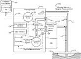
- FIG. 1is a block diagram of a wound therapy system including a therapy device coupled to a wound dressing via tubing, according to an exemplary embodiment.
- FIG. 2is a block diagram illustrating the therapy device of FIG. 1 in greater detail when the therapy device operates to draw a vacuum within a negative pressure circuit, according to an exemplary embodiment.
- FIG. 3Ais a block diagram illustrating the therapy device of FIG. 1 in greater detail when the therapy device operates to vent the negative pressure circuit, according to an exemplary embodiment.
- FIG. 3Bis a block diagram illustrating the therapy device of FIG. 1 in greater detail when the therapy device uses an orifice to vent the negative pressure circuit, according to an exemplary embodiment.
- FIG. 4is a block diagram illustrating the therapy device of FIG. 1 in greater detail when the therapy device operates to deliver instillation fluid to the wound dressing and/or a wound, according to an exemplary embodiment.
- FIG. 5is a block diagram illustrating a controller of the therapy device of FIG. 1 in greater detail, according to an exemplary embodiment.
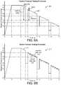
- FIG. 6Ais a graph illustrating a passive pressure testing procedure which can be performed by the therapy device of FIG. 1 , according to an exemplary embodiment.
- FIG. 6Bis a graph illustrating an active pressure testing procedure which can be performed by the therapy device of FIG. 1 , according to an exemplary embodiment.
- FIG. 6Cis a graph illustrating an uncontrolled pressure testing procedure with a variable leak rate which can be performed by the therapy device of FIG. 1 , according to an exemplary embodiment.
- FIG. 6Dis a graph illustrating an uncontrolled pressure testing procedure with a constant leak rate which can be performed by the therapy device of FIG. 1 , according to an exemplary embodiment.
- FIG. 7Ais a graph illustrating several pressure decay curves which can be generated and/or used by the therapy device of FIG. 1 to relate measured pressure to wound volume, according to an exemplary embodiment.
- FIG. 7Bis a graph illustrating an unassisted pressure decay curve generated using the passive pressure testing procedure of FIG. 6A and an assisted pressure decay curve generated using the active pressure testing procedure of FIG. 6B , according to an exemplary embodiment.
- FIG. 8is a flowchart of a process for generating a pressure response model that relates dynamic pressure response parameters to wound volume, according to an exemplary embodiment.
- FIG. 9is a flowchart of a process for estimating wound volume by applying a pressure stimulus to a negative pressure circuit and observing the dynamic pressure response, according to an exemplary embodiment.
- FIG. 10is a flowchart of a process for monitoring healing progression over time based on a set of wound volume estimates, according to an exemplary embodiment.
- FIG. 11is a graph illustrating wound volume and instillation fluid volume over time, according to an exemplary embodiment.
- FIG. 12is a flowchart of a process for determining an amount of instillation fluid to deliver to a wound based on an estimated wound volume, according to an exemplary embodiment.
- FIG. 13is a graph illustrating a wound therapy process including leak rate determination, wound volume determination, and fluid instillation stages, according to an exemplary embodiment.
- the wound therapy systemmay include a therapy device and a wound dressing.
- the therapy devicemay include an instillation fluid canister, a removed fluid canister, a valve, a pneumatic pump, an instillation pump, and a controller.
- the wound dressingcan be applied to a patient's skin surrounding a wound.
- the therapy devicecan be configured to deliver instillation fluid to the wound and provide negative pressure wound therapy (NPWT) by maintaining the wound at negative pressure.
- NGWTnegative pressure wound therapy
- the controllercan be configured to operate the pneumatic pump, the instillation pump, the valve, and/or other controllable components of the therapy device.
- the controllerperforms a pressure testing procedure by applying a pressure stimulus to the negative pressure circuit. For example, the controller may instruct the valve to close and operate the pneumatic pump to establish negative pressure within the negative pressure circuit. Once the negative pressure has been established, the controller may deactivate the pneumatic pump. The controller may cause the valve to open for a predetermined amount of time and then close after the predetermined amount of time has elapsed. In some embodiments, the controller operates the pneumatic pump while the valve is closed to mitigate air leakage into the negative pressure circuit.
- the controllermay observe a dynamic pressure response of the negative pressure circuit to the pressure stimulus using pressure measurements recorded by a pressure sensor.
- the dynamic pressure responsemay be characterized by a variety of parameters including, for example, a depth of purge parameter, a rebound parameter, a delta parameter, and a leak rate parameter (described in greater detail below).
- the controllercan estimate the volume of the wound based on the observed dynamic pressure response. For example, the controller can apply the observed parameters as inputs to a pressure model that defines a relationship between the observed parameters and the volume of the negative pressure circuit and/or the volume of the wound.
- the modelmay include a polynomial approximation model, a neural network model, or any other model that relates the observed parameters to the volume of the negative pressure circuit and/or the volume of the wound.
- the pressure modelis a pre-existing model stored in the controller by the manufacturer of the therapy device.
- the controllercan generate the pressure model on-site by performing a training procedure.
- the training proceduremay be the same as the pressure testing procedure with the exception that the therapy device is connected to a training circuit having a known volume.
- the wound dressingcan be applied to a test device having a known volume rather than to a patient's skin surrounding a wound.
- the controllercan apply the pressure stimulus to various training circuits having various known volumes and may observe the dynamic pressure response of each training circuit. Each of the known volumes may result in a different dynamic pressure response to the pressure stimulus.
- the controllercan then associate the known volume of each training circuit with the corresponding dynamic pressure response.
- the controlleruses the dynamic pressure responses of the training circuits to generate the pressure model that defines a relationship between the observed parameters of the dynamic pressure response (e.g., depth of purge, rebound, delta, leak rate, etc.) and the volume of the training circuit.
- the pressure modelcan then be stored in the therapy device and used to estimate the volume of a wound, as previously described.
- the controlleris configured to execute the pressure testing procedure, observe the dynamic pressure response, and estimate the wound volume at a plurality of times during wound treatment. The controller can then determine healing progression based on changes in the wound volume during wound treatment. In some embodiments, the controller is configured to determine a volume of instillation fluid to deliver to the wound based on the estimated wound volume. The volume of instillation fluid to deliver may be a predetermined percentage of the volume of the wound (e.g., 20%, 50%, 80%, etc.). The controller can then operate the instillation pump to deliver the determined volume of instillation fluid to the wound.
- NPWT system 100is shown, according to an exemplary embodiment.
- NPWT system 100is shown to include a therapy device 102 fluidly connected to a wound dressing 112 via tubing 108 and 110 .
- Wound dressing 112may be adhered or sealed to a patient's skin 116 surrounding a wound 114 .
- wound dressings 112which can be used in combination with NPWT system 100 are described in detail in U.S. Pat. No. 7,651,484 granted Jan. 26, 2010, U.S. Pat. No. 8,394,081 granted Mar. 12, 2013, and U.S. patent application Ser. No. 14/087,418 filed Nov. 22, 2013. The entire disclosure of each of these patents and patent applications is incorporated by reference herein.
- Therapy device 102can be configured to provide negative pressure wound therapy by reducing the pressure at wound 114 .
- Therapy device 102can draw a vacuum at wound 114 (relative to atmospheric pressure) by removing wound exudate, air, and other fluids from wound 114 .
- Wound exudatemay include fluid that filters from a patient's circulatory system into lesions or areas of inflammation.
- wound exudatemay include water and dissolved solutes such as blood, plasma proteins, white blood cells, platelets, and red blood cells.
- Other fluids removed from wound 114may include instillation fluid 105 previously delivered to wound 114 .
- Instillation fluid 105can include, for example, a cleansing fluid, a prescribed fluid, a medicated fluid, an antibiotic fluid, or any other type of fluid which can be delivered to wound 114 during wound treatment. Instillation fluid 105 may be held in an instillation fluid canister 104 and controllably dispensed to wound 114 via instillation fluid tubing 108 . In some embodiments, instillation fluid canister 104 is detachable from therapy device 102 to allow canister 106 to be refilled and replaced as needed.
- Removed fluid canister 106may be a component of therapy device 102 configured to collect wound exudate and other fluids 107 removed from wound 114 .
- removed fluid canister 106is detachable from therapy device 102 to allow canister 106 to be emptied and replaced as needed.
- a lower portion of canister 106may be filled with wound exudate and other fluids 107 removed from wound 114 , whereas an upper portion of canister 106 may be filled with air.
- Therapy device 102can be configured to draw a vacuum within canister 106 by pumping air out of canister 106 .
- the reduced pressure within canister 106can be translated to wound dressing 112 and wound 114 via tubing 110 such that wound dressing 112 and wound 114 are maintained at the same pressure as canister 106 .
- Therapy device 102is shown to include a pneumatic pump 120 , an instillation pump 122 , a valve 132 , a filter 128 , and a controller 118 .
- Pneumatic pump 120can be fluidly coupled to removed fluid canister 106 (e.g., via conduit 136 ) and can be configured to draw a vacuum within canister 106 by pumping air out of canister 106 .
- pneumatic pump 120is configured to operate in both a forward direction and a reverse direction.
- pneumatic pump 120can operate in the forward direction to pump air out of canister 106 and decrease the pressure within canister 106 .
- Pneumatic pump 120can operate in the reverse direction to pump air into canister 106 and increase the pressure within canister 106 .
- Pneumatic pump 120can be controlled by controller 118 , described in greater detail below.
- instillation pump 122can be fluidly coupled to instillation fluid canister 104 via tubing 109 and fluidly coupled to wound dressing 112 via tubing 108 .
- Instillation pump 122can be operated to deliver instillation fluid 105 to wound dressing 112 and wound 114 by pumping instillation fluid 105 through tubing 109 and tubing 108 , as shown in FIG. 4 .
- Instillation pump 122can be controlled by controller 118 , described in greater detail below.
- Filter 128can be positioned between removed fluid canister 106 and pneumatic pump 120 (e.g., along conduit 136 ) such that the air pumped out of canister 106 passes through filter 128 .
- Filter 128can be configured to prevent liquid or solid particles from entering conduit 136 and reaching pneumatic pump 120 .
- Filter 128may include, for example, a bacterial filter that is hydrophobic and/or lipophilic such that aqueous and/or oily liquids will bead on the surface of filter 128 .
- Pneumatic pump 120can be configured to provide sufficient airflow through filter 128 that the pressure drop across filter 128 is not substantial (e.g., such that the pressure drop will not substantially interfere with the application of negative pressure to wound 114 from therapy device 102 ).
- therapy device 102operates a valve 132 to controllably vent the negative pressure circuit, as shown in FIG. 3A .
- Valve 132can be fluidly connected with pneumatic pump 120 and filter 128 via conduit 136 .
- valve 132is configured to control airflow between conduit 136 and the environment around therapy device 102 .
- valve 132can be opened to allow airflow into conduit 136 via vent 134 and conduit 138 , and closed to prevent airflow into conduit 136 via vent 134 and conduit 138 .
- Valve 132can be opened and closed by controller 118 , described in greater detail below.
- the negative pressure circuitmay include any component of system 100 that can be maintained at a negative pressure when performing negative pressure wound therapy (e.g., conduit 136 , removed fluid canister 106 , tubing 110 , wound dressing 112 , and/or wound 114 ).
- the negative pressure circuitmay include conduit 136 , removed fluid canister 106 , tubing 110 , wound dressing 112 , and/or wound 114 .
- valve 132When valve 132 is open, airflow from the environment around therapy device 102 may enter conduit 136 via vent 134 and conduit 138 and fill the vacuum within the negative pressure circuit.
- the airflow from conduit 136 into canister 106 and other volumes within the negative pressure circuitmay pass through filter 128 in a second direction, opposite the first direction, as shown in FIG. 3A .
- therapy device 102vents the negative pressure circuit via an orifice 158 , as shown in FIG. 3B .
- Orifice 158may be a small opening in conduit 136 or any other component of the negative pressure circuit (e.g., removed fluid canister 106 , tubing 110 , tubing 111 , wound dressing 112 , etc.) and may allow air to leak into the negative pressure circuit at a known rate.
- therapy device 102vents the negative pressure circuit via orifice 158 rather than operating valve 132 .
- Valve 132can be omitted from therapy device 102 for any embodiment in which orifice 158 is included.
- the rate at which air leaks into the negative pressure circuit via orifice 158may be substantially constant or may vary as a function of the negative pressure, depending on the geometry of orifice 158 .
- controller 118can use a stored relationship between negative pressure and leak rate to calculate the leak rate via orifice 158 based measurements of the negative pressure.
- the leakage of air into the negative pressure circuit via orifice 158can be used to generate a pressure decay curve for use in estimating the volume of wound 114 , as described with reference to FIGS. 5-9 .
- therapy device 102includes a variety of sensors.
- therapy device 102is shown to include a pressure sensor 130 configured to measure the pressure within canister 106 and/or the pressure at wound dressing 112 or wound 114 .
- therapy device 102includes a pressure sensor 113 configured to measure the pressure within tubing 111 .
- Tubing 111may be connected to wound dressing 112 and may be dedicated to measuring the pressure at wound dressing 112 or wound 114 without having a secondary function such as channeling installation fluid 105 or wound exudate.
- tubing 108 , 110 , and 111may be physically separate tubes or separate lumens within a single tube that connects therapy device 102 to wound dressing 112 .
- tubing 110may be described as a negative pressure lumen that functions apply negative pressure wound dressing 112 or wound 114
- tubing 111may be described as a sensing lumen configured to sense the pressure at wound dressing 112 or wound 114
- Pressure sensors 130 and 113can be located within therapy device 102 , positioned at any location along tubing 108 , 110 , and 111 , or located at wound dressing 112 in various embodiments. Pressure measurements recorded by pressure sensors 130 and/or 113 can be communicated to controller 118 . Controller 118 use the pressure measurements as inputs to various pressure testing operations and control operations performed by controller 118 (described in greater detail with reference to FIGS. 5-12 ).
- Controller 118can be configured to operate pneumatic pump 120 , instillation pump 122 , valve 132 , and/or other controllable components of therapy device 102 .
- controller 118performs a pressure testing procedure by applying a pressure stimulus to the negative pressure circuit. For example, controller 118 may instruct valve 132 to close and operate pneumatic pump 120 to establish negative pressure within the negative pressure circuit. Once the negative pressure has been established, controller 118 may deactivate pneumatic pump 120 . Controller 118 may cause valve 132 to open for a predetermined amount of time and then close after the predetermined amount of time has elapsed. Controller 118 may observe a dynamic pressure response of the negative pressure circuit to the pressure stimulus using pressure measurements recorded by pressure sensors 130 and/or 113 . The dynamic pressure response may be characterized by a variety of parameters including, for example, a depth of purge parameter, a rebound parameter, a delta parameter, and a leak rate parameter (described in greater detail with reference to FIG. 5 ).
- Controller 118can estimate the volume of wound 114 based on the observed dynamic pressure response. For example, controller 118 can apply the observed parameters as inputs to a pressure model that defines a relationship between the observed parameters and the volume of the negative pressure circuit and/or the volume of wound 114 .
- the modelmay include a polynomial approximation model, a neural network model, or any other model that relates the observed parameters to the volume of the negative pressure circuit and/or the volume of wound 114 .
- the pressure modelis a pre-existing model stored in controller 118 by the manufacturer of therapy device 102 .
- controller 118can generate the pressure model on-site by performing a training procedure.
- the training proceduremay be the same as the pressure testing procedure with the exception that therapy device 102 is connected to a training circuit having a known volume.
- wound dressing 112can be applied to a test device having a known volume rather than to a patient's skin 116 surrounding wound 114 .
- Controller 118can apply the pressure stimulus to various training circuits having various known volumes and may observe the dynamic pressure response of each training circuit. Each of the known volumes may result in a different dynamic pressure response to the pressure stimulus. Controller 118 can then associate the known volume of each training circuit with the corresponding dynamic pressure response.
- controller 118uses the dynamic pressure responses of the training circuits to generate the pressure model that defines a relationship between the observed parameters of the dynamic pressure response (e.g., depth of purge, rebound, delta, leak rate, etc.) and the volume of the training circuit.
- the pressure modelcan then be stored in controller 118 and used to estimate the volume of a wound 114 , as previously described.
- controller 118is configured to execute the pressure testing procedure, observe the dynamic pressure response, and estimate the wound volume at a plurality of times during wound treatment. Controller 118 can then determine healing progression based on changes in the wound volume during wound treatment. In some embodiments, controller 118 is configured to determine a volume of instillation fluid 105 to deliver to wound 114 based on the estimated wound volume. The volume of instillation fluid 105 to deliver may be a predetermined percentage of the volume of wound 114 (e.g., 20%, 50%, 80%, etc.). Controller 118 can then operate instillation pump 122 to deliver the determined volume of instillation fluid 105 to wound 114 . These and other features of controller 118 are described in greater detail with reference to FIGS. 5-12 .
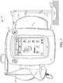
- therapy device 102includes a user interface 126 .
- User interface 126may include one or more buttons, dials, sliders, keys, or other input devices configured to receive input from a user.
- User interface 126may also include one or more display devices (e.g., LEDs, LCD displays, etc.), speakers, tactile feedback devices, or other output devices configured to provide information to a user.
- the pressure measurements recorded by pressure sensors 130 and/or 113are presented to a user via user interface 126 .
- User interface 126can also display alerts generated by controller 118 . For example, controller 118 can generate a “no canister” alert if canister 106 is not detected.
- therapy device 102includes a data communications interface 124 (e.g., a USB port, a wireless transceiver, etc.) configured to receive and transmit data.
- Communications interface 124may include wired or wireless communications interfaces (e.g., jacks, antennas, transmitters, receivers, transceivers, wire terminals, etc.) for conducting data communications external systems or devices.
- the communicationsmay be direct (e.g., local wired or wireless communications) or via a communications network (e.g., a WAN, the Internet, a cellular network, etc.).
- communications interface 124can include a USB port or an Ethernet card and port for sending and receiving data via an Ethernet-based communications link or network.
- communications interface 124can include a Wi-Fi transceiver for communicating via a wireless communications network or cellular or mobile phone communications transceivers.
- Controller 118is shown to include a processing circuit 140 including a processor 142 and memory 144 .
- Processor 142may be a general purpose or specific purpose processor, an application specific integrated circuit (ASIC), one or more field programmable gate arrays (FPGAs), a group of processing components, or other suitable processing components.
- ASICapplication specific integrated circuit
- FPGAsfield programmable gate arrays
- Processor 142is configured to execute computer code or instructions stored in memory 144 or received from other computer readable media (e.g., CDROM, network storage, a remote server, etc.).
- Memory 144may include one or more devices (e.g., memory units, memory devices, storage devices, etc.) for storing data and/or computer code for completing and/or facilitating the various processes described in the present disclosure.
- Memory 144may include random access memory (RAM), read-only memory (ROM), hard drive storage, temporary storage, non-volatile memory, flash memory, optical memory, or any other suitable memory for storing software objects and/or computer instructions.
- Memory 144may include database components, object code components, script components, or any other type of information structure for supporting the various activities and information structures described in the present disclosure.
- Memory 144may be communicably connected to processor 142 via processing circuit 140 and may include computer code for executing (e.g., by processor 142 ) one or more processes described herein. When processor 142 executes instructions stored in memory 144 , processor 142 generally configures controller 118 (and more particularly processing circuit 140 ) to complete such activities.
- Controller 118is shown to include a pump controller 146 and a valve controller 150 .
- Pump controller 146can be configured to operate pumps 120 and 122 by generating and providing control signals to pumps 120 - 122 .
- the control signals provided to pumps 120 - 122can cause pumps 120 - 122 to activate, deactivate, or achieve a variable capacity or speed (e.g., operate at half speed, operate at full speed, etc.).
- valve controller 150can be configured to operate valve 132 by generating and providing control signals to valve 132 .
- the control signals provided to valve 132can cause valve 132 to open, close, or achieve a specified intermediate position (e.g., one-third open, half open, etc.).
- pump controller 146 and valve controller 150are used by other components of controller 118 (e.g., testing procedure controller 148 , wound volume estimator 156 , etc.) to operate pumps 120 - 122 and valve 132 when carrying out the processes described herein.
- pump controller 146uses input from a canister sensor configured to detect whether removed fluid canister 106 is present.
- Pump controller 146can be configured to activate pneumatic pump 120 only when removed fluid canister 106 is present. For example, pump controller 146 can check whether canister 106 is present and can activate pneumatic pump 120 in response to a determination that canister 106 is present. However, if canister 106 is not present, pump controller 146 may prevent pneumatic pump 120 from activating.
- pump controller 146can be configured to activate instillation pump 122 only when instillation fluid canister 104 is present. For example, pump controller 146 can check whether canister 104 is present and can activate instillation pump 122 in response to a determination that canister 104 is present. However, if canister 104 is not present, pump controller 146 may prevent instillation pump 122 from activating.
- Controller 118is shown to include a pressure monitor 152 .
- Pressure monitor 152can be configured to monitor the pressure within removed fluid canister 106 and/or the pressure within wound dressing 112 or wound 114 using feedback from pressure sensors 130 and/or 113 .
- pressure sensors 130 and/or 113may provide pressure measurements to pressure monitor 152 .
- Pressure monitor 152can use the pressure measurements to determine the pressure within canister 106 and/or the pressure within wound dressing 112 or wound 114 in real-time.
- Pressure monitor 152can provide the pressure value to model generator 154 , pump controller 146 , testing procedure controller 148 , and/or valve controller 150 for use as an input to control processes performed by such components.
- controller 118is shown to include a testing procedure controller 148 .
- Testing procedure controller 148can be configured to execute a pressure testing procedure to invoke and observe a dynamic pressure response. If therapy device 102 is connected to a wound dressing 112 applied to a patient's skin 116 over a wound 114 , testing procedure controller 148 can observe the dynamic pressure response of a negative pressure circuit that includes conduit 136 , removed fluid canister 106 , tubing 110 , wound dressing 112 , and/or wound 114 (which may have an unknown volume).
- testing procedure controller 148can observe the dynamic pressure response of a training circuit that includes conduit 136 , removed fluid canister 106 , tubing 110 , wound dressing 112 , and/or the training device.
- testing procedure controller 148can be configured to operate pneumatic pump 120 to establish negative pressure within the negative pressure circuit and/or the training circuit.
- the negative pressuremay be defined as the difference between the atmospheric pressure surrounding therapy device 102 and the pressure within the negative pressure circuit and/or the training circuit (i.e., the amount by which atmospheric pressure exceeds the pressure within the negative pressure circuit and/or the training circuit). For example, at time t 0 , the negative pressure is shown having a value of P 0 (e.g., zero mmHg), which indicates that the pressure within the negative pressure circuit and/or the training circuit is equal to atmospheric pressure around therapy device 102 .
- P 0e.g., zero mmHg
- testing procedure controller 148begins operating pneumatic pump 120 to reduce the pressure within the negative pressure circuit and/or the training circuit. The negative pressure continues to decrease until it reaches a negative pressure value of P 8 mmHg below atmospheric pressure (e.g., 125 mmHg) at time t 1 . Between time t 1 and time t 2 , testing procedure controller 148 maintains the negative pressure at the value of P 8 by operating pneumatic pump 120 as needed to remove air from the negative pressure circuit and/or the training circuit. Testing procedure controller 148 may then apply a pressure stimulus to the negative pressure circuit and/or the training circuit after the negative pressure has been established within the negative pressure circuit and/or the training circuit.
- P 8 mmHgbelow atmospheric pressure (e.g., 125 mmHg)
- testing procedure controller 148deactivates pneumatic pump 120 .
- the magnitude of the negative pressure within the negative pressure circuit and/or the training circuitmay decrease due to leakage of air into the negative pressure circuit and/or the training circuit while valve 132 is closed.
- the rate at which the negative pressure decreases while valve 132 is closedis defined by the slope of line 202 between time t 2 and time t 3 .
- Testing procedure controller 148may determine the slope of line 202 between time t 2 and time t 3 and may store the slope as the value of the leak rate parameter.
- the leak rate parametermay be one of the parameters that characterizes the dynamic pressure response of the negative pressure circuit and/or the training circuit.
- testing procedure controller 148applies a pressure stimulus to the negative pressure circuit and/or the training circuit. Applying the pressure stimulus may include operating valve 132 to controllably vent the negative pressure circuit and/or the training circuit. For example, testing procedure controller 148 may cause valve 132 to open at time t 3 to allow airflow into the negative pressure circuit and/or the training circuit. Testing procedure controller 148 may keep valve 132 open for a predetermined amount of time (i.e., from time t 3 to time t 4 ) and may close valve 132 after closing the valve after the predetermined amount of time has elapsed (i.e., at time t 4 ).
- testing procedure controller 148may observe the dynamic pressure response of the negative pressure circuit and/or the training circuit to the pressure stimulus.
- the dynamic pressure responsemay be characterized by several additional parameters including a depth of purge parameter, a rebound parameter, and a delta parameter.
- testing procedure controller 148applies the pressure stimulus one or more additional times until the negative pressure reaches a threshold value P 1 when valve 132 is closed. Between each application of the pressure stimulus, testing procedure controller 148 may wait for another predetermined amount of time (i.e., from time t 4 to time t 5 and from time t 6 to time t 7 ). For example, testing procedure controller 148 may wait for a predetermined amount of time from time t 4 to time t 5 and may apply the pressure stimulus again at time t 5 . Testing procedure controller 148 may cause valve 132 to open at time t 5 to allow airflow into the negative pressure circuit and/or the training circuit.
- Testing procedure controller 148may keep valve 132 open for a predetermined amount of time (i.e., from time t 5 to time t 6 ) and may close valve 132 after closing the valve after the predetermined amount of time has elapsed (i.e., at time t 6 ).
- testing procedure controller 148can be configured to operate pneumatic pump 120 to establish negative pressure within the negative pressure circuit and/or the training circuit.
- the negative pressuremay be defined as the difference between the atmospheric pressure surrounding therapy device 102 and the pressure within the negative pressure circuit and/or the training circuit (i.e., the amount by which atmospheric pressure exceeds the pressure within the negative pressure circuit and/or the training circuit).
- the negative pressureis shown having a value of P 0 (e.g., zero mmHg), which indicates that the pressure within the negative pressure circuit and/or the training circuit is equal to atmospheric pressure around therapy device 102 .
- the active testing procedure illustrated in FIG. 6Bmay be substantially similar to the passive testing procedure illustrated in FIG. 6A .
- controller 148can be configured to operate pneumatic pump 120 using brief controlled activations of pneumatic pump 120 while valve 132 is closed (e.g., between times t 4 and t 5 , between times t 6 and t 7 , and between times t 8 and t 9 ) to compensate for a high leak rate of air into the negative pressure circuit and/or the training circuit.
- line 212represents the pressure within the negative pressure circuit and/or the training circuit as a function of time.
- the actual leak rate of air into the negative pressure circuit and/or the training circuit while valve 132 is closedis indicated by the slope of line segments 216 , whereas the slope of line 214 represents the average or assisted leak rate between times t 4 and t 5 .
- the brief controlled activations of pneumatic pump 120remove some of the air from the negative pressure circuit and/or the training circuit between times t 4 and t 5 (causing the negative pressure to increase with each controlled activation) such that the average or assisted leak rate is equal to
- graphs 220 and 230 illustrating an uncontrolled testing procedure performed by testing procedure controller 148is shown, according to an exemplary embodiment.
- the uncontrolled testing proceduredoes not make use of valve 132 and can be performed for embodiments in which therapy device 102 includes orifice 158 in place of valve 132 .
- Graph 220illustrates the uncontrolled testing procedure when orifice 158 leaks air into the negative pressure circuit and/or training circuit at a variable leak rate, whereas graph 220 illustrates the uncontrolled testing procedure when orifice 158 leaks air into the negative pressure circuit and/or training circuit at a substantially constant leak rate.
- testing procedure controller 148begins operating pneumatic pump 120 to reduce the pressure within the negative pressure circuit and/or the training circuit.
- the negative pressurecontinues to decrease until it reaches a negative pressure value of P 2 mmHg below atmospheric pressure (e.g., 125 mmHg) at time t 1 .
- testing procedure controller 148deactivates pneumatic pump 120 .
- the magnitude of the negative pressure within the negative pressure circuit and/or the training circuitmay decrease due to leakage of air into the negative pressure circuit and/or the training circuit via orifice 158 .
- the rate at which the negative pressure decreasesis defined by the slope of line 222 between time t 1 and time t 2 .
- leakage of air into the negative pressure circuit and/or training circuit via orifice 158occurs more quickly near time t 1 and more slowly near time t 2 , as shown by the slope of line 222 becoming closer to zero as time elapses between t 1 and t 2 .
- testing procedure controller 148may determine the slope of line 222 at one or more times between time t 1 and time t 2 and may store the slope as the value of the leak rate parameter.
- the leak rate parametercan be defined as the amount of time required for the negative pressure to drop from P 2 to P 1 and can be calculated by subtracting t 1 from t 2 (i.e., t 2 ⁇ t 1 ).
- the leak rate parametermay be one of the parameters that characterizes the dynamic pressure response of the negative pressure circuit and/or the training circuit.
- Testing procedure controller 148can be configured to execute the passive testing procedure, the active testing procedure, and/or the uncontrolled testing procedure in various embodiments.
- the passive testing proceduremay be suitable under most conditions and may be the primary or default testing procedure used by testing procedure controller 148 .
- the active testing proceduremay be suitable in the presence of a high leak rate and may be used by testing procedure controller 148 in response to a determination that the actual leak rate exceeds a predetermined leak rate threshold.
- the uncontrolled testing proceduremay be suitable for embodiments in which valve 132 is replaced with orifice 158 .
- Leak ratecan be determined in a variety of ways.
- leak rateis determined by operating pneumatic pump 120 to achieve a predetermined negative pressure within the negative pressure circuit and measuring the pressure decay over time.
- leak rateis determined based on the effort of pneumatic pump 120 or power consumed by pneumatic pump 120 .
- pump controller 146can be configured to perform brief controlled activations of pneumatic pump 120 to maintain the negative pressure at a setpoint or prevent the negative pressure from dropping at a rate that exceeds a predetermined leak rate threshold, as previously described. The number or frequency of these brief controlled activations of pneumatic pump 120 depends on the leak rate and can be used to determine the leak rate.
- controller 118can be configured to record the number of brief controlled activations of pneumatic pump 120 within a given time period, measure a frequency or interval of the brief controlled activations, measure a duty cycle of pneumatic pump 120 (e.g., a percentage of time pneumatic pump 120 is active), or measure an amount of power consumed by pneumatic pump 120 to perform the brief controlled activations. Any of these metrics may characterize pump effort and can be stored as a pump effort parameter. Controller 118 can use a stored equation or predetermined relationship to calculate leak rate as a function of the pump effort.
- controller 118is shown to include a model generator 154 .
- Model generator 154can be configured to generate a model that defines a relationship between the parameters of the dynamic pressure response and the volume of wound 114 .
- model generator 154can cause testing procedure controller 148 to run the pressure testing procedure outlined above for several different training circuits having several different known volumes (e.g., 50 cc, 100 cc, 200 cc, 300 cc, etc.).
- the pressure testing proceduremay be referred to as a training procedure.
- Each performance of the training proceduremay include applying the pressure stimulus to a training circuit having a known volume, observing the dynamic pressure response of the training circuit to the pressure stimulus, and associating the known volume with the dynamic pressure response of the training circuit.
- model generator 154records the values of the parameters of the dynamic pressure response (i.e., leak rate, depth of purge, rebound, delta, etc.) for each known volume and associates those values with the known volume.
- the values of the parameters and the known volumeform a set of training data which can be used to construct a model.
- the values of the parametersform a set of model input training data, whereas the known volumes form a set of model output training data.
- Model generator 154can use any of a variety of model generation techniques to construct a model (i.e., a mathematical model) that relates the values of the parameters to the corresponding volume in the set of training data.
- model generator 154creates a polynomial approximation model to relate the values of the parameters to the corresponding volume.
- model generator 154can perform a curve fitting process such as polynomial regression using any of a variety of regression techniques. Examples of regression techniques which can be used by model generator 154 include least squares, ordinary least squares, linear least squares, partial least squares, total least squares, generalized least squares, weighted least squares non-linear least squares, non-negative least squares, iteratively reweighted least squares, ridge regression, least absolute deviations, Bayesian linear regression, Bayesian multivariate linear regression, etc.
- model generator 154creates a neural network model to relate the values of the parameters to the corresponding volume.
- model generator 154can perform a machine learning process. Examples of machine learning techniques which can be used by model generator 154 include decision tree learning, association rule learning, artificial neural networks, deep learning, inductive logic programming, support vector machines, clustering, Bayesian networks, reinforcement learning, representation learning, similarity and metric learning, sparse dictionary learning, genetic algorithms, rule-based machine learning, etc.
- Each of pressure decay curves 252 - 258corresponds to a known volume and represents the pressure within the negative pressure circuit and/or the training circuit as a function of time for the corresponding volume.
- pressure decay curve 252corresponds to a volume of 300 cc
- pressure decay curve 254corresponds to a volume of 200 cc
- pressure decay curve 256corresponds to a volume of 100 cc
- pressure decay curve 258corresponds to a volume of 50 cc.
- Each of pressure decay curves 252 - 258may be created by model generator 154 using any of the modeling techniques described above.
- pressure decay curves 252 - 258can be created by running the pressure testing procedure for each known volume and plotting the pressure decay over time for each known volume.
- controller 118uses pressure decay curves 252 - 258 to translate a measured pressure value into a corresponding volume when estimating the volume of wound 114 .
- controller 118can measure the pressure of the negative pressure circuit and identify a time at which the pressure was measured.
- Controller 118can interpolate between pressure decay curves 252 - 258 to determine an interpolated pressure value that corresponds to the measured pressure and time pair.
- controller 118may observe a pressure value of P 1 .
- the combination of time t 1 and pressure P 1defines a point 260 in graph 250 . Point 260 lies approximately halfway between pressure decay curve 252 and pressure decay curve 254 .
- Controller 118can interpolate between pressure decay curves 252 and 254 to estimate that the volume of the negative pressure circuit is approximately halfway between the known volumes corresponding to pressure decay curves 252 and 254 (i.e., approximately 250 cc). In other embodiments, controller 118 estimates the volume of wound 114 by applying observed parameters of a dynamic pressure response as inputs to a pressure model.
- both unassisted pressure decay curve 264 and assisted pressure decay curve 262correspond to the same volume of the negative pressure circuit and/or training circuit.
- Unassisted pressure decay curve 264illustrates the pressure decay during the passive testing procedure shown in FIG. 6A (i.e., when pneumatic pump 120 is not operated to compensate for a high leak rate).
- assisted pressure decay curve 262illustrates the pressure decay during the active testing procedure (i.e., when pneumatic pump 120 is operated to compensate for a high leak rate).
- operating pneumatic pump 120 during the active testing proceduremitigates the pressure decay and therefore results in a more gradual assisted pressure decay curve 262 relative to unassisted pressure decay curve 264 .
- controller 118is shown to include a wound volume estimator 156 .
- Wound volume estimator 156can be configured to estimate the volume of wound 114 based on pressure measurements collected by pressure sensors 130 and/or 113 .
- wound volume estimator 156estimates the volume of wound 114 by performing a pressure testing procedure.
- the pressure testing proceduremay include applying a pressure stimulus to the negative pressure circuit and observing the dynamic pressure response of the negative pressure circuit to the pressure stimulus.
- the negative pressure circuitmay include any component of system 100 that can be maintained at a negative pressure when performing negative pressure wound therapy (e.g., conduit 136 , removed fluid canister 106 , tubing 110 , wound dressing 112 , and/or wound 114 ).
- wound volume estimator 156may instruct valve 132 to close and operate pneumatic pump 120 to establish negative pressure within the negative pressure circuit. Once the negative pressure has been established, wound volume estimator 156 may deactivate pneumatic pump 120 . Wound volume estimator 156 may cause valve 132 to open for a predetermined amount of time and then close after the predetermined amount of time has elapsed. Wound volume estimator 156 may observe a dynamic pressure response of the negative pressure circuit to the pressure stimulus using pressure measurements recorded by pressure sensors 130 and/or 113 . The dynamic pressure response may be characterized by a variety of parameters including, for example, a depth of purge parameter, a rebound parameter, a delta parameter, and a leak rate parameter, as previously described.
- Wound volume estimator 156can estimate the volume of wound 114 based on the observed dynamic pressure response. For example, wound volume estimator 156 can apply the observed parameters as inputs to a pressure model that defines a relationship between the observed parameters and the volume of the negative pressure circuit and/or the volume of wound 114 .
- the pressure modelis the model created by model generator 154 (e.g., by performing the training procedure based on training data collected using the training circuits).
- the modelmay include a polynomial approximation model, a neural network model, or any other model that relates the observed parameters to the volume of the negative pressure circuit and/or the volume of wound 114 .
- the pressure modelis a pre-existing model stored in memory 144 by the manufacturer of therapy device 102 .
- wound volume estimator 156is configured to execute the pressure testing procedure, observe the dynamic pressure response, and estimate the wound volume at a plurality of times during wound treatment. Wound volume estimator 156 can then determine healing progression based on changes in the wound volume during wound treatment. In some embodiments, wound volume estimator 156 is configured to determine a volume of instillation fluid 105 to deliver to wound 114 based on the estimated wound volume. The volume of instillation fluid 105 to deliver may be a predetermined percentage of the volume of wound 114 (e.g., 20%, 50%, 80%, etc.). Wound volume estimator 156 can then operate instillation pump 122 to deliver the determined volume of instillation fluid 105 to wound 114 .
- Process 300can be performed by one or more components of therapy device 102 to create a model that characterizes the dynamic pressure response of a training circuit and/or negative pressure circuit.
- process 300can be performed by controller 118 , pneumatic pump 120 , valve 132 , and/or pressure sensors 130 and/or 113 .
- process 300is executed by testing procedure controller 148 and model generator 154 .
- Process 300is shown to include applying a pressure stimulus to a training circuit having a known volume (step 302 ).
- the training circuitmay include one or more components of therapy device 102 (e.g., conduit 136 , removed fluid canister 106 , etc.) and/or other components of system 100 (e.g., tubing 110 , wound dressing 112 ). Under wound treatment conditions, wound dressing 112 would normally be applied to a patient's skin 116 surrounding a wound 114 . However, the training circuit may replace wound 114 with a training device having a known volume.
- Step 302may include instructing valve 132 to close and operating pneumatic pump 120 to establish negative pressure within the training circuit. Once the negative pressure has been established, pneumatic pump 120 may be deactivated.
- Step 302may include causing valve 132 to open for a predetermined amount of time and then closing valve 132 after the predetermined amount of time has elapsed.
- Process 300is shown to include observing the dynamic pressure response of the training circuit to the pressure stimulus (step 304 ) and associating the known volume of the training circuit with the dynamic pressure response (step 306 ).
- Step 304may include monitoring the pressure of the training circuit over time using pressure measurements recorded by pressure sensors 130 and/or 113 .
- the dynamic pressure responsemay be characterized by a variety of parameters including, for example, a depth of purge parameter, a rebound parameter, a delta parameter, and a leak rate parameter, as previously described.
- Step 306may include storing the values of the parameters of the dynamic pressure response as input training data and storing the known volume of the training circuit as output training data that corresponds to the input training data.
- Process 300is shown to include determining whether all volumes have been tested (step 308 ). If not all volumes have been tested (i.e., the result of step 308 is “no”), the training device to which therapy device 102 is connected can be replaced with a different training device having a different known volume. Steps 302 - 306 can then be repeated to apply the pressure stimulus to apply the pressure stimulus and observe the dynamic pressure response of the training circuit for each known volume. Each set of dynamic pressure response parameters can be stored as input training data and each set and the corresponding known volume can be stored as output training data.
- Step 310may include using any of a variety of model generation techniques to construct a model (i.e., a mathematical model) that relates the values of the dynamic pressure response parameters to the corresponding volume in the set of training data.
- a modeli.e., a mathematical model
- the model generated in step 310is a polynomial approximation model.
- Step 310may include performing a curve fitting process such as polynomial regression using any of a variety of regression techniques.
- regression techniqueswhich can be used in step 310 include least squares, ordinary least squares, linear least squares, partial least squares, total least squares, generalized least squares, weighted least squares non-linear least squares, non-negative least squares, iteratively reweighted least squares, ridge regression, least absolute deviations, Bayesian linear regression, Bayesian multivariate linear regression, etc.
- the model generated in step 310is a neural network model.
- Step 310may include using any of a variety of machine learning techniques to generate a neural network model that relates the values of the dynamic pressure response parameters to the corresponding volume in the set of training data.
- machine learning techniqueswhich can be used in step 310 include decision tree learning, association rule learning, artificial neural networks, deep learning, inductive logic programming, support vector machines, clustering, Bayesian networks, reinforcement learning, representation learning, similarity and metric learning, sparse dictionary learning, genetic algorithms, rule-based machine learning, etc.
- the pressure modelcan then be stored for use in estimating the volume of wound 114 .
- Process 400can be performed by one or more components of therapy device 102 estimate the volume of wound 114 .
- process 400can be performed by controller 118 , pneumatic pump 120 , valve 132 , and/or pressure sensors 130 and/or 113 .
- process 400is executed by testing procedure controller 148 and wound volume estimator 156 .
- Process 400is shown to include applying a pressure stimulus to a negative pressure circuit having an unknown volume (step 402 ).
- the negative pressure circuitmay include one or more components of therapy device 102 (e.g., conduit 136 , removed fluid canister 106 , etc.) and/or other components of system 100 (e.g., tubing 110 , wound dressing 112 , wound 114 ). Under wound treatment conditions, wound dressing 112 may be applied to a patient's skin 116 surrounding wound 114 . Accordingly, the volume of wound 114 forms part of the negative pressure circuit.
- Step 402may include instructing valve 132 to close and operating pneumatic pump 120 to establish negative pressure within the negative pressure circuit. Once the negative pressure has been established, pneumatic pump 120 may be deactivated.
- Step 402may include causing valve 132 to open for a predetermined amount of time and then closing valve 132 after the predetermined amount of time has elapsed.
- step 402includes executing the passive testing procedure and/or the active testing procedure, as described with reference to FIGS. 6A-6B .
- Process 400is shown to include observing the dynamic pressure response of the negative pressure circuit to the pressure stimulus (step 404 ) and determining values for parameters that characterize the dynamic pressure response (step 406 ).
- Step 404may include monitoring the pressure of the negative pressure circuit over time using pressure measurements recorded by pressure sensors 130 and/or 113 .
- the dynamic pressure responsemay be characterized by a variety of parameters including, for example, a depth of purge parameter, a rebound parameter, a delta parameter, and a leak rate parameter, as previously described.
- Step 406may include storing the values of the parameters of the dynamic pressure response.
- Process 400is shown to include applying the values of the parameters as inputs to a pressure response model that defines a wound volume as a function of the parameters (step 408 ).
- the pressure response modelis the model created by performing process 300 (e.g., by performing a regression process or machine learning process using training data collected using the training circuits).
- the modelmay include a polynomial approximation model, a neural network model, or any other model that relates the observed parameters to the volume of the negative pressure circuit and/or the volume of wound 114 .
- Process 400is shown to include estimating the volume of the wound based on an output of the model (step 410 ).
- the output of the pressure response modelis the estimated volume of wound 114 . Accordingly, the output of the pressure response model can be used as the estimated wound volume.
- the output of the pressure response modelis the estimated volume of the negative pressure circuit.
- step 410may include subtracting known volumes of other components of the negative pressure circuit to isolate the estimated volume of wound 114 .
- step 410may include subtracting the known volumes of conduit 136 , removed fluid canister 106 , tubing 110 , and/or wound dressing 112 such that the only volume remaining is the volume of wound 114 .
- the volume of removed fluid canister 106 that forms part of the negative pressure circuitis limited to the volume of the air within canister 106 .
- the volume of the air within canister 106may vary based on the level of removed fluid 107 within canister 106 .
- removed fluid canister 106includes a sensor (e.g., a level sensor, a weight sensor, etc.) that operates to record the level of removed fluid 107 within canister 106 .
- the observed level of removed fluid 107can then be used to estimate the air volume within canister 106 .
- the volume of air within canister 106can be estimated by performing a dead-space detection process.
- Process 500can be performed by one or more components of therapy device 102 to assess healing progression based on the volume of wound 114 .
- process 500can be performed by controller 118 , pneumatic pump 120 , valve 132 , and/or pressure sensors 130 and/or 113 .
- Process 500is shown to include executing a pressure testing procedure to estimate wound volume at a plurality of times during wound treatment (step 502 ).
- Step 502may include performing process 400 multiple times during wound treatment (e.g., once per day).
- Each time process 400 is performedthe volume of wound 114 may be estimated.
- Each estimate of the wound volumecan be stored along with the time at which the estimate was obtained.
- the pairs of time and estimated wound volumecan be stored as data points within the memory of therapy device 102 and/or presented to a user as an output of therapy device 102 (e.g., via communications interface 124 or user interface 126 ).
- the estimated wound volumecan be plotted as a function of time, as shown in FIG. 11 .
- Process 500is shown to include determining healing progression based on changes in the wound volume during wound treatment (step 504 ).
- Step 504may include comparing a current estimate of the wound volume to one or more previous estimates of the wound volume to identify a change in the wound volume.
- step 504includes determining a rate at which wound 114 is healing based on the changes in the wound volume over time.
- step 504includes extrapolating or predicting a time at which wound 114 will be fully healed based on a series of wound volume estimates. For example, step 504 may include predicting a time at which the estimated wound volume will reach zero (or another threshold value) based on the series of wound volume estimates obtained in step 502 .
- Controller 118can use the estimated wound volume to calculate a volume of instillation fluid 105 to deliver to wound 114 (step 702 ). In some embodiments, controller 118 calculates the volume of instillation fluid 105 to deliver to wound 114 by multiplying the estimated wound volume by a fluid instillation factor.
- the fluid instillation factormay be less than one (i.e., between zero and one) such that the calculated volume of instillation fluid 105 is less than the volume of wound 114 . In some embodiments, the fluid instillation factor is between approximately 0.2 and approximately 0.8. However, it is contemplated that the fluid instillation factor can have any value in various alternative embodiments.
- line 602represents the estimated volume of wound 114 as a function of time
- line 604represents the calculated volume of instillation fluid 105 to deliver to wound 114 over time.
- the estimated volume of wound 114is V 4 .
- the estimated volume of wound 114decreases and reaches a value of V 2 at time t 2 .
- Controller 118can then operate a pump to deliver the calculated volume of instillation fluid 105 to wound 114 (step 704 ).
- Step 704can include operating instillation pump 122 to draw instillation fluid 105 from instillation fluid canister 104 and deliver instillation fluid 105 to wound 114 via tubing 109 and 108 .
- the calculated volume of instillation fluid 105is also used to control the operation of pneumatic pump 120 .
- controller 118can operate pneumatic pump 120 to remove the volume of instillation fluid 105 from wound 114 via tubing 110 .
- the amount of time that pneumatic pump 120 operatesmay be a function of the volume of instillation fluid 105 that was delivered to wound 114 .
- FIG. 13a graph 800 illustrating several stages of a wound therapy process is shown, according to an exemplary embodiment.
- the wound therapy process illustrated in FIG. 13can be performed by one or more components of therapy device 102 as previously described.
- Line 802represents the negative pressure within the negative pressure circuit at each stage of the wound therapy process.
- therapy device 102begins operating pneumatic pump 120 to reduce the negative pressure within the negative pressure circuit during an initial draw down stage 804 that occurs between time t 0 and t 1 .
- the negative pressure within the negative pressure circuitreaches approximately 125 mmHg below atmospheric pressure and pneumatic pump 120 is deactivated.
- negative pressure within the negative pressure circuitis monitored using measurements from pressure sensors 130 and/or 113 during a seal check stage 806 .
- a substantial change in the pressure between times t 1 and t 2may indicate that the seal between wound dressing 112 and the patient's skin is not airtight whereas a substantially constant pressure between times t 1 and t 2 may indicate that wound dressing 112 is properly sealed to the patient's skin.
- pneumatic pump 120is activated until the negative pressure within the negative pressure circuit is reduced to approximately 200 mmHg below atmospheric pressure. Upon reaching a negative pressure of 200 mmHg, pneumatic pump 120 is deactivated and a wound volume determination stage 808 is initiated. Pneumatic pump 120 may be intermittently activated during stage 808 to maintain the negative pressure at approximately 200 mmHg and compensate for any leakage of air into the negative pressure circuit.
- pneumatic pump 120is deactivated and a leak determination stage 810 begins. Between times t 3 and t 4 , the negative pressure within the negative pressure circuit is monitored to determine a rate at which air leaks into the negative pressure circuit. At time t 4 , pneumatic pump 120 is reactivated to reduce the negative pressure back to approximately 200 mmHg. Pneumatic pump 120 may be intermittently activated between time t 4 and t 5 to maintain the negative pressure at approximately 200 mmHg and compensate for any leakage of air into the negative pressure circuit.
- pneumatic pump 120is deactivated and a wound volume determination stage 812 begins.
- therapy device 102may perform one or more of the pressure testing procedures described with reference to FIGS. 6A-6D .
- the time ranges shown in graphs 200 , 210 , 220 , and 230may occur entirely between times t 5 and t 6 in graph 800 .
- pneumatic pump 120is activated and the negative pressure is reduced to approximately 125 mmHg below atmospheric pressure during a draw down for instillation stage 814 .
- pneumatic pump 120is deactivated.
- Pneumatic pump 120may be intermittently activated between times t 7 and t 8 to maintain the negative pressure at approximately 125 mmHg and compensate for any leakage of air into the negative pressure circuit.
- instillation fluid 105may be delivered to wound 114 .
- the present disclosurecontemplates methods, systems and program products on any machine-readable media for accomplishing various operations.
- the embodiments of the present disclosurecan be implemented using existing computer processors, or by a special purpose computer processor for an appropriate system, incorporated for this or another purpose, or by a hardwired system.
- Embodiments within the scope of the present disclosureinclude program products comprising machine-readable media for carrying or having machine-executable instructions or data structures stored thereon.
- Such machine-readable mediacan be any available media that can be accessed by a general purpose or special purpose computer or other machine with a processor.
- machine-readable mediacan comprise RAM, ROM, EPROM, EEPROM, CD-ROM or other optical disk storage, magnetic disk storage or other magnetic storage devices, or any other medium which can be used to carry or store desired program code in the form of machine-executable instructions or data structures and which can be accessed by a general purpose or special purpose computer or other machine with a processor. Combinations of the above are also included within the scope of machine-readable media.
- Machine-executable instructionsinclude, for example, instructions and data which cause a general purpose computer, special purpose computer, or special purpose processing machines to perform a certain function or group of functions.
Landscapes
- Health & Medical Sciences (AREA)
- Heart & Thoracic Surgery (AREA)
- Life Sciences & Earth Sciences (AREA)
- Veterinary Medicine (AREA)
- Engineering & Computer Science (AREA)
- Biomedical Technology (AREA)
- Public Health (AREA)
- Animal Behavior & Ethology (AREA)
- General Health & Medical Sciences (AREA)
- Hematology (AREA)
- Anesthesiology (AREA)
- Vascular Medicine (AREA)
- Surgery (AREA)
- Physics & Mathematics (AREA)
- Oral & Maxillofacial Surgery (AREA)
- Pathology (AREA)
- Molecular Biology (AREA)
- Medical Informatics (AREA)
- Biophysics (AREA)
- Dentistry (AREA)
- Pulmonology (AREA)
- Dermatology (AREA)
- Fluid Mechanics (AREA)
- Media Introduction/Drainage Providing Device (AREA)
- External Artificial Organs (AREA)
- Measuring Pulse, Heart Rate, Blood Pressure Or Blood Flow (AREA)
Abstract
Description
Similar negative pressure adjustments can be made between times t6and t7and between times t8and t9. In this way, the influx of air into the negative pressure circuit and/or training can be mitigated to compensate for a high actual leak rate while
Claims (36)
Priority Applications (2)
| Application Number | Priority Date | Filing Date | Title |
|---|---|---|---|
| US16/363,763US11141317B2 (en) | 2018-03-29 | 2019-03-25 | Wound therapy system with wound volume estimation |
| US17/470,679US20210401629A1 (en) | 2018-03-29 | 2021-09-09 | Wound therapy system with wound volume estimation |
Applications Claiming Priority (3)
| Application Number | Priority Date | Filing Date | Title |
|---|---|---|---|
| US201862650132P | 2018-03-29 | 2018-03-29 | |
| US201962799241P | 2019-01-31 | 2019-01-31 | |
| US16/363,763US11141317B2 (en) | 2018-03-29 | 2019-03-25 | Wound therapy system with wound volume estimation |
Related Child Applications (1)
| Application Number | Title | Priority Date | Filing Date |
|---|---|---|---|
| US17/470,679DivisionUS20210401629A1 (en) | 2018-03-29 | 2021-09-09 | Wound therapy system with wound volume estimation |
Publications (2)
| Publication Number | Publication Date |
|---|---|
| US20190298579A1 US20190298579A1 (en) | 2019-10-03 |
| US11141317B2true US11141317B2 (en) | 2021-10-12 |
Family
ID=66102237
Family Applications (3)
| Application Number | Title | Priority Date | Filing Date |
|---|---|---|---|
| US16/363,763Active2039-12-26US11141317B2 (en) | 2018-03-29 | 2019-03-25 | Wound therapy system with wound volume estimation |
| US16/982,415AbandonedUS20210077671A1 (en) | 2018-03-29 | 2019-03-25 | Wound therapy system with wound volume estimation |
| US17/470,679PendingUS20210401629A1 (en) | 2018-03-29 | 2021-09-09 | Wound therapy system with wound volume estimation |
Family Applications After (2)
| Application Number | Title | Priority Date | Filing Date |
|---|---|---|---|
| US16/982,415AbandonedUS20210077671A1 (en) | 2018-03-29 | 2019-03-25 | Wound therapy system with wound volume estimation |
| US17/470,679PendingUS20210401629A1 (en) | 2018-03-29 | 2021-09-09 | Wound therapy system with wound volume estimation |
Country Status (5)
| Country | Link |
|---|---|
| US (3) | US11141317B2 (en) |
| EP (2) | EP3773777B1 (en) |
| JP (3) | JP7331002B2 (en) |
| CN (2) | CN111936177B (en) |
| WO (1) | WO2019190993A1 (en) |
Cited By (1)
| Publication number | Priority date | Publication date | Assignee | Title |
|---|---|---|---|---|
| US20210401629A1 (en)* | 2018-03-29 | 2021-12-30 | Kci Licensing, Inc. | Wound therapy system with wound volume estimation |
Families Citing this family (34)
| Publication number | Priority date | Publication date | Assignee | Title |
|---|---|---|---|---|
| GB0808376D0 (en) | 2008-05-08 | 2008-06-18 | Bristol Myers Squibb Co | Wound dressing |
| GB0817796D0 (en) | 2008-09-29 | 2008-11-05 | Convatec Inc | wound dressing |
| GB201020236D0 (en) | 2010-11-30 | 2011-01-12 | Convatec Technologies Inc | A composition for detecting biofilms on viable tissues |
| WO2012078724A1 (en) | 2010-12-08 | 2012-06-14 | Convatec Technologies Inc. | Apparatus and method for applying pressure to a wound site |
| US10207031B2 (en) | 2010-12-08 | 2019-02-19 | Convatec Technologies Inc. | Integrated system for assessing wound exudates |
| ES2748519T3 (en) | 2010-12-08 | 2020-03-17 | Convatec Technologies Inc | Wound exudate system accessory |
| GB201115182D0 (en) | 2011-09-02 | 2011-10-19 | Trio Healthcare Ltd | Skin contact material |
| GB2497406A (en) | 2011-11-29 | 2013-06-12 | Webtec Converting Llc | Dressing with a perforated binder layer |
| JP2016507663A (en) | 2012-12-20 | 2016-03-10 | コンバテック・テクノロジーズ・インコーポレイテッドConvatec Technologies Inc | Processing of chemically modified cellulosic fibers |
| US20150133861A1 (en) | 2013-11-11 | 2015-05-14 | Kevin P. McLennan | Thermal management system and method for medical devices |
| NZ737340A (en) | 2015-05-26 | 2019-06-28 | Icu Medical Inc | Disposable infusion fluid delivery device for programmable large volume drug delivery |
| GB2543544A (en) | 2015-10-21 | 2017-04-26 | Brightwake Ltd | Wound dressing |
| AU2017243601A1 (en) | 2016-03-30 | 2018-11-22 | Acib Gmbh | Detecting microbial infection in wounds |
| PL3435941T3 (en) | 2016-03-30 | 2022-05-09 | Convatec Technologies Inc. | Detecting microbial infections in wounds |
| MX2019000232A (en) | 2016-07-08 | 2019-11-12 | Convatec Technologies Inc | Fluid flow sensing. |
| DK3481349T3 (en) | 2016-07-08 | 2021-07-12 | Convatec Technologies Inc | Flexible vacuum system |
| EP3481348A4 (en) | 2016-07-08 | 2020-02-26 | ConvaTec Technologies Inc. | Fluid collection apparatus |
| CN111836655A (en) | 2017-11-16 | 2020-10-27 | 康沃特克有限公司 | fluid collection equipment |
| US11701264B2 (en) | 2018-06-27 | 2023-07-18 | Kci Licensing, Inc. | Wound therapy system with wound volume estimation using geometric approximation |
| US20210316060A1 (en)* | 2018-12-29 | 2021-10-14 | Tienan LIU | Medical drainage monitoring method, apparatus, and system based on image recognition |
| USD903093S1 (en)* | 2019-03-08 | 2020-11-24 | Kci Licensing, Inc. | Negative-pressure therapy device module |
| WO2020185385A1 (en)* | 2019-03-11 | 2020-09-17 | Kci Licensing, Inc. | Incision model to demonstrate closure effectiveness |
| US11426506B2 (en) | 2019-03-27 | 2022-08-30 | Kci Licensing, Inc. | Wound therapy system with wound volume estimation |
| WO2020197552A1 (en)* | 2019-03-27 | 2020-10-01 | Kci Licensing, Inc. | Wound therapy system with wound volume estimation |
| EP4295869A3 (en) | 2019-06-03 | 2024-03-20 | Convatec Limited | Methods and devices to disrupt and contain pathogens |
| USD939079S1 (en) | 2019-08-22 | 2021-12-21 | Icu Medical, Inc. | Infusion pump |
| US11771819B2 (en) | 2019-12-27 | 2023-10-03 | Convatec Limited | Low profile filter devices suitable for use in negative pressure wound therapy systems |
| US11331221B2 (en) | 2019-12-27 | 2022-05-17 | Convatec Limited | Negative pressure wound dressing |
| EP4096734A1 (en)* | 2020-01-29 | 2022-12-07 | KCI Licensing, Inc. | Wound therapy system with in-line orifice |
| GB202001212D0 (en)* | 2020-01-29 | 2020-03-11 | Smith & Nephew | Systems and methods for measuring and tracking wound volume |
| DK3915530T3 (en)* | 2020-05-25 | 2024-05-06 | Moelnlycke Health Care Ab | CONNECTION FOR NATIVE PRESSURE WOUND TREATMENT (NPWT) |
| ES2983577T3 (en) | 2020-05-25 | 2024-10-23 | Moelnlycke Health Care Ab | Negative Pressure Wound Therapy (NPWT) Dressing |
| USD1052728S1 (en)* | 2021-11-12 | 2024-11-26 | Icu Medical, Inc. | Medical fluid infusion pump |
| WO2025084686A1 (en)* | 2023-10-19 | 2025-04-24 | (주)시지바이오 | Negative pressure therapy device and method for controlling same |
Citations (130)
| Publication number | Priority date | Publication date | Assignee | Title |
|---|---|---|---|---|
| US1355846A (en) | 1920-02-06 | 1920-10-19 | David A Rannells | Medical appliance |
| US2547758A (en) | 1949-01-05 | 1951-04-03 | Wilmer B Keeling | Instrument for treating the male urethra |
| US2632443A (en) | 1949-04-18 | 1953-03-24 | Eleanor P Lesher | Surgical dressing |
| GB692578A (en) | 1949-09-13 | 1953-06-10 | Minnesota Mining & Mfg | Improvements in or relating to drape sheets for surgical use |
| US2682873A (en) | 1952-07-30 | 1954-07-06 | Johnson & Johnson | General purpose protective dressing |
| US2910763A (en) | 1955-08-17 | 1959-11-03 | Du Pont | Felt-like products |
| US2969057A (en) | 1957-11-04 | 1961-01-24 | Brady Co W H | Nematodic swab |
| US3066672A (en) | 1960-09-27 | 1962-12-04 | Jr William H Crosby | Method and apparatus for serial sampling of intestinal juice |
| US3367332A (en) | 1965-08-27 | 1968-02-06 | Gen Electric | Product and process for establishing a sterile area of skin |
| US3520300A (en) | 1967-03-15 | 1970-07-14 | Amp Inc | Surgical sponge and suction device |
| US3568675A (en) | 1968-08-30 | 1971-03-09 | Clyde B Harvey | Fistula and penetrating wound dressing |
| US3648692A (en) | 1970-12-07 | 1972-03-14 | Parke Davis & Co | Medical-surgical dressing for burns and the like |
| US3682180A (en) | 1970-06-08 | 1972-08-08 | Coilform Co Inc | Drain clip for surgical drain |
| US3826254A (en) | 1973-02-26 | 1974-07-30 | Verco Ind | Needle or catheter retaining appliance |
| DE2640413A1 (en) | 1976-09-08 | 1978-03-09 | Wolf Gmbh Richard | CATHETER MONITORING DEVICE |
| US4080970A (en) | 1976-11-17 | 1978-03-28 | Miller Thomas J | Post-operative combination dressing and internal drain tube with external shield and tube connector |
| US4096853A (en) | 1975-06-21 | 1978-06-27 | Hoechst Aktiengesellschaft | Device for the introduction of contrast medium into an anus praeter |
| US4139004A (en) | 1977-02-17 | 1979-02-13 | Gonzalez Jr Harry | Bandage apparatus for treating burns |
| US4165748A (en) | 1977-11-07 | 1979-08-28 | Johnson Melissa C | Catheter tube holder |
| US4184510A (en) | 1977-03-15 | 1980-01-22 | Fibra-Sonics, Inc. | Valued device for controlling vacuum in surgery |
| WO1980002182A1 (en) | 1979-04-06 | 1980-10-16 | J Moss | Portable suction device for collecting fluids from a closed wound |
| US4233969A (en) | 1976-11-11 | 1980-11-18 | Lock Peter M | Wound dressing materials |
| US4245630A (en) | 1976-10-08 | 1981-01-20 | T. J. Smith & Nephew, Ltd. | Tearable composite strip of materials |
| US4256109A (en) | 1978-07-10 | 1981-03-17 | Nichols Robert L | Shut off valve for medical suction apparatus |
| US4261363A (en) | 1979-11-09 | 1981-04-14 | C. R. Bard, Inc. | Retention clips for body fluid drains |
| US4275721A (en) | 1978-11-28 | 1981-06-30 | Landstingens Inkopscentral Lic, Ekonomisk Forening | Vein catheter bandage |
| US4284079A (en) | 1979-06-28 | 1981-08-18 | Adair Edwin Lloyd | Method for applying a male incontinence device |
| US4297995A (en) | 1980-06-03 | 1981-11-03 | Key Pharmaceuticals, Inc. | Bandage containing attachment post |
| US4333468A (en) | 1980-08-18 | 1982-06-08 | Geist Robert W | Mesentery tube holder apparatus |
| US4373519A (en) | 1981-06-26 | 1983-02-15 | Minnesota Mining And Manufacturing Company | Composite wound dressing |
| US4382441A (en) | 1978-12-06 | 1983-05-10 | Svedman Paul | Device for treating tissues, for example skin |
| US4392858A (en) | 1981-07-16 | 1983-07-12 | Sherwood Medical Company | Wound drainage device |
| US4392853A (en) | 1981-03-16 | 1983-07-12 | Rudolph Muto | Sterile assembly for protecting and fastening an indwelling device |
| US4419097A (en) | 1981-07-31 | 1983-12-06 | Rexar Industries, Inc. | Attachment for catheter tube |
| EP0100148A1 (en) | 1982-07-06 | 1984-02-08 | Dow Corning Limited | Medical-surgical dressing and a process for the production thereof |
| US4465485A (en) | 1981-03-06 | 1984-08-14 | Becton, Dickinson And Company | Suction canister with unitary shut-off valve and filter features |
| EP0117632A2 (en) | 1983-01-27 | 1984-09-05 | Johnson & Johnson Products Inc. | Adhesive film dressing |
| US4475909A (en) | 1982-05-06 | 1984-10-09 | Eisenberg Melvin I | Male urinary device and method for applying the device |
| US4480638A (en) | 1980-03-11 | 1984-11-06 | Eduard Schmid | Cushion for holding an element of grafted skin |
| US4525374A (en) | 1984-02-27 | 1985-06-25 | Manresa, Inc. | Treating hydrophobic filters to render them hydrophilic |
| US4525166A (en) | 1981-11-21 | 1985-06-25 | Intermedicat Gmbh | Rolled flexible medical suction drainage device |
| US4540412A (en) | 1983-07-14 | 1985-09-10 | The Kendall Company | Device for moist heat therapy |
| US4543100A (en) | 1983-11-01 | 1985-09-24 | Brodsky Stuart A | Catheter and drain tube retainer |
| US4548202A (en) | 1983-06-20 | 1985-10-22 | Ethicon, Inc. | Mesh tissue fasteners |
| US4551139A (en) | 1982-02-08 | 1985-11-05 | Marion Laboratories, Inc. | Method and apparatus for burn wound treatment |
| EP0161865A2 (en) | 1984-05-03 | 1985-11-21 | Smith and Nephew Associated Companies p.l.c. | Adhesive wound dressing |
| US4569348A (en) | 1980-02-22 | 1986-02-11 | Velcro Usa Inc. | Catheter tube holder strap |
| AU550575B2 (en) | 1981-08-07 | 1986-03-27 | Richard Christian Wright | Wound drainage device |
| US4605399A (en) | 1984-12-04 | 1986-08-12 | Complex, Inc. | Transdermal infusion device |
| US4608041A (en) | 1981-10-14 | 1986-08-26 | Frese Nielsen | Device for treatment of wounds in body tissue of patients by exposure to jets of gas |
| US4640688A (en) | 1985-08-23 | 1987-02-03 | Mentor Corporation | Urine collection catheter |
| US4655754A (en) | 1984-11-09 | 1987-04-07 | Stryker Corporation | Vacuum wound drainage system and lipids baffle therefor |
| US4664662A (en) | 1984-08-02 | 1987-05-12 | Smith And Nephew Associated Companies Plc | Wound dressing |
| WO1987004626A1 (en) | 1986-01-31 | 1987-08-13 | Osmond, Roger, L., W. | Suction system for wound and gastro-intestinal drainage |
| US4710165A (en) | 1985-09-16 | 1987-12-01 | Mcneil Charles B | Wearable, variable rate suction/collection device |
| US4733659A (en) | 1986-01-17 | 1988-03-29 | Seton Company | Foam bandage |
| GB2195255A (en) | 1986-09-30 | 1988-04-07 | Vacutec Uk Limited | Method and apparatus for vacuum treatment of an epidermal surface |
| US4743232A (en) | 1986-10-06 | 1988-05-10 | The Clinipad Corporation | Package assembly for plastic film bandage |
| GB2197789A (en) | 1986-11-28 | 1988-06-02 | Smiths Industries Plc | Anti-foaming disinfectants used in surgical suction apparatus |
| US4758220A (en) | 1985-09-26 | 1988-07-19 | Alcon Laboratories, Inc. | Surgical cassette proximity sensing and latching apparatus |
| US4787888A (en) | 1987-06-01 | 1988-11-29 | University Of Connecticut | Disposable piezoelectric polymer bandage for percutaneous delivery of drugs and method for such percutaneous delivery (a) |
| US4826494A (en) | 1984-11-09 | 1989-05-02 | Stryker Corporation | Vacuum wound drainage system |
| US4838883A (en) | 1986-03-07 | 1989-06-13 | Nissho Corporation | Urine-collecting device |
| US4840187A (en) | 1986-09-11 | 1989-06-20 | Bard Limited | Sheath applicator |
| US4863449A (en) | 1987-07-06 | 1989-09-05 | Hollister Incorporated | Adhesive-lined elastic condom cathether |
| US4872450A (en) | 1984-08-17 | 1989-10-10 | Austad Eric D | Wound dressing and method of forming same |
| US4878901A (en) | 1986-10-10 | 1989-11-07 | Sachse Hans Ernst | Condom catheter, a urethral catheter for the prevention of ascending infections |
| GB2220357A (en) | 1988-05-28 | 1990-01-10 | Smiths Industries Plc | Medico-surgical containers |
| US4897081A (en) | 1984-05-25 | 1990-01-30 | Thermedics Inc. | Percutaneous access device |
| US4906233A (en) | 1986-05-29 | 1990-03-06 | Terumo Kabushiki Kaisha | Method of securing a catheter body to a human skin surface |
| US4906240A (en) | 1988-02-01 | 1990-03-06 | Matrix Medica, Inc. | Adhesive-faced porous absorbent sheet and method of making same |
| US4919654A (en) | 1988-08-03 | 1990-04-24 | Kalt Medical Corporation | IV clamp with membrane |
| CA2005436A1 (en) | 1988-12-13 | 1990-06-13 | Glenda G. Kalt | Transparent tracheostomy tube dressing |
| US4941882A (en) | 1987-03-14 | 1990-07-17 | Smith And Nephew Associated Companies, P.L.C. | Adhesive dressing for retaining a cannula on the skin |
| US4953565A (en) | 1986-11-26 | 1990-09-04 | Shunro Tachibana | Endermic application kits for external medicines |
| WO1990010424A1 (en) | 1989-03-16 | 1990-09-20 | Smith & Nephew Plc | Absorbent devices and precursors therefor |
| US4969880A (en) | 1989-04-03 | 1990-11-13 | Zamierowski David S | Wound dressing and treatment method |
| US4985019A (en) | 1988-03-11 | 1991-01-15 | Michelson Gary K | X-ray marker |
| GB2235877A (en) | 1989-09-18 | 1991-03-20 | Antonio Talluri | Closed wound suction apparatus |
| US5037397A (en) | 1985-05-03 | 1991-08-06 | Medical Distributors, Inc. | Universal clamp |
| US5086170A (en) | 1989-01-16 | 1992-02-04 | Roussel Uclaf | Process for the preparation of azabicyclo compounds |
| US5092858A (en) | 1990-03-20 | 1992-03-03 | Becton, Dickinson And Company | Liquid gelling agent distributor device |
| US5100396A (en) | 1989-04-03 | 1992-03-31 | Zamierowski David S | Fluidic connection system and method |
| US5134994A (en) | 1990-02-12 | 1992-08-04 | Say Sam L | Field aspirator in a soft pack with externally mounted container |
| US5149331A (en) | 1991-05-03 | 1992-09-22 | Ariel Ferdman | Method and device for wound closure |
| US5167613A (en) | 1992-03-23 | 1992-12-01 | The Kendall Company | Composite vented wound dressing |
| US5176663A (en) | 1987-12-02 | 1993-01-05 | Pal Svedman | Dressing having pad with compressibility limiting elements |
| WO1993009727A1 (en) | 1991-11-14 | 1993-05-27 | Wake Forest University | Method and apparatus for treating tissue damage |
| US5215522A (en) | 1984-07-23 | 1993-06-01 | Ballard Medical Products | Single use medical aspirating device and method |
| US5232453A (en) | 1989-07-14 | 1993-08-03 | E. R. Squibb & Sons, Inc. | Catheter holder |
| US5261893A (en) | 1989-04-03 | 1993-11-16 | Zamierowski David S | Fastening system and method |
| US5278100A (en) | 1991-11-08 | 1994-01-11 | Micron Technology, Inc. | Chemical vapor deposition technique for depositing titanium silicide on semiconductor wafers |
| US5279550A (en) | 1991-12-19 | 1994-01-18 | Gish Biomedical, Inc. | Orthopedic autotransfusion system |
| US5298015A (en) | 1989-07-11 | 1994-03-29 | Nippon Zeon Co., Ltd. | Wound dressing having a porous structure |
| US5342376A (en) | 1993-05-03 | 1994-08-30 | Dermagraphics, Inc. | Inserting device for a barbed tissue connector |
| US5344415A (en) | 1993-06-15 | 1994-09-06 | Deroyal Industries, Inc. | Sterile system for dressing vascular access site |
| DE4306478A1 (en) | 1993-03-02 | 1994-09-08 | Wolfgang Dr Wagner | Drainage device, in particular pleural drainage device, and drainage method |
| WO1994020041A1 (en) | 1993-03-09 | 1994-09-15 | Wake Forest University | Wound treatment employing reduced pressure |
| US5358494A (en) | 1989-07-11 | 1994-10-25 | Svedman Paul | Irrigation dressing |
| US5437622A (en) | 1992-04-29 | 1995-08-01 | Laboratoire Hydrex (Sa) | Transparent adhesive dressing with reinforced starter cuts |
| US5437651A (en) | 1993-09-01 | 1995-08-01 | Research Medical, Inc. | Medical suction apparatus |
| DE29504378U1 (en) | 1995-03-15 | 1995-09-14 | MTG Medizinisch, technische Gerätebau GmbH, 66299 Friedrichsthal | Electronically controlled low-vacuum pump for chest and wound drainage |
| WO1996005873A1 (en) | 1994-08-22 | 1996-02-29 | Kinetic Concepts Inc. | Wound drainage equipment |
| US5527293A (en) | 1989-04-03 | 1996-06-18 | Kinetic Concepts, Inc. | Fastening system and method |
| US5549584A (en) | 1994-02-14 | 1996-08-27 | The Kendall Company | Apparatus for removing fluid from a wound |
| US5556375A (en) | 1994-06-16 | 1996-09-17 | Hercules Incorporated | Wound dressing having a fenestrated base layer |
| US5607388A (en) | 1994-06-16 | 1997-03-04 | Hercules Incorporated | Multi-purpose wound dressing |
| WO1997018007A1 (en) | 1995-11-14 | 1997-05-22 | Kci Medical Limited | Portable wound treatment apparatus |
| GB2329127A (en) | 1997-09-12 | 1999-03-17 | Kci Medical Ltd | Suction head and drape wound treatment assembly |
| US6071267A (en) | 1998-02-06 | 2000-06-06 | Kinetic Concepts, Inc. | Medical patient fluid management interface system and method |
| US6135116A (en) | 1997-07-28 | 2000-10-24 | Kci Licensing, Inc. | Therapeutic method for treating ulcers |
| US6241747B1 (en) | 1993-05-03 | 2001-06-05 | Quill Medical, Inc. | Barbed Bodily tissue connector |
| US6287316B1 (en) | 1999-03-26 | 2001-09-11 | Ethicon, Inc. | Knitted surgical mesh |
| US20020077661A1 (en) | 2000-12-20 | 2002-06-20 | Vahid Saadat | Multi-barbed device for retaining tissue in apposition and methods of use |
| US20020115951A1 (en) | 2001-02-22 | 2002-08-22 | Core Products International, Inc. | Ankle brace providing upper and lower ankle adjustment |
| US20020120185A1 (en) | 2000-05-26 | 2002-08-29 | Kci Licensing, Inc. | System for combined transcutaneous blood gas monitoring and vacuum assisted wound closure |
| US20020143286A1 (en) | 2001-03-05 | 2002-10-03 | Kci Licensing, Inc. | Vacuum assisted wound treatment apparatus and infection identification system and method |
| US6488643B1 (en) | 1998-10-08 | 2002-12-03 | Kci Licensing, Inc. | Wound healing foot wrap |
| US6493568B1 (en) | 1994-07-19 | 2002-12-10 | Kci Licensing, Inc. | Patient interface system |
| AU755496B2 (en) | 1997-09-12 | 2002-12-12 | Kci Licensing, Inc. | Surgical drape and suction head for wound treatment |
| JP4129536B2 (en) | 2000-02-24 | 2008-08-06 | ヴェネテック インターナショナル,インコーポレイテッド | Highly compatible catheter anchoring system |
| WO2009071924A1 (en) | 2007-12-06 | 2009-06-11 | Smith & Nephew Plc | Apparatus and method for wound volume measurement |
| US20160287763A1 (en)* | 2015-04-06 | 2016-10-06 | Kci Licensing, Inc. | Apparatus, Method, And System For Controlling Negative-Pressure Treatment |
| US20160325028A1 (en)* | 2015-05-08 | 2016-11-10 | Kci Licensing, Inc. | Wound debridement by irrigation with ultrasonically activated microbubbles |
| US20160354535A1 (en)* | 2004-04-27 | 2016-12-08 | Smith & Nephew Plc | Wound treatment apparatus and method |
| US20160361475A1 (en)* | 2006-02-06 | 2016-12-15 | Kci Licensing, Inc. | Systems And Methods For Improved Connection To Wound Dressings In Conjunction With Reduced Pressure Wound Treatment Systems |
| US20170296715A1 (en)* | 2006-10-13 | 2017-10-19 | Bluesky Medical Group, Inc. | Control circuit and method for negative pressure wound treatment apparatus |
| EP3269404A1 (en) | 2015-03-10 | 2018-01-17 | CG Bio Co., Ltd. | Method and device for healing wound |
| US20180042521A1 (en)* | 2015-02-10 | 2018-02-15 | Cg Bio Co., Ltd. | Wound volume measuring method and device |
| US20200376175A1 (en)* | 2016-02-12 | 2020-12-03 | Smith & Nephew, Inc. | Systems and methods for detecting operational conditions of reduced pressure therapy |
Family Cites Families (37)
| Publication number | Priority date | Publication date | Assignee | Title |
|---|---|---|---|---|
| JP2004534595A (en)* | 2001-07-12 | 2004-11-18 | ヒル−ロム サービシズ,インコーポレイテッド | Control of vacuum rate of change |
| US7625362B2 (en)* | 2003-09-16 | 2009-12-01 | Boehringer Technologies, L.P. | Apparatus and method for suction-assisted wound healing |
| US7862339B2 (en)* | 2006-09-21 | 2011-01-04 | Tyco Healthcare Group Lp | Negative wound pressure therapy test system |
| GB0712757D0 (en)* | 2007-07-02 | 2007-08-08 | Smith & Nephew | Pressure control |
| US9408954B2 (en)* | 2007-07-02 | 2016-08-09 | Smith & Nephew Plc | Systems and methods for controlling operation of negative pressure wound therapy apparatus |
| US8366692B2 (en)* | 2008-01-08 | 2013-02-05 | Richard Scott Weston | Sustained variable negative pressure wound treatment and method of controlling same |
| US8307827B2 (en)* | 2008-03-10 | 2012-11-13 | University Of Florida Research Foundation, Inc. | Automated inspiratory muscle training for patients receiving mechanical ventilation |
| US7935858B2 (en)* | 2008-08-18 | 2011-05-03 | Daron Carl Praetzel | Tissue spacer for wound treatment employing reduced pressure and method and apparatus employing same |
| US11406269B2 (en)* | 2008-10-29 | 2022-08-09 | Flashback Technologies, Inc. | Rapid detection of bleeding following injury |
| US11478190B2 (en)* | 2008-10-29 | 2022-10-25 | Flashback Technologies, Inc. | Noninvasive hydration monitoring |
| US8394081B2 (en) | 2010-01-29 | 2013-03-12 | Kci Licensing, Inc. | Wound treatment apparatuses and methods for controlled delivery of fluids to a wound |
| ES2639776T3 (en)* | 2010-09-20 | 2017-10-30 | Smith & Nephew, Plc | Negative pressure device |
| GB201015656D0 (en)* | 2010-09-20 | 2010-10-27 | Smith & Nephew | Pressure control apparatus |
| US10207031B2 (en)* | 2010-12-08 | 2019-02-19 | Convatec Technologies Inc. | Integrated system for assessing wound exudates |
| CN106730060B (en)* | 2011-05-27 | 2020-12-04 | 凯希特许有限公司 | Systems and methods for delivering fluid to a wound therapy dressing |
| CA2857971C (en)* | 2012-02-02 | 2022-08-02 | Kci Licensing, Inc. | Systems and methods for delivering fluid to a wound therapy dressing |
| EP2626049B1 (en)* | 2012-02-11 | 2018-07-25 | Paul Hartmann AG | Wound treatment device |
| EP3590553B1 (en) | 2013-12-18 | 2021-01-27 | 3M Innovative Properties Company | Autonomous fluid instillation system with tissue site pressure monitoring |
| EP3240587B1 (en)* | 2014-12-30 | 2020-05-27 | Smith & Nephew, Inc | Systems for applying reduced pressure therapy |
| KR101685509B1 (en)* | 2015-06-15 | 2016-12-13 | (주)시지바이오 | Method for checking drain tube and recalculation volume of wound |
| EP3714916A1 (en)* | 2015-07-29 | 2020-09-30 | Innovative Therapies Inc. | Wound therapy device pressure monitoring and control system |
| EP3187203B2 (en)* | 2015-12-30 | 2022-08-24 | Paul Hartmann AG | Methods and devices for controlling negative pressure at a wound site |
| EP3528861A4 (en)* | 2016-10-19 | 2020-06-17 | Medtec Medical, Inc. | Electronic vacuum regulator device |
| EP3544646A1 (en)* | 2016-11-23 | 2019-10-02 | Mölnlycke Health Care AB | Methods and systems for managing patient compliance |
| WO2018231874A1 (en)* | 2017-06-14 | 2018-12-20 | Smith & Nephew, Inc. | Control of wound closure and fluid removal management in wound therapy |
| US11123476B2 (en)* | 2017-06-14 | 2021-09-21 | Smith & Nephew, Inc. | Fluid removal management and control of wound closure in wound therapy |
| US20210085838A1 (en)* | 2017-07-27 | 2021-03-25 | Kci Licensing, Inc. | Wound therapy system with fluid instillation and removal |
| MX2020006761A (en)* | 2017-12-28 | 2020-10-22 | Deroyal Ind Inc | Negative pressure wound therapy system. |
| US11141317B2 (en)* | 2018-03-29 | 2021-10-12 | Kci Licensing, Inc. | Wound therapy system with wound volume estimation |
| US11701264B2 (en)* | 2018-06-27 | 2023-07-18 | Kci Licensing, Inc. | Wound therapy system with wound volume estimation using geometric approximation |
| CN112423800B (en)* | 2018-08-03 | 2024-05-17 | 3M创新知识产权公司 | Wound treatment system with wound volume estimation |
| EP3840794B1 (en)* | 2018-08-21 | 2023-10-11 | 3M Innovative Properties Company | System for utilizing pressure decay to determine available fluid capacity in a negative pressure dressing |
| EP3873551B1 (en)* | 2018-11-02 | 2025-10-15 | Solventum Intellectual Properties Company | Wound therapy tubeset system for wound volume estimation |
| AU2019428716B2 (en)* | 2019-02-06 | 2025-03-20 | Solventum Intellectual Properties Company | Wound therapy system with internal alternating orifice |
| US11471573B2 (en)* | 2019-03-27 | 2022-10-18 | Kci Licensing, Inc. | Wound therapy system with wound volume estimation |
| US11426506B2 (en)* | 2019-03-27 | 2022-08-30 | Kci Licensing, Inc. | Wound therapy system with wound volume estimation |
| GB202001212D0 (en)* | 2020-01-29 | 2020-03-11 | Smith & Nephew | Systems and methods for measuring and tracking wound volume |
- 2019
- 2019-03-25USUS16/363,763patent/US11141317B2/enactiveActive
- 2019-03-25CNCN201980023789.3Apatent/CN111936177B/enactiveActive
- 2019-03-25WOPCT/US2019/023904patent/WO2019190993A1/ennot_activeCeased
- 2019-03-25CNCN202410945381.4Apatent/CN118787795A/enactivePending
- 2019-03-25EPEP19716660.6Apatent/EP3773777B1/enactiveActive
- 2019-03-25USUS16/982,415patent/US20210077671A1/ennot_activeAbandoned
- 2019-03-25JPJP2020548904Apatent/JP7331002B2/enactiveActive
- 2019-03-25EPEP24151949.5Apatent/EP4331481A3/enactivePending
- 2021
- 2021-09-09USUS17/470,679patent/US20210401629A1/enactivePending
- 2023
- 2023-08-09JPJP2023129910Apatent/JP7654726B2/enactiveActive
- 2025
- 2025-03-19JPJP2025044290Apatent/JP2025102822A/enactivePending
Patent Citations (146)
| Publication number | Priority date | Publication date | Assignee | Title |
|---|---|---|---|---|
| US1355846A (en) | 1920-02-06 | 1920-10-19 | David A Rannells | Medical appliance |
| US2547758A (en) | 1949-01-05 | 1951-04-03 | Wilmer B Keeling | Instrument for treating the male urethra |
| US2632443A (en) | 1949-04-18 | 1953-03-24 | Eleanor P Lesher | Surgical dressing |
| GB692578A (en) | 1949-09-13 | 1953-06-10 | Minnesota Mining & Mfg | Improvements in or relating to drape sheets for surgical use |
| US2682873A (en) | 1952-07-30 | 1954-07-06 | Johnson & Johnson | General purpose protective dressing |
| US2910763A (en) | 1955-08-17 | 1959-11-03 | Du Pont | Felt-like products |
| US2969057A (en) | 1957-11-04 | 1961-01-24 | Brady Co W H | Nematodic swab |
| US3066672A (en) | 1960-09-27 | 1962-12-04 | Jr William H Crosby | Method and apparatus for serial sampling of intestinal juice |
| US3367332A (en) | 1965-08-27 | 1968-02-06 | Gen Electric | Product and process for establishing a sterile area of skin |
| US3520300A (en) | 1967-03-15 | 1970-07-14 | Amp Inc | Surgical sponge and suction device |
| US3568675A (en) | 1968-08-30 | 1971-03-09 | Clyde B Harvey | Fistula and penetrating wound dressing |
| US3682180A (en) | 1970-06-08 | 1972-08-08 | Coilform Co Inc | Drain clip for surgical drain |
| US3648692A (en) | 1970-12-07 | 1972-03-14 | Parke Davis & Co | Medical-surgical dressing for burns and the like |
| US3826254A (en) | 1973-02-26 | 1974-07-30 | Verco Ind | Needle or catheter retaining appliance |
| US4096853A (en) | 1975-06-21 | 1978-06-27 | Hoechst Aktiengesellschaft | Device for the introduction of contrast medium into an anus praeter |
| DE2640413A1 (en) | 1976-09-08 | 1978-03-09 | Wolf Gmbh Richard | CATHETER MONITORING DEVICE |
| US4245630A (en) | 1976-10-08 | 1981-01-20 | T. J. Smith & Nephew, Ltd. | Tearable composite strip of materials |
| US4233969A (en) | 1976-11-11 | 1980-11-18 | Lock Peter M | Wound dressing materials |
| US4080970A (en) | 1976-11-17 | 1978-03-28 | Miller Thomas J | Post-operative combination dressing and internal drain tube with external shield and tube connector |
| US4139004A (en) | 1977-02-17 | 1979-02-13 | Gonzalez Jr Harry | Bandage apparatus for treating burns |
| US4184510A (en) | 1977-03-15 | 1980-01-22 | Fibra-Sonics, Inc. | Valued device for controlling vacuum in surgery |
| US4165748A (en) | 1977-11-07 | 1979-08-28 | Johnson Melissa C | Catheter tube holder |
| US4256109A (en) | 1978-07-10 | 1981-03-17 | Nichols Robert L | Shut off valve for medical suction apparatus |
| US4275721A (en) | 1978-11-28 | 1981-06-30 | Landstingens Inkopscentral Lic, Ekonomisk Forening | Vein catheter bandage |
| US4382441A (en) | 1978-12-06 | 1983-05-10 | Svedman Paul | Device for treating tissues, for example skin |
| WO1980002182A1 (en) | 1979-04-06 | 1980-10-16 | J Moss | Portable suction device for collecting fluids from a closed wound |
| US4284079A (en) | 1979-06-28 | 1981-08-18 | Adair Edwin Lloyd | Method for applying a male incontinence device |
| US4261363A (en) | 1979-11-09 | 1981-04-14 | C. R. Bard, Inc. | Retention clips for body fluid drains |
| US4569348A (en) | 1980-02-22 | 1986-02-11 | Velcro Usa Inc. | Catheter tube holder strap |
| US4480638A (en) | 1980-03-11 | 1984-11-06 | Eduard Schmid | Cushion for holding an element of grafted skin |
| US4297995A (en) | 1980-06-03 | 1981-11-03 | Key Pharmaceuticals, Inc. | Bandage containing attachment post |
| US4333468A (en) | 1980-08-18 | 1982-06-08 | Geist Robert W | Mesentery tube holder apparatus |
| US4465485A (en) | 1981-03-06 | 1984-08-14 | Becton, Dickinson And Company | Suction canister with unitary shut-off valve and filter features |
| US4392853A (en) | 1981-03-16 | 1983-07-12 | Rudolph Muto | Sterile assembly for protecting and fastening an indwelling device |
| US4373519A (en) | 1981-06-26 | 1983-02-15 | Minnesota Mining And Manufacturing Company | Composite wound dressing |
| US4392858A (en) | 1981-07-16 | 1983-07-12 | Sherwood Medical Company | Wound drainage device |
| US4419097A (en) | 1981-07-31 | 1983-12-06 | Rexar Industries, Inc. | Attachment for catheter tube |
| AU550575B2 (en) | 1981-08-07 | 1986-03-27 | Richard Christian Wright | Wound drainage device |
| US4608041A (en) | 1981-10-14 | 1986-08-26 | Frese Nielsen | Device for treatment of wounds in body tissue of patients by exposure to jets of gas |
| US4525166A (en) | 1981-11-21 | 1985-06-25 | Intermedicat Gmbh | Rolled flexible medical suction drainage device |
| US4551139A (en) | 1982-02-08 | 1985-11-05 | Marion Laboratories, Inc. | Method and apparatus for burn wound treatment |
| US4475909A (en) | 1982-05-06 | 1984-10-09 | Eisenberg Melvin I | Male urinary device and method for applying the device |
| EP0100148A1 (en) | 1982-07-06 | 1984-02-08 | Dow Corning Limited | Medical-surgical dressing and a process for the production thereof |
| EP0117632A2 (en) | 1983-01-27 | 1984-09-05 | Johnson & Johnson Products Inc. | Adhesive film dressing |
| US4548202A (en) | 1983-06-20 | 1985-10-22 | Ethicon, Inc. | Mesh tissue fasteners |
| US4540412A (en) | 1983-07-14 | 1985-09-10 | The Kendall Company | Device for moist heat therapy |
| US4543100A (en) | 1983-11-01 | 1985-09-24 | Brodsky Stuart A | Catheter and drain tube retainer |
| US4525374A (en) | 1984-02-27 | 1985-06-25 | Manresa, Inc. | Treating hydrophobic filters to render them hydrophilic |
| EP0161865A2 (en) | 1984-05-03 | 1985-11-21 | Smith and Nephew Associated Companies p.l.c. | Adhesive wound dressing |
| US4897081A (en) | 1984-05-25 | 1990-01-30 | Thermedics Inc. | Percutaneous access device |
| US5215522A (en) | 1984-07-23 | 1993-06-01 | Ballard Medical Products | Single use medical aspirating device and method |
| US4664662A (en) | 1984-08-02 | 1987-05-12 | Smith And Nephew Associated Companies Plc | Wound dressing |
| US4872450A (en) | 1984-08-17 | 1989-10-10 | Austad Eric D | Wound dressing and method of forming same |
| US4655754A (en) | 1984-11-09 | 1987-04-07 | Stryker Corporation | Vacuum wound drainage system and lipids baffle therefor |
| US4826494A (en) | 1984-11-09 | 1989-05-02 | Stryker Corporation | Vacuum wound drainage system |
| US4605399A (en) | 1984-12-04 | 1986-08-12 | Complex, Inc. | Transdermal infusion device |
| US5037397A (en) | 1985-05-03 | 1991-08-06 | Medical Distributors, Inc. | Universal clamp |
| US4640688A (en) | 1985-08-23 | 1987-02-03 | Mentor Corporation | Urine collection catheter |
| US4710165A (en) | 1985-09-16 | 1987-12-01 | Mcneil Charles B | Wearable, variable rate suction/collection device |
| US4758220A (en) | 1985-09-26 | 1988-07-19 | Alcon Laboratories, Inc. | Surgical cassette proximity sensing and latching apparatus |
| US4733659A (en) | 1986-01-17 | 1988-03-29 | Seton Company | Foam bandage |
| WO1987004626A1 (en) | 1986-01-31 | 1987-08-13 | Osmond, Roger, L., W. | Suction system for wound and gastro-intestinal drainage |
| US4838883A (en) | 1986-03-07 | 1989-06-13 | Nissho Corporation | Urine-collecting device |
| US4906233A (en) | 1986-05-29 | 1990-03-06 | Terumo Kabushiki Kaisha | Method of securing a catheter body to a human skin surface |
| US4840187A (en) | 1986-09-11 | 1989-06-20 | Bard Limited | Sheath applicator |
| GB2195255A (en) | 1986-09-30 | 1988-04-07 | Vacutec Uk Limited | Method and apparatus for vacuum treatment of an epidermal surface |
| US4743232A (en) | 1986-10-06 | 1988-05-10 | The Clinipad Corporation | Package assembly for plastic film bandage |
| US4878901A (en) | 1986-10-10 | 1989-11-07 | Sachse Hans Ernst | Condom catheter, a urethral catheter for the prevention of ascending infections |
| US4953565A (en) | 1986-11-26 | 1990-09-04 | Shunro Tachibana | Endermic application kits for external medicines |
| GB2197789A (en) | 1986-11-28 | 1988-06-02 | Smiths Industries Plc | Anti-foaming disinfectants used in surgical suction apparatus |
| US4941882A (en) | 1987-03-14 | 1990-07-17 | Smith And Nephew Associated Companies, P.L.C. | Adhesive dressing for retaining a cannula on the skin |
| US4787888A (en) | 1987-06-01 | 1988-11-29 | University Of Connecticut | Disposable piezoelectric polymer bandage for percutaneous delivery of drugs and method for such percutaneous delivery (a) |
| US4863449A (en) | 1987-07-06 | 1989-09-05 | Hollister Incorporated | Adhesive-lined elastic condom cathether |
| US5176663A (en) | 1987-12-02 | 1993-01-05 | Pal Svedman | Dressing having pad with compressibility limiting elements |
| US4906240A (en) | 1988-02-01 | 1990-03-06 | Matrix Medica, Inc. | Adhesive-faced porous absorbent sheet and method of making same |
| US4985019A (en) | 1988-03-11 | 1991-01-15 | Michelson Gary K | X-ray marker |
| EP0358302A2 (en) | 1988-05-28 | 1990-03-14 | Smiths Industries Public Limited Company | Medico-surgical suction container |
| GB2220357A (en) | 1988-05-28 | 1990-01-10 | Smiths Industries Plc | Medico-surgical containers |
| US4919654A (en) | 1988-08-03 | 1990-04-24 | Kalt Medical Corporation | IV clamp with membrane |
| CA2005436A1 (en) | 1988-12-13 | 1990-06-13 | Glenda G. Kalt | Transparent tracheostomy tube dressing |
| US5086170A (en) | 1989-01-16 | 1992-02-04 | Roussel Uclaf | Process for the preparation of azabicyclo compounds |
| WO1990010424A1 (en) | 1989-03-16 | 1990-09-20 | Smith & Nephew Plc | Absorbent devices and precursors therefor |
| US5261893A (en) | 1989-04-03 | 1993-11-16 | Zamierowski David S | Fastening system and method |
| US4969880A (en) | 1989-04-03 | 1990-11-13 | Zamierowski David S | Wound dressing and treatment method |
| US5100396A (en) | 1989-04-03 | 1992-03-31 | Zamierowski David S | Fluidic connection system and method |
| US5527293A (en) | 1989-04-03 | 1996-06-18 | Kinetic Concepts, Inc. | Fastening system and method |
| US5358494A (en) | 1989-07-11 | 1994-10-25 | Svedman Paul | Irrigation dressing |
| US5298015A (en) | 1989-07-11 | 1994-03-29 | Nippon Zeon Co., Ltd. | Wound dressing having a porous structure |
| US5232453A (en) | 1989-07-14 | 1993-08-03 | E. R. Squibb & Sons, Inc. | Catheter holder |
| GB2235877A (en) | 1989-09-18 | 1991-03-20 | Antonio Talluri | Closed wound suction apparatus |
| US5134994A (en) | 1990-02-12 | 1992-08-04 | Say Sam L | Field aspirator in a soft pack with externally mounted container |
| US5092858A (en) | 1990-03-20 | 1992-03-03 | Becton, Dickinson And Company | Liquid gelling agent distributor device |
| US5149331A (en) | 1991-05-03 | 1992-09-22 | Ariel Ferdman | Method and device for wound closure |
| US5278100A (en) | 1991-11-08 | 1994-01-11 | Micron Technology, Inc. | Chemical vapor deposition technique for depositing titanium silicide on semiconductor wafers |
| WO1993009727A1 (en) | 1991-11-14 | 1993-05-27 | Wake Forest University | Method and apparatus for treating tissue damage |
| US5645081A (en) | 1991-11-14 | 1997-07-08 | Wake Forest University | Method of treating tissue damage and apparatus for same |
| US5636643A (en) | 1991-11-14 | 1997-06-10 | Wake Forest University | Wound treatment employing reduced pressure |
| US5279550A (en) | 1991-12-19 | 1994-01-18 | Gish Biomedical, Inc. | Orthopedic autotransfusion system |
| US5167613A (en) | 1992-03-23 | 1992-12-01 | The Kendall Company | Composite vented wound dressing |
| US5437622A (en) | 1992-04-29 | 1995-08-01 | Laboratoire Hydrex (Sa) | Transparent adhesive dressing with reinforced starter cuts |
| DE4306478A1 (en) | 1993-03-02 | 1994-09-08 | Wolfgang Dr Wagner | Drainage device, in particular pleural drainage device, and drainage method |
| WO1994020041A1 (en) | 1993-03-09 | 1994-09-15 | Wake Forest University | Wound treatment employing reduced pressure |
| US5342376A (en) | 1993-05-03 | 1994-08-30 | Dermagraphics, Inc. | Inserting device for a barbed tissue connector |
| US6241747B1 (en) | 1993-05-03 | 2001-06-05 | Quill Medical, Inc. | Barbed Bodily tissue connector |
| US5344415A (en) | 1993-06-15 | 1994-09-06 | Deroyal Industries, Inc. | Sterile system for dressing vascular access site |
| US5437651A (en) | 1993-09-01 | 1995-08-01 | Research Medical, Inc. | Medical suction apparatus |
| US5549584A (en) | 1994-02-14 | 1996-08-27 | The Kendall Company | Apparatus for removing fluid from a wound |
| US5556375A (en) | 1994-06-16 | 1996-09-17 | Hercules Incorporated | Wound dressing having a fenestrated base layer |
| US5607388A (en) | 1994-06-16 | 1997-03-04 | Hercules Incorporated | Multi-purpose wound dressing |
| US6493568B1 (en) | 1994-07-19 | 2002-12-10 | Kci Licensing, Inc. | Patient interface system |
| WO1996005873A1 (en) | 1994-08-22 | 1996-02-29 | Kinetic Concepts Inc. | Wound drainage equipment |
| DE29504378U1 (en) | 1995-03-15 | 1995-09-14 | MTG Medizinisch, technische Gerätebau GmbH, 66299 Friedrichsthal | Electronically controlled low-vacuum pump for chest and wound drainage |
| WO1997018007A1 (en) | 1995-11-14 | 1997-05-22 | Kci Medical Limited | Portable wound treatment apparatus |
| US6135116A (en) | 1997-07-28 | 2000-10-24 | Kci Licensing, Inc. | Therapeutic method for treating ulcers |
| GB2329127A (en) | 1997-09-12 | 1999-03-17 | Kci Medical Ltd | Suction head and drape wound treatment assembly |
| WO1999013793A1 (en) | 1997-09-12 | 1999-03-25 | Kci Medical Limited | Surgical drape and suction head for wound treatment |
| GB2333965A (en) | 1997-09-12 | 1999-08-11 | Kci Medical Ltd | Surgical drape |
| US6345623B1 (en) | 1997-09-12 | 2002-02-12 | Keith Patrick Heaton | Surgical drape and suction head for wound treatment |
| AU745271B2 (en) | 1997-09-12 | 2002-03-14 | Kci Licensing, Inc. | Surgical drape and suction head for wound treatment |
| US6553998B2 (en) | 1997-09-12 | 2003-04-29 | Kci Licensing, Inc. | Surgical drape and suction head for wound treatment |
| EP1018967A1 (en) | 1997-09-12 | 2000-07-19 | KCI Medical Ltd. | Surgical drape and suction head for wound treatment |
| AU755496B2 (en) | 1997-09-12 | 2002-12-12 | Kci Licensing, Inc. | Surgical drape and suction head for wound treatment |
| US6814079B2 (en) | 1997-09-12 | 2004-11-09 | Kci Licensing, Inc. | Surgical drape and suction head for wound treatment |
| US6071267A (en) | 1998-02-06 | 2000-06-06 | Kinetic Concepts, Inc. | Medical patient fluid management interface system and method |
| US6488643B1 (en) | 1998-10-08 | 2002-12-03 | Kci Licensing, Inc. | Wound healing foot wrap |
| US6287316B1 (en) | 1999-03-26 | 2001-09-11 | Ethicon, Inc. | Knitted surgical mesh |
| JP4129536B2 (en) | 2000-02-24 | 2008-08-06 | ヴェネテック インターナショナル,インコーポレイテッド | Highly compatible catheter anchoring system |
| US20020120185A1 (en) | 2000-05-26 | 2002-08-29 | Kci Licensing, Inc. | System for combined transcutaneous blood gas monitoring and vacuum assisted wound closure |
| US20020077661A1 (en) | 2000-12-20 | 2002-06-20 | Vahid Saadat | Multi-barbed device for retaining tissue in apposition and methods of use |
| US20020115951A1 (en) | 2001-02-22 | 2002-08-22 | Core Products International, Inc. | Ankle brace providing upper and lower ankle adjustment |
| US20020143286A1 (en) | 2001-03-05 | 2002-10-03 | Kci Licensing, Inc. | Vacuum assisted wound treatment apparatus and infection identification system and method |
| US20160354535A1 (en)* | 2004-04-27 | 2016-12-08 | Smith & Nephew Plc | Wound treatment apparatus and method |
| US20160361475A1 (en)* | 2006-02-06 | 2016-12-15 | Kci Licensing, Inc. | Systems And Methods For Improved Connection To Wound Dressings In Conjunction With Reduced Pressure Wound Treatment Systems |
| US20170296715A1 (en)* | 2006-10-13 | 2017-10-19 | Bluesky Medical Group, Inc. | Control circuit and method for negative pressure wound treatment apparatus |
| US9192332B2 (en) | 2007-12-06 | 2015-11-24 | Smith & Nephew | Apparatus and method for wound volume measurement |
| US20150032031A1 (en) | 2007-12-06 | 2015-01-29 | Smith & Nephew Plc | Apparatus and method for wound volume measurement |
| US8814841B2 (en) | 2007-12-06 | 2014-08-26 | Smith & Nephew Plc | Apparatus and method for wound volume measurement |
| WO2009071924A1 (en) | 2007-12-06 | 2009-06-11 | Smith & Nephew Plc | Apparatus and method for wound volume measurement |
| US9987402B2 (en) | 2007-12-06 | 2018-06-05 | Smith & Nephew Plc | Apparatus and method for wound volume measurement |
| US20180369456A1 (en) | 2007-12-06 | 2018-12-27 | Smith & Nephew Plc | Apparatus and method for wound volume measurement |
| US20180042521A1 (en)* | 2015-02-10 | 2018-02-15 | Cg Bio Co., Ltd. | Wound volume measuring method and device |
| EP3269404A1 (en) | 2015-03-10 | 2018-01-17 | CG Bio Co., Ltd. | Method and device for healing wound |
| US20180050137A1 (en)* | 2015-03-10 | 2018-02-22 | Cg Bio Co., Ltd. | Wound treatment method and apparatus |
| US20160287763A1 (en)* | 2015-04-06 | 2016-10-06 | Kci Licensing, Inc. | Apparatus, Method, And System For Controlling Negative-Pressure Treatment |
| US20160325028A1 (en)* | 2015-05-08 | 2016-11-10 | Kci Licensing, Inc. | Wound debridement by irrigation with ultrasonically activated microbubbles |
| US20200376175A1 (en)* | 2016-02-12 | 2020-12-03 | Smith & Nephew, Inc. | Systems and methods for detecting operational conditions of reduced pressure therapy |
Non-Patent Citations (41)
| Title |
|---|
| A.A. Safronov, Dissertation Abstract, Vacuum Therapy of Trophic Ulcers of the Lower Leg with Simultaneous Autoplasty of the Skin (Central Scientific Research Institute of Traumatology and Orthopedics, Moscow, U.S.S.R. 1967). |
| Arnljots, Björn et al.: "Irrigation Treatment in Split-Thickness Skin Grafting of Intractable Leg Ulcers", Scand J. Plast Reconstr. Surg., No. 19, 1985, pp. 211-213. |
| C.E. Tennants, "The Use of Hypermia in the Postoperative Treatment of Lesions of the Extremities and Thorax," Journal of the American Medical Association 64 (1915), pp. 1548-1549. |
| Chariker, Mark E., M.D., et al; "Effective Management of incisional and cutaneous fistulae with closed suction wound drainage"; Contemporary Surgery, vol. 34, Jun. 1989, pp. 59-63. |
| Chinn, Steven D. et al.: "Closed Wound Suction Drainage", The Journal of Foot Surgery, vol. 24, No. 1, 1985, pp. 76-81. |
| D.E. Tribble, An Improved Sump Drain-Irrigation Device of Simple Construction, Archives of Surgery 105 (1972) pp. 511-513. |
| Dattilo, Philip P., Jr., et al; "Medical Textiles: Application of an Absorbable Barbed Bi-directional Surgical Suture" Journal of Textile and Apparel, Technology and Management, vol. 2, Issue 2, Spring 2002, pp. 1-5. |
| Davydov, Yu. A., et al; "Vacuum Therapy in the Treatment of Purulent Lactation Mastitis"; Vestnik Khirurgi, May 14, 1986, pp. 66-70, and 9 page English translation thereof. |
| Davydov, Yu.A., et al; "Bacteriological and Cytological Assessment of Vacuum Therapy for Purulent Wounds"; Vestnik Khirugi, Oct. 1988, pp. 48-52, and 8 page English translation thereof. |
| Davydov, Yu.A., et al; "Concepts for the Clinical-Biological Management of the Wound Process in the Treatment of Purulent Wounds by Means of Vacuum Therapy"; Vestnik Khirurgi, Jul. 7, 1980, pp. 132-136, and 8 page English translation thereof. |
| Egnell Minor, Instruction Book, First Edition, 300 7502, Feb. 1975, pp. 24. |
| Egnell Minor: Addition to the Users Manual Concerning Overflow Protection—Concerns all Egnell Pumps, Feb. 3, 1983, pp. 2. |
| F.E. Johnson, "An Improved Technique for Skin Graft Placement Using a Suction Drain," Surgery, Gynecology, and Obstetrics 159 (1984), pp. 584-585. |
| G. {hacek over (Z)}ivadinovi?, V. ?uki?, {hacek over (Z)}. Maksimovi?, ?. Radak, and P. Pe{hacek over (s)}ka, "Vacuum Therapy in the Treatment of Peripheral Blood Vessels," Timok Medical Journal 11 (1986), pp. 161-164. |
| George V. Letsou, MD., et al; "Stimulation of Adenylate Cyclase Activity in Cultured Endothelial Cells Subjected to Cyclic Stretch"; Journal of Cardiovascular Surgery, 31, 1990, pp. 634-639. |
| International Search Report and Written Opinion in International Application No. PCT/US2019/023904, dated Sep. 9, 2019. (20 pages). |
| International Search Report for PCT International Application PCT/GB95/01983; dated Nov. 23, 1995. |
| James H. Blackburn II, MD et al.: Negative-Pressure Dressings as a Bolster for Skin Grafts; Annals of Plastic Surgery, vol. 40, No. 5, May 1998, pp. 453-457; Lippincott Williams & Wilkins, Inc., Philidelphia, PA, USA. |
| John Masters; "Reliable, Inexpensive and Simple Suction Dressings"; Letter to the Editor, British Journal of Plastic Surgery, 1998, vol. 51 (3), p. 267; Elsevier Science/The British Association of Plastic Surgeons, UK. |
| K.F. Jeter, T.E. Tintle, and M. Chariker, "Managing Draining Wounds and Fistulae: New and Established Methods," Chronic Wound Care, edited by D. Krasner (Health Management Publications, Inc., King of Prussia, PA 1990), pp. 240-246. |
| Kostyuchenok, B.M., et al; "Vacuum Treatment in the Surgical Management of Purulent Wounds"; Vestnik Khirurgi, Sep. 1986, pp. 18-21 and 6 page English translation thereof. |
| Louis C. Argenta, MD and Michael J. Morykwas, PhD; Vacuum-Assisted Closure: A New Method for Wound Control and Treatment: Clinical Experience; Annals of Plastic Surgery; vol. 38, No. 6, Jun. 1997; pp. 563-576. |
| M. Schein, R. Saadia, J.R. Jamieson, and G.A.G. Decker, "The ‘Sandwich Technique’ in the Management of the Open Abdomen," British Journal of Surgery 73 (1986), pp. 369-370. |
| M.J. Morykwas, L.C. Argenta, E.I. Shelton-Brown, and W. McGuirt, "Vacuum-Assisted Closure: A New Method for Wound Control and Treatment: Animal Studies and Basic Foundation," Annals of Plastic Surgery 38 (1997), pp. 553-562 (Morykwas I). |
| N.A. Bagautdinov, "Variant of External Vacuum Aspiration in the Treatment of Purulent Diseases of Soft Tissues," Current Problems in Modern Clinical Surgery: Interdepartmental Collection, edited by V. Ye Volkov et al. (Chuvashia State University, Cheboksary, U.S.S.R. 1986); pp. 94-96. |
| Orringer, Jay, et al; "Management of Wounds In Patients with Complex Enterocutaneous Fistulas"; Surgery, Gynecology & Obstetrics, Jul. 1987, vol. 165, pp. 79-80. |
| PCT International Examination and Search Report, PCT International Application PCT/GB96/02802; dated Jan. 15, 1998 & Apr. 29, 1997. |
| PCT International Search Report for PCT International Application PCT/GB98/02713; dated Jan. 8, 1999. |
| PCT Written Opinion, PCT International Application PCT/GB96/02802; dated Sep. 3, 1997. |
| PCT Written Opinion; PCT International Application PCT/GB98/02713; dated Jun. 8, 1999. |
| S.E. Greer, et al. "The Use of Subatmospherlc Pressure Dressing Therapy to Close Lymphocutaneous Fistulas of the Groin" British Journal of Plastic Surgery (2000), 53, pp. 484-487. |
| Selections from W. Meyer and V. Schmieden, Bier's Hyperemic Treatment in Surgery, Medicine, and the Specialties: A Manual of Its Practical Application, (W.B. Saunders Co., Philadelphia, PA 1909), pp. 17-25, 44-64, 90-96, 167-170, and 210-211. |
| Susan Mendez-Eatmen, RN; "When wounds Won't Heal" RN Jan. 1998, vol. 61 (1); Medical Economics Company, Inc., Montvale, NJ, USA; pp. 20-24. |
| Svedman, P. et al: "A Dressing System Providing Fluid Supply and Suction Drainage Used for Continuous of Intermittent Irrigation", Annals of Plastic Surgery, vol. 17, No. 2, Aug. 1986, pp. 125-133. |
| Svedman, P.: "A Dressing Allowing Continuous Treatment of a Biosurface", IRCS Medical Science: Biomedical Technology, Clinical Medicine, Surgery and Transplantation, vol. 7, 1979, p. 221. |
| Svedman, P.: "Irrigation Treatment of Leg Ulcers", The Lancet, Sep. 3, 1983, pp. 532-534. |
| V.A. Kuznetsov & N.a. Bagautdinov, "Vacuum and Vacuum-Sorption Treatment of Open Septic Wounds," in II All-Union Conference on Wounds and Wound Infections: Presentation Abstracts, edited by B.M. Kostyuchenok et al. (Moscow, U.S.S.R. Oct. 28-29, 1986) pp. 91-92 ("Bagautdinov II"). |
| V.A. Solovev et al., Guidelines, The Method of Treatment of Immature External Fistulas in the Upper Gastrointestinal Tract, editor-in-chief Prov. V.I. Parahonyak (S.M. Kirov Gorky State Medical Institute, Gorky, U.S.S.R. 1987) ("Solovev Guidelines"). |
| V.A. Solovev, Dissertation Abstract, Treatment and Prevention of Suture Failures after Gastric Resection (S.M. Kirov Gorky State Medical Institute, Gorky, U.S.S.R. 1988) ("Solovev Abstract"). |
| V.A.C.® Therapy Clinical Guidelines: A Reference Source for Clinicians; Jul. 2007. |
| Yusupov. Yu.N., et al; "Active Wound Drainage", Vestnki Khirurgi, vol. 138, Issue 4, 1987, and 7 page English translation thereof. |
Cited By (1)
| Publication number | Priority date | Publication date | Assignee | Title |
|---|---|---|---|---|
| US20210401629A1 (en)* | 2018-03-29 | 2021-12-30 | Kci Licensing, Inc. | Wound therapy system with wound volume estimation |
Also Published As
| Publication number | Publication date |
|---|---|
| EP4331481A2 (en) | 2024-03-06 |
| US20210401629A1 (en) | 2021-12-30 |
| US20190298579A1 (en) | 2019-10-03 |
| JP7654726B2 (en) | 2025-04-01 |
| EP3773777A1 (en) | 2021-02-17 |
| JP7331002B2 (en) | 2023-08-22 |
| JP2023162239A (en) | 2023-11-08 |
| EP3773777B1 (en) | 2024-01-17 |
| CN118787795A (en) | 2024-10-18 |
| EP4331481A3 (en) | 2024-04-03 |
| JP2025102822A (en) | 2025-07-08 |
| WO2019190993A1 (en) | 2019-10-03 |
| JP2021518175A (en) | 2021-08-02 |
| US20210077671A1 (en) | 2021-03-18 |
| CN111936177A (en) | 2020-11-13 |
| CN111936177B (en) | 2024-08-02 |
Similar Documents
| Publication | Publication Date | Title |
|---|---|---|
| US20210401629A1 (en) | Wound therapy system with wound volume estimation | |
| US11253401B2 (en) | Wound therapy system with wound volume estimation | |
| US20230001070A1 (en) | Wound therapy system with wound volume estimation | |
| US11701264B2 (en) | Wound therapy system with wound volume estimation using geometric approximation | |
| US12367974B2 (en) | Wound therapy system with wound volume estimation | |
| US11318244B2 (en) | Negative pressure wound therapy device with automated filter purging | |
| EP3946492B1 (en) | Wound therapy system with wound volume estimation | |
| US20220001100A1 (en) | Wound therapy system with blockage and leak detection | |
| EP3946493B1 (en) | Wound therapy system with wound volume estimation |
Legal Events
| Date | Code | Title | Description |
|---|---|---|---|
| FEPP | Fee payment procedure | Free format text:ENTITY STATUS SET TO UNDISCOUNTED (ORIGINAL EVENT CODE: BIG.); ENTITY STATUS OF PATENT OWNER: LARGE ENTITY | |
| STPP | Information on status: patent application and granting procedure in general | Free format text:DOCKETED NEW CASE - READY FOR EXAMINATION | |
| AS | Assignment | Owner name:KCI LICENSING, INC., TEXAS Free format text:ASSIGNMENT OF ASSIGNORS INTEREST;ASSIGNORS:MOORE, BRETT L.;INGRAM, SHANNON C.;RICE, JUSTIN R.;SIGNING DATES FROM 20180330 TO 20180423;REEL/FRAME:053618/0869 | |
| STPP | Information on status: patent application and granting procedure in general | Free format text:NON FINAL ACTION MAILED | |
| STPP | Information on status: patent application and granting procedure in general | Free format text:RESPONSE TO NON-FINAL OFFICE ACTION ENTERED AND FORWARDED TO EXAMINER | |
| STPP | Information on status: patent application and granting procedure in general | Free format text:NOTICE OF ALLOWANCE MAILED -- APPLICATION RECEIVED IN OFFICE OF PUBLICATIONS | |
| STPP | Information on status: patent application and granting procedure in general | Free format text:PUBLICATIONS -- ISSUE FEE PAYMENT RECEIVED | |
| STPP | Information on status: patent application and granting procedure in general | Free format text:PUBLICATIONS -- ISSUE FEE PAYMENT VERIFIED | |
| STCF | Information on status: patent grant | Free format text:PATENTED CASE | |
| AS | Assignment | Owner name:3M INNOVATIVE PROPERTIES COMPANY, MINNESOTA Free format text:ASSIGNMENT OF ASSIGNORS INTEREST;ASSIGNOR:KCI LICENSING, INC.;REEL/FRAME:064788/0823 Effective date:20230830 | |
| AS | Assignment | Owner name:3M INNOVATIVE PROPERTIES COMPANY, MINNESOTA Free format text:CORRECTIVE ASSIGNMENT TO CORRECT THE APPLICATION LISTED ON SCHEDULE OF IP RIGHTS ATTACHED TO ASSIGNMENT AT LINES 55: 71; 89; 116-129; AND 131 NEED TO BE DELETED PREVIOUSLY RECORDED AT REEL: 064788 FRAME: 0823. ASSIGNOR(S) HEREBY CONFIRMS THE ASSIGNMENT;ASSIGNOR:KCI LICENSING, INC.;REEL/FRAME:064886/0479 Effective date:20230830 | |
| AS | Assignment | Owner name:SOLVENTUM INTELLECTUAL PROPERTIES COMPANY, MINNESOTA Free format text:ASSIGNMENT OF ASSIGNORS INTEREST;ASSIGNOR:3M INNOVATIVE PROPERTIES COMPANY;REEL/FRAME:066432/0376 Effective date:20240201 | |
| MAFP | Maintenance fee payment | Free format text:PAYMENT OF MAINTENANCE FEE, 4TH YEAR, LARGE ENTITY (ORIGINAL EVENT CODE: M1551); ENTITY STATUS OF PATENT OWNER: LARGE ENTITY Year of fee payment:4 |