US11141263B2 - Multi-piece accommodating intraocular lens - Google Patents
Multi-piece accommodating intraocular lensDownload PDFInfo
- Publication number
- US11141263B2 US11141263B2US15/776,380US201615776380AUS11141263B2US 11141263 B2US11141263 B2US 11141263B2US 201615776380 AUS201615776380 AUS 201615776380AUS 11141263 B2US11141263 B2US 11141263B2
- Authority
- US
- United States
- Prior art keywords
- lens
- optical
- fluid
- aiol
- accommodating
- Prior art date
- Legal status (The legal status is an assumption and is not a legal conclusion. Google has not performed a legal analysis and makes no representation as to the accuracy of the status listed.)
- Active, expires
Links
Images


Classifications
- A—HUMAN NECESSITIES
- A61—MEDICAL OR VETERINARY SCIENCE; HYGIENE
- A61F—FILTERS IMPLANTABLE INTO BLOOD VESSELS; PROSTHESES; DEVICES PROVIDING PATENCY TO, OR PREVENTING COLLAPSING OF, TUBULAR STRUCTURES OF THE BODY, e.g. STENTS; ORTHOPAEDIC, NURSING OR CONTRACEPTIVE DEVICES; FOMENTATION; TREATMENT OR PROTECTION OF EYES OR EARS; BANDAGES, DRESSINGS OR ABSORBENT PADS; FIRST-AID KITS
- A61F2/00—Filters implantable into blood vessels; Prostheses, i.e. artificial substitutes or replacements for parts of the body; Appliances for connecting them with the body; Devices providing patency to, or preventing collapsing of, tubular structures of the body, e.g. stents
- A61F2/02—Prostheses implantable into the body
- A61F2/14—Eye parts, e.g. lenses or corneal implants; Artificial eyes
- A61F2/16—Intraocular lenses
- A61F2/1613—Intraocular lenses having special lens configurations, e.g. multipart lenses; having particular optical properties, e.g. pseudo-accommodative lenses, lenses having aberration corrections, diffractive lenses, lenses for variably absorbing electromagnetic radiation, lenses having variable focus
- A61F2/1624—Intraocular lenses having special lens configurations, e.g. multipart lenses; having particular optical properties, e.g. pseudo-accommodative lenses, lenses having aberration corrections, diffractive lenses, lenses for variably absorbing electromagnetic radiation, lenses having variable focus having adjustable focus; power activated variable focus means, e.g. mechanically or electrically by the ciliary muscle or from the outside
- A61F2/1635—Intraocular lenses having special lens configurations, e.g. multipart lenses; having particular optical properties, e.g. pseudo-accommodative lenses, lenses having aberration corrections, diffractive lenses, lenses for variably absorbing electromagnetic radiation, lenses having variable focus having adjustable focus; power activated variable focus means, e.g. mechanically or electrically by the ciliary muscle or from the outside for changing shape
- A—HUMAN NECESSITIES
- A61—MEDICAL OR VETERINARY SCIENCE; HYGIENE
- A61F—FILTERS IMPLANTABLE INTO BLOOD VESSELS; PROSTHESES; DEVICES PROVIDING PATENCY TO, OR PREVENTING COLLAPSING OF, TUBULAR STRUCTURES OF THE BODY, e.g. STENTS; ORTHOPAEDIC, NURSING OR CONTRACEPTIVE DEVICES; FOMENTATION; TREATMENT OR PROTECTION OF EYES OR EARS; BANDAGES, DRESSINGS OR ABSORBENT PADS; FIRST-AID KITS
- A61F2/00—Filters implantable into blood vessels; Prostheses, i.e. artificial substitutes or replacements for parts of the body; Appliances for connecting them with the body; Devices providing patency to, or preventing collapsing of, tubular structures of the body, e.g. stents
- A61F2/02—Prostheses implantable into the body
- A61F2/14—Eye parts, e.g. lenses or corneal implants; Artificial eyes
- A61F2/16—Intraocular lenses
- A61F2/1601—Lens body having features to facilitate aqueous fluid flow across the intraocular lens, e.g. for pressure equalization or nutrient delivery
- A—HUMAN NECESSITIES
- A61—MEDICAL OR VETERINARY SCIENCE; HYGIENE
- A61F—FILTERS IMPLANTABLE INTO BLOOD VESSELS; PROSTHESES; DEVICES PROVIDING PATENCY TO, OR PREVENTING COLLAPSING OF, TUBULAR STRUCTURES OF THE BODY, e.g. STENTS; ORTHOPAEDIC, NURSING OR CONTRACEPTIVE DEVICES; FOMENTATION; TREATMENT OR PROTECTION OF EYES OR EARS; BANDAGES, DRESSINGS OR ABSORBENT PADS; FIRST-AID KITS
- A61F2/00—Filters implantable into blood vessels; Prostheses, i.e. artificial substitutes or replacements for parts of the body; Appliances for connecting them with the body; Devices providing patency to, or preventing collapsing of, tubular structures of the body, e.g. stents
- A61F2/02—Prostheses implantable into the body
- A61F2/14—Eye parts, e.g. lenses or corneal implants; Artificial eyes
- A61F2/16—Intraocular lenses
- A61F2/1613—Intraocular lenses having special lens configurations, e.g. multipart lenses; having particular optical properties, e.g. pseudo-accommodative lenses, lenses having aberration corrections, diffractive lenses, lenses for variably absorbing electromagnetic radiation, lenses having variable focus
- A61F2/1637—Correcting aberrations caused by inhomogeneities; correcting intrinsic aberrations, e.g. of the cornea, of the surface of the natural lens, aspheric, cylindrical, toric lenses
- A61F2/1645—Toric lenses
- A—HUMAN NECESSITIES
- A61—MEDICAL OR VETERINARY SCIENCE; HYGIENE
- A61F—FILTERS IMPLANTABLE INTO BLOOD VESSELS; PROSTHESES; DEVICES PROVIDING PATENCY TO, OR PREVENTING COLLAPSING OF, TUBULAR STRUCTURES OF THE BODY, e.g. STENTS; ORTHOPAEDIC, NURSING OR CONTRACEPTIVE DEVICES; FOMENTATION; TREATMENT OR PROTECTION OF EYES OR EARS; BANDAGES, DRESSINGS OR ABSORBENT PADS; FIRST-AID KITS
- A61F2/00—Filters implantable into blood vessels; Prostheses, i.e. artificial substitutes or replacements for parts of the body; Appliances for connecting them with the body; Devices providing patency to, or preventing collapsing of, tubular structures of the body, e.g. stents
- A61F2/02—Prostheses implantable into the body
- A61F2/14—Eye parts, e.g. lenses or corneal implants; Artificial eyes
- A61F2/16—Intraocular lenses
- A61F2/1613—Intraocular lenses having special lens configurations, e.g. multipart lenses; having particular optical properties, e.g. pseudo-accommodative lenses, lenses having aberration corrections, diffractive lenses, lenses for variably absorbing electromagnetic radiation, lenses having variable focus
- A61F2/1648—Multipart lenses
- A—HUMAN NECESSITIES
- A61—MEDICAL OR VETERINARY SCIENCE; HYGIENE
- A61F—FILTERS IMPLANTABLE INTO BLOOD VESSELS; PROSTHESES; DEVICES PROVIDING PATENCY TO, OR PREVENTING COLLAPSING OF, TUBULAR STRUCTURES OF THE BODY, e.g. STENTS; ORTHOPAEDIC, NURSING OR CONTRACEPTIVE DEVICES; FOMENTATION; TREATMENT OR PROTECTION OF EYES OR EARS; BANDAGES, DRESSINGS OR ABSORBENT PADS; FIRST-AID KITS
- A61F2/00—Filters implantable into blood vessels; Prostheses, i.e. artificial substitutes or replacements for parts of the body; Appliances for connecting them with the body; Devices providing patency to, or preventing collapsing of, tubular structures of the body, e.g. stents
- A61F2/02—Prostheses implantable into the body
- A61F2/14—Eye parts, e.g. lenses or corneal implants; Artificial eyes
- A61F2/16—Intraocular lenses
- A61F2002/1681—Intraocular lenses having supporting structure for lens, e.g. haptics
- A—HUMAN NECESSITIES
- A61—MEDICAL OR VETERINARY SCIENCE; HYGIENE
- A61F—FILTERS IMPLANTABLE INTO BLOOD VESSELS; PROSTHESES; DEVICES PROVIDING PATENCY TO, OR PREVENTING COLLAPSING OF, TUBULAR STRUCTURES OF THE BODY, e.g. STENTS; ORTHOPAEDIC, NURSING OR CONTRACEPTIVE DEVICES; FOMENTATION; TREATMENT OR PROTECTION OF EYES OR EARS; BANDAGES, DRESSINGS OR ABSORBENT PADS; FIRST-AID KITS
- A61F2220/00—Fixations or connections for prostheses classified in groups A61F2/00 - A61F2/26 or A61F2/82 or A61F9/00 or A61F11/00 or subgroups thereof
- A61F2220/0025—Connections or couplings between prosthetic parts, e.g. between modular parts; Connecting elements
- A61F2220/0033—Connections or couplings between prosthetic parts, e.g. between modular parts; Connecting elements made by longitudinally pushing a protrusion into a complementary-shaped recess, e.g. held by friction fit
- A—HUMAN NECESSITIES
- A61—MEDICAL OR VETERINARY SCIENCE; HYGIENE
- A61F—FILTERS IMPLANTABLE INTO BLOOD VESSELS; PROSTHESES; DEVICES PROVIDING PATENCY TO, OR PREVENTING COLLAPSING OF, TUBULAR STRUCTURES OF THE BODY, e.g. STENTS; ORTHOPAEDIC, NURSING OR CONTRACEPTIVE DEVICES; FOMENTATION; TREATMENT OR PROTECTION OF EYES OR EARS; BANDAGES, DRESSINGS OR ABSORBENT PADS; FIRST-AID KITS
- A61F2220/00—Fixations or connections for prostheses classified in groups A61F2/00 - A61F2/26 or A61F2/82 or A61F9/00 or A61F11/00 or subgroups thereof
- A61F2220/0025—Connections or couplings between prosthetic parts, e.g. between modular parts; Connecting elements
- A61F2220/005—Connections or couplings between prosthetic parts, e.g. between modular parts; Connecting elements using adhesives
Definitions
- the present disclosurerelates to medical devices and methods.
- the present disclosurerelates to accommodating intraocular lenses (hereinafter “AIOLs”).
- AIOLsintraocular lenses
- Cataractscan affect a large percentage of the worldwide adult population with clouding of the native crystalline lens and resulting loss of vision.
- Patients with cataractscan be treated by native lens removal and surgical implantation of a synthetic intraocular lens (IOL).
- IOLintraocular lens
- IOL implantationcan be effective at restoring vision
- the prior IOLsprovide less than ideal results in at least some instances.
- Many prior IOLsare not able to change focus as a natural lens would (known as accommodation).
- the eyes receiving prior IOLscan have at least some refractive error after implantation, such that glasses can be helpful with distance vision.
- prior IOLscan be effective in providing good far vision, patients in many cases need to wear glasses for intermediate and near vision.
- prior multi-focal IOLsthat address this drawback have been proposed, the prior multi-focal IOLs can be less than ideal.
- multi-focal IOLsgenerally perform well for reading and distance vision, in at least some instances prior multi-focal IOLs may cause significant glare, halos, and visual artifacts in at least some instances.
- prior AIOLscan be less than ideal in at least some respects.
- prior AIOLscan provide less than ideal amounts of accommodation after implantation, and may provide less than ideal refractive correction of the eye.
- the amount of accommodation of the prior AIOLscan decrease after implantation in at least some instances.
- At least some of the prior AIOLscan be somewhat larger than would be ideal when inserted through an incision of the eye, and may require the incision to be somewhat larger than would be ideal.
- work in relation to embodimentssuggests that at least some of the prior AIOLs can be somewhat less stable when placed in the eye than would be ideal in at least some instances.
- Improved implantable intraocular lensesthat accommodate with the natural focusing response of the eye that overcome at least some of the above deficiencies would be desirable.
- improved AIOLswould provide increased amounts of accommodation when implanted, provide refractive stability, introduce few if any perceptible visual artifacts, and allow the optical power of the eye to change from far vision to near vision in response to the distance of the object viewed by the patient.
- the AIOLcomprises an inner fluid reservoir and an outer fluid reservoir disposed continuously about the inner fluid reservoir.
- the inner region of the AIOLincluding the inner fluid reservoir, provides optical power.
- the outer fluid reservoirmay comprise a bellows region fluidically coupled to the lens capsule.
- the AIOLprovides optical power accommodation in one or more ways.
- a compliant fold region of the bellows regioncan allow the profile of the inner region of the AIOL to deflect when the eye accommodates for near vision.
- the bellows regionallows fluid to transfer between the inner fluid chamber and the outer fluid reservoir to provide optical power changes when the eye accommodates.
- a plurality of protrusionssuch as posts or bumps may provide a predetermined amount of separation between the first and second lens components and may define one or more fluid channels between the inner fluid chamber and the outer fluid reservoir.
- the bellowscan be configured in many ways, in many embodiments, the bellows extend continuously and circumferentially around an optical axis of the lens, with one or more folds of opposing sides of the bellows extending toward each other in a direction similar to the optical axis.
- the folds of the bellowsmay extend continuously and circumferentially substantially around the optical axis, and can extend three hundred and sixty (360) degrees around the optical axis, for example.
- the accommodating intraocular lensmay comprise a first component having a first lens region and a first bellows region, and a second component having a second lens region and a second bellows region, the second component coupled to the first component.
- a fluid chambercan be formed between the first lens region and the second lens region.
- a fluid reservoircan be formed between the first bellows region and the second bellows region, in which the fluid reservoir is in fluid communication with the fluid chamber to transfer fluid between the fluid chamber and the fluid reservoir in response to shape changes of the lens capsule to provide optical power changes to the accommodating intraocular lens.
- the first lens componentis glued to the second lens component at a joint.
- Bumpscan be located on an inner surface of one or more of the first component or the second lens component to provide a gap between the first component and the second component.
- the first lens componentcan be glued to the second lens component at a joint extending circumferentially around the first lens component and the second lens component.
- the first bellows regioncan extend continuously circumferentially around the first lens region and the second bellows region can extends continuously circumferentially around the second lens region.
- the first bellows regionmay comprise one or more folds extending continuously circumferentially around an optical axis of the first lens region and the second bellows region may comprise one or more folds extending continuously circumferentially around an optical axis of the second lens region.
- the first bellows regionmay comprise a first one or more folds extending inwardly and continuously circumferentially around the first lens region and the second bellows region may comprise a second one or more folds extending inwardly and continuously circumferentially around the second lens region, the first one or more folds and the second one or more folds extending toward each other.
- the first componentmay comprise a first annularly-shaped stiff coupling structure extending circumferentially between the first lens region and the first bellows region to inhibit radial movement of the first lens region with radial movement of the first bellows region.
- the second componentmay comprise a second annularly-shaped stiff coupling structure extending circumferentially between the second lens region and the second bellows region to inhibit radial movement of the second lens region with radial movement of the second bellows region.
- the first annularly-shaped structuremay comprise a first radial thickness greater than a first thickness of the first bellows region and the second annularly-shaped structure may comprise a second radial thickness greater than a second thickness of the second bellows region.
- the first lens regionmay comprise an anterior lens region and the second lens region may comprise a posterior lens component.
- the first lens regionmay comprise a first planar member and the second lens region may comprise a second planar member.
- One or more of the first and second componentsmay comprise a shell, such as a non-planar shell.
- One of the first or second componentsmay comprise a planar member and the other of the first or second components may comprise a plano-convex member shaped to provide an optical power.
- the fluid within the fluid chambermay shape the fluid chamber so as to provide an optical power.
- Optical power changes to the accommodating intraocular lensmay comprise a change to the optical power provided by the shape of the fluid within the fluid chamber.
- the change to the optical power provided by the shape of the fluid within the fluid chambermay comprise a change to a shape of the fluid chamber.
- Optical power changes to the accommodating intraocular lensmay comprise a change to a separation distance between the first lens region and the second lens region.
- Protrusions peripheral to edges of the first and second lens regions and radially inward from the bellows regionmay overlap and may be bonded with one another.
- the fluid reservoirmay comprise a compliant fold region between inner and outer bellows.
- the compliant regionmay be thinner than the inner and outer bellows.
- the lens chambermay be deflectable in response to deflection of the compliant fold region of the fluid reservoir.
- the compliant regionmay be thinner than inner and outer bellows portions located radially inward and radially outward to the fold region, respectively.
- the accommodating intraocular lensmay further comprise a plurality of protrusions, such as one or more of bumps and posts, coupled to one or more of the first and second lens components and the first and second lens components may be separated from one another.
- the plurality of protrusionsmay be disposed along outer edges of the inner portions of the first and second lens components.
- the plurality of protrusionsmay define a plurality of fluid channels between the fluid chamber and the fluid reservoir, each fluid channel being defined between two adjacent protrusions such as posts or bumps.
- the protrusionscan be located between the bellows region and the lens region to connect the first lens component to the second lens component.
- the protrusionscan be located on one or more stiff coupling structures of one or more of the first lens component and the second lens component to provide the gap between the first component and the second component and define a plurality of channels extending around the protrusions and between the chamber and the reservoir to fluidically couple the reservoir to the chamber.
- the fluid reservoircomprises a compliant fold region between inner and outer bellows regions, the compliant region being thinner than the inner and outer bellows.
- a plurality of protrusionsis coupled to the first or second components and separates the first and second lens components from one another.
- the plurality of protrusionscan be disposed between the bellows regions and the lens regions, and plurality of protrusions can define a plurality of fluid channels between the fluid chamber and the fluid reservoir, in which each of the plurality of fluid channels is defined between two adjacent posts.
- One or more of the first or second lens componentsmay comprise a polymeric material such as a PMMA copolymer.
- the polymeric materialmay be water permeable.
- the polymeric materialmay be hydrophilic. Water within the lens capsule of the subject may transfer into or out of one or more of the fluid chamber or fluid reservoir through the polymeric material to achieve an osmotic equilibrium when the accommodating intraocular lens is placed within the lens capsule.
- the polymeric materialmay be non-permeable to compounds having a molecular weight of greater than 40 kDa, for example.
- the accommodating intraocular lensmay further comprise the fluid within the fluid chamber.
- the fluidmay comprise one or more of a solution, an oil, a silicone oil, a solution of dextran, a solution of high molecular weight dextran, or a solution of another high molecular weight compound.
- the fluid reservoircomprises a continuous baffle structure disposed about a periphery of the fluid chamber.
- the continuous structuremay comprise one or more of an annular, elliptical, or rotationally symmetric shape.
- the first and second componentsare sufficiently flexible to be folded into a reduced cross-section delivery configuration.
- the reduced cross-section delivery configurationmay comprise one or more of folds or rolls of the intraocular lens around a delivery axis transverse to an optical axis of the accommodating intraocular lens.
- the accommodating intraocular lensmay comprise a delivery tube or aperture, and the reduced cross-section delivery configuration may comprise the intraocular lens advanced into the delivery tube or aperture.
- the fluid reservoircomprises a haptic structure to engage the lens capsule.
- the fluid within the fluid chamberhas an index of refraction greater than an index of refraction of an aqueous humor of the eye of about 1.336.
- the first or second lens regionsprovide no optical power.
- the fluid within the fluid chamberprovides optical power.
- the first and second lens componentsare bonded to one another.
- the first and second lens componentscomprise a polymer material, and the first and second lens components are bonded with a prepolymer of polymer material.
- one or more of the first lens component or the second lens componenthave been directly fabricated, such as by three-dimensional (3D) printing.
- the first lens component and the second lens componenthave been directly fabricated together and comprise a single piece.
- the first lens component and the second lens componenthave been molded separately and bonded together.
- the first lens component and the second lens componenthave been lathed separately and bonded together.
- the first lens component and the second lens componentare bonded together at protrusions extending between the first component and the second component.
- the first lens componentcomprises a first fabricated part and the second lens component comprises a second fabricated part.
- aspects of the present disclosureprovide a method of providing accommodation to an eye of a subject.
- a varying compressive force from the lens capsulemay be received by an outer fluid reservoir of the accommodating intraocular lens placed within a lens capsule of the eye.
- a fluidmay be urged between an inner fluid chamber of the accommodating intraocular lens and a bellows region of the outer fluid reservoir in response to received varying compressive force, the bellows regions comprising a fold extending continuously circumferentially around an optical axis of the intraocular lens.
- One or more of a size or shape of the inner fluid chambermay be changed in response to the fluid urged into or out of the inner fluid chamber to change an optical power of the accommodating intraocular lens.
- inner and outer bellows regionsare in fluid communication with one another and the inner fluid chamber.
- One or more of the bellows regioncan be annular, elliptical, or rotationally symmetric in shape.
- the fluid reservoircomprises a haptic structure to engage the lens capsule.
- changing one or more of the size or shape of the inner fluid chambercomprises changing a separation distance between portions of first and second lens regions.
- changing one or more of the size or shape of the inner fluid chambercomprises changing a radius of curvature of one or more of first or second lens regions which define the inner fluid chamber.
- the accommodating intraocular lenscomprises first and second lens regions which define the inner fluid chamber, and one or more of the first or second lens regions comprises a plano-convex member shaped to provide a minimum optical power to the accommodating intraocular lens.
- the inner fluid chambercomprises a fluid therein and the inner fluid chamber provides a shape to the fluid such that the fluid provides the optical power to the accommodating intraocular lens.
- increasing the varying compressive forceurges fluid into the inner fluid chamber.
- the AIOLcomprises an optical structure comprising a stiff member and a deflectable member coupled to a haptic structure, such that the stiff member and the deflectable member substantially define a chamber of the AIOL.
- the chamber of the AIOLcomprises a fluid having an index of refraction greater than the aqueous humor of the eye, such that the deflectable member defines a convexly curved surface of the chamber fluid in order to provide a fluid lens having adjustable optical power.
- the deflectable member and stiff membermay be coupled to the haptic structure in order to deflect the profile of the deflectable member and fluid lens to a convexly curved profile when the eye accommodates for near vision.
- the haptic structurerotates relative to the stiff member in order to provide an inward force to the deflectable member when the capsular bag moves inward and the eye accommodates for near vision.
- the haptic structuremay comprise a curved capsular bag engaging portion shaped to receive the capsular bag.
- the haptic structurecan be coupled to the stiff member at a first region, and to the deflectable member at a second region between the first region and the bag engaging portion, such that the forces of the capsular bag can be increased with leverage, in order to provide increased amounts of inward force to the outer portions of the deformable member.
- the deflectable memberis configured to amplify inward movement of the outer portion of the deflectable member, such that an inner portion of the deflectable member moves away from the stiff member more than the outer portion of the peripheral portion moves inward when the eye accommodates. This amplification of movement of the inner portion of the deflectable member and corresponding increase in curvature coupled with leverage of the capsular forces of the haptic can provide improved accommodation of the AIOL.
- the arrangement of the stiff member, the deflectable member and the rotating hapticis capable of deflecting the deflectable member with inward forces, such that decreased amounts of fluid can be used with the AIOL and incision size may be decreased.
- the arrangement of the stiff member, the deflectable member, and the rotating hapticis capable of deflecting the deflectable member with inward forces without fluidic pressure of the lens chamber, and in at least some embodiments the arrangement can provide a convex curvature to the deflectable member with negative pressure of the chamber.
- the chamber at least partially defined with the deflectable member and the stiff memberreceives fluid from an outer portion of the chamber beneath the outer potion of the deflectable member, such that the amount of fluid contained in the AIOL and insertion profile can be decreased.
- the optical structurecan be configured in one or more of many ways to provide increased amounts of accommodation.
- the deflectable membermay comprise an inner optically corrective portion and an outer extension portion to provide a curvature transition between the inner optical portion and the haptic.
- the oppositely curved outer portioncan decrease the diameter of the optically corrective portion in order to concentrate the optical power change within the inner portion.
- the inner portioncomprises an outer convexly curved surface to provide optical power with the fluid of the chamber
- the extensioncomprises a concave curvature, which is opposite the curvature of the inner portion.
- the oppositely curved extensioncan decrease the size of the inner optical zone, such that the optical power and curvature provided with the deflectable member are increased.
- the outer surface of the inner portion of the deflectable membercan be convexly curved, concavely curved, or substantially flat for far vision and comprises a more positive curvature when deflected to the accommodation configuration for near vision.
- the outer surface of the outer portioncan be concavely curved or substantially flat for far vision and comprises a more negative curvature when deflected to the accommodation configuration for near vision.
- the inner surfaces of the inner and outer portions of the deflectable membercan be similarly curved.
- the deflectable membercomprises a substantially uniform thickness.
- the outer portionmay comprise a decreased thickness relative to the inner portion, and may comprise an outer surface having a concave profile to facilitate convex curvature of the inner portion when inward force is applied with the haptic.
- the outer portioncan be sized such that at least a portion of the outer portion is covered with the pupil in order to inhibit aberrations when the inner portion comprises the convex curvature and the outer portion comprises the concave curvature.
- the stiff membercomprises a lens such as a plano-convex lens having an optical power configured to treat far vision of the patient.
- the deflectable portionprovides additional optical power for near vision.
- the diameter of the lens of the stiff membercorresponds to the diameter of the inner portion of the deflectable member, such that the diameter of the lens of the stiff member is sized smaller than the outer portion of the deflectable member, in order to decrease the thickness profile of the AIOL when inserted into the eye.
- an accommodating IOLcomprises a first lens component and a second lens component each composed of a polymer, and adhesive comprising the polymer.
- the first componentcan be affixed to the second component with mechanical coupling such as interlocking joints, threads, mounts or fasteners.
- the polymercan be hydrated and swells with hydration, such that the first component, the second component, and the adhesive swell together (e.g., at the same or substantially similar rate). By swelling together, stresses among the first component, the second component, and the adhesive can be inhibited substantially.
- the hydratable adhesiveallows the first and second components to be machined in a stiff less than fully hydrated configuration prior to adhering of the components together.
- the stiff configurationmay comprise a less than fully hydrated polymer, such as a substantially dry polymer.
- the componentscan be bonded together in the substantially stiff configuration to facilitate handling during manufacturing, and subsequently hydrated such that the components bonded by the adhesive comprise a soft hydrated configuration for insertion into the eye.
- the adhesive comprising the polymercan bond the first and second lens components together with chemical bonds similar to the polymer material itself in order to provide increased strength.
- an intraocular lenscomprises an optical structure having an optical power and a haptic structure.
- the optical structurecomprises a deflectable member, a stiff member, and a fluidic chamber defined at least partially by the stiff member and the deflectable member.
- the haptic structurehas an outer structure to engage a capsule of the eye and an inner structure coupled to the deflectable member to increase curvature of the deflectable member when the haptic structure rotates relative to the stiff member.
- the deflectable memberis deflected from a first profile to a second profile, in which the second profile is more curved than the first profile.
- the chambercomprises a fluid having an index of refraction greater than 1.33, such that the chamber comprises a first amount of optical power with the deflectable member in the first configuration and a second amount of optical power with the deflectable member in the second configuration, and the second amount of optical power is greater than the first amount.
- the deflectable structurecomprises an inner optical portion and an outer extension portion.
- the stiff member, the haptic, and the deflectable membercan be arranged such that the inner optical portion moves away from the stiff member with increased curvature and the outer extension moves toward the stiff member with an opposite curvature in order to provide increased optical power. Movement of the inner optical portion away from the stiff member and movement of the outer extension portion toward the stiff member can transmit fluid from an outer portion of the chamber beneath the outer extension portion to an inner portion of the chamber beneath the inner optical portion, such that fluid transfer is decreased and a volume of fluid of the AIOL can be decreased.
- the rotationoccurs about an axis extending through a perimeter of the haptic structure.
- the perimeter of the haptic structuremay be on a plane transverse to the optical axis of the eye, for example.
- the haptic structuremay comprise a cantilevered haptic structure anchored on an inner end to the stiff member at a first location.
- the hapticmay comprise a length extending a distance from the inner end to an outer end.
- the haptic structuremay comprise a thickness, and the length may be greater than the thickness.
- the deflectable membermay be coupled to the haptic structure at a second location separated from the first location by a separation distance. The length may be greater than the separation distance in order to separate an inner optical portion the deflectable member from the stiff member when the haptic structure rotates relative to the stiff member.
- the stiff membercomprises one or more convexly curved optical surfaces.
- the stiff membermay extend to a thin portion located near an outer edge of the stiff member.
- the thin portionmay define an anchoring pivot structure around which the haptic structure rotates in order to urge the deflectable member inward with radial force when the haptic rotates in response to pressure of the structure of the eye.
- the deflectable membercomprises an inner optical portion and an outer resilient extension coupled to the haptic structure.
- the resilient extensionmay comprise a thickness less than a thickness of the inner region of the deflectable member.
- the resilient extensionmay comprise a curvature opposite a curvature of the inner optical region when the resilient extension has separated the inner optical portion of the deflectable member away from the stiff member.
- the inner edge of the haptic structuremay exert a radial force on the resilient extension of the deformable member to one or more of decrease a diameter of the inner optical region, or to deflect curvature of the resilient extension and the inner optical region in opposite directions relative to one another in order to urge the inner optical region away from the stiff member with spherical deflection of the inner optical region and urge the extension toward the stiff member in response to rotation of the haptic structure relative to the stiff member.
- a decrease in diameter of the deflectable membercomprises a transition from a first diameter to a second diameter less than the first diameter in response to rotation of the haptic structure, wherein the decrease in diameter spherically deflects the inner optical portion away from the stiff member and changes a shape of the fluid-filled chamber to a more convexly curved profile in order to increase the optical power of the optical structure.
- the convexly curved profile of the fluid-filled chambercomprises an increased volume in order to change the optical power of the optical structure. Fluid may be drawn into the chamber from a peripheral reservoir in response to the increased volume.
- the haptic structuremoves a peripheral portion of the deflectable member radially inward a first distance in response to the radial force directed thereon and the inner region of the deformable member may be urged away from the stiff member a second distance greater than the first distance in response to the rotation of the haptic structure so as to provide amplification of the second movement relative to the first movement and shape the deflectable member with a spherical profile.
- the deflectable membermay comprise a substantially uniform and constant thickness to inhibit distortion.
- a method of providing accommodation to an eye of the patientcomprises placing an intraocular lens within a lens capsule of the eye.
- the intraocular lensmay have an optical structure and a haptic structure coupled to the optical structure at an outer region of the optical structure.
- the optical power of an optical structure of the intraocular lensmay be changed by rotating the haptic structure at the outer region in response to an inward force of the lens capsule.
- the haptic structureis rotated about an axis extending through a perimeter of the haptic structure.
- the perimeter of the haptic structuremay be on a plane transverse to the optical axis of the eye, for example.
- the methodmay further include anteriorly translating the at least a portion of the optical structure relative to an outer edge of the haptic structure in response to the rotation of the haptic structure. The translation of the at least a portion of the optical structure may change an optical power of the eye.
- the at least a portion of the optical structuremay comprise a deflectable profile member comprising an outer region coupled to the inner edge of the haptic structure, an inner region, and a pivoting region between the haptic structure and the inner region.
- the inner edge of the haptic structuremay exert an inward force on the outer region of the deflectable member to one or more of: decrease a diameter thereof; or pivot the outer and inner regions relative to one another at the pivoting region to deflect the inner region away from the stiff member in response to the rotation of the haptic structure to change the haptic power.
- the decrease in diameter of the deflectable member and the pivoting of the outer and inner regions of the deflectable member relative to one anothermay change one or more of a shape or a volume of the fluid-filled chamber to change the optical power of the optical structure.
- the inner edge of the hapticmay move a first distance relative to the inner edge in response to the radial force directed on the inner edge; and the inner region of the deflectable member may be deflected away from the stiff member a second distance greater than the first distance in response to the rotation of the haptic structure.
- an intraocular lensmay comprise an optical structure having an optical power and comprising a deflectable member, a stiff member, and a fluid chamber defined at least partially between the deflectable member and the stiff member.
- the intraocular lensmay comprise a haptic structure coupled to a peripheral region of the stiff member and comprising a first exterior element, a second exterior element, and a fluid reservoir defined at least partially between the first exterior element and the second exterior element.
- the fluid reservoirmay be in fluid communication with the fluid chamber with one or more channels.
- the haptic structuremay be configured to rotate at the peripheral region and the second exterior element may be configured to deflect inward toward the first exterior element to decrease a volume of the fluid reservoir in response to an inward force of a lens capsule in order to change the optical power.
- the haptic structureis configured to rotate about an axis extending through a perimeter of the haptic structure.
- the perimeter of the haptic structuremay be on a plane transverse to the optical axis of the eye, for example.
- the second exterior elementmay have an outer region, an inner region, and a pivoting region between the outer region and the inner region.
- the outer and inner regions of the second exterior elementmay pivot relative to one another at the pivoting region to deflect the second exterior element toward the first exterior element.
- a volume of the fluid chambermay increase in response to the decrease in the volume of the fluid reservoir to change the optical power.
- a shape of the fluid-filled chambermay change in response to the increase in the volume of the lens fluid chamber to change the optical power.
- the shape change of the fluid-filled chambermay comprise a deflection of an inner region of the deflectable member away from the stiff member and a decrease in a radius of curvature of the deflectable member.
- an inner edge of the haptic structuremay move a first distance in response to the rotation of the haptic structure and the inner region of the deflectable member may be deflected away from the stiff member a second distance greater than the first distance to change the optical power.
- the shape change of the fluid chambermay leave the geometry of the stiff member substantially undeflected.
- the deflectable membermay comprise an outer region coupled to the inner edge of the haptic structure, an inner region, and a pivoting region between the outer and inner regions.
- the inner edge of the haptic structuremay exert an inward force on the outer region of the deflectable member to one or more of: change a diameter thereof; or pivot the outer and inner regions relative to one another at the pivoting region to deflect the inner region away from the stiff member in response to the rotation of the haptic structure to change the optical power of the optical structure.
- the deflectable member and the stiff membermay be supported with the haptic structure and may translate together in a first direction in response to the rotation of the outer end of the haptic structure in a second direction opposite the first direction.
- the deflectable membermay be located on a posterior portion of the optical structure and the stiff member may be located on an anterior portion of the optical structure of the eye.
- the deflectable membermay move posteriorly relative to the stiff member to increase curvature of the deflectable member when the haptic structure rotates in response to the inward force of the lens capsule.
- the haptic structuremay translate the stiff member and the deflectable member anteriorly together such that the optical power of the eye is increased with each of the increased curvature of the deflectable member, deflection of the deflectable member posteriorly relative to the stiff member, and anterior translation of the stiff member and the deflectable member.
- This aspect of the disclosuremay also provide a method of providing accommodation to a patients eye, such as by providing and using the intraocular lens provided.
- a methodfor providing accommodation to an eye of the patient.
- the methodmay comprise placing an intraocular lens within a lens capsule of the eye.
- a haptic structure of the intraocular lens at a peripheral portion of an optical structure of the intraocular lensmay be rotated in response to an inward force of the lens capsule. The rotation may occur about an axis extending through a perimeter of the haptic structure.
- a member of the optical structuremay be deflected to a more curved profile in response to the rotation to change an optical power of the eye.
- a shape and a volume of a fluid chamber of the optical structuremay be changed in response to the rotation to change the optical power.
- the shape and volume of the fluid chambermay be changed by deflection of one or more of an anterior or posterior member of the optical structure to increase a radius of curvature.
- the optical structuremay be translated in an anterior direction relative to an outer edge of the haptic structure in response to the rotation to change the optical power.
- the combination of such separation, deflection, and translationmay combine to change the optical power.
- a method of providing accommodation to an eye of the patientmay comprise placing an intraocular lens within a lens capsule of the eye.
- the intraocular lensmay comprise an optical structure and a haptic structure coupled to a peripheral region of the optical structure.
- An optical power of an optical structure of the intraocular lensmay be changed be rotating a haptic structure of the intraocular lens at the peripheral region to decrease a volume of a fluid reservoir of the haptic structure in response to an inward force of the lens capsule.
- the rotation of the haptic structure of the intraocular lensmay occur about an axis extending through a perimeter of the haptic structure.
- the perimeter of the haptic structuremay be on a plane transverse to the optical axis of the eye, for example.
- the fluid reservoir of the haptic structuremay be defined at least partially between first and second exterior members of the haptic structure.
- the volume of the fluid reservoirmay be decreased by deflecting the second exterior member inward toward the first exterior member in response to the inward force.
- Changing the optical power of the optical structuremay further comprise increasing a volume of a fluid chamber of an optical structure in response to the decrease in the volume of the fluid reservoir.
- Changing the optical power of the optical structuremay further comprise changing a shape of the fluid-filled chamber in response to the increased volume of the fluid-filled chamber.
- changing the shape of the fluid-filled chambercomprises a deflection of an inner region of a deflectable member of the optical structure away from a stiff member and a decrease in a radius of curvature of the deflectable member toward the stiff member.
- the shape of the fluid-filled chambermay further be changed by translating the inner region and an outer region of the deflectable member away from the stiff member.
- An inner edge of the haptic structuremay move a first distance in response to the rotating of the haptic structure.
- the inner region of the deflectable membermay be deflected away from the stiff member a second distance greater than the first distance to change the optical power.
- the shape change of the fluid-filled chambermay leave the geometry of the stiff member substantially undeformed.
- the deflectable member of the optical structuremay be located on a posterior portion of the optical structure and the stiff member may be located on an anterior portion of the optical structure when placed in the eye.
- Changing the optical power of the optical structuremay comprise moving the deflectable member anteriorly relative to the stiff member to increase curvature of the deflectable member when the haptic structure rotates in response to the inward force of the lens capsule to increase the optical power of the eye.
- the stiff member and the deflectable membermay be translated anteriorly together with the haptic structure to increase the optical power of the eye.
- the perimeter of the deflectable membermay be separated away from the perimeter of the stiff member to increase the optical power of the eye. In many embodiments, such deflection, translation, and separation can be used in combination to increase the optical power of the eye.
- an intraocular lenscomprises an optical structure comprising a posterior member, an anterior member, and a fluid-filled chamber between the posterior and anterior members.
- the intraocular lensmay include a haptic structure interlocking peripheral regions of the posterior and anterior members to inhibit leakage of a fluid into and out of the fluid-filled haptic chamber.
- the interlocking regionsmay comprise a fluid tight seal to inhibit leakage of the fluid.
- the haptic structuremay have a first side having one or more male members and a second side having one or more female members. The one or more male members may pass through the peripheral regions of the posterior and anterior members to be received by the one or more female members to interlock the peripheral regions.
- the peripheral regions of the posterior and anterior membersmay have one or more aperture through which the one or more members pass through.
- the peripheral regions of one or more of the posterior or anterior membersmay have one or more male members to be received by one or more female members of the haptic structure to interlock the peripheral regions.
- the interlocking of the peripheral regions of the posterior and anterior members by the haptic structuremay be maintained as the intraocular lens is one or more of: deformed to change an optical power of the optical structure; or, folded or rolled into a delivery configuration.
- an intraocular lenscomprises an optical structure comprising a posterior member, an anterior member, and a fluid-filled chamber between the posterior and anterior members providing an optical power.
- the intraocular lensmay comprise a haptic structure coupled to the optical structure.
- One or more of a shape or volume of the fluid-filled chambermay be configured to change in response to a radial force exerted on the haptic structure.
- the change of one or more of the shape or volume of the fluid-filled chambermay change the optical power of the fluid-filled chamber while leaving optical powers provided by the posterior and anterior members substantially unchanged.
- a method of providing accommodation to an eye of the patientmay comprise placing an intraocular lens within a lens capsule of the eye.
- One or more of a shape or volume of a fluid-filled chamber of the intraocular lensmay be changed to change an optical power of the fluid-filled chamber while leaving optical powers provided by the posterior and anterior members substantially unchanged.
- an intraocular lensmay comprise an optical structure for placement in an eye.
- a methodmay comprise placing an optical structure in an eye.
- the deflectable optical members as described hereinhave the advantage of deflecting while substantially maintaining a thickness of the optical member in order to inhibit optical aberrations when the member deflects.
- the intraocular lensmay comprise an optical structure and a haptic structure.
- the optical structuremay have a peripheral portion and may comprise a planar member, a piano-convex member coupled to the planar member at the peripheral portion, and a fluid optical element defined between the planar member and the piano-convex member.
- the fluid optical elementmay comprise a fluid having a refractive index similar to either or both the materials comprising the planar member and the piano-convex member.
- the haptic structuremay couple the planar member and the piano-convex member at the peripheral portion of the optical structure.
- the haptic structuremay comprise a fluid reservoir in fluid communication with the fluid optical element and a peripheral structure for interfacing to the lens capsule.
- Shape changes of the lens capsulemay cause one or more of volume or shape changes to the fluid optical element in correspondence to deformations of the planar member to modify the optical power of the fluid optical element.
- shape changes of the lens capsulemay cause the haptic structure to exert a mechanical force on the planar member to deform the member and correspondingly modify the optical power of the fluid optical element.
- Such deformations of the planar membermay in some cases cause no change to the optical power of the planar member, the piano-convex member, or both (i.e., the change in optical power may solely be provided by one or more of the shape or volume changes to the fluid optical element and optionally changes to the anterior-posterior position of the intraocular lens within the lens capsule.)
- the haptic peripheral structuremay be stiffly coupled to the substantially planar member of the optical structure such that a radially directed force on the haptic peripheral structure may deflect the substantially planar member away from the plano-convex member in order to modify the optical power of the fluid optical element.
- the planar membermay be anchored to a structure along a circular peripheral portion of the planar member. Deflection of the planar member away from the piano-convex member may provide a spherical optical correction.
- the change in optical power of the fluid optical elementmay comprise a response to a transfer of fluid into or out of the fluid optical element from the fluid reservoir of the haptic structure.
- a force imposed on the haptic fluid reservoirmay deform the haptic fluid reservoir to modify the optical power of the fluid optical element.
- the force imposed on the haptic fluid reservoirmay cause fluid to transfer into or out of the fluid optical element from the haptic fluid reservoir to reversibly deform the haptic fluid reservoir.
- volume changes to the fluid optical elementare provided by a fluid of the haptic fluid reservoir.
- fluid transfer into or out of the fluid optical elementleaves the plano-convex member undeformed.
- the plano-convex membermay comprise a stiff member and the planar member may comprise a deflectable member.
- the fluid optical elementmay provide a majority of the optical power of the intraocular lens.
- Fluid within the fluid optical element and within the fluid reservoir of the haptic structuremay have a refractive index of greater than or equal to 1.33.
- the fluid within the fluid optical element and the fluid reservoir of the haptic structuremay comprise oil such as a silicone oil or a solution such as a high molecular weight dextran.
- the fluidcan be provided with a suitable index of refraction.
- the high molecular weight dextranconfigured with a suitable index of refraction greater than 1.33 and an osmolality similar to the aqueous humor of the eye.
- the high molecular weight dextranmay have a mean molecular weight of at least 40 kDa, and the mean molecular weight can be within a range from about 40 kDa to about 2000 kDa, with intermediate ranges having upper and lower values defined with any of 40 kDa, 70 kDa, 100 kDa, 1000 kDa, or 2000 kDa.
- the high molecular weight dextranmay comprise a distribution of molecular weights, and the distribution of molecular weights can be narrow or broad.
- the index of refractioncan be determined based on the weight of dextran per volume and the osmolality by the number of solute particles per volume, the mean molecular weight and amount of dextran can be used to configure the dextran solution with the appropriate index of refraction and osmolality.
- the haptic structureis configured to orient the intraocular lens in place within the lens capsule of the patients eye.
- the haptic structurecomprises an anterior haptic structure and a posterior haptic structure, and the anterior haptic structure and the posterior structure are coupled together to define the fluid reservoir therebetween.
- the haptic structurecomprises an annular structure coupled to the peripheral region of the optical structure.
- the haptic structuremay comprise a plurality of tab structures coupled to and distributed over the peripheral portion of the optical structure.
- the peripheral portionmay comprise a plurality of apertures and the haptic structure may be coupled to the peripheral portion through the plurality of apertures.
- the plurality of aperturesmay be oriented substantially parallel to the optical axis of the intraocular lens.
- the plurality of aperturesmay be oriented transverse to the optical axis of the intraocular lens.
- the haptic structuremay comprise one or more posts or other structures for placement through the plurality of apertures of the peripheral portion of the optical structure to couple the haptic structure to the peripheral portion.
- the optical structuremay comprise posts for mating with structures such as apertures in the haptic structures.
- the intraocular lensmay be sufficiently flexible to be folded into a reduced cross-section delivery configuration.
- the reduced cross-section delivery configuration of the intraocular lensmay be attained by folding or rolling the intraocular lens around a delivery axis normal to an optical axis of the lens.
- the reduced cross-section delivery configuration of the intraocular lensmay be attained by advancing the intraocular lens through a delivery tube or aperture.
- the planar memberis posterior of the plano-convex member when the intraocular lens is placed in the lens capsule.
- an intraocular lensmay be provided.
- the provided intraocular lensmay comprise an optical structure having a peripheral portion and a haptic structure.
- the optical structuremay comprise a planar member, a plano-convex member coupled to the planar member at the peripheral portion, and a fluid optical element defined between the planar and plano-convex members.
- the fluid optical elementmay comprise a fluid having a refractive index similar to either or both the materials comprising the between the planar and plano-convex members.
- the fluid optical elementmay have an optical power.
- the haptic structuremay couple the planar and plano-convex members together at the peripheral portion of the optical structure.
- the haptic structuremay comprise a fluid reservoir in fluid communication with the fluid optical element and a peripheral structure for interfacing to the lens capsule.
- the intraocular lensmay be folded into a reduced profile configuration.
- the folded intraocular lensmay be implanted into a lens capsule of the patients eye.
- the folded intraocular lensreverts into a working configuration from the reduced profile configuration when implanted into the lens capsule.
- one or more of the optical structure or the haptic structuremay be actuated to cause one or more of volume or shape changes to the fluid optical element in correspondence to deformations in the planar member to modify the optical power of the fluid optical element.
- One or more of the optical or haptic structuremay be actuated by radially directing a force on the haptic structure to deform the planar member to modify the optical power of the fluid optical element.
- the haptic peripheral structuremay be stiffly coupled to the substantially planar member of the optical structure.
- the change in optical power of the fluid optical elementmay be accompanied by a transfer of fluid into or out of the fluid optical element from the fluid reservoir of the haptic structure. Transfer of fluid into or out of the fluid optical element from the haptic fluid chamber may deflect the planar member while leaving the plano-convex member undeflected. In alternative embodiments, transfer of fluid into or out of the fluid optical element from the haptic fluid chamber may deflect the planar member and optionally also the plano-convex member.
- Actuating one or more of the optical structure and the haptic structuremay be actuated by imposing a force on the haptic fluid reservoir to reversibly deform the haptic fluid reservoir to modify the optical power of the fluid optical element.
- the peripheral portion of the optical structurecomprises a plurality of apertures and the haptic structure couples the posterior and anterior members together at the peripheral portion of the optical structure through the plurality of apertures.
- the haptic structure coupled to the plurality of apertures of the peripheral portionmay maintain the substantially planar and plano-convex members coupled together as the intraocular lens is folded and during function or operation of the intraocular lens.
- the plurality of aperturesmay be oriented substantially parallel to the optical axis of the intraocular lens.
- the plurality of aperturesmay be oriented transverse to the optical axis of the intraocular lens.
- the haptic structuremay comprise one or more posts for placement through the plurality of apertures to couple the haptic structure to the peripheral region.
- the peripheral portion of the optical structuremay have one or more apertures through which one or more posts of the haptic structure can pass through to couple the optical and haptic structures together.
- the intraocular lensmay be folded into the reduced profile configuration by folding or rolling the intraocular lens around a delivery axis normal to an optical axis of the lens.
- the intraocular lensmay be folded into the reduced profile configuration by advancing the intraocular lens through a delivery tube or aperture.
- the folded intraocular lensmay be implanted into the lens capsule by allowing the fluid within the lens fluid chamber to reach an osmotic equilibrium with fluid present in the lens capsule.
- One or more of the planar or plano-convex membersmay be water permeable to allow the osmotic equilibrium to be reached.
- the porous posterior or anterior memberis non-permeable to compounds having a molecular weight of greater than 40 kDa.
- one or more of the planar or plano-convex membershas substantially no optical power.
- the planar memberis posterior of the piano-convex member when the intraocular lens is placed in the lens capsule.
- embodimentsprovide a method of manufacturing an accommodating intraocular lens.
- a first lens component comprising a polymeris provided.
- a second lens component comprising the polymeris provided.
- the first lens componentis bonded to the second lens component with an adhesive.
- the adhesivemay comprise a prepolymer of the polymer.
- the prepolymeris cured to bond the first lens component to the second lens component with the polymer extending between the first lens component and the second lens component.
- the first lens component and the second lens componenteach comprise a stiff configuration when the first lens component is bonded to the second lens component with the polymer extending between the first component and the second component.
- the first lens componentis hydrated, the second lens component and the cured adhesive are hydrated to provide a hydrated, soft accommodating intraocular lens.
- hydrating the first lens component, the second lens component and the adhesivecomprises fully hydrating the polymer of each of the components and the adhesive to an amount of hydration corresponding to an amount of hydration of the polymer when implanted.
- each of the first lens component, the second lens component and the cured adhesiveeach comprise a stiff configuration prior to hydration and soft configuration when hydrated and wherein each of the first lens component, the second lens component, and the cured adhesive expand a substantially similar amount from the first configuration to the second configuration in order to inhibit stress at interfaces between the adhesive and the first and second components.
- Many embodimentsfurther comprise providing the polymer material and shaping the first lens component and the second lens component from the polymer material.
- the first lens component and the second lens componentare each turned on a lathe when stiff in order to shape the first lens component and the second lens component.
- the first lens component and the second lens componentare molded.
- the prepolymercomprises one or more of a monomer, an oligomer, a partially cured monomer, particles, or nano-particles of the polymer.
- the first lens componentcomprises a disc shaped structure and the second component comprises a disc shaped structure and wherein the first component and the second components define a chamber with the disc shaped structures on opposite sides of the chamber when bonded together.
- one or more of the first component or the second componentcomprises a groove sized and shaped to receive the opposite component and wherein the adhesive is placed on the groove.
- one or more of the first component or the second componentcomprises an annular structure extending between the disc structure and the second disc structure in order to separate the first disc structure from the second disc structure and define a side wall of the chamber.
- an accommodating intraocular lenscomprises a first lens component, a second lens component, and an adhesive.
- the first lens componentcomprises a polymer material.
- the second lens componentcomprises the polymer material.
- a cured adhesivecomprises the polymer between at least a portion of the first component and the second component in order to bond the first lens component to the second lens component and define a chamber.
- the chambercomprises an optical element.
- Many embodimentsfurther comprise a fluid within the chamber having an index of refraction greater than an index of refraction of an aqueous humor of an eye of about 1.336 and wherein one or more of the first component or the second component is configured to deform to increase an optical power of the accommodating intraocular lens.
- Many embodimentsfurther comprise one or more haptics to engage a wall of a capsular bag of the eye and increase curvature of one or more of the first lens component or the second lens component in response to the wall of the capsular bag contracting in order to increase optical power of the accommodating intraocular lens.
- Many embodimentsfurther comprise a fluid, the fluid comprising one or more of a solution, an oil, a silicone, oil, a solution of high molecular weight molecules, or high molecular weight dextran.
- Many embodimentsfurther comprise a seam comprising the adhesive, the seam extending circumferentially along the at least a portion of the first component and the second component.
- the first lens componentcomprises a first disc shaped structure and the second lens component comprises a second disc shaped structure on opposite sides of the chamber and wherein an annular structure extends between the first disc shaped structure and the second disc shaped structure to separate the first disc shaped structure from the second disc shaped structure and define the chamber.
- the intraocular lenscomprises a stiff configuration prior to implantation and a soft configuration when implanted.
- the first lens componentcomprises a first disc shaped optical structure comprising one or more of a lens, a meniscus, a meniscus lens, or a flat plate
- the second lens componentcomprises a second disc shaped optical structure comprising one or more of a lens, a meniscus, a meniscus lens, or a flat plate
- the intraocular lensmay comprise an optical structure and a haptic structure.
- the optical structuremay have a peripheral portion and may comprise a posterior member, an anterior member coupled to the posterior member at the peripheral portion, and a fluid optical element defined between the posterior and anterior members.
- the fluid optical elementmay comprise a fluid having a refractive index similar to either or both the materials comprising the posterior member and the anterior member.
- the fluid optical elementmay have an optical power.
- the haptic structuremay couple the posterior and anterior members at the peripheral portion of the optical structure.
- the haptic structuremay comprise a fluid reservoir in fluid communication with the fluid optical element and a peripheral structure for interfacing to the lens capsule.
- Shape changes of the lens capsulemay cause one or more of volume or shape changes to the fluid optical element in correspondence to deformations in one or more of the posterior or anterior members to modify the optical power of the fluid optical element.
- One or more of the posterior member or the anterior member of the optical structuremay be permeable to water such that water present in the lens capsule of the patients eye may be capable of transferring into or out of the fluid lens chamber there through to achieve an osmotic equilibrium with fluid present in the lens capsule when the intraocular lens is placed therein.
- the various features of the intraocular lensmay further be configured in many ways in accordance with the many embodiments disclosed herein.
- an implantable intraocular lensmay comprise an optical structure having a fluid chamber and a material within the fluid chamber.
- the materialmay comprise a less than fully hydrated state.
- a portion of the optical structuremay be configured to provide water to the fluid chamber and inhibit leakage of the material from the fluid chamber in order to fully hydrate the material and expand the fluid chamber when placed in the eye.
- a method of implanting an artificial lens within a lens capsule of a patients eyemay comprise advancing an intraocular lens comprising a less than fully hydrated configuration through an incision of the eye. Water from the lens capsule may pass through at least a portion of the optical structure to fully hydrate the intraocular lens.
- material within a fluid chamber of an optical structure of intraocular lensmay be inhibited from leakage from the at least a portion of the optical structure while water from the lens capsule passes through to fully hydrate the material.
- FIG. 1illustrates an accommodating intraocular lens (AIOL) system, in accordance with many embodiments
- FIG. 2illustrates a side view of a lens support structure and lens, in accordance with many embodiments
- FIG. 3illustrates a sectioned view of a lens support structure incorporating a lens interface using threads, in accordance with many embodiments
- FIG. 4illustrates a sectioned view of a lens support structure incorporating a lens interfaced using an interference fit, in accordance with many embodiments
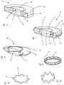
- FIG. 5illustrates an AIOL in which half of the support structure and haptic structures are comprised in an upper and lower half of the AIOL and all fabricated from the same material, in accordance with many embodiments;
- FIG. 6illustrates an AIOL wherein the haptic and support structures are integral and are configured as a toroid like structure, in accordance with many embodiments
- FIG. 7illustrates a variation of the AIOL of FIG. 6 which incorporates features which help to reduce the delivery cross-section, in accordance with many embodiments;
- FIG. 8illustrates an AIOL which comprises an elastomeric support structure filled with a fluid capable of being hardened after delivery of the AIOL, in accordance with many embodiments
- FIGS. 9A, 9B, and 9Cdepict alternate collapsible lens support structures, in accordance with many embodiments.
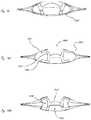
- FIGS. 10 through 14Billustrate alternate AIOL structures where an AIOL is inserted into and interfaced to the natural capsule such that the attachment zones seal a semi toroidal region of capsule, and where fluid transfer between the semi toroidal region and the interior of the AIOL causes an accommodation change in the AIOL, in accordance with many embodiments;
- FIG. 10depicts an AIOL with alternate haptic structures where a fluid chamber is formed by sealing the equatorial and posterior regions of the lens capsule incorporating one optical element, in accordance with many embodiments;
- FIG. 11depicts an AIOL with alternate haptic structures where a fluid chamber is formed by sealing the equatorial and posterior regions of the lens capsule incorporating two optical element, in accordance with many embodiments;
- FIG. 12depicts an AIOL with alternate haptic structures where a fluid chamber is formed by a thin membrane sealing the equatorial and posterior regions of the lens capsule incorporating two optical elements; in accordance with many embodiments;
- FIG. 13depicts an AIOL with alternate haptic structures where a fluid chamber is formed by a thin membrane and by sealing the equatorial and posterior regions of the lens capsule incorporating one optical element, in accordance with many embodiments;
- FIG. 14Aillustrates an alternate embodiment after implantation of the AIOL, in accordance with many embodiments
- FIG. 14Billustrates the installed AIOL of FIG. 14A , post-surgery, where the lens capsule has conformed to the installed device, in accordance with many embodiments;
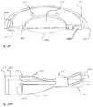
- FIG. 15depicts an optical structure comprising an anterior and posterior surface, in accordance with many embodiments
- FIG. 16Aillustrates a lens support structure joined to an optical structure prior to bonding, in accordance with many embodiments
- FIG. 16Brepresents a final AIOL with points bonded together providing a seal along the perimeter, in accordance with many embodiments
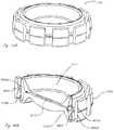
- FIG. 17represents the addition of alternate posterior opacification cell dam and anterior capsulorhexis support to the AIOL of FIG. 16B , in accordance with many embodiments;
- FIG. 18depicts an alternate AIOL, in accordance with many embodiments.
- FIG. 19depicts an alternate optical structure, in accordance with many embodiments.
- FIG. 20is a top sectional view of an AIOL incorporating the optical assembly depicted in FIG. 19 ;
- FIG. 21Ais a lateral sectional view of the AIOL of FIG. 20 ;
- FIG. 21Bis a modeled view of the haptic structure of FIGS. 20-22 under radial and pressure loading associated with forces generated by a capsular structure of the eye, in accordance with many embodiments
- FIG. 22is a view of a final AIOL assembly comprised of elements depicted in FIGS. 19-21 , in accordance with many embodiments;
- FIGS. 23A and 23Billustrate an alternate AIOL embodiment and method of manufacture, in accordance with many embodiments
- FIG. 24depicts an alternate low-profile AIOL with alternate haptics and support structure, in accordance with many embodiments
- FIG. 25Ais a model of the accommodation potential an AIOL similar that that of FIG. 24 , in accordance with many embodiments;
- FIGS. 25B and 25Cshow perspective sectional views of the AIOL of FIG. 25A ;
- FIG. 26shows a model of an AIOL similar to that of FIG. 25A deformed
- FIG. 27shows a model of the accommodation potential of the AIOL of FIG. 24 ;
- FIG. 28Ashows a perspective sectional view of another AIOL, in accordance with many embodiments.
- FIG. 28Bshows a model of the accommodation potential of the AIOL of FIG. 28A ;
- FIG. 29shows a perspective sectional view of yet another AIOL, in accordance with many embodiments.
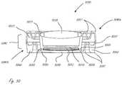
- FIG. 30shows the lenses associated with the AIOL of FIG. 29 ;
- FIG. 31shows a model of the accommodation potential of another AIOL, in accordance with many embodiments.
- FIG. 32shows a model of the accommodation potential of yet another AIOL, in accordance with many embodiments.
- FIG. 33shows a schematic of the accommodation potential of an AIOL, in accordance with many embodiments
- FIG. 34Ashows an AIOL, in accordance with embodiments
- FIG. 34Bshows internal pressure of the AIOL chamber as in FIG. 34A ;
- FIG. 35Ashows an AIOL, in accordance with embodiments
- FIG. 35Bshows internal pressure of the AIOL chamber as in FIG. 35A ;
- FIG. 36shows a method of manufacturing an AIOL, in accordance with many embodiments.
- FIG. 37shows an optical structure deformed to provide optical power
- FIG. 38Ashows an AIOL with an anterior-most portion of the AIOL anterior to the anterior most-portion of the haptic, in which the deflectable member of the AIOL is configured to deflect in response to translational and rotational movement of the haptic, in accordance with embodiments;
- FIG. 38Bshows internal chamber pressure in response to loading of the AIOL as in FIG. 38A ;
- FIG. 39Ashows a perspective view of an intraocular lens, in accordance with embodiments.
- FIG. 39Bshows a cross-sectional view of the intraocular lens of FIG. 39A , in accordance with embodiments;
- FIG. 40Ashows a perspective view of an intraocular lens, in accordance with embodiments.
- FIG. 40Bshows a cross-sectional view of the intraocular lens of FIG. 40A , in accordance with embodiments;
- FIG. 41Ashows a cross-sectional view of an accommodating intraocular lens, in accordance with embodiments
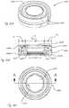
- FIG. 41Bshows a perspective view of a lens component of the intraocular lens of FIG. 41A ;
- FIG. 41Cshows a perspective view of the opposite lens component of the intraocular lens of FIG. 41A ;
- FIG. 42shows a cross-sectional view of an intraocular lens, in accordance with embodiments.
- FIG. 43shows a cross-sectional view of a fluid filled accommodating lens system comprising a bellows structure in accordance with embodiments
- FIG. 44shows a cross-sectional view of an alternate accommodating lens system in accordance with embodiments
- FIG. 45shows a cross-sectional view of an alternate fluid filled accommodating lens system in accordance with embodiments
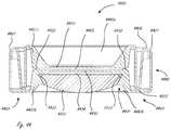
- FIGS. 46A-46Cillustrate an assembly of an alternate AIOL comprising four main parts, in accordance with embodiments
- FIG. 47is a completed assembly as embodied in FIGS. 46A-46C ;
- FIGS. 48A-48Cillustrate an alternate AIOL comprising three main parts, in accordance with embodiments.
- FIGS. 49A-49Billustrate another AIOL comprising three main parts, in accordance with embodiments.
- FIG. 50depicts an alternate AIOL lens system comprising multiple square shaped annular regions edges.
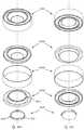
- FIGS. 51A-51CIllustrates an embodiment incorporating a toric lens with indexing features and capsular rotation restraint.
- FIGS. 52A-52CIllustrates an alternate embodiment incorporating a toric lens with indexing features and capsular rotation restraint.
- FIG. 53Depicts an AIOL with capsular rotation restraints, properly positioned within a delivery device.
- FIGS. 54A-54Cpresent an alternate embodiment comprising a mid-bellows stabilizing feature.
- the accommodating intraocular lens (AIOL) as described hereincan be used to provide improved vision, and can be combined with one or more of many known surgical procedures and apparatus, such as cataract surgery and intra-ocular lens inserters.
- the optical structures of the AIOLare well suited for use with commercially available IOL power calculations based on biometry of the eye, and can be used to provide improved vision.
- a physiciancan insert the AIOL as described herein in a manner similar to prior non-accommodating IOLs such that the AIOLs as described herein can be readily used.
- the AIOLcomprises optical structures composed of a soft material, in which the optical structures are coupled to haptics, in order to provide optical power with natural forces of the lens capsule of the eye, as described herein, for example.
- the deflectable membercomprises sufficient radial strength such that a radially inward force to an outer portion of the deflectable member causes deflection of an inner portion of the deflectable member.
- the deflectionmay comprise a first order reversible buckling of the deflectable member, for example.
- the deflectable memberbends such that the inner portion comprises a convex curvature along the outer surface and the outer portion comprises an opposing convex curvature along the outer surface.
- the convex inner portionmay comprise a disc shape and the outer concave portion may comprise an annular shape adjacent the disc shape. The arrangement of convex disc shape and concave annular shape can provide two inflection points across the diameter of the deflectable member, for example.
- the radially extending deflectable membercan be configured in one or more of many ways to provide radial strength in order deflect to at least the inner portion, for example with one or more of a modulus of elasticity, a thickness, or a diameter.
- the deflectable membercan be coupled to the haptics in one or more of many ways so as to deflect when urged radially inward by the haptics engaging the lens capsule.
- the deflectable membercomprises sufficient radial strength to induce shape changes of at least the inner portion when the outer portion of the deflectable member is urged radially inward, rotated, or combinations thereof.
- the deflectable memberis coupled to the lens capsule such that rotation of the haptics relative to the stiff member induces a radially inward movement and rotational deflection of an outer portion of the deflectable member.
- the hapticscan be arranged to slide radially and in relation to the stiff member in order to urge the deflectable member inward with radial force and deflect the inner portion of the deflectable member with radial strength of the outer portion.
- the deflectable membermay comprise one or more structures on the outer portion to encourage deflection, such as a concave outer portion or thinner annular region to encourage concave deflection of the outer portion and convex deflection of the inner portion, for example.
- the present disclosurerelates to devices, methods, and systems associated with an improved accommodating intraocular lens (AIOL).
- AIOLaccommodating intraocular lens
- Some embodimentswill comprise a central optical structure comprised of two deformable lenses spaced apart along their optical axis, such as by a lens support structure concentric with the optical axis of the lenses.
- the volume bounded by the lenses and optionally the lens support structuremay be filled with an ionic solution, such as saline, or non-ionic solutions such as dextran or silicone oil.
- the optical structurein turn may be bounded by one or more haptic structures, the haptic structures being either fluid-filled or of another embodiment, arranged in a plane normal to the optical axis of the lenses.
- the haptic structurescan be in fluid communication with the fluid bounded by the optical structure.
- the transfer of fluid between the haptic structures and the fluid-filled optical structurecan change the accommodating power of the lenses by deforming one or both of the lenses.
- the haptic structuresmay directly exert mechanical forces on the lenses of the fluid-filled optical structure to cause deformation and change accommodating power.
- the improved accommodating intraocular lens systemmay additionally comprise any combination of the features described herein.
- the lenses and some of the support structures described hereinwill typically be fabricated from a hydrophilic material that is optically clear when hydrated, swells on hydration by more than 10%, and accommodates strain levels of greater than 100% when hydrated.
- the materialcan be purchased as small disks and rods.
- the hydrophilic materialmay comprise a copolymer of hydroxyethyl methacrylate (HEMA) and methyl methacrylate (MMA) such as C118, C121, or C126 produced by Contamac Ltd. of the UK.
- HEMAhydroxyethyl methacrylate
- MMAmethyl methacrylate
- any of the intraocular lens systems shown and described hereincan be made from Benz IOL 25 UVXTM material manufactured by Benz Research and Development of Sarasota, Fla.
- PMMArefers to a polymer comprising PMMA or a copolymer comprising PMMA, such as one or more of PMMA polymer (also referred to herein as “poly(methyl methacrylate)”), or a copolymer of HEMA and PMMA such as p(HEMA-co-MMA), for example.
- PMMA polymeralso referred to herein as “poly(methyl methacrylate)”
- p(HEMA-co-MMA)refers to a copolymer of HEMA and PMMA and can also be referred to as p(HEMA-MMA).
- the copolymermay comprise one or more of a block copolymer (PPPP-HHHH), alternating copolymer (PHPHPHPH), statistical or random copolymer (PHPPHPHH), a star copolymer, a brush copolymer, or a graft copolymer, for example, where “P” identifies “MMA” and “H” identifies “HEMA”, for example.
- PPPP-HHHHblock copolymer
- PHPHPHPHalternating copolymer
- PHPPHPHHstatistical or random copolymer
- Pidentifies “MMA”
- Hidentifies “HEMA”, for example.
- components of a hydrogel AIOLmay be fabricated by 3D printing, including but are not limited to any of the following common 3D printing processes: Stereolithography (SLA), Inkjet material jetting (IMJ), Digital Light Processing (DLP), Selective Laser Sintering (SLS), Fused Deposition Modeling, or Fused Filament Fabrication (FDM/FFF).
- SLAStereolithography
- IMJInkjet material jetting
- DLPDigital Light Processing
- SLSSelective Laser Sintering
- FDM/FFFFused Filament Fabrication
- Methods such as SLA, IMJ, and DLPmay be particularly suited to the fabrication of AIOL elements comprised of hydrogels such as PMMA's and copolymers such as HEMA.
- the starting materialmay be monomer or oligomer precursors, or combinations thereof, of the hydrogel polymer.
- One such polymer useful in the fabrication of AIOLs herein describedmay comprise pHEMA, in which the polymerization reaction can be photo initiated by a UV source of appropriate wavelength and duration.
- photo initiationmay be further enhanced by the addition of a photoinitiator compound mixed with the monomers used for printing.
- photoinitiatorscan release additional free radicals on illumination thereby increasing the rate of the polymerization reactions.
- a selection of photoinitiatorsis listed below.
- the complete AIOLmay be fabricated by the 3D printing process and the un-polymerized materials on the inside of the structure removed after completion of the build.
- the un-polymerized materials within the lens structuremay be treated such that reactive end groups are rendered nonreactive such that no further polymerization of that material may take place.
- the AIOL structuresmay be fabricated as subcomponents for later assembly as described elsewhere herein for machined parts.
- a positive curvature of an outer surfaceencompasses a convex curvature and a negative curvature of an outer surface encompasses a concave curvature.
- like reference numeralsrefer to like structures.
- the reference numeralscomprise three or four digits in which the first one or two digits refer to the number of the drawing and the last two digits refer to like structures among figures having different numbers.
- the reference numerals 2503 and 3303refer to similar deflectable members of FIG. 25 and FIG. 33 , respectively.
- the deflectable membercomprises an inner optical portion and an outer extension portion, so as to concentrate and amplify optical power within the inner optical portion.
- the inner optical portioncan move away from the stiff member to comprise a convexly curved outer surface providing an increased optical power.
- the outer portionmay be deflected toward the stiff member so as to comprise an opposite curvature and move toward the stiff member.
- the oppositely curved outer portioncan decrease the diameter of the optically corrective portion in order to concentrate the optical power change within the inner portion.
- the optical power of the inner portionis related to the increased distance of the center of the inner portion from the stiff member, and the decreased distance from the outer extension portion to the stiff member. This combined effect of increased inner separation distance and decreased outer separation distance has a combined effect on increase optical power.
- the optical power of the lenscan decrease approximately as the square of the diameter of the lens
- the decreased diameter of the inner portion provided with the oppositely curved outer portioncan further increase the optical power of the lens.
- the intraocular lens/lens system and/or other components defining the lens chamber or fluid optical elementare filled with a water-based clear fluid with a refractive index higher than water, in order to increase the optical power of the system.
- the high refractive index of the lens chamber liquidmay be caused by the presence of solutes.
- solutesoften comprise large molecules incapable of crossing the chamber defining components. Examples of such large molecules include dextran, with exemplary molecular weights of ⁇ 40 kD, ⁇ 70 kD, ⁇ 500 kD, and ⁇ 1000 kD. Further examples of such solutes include sugar molecules.
- the solutes and watermay compose a diluted solution having an osmolality. Such osmolality may cause the movement of water into or out of the chamber to achieve an osmotic equilibrium volume. Such volume can be adequate to produce the appropriate optical power in the system to the desired power for the patient.
- Each of the accommodating IOLs as described hereincomprises an anterior side and a posterior side.
- a nodal point of the lensis preferably located along an optical axis of the lens at a midpoint located along the optical axis approximately equidistant from the anterior and posterior surfaces of the optical structure of the lens.
- the nodal point of the lensis located away from a plane extending between the peripheral haptic lever structures so as to define an anterior to posterior orientation of the lens.
- the anterior to posterior orientation of the lenscan be reversed by a person of ordinary skill in the art based on the teachings disclosed herein.
- the soft material of the optical structures of the AIOLcan be shaped in one or more of many ways, and may comprise machined components, molded components, or combinations thereof, for example.
- An improved accommodating intraocular lenscan have a reduced delivery cross-section.
- the reduced delivery cross-sectioncan be facilitated by an optical structure capable of translating from a delivery configuration to an operational configuration.
- the optical structuremay have a small dimension along the optical axis in the delivery configuration and larger dimension along the optical axis in operational configuration.
- a lens support structurecan be configured to maintain the distance between the peripheries of the two lenses in the operational configuration and to allow fluid to pass between the haptic structures and the fluid volume bounded by the optical structure in either configuration.
- the delivery cross-sectionmay be attained by folding or rolling the AIOL around a delivery axis normal to the optical axis.
- the delivery cross-sectionmay be measured as the largest dimension in the delivery configuration measured in a plane normal to the delivery axis.
- Delivery cross-sections attainable for the AIOLs disclosed hereinmay be less than 4.5 mm, and preferably less than 2.5 mm.
- the delivery cross-sectioncan be attained by forcing the AIOL through a tube or delivery aperture.
- a tubemay be conical in cross-section such that the AIOL may be compressed as it progresses down the tube.
- the distal endmay be sized to interface with an incision in the eye. Delivery may be facilitated by syringes or plungers.
- the intraocular lens systemmay be comprised of at least two hydrophilic PMMA lenses where PMMA denotes a compound comprising one or more of poly(methyl methacrylate) (PMMA), poly(hydroxyethyl methacrylate) (PHEMA), (Hydroxyethyl)methacrylate (HEMA), or Methyl methacrylate (MMA), for example.
- PMMApoly(methyl methacrylate)
- PHEMApoly(hydroxyethyl methacrylate)
- HEMAHydroxyethyl)methacrylate
- MMAMethyl methacrylate
- the lens systemmay include other elements comprised of any or any combination of the following materials: NiTi, polyurethane, hydrophilic PMMA, photo-activated polymers, precursors to PMMA, Ethylene glycol dimethacrylate (EGDMA), silicones, silicone copolymers, among others.
- Ethylene glycol dimethacrylateEthylene glycol dimeth
- the substantially planar member or the plano-convex membermay comprise a polymeric material.
- the polymeric materialmay comprise a material, for example available from Contamac Ltd. of the UK or Vista Optics Ltd. of the UK.
- the PMMA copolymermay be selected from the list comprising a Definitive 50 material, a Definitive 65 material, a Definitive 74 material, a Filcon V3 material, a Filcon V4 material, a Filcon V5 material, an Optimum Classic material, an Optimum Comfort material, an Optimum Extra material, an Optimum Extra 16 material, an Optimum Extra 18.25 mm material, an Optimum Extra 19 mm material, an Optimum Extra 21 mm material, an Optimum Extreme material, an F2 material, an F2 Low material, an F2 Mid material, an F2 High material, a Focon III 2 material, a Focon III 3 material, a Focon III 4 material, a Hybrid FS
- the polymeric materialmay be one or more of water permeable and hydrophilic. Water present in the lens capsule of the patients eye may transfer into or out of the fluid optical element through the polymeric material to achieve an osmotic equilibrium with fluid present in the lens capsule when the intraocular lens is placed therein.
- the polymeric materialmay be non-permeable to silicone oil.
- the polymeric materialmay be non-permeable to compounds having molecular weights of greater than 40 kDa.
- an AIOLis inserted into and interfaced to the natural capsule such that the interface zones create a seal which forms a semi toroidal region of capsule, where fluid transfer between the semi toroidal region and the interior of the AIOL causes an accommodation change in the AIOL.
- fluidsuch as saline may be injected into the semi toroidal region.
- the optical structureis comprised of a material which is changed from a delivery configuration to an operation configuration after introduction into the capsule of the eye.
- a materialwhich is changed from a delivery configuration to an operation configuration after introduction into the capsule of the eye.
- One such materialmay comprise a photoactive polymer which in the delivery configuration is a liquid which is hardened by photo activation after introduction.
- Another such materialmay comprise a memory metal such as an NiTi alloy which in the delivery configuration has a thin dimension in a plane normal to the optical axis and after introduction is initiated to change to an operational configuration by heating via inductive coupling.
- the NiTimay rely on its super elastic characteristics to shift from a delivery to an operational configuration.
- the optical structurein some embodiments is mechanically more stable in the operational configuration than in the delivery configuration, and spontaneously changes from a delivery configuration to an operational configuration after introduction into the capsule of the eye.
- the optical structuremay be coaxed into a delivery configuration just prior to delivery or at manufacture.
- One such systemmay comprise a super elastic metal element which springs from the delivery configuration upon introduction of the device into the capsule.
- the lens support structure and one lensare machined or molded as a single structure and the second lens is affixed to the support structure by a bonding means.
- the AIOLis comprised of two halves, each incorporating a lens, which are bonded together to form the optical structure. Such embodiments may incorporate the haptic structures.
- a second machining operationcan be performed on the bonded structure.
- Alternate bonding meansmay include mechanical interfaces such as threading where the outer periphery of the lens is threaded and the inner surface of the support structure is threaded. In alternate embodiments, the interface can be a simple interference fit.
- affixingcomprises bonding the materials by treating the one or both of the separate bonding surfaces with a precursor monomer, then assembling the structure, applying a load across the bonding surfaces, and heating the assembly for a period of time.
- a precursor monomermay be mixed with small particles of the polymer.
- Bonding agentsmay additionally include urethanes, silicones, epoxies, and acrylics among others.
- the lensesmay be compromised of a water and ion permeable material.
- the AIOLcan be allowed to self-fill after implantation, thereby minimizing the delivery cross-section.
- the AIOLis filled after implantation.
- FIG. 1illustrates an accommodating intraocular lens (AIOL) system or intraocular lens 10 comprised of a central lens support structure 11 , two haptic structures 12 , two deflectable lenses 13 of which only one is visible in FIG. 1 , and two compression bands 14 .
- the haptics structures 12may comprise thin walled structures configured to deform under minimal loads and comprised of an elastomeric material.
- the internal volume of the AIOL 10can be filled with a clear fluid such as saline of comparable osmolality to that of the fluids in the eye around the lens capsule.
- the AIOL 10can be filled with fluids of high refractive index as described elsewhere herein.
- the lenses 13are interfaced to the support structure 11 such that as fluid transfers from the haptics into the internal volume of the support structure the lenses are caused to deflect thereby changing their accommodative power.
- FIG. 2A side view of the lens support structure 11 of FIG. 1 along with two lenses 13 is illustrated in FIG. 2 .
- the lenses 13may be of the same shape or may have differing shapes.
- the haptic structure interface features 15comprised in the lens support structure 11 .
- the open end of the haptics structures 12are fit over the haptic structure interface features 15 and are further affixed to the lens support structure interface feature 15 using compression bands 14 .
- an adhesive or sealantsuch as silicone may be used.
- a press fitmay be used.
- the haptics 12may be molded onto a haptic interface.
- the haptic 12is molded onto a PMMA barb which is then bonded to the support structure 11 .
- Said bondingmay be by adhesive or facilitating cross linking between the barb and the support structure as described below herein.
- Materials for the haptic structures 12 and haptic structure interfacingmay include any or any combination of silicone, PEBAX, urethane, copolymers of PMMA and silicone, and other elastomeric material.
- the distance between the periphery of the lenses 13may be maintained by the support structure 11 while the center of the lenses are allowed to deflect as the fluid volume within the support structure 11 increases, thereby changing the accommodative power of the structure.
- the haptic structures 12may be fabricated from an extrusion.
- FIG. 3illustrates a lens support structure 31 in which one of the two lenses, first lens 36 , is comprised in or integral with the support structure 31 .
- the second lens, lens 33in the embodiment of FIG. 3 is configured to interface to the support structure 31 via threads 37 .
- a structure 35extends outward to couple the lens body to haptics.
- FIG. 4Another embodiment for a central support structure similar to that shown in FIG. 3 is illustrated in FIG. 4 .
- the second lens 43is interfaced via an interference fit.
- the interference fitmay be further sealed through the use of a sealant or adhesive.
- the interference fitis further facilitated by the procedure used to assemble and rehydrate the components.
- One such procedure as implemented on the support structure 41 shown in FIG. 4is as follows: the bottom of the support structure 41 comprising lens 46 is hydrated, lens 43 in the unhydrated condition is then fitted into the groove comprised in the support structure 41 , the support structure 41 and lenses 43 and 46 are allowed to completely hydrate, and, if required, a sealant or adhesive is then applied.
- the use of interference fitscan minimize the requirement and or amount of bonding agent.
- FIG. 5illustrates another embodiment of an AIOL 50 in which half of the support structure 51 and haptic structures 52 are comprised in an upper and lower half of the AIOL 50 and thereby all fabricated from the same material.
- the two halvesare bonded together at seam 59 to form the complete haptic and support structure 51 .
- Lens 53may either be integral to the half structures or bonded to the support structure 51 . In the manufacturing environment, allowing one lens to be aligned and bonded after the fabrication of the rest of the structure can provide an advantage in assuring the optical axis of the two lenses are precisely aligned.
- the haptic structures 12are configured in such a fashion that they may be folded out and away from the support structure 11 in a plane normal to the optical axis of the lenses. Such a configuration can facilitate a reduction in delivery cross-section for a fluid-filled device.
- the haptic structuresare both integral to the lens support structure and attached continuously around the perimeter of the lens support structure.
- FIG. 6illustrates an embodiment of an AIOL 60 wherein the haptic structure 62 and support structure 61 are integral and are configured as a toroid-like structure; the inner radius of the toroid-like structure comprising the support structure 61 . Fluid may be allowed to flow between the haptic structure 62 and the inner volume of the support structure 61 through openings 67 .
- the AIOL 60can be fabricated by bonding the two halves at seam 69 .
- Lens 63may be integral with the halves or bonded separately to the halves.
- FIG. 7A variation on the embodiment of FIG. 6 is illustrated in FIG. 7 .
- the embodiment of the AIOL 70incorporates features which help to reduce the delivery cross-section.
- Half of the support structuremay be comprised on each the upper and lower halves on the AIOL 70 and may be comprised of a series of structures 71 each separated by a space forming a castellated ring.
- Castellated structurescan be meshed at assembly prior to bonding at seam 79 .
- Spring ring 79 ′can fit in a grove and can lock the upper and lower halves of the structure relative to displacements along the optical axis.
- lenses 73can be integral to the half structures comprising the AIOL 70 . In other embodiments, the lenses 73 may be separate and bonded at another time.
- the support structurecan be capable of greater deformation during delivery as the castellated elements can fold over a greater radius of curvature.
- AIOL 70may also comprise feature 78 , which can allow for a means of applying pressure directly across seam 79 during the bonding process.
- the surfaces which comprise the seammay additionally incorporate chamfers or fillets to direct the flow of bonding agents and minimize the likelihood of creating voids.
- FIG. 8represents an embodiment of an AIOL 80 which comprises an elastomeric support structure 81 filled with a fluid capable of being hardened after delivery of the AIOL.
- a fluidcapable of being hardened after delivery of the AIOL.
- Such fluidsmay be optically cured and may comprise, for example, a UV curing silicone or epoxy, a pH cured fluid such as a collagen solution, or a heat cured fluid where the material comprises a suspension of particle capable of being inductively heated such as magnetite particles.
- Channels 87can allow fluid to pass between the haptic and the central volume of the support structure.
- the support structure 81 of AIOL 80may be replaced with a support structure 91 comprising channel structures 97 as indicated in the expanded configuration of AIOL 80 shown in FIG. 9A , or by support structure 98 as indicated in FIG. 9B and FIG. 9C , which may be comprised of a memory metal which can be flattened to comprise a flattened configuration 99 as indicated in FIG. 9B prior to assembly then heated by inductive coupling allowing it to take an operational configuration after delivery as indicated in FIG. 9C .
- Such a configurationmay provide for a reduced cross-section.
- Embodiments described hereinalso allow for sequencing the assembly and the use of long setting, heat, pressure, and/or optical initiated bonding materials to insure proper optical alignment of the lenses.
- Bonding of a copolymer of HEMA and MMAmay be facilitated by treating the bond surfaces with EGDMA or Triethylene glycol dimethacrylate (TEGDMA) and then subjecting the bonded surfaces to pressure and temperature. Treatments may include but are not limited to vapor treatment, wetting, wetting and allowing for evaporation, applying a mixture of EGDMA or TEGDMA and particles of a copolymer of hydroxyethyl methacrylate and methyl methacrylate. In one such procedure, 40 micron beads of a copolymer of HEMA and MMA can be mixed with EGDMA and used as a bonding agent. Such a bonding scheme can provide advantage in that there can be no or minimal seam and the mechanical properties of the bonded interface have the same mechanical properties as the structure.
- EGDMA or Triethylene glycol dimethacrylateTEGDMA
- Treatmentsmay include but are not limited to vapor treatment, wetting, wetting and allowing for evaporation, applying a mixture of EGDMA
- Delivery proceduresmay vary and will depend on the embodiment of the device.
- a devicein one delivery procedure for an AIOL, which is typically pre-filled with an operating fluid at manufacturing and ready for use, a device can be selected for size and base accommodating power to match the patient's requirements.
- the eyecan be prepared according to standard procedures typical for the instillation of non-accommodating lenses, with the possible exception that the incision may be larger in some embodiments.
- the AIOLmay be loaded into an injector and then injected into the prepared eye capsule.
- the AIOLcan then be adjusted for position.
- the lensmay be filled at the time of surgery.
- fillingcan comprise sizing the AIOL and or setting the base power of the AIOL.
- the devicemay incorporate a filling port which can be sealable by bonding prior to implantation or a port comprising a self-sealing material such as an elastomeric material.
- the AIOLmay be filled after implant, thereby minimizing the delivery cross-section.
- the deviceafter implant, the device may be filled via a filling port as previously described.
- the devicemay be initially be in a less than fully hydrated state and allowed to become fully hydrated after implantation, such as by self-filling with fluids naturally available in the eye.
- the AIOLmay comprise a material in a less than fully hydrated state, such as a fluid element within the AIOL, which can be fully hydrated by fluid from the eye and is inhibited from leaking from the AIOL during the hydration process.
- Such embodimentsmay rely on the permeability to water and small molecules of materials comprised in the AIOL.
- a device properly sized and filled with an appropriate operating fluidtypically a saline solution with an osmolality and ionic balance comparable to the fluids naturally occurring in the eye
- an appropriate operating fluidtypically a saline solution with an osmolality and ionic balance comparable to the fluids naturally occurring in the eye
- an appropriate operating fluidtypically a saline solution with an osmolality and ionic balance comparable to the fluids naturally occurring in the eye
- an appropriate operating fluidtypically a saline solution with an osmolality and ionic balance comparable to the fluids naturally occurring in the eye
- an appropriate operating fluidtypically a saline solution with an osmolality and ionic balance comparable to the fluids naturally occurring in the eye
- the osmolality of the AIOLmay further be adjusted by the incorporation of a molecule too large to diffuse through materials comprising the AIOL at the time of manufacture.
- the equilibrium fill pressure for the AIOLmay be adjusted or set on filling.
- FIG. 10depicts an AIOL with alternate haptic structures where a fluid chamber is formed by sealing the equatorial region of the capsule 1002 at the locations 1004 and 1005 .
- Equatorial chamber 1002can communicate with posterior chamber 1006 by holes 1007 in the structure of the AIOL. Movement of the ciliary body can cause the fluid of chamber 1002 to go in and out of chamber 1006 , deflecting the single optical element 1003 and providing accommodation.
- Chambers 1002 and 1006can be filled either naturally, as with aqueous, or with other fluids such as saline; viscous cohesive fluids may be used to prevent leakage at contact locations 1004 and 1005 .
- Gluemay be applied as a bond to the capsule; fibrogenic mechanisms may be induced; sharp protrusions may be provided at contact points to increase sealing against the capsule by indenting it; anterior contact location 1005 can be provided with means to capture the edge of the capsulorhexis 1001 .
- Optical element 1003can be provided with means of hinging along the edges of the optical area to increase deflection and displacement, and therefore optical power.
- the assemblycould have external envelope with dimensions close to the crystalline, and therefore minimize the chance of capsular contraction.
- the only relevant capsular dimensionmay be its height.
- the systemmay be indifferent to osmotic variations in the aqueous humor.
- the as-cut dimensionscould be in the accommodated geometry.
- FIG. 11shows an alternative AIOL, in accordance with many embodiments, which incorporates two optical element lens system with haptic structures configured to form a fluid chamber by sealing the equatorial and posterior regions of the lens capsule.
- Additional posterior optical element 1101defines the fluid optical element or fluid chamber 1102 and may be provided for optical reasons (e.g., establishing fluid chamber 1102 and providing improved optical accommodation.)
- FIG. 12shows an alternative AIOL, in accordance with many embodiments, which incorporates two optical elements with haptic structures configured to form a fluid chamber by sealing the equatorial and posterior regions of the lens capsule and where a thin membrane 1201 can be attached to the structure to contain the fluid.
- FIG. 13shows an alternative AIOL, in accordance with many embodiments, which has haptic structures configured to form a fluid chamber by sealing the equatorial and posterior regions of the lens capsule incorporating one optical element and where a thin membrane 1301 can be attached to the structure to contain the fluid on a single optical element implementation.
- FIG. 14A and FIG. BIBillustrate an alternate AIOL, in accordance with many embodiments, where a single optical element lens support structure 1401 is uniformly open circumferentially along the perimeter of the device and where said lens support structure is not connected to fluid-filled or other conventional haptics.
- the AIOL deviceis shown in FIG. 14A and FIG. BIB as resting in lens capsule receiving structure or chamber 1405 , and lens support structure 1401 is in contact with the posterior lens capsule at 1402 and is also in contact with the anterior lens capsule at 1403 .
- the devicecan be positioned such that the anterior capsule opening 1404 and lens support structure 1401 may be aligned with the capsulorhexis 1001 in some fashion as to affect a working mechanical seal, described below.
- BIBillustrates the installed AIOL, post-surgery, where the lens capsule has conformed to the installed device and provides the seal required to create chambers 1405 and 1406 for the activation and relief of accommodation in the lens.
- the AIOLcan be inserted into and interfaced to the natural capsule such that the attachment zones seal a semi toroidal region of capsule. Fluid transfer between the semi-toroidal region and the interior of the AIOL can causes an accommodation change in the AIOL, such as a deflection of lens surface 1407 .
- FIGS. 15 through 23Billustrate alternate AIOL embodiment with an emphasis on their manufacture.
- FIG. 15is an optical sub-assembly comprised of anterior lens element 1501 and posterior lens element 1502 .
- Optical fluid channels 1503allow fluid to enter fluid optical element or optical chamber 1504 and the sub-assembly is bonded to lens support structure 1601 at mounting hole 1505 .
- FIG. 16A and FIG. 16Bdepict the optical sub-assembly of FIG. 15 insert molded into lens support structure 1601 and with contact points 1602 and 1603 bonded together at 1604 to complete the AIOL assembly.
- FIG. 17shows a modified embodiment of the aforementioned in FIG. 16 incorporating posterior opacification cell dam 1701 and capsulorhexis support flange 1702 .
- FIG. 18illustrates an AIOL final assembly where optical sub-assembly 1806 is insert molded into lens support structure 1805 with haptic structure 1801 bonded to 1805 at points 1802 and 1803 , creating haptic fluid chamber 1804 .
- This configurationmay alternately incorporate a lens such as that illustrated in FIG. 19 where optical assembly 1901 is bonded, using either solvent or heat, to support structure 1903 at insert posts 1902 .
- the lens system of FIG. 19seals after assembly by hydrating the lens system until it swells approximately 10% thereby resulting in a fluid-tight force-fit.
- FIG. 20is a top view of an AIOL incorporating an optical assembly such as that depicted in FIG. 19 . Insertion and bonding points 2001 are shown. Accommodation can occur when fluid channels 2002 allow transfer of fluid into a central fluid optical element or lens chamber as haptic structures 2003 are compressed by the equatorial perimeter of the lens capsule (not shown). Haptic relief 2004 can provide for minimal circumferential stress during compression and quick recovery to the non-accommodating position when compression is relaxed.
- FIG. 21Ais a lateral sectional view of the AIOL in FIG. 20 indicating points 2101 of minimal deformation in the haptic structure
- FIG. 21Bdepicts the deformations of the haptic structure given physiologically relevant loadings on the haptic structure.
- FIG. 22is an isometric view of the AIOL assembly of FIGS. 20, 21A, and 21B .
- FIG. 23Ais an alternate embodiment and assembly method wherein lens system 2302 is insert molded into haptic structure enclosure 2303 .
- FIG. 23Bshows the completed AIOL assembly with sealed haptic seam 2307 , creating haptic chamber 2308 , and a central fluid optical element or lens chamber 2304 .
- FIG. 24depicts an alternate low-profile AIOL with alternate haptic structures and support structure comprised of the optical structure as described herein, posterior haptic structure 2406 , and anterior haptic structure 2407 .
- the optical structurecan be aligned and secured via mounting to post 2441 and post 2441 can be bonded at point 2401 .
- a haptic seam 2442 at the periphery 2402 of the AIOLcan be bonded to form a seal and create a haptic fluid reservoir 2404 .
- the bonding at point 2401 and the haptic seam 2442can form a fluid-tight seal to prevent fluid from leaking into and/or out of the haptic fluid reservoir 2404 .
- the central optical structuremay comprise an anterior planar member 2403 that may be deflectable and a posterior piano-convex member 2410 that may be resistant to deflection.
- FIGS. 25A to 28B and 31 to 35Bcan be combined so as to include similar or alternative structures as described herein, and combinations thereof, in which the last two digits of the identifying numbers of the figures identify like structures.
- FIG. 25Ashows a model of the accommodation potential of the AIOL similar to that of FIG. 24 .
- the AIOLcomprises an undeflected configuration 2521 for far vision and a deflected configuration 2522 for near vision.
- the AIOLis shown in a non-accommodating configuration with a planar configuration of anterior planar deflectable member 2503 coupled to lever haptic structure 2502 .
- An outer structure of haptic 2502is configured to engage the lens capsule, and may comprise structures to reduce pressure on the capsule as described herein.
- a stiff member 2510may comprise a lens to provide optical power for far vision.
- the deflectable member 2503may comprise a substantially planar member having a substantially constant thickness, for example.
- the deflectable member 2503comprises an inner optical portion and an outer, peripheral extension. The extension extends between the inner optical portion and the rotating haptic structure 2502 . When the inner optical portion comprises the convex deflection, the fluid of the chamber beneath the inner optical portion is shaped to provide an optical correction
- the deflectable member 2503 and stiff member 2510define at least a portion of an inner chamber 2512 .
- the inner chamber 2512comprises a fluid having an index of refraction greater than an index of refraction of an aqueous humor of the eye.
- the internal fluidcomprises a convex lens shape and provides additional optical power.
- the AIOLcomprises a central thickness extending from an outer surface of the stiff member 2510 to an outer surface of the deflectable member 2503 .
- the central thicknessmay comprise a first central thickness 2530 of the AIOL lens in a far vision configuration, and a second central thickness 2531 of the AIOL lens in a near vision configuration.
- the increase in thickness of the lens centrallyis related to the increased optical power of the lens.
- the increased optical power of the lensis also approximately inversely related to a square of the diameter of the central optical portion.
- the extension portioncan decrease the diameter of the optical portion and provide increased optical power for an amount of change between first distance 2530 and second distance 2531 .
- the stiff member 2510is connected to haptic structure 2502 , such that the haptic structure 2502 rotates when the lens accommodates for near vision.
- the haptic structure 2502extends to a first anchor region such as an anchor point (in a similar location to anchor point 2640 shown in FIG. 26 ) about which the haptic rotates relative to the stiff member 2510 .
- the haptic structureextends a distance from the first anchor region to the wall of the lens capsule.
- the haptic structure 2502extends to a second anchor region such as second anchor region or point (in a similar location to anchor region or point 2641 shown in FIG. 26 ).
- the second anchor regioncouples to the deflectable member 2503 in order to induce inward force on the deflectable member.
- the distance from the first region to the outer structure of the haptic engaging the lens capsuleis greater than the distance from the first region to the second region. This difference in distance provides mechanical leverage of the lens capsule forces on the deflectable member 2503 .
- the force of the lens capsule on the deflectable member 2502induces a convex deflection 2524 of the deflectable membrane.
- the extension 2511comprises an opposite concave curvature.
- the extension portionmay comprise an opposite concave curvature
- this curvaturecan be provided in one or more of many ways to decrease visual artifacts.
- the amount of accommodative optical correctioncan be approximately 2 to 10 Diopters, such that the opposite curvature of the extension portion may comprise no patient perceptible optical affect.
- the eyenaturally comprises spherical aberration, and small amounts of aberration may not be perceptible.
- the lenscan be sized such that the pupil covers at least a portion of the oppositely curved concave portion.
- the thickness profile of the extension portion of the deflectable componentcan be thinner to localize the opposing curvature to the thinner outer portion of the deflectable member. Work in relation to embodiments suggests that the substantially planar deflectable member decreases visual artifacts that may occur with internal reflections, for example, although a curved deflectable member can be provided and configured to inhibit visual artifacts related to internal reflections.
- the haptic 2502comprises an outer reservoir coupled to chamber 2512 , and forces of the haptic to the outer reservoir can urge fluid toward the chamber 2512 when the eye accommodates, in addition to inward forces of the haptic 2502 at anchor point 2541 , for example.
- the AIOLs as described hereincan be studied with finite element modeling. While the finite element modeling can be performed in one or more of many ways, in many embodiments, the finite element modeling is performed with known commercially available software such as Abaqus, known to a person of ordinary skill in the art.
- the lenses as described hereincan be modeled with a finite element mesh and known material properties of one or more materials as described herein, and the response of the AIOL to lens capsule forces determined.
- FIGS. 25A to 28B and 31 to 35Bshow responses of an AIOL to forces of the capsular bag in accordance with embodiments.
- FIG. 25Bshows a sectional view of the model from which FIG. 25A was developed.
- the lens or optical structure 2505comprises additional space between the individual lenses and that the posterior and anterior haptic structures 2506 and 2507 incorporate an additional mating surface 2508 .
- the haptic structures 2506 , 2507may be over molded onto the lens or optical structure(s) 2503 .
- the haptic structures 2506 , 2507may be comprised of a thermoplastic or solvent weldable material thereby facilitating the joining of the two halves.
- the features comprising mating surface 2508may also include fluid paths 2509 as shown in FIG. 25C or locating and alignment features not shown.
- the deflection of the deflectable structure or lens 2503may be primarily driven by mechanical forces applied to the peripheral edge of haptic structure 2502 transmitted to the deflectable structure or lens 2503 by the intermediary portion of the haptic structure 2502 . Since the deflectable structure or lens 2503 does not sit directly on the non-deflecting lens 2510 , the deflectable structure or lens 2503 may be allowed to buckle as shown. In such embodiments, the deflection experienced by the deflectable lens or structure 2503 will increase the accommodating power of fluid optical element or lens created between the deflectable structure or lens 2503 and non-deflecting structure or lens 2510 and the volume of the fluid optical element will increase as accommodating power increases. Additional optical fluid may therefore be required and provided from the reservoir comprised in the haptic structure 2502 via channels 2509 .
- FIG. 26represents a variation on the AIOL of FIGS. 25A-25C , wherein the anterior haptic structure 2602 has been stiffened at haptic structure wall 2606 to better couple forces into the deflectable structure 2603 . Forces provided from the equatorial region of the capsular structure of the eye are coupled via the periphery of the haptic structure 2602 creating a moment around flexural point 2611 . The moment produces an outward deflection of deflectable structure 2603 .
- the FIG. 26 AIOLmay include elements similar to those in that of FIGS.
- a stiff member 2610such as a stiff member 2610 , an inner chamber 2612 , a deflected configuration 2622 , a convex deflection 2624 , an inner optical portion 2625 , a first central thickness 2630 , a second central thickness 2631 , an anchor point 2640 , and an anchor point or region 2641 .
- FIG. 27is a representation of the accommodating potential of the AIOL 2700 similar to that of FIG. 24 .
- the AIOLincludes a deflectable structure or anterior lens 2703 , a stiff or non-deflectable member 2710 , and a haptic structure 2702 supporting the deflectable structure 2703 and stiff member 2710 .
- the deflectable member 2703can be located on the anterior portion of the AIOL and the stiff member 2710 can be located on the posterior portion of the AIOL when placed in the eye.
- the haptic wall 2706 of haptic structure 2702is coupled to a haptic reservoir 2707 in fluid communication (e.g., through fluid channels) with a fluid lens structure of inner chamber 2712 of the AIOL.
- Deflections of deflectable member 2703 of the optical structurecan be provided at least in part by fluid pressure created by the deflection of the haptic structure 2702 and haptic wall 2706 .
- the periphery of the haptic structure 2702can be rotated by forces applied to the periphery of the haptic structure 2702 (e.g., inward forces of the capsular structures), causing in turn an inward collapse in the haptic reservoir 2707 thereby increasing the pressure within and transferring fluid from the haptic reservoir 2707 into the fluid lens structure 2712 .
- the increase in volume of fluid lens structure 2712can cause the deflectable member 2703 to move anteriorly relative to the stiff member 2710 , thereby increasing in curvature and increasing the optical power of the eye.
- the rotation of the haptic structure 2702can further cause the deflectable structure 2703 and the stiff member 2710 to move together relative to the haptic structure 2702 in a direction opposite of the direction of rotation to increase the optical power of the eye.
- the AIOL 2700may further include elements similar to those of the AIOLs described in FIGS. 25A-25C and 26 .
- the AIOL 2700may further include a flexural point 2711 , a deflected configuration 2722 , a convex deflection 2724 , an inner optical portion 2725 , a first central thickness 2730 , a second central thickness 2731 , an anchor point 2720 , and an anchor point or region 2741 .
- FIG. 28A and FIG. 28Billustrate a variation on the AIOL of FIG. 25 and FIG. 26 .
- FIG. 28Ashows a half section of the AIOL.
- the AIOLis comprised of an optical or lens structure 2805 , in turn comprised of a deflectable structure or member 2803 , a stiff or non-deflectable lens or member 2810 , and a fluid-filled lens chamber or fluid optical element 2812 .
- the optical or lens structure 2805can be held together by a haptic structure 2802 .
- the haptic structure 2802may comprises an alignment structure 2816 upon which the elements of the AIOL can be stacked during assembly.
- the alignment structure 2816may also comprise alignment posts 2822 and a diaphragm element 2826 .
- the other elementsinclude a spacer 2814 and a cover seal 2815 .
- the materials from which the haptic structure 2802 is comprisedare typically solvent and or heat weldable.
- the spacer element 2814comprises channeling which facilitates fluid communication between the fluid-filled lens chamber 2812 and the haptic reservoir 2813 comprising diaphragm 2826 .
- the fluid-filled lens chamber 2812 and the haptic reservoir 2813may form a closed system such as a sealed reservoir.
- the haptic reservoir 2813is not deformed as by the activation forces applied to the periphery of the haptic structure 2802 .
- Diaphragm element 2826which may be isolated from experiencing direct forces delivered from the capsular structure of the eye, deflects in accommodation of the pressure changes within the fluid-filled lens chamber or fluid optical element 2812 .
- Diaphragm element 2826may be fluidly coupled to the fluid-filled lens chamber 2812 such that an anterior deflection of diaphragm element 2826 , as shown in FIG. 28B , corresponds to an increase in the volume of fluid-filled lens chamber 2812 and a posterior deflection of deflectable structure 2803 .
- Such embodimentsmay have advantage when it is desired to use only the forces generated at the equatorial region of the capsule to mediate accommodation. In such embodiments, pressure in internal lens chamber can be negative.
- 28A-28Bmay further include elements similar to those of the AIOLs described in FIGS. 25A-25C, 26, and 27 such as a flexural point 2811 , an undeflected configuration 2821 , 2821 , a convex deflection 2824 , an inner optical portion 2825 , a first central thickness 2830 , a second central thickness 2831 , an anchor point 2820 , and an anchor point or region 2841 .
- the AIOLwill be assembled when all of its components are in a dry state.
- the optical or lens structuresare comprised of hydrophilic PMMA copolymers
- the systemwill be hydrated at the completion of assembly. When hydrated, the hydrophilic lens components will swell thereby enhancing the sealing of the chambers within the structure.
- FIG. 29shows an embodiment of an AIOL wherein the lens or optical structure is created by over molding a lens 2910 into each of two halves of the AIOL 2906 and 2907 .
- the lensesare the same. In some embodiments, however, it may be desirable that they are different such as when one lens is deflectable and the other not.
- the haptic structure 2902 comprising the haptic fluid chamber 2913can be created on assembly by folding the peripheral element of the structure 2906 and bonding it to a bond surface 2903 .
- the seam 2908may be left un-bonded such as at location 2909 .
- lenses 2910will be displaced and deflected.
- Such structuresmay also provide advantage by minimizing the delivery cross-section, as the upper and lower halves can telescope on each other when the structure is compressed.
- FIG. 30illustrates a lens structure from the AIOL of FIG. 29 incorporating a hole feature 2920 which facilitates fixation of the components of the haptic structure 2902 when the lens is over-molded into a either half of the AIOL structure.
- FIG. 31shows an embodiment of an AIOL 3100 comprising a deflectable member 3103 comprising a concave region 3111 , a stiff or non-deflectable member 3110 , and a fluid-filled chamber 3112 .
- the concave surface of concave member 3111causes an inward deflection of the central portion of the concave region 3111 relative to the stiff or non-deflectable member to produce an outward deflection of deflectable member 3103 relative to the stiff or non-deflectable member into a convex configuration.
- the inward deflection of the concave region 3111is in the anterior direction and the outward deflection of the central portion of the concave member 3111 is in the posterior direction when the AIOL 3100 is placed in the lens capsule, or vice versa in alternative embodiments.
- the concave region 3111has a uniform thickness.
- the AIOL 3100may further include elements similar to those of the AIOLS described above (such as in FIGS.
- 25A-25C, 26, 27, and 28A-28Bsuch as an inner chamber 3112 , a deflected configuration 3122 , a convex deflection 3124 , an inner optical portion 3125 , a first central thickness 3130 , a second central thickness 3131 , an anchor point 3140 , and an anchor point or region 3141 .
- FIG. 32shows an embodiment of an AIOL 3200 comprising a deflectable member 3203 comprising a concave region 3211 , a stiff or non-deflectable member 3210 , a fluid-filled lens chamber 3212 , and a haptic structure comprising a wall 3221 .
- the concave surface of concave member 3211converts a rotation of the haptic and haptic structure wall 3221 relative to stiff member 3210 into an outward deflection of deflectable member 3203 relative to stiff member 3210 , such that a center of the deflectable member 3203 separates from stiff member 3210 as the outer portion of the deflectable member moves toward the stiff member.
- the inward deflection of the concave region 3211is in the anterior direction and the outward deflection of the central portion of the concave member 3211 is in the posterior direction when the AIOL 3200 is placed in the lens capsule, or vice versa in alternative embodiments.
- the concave region 3211thins the remainder of the deflectable member 3203 so as to act as a hinge.
- the concave region 3211may comprise a concave cut-out of an external surface region of the deflectable member 3203 .
- the AIOL 3200may further include elements similar to those of the AIOLs described above (such as in FIGS.
- a deflected configuration 3222such as a deflected configuration 3222 , a convex deflection 3224 , an inner optical portion 3225 , a first central thickness 3230 , a second central thickness 3231 , an anchor point 3240 , and an anchor point or region 3241 .
- FIG. 33shows a schematic of an AIOL in an undeflected configuration 3321 and a deflected configuration 3322 .
- the AIOLcomprises a stiff or non-deflectable member 3310 (e.g., one more convexly curved optical surface), a deflectable member 3303 (e.g., an optical material having a uniform and constant thickness to inhibit distortion) that can be deflected to a deflected configuration 3325 , a fluid-filled chamber 3312 , and a lever or cantilevered haptic structure 3302 .
- the lever structure haptic 3302is connected to the stiff member 3310 at a first anchor point 3340 or region, such as a thin portion near an outer edge of the stiff member 3310 .
- the first anchor point 3340 or regionmay be any point or region along an axis extending though the outer edge of the stiff member 3310 and the perimeter of the lever structure haptic 3302 .
- the perimeter of the lever structure haptic 3302may extend in a direction transverse or normal to an optical axis of the eye.
- the lever structure haptic 3302is also connected to the deflectable member 3303 through a resilient extension 3311 at a second anchor point 3341 or region.
- the resilient extension 3311has a thickness less than the thickness of the deflectable member 3303 .
- the lever structure haptic 3302has a thickness and a length greater than the thickness.
- the length of lever structure haptic 3302can be greater than the distance between the first anchor point 3340 and second anchor point 3341 , such that mechanical leverage (e.g., an inward force from the lens capsule or pressure of the eye) can be applied to the second anchor point 3341 from the end of the lever structure haptic 3302 contacting the lens capsule of the eye.
- mechanical leveragee.g., an inward force from the lens capsule or pressure of the eye
- the rotation of lever structure haptic 3302 about the first anchor point 3340 of stiff member 3310can exert a force on resilient extension 3311 in order to deflect resilient extension 3311 and deflectable member 3303 in opposite directions with opposite curvatures.
- the rotationmay cause resilient extension 3311 to move closer to the stiff member 3310 with an outer concave surface and deflectable member 3303 to separate further away from the stiff member 3310 with a convex outer surface.
- the deflection of deflectable member 3303can involve a transition from a first diameter DI to a second diameter D 2 , the second diameter D 2 being a smaller than the first diameter DI.
- the decrease in diameter sizecan cause a convex deflection 3324 such as a spherical deflection of the deflectable member 3303 away from the stiff member 3310 .
- the convex deflection 3324 of the deflectable member 3303can be characterized by a curvature
- the resilient extension 3311can be characterized by an opposite curvature.
- the curvature of the convex deflection 3324can be the opposite of the curvature of the resilient extension 3311 .
- curvature of the convex deflection 3324may be a positive curvature along an outer surface of the AIOL and the curvature of the extension may comprise a negative curvature along the outer surface of the AIOL.
- the change in diameter of the deflectable member 3303 from DI to D 2may produce a corresponding amplified movement away from the stiff member 3310 , such that the deflection height between a first height 3330 and a second height 3331 is greater than the corresponding change in diameter.
- the positive curvature of the spherical deflectioncan cause the fluid-filled chamber 3312 to assume a more convexly curved profile to change the optical power of the AIOL.
- the change in shape of the fluid-filled chamber 3312can cause an increase in volume and thereby pull fluid into the fluid-filled chamber 3312 , such as from a peripheral reservoir.
- the change in shape of the deflectable member 3303 and fluid chamber 3312may occur without a substantial change in volume of the chamber 3312 .
- the change in the shape of the fluid-filled chamber 3312can cause a redistribution of the internal fluid to change optical power such as by drawing fluid from an outer portion of the chamber 3312 and without drawing fluid from a peripheral reservoir.
- the rotation of the lever structure haptic 3302may cause the deflectable member 3303 and the stiff member 3310 to translate together in the anterior direction relative to the outer edge of the lever structure haptic 3302 when the AIOL is placed in the lens capsule. Such translation may further change the optical power of the eye.
- the separation of the deflectable member 3303 away from the stiff member 3310 , the deflection of the deflectable member 3303 to increase its curvature, and the translation of deflectable member 3303 and the stiff member 3310 together in the anterior directionmay combine to change the optical power of the eye.
- this combinationcan amplify a small contraction in the lens capsule housing the AIOL into a significant change in optical power of the AIOL.
- Such a change in optical powermay be significantly greater than any of one of separation, deflection, and translation motions alone.
- the haptic structures described hereinmay comprise of silicones, urethanes, or other suitable thermoplastics, PMMA and PMMA copolymers. In many embodiments, the haptic structures comprise the same or similar materials as the optical structure.
- FIG. 34Ashows an AIOL in accordance with embodiments.
- the undeflected configuration 3421is shown in dashed lines and the deflected configuration 3422 is shown with solid lines.
- the AIOLcomprises the inner optical portion 3425 and the extension as described herein. Similar structures identified with similar last two digits are identified herein.
- FIG. 34Bshows internal pressure of the AIOL chamber as in FIG. 34A .
- the pressure of the internal chamber 3412is shown to increase with load. This increased pressure with load indicates that both the inward force of the lever haptic structure and internal pressure of the AIOL contribute to the convex deflection 3424 of the inner optical structure 3425 .
- the AIOL of FIGS. 34A-34Bmay further include elements similar to those of the AIOLs described above (such as in FIGS. 25A-25C, 26, 27, 28A-28B, 31, and 32 ), such as a haptic structure 3402 , a deflectable structure or anterior lens 3403 , a stiff member 3410 , a flexural point 3411 , a first central thickness 3430 , a second central thickness 3431 , an anchor point 3440 , and an anchor point or region 3441 .
- elements similar to those of the AIOLs described abovesuch as in FIGS. 25A-25C, 26, 27, 28A-28B, 31, and 32 ), such as a haptic structure 3402 , a deflectable structure or anterior lens 3403 , a stiff member 3410 , a flexural point 3411 , a first central thickness 3430 , a second central thickness 3431 , an anchor point 3440 , and an anchor point or region 3441 .
- FIG. 35Ashows an AIOL in accordance with embodiments.
- the undeflected configuration 3521is shown in dashed lines and the deflected configuration 3522 is shown with solid lines.
- the AIOLcomprises the inner optical portion 3525 and the extension as described herein. Similar structures identified with similar last two digits are identified herein.
- FIG. 35Bshows internal pressure of the AIOL chamber as in FIG. 35A .
- the pressure of the internal chamber 3512is shown to decrease with load.
- This decreased pressure with loadshows that the inward force of the lever haptic structure is capable of providing the convex deflection 3524 of the inner optical structure 3525 .
- this pressure response curveshows that the deflection and change in optical power are the result of mechanically driven inward radial loading as opposed to from pressure from the fluid of the chamber.
- FIG. 35Bshows that the inward force of the lever haptic structure is capable of deflecting deflectable member 3503 with negative pressure of the internal chamber.
- the AIOL of FIGS. 35A-35Bmay further include elements similar to those of the AIOLs described above (such as in FIGS. 25A-25C, 26, 27, 28A-28B, 31, 32, and 34A-34B ), such as a haptic structure 3502 , a deflectable structure or anterior lens 3503 , a stiff member 3510 , a flexural point 3511 , an inner chamber 3512 , a convex deflection 3512 , a first central thickness 3530 , a second central thickness 3531 , an anchor point 3540 , and an anchor point or region 3541 .
- elements similar to those of the AIOLs described abovesuch as in FIGS. 25A-25C, 26, 27, 28A-28B, 31, 32, and 34A-34B ), such as a haptic structure 3502 , a deflectable structure or anterior lens 3503 , a stiff member 3510 , a flexural point 3511 , an inner chamber 3512 , a convex def
- Bondingcan be used to adhere one or more of many AIOL structures as disclosed herein.
- the structurescan be bonded in one or more of many ways as described herein, and the steps, processes and materials can be combined to provide improved bonding of the AIOL structures.
- the bonding of components as described hereincan be used with one or more of many IOL components, can be used with one or more of many IOL materials, can be used with accommodating and non-accommodating IOLs, and can be used with one or more of many AIOLs as described herein, for example.
- the accommodating IOLmay comprise one or more haptics to couple the disc shaped components to the capsular bag in order to change the optical power of the lens in response to deformations of the capsular bag.
- the one or more hapticscomprise chambers fluidically coupled to the chamber comprising the first and second lens components.
- the hapticscan be made of a soft material as described herein, such as an acrylate polymer or a silicone polymer, or combinations thereof, for example.
- bonding stiff, machined polymerthe bonding as disclosed herein can be used with one or more of hydrated polymer, soft hydrated polymer, machined polymer, molded polymer, molded dry polymer, molded stiff polymer, molded soft polymer, or molded hydrated polymer, and combinations thereof, for example.
- the AIOLcomprises a first component and a second component.
- a first componentcomprises a first disc-shaped structure and the second component comprises a second disc-shaped structure.
- An annular structureextends between the first disc shaped structure and the second disc shaped structure to define a chamber containing a fluid having an index of refraction greater than about 1.336, which is the index of refraction of the aqueous humor of the eye.
- the first and second componentscan be bonded to each other at one or more bonding surfaces.
- the location of the bonding surface(s)can be selected to decrease the impact of the bonding surface(s) on the optical properties of the AIOL.
- a bonding surfacecan extend circumferentially around one or more of the annular structure, the first disc shaped component, the second disc shaped component, and combinations thereof.
- the bonding surfaceis located in or near a seam extending circumferentially around the one or more of the annular structure, the first disc shaped component, the second disc shaped component, and combinations thereof, which bonds the components together. Locating the seam away from the optical portions of the first and second components provides improved optical properties.
- the first and second componentsare machined on a lathe to provide rotationally symmetric structures, such as the first disc shaped structure and the second disc shaped structure.
- One or more of the first component or the second componentmay comprise the annular structure prior to bonding the components together.
- One or more annular groovescan be provided on the first component and the second component in order to align optically the first component with the second component.
- One or more portions of the annular grooves, or other shaped groove or grooves,can be used as bonding surfaces for bonding the first and second components together.
- Direct bonding methodscan be used to join the bonding surfaces described herein.
- Direct bonding methodscan advantageously provide a continuous bonded interface having similar material and mechanical properties as the rest of the structure.
- the bonded interfacemay swell similarly to the first and second components of the structure.
- Exemplary direct bonding methodsmay include thermal bonding, solvent bonding, localized welding, or surface modification.
- Thermal bonding of the first and second componentscan involve heating the components (e.g., at or near the bonding surfaces) to a temperature near or above the glass transition temperature of one or both of the components. During the heating process, pressure can be applied to increase the contact forces between the components at the bonding surfaces. The use of suitable temperature and pressure conditions can cause the polymer chains of the components to interdiffuse between the bonding surfaces and entangle with each other, thereby bonding the first and second components together.
- Solvent bondingcan involve applying a suitable solvent to the bonding surfaces of the first and second components.
- the solventcan solvate the polymer chains of the components at the bonding surfaces, thereby increasing chain mobility and interdiffusion between the bonding surfaces.
- solvent bonding of components fabricated from a copolymer of HEMA and MMAmay be facilitated by treating the bond surfaces with a suitable solvent.
- Exemplary solventscan include EGDMA, diethylene glycol dimethacrylate (DEGDMA), triethylene glycol dimethacrylate (TEGDMA), water, methanol, ethanol, acetone, dimethyl sulfoxide, acetonitrile, isopropanol, n-hexanol, ethylene dichloride, methylene dichloride, cydohexane, or suitable combinations thereof.
- the bonding surfacescan be cleaned and then wetted with the solvent.
- the bonding surfacescan be brought into contact with each other and bonded by being subjected to suitable pressure and temperature conditions (e.g., using a press, oven, heated plates, etc.) for a predetermined length of time.
- Localized weldingcan involve the focused application of energy at or near the bonding surfaces to heat and soften the bonding surfaces, thereby bonding the components together.
- Suitable forms of energymay include ultrasonic energy, microwave energy, or infrared energy.
- suitable componentscan be formed in one or more of the components so as to direct the applied energy to the appropriate regions of the bonding surfaces.
- suitable surface modification techniquescan be applied to one or more of the bonding surfaces described herein in order to achieve direct bonding.
- Surface modificationcan involve treating the bonding surfaces in order to increase the surface energies thereof, thus improving surface contact and increasing the extent of polymer chain entanglement between the bonding surfaces.
- the bonding surfacescan be modified by plasma activation, UV exposure, and/or ozone exposure.
- the parameters of the surface modification treatments described hereine.g., treatment time
- the adhesivecan be applied to at least a portion of the bonding surfaces described herein.
- the adhesiveis selected to have similar material and mechanical properties as the first and second components.
- the adhesivemay comprise a prepolymer of the polymer of the components.
- the prepolymermay comprise one or more of a monomer, an oligomer, a partially cured monomer, particles, and nanoparticles of the polymer, for example.
- Such bonding embodimentscan provide advantage in that there is no or a decreased seam—the bonded interface has similar mechanical properties as the structure.
- the adhesivemay swell similarly to the first and second components.
- the adhesivee.g., the prepolymer
- the adhesiveis cured to bond the first and second components together.
- the curing processmay involve the polymerization of one or more constituents of the adhesive using techniques known to one of skill in the art.
- precursor monomers in a prepolymermay be partially or fully polymerized by the addition of an initiator.
- the initiatormay be a photoinitiator such as Irgacure 651 (I651, Ciba-Geigy), or a radical initiator such as 2,2′-azobis(isobutyronitrile), 2,2′-azobis(2,4-dimethylvaleronitrile), dilauroyl peroxide, or bis(4-t-butylcyclohexyl)peroxydicarbonate, for example.
- the monomersare polymerized in the presence of a crosslinking agent.
- the crosslinking agentmay comprise one or more of EGDMA, DEGDMA, or TEGDMA.
- the polymerization of the monomers and crosslinking agentmay form an interpenetrating polymer network (IPN), which may be entangled with the first and second components, thereby joining them together.
- IPNinterpenetrating polymer network
- the bonding surfacescan be activated using suitable activating agents to provide exposed reactive groups, thereby enabling the formation of chemical bonds between the bonding surfaces and the prepolymer and/or crosslinking agent.
- excess reagentscan be removed by rinsing, immersion in a suitable solvent, or other methods known to those of ordinary skill in the art.
- the first and second componentscan be bonded to each other while in the stiff, substantially dry configuration.
- Each of the componentscan be provided in a stiff configuration for machining and bonded together with the adhesive while in a stiff configuration.
- the componentscan be subsequently hydrated.
- the componentscan be bonded while in a partially or fully hydrated configuration.
- the first and second lens componentscomprise a copolymer of hydroxyethyl methacrylate and methyl methacrylate.
- the adhesivecomprises the copolymer of hydroxyethyl methacrylate and methyl methacrylate.
- This configurationcan allow the lens to expand from a stiff less than fully hydrated configuration, to the fully hydrated configuration with substantially swelling and inhibited stress to the components and the adhesive located along the seam.
- the stiff, less than fully hydrated configuration of the polymer materialwill be understood by a person of ordinary skill in the art to comprise a polymer having a sufficiently low amount of water to provide stiffness to the polymer material of the first and second components.
- the less than fully hydrated configurationmay comprise a substantially dry configuration composed of no more than about 5% water, for example 0.2-3% water, such that the polymer material comprises sufficient stiffness for machining the material to optical tolerances as will be readily understood by a person of ordinary skill in the art.
- the polymermay swell to a hydrated state and gradually to a fully hydrated state.
- the polymer in the fully hydrated statemay be composed of about 15% to 30% water, for example, depending on the material selected.
- the polymer in the fully hydrated statemay swell by more than 10%, such as 10% to 15%.
- FIG. 36shows a method 3600 of manufacturing and providing an AIOL.
- a block of polymer material as described hereinis provided.
- the block of materialis cut into a first component 3612 and a second component 3614 .
- the polymer materialcomprises a stiff configuration as described herein.
- the first component 3612 and the second component 3614are shaped into first lens component 3622 and second lens component 3624 of the AIOL.
- the componentscan be shaped in one or more of many ways such as turning on a lathe, cutting, ablation, and other known methods of shaping optical lenses. Alternatively, or in combination, the components may be molded.
- One or more of the components 3622 , 3624comprises a feature 3626 shaped to receive the opposing component (the feature 3626 may comprise an annular groove, for example).
- a channel 3628can be provided to allow fluidic communication with the chamber 3636 of the AIOL. Alternatively, or in combination, the channel 3628 can be formed when the first and second components are bonded together.
- the first and second components 3622 , 3624are bonded together with an adhesive 3632 provided in the feature 3626 .
- the first component 3622 and the second component 3624define a chamber 3636 .
- the adhesive 3632comprises a prepolymer of the polymer of the components 3612 and 3614 .
- the componentsare shown provided from a single block, the polymer material can be provided with separate blocks of material having similar polymer composition.
- a haptic 3638can be affixed to the AIOL 3635 , such that an internal chamber of the IOL is fluidically coupled to the chamber of the haptic.
- the hapticmay comprise a material similar to the AIOL, or a different material.
- the haptic 3638may have a thickness 3639 .
- the AIOLmay comprise an acrylate as described herein and the haptic 3638 may comprise a soft silicon material.
- the hapticmay comprise a soft material inserted into the AIOL when the AIOL comprises a stiff configuration, for example.
- the AIOL in the stiff configurationcomprises a dimension 3634 across, such as a diameter.
- the AIOLmay comprise a thickness 3648 extending between an anterior most portion of the AIOL body and the posterior most portion of the AIOL body.
- the AIOL 3635is hydrated to a substantially hydrated configuration to decrease stiffness, such that the AIOL comprises a soft material.
- the hydrated configurationdimensions of the AIOL increase, and may increase proportionally to each other. In many embodiments, the increase comprises a similar percentage increase along each dimension.
- the amount of hydration in the stiff configurationcomprises a predetermined amount of hydration in order to accurately machine the lens components to an appropriate amount of refractive power when the AIOL comprises the fully hydrated state when implanted in the eye.
- the disc shaped optical structure of the upper component 3622can be flat, or lens shaped, for example.
- the disc shaped optical structure of the lower component 3624can be flat, or lens shaped, for example, such that one or more of the optical structures deforms to provide optical power.
- FIG. 37shows the optical structure deformed with a deflected surface profile in order to provide optical power with a curved spherical surface profile 3700 as described herein.
- the fluid of the AIOLcan be greater than the index of refraction of 1.33 of the aqueous humor in order to provide the increased optical power with curved surface 3700 .
- the optical component 3624may comprise a substantially planar shape providing no significant optical power in a first configuration, and can be deformed to a deflected curved spherical surface profile 3700 that provides optical power for accommodation.
- the polymer and prepolymermay comprise silicone hydrogel materials, for example.
- FIG. 38Ashows an AIOL with an anterior-most portion of the AIOL anterior to the anterior most-portion of the haptic (both shown lower on the page), in which the deflectable member of the AIOL is configured to deflect in response to translational and rotational movement of the haptic.
- the lenscan be placed with an opposite anterior posterior orientation as described herein.
- the deflectable member 3803comprises sufficient radial strength such that a radially inward force to an outer portion of the deflectable member causes deflection of an inner portion of the deflectable member as described herein.
- the deflectable membercan be configured in one or more of many ways to provide radial strength in order deflect to at least the inner portion, for example with one or more of a modulus of elasticity, a thickness, or a diameter.
- the deflectable membercan be coupled to the haptics in one or more of many ways so as to deflect when urged radially inward by the haptics engaging the lens capsule.
- the deflectable membercomprises sufficient radial strength to induce shape changes of at least the inner portion when the outer portion of the deflectable member is urged radially inward, or rotated, and combinations thereof.
- the deflectable memberis coupled to the lens capsule such that rotation of the haptics relative to the stiff member induces a radially inward movement and rotational deflection of an outer portion of the deflectable member.
- the hapticscan be arranged to slide radially and in relation to the stiff member in order to urge the deflectable member inward with radial force and deflect the inner portion of the deflectable member with radial strength of the outer portion.
- the deflectable membermay comprise one or more structures on the outer portion to encourage deflection, such as a concave outer portion or thinner annular region to encourage concave deflection of the outer portion and convex deflection of the inner portion, for example.
- the AIOLcomprises undeflected configuration 3821 for far vision and deflected configuration 3822 for near vision.
- the AIOLis depicted in a non-accommodating configuration with a planar configuration anterior planar deflectable member 3803 coupled to lever haptic structure 3802 .
- An outer structure of haptic 3802is configured to engage the lens capsule, and may comprise structures to reduce pressure on the capsule as described herein.
- a stiff member 3810may comprise a lens to provide optical power for far vision.
- the deflectable member 3803may comprise a substantially planar member having a substantially constant thickness, for example.
- the deflectable member 3803comprises an inner optical portion 3825 and an extension 3811 . Extension 3811 extends between the inner optical portion 3825 and the translating and rotating haptic structure 3802 .
- the inner optical portion 3825comprises the convex deflection 3824
- the fluid of the chamber beneath the inner optical portionis shaped to provide an optical correction for near vision.
- the deflectable member 3803 and stiff member 3810define at least a portion of an inner chamber 3812 as described herein.
- the AIOLcomprises a central thickness extending from an outer surface of the stiff member 3810 to an outer surface of the deflectable member 3803 .
- the central thicknessmay comprise a first central thickness 3830 of the lens in a far vision configuration, and a second central thickness 3831 of the lens in a near vision configuration.
- the increase in thickness of the lens centrallyis related to the increased optical power of the lens.
- the increased optical power of the lensis also approximately inversely related to a square of the diameter of the central optical portion.
- the extension portioncan decrease the diameter of the optical portion and provide increased optical power for an amount of change between first distance 3830 and second distance 3831 .
- the stiff member 3810is connected to haptic structure 3802 , such that the haptic structure 3802 rotates when the lens accommodates for near vision.
- the haptic structure 3802extends to a first anchor region such as an anchor point 3840 about which the haptic translates and rotates relative to the stiff member 3810 .
- the haptic structureextends a distance from the first anchor region to the wall of the lens capsule.
- the haptic structure 3802extends to a second anchor region such as second anchor point 3841 .
- the second anchor region 3841couples to the deflectable member 3803 in order to induce inward force on the deflectable member.
- the distance from the first region to the outer structure of the haptic engaging the lens capsuleis greater than the distance from the first region to the second region.
- this difference in distancecan provide at least some mechanical leverage of the lens capsule forces on the deflectable member 3803 .
- the radial force of the lens capsule on the deflectable member 3803induces a convex deflection 3824 of the deflectable membrane.
- the extension 3811comprises an opposite concave curvature.
- the components of the AIOLsuch as the stiff member, the deflectable member, and the one or more haptics may comprise the same polymer as described herein. These components can have varying amounts of softness and stiffness depending on the thickness, for example.
- the hapticcomprises a thickness so as to reversibly deform at least partially when urging the deflectable member radially inward with one or more of rotation or translation in response to radially inward force from the lens capsule.
- FIG. 38Bshows internal chamber pressure in response to loading of the AIOL as in FIG. 38A .
- the internal pressure of the AIOLincreases approximately linearly with the load of the AIOL.
- the combination of internal pressure and radially inward forcecan deflect the member 3803 to provide optical power when the eye accommodates as described herein.
- the load modeledwas normalized with respect to one or more published maximum load values corresponding to force of lens capsule on the AIOL, which can be readily determined by a person of ordinary skill in the art based on published data.
- the material properties of the AIOL as modeled hereincan be readily determined based on published data for the materials as described herein.
- FIG. 39Ashows an accommodating intraocular lens 3900 .
- the intraocular lens 3900may comprise a central lens region 3904 and a peripheral bellows region 3903 with two bellows 3903 a , 3903 b .
- the intraocular lens 3900may be manufactured in two components, a top half 3900 a and a bottom half 3900 b .
- the material usedmay be compliant, as for example a hydrophilic acrylic or a hydrogel. Other materials can be used Alternatively, or in combination.
- the two halves 3900 a , 3900 bcan be assembled as shown in the FIG. 39B by gluing the top half 3900 a to the bottom half 3900 b at joint 3901 .
- the cavity 3905 between the two halves 3900 a , 3900 bmay be filled with a high refractive index fluid, causing the intraocular lens 3900 to function as a lens.
- a function of the double bellows feature 3903may be to increase the response of the intraocular lens 3900 .
- the outermost part 3903 c of the bellows 3903may interact with the capsular bag of the eye. When the bag exerts pressure on the bellows 3903 , fluid may be displaced from the bellows region 3903 into the central lens cavity. The increased pressure may cause the top lens part 3900 a to deform upwards, changing its radius of curvature and therefore produce power change and accommodation.
- the innermost bellows 3903 amay be adapted so that its outermost wall may be very compliant. Any pressure exerted from the innermost wall of the outermost bellows 3903 b may be translated in fluid displacement out of the innermost bellows 3903 a cavity. In this fashion, if there is an increase in stiffness due to the glue line along the outermost bellows 3903 , the deformation may still be allowed to occur in the innermost bellows 3903 a.
- a line of discrete protrusions, or bumps 3902may be built on the inner surface 3906 b of the bottom half 3900 b as shown in FIG. 39B , or alternatively the inner surface 3906 a of the top half 3900 a .
- the bumps 3902may serve to preserve the gap between the two halves thereby facilitating fabrication.
- any of the features of the intraocular lens 3900may be combined with any of the features of the other intraocular lenses described herein any vice versa.
- FIGS. 40A and 40Bshow an accommodating intraocular lens 4000 .
- the intraocular lens 4000may comprise a central lens region 4004 and a peripheral bellows region 4003 .
- the intraocular lens 4000may be manufactured in two components, a top half 4000 a and a bottom half 4000 b .
- the material usedmay be compliant, as for example a hydrophilic acrylic or a hydrogel. Other materials can be used Alternatively, or in combination.
- the two halves 4000 a , 4000 bmay be assembled as shown in FIG. 40B by gluing the top half 4000 a to the bottom half 4000 b at joint 4001 .
- the cavity 4005 between the two halves 4000 a , 4000 bmay be filled with a high refractive index fluid, causing the intraocular lens 4000 to function as a lens.
- a series of discrete paddles 4002may be built alongside the outermost wall of the bellows 4003 .
- the paddles 4002may transfer the forces to the outermost wall of the bellows 4003 , causing said wall to deform radially inwards. In such manner, fluid may be displaced from the bellows region 4003 into the central lens cavity 4005 .
- the paddles 4002may not be continuous along the circumferential periphery of the intraocular lens 4000 as shown in FIG. 40A to reduce the circumferential and therefore radial stiffness of the assembly or lens 4000 .
- the displaced fluidmay cause an increase in pressure and this pressure increase may causes the top lens part 4000 a to deform upwards, changing its radius of curvature and therefore produce power change and accommodation.
- a line of discrete protrusions, or bumpscould be built on the inner surface 4006 b of the bottom half 4000 b as shown in FIG. 39B , or alternatively the inner surface 4006 a of the top half 4000 a .
- the bumpsmay serve to preserve the gap between the two halves 4000 a , 4000 b thereby facilitating fabrication.
- any of the features of the intraocular lens 4000may be combined with any of the features of the other intraocular lenses described herein and vice versa.
- FIG. 41Ashows an accommodating intraocular lens 4100 .
- An optical axis 4140extends through the central lens region 4104 .
- the intraocular lens 4100may comprise a central lens region 4104 and a peripheral bellows region 4103 with two bellows, for example.
- An annularly-shaped stiff coupling structurecan extend circumferentially around the central lens region 4104 comprising the optical axis.
- the annularly-shaped stiff coupling structuremay comprise a first annularly-shaped stiff coupling structure 4107 a located on the first component, and a second annularly-shaped stiff coupling structure 4107 b located on the second component.
- the two bellowsmay comprise an inner continuous bellow 4103 a and an outer continuous bellow 4103 b in fluid communication with one another.
- the bellowscomprise one or more folds.
- the folds of the bellowshave the advantage of decreasing resistance to the capsular bag as the capsular bag urges inward, and allowing the bellows to move radially outward as the capsular bag expands.
- the foldsmay also provide a very gentle outward force against the capsular bag to improve coupling with the capsular bag.
- biometrysuch as optical coherence tomography to size the bellows region to the capsular bag.
- the bellows region 4103may comprise a first fold 4108 a on the first component and a second fold 4108 b on the second component.
- the first fold 4108 a and the second fold 4108 bcan extend inwardly and toward each other in a direction similar to the optical axis.
- the first fold and the second foldcan extend continuously and circumferentially around the optical axis, for example for 360 degrees around the optical axis. This arrangement of the folds can provide coupling of the lens to the lens capsule with deflection of the folds.
- the bellows regioncan be configured in many ways and comprises one or more folds to allow the outer reservoir to couple to the inner chamber. While two circumferentially extending bellows with a fold extending therebetween are shown, different numbers of bellows such as three or more bellows may be provided, for example.
- the bellows 4103 a , 4103 bmay be continuous along the periphery of the central lens region 4104 .
- the bellows 4103 a , 4103 bmay be annular, elliptical, or rotationally symmetric in shape. Fluid may be present within the continuous inner volumes of the bellows 4103 a , 4103 b .
- the inner bellow 4103 amay be in fluid communication with the central lens region 4104 .
- the stiff coupling structurecan be configured in many ways to inhibit radially inward movement or forces from the bellows region to the central lens region 4104 when the lens capsule urges against the bellows region and transfers fluid from the bellows region into the central lens region 4104 .
- the stiff coupling structuressimilarly inhibit radially outward movement of the central lens region 4104 when the bellows region moves radially outward in response to decreased force of the lens capsule.
- the first annularly-shaped stiff coupling structure 4107 amay comprises a first radial thickness greater than a first thickness of the first bellows region 4103 a
- the second annularly-shaped structure 4107 bmay comprise a second radial thickness greater than the second thickness of the second bellows region 4103 b .
- the stiff coupling structurecan be relatively stiff compared with other structures of the lens such as the folds, the stiff coupling structure can be configured to be one or more of rolled, folded, or compressed for insertion through a small incision in the eye, for example.
- the intraocular lens 4100may be manufactured in many ways, for example with one or more of lathe turning to shape one or more components, molding to form one or more components, or direct fabrication to form one or more component. Alternatively, or in combination, the components can be manufactured with direct fabrication based on a computer model of the lens. The lens components can be fabricated separately or together with direct fabrication. The lens can be fabricated directly as a single piece lens comprising the components described herein.
- the intraocular lensis manufactured in two component pieces, a top component 4100 a and a bottom component 4100 b .
- the material usedmay be compliant, as for example a hydrophilic acrylic or a hydrogel. Other materials can be used Alternatively, or in combination.
- the two components 4100 a , 4100 bcan be assembled as shown in the FIG. 41A by bonding the top component 4100 a to the bottom component 4100 b at joint 4101 .
- the cavity 4105 between the two components 4100 a , 4100 bmay be filled with a high refractive index fluid, providing a deformable fluid space within the intraocular lens 4100 that function as a lens with a variable optical power.
- the peripheral bellows region 4103may comprise a continuous fluid reservoir or chamber defined by a plurality of folds of the top component 4100 a and bottom component 4100 b , with the folds defining the inner bellow 4103 a and outer bellow 4103 b .
- the top and bottom components 4100 a , 4100 bmay be folded inward between the inner and outer bellows 4103 a , 4103 b to define a compliant region between the inner and outer bellows 4103 a , 4103 b .
- This compliant regionmay define one or more fluid channels between the inner and outer bellows 4103 a , 4103 b .
- the fluid channel(s)may be annular, peripheral, or rotationally symmetric in shape much like the inner and outer bellows 4103 a , 4103 b . In the anterior-posterior direction, this compliant region may be thinner than the inner and outer bellows 4103 a , 4103 b.
- the top component 4100 amay comprise a deflectable, planar member 4110 ( FIG. 41C ) and the bottom component 4100 a may comprise a piano-convex member 4120 which may provide optical power ( FIG. 41B ).
- the bottom component 4100 amay comprise a planar member providing substantially no optical power; and, the top component 4100 b may be pre-curved (or in the form of a shell) to provide a shape to the cavity 4105 which may be filled with a refractive fluid to provide the optical power.
- the top component 4100 aWhen placed in the lens capsule, the top component 4100 a may be in the anterior position and the bottom component 4100 b may be in the posterior position. Alternatively, the top component 4100 a may be in the posterior position and the bottom component 4100 b may be in the anterior position.
- a function of the double fold in the multiple bellows feature 4103may be to increase the mechanical response of the intraocular lens 4100 .
- the outermost part 4103 c of the bellows 4103may interact with the capsular bag of the eye.
- fluidWhen the bag exerts pressure on the bellows 4103 , fluid may be displaced from the bellows region 4103 into the central lens cavity 4105 .
- the increased pressure and volume of fluid in the central lens cavity 4105will typically cause the top lens part 4100 a to deform upwards and change its radius of curvature and therefore produce power change and accommodation.
- the planar member 4110may deflect upward and experience a decrease in radius of curvature.
- a separation distance between the two components 4100 a , 4100 bincreases in response to the increased pressure to change the optical power (i.e., the regions of the components 4100 a , 4100 b which define the periphery of central lens region 4104 may separate in the anterior-posterior direction).
- the innermost bellows 4103 amay be adapted so that its outermost wall may be very compliant. A pressure exerted from the innermost wall of the outermost bellows 4103 b resulting from forces applied to the outermost fold in the bellows may be translated in fluid displacement out of the innermost bellows 4103 a cavity. In this fashion, if there is an increase in stiffness due to the bonding line along the outermost bellows 4103 , the deformation may still be allowed to occur in the innermost bellows 4103 a.
- the bellows region 4103can be rotationally symmetric about an optical axis of the lens region in order to facilitate manufacturing.
- the rotationally symmetric structures of the bellowcan be readily turned on a lathe, or formed from a mold that can be readily lathed.
- a plurality of protrusions, or bumps or posts 4102may be radially disposed on the inner surface 4106 b of the bottom component 4100 b as shown in FIG. 41A and FIG. 41B , or alternatively the inner surface 4106 a of the top component 4100 a , and combinations thereof, for example.
- the bumps or posts 4102may serve to preserve the gap between the two components thereby facilitating fabrication.
- the bumps or posts 4102may be bonded to the other component of the intraocular lens 4100 after the top and bottom components 4100 a , 4100 b are brought together.
- the space between adjacent bumps or posts 4102may serve as conduits for fluid between the bellows 4103 and the cavity 4105 .
- the bumps or posts 4102may be free from the other component of the intraocular lens 4100 to minimize non-symmetric deformation of opposing planar member.
- the planar member opposing the bumps or posts 4102may comprise an outer annular region in contact with the bumps or posts 4102 and a deflectable, inner circular region raised and separated from the outer annular region and the bumps or posts 4102 .
- the top and bottom portions 4100 a , 4100 b comprising the top and bottom componentscan be formed in many ways.
- the top and bottom portions 4100 a , 4100 bcan be formed by turning each portion on a lathe or by molding, for example.
- the top and bottom portionseach comprise rotationally symmetric structures such as the bellow and other components as described herein.
- the protrusionscan be formed in many ways.
- the rotationally symmetric componentscan be bonded together to form the lens as disclosed herein.
- the bellows 4103 a , 4103 b as disclosed hereincan provide improved coupling of the fluid reservoir with the lens capsule of the eye.
- the folded structures of the bellows 4103 a , 4103 bcan provide a resilient spring function to the reservoir such that the reservoir can urge gently against the lens capsule and allow the lens capsule to move inward to transfer fluid from the reservoir to the inner lens structure to provide optical power.
- the protrusions 4102can be formed in many ways to provide fluid transfer and separation of the anterior and posterior lens components 4100 a , 4100 b .
- the protrusions 4102can provide discrete protrusions, bumps, or posts.
- the protrusions 4102may comprise portions of an annular structure such as a rim.
- the rimmay have channels cut at least partially into the rim in order to allow fluid transfer.
- the plurality of protrusionscan be separated from each other to define a plurality of channels 4107 defined by the plurality of protrusions in order to fluidically couple the chamber to the reservoir.
- the protrusions 4102can be located away from the optically used portion of the lens 4100 in order to inhibit optical aberrations and artifacts.
- any of the features of the intraocular lens 4100may be combined with any of the features of the other intraocular lenses described herein any vice versa.
- FIG. 42shows a cross-sectional view of an accommodating intraocular lens 4200 , the embodiment of which comprises structures similar to accommodating intraocular lens 4100 .
- First component 4200 amay comprise a deflectable, planar member 4210 and second component 4200 b may comprise a shell member 4220 bounding an optical gel or fluid which may provide optical power.
- First component 4200 a and second component 4200 bare affixed at seam 4201 .
- a plurality of protrusions 4202may be radially disposed on the inner surface 4206 and may serve to preserve the gap between the two components thereby facilitating fabrication.
- Protrusions 4202can define a plurality of channels 4207 to fluidically couple the chamber to the bellows.
- Accommodating intraocular lens 4200is configured such that the chamber 4205 extends into the second component.
- the second componentcan comprise decreased amounts of solid material as compared with lens 4100 , which can facilitate folding, rolling, or compressing lens 4200 into a smaller cross-section in order to configure the lens with a narrow insertion profile in order to fit within a narrow incision of the eye.
- Optical axis 4240extends through the central lens region 4204 of accommodating lens system 4200 ; first component coupling structure 4207 a and second component coupling structure 4207 b extend circumferentially around the central lens region 4204 comprising the optical axis.
- Multiple bellows feature 4203illustrates a double fold bellows configuration comprising innermost bellows 4203 a , outer bellows 4203 b , and outermost bellows region 4203 c .
- Bellows feature 4203may comprise a first fold 4208 a on the first component and a second fold 4208 b on the second component.
- any of the features of the intraocular lens 4200may be combined with any of the features of the other intraocular lenses described herein and vice versa
- FIG. 43illustrates an AIOL system 4300 comprising a fixed lens 4330 (e.g., a fixed-power lens) and an accommodating lens unit having a fluid-filled structure 4340 .
- the fluid-filled structure 4340is related to the structure of AIOL 4200 in operation, but the fluid-filled structure 4340 may have negative base power, no base power or positive base power associated with the structural elements when the AIOL system 4300 is in a relaxed condition (e.g., a state in which external pressure is not applied to the bellows structure 4303 ).
- the fluid-filled structure 4340may include a first component 4340 a (e.g., a first structural element) and a second component 4340 b (e.g., a second structural element) affixed to one another at a seam or joint 4301 using, for example, a glue or bonding agent as described previously herein.
- the joint 4301may be substantially similar to any of the joints or seams described previously herein.
- the joint 4301may extend circumferentially around the first component 4340 a and the second component 4340 b .
- the first component 4340 a and/or the second component 4340 bcan have protrusions 4302 (also referred to herein as posts) located on the inner surface of one or more of the first component 4340 a and the second component 4340 b , and the first and second components 4340 a and 4340 b can optionally be affixed to one another at the protrusions 4302 as well as the joint 4301 .
- the protrusions 4302may be located on a first stiff coupling structure 4307 a of the first component 4340 a and/or a second stiff coupling member 4307 b of the second component 4340 b .
- the protrusions 4302may, for example, provide a gap between the first component 4340 a and the second component 4340 b to separate the first and second components 4340 a , 4340 b as previously described herein.
- the fluid-filled structure 4340may include a chamber 4305 and an outer portion 4308 defining, at least in part, a fluid reservoir 4303 that extends at least partially around the chamber 4305 .
- the fluid reservoir 4303may comprise a continuous baffle structure disposed about a periphery of the fluid chamber 4305 .
- the fluid reservoir 4303can define a bellows region.
- the continuous structure of the fluid reservoir 4303may have an annular, elliptical, and/or rotationally symmetric shape as previously described herein.
- the outer portion 4308 of the fluid-filled structure 4340may be rotationally asymmetric with respect to the optical axis of the AIOL 4300 .
- the fluid reservoir 4303may comprise a haptic structure to engage the lens capsule as previously described herein.
- the fluid-filled structure 4340may contain an optical fluid of relatively high refractive index in the fluid reservoir 4303 and the chamber 4305 .
- the chamber 4305 and the fluid reservoir 4303are in fluid communication with each other such that the optical fluid can flow between the fluid reservoir 4303 and the chamber 4305 in response to forces exerted on the fluid reservoir 4303 .
- the fluid reservoir 4303is more specifically the volume between an inner surface of an outer region of the first component 4340 a and an inner surface of an outer region of the second component 4340 b as previously described herein.
- the fluid reservoir 4303may comprise one or more folds 4309 a , 4309 b that extend continuously circumferentially around an optical axis of one or more of the first and second components 4340 a , 4340 b as previously described herein, and the folds 4309 a , 4309 b may extend towards each other such that the fluid reservoir 4303 comprises a plurality of bellows including an inner bellows and an outer bellows.
- the fluid reservoir 4303may comprise a compliant fold region between inner and outer bellows of the plurality of bellows as previously described herein.
- the chamber 4305may be defined between an inner surface of a first optical component 4310 defined be the inner region of the first component 4340 a and an inner surface of a second optical component 4350 defined by an inner region of the second component 4340 b .
- the first and second optical components 4310 and 4350can be surrounded by the fluid reservoir 4303 .
- the fluid reservoir 4303extends continuously circumferentially around the first and second optical components 4310 and 4350 .
- the protrusions 4302are disposed between the optical components 4310 , 4350 and the fluid reservoir 4303 to define a plurality of fluid channels or conduits between the chamber 4305 and the fluid reservoir 4303 as previously described herein.
- the fluid reservoir 4303 and the chamber 4305are accordingly in fluid communication with each other to change the optical power of the AIOL in response to shape changes of the lens capsule as previously described herein.
- the first stiff coupling region 4307 a and the second stiff coupling region 4307 bmay be configured to inhibit radial movement of the optical components 4310 and 4350 with respect to the outer regions as previously described herein.
- the first and second coupling regions 4307 a - baccordingly maintain the optical integrity of the optical components 4310 , 4350 while forces are exerted against the fluid reservoir 4303 (e.g., the outer circumferences of the optical components 4310 , 4350 are maintained within desired operational dimensions).
- the second component 4340 bmay further comprise an interfacing feature 4331 (e.g., coupling feature), such as a releasable locking feature or capture feature, which can capture (e.g., hold) the fixed lens 4330 such that the fixed lens 4330 may be coupled to the second component 4340 b as illustrated.
- the fixed lens 4330may be coupled to the first component 4340 a instead of the second component 4340 b .
- the periphery of the fixed lens 4330is configured to be within a periphery of the first component 4340 a and/or the second component 4340 b .
- the fixed lens 4330is configured to snap-fit onto the first or second components 4340 a , 4340 b , and in several embodiments the fixed lens 4330 is configured to be releasably attached to either the first component 4340 a or the second component 4340 b.
- the fixed lens 4330 and the first component 4340 a and/or the second component 4340 bmay be configured such that the fixed lens 4330 may be releasably coupled to the first or second components 4340 a , 4340 b in situ within an eye of a patient, such as within a native lens capsule of the eye after the assembled fluid-filled structure 4340 has been placed in the native lens capsule of the eye.
- the second component 4340 bis the anterior component, this enables the fixed lens 4330 to be removed from the accommodating lens unit and replaced by another fixed lens 4330 in situ.
- This featureallows the fixed optical power of the AIOL 4300 to be changed (e.g., adjusted) after the accommodating lens unit has been placed in the native lens capsule and without removing the accommodating lens unit from the native lens capsule.
- the interfacing feature 4331 and/or the fixed lens 4330may be configured such that channels exist to allow body fluids to freely communicate with relief spaces 4334 and 4333 .
- the fixed lens 4330may, for example, have an inner surface facing and adjacent to an outer surface of the first optical component 4310 or the outer surface of the second optical component 4350 of the first or second components 4340 a , 4340 b , respectively, to which the fixed lens 4330 is coupled.
- the fixed lens 4330may for example define a third component of the AIOL system 4300 .
- the fixed lens 4330may have an optical power.
- the optical components 4310 and/or 4350 of the first and/or second components 4340 a , 4340 bmay comprise a planar member.
- the optical components 4310 and/or 4350may be biased to be in a configuration that provides no optical power.
- the first optical component 4310may comprise a deflectable member configured to deflect from a planar shape in a neutral pressure state to a curved shape in response to fluid transfer between the fluid chamber 4305 and the fluid reservoir 4303 . When the fluid reservoir 4303 is compressed and fluid is forced into chamber 4305 , the first optical component 4310 deflects upwards from the planar shape in the neutral state shown in FIG.
- the fluid in the chamber 4305 and the first optical component 4310impart an optical power that changes dynamically based on the compression of the fluid reservoir 4303 .
- Deflection of the first optical component 4310may change the dimensions and/or shape of the fluid chamber 4305 as previously described herein, such as a change in a separation distance between inner surfaces of the optical components 4310 and 4350 , which results in a change in the radius of curvature of the first optical component 4310 .
- the optical power provided by the fluid in the chamber 4305 in combination with the shape of the first optical component 4310may, for example, effectuate a portion of the optical power change of the AIOL system 4300 .
- the second optical component 4350may have a larger cross-section (e.g., thickness) than the first optical component 4310 such that the second optical component 4350 deforms less than first optical component 4310 or even not at all.
- the extent of the deformation of second optical component 4350may be accommodated by the depth of the relief 4334 space between the second lens component 4340 b and the fixed lens 4330 .
- the depth of the relief space 4334is such that the solid surfaces in the optical field may never touch each other.
- One or more of the optical components 4310 and/or 4350may comprise a shell, such as a non-planar shell, as previously described herein.
- the first component 4340 amay comprise an anterior component
- the second component 4340 bmay comprise a posterior component as previously described herein.
- the first component 4340 acan define a posterior component
- the second component 4340 bcan define an anterior component.
- optical components 4310 and 4350are showing in FIG. 43 as planar members, either one may comprise a separate piano-convex member shaped to provide optical power, while the other of the optical components 4310 and 4350 comprises a planar member.
- the optical components 4310 and 4350can be configured as a toric element.
- first and second components 4340 a , 4340 bmay comprise a polymeric material as previously described herein.
- the first and second components 4340 a , 4340 bmay be sufficiently flexible to be folded into a reduced cross-section delivery configuration for delivery to the eye as previously described herein.
- the first and second components 4340 a , 4340 bmay be bonded to each other as previously described herein.
- the first and second components 4340 a , 4340 bmay be fabricated as previously described herein.
- the third componenti.e., fixed lens 4330
- the third componentmay be sufficiently flexible to be folded into a reduced cross-section delivery configuration for delivery to the eye as well, and as described above, may be fixedly (e.g., permanently or releasably) coupled to the first or second components 4340 a , 4340 b in situ.
- the fluidmay comprise any of the fluids previously described herein.
- the fluid in the fluid chamber 4305may provide optical power.
- FIG. 44illustrates an alternate AIOL system 4400 similar to AIOL system 4300 in which the last two digits of the reference numerals identify similar structures.
- the AIOL system 4400differs from the AIOL system 4300 in that the AIOL system 4400 has a second optical component 4450 that is thinner than the second optical component 4350 of the second component 4340 b .
- the second optical component 4450may deform in a fashion which adds an optical power to the accommodating lens compared to the second optical component 4350 of the second component 4340 b , which may be biased to provide no optical power.
- the thinning of the second optical component 4450 within the optical field of viewadditionally may be provided for by the relief 4434 .
- the fluid reservoir 4403also differs from the fluid reservoir 4303 in that the fluid reservoir 4403 may comprise two folds only in one half of the structure of 4440 .
- the outer region of the first component 4440 amay comprise two folds 4408 while the outer region of the second component 4440 b has none (e.g., the anterior half of the fluid reservoir 4403 comprises two folds 4408 ).
- FIG. 45illustrates an AIOL system 4500 , which is similar in structure to the AIOL system 4400 , in which the last two digits of the reference numerals identify similar structures.
- the fluid-filled bellows structure 4503may for example have a rectilinear cross-sectional shape extending circumferentially around the outer portion of the first and second components 4540 a and 4540 b.
- the various peripheral fluid reservoir structures of the AIOLs 4200 , 4300 , 4400 , and 4500may provide a means of controlling the stiffness of the fluid reservoir and thereby the relation between varying accommodation and the forces applied by the eye on the structure as previously described herein.
- FIGS. 46A, 46B and 46Cillustrate yet another embodiment of an AIOL system 4600 similar to the AIOL systems 4300 , 4400 , and 4500 described above, and the last two digits of the reference numerals identify similar structures in FIGS. 43-46C .
- the AIOL 4600may be fabricated of four primary parts including a first component 4640 a , a second component 4640 b , a fixed lens structure 4630 defining the third component, and a thin-walled ring 4640 c defining the fourth component.
- the AIOL 4600includes a fluid reservoir 4603 defined by the thin-walled ring 4640 c and the outer portions of the first and second components 4640 a and 4640 b .
- the thin-walled ring 4640 cmay be affixed to the first component 4640 a and the second component 4640 b at seams or joints 4601 such that the thin-walled ring 4640 c couples the peripheries of the first and second components 4640 a , 4640 b to one another.
- the thin-walled ring 4640 cmay be fabricated of a material with different material properties than the rest of the components of the structure. In some embodiments, the thin-walled ring 4640 c may be fabricated with a version of the polymer used to fabricate the first component 4640 a and second component 4640 b with a reduced modulus of elasticity.
- the thin-walled ring 4640 cmay therefore be more easily fabricated and fabricated with a thinner cross-section than might otherwise be possible.
- the thin-walled ring 4640 ccan be spin cast or centripetally cast, thus allowing for structures even thinner than might be obtainable by machining.
- This particular embodimentis expected to provide good response to the movement of the native anatomy, and in a particular example it provides a larger response to lower pressures.
- the fixed lens structure 4630may for example comprise a convex-concave configuration.
- Haptic-like structures 4635may be used to interlock in an interface feature 4631 .
- a relief 4634may be created by offsetting the haptic-like structures 4635 and the convex surface of the fixed lens 4630 .
- FIG. 47illustrates an AIOL system 4700 which is a variation on the AIOL system 4600 shown in FIGS. 46A-46C .
- various structuresare identified by various reference numerals and the last two digits of the reference numerals identify similar structures to those described above.
- the interfacing zones between the first component 4740 a and the third component 4740 c , and the interfacing zones between a second component, e.g., the second component 4640 b shown in FIGS. 46B and 46C , and the third component 4740 cmay have a plurality of slots 4770 to allow for a less rigid structure.
- the slots 4770may be fabricated in the components of AIOL system 4700 before assembling the fluid-filled structure 4740 , or the slots 4770 may be created after the components have been assembled.
- the slots 4770when added after the structure has been assembled, may be created by one or more of mechanical cutting means, laser cutting, and any other suitable means.
- the slots 4770may be created such that they extend partially down a seam so that a portion of the seam remains uncut and the seal between components of the AIOL remains.
- FIGS. 48A, 48B and 48Cillustrate aspects of an alternate embodiment of an AIOL system 4800 similar to the embodiments of the AIOL systems 4300 , 4400 , 4500 , 4600 and 4700 , described above with reference to FIGS. 43-47 .
- the AIOL system 4800comprises a fixed lens 4830 and a fluid-filled structure 4840 including a first structural element 4840 a and a second structural element 4840 b .
- the first structural element 4840 acan include an inner region defining a first optic component 4810 , an annular stiff coupling region 4807 around the first optic component 4810 , and an outer region 4808 around the stiff coupling region 4807 .
- the stiff coupling region 4807can be an annular wall that performs any of several functions: 1) it isolates the first optic component 4810 from external forces exerted against the outer region 4808 to maintain the optical integrity of the first optic component 4810 , 2) it has a height that forms a cavity 4841 in the space between the fixed lens 4830 and the first optic component 4810 , 3) it maintains a shape at the anterior end to securely hold the fixed lens 4830 in place as the fluid reservoir 4803 deforms, and 4) it defines a set inner boundary of the fluid reservoir 4803 so that optic fluid is directed into the accommodating lens.
- the first and second structural elements 4840 a and 4840 bare bonded together at seam 4801 to define a fluid reservoir 4803 at the outer portion 4808 of the fluid-filled structure 4840 as shown in the cross-section assembly view of FIG. 48A .
- the first structural element 4840 acan be an anterior component facing anteriorly with respect to the native lens capsule such that the cavity 4841 defines an anterior space between the first optic component 4801 and the fixed lens 4830 .
- the second structural element 4840 bcan include a second optic component 4850 .
- the second optic component 4850can be stiffer than the first optic component 4810 .
- the second optic component 4850can be stiff (e.g., rigid) and the first optic component 4810 can be flexible.
- the space 4812 between the first optic component 4810 and the second optic component 4850can be filled with an optical fluid.
- the fluid-filled structure 4840has fluid channels 4849 ( FIG. 48A ) between the fluid reservoir 4830 and the space 4812 between the first and second optic components 4810 and 4850 .
- optical fluidpasses between the fluid reservoir 4830 and the space 4812 in response to forces exerted by the native lens capsule.
- at least the first optic component 4810deflects anteriorly into the cavity 4841 toward the fixed lens 4830 to dynamically change the optical power of the AIOL system 4800 and provide accommodation.
- the optical fluid in the space 4812 and at least the first optic component 4810accordingly define an accommodating lens.
- the first structural element 4840 acan further comprise bonding pins 4855 and the second structural element can further comprise receivers 4856 configured to receive the bonding pins 4855 .
- the bonding pins 4855can project downwardly from the stiff coupling region 4807 of the first structural element 4840 a in the orientation shown in FIG. 48C , and the receivers 4856 can be through holes around the perimeter of the second optic component 4850 .
- the second structural element 4840 bfurther comprises standoffs 4857 which, upon bonding the first and second structural elements 4840 a - b together at the bonding pins 4855 and the receivers 4856 form fluid channels 4849 ( FIG. 48A ) to allow the optical fluid to flow between the fluid reservoir 4803 and the space 4812 between the first and second optic components 4850 .
- the fluid-filled structure 4840can have a square edged annular region 4851 that provides for a barrier to cell migration from the periphery of the native lens capsule to the optical part of lens 4800 . Such cell migration could cause post-surgery opacification of the optical system.
- the fixed lens 4830 shown in FIGS. 48A and 48Bincludes at least one passage 4820 , such as a hole or a cutout (e.g., recess), at the perimeter that allows aqueous fluid in the native lens capsule to pass through the fixed lens 4830 into and out of the cavity 4841 .
- the native aqueous fluid in the cavity 4841passes through the passages 4820 in the fixed lens 4830 in response to the changes in shape of the first optic component 4810 .
- the passages 4820accordingly allow native aqueous fluid to wet the first optic component 4810 so that the first optic component 4810 maintains the desired performance while allowing the first optic component 4810 to deflect anteriorly while a liquid is in the cavity 4841 .
- the fixed lens 4830can be attached to the stiff coupling region 4807 of the first structural element 4840 a at a fixed lens receiver 4831 positioned at or near the anterior portion of the cavity 4841 (detailed in the cross-section of FIG. 48C ).
- the fixed lens receiver 4831 and the fixed lens 4830are configured so that the fixed lens 4830 can be attached to the first structural element 4840 a and removed from the first structural element 4840 a after the fluid-filled structure 4840 has been implanted in the native lens capsule. This is possible because the fixed lens 4830 is attached to the anterior portion of the fluid-filled structure 4840 .
- This designallows for providing the correct fixed lens power needed for the patient at the time of the procedure after the accommodating fluid-filled portion 4840 has been placed in the native lens capsule.
- the fixed lens 4830 and the lens receiver 4831are configured such that the fixed lens 4830 can be removed from the fluid-filled portion in situ, a fixed lens 4830 of one optical power can be replaced with a fixed lens 4830 of a different optical power to adjust the optical power of the fixed lens 4830 in situ.
- This configurationis expected to provide better efficacy because the shape of the accommodating lens unit may not be the same after it is implanted compared to before implantation, and thus the fixed optical power can be determined based on the actual shape and power of the accommodating lens unit after implantation. Also, the patients vision may change over time, and the fixed lens can be changed as the patients prescription changes.
- FIG. 49Ais a top view and FIG. 49B is a cross-sectional side view of an alternate embodiment in which the second structural element 4840 b of the embodiment shown in FIGS. 48A-48C is replaced with a second structural element 4940 b .
- the second structural element 4940 bcomprises a thickened feature 4960 in a portion of the fluid reservoir 4903 .
- the thickened feature 4960is at only one side of the second structural element 4940 b , and the thickened feature 4960 extends around only a portion of the circumference of the second structural element 4940 b .
- the thickened feature 4960provides for a longer material path for use in accessing the interior of the completed assembly via a needle or tubular member for use in delivering a fluid into and removing gases from the interior of the assembly.
- the longer path of the needle through bulk material of 4960provides for more surface area to seal the path when the tubular member is removed possibly eliminating the need for additional sealing measures after removal of a needle.
- the second structural element 4940 balso comprises alternate receivers 4956 defined by recesses as opposed to the through hole receivers 4856 in the embodiment shown in FIG. 48C .
- FIG. 50illustrates yet another embodiment of an AIOL system 5000 similar to the embodiments shown in FIGS. 48A-49B .
- the AIOL system 5000includes a fixed lens 5030 and a fluid-filled unit 5040 having a first structural element 5040 a and a second structural element 5040 b .
- the second structural element 5040 bincludes multiple annular region 5051 with squared outer edges. These four annular regions 5051 incorporated in the posterior and anterior regions of the bellows structures provide additional protection against cell migration associated with posterior capsule opacification.
- the embodiment of the AIOL system 5000additionally incorporates two thickened features 5060 diametrically opposed to each other to allow for fluid inflow and fluid outflow during the filling procedure.
- the first structural element 5040 a of the AIOL system 5000further includes standoffs 5055 that interface with a continuous receiver ring 5056 of the second structural element 5040 b .
- various structuresare identified by various reference numerals and the last two digits of the reference numerals identify similar structures to those described in FIGS. 48A-49B .
- FIGS. 51 and 52illustrate AIOL systems 5100 and 5200 similar to those illustrated in FIGS. 48A-50B in which additional features have been incorporated to enhance performance. Both embodiments comprise features to enhance performance when the AIOL system includes a toric lens.
- the toric lensmay be in either the accommodating portion or the fixed portion. These features primarily minimize rotation of the optical components relative to themselves and or the capsule into which they have been implanted.
- the fixed lens 5130 or 5230are configured to be toric.
- the AIOL systems 5100 and 5200include capsular rotation constraints 5166 ( FIGS. 51A and 51C ) and 5266 ( FIGS. 52A and 52C ), respectively, on the outer periphery to engage the capsule and inhibit rotation of the AIOL systems 5100 and 5300 within the native lens capsule.
- the capsular rotational constraints 5166 and 5266can be thickened portions of the first and/or second structural elements 5140 a - b , 5240 a - b on the outer periphery of the AIOL systems 5100 and 5200 , respectively.
- Alternative embodiments for the capsular rotation constraintscan be any feature that engages the native capsule more securely than other surfaces on the periphery.
- the AIOL systems 5100 or 5200can have only one or more than two capsular rotation restraints 5166 or 5266 .
- the AIOL systems 5100 and 5200can also include features that rotationally maintain the orientation of the fixed lens relative to the accommodating portion of the AIOL system.
- the fixed lens rotational constraint or toric indexing features of the AIOL systems 5100 and 5200provide for this function.
- the fixed lens 5130 of the AIOL system 5100has a plurality of passages 5120 defined by cutouts or holes along the perimeter of the fixed lens 5130 , and one of the passages 5120 defines a receiver 5167 at a location to guide the proper orientation of the fixed lens 5130 with respect to the first structural element 5140 a .
- the first structural element 5140 acomprises a key 5168 at a corresponding radial location to align a toric fixed lens 5130 .
- the receiver 5167 and the key 5168together define a toric indexing feature 5170 .
- the fixed lens 5130can further include a toric indexing mark 5169 on, or in, the fixed lens 5130 that identifies which passage 5120 the receiver 5167 is to be aligned with the key 5168 .
- the key/receiver associated with the correct alignmentcan have a different shape (e.g., triangular) than the other passages 5120 in the lens (e.g., curved).
- FIG. 52illustrates an alternate embodiment in which the receiver 5267 is a cutout or recess in the inner perimeter of the first structural element 5240 a and the toric fixed lens 5230 comprises a key 5268 configured to mate with the receiver 5267 .
- the thickened regions of the capsular rotational constraints 5166 and 5266 of the AIOL systems 5100 and 5200further provide a more robust leading edge for use when delivering the AIOL systems 5100 and 5200 through a narrow bore constriction or tube of an AIOL delivery device as described in copending provisional applications 62/334,998, 62/331,407.
- One of the thickened rotational constraints 5166 and 5266can be positioned to be a leading edge of the AIOL systems 5100 and 5200 and the other a trailing edge as they are passed through the narrow bore or tube of a delivery device.
- the leading portion of the AIOL systems 5100 , 5200can sustain larger pressures as fluid is trapped in the leading section of the AIOL systems during the delivery process after the most distal portion has entered the constricted zone of the delivery tool.
- FIG. 53schematically illustrates how one of the thickened rotational constraints 5166 of the AIOL system 5100 operates in a distal tip of a delivery device 5300 during delivery.
- the AIOL system 5100is shown properly oriented relative to the capsular rotational constraints 5166 and entering the injector tip 5375 for delivery.
- the AIOL system 5100conforms to the delivery tool constrictions while being pushed through the insertion funnel 5376 by the distal end of the plunger 5377 comprising a flexible distal end 5378 . It will be appreciated that the internal pressure of the fluid in the AIOL system 5100 increases as it is compressed in the funnel 5376 .
- the thickened rotational constraint 5166 at the leading edgeprovides more material to withstand the increase in pressure to prevent the front end from rupturing during delivery.
- FIGS. 54A-54Cillustrate an alternative AIOL system 5400 comprising at least one mid-bellows attachment feature 5471 (shown in the cross-sectional views of in FIGS. 54B-54C ).
- the AIOL system 5400is similar to the embodiment of the AIOL system 5200 described above.
- the illustrated embodiment of the AIOL system 5400comprises upper and lower structural elements 5440 a and 5440 b , respectively, that are bonded together at a seam 5401 that defines a bellows region 5403 .
- the AIOL system 5400further comprises a fixed lens 5430 , a first optic component 5410 , a second optic component 5450 , and a space 5412 between the first and second optic components 5410 and 5450 .
- At least one of the first and second optic components 5410 and 5450is deformable (e.g., able to flex anteriorly and/or posteriorly), and in several embodiments the first optic component 5410 is more deformable than the second optic component 5450 .
- the first optic component 5410can be a thin flexible member, while the second optic component 5450 is at least substantially rigid (e.g., does not flex in a manner that changes the optical power).
- the first optic component 5410 and/or the second optic component 5450 in combination with an optical fluid in the space 5412define a fluid accommodating lens.
- the AIOL system 5400also includes (a) thickened features 5460 that facilitate fluid delivery during the filling procedure as described above with respect to features 4960 and (b) a square shaped annular edge 5451 that provides a barrier to cell migration from the periphery of the patients capsule to portions of the AIOL system 5400 within the optical path.
- the mid-bellows attachment features 5471can each comprise upper and lower mating elements 5471 a and 5471 b integrated into the upper and lower structural elements 5440 a and 5440 b , respectively.
- the upper and lower mating elements 5471 a and 5471 bare joined together at a mating region 5472 .
- the mid-bellows attachment features 5471may be distributed circumferentially around the midsection of the bellows structure 5403 at a plurality of discrete locations that are spaced apart from each other.
- the mid-bellows attachment features 5471are evenly distributed at eight spaced apart locations (not shown) around the midsection of the bellows structure 5403 , however the bellows attachment features 5471 are not limited to a specific quantity.
- the mid-bellows attachment features 5471are expected to provide a more efficient transfer of fluid from the bellows structure 5403 to the space 5412 of the accommodating lens. More specifically, without the mid-bellows attachment features 5471 , the apexes of the periphery of the upper and lower structural elements 5404 a and 5404 b tend to separate from each other as pressure increases in the bellows structure 5403 .
- the mid-bellows attachment features 5471limit such undesirable or excessive expansion in the midsection of the bellows structure 5403 during accommodation by inhibiting separation of the apexes of the periphery of the upper and lower structural elements 5404 a and 5404 b .
- the mid-bellows attachment features 5471accordingly stabilize the volume of the midsection of the bellows structure 5403 as fluid flows into the space 5412 , which more efficiently transfers the accommodating fluid from the bellows structure 5403 to the space 5412 of the accommodating lens.
- FIG. 54Billustrates a section through the AIOL system 5400 which passes through two of the mid-bellows attachment features 5471
- FIG. 54Cillustrates a section of the AIOL system 5400 that passes through two spaces between mid-bellows attachment features 5471 that allow fluid to pass from the outer perimeter of the bellows to the space 5412 of the fluid accommodating lens.
- the mid-bellows attachment features 5471are not limited to use in the embodiments of the AIOL system 5400 describe above with reference to FIGS. 54A-54C , but rather may be incorporated into any appropriate embodiment of an AIOL system disclosed herein.
- several of the foregoing AIOL systems with a bellows structurecan incorporate the mid-bellows attachment features 5471 , such as but not limited to, embodiments of the AIOL systems 3900 , 4100 , 4200 , 4300 , 4400 , 4800 , 5000 , 5200 and 5300 .
- Embodiments such as but not limited to any of those illustrated in FIGS. 43 through 54Cmay be constructed from parts in which some or all of the portions not in the optical path XX have been dyed or treated to reduce light throughput to limit the ability of stray light entering portions outside the optical path from scattering into the optical path YY as indicated in FIG. 51B .
- the fixed lens described in any of the embodiments described hereinmay be of spheric, aspheric, toric, or any other known lens configuration.
- the fixed solid lensmay be piano-convex, convex-concave, or convex-convex.
- the fixed lensmay be configured to have positive or have negative fixed power.
- the fluid lenses described hereinmay be configured so as to have one or more accommodating surfaces, for example two accommodating surfaces.
- the optical fluidmay be comprised of a high refractive index poly vinyl alcohol.
- the AIOL devices described in FIGS. 43-54Cmay be implanted in the following fashion.
- the eyemay be prepared and the native lens removed from the capsule in any appropriate manner.
- the fluid-filled structuremay then be placed in the capsule of the eye.
- the patientmay then be evaluated for a base optical power and or astigmatic correction in order to choose a fixed lens.
- the chosen fixed lensmay then be inserted into the previously implanted fluid-filled structure of the AIOL.
- the chosen fixed lensmay then be coupled to the fluid-filled structure within the eye capsule.
- one or more of the fluid-filled structure or fixed lensmay each be flexible such that they may be reconfigured (e.g., folded) to a reduced-profile delivery configuration for delivery into the lens capsule.
- itmay be required to make a further correction to the fixed portion after the time of the surgery. Such instance may occur anywhere from days to years after the surgery.
- the patientmay return to the physician and the fixed lens may be replaced with a new fixed lens having a different optical power or other prescription.
- the new prescriptionmay be characterized prior to or after removal of the original fixed lens.
- the new fixed lensmay be fabricated and implanted at the time of the examination, in others the patient may return for implantation of the fixed lens sometime after the examination.
- the fixed portion of the AIOLmay be fabricated from materials different from the accommodating portion.
- materialsinclude hydrophilic or hydrophobic methacrylate or silicones and any other materials traditionally used in non-accommodating IOL's.
- the fixed lensmay be fabricated from materials harder than those used for the accommodating portion.
- any of the features of the intraocular lens systems described in FIGS. 43-54may be combined with any of the features of the other intraocular lenses described herein and vice versa.
Landscapes
- Health & Medical Sciences (AREA)
- Ophthalmology & Optometry (AREA)
- Cardiology (AREA)
- Oral & Maxillofacial Surgery (AREA)
- Transplantation (AREA)
- Engineering & Computer Science (AREA)
- Biomedical Technology (AREA)
- Heart & Thoracic Surgery (AREA)
- Vascular Medicine (AREA)
- Life Sciences & Earth Sciences (AREA)
- Animal Behavior & Ethology (AREA)
- General Health & Medical Sciences (AREA)
- Public Health (AREA)
- Veterinary Medicine (AREA)
- Physics & Mathematics (AREA)
- Fluid Mechanics (AREA)
- Prostheses (AREA)
Abstract
Description
Claims (12)
Priority Applications (1)
| Application Number | Priority Date | Filing Date | Title |
|---|---|---|---|
| US15/776,380US11141263B2 (en) | 2015-11-18 | 2016-11-15 | Multi-piece accommodating intraocular lens |
Applications Claiming Priority (9)
| Application Number | Priority Date | Filing Date | Title |
|---|---|---|---|
| US201562257087P | 2015-11-18 | 2015-11-18 | |
| US201662300695P | 2016-02-26 | 2016-02-26 | |
| US201662331407P | 2016-05-03 | 2016-05-03 | |
| US201662331946P | 2016-05-04 | 2016-05-04 | |
| US201662334691P | 2016-05-11 | 2016-05-11 | |
| US201662334998P | 2016-05-11 | 2016-05-11 | |
| US201662362896P | 2016-07-15 | 2016-07-15 | |
| US15/776,380US11141263B2 (en) | 2015-11-18 | 2016-11-15 | Multi-piece accommodating intraocular lens |
| PCT/US2016/061977WO2017087358A1 (en) | 2015-11-18 | 2016-11-15 | Multi-piece accommodating intraocular lens |
Related Parent Applications (1)
| Application Number | Title | Priority Date | Filing Date |
|---|---|---|---|
| PCT/US2016/061977A-371-Of-InternationalWO2017087358A1 (en) | 2015-11-18 | 2016-11-15 | Multi-piece accommodating intraocular lens |
Related Child Applications (1)
| Application Number | Title | Priority Date | Filing Date |
|---|---|---|---|
| US17/495,257DivisionUS12376957B2 (en) | 2015-11-18 | 2021-10-06 | Multi-piece accommodating intraocular lens |
Publications (2)
| Publication Number | Publication Date |
|---|---|
| US20200008931A1 US20200008931A1 (en) | 2020-01-09 |
| US11141263B2true US11141263B2 (en) | 2021-10-12 |
Family
ID=69102502
Family Applications (1)
| Application Number | Title | Priority Date | Filing Date |
|---|---|---|---|
| US15/776,380Active2038-01-23US11141263B2 (en) | 2015-11-18 | 2016-11-15 | Multi-piece accommodating intraocular lens |
Country Status (1)
| Country | Link |
|---|---|
| US (1) | US11141263B2 (en) |
Cited By (7)
| Publication number | Priority date | Publication date | Assignee | Title |
|---|---|---|---|---|
| US11464622B2 (en) | 2013-11-01 | 2022-10-11 | Lensgen, Inc. | Two-part accommodating intraocular lens device |
| US11464621B2 (en) | 2014-07-31 | 2022-10-11 | Lensgen, Inc. | Accommodating intraocular lens device |
| US11471270B2 (en) | 2015-12-01 | 2022-10-18 | Lensgen, Inc. | Accommodating intraocular lens device |
| US11540916B2 (en) | 2013-02-14 | 2023-01-03 | Shifamed Holdings, Llc | Accommodating intraocular lens |
| US11583390B2 (en) | 2014-08-26 | 2023-02-21 | Shifamed Holdings, Llc | Accommodating intraocular lens |
| US12167960B2 (en) | 2016-12-23 | 2024-12-17 | Shifamed Holdings, Llc | Multi-piece accommodating intraocular lenses and methods for making and using same |
| US12376958B2 (en) | 2015-11-18 | 2025-08-05 | Shifamed Holdings, Llc | Multi-piece accommodating intraocular lens |
Families Citing this family (9)
| Publication number | Priority date | Publication date | Assignee | Title |
|---|---|---|---|---|
| US10433949B2 (en)* | 2011-11-08 | 2019-10-08 | Powervision, Inc. | Accommodating intraocular lenses |
| US9486311B2 (en) | 2013-02-14 | 2016-11-08 | Shifamed Holdings, Llc | Hydrophilic AIOL with bonding |
| US10856969B2 (en)* | 2016-04-08 | 2020-12-08 | Kowa Company, Ltd. | Toric intraocular lens and intraocular lens insertion apparatus |
| US10350056B2 (en) | 2016-12-23 | 2019-07-16 | Shifamed Holdings, Llc | Multi-piece accommodating intraocular lenses and methods for making and using same |
| WO2019069948A1 (en)* | 2017-10-03 | 2019-04-11 | 株式会社Mirai Eye | Accommodative intraocular lens |
| US11719958B2 (en)* | 2020-02-04 | 2023-08-08 | Valdemar Portney | Multi-chamber switchable optical element |
| WO2023149862A1 (en)* | 2022-02-01 | 2023-08-10 | Carl Zeiss Meditec Ag | Production device and process for producing an intraocular lens blank, intraocular lens blank |
| US12295831B2 (en) | 2023-10-23 | 2025-05-13 | California Institute Of Technology | Liquid accommodating intraocular lens with an asymmetric chamber |
| WO2025090098A1 (en)* | 2023-10-23 | 2025-05-01 | California Institute Of Technology | Liquid Accommodating Intraocular Lens with Suspended Central Lens |
Citations (307)
| Publication number | Priority date | Publication date | Assignee | Title |
|---|---|---|---|---|
| US4440918A (en) | 1982-01-18 | 1984-04-03 | Minnesota Mining And Manufacturing Company | Contact lens containing a fluorinated telechelic polyether |
| JPS59501897A (en) | 1982-09-30 | 1984-11-15 | ミケルソン,ポ−ル イ−. | Permeation means for various physiological applications |
| US4663409A (en) | 1984-12-24 | 1987-05-05 | Bausch & Lomb Incorporated | Alpha, beta-unsaturated carbonyl modified amino acid monomer and polymers for biomedical uses |
| US4709996A (en) | 1982-09-30 | 1987-12-01 | Michelson Paul E | Fluid lens |
| US4731078A (en) | 1985-08-21 | 1988-03-15 | Kingston Technologies Limited Partnership | Intraocular lens |
| US4731080A (en) | 1985-01-18 | 1988-03-15 | Galin Miles A | Coated intraocular lens |
| US4842601A (en) | 1987-05-18 | 1989-06-27 | Smith S Gregory | Accommodating intraocular lens and method of implanting and using same |
| JPH01223970A (en) | 1988-03-02 | 1989-09-07 | Kobe Steel Ltd | Substitute bone |
| US4892543A (en)* | 1989-02-02 | 1990-01-09 | Turley Dana F | Intraocular lens providing accomodation |
| US4932966A (en) | 1988-08-15 | 1990-06-12 | Storz Instrument Company | Accommodating intraocular lens |
| US4932971A (en)* | 1989-06-05 | 1990-06-12 | Kelman Charles D | Clip-on optic assembly |
| WO1990007545A2 (en) | 1988-12-30 | 1990-07-12 | Anderson David M | Stabilized microporous materials and hydrogel materials |
| FR2653325A1 (en) | 1989-10-24 | 1991-04-26 | Dalloz Sa Christian | Intraocular implant, in particular of the intrasaccular type |
| US5074942A (en) | 1990-05-15 | 1991-12-24 | Texceed Corporation | Method for making intraocular lens with integral colored haptics |
| US5211662A (en) | 1989-05-04 | 1993-05-18 | Alcon Laboratories, Inc. | Bicomposite intraocular lenses |
| US5217491A (en) | 1990-12-27 | 1993-06-08 | American Cyanamid Company | Composite intraocular lens |
| EP0604369A1 (en) | 1992-12-23 | 1994-06-29 | Ciba-Geigy Ag | Deposit-resistant contact lenses |
| US5366502A (en)* | 1989-04-28 | 1994-11-22 | Nestle S.A. | Supplementary intraocular lens system |
| US5405386A (en) | 1993-07-09 | 1995-04-11 | Kabi Pharmacia Ophthalmics, Inc. | Intraocular lens with improved cylindrical haptic |
| US5423929A (en) | 1993-10-27 | 1995-06-13 | Allergan, Inc. | Intraocular lenses and methods for producing same |
| WO1995016475A1 (en) | 1993-12-14 | 1995-06-22 | University Of Washington | Polyethylene oxide coated intraocular lens |
| US5489302A (en) | 1994-05-24 | 1996-02-06 | Skottun; Bernt C. | Accommodating intraocular lens |
| WO1996011235A1 (en) | 1994-10-06 | 1996-04-18 | Pharmacia & Upjohn Ab | Intraocular lens materials |
| WO1996020919A1 (en) | 1994-12-30 | 1996-07-11 | Novartis Ag | Functionalised photoinitiators, derivatives and macromers therefrom and their use |
| US5556929A (en) | 1993-09-27 | 1996-09-17 | Menicon Co., Ltd. | Ocular lens material |
| WO1996031791A1 (en) | 1995-04-04 | 1996-10-10 | Novartis Ag | Polysiloxane-comprising perfluoroalkyl ethers, and the preparation and use thereof |
| WO1996036890A1 (en) | 1995-05-19 | 1996-11-21 | Novartis Ag | Polysiloxane-polyol macromers, their preparation and their use |
| US5612391A (en) | 1993-07-02 | 1997-03-18 | Ciba Geigy Corporation | Functionalized photoinitiators, macromers thereof, and the use thereof for contact lens |
| US5620720A (en) | 1994-11-29 | 1997-04-15 | Allergan | Cast molding of intraocular lenses |
| WO1997049740A1 (en) | 1996-06-27 | 1997-12-31 | Novartis Ag | Amphiphilic, segmented copolymer of controlled morphology and ophthalmic devices including contact lenses made therefrom |
| EP0898972A2 (en) | 1997-08-20 | 1999-03-03 | Menicon Co., Ltd. | Soft intraocular lens material |
| US5891931A (en) | 1997-08-07 | 1999-04-06 | Alcon Laboratories, Inc. | Method of preparing foldable high refractive index acrylic ophthalmic device materials |
| WO1999017684A1 (en) | 1997-10-08 | 1999-04-15 | Ras Holding Corporation | Segmented scleral band for treatment of presbyopia and other eye disorders |
| WO1999029818A1 (en) | 1997-12-09 | 1999-06-17 | Biocompatibles Limited | Contact lens cleaning solutions comprising a zwitterionic copolymer |
| US5914355A (en) | 1998-05-15 | 1999-06-22 | Bausch & Lomb Incorporated | Method for making contact lenses having UV absorbing properties |
| US5944753A (en) | 1991-08-16 | 1999-08-31 | Galin; Miles A. | Medicament coated refractive anterior chamber ocular implant |
| US5945465A (en) | 1998-05-15 | 1999-08-31 | Bausch & Lomb Incorporated | Method for polymerizing contact lenses having UV absorbing properties |
| EP0947856A2 (en) | 1998-04-03 | 1999-10-06 | Menicon Co., Ltd. | Ocular lens material |
| WO1999057581A1 (en) | 1998-04-30 | 1999-11-11 | Novartis Ag | Organic articles |
| WO2000004078A1 (en) | 1998-07-17 | 2000-01-27 | Biocompatibles Limited | Method for providing coated moulded polymeric articles |
| EP0989138A2 (en) | 1998-09-21 | 2000-03-29 | Menicon Co., Ltd. | Ocular lens material and process for producing the same |
| WO2000026980A1 (en) | 1998-10-30 | 2000-05-11 | Motorola Inc. | Planar fuel cell |
| WO2000071613A1 (en) | 1999-05-20 | 2000-11-30 | Bausch & Lomb Incorporated | Surface treatment of silicone hydrogel contact lenses comprising hydrophilic polymer chains attached to an intermediate carbon coating |
| WO2001008607A1 (en) | 1999-07-29 | 2001-02-08 | Bausch & Lomb Surgical, Inc. | Intraocular lenses |
| EP1095711A2 (en) | 1999-10-27 | 2001-05-02 | Novartis AG | Process for coating a material surface |
| EP1095965A1 (en) | 1999-10-27 | 2001-05-02 | Novartis AG | Process for the modification of a material surface |
| EP1095966A2 (en) | 1999-10-27 | 2001-05-02 | Novartis AG | Process for the modification of a material surface |
| WO2001030512A2 (en) | 1999-10-27 | 2001-05-03 | Novartis Ag | Coating process |
| WO2001034067A1 (en) | 1999-11-05 | 2001-05-17 | Bausch & Lomb Incorporated. | Intraocular lens system |
| WO2001071392A1 (en) | 2000-03-24 | 2001-09-27 | Novartis Ag | Crosslinkable or polymerizable prepolymers |
| EP1141054A1 (en) | 1998-12-11 | 2001-10-10 | Biocompatibles Ltd. | Crosslinked polymers and refractive devices formed therefrom |
| US20010056165A1 (en) | 1999-04-12 | 2001-12-27 | Surgidev Corporation | Water plasticized high refractive index polymer for ophthalmic applications |
| US20020072795A1 (en) | 2000-12-12 | 2002-06-13 | Green George F. | Durable flexible attachment components for accommodating intraocular lens |
| US20020086160A1 (en) | 2000-08-24 | 2002-07-04 | Yongxing Qiu | Process for surface modifying substrates and modified substrates resulting therefrom |
| EP1223970A1 (en) | 1999-10-13 | 2002-07-24 | Yeda Research And Development Company, Ltd. | Short segments of dap-kinase |
| US20020107568A1 (en) | 2001-01-25 | 2002-08-08 | Gholam-Reza Zadno-Azizi | Accommodating intraocular lens system |
| US6465056B1 (en) | 1999-10-27 | 2002-10-15 | Novartis Ag | Process for coating a material surface |
| WO2002094331A1 (en) | 2001-05-21 | 2002-11-28 | Novartis Ag | Bottle-brush type coatings with entangled hydrophilic polymer |
| WO2003009014A1 (en) | 2001-07-16 | 2003-01-30 | Pharmacia Groningen Bv | Compositions capable of forming hydrogels in the eye |
| US6521352B1 (en) | 1999-10-27 | 2003-02-18 | Novartis Ag | Process for the modification of a material surface |
| US6537316B1 (en) | 1997-12-10 | 2003-03-25 | Staar Surgical Co., Inc. | Frosted haptic intraocular lens |
| US20030074060A1 (en) | 2001-01-25 | 2003-04-17 | Gholam-Reza Zadno-Azizi | Method of preparing an intraocular lens for implantation |
| US20030074061A1 (en) | 2001-01-25 | 2003-04-17 | Hai-Minh Pham | Accommodating intraocular lens system and method of making same |
| US20030078658A1 (en) | 2001-01-25 | 2003-04-24 | Gholam-Reza Zadno-Azizi | Single-piece accomodating intraocular lens system |
| US20030078657A1 (en) | 2001-01-25 | 2003-04-24 | Gholam-Reza Zadno-Azizi | Materials for use in accommodating intraocular lens system |
| US20030078656A1 (en) | 2001-01-25 | 2003-04-24 | Nguyen Tuan Anh | Accommodating intraocular lens system with separation member |
| US20030100666A1 (en) | 2001-07-16 | 2003-05-29 | Degroot Jacqueline Hermina | Compositions capable of forming hydrogels in the eye |
| US6586038B1 (en) | 1999-10-27 | 2003-07-01 | Novartis Ag | Process for the modification of a material surface |
| WO2003066707A1 (en) | 2002-02-08 | 2003-08-14 | Ophtec B.V. | High refractive index flexible silicone |
| US20030158560A1 (en) | 1999-03-22 | 2003-08-21 | Valdemar Portney | Corrective intraocular lens system, intraocular lenses, and lens handling and installation devices for use therewith, and installation method |
| US20030162929A1 (en) | 2002-02-08 | 2003-08-28 | Verbruggen Miriam Adrienne Lambertina | High refractive index flexible silicone |
| EP1364663A1 (en) | 2002-05-21 | 2003-11-26 | Commonwealth Scientific And Industrial Research Organisation | Ocular devices with functionalized surface with adhesive properties |
| US6660035B1 (en) | 2000-08-02 | 2003-12-09 | Advanced Medical Optics, Inc. | Accommodating intraocular lens with suspension structure |
| WO2004010905A2 (en) | 2002-07-25 | 2004-02-05 | Visiogen, Inc. | Intraocular lens system |
| US6695881B2 (en)* | 2002-04-29 | 2004-02-24 | Alcon, Inc. | Accommodative intraocular lens |
| US6713583B2 (en) | 1998-10-29 | 2004-03-30 | Advanced Medical Optics, Inc. | Intraocular lenses made from polymeric compositions |
| US20040082993A1 (en)* | 2002-10-25 | 2004-04-29 | Randall Woods | Capsular intraocular lens implant having a refractive liquid therein |
| US6730123B1 (en) | 2000-06-22 | 2004-05-04 | Proteus Vision, Llc | Adjustable intraocular lens |
| WO2004046768A2 (en) | 2002-11-20 | 2004-06-03 | Powervision | Lens system and method for power adjustment |
| US20040111152A1 (en) | 2002-12-10 | 2004-06-10 | Kelman Charles David | Accommodating multifocal intraocular lens |
| WO2004052242A1 (en) | 2002-12-12 | 2004-06-24 | Powervision | Lens system for power adjustment using micropumps |
| WO2004054471A2 (en) | 2002-12-12 | 2004-07-01 | Powervision | Accommodating intraocular lens system and method |
| WO2004058318A1 (en) | 2002-12-23 | 2004-07-15 | Bausch & Lomb Incorporated | Surface treatment utilizing microwave radiation |
| WO2004072689A2 (en) | 2003-02-06 | 2004-08-26 | Powervision, Incorporated | Adaptive optic lens system and method of use |
| US20040184158A1 (en) | 2002-02-06 | 2004-09-23 | Shadduck John H. | Adaptive optic lens and method of making |
| US6797004B1 (en)* | 2000-03-02 | 2004-09-28 | Advanced Medical Optics, Inc. | Holders for intraocular lenses |
| US6818017B1 (en) | 2001-02-15 | 2004-11-16 | Stephen Shu | High gain wide range accommodating intraocular lens for implant into the capsular bag |
| US20050013842A1 (en) | 2003-07-16 | 2005-01-20 | Yongxing Qiu | Antimicrobial medical devices |
| WO2005023331A2 (en) | 2003-09-04 | 2005-03-17 | The United States Of America As Represented By The Department Of Veterans Affairs | Hydrogel nanocompsites for ophthalmic applications |
| US20050149183A1 (en) | 2001-08-31 | 2005-07-07 | Shadduck John H. | Intraocular lens system and method for power adjustment |
| US20050153055A1 (en) | 2003-12-22 | 2005-07-14 | Bausch & Lomb Incorporated | Surface treatment utilizing supercritical fluid |
| US20060069432A1 (en) | 2004-09-30 | 2006-03-30 | Tran Son T | Intraocular lens system |
| WO2006047383A2 (en) | 2004-10-22 | 2006-05-04 | Powervision | Accomodating intraocular lens system and method |
| US20060100701A1 (en) | 2002-12-12 | 2006-05-11 | Powervision, Inc. | Accommodating intraocular lens having peripherally actuated deflectable surface and method |
| US20060100703A1 (en) | 2004-11-10 | 2006-05-11 | Scott Evans | Method of implanting an intraocular lens |
| US20060116765A1 (en) | 2000-08-04 | 2006-06-01 | Blake Larry W | Refractive corrective lens (RCL) |
| AU2006200142A1 (en) | 2005-01-13 | 2006-07-27 | Minas Theodore Coroneo | Ocular auto-focusing lenses |
| US7097660B2 (en)* | 2001-12-10 | 2006-08-29 | Valdemar Portney | Accommodating intraocular lens |
| EP1353611B1 (en) | 2001-01-25 | 2006-09-06 | Gholam-Reza Zadno-Azizi | Accommodating intraocular lens system |
| WO2006103674A2 (en) | 2005-03-30 | 2006-10-05 | Nulens Ltd | Accommodating intraocular lens (aiol) assemblies, and discrete components therfor |
| US20060241752A1 (en) | 2005-04-20 | 2006-10-26 | Israel Henry M | Accommodating multiple lens assembly |
| WO2006126095A2 (en) | 2005-05-25 | 2006-11-30 | Chemisches Institut Schaefer Ag | Biocompatible polymers and co-polymers comprising amino acids in the side chain |
| WO2007005778A2 (en) | 2005-07-01 | 2007-01-11 | Powervision, Inc. | Accommodating intraocular lens system and method |
| EP1750157A1 (en) | 2004-05-28 | 2007-02-07 | Menicon Co., Ltd. | Contact lens |
| JP2007506516A (en) | 2003-09-24 | 2007-03-22 | ウォーソー・オーソペディック・インコーポレーテッド | Reinforced fusion implant |
| US20070078515A1 (en)* | 2005-09-30 | 2007-04-05 | Brady Daniel G | Deformable intraocular lenses and lens systems |
| US20070088433A1 (en) | 2005-10-17 | 2007-04-19 | Powervision | Accommodating intraocular lens system utilizing direct force transfer from zonules and method of use |
| US20070092830A1 (en) | 2005-10-24 | 2007-04-26 | Bausch & Lomb Incorporated | Polymeric radiation-absorbing materials and ophthalmic devices comprising same |
| US20070106377A1 (en) | 2002-12-12 | 2007-05-10 | Powervision, Inc. | Accommodating intraocular lens system having spherical aberration compensation and method |
| US20070122540A1 (en) | 2005-11-29 | 2007-05-31 | Bausch & Lomb Incorporated | Coatings on ophthalmic lenses |
| JP2007517616A (en) | 2004-01-09 | 2007-07-05 | ウォーソー・オーソペディック・インコーポレーテッド | Split spine device and method |
| US20070201138A1 (en) | 2004-03-31 | 2007-08-30 | Lo Yu-Hwa | Fluidic Adaptive Lens Systems and Methods |
| EP1857477A1 (en) | 2005-03-09 | 2007-11-21 | Hoya Corporation | (meth)acrylate compound, process for production of the compound, (meth)acrylate copolymer, process for production of the copolymer, and soft intraocular lens |
| US20070269488A1 (en) | 2002-11-13 | 2007-11-22 | Nathan Ravi | Hydrogel Nanocompsites for Ophthalmic Applications |
| US20080001318A1 (en) | 2006-06-30 | 2008-01-03 | Derek Schorzman | Polymerizable siloxane-quaternary amine copolymers |
| US20080003261A1 (en) | 2006-06-30 | 2008-01-03 | Derek Schorzman | Fluorinated poly(ether)s end-capped with polymerizable cationic hydrophilic groups |
| US20080003259A1 (en) | 2006-06-30 | 2008-01-03 | Salamone Joseph C | Modification of surfaces of polymeric articles by Michael addition reaction |
| WO2008005752A2 (en) | 2006-06-30 | 2008-01-10 | Bausch & Lomb Incorporated | Modification of surfaces of polymeric articles by michael addition reaction |
| US20080027461A1 (en) | 2006-07-25 | 2008-01-31 | Vaquero Edward A | Intraocular Lens Inserter Plunger |
| WO2008024766A2 (en) | 2006-08-21 | 2008-02-28 | Powervision, Inc. | Intraocular lenses and business methods |
| EP1902737A1 (en) | 2005-07-08 | 2008-03-26 | Menicon Co., Ltd. | Ophthalmic lens, cell or organ culture substrate, container for biological material and transparent gel produced by polymerization of cyclic siloxane compound and process for production thereof |
| US20080076897A1 (en) | 2006-09-27 | 2008-03-27 | Kunzler Jay F | Pendant end-capped low modulus cationic siloxanyls |
| US20080143958A1 (en) | 2006-12-13 | 2008-06-19 | Arturo Norberto Medina | Production of ophthalmic devices based on photo-induced step growth polymerization |
| WO2008077040A2 (en) | 2006-12-19 | 2008-06-26 | Powervision Inc. | Accommodating intraocular lens system having circumferential haptic support and method |
| US20080181931A1 (en) | 2007-01-31 | 2008-07-31 | Yongxing Qiu | Antimicrobial medical devices including silver nanoparticles |
| US7416562B2 (en) | 2002-07-29 | 2008-08-26 | Yosef Gross | Tensioning intraocular lens assembly |
| WO2008103798A2 (en) | 2007-02-21 | 2008-08-28 | Powervision, Inc. | Polymeric materials suitable for ophthalmic devices and methods of manufacture |
| WO2008107882A2 (en) | 2007-03-05 | 2008-09-12 | Nulens Ltd | Unitary accommodating intraocular lenses (aiols) and discrete base members for use therewith |
| US20080234457A1 (en) | 2007-03-22 | 2008-09-25 | Zhou Jian S | Silicone-containing prepolymers with dangling hydrophilic polymer chains |
| WO2008151088A2 (en) | 2007-06-01 | 2008-12-11 | University Of Maryland, Baltimore | Immunoglobulin constant region fc receptor binding agents |
| US20080314767A1 (en) | 2007-06-22 | 2008-12-25 | Bausch & Lomb Incorporated | Ophthalmic Solutions |
| WO2009002789A1 (en) | 2007-06-26 | 2008-12-31 | Bausch & Lomb Incorporated | Intraocular lens injector |
| CN101351169A (en) | 2005-12-07 | 2009-01-21 | C&C影像国际有限公司 | Hydraulic accommodating intraocular lens |
| WO2009015226A2 (en) | 2007-07-23 | 2009-01-29 | Powervision, Inc. | Accommodating intraocular lenses and methods of use |
| WO2009015161A2 (en) | 2007-07-23 | 2009-01-29 | Powervision, Inc. | Lens material with uv initiator and uv absorber and methods of curing with uv light |
| WO2009015240A2 (en) | 2007-07-23 | 2009-01-29 | Powervision, Inc. | Lens delivery system |
| WO2009015234A2 (en) | 2007-07-23 | 2009-01-29 | Powervision, Inc. | Post-implant lens power modification |
| US20090043384A1 (en)* | 2005-09-28 | 2009-02-12 | Kowa Company, Ltd. | Intraocular lens |
| US20090076603A1 (en) | 2007-09-18 | 2009-03-19 | Advanced Medical Optics, Inc. | Partial coating of intraocular lenses using atmospheric pressure chemcial vapor deposition |
| US20090118739A1 (en) | 2002-07-26 | 2009-05-07 | Advanced Medical Optics, Inc. | Method and Device for Manipulation of an Intraocular Lens |
| US20090143499A1 (en) | 2007-11-30 | 2009-06-04 | Frank Chang | Actinically-crosslinkable silicone-containing block copolymers |
| US20090171459A1 (en) | 2007-12-27 | 2009-07-02 | Linhardt Jeffrey G | Coating solutions comprising segmented reactive block copolymers |
| US20090170976A1 (en) | 2007-12-28 | 2009-07-02 | Far Eastern Textile Ltd. | Polysiloxane-based prepolymer and hydrogel |
| US7557231B2 (en) | 2006-06-30 | 2009-07-07 | Bausch & Lomb Incorporated | Carboxylic tris-like siloxanyl monomers |
| WO2009085756A1 (en) | 2007-12-27 | 2009-07-09 | Bausch & Lomb Incorporated | Coating solutions comprising segmented interactive block copolymers |
| WO2009085755A1 (en) | 2007-12-27 | 2009-07-09 | Bausch & Lomb Incorporated | Coating solutions comprising segmented reactive block copolymers |
| US20090204210A1 (en) | 2005-11-21 | 2009-08-13 | Joel Pynson | Accommodative Intraocular Lens |
| US7591849B2 (en) | 2005-07-01 | 2009-09-22 | Bausch & Lomb Incorpoted | Multi-component accommodative intraocular lens with compressible haptic |
| US20090247661A1 (en) | 2005-12-01 | 2009-10-01 | Coronis Gmbh | Polymer composition having a high refractive index |
| US7601766B2 (en) | 2006-06-30 | 2009-10-13 | Bausch & Lomb Incorporated | Carboxylic siloxanyl monomers with pendant polymerizable groups |
| WO2009127844A2 (en) | 2008-04-18 | 2009-10-22 | Aston University | Intervertebral disc and intraocular lens |
| US20090292355A1 (en) | 2008-01-03 | 2009-11-26 | Stephen Boyd | Intraocular, accommodating lens and methods of use |
| US20100016964A1 (en)* | 2007-01-29 | 2010-01-21 | Werblin Research & Development Corp. | Intraocular lens system |
| US20100120939A1 (en) | 2008-11-13 | 2010-05-13 | John Christopher Phelan | Silicone hydrogel materials with chemically bound wetting agents |
| US20100120938A1 (en) | 2008-11-13 | 2010-05-13 | John Christopher Phelan | Polysiloxane copolymers with terminal hydrophilic polymer chains |
| JP2010517639A (en) | 2007-02-02 | 2010-05-27 | キー メディカル テクノロジーズ インコーポレイテッド | Interfacial refraction adjusting lens (IRAL) |
| US20100160482A1 (en) | 2008-12-18 | 2010-06-24 | Juergen Nachbaur | Ophthalmologic Composition And Ophthalmologic Lens |
| US20100179653A1 (en) | 2009-01-09 | 2010-07-15 | Claudio Argento | Intraocular Lenses and Methods of Accounting for Capsule Size Variability and Post-Implant Changes in the Eye |
| CA2752046A1 (en) | 2009-02-13 | 2010-08-19 | Visiogen, Inc. | Copolymers for intraocular lens systems |
| US7781558B2 (en) | 2006-09-27 | 2010-08-24 | Bausch & Lomb Incorporated | Hydrophilic siloxanyl monomers with pendant polymerizable groups |
| US7806929B2 (en) | 2004-08-27 | 2010-10-05 | Brown David C | Intracapsular pseudophakic device |
| US7806930B2 (en) | 2004-08-27 | 2010-10-05 | Brown David C | Device for attachment to a capsule in an eye |
| US7842087B2 (en) | 2004-04-29 | 2010-11-30 | Nulens Ltd. | Accommodating intraocular lens assemblies and accommodation measurement implant |
| WO2011005937A2 (en) | 2009-07-09 | 2011-01-13 | Bausch & Lomb Incorporated | Mono ethylenically unsaturated polymerizable group containing polycarbosiloxane monomers |
| US20110046332A1 (en) | 2008-06-12 | 2011-02-24 | Evonik Roehm Gmbh | Hydrogel based on copolymers containing silicone |
| WO2011026068A2 (en) | 2009-08-31 | 2011-03-03 | Powervision, Inc. | Lens capsule size estimation |
| US20110112636A1 (en)* | 2008-07-24 | 2011-05-12 | Joshua Ben Nun | Accommodating Intraocular Lens (AIOL) Capsules |
| US20110118834A1 (en) | 2004-03-31 | 2011-05-19 | Yuhwa Lo | Fluidic intraocular lens systems and methods |
| US20110133350A1 (en) | 2009-12-07 | 2011-06-09 | Yongxing Qiu | Methods for increasing the ion permeability of contact lenses |
| US20110140292A1 (en) | 2009-12-14 | 2011-06-16 | Frank Chang | Methods for making silicone hydrogel lenses from water-based lens formulations |
| WO2011106435A2 (en) | 2010-02-23 | 2011-09-01 | Powervision, Inc. | Fluid for accommodating intraocular lenses |
| US8034107B2 (en) | 2005-09-01 | 2011-10-11 | Stenger Donald C | Accommodating intraocular lens |
| US8048155B2 (en) | 2002-02-02 | 2011-11-01 | Powervision, Inc. | Intraocular implant devices |
| US20110295368A1 (en) | 2009-02-08 | 2011-12-01 | Nir Betser | Accommodative intraocular lens assembly |
| WO2012006616A2 (en) | 2010-07-09 | 2012-01-12 | Powervision, Inc. | Intraocular lens delivery devices and methods of use |
| US20120023869A1 (en) | 2010-07-30 | 2012-02-02 | Samuel Newton T | Method for making uv-absorbing ophthalmic lenses |
| US20120033183A1 (en) | 2007-05-24 | 2012-02-09 | Amo Development, Llc | Accommodation compensation systems and methods |
| US20120046743A1 (en) | 2003-12-05 | 2012-02-23 | Leonard Pinchuk | Ocular Lens |
| US20120063000A1 (en) | 2005-05-14 | 2012-03-15 | Holochip Corporation | Fluidic lens with reduced optical aberration |
| US20120078364A1 (en) | 2005-09-01 | 2012-03-29 | Stenger Donald C | Accommodating intraocular lens |
| US20120078363A1 (en) | 2009-11-17 | 2012-03-29 | Lu Kenneth L | Accommodating intraocular lens |
| US20120088861A1 (en) | 2010-10-06 | 2012-04-12 | Jinyu Huang | Water-processable silicone-containing prepolymers and uses thereof |
| US20120088843A1 (en) | 2010-10-06 | 2012-04-12 | Frank Chang | Polymerizable chain-extended polysiloxanes with pendant hydrophilic groups |
| US20120088844A1 (en) | 2010-10-06 | 2012-04-12 | Selma Kuyu | Chain-extended polysiloxane crosslinkers with dangling hydrophilic polymer chains |
| US20120115979A1 (en) | 2010-11-10 | 2012-05-10 | Ken-Yuan Chang | Chlorinated polymer enhancing wettability of silicone hydrogel, silicone hydrogel comprising the same and ocular article made therefrom |
| US20120147323A1 (en) | 2010-12-13 | 2012-06-14 | Angelika Maria Domschke | Ophthalmic lenses modified with functional groups and methods of making thereof |
| CA2829143A1 (en) | 2011-03-09 | 2012-09-13 | Iol Innovations Aps | Methods of predicting the post-operative position of an iol and uses of such methods |
| US20120238857A1 (en) | 2010-09-16 | 2012-09-20 | Orthomems, Inc. | Expandable implantable pressure sensor for intraocular surgery |
| WO2012129407A2 (en) | 2011-03-24 | 2012-09-27 | Powervision, Inc. | Intraocular lens loading systems and methods of use |
| WO2012129419A1 (en) | 2011-03-22 | 2012-09-27 | Alcon Research, Ltd. | Plunger tip coupling device for intraocular lens injector |
| EP2514791A1 (en) | 2009-12-17 | 2012-10-24 | Menicon Co., Ltd. | Anthraquinone pigment, ocular lens material using same, ocular lens material manufacturing method, and ocular lens |
| US8328869B2 (en) | 2002-12-12 | 2012-12-11 | Powervision, Inc. | Accommodating intraocular lenses and methods of use |
| US20120314183A1 (en) | 2010-02-16 | 2012-12-13 | Masataka Nakamura | Low water content soft lens for eye, and method for producing the same |
| US20120330415A1 (en) | 2011-06-23 | 2012-12-27 | Anew Optics, Inc. | Haptic devices for intraocular lens |
| US20130053954A1 (en) | 2010-04-27 | 2013-02-28 | Lensgen, Inc. | Accommodating intraocular lens device |
| US8414646B2 (en) | 2007-12-27 | 2013-04-09 | Forsight Labs, Llc | Intraocular, accommodating lens and methods of use |
| WO2013055746A1 (en) | 2011-10-12 | 2013-04-18 | Novartis Ag | Method for making uv-absorbing ophthalmic lenses by coating |
| US8425595B2 (en) | 2008-03-12 | 2013-04-23 | Visiogen, Inc. | Method for inserting an intraocular lens |
| WO2013059195A1 (en) | 2011-10-17 | 2013-04-25 | Elenza, Inc. | Methods, apparatus, and system for triggering an accommodative implantable ophthalmic device based on changes in intraocular pressure |
| US20130110234A1 (en)* | 2011-10-28 | 2013-05-02 | Lauren DeVita | Dual optic accommodating iol with low refractive index gap material |
| US20130116781A1 (en) | 2010-08-15 | 2013-05-09 | Joshua Ben Nun | Discrete pre-assembled monolithic aiol assemblages and aiol assemblies including same |
| WO2013070924A1 (en) | 2011-11-08 | 2013-05-16 | Powervision, Inc. | Accommodating intraocular lenses and mehtods of use |
| US20130176628A1 (en) | 2010-02-16 | 2013-07-11 | Holochip Corporation | Adaptive optical devices with controllable focal power and aspheric shape |
| US8486142B2 (en) | 2009-06-26 | 2013-07-16 | Abbott Medical Optics Inc. | Accommodating intraocular lenses |
| US20130197125A1 (en) | 2009-07-09 | 2013-08-01 | Bausch & Lomb Incorporated | Mono ethylenically unsaturated polymerizable group containing polycarbosiloxane monomers |
| US8500806B1 (en) | 2012-01-31 | 2013-08-06 | Andrew F. Phillips | Accommodating intraocular lens |
| WO2013158942A1 (en) | 2012-04-20 | 2013-10-24 | Hanita Lenses R.C.A. Ltd. | Intraocular assembly |
| US20130289294A1 (en) | 2009-07-09 | 2013-10-31 | Bausch & Lomb Incorporated | Ethylenically unsaturated polymerizable groups comprising polycarbosiloxane monomers |
| WO2013166068A1 (en) | 2012-04-30 | 2013-11-07 | Lensgen, Inc. | Method and system for adjusting the refractive power of an implanted intraocular lens |
| US20130304203A1 (en) | 2012-05-10 | 2013-11-14 | Z Lens LLC | Accommodative-Disaccommodative intraocular Lens |
| US20130317607A1 (en) | 2012-05-25 | 2013-11-28 | Charles DeBoer | Accomodating intraocular composite lens and related methods |
| US8603166B2 (en) | 2007-03-08 | 2013-12-10 | Kyong Jin Park | Intraocular lens assembly |
| WO2014029383A2 (en) | 2012-08-24 | 2014-02-27 | Be Innovative Gmbh | Intraocular lens, in particular capsular sac intraocular lens |
| US8663510B2 (en) | 2004-09-30 | 2014-03-04 | Bausch & Lomb Incorporated | Method for injection molding an intraocular lens device |
| EP1830898B1 (en) | 2004-12-15 | 2014-03-05 | Physiol | Polymer composition for an intraocular lens |
| US8728158B2 (en) | 2009-02-09 | 2014-05-20 | Jeffrey C. Whitsett | Exchangeable intraocular lens device and method of use |
| WO2014093764A1 (en) | 2012-12-14 | 2014-06-19 | Novartis Ag | Amphiphilic siloxane-containing (meth)acrylamides and uses thereof |
| US20140171542A1 (en) | 2012-12-14 | 2014-06-19 | Novartis Ag | Amphiphilic siloxane-containing vinylic monomers and uses thereof |
| US20140180407A1 (en) | 2012-12-26 | 2014-06-26 | Rainbow Medical Ltd. | Accommodative intraocular lens |
| US20140180403A1 (en)* | 2012-12-21 | 2014-06-26 | Lensgen, Inc. | Accommodating intraocular lens |
| US20140178595A1 (en) | 2012-12-17 | 2014-06-26 | Novartis Ag | Method for Making Improved UV-Absorbing Ophthalmic Lenses |
| US20140180406A1 (en) | 2012-12-21 | 2014-06-26 | Novartis Ag | Accommodating intraocular lens |
| US20140228949A1 (en) | 2013-02-14 | 2014-08-14 | Shifamed Holdings, Llc | Hydrophilic AIOL with Bonding |
| US8834566B1 (en)* | 2012-09-12 | 2014-09-16 | David Jones | Presbyopia-correcting intraocular lens implant |
| US20140277439A1 (en) | 2013-03-15 | 2014-09-18 | Abbott Medical Optics Inc. | Surface treatment of silicone materials |
| WO2014143926A1 (en) | 2013-03-15 | 2014-09-18 | Bausch & Lomb Incorporated | Ethylenically unsaturated polymerizable groups comprising polycarbosiloxane monomers |
| WO2014152017A1 (en) | 2013-03-21 | 2014-09-25 | Shifamed Holdings, Llc | Accommodating intraocular lens |
| US20140309735A1 (en) | 2012-12-26 | 2014-10-16 | Rainbow Medical Ltd. | Accommodative intraocular lens |
| US8863749B2 (en) | 2011-10-21 | 2014-10-21 | Optimedica Corporation | Patient interface for ophthalmologic diagnostic and interventional procedures |
| US20140316521A1 (en) | 2013-04-19 | 2014-10-23 | The Regents Of The University Of Colorado, A Body Corporate | Rewriteable Aberration-Corrected Gradient-Index Intraocular Lenses |
| US8968399B2 (en) | 2009-12-22 | 2015-03-03 | Marwan Ghabra | Intraocular lens |
| WO2015038620A2 (en) | 2013-09-12 | 2015-03-19 | Battelle Memorial Institute | Methods for tailoring the refractive index of lenses |
| US20150088149A1 (en) | 2012-06-04 | 2015-03-26 | Alcon Pharmaceuticals, Ltd. | Intraocular lens inserter |
| US20150092155A1 (en) | 2013-09-30 | 2015-04-02 | Novartis Ag | Silicone hydrogel lenses with relatively-long thermal stability |
| WO2015048279A1 (en) | 2013-09-30 | 2015-04-02 | Novartis Ag | Silicone hydrogel lenses with relatively-long thermal stability |
| US9006359B2 (en) | 2011-12-14 | 2015-04-14 | Semprus Biosciences Corporation | Imbibing process for contact lens surface modification |
| WO2015066502A1 (en) | 2013-11-01 | 2015-05-07 | Thomas Silvestrini | Accomodating intraocular lens device |
| US9034035B2 (en) | 2010-03-16 | 2015-05-19 | Mor Research Applications Ltd. | Accommodating intraocular lens assembly |
| US9044302B2 (en) | 2011-10-21 | 2015-06-02 | Optimedica Corp. | Patient interface for ophthalmologic diagnostic and interventional procedures |
| US20150164321A1 (en) | 2013-12-16 | 2015-06-18 | Google Inc. | Contact Lens for Measuring Intraocular Pressure |
| US9095424B2 (en) | 2012-01-24 | 2015-08-04 | Clarvista Medical, Inc. | Modular intraocular lens designs and methods |
| WO2015148673A1 (en) | 2014-03-28 | 2015-10-01 | Forsight Labs, Llc | Accommodating intraocular lens |
| US9198752B2 (en)* | 2003-12-15 | 2015-12-01 | Abbott Medical Optics Inc. | Intraocular lens implant having posterior bendable optic |
| US20150351901A1 (en) | 2013-01-15 | 2015-12-10 | Medicem Ophthalmic (Cy) Limited | Bioanalogic intraocular lens |
| AU2015258287A1 (en) | 2006-12-27 | 2015-12-10 | Alcon Inc. | Accommodating intraocular lens system having spherical aberration compensation and method |
| US20160000558A1 (en)* | 2013-02-28 | 2016-01-07 | Richard Honigsbaum | Tensioning rings for anterior capsules and accommodative intraocular lenses for use therewith |
| EP2200536B1 (en) | 2007-09-28 | 2016-01-27 | Abbott Medical Optics Inc. | Polymer compositions suitable for intraocular lenses and related methods |
| WO2016018932A1 (en) | 2014-07-31 | 2016-02-04 | Lensgen, Inc. | Accommodating intraocular lens device |
| US9254189B2 (en) | 2003-11-13 | 2016-02-09 | Massachusetts Eye And Ear Infirmary | Aberration-correcting vision prosthesis |
| US9265604B2 (en) | 2013-04-10 | 2016-02-23 | Duckworth And Kent Limited | Device for use in delivery of ophthalmic lenses |
| WO2016033217A1 (en) | 2014-08-26 | 2016-03-03 | Shifamed Holdings, Llc | Accommodating intraocular lens |
| US20160058553A1 (en) | 2013-03-21 | 2016-03-03 | Shifamed Holdings, Llc | Accommodating intraocular lens |
| US9280000B2 (en) | 2010-02-17 | 2016-03-08 | Akkolens International B.V. | Adjustable chiral ophthalmic lens |
| WO2016038470A2 (en) | 2014-03-10 | 2016-03-17 | Amo Groningen B.V. | Dual-optic intraocular lens that improves overall vision where there is a local loss of retinal function |
| EP2129331B1 (en) | 2007-01-29 | 2016-04-06 | Emmetropia, Inc. | Intraocular lens system |
| EP3003217A1 (en) | 2013-06-03 | 2016-04-13 | Clarvista Medical, Inc. | Modular intraocular lens designs and methods |
| US20160100938A1 (en) | 2007-08-27 | 2016-04-14 | Amo Groningen B.V. | Toric lens with decreased sensitivity to cylinder power and rotation and method of using the same |
| WO2016061233A1 (en) | 2014-10-15 | 2016-04-21 | 1Co, Inc. | Methods and intraocular lens for counteracting astigmatism aberrations |
| US9326848B2 (en) | 2012-04-12 | 2016-05-03 | Duckworth And Kent Limited | Actuator for device for delivery of ophthalmic lenses |
| EP3025678A1 (en) | 2013-07-24 | 2016-06-01 | Kowa Company, Ltd. | Intraocular lens-inserting instrument |
| US9364316B1 (en) | 2012-01-24 | 2016-06-14 | Clarvista Medical, Inc. | Modular intraocular lens designs, tools and methods |
| US20160184092A1 (en) | 2009-01-09 | 2016-06-30 | Terah Whiting Smiley | Accommodating intraocular lenses and methods of use |
| CA2973684A1 (en) | 2015-03-03 | 2016-07-07 | Novartis Ag | Dual optic, curvature changing accommodative iol |
| US9398949B2 (en) | 2007-01-29 | 2016-07-26 | Emmetropia, Inc. | Intraocular lens system |
| EP3049023A1 (en) | 2013-09-24 | 2016-08-03 | Consejo Superior de Investigaciones Científicas (CSIC) | Intraocular lens with accommodation capacity |
| WO2016122805A1 (en) | 2015-01-30 | 2016-08-04 | Clarvista Medical, Inc. | Modular intraocular lens designs |
| WO2016133558A1 (en) | 2015-02-16 | 2016-08-25 | Novartis Ag | Curvature-changing, accommodative intraocular lenses with expandable peripheral reservoirs |
| EP3062742A1 (en) | 2013-11-01 | 2016-09-07 | Lensgen, Inc | Two-part accommodating intraocular lens device |
| US20160262875A1 (en) | 2004-10-22 | 2016-09-15 | David John Smith | Accommodating intraocular lens system having spherical aberration compensation and method |
| EP3072476A1 (en) | 2013-11-19 | 2016-09-28 | Kowa Company, Ltd. | Intraocular lens insertion instrument |
| US20160296320A1 (en) | 2015-04-09 | 2016-10-13 | Mark S. Humayun | Intraocular lenses utilizing multiple filling fluids |
| US20160296662A1 (en) | 2013-01-15 | 2016-10-13 | Medicem Ophthalmic (Cy) Limited | Light-adjustable hydrogel and bioanalogic intraocular lens |
| US20160331587A1 (en) | 2014-02-20 | 2016-11-17 | Santen Pharmaceutical Co., Ltd. | Injector for intraocular lens |
| US9498326B2 (en) | 2004-02-02 | 2016-11-22 | Visiogen, Inc. | Injector for intraocular lens system |
| EP1999188B1 (en) | 2006-03-27 | 2016-11-23 | Abbott Medical Optics Inc. | Novel hybrid intraocular lens materials for small incision surgery |
| EP2685935B1 (en) | 2011-05-31 | 2016-11-30 | Novartis AG | Accommodative intraocular lens and method of implantation |
| WO2016195095A1 (en) | 2015-06-04 | 2016-12-08 | 興和株式会社 | Intraocular lens insertion tool |
| CA2987311A1 (en) | 2015-06-10 | 2016-12-15 | Powervision, Inc. | Intraocular lens materials and components |
| US20160361157A1 (en) | 2015-06-10 | 2016-12-15 | Richard F. Honigsbaum | Anterior-Posterior-Capsule-Actuated Hydraulic Accommodative Intraocular Lenses and Lens Systems |
| US20170000602A1 (en) | 2012-12-26 | 2017-01-05 | Rainbow Medical Ltd. | Accommodative intraocular lens |
| US20170049561A1 (en) | 2011-11-08 | 2017-02-23 | Terah Whiting Smiley | Accommodating intraocular lenses |
| US9603703B2 (en) | 2009-08-03 | 2017-03-28 | Abbott Medical Optics Inc. | Intraocular lens and methods for providing accommodative vision |
| US9622855B2 (en) | 2012-10-08 | 2017-04-18 | Valdemar Portney | Remote multifocal to monofocal optic conversion |
| AU2015361227A1 (en) | 2014-12-09 | 2017-04-20 | Alcon Inc. | Accommodative, curvature-changing intraocular lenses |
| EP3157466A1 (en) | 2014-06-19 | 2017-04-26 | Omega Ophthalmics LLC | Prostheticcapsular devices, systems, and methods |
| EP3160683A1 (en) | 2014-06-26 | 2017-05-03 | Revision Optics, Inc. | Integrated part fixturing for lathing processes |
| EP3160404A2 (en) | 2014-06-24 | 2017-05-03 | Rainbow Medical Ltd. | Accommodative intraocular lens |
| US20170119521A1 (en) | 2012-01-24 | 2017-05-04 | Clarvista Medical, Inc. | Modular intraocular lens designs, tools and methods |
| WO2017079733A1 (en) | 2015-11-06 | 2017-05-11 | Powervision, Inc. | Accommodating intraocular lenses and methods of manufacturing |
| WO2017079449A1 (en) | 2015-11-04 | 2017-05-11 | Clarvista Medical, Inc. | Modular intraocular lens designs, tools and methods |
| US9655775B2 (en) | 2007-08-13 | 2017-05-23 | Novartis Ag | Toric lenses alignment using pre-operative images |
| WO2017087358A1 (en) | 2015-11-18 | 2017-05-26 | Shifamed Holdings, Llc | Multi-piece accommodating intraocular lens |
| US9744027B2 (en) | 2012-08-24 | 2017-08-29 | Biolnic Ug | Intraocular lens, in particular ciliary intraocular lens |
| US20170258581A1 (en)* | 2016-03-08 | 2017-09-14 | Novartis Ag | Dual optic, curvature changing accommodative iol having a fixed disaccommodated refractive state |
| WO2017208230A1 (en) | 2016-06-01 | 2017-12-07 | Rainbow Medical Ltd. | Accommodative intraocular lens |
| US20170348094A1 (en) | 2016-06-01 | 2017-12-07 | Rainbow Medical Ltd. | Accommodative intraocular lens |
| WO2017223544A2 (en) | 2016-06-24 | 2017-12-28 | University Of Iowa Research Foundation | Durable photopolymerizable cross-linked anti-fouling coatings |
| WO2017221198A1 (en) | 2016-06-22 | 2017-12-28 | Iveco Magirus Ag | Positioning system and method for determining an operating position of an aerial device |
| US9907881B2 (en) | 2014-02-27 | 2018-03-06 | Acrylian | Crosslinked, hydrophobic acrylic copolymer made of 2-phenoxytetraethylene-glycol acrylate and intended for intraocular lenses |
| US20180110613A1 (en) | 2016-10-21 | 2018-04-26 | Omega Ophthalmics Llc | Prosthetic capsular devices, systems, and methods |
| US20180177589A1 (en) | 2016-12-23 | 2018-06-28 | Shifamed Holdings, Llc | Multi-piece accommodating intraocular lenses and methods for making and using same |
| WO2018119408A1 (en) | 2016-12-23 | 2018-06-28 | Shifamed Holdings, Llc | Multi-piece accommodating intraocular lenses and methods for making and using same |
| WO2018222579A1 (en) | 2017-05-30 | 2018-12-06 | Shifamed Holdings, Llc | Surface treatments for accommodating intraocular lenses and associated methods and devices |
| WO2018227014A1 (en) | 2017-06-07 | 2018-12-13 | Shifamed Holdings, Llc | Adjustable optical power intraocular lenses |
| US10526353B2 (en) | 2016-05-27 | 2020-01-07 | Lensgen, Inc. | Lens oil having a narrow molecular weight distribution for intraocular lens devices |
| WO2020219456A1 (en) | 2019-04-22 | 2020-10-29 | Shifamed Holdings, Llc | Aiol delivery systems and associated devices and methods |
| WO2021007535A1 (en) | 2019-07-11 | 2021-01-14 | Shifamed Holdings, Llc | Accommodating intraocular lenses and associated methods |
- 2016
- 2016-11-15USUS15/776,380patent/US11141263B2/enactiveActive
Patent Citations (644)
| Publication number | Priority date | Publication date | Assignee | Title |
|---|---|---|---|---|
| US4440918A (en) | 1982-01-18 | 1984-04-03 | Minnesota Mining And Manufacturing Company | Contact lens containing a fluorinated telechelic polyether |
| JPS59501897A (en) | 1982-09-30 | 1984-11-15 | ミケルソン,ポ−ル イ−. | Permeation means for various physiological applications |
| US4709996A (en) | 1982-09-30 | 1987-12-01 | Michelson Paul E | Fluid lens |
| US4663409A (en) | 1984-12-24 | 1987-05-05 | Bausch & Lomb Incorporated | Alpha, beta-unsaturated carbonyl modified amino acid monomer and polymers for biomedical uses |
| US4731080A (en) | 1985-01-18 | 1988-03-15 | Galin Miles A | Coated intraocular lens |
| US4731078A (en) | 1985-08-21 | 1988-03-15 | Kingston Technologies Limited Partnership | Intraocular lens |
| US4842601A (en) | 1987-05-18 | 1989-06-27 | Smith S Gregory | Accommodating intraocular lens and method of implanting and using same |
| JPH01223970A (en) | 1988-03-02 | 1989-09-07 | Kobe Steel Ltd | Substitute bone |
| US4932966A (en) | 1988-08-15 | 1990-06-12 | Storz Instrument Company | Accommodating intraocular lens |
| WO1990007575A1 (en) | 1988-12-30 | 1990-07-12 | Anderson David M | Stabilized microporous materials and hydrogel materials |
| WO1990007545A2 (en) | 1988-12-30 | 1990-07-12 | Anderson David M | Stabilized microporous materials and hydrogel materials |
| US4892543A (en)* | 1989-02-02 | 1990-01-09 | Turley Dana F | Intraocular lens providing accomodation |
| US5366502A (en)* | 1989-04-28 | 1994-11-22 | Nestle S.A. | Supplementary intraocular lens system |
| US5211662A (en) | 1989-05-04 | 1993-05-18 | Alcon Laboratories, Inc. | Bicomposite intraocular lenses |
| US4932971A (en)* | 1989-06-05 | 1990-06-12 | Kelman Charles D | Clip-on optic assembly |
| FR2653325A1 (en) | 1989-10-24 | 1991-04-26 | Dalloz Sa Christian | Intraocular implant, in particular of the intrasaccular type |
| US5074942A (en) | 1990-05-15 | 1991-12-24 | Texceed Corporation | Method for making intraocular lens with integral colored haptics |
| US5217491A (en) | 1990-12-27 | 1993-06-08 | American Cyanamid Company | Composite intraocular lens |
| US5944753A (en) | 1991-08-16 | 1999-08-31 | Galin; Miles A. | Medicament coated refractive anterior chamber ocular implant |
| EP0604369B1 (en) | 1992-12-23 | 1999-08-25 | Novartis AG | Deposit-resistant contact lenses |
| EP0604369A1 (en) | 1992-12-23 | 1994-06-29 | Ciba-Geigy Ag | Deposit-resistant contact lenses |
| US5612391A (en) | 1993-07-02 | 1997-03-18 | Ciba Geigy Corporation | Functionalized photoinitiators, macromers thereof, and the use thereof for contact lens |
| US5405386A (en) | 1993-07-09 | 1995-04-11 | Kabi Pharmacia Ophthalmics, Inc. | Intraocular lens with improved cylindrical haptic |
| US5556929A (en) | 1993-09-27 | 1996-09-17 | Menicon Co., Ltd. | Ocular lens material |
| US5423929A (en) | 1993-10-27 | 1995-06-13 | Allergan, Inc. | Intraocular lenses and methods for producing same |
| EP0734269A1 (en) | 1993-12-14 | 1996-10-02 | University of Washington | Polyethylene oxide coated intraocular lens |
| WO1995016475A1 (en) | 1993-12-14 | 1995-06-22 | University Of Washington | Polyethylene oxide coated intraocular lens |
| US5489302A (en) | 1994-05-24 | 1996-02-06 | Skottun; Bernt C. | Accommodating intraocular lens |
| WO1996011235A1 (en) | 1994-10-06 | 1996-04-18 | Pharmacia & Upjohn Ab | Intraocular lens materials |
| EP0784652A1 (en) | 1994-10-06 | 1997-07-23 | Pharmacia & Upjohn Aktiebolag | Intraocular lens materials |
| US5620720A (en) | 1994-11-29 | 1997-04-15 | Allergan | Cast molding of intraocular lenses |
| WO1996020919A1 (en) | 1994-12-30 | 1996-07-11 | Novartis Ag | Functionalised photoinitiators, derivatives and macromers therefrom and their use |
| EP0800511B1 (en) | 1994-12-30 | 2000-01-26 | Novartis AG | Functionalised photoinitiators, derivatives and macromers therefrom and their use |
| EP0800511A1 (en) | 1994-12-30 | 1997-10-15 | Novartis AG | Functionalised photoinitiators, derivatives and macromers therefrom and their use |
| EP0820601A1 (en) | 1995-04-04 | 1998-01-28 | Novartis AG | Polysiloxane-comprising perfluoroalkyl ethers, and the preparation and use thereof |
| US5945498A (en) | 1995-04-04 | 1999-08-31 | Novartis Ag | Polysiloxane-comprising perfluoroalkyl ethers and the preparation and use thereof |
| WO1996031791A1 (en) | 1995-04-04 | 1996-10-10 | Novartis Ag | Polysiloxane-comprising perfluoroalkyl ethers, and the preparation and use thereof |
| EP0820601B1 (en) | 1995-04-04 | 1999-12-22 | Novartis AG | Polysiloxane-comprising perfluoroalkyl ethers, and the preparation and use thereof |
| EP0826158A1 (en) | 1995-05-19 | 1998-03-04 | Novartis AG | Polysiloxane-polyol macromers, their preparation and their use |
| EP0826158B1 (en) | 1995-05-19 | 1999-09-15 | Novartis AG | Polysiloxane-polyol macromers, their preparation and their use |
| WO1996036890A1 (en) | 1995-05-19 | 1996-11-21 | Novartis Ag | Polysiloxane-polyol macromers, their preparation and their use |
| EP0907668B1 (en) | 1996-06-27 | 2001-09-19 | Novartis AG | Amphiphilic, segmented copolymer of controlled morphology and ophthalmic devices including contact lenses made therefrom |
| WO1997049740A1 (en) | 1996-06-27 | 1997-12-31 | Novartis Ag | Amphiphilic, segmented copolymer of controlled morphology and ophthalmic devices including contact lenses made therefrom |
| EP0907668A1 (en) | 1996-06-27 | 1999-04-14 | Novartis AG | Amphiphilic, segmented copolymer of controlled morphology and ophthalmic devices including contact lenses made therefrom |
| US5807944A (en) | 1996-06-27 | 1998-09-15 | Ciba Vision Corporation | Amphiphilic, segmented copolymer of controlled morphology and ophthalmic devices including contact lenses made therefrom |
| US5891931A (en) | 1997-08-07 | 1999-04-06 | Alcon Laboratories, Inc. | Method of preparing foldable high refractive index acrylic ophthalmic device materials |
| US6140438A (en) | 1997-08-20 | 2000-10-31 | Menicon Co., Ltd. | Soft intraocular lens material |
| EP0898972A2 (en) | 1997-08-20 | 1999-03-03 | Menicon Co., Ltd. | Soft intraocular lens material |
| EP0898972B1 (en) | 1997-08-20 | 2003-04-09 | Menicon Co., Ltd. | Soft intraocular lens material |
| WO1999017684A1 (en) | 1997-10-08 | 1999-04-15 | Ras Holding Corporation | Segmented scleral band for treatment of presbyopia and other eye disorders |
| ES2283058T3 (en) | 1997-10-08 | 2007-10-16 | Refocus Ocular, Inc. | SEGMENTED SCALE BAND FOR THE TREATMENT OF PRESBIOPIA AND OTHER EYE DISORDERS. |
| EP0930357A1 (en) | 1997-12-09 | 1999-07-21 | Biocompatibles Limited | Contact lens cleaning solutions |
| WO1999029818A1 (en) | 1997-12-09 | 1999-06-17 | Biocompatibles Limited | Contact lens cleaning solutions comprising a zwitterionic copolymer |
| US6537316B1 (en) | 1997-12-10 | 2003-03-25 | Staar Surgical Co., Inc. | Frosted haptic intraocular lens |
| EP0947856A2 (en) | 1998-04-03 | 1999-10-06 | Menicon Co., Ltd. | Ocular lens material |
| WO1999057581A1 (en) | 1998-04-30 | 1999-11-11 | Novartis Ag | Organic articles |
| US20020197414A1 (en) | 1998-04-30 | 2002-12-26 | Peter Chabrecek | Organic articles |
| EP1084428A1 (en) | 1998-04-30 | 2001-03-21 | Novartis AG | Organic articles |
| US6447920B1 (en) | 1998-04-30 | 2002-09-10 | Novartis Ag | Organic articles |
| US6734321B2 (en) | 1998-04-30 | 2004-05-11 | Novartis Ag | Organic articles |
| EP1088246A1 (en) | 1998-05-15 | 2001-04-04 | Bausch & Lomb Incorporated | Method for polymerizing contact lenses having uv absorbing properties |
| EP1088246B1 (en) | 1998-05-15 | 2007-11-28 | Bausch & Lomb Incorporated | Method for preparing lenses having UV-absorbing properties |
| WO1999060428A1 (en) | 1998-05-15 | 1999-11-25 | Bausch & Lomb Incorporated | Method for making contact lenses having uv absorbing properties |
| EP1090313A1 (en) | 1998-05-15 | 2001-04-11 | Bausch & Lomb Incorporated | Method for making contact lenses having uv absorbing properties |
| US5945465A (en) | 1998-05-15 | 1999-08-31 | Bausch & Lomb Incorporated | Method for polymerizing contact lenses having UV absorbing properties |
| WO1999063366A1 (en) | 1998-05-15 | 1999-12-09 | Bausch & Lomb Incorporated | Method for polymerizing contact lenses having uv absorbing properties |
| US5914355A (en) | 1998-05-15 | 1999-06-22 | Bausch & Lomb Incorporated | Method for making contact lenses having UV absorbing properties |
| US6893595B1 (en) | 1998-07-17 | 2005-05-17 | Biocompatibles Uk Limited | Method for providing coated moulded polymeric articles |
| EP1109853A1 (en) | 1998-07-17 | 2001-06-27 | Biocompatibles Ltd. | Method for providing coated moulded polymeric articles |
| WO2000004078A1 (en) | 1998-07-17 | 2000-01-27 | Biocompatibles Limited | Method for providing coated moulded polymeric articles |
| EP1109853B1 (en) | 1998-07-17 | 2004-09-22 | Biocompatibles UK Limited | Method for providing coated moulded polymeric articles |
| EP0989138A2 (en) | 1998-09-21 | 2000-03-29 | Menicon Co., Ltd. | Ocular lens material and process for producing the same |
| EP0989138B1 (en) | 1998-09-21 | 2005-02-09 | Menicon Co., Ltd. | Ocular lens material and process for producing the same |
| US6346594B1 (en) | 1998-09-21 | 2002-02-12 | Menicon Co., Ltd. | Ocular lens material and process for producing same |
| US6713583B2 (en) | 1998-10-29 | 2004-03-30 | Advanced Medical Optics, Inc. | Intraocular lenses made from polymeric compositions |
| WO2000026980A1 (en) | 1998-10-30 | 2000-05-11 | Motorola Inc. | Planar fuel cell |
| US6767979B1 (en) | 1998-12-11 | 2004-07-27 | Biocompatibles Uk Limited | Crosslinked polymers and refractive devices formed therefrom |
| EP1141054A1 (en) | 1998-12-11 | 2001-10-10 | Biocompatibles Ltd. | Crosslinked polymers and refractive devices formed therefrom |
| EP1141054B1 (en) | 1998-12-11 | 2004-02-25 | Biocompatibles UK Limited | Crosslinked polymers and refractive devices formed therefrom |
| US20030158560A1 (en) | 1999-03-22 | 2003-08-21 | Valdemar Portney | Corrective intraocular lens system, intraocular lenses, and lens handling and installation devices for use therewith, and installation method |
| US20010056165A1 (en) | 1999-04-12 | 2001-12-27 | Surgidev Corporation | Water plasticized high refractive index polymer for ophthalmic applications |
| US6630243B2 (en) | 1999-05-20 | 2003-10-07 | Bausch & Lomb Incorporated | Surface treatment of silicone hydrogel contact lenses comprising hydrophilic polymer chains attached to an intermediate carbon coating |
| US20020102415A1 (en) | 1999-05-20 | 2002-08-01 | Paul L. Valint | Surface treatment of silicone hydrogel contact lenses comprising hydrophilic polymer chains attached to an intermediate carbon coating |
| EP1187873A1 (en) | 1999-05-20 | 2002-03-20 | Bausch & Lomb Incorporated | Surface treatment of silicone hydrogel contact lenses comprising hydrophilic polymer chains attached to an intermediate carbon coating |
| EP1187873B1 (en) | 1999-05-20 | 2004-09-15 | Bausch & Lomb Incorporated | Surface treatment of silicone hydrogel contact lenses comprising hydrophilic polymer chains attached to an intermediate carbon coating |
| WO2000071613A1 (en) | 1999-05-20 | 2000-11-30 | Bausch & Lomb Incorporated | Surface treatment of silicone hydrogel contact lenses comprising hydrophilic polymer chains attached to an intermediate carbon coating |
| US20030224185A1 (en) | 1999-05-20 | 2003-12-04 | Bausch & Lomb Incorporated | Surface treatment for silicone hydrogel contact lenses comprising hydrophilic polymer chains attached to an intermediate carbon coating |
| EP1200019A1 (en) | 1999-07-29 | 2002-05-02 | Bausch & Lomb Incorporated | Intraocular lenses |
| EP1200019B1 (en) | 1999-07-29 | 2005-09-14 | Bausch & Lomb Incorporated | Intraocular lenses |
| US20020103536A1 (en) | 1999-07-29 | 2002-08-01 | Michael T. Landreville | Intracocular lenses |
| US6685741B2 (en) | 1999-07-29 | 2004-02-03 | Bausch & Lomb Incorporated | Intraocular lenses |
| WO2001008607A1 (en) | 1999-07-29 | 2001-02-08 | Bausch & Lomb Surgical, Inc. | Intraocular lenses |
| EP1223970A1 (en) | 1999-10-13 | 2002-07-24 | Yeda Research And Development Company, Ltd. | Short segments of dap-kinase |
| EP1095966B1 (en) | 1999-10-27 | 2006-01-11 | Novartis AG | Process for the modification of a material surface |
| EP1095711B1 (en) | 1999-10-27 | 2004-01-28 | Novartis AG | Process for coating a material surface |
| US6465056B1 (en) | 1999-10-27 | 2002-10-15 | Novartis Ag | Process for coating a material surface |
| EP1095711A2 (en) | 1999-10-27 | 2001-05-02 | Novartis AG | Process for coating a material surface |
| EP1095965A1 (en) | 1999-10-27 | 2001-05-02 | Novartis AG | Process for the modification of a material surface |
| EP1095966A2 (en) | 1999-10-27 | 2001-05-02 | Novartis AG | Process for the modification of a material surface |
| EP1230041A2 (en) | 1999-10-27 | 2002-08-14 | Novartis AG | Coating process |
| EP1095965B1 (en) | 1999-10-27 | 2005-02-09 | Novartis AG | Process for the modification of a material surface |
| WO2001030512A2 (en) | 1999-10-27 | 2001-05-03 | Novartis Ag | Coating process |
| US6521352B1 (en) | 1999-10-27 | 2003-02-18 | Novartis Ag | Process for the modification of a material surface |
| US6586038B1 (en) | 1999-10-27 | 2003-07-01 | Novartis Ag | Process for the modification of a material surface |
| US6582754B1 (en) | 1999-10-27 | 2003-06-24 | Novartis Ag | Coating process |
| EP1230041B1 (en) | 1999-10-27 | 2004-12-01 | Novartis AG | Coating process |
| WO2001034067A1 (en) | 1999-11-05 | 2001-05-17 | Bausch & Lomb Incorporated. | Intraocular lens system |
| US6767363B1 (en) | 1999-11-05 | 2004-07-27 | Bausch & Lomb Surgical, Inc. | Accommodating positive and negative intraocular lens system |
| US20040230300A1 (en) | 1999-11-05 | 2004-11-18 | Bandhauer Mark H. | Accommodating positive and negative intraocular lens system |
| EP1227773A1 (en) | 1999-11-05 | 2002-08-07 | Bausch & Lomb, Inc. | Intraocular lens system |
| EP1227773B1 (en) | 1999-11-05 | 2008-01-23 | Bausch & Lomb Incorporated | Intraocular lens system |
| US6797004B1 (en)* | 2000-03-02 | 2004-09-28 | Advanced Medical Optics, Inc. | Holders for intraocular lenses |
| WO2001071392A1 (en) | 2000-03-24 | 2001-09-27 | Novartis Ag | Crosslinkable or polymerizable prepolymers |
| EP1266246A1 (en) | 2000-03-24 | 2002-12-18 | Novartis AG | Crosslinkable or polymerizable prepolymers |
| US20010037001A1 (en) | 2000-03-24 | 2001-11-01 | Beat Muller | Novel polymers |
| EP1266246B1 (en) | 2000-03-24 | 2004-06-02 | Novartis AG | Crosslinkable or polymerizable prepolymers |
| US6730123B1 (en) | 2000-06-22 | 2004-05-04 | Proteus Vision, Llc | Adjustable intraocular lens |
| US6660035B1 (en) | 2000-08-02 | 2003-12-09 | Advanced Medical Optics, Inc. | Accommodating intraocular lens with suspension structure |
| US20060116765A1 (en) | 2000-08-04 | 2006-06-01 | Blake Larry W | Refractive corrective lens (RCL) |
| US20020086160A1 (en) | 2000-08-24 | 2002-07-04 | Yongxing Qiu | Process for surface modifying substrates and modified substrates resulting therefrom |
| US6893685B2 (en) | 2000-08-24 | 2005-05-17 | Novartis Ag | Process for surface modifying substrates and modified substrates resulting therefrom |
| US6558420B2 (en) | 2000-12-12 | 2003-05-06 | Bausch & Lomb Incorporated | Durable flexible attachment components for accommodating intraocular lens |
| EP1341485A1 (en) | 2000-12-12 | 2003-09-10 | Bausch & Lomb Incorporated | Durable flexible attachment components for accommodating intraocular lens |
| WO2002047583A1 (en) | 2000-12-12 | 2002-06-20 | Bausch & Lomb Incorporated | Durable flexible attachment components for accommodating intraocular lens |
| US20020072795A1 (en) | 2000-12-12 | 2002-06-13 | Green George F. | Durable flexible attachment components for accommodating intraocular lens |
| EP1341485B1 (en) | 2000-12-12 | 2006-11-08 | Bausch & Lomb Incorporated | Attachment components for accommodating intraocular lens |
| US20060271187A1 (en) | 2001-01-25 | 2006-11-30 | Gholam-Reza Zadno-Azizi | Materials for use in accommodating intraocular lens system |
| US20030074061A1 (en) | 2001-01-25 | 2003-04-17 | Hai-Minh Pham | Accommodating intraocular lens system and method of making same |
| US7041134B2 (en) | 2001-01-25 | 2006-05-09 | Visiogen, Inc. | Hydraulic configuration for intraocular lens system |
| EP1723934B1 (en) | 2001-01-25 | 2009-06-03 | Visiogen, Inc. | Accomodating intraocular lens system |
| US7087080B2 (en) | 2001-01-25 | 2006-08-08 | Visiogen, Inc. | Materials for use in intraocular lens system |
| US20060178741A1 (en) | 2001-01-25 | 2006-08-10 | Gholam-Reza Zadno-Azizi | Materials for use in intraocular lens system |
| US8187325B2 (en) | 2001-01-25 | 2012-05-29 | Visiogen, Inc. | Materials for use in accommodating intraocular lens system |
| EP1723933B1 (en) | 2001-01-25 | 2008-11-19 | Gholam-Reza Zadno-Azizi | Accommodating intraocular lens system |
| US7452378B2 (en) | 2001-01-25 | 2008-11-18 | Visiogen, Inc. | Distending portion for intraocular lens system |
| US20020116058A1 (en) | 2001-01-25 | 2002-08-22 | Gholam-Reza Zadno-Azizi | Connection geometry for intraocular lens system |
| EP1353611B1 (en) | 2001-01-25 | 2006-09-06 | Gholam-Reza Zadno-Azizi | Accommodating intraocular lens system |
| US20020107568A1 (en) | 2001-01-25 | 2002-08-08 | Gholam-Reza Zadno-Azizi | Accommodating intraocular lens system |
| US7744603B2 (en) | 2001-01-25 | 2010-06-29 | Visiogen, Inc. | Method of implanting an intraocular lens system |
| US7744646B2 (en) | 2001-01-25 | 2010-06-29 | Visiogen, Inc. | Method of preparing an intraocular lens for implantation |
| US20020111678A1 (en) | 2001-01-25 | 2002-08-15 | Gholam-Reza Zadno-Azizi | Distending portion for intraocular lens system |
| US6761737B2 (en) | 2001-01-25 | 2004-07-13 | Visiogen, Inc. | Translation member for intraocular lens system |
| US8025823B2 (en) | 2001-01-25 | 2011-09-27 | Visiogen, Inc. | Single-piece accommodating intraocular lens system |
| US6764511B2 (en) | 2001-01-25 | 2004-07-20 | Visiogen, Inc. | Distending portion for intraocular lens system |
| US20020116057A1 (en) | 2001-01-25 | 2002-08-22 | Ting Albert C. | Optic configuration for intraocular lens system |
| US20050228401A1 (en) | 2001-01-25 | 2005-10-13 | Gholam-Reza Zadno-Azizi | Method of preparing an intraocular lens for implantation |
| US20020116059A1 (en) | 2001-01-25 | 2002-08-22 | Gholam-Reza Zadno-Azizi | Translation member for intraocular lens system |
| US7226478B2 (en) | 2001-01-25 | 2007-06-05 | Visiogen, Inc. | Optic configuration for intraocular lens system |
| US20070108643A1 (en) | 2001-01-25 | 2007-05-17 | Gholam-Reza Zadno-Azizi | Single-piece accommodating intraocular lens system |
| US6786934B2 (en) | 2001-01-25 | 2004-09-07 | Visiogen, Inc. | Biasing element for intraocular lens system |
| US20030078656A1 (en) | 2001-01-25 | 2003-04-24 | Nguyen Tuan Anh | Accommodating intraocular lens system with separation member |
| US20030078657A1 (en) | 2001-01-25 | 2003-04-24 | Gholam-Reza Zadno-Azizi | Materials for use in accommodating intraocular lens system |
| US7198640B2 (en) | 2001-01-25 | 2007-04-03 | Visiogen, Inc. | Accommodating intraocular lens system with separation member |
| US20030078658A1 (en) | 2001-01-25 | 2003-04-24 | Gholam-Reza Zadno-Azizi | Single-piece accomodating intraocular lens system |
| US20070050025A1 (en) | 2001-01-25 | 2007-03-01 | Nguyen Tuan A | Hydraulic configuration for intraocular lens system |
| US20020138141A1 (en) | 2001-01-25 | 2002-09-26 | Gholam-Reza Zadno-Azizi | Biasing element for intraocular lens system |
| US6818158B2 (en) | 2001-01-25 | 2004-11-16 | Visiogen, Inc. | Accommodating intraocular lens system and method of making same |
| US20020116060A1 (en) | 2001-01-25 | 2002-08-22 | Nguyen Tuan Anh | Hydraulic configuration for intraocular lens system |
| US20030074060A1 (en) | 2001-01-25 | 2003-04-17 | Gholam-Reza Zadno-Azizi | Method of preparing an intraocular lens for implantation |
| US7118596B2 (en) | 2001-01-25 | 2006-10-10 | Visiogen, Inc. | Accommodating intraocular lens system |
| US20070027540A1 (en) | 2001-01-25 | 2007-02-01 | Gholam-Reza Zadno-Azizi | Method of implanting an intraocular lens system |
| US6846326B2 (en) | 2001-01-25 | 2005-01-25 | Visiogen, Inc. | Connection geometry for intraocular lens system |
| US20050165410A1 (en) | 2001-01-25 | 2005-07-28 | Gholam-Reza Zadno-Azizi | Method of implanting an intraocular lens system |
| US20020116061A1 (en) | 2001-01-25 | 2002-08-22 | Gholam-Reza Zadno-Azizi | Materials for use in intraocular lens system |
| US20060259139A1 (en) | 2001-01-25 | 2006-11-16 | Gholam-Reza Zadno-Azizi | Accommodating intraocular lens system |
| US6858040B2 (en) | 2001-01-25 | 2005-02-22 | Visiogen, Inc. | Hydraulic configuration for intraocular lens system |
| US20130013060A1 (en) | 2001-01-25 | 2013-01-10 | Visiogen, Inc. | Materials for use in accommodating intraocular lens system |
| US20050049700A1 (en) | 2001-01-25 | 2005-03-03 | Gholam-Reza Zadno-Azizi | Distending portion for intraocular lens system |
| US20050055092A1 (en) | 2001-01-25 | 2005-03-10 | Nguyen Tuan Anh | Hydraulic configuration for intraocular lens system |
| EP1723933A2 (en) | 2001-01-25 | 2006-11-22 | Gholam-Reza Zadno-Azizi | Accommodating intraocular lens system |
| US6884261B2 (en) | 2001-01-25 | 2005-04-26 | Visiogen, Inc. | Method of preparing an intraocular lens for implantation |
| EP1723934A2 (en) | 2001-01-25 | 2006-11-22 | Gholam-Reza Zadno-Azizi | Accomodating intraocular lens system |
| US6899732B2 (en) | 2001-01-25 | 2005-05-31 | Visiogen, Inc. | Method of implanting an intraocular lens system |
| US20020173847A1 (en) | 2001-01-25 | 2002-11-21 | Hai-Minh Pham | Method of manufacturing an intraocular lens system |
| US6818017B1 (en) | 2001-02-15 | 2004-11-16 | Stephen Shu | High gain wide range accommodating intraocular lens for implant into the capsular bag |
| EP1395302A1 (en) | 2001-05-21 | 2004-03-10 | Novartis AG | Bottle-brush type coatings with entangled hydrophilic polymer |
| US20030008063A1 (en) | 2001-05-21 | 2003-01-09 | Peter Chabrecek | Bottle-brush type coatings with entangled hydrophilic polymer |
| WO2002094331A1 (en) | 2001-05-21 | 2002-11-28 | Novartis Ag | Bottle-brush type coatings with entangled hydrophilic polymer |
| EP1395302B1 (en) | 2001-05-21 | 2005-02-02 | Novartis AG | Bottle-brush type coatings with entangled hydrophilic polymer |
| US6835410B2 (en) | 2001-05-21 | 2004-12-28 | Novartis Ag | Bottle-brush type coatings with entangled hydrophilic polymer |
| WO2003009014A1 (en) | 2001-07-16 | 2003-01-30 | Pharmacia Groningen Bv | Compositions capable of forming hydrogels in the eye |
| US20030100666A1 (en) | 2001-07-16 | 2003-05-29 | Degroot Jacqueline Hermina | Compositions capable of forming hydrogels in the eye |
| US6747090B2 (en) | 2001-07-16 | 2004-06-08 | Pharmacia Groningen Bv | Compositions capable of forming hydrogels in the eye |
| EP1410074B1 (en) | 2001-07-16 | 2012-10-17 | AMO Groningen B.V. | Compositions capable of forming hydrogels in the eye |
| EP1410074A1 (en) | 2001-07-16 | 2004-04-21 | Pharmacia Groningen B.V. | Compositions capable of forming hydrogels in the eye |
| US8992609B2 (en) | 2001-08-31 | 2015-03-31 | Powervision, Inc. | Intraocular lens system and method for power adjustment |
| US20050149183A1 (en) | 2001-08-31 | 2005-07-07 | Shadduck John H. | Intraocular lens system and method for power adjustment |
| US7097660B2 (en)* | 2001-12-10 | 2006-08-29 | Valdemar Portney | Accommodating intraocular lens |
| US20170020662A1 (en) | 2002-02-02 | 2017-01-26 | John H. Shadduck | Accommodating intraocular lenses |
| US8425599B2 (en) | 2002-02-02 | 2013-04-23 | Powervision, Inc. | Accommodating intraocular lenses and methods of use |
| US9456895B2 (en) | 2002-02-02 | 2016-10-04 | Powervision, Inc. | Accommodating intraocular lens |
| US8048155B2 (en) | 2002-02-02 | 2011-11-01 | Powervision, Inc. | Intraocular implant devices |
| US20040184158A1 (en) | 2002-02-06 | 2004-09-23 | Shadduck John H. | Adaptive optic lens and method of making |
| US6935743B2 (en) | 2002-02-06 | 2005-08-30 | John H. Shadduck | Adaptive optic lens and method of making |
| WO2003066707A1 (en) | 2002-02-08 | 2003-08-14 | Ophtec B.V. | High refractive index flexible silicone |
| US20070203317A1 (en) | 2002-02-08 | 2007-08-30 | Ophtec B.V. | High refractive index flexible silicone |
| US20030162929A1 (en) | 2002-02-08 | 2003-08-28 | Verbruggen Miriam Adrienne Lambertina | High refractive index flexible silicone |
| US7217778B2 (en) | 2002-02-08 | 2007-05-15 | Ophtec B.V. | High refractive index flexible silicone |
| EP1472305A1 (en) | 2002-02-08 | 2004-11-03 | Ophtec B.V. | High refractive index flexible silicone |
| US6695881B2 (en)* | 2002-04-29 | 2004-02-24 | Alcon, Inc. | Accommodative intraocular lens |
| US6969403B2 (en) | 2002-04-29 | 2005-11-29 | Alcon, Inc. | Accommodative intraocular lens |
| EP1507811A1 (en) | 2002-05-21 | 2005-02-23 | Commonwealth Scientific And Industrial Research Organisation | Polymer having charged units |
| WO2003097711A1 (en) | 2002-05-21 | 2003-11-27 | Commonwealth Scientific And Industrial Research Organisation | Polymer having charged units |
| US7479530B2 (en) | 2002-05-21 | 2009-01-20 | Commonwealth Scientific And Industrial Research Organisation | Polymer having charged units |
| EP1364663A1 (en) | 2002-05-21 | 2003-11-26 | Commonwealth Scientific And Industrial Research Organisation | Ocular devices with functionalized surface with adhesive properties |
| US20050228120A1 (en) | 2002-05-21 | 2005-10-13 | Commonwealth Scientific & Industrial Research | Polymer having charged units |
| EP1524953A2 (en) | 2002-07-25 | 2005-04-27 | Visiogen, Inc. | Intraocular lens system |
| WO2004010905A2 (en) | 2002-07-25 | 2004-02-05 | Visiogen, Inc. | Intraocular lens system |
| US20090118739A1 (en) | 2002-07-26 | 2009-05-07 | Advanced Medical Optics, Inc. | Method and Device for Manipulation of an Intraocular Lens |
| US7416562B2 (en) | 2002-07-29 | 2008-08-26 | Yosef Gross | Tensioning intraocular lens assembly |
| US20040082993A1 (en)* | 2002-10-25 | 2004-04-29 | Randall Woods | Capsular intraocular lens implant having a refractive liquid therein |
| US8585758B2 (en) | 2002-10-25 | 2013-11-19 | Abbott Medical Optics Inc. | Accommodating intraocular lenses |
| US20070269488A1 (en) | 2002-11-13 | 2007-11-22 | Nathan Ravi | Hydrogel Nanocompsites for Ophthalmic Applications |
| US8877227B2 (en) | 2002-11-13 | 2014-11-04 | The United States Of America, As Represented By The Department Of Veterans Affairs | Hydrogel nanocomposites for intraocular lens applicatons |
| US20110144228A1 (en) | 2002-11-13 | 2011-06-16 | Nathan Ravi | Hydrogel nanocomposites for intraocular lens applicatons |
| WO2004046768A2 (en) | 2002-11-20 | 2004-06-03 | Powervision | Lens system and method for power adjustment |
| WO2004053536A2 (en) | 2002-12-10 | 2004-06-24 | Charles David Kelman | Accomodating multifocal intraocular lens |
| US20040111152A1 (en) | 2002-12-10 | 2004-06-10 | Kelman Charles David | Accommodating multifocal intraocular lens |
| US8454688B2 (en) | 2002-12-12 | 2013-06-04 | Powervision, Inc. | Accommodating intraocular lens having peripherally actuated deflectable surface and method |
| US20070213817A1 (en) | 2002-12-12 | 2007-09-13 | Victor Esch | Accommodating intraocular lens having peripherally actuated deflectable surface and method |
| US20070106377A1 (en) | 2002-12-12 | 2007-05-10 | Powervision, Inc. | Accommodating intraocular lens system having spherical aberration compensation and method |
| US7637947B2 (en) | 2002-12-12 | 2009-12-29 | Powervision, Inc. | Accommodating intraocular lens system having spherical aberration compensation and method |
| US20040169816A1 (en) | 2002-12-12 | 2004-09-02 | Powervision | Accommodating intraocular lens system and method |
| US9795473B2 (en) | 2002-12-12 | 2017-10-24 | Powervision, Inc. | Accommodating intraocular lenses |
| US20080015689A1 (en) | 2002-12-12 | 2008-01-17 | Victor Esch | Accommodating Intraocular Lens System and Method |
| US20060100701A1 (en) | 2002-12-12 | 2006-05-11 | Powervision, Inc. | Accommodating intraocular lens having peripherally actuated deflectable surface and method |
| US8328869B2 (en) | 2002-12-12 | 2012-12-11 | Powervision, Inc. | Accommodating intraocular lenses and methods of use |
| WO2004052242A1 (en) | 2002-12-12 | 2004-06-24 | Powervision | Lens system for power adjustment using micropumps |
| US7438723B2 (en) | 2002-12-12 | 2008-10-21 | Powervision, Inc. | Lens system and method for power adjustment using externally actuated micropumps |
| US20160184091A1 (en) | 2002-12-12 | 2016-06-30 | Terah Whiting Smiley | Accommodating intraocular lenses |
| JP2006518222A (en) | 2002-12-12 | 2006-08-10 | パワービジョン | Intraocular lens adjustment and method |
| US20080046074A1 (en) | 2002-12-12 | 2008-02-21 | Smith David J | Accommodating Intraocular Lens System Having Spherical Aberration Compensation and Method |
| WO2004054471A2 (en) | 2002-12-12 | 2004-07-01 | Powervision | Accommodating intraocular lens system and method |
| US20100228346A1 (en) | 2002-12-12 | 2010-09-09 | Esch Victor C | Accommodating Intraocular Lens |
| US20110282442A1 (en) | 2002-12-12 | 2011-11-17 | Powervision, Inc. | Accommodating Intraocular Lenses |
| WO2004058318A1 (en) | 2002-12-23 | 2004-07-15 | Bausch & Lomb Incorporated | Surface treatment utilizing microwave radiation |
| US20040166232A1 (en) | 2002-12-23 | 2004-08-26 | Bausch & Lomb Incorporated | Surface treatment utilizing microwave radiation |
| WO2004072689A2 (en) | 2003-02-06 | 2004-08-26 | Powervision, Incorporated | Adaptive optic lens system and method of use |
| US8425926B2 (en) | 2003-07-16 | 2013-04-23 | Yongxing Qiu | Antimicrobial medical devices |
| US20130228943A1 (en) | 2003-07-16 | 2013-09-05 | Novartis Ag | Antimicrobial medical devices |
| EP1648534B1 (en) | 2003-07-16 | 2009-09-16 | Novartis AG | Antimicrobial medical devices |
| US20050013842A1 (en) | 2003-07-16 | 2005-01-20 | Yongxing Qiu | Antimicrobial medical devices |
| US20130224309A1 (en) | 2003-07-16 | 2013-08-29 | Novartis Ag | Antimicrobial medical devices |
| WO2005023331A2 (en) | 2003-09-04 | 2005-03-17 | The United States Of America As Represented By The Department Of Veterans Affairs | Hydrogel nanocompsites for ophthalmic applications |
| EP1660153A2 (en) | 2003-09-04 | 2006-05-31 | The United States of America as represented by the Department of Veterans Affairs | Hydrogel nanocompsites for ophthalmic applications |
| JP2007506516A (en) | 2003-09-24 | 2007-03-22 | ウォーソー・オーソペディック・インコーポレーテッド | Reinforced fusion implant |
| US9254189B2 (en) | 2003-11-13 | 2016-02-09 | Massachusetts Eye And Ear Infirmary | Aberration-correcting vision prosthesis |
| US20120046743A1 (en) | 2003-12-05 | 2012-02-23 | Leonard Pinchuk | Ocular Lens |
| US9198752B2 (en)* | 2003-12-15 | 2015-12-01 | Abbott Medical Optics Inc. | Intraocular lens implant having posterior bendable optic |
| US20160074154A1 (en) | 2003-12-15 | 2016-03-17 | Abbott Medical Optics Inc. | Intraocular lens implant having posterior bendable optic |
| US20050153055A1 (en) | 2003-12-22 | 2005-07-14 | Bausch & Lomb Incorporated | Surface treatment utilizing supercritical fluid |
| EP1696975A1 (en) | 2003-12-22 | 2006-09-06 | Bausch & Lomb Incorporated | Surface treatment utilizing supercritical fluid |
| WO2005065734A1 (en) | 2003-12-22 | 2005-07-21 | Bausch & Lomb Incorporated | Surface treatment utilizing supercritical fluid |
| JP2007517616A (en) | 2004-01-09 | 2007-07-05 | ウォーソー・オーソペディック・インコーポレーテッド | Split spine device and method |
| US9498326B2 (en) | 2004-02-02 | 2016-11-22 | Visiogen, Inc. | Injector for intraocular lens system |
| US20070201138A1 (en) | 2004-03-31 | 2007-08-30 | Lo Yu-Hwa | Fluidic Adaptive Lens Systems and Methods |
| US20110118834A1 (en) | 2004-03-31 | 2011-05-19 | Yuhwa Lo | Fluidic intraocular lens systems and methods |
| US8956409B2 (en) | 2004-04-29 | 2015-02-17 | Nulens Ltd. | Accommodating intraocular lens assemblies and accommodation measurement implant |
| US7842087B2 (en) | 2004-04-29 | 2010-11-30 | Nulens Ltd. | Accommodating intraocular lens assemblies and accommodation measurement implant |
| US7588334B2 (en) | 2004-05-28 | 2009-09-15 | Menicon Co., Ltd. | Contact lens |
| EP1750157A1 (en) | 2004-05-28 | 2007-02-07 | Menicon Co., Ltd. | Contact lens |
| US20070232755A1 (en) | 2004-05-28 | 2007-10-04 | Ryo Matsushita | Contact Lens |
| EP1750157B1 (en) | 2004-05-28 | 2010-10-13 | Menicon Co., Ltd. | Contact lens |
| US9198572B2 (en) | 2004-06-17 | 2015-12-01 | Amo Development, Llc | Accommodation compensation systems and methods |
| US20100324674A1 (en) | 2004-08-27 | 2010-12-23 | Brown David C | Intracapsular Pseudophakic Device |
| US7806929B2 (en) | 2004-08-27 | 2010-10-05 | Brown David C | Intracapsular pseudophakic device |
| US7806930B2 (en) | 2004-08-27 | 2010-10-05 | Brown David C | Device for attachment to a capsule in an eye |
| US7300464B2 (en)* | 2004-09-30 | 2007-11-27 | Alcon, Inc. | Intraocular lens |
| US8663510B2 (en) | 2004-09-30 | 2014-03-04 | Bausch & Lomb Incorporated | Method for injection molding an intraocular lens device |
| US20060069432A1 (en) | 2004-09-30 | 2006-03-30 | Tran Son T | Intraocular lens system |
| CN101031257A (en) | 2004-09-30 | 2007-09-05 | 爱尔康公司 | Intraocular lens system |
| US20160262875A1 (en) | 2004-10-22 | 2016-09-15 | David John Smith | Accommodating intraocular lens system having spherical aberration compensation and method |
| WO2006047383A2 (en) | 2004-10-22 | 2006-05-04 | Powervision | Accomodating intraocular lens system and method |
| US20060100703A1 (en) | 2004-11-10 | 2006-05-11 | Scott Evans | Method of implanting an intraocular lens |
| US20130150961A1 (en) | 2004-11-10 | 2013-06-13 | Visiogen, Inc. | Method of implanting an intraocular lens |
| US8377123B2 (en) | 2004-11-10 | 2013-02-19 | Visiogen, Inc. | Method of implanting an intraocular lens |
| EP1830898B1 (en) | 2004-12-15 | 2014-03-05 | Physiol | Polymer composition for an intraocular lens |
| AU2006200142A1 (en) | 2005-01-13 | 2006-07-27 | Minas Theodore Coroneo | Ocular auto-focusing lenses |
| US7714090B2 (en) | 2005-03-09 | 2010-05-11 | Hoya Corporation | (Meth)acrylate compound and process for the production thereof, (meth)acrylate copolymer and process for the production of (meth)acrylate copolymer, and soft intraocular lens |
| EP1857477B1 (en) | 2005-03-09 | 2012-06-27 | Hoya Corporation | (meth)acrylate compound, process for production of the compound, (meth)acrylate copolymer, process for production of the copolymer, and soft intraocular lens |
| US20080139769A1 (en) | 2005-03-09 | 2008-06-12 | Hoya Corporation | (Meth)Acrylate Compound and Process For the Production Thereof, (Meth)Acrylate Copolymer and Process For the Production of (Meth)Acrylate Copolymer, and Soft Intraocular Lens |
| EP1857477A1 (en) | 2005-03-09 | 2007-11-21 | Hoya Corporation | (meth)acrylate compound, process for production of the compound, (meth)acrylate copolymer, process for production of the copolymer, and soft intraocular lens |
| US9814568B2 (en)* | 2005-03-30 | 2017-11-14 | Forsight Vision6, Inc. | Accommodating intraocular lens having dual shape memory optical elements |
| EP1890650A2 (en) | 2005-03-30 | 2008-02-27 | Nulens Ltd | Accommodating intraocular lens (aiol) assemblies, and discrete components therfor |
| US20080300680A1 (en)* | 2005-03-30 | 2008-12-04 | Nulens Ltd | Accommodating Intraocular Lens (Aiol) and Discrete Components Therefor |
| WO2006103674A2 (en) | 2005-03-30 | 2006-10-05 | Nulens Ltd | Accommodating intraocular lens (aiol) assemblies, and discrete components therfor |
| US20140379079A1 (en) | 2005-03-30 | 2014-12-25 | Nulens Ltd. | Accommodating intraocular lens having dual shape memory optical elements |
| US20060241752A1 (en) | 2005-04-20 | 2006-10-26 | Israel Henry M | Accommodating multiple lens assembly |
| US20120063000A1 (en) | 2005-05-14 | 2012-03-15 | Holochip Corporation | Fluidic lens with reduced optical aberration |
| EP1888660A2 (en) | 2005-05-25 | 2008-02-20 | Chemisches Institut Schaefer AG | Biocompatible polymers and co-polymers comprising amino acids in the side chain |
| WO2006126095A2 (en) | 2005-05-25 | 2006-11-30 | Chemisches Institut Schaefer Ag | Biocompatible polymers and co-polymers comprising amino acids in the side chain |
| US20090232871A1 (en) | 2005-05-25 | 2009-09-17 | Hans Hitz | Biocompatible polymers and co-polymers, and uses thereof |
| EP2292672A2 (en) | 2005-05-25 | 2011-03-09 | Chemisches Institut Schaefer AG | Biocompatible polymers and co-polymers comprising amino acids in the side chain |
| US7591849B2 (en) | 2005-07-01 | 2009-09-22 | Bausch & Lomb Incorpoted | Multi-component accommodative intraocular lens with compressible haptic |
| WO2007005778A2 (en) | 2005-07-01 | 2007-01-11 | Powervision, Inc. | Accommodating intraocular lens system and method |
| US20100119744A1 (en) | 2005-07-08 | 2010-05-13 | Yasuhiro Yokoyama | Ophthalmic lens, culture substrate material for cell or organ, container for living thing and transparent gel obtained by polymerization of cyclic siloxane and their production method |
| EP1902737A1 (en) | 2005-07-08 | 2008-03-26 | Menicon Co., Ltd. | Ophthalmic lens, cell or organ culture substrate, container for biological material and transparent gel produced by polymerization of cyclic siloxane compound and process for production thereof |
| US20120078364A1 (en) | 2005-09-01 | 2012-03-29 | Stenger Donald C | Accommodating intraocular lens |
| US8034107B2 (en) | 2005-09-01 | 2011-10-11 | Stenger Donald C | Accommodating intraocular lens |
| US7883540B2 (en) | 2005-09-28 | 2011-02-08 | Kowa Company, Ltd. | Intraocular lens |
| US20090043384A1 (en)* | 2005-09-28 | 2009-02-12 | Kowa Company, Ltd. | Intraocular lens |
| US20070078515A1 (en)* | 2005-09-30 | 2007-04-05 | Brady Daniel G | Deformable intraocular lenses and lens systems |
| US9636213B2 (en) | 2005-09-30 | 2017-05-02 | Abbott Medical Optics Inc. | Deformable intraocular lenses and lens systems |
| US20070088433A1 (en) | 2005-10-17 | 2007-04-19 | Powervision | Accommodating intraocular lens system utilizing direct force transfer from zonules and method of use |
| WO2007047530A2 (en) | 2005-10-17 | 2007-04-26 | Powervision, Inc. | Accommodating intraocular lens having peripherally actuated deflectable surface and method |
| WO2007047529A2 (en) | 2005-10-17 | 2007-04-26 | Powervision, Inc. | Accommodating intraocular lens system utilizing direct force transfer from zonules and method of use |
| US20070092830A1 (en) | 2005-10-24 | 2007-04-26 | Bausch & Lomb Incorporated | Polymeric radiation-absorbing materials and ophthalmic devices comprising same |
| WO2007050394A2 (en) | 2005-10-24 | 2007-05-03 | Bausch & Lomb Incorporated | Polymeric radiation-absorbing materials and ophthalmic devices comprising same |
| US20090204210A1 (en) | 2005-11-21 | 2009-08-13 | Joel Pynson | Accommodative Intraocular Lens |
| US20070122540A1 (en) | 2005-11-29 | 2007-05-31 | Bausch & Lomb Incorporated | Coatings on ophthalmic lenses |
| WO2007064594A2 (en) | 2005-11-29 | 2007-06-07 | Bausch & Lomb Incorporated | New coatings on ophthalmic lenses |
| US20090247661A1 (en) | 2005-12-01 | 2009-10-01 | Coronis Gmbh | Polymer composition having a high refractive index |
| US8759414B2 (en) | 2005-12-01 | 2014-06-24 | Coronis Gmbh | Polymer composition having a high refractive index |
| CN101351169A (en) | 2005-12-07 | 2009-01-21 | C&C影像国际有限公司 | Hydraulic accommodating intraocular lens |
| EP1999188B1 (en) | 2006-03-27 | 2016-11-23 | Abbott Medical Optics Inc. | Novel hybrid intraocular lens materials for small incision surgery |
| US20080003259A1 (en) | 2006-06-30 | 2008-01-03 | Salamone Joseph C | Modification of surfaces of polymeric articles by Michael addition reaction |
| US20080001318A1 (en) | 2006-06-30 | 2008-01-03 | Derek Schorzman | Polymerizable siloxane-quaternary amine copolymers |
| US7468397B2 (en) | 2006-06-30 | 2008-12-23 | Bausch & Lomb Incorporated | Polymerizable siloxane-quaternary amine copolymers |
| US7557231B2 (en) | 2006-06-30 | 2009-07-07 | Bausch & Lomb Incorporated | Carboxylic tris-like siloxanyl monomers |
| US7601766B2 (en) | 2006-06-30 | 2009-10-13 | Bausch & Lomb Incorporated | Carboxylic siloxanyl monomers with pendant polymerizable groups |
| US8105623B2 (en) | 2006-06-30 | 2012-01-31 | Bausch & Lomb Incorporated | Fluorinated poly(ether)s end-capped with polymerizable cationic hydrophilic groups |
| EP2035486B1 (en) | 2006-06-30 | 2012-04-25 | Bausch & Lomb Incorporated | Polymerizable siloxane-quaternary amine copolymers |
| EP2035480A1 (en) | 2006-06-30 | 2009-03-18 | Bausch & Lomb Incorporated | Fluorinated poly (ether)s end-capped with polymerizable cationic hydrophilic groups |
| US20080003261A1 (en) | 2006-06-30 | 2008-01-03 | Derek Schorzman | Fluorinated poly(ether)s end-capped with polymerizable cationic hydrophilic groups |
| EP2035480B1 (en) | 2006-06-30 | 2010-02-17 | Bausch & Lomb Incorporated | Fluorinated poly (ether)s end-capped with polymerizable cationic hydrophilic groups |
| WO2008005644A1 (en) | 2006-06-30 | 2008-01-10 | Bausch & Lomb Incorporated | Polymerizable siloxane-quaternary amine copolymers |
| WO2008005752A2 (en) | 2006-06-30 | 2008-01-10 | Bausch & Lomb Incorporated | Modification of surfaces of polymeric articles by michael addition reaction |
| EP2035050A2 (en) | 2006-06-30 | 2009-03-18 | Bausch & Lomb Incorporated | Modification of surfaces of polymeric articles by michael addition reaction |
| WO2008005652A1 (en) | 2006-06-30 | 2008-01-10 | Bausch & Lomb Incorporated | Fluorinated poly (ether)s end-capped with polymerizable cationic hydrophilic groups |
| EP2035486A1 (en) | 2006-06-30 | 2009-03-18 | Bausch & Lomb Incorporated | Polymerizable siloxane-quaternary amine copolymers |
| US20080027461A1 (en) | 2006-07-25 | 2008-01-31 | Vaquero Edward A | Intraocular Lens Inserter Plunger |
| WO2008024766A2 (en) | 2006-08-21 | 2008-02-28 | Powervision, Inc. | Intraocular lenses and business methods |
| EP2066732A2 (en) | 2006-09-27 | 2009-06-10 | Bausch & Lomb Incorporated | Pendant end-capped low modulus cationic siloxanyls |
| US7781558B2 (en) | 2006-09-27 | 2010-08-24 | Bausch & Lomb Incorporated | Hydrophilic siloxanyl monomers with pendant polymerizable groups |
| WO2008039655A2 (en) | 2006-09-27 | 2008-04-03 | Bausch & Lomb Incorporated | Pendant end-capped low modulus cationic siloxanyls |
| US20080076897A1 (en) | 2006-09-27 | 2008-03-27 | Kunzler Jay F | Pendant end-capped low modulus cationic siloxanyls |
| US20080143958A1 (en) | 2006-12-13 | 2008-06-19 | Arturo Norberto Medina | Production of ophthalmic devices based on photo-induced step growth polymerization |
| US20110269869A1 (en) | 2006-12-13 | 2011-11-03 | Arturo Norberto Medina | Production of ophthalmic devices based on photo-induced step growth polymerization |
| US8003710B2 (en) | 2006-12-13 | 2011-08-23 | Novartis Ag | Production of ophthalmic devices based on photo-induced step growth polymerization |
| EP2092376A1 (en) | 2006-12-13 | 2009-08-26 | Novartis Ag | Production of ophthalmic devices based on photo-induced step growth polymerization |
| US20130106007A1 (en) | 2006-12-13 | 2013-05-02 | Novartis Ag | Production of ophthalmic devices based on photo-induced step growth polymerization |
| EP2092376B1 (en) | 2006-12-13 | 2012-10-17 | Novartis AG | Production of ophthalmic devices based on photo-induced step growth polymerization |
| US8357771B2 (en) | 2006-12-13 | 2013-01-22 | Novartis Ag | Production of ophthalmic devices based on photo-induced step growth polymerization |
| US8609745B2 (en) | 2006-12-13 | 2013-12-17 | Novartis Ag | Production of ophthalmic devices based on photo-induced step growth polymerization |
| WO2008076729A1 (en) | 2006-12-13 | 2008-06-26 | Novartis Ag | Production of ophthalmic devices based on photo-induced step growth polymerization |
| WO2008077040A2 (en) | 2006-12-19 | 2008-06-26 | Powervision Inc. | Accommodating intraocular lens system having circumferential haptic support and method |
| AU2015258287A1 (en) | 2006-12-27 | 2015-12-10 | Alcon Inc. | Accommodating intraocular lens system having spherical aberration compensation and method |
| EP2094193A2 (en) | 2006-12-27 | 2009-09-02 | PowerVision, Inc. | Accommodating intraocular lens system having spherical aberration compensation and method |
| WO2008082957A2 (en) | 2006-12-27 | 2008-07-10 | Powervision, Inc. | Accommodating intraocular lens system having spherical aberration compensation and method |
| CN101547663A (en) | 2006-12-27 | 2009-09-30 | 力景公司 | Accommodating intraocular lens system with spherical aberration compensation and method |
| EP3181094A1 (en) | 2006-12-27 | 2017-06-21 | PowerVision, Inc. | Accommodating intraocular lens system having spherical aberration compensation and method |
| US9398949B2 (en) | 2007-01-29 | 2016-07-26 | Emmetropia, Inc. | Intraocular lens system |
| US20100016964A1 (en)* | 2007-01-29 | 2010-01-21 | Werblin Research & Development Corp. | Intraocular lens system |
| EP2129331B1 (en) | 2007-01-29 | 2016-04-06 | Emmetropia, Inc. | Intraocular lens system |
| US20080181931A1 (en) | 2007-01-31 | 2008-07-31 | Yongxing Qiu | Antimicrobial medical devices including silver nanoparticles |
| WO2008094876A1 (en) | 2007-01-31 | 2008-08-07 | Novartis Ag | Antimicrobial medical devices including silver nanoparticles |
| EP2109784B1 (en) | 2007-01-31 | 2011-10-26 | Novartis AG | Antimicrobial medical devices including silver nanoparticles |
| EP2109784A1 (en) | 2007-01-31 | 2009-10-21 | Novartis Ag | Antimicrobial medical devices including silver nanoparticles |
| JP2010517639A (en) | 2007-02-02 | 2010-05-27 | キー メディカル テクノロジーズ インコーポレイテッド | Interfacial refraction adjusting lens (IRAL) |
| WO2008103798A2 (en) | 2007-02-21 | 2008-08-28 | Powervision, Inc. | Polymeric materials suitable for ophthalmic devices and methods of manufacture |
| US8158712B2 (en) | 2007-02-21 | 2012-04-17 | Powervision, Inc. | Polymeric materials suitable for ophthalmic devices and methods of manufacture |
| EP2120789A2 (en) | 2007-03-05 | 2009-11-25 | Nulens Ltd | Unitary accommodating intraocular lenses (aiols) and discrete base members for use therewith |
| US20100121444A1 (en) | 2007-03-05 | 2010-05-13 | Nulens Ltd. | Unitary Accommodating Intraocular Lenses (AIOLs) and Discrete Base Members For Use Therewith |
| WO2008107882A2 (en) | 2007-03-05 | 2008-09-12 | Nulens Ltd | Unitary accommodating intraocular lenses (aiols) and discrete base members for use therewith |
| US8603166B2 (en) | 2007-03-08 | 2013-12-10 | Kyong Jin Park | Intraocular lens assembly |
| US8283429B2 (en) | 2007-03-22 | 2012-10-09 | Novartis Ag | Silicone-containing prepolymers with dangling hydrophilic polymer chains |
| US20080234457A1 (en) | 2007-03-22 | 2008-09-25 | Zhou Jian S | Silicone-containing prepolymers with dangling hydrophilic polymer chains |
| US8071703B2 (en) | 2007-03-22 | 2011-12-06 | Novartis Ag | Silicone-containing prepolymers with dangling hydrophilic polymer chains |
| US20120041097A1 (en) | 2007-03-22 | 2012-02-16 | Zhou Jian S | Silicone-containing prepolymers with dangling hydrophilic polymer chains |
| EP2126614A2 (en) | 2007-03-22 | 2009-12-02 | Novartis Ag | Silicone-containing prepolymers with hydrophilic polymeric chains |
| WO2008116132A2 (en) | 2007-03-22 | 2008-09-25 | Novartis Ag | Silicone-containing prepolymers with hydrophilic polymeric chains |
| US8851670B2 (en) | 2007-05-24 | 2014-10-07 | Amo Development Llc | Accommodation compensation systems and methods |
| US8251509B2 (en) | 2007-05-24 | 2012-08-28 | Amo Development Llc. | Accommodation compensation systems and methods |
| US20120033183A1 (en) | 2007-05-24 | 2012-02-09 | Amo Development, Llc | Accommodation compensation systems and methods |
| US20140055750A1 (en) | 2007-05-24 | 2014-02-27 | Amo Development, Llc | Accommodation compensation systems and methods |
| US20100239633A1 (en) | 2007-06-01 | 2010-09-23 | University Of Maryland Baltimore | Immunoglobulin constant region fc receptor binding agents |
| EP2185589A2 (en) | 2007-06-01 | 2010-05-19 | University Of Maryland, Baltimore | Immunoglobulin constant region fc receptor binding agents |
| WO2008151088A2 (en) | 2007-06-01 | 2008-12-11 | University Of Maryland, Baltimore | Immunoglobulin constant region fc receptor binding agents |
| EP2170708A2 (en) | 2007-06-22 | 2010-04-07 | Bausch & Lomb Incorporated | Ophthalmic solutions |
| WO2009002703A2 (en) | 2007-06-22 | 2008-12-31 | Bausch & Lomb Incorporated | Ophthalmic solutions |
| US20080314767A1 (en) | 2007-06-22 | 2008-12-25 | Bausch & Lomb Incorporated | Ophthalmic Solutions |
| WO2009002789A1 (en) | 2007-06-26 | 2008-12-31 | Bausch & Lomb Incorporated | Intraocular lens injector |
| WO2009015226A2 (en) | 2007-07-23 | 2009-01-29 | Powervision, Inc. | Accommodating intraocular lenses and methods of use |
| WO2009015161A2 (en) | 2007-07-23 | 2009-01-29 | Powervision, Inc. | Lens material with uv initiator and uv absorber and methods of curing with uv light |
| WO2009015240A2 (en) | 2007-07-23 | 2009-01-29 | Powervision, Inc. | Lens delivery system |
| WO2009015234A2 (en) | 2007-07-23 | 2009-01-29 | Powervision, Inc. | Post-implant lens power modification |
| US9655775B2 (en) | 2007-08-13 | 2017-05-23 | Novartis Ag | Toric lenses alignment using pre-operative images |
| US20160100938A1 (en) | 2007-08-27 | 2016-04-14 | Amo Groningen B.V. | Toric lens with decreased sensitivity to cylinder power and rotation and method of using the same |
| US20090076603A1 (en) | 2007-09-18 | 2009-03-19 | Advanced Medical Optics, Inc. | Partial coating of intraocular lenses using atmospheric pressure chemcial vapor deposition |
| EP2200536B1 (en) | 2007-09-28 | 2016-01-27 | Abbott Medical Optics Inc. | Polymer compositions suitable for intraocular lenses and related methods |
| US20120010321A1 (en) | 2007-11-30 | 2012-01-12 | Frank Chang | Actinically-crosslinkable silicone-containing block copolymers |
| US8211955B2 (en) | 2007-11-30 | 2012-07-03 | Novartis Ag | Actinically-crosslinkable silicone-containing block copolymers |
| US20090143499A1 (en) | 2007-11-30 | 2009-06-04 | Frank Chang | Actinically-crosslinkable silicone-containing block copolymers |
| WO2009085755A1 (en) | 2007-12-27 | 2009-07-09 | Bausch & Lomb Incorporated | Coating solutions comprising segmented reactive block copolymers |
| WO2009085756A1 (en) | 2007-12-27 | 2009-07-09 | Bausch & Lomb Incorporated | Coating solutions comprising segmented interactive block copolymers |
| US20090171459A1 (en) | 2007-12-27 | 2009-07-02 | Linhardt Jeffrey G | Coating solutions comprising segmented reactive block copolymers |
| US8414646B2 (en) | 2007-12-27 | 2013-04-09 | Forsight Labs, Llc | Intraocular, accommodating lens and methods of use |
| US20090168012A1 (en) | 2007-12-27 | 2009-07-02 | Linhardt Jeffrey G | Coating solutions comprising segmented interactive block copolymers |
| EP2231207A1 (en) | 2007-12-27 | 2010-09-29 | Bausch & Lomb Incorporated | Coating solutions comprising segmented interactive block copolymers |
| EP2597113A1 (en) | 2007-12-27 | 2013-05-29 | Bausch & Lomb Incorporated | Coating solutions comprising segmented reactive block copolymers |
| EP2235094A1 (en) | 2007-12-27 | 2010-10-06 | Bausch & Lomb Incorporated | Coating solutions comprising segmented reactive block copolymers |
| US7942929B2 (en) | 2007-12-27 | 2011-05-17 | Bausch & Lomb Incorporated | Coating solutions comprising segmented reactive block copolymers |
| US7906563B2 (en) | 2007-12-28 | 2011-03-15 | Far Eastern New Century Corporation | Polysiloxane-based prepolymer and hydrogel |
| EP2077292B1 (en) | 2007-12-28 | 2013-08-14 | Far Eastern New Century Corporation | Polysiloxane-based prepolymer and hydrogel |
| US20090170976A1 (en) | 2007-12-28 | 2009-07-02 | Far Eastern Textile Ltd. | Polysiloxane-based prepolymer and hydrogel |
| EP2077292A1 (en) | 2007-12-28 | 2009-07-08 | Far Eastern Texile Ltd. | Polysiloxane-based prepolymer and hydrogel |
| US20090292355A1 (en) | 2008-01-03 | 2009-11-26 | Stephen Boyd | Intraocular, accommodating lens and methods of use |
| US8425595B2 (en) | 2008-03-12 | 2013-04-23 | Visiogen, Inc. | Method for inserting an intraocular lens |
| EP2259750B1 (en) | 2008-03-12 | 2016-07-20 | Visiogen, Inc. | Method and device for inserting an intraocular lens |
| US8784485B2 (en) | 2008-03-12 | 2014-07-22 | Visiogen, Inc. | Method and device for inserting an intraocular lens |
| EP2276513A2 (en) | 2008-04-18 | 2011-01-26 | Aston University | Intervertebral disc and intraocular lens |
| US20110118379A1 (en) | 2008-04-18 | 2011-05-19 | Tighe Brian J | Intervertebral disc and intraocular lens |
| WO2009127844A2 (en) | 2008-04-18 | 2009-10-22 | Aston University | Intervertebral disc and intraocular lens |
| US20110046332A1 (en) | 2008-06-12 | 2011-02-24 | Evonik Roehm Gmbh | Hydrogel based on copolymers containing silicone |
| US20110112636A1 (en)* | 2008-07-24 | 2011-05-12 | Joshua Ben Nun | Accommodating Intraocular Lens (AIOL) Capsules |
| WO2010056686A1 (en) | 2008-11-13 | 2010-05-20 | Novartis Ag | Polysiloxane copolymers with terminal hydrophilic polymer chains |
| EP2356170A1 (en) | 2008-11-13 | 2011-08-17 | Novartis AG | Polysiloxane copolymers with terminal hydrophilic polymer chains |
| EP2356170B1 (en) | 2008-11-13 | 2012-12-26 | Novartis AG | Polysiloxane copolymers with terminal hydrophilic polymer chains |
| US20100120939A1 (en) | 2008-11-13 | 2010-05-13 | John Christopher Phelan | Silicone hydrogel materials with chemically bound wetting agents |
| US20100120938A1 (en) | 2008-11-13 | 2010-05-13 | John Christopher Phelan | Polysiloxane copolymers with terminal hydrophilic polymer chains |
| EP2356497A2 (en) | 2008-11-13 | 2011-08-17 | Novartis AG | Silicone hydrogel materials with chemically bound wetting agents |
| WO2010056687A2 (en) | 2008-11-13 | 2010-05-20 | Novartis Ag | Silicone hydrogel materials with chemically bound wetting agents |
| US20100160482A1 (en) | 2008-12-18 | 2010-06-24 | Juergen Nachbaur | Ophthalmologic Composition And Ophthalmologic Lens |
| WO2010081093A2 (en) | 2009-01-09 | 2010-07-15 | Powervision, Inc. | Intraocular lenses and methods of accounting for capsule size variability and post-implant changes in the eye |
| AU2010203427A1 (en) | 2009-01-09 | 2011-07-14 | Alcon Inc. | Intraocular lenses and methods of accounting for capsule size variability and post-implant changes in the eye |
| CN102271623A (en) | 2009-01-09 | 2011-12-07 | 力景公司 | Intraocular lens and method of compensating for changes in capsule size and changes in the eye after implantation |
| US20160184092A1 (en) | 2009-01-09 | 2016-06-30 | Terah Whiting Smiley | Accommodating intraocular lenses and methods of use |
| US20100179653A1 (en) | 2009-01-09 | 2010-07-15 | Claudio Argento | Intraocular Lenses and Methods of Accounting for Capsule Size Variability and Post-Implant Changes in the Eye |
| US20110295368A1 (en) | 2009-02-08 | 2011-12-01 | Nir Betser | Accommodative intraocular lens assembly |
| US8728158B2 (en) | 2009-02-09 | 2014-05-20 | Jeffrey C. Whitsett | Exchangeable intraocular lens device and method of use |
| EP2396355A2 (en) | 2009-02-13 | 2011-12-21 | Visiogen, Inc. | Copolymers for intraocular lens systems |
| CA2752046A1 (en) | 2009-02-13 | 2010-08-19 | Visiogen, Inc. | Copolymers for intraocular lens systems |
| WO2010093823A2 (en) | 2009-02-13 | 2010-08-19 | Visiogen, Inc. | Copolymers for intraocular lens systems |
| US8430928B2 (en) | 2009-02-13 | 2013-04-30 | Visiogen, Inc. | Copolymers for intraocular lens systems |
| US20100211170A1 (en) | 2009-02-13 | 2010-08-19 | Visiogen, Inc. | Copolymers for intraocular lens systems |
| US20120245684A1 (en) | 2009-02-13 | 2012-09-27 | Visiogen, Inc. | Copolymers for intraocular lens systems |
| US20130245756A1 (en) | 2009-02-13 | 2013-09-19 | Visiogen, Inc. | Copolymers for intraocular lens systems |
| US8680172B2 (en) | 2009-02-13 | 2014-03-25 | Visiogen, Inc. | Copolymers for intraocular lens systems |
| US8222360B2 (en) | 2009-02-13 | 2012-07-17 | Visiogen, Inc. | Copolymers for intraocular lens systems |
| US9011532B2 (en) | 2009-06-26 | 2015-04-21 | Abbott Medical Optics Inc. | Accommodating intraocular lenses |
| US8486142B2 (en) | 2009-06-26 | 2013-07-16 | Abbott Medical Optics Inc. | Accommodating intraocular lenses |
| JP2012532685A (en) | 2009-07-08 | 2012-12-20 | ワーブリン・リサーチ・アンド・ディベロップメント・コーポレーション | Intraocular lens system |
| US20130289294A1 (en) | 2009-07-09 | 2013-10-31 | Bausch & Lomb Incorporated | Ethylenically unsaturated polymerizable groups comprising polycarbosiloxane monomers |
| US20130197125A1 (en) | 2009-07-09 | 2013-08-01 | Bausch & Lomb Incorporated | Mono ethylenically unsaturated polymerizable group containing polycarbosiloxane monomers |
| US8827447B2 (en) | 2009-07-09 | 2014-09-09 | Bausch & Lomb Incorporated | Mono ethylenically unsaturated polymerizable group containing polycarbosiloxane monomers |
| EP2452212B1 (en) | 2009-07-09 | 2015-03-25 | Bausch & Lomb Incorporated | Mono ethylenically unsaturated polymerizable group containing polycarbosiloxane monomers |
| US8420711B2 (en) | 2009-07-09 | 2013-04-16 | Bausch & Lomb Incorporated | Mono ethylenically unsaturated polymerizable group containing polycarbosiloxane monomers |
| US9039174B2 (en) | 2009-07-09 | 2015-05-26 | Bausch & Lomb Incorporated | Ethylenically unsaturated polymerizable groups comprising polycarbosiloxane monomers |
| EP2452212A2 (en) | 2009-07-09 | 2012-05-16 | Bausch & Lomb Incorporated | Mono ethylenically unsaturated polymerizable group containing polycarbosiloxane monomers |
| US20110009519A1 (en) | 2009-07-09 | 2011-01-13 | Alok Kumar Awasthi | Mono ethylenically unsaturated polymerizable group containing polycarbosiloxane monomers |
| WO2011005937A2 (en) | 2009-07-09 | 2011-01-13 | Bausch & Lomb Incorporated | Mono ethylenically unsaturated polymerizable group containing polycarbosiloxane monomers |
| US9603703B2 (en) | 2009-08-03 | 2017-03-28 | Abbott Medical Optics Inc. | Intraocular lens and methods for providing accommodative vision |
| WO2011026068A2 (en) | 2009-08-31 | 2011-03-03 | Powervision, Inc. | Lens capsule size estimation |
| US20120078363A1 (en) | 2009-11-17 | 2012-03-29 | Lu Kenneth L | Accommodating intraocular lens |
| EP2510051A1 (en) | 2009-12-07 | 2012-10-17 | Novartis AG | Methods for increasing the ion permeability of contact lenses |
| US20110133350A1 (en) | 2009-12-07 | 2011-06-09 | Yongxing Qiu | Methods for increasing the ion permeability of contact lenses |
| WO2011071790A1 (en) | 2009-12-07 | 2011-06-16 | Novartis Ag | Methods for increasing the ion permeability of contact lenses |
| EP2513711A1 (en) | 2009-12-14 | 2012-10-24 | Novartis AG | Methods for making silicone hydrogel lenses from water-based lens formulations |
| US9005492B2 (en) | 2009-12-14 | 2015-04-14 | Novartis Ag | Methods for making silicone hydrogel lenses from water-based lens formulations |
| WO2011075377A1 (en) | 2009-12-14 | 2011-06-23 | Novartis Ag | Methods for making silicone hydrogel lenses from water-based lens formulations |
| US20110140292A1 (en) | 2009-12-14 | 2011-06-16 | Frank Chang | Methods for making silicone hydrogel lenses from water-based lens formulations |
| EP2514791A1 (en) | 2009-12-17 | 2012-10-24 | Menicon Co., Ltd. | Anthraquinone pigment, ocular lens material using same, ocular lens material manufacturing method, and ocular lens |
| US8968399B2 (en) | 2009-12-22 | 2015-03-03 | Marwan Ghabra | Intraocular lens |
| US20150177417A1 (en) | 2010-02-16 | 2015-06-25 | Toray Industries, Inc. | Low water content soft lens for eye, and method for producing the same |
| US20130176628A1 (en) | 2010-02-16 | 2013-07-11 | Holochip Corporation | Adaptive optical devices with controllable focal power and aspheric shape |
| EP2538266A1 (en) | 2010-02-16 | 2012-12-26 | Toray Industries, Inc. | Soft ocular lens having low moisture content and method for producing same |
| US20120314183A1 (en) | 2010-02-16 | 2012-12-13 | Masataka Nakamura | Low water content soft lens for eye, and method for producing the same |
| US9280000B2 (en) | 2010-02-17 | 2016-03-08 | Akkolens International B.V. | Adjustable chiral ophthalmic lens |
| WO2011106435A2 (en) | 2010-02-23 | 2011-09-01 | Powervision, Inc. | Fluid for accommodating intraocular lenses |
| EP2539351A2 (en) | 2010-02-23 | 2013-01-02 | PowerVision, Inc. | Fluid for accommodating intraocular lenses |
| US8900298B2 (en) | 2010-02-23 | 2014-12-02 | Powervision, Inc. | Fluid for accommodating intraocular lenses |
| US9034035B2 (en) | 2010-03-16 | 2015-05-19 | Mor Research Applications Ltd. | Accommodating intraocular lens assembly |
| US20130053954A1 (en) | 2010-04-27 | 2013-02-28 | Lensgen, Inc. | Accommodating intraocular lens device |
| EP2563275A1 (en) | 2010-04-27 | 2013-03-06 | Lensgen, Inc | Accommodating intraocular lens device |
| WO2012006616A2 (en) | 2010-07-09 | 2012-01-12 | Powervision, Inc. | Intraocular lens delivery devices and methods of use |
| US9693858B2 (en) | 2010-07-09 | 2017-07-04 | Powervision, Inc. | Intraocular lens delivery devices and methods of use |
| US20120023869A1 (en) | 2010-07-30 | 2012-02-02 | Samuel Newton T | Method for making uv-absorbing ophthalmic lenses |
| WO2012015639A1 (en) | 2010-07-30 | 2012-02-02 | Novartis Ag | Method for making uv-absorbing ophthalmic lenses |
| EP2598936A1 (en) | 2010-07-30 | 2013-06-05 | Novartis AG | Method for making uv-absorbing ophthalmic lenses |
| US9052439B2 (en) | 2010-07-30 | 2015-06-09 | Novartis Ag | Method for making UV-absorbing ophthalmic lenses |
| US20130116781A1 (en) | 2010-08-15 | 2013-05-09 | Joshua Ben Nun | Discrete pre-assembled monolithic aiol assemblages and aiol assemblies including same |
| US20120238857A1 (en) | 2010-09-16 | 2012-09-20 | Orthomems, Inc. | Expandable implantable pressure sensor for intraocular surgery |
| US8835525B2 (en) | 2010-10-06 | 2014-09-16 | Novartis Ag | Chain-extended polysiloxane crosslinkers with dangling hydrophilic polymer chains |
| US20120088861A1 (en) | 2010-10-06 | 2012-04-12 | Jinyu Huang | Water-processable silicone-containing prepolymers and uses thereof |
| US20120088844A1 (en) | 2010-10-06 | 2012-04-12 | Selma Kuyu | Chain-extended polysiloxane crosslinkers with dangling hydrophilic polymer chains |
| WO2012047961A1 (en) | 2010-10-06 | 2012-04-12 | Novartis Ag | Polymerizable chain-extended polysiloxanes with pendant hydrophilic groups |
| US9052440B2 (en) | 2010-10-06 | 2015-06-09 | Novartis Ag | Chain-extended polysiloxane crosslinkers with dangling hydrophilic polymer chains |
| US20150152228A1 (en) | 2010-10-06 | 2015-06-04 | Novartis Ag | Polymerizable chain-extended polysiloxanes with pendant hydrophilic groups |
| EP2625218A1 (en) | 2010-10-06 | 2013-08-14 | Novartis AG | Water-processable silicone-containing prepolymers and uses thereof |
| EP2625216A1 (en) | 2010-10-06 | 2013-08-14 | Novartis AG | Polymerizable chain-extended polysiloxanes with pendant hydrophilic groups |
| WO2012047964A1 (en) | 2010-10-06 | 2012-04-12 | Novartis Ag | Chain-extended polysiloxane crosslinkers with dangling hydrophilic polymer chains |
| US20140350124A1 (en) | 2010-10-06 | 2014-11-27 | Novartis Ag | Chain-extended polysiloxane crosslinkers with dangling hydrophilic polymer chains |
| WO2012047969A1 (en) | 2010-10-06 | 2012-04-12 | Novartis Ag | Water-processable silicone-containing prepolymers and uses thereof |
| US8993651B2 (en) | 2010-10-06 | 2015-03-31 | Novartis Ag | Polymerizable chain-extended polysiloxanes with pendant hydrophilic groups |
| EP2625217A1 (en) | 2010-10-06 | 2013-08-14 | Novartis AG | Chain-extended polysiloxane crosslinkers with dangling hydrophilic polymer chains |
| US20120088843A1 (en) | 2010-10-06 | 2012-04-12 | Frank Chang | Polymerizable chain-extended polysiloxanes with pendant hydrophilic groups |
| US20120115979A1 (en) | 2010-11-10 | 2012-05-10 | Ken-Yuan Chang | Chlorinated polymer enhancing wettability of silicone hydrogel, silicone hydrogel comprising the same and ocular article made therefrom |
| US20120147323A1 (en) | 2010-12-13 | 2012-06-14 | Angelika Maria Domschke | Ophthalmic lenses modified with functional groups and methods of making thereof |
| US8899745B2 (en) | 2010-12-13 | 2014-12-02 | Novartis Ag | Ophthalmic lenses modified with functional groups and methods of making thereof |
| WO2012082704A1 (en) | 2010-12-13 | 2012-06-21 | Novartis Ag | Ophthalmic lenses modified with functional groups and methods of making thereof |
| EP2652532A1 (en) | 2010-12-13 | 2013-10-23 | Novartis AG | Ophthalmic lenses modified with functional groups and methods of making thereof |
| EP2683287A1 (en) | 2011-03-09 | 2014-01-15 | IOL Innovations APS | Methods of predicting the post - operative position of an iol and uses of such methods |
| CA2829143A1 (en) | 2011-03-09 | 2012-09-13 | Iol Innovations Aps | Methods of predicting the post-operative position of an iol and uses of such methods |
| WO2012129419A1 (en) | 2011-03-22 | 2012-09-27 | Alcon Research, Ltd. | Plunger tip coupling device for intraocular lens injector |
| WO2012129407A2 (en) | 2011-03-24 | 2012-09-27 | Powervision, Inc. | Intraocular lens loading systems and methods of use |
| EP2685935B1 (en) | 2011-05-31 | 2016-11-30 | Novartis AG | Accommodative intraocular lens and method of implantation |
| US20120330415A1 (en) | 2011-06-23 | 2012-12-27 | Anew Optics, Inc. | Haptic devices for intraocular lens |
| EP2766750A1 (en) | 2011-10-12 | 2014-08-20 | Novartis AG | Method for making uv-absorbing ophthalmic lenses by coating |
| WO2013055746A1 (en) | 2011-10-12 | 2013-04-18 | Novartis Ag | Method for making uv-absorbing ophthalmic lenses by coating |
| US9005700B2 (en) | 2011-10-12 | 2015-04-14 | Novartis Ag | Method for making UV-absorbing ophthalmic lenses |
| US20130095235A1 (en) | 2011-10-12 | 2013-04-18 | Novartis Ag | Method for making uv-absorbing ophthalmic lenses |
| WO2013059195A1 (en) | 2011-10-17 | 2013-04-25 | Elenza, Inc. | Methods, apparatus, and system for triggering an accommodative implantable ophthalmic device based on changes in intraocular pressure |
| US8863749B2 (en) | 2011-10-21 | 2014-10-21 | Optimedica Corporation | Patient interface for ophthalmologic diagnostic and interventional procedures |
| US9044302B2 (en) | 2011-10-21 | 2015-06-02 | Optimedica Corp. | Patient interface for ophthalmologic diagnostic and interventional procedures |
| US20130110234A1 (en)* | 2011-10-28 | 2013-05-02 | Lauren DeVita | Dual optic accommodating iol with low refractive index gap material |
| AU2012335677A1 (en) | 2011-11-08 | 2014-05-29 | Alcon Inc. | Accommodating intraocular lenses and methods of use |
| US20170049561A1 (en) | 2011-11-08 | 2017-02-23 | Terah Whiting Smiley | Accommodating intraocular lenses |
| WO2013070924A1 (en) | 2011-11-08 | 2013-05-16 | Powervision, Inc. | Accommodating intraocular lenses and mehtods of use |
| US9006359B2 (en) | 2011-12-14 | 2015-04-14 | Semprus Biosciences Corporation | Imbibing process for contact lens surface modification |
| US9364316B1 (en) | 2012-01-24 | 2016-06-14 | Clarvista Medical, Inc. | Modular intraocular lens designs, tools and methods |
| US20170119521A1 (en) | 2012-01-24 | 2017-05-04 | Clarvista Medical, Inc. | Modular intraocular lens designs, tools and methods |
| US9421088B1 (en) | 2012-01-24 | 2016-08-23 | Clarvista Medical, Inc. | Modular intraocular lens designs, tools and methods |
| US9289287B2 (en) | 2012-01-24 | 2016-03-22 | Clarvista Medical, Inc. | Modular intraocular lens designs and methods |
| US9681946B2 (en) | 2012-01-24 | 2017-06-20 | Clarvista Medical, Inc. | Modular intraocular lens designs and methods |
| US9095424B2 (en) | 2012-01-24 | 2015-08-04 | Clarvista Medical, Inc. | Modular intraocular lens designs and methods |
| US9387069B2 (en) | 2012-01-24 | 2016-07-12 | ClarViata Medical, Inc. | Modular intraocular lens designs and methods |
| US9125736B2 (en) | 2012-01-24 | 2015-09-08 | Clarvista Medical, Inc. | Modular intraocular lens designs and methods |
| US20160250020A1 (en) | 2012-01-24 | 2016-09-01 | Clarvista Medical, Inc. | Modular intraocular lens designs, tools and methods |
| US8500806B1 (en) | 2012-01-31 | 2013-08-06 | Andrew F. Phillips | Accommodating intraocular lens |
| US9326848B2 (en) | 2012-04-12 | 2016-05-03 | Duckworth And Kent Limited | Actuator for device for delivery of ophthalmic lenses |
| WO2013158942A1 (en) | 2012-04-20 | 2013-10-24 | Hanita Lenses R.C.A. Ltd. | Intraocular assembly |
| WO2013166068A1 (en) | 2012-04-30 | 2013-11-07 | Lensgen, Inc. | Method and system for adjusting the refractive power of an implanted intraocular lens |
| US20150105760A1 (en) | 2012-04-30 | 2015-04-16 | Lensgen, Inc. | Method and system for adjusting the refractive power of an implanted intraocular lens |
| US20130304203A1 (en) | 2012-05-10 | 2013-11-14 | Z Lens LLC | Accommodative-Disaccommodative intraocular Lens |
| US9427312B2 (en) | 2012-05-25 | 2016-08-30 | California Institute Of Technology | Accommodating intraocular composite lens and related methods |
| US20130317607A1 (en) | 2012-05-25 | 2013-11-28 | Charles DeBoer | Accomodating intraocular composite lens and related methods |
| US20150088149A1 (en) | 2012-06-04 | 2015-03-26 | Alcon Pharmaceuticals, Ltd. | Intraocular lens inserter |
| WO2014029383A2 (en) | 2012-08-24 | 2014-02-27 | Be Innovative Gmbh | Intraocular lens, in particular capsular sac intraocular lens |
| US9744027B2 (en) | 2012-08-24 | 2017-08-29 | Biolnic Ug | Intraocular lens, in particular ciliary intraocular lens |
| US8834566B1 (en)* | 2012-09-12 | 2014-09-16 | David Jones | Presbyopia-correcting intraocular lens implant |
| US9622855B2 (en) | 2012-10-08 | 2017-04-18 | Valdemar Portney | Remote multifocal to monofocal optic conversion |
| US9097840B2 (en) | 2012-12-14 | 2015-08-04 | Novartis Ag | Amphiphilic siloxane-containing (meth)acrylamides and uses thereof |
| WO2014093751A2 (en) | 2012-12-14 | 2014-06-19 | Novartis Ag | Amphiphilic siloxane-containing vinylic monomers and uses thereof |
| WO2014093764A1 (en) | 2012-12-14 | 2014-06-19 | Novartis Ag | Amphiphilic siloxane-containing (meth)acrylamides and uses thereof |
| US20140171539A1 (en) | 2012-12-14 | 2014-06-19 | Novartis Ag | Amphiphilic siloxane-containing (meth)acrylamides and uses thereof |
| US20140171542A1 (en) | 2012-12-14 | 2014-06-19 | Novartis Ag | Amphiphilic siloxane-containing vinylic monomers and uses thereof |
| US20140178595A1 (en) | 2012-12-17 | 2014-06-26 | Novartis Ag | Method for Making Improved UV-Absorbing Ophthalmic Lenses |
| WO2014095690A1 (en) | 2012-12-17 | 2014-06-26 | Novartis Ag | Method for making improved uv-absorbing ophthalmic lenses |
| WO2014099630A1 (en) | 2012-12-21 | 2014-06-26 | Lensgen, Inc. | Accomodating intraocular lens |
| US20140180403A1 (en)* | 2012-12-21 | 2014-06-26 | Lensgen, Inc. | Accommodating intraocular lens |
| US20160128826A1 (en) | 2012-12-21 | 2016-05-12 | Lensgen, Inc. | Accommodating intraocular lens |
| EP2934383A4 (en) | 2012-12-21 | 2016-07-27 | Lensgen Inc | ACCOMMODATE INTRAOCULAR LENS |
| US20140180406A1 (en) | 2012-12-21 | 2014-06-26 | Novartis Ag | Accommodating intraocular lens |
| US9186244B2 (en) | 2012-12-21 | 2015-11-17 | Lensgen, Inc. | Accommodating intraocular lens |
| EP2934383A1 (en) | 2012-12-21 | 2015-10-28 | Lensgen, Inc | Accomodating intraocular lens |
| US20170000602A1 (en) | 2012-12-26 | 2017-01-05 | Rainbow Medical Ltd. | Accommodative intraocular lens |
| US20140180407A1 (en) | 2012-12-26 | 2014-06-26 | Rainbow Medical Ltd. | Accommodative intraocular lens |
| US20140309735A1 (en) | 2012-12-26 | 2014-10-16 | Rainbow Medical Ltd. | Accommodative intraocular lens |
| US20160296662A1 (en) | 2013-01-15 | 2016-10-13 | Medicem Ophthalmic (Cy) Limited | Light-adjustable hydrogel and bioanalogic intraocular lens |
| US20150351901A1 (en) | 2013-01-15 | 2015-12-10 | Medicem Ophthalmic (Cy) Limited | Bioanalogic intraocular lens |
| US10350057B2 (en) | 2013-02-14 | 2019-07-16 | Shifamed Holdings, Llc | Hydrophilic AIOL with bonding |
| US20170049562A1 (en) | 2013-02-14 | 2017-02-23 | Shifamed Holdings, Llc | Hydrophilic aiol with bonding |
| US20180161152A1 (en) | 2013-02-14 | 2018-06-14 | Shifamed Holdings, Llc | Hydrophilic aiol with bonding |
| US9486311B2 (en) | 2013-02-14 | 2016-11-08 | Shifamed Holdings, Llc | Hydrophilic AIOL with bonding |
| US20140228949A1 (en) | 2013-02-14 | 2014-08-14 | Shifamed Holdings, Llc | Hydrophilic AIOL with Bonding |
| US10709549B2 (en) | 2013-02-14 | 2020-07-14 | Shifamed Holdings, Llc | Hydrophilic AIOL with bonding |
| US20200306031A1 (en) | 2013-02-14 | 2020-10-01 | Shifamed Holdings, Llc | Accommodating intraocular lens |
| US20160000558A1 (en)* | 2013-02-28 | 2016-01-07 | Richard Honigsbaum | Tensioning rings for anterior capsules and accommodative intraocular lenses for use therewith |
| WO2014143926A1 (en) | 2013-03-15 | 2014-09-18 | Bausch & Lomb Incorporated | Ethylenically unsaturated polymerizable groups comprising polycarbosiloxane monomers |
| US20140277439A1 (en) | 2013-03-15 | 2014-09-18 | Abbott Medical Optics Inc. | Surface treatment of silicone materials |
| WO2014149462A1 (en) | 2013-03-15 | 2014-09-25 | Abbott Medical Optics Inc. | Surface treatment of silicone materials |
| US9023915B2 (en) | 2013-03-15 | 2015-05-05 | Abbott Medical Optics Inc. | Surface treatment of silicone materials |
| US20160008126A1 (en) | 2013-03-21 | 2016-01-14 | Shifamed Holdings, Llc | Accommodating intraocular lens |
| US10195018B2 (en) | 2013-03-21 | 2019-02-05 | Shifamed Holdings, Llc | Accommodating intraocular lens |
| US10548718B2 (en) | 2013-03-21 | 2020-02-04 | Shifamed Holdings, Llc | Accommodating intraocular lens |
| WO2014152017A1 (en) | 2013-03-21 | 2014-09-25 | Shifamed Holdings, Llc | Accommodating intraocular lens |
| US20160058553A1 (en) | 2013-03-21 | 2016-03-03 | Shifamed Holdings, Llc | Accommodating intraocular lens |
| EP2976042A1 (en) | 2013-03-21 | 2016-01-27 | Shifamed Holdings, LLC | Accommodating intraocular lens |
| US9265604B2 (en) | 2013-04-10 | 2016-02-23 | Duckworth And Kent Limited | Device for use in delivery of ophthalmic lenses |
| US20140316521A1 (en) | 2013-04-19 | 2014-10-23 | The Regents Of The University Of Colorado, A Body Corporate | Rewriteable Aberration-Corrected Gradient-Index Intraocular Lenses |
| EP3003217A1 (en) | 2013-06-03 | 2016-04-13 | Clarvista Medical, Inc. | Modular intraocular lens designs and methods |
| EP3025678A1 (en) | 2013-07-24 | 2016-06-01 | Kowa Company, Ltd. | Intraocular lens-inserting instrument |
| US20160151150A1 (en) | 2013-07-24 | 2016-06-02 | Kowa Company, Ltd. | Intraocular lens-inserting instrument |
| WO2015038620A2 (en) | 2013-09-12 | 2015-03-19 | Battelle Memorial Institute | Methods for tailoring the refractive index of lenses |
| EP3049023A1 (en) | 2013-09-24 | 2016-08-03 | Consejo Superior de Investigaciones Científicas (CSIC) | Intraocular lens with accommodation capacity |
| WO2015048279A1 (en) | 2013-09-30 | 2015-04-02 | Novartis Ag | Silicone hydrogel lenses with relatively-long thermal stability |
| US20150092155A1 (en) | 2013-09-30 | 2015-04-02 | Novartis Ag | Silicone hydrogel lenses with relatively-long thermal stability |
| US20160317287A1 (en) | 2013-11-01 | 2016-11-03 | Lensgen, Inc. | Accommodating intraocular lens device |
| EP3062741A1 (en) | 2013-11-01 | 2016-09-07 | Lensgen, Inc | Accomodating intraocular lens device |
| EP3062742A1 (en) | 2013-11-01 | 2016-09-07 | Lensgen, Inc | Two-part accommodating intraocular lens device |
| JP2016534816A (en) | 2013-11-01 | 2016-11-10 | レンスゲン、インコーポレイテッド | Two-part adjustable intraocular lens device |
| WO2015066502A1 (en) | 2013-11-01 | 2015-05-07 | Thomas Silvestrini | Accomodating intraocular lens device |
| US20160317286A1 (en)* | 2013-11-01 | 2016-11-03 | Lensgen, Inc. | Two-part accommodating intraocular lens device |
| EP3072476A1 (en) | 2013-11-19 | 2016-09-28 | Kowa Company, Ltd. | Intraocular lens insertion instrument |
| US20160278914A1 (en) | 2013-11-19 | 2016-09-29 | Kowa Company, Ltd. | Intraocular lens insertion apparatus |
| US20150164321A1 (en) | 2013-12-16 | 2015-06-18 | Google Inc. | Contact Lens for Measuring Intraocular Pressure |
| US20160331587A1 (en) | 2014-02-20 | 2016-11-17 | Santen Pharmaceutical Co., Ltd. | Injector for intraocular lens |
| US9907881B2 (en) | 2014-02-27 | 2018-03-06 | Acrylian | Crosslinked, hydrophobic acrylic copolymer made of 2-phenoxytetraethylene-glycol acrylate and intended for intraocular lenses |
| WO2016038470A2 (en) | 2014-03-10 | 2016-03-17 | Amo Groningen B.V. | Dual-optic intraocular lens that improves overall vision where there is a local loss of retinal function |
| WO2015148673A1 (en) | 2014-03-28 | 2015-10-01 | Forsight Labs, Llc | Accommodating intraocular lens |
| EP3157466A1 (en) | 2014-06-19 | 2017-04-26 | Omega Ophthalmics LLC | Prostheticcapsular devices, systems, and methods |
| EP3160404A2 (en) | 2014-06-24 | 2017-05-03 | Rainbow Medical Ltd. | Accommodative intraocular lens |
| EP3160683A1 (en) | 2014-06-26 | 2017-05-03 | Revision Optics, Inc. | Integrated part fixturing for lathing processes |
| EP3174500A1 (en) | 2014-07-31 | 2017-06-07 | Lensgen, Inc | Accommodating intraocular lens device |
| WO2016018932A1 (en) | 2014-07-31 | 2016-02-04 | Lensgen, Inc. | Accommodating intraocular lens device |
| US20160030161A1 (en)* | 2014-07-31 | 2016-02-04 | Lensgen, Inc. | Accommodating intraocular lens device |
| US10736734B2 (en) | 2014-08-26 | 2020-08-11 | Shifamed Holdings, Llc | Accommodating intraocular lens |
| US20200397566A1 (en) | 2014-08-26 | 2020-12-24 | Shifamed Holdings, Llc | Accommodating intraocular lens |
| EP3185818A1 (en) | 2014-08-26 | 2017-07-05 | Shifamed Holdings, LLC | Accommodating intraocular lens |
| US20190159890A1 (en) | 2014-08-26 | 2019-05-30 | Shifamed Holdings, Llc | Accommodating intraocular lens |
| WO2016033217A1 (en) | 2014-08-26 | 2016-03-03 | Shifamed Holdings, Llc | Accommodating intraocular lens |
| WO2016061233A1 (en) | 2014-10-15 | 2016-04-21 | 1Co, Inc. | Methods and intraocular lens for counteracting astigmatism aberrations |
| AU2015361227A1 (en) | 2014-12-09 | 2017-04-20 | Alcon Inc. | Accommodative, curvature-changing intraocular lenses |
| WO2016122805A1 (en) | 2015-01-30 | 2016-08-04 | Clarvista Medical, Inc. | Modular intraocular lens designs |
| CA2974639A1 (en) | 2015-01-30 | 2016-08-04 | Clarvista Medical, Inc. | Modular intraocular lens designs, tools and methods |
| WO2016133558A1 (en) | 2015-02-16 | 2016-08-25 | Novartis Ag | Curvature-changing, accommodative intraocular lenses with expandable peripheral reservoirs |
| WO2016140708A1 (en) | 2015-03-03 | 2016-09-09 | Novartis Ag | Dual optic, curvature changing accommodative iol |
| US20160256265A1 (en) | 2015-03-03 | 2016-09-08 | Novartis Ag | Dual optic, curvature changing accommodative iol |
| CA2973684A1 (en) | 2015-03-03 | 2016-07-07 | Novartis Ag | Dual optic, curvature changing accommodative iol |
| US20160296320A1 (en) | 2015-04-09 | 2016-10-13 | Mark S. Humayun | Intraocular lenses utilizing multiple filling fluids |
| WO2016195095A1 (en) | 2015-06-04 | 2016-12-08 | 興和株式会社 | Intraocular lens insertion tool |
| US20160361157A1 (en) | 2015-06-10 | 2016-12-15 | Richard F. Honigsbaum | Anterior-Posterior-Capsule-Actuated Hydraulic Accommodative Intraocular Lenses and Lens Systems |
| WO2016201351A1 (en) | 2015-06-10 | 2016-12-15 | Powervision, Inc. | Intraocular lens materials and components |
| CA2987311A1 (en) | 2015-06-10 | 2016-12-15 | Powervision, Inc. | Intraocular lens materials and components |
| WO2017079449A1 (en) | 2015-11-04 | 2017-05-11 | Clarvista Medical, Inc. | Modular intraocular lens designs, tools and methods |
| WO2017079733A1 (en) | 2015-11-06 | 2017-05-11 | Powervision, Inc. | Accommodating intraocular lenses and methods of manufacturing |
| WO2017087358A1 (en) | 2015-11-18 | 2017-05-26 | Shifamed Holdings, Llc | Multi-piece accommodating intraocular lens |
| CN108472129A (en) | 2015-11-18 | 2018-08-31 | 施菲姆德控股有限责任公司 | The modulability intraocular lens of combination |
| US20170258581A1 (en)* | 2016-03-08 | 2017-09-14 | Novartis Ag | Dual optic, curvature changing accommodative iol having a fixed disaccommodated refractive state |
| US10526353B2 (en) | 2016-05-27 | 2020-01-07 | Lensgen, Inc. | Lens oil having a narrow molecular weight distribution for intraocular lens devices |
| US20170348094A1 (en) | 2016-06-01 | 2017-12-07 | Rainbow Medical Ltd. | Accommodative intraocular lens |
| WO2017208230A1 (en) | 2016-06-01 | 2017-12-07 | Rainbow Medical Ltd. | Accommodative intraocular lens |
| WO2017221198A1 (en) | 2016-06-22 | 2017-12-28 | Iveco Magirus Ag | Positioning system and method for determining an operating position of an aerial device |
| WO2017223544A2 (en) | 2016-06-24 | 2017-12-28 | University Of Iowa Research Foundation | Durable photopolymerizable cross-linked anti-fouling coatings |
| US20180110613A1 (en) | 2016-10-21 | 2018-04-26 | Omega Ophthalmics Llc | Prosthetic capsular devices, systems, and methods |
| US10350056B2 (en) | 2016-12-23 | 2019-07-16 | Shifamed Holdings, Llc | Multi-piece accommodating intraocular lenses and methods for making and using same |
| US20190274823A1 (en) | 2016-12-23 | 2019-09-12 | Shifamed Holdings, Llc | Multi-piece accommodating intraocular lenses and methods for making and using same |
| WO2018119408A1 (en) | 2016-12-23 | 2018-06-28 | Shifamed Holdings, Llc | Multi-piece accommodating intraocular lenses and methods for making and using same |
| US20180177589A1 (en) | 2016-12-23 | 2018-06-28 | Shifamed Holdings, Llc | Multi-piece accommodating intraocular lenses and methods for making and using same |
| WO2018222579A1 (en) | 2017-05-30 | 2018-12-06 | Shifamed Holdings, Llc | Surface treatments for accommodating intraocular lenses and associated methods and devices |
| WO2018227014A1 (en) | 2017-06-07 | 2018-12-13 | Shifamed Holdings, Llc | Adjustable optical power intraocular lenses |
| US20200146813A1 (en) | 2017-06-07 | 2020-05-14 | Shifamed Holdings, Llc | Adjustable optical power intraocular lenses |
| WO2020219456A1 (en) | 2019-04-22 | 2020-10-29 | Shifamed Holdings, Llc | Aiol delivery systems and associated devices and methods |
| WO2021007535A1 (en) | 2019-07-11 | 2021-01-14 | Shifamed Holdings, Llc | Accommodating intraocular lenses and associated methods |
Non-Patent Citations (30)
| Title |
|---|
| English translation of First Chinese Office Action dated Sep. 10, 2020 for Chinese Patent Application No. 201780087361.6, Applicant: Shifamed Holdings, LLC, filing date: Dec. 23, 2017, 19 pages. |
| English translation of first Chinese Office Action issued for Patent Application No. 201580057973.1; dated Apr. 20, 2018, Applicant: Shifamed Holdings, LLC, 6 pages. |
| English translation of Japanese Office Action issued for Patent Application No. 2016-504315; dated Jan. 16, 2018, Applicant: Shifamed Holdings, LLC, 5 pages. |
| European Extended Search Report dated Jul. 2, 2019 for European Patent Application No. 16866930.7, Applicant: Shifamed Holdings, LLC, filing date: Nov. 15, 2016, 8 pages. |
| European Extended Search Report dated Mar. 12, 2018 for European Patent Application No. 15836820.9, Applicant: Shifamed Holding, LLC, filing date: Aug. 26, 2015, 21 pages. |
| European Extended Search Report mailed Jan. 27, 2021 for European Patent Application No. 18809676.2, Applicant: Shifamed Holdings, LLC, filing date: May 29, 2018, 8 pages. |
| Final Office Action dated Dec. 21, 2017 for U.S. Appl. No. 14/860,162, filed Sep. 21, 2015. |
| Final Office Action dated Mar. 3, 2016 for U.S. Appl. No. 14/181,145 for Argento, C. et al., filed Feb. 14, 2014. |
| International Search Report and Written Opinion for PCT Application No. PCT/US2017/068226, filed Dec. 22, 2017, Applicant: Shifamed Holdings, LLC, dated Apr. 17, 2018, 15 pages. |
| International Search Report and Written Opinion for PCT Application No. PCT/US2018/036548, filed Jun. 7, 2018, Applicant: Shifamed Holdings, LLC, dated Jun. 7, 2018, 8 pages. |
| International Search Report and Written Opinion for PCT Application No. PCT/US2020/029131, filed Apr. 21, 2020, Applicant: Shifamed Holdings, LLC, dated Sep. 21, 2020, 15 pages. |
| International Search Report and Written Opinion for PCT Application No. PCT/US2020/041644, filed Jul. 10, 2020, Applicant: Shifamed Holdings, LLC, dated Oct. 27, 2020, 11 pages. |
| International search Report and Written Opinion received for PCT Application No. PCT/US2014/026817, filed Aug. 28, 2014, Applicant: Shifamed Holdings, LLC, dated Aug. 28, 2014, 29 pages. |
| International Search Report and Written Opinion received for PCT Application No. PCT/US2015/046998, filed Aug. 26, 2015, Applicant: Shifamed Holdings, LLC, dated Nov. 30, 2015, 13 pages. |
| Klank, et al. CO2-laser micromachining and back-end processing for rapid production of PMMA-based microfluidic systems. Lab Chip, 2002, 2, 242-246. |
| Liang et al., "Bionic intraocular lens with variable focus and integrated structure," Optical Engineering 2015, vol. 54, No. 10, Article No. 105106, Internal pp. 1-7. |
| Non-Final Office Action dated Apr. 13, 2017 for U.S. Appl. No. 14/860,162 for Salahieh, A. et al., filed Sep. 21, 2015. |
| Non-Final Office Action dated Aug. 15, 2018 for U.S. Appl. No. 15/890,631, Applicant: Shifamed Holdings, LLC, filed Feb. 7, 2018, 8 pages. |
| Non-Final Office Action dated Aug. 17, 2015 for U.S. Appl. No. 14/181,145 for Argento, C. et al., filed Feb. 14, 2014. |
| Non-Final Office Action dated Aug. 2, 2018 for U.S. Appl. No. 15/345,278, Applicant: Shifamed Holdings, LLC, filed Nov. 7, 2016, 36 pages. |
| Non-Final Office Action dated Jan. 12, 2018 for U.S. Appl. No. 14/836,646 for Salahieh, A. et al., filed Aug. 26, 2015. |
| Non-Final Office Action dated Jun. 6, 2018 for U.S. Appl. No. 14/860,162, Applicant: Shifamed Holdings, LLC, filed Sep. 21, 2015, 26 pages. |
| Notice of Allowance dated Jul. 23, 2018 for U.S. Appl. No. 14/836,646, Applicant: Shifamed Holdings, LLC, filed Aug. 26, 2015, 9 pages. |
| Notice of Allowance dated Jul. 7, 2016 for U.S. Appl. No. 14/181,145 for Argento, C. et al., filed Feb. 14, 2014. |
| Notice of Allowance dated Sep. 26, 2017 for Canadian Patent Application No. 2,959,354, Applicant: Shifamed Holdings, LLC, filed Aug. 26, 2015, 1 page. |
| Restriction Requirement dated Jul. 17, 2017 for U.S. Appl. No. 14/836,646 for Salahieh, A. et al., filed Aug. 26, 2015. |
| Restriction Requirement dated Mar. 5, 2015 for U.S. Appl. No. 14/181,145 for Argento, C. et al., filed Feb. 14, 2014. |
| Supplementary European Search Report dated Nov. 15, 2016 for European Patent Application No. 14769563.9, Applicant: Shifamed Holding, LLC, filing date: Mar. 13, 2014, 9 pages. |
| Tsao, et al. Bonding of thermoplastic polymer microfluidics. Microfluid Nanofuild (2009) 6:1-16. |
| Umbrecht, et al. Solvent assisted bonding of polymethylmethacrylate: characterization using the response surface methodology. pp. 1325-1328. |
Cited By (12)
| Publication number | Priority date | Publication date | Assignee | Title |
|---|---|---|---|---|
| US11540916B2 (en) | 2013-02-14 | 2023-01-03 | Shifamed Holdings, Llc | Accommodating intraocular lens |
| US11464622B2 (en) | 2013-11-01 | 2022-10-11 | Lensgen, Inc. | Two-part accommodating intraocular lens device |
| US11464624B2 (en) | 2013-11-01 | 2022-10-11 | Lensgen, Inc. | Two-part accommodating intraocular lens device |
| US11471273B2 (en) | 2013-11-01 | 2022-10-18 | Lensgen, Inc. | Two-part accommodating intraocular lens device |
| US11464621B2 (en) | 2014-07-31 | 2022-10-11 | Lensgen, Inc. | Accommodating intraocular lens device |
| US11826246B2 (en) | 2014-07-31 | 2023-11-28 | Lensgen, Inc | Accommodating intraocular lens device |
| US11583390B2 (en) | 2014-08-26 | 2023-02-21 | Shifamed Holdings, Llc | Accommodating intraocular lens |
| US12251303B2 (en) | 2014-08-26 | 2025-03-18 | Shifamed Holdings, Llc | Accommodating intraocular lens |
| US12376958B2 (en) | 2015-11-18 | 2025-08-05 | Shifamed Holdings, Llc | Multi-piece accommodating intraocular lens |
| US12376957B2 (en) | 2015-11-18 | 2025-08-05 | Shifamed Holdings, Llc | Multi-piece accommodating intraocular lens |
| US11471270B2 (en) | 2015-12-01 | 2022-10-18 | Lensgen, Inc. | Accommodating intraocular lens device |
| US12167960B2 (en) | 2016-12-23 | 2024-12-17 | Shifamed Holdings, Llc | Multi-piece accommodating intraocular lenses and methods for making and using same |
Also Published As
| Publication number | Publication date |
|---|---|
| US20200008931A1 (en) | 2020-01-09 |
Similar Documents
| Publication | Publication Date | Title |
|---|---|---|
| US12376958B2 (en) | Multi-piece accommodating intraocular lens | |
| US12251303B2 (en) | Accommodating intraocular lens | |
| US11540916B2 (en) | Accommodating intraocular lens | |
| US11141263B2 (en) | Multi-piece accommodating intraocular lens | |
| US10195018B2 (en) | Accommodating intraocular lens | |
| HK1257230B (en) | Multi-piece accommodating intraocular lens |
Legal Events
| Date | Code | Title | Description |
|---|---|---|---|
| FEPP | Fee payment procedure | Free format text:ENTITY STATUS SET TO UNDISCOUNTED (ORIGINAL EVENT CODE: BIG.); ENTITY STATUS OF PATENT OWNER: SMALL ENTITY | |
| AS | Assignment | Owner name:SHIFAMED HOLDINGS, LLC, CALIFORNIA Free format text:ASSIGNMENT OF ASSIGNORS INTEREST;ASSIGNORS:ARGENTO, CLAUDIO;SAUL, TOM;REEL/FRAME:047469/0082 Effective date:20180814 | |
| FEPP | Fee payment procedure | Free format text:ENTITY STATUS SET TO SMALL (ORIGINAL EVENT CODE: SMAL); ENTITY STATUS OF PATENT OWNER: SMALL ENTITY | |
| STPP | Information on status: patent application and granting procedure in general | Free format text:DOCKETED NEW CASE - READY FOR EXAMINATION | |
| STPP | Information on status: patent application and granting procedure in general | Free format text:NON FINAL ACTION MAILED | |
| STPP | Information on status: patent application and granting procedure in general | Free format text:RESPONSE TO NON-FINAL OFFICE ACTION ENTERED AND FORWARDED TO EXAMINER | |
| STPP | Information on status: patent application and granting procedure in general | Free format text:NON FINAL ACTION MAILED | |
| STPP | Information on status: patent application and granting procedure in general | Free format text:NON FINAL ACTION MAILED | |
| STPP | Information on status: patent application and granting procedure in general | Free format text:RESPONSE TO NON-FINAL OFFICE ACTION ENTERED AND FORWARDED TO EXAMINER | |
| STPP | Information on status: patent application and granting procedure in general | Free format text:NOTICE OF ALLOWANCE MAILED -- APPLICATION RECEIVED IN OFFICE OF PUBLICATIONS | |
| STPP | Information on status: patent application and granting procedure in general | Free format text:PUBLICATIONS -- ISSUE FEE PAYMENT VERIFIED | |
| STCF | Information on status: patent grant | Free format text:PATENTED CASE | |
| MAFP | Maintenance fee payment | Free format text:PAYMENT OF MAINTENANCE FEE, 4TH YR, SMALL ENTITY (ORIGINAL EVENT CODE: M2551); ENTITY STATUS OF PATENT OWNER: SMALL ENTITY Year of fee payment:4 |