US11139767B2 - Methods and apparatus for driving a transducer - Google Patents
Methods and apparatus for driving a transducerDownload PDFInfo
- Publication number
- US11139767B2 US11139767B2US16/207,340US201816207340AUS11139767B2US 11139767 B2US11139767 B2US 11139767B2US 201816207340 AUS201816207340 AUS 201816207340AUS 11139767 B2US11139767 B2US 11139767B2
- Authority
- US
- United States
- Prior art keywords
- transducer
- electrical response
- driving signal
- voltage
- controller
- Prior art date
- Legal status (The legal status is an assumption and is not a legal conclusion. Google has not performed a legal analysis and makes no representation as to the accuracy of the status listed.)
- Active
Links
Images


Classifications
- H—ELECTRICITY
- H02—GENERATION; CONVERSION OR DISTRIBUTION OF ELECTRIC POWER
- H02P—CONTROL OR REGULATION OF ELECTRIC MOTORS, ELECTRIC GENERATORS OR DYNAMO-ELECTRIC CONVERTERS; CONTROLLING TRANSFORMERS, REACTORS OR CHOKE COILS
- H02P25/00—Arrangements or methods for the control of AC motors characterised by the kind of AC motor or by structural details
- H02P25/02—Arrangements or methods for the control of AC motors characterised by the kind of AC motor or by structural details characterised by the kind of motor
- H02P25/032—Reciprocating, oscillating or vibrating motors
- H02P25/034—Voice coil motors
- B—PERFORMING OPERATIONS; TRANSPORTING
- B06—GENERATING OR TRANSMITTING MECHANICAL VIBRATIONS IN GENERAL
- B06B—METHODS OR APPARATUS FOR GENERATING OR TRANSMITTING MECHANICAL VIBRATIONS OF INFRASONIC, SONIC, OR ULTRASONIC FREQUENCY, e.g. FOR PERFORMING MECHANICAL WORK IN GENERAL
- B06B1/00—Methods or apparatus for generating mechanical vibrations of infrasonic, sonic, or ultrasonic frequency
- B06B1/02—Methods or apparatus for generating mechanical vibrations of infrasonic, sonic, or ultrasonic frequency making use of electrical energy
- B06B1/0207—Driving circuits
- B06B1/0223—Driving circuits for generating signals continuous in time
- B06B1/0238—Driving circuits for generating signals continuous in time of a single frequency, e.g. a sine-wave
- B06B1/0246—Driving circuits for generating signals continuous in time of a single frequency, e.g. a sine-wave with a feedback signal
- B06B1/0253—Driving circuits for generating signals continuous in time of a single frequency, e.g. a sine-wave with a feedback signal taken directly from the generator circuit
- G—PHYSICS
- G06—COMPUTING OR CALCULATING; COUNTING
- G06F—ELECTRIC DIGITAL DATA PROCESSING
- G06F3/00—Input arrangements for transferring data to be processed into a form capable of being handled by the computer; Output arrangements for transferring data from processing unit to output unit, e.g. interface arrangements
- G06F3/01—Input arrangements or combined input and output arrangements for interaction between user and computer
- G06F3/016—Input arrangements with force or tactile feedback as computer generated output to the user
- G—PHYSICS
- G08—SIGNALLING
- G08B—SIGNALLING OR CALLING SYSTEMS; ORDER TELEGRAPHS; ALARM SYSTEMS
- G08B6/00—Tactile signalling systems, e.g. personal calling systems
- H—ELECTRICITY
- H02—GENERATION; CONVERSION OR DISTRIBUTION OF ELECTRIC POWER
- H02P—CONTROL OR REGULATION OF ELECTRIC MOTORS, ELECTRIC GENERATORS OR DYNAMO-ELECTRIC CONVERTERS; CONTROLLING TRANSFORMERS, REACTORS OR CHOKE COILS
- H02P21/00—Arrangements or methods for the control of electric machines by vector control, e.g. by control of field orientation
- H02P21/0003—Control strategies in general, e.g. linear type, e.g. P, PI, PID, using robust control
- H02P21/0007—Control strategies in general, e.g. linear type, e.g. P, PI, PID, using robust control using sliding mode control
- H—ELECTRICITY
- H02—GENERATION; CONVERSION OR DISTRIBUTION OF ELECTRIC POWER
- H02P—CONTROL OR REGULATION OF ELECTRIC MOTORS, ELECTRIC GENERATORS OR DYNAMO-ELECTRIC CONVERTERS; CONTROLLING TRANSFORMERS, REACTORS OR CHOKE COILS
- H02P21/00—Arrangements or methods for the control of electric machines by vector control, e.g. by control of field orientation
- H02P21/13—Observer control, e.g. using Luenberger observers or Kalman filters
- H—ELECTRICITY
- H02—GENERATION; CONVERSION OR DISTRIBUTION OF ELECTRIC POWER
- H02P—CONTROL OR REGULATION OF ELECTRIC MOTORS, ELECTRIC GENERATORS OR DYNAMO-ELECTRIC CONVERTERS; CONTROLLING TRANSFORMERS, REACTORS OR CHOKE COILS
- H02P21/00—Arrangements or methods for the control of electric machines by vector control, e.g. by control of field orientation
- H02P21/14—Estimation or adaptation of machine parameters, e.g. flux, current or voltage
- H02P21/18—Estimation of position or speed
- H—ELECTRICITY
- H02—GENERATION; CONVERSION OR DISTRIBUTION OF ELECTRIC POWER
- H02P—CONTROL OR REGULATION OF ELECTRIC MOTORS, ELECTRIC GENERATORS OR DYNAMO-ELECTRIC CONVERTERS; CONTROLLING TRANSFORMERS, REACTORS OR CHOKE COILS
- H02P21/00—Arrangements or methods for the control of electric machines by vector control, e.g. by control of field orientation
- H02P21/22—Current control, e.g. using a current control loop
- H—ELECTRICITY
- H02—GENERATION; CONVERSION OR DISTRIBUTION OF ELECTRIC POWER
- H02P—CONTROL OR REGULATION OF ELECTRIC MOTORS, ELECTRIC GENERATORS OR DYNAMO-ELECTRIC CONVERTERS; CONTROLLING TRANSFORMERS, REACTORS OR CHOKE COILS
- H02P23/00—Arrangements or methods for the control of AC motors characterised by a control method other than vector control
- H02P23/12—Observer control, e.g. using Luenberger observers or Kalman filters
- H—ELECTRICITY
- H03—ELECTRONIC CIRCUITRY
- H03H—IMPEDANCE NETWORKS, e.g. RESONANT CIRCUITS; RESONATORS
- H03H17/00—Networks using digital techniques
- H03H17/02—Frequency selective networks
- H03H17/0202—Two or more dimensional filters; Filters for complex signals
- H—ELECTRICITY
- H03—ELECTRONIC CIRCUITRY
- H03H—IMPEDANCE NETWORKS, e.g. RESONANT CIRCUITS; RESONATORS
- H03H17/00—Networks using digital techniques
- H03H17/02—Frequency selective networks
- H03H17/0202—Two or more dimensional filters; Filters for complex signals
- H03H2017/0205—Kalman filters
Definitions
- Embodiments described hereinrelate to methods and apparatus for driving a transducer, in particular a haptic transducer, such that the acceleration and/or deceleration time of the transducer may be compensated.
- Linear Resonant Actuatorsare devices which may be used to stimulate the vibro-tactile sensing system of the human body in order to elicit touch sensations programmatically.
- the human tactile systemis particularly sensitive to vibrations of a frequency within the range 100 Hz to 400 Hz.
- LRAsmay be used to stimulate the tactile system directly through controlled vibrations. These vibrations may be achieved by applying an electromechanical force to a small mass held by a spring, or set of springs. The electromechanical force may be elicited by applying an input voltage (usually oscillatory) to the LRA which makes the inner mass of the LRA move.
- LRAsmay be designed to have a resonant frequency (FO) in the range of 150 Hz to 200 Hz. This resonance characteristic implies, in most cases, a relatively large acceleration rise time.
- FOresonant frequency
- removing the input voltagemay not stop the motion of the mass instantaneously. Instead, the mass may continue to oscillate and decay slowly.
- FIG. 1Aillustrates an example voltage input into a haptic transducer.
- FIG. 1Billustrates the corresponding response of the haptic transducer to the voltage signal illustrated in FIG. 1A .
- the 2V voltage inputstarts at time 0 s, but the haptic transducer takes until time 0.05 s to reach maximum acceleration.
- the acceleration of the haptic transducerstarts to decay but does not reach zero until at least 0.3 s.
- Haptic applicationsmay seek to drive haptic transducers near resonance frequency to obtain the highest vibration amplitude (i.e. acceleration) per unit of input power.
- vibration amplitudei.e. acceleration
- applicationsmay save in energy consumption, or may elicit stronger vibration stimulation to a user.
- the resonance frequency of the haptic transducermay still constrain the rise and stop times of the response of the haptic transducer.
- a method for providing a driving signal to a transducerwherein the driving signal is output by an amplifier.
- the methodcomprises receiving an indication of a voltage and a current of the driving signal; based on an electrical model of the transducer and the voltage and the current of the driving signal, estimating an estimated electrical response of the transducer representative of movement of a mass in the transducer; comparing the estimated electrical response to a desired electrical response; and controlling the driving signal based on the comparison.
- a controllerfor controlling a driving signal to a transducer, wherein the driving signal is output by an amplifier.
- the controllercomprises an estimation block configured to: receive an indication of a voltage and a current of the driving signal; and based on an electrical model of the transducer and the voltage and the current of the driving signal, estimate an estimated electrical response of the transducer representative of movement of a mass in the transducer.
- the controllerfurther comprises a comparison block configured to compare the estimated electrical response to a desired electrical response; wherein the controller is configured to control the driving signal based on the comparison.
- an electronic apparatuscomprising a haptic transducer; and an integrated circuit.
- the integrated circuitcomprises an amplifier configured to output a driving signal to the haptic transducer; and a controller comprising: an estimation block configured to receive an indication of a voltage and a current of the driving signal; and based on an electrical model of the transducer and the voltage and the current of the driving signal, estimate an estimated electrical response of the transducer representative of movement of a mass in the transducer; and a comparison block configured to compare the estimated electrical response to a desired electrical response; wherein the controller is configured to control the driving signal based on the comparison.
- FIG. 1Aillustrates an example voltage input into a haptic transducer
- FIG. 1Billustrates the corresponding response of the haptic transducer to the voltage signal illustrated in FIG. 1A in accordance with the prior art
- FIG. 2illustrates an example of a Linear Resonant Actuator (LRA) modelled as a linear system
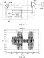
- FIG. 3illustrates an example of a Linear Resonant Actuator (LRA) modelled as a purely electrical system
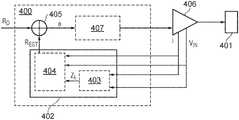
- FIG. 4illustrates an example of a controller 400 for providing a driving voltage V D to a haptic transducer 401 in accordance with some embodiments
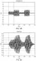
- FIG. 5Ais a graph illustrating an example of a desired electrical response in a haptic transducer
- FIG. 5Bis a graph illustrating an example of a driving signal for driving a haptic transducer
- FIG. 5Cis a graph illustrating an example of an actual electrical response in a haptic transducer
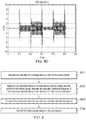
- FIG. 5Dis a graph illustrating an example of a controlled driving signal for driving a haptic transducer in accordance with some embodiments
- FIG. 6is a flow chart illustrating a method of providing a driving signal to a transducer in accordance with some embodiments.
- Various electronic devices or smart devicesmay have transducers, speakers, or any acoustic output transducers, for example any transducer for converting a suitable electrical driving signal into an acoustic output such as a sonic pressure wave or mechanical vibration.
- many electronic devicesmay include one or more speakers or loudspeakers for sound generation, for example, for playback of audio content, voice communications, and/or for providing audible notifications.
- Such speakers or loudspeakersmay comprise an electromagnetic actuator, for example a voice coil motor, which is mechanically coupled to a flexible diaphragm, for example a conventional loudspeaker cone, or which is mechanically coupled to a surface of a device, for example the glass screen of a mobile device.
- Some electronic devicesmay also include acoustic output transducers capable of generating ultrasonic waves, for example for use in proximity detection type applications and/or machine-to-machine communication.
- an electronic devicemay additionally or alternatively include more specialized acoustic output transducers, for example, haptic transducers, tailored for generating vibrations for haptic control feedback or notifications to a user.
- an electronic devicemay have a connector, e.g. a socket, for making a removable mating connection with a corresponding connector of an accessory apparatus and may be arranged to provide a driving signal to the connector so as to drive a transducer, of one or more of the types mentioned above, of the accessory apparatus when connected.
- Such an electronic devicewill thus comprise driving circuitry for driving the transducer of the host device or connected accessory with a suitable driving signal.
- the driving signalwill generally be an analog time varying voltage signal, for example, a time varying waveform.
- FIG. 2illustrates an example of a Linear Resonant Actuator (LRA) modelled as a linear system.
- LRAsare non-linear components that may behave differently depending on, for example, the voltage levels applied, the operating temperature, and the frequency of operation. However, these components may be modelled as linear components within the certain conditions.
- the LRAis modelled as a third order system having electrical and mechanical elements.
- an LRAmay be modelled as a purely electrical circuit as illustrated in FIG. 3 , with a resistor Res, inductor Les and capacitor Ces connected in parallel representing the mechanical attributes of the motion of the moving mass in the LRA.
- the values of Res, Ces and Lesmay be modelled for each individual haptic transducer. For example, test frequencies may be utilised to determine the value of each parameter (Le, Re, Res, Ces, Les) of the model for a particular haptic transducer.
- FIG. 3is an example electrical model, and that other types of model for a haptic transducer may be used in the embodiments described herein.
- the voltage across the capacitor Cesrepresents the back electromotive force voltage in the transducer, V B .
- This voltagemay be modelled as being proportional to the speed of the moving mass in the transducer.
- the current through the inductor I Lmay be modelled as proportional to the position of the moving mass in the transducer.
- This state equationrelates the value of variables at a future time to the value of variables at a current time in the system.
- a Kalman filtermay be used to estimate the state of a system based on the previous states in the system.
- a state equation for a Kalman filtermay be illustrated as: ⁇ circumflex over (x) ⁇ k
- k-1F k ⁇ circumflex over (x) ⁇ k-1
- the state equation for the haptic transducer equation (1)may be written as:
- [ I . I . L V . B ][ - Re Le 0 - 1 Le 0 0 1 Les 1 Ces - 1 Ces 1 ResCes ] ⁇ [ I I L V B ] + [ 1 Le 0 0 ] ⁇ V IN ⁇ ⁇
- ⁇ [ I . I . L V . B ] ( 2 )is a state vector, ⁇ circumflex over (x) ⁇ k
- [ I I L V B ]is a state vector, ⁇ circumflex over (x) ⁇ k-1
- the values of Le, Re, Les, Res and Cesmay be derived from the electrical model of the particular transducer, and V IN is the terminal voltage across the haptic transducer.
- the state transition model F kmay be given as:
- control-input model B kmay be given as:
- FIG. 4illustrates an example of a controller 400 for providing a driving signal V(t) to a haptic transducer 401 .
- the haptic transducercomprises a LRA, however, it will be appreciated that any form of haptic transducer may be utilised, and that a model for the haptic transducer may be adjusted accordingly.
- the terminal voltage V IN and current across the haptic transducer Imay be measured.
- the terminal voltage V INmay be measured using a voltage meter across the input to the haptic transducer.
- the current across the haptic transducer Imay be measured by measuring the voltage across a shunt resistor on a signal path to the haptic transducer.
- the controller 400comprises an estimation block 402 configured to, based on an electrical model of the haptic transducer and the voltage and the current of the driving signal, estimate an estimated electrical response, R EST of the transducer representative of movement of a mass in the transducer.
- the electrical modelmay comprise the values of Le, Re, Les, Res and Ces as illustrated in FIG. 3 .
- the estimated electrical response of the transducermay be an estimate at time k- 1 of what the electrical response will be at a time k, based on a previous estimate of the electrical response.
- the estimated electrical responsemay comprise estimate of the back electromotive force (EMF) voltage, V B , in the haptic transducer, wherein the back EMF voltage in the haptic transducer is representative of a velocity of the mass in the haptic transducer.
- the estimated electrical responsemay comprise an estimate of an inductor current, I L , in the transducer, wherein the inductor current in the transducer is representative of an excursion of the mass in the transducer. It will be appreciated that any electrical response or combination of electrical responses which represent movement of the moving mass of the haptic transducer may be used.
- a modelled electrical response at a time k ⁇ 1may be estimated as:
- V BV IN - ReI - Le ⁇ dI dt ( 5 )
- a modelled electrical response at a time k ⁇ 1may be estimated as:
- I LI - Ces ⁇ ( dV B dt ) - V B Res , ( 6 ) where back EMF voltage V B is calculated as illustrated in equation (5).
- the estimation block 402may comprise a state modelling block 403 configured to model or observe the electrical response at time k.
- the modelled electrical response at time k ⁇ 1may be given as z k-1 .
- z k-1may be calculated based on the measurements of current I and voltage V IN , along with the modelled values of Ces, Res, Re and Le from the electrical model of the haptic transducer.
- the state modelling block 403may be configured to determine a modelled electrical response z k-1 based on the voltage and the current of the driving signal and the electrical model of the transducer.
- the estimation block 402may then further comprise a smooth state estimator, for example a Kalman filter 404 , configured to receive the modelled electrical response z k-1 .
- a smooth state estimatorfor example a Kalman filter 404
- any suitable state estimator or state observer systemfor example a sliding mode observer or a Luenberger observer, may be used.
- the smooth state estimatormay be configured to estimate the estimated electrical response of the transducer based on a previous estimated electrical response and a state equation, for example equation (2), wherein the state equation is based on the electrical model of the transducer.
- the state equation for a smooth state estimatormay utilize parameters determined from the electrical model of the transducer.
- the state equationcomprises a state transition model, for example F k in equation (2), for applying to the previous estimate of the electrical response.
- the state transition modelmay comprise estimations of internal parameters of the electrical model of the transducer.
- the state equationmay comprise a Kalman Filter state equation, a Luenberger state equation, or a sliding mode observer state equation, depending on the type of state estimator used.
- the Kalman filter 404may be used to enhance the process of estimating the estimated electrical response, and may mitigate the effect of noise measurements as well as parameter mismatch.
- the Kalman filter 404may then first update a previous estimated electrical response, ⁇ circumflex over (x) ⁇ k-1
- k-1⁇ circumflex over (x) ⁇ k-1
- the modelled electrical response, z k-1may represent the actual current model of the electrical response based on current measurements of the voltage and current across the transducer. By comparing this response to the updated estimate made by the Kalman filter at a previous time, ⁇ circumflex over (x) ⁇ k-1
- the Kalman filtermay then predict the estimated electrical response ⁇ circumflex over (x) ⁇ k
- k-1F k ⁇ circumflex over (x) ⁇ k-1
- the current Imay be measured directly and may be used to enhance the model estimator for estimated back EMF voltage V B .
- inductor current I Lis neither measured nor estimated, however, in some examples, inductor current I L may be utilized as the control variable and may be estimated as illustrated in equation (6) or using a second order approximation.
- the Kalman filter 404may also be tuned to respond with minimal delay and high accuracy in the operating regions of the haptic transducer.
- the controller 400further comprises a comparison block 405 configured to compare the estimated electrical response, R EST , to a desired electrical response R D .
- the desired electrical responsemay for example illustrate the desired movement of the haptic transducer 401 .
- An example of a desired electrical response, (in this case a desired back EMF voltage V B )is illustrated in FIG. 5A .
- the comparison blockmay, for example, be configured to subtract the estimated electrical response, R EST , from the desired electrical response, R D .
- the error signal, emay then be input into an amplifier 406 to generate the driving signal V D .
- the error signalmay be processed by a processing block 407 before inputting the error signal into the amplifier 406 .
- the processing block 407may apply a fixed gain to the error signal, e.
- the processing block 407may also comprise a controller that may drive the VCO or DCO smoothly, for example, the processing block 407 may comprise a Proportional, Integral and Derivative controller (or PID).
- the processing block 407may use a fixed gain which may correspond to a proportional controller (P). However, the processing block 407 may also use a proportional and integral controller (PI), or a Proportional and Derivative (PD) controller. The processing block may be selected dependent on a desired control action (for example, fast convergence, noise robustness, minimum delay, etc.).
- Pproportional controller
- PIproportional and integral controller
- PDProportional and Derivative
- the processing blockmay be selected dependent on a desired control action (for example, fast convergence, noise robustness, minimum delay, etc.).
- the controller 400may therefore control the driving signal, V D into the transducer based on the comparison between the estimated electrical response and the desired electrical response.
- the controller 400may be implemented on an integrated circuit forming part of an electronic apparatus.
- the electronic devicemay comprise a haptic transducer coupled to receive a driving signal from an amplifier, as illustrated in FIG. 4 .
- the integrated circuit comprising the controllermay then control the driving signal as illustrated in FIG. 4 .
- the electronic apparatusmay comprise at least one of: a portable device; a battery power device; a computing device; a communications device; a gaming device; a mobile telephone; a personal media player; a laptop, tablet or notebook computing device.
- FIGS. 5A and 5Cillustrate example back EMF responses in a haptic transducer. It will be appreciated that other electrical responses, for example, the inductor current I L may be equally used to control the driving signal as illustrated in FIG. 4 .
- the FIG. 5Aillustrates the desired back EMF voltage which represents the desired movement of the transducer.
- the driving signalnot take into account any acceleration or deceleration of the haptic transducer, for example, by using an input signal as illustrated in FIG. 5B with the intention of creating the back EMF voltage response illustrated in FIG. 5A
- the actual resulting back EMF voltage across the haptic transducermay be as illustrated in FIG. 5C .
- the driving signal V INis set to oscillate at a magnitude of 1.5 V. This set magnitude is intended to result in a back EMF of 0.2 V in the haptic transducer.
- the haptic transducer in this exampleactually takes 0.05 s for the back EMF voltage, representative of the speed of the moving mass in the haptic transducer, to increase from 0 to 0.2 V in magnitude.
- the driving signalis increased to 2.5 V in magnitude.
- This set magnitudeis intended to result in a back EMF voltage of 0.45 V.
- the haptic transducer in this exampleactually takes 0.05 s for the back EMF voltage, representative of the speed of the moving mass in the haptic transducer, to increase from 0 to 0.2 V in magnitude.
- the resulting back EMFmay be as illustrated in FIG. 5A .
- the desired electrical response, or a good estimate of the desired electrical responsemay be reproduced in the haptic transducer.
- the error signalmay produce a spike, e.g. at times 0.1 s, 0.2 s, 0.3 s, 0.4 s and 0.5 s.
- spikes in the error signalwhen used to generate the input signal V IN , cause the haptic transducer to accelerate or decelerate quickly when the electrical response of the transducer is expected to change. These spikes therefore overdrive the transducer in one direction or another, thereby compensating for the rise and fall times illustrated in FIG. 5A .
- the spikes in the error signalmay be constrained by the following criteria.
- the inner massmay be required to not exceed a predetermined excursion limit to prevent damage of the internal components of the haptic transducer.
- the desired electrical responsefor example the desired inductor current, may be limited by a predetermined maximum inductor current.
- a predetermined maximum voltage and current for the driving signalmay also apply to prevent damage of the internal components of the haptic transducer. In this example, therefore, the voltage and current of the driving signal may be limited by predetermined maximum values.
- FIG. 6illustrates a method for providing a driving signal to a transducer, wherein the driving signal is output by an amplifier.
- step 601the method comprises receiving an indication of a voltage and a current of the driving signal.
- the methodcomprises, based on an electrical model of the transducer and the voltage and the current of the driving signal, estimating an estimated electrical response of the transducer representative of movement of a mass in the transducer.
- the estimated electrical responsemay be estimated by a state observer, for example, a Kalman filter, as described with reference to FIG. 4 .
- the electrical responsemay comprise any electrical response, or combination of electrical responses which are representative of the movement of the moving mass in the haptic transducer.
- the electrical responsemay comprise the back EMF in the haptic transducer, or the inductor current through the inductor in the electrical model of the haptic transducer.
- the methodcomprises comparing the estimated electrical response to a desired electrical response. For example, the estimated electrical response may be subtracted from the desired electrical response.
- step 604the method comprises controlling the driving signal based on the comparison.
- methods and apparatus for controlling the movement of the mass inside a haptic transducer accuratelyare described.
- methods described hereinutilize a smooth state estimator, such as a Kalman filter, to provide an estimate of a state of an electrical response of the haptic transducer which is representative of the movement of the haptic transducer. This estimate may then be compared against a desired electrical response in order to control the driving signal applied to the haptic transducer.
- a smooth state estimatorsuch as a Kalman filter
- analog conditioning circuitas described above or various blocks or parts thereof may be co-integrated with other blocks or parts thereof or with other functions of a host device on an integrated circuit such as a Smart Codec.
- processor control codefor example on a non-volatile carrier medium such as a disk, CD- or DVD-ROM, programmed memory such as read only memory (Firmware), or on a data carrier such as an optical or electrical signal carrier.
- a non-volatile carrier mediumsuch as a disk, CD- or DVD-ROM
- programmed memorysuch as read only memory (Firmware)
- a data carriersuch as an optical or electrical signal carrier.
- the codemay comprise conventional program code or microcode or, for example code for setting up or controlling an ASIC or FPGA.
- the codemay also comprise code for dynamically configuring re-configurable apparatus such as re-programmable logic gate arrays.
- the codemay comprise code for a hardware description language such as VerilogTM or VHDL (Very high speed integrated circuit Hardware Description Language).
- VerilogTMVery high speed integrated circuit Hardware Description Language
- VHDLVery high speed integrated circuit Hardware Description Language
- the codemay be distributed between a plurality of coupled components in communication with one another.
- the embodimentsmay also be implemented using code running on a field-(re)programmable analogue array or similar device in order to configure analogue hardware.
Landscapes
- Engineering & Computer Science (AREA)
- Power Engineering (AREA)
- General Engineering & Computer Science (AREA)
- Physics & Mathematics (AREA)
- Theoretical Computer Science (AREA)
- General Physics & Mathematics (AREA)
- Computer Hardware Design (AREA)
- Mathematical Physics (AREA)
- Mechanical Engineering (AREA)
- Human Computer Interaction (AREA)
- Apparatuses For Generation Of Mechanical Vibrations (AREA)
- User Interface Of Digital Computer (AREA)
Abstract
Description
{circumflex over (x)}k|k-1=Fk{circumflex over (x)}k-1|k-1+Bkuk, where (1)
Fkcomprises a state-transition model; xk-1|k-1is the posteriori state estimate at time k−1 given observations up to and including at time k−1, xk|k-1is the a priori state estimate of x at time k given observations up to and including at time k−1, and Bkis the control-input model which is applied to the control vector uk.
is a state vector, {circumflex over (x)}k|k-1representing the values of I, ILand VBat a time k given observations up to and including at time k−1, and
is a state vector, {circumflex over (x)}k-1|k-1representing the values of I, ILand VBat a time k−1 given observations up to and including at time k−1. The values of Le, Re, Les, Res and Ces may be derived from the electrical model of the particular transducer, and VINis the terminal voltage across the haptic transducer.
where back EMF voltage VBis calculated as illustrated in equation (5).
{circumflex over (x)}k-1|k-1={circumflex over (x)}k-1|k-2+Kk{tilde over (y)}k. (7)
{circumflex over (x)}k|k-1=Fk{circumflex over (x)}k-1|k-1+Bkuk, (1)
2) A predetermined maximum voltage and current for the driving signal may also apply to prevent damage of the internal components of the haptic transducer. In this example, therefore, the voltage and current of the driving signal may be limited by predetermined maximum values.
Claims (26)
Priority Applications (4)
| Application Number | Priority Date | Filing Date | Title |
|---|---|---|---|
| US16/207,340US11139767B2 (en) | 2018-03-22 | 2018-12-03 | Methods and apparatus for driving a transducer |
| PCT/GB2019/050770WO2019180424A1 (en) | 2018-03-22 | 2019-03-19 | Methods and apparatus for driving a transducer |
| CN201980020857.0ACN111886083B (en) | 2018-03-22 | 2019-03-19 | Method and apparatus for driving a transducer |
| EP19715192.1AEP3768439A1 (en) | 2018-03-22 | 2019-03-19 | Methods and apparatus for driving a transducer |
Applications Claiming Priority (2)
| Application Number | Priority Date | Filing Date | Title |
|---|---|---|---|
| US201862646563P | 2018-03-22 | 2018-03-22 | |
| US16/207,340US11139767B2 (en) | 2018-03-22 | 2018-12-03 | Methods and apparatus for driving a transducer |
Publications (2)
| Publication Number | Publication Date |
|---|---|
| US20190296674A1 US20190296674A1 (en) | 2019-09-26 |
| US11139767B2true US11139767B2 (en) | 2021-10-05 |
Family
ID=67985786
Family Applications (1)
| Application Number | Title | Priority Date | Filing Date |
|---|---|---|---|
| US16/207,340ActiveUS11139767B2 (en) | 2018-03-22 | 2018-12-03 | Methods and apparatus for driving a transducer |
Country Status (4)
| Country | Link |
|---|---|
| US (1) | US11139767B2 (en) |
| EP (1) | EP3768439A1 (en) |
| CN (1) | CN111886083B (en) |
| WO (1) | WO2019180424A1 (en) |
Cited By (22)
| Publication number | Priority date | Publication date | Assignee | Title |
|---|---|---|---|---|
| US11269415B2 (en) | 2018-08-14 | 2022-03-08 | Cirrus Logic, Inc. | Haptic output systems |
| US11283337B2 (en) | 2019-03-29 | 2022-03-22 | Cirrus Logic, Inc. | Methods and systems for improving transducer dynamics |
| US11380175B2 (en) | 2019-10-24 | 2022-07-05 | Cirrus Logic, Inc. | Reproducibility of haptic waveform |
| US11408787B2 (en) | 2019-10-15 | 2022-08-09 | Cirrus Logic, Inc. | Control methods for a force sensor system |
| US11500469B2 (en) | 2017-05-08 | 2022-11-15 | Cirrus Logic, Inc. | Integrated haptic system |
| US11507267B2 (en) | 2018-10-26 | 2022-11-22 | Cirrus Logic, Inc. | Force sensing system and method |
| US11509292B2 (en) | 2019-03-29 | 2022-11-22 | Cirrus Logic, Inc. | Identifying mechanical impedance of an electromagnetic load using least-mean-squares filter |
| US11515875B2 (en) | 2019-03-29 | 2022-11-29 | Cirrus Logic, Inc. | Device comprising force sensors |
| US11545951B2 (en) | 2019-12-06 | 2023-01-03 | Cirrus Logic, Inc. | Methods and systems for detecting and managing amplifier instability |
| US11552649B1 (en) | 2021-12-03 | 2023-01-10 | Cirrus Logic, Inc. | Analog-to-digital converter-embedded fixed-phase variable gain amplifier stages for dual monitoring paths |
| US11636742B2 (en) | 2018-04-04 | 2023-04-25 | Cirrus Logic, Inc. | Methods and apparatus for outputting a haptic signal to a haptic transducer |
| US11644370B2 (en) | 2019-03-29 | 2023-05-09 | Cirrus Logic, Inc. | Force sensing with an electromagnetic load |
| US11656711B2 (en) | 2019-06-21 | 2023-05-23 | Cirrus Logic, Inc. | Method and apparatus for configuring a plurality of virtual buttons on a device |
| US11662821B2 (en) | 2020-04-16 | 2023-05-30 | Cirrus Logic, Inc. | In-situ monitoring, calibration, and testing of a haptic actuator |
| US11669165B2 (en) | 2019-06-07 | 2023-06-06 | Cirrus Logic, Inc. | Methods and apparatuses for controlling operation of a vibrational output system and/or operation of an input sensor system |
| US11726596B2 (en) | 2019-03-29 | 2023-08-15 | Cirrus Logic, Inc. | Controller for use in a device comprising force sensors |
| US11765499B2 (en) | 2021-06-22 | 2023-09-19 | Cirrus Logic Inc. | Methods and systems for managing mixed mode electromechanical actuator drive |
| US11908310B2 (en) | 2021-06-22 | 2024-02-20 | Cirrus Logic Inc. | Methods and systems for detecting and managing unexpected spectral content in an amplifier system |
| US11933822B2 (en) | 2021-06-16 | 2024-03-19 | Cirrus Logic Inc. | Methods and systems for in-system estimation of actuator parameters |
| US12035445B2 (en) | 2019-03-29 | 2024-07-09 | Cirrus Logic Inc. | Resonant tracking of an electromagnetic load |
| US12244253B2 (en) | 2020-04-16 | 2025-03-04 | Cirrus Logic Inc. | Restricting undesired movement of a haptic actuator |
| US12276687B2 (en) | 2019-12-05 | 2025-04-15 | Cirrus Logic Inc. | Methods and systems for estimating coil impedance of an electromagnetic transducer |
Families Citing this family (10)
| Publication number | Priority date | Publication date | Assignee | Title |
|---|---|---|---|---|
| US11259121B2 (en) | 2017-07-21 | 2022-02-22 | Cirrus Logic, Inc. | Surface speaker |
| US10620704B2 (en) | 2018-01-19 | 2020-04-14 | Cirrus Logic, Inc. | Haptic output systems |
| US10455339B2 (en) | 2018-01-19 | 2019-10-22 | Cirrus Logic, Inc. | Always-on detection systems |
| US10795443B2 (en) | 2018-03-23 | 2020-10-06 | Cirrus Logic, Inc. | Methods and apparatus for driving a transducer |
| US10667051B2 (en) | 2018-03-26 | 2020-05-26 | Cirrus Logic, Inc. | Methods and apparatus for limiting the excursion of a transducer |
| US10820100B2 (en) | 2018-03-26 | 2020-10-27 | Cirrus Logic, Inc. | Methods and apparatus for limiting the excursion of a transducer |
| US11069206B2 (en) | 2018-05-04 | 2021-07-20 | Cirrus Logic, Inc. | Methods and apparatus for outputting a haptic signal to a haptic transducer |
| US10726683B1 (en) | 2019-03-29 | 2020-07-28 | Cirrus Logic, Inc. | Identifying mechanical impedance of an electromagnetic load using a two-tone stimulus |
| US10828672B2 (en) | 2019-03-29 | 2020-11-10 | Cirrus Logic, Inc. | Driver circuitry |
| US11150733B2 (en) | 2019-06-07 | 2021-10-19 | Cirrus Logic, Inc. | Methods and apparatuses for providing a haptic output signal to a haptic actuator |
Citations (210)
| Publication number | Priority date | Publication date | Assignee | Title |
|---|---|---|---|---|
| US3686927A (en) | 1967-03-24 | 1972-08-29 | Bolt Beranek & Newman | Vibration testing method and apparatus |
| JPS6250985B2 (en) | 1978-04-05 | 1987-10-28 | Tokyo Shibaura Electric Co | |
| JPS6321351B2 (en) | 1983-02-18 | 1988-05-06 | Nippon Electric Co | |
| US4902136A (en) | 1987-10-26 | 1990-02-20 | Siemens Aktiengesellschaft | Arrangement for high-resolution spectroscopy |
| JPH08149006A (en) | 1994-11-24 | 1996-06-07 | Tera Tec:Kk | Analog-digital converter |
| US5684722A (en) | 1994-09-21 | 1997-11-04 | Thorner; Craig | Apparatus and method for generating a control signal for a tactile sensation generator |
| US5748578A (en) | 1995-01-25 | 1998-05-05 | Discovision Associates | Colpitts type oscillator having reduced ringing and improved optical disc system utilizing same |
| US5857986A (en) | 1996-05-24 | 1999-01-12 | Moriyasu; Hiro | Interactive vibrator for multimedia |
| US6050393A (en) | 1996-10-14 | 2000-04-18 | Aisan Kogyo Kabushiki Kaisha | Drive apparatus for driving an oscillator and a powder feeder having the drive apparatus therein |
| US6278790B1 (en) | 1997-11-11 | 2001-08-21 | Nct Group, Inc. | Electroacoustic transducers comprising vibrating panels |
| US20010043714A1 (en) | 1998-01-16 | 2001-11-22 | Sony Corporation | Speaker apparatus and electronic apparatus having speaker apparatus enclosed therein |
| US6332029B1 (en) | 1995-09-02 | 2001-12-18 | New Transducers Limited | Acoustic device |
| US20020018578A1 (en) | 2000-08-03 | 2002-02-14 | Paul Burton | Bending wave loudspeaker |
| US6388520B2 (en) | 1999-12-27 | 2002-05-14 | Semiconductor Technology Academic Research Center | Semiconductor integrated circuit |
| US20030068053A1 (en) | 2001-10-10 | 2003-04-10 | Chu Lonny L. | Sound data output and manipulation using haptic feedback |
| US6580796B1 (en) | 1998-01-27 | 2003-06-17 | Yamaha Corporation | Sound effect imparting apparatus |
| US20030214485A1 (en) | 2002-05-17 | 2003-11-20 | Roberts Jerry B. | Calibration of force based touch panel systems |
| US6683437B2 (en) | 2001-10-31 | 2004-01-27 | Immersion Corporation | Current controlled motor amplifier system |
| US6762745B1 (en) | 1999-05-10 | 2004-07-13 | Immersion Corporation | Actuator control providing linear and continuous force output |
| US20050031140A1 (en) | 2003-08-07 | 2005-02-10 | Tymphany Corporation | Position detection of an actuator using a capacitance measurement |
| US6906697B2 (en) | 2000-08-11 | 2005-06-14 | Immersion Corporation | Haptic sensations for tactile feedback interface devices |
| US20050134562A1 (en) | 2003-12-22 | 2005-06-23 | Grant Danny A. | System and method for controlling haptic devices having multiple operational modes |
| US6995747B2 (en) | 2001-09-07 | 2006-02-07 | Microsoft Corporation | Capacitive sensing and data input device power management |
| US20060028095A1 (en) | 2004-08-03 | 2006-02-09 | Shigeaki Maruyama | Piezoelectric composite device, method of manufacturing same, method of controlling same, input-output device, and electronic device |
| US20060197753A1 (en) | 2005-03-04 | 2006-09-07 | Hotelling Steven P | Multi-functional hand-held device |
| US20060284856A1 (en) | 2005-06-10 | 2006-12-21 | Soss David A | Sensor signal conditioning in a force-based touch device |
| US7154470B2 (en) | 2001-07-17 | 2006-12-26 | Immersion Corporation | Envelope modulator for haptic feedback devices |
| US20080167832A1 (en) | 2005-06-10 | 2008-07-10 | Qsi Corporation | Method for determining when a force sensor signal baseline in a force-based input device can be updated |
| US20080226109A1 (en) | 2007-02-28 | 2008-09-18 | Yoko Yamakata | Acoustic vibration reproducing apparatus |
| US20080240458A1 (en) | 2006-12-31 | 2008-10-02 | Personics Holdings Inc. | Method and device configured for sound signature detection |
| US20080293453A1 (en) | 2007-05-25 | 2008-11-27 | Scott J. Atlas | Method and apparatus for an audio-linked remote indicator for a wireless communication device |
| US20080316181A1 (en) | 2007-06-19 | 2008-12-25 | Nokia Corporation | Moving buttons |
| US20090020343A1 (en) | 2007-07-17 | 2009-01-22 | Apple Inc. | Resistive force sensor with capacitive discrimination |
| US20090079690A1 (en) | 2007-09-21 | 2009-03-26 | Sony Computer Entertainment America Inc. | Method and apparatus for enhancing entertainment software through haptic insertion |
| US20090088220A1 (en) | 2007-10-01 | 2009-04-02 | Sony Ericsson Mobile Communications Ab | Cellular terminals and other electronic devices and methods using electroactive polymer transducer indicators |
| US20090096632A1 (en) | 2007-10-16 | 2009-04-16 | Immersion Corporation | Synchronization of haptic effect data in a media stream |
| US20090102805A1 (en) | 2007-10-18 | 2009-04-23 | Microsoft Corporation | Three-dimensional object simulation using audio, visual, and tactile feedback |
| US20090153499A1 (en) | 2007-12-18 | 2009-06-18 | Electronics And Telecommunications Research Institute | Touch action recognition system and method |
| US20090278819A1 (en) | 1999-09-28 | 2009-11-12 | Immersion Corporation | Controlling Haptic Sensations For Vibrotactile Feedback Interface Devices |
| US7623114B2 (en) | 2001-10-09 | 2009-11-24 | Immersion Corporation | Haptic feedback sensations based on audio output from computer devices |
| US7639232B2 (en) | 2004-11-30 | 2009-12-29 | Immersion Corporation | Systems and methods for controlling a resonant device for generating vibrotactile haptic effects |
| US20100013761A1 (en) | 2008-07-15 | 2010-01-21 | Immersion Corporation | Systems And Methods For Shifting Haptic Feedback Function Between Passive And Active Modes |
| US20100141606A1 (en) | 2008-12-08 | 2010-06-10 | Samsung Electronics Co., Ltd. | Method for providing haptic feedback in a touch screen |
| US20100141408A1 (en) | 2008-12-05 | 2010-06-10 | Anthony Stephen Doy | Audio amplifier apparatus to drive a panel to produce both an audio signal and haptic feedback |
| US7791588B2 (en) | 2003-12-22 | 2010-09-07 | Immersion Corporation | System and method for mapping instructions associated with haptic feedback |
| US20110056763A1 (en) | 2009-09-07 | 2011-03-10 | Yamaha Corporation | Acoustic resonance device |
| US20110141052A1 (en) | 2009-12-10 | 2011-06-16 | Jeffrey Traer Bernstein | Touch pad with force sensors and actuator feedback |
| US20110163985A1 (en) | 2010-01-05 | 2011-07-07 | Samsung Electronics Co., Ltd. | Haptic feedback control method and apparatus for a wireless terminal having a touch screen |
| US20110167391A1 (en) | 2010-01-06 | 2011-07-07 | Brian Momeyer | User interface methods and systems for providing force-sensitive input |
| US7979146B2 (en)* | 2006-04-13 | 2011-07-12 | Immersion Corporation | System and method for automatically producing haptic events from a digital audio signal |
| EP2363785A1 (en) | 2010-02-03 | 2011-09-07 | Honeywell International Inc. | Touch screen having adaptive input parameter |
| US8068025B2 (en) | 2009-05-28 | 2011-11-29 | Simon Paul Devenyi | Personal alerting device and method |
| US20120011436A1 (en) | 2009-11-02 | 2012-01-12 | Motorola, Inc. | Devices and Methods of a User Interface for a Small Display Screen |
| US8098234B2 (en) | 2007-02-20 | 2012-01-17 | Immersion Corporation | Haptic feedback system with stored effects |
| US20120105358A1 (en) | 2010-11-03 | 2012-05-03 | Qualcomm Incorporated | Force sensing touch screen |
| US20120112894A1 (en) | 2010-11-08 | 2012-05-10 | Korea Advanced Institute Of Science And Technology | Haptic feedback generator, portable device, haptic feedback providing method using the same and recording medium thereof |
| EP2487780A1 (en) | 2011-02-14 | 2012-08-15 | Siemens Aktiengesellschaft | Controller for a power converter and method of operating the same |
| US20120206247A1 (en) | 2011-02-11 | 2012-08-16 | Immersion Corporation | Sound to haptic effect conversion system using waveform |
| US20120206246A1 (en) | 2011-02-11 | 2012-08-16 | Immersion Corporation | Sound to haptic effect conversion system using amplitude value |
| US20120229264A1 (en) | 2011-03-09 | 2012-09-13 | Analog Devices, Inc. | Smart linear resonant actuator control |
| US20120253698A1 (en) | 2011-02-18 | 2012-10-04 | Valerijan Cokonaj | Integrated phased array transducer, system and methodology for structural health monitoring of aerospace structures |
| KR20120126446A (en) | 2011-05-11 | 2012-11-21 | 엘지전자 주식회사 | An apparatus for generating the vibrating feedback from input audio signal |
| US8325144B1 (en) | 2007-10-17 | 2012-12-04 | Immersion Corporation | Digital envelope modulator for haptic feedback devices |
| US20120306631A1 (en) | 2011-06-03 | 2012-12-06 | Apple Inc. | Audio Conversion To Vibration Patterns |
| US20130027359A1 (en) | 2010-01-13 | 2013-01-31 | Elo Touch Solutions, Inc. | Noise reduction in electronic device with touch sensitive surface |
| US20130038792A1 (en) | 2008-10-10 | 2013-02-14 | Internet Services, Llc | System and method for synchronization of haptic data and media data |
| US8441444B2 (en) | 2000-09-28 | 2013-05-14 | Immersion Corporation | System and method for providing directional tactile sensations |
| EP2600225A1 (en) | 2010-07-27 | 2013-06-05 | Kyocera Corporation | Tactile feedback device, and tactile feedback device control method |
| US20130141382A1 (en) | 2011-12-01 | 2013-06-06 | Martin John Simmons | Touch Sensor With Force Sensing |
| US8466778B2 (en) | 2009-07-31 | 2013-06-18 | Lg Electronics Inc. | Apparatus and method for generating vibration pattern |
| CN103165328A (en) | 2013-02-25 | 2013-06-19 | 苏州达方电子有限公司 | Force feedback keyboard structure |
| US8480240B2 (en) | 2007-02-20 | 2013-07-09 | Canon Kabushiki Kaisha | Image capturing apparatus |
| WO2013104919A1 (en) | 2012-01-13 | 2013-07-18 | Hiwave Technologies (Uk) Limited | Haptic feedback and pressure sensing |
| US20130275058A1 (en) | 2012-04-13 | 2013-10-17 | Google Inc. | Apparatus and method for a pressure sensitive device interface |
| US8572296B2 (en) | 2005-06-30 | 2013-10-29 | Freescale Semiconductor, Inc. | Device and method for arbitrating between direct memory access task requests |
| US8572293B2 (en) | 2004-07-15 | 2013-10-29 | Immersion Corporation | System and method for ordering haptic effects |
| US20130289994A1 (en) | 2012-04-26 | 2013-10-31 | Michael Jack Newman | Embedded system for construction of small footprint speech recognition with user-definable constraints |
| CN103403796A (en) | 2011-02-02 | 2013-11-20 | 通用显示器公司 | Explosion Proof Sound Sources for Hazardous Locations |
| WO2013186845A1 (en) | 2012-06-11 | 2013-12-19 | 富士通株式会社 | Electronic device, vibration generation program, and system using vibration patterns |
| WO2014018086A1 (en) | 2012-07-26 | 2014-01-30 | Changello Enterprise Llc | Force correction on multiple sense elements |
| US8648829B2 (en) | 2002-10-20 | 2014-02-11 | Immersion Corporation | System and method for providing rotational haptic feedback |
| US8659208B1 (en) | 2007-06-14 | 2014-02-25 | Misonix, Inc. | Waveform generator for driving electromechanical device |
| US20140056461A1 (en) | 2012-08-21 | 2014-02-27 | Immerz, Inc. | Systems and methods for a vibrating input device |
| US20140064516A1 (en) | 2012-08-31 | 2014-03-06 | Immersion Corporation | Sound to haptic effect conversion system using mapping |
| US20140079248A1 (en) | 2012-05-04 | 2014-03-20 | Kaonyx Labs LLC | Systems and Methods for Source Signal Separation |
| US20140085064A1 (en) | 2012-09-27 | 2014-03-27 | Fairchild Semiconductor Corporation | Resonance driver and detection |
| US20140118125A1 (en) | 2012-10-26 | 2014-05-01 | Immersion Corporation | Stream-independent sound to haptic effect conversion system |
| US20140119244A1 (en) | 2012-11-01 | 2014-05-01 | Research In Motion Limited | Cognitive radio rf front end |
| US20140118126A1 (en) | 2012-10-30 | 2014-05-01 | Texas Instruments Incorporated | Haptic actuator controller |
| US20140139327A1 (en) | 2012-11-19 | 2014-05-22 | Disney Enterprises, Inc. | Controlling a user's tactile perception in a dynamic physical environment |
| US8754757B1 (en) | 2013-03-05 | 2014-06-17 | Immersion Corporation | Automatic fitting of haptic effects |
| WO2014094283A1 (en) | 2012-12-20 | 2014-06-26 | Intel Corporation | Touchscreen including force sensors |
| US20140226068A1 (en) | 2005-10-19 | 2014-08-14 | Immersion Corporation | Synchronization of haptic effect data in a media transport stream |
| US20140292501A1 (en)* | 2013-03-27 | 2014-10-02 | Electronics And Telecommunications Research Institute | Apparatus and method for providing haptic effect using sound effect |
| US20140340209A1 (en) | 2013-05-17 | 2014-11-20 | Immersion Corporation | Low-frequency effects haptic conversion system |
| US20140347176A1 (en) | 2013-05-24 | 2014-11-27 | Immersion Corporation | Method and apparatus to provide haptic feedback based on media content and one or more external parameters |
| US8947216B2 (en) | 2012-11-02 | 2015-02-03 | Immersion Corporation | Encoding dynamic haptic effects |
| US20150061846A1 (en) | 2012-04-19 | 2015-03-05 | Nokia Corporation | Display apparatus |
| EP2846329A1 (en) | 2013-09-06 | 2015-03-11 | Immersion Corporation | Dynamic haptic conversion system |
| EP2846229A2 (en) | 2013-09-06 | 2015-03-11 | Immersion Corporation | Systems and methods for generating haptic effects associated with audio signals |
| EP2846218A1 (en) | 2013-09-06 | 2015-03-11 | Immersion Corporation | Haptic conversion system using segmenting and combining |
| US8981915B2 (en) | 2012-05-16 | 2015-03-17 | Immersion Corporation | System and method for display of multiple data channels on a single haptic display |
| US20150084752A1 (en) | 2009-10-29 | 2015-03-26 | Immersion Corporation | Systems and Methods for Haptic Augmentation of Voice-to-Text Conversion |
| US8994518B2 (en) | 2008-12-16 | 2015-03-31 | Immersion Corporation | Haptic feedback generation based on resonant frequency |
| US9030428B2 (en) | 2012-07-11 | 2015-05-12 | Immersion Corporation | Generating haptic effects for dynamic events |
| US20150130767A1 (en) | 2011-09-27 | 2015-05-14 | Apple Inc. | Electronic Devices With Sidewall Displays |
| US9063570B2 (en) | 2012-06-27 | 2015-06-23 | Immersion Corporation | Haptic feedback control system |
| US20150208189A1 (en) | 2014-01-23 | 2015-07-23 | Richtek Technology Corp | Device and method for detecting force factor of loudspeaker |
| US20150216762A1 (en) | 2012-08-16 | 2015-08-06 | Action Research Co., Ltd. | Vibration processing device and method |
| US9117347B2 (en) | 2013-02-25 | 2015-08-25 | Nokia Technologies Oy | Method and apparatus for a flexible housing |
| US9128523B2 (en) | 2012-12-20 | 2015-09-08 | Amazon Technologies, Inc. | Dynamically generating haptic effects from audio data |
| US9164587B2 (en) | 2013-11-14 | 2015-10-20 | Immersion Corporation | Haptic spatialization system |
| US20150325116A1 (en) | 2014-05-09 | 2015-11-12 | Sony Computer Entertainment Inc. | Scheme for embedding a control signal in an audio signal using pseudo white noise |
| US20150324116A1 (en) | 2007-09-19 | 2015-11-12 | Apple Inc. | Systems and methods for detecting a press on a touch-sensitive surface |
| US9196135B2 (en) | 2013-06-28 | 2015-11-24 | Immersion Corporation | Uniform haptic actuator response with a variable supply voltage |
| US20150341714A1 (en) | 2014-05-20 | 2015-11-26 | Samsung Display Co., Ltd. | Display apparatus |
| CN204903757U (en) | 2014-07-11 | 2015-12-23 | 菲力尔系统公司 | Sonar system |
| CN105264551A (en) | 2012-12-28 | 2016-01-20 | 通用电气公司 | Resonant sensor assembly and system for analysis of fluids |
| US9248840B2 (en) | 2013-12-20 | 2016-02-02 | Immersion Corporation | Gesture based input system in a vehicle with haptic feedback |
| EP2988528A1 (en) | 2014-08-18 | 2016-02-24 | Nxp B.V. | Voice coil motor and loudspeaker controller |
| US20160063826A1 (en) | 2014-09-02 | 2016-03-03 | Apple Inc. | Haptic Notifications |
| US20160070392A1 (en) | 2014-08-05 | 2016-03-10 | Georgia Tech Research Corporation | Self-powered, ultra-sensitive, flexible tactile sensors based on contact electrification |
| US20160074278A1 (en) | 2012-02-29 | 2016-03-17 | Frederick Muench | Systems, Devices, Components and Methods for Triggering or Inducing Resonance or High Amplitude Oscillations in a Cardiovascular System of a Patient |
| US9326066B2 (en) | 2013-08-01 | 2016-04-26 | Wolfgang Klippel | Arrangement and method for converting an input signal into an output signal and for generating a predefined transfer behavior between said input signal and said output signal |
| US9329721B1 (en) | 2010-08-05 | 2016-05-03 | Amazon Technologies, Inc. | Reduction of touch-sensor interference from stable display |
| US20160132118A1 (en) | 2012-12-14 | 2016-05-12 | Samsung Electronics Co., Ltd. | Method and apparatus for controlling haptic feedback of an input tool for a mobile terminal |
| US20160162031A1 (en) | 2012-05-09 | 2016-06-09 | Apple Inc. | Thresholds for Determining Feedback in Computing Devices |
| WO2016105496A1 (en) | 2014-12-23 | 2016-06-30 | Immersion Corporation | Feedback reduction for a user input element associated with a haptic output device |
| US20160239089A1 (en) | 2013-12-06 | 2016-08-18 | Fujitsu Limited | Drive apparatus, electronic device, drive control program, and drive signal generating method |
| US20160246378A1 (en) | 2015-02-25 | 2016-08-25 | Immersion Corporation | Systems and methods for providing context-sensitive haptic notification frameworks |
| WO2016164193A1 (en) | 2015-04-09 | 2016-10-13 | Microsoft Technology Licensing, Llc | Force-sensitive touch sensor compensation |
| US9489047B2 (en) | 2013-03-01 | 2016-11-08 | Immersion Corporation | Haptic device with linear resonant actuator |
| US9507423B2 (en) | 2013-10-08 | 2016-11-29 | Immersion Corporation | Generating haptic effects while minimizing cascading |
| US20160358605A1 (en) | 2013-03-12 | 2016-12-08 | Nuance Communications, Inc. | Methods and apparatus for detecting a voice command |
| US9520036B1 (en) | 2013-09-18 | 2016-12-13 | Amazon Technologies, Inc. | Haptic output generation with dynamic feedback control |
| CN106438890A (en) | 2016-09-05 | 2017-02-22 | 南京航空航天大学 | Macro-micro combination continuously variable transmission of electromagnet-ultrasonic transducer and method of macro-micro combination continuously variable transmission |
| US9588586B2 (en) | 2014-06-09 | 2017-03-07 | Immersion Corporation | Programmable haptic devices and methods for modifying haptic strength based on perspective and/or proximity |
| US20170078804A1 (en) | 2015-09-15 | 2017-03-16 | Oticon A/S | Hearing device comprising an improved feedback cancellation system |
| US20170083096A1 (en) | 2015-09-22 | 2017-03-23 | Immersion Corporation | Pressure-based haptics |
| US20170090572A1 (en) | 2015-09-30 | 2017-03-30 | Apple Inc. | Haptic feedback for rotary inputs |
| US20170090573A1 (en) | 2015-09-30 | 2017-03-30 | Apple Inc. | Electronic device including closed-loop controller for haptic actuator and related methods |
| US9640047B2 (en) | 2014-07-25 | 2017-05-02 | Postech Academy-Industry Foundation | Method and apparatus for generating haptic signal with auditory saliency estimation |
| US20170153760A1 (en) | 2015-12-01 | 2017-06-01 | Apple Inc. | Gain-based error tracking for force sensing |
| US20170168574A1 (en) | 2015-12-11 | 2017-06-15 | Xiaomi Inc. | Method and apparatus for inputting contents based on virtual keyboard, and touch device |
| US9697450B1 (en) | 2016-07-29 | 2017-07-04 | Alpha And Omega Semiconductor Incorporated | Magnetic stripe data transmission system and method for reliable data transmission and low power consumption |
| WO2017113651A1 (en) | 2015-12-31 | 2017-07-06 | 歌尔股份有限公司 | Tactile vibration control system and method for smart terminal |
| CN106950832A (en) | 2017-03-08 | 2017-07-14 | 杭州电子科技大学 | A kind of ultrasonic disperse control device and method of utilization cavitation intensity feedback |
| US9715300B2 (en) | 2013-03-04 | 2017-07-25 | Microsoft Technology Licensing, Llc | Touch screen interaction using dynamic haptic feedback |
| US20170220197A1 (en) | 2016-02-02 | 2017-08-03 | Fujitsu Ten Limited | Input device, system, method of manufacturing input device and display device |
| US9740381B1 (en) | 2016-09-06 | 2017-08-22 | Apple Inc. | Devices, methods, and graphical user interfaces for providing feedback during interaction with an intensity-sensitive button |
| US20170256145A1 (en) | 2014-02-13 | 2017-09-07 | Nxp B.V. | Multi-tone haptic pattern generator |
| US20170277350A1 (en) | 2016-03-22 | 2017-09-28 | Synaptics Incorporated | Force sensor recalibration |
| US9842476B2 (en) | 2015-09-25 | 2017-12-12 | Immersion Corporation | Programmable haptic devices and methods for modifying haptic effects to compensate for audio-haptic interference |
| US20170357440A1 (en) | 2016-06-08 | 2017-12-14 | Qualcomm Incorporated | Providing Virtual Buttons in a Handheld Device |
| US9864567B2 (en) | 2012-12-03 | 2018-01-09 | Samsung Electronics Co., Ltd. | Portable apparatus having a plurality of touch screens and method of outputting sound thereof |
| US9881467B2 (en) | 2016-02-22 | 2018-01-30 | Immersion Corporation | Haptic effects conflict avoidance |
| US9886829B2 (en) | 2016-06-20 | 2018-02-06 | Immersion Corporation | Systems and methods for closed-loop control for haptic feedback |
| CN107665051A (en) | 2016-07-27 | 2018-02-06 | 意美森公司 | Braking characteristic detecting system for tactile actuator |
| US20180059793A1 (en)* | 2016-08-31 | 2018-03-01 | Apple Inc. | Electronic device including multi-phase driven linear haptic actuator and related methods |
| US20180067557A1 (en) | 2016-09-06 | 2018-03-08 | Apple Inc. | Devices, Methods, and Graphical User Interfaces for Generating Tactile Outputs |
| US20180074637A1 (en) | 2016-09-09 | 2018-03-15 | Sensel Inc. | System for detecting and characterizing inputs on a touch sensor |
| US20180084362A1 (en) | 2016-09-19 | 2018-03-22 | Apple Inc. | Augmented performance synchronization |
| WO2018053159A1 (en) | 2016-09-14 | 2018-03-22 | SonicSensory, Inc. | Multi-device audio streaming system with synchronization |
| US20180082673A1 (en) | 2016-07-28 | 2018-03-22 | Theodore Tzanetos | Active noise cancellation for defined spaces |
| WO2018067613A1 (en) | 2016-10-03 | 2018-04-12 | Christopher Harrison | Touch-sensing system |
| US9946348B2 (en) | 2014-03-21 | 2018-04-17 | Immersion Corporation | Automatic tuning of haptic effects |
| US9947186B2 (en) | 2015-12-10 | 2018-04-17 | Nxp B.V. | Haptic feedback controller |
| US9959744B2 (en) | 2014-04-25 | 2018-05-01 | Motorola Solutions, Inc. | Method and system for providing alerts for radio communications |
| US9965092B2 (en) | 2016-05-18 | 2018-05-08 | Apple Inc. | Managing power consumption of force sensors |
| US20180151036A1 (en) | 2016-11-30 | 2018-05-31 | Samsung Electronics Co., Ltd. | Method for producing haptic signal and electronic device supporting the same |
| US20180160227A1 (en) | 2016-12-06 | 2018-06-07 | Cirrus Logic International Semiconductor Ltd. | Speaker protection excursion oversight |
| US20180158289A1 (en) | 2016-12-06 | 2018-06-07 | Dialog Semiconductor (Uk) Limited | Apparatus and Method for Controlling a Haptic Actuator |
| US20180178114A1 (en) | 2016-12-28 | 2018-06-28 | Nintendo Co., Ltd. | Information processing system, non-transitory storage medium having information processing program stored therein, information processing apparatus, and information processing method |
| US20180182212A1 (en) | 2015-12-13 | 2018-06-28 | Goertek Inc. | Tactile vibration control system and method for smart terminal |
| WO2018125347A1 (en) | 2016-12-29 | 2018-07-05 | Google Llc | Multi-task machine learning for predicted touch interpretations |
| US20180196567A1 (en) | 2017-01-09 | 2018-07-12 | Microsoft Technology Licensing, Llc | Pressure sensitive virtual keyboard |
| US10032550B1 (en) | 2017-03-30 | 2018-07-24 | Apple Inc. | Moving-coil haptic actuator for electronic devices |
| US20180237033A1 (en) | 2015-08-05 | 2018-08-23 | Ford Global Technologies, Llc | System and method for sound direction detection in a vehicle |
| US20180253123A1 (en) | 2016-08-02 | 2018-09-06 | Immersion Corporation | Systems and methods for deformation and haptic effects |
| US10074246B2 (en) | 2012-04-04 | 2018-09-11 | Immersion Corporation | Sound to haptic effect conversion system using multiple actuators |
| US20180267897A1 (en) | 2017-03-14 | 2018-09-20 | SK Hynix Inc. | Memory system and operating method thereof |
| EP3379382A2 (en) | 2016-05-17 | 2018-09-26 | CK Materials Lab Co., Ltd. | Method for converting acoustic signal into haptic signal, and haptic device using same |
| US20180294757A1 (en) | 2016-09-05 | 2018-10-11 | Goertek Inc. | Method and circuit for acquiring output quantity of linear resonance actuator |
| US20180301060A1 (en) | 2017-04-17 | 2018-10-18 | Facebook, Inc. | Calibration of haptic device using sensor harness |
| US10110152B1 (en) | 2017-09-29 | 2018-10-23 | Apple Inc. | Integrated driver and controller for haptic engine |
| US20180321748A1 (en) | 2017-05-08 | 2018-11-08 | Cirrus Logic International Semiconductor Ltd. | Integrated haptic system |
| US20180329172A1 (en) | 2017-05-15 | 2018-11-15 | Semiconductor Components Industries, Llc | Methods and apparatus for actuator control |
| US20180335848A1 (en) | 2017-05-16 | 2018-11-22 | Apple Inc. | Tactile Feedback for Locked Device User Interfaces |
| US20180367897A1 (en) | 2017-06-15 | 2018-12-20 | Cirrus Logic International Semiconductor Ltd. | Temperature monitoring for loudspeakers |
| US10171008B2 (en) | 2014-10-27 | 2019-01-01 | Canon Kabushiki Kaisha | Vibration wave motor and driving apparatus using the vibration wave motor |
| US10175763B2 (en) | 2014-12-04 | 2019-01-08 | Immersion Corporation | Device and method for controlling haptic signals |
| US20190073078A1 (en) | 2017-08-14 | 2019-03-07 | Sentons Inc. | Touch input detection using a piezoresistive sensor |
| US20190103829A1 (en) | 2017-09-29 | 2019-04-04 | Apple Inc. | Closed-loop control of linear resonant actuator using back emf and inertial compensation |
| US10264348B1 (en) | 2017-12-29 | 2019-04-16 | Nvf Tech Ltd | Multi-resonant coupled system for flat panel actuation |
| US20190114496A1 (en) | 2017-10-13 | 2019-04-18 | Cirrus Logic International Semiconductor Ltd. | Detection of liveness |
| US10275087B1 (en) | 2011-08-05 | 2019-04-30 | P4tents1, LLC | Devices, methods, and graphical user interfaces for manipulating user interface objects with visual and/or haptic feedback |
| US20190163234A1 (en) | 2017-11-28 | 2019-05-30 | Lg Display Co., Ltd. | Display device |
| US20190206396A1 (en) | 2017-12-29 | 2019-07-04 | Comcast Cable Communications. LLC | Localizing and Verifying Utterances by Audio Fingerprinting |
| US20190227628A1 (en) | 2018-01-19 | 2019-07-25 | Cirrus Logic International Semiconductor Ltd. | Haptic output systems |
| US20190235629A1 (en) | 2018-01-29 | 2019-08-01 | Cirrus Logic International Semiconductor Ltd. | Vibro-haptic design and automatic evaluation of haptic stimuli |
| US20190297418A1 (en) | 2018-03-26 | 2019-09-26 | Cirrus Logic International Semiconductor Ltd. | Methods and apparatus for limiting the excursion of a transducer |
| US20190294247A1 (en) | 2018-03-23 | 2019-09-26 | Cirrus Logic International Semiconductor Ltd. | Methods and apparatus for driving a transducer |
| US20190311590A1 (en) | 2018-04-04 | 2019-10-10 | Cirrus Logic International Semiconductor Ltd. | Methods and apparatus for outputting a haptic signal to a haptic transducer |
| US20190341903A1 (en) | 2018-05-04 | 2019-11-07 | Samsung Electro-Mechanics Co., Ltd. | Filter including bulk acoustic wave resonator |
| WO2020004840A1 (en) | 2018-06-28 | 2020-01-02 | 주식회사 동운아나텍 | Actuator control device and method |
| US10564727B2 (en) | 2016-06-16 | 2020-02-18 | Immersion Corporation | Systems and methods for a low profile haptic actuator |
| WO2020055405A1 (en) | 2018-09-12 | 2020-03-19 | Google Llc | Calibrating haptic output for trackpad |
| US20200117506A1 (en) | 2016-05-09 | 2020-04-16 | Oracle International Corporation | Correlation of thread intensity and heap usage to identify heap-hoarding stack traces |
| US20200218352A1 (en) | 2019-01-07 | 2020-07-09 | Goodix Technology (Hk) Company Limited | Audio-haptic signal generator |
| US10828672B2 (en) | 2019-03-29 | 2020-11-10 | Cirrus Logic, Inc. | Driver circuitry |
- 2018
- 2018-12-03USUS16/207,340patent/US11139767B2/enactiveActive
- 2019
- 2019-03-19WOPCT/GB2019/050770patent/WO2019180424A1/ennot_activeCeased
- 2019-03-19CNCN201980020857.0Apatent/CN111886083B/enactiveActive
- 2019-03-19EPEP19715192.1Apatent/EP3768439A1/enactivePending
Patent Citations (240)
| Publication number | Priority date | Publication date | Assignee | Title |
|---|---|---|---|---|
| US3686927A (en) | 1967-03-24 | 1972-08-29 | Bolt Beranek & Newman | Vibration testing method and apparatus |
| JPS6250985B2 (en) | 1978-04-05 | 1987-10-28 | Tokyo Shibaura Electric Co | |
| JPS6321351B2 (en) | 1983-02-18 | 1988-05-06 | Nippon Electric Co | |
| US4902136A (en) | 1987-10-26 | 1990-02-20 | Siemens Aktiengesellschaft | Arrangement for high-resolution spectroscopy |
| JPH02130433A (en) | 1987-10-26 | 1990-05-18 | Siemens Ag | High-resolution spectroscopy equipment |
| US5684722A (en) | 1994-09-21 | 1997-11-04 | Thorner; Craig | Apparatus and method for generating a control signal for a tactile sensation generator |
| EP0784844B1 (en) | 1994-09-21 | 2005-06-01 | Craig Thorner | A tactile sensation generator |
| JPH08149006A (en) | 1994-11-24 | 1996-06-07 | Tera Tec:Kk | Analog-digital converter |
| US5748578A (en) | 1995-01-25 | 1998-05-05 | Discovision Associates | Colpitts type oscillator having reduced ringing and improved optical disc system utilizing same |
| US6332029B1 (en) | 1995-09-02 | 2001-12-18 | New Transducers Limited | Acoustic device |
| US5857986A (en) | 1996-05-24 | 1999-01-12 | Moriyasu; Hiro | Interactive vibrator for multimedia |
| US6050393A (en) | 1996-10-14 | 2000-04-18 | Aisan Kogyo Kabushiki Kaisha | Drive apparatus for driving an oscillator and a powder feeder having the drive apparatus therein |
| US6278790B1 (en) | 1997-11-11 | 2001-08-21 | Nct Group, Inc. | Electroacoustic transducers comprising vibrating panels |
| US20010043714A1 (en) | 1998-01-16 | 2001-11-22 | Sony Corporation | Speaker apparatus and electronic apparatus having speaker apparatus enclosed therein |
| US6580796B1 (en) | 1998-01-27 | 2003-06-17 | Yamaha Corporation | Sound effect imparting apparatus |
| US6762745B1 (en) | 1999-05-10 | 2004-07-13 | Immersion Corporation | Actuator control providing linear and continuous force output |
| US20090278819A1 (en) | 1999-09-28 | 2009-11-12 | Immersion Corporation | Controlling Haptic Sensations For Vibrotactile Feedback Interface Devices |
| US6388520B2 (en) | 1999-12-27 | 2002-05-14 | Semiconductor Technology Academic Research Center | Semiconductor integrated circuit |
| US20020018578A1 (en) | 2000-08-03 | 2002-02-14 | Paul Burton | Bending wave loudspeaker |
| US6906697B2 (en) | 2000-08-11 | 2005-06-14 | Immersion Corporation | Haptic sensations for tactile feedback interface devices |
| US8441444B2 (en) | 2000-09-28 | 2013-05-14 | Immersion Corporation | System and method for providing directional tactile sensations |
| US7154470B2 (en) | 2001-07-17 | 2006-12-26 | Immersion Corporation | Envelope modulator for haptic feedback devices |
| US8102364B2 (en) | 2001-08-02 | 2012-01-24 | Immersion Corporation | Envelope modulator for haptic feedback devices |
| US6995747B2 (en) | 2001-09-07 | 2006-02-07 | Microsoft Corporation | Capacitive sensing and data input device power management |
| US7623114B2 (en) | 2001-10-09 | 2009-11-24 | Immersion Corporation | Haptic feedback sensations based on audio output from computer devices |
| US6703550B2 (en) | 2001-10-10 | 2004-03-09 | Immersion Corporation | Sound data output and manipulation using haptic feedback |
| US20030068053A1 (en) | 2001-10-10 | 2003-04-10 | Chu Lonny L. | Sound data output and manipulation using haptic feedback |
| AU2002347829A1 (en) | 2001-10-10 | 2003-04-22 | Immersion Corporation | Sound data output and manipulation using haptic feedback |
| US6683437B2 (en) | 2001-10-31 | 2004-01-27 | Immersion Corporation | Current controlled motor amplifier system |
| US20030214485A1 (en) | 2002-05-17 | 2003-11-20 | Roberts Jerry B. | Calibration of force based touch panel systems |
| US8648829B2 (en) | 2002-10-20 | 2014-02-11 | Immersion Corporation | System and method for providing rotational haptic feedback |
| US20050031140A1 (en) | 2003-08-07 | 2005-02-10 | Tymphany Corporation | Position detection of an actuator using a capacitance measurement |
| US8427286B2 (en) | 2003-12-22 | 2013-04-23 | Immersion Corporation | System and method for controlling haptic devices having multiple operational modes |
| US8593269B2 (en) | 2003-12-22 | 2013-11-26 | Immersion Corporation | System and method for controlling haptic devices having multiple operational modes |
| US20050134562A1 (en) | 2003-12-22 | 2005-06-23 | Grant Danny A. | System and method for controlling haptic devices having multiple operational modes |
| US7791588B2 (en) | 2003-12-22 | 2010-09-07 | Immersion Corporation | System and method for mapping instructions associated with haptic feedback |
| US8572293B2 (en) | 2004-07-15 | 2013-10-29 | Immersion Corporation | System and method for ordering haptic effects |
| US20060028095A1 (en) | 2004-08-03 | 2006-02-09 | Shigeaki Maruyama | Piezoelectric composite device, method of manufacturing same, method of controlling same, input-output device, and electronic device |
| US7639232B2 (en) | 2004-11-30 | 2009-12-29 | Immersion Corporation | Systems and methods for controlling a resonant device for generating vibrotactile haptic effects |
| US20060197753A1 (en) | 2005-03-04 | 2006-09-07 | Hotelling Steven P | Multi-functional hand-held device |
| US20080167832A1 (en) | 2005-06-10 | 2008-07-10 | Qsi Corporation | Method for determining when a force sensor signal baseline in a force-based input device can be updated |
| US20060284856A1 (en) | 2005-06-10 | 2006-12-21 | Soss David A | Sensor signal conditioning in a force-based touch device |
| US8572296B2 (en) | 2005-06-30 | 2013-10-29 | Freescale Semiconductor, Inc. | Device and method for arbitrating between direct memory access task requests |
| US20140226068A1 (en) | 2005-10-19 | 2014-08-14 | Immersion Corporation | Synchronization of haptic effect data in a media transport stream |
| US7979146B2 (en)* | 2006-04-13 | 2011-07-12 | Immersion Corporation | System and method for automatically producing haptic events from a digital audio signal |
| US20080240458A1 (en) | 2006-12-31 | 2008-10-02 | Personics Holdings Inc. | Method and device configured for sound signature detection |
| US8480240B2 (en) | 2007-02-20 | 2013-07-09 | Canon Kabushiki Kaisha | Image capturing apparatus |
| US8098234B2 (en) | 2007-02-20 | 2012-01-17 | Immersion Corporation | Haptic feedback system with stored effects |
| US20080226109A1 (en) | 2007-02-28 | 2008-09-18 | Yoko Yamakata | Acoustic vibration reproducing apparatus |
| US20080293453A1 (en) | 2007-05-25 | 2008-11-27 | Scott J. Atlas | Method and apparatus for an audio-linked remote indicator for a wireless communication device |
| US8659208B1 (en) | 2007-06-14 | 2014-02-25 | Misonix, Inc. | Waveform generator for driving electromechanical device |
| US20080316181A1 (en) | 2007-06-19 | 2008-12-25 | Nokia Corporation | Moving buttons |
| US20090020343A1 (en) | 2007-07-17 | 2009-01-22 | Apple Inc. | Resistive force sensor with capacitive discrimination |
| US20150324116A1 (en) | 2007-09-19 | 2015-11-12 | Apple Inc. | Systems and methods for detecting a press on a touch-sensitive surface |
| US20090079690A1 (en) | 2007-09-21 | 2009-03-26 | Sony Computer Entertainment America Inc. | Method and apparatus for enhancing entertainment software through haptic insertion |
| US20090088220A1 (en) | 2007-10-01 | 2009-04-02 | Sony Ericsson Mobile Communications Ab | Cellular terminals and other electronic devices and methods using electroactive polymer transducer indicators |
| US20090096632A1 (en) | 2007-10-16 | 2009-04-16 | Immersion Corporation | Synchronization of haptic effect data in a media stream |
| US8325144B1 (en) | 2007-10-17 | 2012-12-04 | Immersion Corporation | Digital envelope modulator for haptic feedback devices |
| US20090102805A1 (en) | 2007-10-18 | 2009-04-23 | Microsoft Corporation | Three-dimensional object simulation using audio, visual, and tactile feedback |
| US20090153499A1 (en) | 2007-12-18 | 2009-06-18 | Electronics And Telecommunications Research Institute | Touch action recognition system and method |
| US20100013761A1 (en) | 2008-07-15 | 2010-01-21 | Immersion Corporation | Systems And Methods For Shifting Haptic Feedback Function Between Passive And Active Modes |
| US20130038792A1 (en) | 2008-10-10 | 2013-02-14 | Internet Services, Llc | System and method for synchronization of haptic data and media data |
| US20100141408A1 (en) | 2008-12-05 | 2010-06-10 | Anthony Stephen Doy | Audio amplifier apparatus to drive a panel to produce both an audio signal and haptic feedback |
| US20100141606A1 (en) | 2008-12-08 | 2010-06-10 | Samsung Electronics Co., Ltd. | Method for providing haptic feedback in a touch screen |
| US8994518B2 (en) | 2008-12-16 | 2015-03-31 | Immersion Corporation | Haptic feedback generation based on resonant frequency |
| US9513709B2 (en) | 2008-12-16 | 2016-12-06 | Immersion Corporation | Haptic feedback generation based on resonant frequency |
| US8068025B2 (en) | 2009-05-28 | 2011-11-29 | Simon Paul Devenyi | Personal alerting device and method |
| US8466778B2 (en) | 2009-07-31 | 2013-06-18 | Lg Electronics Inc. | Apparatus and method for generating vibration pattern |
| US20110056763A1 (en) | 2009-09-07 | 2011-03-10 | Yamaha Corporation | Acoustic resonance device |
| US20150084752A1 (en) | 2009-10-29 | 2015-03-26 | Immersion Corporation | Systems and Methods for Haptic Augmentation of Voice-to-Text Conversion |
| US20120011436A1 (en) | 2009-11-02 | 2012-01-12 | Motorola, Inc. | Devices and Methods of a User Interface for a Small Display Screen |
| US20110141052A1 (en) | 2009-12-10 | 2011-06-16 | Jeffrey Traer Bernstein | Touch pad with force sensors and actuator feedback |
| US20110163985A1 (en) | 2010-01-05 | 2011-07-07 | Samsung Electronics Co., Ltd. | Haptic feedback control method and apparatus for a wireless terminal having a touch screen |
| US20110167391A1 (en) | 2010-01-06 | 2011-07-07 | Brian Momeyer | User interface methods and systems for providing force-sensitive input |
| US20130027359A1 (en) | 2010-01-13 | 2013-01-31 | Elo Touch Solutions, Inc. | Noise reduction in electronic device with touch sensitive surface |
| EP2363785A1 (en) | 2010-02-03 | 2011-09-07 | Honeywell International Inc. | Touch screen having adaptive input parameter |
| EP2600225A1 (en) | 2010-07-27 | 2013-06-05 | Kyocera Corporation | Tactile feedback device, and tactile feedback device control method |
| US9329721B1 (en) | 2010-08-05 | 2016-05-03 | Amazon Technologies, Inc. | Reduction of touch-sensor interference from stable display |
| US20120105358A1 (en) | 2010-11-03 | 2012-05-03 | Qualcomm Incorporated | Force sensing touch screen |
| US20120112894A1 (en) | 2010-11-08 | 2012-05-10 | Korea Advanced Institute Of Science And Technology | Haptic feedback generator, portable device, haptic feedback providing method using the same and recording medium thereof |
| CN103403796A (en) | 2011-02-02 | 2013-11-20 | 通用显示器公司 | Explosion Proof Sound Sources for Hazardous Locations |
| US20120206246A1 (en) | 2011-02-11 | 2012-08-16 | Immersion Corporation | Sound to haptic effect conversion system using amplitude value |
| US20120206247A1 (en) | 2011-02-11 | 2012-08-16 | Immersion Corporation | Sound to haptic effect conversion system using waveform |
| US10055950B2 (en) | 2011-02-11 | 2018-08-21 | Immersion Corporation | Sound to haptic effect conversion system using waveform |
| JP6026751B2 (en) | 2011-02-11 | 2016-11-16 | イマージョン コーポレーションImmersion Corporation | Acoustic-tactile effect conversion system using amplitude values |
| EP2487780A1 (en) | 2011-02-14 | 2012-08-15 | Siemens Aktiengesellschaft | Controller for a power converter and method of operating the same |
| US20120253698A1 (en) | 2011-02-18 | 2012-10-04 | Valerijan Cokonaj | Integrated phased array transducer, system and methodology for structural health monitoring of aerospace structures |
| US20120229264A1 (en) | 2011-03-09 | 2012-09-13 | Analog Devices, Inc. | Smart linear resonant actuator control |
| KR20120126446A (en) | 2011-05-11 | 2012-11-21 | 엘지전자 주식회사 | An apparatus for generating the vibrating feedback from input audio signal |
| US9083821B2 (en) | 2011-06-03 | 2015-07-14 | Apple Inc. | Converting audio to haptic feedback in an electronic device |
| US20120306631A1 (en) | 2011-06-03 | 2012-12-06 | Apple Inc. | Audio Conversion To Vibration Patterns |
| US10275087B1 (en) | 2011-08-05 | 2019-04-30 | P4tents1, LLC | Devices, methods, and graphical user interfaces for manipulating user interface objects with visual and/or haptic feedback |
| US20150130767A1 (en) | 2011-09-27 | 2015-05-14 | Apple Inc. | Electronic Devices With Sidewall Displays |
| EP3125508A1 (en) | 2011-09-27 | 2017-02-01 | Apple Inc. | Electronic devices with sidewall displays |
| US20130141382A1 (en) | 2011-12-01 | 2013-06-06 | Martin John Simmons | Touch Sensor With Force Sensing |
| WO2013104919A1 (en) | 2012-01-13 | 2013-07-18 | Hiwave Technologies (Uk) Limited | Haptic feedback and pressure sensing |
| US20160074278A1 (en) | 2012-02-29 | 2016-03-17 | Frederick Muench | Systems, Devices, Components and Methods for Triggering or Inducing Resonance or High Amplitude Oscillations in a Cardiovascular System of a Patient |
| US10074246B2 (en) | 2012-04-04 | 2018-09-11 | Immersion Corporation | Sound to haptic effect conversion system using multiple actuators |
| US20130275058A1 (en) | 2012-04-13 | 2013-10-17 | Google Inc. | Apparatus and method for a pressure sensitive device interface |
| US20150061846A1 (en) | 2012-04-19 | 2015-03-05 | Nokia Corporation | Display apparatus |
| US20130289994A1 (en) | 2012-04-26 | 2013-10-31 | Michael Jack Newman | Embedded system for construction of small footprint speech recognition with user-definable constraints |
| US20140079248A1 (en) | 2012-05-04 | 2014-03-20 | Kaonyx Labs LLC | Systems and Methods for Source Signal Separation |
| US20160162031A1 (en) | 2012-05-09 | 2016-06-09 | Apple Inc. | Thresholds for Determining Feedback in Computing Devices |
| US8981915B2 (en) | 2012-05-16 | 2015-03-17 | Immersion Corporation | System and method for display of multiple data channels on a single haptic display |
| WO2013186845A1 (en) | 2012-06-11 | 2013-12-19 | 富士通株式会社 | Electronic device, vibration generation program, and system using vibration patterns |
| US9063570B2 (en) | 2012-06-27 | 2015-06-23 | Immersion Corporation | Haptic feedback control system |
| US9030428B2 (en) | 2012-07-11 | 2015-05-12 | Immersion Corporation | Generating haptic effects for dynamic events |
| WO2014018086A1 (en) | 2012-07-26 | 2014-01-30 | Changello Enterprise Llc | Force correction on multiple sense elements |
| US20150216762A1 (en) | 2012-08-16 | 2015-08-06 | Action Research Co., Ltd. | Vibration processing device and method |
| US20140056461A1 (en) | 2012-08-21 | 2014-02-27 | Immerz, Inc. | Systems and methods for a vibrating input device |
| JP6250985B2 (en) | 2012-08-31 | 2017-12-20 | イマージョン コーポレーションImmersion Corporation | A system to convert sound into haptic effect using mapping |
| US20140064516A1 (en) | 2012-08-31 | 2014-03-06 | Immersion Corporation | Sound to haptic effect conversion system using mapping |
| US9368005B2 (en) | 2012-08-31 | 2016-06-14 | Immersion Corporation | Sound to haptic effect conversion system using mapping |
| US20140085064A1 (en) | 2012-09-27 | 2014-03-27 | Fairchild Semiconductor Corporation | Resonance driver and detection |
| US20140118125A1 (en) | 2012-10-26 | 2014-05-01 | Immersion Corporation | Stream-independent sound to haptic effect conversion system |
| JP6321351B2 (en) | 2012-10-26 | 2018-05-09 | イマージョン コーポレーションImmersion Corporation | A system that converts stream-independent sound into haptic effects |
| US9092059B2 (en) | 2012-10-26 | 2015-07-28 | Immersion Corporation | Stream-independent sound to haptic effect conversion system |
| US20140118126A1 (en) | 2012-10-30 | 2014-05-01 | Texas Instruments Incorporated | Haptic actuator controller |
| US20140119244A1 (en) | 2012-11-01 | 2014-05-01 | Research In Motion Limited | Cognitive radio rf front end |
| US8947216B2 (en) | 2012-11-02 | 2015-02-03 | Immersion Corporation | Encoding dynamic haptic effects |
| US20140139327A1 (en) | 2012-11-19 | 2014-05-22 | Disney Enterprises, Inc. | Controlling a user's tactile perception in a dynamic physical environment |
| US9864567B2 (en) | 2012-12-03 | 2018-01-09 | Samsung Electronics Co., Ltd. | Portable apparatus having a plurality of touch screens and method of outputting sound thereof |
| US20160132118A1 (en) | 2012-12-14 | 2016-05-12 | Samsung Electronics Co., Ltd. | Method and apparatus for controlling haptic feedback of an input tool for a mobile terminal |
| US9128523B2 (en) | 2012-12-20 | 2015-09-08 | Amazon Technologies, Inc. | Dynamically generating haptic effects from audio data |
| WO2014094283A1 (en) | 2012-12-20 | 2014-06-26 | Intel Corporation | Touchscreen including force sensors |
| CN105264551A (en) | 2012-12-28 | 2016-01-20 | 通用电气公司 | Resonant sensor assembly and system for analysis of fluids |
| US9117347B2 (en) | 2013-02-25 | 2015-08-25 | Nokia Technologies Oy | Method and apparatus for a flexible housing |
| CN103165328A (en) | 2013-02-25 | 2013-06-19 | 苏州达方电子有限公司 | Force feedback keyboard structure |
| US9652041B2 (en) | 2013-03-01 | 2017-05-16 | Immersion Corporation | Haptic device with linear resonant actuator |
| US20170052593A1 (en) | 2013-03-01 | 2017-02-23 | Immersion Corporation | Haptic device with linear resonant actuator |
| US9489047B2 (en) | 2013-03-01 | 2016-11-08 | Immersion Corporation | Haptic device with linear resonant actuator |
| US9715300B2 (en) | 2013-03-04 | 2017-07-25 | Microsoft Technology Licensing, Llc | Touch screen interaction using dynamic haptic feedback |
| US8754757B1 (en) | 2013-03-05 | 2014-06-17 | Immersion Corporation | Automatic fitting of haptic effects |
| US20160358605A1 (en) | 2013-03-12 | 2016-12-08 | Nuance Communications, Inc. | Methods and apparatus for detecting a voice command |
| US20140292501A1 (en)* | 2013-03-27 | 2014-10-02 | Electronics And Telecommunications Research Institute | Apparatus and method for providing haptic effect using sound effect |
| US9354704B2 (en) | 2013-05-17 | 2016-05-31 | Immersion Corporation | Low-frequency effects haptic conversion system |
| US20140340209A1 (en) | 2013-05-17 | 2014-11-20 | Immersion Corporation | Low-frequency effects haptic conversion system |
| US20160179203A1 (en) | 2013-05-24 | 2016-06-23 | Immersion Corporation | Method and apparatus to provide haptic feedback based on media content and one or more external parameters |
| US20140347176A1 (en) | 2013-05-24 | 2014-11-27 | Immersion Corporation | Method and apparatus to provide haptic feedback based on media content and one or more external parameters |
| US9196135B2 (en) | 2013-06-28 | 2015-11-24 | Immersion Corporation | Uniform haptic actuator response with a variable supply voltage |
| US9326066B2 (en) | 2013-08-01 | 2016-04-26 | Wolfgang Klippel | Arrangement and method for converting an input signal into an output signal and for generating a predefined transfer behavior between said input signal and said output signal |
| EP2846329A1 (en) | 2013-09-06 | 2015-03-11 | Immersion Corporation | Dynamic haptic conversion system |
| EP2846229A2 (en) | 2013-09-06 | 2015-03-11 | Immersion Corporation | Systems and methods for generating haptic effects associated with audio signals |
| EP2846218A1 (en) | 2013-09-06 | 2015-03-11 | Immersion Corporation | Haptic conversion system using segmenting and combining |
| US20150070260A1 (en) | 2013-09-06 | 2015-03-12 | Immersion Corporation | Haptic Conversion System Using Segmenting and Combining |
| US9520036B1 (en) | 2013-09-18 | 2016-12-13 | Amazon Technologies, Inc. | Haptic output generation with dynamic feedback control |
| US9507423B2 (en) | 2013-10-08 | 2016-11-29 | Immersion Corporation | Generating haptic effects while minimizing cascading |
| US9164587B2 (en) | 2013-11-14 | 2015-10-20 | Immersion Corporation | Haptic spatialization system |
| US20160239089A1 (en) | 2013-12-06 | 2016-08-18 | Fujitsu Limited | Drive apparatus, electronic device, drive control program, and drive signal generating method |
| US9248840B2 (en) | 2013-12-20 | 2016-02-02 | Immersion Corporation | Gesture based input system in a vehicle with haptic feedback |
| US20150208189A1 (en) | 2014-01-23 | 2015-07-23 | Richtek Technology Corp | Device and method for detecting force factor of loudspeaker |
| US20170256145A1 (en) | 2014-02-13 | 2017-09-07 | Nxp B.V. | Multi-tone haptic pattern generator |
| US9946348B2 (en) | 2014-03-21 | 2018-04-17 | Immersion Corporation | Automatic tuning of haptic effects |
| US9959744B2 (en) | 2014-04-25 | 2018-05-01 | Motorola Solutions, Inc. | Method and system for providing alerts for radio communications |
| US20150325116A1 (en) | 2014-05-09 | 2015-11-12 | Sony Computer Entertainment Inc. | Scheme for embedding a control signal in an audio signal using pseudo white noise |
| US20150341714A1 (en) | 2014-05-20 | 2015-11-26 | Samsung Display Co., Ltd. | Display apparatus |
| US9588586B2 (en) | 2014-06-09 | 2017-03-07 | Immersion Corporation | Programmable haptic devices and methods for modifying haptic strength based on perspective and/or proximity |
| CN204903757U (en) | 2014-07-11 | 2015-12-23 | 菲力尔系统公司 | Sonar system |
| US9640047B2 (en) | 2014-07-25 | 2017-05-02 | Postech Academy-Industry Foundation | Method and apparatus for generating haptic signal with auditory saliency estimation |
| US20160070392A1 (en) | 2014-08-05 | 2016-03-10 | Georgia Tech Research Corporation | Self-powered, ultra-sensitive, flexible tactile sensors based on contact electrification |
| EP2988528A1 (en) | 2014-08-18 | 2016-02-24 | Nxp B.V. | Voice coil motor and loudspeaker controller |
| US20160063826A1 (en) | 2014-09-02 | 2016-03-03 | Apple Inc. | Haptic Notifications |
| US10171008B2 (en) | 2014-10-27 | 2019-01-01 | Canon Kabushiki Kaisha | Vibration wave motor and driving apparatus using the vibration wave motor |
| US10175763B2 (en) | 2014-12-04 | 2019-01-08 | Immersion Corporation | Device and method for controlling haptic signals |
| US20190138098A1 (en) | 2014-12-04 | 2019-05-09 | Immersion Corporation | Device and method for controlling haptic signals |
| WO2016105496A1 (en) | 2014-12-23 | 2016-06-30 | Immersion Corporation | Feedback reduction for a user input element associated with a haptic output device |
| US20160246378A1 (en) | 2015-02-25 | 2016-08-25 | Immersion Corporation | Systems and methods for providing context-sensitive haptic notification frameworks |
| WO2016164193A1 (en) | 2015-04-09 | 2016-10-13 | Microsoft Technology Licensing, Llc | Force-sensitive touch sensor compensation |
| US20180237033A1 (en) | 2015-08-05 | 2018-08-23 | Ford Global Technologies, Llc | System and method for sound direction detection in a vehicle |
| US20170078804A1 (en) | 2015-09-15 | 2017-03-16 | Oticon A/S | Hearing device comprising an improved feedback cancellation system |
| US20170083096A1 (en) | 2015-09-22 | 2017-03-23 | Immersion Corporation | Pressure-based haptics |
| US9842476B2 (en) | 2015-09-25 | 2017-12-12 | Immersion Corporation | Programmable haptic devices and methods for modifying haptic effects to compensate for audio-haptic interference |
| US20170090573A1 (en) | 2015-09-30 | 2017-03-30 | Apple Inc. | Electronic device including closed-loop controller for haptic actuator and related methods |
| US20170090572A1 (en) | 2015-09-30 | 2017-03-30 | Apple Inc. | Haptic feedback for rotary inputs |
| US20170153760A1 (en) | 2015-12-01 | 2017-06-01 | Apple Inc. | Gain-based error tracking for force sensing |
| US9947186B2 (en) | 2015-12-10 | 2018-04-17 | Nxp B.V. | Haptic feedback controller |
| US20170168574A1 (en) | 2015-12-11 | 2017-06-15 | Xiaomi Inc. | Method and apparatus for inputting contents based on virtual keyboard, and touch device |
| US20180182212A1 (en) | 2015-12-13 | 2018-06-28 | Goertek Inc. | Tactile vibration control system and method for smart terminal |
| US20180183372A1 (en) | 2015-12-31 | 2018-06-28 | Goertek Inc. | Tactile vibration control system and method for smart terminal |
| WO2017113651A1 (en) | 2015-12-31 | 2017-07-06 | 歌尔股份有限公司 | Tactile vibration control system and method for smart terminal |
| US20170220197A1 (en) | 2016-02-02 | 2017-08-03 | Fujitsu Ten Limited | Input device, system, method of manufacturing input device and display device |
| US9881467B2 (en) | 2016-02-22 | 2018-01-30 | Immersion Corporation | Haptic effects conflict avoidance |
| US20170277350A1 (en) | 2016-03-22 | 2017-09-28 | Synaptics Incorporated | Force sensor recalibration |
| US20200117506A1 (en) | 2016-05-09 | 2020-04-16 | Oracle International Corporation | Correlation of thread intensity and heap usage to identify heap-hoarding stack traces |
| US20190064925A1 (en) | 2016-05-17 | 2019-02-28 | Ck Materials Lab Co., Ltd. | Method for converting acoustic signal into haptic signal, and haptic device using same |
| EP3379382A2 (en) | 2016-05-17 | 2018-09-26 | CK Materials Lab Co., Ltd. | Method for converting acoustic signal into haptic signal, and haptic device using same |
| US9965092B2 (en) | 2016-05-18 | 2018-05-08 | Apple Inc. | Managing power consumption of force sensors |
| US20170357440A1 (en) | 2016-06-08 | 2017-12-14 | Qualcomm Incorporated | Providing Virtual Buttons in a Handheld Device |
| US10564727B2 (en) | 2016-06-16 | 2020-02-18 | Immersion Corporation | Systems and methods for a low profile haptic actuator |
| US9886829B2 (en) | 2016-06-20 | 2018-02-06 | Immersion Corporation | Systems and methods for closed-loop control for haptic feedback |
| CN107665051A (en) | 2016-07-27 | 2018-02-06 | 意美森公司 | Braking characteristic detecting system for tactile actuator |
| US20180082673A1 (en) | 2016-07-28 | 2018-03-22 | Theodore Tzanetos | Active noise cancellation for defined spaces |
| US9697450B1 (en) | 2016-07-29 | 2017-07-04 | Alpha And Omega Semiconductor Incorporated | Magnetic stripe data transmission system and method for reliable data transmission and low power consumption |
| US20180253123A1 (en) | 2016-08-02 | 2018-09-06 | Immersion Corporation | Systems and methods for deformation and haptic effects |
| US20180059793A1 (en)* | 2016-08-31 | 2018-03-01 | Apple Inc. | Electronic device including multi-phase driven linear haptic actuator and related methods |
| CN106438890A (en) | 2016-09-05 | 2017-02-22 | 南京航空航天大学 | Macro-micro combination continuously variable transmission of electromagnet-ultrasonic transducer and method of macro-micro combination continuously variable transmission |
| US20180294757A1 (en) | 2016-09-05 | 2018-10-11 | Goertek Inc. | Method and circuit for acquiring output quantity of linear resonance actuator |
| US9740381B1 (en) | 2016-09-06 | 2017-08-22 | Apple Inc. | Devices, methods, and graphical user interfaces for providing feedback during interaction with an intensity-sensitive button |
| US20180067557A1 (en) | 2016-09-06 | 2018-03-08 | Apple Inc. | Devices, Methods, and Graphical User Interfaces for Generating Tactile Outputs |
| US20180074637A1 (en) | 2016-09-09 | 2018-03-15 | Sensel Inc. | System for detecting and characterizing inputs on a touch sensor |
| WO2018053159A1 (en) | 2016-09-14 | 2018-03-22 | SonicSensory, Inc. | Multi-device audio streaming system with synchronization |
| US20190215349A1 (en) | 2016-09-14 | 2019-07-11 | SonicSensory, Inc. | Multi-device audio streaming system with synchronization |
| US20180084362A1 (en) | 2016-09-19 | 2018-03-22 | Apple Inc. | Augmented performance synchronization |
| WO2018067613A1 (en) | 2016-10-03 | 2018-04-12 | Christopher Harrison | Touch-sensing system |
| US20180151036A1 (en) | 2016-11-30 | 2018-05-31 | Samsung Electronics Co., Ltd. | Method for producing haptic signal and electronic device supporting the same |
| US20180158289A1 (en) | 2016-12-06 | 2018-06-07 | Dialog Semiconductor (Uk) Limited | Apparatus and Method for Controlling a Haptic Actuator |
| US20180160227A1 (en) | 2016-12-06 | 2018-06-07 | Cirrus Logic International Semiconductor Ltd. | Speaker protection excursion oversight |
| US20180178114A1 (en) | 2016-12-28 | 2018-06-28 | Nintendo Co., Ltd. | Information processing system, non-transitory storage medium having information processing program stored therein, information processing apparatus, and information processing method |
| WO2018125347A1 (en) | 2016-12-29 | 2018-07-05 | Google Llc | Multi-task machine learning for predicted touch interpretations |
| US20180196567A1 (en) | 2017-01-09 | 2018-07-12 | Microsoft Technology Licensing, Llc | Pressure sensitive virtual keyboard |
| CN106950832A (en) | 2017-03-08 | 2017-07-14 | 杭州电子科技大学 | A kind of ultrasonic disperse control device and method of utilization cavitation intensity feedback |
| US20180267897A1 (en) | 2017-03-14 | 2018-09-20 | SK Hynix Inc. | Memory system and operating method thereof |
| US10032550B1 (en) | 2017-03-30 | 2018-07-24 | Apple Inc. | Moving-coil haptic actuator for electronic devices |
| US20180301060A1 (en) | 2017-04-17 | 2018-10-18 | Facebook, Inc. | Calibration of haptic device using sensor harness |
| US20180321748A1 (en) | 2017-05-08 | 2018-11-08 | Cirrus Logic International Semiconductor Ltd. | Integrated haptic system |
| US20180329172A1 (en) | 2017-05-15 | 2018-11-15 | Semiconductor Components Industries, Llc | Methods and apparatus for actuator control |
| US20180335848A1 (en) | 2017-05-16 | 2018-11-22 | Apple Inc. | Tactile Feedback for Locked Device User Interfaces |
| US20180367897A1 (en) | 2017-06-15 | 2018-12-20 | Cirrus Logic International Semiconductor Ltd. | Temperature monitoring for loudspeakers |
| US20190073078A1 (en) | 2017-08-14 | 2019-03-07 | Sentons Inc. | Touch input detection using a piezoresistive sensor |
| US20190103829A1 (en) | 2017-09-29 | 2019-04-04 | Apple Inc. | Closed-loop control of linear resonant actuator using back emf and inertial compensation |
| US10110152B1 (en) | 2017-09-29 | 2018-10-23 | Apple Inc. | Integrated driver and controller for haptic engine |
| US20190114496A1 (en) | 2017-10-13 | 2019-04-18 | Cirrus Logic International Semiconductor Ltd. | Detection of liveness |
| US20190163234A1 (en) | 2017-11-28 | 2019-05-30 | Lg Display Co., Ltd. | Display device |
| US10264348B1 (en) | 2017-12-29 | 2019-04-16 | Nvf Tech Ltd | Multi-resonant coupled system for flat panel actuation |
| US20190206396A1 (en) | 2017-12-29 | 2019-07-04 | Comcast Cable Communications. LLC | Localizing and Verifying Utterances by Audio Fingerprinting |
| US10620704B2 (en) | 2018-01-19 | 2020-04-14 | Cirrus Logic, Inc. | Haptic output systems |
| US20190227628A1 (en) | 2018-01-19 | 2019-07-25 | Cirrus Logic International Semiconductor Ltd. | Haptic output systems |
| US10782785B2 (en) | 2018-01-29 | 2020-09-22 | Cirrus Logic, Inc. | Vibro-haptic design and automatic evaluation of haptic stimuli |
| US20190235629A1 (en) | 2018-01-29 | 2019-08-01 | Cirrus Logic International Semiconductor Ltd. | Vibro-haptic design and automatic evaluation of haptic stimuli |
| US20190294247A1 (en) | 2018-03-23 | 2019-09-26 | Cirrus Logic International Semiconductor Ltd. | Methods and apparatus for driving a transducer |
| US10795443B2 (en) | 2018-03-23 | 2020-10-06 | Cirrus Logic, Inc. | Methods and apparatus for driving a transducer |
| US20190297418A1 (en) | 2018-03-26 | 2019-09-26 | Cirrus Logic International Semiconductor Ltd. | Methods and apparatus for limiting the excursion of a transducer |
| US10667051B2 (en) | 2018-03-26 | 2020-05-26 | Cirrus Logic, Inc. | Methods and apparatus for limiting the excursion of a transducer |
| US20190311590A1 (en) | 2018-04-04 | 2019-10-10 | Cirrus Logic International Semiconductor Ltd. | Methods and apparatus for outputting a haptic signal to a haptic transducer |
| US10832537B2 (en) | 2018-04-04 | 2020-11-10 | Cirrus Logic, Inc. | Methods and apparatus for outputting a haptic signal to a haptic transducer |
| US20190341903A1 (en) | 2018-05-04 | 2019-11-07 | Samsung Electro-Mechanics Co., Ltd. | Filter including bulk acoustic wave resonator |
| WO2020004840A1 (en) | 2018-06-28 | 2020-01-02 | 주식회사 동운아나텍 | Actuator control device and method |
| WO2020055405A1 (en) | 2018-09-12 | 2020-03-19 | Google Llc | Calibrating haptic output for trackpad |
| US20200218352A1 (en) | 2019-01-07 | 2020-07-09 | Goodix Technology (Hk) Company Limited | Audio-haptic signal generator |
| US10828672B2 (en) | 2019-03-29 | 2020-11-10 | Cirrus Logic, Inc. | Driver circuitry |
Non-Patent Citations (21)
| Title |
|---|
| Combined Search and Examination Report UKIPO, Application No. GB1720424.9, dated Jun. 5, 2018. |
| Combined Search and Examination Report, United Kingdom Intellectual Property Office, Application No. GB2018051.9, dated Jun. 30, 2021. |
| Communication pursuant to Rule 164(2)(b) and Article 94(3) EPC, European Patent Office, Application No. 18727512.8, dated Jul. 8, 2021. |
| Communication Relating to the Results of the Partial International Search, and Provisional Opinion Accompanying the Partial Search Result, of the International Searching Authority, International Application No. PCT/GB2020/050822, dated Jul. 9, 2020. |
| Communication Relating to the Results of the Partial International Search, and Provisional Opinion Accompanying the Partial Search Result, of the International Searching Authority, International Application No. PCT/US2018/031329, dated Jul. 20, 2018. |
| First Examination Opinion Notice, State Intellectual Property Office of the People's Republic of China, Application No. 201880037435.X, dated Dec. 31, 2020. |
| First Office Action, China National Intellectual Property Administration, Patent Application No. 2019800208570, dated Jun. 3, 2021. |
| Gottfried Behler: "Measuring the Loudspeaker's Impedance during Operation for the Derivation of the Voice Coil Temperature", AES CONVENTION PREPRINT, Feb. 25, 1995 (Feb. 25, 1995), Paris. |
| International Search Report and Written Opinion of the International Searching Authority, International Application No. PCT/GB2019/050770, dated Jul. 5, 2019. |
| International Search Report and Written Opinion of the International Searching Authority, International Application No. PCT/GB2019/050964, dated Sep. 3, 2019. |
| International Search Report and Written Opinion of the International Searching Authority, International Application No. PCT/GB2020/050823, dated Jun. 30, 2020. |
| International Search Report and Written Opinion of the International Searching Authority, International Application No. PCT/GB2020/051035, dated Jul. 10, 2020. |
| International Search Report and Written Opinion of the International Searching Authority, International Application No. PCT/GB2020/051037, dated Jul. 9, 2020. |
| International Search Report and Written Opinion of the International Searching Authority, International Application No. PCT/GB2020/051438, dated Sep. 28, 2020. |
| International Search Report and Written Opinion of the International Searching Authority, International Application No. PCT/GB2020/052537, dated Mar. 9, 2021. |
| International Search Report and Written Opinion of the International Searching Authority, International Application No. PCT/US2020/023342, dated Jun. 9, 2020. |
| International Search Report and Written Opinion of the International Searching Authority, International Application No. PCT/US2020/024864, dated Jul. 6, 2020. |
| International Search Report and Written Opinion of the International Searching Authority, International Application No. PCT/US2020/056610, dated Jan. 21, 2021. |
| International Search Report and Written Opinion of the International Searching Authority, International Application No. PCT/US2021/021908, dated Jun. 9, 2021. |
| Notice of Preliminary Rejection, Korean Intellectual Property Office, Application No. 10-2019-7036236, dated Jun. 29, 2021. |
| Office Action of the Intellectual Property Office, ROC (Taiwan) Patent Application No. 107115475, dated Apr. 30, 2021. |
Cited By (32)
| Publication number | Priority date | Publication date | Assignee | Title |
|---|---|---|---|---|
| US12032744B2 (en) | 2017-05-08 | 2024-07-09 | Cirrus Logic Inc. | Integrated haptic system |
| US11500469B2 (en) | 2017-05-08 | 2022-11-15 | Cirrus Logic, Inc. | Integrated haptic system |
| US11636742B2 (en) | 2018-04-04 | 2023-04-25 | Cirrus Logic, Inc. | Methods and apparatus for outputting a haptic signal to a haptic transducer |
| US12190716B2 (en) | 2018-04-04 | 2025-01-07 | Cirrus Logic Inc. | Methods and apparatus for outputting a haptic signal to a haptic transducer |
| US11966513B2 (en) | 2018-08-14 | 2024-04-23 | Cirrus Logic Inc. | Haptic output systems |
| US11269415B2 (en) | 2018-08-14 | 2022-03-08 | Cirrus Logic, Inc. | Haptic output systems |
| US12314558B2 (en) | 2018-10-26 | 2025-05-27 | Cirrus Logic Inc. | Force sensing system and method |
| US11507267B2 (en) | 2018-10-26 | 2022-11-22 | Cirrus Logic, Inc. | Force sensing system and method |
| US11972105B2 (en) | 2018-10-26 | 2024-04-30 | Cirrus Logic Inc. | Force sensing system and method |
| US11726596B2 (en) | 2019-03-29 | 2023-08-15 | Cirrus Logic, Inc. | Controller for use in a device comprising force sensors |
| US11515875B2 (en) | 2019-03-29 | 2022-11-29 | Cirrus Logic, Inc. | Device comprising force sensors |
| US11644370B2 (en) | 2019-03-29 | 2023-05-09 | Cirrus Logic, Inc. | Force sensing with an electromagnetic load |
| US11283337B2 (en) | 2019-03-29 | 2022-03-22 | Cirrus Logic, Inc. | Methods and systems for improving transducer dynamics |
| US12176781B2 (en) | 2019-03-29 | 2024-12-24 | Cirrus Logic Inc. | Methods and systems for estimating transducer parameters |
| US12035445B2 (en) | 2019-03-29 | 2024-07-09 | Cirrus Logic Inc. | Resonant tracking of an electromagnetic load |
| US11736093B2 (en) | 2019-03-29 | 2023-08-22 | Cirrus Logic Inc. | Identifying mechanical impedance of an electromagnetic load using least-mean-squares filter |
| US11509292B2 (en) | 2019-03-29 | 2022-11-22 | Cirrus Logic, Inc. | Identifying mechanical impedance of an electromagnetic load using least-mean-squares filter |
| US11669165B2 (en) | 2019-06-07 | 2023-06-06 | Cirrus Logic, Inc. | Methods and apparatuses for controlling operation of a vibrational output system and/or operation of an input sensor system |
| US11972057B2 (en) | 2019-06-07 | 2024-04-30 | Cirrus Logic Inc. | Methods and apparatuses for controlling operation of a vibrational output system and/or operation of an input sensor system |
| US11656711B2 (en) | 2019-06-21 | 2023-05-23 | Cirrus Logic, Inc. | Method and apparatus for configuring a plurality of virtual buttons on a device |
| US11692889B2 (en) | 2019-10-15 | 2023-07-04 | Cirrus Logic, Inc. | Control methods for a force sensor system |
| US11408787B2 (en) | 2019-10-15 | 2022-08-09 | Cirrus Logic, Inc. | Control methods for a force sensor system |
| US11847906B2 (en) | 2019-10-24 | 2023-12-19 | Cirrus Logic Inc. | Reproducibility of haptic waveform |
| US11380175B2 (en) | 2019-10-24 | 2022-07-05 | Cirrus Logic, Inc. | Reproducibility of haptic waveform |
| US12276687B2 (en) | 2019-12-05 | 2025-04-15 | Cirrus Logic Inc. | Methods and systems for estimating coil impedance of an electromagnetic transducer |
| US11545951B2 (en) | 2019-12-06 | 2023-01-03 | Cirrus Logic, Inc. | Methods and systems for detecting and managing amplifier instability |
| US12244253B2 (en) | 2020-04-16 | 2025-03-04 | Cirrus Logic Inc. | Restricting undesired movement of a haptic actuator |
| US11662821B2 (en) | 2020-04-16 | 2023-05-30 | Cirrus Logic, Inc. | In-situ monitoring, calibration, and testing of a haptic actuator |
| US11933822B2 (en) | 2021-06-16 | 2024-03-19 | Cirrus Logic Inc. | Methods and systems for in-system estimation of actuator parameters |
| US11908310B2 (en) | 2021-06-22 | 2024-02-20 | Cirrus Logic Inc. | Methods and systems for detecting and managing unexpected spectral content in an amplifier system |
| US11765499B2 (en) | 2021-06-22 | 2023-09-19 | Cirrus Logic Inc. | Methods and systems for managing mixed mode electromechanical actuator drive |
| US11552649B1 (en) | 2021-12-03 | 2023-01-10 | Cirrus Logic, Inc. | Analog-to-digital converter-embedded fixed-phase variable gain amplifier stages for dual monitoring paths |
Also Published As
| Publication number | Publication date |
|---|---|
| US20190296674A1 (en) | 2019-09-26 |
| WO2019180424A1 (en) | 2019-09-26 |
| CN111886083B (en) | 2022-07-05 |
| CN111886083A (en) | 2020-11-03 |
| EP3768439A1 (en) | 2021-01-27 |
Similar Documents
| Publication | Publication Date | Title |
|---|---|---|
| US11139767B2 (en) | Methods and apparatus for driving a transducer | |
| US10667051B2 (en) | Methods and apparatus for limiting the excursion of a transducer | |
| US10820100B2 (en) | Methods and apparatus for limiting the excursion of a transducer | |
| US10795443B2 (en) | Methods and apparatus for driving a transducer | |
| US11121661B2 (en) | Minimizing transducer settling time | |
| US11662821B2 (en) | In-situ monitoring, calibration, and testing of a haptic actuator | |
| US11847906B2 (en) | Reproducibility of haptic waveform | |
| US11283337B2 (en) | Methods and systems for improving transducer dynamics | |
| US12244253B2 (en) | Restricting undesired movement of a haptic actuator | |
| US11933822B2 (en) | Methods and systems for in-system estimation of actuator parameters | |
| US11228284B2 (en) | Controlling parameters of an amplifier system based on a measured physical quantity | |
| US12163986B2 (en) | Compensating for current splitting errors in a measurement system | |
| US12159528B2 (en) | Detection and prevention of non-linear excursion in a haptic actuator | |
| US11854738B2 (en) | Slew control for variable load pulse-width modulation driver and load sensing | |
| KR20240138508A (en) | Detection and prevention of nonlinear deviation in haptic actuators | |
| WO2020021249A1 (en) | Audio distortion compensation | |
| US20250240563A1 (en) | Vibrational transducer control | |
| WO2024069124A1 (en) | Vibrational transducer control |
Legal Events
| Date | Code | Title | Description |
|---|---|---|---|
| FEPP | Fee payment procedure | Free format text:ENTITY STATUS SET TO UNDISCOUNTED (ORIGINAL EVENT CODE: BIG.); ENTITY STATUS OF PATENT OWNER: LARGE ENTITY | |
| AS | Assignment | Owner name:CIRRUS LOGIC INTERNATIONAL SEMICONDUCTOR LTD., UNITED KINGDOM Free format text:ASSIGNMENT OF ASSIGNORS INTEREST;ASSIGNORS:JANKO, MARCO;RAO, HARSHA;STAHL, CARL;AND OTHERS;SIGNING DATES FROM 20181214 TO 20190129;REEL/FRAME:048457/0518 Owner name:CIRRUS LOGIC INTERNATIONAL SEMICONDUCTOR LTD., UNI Free format text:ASSIGNMENT OF ASSIGNORS INTEREST;ASSIGNORS:JANKO, MARCO;RAO, HARSHA;STAHL, CARL;AND OTHERS;SIGNING DATES FROM 20181214 TO 20190129;REEL/FRAME:048457/0518 | |
| STPP | Information on status: patent application and granting procedure in general | Free format text:NON FINAL ACTION MAILED | |
| STPP | Information on status: patent application and granting procedure in general | Free format text:FINAL REJECTION MAILED | |
| STPP | Information on status: patent application and granting procedure in general | Free format text:ADVISORY ACTION MAILED | |
| STPP | Information on status: patent application and granting procedure in general | Free format text:NON FINAL ACTION MAILED | |
| STPP | Information on status: patent application and granting procedure in general | Free format text:RESPONSE TO NON-FINAL OFFICE ACTION ENTERED AND FORWARDED TO EXAMINER | |
| STPP | Information on status: patent application and granting procedure in general | Free format text:NOTICE OF ALLOWANCE MAILED -- APPLICATION RECEIVED IN OFFICE OF PUBLICATIONS | |
| STPP | Information on status: patent application and granting procedure in general | Free format text:AWAITING TC RESP., ISSUE FEE NOT PAID | |
| STPP | Information on status: patent application and granting procedure in general | Free format text:NOTICE OF ALLOWANCE MAILED -- APPLICATION RECEIVED IN OFFICE OF PUBLICATIONS | |
| AS | Assignment | Owner name:CIRRUS LOGIC, INC., TEXAS Free format text:ASSIGNMENT OF ASSIGNORS INTEREST;ASSIGNOR:CIRRUS LOGIC INTERNATIONAL SEMICONDUCTOR LTD.;REEL/FRAME:056671/0428 Effective date:20150407 | |
| STPP | Information on status: patent application and granting procedure in general | Free format text:PUBLICATIONS -- ISSUE FEE PAYMENT RECEIVED | |
| STPP | Information on status: patent application and granting procedure in general | Free format text:PUBLICATIONS -- ISSUE FEE PAYMENT VERIFIED | |
| STPP | Information on status: patent application and granting procedure in general | Free format text:AWAITING TC RESP, ISSUE FEE PAYMENT VERIFIED | |
| STCF | Information on status: patent grant | Free format text:PATENTED CASE | |
| STPP | Information on status: patent application and granting procedure in general | Free format text:AWAITING TC RESP., ISSUE FEE NOT PAID | |
| STPP | Information on status: patent application and granting procedure in general | Free format text:PUBLICATIONS -- ISSUE FEE PAYMENT VERIFIED | |
| STCF | Information on status: patent grant | Free format text:PATENTED CASE | |
| MAFP | Maintenance fee payment | Free format text:PAYMENT OF MAINTENANCE FEE, 4TH YEAR, LARGE ENTITY (ORIGINAL EVENT CODE: M1551); ENTITY STATUS OF PATENT OWNER: LARGE ENTITY Year of fee payment:4 |