US11136234B2 - Rehabilitation systems and methods - Google Patents
Rehabilitation systems and methodsDownload PDFInfo
- Publication number
- US11136234B2 US11136234B2US15/872,964US201815872964AUS11136234B2US 11136234 B2US11136234 B2US 11136234B2US 201815872964 AUS201815872964 AUS 201815872964AUS 11136234 B2US11136234 B2US 11136234B2
- Authority
- US
- United States
- Prior art keywords
- rehabilitation
- tilting
- tilting table
- support
- patient
- Prior art date
- Legal status (The legal status is an assumption and is not a legal conclusion. Google has not performed a legal analysis and makes no representation as to the accuracy of the status listed.)
- Active, expires
Links
Images


Classifications
- B—PERFORMING OPERATIONS; TRANSPORTING
- B67—OPENING, CLOSING OR CLEANING BOTTLES, JARS OR SIMILAR CONTAINERS; LIQUID HANDLING
- B67D—DISPENSING, DELIVERING OR TRANSFERRING LIQUIDS, NOT OTHERWISE PROVIDED FOR
- B67D7/00—Apparatus or devices for transferring liquids from bulk storage containers or reservoirs into vehicles or into portable containers, e.g. for retail sale purposes
- B67D7/02—Apparatus or devices for transferring liquids from bulk storage containers or reservoirs into vehicles or into portable containers, e.g. for retail sale purposes for transferring liquids other than fuel or lubricants
- B67D7/0227—Apparatus or devices for transferring liquids from bulk storage containers or reservoirs into vehicles or into portable containers, e.g. for retail sale purposes for transferring liquids other than fuel or lubricants by an ejection plunger
- A—HUMAN NECESSITIES
- A61—MEDICAL OR VETERINARY SCIENCE; HYGIENE
- A61F—FILTERS IMPLANTABLE INTO BLOOD VESSELS; PROSTHESES; DEVICES PROVIDING PATENCY TO, OR PREVENTING COLLAPSING OF, TUBULAR STRUCTURES OF THE BODY, e.g. STENTS; ORTHOPAEDIC, NURSING OR CONTRACEPTIVE DEVICES; FOMENTATION; TREATMENT OR PROTECTION OF EYES OR EARS; BANDAGES, DRESSINGS OR ABSORBENT PADS; FIRST-AID KITS
- A61F5/00—Orthopaedic methods or devices for non-surgical treatment of bones or joints; Nursing devices ; Anti-rape devices
- B—PERFORMING OPERATIONS; TRANSPORTING
- B67—OPENING, CLOSING OR CLEANING BOTTLES, JARS OR SIMILAR CONTAINERS; LIQUID HANDLING
- B67D—DISPENSING, DELIVERING OR TRANSFERRING LIQUIDS, NOT OTHERWISE PROVIDED FOR
- B67D7/00—Apparatus or devices for transferring liquids from bulk storage containers or reservoirs into vehicles or into portable containers, e.g. for retail sale purposes
- B67D7/02—Apparatus or devices for transferring liquids from bulk storage containers or reservoirs into vehicles or into portable containers, e.g. for retail sale purposes for transferring liquids other than fuel or lubricants
- B67D7/0238—Apparatus or devices for transferring liquids from bulk storage containers or reservoirs into vehicles or into portable containers, e.g. for retail sale purposes for transferring liquids other than fuel or lubricants utilising compressed air or other gas acting directly or indirectly on liquids in storage containers
Definitions
- the present disclosureis a device, system and method of providing rehabilitation to several types of patients in a rehabilitation hospital or outpatient clinic.
- the approachintegrates an actuated tilting and lifting low-friction rehabilitation table, video or infrared tracking of the patient's arm, or arms, and opposite shoulder, one or two low-friction forearm support(s) with grasping force sensing and finger extension sensing, remote data transmission and additional weighting means, one or more large displays, a computer, a control box, and a plurality of video games.
- a training system for arm rehabilitationis described in Yu-Luen Chen et al., “Aid Training System for Upper Extremity Rehabilitation,” 2001 Proceedings of the EMBS International Conference, Istanbul, Turkey.
- Patientsexercise on a special table that incorporates reed relays and a hand support (“arm skate”) with small underside wheels.
- the movement of the arm in the arm skate on the supporting tableis detected by the interaction of the magnet incorporated in the arm skate with the relays integrated in the table.
- a computerpresents a variety of patterns on its monitor, which the patient needs to replicate to improve arm coordination, with performance data stored by the computer in a clinical database.
- the tableis horizontal, not tilted, and does not use virtual reality simulations.
- tilting tablesexist commercially and are used in rehabilitation. They are meant for people who have low blood pressure and who get dizzy when they stand up. Tilting tables are also used for the rehabilitation of patients who have to lie down for a long period of time. The person lies face up on a padded table with a footboard and is held in place with a safety belt. The table is tilted so that the angle is very slowly increased until the person is nearly upright. By slowly increasing the angle, the patient's blood vessels regain the ability to constrict.
- Tilt tablesare known for providing tilting manually or using an electrical motor, such as in a Rehab Electric Tilt Table manufactured by Cardon Rehab.
- tilting-table based systemsare for rehabilitation of the legs.
- the tilting tables described abovedo not incorporate virtual reality simulations and do not store/upload clinical data automatically. They have a single degree of freedom (the tilting angle).
- Arm reach and grasp strengthare measured at the start of session so as to adapt games to dissimilar arm capabilities.
- a similar settingwas used for patients with chronic upper body pain, which affects the motor function, strength and range of the arms.
- Systems for rehabilitating the armsare known, and are based on force feedback joysticks (such as those manufactured by Logitech or Microsoft), or various types of planar or 3D robots.
- planar robotsare the MIT Manus or those described in Colombo et al., “Upper Limb Rehabilitation and Evaluation of Stroke Patients Using Robot-Aided Techniques”, Rehabilitation Robotics, 515-518 (2005).
- Other examples of 3D robotsare the Reo robot manufactured by Motorika, N.J., or the Haptic Master manufactured by FCS, Holland.
- U.S. Pat. No. 7,204,814describes an orthotic system that performs predefined or user-controlled limb movements, collects data regarding the limb movement, performs data analysis and displays the data results, modifies operational parameters based on the data to optimize the rehabilitative process performed by the system.
- a force sensor data, torque data and angular velocity datacan be collected using an external actuating device.
- U.S. Patent Application Publication No. 2007/0060445describes a method and apparatus for upper limb rehabilitation training of coordinated arm/forearm, forearm/forearm, and grasping movements comprising a non-robotic, passive support, an arm/forearm sensor, gripping device and sensor.
- a computerprocesses measurements of movements to control a graphical representation of the arm/forearm and grasping movements in interaction with a virtual environment.
- an activated low-friction tilting and lifting tableprovides a plurality of degrees of freedom and grasping force and finger extension sensing are integrated into a video tracking system.
- the present disclosureintegrates an actuated tilting and lifting rehabilitation table, video tracking of one or both of the patient arm(s) and shoulder, low-friction forearm supports with grasping force and finger extension sensing, remote data transmission and additional weighing means, one or more large displays, a computer, a control box, and a plurality of simulation exercises, such as therapeutic video games.
- the patientcan be monitored by a local or remote clinician.
- Online storage of data obtained by the rehabilitation tilting tablecan be provided.
- Automated session reportcan be generated.
- the table surfacecan be constructed as a graphics display making a separate display unnecessary.
- a patient's armrests on a forearm support that has infrared LEDs.
- the patientwears similar LEDs on the opposite shoulder, and an infrared video camera is used to track the patient's arm movement on the table.
- the tabletilts in order to increase exercise difficulty due to gravity loading on the patient's arm.
- the present the inventionincludes an actuated tilting table which tilts in four degrees of freedom.
- a large display, facing the patientpresents a sequence of rehabilitation games with which the patient interacts by moving the arm resting on the low-friction support, on the table surface.
- the patientsits in a wheel chair, while resting both arms which are tracked by infrared trackers, such as those available commercially.
- the shape of the table surfaceis such as to accommodate the trunk of the patient seated at the table.
- the underside of the tablehas a safety mechanism to detect a proximity of the knees and legs of a patient.
- the table actuatorsare elevated from the table frame, so as to allow a patient to stretch his or her legs in front of the wheelchair.
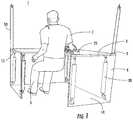
- FIG. 1is a schematic diagram of a tilting rehabilitation table system being used by a patient
- FIG. 2is a schematic diagram of the tilting rehabilitation table system
- FIG. 3is a schematic diagram in which a top surface of the tilting table is provided at an increased angle from the patient;
- FIG. 4is a schematic diagram in which the top surface of the tilting table is provided at an increased right angle from the patient;
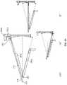
- FIG. 5is a schematic diagram of actuators of the tilting rehabilitation table system used with the tilting table
- FIG. 6is a detailed view of a top joint assembly connecting an actuator shaft to the top surface of the tilting table
- FIG. 7is a detailed view of a bottom joint assembly connecting an actuator shaft to the bottom surface of the tilting table
- FIG. 8is a side elevation view of patient wearing the forearm support assembly used in the tilting rehabilitation table system
- FIG. 9is a schematic diagram of an underside of a forearm support assembly of the tilting rehabilitation table.
- FIG. 10is a view of the patient wearing a shoulder harness assembly used in the tilting rehabilitation table system
- FIG. 11is a schematic diagram of an alternate embodiment of the tilting table
- FIG. 12is a schematic diagram of an alternate embodiment of the tilting table where top surface is a display
- FIG. 13is a system block diagram for the tilting rehabilitation table system
- FIG. 14is a schematic diagram of a patient baseline screen displayed by the tilting rehabilitation table system
- FIG. 15Ais a schematic diagram of a virtual scene displayed by the tilting rehabilitation table system
- FIG. 15Bis a schematic diagram of a virtual scene displayed by the tilting rehabilitation table system
- FIG. 15Cis a schematic diagram of a virtual scene displayed by the tilting rehabilitation table system
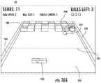
- FIG. 16Ais a schematic diagram of a virtual scene displayed by the tilting rehabilitation table system
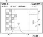
- FIG. 16Bis a schematic diagram of a virtual scene displayed by the tilting rehabilitation table system
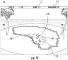
- FIG. 17is a schematic diagram of a virtual scene displayed by the tilting rehabilitation table system
- FIG. 18Ais a rear view schematic diagram of another aspect of the tilting rehabilitation table system.
- FIG. 18Bis a front view schematic diagram of another aspect of the tilting rehabilitation table system.
- FIG. 19is a schematic diagram of a base of the tilting rehabilitation table system of FIG. 18 ;
- FIG. 20is a schematic diagram of the tilting rehabilitation table system of FIG. 18 in a stowed position for storage and/or transport;
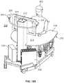
- FIG. 21is a schematic diagram of a lift and tilt mechanism of the tilting rehabilitation table system of FIG. 18 ;
- FIG. 22is a schematic diagram of a rolling assembly of the lift and tilt mechanism of FIG. 21 ;
- FIG. 23is a schematic diagram of a slit-pinion mechanism of the lift and tilt mechanism of FIG. 21 ;
- FIG. 24is a schematic diagram of an angle adjustment range of the lift and tilt mechanism of FIG. 21 .
- FIGS. 1 and 2illustrate tilting rehabilitation table system 1 .
- Tilting rehabilitation table system 1incorporates tilting table 2 which has top surface 3 and underside surface 4 .
- Top surface 3can be a U-shaped, symmetrical, low-friction surface.
- Underside surface 4can have a U-shape.
- low top surface 3can be made of carbon fiber, or other durable and light material, covered by a low-friction coating. Suitable low-friction coatings include TEFLON® sheets.
- Underside walls 14extend upwardly from underside surface 4 .
- Video camera 9is attached to vertical support 10 .
- Vertical support 10can be U-shaped and rigid. Vertical support 10 extends from and is attached to top surface 3 . This arrangement allows video camera 9 to view tilting table 2 and patient 5 simultaneously.
- Video camera 9can be a conventional digital camera.
- Infrared filter 11can be attached to lens 12 of video camera 9 .
- LEDs 13are mounted at the corners of top surface 3 and can be wired to direct current source (not shown).
- three LEDscan be used for providing calibration of video camera 9 .
- Vertical support 10is mounted to top surface 3 such that it keeps the same relative orientation regardless of tilt angle 15 of top surface 3 , thereby making re-calibration of video camera 9 unnecessary once tilt angle 15 changes during a rehabilitation session.
- Computer 16renders exercise simulation 17 and displays them on display 8 .
- exercise simulation 17can be an animated or virtual reality sequence.
- Computer 16is preferably a multi-core PC workstation.
- Computer 16also receives input from video camera 9 .
- Computer 16runs tracking software 18 and communicates with controller 19 .
- Controller 19activates actuators 20 to provide tilt of top surface 3 .
- Computer 16is connected to Internet 66 and transparently uploads clinical data 67 to remote clinical database server 68 .
- Remote computer 181 connected to clinical database server 68 over Internet 66is used to execute remote graphing software 180 .
- FIG. 3shows the orientation of top surface 3 and camera support 10 when tilt angle 15 is increased to move the angle away from patient 5 . Increased tilt angle 15 makes in/out movements of arm 7 more difficult.
- FIG. 4shows a different tilt of top surface 3 , in which tilt angle 15 is to the right of patient 5 .
- This tilt anglemakes arm movements from left-to-right more difficult than those when top surface 3 is horizontal.
- Other tilt angles 15can be used when the left side of top surface 3 is tilted up or when the side closer to patient 5 is tilted up. These make more difficult corresponding arm 7 movements, such as right-left or out-in, respectively.
- top surface 3can be tilted in four degrees of freedom.
- Tilt angle 15is produced by two or more actuators 20 placed under top surface 3 , as shown in FIG. 5 .
- Actuators 20are preferably linear electrical actuators. Actuators 20 are positioned under top surface 3 .
- Each actuator 20includes base 21 and translating shaft 22 .
- Translating shaft 22is connected to top surface 3 by top joint assembly 23 .
- Base 21is connected to underside walls 14 with bottom joint assembly 30 .
- Actuators 20are controlled by controller 19 .
- Controller 19can be a multi-channel micro-controller such as those which are available commercially. Controller 19 in turn receives commands from computer 16 running exercise simulation 17 .
- five actuators 20can be used and the amount of translation of actuator shaft 22 provides tilt angle 15 which can be varied from about 0 degrees (horizontal) to about 30 degrees. The more top surface 3 is tilted, the larger the effect gravity has due to the weight of arm 7 of patient 5 and of forearm support 25 and the harder exercise simulation 17 is to perform.
- FIG. 6shows a detailed view of top joint assembly 23 which connects actuator shaft 22 to the underside of top surface 3 .
- Top joint assembly 23has horizontal rotating joint 26 and vertical rotating joint 27 which together produce two degrees of freedom for top joint assembly 23 .
- the axis of rotation of horizontal rotating joint 26is perpendicular to the axis of rotation of vertical rotating joint 27 .
- Horizontal rotating joint 26is attached to the underside of top surface 3 using plate 28 and bolts 29 .
- FIG. 7shows a detailed view of bottom joint assembly 30 , which connects base 21 to the inner side of underside walls 14 .
- Bottom joint assembly 30has horizontal rotating joint 31 and vertical rotating joint 32 which together produce two degrees of freedom for bottom joint assembly 30 .
- the axis of rotation of horizontal rotating joint 31is perpendicular to the axis of rotation of vertical rotating joint 32 .
- Vertical rotating joint 32is attached to the inner side of underside walls 14 through plate 33 and bolts 34 .
- FIG. 8A side view of the patient 5 sitting in chair 6 and using of forearm support assembly 25 used by patient 5 is shown in FIG. 8 .
- Forearm 7 and wrist 35 of patient 5are secured to forearm support base 36 using a plurality of straps 37 .
- Stras 37can be formed of a hook and loop material of VELCRO®.
- Forearm support base 36can be made of a lightweight material such as plastic, and is hollow.
- Pressure sensor 41measures the air pressure inside hollow compliant element 44 .
- a suitable hollow compliant element 44can be a rubber ball. Grasping forces 45 exercised by fingers 46 of patient 5 are measured.
- Video camera 9 shown in FIG. 1views LED assembly 42 which is formed of two infrared LEDs 50 mounted on plastic support 51 for providing data on arm movements and rotation.
- LED assembly 42in turn is mounted on movable assembly 52 .
- Movable assembly 52rotates on hinges 53 attached to forearm support base 36 .
- Movable assembly 52rotates open to allow forearm 7 to be placed on forearm support top surface 54 .
- Forearm support top surface 54is preferably made of a compliant material (such as plastic foam), for increased comfort.
- Forearm support base 36has chambers 39 , 76 and 77 . Chamber 39 can be used to incorporate electronics assembly 40 to which is connected pressure sensor 41 . Output of pressure sensor 41 is processed by electronics assembly 40 .
- Electronics assembly 40includes an analog-to-digital converter 47 and wireless transmitter 48 .
- Transmitter 48can be a conventional wireless Bluetooth® type transmitter.
- Transmitter 48communicates with receiver 49 incorporated in computer 16 , as shown in FIG. 2 .
- Computer 16can change exercise simulation 17 according to grasping forces 45 of patient 5 .
- Computer 16can also change exercise simulation 17 based on forearm 7 position/orientation given by video camera 9 .
- exercise simulation 17can be rehabilitation games.
- LED assembly 42 and electronics assembly 40are connected to battery 43 in chamber 77 .
- Chamber 76 of base 36can be used to allow the addition of modular weights 56 .
- the addition of modular weights 56 to forearm support base 36allows an increased difficulty of exercise simulation 17 .
- the difficulty of performing exercise simulation 17is increased with the increase in modular weights 56 , with the increase in tilting angle 15 , and with the number and level of exercise simulation 17 .
- FIG. 9is a view of the underside of the forearm support assembly 25 .
- Underside surface 38 of forearm support 25has a plurality of low friction studs 55 .
- Low friction studs 55are preferably made of TEFLON®.
- FIG. 10shows shoulder harness assembly 57 worn by patient 5 on shoulder 58 opposite to arm 7 being rehabilitated.
- Shoulder harness assembly 57incorporates shoulder LED 59 wired to battery 60 .
- Shoulder LED 59is an infrared LED for providing data on compensatory movements of patient 5 .
- Harness assembly 57is formed of adjustable segments 61 . Segments 61 are preferably formed of a hook and loop material, such as VELCRO®.
- Video camera 9takes images of shoulder LED 59 .
- Tracking software 18 running on computer 16determines when patient 5 is doing undesirable compensatory leaning movements. Tracking software 18 can be adjusted by a therapist to be more sensitive, or less sensitive to leaning of patient 5 .
- FIG. 11illustrates an alternate embodiment of tilting table 62 for use with two forearm supports 25 .
- Top surface 3has a U-shape cutout 63 allowing patient 5 to be seated centrally to table axis 64 .
- Patient 5moves two arms 7 while supported by two low-friction forearm support assemblies 25 . This allows training of both arms simultaneously, with benefits to recovery of patient 5 .
- patient 5also wears one shoulder harness 57 , as it is sufficient to detect the leaning of the shoulder opposite to the disabled arm 7 .
- Video camera 9views LEDs 42 on both forearm support assemblies 25 , as well as LEDs 59 on one shoulder harness assembly 57 .
- Forearm support assembly 25is modified such that the number of infrared LEDs 42 differs between the two forearm support assemblies 25 .
- three LEDs 42will be on the left-arm forearm support 73 , while the right-arm support 71 still has two LEDs 42 as previously described in FIG. 8 .
- Thisallows tracking software 18 to differentiate between left arm and right arm movements. Tracking software 18 tracks two arms 7 in real time. Data from tracking software 18 is used by computer 16 to run two-arm exercise simulation 17 .
- the same type of actuators 20 as shown in FIG. 5can be used in this embodiment. Preferably, four actuators 20 are used in this embodiment.
- FIG. 12illustrates an alternate embodiment of tilting table 2 .
- top surface 3is also display 69 .
- display 69can be similar to commercially available thin organic LED (OLED) displays.
- the tracking of forearm 7may be performed by infrared camera 9 , or through a touch-sensitive layer 70 incorporated in display 69 .
- the display 69is a touch sensitive screen such as those available commercially.
- forearm support assembly 25is modified as shown in FIG. 11 .
- Actuator assembly 20can be connected to frame 72 bordering display 69 and to supporting surface 4 .
- a low-friction transparent film 75can be retrofitted to display 69 , to prevent scratching by the forearm support assemblies 71 and 73 that sit on it.
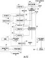
- FIG. 13A system block diagram for the tilting rehabilitation table system 1 is illustrated in FIG. 13 .
- Each rehabilitation sessionstarts with session start block 78 .
- Session start block 78loads the patient's ID and other clinical data 67 for arm 7 to be rehabilitated.
- Session start block 78transfers control to the session scheduler block 79 which sets the structure of a rehabilitation session, for example, number, type and order of exercises, as well as the difficulty level settings.
- Session scheduler block 79is structured such that it applies a customized treatment depending on progress of patient 5 (the order of the particular session being done out of the prescribed number of sessions).
- Session scheduler block 79begins by starting session baseline 80 which measures the performance of patient 5 in that day.
- Session baseline 80is stored transparently by clinical database server 68 and can be used to track progress of patient 5 over the sequence of rehabilitation sessions. Patient 5 progress can be graphed using remote graphing application 180 running on remote computer 181 . It is envisioned that remote computer 181 communicates with clinical database server over Internet 66 . Session baseline 80 is also used to fine-tune the “gains” of exercise simulation blocks 81 , 82 and 83 , such that in virtual reality movements are amplified and success assured even for very limited real arm 7 movements. Exercise simulation blocks 81 , 82 and 83 can perform exercise simulation 17 . Intelligent agent block 84 monitors the patient progress and can automatically vary tilt angle 15 to assist/resist movement.
- Intelligent agent block 84can control actuators 20 through their controller 19 connected to computer 16 running exercise simulation blocks 81 , 82 and 83 .
- Actuators 20provide data to exercise simulation blocks 81 , 82 and 83 such that virtual table (not shown) in the scene mimics tilt of tilting table 2 .
- Video camera 9detects the position of LEDs 50 at the top of forearm support assembly 25 and sends the information to tracking software 18 run by computer 16 .
- Tracking software 18extracts arm position information and body leaning information and transmits this data to exercise simulation blocks 81 , 82 and 83 . This data is then used to animate in real time an avatar of the patient's hand(s) (not shown).
- Manual emergency switch 85when pressed by attending therapist and/or patient 5 triggers an end to the rehabilitation session through software block 86 .
- FIG. 14illustrates an example of patient baseline screen 87 displayed in display 8 or on display 69 .
- Patient 5is asked to move the arm 7 in large circles to color virtual representation 88 of the rehabilitation table surface 3 .
- the surface of colored area 89increases with the movement of virtual sphere 90 which responds to the movements of forearm support assembly 25 .
- Size and shape of colored area 89are a measure of the ability of patient 5 that day. Extent of movement 91 in the left/right (horizontal) direction and extent of movement 92 in the in/out direction are used to adjust the rehabilitation exercise simulation blocks 81 , 82 and 83 .
- Baseline screen 87also shows tilt angle 15 at which baseline 80 was taken.
- FIG. 15Ashows an embodiment of rehabilitation exercise simulation block 81 with a virtual world representation having tilted table avatar 88 .
- Virtual sphere 94is shown on table surface 93 together with a virtual target rectangle 95 .
- An ideal path between virtual sphere 94 and virtual target rectangle 95is visualized by path shown as dotted line 96 .
- the placement of virtual target rectangle 95 and virtual sphere 94 on table surface 88is such that it requires patient 5 to move arm 7 close to extent of movement 91 and extent of movement 92 of baseline 87 .
- Patient 5is asked to pick up virtual sphere 94 with a semi-transparent hand avatar 98 and place it in virtual target rectangle area 95 .
- transparent hand avatar 98has to overlap virtual sphere 94 and patient 5 squeezes compliant element 44 on forearm support assembly 25 , as shown in FIG. 1 .
- Real movement of patient 5is tracked by video camera 9 and computer 16 shows a corresponding trace 97 on table surface 88 .
- FIG. 15Bshows an alternate embodiment of exercise simulation block 81 of the pick-and-place exercise in which ideal path 96 shown as a straight dotted line. This corresponds to in/out movements of arm 7 . This process is repeated a number of times, with the trial (repetition) number 190 and the total arm movement (endurance) 191 corresponding to these repetitions being displayed in simulation 81 .
- Other placements of virtual target rectangle 95 and virtual sphere 94can be used with corresponding ideal path specifications 96 .
- the difficulty exercise simulation block 81such as a pick-and-place exercise, is varied by making virtual target rectangle 95 smaller and by requiring patient 5 to make more pick-and-place movements. For patient 5 capable of exerting finger forces 45 , difficulty is further increased by elevating the threshold of finger grasping forces 45 detected by the forearm assembly 25 in FIG. 8 at which level corresponding hand avatar 98 can capture virtual sphere 94 .
- FIG. 15Cshows bundle of traces 99 displayed by exercise simulation block 81 at the end of exercises after a number of pick-and-place movements were completed.
- bundle of traces 99corresponds to repeated pick-and-place movements of arm 7 in the left-right-left direction.
- the tightness of bundle of traces 99is indicative of the motor control abilities that day for patient 5 .
- FIG. 16Ashows an embodiment of exercise simulation block 82 referred to “Breakout 3D”.
- This exercisedepicts ball 100 , paddle 101 , and array of cubes 102 , all located on play board 103 .
- Paddle 101is used to bounce ball 100 towards cubes 102 with one cube being destroyed for each bounce of ball 100 off of paddle 101 .
- Ball 100can bounce off of three sides 104 of play board 103 , or off multiple cubes 102 , but is lost if it misses paddle 101 .
- paddle 101can move mostly left-right, within the lower portion of play board 103 , delineated by dashed line 105 .
- the difficulty of exercise simulation block 82is set by the number of available balls 100 , the speed of balls 100 , and the size of paddle 101 .
- the goal of the Breakout 3D exercise simulation block 82is to destroy all cubes 102 with the available number of balls 100 .
- the Breakout 3D of exercise simulation block 82is designed to improve hand-eye coordination and cognitive anticipatory strategies of patient 5 .
- FIG. 16Bis another embodiment of the Breakout 3D of exercise simulation block 82 , in which board 103 is rotated to show array of cubes 102 to one side of the scene.
- paddle 101moves mostly vertically in the scene, within the area to the right of dotted line 105 , requiring corresponding in-out-in movements of arm 7 .
- FIG. 17is an embodiment of exercise simulation block 83 called “Treasure Hunt”.
- the scenedepicts deserted island 106 with line of stones 107 on top of virtual sand 108 .
- the shape of line of stones 107replicates the shape of baseline surface colored area 89 .
- Patient 5controls virtual shovel 110 with which to remove sand 108 covering treasure chests 109 . Every time a new treasure chest 109 is found score 111 displayed in the scene is increased. In order to find a new treasure chest 109 shovel 110 has to be moved in sand 108 that overlaps treasure chest 109 .
- tracking software 18detects leaning of patient 5 treasure chest 109 is not revealed even if shovel 110 is in the correct position and score 111 is not increased.
- a sand stormoccurs. Part of the already uncovered treasure chests 109 are covered again by sand 108 requiring more movement of arm 7 of patient 5 arm 7 to uncover treasure chest 109 again.
- the Treasure Hunt exercise simulation block 83is timed and remaining time 112 is displayed at the top of the scene. Patient 5 attempts to uncover all of treasure chests 109 in the allowed amount of time 112 . This exercise is aimed at increasing arm endurance of patient 5 . In other embodiments, other simulation exercises can be played by patient 5 .
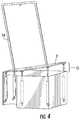
- FIGS. 18A and 18Bare respectively rear and front view schematic diagrams of another aspect of the tilting rehabilitation table system 200 .
- the tilting and lifting rehabilitation table system 200includes a infrared emitter system 204 , a display 206 , a hollow vertical support 210 , a tilting and lifting table 214 , a base 230 , a computer 232 and a control box 233 .
- the tilting and lifting table 214has a top surface 216 and an underside surface 218 .
- the tilting and lifting table 214may have a shape matching the perimeter of a person's arm span reaching forward and sweeping back, with a parabolic entry 215 to accommodate a patient 202 when seated at the tilting and lifting table 214 of the tilting rehabilitation table system 200 .
- the parabolic entry 215accommodates a torso of the patient 202 .
- the parabolic entry 215may also accommodate a manually operated (e.g., a wheel chair) or a power-driven device designed for use by a patient 202 with a mobile disability.
- the parabolic entry 215is placed such that the tilting axis 3000 of the top surface 216 passes through the torso of patient 202 .
- a sensor 222 amay be positioned on an interior wall 220 a of the parabolic entry 215 and another sensor 222 b may be positioned on an interior wall 220 b of the parabolic entry 215 .
- the sensors 222 a and 222 bmay be infrared or LED sensors or the like.
- the sensors 222 a and 222 bmay detect whether a patient 202 is properly seated at the tilting and lifting table 214 of the tilting rehabilitation table system 200 by detecting whether a beam between the sensors 222 a and 222 b is interrupted when the patient 202 is seated.
- at least one sensor 226(not illustrated) may be positioned on the underside surface 218 of the tilting and lifting table 214 .
- the sensor 226may be also be an infrared or LED sensor or the like.
- the sensor 226may detect a position of the legs of the patient 202 via an infrared beam such that the tilting and lifting table 214 does not immediately contact the legs of the patient 202 .
- the tilting and lifting table 214may be symmetrical, light weight and have a low-friction top surface.
- the tilting and lifting table 214may be carbon fiber or another durable and light weight material wherein the top surface 216 has a low-friction coating.
- Suitable low-friction coatingsmay include TEFLON® sheets or Formica or other such materials.
- the patient 202rests at least one arm to be rehabilitated on the top surface 216 of the tilting and lifting table 214 wherein the at least one arm is positioned in a low-friction forearm controller (not illustrated) to allow for pronation and supination forearm rotation.
- the low-friction underside of the forearm controllerminimizes friction between the at least one arm of the patient 202 and the top surface 216 of the tilting and lifting table 214 as the patient 202 moves the forearm controller over the top surface 216 .
- the low-friction forearm controllermay be a controller as disclosed in U.S. patent application Ser. No. 15/669,952.
- the tilting and lifting rehabilitation table system 200may benefit a patient 202 with at least one weak arm such as a patient 202 who has survived a stroke.
- the tilting and lifting rehabilitation system 200may also benefit a patient 202 having chronic upper body pain (e.g., nerve pain), a traumatic brain injury (e.g., a brain concussion) and/or arthritis (e.g., rheumatoid arthritis), or any patient in need of physical and/or mental rehabilitation.
- chronic upper body paine.g., nerve pain
- a traumatic brain injurye.g., a brain concussion
- arthritise.g., rheumatoid arthritis
- a size of the tilting and lifting table 214may meet at least the ninetieth percentile of an average adult's reach when seated at the tilting and lifting table 214 of the tilting rehabilitation table system 200 . Accordingly, the tilting rehabilitation table system 200 requires less clinical space for operation, transport when stowed (e.g., the system 200 may fit through a doorway) and storage when stowed. For example, tilting and lifting table 214 has reduced size than tilting table 224 of other aspects of the tilting and lifting rehabilitation table system.
- the patient 202exercises via the forearm controller while viewing a graphic display 208 on a display 206 .
- the display 206may be a medical grade monitor or television (e.g., a high-definition television (HDTV)), have any suitable dimensions, large or small, such as a television of 43′′ diagonal, or larger, or smaller, and include at least one speaker to provide sounds associated with the graphic display 208 .
- the display 206is mounted on a vertical support 210 such that the patient 202 may view the graphic display 208 on the display 206 when seated at the tilting and lifting table 214 even when the tilting and lifting table 214 is positioned at an angle.
- the vertical support 210may be rigid, hollow and houses a lift and tilt mechanism 212 for modifying a position of the tilting and lifting table 214 relative to the patient 202 .
- Infrared emitters 204are also mounted on the vertical support 210 , or on the TV, via a rigid U-shaped support 228 , or other suitable mounting means, wherein the infrared emitters 204 are fixed on the support 228 and positioned at or above the display 206 .
- the infrared emitters 204may also be positioned to be even with sides of the display 206 .
- the infrared emitters 204may be HTC VIVE infrared emitters, which are commercially available. Alternatively, the infrared emitters 204 may be conventional digital cameras having infrared filters attached to the lenses thereof.
- the arrangement of the infrared emitters 204 and display 206 relative to the patient 202allows the infrared emitters 204 to be directed to the tilting and lifting table 214 and patient 202 simultaneously.
- Infrared receivers/detectorsmay be mounted on the top surface 216 of the tilting and lifting table 214 to calibrate the infrared emitters 204 and to locate movement and position on the patient's arms during use.
- the support bar 228is mounted to the vertical support 210 such that the support bar 228 maintains the same relative orientation regardless of a tilt angle of the top surface 216 , thereby making re-calibration of the infrared emitters 204 unnecessary if a tilt angle of the tilting and lifting table 214 changes during a rehabilitation session.
- the vertical support 210is positioned on a top frame 234 of the base 230 such that the legs of the patient 202 may be accommodated under the tilting and lifting table 214 without interference from a base of the vertical support 210 .
- Computer 232may be enclosed in a box for safety and protection, while a control box 233 ( FIG. 18 b ) houses at least one electronic controller to control actuators located in vertical support 210 .
- Computer 232renders an exercise simulation displayed as a graphic display 208 on the display 206 .
- the exercise simulationmay be an animated sequence or a virtual reality sequence.
- the exercise simulation 17could be at least one game.
- Gamesmay be a plurality of simulations 17 , may differ and may be sequenced to form an integrative rehabilitation session wherein the cognitive, motor and emotive aspects of a patient 202 are treated simultaneously.
- the brain of a patient 202may be engaged by playing the games with at least one arm and hand.
- the computer 232may be a multi-core PC workstation. To render graphics quickly, it is appreciated that computer 232 may incorporate a graphics card (not shown). Computer 232 receives an input from the forearm supports based on signals from the infrared emitters 204 . As mentioned above with reference to FIG. 2 , the computer 232 may execute tracking software and communicate with a electronic controller positioned inside the control box 233 , wherein the controller activates actuators to tilt the tilting and lifting table 214 during a rehabilitative session. The computer 232 may also be connected to the Internet and upload clinical data based on the rehabilitative session to a remote clinical database server. It is appreciated that such clinical data may be an automatically-generated session report.
- the computermay store and upload clinical data including but not limited to specific games played, duration, performance, scores, error rates, cognitive area trained and a number of movement repetitions by the arms and fingers of a patient 202 .
- the computer 232may also compose a rehabilitative session report that may be presented locally on the display 206 and/or transmitted to a remote clinician.
- the tilting and lifting rehabilitation table system 200provides advantages over conventional systems and methods relating to an elevated intensity of a rehabilitation session and lower costs of a rehabilitation session based on the automated collection, compilation and transmission of clinical data regarding the rehabilitation session. Further advantages of the system 200 is that the system 200 allows for training both arms simultaneously, which is associated with a higher level of brain training and physical exercise. Yet another advantage of the system 200 is increased patient 202 safety. The system 200 is passive wherein actuators are not connected directly to the arms of a patient 202 , unlike rehabilitation robots which are active elements.
- FIG. 19is a schematic diagram of the base 230 of the tilting and lifting rehabilitation table system 200 .
- the base 230includes a top frame 234 , a rear frame 236 , a first side frame 238 a and a second side frame 238 b (not illustrated) wherein a first leg frame 240 a extends from the first side frame 238 a and a second leg frame 240 b extends from the second side frame 238 b .
- the vertical support 210is positioned on a top surface of the top frame 234 such that the legs of the patient 202 may be accommodated under the tilting and lifting table 214 without interference from a base of the vertical support 210 .
- the first side frame 238 a and the second side frame 238 brespectively extend from the rear frame 236 at obtuse angles ⁇ 1 and ⁇ 2 (not illustrated) such that a distance between the first leg frame 240 a and the second leg frame 240 b is greater than a length of the rear frame 236 .
- the base 230may accommodate a base portion (or foot support mechanism) of a manually operated (e.g., a wheel chair) or a power-driven device designed for use by a patient 202 with a mobile disability.
- FIG. 20is a schematic diagram of the tilting and lifting rehabilitation table system of FIG. 18 in a stowed position for storage and/or transport.
- a size of the tilting and lifting table 214may meet at least the ninetieth percentile of an average adult's reach when seated at the tilting and lifting table 214 of the tilting and lifting rehabilitation table system 200 . Accordingly, the tilting and lifting rehabilitation table system 200 requires less clinical space for operation, transport when stowed (e.g., the system 200 may fit through a doorway) and storage when stowed.
- tilting and lifting table 214is smaller than tilting table 224 of another embodiment of the tilting rehabilitation table system.
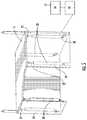
- FIG. 21is a schematic diagram of a lift and tilt mechanism 212 of the tilting and lifting rehabilitation table system 200 of FIG. 18 .
- the lift and tilt mechanism 212includes a first actuator 250 a coupled to a first vertical shuttle 252 a , a second actuator 250 b coupled to a second vertical shuttle 252 b , a vertical linkage system 254 , a rolling assembly 256 , a lateral linkage system 258 including a first support 260 a and a second support 260 b and a slit-pinion mechanism 262 .
- the vertical support 210houses the first actuator 250 a , the first vertical shuttle 252 a , the second actuator 250 b and the second vertical shuttle 252 b , the vertical linkage system 254 and the slit-pinion mechanism 262 .
- a height of the tilting and lifting table 214may be modified by the first actuator 250 a in combination with the rolling assembly 256
- An angle of the tilting and lifting table 214may be modified by the second actuator 250 b in combination with the slit-pinion mechanism 262 .
- the first actuator 250 a and the second actuator 250 bmay be linear electrical actuators.
- the first actuator 250 amay be a Progressive Automations PA-18_10 linear actuator and the second actuator 250 b may be a Progressive Automations PA-18-30 linear actuator.
- a control box 233( FIG. 18 b ) positioned on the base 230 houses electronics that control each of the first actuator 250 a and the second actuator 250 b .
- a controllercontrols the first actuator 250 a and the second actuator 250 b based on received commands from the computer 232 when executing an exercise simulation.
- the controllermay be a commercially available multi-channel micro-controller or another commercially available conventional controller.
- a first independent string potentiometer(not shown) measures a position of the first actuator 250 a .
- a second independent string potentiometermeasures a position of the second actuator 250 b .
- the combination of inputs from the first and the second string potentiometersprovides feedback to the controller to enable accurate control of each of the first actuator 250 a and the second actuator 250 b .
- the first string potentiometeris unwound by the linear movement of the first actuator 250 a and the second string potentiometer is unwound by the linear movement of the second actuator 250 b.
- FIG. 22is a schematic diagram of the rolling assembly 256 of the lift and tilt mechanism 212 of FIG. 21 .
- the first actuator 250 ahas an anchor point coupled to the first vertical shuttle 252 a and performs lift actuation to modify a height of the tilting and lifting table 214 . Modifying a height of the tilting and lifting table 214 provides for accommodating varying body types of patients seated at the tilting and lifting table 214 .
- the rolling assembly 256includes a plurality of plastic roller pairs 270 , a metal plate 272 having an extension 274 and an opening 276 , and a mating bar 278 positioned within the opening 276 .
- the plurality of plastic roller pairs 270are configured such that respective rollers of a pair are positioned on opposite sides of the metal plate 272 .
- half of the plurality of plastic roller pairs 270may be positioned within the vertical support 210 and half of the plurality of plastic roller pairs 270 may be positioned outside of the vertical support 210 .
- the plurality of plastic roller pairs 270may include plastic rollers similar to those known in the art (e.g., roller blade rollers). It is envisioned that such plastic rollers reduce the noise generated when lifting or lowering the table 214 .
- the extension 274couples the rolling assembly 256 to the first vertical shuttle 252 a and the opening 276 couples the rolling assembly 256 to the lateral linkage system 258 .
- the mating bar 278positioned within the opening 276 , may be positioned within the first support 260 a to couple the rolling assembly 256 to the first support 260 a of the lateral linkage system 258 .
- the first actuator 250 a and first vertical shuttle 252 a in combination with the rolling assembly 256may modify the height of the tilting and lifting table 214 with minimal noise and/or vibration. It is appreciated that the plurality of plastic roller pairs 270 may be vibration dampeners and motion guides.
- FIG. 23is a schematic diagram of a slit-pinion mechanism 262 of the lift and tilt mechanism of FIG. 21 .
- the second actuator 250 bhas an anchor point coupled to the second vertical shuttle 252 b and performs tilt actuation to modify an angle of the tilting and lifting table 214 .
- the slit-pinion mechanism 262couples the second actuator 250 b and second vertical shuttle 252 b to the tilting and lifting table 214 .
- the slit-pinion mechanism 262provides for a rotary tilting movement of the tilting and lifting table 214 in comparison to the linear and vertical movement of the second actuator 250 b and the second vertical shuttle 252 b . Modifying an angle of the tilting and lifting table 214 modulates gravity acting on the arms of a patient 202 .
- tilting the tilting and lifting table 214 downfacilitates movement of the arms of the patient 202 away from a trunk of the patient 202 .
- tilting the tilting and lifting table 214 upresists the movement of the arms of the patient 202 away from the trunk of the patient 202 .
- FIG. 24is a schematic diagram of an angle adjustment range of the lift and tilt mechanism 212 of FIG. 21 .
- the lateral linkage system 258includes a first support 260 a coupled to the roller assembly 256 and a second support 260 b coupled to the underside surface 218 of the tilting and lifting table 214 wherein the first support 260 a and the second support 260 b are coupled together by a rotary joint 264 .
- the slit-pinion mechanism 262couples the second actuator 250 b and second vertical shuttle 252 b to the tilting and lifting table 214 .
- the combination of the second actuator 250 b and the second vertical shuttle 252 b , the lateral linkage system 258 and the slit-pinion mechanism 262provides for modifying an angle of the tilting and lifting table 214 .
- the tilting and lifting rehabilitation table system 200may utilize twenty-four inches of a thirty inch effective stroke span of the second actuator 250 b which provides for a +20° to ⁇ 15° angle adjustment range and adjustable difficulty levels for a patient 202 .
- the second actuator 250 a and second vertical shuttle 252 bare coupled to the first actuator 250 a and first vertical shuttle 252 a via a linkage system 254 .
- the linkage system 254provides for modifying a height of the tilting and lifting table 214 without modifying an angle of the same.
Landscapes
- Health & Medical Sciences (AREA)
- Engineering & Computer Science (AREA)
- Mechanical Engineering (AREA)
- Vascular Medicine (AREA)
- Biomedical Technology (AREA)
- Heart & Thoracic Surgery (AREA)
- Orthopedic Medicine & Surgery (AREA)
- Life Sciences & Earth Sciences (AREA)
- Animal Behavior & Ethology (AREA)
- General Health & Medical Sciences (AREA)
- Public Health (AREA)
- Veterinary Medicine (AREA)
- Nursing (AREA)
- Rehabilitation Tools (AREA)
Abstract
Description
Claims (14)
Priority Applications (1)
| Application Number | Priority Date | Filing Date | Title |
|---|---|---|---|
| US15/872,964US11136234B2 (en) | 2007-08-15 | 2018-01-16 | Rehabilitation systems and methods |
Applications Claiming Priority (4)
| Application Number | Priority Date | Filing Date | Title |
|---|---|---|---|
| US96486107P | 2007-08-15 | 2007-08-15 | |
| US12/192,848US7762434B2 (en) | 2004-03-31 | 2008-08-15 | Refillable material transfer system |
| US14/575,519US9868012B2 (en) | 2007-08-15 | 2014-12-18 | Rehabilitation systems and methods |
| US15/872,964US11136234B2 (en) | 2007-08-15 | 2018-01-16 | Rehabilitation systems and methods |
Related Parent Applications (1)
| Application Number | Title | Priority Date | Filing Date |
|---|---|---|---|
| US14/575,519Continuation-In-PartUS9868012B2 (en) | 2007-08-15 | 2014-12-18 | Rehabilitation systems and methods |
Publications (3)
| Publication Number | Publication Date |
|---|---|
| US20180237284A1 US20180237284A1 (en) | 2018-08-23 |
| US11136234B2true US11136234B2 (en) | 2021-10-05 |
| US20210316984A9 US20210316984A9 (en) | 2021-10-14 |
Family
ID=63166528
Family Applications (1)
| Application Number | Title | Priority Date | Filing Date |
|---|---|---|---|
| US15/872,964Active2029-08-09US11136234B2 (en) | 2007-08-15 | 2018-01-16 | Rehabilitation systems and methods |
Country Status (1)
| Country | Link |
|---|---|
| US (1) | US11136234B2 (en) |
Families Citing this family (2)
| Publication number | Priority date | Publication date | Assignee | Title |
|---|---|---|---|---|
| CN109730653B (en)* | 2018-12-07 | 2023-12-29 | 南京医科大学 | Hand rehabilitation evaluation system and method for cerebral apoplexy patient |
| JP6714285B1 (en)* | 2019-07-31 | 2020-06-24 | 株式会社mediVR | Rehabilitation support device and rehabilitation support method |
Citations (115)
| Publication number | Priority date | Publication date | Assignee | Title |
|---|---|---|---|---|
| US4002165A (en) | 1974-05-07 | 1977-01-11 | Gertrud Agnes Matilda Lind | Auto-traction table |
| US4337050A (en) | 1979-12-03 | 1982-06-29 | Baltimore Therapeutic Equipment Company | Method and apparatus for rehabilitation of damaged limbs |
| US4375674A (en) | 1980-10-17 | 1983-03-01 | The United States Of America As Represented By The Administrator Of The National Aeronautics And Space Administration | Kinesimetric method and apparatus |
| US4471957A (en) | 1979-12-03 | 1984-09-18 | Baltimore Therapeutic Equipment Company | Method and apparatus for rehabilitation of damaged limbs |
| US4637789A (en) | 1985-05-13 | 1987-01-20 | Netznik Frederick P | Cushion fabrication apparatus |
| US4773639A (en) | 1985-08-21 | 1988-09-27 | Graves Kurt M | Infant walker |
| US4861051A (en) | 1988-06-06 | 1989-08-29 | Napper John C | Rehabilitation walker device |
| US4885687A (en) | 1986-05-08 | 1989-12-05 | Regents Of The University Of Minnesota | Trackig instrumentation for measuring human motor control |
| US4976426A (en) | 1989-09-06 | 1990-12-11 | Garden Reach Developments Ltd. | Rehabilitation exercise device |
| US5186695A (en) | 1989-02-03 | 1993-02-16 | Loredan Biomedical, Inc. | Apparatus for controlled exercise and diagnosis of human performance |
| US5241952A (en) | 1992-03-30 | 1993-09-07 | Ortiz David G | Therapeutic range-of-motion exercise device |
| US5265589A (en) | 1993-01-13 | 1993-11-30 | Wang Yuen Fu | Multiple-rehabilitation-equipment supporter |
| US5350304A (en) | 1991-12-05 | 1994-09-27 | Smith & Nephew Rolyan, Inc. | Method of rehabilitating muscles and neurological pathways in a patient using a multifunctional therapeutic workstation kit |
| US5466213A (en) | 1993-07-06 | 1995-11-14 | Massachusetts Institute Of Technology | Interactive robotic therapist |
| US5518475A (en) | 1995-04-20 | 1996-05-21 | Garland; Thomas A. | Baby walker |
| US5692517A (en) | 1993-01-06 | 1997-12-02 | Junker; Andrew | Brain-body actuated system |
| US5700201A (en) | 1995-11-09 | 1997-12-23 | Graco Children's Products Inc. | Child entertainment device with flexible support legs |
| US5728030A (en) | 1996-07-29 | 1998-03-17 | Hsieh; Charles Ping-Chao | Infant training walker |
| US5827072A (en) | 1996-02-21 | 1998-10-27 | Neufer; David J. | Graphic, sports-related instruction board |
| US5846086A (en) | 1994-07-01 | 1998-12-08 | Massachusetts Institute Of Technology | System for human trajectory learning in virtual environments |
| US5871445A (en)* | 1993-04-26 | 1999-02-16 | St. Louis University | System for indicating the position of a surgical probe within a head on an image of the head |
| US5913749A (en) | 1991-05-10 | 1999-06-22 | Harmon; Larry Shane | Adaptable range-of-motion exercise apparatus |
| US5954621A (en) | 1993-07-09 | 1999-09-21 | Kinetecs, Inc. | Exercise apparatus and technique |
| US5976063A (en) | 1993-07-09 | 1999-11-02 | Kinetecs, Inc. | Exercise apparatus and technique |
| US5980435A (en) | 1993-07-09 | 1999-11-09 | Kinetecs, Inc. | Methods of therapy or controlled exercise using a jointed brace |
| US5986224A (en) | 1995-04-19 | 1999-11-16 | Elo Touchsystems, Inc. | Acoustic condition sensor employing a plurality of mutually non-orthogonal waves |
| US6162189A (en) | 1999-05-26 | 2000-12-19 | Rutgers, The State University Of New Jersey | Ankle rehabilitation system |
| US6302037B1 (en) | 1997-10-20 | 2001-10-16 | Paul J. Del Frari | Posture stabilizing demountable component table system |
| US20010034014A1 (en) | 2000-03-24 | 2001-10-25 | Tetsuo Nishimoto | Physical motion state evaluation apparatus |
| US6334778B1 (en) | 1994-04-26 | 2002-01-01 | Health Hero Network, Inc. | Remote psychological diagnosis and monitoring system |
| US6413190B1 (en) | 1999-07-27 | 2002-07-02 | Enhanced Mobility Technologies | Rehabilitation apparatus and method |
| US6416447B1 (en) | 1999-06-21 | 2002-07-09 | Larry Shane Harmon | Adaptable range-of-motion exercise apparatus |
| US20020103429A1 (en) | 2001-01-30 | 2002-08-01 | Decharms R. Christopher | Methods for physiological monitoring, training, exercise and regulation |
| US6454681B1 (en) | 1998-01-05 | 2002-09-24 | Thomas Brassil | Hand rehabilitation glove |
| US20030028130A1 (en) | 2001-08-04 | 2003-02-06 | Craig Wunderly | Machine for upper limb physical therapy |
| US20030077556A1 (en) | 1999-10-20 | 2003-04-24 | French Barry J. | Education system challenging a subject's physiologic and kinesthetic systems to synergistically enhance cognitive function |
| US20030120183A1 (en) | 2000-09-20 | 2003-06-26 | Simmons John C. | Assistive clothing |
| US6592315B2 (en) | 2000-05-08 | 2003-07-15 | William Joseph Osborne, Jr. | Self-feeding apparatus with hover mode |
| US6613000B1 (en) | 2000-09-30 | 2003-09-02 | The Regents Of The University Of California | Method and apparatus for mass-delivered movement rehabilitation |
| US20040006287A1 (en) | 2002-07-03 | 2004-01-08 | Epley John M. | Comprehensive vertigo management |
| US6682139B2 (en) | 1999-05-26 | 2004-01-27 | Graco Children's Products Inc. | Child activity center, entertainment system, and components thereof |
| US6817864B1 (en) | 2002-06-03 | 2004-11-16 | Irene Martinez | Infant motor skill developmental aid apparatus |
| US20050065452A1 (en) | 2003-09-06 | 2005-03-24 | Thompson James W. | Interactive neural training device |
| US20050091749A1 (en) | 2003-10-31 | 2005-05-05 | Humbles Frank F. | Surgical arm positioning pad |
| US20050113652A1 (en) | 1999-06-23 | 2005-05-26 | Izex Technologies, Inc. | Remote psychological evaluation |
| US20050167907A1 (en) | 2003-11-26 | 2005-08-04 | Curkendall Leland D. | Method and apparatus for portable exercise system with electronic targets |
| US20050181347A1 (en) | 2004-01-16 | 2005-08-18 | Barnes Phineas A. | Instructional gaming methods and apparatus |
| US20050187071A1 (en) | 2002-10-24 | 2005-08-25 | Hidekazu Ogawa | Repositioning device, garment, and posture molding method and training instruction method using them |
| US20050216243A1 (en) | 2004-03-02 | 2005-09-29 | Simon Graham | Computer-simulated virtual reality environments for evaluation of neurobehavioral performance |
| US20050283053A1 (en) | 2002-01-30 | 2005-12-22 | Decharms Richard C | Methods for physiological monitoring, training, exercise and regulation |
| US20060001296A1 (en) | 2004-04-21 | 2006-01-05 | Riach Jeffrey M | Articulating table |
| US20060079817A1 (en) | 2004-09-29 | 2006-04-13 | Dewald Julius P | System and methods to overcome gravity-induced dysfunction in extremity paresis |
| US20060161218A1 (en) | 2003-11-26 | 2006-07-20 | Wicab, Inc. | Systems and methods for treating traumatic brain injury |
| US20060195018A1 (en) | 2005-02-25 | 2006-08-31 | Diego Guillen | Reflex tester and method for measurement |
| US20060241718A1 (en) | 2003-11-26 | 2006-10-26 | Wicab, Inc. | Systems and methods for altering brain and body functions and for treating conditions and diseases of the same |
| US20060293617A1 (en) | 2004-02-05 | 2006-12-28 | Reability Inc. | Methods and apparatuses for rehabilitation and training |
| US20070003915A1 (en) | 2004-08-11 | 2007-01-04 | Templeman James N | Simulated locomotion method and apparatus |
| US20070043308A1 (en) | 2005-08-22 | 2007-02-22 | Kyungpook National University Industry-Academic Cooperation Foundation | Apparatus and method for lower-limb rehabilitation |
| US20070060445A1 (en) | 2005-08-31 | 2007-03-15 | David Reinkensmeyer | Method and apparatus for automating arm and grasping movement training for rehabilitation of patients with motor impairment |
| US20070060849A1 (en) | 2003-04-30 | 2007-03-15 | Nini Bluman | Method and system for motion improvement |
| US7204814B2 (en) | 2003-05-29 | 2007-04-17 | Muscle Tech Ltd. | Orthodynamic rehabilitator |
| US20070087901A1 (en) | 1998-01-05 | 2007-04-19 | Brassil Thomas W | Therapy system |
| US20070100214A1 (en) | 2005-03-10 | 2007-05-03 | Steinert John W | Method and apparatus for stimulating exercise |
| US20070136093A1 (en) | 2005-10-11 | 2007-06-14 | Rankin Innovations, Inc. | Methods, systems, and programs for health and wellness management |
| US7257237B1 (en) | 2003-03-07 | 2007-08-14 | Sandia Corporation | Real time markerless motion tracking using linked kinematic chains |
| US20070191141A1 (en) | 2006-02-13 | 2007-08-16 | Mark Weber | Interactive sports training device |
| US20070250119A1 (en) | 2005-01-11 | 2007-10-25 | Wicab, Inc. | Systems and methods for altering brain and body functions and for treating conditions and diseases of the same |
| US20070254787A1 (en) | 2006-04-27 | 2007-11-01 | Konami Sports & Life Co., Ltd. | Training apparatus |
| US20070282228A1 (en) | 2004-02-05 | 2007-12-06 | Omer Einav | Methods and Apparatus for Rehabilitation and Training |
| US20080009772A1 (en) | 2003-11-26 | 2008-01-10 | Wicab, Inc. | Systems and methods for altering brain and body functions and for treating conditions and diseases of the same |
| US20080009771A1 (en) | 2006-03-29 | 2008-01-10 | Joel Perry | Exoskeleton |
| US20080036737A1 (en) | 2006-08-13 | 2008-02-14 | Hernandez-Rebollar Jose L | Arm Skeleton for Capturing Arm Position and Movement |
| US20080061949A1 (en) | 2004-07-29 | 2008-03-13 | Kevin Ferguson | Human movement measurement system |
| US20080132383A1 (en) | 2004-12-07 | 2008-06-05 | Tylerton International Inc. | Device And Method For Training, Rehabilitation And/Or Support |
| US20080139975A1 (en) | 2004-02-05 | 2008-06-12 | Motorika, Inc. | Rehabilitation With Music |
| US7394459B2 (en) | 2004-04-29 | 2008-07-01 | Microsoft Corporation | Interaction between objects and a virtual environment display |
| US7401783B2 (en) | 1999-07-08 | 2008-07-22 | Pryor Timothy R | Camera based man machine interfaces |
| US20080242521A1 (en) | 2004-02-05 | 2008-10-02 | Motorika, Inc. | Methods and Apparatuses for Rehabilitation Exercise and Training |
| US20080281633A1 (en) | 2007-05-10 | 2008-11-13 | Grigore Burdea | Periodic evaluation and telerehabilitation systems and methods |
| US20080319349A1 (en) | 2005-04-18 | 2008-12-25 | Yitzhak Zilberman | System and Related Method For Determining a Measurement Between Locations on a Body |
| US7476102B2 (en) | 2006-06-09 | 2009-01-13 | Maples Paul D | Contamination avoiding device |
| US20090023122A1 (en) | 2007-07-19 | 2009-01-22 | Jeff Lieberman | Motor Learning And Rehabilitation Using Tactile Feedback |
| US20090091229A1 (en) | 2007-10-05 | 2009-04-09 | Karl Richard B | Intensive use furniture |
| US7525538B2 (en) | 2005-06-28 | 2009-04-28 | Microsoft Corporation | Using same optics to image, illuminate, and project |
| US7523984B2 (en) | 2006-02-28 | 2009-04-28 | Evenflo Company, Inc. | Reconfigurable infant activity center |
| US20090131225A1 (en)* | 2007-08-15 | 2009-05-21 | Burdea Grigore C | Rehabilitation systems and methods |
| US20090227888A1 (en) | 2005-12-20 | 2009-09-10 | Smart Valley Software Oy | Method and an apparatus for measuring and analyzing movements of a human or an animal using sound signals |
| US20090233769A1 (en) | 2001-03-07 | 2009-09-17 | Timothy Pryor | Motivation and enhancement of physical and mental exercise, rehabilitation, health and social interaction |
| US20090305207A1 (en) | 2005-12-12 | 2009-12-10 | Hiromu Ueshima | Training method, training device, and coordination training method |
| US7648473B1 (en) | 2006-09-18 | 2010-01-19 | Jedheesh Peruvingal | Traction extension table |
| US20100016766A1 (en) | 2007-02-16 | 2010-01-21 | Rehabtek Llc | Robotic rehabilitation apparatus and method |
| US20100068686A1 (en) | 2005-12-12 | 2010-03-18 | Hiromu Ueshima | Memory testing apparatus, judgment testing apparatus, comparison-faculty testing apparatus, coordination training apparatus, and working memory training apparatus |
| US7725175B2 (en) | 2002-12-04 | 2010-05-25 | Kinetic Muscles, Inc. | System and method for neuromuscular reeducation |
| US20100179453A1 (en) | 2008-11-14 | 2010-07-15 | University Of Southern California | Upper Limb Measurement and Rehabilitation Method and System |
| US20100182220A1 (en) | 2009-01-16 | 2010-07-22 | Microsoft Corporation | Surface puck |
| US20100204616A1 (en) | 2006-01-09 | 2010-08-12 | Applied Technology Holdings, Inc. | Apparatus, systems, and methods for gathering and processing biometric and biomechanical data |
| US20100234182A1 (en) | 2009-01-15 | 2010-09-16 | Saebo, Inc. | Neurological device |
| US20100271315A1 (en) | 2009-04-28 | 2010-10-28 | Microsoft Corporation | Encoding and decoding adaptive input device inputs |
| US7856264B2 (en) | 2005-10-19 | 2010-12-21 | Advanced Neuromodulation Systems, Inc. | Systems and methods for patient interactive neural stimulation and/or chemical substance delivery |
| US7880717B2 (en) | 2003-03-26 | 2011-02-01 | Mimic Technologies, Inc. | Method, apparatus, and article for force feedback based on tension control and tracking through cables |
| US20110112441A1 (en) | 2007-08-15 | 2011-05-12 | Burdea Grigore C | Combined Cognitive and Physical Therapy |
| US8012108B2 (en) | 2005-08-12 | 2011-09-06 | Bonutti Research, Inc. | Range of motion system and method |
| US20110319166A1 (en) | 2010-06-23 | 2011-12-29 | Microsoft Corporation | Coordinating Device Interaction To Enhance User Experience |
| US20120108909A1 (en) | 2010-11-03 | 2012-05-03 | HeadRehab, LLC | Assessment and Rehabilitation of Cognitive and Motor Functions Using Virtual Reality |
| US20120157263A1 (en) | 2009-01-20 | 2012-06-21 | Mark Sivak | Multi-user smartglove for virtual environment-based rehabilitation |
| US20130061395A1 (en) | 2011-07-20 | 2013-03-14 | Norix Group, Inc. | Intensive Use Bed |
| US20150099614A1 (en) | 2013-10-07 | 2015-04-09 | Daniel R. Tekulve | Portable rehab station |
| US20160038075A1 (en) | 2012-09-21 | 2016-02-11 | Bright Cloud International Corporation | Bimanual computer games system for dementia screening |
| US20160144229A1 (en) | 2013-07-02 | 2016-05-26 | New York University | Modular multi-joint rehabilitation training system and method |
| US9351857B2 (en) | 2010-11-15 | 2016-05-31 | Advanced Mechanical Technology, Inc. | Method and apparatus for joint motion simulation |
| US20160166451A1 (en) | 2014-10-20 | 2016-06-16 | Daniel Tekulve | Portable rehab station with standing assist |
| US9724598B2 (en) | 2012-09-21 | 2017-08-08 | Bright Cloud International Corp. | Bimanual integrative virtual rehabilitation systems and methods |
| US20180214761A1 (en) | 2017-01-27 | 2018-08-02 | The Johns Hopkins University | Rehabilitation and training gaming system to promote cognitive-motor engagement description |
| US20180228407A1 (en) | 2017-02-16 | 2018-08-16 | The Johns Hopkins University | System for hand rehabilitation |
| US10722784B2 (en) | 2012-09-21 | 2020-07-28 | Bright Cloud International Corporation | Bimanual integrative virtual rehabilitation system and methods |
- 2018
- 2018-01-16USUS15/872,964patent/US11136234B2/enactiveActive
Patent Citations (132)
| Publication number | Priority date | Publication date | Assignee | Title |
|---|---|---|---|---|
| US4002165A (en) | 1974-05-07 | 1977-01-11 | Gertrud Agnes Matilda Lind | Auto-traction table |
| US4337050A (en) | 1979-12-03 | 1982-06-29 | Baltimore Therapeutic Equipment Company | Method and apparatus for rehabilitation of damaged limbs |
| US4471957A (en) | 1979-12-03 | 1984-09-18 | Baltimore Therapeutic Equipment Company | Method and apparatus for rehabilitation of damaged limbs |
| US4375674A (en) | 1980-10-17 | 1983-03-01 | The United States Of America As Represented By The Administrator Of The National Aeronautics And Space Administration | Kinesimetric method and apparatus |
| US4637789A (en) | 1985-05-13 | 1987-01-20 | Netznik Frederick P | Cushion fabrication apparatus |
| US4773639A (en) | 1985-08-21 | 1988-09-27 | Graves Kurt M | Infant walker |
| US4885687A (en) | 1986-05-08 | 1989-12-05 | Regents Of The University Of Minnesota | Trackig instrumentation for measuring human motor control |
| US4861051A (en) | 1988-06-06 | 1989-08-29 | Napper John C | Rehabilitation walker device |
| US5186695A (en) | 1989-02-03 | 1993-02-16 | Loredan Biomedical, Inc. | Apparatus for controlled exercise and diagnosis of human performance |
| US4976426A (en) | 1989-09-06 | 1990-12-11 | Garden Reach Developments Ltd. | Rehabilitation exercise device |
| US5913749A (en) | 1991-05-10 | 1999-06-22 | Harmon; Larry Shane | Adaptable range-of-motion exercise apparatus |
| US5350304A (en) | 1991-12-05 | 1994-09-27 | Smith & Nephew Rolyan, Inc. | Method of rehabilitating muscles and neurological pathways in a patient using a multifunctional therapeutic workstation kit |
| US5435728A (en) | 1991-12-05 | 1995-07-25 | Smith & Nephew Rolyan, Inc. | Multi-functional therapeutic workstation kit |
| US5241952A (en) | 1992-03-30 | 1993-09-07 | Ortiz David G | Therapeutic range-of-motion exercise device |
| US5692517A (en) | 1993-01-06 | 1997-12-02 | Junker; Andrew | Brain-body actuated system |
| US5265589A (en) | 1993-01-13 | 1993-11-30 | Wang Yuen Fu | Multiple-rehabilitation-equipment supporter |
| US5871445A (en)* | 1993-04-26 | 1999-02-16 | St. Louis University | System for indicating the position of a surgical probe within a head on an image of the head |
| US5466213A (en) | 1993-07-06 | 1995-11-14 | Massachusetts Institute Of Technology | Interactive robotic therapist |
| US5980435A (en) | 1993-07-09 | 1999-11-09 | Kinetecs, Inc. | Methods of therapy or controlled exercise using a jointed brace |
| US5976063A (en) | 1993-07-09 | 1999-11-02 | Kinetecs, Inc. | Exercise apparatus and technique |
| US5954621A (en) | 1993-07-09 | 1999-09-21 | Kinetecs, Inc. | Exercise apparatus and technique |
| US6334778B1 (en) | 1994-04-26 | 2002-01-01 | Health Hero Network, Inc. | Remote psychological diagnosis and monitoring system |
| US5846086A (en) | 1994-07-01 | 1998-12-08 | Massachusetts Institute Of Technology | System for human trajectory learning in virtual environments |
| US5986224A (en) | 1995-04-19 | 1999-11-16 | Elo Touchsystems, Inc. | Acoustic condition sensor employing a plurality of mutually non-orthogonal waves |
| US5518475A (en) | 1995-04-20 | 1996-05-21 | Garland; Thomas A. | Baby walker |
| US5700201A (en) | 1995-11-09 | 1997-12-23 | Graco Children's Products Inc. | Child entertainment device with flexible support legs |
| US5827072A (en) | 1996-02-21 | 1998-10-27 | Neufer; David J. | Graphic, sports-related instruction board |
| US5728030A (en) | 1996-07-29 | 1998-03-17 | Hsieh; Charles Ping-Chao | Infant training walker |
| US6302037B1 (en) | 1997-10-20 | 2001-10-16 | Paul J. Del Frari | Posture stabilizing demountable component table system |
| US6454681B1 (en) | 1998-01-05 | 2002-09-24 | Thomas Brassil | Hand rehabilitation glove |
| US20070087901A1 (en) | 1998-01-05 | 2007-04-19 | Brassil Thomas W | Therapy system |
| US6682139B2 (en) | 1999-05-26 | 2004-01-27 | Graco Children's Products Inc. | Child activity center, entertainment system, and components thereof |
| US6162189A (en) | 1999-05-26 | 2000-12-19 | Rutgers, The State University Of New Jersey | Ankle rehabilitation system |
| US6416447B1 (en) | 1999-06-21 | 2002-07-09 | Larry Shane Harmon | Adaptable range-of-motion exercise apparatus |
| US20060003877A1 (en) | 1999-06-21 | 2006-01-05 | Harmon Larry S | Adaptable bi-directional range-of-motion exercise apparatus providing repose configuration |
| US20020169058A1 (en) | 1999-06-21 | 2002-11-14 | Harmon Larry Shane | Adaptable range-of-motion exercise apparatus |
| US20100125033A1 (en) | 1999-06-21 | 2010-05-20 | Isopulse, Inc. | Adaptable bi-directional range-of-motion exercise apparatus providing repose configuration |
| US20130109549A1 (en) | 1999-06-21 | 2013-05-02 | Larry Shane Harmon | Adaptable bi-directional range-of-motion exercise apparatus providing repose configuration |
| US20050113652A1 (en) | 1999-06-23 | 2005-05-26 | Izex Technologies, Inc. | Remote psychological evaluation |
| US7401783B2 (en) | 1999-07-08 | 2008-07-22 | Pryor Timothy R | Camera based man machine interfaces |
| US6413190B1 (en) | 1999-07-27 | 2002-07-02 | Enhanced Mobility Technologies | Rehabilitation apparatus and method |
| US20020143277A1 (en) | 1999-07-27 | 2002-10-03 | Enhanced Mobility Technologies | Rehabilitation apparatus and method |
| US20030077556A1 (en) | 1999-10-20 | 2003-04-24 | French Barry J. | Education system challenging a subject's physiologic and kinesthetic systems to synergistically enhance cognitive function |
| US6749432B2 (en) | 1999-10-20 | 2004-06-15 | Impulse Technology Ltd | Education system challenging a subject's physiologic and kinesthetic systems to synergistically enhance cognitive function |
| US6685480B2 (en) | 2000-03-24 | 2004-02-03 | Yamaha Corporation | Physical motion state evaluation apparatus |
| US20010034014A1 (en) | 2000-03-24 | 2001-10-25 | Tetsuo Nishimoto | Physical motion state evaluation apparatus |
| US6592315B2 (en) | 2000-05-08 | 2003-07-15 | William Joseph Osborne, Jr. | Self-feeding apparatus with hover mode |
| US20030120183A1 (en) | 2000-09-20 | 2003-06-26 | Simmons John C. | Assistive clothing |
| US6613000B1 (en) | 2000-09-30 | 2003-09-02 | The Regents Of The University Of California | Method and apparatus for mass-delivered movement rehabilitation |
| US20020103429A1 (en) | 2001-01-30 | 2002-08-01 | Decharms R. Christopher | Methods for physiological monitoring, training, exercise and regulation |
| US20090233769A1 (en) | 2001-03-07 | 2009-09-17 | Timothy Pryor | Motivation and enhancement of physical and mental exercise, rehabilitation, health and social interaction |
| US20030028130A1 (en) | 2001-08-04 | 2003-02-06 | Craig Wunderly | Machine for upper limb physical therapy |
| US20050283053A1 (en) | 2002-01-30 | 2005-12-22 | Decharms Richard C | Methods for physiological monitoring, training, exercise and regulation |
| US6817864B1 (en) | 2002-06-03 | 2004-11-16 | Irene Martinez | Infant motor skill developmental aid apparatus |
| US20040006287A1 (en) | 2002-07-03 | 2004-01-08 | Epley John M. | Comprehensive vertigo management |
| US20050187071A1 (en) | 2002-10-24 | 2005-08-25 | Hidekazu Ogawa | Repositioning device, garment, and posture molding method and training instruction method using them |
| US7725175B2 (en) | 2002-12-04 | 2010-05-25 | Kinetic Muscles, Inc. | System and method for neuromuscular reeducation |
| US7257237B1 (en) | 2003-03-07 | 2007-08-14 | Sandia Corporation | Real time markerless motion tracking using linked kinematic chains |
| US7880717B2 (en) | 2003-03-26 | 2011-02-01 | Mimic Technologies, Inc. | Method, apparatus, and article for force feedback based on tension control and tracking through cables |
| US20070060849A1 (en) | 2003-04-30 | 2007-03-15 | Nini Bluman | Method and system for motion improvement |
| US7204814B2 (en) | 2003-05-29 | 2007-04-17 | Muscle Tech Ltd. | Orthodynamic rehabilitator |
| US20050065452A1 (en) | 2003-09-06 | 2005-03-24 | Thompson James W. | Interactive neural training device |
| US7452336B2 (en) | 2003-09-06 | 2008-11-18 | Interactive Neuro Technology, Inc. | Interactive neural training device |
| US20110167563A1 (en) | 2003-10-31 | 2011-07-14 | Frank Forrest Humbles | Surgical arm positioning pad |
| US20050091749A1 (en) | 2003-10-31 | 2005-05-05 | Humbles Frank F. | Surgical arm positioning pad |
| US20080009772A1 (en) | 2003-11-26 | 2008-01-10 | Wicab, Inc. | Systems and methods for altering brain and body functions and for treating conditions and diseases of the same |
| US20060241718A1 (en) | 2003-11-26 | 2006-10-26 | Wicab, Inc. | Systems and methods for altering brain and body functions and for treating conditions and diseases of the same |
| US20050167907A1 (en) | 2003-11-26 | 2005-08-04 | Curkendall Leland D. | Method and apparatus for portable exercise system with electronic targets |
| US20060161218A1 (en) | 2003-11-26 | 2006-07-20 | Wicab, Inc. | Systems and methods for treating traumatic brain injury |
| US20050181347A1 (en) | 2004-01-16 | 2005-08-18 | Barnes Phineas A. | Instructional gaming methods and apparatus |
| US20090062698A1 (en) | 2004-02-05 | 2009-03-05 | Motorika Inc. | Methods and apparatuses for rehabilitation and training |
| US20060293617A1 (en) | 2004-02-05 | 2006-12-28 | Reability Inc. | Methods and apparatuses for rehabilitation and training |
| US20080242521A1 (en) | 2004-02-05 | 2008-10-02 | Motorika, Inc. | Methods and Apparatuses for Rehabilitation Exercise and Training |
| US20080139975A1 (en) | 2004-02-05 | 2008-06-12 | Motorika, Inc. | Rehabilitation With Music |
| US20070282228A1 (en) | 2004-02-05 | 2007-12-06 | Omer Einav | Methods and Apparatus for Rehabilitation and Training |
| US20080004550A1 (en) | 2004-02-05 | 2008-01-03 | Motorika, Inc. | Methods and Apparatus for Rehabilitation and Training |
| US20050216243A1 (en) | 2004-03-02 | 2005-09-29 | Simon Graham | Computer-simulated virtual reality environments for evaluation of neurobehavioral performance |
| US20060001296A1 (en) | 2004-04-21 | 2006-01-05 | Riach Jeffrey M | Articulating table |
| US7907128B2 (en) | 2004-04-29 | 2011-03-15 | Microsoft Corporation | Interaction between objects and a virtual environment display |
| US7394459B2 (en) | 2004-04-29 | 2008-07-01 | Microsoft Corporation | Interaction between objects and a virtual environment display |
| US20080061949A1 (en) | 2004-07-29 | 2008-03-13 | Kevin Ferguson | Human movement measurement system |
| US20070003915A1 (en) | 2004-08-11 | 2007-01-04 | Templeman James N | Simulated locomotion method and apparatus |
| US20070066918A1 (en) | 2004-09-29 | 2007-03-22 | Dewald Julius P | System and methods to overcome gravity-induced dysfunction in extremity paresis |
| US7252644B2 (en) | 2004-09-29 | 2007-08-07 | Northwestern University | System and methods to overcome gravity-induced dysfunction in extremity paresis |
| US20060079817A1 (en) | 2004-09-29 | 2006-04-13 | Dewald Julius P | System and methods to overcome gravity-induced dysfunction in extremity paresis |
| US20080132383A1 (en) | 2004-12-07 | 2008-06-05 | Tylerton International Inc. | Device And Method For Training, Rehabilitation And/Or Support |
| US20070250119A1 (en) | 2005-01-11 | 2007-10-25 | Wicab, Inc. | Systems and methods for altering brain and body functions and for treating conditions and diseases of the same |
| US20060195018A1 (en) | 2005-02-25 | 2006-08-31 | Diego Guillen | Reflex tester and method for measurement |
| US20070100214A1 (en) | 2005-03-10 | 2007-05-03 | Steinert John W | Method and apparatus for stimulating exercise |
| US20080319349A1 (en) | 2005-04-18 | 2008-12-25 | Yitzhak Zilberman | System and Related Method For Determining a Measurement Between Locations on a Body |
| US7525538B2 (en) | 2005-06-28 | 2009-04-28 | Microsoft Corporation | Using same optics to image, illuminate, and project |
| US8012108B2 (en) | 2005-08-12 | 2011-09-06 | Bonutti Research, Inc. | Range of motion system and method |
| US20070043308A1 (en) | 2005-08-22 | 2007-02-22 | Kyungpook National University Industry-Academic Cooperation Foundation | Apparatus and method for lower-limb rehabilitation |
| US20070060445A1 (en) | 2005-08-31 | 2007-03-15 | David Reinkensmeyer | Method and apparatus for automating arm and grasping movement training for rehabilitation of patients with motor impairment |
| US20070136093A1 (en) | 2005-10-11 | 2007-06-14 | Rankin Innovations, Inc. | Methods, systems, and programs for health and wellness management |
| US7856264B2 (en) | 2005-10-19 | 2010-12-21 | Advanced Neuromodulation Systems, Inc. | Systems and methods for patient interactive neural stimulation and/or chemical substance delivery |
| US20100068686A1 (en) | 2005-12-12 | 2010-03-18 | Hiromu Ueshima | Memory testing apparatus, judgment testing apparatus, comparison-faculty testing apparatus, coordination training apparatus, and working memory training apparatus |
| US20090305207A1 (en) | 2005-12-12 | 2009-12-10 | Hiromu Ueshima | Training method, training device, and coordination training method |
| US20090227888A1 (en) | 2005-12-20 | 2009-09-10 | Smart Valley Software Oy | Method and an apparatus for measuring and analyzing movements of a human or an animal using sound signals |
| US20100204616A1 (en) | 2006-01-09 | 2010-08-12 | Applied Technology Holdings, Inc. | Apparatus, systems, and methods for gathering and processing biometric and biomechanical data |
| US20070191141A1 (en) | 2006-02-13 | 2007-08-16 | Mark Weber | Interactive sports training device |
| US7523984B2 (en) | 2006-02-28 | 2009-04-28 | Evenflo Company, Inc. | Reconfigurable infant activity center |
| US20080009771A1 (en) | 2006-03-29 | 2008-01-10 | Joel Perry | Exoskeleton |
| US20070254787A1 (en) | 2006-04-27 | 2007-11-01 | Konami Sports & Life Co., Ltd. | Training apparatus |
| US7476102B2 (en) | 2006-06-09 | 2009-01-13 | Maples Paul D | Contamination avoiding device |
| US20080036737A1 (en) | 2006-08-13 | 2008-02-14 | Hernandez-Rebollar Jose L | Arm Skeleton for Capturing Arm Position and Movement |
| US7648473B1 (en) | 2006-09-18 | 2010-01-19 | Jedheesh Peruvingal | Traction extension table |
| US20100016766A1 (en) | 2007-02-16 | 2010-01-21 | Rehabtek Llc | Robotic rehabilitation apparatus and method |
| US20080281633A1 (en) | 2007-05-10 | 2008-11-13 | Grigore Burdea | Periodic evaluation and telerehabilitation systems and methods |
| US20090023122A1 (en) | 2007-07-19 | 2009-01-22 | Jeff Lieberman | Motor Learning And Rehabilitation Using Tactile Feedback |
| US9868012B2 (en) | 2007-08-15 | 2018-01-16 | Bright Cloud International Corp. | Rehabilitation systems and methods |
| US20150105222A1 (en) | 2007-08-15 | 2015-04-16 | Grigore C. Burdea | Rehabilitation systems and methods |
| US20090131225A1 (en)* | 2007-08-15 | 2009-05-21 | Burdea Grigore C | Rehabilitation systems and methods |
| US20110112441A1 (en) | 2007-08-15 | 2011-05-12 | Burdea Grigore C | Combined Cognitive and Physical Therapy |
| US20090091229A1 (en) | 2007-10-05 | 2009-04-09 | Karl Richard B | Intensive use furniture |
| US20100179453A1 (en) | 2008-11-14 | 2010-07-15 | University Of Southern California | Upper Limb Measurement and Rehabilitation Method and System |
| US20100234182A1 (en) | 2009-01-15 | 2010-09-16 | Saebo, Inc. | Neurological device |
| US20100182220A1 (en) | 2009-01-16 | 2010-07-22 | Microsoft Corporation | Surface puck |
| US20120157263A1 (en) | 2009-01-20 | 2012-06-21 | Mark Sivak | Multi-user smartglove for virtual environment-based rehabilitation |
| US20100271315A1 (en) | 2009-04-28 | 2010-10-28 | Microsoft Corporation | Encoding and decoding adaptive input device inputs |
| US20110319166A1 (en) | 2010-06-23 | 2011-12-29 | Microsoft Corporation | Coordinating Device Interaction To Enhance User Experience |
| US20120108909A1 (en) | 2010-11-03 | 2012-05-03 | HeadRehab, LLC | Assessment and Rehabilitation of Cognitive and Motor Functions Using Virtual Reality |
| US9351857B2 (en) | 2010-11-15 | 2016-05-31 | Advanced Mechanical Technology, Inc. | Method and apparatus for joint motion simulation |
| US20130061395A1 (en) | 2011-07-20 | 2013-03-14 | Norix Group, Inc. | Intensive Use Bed |
| US20160038075A1 (en) | 2012-09-21 | 2016-02-11 | Bright Cloud International Corporation | Bimanual computer games system for dementia screening |
| US9724598B2 (en) | 2012-09-21 | 2017-08-08 | Bright Cloud International Corp. | Bimanual integrative virtual rehabilitation systems and methods |
| US10722784B2 (en) | 2012-09-21 | 2020-07-28 | Bright Cloud International Corporation | Bimanual integrative virtual rehabilitation system and methods |
| US20160144229A1 (en) | 2013-07-02 | 2016-05-26 | New York University | Modular multi-joint rehabilitation training system and method |
| US20150099614A1 (en) | 2013-10-07 | 2015-04-09 | Daniel R. Tekulve | Portable rehab station |
| US20160166451A1 (en) | 2014-10-20 | 2016-06-16 | Daniel Tekulve | Portable rehab station with standing assist |
| US20180214761A1 (en) | 2017-01-27 | 2018-08-02 | The Johns Hopkins University | Rehabilitation and training gaming system to promote cognitive-motor engagement description |
| US20180228407A1 (en) | 2017-02-16 | 2018-08-16 | The Johns Hopkins University | System for hand rehabilitation |
Non-Patent Citations (36)
| Title |
|---|
| Applicant-Initiated Interview Summary dated Jul. 7, 2017, issued in connection with U.S. Appl. No. 14/575,519 (3 pages). |
| Ausenda, CD., et al., "Transfer of Motor Skill Learning from the Healthy Hand to the Paretic Hand in Stroke Patients: A Randomized Controlled Trial," Eur. J. Rehabil Med., 2011; vol. 47(3), pp. 417-425. |
| Brooks, CA., et al., "Traumatic Brain Injury: Designing and Implementing a Population-Based Follow-Up System," Arch Phys Med. Rehabil. 1997; vol. 78(8), pp. 26-30. |
| Burdea et al., The Rutgers Arm II Rehabilitation System, Jul. 23, 2008. |
| Burdea, GC., "Virtual Rehabilitation-Benefits and Challenges," Methods Inf Med. 2003; vol. 42(5), pp. 519-523. |
| Burdea, GC., et al., "The Rutgers Arm II Rehabilitation System—A Feasibility Study," IEEE Trans Neural Sys Rehab Eng., vol. 18(5), pp. 505-514. |
| Burke, J.W., et al., "Optimising Engagement for Stroke Rehabilitation Using Serious Games," Vis. Comput, 2009, pp. 1085-1099. |
| Cameirao MS, et al., "The Rehabilitation Gaming System: A Review,". Stud Health Technol Inform. 2009; vol. 145, pp. 65-83. PubMed PMID: 19592787. |
| Cameirao, et al., "Neurorehabilitation Using the Virtual Reality Based Rehabilitation Gaming System: Methodology, Design, Psychometrics, Usability and Validation" 2010 (14 pages). |
| Cauraugh, JH., et al., "Bilateral Movement Training and Stroke Motor Recovery Progress: A Structured Review and Meta-Analysis," Hum. Mov. Sci., 2010; vol. 29(5), pp. 853-870. |
| Chen et al., Aid Training System for Upper Extremity Rehabilitation, 2001 Proceedings of the 23rd Annual EMBS International Conference, Oct. 25-28, 2001. |
| CNet Leap Motion Controller Review: Virtual Reality for Your Hands, Jul. 22, 2013 http://www.cnet.com/products/leap-motion-controller/ (9 pages). |
| Colombo G, et al., "Novel tilt table with integrated robotic stepping mechanism: Design principles and clinical application", Proceedings of the 2005 IEEE, 9th International Conference on Rehabilitation Robotics, 2005, pp. 227-230. |
| Colombo R, et al., "Upper limb rehabilitation and evaluation of stroke patients using robot-aided techniques", Proceedings of the 2005 IEEE, 9th Intemaitonal Conference on Rehabilitation Robotics, 2005, pp. 515-518. |
| Dewald et al., Upper-Limb Discoordination in Hemiparetic Stroke: Implications for Neurorehabilitation, Top Stroke Rehabil, 2001; vol. 8(1), pp. 1-12. |
| Duncan, PW., et al., "Reliability of the Fugl-Meyer Assessment of Sensorimotor Recovery Following Cerebrovascular Accident," Phys Ther., 1983; vol. 63(10), pp. 1606-1610. |
| House, G et al. "A feasibility study to determine the benefits of upper extremity virtual rehabilitation therapy for coping with chronic pain post-cancer surgery" The British Journal of Pain, Nov. 2016, vol. 10(4), pp. 186-197. |
| House, G et al. "Integrative rehabilitation of stroke survivors in skilled nursing facilities: the design and evaluation of the BrightArm Duo." Disability and Rehabilitation-Assistive Technology. Nov. 2016. vol. 11(8), pp. 683-694. |
| House, G. et al. "Integrative Virtual Reality Therapy Produces Lasting Benefits for a Young Woman Suffering from Chronic Pain and Depression Post Cancer Surgery: A Case Study." 11th Int Conference on Disability and Virtual Reality Technology, Sep. 2016. (9 pages). |
| Kim S.H., et al., "An intelligent tilt table for paralytic patients", Biomed 06, IFMBE Proceedings, 2007, vol. 15, pp. 615-617. |
| Kuttuva M, et al., "The Rutgers Arm: An upper-extremity rehabilitation system in virtual reality", Fourth Int. Workshop on Virtual Rehabilitation, 2005, pp. 1-8. |
| Lin, KC., et al., "The Effects of Bilateral Arm Training on Motor Control and Functional Performance in Chronic Stroke: A Randomized Controlled Study," Neurorehabil Neural Repair, 2010; vol. 24(1), pp. 42-51. |
| Liu, Huajun, et al. "Realtime human motion control with a small number of inertial sensors." Symposium on Interactive 3D Graphics and Games. ACM, 2011 (8 pages). |
| Loureiro et al., Robot Aided Therapy: Challenges Ahead for Upper Limb Stroke Rehabilitation, Proc. 5th Intl. Conf. Disability, Virtual Reality & Assoc. Tech., Oxford, UK, 2004. |
| Notice of Allowance dated Sep. 11, 2017, issued in connection with U.S. Appl. No. 14/575,519 (9 pages). |
| Office Action dated Apr. 11, 2012, issued in connection with U.S. Appl. No. 12/192,818 (14 pages). |
| Office Action dated Aug. 18, 2011, issued in connection with U.S. Appl. No. 12/192,818 (20 pages). |
| Office Action dated Feb. 9, 2017, issued in connection with U.S. Appl. No. 14/575,519 (16 pages). |
| Office Action dated Jul. 29, 2016, issued in connection with U.S. Appl. No. 14/575,519 (22 pages). |
| Office Action dated Jun. 18, 2014, issued in connection with U.S. Appl. No. 12/192,818 (19 pages). |
| Optale, G., et al., "Controlling Memory Impairment in Elderly Adults Using Virtual Reality Memory Training: A Randomized Controlled Pilot Study," Neurorehabil Neural Repair, 2010; vol. 24(4), pp. 348-357. |
| Rabadi, MH, et al., "Intensive Nutritional Supplements Can Improve Outcomes in Stroke Rehabilitation," Neurology, 2008, pp. 1856-1861. |
| Roger, VL., et al., "Executive Summary: Heart Disease and Stroke Statistics—2012 Update: A Report from the American Heart Association," Circulation, 2012; vol. 125(1), pp. 188-197. |
| Sixense Entertainment, Razer Hydra Master Guide, 2011, pp. 1-11. |
| Wang, M., et al., "Neuronal Basis of Age-Related Working Memory Decline," Nature, 2011; vol. 476(7359), pp. 210-213. |
| Wu, CY. et al., "Randomized Trial of Distributed Constraint-Induced Therapy Versus Bilateral Arm Training for the Rehabilitation of Upper-Limb Motor Control and Function After Stroke," Neurorehabil Neural Repair, 2011, vol. 25(2), pp. 130-139. |
Also Published As
| Publication number | Publication date |
|---|---|
| US20210316984A9 (en) | 2021-10-14 |
| US20180237284A1 (en) | 2018-08-23 |
Similar Documents
| Publication | Publication Date | Title |
|---|---|---|
| US9868012B2 (en) | Rehabilitation systems and methods | |
| US11311209B1 (en) | Force measurement system and a motion base used therein | |
| US11052288B1 (en) | Force measurement system | |
| US10856796B1 (en) | Force measurement system | |
| US11331557B2 (en) | Virtual reality haptic system and apparatus | |
| US11540744B1 (en) | Force measurement system | |
| US10646153B1 (en) | Force measurement system | |
| US10413230B1 (en) | Force measurement system | |
| US10231662B1 (en) | Force measurement system | |
| EP2298266B1 (en) | Portable device for upper limb rehabilitation | |
| US10010286B1 (en) | Force measurement system | |
| US9028258B2 (en) | Combined cognitive and physical therapy | |
| US8888723B2 (en) | Gait rehabilitation methods and apparatuses | |
| US9770203B1 (en) | Force measurement system and a method of testing a subject | |
| KR102154320B1 (en) | Equipment for motor rehabilitation of upper and lower limbs | |
| US9526443B1 (en) | Force and/or motion measurement system and a method of testing a subject | |
| US9081436B1 (en) | Force and/or motion measurement system and a method of testing a subject using the same | |
| US8206267B2 (en) | Virtual ankle and balance trainer system | |
| JP4927111B2 (en) | Rehabilitation device and rehabilitation method | |
| WO2018195344A1 (en) | Virtual reality haptic system and apparatus | |
| US11136234B2 (en) | Rehabilitation systems and methods | |
| Rodriguez-Cianca et al. | Design, control and evaluation of a treadmill-based Pelvic Exoskeleton (PeXo) with self-paced walking mode | |
| Rito | Virtual reality tool for balance training |
Legal Events
| Date | Code | Title | Description |
|---|---|---|---|
| FEPP | Fee payment procedure | Free format text:ENTITY STATUS SET TO UNDISCOUNTED (ORIGINAL EVENT CODE: BIG.); ENTITY STATUS OF PATENT OWNER: SMALL ENTITY | |
| FEPP | Fee payment procedure | Free format text:ENTITY STATUS SET TO SMALL (ORIGINAL EVENT CODE: SMAL); ENTITY STATUS OF PATENT OWNER: SMALL ENTITY | |
| STPP | Information on status: patent application and granting procedure in general | Free format text:DOCKETED NEW CASE - READY FOR EXAMINATION | |
| AS | Assignment | Owner name:BRIGHT CLOUD INTERNATIONAL CORPORATION, NEW JERSEY Free format text:ASSIGNMENT OF ASSIGNORS INTEREST;ASSIGNORS:BURDEA, GRIGORE CRISTIAN;KIM, NAM-HUN;ROLL, DORU TADEUSZ;SIGNING DATES FROM 20180829 TO 20190226;REEL/FRAME:048686/0030 | |
| STPP | Information on status: patent application and granting procedure in general | Free format text:NON FINAL ACTION MAILED | |
| STPP | Information on status: patent application and granting procedure in general | Free format text:FINAL REJECTION MAILED | |
| STPP | Information on status: patent application and granting procedure in general | Free format text:DOCKETED NEW CASE - READY FOR EXAMINATION | |
| STPP | Information on status: patent application and granting procedure in general | Free format text:NOTICE OF ALLOWANCE MAILED -- APPLICATION RECEIVED IN OFFICE OF PUBLICATIONS | |
| STPP | Information on status: patent application and granting procedure in general | Free format text:AWAITING TC RESP., ISSUE FEE NOT PAID | |
| STPP | Information on status: patent application and granting procedure in general | Free format text:NOTICE OF ALLOWANCE MAILED -- APPLICATION RECEIVED IN OFFICE OF PUBLICATIONS | |
| STPP | Information on status: patent application and granting procedure in general | Free format text:DOCKETED NEW CASE - READY FOR EXAMINATION | |
| STPP | Information on status: patent application and granting procedure in general | Free format text:NOTICE OF ALLOWANCE MAILED -- APPLICATION RECEIVED IN OFFICE OF PUBLICATIONS | |
| FEPP | Fee payment procedure | Free format text:PETITION RELATED TO MAINTENANCE FEES GRANTED (ORIGINAL EVENT CODE: PTGR); ENTITY STATUS OF PATENT OWNER: SMALL ENTITY | |
| STPP | Information on status: patent application and granting procedure in general | Free format text:PUBLICATIONS -- ISSUE FEE PAYMENT VERIFIED | |
| STCF | Information on status: patent grant | Free format text:PATENTED CASE | |
| FEPP | Fee payment procedure | Free format text:MAINTENANCE FEE REMINDER MAILED (ORIGINAL EVENT CODE: REM.); ENTITY STATUS OF PATENT OWNER: SMALL ENTITY | |
| FEPP | Fee payment procedure | Free format text:SURCHARGE FOR LATE PAYMENT, SMALL ENTITY (ORIGINAL EVENT CODE: M2554); ENTITY STATUS OF PATENT OWNER: SMALL ENTITY | |
| MAFP | Maintenance fee payment | Free format text:PAYMENT OF MAINTENANCE FEE, 4TH YR, SMALL ENTITY (ORIGINAL EVENT CODE: M2551); ENTITY STATUS OF PATENT OWNER: SMALL ENTITY Year of fee payment:4 |