US11135056B2 - Devices and methods of commissure formation for prosthetic heart valve - Google Patents
Devices and methods of commissure formation for prosthetic heart valveDownload PDFInfo
- Publication number
- US11135056B2 US11135056B2US15/978,459US201815978459AUS11135056B2US 11135056 B2US11135056 B2US 11135056B2US 201815978459 AUS201815978459 AUS 201815978459AUS 11135056 B2US11135056 B2US 11135056B2
- Authority
- US
- United States
- Prior art keywords
- commissure
- frame
- members
- leaflets
- portions
- Prior art date
- Legal status (The legal status is an assumption and is not a legal conclusion. Google has not performed a legal analysis and makes no representation as to the accuracy of the status listed.)
- Active, expires
Links
Images


Classifications
- A—HUMAN NECESSITIES
- A61—MEDICAL OR VETERINARY SCIENCE; HYGIENE
- A61F—FILTERS IMPLANTABLE INTO BLOOD VESSELS; PROSTHESES; DEVICES PROVIDING PATENCY TO, OR PREVENTING COLLAPSING OF, TUBULAR STRUCTURES OF THE BODY, e.g. STENTS; ORTHOPAEDIC, NURSING OR CONTRACEPTIVE DEVICES; FOMENTATION; TREATMENT OR PROTECTION OF EYES OR EARS; BANDAGES, DRESSINGS OR ABSORBENT PADS; FIRST-AID KITS
- A61F2/00—Filters implantable into blood vessels; Prostheses, i.e. artificial substitutes or replacements for parts of the body; Appliances for connecting them with the body; Devices providing patency to, or preventing collapsing of, tubular structures of the body, e.g. stents
- A61F2/02—Prostheses implantable into the body
- A61F2/24—Heart valves ; Vascular valves, e.g. venous valves; Heart implants, e.g. passive devices for improving the function of the native valve or the heart muscle; Transmyocardial revascularisation [TMR] devices; Valves implantable in the body
- A61F2/2412—Heart valves ; Vascular valves, e.g. venous valves; Heart implants, e.g. passive devices for improving the function of the native valve or the heart muscle; Transmyocardial revascularisation [TMR] devices; Valves implantable in the body with soft flexible valve members, e.g. tissue valves shaped like natural valves
- A61F2/2418—Scaffolds therefor, e.g. support stents
- A—HUMAN NECESSITIES
- A61—MEDICAL OR VETERINARY SCIENCE; HYGIENE
- A61F—FILTERS IMPLANTABLE INTO BLOOD VESSELS; PROSTHESES; DEVICES PROVIDING PATENCY TO, OR PREVENTING COLLAPSING OF, TUBULAR STRUCTURES OF THE BODY, e.g. STENTS; ORTHOPAEDIC, NURSING OR CONTRACEPTIVE DEVICES; FOMENTATION; TREATMENT OR PROTECTION OF EYES OR EARS; BANDAGES, DRESSINGS OR ABSORBENT PADS; FIRST-AID KITS
- A61F2220/00—Fixations or connections for prostheses classified in groups A61F2/00 - A61F2/26 or A61F2/82 or A61F9/00 or A61F11/00 or subgroups thereof
- A61F2220/0025—Connections or couplings between prosthetic parts, e.g. between modular parts; Connecting elements
- A61F2220/0033—Connections or couplings between prosthetic parts, e.g. between modular parts; Connecting elements made by longitudinally pushing a protrusion into a complementary-shaped recess, e.g. held by friction fit
- A—HUMAN NECESSITIES
- A61—MEDICAL OR VETERINARY SCIENCE; HYGIENE
- A61F—FILTERS IMPLANTABLE INTO BLOOD VESSELS; PROSTHESES; DEVICES PROVIDING PATENCY TO, OR PREVENTING COLLAPSING OF, TUBULAR STRUCTURES OF THE BODY, e.g. STENTS; ORTHOPAEDIC, NURSING OR CONTRACEPTIVE DEVICES; FOMENTATION; TREATMENT OR PROTECTION OF EYES OR EARS; BANDAGES, DRESSINGS OR ABSORBENT PADS; FIRST-AID KITS
- A61F2220/00—Fixations or connections for prostheses classified in groups A61F2/00 - A61F2/26 or A61F2/82 or A61F9/00 or A61F11/00 or subgroups thereof
- A61F2220/0025—Connections or couplings between prosthetic parts, e.g. between modular parts; Connecting elements
- A61F2220/0075—Connections or couplings between prosthetic parts, e.g. between modular parts; Connecting elements sutured, ligatured or stitched, retained or tied with a rope, string, thread, wire or cable
- A—HUMAN NECESSITIES
- A61—MEDICAL OR VETERINARY SCIENCE; HYGIENE
- A61F—FILTERS IMPLANTABLE INTO BLOOD VESSELS; PROSTHESES; DEVICES PROVIDING PATENCY TO, OR PREVENTING COLLAPSING OF, TUBULAR STRUCTURES OF THE BODY, e.g. STENTS; ORTHOPAEDIC, NURSING OR CONTRACEPTIVE DEVICES; FOMENTATION; TREATMENT OR PROTECTION OF EYES OR EARS; BANDAGES, DRESSINGS OR ABSORBENT PADS; FIRST-AID KITS
- A61F2220/00—Fixations or connections for prostheses classified in groups A61F2/00 - A61F2/26 or A61F2/82 or A61F9/00 or A61F11/00 or subgroups thereof
- A61F2220/0025—Connections or couplings between prosthetic parts, e.g. between modular parts; Connecting elements
- A61F2220/0091—Connections or couplings between prosthetic parts, e.g. between modular parts; Connecting elements connected by a hinged linkage mechanism, e.g. of the single-bar or multi-bar linkage type
- A—HUMAN NECESSITIES
- A61—MEDICAL OR VETERINARY SCIENCE; HYGIENE
- A61F—FILTERS IMPLANTABLE INTO BLOOD VESSELS; PROSTHESES; DEVICES PROVIDING PATENCY TO, OR PREVENTING COLLAPSING OF, TUBULAR STRUCTURES OF THE BODY, e.g. STENTS; ORTHOPAEDIC, NURSING OR CONTRACEPTIVE DEVICES; FOMENTATION; TREATMENT OR PROTECTION OF EYES OR EARS; BANDAGES, DRESSINGS OR ABSORBENT PADS; FIRST-AID KITS
- A61F2230/00—Geometry of prostheses classified in groups A61F2/00 - A61F2/26 or A61F2/82 or A61F9/00 or A61F11/00 or subgroups thereof
- A61F2230/0002—Two-dimensional shapes, e.g. cross-sections
- A61F2230/0028—Shapes in the form of latin or greek characters
- A61F2230/0054—V-shaped
- A—HUMAN NECESSITIES
- A61—MEDICAL OR VETERINARY SCIENCE; HYGIENE
- A61F—FILTERS IMPLANTABLE INTO BLOOD VESSELS; PROSTHESES; DEVICES PROVIDING PATENCY TO, OR PREVENTING COLLAPSING OF, TUBULAR STRUCTURES OF THE BODY, e.g. STENTS; ORTHOPAEDIC, NURSING OR CONTRACEPTIVE DEVICES; FOMENTATION; TREATMENT OR PROTECTION OF EYES OR EARS; BANDAGES, DRESSINGS OR ABSORBENT PADS; FIRST-AID KITS
- A61F2230/00—Geometry of prostheses classified in groups A61F2/00 - A61F2/26 or A61F2/82 or A61F9/00 or A61F11/00 or subgroups thereof
- A61F2230/0063—Three-dimensional shapes
- A61F2230/0069—Three-dimensional shapes cylindrical
- A—HUMAN NECESSITIES
- A61—MEDICAL OR VETERINARY SCIENCE; HYGIENE
- A61F—FILTERS IMPLANTABLE INTO BLOOD VESSELS; PROSTHESES; DEVICES PROVIDING PATENCY TO, OR PREVENTING COLLAPSING OF, TUBULAR STRUCTURES OF THE BODY, e.g. STENTS; ORTHOPAEDIC, NURSING OR CONTRACEPTIVE DEVICES; FOMENTATION; TREATMENT OR PROTECTION OF EYES OR EARS; BANDAGES, DRESSINGS OR ABSORBENT PADS; FIRST-AID KITS
- A61F2250/00—Special features of prostheses classified in groups A61F2/00 - A61F2/26 or A61F2/82 or A61F9/00 or A61F11/00 or subgroups thereof
- A61F2250/0058—Additional features; Implant or prostheses properties not otherwise provided for
- A61F2250/0069—Sealing means
Definitions
- the present disclosureconcerns devices and methods for securing leaflets of a prosthetic heart valve together to form a commissure, and securing the leaflets to a frame of the prosthetic valve.
- the human heartcan suffer from various valvular diseases. These valvular diseases can result in significant malfunctioning of the heart and ultimately require replacement of the native valve with an artificial valve.
- valvular diseasescan result in significant malfunctioning of the heart and ultimately require replacement of the native valve with an artificial valve.
- valve-lung machineWhen the native valve is replaced, surgical implantation of the prosthetic valve typically requires an open-chest surgery during which the heart is stopped and patient placed on cardiopulmonary bypass (a so-called “heart-lung machine”).
- the diseased native valve leafletsare excised and a prosthetic valve is sutured to the surrounding tissue at the valve annulus.
- some patientsdo not survive the surgical procedure or die shortly thereafter. It is well known that the risk to the patient increases with the amount of time required on extracorporeal circulation. Due to these risks, a substantial number of patients with defective native valves are deemed inoperable because their condition is too frail to withstand the procedure. By some estimates, more than 50% of the subjects suffering from valve stenosis who are older than 80 years cannot be operated on for valve replacement.
- a prosthetic valveis configured to be implanted in a much less invasive procedure by way of catheterization.
- U.S. Pat. Nos. 5,411,522 and 6,730,118which are incorporated herein by reference, describe collapsible transcatheter heart valves that can be percutaneously introduced in a compressed state on a catheter and expanded in the desired position by balloon inflation or by utilization of a self-expanding frame or stent.
- An important design parameter of a transcatheter heart valveis the diameter of the folded or crimped profile.
- the diameter of the crimped profileis important because it directly influences the physician's ability to advance the transcatheter heart valve through the femoral artery or vein. More particularly, a smaller profile allows for treatment of a wider population of patients, with enhanced safety.
- Another important design considerationis attachment of the leaflets to the frame of the prosthetic valve to form commissures, which can be difficult and time-consuming.
- the leafletsmay articulate against the frame members during valve operation, which can damage the leaflets over time. Accordingly, there is a need for improvements to devices and methods for securing leaflets together to form commissures in prosthetic valves.
- a prosthetic heart valvecomprises an annular frame including a plurality of angled strut members.
- the frameis radially collapsible to a collapsed configuration and radially expandable to an expanded configuration.
- a leaflet structureis situated at least partially within the frame.
- the leaflet structurecomprises a plurality of leaflets, and each leaflet comprises opposing commissure tab portions on opposite sides of the leaflet. Each commissure tab portion is paired with an adjacent commissure tab portion of an adjacent leaflet to form one or more commissures.
- the prosthetic valvefurther comprises a plurality of commissure support elements.
- a commissure support elementis positioned at each of the one or more commissures, and each of the commissure support elements comprises a first member and a second member.
- the first and second membersare separable from each other and configured to receive leaflets therebetween.
- the first and second members of the commissure support elementsare detached from the frame, and spaced radially inwardly from the frame such that the first and second members contact the leaflets radially inward from the frame and limit movement of the leaflets so that the leaflets articulate at a location that is spaced radially inwardly from the frame during valve operation.
- first member of each commissure support elementis secured to one of the adjacent commissure tab portions, and the second member of each commissure support element is secured to the other of the adjacent commissure tab portions.
- the commissure tab portions of each commissureare folded around the first and second members of an adjacent commissure support element.
- first and second members of each commissure support elementare spaced apart from each other, and the prosthetic valve further comprises an attachment member secured to and extending between the commissure tab portions of the leaflets of each commissure.
- each commissurefurther comprises an outer support member including a main body portion positioned within the frame and an extension portion extending over an outflow end of the frame and situated on the outside of the frame.
- the attachment member of each commissureis situated around the extension portion of the outer support member such that the commissure is supported within the frame.
- each commissure support elementat least partially define a commissure window through which the commissure tab portions of the leaflets extend.
- first and second members of each commissure support elementare secured to each other with sutures.
- the commissure tab portions of each leafletare folded to form four layers, and the first and second members are situated between second and third layers of the respective commissure tab portions.
- the second layers of the folded commissure tab portionsextend radially inwardly of the commissure support elements such that the leaflets articulate about edge portions of the second layers.
- each commissure support elementmechanically interlock with each other to form a commissure window.
- the first member of each commissure support elementdefines openings configured to receive corresponding projections on the second members.
- a prosthetic heart valvecomprises an annular frame including a plurality of angled strut members.
- the frameis radially collapsible to a collapsed configuration and radially expandable to an expanded configuration.
- a leaflet structureis situated at least partially within the frame, and comprises a plurality of leaflets. Each leaflet comprises opposing commissure tab portions on opposite sides of the leaflet, and each commissure tab portion is paired with an adjacent commissure tab portion of an adjacent leaflet to form one or more commissures.
- the prosthetic heart valvefurther comprises a plurality of commissure support elements.
- a commissure support elementis positioned at each of the one or more commissures, and each of the commissure support elements comprises a first member and a second member.
- each commissure support elementmechanically interlock with each other to define a commissure window configured to receive the commissure tabs of respective leaflets and limit movement of the commissure tabs such that the leaflets articulate at a location that is spaced radially inwardly from the frame during valve operation.
- the first member of each commissure support elementdefines openings configured to receive corresponding projections on the second members.
- the first member of each commissure support elementis a C-shaped member comprising a main body portion and first and second coupling portions extending laterally from the main body portion, and the openings are defined in the first and second coupling portions.
- each of the coupling portions of the first members of the commissure support elementscomprise a pair of laterally-extending tines that define a T-shaped recess
- the second member of each commissure support elementcomprises a pair of T-shaped extension portions configured to be received in the corresponding T-shaped recesses of the first member.
- the projections of the second membersare configured as fastening portions that are bent to secure the first and second members together.
- a prosthetic heart valvecomprises an annular frame including a plurality of angled strut members.
- the frameis radially collapsible to a collapsed configuration and radially expandable to an expanded configuration.
- the prosthetic heart valvefurther comprises a leaflet structure situated at least partially within the frame, the leaflet structure comprising a plurality of leaflets configured to form one or more commissures.
- the prosthetic heart valvefurther comprises a plurality of commissure clamps.
- a commissure clampis positioned at each of the one or more commissures, and each of the commissure clamps comprises a main portion, a first clamp member extending radially inwardly from the main portion, and a second clamp member extending radially inwardly from the main portion on the opposite side of the main portion from the first clamp member.
- the first and second clamp members of the commissure clampsare shaped such that the first clamp member at least partially defines a first leaflet-receiving space radially inward of the main portion and the second clamp member at least partially defines an opposing second leaflet-receiving space radially inward of the main portion.
- one leaflet of the commissureis received in the first leaflet-receiving space of the first clamp member, and the other leaflet of the commissure is received in the second leaflet-receiving space of the second clamp member.
- the frameis a mechanically-expandable frame comprising a plurality of tubular actuators on the frame.
- the actuatorsare configured to expand the frame and collapse the frame.
- the main portions of the commissure clampscan comprise cylindrically-shaped coupling portions, and respective actuators are received in the coupling portions of the commissure clamps such that the commissure clamps are supported by the actuators.
- the leafletsarticulate about curved end portions of the first and second clamp members radially inward of the frame.
- the first and second clamp membersinclude one or more curved leaflet-engaging portions configured to engage the leaflets.
- the end portions of the first and second clamp membersare radially offset from the leaflet-engaging portions in a direction toward a center of the frame.
- the framecomprises a plurality of commissure windows, the commissure clamps are positioned at the commissure windows, and at least a portion of the first clamp member of each commissure clamp and at least a portion of the second clamp member of each commissure clamp extend through the commissure windows such that the main portions of the commissure clamps and the first and second leaflet-receiving spaces are on the outside of the frame.
- first clamp member of each commissure clampis folded against the inside of the frame such that the frame is clamped by the first clamp member
- the second clamp member of each commissure clampis folded against the inside of the frame such that the frame is clamped by the second clamp member
- a portion of one of the leafletsis clamped between the main portion and the first clamp member and a portion of the other leaflet is clamped between the main portion and the second clamp member.
- FIGS. 1A-1Bare perspective views of a prosthetic heart valve, according to one embodiment.
- FIG. 2is a side elevation of the sealing member of the prosthetic heart valve of FIG. 1 .
- FIG. 3is a perspective, sectional view of the sealing member of FIG. 1 .
- FIG. 4is a cross-sectional view of the prosthetic heart valve of FIG. 1 , showing the flow of retrograde blood through the valve.
- FIG. 5is an enlarged perspective view showing a portion of the inside of the prosthetic heart valve of FIG. 1 .
- FIG. 6shows a strip of fabric that can be used to form a sealing member, such as the sealing member of FIG. 3 .
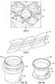
- FIGS. 7A-7Bare perspective views of exemplary tubular bodies that can be used to form a sealing member for a prosthetic heart valve.
- FIG. 8is a perspective view of a partially assembled prosthetic heart valve showing the attachment of leaflets using connecting skirts, according to one embodiment.
- FIG. 9is a plan view of a leaflet and a connecting skirt used in the prosthetic heart valve of FIG. 8 .
- FIGS. 10, 10A, 11A, and 11Bare various views showing the attachment of the connecting skirt and the leaflet of FIG. 9 .
- FIGS. 12, 12A, and 12Bare various views showing the connection of the connecting skirt of FIG. 9 to the frame of the prosthetic valve of FIG. 8 .
- FIG. 13Ais a perspective view of a frame of a prosthetic heart valve and leaflets mounted inside the frame, according to one embodiment.
- FIG. 13Bis an enlarged view of a portion of the frame and one of the leaflets of FIG. 13A .
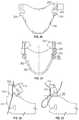
- FIG. 14is a plan view of a leaflet that can be used in a prosthetic heart valve, according to one embodiment.
- FIGS. 15, 16, and 17show the formation of one-half of a commissure using the leaflet of FIG. 14 , according to one embodiment.
- FIG. 18is a cross-sectional view of a commissure formed from two leaflets of the type shown in FIG. 14 , according to one embodiment.
- FIG. 19is a cross-sectional view of a commissure formed from two leaflets of the type shown in FIG. 14 , according to another embodiment.
- FIG. 20is a plan view of a leaflet that can be used in a prosthetic heart valve, according to another embodiment.
- FIG. 21is a plan view of a leaflet that can be used in a prosthetic heart valve, according to another embodiment.
- FIGS. 22, 23, 24, 25, and 26show the formation of a commissure from two leaflets of the type shown in FIG. 21 , according to one embodiment.
- FIG. 27is a cross-sectional view of a commissure formed from two leaflets of the type shown in FIG. 21 , according to one embodiment.
- FIG. 28is a cross-sectional view of a commissure formed from two leaflets of the type shown in FIG. 14 , according to another embodiment.
- FIG. 29is a cross-sectional view of a commissure formed from two leaflets of the type shown in FIG. 21 , according to another embodiment.
- FIG. 30is a plan view of a leaflet that can be used in a prosthetic heart valve, according to another embodiment.
- FIGS. 31-32are cross-sectional views of two embodiments of a commissure formed from two leaflets of the type shown in FIG. 30 .
- FIGS. 33, 34, 35, and 36are various views showing the attachment of the commissure of FIG. 31 or 32 to the frame of a prosthetic heart valve using a commissure attachment member.
- FIG. 37is a perspective view of another embodiment of a prosthetic heart valve.
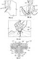
- FIG. 38Ais a plan view of a reinforcing member.
- FIG. 38Bis a plan view of a commissure support element including a commissure window that can be formed using two of the reinforcing members of FIG. 38A .
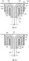
- FIGS. 39 and 40are plan views illustrating alternative embodiments of reinforcing members.
- FIG. 41is a plan view of another embodiment of a leaflet that can be used in a prosthetic heart valve, along with a reinforcing member of FIG. 38A and an attachment member.
- FIGS. 42-49are various views showing the formation of a commissure from two leaflets of the type shown in FIG. 41 using the reinforcing member of FIG. 38A , according to one embodiment.
- FIG. 50is a cross-sectional view of a commissure formed from two leaflets of the type shown in FIG. 41 using the reinforcing member of FIG. 38A .
- FIG. 51is a rear perspective view of the commissure of FIG. 50 .
- FIG. 52is a cross-sectional view showing attachment of the commissure of FIG. 50 to a commissure attachment member.
- FIG. 53is a rear side elevational view of the commissure and the commissure attachment member of FIG. 52 .
- FIGS. 54-58are various views showing the attachment of the commissure of FIG. 50 to the frame of a prosthetic heart valve using a commissure attachment member.
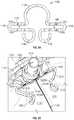
- FIG. 59is a plan view of a commissure clasp member, according to one embodiment.
- FIG. 60is a side elevation view illustrating bending of the commissure clasp member of FIG. 59 using a tool.
- FIGS. 61A, 61B, 62A, 62B, 63A, and 63Bare various views illustrating the formation of a commissure using the clasp member of FIG. 59 .
- FIGS. 64 and 65are perspective views of another embodiment of a frame including integral commissure clasp members.
- FIG. 66is a perspective view illustrating a leaflet structure situated in the frame of FIG. 64 with the clasp members holding respective pairs of leaflets to form commissures.
- FIGS. 67-80are perspective views of various separable members that can be secured together to form various embodiments of commissure support elements including a commissure window.
- FIG. 81is a perspective view illustrating another embodiment of a prosthetic heart valve including a plurality of commissure support elements configured as commissure clamps.
- FIG. 82is a plan view illustrating a portion of the prosthetic heart valve of FIG. 81 .
- FIG. 83is a perspective view of a commissure clamp, according to one embodiment.
- FIG. 84is a plan view of the commissure clamp of FIG. 83 .
- FIG. 85is a perspective view illustrating a portion of the prosthetic heart valve of FIG. 81 including another embodiment of a commissure clamp.
- FIGS. 86-90are various views showing additional embodiments of commissure clamps.
- FIGS. 91-93are plan views illustrating additional embodiments of commissure clamps situated within a schematic illustration of the frame of FIG. 81 in a radially collapsed configuration.
- FIGS. 94 and 95illustrate another embodiment of a commissure clamp.
- FIG. 96is a perspective view illustrating an embodiment of a prosthetic heart valve including the commissure clamp of FIGS. 94 and 95 .
- FIG. 97is a perspective view of the frame of the prosthetic heart valve of FIG. 96 .
- FIG. 98is a side elevation view of a leaflet of the prosthetic heart valve of FIG. 96 , according to one embodiment.
- FIG. 99is a magnified top view illustrating a commissure of the prosthetic heart valve of FIG. 96 including the commissure clamp of FIG. 94 .
- FIG. 100is a perspective view of the commissure of FIG. 99 .
- the prosthetic devicecomprises a prosthetic heart valve, and can be configured to be implanted in any of the native heart valves (aortic, mitral, pulmonary, and tricuspid).
- the prosthetic heart valvecan be, for example, a transcatheter heart valve, a surgical heart valve, or a minimally-invasive heart valve.
- the prosthetic valvealso can comprise other types of valves implantable within other body lumens outside of the heart or heart valves that are implantable within the heart at locations other than the native valves, such as trans-atrial or trans-ventricle septum valves.
- the prosthetic valves described hereincan include commissure support elements that are configured to restrict movement of the leaflets adjacent the frame such that the leaflets articulate primarily at a location radially inward of the frame during valve operation.
- the commissure-forming elementscan include first and second members that are spaced apart from each other such that the leaflets of a commissure can be received therebetween.
- portions of the leaflets, such as commissure tabscan be folded about the first and second members.
- the first and second memberscan be assembled together to form a commissure window through which commissure tabs of the leaflets can be inserted.
- the first and second memberscan be secured to each other with, for example, sutures.
- the commissure support elementscan comprise integrally-formed clasp or clamp members.
- the first and second memberscan extend from a coupling portion of the clamp member that is coupled to the frame, and the leaflets can articulate about end portions of the first and second members located radially inward of the frame.
- the disclosed prosthetic heart valvesare particularly suited for implantation in the native aortic valve.
- the terms “lower” and “upper”are used interchangeably with the terms “inflow” and “outflow”, respectively, for convenience.
- the lower end of the prosthetic valveis its inflow end and the upper end of the prosthetic valve is its outflow end in the orientation shown in the drawings.
- the prosthetic valvecan be implanted in the reverse orientation.
- the upper end of the prosthetic valveis the inflow end and the lower end of the valve is the outflow end.
- FIG. 1Ais a perspective view of a prosthetic heart valve 10 , according to one embodiment.
- the illustrated valveis adapted to be implanted in the native aortic annulus, although in other embodiments it can be adapted to be implanted in the other native annuluses of the heart.
- the valve 10can have three main components: a stent, or frame, 12 , a valvular structure 14 , and a sealing member 16 .
- FIG. 1Bis a perspective view of the prosthetic valve 10 with the components on the outside of the frame 12 (including the sealing member 16 ) shown in phantom lines for purposes of illustration.
- the valvular structure 14can comprise three leaflets 20 , collectively forming a leaflet structure, which can be arranged to collapse in a tricuspid arrangement, although in other embodiments there can be greater or fewer leaflets (e.g., one or more leaflets 20 ).
- the lower edge of leaflet structure 14desirably has an undulating, curved scalloped shape. By forming the leaflets with this scalloped geometry, stresses on the leaflets are reduced, which in turn improves durability of the valve. Moreover, by virtue of the scalloped shape, folds and ripples at the belly of each leaflet (the central region of each leaflet), which can cause early calcification in those areas, can be eliminated or at least minimized.
- the scalloped geometryalso reduces the amount of tissue material used to form leaflet structure, thereby allowing a smaller, more even crimped profile at the inflow end of the valve.
- the leaflets 20can be formed of pericardial tissue (e.g., bovine pericardial tissue), biocompatible synthetic materials, or various other suitable natural or synthetic materials as known in the art and described in U.S. Pat. No. 6,730,118, which is incorporated by reference herein.
- Each leaflet 20can be coupled to the frame 12 along its inflow edge 30 (the lower edge in the figures; also referred to as “cusp edges”) and at commissures 32 of the valvular structure 14 where adjacent portions of two leaflets are connected to each other, as further described below.
- the frame 12can be made of any of various suitable plastically-expandable materials (e.g., stainless steel, etc.) or self-expanding materials (e.g., Nitinol) as known in the art.
- the frame 12When constructed of a plastically-expandable material, the frame 12 (and thus the prosthetic valve 10 ) can be crimped to a radially compressed state on a delivery catheter and then expanded inside a patient by an inflatable balloon, by mechanical means, or by any equivalent expansion mechanism.
- the frame 12(and thus the prosthetic valve 10 ) can be crimped to a radially compressed state and restrained in the compressed state by insertion into a sheath or equivalent mechanism of a delivery catheter. Once inside the body, the prosthetic valve can be advanced from the delivery sheath, which allows the valve to expand to its functional size.
- Suitable plastically-expandable materials that can be used to form the frame 12include, without limitation, stainless steel, a nickel based alloy (e.g., a cobalt-chromium or a nickel-cobalt-chromium alloy), polymers, or combinations thereof.
- frame 12is made of a nickel-cobalt-chromium-molybdenum alloy, such as MP35NTM (tradename of SPS Technologies), which is equivalent to UNS R30035 (covered by ASTM F562-02).
- MP35NTM/UNS R30035comprises 35% nickel, 35% cobalt, 20% chromium, and 10% molybdenum, by weight. It has been found that the use of MP35N to form frame 12 provides superior structural results over stainless steel.
- the frame materialwhen MP35N is used as the frame material, less material is needed to achieve the same or better performance in radial and crush force resistance, fatigue resistances, and corrosion resistance. Moreover, since less material is required, the crimped profile of the frame can be reduced, thereby providing a lower profile valve assembly for percutaneous delivery to the treatment location in the body.
- the frame 12 in the illustrated embodimentcomprises a plurality of circumferentially extending rows of angled struts 22 defining rows of cells, or openings, 24 of the frame.
- the frame 12can have a cylindrical or substantially cylindrical shape having a constant diameter from an inflow end 26 to an outflow end 28 of the frame as shown, or the frame can vary in diameter along the height of the frame, as disclosed in US Publication No. 2012/0239142, which is incorporated herein by reference.
- the sealing member 16 in the illustrated embodimentis mounted on the outside of the frame 12 and functions to create a seal against the surrounding tissue (e.g., the native leaflets and/or native annulus) to prevent or at least minimize paravalvular leakage.
- the sealing member 16can comprise an inner layer 34 (which can be in contact with the outer surface of the frame 12 ) and/or an outer layer 36 .
- the sealing member 16can be connected to the frame 12 using suitable techniques or mechanisms.
- the sealing member 16can be sutured to the frame 12 via sutures 38 ( FIG. 5 ) that can extend around the struts 22 and through the inner layer 34 .
- the outer layer 36can be configured or shaped to extend radially outward from the inner layer 34 and the frame 12 when the prosthetic valve 10 is deployed. As best shown in FIG. 3 , when the prosthetic valve is fully expanded outside of a patient's body, the outer layer 36 can expand away from the inner layer 34 to create a space 40 between the two layers. Thus, when implanted in the body, this allows the outer layer 36 to expand into contact with the surrounding tissue.
- the inner layer 34desirably is formed with a plurality of apertures, or openings, 42 ( FIG. 5 ). As best shown in FIG.
- retrograde blood(indicated by arrows 44 ) can flow along the outside of the leaflets 20 , through the cells 24 of the frame, through the openings 42 in the inner layer 34 and into the space 40 between the inner and outer layers 34 , 36 , to facilitate expansion of the sealing member 16 and creating a seal against the surrounding tissue.
- the outer layer 36can be formed with a plurality of apertures, or openings, which can allow blood to flow into the sealing member at least during valve deployment.
- the openings 42can be centered at junctions 50 where the frame struts 22 intersect, which inhibits material of the inner layer 34 surrounding the openings from protruding inwardly through the frame and contacting the leaflets.
- the sealing member 16can be formed from fabric or non-fabric materials such as PET, PTFE, ePTFE, polyurethane, silicone, polyester, wire mesh, natural tissue (e.g., pericardium) and/or other suitable materials configured to restrict and/or prevent blood-flow therethrough.
- the sealing membercan be formed from a generally flat strip, folded lengthwise to form the inner and outer layers, and then formed into a tube, such as by welding or stitching the ends together.
- the sealing member 16can be formed by weaving, knitting, or braiding the sealing member into a tubular shape.
- the bulge in the outer layer 36can be formed, for example, by shape-setting the material to a desired configuration (e.g., as shown in FIGS.
- the shape-setting of the outer layercan allow the outer layer to be self-expandable or induce radial expansion of the outer layer. Additionally or alternatively, the outer layer 36 can be self-expandable by including Nitinol threads in the outer layer.
- the inner layer 34does not have any openings 42 , but can be formed from a porous material that allows blood to flow through the inner layer.
- the inner layer 34can be formed from a relatively more porous material than the outer layer 36 .
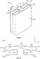
- FIG. 6shows a strip of fabric that can be used to form the sealing member 16 , according to one embodiment.
- a fabric stripcan comprise a center section 52 and first and second longitudinal edge portions 54 , 56 extending along opposing sides of the center section 52 .
- the center section 52can include three sets of openings 42 (e.g., three openings in each set in the illustrated embodiment).
- the openings 42are positioned to correspond with the position of junctions 50 below the commissures of the prosthetic valve.
- the first and second longitudinal edge portions 54 , 56can be folded over the center portion 52 and secured to each other, such as with stitching, to form the sealing member.
- the longitudinal edge portions 54 , 56collectively form the outer layer 36 , while the center portion 52 forms the inner layer 34 .
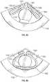
- FIGS. 7A and 7Bare perspective views of exemplary tubular bodies that can be used to form a sealing member 16 .
- a tubular body 80can comprise an upper portion 82 and a lower portion 84 .
- the upper portion 82can include a radial bulge 86 .
- the tubular body 80can be formed, for example, by three-dimensional weaving, knitting, or braiding.
- the lower portion 84can be folded or inverted into the upper portion 82 to form a sealing member having an outer layer formed by the upper portion 82 and an inner layer formed from the lower portion 84 .
- a tubular body 90can comprise a cylindrical central portion 92 , a flared upper portion 94 , and a flared lower portion 96 .
- the tubular body 90can be formed, for example, by three-dimensional weaving, knitting, or braiding.
- the upper portion 94can folded or inverted over the lower portion 94 to form two layers of a sealing member.
- FIGS. 8-13illustrate a technique for mounting the inflow edges 30 of the leaflets 20 to the frame 12 , according to one embodiment.
- a connecting skirt 100is secured to a lower edge portion 102 (also referred to as a cusp edge portion) of each leaflet.
- each connecting skirt 100can comprise an elongated, generally rectangular body 104 formed with a plurality of flaps 106 a , 106 b formed along opposing longitudinal edges of the body 104 .
- the skirt 100can comprise any suitable synthetic material (e.g., PET) or natural tissue.
- the body 104is folded along a central longitudinal fold bisecting the body to form folded portions 110 a , 110 b , which are then placed on opposite sides of the lower edge portion 102 of the leaflet 20 such that the flaps 106 a are adjacent the outer surface of the leaflet and the flaps 106 b are adjacent the inner surface of the leaflet.
- a suturecan then be used to form stitches 108 that extend through the opposing portions 110 a , 110 b of the body 104 and the lower edge portion 102 of the leaflet and longitudinally along the length of the lower edge portion 102 .
- FIG. 11Ashows a flattened view of the leaflet 20 with the skirt 100 folded around the lower edge portion 102 of the leaflet.
- FIG. 11Bshows a flattened view of the leaflet 20 and the skirt 100 after being secured to the leaflet with stitches 108 .
- each pair of flaps 106 a , 106 bare folded away from the leaflet 20 over a respective strut 22 of the frame and secured in place with stitches 112 that extend through the flaps 106 a , 106 b along a stitching line outside of the frame 12 .
- the connecting skirt 100mounts the leaflet to the frame 12 such that the lower edge portion 102 extends radially inwardly at about a 90-degree angle relative to the frame 12 . This effectively moves the bending axis of the lower edge portion 102 inwardly away from the inner surface of the frame and toward the center of the frame.
- each of the skirts 100is secured to the frame along a diagonal line 116 extending along the curved surface of the frame defined by a diagonally extending row of struts 22 extending from the inflow end of the frame toward the outflow end.
- the lower edge portion 102 of each leafletis also positioned along a respective diagonal line 116 defined by a respective diagonally extending row of struts 22 . This advantageously reduces the formation of wrinkles in the leaflets 20 and the crimping profile of the prosthetic valve when the prosthetic valve is radially compressed to its delivery configuration.
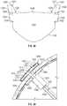
- FIG. 13Ais a perspective view of the frame 12 and the leaflets 20 supported in the frame shown in their mounted configuration with the connecting skirts 100 removed for purposes of illustration.
- FIG. 13Bis an enlarged, partial cross-sectional view of the frame and a leaflet.
- the lower edge portion 102 of the leafletextends perpendicularly relative to the frame, creating a gap G between the inner surface of the frame and the bending axis 114 of the leaflet 20 .
- thishelps prevent or at least minimize contact between the outer surfaces of the leaflets and the frame when the leaflets open during valve operation, thereby inhibiting undesirable abrasion of the leaflets that occurs through contact with the frame.
- the enlarged spaced between the leaflet and the framealso can promote blood washing over the leaflets at the bending axes of the leaflets.
- known prosthetic valvescare must be taken to prevent the leaflets from contacting the inner surface of the frame or extending through the open cells of the frame during crimping so as to prevent damage to the leaflets.
- known crimping devices for prosthetic valvescan include features or accessories that press the leaflets away from the frame or shield the leaflets from contacting the frame during crimping.
- the skirts 100assist in maintaining the leaflets spaced from inner surface of the frame during crimping of the prosthetic valve without the use of such specially designed crimping accessories.
- the connecting skirts 100can facilitate assembly of the prosthetic valve compared to known assembly techniques.
- the leaflets and the skirtscan be assembled while the leaflets are in a flattened configuration, prior to forming the tubular (annular) configuration the valvular structure 14 .
- Automated or semi-automated techniquescan be used to suture the skirts to the leaflets.
- the lower edge portions 102 of the leafletscan be secured to the frame with stitching that is completely outside of the frame 12 . This can substantially reduce assembly time as the assembler does not have to thread the needle for forming stitches 112 in and out of the cells 24 of the frame.
- each leaflet 20comprises opposing tabs 60 .
- Each tab 60can be secured to an adjacent tab 60 of an adjacent leaflet 20 to form a commissure that is secured to the frame 12 .
- Each tab 60can be folded to form a radially extending layer 60 a and a circumferentially extending layer 60 b facing the frame. Methods for mounting commissures to the frame are described in detail below and can be incorporated into the prosthetic valve shown in FIGS. 13A-13B .
- the tab layer 60 acan have an inclined edge 62 that extends radially inwardly from a location on the frame to a coaptation edge 64 of the leaflet.
- the inclined edge 62also extends in an axial direction from the location on the frame to the coaptation edge 64 . This places the center of the coaptation edge 64 (halfway between adjacent commisures) lower than the commissures and the attachment areas of the tabs 60 to the frame. In other words, the commissures are located at different locations along the height of the frame than the centers of the coaptation edges 64 .
- This configurationis advantageous in that it more evenly distributes stress along the tabs 60 during valve cycling.
- the entire coaptation edge 64 of a leafletis below the location where the commissures are attached to the frame, at least when the leaflets are in the closed positions.
- the leafletscan articulate at the inner most edges 66 of the tab layers 60 a , which helps space the leaflets away from the frame during normal operation of the prosthetic valve. This is particular advantageous in cases where the prosthetic valve is not fully expanded to its nominal size when implanted in a patient. As such, the prosthetic valve can be implanted in a wider range of patient annulus sizes. Under relatively higher forces, such as when the prosthetic valve is radially compressed for delivery, the leaflets can splay apart from each other at the frame to relieve stress on the leaflets.
- the commissures and the coaptation edges of the leafletstypically are relatively bulky portions of leaflets and can inhibit full radial compression of the prosthetic valve if they are at the same height along the frame.
- Another advantage of the commissure tabs 60 shown in FIGS. 13A-13Bis that the commissures and the coaptation edges are separated from each other in the axial direction when the prosthetic valve is radially compressed for delivery into a patient's body. Separating these portions of the leaflets reduces the overall crimp profile of the prosthetic valve.
- FIGS. 14-18show a technique for mounting the commissures of a valvular structure to a frame, such as the commissures 32 to the frame 12 , according to one embodiment.
- FIG. 14shows a leaflet 200 having a lower edge portion 202 that can be mounted to the frame 12 using any of the previously described embodiments.
- the lower edge portion 202terminates at its upper ends at two laterally projecting integral lower tabs 204 .
- Projecting from the upper corners of the leaflet 200are integral upper tabs 206 (also referred to as commissure tabs).
- the upper tabs 206can be spaced from the lower tabs 204 by laterally extending gaps or recesses 238 formed in the leaflet.
- each upper tab 206is folded along a horizontal fold line 208 to form first and second tab layers 206 a , 206 b , as shown in FIG. 14 (see also FIG. 18 ).
- a first vertically extending reinforcing member 210can be placed against the first tab layer 206 a adjacent its inner edge.
- a second vertically extending reinforcing member 212can be placed against the second tab layer 206 b opposite the first reinforcing member 210 .
- the first and second tab layers 206 a , 206 bcan be secured to each other with stitching 214 that extends through the first and second tab layers 206 a , 206 b and the first and second reinforcing members 210 , 212 .
- the first and second tab layers 206 a , 206 bcan then be folded lengthwise along a vertical fold line as shown in FIG. 16 to form an outer folded portion 216 and an inner folded portion 218 that extends radially inwardly from the outer folded portion 216 .
- a third vertically extending reinforcing member 220can be placed against the first folded layer 206 a of the outer folded portion 216 and a commissure attachment member 222 can be placed against the second folded layer 206 b of the outer folded portion 216 .
- the outer folded portion 216can be secured to the commissure attachment member 222 with stitches 224 that extend through the third reinforcing member 220 , the first and second tab layers 206 a , 206 b , and the commissure attachment member 222 .
- first and second tab layers 206 a , 206 bcan be further secured to the commissure attachment member 222 with stitches 226 .
- the upper tab 206 of a second leaflet 200can be assembled in the same manner with respective reinforcing members and attached to the commissure attachment member 222 adjacent the first leaflet to form a commissure 228 as shown in FIG. 18 .
- the commissure attachment member 222can then be secured to the struts of the frame, as further described below.
- the folded tab layers 206 a , 206 breinforced by the first and second reinforcing members 210 , 212 , can be more resistant to bending, or articulating, than the portions 230 of the leaflets that are radially inward of the tab layers.
- Thiscauses the leaflets 200 to articulate primarily at inner edges 232 of the folded layers 206 a in response to blood flowing through the prosthetic valve during operation of the prosthetic valve in the body, as opposed to articulating about respective axes on or adjacent the metal struts of the frame. Because the leaflets articulate at a location spaced radially inwardly from the frame 12 , the leaflets can avoid contact with and damage from the frame. This is particularly advantageous in cases where the prosthetic valve is not fully expanded to its nominal size when implanted in a patient's body. As such, the prosthetic valve can be implanted in a wider range of patient annulus sizes.
- the folded tab layers 206 a , 206 b of adjacent leafletscan splay apart from each other about respective axes 234 ( FIG. 18 ) adjacent to the frame 12 , with each inner folded portion 218 folding out against the respective outer folded portion 216 .
- thiscan occur when the prosthetic valve 10 is compressed and mounted onto a shaft of a delivery apparatus, allowing for a smaller crimped diameter.
- the folded tab layerscan also splay apart about their axes 234 when the balloon of the balloon catheter is inflated during expansion of the prosthetic valve, which can relieve some of the pressure on the commissures caused by the balloon and so the commissures are not damaged during expansion.
- the lower tabs 204 of each leafletcan be folded downwardly against the cusp edge portion 202 and held in place, such as with sutures.
- the folded lower tabs 204help reinforce the connection between the cusp edge portions 202 of the leaflets and the frame along the upper sections of the cusp edge portions adjacent the commissures.
- the folded lower tabs 204also move the bending axes of the upper sections of the cusp edge portions inwardly and away from the inner surface of the frame to prevent or minimize contact between the leaflets and the frame in the areas below the commissures.
- the side edges 238 between the lower and upper tabs 204 , 206can be left unattached to the frame of the prosthetic valve.
- the unattached side edges 238provide several advantages, including reducing stress in the leaflets, by allowing greater elongation or stretching of the leaflets in the axial direction when the prosthetic valve is compressed from the radial expanded state to the radial compressed state during the crimping process and by allowing greater elongation or stretching of the leaflets in the radial direction when the prosthetic valve is expanded to its radial expanded state.
- the unattached side edges 238also allow blood to flow in the space between a pair of side edges 238 of adjacent leaflets and the inner surface of the frame to reduce stagnant blood flow and thrombosis.
- the adjacent side edges 238can coapt with each other and prevent retrograde blood from flowing between the side edges 238 .
- the adjacent side edges 238can separate from each other and allow antegrade blood to flow between side edges 238 and help wash away blood from the areas underneath the commissures.
- the reinforcing members 210 , 212 , 220desirably comprise relatively soft and flexible, non-metallic materials.
- the reinforcing memberscan comprise multi-filament sutures (e.g., Ethibond sutures) or strips of synthetic material, such as fabric (e.g., PET) or non-fabric material (e.g., silicone or polyurethane), or natural tissue (e.g., pericardium).
- the commissure attachment member 222similarly can comprise a soft and flexible, non-metallic material, such as strips of synthetic material, such as fabric (e.g., PET) or non-fabric material (e.g., silicone or polyurethane), or natural tissue (e.g., pericardium).
- the commissure 228does not include metallic components or other materials having similar rigidity. The absence of such materials can reduce abrasion and wear of the leaflet material and reduce the overall crimp profile of the prosthetic valve.
- FIG. 19shows a modification of the embodiment shown in FIG. 18 .
- the embodiment of FIG. 19can be the same as that shown in FIG. 18 except that the pair of folded layers 206 a , 206 b of adjacent leaflets 200 can be secured to each other with a suture 236 that extends through the reinforcing members 210 , 212 and the tab layers 206 a , 206 b of each leaflet 200 . Securing the leaflets together can reinforce the bending axes of the articulating portions 230 of the leaflets during normal valve operation.
- FIG. 20shows an alternative embodiment of a leaflet 240 , which is similar to the leaflet 200 , except that the leaflet 240 includes upper tabs 240 that project laterally a greater distance than the upper tabs 206 .
- Each upper tab 240can be folded widthwise along a respective vertical fold line 242 to form two folded tab layers that are paired with folded tab layers of an adjacent leaflet to form a commissure as previously described.
- FIGS. 21-27show another embodiment of a leaflet and a method for forming a commissure from two leaflets.
- a leaflet 300comprises a lower edge portion 302 terminating at lower tabs 304 , upper tabs 306 (also referred to as commissure tabs) spaced from the lower tabs 304 by gaps 308 .
- the lower tabs 304can be folded downwardly against the lower edge portion 302 to reinforce those areas of the leaflet and to move the bending axes of the upper sections of the edge portions 302 (the portions just below the commissures) inwardly away from the inner surface of the frame, as previously described.
- Each upper tab 306includes a lower tab portion 310 , an upper tab portion 312 extending from the lower tab portion, and a side tab portion 314 extending laterally inwardly from the upper tab portion.
- a reinforcement member 318e.g., a multi-filament suture or a strip of fabric
- the side tab portion 314can then be folded along a fold line 316 against the upper tab portion 312 as shown in FIGS. 22-23 .
- the dual layer of the side tab portion 314 and the upper tab portion 312can then be folded along horizontal fold line 320 against the lower tab portion 310 , as depicted in FIGS. 23-24 .
- a commissure attachment member 322can then be placed against the rear (outer) surface of the lower tab portion 310 and secured to the upper tab 306 with stitching 324 that extends through the upper tab portion 312 , reinforcement member 318 , the side tab portion 314 , the lower tab portion 310 , and the commissure attachment member 322 .
- the three layers formed by the lower tab portion 310 , the upper tab portion 314 , and the side tab portion 314can then folded into an L-shape to form an outer folded portion 326 adjacent the commissure attachment member 322 and an inner folded portion 328 extending radially inwardly from the outer folded portion as shown in FIG. 27 .
- FIG. 25As shown in FIG.
- the tab layers of the outer folded portion 326can be further secured to the commissure attachment member 322 with stitches 332 .
- the upper tab 306 of another leafletcan be assembled in the same manner and secured to the same commissure attachment member 322 to form a commissure 330 as shown in FIGS. 26-27 .
- the stitches 324can extend through each layer formed by the lower tab portion 310 , the upper tab portion 314 , and the side tab portion 314 . As shown in FIG. 27 , the stitches 324 from each commissure tab 306 can extend diagonally toward each other to compress the folded commissure tabs 306 against each other and the commissure attachment member 322 . In alternative embodiments, the stitches 324 can be placed through the reinforcement member 318 , the side tab portion 314 and the lower tab portion 310 prior to folding the upper tab portion and the side tab portion along fold line 320 . In this manner, the stitches 324 need not extend through the upper tab portion 312 , as depicted in FIG. 27 . In some embodiments, another reinforcement member 438 can be placed against the outer surface of the commissure reinforcement member 322 ( FIG. 27 ). The stitches 324 from each commissure tab 306 can extend through the reinforcement member 338 at the same location as shown or at spaced apart locations.
- the commissure 330can function similar to the commissure 228 described above.
- the leaflets 300can articulate about respective axes at the inner ends 334 of the tab layers 312 .
- the compression of the folded commissure tabs 306 by stitches 324helps maintain the normal bending axes of the leaflets 300 away from the frame.
- the leafletscan splay apart from each other at an axis 336 adjacent the commissure attachment member 322 .
- FIG. 28shows an alternative configuration for forming a commissure.
- the embodiment of FIG. 28is similar to the embodiment of FIGS. 14-18 except that a vertical reinforcement member 244 can be placed between two layers of the commissure tab of the leaflet.
- the commissurecan be formed by placing the reinforcement member 244 on tab portion 206 a prior to folding tab portion 206 a along fold line 208 .
- the folded layers 206 a , 206 bcan be secured to the commissure attachment member 222 with stitches 246 that extend through the reinforcement member 244 , both tab layers 206 a , 206 b , and the commissure attachment member 222 .
- FIG. 29shows an alternative configuration for forming a commissure similar to FIG. 27 , except that each folded commissure tab 306 is secured to a separate reinforcing member 338 (one of which is shown in FIG. 29 ). Also, stitches 340 can secure the side tab portion 312 to the reinforcing member 318 .
- FIGS. 30-35show another embodiment of a leaflet and a method for forming a commissure 32 from two leaflets.
- a leaflet 400comprises a lower edge portion 402 terminating at lower tabs 404 , upper tabs 406 (also referred to as commissure tabs) spaced from the lower tabs 404 by gaps 408 .
- the lower tabs 404can be folded downwardly against the lower edge portion 402 to reinforce those areas of the leaflet and to move the bending axes of the upper sections of the edge portions 402 (the portions just below the commissures) inwardly away from the inner surface of the frame, as previously described.
- Each commissure tab 406includes a lower tab portion 410 and an upper tab portion 412 .
- the upper tab portion 412is folded along fold line 414 against the lower tab portion 410 .
- the dual layer comprising tab portions 410 , 412can then be folded along a vertical fold line 416 to form a first layer 418 , a second layer 420 , a third layer 422 , and a fourth layer 424 from each commissure tab 406 , as depicted in FIGS. 31-33 .
- a reinforcement member 426such as strip of fabric (e.g., PET), can be positioned between the second layer 420 and the third layer 422 .
- the commissure tab 406 of another leaflet 400is folded in the same manner and placed against the folded commissure tab of the first leaflet within a commissure attachment member 428 .
- the commissure attachment member 428can be folded as shown in FIG. 31 to form a central outer portion 430 , outer end portions 432 , and side portions 434 , each comprising first and second layers 434 a , 434 b of material extending from respective ends of an end portion 432 and the central outer portion 430 .
- the side portions 434can be placed against respective fourth layers 424 of the commissure tabs.
- each side portion 434can be secured to each other with stitching 436 .
- Each side portion 434can be secured to a commissure tab 406 with stitching 438 extending through a respective reinforcing member 426 , respective third and fourth layers 422 , 424 , and both layers of a respective side portion 434 .
- the commissure attachment member 428can be secured to the struts 22 of a frame 12 with sutures or other techniques or mechanisms.
- FIG. 32shows another way of securing the folded commissure tabs 406 to the commissure attachment member 430 .
- a row of laterally extending stitches 440can be used to secure the inner end portions of the layers 434 a , 434 b of the side portion, the third and fourth layers 422 , 424 , and the reinforcing member 426 .
- a diagonally extending row of stitches 442can be used to secure the reinforcing member 426 , the third and fourth layers 422 , 424 , and the rear end portions of layers 434 a , 434 b of the side portion.
- each commissure 32can include an inner sleeve 444 and an outer support member 446 .
- the inner sleeve 444can comprise first and second portions 444 a , 444 b , each of which extends around the outer side as well as the upper and lower portions of a respective folded commissure tab 406 .
- the adjacent upper ends 448 of the first and second portions 444 a , 444 bcan be secured to each other (e.g., with sutures) at the center of the commissure 32 .
- the adjacent lower ends of the first and second portions 444 a , 444 bcan be secured to each other (e.g., with sutures) in a similar manner at the center of the commissure 32 .
- Each of the side portions 434 of the commissure attachment member 428can be secured to one of the first and second portions 444 a , 444 b of the inner sleeve (e.g., with sutures).
- the outer support member 446can be secured to the central outer portion 430 and/or the end portions 432 of the commissure attachment member 428 (e.g., with sutures).
- the outer support member 446can be positioned outside of the frame 12 .
- the outer support member 446can be secured (e.g., with sutures) to each strut 22 of a set of struts forming a cell of the frame.
- the outer support member 446can be sutured to each strut of a diamond-shaped cell comprised of four struts 22 .
- the inner sleeve 444 and the outer support member 446can comprise any suitable relatively flexible and soft material.
- the outer support member 446 and the inner sleeve 444can comprise natural or synthetic fabric materials, non-fabric polymeric materials (e.g., silicone or polyurethane), or natural tissue (e.g., pericardium)
- the inner sleeve 444 and the outer support member 446comprise PET fabric.
- FIG. 36shows a modification of the commissure 32 shown in FIGS. 33-35 .
- the embodiment of FIG. 36can be the same as the embodiment of FIGS. 33-35 , except that the former includes reinforcing members 454 in the form of multi-filament sutures positioned between the second and third layers 420 , 422 of each commissure tab 406 .
- Additional systems and methods for attaching leaflets to a framecan be found in U.S. patent application Ser. No. 15/664,430 filed on Jul. 31, 2017, which is incorporated herein by reference.
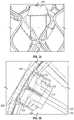
- FIGS. 37-58illustrate another modification of the commissure 32 shown in FIGS. 33-35 .
- Each of the commissurescan include a commissure support element or assembly 413 comprising a pair of reinforcing members 456 that are detached, separate, or not connected to the frame, and spaced radially inward from the frame.
- the reinforcing members 456can be situated between, for example, the second and third layers 420 , 422 of the upper commissure tabs 406 of adjacent leaflets.
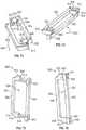
- FIG. 38AA representative example of a reinforcing member 456 is shown in FIG. 38A .
- the reinforcing member 456can include a main body portion 458 having a longitudinal axis 468 , and first and second end portions configured as attachment portions 460 , 462 .
- the attachment portions 460 , 462can be curved or hooked such that they define respective suture receiving portions 464 , 466 , and such that the reinforcing member 456 has a C-shaped profile that depends upon the lateral dimensions of the suture receiving portions 464 and 466 .
- the first attachment portion 460can be defined by a first portion 470 of the reinforcing member 456 extending away from the main body portion 458 and perpendicular to the longitudinal axis 468 , a second portion 472 extending parallel to the longitudinal axis 468 and offset from the main body portion 458 , and a third portion 474 extending toward the main body portion 458 and perpendicular to the longitudinal axis 468 .
- An end portion 476 of the third portion 474can be spaced apart from the main body portion 458 by a gap or opening 478 .
- a connecting membersuch as a yarn or suture thread, can be inserted into the suture-receiving portion 464 through the gap 478 , as further described below.
- the second attachment portion 462has a configuration similar to the first attachment portion 460 , although the first and second attachment portions 460 , 462 may be configured the same or differently, as desired.
- a commissure support element or support structure 413can be formed by situating two reinforcement members 456 A, 456 B such that the second portions 472 A, 472 B of the respective attachment portions 460 A, 460 B are adjacent one another, and the respective gaps 478 A, 478 B face away from each other.
- the attachment portions 462 A, 462 Bcan be arranged in a similar configuration.
- the pair of reinforcement members 456 A, 456 Bcan define a commissure window 480 that is at least partially bounded by the main body portions 458 A, 458 B and the first portions 470 A, 470 B of the respective attachment portions of each reinforcement member.
- the reinforcement members 456 A, 456 Bcan be tied or otherwise secured together by, for example, suture 482 extending through the respective attachment portions 460 A, 460 B and 462 A, 462 B of each reinforcement member.
- FIGS. 39 and 40illustrate alternative embodiments of commissure support elements or structures using other configurations of reinforcing members.
- one or more of the attachment portions 460 , 462can be configured as eyelets 484 , as shown in FIGS. 39 and 40 .
- the reinforcement members 456can define grooves 486 (e.g., in the main body portion 458 ). The grooves 486 can be defined on the surface of the main body portion 458 that is oriented toward the interior of the commissure window 480 , on the surface oriented away from the commissure window, or both, as desired.
- the grooves 486can aid in securing or clamping the leaflets between the members 456 , or can provide a location of additional suture attachment.
- the reinforcement members 456need only include one attachment portion, such as at the attachment portion 460 of the embodiment of FIG. 40 , such that the commissure window 480 is open on the end opposite the attachment portions 460 .
- the reinforcement members 456can be formed from any of various metals such as nitinol, stainless steel, cobalt chromium, etc., or polymeric materials such as any of various plastics.
- the reinforcement members 456 A and 456 Bare shown contacting each other in FIGS. 38B, 39, and 40 , in use the reinforcement members may be spaced apart from each other by portions of the valve leaflets to which the reinforcement members are attached, as further described below.
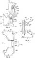
- FIGS. 41-53illustrate a representative method of forming a commissure 32 using the reinforcement members 456 of FIGS. 38A and 38B .
- the leaflet 400can have a first side surface 488 and a second side surface 490 (see, e.g., FIG. 44 ).
- the upper tab 406is folded over in FIG. 44 such that the second side surface 490 is visible.
- the first side surface 488can correspond to the ventricular side of the leaflet, and can be relatively smooth.
- the second side surface 490can correspond to the arterial side of the leaflet, and can comprise, for example, a plurality of ridges or other textures or features.
- the upper tab portion 412 of the upper tab 406can be folded down along line 414 in the direction of the first side surface 488 .
- a reinforcement member 456can then be attached (e.g., by suturing) to the exposed second side surface 490 A of the upper tab 406
- an attachment member 492can be attached (e.g., by suturing) to the second side surface 490 B (see FIGS. 44 and 45 ) of the lower tab portion 410 .
- the reinforcement member 456can be attached to the upper tab 406 at a distance D 1 from the outer edge 494 of the upper tab.
- the distance D 1can be about 2 mm, although the distance D 1 can be any suitable distance depending upon, for example, the width of the upper tab 406 .
- the reinforcement member 456can be positioned such that the first and second attachment portions 460 , 462 extend beyond the upper and lower edges of the folded commissure tab 406 , as shown in FIG. 44 .
- the reinforcement member 456can also be situated such that the gaps 478 of the respective first and second attachment portions 460 , 462 are oriented in a direction toward the attachment member 492 , as best shown in FIG. 46 .
- the attachment member 492can be configured as a strip of material, and can have a first end portion 496 and a second end portion 498 .
- the attachment member 492can also have an L-shaped profile, with a first body portion 493 and a second body portion 495 that extends from one edge of the first body portion 493 and is oriented perpendicular to the first body portion, as best shown in FIG. 47 .
- the attachment member 492can be formed from any of various flexible and/or deformable materials, including shape-memory metal alloys such as nitinol, plastically-deformable alloys such as stainless steel, cobalt chromium, etc., polymeric materials such as any of various plastic or rubber compounds, strips of synthetic material such as fabric (e.g., PET) or non-fabric material (e.g., silicone or polyurethane), or natural tissue (e.g., pericardium).
- shape-memory metal alloyssuch as nitinol
- plastically-deformable alloyssuch as stainless steel, cobalt chromium, etc.
- polymeric materialssuch as any of various plastic or rubber compounds
- strips of synthetic materialsuch as fabric (e.g., PET) or non-fabric material (e.g., silicone or polyurethane), or natural tissue (e.g., pericardium).
- the first end portion 496 of the attachment member 492can be secured to the lower tab portion 410 such that the first body portion 493 is adjacent the commissure tab 406 and the second body portion 495 extends away from the commissure tab, as shown in FIGS. 45 and 46 .
- an edge 481 of the first body portion 493 of the attachment member 492can be aligned with the outer edge 494 of the upper tab 406 , as shown in FIGS. 44-46 .
- the edge 481can be offset from the edge 494 of the upper tab 406 , as shown in FIG. 43 .
- the reinforcement member 456 and the attachment member 492can be secured to the upper tab 406 by suturing.
- suture 483can be passed through the attachment member 492 (e.g., through the first body portion 493 ), through the upper and lower tab portions 410 , 412 , and looped around the reinforcement member 456 before passing back through the tab portions 410 , 412 and the attachment member 492 to form suture loops 485 .
- This processcan be repeated along the length of the main body portion 458 of the reinforcement member 456 .
- the reinforcement member 456 and the attachment member 492are secured to the upper tab 406 by three suture loops 485 A- 485 C, although greater or fewer suture loops may be employed.
- the loops 485 A- 485 Ccan be stitched such that a first length of suture or “suture tail” 487 can extend from the first end portion 496 of the attachment member 492 adjacent the first suture loop 485 A, and a second length of suture or “suture tail” 489 can extend from the first end portion of the attachment member 492 adjacent the third suture loop 485 C, as shown in FIG. 43 .
- the second end portion 498 of the attachment member 492can be secured to a commissure tab of another leaflet 400 along with another reinforcement member 456 in the manner described above.
- the commissure tabs 406can be folded around the reinforcement members 456 in the manner of arrow 491 in a direction toward the first surface 488 to form first, second, third, and fourth layers 418 , 420 , 422 , 424 , similar to those described above with respect to FIG. 31 .
- FIG. 48is a top plan view showing the assembly as viewed from the side of the first surfaces 488 of the leaflets
- FIG. 49is a bottom plan view illustrating the assembly as viewed from the side of the second surfaces 490 of the leaflets.
- the leaflets 400can then be folded together about fold line or axis 471 in the manner indicated by arrow 497 such that the second surfaces 490 of the leaflets are folded toward one another to form a commissure 32 .
- the first and second end portions 496 , 498 of the attachment member 492can then be bent or folded about fold line 473 in the direction of arrow 451 such that the first and second end portions 496 , 498 extend downwardly from a mid-portion 475 of the attachment member 492 and are substantially parallel to the reinforcement members 456 A, 456 B and to each other.
- FIG. 50is a partial cross-sectional view taken along line 50 - 50 of FIG. 57 .
- the respective suture tails 489 A, 489 Bcan be inserted through the first body portion 493 of the attachment member 492 on their respective sides of the commissure.
- the suture tails 489 A, 489 Bcan then be looped through the suture-receiving portions of the respective attachment portions 460 A, 460 B of the reinforcement members 456 A, 456 B.
- the suture tails 489 A, 489 Bcan be wrapped around the attachment portions 460 A, 460 B (e.g., two times, three times, etc.) such that the suture tails form suture loops 453 extending between the reinforcement members 456 A, 456 B.
- the suture tails 489 A, 489 Bcan then be tied together (e.g., in a double square knot) to secure the attachment portions 460 A, 460 B together.
- the suture tails 487 A, 487 Bcan be wrapped around the attachment portions 462 A, 462 B and tied together in a similar manner (see, e.g., FIG. 51 ) to form the commissure window 480 of the support element 413 .
- the remaining length of the suture tails 489 A, 489 Bcan be used to secure the assembly to the struts of the frame.
- the reinforcement memberscan be secured together by wrapping the suture tail 489 A around the attachment portion 460 A of the reinforcement member 456 A one or more times, wrapping the suture tail 489 B around the attachment portion 460 B of the reinforcement member 456 B one or more times, and then tying the suture tails together.
- the attachment member 492 of the assembled commissure 32can then be placed around an upper portion 477 of an outer support member 446 .
- the suture tails 487 A, 487 Bcan then be used to suture the attachment member 492 to the outer support member 446 .
- the suture tails 487 A, 487 Bcan be used to stitch the second body portion 495 of the attachment member 492 to side portions 461 , 463 of the outer support member 446 to form stitches 465 .
- suture tails 487 A, 487 Bcan then be tied off and terminated, and the upper portion 477 of the outer support member 446 can be folded over the mid-portion 475 of the attachment member 492 in the direction indicated by arrow 455 and secured to the main body of the outer support member 446 to secure the commissure assembly 32 to the outer support member.
- the suture tails 489 A, 489 Bcan be used to attach the attachment member 492 to the outer support member 446 (e.g., at the mid-portion 475 ).
- the reinforcing members 456 A, 456 Bcan be detached from the frame (i.e., not directly connected to the frame), and spaced radially inwardly from the frame by, for example, a distance equal to the combined thickness of the first and second layers 418 , 420 of the commissure tabs 406 , which are located between the reinforcing members and the interior surface of the frame.
- the reinforcing members 456 A, 456 Bcan restrict movement of the leaflets 400 adjacent the frame such that the leaflets articulate primarily at inner edges of the folded tab portions 418 - 424 in response to blood flowing through the prosthetic valve, as opposed to articulating about respective axes on or against the frame struts.
- the leaflets 400can articulate primarily about the inner edge 421 of the second layer 420 . Because the leaflets 400 articulate at a location spaced radially inwardly from the frame 12 , the leaflets can avoid contact with and damage from the frame, as described above.
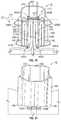
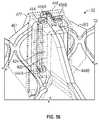
- FIGS. 54-58are additional views of the commissure 32 of FIGS. 37-53 .
- FIG. 54is a perspective view of the commissure 32 illustrating the entirety of the outer support member 446 and the first and second portions 444 A, 444 B of the inner sleeve 444 .
- the top portions of the first and second portions 444 A and 444 B of the inner sleeve 444can comprise openings or slits to allow the respective reinforcing members 456 A and 456 B to at least partially protrude through the portions 444 A and 444 B, as illustrated in FIG. 54 .
- the reinforcing members 456 A and 456 Bcan be disposed fully within the portions 444 A and 444 B of the inner sleeve 444 .
- FIG. 55illustrates the commissure 32 with the outer support member 446 and the inner sleeve 444 shown in phantom
- FIG. 56shows the commissure 32 with the outer support member 446 and one of the leaflets 400 shown in phantom. As shown in FIGS.
- the fourth layer 424 of each folded commissure tab 406can extend beyond the third layer 422 (e.g., in a direction radially inward toward the center of the valve), and can be disposed across the end portion of the third layer 422 such that the radially innermost portion of the fourth layer 424 is adjacent the second layer 420 .
- FIG. 57is a top plan view of the commissure 32 with the outer support member 446 and the inner sleeve 444 outlined in phantom.
- FIG. 58is a top plan view of the prosthetic valve of FIG. 37 illustrating the three commissures 32 .
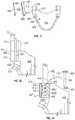
- FIG. 59illustrates an embodiment of a commissure support element configured as a clasp member 500 that can be used to secure two leaflets together to form a commissure.
- the clasp member 500includes a first end portion 502 (also referred to as a first member), an intermediate portion 504 , and second end portion 506 (also referred to as a second member).
- the clasp member 500is configured to be bent or otherwise plastically deformed from a straight configuration to a curved or U-shaped configuration, as shown in FIG. 60 .
- the intermediate portion 504can have a thickness t that is less than the thicknesses of the first and second end portions 502 , 506 to facilitate bending of the intermediate portion with a tool 508 .
- the first and second end portions 502 , 506can also define one or more recesses 510 .
- the first and second end portions 502 , 506have an equal number of recesses 510 located so as to form corresponding pairs of recesses when the clasp member 500 is in the bent configuration, as shown in FIG. 59 .
- two leaflets 512 including commissure tabs 514can be situated such that the commissure tabs 514 are adjacent one another, and the clasp member 500 can be placed on the commissure tabs of the leaflets such that the first end portion 502 is disposed on the commissure tab 514 of one leaflet 512 and the second end portion 506 is disposed on the commissure tab 514 of the other leaflet.
- the leaflets 512can be spaced apart such that the intermediate portion 504 is located between the two commissure tabs 514 .
- the clasp member 500can be secured to the commissure tabs 514 by suturing.
- the first end portion 502can be secured to the respective leaflet 512 with sutures 516 received in the recesses 510 .
- the second end portion 506can be secure to the respective leaflet 512 in a similar manner.
- the commissure tabs 514can then be folded over the clasp member 500 in the direction indicated by arrow 518 .
- the clasp member 500can then be bent or otherwise plastically deformed into a U-shape to form a commissure 520 , as shown in FIGS. 63A and 63B .
- FIG. 62Bthe outline of one leaflet 512 is shown in phantom to illustrate the sutures 516 connecting the second end portion 506 of the clasp member to the commissure tab 514 .
- the clasp member 500can restrict movement of the leaflets such that the leaflets articulate about axes spaced inwardly from a prosthetic valve frame into which the leaflets are incorporated.
- the leafletscan articulate about the clasp member 500 , and/or about the inward edges of the commissure tabs 514 .
- the clasp member 500can be made from any suitable biocompatible and plastically deformable material, such as any of various metals including nitinol, stainless steel, cobalt chromium, etc., or other materials such as plastics.
- the assembled leaflet structurecan be attached to a frame by suturing, or any other suitable attachment method, and the clasp member 500 can be detached (not directly connected) and spaced inwardly from the frame.
- FIGS. 64-66illustrate an embodiment of a frame 600 for a prosthetic heart valve including commissure support elements configured as integral clasp members 602 that can be used to secure two leaflets together to form a commissure.
- the frame 600can comprise a plurality of circumferentially extending rows of angled struts 604 defining rows of cells 606 of the frame, similar to the frame 12 described above with respect to FIGS. 1A and 1B .
- the frame 600can have an inflow end 608 and an outflow end 610 , and the strut members 604 can intersect to form apices 612 at the inflow and outflow ends of the frame.
- the clasp members 602can extend from certain of the apices 612 at the outflow end 610 of the frame, and can be circumferentially spaced apart around the frame (e.g., by about 120 degrees) at locations corresponding to the locations of commissures of the leaflet assembly when the leaflet assembly is situated in the frame (see, e.g., FIG. 66 ).
- FIG. 64illustrates the frame 600 in an initial configuration (e.g., after manufacture).
- the clasp members 602can include base portions 614 that extend from the respective apices 612 to which the clasp members are coupled, and a pair of clasp arms 616 , 618 that are spaced apart from one another and extend from the base portion 614 .
- the clasp members 602can extend in the direction of flow parallel to the longitudinal axis 620 of the frame.
- the base portions 614 of the clasp members 602can then be bent radially inwardly such that the clasp arms 616 , 618 of the clasp members are located inside the frame 600 and extend toward the inflow end 608 of the frame.
- the clasp arms 616 , 618 of each clasp member 602can define a leaflet-receiving space 622 open in the direction of the inflow end 608 of the frame.
- respective commissure tabs 624 of a corresponding pair of leaflets 626can be received in the leaflet-receiving space 622 between the clasping arms 616 , 618 of each clasp member 602 to form commissures 628 .
- the base portions 614can define openings 630 , which can induce bending of the clasp members 602 at the location of the openings and reduce the force required to bend the clasp members.
- the clasp members 602can be integrally formed with the frame 600 (e.g., by laser cutting) and, thus, can be made of the same material as the frame. In certain embodiments, because the location of the commissures 628 is not the thickest part of the prosthetic valve assembly, the clasp members 602 do not increase the overall crimp profile of the prosthetic valve. By being integrally formed with the strut members 604 and requiring only a simple bend in order to be placed in their operational orientation, the clasp members 602 can reduce the complexity and overall time required to assemble the commissures of the prosthetic valve compared to known techniques.
- the clasp members 602can also reduce or prevent shifting and/or tilting of the commissures 628 when the prosthetic valve is in use, and can increase manufacturing yield.
- the clasp members 602can also be separately formed and secured to the frame.
- the leafletscan articulate about inner edges of the members 618 of the clasp members 602 , which can be offset radially inward from the frame 600 to prevent damage to the leaflets, as shown in FIGS. 65 and 66 .
- FIGS. 67-76illustrate various other embodiments of commissure support elements configured as commissure clamps or clasp members that can be used to secure adjacent portions of adjacent leaflets (e.g., adjacent tab portions) to each other to form a commissure, which in turn can be secured to a frame (e.g., frame 12 ) as disclosed herein (e.g., such as shown in FIG. 37 ).
- FIG. 67illustrates a separable clasp member 700 including a first member 702 and a second member 704 that can be assembled together to define an opening or “commissure window” 706 .
- the first member 702can include a main body portion 708 , and first and second coupling portions 710 , 712 extending perpendicularly from the main body portion 708 such that the first member 702 is C-shaped.
- the first and second coupling portions 710 , 712 of the first member 702can define respective openings 714 , 716 extending through the member and configured to receive corresponding projections 718 , 720 on the second member 704 .
- the first and second coupling portions 710 , 712 of the first membercan be elastically deformed in the direction of arrows 722 , 724 .
- the second member 704can be inserted between the first and second coupling portions 710 , 712 of the first member 702 , and the coupling portions can be allowed to return to their non-deflected state such that the projection 718 of the second member 704 is received in the opening 714 of the first coupling portion 710 , and the projection 720 of the second member is received in the opening 716 of the second coupling portion 712 .
- first and second members 702 , 704can be mechanically coupled together by the projections 718 , 720 and the openings 714 , 716 to form the commissure window 706 , and reducing the likelihood of the two members separating during use.
- the resulting clasp member 700can be disposed inside or outside the frame, and the commissure tabs of two leaflets can be inserted through the commissure window 706 and secured to the frame (e.g., by suturing) to form a commissure, similar to the commissures described above.
- the clasp members 700can be detached or separate from the frame members such that the clasp members 700 are movable relative to the frame.
- the clasp member 700When the clasp member 700 is located inside the frame (e.g., against or spaced inwardly from the inner surface of the frame), the clasp member can space the leaflets away from the frame to avoid abrasion.
- the mechanical fastening between the first member 702 and the second member 704can reduce the time required to assemble the commissure, and the clasp member can reduce the amount of stitching required to attach the leaflets to the frame.
- the openings 714 , 716can also be configured as slots that are open at one end such that the projections 718 , 720 can be inserted into the slots without deforming the first and second coupling portions 714 , 716 of the first member 702 .
- Another alternative embodiment of the clasp member 700is shown in FIG. 80 .
- FIGS. 71-74illustrate another embodiment of a clasp member 800 similar to the clasp member 700 .
- the clasp member 800can include separable first and second members 802 , 804 that when assembled together define an opening or commissure window 806 ( FIG. 72 ).
- the first member 802can include a main body portion 808 and first and second coupling portions 810 , 812 .
- the coupling portions 810 , 812can be female coupling portions.
- the first coupling portion 810can include two arms or tines 814 , 816 extending perpendicular to the main body portion 808 .
- the tines 814 , 816are shaped such that they define a T-shaped recess or keyway 818 having a first portion 820 and a second portion 822 .
- a longitudinal axis 824 of the first portion 820can extend perpendicular to the main body portion 808
- a longitudinal axis 826 of the second portion 822can extend parallel to the main body portion.
- the second coupling portion 812can include tines 813 , 815 defining a keyway 846 similar to the keyway 818 .
- the second member 804can include a main body portion 828 and first and second end portions 830 , 832 .
- the first and second end portions 830 , 832can be configured as male coupling portions.
- the first end portion 830can include a member 834 having a first portion 836 and a second portion 838 in a T-shaped arrangement corresponding to the keyway 818 of the first member 802 .
- the second end portion 832can include a member 840 having a first portion 842 and a second portion 844 in a T-shaped arrangement corresponding to the keyway 846 .
- the first and second members 802 , 804can be assembled to form the clasp member 800 by inserting the members 834 , 840 of the second member 804 into the corresponding keyways 818 , 846 of the first member 802 .
- FIG. 73illustrates one method of assembly in which the members 834 , 840 of member 804 are oriented parallel to the tines (e.g., tines 814 , 816 ) of the member 802 , and the members 834 , 840 are inserted into the keyways 818 , 846 in the direction of arrow 848 .
- FIG. 74illustrates another method of assembly in which the members 834 , 840 are inserted in the keyways 818 , 846 and are initially oriented perpendicular to the tines (e.g., tines 814 , 816 ) of the first member 802 .
- the second member 804can then be rotated in the direction of arrow 850 such that the portions 838 , 844 of the members 834 , 840 are received in the corresponding portions of the keyways 818 , 846 to interlock the first and second members 802 , 804 .
- the members 802 , 804When fastened together, the members 802 , 804 can be prevented from moving relative to one another in the plane of the commissure window 806 by the interlocking of the members 834 , 840 with the keyways 818 , 846 .
- the members 802 , 804can be, for example, tied together (e.g., with suture).
- the first member 802can a define recess 852 adjacent the first coupling portion 810 and a recess 854 adjacent the second coupling portion 812 .
- the second member 804can include recesses 856 , 858 at the respective first and second end portions 830 , 832 .
- the recesses 852 , 854can be located on the opposite side of the first member 802 from the keyways 818 , 846 , and the recesses 856 , 858 can be located on the opposite side of the second member 804 from the T-shaped members 834 , 840 .
- the recesses 852 and 856can be aligned with one another at the top of the commissure window 806
- the recesses 854 and 858can be aligned with one another at the bottom of the commissure window.
- the first and second members 802 , 804can then be tied together using suture, thread, etc., looped through the recesses 852 , 856 and the recesses 854 , 858 to prevent movement of the members 802 , 804 in a direction perpendicular to the plane of the commissure window 806 .
- FIGS. 75 and 76illustrate yet another embodiment of a separable clasp member 900 that can be used to form a commissure.
- the clasp member 900can include a first member 902 and a second member 904 .
- the first member 902can include a main body portion 906 , and first and second coupling portions 908 , 910 that extend from the ends of the main body portion and perpendicular to the main body portion such that the first member is C-shaped.
- the first coupling portion 908can include a first portion configured as a stop portion 912 , and a second portion configured as a fastening portion 914 .
- the stop portion 912is relatively thicker than the fastening portion 914 .
- the second coupling portion 910can include a stop portion 916 and a fastening portion 918 similar to the portions 912 , 914 of the first coupling portion.
- the second member 904can include openings 920 , 922 defined at respective end portions of the second member.
- the fastening portions 914 , 918 of the first member 902can be inserted through the corresponding openings 920 , 922 of the second member 904 , and the fastening portions can be bent (e.g., upwardly or downwardly) such that the end portions of the second member are retained between the respective stop portions 912 , 916 and the bent fastening portions 914 , 918 .
- the first and second members 902 , 904can define a commissure window 924 .
- FIGS. 77-79illustrate further embodiments of commissure clasps 1000 including two separable members 1002 , 1004 , both of which are C-shaped such that the clasp members define a commissure window 1006 when assembled together.
- the first member 1002can include a first coupling portion 1008 and a second coupling portion 1010 with a main body portion 1012 extending therebetween.
- the second member 1004can include a first coupling portion 1014 and a second coupling portion 1016 , with a main body portion 1018 extending therebetween.
- the coupling portions 1008 , 1010 of the first clasp member 1002 and the coupling portions 1014 , 1016 of the second clasp member 1004can be aligned along respective vertical axes 1020 , 1022 .
- the main body portions 1012 , 1018can be offset from the respective vertical axes 1020 , 1022 such that the clasp members 1002 , 1004 are C-shaped and define the commissure window 1006 when assembled together.
- the clasp members 1002 , 1004can be secured to one another in a variety of ways.
- the clasp members 1002 , 1004can be sutured together using sutures, or coupled together using any of various crimpable tabs or clamps.
- a clamp member 1024can be disposed around the coupling portions 1008 , 1014 at the tops of the members 1002 , 1004
- clamp member 1026can be disposed around the coupling portions 1010 , 1016 at the bottom of the members.
- the clamp members 1024 , 1026can be crimped around the respective coupling portions to secure the members together.
- the clamp members 1024 , 1026can be, for example, ring shaped clamp members that extend all the way around the top and bottom portions of the members 1002 , 1004 , or alternatively the clamp members 1024 , 1026 can be C-shaped clamp members that extend partially around the top and bottom portions of the members 1002 , 1004 .
- the clasp members 1002 , 1004can also be secured to one another by one or more fasteners.
- a fastener 1028e.g., a screw or bolt
- a fastener 1028can extend through the coupling portions 1008 , 1014 , or through the coupling portions 1010 , 1016 , or both.
- FIG. 79illustrates another embodiment of the leaflet clasp 1000 in which the coupling portions 1014 , 1016 of the second member 1004 extend over and engage the coupling portions 1008 , 1010 of the first member 1002 .
- the coupling portions 1014 , 1016can define one or more recesses 1030 configured to receive the coupling portions 1008 , 1010 when the clasp members 1002 , 1004 are assembled together.
- FIG. 81illustrates another embodiment of a prosthetic valve 1100 .
- the prosthetic valve 1100can include an annular stent or frame 1102 , and a leaflet structure 1104 situated within and coupled to the frame 1102 .
- the frame 1102can include an inflow end 1106 and an outflow end 1108 .
- the leaflet structurecan comprise a plurality of leaflets 1110 , such as three leaflets arranged to collapse in a tricuspid arrangement similar to the aortic valve such that the leaflets form commissures 1132 where respective outflow edge portions 1134 of the leaflets contact each other.
- the prosthetic valvecan include two leaflets 1110 configured to collapse in a bicuspid arrangement similar to the mitral valve, or more than three leaflets, depending upon the particular application.
- the frame 1102can include a plurality of interconnected lattice struts 1112 arranged in a lattice-type pattern and forming a plurality of apices 1114 at the outflow end 1108 of the prosthetic valve.
- the struts 1112can also form similar apices at the inflow end 1106 of the prosthetic valve.
- the lattice struts 1112can be pivotably coupled to one another by hinges 1116 located where the struts overlap each other, and also at the apices 1114 .
- the hinges 1116can allow the struts 1112 to pivot relative to one another as the frame 1102 is expanded or contracted, such as during assembly, preparation, or implantation of the prosthetic valve 1100 .
- the hinges 1116can comprise rivets or pins that extend through apertures formed in the struts 1112 at the locations where the struts overlap each other. Additional details regarding the frame 1102 and devices and techniques for radially expanding and collapsing the frame can be found in U.S. patent application Ser. No. 15/831,197, filed on Dec. 4, 2017, which is incorporated herein by reference.
- the frame 1102can comprise a plurality of actuators 1118 that can also function as release-and-locking units (also referred to as locking assemblies) configured to radially expand and contract the frame.
- the frame 1102can comprise three actuators 1118 coupled to the frame 1102 at circumferentially spaced locations, although the frame may include more or fewer actuators depending upon the particular application.
- Each of the actuators 1118generally can comprise an inner member 1120 , such as an inner tubular member, and an outer member 1122 , such as an outer tubular member concentrically disposed about the inner member 1120 .
- the inner members 1120 and the outer members 1122can be moveable longitudinally relative to each other in a telescoping manner to radially expand and contract the frame 1102 , as further described in U.S. patent application Ser. No. 15/831,197 incorporated by reference above.
- the inner members 1120can have distal end portions 1124 coupled to the inflow end 1106 of the frame 1102 (e.g., with a coupling element such as a pin member).
- each of the inner members 1120are coupled to the frame at respective apices 1114 at the inflow end 1106 of the frame.
- the outer members 1122can be coupled to apices 1114 at the outflow end 1108 of the frame 1102 at, for example, a mid-portion of the outer member, as shown in FIG. 81 , or at a proximal end portion of the outer member, as desired.
- the inner member 1120 and the outer member 1122can telescope relative to each other between a fully contracted state (corresponding to a fully radially expanded state of the prosthetic valve) and a fully extended state (corresponding to a fully radially compressed state of the prosthetic valve).
- a fully contracted statecorresponding to a fully radially expanded state of the prosthetic valve
- a fully extended statecorresponding to a fully radially compressed state of the prosthetic valve.
- the actuators 1118allow the prosthetic valve to be fully expanded or partially expanded to different diameters and retain the prosthetic valve in the partially or fully expanded state.
- the prosthetic valve 1100can include a plurality of commissure support elements configured as commissure clasps or clamps 1136 .
- the prosthetic valveincludes a commissure clamp 1136 positioned at each commissure 1132 and configured to grip the leaflets 1110 of the commissure at a location spaced radially inwardly of the frame 1102 .
- FIGS. 82-84illustrate a representative commissure clamp 1136 in greater detail.
- the commissure clamp 1136can include a main portion or coupling portion 1138 configured as a cylindrically-shaped recessed portion or collar, and first and second clamp members 1140 , 1142 extending curvilinearly from opposite sides of the coupling portion 1138 .
- the first clamp member 1140can include a first portion 1144 extending away from the coupling portion 1138 .
- the clamp member 1140can be curved (e.g., by 180°) such that a second portion 1146 extends from the first portion 1144 parallel to and spaced apart from the first portion 1142 in a direction back toward the coupling portion 1138 .
- a third portion 1148can extend from the second portion 1146 , and can curve around (e.g., by 180°) such that an end portion of the third portion 1148 is adjacent a mid-portion of the second portion 1146 .
- the first and second portions 1144 , 1146can define a leaflet-receiving space 1150 therebetween.
- the second clamp member 1142can be symmetrical with the first member 1140 , and can include first and second portions 1152 , 1154 defining a leaflet-receiving space 1156 opposite the leaflet-receiving space 1150 and in communication with the leaflet-receiving space 1150 .
- a curved third portion 1158can extend from the second portion 1154 similar to the portion 1148 of the first member 1140 .
- the inward-facing surfaces of the second portions 1146 , 1154can comprise openings 1162 .
- the commissure clamps 1136can be situated on the actuators 1118 such that the outer members 1122 are received in the coupling portions 1138 of the commissure clamps, and such that the leaflet-receiving spaces 1150 and 1156 extend at an angle to the commissure 1132 (e.g., at an angle of 90°).
- the coupling portion 1138can be sized and shaped to frictionally engage and/or clamp onto the outer surface of the outer member 1122 of the actuator 1118 so as to secure the commissure clamp 1136 to the outer member 1122 .
- the coupling portion 1138can be welded to the outer member 1122 , or secured to the outer member 1122 using an adhesive, sutures and/or mechanical fasteners.
- commissure tabs 1160 of the leaflets 1110can be inserted into the leaflet-receiving spaces 1148 , 1152 of the commissure clamps 1136 at each commissure.
- the commissure tab 1160 of one leaflet 1110can be folded around the third portion 1148 and inserted into the leaflet-receiving space 1150 such that a portion of the commissure tab extends radially between the third portions 1148 , 1158 of the members 1140 , 1142 , and the portion of the commissure tab in the leaflet-receiving space extends circumferentially along the frame.
- the commissure tab 1160 of the other leaflet 1110can be folded and inserted into the leaflet-receiving space 1156 in a similar manner.
- the leaflets 1110can be sutured to the commissure clamps 1136 through the openings 1162 .
- the curved third portions 1148 , 1158 of the first and second clamp memberscan cooperate to grip the leaflets 1110 of each commissure 1132 at a location that is offset radially inwardly from the strut members of the frame 1102 .
- the leaflets 1110can articulate about axes offset from the frame 1102 as they coapt and move away from each other during valve operation.
- the leaflets 1110can articulate about the third portions 1148 , 1158 of the first and second clamp members 1140 , 1142 .
- the portions 1148 , 1158can be smooth, and can have relatively large radii configured to reduce stress and/or damage to the leaflets where the leaflets contact the members 1140 , 1142 during valve operation.
- FIG. 85illustrates another embodiment of a commissure clamp 1200 that can be used in combination with the prosthetic valve 1100 of FIG. 81 .
- the commissure clamp 1200is shown in an open configuration prior to crimping or closing of the clamping arms to clamp the leaflets 1110 .
- the commissure clamp 1200can include a main portion configured as a coupling portion 1202 defining a cylindrically-shaped recess shaped to be placed around an actuator.
- the commissure clampcan further comprise first and second clamp members 1204 , 1206 extending from the coupling portion 1202 .
- the first clamp member 1204can include a first portion 1208 extending outwardly from the coupling portion 1202 , and a second portion 1210 extending at an angle to the first portion 1208 such that the first and second portions 1208 , 1210 define a leaflet-receiving space 1212 .
- the second portion 1210can include one or more curved portions configured as leaflet-engaging portions 1214 .
- the first clamp member 1204includes two leaflet-engaging portions 1214 A and 1214 B, wherein the leaflet-engaging portion 1214 B is offset from the leaflet-engaging portion 1214 A in a direction radially inward toward the center of the prosthetic valve in the position illustrated in FIG. 85 .
- the second clamp member 1206can be configured similar to the first clamp member 1204 , with a first portion 1216 extending from the coupling portion 1202 in the opposite direction from the first portion 1208 of the first clamp member 1204 .
- the second clamp member 1206can further include a second portion 1218 extending at an angle to the first portion 1216 .
- the second portion 1218can include two curved leaflet-engaging portions 1220 A and 1220 B opposing the leaflet-engaging portions 1214 A, 1214 B of the first member 1204 .
- the leaflet-engaging portion 1220 Bcan be offset from the leaflet-engaging portion 1220 A in a direction radially inward toward the center of the prosthetic valve, similar to the leaflet-engaging portion 1214 B.
- the second portions 1210 , 1218 of the first and second clamp members 1204 , 1206can be configured to clamp the leaflets 1110 (or commissure tabs of the leaflets) when the leaflets are inserted between the first and second clamp members.
- the second portions 1210 and 1218 of the respective clamp members 1204 and 1206can be crimped from the open position shown in FIG. 85 to a closed position wherein the portion 1210 is parallel to the portion 1208 and the portion 1218 is parallel to the portion 1216 , similar to the embodiment of FIG. 84 .
- the leaflet-engaging portion 1214 Acan clamp the leaflet 1110 on the left side of FIG.
- the leaflet-engaging portion 1220 Acan clamp the leaflet 1110 on the right side of FIG. 85 against the portion 1216 .
- the leaflets 1110can also be clamped or pressed together between the leaflet-engaging portions 1214 B and 1220 B, and/or between the curved end portions 1222 and 1224 of the respective members 1204 and 1206 . In this manner, the leaflets 1110 can articulate about axes adjacent the end portions 1222 and 1224 spaced radially inwardly from the frame 1102 .
- the clamp members 1204 and 1206can remain in the configuration illustrated in FIG.
- the leaflet-engaging portions 1214 A and 1220 Acan cooperate to clamp the leaflets 1110 at a first location, and the leaflet-engaging portions 1214 B and 1220 B can clamp the leaflets at a second location adjacent the first location.
- the leaflets 1110can articulate about axes adjacent the leaflet-engaging portions 1214 B and 1220 B, and offset radially inwardly from the frame 1102 .
- clamping the leaflets at multiple locationssuch as between the leaflet-engaging portion 1214 A and the portion 1208 on the left side of FIG. 85 , between the leaflet-engaging portion 1220 A and the portion 1216 on the right side of FIG.
- the leaflet-engaging portions 1214 A and 1220 Acan also provide the elastic strain-recovery shape-maintenance functionality described in greater detail below with reference to FIG. 88 .
- FIGS. 86-88illustrate another embodiment of a commissure clamp 1300 .
- the commissure clamp 1300may also be used with prosthetic heart valves that do not have actuators, such as self-expandable prosthetic heart valves and plastically-expandable prosthetic heart valves (e.g., such as those that are expanded to their functional size by inflating a balloon), such as the prosthetic valve 1500 illustrated in FIG. 96 and further described below.
- FIGS. 86 and 87illustrate the commissure clamp 1300 in an initial, non-crimped configuration.
- the commissure clamp 1300can include a straight main portion 1302 , and first and second arms or clamp members 1304 , 1306 extending from the main portion 1302 at an angle to the main portion.
- the first clamp member 1304includes a first portion 1308 , a curved second portion configured as a leaflet-engaging portion 1310 , and a third portion 1312 extending from the leaflet-engaging portion 1310 at an angle to the first portion 1308 .
- the second clamp member 1306includes a first portion 1314 , a curved second portion configured as a leaflet-engaging portion 1316 , and a third portion 1318 extending from the leaflet-engaging portion 1316 at an angle to the first portion 1314 .
- the left-hand portion of the main portion 1302 and the first portion 1308 of the first clamp member 1304can define a first leaflet-receiving space 1320 .
- the right-hand portion of the main portion 1302 and the first portion 1314 of the second clamp member 1306can define a second leaflet-receiving space 1322 .
- the leaflet-receiving spaces 1320 and 1322can be in communication with each other, and can extend at an angle to the line of coaptation between the leaflets 1110 at the commissure 1132 , as best shown in FIGS. 88 and 89 .
- a commissure tab 1160 of one leaflet 1110when used to support a commissure, a commissure tab 1160 of one leaflet 1110 can be inserted into the leaflet-receiving space 1320 , and a commissure tab 1160 of the other leaflet 1110 of the commissure can be inserted into the leaflet-receiving space 1322 .
- the first and second clamp members 1304 , 1306can then be crimped to the closed position shown in FIG. 88 , wherein the leaflets 1110 can be engaged, pressed, or clamped between the main portion 1302 and the respective leaflet-engaging portions 1310 , 1316 . In the crimped configuration illustrated in FIG.
- the portions 1312 and 1318 of the first and second clamp members 1304 , 1306can extend radially inwardly relative to the frame.
- the portions 1312 , 1318can restrict movement of the leaflets 1110 such that the leaflets articulate about axes adjacent respective end portions 1324 , 1326 of the first and second clamp members 1304 , 1306 that are offset from the leaflet-engaging portions 1310 , 1316 in a direction toward the center of the frame. This is illustrated in FIG. 88 , in which the leaflets 1110 are shown in the open position in phantom and at or near the closed position in solid lines.
- FIG. 89illustrates another embodiment of the commissure clamp 1300 in which the first and second clamp members 1304 , 1306 each include two leaflet-engaging portions.
- the first clamp member 1304includes leaflet-engaging portions 1328 A and 1328 B
- the second clamp member 1306includes leaflet-engaging portions 1330 A and 1330 B.
- the leaflet-engaging portions 1328 A and 1330 Aare located within the respective leaflet-receiving spaces 1320 and 1322 , and include peaks 1332 oriented in a direction toward the main portion 1302 .
- the leaflet-engaging portions 1328 B and 1330 Bcan be angularly offset from the portions 1328 A, 1330 A and angled toward each other.
- peaks 1334 of the leaflet-engaging portions 1328 B, 1330 Bcan be pointed, while the peaks 1332 of the portions 1328 A, 1330 A can be rounded, although the peaks of the leaflet-engaging portions can have any suitable shape depending upon the particular characteristics desired.
- FIG. 90illustrates another embodiment of the commissure clamp 1300 in which the first and third portions 1308 , 1312 of the first clamp member 1304 form an angle (e.g., a right angle), and the leaflet-engaging portion 1310 forms an arc between the first and third portions.
- the first and third portions 1314 and 1318 of the second clamp member 1306form an angle (e.g., a right angle)
- the leaflet-engaging portion 1316forms an arc between the first and third portions of the second clamp member.
- the commissure clamps of FIGS. 81-93 described above and belowcan be made from any of various plastically deformable materials with suitable elastic, plastic, and/or shape memory properties.
- the commissure clampscan be made from any of various metal alloys including Nitinol, titanium, stainless steel, etc.
- the commissure clampscan be formed by plastically deforming the material (e.g., by stamping or bending).
- any of the clamps of FIGS. 81-93can be used with prosthetic heart valve frames such as the type shown in FIG.
- a commissure clampe.g., a clamp 1300
- a commissure clampcan be mounted or coupled to a frame of a prosthetic heart valve in any convenient manner, such as by securing the clamp directly to the frame or on an actuator mounted on the frame.
- a commissure clampcan be welded to the frame or an actuator, or secured to the frame or an actuator using an adhesive or with mechanical fasteners.
- the first and second clamp memberswhen force is applied to the commissure clamps during, for example, balloon expansion of the prosthetic valve, the first and second clamp members may be elastically and/or plastically deformed.
- a portion of the overall deformation of the various portions of the first and second clamp membersmay be elastic deformation (also referred to as elastic strain) that is recovered when the force is released.
- the bends or curved portions formed in the first and second clamp membersmay be configured such that elastic strain recovery in one or more curved portions offsets the elastic strain recovery of one or more adjacent curved portions. This can limit the overall change in shape of the clamp members when a force applied to the members is released (e.g., when the balloon is deflated).
- the balloonwhen the prosthetic valve is expanded, the balloon can apply a force to the first clamp member 1304 represented by the arrow F.
- the first portion 1308can bend or pivot in the direction of the arrow F.
- At least a portion of the overall strain of the first portion 1308can be elastic strain.
- this elastic straincan be recovered such that the first portion 1308 moves or pivots, for example, in a direction back toward the center of the valve, as indicated by arrow 1340 .
- the portion 1310can be pressed against the leaflet 1110 and/or against the main portion 1302 , which can cause the portion 1310 to bend or deform radially inwardly.
- the elastic strain recovery of the second portion 1310can be in the radially outward direction generally indicated by arrow 1342 .
- the elastic strain recovery of the first portion 1308 and the elastic strain recovery of the second portion 1310are, thus, in opposite directions, and can cancel or nearly cancel one another such that overall movement of the first clamp member 1304 is minimized when the force F is released.
- the curved portions of the first and second clamp members of any of the commissure clamps described hereincan be configured to produce such an effect.
- FIGS. 91-93illustrate additional embodiments of commissure clamps 1300 within a schematic, partial cross-section of the frame 1102 of FIG. 81 in a radially collapsed configuration.
- the main portion 1302is curved such that it extends around the actuator 1118 of the frame 1102 . Curving the main portion 1302 in this manner can allow the frame 1102 to be crimped to a reduced radius R with the commissure clamp inside the frame.
- the clamp 1300can be secured to the outer surface of the actuator 1118 , such as by welding, an adhesive and/or with mechanical fasteners.
- the first and second clamp members 1304 , 1306can include multiple curved leaflet-engaging portions 1350 .
- FIG. 93illustrates another embodiment in which the main portion 1302 extends behind the actuator 1118 , and the first and second clamp members 1304 , 1306 extend or curve around the locking unit in a radially-inward direction similar to the embodiments of FIGS. 81 and 85 .
- the other commissure clamp embodiments described hereincan also be curved in a similar manner, as desired.
- the commissure tabs of the leaflets of a prosthetic valveare wrapped with a layer of cloth in order to protect the leaflets from damage from the frame and/or other components of the prosthetic valve.
- a force of 4.82 N to 6.84 Nwas required in order to pull the leaflet-cloth combination out of the commissure clamp.
- a force of 5.46 Nwas required to pull the leaflet-cloth combination out of the commissure clamp 1300 of FIG. 90 .
- the clampscan be secured to the actuators 1118 of the prosthetic valve 1100 in a variety of ways.
- the main portion 1302 of the clamp 1300can serve as a coupling portion and can be configured for attachment to the outer surface of the actuators 1118 (e.g., as illustrated in FIGS. 91 and 92 ) such as by welding, brazing, any of various adhesives, suturing, etc.
- the clamps 1300may also be situated around the actuators 1118 with or without fixation (e.g., welding, adhesive, sutures, etc.) such that the arms of the clamps extend radially inwardly toward the center of the prosthetic valve from around the actuator, as illustrated in FIG. 93 .
- fixatione.g., welding, adhesive, sutures, etc.
- FIGS. 94 and 95illustrate another embodiment of a commissure clamp 1400 similar to the commissure clamp 1300 of FIG. 87 .
- the commissure clamp 1400can include a curved main portion or outer portion 1402 , and first and second arms or clamp members generally indicated at 1404 and 1406 , respectively, that extend from the outer portion 1402 .
- the outer portion 1402can be curved in the x-y plane (note Cartesian coordinate axes shown).
- the outer portion 1402can have a radius of curvature R in the x-y plane that corresponds to the radius of the expanded prosthetic valve into which the clamp 1400 is incorporated (see, e.g., the prosthetic valve shown in FIG. 96 described below).
- Portions of the commissure clamp 1400 that extend parallel to the outer portion 1402are referred to herein as extending circumferentially, while portions that are perpendicular to the outer portion 1402 are referred to as extending radially.
- the first clamp member 1404includes a tightly curved first portion 1408 , and a gently curved second portion 1410 .
- the first portion 1408can curve 180° such that the second portion 1410 extends circumferentially from the first portion 1408 in a direction back toward a center or mid-portion of the outer portion 1402 (e.g., in the positive x-direction in FIG. 95 ).
- the second portion 1410can also have the radius of curvature R in the x-y plane, similar to the outer portion 1402 .
- the second portion 1410 , the first portion 1408 , and the left-hand side of the outer portion 1402can together define a leaflet-receiving region 1412 .
- the arm 1402can further comprise a third portion 1414 extending radially from the second portion 1410 at an angle to the second portion 1410 (e.g., 90°).
- a gently curved fourth portion 1416can extend circumferentially away from the third portion 1414 (e.g., in the negative x-direction) at an angle to the third portion (e.g., 90°) and parallel to the second portion 1410 .
- the fourth portion 1416can also comprise the radius of curvature R in the x-y plane.
- the second clamp member 1406can be configured similarly to the first clamp member with a tightly curved first portion 1418 with a curvature of 180° such that a gently curved second portion 1420 that extends from the first portion 1418 doubles back along the outer portion 1402 parallel to but spaced apart from the outer portion 1402 .
- the second portion 1420 , the first portion 1418 , and the right-hand portion of the outer portion 1402can together define a leaflet-receiving region 1422 opposite the leaflet-receiving region 1412 and in fluid communication with the leaflet-receiving region 1412 .
- a third portion 1424can extend radially from the second portion 1420 at an angle to the second portion (e.g., 90°) and spaced apart from the third portion 1414 of the first arm 1404 .
- the portions 1414 and 1424can be angled toward each other.
- a gently curved fourth portion 1426can extend from the third portion 1424 at an angle to the third portion 1424 (e.g., 90°), and in the opposite direction from the fourth portion 1416 of the first arm 1402 (e.g., in the positive x-direction).
- the portions 1420 and 1426 of the second clamp 1406can comprise the radius of curvature R in the x-y plane, similar to the portions 1410 and 1416 of the first clamp member 1404 .
- the commissure clamp 1400can be configured for use with the prosthetic heart valve 1500 illustrated in FIGS. 96 and 97 .
- a transcatheter heart valve with a valve profile similar to the prosthetic valve shown in FIGS. 96 and 97is the Edwards Lifesciences SAPIEN 3TM valve, which is described in detail in U.S. Publication No. 2012/0123529 incorporated by reference above.
- the prosthetic valve 1500 in FIGS. 96 and 97has an inflow end 1502 and an outflow end 1504 , includes a frame or stent 1506 , and a leaflet structure comprising a plurality of leaflets 1508 supported inside the frame 1506 .
- the leaflet structureincludes three leaflets 1508 configured to collapse in a tricuspid arrangement ( FIG. 96 ) similar to the native aortic valve, although the prosthetic valve can also include two leaflets configured to collapse in a bicuspid arrangement in the manner of the native mitral valve, or more than three leaflets, as desired.
- a skirt 1510can be attached to an inner surface of the frame 1506 to serve as an attachment surface for the valve leaflets 1508 .
- FIG. 97illustrates the frame 1506 without the leaflet structure and the skirt.
- the frame 1506can be formed by a plurality of angled strut members 1512 arranged end-to-end to form a plurality of rows or rungs of strut members that extend circumferentially around the frame 1506 , as further described in U.S. Publication No. 2012/0123529, incorporated by reference above.
- the frame 1506can be formed with a plurality of circumferentially spaced slots, or commissure windows, 1514 (three in the illustrated embodiment) that are adapted to mount the commissures 1516 of the valvular structure to the frame, as described in greater detail below.
- the frame 1506can be made of any bio-compatible expandable material that permits both crimping to a radially collapsed state and expansion back to the expanded functional state illustrated in FIGS. 96 and 97 .
- the frame 1506can be made of Nitinol or another self-expanding material.
- the prosthetic valvecan be a plastically expandable valve that is expanded to its functional size by a balloon or another expansion device, in which case the frame can be made of a plastically expandable material, such as stainless steel or a cobalt-chromium alloy. Other suitable materials can also be used.
- FIG. 98illustrates a leaflet 1508 of the prosthetic valve 1500 in an unfolded, laid-flat configuration.
- the leaflet 1508can comprise a lower edge portion 1518 that can be secured to the frame 1506 by suturing, and/or in the manner of any of the previously described embodiments.
- the lower edge portion 1518terminates at its upper ends at two laterally projecting integral lower tab portions 1520 .
- Projecting from the upper corners of the leaflet 1508are integral upper tab portions 1522 .
- the upper tabs 1522can be spaced from the lower tabs 1520 by laterally extending gaps or recesses 1524 formed in the leaflet.
- the lower tabs 1520can also be spaced from the main body or belly 1530 of the leaflet by relatively small gaps or recesses 1532 . With the lower tabs 1520 immobilized in the commissure clamp 1400 as further described below, the recesses 1532 can allow the main body 1530 to articulate relative to the lower tabs 1520 during valve operation without tearing the tabs.
- a commissure clamp 1400is inserted through one of the three commissure windows 1514 ( FIG. 97 ) such that the portions 1414 and 1424 ( FIG. 95 ) of the respective clamp members 1404 and 1406 extend through the commissure window 1514 to the inside of the frame 1506 .
- the outer portion 1402 , the portion 1410 of the first clamp member 1404 , the portion 1420 of the second clamp member 1406 , and the two leaflet-receiving regions 1412 and 1422can be outside the frame 1506 .
- the portions 1410 and 1420 of the first and second clamp members 1404 and 1406respectively, can be disposed against or adjacent the outer surface of the frame 1506 .
- the portions 1416 and 1426can initially extend straight from the respective portions 1414 and 1424 without the 90° bends illustrated in FIG. 95 in order to facilitate insertion of the clamp members through the commissure windows.
- the lower tab portion 1520 of the leaflet 1508 on the lower left-hand side of FIG. 99can then be inserted between the portions 1414 and 1424 (see FIG. 95 ) and into the leaflet-receiving portion 1412 of the first clamp member 1404 .
- the lower tab portion 1520 of the leaflet 1508 on the upper right-hand side of FIG. 99can be inserted between the portions 1414 and 1424 and into the leaflet-receiving portion 1422 .
- the clamp members 1404 and 1406can be folded or bent such that the portions 1416 and 1426 lie against the interior surface of the frame 1506 , as illustrated in FIG. 99 .
- the first clamp member 1404can clamp the frame 1506 (e.g., the side wall of the commissure window 1514 ) between the portions 1410 and 1416
- the second clamp member 1406can clamp the frame (e.g., the opposite side wall of the commissure window) between the portions 1420 and 1426 . This can prevent the commissure clamp 1400 from moving or becoming dislodged during valve operation.
- the upper tabs 1522 of the leafletscan then be folded downwardly in a direction toward the belly 1530 of the leaflet along the fold line 1526 .
- a radially outward portion 1528 of each of the upper tabs 1522can then be folded about a fold line 1534 such that the portions 1528 extend circumferentially along the interior of the frame 1506 .
- the radially outward portion 1528 of the upper tab 1522 on the lower left-hand side of FIG. 99can be folded along the fold line 1534 ( FIG. 98 ) such that the portion 1528 lies against the clamp portion 1416 .
- the leaflets 1508may be further secured to the commissure clamp 1400 and/or to the frame 1506 with, for example, sutures.
- the leaflets 1508can articulate about axes 1536 located at or near the radially inner ends of the folded upper tabs 1522 , and perpendicular to the plane of the page in FIG. 99 .
- the upper tabs 1522can function to keep the moving portions of the leaflets 1508 away from the frame during valve operation.
- the leaflets 1508can separate at a location closer to the frame (e.g., proximate the fold line 1534 in FIG. 98 , allowing the leaflets to fold more predictably and evenly inside of the frame during crimping of the prosthetic valve.
- the commissure clamp configurations shown in FIGS. 86-93can be adapted for use with the prosthetic valve 1500 , and can be used to assemble a commissure in a manner similar to that described above with respect to the commissure clamp 1400 .
- the portion 1312 of the clamp member 1304 and the portion 1318 of the clamp member 1306 of the commissure clamp 1300 of FIG. 86can be inserted through a commissure window 1514 and crimped to the closed position in a manner similar to the process described above with reference to the commissure clamp 1400 .
- the singular forms “a,” “an,” and “the”include the plural forms unless the context clearly dictates otherwise.
- the term “includes”means “comprises.”
- the terms “coupled” and “associated”generally mean electrically, electromagnetically, and/or physically (e.g., mechanically or chemically) coupled or linked and does not exclude the presence of intermediate elements between the coupled or associated items absent specific contrary language.
- the terms “lower” and “upper”are used interchangeably with the terms “inflow” and “outflow”, respectively.
- the lower end of the valveis its inflow end and the upper end of the valve is its outflow end.
- proximalrefers to a position, direction, or portion of a device that is closer to the user and further away from the implantation site.
- distalrefers to a position, direction, or portion of a device that is further away from the user and closer to the implantation site.
- proximal motion of a deviceis motion of the device toward the user
- distal motion of the deviceis motion of the device away from the user.
- longitudinal and axialrefer to an axis extending in the proximal and distal directions, unless otherwise expressly defined.
- integrally formedand “unitary construction” refer to a construction that does not include any welds, fasteners, or other means for securing separately formed pieces of material to each other.
Landscapes
- Health & Medical Sciences (AREA)
- Engineering & Computer Science (AREA)
- Biomedical Technology (AREA)
- Cardiology (AREA)
- Oral & Maxillofacial Surgery (AREA)
- Transplantation (AREA)
- Heart & Thoracic Surgery (AREA)
- Vascular Medicine (AREA)
- Life Sciences & Earth Sciences (AREA)
- Animal Behavior & Ethology (AREA)
- General Health & Medical Sciences (AREA)
- Public Health (AREA)
- Veterinary Medicine (AREA)
- Prostheses (AREA)
Abstract
Description
Claims (24)
Priority Applications (8)
| Application Number | Priority Date | Filing Date | Title |
|---|---|---|---|
| US15/978,459US11135056B2 (en) | 2017-05-15 | 2018-05-14 | Devices and methods of commissure formation for prosthetic heart valve |
| CN201880045850.XACN110868962B (en) | 2017-05-15 | 2018-05-15 | Commissure formation devices and methods for prosthetic heart valves |
| CA3063388ACA3063388A1 (en) | 2017-05-15 | 2018-05-15 | Devices and methods of commissure formation for prosthetic heart valve |
| EP18802855.9AEP3624733A4 (en) | 2017-05-15 | 2018-05-15 | Devices and methods of commissure formation for prosthetic heart valve |
| CR20190510ACR20190510A (en) | 2017-05-15 | 2018-05-15 | Devices and methods of commissure formation for prosthetic heart valve |
| PCT/US2018/032729WO2018213284A1 (en) | 2017-05-15 | 2018-05-15 | Devices and methods of commissure formation for prosthetic heart valve |
| US17/492,408US12048623B2 (en) | 2017-05-15 | 2021-10-01 | Devices and methods of commissure formation for prosthetic heart valve |
| US18/767,437US20240358503A1 (en) | 2017-05-15 | 2024-07-09 | Devices and methods of commissure formation for prosthetic heart valve |
Applications Claiming Priority (3)
| Application Number | Priority Date | Filing Date | Title |
|---|---|---|---|
| US201762506430P | 2017-05-15 | 2017-05-15 | |
| US201862614299P | 2018-01-05 | 2018-01-05 | |
| US15/978,459US11135056B2 (en) | 2017-05-15 | 2018-05-14 | Devices and methods of commissure formation for prosthetic heart valve |
Related Child Applications (1)
| Application Number | Title | Priority Date | Filing Date |
|---|---|---|---|
| US17/492,408ContinuationUS12048623B2 (en) | 2017-05-15 | 2021-10-01 | Devices and methods of commissure formation for prosthetic heart valve |
Publications (2)
| Publication Number | Publication Date |
|---|---|
| US20180325665A1 US20180325665A1 (en) | 2018-11-15 |
| US11135056B2true US11135056B2 (en) | 2021-10-05 |
Family
ID=64096318
Family Applications (3)
| Application Number | Title | Priority Date | Filing Date |
|---|---|---|---|
| US15/978,459Active2039-05-15US11135056B2 (en) | 2017-05-15 | 2018-05-14 | Devices and methods of commissure formation for prosthetic heart valve |
| US17/492,408Active2038-11-18US12048623B2 (en) | 2017-05-15 | 2021-10-01 | Devices and methods of commissure formation for prosthetic heart valve |
| US18/767,437PendingUS20240358503A1 (en) | 2017-05-15 | 2024-07-09 | Devices and methods of commissure formation for prosthetic heart valve |
Family Applications After (2)
| Application Number | Title | Priority Date | Filing Date |
|---|---|---|---|
| US17/492,408Active2038-11-18US12048623B2 (en) | 2017-05-15 | 2021-10-01 | Devices and methods of commissure formation for prosthetic heart valve |
| US18/767,437PendingUS20240358503A1 (en) | 2017-05-15 | 2024-07-09 | Devices and methods of commissure formation for prosthetic heart valve |
Country Status (6)
| Country | Link |
|---|---|
| US (3) | US11135056B2 (en) |
| EP (1) | EP3624733A4 (en) |
| CN (1) | CN110868962B (en) |
| CA (1) | CA3063388A1 (en) |
| CR (1) | CR20190510A (en) |
| WO (1) | WO2018213284A1 (en) |
Cited By (47)
| Publication number | Priority date | Publication date | Assignee | Title |
|---|---|---|---|---|
| US20220008196A1 (en)* | 2011-12-09 | 2022-01-13 | Edwards Lifesciences Corporation | Prosthetic heart valve having improved commissure supports |
| WO2022159431A1 (en) | 2021-01-20 | 2022-07-28 | Edwards Lifesciences Corporation | Mechanically expandable bi-caval docking device |
| WO2022256590A1 (en) | 2021-06-03 | 2022-12-08 | Edwards Lifesciences Corporation | Skirt for prosthetic heart valve |
| WO2022266422A1 (en) | 2021-06-18 | 2022-12-22 | Edwards Lifesciences Corporation | Hybrid frame for prosthetic heart valve |
| WO2023086650A1 (en) | 2021-11-15 | 2023-05-19 | Edwards Lifesciences Corporation | Prosthetic valves with wider outflow cells |
| US20230270541A1 (en)* | 2020-11-12 | 2023-08-31 | Edwards Lifesciences Corporation | Prosthetic heart valve leaflet assemblies and methods |
| WO2023192411A1 (en) | 2022-03-30 | 2023-10-05 | Edwards Lifesciences Corporation | Delivery apparatus for mechanically expandable valve |
| WO2024006230A1 (en) | 2022-06-27 | 2024-01-04 | Edwards Lifesciences Corporation | Leaflet perforation tools and associated methods |
| WO2024025897A1 (en) | 2022-07-27 | 2024-02-01 | Edwards Lifesciences Corporation | Balloon assemblies with inflatable toroid balloons |
| WO2024030290A1 (en) | 2022-08-01 | 2024-02-08 | Edwards Lifesciences Corporation | Inflatable balloons with flow channels |
| WO2024050043A1 (en) | 2022-09-02 | 2024-03-07 | Edwards Lifesciences Corporation | Prosthetic valves with non-uniform valvular structures |
| WO2024129491A1 (en) | 2022-12-15 | 2024-06-20 | Edwards Lifesciences Corporation | Prosthetic valves with thrombus anchoring strips |
| WO2024129447A1 (en) | 2022-12-16 | 2024-06-20 | Edwards Lifesciences Corporation | Leaflet clamping members |
| WO2024182197A1 (en) | 2023-03-02 | 2024-09-06 | Edwards Lifesciences Corporation | Perforation device with conductive guidewire |
| WO2024182508A1 (en) | 2023-03-02 | 2024-09-06 | Edwards Lifesciences Corporation | Perforation assembly with conductive electrode |
| WO2024182495A1 (en) | 2023-03-02 | 2024-09-06 | Edwards Lifesciences Corporation | Tissue cutting tool |
| WO2024186674A1 (en) | 2023-03-08 | 2024-09-12 | Edwards Lifesciences Corporation | Prosthetic valves with apex coverings |
| WO2024191981A1 (en) | 2023-03-13 | 2024-09-19 | Edwards Lifesciences Corporation | Tissue perforation assemblies with stiff dilators |
| WO2024191984A1 (en) | 2023-03-13 | 2024-09-19 | Edwards Lifesciences Corporation | Helical nosecone |
| WO2024191987A1 (en) | 2023-03-13 | 2024-09-19 | Edwards Lifesciences Corporation | Tissue cutting assemblies with axially movable blades |
| WO2024206879A1 (en) | 2023-03-30 | 2024-10-03 | Edwards Lifesciences Corporation | Prosthetic valve assemblies with expansion control rods |
| WO2024226420A1 (en) | 2023-04-25 | 2024-10-31 | Edwards Lifesciences Corporation | Prosthetic valves with releasable outer skirts |
| WO2024229310A1 (en) | 2023-05-04 | 2024-11-07 | Edwards Lifesciences Corporation | Prosthetic valves and delivery assemblies with positioning and stabilization members |
| WO2025042731A1 (en) | 2023-08-21 | 2025-02-27 | Edwards Lifesciences Corporation | Leaflets with polymeric tissue-adherent surfaces |
| WO2025064478A1 (en) | 2023-09-20 | 2025-03-27 | Edwards Lifesciences Corporation | Steerable delivery systems |
| WO2025072244A1 (en) | 2023-09-27 | 2025-04-03 | Edwards Lifesciences Corporation | Stabilized tissue modification systems |
| WO2025072248A1 (en) | 2023-09-28 | 2025-04-03 | Edwards Lifesciences Corporation | Steerable tubes |
| WO2025080703A1 (en) | 2023-10-10 | 2025-04-17 | Edwards Lifesciences Corporation | Tissue perforation systems |
| WO2025080729A1 (en) | 2023-10-10 | 2025-04-17 | Edwards Lifesciences Corporation | Delivery apparatus with perforation device |
| WO2025085424A1 (en) | 2023-10-16 | 2025-04-24 | Edwards Lifesciences Corporation | Commissure cutting assemblies |
| WO2025090437A1 (en) | 2023-10-23 | 2025-05-01 | Edwards Lifesciences Corporation | Frames for prosthetic valves |
| WO2025101895A1 (en) | 2023-11-09 | 2025-05-15 | Edwards Lifesciences Corporation | Percutaneous valve leaflet modification |
| WO2025101859A1 (en) | 2023-11-10 | 2025-05-15 | Edwards Lifesciences Corportion | Prosthetic valves with skirt support features |
| WO2025106473A1 (en) | 2023-11-14 | 2025-05-22 | Edwards Lifesciences Corporation | Prosthetic valves and valvular structures thereof |
| WO2025106650A1 (en) | 2023-11-17 | 2025-05-22 | Edwards Lifesciences Corporation | Systems and methods for leaflet folding |
| WO2025111203A1 (en) | 2023-11-22 | 2025-05-30 | Edwards Lifesciences Corporation | Rotation control assemblies for tubes |
| WO2025117407A1 (en) | 2023-11-30 | 2025-06-05 | Edwards Lifesciences Corporation | Reinforcement posts secured to leaflets of prosthetic valves |
| WO2025136690A1 (en) | 2023-12-19 | 2025-06-26 | Edwards Lifesciences Corporation | Tissue perforation assemblies with needle stoppers |
| WO2025151465A1 (en) | 2024-01-09 | 2025-07-17 | Edwards Lifesciences Corporation | Prosthetic valves and outer skirts thereof |
| WO2025151779A1 (en) | 2024-01-11 | 2025-07-17 | Edwards Lifesciences Corporation | Delivery assemblies with ultrasound sensors |
| WO2025188826A1 (en) | 2024-03-06 | 2025-09-12 | Edwards Lifesciences Corporation | Tissue perforation systems and handles thereof |
| WO2025194032A1 (en) | 2024-03-15 | 2025-09-18 | Edwards Lifesciences Corporation | Prosthetic valves |
| WO2025193696A1 (en) | 2024-03-12 | 2025-09-18 | Edwards Lifesciences Corporation | Prosthetic valves and skirts thereof |
| WO2025199221A1 (en) | 2024-03-21 | 2025-09-25 | Edwards Lifesciences Corporation | Tissue modification apparatus |
| WO2025199105A1 (en) | 2024-03-19 | 2025-09-25 | Edwards Lifesciences Corporation | Prosthetic valves and frames thereof |
| WO2025199016A1 (en) | 2024-03-18 | 2025-09-25 | Edwards Lifesciences Corporation | Prosthetic valves with anchoring sections |
| WO2025207672A1 (en) | 2024-03-27 | 2025-10-02 | Edwards Lifesciences Corporation | Devices and methods for valvular structure replacement |
Families Citing this family (160)
| Publication number | Priority date | Publication date | Assignee | Title |
|---|---|---|---|---|
| US9585743B2 (en) | 2006-07-31 | 2017-03-07 | Edwards Lifesciences Cardiaq Llc | Surgical implant devices and methods for their manufacture and use |
| ES2781686T3 (en) | 2007-12-14 | 2020-09-04 | Edwards Lifesciences Corp | Leaflet Junction Frame for a Prosthetic Valve |
| PL4223257T3 (en) | 2008-06-06 | 2024-09-23 | Edwards Lifesciences Corporation | LOW-PROFILE TRANSCATHETIC HEART VALVE |
| US8795354B2 (en) | 2010-03-05 | 2014-08-05 | Edwards Lifesciences Corporation | Low-profile heart valve and delivery system |
| DK4233795T3 (en) | 2010-10-05 | 2024-08-26 | Edwards Lifesciences Corp | Prosthetic heart valve |
| US9155619B2 (en) | 2011-02-25 | 2015-10-13 | Edwards Lifesciences Corporation | Prosthetic heart valve delivery apparatus |
| US12364596B2 (en) | 2011-10-21 | 2025-07-22 | Edwards Lifesciences Cardiaq Llc | Actively controllable stent, stent graft, heart valve and method of controlling same |
| CA3199859A1 (en) | 2013-08-12 | 2015-02-19 | Mitral Valve Technologies Sarl | Apparatus and methods for implanting a replacement heart valve |
| CR20160240A (en) | 2013-11-11 | 2016-08-04 | Edwards Lifesciences Cardiaq Llc | SYSTEMS AND METHODS FOR THE MANUFACTURE OF THE FRAME OF A CANNULA |
| US10098734B2 (en) | 2013-12-05 | 2018-10-16 | Edwards Lifesciences Corporation | Prosthetic heart valve and delivery apparatus |
| US10016272B2 (en) | 2014-09-12 | 2018-07-10 | Mitral Valve Technologies Sarl | Mitral repair and replacement devices and methods |
| CN108882980B (en) | 2016-03-24 | 2020-12-08 | 爱德华兹生命科学公司 | Delivery system for prosthetic heart valve |
| US10463484B2 (en) | 2016-11-17 | 2019-11-05 | Edwards Lifesciences Corporation | Prosthetic heart valve having leaflet inflow below frame |
| US10973631B2 (en) | 2016-11-17 | 2021-04-13 | Edwards Lifesciences Corporation | Crimping accessory device for a prosthetic valve |
| US10603165B2 (en) | 2016-12-06 | 2020-03-31 | Edwards Lifesciences Corporation | Mechanically expanding heart valve and delivery apparatus therefor |
| US11013600B2 (en) | 2017-01-23 | 2021-05-25 | Edwards Lifesciences Corporation | Covered prosthetic heart valve |
| US11185406B2 (en) | 2017-01-23 | 2021-11-30 | Edwards Lifesciences Corporation | Covered prosthetic heart valve |
| US11654023B2 (en) | 2017-01-23 | 2023-05-23 | Edwards Lifesciences Corporation | Covered prosthetic heart valve |
| CN114631913A (en) | 2017-05-22 | 2022-06-17 | 爱德华兹生命科学公司 | Valve anchor and installation method |
| US12064341B2 (en) | 2017-05-31 | 2024-08-20 | Edwards Lifesciences Corporation | Sealing member for prosthetic heart valve |
| US11026785B2 (en) | 2017-06-05 | 2021-06-08 | Edwards Lifesciences Corporation | Mechanically expandable heart valve |
| US10918473B2 (en) | 2017-07-18 | 2021-02-16 | Edwards Lifesciences Corporation | Transcatheter heart valve storage container and crimping mechanism |
| WO2019032992A2 (en) | 2017-08-11 | 2019-02-14 | Edwards Lifesciences Corportion | Sealing element for prosthetic heart valve |
| US11083575B2 (en) | 2017-08-14 | 2021-08-10 | Edwards Lifesciences Corporation | Heart valve frame design with non-uniform struts |
| US10932903B2 (en) | 2017-08-15 | 2021-03-02 | Edwards Lifesciences Corporation | Skirt assembly for implantable prosthetic valve |
| US10898319B2 (en) | 2017-08-17 | 2021-01-26 | Edwards Lifesciences Corporation | Sealing member for prosthetic heart valve |
| US10973628B2 (en) | 2017-08-18 | 2021-04-13 | Edwards Lifesciences Corporation | Pericardial sealing member for prosthetic heart valve |
| US10722353B2 (en) | 2017-08-21 | 2020-07-28 | Edwards Lifesciences Corporation | Sealing member for prosthetic heart valve |
| US10973629B2 (en) | 2017-09-06 | 2021-04-13 | Edwards Lifesciences Corporation | Sealing member for prosthetic heart valve |
| US11147667B2 (en) | 2017-09-08 | 2021-10-19 | Edwards Lifesciences Corporation | Sealing member for prosthetic heart valve |
| CA3088320A1 (en) | 2018-01-19 | 2019-07-25 | Edwards Lifesciences Corporation | Covered prosthetic heart valve |
| WO2019195860A2 (en) | 2018-04-04 | 2019-10-10 | Vdyne, Llc | Devices and methods for anchoring transcatheter heart valve |
| US11318011B2 (en) | 2018-04-27 | 2022-05-03 | Edwards Lifesciences Corporation | Mechanically expandable heart valve with leaflet clamps |
| AU2019325548B2 (en) | 2018-08-21 | 2025-06-26 | Shifamed Holdings, Llc | Prosthetic cardiac valve devices, systems, and methods |
| US12161551B2 (en) | 2018-08-30 | 2024-12-10 | Edwards Lifesciences Corporation | Systems and methods for sizing and implanting prosthetic heart valves |
| US11344413B2 (en) | 2018-09-20 | 2022-05-31 | Vdyne, Inc. | Transcatheter deliverable prosthetic heart valves and methods of delivery |
| US10321995B1 (en) | 2018-09-20 | 2019-06-18 | Vdyne, Llc | Orthogonally delivered transcatheter heart valve replacement |
| US12186187B2 (en) | 2018-09-20 | 2025-01-07 | Vdyne, Inc. | Transcatheter deliverable prosthetic heart valves and methods of delivery |
| US10595994B1 (en) | 2018-09-20 | 2020-03-24 | Vdyne, Llc | Side-delivered transcatheter heart valve replacement |
| US11071627B2 (en) | 2018-10-18 | 2021-07-27 | Vdyne, Inc. | Orthogonally delivered transcatheter heart valve frame for valve in valve prosthesis |
| US11278437B2 (en) | 2018-12-08 | 2022-03-22 | Vdyne, Inc. | Compression capable annular frames for side delivery of transcatheter heart valve replacement |
| CN113260337A (en) | 2018-10-05 | 2021-08-13 | 施菲姆德控股有限责任公司 | Prosthetic heart valve devices, systems, and methods |
| KR20210082188A (en) | 2018-10-19 | 2021-07-02 | 에드워즈 라이프사이언시스 코포레이션 | Artificial heart valve with non-cylindrical frame |
| CN113056302B (en) | 2018-10-19 | 2023-03-28 | 施菲姆德控股有限责任公司 | Adjustable medical device |
| US12310847B2 (en) | 2018-10-19 | 2025-05-27 | Edwards Lifesciences Corporation | Prosthetic heart valve having non-cylindrical frame |
| US11109969B2 (en) | 2018-10-22 | 2021-09-07 | Vdyne, Inc. | Guidewire delivery of transcatheter heart valve |
| WO2020092248A1 (en) | 2018-10-30 | 2020-05-07 | Edwards Lifesciences Corporation | Prosthetic valve delivery assembly |
| JP7395598B2 (en) | 2018-10-30 | 2023-12-11 | エドワーズ ライフサイエンシーズ コーポレイション | Monitoring valve diameter and force of prosthetic valves |
| WO2020117887A1 (en) | 2018-12-06 | 2020-06-11 | Edwards Lifesciences Corporation | Mechanically expandable prosthetic heart valve and delivery apparatus |
| US11253359B2 (en) | 2018-12-20 | 2022-02-22 | Vdyne, Inc. | Proximal tab for side-delivered transcatheter heart valves and methods of delivery |
| US10653522B1 (en) | 2018-12-20 | 2020-05-19 | Vdyne, Inc. | Proximal tab for side-delivered transcatheter heart valve prosthesis |
| WO2020146842A1 (en) | 2019-01-10 | 2020-07-16 | Vdyne, Llc | Anchor hook for side-delivery transcatheter heart valve prosthesis |
| WO2020150378A1 (en) | 2019-01-17 | 2020-07-23 | Edwards Lifesciences Corporation | Frame for prosthetic heart valve |
| US11273032B2 (en) | 2019-01-26 | 2022-03-15 | Vdyne, Inc. | Collapsible inner flow control component for side-deliverable transcatheter heart valve prosthesis |
| US11185409B2 (en) | 2019-01-26 | 2021-11-30 | Vdyne, Inc. | Collapsible inner flow control component for side-delivered transcatheter heart valve prosthesis |
| CN119857008A (en) | 2019-01-28 | 2025-04-22 | 爱德华兹生命科学公司 | Prosthetic valve |
| WO2020167531A1 (en) | 2019-02-13 | 2020-08-20 | Edwards Lifesciences Corporation | Heart valve frame design with non-uniform struts |
| JP7541023B2 (en)* | 2019-03-04 | 2024-08-27 | エドワーズ ライフサイエンシーズ コーポレイション | Commissure attachment for artificial valves |
| WO2020181154A2 (en) | 2019-03-05 | 2020-09-10 | Vdyne, Inc. | Tricuspid regurgitation control devices for orthogonal transcatheter heart valve prosthesis |
| US10758346B1 (en) | 2019-03-14 | 2020-09-01 | Vdyne, Inc. | A2 clip for side-delivered transcatheter mitral valve prosthesis |
| US10631983B1 (en) | 2019-03-14 | 2020-04-28 | Vdyne, Inc. | Distal subannular anchoring tab for side-delivered transcatheter valve prosthesis |
| US11173027B2 (en) | 2019-03-14 | 2021-11-16 | Vdyne, Inc. | Side-deliverable transcatheter prosthetic valves and methods for delivering and anchoring the same |
| US11076956B2 (en) | 2019-03-14 | 2021-08-03 | Vdyne, Inc. | Proximal, distal, and anterior anchoring tabs for side-delivered transcatheter mitral valve prosthesis |
| JP7520034B2 (en) | 2019-03-26 | 2024-07-22 | エドワーズ ライフサイエンシーズ コーポレイション | Artificial Heart Valves |
| CN109984870A (en)* | 2019-04-08 | 2019-07-09 | 北京佰仁医疗科技股份有限公司 | The intervention valve mesopetalum and intervention aorta petal of a kind of bracket and the connection structure and application of the leaflet connection structure |
| CN110123490B (en)* | 2019-04-08 | 2024-07-02 | 北京佰仁医疗科技股份有限公司 | Connecting structure of stent and valve leaflet and interventional pulmonary valve and interventional aortic valve applying connecting structure |
| EP4467102A1 (en) | 2019-04-11 | 2024-11-27 | Edwards Lifesciences Corporation | Method of assembling a prosthetic heart valve |
| CA3138875A1 (en) | 2019-05-04 | 2020-11-12 | Vdyne, Inc. | Cinch device and method for deployment of a side-delivered prosthetic heart valve in a native annulus |
| WO2021003167A1 (en) | 2019-07-02 | 2021-01-07 | Edwards Lifesciences Corporation | Prosthetic heart valve and delivery apparatus therefor |
| CA3141139A1 (en) | 2019-07-03 | 2021-01-07 | Edwards Lifesciences Corporation | Force limiting mechanism for prosthetic heart valve delivery apparatus |
| EP3999000A1 (en) | 2019-07-19 | 2022-05-25 | Edwards Lifesciences Corporation | Crimping devices for prosthetic heart valves |
| JP7506098B2 (en) | 2019-08-13 | 2024-06-25 | エドワーズ ライフサイエンシーズ コーポレイション | Prosthetic heart valve having at least two types of struts |
| EP4480458A3 (en) | 2019-08-20 | 2025-04-09 | Vdyne, Inc. | Delivery devices for side-deliverable transcatheter prosthetic valves |
| CN120531525A (en) | 2019-08-26 | 2025-08-26 | 维迪内股份有限公司 | Laterally deliverable transcatheter prosthetic valve and method for its delivery and anchoring |
| EP4563126A2 (en) | 2019-08-29 | 2025-06-04 | Edwards Lifesciences Corporation | Prosthetic heart valves |
| EP4042972A4 (en)* | 2019-10-08 | 2023-10-18 | Venus MedTech (HangZhou), Inc. | Improved leaflet of cardiac valve, and cardiac valve preform, cardiac valve, and processing method therefor |
| CN215960461U (en) | 2019-10-30 | 2022-03-08 | 爱德华兹生命科学公司 | Implantable prosthetic device, assembly including the same, and expansion and locking mechanism therein |
| WO2021086611A1 (en) | 2019-10-31 | 2021-05-06 | Edwards Lifesciences Corporation | Expandable transition element for a transcatheter delivery device |
| WO2021086850A1 (en) | 2019-10-31 | 2021-05-06 | Edwards Lifesciences Corporation | Prosthetic heart valve leaflet assemblies and methods of assembling |
| EP4069144A1 (en)* | 2019-12-06 | 2022-10-12 | Edwards Lifesciences Corporation | Prosthetic heart valves with commissure post protrusions for commissure assembly position locking |
| CA3143011A1 (en) | 2019-12-06 | 2021-06-10 | Edwards Lifesciences Corporation | Belt for prosthetic heart valve |
| AU2020396962A1 (en) | 2019-12-06 | 2021-12-23 | Edwards Lifesciences Corporation | Flex sensors for measuring real-time valve diameter during procedure |
| JP7704689B2 (en) | 2019-12-06 | 2025-07-08 | エドワーズ ライフサイエンシーズ コーポレイション | Delivery device and method for implanting a prosthetic heart valve - Patents.com |
| EP4069149A1 (en) | 2019-12-06 | 2022-10-12 | Edwards Lifesciences Corporation | Prosthetic heart valve having non-linear struts |
| EP4061283B1 (en) | 2020-01-10 | 2024-12-04 | Edwards Lifesciences Corporation | Assembly methods for a prosthetic heart valve leaflet |
| WO2021141888A1 (en) | 2020-01-10 | 2021-07-15 | Edwards Lifesciences Corporation | Prosthetic heart valve leaflet assemblies and methods |
| CA3166717A1 (en) | 2020-01-13 | 2021-07-22 | Edwards Lifesciences Corporation | Handle locking mechanisms for a transcatheter delivery system |
| EP4065049B1 (en) | 2020-01-14 | 2024-10-30 | Edwards Lifesciences Corporation | Prosthetic heart valve leaflet assemblies and methods |
| EP4461267A3 (en) | 2020-01-14 | 2025-02-19 | Edwards Lifesciences Corporation | Expansion and locking mechanism for mechanically expandable valves |
| US11234813B2 (en) | 2020-01-17 | 2022-02-01 | Vdyne, Inc. | Ventricular stability elements for side-deliverable prosthetic heart valves and methods of delivery |
| EP4609835A2 (en) | 2020-02-06 | 2025-09-03 | Edwards Lifesciences Corporation | Prosthetic heart valve leaflet commissure assemblies and methods |
| CN115052560A (en)* | 2020-02-19 | 2022-09-13 | 爱德华兹生命科学公司 | Prosthetic heart valve |
| CN115297810A (en) | 2020-02-24 | 2022-11-04 | 爱德华兹生命科学公司 | Hybrid frame for prosthetic heart valve |
| EP4114313B1 (en)* | 2020-03-03 | 2025-10-01 | Shifamed Holdings, LLC | Prosthetic cardiac valve devices, systems |
| CN115426980A (en) | 2020-03-03 | 2022-12-02 | 爱德华兹生命科学公司 | Prosthetic heart valve leaflet commissure assemblies and methods |
| CA3170172A1 (en)* | 2020-03-04 | 2021-09-10 | Edwards Lifesciences Corporation | Suture with aperture for use in prosthetic devices |
| WO2021178276A1 (en) | 2020-03-05 | 2021-09-10 | Edwards Lifesciences Corporation | Prosthetic heart valve leaflet assemblies and methods |
| JP7741083B2 (en) | 2020-03-06 | 2025-09-17 | エドワーズ ライフサイエンシーズ コーポレイション | Delivery device having a nose cone with a ball joint |
| EP4103108A2 (en) | 2020-03-17 | 2022-12-21 | Edwards Lifesciences Corporation | Modification of existing valvular structures for prosthetic heart valve implantation |
| WO2021202172A1 (en)* | 2020-03-31 | 2021-10-07 | Edwards Lifesciences Corporation | Leaflet commissure assemblies and assembly methods for a prosthetic heart valve |
| JP2023520484A (en) | 2020-04-01 | 2023-05-17 | エドワーズ ライフサイエンシーズ コーポレイション | Skirt assembly for implantable prosthetic valve |
| EP4146122A1 (en) | 2020-05-04 | 2023-03-15 | Edwards Lifesciences Corporation | Leaflet attachment in prosthetic heart valves using buckle commissure clamps |
| JP7749594B2 (en)* | 2020-05-14 | 2025-10-06 | エドワーズ ライフサイエンシーズ コーポレイション | Prosthetic heart valve leaflet commissure assembly and method |
| JP7655946B2 (en) | 2020-05-15 | 2025-04-02 | エドワーズ ライフサイエンシーズ コーポレイション | Leaflet commissure assembly and method for prosthetic heart valve - Patents.com |
| CN219289798U (en) | 2020-05-28 | 2023-07-04 | 爱德华兹生命科学公司 | System for lobule capture |
| EP4157151A1 (en) | 2020-05-29 | 2023-04-05 | Edwards Lifesciences Corporation | Delivery apparatus and methods for implanting prosthetic heart valves |
| EP4167911B1 (en) | 2020-06-18 | 2024-10-30 | Edwards Lifesciences Corporation | Crimping methods |
| CN216797940U (en) | 2020-07-09 | 2022-06-24 | 爱德华兹生命科学公司 | Prosthetic Devices and Components |
| JP2023533048A (en) | 2020-07-10 | 2023-08-01 | エドワーズ ライフサイエンシーズ コーポレイション | Leaflet and skirt attachment configuration to prosthetic valve frame |
| CN115835837A (en) | 2020-07-10 | 2023-03-21 | 爱德华兹生命科学公司 | Prosthetic heart valve with expansion and locking assembly |
| CN113925646A (en) | 2020-07-13 | 2022-01-14 | 爱德华兹生命科学公司 | Clamp for coupling expansion and locking assembly to frame of prosthetic valve |
| CN113940788A (en)* | 2020-07-15 | 2022-01-18 | 爱德华兹生命科学公司 | Device and method for adjusting the tension of leaflets installed in prosthetic valves |
| WO2022016066A1 (en) | 2020-07-17 | 2022-01-20 | Edwards Lifesciences Corporation | Commissure assemblies formed from tabs of asymmetric leaflets |
| EP4185241B1 (en) | 2020-07-21 | 2024-11-13 | Edwards Lifesciences Corporation | Prosthetic heart valves with h-shaped commissure windows and methods for assembly thereof |
| CN220069928U (en)* | 2020-07-27 | 2023-11-24 | 爱德华兹生命科学公司 | Implantable prosthetic device |
| WO2022036022A1 (en) | 2020-08-12 | 2022-02-17 | Edwards Lifesciences Corporation | Prosthetic heart valve |
| EP4181831A1 (en) | 2020-08-18 | 2023-05-24 | Edwards Lifesciences Corporation | Prosthetic heart valve including an expansion and locking mechanism transitionable between locked and unlocked states |
| CN116456937A (en) | 2020-08-31 | 2023-07-18 | 施菲姆德控股有限责任公司 | Prosthetic Valve Delivery System |
| US12016773B2 (en)* | 2020-09-04 | 2024-06-25 | Michael B. McDonald | Heart replacement valve with leaflet inversion and replacement procedure of a heart valve |
| EP4210634B1 (en) | 2020-09-09 | 2025-07-16 | Edwards Lifesciences Corporation | Tapered prosthetic heart valves with valvular structures forming tapered flow channels |
| EP4221635B1 (en) | 2020-09-30 | 2024-11-06 | Edwards Lifesciences Corporation | Prosthetic heart valve leaflet assemblies |
| WO2022072564A1 (en) | 2020-09-30 | 2022-04-07 | Edwards Lifesciences Corporation | Delivery apparatus for mechanically expandable valve |
| WO2022076492A1 (en) | 2020-10-06 | 2022-04-14 | Edwards Lifesciences Corporation | Commissure locking member |
| EP4537791A3 (en) | 2020-10-20 | 2025-06-18 | Edwards Lifesciences Corporation | Sound and vibration sensors for estimating prosthetic valve diameter during expansion |
| WO2022093896A1 (en) | 2020-10-28 | 2022-05-05 | Edwards Lifesciences Corporation | Systems and methods for estimating outer diameters of prosthetic valves |
| WO2022094456A1 (en) | 2020-11-02 | 2022-05-05 | Edwards Lifesciences Corporation | Delivery apparatus for prosthetic implants |
| CN114452040A (en) | 2020-11-10 | 2022-05-10 | 爱德华兹生命科学公司 | Prosthetic heart valve with air barrier or valve structure to reduce risk of thrombosis |
| CA3199758A1 (en) | 2020-11-11 | 2022-05-19 | Edwards Lifesciences Corporation | Prosthetic heart valves with sealing frames to reduce paravalvular leakage |
| US12329635B2 (en)* | 2020-12-04 | 2025-06-17 | Shifamed Holdings, Llc | Flared prosthetic cardiac valve delivery devices and systems |
| CN114617674B (en)* | 2020-12-11 | 2024-12-06 | 上海微创心通医疗科技有限公司 | Artificial heart valve prosthesis |
| EP4281014A1 (en) | 2021-01-20 | 2023-11-29 | Edwards Lifesciences Corporation | Connecting skirt for attaching a leaflet to a frame of a prosthetic heart valve |
| WO2022185196A1 (en)* | 2021-03-01 | 2022-09-09 | Medtronic, Inc. | Implant tissue protection tool |
| US12064362B2 (en) | 2021-03-01 | 2024-08-20 | Medtronic, Inc. | Implant tissue protection tool |
| US12201521B2 (en) | 2021-03-22 | 2025-01-21 | Shifamed Holdings, Llc | Anchor position verification for prosthetic cardiac valve devices |
| KR20230160297A (en) | 2021-03-23 | 2023-11-23 | 에드워즈 라이프사이언시스 코포레이션 | Artificial heart valve with elongated sealing member |
| EP4326195A1 (en) | 2021-04-22 | 2024-02-28 | Edwards Lifesciences Corporation | Prosthetic heart valves with ratcheting lock mechanisms, and methods for fabrication and use |
| CN115399919A (en) | 2021-05-28 | 2022-11-29 | 爱德华兹生命科学公司 | Mechanically expandable prosthetic heart valves, delivery devices, and methods |
| JP2024523010A (en) | 2021-06-07 | 2024-06-25 | エドワーズ ライフサイエンシーズ コーポレイション | Leaflets and leaflet separators for artificial valves |
| CN217987802U (en) | 2021-06-11 | 2022-12-09 | 爱德华兹生命科学公司 | Prosthetic heart valve |
| WO2022266065A1 (en) | 2021-06-15 | 2022-12-22 | Edwards Lifesciences Corporation | Prosthetic valve assemblies |
| WO2023003696A1 (en) | 2021-07-22 | 2023-01-26 | Edwards Lifesciences Corporation | Prosthetic heart valve |
| EP4376770A1 (en) | 2021-07-28 | 2024-06-05 | Edwards Lifesciences Corporation | Prosthetic heart valve frames with radially offset commissure portions |
| WO2023014555A1 (en) | 2021-08-03 | 2023-02-09 | Edwards Lifesciences Corporation | Prosthetic valves with mechanisms for controlled expansion |
| EP4384119A1 (en) | 2021-08-11 | 2024-06-19 | Edwards Lifesciences Corporation | Mechanically-expandable prosthetic heart valve |
| WO2023086402A1 (en) | 2021-11-12 | 2023-05-19 | Edwards Lifesciences Corporation | Commissure marker for a prosthetic heart valve |
| WO2023091419A1 (en) | 2021-11-16 | 2023-05-25 | Edwards Lifesciences Corporation | Device for folding valve leaflets |
| EP4432980A1 (en) | 2021-11-16 | 2024-09-25 | Edwards Lifesciences Corporation | Prosthetic heart valve |
| EP4433127A1 (en) | 2021-11-17 | 2024-09-25 | Edwards Lifesciences Corporation | Prosthetic valve delivery apparatus with strain relief nosecone |
| EP4463104A1 (en) | 2022-01-11 | 2024-11-20 | Edwards Lifesciences Corporation | Mechanically-expandable prosthetic valve |
| EP4463103A1 (en) | 2022-01-11 | 2024-11-20 | Edwards Lifesciences Corporation | Prosthetic heart valve |
| WO2023158594A1 (en) | 2022-02-15 | 2023-08-24 | Edwards Lifesciences Corporation | Locking mechanism for a mechanically expandable prosthetic valve |
| WO2023167851A1 (en) | 2022-03-02 | 2023-09-07 | Edwards Lifesciences Corporation | Devices and methods for prosthetic valve positioning |
| EP4496537A1 (en) | 2022-03-23 | 2025-01-29 | Edwards Lifesciences Corporation | Prosthetic valves with valvular structures retained between two frames |
| EP4577156A1 (en) | 2022-08-23 | 2025-07-02 | Edwards Lifesciences Corporation | Prosthetic valve |
| WO2024059254A1 (en) | 2022-09-16 | 2024-03-21 | Edwards Lifesciences Corporation | Capsule loading assist apparatuses and associated methods |
| WO2024129450A1 (en) | 2022-12-12 | 2024-06-20 | Edwards Lifesciences Corporation | Prosthetic heart valves with commissure coupling elements |
| WO2024211370A1 (en)* | 2023-04-04 | 2024-10-10 | Boston Scientific Scimed, Inc. | Replacement heart valve implant and a tool and method for assembling a replacement heart valve implant |
| WO2025160281A1 (en) | 2024-01-24 | 2025-07-31 | Edwards Lifesciences Corporation | Leaflets for prosthetic valves |
| WO2025160295A1 (en) | 2024-01-25 | 2025-07-31 | Edwards Lifesciences Corporation | Leaflets for prosthetic valves |
| WO2025193854A1 (en) | 2024-03-13 | 2025-09-18 | Edwards Lifesciences Corporation | Prosthetic heart valve having radiopaque markers for commissure alignment |
Citations (253)
| Publication number | Priority date | Publication date | Assignee | Title |
|---|---|---|---|---|
| DE144167C (en) | 1903-09-28 | |||
| US3409013A (en) | 1965-08-23 | 1968-11-05 | Berry Henry | Instrument for inserting artificial heart valves |
| US3548417A (en) | 1967-09-05 | 1970-12-22 | Ronnie G Kischer | Heart valve having a flexible wall which rotates between open and closed positions |
| US3587115A (en) | 1966-05-04 | 1971-06-28 | Donald P Shiley | Prosthetic sutureless heart valves and implant tools therefor |
| US3657744A (en) | 1970-05-08 | 1972-04-25 | Univ Minnesota | Method for fixing prosthetic implants in a living body |
| US3671979A (en) | 1969-09-23 | 1972-06-27 | Univ Utah | Catheter mounted artificial heart valve for implanting in close proximity to a defective natural heart valve |
| US3714671A (en) | 1970-11-30 | 1973-02-06 | Cutter Lab | Tissue-type heart valve with a graft support ring or stent |
| DE2246526A1 (en) | 1971-09-24 | 1973-03-29 | Smiths Industries Ltd | MEDICAL AND / OR SURGICAL EQUIPMENT |
| US3755823A (en) | 1971-04-23 | 1973-09-04 | Hancock Laboratories Inc | Flexible stent for heart valve |
| US4035849A (en) | 1975-11-17 | 1977-07-19 | William W. Angell | Heart valve stent and process for preparing a stented heart valve prosthesis |
| US4056854A (en) | 1976-09-28 | 1977-11-08 | The United States Of America As Represented By The Department Of Health, Education And Welfare | Aortic heart valve catheter |
| US4106129A (en) | 1976-01-09 | 1978-08-15 | American Hospital Supply Corporation | Supported bioprosthetic heart valve with compliant orifice ring |
| US4222126A (en) | 1978-12-14 | 1980-09-16 | The United States Of America As Represented By The Secretary Of The Department Of Health, Education & Welfare | Unitized three leaflet heart valve |
| GB2056023A (en) | 1979-08-06 | 1981-03-11 | Ross D N Bodnar E | Stent for a cardiac valve |
| US4265694A (en) | 1978-12-14 | 1981-05-05 | The United States Of America As Represented By The Department Of Health, Education And Welfare | Method of making unitized three leaflet heart valve |
| US4297749A (en) | 1977-04-25 | 1981-11-03 | Albany International Corp. | Heart valve prosthesis |
| US4339831A (en) | 1981-03-27 | 1982-07-20 | Medtronic, Inc. | Dynamic annulus heart valve and reconstruction ring |
| US4345340A (en) | 1981-05-07 | 1982-08-24 | Vascor, Inc. | Stent for mitral/tricuspid heart valve |
| US4373216A (en) | 1980-10-27 | 1983-02-15 | Hemex, Inc. | Heart valves having edge-guided occluders |
| US4406022A (en) | 1981-11-16 | 1983-09-27 | Kathryn Roy | Prosthetic valve means for cardiovascular surgery |
| EP0103546A1 (en) | 1982-08-09 | 1984-03-21 | Domenico Iorio | Surgical instrument for implanting prosthetic heart valves or the like |
| US4441216A (en) | 1980-11-03 | 1984-04-10 | Shiley, Inc. | Tissue heart valve and stent |
| US4470157A (en) | 1981-04-27 | 1984-09-11 | Love Jack W | Tricuspid prosthetic tissue heart valve |
| US4535483A (en) | 1983-01-17 | 1985-08-20 | Hemex, Inc. | Suture rings for heart valves |
| US4574803A (en) | 1979-01-19 | 1986-03-11 | Karl Storz | Tissue cutter |
| US4592340A (en) | 1984-05-02 | 1986-06-03 | Boyles Paul W | Artificial catheter means |
| US4605407A (en) | 1983-01-11 | 1986-08-12 | The University Of Sheffield | Heart valve replacements |
| US4612011A (en) | 1983-07-22 | 1986-09-16 | Hans Kautzky | Central occluder semi-biological heart valve |
| SU1271508A1 (en) | 1984-11-29 | 1986-11-23 | Горьковский государственный медицинский институт им.С.М.Кирова | Artificial heart valve |
| US4643732A (en) | 1984-11-17 | 1987-02-17 | Beiersdorf Aktiengesellschaft | Heart valve prosthesis |
| US4655771A (en) | 1982-04-30 | 1987-04-07 | Shepherd Patents S.A. | Prosthesis comprising an expansible or contractile tubular body |
| US4692164A (en) | 1986-03-06 | 1987-09-08 | Moskovskoe Vysshee Tekhnicheskoe Uchilische, Imeni N.E. Baumana | Bioprosthetic heart valve, methods and device for preparation thereof |
| US4733665A (en) | 1985-11-07 | 1988-03-29 | Expandable Grafts Partnership | Expandable intraluminal graft, and method and apparatus for implanting an expandable intraluminal graft |
| US4759758A (en) | 1984-12-07 | 1988-07-26 | Shlomo Gabbay | Prosthetic heart valve |
| US4762128A (en) | 1986-12-09 | 1988-08-09 | Advanced Surgical Intervention, Inc. | Method and apparatus for treating hypertrophy of the prostate gland |
| US4777951A (en) | 1986-09-19 | 1988-10-18 | Mansfield Scientific, Inc. | Procedure and catheter instrument for treating patients for aortic stenosis |
| US4787901A (en) | 1984-07-17 | 1988-11-29 | Doguhan Baykut | Two-way acting valve and cardiac valve prosthesis |
| US4787899A (en) | 1983-12-09 | 1988-11-29 | Lazarus Harrison M | Intraluminal graft device, system and method |
| US4796629A (en) | 1987-06-03 | 1989-01-10 | Joseph Grayzel | Stiffened dilation balloon catheter device |
| US4820299A (en) | 1985-09-23 | 1989-04-11 | Avions Marcel Dassault-Breguet Aviation | Prosthetic cardiac valve |
| US4829990A (en) | 1987-06-25 | 1989-05-16 | Thueroff Joachim | Implantable hydraulic penile erector |
| US4851001A (en) | 1987-09-17 | 1989-07-25 | Taheri Syde A | Prosthetic valve for a blood vein and an associated method of implantation of the valve |
| US4856516A (en) | 1989-01-09 | 1989-08-15 | Cordis Corporation | Endovascular stent apparatus and method |
| US4878906A (en) | 1986-03-25 | 1989-11-07 | Servetus Partnership | Endoprosthesis for repairing a damaged vessel |
| US4878495A (en) | 1987-05-15 | 1989-11-07 | Joseph Grayzel | Valvuloplasty device with satellite expansion means |
| US4883458A (en) | 1987-02-24 | 1989-11-28 | Surgical Systems & Instruments, Inc. | Atherectomy system and method of using the same |
| US4922905A (en) | 1985-11-30 | 1990-05-08 | Strecker Ernst P | Dilatation catheter |
| US4966604A (en) | 1989-01-23 | 1990-10-30 | Interventional Technologies Inc. | Expandable atherectomy cutter with flexibly bowed blades |
| US4979939A (en) | 1984-05-14 | 1990-12-25 | Surgical Systems & Instruments, Inc. | Atherectomy system with a guide wire |
| US4986830A (en) | 1989-09-22 | 1991-01-22 | Schneider (U.S.A.) Inc. | Valvuloplasty catheter with balloon which remains stable during inflation |
| US4994077A (en) | 1989-04-21 | 1991-02-19 | Dobben Richard L | Artificial heart valve for implantation in a blood vessel |
| US5007896A (en) | 1988-12-19 | 1991-04-16 | Surgical Systems & Instruments, Inc. | Rotary-catheter for atherectomy |
| US5026366A (en) | 1984-03-01 | 1991-06-25 | Cardiovascular Laser Systems, Inc. | Angioplasty catheter and method of use thereof |
| US5032128A (en) | 1988-07-07 | 1991-07-16 | Medtronic, Inc. | Heart valve prosthesis |
| US5037434A (en) | 1990-04-11 | 1991-08-06 | Carbomedics, Inc. | Bioprosthetic heart valve with elastic commissures |
| US5047041A (en) | 1989-08-22 | 1991-09-10 | Samuels Peter B | Surgical apparatus for the excision of vein valves in situ |
| US5059177A (en) | 1990-04-19 | 1991-10-22 | Cordis Corporation | Triple lumen balloon catheter |
| WO1991017720A1 (en) | 1990-05-18 | 1991-11-28 | Henning Rud Andersen | A valve prosthesis for implantation in the body and a catheter for implantating such valve prosthesis |
| US5080668A (en) | 1988-11-29 | 1992-01-14 | Biotronik Mess- und Therapiegerate GmbH & Co. KG Ingenieurburo Berlin | Cardiac valve prosthesis |
| US5085635A (en) | 1990-05-18 | 1992-02-04 | Cragg Andrew H | Valved-tip angiographic catheter |
| US5089015A (en) | 1989-11-28 | 1992-02-18 | Promedica International | Method for implanting unstented xenografts and allografts |
| US5152771A (en) | 1990-12-31 | 1992-10-06 | The Board Of Supervisors Of Louisiana State University | Valve cutter for arterial by-pass surgery |
| WO1992017118A1 (en) | 1991-04-04 | 1992-10-15 | Shturman Cardiology Systems, Inc. | Method and apparatus for in vivo heart valve decalcification |
| US5163953A (en) | 1992-02-10 | 1992-11-17 | Vince Dennis J | Toroidal artificial heart valve stent |
| US5167628A (en) | 1991-05-02 | 1992-12-01 | Boyles Paul W | Aortic balloon catheter assembly for indirect infusion of the coronary arteries |
| WO1993001768A1 (en) | 1991-07-16 | 1993-02-04 | Stevens John H | Endovascular aortic valve replacement |
| US5192297A (en) | 1991-12-31 | 1993-03-09 | Medtronic, Inc. | Apparatus and method for placement and implantation of a stent |
| US5266073A (en) | 1987-12-08 | 1993-11-30 | Wall W Henry | Angioplasty stent |
| US5282847A (en) | 1991-02-28 | 1994-02-01 | Medtronic, Inc. | Prosthetic vascular grafts with a pleated structure |
| US5332402A (en) | 1992-05-12 | 1994-07-26 | Teitelbaum George P | Percutaneously-inserted cardiac valve |
| US5360444A (en) | 1991-03-19 | 1994-11-01 | Kenji Kusuhara | Occluder supporter and a method of attachment thereof |
| US5397351A (en) | 1991-05-13 | 1995-03-14 | Pavcnik; Dusan | Prosthetic valve for percutaneous insertion |
| US5411055A (en) | 1992-11-24 | 1995-05-02 | Mannesmann Aktiengesellschaft | Flow limiting throttle element |
| US5411552A (en) | 1990-05-18 | 1995-05-02 | Andersen; Henning R. | Valve prothesis for implantation in the body and a catheter for implanting such valve prothesis |
| US5480424A (en) | 1993-11-01 | 1996-01-02 | Cox; James L. | Heart valve replacement using flexible tubes |
| US5500014A (en) | 1989-05-31 | 1996-03-19 | Baxter International Inc. | Biological valvular prothesis |
| US5545209A (en) | 1993-09-30 | 1996-08-13 | Texas Petrodet, Inc. | Controlled deployment of a medical device |
| US5549665A (en) | 1993-06-18 | 1996-08-27 | London Health Association | Bioprostethic valve |
| US5554185A (en) | 1994-07-18 | 1996-09-10 | Block; Peter C. | Inflatable prosthetic cardiovascular valve for percutaneous transluminal implantation of same |
| US5558644A (en) | 1991-07-16 | 1996-09-24 | Heartport, Inc. | Retrograde delivery catheter and method for inducing cardioplegic arrest |
| US5571175A (en) | 1995-06-07 | 1996-11-05 | St. Jude Medical, Inc. | Suture guard for prosthetic heart valve |
| US5584803A (en) | 1991-07-16 | 1996-12-17 | Heartport, Inc. | System for cardiac procedures |
| US5591185A (en) | 1989-12-14 | 1997-01-07 | Corneal Contouring Development L.L.C. | Method and apparatus for reprofiling or smoothing the anterior or stromal cornea by scraping |
| US5591195A (en) | 1995-10-30 | 1997-01-07 | Taheri; Syde | Apparatus and method for engrafting a blood vessel |
| US5609626A (en) | 1989-05-31 | 1997-03-11 | Baxter International Inc. | Stent devices and support/restrictor assemblies for use in conjunction with prosthetic vascular grafts |
| DE19532846A1 (en) | 1995-09-06 | 1997-03-13 | Georg Dr Berg | Valve for use in heart |
| US5628792A (en) | 1992-03-13 | 1997-05-13 | Jcl Technic Ab | Cardiac valve with recessed valve flap hinges |
| US5639274A (en) | 1995-06-02 | 1997-06-17 | Fischell; Robert E. | Integrated catheter system for balloon angioplasty and stent delivery |
| DE19546692A1 (en) | 1995-12-14 | 1997-06-19 | Figulla Hans Reiner Prof Dr Me | Self-expandable heart valve bio-prosthesis or synthetic polyurethane valve |
| WO1997024080A1 (en) | 1995-12-28 | 1997-07-10 | Cogent | Kit for surgical treatment of intracorporal lumens |
| US5665115A (en) | 1992-02-21 | 1997-09-09 | Boston Scientific Technology, Inc. | Intraluminal stent |
| US5716417A (en) | 1995-06-07 | 1998-02-10 | St. Jude Medical, Inc. | Integral supporting structure for bioprosthetic heart valve |
| US5728068A (en) | 1994-06-14 | 1998-03-17 | Cordis Corporation | Multi-purpose balloon catheter |
| US5749890A (en) | 1996-12-03 | 1998-05-12 | Shaknovich; Alexander | Method and system for stent placement in ostial lesions |
| US5756476A (en) | 1992-01-14 | 1998-05-26 | The United States Of America As Represented By The Department Of Health And Human Services | Inhibition of cell proliferation using antisense oligonucleotides |
| US5769812A (en) | 1991-07-16 | 1998-06-23 | Heartport, Inc. | System for cardiac procedures |
| EP0850607A1 (en) | 1996-12-31 | 1998-07-01 | Cordis Corporation | Valve prosthesis for implantation in body channels |
| US5800508A (en) | 1994-02-09 | 1998-09-01 | Boston Scientific Technology, Inc. | Bifurcated endoluminal prosthesis |
| US5855597A (en) | 1997-05-07 | 1999-01-05 | Iowa-India Investments Co. Limited | Stent valve and stent graft for percutaneous surgery |
| US5855601A (en) | 1996-06-21 | 1999-01-05 | The Trustees Of Columbia University In The City Of New York | Artificial heart valve and method and device for implanting the same |
| US5855602A (en) | 1996-09-09 | 1999-01-05 | Shelhigh, Inc. | Heart valve prosthesis |
| WO1999033414A1 (en) | 1997-12-29 | 1999-07-08 | Ivan Vesely | System for minimally invasive insertion of a bioprosthetic heart valve |
| US5925063A (en) | 1997-09-26 | 1999-07-20 | Khosravi; Farhad | Coiled sheet valve, filter or occlusive device and methods of use |
| WO1999040964A1 (en) | 1998-02-16 | 1999-08-19 | Medicorp S.A. | Angioplasty and stent delivery catheter |
| WO1999047075A1 (en) | 1998-03-17 | 1999-09-23 | Medicorp S.A. | Reversible-action endoprosthesis delivery device |
| US5957949A (en) | 1997-05-01 | 1999-09-28 | World Medical Manufacturing Corp. | Percutaneous placement valve stent |
| US6027525A (en) | 1996-05-23 | 2000-02-22 | Samsung Electronics., Ltd. | Flexible self-expandable stent and method for making the same |
| WO2000018333A1 (en) | 1998-09-28 | 2000-04-06 | Autogenics | Heart valve having tissue retention with anchors and an outer sheath |
| DE19857887A1 (en) | 1998-12-15 | 2000-07-06 | Fraunhofer Ges Forschung | Anchoring support for a heart valve prosthesis comprises a single-piece component which is formed of rod shaped elements made of a memory metal, and has at least in part a lattice structure |
| FR2788217A1 (en) | 1999-01-12 | 2000-07-13 | Brice Letac | PROSTHETIC VALVE IMPLANTABLE BY CATHETERISM, OR SURGICAL |
| WO2000047139A1 (en) | 1999-02-10 | 2000-08-17 | Heartport, Inc. | Methods and devices for implanting cardiac valves |
| DE19907646A1 (en) | 1999-02-23 | 2000-08-24 | Georg Berg | Valve for blood vessels uses flap holders and counterpart holders on stent to latch together in place and all channeled for guide wire. |
| US6132473A (en) | 1997-05-02 | 2000-10-17 | St. Jude Medical, Inc. | Differential treatment of prosthetic devices |
| EP1057460A1 (en) | 1999-06-01 | 2000-12-06 | Numed, Inc. | Replacement valve assembly and method of implanting same |
| US6171335B1 (en) | 1997-01-24 | 2001-01-09 | Aortech Europe Limited | Heart valve prosthesis |
| US6174327B1 (en) | 1998-02-27 | 2001-01-16 | Scimed Life Systems, Inc. | Stent deployment apparatus and method |
| US6210408B1 (en) | 1999-02-24 | 2001-04-03 | Scimed Life Systems, Inc. | Guide wire system for RF recanalization of vascular blockages |
| US6217585B1 (en) | 1996-08-16 | 2001-04-17 | Converge Medical, Inc. | Mechanical stent and graft delivery system |
| US6231602B1 (en) | 1999-04-16 | 2001-05-15 | Edwards Lifesciences Corporation | Aortic annuloplasty ring |
| WO2001035878A2 (en) | 1999-11-18 | 2001-05-25 | Thermamed Gmbh | Medical warming device |
| US6245102B1 (en) | 1997-05-07 | 2001-06-12 | Iowa-India Investments Company Ltd. | Stent, stent graft and stent valve |
| WO2001049213A2 (en) | 1999-12-31 | 2001-07-12 | Advanced Bio Prosthetic Surfaces, Ltd. | Endoluminal cardiac and venous valve prostheses and methods of manufacture and delivery thereof |
| WO2001054624A1 (en) | 2000-01-27 | 2001-08-02 | 3F Therapeutics, Inc. | Prosthetic heart valve |
| WO2001054625A1 (en) | 2000-01-31 | 2001-08-02 | Cook Biotech Incorporated | Stent valves and uses of same |
| WO2001062189A1 (en) | 2000-02-28 | 2001-08-30 | Fraunhofer-Gesellschaft zur Förderung der angewandten Forschung e.V. | Device for fastening and anchoring cardiac valve prostheses |
| WO2001064137A1 (en) | 2000-02-28 | 2001-09-07 | Fraunhofer-Gesellschaft zur Förderung der angewandten Forschung e.V. | Anchoring system for implantable heart valve prostheses |
| US6299637B1 (en) | 1999-08-20 | 2001-10-09 | Samuel M. Shaolian | Transluminally implantable venous valve |
| WO2001076510A2 (en) | 2000-04-06 | 2001-10-18 | Edwards Lifesciences Corporation | Minimally-invasive heart valves and methods of use |
| US6350277B1 (en) | 1999-01-15 | 2002-02-26 | Scimed Life Systems, Inc. | Stents with temporary retaining bands |
| US20020026094A1 (en) | 1993-02-22 | 2002-02-28 | Roth Alex T. | Devices for less-invasive intracardiac interventions |
| US6352547B1 (en) | 1999-09-22 | 2002-03-05 | Scimed Life Systems, Inc. | Stent crimping system |
| US20020032481A1 (en) | 2000-09-12 | 2002-03-14 | Shlomo Gabbay | Heart valve prosthesis and sutureless implantation of a heart valve prosthesis |
| WO2002022054A1 (en) | 2000-09-12 | 2002-03-21 | Gabbay S | Valvular prosthesis and method of using same |
| DE10049812A1 (en) | 2000-10-09 | 2002-04-18 | Universitaetsklinikum Freiburg | Blood-filter consists of two filter screens placed on connecting axis with facing concave sides and operated by catheter |
| DE10049813C1 (en) | 2000-10-09 | 2002-04-18 | Universitaetsklinikum Freiburg | Instrument for the local removal of built-up matter at an aortic valve, in a human or animal heart, is a hollow catheter with a cutting unit at the far end within a closure cap for minimum invasion |
| DE10049814A1 (en) | 2000-10-09 | 2002-04-18 | Universitaetsklinikum Freiburg | Operating framework has anchoring elements attaching it to vessel's inner wall, is coiled or folded into cylindrical, and has connecting or contact structure. |
| DE10049815A1 (en) | 2000-10-09 | 2002-04-25 | Universitaetsklinikum Freiburg | Aortic valve removal system uses hollow catheter flexibly conforming to aortic arch and fluid tightly fitted to sharp-edged sleeve with projecting spiral element. |
| FR2815844A1 (en) | 2000-10-31 | 2002-05-03 | Jacques Seguin | TUBULAR SUPPORT FOR SETTING UP, BY PERCUTANEOUS, OF A REPLACEMENT HEART VALVE |
| WO2002041789A2 (en) | 2000-11-21 | 2002-05-30 | Rex Medical, L.P. | Percutaneous aortic valve |
| WO2002043620A1 (en) | 2000-12-01 | 2002-06-06 | Prodesco, Inc. | Endovascular valve |
| WO2002047575A2 (en) | 2000-12-15 | 2002-06-20 | Angiomed Gmbh & Co. Medizintechnik Kg | Stent with valve |
| WO2002049540A2 (en) | 2000-12-21 | 2002-06-27 | The Cleveland Clinic Foundation | Bioprosthetic cardiovascular valve system |
| US6440764B1 (en) | 2000-11-22 | 2002-08-27 | Agere Systems Guardian Corp. | Enhancement of carrier concentration in As-containing contact layers |
| US20020138135A1 (en) | 2001-03-21 | 2002-09-26 | Duerig Thomas W. | Stent-based venous valves |
| US6461382B1 (en) | 2000-09-22 | 2002-10-08 | Edwards Lifesciences Corporation | Flexible heart valve having moveable commissures |
| US6468660B2 (en) | 2000-12-29 | 2002-10-22 | St. Jude Medical, Inc. | Biocompatible adhesives |
| US6482228B1 (en) | 2000-11-14 | 2002-11-19 | Troy R. Norred | Percutaneous aortic valve replacement |
| US20020173842A1 (en) | 2001-05-17 | 2002-11-21 | Buchanan Eric S. | Prosthetic heart valve with slit stent |
| US6488704B1 (en) | 2001-05-07 | 2002-12-03 | Biomed Solutions, Llc | Implantable particle measuring apparatus |
| US6527979B2 (en) | 1999-08-27 | 2003-03-04 | Corazon Technologies, Inc. | Catheter systems and methods for their use in the treatment of calcified vascular occlusions |
| US20030050694A1 (en) | 2001-09-13 | 2003-03-13 | Jibin Yang | Methods and apparatuses for deploying minimally-invasive heart valves |
| US20030100939A1 (en) | 2001-11-23 | 2003-05-29 | Mindguard Ltd. | Expandable delivery appliance particularly for delivering intravascular devices |
| WO2003047468A1 (en) | 2001-10-11 | 2003-06-12 | Percutaneous Valve Technologies | Implantable prosthetic valve |
| US6605112B1 (en) | 1996-12-18 | 2003-08-12 | Venpro Corporation | Device for regulating the flow of blood through the blood system |
| US20030158597A1 (en) | 1993-08-05 | 2003-08-21 | Quiachon Dinah B. | Multicapsule intraluminal grafting system and method |
| US20030212454A1 (en) | 2002-05-08 | 2003-11-13 | Scott Michael J. | Compressed tissue for heart valve leaflets |
| US6689123B2 (en) | 1998-12-22 | 2004-02-10 | Medinol Ltd. | Apparatus and method for securing a stent on a balloon |
| US6716244B2 (en) | 2000-12-20 | 2004-04-06 | Carbomedics, Inc. | Sewing cuff assembly for heart valves |
| US6733525B2 (en) | 2001-03-23 | 2004-05-11 | Edwards Lifesciences Corporation | Rolled minimally-invasive heart valves and methods of use |
| US6769161B2 (en) | 1997-10-16 | 2004-08-03 | Scimed Life Systems, Inc. | Radial stent crimper |
| US6783542B2 (en) | 2001-02-22 | 2004-08-31 | Scimed Life Systems, Inc | Crimpable balloon/stent protector |
| US20040186563A1 (en) | 2003-03-18 | 2004-09-23 | Lobbi Mario M. | Minimally-invasive heart valve with cusp positioners |
| US6830584B1 (en) | 1999-11-17 | 2004-12-14 | Jacques Seguin | Device for replacing a cardiac valve by percutaneous route |
| US20040260389A1 (en) | 2003-04-24 | 2004-12-23 | Cook Incorporated | Artificial valve prosthesis with improved flow dynamics |
| US20050075728A1 (en) | 2003-10-06 | 2005-04-07 | Nguyen Tuoc Tan | Minimally invasive valve replacement system |
| US6878162B2 (en) | 2002-08-30 | 2005-04-12 | Edwards Lifesciences Ag | Helical stent having improved flexibility and expandability |
| WO2005034812A1 (en) | 2003-10-02 | 2005-04-21 | Edwards Lifesciences Corporation | Implantable prosthetic valve with non-laminar flow |
| US20050188525A1 (en) | 2004-02-26 | 2005-09-01 | Scimed Life Systems, Inc. | Crimper |
| EP1570809A1 (en) | 2004-03-03 | 2005-09-07 | Sorin Biomedica Cardio S.R.L. | "Cardiac-valve prosthesis" |
| US20050203614A1 (en) | 2004-02-27 | 2005-09-15 | Cardiacmd, Inc. | Prosthetic heart valves, scaffolding structures, and systems and methods for implantation of same |
| US20050234546A1 (en) | 2004-02-05 | 2005-10-20 | Alan Nugent | Transcatheter delivery of a replacement heart valve |
| US20060004469A1 (en) | 2004-06-16 | 2006-01-05 | Justin Sokel | Tissue prosthesis processing technology |
| US20060025857A1 (en)* | 2004-04-23 | 2006-02-02 | Bjarne Bergheim | Implantable prosthetic valve |
| WO2006014233A2 (en) | 2004-07-02 | 2006-02-09 | Xtent, Inc. | Apparatus and methods for positioning prostheses for deployment from a catheter |
| US20060058872A1 (en) | 2003-12-23 | 2006-03-16 | Amr Salahieh | Methods and apparatus for endovascular heart valve replacement comprising tissue grasping elements |
| WO2006032051A2 (en) | 2004-09-14 | 2006-03-23 | Edwards Lifesciences Ag | Device and method for treatment of heart valve regurgitation |
| US7018406B2 (en) | 1999-11-17 | 2006-03-28 | Corevalve Sa | Prosthetic valve for transluminal delivery |
| WO2006034008A2 (en) | 2004-09-17 | 2006-03-30 | Acclarent, Inc. | Apparatus and methods for dilating and modifying ostia of paranasal sinuses and other intranasal or paranasal structures |
| US20060149350A1 (en) | 2003-06-05 | 2006-07-06 | Flowmedica, Inc. | Systems and methods for performing bi-lateral interventions or diagnosis in branched body lumens |
| US20060183383A1 (en) | 2005-02-15 | 2006-08-17 | Boston Scientific Scimed, Inc. | Protective sheet loader |
| US7096554B2 (en) | 2003-04-04 | 2006-08-29 | Boston Scientific Scimed, Inc. | Protective loading of stents |
| US20060229719A1 (en) | 2005-04-06 | 2006-10-12 | Salvador Marquez | Highly flexible heart valve connecting band |
| WO2006111391A1 (en) | 2005-04-21 | 2006-10-26 | Edwards Lifesciences Ag | A blood flow controlling apparatus |
| US20060259137A1 (en) | 2003-10-06 | 2006-11-16 | Jason Artof | Minimally invasive valve replacement system |
| WO2006127089A1 (en) | 2005-05-25 | 2006-11-30 | Boston Scientific Limited | Method and apparatus for reducing a stent |
| WO2006138173A2 (en) | 2005-06-13 | 2006-12-28 | Edwards Lifesciences Corporation | Heart valve delivery system |
| US20070010877A1 (en) | 2003-12-23 | 2007-01-11 | Amr Salahieh | Methods and Apparatus for Endovascularly Replacing a Heart Valve |
| US20070010876A1 (en) | 2003-12-23 | 2007-01-11 | Amr Salahieh | Externally Expandable Heart Valve Anchor and Method |
| WO2007047488A2 (en) | 2005-10-18 | 2007-04-26 | Edwards Lifesciences Corporation | Heart valve delivery system with valve catheter |
| US20070112422A1 (en) | 2005-11-16 | 2007-05-17 | Mark Dehdashtian | Transapical heart valve delivery system and method |
| US7225518B2 (en) | 2004-02-23 | 2007-06-05 | Boston Scientific Scimed, Inc. | Apparatus for crimping a stent assembly |
| WO2007067942A1 (en) | 2005-12-07 | 2007-06-14 | Arbor Surgical Technologies, Inc. | Connection systems for two piece prosthetic heart valve assemblies |
| US20070162102A1 (en) | 2006-01-11 | 2007-07-12 | Medtronic, Inc. | Sterile cover for compressible stents used in percutaneous device delivery systems |
| US20070203575A1 (en) | 2006-02-27 | 2007-08-30 | Cardiacmd, Inc., A California Corporation | Methods and devices for delivery of prosthetic heart valves and other prosthetics |
| WO2007097983A2 (en) | 2006-02-14 | 2007-08-30 | Sadra Medical, Inc. | Systems and methods for delivering a medical implant |
| US20070203576A1 (en) | 2005-06-03 | 2007-08-30 | Arbor Surgical Technologies, Inc. | Apparatus and methods for making leaflets and valve prostheses including such leaflets |
| US20070213813A1 (en) | 2005-12-22 | 2007-09-13 | Symetis Sa | Stent-valves for valve replacement and associated methods and systems for surgery |
| US7276078B2 (en) | 2004-06-30 | 2007-10-02 | Edwards Lifesciences Pvt | Paravalvular leak detection, sealing, and prevention |
| US20070233228A1 (en) | 2006-03-28 | 2007-10-04 | Medtronic, Inc. | Prosthetic cardiac valve formed from pericardium material and methods of making same |
| US20070260305A1 (en) | 2006-04-29 | 2007-11-08 | Drews Michael J | Guide shields for multiple component prosthetic heart valve assemblies and apparatus and methods for using them |
| US20070265700A1 (en) | 2005-10-26 | 2007-11-15 | Eliasen Kenneth A | Safety for Mitral Valve Plug |
| WO2008005405A2 (en) | 2006-06-28 | 2008-01-10 | Lemaitre Vascular, Inc. | Non-occluding dilation device |
| US7318278B2 (en) | 2002-09-20 | 2008-01-15 | Edwards Lifesciences Corporation | Method of manufacture of a heart valve support frame |
| WO2008015257A2 (en) | 2006-08-02 | 2008-02-07 | Syntach Ag | Luminal implant with large expansion ratio |
| WO2008035337A2 (en) | 2006-09-19 | 2008-03-27 | Ventor Technologies, Ltd. | Fixation member for valve |
| US20080114442A1 (en) | 2006-11-14 | 2008-05-15 | Medtronic Vascular, Inc. | Delivery System for Stent-Graft With Anchoring Pins |
| US7374571B2 (en) | 2001-03-23 | 2008-05-20 | Edwards Lifesciences Corporation | Rolled minimally-invasive heart valves and methods of manufacture |
| US20080154355A1 (en) | 2006-12-22 | 2008-06-26 | Netanel Benichou | Implantable prosthetic valve assembly and method of making the same |
| US20080183271A1 (en) | 2007-01-31 | 2008-07-31 | Abbott Laboratories | Compliant crimping sheath |
| WO2008091515A2 (en) | 2007-01-19 | 2008-07-31 | Medtronic, Inc. | Stented heart valve devices and methods for atrioventricular valve replacement |
| US20080275537A1 (en) | 2007-05-04 | 2008-11-06 | Limon Timothy A | Stents with High Radial Strength and Methods of Manufacturing Same |
| WO2008147964A1 (en) | 2007-05-25 | 2008-12-04 | Medical Entrepreneurs Ii, Inc. | Prosthetic heart valve |
| US7462191B2 (en) | 2004-06-30 | 2008-12-09 | Edwards Lifesciences Pvt, Inc. | Device and method for assisting in the implantation of a prosthetic valve |
| WO2008150529A1 (en) | 2007-06-04 | 2008-12-11 | St. Jude Medical, Inc. | Prosthetic heart valves |
| WO2009033469A1 (en) | 2007-09-13 | 2009-03-19 | Georg Lutter | Heart valve stent |
| US20090125118A1 (en) | 2006-11-15 | 2009-05-14 | Victoria Gong | Patterned mold for medical device |
| US20090157175A1 (en) | 2007-12-14 | 2009-06-18 | Edwards Lifesciences Corporation | Leaflet attachment frame for a prosthetic valve |
| US7563280B2 (en) | 1999-04-28 | 2009-07-21 | St. Jude Medical, Inc. | Efficient implantation of heart valve prostheses |
| US20090276040A1 (en) | 2008-05-01 | 2009-11-05 | Edwards Lifesciences Corporation | Device and method for replacing mitral valve |
| US20090281619A1 (en) | 2008-05-09 | 2009-11-12 | Edwards Lifesciences Corporation | Low Profile Delivery System for Transcatheter Heart Valve |
| US20090299452A1 (en) | 2008-05-30 | 2009-12-03 | Boston Scientific Scimed, Inc. | Devices and methods for abluminally coating medical devices |
| US20090319037A1 (en) | 2008-06-20 | 2009-12-24 | Edwards Lifesciences Corporation | Retaining mechanisms for prosthetic valves |
| US20100049313A1 (en) | 2008-08-22 | 2010-02-25 | Edwards Lifesciences Corporation | Prosthetic heart valve and delivery apparatus |
| US20100168844A1 (en) | 2007-01-26 | 2010-07-01 | 3F Therapeutics, Inc. | Methods and systems for reducing paravalvular leakage in heart valves |
| US20100204781A1 (en) | 2007-08-24 | 2010-08-12 | Alkhatib Yousef F | Prosthetic aortic heart valves |
| US7785366B2 (en) | 2005-10-26 | 2010-08-31 | Maurer Christopher W | Mitral spacer |
| WO2010121076A2 (en) | 2009-04-15 | 2010-10-21 | Cardiaq Valve Technologies, Inc. | Vascular implant and delivery system |
| US20110015729A1 (en) | 2009-07-14 | 2011-01-20 | Edwards Lifesciences Corporation | Transapical delivery system for heart valves |
| US7959672B2 (en) | 2003-12-23 | 2011-06-14 | Sadra Medical | Replacement valve and anchor |
| US7993394B2 (en) | 2008-06-06 | 2011-08-09 | Ilia Hariton | Low profile transcatheter heart valve |
| US8029556B2 (en) | 2006-10-04 | 2011-10-04 | Edwards Lifesciences Corporation | Method and apparatus for reshaping a ventricle |
| US20120089223A1 (en) | 2010-10-05 | 2012-04-12 | Edwards Lifesciences Corporation | Bar-less commissure attachment for prosthetic valve |
| US20120123529A1 (en)* | 2010-10-05 | 2012-05-17 | Edwards Lifesciences Corporation | Prosthetic heart valve |
| US20120259409A1 (en) | 2005-05-13 | 2012-10-11 | Medtronic Corevalve, Inc. | Heart Valve Prosthesis and Methods of Manufacture and Use |
| US20130023985A1 (en) | 2011-01-28 | 2013-01-24 | Middle Peak Medical, Inc. | Device, system, and method for transcatheter treatment of valve regurgitation |
| US8449606B2 (en) | 2005-10-26 | 2013-05-28 | Cardiosolutions, Inc. | Balloon mitral spacer |
| US20130190857A1 (en) | 2011-09-09 | 2013-07-25 | Endoluminal Sciences Pty Ltd. | Means for controlled sealing of endovascular devices |
| US20130274873A1 (en) | 2012-03-22 | 2013-10-17 | Symetis Sa | Transcatheter Stent-Valves and Methods, Systems and Devices for Addressing Para-Valve Leakage |
| US20130317598A1 (en) | 2005-05-24 | 2013-11-28 | Edwards Lifesciences Corporation | Rapid deployment prosthetic heart valves |
| US20130331929A1 (en) | 2011-09-09 | 2013-12-12 | Endoluminal Sciences Pty Ltd. | Means for Controlled Sealing of Endovascular Devices |
| US8652203B2 (en) | 2010-09-23 | 2014-02-18 | Cardiaq Valve Technologies, Inc. | Replacement heart valves, delivery devices and methods |
| US8747463B2 (en) | 2003-08-22 | 2014-06-10 | Medtronic, Inc. | Methods of using a prosthesis fixturing device |
| US20140194981A1 (en) | 2013-01-10 | 2014-07-10 | Medtronic CV Luxembourg S.a.r.l. | Anti-Paravalvular Leakage Components for a Transcatheter Valve Prosthesis |
| US20140200661A1 (en) | 2010-09-10 | 2014-07-17 | Edwards Lifesciences Corporation | Rapidly deployable surgical heart valves |
| US20140209238A1 (en) | 2011-05-20 | 2014-07-31 | Edwards Lifesciences Corporation | Methods of making encapsulated heart valves |
| US20140277417A1 (en) | 2013-03-14 | 2014-09-18 | St. Jude Medical, Cardiology Division, Inc. | Cuff configurations for prosthetic heart valve |
| US20140277424A1 (en) | 2013-03-12 | 2014-09-18 | St. Jude Medical, Cardiology Division, Inc. | Paravalvular leak protection |
| US20140277419A1 (en) | 2013-03-12 | 2014-09-18 | Medtronic, Inc. | Anti-Paravalvular Leakage Component for a Transcatheter Valve Prosthesis |
| US20140330372A1 (en) | 2013-05-03 | 2014-11-06 | Medtronic, Inc. | Medical Devices for Implanting in a Valve and Associated Methods |
| US20140343671A1 (en) | 2011-07-15 | 2014-11-20 | Edwards Lifesciences Corporation | Perivalvular sealing for transcatheter heart valve |
| US20140350667A1 (en) | 2008-07-15 | 2014-11-27 | St. Jude Medical, Inc. | Collapsible and re-expandable prosthetic heart valve cuff designs and complementary technological applications |
| EP2816980A2 (en) | 2012-02-22 | 2014-12-31 | Syntheon Cardiology LLC | Actively controllable stent, stent graft, heart valve and method of controlling same |
| US20150073545A1 (en) | 2013-09-12 | 2015-03-12 | St. Jude Medical, Cardiology Division, Inc. | Stent designs for prosthetic heart valves |
Family Cites Families (16)
| Publication number | Priority date | Publication date | Assignee | Title |
|---|---|---|---|---|
| US4725274A (en)* | 1986-10-24 | 1988-02-16 | Baxter Travenol Laboratories, Inc. | Prosthetic heart valve |
| US5411522A (en) | 1993-08-25 | 1995-05-02 | Linvatec Corporation | Unitary anchor for soft tissue fixation |
| US20050228494A1 (en)* | 2004-03-29 | 2005-10-13 | Salvador Marquez | Controlled separation heart valve frame |
| US9814611B2 (en)* | 2007-07-31 | 2017-11-14 | Edwards Lifesciences Cardiaq Llc | Actively controllable stent, stent graft, heart valve and method of controlling same |
| US8986374B2 (en)* | 2010-05-10 | 2015-03-24 | Edwards Lifesciences Corporation | Prosthetic heart valve |
| AU2011306028B2 (en)* | 2010-09-20 | 2014-07-17 | St. Jude Medical, Cardiology Division, Inc. | Valve leaflet attachment in collapsible prosthetic valves |
| US20120089023A1 (en)* | 2010-10-09 | 2012-04-12 | Dan Schlager | Parameter-sensing endotracheal tube |
| US9155619B2 (en) | 2011-02-25 | 2015-10-13 | Edwards Lifesciences Corporation | Prosthetic heart valve delivery apparatus |
| US9308087B2 (en)* | 2011-04-28 | 2016-04-12 | Neovasc Tiara Inc. | Sequentially deployed transcatheter mitral valve prosthesis |
| US20130023984A1 (en)* | 2011-07-20 | 2013-01-24 | Edwards Lifesciences Corporation | Commissure modification of prosthetic heart valve frame for improved leaflet attachment |
| CN104114127B (en)* | 2011-12-09 | 2017-09-05 | 爱德华兹生命科学公司 | Prosthetic heart valve with improved commissural support |
| US9737398B2 (en)* | 2012-12-19 | 2017-08-22 | W. L. Gore & Associates, Inc. | Prosthetic valves, frames and leaflets and methods thereof |
| EP3182927B1 (en)* | 2014-08-18 | 2024-11-13 | St. Jude Medical, Cardiology Division, Inc. | Prosthetic heart devices having diagnostic capabilities |
| US11096781B2 (en) | 2016-08-01 | 2021-08-24 | Edwards Lifesciences Corporation | Prosthetic heart valve |
| CN106344213B (en)* | 2016-10-24 | 2020-04-17 | 宁波健世生物科技有限公司 | Asymmetric heart valve prosthesis |
| US10603165B2 (en) | 2016-12-06 | 2020-03-31 | Edwards Lifesciences Corporation | Mechanically expanding heart valve and delivery apparatus therefor |
- 2018
- 2018-05-14USUS15/978,459patent/US11135056B2/enactiveActive
- 2018-05-15CACA3063388Apatent/CA3063388A1/enactivePending
- 2018-05-15CRCR20190510Apatent/CR20190510A/enunknown
- 2018-05-15WOPCT/US2018/032729patent/WO2018213284A1/ennot_activeCeased
- 2018-05-15EPEP18802855.9Apatent/EP3624733A4/enactivePending
- 2018-05-15CNCN201880045850.XApatent/CN110868962B/enactiveActive
- 2021
- 2021-10-01USUS17/492,408patent/US12048623B2/enactiveActive
- 2024
- 2024-07-09USUS18/767,437patent/US20240358503A1/enactivePending
Patent Citations (307)
| Publication number | Priority date | Publication date | Assignee | Title |
|---|---|---|---|---|
| DE144167C (en) | 1903-09-28 | |||
| US3409013A (en) | 1965-08-23 | 1968-11-05 | Berry Henry | Instrument for inserting artificial heart valves |
| US3587115A (en) | 1966-05-04 | 1971-06-28 | Donald P Shiley | Prosthetic sutureless heart valves and implant tools therefor |
| US3548417A (en) | 1967-09-05 | 1970-12-22 | Ronnie G Kischer | Heart valve having a flexible wall which rotates between open and closed positions |
| US3671979A (en) | 1969-09-23 | 1972-06-27 | Univ Utah | Catheter mounted artificial heart valve for implanting in close proximity to a defective natural heart valve |
| US3657744A (en) | 1970-05-08 | 1972-04-25 | Univ Minnesota | Method for fixing prosthetic implants in a living body |
| US3714671A (en) | 1970-11-30 | 1973-02-06 | Cutter Lab | Tissue-type heart valve with a graft support ring or stent |
| US3755823A (en) | 1971-04-23 | 1973-09-04 | Hancock Laboratories Inc | Flexible stent for heart valve |
| DE2246526A1 (en) | 1971-09-24 | 1973-03-29 | Smiths Industries Ltd | MEDICAL AND / OR SURGICAL EQUIPMENT |
| US4035849A (en) | 1975-11-17 | 1977-07-19 | William W. Angell | Heart valve stent and process for preparing a stented heart valve prosthesis |
| US4106129A (en) | 1976-01-09 | 1978-08-15 | American Hospital Supply Corporation | Supported bioprosthetic heart valve with compliant orifice ring |
| US4056854A (en) | 1976-09-28 | 1977-11-08 | The United States Of America As Represented By The Department Of Health, Education And Welfare | Aortic heart valve catheter |
| US4297749A (en) | 1977-04-25 | 1981-11-03 | Albany International Corp. | Heart valve prosthesis |
| US4222126A (en) | 1978-12-14 | 1980-09-16 | The United States Of America As Represented By The Secretary Of The Department Of Health, Education & Welfare | Unitized three leaflet heart valve |
| US4265694A (en) | 1978-12-14 | 1981-05-05 | The United States Of America As Represented By The Department Of Health, Education And Welfare | Method of making unitized three leaflet heart valve |
| US4574803A (en) | 1979-01-19 | 1986-03-11 | Karl Storz | Tissue cutter |
| GB2056023A (en) | 1979-08-06 | 1981-03-11 | Ross D N Bodnar E | Stent for a cardiac valve |
| US4343048A (en) | 1979-08-06 | 1982-08-10 | Ross Donald N | Stent for a cardiac valve |
| US4373216A (en) | 1980-10-27 | 1983-02-15 | Hemex, Inc. | Heart valves having edge-guided occluders |
| US4441216A (en) | 1980-11-03 | 1984-04-10 | Shiley, Inc. | Tissue heart valve and stent |
| US4339831A (en) | 1981-03-27 | 1982-07-20 | Medtronic, Inc. | Dynamic annulus heart valve and reconstruction ring |
| US4470157A (en) | 1981-04-27 | 1984-09-11 | Love Jack W | Tricuspid prosthetic tissue heart valve |
| US4345340A (en) | 1981-05-07 | 1982-08-24 | Vascor, Inc. | Stent for mitral/tricuspid heart valve |
| US4406022A (en) | 1981-11-16 | 1983-09-27 | Kathryn Roy | Prosthetic valve means for cardiovascular surgery |
| US4655771B1 (en) | 1982-04-30 | 1996-09-10 | Medinvent Ams Sa | Prosthesis comprising an expansible or contractile tubular body |
| US4655771A (en) | 1982-04-30 | 1987-04-07 | Shepherd Patents S.A. | Prosthesis comprising an expansible or contractile tubular body |
| EP0103546A1 (en) | 1982-08-09 | 1984-03-21 | Domenico Iorio | Surgical instrument for implanting prosthetic heart valves or the like |
| US4605407A (en) | 1983-01-11 | 1986-08-12 | The University Of Sheffield | Heart valve replacements |
| US4535483A (en) | 1983-01-17 | 1985-08-20 | Hemex, Inc. | Suture rings for heart valves |
| US4612011A (en) | 1983-07-22 | 1986-09-16 | Hans Kautzky | Central occluder semi-biological heart valve |
| US4787899A (en) | 1983-12-09 | 1988-11-29 | Lazarus Harrison M | Intraluminal graft device, system and method |
| US5026366A (en) | 1984-03-01 | 1991-06-25 | Cardiovascular Laser Systems, Inc. | Angioplasty catheter and method of use thereof |
| US4592340A (en) | 1984-05-02 | 1986-06-03 | Boyles Paul W | Artificial catheter means |
| US4979939A (en) | 1984-05-14 | 1990-12-25 | Surgical Systems & Instruments, Inc. | Atherectomy system with a guide wire |
| US4787901A (en) | 1984-07-17 | 1988-11-29 | Doguhan Baykut | Two-way acting valve and cardiac valve prosthesis |
| US4643732A (en) | 1984-11-17 | 1987-02-17 | Beiersdorf Aktiengesellschaft | Heart valve prosthesis |
| SU1271508A1 (en) | 1984-11-29 | 1986-11-23 | Горьковский государственный медицинский институт им.С.М.Кирова | Artificial heart valve |
| US4759758A (en) | 1984-12-07 | 1988-07-26 | Shlomo Gabbay | Prosthetic heart valve |
| US4820299A (en) | 1985-09-23 | 1989-04-11 | Avions Marcel Dassault-Breguet Aviation | Prosthetic cardiac valve |
| US4733665B1 (en) | 1985-11-07 | 1994-01-11 | Expandable Grafts Partnership | Expandable intraluminal graft,and method and apparatus for implanting an expandable intraluminal graft |
| US4733665A (en) | 1985-11-07 | 1988-03-29 | Expandable Grafts Partnership | Expandable intraluminal graft, and method and apparatus for implanting an expandable intraluminal graft |
| US4733665C2 (en) | 1985-11-07 | 2002-01-29 | Expandable Grafts Partnership | Expandable intraluminal graft and method and apparatus for implanting an expandable intraluminal graft |
| US4922905A (en) | 1985-11-30 | 1990-05-08 | Strecker Ernst P | Dilatation catheter |
| US4692164A (en) | 1986-03-06 | 1987-09-08 | Moskovskoe Vysshee Tekhnicheskoe Uchilische, Imeni N.E. Baumana | Bioprosthetic heart valve, methods and device for preparation thereof |
| US4878906A (en) | 1986-03-25 | 1989-11-07 | Servetus Partnership | Endoprosthesis for repairing a damaged vessel |
| US4777951A (en) | 1986-09-19 | 1988-10-18 | Mansfield Scientific, Inc. | Procedure and catheter instrument for treating patients for aortic stenosis |
| US4762128A (en) | 1986-12-09 | 1988-08-09 | Advanced Surgical Intervention, Inc. | Method and apparatus for treating hypertrophy of the prostate gland |
| US4883458A (en) | 1987-02-24 | 1989-11-28 | Surgical Systems & Instruments, Inc. | Atherectomy system and method of using the same |
| US4878495A (en) | 1987-05-15 | 1989-11-07 | Joseph Grayzel | Valvuloplasty device with satellite expansion means |
| US4796629A (en) | 1987-06-03 | 1989-01-10 | Joseph Grayzel | Stiffened dilation balloon catheter device |
| US4829990A (en) | 1987-06-25 | 1989-05-16 | Thueroff Joachim | Implantable hydraulic penile erector |
| US4851001A (en) | 1987-09-17 | 1989-07-25 | Taheri Syde A | Prosthetic valve for a blood vein and an associated method of implantation of the valve |
| US5266073A (en) | 1987-12-08 | 1993-11-30 | Wall W Henry | Angioplasty stent |
| US5032128A (en) | 1988-07-07 | 1991-07-16 | Medtronic, Inc. | Heart valve prosthesis |
| US5080668A (en) | 1988-11-29 | 1992-01-14 | Biotronik Mess- und Therapiegerate GmbH & Co. KG Ingenieurburo Berlin | Cardiac valve prosthesis |
| US5007896A (en) | 1988-12-19 | 1991-04-16 | Surgical Systems & Instruments, Inc. | Rotary-catheter for atherectomy |
| US4856516A (en) | 1989-01-09 | 1989-08-15 | Cordis Corporation | Endovascular stent apparatus and method |
| US4966604A (en) | 1989-01-23 | 1990-10-30 | Interventional Technologies Inc. | Expandable atherectomy cutter with flexibly bowed blades |
| US4994077A (en) | 1989-04-21 | 1991-02-19 | Dobben Richard L | Artificial heart valve for implantation in a blood vessel |
| US5609626A (en) | 1989-05-31 | 1997-03-11 | Baxter International Inc. | Stent devices and support/restrictor assemblies for use in conjunction with prosthetic vascular grafts |
| US5500014A (en) | 1989-05-31 | 1996-03-19 | Baxter International Inc. | Biological valvular prothesis |
| US5047041A (en) | 1989-08-22 | 1991-09-10 | Samuels Peter B | Surgical apparatus for the excision of vein valves in situ |
| US4986830A (en) | 1989-09-22 | 1991-01-22 | Schneider (U.S.A.) Inc. | Valvuloplasty catheter with balloon which remains stable during inflation |
| US5089015A (en) | 1989-11-28 | 1992-02-18 | Promedica International | Method for implanting unstented xenografts and allografts |
| US5591185A (en) | 1989-12-14 | 1997-01-07 | Corneal Contouring Development L.L.C. | Method and apparatus for reprofiling or smoothing the anterior or stromal cornea by scraping |
| US5037434A (en) | 1990-04-11 | 1991-08-06 | Carbomedics, Inc. | Bioprosthetic heart valve with elastic commissures |
| US5059177A (en) | 1990-04-19 | 1991-10-22 | Cordis Corporation | Triple lumen balloon catheter |
| US6168614B1 (en) | 1990-05-18 | 2001-01-02 | Heartport, Inc. | Valve prosthesis for implantation in the body |
| US7618446B2 (en) | 1990-05-18 | 2009-11-17 | Edwards Lifesciences Ag | Valve prosthesis for implantation in the body and a catheter for implanting such valve prosthesis |
| WO1991017720A1 (en) | 1990-05-18 | 1991-11-28 | Henning Rud Andersen | A valve prosthesis for implantation in the body and a catheter for implantating such valve prosthesis |
| US5840081A (en) | 1990-05-18 | 1998-11-24 | Andersen; Henning Rud | System and method for implanting cardiac valves |
| US6582462B1 (en) | 1990-05-18 | 2003-06-24 | Heartport, Inc. | Valve prosthesis for implantation in the body and a catheter for implanting such valve prosthesis |
| US5085635A (en) | 1990-05-18 | 1992-02-04 | Cragg Andrew H | Valved-tip angiographic catheter |
| US5411552A (en) | 1990-05-18 | 1995-05-02 | Andersen; Henning R. | Valve prothesis for implantation in the body and a catheter for implanting such valve prothesis |
| US5152771A (en) | 1990-12-31 | 1992-10-06 | The Board Of Supervisors Of Louisiana State University | Valve cutter for arterial by-pass surgery |
| US5607464A (en) | 1991-02-28 | 1997-03-04 | Medtronic, Inc. | Prosthetic vascular graft with a pleated structure |
| US5282847A (en) | 1991-02-28 | 1994-02-01 | Medtronic, Inc. | Prosthetic vascular grafts with a pleated structure |
| US5360444A (en) | 1991-03-19 | 1994-11-01 | Kenji Kusuhara | Occluder supporter and a method of attachment thereof |
| US5295958A (en) | 1991-04-04 | 1994-03-22 | Shturman Cardiology Systems, Inc. | Method and apparatus for in vivo heart valve decalcification |
| US5443446A (en) | 1991-04-04 | 1995-08-22 | Shturman Cardiology Systems, Inc. | Method and apparatus for in vivo heart valve decalcification |
| WO1992017118A1 (en) | 1991-04-04 | 1992-10-15 | Shturman Cardiology Systems, Inc. | Method and apparatus for in vivo heart valve decalcification |
| US5167628A (en) | 1991-05-02 | 1992-12-01 | Boyles Paul W | Aortic balloon catheter assembly for indirect infusion of the coronary arteries |
| US5397351A (en) | 1991-05-13 | 1995-03-14 | Pavcnik; Dusan | Prosthetic valve for percutaneous insertion |
| US5545214A (en) | 1991-07-16 | 1996-08-13 | Heartport, Inc. | Endovascular aortic valve replacement |
| WO1993001768A1 (en) | 1991-07-16 | 1993-02-04 | Stevens John H | Endovascular aortic valve replacement |
| US5558644A (en) | 1991-07-16 | 1996-09-24 | Heartport, Inc. | Retrograde delivery catheter and method for inducing cardioplegic arrest |
| US5584803A (en) | 1991-07-16 | 1996-12-17 | Heartport, Inc. | System for cardiac procedures |
| US5769812A (en) | 1991-07-16 | 1998-06-23 | Heartport, Inc. | System for cardiac procedures |
| US5370685A (en) | 1991-07-16 | 1994-12-06 | Stanford Surgical Technologies, Inc. | Endovascular aortic valve replacement |
| US5192297A (en) | 1991-12-31 | 1993-03-09 | Medtronic, Inc. | Apparatus and method for placement and implantation of a stent |
| US5756476A (en) | 1992-01-14 | 1998-05-26 | The United States Of America As Represented By The Department Of Health And Human Services | Inhibition of cell proliferation using antisense oligonucleotides |
| US5163953A (en) | 1992-02-10 | 1992-11-17 | Vince Dennis J | Toroidal artificial heart valve stent |
| US5665115A (en) | 1992-02-21 | 1997-09-09 | Boston Scientific Technology, Inc. | Intraluminal stent |
| US5628792A (en) | 1992-03-13 | 1997-05-13 | Jcl Technic Ab | Cardiac valve with recessed valve flap hinges |
| US5332402A (en) | 1992-05-12 | 1994-07-26 | Teitelbaum George P | Percutaneously-inserted cardiac valve |
| US5411055A (en) | 1992-11-24 | 1995-05-02 | Mannesmann Aktiengesellschaft | Flow limiting throttle element |
| US20020026094A1 (en) | 1993-02-22 | 2002-02-28 | Roth Alex T. | Devices for less-invasive intracardiac interventions |
| US5549665A (en) | 1993-06-18 | 1996-08-27 | London Health Association | Bioprostethic valve |
| US20030158597A1 (en) | 1993-08-05 | 2003-08-21 | Quiachon Dinah B. | Multicapsule intraluminal grafting system and method |
| US5545209A (en) | 1993-09-30 | 1996-08-13 | Texas Petrodet, Inc. | Controlled deployment of a medical device |
| US5480424A (en) | 1993-11-01 | 1996-01-02 | Cox; James L. | Heart valve replacement using flexible tubes |
| US5800508A (en) | 1994-02-09 | 1998-09-01 | Boston Scientific Technology, Inc. | Bifurcated endoluminal prosthesis |
| US6302906B1 (en) | 1994-02-09 | 2001-10-16 | Boston Scientific Technology, Inc. | System for delivering a prosthesis |
| US5728068A (en) | 1994-06-14 | 1998-03-17 | Cordis Corporation | Multi-purpose balloon catheter |
| US5554185A (en) | 1994-07-18 | 1996-09-10 | Block; Peter C. | Inflatable prosthetic cardiovascular valve for percutaneous transluminal implantation of same |
| US5639274A (en) | 1995-06-02 | 1997-06-17 | Fischell; Robert E. | Integrated catheter system for balloon angioplasty and stent delivery |
| US5571175A (en) | 1995-06-07 | 1996-11-05 | St. Jude Medical, Inc. | Suture guard for prosthetic heart valve |
| US5716417A (en) | 1995-06-07 | 1998-02-10 | St. Jude Medical, Inc. | Integral supporting structure for bioprosthetic heart valve |
| DE19532846A1 (en) | 1995-09-06 | 1997-03-13 | Georg Dr Berg | Valve for use in heart |
| US5591195A (en) | 1995-10-30 | 1997-01-07 | Taheri; Syde | Apparatus and method for engrafting a blood vessel |
| DE19546692A1 (en) | 1995-12-14 | 1997-06-19 | Figulla Hans Reiner Prof Dr Me | Self-expandable heart valve bio-prosthesis or synthetic polyurethane valve |
| WO1997024080A1 (en) | 1995-12-28 | 1997-07-10 | Cogent | Kit for surgical treatment of intracorporal lumens |
| US6027525A (en) | 1996-05-23 | 2000-02-22 | Samsung Electronics., Ltd. | Flexible self-expandable stent and method for making the same |
| US5855601A (en) | 1996-06-21 | 1999-01-05 | The Trustees Of Columbia University In The City Of New York | Artificial heart valve and method and device for implanting the same |
| US6217585B1 (en) | 1996-08-16 | 2001-04-17 | Converge Medical, Inc. | Mechanical stent and graft delivery system |
| US5855602A (en) | 1996-09-09 | 1999-01-05 | Shelhigh, Inc. | Heart valve prosthesis |
| US5749890A (en) | 1996-12-03 | 1998-05-12 | Shaknovich; Alexander | Method and system for stent placement in ostial lesions |
| US6605112B1 (en) | 1996-12-18 | 2003-08-12 | Venpro Corporation | Device for regulating the flow of blood through the blood system |
| WO1998029057A1 (en) | 1996-12-31 | 1998-07-09 | Cordis Corporation | Valve prosthesis for implantation in body channels |
| US6908481B2 (en) | 1996-12-31 | 2005-06-21 | Edwards Lifesciences Pvt, Inc. | Value prosthesis for implantation in body channels |
| US7585321B2 (en) | 1996-12-31 | 2009-09-08 | Edwards Lifesciences Pvt, Inc. | Methods of implanting a prosthetic heart valve within a native heart valve |
| EP0850607A1 (en) | 1996-12-31 | 1998-07-01 | Cordis Corporation | Valve prosthesis for implantation in body channels |
| US6171335B1 (en) | 1997-01-24 | 2001-01-09 | Aortech Europe Limited | Heart valve prosthesis |
| US5957949A (en) | 1997-05-01 | 1999-09-28 | World Medical Manufacturing Corp. | Percutaneous placement valve stent |
| US6132473A (en) | 1997-05-02 | 2000-10-17 | St. Jude Medical, Inc. | Differential treatment of prosthetic devices |
| US5855597A (en) | 1997-05-07 | 1999-01-05 | Iowa-India Investments Co. Limited | Stent valve and stent graft for percutaneous surgery |
| US6245102B1 (en) | 1997-05-07 | 2001-06-12 | Iowa-India Investments Company Ltd. | Stent, stent graft and stent valve |
| US5925063A (en) | 1997-09-26 | 1999-07-20 | Khosravi; Farhad | Coiled sheet valve, filter or occlusive device and methods of use |
| US6221091B1 (en) | 1997-09-26 | 2001-04-24 | Incept Llc | Coiled sheet valve, filter or occlusive device and methods of use |
| US6769161B2 (en) | 1997-10-16 | 2004-08-03 | Scimed Life Systems, Inc. | Radial stent crimper |
| WO1999033414A1 (en) | 1997-12-29 | 1999-07-08 | Ivan Vesely | System for minimally invasive insertion of a bioprosthetic heart valve |
| US6569196B1 (en) | 1997-12-29 | 2003-05-27 | The Cleveland Clinic Foundation | System for minimally invasive insertion of a bioprosthetic heart valve |
| WO1999040964A1 (en) | 1998-02-16 | 1999-08-19 | Medicorp S.A. | Angioplasty and stent delivery catheter |
| US6174327B1 (en) | 1998-02-27 | 2001-01-16 | Scimed Life Systems, Inc. | Stent deployment apparatus and method |
| WO1999047075A1 (en) | 1998-03-17 | 1999-09-23 | Medicorp S.A. | Reversible-action endoprosthesis delivery device |
| WO2000018333A1 (en) | 1998-09-28 | 2000-04-06 | Autogenics | Heart valve having tissue retention with anchors and an outer sheath |
| DE19857887A1 (en) | 1998-12-15 | 2000-07-06 | Fraunhofer Ges Forschung | Anchoring support for a heart valve prosthesis comprises a single-piece component which is formed of rod shaped elements made of a memory metal, and has at least in part a lattice structure |
| US6689123B2 (en) | 1998-12-22 | 2004-02-10 | Medinol Ltd. | Apparatus and method for securing a stent on a balloon |
| WO2000041652A1 (en) | 1999-01-12 | 2000-07-20 | Brice Letac | Prosthetic heart valve implantable by catheter insertion or surgically |
| FR2788217A1 (en) | 1999-01-12 | 2000-07-13 | Brice Letac | PROSTHETIC VALVE IMPLANTABLE BY CATHETERISM, OR SURGICAL |
| US6350277B1 (en) | 1999-01-15 | 2002-02-26 | Scimed Life Systems, Inc. | Stents with temporary retaining bands |
| US6425916B1 (en) | 1999-02-10 | 2002-07-30 | Michi E. Garrison | Methods and devices for implanting cardiac valves |
| WO2000047139A1 (en) | 1999-02-10 | 2000-08-17 | Heartport, Inc. | Methods and devices for implanting cardiac valves |
| DE19907646A1 (en) | 1999-02-23 | 2000-08-24 | Georg Berg | Valve for blood vessels uses flap holders and counterpart holders on stent to latch together in place and all channeled for guide wire. |
| US6210408B1 (en) | 1999-02-24 | 2001-04-03 | Scimed Life Systems, Inc. | Guide wire system for RF recanalization of vascular blockages |
| US6231602B1 (en) | 1999-04-16 | 2001-05-15 | Edwards Lifesciences Corporation | Aortic annuloplasty ring |
| US7563280B2 (en) | 1999-04-28 | 2009-07-21 | St. Jude Medical, Inc. | Efficient implantation of heart valve prostheses |
| EP1057460A1 (en) | 1999-06-01 | 2000-12-06 | Numed, Inc. | Replacement valve assembly and method of implanting same |
| US6299637B1 (en) | 1999-08-20 | 2001-10-09 | Samuel M. Shaolian | Transluminally implantable venous valve |
| US6527979B2 (en) | 1999-08-27 | 2003-03-04 | Corazon Technologies, Inc. | Catheter systems and methods for their use in the treatment of calcified vascular occlusions |
| US6352547B1 (en) | 1999-09-22 | 2002-03-05 | Scimed Life Systems, Inc. | Stent crimping system |
| US7018406B2 (en) | 1999-11-17 | 2006-03-28 | Corevalve Sa | Prosthetic valve for transluminal delivery |
| US6830584B1 (en) | 1999-11-17 | 2004-12-14 | Jacques Seguin | Device for replacing a cardiac valve by percutaneous route |
| WO2001035878A2 (en) | 1999-11-18 | 2001-05-25 | Thermamed Gmbh | Medical warming device |
| US6458153B1 (en) | 1999-12-31 | 2002-10-01 | Abps Venture One, Ltd. | Endoluminal cardiac and venous valve prostheses and methods of manufacture and delivery thereof |
| US20080125853A1 (en) | 1999-12-31 | 2008-05-29 | Abps Venture One, Ltd. | Endoluminal cardiac and venous valve prostheses and methods of manufacture and delivery thereof |
| US7018408B2 (en) | 1999-12-31 | 2006-03-28 | Abps Venture One, Ltd. | Endoluminal cardiac and venous valve prostheses and methods of manufacture and delivery thereof |
| WO2001049213A2 (en) | 1999-12-31 | 2001-07-12 | Advanced Bio Prosthetic Surfaces, Ltd. | Endoluminal cardiac and venous valve prostheses and methods of manufacture and delivery thereof |
| US20010021872A1 (en) | 1999-12-31 | 2001-09-13 | Bailey Steven R. | Endoluminal cardiac and venous valve prostheses and methods of manufacture and delivery thereof |
| US6652578B2 (en) | 1999-12-31 | 2003-11-25 | Abps Venture One, Ltd. | Endoluminal cardiac and venous valve prostheses and methods of manufacture and delivery thereof |
| WO2001054624A1 (en) | 2000-01-27 | 2001-08-02 | 3F Therapeutics, Inc. | Prosthetic heart valve |
| US20050096736A1 (en) | 2000-01-31 | 2005-05-05 | Osse Francisco J. | Percutaneous heart valve devices |
| WO2001054625A1 (en) | 2000-01-31 | 2001-08-02 | Cook Biotech Incorporated | Stent valves and uses of same |
| WO2001064137A1 (en) | 2000-02-28 | 2001-09-07 | Fraunhofer-Gesellschaft zur Förderung der angewandten Forschung e.V. | Anchoring system for implantable heart valve prostheses |
| WO2001062189A1 (en) | 2000-02-28 | 2001-08-30 | Fraunhofer-Gesellschaft zur Förderung der angewandten Forschung e.V. | Device for fastening and anchoring cardiac valve prostheses |
| US6454799B1 (en) | 2000-04-06 | 2002-09-24 | Edwards Lifesciences Corporation | Minimally-invasive heart valves and methods of use |
| US6767362B2 (en) | 2000-04-06 | 2004-07-27 | Edwards Lifesciences Corporation | Minimally-invasive heart valves and methods of use |
| US20040186565A1 (en) | 2000-04-06 | 2004-09-23 | Stefan Schreck | Minimally-invasive heart valves with wireforms |
| WO2001076510A2 (en) | 2000-04-06 | 2001-10-18 | Edwards Lifesciences Corporation | Minimally-invasive heart valves and methods of use |
| WO2002022054A1 (en) | 2000-09-12 | 2002-03-21 | Gabbay S | Valvular prosthesis and method of using same |
| US20020032481A1 (en) | 2000-09-12 | 2002-03-14 | Shlomo Gabbay | Heart valve prosthesis and sutureless implantation of a heart valve prosthesis |
| US6461382B1 (en) | 2000-09-22 | 2002-10-08 | Edwards Lifesciences Corporation | Flexible heart valve having moveable commissures |
| DE10049815A1 (en) | 2000-10-09 | 2002-04-25 | Universitaetsklinikum Freiburg | Aortic valve removal system uses hollow catheter flexibly conforming to aortic arch and fluid tightly fitted to sharp-edged sleeve with projecting spiral element. |
| DE10049812A1 (en) | 2000-10-09 | 2002-04-18 | Universitaetsklinikum Freiburg | Blood-filter consists of two filter screens placed on connecting axis with facing concave sides and operated by catheter |
| DE10049813C1 (en) | 2000-10-09 | 2002-04-18 | Universitaetsklinikum Freiburg | Instrument for the local removal of built-up matter at an aortic valve, in a human or animal heart, is a hollow catheter with a cutting unit at the far end within a closure cap for minimum invasion |
| DE10049814A1 (en) | 2000-10-09 | 2002-04-18 | Universitaetsklinikum Freiburg | Operating framework has anchoring elements attaching it to vessel's inner wall, is coiled or folded into cylindrical, and has connecting or contact structure. |
| WO2002036048A1 (en) | 2000-10-31 | 2002-05-10 | Jacques Seguin | Tubular support for setting, by percutaneous route, a substitution cusp |
| FR2815844A1 (en) | 2000-10-31 | 2002-05-03 | Jacques Seguin | TUBULAR SUPPORT FOR SETTING UP, BY PERCUTANEOUS, OF A REPLACEMENT HEART VALVE |
| US6482228B1 (en) | 2000-11-14 | 2002-11-19 | Troy R. Norred | Percutaneous aortic valve replacement |
| WO2002041789A2 (en) | 2000-11-21 | 2002-05-30 | Rex Medical, L.P. | Percutaneous aortic valve |
| US6440764B1 (en) | 2000-11-22 | 2002-08-27 | Agere Systems Guardian Corp. | Enhancement of carrier concentration in As-containing contact layers |
| WO2002043620A1 (en) | 2000-12-01 | 2002-06-06 | Prodesco, Inc. | Endovascular valve |
| WO2002047575A2 (en) | 2000-12-15 | 2002-06-20 | Angiomed Gmbh & Co. Medizintechnik Kg | Stent with valve |
| US6716244B2 (en) | 2000-12-20 | 2004-04-06 | Carbomedics, Inc. | Sewing cuff assembly for heart valves |
| WO2002049540A2 (en) | 2000-12-21 | 2002-06-27 | The Cleveland Clinic Foundation | Bioprosthetic cardiovascular valve system |
| US6468660B2 (en) | 2000-12-29 | 2002-10-22 | St. Jude Medical, Inc. | Biocompatible adhesives |
| US6783542B2 (en) | 2001-02-22 | 2004-08-31 | Scimed Life Systems, Inc | Crimpable balloon/stent protector |
| US20020138135A1 (en) | 2001-03-21 | 2002-09-26 | Duerig Thomas W. | Stent-based venous valves |
| US7276084B2 (en) | 2001-03-23 | 2007-10-02 | Edwards Lifesciences Corporation | Rolled minimally invasive heart valves |
| US6733525B2 (en) | 2001-03-23 | 2004-05-11 | Edwards Lifesciences Corporation | Rolled minimally-invasive heart valves and methods of use |
| US7374571B2 (en) | 2001-03-23 | 2008-05-20 | Edwards Lifesciences Corporation | Rolled minimally-invasive heart valves and methods of manufacture |
| US6488704B1 (en) | 2001-05-07 | 2002-12-03 | Biomed Solutions, Llc | Implantable particle measuring apparatus |
| US20020173842A1 (en) | 2001-05-17 | 2002-11-21 | Buchanan Eric S. | Prosthetic heart valve with slit stent |
| US6936067B2 (en) | 2001-05-17 | 2005-08-30 | St. Jude Medical Inc. | Prosthetic heart valve with slit stent |
| US20030050694A1 (en) | 2001-09-13 | 2003-03-13 | Jibin Yang | Methods and apparatuses for deploying minimally-invasive heart valves |
| US7393360B2 (en) | 2001-10-11 | 2008-07-01 | Edwards Lifesciences Pvt, Inc. | Implantable prosthetic valve |
| US6893460B2 (en) | 2001-10-11 | 2005-05-17 | Percutaneous Valve Technologies Inc. | Implantable prosthetic valve |
| US20040039436A1 (en) | 2001-10-11 | 2004-02-26 | Benjamin Spenser | Implantable prosthetic valve |
| US7510575B2 (en) | 2001-10-11 | 2009-03-31 | Edwards Lifesciences Corporation | Implantable prosthetic valve |
| US6730118B2 (en) | 2001-10-11 | 2004-05-04 | Percutaneous Valve Technologies, Inc. | Implantable prosthetic valve |
| WO2003047468A1 (en) | 2001-10-11 | 2003-06-12 | Percutaneous Valve Technologies | Implantable prosthetic valve |
| US20150250591A1 (en) | 2001-10-11 | 2015-09-10 | Edwards Lifesciences Pvt, Inc. | Prosthetic heart valve and method |
| US20030100939A1 (en) | 2001-11-23 | 2003-05-29 | Mindguard Ltd. | Expandable delivery appliance particularly for delivering intravascular devices |
| US20030212454A1 (en) | 2002-05-08 | 2003-11-13 | Scott Michael J. | Compressed tissue for heart valve leaflets |
| US6878162B2 (en) | 2002-08-30 | 2005-04-12 | Edwards Lifesciences Ag | Helical stent having improved flexibility and expandability |
| US7318278B2 (en) | 2002-09-20 | 2008-01-15 | Edwards Lifesciences Corporation | Method of manufacture of a heart valve support frame |
| US20040186563A1 (en) | 2003-03-18 | 2004-09-23 | Lobbi Mario M. | Minimally-invasive heart valve with cusp positioners |
| US7096554B2 (en) | 2003-04-04 | 2006-08-29 | Boston Scientific Scimed, Inc. | Protective loading of stents |
| US20040260389A1 (en) | 2003-04-24 | 2004-12-23 | Cook Incorporated | Artificial valve prosthesis with improved flow dynamics |
| US7618447B2 (en) | 2003-04-24 | 2009-11-17 | Cook Incorporated | Artificial valve prosthesis with improved flow dynamics |
| US20060149350A1 (en) | 2003-06-05 | 2006-07-06 | Flowmedica, Inc. | Systems and methods for performing bi-lateral interventions or diagnosis in branched body lumens |
| US8747463B2 (en) | 2003-08-22 | 2014-06-10 | Medtronic, Inc. | Methods of using a prosthesis fixturing device |
| WO2005034812A1 (en) | 2003-10-02 | 2005-04-21 | Edwards Lifesciences Corporation | Implantable prosthetic valve with non-laminar flow |
| US20050075728A1 (en) | 2003-10-06 | 2005-04-07 | Nguyen Tuoc Tan | Minimally invasive valve replacement system |
| US20060259137A1 (en) | 2003-10-06 | 2006-11-16 | Jason Artof | Minimally invasive valve replacement system |
| US20070203503A1 (en) | 2003-12-23 | 2007-08-30 | Amr Salahieh | Systems and methods for delivering a medical implant |
| US20060058872A1 (en) | 2003-12-23 | 2006-03-16 | Amr Salahieh | Methods and apparatus for endovascular heart valve replacement comprising tissue grasping elements |
| US7959672B2 (en) | 2003-12-23 | 2011-06-14 | Sadra Medical | Replacement valve and anchor |
| US20070010877A1 (en) | 2003-12-23 | 2007-01-11 | Amr Salahieh | Methods and Apparatus for Endovascularly Replacing a Heart Valve |
| US20070010876A1 (en) | 2003-12-23 | 2007-01-11 | Amr Salahieh | Externally Expandable Heart Valve Anchor and Method |
| US20050234546A1 (en) | 2004-02-05 | 2005-10-20 | Alan Nugent | Transcatheter delivery of a replacement heart valve |
| US7225518B2 (en) | 2004-02-23 | 2007-06-05 | Boston Scientific Scimed, Inc. | Apparatus for crimping a stent assembly |
| US20050188525A1 (en) | 2004-02-26 | 2005-09-01 | Scimed Life Systems, Inc. | Crimper |
| US20050203614A1 (en) | 2004-02-27 | 2005-09-15 | Cardiacmd, Inc. | Prosthetic heart valves, scaffolding structures, and systems and methods for implantation of same |
| WO2005084595A1 (en) | 2004-02-27 | 2005-09-15 | Cardiacmd, Inc. | Prosthetic heart valve delivery systems and methods |
| US20050203617A1 (en) | 2004-02-27 | 2005-09-15 | Cardiacmd, Inc. | Prosthetic heart valves, scaffolding structures, and systems and methods for implantation of same |
| EP1570809A1 (en) | 2004-03-03 | 2005-09-07 | Sorin Biomedica Cardio S.R.L. | "Cardiac-valve prosthesis" |
| US20060025857A1 (en)* | 2004-04-23 | 2006-02-02 | Bjarne Bergheim | Implantable prosthetic valve |
| US20060004469A1 (en) | 2004-06-16 | 2006-01-05 | Justin Sokel | Tissue prosthesis processing technology |
| US7276078B2 (en) | 2004-06-30 | 2007-10-02 | Edwards Lifesciences Pvt | Paravalvular leak detection, sealing, and prevention |
| US7462191B2 (en) | 2004-06-30 | 2008-12-09 | Edwards Lifesciences Pvt, Inc. | Device and method for assisting in the implantation of a prosthetic valve |
| WO2006014233A2 (en) | 2004-07-02 | 2006-02-09 | Xtent, Inc. | Apparatus and methods for positioning prostheses for deployment from a catheter |
| US20100198347A1 (en) | 2004-09-14 | 2010-08-05 | Edwards Lifesciences Ag | Device and method for treatment of heart valve regurgitation |
| WO2006032051A2 (en) | 2004-09-14 | 2006-03-23 | Edwards Lifesciences Ag | Device and method for treatment of heart valve regurgitation |
| WO2006034008A2 (en) | 2004-09-17 | 2006-03-30 | Acclarent, Inc. | Apparatus and methods for dilating and modifying ostia of paranasal sinuses and other intranasal or paranasal structures |
| US20060183383A1 (en) | 2005-02-15 | 2006-08-17 | Boston Scientific Scimed, Inc. | Protective sheet loader |
| US20060229719A1 (en) | 2005-04-06 | 2006-10-12 | Salvador Marquez | Highly flexible heart valve connecting band |
| WO2006111391A1 (en) | 2005-04-21 | 2006-10-26 | Edwards Lifesciences Ag | A blood flow controlling apparatus |
| US20120259409A1 (en) | 2005-05-13 | 2012-10-11 | Medtronic Corevalve, Inc. | Heart Valve Prosthesis and Methods of Manufacture and Use |
| US20130317598A1 (en) | 2005-05-24 | 2013-11-28 | Edwards Lifesciences Corporation | Rapid deployment prosthetic heart valves |
| WO2006127089A1 (en) | 2005-05-25 | 2006-11-30 | Boston Scientific Limited | Method and apparatus for reducing a stent |
| US20070203576A1 (en) | 2005-06-03 | 2007-08-30 | Arbor Surgical Technologies, Inc. | Apparatus and methods for making leaflets and valve prostheses including such leaflets |
| WO2006138173A2 (en) | 2005-06-13 | 2006-12-28 | Edwards Lifesciences Corporation | Heart valve delivery system |
| US20070005131A1 (en) | 2005-06-13 | 2007-01-04 | Taylor David M | Heart valve delivery system |
| WO2006138173A3 (en) | 2005-06-13 | 2007-03-08 | Edwards Lifesciences Corp | Heart valve delivery system |
| WO2007047488A2 (en) | 2005-10-18 | 2007-04-26 | Edwards Lifesciences Corporation | Heart valve delivery system with valve catheter |
| US8167932B2 (en) | 2005-10-18 | 2012-05-01 | Edwards Lifesciences Corporation | Heart valve delivery system with valve catheter |
| US20070265700A1 (en) | 2005-10-26 | 2007-11-15 | Eliasen Kenneth A | Safety for Mitral Valve Plug |
| US8449606B2 (en) | 2005-10-26 | 2013-05-28 | Cardiosolutions, Inc. | Balloon mitral spacer |
| US7785366B2 (en) | 2005-10-26 | 2010-08-31 | Maurer Christopher W | Mitral spacer |
| US20070112422A1 (en) | 2005-11-16 | 2007-05-17 | Mark Dehdashtian | Transapical heart valve delivery system and method |
| WO2007067942A1 (en) | 2005-12-07 | 2007-06-14 | Arbor Surgical Technologies, Inc. | Connection systems for two piece prosthetic heart valve assemblies |
| US20070213813A1 (en) | 2005-12-22 | 2007-09-13 | Symetis Sa | Stent-valves for valve replacement and associated methods and systems for surgery |
| US20070162102A1 (en) | 2006-01-11 | 2007-07-12 | Medtronic, Inc. | Sterile cover for compressible stents used in percutaneous device delivery systems |
| US9078781B2 (en) | 2006-01-11 | 2015-07-14 | Medtronic, Inc. | Sterile cover for compressible stents used in percutaneous device delivery systems |
| WO2007097983A2 (en) | 2006-02-14 | 2007-08-30 | Sadra Medical, Inc. | Systems and methods for delivering a medical implant |
| US20070203575A1 (en) | 2006-02-27 | 2007-08-30 | Cardiacmd, Inc., A California Corporation | Methods and devices for delivery of prosthetic heart valves and other prosthetics |
| US20070233228A1 (en) | 2006-03-28 | 2007-10-04 | Medtronic, Inc. | Prosthetic cardiac valve formed from pericardium material and methods of making same |
| US20070260305A1 (en) | 2006-04-29 | 2007-11-08 | Drews Michael J | Guide shields for multiple component prosthetic heart valve assemblies and apparatus and methods for using them |
| WO2008005405A2 (en) | 2006-06-28 | 2008-01-10 | Lemaitre Vascular, Inc. | Non-occluding dilation device |
| WO2008015257A2 (en) | 2006-08-02 | 2008-02-07 | Syntach Ag | Luminal implant with large expansion ratio |
| WO2008035337A2 (en) | 2006-09-19 | 2008-03-27 | Ventor Technologies, Ltd. | Fixation member for valve |
| US8029556B2 (en) | 2006-10-04 | 2011-10-04 | Edwards Lifesciences Corporation | Method and apparatus for reshaping a ventricle |
| US20080114442A1 (en) | 2006-11-14 | 2008-05-15 | Medtronic Vascular, Inc. | Delivery System for Stent-Graft With Anchoring Pins |
| US7655034B2 (en) | 2006-11-14 | 2010-02-02 | Medtronic Vascular, Inc. | Stent-graft with anchoring pins |
| US20090125118A1 (en) | 2006-11-15 | 2009-05-14 | Victoria Gong | Patterned mold for medical device |
| US20080154355A1 (en) | 2006-12-22 | 2008-06-26 | Netanel Benichou | Implantable prosthetic valve assembly and method of making the same |
| WO2008091515A2 (en) | 2007-01-19 | 2008-07-31 | Medtronic, Inc. | Stented heart valve devices and methods for atrioventricular valve replacement |
| US20100168844A1 (en) | 2007-01-26 | 2010-07-01 | 3F Therapeutics, Inc. | Methods and systems for reducing paravalvular leakage in heart valves |
| US20080183271A1 (en) | 2007-01-31 | 2008-07-31 | Abbott Laboratories | Compliant crimping sheath |
| US20080275537A1 (en) | 2007-05-04 | 2008-11-06 | Limon Timothy A | Stents with High Radial Strength and Methods of Manufacturing Same |
| WO2008147964A1 (en) | 2007-05-25 | 2008-12-04 | Medical Entrepreneurs Ii, Inc. | Prosthetic heart valve |
| US20150073546A1 (en) | 2007-06-04 | 2015-03-12 | St. Jude Medical, Inc. | Prosthetic heart valves |
| WO2008150529A1 (en) | 2007-06-04 | 2008-12-11 | St. Jude Medical, Inc. | Prosthetic heart valves |
| US20100204781A1 (en) | 2007-08-24 | 2010-08-12 | Alkhatib Yousef F | Prosthetic aortic heart valves |
| WO2009033469A1 (en) | 2007-09-13 | 2009-03-19 | Georg Lutter | Heart valve stent |
| US20090157175A1 (en) | 2007-12-14 | 2009-06-18 | Edwards Lifesciences Corporation | Leaflet attachment frame for a prosthetic valve |
| US20090276040A1 (en) | 2008-05-01 | 2009-11-05 | Edwards Lifesciences Corporation | Device and method for replacing mitral valve |
| US20090281619A1 (en) | 2008-05-09 | 2009-11-12 | Edwards Lifesciences Corporation | Low Profile Delivery System for Transcatheter Heart Valve |
| US20090299452A1 (en) | 2008-05-30 | 2009-12-03 | Boston Scientific Scimed, Inc. | Devices and methods for abluminally coating medical devices |
| US8291570B2 (en) | 2008-05-30 | 2012-10-23 | Boston Scientific Scimed, Inc. | Methods for abluminally coating medical devices |
| US7993394B2 (en) | 2008-06-06 | 2011-08-09 | Ilia Hariton | Low profile transcatheter heart valve |
| US8454685B2 (en) | 2008-06-06 | 2013-06-04 | Edwards Lifesciences Corporation | Low profile transcatheter heart valve |
| US20130310926A1 (en) | 2008-06-06 | 2013-11-21 | Edwards Lifesciences Corporation | Low profile transcatheter heart valve |
| US20110319991A1 (en) | 2008-06-06 | 2011-12-29 | Edwards Lifesciences Corporation | Low Profile Transcatheter Heart Valve |
| US20090319037A1 (en) | 2008-06-20 | 2009-12-24 | Edwards Lifesciences Corporation | Retaining mechanisms for prosthetic valves |
| US20140350667A1 (en) | 2008-07-15 | 2014-11-27 | St. Jude Medical, Inc. | Collapsible and re-expandable prosthetic heart valve cuff designs and complementary technological applications |
| US20100049313A1 (en) | 2008-08-22 | 2010-02-25 | Edwards Lifesciences Corporation | Prosthetic heart valve and delivery apparatus |
| WO2010121076A2 (en) | 2009-04-15 | 2010-10-21 | Cardiaq Valve Technologies, Inc. | Vascular implant and delivery system |
| US20110015729A1 (en) | 2009-07-14 | 2011-01-20 | Edwards Lifesciences Corporation | Transapical delivery system for heart valves |
| US20140200661A1 (en) | 2010-09-10 | 2014-07-17 | Edwards Lifesciences Corporation | Rapidly deployable surgical heart valves |
| US8652203B2 (en) | 2010-09-23 | 2014-02-18 | Cardiaq Valve Technologies, Inc. | Replacement heart valves, delivery devices and methods |
| US20120089223A1 (en) | 2010-10-05 | 2012-04-12 | Edwards Lifesciences Corporation | Bar-less commissure attachment for prosthetic valve |
| US20120123529A1 (en)* | 2010-10-05 | 2012-05-17 | Edwards Lifesciences Corporation | Prosthetic heart valve |
| US20130023985A1 (en) | 2011-01-28 | 2013-01-24 | Middle Peak Medical, Inc. | Device, system, and method for transcatheter treatment of valve regurgitation |
| US20140209238A1 (en) | 2011-05-20 | 2014-07-31 | Edwards Lifesciences Corporation | Methods of making encapsulated heart valves |
| US20140343671A1 (en) | 2011-07-15 | 2014-11-20 | Edwards Lifesciences Corporation | Perivalvular sealing for transcatheter heart valve |
| US20130190857A1 (en) | 2011-09-09 | 2013-07-25 | Endoluminal Sciences Pty Ltd. | Means for controlled sealing of endovascular devices |
| US20130331929A1 (en) | 2011-09-09 | 2013-12-12 | Endoluminal Sciences Pty Ltd. | Means for Controlled Sealing of Endovascular Devices |
| EP2816980A2 (en) | 2012-02-22 | 2014-12-31 | Syntheon Cardiology LLC | Actively controllable stent, stent graft, heart valve and method of controlling same |
| US20130274873A1 (en) | 2012-03-22 | 2013-10-17 | Symetis Sa | Transcatheter Stent-Valves and Methods, Systems and Devices for Addressing Para-Valve Leakage |
| US20140194981A1 (en) | 2013-01-10 | 2014-07-10 | Medtronic CV Luxembourg S.a.r.l. | Anti-Paravalvular Leakage Components for a Transcatheter Valve Prosthesis |
| US20140277419A1 (en) | 2013-03-12 | 2014-09-18 | Medtronic, Inc. | Anti-Paravalvular Leakage Component for a Transcatheter Valve Prosthesis |
| US20140277424A1 (en) | 2013-03-12 | 2014-09-18 | St. Jude Medical, Cardiology Division, Inc. | Paravalvular leak protection |
| US20140277417A1 (en) | 2013-03-14 | 2014-09-18 | St. Jude Medical, Cardiology Division, Inc. | Cuff configurations for prosthetic heart valve |
| US20140330372A1 (en) | 2013-05-03 | 2014-11-06 | Medtronic, Inc. | Medical Devices for Implanting in a Valve and Associated Methods |
| US20150073545A1 (en) | 2013-09-12 | 2015-03-12 | St. Jude Medical, Cardiology Division, Inc. | Stent designs for prosthetic heart valves |
Non-Patent Citations (9)
| Title |
|---|
| Al-Khaja, et al. "Eleven Years' Experience with Carpentier-Edwards Biological Valves in Relation to Survival and Complications;" European Journal of Cardiothoracic Surgery, vol. 3. pp. 305-311. 1989. |
| Bailey, S. "Percutaneous Expandable Prosthetic Valves," Textbook of Interventional Cardiology vol. 2, 2nd Ed. pp. 1268-1276. 1994. |
| H.R. Andersen "History of Percutaneous Aortic Valve Prosthesis," Herz No. 34. pp. 343-346. 2009. |
| H.R. Andersen, et al. "Transluminal Implantation of Artificial Heart Valve. Description of a New Expandable Aortic Valve and Initial Results with implantation by Catheter Technique in Closed Chest Pig," European Heart Journal, No. 13. pp. 704-708. 1992. |
| Pavcnik, et al. "Development and initial Experimental Evaluation of a Prosthetic Aortic Valve for Transcatheter Placement," Cardiovascular Radiology, vol. 183, No. 1. pp. 151-154. 1992. |
| Ross, "Aortic Valve Surgery," At a meeting of the Council on Aug. 4, 1966. pp. 192-197. |
| Sabbah, et al. "Mechanical Factors in the Degeneration of Porcine Bioprosthetic Valves: An Overview," Journal of Cardiac Surgery, vol. 4, No. 4. pp. 302-309. 1989. |
| Uchida, "Modifications of Gianturco Expandable Wire Stents," American Journal of Roentgenology, vol. 150. pp. 1185-1187. 1986. |
| Wheatley, "Valve Prostheses," Operative Surgery, 4th ed. pp. 415-424. 1986. |
Cited By (50)
| Publication number | Priority date | Publication date | Assignee | Title |
|---|---|---|---|---|
| US20220008196A1 (en)* | 2011-12-09 | 2022-01-13 | Edwards Lifesciences Corporation | Prosthetic heart valve having improved commissure supports |
| US12295832B2 (en)* | 2011-12-09 | 2025-05-13 | Edwards Lifesciences Corporation | Prosthetic heart valve having improved commissure supports |
| US20230270541A1 (en)* | 2020-11-12 | 2023-08-31 | Edwards Lifesciences Corporation | Prosthetic heart valve leaflet assemblies and methods |
| US20250041053A1 (en)* | 2020-11-12 | 2025-02-06 | Edwards Lifesciences Corporation | Prosthetic heart valve leaflet assemblies and methods |
| US12232956B2 (en)* | 2020-11-12 | 2025-02-25 | Edwards Lifesciences Corporation | Prosthetic heart valve leaflet assemblies and methods |
| WO2022159431A1 (en) | 2021-01-20 | 2022-07-28 | Edwards Lifesciences Corporation | Mechanically expandable bi-caval docking device |
| WO2022256590A1 (en) | 2021-06-03 | 2022-12-08 | Edwards Lifesciences Corporation | Skirt for prosthetic heart valve |
| WO2022266422A1 (en) | 2021-06-18 | 2022-12-22 | Edwards Lifesciences Corporation | Hybrid frame for prosthetic heart valve |
| WO2023086650A1 (en) | 2021-11-15 | 2023-05-19 | Edwards Lifesciences Corporation | Prosthetic valves with wider outflow cells |
| WO2023192411A1 (en) | 2022-03-30 | 2023-10-05 | Edwards Lifesciences Corporation | Delivery apparatus for mechanically expandable valve |
| WO2024006230A1 (en) | 2022-06-27 | 2024-01-04 | Edwards Lifesciences Corporation | Leaflet perforation tools and associated methods |
| WO2024025897A1 (en) | 2022-07-27 | 2024-02-01 | Edwards Lifesciences Corporation | Balloon assemblies with inflatable toroid balloons |
| WO2024030290A1 (en) | 2022-08-01 | 2024-02-08 | Edwards Lifesciences Corporation | Inflatable balloons with flow channels |
| WO2024050043A1 (en) | 2022-09-02 | 2024-03-07 | Edwards Lifesciences Corporation | Prosthetic valves with non-uniform valvular structures |
| WO2024129491A1 (en) | 2022-12-15 | 2024-06-20 | Edwards Lifesciences Corporation | Prosthetic valves with thrombus anchoring strips |
| WO2024129447A1 (en) | 2022-12-16 | 2024-06-20 | Edwards Lifesciences Corporation | Leaflet clamping members |
| WO2024182495A1 (en) | 2023-03-02 | 2024-09-06 | Edwards Lifesciences Corporation | Tissue cutting tool |
| WO2024182197A1 (en) | 2023-03-02 | 2024-09-06 | Edwards Lifesciences Corporation | Perforation device with conductive guidewire |
| WO2024182508A1 (en) | 2023-03-02 | 2024-09-06 | Edwards Lifesciences Corporation | Perforation assembly with conductive electrode |
| WO2024186674A1 (en) | 2023-03-08 | 2024-09-12 | Edwards Lifesciences Corporation | Prosthetic valves with apex coverings |
| WO2024191981A1 (en) | 2023-03-13 | 2024-09-19 | Edwards Lifesciences Corporation | Tissue perforation assemblies with stiff dilators |
| WO2024191984A1 (en) | 2023-03-13 | 2024-09-19 | Edwards Lifesciences Corporation | Helical nosecone |
| WO2024191987A1 (en) | 2023-03-13 | 2024-09-19 | Edwards Lifesciences Corporation | Tissue cutting assemblies with axially movable blades |
| WO2024206879A1 (en) | 2023-03-30 | 2024-10-03 | Edwards Lifesciences Corporation | Prosthetic valve assemblies with expansion control rods |
| WO2024226420A1 (en) | 2023-04-25 | 2024-10-31 | Edwards Lifesciences Corporation | Prosthetic valves with releasable outer skirts |
| WO2024229310A1 (en) | 2023-05-04 | 2024-11-07 | Edwards Lifesciences Corporation | Prosthetic valves and delivery assemblies with positioning and stabilization members |
| WO2025042731A1 (en) | 2023-08-21 | 2025-02-27 | Edwards Lifesciences Corporation | Leaflets with polymeric tissue-adherent surfaces |
| WO2025064478A1 (en) | 2023-09-20 | 2025-03-27 | Edwards Lifesciences Corporation | Steerable delivery systems |
| WO2025072244A1 (en) | 2023-09-27 | 2025-04-03 | Edwards Lifesciences Corporation | Stabilized tissue modification systems |
| WO2025072248A1 (en) | 2023-09-28 | 2025-04-03 | Edwards Lifesciences Corporation | Steerable tubes |
| WO2025080703A1 (en) | 2023-10-10 | 2025-04-17 | Edwards Lifesciences Corporation | Tissue perforation systems |
| WO2025080729A1 (en) | 2023-10-10 | 2025-04-17 | Edwards Lifesciences Corporation | Delivery apparatus with perforation device |
| WO2025085424A1 (en) | 2023-10-16 | 2025-04-24 | Edwards Lifesciences Corporation | Commissure cutting assemblies |
| WO2025090437A1 (en) | 2023-10-23 | 2025-05-01 | Edwards Lifesciences Corporation | Frames for prosthetic valves |
| WO2025101895A1 (en) | 2023-11-09 | 2025-05-15 | Edwards Lifesciences Corporation | Percutaneous valve leaflet modification |
| WO2025101859A1 (en) | 2023-11-10 | 2025-05-15 | Edwards Lifesciences Corportion | Prosthetic valves with skirt support features |
| WO2025106473A1 (en) | 2023-11-14 | 2025-05-22 | Edwards Lifesciences Corporation | Prosthetic valves and valvular structures thereof |
| WO2025106650A1 (en) | 2023-11-17 | 2025-05-22 | Edwards Lifesciences Corporation | Systems and methods for leaflet folding |
| WO2025111203A1 (en) | 2023-11-22 | 2025-05-30 | Edwards Lifesciences Corporation | Rotation control assemblies for tubes |
| WO2025117407A1 (en) | 2023-11-30 | 2025-06-05 | Edwards Lifesciences Corporation | Reinforcement posts secured to leaflets of prosthetic valves |
| WO2025136690A1 (en) | 2023-12-19 | 2025-06-26 | Edwards Lifesciences Corporation | Tissue perforation assemblies with needle stoppers |
| WO2025151465A1 (en) | 2024-01-09 | 2025-07-17 | Edwards Lifesciences Corporation | Prosthetic valves and outer skirts thereof |
| WO2025151779A1 (en) | 2024-01-11 | 2025-07-17 | Edwards Lifesciences Corporation | Delivery assemblies with ultrasound sensors |
| WO2025188826A1 (en) | 2024-03-06 | 2025-09-12 | Edwards Lifesciences Corporation | Tissue perforation systems and handles thereof |
| WO2025193696A1 (en) | 2024-03-12 | 2025-09-18 | Edwards Lifesciences Corporation | Prosthetic valves and skirts thereof |
| WO2025194032A1 (en) | 2024-03-15 | 2025-09-18 | Edwards Lifesciences Corporation | Prosthetic valves |
| WO2025199016A1 (en) | 2024-03-18 | 2025-09-25 | Edwards Lifesciences Corporation | Prosthetic valves with anchoring sections |
| WO2025199105A1 (en) | 2024-03-19 | 2025-09-25 | Edwards Lifesciences Corporation | Prosthetic valves and frames thereof |
| WO2025199221A1 (en) | 2024-03-21 | 2025-09-25 | Edwards Lifesciences Corporation | Tissue modification apparatus |
| WO2025207672A1 (en) | 2024-03-27 | 2025-10-02 | Edwards Lifesciences Corporation | Devices and methods for valvular structure replacement |
Also Published As
| Publication number | Publication date |
|---|---|
| CR20190510A (en) | 2020-03-31 |
| US20240358503A1 (en) | 2024-10-31 |
| EP3624733A4 (en) | 2020-09-09 |
| US20220023038A1 (en) | 2022-01-27 |
| CN110868962B (en) | 2022-04-26 |
| US20180325665A1 (en) | 2018-11-15 |
| CA3063388A1 (en) | 2018-11-22 |
| CN110868962A (en) | 2020-03-06 |
| WO2018213284A1 (en) | 2018-11-22 |
| EP3624733A1 (en) | 2020-03-25 |
| US12048623B2 (en) | 2024-07-30 |
Similar Documents
| Publication | Publication Date | Title |
|---|---|---|
| US12048623B2 (en) | Devices and methods of commissure formation for prosthetic heart valve | |
| US11872125B2 (en) | Prosthetic heart valve | |
| US12295833B2 (en) | Method of assembling a prosthetic heart valve | |
| WO2020198283A1 (en) | Sealing member for prosthetic heart valve | |
| HK40077215B (en) | Prosthetic heart valve | |
| HK40079862B (en) | Prosthetic heart valve | |
| HK40008860A (en) | Prosthetic heart valve | |
| HK40008860B (en) | Prosthetic heart valve |
Legal Events
| Date | Code | Title | Description |
|---|---|---|---|
| AS | Assignment | Owner name:EDWARDS LIFESCIENCES CORPORATION, CALIFORNIA Free format text:ASSIGNMENT OF ASSIGNORS INTEREST;ASSIGNORS:GUROVICH, NIKOLAY;BUKIN, MICHAEL;TSYPENYUK, ALEXEY M.;AND OTHERS;SIGNING DATES FROM 20170516 TO 20170521;REEL/FRAME:045797/0139 | |
| FEPP | Fee payment procedure | Free format text:ENTITY STATUS SET TO UNDISCOUNTED (ORIGINAL EVENT CODE: BIG.); ENTITY STATUS OF PATENT OWNER: LARGE ENTITY | |
| AS | Assignment | Owner name:EDWARDS LIFESCIENCES CORPORATION, CALIFORNIA Free format text:ASSIGNMENT OF ASSIGNORS INTEREST;ASSIGNORS:TAYEB, LIRON;YOHANAN, ZIV;BARASH, ALEXANDER;AND OTHERS;SIGNING DATES FROM 20180112 TO 20180114;REEL/FRAME:045833/0780 | |
| STPP | Information on status: patent application and granting procedure in general | Free format text:DOCKETED NEW CASE - READY FOR EXAMINATION | |
| STPP | Information on status: patent application and granting procedure in general | Free format text:NON FINAL ACTION MAILED | |
| STPP | Information on status: patent application and granting procedure in general | Free format text:RESPONSE TO NON-FINAL OFFICE ACTION ENTERED AND FORWARDED TO EXAMINER | |
| STPP | Information on status: patent application and granting procedure in general | Free format text:NON FINAL ACTION MAILED | |
| STPP | Information on status: patent application and granting procedure in general | Free format text:FINAL REJECTION MAILED | |
| STPP | Information on status: patent application and granting procedure in general | Free format text:RESPONSE AFTER FINAL ACTION FORWARDED TO EXAMINER | |
| STPP | Information on status: patent application and granting procedure in general | Free format text:NOTICE OF ALLOWANCE MAILED -- APPLICATION RECEIVED IN OFFICE OF PUBLICATIONS | |
| STPP | Information on status: patent application and granting procedure in general | Free format text:AWAITING TC RESP., ISSUE FEE NOT PAID | |
| STPP | Information on status: patent application and granting procedure in general | Free format text:NOTICE OF ALLOWANCE MAILED -- APPLICATION RECEIVED IN OFFICE OF PUBLICATIONS | |
| STPP | Information on status: patent application and granting procedure in general | Free format text:PUBLICATIONS -- ISSUE FEE PAYMENT VERIFIED | |
| STCF | Information on status: patent grant | Free format text:PATENTED CASE | |
| MAFP | Maintenance fee payment | Free format text:PAYMENT OF MAINTENANCE FEE, 4TH YEAR, LARGE ENTITY (ORIGINAL EVENT CODE: M1551); ENTITY STATUS OF PATENT OWNER: LARGE ENTITY Year of fee payment:4 |