US11135026B2 - Robotic surgical system - Google Patents
Robotic surgical systemDownload PDFInfo
- Publication number
- US11135026B2 US11135026B2US15/816,861US201715816861AUS11135026B2US 11135026 B2US11135026 B2US 11135026B2US 201715816861 AUS201715816861 AUS 201715816861AUS 11135026 B2US11135026 B2US 11135026B2
- Authority
- US
- United States
- Prior art keywords
- tool
- arm
- computer
- surgical
- image
- Prior art date
- Legal status (The legal status is an assumption and is not a legal conclusion. Google has not performed a legal analysis and makes no representation as to the accuracy of the status listed.)
- Active, expires
Links
- 230000033001locomotionEffects0.000claimsdescription46
- 239000000523sampleSubstances0.000claimsdescription26
- 238000002604ultrasonographyMethods0.000claimsdescription20
- 230000004044responseEffects0.000claimsdescription10
- 230000008859changeEffects0.000claimsdescription9
- 239000000463materialSubstances0.000claimsdescription5
- 210000003484anatomyAnatomy0.000claimsdescription3
- 239000003550markerSubstances0.000claims3
- 238000001356surgical procedureMethods0.000abstractdescription46
- 210000000988bone and boneAnatomy0.000abstractdescription18
- 238000000034methodMethods0.000abstractdescription15
- 210000001519tissueAnatomy0.000abstractdescription9
- 210000004872soft tissueAnatomy0.000abstractdescription4
- 230000007246mechanismEffects0.000description36
- 210000000707wristAnatomy0.000description21
- 239000012636effectorSubstances0.000description12
- 230000005540biological transmissionEffects0.000description11
- 238000005520cutting processMethods0.000description10
- 230000006378damageEffects0.000description10
- 238000002591computed tomographyMethods0.000description8
- 230000010355oscillationEffects0.000description8
- 230000036961partial effectEffects0.000description8
- 238000013459approachMethods0.000description7
- 210000000845cartilageAnatomy0.000description7
- 238000003860storageMethods0.000description7
- 230000000712assemblyEffects0.000description6
- 238000000429assemblyMethods0.000description6
- 238000010276constructionMethods0.000description6
- 239000002657fibrous materialSubstances0.000description6
- 230000004927fusionEffects0.000description6
- 210000000278spinal cordAnatomy0.000description6
- 230000000694effectsEffects0.000description5
- 238000003384imaging methodMethods0.000description5
- 238000012285ultrasound imagingMethods0.000description5
- 230000008901benefitEffects0.000description4
- 210000005036nerveAnatomy0.000description4
- 210000004556brainAnatomy0.000description3
- 238000001816coolingMethods0.000description3
- 208000037265diseases, disorders, signs and symptomsDiseases0.000description3
- 230000006870functionEffects0.000description3
- 210000004705lumbosacral regionAnatomy0.000description3
- 230000000399orthopedic effectEffects0.000description3
- 230000008569processEffects0.000description3
- 230000006641stabilisationEffects0.000description3
- 238000011105stabilizationMethods0.000description3
- 238000012800visualizationMethods0.000description3
- 238000004891communicationMethods0.000description2
- 201000010099diseaseDiseases0.000description2
- 238000002594fluoroscopyMethods0.000description2
- 239000007943implantSubstances0.000description2
- 208000014674injuryDiseases0.000description2
- 230000000670limiting effectEffects0.000description2
- 230000004048modificationEffects0.000description2
- 238000012986modificationMethods0.000description2
- 230000003534oscillatory effectEffects0.000description2
- 238000002432robotic surgeryMethods0.000description2
- 238000010008shearingMethods0.000description2
- 239000000126substanceSubstances0.000description2
- 210000000115thoracic cavityAnatomy0.000description2
- 238000013519translationMethods0.000description2
- 208000003618Intervertebral Disc DisplacementDiseases0.000description1
- 206010061246Intervertebral disc degenerationDiseases0.000description1
- 208000020307Spinal diseaseDiseases0.000description1
- 208000007103SpondylolisthesisDiseases0.000description1
- 229910000831SteelInorganic materials0.000description1
- 208000027418Wounds and injuryDiseases0.000description1
- 230000032683agingEffects0.000description1
- 230000003110anti-inflammatory effectEffects0.000description1
- 210000003169central nervous systemAnatomy0.000description1
- 210000000038chestAnatomy0.000description1
- 230000006835compressionEffects0.000description1
- 238000007906compressionMethods0.000description1
- 238000012937correctionMethods0.000description1
- 238000011161developmentMethods0.000description1
- 230000018109developmental processEffects0.000description1
- 208000035475disorderDiseases0.000description1
- 238000005553drillingMethods0.000description1
- 239000003814drugSubstances0.000description1
- 229940079593drugDrugs0.000description1
- 230000002068genetic effectEffects0.000description1
- 210000003041ligamentAnatomy0.000description1
- 238000002483medicationMethods0.000description1
- 238000002324minimally invasive surgeryMethods0.000description1
- 238000012978minimally invasive surgical procedureMethods0.000description1
- 210000003205muscleAnatomy0.000description1
- 210000000944nerve tissueAnatomy0.000description1
- 230000001537neural effectEffects0.000description1
- 210000000056organAnatomy0.000description1
- 230000035479physiological effects, processes and functionsEffects0.000description1
- 238000002360preparation methodMethods0.000description1
- 230000000750progressive effectEffects0.000description1
- 230000002035prolonged effectEffects0.000description1
- 230000005855radiationEffects0.000description1
- 230000002829reductive effectEffects0.000description1
- 230000000717retained effectEffects0.000description1
- 230000002441reversible effectEffects0.000description1
- 210000000954sacrococcygeal regionAnatomy0.000description1
- 206010039722scoliosisDiseases0.000description1
- 230000035807sensationEffects0.000description1
- 238000004904shorteningMethods0.000description1
- 125000006850spacer groupChemical group0.000description1
- 206010041569spinal fractureDiseases0.000description1
- 230000007480spreadingEffects0.000description1
- 238000003892spreadingMethods0.000description1
- 239000010959steelSubstances0.000description1
- 230000008733traumaEffects0.000description1
- 210000002517zygapophyseal jointAnatomy0.000description1
Images


Classifications
- A—HUMAN NECESSITIES
- A61—MEDICAL OR VETERINARY SCIENCE; HYGIENE
- A61B—DIAGNOSIS; SURGERY; IDENTIFICATION
- A61B34/00—Computer-aided surgery; Manipulators or robots specially adapted for use in surgery
- A61B34/30—Surgical robots
- A61B34/35—Surgical robots for telesurgery
- A—HUMAN NECESSITIES
- A61—MEDICAL OR VETERINARY SCIENCE; HYGIENE
- A61B—DIAGNOSIS; SURGERY; IDENTIFICATION
- A61B17/00—Surgical instruments, devices or methods
- A61B17/32—Surgical cutting instruments
- A61B17/320016—Endoscopic cutting instruments, e.g. arthroscopes, resectoscopes
- A61B17/32002—Endoscopic cutting instruments, e.g. arthroscopes, resectoscopes with continuously rotating, oscillating or reciprocating cutting instruments
- A—HUMAN NECESSITIES
- A61—MEDICAL OR VETERINARY SCIENCE; HYGIENE
- A61B—DIAGNOSIS; SURGERY; IDENTIFICATION
- A61B34/00—Computer-aided surgery; Manipulators or robots specially adapted for use in surgery
- A61B34/25—User interfaces for surgical systems
- A—HUMAN NECESSITIES
- A61—MEDICAL OR VETERINARY SCIENCE; HYGIENE
- A61B—DIAGNOSIS; SURGERY; IDENTIFICATION
- A61B34/00—Computer-aided surgery; Manipulators or robots specially adapted for use in surgery
- A61B34/30—Surgical robots
- A—HUMAN NECESSITIES
- A61—MEDICAL OR VETERINARY SCIENCE; HYGIENE
- A61B—DIAGNOSIS; SURGERY; IDENTIFICATION
- A61B34/00—Computer-aided surgery; Manipulators or robots specially adapted for use in surgery
- A61B34/70—Manipulators specially adapted for use in surgery
- A61B34/76—Manipulators having means for providing feel, e.g. force or tactile feedback
- A—HUMAN NECESSITIES
- A61—MEDICAL OR VETERINARY SCIENCE; HYGIENE
- A61B—DIAGNOSIS; SURGERY; IDENTIFICATION
- A61B17/00—Surgical instruments, devices or methods
- A61B2017/00477—Coupling
- A—HUMAN NECESSITIES
- A61—MEDICAL OR VETERINARY SCIENCE; HYGIENE
- A61B—DIAGNOSIS; SURGERY; IDENTIFICATION
- A61B17/00—Surgical instruments, devices or methods
- A61B17/32—Surgical cutting instruments
- A61B17/320016—Endoscopic cutting instruments, e.g. arthroscopes, resectoscopes
- A61B17/32002—Endoscopic cutting instruments, e.g. arthroscopes, resectoscopes with continuously rotating, oscillating or reciprocating cutting instruments
- A61B2017/320028—Endoscopic cutting instruments, e.g. arthroscopes, resectoscopes with continuously rotating, oscillating or reciprocating cutting instruments with reciprocating movements
- A—HUMAN NECESSITIES
- A61—MEDICAL OR VETERINARY SCIENCE; HYGIENE
- A61B—DIAGNOSIS; SURGERY; IDENTIFICATION
- A61B34/00—Computer-aided surgery; Manipulators or robots specially adapted for use in surgery
- A61B34/30—Surgical robots
- A61B2034/305—Details of wrist mechanisms at distal ends of robotic arms
- A—HUMAN NECESSITIES
- A61—MEDICAL OR VETERINARY SCIENCE; HYGIENE
- A61B—DIAGNOSIS; SURGERY; IDENTIFICATION
- A61B90/00—Instruments, implements or accessories specially adapted for surgery or diagnosis and not covered by any of the groups A61B1/00 - A61B50/00, e.g. for luxation treatment or for protecting wound edges
- A61B90/36—Image-producing devices or illumination devices not otherwise provided for
- A61B90/37—Surgical systems with images on a monitor during operation
- A61B2090/378—Surgical systems with images on a monitor during operation using ultrasound
- A—HUMAN NECESSITIES
- A61—MEDICAL OR VETERINARY SCIENCE; HYGIENE
- A61B—DIAGNOSIS; SURGERY; IDENTIFICATION
- A61B90/00—Instruments, implements or accessories specially adapted for surgery or diagnosis and not covered by any of the groups A61B1/00 - A61B50/00, e.g. for luxation treatment or for protecting wound edges
- A61B90/39—Markers, e.g. radio-opaque or breast lesions markers
- A61B2090/3925—Markers, e.g. radio-opaque or breast lesions markers ultrasonic
- A—HUMAN NECESSITIES
- A61—MEDICAL OR VETERINARY SCIENCE; HYGIENE
- A61B—DIAGNOSIS; SURGERY; IDENTIFICATION
- A61B90/00—Instruments, implements or accessories specially adapted for surgery or diagnosis and not covered by any of the groups A61B1/00 - A61B50/00, e.g. for luxation treatment or for protecting wound edges
- A61B90/39—Markers, e.g. radio-opaque or breast lesions markers
- A61B2090/3966—Radiopaque markers visible in an X-ray image
- A—HUMAN NECESSITIES
- A61—MEDICAL OR VETERINARY SCIENCE; HYGIENE
- A61B—DIAGNOSIS; SURGERY; IDENTIFICATION
- A61B34/00—Computer-aided surgery; Manipulators or robots specially adapted for use in surgery
- A61B34/70—Manipulators specially adapted for use in surgery
- A61B34/74—Manipulators with manual electric input means
Definitions
- the present inventionrelates to surgical systems and, more particularly, to a multi-axis robotic device having an end effector constructed to remove bone and non-fibrous tissues while minimizing damage to soft tissue.
- the central nervous systemis a vital part of the human physiology that coordinates human activity. It is primarily made up of the brain and the spinal cord.
- the spinal cordis made up of a bundle of nerve tissue which originates in the brain and branches out to various parts of the body, acting as a conduit to communicate neuronal signals from the brain to the rest of the body, including motor control and sensations.
- Protecting the spinal cordis the spinal, or vertebral, column.
- the spinal columnis made up of several regions including the cervical, thoracic, lumbar and sacral regions.
- the cervical spineis made up of seven vertebrae and functions to support the weight of the head.
- the thoracic spineis made up of twelve vertebrae and functions to protect the organs located within the chest.
- the lumbar spinecontains the largest vertebra and functions as the main weight bearing portion of the spine. Located at the base of the spine is the five fused vertebrae known as the sacrum. The coccyx sits at the base of the spinal column and consists of four fused vertebrae.
- Each of the vertebrae associated with the various spinal cord regionsare made up of a vertebral body, a posterior arch, and transverse processes.
- the vertebral bodyoften described as having a drum-like shape, is designed to bear weight and withstand compression or loading.
- the intervertebral discIn between the vertebral bodies is the intervertebral disc.
- the intervertebral discis filled with a soft, gelatinous-like substance which helps cushion the spine against various movements and can be the source of various diseases.
- the posterior arch of the vertebraeis made up of the lamina, pedicles and facet joints. Transverse processes extend outwardly from the vertebrae and provide the means for muscle and ligament attachment, which aid in movement and stabilization of the vertebra.
- spinal cordsWhile most people have fully functional spinal cords, it is not uncommon for individuals to suffer some type of spinal ailment, including spondylolisthesis, scoliosis, or spinal fractures.
- Damage to the discsresults from physical injury, disease, genetic disposition, or as part of the natural aging process.
- Disc damageoften results in intervertebral spacing not being maintained, causing pinching of exiting nerve roots between the discs, resulting in pain.
- disc herniationis a condition in which the disc substance bulges from the disc space between the two vertebrae bodies. It is the bulging of the disc material which causes impingement on the nerves, manifesting in pain to the patient.
- PLIFPosterior Lumbar Interbody Fusion
- TLIFTransforaminal Lumbar Interbody Fusion
- ALIFAnterior Lumbar Interbody Fusion
- the patientundergoes spinal fusion surgery in which two or more vertebrae are linked or fused together through the use of a bone spacing device and/or use of bone grafts.
- spinal fusion surgeryin which two or more vertebrae are linked or fused together through the use of a bone spacing device and/or use of bone grafts.
- the resulting surgeryeliminates any movement between the spinal sections which have been fused together.
- spinal fusion surgeryoften utilizes spinal instrumentation or surgical hardware, such as pedicle screws, plates, or spinal rods.
- spinal instrumentation or surgical hardwaresuch as pedicle screws, plates, or spinal rods.
- Robotic surgery, computer-assisted surgery, and robotically-assisted surgeryare terms for technological developments that use robotic systems to aid in surgical procedures.
- Robotically-assisted surgerywas developed to overcome the limitations of pre-existing minimally-invasive surgical procedures and to enhance the capabilities of surgeons performing open surgery.
- a telemanipulatoris a remote manipulator that allows the surgeon to perform the normal movements associated with the surgery while the robotic arms carry out those movements using end-effectors and manipulators to perform the actual surgery on the patient.
- the surgeonuses a computer to control the robotic arms and its end-effectors, though these systems can also still use telemanipulators for their input.
- One advantage of using the computerized methodis that the surgeon does not have to be present, but can be anywhere in the world, leading to the possibility for remote surgery.
- One drawbackrelates to the lack of tactile feedback to the surgeon.
- Another drawbackrelates to visualization of the surgical site. Because the surgeon may be remote or the surgery may be percutaneous, is it difficult for the surgeon view the surgery as precisely as may be needed.
- the robotic surgical systemshould provide ultrasound capabilities to provide the surgeon with the capability of visualization and/or real time visualization of the surgical field.
- the prior arthas provided rotary bone, cartilage, and disk removal tool assemblies.
- a problem with rotary bone, cartilage, and disk removal tool assembliesis caused by an encounter with fibrous material, which may wrap about a rotary cutting tool and cause unwanted damage.
- the prior arthas also provided rotary oscillating bone, cartilage, and disk removal tool assemblies.
- surgical proceduresthat are assisted or completed through the use of multi-axis robots in combination with rotary bone or non-fibrous tissue removal tools have remained unused.
- the present inventionprovides an apparatus, system and method for providing robotically assisted surgery that involves the removal of bone or non-fibrous type tissues during a surgical procedure.
- the systemutilizes a multi-axis robot having a reciprocating tool that is constructed and arranged to remove hard or non-fibrous tissues while leaving soft tissues unharmed.
- the multi-axis robotmay be controlled via computer or telemanipulator, which allows the surgeon to complete a surgery from an area adjacent to the patient to thousands of miles away.
- the systemalso provides ultrasound, also referred to as sonography, to develop real time images of the surgical field to assist the surgeon in successfully completing the surgery.
- Yet another objective of the present inventionis to provide a robotic surgical system that utilizes ultrasound to provide real time images to the surgeon completing or controlling the robotic surgery.
- Still yet another objective of the present inventionis to provide a robotic surgical system wherein the robot includes an automatic tool changer, allowing the surgeon to quickly interchange tools on the robotic arm.
- a further objective of the present inventionis to provide a robotic surgical system that utilizes two robotic arms functioning in tandem so that one robotic arm provides ultrasonic images to allow the second robotic arm to complete the desired surgical procedure.
- FIG. 1illustrates one embodiment of the multi-axis robot along with an operator station
- FIG. 2illustrates a side view of one embodiment of the multi-axis robot
- FIG. 3illustrates an isometric view of one embodiment of the oscillating tool secured to the distal arm of a multi-axis robot
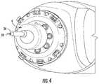
- FIG. 4is an isometric end view of the embodiment illustrated in FIG. 3 ;
- FIG. 5is a side isometric view of the embodiment illustrated in FIG. 3 ;
- FIG. 6is a front isometric view of the embodiment illustrated in FIG. 3 ;
- FIG. 7is an isometric view of an alternative embodiment of the oscillating tool secured to the distal arm of the multi-axis robot
- FIG. 8is a front isometric view of an alternative embodiment of the oscillating tool secured to the distal arm of the multi-axis robot;
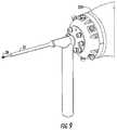
- FIG. 9is a front isometric view of an alternative embodiment of the oscillating tool secured to the distal arm of the multi-axis robot;
- FIG. 10is a partial section view illustrating one embodiment of the oscillating tool
- FIG. 11is a partial section view of the embodiment illustrated in FIG. 10 ;
- FIG. 12is a partial isometric view of the embodiment illustrated in FIG. 10 illustrating a scotch yoke mechanism for creating oscillatory movement;
- FIG. 13is an isometric view of an alternative oscillating mechanism illustrated without the outer case
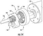
- FIG. 14is a partial isometric view of the embodiment illustrated in FIG. 13 ;
- FIG. 15is a partial isometric section view of the embodiment illustrated in FIG. 13 ;
- FIG. 16is an isometric view of an alternative oscillating mechanism illustrated without the outer case
- FIG. 17is a partial section view illustrating a cam mechanism for creating the oscillating movement of the cutting tool
- FIG. 18is a partial section view illustrating a cam mechanism for creating the oscillating movement of the cutting tool
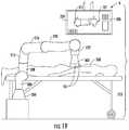
- FIG. 19is a side view illustrating a robotic arm with an ultrasound probe and a display of the image generated
- FIG. 20is a partial view of the embodiment illustrated in FIG. 19 ;
- FIG. 21is a side view illustrating one embodiment of a tool change system for use with a robotic arm
- FIG. 22is an isometric view of one embodiment of the robotic arm including an ultrasonic probe and an oscillating tool
- FIG. 23is a side view of one embodiment of the present system utilizing two robotic arms.
- the robotic surgical system 100generally includes a multi-axis robot 2 , a tool 4 (oscillating tool assembly below) with an effector 5 on a distal end thereof, and an operator station 6 .
- the tool 4is preferably an oscillating tool as more fully described below.
- the multi-axis robot 2includes a plurality of axes about which the oscillating tool 4 can be precisely maneuvered and oriented for surgical procedures.
- the multi-axis robotincludes seven axes of movement.
- the axes of movementinclude the base axis 202 generally centered within the base 200 and about which the first arm 204 rotates.
- the second axis 206is substantially perpendicular to the first axis 202 and about which the second arm 208 rotates.
- the second arm 208includes the third axis 210 about which the third arm 212 rotates.
- the third arm 212includes the fourth axis of rotation 214 which is oriented substantially perpendicular with respect to the first axis 202 and substantially parallel to the second axis 206 .
- the fourth arm 216rotates about the fourth axis 214 .
- the fourth arm 216includes the fifth axis 218 about which the fifth arm 220 rotates.
- the fifth arm 220includes the sixth axis 222 which includes the most available rotation about the sixth axis 222 for the wrist 224 of the robot.
- the wrist 224carries the tool 4 and effector 5 and has a seventh axis of rotation 228 for the cutting tool.
- the wrist 224is at the distal end of the fifth arm 220 .
- each axis of rotationprovides an additional freedom of movement for manipulation and orientation of the tool 4 .
- the multi-axis robot 2is only illustrated with the tool 4 , the preferred embodiment is capable of changing the effector to a variety of tools that are required to complete a particular surgery.
- Drivesare utilized to move the arms into their desired positions.
- the drivesmay be electric, hydraulic or pneumatic without departing from the scope of the invention.
- Rotational positioncan be signaled to a computer 230 , as with an encoder (not shown) associated with each arm 206 , 208 , 212 , 216 , 220 and other components having an axis of rotation.
- the drivesare in electrical communication with the computer 230 , and may further be combined with a telemanipulator, or pendant (not shown).
- the computer 230is programmed to control movement and operation of the robot(s) 2 through a controller portion 231 , and can utilize a software package such as ExcelsiusGPSTM from Globus. Alternatively, other software programming may be provided without departing from the scope of the invention.
- the computer 230can have a primary storage device (commonly referred to as memory) and/or a secondary storage device that can be used to store digital information such as images described herein.
- Primary and secondary storageare herein referred to as storage collectively, and can include one or both primary and secondary storage.
- the system 100may further include sensors positioned along various places on the multi-axis robot 2 , which provide tactile feedback to the operator or surgeon 232 .
- the computer 230is electrically connected or coupled to the multi-axis robot 2 in a manner that allows for operation of the multi-axis robot 2 , ranging from positions adjacent the robot to thousands of miles away.
- the computer 230is preferably capable of accepting, retaining and executing programmed movements of the multi-axis robot 2 in a precise manner.
- the controller 231can include a movement control input device 233 , such as a joy stick, keyboard, mouse or electronic screen 306 , see FIG. 19 , that can be touch activated.
- the screen 306can be part of the monitor 234 .
- Tool change commandscan be input using the screen 306 .
- the oscillating tool assembly 4can be used in surgical operations, such as spinal surgery, wherein bone, cartilage, disk, and other non-fibrous body material may be removed, such as from the spine.
- the oscillating tool assembly 4has an output spindle 36 which is driven to rotate in both directions, or rotary oscillate about its axis 228 .
- the spindle 36supports a cutting tool 38 , which is driven by the spindle 36 to rotate partially in both directions with a limited range of rotation.
- Such oscillatory cuttingis effective for bone, cartilage, and disk removal by a shearing operation, while effective in minimizing damage to any fibrous material.
- the fibrous materialis likely to be oscillated due to the flexibility of the fibrous material with minimal shearing, thereby minimizing damage to the fibrous material.
- FIG. 10illustrates some internal components of the oscillating tool assembly 4 .
- a power sourcemay be provided by a battery supply 46 oriented in the housing 32 .
- the battery supply 46may be charged or recharged by the multi-axis robot 2 .
- Electronics 48are provided in the housing 32 for controlling the operations of the tool assembly 4 .
- the power switch(not shown) may be remotely operated via the computer 230 , telemanipulator, or pendant.
- a plurality of indicator lamps 50may be provided on the housing 32 and illuminated by LEDs for indicating operational characteristics of the tool assembly 4 , such as the state of charge of the battery supply 46 .
- the tool 4may communicate wirelessly via Bluetooth, ZIGBY chip or the like to the computer 230 , whereby the signal is visible on the monitor 234 either locally and/or remotely.
- a motor 52is mounted in the housing 32 for providing a rotary input.
- the motor 52is powered by the battery supply 46 when controlled by the electronics 48 .
- the motor 52drives a transmission 54 for converting continuous rotary motion from the motor 52 to rotary oscillation to the spindle 36 .
- the spindle 36is journalled in the housing 32 and driven by the transmission 54 .
- the spindle 36is preferably straight, but may be angled relative to the housing 32 as depicted in FIGS. 10-12 for specific operations. Cooling fins, or a cooling fan (not shown), may be attached to or near the motor 52 for cooling the motor 52 and/or the tool assembly 4 .
- the motor 52drives an eccentric drive 56 .
- the eccentric drive 56includes a roller 58 supported to rotate upon the drive 56 , which is offset from an axis 60 of the motor 52 .
- rotation of the eccentric drive 56causes the roller 58 to revolve about the axis 60 .
- the eccentric drive 56also includes a counter-balance 62 offset from the axis 60 , opposed from the roller 58 , to counter-balance the transmission 54 and to minimize unwanted vibrations.
- the counter-balance 62can be formed integrally with the eccentric drive 56 according to at least one embodiment.
- the counter-balance 62may include an additional weight according to another embodiment.
- the roller 58may be a pin.
- a guideillustrated herein as a pair of pins 64 , 65 are supported in the housing 32 , generally perpendicular to the motor axis 61 .
- a single rail(not shown) may be utilized without departing from the scope of the invention.
- a shuttle 68is provided on the guide 64 for reciprocating translation upon the guide 64 .
- the shuttle 68includes a channel 70 that is generally perpendicular to the guide 64 .
- the channel 70receives the roller 58 of the eccentric drive 56 .
- the channel 70cooperates as a follower for permitting the roller 58 to translate along a length of the channel 70 while driving the shuttle 68 along the guide 64 .
- the guide 64may utilize bearings and/or rollers or the like to reduce friction.
- a gear rack 72is formed upon the shuttle 68 .
- the gear rack 72is formed generally parallel to the spindle 36 .
- a pinion gear or burr gear 74is mounted to the spindle 36 in engagement with the gear rack 72 , thereby providing a rack-and-pinion mechanism for converting the reciprocating translation of the shuttle 68 to rotary oscillation of the spindle 36 .
- a pair of bearing assemblies 76may also be provided in the housing for providing bearing support to the spindle 36 .
- the transmission 54may include any additional gearsets, as is known in the art, to vary speed or torque. According to one embodiment, a spur gear may be added to a motor output shaft to multiply speed of the roller 58 .#
- the eccentric drive 56 and shuttle 68cooperate as a Scotch-yoke mechanism for converting continuous rotary motion to linear reciprocating motion.
- Scotch-yoke mechanismany mechanism for converting rotary motion to reciprocation can be employed, such as a crank-and-slider mechanism, or the like.
- the spindle 36 and spindle tube 37are removable and replaceable from the remainder of the housing. In this manner, cutters or gear ratios that provide more or less oscillation can be easily changed to suit a particular need.
- FIGS. 8 and 9alternative embodiments of the oscillating tool assembly 4 are illustrated.
- the electric motor 52 and transmission assembly 54are oriented at about a right angle with respect to the spindle 36 .
- This constructionmay provide advantages for types of operations by shortening the distance from the end of the wrist 224 to the end of the spindle 36 .
- the transmission 154is positioned in the housing 132 and operably couples the shaft 136 to the motor 152 , and is operable to convert the continuous rotary motion of the motor shaft 163 ( FIG. 15 ) of the motor 152 to oscillating rotary motion of the shaft 136 .
- oscillating rotary motionit is meant that the shaft 136 will rotate a portion of a complete revolution first in one rotation direction then in another rotation direction; say first counterclockwise, then clockwise, then counterclockwise again and so on.
- the transmission 154comprises two sections.
- the first sectionis designated generally 161 , and is operable to convert the rotary motion of the shaft 163 of the motor 152 to reciprocating linear motion of a portion thereof, and the second section is designated generally 162 , and is operable to convert that reciprocating motion to oscillating rotary motion.
- the transmission section 154is in the form of a Cardan mechanism that utilizes an internal ring gear 164 and an external pinion gear 165 , with the pinion gear 165 being positioned inside of and having its external gear teeth in engagement with the internal gear teeth of the ring gear 164 .
- the gear ratio of the ring gear 164 to pinion gear 165is 2:1.
- the ring gear 164is suitably fixed in the housing 32 to prevent its motion relative to the housing 32 .
- the pinion gear 165is suitably mounted to a crank arm 166 , which in turn is secured to the shaft 163 of the motor 152 and is offset from the axis of rotation of the shaft 163 , whereby the pinion gear 165 revolves about the axis of rotation of the shaft 163 while inside the ring gear 164 .
- the crank arm 166has a counterweight 167 opposite of where the pinion gear 165 is mounted to the crank arm 166 .
- one point on the pinion gearwill move linearly in a reciprocating manner within the ring gear associated therewith. In the illustrated embodiment, the path of movement of this point is timed to move in a generally transverse plane relative to a portion of the transmission 154 .
- a driver arm 169Secured to the pinion gear 165 , preferably in an integral manner, is a driver arm 169 that extends forwardly of the ring gear 164 for receipt in a follower 170 to effect movement of the follower 170 in response to movement of the driver arm 169 .
- the follower 170is suitably mounted in the housing 32 in a manner to permit its pivoting movement about an axle 171 .
- the transverse linear movement of a spot on the pinion gear 165is generally transverse to the longitudinal axis of elongate slot 174 in the follower 170 .
- the axle 171is suitably mounted in bearing supports 173 that are in turn suitably mounted to the housing 32 .
- each end of the axle 171have a bearing 173 associated therewith.
- the axle 171could utilize the follower 170 as a bearing for rotation of the follower 170 about the axle 171 , and have the axle 171 mounted to the housing 32 in a fixed manner.
- the driver arm 169is received within the elongate slot 174 for effecting movement of the follower 170 in a rotary oscillating manner.
- the follower 170moves in an oscillating rotary manner about the axis 186 of the axle 171 .
- the driver arm 169When a portion of the driver arm 169 is moving in its linear path, portions of the arm 169 engage sides of the slot 174 to effect movement of the follower 170 in response to movement of the driver arm 169 .
- the driver arm 169is offset to the outside diameter of the pinion gear 165 , and thus its central axis does not move in a linear path, but will move in a series of arcs that are elongated in a horizontal plane and reduced in the vertical direction. This back-and-forth and up-and-down movement is accommodated by constructing the slot 174 to be elongated, as best seen in FIG. 15 .
- the follower 170is provided with a sector gear 176 that is operably coupled to a gear 177 secured to the shaft 136 . As the follower 170 moves, the shaft 136 moves in response thereto by engagement between the gears 176 and 177 . Because the follower 170 moves in a rotary oscillating manner, the shaft 136 also moves in a rotary oscillating manner.
- the components of the transmission sections 161 , 162are configured relative to one another such that, when the rotary oscillating movement changes direction at the shaft 136 , the applied torque by the motor 152 would be high; while at the center of one oscillation, the applied torque by the motor 152 would be lower. This assists in providing a high starting torque for the cutter 38 to reverse rotation direction.
- the alternative oscillating tool assembly 200includes a motor 202 mounted in a housing 204 .
- the motor 202drives a cam mechanism 206 for continuous rotation.
- the cam mechanism 206has four distinct cam profiles 208 , 210 , 212 , 214 stacked axially from the motor 202 .
- Each of the cam profiles 208 , 210 , 212 , 214is illustrated schematically in FIGS. 17-18 .
- a follower mechanism 216is mounted for rotation in the housing 204 .
- the follower mechanism 216has four follower profiles 218 , 220 , 222 , 224 , each for cooperating with one of the cam profiles 208 , 210 , 212 , 214 , as also illustrated in FIGS. 16-18 .
- a spindle 226is provided in the housing 204 with bearing support.
- the cam mechanism 206 and the follower mechanism 216cooperate as a transmission 229 for converting one rotation of the cam mechanism into two rotary oscillations of the follower mechanism 216 .
- the electric motor 202spins the cam mechanism 206 continually in one direction, which is clockwise in FIGS. 17-18 .
- the cam profiles 208 , 210 , 212 , 214engage the follower profiles 218 , 220 , 222 , 224 at two contact points at all times.
- the cam mechanism 206pushes the follower mechanism 216 to rotate.
- the cam mechanism 206prevents the follower mechanism 216 from over-rotating.
- the profiles 208 , 210 , 212 , 214 on the cam mechanism 206work together to cause the follower mechanism 216 to rotationally oscillate in two directions.
- each of the four cam profiles 208 , 210 , 212 , 214consists of two symmetrical lobes, which causes the follower mechanism 216 to make two complete oscillations (back and forth twice) for every complete revolution of the motor 202 .
- the cam mechanism 206could also be designed asymmetrical, and/or so that it causes the follower mechanism 216 to make any number of oscillations, such as one, or more than two, per motor revolution.
- the second cam profile 210contacts the second follower profile 220 for preventing over-rotation of the follower mechanism 216 , while the fourth cam profile 214 drives the fourth follower profile 224 .
- the second cam profile 210contacts the second follower profile 220 for driving the follower mechanism 216
- the third cam profile 212engages the third follower profile 222 to prevent over-rotation of the follower mechanism.
- the first cam profile 208contacts the first follower profile 218 for preventing over-rotation of the follower mechanism, while the third cam profile 212 drives the third follower profile 222 , thereby reversing directions.
- the first cam profile 208contacts the first follower profile to prevent over-rotation of the follower mechanism 216
- the fourth cam profile 214drives the fourth follower profile 224 . The process is repeated at FIG. 17 .
- the robotic surgical system 100generally includes one or two multi-axis robot(s) 2 , an ultrasound imaging system 300 , an effector such as an oscillating tool 4 , and an operator station 6 .
- a surgeonwould utilize fluoroscopy or fluoroscopy in combination with computer tomography (CT) scans or the like in order to perform surgery on the spine or other skeletal parts.
- CT scansare performed prior to the surgery so the surgeon can identify landmarks within the patient 308 and attempt to align the fluoroscopic image with the CT scan image to perform the surgery.
- the fluoroscopic imagesare often difficult to align because the patient is in a different position, causing distortion in the fluoroscopic imaging etc.
- one of the robot(s) 2may be fitted with an ultrasound imaging probe 302 .
- the ultrasonic imaging probe 302is electrically connected to an imaging system electronic controller 304 provided in the computer 230 which allows the operator to project the real-time images upon of monitor 234 and ensure proper overlay of the ultrasound image with the CT scan.
- the CT scan image(s) and ultrasonic image(s)can be stored in and recalled from the computer 230 storage and displayed on the monitor 234 .
- the monitor 234may be positioned in the operator station 6 and/or within the operating room 310 .
- This constructionallows the operator 232 to take fluoroscopic images without subjecting himself or herself to the radiation, while still allowing landmarks within the patient 308 to be closely identified and located for storage within the operator's station for use in the surgery.
- the operatorcan calibrate the robots positioning to correspond to the real-time ultrasonic image for completing the surgery.
- the operatorcan change the ultrasound probe 302 for a surgical instrument(s) tool 4 with effector 5 needed for the surgery in progressive order so that the tool(s) can be precisely maneuvered and oriented for surgical procedures.
- Springs or the likemay also be utilized to control the amount of force that is used to push against the patient with the probe, e.g., the probe 302 can be spring loaded to reduce the risk of hard contact with a patient during probe movement.
- the wrist 223 portion of the robotcarries the ultrasound probe 302 .
- the ultrasound probe 302is removably secured to the wrist 223 to allow probes or tools having different configurations to be interchanged by the robot upon command from the operator 232 through the computer 230 and coupled operator input controller 231 that allows the computer to know what the length 312 as well as the diameter 314 of the probe or tool 4 and effector 5 are.
- the robotcan make fast approaches to the patient and slow down when the probe 302 or tool 4 is close to the patient, and still touch the patient in a soft controlled manner.
- the computer 230can also alter the three-dimensional positioning of the robot to correspond to the tool or probe size in relation to the real-time images.
- Fiducial point devices 351can be used to assist in determining the position of a tool 4 relative to a patient 308 , and to assist in overlaying the various images, like the CT scan and ultrasound images. Typically for orthopedic surgery, fiducial point devices 351 are attached to a bone as with a screw. Such fiducial point devices are available from Northern Digital, Inc.
- FIG. 21illustrates an embodiment of the present device that includes an automatic tool changer 316 .
- the automatic tool changer 316is constructed and arranged to allow the tool 4 with effector 5 to be changed by the robot 2 in response to a command from the computer 230 , input preferably by the operator 232 .
- the wrist 224 of robot 2is positioned in a predetermined place.
- a tool arm 318rises or rotates to engage the tool in the wrist 224 which is released.
- the tool arm 318then lowers to remove the tool 4 and rotates to position an alternative tool under the wrist 224 .
- the tool arm 318rises to position the new tool within the wrist 224 where the wrist engages the tool 4 .
- the tool arm 318may then either retain the removed tool or place it onto a carrousel or conveyor 320 , which may include any number of tools.
- Each tool 4is provided with a tapered or otherwise shaped shank 322 which is shaped to cooperate with a cavity within the wrist 224 to provide repeatable positioning.
- each toolis also provided with a tang 324 which cooperates with a drawbar or draw mechanism (not shown) within the wrist 224 to pull the tool into the wrist in a controlled and repeatable manner.
- a tool changersuch as the MC-16R, QC-11 and QC-21 made by ATI can also be used instead of the drawbar type just described.
- each toolis retained within the computer 230 in the operator's station 6 so that positioning of the robot 2 arms is altered to correspond to each tool. In this manner, one tool can be utilized and quickly changed to the next needed tool while still utilizing the calibration and positioning provided from the ultrasound imaging.
- the robotcan be configured to rotate the wrist of the 223 of the robot to measure the moment of the tool as a second check that the proper tool is inserted into the wrist.
- the ultrasound probe 302is secured to a side or other surface of the wrist 223 .
- This constructionallows the wrist 223 to be simply rotated to touch the ultrasound imaging probe 302 onto the patient 308 to provide imaging and/or repositioning of the wrist 223 with respect to the image. Once the image and positioning are checked or rechecked, the wrist 223 can be rotated to use the tool also carried by the wrist.
- the computer 230keeps track of both the length 312 and diameter 314 of the ultrasound probe 302 and tool 4 so that precise locations are maintained when switching from the probe to the tool or between tools.
- the systemis provided with two or more robots 2 which work in unison and communicate positioning with the operator station 6 and each other to prevent collisions and coordinate actions.
- one robot 2utilizes the ultrasound imaging probe 302
- the other robotutilizes the tool 4 .
- imagescan be taken simultaneously with operation of the cutting, drilling or other tools 4 .
- the automatic tool changermay be used in conjunction with this or any other embodiment disclosed herein to add versatility to the system.
- the ultrasound toolis illustrated as having a different trajectory than that of the robot with the tool, the second robot will preferably direct the ultrasound on an intersecting trajectory with the cutting tool.
- a patient 308is scheduled for surgery.
- a first image of the surgical sightis created, for example, with a CT scan.
- the first imageis three-dimensional.
- the first imageis digitally stored in the computer 230 .
- At least one and preferably a plurality of fiducial point devices 351are secured to the patient 308 and are included in the first image.
- the patient 308is prepared for surgery and moved to the operating room 310 .
- At least one robot 2is located in the operating room, along with an automatic tool changer 316 positioned adjacent the robot(s) 2 .
- the patient's surgical sightis exposed to the robot(s) 2 .
- An ultrasound probe 302is mounted to a robot 2 , and a second digital image is created of the surgical sight and stored in the computer 230 .
- the first and second imagesare overlaid by the computer 230 using the fiducial point device(s) 351 as a coordinating reference.
- At least the second image of the surgical sightin displayed on the screen 306 of the monitor 234 , showing the surgical sight in real time at least at the beginning of surgery.
- both the first and second imagesare simultaneously displayed on the monitor 234 and are both preferably three-dimensional images.
- a continuous second imagecan be displayed in real time or, if one robot 2 is used, the ultrasound probe can be used intermittently as selected by the operator 232 as, for example, between tool 4 changes.
- the ultrasound probe 302is pointed in a direction to sense the effector 5 of the tool 4 and display it in the second image.
- the computer 230 , the operator controller 231 , the monitor 234 , screen 306 , ultrasound probe 302 and robots 2are operably coupled together to effect the various operations of each. While a single computer 230 is shown, it is to be understood that multiple computers can be in communication with one another to form a computer 230 . For example, a remote computer can be coupled to a local computer through an internet server to form the computer 230 .
- An operation control systemincludes the imaging control system 304 , controller 231 and possibly screen 306 , depending on its construction.
Landscapes
- Health & Medical Sciences (AREA)
- Life Sciences & Earth Sciences (AREA)
- Surgery (AREA)
- Engineering & Computer Science (AREA)
- Medical Informatics (AREA)
- Nuclear Medicine, Radiotherapy & Molecular Imaging (AREA)
- Biomedical Technology (AREA)
- Heart & Thoracic Surgery (AREA)
- Molecular Biology (AREA)
- Animal Behavior & Ethology (AREA)
- General Health & Medical Sciences (AREA)
- Public Health (AREA)
- Veterinary Medicine (AREA)
- Robotics (AREA)
- Orthopedic Medicine & Surgery (AREA)
- Human Computer Interaction (AREA)
- Manipulator (AREA)
Abstract
Description
Claims (10)
Priority Applications (4)
| Application Number | Priority Date | Filing Date | Title |
|---|---|---|---|
| US15/816,861US11135026B2 (en) | 2012-05-11 | 2017-11-17 | Robotic surgical system |
| US17/459,754US11819300B2 (en) | 2012-05-11 | 2021-08-27 | Robotic surgical system and method |
| US17/461,151US12408984B2 (en) | 2016-11-17 | 2021-08-30 | Surgical image system and method |
| US18/514,151US20240081931A1 (en) | 2012-05-11 | 2023-11-20 | Robotic surgical system and method |
Applications Claiming Priority (6)
| Application Number | Priority Date | Filing Date | Title |
|---|---|---|---|
| US13/469,665US10194922B2 (en) | 2012-05-11 | 2012-05-11 | Rotary oscillating bone, cartilage, and disk removal tool assembly |
| US201662423651P | 2016-11-17 | 2016-11-17 | |
| US201662423624P | 2016-11-17 | 2016-11-17 | |
| US201662423677P | 2016-11-17 | 2016-11-17 | |
| US15/814,891US10835263B2 (en) | 2016-11-17 | 2017-11-16 | Rotary oscillating surgical tool |
| US15/816,861US11135026B2 (en) | 2012-05-11 | 2017-11-17 | Robotic surgical system |
Related Parent Applications (1)
| Application Number | Title | Priority Date | Filing Date |
|---|---|---|---|
| US13/469,665Continuation-In-PartUS10194922B2 (en) | 2012-05-11 | 2012-05-11 | Rotary oscillating bone, cartilage, and disk removal tool assembly |
Related Child Applications (2)
| Application Number | Title | Priority Date | Filing Date |
|---|---|---|---|
| US17/459,754ContinuationUS11819300B2 (en) | 2012-05-11 | 2021-08-27 | Robotic surgical system and method |
| US17/461,151Continuation-In-PartUS12408984B2 (en) | 2016-11-17 | 2021-08-30 | Surgical image system and method |
Publications (2)
| Publication Number | Publication Date |
|---|---|
| US20180168757A1 US20180168757A1 (en) | 2018-06-21 |
| US11135026B2true US11135026B2 (en) | 2021-10-05 |
Family
ID=62557071
Family Applications (2)
| Application Number | Title | Priority Date | Filing Date |
|---|---|---|---|
| US15/816,861Active2033-10-21US11135026B2 (en) | 2012-05-11 | 2017-11-17 | Robotic surgical system |
| US17/459,754Active2032-10-10US11819300B2 (en) | 2012-05-11 | 2021-08-27 | Robotic surgical system and method |
Family Applications After (1)
| Application Number | Title | Priority Date | Filing Date |
|---|---|---|---|
| US17/459,754Active2032-10-10US11819300B2 (en) | 2012-05-11 | 2021-08-27 | Robotic surgical system and method |
Country Status (1)
| Country | Link |
|---|---|
| US (2) | US11135026B2 (en) |
Families Citing this family (13)
| Publication number | Priority date | Publication date | Assignee | Title |
|---|---|---|---|---|
| TWI783995B (en)* | 2017-04-28 | 2022-11-21 | 美商尼奧西斯股份有限公司 | Methods for conducting guided oral and maxillofacial procedures, and associated system |
| US11648058B2 (en)* | 2018-09-24 | 2023-05-16 | Simplify Medical Pty Ltd | Robotic system and method for bone preparation for intervertebral disc prosthesis implantation |
| US11857351B2 (en)* | 2018-11-06 | 2024-01-02 | Globus Medical, Inc. | Robotic surgical system and method |
| US10898218B2 (en)* | 2019-02-25 | 2021-01-26 | Covidien Lp | Tissue resecting device including a motor cooling assembly |
| US11986192B2 (en) | 2020-11-25 | 2024-05-21 | Medtronic Xomed, Inc. | Ultrasonic bone cutting device with integrated sensing |
| US11957361B2 (en)* | 2020-12-01 | 2024-04-16 | Medtronic Xomed, Inc. | Non-rotational bone cutting tools and related systems and methods |
| US20220354585A1 (en)* | 2021-04-21 | 2022-11-10 | The Cleveland Clinic Foundation | Robotic surgery |
| US20230098670A1 (en) | 2021-09-29 | 2023-03-30 | Cilag Gmbh International | Surgical devices, systems, and methods using multi-source imaging |
| US12295667B2 (en)* | 2021-09-29 | 2025-05-13 | Cilag Gmbh International | Surgical devices, systems, and methods using multi-source imaging |
| WO2023152561A1 (en)* | 2022-02-10 | 2023-08-17 | Lem Surgical Ag | Mobile system for bilateral robotic tool feeding |
| US20240000526A1 (en)* | 2022-06-30 | 2024-01-04 | Cilag Gmbh International | Robotic surgical system with removable portion and method of disassembling same |
| US20240227200A9 (en)* | 2022-10-25 | 2024-07-11 | Covidien Lp | Surgical robotic system and method for restoring operational state |
| WO2025119761A1 (en) | 2023-12-04 | 2025-06-12 | Lem Surgical Ag | Arm-mounted surgical robotic tool cassettes and methods for their use |
Citations (108)
| Publication number | Priority date | Publication date | Assignee | Title |
|---|---|---|---|---|
| US1154159A (en) | 1915-07-12 | 1915-09-21 | Asa Ashworth | Bit for valve-grinders. |
| US2557429A (en) | 1949-10-28 | 1951-06-19 | Zimmer Mfg Company | Surgical bone saw drive |
| US2831295A (en) | 1955-09-21 | 1958-04-22 | Gulton Ind Inc | Ultrasonic drill |
| US3091060A (en) | 1957-07-12 | 1963-05-28 | Lehfeldt & Company G M B H Dr | Ultrasonic machining |
| US3554197A (en) | 1967-08-11 | 1971-01-12 | Desoutter Brothers Ltd | Portable power-operated saw |
| US3577579A (en) | 1969-10-29 | 1971-05-04 | John P Duve | Electric toothbrush |
| US4007528A (en) | 1975-10-22 | 1977-02-15 | Shea John J | High speed bone drill |
| US4008720A (en) | 1974-06-08 | 1977-02-22 | Paul Brinckmann | Blade with irrigation tubes |
| US4081704A (en) | 1976-02-13 | 1978-03-28 | Skil Corporation | Powered hand-held tool with unitary sub-assembly mounted by the tool housing sections |
| BE861446A (en) | 1976-12-22 | 1978-03-31 | Leuenberger Roland | PROCESS FOR DRILLING HARD PARTS, IN SURGERY, AND APPARATUS FOR ITS IMPLEMENTATION |
| USD248967S (en) | 1976-08-18 | 1978-08-15 | Xomed Inc. | High speed bone drill |
| JPS5613462A (en) | 1979-07-10 | 1981-02-09 | Sumitomo Metal Ind Ltd | Line pipe steel with superior hydrogen sulfide crack resistance |
| JPS5826771B2 (en) | 1979-07-03 | 1983-06-04 | ユリイ イグナテイエビツチ ドドノフ | Magnetron type microwave device |
| EP0148304A1 (en) | 1984-01-12 | 1985-07-17 | Storz, Karl, Dr.med. h.c. | Operating instrument with an ultrasonic drill probe |
| US4596243A (en) | 1983-05-25 | 1986-06-24 | Bray Robert S | Surgical methods and apparatus for bone removal |
| US4620539A (en) | 1983-07-11 | 1986-11-04 | Andrews E Trent | Pistol grip, bone drill |
| EP0261260A1 (en) | 1986-09-23 | 1988-03-30 | Heinz-Jürgen List | Surgical bone drill |
| US4828052A (en) | 1988-06-20 | 1989-05-09 | The United States Of America As Represented By The United States Department Of Energy | Ultrasonic drilling apparatus |
| US4932935A (en) | 1986-09-15 | 1990-06-12 | Barry Swartz | Assisted lipectomy device |
| WO1991007116A1 (en) | 1989-11-14 | 1991-05-30 | Braun Aktiengesellschaft | Electric toothbrush with rotary bristle carrier |
| US5092875A (en) | 1990-04-30 | 1992-03-03 | Mclees Donald J | Bone saw for tendon transplant surgery |
| US5522829A (en) | 1992-04-16 | 1996-06-04 | Arthur D. Little Enterprises, Inc. | Surgical cutting instrument |
| US5733119A (en) | 1995-04-17 | 1998-03-31 | Carr; Gary B. | Dental retro-filling drill tool |
| US5843110A (en) | 1995-03-29 | 1998-12-01 | Linvatec Corporation | Apparatus and method for harvesting a bone-tendon-bone ligament graft |
| US6021538A (en) | 1995-06-24 | 2000-02-08 | Braun Aktiengesellschaft | Brush section for an electric toothbrush |
| US6110174A (en) | 1992-06-12 | 2000-08-29 | Larry S. Nichter | Method of fixating bone by driving a wire through oscillation |
| EP1041918A2 (en) | 1997-12-01 | 2000-10-11 | Eric Richard Cosman | Surgical positioning system |
| US20010015649A1 (en) | 1997-09-16 | 2001-08-23 | Rainer Herrmann | Microwave leakage field sensor for measuring moisture and/or density |
| WO2002015799A1 (en) | 2000-08-25 | 2002-02-28 | Nanxiang Gao | Sternum cutting apparatus |
| US20030060927A1 (en) | 2001-09-25 | 2003-03-27 | Intuitive Surgical, Inc. | Removable infinite roll master grip handle and touch sensor for robotic surgery |
| US6546279B1 (en) | 2001-10-12 | 2003-04-08 | University Of Florida | Computer controlled guidance of a biopsy needle |
| US6606539B2 (en)* | 1993-02-23 | 2003-08-12 | Faro Technologies, Inc. | Portable coordinate measurement machine with pre-stressed bearings |
| US6635067B2 (en) | 2000-09-24 | 2003-10-21 | Medtronic, Inc. | Liquid cooled, powered surgical handpiece |
| US6689087B2 (en) | 2001-03-28 | 2004-02-10 | Cybersonics, Inc. | Floating probe for ultrasonic transducers |
| US20040050603A1 (en) | 2000-02-23 | 2004-03-18 | Jaeger Eduard A. | Mounting arrangement for vehicle power source |
| US6716215B1 (en) | 1999-10-29 | 2004-04-06 | Image-Guided Neurologics | Cranial drill with sterile barrier |
| US6721986B2 (en) | 2001-06-28 | 2004-04-20 | Qingping Zhuan | Electric toothbrush |
| CA2513071A1 (en) | 2003-01-09 | 2004-07-29 | Synthes (U.S.A.) | Device for converting a rotary motion into an oscillating motion |
| US20040147934A1 (en) | 2002-10-18 | 2004-07-29 | Kiester P. Douglas | Oscillating, steerable, surgical burring tool and method of using the same |
| US20050027397A1 (en) | 1999-04-07 | 2005-02-03 | Intuitive Surgical, Inc. | Aspects of a control system of a minimally invasive surgical apparatus |
| US20050043718A1 (en) | 1997-09-19 | 2005-02-24 | Intuitive Surgical, Inc. | Robotic apparatus |
| US6895305B2 (en)* | 2001-02-27 | 2005-05-17 | Anthrotronix, Inc. | Robotic apparatus and wireless communication system |
| US20050171557A1 (en) | 2000-07-24 | 2005-08-04 | Moshe Shoham | Miniature bone-attached surgical robot |
| EP1571581A1 (en) | 2003-01-30 | 2005-09-07 | Surgical Navigation Technologies, Inc. | Method and apparatus for preplanning a surgical procedure |
| US6966912B2 (en) | 1998-06-09 | 2005-11-22 | Sdgi Holdings, Inc. | Device and method for preparing a space between adjacent vertebrae to receive an insert |
| EP1690649A1 (en) | 2005-02-10 | 2006-08-16 | Makita Corporation | Power tool |
| US20060229624A1 (en) | 2005-03-31 | 2006-10-12 | Zimmer Technology, Inc. | Orthopaedic cutting instrument and method |
| US20060235306A1 (en) | 2005-04-15 | 2006-10-19 | Integra Lifesciences (Ireland) | Ultrasonic horn for removal of hard tissue |
| US20060235305A1 (en) | 2005-04-15 | 2006-10-19 | Integra Lifesciences (Ireland) Ltd. | Bone abrading ultrasonic horns |
| US20070005045A1 (en)* | 2005-06-30 | 2007-01-04 | Intuitive Surgical Inc. | Indicator for tool state and communication in multi-arm robotic telesurgery |
| US7160304B2 (en) | 1998-06-09 | 2007-01-09 | Warsaw Orthopedic, Inc. | Method for preparing a space between adjacent vertebrae to receive an insert |
| WO2007008703A2 (en) | 2005-07-08 | 2007-01-18 | Conceptual Gray, Llc | Apparatus and method thereof for drilling holes in discrete controlled increments |
| US20070021738A1 (en) | 2005-06-06 | 2007-01-25 | Intuitive Surgical Inc. | Laparoscopic ultrasound robotic surgical system |
| US7194120B2 (en) | 2003-05-29 | 2007-03-20 | Board Of Regents, The University Of Texas System | Methods and systems for image-guided placement of implants |
| US20070276423A1 (en) | 1992-01-21 | 2007-11-29 | Sri International | Roll-Pitch-Roll Wrist Methods for Minimally Invasive Robotic Surgery |
| US20070282344A1 (en) | 2006-06-01 | 2007-12-06 | Yedlicka Joseph W | Bone drill and methods of use |
| US20070282345A1 (en) | 2006-06-01 | 2007-12-06 | Yedlicka Joseph W | Cavity creation device and methods of use |
| US20080027449A1 (en) | 2006-07-28 | 2008-01-31 | Depuy Products, Inc. | Adapters to convert output motion of orthopaedic bone saws and bone drills |
| US20080061784A1 (en) | 2003-12-04 | 2008-03-13 | Dharmendra Pal | Floating probe for ultrasonic transducers |
| US7346417B2 (en) | 2001-03-26 | 2008-03-18 | Lb Medical Gmbh | Method and device system for removing material or for working material |
| US20080108010A1 (en) | 2006-11-07 | 2008-05-08 | Wen-Hao Wang | Illuminator for a dental drill |
| US20080108991A1 (en) | 2006-11-08 | 2008-05-08 | General Electric Company | Method and apparatus for performing pedicle screw fusion surgery |
| US20080213889A1 (en) | 2003-04-01 | 2008-09-04 | Palmer Stephen S | Inhibitors of phosphodiesterases in infertility |
| WO2009151926A2 (en) | 2008-05-23 | 2009-12-17 | Spine View, Inc. | Method and devices for treating spinal stenosis |
| US7660623B2 (en)* | 2003-01-30 | 2010-02-09 | Medtronic Navigation, Inc. | Six degree of freedom alignment display for medical procedures |
| US20100145343A1 (en) | 2007-04-04 | 2010-06-10 | Alexandria Research Technologies, Llc | Apparatus and method for sculpting the surface of a joint |
| US20100165793A1 (en) | 2006-09-27 | 2010-07-01 | Willi Haug | Ultrasonic vibration transducer for ultrasonic drilling |
| US20100249506A1 (en) | 2009-03-26 | 2010-09-30 | Intuitive Surgical, Inc. | Method and system for assisting an operator in endoscopic navigation |
| US20100249786A1 (en) | 2009-03-30 | 2010-09-30 | Reinhold Schmieding | Microfracture instrument |
| US20110015635A1 (en) | 2009-07-17 | 2011-01-20 | Aryan Henry E | Apparatus and method for facilitating intervertebral arthrodesis and disc space preparation as part of treatment of spinal degenerative disease |
| US20110118708A1 (en) | 2009-11-13 | 2011-05-19 | Intuitive Surgical Operations, Inc. | Double universal joint |
| US20110118709A1 (en) | 2009-11-13 | 2011-05-19 | Intuitive Surgical Operations, Inc. | Surgical tool with a two degree of freedom wrist |
| US20110118778A1 (en) | 2009-11-13 | 2011-05-19 | Intuitive Surgical Operations, Inc. | End effector with redundant closing mechanisms |
| US20110196404A1 (en) | 2010-02-11 | 2011-08-11 | Ethicon Endo-Surgery, Inc. | Ultrasonic surgical instruments with moving cutting implement |
| US20110230886A1 (en) | 2008-11-21 | 2011-09-22 | Gustilo Ramon B | Drill assembly and system and method for forming a pilot hole |
| US8029523B2 (en) | 2007-03-30 | 2011-10-04 | Innovative Implant Technology, Llc | Maxillary bone cutting system, kit, and method of using the same |
| US20110295270A1 (en) | 2007-01-10 | 2011-12-01 | Ethicon Endo-Surgery, Inc. | Surgical instrument with wireless communication between a control unit of a robotic system and remote sensor |
| US20110306873A1 (en) | 2010-05-07 | 2011-12-15 | Krishna Shenai | System for performing highly accurate surgery |
| US20110313428A1 (en) | 2006-06-13 | 2011-12-22 | Intuitive Surgical Operations, Inc. | Bracing of Bundled Medical Devices for Single Port Entry, Robotically Assisted Medical Procedures |
| US20110319941A1 (en) | 2008-12-01 | 2011-12-29 | Yossef Bar | Robot Guided Oblique Spinal Stabilization |
| US20120059392A1 (en) | 2007-06-13 | 2012-03-08 | Intuitive Surgical Operations, Inc. | Method and system for moving a plurality of articulated instruments in tandem back towards an entry guide |
| US8170717B2 (en) | 2002-08-13 | 2012-05-01 | Neuroarm Surgical Ltd. | Microsurgical robot system |
| US8219178B2 (en) | 2007-02-16 | 2012-07-10 | Catholic Healthcare West | Method and system for performing invasive medical procedures using a surgical robot |
| US20120186372A1 (en) | 2008-05-09 | 2012-07-26 | Smith Ronald D | Oscillating device and process for drilling holes in soft materials |
| US20120220831A1 (en) | 2001-06-29 | 2012-08-30 | Intuititve Surgical Operations, Inc. | Surgical tool having positively positionable tendon-actuated multi-disk wrist joint |
| US20120266442A1 (en) | 2008-06-30 | 2012-10-25 | Intuitive Surgical Operations, Inc. | Fixture for shape-sensing optical fiber in a kinematic chain |
| US20130096540A1 (en) | 2002-12-06 | 2013-04-18 | Intuitive Surgical Operations, Inc. | Flexible wrist for surgical tool |
| US20130178856A1 (en) | 2010-09-30 | 2013-07-11 | Chongqing Runze Medical Instruments Co., Ltd. | Craniotomy drill |
| US8491603B2 (en) | 2006-06-14 | 2013-07-23 | MacDonald Dettwiller and Associates Inc. | Surgical manipulator |
| US20130206441A1 (en) | 2010-04-27 | 2013-08-15 | Robert Bosch Gmbh | Minimal Quantity Lubricating System |
| US20130244820A1 (en) | 2004-09-30 | 2013-09-19 | Intuitive Surgical Operations, Inc. | [[Multi-Ply]] Strap guide system and methods thereof for robotic surgical arms Drive Trains for Robotic Arms |
| US20130245629A1 (en) | 2012-03-14 | 2013-09-19 | Stryker Corporation | Surgical drill with drive shaft and drill bit that, after disengaging the drill bit from the drive shaft, allows the drill bit to be driven in reverse |
| US20130296886A1 (en) | 1995-06-07 | 2013-11-07 | Sri International | Surgical manipulator for a telerobotic system |
| US20130304069A1 (en) | 2012-05-11 | 2013-11-14 | Peter L. Bono | Rotary oscillating bone, cartilage, and disk removal tool assembly |
| US20130345718A1 (en) | 2007-02-16 | 2013-12-26 | Excelsius Surgical, L.L.C. | Surgical robot platform |
| US20140051922A1 (en) | 1999-04-07 | 2014-02-20 | Intuitive Surgical, Inc. | Real-time generation of three- dimensional ultrasound image using a two-dimensional ultrasound transducer in a robotic system |
| US8657821B2 (en) | 2008-11-14 | 2014-02-25 | Revascular Therapeutics Inc. | Method and system for reversibly controlled drilling of luminal occlusions |
| US20140100574A1 (en) | 2012-10-08 | 2014-04-10 | Peter Bono | Cutting tool for bone, cartilage, and disk removal |
| US8728085B2 (en) | 2009-05-28 | 2014-05-20 | Depuy International Limited | Bone cutting assembly |
| US20140194894A1 (en) | 2009-11-13 | 2014-07-10 | Intuitive Surgical Operations, Inc. | Motor Interface for Parallel Drive Shafts Within an Independently Rotating Member |
| US20140222003A1 (en) | 2013-02-05 | 2014-08-07 | Path Scientific, Llc | Precision bone drill and method of use |
| US8828001B2 (en) | 2007-02-20 | 2014-09-09 | Gabriel Institute, Inc. | Bone drill and methods of treatment |
| WO2014150514A1 (en) | 2013-03-15 | 2014-09-25 | Misonix, Incorporated | Ultrasonic surgical drill and associated surgical method |
| US20140350391A1 (en) | 2009-03-26 | 2014-11-27 | Intuitive Surgical Operations, Inc. | Method And System For Providing Visual Guidance To An Operator For Steering A Tip Of An Endoscopic Device Towards One Or More Landmarks In A Patient |
| WO2015006296A1 (en) | 2013-07-09 | 2015-01-15 | Stryker Corporation | Surgical drill having brake that, upon the drill bit penetrating through bone, prevents further insertion of the drill bit |
| US8943634B2 (en) | 2011-05-02 | 2015-02-03 | Water Pik, Inc. | Mechanically-driven, sonic toothbrush system |
| WO2015166487A1 (en) | 2014-04-28 | 2015-11-05 | Mazor Robotics Ltd. | Ultrasound guided hand held robot |
| US20160151120A1 (en) | 2014-12-02 | 2016-06-02 | KB Medical SA | Robot Assisted Volume Removal During Surgery |
Family Cites Families (7)
| Publication number | Priority date | Publication date | Assignee | Title |
|---|---|---|---|---|
| US6711433B1 (en)* | 1999-09-30 | 2004-03-23 | Siemens Corporate Research, Inc. | Method for providing a virtual contrast agent for augmented angioscopy |
| US20080213899A1 (en) | 2006-10-12 | 2008-09-04 | University Of Connecticut | Rotationally Oscillating Injector |
| CA2712607A1 (en) | 2008-01-25 | 2009-07-30 | Mcmaster University | Surgical guidance utilizing tissue feedback |
| FR2983059B1 (en) | 2011-11-30 | 2014-11-28 | Medtech | ROBOTIC-ASSISTED METHOD OF POSITIONING A SURGICAL INSTRUMENT IN RELATION TO THE BODY OF A PATIENT AND DEVICE FOR CARRYING OUT SAID METHOD |
| US9788906B2 (en)* | 2013-03-15 | 2017-10-17 | Synaptive Medical (Barbados) Inc. | Context aware surgical systems for intraoperatively configuring imaging devices |
| EP3175791B1 (en)* | 2013-11-04 | 2021-09-08 | Ecential Robotics | Method for reconstructing a 3d image from 2d x-ray images |
| CN107813490A (en) | 2017-12-11 | 2018-03-20 | 江苏名欧高分子科技有限公司 | A kind of Automatic-drawing shaped device of plastic tubulature |
- 2017
- 2017-11-17USUS15/816,861patent/US11135026B2/enactiveActive
- 2021
- 2021-08-27USUS17/459,754patent/US11819300B2/enactiveActive
Patent Citations (145)
| Publication number | Priority date | Publication date | Assignee | Title |
|---|---|---|---|---|
| US1154159A (en) | 1915-07-12 | 1915-09-21 | Asa Ashworth | Bit for valve-grinders. |
| US2557429A (en) | 1949-10-28 | 1951-06-19 | Zimmer Mfg Company | Surgical bone saw drive |
| US2831295A (en) | 1955-09-21 | 1958-04-22 | Gulton Ind Inc | Ultrasonic drill |
| US3091060A (en) | 1957-07-12 | 1963-05-28 | Lehfeldt & Company G M B H Dr | Ultrasonic machining |
| US3554197A (en) | 1967-08-11 | 1971-01-12 | Desoutter Brothers Ltd | Portable power-operated saw |
| US3577579A (en) | 1969-10-29 | 1971-05-04 | John P Duve | Electric toothbrush |
| US4008720A (en) | 1974-06-08 | 1977-02-22 | Paul Brinckmann | Blade with irrigation tubes |
| US4007528A (en) | 1975-10-22 | 1977-02-15 | Shea John J | High speed bone drill |
| USRE29736E (en) | 1975-10-22 | 1978-08-22 | Xomed Inc. | High speed bone drill |
| US4081704A (en) | 1976-02-13 | 1978-03-28 | Skil Corporation | Powered hand-held tool with unitary sub-assembly mounted by the tool housing sections |
| USD248967S (en) | 1976-08-18 | 1978-08-15 | Xomed Inc. | High speed bone drill |
| ES465719A1 (en) | 1976-12-22 | 1980-12-16 | Leuenberger Roland | Process for drilling holes in hard materials, in surgical procedures, and apparatus for carrying out the process |
| CH610753A5 (en) | 1976-12-22 | 1979-05-15 | Roland Leuenberger | |
| NL7713563A (en) | 1976-12-22 | 1978-06-26 | Leuenberger Roland | PROCEDURE FOR DRILLING HOLES IN HARD MATERIALS DURING OPERATIONS AND THE EQUIPMENT THEREOF. |
| DE2730227A1 (en) | 1976-12-22 | 1978-06-29 | Roland Leuenberger | DEVICE FOR PROCESSING HARD BODY PARTS, IN PARTICULAR BONES |
| JPS5380789A (en) | 1976-12-22 | 1978-07-17 | Leuenberger Roland | Method of and device for perforating hard material by surgical treatment |
| FR2374886A1 (en) | 1976-12-22 | 1978-07-21 | Leuenberger Roland | PROCESS FOR DRILLING HARD PARTS, IN SURGERY, AND APPARATUS FOR ITS IMPLEMENTATION |
| DK570977A (en) | 1976-12-22 | 1978-06-23 | Leuenberger Roland | HOLE PROCEDURE AND APPARATUS |
| FI773650A7 (en) | 1976-12-22 | 1978-06-23 | Roland Leuenberger | FOERFARANDE FOER BORRANDE AV HAOL I HAORDA AEMNEN FOER KIRURGISKA AENDAMAOL OCH ANORDNING FOER GENOMFOERANDE AV FOERFARANDE |
| US4111208A (en) | 1976-12-22 | 1978-09-05 | Roland Leuenberger | Process for drilling holes in hard materials, in surgical procedures, and apparatus for carrying out the process |
| NO774411L (en) | 1976-12-22 | 1978-06-23 | Roland Leuenberger | PROCEDURE FOR DRILLING HOLES IN HARD MATERIALS FOR SURGICAL INTERVENTIONS AND APPARATUS FOR ITS PERFORMANCE |
| GB1550577A (en) | 1976-12-22 | 1979-08-15 | Leuenberger Roland | Methods of and apparatus for surgical drilling |
| BE861446A (en) | 1976-12-22 | 1978-03-31 | Leuenberger Roland | PROCESS FOR DRILLING HARD PARTS, IN SURGERY, AND APPARATUS FOR ITS IMPLEMENTATION |
| IT1081824B (en) | 1976-12-22 | 1985-05-21 | Leuenberger Roland | PARTIDURE DRILLING PROCEDURE, AND APPARATUS FOR ITS REALIZATION |
| CA1112970A (en) | 1976-12-22 | 1981-11-24 | Roland Leuenberger | Process for drilling holes in hard material in surgical procedures, and apparatus for carrying out the process |
| AT370608B (en) | 1976-12-22 | 1983-04-25 | Leuenberger Roland | DEVICE FOR DRILLING HARD PARTS IN SURGERY |
| JPS5826771B2 (en) | 1979-07-03 | 1983-06-04 | ユリイ イグナテイエビツチ ドドノフ | Magnetron type microwave device |
| JPS5613462A (en) | 1979-07-10 | 1981-02-09 | Sumitomo Metal Ind Ltd | Line pipe steel with superior hydrogen sulfide crack resistance |
| US4596243A (en) | 1983-05-25 | 1986-06-24 | Bray Robert S | Surgical methods and apparatus for bone removal |
| US4620539A (en) | 1983-07-11 | 1986-11-04 | Andrews E Trent | Pistol grip, bone drill |
| EP0148304A1 (en) | 1984-01-12 | 1985-07-17 | Storz, Karl, Dr.med. h.c. | Operating instrument with an ultrasonic drill probe |
| US4932935A (en) | 1986-09-15 | 1990-06-12 | Barry Swartz | Assisted lipectomy device |
| EP0261260A1 (en) | 1986-09-23 | 1988-03-30 | Heinz-Jürgen List | Surgical bone drill |
| US4828052A (en) | 1988-06-20 | 1989-05-09 | The United States Of America As Represented By The United States Department Of Energy | Ultrasonic drilling apparatus |
| WO1991007116A1 (en) | 1989-11-14 | 1991-05-30 | Braun Aktiengesellschaft | Electric toothbrush with rotary bristle carrier |
| US5092875A (en) | 1990-04-30 | 1992-03-03 | Mclees Donald J | Bone saw for tendon transplant surgery |
| US20070276423A1 (en) | 1992-01-21 | 2007-11-29 | Sri International | Roll-Pitch-Roll Wrist Methods for Minimally Invasive Robotic Surgery |
| US5522829A (en) | 1992-04-16 | 1996-06-04 | Arthur D. Little Enterprises, Inc. | Surgical cutting instrument |
| US6110174A (en) | 1992-06-12 | 2000-08-29 | Larry S. Nichter | Method of fixating bone by driving a wire through oscillation |
| US6606539B2 (en)* | 1993-02-23 | 2003-08-12 | Faro Technologies, Inc. | Portable coordinate measurement machine with pre-stressed bearings |
| US5843110A (en) | 1995-03-29 | 1998-12-01 | Linvatec Corporation | Apparatus and method for harvesting a bone-tendon-bone ligament graft |
| US5733119A (en) | 1995-04-17 | 1998-03-31 | Carr; Gary B. | Dental retro-filling drill tool |
| US20130296886A1 (en) | 1995-06-07 | 2013-11-07 | Sri International | Surgical manipulator for a telerobotic system |
| US6021538A (en) | 1995-06-24 | 2000-02-08 | Braun Aktiengesellschaft | Brush section for an electric toothbrush |
| US20010015649A1 (en) | 1997-09-16 | 2001-08-23 | Rainer Herrmann | Microwave leakage field sensor for measuring moisture and/or density |
| US20050043718A1 (en) | 1997-09-19 | 2005-02-24 | Intuitive Surgical, Inc. | Robotic apparatus |
| EP1041918A2 (en) | 1997-12-01 | 2000-10-11 | Eric Richard Cosman | Surgical positioning system |
| US7160304B2 (en) | 1998-06-09 | 2007-01-09 | Warsaw Orthopedic, Inc. | Method for preparing a space between adjacent vertebrae to receive an insert |
| US6966912B2 (en) | 1998-06-09 | 2005-11-22 | Sdgi Holdings, Inc. | Device and method for preparing a space between adjacent vertebrae to receive an insert |
| US20050027397A1 (en) | 1999-04-07 | 2005-02-03 | Intuitive Surgical, Inc. | Aspects of a control system of a minimally invasive surgical apparatus |
| US20140051922A1 (en) | 1999-04-07 | 2014-02-20 | Intuitive Surgical, Inc. | Real-time generation of three- dimensional ultrasound image using a two-dimensional ultrasound transducer in a robotic system |
| US6716215B1 (en) | 1999-10-29 | 2004-04-06 | Image-Guided Neurologics | Cranial drill with sterile barrier |
| US20040050603A1 (en) | 2000-02-23 | 2004-03-18 | Jaeger Eduard A. | Mounting arrangement for vehicle power source |
| US20100198230A1 (en) | 2000-07-24 | 2010-08-05 | Moshe Shoham | Miniature bone-attached surgical robot |
| US20050171557A1 (en) | 2000-07-24 | 2005-08-04 | Moshe Shoham | Miniature bone-attached surgical robot |
| WO2002015799A1 (en) | 2000-08-25 | 2002-02-28 | Nanxiang Gao | Sternum cutting apparatus |
| US6635067B2 (en) | 2000-09-24 | 2003-10-21 | Medtronic, Inc. | Liquid cooled, powered surgical handpiece |
| US6895305B2 (en)* | 2001-02-27 | 2005-05-17 | Anthrotronix, Inc. | Robotic apparatus and wireless communication system |
| US7346417B2 (en) | 2001-03-26 | 2008-03-18 | Lb Medical Gmbh | Method and device system for removing material or for working material |
| US6689087B2 (en) | 2001-03-28 | 2004-02-10 | Cybersonics, Inc. | Floating probe for ultrasonic transducers |
| US6721986B2 (en) | 2001-06-28 | 2004-04-20 | Qingping Zhuan | Electric toothbrush |
| US20120220831A1 (en) | 2001-06-29 | 2012-08-30 | Intuititve Surgical Operations, Inc. | Surgical tool having positively positionable tendon-actuated multi-disk wrist joint |
| US20030060927A1 (en) | 2001-09-25 | 2003-03-27 | Intuitive Surgical, Inc. | Removable infinite roll master grip handle and touch sensor for robotic surgery |
| US6546279B1 (en) | 2001-10-12 | 2003-04-08 | University Of Florida | Computer controlled guidance of a biopsy needle |
| US8170717B2 (en) | 2002-08-13 | 2012-05-01 | Neuroarm Surgical Ltd. | Microsurgical robot system |
| US20040147934A1 (en) | 2002-10-18 | 2004-07-29 | Kiester P. Douglas | Oscillating, steerable, surgical burring tool and method of using the same |
| US20130096540A1 (en) | 2002-12-06 | 2013-04-18 | Intuitive Surgical Operations, Inc. | Flexible wrist for surgical tool |
| JP4481173B2 (en) | 2003-01-09 | 2010-06-16 | ジンテーズ ゲゼルシャフト ミト ベシュレンクテル ハフツング | A device that converts rotational motion into vibration |
| CA2513071A1 (en) | 2003-01-09 | 2004-07-29 | Synthes (U.S.A.) | Device for converting a rotary motion into an oscillating motion |
| WO2004062863A1 (en) | 2003-01-09 | 2004-07-29 | Synthes Ag Chur | Device for translating a rotational motion into an oscillating motion |
| AU2003200831A1 (en) | 2003-01-09 | 2004-08-10 | Synthes Gmbh | Device for translating a rotational motion into an oscillating motion |
| JP2006512954A (en) | 2003-01-09 | 2006-04-20 | ジンテーズ アクチエンゲゼルシャフト クール | A device that converts rotational motion into vibration |
| US20050283175A1 (en) | 2003-01-09 | 2005-12-22 | Peter Tanner | Device for converting a rotary motion into an oscillating motion |
| EP1581374A1 (en) | 2003-01-09 | 2005-10-05 | SYNTHES AG Chur | Device for translating a rotational motion into an oscillating motion |
| AR042807A1 (en) | 2003-01-09 | 2005-07-06 | Synthes Ag | DEVICE FOR TRANSFORMING A ROTATING MOVEMENT IN AN OSCILLATING ROTATING MOVEMENT |
| EP1571581A1 (en) | 2003-01-30 | 2005-09-07 | Surgical Navigation Technologies, Inc. | Method and apparatus for preplanning a surgical procedure |
| US7660623B2 (en)* | 2003-01-30 | 2010-02-09 | Medtronic Navigation, Inc. | Six degree of freedom alignment display for medical procedures |
| US20080213889A1 (en) | 2003-04-01 | 2008-09-04 | Palmer Stephen S | Inhibitors of phosphodiesterases in infertility |
| US7194120B2 (en) | 2003-05-29 | 2007-03-20 | Board Of Regents, The University Of Texas System | Methods and systems for image-guided placement of implants |
| US20080061784A1 (en) | 2003-12-04 | 2008-03-13 | Dharmendra Pal | Floating probe for ultrasonic transducers |
| US8038630B2 (en) | 2003-12-04 | 2011-10-18 | Cybersonics, Inc. | Floating probe for ultrasonic transducers |
| US20130244820A1 (en) | 2004-09-30 | 2013-09-19 | Intuitive Surgical Operations, Inc. | [[Multi-Ply]] Strap guide system and methods thereof for robotic surgical arms Drive Trains for Robotic Arms |
| EP1690649A1 (en) | 2005-02-10 | 2006-08-16 | Makita Corporation | Power tool |
| US20060229624A1 (en) | 2005-03-31 | 2006-10-12 | Zimmer Technology, Inc. | Orthopaedic cutting instrument and method |
| US7922720B2 (en) | 2005-03-31 | 2011-04-12 | Zimmer Technology, Inc. | Orthopaedic cutting instrument and method |
| US20060235305A1 (en) | 2005-04-15 | 2006-10-19 | Integra Lifesciences (Ireland) Ltd. | Bone abrading ultrasonic horns |
| US20060235306A1 (en) | 2005-04-15 | 2006-10-19 | Integra Lifesciences (Ireland) | Ultrasonic horn for removal of hard tissue |
| US20070021738A1 (en) | 2005-06-06 | 2007-01-25 | Intuitive Surgical Inc. | Laparoscopic ultrasound robotic surgical system |
| US20070005045A1 (en)* | 2005-06-30 | 2007-01-04 | Intuitive Surgical Inc. | Indicator for tool state and communication in multi-arm robotic telesurgery |
| WO2007008703A2 (en) | 2005-07-08 | 2007-01-18 | Conceptual Gray, Llc | Apparatus and method thereof for drilling holes in discrete controlled increments |
| US8465491B2 (en) | 2006-06-01 | 2013-06-18 | Osteo Innovations Llc | Bone drill |
| US20070282344A1 (en) | 2006-06-01 | 2007-12-06 | Yedlicka Joseph W | Bone drill and methods of use |
| US20070282345A1 (en) | 2006-06-01 | 2007-12-06 | Yedlicka Joseph W | Cavity creation device and methods of use |
| US20110313428A1 (en) | 2006-06-13 | 2011-12-22 | Intuitive Surgical Operations, Inc. | Bracing of Bundled Medical Devices for Single Port Entry, Robotically Assisted Medical Procedures |
| US8491603B2 (en) | 2006-06-14 | 2013-07-23 | MacDonald Dettwiller and Associates Inc. | Surgical manipulator |
| US20080027449A1 (en) | 2006-07-28 | 2008-01-31 | Depuy Products, Inc. | Adapters to convert output motion of orthopaedic bone saws and bone drills |
| US20100165793A1 (en) | 2006-09-27 | 2010-07-01 | Willi Haug | Ultrasonic vibration transducer for ultrasonic drilling |
| US20080108010A1 (en) | 2006-11-07 | 2008-05-08 | Wen-Hao Wang | Illuminator for a dental drill |
| US20080108991A1 (en) | 2006-11-08 | 2008-05-08 | General Electric Company | Method and apparatus for performing pedicle screw fusion surgery |
| US20120211546A1 (en) | 2007-01-10 | 2012-08-23 | Ethicon Endo-Surgery, Inc. | Drive interface for operably coupling a manipulatable surgical tool to a robot |
| US20110295270A1 (en) | 2007-01-10 | 2011-12-01 | Ethicon Endo-Surgery, Inc. | Surgical instrument with wireless communication between a control unit of a robotic system and remote sensor |
| US20130345718A1 (en) | 2007-02-16 | 2013-12-26 | Excelsius Surgical, L.L.C. | Surgical robot platform |
| US20130123799A1 (en) | 2007-02-16 | 2013-05-16 | David W. Smith | Method and system for performing invasive medical procedures using a surgical robot |
| US8219178B2 (en) | 2007-02-16 | 2012-07-10 | Catholic Healthcare West | Method and system for performing invasive medical procedures using a surgical robot |
| US8828001B2 (en) | 2007-02-20 | 2014-09-09 | Gabriel Institute, Inc. | Bone drill and methods of treatment |
| US8029523B2 (en) | 2007-03-30 | 2011-10-04 | Innovative Implant Technology, Llc | Maxillary bone cutting system, kit, and method of using the same |
| US20100145343A1 (en) | 2007-04-04 | 2010-06-10 | Alexandria Research Technologies, Llc | Apparatus and method for sculpting the surface of a joint |
| US20120059392A1 (en) | 2007-06-13 | 2012-03-08 | Intuitive Surgical Operations, Inc. | Method and system for moving a plurality of articulated instruments in tandem back towards an entry guide |
| US20120186372A1 (en) | 2008-05-09 | 2012-07-26 | Smith Ronald D | Oscillating device and process for drilling holes in soft materials |
| WO2009151926A2 (en) | 2008-05-23 | 2009-12-17 | Spine View, Inc. | Method and devices for treating spinal stenosis |
| US20120266442A1 (en) | 2008-06-30 | 2012-10-25 | Intuitive Surgical Operations, Inc. | Fixture for shape-sensing optical fiber in a kinematic chain |
| US8657821B2 (en) | 2008-11-14 | 2014-02-25 | Revascular Therapeutics Inc. | Method and system for reversibly controlled drilling of luminal occlusions |
| US20110230886A1 (en) | 2008-11-21 | 2011-09-22 | Gustilo Ramon B | Drill assembly and system and method for forming a pilot hole |
| US20110319941A1 (en) | 2008-12-01 | 2011-12-29 | Yossef Bar | Robot Guided Oblique Spinal Stabilization |
| US20100249506A1 (en) | 2009-03-26 | 2010-09-30 | Intuitive Surgical, Inc. | Method and system for assisting an operator in endoscopic navigation |
| US20140350391A1 (en) | 2009-03-26 | 2014-11-27 | Intuitive Surgical Operations, Inc. | Method And System For Providing Visual Guidance To An Operator For Steering A Tip Of An Endoscopic Device Towards One Or More Landmarks In A Patient |
| US20100249786A1 (en) | 2009-03-30 | 2010-09-30 | Reinhold Schmieding | Microfracture instrument |
| US8728085B2 (en) | 2009-05-28 | 2014-05-20 | Depuy International Limited | Bone cutting assembly |
| US20110015635A1 (en) | 2009-07-17 | 2011-01-20 | Aryan Henry E | Apparatus and method for facilitating intervertebral arthrodesis and disc space preparation as part of treatment of spinal degenerative disease |
| US20110118709A1 (en) | 2009-11-13 | 2011-05-19 | Intuitive Surgical Operations, Inc. | Surgical tool with a two degree of freedom wrist |
| US20110118778A1 (en) | 2009-11-13 | 2011-05-19 | Intuitive Surgical Operations, Inc. | End effector with redundant closing mechanisms |
| US20110118708A1 (en) | 2009-11-13 | 2011-05-19 | Intuitive Surgical Operations, Inc. | Double universal joint |
| US20140194894A1 (en) | 2009-11-13 | 2014-07-10 | Intuitive Surgical Operations, Inc. | Motor Interface for Parallel Drive Shafts Within an Independently Rotating Member |
| US20150119916A1 (en) | 2010-02-11 | 2015-04-30 | Ethicon Endo-Surgery, Inc. | Ultrasonic surgical instruments with moving cutting implement |
| JP5826771B2 (en) | 2010-02-11 | 2015-12-02 | エシコン・エンド−サージェリィ・インコーポレイテッドEthicon Endo−Surgery,Inc. | Surgical ultrasonic instrument with a driven cutting tool |
| JP2013519434A (en) | 2010-02-11 | 2013-05-30 | エシコン・エンド−サージェリィ・インコーポレイテッド | Surgical ultrasonic instrument with a driven cutting tool |
| CN102781349A (en) | 2010-02-11 | 2012-11-14 | 伊西康内外科公司 | Ultrasonic surgical instruments with moving cutting implement |
| EP2533703A1 (en) | 2010-02-11 | 2012-12-19 | Ethicon Endo-Surgery, Inc. | Ultrasonic surgical instruments with moving cutting implement |
| US20110196404A1 (en) | 2010-02-11 | 2011-08-11 | Ethicon Endo-Surgery, Inc. | Ultrasonic surgical instruments with moving cutting implement |
| AU2011215901A1 (en) | 2010-02-11 | 2012-08-16 | Ethicon Endo-Surgery, Inc. | Ultrasonic surgical instruments with moving cutting implement |
| WO2011100313A1 (en) | 2010-02-11 | 2011-08-18 | Ethicon Endo-Surgery, Inc. | Ultrasonic surgical instruments with moving cutting implement |
| CA2788918A1 (en) | 2010-02-11 | 2011-08-18 | Ethicon Endo-Surgery, Inc. | Ultrasonic surgical instruments with moving cutting implement |
| US20130206441A1 (en) | 2010-04-27 | 2013-08-15 | Robert Bosch Gmbh | Minimal Quantity Lubricating System |
| US20110306873A1 (en) | 2010-05-07 | 2011-12-15 | Krishna Shenai | System for performing highly accurate surgery |
| US20130178856A1 (en) | 2010-09-30 | 2013-07-11 | Chongqing Runze Medical Instruments Co., Ltd. | Craniotomy drill |
| US8943634B2 (en) | 2011-05-02 | 2015-02-03 | Water Pik, Inc. | Mechanically-driven, sonic toothbrush system |
| WO2012166476A1 (en) | 2011-05-27 | 2012-12-06 | Ethicon Endo - Surgery, Inc. | Surgical instrument with wireless communication between a control unit of a robotic system and remote sensor |
| US20130245629A1 (en) | 2012-03-14 | 2013-09-19 | Stryker Corporation | Surgical drill with drive shaft and drill bit that, after disengaging the drill bit from the drive shaft, allows the drill bit to be driven in reverse |
| US20130304069A1 (en) | 2012-05-11 | 2013-11-14 | Peter L. Bono | Rotary oscillating bone, cartilage, and disk removal tool assembly |
| US20140100574A1 (en) | 2012-10-08 | 2014-04-10 | Peter Bono | Cutting tool for bone, cartilage, and disk removal |
| US20140222003A1 (en) | 2013-02-05 | 2014-08-07 | Path Scientific, Llc | Precision bone drill and method of use |
| WO2014150514A1 (en) | 2013-03-15 | 2014-09-25 | Misonix, Incorporated | Ultrasonic surgical drill and associated surgical method |
| WO2015006296A1 (en) | 2013-07-09 | 2015-01-15 | Stryker Corporation | Surgical drill having brake that, upon the drill bit penetrating through bone, prevents further insertion of the drill bit |
| WO2015166487A1 (en) | 2014-04-28 | 2015-11-05 | Mazor Robotics Ltd. | Ultrasound guided hand held robot |
| US20160151120A1 (en) | 2014-12-02 | 2016-06-02 | KB Medical SA | Robot Assisted Volume Removal During Surgery |
Non-Patent Citations (5)
| Title |
|---|
| Cutting Tool, Drill Bit, End Mill, Internet catalogue, http://lzqtool.com/include/search.aspx?keycode=c-grade&type=1&language=en, (Retrieved Feb. 7, 2018). |
| MasterCut Tool Corp., Bur Series, Metric, (2018). |
| MasterCut Tool Corp., Bur Series, US, (2010). |
| News & Notes, British Dental Journal, vol. 191, No. 7, pp. 410-411 (Oct. 13, 2001). |
| Tungsten Carbide Drills Mills & Burs, Internet catalogue, http://chinatungsten.com/picture-bank/tungsten-carbide-drills.html, (Retrieved Feb. 7, 2018). |
Also Published As
| Publication number | Publication date |
|---|---|
| US20220061937A1 (en) | 2022-03-03 |
| US11819300B2 (en) | 2023-11-21 |
| US20180168757A1 (en) | 2018-06-21 |
Similar Documents
| Publication | Publication Date | Title |
|---|---|---|
| US11819300B2 (en) | Robotic surgical system and method | |
| US12383283B2 (en) | Two degree of freedom system and method | |
| EP3919017B1 (en) | Surgical system comprising a machine learning system for navigated spinal surgeries | |
| EP3007636B1 (en) | System for positioning a surgical device | |
| US12357399B2 (en) | Surgical sensor anchor system | |
| CN110114021B (en) | robotic surgery system | |
| US11806197B2 (en) | Patient-matched apparatus for use in spine related surgical procedures and methods for using the same | |
| JP2017516629A (en) | Auxiliary robot for spine surgery | |
| CN105476713B (en) | A kind of robot for orthopaedic surgery that the antiwind micro-wound pressure-reduced manipulator of bushing type is avoided based on collet | |
| US20240081931A1 (en) | Robotic surgical system and method | |
| CN205251686U (en) | Bone surgery robot based on antiwind wicresoft of bushing type decompression manipulator is dodged to collet | |
| Lee et al. | Cooperative robotic assistant with drill‐by‐wire end‐effector for spinal fusion surgery | |
| US12408984B2 (en) | Surgical image system and method | |
| US11857351B2 (en) | Robotic surgical system and method | |
| EP3815643A1 (en) | Two degree of freedom system | |
| HK40012898A (en) | Robotic surgical system | |
| HK40012898B (en) | Robotic surgical system | |
| CN112842528A (en) | Two degree of freedom system and method | |
| US20250295470A1 (en) | Patient-matched apparatus for use in spine related surgical procedures and methods for using the same | |
| Shoham et al. | Bone-mounted miniature robotic system for spine surgery | |
| US20240065800A1 (en) | Patient-matched apparatus for use in spine related surgical procedures and methods for using the same | |
| CN116138889A (en) | Side-placement depth-detection type spine minimally invasive decompression surgical robot suitable for blind operation | |
| HK40046534A (en) | Surgical sensor anchor system | |
| HK40046534B (en) | Surgical sensor anchor system |
Legal Events
| Date | Code | Title | Description |
|---|---|---|---|
| FEPP | Fee payment procedure | Free format text:ENTITY STATUS SET TO UNDISCOUNTED (ORIGINAL EVENT CODE: BIG.); ENTITY STATUS OF PATENT OWNER: SMALL ENTITY | |
| FEPP | Fee payment procedure | Free format text:ENTITY STATUS SET TO SMALL (ORIGINAL EVENT CODE: SMAL); ENTITY STATUS OF PATENT OWNER: SMALL ENTITY | |
| STPP | Information on status: patent application and granting procedure in general | Free format text:DOCKETED NEW CASE - READY FOR EXAMINATION | |
| AS | Assignment | Owner name:PETER L. BONO, MICHIGAN Free format text:ASSIGNMENT OF ASSIGNORS INTEREST;ASSIGNORS:BONO, PETER L.;LARK, JAMES D.;SCALES, JOHN S.;SIGNING DATES FROM 20191220 TO 20191223;REEL/FRAME:051366/0449 | |
| STPP | Information on status: patent application and granting procedure in general | Free format text:NON FINAL ACTION MAILED | |
| STPP | Information on status: patent application and granting procedure in general | Free format text:RESPONSE TO NON-FINAL OFFICE ACTION ENTERED AND FORWARDED TO EXAMINER | |
| STPP | Information on status: patent application and granting procedure in general | Free format text:FINAL REJECTION MAILED | |
| STPP | Information on status: patent application and granting procedure in general | Free format text:NON FINAL ACTION MAILED | |
| STPP | Information on status: patent application and granting procedure in general | Free format text:RESPONSE TO NON-FINAL OFFICE ACTION ENTERED AND FORWARDED TO EXAMINER | |
| STPP | Information on status: patent application and granting procedure in general | Free format text:NOTICE OF ALLOWANCE MAILED -- APPLICATION RECEIVED IN OFFICE OF PUBLICATIONS | |
| STPP | Information on status: patent application and granting procedure in general | Free format text:AWAITING TC RESP., ISSUE FEE NOT PAID | |
| STPP | Information on status: patent application and granting procedure in general | Free format text:NOTICE OF ALLOWANCE MAILED -- APPLICATION RECEIVED IN OFFICE OF PUBLICATIONS | |
| AS | Assignment | Owner name:PETER L. BONO, MICHIGAN Free format text:ASSIGNMENT OF ASSIGNORS INTEREST;ASSIGNOR:LORD, THOMAS J.;REEL/FRAME:057262/0020 Effective date:20210813 | |
| STPP | Information on status: patent application and granting procedure in general | Free format text:PUBLICATIONS -- ISSUE FEE PAYMENT RECEIVED | |
| STPP | Information on status: patent application and granting procedure in general | Free format text:PUBLICATIONS -- ISSUE FEE PAYMENT VERIFIED | |
| STCF | Information on status: patent grant | Free format text:PATENTED CASE | |
| AS | Assignment | Owner name:CAPSTONE SURGICAL TECHNOLOGIES, LLC, MICHIGAN Free format text:ASSIGNMENT OF ASSIGNORS INTEREST;ASSIGNOR:BONO, PETER L.;REEL/FRAME:057844/0893 Effective date:20211013 | |
| AS | Assignment | Owner name:GLOBUS MEDICAL, INC., PENNSYLVANIA Free format text:ASSIGNMENT OF ASSIGNORS INTEREST;ASSIGNOR:CAPSTONE SURGICAL TECHNOLOGIES, LLC;REEL/FRAME:058292/0850 Effective date:20211104 | |
| MAFP | Maintenance fee payment | Free format text:PAYMENT OF MAINTENANCE FEE, 4TH YR, SMALL ENTITY (ORIGINAL EVENT CODE: M2551); ENTITY STATUS OF PATENT OWNER: SMALL ENTITY Year of fee payment:4 |