US11131474B2 - Thermostat with user interface features - Google Patents
Thermostat with user interface featuresDownload PDFInfo
- Publication number
- US11131474B2 US11131474B2US16/292,020US201916292020AUS11131474B2US 11131474 B2US11131474 B2US 11131474B2US 201916292020 AUS201916292020 AUS 201916292020AUS 11131474 B2US11131474 B2US 11131474B2
- Authority
- US
- United States
- Prior art keywords
- user
- thermostat
- interface
- user interface
- building
- Prior art date
- Legal status (The legal status is an assumption and is not a legal conclusion. Google has not performed a legal analysis and makes no representation as to the accuracy of the status listed.)
- Active, expires
Links
Images


Classifications
- F—MECHANICAL ENGINEERING; LIGHTING; HEATING; WEAPONS; BLASTING
- F24—HEATING; RANGES; VENTILATING
- F24F—AIR-CONDITIONING; AIR-HUMIDIFICATION; VENTILATION; USE OF AIR CURRENTS FOR SCREENING
- F24F11/00—Control or safety arrangements
- F24F11/30—Control or safety arrangements for purposes related to the operation of the system, e.g. for safety or monitoring
- F24F11/49—Control or safety arrangements for purposes related to the operation of the system, e.g. for safety or monitoring ensuring correct operation, e.g. by trial operation or configuration checks
- F—MECHANICAL ENGINEERING; LIGHTING; HEATING; WEAPONS; BLASTING
- F24—HEATING; RANGES; VENTILATING
- F24F—AIR-CONDITIONING; AIR-HUMIDIFICATION; VENTILATION; USE OF AIR CURRENTS FOR SCREENING
- F24F11/00—Control or safety arrangements
- F24F11/50—Control or safety arrangements characterised by user interfaces or communication
- F24F11/52—Indication arrangements, e.g. displays
- F—MECHANICAL ENGINEERING; LIGHTING; HEATING; WEAPONS; BLASTING
- F24—HEATING; RANGES; VENTILATING
- F24F—AIR-CONDITIONING; AIR-HUMIDIFICATION; VENTILATION; USE OF AIR CURRENTS FOR SCREENING
- F24F11/00—Control or safety arrangements
- F24F11/0008—Control or safety arrangements for air-humidification
- F—MECHANICAL ENGINEERING; LIGHTING; HEATING; WEAPONS; BLASTING
- F24—HEATING; RANGES; VENTILATING
- F24F—AIR-CONDITIONING; AIR-HUMIDIFICATION; VENTILATION; USE OF AIR CURRENTS FOR SCREENING
- F24F11/00—Control or safety arrangements
- F24F11/50—Control or safety arrangements characterised by user interfaces or communication
- F24F11/56—Remote control
- F—MECHANICAL ENGINEERING; LIGHTING; HEATING; WEAPONS; BLASTING
- F24—HEATING; RANGES; VENTILATING
- F24F—AIR-CONDITIONING; AIR-HUMIDIFICATION; VENTILATION; USE OF AIR CURRENTS FOR SCREENING
- F24F11/00—Control or safety arrangements
- F24F11/62—Control or safety arrangements characterised by the type of control or by internal processing, e.g. using fuzzy logic, adaptive control or estimation of values
- F24F11/63—Electronic processing
- F—MECHANICAL ENGINEERING; LIGHTING; HEATING; WEAPONS; BLASTING
- F25—REFRIGERATION OR COOLING; COMBINED HEATING AND REFRIGERATION SYSTEMS; HEAT PUMP SYSTEMS; MANUFACTURE OR STORAGE OF ICE; LIQUEFACTION SOLIDIFICATION OF GASES
- F25B—REFRIGERATION MACHINES, PLANTS OR SYSTEMS; COMBINED HEATING AND REFRIGERATION SYSTEMS; HEAT PUMP SYSTEMS
- F25B30/00—Heat pumps
- G—PHYSICS
- G05—CONTROLLING; REGULATING
- G05B—CONTROL OR REGULATING SYSTEMS IN GENERAL; FUNCTIONAL ELEMENTS OF SUCH SYSTEMS; MONITORING OR TESTING ARRANGEMENTS FOR SUCH SYSTEMS OR ELEMENTS
- G05B15/00—Systems controlled by a computer
- G05B15/02—Systems controlled by a computer electric
- F—MECHANICAL ENGINEERING; LIGHTING; HEATING; WEAPONS; BLASTING
- F24—HEATING; RANGES; VENTILATING
- F24F—AIR-CONDITIONING; AIR-HUMIDIFICATION; VENTILATION; USE OF AIR CURRENTS FOR SCREENING
- F24F2110/00—Control inputs relating to air properties
- F24F2110/10—Temperature
- F—MECHANICAL ENGINEERING; LIGHTING; HEATING; WEAPONS; BLASTING
- F24—HEATING; RANGES; VENTILATING
- F24F—AIR-CONDITIONING; AIR-HUMIDIFICATION; VENTILATION; USE OF AIR CURRENTS FOR SCREENING
- F24F2110/00—Control inputs relating to air properties
- F24F2110/20—Humidity
- F—MECHANICAL ENGINEERING; LIGHTING; HEATING; WEAPONS; BLASTING
- F24—HEATING; RANGES; VENTILATING
- F24F—AIR-CONDITIONING; AIR-HUMIDIFICATION; VENTILATION; USE OF AIR CURRENTS FOR SCREENING
- F24F2110/00—Control inputs relating to air properties
- F24F2110/50—Air quality properties
- F—MECHANICAL ENGINEERING; LIGHTING; HEATING; WEAPONS; BLASTING
- F24—HEATING; RANGES; VENTILATING
- F24F—AIR-CONDITIONING; AIR-HUMIDIFICATION; VENTILATION; USE OF AIR CURRENTS FOR SCREENING
- F24F2110/00—Control inputs relating to air properties
- F24F2110/50—Air quality properties
- F24F2110/52—Air quality properties of the outside air
- F—MECHANICAL ENGINEERING; LIGHTING; HEATING; WEAPONS; BLASTING
- F24—HEATING; RANGES; VENTILATING
- F24F—AIR-CONDITIONING; AIR-HUMIDIFICATION; VENTILATION; USE OF AIR CURRENTS FOR SCREENING
- F24F2110/00—Control inputs relating to air properties
- F24F2110/50—Air quality properties
- F24F2110/65—Concentration of specific substances or contaminants
- F24F2110/66—Volatile organic compounds [VOC]
- F—MECHANICAL ENGINEERING; LIGHTING; HEATING; WEAPONS; BLASTING
- F24—HEATING; RANGES; VENTILATING
- F24F—AIR-CONDITIONING; AIR-HUMIDIFICATION; VENTILATION; USE OF AIR CURRENTS FOR SCREENING
- F24F2110/00—Control inputs relating to air properties
- F24F2110/50—Air quality properties
- F24F2110/65—Concentration of specific substances or contaminants
- F24F2110/70—Carbon dioxide
- F—MECHANICAL ENGINEERING; LIGHTING; HEATING; WEAPONS; BLASTING
- F25—REFRIGERATION OR COOLING; COMBINED HEATING AND REFRIGERATION SYSTEMS; HEAT PUMP SYSTEMS; MANUFACTURE OR STORAGE OF ICE; LIQUEFACTION SOLIDIFICATION OF GASES
- F25B—REFRIGERATION MACHINES, PLANTS OR SYSTEMS; COMBINED HEATING AND REFRIGERATION SYSTEMS; HEAT PUMP SYSTEMS
- F25B13/00—Compression machines, plants or systems, with reversible cycle
- F—MECHANICAL ENGINEERING; LIGHTING; HEATING; WEAPONS; BLASTING
- F25—REFRIGERATION OR COOLING; COMBINED HEATING AND REFRIGERATION SYSTEMS; HEAT PUMP SYSTEMS; MANUFACTURE OR STORAGE OF ICE; LIQUEFACTION SOLIDIFICATION OF GASES
- F25B—REFRIGERATION MACHINES, PLANTS OR SYSTEMS; COMBINED HEATING AND REFRIGERATION SYSTEMS; HEAT PUMP SYSTEMS
- F25B2313/00—Compression machines, plants or systems with reversible cycle not otherwise provided for
- F25B2313/029—Control issues
- F25B2313/0293—Control issues related to the indoor fan, e.g. controlling speed
- F—MECHANICAL ENGINEERING; LIGHTING; HEATING; WEAPONS; BLASTING
- F25—REFRIGERATION OR COOLING; COMBINED HEATING AND REFRIGERATION SYSTEMS; HEAT PUMP SYSTEMS; MANUFACTURE OR STORAGE OF ICE; LIQUEFACTION SOLIDIFICATION OF GASES
- F25B—REFRIGERATION MACHINES, PLANTS OR SYSTEMS; COMBINED HEATING AND REFRIGERATION SYSTEMS; HEAT PUMP SYSTEMS
- F25B2313/00—Compression machines, plants or systems with reversible cycle not otherwise provided for
- F25B2313/029—Control issues
- F25B2313/0294—Control issues related to the outdoor fan, e.g. controlling speed
- F—MECHANICAL ENGINEERING; LIGHTING; HEATING; WEAPONS; BLASTING
- F25—REFRIGERATION OR COOLING; COMBINED HEATING AND REFRIGERATION SYSTEMS; HEAT PUMP SYSTEMS; MANUFACTURE OR STORAGE OF ICE; LIQUEFACTION SOLIDIFICATION OF GASES
- F25B—REFRIGERATION MACHINES, PLANTS OR SYSTEMS; COMBINED HEATING AND REFRIGERATION SYSTEMS; HEAT PUMP SYSTEMS
- F25B2313/00—Compression machines, plants or systems with reversible cycle not otherwise provided for
- F25B2313/031—Sensor arrangements
- F25B2313/0312—Pressure sensors near the indoor heat exchanger
- F—MECHANICAL ENGINEERING; LIGHTING; HEATING; WEAPONS; BLASTING
- F25—REFRIGERATION OR COOLING; COMBINED HEATING AND REFRIGERATION SYSTEMS; HEAT PUMP SYSTEMS; MANUFACTURE OR STORAGE OF ICE; LIQUEFACTION SOLIDIFICATION OF GASES
- F25B—REFRIGERATION MACHINES, PLANTS OR SYSTEMS; COMBINED HEATING AND REFRIGERATION SYSTEMS; HEAT PUMP SYSTEMS
- F25B2313/00—Compression machines, plants or systems with reversible cycle not otherwise provided for
- F25B2313/031—Sensor arrangements
- F25B2313/0314—Temperature sensors near the indoor heat exchanger
- F—MECHANICAL ENGINEERING; LIGHTING; HEATING; WEAPONS; BLASTING
- F25—REFRIGERATION OR COOLING; COMBINED HEATING AND REFRIGERATION SYSTEMS; HEAT PUMP SYSTEMS; MANUFACTURE OR STORAGE OF ICE; LIQUEFACTION SOLIDIFICATION OF GASES
- F25B—REFRIGERATION MACHINES, PLANTS OR SYSTEMS; COMBINED HEATING AND REFRIGERATION SYSTEMS; HEAT PUMP SYSTEMS
- F25B2313/00—Compression machines, plants or systems with reversible cycle not otherwise provided for
- F25B2313/031—Sensor arrangements
- F25B2313/0315—Temperature sensors near the outdoor heat exchanger
- F—MECHANICAL ENGINEERING; LIGHTING; HEATING; WEAPONS; BLASTING
- F25—REFRIGERATION OR COOLING; COMBINED HEATING AND REFRIGERATION SYSTEMS; HEAT PUMP SYSTEMS; MANUFACTURE OR STORAGE OF ICE; LIQUEFACTION SOLIDIFICATION OF GASES
- F25B—REFRIGERATION MACHINES, PLANTS OR SYSTEMS; COMBINED HEATING AND REFRIGERATION SYSTEMS; HEAT PUMP SYSTEMS
- F25B2600/00—Control issues
- F25B2600/02—Compressor control
- F25B2600/025—Compressor control by controlling speed
- F25B2600/0253—Compressor control by controlling speed with variable speed
- F—MECHANICAL ENGINEERING; LIGHTING; HEATING; WEAPONS; BLASTING
- F25—REFRIGERATION OR COOLING; COMBINED HEATING AND REFRIGERATION SYSTEMS; HEAT PUMP SYSTEMS; MANUFACTURE OR STORAGE OF ICE; LIQUEFACTION SOLIDIFICATION OF GASES
- F25B—REFRIGERATION MACHINES, PLANTS OR SYSTEMS; COMBINED HEATING AND REFRIGERATION SYSTEMS; HEAT PUMP SYSTEMS
- F25B2700/00—Sensing or detecting of parameters; Sensors therefor
- F25B2700/19—Pressures
- F25B2700/193—Pressures of the compressor
- F25B2700/1931—Discharge pressures
- F—MECHANICAL ENGINEERING; LIGHTING; HEATING; WEAPONS; BLASTING
- F25—REFRIGERATION OR COOLING; COMBINED HEATING AND REFRIGERATION SYSTEMS; HEAT PUMP SYSTEMS; MANUFACTURE OR STORAGE OF ICE; LIQUEFACTION SOLIDIFICATION OF GASES
- F25B—REFRIGERATION MACHINES, PLANTS OR SYSTEMS; COMBINED HEATING AND REFRIGERATION SYSTEMS; HEAT PUMP SYSTEMS
- F25B2700/00—Sensing or detecting of parameters; Sensors therefor
- F25B2700/19—Pressures
- F25B2700/193—Pressures of the compressor
- F25B2700/1933—Suction pressures
- F—MECHANICAL ENGINEERING; LIGHTING; HEATING; WEAPONS; BLASTING
- F25—REFRIGERATION OR COOLING; COMBINED HEATING AND REFRIGERATION SYSTEMS; HEAT PUMP SYSTEMS; MANUFACTURE OR STORAGE OF ICE; LIQUEFACTION SOLIDIFICATION OF GASES
- F25B—REFRIGERATION MACHINES, PLANTS OR SYSTEMS; COMBINED HEATING AND REFRIGERATION SYSTEMS; HEAT PUMP SYSTEMS
- F25B2700/00—Sensing or detecting of parameters; Sensors therefor
- F25B2700/21—Temperatures
- F25B2700/2104—Temperatures of an indoor room or compartment
- F—MECHANICAL ENGINEERING; LIGHTING; HEATING; WEAPONS; BLASTING
- F25—REFRIGERATION OR COOLING; COMBINED HEATING AND REFRIGERATION SYSTEMS; HEAT PUMP SYSTEMS; MANUFACTURE OR STORAGE OF ICE; LIQUEFACTION SOLIDIFICATION OF GASES
- F25B—REFRIGERATION MACHINES, PLANTS OR SYSTEMS; COMBINED HEATING AND REFRIGERATION SYSTEMS; HEAT PUMP SYSTEMS
- F25B2700/00—Sensing or detecting of parameters; Sensors therefor
- F25B2700/21—Temperatures
- F25B2700/2106—Temperatures of fresh outdoor air
- Y—GENERAL TAGGING OF NEW TECHNOLOGICAL DEVELOPMENTS; GENERAL TAGGING OF CROSS-SECTIONAL TECHNOLOGIES SPANNING OVER SEVERAL SECTIONS OF THE IPC; TECHNICAL SUBJECTS COVERED BY FORMER USPC CROSS-REFERENCE ART COLLECTIONS [XRACs] AND DIGESTS
- Y02—TECHNOLOGIES OR APPLICATIONS FOR MITIGATION OR ADAPTATION AGAINST CLIMATE CHANGE
- Y02B—CLIMATE CHANGE MITIGATION TECHNOLOGIES RELATED TO BUILDINGS, e.g. HOUSING, HOUSE APPLIANCES OR RELATED END-USER APPLICATIONS
- Y02B30/00—Energy efficient heating, ventilation or air conditioning [HVAC]
- Y02B30/70—Efficient control or regulation technologies, e.g. for control of refrigerant flow, motor or heating
Definitions
- the present disclosurerelates generally to a thermostat of a building. More particularly, the present disclosure relates to systems and methods for user interaction with the thermostat via a user interface of the thermostat.
- a thermostatcan be configured to generate control decisions and operate, based on the control decisions, one or more pieces of building equipment to control an environmental condition of a building to a setpoint value.
- the thermostatcan include a user interface by which a user interacts with the thermostat, i.e., receives information from the thermostat and controls the behavior of the thermostat by changing operational parameters of the thermostat.
- users of a thermostatare often not technicians and therefore, may have difficulty interacting with the thermostat since the information they receive from the thermostat may not be user friendly but more readily understood by a knowledgeable technician.
- many thermostatsmay not allow user intuitive control of parameters of the thermostat.
- One implementation of the present disclosureis a controller for a building, the controller including a user interface configured to present information to a user, an air quality sensor configured to sense indoor air quality conditions, a communications interface configured to communicate with a server system and receive outdoor air quality data from the server system, and a processing circuit.
- the processing circuitis configured to generate indoor air quality data based on the indoor air quality conditions sensed by the air quality sensor, receive, via the communications interface, the outdoor air quality data from the server system, and generate one or more interfaces indicating the indoor air quality conditions and outdoor air quality conditions based on the indoor air quality data and the outdoor air quality data and cause the user interface to display the one or more interfaces.
- the one or more interfacesinclude one or more bubble elements, wherein a position of each of the one or more bubble elements within the one or more interfaces is based on a value of at least one of the indoor air quality conditions or the outdoor air quality conditions.
- the indoor air quality dataincludes at least one of a value for indoor volatile organic compounds (VOCs) or a value for carbon diode (CO2).
- VOCsindoor volatile organic compounds
- CO2carbon diode
- the indoor air quality datafurther includes a value for relative humidity (RH).
- RHrelative humidity
- the one or more interfacesinclude an indoor air quality interface.
- the processing circuitis configured to generate the indoor air quality interface based on the value of the VOCs, the value of the CO2, and the value of the RH by generating an indication of the indoor air quality conditions based on the value of the VOCs, the value of the CO2, and the value of the RH.
- the indication of the indoor air quality interfaceis a VOC bubble, a CO2 bubble, and a RH bubble.
- the processing circuitis configured to generate a VOC bubble vertical position of the VOC bubble based on the value of the VOC bubble, generate a CO2 bubble vertical position of the CO2 bubble based on the value of the VOC bubble, generate a RH bubble vertical position of the RH bubble based on the value of the VOC bubble, and cause the user interface to display the indoor air quality interface with the VOC bubble, the CO2 bubble, and the RH bubble located in a particular location within the indoor air quality interface based on the VOC bubble vertical position, the CO2 bubble vertical position, and the RH bubble vertical position.
- the processing circuitis configured to receive, via the user interface, an interaction with the VOC bubble, generate a VOC interface and cause the user interface to display the VOC interface in response to receiving the interaction with the VOC bubble, wherein the VOC interface indicates the value of the VOCs and indicates a plurality of VOC value ranges and a first air quality rating for each of the plurality of VOC value ranges, receive, via the user interface, an interaction with the CO2 bubble, generate a CO2 interface and cause the user interface to display the CO2 interface in response to receiving the interaction with the CO2 bubble, wherein the CO2 interface indicates the value of the CO2 and indicates a plurality of CO2 value ranges and a second air quality rating for each of the plurality of CO2 value ranges, receive, via the user interface, an interaction with the RH bubble, and generate a RH interface and cause the user interface to display the RH interface in response to receiving the interaction with the RH bubble, wherein the RH interface indicates the value of the RH and indicates a plurality of
- the outdoor air quality dataincludes one or more values for outdoor pollen, one or more values for outdoor pollution, and a value for outdoor ultraviolet (UV) conditions.
- UVoutdoor ultraviolet
- the one or more values for the outdoor pollencomprises values for weed pollen, grass pollen, tree pollen, and mold pollen, wherein the one or more values for the outdoor pollution comprise a carbon monoxide (CO) value, an ozone (O3) value, a nitrogen dioxide (NO2) value, and a sulfur dioxide (SO2) value.
- COcarbon monoxide
- O3ozone
- NO2nitrogen dioxide
- SO2sulfur dioxide
- the one or more interfacesinclude an outdoor air quality interface comprising an indication of outdoor air quality.
- the processing circuitis configured to generate the outdoor air quality interface based on the one or more values for the outdoor pollen, the one or more values for the outdoor pollution, and the value for outdoor ultraviolet (UV) conditions.
- the indication of the outdoor air quality interfaceis an outdoor pollen bubble for the outdoor pollen, an outdoor pollution bubble for the outdoor pollution, and an UV bubble for the UV conditions.
- the processing circuitis configured to generate an outdoor pollen bubble vertical position of the outdoor pollen bubble based on the one or more values of the outdoor pollen, generate an outdoor pollution bubble vertical position of the outdoor pollution bubble based on the one or more values for the outdoor pollution, generate an UV bubble vertical position of the UV bubble based on the value of the UV conditions, and cause the user interface to display the outdoor air quality interface with the outdoor pollen bubble, the outdoor pollution bubble, and the UV bubble located in a particular location within the outdoor air quality interface based on the outdoor pollen bubble vertical position, the outdoor pollution bubble vertical position, and the UV bubble vertical position.
- the processing circuitis configured to receive, via the user interface, an interaction with the outdoor pollen bubble, generate an outdoor pollen interface and cause the user interface to display the outdoor pollen interface in response to receiving the interaction with the outdoor pollen bubble, wherein the outdoor pollen interface indicates the one or more values of the outdoor pollen, receive, via the user interface, an interaction with the outdoor pollution bubble, generate an outdoor pollution interface and cause the user interface to display the outdoor pollution interface in response to receiving the interaction with the outdoor pollution bubble, wherein the outdoor pollution interface indicates the one or more values of the outdoor pollution, receive, via the user interface, an interaction with the UV bubble, and generate a UV interface and cause the user interface to display the UV interface in response to receiving the interaction with the UV bubble, wherein the UV interface indicates the value of the UV and indicates a plurality of UV ranges and a rating for each of the UV ranges.
- thermostatfor a building
- the thermostatincluding a user interface configured to present information to a user, an air quality sensor configured to sense indoor air quality conditions, and a processing circuit.
- the processing circuitis configured to generate indoor air quality data based on the indoor air quality conditions sensed by the air quality sensor, generate one or more interfaces indicating the indoor air quality conditions based on the indoor air quality data, wherein the one or more interfaces include one or more bubble elements, wherein a position of each of the one or more bubble elements within the one or more interfaces is based on a value of the indoor air quality conditions, and cause the user interface to display the one or more interfaces.
- the controllerincludes a user interface configured to present information to a user and receive input from the user and a processing circuit.
- the processing circuitis configured to operate a plurality of system components to perform a plurality of system tests to determine whether the controller is installed correctly, receive, via the user interface, a plurality of indications of proper installation or improper installation from the user, wherein each of the plurality of system tests is associated with one of the plurality of indications, generate a system test summary page based on each of the plurality of indications, and cause the user interface to display the system test summary page.
- the controllerfurther includes a plurality of wiring terminals and one or more detection circuits for the plurality of wiring terminals configured to determine whether a wire is connected to each of the plurality of wiring terminals.
- the processing circuitis communicably coupled to the one or more detection circuits.
- the processing circuitis configured to receive an indication of whether the wire is connected to each of the plurality of wiring terminals from the one or more detection circuits, generate a wiring user interface based on the indication of whether the wire is connected to each of the plurality of wiring terminals, wherein the wiring user interface comprises an indication of each of the plurality of wiring terminals and an indication of which of the plurality of wiring terminals the wire is connected to, and cause the user interface to display the wiring user interface.
- the processing circuitis configured to receive, via the user interface, a first terminal override command in response to the user taping a first indication of a first wiring terminal of the wiring user interface, update the wiring interface to display an indication that the wire is connected to the first wiring terminal based on the first terminal override command and in response to determining that the wire is not connected to the first wiring terminal, update the wiring interface to include an override indication indicating that the first wiring terminal has been overridden, and cause the user interface to display the updated wiring interface.
- the processing circuitis configured to receive, via the user interface, a first terminal override command in response to the user taping a first indication of a first wiring terminal of the wiring user interface, update the wiring interface to not display the indication that the wire is connected to the first wiring terminal based on the first terminal override command and in response to determining that the wire is connected to the first wiring terminal, update the wiring interface to comprise an override indication indicating that the first wiring terminal has been overridden, and cause the user interface to display the updated wiring interface.
- the processing circuitis configured to operate the plurality of system components to perform the plurality of different system tests to determine whether the controller is installed correctly by causing a fan to run in response to determining that the wire is connected to a fan terminal.
- the processing circuitis configured to generate a fan operation interface comprising a question regarding whether the fan is circulating air and cause the user interface to display the fan operation interface.
- receiving, via the user interface, the plurality of indications of proper installation or improper installation from the usercomprises receiving, via the fan operation interface, an indication regarding whether the fan is circulating air.
- the plurality of system testscomprises a heating test
- the processing circuitis configured to perform the heating test by causing a heat pump to heat the building in response to determining that wires for the heat pump are connected to the plurality of wiring terminals, generating a heating test question interface comprising a question regarding whether hot air is exiting a vent of the building and causing the user interface to display the heating test question, receiving, via the user interface, an indication regarding whether the hot air is exiting the vent of the building, generating a reversing valve polarity question in response to receiving the indication indicating the hot air is not exiting the vent of the building, wherein the reversing valve polarity question asks the user whether cold air is exiting the vent of the building and causing the user interface to display the reversing valve polarity question, switching a polarity of a reversing valve command in response to receiving, via the user interface, an indication that cold is exiting the vent of the building, and performing the heating test a second time with the
- the plurality of system testsinclude a cooling test
- the processing circuitis configured to perform the cooling test by causing an air conditioner to cool the building in response to determining that wires for the air conditioner are connected to the plurality of wiring terminals, generating a cooling test question interface comprising a question regarding whether cold air is exiting a vent of the building and causing the user interface to display the cooling test question, receiving, via the user interface, an indication regarding whether the cold air is exiting the vent of the building, generating a reversing valve polarity question in response to receiving the indication indicating that the cold air is not exiting the vent of the building, wherein the reversing valve polarity question asks the user whether hot air is exiting the vent of the building and causing the user interface to display the reversing valve polarity question, switching a polarity of a reversing valve command in response to receiving, via the user interface, an indication that hot is exiting the vent of the building, and performing the cooling test a second time with the
- the thermostatfor controlling an environmental condition of a building via building equipment.
- the thermostatincludes a user interface configured to present information to a user and receive input from the user.
- the thermostatincludes a processing circuit communicably coupled to the user interface.
- the processing circuitis configured to determine a predicted runtime length, wherein the predicted runtime length is a length of time that the thermostat would operate the building equipment without energy savings features of the thermostat, record an actual runtime length, wherein the actual runtime length is an actual length of time that the thermostat operates the building equipment with the energy savings features of the thermostat, generate an energy savings metric based on the predicted runtime length and the actual runtime length, and generate a user interface displaying the energy savings metric and cause the user interface to display the energy savings metric.
- the energy savings metricis a percentage value indicating a percentage of energy saved, wherein the processing circuit is configured to generate the percentage value by subtracting the actual runtime length divided by the predicted runtime length from the predicted runtime length.
- the user interfacecomprises an energy savings trend.
- the processing circuitis configured to generate a plurality of energy savings metrics for each of a plurality of days, wherein each of the plurality of energy savings metrics is the energy savings metric for a particular day and generate the energy savings trend based on the plurality of energy savings metrics for each of the plurality of days.
- the user interfaceincludes an information element.
- the processing circuitis configured to receive, via the user interface, a user interaction with the information element, generate an information user interface comprising an indication of a calculation method for determining the energy savings metric, and causing the user interface to display the information user interface.
- the processing circuitis configured to record a plurality of actual runtimes, wherein each of the recorded plurality of actual runtimes is the actual runtime for a particular day, generate an aggregate runtime, wherein the aggregate runtime is the summation of the plurality of runtimes, and generate an actual runtime trend interface, wherein the actual runtime trend indicates the plurality of actual runtimes at the particular days and indicates the aggregate runtime.
- the processing circuitis configured to receive, via the user interface, a swipe left interaction on the user interface and cause the user interface to display the actual runtime trend interface in response to receiving the swipe left interaction.
- the thermostatincludes a user interface configured to present information to a user and receive input from the user and a processing circuit.
- the processing circuitis configured to receive, via the user interface, a first schedule from the user interface, wherein the schedule indicates one or more first time periods and first temperature values associated with the one or more time periods for a first day, receive, via the user interface, a cloning command and a selection of a second day, update a second schedule for the second day based on the first schedule, wherein the generated second schedule comprises the one or more first time periods and the first temperature values, and control the building equipment to control the environmental condition of the building based on the first scheduled and the updated second schedule.
- the processing circuitis configured to receive, via the user interface, the second schedule from the user interface, wherein the second schedule indicates one or more second time periods and second temperature values associated with the one or more second periods for the second day.
- the processing circuitis configured to determine whether the one or more first time periods conflict with the one or more second time periods and generate a conflict user interface indicating that the one or more first times conflict with the one or more second times and cause the user interface to display the conflict user interface.
- the processing circuitis configured to receive, via the user interface, a proceed confirmation, delete one or more conflicting time periods of the second schedule in response to receiving the proceed confirmation, wherein the conflicting time periods are time periods of the one or more second time periods that overlap with time periods of the one or more first time periods, and add the one or more first time periods to the second schedule in response to receiving the proceed confirmation.
- the processing circuitis configured to cause the user interface to display one or more question interfaces prompting the user to enter a wake-up time, a sleep-time, a home temperature, and a sleep temperature, receive the wake-up time, the sleep-time, the home temperature, and the sleep temperature from the user via the user device, generate a general schedule based on the received wake-up time, the sleep-time, the home temperature, and the sleep temperature from the user via the user device, and control the building equipment to control the environmental condition of the building based on the general schedule, the first schedule, and the second schedule.
- the thermostatfor controlling an environmental condition of a building via building equipment.
- the thermostatincludes a user interface configured to present information to a user and receive input from the user and a processing circuit.
- the processing circuitis configured to generate a fan operation user interface, wherein the fan operation interface comprises an option for operating the fan in an automatic mode and an on mode and cause the user interface to display the fan operation user interface, generate a fan runtime selection interface comprising a fan runtime selector for selecting a fan runtime in response to a user selection of the on mode via the fan operation user interface and cause the user interface to display the fan runtime selection interface, receive, via the user interface, a selected fan runtime from the user selected via the fan runtime selector, and cause a fan to circulate air continuously for the selected fan runtime.
- the processing circuitis configured to generate a countdown timer, wherein the countdown timer counts down from the selected fan runtime to zero, update the fan operation user interface by replacing the on mode with a current value of the countdown timer, and cause the user interface to display the updated fan operation user interface.
- the processing circuitis configured receive, via the user interface, a selection of the current value of the countdown timer of the updated fan operation user interface, generate a countdown user interface, wherein the countdown user interface comprises an indication of the current value of the countdown timer and a stop element, receive, via the user interface, an interaction with the stop element, and cause the fan to stop circulating air continuously for the selected fan runtime.
- thermostatfor controlling an environmental condition of a building via building equipment.
- the thermostatincludes a user interface configured to present information to a user and receive input from the user and a processing circuit.
- the processing circuitis configured to generate a home screen interface comprising an indication of a current temperature, an indication of a setpoint temperature, one or more adjustment elements for updating the setpoint temperature, and one or more temperature setpoint hold elements, cause the user interface to display the home screen interface, receive, via the user interface, a selection of the temperature setpoint hold elements, wherein the selection indicates a temperature setpoint hold time, and control the building equipment to achieve the setpoint temperature within the building and ignore energy saving features of the thermostat for the selected temperature setpoint hold time.
- the processing circuitis configured to cause the user interface to not display the one or more temperature setpoint hold elements, receive, via the user interface, an interaction with the one or more adjustment elements, cause the user interface to display the one or more temperature setpoint hold elements, cause the user interface to not display the one or more temperature setpoint hold elements in response to not receiving an interaction with the one or more temperature setpoint hold elements within a predefined amount of time, and cause the user interface to display the one or more temperature setpoint hold elements in response to receiving the interaction with the one or more temperature setpoint hold elements for a second predefined amount of time, wherein the second predefined amount of time is based on the interaction with the one or more temperature setpoint hold elements.
- the temperature setpoint hold elementsinclude a first temperature setpoint hold element associated with a first temperature setpoint hold time, a second temperature setpoint hold element associated with a second temperature setpoint hold time, and a limitless temperature setpoint hold element associated with an limitless temperature setpoint hold time.
- the processing circuitis configured to receive, via the user interface, a selection of the limitless temperature setpoint hold element, control the building equipment to achieve the setpoint temperature within the building and ignore the energy saving features of the thermostat, receive, via the user interface, a cancellation of the limitless temperature setpoint hold element selection, and control the building equipment to achieve the setpoint temperature within the building based on the energy saving features of the thermostat.
- FIG. 1is a drawing of a building equipped with a HVAC system, according to an exemplary embodiment.
- FIG. 2is a block diagram of a waterside system that may be used in conjunction with the building of FIG. 1 , according to an exemplary embodiment.
- FIG. 3is a block diagram of an airside system that may be used in conjunction with the building of FIG. 1 , according to an exemplary embodiment.
- FIG. 4is a drawing of a thermostat with a transparent display, according to an exemplary embodiment.
- FIG. 5is a schematic drawing of a building equipped with a residential heating and cooling system and the thermostat of FIG. 4 , according to an exemplary embodiment.
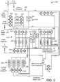
- FIG. 6is a schematic drawing of the thermostat of FIG. 4 and the residential heating and cooling system of FIG. 5 , according to an exemplary embodiment.
- FIG. 7is a block diagram of the thermostat of FIG. 4 shown in greater detail to communicate with a user device, according to an exemplary embodiment.
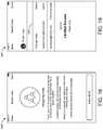
- FIG. 8Ais a user interface for pairing the user device of FIG. 4 with the thermostat of FIG. 4 that can be generated by the thermostat of FIG. 4 and displayed on the display of the thermostat of FIG. 4 , according to an exemplary embodiment.
- FIG. 8Bis a user interface for pairing the user device of FIG. 4 with the thermostat of FIG. 4 that can generated by the user device of FIG. 4 and displayed on a display of the user device of FIG. 4 , according to an exemplary embodiment.
- FIG. 9is a user interface displayed by the thermostat of FIG. 4 for presenting energy savings information to a user in the form of a percentage of energy saved, according to an exemplary embodiment.
- FIG. 10is a user interfaces displayed by the thermostat of FIG. 4 for presenting energy savings information to a user in the form of hours of equipment runtime, according to an exemplary embodiment.
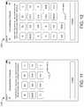
- FIG. 11is a user interface including wire selection inputs for detecting whether the thermostat of FIG. 4 is compatible with building equipment of a user, according to an exemplary embodiment.
- FIG. 12is a user interface including additional wire selection inputs for detecting whether the thermostat of FIG. 4 is compatible with building equipment of a user, according to an exemplary embodiment.
- FIG. 13is a user interface confirming that building equipment of a user is compatible with the thermostat of FIG. 4 , according to an exemplary embodiment.
- FIG. 14is a user interface indicating that additional information is required to confirm that building equipment of a user is compatible with the thermostat of FIG. 4 , according to an exemplary embodiment.
- FIG. 15is a user interface indicating that building equipment of a user is not compatible with the thermostat of FIG. 4 , according to an exemplary embodiment.
- FIG. 16is a user interface for searching a user in order to manage user accounts associated with the thermostat of FIG. 4 , according to an exemplary embodiment.
- FIG. 17is a user interface for selecting a location associated with the user searched in FIG. 16 , according to an exemplary embodiment.
- FIG. 18is a user interface providing a user with information on assigning different roles to a user, according to an exemplary embodiment.
- FIG. 19is a user interface allowing a user to change roles of users for the selected location of FIG. 17 , according to an exemplary embodiment.
- FIG. 20is a user interfaces displayed by the thermostat of FIG. 4 including an interface element for accessing a media control panel, according to an exemplary embodiment.
- FIG. 21is a user interfaces displayed by the thermostat of FIG. 4 including the media control panel accessed via the interface element of FIG. 20 , according to an exemplary embodiment.
- FIG. 22Ais a process for displaying installation user interfaces and installing the thermostat of FIG. 4 by detecting and confirming a wiring configuration, according to an exemplary embodiment.
- FIG. 22Bare user interfaces displayed in the process of FIG. 22A providing a user with feedback and a detected wiring configuration, according to an exemplary embodiment.
- FIG. 23is a user interface for forcing a hot wire heating (RH) power connection if the thermostat of FIG. 4 did not sense a connection to an RH terminal, according to an exemplary embodiment.
- RHhot wire heating
- FIG. 24is a user interface for forcing an common wire connection if the thermostat of FIG. 4 did not sense a connection to an common terminal, according to an exemplary embodiment.
- FIG. 25is a user interface for forcing an hot wire (R) connection if the thermostat of FIG. 4 did not sense a connection to an R terminal, according to an exemplary embodiment.
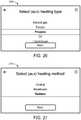
- FIG. 26is a user interface for identifying auxiliary heating type of auxiliary heating equipment connected to the thermostat of FIG. 4 , according to an exemplary embodiment.
- FIG. 27is a user interface for identifying auxiliary heating method performed by the auxiliary heating equipment connected to the thermostat of FIG. 4 , according to an exemplary embodiment.
- FIG. 28is a user interface for identifying a heat pump type for a heat pump connected to the thermostat of FIG. 4 , according to an exemplary embodiment.
- FIG. 29Ais a user interface for identifying a reversing valve polarity of the heat pump connected to the thermostat of FIG. 4 , according to an exemplary embodiment.
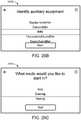
- FIG. 29Bis a user interface for identifying auxiliary equipment connected to the thermostat of FIG. 4 , according to an exemplary embodiment.
- FIG. 29Cis a user interface for identifying a thermostat operating mode for the thermostat of FIG. 4 to perform a test to verify proper connections to equipment connected to the thermostat of FIG. 4 , according to an exemplary embodiment.
- FIG. 30is a process for displaying user interfaces and verifying whether a fan connected to the thermostat of FIG. 4 is operating properly, according to an exemplary embodiment.
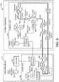
- FIG. 31is a process for displaying user interfaces and verifying whether cooling equipment connected to the thermostat of FIG. 4 is operating properly, according to an exemplary embodiment.
- FIG. 32is a process for displaying user interfaces and verifying whether heating equipment connected to the thermostat of FIG. 4 is operating properly, according to an exemplary embodiment.
- FIG. 33Ais a process for displaying user interfaces and verifying whether auxiliary heating equipment connected to the thermostat of FIG. 4 is operating properly, according to an exemplary embodiment.
- FIG. 33Bis a user interface that can be displayed in the process of FIG. 30 prompting a user to begin a system test for the thermostat of FIG. 4 , according to an exemplary embodiment.
- FIG. 33Cis a user interface that can be displayed in the process of FIG. 30 prompting a user to verify whether a fan connected to the thermostat of FIG. 4 is operating properly, according to an exemplary embodiment.
- FIG. 33Dis a user interface that can be displayed in the process of FIG. 30 prompting a user to review connections of equipment connected to the thermostat of FIG. 4 in response to detecting that the fan is not operating properly based on user input received via the user interface of FIG. 33C , according to an exemplary embodiment.
- FIG. 33Eis a user interface that can be displayed in the process of FIG. 31 prompting a user to begin a system test of cooling equipment connected to the thermostat of FIG. 4 , according to an exemplary embodiment.
- FIG. 33Fis a user interface that can be displayed in the process of FIG. 31 prompting a user to verify whether the cooling equipment connected to the thermostat of FIG. 4 is operating properly, according to an exemplary embodiment.
- FIG. 33Gis a user interface that can be displayed in the process of FIG. 31 prompting a user to verify whether the polarity of a reversing value has been properly configured, according to an exemplary embodiment.
- FIG. 33His a user interface that can be displayed in the process of FIG. 32 prompting a user to begin a system test of heating equipment connected to the thermostat of FIG. 4 , according to an exemplary embodiment.
- FIG. 33Iis a user interface that can be displayed in the process of FIG. 32 prompting a user to verify whether the heating equipment connected to the thermostat of FIG. 4 is operating properly, according to an exemplary embodiment.
- FIG. 33Jis a user interface that can be displayed in the process of FIG. 32 prompting a user to verify whether the polarity of a reversing value has been properly configured, according to an exemplary embodiment.
- FIG. 33Kis a user interface that can be displayed in the process of FIG. 33A prompting a user to begin a system test of auxiliary heating equipment connected to the thermostat of FIG. 4 , according to an exemplary embodiment.
- FIG. 33Lis a user interface that can be displayed in the process of FIG. 33A prompting a user to verify whether the auxiliary heating equipment connected to the thermostat of FIG. 4 is operating properly, according to an exemplary embodiment.
- FIG. 33Mis a user interface that can be displayed in the process of FIG. 33A prompting providing a user with a summary of the test for the equipment connected to the thermostat of FIG. 4 , according to an exemplary embodiment.
- FIG. 34is a user interface displayed by the thermostat of FIG. 4 for indicating that there are new notifications for user review, according to an exemplary embodiment.
- FIG. 35is a user interface displayed by the thermostat of FIG. 4 including a list of notifications, according to an exemplary embodiment.
- FIG. 36is a user interface displayed by the thermostat of FIG. 4 providing a seasonal maintenance reminder for a user, according to an exemplary embodiment.
- FIG. 37is a user interface displayed by the thermostat of FIG. 4 indicating that there are no notifications for the thermostat of FIG. 4 , according to an exemplary embodiment.
- FIG. 38is a user interface displayed by the thermostat of FIG. 4 indicating that the thermostat of FIG. 4 is not connected to a wireless network, according to an exemplary embodiment.
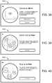
- FIG. 39is a user interface displayed by the thermostat of FIG. 4 indicating that outdoor air quality is at a poor level, according to an exemplary embodiment.
- FIG. 40is a user interface displayed by the thermostat of FIG. 4 indicating that indoor air quality is at a fair level, according to an exemplary embodiment.
- FIG. 41is a user interface displayed by the thermostat of FIG. 4 indicating that equipment connected to the thermostat of FIG. 4 requires service, according to an exemplary embodiment.
- FIG. 42is a user interface displayed by the thermostat of FIG. 4 indicating that equipment connected to the thermostat of FIG. 4 requires service, the interface including an indication of a dealer for performing the service, according to an exemplary embodiment.
- FIG. 43is a user interface displayed by the thermostat of FIG. 4 indicating that a filter of equipment connected to the thermostat of FIG. 4 should be replaced, according to an exemplary embodiment.
- FIG. 44is a user interface displayed by the thermostat of FIG. 4 indicating that a temperature sensed by the thermostat of FIG. 4 has exceeded a first safety threshold of a safety temperature range, according to an exemplary embodiment.
- FIG. 45is a user interface displayed by the thermostat of FIG. 4 indicating that a temperature sensed by the thermostat of FIG. 4 has fallen below a second safety threshold of the safety temperature range, according to an exemplary embodiment.
- FIG. 46is a user interface displayed by the thermostat of FIG. 4 for setting fan and ventilation parameters for controlling air circulation, according to an exemplary embodiment.
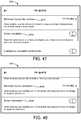
- FIG. 47is a user interface displayed by the thermostat of FIG. 4 for setting additional fan and ventilation parameters for controlling air circulation, according to an exemplary embodiment.
- FIG. 48is a user interface displayed by the thermostat of FIG. 4 for setting additional fan and ventilation parameters for controlling air circulation, according to an exemplary embodiment.
- FIG. 49is a user interface displayed by the thermostat of FIG. 4 for navigating to a tumbler user interface setting a fan runtime parameter, according to an exemplary embodiment.
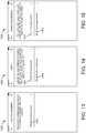
- FIG. 50is the tumbler user interface for setting the fan runtime parameter, according to an exemplary embodiment.
- FIG. 51is a settings interface displayed by the thermostat of FIG. 4 including a countdown timer from a fan runtime selected via the interface of FIG. 50 , according to an exemplary embodiment.
- FIG. 52is a countdown interface displayed by the thermostat of FIG. 4 including a countdown timer from the fan runtime selected via the interface of FIG. 50 , according to an exemplary embodiment.
- FIG. 53is a user interface displayed by the thermostat of FIG. 4 for calibrating an air quality sensor of the thermostat of FIG. 4 , according to an exemplary embodiment.
- FIG. 54is a user interface displayed by the thermostat of FIG. 4 providing a user with information on air quality, according to an exemplary embodiment.
- FIG. 55is a user interface displayed by the thermostat of FIG. 4 indicating that indoor air quality is at a first level and notifying a user of interactions to acquire additional information on the indoor air quality, according to an exemplary embodiment.
- FIG. 56is a user interface displayed by the thermostat of FIG. 4 indicating that indoor air quality is at the first level and notifying a user of interactions to navigate to outdoor air quality, according to an exemplary embodiment.
- FIG. 57is a user interface displayed by the thermostat of FIG. 4 indicating that indoor air quality is at the first level where a user is providing an input to the user interface to navigate to outdoor air quality, according to an exemplary embodiment.
- FIG. 58is a user interface displayed by the thermostat of FIG. 4 in response to the input received by the user interface of FIG. 57 indicating that outdoor air quality cannot be displayed in view of a network connection issue of the thermostat of FIG. 4 , according to an exemplary embodiment.
- FIG. 59is a user interface displayed by the thermostat of FIG. 4 in response to the input received by the user interface of FIG. 57 indicating that outdoor air quality cannot be displayed since the thermostat of FIG. 4 does not store a zip code for which to retrieve air quality data, according to an exemplary embodiment.
- FIG. 60is a user interface displayed by the thermostat of FIG. 4 in response to the input received by the user interface of FIG. 57 indicating the outdoor air quality, according to an exemplary embodiment.
- FIG. 61is a user interface displayed by the thermostat of FIG. 4 indicating that indoor air quality is at a first level, according to an exemplary embodiment.
- FIG. 62is a user interface displayed by the thermostat of FIG. 4 indicating that indoor air quality is at a second level, according to an exemplary embodiment.
- FIG. 63is a user interface displayed by the thermostat of FIG. 4 indicating that indoor air quality is at a third level, according to an exemplary embodiment.
- FIG. 64is a user interface displayed by the thermostat of FIG. 4 indicating that outdoor air quality is at a first level, according to an exemplary embodiment.
- FIG. 65is a user interface displayed by the thermostat of FIG. 4 indicating that outdoor air quality is at a second level, according to an exemplary embodiment.
- FIG. 66is a user interface displayed by the thermostat of FIG. 4 indicating that outdoor air quality is at a third level, according to an exemplary embodiment.
- FIG. 67is a user interface displayed by the thermostat of FIG. 4 indicating volatile organic compound (VOC) levels of indoor air quality, according to an exemplary embodiment.
- VOCvolatile organic compound
- FIG. 68is a user interface displayed by the thermostat of FIG. 4 indicating carbon dioxide (CO2) levels of indoor air quality, according to an exemplary embodiment.
- CO2carbon dioxide
- FIG. 69is a user interface displayed by the thermostat of FIG. 4 indicating relative humidity (RH) levels of indoor air quality, according to an exemplary embodiment.
- RHrelative humidity
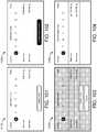
- FIG. 70is a user interface displayed by the thermostat of FIG. 4 indicating allergen levels of outdoor air quality, according to an exemplary embodiment.
- FIG. 71is a user interface displayed by the thermostat of FIG. 4 indicating air quality index (AQI) levels of outdoor air quality, according to an exemplary embodiment.
- AQIair quality index
- FIG. 72is a user interface displayed by the thermostat of FIG. 4 ultraviolet (UV) index levels of outdoor air quality, according to an exemplary embodiment.
- UVultraviolet
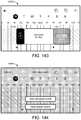
- FIG. 73is a table indicating VOC, CO2, and pollen levels that are used to display air quality information to a user via the thermostat of FIG. 4 , according to an exemplary embodiment.
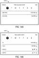
- FIG. 74is a table indicating humidity levels that are used to display air quality information to a user via the thermostat of FIG. 4 , according to an exemplary embodiment.
- FIG. 75is a user interface displayed by the thermostat of FIG. 4 prompting a user to start a smart scheduling process to generate a schedule for the thermostat of FIG. 4 to operate with, according to an exemplary embodiment.
- FIG. 76is a user interface displayed by the thermostat of FIG. 4 prompting a user to enter a time at which the user wakes up, according to an exemplary embodiment.
- FIG. 77is a user interface displayed by the thermostat of FIG. 4 prompting the user to enter a time at which the user goes to sleep, according to an exemplary embodiment.
- FIG. 78is a user interface displayed by the thermostat of FIG. 4 prompting the user to enter a temperature range for when the user is within a building controlled by the thermostat of FIG. 4 , according to an exemplary embodiment.
- FIG. 79is a user interface displayed by the thermostat of FIG. 4 prompting the user to enter a temperature range for when the user is asleep within the building controlled by the thermostat of FIG. 4 , according to an exemplary embodiment.
- FIG. 80is a user interface displayed by the thermostat of FIG. 4 including an interface element for adding an energy savings item to a schedule of the thermostat of FIG. 4 , according to an exemplary embodiment.
- FIG. 81is a user interface displayed by the thermostat of FIG. 4 including an interface element for cloning events of one day of a schedule to another day of the schedule, according to an exemplary embodiment.
- FIG. 82is a user interface displayed by the thermostat of FIG. 4 including an interface element for adding a vacation period to a schedule of the thermostat of FIG. 4 , according to an exemplary embodiment.
- FIG. 83is a user interface displayed by the thermostat of FIG. 4 allowing a user to adjust wake up and sleep times of a schedule of the thermostat of FIG. 4 , according to an exemplary embodiment.
- FIG. 85is a user interface displayed by the thermostat of FIG. 4 including interface elements for adding events to a schedule of the thermostat of FIG. 4 , according to an exemplary embodiment.
- FIG. 86is a user interface displayed by the thermostat of FIG. 4 including interface elements for defining a start time and an end time of an event of a schedule of the thermostat of FIG. 4 , according to an exemplary embodiment.
- FIG. 87is a user interface displayed by the thermostat of FIG. 4 including a schedule with an event, according to an exemplary embodiment.
- FIG. 88is a user interface displayed by the thermostat of FIG. 4 including a schedule with an event that has been selected by a user, according to an exemplary embodiment.
- FIG. 89is a user interface displayed by the thermostat of FIG. 4 including a schedule with an event that has been selected by a user and has been updated to a new duration, according to an exemplary embodiment.
- FIG. 90is a user interface displayed by the thermostat of FIG. 4 including a schedule with an event that is not selected by a user, according to an exemplary embodiment.
- FIG. 91is a user interface displayed by the thermostat of FIG. 4 including a schedule with a first event and a second event that a user is updating to overlap with the first event, according to an exemplary embodiment.
- FIG. 92is a user interface displayed by the thermostat of FIG. 4 including a schedule with a first event and a second event and a reminder that the first event and the second event cannot overlap, according to an exemplary embodiment.
- FIG. 93is a user interface displayed by the thermostat of FIG. 4 including interface elements for adding custom events to a schedule of the thermostat of FIG. 4 , according to an exemplary embodiment.
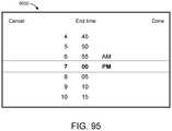
- FIG. 95is a user interface displayed by the thermostat of FIG. 4 including interface elements for defining an end time of an event of a schedule of the thermostat of FIG. 4 , according to an exemplary embodiment.
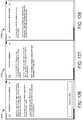
- FIG. 96is a user interface displayed by the thermostat of FIG. 4 including a schedule with a custom event that has been selected by a user, according to an exemplary embodiment.
- FIG. 97is a user interface displayed by the thermostat of FIG. 4 including a schedule with a custom event that has been selected by a user and has been updated to a new duration, according to an exemplary embodiment.
- FIG. 98is a user interface displayed by the thermostat of FIG. 4 including a schedule with a custom event that has not been selected by a user, according to an exemplary embodiment.
- FIG. 99is a user interface displayed by the thermostat of FIG. 4 including a schedule with a sleeping time period and an event, according to an exemplary embodiment.
- FIG. 100is a user interface displayed by the thermostat of FIG. 4 including a schedule with a sleeping time period overlapping with an event, according to an exemplary embodiment.
- FIG. 101is a user interface displayed by the thermostat of FIG. 4 including interface elements for editing a start time and an end time of an event, according to an exemplary embodiment.
- FIG. 102is a user interface displayed by the thermostat of FIG. 4 including interface elements for editing a start time and an end time of an event and including an indication that a start time overlaps with another event of a schedule of the thermostat of FIG. 4 , according to an exemplary embodiment.
- FIG. 103is a user interface displayed by the thermostat of FIG. 4 including interface elements for confirming a deletion of an event of a schedule of the thermostat of FIG. 4 , according to an exemplary embodiment.
- FIG. 104is a user interface displayed by the thermostat of FIG. 4 including interface elements for editing a wake up time and a sleep time a schedule of the thermostat of FIG. 4 , according to an exemplary embodiment.
- FIG. 105is a user interface displayed by the thermostat of FIG. 4 including a selection of days to clone a schedule of a first day to and a direction indicator informing a user how to perform the clone, according to an exemplary embodiment.
- FIG. 106is a user interface displayed by the thermostat of FIG. 4 including a selection of days to clone a schedule of a first day to, according to an exemplary embodiment.
- FIG. 107is a user interface displayed by the thermostat of FIG. 4 including a confirmation message to clone a schedule of a first day to other days, according to an exemplary embodiment.
- FIG. 108is a user interface displayed by the thermostat of FIG. 4 including a schedule of the thermostat of FIG. 4 and a confirmation that a cloning action has been completed, according to an exemplary embodiment.
- FIG. 109is a user interface displayed by the thermostat of FIG. 4 indicating the size of different events of varying time periods, according to an exemplary embodiment.
- FIG. 110is introductory user interface displayed by the user device of FIG. 4 for guiding a user through installing the thermostat of FIG. 4 , according to an exemplary embodiment.
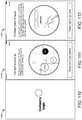
- FIG. 111is user interface displayed by the user device of FIG. 4 for guiding a user through installing the thermostat of FIG. 4 , the user interface including information regarding air quality, according to an exemplary embodiment.
- FIG. 112is user interface displayed by the user device of FIG. 4 for guiding a user through installing the thermostat of FIG. 4 , the user interface including information regarding energy savings, according to an exemplary embodiment.
- FIG. 113is user interface displayed by the user device of FIG. 4 for guiding a user through installing the thermostat of FIG. 4 , the user interface including information regarding scheduling, according to an exemplary embodiment.
- FIG. 114is user interface displayed by the user device of FIG. 4 for guiding a user through installing the thermostat of FIG. 4 , the user interface including a menu, according to an exemplary embodiment.
- FIG. 115is user interface displayed by the user device of FIG. 4 for guiding a user through installing the thermostat of FIG. 4 , the user interface allowing a user to sign into an account, according to an exemplary embodiment.
- FIG. 116is user interface displayed by the user device of FIG. 4 for guiding a user through installing the thermostat of FIG. 4 , the user interface including an overview of steps for installing the thermostat of FIG. 4 , according to an exemplary embodiment.
- FIG. 117is user interface displayed by the user device of FIG. 4 for guiding a user through installing the thermostat of FIG. 4 , the user interface including assistance guides and contacts, according to an exemplary embodiment.
- FIG. 118is user interface displayed by the user device of FIG. 4 for guiding a user through installing the thermostat of FIG. 4 , the user interface including an indication of equipment in a packaging box of the thermostat of FIG. 4 , according to an exemplary embodiment.
- FIG. 119is user interface displayed by the user device of FIG. 4 for guiding a user through installing the thermostat of FIG. 4 , the user interface including an indication of compatibility requirements of the thermostat of FIG. 4 , according to an exemplary embodiment.
- FIG. 120is user interface displayed by the user device of FIG. 4 for guiding a user through installing the thermostat of FIG. 4 , the user interface including of terminals of the thermostat of FIG. 4 , according to an exemplary embodiment.
- FIG. 121is user interface displayed by the user device of FIG. 4 for guiding a user through installing the thermostat of FIG. 4 , the user interface including instructions to determine whether a system of a user is a high voltage system, according to an exemplary embodiment.
- FIG. 122is user interface displayed by the user device of FIG. 4 for guiding a user through installing the thermostat of FIG. 4 , the user interface an installation warning, according to an exemplary embodiment.
- FIG. 123is user interface displayed by the user device of FIG. 4 for guiding a user through installing the thermostat of FIG. 4 , the user interface including instructions to power off a system, according to an exemplary embodiment.
- FIG. 124is user interface displayed by the user device of FIG. 4 for guiding a user through installing the thermostat of FIG. 4 , the user interface including instructions review a wiring configuration of a previously installed thermostat and capture an image of the wiring configuration, according to an exemplary embodiment.
- FIG. 126is user interface displayed by the user device of FIG. 4 for guiding a user through installing the thermostat of FIG. 4 , the user interface including instructions for installing a wire adapter, according to an exemplary embodiment.
- FIG. 127is user interface displayed by the user device of FIG. 4 for guiding a user through installing the thermostat of FIG. 4 , the user interface including further instructions for installing a wire adapter, according to an exemplary embodiment.
- FIG. 128is user interface displayed by the user device of FIG. 4 for guiding a user through installing the thermostat of FIG. 4 , the user interface including to remove a previously installed thermostat, according to an exemplary embodiment.
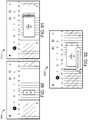
- FIG. 129is user interface displayed by the user device of FIG. 4 for guiding a user through installing the thermostat of FIG. 4 , the user interface including instructions for installing the thermostat of FIG. 4 on a wall, according to an exemplary embodiment.
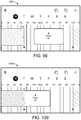
- FIG. 130is user interface displayed by the user device of FIG. 4 for guiding a user through installing the thermostat of FIG. 4 , the user interface including further instructions for installing the thermostat of FIG. 4 on a wall, according to an exemplary embodiment.
- FIG. 131is user interface displayed by the user device of FIG. 4 for guiding a user through installing the thermostat of FIG. 4 , the user interface including instructions for wiring the thermostat of FIG. 4 , according to an exemplary embodiment.
- FIG. 132is user interface displayed by the user device of FIG. 4 for guiding a user through installing the thermostat of FIG. 4 , the user interface including instructions for attaching a front plate of to the thermostat of FIG. 4 , according to an exemplary embodiment.
- FIG. 133is user interface displayed by the user device of FIG. 4 for guiding a user through installing the thermostat of FIG. 4 , the user interface including instructions for powering on a system connected to the thermostat of FIG. 4 , according to an exemplary embodiment.
- FIG. 134is user interface displayed by the user device of FIG. 4 for guiding a user through installing the thermostat of FIG. 4 , the user interface including a confirmation of installation of the thermostat of FIG. 4 , according to an exemplary embodiment.
- FIG. 135is a user interface displayed by the thermostat of FIG. 4 prompting a user to enter a time at which tenants or employees arrive at a building, according to an exemplary embodiment.
- FIG. 136is a user interface displayed by the thermostat of FIG. 4 prompting the user to enter a time at which tenants or employees depart from the building, according to an exemplary embodiment.
- FIG. 137is a user interface displayed by the thermostat of FIG. 4 prompting the user to enter a temperature range for when the building is occupied, according to an exemplary embodiment.
- FIG. 138is a user interface displayed by the thermostat of FIG. 4 prompting the user to enter a temperature range for when the building is unoccupied, according to an exemplary embodiment.
- FIG. 139is a user interface displayed by the thermostat of FIG. 4 including an unoccupied time period of a schedule of the thermostat of FIG. 4 , according to an exemplary embodiment.
- FIG. 140is a user interface displayed by the thermostat of FIG. 4 including an unoccupied time period and an occupied time period of a schedule of the thermostat of FIG. 4 , according to an exemplary embodiment.
- FIG. 141is a user interface displayed by the thermostat of FIG. 4 including an unoccupied time period, an occupied time period, and an exception of a schedule of the thermostat of FIG. 4 , according to an exemplary embodiment.
- FIG. 142is a user interface displayed by the thermostat of FIG. 4 including an unoccupied time period, a first occupied time period, and a second occupied time period with a custom temperature range of a schedule of the thermostat of FIG. 4 , according to an exemplary embodiment.
- FIG. 143is a user interface displayed by the thermostat of FIG. 4 including an unoccupied time period, a first occupied time period, a second occupied time period with a custom temperature range, and an exception time period of a schedule of the thermostat of FIG. 4 , according to an exemplary embodiment.
- FIG. 144is a user interface displayed by the thermostat of FIG. 4 including interface elements for adding new occupied events to a schedule of the thermostat of FIG. 4 , according to an exemplary embodiment.
- FIG. 145is a user interface displayed by the thermostat of FIG. 4 including interface elements for setting a start time and an end time of a new occupied event, according to an exemplary embodiment.
- FIG. 146is a user interface displayed by the thermostat of FIG. 4 including interface elements for setting a start time, an end time, a heating temperature, and a cooling temperature of a new custom occupied event, according to an exemplary embodiment.
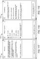
- FIG. 147is an interface displayed by the thermostat of FIG. 4 for performing a temperature hold function for a first time period, a second time period, or an indefinite time period, according to an exemplary embodiment.
- FIG. 148is an interface displayed by the thermostat of FIG. 4 for performing a temperature hold function for a first time period, a second time period, or an indefinite time period where the first time period is selected by a user, according to an exemplary embodiment.
- FIG. 149is an interface displayed by the thermostat of FIG. 4 performing a temperature hold function for the first time period, according to an exemplary embodiment.
- FIG. 150is an interface displayed by the thermostat of FIG. 4 performing a temperature hold function for the indefinite time period, according to an exemplary embodiment.
- FIG. 151is an interface displayed by the thermostat of FIG. 4 for performing a temperature hold function for a first time period, a second time period, or an indefinite time period, where the user interface includes directions to operate a temperature hold, according to an exemplary embodiment.
- the thermostatcan include a user interface, e.g., a touchscreen user interface, configured to provide information to a user and receive input from the user. Since a user of the thermostat may not be a knowledgeable technician, the user interfaces of the thermostat may be intuitive such that the interactions with the user can be convenient for the user.
- a user interfacee.g., a touchscreen user interface
- the thermostatcan be configured to generate and/or display information pertaining to the energy usage of a building of the thermostat. More specifically, the thermostat can be configured to generate and/or display interfaces indicative of the energy consumed by equipment operated by the thermostat.
- the thermostatcan determine runtime, i.e., the length of time that the thermostat operates equipment connected to it. Based on energy savings configurations of the thermostat (e.g., scheduling, smart operations, etc.), the length of time that the system is run by the thermostat as compared to other thermostat models can be reduced.
- the thermostatcan determine a normal length of time that the thermostat would have operated the equipment without the energy savings configurations, a baseline runtime. Based on the actual recorded runtime and the baseline runtime, the thermostat can be configured to generate and/or display user interfaces to a user such that the user can easily understand the performance and energy savings benefits of the thermostat.
- the thermostatcan be configured to record air quality information for within a building and/or outside a building. Based on the recorded air quality information, the thermostat can be configured to generate air quality interfaces providing a user with information pertaining to the air quality of their building and neighborhood around their building.
- the thermostatmay include air quality sensors configured to measure indoor air quality data such as volatile organic compounds (VOCs), carbon dioxide, etc.
- the thermostatmay store a location indicator and retrieve, via a network (e.g., the Internet) outdoor air quality for the location indicator.
- the outdoor air qualitymay be ultraviolet (UV) levels, air quality index (AQI) values, allergen levels, etc.
- the thermostatcan generate and/or display interfaces that provide the indoor and/or outdoor air quality information to a user.
- the interfacesinclude elements that move along a vertical path, where the position of the elements indicates a level of the element (e.g., higher indicating worse air quality, lower indicating better air quality).
- the display screencan include elements of various colors, e.g., dark green, lighter green, orange, and red.
- the thermostatcan generate and/or display scheduling interfaces.
- the scheduling interfacescan allow a user to generate and/or modify events of a schedule which control the operation of the thermostat.
- the scheduling interfacescan prompt a user for information in an intuitive manner, e.g., identifying day and night time periods by asking a user when they wake up and when the go to sleep.
- the thermostatcan display interfaces which allow a user to clone a particular schedule for one day to multiple days such that a user only needs to manually define a single day and then cause other days to take on the same definition (e.g., same scheduled events) as the single day.
- the thermostatcan include interfaces that guide a user through installation of the thermostat.
- the thermostatcan be configured to electrically detect what wires have been connected to what terminals of the thermostat. Based one or multiple detections, the thermostat can be configured to provide an indication of the configuration to a user for their review.
- the thermostatcan verify, based on the one or more detections that the user has appropriately connected their equipment to the thermostat.
- the thermostatgenerates user interfaces that guide a user through testing their equipment, i.e., to verify that they have configured the thermostat properly and connected their equipment to the thermostat properly.
- the testscan be performed in stages, e.g., a first stage to test a fan of the thermostat, a second stage to test heating equipment of the thermostat, a third stage to test cooling equipment of the thermostat, a fourth stage to test auxiliary heating equipment of the thermostat, etc.
- the thermostatcan generate and/or display a summary interface indicating the result of each test.
- the thermostatis configured to operate a fan control operation and/or display interfaces for allowing the user to interact with the fan control operation.
- the thermostatcan generate a user interface prompting the user to select a particular time period, based on the time period, the thermostat can operate the fan for the particular time period.
- the thermostatcan manage countdown timers and cause the user interfaces to display indications of the remaining length of time that the fan will be operated. In some embodiments, other control decisions, e.g., heating, cooling, etc. are ignored and the thermostat operates the fan for the length of time regardless of other control operations.
- the thermostatis configured to implement a temperature hold operation and/or generate and/or display a user interface allowing a user to interact with the temperature hold operation.
- the thermostatis configured to display predefined time periods, e.g., lengths of time that a user may want the thermostat to hold a particular temperature outside of a temperature setpoint and/or a schedule.
- the user interfaceis configured to receive the temperature hold command and the thermostat is configured to operate building equipment to control a temperature to the held temperature setpoint for the length of time.
- FIGS. 1-3an exemplary building management system (BMS) and HVAC system in which the systems and methods of the present invention can be implemented are shown, according to an exemplary embodiment.
- BMSbuilding management system
- HVAC systemHVAC system
- FIG. 1a perspective view of a building 10 is shown.
- Building 10is served by a BMS.
- a BMSis, in general, a system of devices configured to control, monitor, and manage equipment in or around a building or building area.
- a BMScan include, for example, a HVAC system, a security system, a lighting system, a fire alerting system, any other system that is capable of managing building functions or devices, or any combination thereof.
- HVAC system 100can include a plurality of HVAC devices (e.g., heaters, chillers, air handling units, pumps, fans, thermal energy storage, etc.) configured to provide heating, cooling, ventilation, or other services for building 10 .
- HVAC system 100is shown to include a waterside system 120 and an airside system 130 .
- Waterside system 120can provide a heated or chilled fluid to an air handling unit of airside system 130 .
- Airside system 130can use the heated or chilled fluid to heat or cool an airflow provided to building 10 .
- An exemplary waterside system and airside system which can be used in HVAC system 100are described in greater detail with reference to FIGS. 2-3 .
- HVAC system 100is shown to include a chiller 102 , a boiler 104 , and a rooftop air handling unit (AHU) 106 .
- Waterside system 120can use boiler 104 and chiller 102 to heat or cool a working fluid (e.g., water, glycol, etc.) and can circulate the working fluid to AHU 106 .
- the HVAC devices of waterside system 120can be located in or around building 10 (as shown in FIG. 1 ) or at an offsite location such as a central plant (e.g., a chiller plant, a steam plant, a heat plant, etc.).
- the working fluidcan be heated in boiler 104 or cooled in chiller 102 , depending on whether heating or cooling is required in building 10 .
- Boiler 104can add heat to the circulated fluid, for example, by burning a combustible material (e.g., natural gas) or using an electric heating element.
- Chiller 102can place the circulated fluid in a heat exchange relationship with another fluid (e.g., a refrigerant) in a heat exchanger (e.g., an evaporator) to absorb heat from the circulated fluid.
- the working fluid from chiller 102 and/or boiler 104can be transported to AHU 106 via piping 108 .
- AHU 106can place the working fluid in a heat exchange relationship with an airflow passing through AHU 106 (e.g., via one or more stages of cooling coils and/or heating coils).
- the airflowcan be, for example, outside air, return air from within building 10 , or a combination of both.
- AHU 106can transfer heat between the airflow and the working fluid to provide heating or cooling for the airflow.
- AHU 106can include one or more fans or blowers configured to pass the airflow over or through a heat exchanger containing the working fluid. The working fluid can then return to chiller 102 or boiler 104 via piping 110 .
- Airside system 130can deliver the airflow supplied by AHU 106 (i.e., the supply airflow) to building 10 via air supply ducts 112 and can provide return air from building 10 to AHU 106 via air return ducts 114 .
- airside system 130includes multiple variable air volume (VAV) units 116 .
- VAVvariable air volume
- airside system 130is shown to include a separate VAV unit 116 on each floor or zone of building 10 .
- VAV units 116can include dampers or other flow control elements that can be operated to control an amount of the supply airflow provided to individual zones of building 10 .
- airside system 130delivers the supply airflow into one or more zones of building 10 (e.g., via supply ducts 112 ) without using intermediate VAV units 116 or other flow control elements.
- AHU 106can include various sensors (e.g., temperature sensors, pressure sensors, etc.) configured to measure attributes of the supply airflow.
- AHU 106can receive input from sensors located within AHU 106 and/or within the building zone and can adjust the flow rate, temperature, or other attributes of the supply airflow through AHU 106 to achieve set-point conditions for the building zone.
- waterside system 200can supplement or replace waterside system 120 in HVAC system 100 or can be implemented separate from HVAC system 100 .
- HVAC system 100waterside system 200 can include a subset of the HVAC devices in HVAC system 100 (e.g., boiler 104 , chiller 102 , pumps, valves, etc.) and can operate to supply a heated or chilled fluid to AHU 106 .
- the HVAC devices of waterside system 200can be located within building 10 (e.g., as components of waterside system 120 ) or at an offsite location such as a central plant.
- waterside system 200is shown as a central plant having a plurality of subplants 202 - 212 .
- Subplants 202 - 212are shown to include a heater subplant 202 , a heat recovery chiller subplant 204 , a chiller subplant 206 , a cooling tower subplant 208 , a hot thermal energy storage (TES) subplant 210 , and a cold thermal energy storage (TES) subplant 212 .
- Subplants 202 - 212consume resources (e.g., water, natural gas, electricity, etc.) from utilities to serve the thermal energy loads (e.g., hot water, cold water, heating, cooling, etc.) of a building or campus.
- resourcese.g., water, natural gas, electricity, etc.
- heater subplant 202can be configured to heat water in a hot water loop 214 that circulates the hot water between heater subplant 202 and building 10 .
- Chiller subplant 206can be configured to chill water in a cold water loop 216 that circulates the cold water between chiller subplant 206 building 10 .
- Heat recovery chiller subplant 204can be configured to transfer heat from cold water loop 216 to hot water loop 214 to provide additional heating for the hot water and additional cooling for the cold water.
- Condenser water loop 218can absorb heat from the cold water in chiller subplant 206 and reject the absorbed heat in cooling tower subplant 208 or transfer the absorbed heat to hot water loop 214 .
- Hot TES subplant 210 and cold TES subplant 212can store hot and cold thermal energy, respectively, for subsequent use.
- Hot water loop 214 and cold water loop 216can deliver the heated and/or chilled water to air handlers located on the rooftop of building 10 (e.g., AHU 106 ) or to individual floors or zones of building 10 (e.g., VAV units 116 ).
- the air handlerspush air past heat exchangers (e.g., heating coils or cooling coils) through which the water flows to provide heating or cooling for the air.
- the heated or cooled aircan be delivered to individual zones of building 10 to serve the thermal energy loads of building 10 .
- the waterthen returns to subplants 202 - 212 to receive further heating or cooling.
- subplants 202 - 212are shown and described as heating and cooling water for circulation to a building, it is understood that any other type of working fluid (e.g., glycol, CO2, etc.) can be used in place of or in addition to water to serve the thermal energy loads. In other embodiments, subplants 202 - 212 can provide heating and/or cooling directly to the building or campus without requiring an intermediate heat transfer fluid. These and other variations to waterside system 200 are within the teachings of the present invention.
- working fluide.g., glycol, CO2, etc.
- Each of subplants 202 - 212can include a variety of equipment configured to facilitate the functions of the subplant.
- heater subplant 202is shown to include a plurality of heating elements 220 (e.g., boilers, electric heaters, etc.) configured to add heat to the hot water in hot water loop 214 .
- Heater subplant 202is also shown to include several pumps 222 and 224 configured to circulate the hot water in hot water loop 214 and to control the flow rate of the hot water through individual heating elements 220 .
- Chiller subplant 206is shown to include a plurality of chillers 232 configured to remove heat from the cold water in cold water loop 216 .
- Chiller subplant 206is also shown to include several pumps 234 and 236 configured to circulate the cold water in cold water loop 216 and to control the flow rate of the cold water through individual chillers 232 .
- Heat recovery chiller subplant 204is shown to include a plurality of heat recovery heat exchangers 226 (e.g., refrigeration circuits) configured to transfer heat from cold water loop 216 to hot water loop 214 .
- Heat recovery chiller subplant 204is also shown to include several pumps 228 and 230 configured to circulate the hot water and/or cold water through heat recovery heat exchangers 226 and to control the flow rate of the water through individual heat recovery heat exchangers 226 .
- Cooling tower subplant 208is shown to include a plurality of cooling towers 238 configured to remove heat from the condenser water in condenser water loop 218 .
- Cooling tower subplant 208is also shown to include several pumps 240 configured to circulate the condenser water in condenser water loop 218 and to control the flow rate of the condenser water through individual cooling towers 238 .
- Hot TES subplant 210is shown to include a hot TES tank 242 configured to store the hot water for later use.
- Hot TES subplant 210can also include one or more pumps or valves configured to control the flow rate of the hot water into or out of hot TES tank 242 .
- Cold TES subplant 212is shown to include cold TES tanks 244 configured to store the cold water for later use.
- Cold TES subplant 212can also include one or more pumps or valves configured to control the flow rate of the cold water into or out of cold TES tanks 244 .
- one or more of the pumps in waterside system 200(e.g., pumps 222 , 224 , 228 , 230 , 234 , 236 , and/or 240 ) or pipelines in waterside system 200 include an isolation valve associated therewith. Isolation valves can be integrated with the pumps or positioned upstream or downstream of the pumps to control the fluid flows in waterside system 200 .
- waterside system 200can include more, fewer, or different types of devices and/or subplants based on the particular configuration of waterside system 200 and the types of loads served by waterside system 200 .
- airside system 300can supplement or replace airside system 130 in HVAC system 100 or can be implemented separate from HVAC system 100 .
- airside system 300can include a subset of the HVAC devices in HVAC system 100 (e.g., AHU 106 , VAV units 116 , ducts 112 - 114 , fans, dampers, etc.) and can be located in or around building 10 .
- Airside system 300can operate to heat or cool an airflow provided to building 10 using a heated or chilled fluid provided by waterside system 200 .
- airside system 300is shown to include an economizer-type air handling unit (AHU) 302 .
- Economizer-type AHUsvary the amount of outside air and return air used by the air handling unit for heating or cooling.
- AHU 302can receive return air 304 from building zone 306 via return air duct 308 and can deliver supply air 310 to building zone 306 via supply air duct 312 .
- AHU 302is a rooftop unit located on the roof of building 10 (e.g., AHU 106 as shown in FIG. 1 ) or otherwise positioned to receive both return air 304 and outside air 314 .
- AHU 302can be configured to operate exhaust air damper 316 , mixing damper 318 , and outside air damper 320 to control an amount of outside air 314 and return air 304 that combine to form supply air 310 . Any return air 304 that does not pass through mixing damper 318 can be exhausted from AHU 302 through exhaust damper 316 as exhaust air 322 .
- Each of dampers 316 - 320can be operated by an actuator.
- exhaust air damper 316can be operated by actuator 324
- mixing damper 318can be operated by actuator 326
- outside air damper 320can be operated by actuator 328 .
- Actuators 324 - 328can communicate with an AHU controller 330 via a communications link 332 .
- Actuators 324 - 328can receive control signals from AHU controller 330 and can provide feedback signals to AHU controller 330 .
- Feedback signalscan include, for example, an indication of a current actuator or damper position, an amount of torque or force exerted by the actuator, diagnostic information (e.g., results of diagnostic tests performed by actuators 324 - 328 ), status information, commissioning information, configuration settings, calibration data, and/or other types of information or data that can be collected, stored, or used by actuators 324 - 328 .
- diagnostic informatione.g., results of diagnostic tests performed by actuators 324 - 328
- status informatione.g., commissioning information, configuration settings, calibration data, and/or other types of information or data that can be collected, stored, or used by actuators 324 - 328 .
- AHU controller 330can be an economizer controller configured to use one or more control algorithms (e.g., state-based algorithms, extremum seeking control (ESC) algorithms, proportional-integral (PI) control algorithms, proportional-integral-derivative (PID) control algorithms, model predictive control (MPC) algorithms, feedback control algorithms, etc.) to control actuators 324 - 328 .
- control algorithmse.g., state-based algorithms, extremum seeking control (ESC) algorithms, proportional-integral (PI) control algorithms, proportional-integral-derivative (PID) control algorithms, model predictive control (MPC) algorithms, feedback control algorithms, etc.
- AHU 302is shown to include a cooling coil 334 , a heating coil 336 , and a fan 338 positioned within supply air duct 312 .
- Fan 338can be configured to force supply air 310 through cooling coil 334 and/or heating coil 336 and provide supply air 310 to building zone 306 .
- AHU controller 330can communicate with fan 338 via communications link 340 to control a flow rate of supply air 310 .
- AHU controller 330controls an amount of heating or cooling applied to supply air 310 by modulating a speed of fan 338 .
- Cooling coil 334can receive a chilled fluid from waterside system 200 (e.g., from cold water loop 216 ) via piping 342 and can return the chilled fluid to waterside system 200 via piping 344 .
- Valve 346can be positioned along piping 342 or piping 344 to control a flow rate of the chilled fluid through cooling coil 334 .
- cooling coil 334includes multiple stages of cooling coils that can be independently activated and deactivated (e.g., by AHU controller 330 , by BMS controller 366 , etc.) to modulate an amount of cooling applied to supply air 310 .
- Heating coil 336can receive a heated fluid from waterside system 200 (e.g., from hot water loop 214 ) via piping 348 and can return the heated fluid to waterside system 200 via piping 350 .
- Valve 352can be positioned along piping 348 or piping 350 to control a flow rate of the heated fluid through heating coil 336 .
- heating coil 336includes multiple stages of heating coils that can be independently activated and deactivated (e.g., by AHU controller 330 , by BMS controller 366 , etc.) to modulate an amount of heating applied to supply air 310 .
- valves 346 and 352can be controlled by an actuator.
- valve 346can be controlled by actuator 354 and valve 352 can be controlled by actuator 356 .
- Actuators 354 - 356can communicate with AHU controller 330 via communications links 358 - 360 .
- Actuators 354 - 356can receive control signals from AHU controller 330 and can provide feedback signals to controller 330 .
- AHU controller 330receives a measurement of the supply air temperature from a temperature sensor 362 positioned in supply air duct 312 (e.g., downstream of cooling coil 334 and/or heating coil 336 ).
- AHU controller 330can also receive a measurement of the temperature of building zone 306 from a temperature sensor 364 located in building zone 306 .
- AHU controller 330operates valves 346 and 352 via actuators 354 - 356 to modulate an amount of heating or cooling provided to supply air 310 (e.g., to achieve a set-point temperature for supply air 310 or to maintain the temperature of supply air 310 within a set-point temperature range).
- the positions of valves 346 and 352affect the amount of heating or cooling provided to supply air 310 by cooling coil 334 or heating coil 336 and may correlate with the amount of energy consumed to achieve a desired supply air temperature.
- AHU controller 330can control the temperature of supply air 310 and/or building zone 306 by activating or deactivating coils 334 - 336 , adjusting a speed of fan 338 , or a combination of both.
- airside system 300is shown to include a building management system (BMS) controller 366 and a client device 368 .
- BMS controller 366can include one or more computer systems (e.g., servers, supervisory controllers, subsystem controllers, etc.) that serve as system level controllers, application or data servers, head nodes, or master controllers for airside system 300 , waterside system 200 , HVAC system 100 , and/or other controllable systems that serve building 10 .
- computer systemse.g., servers, supervisory controllers, subsystem controllers, etc.
- application or data serverse.g., application or data servers, head nodes, or master controllers for airside system 300 , waterside system 200 , HVAC system 100 , and/or other controllable systems that serve building 10 .
- BMS controller 366can communicate with multiple downstream building systems or subsystems (e.g., HVAC system 100 , a security system, a lighting system, waterside system 200 , etc.) via a communications link 370 according to like or disparate protocols (e.g., LON, BACnet, etc.).
- AHU controller 330 and BMS controller 366can be separate (as shown in FIG. 3 ) or integrated.
- AHU controller 330can be a software module configured for execution by a processor of BMS controller 366 .
- AHU controller 330receives information from BMS controller 366 (e.g., commands, set-points, operating boundaries, etc.) and provides information to BMS controller 366 (e.g., temperature measurements, valve or actuator positions, operating statuses, diagnostics, etc.).
- BMS controller 366e.g., temperature measurements, valve or actuator positions, operating statuses, diagnostics, etc.
- AHU controller 330can provide BMS controller 366 with temperature measurements from temperature sensors 362 - 364 , equipment on/off states, equipment operating capacities, and/or any other information that can be used by BMS controller 366 to monitor or control a variable state or condition within building zone 306 .
- Client device 368can include one or more human-machine interfaces or client interfaces (e.g., graphical user interfaces, reporting interfaces, text-based computer interfaces, client-facing web services, web servers that provide pages to web clients, etc.) for controlling, viewing, or otherwise interacting with HVAC system 100 , its subsystems, and/or devices.
- Client device 368can be a computer workstation, a client terminal, a remote or local interface, or any other type of user interface device.
- Client device 368can be a stationary terminal or a mobile device.
- client device 368can be a desktop computer, a computer server with a user interface, a laptop computer, a tablet, a smartphone, a PDA, or any other type of mobile or non-mobile device.
- Client device 368can communicate with BMS controller 366 and/or AHU controller 330 via communications link 372 .
- the thermostat 400is shown to include a display 402 .
- the display 402may be an interactive display that can display information to a user and receive input from the user.
- the displaymay be transparent such that a user can view information on the display and view the surface located behind the display.
- Thermostats with transparent and cantilevered displaysare described in further detail in U.S. patent application Ser. No. 15/146,649 filed May 4, 2016, the entirety of which is incorporated by reference herein.
- the display 402can be a touchscreen or other type of electronic display configured to present information to a user in a visual format (e.g., as text, graphics, etc.) and receive input from a user (e.g., via a touch-sensitive panel).
- the display 402may include a touch-sensitive panel layered on top of an electronic visual display.
- a usercan provide inputs through simple or multi-touch gestures by touching the display 402 with one or more fingers and/or with a stylus or pen.
- the display 402can use any of a variety of touch-sensing technologies to receive user inputs, such as capacitive sensing (e.g., surface capacitance, projected capacitance, mutual capacitance, self-capacitance, etc.), resistive sensing, surface acoustic wave, infrared grid, infrared acrylic projection, optical imaging, dispersive signal technology, acoustic pulse recognition, or other touch-sensitive technologies known in the art. Many of these technologies allow for multi-touch responsiveness of display 402 allowing registration of touch in two or even more locations at once.
- capacitive sensinge.g., surface capacitance, projected capacitance, mutual capacitance, self-capacitance, etc.
- resistive sensinge.g., surface acoustic wave, infrared grid, infrared acrylic projection, optical imaging, dispersive signal technology, acoustic pulse recognition, or other touch-sensitive technologies known in the art.
- Many of these technologiesallow for multi-
- the displaymay use any of a variety of display technologies such as light emitting diode (LED), organic light-emitting diode (OLED), liquid-crystal display (LCD), organic light-emitting transistor (OLET), surface-conduction electron-emitter display (SED), field emission display (FED), digital light processing (DLP), liquid crystal on silicon (LCoC), or any other display technologies known in the art.
- the display 402is configured to present visual media (e.g., text, graphics, etc.) without requiring a backlight.
- a residential heating and cooling system 500may provide heated and cooled air to a residential structure.
- a residential heating and cooling system 500may include commercial HVAC units (e.g., roof top units).
- a residence 502includes refrigerant conduits that operatively couple an indoor unit 506 to an outdoor unit 504 .
- Indoor unit 28may be positioned in a utility space, an attic, a basement, and so forth.
- Outdoor unit 504is situated adjacent to a side of residence 502 .
- Refrigerant conduitstransfer refrigerant between indoor unit 506 and outdoor unit 504 , typically transferring primarily liquid refrigerant in one direction and primarily vaporized refrigerant in an opposite direction.
- a coil in outdoor unit 504serves as a condenser for recondensing vaporized refrigerant flowing from indoor unit 506 to outdoor unit 504 via one of the refrigerant conduits.
- a coil of the indoor unit 506designated by the reference numeral 508 , serves as an evaporator coil.
- Evaporator coil 508receives liquid refrigerant (which may be expanded by an expansion device, not shown) and evaporates the refrigerant before returning it to outdoor unit 504 .
- Outdoor unit 504draws in environmental air through its sides, forces the air through the outer unit coil using a fan, and expels the air.
- the airis heated by the condenser coil within the outdoor unit 504 and exits the top of the unit at a temperature higher than it entered the sides. Air is blown over indoor coil 504 and is then circulated through residence 502 by means of ductwork 510 , as indicated by the arrows entering and exiting ductwork 510 .
- the overall system 500operates to maintain a desired temperature as set by thermostat 400 .
- the air conditionerwill become operative to refrigerate additional air for circulation through the residence 502 .
- the unitcan stop the refrigeration cycle temporarily.
- the system 500configured so that the outdoor unit 504 is controlled to achieve a more elegant control over temperature and humidity within the residence 502 .
- the outdoor unit 504is controlled to operate components within the outdoor unit 504 , and the system 500 , based on a percentage of a delta between a minimum operating value of the compressor and a maximum operating value of the compressor plus the minimum operating value.
- the minimum operating value and the maximum operating valueare based on the determined outdoor ambient temperature, and the percentage of the delta is based on a predefined temperature differential multiplier and one or more time dependent multipliers.
- an HVAC system 600is shown according to an exemplary embodiment.
- Various components of system 600are located inside residence 502 while other components are located outside residence 502 .
- Outdoor unit 504as described with reference to FIG. 5
- indoor unit 506 and thermostat 400as described with reference to FIG. 6
- the thermostat 400can cause the indoor unit 506 and the outdoor unit 504 to heat residence 502 .
- the thermostat 400can cause the indoor unit 506 and the outdoor unit 504 to cool the residence 502 .
- the thermostat 400can command an airflow change within the residence 502 to adjust the humidity within the residence 502 .
- Thermostat 400can be configured to generate control signals for indoor unit 506 and/or outdoor unit 504 .
- the thermostat 400is shown to be connected to an indoor ambient temperature sensor 602
- an outdoor unit controller 606is shown to be connected to an outdoor ambient temperature sensor 602 .
- the indoor ambient temperature sensor 602 and the outdoor ambient temperature sensor 604may be any kind of temperature sensor (e.g., thermistor, thermocouple, etc.).
- the thermostat 400may measure the temperature of residence 502 via the indoor ambient temperature sensor 602 . Further, the thermostat 400 can be configured to receive the temperature outside residence 502 via communication with the outdoor unit controller 606 .
- the thermostat 10generates control signals for the indoor unit 506 and the outdoor unit 504 based on the indoor ambient temperature (e.g., measured via indoor ambient temperature sensor 602 ), the outdoor temperature (e.g., measured via the outdoor ambient temperature sensor 604 ), and/or a temperature set point.
- the indoor unit 28 and the outdoor unit 504may be electrically connected. Further, indoor unit 28 and outdoor unit 504 may be coupled via conduits 210 .
- the outdoor unit 504can be configured to compress refrigerant inside conduits 210 to either heat or cool the building based on the operating mode of the indoor unit 28 and the outdoor unit 504 (e.g., heat pump operation or air conditioning operation).
- the refrigerant inside conduits 210may be any fluid that absorbs and extracts heat.
- the refrigerantmay be hydro fluorocarbon (HFC) based R-410A, R-407C, and/or R-134a.
- the outdoor unit 504is shown to include the outdoor unit controller 606 , a variable speed drive 608 , a motor 610 and a compressor 612 .
- the outdoor unit 504can be configured to control the compressor 612 and to further cause the compressor 612 to compress the refrigerant inside conduits 210 .
- the compressor 612may be driven by the variable speed drive 608 and the motor 610 .
- the outdoor unit controller 606can generate control signals for the variable speed drive 608 .
- the variable speed drive 608(e.g., an inverter, a variable frequency drive, etc.) may be an AC-AC inverter, a DC-AC inverter, and/or any other type of inverter.
- the variable speed drive 608can be configured to vary the torque and/or speed of the motor 610 which in turn drives the speed and/or torque of compressor 612 .
- the compressor 612may be any suitable compressor such as a screw compressor, a reciprocating compressor, a rotary compressor, a swing link compressor, a scroll compressor, or a turbine compressor, etc.
- the outdoor unit controller 606is configured to process data received from the thermostat 400 to determine operating values for components of the system 600 , such as the compressor 612 . In one embodiment, the outdoor unit controller 606 is configured to provide the determined operating values for the compressor 612 to the variable speed drive 608 , which controls a speed of the compressor 612 . The outdoor unit controller 606 is controlled to operate components within the outdoor unit 504 , and the indoor unit 506 , based on a percentage of a delta between a minimum operating value of the compressor and a maximum operating value of the compressor plus the minimum operating value. In some embodiments, the minimum operating value and the maximum operating value are based on the determined outdoor ambient temperature, and the percentage of the delta is based on a predefined temperature differential multiplier and one or more time dependent multipliers.
- the outdoor unit controller 604can control a reversing valve 614 to operate system 600 as a heat pump or an air conditioner.
- the outdoor unit controller 606may cause reversing valve 614 to direct compressed refrigerant to the indoor coil 508 while in heat pump mode and to an outdoor coil 616 while in air conditioner mode.
- the indoor coil 508 and the outdoor coil 616can both act as condensers and evaporators depending on the operating mode (i.e., heat pump or air conditioner) of system 600 .
- outdoor unit controller 504can be configured to control and/or receive data from an outdoor electronic expansion valve (EEV) 518 .
- the outdoor electronic expansion valve 518may be an expansion valve controlled by a stepper motor.
- the outdoor unit controller 504can be configured to generate a step signal (e.g., a PWM signal) for the outdoor electronic expansion valve 518 . Based on the step signal, the outdoor electronic expansion valve 518 can be held fully open, fully closed, partial open, etc.
- the outdoor unit controller 606can be configured to generate step signal for the outdoor electronic expansion valve 518 based on a subcool and/or superheat value calculated from various temperatures and pressures measured in system 600 .
- the outdoor unit controller 606is configured to control the position of the outdoor electronic expansion valve 518 based on a percentage of a delta between a minimum operating value of the compressor and a maximum operating value of the compressor plus the minimum operating value.
- the minimum operating value and the maximum operating valueare based on the determined outdoor ambient temperature, and the percentage of the delta is based on a predefined temperature differential multiplier and one or more time dependent multipliers.
- the outdoor unit controller 606can be configured to control and/or power outdoor fan 620 .
- the outdoor fan 620can be configured to blow air over the outdoor coil 616 .
- the outdoor unit controller 606can control the amount of air blowing over the outdoor coil 616 by generating control signals to control the speed and/or torque of outdoor fan 620 .
- the control signalsare pulse wave modulated signals (PWM), analog voltage signals (i.e., varying the amplitude of a DC or AC signal), and/or any other type of signal.
- the outdoor unit controller 606can control an operating value of the outdoor fan 620 , such as speed, based on a percentage of a delta between a minimum operating value of the compressor and a maximum operating value of the compressor plus the minimum operating value.
- the minimum operating value and the maximum operating valueare based on the determined outdoor ambient temperature, and the percentage of the delta is based on a predefined temperature differential multiplier and one or more time dependent multipliers.
- the outdoor unit 504may include one or more temperature sensors and one or more pressure sensors.
- the temperature sensors and pressure sensorsmay be electrical connected (i.e., via wires, via wireless communication, etc.) to the outdoor unit controller 606 .
- the outdoor unit controller 606can be configured to measure and store the temperatures and pressures of the refrigerant at various locations of the conduits 622 .
- the pressure sensorsmay be any kind of transducer that can be configured to sense the pressure of the refrigerant in the conduits 622 .
- the outdoor unit 504is shown to include pressure sensor 624 .
- the pressure sensor 624may measure the pressure of the refrigerant in conduit 622 in the suction line (i.e., a predefined distance from the inlet of compressor 612 ).
- the outdoor unit 504is shown to include pressure sensor 626 .
- the pressure sensor 626may be configured to measure the pressure of the refrigerant in conduits 622 on the discharge line (e.g., a predefined distance from the outlet of compressor 612 ).
- the temperature sensors of outdoor unit 504may include thermistors, thermocouples, and/or any other temperature sensing device.
- the outdoor unit 504is shown to include temperature sensor 630 , temperature sensor 632 , temperature sensor 634 , and temperature sensor 636 .
- the temperature sensorsi.e., temperature sensor 630 , temperature sensor 632 , temperature sensor 634 , and/or temperature sensor 636 ) can be configured to measure the temperature of the refrigerant at various locations inside conduits 622 .
- the indoor unit 506is shown to include indoor unit controller 604 , indoor electronic expansion valve controller 636 , an indoor fan 638 , an indoor coil 640 , an indoor electronic expansion valve 642 , a pressure sensor 644 , and a temperature sensor 646 .
- the indoor unit controller 604can be configured to generate control signals for indoor electronic expansion valve controller 642 .
- the signalsmay be set points (e.g., temperature set point, pressure set point, superheat set point, subcool set point, step value set point, etc.).
- indoor electronic expansion valve controller 636can be configured to generate control signals for indoor electronic expansion valve 642 .
- indoor electronic expansion valve 642may be the same type of valve as outdoor electronic expansion valve 618 .
- indoor electronic expansion valve controller 636can be configured to generate a step control signal (e.g., a PWM wave) for controlling the stepper motor of the indoor electronic expansion valve 642 .
- indoor electronic expansion valve controller 636can be configured to fully open, fully close, or partially close the indoor electronic expansion valve 642 based on the step signal.
- Indoor unit controller 604can be configured to control indoor fan 638 .
- the indoor fan 238can be configured to blow air over indoor coil 640 .
- the indoor unit controller 604can control the amount of air blowing over the indoor coil 640 by generating control signals to control the speed and/or torque of the indoor fan 638 .
- the control signalsare pulse wave modulated signals (PWM), analog voltage signals (i.e., varying the amplitude of a DC or AC signal), and/or any other type of signal.
- the indoor unit controller 604may receive a signal from the outdoor unit controller indicating one or more operating values, such as speed for the indoor fan 638 .
- the operating value associated with the indoor fan 638is an airflow, such as cubic feet per minute (CFM).
- the outdoor unit controller 606may determine the operating value of the indoor fan based on a percentage of a delta between a minimum operating value of the compressor and a maximum operating value of the compressor plus the minimum operating value.
- the minimum operating value and the maximum operating valueare based on the determined outdoor ambient temperature, and the percentage of the delta is based on a predefined temperature differential multiplier and one or more time dependent multipliers.
- the indoor unit controller 604may be electrically connected (e.g., wired connection, wireless connection, etc.) to pressure sensor 644 and/or temperature sensor 646 .
- the indoor unit controller 604can take pressure and/or temperature sensing measurements via pressure sensor 644 and/or temperature sensor 646 .
- pressure sensor 644 and temperature sensor 646are located on the suction line (i.e., a predefined distance from indoor coil 640 ). In other embodiments, the pressure sensor 644 and/or the temperature sensor 646 may be located on the liquid line (i.e., a predefined distance from indoor coil 640 ).
- FIGS. 8A-151user interfaces are shown for various thermostat control functionalities and user interactions, according to various exemplary embodiments.
- the user interfaces of FIGS. 8A-151can be displayed on various devices and/or user interfaces.
- a thermostata mobile device, a laptop computer, a desktop computer and/or any other type of computing device with a display screen and/or user input device (e.g., touch screen input, keyboard, mouse, buttons, etc.) that can be configured to generate and display the user interfaces of FIGS. 8A-151 and/or receive input from a user.
- the interfaces of FIGS. 8A-151provide an interactive user experience to an end user for operating a thermostat, reviewing thermostat information, and/or configuring the thermostat.
- the interfacescan be interfaces displayed by a thermostat to perform scheduling functionality, energy savings functionality, air quality functionality, user role management, equipment installation, and/or various other functionalities as described further elsewhere herein.
- FIG. 7the thermostat 400 of FIG. 4 is shown in greater detail, according to an exemplary embodiment.
- a server system 726 and a user device 724are shown in FIG. 7 communicating with the thermostat 400 via a network 722 .
- Each of the thermostat 400 , the server system 726 , and/or the user device 724can be configured to communicate (e.g., send and/or receive data) among each other via the network 722 .
- the user device 724can be a smartphone, a tablet, a laptop computer, a desktop computer, and/or any other user device for reviewing interfaces and receiving user input.
- the network 722is at least one of and/or a combination of a Wi-Fi network, a wired Ethernet network, a Zigbee network, a Bluetooth network, and/or any other wireless and/or wired network.
- the network 722may be a local area network and/or a wide area network (e.g., the Internet, a building WAN, etc.) and may use a variety of communications protocols (e.g., BACnet, IP, LON, etc.).
- the network 804may include routers, modems, and/or network switches.
- the network 722may be a combination of wired and wireless networks.
- the thermostat 400is shown to include a processing circuit 700 including a processor 702 , and a memory 704 .
- the processor 702can be implemented as a general purpose processor, an application specific integrated circuit (ASIC), one or more field programmable gate arrays (FPGAs), a group of processing components, or other suitable electronic processing components.
- the memory 704(e.g., memory, memory unit, storage device, etc.) may include one or more devices (e.g., RAM, ROM, Flash memory, hard disk storage, etc.) for storing data and/or computer code for completing or facilitating the various processes, layers and modules described in the present application.
- the memory 704can be or include volatile memory or non-volatile memory.
- the memory 704can include object code components, script components, or any other type of information structure for supporting the various activities and information structures described in the present application. According to some embodiments, the memory 704 is communicably connected to the processor 702 via the processing circuit 700 and can include computer code for executing (e.g., by the processing circuit 700 and/or the processor 702 ) one or more processes and/or functionalities described herein.
- the memory 704is shown to include an air quality manager 706 .
- the air quality manager 706can be configured to communicate with an air quality sensor 736 of the thermostat 400 to receive indoor air quality data.
- the indoor air quality datacan include humidity, relative humidity, volatile organic compounds (VOCs), carbon dioxide (CO2), an air quality index (AQI), and/or any other data shown or described herein that is associated with a building that the thermostat 400 is located within.
- VOCsvolatile organic compounds
- CO2carbon dioxide
- AQIair quality index
- the air quality manager 706can be configured to receive outdoor air quality data from a web server, e.g., the server system 726 .
- the air quality manger 706can be configured to receive air quality data for particular regions (e.g., cities, states, countries, etc.).
- the air quality manger 706can be configured to communicate a geographic region, e.g., a zip code, a state name, a city name, etc. to the web server and receive air quality data for said area from the web server.
- the air quality manager 706can receive outdoor air quality data from an outdoor air quality sensor communicably coupled to the thermostat 400 via the network 722 .
- a usercan install an outdoor air quality sensor outside their home.
- the outdoor air quality sensormay be a wireless air quality sensor that can communicate to the thermostat 400 and provide the thermostat 400 with outdoor air quality data.
- the air quality manager 706can be configured to generate interfaces and display the generated user interfaces on the display 402 for communicating air quality conditions to a user. Examples of air quality interfaces that the air quality manager 706 can generate are shown in FIGS. 53-72 .
- the startup manager 710is shown to be included in the memory 704 .
- the startup manager 710can be configured to facilitate an initial installation of the thermostat 400 with building equipment, e.g., the building equipment discussed with reference to FIGS. 1-3 and 5-6 and gathering information for operating the thermostat (e.g., logon to networks, receive a user schedule, etc.).
- the startup manager 710can be configured to detect wiring inputs at various wiring terminals via a wiring detection circuit.
- An example of a thermostat with wiring terminals that can be configured to provide interacting thermostat installation featuresis shown in U.S. patent application Ser. No. 15/473,142 filed Mar. 29, 2017, the entirety of which is incorporated by reference herein.
- the startup manager 710can be configured to generate and display the interfaces of FIGS. 75-108 and/or the interfaces of FIGS. 22A-33M and/or receive user input for the installation via the display 402 .
- the scheduling manger 714can be configured to generate operational schedules for the thermostat 400 that can allow the thermostat 400 to heat and/or cool a building based on the generated schedules.
- the scheduling manger 714can be configured to generate questions which prompt the user to enter scheduling data.
- the scheduling manager 714can be configured to generate a primary schedule, a first schedule, which can serve as a basis for heating and/or cooling operation of the thermostat 400 .
- the scheduling manger 714can receive secondary scheduling data.
- the secondary scheduling datamay be various occupied and/or non-occupied defined periods in a day. Based on the first and second schedules, the scheduling manager 714 can be configured to operate building equipment.
- the scheduling manager 714can be configured to generate the interfaces of FIGS. 75-109 and/or the interfaces of FIGS. 135-146 and cause the display 402 to display the user interfaces.
- the scheduling manager 714can be configured to receive scheduling input data from the display 402 .
- the notifications manager 718can be configured to generate notifications for the thermostat 400 .
- the notificationsmay indicate that the thermostat 400 and/or equipment attached to the thermostat require user attention.
- a notificationmay indicate that indoor and/or outdoor air quality is poor, equipment is not properly functioning, a filter needs to be replaced, etc.
- the notifications manager 718can be configured to generate the interfaces 34 - 45 and cause the display 402 to display the generated user interfaces.
- the notifications manager 718can be configured to receive notification input data from the user via the display 402 .
- the memory 704is shown to include the device pairing manger 708 .
- the device pairing manager 708can be configured to generate (e.g., pseudo-randomly generate) a device pairing key and cause the display 402 to display the device pairing key.
- the device pairing manager 708can be configured to facilitate a network connection with the user device 724 based on the user entering the displayed device pairing key into the user device 724 .
- the device pairing manager 708can be configured to generate the interface of FIG. 8A while the user device 724 can be configured to generate the interface of FIG. 8B .
- the device pairing manager 708can be configured to cause the display 402 to display the interface of FIG. 8A and receive any pairing data from the interface of FIG. 8B .
- the user device 724can be configured to generate and/or display the interface of FIG. 8B on an interface (e.g., an interface similar to the display 402 ) and receive pairing data (e.g., the device key displayed on the thermostat 400 ) from the user.
- an interfacee.g., an interface similar to the display 402
- pairing datae.g., the device key displayed on the thermostat 400
- the energy savings manager 712is shown to be included by the memory 704 .
- the energy savings manager 712can be configured to determine an amount of energy savings, generate a user interfaces for the energy savings, and the display 402 to display the indications of energy savings.
- the energy savings manager 712can be configured to record an actual equipment runtime of the thermostat 400 based on how long the thermostat 400 causes heating and/or cooling equipment to operate.
- the energy savings manager 712can generate and train predictive models of the thermostat 400 , the building that the thermostat 400 is located within, and/or the equipment which the thermostat 400 controls.
- the energy savings manager 712can be configured to determine a predicted runtime that would occur if the thermostat 400 did not utilize various energy savings operational and/or scheduling features.
- the energy savings manager 712can be configured to generate the energy savings interfaces.
- the energy savings manager 712can determine energy savings the same as, and/or similar to, the thermostat of discussed in U.S. Provisional Patent Application No. 62/595,757 filed Dec. 7, 2017 and U.S. patent application Ser. No. 16/146,659 filed Sep. 28, 2018, the entirety of both of which are incorporated by reference herein.
- the energy savings manager 717can be configured to generate the energy savings interfaces shown and described in U.S. Provisional Patent Application No. 62/595,757 filed Dec. 7, 2017 and U.S. patent application Ser. No. 16/146,659 filed Sep. 28, 2018.
- the energy savings manager 712can be configured to generate the interfaces shown in FIGS. 9-10 .
- the energy savings manager 712can be configured to cause the display 402 to display the generated interfaces.
- the energy savings manager 712can be configured to generate an energy savings metric and cause the display 402 to display the energy savings metric.
- the energy savings metricis a number of “savings hours.”
- the metricis a percentage
- Another example of a metricmay be,
- the memory 704is shown to include a virtual assistant manager 716 .
- the virtual assistant manager 716can be configured to integrate the thermostat 400 with a virtual assistant via the server system 726 .
- a virtual assistante.g., the virtual assistant 732 of the server system 726 , can be a bot configured to integrate natural language processing with the thermostat 400 .
- the virtual assistant 732can be a virtual assistant e.g., CORTANA and/or SIRI.
- the virtual assistant manager 716can be configured to receive typed or spoken data (e.g., via the display 402 and/or a microphone), and provide the data to the virtual assistant 732 via the network 722 .
- the virtual assistant manager 716can receive information from the server system 726 based on the transmitted data to the server system 726 .
- a usermay speak “What is the weather forecast for my city?” to the thermostat 400 .
- This spoken data, and/or data indicative of the spoken datae.g., a text translation of the spoken data
- the virtual assistant 732can be configured to determine the weather forecast for the city and cause the thermostat 400 to display the weather forecast.
- the virtual assistant 732identifies a web page or web page excerpt and causes the display 402 of the thermostat 400 to display the web page or excerpts from the web page.
- the memoryis shown to include a thermostat controller 720 .
- the thermostat controller 720can be configured to control building equipment connected to the thermostat 400 .
- the thermostat controller 720can be configured to cause an audio device (e.g., an audio device of the thermostat 400 or an audio device connected to the thermostat 4090 ) to play music.
- the thermostat controller 720can be configured to perform various temperature control commands.
- the thermostat controller 720can be configured to receive setpoint hold commands.
- a hold commandmay be a command to hold a particular setpoint for a predefined amount of time before reverting to a schedule. For example, a user could adjust a setpoint temperature from a schedule setpoint to a manual setpoint and press a two hour hold command.
- the thermostat controller 720can be configured to operate the equipment connected to the thermostat 400 based on the manual setpoint for the two hour period after which, the thermostat controller 720 can be configured to revert to the schedule setpoint.
- the thermostat controller 720can be configured to generate the interfaces of FIGS. 20-21, 46-52 , and/or FIGS. 147-151 .
- the thermostat controller 720can be configured to cause the display 402 to display the generated interfaces and can be configured to receive user input from the display 402 .
- FIG. 7is shown to include the server system 726 .
- the server system 726can include one or multiple processing circuits configured to perform the functional operations for the server system 726 .
- the server system 726can include a user manager 728 , an information manager 730 , and a virtual assistant 732 .
- the server system 726can be configured to work with the user device 724 to display interfaces to a user.
- the server system 726can be configured to cause a web browser of the user device 724 to display an interface.
- the server system 726can cause a mobile application running on the user device 724 to display certain information provided to the user device 724 by the server system.
- the user manager 728can be configured to manage various user accounts and the access levels which each account is associated with. In some embodiments, the user manager 728 generates a master account for a master user and allows master account to add other user accounts and give those user accounts the ability to control the thermostat 400 . In some embodiments, the user manager 728 (or the user device 724 ) can be configured to generate and display the interfaces shown in FIGS. 16-19 .
- the information manager 730can be configured to provide installation information and/or specification information for the thermostat 400 to an end user.
- the information manager 730can be configured to generate the interfaces shown in FIGS. 11-15 and/or cause the user device 724 to generate and/or display the interfaces of FIGS. 11-15 .
- the thermostat 400is associated with a Quick Response (QR) Code.
- QR codemay be an adhesive QR code located on an enclosure of the thermostat 400 , a printed QR code on the enclosure of the thermostat 400 , and/or located on a box of the thermostat 400 .
- the thermostat 400can cause the display 402 to display the QR code.
- the user device 724may be configured to navigate to a link to download an application and/or display a particular web page.
- the application and/or web pagemay display various specification information for the thermostat 400 . Examples of such interfaces are the interfaces of FIGS. 11-15 .
- the interface 800 Aillustrates an interface displayed by the display 402 including a pairing key.
- the pairing keymay be available for a predefined time, i.e., pairing the user device 724 with the thermostat 400 before the time period expires.
- the predefined timemay be displayed on the interface 800 A along with a countdown timer indicating the remaining time.
- an input boxis shown where a user can input the pairing key shown in the interface 800 A.
- the interface 800 Bmay be displayed on the user device 724 . Once the user inputs the pairing key, the user device 724 can pair with the thermostat 400 providing that the user has entered the correct pairing key and the expiration time has not yet expired.
- the energy savings manager 712can be configured to generate and display the interfaces 900 and 1000 on the display 402 .
- the metric trend 902indicates the energy savings metric (e.g., the metric determined by the Equation 3) over previous days and the current day. If the user swipes to the right in the interfaces 900 , the energy savings manager 712 can cause the display 402 to display the interface 1000 .
- the user interface 1000illustrates a trend 1002 of the hours of runtime recorded by the energy savings manager 712 .
- the information button 904is shown to be included in the interfaces 900 and 1000 .
- the usermay be presented with information indicating how the energy metrics are generated for the thermostat 400 .
- the display 402may provide an indication of (or the actual) equation used to determine the energy savings metrics (e.g., Equation 3).
- interfaces 1100 - 1200are shown for determining whether the thermostat 400 is compatible with an existing HVAC configuration of a user, according to various exemplary embodiments.
- the user interfaces 1100 - 1200may be displayed in response to a user scanning a QR code of the thermostat 400 located on a packaging box of the thermostat 400 .
- a usercan determine whether their existing HVAC system is compatible with the thermostat 400 before the user opens the box and/or purchases the thermostat 400 .
- the interface 1100includes multiple power connections (e.g., R, Rc, Rh, and C) various heating and cooling stage connections (e.g., W/W1, W2, Y/Y2, Y2), a fan connection (G), a reversing valve control connection (O/B), an auxiliary connection (AUX), and an emergency heat relay control connection for a heat pump (E).
- various heating and cooling stage connectionse.g., W/W1, W2, Y/Y2, Y2
- W/W1, W2, Y/Y2, Y2a fan connection
- O/Breversing valve control connection
- AUXauxiliary connection
- Eemergency heat relay control connection for a heat pump
- a usercan select the connections shown in FIG. 11 .
- the user device 724 and/or the server system 726can be configured to compare selected connections to a set of allowed connections to determine whether the thermostat 400 is compatible with a current HVAC system of the user.
- additional connectionsare displayed in response to the user interacting with the “More Wires” interface element 1112 .
- the additional connectionsmay be an energize to cool connection (O), an energize to heat connection (B), a cooling contractor connection (Y(O)), a heat relay or value connection (W(B)), a third stage cooling connection (Y3), a third stage heating connection (W3), a dehumidifier connection (Dehum), a humidifier connection (Hum), an accessory connection (Acc), and/or any other connection.
- the user device 724 and/or the server system 726can be configured to display the interfaces 1300 , 1400 , and/or 1500 based on the input entered by the user via the interfaces 1100 - 1200 .
- the interface 1300may indicate that the current HVAC system is compatible with the thermostat 400 while the interface 1500 may indicate that the current HVAC system is not compatible with the thermostat 400 .
- the interface 1400can be displayed indicating that additional information (e.g., a photo) is necessary for determining whether the thermostat 400 is compatible. This screen shot can be emailed to a technical support member.
- the interface 1300is shown to include a “Download wiring diagram” user interface element 1302 .
- a wiring diagramcan be generated and/or retrieved based on the thermostat 400 and/or the wiring inputs indicated via the interfaces 1100 - 1200 .
- Interfaces 1400 and 1500are shown to include “Call GLAS support team” interface elements 1402 . Interacting with the element 1402 can cause the user device 724 to place a call to the support team. Interacting with the “Email GLAS support team” element 1404 may open an email client of the user device 724 and cause an email to be prepared directed to a predefined email address of the support team.
- interfaces 1600 - 1900are shown for assigning various user roles for the thermostat 400 , according to an exemplary embodiment.
- the user device 724 and/or the server system 726can be configured to generate and/or display the interfaces 1600 - 1900 of FIGS. 16-19 .
- the interfaces 1600 - 1900may be user interfaces displayed to a master user who has installed the thermostat 400 and generated a master account for the thermostat 400 .
- the interface 1600is shown to include a search interface for indicating various user contacts (e.g., one or multiple contacts) (e.g., emails, phone numbers, etc.) that the master user can select. Once the users are selected in the interface 1600 , the interface 1700 may be displayed.
- the master usercan select one or multiple locations that the master user would like the selected users of interface 1600 to have access to.
- the titlesmay indicate buildings, hotels, schools, or other locations where the thermostat 400 or a similar thermostat associated with the master user is installed.
- the usercan select what role each of the user receives. For example, each selected user can, for a particular building, have an “Admin” account, a “Limited Access” account, or a “Read Only” account.
- the “Change roles” element 1902the user can perform a bulk edit of multiple user roles or of multiple buildings simultaneously.
- the thermostat controller 720can be configured to generate the interfaces 2000 and 2100 and cause the display 402 to display the interfaces 2000 and 2100 .
- the interface 2000may be a home screen interface displaying a temperature, a heating setpoint, and a cooling setpoint. If a user interacts with (e.g., swipes down), down element 2002 , a media tray 2102 may be displayed (e.g., as shown in FIG. 21 ).
- the interface 2100is shown to display information for controlling and/or adjusting the thermostat 400 .
- the thermostat controller 720can be configured to play a song via a speaker of the thermostat 400 .
- the title of the song and/or a song artistcan be displayed on the interface 2100 in addition to controls (e.g., a pause play button, a forward track button, a backward track button, etc.).
- the interface 2100may also include a volume slider for adjusting the volume of the thermostat 400 .
- the interface 2100is also shown to include a brightness slider for adjusting the brightness of the user interface 402 .
- Startup manager 710can detect whether wires have been inserted into wiring terminals of the thermostat 400 (step 2203 ). In response to detecting the wires, the startup manager 710 can generate and/or display an interface 2202 shown in greater detail in FIG. 22B (step 2205 ). The interface 2202 can inform a user that the thermostat 400 has just detected wires connected with the thermostat 400 . The startup manager 710 can then display the interface 2204 (step 2207 ). The interface 2204 indicates highlighted terminals that have been detected. The user can tap on the terminals to select or deselect the wiring terminals to correct for any errors that the thermostat 400 may have made in the detection of the wiring.
- the startup manager 710can determine whether the currently selected wiring configuration is valid (step 2209 ). If the configuration is not valid, the startup manager 710 can display the interface 2206 indicating that the wiring configuration is incorrect (step 2211 ). The interface can further provide the user with a reason for the incorrect configuration. As shown in the interface 2206 , a notification is shown indicating to a user that for a dual stage system, there must exist two connections. The user can then update the connections via the user interface 2204 (step 2213 ). As shown in FIG. 2208 , if the user taps a connection of the interface 2204 to add a wire not already detected, the interface 2208 will add a dot next to the wire connection to indicate that the user has added the connection (step 2215 ). A dot can also be added next to a connection that a user has deselected. The dot can help a user keep track of which connections were automatically detected by the thermostat 400 and which connections were manually defined by the user.
- interfaces 2300 , 2400 , and 2500are shown for indicating to an end user specific connection information for wiring connections to the thermostat 400 .
- the interface 2300may be displayed giving a user additional information regarding the purpose of the RH wire.
- the interface 2400may be displayed indicating the purpose of the C wire. If the thermostat 400 is connected to HVAC equipment via a wire adapter box, the C wire may not be lit up. If the wire taps on the R wire, the interface 2500 may be displayed. The R wire may be required for operation of the thermostat 400 and thus override of this connection may not be available to the user.
- question interfaces 2600 - 2900 Care shown for receiving equipment information from a user, according to various exemplary embodiments. If the user selected the W1 and/or W2 connections of the interface 2204 , they may be presented with the selection interface 2600 prompting the user to select a heating type. If there is no connection type, the interface 2600 will not include an “(aux)” request. If the user has selected W1, W2, and Fan in the interface 2204 , the user may be displayed with a heating method request, the interface 2700 to identify the type of heating system of the user.
- the interface 2800can be displayed to a user to select a type of heat pump to be controlled by the thermostat 400 . Furthermore, if the user has indicated, based on the connection of the interface 2204 , that a heat pump is present, the interface 2900 A can be presented to a user to prompt the user to select a type of reversing valve. If the AUX wire of the thermostat 400 is connected in the interface 2204 , the interface 2900 B can be presented to a user to select the type of equipment that is to be controlled by the AUX connection. Finally, the user may be presented with a test start interface 2900 C where a user can select to start a system test in one of multiple modes (e.g., auto, cooling, heating, etc.).
- modese.g., auto, cooling, heating, etc.
- the startup manager 710can be configured to display the interface 3300 B (step 3004 ) prompting the user to test the thermostat 400 in a process 3002 .
- the startup manager 710can determine whether a fan connection is connected to the thermostat 400 (or has been manually defined by a user) (step 3006 ). If the fan is connected, the startup manager 710 can cause the fan to be operated and can cause an interface 3300 C to be display prompting the user to determine whether the fan is circulating air (step 3008 ). If so, the user can indicate that the fan is circulating air and the startup manager 710 can proceed to the next step. If not, the startup manager 710 can cause the interface 3300 D to be displayed prompting the user to check their wiring and then retry the test of the thermostat 400 installation (step 3010 ).
- the startup manager 710can be configured to determine whether cooling connections have been made to the thermostat 400 (step 3104 ). If cooling connections have been made, the startup manager 710 can cause the interface 3300 E to be displayed prompting the user to begin the cooling test (step 3106 ). The thermostat 400 can cause the cooling connections to cause the connected system to cool the building. The startup manager 710 can cause the interface 3300 F to be displayed where the user can confirm whether cool air is coming from a vent of the building (step 3108 ).
- the startup manager 710can cause the interface 3300 G to be displayed prompting the user to switch the polarity of the reversing valve and perform the test again (step 3110 ). If cool air has not been detected and no a heat pump connection has been detected (step 3112 ), the startup manager 710 can cause the interface 3300 D to be displayed prompting the user to check the wiring of the thermostat 400 (step 3114 ).
- the startup manager 710determine whether heating connections have been made to the thermostat 400 (step 3204 ). If heating connections have been made, the startup manager 710 can cause the interface 3300 H to be displayed prompting the user to begin the heating test (step 3206 ). The thermostat 400 can cause the heating connections to cause the connected system to heat the building. The startup manager 710 can cause the interface 3300 I to be displayed where the user can confirm whether hot air is coming from a vent of the building (step 3208 ).
- the startup manager 710can cause the interface 3300 J to be displayed prompting the user to switch the polarity of the reversing valve and perform the test again (step 3210 ). If hot air has not been detected and no a heat pump connection has been detected and/or polarity of the reversing valve has not been switched (step 3212 ), the startup manager 710 can cause the interface 3300 D to be displayed prompting the user to check the wiring of the thermostat 400 ( 3214 ).
- the startup manager 710can cause the interface 3300 K to be displayed prompting the user to perform an auxiliary heating test (step 3306 ).
- the startup manager 710cause the auxiliary heating equipment to heat the building and can prompt the user to confirm whether hot air is coming from a vent of the building in the interface 3300 L (step 3308 ). If no hot air is present, the startup manager 710 can prompt the user to review the wiring connections of the thermostat 400 via the interface 3300 D (step 3310 ).
- the startup manager 710can display the interface 3300 M where the results of the test are shown (step 3312 ). If a user has skipped a test, the test will be shown as “SKIPPED.” For a test, if the user indicated they felt the warm and/or cool air, a “PASSED” indication can be displayed indicating that the thermostat 400 passed the test. For a failed test, the startup manager 710 can display a customer service number to call. If during the test, the user indicated that the polarity of the reversing valve should be reversed, the thermostat 400 may indicate a manual polarity reversal in various setting and/or information interfaces (e.g., an indicator on an interface such as interface 2204 ).
- a manual polarity reversale.g., an indicator on an interface such as interface 2204 .
- the notifications manager 718can be configured to monitor the status of the thermostat 400 . For example, if a software update has failed, the air quality is poor, a current date indicates that seasonal maintenance is required, a timer indicates that a filter needs to be replaced, or that a temperature has exceeded or dropped below a safety level, the notifications manager 718 can record the information and generate one of corresponding interfaces 3400 - 3700 .
- a homescreen of the thermostat 400is shown allowing a user to set heating and/or cooling setpoints as well as view a currently sensed temperature.
- the thermostat 400can cause an indication of the new notifications to be displayed in the interface 3400 .
- the indicationincludes the number of new notifications.
- a list of notificationscan be displayed.
- the listmay be in order of oldest notification to newest notification.
- the thermostat 400can be configured to cause the interface 3500 to be displayed by the display 402 in response to a user interacting with the new notifications indication of the interface 3400 .
- a seasonal maintenance reminderis shown.
- the thermostat 400can be configured to periodically display a maintenance reminder based on a current date. For example, when a current date becomes a particular date, the thermostat 400 can be configured to generate the maintenance reminder.
- the interface 3700provides an indication of a notifications page when no notifications are determined
- interfaces 3800 - 4000are shown illustrating particular notifications, according to various exemplary embodiments. If a user were to interact with one of the notification icons of the notifications list shown in interface 3500 , one of the interfaces 3800 - 4000 can be displayed.
- interfaces 4100 - 4500are shown illustrating service reminder notifications, filter reminder notifications, and temperature safety notifications, according to various exemplary embodiments.
- the interface 4100illustrates a service reminder.
- the service remindermay be a monthly, annual, seasonal and/or any other notification that is displayed at a particular interval reminding a user to perform maintenance on the thermostat 400 .
- the service remindermay indicate contact information for a particular dealer.
- a filter reminder interface 4300illustrates a filter reminder notification indicating that a user should replace their filter. This notification can be generated at a particular time period (e.g., every three months, every six months, etc.). If an ambient temperature becomes greater than or less than a particular threshold, the thermostat 400 can generate and/or display the interfaces 4400 and/or 4500 .
- settings interface 4600is shown for managing control of a fan controlled by the thermostat 400 , according to various exemplary embodiments.
- the interface 4600is shown to include a minimum hourly fan runtime 4602 .
- the minimum hourly fan runtime 4602may be a set time period that the user of the thermostat 400 can set so that the fan, whether due to heating or cooling or based on the fan running outside of a heating or cooling cycle, must run every hour.
- a usercan input various time periods, e.g., 10 minutes, 15 minutes, 20 minutes, etc. for the defined runtime.
- the smart circulation setting 4604can be an on or off setting which causes the thermostat controller 720 to skip the minimum hour fan runtime of setting 4602 based on air quality.
- the fanmay be a furnace fan.
- the thermostat controller 720can be configured to record air quality data (e.g., the air quality data of the air quality sensor 736 ), and determine, based on the air quality data, whether running the fan for the minimum hourly runtime is necessary. For example, if the air quality indicates that the air quality is good (e.g., various data points are less than a predefined amount), the thermostat controller 720 can be configured to ignore the minimum hourly runtime.
- the minimum hourly ventilation setting 4606may be a setting for causing the thermostat controller 720 to run a ventilator for a predefined user set time every hour. If the user turns on the smart ventilation setting 4608 , the thermostat controller 720 can be configured to run the minimum hourly ventilation every hour. Furthermore, the smart ventilation setting 4608 may cause the thermostat controller 720 can be configured to cause the ventilator to skip running at the minimum hourly ventilation time if the air quality is determined to be good (e.g., the air quality data of the air quality sensor 736 indicates that the air quality is good, e.g., an air quality data point is less than a predefined value). Furthermore, the interface 4600 is shown to include a continuous fan run when home option 4610 .
- the thermostat 400can run a fan. For example, based on a schedule, detected occupancy, etc. the thermostat 400 can determine that the user is at home and can run the fan continuously when the thermostat 400 determines that the user is at home.
- interfaces 4900 - 5200are shown for running a fan based on a timer, according to an exemplary embodiment.
- the thermostat controller 720can cause the thermostat 400 to display the interface 5000 .
- the interface 4900may be a control interface for setting the thermostat 400 in a home or away mode, a heating on or off mode, a cooling on or off mode, and/or a fan auto or on mode.
- the interface 5000can include a tumbler which the user can set to predefined values (e.g., 15 minutes, 30 minutes, 1 hour, 2 hours) or to a constant run for constantly running the fan.
- the thermostat controller 720can cause the interface 5100 to be displayed.
- the interface 5100may be the same as and/or similar to the interface 4900 .
- the interface 5100can replace the “on” setting of the interface 4900 with a countdown timer that actively counts down from the selected runtime of the interface 500 .
- the fan icon of the interface 5100can be animated to spin. If the user interacts with the fan countdown timer element, the user may be presented with the interface 5200 which displays the countdown timer. The user can stop the fan and/or the countdown timer by pressing the stop button of the interface 5200 .
- the air quality manager 706can perform a calibration of the air quality sensor 736 . If the user interfaces with the “Why do I need to know what's in my air?” element of the interface 5300 , the user may be presented with the interface 5400 detailing that the thermostat 400 can be configured to control fans and/or ventilation based on air quality. If the user interacts with the “What does ‘calibrating’ do?” element, the user may be presented with an interface detailing what function of calibrating the air quality sensor 736 .
- the first time the user interacts with the thermostat 400 to view air quality datathe user may be presented with air quality coachmarks shown in FIGS. 55 and 56 .
- the interface 5500can inform a user that if the user taps on the VOCs, CO2, or RH bubbles, they will be presented with specific information regarding the air quality data.
- Interface 5600informs the user that if they swipe to the left, they will be presented with outdoor air quality information.
- interfaces 5700 - 5900are shown for displaying air quality information to a user, according to an exemplary embodiment.
- the indoor air qualityis shown.
- the indoor air quality interface 5700can be generated based on VOC values, CO2 values, an RH values measured by one or more sensors, e.g., the air quality sensor 736 .
- the bubbles displaying each air quality valuemay move up and down based on the value of the air quality value which the bubble represents. If the thermostat 400 is not connected to the network 722 , the thermostat 400 can display the interface 5800 .
- the interface 5800may inform the user that the thermostat 400 cannot retrieve and display outdoor air quality. If the thermostat 400 can connect to the network 722 but does not store a location of the thermostat 400 , the thermostat 400 can display the interface 5900 indicating that a zip code is required to retrieve the outdoor air quality data. If the thermostat 400 can connected to the network 722 and stores a zip code for the location of the thermostat 400 which it uses to retrieve air quality data, the thermostat 400 can display the interface 6000 of FIG. 60 which displays the current outdoor air quality.
- the outdoor air quality datamay be pollen, pollution, and ultraviolet (UV) levels retrieved from a web server via the network 722 . This information can be displayed by the bubble shown in the interface 6000 . Furthermore, the interface 6000 displays outdoor temperature, humidity, and wind speed retrieved via the network 722 .
- UVultraviolet
- FIGS. 61-63provide examples of interfaces displaying indoor air quality.
- Interface 6100is an example of an interface that can be displayed by the thermostat 400 when the indoor air quality is good. None of the air quality data, displayed by the bubbles, is above a first predefined amount and therefore the green interface with the “Good” indicator is shown.
- the VOCs levelsare above the first predefined amount but below a second predefined amount.
- the VOC bubbleis displayed in interface 6200 with an increased size, the yellow/orange interface is shown with the “Fair” indicator.
- the VOCs valueis above the second predefined amount and is illustrated with a large bubble.
- the indicator “Poor”is shown and the interface is shown in red.
- a fan indicatoris shown. The fan indicator indicates that smart fan settings have been enabled and/or that the fan is running to improve the air quality, e.g., the smart fan settings as discussed with reference to FIG. 46-48 .
- interfaces 6400 , 6500 , and 6600are shown illustrating outdoor air quality levels.
- the interface 6400indicates that the pollen, pollution, and UV levels are at a good level, i.e., they are all below a first predefined amount.
- the air qualityis fair, i.e., one or more of the pollen, pollution, or UV levels are above the first predefined amount.
- the interface 6600illustrates poor air quality.
- one or more of the pollen, pollution, and UV levelsare above the second predefined level.
- interfaces 6100 - 6300if a user taps on one of the bubbles, they may be presented with detailed information for the air quality value. For example, if the user taps on the VOC bubble, they may be presented with interface 6700 where a value of the VOC is displayed (e.g., displayed in units of parts per billion (ppb)). Furthermore, the windows indicating VOC ranges for great, good, fair, and/or poor VOC ranges. The corresponding window for the value of the current VOC level may be highlighted in the interface 6900 . Interfaces 6800 and 6900 may be similar to the interface 6700 but may be generated and displayed by the thermostat 400 when the user interfaces with the CO2 bubble or the RH bubble.
- Interfaces 7000 - 7200can display information for pollen, pollution, and UV levels. If the user interacts with one of the bubbles of the interfaces 6400 - 6600 , one of the interfaces 7000 - 7200 can be displayed by the thermostat 4000 .
- the interface 7000displays information for pollen in a region (e.g., neighborhood, city, state) where the thermostat 400 is located.
- the pollen datamay indicate the levels of weed pollen, grass pollen, tree pollen, and mold pollen.
- pollutioni.e., an air quality index (AQI)
- AQIair quality index
- COcarbon monoxide values
- O3ozone
- NO2nitrogen dioxide
- SO2sulfur dioxide
- charts 7300 and 7400illustrate the levels determined based on the indoor and/or outdoor air quality data.
- various rangesmay define whether the air quality is great, good, fair, and/or poor, as shown in chart 7300 .
- Various level rangesmay define the determination of the air quality, for example, a first range may correspond to great, a second range may correspond to good, a third range may correspond to fair, while a third range may correspond to poor.
- the levelsmay be dry, normal and humid.
- the levelsmay correspond to ranges of humidity, for example, a first range may correspond to dry, a second range may correspond to normal, while a third range may correspond to humid.
- the interface 7500may provide an overview of the scheduling process that the scheduling manager 714 can be configured to perform.
- the thermostat 400can display the interface 7600 which prompts the user to enter a wakeup time.
- the usercan interact with a tumbler of the interface 7600 to select their wakeup time.
- the thermostat 400can provide the user with an interface prompting the user to identify a temperature range which they prefer when they are at home.
- a tumblermay be included in the interface 7800 .
- the tumblermay be a tumbler of predefined temperature ranges. The ranges may be in increments of four degrees in some embodiments.
- the usercan select, via a tumbler, a preferred sleeping temperature.
- the thermostat 400can present the user with a series of coachmarks interfaces 8000 - 8300 .
- the coachmarks interfacesmay walk a user through various scheduling settings and functions.
- the interface 8000can provide an indication of the button with which to add energy savings away periods where the thermostat 400 can operate the equipment connected to the thermostat 400 at a reduced demand to lower energy usage.
- the interface 8100may indicate a clone button which can be used to clone schedules for one day to another or multiple other days.
- the interface 8200may indicate to a user the button to interact with to set up a vacation schedule for setting away periods to be longer than a regularly scheduled away period. Furthermore, the interface 8300 can instruct a user how to adjust their waking and sleeping times for a day or days. The waking and sleeping times may be the waking and sleeping times defined in the interfaces 7600 - 7900 by the user.
- interfaces 8400 and 8500are shown for reviewing a current schedule and adding new events.
- the interface 8400presents a user with an interface that displays a waking and sleeping schedule and day events that occur between the wake up time and the sleep time defined by the sunrise and moon symbols.
- a usercan view the schedules for multiple different days by tapping on the day or by swiping on the current schedule timeline. If the user interacts with the plus button in the interface 8400 , the thermostat 400 can display the interface 8500 which prompts the user to add new away events to the current schedule or new custom events. If the user selects to add new away events, the user may be guided through interfaces 8600 - 9200 .
- the usermay be presented with an interface to define a start time and an end time for the away event. If the user interacts with the start time or the end time, the user may be presented with interface 9500 where a tumbler may be present to select the start time or the end time.
- the usermay be returned to the main scheduling interface with the added away event present, as shown in the interface 8700 of FIG. 87 .
- the start time and the end timemay be any time so long as the start time and the end time do not overlap with another event on the schedule timeline. If a user taps on the away event of interface 8700 , an editing mode may be enabled as shown in the interface 8800 .
- the away eventmay indicate, with vertical lines at the ends of the away event, that a user can adjust the away event by dragging the ends of the away event.
- the away eventmay be adjusted in increments of fifteen minutes or any other interval as the user drags the ends of the away event.
- a minimum timemay be allowed for an away event (e.g., one hour).
- As a user decreases the time of the away eventless information may be shown in the away event block, e.g., interface 8900 of FIG. 89 . If the user taps anywhere on the screen, they may exit the editing mode and return to a view mode as shown in interface 9000 .
- the usercan drag an entire away event and move it to a new position on the schedule time-line.
- the current location of the eventmay be ghosted. If the dragged event overlaps with another existing event, a red indicator may be displayed. Furthermore, if the user releases the grabbed event while overlapping with another event, the event may move back to the ghosted position.
- This functionalityis illustrated in interfaces 9000 , 9100 , and 9200 .
- the usermay be presented with the interface 9300 for adding a custom schedule event.
- the usercan define a starting time, and ending time, a heating setpoint, and/or a cooling setpoint via the interface 9300 .
- the usermay be presented with a tumbler to adjust the value of the selected parameter e.g., as shown in the interface 9500 .
- the usermay view the schedule time-line with the new event as shown in the interface 9400 .
- Interfaces 9600 - 9800illustrate adjusting and editing the custom event as defined by the user via the interface 9300 .
- a usercan be configured to adjust the day and night schedule for a particular day in a similar manner as adjusting the away and/or customer scheduled events.
- a usercan select the sleeping period and drag the sleeping period to adjust the wakeup or go to sleep times of the sleeping period. If the adjusted time of the sleep period falls on a current event of the schedule, the sleeping period may turn red indicating the schedule conflict. If the user lets go of the sleep schedule while there is a conflict, the sleep schedule may return to its original location.
- a user taps on an existing away or custom eventthe user may be presented with the interface 10100 for editing the event. The user can also delete the event as shown in interface 10300 . If the user adjusts the start or end times of the selected event and changes the start or end times to a time which conflicts with another existing time of the current schedule, the time may be highlighted in red and a pop up notification can be displayed indicating that the user needs to adjust their start or end time to an acceptable time as shown in interface 10200 . If the user taps on the sleep schedule, the user may be presented with the interface 10400 where the user can adjust the wake up time or the sleep time for the sleep schedule.
- interfaces 10500 , 10600 , 10700 , and 10800interfaces are shown for cloning schedules from one day to another day. Cloning schedules allows a user to quickly copy a desired scheduled defined for a first day to a second day. If the user interacts with the clone button shown in the interface 10500 , the user may be prompted to select multiple days other than the current day. These days may be the days to clone the schedule of the first day. In the interface 10600 , the first day is shown by a dark blue circle while the days to receive the schedule of the first day are shown in a lighter blue.
- the scheduling manager 714can be configured to determine whether the schedule of the first day conflicts (e.g., where any scheduled events of the days overlap). If there is an overlap, the thermostat 400 can indicate, e.g., as shown in the interface 10700 , which days selected in interfaces 10500 and 10600 have conflicts. If the user determines to proceed with the cloning, the events (or the conflicting events) of the conflicting days may be deleted so that the day can accept the cloned schedule. Once the cloning is completed the user may be displayed a pop up notification indicating that the days have been successfully cloned, as illustrated in the interface 10800 .
- Interface 10900 of FIG. 109illustrates the various event sizes that the thermostat 400 may display.
- the thermostat 400display events in a one hour form, a one and a half hour hour form, a two hour form, a three hour form, and a four hour form.
- the one hour and one and a half hour blockmay display no event information.
- the two hour formonly the time in hours may be displayed.
- the eventmay display both the time in hours and the time in minutes of the event.
- the eventmay display the time in hours and/or the time in minutes and further include the type of the event, e.g., a custom event or an away event.
- installation instruction interfaces for installing the thermostat 400that can be displayed on the user device 724 are shown, according to an exemplary embodiment.
- the installation instructionscan be generated and displayed by the user device 724 via a mobile application.
- the installation instruction interfacescan be generated by the server system 726 or the server system 726 can cause the user device 724 to generate the installation instruction interfaces.
- a splash screen 11000may be displayed followed by information interfaces detailing scheduling of the thermostat 400 (e.g., the interface 11300 ), and/or an interface detailing the air quality features (e.g., the interface 11100 ) and the energy savings features of the thermostat 400 (e.g., the interface 11200 ).
- the informationmay also include details on smart scheduling features that the thermostat 400 can be configured to perform (e.g., the interface 11300 ).
- the usermay be provided with an task overview interface 11600 of the required steps for installing the thermostat 400 .
- interface 11400if a user interacts with the “check your wiring compatibility?” element, the user may be directed to the interfaces 1100 - 1500 of FIGS. 11-15 to determine whether the current installed system of the user is compatible with the thermostat 400 .
- the interfaces 11700 - 13400may guide a user through the steps of installing the thermostat 400 and completing the list of tasks shown in interface 11600 . While the user is installing the thermostat 400 via the interfaces 11700 - 13400 , the user may be presented with the interface 11600 where a check mark may be displayed for each task completed. Via the interface 11600 , the user can select various steps and jump between steps causing the user device 724 to display the instruction screen for a selected step.
- the usermay be presented with a link to download an digital copy of an instruction manual as well as support contact information.
- the usermay be presented with the interface 11800 .
- the interface 11800can display the components that come with the thermostat 400 .
- a useris presented with a brief overview of the equipment that the thermostat 400 can be configured to control.
- the usermay be presented with terminal information describing the functionality of each terminal of the thermostat 400 .
- the usercan be presented with various warnings for safely and properly installing the thermostat 400 .
- the usercan be instructed to turn off system power so that the equipment that will be connected to the thermostat 400 is powered off during the installation period.
- the usercan be presented with a “take picture” element which, when interacted with, causes a camera interface 12500 to be displayed so that a user can take a picture of the current wiring of their existing thermostat.
- the usermay be asked whether they have a c-wire, a “common wire.” If the user indicates that they do not have a c-wire, the user may be presented with the interface 12700 indicating to the user how to install an adapter unit which may be required for operating the thermostat 400 when the thermostat 400 will not be connected to a c-wire.
- the usercan be presented with instructions for removing their existing thermostat and installing the thermostat 400 .
- the usermay be instructed to wire the existing thermostat to the equipment to be controlled by the thermostat.
- the interface 13100may include an element which, when interacted with, can present the picture of the previous wiring of the previous thermostat captured via the interface 12500 .
- the usercan view the final setup steps of interface 13200 - 13300 and presented with a completion interface 13400 once the last step is completed.
- scheduling interfaces 13500 - 14600are shown for generating a schedule for a commercial building, according to various exemplary embodiments.
- the interfaces 135000 - 14600can be generated by the scheduling manager 714 when the thermostat 400 is installed in a commercial building, e.g., an office building.
- the interfaces 13500 - 14600 and functionality described with reference to the interfaces 13500 - 14600is similar to the functionality and the interfaces as described with reference to FIGS. 75-109 .
- a tumblermay be present prompting a user to indicate a time at which tenants or employees typically arrive at a building.
- the interface 13600prompts the user to enter a time at which the tenants or employees leave the building.
- the useris prompted with tumbler interfaces prompting the user to selected a temperature range that is desired during an occupied time period and an unoccupied time period.
- the temperature for the occupied time periodmay be the time between when the employees arrive to when the employees leave.
- the unoccupied temperature rangemay be used to heat or cool the building between when the employees leave and when the employees arrive.
- a coachmarks processis shown for informing the user of the schedule interface for adjusting a schedule.
- the interface 13900indicates unoccupied times of the building.
- the unoccupied timesmay be the time period determined via the interfaces 13500 - 13600 .
- the occupied time shown in interface 14000indicates a time period determined based on the input of the user via the interfaces 13500 - 13600 . This occupied time period indicates when building employees are present in the building.
- the BAS systemmay provide the thermostat 400 with exception time periods as shown in interface 14100 .
- the exception time periodsmay be times where the BAS has determined that a particular heating and/or cooling schedule should be operated.
- the thermostat 400can be configured to receive the exception times from the BAS and add the exception times to the schedule operates by the thermostat 400 .
- Interface 14100 and 14300indicate examples of schedules with an occupied time, an unoccupied time, a custom event, and an exception time.
- Interface 14200illustrates an interface with an occupied time and a custom event.
- Interface 14400can be displayed by the thermostat 400 after a user interacts with a plus button on the interface 14400 .
- the interface 14400can display elements which can add occupied events or custom events. If the user interacts with the new occupied event element of the interface 14400 , the user may be provided with the interface 14500 for selecting a starting time and an ending time for an occupied event. If the user selects the new custom event element of the interface 14400 , the user may be provided with the interface 14600 where the user can set a time period for a custom event, a heating setpoint, and/or a cooling setpoint.
- interfaces 14700 - 15100are shown for performing a setpoint hold for the thermostat 400 , according to an exemplary embodiment.
- the thermostat controller 720can be configured to generate the interface 14700 - 15100 and operate the equipment connected to the thermostat 400 configured to heat and/or cool the building that the thermostat 400 is located in based on user input received from the thermostat 400 . If the user is on a home screen of the thermostat 400 , e.g., the interface 14700 and the user taps the setpoint up or setpoint down buttons, the thermostat 400 can cause the interface 14800 to display setpoint hold settings 14802 .
- the hold settings 14802may be one or more options for holding a currently displayed setpoint temperature.
- the thermostat controller 720can be configured to operate the thermostat 400 to condition a space to the held setpoint regardless of any scheduling or occupancy based determinations.
- One optionmay be a “Hold” option instead of a time option as shown in the interface 15000 . This option may cause the thermostat 400 to hold the displayed setpoint indefinitely until a user presses the hold element again causing thermostat 400 to revert to a schedule or occupancy based determinations for setpoint temperature.
- usermay be presented with a cancel button once they have selected a hold option. When a user interacts with the cancel button, the hold period can be cancelled and the thermostat 400 can return to its normal operational mode.
- a coachmark interfaceis shown indicating to a user the function of the hold settings 14702 .
- the coachmark interface 15100can be displayed by the thermostat 400 when the user first installs and turns the thermostat 400 on or when the user first adjusts a temperature setpoint for the thermostat 400 .
- the present disclosurecontemplates methods, systems and program products on any machine-readable media for accomplishing various operations.
- the embodiments of the present disclosuremay be implemented using existing computer processors, or by a special purpose computer processor for an appropriate system, incorporated for this or another purpose, or by a hardwired system.
- Embodiments within the scope of the present disclosureinclude program products comprising machine-readable media for carrying or having machine-executable instructions or data structures stored thereon.
- Such machine-readable mediacan be any available media that can be accessed by a general purpose or special purpose computer or other machine with a processor.
- machine-readable mediacan comprise RAM, ROM, EPROM, EEPROM, CD-ROM or other optical disk storage, magnetic disk storage or other magnetic storage devices, or any other medium which can be used to carry or store desired program code in the form of machine-executable instructions or data structures and which can be accessed by a general purpose or special purpose computer or other machine with a processor.
- a network or another communications connectioneither hardwired, wireless, or a combination of hardwired or wireless
- any such connectionis properly termed a machine-readable medium.
- Machine-executable instructionsinclude, for example, instructions and data which cause a general purpose computer, special purpose computer, or special purpose processing machines to perform a certain function or group of functions.
Landscapes
- Engineering & Computer Science (AREA)
- General Engineering & Computer Science (AREA)
- Mechanical Engineering (AREA)
- Chemical & Material Sciences (AREA)
- Combustion & Propulsion (AREA)
- Physics & Mathematics (AREA)
- Human Computer Interaction (AREA)
- Signal Processing (AREA)
- General Physics & Mathematics (AREA)
- Automation & Control Theory (AREA)
- Thermal Sciences (AREA)
- Fuzzy Systems (AREA)
- Mathematical Physics (AREA)
- Air Conditioning Control Device (AREA)
Abstract
Description
Energy Savings Hours=Predicted Runtime−Actual Runtime (Equation 1)
where the Energy Savings Hours is the energy savings metric, the Predicted Runtime is the predicted runtime determined if the
Claims (7)
Priority Applications (1)
| Application Number | Priority Date | Filing Date | Title |
|---|---|---|---|
| US16/292,020US11131474B2 (en) | 2018-03-09 | 2019-03-04 | Thermostat with user interface features |
Applications Claiming Priority (2)
| Application Number | Priority Date | Filing Date | Title |
|---|---|---|---|
| US201862640654P | 2018-03-09 | 2018-03-09 | |
| US16/292,020US11131474B2 (en) | 2018-03-09 | 2019-03-04 | Thermostat with user interface features |
Publications (2)
| Publication Number | Publication Date |
|---|---|
| US20190277530A1 US20190277530A1 (en) | 2019-09-12 |
| US11131474B2true US11131474B2 (en) | 2021-09-28 |
Family
ID=67842401
Family Applications (1)
| Application Number | Title | Priority Date | Filing Date |
|---|---|---|---|
| US16/292,020Active2039-03-11US11131474B2 (en) | 2018-03-09 | 2019-03-04 | Thermostat with user interface features |
Country Status (1)
| Country | Link |
|---|---|
| US (1) | US11131474B2 (en) |
Cited By (3)
| Publication number | Priority date | Publication date | Assignee | Title |
|---|---|---|---|---|
| US11441804B2 (en)* | 2019-12-18 | 2022-09-13 | Ademco Inc. | Thermostat wire detection |
| US11918715B2 (en) | 2020-01-31 | 2024-03-05 | Triatomic Environmental, Inc. | Polarized LED filtration system |
| US12320569B2 (en) | 2022-11-17 | 2025-06-03 | Copeland Lp | Climate control systems having ejector cooling for use with moderate to high glide working fluids and methods for operation thereof |
Families Citing this family (16)
| Publication number | Priority date | Publication date | Assignee | Title |
|---|---|---|---|---|
| CN107979955B (en)* | 2017-11-24 | 2020-06-30 | 北京百度网讯科技有限公司 | A modular liquid-cooled server chassis |
| USD1006044S1 (en) | 2019-12-12 | 2023-11-28 | Honeywell International Inc. | Display screen with graphical user interface for a building controller |
| DE102020105004A1 (en)* | 2020-02-26 | 2021-08-26 | Bayerische Motoren Werke Aktiengesellschaft | Method and control unit for operating a user interface for an air conditioning system |
| DE102020203454A1 (en)* | 2020-03-18 | 2021-09-23 | Robert Bosch Gesellschaft mit beschränkter Haftung | Heat generating device, heat generating system and method for operating the heat generating device |
| US11823295B2 (en) | 2020-06-19 | 2023-11-21 | Honeywell International, Inc. | Systems and methods for reducing risk of pathogen exposure within a space |
| US11553618B2 (en)* | 2020-08-26 | 2023-01-10 | PassiveLogic, Inc. | Methods and systems of building automation state load and user preference via network systems activity |
| USD977996S1 (en) | 2020-12-18 | 2023-02-14 | Research Products Corporation | Heating ventilation and air conditioning controller |
| USD977343S1 (en) | 2021-03-09 | 2023-02-07 | Research Products Corporation | Heating ventilation and air conditioning controller |
| USD980240S1 (en)* | 2021-03-22 | 2023-03-07 | Samsung Electronics Co., Ltd. | Display screen or portion thereof with graphical user interface |
| US11796233B2 (en)* | 2021-03-29 | 2023-10-24 | LGL France S.A.S. | Combined chiller and free cooling system for operation at intermediate ambient temperature |
| US11796236B2 (en)* | 2021-03-29 | 2023-10-24 | LGL France S.A.S. | Combined chiller and free cooling system for operation at low ambient temperature |
| US11906182B2 (en) | 2021-04-02 | 2024-02-20 | Carrier Corporation | Scoring a building's atmospheric environment |
| CN113606753B (en)* | 2021-07-19 | 2023-01-10 | 启北公司 | Temperature controller function configuration method and device, computer equipment and readable storage medium |
| US20230031655A1 (en)* | 2021-07-29 | 2023-02-02 | Carrier Corporation | Intelligent environmental air management system |
| JP7724452B2 (en)* | 2023-02-08 | 2025-08-18 | パナソニックIpマネジメント株式会社 | Display method, terminal device, display system, and program |
| USD1092500S1 (en) | 2023-05-17 | 2025-09-09 | Honeywell International Inc. | Building controller display screen or portion thereof with graphical user interface |
Citations (484)
| Publication number | Priority date | Publication date | Assignee | Title |
|---|---|---|---|---|
| US5065813A (en)* | 1988-12-09 | 1991-11-19 | Arnold D. Berkeley | Interactive electronic thermostat with installation assistance |
| US5082173A (en) | 1989-02-22 | 1992-01-21 | Mcmaster University | Environmental controller for a sealed structure |
| US5161606A (en) | 1988-12-09 | 1992-11-10 | Arnold D. Berkeley | Interactive electronic thermostat with minimum and maximum temperature thermal limit switches |
| US5232152A (en) | 1991-10-30 | 1993-08-03 | Tsang Richard W B | Range hood fan with atmospheric humidity sensor |
| US5364026A (en) | 1991-11-14 | 1994-11-15 | Control Resources, Inc. | Ventilation fan control |
| US5381950A (en) | 1993-10-20 | 1995-01-17 | American Standard Inc. | Zone sensor or thermostat with forced air |
| US5433377A (en) | 1994-01-26 | 1995-07-18 | Carrier Corporation | Interlock and forced air furnace and HRV |
| WO1995028606A1 (en) | 1994-04-15 | 1995-10-26 | American Standard, Inc. | Indoor air quality sensor and method |
| US5482210A (en) | 1993-08-30 | 1996-01-09 | Georgia Tech Research Corporation | Poultry environmental control systems and methods |
| US5547107A (en) | 1993-01-04 | 1996-08-20 | Package Research, Inc. | Dispenser for flowable materials |
| US5902183A (en) | 1996-11-15 | 1999-05-11 | D'souza; Melanius | Process and apparatus for energy conservation in buildings using a computer controlled ventilation system |
| US5950709A (en) | 1995-07-21 | 1999-09-14 | Honeywell Inc. | Temperature control with stored multiple configuration programs |
| WO2000022491A1 (en) | 1996-12-13 | 2000-04-20 | Wilson Don R | Thermostat with occupancy detector |
| US6119680A (en) | 1998-07-31 | 2000-09-19 | Maytag Corporation | Ventilation system for an appliance |
| US6161764A (en) | 1999-01-22 | 2000-12-19 | Honeywell International Inc. | Enhanced economizer controller |
| US6164374A (en) | 1998-07-02 | 2000-12-26 | Emerson Electric Co. | Thermostat having a multiple color signal capability with single indicator opening |
| US6169937B1 (en) | 1998-04-14 | 2001-01-02 | Honeywell International Inc. | Subbase programmable control system |
| US20010015281A1 (en) | 1999-06-29 | 2001-08-23 | Schiedegger Charles E. | Electrical block |
| US6318639B1 (en) | 1999-10-15 | 2001-11-20 | Emerson Electric Co. | Thermostat with temporary fan on function |
| US6351693B1 (en) | 1999-01-22 | 2002-02-26 | Honeywell International Inc. | Computerized system for controlling thermostats |
| US6398118B1 (en) | 1999-01-29 | 2002-06-04 | Howard B. Rosen | Thermostat incorporating thin film carbon dioxide sensor and environmental control system |
| US6431268B1 (en) | 1997-08-18 | 2002-08-13 | University Of Central Florida | Air distribution fan and outside air damper recycling control |
| US6435418B1 (en) | 2000-01-25 | 2002-08-20 | Emerson Electric Co. | Thermostat having an illuminated keypad and display |
| US6467695B1 (en) | 2000-07-21 | 2002-10-22 | Gun Valley Temperature Controls Llc | Environmental control system and method for storage buildings |
| US6514138B2 (en) | 2001-01-09 | 2003-02-04 | Kevin Estepp | Demand ventilation module |
| US20030034897A1 (en) | 2001-08-20 | 2003-02-20 | Shamoon Charles G. | Thermostat and remote control apparatus |
| US20030034898A1 (en) | 2001-08-20 | 2003-02-20 | Shamoon Charles G. | Thermostat and remote control system and method |
| US6557771B2 (en) | 2000-12-21 | 2003-05-06 | Honeywell International Inc. | Integrated temperature and humidity controller with priority for humidity temperature control |
| US20030177012A1 (en) | 2002-03-13 | 2003-09-18 | Brett Drennan | Voice activated thermostat |
| US6641054B2 (en) | 2002-01-23 | 2003-11-04 | Randall L. Morey | Projection display thermostat |
| US20040041564A1 (en) | 2002-09-03 | 2004-03-04 | Richard Brown | System and method for improving indoor air quality |
| US20040074978A1 (en) | 2002-01-30 | 2004-04-22 | Howard Rosen | Programmable thermostat including a feature for providing a running total for the cost of energy consumed during a given period for heating and/or cooling a conditioned space |
| US6726112B1 (en) | 2003-03-07 | 2004-04-27 | Joseph Ho | Illuminating thermostat |
| US6726113B2 (en) | 2002-02-25 | 2004-04-27 | Carrier Corporation | Temperature control strategy utilizing neural network processing of occupancy and activity level sensing |
| US6810307B1 (en) | 2003-11-14 | 2004-10-26 | Honeywell International, Inc. | Thermostat having a temperature stabilized superregenerative RF receiver |
| US6824069B2 (en) | 2002-01-30 | 2004-11-30 | Howard B. Rosen | Programmable thermostat system employing a touch screen unit for intuitive interactive interface with a user |
| US20040262410A1 (en) | 2003-04-11 | 2004-12-30 | Hull Gerry G. | Graphical thermostat and sensor |
| US20050040943A1 (en) | 2003-08-22 | 2005-02-24 | Honeywell International, Inc. | RF interconnected HVAC system and security system |
| US20050083168A1 (en) | 2003-10-17 | 2005-04-21 | Breitenbach John M. | Modular thermostat system |
| US6888441B2 (en) | 2003-08-28 | 2005-05-03 | Emerson Electric Co. | Apparatus adapted to be releasably connectable to the sub base of a thermostat |
| US6920874B1 (en) | 2004-03-01 | 2005-07-26 | Robert Paul Siegel | Intelligent ventilating safety range hood |
| DE102004005962A1 (en) | 2004-02-06 | 2005-08-25 | Angelika Berthold | Building automation system has a central control system that is joined to supply unit via signal lines so that the supply units can be individually controlled by the central control system |
| US6935570B2 (en) | 2002-09-03 | 2005-08-30 | Phillip F. Acker | Ventilation system with humidity responsive ventilation controller |
| US6941193B2 (en) | 2003-02-12 | 2005-09-06 | Awi Licensing Company | Sensor system for measuring and monitoring indoor air quality |
| US20050194456A1 (en) | 2004-03-02 | 2005-09-08 | Tessier Patrick C. | Wireless controller with gateway |
| US20050195757A1 (en) | 2004-03-02 | 2005-09-08 | Kidder Kenneth B. | Wireless association approach and arrangement therefor |
| US20050224069A1 (en) | 2004-03-29 | 2005-10-13 | Patil Mahendra M | System and method for managing air from a cooktop |
| US20050270151A1 (en) | 2003-08-22 | 2005-12-08 | Honeywell International, Inc. | RF interconnected HVAC system and security system |
| US20060004492A1 (en) | 2004-07-01 | 2006-01-05 | Terlson Brad A | Devices and methods for providing configuration information to a controller |
| US6988671B2 (en) | 2003-05-05 | 2006-01-24 | Lux Products Corporation | Programmable thermostat incorporating air quality protection |
| US6995518B2 (en) | 2003-10-03 | 2006-02-07 | Honeywell International Inc. | System, apparatus, and method for driving light emitting diodes in low voltage circuits |
| US20060038025A1 (en) | 2004-08-20 | 2006-02-23 | Lee Wilfred K | Wall thermostat kit to improve overall energy efficiency |
| US7028912B1 (en) | 2003-09-03 | 2006-04-18 | Howard Rosen | Programmable thermostat incorporating a display screen selectively presenting system modes that includes a simple mode |
| US7044397B2 (en) | 2004-01-16 | 2006-05-16 | Honeywell Int Inc | Fresh air ventilation control methods and systems |
| US20060113398A1 (en) | 2004-11-30 | 2006-06-01 | Ranco Incorporated Of Delaware | Temperature control with induced airflow |
| WO2006041599A9 (en) | 2004-10-06 | 2006-07-13 | Lawrence Kates | System and method for zone heating and cooling |
| US7083109B2 (en) | 2003-08-18 | 2006-08-01 | Honeywell International Inc. | Thermostat having modulated and non-modulated provisions |
| US20060192022A1 (en) | 2005-02-28 | 2006-08-31 | Barton Eric J | HVAC controller with removable instruction card |
| US7113086B2 (en) | 2003-04-07 | 2006-09-26 | Altec Energy Systems | Systems and methods for monitoring room conditions to improve occupant performance |
| US20060213000A1 (en) | 2005-03-25 | 2006-09-28 | Kimble Christopher J | Automatic energy-efficient bathroom exhaust fan controller |
| US20060265489A1 (en) | 2005-02-01 | 2006-11-23 | Moore James F | Disaster management using an enhanced syndication platform |
| US20060260334A1 (en) | 2005-05-17 | 2006-11-23 | Carey Steven L | Thermostat and method for operating in either a normal or dehumidification mode |
| US7140551B2 (en) | 2004-03-01 | 2006-11-28 | Honeywell International Inc. | HVAC controller |
| US7146253B2 (en) | 2003-03-24 | 2006-12-05 | Smartway Solutions, Inc. | Device and method for interactive programming of a thermostat |
| US7156317B1 (en) | 2004-09-09 | 2007-01-02 | Braeburn Systems Llc | Recirculating fan thermostat |
| US7159790B2 (en) | 2004-06-22 | 2007-01-09 | Honeywell International Inc. | Thermostat with offset drive |
| US7159789B2 (en) | 2004-06-22 | 2007-01-09 | Honeywell International Inc. | Thermostat with mechanical user interface |
| US7167079B2 (en) | 2004-03-24 | 2007-01-23 | Carrier Corporation | Method of setting the output power of a pager to aid in the installation of a wireless system |
| US20070050732A1 (en) | 2005-08-31 | 2007-03-01 | Ranco Incorporated Of Delaware | Proportional scroll bar for menu driven thermostat |
| US20070045431A1 (en) | 2005-08-31 | 2007-03-01 | Ranco Incorporated Of Delaware | Occupancy-based zoning climate control system and method |
| US20070045441A1 (en) | 2005-08-31 | 2007-03-01 | Ranco Incorporated Of Delaware | Thermostat configuration wizard |
| US7188002B2 (en) | 2004-01-08 | 2007-03-06 | Maple Chase Company | Appliance diagnostic display apparatus and network incorporating same |
| US20070057079A1 (en) | 2005-09-13 | 2007-03-15 | Emerson Electric Co. | Thermostat capable of displaying downloaded images |
| US20070062513A1 (en) | 2005-09-21 | 2007-03-22 | Gagas John M | Cooking system with ventilator and blower |
| US7212887B2 (en) | 2004-01-20 | 2007-05-01 | Carrier Corporation | Service and diagnostic tool for HVAC systems |
| US20070114295A1 (en) | 2005-11-22 | 2007-05-24 | Robertshaw Controls Company | Wireless thermostat |
| US7222494B2 (en) | 2004-01-07 | 2007-05-29 | Honeywell International Inc. | Adaptive intelligent circulation control methods and systems |
| US7226496B2 (en) | 2004-11-30 | 2007-06-05 | Ranco Incorporated Of Delaware | Spot ventilators and method for spot ventilating bathrooms, kitchens and closets |
| US7232075B1 (en) | 2003-05-15 | 2007-06-19 | Howard Rosen | Thermostat system with touchscreen with user interfaces or operational algorithms via a remote correspondent |
| US20070198099A9 (en) | 2000-10-26 | 2007-08-23 | Shah Dipak J | Graphical user interface system for a thermal comfort controller |
| US7261243B2 (en) | 2004-12-22 | 2007-08-28 | Emerson Electric Co. | Thermostat responsive to inputs from external devices |
| US7274972B2 (en) | 2003-12-02 | 2007-09-25 | Honeywell International Inc. | Programmable controller with saving changes indication |
| US20070221741A1 (en) | 2006-03-27 | 2007-09-27 | Ranco Incorporated Of Delaware | Connector terminal system and wiring method for thermostat |
| US20070228183A1 (en) | 2006-03-28 | 2007-10-04 | Kennedy Kimberly A | Thermostat |
| US20070228182A1 (en) | 2006-03-31 | 2007-10-04 | Ranco Incorporated Of Delaware | Thermostat with single button access to a menu of commonly used functions |
| US20070244576A1 (en) | 2006-02-09 | 2007-10-18 | Potucek Kevin L | Programmable temperature control system for pools and spas |
| US20070241203A1 (en) | 2006-04-14 | 2007-10-18 | Ranco Inc. Of Delaware | Management of a thermostat's power consumption |
| US7287709B2 (en) | 2004-09-21 | 2007-10-30 | Carrier Corporation | Configurable multi-level thermostat backlighting |
| US20070264927A1 (en) | 2005-02-15 | 2007-11-15 | Choi Ho S | Vantilating system and method for controlling the same |
| US7296426B2 (en) | 2005-02-23 | 2007-11-20 | Emerson Electric Co. | Interactive control system for an HVAC system |
| US7299996B2 (en) | 2004-11-12 | 2007-11-27 | American Standard International Inc. | Thermostat with energy saving backlit switch actuators and visual display |
| US7308384B2 (en) | 2004-01-20 | 2007-12-11 | Carrier Corporation | Ordered record of system-wide fault in an HVAC system |
| US20070294002A1 (en)* | 2006-06-14 | 2007-12-20 | Underdal Olav M | Interactive schematic generating method and apparatus for a vehicle diagnostic procedure |
| US7317970B2 (en) | 2006-03-02 | 2008-01-08 | Siemens Building Technologies, Inc. | Remote sensing for building automation |
| US7320110B2 (en) | 2000-11-03 | 2008-01-15 | Honeywell International Inc. | Multiple language user interface for thermal comfort controller |
| US20080011863A1 (en) | 2005-06-14 | 2008-01-17 | Clifford Roux | Moisture vapor exhaust system |
| US7325748B2 (en) | 2002-09-03 | 2008-02-05 | Phillip F. Acker, Jr. | Ventilation system with humidity responsive ventilation controller |
| US7331187B2 (en) | 2004-08-11 | 2008-02-19 | Lawrence Kates | Intelligent thermostat system for monitoring a refrigerant-cycle apparatus |
| US20080048046A1 (en) | 2006-08-24 | 2008-02-28 | Ranco Inc. Of Delaware | Networked appliance information display apparatus and network incorporating same |
| US20080054084A1 (en) | 2006-08-29 | 2008-03-06 | American Standard International Inc. | Two-wire power and communication link for a thermostat |
| CA2466854C (en) | 2003-11-18 | 2008-04-01 | Lux Products Corporation | Thermostat having multiple mounting configurations |
| US20080102744A1 (en) | 2006-10-31 | 2008-05-01 | Everdry Marketing & Management, Inc. | Ventilation system |
| US20080099568A1 (en) | 2006-10-31 | 2008-05-01 | Tonerhead, Inc. | Wireless temperature control system |
| US20080120446A1 (en) | 2006-11-17 | 2008-05-22 | Butler William P | Thermostat with usb interface |
| US7402780B2 (en) | 2005-07-29 | 2008-07-22 | Emerson Electric Co. | Thermostat for a heat pump or conventional heating system |
| US7434744B2 (en) | 2005-12-12 | 2008-10-14 | Emerson Electric Co. | Low voltage power line communication for climate control system |
| US7434413B2 (en) | 2005-01-10 | 2008-10-14 | Honeywell International Inc. | Indoor air quality and economizer control methods and controllers |
| US20080290183A1 (en) | 2007-05-22 | 2008-11-27 | Honeywell International Inc. | Special purpose controller interface with instruction area |
| US20080294274A1 (en) | 2007-05-22 | 2008-11-27 | Honeywell International Inc. | Special purpose controller interface with breadcrumb navigation support |
| US20080295030A1 (en) | 2007-05-22 | 2008-11-27 | Honeywell International Inc. | User interface for special purpose controller |
| US20090001179A1 (en) | 2006-02-14 | 2009-01-01 | Carrier Corporation | Energy Efficient House Ventilation |
| WO2009006133A1 (en) | 2007-06-28 | 2009-01-08 | Honeywell International Inc. | Thermostat with messaging capability on display |
| US7475558B2 (en) | 2005-08-19 | 2009-01-13 | Emerson Electric Co. | Control of a heating and cooling system for a multi-level space |
| WO2009036764A2 (en) | 2007-09-20 | 2009-03-26 | Danfoss A/S | Distance regulated energy consuming devices |
| WO2009058127A1 (en) | 2007-10-30 | 2009-05-07 | Henry Lewis Steinberg | Dwellings climate control management system and method |
| US20090140065A1 (en) | 2007-11-30 | 2009-06-04 | Honeywell International Inc. | Hvac controller with save a wire terminal |
| US20090143880A1 (en) | 2007-11-30 | 2009-06-04 | Honeywell International, Inc. | Hvac controller with context sensitive help screens |
| US7556207B2 (en) | 2005-08-04 | 2009-07-07 | Emerson Electric Co. | Thermostat with touch membrane feature |
| US7575179B2 (en) | 2006-04-22 | 2009-08-18 | International Contols And Measurments Corp. | Reconfigurable programmable thermostat |
| US7584897B2 (en) | 2005-03-31 | 2009-09-08 | Honeywell International Inc. | Controller system user interface |
| US20090251422A1 (en) | 2008-04-08 | 2009-10-08 | Honeywell International Inc. | Method and system for enhancing interaction of a virtual keyboard provided through a small touch screen |
| US20090276096A1 (en) | 2008-05-02 | 2009-11-05 | Carrier Corporation | Device and method for controlling a display using a virtual display buffer |
| US7614567B2 (en) | 2006-01-10 | 2009-11-10 | Ranco Incorporated of Deleware | Rotatable thermostat |
| US7624397B1 (en)* | 2002-10-22 | 2009-11-24 | Adobe Systems Incorporated | Universal component system for application servers |
| US7624931B2 (en) | 2005-08-31 | 2009-12-01 | Ranco Incorporated Of Delaware | Adjustable display resolution for thermostat |
| US7633743B2 (en) | 2006-07-14 | 2009-12-15 | Honeywell International Inc. | Wall mounted controller assembly |
| US7636604B2 (en) | 2003-12-01 | 2009-12-22 | Honeywell International Inc. | Setting change touch region for a controller having a touch screen display |
| US7638739B2 (en) | 2005-12-15 | 2009-12-29 | Emerson Electric Co. | Thermostat having a discardable protective cover |
| US7645158B2 (en) | 2006-12-29 | 2010-01-12 | Honeywell International Inc. | Terminal block and test pad for an HVAC controller |
| US7667163B2 (en) | 2006-07-10 | 2010-02-23 | Ranco Incorporated Of Delaware | Thermostat with adjustable color for aesthetics and readability |
| US20100070089A1 (en) | 2008-09-15 | 2010-03-18 | Johnson Controls Technology Company | Hvac controller user interfaces |
| US20100070092A1 (en) | 2008-09-16 | 2010-03-18 | Williams Furnace Company | System and method for controlling a room environment |
| US20100107076A1 (en)* | 2008-10-27 | 2010-04-29 | Lennox Industries Incorporation | System and method of use for a user interface dashboard of a heating, ventilation and air conditioning network |
| WO2010059143A1 (en) | 2008-11-21 | 2010-05-27 | Trilliant Networks, Inc. | Methods and systems for virtual energy management display |
| US7726581B2 (en) | 2006-01-12 | 2010-06-01 | Honeywell International Inc. | HVAC controller |
| US7731096B2 (en) | 2005-11-02 | 2010-06-08 | Emerson Electric Co. | Controller for two-stage heat source usable with single and two stage thermostats |
| US7740184B2 (en) | 2006-08-03 | 2010-06-22 | Honeywell International Inc. | Methods of dehumidification control in unoccupied spaces |
| US20100163633A1 (en) | 2008-12-30 | 2010-07-01 | Aquante Llc | Automatically Balancing Register for HVAC Systems |
| US20100163635A1 (en) | 2008-12-25 | 2010-07-01 | Shanghai Okonoff Electric Co., Ltd. | Thermostat with gfci |
| US7748640B2 (en) | 2006-12-18 | 2010-07-06 | Carrier Corporation | Stackable thermostat |
| US20100171889A1 (en) | 2009-01-06 | 2010-07-08 | Joseph Pantel | Weather-resistant display |
| US7755220B2 (en) | 2004-08-11 | 2010-07-13 | Carrier Corporation | Power stealing for a thermostat using a TRIAC with FET control |
| US7758408B2 (en) | 2006-06-01 | 2010-07-20 | Ventotech Ab | Dehumidifying ventilation and regulation of airflow in enclosed structures |
| US20100182743A1 (en) | 2006-12-29 | 2010-07-22 | Carrier Corporation | Universalthermostat expansion port |
| US7765826B2 (en) | 2006-08-01 | 2010-08-03 | Honeywell International Inc. | Selective autodiscovery system |
| WO2010088663A1 (en) | 2009-02-02 | 2010-08-05 | Corporate Systems Engineering, Llc | Energy delivery control systems and methods |
| US20100204834A1 (en) | 2007-02-13 | 2010-08-12 | Comerford Timothy N | Lifestyle activity choice comfort settings |
| US7784704B2 (en) | 2007-02-09 | 2010-08-31 | Harter Robert J | Self-programmable thermostat |
| US7793510B2 (en) | 2007-04-30 | 2010-09-14 | Emerson Electric Co. | Two mode thermostat with set-back temperature and humidity set-point feature |
| US7798418B1 (en) | 2005-06-01 | 2010-09-21 | ABT Systems, LLC | Ventilation system control |
| US7802618B2 (en) | 2005-01-19 | 2010-09-28 | Tim Simon, Inc. | Thermostat operation method and apparatus |
| US7832652B2 (en) | 2005-01-31 | 2010-11-16 | Honeywell International Inc. | HVAC controller with side removable battery holder |
| US7845576B2 (en) | 2007-06-28 | 2010-12-07 | Honeywell International Inc. | Thermostat with fixed segment display having both fixed segment icons and a variable text display capacity |
| US7861941B2 (en) | 2005-02-28 | 2011-01-04 | Honeywell International Inc. | Automatic thermostat schedule/program selector system |
| US7867646B2 (en) | 2007-01-25 | 2011-01-11 | Emerson Electric, Co. | Thermostat with opening portion for accessing batteries field |
| US20110010653A1 (en) | 2008-08-22 | 2011-01-13 | Lennox Industries, Incorporated | Display apparatus and method having custom date and time-based schedule hold capability for an environmental control system |
| US20110007017A1 (en) | 2008-08-22 | 2011-01-13 | Lennox Industries, Incorporated | Display apparatus and method having schedule toggle capability for an environmental control system |
| US20110006887A1 (en) | 2009-07-13 | 2011-01-13 | Kmc Controls, Inc. | Programmable Communicating Thermostat And System |
| CA2633200C (en) | 2007-10-29 | 2011-01-25 | Eebeeyess Technologies Inc. | Programmable thermostat with preemptive setpoint adaptation based upon detection of occupancy |
| EP2283279A2 (en) | 2008-04-03 | 2011-02-16 | Société Muller & Cie | Method for the self-balancing of a heating device |
| US7908117B2 (en) | 2007-08-03 | 2011-03-15 | Ecofactor, Inc. | System and method for using a network of thermostats as tool to verify peak demand reduction |
| US20110067851A1 (en) | 2009-09-23 | 2011-03-24 | Honeywell International Inc. | Bypass humidifier with damper control |
| US7918406B2 (en) | 2008-07-22 | 2011-04-05 | Howard Rosen | Override of nonoccupancy status in a thermostat device based upon analysis of recent patterns of occupancy |
| US20110088416A1 (en) | 2009-10-16 | 2011-04-21 | CoreRed, LLC | Vacuum And Freeze-Up HVAC Sensor |
| US7941294B2 (en) | 2009-02-10 | 2011-05-10 | Emerson Electric Co. | System and method for detecting fluid delivery system conditions based on motor parameters |
| US7938336B2 (en) | 2008-11-11 | 2011-05-10 | Emerson Electric Co. | Apparatus and method for isolating a temperature sensing device in a thermostat |
| US7954726B2 (en) | 2007-06-28 | 2011-06-07 | Honeywell International Inc. | Thermostat with utility messaging |
| US20110132991A1 (en) | 2009-12-07 | 2011-06-09 | Hunter Fan Company | Thermostat |
| US7963454B2 (en) | 2007-08-27 | 2011-06-21 | Honeywell International Inc. | Remote HVAC control with remote sensor wiring diagram generation |
| US20110181412A1 (en) | 2010-01-22 | 2011-07-28 | Assa Abloy Hospitality, Inc. | Energy management and security in multi-unit facilities |
| CA2633121C (en) | 2008-03-07 | 2011-08-16 | Eebeeyess Technologies Inc. | Simplified user interface and graduated response in a programmable baseboard thermostat incorporating an occupancy sensor |
| US8010237B2 (en) | 2008-07-07 | 2011-08-30 | Ecofactor, Inc. | System and method for using ramped setpoint temperature variation with networked thermostats to improve efficiency |
| US20110223850A1 (en) | 2011-05-16 | 2011-09-15 | EchoFirst Inc. | Method and system of ventilation for a healthy home configured for efficient energy usage and conservation of energy resources |
| US20110264279A1 (en) | 2010-04-23 | 2011-10-27 | Poth Robert J | HVAC control |
| US8082065B2 (en) | 2009-08-21 | 2011-12-20 | Allure Energy, Inc. | Communication Interface for Wireless Energy Networks |
| US8089032B2 (en) | 2006-10-27 | 2012-01-03 | Honeywell International Inc. | Wall mount electronic controller |
| US20120001873A1 (en) | 2010-07-05 | 2012-01-05 | Fih (Hong Kong) Limited | Transparent touch surface keyboard |
| US8091794B2 (en) | 2007-06-28 | 2012-01-10 | Honeywell International Inc. | Thermostat with usage history |
| US20120007555A1 (en) | 2010-07-07 | 2012-01-12 | Hans Bukow | Smart Wall Plate |
| US8100746B2 (en) | 2006-01-04 | 2012-01-24 | Broan-Nutone Llc | Indoor air quality systems and methods |
| US20120023428A1 (en) | 2010-07-20 | 2012-01-26 | Honeywell International Inc. | Environmental sensor touchscreen interface for public areas |
| US20120048955A1 (en) | 2010-08-27 | 2012-03-01 | Hunter Fan Company | Thermostat |
| US20120061480A1 (en) | 2010-09-10 | 2012-03-15 | Energate Inc. | Portable information display dockable to a base thermostat |
| US8141791B2 (en) | 2009-03-26 | 2012-03-27 | Howard Rosen | Energy management improvement for a heating system with reduced setpoint temperature during no occupancy based upon historical sampling of room thermal response with highest power heat applied |
| WO2012042232A2 (en) | 2010-10-01 | 2012-04-05 | Thorn Security Limited | Mounting unit |
| WO2012047938A2 (en) | 2010-10-04 | 2012-04-12 | Global Solar Water And Power Systems, Inc. | Multiplatform heating ventilation and air conditioning control system |
| US20120095601A1 (en) | 2009-07-30 | 2012-04-19 | Lutron Electronics Co., Inc. | Dynamic Keypad for Controlling Energy-Savings Modes of a Load Control System |
| US8165721B2 (en) | 2011-10-02 | 2012-04-24 | John Alexander Petit | Intelliaire climate controller |
| US8167216B2 (en) | 2007-11-30 | 2012-05-01 | Honeywell International Inc. | User setup for an HVAC remote control unit |
| US8180492B2 (en) | 2008-07-14 | 2012-05-15 | Ecofactor, Inc. | System and method for using a networked electronic device as an occupancy sensor for an energy management system |
| US8185244B2 (en) | 2004-04-13 | 2012-05-22 | Tuckernuck Technologies Llc | Ventilation system and method |
| WO2012068507A2 (en) | 2010-11-19 | 2012-05-24 | Nest Labs, Inc. | Thermostat with integrated sensing systems |
| WO2012068437A2 (en) | 2010-11-19 | 2012-05-24 | Nest Labs, Inc. | Thermostat battery recharging |
| WO2012068503A1 (en) | 2010-11-19 | 2012-05-24 | Nest Labs, Inc. | User friendly interface for control unit |
| US20120130547A1 (en) | 2010-11-19 | 2012-05-24 | Nest Labs, Inc. | Thermostat user interface |
| WO2012068517A1 (en) | 2010-11-19 | 2012-05-24 | Nest Labs, Inc. | User interfaces for remote management and control of network-connected thermostats |
| US20120131504A1 (en) | 2010-11-19 | 2012-05-24 | Nest Labs, Inc. | Thermostat graphical user interface |
| WO2012068526A1 (en) | 2010-11-19 | 2012-05-24 | Nest Labs, Inc. | Methods and systems for data interchange between a network-connected thermostat and cloud-based management server |
| WO2012068495A1 (en) | 2010-11-19 | 2012-05-24 | Nest Labs, Inc. | Control unit with automatic setback capability |
| CA2818696A1 (en) | 2010-12-31 | 2012-05-24 | Nest Labs, Inc. | Flexible functionality partitioning within intelligent-thermostat-controlled hvac systems |
| US8190367B2 (en) | 2006-02-21 | 2012-05-29 | Nir Bassa | System and method for assessing and reducing air pollution by regulating airflow ventilation |
| US8190296B2 (en) | 2008-11-11 | 2012-05-29 | Emerson Electric Co. | Apparatus and method for control of a thermostat |
| US8196185B2 (en) | 2007-08-27 | 2012-06-05 | Honeywell International Inc. | Remote HVAC control with a customizable overview display |
| US8209059B2 (en) | 2009-03-13 | 2012-06-26 | Zeta Communites, Zero Energy Technology & Architecture | Thermostatic controller |
| US20120165993A1 (en) | 2010-10-28 | 2012-06-28 | University Of Virginia Patent Foundation | Self-Programming Thermostat System, Method and Computer Program Product |
| US8214085B2 (en) | 2008-02-28 | 2012-07-03 | Air Tech Equipment Ltd. | Ventilator control optimizer |
| US20120193437A1 (en) | 2011-01-31 | 2012-08-02 | Tpi Corporation | Wireless thermostat adapter system |
| US8239066B2 (en) | 2008-10-27 | 2012-08-07 | Lennox Industries Inc. | System and method of use for a user interface dashboard of a heating, ventilation and air conditioning network |
| US20120230661A1 (en) | 2008-11-11 | 2012-09-13 | Emerson Electric Co. | Apparatus and Method for Control of a Thermostat |
| US20120245740A1 (en) | 2009-11-20 | 2012-09-27 | Zerogroup Holding Oü | Method and system for controlling environmental conditions of entity |
| US8276829B2 (en) | 2007-11-30 | 2012-10-02 | Honeywell International Inc. | Building control system with remote control unit and methods of operation |
| US20120252345A1 (en) | 2011-04-01 | 2012-10-04 | Tuckernuck Technologies Llc | Ventilation Systems and Methods |
| US8289182B2 (en) | 2008-11-21 | 2012-10-16 | Trilliant Networks, Inc. | Methods and systems for virtual energy management display |
| US8289226B2 (en) | 2007-11-28 | 2012-10-16 | Honeywell International Inc. | Antenna for a building controller |
| WO2012142477A2 (en) | 2011-04-15 | 2012-10-18 | Egs Electrical Group, Llc | Self-adjusting thermostat for floor warming control systems and other applications |
| US8299919B2 (en) | 2007-03-06 | 2012-10-30 | American Messaging Services, Llc | System and method of remotely monitoring a plurality of individuals |
| US8321058B2 (en) | 2010-09-24 | 2012-11-27 | Trane International Inc. | HVAC control system having integrated CPH cycling control and deadband staging |
| US20120298763A1 (en) | 2011-05-26 | 2012-11-29 | Digi International Inc. | Distributed networked thermostat system and method |
| US20120303828A1 (en) | 2011-05-26 | 2012-11-29 | Digi International Inc. | Cloud enabled virtual gateway |
| US20130040550A1 (en) | 2010-04-29 | 2013-02-14 | Dryvent Solutions Of Scandinavia Ab | System and method for ventilating a defined space |
| US20130054758A1 (en) | 2011-08-30 | 2013-02-28 | Allure Energy, Inc. | Customer engagement platform and portal having multi-media capabilities |
| US8387891B1 (en) | 2008-07-28 | 2013-03-05 | Tim Simon, Inc. | Programmable thermostat time/temperature display and method |
| US20130060385A1 (en)* | 2011-09-07 | 2013-03-07 | Honeywell International Inc. | Hvac controller including user interaction log |
| US20130057381A1 (en) | 2011-09-06 | 2013-03-07 | Honeywell International Inc. | Thermostat and method |
| US8393550B2 (en) | 2009-01-30 | 2013-03-12 | Tim Simon, Inc. | Thermostat assembly with removable communication module and method |
| WO2013052389A1 (en) | 2011-10-07 | 2013-04-11 | Nest Labs, Inc. | Hvac controller with user-friendly installation features facilitating both do-it-yourself and professional installation scenarios |
| WO2013052901A2 (en) | 2011-10-06 | 2013-04-11 | Nest Labs, Inc. | Strategic reduction of power usage in multi-sensing, wirelessly communicating learning thermostat |
| US20130090767A1 (en) | 2011-10-07 | 2013-04-11 | Nest Labs, Inc. | Methods and graphical user interfaces for reporting performance information for an hvac system controlled by a self-programming network-connected thermostat |
| US8429566B2 (en) | 2010-11-09 | 2013-04-23 | Honeywell International Inc. | Programmable HVAC controller with cross column selection on a touch screen interface |
| WO2013058968A1 (en) | 2011-10-21 | 2013-04-25 | Nest Labs, Inc. | Smart-home device that self-qualifies for away-state functionality |
| US20130099008A1 (en) | 2007-12-04 | 2013-04-25 | Honeywell International Inc. | System for determining ambient temperature |
| US20130123991A1 (en) | 2011-11-16 | 2013-05-16 | Robert Charles Richmond | Thermostat and irrigation controller with removable user interface |
| US20130138250A1 (en) | 2011-11-30 | 2013-05-30 | Lennox Industries Inc. | Intelligent comfort management using natural language processing to interface with a comfort system controller |
| US20130144443A1 (en) | 2009-10-19 | 2013-06-06 | Openpeak Inc. | System, method and apparatus for temperature control |
| US8463344B2 (en) | 2007-06-22 | 2013-06-11 | Marlon Williams | Antigen monitoring system |
| US20130151018A1 (en) | 2011-12-13 | 2013-06-13 | Lennox Industries Inc. | Heating, ventilation and air conditioning system user interface having remote platform access application associated therewith and method of operation thereof |
| US20130151016A1 (en) | 2011-12-13 | 2013-06-13 | Lennox Industries Inc. | Heating, ventilation and air conditioning system user interface having a one-touch away feature and method of operation thereof |
| US20130158716A1 (en)* | 2011-12-14 | 2013-06-20 | Honeywell International Inc. | Hvac controller with utility saver switch diagnostic feature |
| US8476964B1 (en) | 2012-05-17 | 2013-07-02 | Emerson Electric Co. | Obtaining elevated output voltages from charge pump circuits |
| US20130180700A1 (en) | 2010-10-07 | 2013-07-18 | James L. Aycock | Whole House Ventilation System |
| US20130190932A1 (en) | 2012-01-20 | 2013-07-25 | Daniel C. Schuman | System and method for operation of an hvac system to adjust ambient air temperature |
| US8504180B2 (en) | 2009-08-21 | 2013-08-06 | Allure Energy, Inc. | Establishing proximity detection using 802.11 based networks |
| US20130204408A1 (en) | 2012-02-06 | 2013-08-08 | Honeywell International Inc. | System for controlling home automation system using body movements |
| US20130204442A1 (en) | 2010-11-19 | 2013-08-08 | Nest Labs, Inc. | Hvac controller configurations that compensate for heating caused by direct sunlight |
| US20130204440A1 (en)* | 2010-11-19 | 2013-08-08 | Nest Labs, Inc. | Hvac controller with user-friendly installation features with wire insertion detection |
| US20130204441A1 (en) | 2010-11-19 | 2013-08-08 | Nest Labs, Inc. | Graphical user interface for setpoint creation and modification |
| US8510255B2 (en) | 2010-09-14 | 2013-08-13 | Nest Labs, Inc. | Occupancy pattern detection, estimation and prediction |
| US20130211600A1 (en) | 2012-02-14 | 2013-08-15 | Honeywell International Inc. | Hvac controller with ventilation boost control |
| US8511576B2 (en) | 2011-02-24 | 2013-08-20 | Nest Labs, Inc. | Power management in energy buffered building control unit |
| US8511578B2 (en) | 2002-05-21 | 2013-08-20 | Bsh Bosch Und Siemens Hausgeraete Gmbh | Vapor extraction apparatus having an extended range of functions |
| US8511577B2 (en) | 2011-02-24 | 2013-08-20 | Nest Labs, Inc. | Thermostat with power stealing delay interval at transitions between power stealing states |
| US8517088B2 (en) | 2011-03-10 | 2013-08-27 | Braeburn Systems, Llc | Rapid programming of thermostat with multiple programming mode conditions |
| US20130221117A1 (en) | 2010-11-19 | 2013-08-29 | Nest Labs, Inc. | Power management in single circuit hvac systems and in multiple circuit hvac systems |
| US20130226352A1 (en) | 2012-02-23 | 2013-08-29 | Honeywell International Inc. | Hvac controller with indoor air quality scheduling |
| US8523083B2 (en) | 2011-02-24 | 2013-09-03 | Nest Labs, Inc. | Thermostat with self-configuring connections to facilitate do-it-yourself installation |
| US8523803B1 (en) | 2012-03-20 | 2013-09-03 | Medtronic Minimed, Inc. | Motor health monitoring and medical device incorporating same |
| US8527096B2 (en) | 2008-10-24 | 2013-09-03 | Lennox Industries Inc. | Programmable controller and a user interface for same |
| US20130228633A1 (en) | 2012-03-01 | 2013-09-05 | Emerson Electric Co. | Systems and Methods for Power Stealing |
| US20130238142A1 (en) | 2012-03-08 | 2013-09-12 | Honeywell International Inc. | Systems and methods for associating wireless devices of an hvac system |
| US20130245838A1 (en) | 2012-03-14 | 2013-09-19 | Honeywell International Inc. | Hvac controller and remote control unit |
| US8543244B2 (en) | 2008-12-19 | 2013-09-24 | Oliver Joe Keeling | Heating and cooling control methods and systems |
| US8549658B2 (en) | 2011-07-19 | 2013-10-01 | Honeywell International Inc. | Provisioning credentials for embedded wireless devices |
| US20130261807A1 (en) | 2012-03-29 | 2013-10-03 | Honeywell International Inc. | Method and system for configuring wireles sensors in an hvac system |
| US20130261803A1 (en) | 2012-03-27 | 2013-10-03 | Honeywell International Inc. | Home energy management devices, systems, and methods |
| US8550368B2 (en) | 2005-02-23 | 2013-10-08 | Emerson Electric Co. | Interactive control system for an HVAC system |
| US8554374B2 (en) | 2003-12-02 | 2013-10-08 | Honeywell International Inc. | Thermostat with electronic image display |
| US20130268129A1 (en) | 2010-12-31 | 2013-10-10 | Nest Labs, Inc. | Hvac control system with interchangeable control units |
| US8560127B2 (en) | 2011-01-13 | 2013-10-15 | Honeywell International Inc. | HVAC control with comfort/economy management |
| WO2013153480A2 (en) | 2012-04-10 | 2013-10-17 | Koninklijke Philips N.V. | A unifed controller for integrated lighting, shading and thermostat control |
| US20130297078A1 (en) | 2012-05-02 | 2013-11-07 | Honeywell International Inc. | Devices and methods for interacting with an hvac controller |
| US20130292481A1 (en) | 2012-05-07 | 2013-11-07 | Nest Labs, Inc. | Building control unit method and controls |
| US20130318217A1 (en) | 2009-08-21 | 2013-11-28 | Kevin R. Imes | Mobile energy management system |
| US8596550B2 (en) | 2009-05-12 | 2013-12-03 | Ecofactor, Inc. | System, method and apparatus for identifying manual inputs to and adaptive programming of a thermostat |
| US8606409B2 (en) | 2003-12-02 | 2013-12-10 | Honeywell International Inc. | Interview programming for an HVAC controller |
| US20130338837A1 (en) | 2012-06-14 | 2013-12-19 | Ecofactor, Inc. | System and method for optimizing use of individual hvac units in multi-unit chiller-based systems |
| US8613792B2 (en) | 2011-06-20 | 2013-12-24 | Honeywell International Inc. | Method and systems for setting an air filter change threshold value in an HVAC system |
| US20130345882A1 (en) | 2011-12-22 | 2013-12-26 | Steven David Dushane | Programmable environmental comfort controller |
| US20140002461A1 (en) | 2012-06-27 | 2014-01-02 | Emerson Electric Co. | Environmental Controller Displays |
| US8622314B2 (en) | 2011-10-21 | 2014-01-07 | Nest Labs, Inc. | Smart-home device that self-qualifies for away-state functionality |
| US8630741B1 (en) | 2012-09-30 | 2014-01-14 | Nest Labs, Inc. | Automated presence detection and presence-related control within an intelligent controller |
| US8630742B1 (en) | 2012-09-30 | 2014-01-14 | Nest Labs, Inc. | Preconditioning controls and methods for an environmental control system |
| US20140031989A1 (en) | 2012-07-26 | 2014-01-30 | Honeywell International Inc. | Hvac controller with wireless network based occupancy detection and control |
| US8644009B2 (en) | 2011-01-13 | 2014-02-04 | Emerson Electric Co. | Thermostat with interchangeable insert |
| US8640970B2 (en) | 2009-05-27 | 2014-02-04 | Direct Success, Llc | Air quality control system |
| US20140041846A1 (en) | 2012-08-09 | 2014-02-13 | Honeywell International Inc. | Hvac system with multiple equipment interface modules |
| US20140052300A1 (en) | 2010-12-31 | 2014-02-20 | Nest Labs, Inc. | Inhibiting deleterious control coupling in an enclosure having multiple hvac regions |
| US20140048608A1 (en) | 2012-08-14 | 2014-02-20 | Digi International Inc. | System and method for wiring-relay configuration in digital thermostats |
| US8659302B1 (en) | 2012-09-21 | 2014-02-25 | Nest Labs, Inc. | Monitoring and recoverable protection of thermostat switching circuitry |
| US20140058806A1 (en) | 2010-12-31 | 2014-02-27 | Nest Labs, Inc. | Methods for encouraging energy-efficient behaviors based on a network connected thermostat-centric energy efficiency platform |
| US8671702B1 (en) | 2008-09-16 | 2014-03-18 | Hubbell Incorporated | Recessed thermostat and cutting tool |
| US20140081466A1 (en) | 2012-09-15 | 2014-03-20 | Honeywell International Inc. | Gateway round-robin system |
| WO2014047501A1 (en) | 2012-09-21 | 2014-03-27 | Nest Labs, Inc. | Devices, methods, and associated information processing for the smart-sensored home |
| WO2014051632A1 (en) | 2012-09-30 | 2014-04-03 | Nest Labs, Inc. | Automated presence detection and presence-related control within an intelligent controller |
| WO2014051635A1 (en) | 2012-09-30 | 2014-04-03 | Nest Labs, Inc. | Preconditioning controls and methods for an environmental control system |
| US8689572B2 (en) | 2004-12-22 | 2014-04-08 | Emerson Electric Co. | Climate control system including responsive controllers |
| US20140099872A1 (en) | 2012-10-05 | 2014-04-10 | Mitsubishi Electric Corporation | Ventilation system, ventilation method, ventilation control device, and non-transitory computer-readable recording medium |
| WO2014055059A1 (en) | 2012-10-01 | 2014-04-10 | Nest Labs, Inc. | Radiant heating controls and methods for an environmental control system |
| US8695887B2 (en) | 2007-03-06 | 2014-04-15 | Trane International Inc. | Temperature compensation method for thermostats |
| US20140112331A1 (en) | 2012-10-19 | 2014-04-24 | Howard Rosen | Avoidance of network interference between thermostats in a plurality of proximate wireless mesh networks |
| US8708242B2 (en) | 2012-09-21 | 2014-04-29 | Nest Labs, Inc. | Thermostat system with software-repurposable wiring terminals adaptable for HVAC systems of different ranges of complexity |
| US8712590B2 (en) | 2010-08-20 | 2014-04-29 | Ecofactor, Inc. | System and method for optimizing use of plug-in air conditioners and portable heaters |
| US20140118285A1 (en) | 2012-11-01 | 2014-05-01 | Braeburn Systems, Llc | Multi-use segments of touch screen control |
| US20140117103A1 (en) | 2012-10-29 | 2014-05-01 | Mauro Antonio Rossi | Thermostat and housing for thermostat |
| US8718826B2 (en) | 2011-06-01 | 2014-05-06 | Emerson Electric Co. | System for remote control of a condition at a site |
| US20140130574A1 (en) | 2012-11-13 | 2014-05-15 | BSH Bosch und Siemens Hausgeräte GmbH | Monitoring system and method for monitoring and setting air parameters in a room, fume extraction device for use in a monitoring system |
| US8727611B2 (en) | 2010-11-19 | 2014-05-20 | Nest Labs, Inc. | System and method for integrating sensors in thermostats |
| CA2812567A1 (en) | 2012-11-28 | 2014-05-28 | Lennox Industries Inc. | Intelligent comfort management using natural language processing to interface with a comfort system controller |
| US20140149270A1 (en) | 2012-11-26 | 2014-05-29 | Stuart LOMBARD | Hvac controller with integrated metering |
| US20140152631A1 (en) | 2012-12-05 | 2014-06-05 | Braeburn Systems Llc | Climate control panel with non-planar display |
| US20140151456A1 (en) | 2012-11-30 | 2014-06-05 | Honeywell International Inc. | Remote application for controlling an hvac system |
| US20140156087A1 (en) | 2012-11-30 | 2014-06-05 | Honeywell International Inc. | Hvac controller that facilitates installer setup via a remote user interface |
| US20140158338A1 (en) | 2004-10-06 | 2014-06-12 | Nest Labs, Inc. | Occupancy-based wireless control of multiple environmental zones with zone controller identification |
| US8754780B2 (en) | 1998-06-22 | 2014-06-17 | Sipco, Llc | Systems and methods for monitoring and controlling remote devices |
| US20140188287A1 (en) | 2012-12-31 | 2014-07-03 | Ashok Sabata | iComfort: Method to measure and control your micro-climate using a smart phone |
| US8770490B2 (en) | 2010-08-18 | 2014-07-08 | Emerson Electric Co. | Programmable thermostat |
| US20140191848A1 (en) | 2013-01-07 | 2014-07-10 | Allure Energy, Inc. | Home automation using near field communication |
| US20140207291A1 (en) | 2013-01-21 | 2014-07-24 | Lennox Industries Inc. | User interface screens for zoned hvac systems, a controller employing the screens and a method of operating a zoned hvac system |
| US20140207292A1 (en) | 2013-01-22 | 2014-07-24 | Opower, Inc. | Method and System to Control Thermostat Using Biofeedback |
| US20140214212A1 (en) | 2013-01-25 | 2014-07-31 | Honeywell International Inc. | Auto test for delta t diagnostics in an hvac system |
| US20140217186A1 (en) | 2013-02-04 | 2014-08-07 | Blue Radios, Inc. | Wireless Thermostat and System |
| US20140216078A1 (en) | 2013-02-04 | 2014-08-07 | Carrier Corporation | Reduced energy heat pump defrost for unoccupied space |
| US20140217185A1 (en) | 2013-02-07 | 2014-08-07 | Trane International Inc. | HVAC System With Camera and Microphone |
| US8802981B2 (en) | 2008-10-27 | 2014-08-12 | Lennox Industries Inc. | Flush wall mount thermostat and in-set mounting plate for a heating, ventilation and air conditioning system |
| US20140228983A1 (en) | 2013-02-08 | 2014-08-14 | Trane International Inc. | HVAC Customer Support System |
| US20140244047A1 (en) | 2013-02-26 | 2014-08-28 | Honeywell International Inc. | Security System with Integrated HVAC control |
| US20140250399A1 (en) | 2013-03-04 | 2014-09-04 | Emerson Electric Co. | Scheduling Systems |
| US8838282B1 (en) | 2009-11-16 | 2014-09-16 | Comverge, Inc. | Method and system for providing a central controller that can communicate across heterogenous networks for reaching various energy load control devices |
| US20140277769A1 (en) | 2013-03-15 | 2014-09-18 | Nest Labs, Inc. | Systems, apparatus and methods for managing demand-response programs and events |
| US20140262196A1 (en) | 2013-03-13 | 2014-09-18 | Andrew Frank | Thermostat |
| US20140267008A1 (en) | 2013-03-15 | 2014-09-18 | Lutron Electronics Co., Inc. | Gesture-based load control |
| US20140277762A1 (en) | 2013-03-15 | 2014-09-18 | Emerson Electric Co. | Energy Management Based on Location |
| US20140277770A1 (en) | 2013-03-15 | 2014-09-18 | Honeywell International Inc. | Temperature compensation system for an electronic device |
| US8843239B2 (en) | 2010-11-19 | 2014-09-23 | Nest Labs, Inc. | Methods, systems, and related architectures for managing network connected thermostats |
| US20140299670A1 (en) | 2013-04-05 | 2014-10-09 | Emerson Electric Co. | Current Control for Power Stealing |
| US20140317029A1 (en) | 2013-04-17 | 2014-10-23 | Nest Labs, Inc. | Selective carrying out of scheduled control operations by an intelligent controller |
| US20140312694A1 (en) | 2013-04-22 | 2014-10-23 | Emerson Electric Co. | Dual-Mode Power Stealing for a Climate Control System Controller |
| US20140316585A1 (en) | 2013-04-18 | 2014-10-23 | Robert Bosch Gmbh | Remote maintenance |
| US20140316586A1 (en) | 2013-04-18 | 2014-10-23 | Robert Bosch Gmbh | Thermostat for a hvac |
| US20140312129A1 (en) | 2013-04-22 | 2014-10-23 | Emerson Electric Co. | Power Stealing for a Wireless-Enabled Thermostat |
| US20140312131A1 (en) | 2013-04-23 | 2014-10-23 | Honeywell International Inc. | Triac or bypass circuit and mosfet power steal combination |
| US8874497B2 (en) | 2009-11-20 | 2014-10-28 | Zerogroup Holding Ou | Method and system for controlling environmental conditions of different entities |
| US8870087B2 (en) | 2011-09-12 | 2014-10-28 | Siemens Industry, Inc. | Thermostat control device with integrated feedback and notification capability |
| US20140321011A1 (en) | 2013-04-30 | 2014-10-30 | Honeywell International Inc. | Esd protection mechanism for an hvac controller |
| US20140319231A1 (en) | 2013-04-26 | 2014-10-30 | Nest Labs, Inc. | Context adaptive cool-to-dry feature for hvac controller |
| US20140324232A1 (en) | 2013-04-26 | 2014-10-30 | Nest Labs, Inc. | Facilitating ambient temperature measurement accuracy in an hvac controller having internal heat-generating components |
| US8880047B2 (en) | 2005-08-03 | 2014-11-04 | Jeffrey C. Konicek | Realtime, location-based cell phone enhancements, uses, and applications |
| US20140330435A1 (en) | 2013-05-01 | 2014-11-06 | Honeywell International Inc. | Devices and methods for interacting with a control system that is connected to a network |
| US8893032B2 (en) | 2012-03-29 | 2014-11-18 | Google Inc. | User interfaces for HVAC schedule display and modification on smartphone or other space-limited touchscreen device |
| US20140376530A1 (en) | 2013-06-25 | 2014-12-25 | Nest Labs, Inc. | EFFICIENT NETWORK LAYER FOR IPv6 PROTOCOL |
| US8924026B2 (en) | 2010-08-20 | 2014-12-30 | Vigilent Corporation | Energy-optimal control decisions for systems |
| US20150002165A1 (en) | 2013-06-28 | 2015-01-01 | Honeywell International Inc. | Power transformation system with characterization |
| US20150001361A1 (en) | 2013-03-12 | 2015-01-01 | Brainwave Research Corporation | Bracket and sleeve assembly |
| US20150025693A1 (en) | 2013-07-22 | 2015-01-22 | International Business Machines Corporation | System and method of temperature control |
| US8939827B2 (en) | 2007-08-03 | 2015-01-27 | Air Tech Equipment Ltd. | Method and apparatus for controlling ventilation systems |
| WO2015012449A1 (en) | 2013-07-26 | 2015-01-29 | Lg Electronics Inc. | Electronic device and control method thereof |
| US20150032264A1 (en) | 2013-07-26 | 2015-01-29 | Honeywell International Inc. | Air quality based ventilation control for hvac systems |
| US20150037992A1 (en) | 2013-07-30 | 2015-02-05 | Consert Inc. | Apparatus for use in wiring a multi-configurable electrical device during installation thereof at a point of operation |
| US8950687B2 (en) | 2010-09-21 | 2015-02-10 | Honeywell International Inc. | Remote control of an HVAC system that uses a common temperature setpoint for both heat and cool modes |
| US20150053779A1 (en) | 2013-08-21 | 2015-02-26 | Honeywell International Inc. | Devices and methods for interacting with an hvac controller |
| US20150066216A1 (en) | 2013-08-29 | 2015-03-05 | Emerson Electric Co. | Optimizing Communication Modes in Wireless-Enabled Climate Control System Controllers |
| US20150066215A1 (en) | 2013-08-28 | 2015-03-05 | Trane International Inc. | Systems and Methods for HVAC and Irrigation Control |
| US8978994B2 (en) | 2010-12-31 | 2015-03-17 | Braeburn Systems, Llc | Switch for multi-function control of a thermostat |
| US20150081106A1 (en) | 2013-09-18 | 2015-03-19 | Trane International Inc. | Systems and Methods for HVAC and Irrigation Control |
| WO2015039178A1 (en) | 2013-09-20 | 2015-03-26 | Planet Intellectual Property Enterprises Pty Ltd | Thermostat gesture control |
| US20150088272A1 (en) | 2013-09-23 | 2015-03-26 | Emerson Electric Co. | Energy Management Based on Occupancy and Occupant Activity Level |
| US20150100167A1 (en) | 2013-10-07 | 2015-04-09 | Google Inc. | Smart-home control system providing hvac system dependent responses to hazard detection events |
| US20150100166A1 (en) | 2013-10-07 | 2015-04-09 | Google Inc. | Automated Crowdsourced Power Outage Identification and Staggering of HVAC System Restarts |
| US9014686B2 (en) | 2013-05-06 | 2015-04-21 | Emerson Electric Co. | Provisioning a wireless-capable device for a wireless network |
| GB2519441A (en) | 2013-10-16 | 2015-04-22 | tado GmbH | Retrofit set and retrofit method for heating control |
| WO2015057698A1 (en) | 2013-10-14 | 2015-04-23 | Trane International Inc. | System and method for configuring a schedule |
| US20150115045A1 (en) | 2013-10-25 | 2015-04-30 | Emerson Electric Co. | Determining Power Stealing Capability of a Climate Control System Controller |
| US20150140994A1 (en) | 2011-01-03 | 2015-05-21 | Mani Partheesh | Use of geofences for location-based activation and control of services |
| US20150144706A1 (en) | 2013-11-22 | 2015-05-28 | Honeywell International Inc. | Thermostat circuitry to control power usage |
| US20150148963A1 (en) | 2013-11-22 | 2015-05-28 | Honeywell International Inc. | Setup routine to facilitate user setup of an hvac controller |
| US20150144705A1 (en) | 2013-11-22 | 2015-05-28 | Honeywell International Inc. | Methods systems and tools for determining a wiring configuration for an hvac controller |
| US20150156631A1 (en) | 2013-12-03 | 2015-06-04 | Emerson Electric Co. | Providing Wireless Network Authentication Data to Climate Control System Devices |
| US20150153057A1 (en) | 2012-04-05 | 2015-06-04 | Google Inc. | Distribution of call-home events over time to ameliorate high communications and computation peaks in intelligent control system |
| US20150159902A1 (en) | 2013-12-11 | 2015-06-11 | Honeywell International Inc. | Building automation controller with configurable audio/visual cues |
| US20150159893A1 (en) | 2013-12-11 | 2015-06-11 | International Business Machines Corporation | Intelligent thermostat control system |
| US20150160691A1 (en) | 2013-12-06 | 2015-06-11 | ICM Controls Corporation | Controller with dynamically indicated input devices |
| US20150168002A1 (en) | 2013-12-18 | 2015-06-18 | Google Inc. | Systems and methods for determining or modifying a temperature program based on occupant activity |
| US20150167995A1 (en) | 2013-12-12 | 2015-06-18 | Google Inc. | Safe sandbox mode for a home device |
| US20150168003A1 (en) | 2013-12-18 | 2015-06-18 | Google Inc. | Systems and methods for signature-based thermostat control |
| US20150176854A1 (en) | 2013-12-19 | 2015-06-25 | Emerson Electric Co. | HVAC Communication Bus Decoders and Corresponding Methods |
| US20150176855A1 (en) | 2007-08-03 | 2015-06-25 | Honeywell International Inc. | Fan coil thermostat with activity sensing |
| WO2015099721A1 (en) | 2013-12-26 | 2015-07-02 | Schneider Electric Buildings, Llc | System and method for controlling an environment |
| US9074784B2 (en) | 2007-08-03 | 2015-07-07 | Honeywell International Inc. | Fan coil thermostat with fan ramping |
| US9075419B2 (en) | 2010-11-19 | 2015-07-07 | Google Inc. | Systems and methods for a graphical user interface of a controller for an energy-consuming system having spatially related discrete display elements |
| US9080782B1 (en) | 2012-07-27 | 2015-07-14 | Babak Sheikh | Home automation system providing remote room temperature control |
| US9080784B2 (en) | 2011-06-20 | 2015-07-14 | Honeywell International Inc. | HVAC controller with component change notification |
| US20150198346A1 (en) | 2014-01-15 | 2015-07-16 | Girish Vedpathak | Hvac control system and method of controlling an hvac system |
| EP2897018A1 (en) | 2014-01-20 | 2015-07-22 | Irsap Spa | Method for providing a visual indication of the set room temperature in an electronic thermostat, and corresponding electronic thermostat |
| US20150204558A1 (en) | 2014-01-20 | 2015-07-23 | Emerson Electric Co. | Selectively Connecting a Climate Control System Controller With More Than One Destination Server |
| US20150204561A1 (en) | 2014-01-20 | 2015-07-23 | Innosys, Inc. | Control System With Mobile Sensors |
| US20150204569A1 (en) | 2014-01-20 | 2015-07-23 | Emerson Electric Co. | Facilitating Scheduling of Comfort Controllers |
| US20150219357A1 (en) | 2011-10-07 | 2015-08-06 | Google Inc. | Hvac controller with user-friendly installation features facilitating both do-it-yourself and professional installation scenarios |
| US20150234369A1 (en) | 2012-09-21 | 2015-08-20 | Koninklijke Philips N.V. | Unified controller for integrated lighting, shading and thermostat control |
| US20150241078A1 (en) | 2012-09-30 | 2015-08-27 | Google, Inc. | Intelligent controller for an environmental control system |
| US9125049B2 (en) | 2013-03-15 | 2015-09-01 | Oplink Communications, Inc. | Configuring secure wireless networks |
| US9122283B2 (en) | 2013-04-19 | 2015-09-01 | Emerson Electric Co. | Battery power management in a thermostat with a wireless transceiver |
| US20150249605A1 (en) | 2013-06-25 | 2015-09-03 | Google, Inc. | Efficient Communication for Devices of a Home Network |
| WO2015127499A1 (en) | 2014-02-26 | 2015-09-03 | Planet Intellectual Property Enterprises Pty Ltd | Consumer product system |
| WO2015127566A1 (en) | 2014-02-28 | 2015-09-03 | Appareils Connectés Casa Ltée | Thermostat unit and associated system and method |
| WO2015134755A2 (en) | 2014-03-07 | 2015-09-11 | Ubiquiti Networks, Inc. | Devices and methods for networked living and work spaces |
| US20150267935A1 (en) | 2014-03-19 | 2015-09-24 | Opower, Inc. | Method for saving energy efficient setpoints |
| CA2886531A1 (en) | 2014-03-27 | 2015-09-27 | Braeburn Systems, Llc | Thermostat code input system and method therefor |
| US20150276266A1 (en) | 2014-03-28 | 2015-10-01 | Google Inc. | Facilitating radio frequency communications among environmental control system components |
| US20150276237A1 (en) | 2014-03-28 | 2015-10-01 | Google Inc. | Mounting stand for multi-sensing environmental control device |
| US20150277463A1 (en) | 2014-03-25 | 2015-10-01 | Honeywell International Inc. | System for communication, optimization and demand control for an appliance |
| US20150276254A1 (en) | 2013-08-21 | 2015-10-01 | Honeywell International Inc. | User interaction with building controller device using a remote server and a duplex connection |
| US20150276239A1 (en) | 2014-03-28 | 2015-10-01 | Nest Labs, Inc. | Environmental control system retrofittable with multiple types of boiler-based heating systems |
| US20150276238A1 (en) | 2014-03-28 | 2015-10-01 | Google Inc. | User-relocatable self-learning environmental control device capable of adapting previous learnings to current location in controlled environment |
| US9154001B2 (en) | 2011-05-19 | 2015-10-06 | Honeywell International Inc. | Intuitive scheduling for energy management devices |
| US9157764B2 (en) | 2011-07-27 | 2015-10-13 | Honeywell International Inc. | Devices, methods, and systems for occupancy detection |
| US20150292764A1 (en) | 2014-04-10 | 2015-10-15 | Trane International Inc. | Reconfigurable network controller |
| US20150292765A1 (en) | 2012-03-29 | 2015-10-15 | Google Inc. | Enclosure cooling using early compressor turn-off with extended fan operation |
| US20150312696A1 (en) | 2014-04-28 | 2015-10-29 | Johnson Controls Technology Company | Systems and methods for detecting and using occupant location in a building management system |
| US9175871B2 (en) | 2011-10-07 | 2015-11-03 | Google Inc. | Thermostat user interface |
| US20150316285A1 (en) | 2013-05-02 | 2015-11-05 | Eric Douglas Clifton | Wireless wall thermostat |
| US20150316286A1 (en) | 2014-04-30 | 2015-11-05 | Carrier Corporation | System and method of operating an hvac controller based on a third party calendar event |
| US20150316902A1 (en) | 2014-05-01 | 2015-11-05 | Johnson Controls Technology Company | High level central plant optimization |
| US20150327375A1 (en) | 2014-05-06 | 2015-11-12 | Honeywell International Inc. | Hvac controller with air flow barrier |
| US20150327010A1 (en) | 2014-05-07 | 2015-11-12 | Johnson Controls Technology Company | Systems and methods for detecting and using equipment location in a building management system |
| US9191277B2 (en) | 2000-09-06 | 2015-11-17 | Google Inc. | Method of registering a device at a remote site featuring a client application capable of detecting the device and transmitting registration messages between the device and the remote site |
| US20150332150A1 (en) | 2014-05-13 | 2015-11-19 | Carrier Corporation | Method to determine relay wiring required |
| US20150330654A1 (en) | 2012-04-05 | 2015-11-19 | Google Inc. | Continuous intelligent-control-system update using information requests directed to user devices |
| US20150345819A1 (en) | 2014-05-28 | 2015-12-03 | Leviton Manufacturing Co., Inc. | Apparatus and methods for controlling a ventilation mechanism |
| US20150345818A1 (en) | 2014-05-29 | 2015-12-03 | Honeywell International Inc. | Wireless Thermostat With Dual Stage Failsafe Circuits |
| US20150348554A1 (en) | 2014-05-30 | 2015-12-03 | Apple Inc. | Intelligent assistant for home automation |
| US9207817B2 (en) | 2012-05-18 | 2015-12-08 | Emerson Electric Co. | Capacitive touchscreens for thermostats using smaller capacitors in standby mode |
| US20150355371A1 (en) | 2014-06-05 | 2015-12-10 | Honeywell International Inc. | Hvac controller with proximity sensor |
| US9215281B2 (en) | 1999-01-22 | 2015-12-15 | Intellectual Discovery Co., Ltd. | Method and apparatus for setting programmable features of an appliance |
| US9213342B2 (en) | 2011-03-28 | 2015-12-15 | Emerson Electric Co. | Wireless control of a heating or cooling unit |
| CA2894359A1 (en) | 2014-06-16 | 2015-12-16 | Braeburn Systems Llc | Graphical highlight for programming a control |
| US20150362927A1 (en) | 2014-06-17 | 2015-12-17 | Magnum Energy Solutions, LLC | Thermostat and messaging device and methods thereof |
| US20150364135A1 (en) | 2014-06-11 | 2015-12-17 | Honeywell International Inc. | Speech recognition methods, devices, and systems |
| US20150370621A1 (en) | 2014-06-23 | 2015-12-24 | Google Inc. | Methods and apparatus for using smart environment devices via application program interfaces |
| US20150369507A1 (en) | 2014-06-20 | 2015-12-24 | Honeywell International Inc. | Hvac zoning devices, systems, and methods |
| US20150370270A1 (en) | 2014-06-18 | 2015-12-24 | International Controls And Measurements Corporation | DC Thermostat with Latching Relay Repulsing |
| US20160006577A1 (en) | 2009-10-08 | 2016-01-07 | Bringrr Systems, Llc | Method and device to set household parameters based on the movement of items |
| US20160006274A1 (en) | 2014-07-02 | 2016-01-07 | Emerson Electric Co. | Managing Battery Charge to Prolong Battery Life |
| US20160010880A1 (en) | 2014-07-11 | 2016-01-14 | Honeywell International Inc. | Multiple heatsink cooling system for a line voltage thermostat |
| US20160020590A1 (en) | 2014-07-17 | 2016-01-21 | Honeywell International Inc. | Separable wallbox device and memory |
| US20160018122A1 (en) | 2014-07-15 | 2016-01-21 | Opower, Inc. | Location-based approaches for controlling an energy consuming device |
| US9244445B2 (en) | 2009-12-22 | 2016-01-26 | General Electric Company | Temperature control based on energy price |
| US20160025366A1 (en) | 2013-05-24 | 2016-01-28 | Emerson Electric Co. | Facilitating Installation and/or Use of a Controller and/or Maintenance of a Climate Control System |
| US20160036227A1 (en) | 2014-08-04 | 2016-02-04 | Honeywell International Inc. | Power broker module |
| US20160040903A1 (en) | 2014-08-08 | 2016-02-11 | Honeywell International Inc. | Bluetooth thermostat and hub |
| US9268344B2 (en) | 2010-11-19 | 2016-02-23 | Google Inc. | Installation of thermostat powered by rechargeable battery |
| EP2988188A2 (en) | 2014-08-14 | 2016-02-24 | Xpertec GmbH | Thermostat unit and method of automatically regulating the room temperature |
| US20160061471A1 (en) | 2014-08-26 | 2016-03-03 | Carrier Corporation | Hvac controller assembly |
| US20160069582A1 (en) | 2014-09-08 | 2016-03-10 | Trane International Inc. | HVAC System with Motion Sensor |
| US20160069580A1 (en) | 2013-04-26 | 2016-03-10 | Elica S.P.A. | Ventilation system for a room |
| US9285134B2 (en) | 2007-12-14 | 2016-03-15 | Honeywell International Inc. | Configurable wall module system |
| US9286781B2 (en) | 2012-08-31 | 2016-03-15 | Google Inc. | Dynamic distributed-sensor thermostat network for forecasting external events using smart-home devices |
| WO2016038374A1 (en) | 2014-09-11 | 2016-03-17 | Alertme.Com Ltd | System for connecting and controlling multiple devices |
| US20160077532A1 (en) | 2012-07-27 | 2016-03-17 | Assa Abloy Ab | Setback controls based on out-of-room presence information |
| US20160088041A1 (en) | 2008-10-17 | 2016-03-24 | Honeywell International Inc. | System, method and apparatus for binding communication devices through common association |
| US9298196B2 (en) | 2010-11-19 | 2016-03-29 | Google Inc. | Energy efficiency promoting schedule learning algorithms for intelligent thermostat |
| US9298197B2 (en) | 2013-04-19 | 2016-03-29 | Google Inc. | Automated adjustment of an HVAC schedule for resource conservation |
| US20160116177A1 (en) | 2014-10-22 | 2016-04-28 | Honeywell International Inc. | Damper fault detection |
| US9332322B2 (en) | 2009-12-29 | 2016-05-03 | The Regents Of The University Of California | Multimodal climate sensor network |
| US20160146769A1 (en) | 2014-11-21 | 2016-05-26 | Xiaomi Inc. | Methods and devices for acquiring air quality |
| US20160178589A1 (en) | 2014-12-23 | 2016-06-23 | Honeywell International Inc. | System and method of displaying gas concentrations |
| US20160231014A1 (en) | 2015-02-11 | 2016-08-11 | Bitfinder, Inc. | Managing environmental conditions |
| USD763707S1 (en) | 2015-05-04 | 2016-08-16 | Johnson Controls Technology Company | Thermostat with transparent display screen |
| US20160327302A1 (en) | 2015-05-04 | 2016-11-10 | Johnson Controls Technology Company | User control device with hinged mounting plate |
| US20160327298A1 (en) | 2015-05-04 | 2016-11-10 | Johnson Controls Technology Company | Mountable touch thermostat using transparent screen technology |
| US9494337B2 (en) | 2009-09-10 | 2016-11-15 | Munster Simms Engineering Limited | Apparatus for heating air |
| US9506668B2 (en) | 2011-05-03 | 2016-11-29 | Broan-Nutone Llc | Make-up air system and method |
| US9506665B2 (en) | 2009-05-27 | 2016-11-29 | Direct Success, Llc | Remote control system for controlling operation of a fan assembly |
| US20160377298A1 (en) | 2008-12-03 | 2016-12-29 | Oy Halton Group Ltd. | Exhaust Flow Control System and Method |
| US20160377306A1 (en) | 2015-10-08 | 2016-12-29 | Johnson Controls Technology Company | Building control systems with optimization of equipment life cycle economic value while participating in ibdr and pbdr programs |
| US20170052545A1 (en) | 2015-08-19 | 2017-02-23 | Robert Cortez | Gas monitoring and energy recycling system |
| WO2017031688A1 (en) | 2015-08-25 | 2017-03-02 | Honeywell International Inc. | Systems, methods, and devices for utilizing a dust sensor indicator |
| US9594384B2 (en) | 2012-07-26 | 2017-03-14 | Honeywell International Inc. | Method of associating an HVAC controller with an external web service |
| US9638429B2 (en) | 2015-04-01 | 2017-05-02 | William Walter O'Hayer | Method and system for controlling the temperature of an indoor space |
| US20170130981A1 (en) | 2015-10-22 | 2017-05-11 | Triatomic Enviromental, Inc. | System for monitoring and controlling indoor air quality |
| US20170136206A1 (en) | 2012-08-28 | 2017-05-18 | Delos Living Llc | Systems, methods and articles for enhancing wellness associated with habitable environments |
| US9671125B2 (en) | 2010-04-14 | 2017-06-06 | Robert J. Mowris | Fan controller |
| US9677772B2 (en) | 2013-02-21 | 2017-06-13 | Rain Mountain, Llc | Intelligent ventilating safety range hood control system |
| US9683753B2 (en) | 2013-05-24 | 2017-06-20 | Emerson Electric Co. | Facilitating installation of a controller and/or maintenance of a climate control system |
| US20170176963A1 (en) | 2015-12-21 | 2017-06-22 | Carrier Corporation | Method for setting user preferences |
| US9696052B2 (en) | 2011-05-31 | 2017-07-04 | Ecobee Inc. | HVAC controller with predictive set-point control |
- 2019
- 2019-03-04USUS16/292,020patent/US11131474B2/enactiveActive
Patent Citations (705)
| Publication number | Priority date | Publication date | Assignee | Title |
|---|---|---|---|---|
| US5161606A (en) | 1988-12-09 | 1992-11-10 | Arnold D. Berkeley | Interactive electronic thermostat with minimum and maximum temperature thermal limit switches |
| US5065813A (en)* | 1988-12-09 | 1991-11-19 | Arnold D. Berkeley | Interactive electronic thermostat with installation assistance |
| US5082173A (en) | 1989-02-22 | 1992-01-21 | Mcmaster University | Environmental controller for a sealed structure |
| US5232152A (en) | 1991-10-30 | 1993-08-03 | Tsang Richard W B | Range hood fan with atmospheric humidity sensor |
| US5364026A (en) | 1991-11-14 | 1994-11-15 | Control Resources, Inc. | Ventilation fan control |
| US5547107A (en) | 1993-01-04 | 1996-08-20 | Package Research, Inc. | Dispenser for flowable materials |
| US5482210A (en) | 1993-08-30 | 1996-01-09 | Georgia Tech Research Corporation | Poultry environmental control systems and methods |
| US5381950A (en) | 1993-10-20 | 1995-01-17 | American Standard Inc. | Zone sensor or thermostat with forced air |
| US5433377A (en) | 1994-01-26 | 1995-07-18 | Carrier Corporation | Interlock and forced air furnace and HRV |
| WO1995028606A1 (en) | 1994-04-15 | 1995-10-26 | American Standard, Inc. | Indoor air quality sensor and method |
| US5950709A (en) | 1995-07-21 | 1999-09-14 | Honeywell Inc. | Temperature control with stored multiple configuration programs |
| US5902183A (en) | 1996-11-15 | 1999-05-11 | D'souza; Melanius | Process and apparatus for energy conservation in buildings using a computer controlled ventilation system |
| WO2000022491A1 (en) | 1996-12-13 | 2000-04-20 | Wilson Don R | Thermostat with occupancy detector |
| US6431268B1 (en) | 1997-08-18 | 2002-08-13 | University Of Central Florida | Air distribution fan and outside air damper recycling control |
| US6169937B1 (en) | 1998-04-14 | 2001-01-02 | Honeywell International Inc. | Subbase programmable control system |
| US8754780B2 (en) | 1998-06-22 | 2014-06-17 | Sipco, Llc | Systems and methods for monitoring and controlling remote devices |
| US6164374A (en) | 1998-07-02 | 2000-12-26 | Emerson Electric Co. | Thermostat having a multiple color signal capability with single indicator opening |
| US6119680A (en) | 1998-07-31 | 2000-09-19 | Maytag Corporation | Ventilation system for an appliance |
| US6351693B1 (en) | 1999-01-22 | 2002-02-26 | Honeywell International Inc. | Computerized system for controlling thermostats |
| US9215281B2 (en) | 1999-01-22 | 2015-12-15 | Intellectual Discovery Co., Ltd. | Method and apparatus for setting programmable features of an appliance |
| US6161764A (en) | 1999-01-22 | 2000-12-19 | Honeywell International Inc. | Enhanced economizer controller |
| US6398118B1 (en) | 1999-01-29 | 2002-06-04 | Howard B. Rosen | Thermostat incorporating thin film carbon dioxide sensor and environmental control system |
| US20010015281A1 (en) | 1999-06-29 | 2001-08-23 | Schiedegger Charles E. | Electrical block |
| US6318639B1 (en) | 1999-10-15 | 2001-11-20 | Emerson Electric Co. | Thermostat with temporary fan on function |
| US6435418B1 (en) | 2000-01-25 | 2002-08-20 | Emerson Electric Co. | Thermostat having an illuminated keypad and display |
| US6467695B1 (en) | 2000-07-21 | 2002-10-22 | Gun Valley Temperature Controls Llc | Environmental control system and method for storage buildings |
| US9191277B2 (en) | 2000-09-06 | 2015-11-17 | Google Inc. | Method of registering a device at a remote site featuring a client application capable of detecting the device and transmitting registration messages between the device and the remote site |
| US9191909B2 (en) | 2000-09-06 | 2015-11-17 | Google Inc. | Method of registering a device at a remote site featuring a client application capable of establishing multiple wireless connections for transmitting registration messages between device and remote site |
| US20100131884A1 (en) | 2000-10-26 | 2010-05-27 | Honeywell International Inc. | Graphical user interface system for a thermal comfort controller |
| US20150204564A1 (en) | 2000-10-26 | 2015-07-23 | Honeywell International Inc. | Graphical user interface system for a thermal comfort controller |
| US7306165B2 (en) | 2000-10-26 | 2007-12-11 | Honeywell International, Inc. | Graphical user interface system for a thermal comfort controller |
| US20070198099A9 (en) | 2000-10-26 | 2007-08-23 | Shah Dipak J | Graphical user interface system for a thermal comfort controller |
| US20080161978A1 (en) | 2000-10-26 | 2008-07-03 | Honeywell International Inc. | Graphical user interface system for a thermal comfort controller |
| US7320110B2 (en) | 2000-11-03 | 2008-01-15 | Honeywell International Inc. | Multiple language user interface for thermal comfort controller |
| US6557771B2 (en) | 2000-12-21 | 2003-05-06 | Honeywell International Inc. | Integrated temperature and humidity controller with priority for humidity temperature control |
| US6514138B2 (en) | 2001-01-09 | 2003-02-04 | Kevin Estepp | Demand ventilation module |
| US20030034897A1 (en) | 2001-08-20 | 2003-02-20 | Shamoon Charles G. | Thermostat and remote control apparatus |
| US20030034898A1 (en) | 2001-08-20 | 2003-02-20 | Shamoon Charles G. | Thermostat and remote control system and method |
| US6641054B2 (en) | 2002-01-23 | 2003-11-04 | Randall L. Morey | Projection display thermostat |
| US6824069B2 (en) | 2002-01-30 | 2004-11-30 | Howard B. Rosen | Programmable thermostat system employing a touch screen unit for intuitive interactive interface with a user |
| US7152806B1 (en) | 2002-01-30 | 2006-12-26 | Howard Rosen | Programmable thermostat incorporating a liquid crystal display and having a feature for mounting horizontally, vertically and any intermediate orientation |
| US20040074978A1 (en) | 2002-01-30 | 2004-04-22 | Howard Rosen | Programmable thermostat including a feature for providing a running total for the cost of energy consumed during a given period for heating and/or cooling a conditioned space |
| US6726113B2 (en) | 2002-02-25 | 2004-04-27 | Carrier Corporation | Temperature control strategy utilizing neural network processing of occupancy and activity level sensing |
| US20030177012A1 (en) | 2002-03-13 | 2003-09-18 | Brett Drennan | Voice activated thermostat |
| US8511578B2 (en) | 2002-05-21 | 2013-08-20 | Bsh Bosch Und Siemens Hausgeraete Gmbh | Vapor extraction apparatus having an extended range of functions |
| US7325748B2 (en) | 2002-09-03 | 2008-02-05 | Phillip F. Acker, Jr. | Ventilation system with humidity responsive ventilation controller |
| US20040041564A1 (en) | 2002-09-03 | 2004-03-04 | Richard Brown | System and method for improving indoor air quality |
| US6935570B2 (en) | 2002-09-03 | 2005-08-30 | Phillip F. Acker | Ventilation system with humidity responsive ventilation controller |
| US7624397B1 (en)* | 2002-10-22 | 2009-11-24 | Adobe Systems Incorporated | Universal component system for application servers |
| US6941193B2 (en) | 2003-02-12 | 2005-09-06 | Awi Licensing Company | Sensor system for measuring and monitoring indoor air quality |
| US6726112B1 (en) | 2003-03-07 | 2004-04-27 | Joseph Ho | Illuminating thermostat |
| US7146253B2 (en) | 2003-03-24 | 2006-12-05 | Smartway Solutions, Inc. | Device and method for interactive programming of a thermostat |
| US7113086B2 (en) | 2003-04-07 | 2006-09-26 | Altec Energy Systems | Systems and methods for monitoring room conditions to improve occupant performance |
| US20040262410A1 (en) | 2003-04-11 | 2004-12-30 | Hull Gerry G. | Graphical thermostat and sensor |
| US6988671B2 (en) | 2003-05-05 | 2006-01-24 | Lux Products Corporation | Programmable thermostat incorporating air quality protection |
| US7232075B1 (en) | 2003-05-15 | 2007-06-19 | Howard Rosen | Thermostat system with touchscreen with user interfaces or operational algorithms via a remote correspondent |
| US7565813B2 (en) | 2003-08-18 | 2009-07-28 | Honeywell International Inc. | Thermostat having modulated and non-modulated provisions |
| US7083109B2 (en) | 2003-08-18 | 2006-08-01 | Honeywell International Inc. | Thermostat having modulated and non-modulated provisions |
| US20050040943A1 (en) | 2003-08-22 | 2005-02-24 | Honeywell International, Inc. | RF interconnected HVAC system and security system |
| US20050270151A1 (en) | 2003-08-22 | 2005-12-08 | Honeywell International, Inc. | RF interconnected HVAC system and security system |
| US6888441B2 (en) | 2003-08-28 | 2005-05-03 | Emerson Electric Co. | Apparatus adapted to be releasably connectable to the sub base of a thermostat |
| US7028912B1 (en) | 2003-09-03 | 2006-04-18 | Howard Rosen | Programmable thermostat incorporating a display screen selectively presenting system modes that includes a simple mode |
| US7156318B1 (en) | 2003-09-03 | 2007-01-02 | Howard Rosen | Programmable thermostat incorporating a liquid crystal display selectively presenting adaptable system menus including changeable interactive virtual buttons |
| US6995518B2 (en) | 2003-10-03 | 2006-02-07 | Honeywell International Inc. | System, apparatus, and method for driving light emitting diodes in low voltage circuits |
| US20050083168A1 (en) | 2003-10-17 | 2005-04-21 | Breitenbach John M. | Modular thermostat system |
| US6810307B1 (en) | 2003-11-14 | 2004-10-26 | Honeywell International, Inc. | Thermostat having a temperature stabilized superregenerative RF receiver |
| CA2466854C (en) | 2003-11-18 | 2008-04-01 | Lux Products Corporation | Thermostat having multiple mounting configurations |
| US7636604B2 (en) | 2003-12-01 | 2009-12-22 | Honeywell International Inc. | Setting change touch region for a controller having a touch screen display |
| US20150268652A1 (en) | 2003-12-02 | 2015-09-24 | Honeywell International, Inc. | Thermostat with electronic image display |
| US8606409B2 (en) | 2003-12-02 | 2013-12-10 | Honeywell International Inc. | Interview programming for an HVAC controller |
| US20150205310A1 (en) | 2003-12-02 | 2015-07-23 | Honeywell International Inc. | Interview programming for an hvac controller |
| US8903552B2 (en) | 2003-12-02 | 2014-12-02 | Honeywell International Inc. | Interview programming for an HVAC controller |
| US7274972B2 (en) | 2003-12-02 | 2007-09-25 | Honeywell International Inc. | Programmable controller with saving changes indication |
| US9471069B2 (en) | 2003-12-02 | 2016-10-18 | Honeywell International Inc | Configurable thermostat for controlling HVAC system |
| US20150088318A1 (en) | 2003-12-02 | 2015-03-26 | Honeywell International Inc. | Interview programming for an hvac controller |
| US9081393B2 (en) | 2003-12-02 | 2015-07-14 | Honeywell International Inc. | Thermostat with electronic image display |
| US8554374B2 (en) | 2003-12-02 | 2013-10-08 | Honeywell International Inc. | Thermostat with electronic image display |
| US8555662B2 (en) | 2004-01-07 | 2013-10-15 | Honeywell International Inc. | Intelligent circulation control methods and systems |
| US7222494B2 (en) | 2004-01-07 | 2007-05-29 | Honeywell International Inc. | Adaptive intelligent circulation control methods and systems |
| US8141373B2 (en) | 2004-01-07 | 2012-03-27 | Honeywell International Inc. | Adaptive intelligent circulation control methods and systems |
| US7788936B2 (en) | 2004-01-07 | 2010-09-07 | Honeywell International Inc. | Adaptive intelligent circulation control methods and systems |
| US7188002B2 (en) | 2004-01-08 | 2007-03-06 | Maple Chase Company | Appliance diagnostic display apparatus and network incorporating same |
| US7044397B2 (en) | 2004-01-16 | 2006-05-16 | Honeywell Int Inc | Fresh air ventilation control methods and systems |
| US7475828B2 (en) | 2004-01-16 | 2009-01-13 | Honeywell International Inc. | Fresh air ventilation control methods and systems |
| US7212887B2 (en) | 2004-01-20 | 2007-05-01 | Carrier Corporation | Service and diagnostic tool for HVAC systems |
| US7308384B2 (en) | 2004-01-20 | 2007-12-11 | Carrier Corporation | Ordered record of system-wide fault in an HVAC system |
| DE102004005962A1 (en) | 2004-02-06 | 2005-08-25 | Angelika Berthold | Building automation system has a central control system that is joined to supply unit via signal lines so that the supply units can be individually controlled by the central control system |
| US6920874B1 (en) | 2004-03-01 | 2005-07-26 | Robert Paul Siegel | Intelligent ventilating safety range hood |
| US7140551B2 (en) | 2004-03-01 | 2006-11-28 | Honeywell International Inc. | HVAC controller |
| US20150041551A1 (en) | 2004-03-02 | 2015-02-12 | Honeywell International Inc. | Wireless controller with gateway |
| US9033255B2 (en) | 2004-03-02 | 2015-05-19 | Honeywell International Inc. | Wireless controller with gateway |
| US20050195757A1 (en) | 2004-03-02 | 2005-09-08 | Kidder Kenneth B. | Wireless association approach and arrangement therefor |
| US20050194456A1 (en) | 2004-03-02 | 2005-09-08 | Tessier Patrick C. | Wireless controller with gateway |
| US8870086B2 (en) | 2004-03-02 | 2014-10-28 | Honeywell International Inc. | Wireless controller with gateway |
| US20150198347A1 (en) | 2004-03-02 | 2015-07-16 | Honeywell International Inc. | Wireless controller with gateway |
| US7167079B2 (en) | 2004-03-24 | 2007-01-23 | Carrier Corporation | Method of setting the output power of a pager to aid in the installation of a wireless system |
| US20050224069A1 (en) | 2004-03-29 | 2005-10-13 | Patil Mahendra M | System and method for managing air from a cooktop |
| US8185244B2 (en) | 2004-04-13 | 2012-05-22 | Tuckernuck Technologies Llc | Ventilation system and method |
| US7159789B2 (en) | 2004-06-22 | 2007-01-09 | Honeywell International Inc. | Thermostat with mechanical user interface |
| US7159790B2 (en) | 2004-06-22 | 2007-01-09 | Honeywell International Inc. | Thermostat with offset drive |
| US20060004492A1 (en) | 2004-07-01 | 2006-01-05 | Terlson Brad A | Devices and methods for providing configuration information to a controller |
| US20080223051A1 (en) | 2004-08-11 | 2008-09-18 | Lawrence Kates | Intelligent thermostat system for monitoring a refrigerant-cycle apparatus |
| US7331187B2 (en) | 2004-08-11 | 2008-02-19 | Lawrence Kates | Intelligent thermostat system for monitoring a refrigerant-cycle apparatus |
| US7343751B2 (en) | 2004-08-11 | 2008-03-18 | Lawrence Kates | Intelligent thermostat system for load monitoring a refrigerant-cycle apparatus |
| US7755220B2 (en) | 2004-08-11 | 2010-07-13 | Carrier Corporation | Power stealing for a thermostat using a TRIAC with FET control |
| US20080216495A1 (en) | 2004-08-11 | 2008-09-11 | Lawrence Kates | Intelligent thermostat system for load monitoring a refrigerant-cycle apparatus |
| US20060038025A1 (en) | 2004-08-20 | 2006-02-23 | Lee Wilfred K | Wall thermostat kit to improve overall energy efficiency |
| US7156317B1 (en) | 2004-09-09 | 2007-01-02 | Braeburn Systems Llc | Recirculating fan thermostat |
| US7287709B2 (en) | 2004-09-21 | 2007-10-30 | Carrier Corporation | Configurable multi-level thermostat backlighting |
| WO2006041599A9 (en) | 2004-10-06 | 2006-07-13 | Lawrence Kates | System and method for zone heating and cooling |
| US20140158338A1 (en) | 2004-10-06 | 2014-06-12 | Nest Labs, Inc. | Occupancy-based wireless control of multiple environmental zones with zone controller identification |
| US20150354844A1 (en) | 2004-10-06 | 2015-12-10 | Google Inc. | Systems and methods for wirelessly-enabled hvac control |
| US9194600B2 (en) | 2004-10-06 | 2015-11-24 | Google Inc. | Battery charging by mechanical impeller at forced air vent outputs |
| US7299996B2 (en) | 2004-11-12 | 2007-11-27 | American Standard International Inc. | Thermostat with energy saving backlit switch actuators and visual display |
| US7226496B2 (en) | 2004-11-30 | 2007-06-05 | Ranco Incorporated Of Delaware | Spot ventilators and method for spot ventilating bathrooms, kitchens and closets |
| US20060113398A1 (en) | 2004-11-30 | 2006-06-01 | Ranco Incorporated Of Delaware | Temperature control with induced airflow |
| US8689572B2 (en) | 2004-12-22 | 2014-04-08 | Emerson Electric Co. | Climate control system including responsive controllers |
| US7261243B2 (en) | 2004-12-22 | 2007-08-28 | Emerson Electric Co. | Thermostat responsive to inputs from external devices |
| US7731098B2 (en) | 2004-12-22 | 2010-06-08 | Emerson Electric Co. | Thermostat responsive to inputs from external devices |
| US7434413B2 (en) | 2005-01-10 | 2008-10-14 | Honeywell International Inc. | Indoor air quality and economizer control methods and controllers |
| US7802618B2 (en) | 2005-01-19 | 2010-09-28 | Tim Simon, Inc. | Thermostat operation method and apparatus |
| US7832652B2 (en) | 2005-01-31 | 2010-11-16 | Honeywell International Inc. | HVAC controller with side removable battery holder |
| US20060265489A1 (en) | 2005-02-01 | 2006-11-23 | Moore James F | Disaster management using an enhanced syndication platform |
| US20070264927A1 (en) | 2005-02-15 | 2007-11-15 | Choi Ho S | Vantilating system and method for controlling the same |
| US8550368B2 (en) | 2005-02-23 | 2013-10-08 | Emerson Electric Co. | Interactive control system for an HVAC system |
| US7748225B2 (en) | 2005-02-23 | 2010-07-06 | Emerson Electric Co. | Interactive control system for an HVAC system |
| US7784291B2 (en) | 2005-02-23 | 2010-08-31 | Emerson Electric Co. | Interactive control system for an HVAC system |
| US7296426B2 (en) | 2005-02-23 | 2007-11-20 | Emerson Electric Co. | Interactive control system for an HVAC system |
| US20140034284A1 (en) | 2005-02-23 | 2014-02-06 | Emerson Electric Co. | Interactive Control System for an HVAC System |
| US7861941B2 (en) | 2005-02-28 | 2011-01-04 | Honeywell International Inc. | Automatic thermostat schedule/program selector system |
| US20060192022A1 (en) | 2005-02-28 | 2006-08-31 | Barton Eric J | HVAC controller with removable instruction card |
| US20060213000A1 (en) | 2005-03-25 | 2006-09-28 | Kimble Christopher J | Automatic energy-efficient bathroom exhaust fan controller |
| US8083154B2 (en) | 2005-03-31 | 2011-12-27 | Honeywell International Inc. | Controller system user interface |
| US7641126B2 (en) | 2005-03-31 | 2010-01-05 | Honeywell International Inc. | Controller system user interface |
| US7584897B2 (en) | 2005-03-31 | 2009-09-08 | Honeywell International Inc. | Controller system user interface |
| US20060260334A1 (en) | 2005-05-17 | 2006-11-23 | Carey Steven L | Thermostat and method for operating in either a normal or dehumidification mode |
| US7798418B1 (en) | 2005-06-01 | 2010-09-21 | ABT Systems, LLC | Ventilation system control |
| US20080011863A1 (en) | 2005-06-14 | 2008-01-17 | Clifford Roux | Moisture vapor exhaust system |
| US7402780B2 (en) | 2005-07-29 | 2008-07-22 | Emerson Electric Co. | Thermostat for a heat pump or conventional heating system |
| US8880047B2 (en) | 2005-08-03 | 2014-11-04 | Jeffrey C. Konicek | Realtime, location-based cell phone enhancements, uses, and applications |
| US7556207B2 (en) | 2005-08-04 | 2009-07-07 | Emerson Electric Co. | Thermostat with touch membrane feature |
| US7748639B2 (en) | 2005-08-19 | 2010-07-06 | Emerson Electric Co. | Control of a heating and cooling system for a multi-level space |
| US7475558B2 (en) | 2005-08-19 | 2009-01-13 | Emerson Electric Co. | Control of a heating and cooling system for a multi-level space |
| US20070045441A1 (en) | 2005-08-31 | 2007-03-01 | Ranco Incorporated Of Delaware | Thermostat configuration wizard |
| US20070045431A1 (en) | 2005-08-31 | 2007-03-01 | Ranco Incorporated Of Delaware | Occupancy-based zoning climate control system and method |
| US7624931B2 (en) | 2005-08-31 | 2009-12-01 | Ranco Incorporated Of Delaware | Adjustable display resolution for thermostat |
| US20070050732A1 (en) | 2005-08-31 | 2007-03-01 | Ranco Incorporated Of Delaware | Proportional scroll bar for menu driven thermostat |
| US20070057079A1 (en) | 2005-09-13 | 2007-03-15 | Emerson Electric Co. | Thermostat capable of displaying downloaded images |
| US20070062513A1 (en) | 2005-09-21 | 2007-03-22 | Gagas John M | Cooking system with ventilator and blower |
| US7731096B2 (en) | 2005-11-02 | 2010-06-08 | Emerson Electric Co. | Controller for two-stage heat source usable with single and two stage thermostats |
| US20070114295A1 (en) | 2005-11-22 | 2007-05-24 | Robertshaw Controls Company | Wireless thermostat |
| US7434744B2 (en) | 2005-12-12 | 2008-10-14 | Emerson Electric Co. | Low voltage power line communication for climate control system |
| US7979164B2 (en) | 2005-12-12 | 2011-07-12 | Emerson Electric Co. | Low voltage power line communication for climate control system |
| US7638739B2 (en) | 2005-12-15 | 2009-12-29 | Emerson Electric Co. | Thermostat having a discardable protective cover |
| US8100746B2 (en) | 2006-01-04 | 2012-01-24 | Broan-Nutone Llc | Indoor air quality systems and methods |
| US20120190294A1 (en) | 2006-01-04 | 2012-07-26 | Broan-Nutone Llc | Indoor air quality system and method |
| US7614567B2 (en) | 2006-01-10 | 2009-11-10 | Ranco Incorporated of Deleware | Rotatable thermostat |
| US7726581B2 (en) | 2006-01-12 | 2010-06-01 | Honeywell International Inc. | HVAC controller |
| US20070244576A1 (en) | 2006-02-09 | 2007-10-18 | Potucek Kevin L | Programmable temperature control system for pools and spas |
| US20090001179A1 (en) | 2006-02-14 | 2009-01-01 | Carrier Corporation | Energy Efficient House Ventilation |
| US8190367B2 (en) | 2006-02-21 | 2012-05-29 | Nir Bassa | System and method for assessing and reducing air pollution by regulating airflow ventilation |
| US7317970B2 (en) | 2006-03-02 | 2008-01-08 | Siemens Building Technologies, Inc. | Remote sensing for building automation |
| US20070221741A1 (en) | 2006-03-27 | 2007-09-27 | Ranco Incorporated Of Delaware | Connector terminal system and wiring method for thermostat |
| US20070228183A1 (en) | 2006-03-28 | 2007-10-04 | Kennedy Kimberly A | Thermostat |
| US20070228182A1 (en) | 2006-03-31 | 2007-10-04 | Ranco Incorporated Of Delaware | Thermostat with single button access to a menu of commonly used functions |
| US20070241203A1 (en) | 2006-04-14 | 2007-10-18 | Ranco Inc. Of Delaware | Management of a thermostat's power consumption |
| US7575179B2 (en) | 2006-04-22 | 2009-08-18 | International Contols And Measurments Corp. | Reconfigurable programmable thermostat |
| US7758408B2 (en) | 2006-06-01 | 2010-07-20 | Ventotech Ab | Dehumidifying ventilation and regulation of airflow in enclosed structures |
| US20070294002A1 (en)* | 2006-06-14 | 2007-12-20 | Underdal Olav M | Interactive schematic generating method and apparatus for a vehicle diagnostic procedure |
| US7667163B2 (en) | 2006-07-10 | 2010-02-23 | Ranco Incorporated Of Delaware | Thermostat with adjustable color for aesthetics and readability |
| US7633743B2 (en) | 2006-07-14 | 2009-12-15 | Honeywell International Inc. | Wall mounted controller assembly |
| US7765826B2 (en) | 2006-08-01 | 2010-08-03 | Honeywell International Inc. | Selective autodiscovery system |
| US7740184B2 (en) | 2006-08-03 | 2010-06-22 | Honeywell International Inc. | Methods of dehumidification control in unoccupied spaces |
| US20100212879A1 (en) | 2006-08-03 | 2010-08-26 | Honeywell International Inc. | Methods of dehumidification control in unoccupied spaces |
| US20080048046A1 (en) | 2006-08-24 | 2008-02-28 | Ranco Inc. Of Delaware | Networked appliance information display apparatus and network incorporating same |
| US20080054084A1 (en) | 2006-08-29 | 2008-03-06 | American Standard International Inc. | Two-wire power and communication link for a thermostat |
| US8089032B2 (en) | 2006-10-27 | 2012-01-03 | Honeywell International Inc. | Wall mount electronic controller |
| US20080099568A1 (en) | 2006-10-31 | 2008-05-01 | Tonerhead, Inc. | Wireless temperature control system |
| US20080102744A1 (en) | 2006-10-31 | 2008-05-01 | Everdry Marketing & Management, Inc. | Ventilation system |
| US20080120446A1 (en) | 2006-11-17 | 2008-05-22 | Butler William P | Thermostat with usb interface |
| US7748640B2 (en) | 2006-12-18 | 2010-07-06 | Carrier Corporation | Stackable thermostat |
| US7645158B2 (en) | 2006-12-29 | 2010-01-12 | Honeywell International Inc. | Terminal block and test pad for an HVAC controller |
| US20100182743A1 (en) | 2006-12-29 | 2010-07-22 | Carrier Corporation | Universalthermostat expansion port |
| US7867646B2 (en) | 2007-01-25 | 2011-01-11 | Emerson Electric, Co. | Thermostat with opening portion for accessing batteries field |
| USRE45574E1 (en) | 2007-02-09 | 2015-06-23 | Honeywell International Inc. | Self-programmable thermostat |
| US7784704B2 (en) | 2007-02-09 | 2010-08-31 | Harter Robert J | Self-programmable thermostat |
| US20100204834A1 (en) | 2007-02-13 | 2010-08-12 | Comerford Timothy N | Lifestyle activity choice comfort settings |
| US8695887B2 (en) | 2007-03-06 | 2014-04-15 | Trane International Inc. | Temperature compensation method for thermostats |
| US8299919B2 (en) | 2007-03-06 | 2012-10-30 | American Messaging Services, Llc | System and method of remotely monitoring a plurality of individuals |
| US20100084482A1 (en) | 2007-03-23 | 2010-04-08 | Pro1 Iaq | Thermostat |
| US20150039137A1 (en) | 2007-04-30 | 2015-02-05 | Emerson Electric Co. | Two Mode Thermostat With Set-Back Temperature and Humidity Set-Point Feature |
| US7793510B2 (en) | 2007-04-30 | 2010-09-14 | Emerson Electric Co. | Two mode thermostat with set-back temperature and humidity set-point feature |
| US20080295030A1 (en) | 2007-05-22 | 2008-11-27 | Honeywell International Inc. | User interface for special purpose controller |
| US20080294274A1 (en) | 2007-05-22 | 2008-11-27 | Honeywell International Inc. | Special purpose controller interface with breadcrumb navigation support |
| US20080290183A1 (en) | 2007-05-22 | 2008-11-27 | Honeywell International Inc. | Special purpose controller interface with instruction area |
| US8463344B2 (en) | 2007-06-22 | 2013-06-11 | Marlon Williams | Antigen monitoring system |
| US8523084B2 (en) | 2007-06-28 | 2013-09-03 | Honeywell International Inc. | Thermostat with utility messaging |
| US7954726B2 (en) | 2007-06-28 | 2011-06-07 | Honeywell International Inc. | Thermostat with utility messaging |
| US7845576B2 (en) | 2007-06-28 | 2010-12-07 | Honeywell International Inc. | Thermostat with fixed segment display having both fixed segment icons and a variable text display capacity |
| US8091794B2 (en) | 2007-06-28 | 2012-01-10 | Honeywell International Inc. | Thermostat with usage history |
| WO2009006133A1 (en) | 2007-06-28 | 2009-01-08 | Honeywell International Inc. | Thermostat with messaging capability on display |
| US20130340993A1 (en) | 2007-06-28 | 2013-12-26 | Honeywell International Inc. | Thermostat with utility messaging |
| US7908117B2 (en) | 2007-08-03 | 2011-03-15 | Ecofactor, Inc. | System and method for using a network of thermostats as tool to verify peak demand reduction |
| US9182141B2 (en) | 2007-08-03 | 2015-11-10 | Honeywell International Inc. | Fan coil thermostat with activity sensing |
| US20150043615A1 (en) | 2007-08-03 | 2015-02-12 | Ecofactor, Inc. | System and method for using a network of thermostats as tool to verify peak demand reduction |
| US9074784B2 (en) | 2007-08-03 | 2015-07-07 | Honeywell International Inc. | Fan coil thermostat with fan ramping |
| US7908116B2 (en) | 2007-08-03 | 2011-03-15 | Ecofactor, Inc. | System and method for using a network of thermostats as tool to verify peak demand reduction |
| US8939827B2 (en) | 2007-08-03 | 2015-01-27 | Air Tech Equipment Ltd. | Method and apparatus for controlling ventilation systems |
| US8412488B2 (en) | 2007-08-03 | 2013-04-02 | Ecofactor, Inc. | System and method for using a network of thermostats as tool to verify peak demand reduction |
| US20150176855A1 (en) | 2007-08-03 | 2015-06-25 | Honeywell International Inc. | Fan coil thermostat with activity sensing |
| US8738327B2 (en) | 2007-08-03 | 2014-05-27 | Ecofactor, Inc. | System and method for using a network of thermostats as tool to verify peak demand reduction |
| US8131506B2 (en) | 2007-08-03 | 2012-03-06 | Ecofactor, Inc. | System and method for using a network of thermostats as tool to verify peak demand reduction |
| US9134715B2 (en) | 2007-08-27 | 2015-09-15 | Honeywell International Inc. | Remote HVAC control with a customizable overview display |
| US8196185B2 (en) | 2007-08-27 | 2012-06-05 | Honeywell International Inc. | Remote HVAC control with a customizable overview display |
| US7963454B2 (en) | 2007-08-27 | 2011-06-21 | Honeywell International Inc. | Remote HVAC control with remote sensor wiring diagram generation |
| WO2009036764A3 (en) | 2007-09-20 | 2010-01-21 | Danfoss A/S | Distance regulated energy consuming devices |
| WO2009036764A2 (en) | 2007-09-20 | 2009-03-26 | Danfoss A/S | Distance regulated energy consuming devices |
| CA2633200C (en) | 2007-10-29 | 2011-01-25 | Eebeeyess Technologies Inc. | Programmable thermostat with preemptive setpoint adaptation based upon detection of occupancy |
| WO2009058127A1 (en) | 2007-10-30 | 2009-05-07 | Henry Lewis Steinberg | Dwellings climate control management system and method |
| US8289226B2 (en) | 2007-11-28 | 2012-10-16 | Honeywell International Inc. | Antenna for a building controller |
| US20090140065A1 (en) | 2007-11-30 | 2009-06-04 | Honeywell International Inc. | Hvac controller with save a wire terminal |
| US8167216B2 (en) | 2007-11-30 | 2012-05-01 | Honeywell International Inc. | User setup for an HVAC remote control unit |
| US8032254B2 (en) | 2007-11-30 | 2011-10-04 | Honeywell International Inc. | Method and apparatus for configuring an HVAC controller |
| US9151510B2 (en) | 2007-11-30 | 2015-10-06 | Honeywell International Inc. | Display for HVAC systems in remote control units |
| US20090143880A1 (en) | 2007-11-30 | 2009-06-04 | Honeywell International, Inc. | Hvac controller with context sensitive help screens |
| US8346396B2 (en) | 2007-11-30 | 2013-01-01 | Honeywell International Inc. | HVAC controller with parameter clustering |
| US20150204565A1 (en) | 2007-11-30 | 2015-07-23 | Honeywell International, Inc. | Hvac controller with context sensitive help screens |
| US8276829B2 (en) | 2007-11-30 | 2012-10-02 | Honeywell International Inc. | Building control system with remote control unit and methods of operation |
| US20090143918A1 (en) | 2007-11-30 | 2009-06-04 | Honeywell International, Inc. | Method and apparatus for configuring an hvac controller |
| US20120181010A1 (en) | 2007-11-30 | 2012-07-19 | Honeywell International, Inc. | User setup for an hvac remote control unit |
| US8091796B2 (en) | 2007-11-30 | 2012-01-10 | Honeywell International Inc. | HVAC controller that selectively replaces operating information on a display with system status information |
| US8768521B2 (en) | 2007-11-30 | 2014-07-01 | Honeywell International Inc. | HVAC controller with parameter clustering |
| US20130099008A1 (en) | 2007-12-04 | 2013-04-25 | Honeywell International Inc. | System for determining ambient temperature |
| US9285134B2 (en) | 2007-12-14 | 2016-03-15 | Honeywell International Inc. | Configurable wall module system |
| US8214085B2 (en) | 2008-02-28 | 2012-07-03 | Air Tech Equipment Ltd. | Ventilator control optimizer |
| CA2633121C (en) | 2008-03-07 | 2011-08-16 | Eebeeyess Technologies Inc. | Simplified user interface and graduated response in a programmable baseboard thermostat incorporating an occupancy sensor |
| EP2283279A2 (en) | 2008-04-03 | 2011-02-16 | Société Muller & Cie | Method for the self-balancing of a heating device |
| US20090251422A1 (en) | 2008-04-08 | 2009-10-08 | Honeywell International Inc. | Method and system for enhancing interaction of a virtual keyboard provided through a small touch screen |
| US20090276096A1 (en) | 2008-05-02 | 2009-11-05 | Carrier Corporation | Device and method for controlling a display using a virtual display buffer |
| US9134710B2 (en) | 2008-07-07 | 2015-09-15 | Ecofactor, Inc. | System and method for using ramped setpoint temperature variation with networked thermostats to improve efficiency |
| US8010237B2 (en) | 2008-07-07 | 2011-08-30 | Ecofactor, Inc. | System and method for using ramped setpoint temperature variation with networked thermostats to improve efficiency |
| US20160061474A1 (en) | 2008-07-07 | 2016-03-03 | Ecofactor, Inc. | System and method for using ramped setpoint temperature variation with networked thermostats to improve efficiency |
| US8180492B2 (en) | 2008-07-14 | 2012-05-15 | Ecofactor, Inc. | System and method for using a networked electronic device as an occupancy sensor for an energy management system |
| US9244470B2 (en) | 2008-07-14 | 2016-01-26 | Ecofactor, Inc. | System and method for using a wireless device as a sensor for an energy management system |
| US7918406B2 (en) | 2008-07-22 | 2011-04-05 | Howard Rosen | Override of nonoccupancy status in a thermostat device based upon analysis of recent patterns of occupancy |
| US8387891B1 (en) | 2008-07-28 | 2013-03-05 | Tim Simon, Inc. | Programmable thermostat time/temperature display and method |
| US9056539B2 (en) | 2008-08-22 | 2015-06-16 | Lennox Industries Inc. | Display apparatus and method having parameter display toggle capability for an environmental control system |
| US20110010653A1 (en) | 2008-08-22 | 2011-01-13 | Lennox Industries, Incorporated | Display apparatus and method having custom date and time-based schedule hold capability for an environmental control system |
| US20110007017A1 (en) | 2008-08-22 | 2011-01-13 | Lennox Industries, Incorporated | Display apparatus and method having schedule toggle capability for an environmental control system |
| US20110010652A1 (en) | 2008-08-22 | 2011-01-13 | Lennox Industries, Incorporated | Display apparatus and method having service contract entry capability for an environmental control system |
| US8219249B2 (en) | 2008-09-15 | 2012-07-10 | Johnson Controls Technology Company | Indoor air quality controllers and user interfaces |
| US20100070089A1 (en) | 2008-09-15 | 2010-03-18 | Johnson Controls Technology Company | Hvac controller user interfaces |
| US20120310418A1 (en) | 2008-09-15 | 2012-12-06 | Johnson Controls Technology Company | Hvac controller user interfaces |
| US20100070092A1 (en) | 2008-09-16 | 2010-03-18 | Williams Furnace Company | System and method for controlling a room environment |
| US8671702B1 (en) | 2008-09-16 | 2014-03-18 | Hubbell Incorporated | Recessed thermostat and cutting tool |
| US20160088041A1 (en) | 2008-10-17 | 2016-03-24 | Honeywell International Inc. | System, method and apparatus for binding communication devices through common association |
| US8527096B2 (en) | 2008-10-24 | 2013-09-03 | Lennox Industries Inc. | Programmable controller and a user interface for same |
| US8802981B2 (en) | 2008-10-27 | 2014-08-12 | Lennox Industries Inc. | Flush wall mount thermostat and in-set mounting plate for a heating, ventilation and air conditioning system |
| US20100107076A1 (en)* | 2008-10-27 | 2010-04-29 | Lennox Industries Incorporation | System and method of use for a user interface dashboard of a heating, ventilation and air conditioning network |
| US8694164B2 (en) | 2008-10-27 | 2014-04-08 | Lennox Industries, Inc. | Interactive user guidance interface for a heating, ventilation and air conditioning system |
| US8239066B2 (en) | 2008-10-27 | 2012-08-07 | Lennox Industries Inc. | System and method of use for a user interface dashboard of a heating, ventilation and air conditioning network |
| US7938336B2 (en) | 2008-11-11 | 2011-05-10 | Emerson Electric Co. | Apparatus and method for isolating a temperature sensing device in a thermostat |
| US8190296B2 (en) | 2008-11-11 | 2012-05-29 | Emerson Electric Co. | Apparatus and method for control of a thermostat |
| US20120230661A1 (en) | 2008-11-11 | 2012-09-13 | Emerson Electric Co. | Apparatus and Method for Control of a Thermostat |
| US8289182B2 (en) | 2008-11-21 | 2012-10-16 | Trilliant Networks, Inc. | Methods and systems for virtual energy management display |
| WO2010059143A1 (en) | 2008-11-21 | 2010-05-27 | Trilliant Networks, Inc. | Methods and systems for virtual energy management display |
| US20130002447A1 (en) | 2008-11-21 | 2013-01-03 | William Steven Vogel | Methods and Systems For Virtual Energy Management Display |
| US20160377298A1 (en) | 2008-12-03 | 2016-12-29 | Oy Halton Group Ltd. | Exhaust Flow Control System and Method |
| US8543244B2 (en) | 2008-12-19 | 2013-09-24 | Oliver Joe Keeling | Heating and cooling control methods and systems |
| US20100163635A1 (en) | 2008-12-25 | 2010-07-01 | Shanghai Okonoff Electric Co., Ltd. | Thermostat with gfci |
| US20100163633A1 (en) | 2008-12-30 | 2010-07-01 | Aquante Llc | Automatically Balancing Register for HVAC Systems |
| WO2010078459A1 (en) | 2008-12-30 | 2010-07-08 | Aquante Llc | Automatically balancing register for hvac systems |
| US20140000861A1 (en) | 2008-12-30 | 2014-01-02 | Zoner Llc | Automatically Balancing Register for HVAC Systems |
| US20100171889A1 (en) | 2009-01-06 | 2010-07-08 | Joseph Pantel | Weather-resistant display |
| US8746583B2 (en) | 2009-01-30 | 2014-06-10 | Tim Simon, Inc. | Thermostat assembly with removable communication module and method |
| US8393550B2 (en) | 2009-01-30 | 2013-03-12 | Tim Simon, Inc. | Thermostat assembly with removable communication module and method |
| WO2010088663A1 (en) | 2009-02-02 | 2010-08-05 | Corporate Systems Engineering, Llc | Energy delivery control systems and methods |
| US7941294B2 (en) | 2009-02-10 | 2011-05-10 | Emerson Electric Co. | System and method for detecting fluid delivery system conditions based on motor parameters |
| US8209059B2 (en) | 2009-03-13 | 2012-06-26 | Zeta Communites, Zero Energy Technology & Architecture | Thermostatic controller |
| US8141791B2 (en) | 2009-03-26 | 2012-03-27 | Howard Rosen | Energy management improvement for a heating system with reduced setpoint temperature during no occupancy based upon historical sampling of room thermal response with highest power heat applied |
| US8596550B2 (en) | 2009-05-12 | 2013-12-03 | Ecofactor, Inc. | System, method and apparatus for identifying manual inputs to and adaptive programming of a thermostat |
| US9194597B2 (en) | 2009-05-12 | 2015-11-24 | Ecofactor, Inc. | System, method and apparatus for identifying manual inputs to and adaptive programming of a thermostat |
| US9506665B2 (en) | 2009-05-27 | 2016-11-29 | Direct Success, Llc | Remote control system for controlling operation of a fan assembly |
| US8640970B2 (en) | 2009-05-27 | 2014-02-04 | Direct Success, Llc | Air quality control system |
| US20170067239A1 (en) | 2009-05-27 | 2017-03-09 | Direct Success, Llc | Remote control system for controlling operation of a fan assembly |
| US20110006887A1 (en) | 2009-07-13 | 2011-01-13 | Kmc Controls, Inc. | Programmable Communicating Thermostat And System |
| US20120095601A1 (en) | 2009-07-30 | 2012-04-19 | Lutron Electronics Co., Inc. | Dynamic Keypad for Controlling Energy-Savings Modes of a Load Control System |
| US9164524B2 (en) | 2009-08-21 | 2015-10-20 | Allure Energy, Inc. | Method of managing a site using a proximity detection module |
| US8626344B2 (en) | 2009-08-21 | 2014-01-07 | Allure Energy, Inc. | Energy management system and method |
| US20150204563A1 (en) | 2009-08-21 | 2015-07-23 | Allure Energy, Inc. | Auto-adaptable energy management apparatus |
| US20120101637A1 (en) | 2009-08-21 | 2012-04-26 | Imes Kevin R | Zone based system for altering an operating condition |
| US20140316587A1 (en) | 2009-08-21 | 2014-10-23 | Allure Energy, Inc. | Zone based system for altering an operating condition |
| US8571518B2 (en) | 2009-08-21 | 2013-10-29 | Allure Energy, Inc. | Proximity detection module on thermostat |
| US20130325190A1 (en) | 2009-08-21 | 2013-12-05 | Kevin R. Imes | Energy management system and method |
| US8099195B2 (en) | 2009-08-21 | 2012-01-17 | Allure Energy, Inc. | Multi-network communication interfaces for wireless energy networks |
| US8855830B2 (en) | 2009-08-21 | 2014-10-07 | Allure Energy, Inc. | Energy management system and method |
| US8082065B2 (en) | 2009-08-21 | 2011-12-20 | Allure Energy, Inc. | Communication Interface for Wireless Energy Networks |
| US8504180B2 (en) | 2009-08-21 | 2013-08-06 | Allure Energy, Inc. | Establishing proximity detection using 802.11 based networks |
| US8600564B2 (en) | 2009-08-21 | 2013-12-03 | Allure Energy, Inc. | Method for zone based energy management with web browser interface |
| US20120093141A1 (en) | 2009-08-21 | 2012-04-19 | Imes Kevin R | Proximity control using wifi connection |
| US8473109B1 (en) | 2009-08-21 | 2013-06-25 | Allure Energy, Inc. | Apparatus and method for altering an operating window of a device |
| US8108076B2 (en) | 2009-08-21 | 2012-01-31 | Allure Energy, Inc. | Zone based system for altering temperature setpoints |
| US20130318217A1 (en) | 2009-08-21 | 2013-11-28 | Kevin R. Imes | Mobile energy management system |
| US20130318444A1 (en) | 2009-08-21 | 2013-11-28 | Kevin R. Imes | Establishing proximity dectection using 802.11 based networks |
| US9494337B2 (en) | 2009-09-10 | 2016-11-15 | Munster Simms Engineering Limited | Apparatus for heating air |
| US20110067851A1 (en) | 2009-09-23 | 2011-03-24 | Honeywell International Inc. | Bypass humidifier with damper control |
| US20160006577A1 (en) | 2009-10-08 | 2016-01-07 | Bringrr Systems, Llc | Method and device to set household parameters based on the movement of items |
| US20110088416A1 (en) | 2009-10-16 | 2011-04-21 | CoreRed, LLC | Vacuum And Freeze-Up HVAC Sensor |
| US20130144443A1 (en) | 2009-10-19 | 2013-06-06 | Openpeak Inc. | System, method and apparatus for temperature control |
| US8838282B1 (en) | 2009-11-16 | 2014-09-16 | Comverge, Inc. | Method and system for providing a central controller that can communicate across heterogenous networks for reaching various energy load control devices |
| US20120245740A1 (en) | 2009-11-20 | 2012-09-27 | Zerogroup Holding Oü | Method and system for controlling environmental conditions of entity |
| US8874497B2 (en) | 2009-11-20 | 2014-10-28 | Zerogroup Holding Ou | Method and system for controlling environmental conditions of different entities |
| US20110132991A1 (en) | 2009-12-07 | 2011-06-09 | Hunter Fan Company | Thermostat |
| US9244445B2 (en) | 2009-12-22 | 2016-01-26 | General Electric Company | Temperature control based on energy price |
| US9332322B2 (en) | 2009-12-29 | 2016-05-03 | The Regents Of The University Of California | Multimodal climate sensor network |
| US20110181412A1 (en) | 2010-01-22 | 2011-07-28 | Assa Abloy Hospitality, Inc. | Energy management and security in multi-unit facilities |
| US9671125B2 (en) | 2010-04-14 | 2017-06-06 | Robert J. Mowris | Fan controller |
| US20110264279A1 (en) | 2010-04-23 | 2011-10-27 | Poth Robert J | HVAC control |
| US20130040550A1 (en) | 2010-04-29 | 2013-02-14 | Dryvent Solutions Of Scandinavia Ab | System and method for ventilating a defined space |
| US20120001873A1 (en) | 2010-07-05 | 2012-01-05 | Fih (Hong Kong) Limited | Transparent touch surface keyboard |
| US20120007555A1 (en) | 2010-07-07 | 2012-01-12 | Hans Bukow | Smart Wall Plate |
| US20120023428A1 (en) | 2010-07-20 | 2012-01-26 | Honeywell International Inc. | Environmental sensor touchscreen interface for public areas |
| US8770490B2 (en) | 2010-08-18 | 2014-07-08 | Emerson Electric Co. | Programmable thermostat |
| US20140309792A1 (en) | 2010-08-18 | 2014-10-16 | Emerson Electric Co. | Programmable Thermostat |
| US9291358B2 (en) | 2010-08-20 | 2016-03-22 | Vigilent Corporation | Accuracy-optimal control decisions for systems |
| US8712590B2 (en) | 2010-08-20 | 2014-04-29 | Ecofactor, Inc. | System and method for optimizing use of plug-in air conditioners and portable heaters |
| US8924026B2 (en) | 2010-08-20 | 2014-12-30 | Vigilent Corporation | Energy-optimal control decisions for systems |
| US20120048955A1 (en) | 2010-08-27 | 2012-03-01 | Hunter Fan Company | Thermostat |
| US20120061480A1 (en) | 2010-09-10 | 2012-03-15 | Energate Inc. | Portable information display dockable to a base thermostat |
| US9261287B2 (en) | 2010-09-14 | 2016-02-16 | Google Inc. | Adaptive power stealing thermostat |
| US20140346239A1 (en)* | 2010-09-14 | 2014-11-27 | Nest Labs, Inc. | Thermostat facilitating user-friendly installation thereof |
| US20120191257A1 (en) | 2010-09-14 | 2012-07-26 | Corcoran Patrick B | User interfaces for remote management and control of network-connected thermostats |
| US20150142180A1 (en) | 2010-09-14 | 2015-05-21 | Google Inc. | Control unit with automatic setback capability |
| US20120126020A1 (en) | 2010-09-14 | 2012-05-24 | Nest Labs, Inc. | Thermostat wiring connector |
| US20150124853A1 (en) | 2010-09-14 | 2015-05-07 | Google Inc. | System and method for integrating sensors in thermostats |
| US20150354846A1 (en) | 2010-09-14 | 2015-12-10 | Google Inc. | Methods and apparatus for control unit with a variable assist rotational interface and display |
| US20150081109A1 (en) | 2010-09-14 | 2015-03-19 | Google Inc. | Computational load distribution in an environment having multiple sensing microsystems |
| US20120126021A1 (en)* | 2010-09-14 | 2012-05-24 | Nest Labs, Inc. | Thermostat circuitry for connection to hvac systems |
| US20150233596A1 (en) | 2010-09-14 | 2015-08-20 | Google Inc. | Strategic reduction of power usage in multi-sensing, wirelessly communicating learning thermostat |
| US9098279B2 (en) | 2010-09-14 | 2015-08-04 | Google Inc. | Methods and systems for data interchange between a network-connected thermostat and cloud-based management server |
| US20150066220A1 (en) | 2010-09-14 | 2015-03-05 | Google Inc. | Thermostat user interface |
| US9279595B2 (en) | 2010-09-14 | 2016-03-08 | Google Inc. | Methods, systems, and related architectures for managing network connected thermostats |
| US9684317B2 (en) | 2010-09-14 | 2017-06-20 | Google Inc. | Thermostat facilitating user-friendly installation thereof |
| US8510255B2 (en) | 2010-09-14 | 2013-08-13 | Nest Labs, Inc. | Occupancy pattern detection, estimation and prediction |
| US20140231530A1 (en) | 2010-09-14 | 2014-08-21 | Nest Labs, Inc. | Active power stealing |
| US9223323B2 (en) | 2010-09-14 | 2015-12-29 | Google Inc. | User friendly interface for control unit |
| US20160054022A1 (en) | 2010-09-14 | 2016-02-25 | Google Inc. | User friendly interface for control unit |
| US20160026194A1 (en) | 2010-09-14 | 2016-01-28 | Google Inc. | Methods and systems for data interchange between a network-connected thermostat and cloud-based management server |
| US20150127176A1 (en) | 2010-09-21 | 2015-05-07 | Honeywell International Inc. | Remote control of an hvac system that uses a common temperature setpoint for both heat and cool modes |
| US8950687B2 (en) | 2010-09-21 | 2015-02-10 | Honeywell International Inc. | Remote control of an HVAC system that uses a common temperature setpoint for both heat and cool modes |
| US8321058B2 (en) | 2010-09-24 | 2012-11-27 | Trane International Inc. | HVAC control system having integrated CPH cycling control and deadband staging |
| WO2012042232A2 (en) | 2010-10-01 | 2012-04-05 | Thorn Security Limited | Mounting unit |
| WO2012047938A2 (en) | 2010-10-04 | 2012-04-12 | Global Solar Water And Power Systems, Inc. | Multiplatform heating ventilation and air conditioning control system |
| US20140202449A1 (en) | 2010-10-04 | 2014-07-24 | Global Solar Water And Power Systems, Inc. | Multiplatform heating ventilation and air conditioning control system |
| US20130180700A1 (en) | 2010-10-07 | 2013-07-18 | James L. Aycock | Whole House Ventilation System |
| US20120165993A1 (en) | 2010-10-28 | 2012-06-28 | University Of Virginia Patent Foundation | Self-Programming Thermostat System, Method and Computer Program Product |
| US8429566B2 (en) | 2010-11-09 | 2013-04-23 | Honeywell International Inc. | Programmable HVAC controller with cross column selection on a touch screen interface |
| WO2012068507A3 (en) | 2010-11-19 | 2013-08-29 | Nest Labs, Inc. | Thermostat with integrated sensing systems |
| US20150300672A1 (en) | 2010-11-19 | 2015-10-22 | Google Inc. | Temperature controller with model-based time to target calculation and display |
| CA2818356A1 (en) | 2010-11-19 | 2012-05-24 | Nest Labs, Inc. | Thermostat wiring connector |
| WO2012068517A1 (en) | 2010-11-19 | 2012-05-24 | Nest Labs, Inc. | User interfaces for remote management and control of network-connected thermostats |
| US9127853B2 (en) | 2010-11-19 | 2015-09-08 | Google Inc. | Thermostat with ring-shaped control member |
| US8868219B2 (en) | 2010-11-19 | 2014-10-21 | Google Inc. | Thermostat user interface |
| US8961005B2 (en) | 2010-11-19 | 2015-02-24 | Google Inc. | System and method for integrating sensors in thermostats |
| US20120131504A1 (en) | 2010-11-19 | 2012-05-24 | Nest Labs, Inc. | Thermostat graphical user interface |
| WO2012068526A1 (en) | 2010-11-19 | 2012-05-24 | Nest Labs, Inc. | Methods and systems for data interchange between a network-connected thermostat and cloud-based management server |
| US8950686B2 (en) | 2010-11-19 | 2015-02-10 | Google Inc. | Control unit with automatic setback capability |
| US20150233595A1 (en) | 2010-11-19 | 2015-08-20 | Google Inc. | Thermostat user interface |
| US20130204441A1 (en) | 2010-11-19 | 2013-08-08 | Nest Labs, Inc. | Graphical user interface for setpoint creation and modification |
| WO2012068495A1 (en) | 2010-11-19 | 2012-05-24 | Nest Labs, Inc. | Control unit with automatic setback capability |
| US20130338839A1 (en) | 2010-11-19 | 2013-12-19 | Matthew Lee Rogers | Flexible functionality partitioning within intelligent-thermostat-controlled hvac systems |
| US20130204440A1 (en)* | 2010-11-19 | 2013-08-08 | Nest Labs, Inc. | Hvac controller with user-friendly installation features with wire insertion detection |
| US20120130547A1 (en) | 2010-11-19 | 2012-05-24 | Nest Labs, Inc. | Thermostat user interface |
| US9092039B2 (en) | 2010-11-19 | 2015-07-28 | Google Inc. | HVAC controller with user-friendly installation features with wire insertion detection |
| US20120130679A1 (en)* | 2010-11-19 | 2012-05-24 | Nest Labs, Inc. | Thermostat facilitating user-friendly installation thereof |
| US9298196B2 (en) | 2010-11-19 | 2016-03-29 | Google Inc. | Energy efficiency promoting schedule learning algorithms for intelligent thermostat |
| WO2012068503A1 (en) | 2010-11-19 | 2012-05-24 | Nest Labs, Inc. | User friendly interface for control unit |
| WO2012068437A3 (en) | 2010-11-19 | 2014-04-03 | Nest Labs, Inc. | Thermostat battery recharging |
| WO2012068437A2 (en) | 2010-11-19 | 2012-05-24 | Nest Labs, Inc. | Thermostat battery recharging |
| WO2012068507A2 (en) | 2010-11-19 | 2012-05-24 | Nest Labs, Inc. | Thermostat with integrated sensing systems |
| WO2012068459A2 (en) | 2010-11-19 | 2012-05-24 | Nest Labs, Inc. | Thermostat wiring connector |
| WO2012068459A3 (en) | 2010-11-19 | 2014-04-10 | Nest Labs, Inc. | Thermostat wiring connector |
| US20130099009A1 (en) | 2010-11-19 | 2013-04-25 | Nest Labs, Inc. | Thermostat with ring-shaped control member |
| US8843239B2 (en) | 2010-11-19 | 2014-09-23 | Nest Labs, Inc. | Methods, systems, and related architectures for managing network connected thermostats |
| US8706270B2 (en) | 2010-11-19 | 2014-04-22 | Nest Labs, Inc. | Thermostat user interface |
| US20130204442A1 (en) | 2010-11-19 | 2013-08-08 | Nest Labs, Inc. | Hvac controller configurations that compensate for heating caused by direct sunlight |
| US20150293541A1 (en) | 2010-11-19 | 2015-10-15 | Google Inc. | Hvac controller with user-friendly installation features with wire insertion detection |
| US20130221117A1 (en) | 2010-11-19 | 2013-08-29 | Nest Labs, Inc. | Power management in single circuit hvac systems and in multiple circuit hvac systems |
| US9075419B2 (en) | 2010-11-19 | 2015-07-07 | Google Inc. | Systems and methods for a graphical user interface of a controller for an energy-consuming system having spatially related discrete display elements |
| US8560128B2 (en) | 2010-11-19 | 2013-10-15 | Nest Labs, Inc. | Adjusting proximity thresholds for activating a device user interface |
| US9268344B2 (en) | 2010-11-19 | 2016-02-23 | Google Inc. | Installation of thermostat powered by rechargeable battery |
| US8489243B2 (en) | 2010-11-19 | 2013-07-16 | Nest Labs, Inc. | Thermostat user interface |
| WO2012068436A1 (en) | 2010-11-19 | 2012-05-24 | Nest Labs, Inc. | Thermostat circuitry for connection to hvac systems |
| US8727611B2 (en) | 2010-11-19 | 2014-05-20 | Nest Labs, Inc. | System and method for integrating sensors in thermostats |
| US8195313B1 (en) | 2010-11-19 | 2012-06-05 | Nest Labs, Inc. | Thermostat user interface |
| US9026232B2 (en) | 2010-11-19 | 2015-05-05 | Google Inc. | Thermostat user interface |
| US8757507B2 (en) | 2010-11-19 | 2014-06-24 | Nest Labs, Inc. | Thermostat facilitating user-friendly installation thereof |
| US8918219B2 (en) | 2010-11-19 | 2014-12-23 | Google Inc. | User friendly interface for control unit |
| US8544285B2 (en) | 2010-11-19 | 2013-10-01 | Nest Labs, Inc. | HVAC controller with user-friendly installation features facilitating both do-it-yourself and professional installation scenarios |
| US20150260424A1 (en) | 2010-11-19 | 2015-09-17 | Google Inc. | Hvac filter monitoring |
| US20120229521A1 (en) | 2010-11-19 | 2012-09-13 | Hales Iv Steven A | Methods and apparatus for control unit with a variable assist rotational interface and display |
| US20150330658A1 (en) | 2010-11-19 | 2015-11-19 | Google Inc. | Thermostat with ring-shaped control member |
| US20120239207A1 (en) | 2010-11-19 | 2012-09-20 | Nest Labs, Inc. | Thermostat user interface |
| US8280536B1 (en) | 2010-11-19 | 2012-10-02 | Nest Labs, Inc. | Thermostat user interface |
| US8752771B2 (en) | 2010-11-19 | 2014-06-17 | Nest Labs, Inc. | Thermostat battery recharging during HVAC function active and inactive states |
| US20130268129A1 (en) | 2010-12-31 | 2013-10-10 | Nest Labs, Inc. | Hvac control system with interchangeable control units |
| CA2818696A1 (en) | 2010-12-31 | 2012-05-24 | Nest Labs, Inc. | Flexible functionality partitioning within intelligent-thermostat-controlled hvac systems |
| US20140058806A1 (en) | 2010-12-31 | 2014-02-27 | Nest Labs, Inc. | Methods for encouraging energy-efficient behaviors based on a network connected thermostat-centric energy efficiency platform |
| US20140052300A1 (en) | 2010-12-31 | 2014-02-20 | Nest Labs, Inc. | Inhibiting deleterious control coupling in an enclosure having multiple hvac regions |
| US8978994B2 (en) | 2010-12-31 | 2015-03-17 | Braeburn Systems, Llc | Switch for multi-function control of a thermostat |
| US20150140994A1 (en) | 2011-01-03 | 2015-05-21 | Mani Partheesh | Use of geofences for location-based activation and control of services |
| US8560127B2 (en) | 2011-01-13 | 2013-10-15 | Honeywell International Inc. | HVAC control with comfort/economy management |
| US20140039692A1 (en) | 2011-01-13 | 2014-02-06 | Honeywell International Inc. | Hvac control with comfort/economy management |
| US8644009B2 (en) | 2011-01-13 | 2014-02-04 | Emerson Electric Co. | Thermostat with interchangeable insert |
| US20120193437A1 (en) | 2011-01-31 | 2012-08-02 | Tpi Corporation | Wireless thermostat adapter system |
| US8788103B2 (en) | 2011-02-24 | 2014-07-22 | Nest Labs, Inc. | Power management in energy buffered building control unit |
| US8511576B2 (en) | 2011-02-24 | 2013-08-20 | Nest Labs, Inc. | Power management in energy buffered building control unit |
| US8523083B2 (en) | 2011-02-24 | 2013-09-03 | Nest Labs, Inc. | Thermostat with self-configuring connections to facilitate do-it-yourself installation |
| US8770491B2 (en) | 2011-02-24 | 2014-07-08 | Nest Labs Inc. | Thermostat with power stealing delay interval at transitions between power stealing states |
| US8511577B2 (en) | 2011-02-24 | 2013-08-20 | Nest Labs, Inc. | Thermostat with power stealing delay interval at transitions between power stealing states |
| US9086703B2 (en) | 2011-02-24 | 2015-07-21 | Google Inc. | Thermostat with power stealing delay interval at transitions between power stealing states |
| US9116529B2 (en) | 2011-02-24 | 2015-08-25 | Google Inc. | Thermostat with self-configuring connections to facilitate do-it-yourself installation |
| US20140358295A1 (en) | 2011-02-24 | 2014-12-04 | Nest Labs, Inc. | Power management in energy buffered building control unit |
| US20150323212A1 (en) | 2011-02-24 | 2015-11-12 | Google Inc. | Thermostat with power stealing delay interval at transitions between power stealing states |
| US20150115046A1 (en) | 2011-02-24 | 2015-04-30 | Google Inc. | Thermostat with self-configuring connections to facilitate do-it-yourself installation |
| US8944338B2 (en) | 2011-02-24 | 2015-02-03 | Google Inc. | Thermostat with self-configuring connections to facilitate do-it-yourself installation |
| US9014860B2 (en) | 2011-03-10 | 2015-04-21 | Braeburn Systems, Llc | Rapid programming of thermostat with multiple programming mode conditions |
| US8517088B2 (en) | 2011-03-10 | 2013-08-27 | Braeburn Systems, Llc | Rapid programming of thermostat with multiple programming mode conditions |
| US9213342B2 (en) | 2011-03-28 | 2015-12-15 | Emerson Electric Co. | Wireless control of a heating or cooling unit |
| US20120252345A1 (en) | 2011-04-01 | 2012-10-04 | Tuckernuck Technologies Llc | Ventilation Systems and Methods |
| WO2012142477A2 (en) | 2011-04-15 | 2012-10-18 | Egs Electrical Group, Llc | Self-adjusting thermostat for floor warming control systems and other applications |
| WO2012142477A3 (en) | 2011-04-15 | 2013-08-01 | Egs Electrical Group, Llc | Self-adjusting thermostat for floor warming control systems and other applications |
| US9282590B2 (en) | 2011-04-15 | 2016-03-08 | Appleton Grp Llc | Self-adjusting thermostat for floor warming control systems and other applications |
| US9506668B2 (en) | 2011-05-03 | 2016-11-29 | Broan-Nutone Llc | Make-up air system and method |
| US20110223850A1 (en) | 2011-05-16 | 2011-09-15 | EchoFirst Inc. | Method and system of ventilation for a healthy home configured for efficient energy usage and conservation of energy resources |
| US9154001B2 (en) | 2011-05-19 | 2015-10-06 | Honeywell International Inc. | Intuitive scheduling for energy management devices |
| US20120298763A1 (en) | 2011-05-26 | 2012-11-29 | Digi International Inc. | Distributed networked thermostat system and method |
| US20120303828A1 (en) | 2011-05-26 | 2012-11-29 | Digi International Inc. | Cloud enabled virtual gateway |
| US9696052B2 (en) | 2011-05-31 | 2017-07-04 | Ecobee Inc. | HVAC controller with predictive set-point control |
| US8718826B2 (en) | 2011-06-01 | 2014-05-06 | Emerson Electric Co. | System for remote control of a condition at a site |
| US9292022B2 (en) | 2011-06-01 | 2016-03-22 | Emerson Electric Co. | System for remote control of a condition at a site |
| US8613792B2 (en) | 2011-06-20 | 2013-12-24 | Honeywell International Inc. | Method and systems for setting an air filter change threshold value in an HVAC system |
| US9080784B2 (en) | 2011-06-20 | 2015-07-14 | Honeywell International Inc. | HVAC controller with component change notification |
| US8549658B2 (en) | 2011-07-19 | 2013-10-01 | Honeywell International Inc. | Provisioning credentials for embedded wireless devices |
| US9157764B2 (en) | 2011-07-27 | 2015-10-13 | Honeywell International Inc. | Devices, methods, and systems for occupancy detection |
| WO2013033469A1 (en) | 2011-08-30 | 2013-03-07 | Allure Energy, Inc. | Resource manager, system, and method for communicating resource management information for smart energy and media resources |
| US20130054758A1 (en) | 2011-08-30 | 2013-02-28 | Allure Energy, Inc. | Customer engagement platform and portal having multi-media capabilities |
| US20130057381A1 (en) | 2011-09-06 | 2013-03-07 | Honeywell International Inc. | Thermostat and method |
| US20130060385A1 (en)* | 2011-09-07 | 2013-03-07 | Honeywell International Inc. | Hvac controller including user interaction log |
| US8870087B2 (en) | 2011-09-12 | 2014-10-28 | Siemens Industry, Inc. | Thermostat control device with integrated feedback and notification capability |
| US8165721B2 (en) | 2011-10-02 | 2012-04-24 | John Alexander Petit | Intelliaire climate controller |
| WO2013052901A2 (en) | 2011-10-06 | 2013-04-11 | Nest Labs, Inc. | Strategic reduction of power usage in multi-sensing, wirelessly communicating learning thermostat |
| WO2013052901A3 (en) | 2011-10-06 | 2014-05-22 | Nest Labs, Inc. | Strategic reduction of power usage in multi-sensing, wirelessly communicating learning thermostat |
| WO2013052905A1 (en) | 2011-10-06 | 2013-04-11 | Nest Labs, Inc. | Adaptive power stealing thermostat |
| WO2013052389A1 (en) | 2011-10-07 | 2013-04-11 | Nest Labs, Inc. | Hvac controller with user-friendly installation features facilitating both do-it-yourself and professional installation scenarios |
| US20150219357A1 (en) | 2011-10-07 | 2015-08-06 | Google Inc. | Hvac controller with user-friendly installation features facilitating both do-it-yourself and professional installation scenarios |
| US9175871B2 (en) | 2011-10-07 | 2015-11-03 | Google Inc. | Thermostat user interface |
| US20130090767A1 (en) | 2011-10-07 | 2013-04-11 | Nest Labs, Inc. | Methods and graphical user interfaces for reporting performance information for an hvac system controlled by a self-programming network-connected thermostat |
| US20160018127A1 (en) | 2011-10-07 | 2016-01-21 | Google Inc. | Thermostat user interface |
| US8558179B2 (en) | 2011-10-21 | 2013-10-15 | Nest Labs, Inc. | Integrating sensing systems into thermostat housing in manners facilitating compact and visually pleasing physical characteristics thereof |
| US8766194B2 (en) | 2011-10-21 | 2014-07-01 | Nest Labs Inc. | Integrating sensing systems into thermostat housing in manners facilitating compact and visually pleasing physical characteristics thereof |
| US8622314B2 (en) | 2011-10-21 | 2014-01-07 | Nest Labs, Inc. | Smart-home device that self-qualifies for away-state functionality |
| US20140367475A1 (en) | 2011-10-21 | 2014-12-18 | Google Inc. | Round thermostat with rotatable user input member and temperature sensing element disposed in physical communication with a front thermostat cover |
| WO2013058968A1 (en) | 2011-10-21 | 2013-04-25 | Nest Labs, Inc. | Smart-home device that self-qualifies for away-state functionality |
| US8998102B2 (en) | 2011-10-21 | 2015-04-07 | Google Inc. | Round thermostat with flanged rotatable user input member and wall-facing optical sensor that senses rotation |
| US20160047569A1 (en) | 2011-10-21 | 2016-02-18 | Google Inc. | User-friendly, network connected learning thermostat and related systems and methods |
| CA2853081A1 (en) | 2011-10-21 | 2013-04-25 | Nest Labs, Inc. | Power stealing in energy buffered building control unit |
| WO2013058934A1 (en) | 2011-10-21 | 2013-04-25 | Nest Labs, Inc. | Integrating sensing systems into thermostat housing in manners facilitating compact and visually pleasing physical characteristics thereof |
| US20150153060A1 (en) | 2011-10-21 | 2015-06-04 | Google Inc. | Prospective determination of processor wake-up conditions in energy buffered hvac control unit having a preconditioning feature |
| US20140188288A1 (en) | 2011-10-21 | 2014-07-03 | Nest Labs, Inc. | Smart-home device that self-qualifies for away-state functionality |
| US20150330660A1 (en) | 2011-10-21 | 2015-11-19 | Google Inc. | Thermostat with wiring terminals configured for spatial compactness and ease of wire installation |
| US8942853B2 (en) | 2011-10-21 | 2015-01-27 | Google Inc. | Prospective determination of processor wake-up conditions in energy buffered HVAC control unit |
| US9234669B2 (en) | 2011-10-21 | 2016-01-12 | Google Inc. | Integrating sensing systems into thermostat housing in manners facilitating compact and visually pleasing physical characteristics thereof |
| US9291359B2 (en) | 2011-10-21 | 2016-03-22 | Google Inc. | Thermostat user interface |
| US9121623B2 (en) | 2011-10-21 | 2015-09-01 | Google Inc. | Thermostat with wiring terminals configured for spatial compactness and ease of wire installation |
| WO2013058969A1 (en) | 2011-10-21 | 2013-04-25 | Nest Labs, Inc. | Adjusting proximity thresholds for activating device user interface |
| WO2013059684A1 (en) | 2011-10-21 | 2013-04-25 | Nest Labs, Inc. | Power stealing in energy buffered building control unit |
| WO2013058932A1 (en) | 2011-10-21 | 2013-04-25 | Nest Labs, Inc. | Thermostat with wiring terminals configured for spatial compactness and ease of wire installation |
| US9175868B2 (en) | 2011-10-21 | 2015-11-03 | Google Inc. | Thermostat user interface |
| US8532827B2 (en) | 2011-10-21 | 2013-09-10 | Nest Labs, Inc. | Prospective determination of processor wake-up conditions in energy buffered HVAC control unit |
| WO2013058933A1 (en) | 2011-10-21 | 2013-04-25 | Nest Labs, Inc. | Thermostat with ring-shaped control member |
| US20160069583A1 (en) | 2011-10-21 | 2016-03-10 | Google Inc. | Thermostat user interface |
| US20130099010A1 (en) | 2011-10-21 | 2013-04-25 | Nest Labs, Inc. | Thermostat with wiring terminals configured for spatial compactness and ease of wire installation |
| CA2853041A1 (en) | 2011-10-21 | 2013-04-25 | Nest Labs, Inc. | Integrating sensing systems into thermostat housing in manners facilitating compact and visually pleasing physical characteristics thereof |
| US9194598B2 (en) | 2011-10-21 | 2015-11-24 | Google Inc. | Thermostat user interface |
| US20130123991A1 (en) | 2011-11-16 | 2013-05-16 | Robert Charles Richmond | Thermostat and irrigation controller with removable user interface |
| US20130138250A1 (en) | 2011-11-30 | 2013-05-30 | Lennox Industries Inc. | Intelligent comfort management using natural language processing to interface with a comfort system controller |
| US20130151016A1 (en) | 2011-12-13 | 2013-06-13 | Lennox Industries Inc. | Heating, ventilation and air conditioning system user interface having a one-touch away feature and method of operation thereof |
| US20130151018A1 (en) | 2011-12-13 | 2013-06-13 | Lennox Industries Inc. | Heating, ventilation and air conditioning system user interface having remote platform access application associated therewith and method of operation thereof |
| US20130158716A1 (en)* | 2011-12-14 | 2013-06-20 | Honeywell International Inc. | Hvac controller with utility saver switch diagnostic feature |
| US20130345882A1 (en) | 2011-12-22 | 2013-12-26 | Steven David Dushane | Programmable environmental comfort controller |
| US20130190932A1 (en) | 2012-01-20 | 2013-07-25 | Daniel C. Schuman | System and method for operation of an hvac system to adjust ambient air temperature |
| US20130204408A1 (en) | 2012-02-06 | 2013-08-08 | Honeywell International Inc. | System for controlling home automation system using body movements |
| US20130211600A1 (en) | 2012-02-14 | 2013-08-15 | Honeywell International Inc. | Hvac controller with ventilation boost control |
| US20130226352A1 (en) | 2012-02-23 | 2013-08-29 | Honeywell International Inc. | Hvac controller with indoor air quality scheduling |
| US9810441B2 (en) | 2012-02-23 | 2017-11-07 | Honeywell International Inc. | HVAC controller with indoor air quality scheduling |
| US20130228633A1 (en) | 2012-03-01 | 2013-09-05 | Emerson Electric Co. | Systems and Methods for Power Stealing |
| US20130238142A1 (en) | 2012-03-08 | 2013-09-12 | Honeywell International Inc. | Systems and methods for associating wireless devices of an hvac system |
| US20130245838A1 (en) | 2012-03-14 | 2013-09-19 | Honeywell International Inc. | Hvac controller and remote control unit |
| US8523803B1 (en) | 2012-03-20 | 2013-09-03 | Medtronic Minimed, Inc. | Motor health monitoring and medical device incorporating same |
| US20130261803A1 (en) | 2012-03-27 | 2013-10-03 | Honeywell International Inc. | Home energy management devices, systems, and methods |
| US8893032B2 (en) | 2012-03-29 | 2014-11-18 | Google Inc. | User interfaces for HVAC schedule display and modification on smartphone or other space-limited touchscreen device |
| US20150292765A1 (en) | 2012-03-29 | 2015-10-15 | Google Inc. | Enclosure cooling using early compressor turn-off with extended fan operation |
| US20150058779A1 (en) | 2012-03-29 | 2015-02-26 | Google Inc. | User Interfaces for HVAC Schedule Display and Modification on Smartphone or Other Space-Limited Touchscreen Device |
| US20130261807A1 (en) | 2012-03-29 | 2013-10-03 | Honeywell International Inc. | Method and system for configuring wireles sensors in an hvac system |
| US20150330654A1 (en) | 2012-04-05 | 2015-11-19 | Google Inc. | Continuous intelligent-control-system update using information requests directed to user devices |
| US20150153057A1 (en) | 2012-04-05 | 2015-06-04 | Google Inc. | Distribution of call-home events over time to ameliorate high communications and computation peaks in intelligent control system |
| WO2013153480A2 (en) | 2012-04-10 | 2013-10-17 | Koninklijke Philips N.V. | A unifed controller for integrated lighting, shading and thermostat control |
| WO2013153480A3 (en) | 2012-04-10 | 2013-12-05 | Koninklijke Philips N.V. | A unifed controller for integrated lighting, shading and thermostat control |
| US20130297078A1 (en) | 2012-05-02 | 2013-11-07 | Honeywell International Inc. | Devices and methods for interacting with an hvac controller |
| US20130292481A1 (en) | 2012-05-07 | 2013-11-07 | Nest Labs, Inc. | Building control unit method and controls |
| US8476964B1 (en) | 2012-05-17 | 2013-07-02 | Emerson Electric Co. | Obtaining elevated output voltages from charge pump circuits |
| US9207817B2 (en) | 2012-05-18 | 2015-12-08 | Emerson Electric Co. | Capacitive touchscreens for thermostats using smaller capacitors in standby mode |
| US20130338837A1 (en) | 2012-06-14 | 2013-12-19 | Ecofactor, Inc. | System and method for optimizing use of individual hvac units in multi-unit chiller-based systems |
| US20140002461A1 (en) | 2012-06-27 | 2014-01-02 | Emerson Electric Co. | Environmental Controller Displays |
| US20170159954A1 (en) | 2012-07-26 | 2017-06-08 | Honeywell International Inc. | Method of associating an hvac controller with an external web service |
| US9594384B2 (en) | 2012-07-26 | 2017-03-14 | Honeywell International Inc. | Method of associating an HVAC controller with an external web service |
| US20140031989A1 (en) | 2012-07-26 | 2014-01-30 | Honeywell International Inc. | Hvac controller with wireless network based occupancy detection and control |
| US9080782B1 (en) | 2012-07-27 | 2015-07-14 | Babak Sheikh | Home automation system providing remote room temperature control |
| US20160077532A1 (en) | 2012-07-27 | 2016-03-17 | Assa Abloy Ab | Setback controls based on out-of-room presence information |
| US20140041846A1 (en) | 2012-08-09 | 2014-02-13 | Honeywell International Inc. | Hvac system with multiple equipment interface modules |
| US20140048608A1 (en) | 2012-08-14 | 2014-02-20 | Digi International Inc. | System and method for wiring-relay configuration in digital thermostats |
| US20170136206A1 (en) | 2012-08-28 | 2017-05-18 | Delos Living Llc | Systems, methods and articles for enhancing wellness associated with habitable environments |
| US20170139386A1 (en) | 2012-08-28 | 2017-05-18 | Delos Living Llc | Systems, methods and articles for enhancing wellness associated with habitable environments |
| US9286781B2 (en) | 2012-08-31 | 2016-03-15 | Google Inc. | Dynamic distributed-sensor thermostat network for forecasting external events using smart-home devices |
| US20140081466A1 (en) | 2012-09-15 | 2014-03-20 | Honeywell International Inc. | Gateway round-robin system |
| US20140263679A1 (en) | 2012-09-21 | 2014-09-18 | Nest Labs, Inc. | Thermostat system with software-repurposable wiring terminals adaptable for hvac systems of different ranges of complexity |
| US20150234369A1 (en) | 2012-09-21 | 2015-08-20 | Koninklijke Philips N.V. | Unified controller for integrated lighting, shading and thermostat control |
| US8708242B2 (en) | 2012-09-21 | 2014-04-29 | Nest Labs, Inc. | Thermostat system with software-repurposable wiring terminals adaptable for HVAC systems of different ranges of complexity |
| US8659302B1 (en) | 2012-09-21 | 2014-02-25 | Nest Labs, Inc. | Monitoring and recoverable protection of thermostat switching circuitry |
| US20140175181A1 (en) | 2012-09-21 | 2014-06-26 | Nest Labs, Inc. | Monitoring and recoverable protection of thermostat switching circuitry |
| WO2014047501A1 (en) | 2012-09-21 | 2014-03-27 | Nest Labs, Inc. | Devices, methods, and associated information processing for the smart-sensored home |
| WO2014051635A1 (en) | 2012-09-30 | 2014-04-03 | Nest Labs, Inc. | Preconditioning controls and methods for an environmental control system |
| US20140129034A1 (en) | 2012-09-30 | 2014-05-08 | Nest Labs, Inc. | Preconditioning controls and methods for an environmental control system |
| US9189751B2 (en) | 2012-09-30 | 2015-11-17 | Google Inc. | Automated presence detection and presence-related control within an intelligent controller |
| US8630742B1 (en) | 2012-09-30 | 2014-01-14 | Nest Labs, Inc. | Preconditioning controls and methods for an environmental control system |
| US8630741B1 (en) | 2012-09-30 | 2014-01-14 | Nest Labs, Inc. | Automated presence detection and presence-related control within an intelligent controller |
| WO2014051632A1 (en) | 2012-09-30 | 2014-04-03 | Nest Labs, Inc. | Automated presence detection and presence-related control within an intelligent controller |
| US20150241078A1 (en) | 2012-09-30 | 2015-08-27 | Google, Inc. | Intelligent controller for an environmental control system |
| WO2014055059A1 (en) | 2012-10-01 | 2014-04-10 | Nest Labs, Inc. | Radiant heating controls and methods for an environmental control system |
| US20140099872A1 (en) | 2012-10-05 | 2014-04-10 | Mitsubishi Electric Corporation | Ventilation system, ventilation method, ventilation control device, and non-transitory computer-readable recording medium |
| US20140112331A1 (en) | 2012-10-19 | 2014-04-24 | Howard Rosen | Avoidance of network interference between thermostats in a plurality of proximate wireless mesh networks |
| US20140117103A1 (en) | 2012-10-29 | 2014-05-01 | Mauro Antonio Rossi | Thermostat and housing for thermostat |
| US20140118285A1 (en) | 2012-11-01 | 2014-05-01 | Braeburn Systems, Llc | Multi-use segments of touch screen control |
| US20140130574A1 (en) | 2012-11-13 | 2014-05-15 | BSH Bosch und Siemens Hausgeräte GmbH | Monitoring system and method for monitoring and setting air parameters in a room, fume extraction device for use in a monitoring system |
| US20140149270A1 (en) | 2012-11-26 | 2014-05-29 | Stuart LOMBARD | Hvac controller with integrated metering |
| CA2812567A1 (en) | 2012-11-28 | 2014-05-28 | Lennox Industries Inc. | Intelligent comfort management using natural language processing to interface with a comfort system controller |
| US20140151456A1 (en) | 2012-11-30 | 2014-06-05 | Honeywell International Inc. | Remote application for controlling an hvac system |
| US20140156087A1 (en) | 2012-11-30 | 2014-06-05 | Honeywell International Inc. | Hvac controller that facilitates installer setup via a remote user interface |
| US20140152631A1 (en) | 2012-12-05 | 2014-06-05 | Braeburn Systems Llc | Climate control panel with non-planar display |
| US20140188287A1 (en) | 2012-12-31 | 2014-07-03 | Ashok Sabata | iComfort: Method to measure and control your micro-climate using a smart phone |
| US20140191848A1 (en) | 2013-01-07 | 2014-07-10 | Allure Energy, Inc. | Home automation using near field communication |
| US20140207291A1 (en) | 2013-01-21 | 2014-07-24 | Lennox Industries Inc. | User interface screens for zoned hvac systems, a controller employing the screens and a method of operating a zoned hvac system |
| US20140207292A1 (en) | 2013-01-22 | 2014-07-24 | Opower, Inc. | Method and System to Control Thermostat Using Biofeedback |
| US20140214212A1 (en) | 2013-01-25 | 2014-07-31 | Honeywell International Inc. | Auto test for delta t diagnostics in an hvac system |
| US20140217186A1 (en) | 2013-02-04 | 2014-08-07 | Blue Radios, Inc. | Wireless Thermostat and System |
| US20140216078A1 (en) | 2013-02-04 | 2014-08-07 | Carrier Corporation | Reduced energy heat pump defrost for unoccupied space |
| US20140217185A1 (en) | 2013-02-07 | 2014-08-07 | Trane International Inc. | HVAC System With Camera and Microphone |
| US20140228983A1 (en) | 2013-02-08 | 2014-08-14 | Trane International Inc. | HVAC Customer Support System |
| US9677772B2 (en) | 2013-02-21 | 2017-06-13 | Rain Mountain, Llc | Intelligent ventilating safety range hood control system |
| US20140244047A1 (en) | 2013-02-26 | 2014-08-28 | Honeywell International Inc. | Security System with Integrated HVAC control |
| US20140250399A1 (en) | 2013-03-04 | 2014-09-04 | Emerson Electric Co. | Scheduling Systems |
| US20150001361A1 (en) | 2013-03-12 | 2015-01-01 | Brainwave Research Corporation | Bracket and sleeve assembly |
| US20140262196A1 (en) | 2013-03-13 | 2014-09-18 | Andrew Frank | Thermostat |
| US20140277762A1 (en) | 2013-03-15 | 2014-09-18 | Emerson Electric Co. | Energy Management Based on Location |
| US9125049B2 (en) | 2013-03-15 | 2015-09-01 | Oplink Communications, Inc. | Configuring secure wireless networks |
| US20150204570A1 (en) | 2013-03-15 | 2015-07-23 | Honeywell International Inc. | Electronic device and methods |
| WO2014152301A2 (en) | 2013-03-15 | 2014-09-25 | Nest Labs, Inc. | Systems, apparatus and methods for managing demand-response programs and events |
| US20140262484A1 (en) | 2013-03-15 | 2014-09-18 | Honeywell International Inc. | Battery holder for an electronic device |
| US20140267008A1 (en) | 2013-03-15 | 2014-09-18 | Lutron Electronics Co., Inc. | Gesture-based load control |
| WO2014152301A3 (en) | 2013-03-15 | 2014-12-04 | Nest Labs, Inc. | Systems, apparatus and methods for managing demand-response programs and events |
| US20140277769A1 (en) | 2013-03-15 | 2014-09-18 | Nest Labs, Inc. | Systems, apparatus and methods for managing demand-response programs and events |
| US20140277770A1 (en) | 2013-03-15 | 2014-09-18 | Honeywell International Inc. | Temperature compensation system for an electronic device |
| US20140299670A1 (en) | 2013-04-05 | 2014-10-09 | Emerson Electric Co. | Current Control for Power Stealing |
| US20140317029A1 (en) | 2013-04-17 | 2014-10-23 | Nest Labs, Inc. | Selective carrying out of scheduled control operations by an intelligent controller |
| US20140316586A1 (en) | 2013-04-18 | 2014-10-23 | Robert Bosch Gmbh | Thermostat for a hvac |
| US20140316585A1 (en) | 2013-04-18 | 2014-10-23 | Robert Bosch Gmbh | Remote maintenance |
| US9298197B2 (en) | 2013-04-19 | 2016-03-29 | Google Inc. | Automated adjustment of an HVAC schedule for resource conservation |
| US9122283B2 (en) | 2013-04-19 | 2015-09-01 | Emerson Electric Co. | Battery power management in a thermostat with a wireless transceiver |
| US20140312129A1 (en) | 2013-04-22 | 2014-10-23 | Emerson Electric Co. | Power Stealing for a Wireless-Enabled Thermostat |
| US20140312694A1 (en) | 2013-04-22 | 2014-10-23 | Emerson Electric Co. | Dual-Mode Power Stealing for a Climate Control System Controller |
| US20140312131A1 (en) | 2013-04-23 | 2014-10-23 | Honeywell International Inc. | Triac or bypass circuit and mosfet power steal combination |
| US9222693B2 (en) | 2013-04-26 | 2015-12-29 | Google Inc. | Touchscreen device user interface for remote control of a thermostat |
| US20140319231A1 (en) | 2013-04-26 | 2014-10-30 | Nest Labs, Inc. | Context adaptive cool-to-dry feature for hvac controller |
| US20160069580A1 (en) | 2013-04-26 | 2016-03-10 | Elica S.P.A. | Ventilation system for a room |
| US20140324232A1 (en) | 2013-04-26 | 2014-10-30 | Nest Labs, Inc. | Facilitating ambient temperature measurement accuracy in an hvac controller having internal heat-generating components |
| US9146041B2 (en) | 2013-04-30 | 2015-09-29 | Honeywell International Inc. | Battery compartment for an HVAC controller |
| US20140321011A1 (en) | 2013-04-30 | 2014-10-30 | Honeywell International Inc. | Esd protection mechanism for an hvac controller |
| US20150362208A1 (en) | 2013-04-30 | 2015-12-17 | Honeywell International Inc. | Battery compartment for an hvac controller |
| US20140319236A1 (en) | 2013-04-30 | 2014-10-30 | Honeywell International Inc. | Self-setting circuit for an hvac controller |
| US20140330435A1 (en) | 2013-05-01 | 2014-11-06 | Honeywell International Inc. | Devices and methods for interacting with a control system that is connected to a network |
| US20150316285A1 (en) | 2013-05-02 | 2015-11-05 | Eric Douglas Clifton | Wireless wall thermostat |
| US20150327084A1 (en) | 2013-05-06 | 2015-11-12 | Emerson Electric Co. | Provisioning a Wireless-Capable Device for a Wireless Network |
| US9014686B2 (en) | 2013-05-06 | 2015-04-21 | Emerson Electric Co. | Provisioning a wireless-capable device for a wireless network |
| US9088306B1 (en) | 2013-05-06 | 2015-07-21 | Emerson Electric Co. | Provisioning a wireless-capable device for a wireless network |
| US9683753B2 (en) | 2013-05-24 | 2017-06-20 | Emerson Electric Co. | Facilitating installation of a controller and/or maintenance of a climate control system |
| US20160025366A1 (en) | 2013-05-24 | 2016-01-28 | Emerson Electric Co. | Facilitating Installation and/or Use of a Controller and/or Maintenance of a Climate Control System |
| US20150016443A1 (en) | 2013-06-25 | 2015-01-15 | Nest Labs, Inc. | EFFICIENT NETWORK LAYER FOR IPv6 PROTOCOL |
| US20140376530A1 (en) | 2013-06-25 | 2014-12-25 | Nest Labs, Inc. | EFFICIENT NETWORK LAYER FOR IPv6 PROTOCOL |
| US20150249605A1 (en) | 2013-06-25 | 2015-09-03 | Google, Inc. | Efficient Communication for Devices of a Home Network |
| US20150002165A1 (en) | 2013-06-28 | 2015-01-01 | Honeywell International Inc. | Power transformation system with characterization |
| US20150025693A1 (en) | 2013-07-22 | 2015-01-22 | International Business Machines Corporation | System and method of temperature control |
| US20150032264A1 (en) | 2013-07-26 | 2015-01-29 | Honeywell International Inc. | Air quality based ventilation control for hvac systems |
| US20170176030A1 (en) | 2013-07-26 | 2017-06-22 | Honeywell International Inc. | Air quality based ventilation control for hvac systems |
| US9618224B2 (en) | 2013-07-26 | 2017-04-11 | Honeywell International Inc. | Air quality based ventilation control for HVAC systems |
| WO2015012449A1 (en) | 2013-07-26 | 2015-01-29 | Lg Electronics Inc. | Electronic device and control method thereof |
| US20150037992A1 (en) | 2013-07-30 | 2015-02-05 | Consert Inc. | Apparatus for use in wiring a multi-configurable electrical device during installation thereof at a point of operation |
| US20150276254A1 (en) | 2013-08-21 | 2015-10-01 | Honeywell International Inc. | User interaction with building controller device using a remote server and a duplex connection |
| US20150053780A1 (en) | 2013-08-21 | 2015-02-26 | Honeywell International Inc. | Devices and methods for interacting with an hvac controller |
| US20150053779A1 (en) | 2013-08-21 | 2015-02-26 | Honeywell International Inc. | Devices and methods for interacting with an hvac controller |
| US20150053781A1 (en) | 2013-08-21 | 2015-02-26 | Honeywell International Inc. | Devices and methods for interacting with an hvac controller |
| US20150066215A1 (en) | 2013-08-28 | 2015-03-05 | Trane International Inc. | Systems and Methods for HVAC and Irrigation Control |
| US20150066216A1 (en) | 2013-08-29 | 2015-03-05 | Emerson Electric Co. | Optimizing Communication Modes in Wireless-Enabled Climate Control System Controllers |
| US20150081106A1 (en) | 2013-09-18 | 2015-03-19 | Trane International Inc. | Systems and Methods for HVAC and Irrigation Control |
| WO2015039178A1 (en) | 2013-09-20 | 2015-03-26 | Planet Intellectual Property Enterprises Pty Ltd | Thermostat gesture control |
| US20150088272A1 (en) | 2013-09-23 | 2015-03-26 | Emerson Electric Co. | Energy Management Based on Occupancy and Occupant Activity Level |
| US20150100166A1 (en) | 2013-10-07 | 2015-04-09 | Google Inc. | Automated Crowdsourced Power Outage Identification and Staggering of HVAC System Restarts |
| WO2015054272A2 (en) | 2013-10-07 | 2015-04-16 | Google Inc. | Automated crowdsourced power outage identification and staggering of hvac system restarts |
| US20150100167A1 (en) | 2013-10-07 | 2015-04-09 | Google Inc. | Smart-home control system providing hvac system dependent responses to hazard detection events |
| WO2015057698A1 (en) | 2013-10-14 | 2015-04-23 | Trane International Inc. | System and method for configuring a schedule |
| US20150168933A1 (en) | 2013-10-14 | 2015-06-18 | Trane International Inc. | System and method for configuring a schedule |
| GB2519441A (en) | 2013-10-16 | 2015-04-22 | tado GmbH | Retrofit set and retrofit method for heating control |
| US20150115045A1 (en) | 2013-10-25 | 2015-04-30 | Emerson Electric Co. | Determining Power Stealing Capability of a Climate Control System Controller |
| US20150144706A1 (en) | 2013-11-22 | 2015-05-28 | Honeywell International Inc. | Thermostat circuitry to control power usage |
| US20150148963A1 (en) | 2013-11-22 | 2015-05-28 | Honeywell International Inc. | Setup routine to facilitate user setup of an hvac controller |
| US20150144705A1 (en) | 2013-11-22 | 2015-05-28 | Honeywell International Inc. | Methods systems and tools for determining a wiring configuration for an hvac controller |
| US20150156631A1 (en) | 2013-12-03 | 2015-06-04 | Emerson Electric Co. | Providing Wireless Network Authentication Data to Climate Control System Devices |
| US20150160691A1 (en) | 2013-12-06 | 2015-06-11 | ICM Controls Corporation | Controller with dynamically indicated input devices |
| US20150159893A1 (en) | 2013-12-11 | 2015-06-11 | International Business Machines Corporation | Intelligent thermostat control system |
| US20150163945A1 (en) | 2013-12-11 | 2015-06-11 | Honeywell International Inc. | Hvac controller with thermistor biased against an outer housing |
| US20150159903A1 (en) | 2013-12-11 | 2015-06-11 | Honeywell International Inc. | Magnetic aided attachment between a wall plate and a building automation controller body |
| US20150159895A1 (en) | 2013-12-11 | 2015-06-11 | Honeywell International Inc. | Building automation system with user defined lifestyle macros |
| US20150159904A1 (en) | 2013-12-11 | 2015-06-11 | Honeywell International Inc. | Rotary dial mechanism for a building automation controller |
| US20150159902A1 (en) | 2013-12-11 | 2015-06-11 | Honeywell International Inc. | Building automation controller with configurable audio/visual cues |
| US20150159899A1 (en) | 2013-12-11 | 2015-06-11 | Honeywell International Inc. | Building automation system setup using a remote control device |
| US20150167995A1 (en) | 2013-12-12 | 2015-06-18 | Google Inc. | Safe sandbox mode for a home device |
| US20150168002A1 (en) | 2013-12-18 | 2015-06-18 | Google Inc. | Systems and methods for determining or modifying a temperature program based on occupant activity |
| US20150168003A1 (en) | 2013-12-18 | 2015-06-18 | Google Inc. | Systems and methods for signature-based thermostat control |
| US20150176854A1 (en) | 2013-12-19 | 2015-06-25 | Emerson Electric Co. | HVAC Communication Bus Decoders and Corresponding Methods |
| WO2015099721A1 (en) | 2013-12-26 | 2015-07-02 | Schneider Electric Buildings, Llc | System and method for controlling an environment |
| US20150198346A1 (en) | 2014-01-15 | 2015-07-16 | Girish Vedpathak | Hvac control system and method of controlling an hvac system |
| EP2897018A1 (en) | 2014-01-20 | 2015-07-22 | Irsap Spa | Method for providing a visual indication of the set room temperature in an electronic thermostat, and corresponding electronic thermostat |
| US20150204558A1 (en) | 2014-01-20 | 2015-07-23 | Emerson Electric Co. | Selectively Connecting a Climate Control System Controller With More Than One Destination Server |
| US20150204561A1 (en) | 2014-01-20 | 2015-07-23 | Innosys, Inc. | Control System With Mobile Sensors |
| US20150204569A1 (en) | 2014-01-20 | 2015-07-23 | Emerson Electric Co. | Facilitating Scheduling of Comfort Controllers |
| WO2015127499A1 (en) | 2014-02-26 | 2015-09-03 | Planet Intellectual Property Enterprises Pty Ltd | Consumer product system |
| WO2015127566A1 (en) | 2014-02-28 | 2015-09-03 | Appareils Connectés Casa Ltée | Thermostat unit and associated system and method |
| WO2015134755A3 (en) | 2014-03-07 | 2015-10-29 | Ubiquiti Networks, Inc. | Devices and methods for networked living and work spaces |
| WO2015134755A2 (en) | 2014-03-07 | 2015-09-11 | Ubiquiti Networks, Inc. | Devices and methods for networked living and work spaces |
| US20150267935A1 (en) | 2014-03-19 | 2015-09-24 | Opower, Inc. | Method for saving energy efficient setpoints |
| US20150277463A1 (en) | 2014-03-25 | 2015-10-01 | Honeywell International Inc. | System for communication, optimization and demand control for an appliance |
| US20150280935A1 (en) | 2014-03-27 | 2015-10-01 | Braeburn Systems, Llc | Thermostat code input system and method therefor |
| CA2886531A1 (en) | 2014-03-27 | 2015-09-27 | Braeburn Systems, Llc | Thermostat code input system and method therefor |
| US20150276238A1 (en) | 2014-03-28 | 2015-10-01 | Google Inc. | User-relocatable self-learning environmental control device capable of adapting previous learnings to current location in controlled environment |
| US20150276239A1 (en) | 2014-03-28 | 2015-10-01 | Nest Labs, Inc. | Environmental control system retrofittable with multiple types of boiler-based heating systems |
| US20150276237A1 (en) | 2014-03-28 | 2015-10-01 | Google Inc. | Mounting stand for multi-sensing environmental control device |
| US20150276266A1 (en) | 2014-03-28 | 2015-10-01 | Google Inc. | Facilitating radio frequency communications among environmental control system components |
| US20150292764A1 (en) | 2014-04-10 | 2015-10-15 | Trane International Inc. | Reconfigurable network controller |
| US20150312696A1 (en) | 2014-04-28 | 2015-10-29 | Johnson Controls Technology Company | Systems and methods for detecting and using occupant location in a building management system |
| US20150316286A1 (en) | 2014-04-30 | 2015-11-05 | Carrier Corporation | System and method of operating an hvac controller based on a third party calendar event |
| US20150316902A1 (en) | 2014-05-01 | 2015-11-05 | Johnson Controls Technology Company | High level central plant optimization |
| US20150327375A1 (en) | 2014-05-06 | 2015-11-12 | Honeywell International Inc. | Hvac controller with air flow barrier |
| US20150327010A1 (en) | 2014-05-07 | 2015-11-12 | Johnson Controls Technology Company | Systems and methods for detecting and using equipment location in a building management system |
| US20150332150A1 (en) | 2014-05-13 | 2015-11-19 | Carrier Corporation | Method to determine relay wiring required |
| US20150345819A1 (en) | 2014-05-28 | 2015-12-03 | Leviton Manufacturing Co., Inc. | Apparatus and methods for controlling a ventilation mechanism |
| US20150345818A1 (en) | 2014-05-29 | 2015-12-03 | Honeywell International Inc. | Wireless Thermostat With Dual Stage Failsafe Circuits |
| US20150348554A1 (en) | 2014-05-30 | 2015-12-03 | Apple Inc. | Intelligent assistant for home automation |
| US20150355371A1 (en) | 2014-06-05 | 2015-12-10 | Honeywell International Inc. | Hvac controller with proximity sensor |
| US20150364135A1 (en) | 2014-06-11 | 2015-12-17 | Honeywell International Inc. | Speech recognition methods, devices, and systems |
| CA2894359A1 (en) | 2014-06-16 | 2015-12-16 | Braeburn Systems Llc | Graphical highlight for programming a control |
| WO2015195772A1 (en) | 2014-06-17 | 2015-12-23 | Magnum Energy Solutions, LLC | Thermostat and messaging device and methods thereof |
| US20150362927A1 (en) | 2014-06-17 | 2015-12-17 | Magnum Energy Solutions, LLC | Thermostat and messaging device and methods thereof |
| US20150370270A1 (en) | 2014-06-18 | 2015-12-24 | International Controls And Measurements Corporation | DC Thermostat with Latching Relay Repulsing |
| US20150369503A1 (en) | 2014-06-20 | 2015-12-24 | Honeywell International Inc. | Hvac zoning devices, systems, and methods |
| US20150369507A1 (en) | 2014-06-20 | 2015-12-24 | Honeywell International Inc. | Hvac zoning devices, systems, and methods |
| US20150370621A1 (en) | 2014-06-23 | 2015-12-24 | Google Inc. | Methods and apparatus for using smart environment devices via application program interfaces |
| US20150372834A1 (en) | 2014-06-23 | 2015-12-24 | Google Inc. | Methods and apparatus for using smart environment devices via application program interfaces |
| US20150372832A1 (en) | 2014-06-23 | 2015-12-24 | Google Inc. | Methods and apparatus for exploiting interfaces smart environment device application program interfaces |
| US20150370615A1 (en) | 2014-06-23 | 2015-12-24 | Google Inc. | Methods and apparatus for using smart environment devices via application program interfaces |
| US20150372999A1 (en) | 2014-06-23 | 2015-12-24 | Google Inc. | Methods and apparatus for using smart environment devices via application program interfaces |
| US20150370272A1 (en) | 2014-06-23 | 2015-12-24 | Google Inc. | Intelligent configuration of a smart environment based on arrival time |
| US20160006274A1 (en) | 2014-07-02 | 2016-01-07 | Emerson Electric Co. | Managing Battery Charge to Prolong Battery Life |
| US20160010880A1 (en) | 2014-07-11 | 2016-01-14 | Honeywell International Inc. | Multiple heatsink cooling system for a line voltage thermostat |
| US20160018122A1 (en) | 2014-07-15 | 2016-01-21 | Opower, Inc. | Location-based approaches for controlling an energy consuming device |
| US20160020590A1 (en) | 2014-07-17 | 2016-01-21 | Honeywell International Inc. | Separable wallbox device and memory |
| US20160036227A1 (en) | 2014-08-04 | 2016-02-04 | Honeywell International Inc. | Power broker module |
| US20160040903A1 (en) | 2014-08-08 | 2016-02-11 | Honeywell International Inc. | Bluetooth thermostat and hub |
| EP2988188A2 (en) | 2014-08-14 | 2016-02-24 | Xpertec GmbH | Thermostat unit and method of automatically regulating the room temperature |
| US20160061471A1 (en) | 2014-08-26 | 2016-03-03 | Carrier Corporation | Hvac controller assembly |
| US20160069582A1 (en) | 2014-09-08 | 2016-03-10 | Trane International Inc. | HVAC System with Motion Sensor |
| WO2016038374A1 (en) | 2014-09-11 | 2016-03-17 | Alertme.Com Ltd | System for connecting and controlling multiple devices |
| US20160116177A1 (en) | 2014-10-22 | 2016-04-28 | Honeywell International Inc. | Damper fault detection |
| US20160146769A1 (en) | 2014-11-21 | 2016-05-26 | Xiaomi Inc. | Methods and devices for acquiring air quality |
| US20160178589A1 (en) | 2014-12-23 | 2016-06-23 | Honeywell International Inc. | System and method of displaying gas concentrations |
| US20160231014A1 (en) | 2015-02-11 | 2016-08-11 | Bitfinder, Inc. | Managing environmental conditions |
| US9638429B2 (en) | 2015-04-01 | 2017-05-02 | William Walter O'Hayer | Method and system for controlling the temperature of an indoor space |
| US20160327298A1 (en) | 2015-05-04 | 2016-11-10 | Johnson Controls Technology Company | Mountable touch thermostat using transparent screen technology |
| US20160327921A1 (en) | 2015-05-04 | 2016-11-10 | Johnson Controls Technology Company | Multi-function home control system with control system hub and remote sensors |
| US20160327302A1 (en) | 2015-05-04 | 2016-11-10 | Johnson Controls Technology Company | User control device with hinged mounting plate |
| USD763707S1 (en) | 2015-05-04 | 2016-08-16 | Johnson Controls Technology Company | Thermostat with transparent display screen |
| US20170052545A1 (en) | 2015-08-19 | 2017-02-23 | Robert Cortez | Gas monitoring and energy recycling system |
| WO2017031688A1 (en) | 2015-08-25 | 2017-03-02 | Honeywell International Inc. | Systems, methods, and devices for utilizing a dust sensor indicator |
| US20160377306A1 (en) | 2015-10-08 | 2016-12-29 | Johnson Controls Technology Company | Building control systems with optimization of equipment life cycle economic value while participating in ibdr and pbdr programs |
| US20170130981A1 (en) | 2015-10-22 | 2017-05-11 | Triatomic Enviromental, Inc. | System for monitoring and controlling indoor air quality |
| US20170176963A1 (en) | 2015-12-21 | 2017-06-22 | Carrier Corporation | Method for setting user preferences |
Non-Patent Citations (39)
| Title |
|---|
| International Search Report and Written Opinion for Application No. PCT/US2016/030291, dated Sep. 7, 2016, 11 pages. |
| International Search Report and Written Opinion for Application No. PCT/US2016/030827, dated Sep. 7, 2016, 13 pages. |
| International Search Report and Written Opinion for Application No. PCT/US2016/030829, dated Sep. 7, 2016, 15 pages. |
| International Search Report and Written Opinion for Application No. PCT/US2016/030835, dated Sep. 7, 2016, 13 pages. |
| International Search Report and Written Opinion for Application No. PCT/US2016/030836, dated Sep. 7, 2016, 11 pages. |
| International Search Report and Written Opinion for Application No. PCT/US2016/030837, dated Sep. 7, 2016, 13 pages. |
| International Search Report and Written Opinion on PCT/US2018/027324, dated Aug. 23, 2018, 6 pages. |
| Nest, How to Install and Set Up the Nest Learning Thermostat, https://www.youtube.com/watch?v=dHKD-9ul24l, retrieved on Mar. 29, 2017. |
| Nest, Installing the 3rd Generation Nest Learning Thermostat (Video), https://nest.com/support/article/Installing-the-3rd-generation-Nest-Learning-Thermostat-video, retrieved on Mar. 29, 2017. |
| Search Report for International Application No. PCT/US2018/024833, dated Aug. 31, 2018, 11 pages. |
| U.S. Appl. No. 15/146,202, filed May 4, 2016, Johnson Controls Technology Company. |
| U.S. Appl. No. 15/146,649, filed May 4, 2016, Johnson Controls Technology Company. |
| U.S. Appl. No. 15/146,749, May 4, 2016, Johnson Controls Technology Company. |
| U.S. Appl. No. 15/247,777, filed Aug. 25, 2016, Johnson Controls Technology Company. |
| U.S. Appl. No. 15/247,784, filed Aug. 25, 2016, Johnson Controls Technology Company. |
| U.S. Appl. No. 15/247,788, filed Aug. 25, 2016, Johnson Controls Technology Company. |
| U.S. Appl. No. 15/247,793, filed Aug. 25, 2016, Johnson Controls Technology Company. |
| U.S. Appl. No. 15/247,844, filed Aug. 25, 2016, Johnson Controls Technology Company. |
| U.S. Appl. No. 15/247,869, filed Aug. 25, 2016, Johnson Controls Technology Company. |
| U.S. Appl. No. 15/247,872, filed Aug. 25, 2016, Johnson Controls Technology Company. |
| U.S. Appl. No. 15/247,873, filed Aug. 25, 2016, Johnson Controls Technology Company. |
| U.S. Appl. No. 15/247,875, filed Aug. 25, 2016, Johnson Controls Technology Company. |
| U.S. Appl. No. 15/247,879, filed Aug. 25, 2016, Johnson Controls Technology Company. |
| U.S. Appl. No. 15/247,880, filed Aug. 25, 2016, Johnson Controls Technology Company. |
| U.S. Appl. No. 15/247,883, filed Aug. 25, 2016, Johnson Controls Technology Company. |
| U.S. Appl. No. 15/247,885, filed Aug. 25, 2016, Johnson Controls Technology Company. |
| U.S. Appl. No. 15/247,886, filed Aug. 25, 2016, Johnson Controls Technology Company. |
| U.S. Appl. No. 15/338,215, filed Oct. 28, 2016, Johnson Controls Technology Company. |
| U.S. Appl. No. 15/338,221, filed Oct. 28, 2016, Johnson Controls Technology Company. |
| U.S. Appl. No. 29/548,334, filed Dec. 11, 2015, Johnson Controls Technology Company. |
| U.S. Appl. No. 29/563,447, filed May 4, 2016, Johnson Controls Technology Company. |
| U.S. Appl. No. 29/576,515, filed Sep. 2, 2016, Johnson Controls Technology Company. |
| U.S. Appl. No. 62/239,131, filed Oct. 8, 2015, Johnson Controls Technology Company. |
| U.S. Appl. No. 62/239,231, filed Oct. 8, 2015, Johnson Controls Technology Company. |
| U.S. Appl. No. 62/239,233, filed Oct. 8, 2015, Johnson Controls Technology Company. |
| U.S. Appl. No. 62/239,245, filed Oct. 8, 2015, Johnson Controls Technology Company. |
| U.S. Appl. No. 62/239,246, filed Oct. 8, 2015, Johnson Controls Technology Company. |
| U.S. Appl. No. 62/239,249, filed Oct. 8, 2015, Johnson Controls Technology Company. |
| Unknown, National Semiconductor's Temperature Sensor Handbook, Nov. 1, 1997, retrieved from the Internet at http://shrubbery.net/˜heas/willem/PDF/NSC/temphb.pdf on Aug. 11, 2016, pp. 1-40. |
Cited By (3)
| Publication number | Priority date | Publication date | Assignee | Title |
|---|---|---|---|---|
| US11441804B2 (en)* | 2019-12-18 | 2022-09-13 | Ademco Inc. | Thermostat wire detection |
| US11918715B2 (en) | 2020-01-31 | 2024-03-05 | Triatomic Environmental, Inc. | Polarized LED filtration system |
| US12320569B2 (en) | 2022-11-17 | 2025-06-03 | Copeland Lp | Climate control systems having ejector cooling for use with moderate to high glide working fluids and methods for operation thereof |
Also Published As
| Publication number | Publication date |
|---|---|
| US20190277530A1 (en) | 2019-09-12 |
Similar Documents
| Publication | Publication Date | Title |
|---|---|---|
| US11131474B2 (en) | Thermostat with user interface features | |
| US11080800B2 (en) | Thermostat having network connected branding features | |
| US10760809B2 (en) | Thermostat with mode settings for multiple zones | |
| US8826165B2 (en) | System status user interfaces | |
| US10712038B2 (en) | Multi-function thermostat with air quality display | |
| US10907844B2 (en) | Multi-function home control system with control system hub and remote sensors | |
| US20230094692A1 (en) | Smart vent system for localized air quality control | |
| WO2022266451A1 (en) | Whole building air quality control system | |
| US11473797B2 (en) | HVAC system with headless thermostat | |
| US11867420B2 (en) | Backup control for HVAC system with headless thermostat | |
| US20190178518A1 (en) | Thermostat with energy modeling | |
| CN113728205A (en) | Air conditioner, operation control method, and program | |
| US20200224901A1 (en) | Configurable display for sensor device | |
| US11709920B2 (en) | Facility management systems and methods thereof | |
| US10648690B2 (en) | Multi-function thermostat with event schedule controls | |
| US20200224911A1 (en) | Display for sensor device | |
| US12061002B2 (en) | Systems and methods for optimal representation of setpoint selection via an array of lights | |
| CN209279268U (en) | Thermal management system and temperature management system | |
| Peffer et al. | Smart Thermostats Plus Heat Pumps: Incompatible? Or Just Need Counseling? | |
| US20250110545A1 (en) | Electronic devices with low-power user interface | |
| Heinemeier et al. | Smart Thermostats plus Heat Pumps: Incompatible? Or just need counseling? |
Legal Events
| Date | Code | Title | Description |
|---|---|---|---|
| FEPP | Fee payment procedure | Free format text:ENTITY STATUS SET TO UNDISCOUNTED (ORIGINAL EVENT CODE: BIG.); ENTITY STATUS OF PATENT OWNER: LARGE ENTITY | |
| STPP | Information on status: patent application and granting procedure in general | Free format text:NON FINAL ACTION MAILED | |
| STPP | Information on status: patent application and granting procedure in general | Free format text:RESPONSE TO NON-FINAL OFFICE ACTION ENTERED AND FORWARDED TO EXAMINER | |
| STPP | Information on status: patent application and granting procedure in general | Free format text:FINAL REJECTION MAILED | |
| STCV | Information on status: appeal procedure | Free format text:NOTICE OF APPEAL FILED | |
| STPP | Information on status: patent application and granting procedure in general | Free format text:RESPONSE TO NON-FINAL OFFICE ACTION ENTERED AND FORWARDED TO EXAMINER | |
| STPP | Information on status: patent application and granting procedure in general | Free format text:NOTICE OF ALLOWANCE MAILED -- APPLICATION RECEIVED IN OFFICE OF PUBLICATIONS | |
| AS | Assignment | Owner name:JOHNSON CONTROLS TECHNOLOGY COMPANY, MICHIGAN Free format text:ASSIGNMENT OF ASSIGNORS INTEREST;ASSIGNOR:RIBBICH, JOSEPH R.;REEL/FRAME:057149/0156 Effective date:20190312 Owner name:JOHNSON CONTROLS TECHNOLOGY COMPANY, MICHIGAN Free format text:ASSIGNMENT OF ASSIGNORS INTEREST;ASSIGNORS:SCHWEGLER, ALAN S.;POQUETTE, COREY A.;KORNACKI, MICHAEL F.;AND OTHERS;SIGNING DATES FROM 20190228 TO 20200601;REEL/FRAME:057149/0062 | |
| STPP | Information on status: patent application and granting procedure in general | Free format text:PUBLICATIONS -- ISSUE FEE PAYMENT VERIFIED | |
| STCF | Information on status: patent grant | Free format text:PATENTED CASE | |
| AS | Assignment | Owner name:JOHNSON CONTROLS TYCO IP HOLDINGS LLP, WISCONSIN Free format text:NUNC PRO TUNC ASSIGNMENT;ASSIGNOR:JOHNSON CONTROLS TECHNOLOGY COMPANY;REEL/FRAME:058959/0764 Effective date:20210806 | |
| AS | Assignment | Owner name:TYCO FIRE & SECURITY GMBH, SWITZERLAND Free format text:ASSIGNMENT OF ASSIGNORS INTEREST;ASSIGNOR:JOHNSON CONTROLS TYCO IP HOLDINGS LLP;REEL/FRAME:066957/0796 Effective date:20240201 | |
| MAFP | Maintenance fee payment | Free format text:PAYMENT OF MAINTENANCE FEE, 4TH YEAR, LARGE ENTITY (ORIGINAL EVENT CODE: M1551); ENTITY STATUS OF PATENT OWNER: LARGE ENTITY Year of fee payment:4 |