US11131473B2 - HVAC system design and operational tool for building infection control - Google Patents
HVAC system design and operational tool for building infection controlDownload PDFInfo
- Publication number
- US11131473B2 US11131473B2US16/927,766US202016927766AUS11131473B2US 11131473 B2US11131473 B2US 11131473B2US 202016927766 AUS202016927766 AUS 202016927766AUS 11131473 B2US11131473 B2US 11131473B2
- Authority
- US
- United States
- Prior art keywords
- infectious
- design
- disinfection
- hvac
- model
- Prior art date
- Legal status (The legal status is an assumption and is not a legal conclusion. Google has not performed a legal analysis and makes no representation as to the accuracy of the status listed.)
- Active
Links
Images


Classifications
- F—MECHANICAL ENGINEERING; LIGHTING; HEATING; WEAPONS; BLASTING
- F24—HEATING; RANGES; VENTILATING
- F24F—AIR-CONDITIONING; AIR-HUMIDIFICATION; VENTILATION; USE OF AIR CURRENTS FOR SCREENING
- F24F8/00—Treatment, e.g. purification, of air supplied to human living or working spaces otherwise than by heating, cooling, humidifying or drying
- F24F8/20—Treatment, e.g. purification, of air supplied to human living or working spaces otherwise than by heating, cooling, humidifying or drying by sterilisation
- F—MECHANICAL ENGINEERING; LIGHTING; HEATING; WEAPONS; BLASTING
- F24—HEATING; RANGES; VENTILATING
- F24F—AIR-CONDITIONING; AIR-HUMIDIFICATION; VENTILATION; USE OF AIR CURRENTS FOR SCREENING
- F24F11/00—Control or safety arrangements
- F24F11/62—Control or safety arrangements characterised by the type of control or by internal processing, e.g. using fuzzy logic, adaptive control or estimation of values
- F24F11/63—Electronic processing
- F24F11/64—Electronic processing using pre-stored data
- F—MECHANICAL ENGINEERING; LIGHTING; HEATING; WEAPONS; BLASTING
- F24—HEATING; RANGES; VENTILATING
- F24F—AIR-CONDITIONING; AIR-HUMIDIFICATION; VENTILATION; USE OF AIR CURRENTS FOR SCREENING
- F24F11/00—Control or safety arrangements
- F24F11/30—Control or safety arrangements for purposes related to the operation of the system, e.g. for safety or monitoring
- F24F11/46—Improving electric energy efficiency or saving
- F24F11/47—Responding to energy costs
- F—MECHANICAL ENGINEERING; LIGHTING; HEATING; WEAPONS; BLASTING
- F24—HEATING; RANGES; VENTILATING
- F24F—AIR-CONDITIONING; AIR-HUMIDIFICATION; VENTILATION; USE OF AIR CURRENTS FOR SCREENING
- F24F11/00—Control or safety arrangements
- F24F11/50—Control or safety arrangements characterised by user interfaces or communication
- F24F11/52—Indication arrangements, e.g. displays
- F—MECHANICAL ENGINEERING; LIGHTING; HEATING; WEAPONS; BLASTING
- F24—HEATING; RANGES; VENTILATING
- F24F—AIR-CONDITIONING; AIR-HUMIDIFICATION; VENTILATION; USE OF AIR CURRENTS FOR SCREENING
- F24F11/00—Control or safety arrangements
- F24F11/70—Control systems characterised by their outputs; Constructional details thereof
- F—MECHANICAL ENGINEERING; LIGHTING; HEATING; WEAPONS; BLASTING
- F24—HEATING; RANGES; VENTILATING
- F24F—AIR-CONDITIONING; AIR-HUMIDIFICATION; VENTILATION; USE OF AIR CURRENTS FOR SCREENING
- F24F8/00—Treatment, e.g. purification, of air supplied to human living or working spaces otherwise than by heating, cooling, humidifying or drying
- F24F8/10—Treatment, e.g. purification, of air supplied to human living or working spaces otherwise than by heating, cooling, humidifying or drying by separation, e.g. by filtering
- F—MECHANICAL ENGINEERING; LIGHTING; HEATING; WEAPONS; BLASTING
- F24—HEATING; RANGES; VENTILATING
- F24F—AIR-CONDITIONING; AIR-HUMIDIFICATION; VENTILATION; USE OF AIR CURRENTS FOR SCREENING
- F24F8/00—Treatment, e.g. purification, of air supplied to human living or working spaces otherwise than by heating, cooling, humidifying or drying
- F24F8/20—Treatment, e.g. purification, of air supplied to human living or working spaces otherwise than by heating, cooling, humidifying or drying by sterilisation
- F24F8/22—Treatment, e.g. purification, of air supplied to human living or working spaces otherwise than by heating, cooling, humidifying or drying by sterilisation using UV light
- G—PHYSICS
- G05—CONTROLLING; REGULATING
- G05B—CONTROL OR REGULATING SYSTEMS IN GENERAL; FUNCTIONAL ELEMENTS OF SUCH SYSTEMS; MONITORING OR TESTING ARRANGEMENTS FOR SUCH SYSTEMS OR ELEMENTS
- G05B19/00—Programme-control systems
- G05B19/02—Programme-control systems electric
- G05B19/04—Programme control other than numerical control, i.e. in sequence controllers or logic controllers
- G05B19/042—Programme control other than numerical control, i.e. in sequence controllers or logic controllers using digital processors
- F—MECHANICAL ENGINEERING; LIGHTING; HEATING; WEAPONS; BLASTING
- F24—HEATING; RANGES; VENTILATING
- F24F—AIR-CONDITIONING; AIR-HUMIDIFICATION; VENTILATION; USE OF AIR CURRENTS FOR SCREENING
- F24F2110/00—Control inputs relating to air properties
- F24F2110/10—Temperature
- F—MECHANICAL ENGINEERING; LIGHTING; HEATING; WEAPONS; BLASTING
- F24—HEATING; RANGES; VENTILATING
- F24F—AIR-CONDITIONING; AIR-HUMIDIFICATION; VENTILATION; USE OF AIR CURRENTS FOR SCREENING
- F24F2110/00—Control inputs relating to air properties
- F24F2110/20—Humidity
- F—MECHANICAL ENGINEERING; LIGHTING; HEATING; WEAPONS; BLASTING
- F24—HEATING; RANGES; VENTILATING
- F24F—AIR-CONDITIONING; AIR-HUMIDIFICATION; VENTILATION; USE OF AIR CURRENTS FOR SCREENING
- F24F2110/00—Control inputs relating to air properties
- F24F2110/50—Air quality properties
- F—MECHANICAL ENGINEERING; LIGHTING; HEATING; WEAPONS; BLASTING
- F24—HEATING; RANGES; VENTILATING
- F24F—AIR-CONDITIONING; AIR-HUMIDIFICATION; VENTILATION; USE OF AIR CURRENTS FOR SCREENING
- F24F2110/00—Control inputs relating to air properties
- F24F2110/50—Air quality properties
- F24F2110/65—Concentration of specific substances or contaminants
- F—MECHANICAL ENGINEERING; LIGHTING; HEATING; WEAPONS; BLASTING
- F24—HEATING; RANGES; VENTILATING
- F24F—AIR-CONDITIONING; AIR-HUMIDIFICATION; VENTILATION; USE OF AIR CURRENTS FOR SCREENING
- F24F2120/00—Control inputs relating to users or occupants
- F24F2120/20—Feedback from users
- F—MECHANICAL ENGINEERING; LIGHTING; HEATING; WEAPONS; BLASTING
- F24—HEATING; RANGES; VENTILATING
- F24F—AIR-CONDITIONING; AIR-HUMIDIFICATION; VENTILATION; USE OF AIR CURRENTS FOR SCREENING
- F24F2140/00—Control inputs relating to system states
- F24F2140/60—Energy consumption
- G—PHYSICS
- G05—CONTROLLING; REGULATING
- G05B—CONTROL OR REGULATING SYSTEMS IN GENERAL; FUNCTIONAL ELEMENTS OF SUCH SYSTEMS; MONITORING OR TESTING ARRANGEMENTS FOR SUCH SYSTEMS OR ELEMENTS
- G05B15/00—Systems controlled by a computer
- G05B15/02—Systems controlled by a computer electric
- G—PHYSICS
- G05—CONTROLLING; REGULATING
- G05B—CONTROL OR REGULATING SYSTEMS IN GENERAL; FUNCTIONAL ELEMENTS OF SUCH SYSTEMS; MONITORING OR TESTING ARRANGEMENTS FOR SUCH SYSTEMS OR ELEMENTS
- G05B19/00—Programme-control systems
- G05B19/02—Programme-control systems electric
- G05B19/04—Programme control other than numerical control, i.e. in sequence controllers or logic controllers
- G—PHYSICS
- G05—CONTROLLING; REGULATING
- G05B—CONTROL OR REGULATING SYSTEMS IN GENERAL; FUNCTIONAL ELEMENTS OF SUCH SYSTEMS; MONITORING OR TESTING ARRANGEMENTS FOR SUCH SYSTEMS OR ELEMENTS
- G05B2219/00—Program-control systems
- G05B2219/20—Pc systems
- G05B2219/26—Pc applications
- G05B2219/2614—HVAC, heating, ventillation, climate control
- G—PHYSICS
- G06—COMPUTING OR CALCULATING; COUNTING
- G06F—ELECTRIC DIGITAL DATA PROCESSING
- G06F30/00—Computer-aided design [CAD]
- G06F30/20—Design optimisation, verification or simulation
- Y—GENERAL TAGGING OF NEW TECHNOLOGICAL DEVELOPMENTS; GENERAL TAGGING OF CROSS-SECTIONAL TECHNOLOGIES SPANNING OVER SEVERAL SECTIONS OF THE IPC; TECHNICAL SUBJECTS COVERED BY FORMER USPC CROSS-REFERENCE ART COLLECTIONS [XRACs] AND DIGESTS
- Y02—TECHNOLOGIES OR APPLICATIONS FOR MITIGATION OR ADAPTATION AGAINST CLIMATE CHANGE
- Y02B—CLIMATE CHANGE MITIGATION TECHNOLOGIES RELATED TO BUILDINGS, e.g. HOUSING, HOUSE APPLIANCES OR RELATED END-USER APPLICATIONS
- Y02B30/00—Energy efficient heating, ventilation or air conditioning [HVAC]
- Y02B30/70—Efficient control or regulation technologies, e.g. for control of refrigerant flow, motor or heating
Definitions
- the present disclosurerelates generally to a building system in a building.
- the present disclosurerelates more particularly to maintaining occupant comfort in a building through environmental control.
- Maintaining occupant comfort and disinfection in a buildingrequires building equipment (e.g., HVAC equipment) to be operated to change environmental conditions in the building.
- building equipmente.g., HVAC equipment
- occupantsare required to make any desired changes to the environmental conditions themselves if they are not comfortable.
- other environmental conditionsmay be affected as a result. Maintaining occupant comfort and disinfection can be expensive if not performed correctly.
- systems and methodsare needed to maintain occupant comfort and provide sufficient disinfection for multiple environmental conditions while reducing expenses related to maintaining occupant comfort and disinfection.
- HVACheating, ventilation, or air conditioning
- the HVAC systemincludes airside HVAC equipment operable to provide clean air to the one or more building zones and a controller.
- the controlleris configured to obtain a dynamic temperature model and a dynamic infectious quanta model for the one or more building zones, determine an infection probability, and generate control decisions for the airside HVAC equipment using the dynamic temperature model, the dynamic infectious quanta model, and the infection probability.
- the control decisionsprovide a desired level of disinfection.
- the control decisionsindicate an amount of the clean air to be provided to the one or more building zones by the airside HVAC equipment.
- Obtaining the dynamic temperature model and the dynamic infectious quanta modelcan include receiving one or both of the models as inputs, generating one or both of the models, retrieving one or both of the models from a database or from a user device, or otherwise obtaining one or both of the models in any other manner.
- the airside HVAC equipmentincludes disinfection lighting operable to disinfect the clean air before it is provided to the one or more building zones and one or more filters configured to filter the clean air before it is provided to the one or more building zones.
- the controlleris configured to receive a desired level of disinfection via a user interface and generate a threshold value for the infection probability using the desired level of disinfection.
- the controlleris configured to obtain a dynamic humidity model for the one or more building zones and use the dynamic humidity model, in addition to the dynamic temperature model and the dynamic infectious quanta model, to generate the control decisions.
- the one or more building zonesinclude a plurality of building zones and the dynamic temperature model and the dynamic infectious quanta model are either individual dynamic models for each of the plurality of building zones or aggregate dynamic models for the plurality of building zones based on a weighted volume average of the plurality of zones.
- using the dynamic temperature model, the dynamic infectious quanta model, and the infection probability to generate the control decisionsincludes generating optimization constraints based on the dynamic temperature model, the dynamic infectious quanta model, and the infection probability and performing an optimization of an objective function subject to the optimization constraints to generate the control decisions as results of the optimization.
- the controllerincludes one or more processors and memory storing instructions that, when executed by the one or more processors, cause the one or more processors to perform operations including obtaining a dynamic temperature model and a dynamic infectious quanta model for one or more building zones of the building, determining an infection probability, and generating control decisions using the dynamic temperature model, the dynamic infectious quanta model, and the infection probability.
- the operationsfurther include using the control decisions to operate at least one of disinfection lighting, a variable air volume (VAV) unit, or an air handling unit (AHU) of the HVAC system.
- VAVvariable air volume
- AHUair handling unit
- the control decisionsprovide a desired level of disinfection.
- control decisionsindicate an amount of the clean air to be provided to the one or more building zones.
- Obtaining the dynamic temperature model and the dynamic infectious quanta modelcan include receiving one or both of the models as inputs, generating one or both of the models, retrieving one or both of the models from a database or from a user device, or otherwise obtaining one or both of the models in any other manner.
- the controlleris configured to receive a desired level of disinfection via a user interface and generate a threshold value for the infection probability using the desired level of disinfection.
- control signalsare generated using a constraint on infectious quanta concentration based on a Wells-Riley Equation.
- the operationsfurther include obtaining a dynamic humidity model for the one or more building zones and using the dynamic humidity model, in addition to the dynamic temperature model and the dynamic infectious quanta model, to generate the control decisions.
- the one or more building zonesinclude a plurality of building zones and the dynamic temperature model and the dynamic infectious quanta model are either individual dynamic models for each of the plurality of building zones or aggregate dynamic models based on a weighted volume average of the plurality of building zones.
- using the dynamic temperature model, the dynamic infectious quanta model, and the infection probability to generate the control decisionsincludes generating optimization constraints based on the dynamic temperature model, the dynamic infectious quanta model, and the infection probability and performing an optimization of an objective function subject to the optimization constraints to generate the control decisions as results of the optimization.
- control decisionsindicate an amount of clean air to be provided to the one or more building zones and using the control decisions to operate the VAV unit includes generating both a temperature setpoint and a minimum airflow constraint for the VAV unit.
- the minimum airflow constraintmay be the amount of clean air to be provided to the one or more building zones.
- Using the control decisions to operate the VAV unitmay further include operating the VAV unit to control a temperature of the one or more building zones based on the temperature setpoint, subject to the minimum airflow constraint.
- Another implementation of the present disclosureis a method for controlling building equipment to provide a desired level of disinfection.
- the methodincludes obtaining a dynamic temperature model and dynamic infectious quanta model for one or more building zones, determining an infection probability, and generating control decisions using the dynamic temperature model, the dynamic infectious quanta model, and the infection probability.
- the methodincludes using the control decisions to operate the building equipment to provide the amount of clean air to the one or more building zones.
- the control decisionsprovide the desired level of disinfection.
- the control decisionsindicate an amount of clean air to be provided to the one or more building zones by the building equipment.
- Obtaining the dynamic temperature model and the dynamic infectious quanta modelcan include receiving one or both of the models as inputs, generating one or both of the models, retrieving one or both of the models from a database or from a user device, or otherwise obtaining one or both of the models in any other manner.
- using the dynamic temperature model, the dynamic infectious quanta model, and the infection probability to generate the control decisionsincludes generating optimization constraints based on the dynamic temperature model, the dynamic infectious quanta model, and the infection probability and performing an optimization of an objective function subject to the optimization constraints to generate the control decisions as results of the optimization.
- the controlleris configured to receive the desired level of disinfection via a user interface and generate a threshold value for the infection probability using the desired level of disinfection.
- the methodincludes obtaining a dynamic humidity model for the one or more building zones and using the dynamic humidity model, in addition to the dynamic temperature model and the dynamic infectious quanta model, to generate the control decisions.
- the one or more building zonesinclude a plurality of building zones and the dynamic temperature model and the dynamic infectious quanta model are either individual dynamic models for each of the plurality of building zones or aggregate dynamic models based on a weighted volume average of the plurality of building zones.
- the building equipmentinclude at least one of disinfection lighting, a filter, an air handling unit (AHU), or a variable air volume (VAV) unit.
- AHUair handling unit
- VAVvariable air volume
- control decisionsinclude at least one of commands to actuate the disinfection lighting between an on state and an off state, a fresh air intake fraction of the AHU, or an amount of airflow for the VAV unit to provide to the one or more building zones.
- HVACheating, ventilation, or air conditioning
- the HVAC systemincludes airside HVAC equipment operable to provide clean air to the one or more building zones and a controller.
- the controlleris configured to obtain a dynamic infectious quanta model for the one or more building zones, determine an infection probability, and generate control decisions for the airside HVAC equipment using the dynamic infectious quanta model and the infection probability.
- the control decisionsprovide a desired level of disinfection.
- the control decisionsindicate an amount of the clean air to be provided to the one or more building zones by the airside HVAC equipment.
- the controlleris configured to obtain a dynamic temperature model for the one or more building zones and generate the control decisions using both the dynamic infectious quanta model and the dynamic temperature model.
- Obtaining the dynamic temperature model and the dynamic infectious quanta modelcan include receiving one or both of the models as inputs, generating one or both of the models, retrieving one or both of the models from a database or from a user device, or otherwise obtaining one or both of the models in any other manner.
- HVACheating, ventilation, or air conditioning system
- the HVAC design and operational toolincludes one or more processors and memory storing instructions that, when executed by the one or more processors, cause the one or more processors to perform operations including obtaining a dynamic temperature model and a dynamic infectious quanta model for one or more building zones, determining an infection probability, and performing a plurality of simulations for a plurality of different equipment configurations using the dynamic temperature model, the dynamic infectious quanta model, and the infection probability to generate results.
- the operationsinclude generating, using the results of the plurality of simulations, at least one of design including one or more recommended design parameters data or operational data including one or more recommended operational parameters for the HVAC system and initiating an automated action using at least one of the design data or the operational data.
- Obtaining the dynamic temperature model and the dynamic infectious quanta modelcan include receiving one or both of the models as inputs, generating one or both of the models, retrieving one or both of the models from a database or from a user device, or otherwise obtaining one or both of the models in any other manner.
- the operationsfurther include determining a dynamic humidity model for the one or more building zones and performing the plurality of simulations using the dynamic humidity model to generate the results.
- the one or more recommended design parametersindicate whether to include disinfection lighting for disinfection in the HVAC system, whether to include an air filter for disinfection in the HVAC system, and whether to use fresh air for disinfection in the HVAC system.
- the one or more recommended design parameterscomprise a recommended rating of an air filter for use in the HVAC system.
- the automated actionincludes presenting at least one of the design data or the operational data to a user via a user interface.
- the plurality of simulationscomprise at least two of a first simulation in which the HVAC system includes disinfection lighting but does not include an air filter for disinfection, a second simulation in which the HVAC system includes the air filter but does not include the disinfection lighting for disinfection, a third simulation in which the HVAC system includes both the disinfection lighting and the air filter for disinfection, and a fourth simulation in which the HVAC system includes neither of the disinfection lighting nor the air filter for disinfection.
- the operationsfurther include generating an infectious quanta constraint based on a user input indicating a desired a level of disinfection, performing at least one of the plurality of simulations subject to the infectious quanta constraint to generate an estimated cost of operating the HVAC system, and presenting the estimated cost of operating the HVAC system via a user interface.
- the operationsfurther include using the results of the plurality of simulations to provide a user interface that indicates a tradeoff between infection probability and at least one of energy cost or energy consumption.
- the recommended operational parameterscomprise a recommended control scheme for the HVAC system.
- HVACheating, ventilation, or air conditioning
- the HVAC design and operational toolincludes one or more processors and memory storing instructions that, when executed by the one or more processors, cause the one or more processors to perform operations including obtaining a dynamic temperature model and a dynamic infectious quanta model for one or more building zones, determining an infection probability, performing a simulation using the dynamic temperature model, the dynamic infectious quanta model, and the infection probability to generate results including a recommended equipment configuration of the HVAC system, and initiating an automated action using on the results.
- Obtaining the dynamic temperature model and the dynamic infectious quanta modelcan include receiving one or both of the models as inputs, generating one or both of the models, retrieving one or both of the models from a database or from a user device, or otherwise obtaining one or both of the models in any other manner.
- the operationsfurther include obtaining a dynamic humidity model for the one or more building zones and performing the simulation using the dynamic humidity model to generate the results.
- the recommended equipment configurationindicates whether the HVAC system includes disinfection lighting for disinfection, whether the HVAC system includes a filter for disinfection, and whether the HVAC system uses fresh air for disinfection.
- the resultscomprise recommended equipment specifications indicating at least one of a recommended rating of an air filter or a recommended rating of disinfection lighting for disinfection.
- the automated actionincludes presenting the results via a user interface.
- performing the simulationincludes optimizing an objective function indicating a cost of operating the HVAC system using one or more potential equipment configurations to provide a desired level of disinfection.
- the desired level of disinfectionis a user-selected value.
- the operationsfurther include generating an infectious quanta constraint based on a user input indicating a desired a level of disinfection, performing the simulation subject to the infectious quanta constraint to generate an estimated cost of operating the HVAC system, and presenting the estimated cost of operating the HVAC system via a user interface.
- the user inputindicates a tradeoff between the desired level of disinfection and energy cost, the energy cost comprising at least one of an estimated energy consumption of the HVAC system or an estimated monetary cost of the energy consumption of the HVAC system.
- HVACheating, ventilation, or air conditioning
- the methodincludes obtaining a dynamic temperature model and a dynamic infectious quanta model for one or more building zones, determining an infection probability, and using the dynamic temperature model, the dynamic infectious quanta model, and the infection probability to generate at least one of design recommendations or operating recommendations to achieve the desired level of infection control.
- the methodfurther includes operating a display to provide the design recommendations or the operating recommendations to a user, each of the design recommendations or the operating recommendations including an associated cost.
- Obtaining the dynamic temperature model and the dynamic infectious quanta modelcan include receiving one or both of the models as inputs, generating one or both of the models, retrieving one or both of the models from a database or from a user device, or otherwise obtaining one or both of the models in any other manner.
- the design recommendations or the operating recommendationsinclude at least one of a recommended equipment configuration of the HVAC system, recommended equipment specifications of the HVAC system, a recommended filter rating of a filter of the HVAC system, a recommended model of equipment of the HVAC system, or a recommended control scheme for the HVAC system.
- FIG. 1is a drawing of a building equipped with a HVAC system, according to some embodiments.
- FIG. 2is a block diagram of an airside system which can be implemented in the building of FIG. 1 , according to some embodiments.
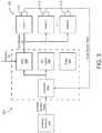
- FIG. 3is a block diagram of an HVAC system including a controller configured to operate an air-handling unit (AHU) of the HVAC system of FIG. 1 , according to some embodiments.
- AHUair-handling unit
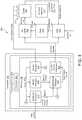
- FIG. 4is a block diagram illustrating the controller of FIG. 3 in greater detail, showing operations performed when the controller is used in an on-line mode or real-time implementation for making control decisions to minimize energy consumption of the HVAC system and provide sufficient disinfection, according to some embodiments.
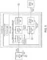
- FIG. 5is a block diagram illustrating the controller of FIG. 3 in greater detail, showing operations performed when the controller is used in an off-line or planning mode for making design suggestions to minimize energy consumption of the HVAC system and provide sufficient disinfection, according to some embodiments.
- FIG. 6is a flow diagram of a process which can be performed by the controller of FIG. 3 for determining control decisions for an HVAC system to minimize energy consumption and provide sufficient disinfection, according to some embodiments.
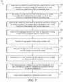
- FIG. 7is a flow diagram of a process which can be performed by the controller of FIG. 3 for determining design suggestions for an HVAC system to minimize energy consumption and provide sufficient disinfection, according to some embodiments.
- FIG. 8is a graph of various design suggestions or information that can be provided by the controller of FIG. 3 , according to some embodiments.
- FIG. 9is a drawing of a user interface that can be used to specify building options and disinfection options and provide simulation results, according to some embodiments.
- FIG. 10is a graph illustrating a technique which can be used by the controller of FIG. 3 to estimate a Pareto front of a tradeoff curve for relative energy cost vs. infection probability, according to some embodiments.
- the systemmay include an AHU that serves multiple zones, a controller, one or more UV lights that disinfect air before it is provided from the AHU to the zones, and/or a filter that is configured to filter air to provide additional disinfection for the air before it is provided to the zones.
- the systemalso includes one or more zone sensors (e.g., temperature and/or humidity sensors, etc.) and one or more ambient or outdoor sensors (e.g., outdoor temperature and/or outdoor humidity sensors, etc.).
- the controlleruses a model-based design and optimization framework to integrate building disinfection control with existing temperature regulation in building HVAC systems.
- the controlleruses the Wells-Riley equation to transform a required upper limit of infection probability into constraints on indoor concentration of infectious particles, according to some embodiments.
- the controlleruses a dynamic model for infectious agent concentration to impose these constraints on an optimization problem similar to temperature and humidity constraints.
- the controllermay utilize a combination of fresh-air ventilation and direct filtration/disinfection to achieve desired infection constraints.
- the controllercan use this composite model for optimal design (e.g., in an off-line implementation of the controller) to determine which additional disinfection strategies are desirable, cost effective, or necessary.
- the controllercan also be used for on-line control to determine control decisions for various controllable equipment (e.g., dampers of the AHU) in real-time to minimize energy consumption or energy costs of the HVAC system while meeting temperature, humidity, and infectious quanta concentration constraints.
- the systems and methods described hereintreat infection control as an integral part of building HVAC operation rather than a short term or independent control objective, according to some embodiments. While it may be possible to achieve disinfection by the addition of UV lights and filters running at full capacity, such a strategy may be costly and consume excessive amounts of energy. However, the systems and methods described herein couple both objectives (disinfection control and minimal energy consumption) to assess optimal design and operational decisions on a case-by-case basis also taking into account climate, energy and disinfection goals of particular buildings.
- the controllercan be implemented in an off-line mode as a design tool.
- building designers and operatorsnow have a wide array of options for retrofitting a building to reduce the spread of infectious diseases to building occupants. This is typically accomplished by lowering the concentration of infectious particles in the air space, which can be accomplished by killing the microbes via UV radiation, trapping them via filtration, or simply forcing them out of the building via fresh-air ventilation. While any one of these strategies individually can provide desired levels of disinfection, it may do so at unnecessarily high cost or with negative consequences for thermal comfort of building occupants.
- the model-based design toolcan estimate annualized capital and energy costs for a given set of disinfection equipment. For a given AHU, this includes dynamic models for temperature, humidity, and infectious particle concentration, and it employs the Wells-Riley infection equation to enforce constraints on maximum occupant infection probability.
- the controllerwhen operating as the design tool in the off-line mode, can present building designers with the tradeoff between cost and disinfection, allowing them to make informed decisions about retrofit.
- a key feature of the design toolis that it shows to what extent the inherent flexibility of the existing HVAC system can be used to provide disinfection.
- a presence of free cooling from fresh outdoor airmeans that the energy landscape is relatively flat regardless of how the controller determines to operate the HVAC system.
- the controllercould potentially increase fresh-air intake significantly to provide sufficient disinfection without UV or advanced filtration while incurring only a small energy penalty.
- the design toolcan provide estimates to customers to allow them to make informed decisions about what additional disinfection equipment (if any) to install and then provide the modified control systems needed to implement the desired infection control.
- the controllercan also be implemented in an on-line mode as a real-time controller.
- equipment like UV lamps and advanced filtrationcan be installed in buildings to mitigate the spread of infectious diseases, it is often unclear how to best operate that equipment to achieve desired disinfection goals in a cost-effective manner.
- a common strategyis to take the robust approach of opting for the highest-efficiency filters and running UV lamps constantly. While this strategy will indeed reduce infection probability to its lowest possible value, it is likely to do so at exorbitant cost due to the constant energy penalties of both strategies.
- Building managersmay potentially choose to completely disable filters and UV lamps to conserve energy consumption. Thus, the building may end up in a worst-of-both-words situation where the building manager has paid for disinfection equipment but the zones are no longer receiving any disinfection.
- the controllercan automate infection control by integrating disinfection control (e.g., based on the Wells-Riley equation) in a model based control scheme. In this way, the controller can simultaneously achieve thermal comfort and provide adequate disinfection at the lowest possible cost given currently available equipment.
- disinfection controle.g., based on the Wells-Riley equation
- the control strategycan optimize in real time the energy and disinfection tradeoffs of all possible control variables.
- the controllermay choose to raise fresh-air intake fraction even though it incurs a slight energy penalty because it allows a significant reduction of infectious particle concentrations while still maintaining comfortable temperatures.
- the existing control infrastructurecan be guided or constrained so as to provide desired disinfection.
- the controllercan find the optimal combination of techniques to achieve desired control objectives at the lowest possible cost.
- the constraint on infection probabilityis configurable, the controller can empower building operators to make their own choices regarding disinfection and energy use (e.g.
- the controllercan provide integrated comfort, disinfection, and energy management to customers to achieve better outcomes in all three areas compared to other narrow and individual solutions.
- the models used to predict temperature, humidity, and/or infectious quantaare dynamic models.
- the term “dynamic model” and variants thereofare used throughout the present disclosure to refer to any type of model that predicts the value of a quantity (e.g., temperature, humidity, infectious quanta) at various points in time as a function of zero or more input variables.
- a dynamic modelmay be “dynamic” as a result of the input variables changing over time even if the model itself does not change. For example, a steady-state model that uses ambient temperature or any other variable that changes over time as an input may be considered a dynamic model.
- Dynamic modelsmay also include models that vary over time.
- models that are retrained periodically, configured to adapt to changing conditions over time, and/or configured to use different relationships between input variables and predicted outputsmay also be considered dynamic models.
- Dynamic modelsmay also include ordinary differential equation (ODE) models or other types of models having input variables that change over time and/or input variables that represent the rate of change of a variable.
- ODEordinary differential equation
- a BMSis, in general, a system of devices configured to control, monitor, and manage equipment in or around a building or building area.
- a BMScan include, for example, a HVAC system, a security system, a lighting system, a fire alerting system, any other system that is capable of managing building functions or devices, or any combination thereof.
- An example of a BMS which can be used to monitor and control building 10is described in U.S. patent application Ser. No. 14/717,593 filed May 20, 2015, the entire disclosure of which is incorporated by reference herein.
- HVAC system 100can include a plurality of HVAC devices (e.g., heaters, chillers, air handling units, pumps, fans, thermal energy storage, etc.) configured to provide heating, cooling, ventilation, or other services for building 10 .
- HVAC system 100is shown to include a waterside system 120 and an airside system 130 .
- Waterside system 120may provide a heated or chilled fluid to an air handling unit of airside system 130 .
- Airside system 130may use the heated or chilled fluid to heat or cool an airflow provided to building 10 .
- waterside system 120can be replaced with or supplemented by a central plant or central energy facility (described in greater detail with reference to FIG. 2 ).
- An example of an airside system which can be used in HVAC system 100is described in greater detail with reference to FIG. 2 .
- HVAC system 100is shown to include a chiller 102 , a boiler 104 , and a rooftop air handling unit (AHU) 106 .
- Waterside system 120may use boiler 104 and chiller 102 to heat or cool a working fluid (e.g., water, glycol, etc.) and may circulate the working fluid to AHU 106 .
- the HVAC devices of waterside system 120can be located in or around building 10 (as shown in FIG. 1 ) or at an offsite location such as a central plant (e.g., a chiller plant, a steam plant, a heat plant, etc.).
- the working fluidcan be heated in boiler 104 or cooled in chiller 102 , depending on whether heating or cooling is required in building 10 .
- Boiler 104may add heat to the circulated fluid, for example, by burning a combustible material (e.g., natural gas) or using an electric heating element.
- Chiller 102may place the circulated fluid in a heat exchange relationship with another fluid (e.g., a refrigerant) in a heat exchanger (e.g., an evaporator) to absorb heat from the circulated fluid.
- the working fluid from chiller 102 and/or boiler 104can be transported to AHU 106 via piping 108 .
- AHU 106may place the working fluid in a heat exchange relationship with an airflow passing through AHU 106 (e.g., via one or more stages of cooling coils and/or heating coils).
- the airflowcan be, for example, outside air, return air from within building 10 , or a combination of both.
- AHU 106may transfer heat between the airflow and the working fluid to provide heating or cooling for the airflow.
- AHU 106can include one or more fans or blowers configured to pass the airflow over or through a heat exchanger containing the working fluid. The working fluid may then return to chiller 102 or boiler 104 via piping 110 .
- Airside system 130may deliver the airflow supplied by AHU 106 (i.e., the supply airflow) to building 10 via air supply ducts 112 and may provide return air from building 10 to AHU 106 via air return ducts 114 .
- airside system 130includes multiple variable air volume (VAV) units 116 .
- VAVvariable air volume
- airside system 130is shown to include a separate VAV unit 116 on each floor or zone of building 10 .
- VAV units 116can include dampers or other flow control elements that can be operated to control an amount of the supply airflow provided to individual zones of building 10 .
- airside system 130delivers the supply airflow into one or more zones of building 10 (e.g., via supply ducts 112 ) without using intermediate VAV units 116 or other flow control elements.
- AHU 106can include various sensors (e.g., temperature sensors, pressure sensors, etc.) configured to measure attributes of the supply airflow.
- AHU 106may receive input from sensors located within AHU 106 and/or within the building zone and may adjust the flow rate, temperature, or other attributes of the supply airflow through AHU 106 to achieve setpoint conditions for the building zone.
- airside system 200may supplement or replace airside system 130 in HVAC system 100 or can be implemented separate from HVAC system 100 .
- airside system 200can include a subset of the HVAC devices in HVAC system 100 (e.g., AHU 106 , VAV units 116 , ducts 112 - 114 , fans, dampers, etc.) and can be located in or around building 10 .
- Airside system 200may operate to heat, cool, humidify, dehumidify, filter, and/or disinfect an airflow provided to building 10 in some embodiments.
- Airside system 200is shown to include an economizer-type air handling unit (AHU) 202 .
- Economizer-type AHUsvary the amount of outside air and return air used by the air handling unit for heating or cooling.
- AHU 202may receive return air 204 from building zone 206 via return air duct 208 and may deliver supply air 210 to building zone 206 via supply air duct 212 .
- AHU 202is a rooftop unit located on the roof of building 10 (e.g., AHU 106 as shown in FIG. 1 ) or otherwise positioned to receive both return air 204 and outside air 214 .
- AHU 202can be configured to operate exhaust air damper 216 , mixing damper 218 , and outside air damper 220 to control an amount of outside air 214 and return air 204 that combine to form supply air 210 . Any return air 204 that does not pass through mixing damper 218 can be exhausted from AHU 202 through exhaust damper 216 as exhaust air 222 .
- Each of dampers 216 - 220can be operated by an actuator.
- exhaust air damper 216can be operated by actuator 224
- mixing damper 218can be operated by actuator 226
- outside air damper 220can be operated by actuator 228 .
- Actuators 224 - 228may communicate with an AHU controller 230 via a communications link 232 .
- Actuators 224 - 228may receive control signals from AHU controller 230 and may provide feedback signals to AHU controller 230 .
- Feedback signalscan include, for example, an indication of a current actuator or damper position, an amount of torque or force exerted by the actuator, diagnostic information (e.g., results of diagnostic tests performed by actuators 224 - 228 ), status information, commissioning information, configuration settings, calibration data, and/or other types of information or data that can be collected, stored, or used by actuators 224 - 228 .
- diagnostic informatione.g., results of diagnostic tests performed by actuators 224 - 228
- status informatione.g., commissioning information, configuration settings, calibration data, and/or other types of information or data that can be collected, stored, or used by actuators 224 - 228 .
- AHU controller 230can be an economizer controller configured to use one or more control algorithms (e.g., state-based algorithms, extremum seeking control (ESC) algorithms, proportional-integral (PI) control algorithms, proportional-integral-derivative (PID) control algorithms, model predictive control (MPC) algorithms, feedback control algorithms, etc.) to control actuators 224 - 228 .
- control algorithmse.g., state-based algorithms, extremum seeking control (ESC) algorithms, proportional-integral (PI) control algorithms, proportional-integral-derivative (PID) control algorithms, model predictive control (MPC) algorithms, feedback control algorithms, etc.
- AHU 202is shown to include a cooling coil 234 , a heating coil 236 , and a fan 238 positioned within supply air duct 212 .
- Fan 238can be configured to force supply air 210 through cooling coil 234 and/or heating coil 236 and provide supply air 210 to building zone 206 .
- AHU controller 230may communicate with fan 238 via communications link 240 to control a flow rate of supply air 210 .
- AHU controller 230controls an amount of heating or cooling applied to supply air 210 by modulating a speed of fan 238 .
- AHU 202includes one or more air filters (e.g., filter 308 ) and/or one or more ultraviolet (UV) lights (e.g., UV lights 306 ) as described in greater detail with reference to FIG. 3 .
- AHU controller 230can be configured to control the UV lights and route the airflow through the air filters to disinfect the airflow as described in greater detail below.
- Cooling coil 234may receive a chilled fluid from central plant 200 (e.g., from cold water loop 216 ) via piping 242 and may return the chilled fluid to central plant 200 via piping 244 .
- Valve 246can be positioned along piping 242 or piping 244 to control a flow rate of the chilled fluid through cooling coil 234 .
- cooling coil 234includes multiple stages of cooling coils that can be independently activated and deactivated (e.g., by AHU controller 230 , by BMS controller 266 , etc.) to modulate an amount of cooling applied to supply air 210 .
- Heating coil 236may receive a heated fluid from central plant 200 (e.g., from hot water loop 214 ) via piping 248 and may return the heated fluid to central plant 200 via piping 250 .
- Valve 252can be positioned along piping 248 or piping 250 to control a flow rate of the heated fluid through heating coil 236 .
- heating coil 236includes multiple stages of heating coils that can be independently activated and deactivated (e.g., by AHU controller 230 , by BMS controller 266 , etc.) to modulate an amount of heating applied to supply air 210 .
- valves 246 and 252can be controlled by an actuator.
- valve 246can be controlled by actuator 254 and valve 252 can be controlled by actuator 256 .
- Actuators 254 - 256may communicate with AHU controller 230 via communications links 258 - 260 .
- Actuators 254 - 256may receive control signals from AHU controller 230 and may provide feedback signals to controller 230 .
- AHU controller 230receives a measurement of the supply air temperature from a temperature sensor 262 positioned in supply air duct 212 (e.g., downstream of cooling coil 334 and/or heating coil 236 ).
- AHU controller 230may also receive a measurement of the temperature of building zone 206 from a temperature sensor 264 located in building zone 206 .
- AHU controller 230operates valves 246 and 252 via actuators 254 - 256 to modulate an amount of heating or cooling provided to supply air 210 (e.g., to achieve a setpoint temperature for supply air 210 or to maintain the temperature of supply air 210 within a setpoint temperature range).
- the positions of valves 246 and 252affect the amount of heating or cooling provided to supply air 210 by cooling coil 234 or heating coil 236 and may correlate with the amount of energy consumed to achieve a desired supply air temperature.
- AHU 230may control the temperature of supply air 210 and/or building zone 206 by activating or deactivating coils 234 - 236 , adjusting a speed of fan 238 , or a combination of both.
- airside system 200is shown to include a building management system (BMS) controller 266 and a client device 268 .
- BMS controller 266can include one or more computer systems (e.g., servers, supervisory controllers, subsystem controllers, etc.) that serve as system level controllers, application or data servers, head nodes, or master controllers for airside system 200 , central plant 200 , HVAC system 100 , and/or other controllable systems that serve building 10 .
- computer systemse.g., servers, supervisory controllers, subsystem controllers, etc.
- system level controllerse.g., application or data servers, head nodes, or master controllers for airside system 200 , central plant 200 , HVAC system 100 , and/or other controllable systems that serve building 10 .
- BMS controller 266may communicate with multiple downstream building systems or subsystems (e.g., HVAC system 100 , a security system, a lighting system, central plant 200 , etc.) via a communications link 270 according to like or disparate protocols (e.g., LON, BACnet, etc.).
- AHU controller 230 and BMS controller 266can be separate (as shown in FIG. 2 ) or integrated.
- AHU controller 230can be a software module configured for execution by a processor of BMS controller 266 .
- AHU controller 230receives information from BMS controller 266 (e.g., commands, setpoints, operating boundaries, etc.) and provides information to BMS controller 266 (e.g., temperature measurements, valve or actuator positions, operating statuses, diagnostics, etc.). For example, AHU controller 230 may provide BMS controller 266 with temperature measurements from temperature sensors 262 - 264 , equipment on/off states, equipment operating capacities, and/or any other information that can be used by BMS controller 266 to monitor or control a variable state or condition within building zone 206 .
- BMS controller 266e.g., commands, setpoints, operating boundaries, etc.
- information to BMS controller 266e.g., temperature measurements, valve or actuator positions, operating statuses, diagnostics, etc.
- AHU controller 230may provide BMS controller 266 with temperature measurements from temperature sensors 262 - 264 , equipment on/off states, equipment operating capacities, and/or any other information that can be used by BMS controller 266 to monitor or control
- Client device 268can include one or more human-machine interfaces or client interfaces (e.g., graphical user interfaces, reporting interfaces, text-based computer interfaces, client-facing web services, web servers that provide pages to web clients, etc.) for controlling, viewing, or otherwise interacting with HVAC system 100 , its subsystems, and/or devices.
- Client device 268can be a computer workstation, a client terminal, a remote or local interface, or any other type of user interface device.
- Client device 268can be a stationary terminal or a mobile device.
- client device 268can be a desktop computer, a computer server with a user interface, a laptop computer, a tablet, a smartphone, a PDA, or any other type of mobile or non-mobile device.
- Client device 268may communicate with BMS controller 266 and/or AHU controller 230 via communications link 272 .
- HVAC system 300that is configured to provide disinfection for various zones of a building (e.g., building 10 ) is shown, according to some embodiments.
- HVAC system 300can include an air handling unit (AHU) 304 (e.g., AHU 230 , AHU 202 , etc.) that can provide conditioned air (e.g., cooled air, supply air 210 , etc.) to various building zones 206 .
- the AHU 304may draw air from the zones 206 in combination with drawing air from outside (e.g., outside air 214 ) to provide conditioned or clean air to zones 206 .
- the HVAC system 1400includes a controller 310 (e.g., AHU controller 230 ) that is configured to determine a fraction x of outdoor air to recirculated air that the AHU 304 should use to provide a desired amount of disinfection to building zones 206 .
- controller 310can generate control signals for various dampers of AHU 304 so that AHU 304 operates to provide the conditioned air to building zones 206 using the fraction x.
- the HVAC system 300can also include ultraviolet (UV) lights 306 that are configured to provide UV light to the conditioned air before it is provided to building zones 206 .
- the UV lights 306can provide disinfection as determined by controller 310 and/or based on user operating preferences. For example, the controller 310 can determine control signals for UV lights 306 in combination with the fraction x of outdoor air to provide a desired amount of disinfection and satisfy an infection probability constraint.
- UV lights 306are referred to throughout the present disclosure, the systems and methods described herein can use any type of disinfection lighting using any frequency, wavelength, or luminosity of light effective for disinfection. It should be understood that UV lights 306 (and any references to UV lights 306 throughout the present disclosure) can be replaced with disinfection lighting of any type without departing from the teachings of the present disclosure.
- the HVAC system 300can also include one or more filters 308 or filtration devices (e.g., air purifiers).
- the filters 308are configured to filter the conditioned air or recirculated air before it is provided to building zones 206 to provide a certain amount of disinfection.
- controller 310can perform an optimization in real-time or as a planning tool to determine control signals for AHU 304 (e.g., the fraction x) and control signals for UV lights 306 (e.g., on/off commands) to provide disinfection for building zones 206 and reduce a probability of infection of individuals that are occupying building zones 206 .
- Controller 310can also function as a design tool that is configured to determine suggestions for building managers regarding benefits of installing or using filters 308 , and/or specific benefits that may arise from using or installing a particular type or size of filter. Controller 310 can thereby facilitate informed design decisions to maintain sterilization of air that is provided to building zones 206 and reduce a likelihood of infection or spreading of infectious matter.
- the systems and methods described hereinmay use an infection probability constraint in various optimizations (e.g., in on-line or real-time optimizations or in off-line optimizations) to facilitate reducing infection probability among residents or occupants of spaces that the HVAC system serves.
- the infection probability constraintcan be based on a steady-state Wells-Riley equation for a probability of airborne transmission of an infectious agent given by:
- Pis a probability that an individual becomes infected (e.g., in a zone, space, room, environment, etc.)
- Dis a number of infected individuals (e.g., in the zone, space, room, environment, etc.)
- Sis a total number of susceptible individuals (e.g., in the zone, space, room, environment, etc.)
- Iis a number of infectious individuals (e.g., in the zone, space, room, environment, etc.)
- qis a disease quanta generation rate (e.g., with units of 1/sec)
- pis a volumetric breath rate of one individual (e.g., in m 3 /sec)
- tis a total exposure time (e.g., in seconds)
- Qis an outdoor ventilation rate (e.g., in m 3 /sec).
- Qmay be
- controller 310may use the Wells-Riley equation (or a dynamic version of the Wells-Riley equation) to determine an actual or current probability of infection P and operate the HVAC system 200 to maintain the actual probability of infection P below (or drive the actual probability of infection below) a constraint or maximum allowable value.
- the constraint valuee.g., P max
- P maxmay be a constant value, or may be adjustable by a user (e.g., a user-set value).
- the usermay set the constraint value of the probability of infection to a maximum desired probability of infection (e.g., either for on-line implementation of controller 310 to maintain the probability of infection below the maximum desired probability, or for an off-line implementation/simulation performed by controller 310 to determine various design parameters for HVAC system 200 such as filter size), or may select from various predetermined values (e.g., 3-5 different choices of the maximum desired probability of infection).
- a maximum desired probability of infectione.g., either for on-line implementation of controller 310 to maintain the probability of infection below the maximum desired probability, or for an off-line implementation/simulation performed by controller 310 to determine various design parameters for HVAC system 200 such as filter size
- various predetermined valuese.g., 3-5 different choices of the maximum desired probability of infection.
- the number of infectious individuals Ican be determined by controller 310 based on data from the Centers for Disease and Control Prevention or a similar data source.
- the value of 1may be typically set equal to 1 but may vary as a function of occupancy of building zones 206 .
- the disease quanta generation rate qmay be a function of the infectious agent. For example, more infectious diseases may have a higher value of q, while less infectious diseases may have a lower value of q.
- the value of q for COVID-19may be 30-300 (e.g., 100).
- the value of the volumetric breath rate pmay be based on a type of building space 206 .
- the volumetric breath rate pmay be higher if the building zone 206 is a gym as opposed to an office setting.
- an expected level of occupant activitymay determine the value of the volumetric breath rate p.
- Dthe number of infected individuals
- Ithe number of infectious individuals
- Dis a number of individuals who are infected (e.g., infected with a disease)
- Iis a number of people that are infected and are actively contagious (e.g., individuals that may spread the disease to other individuals or spread infectious particles when they exhale).
- the disease quanta generation rateindicates a number of infectious droplets that give a 63.2% chance of infecting an individual (e.g., 1 ⁇ exp( ⁇ 1)). For example, if an individual inhales k infectious particles, the probability that the individual becomes infected (P) is given by
- the quanta generation rate qis the rate at which quanta are generated (e.g., K/k 0 ) where K is the rate of infectious particles exhaled by an infectious individual. It should be noted that values of the disease quanta generation rate q may be back-calculated from epidemiological data or may be tabulated for well-known diseases.
- V ⁇ d ⁇ N d ⁇ tIq - N ⁇ Q
- Vis a total air volume (e.g., in m 3 )
- Nis a quantum concentration in the air
- Iis the number of infectious individuals
- qis the disease quanta generation rate
- Qis the outdoor ventilation rate.
- Iqis quanta production by infectious individuals (e.g., as the individuals breathe out or exhale)
- NQis the quanta removal rate due to ventilation (e.g., due to operation of AHU 304 ).
- N ssIq Q according to some embodiments.
- infectious probabilityis given by:
- CO2is a readily-measureable parameter that can be a proxy species, measured by zone sensors 312 .
- a concentration of CO2 in the zones 206may be directly related to a concentration of the infectious quanta.
- a quantity ⁇ that defines a ratio of an infected particle concentration in the building air to the infected particle concentration in the exhaled breath of an infectious individualis defined:
- ⁇ ⁇ ⁇ :⁇ ⁇ p ⁇ N q
- pis the volumetric breath rate for an individual
- Nis the quantum concentration in the air
- qis the disease quanta generation rate
- CO2can be used as a proxy species.
- Vis the total air volume (e.g., in m 3 )
- Cis the net indoor CO2 concentration
- ttime
- Sis the total number of susceptible individuals (e.g., in building zone 206 , or a modeled space, or all of building zones 206 , or building 10 )
- pis the volumetric breath rate for one individual
- cis the net concentration of exhaled CO2
- Qis the outdoor ventilation rate.
- ⁇C c
- ⁇the ratio
- Cthe net indoor CO2 concentration
- cthe net concentration of exhaled CO2.
- HVAC system 200may include one or more filters 308 , and UV lights 306 that can be operated to provide disinfection for building zones 206 . If additional infection mitigation strategies are used, the ventilation rate may instead by an effective ventilation rate for infectious quanta that is different than that of the CO2. Additionally, the only way for the initial conditions ⁇ (0) and ⁇ (0) to be in proportion is for both to be zero. This assumption can be reasonable if HVAC system 200 operates over a prolonged time period (such as overnight, when the concentrations have sufficient time to reach equilibrium zero values).
- CO2 concentrationcan be measured to determine common model parameters (e.g., for the overall system volume V) without being used to estimate current infectious particle concentrations. If fresh outdoor air ventilation is the only mechanism for disinfection of zones 206 , and the HVAC system 200 is run so that the concentrations reach equilibrium, CO2 concentration can be measured and used to estimate current infectious particle concentrations. Dynamic Extension and Infection Probability Constraints
- the infectious quanta concentration N of building zones 206may be desirable to model the infectious quanta concentration N of building zones 206 as a dynamic parameter rather than assuming N is equal to the steady state N ss value. For example, if infectious individuals enter building zones 206 , leave building zones 206 , etc., the infectious quanta concentration N may change over time. This can also be due to the fact that the effective fresh air ventilation rate (which includes outdoor air intake as well as filtration or UV disinfection that affects the infectious agent concentration in the supply air that is provided by AHU 304 to zones 206 ) can vary as HVAC system 200 operates.
- the effective fresh air ventilation ratewhich includes outdoor air intake as well as filtration or UV disinfection that affects the infectious agent concentration in the supply air that is provided by AHU 304 to zones 206
- k [ 0 , T ]⁇ 0 T ⁇ p ⁇ k 0 ⁇ N ⁇ ( t ) ⁇ d ⁇ t
- k [0,T]is the number of infectious particles that an individual inhales over the given time period [0, T]
- pis the volumetric breath rate of one individual
- k 0is the quantum of particles for a particular disease
- N(t)is the time-varying quantum concentration of the infectious particle in the air.
- the constraintcan define a fixed upper boundary on an average value of N t over the given time interval.
- controller 310is shown in greater detail, according to some embodiments.
- Controller 310is configured to generate control signals for any of UV lights 306 , filter 308 , and/or AHU 304 .
- AHU 304operates to draw outdoor air and/or recirculated air (e.g., from zones 206 ) to output conditioned (e.g., cooled) air.
- the conditioned airmay be filtered by passing through filter 308 (e.g., which may include fans to draw the air through the filter 308 ) to output filtered air.
- the filtered air and/or the conditioned aircan be disinfected through operation of UV lights 306 .
- the AHU 304 , filter 308 , and UV lights 306can operate in unison to provide supply air to zones 206 .
- Controller 310includes a processing circuit 402 including a processor 404 and memory 406 .
- Processing circuit 402can be communicably connected with a communications interface of controller 310 such that processing circuit 402 and the various components thereof can send and receive data via the communications interface.
- Processor 404can be implemented as a general purpose processor, an application specific integrated circuit (ASIC), one or more field programmable gate arrays (FPGAs), a group of processing components, or other suitable electronic processing components.
- ASICapplication specific integrated circuit
- FPGAsfield programmable gate arrays
- Memory 406(e.g., memory, memory unit, storage device, etc.) can include one or more devices (e.g., RAM, ROM, Flash memory, hard disk storage, etc.) for storing data and/or computer code for completing or facilitating the various processes, layers and modules described in the present application.
- Memory 406can be or include volatile memory or non-volatile memory.
- Memory 406can include database components, object code components, script components, or any other type of information structure for supporting the various activities and information structures described in the present application.
- memory 406is communicably connected to processor 404 via processing circuit 402 and includes computer code for executing (e.g., by processing circuit 402 and/or processor 404 ) one or more processes described herein.
- controller 310is implemented within a single computer (e.g., one server, one housing, etc.). In various other embodiments controller 310 can be distributed across multiple servers or computers (e.g., that can exist in distributed locations).
- Memory 406can include a constraint generator 410 , a model manager 416 , a sensor manager 414 , an optimization manager 412 , and a control signal generator 408 .
- Sensor manager 414can be configured to obtain zone sensor data from zone sensors 312 and/or ambient sensor data from ambient sensors 314 (e.g., environmental conditions, outdoor temperature, outdoor humidity, etc.) and distribute required sensor data to the various components of memory 406 thereof.
- Constraint generator 410is configured to generate one or more constraints for an optimization problem (e.g., an infection probability constraint) and provide the constraints to optimization manager 412 .
- Model manager 416can be configured to generate dynamic models (e.g., individual or zone-by-zone dynamic models, aggregate models, etc.) and provide the dynamic models to optimization manager 412 .
- Optimization manager 412can be configured to use the constraints provided by constraint generator 410 and the dynamic models provided by model manager 416 to formulate an optimization problem.
- Optimization manager 412can also define an objective function for the optimization problem, and minimize or optimize the objective function subject to the one or more constraints and the dynamic models.
- the objective functionmay be a function that indicates an amount of energy consumption, energy consumption costs, carbon footprint, or any other optimization goals over a time interval or time horizon (e.g., a future time horizon) as a function of various control decisions.
- Optimization manager 412can output optimizations results to control signal generator 408 .
- Control signal generator 408can generate control signals based on the optimization results and provide the control signals to any of AHU 304 , filter 308 , and/or UV lights 306 .
- AHU 304can be configured to serve multiple building zones 206 .
- Each zone 206can have a temperature, referred to as temperature T k (the temperature of the kth zone 206 ), a humidity ⁇ k (the humidity of the kth zone 206 ), and an infectious quanta concentration N k (the infectious quanta concentration of the kth zone 206 ).
- T kthe temperature of the kth zone 206
- ⁇ kthe humidity of the kth zone 206
- N kinfectious quanta concentration of the kth zone 206
- f kis a volumetric flow of air into the kth zone
- ⁇is a mass density of air (e.g., in kg per cubic meters)
- cthe heat capacity of air (e.g., in kJ/kg ⁇ K)
- Q k ( ⁇ )is heat load on the
- T 0is the temperature of the air provided to the kth zone (e.g., as discharged by a VAV box of AHU 304 ), ⁇ 0 is the humidity of the air provided to the kth zone 206 , and N 0 is the infectious quanta concentration of the air provided to the kth zone 206 .
- the temperature T 0 of air output by the AHU 304 , the humidity ⁇ 0 of air output by the AHU 304 , and the infectious quanta concentration N 0 of air output by the AHU 304is calculated using the equations:
- xis the fresh-air intake fraction of AHU 304
- T acurrent ambient temperature
- ⁇ ⁇current ambient humidity
- ⁇ T ctemperature reductions from the cooling coil of AHU 304
- ⁇ chumidity reduction from the cooling coil of AHU 304
- ⁇is a fractional reduction of
- model manager 416can store the individual dynamic models shown above and/or aggregated models (described in greater detail below) and populate the models. The populated models can then be provided by model manager 416 to optimization manager 412 for use in performing an optimization.
- model manager 416is configured to receive sensor data from sensor manager 414 .
- Sensor manager 414may receive sensor data from zone sensors 312 and/or ambient sensors 313 and provide appropriate or required sensor data to the various managers, modules, generators, components, etc., of memory 406 .
- sensor manager 414can obtain values of the current ambient temperature T a , the current ambient humidity ⁇ a , the temperature reduction ⁇ T c resulting from the cooling coil of AHU 304 , and/or the humidity reduction ⁇ c resulting from the cooling coil of AHU 304 , and provide these values to model manager 416 for use in determining T 0 , ⁇ 0 , and N 0 or for populating the dynamic models of the individual zones 206 .
- various parameters or values of the variables of the dynamic models of the individual zones 206are predefined, predetermined, or stored values, or may be determined (e.g., using a function, an equation, a table, a look-up table, a graph, a chart, etc.) based on sensor data (e.g., current environmental conditions of the ambient or outdoor area, environmental conditions of the zones 206 , etc.).
- sensor datae.g., current environmental conditions of the ambient or outdoor area, environmental conditions of the zones 206 , etc.
- the mass density of air pmay be a predetermined value or may be determined based on sensor data.
- model manager 416can use stored values, sensor data, etc., to fully populate the dynamic models of the individual zones 206 (except for control or adjustable variables of the dynamic models of the individual zones 206 that are determined by performing the optimization). Once the models are populated so that only the control variables remain undefined or undetermined, model manager 416 can provide the populated models to optimization manager 412 .
- the number of infectious individuals I kcan be populated based on sensor data (e.g., based on biometric data of occupants or individuals of the building zones 206 ), or can be estimated based on sensor data.
- model manager 416can use an expected number of occupants and various database regarding a number of infected individuals in an area. For example, model manager 416 can query an online database regarding potential infection spread in the area (e.g., number of positive tests of a particular virus or contagious illness) and estimate if it is likely that an infectious individual is in the building zone 206 .
- model manager 416is configured to use an overall approximation of the model for N k .
- Model manager 416can store and use volume-averaged variables:
- N _⁇ k ⁇ V k ⁇ N k
- V _ f _⁇ k ⁇ f k
- the equations shown aboveaggregate the variables N , f , V , and ⁇ across multiple zones 206 by calculating a weighted average based on the volume of zones 206 .
- the K separate ordinary differential equation models(i.e., the dynamic models of the individual zones 206 ) can be added for N k to determine an aggregate quantum concentration model:
- V ⁇ ⁇ d ⁇ N ⁇ d ⁇ tl ⁇ ⁇ q - ( ⁇ + x - ⁇ ⁇ x ) ⁇ ⁇ k ⁇ f k ⁇ N k ⁇ I ⁇ ⁇ q - ( ⁇ + x - ⁇ ⁇ x ) ⁇ fN _ according to some embodiments.
- ⁇ ⁇ ⁇ c ⁇ V ⁇ ⁇ d ⁇ T ⁇ d ⁇ t⁇ k ⁇ Q k ⁇ ( T k ) + ⁇ ⁇ c ⁇ ⁇ k ⁇ f k ⁇ ( x ⁇ ( T a - T k ) - ⁇ ⁇ T c ) ⁇ Q ⁇ ⁇ ( T ⁇ ) + ⁇ ⁇ ⁇ c ⁇ f ⁇ ⁇ ( x ⁇ ( T a - T ⁇ ) - ⁇ ⁇ T c ) according to some embodiments.
- ⁇ ⁇ V ⁇ ⁇ d ⁇ ⁇ ⁇ d ⁇ tw ⁇ + ⁇ ⁇ ⁇ k ⁇ f k ⁇ ( x ⁇ ( ⁇ a - ⁇ k ) - ⁇ ⁇ ⁇ c ) ⁇ w ⁇ + ⁇ ⁇ f ⁇ ⁇ ( x ⁇ ( ⁇ a - ⁇ ⁇ ) - ⁇ ⁇ ⁇ c ) to predict an evolution of volume-averaged humidity, according to some embodiments.
- model manager 416stores and uses the aggregate quantum concentration model, the aggregate thermal model, and/or the aggregate moisture model described hereinabove. Model manager 416 can populate the various parameters of the aggregate models and provide the aggregate models to optimization manager 412 for use in the optimization.
- memory 406includes optimization manager 412 .
- Optimization manager 412can be configured to use the models provided by model manager 416 and various constraints provided by constraint generator 410 to construct an optimization problem for HVAC system 200 (e.g., to determine design outputs and/or to determine control parameters, setpoints, control decisions, etc., for UV lights 306 and/or AHU 304 ).
- Optimization manager 412can construct an optimization problem that uses the individual or aggregated temperature, humidity, and/or quantum concentration models subject to constraints to minimize energy use.
- decision variables of the optimization problem formulated and solved by optimization manager 412are the flows f k (or the aggregate f if the optimization problem uses the aggregate models), the outdoor air fraction x and the infectious quanta removal fraction ⁇ .
- ⁇ filteris an infectious quanta removal fraction that results from using filter 308 (e.g., an amount or fraction of infectious quanta that is removed by filter 308 )
- ⁇ UVis an infectious quanta removal fraction that results from using UV lights 306 (e.g., an amount or fraction of infectious quanta that is removed by operation of UV lights 306 ).
- ⁇ filteris a design-time constant (e.g., determined based on the chosen filter 308 )
- ⁇ UVis an adjustable or controllable variable that can be determined by optimization manager 412 by performing the optimization of the optimization problem.
- ⁇ UVis a discrete variable.
- ⁇ UVis a continuous variable.
- optimization manager 412is configured to store and use the energy consumption model shown above for formulating and performing the optimization.
- the term ⁇ coil ⁇ f (c ⁇ T c +L ⁇ c )is an amount of energy consumed by the cooling coil or heating coil of the AHU 304 (e.g., over an optimization time period or time horizon)
- the term ⁇ fan f ⁇ Pis an amount of energy consumed by the fan of the AHU 304
- ⁇ UV ⁇ UVis the amount of energy consumed by the UV lights 306 .
- the duct pressure drop ⁇ Pis affected by or related to a choice of a type of filter 308 , where higher efficiency filters 308 (e.g., filters 308 that have a higher value of ⁇ filter ) generally resulting in a higher value of the duct pressure drop ⁇ P and therefore greater energy consumption.
- a more complex model of the energy consumptionis used by optimization manager 412 to formulate the optimization problem (e.g., a non-linear fan model and a time-varying or temperature-dependent coil efficiency model).
- the variables ⁇ T c and ⁇ c for the cooling coil of the AHU 304are implicit dependent decision variables.
- a value of a supply temperature T AHUis selected for the AHU 304 and is used to determine the variables ⁇ T c and ⁇ c based on inlet conditions to the AHU 304 (e.g., based on sensor data obtained by sensor manager 414 ).
- Optimization manager 412can use the models (e.g., the individual models, or the aggregated models) provided by model manager 416 , and constraints provided by constraint generator 410 to construct the optimization problem. Optimization manager 412 may formulate an optimization problem to minimize energy consumption subject to constraints on the modeled parameters, ⁇ , and N and additional constraints:
- the boundaries on temperature (T t min ⁇ T t ⁇ T t max ) and humidity ( ⁇ t min ⁇ t ⁇ t max )can be determined by optimization manager 412 based on user inputs or derived from comfort requirements.
- the temperature and humidity boundsmay be enforced by optimization manager 412 as soft constraints.
- the remaining boundse.g., the fresh-air ventilation bound, the VAV flow bounds, and the outdoor-air damper bounds
- the fresh-air ventilation boundis enforced by optimization manager 412 to meet the American Society of Heating, Refrigerating, and Air-Conditioning Engineers (ASHRAE) standards.
- the fresh-air ventilation boundis replaced with a model and corresponding bounds for CO2 concentration.
- the various constraints generated by constraint generator 410 or other constraints imposed on the optimization problemcan be implemented as soft constraints, hard constraints, or a combination thereof.
- Hard constraintsmay impose rigid boundaries (e.g., maximum value, minimum value) on one or more variables in the optimization problem such that any feasible solution to the optimization problem must maintain the hard constrained variables within the limits defined by the hard constraints.
- soft constraintsmay be implemented as penalties that contribute to the value of the objective function (e.g., adding to the objective function if the optimization problem seeks to minimize the objective function or subtracting from the objective function if the optimization problem seeks to maximize the objective function).
- Soft constraintsmay be violated when solving the optimization problem, but doing so will incur a penalty that affects the value of the objective function.
- soft constraintsmay encourage optimization manager 412 to maintain the values of the soft constrained variables within the limits defined by the soft constraints whenever possible to avoid the penalties, but may allow optimization manager 412 to violate the soft constraints when necessary or when doing so would result in a more optimal solution.
- constraint generator 410may impose soft constraints on the optimization problem by defining large penalty coefficients (relative to the scale of the other terms in the objective function) so that optimization manager 412 only violates the soft constraints when absolutely necessary.
- the values of the penalty coefficientscan be adjusted or tuned (e.g., by a person or automatically by constraint generator 410 ) to provide an optimal tradeoff between maintaining the soft constrained variables within limits and the resulting cost (e.g., energy cost, monetary cost) defined by the objective function.
- One approach which can be used by constraint generator 410is to use penalties proportional to amount by which the soft constraint is violated (i.e., static penalty coefficients).
- a penalty coefficient of 0.1 $/° C. ⁇ hr for a soft constrained temperature variablewould add a cost of $0.10 to the objective function for every 1° C. that the temperature variable is outside the soft constraint limit for every hour of the optimization period.
- Another approach which can be used by constraint generator 410is to use variable or progressive penalty coefficients that depend on the amount by which the soft constraint is violated.
- a variable or progressive penalty coefficientcould define a penalty cost of 0.1 $/° C. ⁇ hr for the first 1° C. by which a soft constrained temperature variable is outside the defined limit, but a relatively higher penalty cost of 1.0 $/° C. ⁇ hr for any violations of the soft constrained temperature limit outside the first 1° C.
- the constraint violation budgetmay define a total (e.g., cumulative) amount by which a constrained variable is allowed to violate a defined constraint limit within a given time period.
- a constraint violation budget for a constrained temperature variablemay define 30° C. ⁇ hr (or any other value) as the cumulative amount by which the constrained temperature variable is allowed to violate the temperature limit within a given time period (e.g., a day, a week, a month, etc.). This would allow the temperature to violate the temperature constraint by 30° C. for a single hour, 1° C. for each of 30 separate hours, 0.1° C.
- constraint generator 410may not add a penalty to the objective function or subtract a penalty from the objective function. However, any further violations of the constraint that exceed the constraint violation budget may trigger a penalty.
- the penaltycan be defined using static penalty coefficients or variable/progressive penalty coefficients as discussed above.
- the infection probability constraint(described in greater detail below) is linear, according to some embodiments.
- two sources of nonlinearity in the optimization problemare the dynamic models and a calculation of the coil humidity reduction ⁇ c .
- the optimization problemcan be solved using nonlinear programming techniques provided sufficient bounds are applied to the input variables.
- memory 406is shown to include a constraint generator 410 .
- Constraint generator 410can be configured to generate the infection probability constraint, and provide the infection probability constraint to optimization manager 412 .
- constraint generator 410is configured to also generate the temperature bounds, the humidity bounds, the fresh-air ventilation bound, the VAV flow bounds, and the outdoor-air damper bounds and provide these bounds to optimization manager 412 for performing the optimization.
- an upper bound P maxcan be chosen for P i,[0,T] and can be implemented as a linear constraint:
- variable ⁇it may be different for each individual in the building 10 but can be approximated as described herein.
- the above linear constraintis an average constraint that gives optimization manager 412 (e.g., an optimizer) a maximum amount of flexibility since the average constraint may allow a higher concentration of infectious quanta during certain times of the day (e.g., when extra fresh-air ventilation is expensive due to outdoor ambient conditions) as long as the higher concentrations are balanced by lower concentrations of the infectious quanta during other times of the day.
- the ⁇ it sequencemay be different for each individual in the building 10 . For purposes of the example described herein it is assumed that generally each individual is present a total of 8 hours (e.g., if the building 10 is an office building). However, the estimated amount of time the individual is within the building can be adjusted or set to other values for other types of buildings.
- the amount of time the individual is assumed to be present in the buildingcan be set to an average or estimated amount of time required to complete the corresponding activities (e.g., eating a meal, shopping, etc.). While an occupancy time of the building by each individual may be reasonably known, the times that the individual is present in the building may vary (e.g., the individual may be present from 7 AM to 3 PM, 9 AM to 5 PM, etc.). Therefore, to ensure that the constraint is satisfied for all possible ⁇ it sequences, the constraint may be required to be satisfied when summing over 8 hours of the day that have a highest concentration.
- M⁇ ⁇ + ⁇ t ⁇ ⁇ t ⁇ - 1 p ⁇ ⁇ ⁇ log ⁇ ( 1 - P max ) ⁇ ⁇ ⁇ t + ⁇ ⁇ N t ⁇ ⁇ ⁇ t
- Mis a number of discrete timesteps corresponding to 8 hours (or any other amount of time that an individual is expected to occupy building 10 or one of building zones 206 ).
- this implementation of the infection probability constraintcan be generated by constraint generator 410 and provided to optimization manager 412 for use in the optimization problem when controller 310 is implemented to perform control decisions for HVAC system 200 (e.g., when controller 310 operates in an on-line mode).
- N t ⁇ N t max- 1 M ⁇ p ⁇ ⁇ ⁇ log ⁇ ( 1 - P max ) where N t is constrained to be less than or equal to N t max for a maximum infection probability value P max .
- the pointwise constraint shown aboveis generated by constraint generator 410 for when optimization manager 412 is used in an off-line or design implementation.
- the pointwise constraint shown above, if satisfied in all zones 206ensures that any individual will meet the infection probability constraint.
- Such a constraintmay sacrifice flexibility compared to the other implementation of the infection probability constraint described herein, but translates to a simple box constraint similar to the other bounds in the optimization problem, thereby facilitating a simpler optimization process.
- the maximum allowable or desirable infection probability P maxis a predetermined value that is used by constraint generator 410 to generate the infection probability constraints described herein.
- constraint generator 410is configured to receive the maximum allowable or desirable infection probability P′ from a user as a user input.
- the maximum allowable or desirable infection probability P maxis an adjustable parameter that can be set by a user or automatically generated based on the type of infection, time of year, type or use of the building, or any of a variety of other factors. For example, some buildings (e.g., hospitals) may be more sensitive to preventing disease spread than other types of buildings and may use lower values of P max .
- the value of P maxcan be set to relatively lower values as the severity of the disease increases.
- the value of P maxcan be adjusted by a user and the systems and methods described herein can run a plurality of simulations or optimizations for a variety of different values of P to determine the impact on cost and disease spread. A user can select the desired value of P max in view of the estimated cost and impact on disease spread using the results of the simulations or optimizations.
- optimization manager 412can implement various model enhancements in the optimization.
- optimization manager 412is configured to add a decision variable for auxiliary (e.g., controlled) heating (e.g., via baseboard heat or VAV reheat coils).
- an effect of the auxiliary heatingis included in the dynamic model of temperature similar to the disturbance heat load Q k ( ⁇ ).
- the auxiliary heating decision variablemay be subject to bounds (e.g., with both set to zero during cooling season to disable auxiliary heating) that are generated by constraint generator 410 and used by optimization manager 412 in the optimization problem formulation and solving.
- the auxiliary heatingalso results in optimization manager 412 including another term for associated energy consumption in the energy consumption equation (shown above) that is minimized.
- certain regions or areasmay have variable electricity prices and/or peak demand charges.
- the objective functione.g., the energy consumption equation
- the objective functioncan be augmented by optimization manager 412 to account for such cost structures.
- the existing energy consumption E t that is minimized by optimization manager 412may be multiplied by a corresponding electricity price P t .
- a peak demand chargemay require the use of an additional parameter e t that represents a base electric load of building 10 (e.g., for non-HVAC purposes).
- Optimization manager 412can include such cost structures and may minimize overall cost associated with electricity consumption rather than merely minimizing electrical consumption.
- optimization manager 412accounts for revenue which can be generated by participating in incentive based demand response (IBDR) programs, frequency regulation (FR) programs, economic load demand response (ELDR) programs, or other sources of revenue when generating the objective function. In some embodiments, optimization manager 412 accounts for the time value of money by discounting future costs or future gains to their net present value.
- controller 310can operate to pre-cool the solid mass of building 10 when electricity is cheap so that the solid mass can later provide passive cooling later in the day when electricity is less expensive.
- optimization manager 412 and/or model manager 416are configured to model this effect using a model augmentation by adding a new variable T k m to represent the solid mass of the zone 206 evolving as:
- This quantitycan also be aggregated by model manager 416 to an average value T m similar to T .
- controller 310can add a proportional decay term to the infectious quanta model (in addition to the other terms of the infectious quanta model discussed above).
- a proportional decay termto the infectious quanta model (in addition to the other terms of the infectious quanta model discussed above).
- V ⁇ d ⁇ N d ⁇ t... - V ⁇ ⁇ ⁇ ⁇ N
- controller 310can be configured for use as a design or planning tool for determining various design parameters of HVAC system 300 (e.g., for determining a size of filter 308 , UV lights 306 , etc.).
- controller 310 implemented as a design tool, a planning tool, a recommendation tool, etc.,functions similarly to controller 310 implemented as a real-time control device (e.g., in an on-line mode).
- model manager 416 , constraint generator 410 , and optimization manager 412may receive required sensor input data (i.e., model population data) from a simulation database 424 .
- Simulation database 424can store values of the various parameters of the constraints or boundaries, the dynamic models, or typical energy consumption costs or operational parameters for energy-consuming devices of the HVAC system 200 .
- simulation database 424also stores predicted or historical values as obtained from sensors of HVAC system 200 .
- simulation database 424can store typical ambient temperature, humidity, etc., conditions for use in performing the off-line simulation.
- controller 310may receive user inputs from user input device 420 .
- the user inputsmay be initial inputs for various constraints (e.g., a maximum value of the probability of infection for the simulation) or various required input parameters.
- the usercan also provide simulation data for simulation database 424 used to populate the models or constraints, etc.
- Controller 310can output suggestions of whether to use a particular piece of equipment (e.g., whether or not to use or install UV lights 306 ), whether to use AHU 304 to draw outside air, etc., or other factors to minimize cost (e.g., to optimize the objective function, minimize energy consumption, minimize energy consumption monetary cost, etc.) and to meet disinfection goals (e.g., to provide a desired level of infection probability).
- controller 310may provide different recommendations or suggestions based on a location of building 10 .
- the recommendationsnotify the user regarding what equipment is needed to keep the infection probability of zones 206 within the threshold while not increasing energy cost or carbon footprint.
- the optimization problem formulated by optimization manager 412 for the off-line implementationincludes an additional constraint on the infectious quanta concentration (as described in greater detail above).
- the infectious quanta concentrationcan be controlled or adjusted by (a) changing the airflow into each zone 206 (e.g., adjusting f i ), (b) changing the fresh-air intake fraction (e.g., adjusting x), or (c) destroying infectious particles in the AHU 304 via filtration or UV light (e.g., adjusting ⁇ ).
- the first and second control or adjustmentsmay also affect temperature and humidity of the zones 206 of building 10 .
- the third control option (c)e.g., adjusting the infectious quanta concentration through filtration and/or operation of UV lights
- optimization manager 412may determine results that rely heavily or completely on maintaining the infectious quanta concentration below its corresponding threshold or bound through operation of filter 308 and/or UV lights 306 .
- optimization manager 412can determine adjustments to (a), (b), and (c) simultaneously to achieve lowest or minimal operating costs (e.g., energy consumption). Additionally, since purchasing filters 308 and/or UV lights 306 may incur significant capital costs (e.g., to purchase such devices), controller 310 may perform the optimization as a simulation to determine if purchasing filters 308 and/or UV lights 306 is cost effective.
- controller 310may provide an estimate of a total cost (both capital costs and operating costs) to achieve a desired level of infection control (e.g., to maintain the infection probability below or at a desired amount).
- the purposeis to run a series of independent simulations, assuming different equipment configurations (e.g., as stored and provided by simulation database 424 ) and for different infection probability constraints given typical climate and occupancy data (e.g., as stored and provided by simulation database 424 ).
- the different equipment configurationsinclude scenarios when filters 308 and/or UV lights 306 are installed in the HVAC system 200 , or when filters 308 and/or UV lights 306 are not installed in the HVAC system 200 .
- controller 310can perform a cost benefit analysis based on global design decisions (e.g., whether or not to install UV lights 306 and/or filters 308 ).
- the cost benefit analysismay be performed by results manager 418 and the cost benefit analysis results can be output as display data to a building manager via display device 422 . These results may aid the building manager or a building designer in assessing potential options for infection control of building 10 (as shown in FIG. 8 ).
- graph 800illustrates a potential output of results manager 418 that can be displayed by display device 422 .
- Graph 800illustrates relative cost (the Y-axis) with respect to infection probability (the X-axis) for a case when both filtration and UV lights are used for infection control (represented by series 808 ), a case when filtration is used for infection control without using UV lights (represented by series 802 ), a case when UV lights are used for infection control without using filtration (represented by series 806 ), and a case when neither UV lights and filtration are used for infection control (represented by series 804 ).
- each of the cases illustrated by series 802 - 808assume that fresh-air intake is used to control infection probability.
- Data associated with graph 800can be output by results manager 418 so that graph 800 can be generated and displayed on display device 422 .
- the off-line optimization performed by optimization manager 412is faster or more computationally efficient than the on-line optimization performed by optimization manager 412 .
- the simulationis performed using conventional rule-based control rather than a model-predictive control scheme used for the on-line optimization. Additionally, the simulation may be performed over shorter time horizons than when the optimization is performed in the on-line mode to facilitate simulation of a wide variety of design conditions.
- optimization manager 412is configured to use the aggregate dynamic models as generated, populated, and provided by model manager 416 for the off-line optimization (e.g., the design optimization).
- the variable ⁇can include two positions at each timestep (e.g., corresponding to the UV lights 306 being on or the UV lights 306 being off).
- optimization manager 412can select a coarser grid (e.g., 5 to 10 choices) for the additional variable.
- optimization manager 412is configured to solve a number of one-step optimization problems (e.g., formulate different optimization problems for different sets of the control variables and solve the optimization problem over a single timestep) in a training period, and then train a function approximator (e.g., a neural network) to recreate a mapping. This can improve an efficiency of the optimization.
- optimization manager 412is configured to apply a direct policy optimization to the dynamic models in order to directly learn a control law using multiple parallel optimization problems.
- controller 310when controller 310 functions as the design tool shown in FIG. 5 , there are two design variables.
- the first design variableis whether it is cost effective or desirable to purchase and install UV lights 306
- the second design variableis whether it is cost effective or desirable to purchase and install filters 308 (e.g., advanced filtration devices).
- optimization manager 412is configured to perform a variety of simulations subject to different simulation variables for each simulation month. These simulation variables can be separated into a design decision category and a random parameter category.
- the design decision categoryincludes variables whose values are chosen by system designers, according to some embodiments.
- the random parameters categoryincludes variables whose values are generated by external (e.g., random) processes.
- the design decision categorycan include a first variable of whether to activate UV lights 306 .
- the first variablemay have two values (e.g., a first value for when UV lights 306 are activated and a second value for when UV lights 306 are deactivated).
- the design decision categorycan include a second decision variable of which of a variety of high-efficiency filters to use, if any.
- the second variablemay have any number of values that the building manager wishes to simulate (e.g., 5) and can be provided via user input device 420 .
- the design decisions categorycan also include a third variable of what value should be used for the infection probability constraint (as provided by constraint generator 410 and used in the optimization problem by optimization manager 412 ).
- various values of the third variableare also provided by the user input device 420 .
- various values of the third variableare predetermined or stored in simulation database 424 and provided to optimization manager 412 for use in the simulation.
- the third variablemay have any number of values as desired by the user (e.g., 3 values).
- the random parameters categorycan include an ambient weather and zone occupancy variable and a number of infected individuals that are present in building 10 variable.
- the ambient weather and zone occupancy variablecan have approximately 10 different values.
- the number of infected individuals presentcan have approximately 5 different values.
- optimization manager 412can aggregate the variables in the random parameters category (e.g., average) and then perform an optimization to minimize the energy consumption or cost over feasible values of the variables of the design decisions category.
- some of the design-decision scenariosare restricted by a choice of global design decisions. For example, for optimization manager 412 to calculate monthly operating costs assuming UV lights 306 are chosen to be installed but not filtration, optimization manager 412 may determine that a lowest cost scenario across all scenarios is with no filtration but with the UV lights 306 enabled or disabled. While this may be unusual (e.g., for the UV lights 306 to be disabled) even though the UV lights 306 are installed, various conditions (e.g., such as weather) may make this the most cost effective solution.
- simulation logic performed by optimization manager 412may be performed in a Tensorflow (e.g., as operated by a laptop computer, or any other sufficiently computationally powerful processing device).
- Tensorflowe.g., as operated by a laptop computer, or any other sufficiently computationally powerful processing device. In order to perform 1,500 simulation scenarios for each month, or 18,000 for an entire year, with a timestep of 15 minutes, this implies a total of approximately 52 million timesteps of scenarios for a given simulation year.
- optimization manager 412requires various simulation data in order to perform the off-line simulation (e.g., to determine the design parameters).
- the simulation datais stored in simulation database 424 and provided to any of constraint generator 410 , model manager 416 , and/or optimization manager 412 as required to perform their respective functions.
- the simulation data stored in simulation database 424can include heat-transfer parameters for each zone 206 , thermal and moisture loads for each zone 206 , coil model parameters of the AHU 304 , fan model parameters of the AHU 304 , external temperature, humidity, and solar data, filtration efficiency, pressure drop, and cost versus types of the filter 308 , disinfection fraction and energy consumption of the UV lights 306 , installation costs for the UV lights 306 and the filter 308 , typical breathing rate p, a number of infected individuals T in building zones 206 , and disease quanta generation q values for various diseases.
- the heat-transfer parameters for each zone 206may be obtained by simulation database 424 from previous simulations or from user input device 420 .
- the thermal and moisture loads for each zone 206are estimated based on an occupancy of the zones 206 and ASHRAE guidelines.
- controller 310may perform the simulation (e.g., the off-line optimization) as described herein.
- optimization manager 412is configured to either run multiple optimizations for different equipment selections, or is configured to treat equipment configurations as decision variables and perform a single optimization to determine optimal equipment configurations.
- design datamay include equipment recommendations (e.g., recommendations to purchase particular equipment or a particular type of equipment such as a particular filter) and/or operational recommendations for HVAC system 200 .
- design datamay refer to any information, metrics, operational data, guidance, suggestion, etc., for selecting equipment, an operating strategy, or any other options to improve financial metrics or other control objectives (e.g., comfort and/or infection probability).
- controller 310as described in detail herein with reference to FIG. 5 may be configured to provide recommendations of specific models to purchase.
- controller 310is configured to communicate with an equipment performance database to provide product-specific selections. For example, controller 310 can search the database for equipment that has particular specifications as determined or selected by the optimization.
- controller 310may also provide recommended or suggested control algorithms (e.g., model predictive control) as the design data.
- controller 310may provide a recommendation or suggestion of a general type of equipment or a general equipment configuration without specifying a particular model.
- controller 310may also recommend a specific filter or a specific filter rating.
- optimization manager 412can perform multiple optimizations with different filter ratings and select the filter ratings associated with an optimal result.
- controller 310can be implemented as an on-line controller that is configured to determine optimal control for the equipment of building 10 .
- controller 310may determine optimal operation for UV lights 306 and AHU 304 to minimize energy consumption after UV lights 306 and/or filter 308 are installed and HVAC system 200 is operational.
- controller 310may function similarly to controller 310 as configured for off-line optimization and described in greater detail above with reference to FIG. 5 .
- controller 310can determine optimal control decisions for the particular equipment configuration of building 10 .
- optimization manager 412is configured to perform model predictive control similar to the techniques described in U.S. patent application Ser. No. 15/473,496, filed Mar. 29, 2017, the entire disclosure of which is incorporated by reference herein.
- optimization manager 412can construct and optimize the optimization problem described in greater detail above, and shown below, using MPC techniques, a major difference is that optimization manager 412 performs the optimization with an infectious quanta concentration model as described in greater detail above.
- the resulting optimization problemhas additional constraints on this new variable (the infectious quanta concentration) but also new flexibility by determined decisions for activating UV lights 306 .
- the optimization performed by optimization manager 412can balance, in real time, a tradeoff between takin gin additional outdoor air (which generally incurs a cooling energy penalty) and activating the UV lights 306 (which requires electricity consumption).
- the addition of infectious agent controlcan also provide additional room optimization of HVAC system 200 during a heating season (e.g., during winter). Without considering infectious quanta concentrations, solutions generally lead to a minimum outdoor airflow below a certain break-even temperature, below which heating is required throughout building 10 . However, since the optimization problem formulated by optimization manager 412 can determine to increase outdoor air intake, this can provide an additional benefit of disinfection.
- the HVAC system 200can be modeled on a zone-by-zone basis due to zones 206 each having separate temperature controllers and VAV boxes.
- zone-by-zone temperature measurementsare obtained by controller 310 from zone sensors 312 (e.g., a collection of temperature, humidity, CO2, air quality, etc., sensors that are positioned at each of the multiple zones 206 ).
- optimization manager 412is configured to use zone-level temperature models but aggregate humidity and infectious quanta models for on-line optimization.
- thiscan reduce a necessary modeling effort and a number of decision variables in the optimization problem.
- the zone-level thermal modelingmay be too computationally challenging so optimization manager 412 can use aggregate temperature models.
- optimization manager 412After optimization manager 412 has selected whether to use individual or aggregate models (or some combination thereof), optimization manager 412 can implement a constraint in the form:
- d ⁇ x d ⁇ tf ⁇ ( x ⁇ ( t ) , u ⁇ ( t ) , p ⁇ ( t ) ) ⁇ ⁇ for ⁇ ⁇ all ⁇ ⁇ t ⁇ [ 0 , T ] given a horizon t, where u(t) is a decision, control, or adjustable variable, and p(t) are time-varying parameters (the values of which are forecasted ahead of time).
- optimization manager 412is configured to implement such a constraint by discretizing the u(t) and p(t) signals into piecewise-constant values u n and p n where the discrete index n represents the time interval t ⁇ [n ⁇ , (n+1) ⁇ ] for a fixed sample time ⁇ . Optimization manager 412 may then transform the constraint to:
- optimization manager 412is configured to evaluate this constraint using advanced quadrature techniques.
- optimization manager 412can derive an analytical expression for F( ⁇ ) to perform this calculation directly.
- optimization manager 412uses an approximate midpoint method to derive the analytical expression:
- x n + 1x k + f ⁇ ( x n + 1 + x n 2 , u n , p n ) ⁇ ⁇ where the ordinary differential equation f( ⁇ ) is evaluated at a midpoint of the time interval.
- optimization manager 412is configured to repeatedly solve the optimization problem at regular intervals (e.g., every hour) to revise an optimized sequence of inputs for control signal generator 408 .
- regular intervalse.g., every hour
- optimization manager 412may be advantageous to decrease a frequency at which the optimization problem is solved to provide additional time to retry failed solutions.
- optimization manager 412uses a daily advisory capacity. For example, optimization manager 412 may construct and solve the optimization problem once per day (e.g., in the morning) to determine optimal damper positions (e.g., of AHU 304 ), UV utilizations (e.g., operation of UV lights 306 ), and zone-level airflows. Using the results of this optimization, optimization manager 412 may be configured to pre-schedule time-varying upper and lower bounds on the various variables of the optimized solution, but with a range above and below so that optimization manager 412 can have sufficient flexibility to reject local disturbances. In some embodiments, regulatory control systems of HVAC system 200 are maintained but may saturate at new tighter bounds obtained from the optimization problem.
- optimization manager 412may be configured to re-optimize during a middle of the day if ambient sensor data from ambient sensors 314 (e.g., ambient temperature, outdoor temperature, outdoor humidity, etc.) and/or weather forecasts and/or occupancy forecasts indicate that the optimization should be re-performed (e.g., if the weather forecasts are incorrect or change).
- ambient sensor datae.g., ambient temperature, outdoor temperature, outdoor humidity, etc.
- weather forecasts and/or occupancy forecastsindicate that the optimization should be re-performed (e.g., if the weather forecasts are incorrect or change).
- optimization manager 412is configured to reduce an amount of optimization by training a neural network based on results of multiple offline optimal solutions (e.g., determined by controller 310 when performing off-line optimizations).
- the neural networkis trained to learn a mapping between initial states and disturbance forecasts to optimal control decisions.
- the neural networkcan be used in the online implementation of controller 310 as a substitute for solving the optimization problem.
- One advantage of using a neural networkis that the neural network evaluation is faster than performing an optimization problem, and the neural network is unlikely to suggest poor-quality local optima (provided such solutions are excluded from the training data).
- the neural networkmay, however, return nonsensical values for disturbance sequences.
- controller 310uses neural-network suggestions if they are within a predefined trust region of the optimal solution. If a neural-network suggestion is outside of the predefined trust region, optimization manager 412 may use a previous optimal solution that is within the predefined trust region.
- the optimization problemis formulated by optimization manager 412 assuming the zone-level VAV flows f k are the decision variables.
- a main interface between controller 310 and equipment of HVAC system 200is temperature setpoints that are sent to zone-level thermostats.
- optimization manager 412 and control signal generator 408are configured to shift a predicted optimal temperature sequence backward by one time interval and then pass these values (e.g., results of the optimization) as the temperature setpoint. For example, if the forecasts over-estimate head loads in a particular zone 206 , then a VAV damper for that zone will deliver less airflow to the zone 206 , since less cooling is required to maintain a desired temperature.
- optimization manager 412uses the constraint on infectious quanta concentration
- controller 310can now use the zone-level airflow to control two variables, while the local controllers are only aware of one. Therefore, in a hypothetical scenario, the reduced airflow may result in a violation of the constraint on infection probability.
- optimization manager 412 and/or control signal generator 408are configured to maintain a higher flow rate at the VAV even though the resulting temperature may be lower than predicted.
- optimization manager 412may use the minimum and maximum bounds on the zone-level VAV dampers, specifically setting them to a more narrow range so that the VAV dampers are forced to deliver (at least approximately) an optimized level of air circulation.
- the relevant boundis the lower flow limit (as any higher flow will still satisfy the constraint, albeit at higher energy cost).
- a suitable strategyis to set the VAV minimum position at the level that delivers 75% to 90% of the optimized flow.
- a VAV controlleris free to dip slightly below the optimized level when optimization manager 412 over-estimates heat loads, while also having the full flexibility to increase flow as necessary when optimization manager 412 under-estimates heat loads.
- optimization manager 412may slightly violate the infectious quanta constraint (which could potentially be mitigated via rule-based logic to activate UV lights 306 if flow drops below planned levels), while in the latter case, the optimal solution still satisfies the constraint on infectious quanta.
- optimization manager 412can achieve both control goals without significant disruption to the low-level regulatory controls already in place.
- Process 600can be performed by controller 310 when controller 310 is configured to perform an on-line optimization. In some embodiments, process 600 is performed in real time for HVAC system 200 to determine optimal control of AHU 304 and/or UV lights 306 .
- Process 600can be performed for an HVAC system that includes UV lights 306 configured to provide disinfection for supply air that is provided to one or more zones 206 of a building 10 , filter 308 that filters an air output of an AHU, and/or an AHU (e.g., AHU 304 ).
- Process 600can also be performed for HVAC systems that do not include filter 308 and/or UV lights 306 .
- Process 600includes determining a temperature model for each of multiple zones to predict a temperature of a corresponding zone based on one or more conditions or parameters of the corresponding zone (step 602 ), according to some embodiments.
- the temperature modelcan be generated or determined by model manager 416 for use in an optimization problem.
- the temperature modelis:
- Step 602can be performed by model manager 416 as described in greater detail above with reference to FIGS. 4-5 .
- Process 600includes determining a humidity model for each of the multiple zones to predict a humidity of the corresponding zone based on one or more conditions or parameters of the corresponding zone (step 604 ), according to some embodiments.
- Step 604can be similar to step 602 but for the humidity model instead of the temperature model.
- the humidity modelis:
- step 604is performed by model manager 416 as described in greater detail above with reference to FIGS. 4-5 .
- Process 600includes determining an infectious quanta concentration model for each of the multiple zones to predict an infectious quanta of the corresponding zone based on one or more conditions or parameters of the corresponding zone (step 606 ), according to some embodiments.
- the infectious quanta concentration modelis similar to the humidity model of step 604 or the temperature model of step 602 .
- the infectious quanta concentration modelcan be:
- step 606is performed by model manager 416 .
- Process 600includes determining an aggregated temperature model, an aggregated humidity model, an aggregated infectious quanta model, an aggregated thermal model, and an aggregated moisture model (step 608 ), according to some embodiments.
- step 608is optional.
- Step 608can include generating or determining each of the aggregated models by determining a volume-average across zones 206 .
- the aggregate infectious quanta modelis:
- V _ ⁇ d ⁇ N _ d ⁇ tI _ ⁇ q - ( ⁇ + x - ⁇ ⁇ x ) ⁇ ⁇ k ⁇ f k ⁇ N k ⁇ I _ ⁇ q - ( ⁇ + x - ⁇ ⁇ x ) ⁇ f _ ⁇ ⁇ N _ according to some embodiments.
- the aggregated thermal modelis:
- ⁇ ⁇ c ⁇ V ⁇ ⁇ d ⁇ T ⁇ d ⁇ t⁇ k ⁇ Q k ⁇ ( T k ) + ⁇ ⁇ c ⁇ ⁇ k ⁇ f k ⁇ ( x ⁇ ( T a - T k ) - ⁇ ⁇ T c ) ⁇ Q ⁇ ⁇ ( T ⁇ ) + ⁇ ⁇ c ⁇ f ⁇ ⁇ ( x ⁇ ( T a - T ⁇ ) - ⁇ ⁇ T c ) according to some embodiments.
- the aggregated moisture modelis:
- the aggregated thermal and moisture modelsare aggregate thermal models.
- Step 608can be optional. Step 608 can be performed by model manager 416 .
- Process 600includes populating any of the temperature model, the humidity model, the infectious quanta model, or the aggregated models using sensor data or stored values (step 610 ), according to some embodiments.
- step 610is performed by model manager 416 .
- step 610is optional.
- Step 610can be performed based on sensor data obtained from zone sensors 312 .
- Process 600includes determining an objective function including a cost of operating an HVAC system that serves the zones (step 612 ), according to some embodiments.
- step 612is performed by optimization manager 412 using the dynamic models and/or the aggregated models provided by model manager 416 .
- the objective functionmay be a summation of the energy consumption, energy cost, or other variable of interest over a given time period.
- ⁇is the duration of a discrete time step, according to some embodiments.
- Process 600includes determining one or more constraints for the objective function including an infection probability constraint (step 614 ), according to some embodiments.
- step 614is performed by constraint generator 410 .
- the one or more constraintscan include the infection probability constraint, temperature bounds or constraints, humidity bounds or constraints, fresh-air ventilation bounds or constraints, VAV flow bounds or constraints, and/or outdoor-air damper bounds or constraints.
- the infection probability constraintis:
- N t ⁇ N t max- 1 M ⁇ p ⁇ ⁇ ⁇ log ⁇ ( 1 - P max ) according to some embodiments.
- Process 600includes performing an optimization to determine control decisions for HVAC equipment of the HVAC system, and ultraviolet lights of the HVAC system such that the one or more constraints are met and the cost is minimized (step 616 ), according to some embodiments.
- Step 616can be performed by optimization manager 412 by minimizing the objective function subject to the one or more constraints (e.g., the temperature, humidity, etc., bounds and the infection probability constraint).
- Step 616can also include constructing the optimization problem and constructing the optimization problem based on the objective function, the dynamic models (or the aggregated dynamic models), and the one or more constraints.
- the control decisionscan include a fresh-air fraction x for an AHU of the HVAC system (e.g., AHU 304 ), whether to turn on or off the UV lights, etc.
- Process 700may share similarities with process 600 but can be performed in an off-line mode (e.g., without determining control decisions or based on real-time sensor data) to determine or assess various design decisions and provide design information to a building manager.
- Process 700can be performed by controller 310 when configured for the off-line mode (as shown in FIG. 5 ).
- Process 700includes steps 702 - 708 that can be the same as steps 602 - 608 of process 600 .
- step 608may be optional in process 600 so that the optimization can be performed using a combination of individual dynamic models and aggregate dynamic models
- step 708may be non-optional in process 700 .
- using the aggregate dynamic modelsreduces a computational complexity of the optimization for process 700 .
- Process 700can be performed for a wide variety of design parameters (e.g., different equipment configurations) whereas process 600 can be performed for a single equipment configuration (e.g., the equipment configuration that process 600 is used to optimize). Therefore, it can be advantageous to use aggregate models in process 700 to reduce a complexity of the optimization problem.
- Process 700includes populating the aggregated models using simulation data (step 710 ).
- step 710is performed by model manager 416 using outputs from simulation database 424 (e.g., using values of various parameters of the aggregate models that are stored in simulation database 424 ).
- step 710is performed using known, assumed, or predetermined values to populate the aggregated models.
- Process 700includes determining an objective function including a cost of operating an HVAC system that serves the zones (step 712 ), and determining one or more constraints for the objective function including an infection probability constraint (step 714 ), according to some embodiments.
- step 712 and step 714are similar to or the same as steps 612 and 614 of process 600 .
- Process 700includes performing a sequence of one-step optimizations for various equipment configurations to estimate an operating cost associated with that equipment configuration (step 716 ), according to some embodiments.
- step 716is performed by optimization manager 412 .
- Optimization manager 412can construct different optimization problems for different equipment configurations using the aggregate temperature model, the aggregated humidity model, the aggregated infectious quanta model, the one or more constraints, and the objective function.
- optimization manager 412is configured to solve the optimization problems for the different equipment configurations over a single time step.
- the results of the optimizations problemscan be output to results manager 418 for displaying to a user.
- Process 700includes outputting design suggestions or optimizations results to a user (step 718 ), according to some embodiments.
- step 718includes outputting costs associated with different equipment configurations (e.g., equipment configurations that include UV lights for disinfection and/or filters for disinfection) to a user (e.g., via a display device) so that the user (e.g., a building manager) can determine if they wish to purchase additional disinfection equipment (e.g., UV lights and/or filters).
- step 718can include operating a display to provide graph 800 (or a similar graph) to a user.
- process 700is described primarily as an “off-line” process, it should be understood that process 700 is not limited to off-line implementations only.
- process 700can be used when controller 310 operates in an on-line mode (as described with reference to FIGS. 4 and 6 ).
- the results generated by performing process 700 and/or the results generated when operating controller 310 in the off-line modee.g., recommended equipment configurations, recommended operating parameters, etc.
- controller 310can use the recommended equipment configurations to automatically enable, disable, or alter the operation of HVAC equipment in accordance with the recommended equipment configurations (e.g., enabling the set of HVAC equipment associated with the lowest cost equipment configuration identified by the simulations/optimizations).
- controller 310can use the recommended operating parameters to generate and provide control signals to the HVAC equipment (e.g., operating the HVAC equipment in accordance with the recommended operating parameters).
- the controller 310can use the optimization/simulation results generated when operating controller 310 in the off-line mode to generate design data including one or more recommended design parameters (e.g., whether to include or use UV lights 306 for disinfection, whether to include or use filter 308 for disinfection, whether to use fresh/outdoor air for disinfection, a recommended type or rating of UV lights 306 or filter 308 , etc.) as well as operational data including one or more recommended operational parameters (e.g., the fraction of fresh/outdoor air that should exist in the supply air provided to the building zone, operating decisions for UV lights 306 , an amount of airflow to send to each building zone, etc.).
- the design datamay include a recommended equipment configuration that specifies which HVAC equipment to use in the HVAC system to optimize the energy consumption, energy cost, carbon footprint, or other variable of interest while ensuring that a desired level of disinfection is provided.
- Controller 310can perform or initiate one or more automated actions using the design data and/or the operational data.
- the automated actionsinclude automated control actions such as generating and providing control signals to UV lights 306 , AHU 304 , one or more VAV units, or other types of airside HVAC equipment that operate to provide airflow to one or more building zones.
- the automated actioninclude initiating a process to purchase or install the recommended set of HVAC equipment defined by the design data (e.g., providing information about the recommended set of HVAC equipment to a user, automatically scheduling equipment upgrades, etc.).
- the automated actionsinclude providing the design data and/or the operational data to a user interface device (e.g., display device 422 ) and/or obtaining user input provided via the user interface device.
- Controller 310can be configured to provide any of a variety of user interfaces (examples of which are discussed below) to allow a user to interact with the results of the optimizations/simulations and adjust the operation or design of the HVAC system based on the results.
- user input device 420is configured to provide a user interface 900 to a user.
- An example of a user interface 900 that can be generated and presented via user input device 420is shown in FIG. 9 .
- User interface 900may allow a user to provide one or more user inputs that define which equipment are available in the building or should be considered for design purposes (e.g., filtration, UV, etc.) as well as the desired infection probability (e.g., low, medium, high, percentages, etc.).
- the inputs provided via user interface 900can be used by controller 310 to set up the optimization problem or problems to be solved by optimization manager 412 .
- constraint generator 410can use the inputs received via user interface 900 to generate the various bounds, boundaries, constraints, infection probability constraint, etc., that are used by optimization manager 412 to perform the optimization. After completing all of the simulation scenarios, the results can be presented to the user via the “Results” portion of user interface 900 that allows the user to explore various tradeoffs.
- the “Building Options” portion of user interface 900allows the user to specify desired building and climate parameters such as the square footage of the building, the city in which the building is located, etc. The user may also specify whether UV disinfection and/or advanced filtration should be considered in the simulation scenarios (e.g., by selecting or deselecting the UV and filtration options).
- the “Disinfection Options” portion of user interface 900allows the user to specify the desired level of disinfection or infection probability. For example, the user can move the sliders within the Disinfection Options portion of user interface 900 to define the desired level of disinfection for each month (e.g., low, high, an intermediate level, etc.).
- user interface 900may allow the user to define the desired level of disinfection by inputting infection probability percentages, via a drop-down menu, by selecting or deselecting checkboxes, or any other user interface element.
- optimization manager 412may perform one or more simulations (e.g., by solving one or more optimization problems) using the specified parameters.
- resultsmay be displayed in the “Results” portion of user interface 900 .
- the resultsmay indicate the energy cost, energy consumption, carbon footprint, or any other metric which optimization manager 412 seeks to optimize for each of the design scenarios selected by the user (e.g., UV+Filtration, UV Only, Filtration Only, Neither).
- the resultsmay also indicate the daily infection probability for each of the design scenarios (e.g., mean infection probability, minimum infection probability, maximum infection probability).
- an initial simulation or simulationsare run using default settings for the disinfection options.
- the resultsinclude equipment recommendations (e.g., use UV+Filtration, use UV Only, use Filtration Only, use Neither).
- the results of each simulationcan be sorted to present the most optimal results first and the least optimal results last.
- user interface 900is shown presenting the simulation result with the least energy consumption first and the most energy consumption last.
- the resultscan be sorted by other criteria such as infection probability or any other factor.
- the usercan adjust desired disinfection options on a monthly basis (e.g., by adjusting the sliders within the Disinfection Options portion of user interface 900 ), at which point the results may be re-calculated by averaging over the appropriate subset of simulation instances, which can be performed in real time because the simulations need not repeated.
- thisallows the user to adjust the disinfection options and easily see the impact on energy cost, energy consumption, carbon footprint, etc., as well as the impact on infection probability for each of the design scenarios.
- Additional display options beyond what is shown in FIG. 9may be present in various embodiments, for example to selectively disable UV and/or filtration in certain months or to consider worst-case instances for each month rather than mean values.
- various other graphical displayscould be added to provide more detailed results.
- User interface 900may initially present optimization results and/or equipment recommendations based on default settings, but then the user is free to refine those settings and immediately see updates to cost estimates and suggested equipment.
- controller 310can operate user input device 420 to provide a user interface that includes various sliders, input fields, etc., to receive a variety of user inputs from the user via user input device 420 .
- user input device 420is configured to receive a desired level of disinfection, a desired level of infection probability, etc., from the user and provide the desired level of disinfection, or desired level of infection probability to constraint generator 410 as the user input(s).
- the user interfaceincludes a knob or a slider that allows the user to adjust between a level of energy savings and a level of infection control.
- the usermay adjust the knob or slider on the user input device 420 to adjust the infection probability constraint (e.g., to adjust thresholds or boundaries associated with the infection probability constraint).
- an infection spread probabilityis treated by constraint generator 410 as a constraint, or as a value that is used by constraint generator 410 to determine the infection probability constraint. If a user desires to provide a higher level of disinfection (e.g., a lower level of infection spread probability) and therefore an increased energy consumption or energy consumption cost, the user may adjust the knob or slider on the user interface of user input device 420 to indicate a desired trade-off between energy consumption and infection probability.
- a higher level of disinfectione.g., a lower level of infection spread probability
- the usermay adjust the knob or slider on the user interface of the user input device 420 to indicate such a desired tradeoff between energy consumption or energy consumption cost and disinfection control.
- user input device 420is configured to provide analytics, data, display data, building data, operational data, diagnostics data, energy consumption data, simulation results, estimated energy consumption, or estimated energy consumption cost to the user via the user interface of user input device 420 .
- results manager 418may operate the user input device 420 and/or the display device 422 to provide an estimated energy consumption or energy consumption cost to the user (e.g., results of the optimization of optimization manager 412 when operating in either the on-line or off-line mode/configuration).
- user input device 420 and display device 422are a same device (e.g., a touchscreen display device, etc.) that are configured to provide the user interface, while in other embodiments, user input device 420 and display device 422 are separate devices that are configured to each provide their own respective user interfaces.
- controller 310can perform the off-line or planning or design tool functionality as described in greater detail above in real-time (e.g., as the user adjusts the knob or slider) to determine an estimated energy consumption or energy consumption cost given a particular position of the knob or slider (e.g., given a particular desired level of infection or disinfection control as indicated by the position of the knob or slider).
- controller 310is configured to operate the user input device 420 and/or the display device 422 to provide or display the estimated energy consumption or estimated energy consumption cost as the user adjusts the knob or slider. In this way, the user can be informed regarding an estimation of costs or energy consumption associated with a specific level of disinfection control (e.g., with a particular infection probability constraint).
- providing the estimation of costs or energy consumption associated with the specific level of disinfection control to the user in real-time or near real-timefacilitates the user selecting a level of disinfection control that provides sufficient or desired disinfection control in addition to desired energy consumption or energy consumption costs.
- controller 310may use a more detailed Pareto search that iteratively determines points on a Pareto front 1002 for an energy cost vs. infection probability tradeoff curve. By running additional simulations, this tradeoff curve can be plotted as accurately as possible so that users can fully evaluate the entire continuum of infection probabilities, (e.g., to look for natural breakpoints where additional disinfection probability begins to get more expensive).
- controller 310may start with a small number of infection probabilities already simulated for a given month and plot them against monthly energy cost. Then, additional candidate infection probabilities can be selected (e.g., as the points furthest from already completed simulations). After simulating instances with the new infection probabilities, these points are added to the plot, and the process repeats to the desired accuracy. Many criteria for selecting new points are possible, but one possible strategy is to choose the midpoint of successive points with the largest area (i.e., of the rectangle whose opposite corners are given by the two existing points) between them. This strategy prioritizes regions where the curve is changing rapidly and leads to efficient convergence.
- Controller 310may then select new points in each iteration, run those simulations, and add those points to graph 1000 .
- the points marked with diamond shapes in graph 1000show the points selected for Iteration 1
- the points marked with triangles in graph 1000show the points selected for Iteration 2
- the points marked with inverted triangles in graph 1000show the points selected for Iteration 3
- the points marked with circles in graph 1000show the points selected for Iteration 4.
- the empirical Pareto frontis a good approximation of the true front 1002 , and of course additional iterations can be performed to further improve accuracy.
- the empirical Pareto front generated using this techniquecan be used by controller 300 to solve a Pareto optimization problem to determine an optimal tradeoff between the costs and benefits of selecting different infection probability values in the infection probability constraint.
- determining the infection probability constraint(e.g., to provide an optimal level of disinfection control, or an optimal level of infection probability spread) and the resulting energy consumption or energy consumption costs required for HVAC system 200 to operate to achieve the infection probability constraint is a Pareto optimization problem.
- additional disinfection controlmay require undesirably high energy consumption or energy consumption costs.
- controller 310may solve a Pareto optimization problem given various inputs for the system to determine one or more inflection points along a curve between cost (e.g., energy consumption or energy consumption cost) and a benefit (e.g., disinfection control, infection probability, disinfection, etc.) or to determine an optimal tradeoff between the cost and the benefit.
- controller 310is configured to operate display device 422 and/or user input device 420 to provide an infection probability constraint associated with the optimal tradeoff between the cost and the benefit.
- controller 310can operate according to various modes that can be selected by the user via the user interface of user input device 420 .
- the usermay opt for a first mode where controller 310 solves the Pareto optimization problem to determine the infection probability constraint associated with the optimal tradeoff point between the cost (e.g., the energy consumption or energy consumption cost) and the benefit (e.g., the disinfection control, a provided level of disinfection, an infection probability, etc.).
- the controller 310can automatically determine the infection probability constraint based on the results of the Pareto optimization problem.
- controller 310still operates display device 422 to provide estimated, actual, or current energy consumption or energy consumption costs and infection probability constraints.
- controller 310can provide the user the ability to manually adjust the tradeoff between the cost and the benefit (e.g., by adjusting the slider or knob as described in greater detail above).
- the usermay select the desired tradeoff between infection control and energy consumption or energy consumption costs based on the provided estimations of energy consumption or energy consumption costs.
- controller 310can provide the user additional manual abilities to adjust the infection probability constraint directly.
- the usermay specifically select various boundaries (e.g., linear boundaries if the infection probability constraint is implemented as a linear constraint as described in greater detail above) for the infection probability constraint.
- the usermay select between the various modes (e.g., the first mode, the second mode, and/or the third mode).
- controller 310may also operate display device 422 to provide various comfort parameters that result from a particular position of the knob or slider that is provided on the user interface of user input device 420 .
- additional knobs, sliders, input fields, etc.are also provided on the user interface of user input device 420 to receive various inputs or adjustments for desired comfort parameters (e.g., temperature and/or humidity).
- controller 310e.g., results manager 418
- controller 310is configured to use the dynamic models for temperature or humidity as described above to determine estimations of the various comfort parameters as the user adjusts the knobs or sliders (e.g., the knobs or sliders associated with disinfection control and/or energy consumption or energy cost consumption).
- controller 310can solve the Pareto optimization problem as a multi-variable optimization problem to determine an inflection point or a Pareto efficiency on a surface (e.g., a 3d graph or a multi-variable optimization) which provides an optimal tradeoff between cost (e.g., the energy consumption, the energy consumption cost, etc.), comfort (e.g., temperature and/or humidity), and disinfection control (e.g., the infection probability constraint).
- coste.g., the energy consumption, the energy consumption cost, etc.
- comforte.g., temperature and/or humidity
- disinfection controle.g., the infection probability constraint
- circuitmay include hardware structured to execute the functions described herein.
- each respective “circuit”may include machine-readable media for configuring the hardware to execute the functions described herein.
- the circuitmay be embodied as one or more circuitry components including, but not limited to, processing circuitry, network interfaces, peripheral devices, input devices, output devices, sensors, etc.
- a circuitmay take the form of one or more analog circuits, electronic circuits (e.g., integrated circuits (IC), discrete circuits, system on a chip (SOCs) circuits, etc.), telecommunication circuits, hybrid circuits, and any other type of “circuit.”
- the “circuit”may include any type of component for accomplishing or facilitating achievement of the operations described herein.
- a circuit as described hereinmay include one or more transistors, logic gates (e.g., NAND, AND, NOR, OR, XOR, NOT, XNOR, etc.), resistors, multiplexers, registers, capacitors, inductors, diodes, wiring, and so on).
- the “circuit”may also include one or more processors communicably coupled to one or more memory or memory devices.
- the one or more processorsmay execute instructions stored in the memory or may execute instructions otherwise accessible to the one or more processors.
- the one or more processorsmay be embodied in various ways.
- the one or more processorsmay be constructed in a manner sufficient to perform at least the operations described herein.
- the one or more processorsmay be shared by multiple circuits (e.g., circuit A and circuit B may comprise or otherwise share the same processor which, in some example embodiments, may execute instructions stored, or otherwise accessed, via different areas of memory).
- the one or more processorsmay be structured to perform or otherwise execute certain operations independent of one or more co-processors.
- two or more processorsmay be coupled via a bus to enable independent, parallel, pipelined, or multi-threaded instruction execution.
- Each processormay be implemented as one or more general-purpose processors, application specific integrated circuits (ASICs), field programmable gate arrays (FPGAs), digital signal processors (DSPs), or other suitable electronic data processing components structured to execute instructions provided by memory.
- the one or more processorsmay take the form of a single core processor, multi-core processor (e.g., a dual core processor, triple core processor, quad core processor, etc.), microprocessor, etc.
- the one or more processorsmay be external to the apparatus, for example the one or more processors may be a remote processor (e.g., a cloud based processor). Alternatively or additionally, the one or more processors may be internal and/or local to the apparatus. In this regard, a given circuit or components thereof may be disposed locally (e.g., as part of a local server, a local computing system, etc.) or remotely (e.g., as part of a remote server such as a cloud based server). To that end, a “circuit” as described herein may include components that are distributed across one or more locations.
- the present disclosurecontemplates methods, systems and program products on any machine-readable media for accomplishing various operations.
- the embodiments of the present disclosurecan be implemented using existing computer processors, or by a special purpose computer processor for an appropriate system, incorporated for this or another purpose, or by a hardwired system.
- Embodiments within the scope of the present disclosureinclude program products comprising machine-readable media for carrying or having machine-executable instructions or data structures stored thereon.
- Such machine-readable mediacan be any available media that can be accessed by a general purpose or special purpose computer or other machine with a processor.
- machine-readable mediacan comprise RAM, ROM, EPROM, EEPROM, CD-ROM or other optical disk storage, magnetic disk storage or other magnetic storage devices, or any other medium which can be used to carry or store desired program code in the form of machine-executable instructions or data structures and which can be accessed by a general purpose or special purpose computer or other machine with a processor. Combinations of the above are also included within the scope of machine-readable media.
- Machine-executable instructionsinclude, for example, instructions and data which cause a general purpose computer, special purpose computer, or special purpose processing machines to perform a certain function or group of functions.
Landscapes
- Engineering & Computer Science (AREA)
- Mechanical Engineering (AREA)
- General Engineering & Computer Science (AREA)
- Chemical & Material Sciences (AREA)
- Combustion & Propulsion (AREA)
- Signal Processing (AREA)
- Physics & Mathematics (AREA)
- Fuzzy Systems (AREA)
- Mathematical Physics (AREA)
- Human Computer Interaction (AREA)
- General Physics & Mathematics (AREA)
- Automation & Control Theory (AREA)
- Air Conditioning Control Device (AREA)
Abstract
Description
where P is a probability that an individual becomes infected (e.g., in a zone, space, room, environment, etc.), D is a number of infected individuals (e.g., in the zone, space, room, environment, etc.), S is a total number of susceptible individuals (e.g., in the zone, space, room, environment, etc.), I is a number of infectious individuals (e.g., in the zone, space, room, environment, etc.), q is a disease quanta generation rate (e.g., with units of 1/sec), p is a volumetric breath rate of one individual (e.g., in m3/sec), t is a total exposure time (e.g., in seconds), and Q is an outdoor ventilation rate (e.g., in m3/sec). For example, Q may be a volumetric flow rate of fresh outdoor air that is provided to the
where k is the number of infectious particles that the individual has inhaled, and k0is a quantum of particles for a particular disease (e.g., a predefined value for different diseases). The quanta generation rate q is the rate at which quanta are generated (e.g., K/k0) where K is the rate of infectious particles exhaled by an infectious individual. It should be noted that values of the disease quanta generation rate q may be back-calculated from epidemiological data or may be tabulated for well-known diseases.
where V is a total air volume (e.g., in m3), N is a quantum concentration in the air, I is the number of infectious individuals, q is the disease quanta generation rate, and Q is the outdoor ventilation rate. The term Iq is quanta production by infectious individuals (e.g., as the individuals breathe out or exhale), and the term NQ is the quanta removal rate due to ventilation (e.g., due to operation of AHU304).
according to some embodiments.
where P is the probability that an individual becomes infected, k is the number of infectious particles that the individual has inhaled, and k0is the quantum of particles for the particular disease.
Carbon Dioxide for Infectious Particles Proxy
where p is the volumetric breath rate for an individual, N is the quantum concentration in the air, and q is the disease quanta generation rate. Deriving the above equation with respect to time yields:
where p is the volumetric breath rate for the individual, q is disease quanta generation rate, N is the quantum concentration in the air, t is time, I is the number of infectious individuals, V is the total air volume, ϕ is the ratio, and Q is the outdoor ventilation rate. Since it can be difficult to measure the ratio ϕ of the air, CO2 can be used as a proxy species.
where V is the total air volume (e.g., in m3), C is the net indoor CO2 concentration, t is time, S is the total number of susceptible individuals (e.g., in building
where ψ is the ratio, C is the net indoor CO2 concentration, and c is the net concentration of exhaled CO2.
according to some embodiments.
according to some embodiments. Assuming that the initial condition satisfies:
it can be determined that the right-hand side of the
equation becomes zero. This implies that the term log
and therefore
is a constant. Therefore, ϕ/ψ is constant for all times t and not merely initial conditions when t=0.
relationship only holds true when fresh outdoor air is used as the only disinfection mechanism. However, in many
Dynamic Extension and Infection Probability Constraints
where k[0,T] is the number of infectious particles that an individual inhales over the given time period [0, T], p is the volumetric breath rate of one individual, k0is the quantum of particles for a particular disease, and N(t) is the time-varying quantum concentration of the infectious particle in the air.
the above equation can be rearranged and substitution yields:
according to some embodiments.
according to some embodiments. The constraint can define a fixed upper boundary on an average value of Ntover the given time interval.
Control Formulation
where fkis a volumetric flow of air into the kth zone, ρ is a mass density of air (e.g., in kg per cubic meters), c is the heat capacity of air (e.g., in kJ/kg·K), Qk(⋅) is heat load on the kth zone206 (which may depend on the temperature Tk), wkis the moisture gain of the kth
where x is the fresh-air intake fraction of
according to some embodiments. Specifically, the equations shown above aggregate the variables
according to some embodiments, assuming that Nk≈
according to some embodiments.
allows the k thermal models
to be added:
according to some embodiments (assuming that Tk≈
according to some embodiments.
can similarly be aggregated to yield an aggregate moisture model:
to predict an evolution of volume-averaged humidity, according to some embodiments.
λ=λfilter+λUV
where λfilteris an infectious quanta removal fraction that results from using filter308 (e.g., an amount or fraction of infectious quanta that is removed by filter308), and λUVis an infectious quanta removal fraction that results from using UV lights306 (e.g., an amount or fraction of infectious quanta that is removed by operation of UV lights306). In some embodiments, λfilteris a design-time constant (e.g., determined based on the chosen filter308), whereas λUVis an adjustable or controllable variable that can be determined by
E=ηcoilρ
where L is a latent heat of water, ΔP is a duct pressure drop, ηcoilis an efficiency of the cooling coil of
where ΣtEtis the summation of instantaneous electricity or energy consumption of the
according to some embodiments. Assuming that the individual's probability of infection Pi,[0,T] is a known value, an upper bound Pmaxcan be chosen for Pi,[0,T] and can be implemented as a linear constraint:
according to some embodiments. In some embodiments, the variable δitmay be different for each individual in the
where η and μtare new auxiliary variables in the optimization problem, and M is a number of discrete timesteps corresponding to 8 hours (or any other amount of time that an individual is expected to occupy building10 or one of building zones206). This formulation may work since η is set to an Mth highest value of Ntand each of the μtsatisfy μt=max(Nt−η, 0). Advantageously, this implementation of the infection probability constraint can be generated by
where Ntis constrained to be less than or equal to Ntmaxfor a maximum infection probability value Pmax. In some embodiments, the pointwise constraint shown above is generated by
with a corresponding term:
added to the air temperature model (shown above). This quantity can also be aggregated by
where β represents the natural decay rate (in s−1) of the infectious species and the ellipsis represents the other terms of the infectious quanta model as discussed above. Because the natural decay subtracts from the total amount of infectious particles, the natural decay term is subtracted from the other terms in the infectious quanta model. For example, if a given infectious agent has a half-life t1/2of one hour (i.e., t1/2=1 hr=3600 s), then the corresponding decay rate is given by:
This extra term can ensure that infectious particle concentrations do not accumulate indefinitely over extremely long periods of time.
Off-Line Optimization
given a horizon t, where u(t) is a decision, control, or adjustable variable, and p(t) are time-varying parameters (the values of which are forecasted ahead of time). In some embodiments,
where N=T/Δ the total number of timesteps. In some embodiments,
xn+1=F(xn,un,pn)
where x(t) is discretized to xnand F(⋅) represents a numerical quadrature routine. In some embodiments, if the models provided by
where the ordinary differential equation f(⋅) is evaluated at a midpoint of the time interval.
where ρ is a mass density of air, c is a heat capacity of air, Vkis a volume of the kth zone, fkis a volumetric flow of air into the kth zone, T0is the temperature of air output by the AHU, Tkis the temperature of the kth zone, and Qkis the heat load on the kth zone. Step602 can be performed by
for a
according to some embodiments. In some embodiments,
according to some embodiments. The aggregated thermal model is:
according to some embodiments. The aggregated moisture model is:
according to some embodiments. In some embodiments, the aggregated thermal and moisture models are aggregate thermal models. Step608 can be optional. Step608 can be performed by
E=ηcoilρ
which can be summed or integrated over all time steps of the given time period as follows:
where Δ is the duration of a discrete time step, according to some embodiments.
or:
according to some embodiments.
Claims (21)
Priority Applications (8)
| Application Number | Priority Date | Filing Date | Title |
|---|---|---|---|
| US16/927,766US11131473B2 (en) | 2019-07-12 | 2020-07-13 | HVAC system design and operational tool for building infection control |
| US17/393,138US12222124B2 (en) | 2019-07-12 | 2021-08-03 | HVAC system design and operational tool for building infection control |
| US17/403,669US12007732B2 (en) | 2019-07-12 | 2021-08-16 | HVAC system with building infection control |
| US17/483,078US11960261B2 (en) | 2019-07-12 | 2021-09-23 | HVAC system with sustainability and emissions controls |
| US17/576,615US11714393B2 (en) | 2019-07-12 | 2022-01-14 | Building control system with load curtailment optimization |
| US17/826,635US12393992B2 (en) | 2018-10-18 | 2022-05-27 | Systems and methods for assessing and controlling sustainability of an energy plant |
| US18/432,947US12372934B2 (en) | 2019-07-12 | 2024-02-05 | Building HVAC system with multi-objective optimization control |
| US19/002,527US20250129960A1 (en) | 2019-07-12 | 2024-12-26 | Hvac system design and operational tool for building infection control |
Applications Claiming Priority (3)
| Application Number | Priority Date | Filing Date | Title |
|---|---|---|---|
| US201962873631P | 2019-07-12 | 2019-07-12 | |
| US202063044906P | 2020-06-26 | 2020-06-26 | |
| US16/927,766US11131473B2 (en) | 2019-07-12 | 2020-07-13 | HVAC system design and operational tool for building infection control |
Related Child Applications (1)
| Application Number | Title | Priority Date | Filing Date |
|---|---|---|---|
| US17/393,138ContinuationUS12222124B2 (en) | 2018-10-18 | 2021-08-03 | HVAC system design and operational tool for building infection control |
Publications (2)
| Publication Number | Publication Date |
|---|---|
| US20200348038A1 US20200348038A1 (en) | 2020-11-05 |
| US11131473B2true US11131473B2 (en) | 2021-09-28 |
Family
ID=71944360
Family Applications (4)
| Application Number | Title | Priority Date | Filing Date |
|---|---|---|---|
| US16/927,759ActiveUS11269306B2 (en) | 2018-10-18 | 2020-07-13 | HVAC system with building infection control |
| US16/927,766ActiveUS11131473B2 (en) | 2018-10-18 | 2020-07-13 | HVAC system design and operational tool for building infection control |
| US17/393,138ActiveUS12222124B2 (en) | 2018-10-18 | 2021-08-03 | HVAC system design and operational tool for building infection control |
| US19/002,527PendingUS20250129960A1 (en) | 2019-07-12 | 2024-12-26 | Hvac system design and operational tool for building infection control |
Family Applications Before (1)
| Application Number | Title | Priority Date | Filing Date |
|---|---|---|---|
| US16/927,759ActiveUS11269306B2 (en) | 2018-10-18 | 2020-07-13 | HVAC system with building infection control |
Family Applications After (2)
| Application Number | Title | Priority Date | Filing Date |
|---|---|---|---|
| US17/393,138ActiveUS12222124B2 (en) | 2018-10-18 | 2021-08-03 | HVAC system design and operational tool for building infection control |
| US19/002,527PendingUS20250129960A1 (en) | 2019-07-12 | 2024-12-26 | Hvac system design and operational tool for building infection control |
Country Status (4)
| Country | Link |
|---|---|
| US (4) | US11269306B2 (en) |
| EP (1) | EP3997390A1 (en) |
| CN (1) | CN114364926B (en) |
| WO (1) | WO2021011497A1 (en) |
Cited By (22)
| Publication number | Priority date | Publication date | Assignee | Title |
|---|---|---|---|---|
| US20210364181A1 (en)* | 2019-07-12 | 2021-11-25 | Johnson Controls Tyco IP Holdings LLP | Hvac system design and operational tool for building infection control |
| US20220066754A1 (en)* | 2020-08-26 | 2022-03-03 | PassiveLogic, Inc. | Semantic Labeling Analysis |
| US11599075B2 (en) | 2021-02-26 | 2023-03-07 | Honeywell International Inc. | Healthy building dashboard facilitated by hierarchical model of building control assets |
| US20230177231A1 (en)* | 2021-12-02 | 2023-06-08 | International Business Machines Corporation | Intelligent calibration of systems of equations with a knowledge seeded variational inference framework |
| US11769066B2 (en) | 2021-11-17 | 2023-09-26 | Johnson Controls Tyco IP Holdings LLP | Building data platform with digital twin triggers and actions |
| US11823295B2 (en) | 2020-06-19 | 2023-11-21 | Honeywell International, Inc. | Systems and methods for reducing risk of pathogen exposure within a space |
| US11868104B2 (en) | 2014-08-15 | 2024-01-09 | Honeywell International Inc. | Dashboard and button/tile system for an interface |
| US11887722B2 (en) | 2019-01-11 | 2024-01-30 | Honeywell International Inc. | Methods and systems for improving infection control in a building |
| US11894145B2 (en) | 2020-09-30 | 2024-02-06 | Honeywell International Inc. | Dashboard for tracking healthy building performance |
| US11913659B2 (en) | 2020-06-15 | 2024-02-27 | Honeywell International Inc. | Systems and methods for monitoring operation of an HVAC system |
| US11913655B2 (en) | 2019-07-12 | 2024-02-27 | Johnson Controls Tyco IP Holdings LLP | Systems and methods for optimizing ventilation, filtration, and conditioning schemes for buildings |
| US11934966B2 (en)* | 2021-11-17 | 2024-03-19 | Johnson Controls Tyco IP Holdings LLP | Building data platform with digital twin inferences |
| US11960261B2 (en) | 2019-07-12 | 2024-04-16 | Johnson Controls Tyco IP Holdings LLP | HVAC system with sustainability and emissions controls |
| US12007732B2 (en) | 2019-07-12 | 2024-06-11 | Johnson Controls Tyco IP Holdings LLP | HVAC system with building infection control |
| US12131828B2 (en) | 2020-06-22 | 2024-10-29 | Honeywell Internationa Inc. | Devices, systems, and methods for assessing facility compliance with infectious disease guidance |
| US12260140B2 (en) | 2017-03-31 | 2025-03-25 | Honeywell International Inc. | Providing a comfort dashboard |
| US12264828B2 (en) | 2019-07-12 | 2025-04-01 | Tyco Fire & Security Gmbh | Air quality control and disinfection system |
| US12339021B2 (en) | 2022-01-19 | 2025-06-24 | Carrier Corporation | Method for increasing equipment effectiveness for healthy buildings |
| US12393992B2 (en) | 2018-10-18 | 2025-08-19 | Tyco Fire & Security Gmbh | Systems and methods for assessing and controlling sustainability of an energy plant |
| US12399467B2 (en) | 2021-11-17 | 2025-08-26 | Tyco Fire & Security Gmbh | Building management systems and methods for tuning fault detection thresholds |
| US12406218B2 (en) | 2020-06-15 | 2025-09-02 | Honeywell International Inc. | Dashboard for multi site management system |
| US12431621B2 (en) | 2023-01-26 | 2025-09-30 | Honeywell International Inc. | Compact dual band antenna |
Families Citing this family (59)
| Publication number | Priority date | Publication date | Assignee | Title |
|---|---|---|---|---|
| US11025563B2 (en) | 2017-04-13 | 2021-06-01 | Johnson Controls Technology Company | Space-aware network switch |
| US10962242B1 (en)* | 2017-11-20 | 2021-03-30 | United Services Automobile Association (Usaa) | Systems for workstation-mounted radiant panels |
| US12044419B1 (en) | 2019-01-04 | 2024-07-23 | Kova Comfort, Inc. | HVAC system with coil arrangement in blower unit |
| US11892185B1 (en)* | 2019-01-04 | 2024-02-06 | Renu, Inc. | HVAC system having learning and prediction modeling |
| US11761660B2 (en) | 2019-01-30 | 2023-09-19 | Johnson Controls Tyco IP Holdings LLP | Building control system with feedback and feedforward total energy flow compensation |
| US11714393B2 (en) | 2019-07-12 | 2023-08-01 | Johnson Controls Tyco IP Holdings LLP | Building control system with load curtailment optimization |
| US11513486B2 (en)* | 2019-07-18 | 2022-11-29 | Siemens Industry, Inc. | Systems and methods for intelligent disinfection of susceptible environments based on occupant density |
| US11549710B2 (en)* | 2019-07-19 | 2023-01-10 | University Of Florida Research Foundation, Incorporated | Model predictive control-based building climate controller incorporating humidity |
| US11852505B2 (en) | 2019-09-18 | 2023-12-26 | Johnson Controls Tyco IP Holdings LLP | Critical environment monitoring system |
| US20210080139A1 (en) | 2019-09-18 | 2021-03-18 | Johnson Controls Technology Company | User experience system for improving compliance of temperature, pressure, and humidity |
| EP4136389A4 (en)* | 2020-04-14 | 2024-05-08 | Vigilent Corporation | System and method for controlling the heating, ventilation, and air conditioning (hvac) in a building to defend against pathogens |
| US11433154B2 (en) | 2020-05-18 | 2022-09-06 | Wangs Alliance Corporation | Germicidal lighting |
| US11027038B1 (en) | 2020-05-22 | 2021-06-08 | Delta T, Llc | Fan for improving air quality |
| US20210407690A1 (en) | 2020-06-25 | 2021-12-30 | Johnson Controls Technology Company | Systems and methods for a trusted consumer service |
| US11913654B1 (en)* | 2020-08-14 | 2024-02-27 | Senseware, Inc. | Ventilation control systems based on air exchange rate and ventilation performance indicator |
| US12044424B2 (en) | 2020-08-24 | 2024-07-23 | Tyco Fire & Security Gmbh | Variable air volume systems with filtration and air quality control |
| WO2022051975A1 (en)* | 2020-09-10 | 2022-03-17 | The Procter & Gamble Company | Systems and methods of determining hygiene condition of interior space |
| US11692750B1 (en) | 2020-09-15 | 2023-07-04 | Renu, Inc. | Electronic expansion valve and superheat control in an HVAC system |
| US11378299B2 (en)* | 2020-11-04 | 2022-07-05 | Mann+Hummel Gmbh | Metadata driven method and system for airborne viral infection risk and air quality analysis from networked air quality sensors |
| EP4002239B1 (en)* | 2020-11-13 | 2025-07-16 | Tata Consultancy Services Limited | Method and system for maximizing space utilization in a building |
| DE102020130477B4 (en) | 2020-11-18 | 2023-02-16 | Ivat Gmbh | Germ removal system with a radiation disinfection device and method for its operation |
| CN112484259B (en)* | 2020-12-04 | 2021-11-16 | 珠海格力电器股份有限公司 | Humidity control method and device, electronic equipment and storage medium |
| US11674707B2 (en)* | 2020-12-07 | 2023-06-13 | Syracuse University | System for minimizing indoor infection risk and maximizing energy savings |
| CN112856738B (en)* | 2020-12-31 | 2022-10-14 | 宁波奥克斯电气股份有限公司 | Air conditioner control method and device and air conditioner |
| US12437627B2 (en) | 2021-01-15 | 2025-10-07 | Tyco Fire & Security Gmbh | Systems and methods for on-site pathogen detection |
| WO2022163149A1 (en)* | 2021-01-27 | 2022-08-04 | パナソニックIpマネジメント株式会社 | Space presenting system, space presenting method, and program |
| US12211625B2 (en)* | 2021-02-05 | 2025-01-28 | Cisco Technology, Inc. | Systems and methods for detecting and tracking infectious diseases using sensor data |
| US12142382B2 (en)* | 2021-03-01 | 2024-11-12 | Honeywell International Inc. | Airborne infection early warning system |
| DE102021106402A1 (en) | 2021-03-16 | 2022-09-22 | DTHG Service GmbH | Method and system for assessing an air quality status of a habitable room for room users |
| US20220310270A1 (en)* | 2021-03-26 | 2022-09-29 | Asahi Kasei Microdevices Corporation | Infection risk determination system, infection risk determination method and computer-readable medium |
| US12410937B2 (en)* | 2021-03-29 | 2025-09-09 | Syracuse University | Control system for medium-sized commercial buildings |
| CN113091265B (en)* | 2021-04-14 | 2023-03-21 | 青岛海尔空调器有限总公司 | Method for controlling air conditioning system and air conditioning system |
| DE102021110640A1 (en)* | 2021-04-26 | 2022-10-27 | Technische Universität Braunschweig, Körperschaft des öffentlichen Rechts | Infection protection recommender for a closed room |
| US20220357066A1 (en)* | 2021-05-04 | 2022-11-10 | J. Drew, Inc. d/b/a Network Thermostat | Ultraviolet Germicidal Irradiation Light and Bipolar Ionization Control by HVAC Thermostats |
| US11585799B2 (en)* | 2021-05-12 | 2023-02-21 | IDES Canada Inc. | System for monitoring the probability of viral disease transmission |
| US12261434B2 (en) | 2022-02-10 | 2025-03-25 | Tyco Fire & Security Gmbh | Control system with multi-factor carbon emissions optimization |
| US12398905B2 (en) | 2021-05-28 | 2025-08-26 | Tyco Fire & Security Gmbh | Building control system with multi-objective control of carbon emissions and occupant comfort |
| US20220404055A1 (en)* | 2021-06-16 | 2022-12-22 | United States Of America As Represented By The Secretary Of The Army | Bioprotection of transportion and facilities using lumped element model |
| WO2023278973A1 (en)* | 2021-06-28 | 2023-01-05 | University Of Florida Research Foundation, Inc. | Prevention through design environmental material intelligence center |
| DE102021117117A1 (en) | 2021-07-02 | 2023-01-05 | Insta Gmbh | Multisensor interface system and method for generating an output signal for building technology |
| JP6967329B1 (en)* | 2021-07-09 | 2021-11-17 | 菱機工業株式会社 | Infection risk quantification system and infection risk quantification method |
| EP4388251A1 (en)* | 2021-08-16 | 2024-06-26 | Tyco Fire & Security GmbH | Hvac system with building infection control and sustainability and emissions controls |
| CN114017904B (en)* | 2021-11-04 | 2023-01-20 | 广东电网有限责任公司 | Operation control method and device for building HVAC system |
| CN114000907A (en)* | 2021-12-10 | 2022-02-01 | 重庆邮电大学 | Mine ventilation equipment intelligent regulation and control system based on digital twin technology |
| US20230250988A1 (en)* | 2022-02-08 | 2023-08-10 | Johnson Controls Tyco IP Holdings LLP | Building management system with clean air and infection reduction features |
| CN114440430B (en)* | 2022-02-18 | 2023-02-24 | 珠海格力电器股份有限公司 | Control method of smart home, smart home equipment, storage medium and processor |
| CN114781892B (en)* | 2022-04-28 | 2025-05-13 | 北京清华同衡规划设计研究院有限公司 | Environmental quality evaluation method, system, device and electronic equipment |
| US20230358420A1 (en)* | 2022-05-06 | 2023-11-09 | Carrier Corporation | Filtration of hvac system for improved indoor air quality |
| CN114992821B (en)* | 2022-06-20 | 2023-09-05 | 珠海格力电器股份有限公司 | Air conditioner sterilization control method, air conditioner and computer readable storage medium |
| JP7386364B1 (en) | 2023-01-10 | 2023-11-24 | 旭化成エレクトロニクス株式会社 | Information processing device, information processing method, and program |
| CN115789904B (en)* | 2023-02-06 | 2023-05-09 | 中国海洋大学 | Intelligent air volume control system and control method for inhibiting new crown pneumonia propagation risk |
| US12181844B2 (en) | 2023-04-12 | 2024-12-31 | Tyco Fire & Security Gmbh | Building management system with natural language model-based data structure generation |
| US12282305B2 (en) | 2023-04-12 | 2025-04-22 | Tyco Fire & Security Gmbh | Building management system with generative AI-based predictive maintenance |
| US12242937B1 (en) | 2023-04-12 | 2025-03-04 | Tyco Fire & Security Gmbh | Building management system with generative AI-based root cause prediction |
| US12406232B2 (en) | 2023-04-12 | 2025-09-02 | Tyco Fire & Security Gmbh | Building management system with generative AI-based automated flexible customer report generation and standardization |
| US12265366B1 (en) | 2023-09-11 | 2025-04-01 | Tyco Fire & Security Gmbh | Building system with synthetic data compliance control |
| WO2025072821A1 (en)* | 2023-09-29 | 2025-04-03 | Tyco Fire & Security Gmbh | Building management systems with sustainability improvement architectures |
| CN119450339A (en)* | 2024-11-06 | 2025-02-14 | 广东盘古电子有限公司 | A method for testing the air permeability of a Bluetooth headset tuning net |
| CN119623304A (en)* | 2025-02-08 | 2025-03-14 | 广州智业节能科技有限公司 | A heating, ventilation and air conditioning modeling and simulation method and system |
Citations (105)
| Publication number | Priority date | Publication date | Assignee | Title |
|---|---|---|---|---|
| US6988671B2 (en) | 2003-05-05 | 2006-01-24 | Lux Products Corporation | Programmable thermostat incorporating air quality protection |
| US7099895B2 (en) | 2001-03-09 | 2006-08-29 | Radianse, Inc. | System and method for performing object association using a location tracking system |
| US20070101688A1 (en) | 2003-01-31 | 2007-05-10 | John Wootton | Nbc filtration unit providing unfiltered and filtered air paths |
| US7222494B2 (en) | 2004-01-07 | 2007-05-29 | Honeywell International Inc. | Adaptive intelligent circulation control methods and systems |
| US20070202798A1 (en)* | 2003-09-10 | 2007-08-30 | Jean-Marie Billiotte | Method And A Device For Ventilation And Airborne Decontamination By Mixing Using Blow And Suction Flows Attached By The Coanda Effect |
| US20070219645A1 (en)* | 2006-03-17 | 2007-09-20 | Honeywell International Inc. | Building management system |
| US7311752B2 (en)* | 2005-09-12 | 2007-12-25 | Argonide Corporation | Electrostatic air filter |
| US7394370B2 (en) | 2003-05-06 | 2008-07-01 | Amplus Communication Pte. Ltd. | Apparatus and method of acquiring and storing data of close contacts |
| US20080206767A1 (en) | 2000-09-06 | 2008-08-28 | Egenomics, Inc. | System and method for tracking and controlling infections |
| CN101387428A (en)* | 2008-10-17 | 2009-03-18 | 东南大学 | Infectious Bacteria Airborne Blocking Personalized Ventilation Device |
| US20090078120A1 (en)* | 2007-09-26 | 2009-03-26 | Propulsive Wing Llc | Multi-use personal ventilation/filtration system |
| US20090117798A1 (en)* | 2004-11-02 | 2009-05-07 | Seisuke Takashima | Sheet for use as filter, mask or the like having bacteria adsorbing function |
| US20090126382A1 (en) | 2006-01-20 | 2009-05-21 | Carrier Corporation | Electronic Indoor Air Quality Board For Air Conditoner Controller |
| US20100047115A1 (en)* | 2006-11-09 | 2010-02-25 | Kronos Advanced Technologies, Inc. | Method of and apparatus for cleaning and disinfection of air |
| JP2010128976A (en) | 2008-11-28 | 2010-06-10 | Ohbayashi Corp | Access control system |
| US20100175556A1 (en)* | 2007-09-26 | 2010-07-15 | Propulsive Wing Llc | Multi-use personal ventilation/filtration system |
| US20100198611A1 (en) | 2007-01-25 | 2010-08-05 | Cerner Innovation, Inc. | Person centric infection risk stratification |
| US7817046B2 (en) | 2004-02-11 | 2010-10-19 | Cstar Technologies Inc. | Method and apparatus for cataloging and poling movement in an environment for purposes of tracking and/or containment of infectious diseases |
| US20110093249A1 (en) | 2009-10-19 | 2011-04-21 | Theranos, Inc. | Integrated health data capture and analysis system |
| US7941096B2 (en) | 2009-09-20 | 2011-05-10 | Awarepoint Corporation | Wireless tracking system and method utilizing near-field communication devices |
| US20110172981A1 (en)* | 2008-09-26 | 2011-07-14 | The Regents Of The University Of Michigan | High throughput ensemble-based docking and elucidation of three-dimensional structural confirmations of flexible biomolecular targets |
| US8049614B2 (en) | 2006-03-15 | 2011-11-01 | Dp Technologies, Inc. | Method and apparatus to utilize location-related data |
| US20120112883A1 (en) | 2008-12-08 | 2012-05-10 | Infonaut, Inc. | Disease Mapping and Infection Control System and Method |
| US20120130547A1 (en)* | 2010-11-19 | 2012-05-24 | Nest Labs, Inc. | Thermostat user interface |
| US20120199003A1 (en)* | 2009-07-17 | 2012-08-09 | Technical University Of Denmark | Device and method for reducing spread of microorganisms and airborne health hazardous matter and/or for protection from microorganisms and airborne health hazardous matter |
| US8405503B2 (en) | 2005-03-01 | 2013-03-26 | Chon Meng Wong | System and method for creating a proximity map of living beings and objects |
| US20140260692A1 (en) | 2013-03-15 | 2014-09-18 | Aircuity, Inc. | Methods and apparatus for indoor air contaminant monitoring |
| US20140283682A1 (en) | 2013-03-19 | 2014-09-25 | International Business Machines Corporation | Filter replacement lifetime prediction |
| US8867993B1 (en) | 2009-09-20 | 2014-10-21 | Awarepoint Corporation | Wireless tracking system and method utilizing near-field communication devices |
| US20150028114A1 (en) | 2013-07-29 | 2015-01-29 | Howard Rosen | Apparatus and method for controlling a heating ventilation and / or air conditioning system utilizing an infrared sensing or imaging device for determining radiated temperature of one or more objects or occupants in the conditioned space |
| US20150053366A1 (en)* | 2013-08-22 | 2015-02-26 | Kevin Hans Melsheimer | Building system for cascading flows of matter and energy |
| US8984464B1 (en)* | 2011-11-21 | 2015-03-17 | Tabula, Inc. | Detailed placement with search and repair |
| US20150097688A1 (en) | 2013-10-07 | 2015-04-09 | Google Inc. | Mobile user interface for event notifications arising from smart-home hazard detection devices |
| US20150109442A1 (en) | 2010-09-23 | 2015-04-23 | Stryker Corporation | Video monitoring system |
| US9075909B2 (en) | 2011-11-20 | 2015-07-07 | Flurensics Inc. | System and method to enable detection of viral infection by users of electronic communication devices |
| JP2015152175A (en) | 2014-02-10 | 2015-08-24 | パナソニックIpマネジメント株式会社 | Air quality evaluation device and air quality evaluation system |
| US20150316907A1 (en) | 2014-05-01 | 2015-11-05 | Johnson Controls Technology Company | Building management system for forecasting time series values of building variables |
| US20150354874A1 (en) | 2014-06-10 | 2015-12-10 | Whirlpool Corporation | Air conditioner with selective filtering for air purification |
| US20160066068A1 (en) | 2014-09-03 | 2016-03-03 | Oberon, Inc. | Environmental Monitor Device with Database |
| WO2016047103A1 (en) | 2014-09-25 | 2016-03-31 | パナソニックIpマネジメント株式会社 | Control device, ventilation control system, and program |
| US20160109149A1 (en) | 2013-05-10 | 2016-04-21 | Wello, Inc. | System and process for notification of contagion risk conditions and mitigation thereof |
| US20160116181A1 (en) | 2014-10-28 | 2016-04-28 | Airadvice For Homes, Inc. | Indoor air quality sense and control system |
| US20160210337A1 (en) | 2013-08-21 | 2016-07-21 | Ontoforce Nv | A data processing system for adaptive visualisation of faceted search results |
| FR3031800A1 (en) | 2015-01-21 | 2016-07-22 | Aldes Aeraulique | METHOD FOR DETERMINING THE RUNNING RATE OF AT LEAST ONE FILTER OF A VENTILATION SYSTEM AND ASSOCIATED VENTILATION SYSTEM |
| JP2016138705A (en) | 2015-01-28 | 2016-08-04 | パナソニックIpマネジメント株式会社 | Ventilation system including air quality detection means |
| US9465392B2 (en) | 2012-11-14 | 2016-10-11 | International Business Machines Corporation | Dynamic temperature control for a room containing a group of people |
| US20160306934A1 (en) | 2015-04-20 | 2016-10-20 | Cardeya Corporation | Pathogen Detection And Display System |
| KR20160137767A (en) | 2015-05-21 | 2016-12-01 | 주식회사 레오테크 | a ventilation system based on measurement of indoor and outdoor air quality |
| US20160377306A1 (en)* | 2015-10-08 | 2016-12-29 | Johnson Controls Technology Company | Building control systems with optimization of equipment life cycle economic value while participating in ibdr and pbdr programs |
| US20170016644A1 (en) | 2015-07-13 | 2017-01-19 | Tata Consultancy Services Limited | Method and system to optimize energy consumption in a zone with a multi-air handling unit (ahu) setup |
| US20170039339A1 (en) | 2015-08-06 | 2017-02-09 | Microsoft Technology Licensing, Llc | Computing system for identifying health risk regions |
| US20170097163A1 (en) | 2011-01-14 | 2017-04-06 | Akos R&D Ltd. | Air treatment apparatus and method |
| US9618224B2 (en) | 2013-07-26 | 2017-04-11 | Honeywell International Inc. | Air quality based ventilation control for HVAC systems |
| US20170123440A1 (en) | 2015-10-29 | 2017-05-04 | Honeywell International Inc. | Crowd comfortable settings |
| US20170147722A1 (en)* | 2014-06-30 | 2017-05-25 | Evolving Machine Intelligence Pty Ltd | A System and Method for Modelling System Behaviour |
| US20170193792A1 (en) | 2015-12-31 | 2017-07-06 | International Business Machines Corporation | Visitor Flow Management |
| US20170206334A1 (en) | 2016-01-14 | 2017-07-20 | Stuart Tin Fah Huang | Proximity Tracing Methods and Systems |
| US20170211837A1 (en) | 2014-08-14 | 2017-07-27 | Rensselaer Polytechnic Institute | Collaborative energy management system |
| US9741233B2 (en) | 2014-07-03 | 2017-08-22 | Osla Technologies, L.L.C. | Personnel proximity detection and tracking system |
| US20170246331A1 (en) | 2016-02-25 | 2017-08-31 | Ralph Birchard Lloyd | System and Method for Disinfecting an Occupied Area Using Germicidal Radiation Based on Eye Protection Worn by Persons in the Area |
| KR20170115913A (en) | 2016-04-10 | 2017-10-18 | (주)공존연구소 | Automatic Ventilation apparatus using in-outside air quality monitoring device |
| US9810441B2 (en) | 2012-02-23 | 2017-11-07 | Honeywell International Inc. | HVAC controller with indoor air quality scheduling |
| WO2017203031A1 (en) | 2016-05-27 | 2017-11-30 | Koninklijke Philips N.V. | Air purifier |
| US20170351832A1 (en) | 2016-06-01 | 2017-12-07 | International Business Machines Corporation | Personal travel health vulnerability navigator |
| US20170350611A1 (en) | 2014-12-24 | 2017-12-07 | Koninklijke Philips N.V. | Arrangement and method for air management of a room |
| CN107477782A (en) | 2017-08-18 | 2017-12-15 | 广东美的制冷设备有限公司 | Air conditioner and its control method and device |
| US20180052970A1 (en) | 2016-08-16 | 2018-02-22 | International Business Machines Corporation | Tracking pathogen exposure |
| US9915438B2 (en) | 2015-03-04 | 2018-03-13 | Elwha Llc | System and methods for regulating an environmental variable within a target zone having multiple inhabitants |
| US20180087791A1 (en) | 2015-03-16 | 2018-03-29 | Air D Fin Oy | Intelligent ventilation system |
| US20180110416A1 (en)* | 2015-04-20 | 2018-04-26 | Sharp Kabushiki Kaisha | Monitoring system, monitoring device, and monitoring method |
| US20180117209A1 (en)* | 2015-05-07 | 2018-05-03 | The Regents Of The University Of Michigan | Process for electro-hydrodynamically enhanced destruction of chemical air contaminants and airborne inactivation of biological agents |
| KR101865143B1 (en) | 2017-02-22 | 2018-06-08 | 주식회사 레오테크 | a ventilation system based on measurement of indoor and outdoor air quality |
| US20180204162A1 (en) | 2017-01-13 | 2018-07-19 | Honeywell International Inc. | Assigning spaces in a building based on comfort models |
| US10068116B2 (en) | 2014-07-25 | 2018-09-04 | General Electric Company | Methods and apparatus to facilitate proximity detection and location tracking |
| US20180285800A1 (en) | 2017-03-29 | 2018-10-04 | Johnson Controls Technology Company | Central plant with asset allocator |
| US20180318746A1 (en) | 2017-05-03 | 2018-11-08 | Ul Llc | Method and system for predictive air filter maintenance for sustained indoor air quality |
| CN108980988A (en) | 2018-04-28 | 2018-12-11 | 青岛海尔空调器有限总公司 | A kind of control method of air conditioner indoor unit and its aeration device |
| US20180357577A1 (en) | 2017-06-07 | 2018-12-13 | Johnson Controls Technology Company | Building energy optimization system with economic load demand response (eldr) optimization |
| JP6455326B2 (en) | 2015-06-12 | 2019-01-23 | 三菱電機株式会社 | Ventilation system |
| US10198779B2 (en) | 2016-06-03 | 2019-02-05 | Blyncsy, Inc. | Tracking proximity relationships and uses thereof |
| CN109405151A (en) | 2018-07-17 | 2019-03-01 | 珠海格力电器股份有限公司 | Air conditioning system, air conditioning method and air conditioner adopting air conditioning system |
| WO2019051893A1 (en) | 2017-09-18 | 2019-03-21 | 广东美的制冷设备有限公司 | Control method based on air conditioner, air conditioner, home system, and storage medium |
| US10251610B2 (en) | 2016-01-26 | 2019-04-09 | International Business Machines Corporation | Contact tracing analytics |
| US20190108746A1 (en) | 2017-10-05 | 2019-04-11 | Tamkang University | Indoor air quality control system |
| US20190209806A1 (en)* | 2016-08-24 | 2019-07-11 | Delos Living Llc | Systems, Methods And Articles For Enhancing Wellness Associated With Habitable Environments |
| US20190219293A1 (en)* | 2018-01-12 | 2019-07-18 | Johnson Controls Technology Company | Control system for central energy facility with distributed energy storage |
| US10359748B2 (en) | 2017-02-07 | 2019-07-23 | Johnson Controls Technology Company | Building energy cost optimization system with asset sizing |
| WO2019157514A2 (en) | 2018-02-12 | 2019-08-15 | University Of Maryland, College Park | Occupant monitoring method and system for building energy management |
| US20190249897A1 (en)* | 2018-02-15 | 2019-08-15 | Johnson Controls Technology Company | System and method for output compensation in flow sensors |
| US20190331358A1 (en) | 2018-04-27 | 2019-10-31 | Johnson Controls Technology Company | Masterless air handler unit (ahu) controller system |
| US20190347622A1 (en) | 2017-02-07 | 2019-11-14 | Johnson Controls Technology Company | Model predictive maintenance system with financial analysis functionality |
| CN110529988A (en) | 2019-08-22 | 2019-12-03 | 珠海格力电器股份有限公司 | Control method, device and equipment of air conditioner, air conditioner and storage medium |
| US10528020B2 (en)* | 2016-08-09 | 2020-01-07 | Johnson Controls Technology Company | Building control system with adaptive user interface |
| CN110671798A (en) | 2019-09-25 | 2020-01-10 | 李元亨 | Indoor thermal environment control system for predicting thermal sensation based on artificial intelligence technology |
| CN110822616A (en) | 2018-08-13 | 2020-02-21 | 格力电器(武汉)有限公司 | Automatic air conditioner adjusting method and device |
| US20200090089A1 (en) | 2018-09-17 | 2020-03-19 | Accenture Global Solutions Limited | Adaptive systems and methods for reducing occurrence of undesirable conditions |
| US20200125045A1 (en)* | 2015-04-23 | 2020-04-23 | Johnson Controls Technology Company | Hvac controller with predictive cost optimization |
| KR20200047457A (en) | 2020-03-30 | 2020-05-07 | 주식회사 올라운드 | Trace system for Infectious people and trace method using it |
| US20200141734A1 (en) | 2017-03-21 | 2020-05-07 | Dominion Engineering, Inc. | Crowdsourced mapping of environmental hazards |
| US20200176125A1 (en) | 2017-08-21 | 2020-06-04 | Koninklijke Philips N.V. | Predicting, preventing, and controlling infection transmission within a healthcare facility using a real-time locating system and next generation sequencing |
| US20200176124A1 (en) | 2017-07-28 | 2020-06-04 | Koninklijke Philips N.V. | Monitoring direct and indirect transmission of infections in a healthcare facility using a real-time locating system |
| US20200227159A1 (en) | 2019-01-11 | 2020-07-16 | Honeywell International Inc. | Methods and systems for improving infection control in a building |
| US20200348038A1 (en) | 2019-07-12 | 2020-11-05 | Johnson Controls Technology Company | Hvac system design and operational tool for building infection control |
| US20210011443A1 (en)* | 2019-07-12 | 2021-01-14 | Johnson Controls Technology Company | Heat mapping system |
| US20210043330A1 (en) | 2018-08-08 | 2021-02-11 | Panasonic Intellectual Property Management Co., Ltd. | Information providing method, server, voice recognition device, non-transitory computer-readable recording medium storing information providing program, and information providing system |
Family Cites Families (251)
| Publication number | Priority date | Publication date | Assignee | Title |
|---|---|---|---|---|
| JPS6455326A (en) | 1987-08-26 | 1989-03-02 | Nippon Oil Co Ltd | Heat treatment oil |
| US5209398A (en) | 1992-09-02 | 1993-05-11 | Johnson Service Company | Model-based thermobalance with feedback |
| US5464369A (en) | 1994-02-25 | 1995-11-07 | Johnson Service Company | Method and apparatus for estimating the rate at which a gas is generated within an enclosed space |
| US6033302A (en) | 1997-11-07 | 2000-03-07 | Siemens Building Technologies, Inc. | Room pressure control apparatus having feedforward and feedback control and method |
| US6095426A (en) | 1997-11-07 | 2000-08-01 | Siemens Building Technologies | Room temperature control apparatus having feedforward and feedback control and method |
| US6122603A (en) | 1998-05-29 | 2000-09-19 | Powerweb, Inc. | Multi-utility energy control system with dashboard |
| US6453993B1 (en) | 2000-05-17 | 2002-09-24 | Carrier Corporation | Advanced starting control for multiple zone system |
| US7117045B2 (en) | 2001-09-08 | 2006-10-03 | Colorado State University Research Foundation | Combined proportional plus integral (PI) and neural network (nN) controller |
| JP3783859B2 (en) | 2002-07-19 | 2006-06-07 | 日立プラント建設株式会社 | Air conditioning equipment and control method thereof |
| CN2644960Y (en)* | 2003-06-20 | 2004-09-29 | 邓金荣 | Contagious ward forced ventilation system |
| WO2005071815A1 (en) | 2004-01-23 | 2005-08-04 | Stuart Energy Systems Corporation | An energy network using electrolysers and fuel cells |
| CA2455689A1 (en) | 2004-01-23 | 2005-07-23 | Stuart Energy Systems Corporation | System for controlling hydrogen network |
| WO2006099337A2 (en)* | 2005-03-10 | 2006-09-21 | Aircuity, Inc. | Multipoint air sampling system having common sensors to provide blended air quality parameter information for monitoring and building control |
| US7536364B2 (en) | 2005-04-28 | 2009-05-19 | General Electric Company | Method and system for performing model-based multi-objective asset optimization and decision-making |
| US7645323B2 (en) | 2005-08-16 | 2010-01-12 | Oxyvital Limited | Method and apparatus for improving the air quality within an enclosed space |
| WO2007028158A2 (en) | 2005-09-02 | 2007-03-08 | Lightridge Resources Llc | Energy and chemical species utility management system |
| JP5078119B2 (en) | 2005-12-06 | 2012-11-21 | トヨタ自動車株式会社 | Charger |
| US20070131782A1 (en) | 2005-12-08 | 2007-06-14 | Ziehr Lawrence P | Vehicle position data enhanced solar sensing for vehicle HVAC applications |
| US20070203860A1 (en) | 2006-02-24 | 2007-08-30 | Gridpoint, Inc. | Energy budget manager |
| US7587274B2 (en) | 2006-03-14 | 2009-09-08 | Sap Ag | System and method for navigating a facility |
| US8595161B2 (en) | 2006-05-12 | 2013-11-26 | Vecna Technologies, Inc. | Method and system for determining a potential relationship between entities and relevance thereof |
| US8527109B2 (en) | 2006-07-11 | 2013-09-03 | Regen Energy Inc. | Method and apparatus for managing an energy consuming load |
| US7580775B2 (en) | 2006-07-11 | 2009-08-25 | Regen Energy Inc. | Method and apparatus for implementing enablement state decision for energy consuming load based on demand and duty cycle of load |
| US8527108B2 (en) | 2006-07-11 | 2013-09-03 | Regen Energy Inc. | Method and apparatus for managing an energy consuming load |
| US20090173336A1 (en) | 2006-10-19 | 2009-07-09 | Elcal Research, L.L.C. | Active thermal energy storage system and tank for use therein |
| US7966104B2 (en) | 2007-03-26 | 2011-06-21 | Siemens Corporation | Apparatus and method for the control of the indoor thermal environment having feed forward and feedback control using adaptive reference models |
| US7930068B2 (en) | 2007-03-26 | 2011-04-19 | Prolitec, Inc. | System and method of controlling operation of a liquid diffusion appliance |
| US20080277486A1 (en) | 2007-05-09 | 2008-11-13 | Johnson Controls Technology Company | HVAC control system and method |
| US20090065596A1 (en) | 2007-05-09 | 2009-03-12 | Johnson Controls Technology Company | Systems and methods for increasing building space comfort using wireless devices |
| WO2009012269A2 (en)* | 2007-07-17 | 2009-01-22 | Johnson Controls Technology Company | Extremum seeking control with actuator saturation control |
| ES2936332T3 (en) | 2007-11-30 | 2023-03-16 | Telecom Italia Spa | Electricity supply apparatus of a telecommunications site |
| US8872379B2 (en) | 2007-11-30 | 2014-10-28 | Johnson Controls Technology Company | Efficient usage, storage, and sharing of energy in buildings, vehicles, and equipment |
| US20140114867A1 (en) | 2008-02-12 | 2014-04-24 | Accenture Global Services Gmbh | System for providing actions to reduce a carbon footprint |
| CN201173923Y (en)* | 2008-04-08 | 2008-12-31 | 夏可瑜 | Environmental simulation system for detecting volatile organic compounds in high-temperature environment |
| US8600571B2 (en) | 2008-06-19 | 2013-12-03 | Honeywell International Inc. | Energy optimization system |
| WO2009157847A1 (en) | 2008-06-24 | 2009-12-30 | Camfil Ab | Ventilation system |
| US20100019050A1 (en) | 2008-07-25 | 2010-01-28 | Gm Global Technology Operations, Inc. | Automatic Climate Control for a Vehicle |
| US7692172B2 (en) | 2008-08-06 | 2010-04-06 | Sound Health Designs, LLC | System and method for germicidal sanitizing of an elevator or other enclosed structure |
| US8437984B2 (en) | 2008-08-12 | 2013-05-07 | Rockwell Automation Technologies, Inc. | Visualization employing heat maps to convey quality, prognostics, or diagnostics information |
| CN101363653A (en) | 2008-08-22 | 2009-02-11 | 日滔贸易(上海)有限公司 | Energy consumption control method and device of central air-conditioning refrigeration system |
| US20100063832A1 (en) | 2008-09-09 | 2010-03-11 | Brown Stephen J | Incentive allocation based on thermostat settings |
| US8219249B2 (en) | 2008-09-15 | 2012-07-10 | Johnson Controls Technology Company | Indoor air quality controllers and user interfaces |
| US8671412B2 (en) | 2008-10-24 | 2014-03-11 | International Business Machines Corporation | Calculating and communicating level of carbon offsetting required to compensate for performing a computing task |
| US20100274612A1 (en) | 2009-04-24 | 2010-10-28 | Rockwell Automation Technologies, Inc. | Utilizing sustainability factors for product optimization |
| CN201517972U (en)* | 2009-09-25 | 2010-06-30 | 东莞市升微机电设备科技有限公司 | Test system for detecting volatile organic compounds |
| CN101692025B (en)* | 2009-09-25 | 2012-03-21 | 东莞市升微机电设备科技有限公司 | Test system for detecting volatile organic compounds |
| US9159108B2 (en) | 2009-10-23 | 2015-10-13 | Viridity Energy, Inc. | Facilitating revenue generation from wholesale electricity markets |
| US20130245847A1 (en) | 2009-10-23 | 2013-09-19 | Alain P. Steven | Facilitating revenue generation from wholesale electricity markets using an enineering-based energy asset model |
| US8892264B2 (en) | 2009-10-23 | 2014-11-18 | Viridity Energy, Inc. | Methods, apparatus and systems for managing energy assets |
| US20150278968A1 (en) | 2009-10-23 | 2015-10-01 | Viridity Energy, Inc. | Facilitating revenue generation from data shifting by data centers |
| US20110106501A1 (en) | 2009-10-29 | 2011-05-05 | Christian Thomas W | Automated design of an it infrastructure |
| CN102812303B (en) | 2009-12-16 | 2016-03-30 | 国家科学和工业研究组织 | HVAC control system and method |
| US20110231320A1 (en) | 2009-12-22 | 2011-09-22 | Irving Gary W | Energy management systems and methods |
| CN201558243U (en)* | 2010-03-16 | 2010-08-25 | 魏民 | Isolation sickbed for patient with infectious disease |
| US9687575B2 (en) | 2010-06-01 | 2017-06-27 | Bluemorph, Llc | UV devices, systems and methods for UV sterilization |
| JP2012019652A (en) | 2010-07-09 | 2012-01-26 | Sony Corp | Apparatus and method for controlling power |
| JP5592182B2 (en) | 2010-07-15 | 2014-09-17 | トヨタホーム株式会社 | Residential energy management system |
| JP5707775B2 (en) | 2010-08-11 | 2015-04-30 | ソニー株式会社 | Management apparatus and management method for greenhouse gas emissions or reductions |
| US20120173293A1 (en) | 2010-12-30 | 2012-07-05 | John Motley | Systems and Methods for Carbon Emission Calculation, Tracking and Analysis |
| US20190056126A1 (en) | 2011-01-14 | 2019-02-21 | Akos R&D Ltd. | Air treatment apparatus and method |
| US10373082B2 (en) | 2011-02-24 | 2019-08-06 | Qcoefficient, Inc. | Integration of commercial building operations with electric system operations and markets |
| KR101544482B1 (en) | 2011-03-15 | 2015-08-21 | 주식회사 케이티 | Cloud center controlling apparatus and cloud center selecting method of the same |
| CA2840208A1 (en)* | 2011-06-29 | 2013-01-03 | Janssen Pharmaceutica Nv | Methods for designing, selecting and/or optimizing allosteric processing inhibitors for matrix metalloproteinases |
| US9115908B2 (en) | 2011-07-27 | 2015-08-25 | Honeywell International Inc. | Systems and methods for managing a programmable thermostat |
| US8843238B2 (en) | 2011-09-30 | 2014-09-23 | Johnson Controls Technology Company | Systems and methods for controlling energy use in a building management system using energy budgets |
| US9104183B2 (en) | 2011-10-13 | 2015-08-11 | Siemens Corporation | Advanced human-machine interface for collaborative building control |
| US20130116803A1 (en) | 2011-11-03 | 2013-05-09 | Daniel J. Gmach | Managing the carbon footprint of a structure |
| KR101500304B1 (en) | 2011-12-26 | 2015-03-11 | 주식회사 케이티 | A control method of charging and discharging of energy storage and system for it |
| JP6254953B2 (en) | 2012-03-02 | 2017-12-27 | ヴィジレント コーポレイションVigilent Corporation | Multidimensional optimization to control environmental maintenance modules |
| US20130290511A1 (en) | 2012-04-27 | 2013-10-31 | Susan Chuzhi Tu | Managing a sustainable cloud computing service |
| US9582009B2 (en) | 2012-04-30 | 2017-02-28 | SmrtEn, LLC | System and method for optimizing and reducing the energy usage of an automatically controlled HVAC system |
| CN202568950U (en)* | 2012-05-28 | 2012-12-05 | 高海英 | Ultraviolet disinfection box for infections department |
| AT513342A1 (en) | 2012-06-12 | 2014-03-15 | Fronius Int Gmbh | Method and device for managing energy generated by a power generation unit |
| JP5973829B2 (en) | 2012-08-01 | 2016-08-23 | アズビル株式会社 | Air conditioning control apparatus and method |
| US9547353B1 (en) | 2012-09-19 | 2017-01-17 | Amazon Technologies, Inc. | Processor energy monitoring and dynamic adjustment |
| US9396293B2 (en) | 2012-11-06 | 2016-07-19 | Cenergistic Llc | Adjustment simulation method for energy consumption |
| US20150149257A1 (en) | 2012-11-29 | 2015-05-28 | Andrew C. Bielat | Systems and methods for enterprise profit optimization |
| JP2014129998A (en) | 2012-11-30 | 2014-07-10 | Akira Ishibashi | Wall, high-clean room system, manufacturing method thereof and architectural structure |
| US20140156093A1 (en) | 2012-12-04 | 2014-06-05 | General Electric Company | Auto-discovery of smart meter update interval |
| EP2950828A4 (en) | 2012-12-06 | 2016-07-20 | Xenex Disinfection Services Llc | SYSTEMS FOR DEFINING OPERATING PARAMETERS AND DISINFECTION PROGRAMS FOR GERMICIDAL DEVICES AND GERMICID LAMINATED APPARATUSES COMPRISING LENS SYSTEMS |
| JP2014160457A (en) | 2013-02-20 | 2014-09-04 | Nec Corp | Interactive variable selection device, interactive variable selection method and interactive variable selection program |
| US10418833B2 (en) | 2015-10-08 | 2019-09-17 | Con Edison Battery Storage, Llc | Electrical energy storage system with cascaded frequency response optimization |
| US20140277767A1 (en) | 2013-03-13 | 2014-09-18 | Abraham Othman | Techniques for providing user feedback in a heating ventilation air-conditioning (hvac) system |
| US9436179B1 (en) | 2013-03-13 | 2016-09-06 | Johnson Controls Technology Company | Systems and methods for energy cost optimization in a building system |
| US9852481B1 (en) | 2013-03-13 | 2017-12-26 | Johnson Controls Technology Company | Systems and methods for cascaded model predictive control |
| US9599973B2 (en) | 2013-03-14 | 2017-03-21 | International Business Machines Corporation | Interactive energy device for environmental stewardship |
| US20140324404A1 (en) | 2013-04-26 | 2014-10-30 | Jose de la Torre-Bueno | Systems and Methods for Efficiently Creating An Electronic Description of A Building |
| JP6028102B2 (en) | 2013-09-27 | 2016-11-16 | 株式会社日立製作所 | Power system control device, power system, and power system control method |
| US20150190538A1 (en) | 2014-01-08 | 2015-07-09 | Robert E. Olvera | Sanitizing Systems and Methods |
| WO2015116833A1 (en) | 2014-01-29 | 2015-08-06 | P Tech, Llc | Systems and methods for disinfection |
| US9305266B2 (en) | 2014-02-12 | 2016-04-05 | International Business Machines Corporation | Objective weighing and ranking |
| CN203727247U (en)* | 2014-02-24 | 2014-07-23 | 中国人民解放军军事医学科学院卫生装备研究所 | Sudden acute infectious disease prevention and control team equipment system |
| US20170082305A1 (en) | 2014-03-17 | 2017-03-23 | Sui Chun Law | An Air Purification Device |
| US9737842B2 (en) | 2014-04-25 | 2017-08-22 | Fellowes, Inc. | Air purifier with intelligent sensors and airflow |
| WO2015175923A1 (en) | 2014-05-16 | 2015-11-19 | HST Solar Farms, Inc. | Systems & methods for solar photovoltaic array engineering |
| US11101651B2 (en)* | 2014-07-16 | 2021-08-24 | QCoefficient, Inc | Systems and methods using decision analysis for controlling energy consumption and facilitating building participation in ancillary energy markets |
| EP3186687B1 (en) | 2014-08-26 | 2024-01-03 | Johnson Solid State, LLC | Hvac control system and methods for operating same |
| US10871756B2 (en) | 2014-08-26 | 2020-12-22 | Johnson Solid State, Llc | Temperature control system and methods for operating same |
| US10302318B1 (en)* | 2014-08-28 | 2019-05-28 | Anita Margarette Chambers | Recursive multi-tiered health isolation facility |
| EP3422532A1 (en) | 2014-09-12 | 2019-01-02 | Saint-Augustin Canada Electric Inc. | Energy storage management system |
| EP3197505B1 (en) | 2014-09-23 | 2020-08-26 | Diversey, Inc. | Room decontamination apparatus and method |
| US9651929B2 (en) | 2014-09-29 | 2017-05-16 | International Business Machines Corporation | HVAC system control integrated with demand response, on-site energy storage system and on-site energy generation system |
| EP3206721A1 (en) | 2014-10-15 | 2017-08-23 | Xenex Disinfection Services, LLC | Pre-doffing disinfection systems and methods |
| EP3215898B1 (en) | 2014-11-03 | 2019-08-07 | Siemens Schweiz AG | Thermostat having configurable interface connections |
| EP3237857B1 (en) | 2014-12-22 | 2023-06-14 | Elevated Health Systems, LLC | Ultraviolet light germicidal sanitizing system |
| EP3241079B1 (en) | 2015-01-02 | 2020-03-18 | Earth Networks, Inc. | Optimizing and controlling the energy consumption of a building |
| US20160201933A1 (en) | 2015-01-14 | 2016-07-14 | Google Inc. | Predictively controlling an environmental control system |
| US10761547B2 (en) | 2015-04-23 | 2020-09-01 | Johnson Controls Technology Company | HVAC controller with integrated airside and waterside cost optimization |
| US9482442B1 (en) | 2015-04-24 | 2016-11-01 | Dataxu, Inc. | Decision dashboard balancing competing objectives |
| AU2016257459B2 (en) | 2015-05-04 | 2019-04-04 | Johnson Controls Technology Company | Multi-function home control system with control system hub and remote sensors |
| CN114010812A (en)* | 2015-06-03 | 2022-02-08 | 纽约市哥伦比亚大学托管会 | Devices that selectively affect and/or kill viruses |
| US20180157535A1 (en) | 2015-06-15 | 2018-06-07 | Datto, Inc. | Methods, systems and apparatuses for managing prioritization of time-based processes |
| WO2016209631A1 (en) | 2015-06-26 | 2016-12-29 | Kenall Manufacturing Company | Single-emitter lighting device that outputs a minimum amount of power to produce integrated radiance values sufficient for deactivating pathogens |
| JP6522445B2 (en) | 2015-06-30 | 2019-05-29 | 三菱日立パワーシステムズ株式会社 | Control parameter optimization system and operation control optimization apparatus having the same |
| EP3318809B1 (en) | 2015-07-01 | 2019-10-16 | Mitsubishi Electric Corporation | Air-conditioning system control device and air-conditioning system |
| WO2017058843A1 (en) | 2015-10-02 | 2017-04-06 | Exxonnmobil Research And Engineering Company | Hydrocarbon processing analysis |
| US10190793B2 (en) | 2015-10-08 | 2019-01-29 | Johnson Controls Technology Company | Building management system with electrical energy storage optimization based on statistical estimates of IBDR event probabilities |
| US10389136B2 (en) | 2015-10-08 | 2019-08-20 | Con Edison Battery Storage, Llc | Photovoltaic energy system with value function optimization |
| US10554170B2 (en) | 2015-10-08 | 2020-02-04 | Con Edison Battery Storage, Llc | Photovoltaic energy system with solar intensity prediction |
| US10564610B2 (en) | 2015-10-08 | 2020-02-18 | Con Edison Battery Storage, Llc | Photovoltaic energy system with preemptive ramp rate control |
| US11210617B2 (en) | 2015-10-08 | 2021-12-28 | Johnson Controls Technology Company | Building management system with electrical energy storage optimization based on benefits and costs of participating in PDBR and IBDR programs |
| EP3394519B8 (en) | 2015-12-24 | 2020-04-01 | Koninklijke Philips N.V. | Air purifier with extended humidity working range |
| US11268732B2 (en) | 2016-01-22 | 2022-03-08 | Johnson Controls Technology Company | Building energy management system with energy analytics |
| CN107040034A (en) | 2016-02-03 | 2017-08-11 | 珠海格力电器股份有限公司 | Photovoltaic energy storage air conditioning device and control method |
| KR101905140B1 (en)* | 2016-02-15 | 2018-10-25 | 한국과학기술원 | Windows based indoor airflow regulating system for ventilation, fire smoke and air-infectious disease controls |
| SE539464C2 (en) | 2016-02-24 | 2017-09-26 | Camfil Ab | System, method and computer program product for air filter management |
| CN108700326A (en) | 2016-02-24 | 2018-10-23 | 三菱电机株式会社 | Controls and Control Programs |
| DE112016006530T5 (en) | 2016-03-01 | 2018-11-29 | Gm Global Technology Operations, Llc | Systems and methods for controlling cellular air quality |
| KR102092721B1 (en) | 2016-03-23 | 2020-04-23 | 포그혼 시스템스 인코포레이티드 | Configuration of pattern-driven reaction in real-time data flow programming |
| US20170300657A1 (en)* | 2016-04-14 | 2017-10-19 | Virginia Polytechnic Institute And State University | Computerized Event Simulation Using Synthetic Populations |
| JP7406918B2 (en) | 2016-06-30 | 2023-12-28 | ジョンソン コントロールズ テクノロジー カンパニー | Variable refrigerant flow system with predictive control and how to operate it |
| US11067955B2 (en) | 2016-06-30 | 2021-07-20 | Johnson Controls Technology Company | HVAC system using model predictive control with distributed low-level airside optimization |
| US20180004171A1 (en) | 2016-06-30 | 2018-01-04 | Johnson Controls Technology Company | Hvac system using model predictive control with distributed low-level airside optimization and airside power consumption model |
| US10444210B2 (en) | 2016-07-29 | 2019-10-15 | Baton Intelligent Power Limited | System and method for real-time carbon emissions calculation for electrical devices |
| CA3043996C (en) | 2016-08-09 | 2022-06-28 | Johnson Solid State, Llc | Temperature control system and methods for operating same |
| US10071177B1 (en)* | 2016-08-15 | 2018-09-11 | Synergy Med Global Design Solutions, Llc | Hospital and operating room designs and sterilization methods |
| US10585468B2 (en) | 2016-08-18 | 2020-03-10 | Virtual Power Systems, Inc. | Datacenter power management using dynamic redundancy |
| US10088192B2 (en) | 2016-10-06 | 2018-10-02 | Google Llc | Thermostat algorithms and architecture for efficient operation at low temperatures |
| CN107917484B (en)* | 2016-10-06 | 2021-10-29 | 江森自控科技公司 | Thermostat with heat rise compensation based on wireless data transmission |
| US11371736B2 (en) | 2016-10-11 | 2022-06-28 | Drexel University | Optimal real-time outcome-based ventilation rate control for buildings |
| US11436386B2 (en)* | 2016-10-24 | 2022-09-06 | Joulea, LLC | System for improving the design, construction and operation of a structure |
| US20180150600A1 (en) | 2016-11-30 | 2018-05-31 | International Business Machines Corporation | Reducing contagious disease spread utilizing travel information |
| US20180185533A1 (en) | 2016-12-29 | 2018-07-05 | Vital Vio, Inc. | Control systems for disinfecting light systems and methods of regulating operations of disinfecting light systems |
| US11238547B2 (en) | 2017-01-12 | 2022-02-01 | Johnson Controls Tyco IP Holdings LLP | Building energy cost optimization system with asset sizing |
| US11900287B2 (en) | 2017-05-25 | 2024-02-13 | Johnson Controls Tyco IP Holdings LLP | Model predictive maintenance system with budgetary constraints |
| US10279068B2 (en)* | 2017-03-01 | 2019-05-07 | Dbg Group Investments, Llc | Method and device for enhancing the reduction of pathogens, allergens and odor-causing agents |
| CN113485133A (en) | 2017-04-13 | 2021-10-08 | 江森自控科技公司 | Building management system with spatial profiles |
| US10837665B2 (en) | 2017-04-14 | 2020-11-17 | Johnson Controls Technology Company | Multi-function thermostat with intelligent ventilator control for frost/mold protection and air quality control |
| CN207035361U (en)* | 2017-04-20 | 2018-02-23 | 浙江茂源环保科技有限公司 | A kind of central air-conditioning return air inlet purifier |
| US11371739B2 (en) | 2017-04-25 | 2022-06-28 | Johnson Controls Technology Company | Predictive building control system with neural network based comfort prediction |
| US10816235B2 (en) | 2017-04-27 | 2020-10-27 | Johnson Controls Technology Company | Building energy system with predictive control of battery and green energy resources |
| US10146237B2 (en) | 2017-04-28 | 2018-12-04 | Johnson Controls Technology Company | Smart thermostat with model predictive control |
| CN106975279B (en) | 2017-05-02 | 2019-04-12 | 青岛大学 | A kind of bullet train air cleaning unit, system and method |
| US20180329374A1 (en) | 2017-05-15 | 2018-11-15 | Microsoft Technology Licensing, Llc | Systems and methods for optimizing an energy storage device charging schedule |
| US12282324B2 (en) | 2017-05-25 | 2025-04-22 | Tyco Fire & Security Gmbh | Model predictive maintenance system with degradation impact model |
| US11409274B2 (en) | 2017-05-25 | 2022-08-09 | Johnson Controls Tyco IP Holdings LLP | Model predictive maintenance system for performing maintenance as soon as economically viable |
| US11747800B2 (en) | 2017-05-25 | 2023-09-05 | Johnson Controls Tyco IP Holdings LLP | Model predictive maintenance system with automatic service work order generation |
| JP7184797B2 (en) | 2017-05-25 | 2022-12-06 | ジョンソン コントロールズ テクノロジー カンパニー | Model predictive maintenance system for building equipment |
| US11120411B2 (en) | 2017-05-25 | 2021-09-14 | Johnson Controls Tyco IP Holdings LLP | Model predictive maintenance system with incentive incorporation |
| US12242259B2 (en) | 2017-05-25 | 2025-03-04 | Tyco Fire & Security Gmbh | Model predictive maintenance system with event or condition based performance |
| US11416955B2 (en) | 2017-05-25 | 2022-08-16 | Johnson Controls Tyco IP Holdings LLP | Model predictive maintenance system with integrated measurement and verification functionality |
| US11636429B2 (en) | 2017-05-25 | 2023-04-25 | Johnson Controls Tyco IP Holdings LLP | Model predictive maintenance systems and methods with automatic parts resupply |
| US10571146B2 (en) | 2017-05-26 | 2020-02-25 | Johnson Controls Technology Company | Air handling unit and rooftop unit with predictive control |
| CN109028361A (en) | 2017-06-08 | 2018-12-18 | 开利公司 | Air filtering system and HVAC system |
| US12086650B2 (en) | 2017-06-12 | 2024-09-10 | Pure Storage, Inc. | Workload placement based on carbon emissions |
| CN107252594A (en) | 2017-06-20 | 2017-10-17 | 安徽钟南防化科技有限公司 | A kind of air filter of automatic switchover |
| US10830468B2 (en) | 2017-06-21 | 2020-11-10 | Air Distribution Technologies Ip, Llc | HVAC scrubber unit mechanical improvement systems and methods |
| WO2018237340A1 (en) | 2017-06-23 | 2018-12-27 | Johnson Controls Technology Company | BUILDING EQUIPMENT WITH PREDICTIVE CONTROL |
| CN111587347B (en) | 2017-07-10 | 2022-06-14 | 开利公司 | Condition-based energy smart air circulation system |
| US11379935B2 (en) | 2017-08-25 | 2022-07-05 | Johnson Controls Tyco IP Holdings LLP | Central plant control system with equipment maintenance evaluation |
| WO2019046580A1 (en) | 2017-08-30 | 2019-03-07 | Delos Living Llc | Systems, methods and articles for assessing and/or improving health and well-being |
| WO2019050154A1 (en) | 2017-09-05 | 2019-03-14 | 삼성전자주식회사 | Air purification device and method for controlling same |
| EP3457513A1 (en) | 2017-09-13 | 2019-03-20 | Johnson Controls Technology Company | Building energy system with load balancing |
| US11380438B2 (en) | 2017-09-27 | 2022-07-05 | Honeywell International Inc. | Respiration-vocalization data collection system for air quality determination |
| US20200334967A1 (en) | 2017-10-10 | 2020-10-22 | Connido Limited | Monitor and System for Monitoring |
| US10477395B2 (en) | 2017-11-06 | 2019-11-12 | Fujitsu Limited | Open public internet-of-things systems and methods |
| US20190148023A1 (en) | 2017-11-16 | 2019-05-16 | Google Llc | Machine-Learned Epidemiology |
| US10908561B2 (en) | 2017-12-12 | 2021-02-02 | Distech Controls Inc. | Environment controller and method for inferring one or more commands for controlling an appliance taking into account room characteristics |
| CN108491976A (en) | 2018-03-29 | 2018-09-04 | 华南理工大学 | A kind of micro- energy net multiple target progress control method |
| AU2019245431A1 (en) | 2018-03-31 | 2020-10-22 | Tyco Fire & Security Gmbh | Central plant optimization planning tool with advanced user interface |
| US11009252B2 (en) | 2018-05-07 | 2021-05-18 | Johnson Controls Technology Company | HVAC control system with cost target optimization |
| JP6835905B2 (en) | 2018-05-07 | 2021-02-24 | ジョンソン コントロールズ テクノロジー カンパニーJohnson Controls Technology Company | Cost-targeted optimized systems, methods and non-transitory computer-readable media |
| CN108507057B (en)* | 2018-05-25 | 2024-10-29 | 广州市科帮空气净化科技有限公司 | Indoor air exchange system |
| US11278637B2 (en) | 2018-07-03 | 2022-03-22 | Siemens Industry, Inc. | Systems and methods for intelligent disinfection of disinfection environments through use of ultra-violet lights |
| US10895855B2 (en) | 2018-09-21 | 2021-01-19 | Microsoft Technology Licensing, Llc | Controlling devices using a rich representation of their environment |
| US11216168B2 (en) | 2018-10-09 | 2022-01-04 | Johnson Controls Tyco IP Holdings LLP | Systems and methods for building enterprise management |
| US11960261B2 (en)* | 2019-07-12 | 2024-04-16 | Johnson Controls Tyco IP Holdings LLP | HVAC system with sustainability and emissions controls |
| FR3089164B1 (en) | 2018-12-04 | 2021-05-21 | Renault Sas | Optimized charge management process for a fleet of electric vehicles |
| US11164126B2 (en) | 2018-12-18 | 2021-11-02 | Johnson Controls Tyco IP Holdings LLP | Cost optimization of a central energy facility with block-and-index rate structure |
| US11210591B2 (en) | 2019-01-04 | 2021-12-28 | Johnson Controls Tyco IP Holdings LLP | Building control system with automated Kalman filter parameter initiation and system identification |
| US11761660B2 (en) | 2019-01-30 | 2023-09-19 | Johnson Controls Tyco IP Holdings LLP | Building control system with feedback and feedforward total energy flow compensation |
| US10928089B2 (en) | 2019-01-30 | 2021-02-23 | Johnson Controls Technology Company | Building temperature control system with feedback and feedforward total energy flow compensation |
| WO2020170338A1 (en) | 2019-02-19 | 2020-08-27 | 日立ジョンソンコントロールズ空調株式会社 | Air conditioning system, information processing device, information processing method, and program |
| CN114072826A (en) | 2019-03-15 | 2022-02-18 | 3M创新有限公司 | Controlling hospital operations using causal models |
| US11616839B2 (en) | 2019-04-09 | 2023-03-28 | Johnson Controls Tyco IP Holdings LLP | Intelligent edge computing platform with machine learning capability |
| JP7590348B2 (en) | 2019-05-13 | 2024-11-26 | グレイル リミテッド ライアビリティ カンパニー | Model-Based Featurization and Classification |
| US11398000B2 (en) | 2019-05-20 | 2022-07-26 | Singularity Energy, Inc. | Methods and systems for machine-learning for prediction of grid carbon emissions |
| US11454940B2 (en) | 2019-05-21 | 2022-09-27 | Johnson Controls Tyco IP Holdings LLP | Building control system with heat load estimation using deterministic and stochastic models |
| US11407325B2 (en) | 2019-06-27 | 2022-08-09 | Bayerische Motoren Werke Aktiengesellschaft | Systems and methods for integrating on-premises electric appliances with vehicle-to-grid electric vehicles |
| US12264828B2 (en) | 2019-07-12 | 2025-04-01 | Tyco Fire & Security Gmbh | Air quality control and disinfection system |
| US11714393B2 (en) | 2019-07-12 | 2023-08-01 | Johnson Controls Tyco IP Holdings LLP | Building control system with load curtailment optimization |
| US11274842B2 (en) | 2019-07-12 | 2022-03-15 | Johnson Controls Tyco IP Holdings LLP | Systems and methods for optimizing ventilation, filtration, and conditioning schemes for buildings |
| US11137163B2 (en) | 2019-07-16 | 2021-10-05 | Airthinx, Inc | Environment monitoring and management systems and methods |
| US11098921B2 (en) | 2019-07-18 | 2021-08-24 | Johnson Controls Tyco IP Holdings LLP | Building management system with automatic comfort constraint adjustment |
| WO2021016397A1 (en) | 2019-07-24 | 2021-01-28 | Uplight, Inc. | Adaptive thermal comfort learning for optimized hvac control |
| WO2021050691A1 (en) | 2019-09-10 | 2021-03-18 | Johnson Controls Technology Company | Model predictive maintenance system with short-term scheduling |
| US11662113B2 (en) | 2019-11-18 | 2023-05-30 | Johnson Controls Tyco IP Holdings LLP | Building cooling systems with energy optimization and model predictive control |
| US11281173B2 (en)* | 2019-12-04 | 2022-03-22 | Johnson Controls Tyco IP Holdings LLP | Systems and methods for maintaining occupant comfort for various environmental conditions |
| CN110991764B (en) | 2019-12-16 | 2023-05-09 | 贵州电网有限责任公司 | Day-ahead rolling optimization method for comprehensive energy system |
| US12231255B2 (en) | 2019-12-31 | 2025-02-18 | Tyco Fire & Security Gmbh | Building data platform with graph projections |
| CN111370135A (en) | 2020-03-04 | 2020-07-03 | 苏州远征魂车船技术有限公司 | A precise control system for infectious disease |
| US11193691B1 (en) | 2020-03-06 | 2021-12-07 | Yankee Scientific, Inc. | Controller for heating system diagnostics and operation |
| WO2021183600A1 (en) | 2020-03-11 | 2021-09-16 | Uv Partners, Inc. | Disinfection tracking network |
| US12257919B2 (en) | 2020-03-13 | 2025-03-25 | FlexEnergi, LLC | Multi-modal control plane for demand flexibility and electric vehicle charging |
| US11892187B2 (en) | 2020-03-26 | 2024-02-06 | Generac Power Systems, Inc. | Thermostat device with improved energy optimization |
| US11367534B2 (en) | 2020-04-02 | 2022-06-21 | Johnson Controls Tyco IP Holdings LLP | Systems and methods for contagious disease risk management |
| EP4136389A4 (en) | 2020-04-14 | 2024-05-08 | Vigilent Corporation | System and method for controlling the heating, ventilation, and air conditioning (hvac) in a building to defend against pathogens |
| US12233179B2 (en) | 2020-04-15 | 2025-02-25 | Robotic Research Opco, Llc | Systems and methods for autonomous sterilization |
| US11783652B2 (en) | 2020-06-15 | 2023-10-10 | Honeywell International Inc. | Occupant health monitoring for buildings |
| US20210391089A1 (en) | 2020-06-15 | 2021-12-16 | Honeywell International Inc. | Methods and systems for reducing a risk of spread of an illness in a building |
| US11783658B2 (en) | 2020-06-15 | 2023-10-10 | Honeywell International Inc. | Methods and systems for maintaining a healthy building |
| US20210393834A1 (en) | 2020-06-19 | 2021-12-23 | Honeywell International Inc. | Systems and methods for reducing disease transmission among occupants of a building |
| US11184739B1 (en) | 2020-06-19 | 2021-11-23 | Honeywel International Inc. | Using smart occupancy detection and control in buildings to reduce disease transmission |
| US11823295B2 (en) | 2020-06-19 | 2023-11-21 | Honeywell International, Inc. | Systems and methods for reducing risk of pathogen exposure within a space |
| US20210398659A1 (en) | 2020-06-22 | 2021-12-23 | Honeywell International Inc. | Methods and systems for contact tracing of occupants of a facility |
| US12142385B2 (en) | 2020-06-22 | 2024-11-12 | Honeywell International Inc. | Methods and systems for reducing a risk of spread of disease among people in a space |
| US12131828B2 (en) | 2020-06-22 | 2024-10-29 | Honeywell Internationa Inc. | Devices, systems, and methods for assessing facility compliance with infectious disease guidance |
| US11703818B2 (en)* | 2020-08-03 | 2023-07-18 | Trane International Inc. | Systems and methods for indoor air quality based on dynamic people modeling to simulate or monitor airflow impact on pathogen spread in an indoor space and to model an indoor space with pathogen killing technology, and systems and methods to control administration of a pathogen killing technology |
| US20220054687A1 (en)* | 2020-08-19 | 2022-02-24 | Arizona Board Of Regents On Behalf Of Arizona State University | System and method for mitigating airborne contamination in conditioned indoor environments |
| US20220065479A1 (en) | 2020-08-28 | 2022-03-03 | Johnson Controls Tyco IP Holdings LLP | Infection control tool for hvac system |
| US11883546B2 (en) | 2020-08-28 | 2024-01-30 | Abl Ip Holding Llc | Luminaire with disinfection light exposure and dosage limit control protocol and sensor integration |
| WO2022098887A1 (en) | 2020-11-05 | 2022-05-12 | Schneider Electric Buildings, Llc | A software-defined master system for smart buildings |
| US11865487B2 (en) | 2020-12-29 | 2024-01-09 | Trane International Inc. | Switchable filtration system |
| US12296292B2 (en) | 2020-12-29 | 2025-05-13 | Trane International Inc. | Systems and methods for optimization of occupied space comfort, air quality, and energy consumption |
| US20220207215A1 (en) | 2020-12-31 | 2022-06-30 | Trane International Inc. | Contaminant spread analysis |
| US12320792B2 (en) | 2020-12-31 | 2025-06-03 | Trane International Inc. | Battery life extender for indoor air quality sensor |
| US20220228756A1 (en) | 2021-01-14 | 2022-07-21 | Honeywell International Inc. | Dynamic ventilation control for a building |
| US12142382B2 (en) | 2021-03-01 | 2024-11-12 | Honeywell International Inc. | Airborne infection early warning system |
| US11906189B2 (en) | 2021-03-03 | 2024-02-20 | Siemens Industry, Inc. | System and method for high ventilation of outdoor air |
| EP4063752B1 (en) | 2021-03-26 | 2025-08-13 | Trane International Inc. | Methods and systems for air cleaning and/or sanitization in a heating, ventilation, air conditioning, and/or refrigeration system |
| US20220390137A1 (en) | 2021-05-28 | 2022-12-08 | Johnson Controls Tyco IP Holdings LLP | Building control system with predictive control of carbon emissions using marginal operating emissions rate |
| US20230020417A1 (en) | 2021-07-12 | 2023-01-19 | Johnson Controls Tyco IP Holdings LLP | Control system with adaptive carbon emissions optimization |
| US12398905B2 (en) | 2021-05-28 | 2025-08-26 | Tyco Fire & Security Gmbh | Building control system with multi-objective control of carbon emissions and occupant comfort |
| WO2022251700A1 (en) | 2021-05-28 | 2022-12-01 | Johnson Controls Tyco IP Holdings LLP | Building control system with predictive control of carbon emissions using marginal operating emissions rate |
| US12261434B2 (en) | 2022-02-10 | 2025-03-25 | Tyco Fire & Security Gmbh | Control system with multi-factor carbon emissions optimization |
| US11835246B2 (en) | 2021-06-17 | 2023-12-05 | Google Llc | Managing user account participation in emissions demand response events |
| US11781769B2 (en) | 2021-06-17 | 2023-10-10 | Google Llc | Managing emissions demand response event generation |
| US20230250988A1 (en)* | 2022-02-08 | 2023-08-10 | Johnson Controls Tyco IP Holdings LLP | Building management system with clean air and infection reduction features |
| US20230248869A1 (en) | 2022-02-09 | 2023-08-10 | Actev Motors, Inc. | Methods, systems, and devices for providing light for surface disinfection |
| US11934166B2 (en)* | 2022-04-10 | 2024-03-19 | Building Lens Inc. | Systems and methods for managing energy and air quality |
| US12282306B2 (en) | 2022-04-29 | 2025-04-22 | Tyco Fire & Security Gmbh | Control system for building equipment with dynamic capacity constraints |
- 2020
- 2020-07-13CNCN202080061895.3Apatent/CN114364926B/enactiveActive
- 2020-07-13EPEP20750965.4Apatent/EP3997390A1/enactivePending
- 2020-07-13USUS16/927,759patent/US11269306B2/enactiveActive
- 2020-07-13USUS16/927,766patent/US11131473B2/enactiveActive
- 2020-07-13WOPCT/US2020/041845patent/WO2021011497A1/ennot_activeCeased
- 2021
- 2021-08-03USUS17/393,138patent/US12222124B2/enactiveActive
- 2024
- 2024-12-26USUS19/002,527patent/US20250129960A1/enactivePending
Patent Citations (113)
| Publication number | Priority date | Publication date | Assignee | Title |
|---|---|---|---|---|
| US20080206767A1 (en) | 2000-09-06 | 2008-08-28 | Egenomics, Inc. | System and method for tracking and controlling infections |
| US7099895B2 (en) | 2001-03-09 | 2006-08-29 | Radianse, Inc. | System and method for performing object association using a location tracking system |
| US20070101688A1 (en) | 2003-01-31 | 2007-05-10 | John Wootton | Nbc filtration unit providing unfiltered and filtered air paths |
| US7025281B2 (en) | 2003-05-05 | 2006-04-11 | Lux Products Corporation | Programmable thermostat incorporating air quality protection |
| US7150408B2 (en) | 2003-05-05 | 2006-12-19 | Lux Products Corporation | Programmable thermostat incorporating air quality protection |
| US6988671B2 (en) | 2003-05-05 | 2006-01-24 | Lux Products Corporation | Programmable thermostat incorporating air quality protection |
| US7394370B2 (en) | 2003-05-06 | 2008-07-01 | Amplus Communication Pte. Ltd. | Apparatus and method of acquiring and storing data of close contacts |
| US20070202798A1 (en)* | 2003-09-10 | 2007-08-30 | Jean-Marie Billiotte | Method And A Device For Ventilation And Airborne Decontamination By Mixing Using Blow And Suction Flows Attached By The Coanda Effect |
| US7222494B2 (en) | 2004-01-07 | 2007-05-29 | Honeywell International Inc. | Adaptive intelligent circulation control methods and systems |
| US7817046B2 (en) | 2004-02-11 | 2010-10-19 | Cstar Technologies Inc. | Method and apparatus for cataloging and poling movement in an environment for purposes of tracking and/or containment of infectious diseases |
| US20090117798A1 (en)* | 2004-11-02 | 2009-05-07 | Seisuke Takashima | Sheet for use as filter, mask or the like having bacteria adsorbing function |
| US8405503B2 (en) | 2005-03-01 | 2013-03-26 | Chon Meng Wong | System and method for creating a proximity map of living beings and objects |
| US7311752B2 (en)* | 2005-09-12 | 2007-12-25 | Argonide Corporation | Electrostatic air filter |
| US20090126382A1 (en) | 2006-01-20 | 2009-05-21 | Carrier Corporation | Electronic Indoor Air Quality Board For Air Conditoner Controller |
| US8049614B2 (en) | 2006-03-15 | 2011-11-01 | Dp Technologies, Inc. | Method and apparatus to utilize location-related data |
| US20070219645A1 (en)* | 2006-03-17 | 2007-09-20 | Honeywell International Inc. | Building management system |
| US20100047115A1 (en)* | 2006-11-09 | 2010-02-25 | Kronos Advanced Technologies, Inc. | Method of and apparatus for cleaning and disinfection of air |
| US20100198611A1 (en) | 2007-01-25 | 2010-08-05 | Cerner Innovation, Inc. | Person centric infection risk stratification |
| US20090078120A1 (en)* | 2007-09-26 | 2009-03-26 | Propulsive Wing Llc | Multi-use personal ventilation/filtration system |
| US20100175556A1 (en)* | 2007-09-26 | 2010-07-15 | Propulsive Wing Llc | Multi-use personal ventilation/filtration system |
| US20110172981A1 (en)* | 2008-09-26 | 2011-07-14 | The Regents Of The University Of Michigan | High throughput ensemble-based docking and elucidation of three-dimensional structural confirmations of flexible biomolecular targets |
| CN101387428A (en)* | 2008-10-17 | 2009-03-18 | 东南大学 | Infectious Bacteria Airborne Blocking Personalized Ventilation Device |
| JP2010128976A (en) | 2008-11-28 | 2010-06-10 | Ohbayashi Corp | Access control system |
| US20120112883A1 (en) | 2008-12-08 | 2012-05-10 | Infonaut, Inc. | Disease Mapping and Infection Control System and Method |
| US20140167917A2 (en) | 2008-12-08 | 2014-06-19 | Infonaut, Inc. | Disease Mapping and Infection Control System and Method |
| US20120199003A1 (en)* | 2009-07-17 | 2012-08-09 | Technical University Of Denmark | Device and method for reducing spread of microorganisms and airborne health hazardous matter and/or for protection from microorganisms and airborne health hazardous matter |
| JP2012533720A (en)* | 2009-07-17 | 2012-12-27 | テクニカル ユニバーシティ オブ デンマーク | Devices and methods for reducing the spread of microorganisms and health hazards in the air and / or for protecting against microorganisms and health hazards in the air |
| US7941096B2 (en) | 2009-09-20 | 2011-05-10 | Awarepoint Corporation | Wireless tracking system and method utilizing near-field communication devices |
| US8867993B1 (en) | 2009-09-20 | 2014-10-21 | Awarepoint Corporation | Wireless tracking system and method utilizing near-field communication devices |
| US20110093249A1 (en) | 2009-10-19 | 2011-04-21 | Theranos, Inc. | Integrated health data capture and analysis system |
| US8862448B2 (en)* | 2009-10-19 | 2014-10-14 | Theranos, Inc. | Integrated health data capture and analysis system |
| US20150109442A1 (en) | 2010-09-23 | 2015-04-23 | Stryker Corporation | Video monitoring system |
| US20120130547A1 (en)* | 2010-11-19 | 2012-05-24 | Nest Labs, Inc. | Thermostat user interface |
| US20170097163A1 (en) | 2011-01-14 | 2017-04-06 | Akos R&D Ltd. | Air treatment apparatus and method |
| US9075909B2 (en) | 2011-11-20 | 2015-07-07 | Flurensics Inc. | System and method to enable detection of viral infection by users of electronic communication devices |
| US8984464B1 (en)* | 2011-11-21 | 2015-03-17 | Tabula, Inc. | Detailed placement with search and repair |
| US9810441B2 (en) | 2012-02-23 | 2017-11-07 | Honeywell International Inc. | HVAC controller with indoor air quality scheduling |
| US9465392B2 (en) | 2012-11-14 | 2016-10-11 | International Business Machines Corporation | Dynamic temperature control for a room containing a group of people |
| US20140260692A1 (en) | 2013-03-15 | 2014-09-18 | Aircuity, Inc. | Methods and apparatus for indoor air contaminant monitoring |
| US20140283682A1 (en) | 2013-03-19 | 2014-09-25 | International Business Machines Corporation | Filter replacement lifetime prediction |
| US20160109149A1 (en) | 2013-05-10 | 2016-04-21 | Wello, Inc. | System and process for notification of contagion risk conditions and mitigation thereof |
| US9618224B2 (en) | 2013-07-26 | 2017-04-11 | Honeywell International Inc. | Air quality based ventilation control for HVAC systems |
| US20150028114A1 (en) | 2013-07-29 | 2015-01-29 | Howard Rosen | Apparatus and method for controlling a heating ventilation and / or air conditioning system utilizing an infrared sensing or imaging device for determining radiated temperature of one or more objects or occupants in the conditioned space |
| US20160210337A1 (en) | 2013-08-21 | 2016-07-21 | Ontoforce Nv | A data processing system for adaptive visualisation of faceted search results |
| US20150053366A1 (en)* | 2013-08-22 | 2015-02-26 | Kevin Hans Melsheimer | Building system for cascading flows of matter and energy |
| US20150097688A1 (en) | 2013-10-07 | 2015-04-09 | Google Inc. | Mobile user interface for event notifications arising from smart-home hazard detection devices |
| US20190096233A1 (en) | 2013-10-07 | 2019-03-28 | Google Llc | Mobile user interfaces for smart-home hazard detection devices |
| JP2015152175A (en) | 2014-02-10 | 2015-08-24 | パナソニックIpマネジメント株式会社 | Air quality evaluation device and air quality evaluation system |
| US20150316907A1 (en) | 2014-05-01 | 2015-11-05 | Johnson Controls Technology Company | Building management system for forecasting time series values of building variables |
| US20150354874A1 (en) | 2014-06-10 | 2015-12-10 | Whirlpool Corporation | Air conditioner with selective filtering for air purification |
| US20170147722A1 (en)* | 2014-06-30 | 2017-05-25 | Evolving Machine Intelligence Pty Ltd | A System and Method for Modelling System Behaviour |
| US9741233B2 (en) | 2014-07-03 | 2017-08-22 | Osla Technologies, L.L.C. | Personnel proximity detection and tracking system |
| US10068116B2 (en) | 2014-07-25 | 2018-09-04 | General Electric Company | Methods and apparatus to facilitate proximity detection and location tracking |
| US20170211837A1 (en) | 2014-08-14 | 2017-07-27 | Rensselaer Polytechnic Institute | Collaborative energy management system |
| US20160066068A1 (en) | 2014-09-03 | 2016-03-03 | Oberon, Inc. | Environmental Monitor Device with Database |
| WO2016047103A1 (en) | 2014-09-25 | 2016-03-31 | パナソニックIpマネジメント株式会社 | Control device, ventilation control system, and program |
| US20160116181A1 (en) | 2014-10-28 | 2016-04-28 | Airadvice For Homes, Inc. | Indoor air quality sense and control system |
| US20170350611A1 (en) | 2014-12-24 | 2017-12-07 | Koninklijke Philips N.V. | Arrangement and method for air management of a room |
| FR3031800A1 (en) | 2015-01-21 | 2016-07-22 | Aldes Aeraulique | METHOD FOR DETERMINING THE RUNNING RATE OF AT LEAST ONE FILTER OF A VENTILATION SYSTEM AND ASSOCIATED VENTILATION SYSTEM |
| JP2016138705A (en) | 2015-01-28 | 2016-08-04 | パナソニックIpマネジメント株式会社 | Ventilation system including air quality detection means |
| US9915438B2 (en) | 2015-03-04 | 2018-03-13 | Elwha Llc | System and methods for regulating an environmental variable within a target zone having multiple inhabitants |
| US20180087791A1 (en) | 2015-03-16 | 2018-03-29 | Air D Fin Oy | Intelligent ventilation system |
| US20160306934A1 (en) | 2015-04-20 | 2016-10-20 | Cardeya Corporation | Pathogen Detection And Display System |
| US20180110416A1 (en)* | 2015-04-20 | 2018-04-26 | Sharp Kabushiki Kaisha | Monitoring system, monitoring device, and monitoring method |
| US20200125045A1 (en)* | 2015-04-23 | 2020-04-23 | Johnson Controls Technology Company | Hvac controller with predictive cost optimization |
| US20180117209A1 (en)* | 2015-05-07 | 2018-05-03 | The Regents Of The University Of Michigan | Process for electro-hydrodynamically enhanced destruction of chemical air contaminants and airborne inactivation of biological agents |
| KR20160137767A (en) | 2015-05-21 | 2016-12-01 | 주식회사 레오테크 | a ventilation system based on measurement of indoor and outdoor air quality |
| JP6455326B2 (en) | 2015-06-12 | 2019-01-23 | 三菱電機株式会社 | Ventilation system |
| US20170016644A1 (en) | 2015-07-13 | 2017-01-19 | Tata Consultancy Services Limited | Method and system to optimize energy consumption in a zone with a multi-air handling unit (ahu) setup |
| US20170039339A1 (en) | 2015-08-06 | 2017-02-09 | Microsoft Technology Licensing, Llc | Computing system for identifying health risk regions |
| US20160377306A1 (en)* | 2015-10-08 | 2016-12-29 | Johnson Controls Technology Company | Building control systems with optimization of equipment life cycle economic value while participating in ibdr and pbdr programs |
| US20170123440A1 (en) | 2015-10-29 | 2017-05-04 | Honeywell International Inc. | Crowd comfortable settings |
| US20170193792A1 (en) | 2015-12-31 | 2017-07-06 | International Business Machines Corporation | Visitor Flow Management |
| US20170206334A1 (en) | 2016-01-14 | 2017-07-20 | Stuart Tin Fah Huang | Proximity Tracing Methods and Systems |
| US10251610B2 (en) | 2016-01-26 | 2019-04-09 | International Business Machines Corporation | Contact tracing analytics |
| US20170246331A1 (en) | 2016-02-25 | 2017-08-31 | Ralph Birchard Lloyd | System and Method for Disinfecting an Occupied Area Using Germicidal Radiation Based on Eye Protection Worn by Persons in the Area |
| KR20170115913A (en) | 2016-04-10 | 2017-10-18 | (주)공존연구소 | Automatic Ventilation apparatus using in-outside air quality monitoring device |
| WO2017203031A1 (en) | 2016-05-27 | 2017-11-30 | Koninklijke Philips N.V. | Air purifier |
| US20170351832A1 (en) | 2016-06-01 | 2017-12-07 | International Business Machines Corporation | Personal travel health vulnerability navigator |
| US10198779B2 (en) | 2016-06-03 | 2019-02-05 | Blyncsy, Inc. | Tracking proximity relationships and uses thereof |
| US10528020B2 (en)* | 2016-08-09 | 2020-01-07 | Johnson Controls Technology Company | Building control system with adaptive user interface |
| US20180052970A1 (en) | 2016-08-16 | 2018-02-22 | International Business Machines Corporation | Tracking pathogen exposure |
| US20190209806A1 (en)* | 2016-08-24 | 2019-07-11 | Delos Living Llc | Systems, Methods And Articles For Enhancing Wellness Associated With Habitable Environments |
| US20180204162A1 (en) | 2017-01-13 | 2018-07-19 | Honeywell International Inc. | Assigning spaces in a building based on comfort models |
| US20190347622A1 (en) | 2017-02-07 | 2019-11-14 | Johnson Controls Technology Company | Model predictive maintenance system with financial analysis functionality |
| US10359748B2 (en) | 2017-02-07 | 2019-07-23 | Johnson Controls Technology Company | Building energy cost optimization system with asset sizing |
| KR101865143B1 (en) | 2017-02-22 | 2018-06-08 | 주식회사 레오테크 | a ventilation system based on measurement of indoor and outdoor air quality |
| US20200141734A1 (en) | 2017-03-21 | 2020-05-07 | Dominion Engineering, Inc. | Crowdsourced mapping of environmental hazards |
| US10706375B2 (en) | 2017-03-29 | 2020-07-07 | Johnson Controls Technology Company | Central plant with asset allocator |
| US20180285800A1 (en) | 2017-03-29 | 2018-10-04 | Johnson Controls Technology Company | Central plant with asset allocator |
| US20180318746A1 (en) | 2017-05-03 | 2018-11-08 | Ul Llc | Method and system for predictive air filter maintenance for sustained indoor air quality |
| US20180357577A1 (en) | 2017-06-07 | 2018-12-13 | Johnson Controls Technology Company | Building energy optimization system with economic load demand response (eldr) optimization |
| US20200176124A1 (en) | 2017-07-28 | 2020-06-04 | Koninklijke Philips N.V. | Monitoring direct and indirect transmission of infections in a healthcare facility using a real-time locating system |
| CN107477782A (en) | 2017-08-18 | 2017-12-15 | 广东美的制冷设备有限公司 | Air conditioner and its control method and device |
| US20200176125A1 (en) | 2017-08-21 | 2020-06-04 | Koninklijke Philips N.V. | Predicting, preventing, and controlling infection transmission within a healthcare facility using a real-time locating system and next generation sequencing |
| WO2019051893A1 (en) | 2017-09-18 | 2019-03-21 | 广东美的制冷设备有限公司 | Control method based on air conditioner, air conditioner, home system, and storage medium |
| US20190108746A1 (en) | 2017-10-05 | 2019-04-11 | Tamkang University | Indoor air quality control system |
| US20190219293A1 (en)* | 2018-01-12 | 2019-07-18 | Johnson Controls Technology Company | Control system for central energy facility with distributed energy storage |
| WO2019157514A2 (en) | 2018-02-12 | 2019-08-15 | University Of Maryland, College Park | Occupant monitoring method and system for building energy management |
| US20190249897A1 (en)* | 2018-02-15 | 2019-08-15 | Johnson Controls Technology Company | System and method for output compensation in flow sensors |
| US20190331358A1 (en) | 2018-04-27 | 2019-10-31 | Johnson Controls Technology Company | Masterless air handler unit (ahu) controller system |
| CN108980988A (en) | 2018-04-28 | 2018-12-11 | 青岛海尔空调器有限总公司 | A kind of control method of air conditioner indoor unit and its aeration device |
| CN109405151A (en) | 2018-07-17 | 2019-03-01 | 珠海格力电器股份有限公司 | Air conditioning system, air conditioning method and air conditioner adopting air conditioning system |
| US20210043330A1 (en) | 2018-08-08 | 2021-02-11 | Panasonic Intellectual Property Management Co., Ltd. | Information providing method, server, voice recognition device, non-transitory computer-readable recording medium storing information providing program, and information providing system |
| CN110822616A (en) | 2018-08-13 | 2020-02-21 | 格力电器(武汉)有限公司 | Automatic air conditioner adjusting method and device |
| US20200090089A1 (en) | 2018-09-17 | 2020-03-19 | Accenture Global Solutions Limited | Adaptive systems and methods for reducing occurrence of undesirable conditions |
| US20200227159A1 (en) | 2019-01-11 | 2020-07-16 | Honeywell International Inc. | Methods and systems for improving infection control in a building |
| US20210011443A1 (en)* | 2019-07-12 | 2021-01-14 | Johnson Controls Technology Company | Heat mapping system |
| US20200348038A1 (en) | 2019-07-12 | 2020-11-05 | Johnson Controls Technology Company | Hvac system design and operational tool for building infection control |
| US20210011444A1 (en)* | 2019-07-12 | 2021-01-14 | Johnson Controls Technology Company | Hvac system with building infection control |
| CN110529988A (en) | 2019-08-22 | 2019-12-03 | 珠海格力电器股份有限公司 | Control method, device and equipment of air conditioner, air conditioner and storage medium |
| CN110671798A (en) | 2019-09-25 | 2020-01-10 | 李元亨 | Indoor thermal environment control system for predicting thermal sensation based on artificial intelligence technology |
| KR20200047457A (en) | 2020-03-30 | 2020-05-07 | 주식회사 올라운드 | Trace system for Infectious people and trace method using it |
Non-Patent Citations (29)
| Title |
|---|
| Aghniaey et al., "The Assumption of Equidistance in the Seven-Point Thermal Sensation Scale and a Comparison between Categorical and Continuous Metrics," University of Georgia College of Engineering, Jan. 18, 2019, 4 pages. |
| Alexa Copeland, "The Impact of Patient Room Design on Airborne Hospital-Acquired Infections (HAI)", May 2016, thesis Kent State University, Degree of Masters of Science in Architecture and Environmental Design. (Year: 2016).* |
| Aliabadi et al., "Preventing Airborne Disease Transmission: Review of Methods for Ventilation Design in Health Care Facilities", Feb. 2011, SAGE-Hindawi Access to Research Advances in Preventive Medicine vol. 2011, Article ID 124064, 21 pages. (Year: 2011).* |
| Batterman et al., "Review and Extension of CO2-Based Methods to Determine Ventilation Rates with Application to School Classrooms," International Journal of Environmental Research and Public Health, Feb. 4, 22 pages. |
| Brent Stephens, "HVAC filtration and the Wells-Riley approach to assessing risks of infectious airborne diseases", Mar. 2013, Wells-Riley & HVAC Filtration for infectious airborne aerosols NAFA Foundation Report. (Year: 2013).* |
| C. J. Noakes, C. B. Beggs, P.A. Sleigh and K. G. Kerr, "Modelling the transmission of airborne infections in enclosed spaces", Epidemiol. Infect. (2006), 134, 1082-1091 (Year: 2006).* |
| C.-M. Liao, C.-F. Chang and H.-M. Liang, "A Probabilistic Transmission Dynamic Model to Assess Indoor Airborne Infection Risks", Risk Analysis, vol. 25, No. 5, 2005. (Year: 2005).* |
| Chen et al., "Occupant Feedback Based Model Predictive Control for Thermal Comfort and Energy Optimization: A Chamber Experimental Evaluation," Applied Energy, 2016, 164, pp. 341-351. |
| Dr. Brent Stephens, "HVAC filtration and the Wells-Riley approach to assessing risks of infectious airborne diseases", Mar. 1, 2012, The National Air Filtration Association (NAFA) Foundation. (Year: 2012).* |
| HVAC Filtration and the Wells-Riley Approach to Assessing Risks of Infectious Airborne Diseases, NAFA Foundation Report, Prepared by Dr. Brent Stephens, IIT, Mar. 1, 2012, 47 pages. |
| International Search Report and Written Opinion for International Application No. PCT/US2020/041792 dated Sep. 30, 2020, 15 pages. |
| International Search Report and Written Opinion on PCT/US2020/041770, dated Nov. 3, 2020, 13 pages. |
| International Search Report and Written Opinion on PCT/US2020/041845, dated Jan. 13, 2021, 20 pages. |
| Kang et al., "Novel Modeling and Control Strategies for a HVAC System Including Carbon Dioxide Control," Energies, Jun. 2, 2014, 7, pp. 3599-3617. |
| Lampinen, "Thermodynamics of Humid Air," Sep. 2015, 39 Pages. |
| Ljung, System Identification: Theory for the User, 1999, 2nd ed., Prentice Hall PTR, Upper Saddle River, 63 pages. |
| Luo, "Maximizing Thermal Comfort and International Design: Predicting Thermal Comfort in Mixed-mode Office Building in the UK," Loughborough University, Jan. 18, 2019, 4 pages. |
| M. Kanaan, N. Ghaddar, K. Ghali, and G. Araj, "New airborne pathogen transport model for upper-room UVGI spaces conditioned by chilled ceiling and mixed displacement ventilation: Enhancing air quality and energy performance", Apr. 12, 2014, Energy Conversion and Management 85 (2014) 50-61. (Year: 2014).* |
| Noakes et al., "Applying the Wells-Riley equation to the risk of airborne infection in hospital environments: The importance of stochastic and proximity effects," Indoor Air 2008, The 11th Intl Conference on Indoor Air Quality and CI, Aug. 17-22, 2008, Copenhagen, Denmark, 9 pages. |
| Noakes et al., "Mathematical models for assessing the role of airflow on the risk of airborne infection in hospital wards," Journal of the Royal Society Interface, 2009, 6, S791-S800, 10 pages. |
| P. Azimi and B. Stephens, "HVAC filtration for controlling infectious airborne disease transmission in indoor environments: Predicting risk reductions and operational costs", May 13, 2013, Building and Environment. (Year: 2013).* |
| P. Azimi and B. Stephens,"HVAC filtration for controlling infectious airborne disease transmission in indoor environments: Predicting risk reductions and operational costs", May 2013, Building and Environment 70 (2013) 150-160. (Year: 2013).* |
| Sangeetha Kumar, "A Simulation Framework to Characterize the Effect of Ventilation Control on Airborne Infectious Disease Transmission in Schools", May 2019, Thesis, Graduate School of The University of Texas at Austin. (Year: 2019).* |
| Sudhakaran et al., "Temperature, Relative Humidity, and Carbon-Dioxide Modulation in a Near-Zero Energy Efficient Retrofit House," Purdue University, 2016, 11 pages. |
| Sze et al., "Review and Comparison Between the Wells-Riley and Dose-Response Approaches to Risk Assessment of Infectious Respiratory Diseases," Indoor Air, 2010, 20, pp. 2-16. |
| U.S. Appl. No. 16/703,514, filed Dec. 4, 2019, Johnson Controls Technology Company. |
| Weekly et al., "Modeling and Estimation of the Humans' Effect on the CO2 Dynamics Inside a Conference Room," IEEE Transactions on Control Systems Technology, Sep. 2015, 23.5, 12 pages. |
| Y.H. Joe, K.Y. Yoon and J. Hwang, "Methodology for Modeling the Microbial Contamination of Air Filters", Oct. 3, 2013, PLoS One 9(2). (Year: 2013).* |
| Yu Ho Ching, "An empirical drag coefficient model for simulating the dispersion and deposition of bioaerosol particles in ventilated environments", Jun. 2016, The Hong Kong Polytechnic University Department of Building Services Engineering. (Year: 2016).* |
Cited By (34)
| Publication number | Priority date | Publication date | Assignee | Title |
|---|---|---|---|---|
| US11868104B2 (en) | 2014-08-15 | 2024-01-09 | Honeywell International Inc. | Dashboard and button/tile system for an interface |
| US12393385B2 (en) | 2017-03-31 | 2025-08-19 | Honeywell International Inc. | Providing a comfort dashboard |
| US12260140B2 (en) | 2017-03-31 | 2025-03-25 | Honeywell International Inc. | Providing a comfort dashboard |
| US12393992B2 (en) | 2018-10-18 | 2025-08-19 | Tyco Fire & Security Gmbh | Systems and methods for assessing and controlling sustainability of an energy plant |
| US12183453B2 (en) | 2019-01-11 | 2024-12-31 | Honeywell International Inc. | Methods and systems for improving infection control in a building |
| US12131821B2 (en) | 2019-01-11 | 2024-10-29 | Honeywell International Inc. | Methods and systems for improving infection control in a building |
| US11887722B2 (en) | 2019-01-11 | 2024-01-30 | Honeywell International Inc. | Methods and systems for improving infection control in a building |
| US12372934B2 (en) | 2019-07-12 | 2025-07-29 | Tyco Fire & Security Gmbh | Building HVAC system with multi-objective optimization control |
| US12264828B2 (en) | 2019-07-12 | 2025-04-01 | Tyco Fire & Security Gmbh | Air quality control and disinfection system |
| US20210364181A1 (en)* | 2019-07-12 | 2021-11-25 | Johnson Controls Tyco IP Holdings LLP | Hvac system design and operational tool for building infection control |
| US11913655B2 (en) | 2019-07-12 | 2024-02-27 | Johnson Controls Tyco IP Holdings LLP | Systems and methods for optimizing ventilation, filtration, and conditioning schemes for buildings |
| US12222124B2 (en)* | 2019-07-12 | 2025-02-11 | Tyco Fire & Security Gmbh | HVAC system design and operational tool for building infection control |
| US11960261B2 (en) | 2019-07-12 | 2024-04-16 | Johnson Controls Tyco IP Holdings LLP | HVAC system with sustainability and emissions controls |
| US12007732B2 (en) | 2019-07-12 | 2024-06-11 | Johnson Controls Tyco IP Holdings LLP | HVAC system with building infection control |
| US11913659B2 (en) | 2020-06-15 | 2024-02-27 | Honeywell International Inc. | Systems and methods for monitoring operation of an HVAC system |
| US12406218B2 (en) | 2020-06-15 | 2025-09-02 | Honeywell International Inc. | Dashboard for multi site management system |
| US12282975B2 (en) | 2020-06-19 | 2025-04-22 | Honeywell International Inc. | Systems and methods for reducing risk of pathogen exposure within a space |
| US11823295B2 (en) | 2020-06-19 | 2023-11-21 | Honeywell International, Inc. | Systems and methods for reducing risk of pathogen exposure within a space |
| US12131828B2 (en) | 2020-06-22 | 2024-10-29 | Honeywell Internationa Inc. | Devices, systems, and methods for assessing facility compliance with infectious disease guidance |
| US12108556B2 (en) | 2020-08-26 | 2024-10-01 | Passivelogic, Inc | Method and apparatus for generalized control of devices |
| US20220066754A1 (en)* | 2020-08-26 | 2022-03-03 | PassiveLogic, Inc. | Semantic Labeling Analysis |
| US12120838B2 (en)* | 2020-08-26 | 2024-10-15 | PassiveLogic, Inc. | Semantic labeling analysis |
| US12424329B2 (en) | 2020-09-30 | 2025-09-23 | Honeywell International Inc. | Dashboard for tracking healthy building performance |
| US11894145B2 (en) | 2020-09-30 | 2024-02-06 | Honeywell International Inc. | Dashboard for tracking healthy building performance |
| US11599075B2 (en) | 2021-02-26 | 2023-03-07 | Honeywell International Inc. | Healthy building dashboard facilitated by hierarchical model of building control assets |
| US12111624B2 (en) | 2021-02-26 | 2024-10-08 | Honeywell International Inc. | Healthy building dashboard facilitated by hierarchical model of building control assets |
| US11815865B2 (en) | 2021-02-26 | 2023-11-14 | Honeywell International, Inc. | Healthy building dashboard facilitated by hierarchical model of building control assets |
| US12399467B2 (en) | 2021-11-17 | 2025-08-26 | Tyco Fire & Security Gmbh | Building management systems and methods for tuning fault detection thresholds |
| US11769066B2 (en) | 2021-11-17 | 2023-09-26 | Johnson Controls Tyco IP Holdings LLP | Building data platform with digital twin triggers and actions |
| US12406193B2 (en) | 2021-11-17 | 2025-09-02 | Tyco Fire & Security Gmbh | Building data platform with digital twin triggers and actions |
| US11934966B2 (en)* | 2021-11-17 | 2024-03-19 | Johnson Controls Tyco IP Holdings LLP | Building data platform with digital twin inferences |
| US20230177231A1 (en)* | 2021-12-02 | 2023-06-08 | International Business Machines Corporation | Intelligent calibration of systems of equations with a knowledge seeded variational inference framework |
| US12339021B2 (en) | 2022-01-19 | 2025-06-24 | Carrier Corporation | Method for increasing equipment effectiveness for healthy buildings |
| US12431621B2 (en) | 2023-01-26 | 2025-09-30 | Honeywell International Inc. | Compact dual band antenna |
Also Published As
| Publication number | Publication date |
|---|---|
| WO2021011497A1 (en) | 2021-01-21 |
| CN114364926B (en) | 2024-04-05 |
| US20200348038A1 (en) | 2020-11-05 |
| EP3997390A1 (en) | 2022-05-18 |
| US11269306B2 (en) | 2022-03-08 |
| US20210011444A1 (en) | 2021-01-14 |
| US20210364181A1 (en) | 2021-11-25 |
| US12222124B2 (en) | 2025-02-11 |
| CN114364926A (en) | 2022-04-15 |
| US20250129960A1 (en) | 2025-04-24 |
Similar Documents
| Publication | Publication Date | Title |
|---|---|---|
| US12222124B2 (en) | HVAC system design and operational tool for building infection control | |
| US11960261B2 (en) | HVAC system with sustainability and emissions controls | |
| US12007732B2 (en) | HVAC system with building infection control | |
| US20220065479A1 (en) | Infection control tool for hvac system | |
| US11885510B2 (en) | Systems and methods to mitigate infection risk using air purification | |
| US20230280064A1 (en) | Building management system with clean air and infection reduction features | |
| US11782409B2 (en) | Systems and methods for maintaining occupant comfort for various environmental conditions | |
| US11747037B2 (en) | Building system with an in-zone plume control system | |
| US12264828B2 (en) | Air quality control and disinfection system | |
| JP6827072B2 (en) | Building management system with online configurable system identification | |
| US20250109876A1 (en) | Building system with occupant-specific air cleanliness control | |
| Kim et al. | Decision support for choosing ventilation operation strategy in hospital isolation rooms: A multi-criterion assessment under uncertainty | |
| Wu et al. | Optimizing demand-controlled ventilation with thermal comfort and CO2 concentrations using long short-term memory and genetic algorithm | |
| WO2023022980A1 (en) | Hvac system with building infection control and sustainability and emissions controls | |
| Poço et al. | Improving the energy efficiency of aging retail buildings: a large department store in Lisbon as case study | |
| CN118202199A (en) | HVAC system with building infection control, sustainability and emissions control | |
| US20250230944A1 (en) | Building system with air quality control based on energy, mold risk, and productivity modeling | |
| Torabi et al. | A simulation-based investigation of the robustness of sequences of operation to zone-level faults in single-duct multi-zone variable air volume air handling unit systems | |
| Liu | A Critical Review of IAQ Advanced Control Strategies for Multizone VAV Air Handling and Terminal Units | |
| US20240426500A1 (en) | Building management system with infection modes operating using compliance standards | |
| Cho | The persistence of savings obtained from commissioning of existing buildings | |
| Tummalapalli | Reinforcement Learning for Optimal Energy Control in Data Center Operations | |
| Razban | Feed-Forward Neural Network (FFNN) Based Optimization of Air Handling Units: A State-Of-The-Art Data-Driven Demand-Controlled Ventilation Strategy | |
| Shan | Sensitivity and uncertainty analysis, and robust optimal control strategies for air-conditioning systems with low quality measurements |
Legal Events
| Date | Code | Title | Description |
|---|---|---|---|
| FEPP | Fee payment procedure | Free format text:ENTITY STATUS SET TO UNDISCOUNTED (ORIGINAL EVENT CODE: BIG.); ENTITY STATUS OF PATENT OWNER: LARGE ENTITY | |
| AS | Assignment | Owner name:JOHNSON CONTROLS TECHNOLOGY COMPANY, MICHIGAN Free format text:ASSIGNMENT OF ASSIGNORS INTEREST;ASSIGNORS:RISBECK, MICHAEL J.;DREES, KIRK H.;DOUGLAS, JONATHAN D.;REEL/FRAME:053871/0522 Effective date:20200714 | |
| STPP | Information on status: patent application and granting procedure in general | Free format text:NON FINAL ACTION MAILED | |
| STPP | Information on status: patent application and granting procedure in general | Free format text:RESPONSE TO NON-FINAL OFFICE ACTION ENTERED AND FORWARDED TO EXAMINER | |
| STPP | Information on status: patent application and granting procedure in general | Free format text:NOTICE OF ALLOWANCE MAILED -- APPLICATION RECEIVED IN OFFICE OF PUBLICATIONS | |
| STPP | Information on status: patent application and granting procedure in general | Free format text:AWAITING TC RESP., ISSUE FEE NOT PAID | |
| STPP | Information on status: patent application and granting procedure in general | Free format text:NOTICE OF ALLOWANCE MAILED -- APPLICATION RECEIVED IN OFFICE OF PUBLICATIONS | |
| STPP | Information on status: patent application and granting procedure in general | Free format text:PUBLICATIONS -- ISSUE FEE PAYMENT RECEIVED | |
| STPP | Information on status: patent application and granting procedure in general | Free format text:PUBLICATIONS -- ISSUE FEE PAYMENT VERIFIED | |
| STPP | Information on status: patent application and granting procedure in general | Free format text:AWAITING TC RESP., ISSUE FEE NOT PAID | |
| STPP | Information on status: patent application and granting procedure in general | Free format text:NOTICE OF ALLOWANCE MAILED -- APPLICATION RECEIVED IN OFFICE OF PUBLICATIONS | |
| STPP | Information on status: patent application and granting procedure in general | Free format text:PUBLICATIONS -- ISSUE FEE PAYMENT VERIFIED | |
| STCF | Information on status: patent grant | Free format text:PATENTED CASE | |
| AS | Assignment | Owner name:JOHNSON CONTROLS TYCO IP HOLDINGS LLP, WISCONSIN Free format text:NUNC PRO TUNC ASSIGNMENT;ASSIGNOR:JOHNSON CONTROLS TECHNOLOGY COMPANY;REEL/FRAME:058959/0764 Effective date:20210806 | |
| AS | Assignment | Owner name:TYCO FIRE & SECURITY GMBH, SWITZERLAND Free format text:ASSIGNMENT OF ASSIGNORS INTEREST;ASSIGNOR:JOHNSON CONTROLS TYCO IP HOLDINGS LLP;REEL/FRAME:066957/0796 Effective date:20240201 | |
| MAFP | Maintenance fee payment | Free format text:PAYMENT OF MAINTENANCE FEE, 4TH YEAR, LARGE ENTITY (ORIGINAL EVENT CODE: M1551); ENTITY STATUS OF PATENT OWNER: LARGE ENTITY Year of fee payment:4 |