US11130573B2 - Disbursement system for an unmanned aerial vehicle - Google Patents
Disbursement system for an unmanned aerial vehicleDownload PDFInfo
- Publication number
- US11130573B2 US11130573B2US15/773,074US201615773074AUS11130573B2US 11130573 B2US11130573 B2US 11130573B2US 201615773074 AUS201615773074 AUS 201615773074AUS 11130573 B2US11130573 B2US 11130573B2
- Authority
- US
- United States
- Prior art keywords
- disbursement
- aerial vehicle
- unmanned aerial
- uav
- flowrate
- Prior art date
- Legal status (The legal status is an assumption and is not a legal conclusion. Google has not performed a legal analysis and makes no representation as to the accuracy of the status listed.)
- Active, expires
Links
Images


Classifications
- B—PERFORMING OPERATIONS; TRANSPORTING
- B64—AIRCRAFT; AVIATION; COSMONAUTICS
- B64D—EQUIPMENT FOR FITTING IN OR TO AIRCRAFT; FLIGHT SUITS; PARACHUTES; ARRANGEMENT OR MOUNTING OF POWER PLANTS OR PROPULSION TRANSMISSIONS IN AIRCRAFT
- B64D1/00—Dropping, ejecting, releasing or receiving articles, liquids, or the like, in flight
- B64D1/16—Dropping or releasing powdered, liquid, or gaseous matter, e.g. for fire-fighting
- B64D1/18—Dropping or releasing powdered, liquid, or gaseous matter, e.g. for fire-fighting by spraying, e.g. insecticides
- B—PERFORMING OPERATIONS; TRANSPORTING
- B05—SPRAYING OR ATOMISING IN GENERAL; APPLYING FLUENT MATERIALS TO SURFACES, IN GENERAL
- B05B—SPRAYING APPARATUS; ATOMISING APPARATUS; NOZZLES
- B05B1/00—Nozzles, spray heads or other outlets, with or without auxiliary devices such as valves, heating means
- B05B1/14—Nozzles, spray heads or other outlets, with or without auxiliary devices such as valves, heating means with multiple outlet openings; with strainers in or outside the outlet opening
- B05B1/20—Perforated pipes or troughs, e.g. spray booms; Outlet elements therefor
- B—PERFORMING OPERATIONS; TRANSPORTING
- B05—SPRAYING OR ATOMISING IN GENERAL; APPLYING FLUENT MATERIALS TO SURFACES, IN GENERAL
- B05B—SPRAYING APPARATUS; ATOMISING APPARATUS; NOZZLES
- B05B1/00—Nozzles, spray heads or other outlets, with or without auxiliary devices such as valves, heating means
- B05B1/30—Nozzles, spray heads or other outlets, with or without auxiliary devices such as valves, heating means designed to control volume of flow, e.g. with adjustable passages
- B—PERFORMING OPERATIONS; TRANSPORTING
- B05—SPRAYING OR ATOMISING IN GENERAL; APPLYING FLUENT MATERIALS TO SURFACES, IN GENERAL
- B05B—SPRAYING APPARATUS; ATOMISING APPARATUS; NOZZLES
- B05B12/00—Arrangements for controlling delivery; Arrangements for controlling the spray area
- B05B12/02—Arrangements for controlling delivery; Arrangements for controlling the spray area for controlling time, or sequence, of delivery
- B—PERFORMING OPERATIONS; TRANSPORTING
- B64—AIRCRAFT; AVIATION; COSMONAUTICS
- B64C—AEROPLANES; HELICOPTERS
- B64C39/00—Aircraft not otherwise provided for
- B64C39/02—Aircraft not otherwise provided for characterised by special use
- B64C39/024—Aircraft not otherwise provided for characterised by special use of the remote controlled vehicle type, i.e. RPV
- B—PERFORMING OPERATIONS; TRANSPORTING
- B64—AIRCRAFT; AVIATION; COSMONAUTICS
- B64D—EQUIPMENT FOR FITTING IN OR TO AIRCRAFT; FLIGHT SUITS; PARACHUTES; ARRANGEMENT OR MOUNTING OF POWER PLANTS OR PROPULSION TRANSMISSIONS IN AIRCRAFT
- B64D45/00—Aircraft indicators or protectors not otherwise provided for
- B—PERFORMING OPERATIONS; TRANSPORTING
- B64—AIRCRAFT; AVIATION; COSMONAUTICS
- B64U—UNMANNED AERIAL VEHICLES [UAV]; EQUIPMENT THEREFOR
- B64U10/00—Type of UAV
- B64U10/10—Rotorcrafts
- B64U10/17—Helicopters
- G—PHYSICS
- G05—CONTROLLING; REGULATING
- G05D—SYSTEMS FOR CONTROLLING OR REGULATING NON-ELECTRIC VARIABLES
- G05D7/00—Control of flow
- G05D7/06—Control of flow characterised by the use of electric means
- G05D7/0617—Control of flow characterised by the use of electric means specially adapted for fluid materials
- B64C2201/024—
- B64C2201/12—
- B—PERFORMING OPERATIONS; TRANSPORTING
- B64—AIRCRAFT; AVIATION; COSMONAUTICS
- B64U—UNMANNED AERIAL VEHICLES [UAV]; EQUIPMENT THEREFOR
- B64U2101/00—UAVs specially adapted for particular uses or applications
- B64U2101/30—UAVs specially adapted for particular uses or applications for imaging, photography or videography
- B—PERFORMING OPERATIONS; TRANSPORTING
- B64—AIRCRAFT; AVIATION; COSMONAUTICS
- B64U—UNMANNED AERIAL VEHICLES [UAV]; EQUIPMENT THEREFOR
- B64U2101/00—UAVs specially adapted for particular uses or applications
- B64U2101/40—UAVs specially adapted for particular uses or applications for agriculture or forestry operations
Definitions
- This disclosurerelates generally to disbursement systems and, more specifically, to fluid or particulate disbursement systems for an unmanned aerial vehicle.
- Fluid or particulate disbursement systemssuch as those provided by an unmanned aerial vehicle (“UAV”) (e.g., a helicopter), use flow control systems to disburse an agricultural chemical or product over a defined space.
- UAVunmanned aerial vehicle
- aerial application of chemicals or producte.g., fertilizers, weed killers, fire retardant, etc.
- a pumpe.g., a spool
- valve assemblye.g., a valve assembly that can be modulated as to the amount of chemical being dispersed.
- Disbursing agricultural products aeriallyis prone to inconsistent coverage due, at least in part, to fluctuations in wind speed and in the altitude and velocity of the UAV.
- variation in spray uniformitymay be present due to non-uniform vehicle movements during the acceleration, cruising, and deceleration phases of each spray pass.
- common perturbationssuch as rolling, pitching, and yawing, or forward, vertical, and lateral accelerations of the UAV can contribute to non-uniformity in distribution without an accounting for these motions.
- the disbursement systemmay include a product reservoir, a pump system, a plurality of disbursement nozzles operable to dispense a chemical or product (e.g., an agricultural product) at a flowrate, and a control system to modulate the flowrate.
- the control systemmay include a plurality of sensors operable to monitor a plurality of flight parameters and a processing unit configured to model the effect of the plurality of flight parameters on a first coverage of the agricultural product. Based on the modeled effect, the control system may alter the flowrate of the plurality of disbursement nozzles to achieve a second coverage of the agricultural product.
- Embodiments of the present disclosuremay include an unmanned aerial vehicle.
- the unmanned aerial vehiclemay include a drive system, a control system having a plurality of sensors for monitoring the navigation state of the unmanned aerial vehicle, and at least one disbursement mechanism operable to disburse an agricultural product in a spray pattern over an area.
- the navigation statemay include vehicle longitudinal, lateral, and vertical velocities and accelerations, position and altitude, vehicle attitude angles and angular rates, wind speed and direction, among others.
- the navigation statecan be written in vector form and may be estimated through filtering and weighting of a plurality of aircraft and navigation sensor data.
- An extended Kalman filterfor example, can filter aircraft navigation sensors to arrive at accurate and robust navigation state estimate(s).
- the disbursement mechanism(s)may have a variable flowrate.
- the control systemmay modulate the flowrate of the disbursement mechanism(s) to achieve substantial uniformity of the spray pattern based on data received from the plurality of sensors.
- Embodiments of the present disclosuremay include a method of dispersing a substance aerially over a defined space using an aerial vehicle having at least one disbursement mechanism.
- the methodmay include receiving at least one navigation parameter associated with the flight of the aerial vehicle, modeling a spray pattern of the disbursement mechanism(s) using the navigation parameter(s), and controlling a flowrate of the disbursement mechanism(s) to modulate the spray pattern of the disbursement mechanism(s) to achieve a desired uniformity or pattern.
- FIG. 1is an isometric view of a helicopter UAV incorporating a disbursement system in accordance with an embodiment of the present disclosure.
- FIG. 2is a flowchart of a process of augmenting a flowrate of a disbursement system in accordance with an embodiment of the present disclosure.
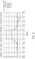
- FIG. 3is a graphical representation of variably augmenting a flowrate of a disbursement system as a function of aircraft velocity in accordance with an embodiment of the present disclosure.
- FIG. 4is a representative view of a UAV with inherent uniformity errors due to pitching dynamics in accordance with an embodiment of the present disclosure.
- FIG. 5is a graphical representation of application rates with various levels of pitch augmentation in accordance with an embodiment of the present disclosure.
- FIG. 6is a representative view of a UAV with inherent uniformity errors due to yaw dynamics in accordance with an embodiment of the present disclosure.
- FIG. 6Ais a representative view of a UAV with a positive yaw disturbance in accordance with an embodiment of the present disclosure.
- FIG. 6Bis a representative view of a UAV with inherent uniformity errors due to non-rectilinear spray areas in accordance with an embodiment of the present disclosure.
- FIG. 7is a representative view of a UAV with inherent uniformity errors due to roll dynamics in accordance with an embodiment of the present disclosure.
- the present disclosuregenerally provides a disbursement system for a UAV that provides more uniform coverage of an agricultural product through the use of higher fidelity modeling and control of the variables that present non-uniform delivery in aerial spray applications.
- the disbursement systemcan be used in a variety of applications, for example, dispersing an agricultural product over a defined space, or the like.
- the disbursement systemintegrates a control system having a plurality of sensors operable to monitor a plurality of flight parameters (e.g., position and trajectory) to control the disbursement of the agricultural product.
- the disbursement systemfunctions to achieve substantial uniformity of the agricultural product over the defined space by modulating the disbursement of the agricultural product based on in-flight data received from the plurality of sensors.
- disbursement system of the present disclosuremay dispense substantially any type of product or chemical, whether liquid, powder, or granular, including but not limited to weed killer, fertilizer, fire retardant, and any other agricultural or non-agricultural substance.
- a helicopter UAV 100generally includes a frame structure 102 to which a main rotor assembly 104 having a plurality of main rotor blades 106 (e.g., two main rotor blades 106 ) is rotatably attached at a first rotational axis R 1 .
- a tail boom 108is connected to the frame structure 102 to locate a tail rotor assembly 110 having a plurality of tail rotor blades 112 (e.g., two tail rotor blades 112 ) a distance away from the first rotational axis R 1 of the main rotor assembly 104 .
- the tail boom 108includes a proximal end 114 and a distal end 116 .
- the proximal end 114 of the tail boom 108is connected to the frame structure 102 (e.g., a rear portion of the frame structure 102 ) and the tail rotor assembly 110 is rotatably attached to the distal end 116 of the tail boom 108 at a second rotational axis R 2 , which may be orthogonally positioned relative to the first rotational axis R 1 .
- the main rotor assembly 104is horizontally-mounted to the UAV 100 to provide vertical lift upon rotation of the main rotor assembly 104 about the first rotational axis R 1 .
- the main rotor assembly 104may also provide pitching and rolling capability to the UAV 100 .
- the tail rotor assembly 110is vertically-mounted to the distal end 116 of the tail boom 108 to provide horizontal thrust upon rotation of the tail rotor assembly 110 about the second rotational axis R 2 .
- the horizontal thrust provided by the tail rotor assembly 110controls the rotational position (i.e., yaw) of the UAV 100 by, for example, counteracting the torque created by rotation of the main rotor assembly 104 .
- the tail boom 108may include a vertical stabilizer 118 to prevent the tail rotor assembly 110 from touching a support surface (e.g., the ground) during landing or ground operation of the UAV 100 .
- the vertical stabilizer 118may support the UAV 100 against the support surface during non-flight operation and/or storage. Additionally or alternatively, the vertical stabilizer 118 may help or otherwise allow the UAV 100 to “weathervane” into the direction of motion during flight.
- the UAV 100includes a drive system 120 to cause flight of the UAV 100 .
- the drive system 120includes a powertrain, the main rotor assembly 104 , and the tail rotor assembly 110 .
- the powertrainincludes a motor (e.g., an electric motor) and a gearing assembly to respectively generate power and deliver it to the main rotor assembly 104 and/or the tail rotor assembly 110 .
- the gearing assemblywhich converts and/or translates the energy (e.g., rotation) of the motor into the rotation required to drive the main rotor assembly 104 and/or the tail rotor assembly 110 , may include a set of meshingly engaged mechanical gearboxes and/or an electromagnetic transmission. Through the set of mechanical gearboxes and/or the electromagnetic transmission, the gearing assembly directs the power generated by the motor to both the main rotor assembly 104 and the tail rotor assembly 110 . In some embodiments, however, the tail rotor assembly 110 may be driven by a secondary powertrain located substantially within the tail boom 108 .
- the UAV 100includes a power source (e.g., a battery pack) to power the motor during flight operation.
- the power sourcemay be rechargeable through connection with DC and/or AC voltage sources. Additionally or alternatively, the power source may recharge through one or more solar panels connected to the UAV 100 .
- portions of the drive system 120may be received within the frame structure 102 to conserve space and protect the individual components of the drive system 120 .
- the UAV 100is equipped with a disbursement system 130 operable to disburse a flowable product or substance (e.g., an agricultural product) at variable flowrates, which may be measured in units per linear measurement.
- the disbursement system 130may include a spray rig 132 attached to the frame structure 102 .
- the spray rig 132may extend laterally from the frame structure 102 such that the spray rig 132 does not contact the support surface during non-flight operation or storage.
- a plurality of disbursement nozzles 134may be attached to the spray rig 132 .
- the agricultural productwhich may be a liquid, a powder, or a granular substance, may be sprayed by the disbursement nozzles 134 as the UAV 100 traverses aerially over a defined space or spray area 136 (see FIG. 6 , for instance).
- Each disbursement nozzle 134may disburse the agricultural product in a constant or variable spray pattern or flow.
- the disbursement system 130and more specifically the disbursement nozzles 134 , may be modulated or controlled by a flow controller 138 (e.g., a variable rate pump system) to achieve substantial uniformity of coverage of the agricultural product over the defined space or spray area 136 (see FIG. 2 ).
- the flow controller 138may be responsive to instructions and may be operable to regulate a volume of the agricultural product dispensed by the disbursement system 130 (e.g., the disbursement nozzles 134 ). Although described with reference to disbursement nozzles 134 , substantially any type of disbursement mechanism is contemplated.
- the UAV 100may be equipped with a control system 140 to both monitor flight parameters and ambient conditions and control the disbursement system 130 during at least in-flight operation.
- the control system 140 of one exemplary embodimentincludes a processing unit 142 , and a plurality of sensors 144 for monitoring position, trajectory, and other flight parameters of the UAV 100 .
- the sensors 144may monitor aircraft position and velocity as well as other measurable and inertial navigation parameters to provide augmentation to the disbursement system 130 .
- sensors 144may monitor aircraft altitude, wind vectors, and/or acceleration of the main rotor assembly 104 to account for at least rotor wash created by the UAV 100 within flow control instructions, as detailed below.
- the data received by each of the sensors 144may be passed to the processing unit 142 to calculate the necessary flowrate output from the disbursement system 130 based upon a mathematical function modeled for the UAV 100 .
- the processing unit 142may model an effect of the monitored flight parameters on first flow control instructions 146 corresponding to a prescription coverage 148 of the agricultural product and calculate and output modulated flow control instructions 150 to the disbursement system 130 (e.g., the flow controller 138 ).
- the control system 140may alter or otherwise modulate the first flow control instructions 146 to change the flowrate of one or more of the disbursement nozzles 134 , either collectively or individually, to achieve an actual coverage of the agricultural product that is closer to the prescription coverage 148 than would have been achieved without the modulated flow control instructions 150 .
- the actual coverageis more uniform compared to a prospective coverage resulting from the first flow control instructions 146 .
- the control system 140is capable to modulate the flowrate of the disbursement system 130 to achieve substantial uniformity of coverage based on real-time data received from the sensors 144 .
- the control system 140can be implemented using standardized control methodologies including dynamic inversion, classical feedback control, and/or more advanced modern control formulations by driving spray errors to approach zero based upon the prescription coverage 148 or spray map that is normalized for the particular topography of the area to be sprayed.
- augmentation of the flowratemay achieve a substantially uniform application of the agricultural product per linear measurement of the area over which the agricultural product is being dispersed.
- FIG. 2One method to modulate the flowrate of the disbursement system 130 is schematically shown in FIG. 2 .
- the prescription coverage 148that is normalized for the particular topography of the spray area 136 to be sprayed is passed to the control system 140 (e.g., the processing unit 142 ).
- the prescription coverage 148provides a flowrate baseline as a function of horizontal position (i.e., x-y position) of the UAV 100 .
- the prescription coverage 148is not vehicle specific nor does it account for ambient conditions or vehicle dynamics.
- a vehicle dynamics module 160is configured to pass the aircraft navigation parameters such as position, velocity, acceleration, angular acceleration, attitude angles, and altitude monitored by the plurality of sensors 144 of the control system 140 to the processing unit 142 for further processing therein.
- a vehicle configuration module 162provides vehicle specific data (e.g., number of disbursement nozzles 134 , size and position of spray rig 132 , and/or disbursing capabilities of the disbursement system 130 ) to the processing unit 142 .
- This modelcan increase in fidelity by introducing more modeled effects and their respective parameter measurements.
- the respective constantse.g., K Ax , K Ay , etc.
- K Ayrepresents the change in flowrate due to lateral acceleration of the vehicle (Ay) required by the disbursement system 130 (e.g., the flow controller 138 ) to achieve the prescribed flowrate on the spray area 136 to be treated.
- these constantsmay be the first derivative of the flowrate with respect to the subscript parameter denoted.
- the form and value of the constantscan be determined through theoretical and physical formulation, through test data regression and statistical methods, and in some cases, their value does not need to be determined, but rather the determination that an effect is present that can be controlled using simple controllers with feedback from an available parameter in the state estimate.
- “simple”is defined as a dynamic system that can be effectively controlled using controllers that can be reasonably hand-tuned through trial and error.
- the control system 140controls the disbursement system 130 (e.g., the flow controller 138 , which may be a variable rate flow control pump) to match the required flowrate FR.
- Controlis provided through communication between the control system 140 (e.g., the processing unit 142 ) and a pump or other liquid or granular disbursement mechanism that is calibrated for a certain range of flowrates.
- Common electronics communication strategiescan be used to communicate between the processing unit 142 and the disbursement mechanism to include serial digital communication, analog communication, pulse width modulation communication, among others.
- Full duplex communicationssuch as that provided by RS 422 or RS 485 physical layers, can be useful when feedback from the pump(s) is desired. For instance, in an example where individual nozzle control is achieved through the modulation of individual pumps for each disbursement nozzle 134 . In such embodiments, full duplex and single bus communications may be desired to reduce wire weight and complexity by controlling all pumps and/or disbursement nozzles 134 , while simultaneously receiving sensor data on a single communication cable.
- the control system 140may account for flight parameters, as noted above, in calculating the required flowrate FR necessary to achieve substantial uniformity in coverage of the agricultural product over the area to be sprayed. For example, to achieve uniformity in coverage, the control system 140 may selectively vary the output of the disbursement system 130 (e.g., the flow controller 138 ) based on, for instance, aircraft velocity. Without accounting for aircraft velocity, non-uniformity in coverage may be present due to variations in the velocity of the UAV 100 . As shown in FIG. 3 , as the velocity of the UAV 100 increases, the control system 140 may increase the flowrate FR of the disbursement system 130 to account for the increased surface area covered per measurement of time. In like manner, as the velocity of the UAV 100 decreases, the control system 140 may correspondingly decrease the flowrate FR of the disbursement system 130 as less surface area is covered per measurement of time.
- the control system 140may account for flight parameters, as noted above, in calculating the required flowrate FR necessary to achieve substantial uniformity
- control system 140may account for environmental parameters, such as prevailing wind conditions. For example, a tailwind may produce a spray pattern corresponding to a higher velocity of the UAV 100 . Similarly, a headwind may produce a spray pattern corresponding to a lower velocity of the UAV 100 . To account for such errors, the control system 140 may calculate a net velocity of the UAV 100 based on both the velocity of the UAV 100 and the environmental parameters.
- the control system 140may account for vehicle specific data, as noted above, in calculating the required flowrate FR.
- the disbursement nozzles 134are located forward and below the center of gravity CG of the UAV 100 . Without accounting for the position of the disbursement nozzles 134 relative to the center of gravity CG of the UAV 100 , non-uniformity in coverage may be present due to at least pitching dynamics of the UAV 100 during flight.
- the rate of change of X resulting from the change in pitch angle ⁇i.e. X′
- X′h ⁇ (1/Cos ⁇ ) 2 ⁇ q, where q is equal to the first derivative of pitch angle ⁇ , or pitch rate.
- the pitch rate qmay be negative during controlled acceleration, up-righting, and/or the second phase of braking of the UAV 100 .
- the pitch rate qmay be positive during the end of acceleration or during an initial braking phase of the UAV 100 .
- the pitch rate qcan be measured directly with a rate gyro associated with the UAV 100 .
- both the pitch angle ⁇ and the pitch rate qmay be outputs measured directly from a flight control system 140 of the UAV 100 .
- X′is directly related to non-uniformity of coverage as a result of pitching dynamics.
- the application rate of the agricultural product dispensed by the disbursement system 130may vary depending on the pitch augmentation K used to account for non-uniformity of coverage as a result of pitching dynamics. As shown in FIG. 5 , different levels of pitch augmentation K causes the application rate to change from highly variable to relatively uniform. For example, the application rate of the agricultural product without any pitch augmentation K is highly variable and non-uniform, whereas higher levels of pitch augmentation K increase the sensitivity of the disbursement system 130 to account for pitch dynamics.
- the control system 140may account for yaw dynamics of the UAV 100 during in-flight operation.
- the yaw rate r of the UAV 100i.e., the rate of change of heading angle
- the spray area 136is rectangular, although the principles described may apply equally to other geometric shapes and a spherical volume, such as a tree, that is to be uniformly sprayed. As shown in FIG.
- a positive or negative yaw rate or disturbance rmay be applied to the UAV 100 by, for example, wind disturbances imparted to the UAV 100 .
- a positive yaw rate rmay be applied to the UAV 100 such that the right side of the spray rig 132 swings aft and the left side of the spray rig 132 swings forward with respect to the flight direction F (see FIG. 6A ).
- the right side of the spray area 136would receive an abundance of agricultural product over that which was prescribed, and the left side of the spray area 136 would receive less agricultural product than was prescribed, thus resulting in a non-uniform coverage of the spray area 136 .
- individual disbursement nozzles 134may be controlled at differing rates to achieve uniform coverage without spraying areas outside the spray area 136 itself.
- a positive yaw disturbance rcauses the left side of the spray area 136 to be increasingly undersprayed, the increasingly undersprayed portion getting larger the further away from a center of the spray rig 132 .
- the right side of the spray area 136receives too much agricultural product, more so at the extents of the spray rig 132 than towards the center.
- the control system 140may calculate and output modulated flow control instructions 150 that individually control each disbursement nozzle 134 to account for yaw disturbance r of the UAV 100 . For instance, in the positive yaw disturbance example shown in FIG.
- the control system 140may augment the disbursement system 130 such that the flow controller 138 causes the disbursement nozzles 134 to flow at decreasing rates from the left side of the spray rig 132 to the right side of the spray rig 132 to create a uniform spray pattern in the presence of a positive yaw disturbance r.
- the rate of change of the individual flowrates of the disbursement nozzles 134 from left to rightmay vary depending on the degree of positive yaw disturbance r. For example, a sufficiently high yaw disturbance r may cause the rate of change of individual flowrates across the spray rig 132 to be relatively steep or large. On the other hand, a relatively small yaw disturbance r may cause the rate of change of individual flowrates across the spray rig 132 to be flat or small.
- the control system 140may be operable to augment the disbursement nozzles 134 , either collectively or individually, to efficiently place or distribute the agricultural product over a non-rectilinear spray area 136 , thus resulting in significantly more uniform coverage of the agricultural product over the spray area 136 .
- each of the disbursement nozzles 134may be individually controlled, such as by the modulated flow control instructions 150 , to alter the flowrate FR to achieve more accurate placement or distribution of the agricultural product over and/or within a circular spray area 136 .
- the control system 140may allow the innermost disbursement nozzles 134 to flow first.
- the control system 140may turn on outer disbursement nozzles 134 in a cascading fashion such that the entire spray area 136 can be covered without unnecessarily turning on the disbursement nozzles 134 too early. Similarly, as the UAV 100 finishes passing over the spray area 136 , the control system 140 may turn off the disbursement nozzles 134 in a cascading fashion from outermost disbursement nozzle 134 to innermost disbursement nozzle 134 . In the embodiment of FIG. 6B , the control system 140 may additionally account for other sources of uniformity errors, such as yaw and pitch dynamics, as explained above, and roll dynamics, as explained below.
- the principles described hereinmay apply equally to non-flat surface anomalies, such as a mound or gulley, that is to be uniformly sprayed.
- the non-flat surface anomaliescan be parameterized and accounted for to modulate the flowrate FR.
- the control system 140may account for the increased surface area of the mound such that the disbursement system 130 automatically applies more agricultural product to compensate for the additional surface area.
- the control system 140may modulate the flowrate FR of the disbursement system 130 to account for undulating terrain as well as other non-flat surface anomalies such as trees.
- the control system 140may account for roll dynamics of the UAV 100 during in-flight operation.
- the roll rate p of the UAV 100i.e., the rate of change of the UAV 100 about its longitudinal axis
- the roll rate p of the UAV 100can be used to modulate flow of the disbursement system 130 .
- a positive or negative roll rate pmay be applied to the UAV 100 by, for example, undulating terrain or wind disturbances applying lateral forces to the vertical stabilizer 118 to cause the UAV 100 to rotate about the tail boom 108 .
- a positive roll rate pmay be applied to the UAV 100 such that the right side of the spray rig 132 swings up and the left side of the spray rig 132 swings down with respect to a horizontal plane parallel to the spray area 136 .
- the control system 140may augment the disbursement system 130 such that the disbursement nozzles 134 flow at decreasing rates to create a uniform spray pattern in the presence of the roll disturbance p.
- the control system 140may augment the disbursement system 130 based on the rotor speed of the main rotor assembly 104 and/or the tail rotor assembly 110 .
- the airflow created by the main rotor assembly 104 and/or the tail rotor assembly 110can be modeled and used to quantify the flight dynamics effect on how the agricultural product is carried to the ground (i.e., the resultant trajectory of the agricultural product). For example, a positive pitch angle ⁇ may propel the agricultural product forward a greater amount due to the airflow created by the main rotor assembly 104 .
- airflow disturbance caused by the tail rotor assembly 110may propel the agricultural product laterally away from the UAV 100 , all other variables being constant.
- augmentation of the disbursement system 130 by the control system 140can be utilized to cancel such effects.
- the concepts disclosed hereincan be used to collect and record data required to analyze and model “as applied” coverage as compared to “as prescribed” coverage. For example, if it were known that because the UAV 100 rolled to a bank angle of 9 degrees for a 1.2 second period without accelerating in any axis, and the effective change in flowrate at a point that is to have zero spray was negative, then the indication is that too much product will land on an area that is to be unsprayed.
- the combined flowrate and aircraft navigation and sensor datacan also be utilized for recordkeeping and evidence of “as applied” disbursement.
- the terrain over which the agricultural product is to be sprayedcan be modeled from photography, ground samples, color, temperature, or any other surface parameter. Sensing of the terrain can take place before application of the agricultural product or can occur simultaneously with product application.
- the UAV 100may model the terrain using accessory equipment 164 attached to the UAV 100 (e.g., through a Nadir mounted DSLR high resolution camera and/or a fully stabilized camera gimbal having electro-optical and/or infrared sensors) (see FIG. 1 ).
- the accessory equipment 164may provide other aviation uses, including, for example, aerial surveillance, inspection, surveying, 3D mapping, photography, and filmmaking. The examples given above, however, are not limiting, and it is contemplated that substantially any type of accessory may be attached to the UAV 100 .
- the UAV 100may include additional components to improve the functionality and capabilities of the UAV 100 .
- the UAV 100may include a canopy 166 attached to the frame structure 102 to improve both the aesthetic and aerodynamic characteristics of the UAV 100 .
- the canopy 166hides or otherwise conceals the internal components of the UAV 100 .
- the UAV 100may include landing gear 168 to support the UAV 100 during non-flight operation or storage.
- the landing gear 168which may include planar or tubular landing skids, is attached to the frame structure 102 (e.g., to opposing sides of the frame structure 102 ).
- the landing skidsmay be the only portion of the UAV 100 touching the support surface, or alternatively support the UAV 100 in a tripod-like manner with the vertical stabilizer 118 .
- the UAV 100may be equipped with communication equipment.
- the UAV 100may be controlled by a hand-held remote control unit or ground station.
- the UAV 100may include an automatic flight control system capable of precise navigation, guidance, and control of the UAV 100 without user intervention.
- the UAV 100may transfer data to, or receive data from, a user, a ground station, and/or other UAV 100 s through Wi-Fi, cellular data, mobile satellite communications, radio frequency, infrared or ultrasonic remote control devices, or any other wireless data communication mediums.
Landscapes
- Engineering & Computer Science (AREA)
- Aviation & Aerospace Engineering (AREA)
- Life Sciences & Earth Sciences (AREA)
- Pest Control & Pesticides (AREA)
- Mechanical Engineering (AREA)
- Remote Sensing (AREA)
- Physics & Mathematics (AREA)
- General Physics & Mathematics (AREA)
- Automation & Control Theory (AREA)
- Catching Or Destruction (AREA)
- Control Of Position, Course, Altitude, Or Attitude Of Moving Bodies (AREA)
- Toys (AREA)
Abstract
Description
ΔFR=KAxAx+KAyAy+KAzAz+Kφφ+Kθθ+Kψψ+KDLDL+Kxx+Kyy+Kzz . . . .
This model can increase in fidelity by introducing more modeled effects and their respective parameter measurements. In the equations above, the respective constants (e.g., KAx, KAy, etc.) represent the amount of change in flow rate due to influence of the parameter denoted by the parameter's subscript. For example, KAyrepresents the change in flowrate due to lateral acceleration of the vehicle (Ay) required by the disbursement system130 (e.g., the flow controller138) to achieve the prescribed flowrate on the
Claims (20)
Priority Applications (1)
| Application Number | Priority Date | Filing Date | Title |
|---|---|---|---|
| US15/773,074US11130573B2 (en) | 2015-11-02 | 2016-11-02 | Disbursement system for an unmanned aerial vehicle |
Applications Claiming Priority (3)
| Application Number | Priority Date | Filing Date | Title |
|---|---|---|---|
| US201562285023P | 2015-11-02 | 2015-11-02 | |
| PCT/US2016/060172WO2017079340A1 (en) | 2015-11-02 | 2016-11-02 | Disbursement system for an unmanned aerial vehicle |
| US15/773,074US11130573B2 (en) | 2015-11-02 | 2016-11-02 | Disbursement system for an unmanned aerial vehicle |
Related Parent Applications (1)
| Application Number | Title | Priority Date | Filing Date |
|---|---|---|---|
| PCT/US2016/060172A-371-Of-InternationalWO2017079340A1 (en) | 2015-11-02 | 2016-11-02 | Disbursement system for an unmanned aerial vehicle |
Related Child Applications (1)
| Application Number | Title | Priority Date | Filing Date |
|---|---|---|---|
| US17/471,797ContinuationUS11338921B2 (en) | 2015-11-02 | 2021-09-10 | Disbursement system for an unmanned aerial vehicle |
Publications (2)
| Publication Number | Publication Date |
|---|---|
| US20180319499A1 US20180319499A1 (en) | 2018-11-08 |
| US11130573B2true US11130573B2 (en) | 2021-09-28 |
Family
ID=57530805
Family Applications (2)
| Application Number | Title | Priority Date | Filing Date |
|---|---|---|---|
| US15/773,074Active2038-06-02US11130573B2 (en) | 2015-11-02 | 2016-11-02 | Disbursement system for an unmanned aerial vehicle |
| US17/471,797ActiveUS11338921B2 (en) | 2015-11-02 | 2021-09-10 | Disbursement system for an unmanned aerial vehicle |
Family Applications After (1)
| Application Number | Title | Priority Date | Filing Date |
|---|---|---|---|
| US17/471,797ActiveUS11338921B2 (en) | 2015-11-02 | 2021-09-10 | Disbursement system for an unmanned aerial vehicle |
Country Status (9)
| Country | Link |
|---|---|
| US (2) | US11130573B2 (en) |
| EP (2) | EP3371051B1 (en) |
| JP (2) | JP6647535B2 (en) |
| KR (2) | KR102164101B1 (en) |
| CN (2) | CN114476073B (en) |
| AU (2) | AU2016349902B2 (en) |
| ES (2) | ES2934128T3 (en) |
| NZ (1) | NZ742375A (en) |
| WO (1) | WO2017079340A1 (en) |
Cited By (4)
| Publication number | Priority date | Publication date | Assignee | Title |
|---|---|---|---|---|
| US20210271266A1 (en)* | 2018-02-13 | 2021-09-02 | Guangzhou Xaircraft Technology Co., Ltd. | Flight attitude control method and apparatus, and flight control system |
| US11470784B2 (en)* | 2017-03-21 | 2022-10-18 | Paul Richard GAUVREAU, Jr. | Unmanned aerial vehicle for augmenting plant pollination |
| US20230150665A1 (en)* | 2021-11-18 | 2023-05-18 | SQ Technology (Shanghai) Corporation | Automatic Spraying Unmanned Aerial Vehicle System Based on Dynamic Adjustment of Early Warning Range, and Method Thereof |
| US12162028B2 (en) | 2020-03-13 | 2024-12-10 | Precision Drone Services Intellectual Property, Llc | Air assist spray assembly |
Families Citing this family (21)
| Publication number | Priority date | Publication date | Assignee | Title |
|---|---|---|---|---|
| CN112829945B (en)* | 2016-11-24 | 2023-01-20 | 深圳市大疆创新科技有限公司 | Agricultural unmanned aerial vehicle and spraying control method thereof |
| EP3455133B1 (en)* | 2017-03-03 | 2021-10-13 | SZ DJI Technology Co., Ltd. | Windproof aerial dispensing method and system |
| EP3378306A1 (en)* | 2017-03-24 | 2018-09-26 | Bayer Aktiengesellschaft | Drift correction in the distribution of plant protection agents |
| CN107333739A (en)* | 2017-06-22 | 2017-11-10 | 深圳市雷凌广通技术研发有限公司 | A kind of Intelligent unattended machine for being used to trim sprinkling |
| EP3651575A1 (en)* | 2017-07-10 | 2020-05-20 | AgroFly SA | System and method for selectively spreading active products in the field of agricultural and wine-growing |
| US11021250B2 (en)* | 2017-09-20 | 2021-06-01 | Kenneth Heck | Airborne fire extinguishing system with infrared imaging and method |
| CN107494499A (en)* | 2017-09-22 | 2017-12-22 | 常州有恒智能装备科技有限公司 | Unmanned plane pesticide spraying control system |
| US10779458B2 (en)* | 2017-12-01 | 2020-09-22 | International Business Machines Corporation | Monitoring aerial application tasks and recommending corrective actions |
| CN107980753A (en)* | 2017-12-10 | 2018-05-04 | 张红彬 | A kind of intelligence unmanned plane pesticide spraying device |
| JP6569050B2 (en)* | 2018-01-18 | 2019-09-04 | 株式会社プロドローン | Unmanned aerial vehicle for aerial application, external device, control program, and aerial application method |
| CN108477109B (en)* | 2018-01-24 | 2020-10-09 | 倪惠芳 | A UAV-based Crop Disease and Insect Pest Control Equipment |
| JP7176785B2 (en)* | 2018-12-27 | 2022-11-22 | 株式会社ナイルワークス | Drone, drone control method, and drone control program |
| CN109508041A (en)* | 2019-01-21 | 2019-03-22 | 梁晓龙 | Plant protection drone group system and plant protection method |
| PL3914514T3 (en)* | 2019-01-21 | 2023-12-27 | Bayer Aktiengesellschaft | An aerial vehicle |
| CA3035225A1 (en)* | 2019-02-28 | 2020-08-28 | Daniel Mccann | System and method for field treatment and monitoring |
| EP3859480A4 (en)* | 2019-04-29 | 2021-11-24 | SZ DJI Technology Co., Ltd. | METHOD OF CONTROLLING AN UNMANNED AIRCRAFT, DEVICE AND SPRAY SYSTEM AND UNMANNED AIRCRAFT AND STORAGE MEDIUM |
| KR102228221B1 (en)* | 2019-12-17 | 2021-03-18 | 전북대학교산학협력단 | Agricultural drone |
| US12078992B2 (en)* | 2020-04-21 | 2024-09-03 | Pyka, Inc. | Unmanned aerial vehicle aerial spraying control |
| RU2754790C1 (en)* | 2021-03-22 | 2021-09-07 | Федеральное государственное бюджетное научное учреждение «Федеральный научный агроинженерный центр ВИМ» (ФГБНУ ФНАЦ ВИМ) | Unmanned helicopter for the application of pesticides, fertilizers and other agrochemicals in precision farming |
| DE102021001701A1 (en) | 2021-04-01 | 2022-10-06 | Airial Robotics GmbH | Unmanned aircraft for agricultural spraying operations with a high payload-to-weight ratio |
| WO2024074704A1 (en)* | 2022-10-06 | 2024-04-11 | Basf Agro Trademarks Gmbh | Measuring spray patterns of individual nozzles for spot spraying and characterization by in spot and out spot behaviours (isos) |
Citations (31)
| Publication number | Priority date | Publication date | Assignee | Title |
|---|---|---|---|---|
| US4948050A (en) | 1989-02-06 | 1990-08-14 | Picot Jules J C | Liquid atomizing apparatus for aerial spraying |
| JPH0398668A (en) | 1989-09-08 | 1991-04-24 | Maruyama Mfg Co Ltd | Method for controlling sprinkling amount of chemical agent of chemical agent sprinkling vehicle |
| JPH08239099A (en) | 1995-03-06 | 1996-09-17 | Yamaha Motor Co Ltd | Battery judgment device |
| US5653389A (en) | 1995-09-15 | 1997-08-05 | Henderson; Graeme W. | Independent flow rate and droplet size control system and method for sprayer |
| US5716032A (en) | 1996-04-22 | 1998-02-10 | United States Of America As Represented By The Secretary Of The Army | Unmanned aerial vehicle automatic landing system |
| JPH10113589A (en) | 1996-10-07 | 1998-05-06 | Japan Aviation Electron Ind Ltd | Aerial spray device |
| US6087984A (en)* | 1998-05-04 | 2000-07-11 | Trimble Navigation Limited | GPS guidance system for use with circular cultivated agricultural fields |
| JP2002211494A (en) | 2001-01-17 | 2002-07-31 | Todaka Seisakusho:Kk | Flight scheduling device for unmanned helicopter |
| JP2004305805A (en) | 2003-04-02 | 2004-11-04 | Fuji Heavy Ind Ltd | Spray control device and control method of spray device |
| JP2005245372A (en) | 2004-03-08 | 2005-09-15 | Katsuhide Akutsu | Spraying device and spraying method using radio controlled helicopter |
| WO2005123503A1 (en) | 2004-06-20 | 2005-12-29 | Colin Pay | Injection variable rate chemical distribution |
| JP2006001485A (en) | 2004-06-21 | 2006-01-05 | Yanmar Co Ltd | Unmanned helicopter monitoring device |
| JP2007030544A (en) | 2005-07-22 | 2007-02-08 | Yanmar Agricult Equip Co Ltd | Aerial sprayer |
| US7640797B2 (en)* | 2005-03-17 | 2010-01-05 | Mississippi State University | Method and system for increasing safety in chemical application from an aircraft |
| WO2011152702A1 (en) | 2010-06-04 | 2011-12-08 | Universiti Malaysia Perlis | A flying apparatus for aerial agricultural application |
| CN102591302A (en) | 2012-03-05 | 2012-07-18 | 无锡汉和航空技术有限公司 | Operating method of spraying pesticides by unmanned aerial vehicle |
| CN102687711A (en) | 2012-06-05 | 2012-09-26 | 南京林业大学 | Electrostatic spraying type unmanned helicopter pesticide applying system |
| WO2013061563A1 (en) | 2011-10-24 | 2013-05-02 | 新明和工業株式会社 | Dispersal assistance apparatus and dispersal assistance method for aircraft |
| CN103777652A (en) | 2014-01-23 | 2014-05-07 | 南京模拟技术研究所 | Intelligent pesticide applying control system based on unmanned helicopter |
| DE202014002338U1 (en) | 2014-03-15 | 2014-05-14 | Volker Jung | Largely autonomous flying UAV helicopter drone for application of pesticides in agriculture, forestry and viticulture (up to a maximum take-off weight of 150kg) |
| JP2014113864A (en) | 2012-12-07 | 2014-06-26 | Hitachi Solutions Ltd | Spray support device |
| US20140303814A1 (en) | 2013-03-24 | 2014-10-09 | Bee Robotics Corporation | Aerial farm robot system for crop dusting, planting, fertilizing and other field jobs |
| CN104554725A (en) | 2014-11-18 | 2015-04-29 | 浙江大学 | Unmanned aerial vehicle capable of spraying variable amount of pesticide and method |
| US9110011B2 (en)* | 2011-07-25 | 2015-08-18 | Beijing Research Center For Information Technology In Agriculture | Remote measurement system and method for pesticide fog distribution and drifting tendency in aerial pesticide application |
| US9173337B2 (en)* | 2009-10-19 | 2015-11-03 | Efc Systems, Inc. | GNSS optimized control system and method |
| US9428272B2 (en)* | 2013-03-04 | 2016-08-30 | Michael Beaugavin Markov | Aerial material distribution method and apparatus |
| US9884330B2 (en)* | 2014-06-20 | 2018-02-06 | Deere & Company | Broadband spray nozzle systems and methods |
| US10266265B2 (en)* | 2015-06-01 | 2019-04-23 | SZ DJI Technology Co., Ltd. | Spraying system having a liquid flow and rotating speed feedback |
| US10303164B2 (en)* | 2014-08-18 | 2019-05-28 | Yamaha Hatsudoki Kabushiki Kaisha | Remote control device |
| US10400758B2 (en)* | 2015-06-01 | 2019-09-03 | SZ DJI Technology Co., Ltd. | Brushless pump motor system |
| US10772253B2 (en)* | 2014-12-10 | 2020-09-15 | The University Of Sydney | Automatic target recognition and dispensing system |
Family Cites Families (14)
| Publication number | Priority date | Publication date | Assignee | Title |
|---|---|---|---|---|
| US4299483A (en)* | 1979-11-13 | 1981-11-10 | Grove Thomas C | Path alignment apparatus |
| US6726120B2 (en)* | 2001-12-19 | 2004-04-27 | Deere & Company | Automatic wind-drift compensation system for agricultural sprayers |
| US7706926B2 (en)* | 2007-10-30 | 2010-04-27 | Agco Corporation | Adaptive feedback sources for application controllers |
| US8360561B2 (en)* | 2008-02-11 | 2013-01-29 | Hewlett-Packard Development Company, L.P. | Self-cleaning ink supply systems |
| KR101191815B1 (en)* | 2009-05-19 | 2012-10-16 | 이종표 | Spray of method and apparatus for agricultural chemicals |
| US8548649B2 (en)* | 2009-10-19 | 2013-10-01 | Agjunction Llc | GNSS optimized aircraft control system and method |
| US9046895B2 (en)* | 2009-12-30 | 2015-06-02 | Caterpillar Inc. | System and method for controlling fluid delivery |
| FR2979684B1 (en) | 2011-09-07 | 2014-08-08 | Commissariat Energie Atomique | DEVICE FOR RELATIVE MOVEMENT OF TWO PIECES UNDER DIFFERENTIAL PRESSURE |
| US9852644B2 (en)* | 2013-03-24 | 2017-12-26 | Bee Robotics Corporation | Hybrid airship-drone farm robot system for crop dusting, planting, fertilizing and other field jobs |
| CN203598980U (en)* | 2013-09-29 | 2014-05-21 | 常州中飞航空技术有限公司 | Pesticide spraying unmanned helicopter unit area spraying quantity controlling and adjusting system |
| KR101594313B1 (en)* | 2013-12-26 | 2016-02-16 | 한국항공대학교 산학협력단 | Multicopter system for crop-dusting |
| WO2015148883A1 (en)* | 2014-03-28 | 2015-10-01 | Schertz Aerial Service, Inc. | Spraying system and method |
| KR101617943B1 (en)* | 2014-06-05 | 2016-05-03 | 변정훈 | Drug injectors wide range |
| US9745060B2 (en)* | 2015-07-17 | 2017-08-29 | Topcon Positioning Systems, Inc. | Agricultural crop analysis drone |
- 2016
- 2016-11-02KRKR1020187015450Apatent/KR102164101B1/enactiveActive
- 2016-11-02EPEP16809224.5Apatent/EP3371051B1/enactiveActive
- 2016-11-02KRKR1020207015033Apatent/KR102297055B1/enactiveActive
- 2016-11-02AUAU2016349902Apatent/AU2016349902B2/enactiveActive
- 2016-11-02EPEP20161610.9Apatent/EP3705400B1/enactiveActive
- 2016-11-02NZNZ74237516Apatent/NZ742375A/enunknown
- 2016-11-02CNCN202210151416.8Apatent/CN114476073B/enactiveActive
- 2016-11-02WOPCT/US2016/060172patent/WO2017079340A1/ennot_activeCeased
- 2016-11-02USUS15/773,074patent/US11130573B2/enactiveActive
- 2016-11-02ESES20161610Tpatent/ES2934128T3/enactiveActive
- 2016-11-02JPJP2018543029Apatent/JP6647535B2/enactiveActive
- 2016-11-02CNCN201680075735.8Apatent/CN108473203B/enactiveActive
- 2016-11-02ESES16809224Tpatent/ES2796341T3/enactiveActive
- 2019
- 2019-12-16JPJP2019226886Apatent/JP6921927B2/enactiveActive
- 2020
- 2020-02-05AUAU2020200833Apatent/AU2020200833B2/enactiveActive
- 2021
- 2021-09-10USUS17/471,797patent/US11338921B2/enactiveActive
Patent Citations (33)
| Publication number | Priority date | Publication date | Assignee | Title |
|---|---|---|---|---|
| US4948050A (en) | 1989-02-06 | 1990-08-14 | Picot Jules J C | Liquid atomizing apparatus for aerial spraying |
| JPH0398668A (en) | 1989-09-08 | 1991-04-24 | Maruyama Mfg Co Ltd | Method for controlling sprinkling amount of chemical agent of chemical agent sprinkling vehicle |
| JPH08239099A (en) | 1995-03-06 | 1996-09-17 | Yamaha Motor Co Ltd | Battery judgment device |
| US5653389A (en) | 1995-09-15 | 1997-08-05 | Henderson; Graeme W. | Independent flow rate and droplet size control system and method for sprayer |
| US5716032A (en) | 1996-04-22 | 1998-02-10 | United States Of America As Represented By The Secretary Of The Army | Unmanned aerial vehicle automatic landing system |
| JPH10113589A (en) | 1996-10-07 | 1998-05-06 | Japan Aviation Electron Ind Ltd | Aerial spray device |
| US6087984A (en)* | 1998-05-04 | 2000-07-11 | Trimble Navigation Limited | GPS guidance system for use with circular cultivated agricultural fields |
| JP2002211494A (en) | 2001-01-17 | 2002-07-31 | Todaka Seisakusho:Kk | Flight scheduling device for unmanned helicopter |
| JP2004305805A (en) | 2003-04-02 | 2004-11-04 | Fuji Heavy Ind Ltd | Spray control device and control method of spray device |
| JP2005245372A (en) | 2004-03-08 | 2005-09-15 | Katsuhide Akutsu | Spraying device and spraying method using radio controlled helicopter |
| WO2005123503A1 (en) | 2004-06-20 | 2005-12-29 | Colin Pay | Injection variable rate chemical distribution |
| JP2006001485A (en) | 2004-06-21 | 2006-01-05 | Yanmar Co Ltd | Unmanned helicopter monitoring device |
| US7640797B2 (en)* | 2005-03-17 | 2010-01-05 | Mississippi State University | Method and system for increasing safety in chemical application from an aircraft |
| JP2007030544A (en) | 2005-07-22 | 2007-02-08 | Yanmar Agricult Equip Co Ltd | Aerial sprayer |
| US9173337B2 (en)* | 2009-10-19 | 2015-11-03 | Efc Systems, Inc. | GNSS optimized control system and method |
| WO2011152702A1 (en) | 2010-06-04 | 2011-12-08 | Universiti Malaysia Perlis | A flying apparatus for aerial agricultural application |
| US20130068892A1 (en)* | 2010-06-04 | 2013-03-21 | Hazry Bin Desa | Flying apparatus for aerial agricultural application |
| US9110011B2 (en)* | 2011-07-25 | 2015-08-18 | Beijing Research Center For Information Technology In Agriculture | Remote measurement system and method for pesticide fog distribution and drifting tendency in aerial pesticide application |
| WO2013061563A1 (en) | 2011-10-24 | 2013-05-02 | 新明和工業株式会社 | Dispersal assistance apparatus and dispersal assistance method for aircraft |
| CN102591302A (en) | 2012-03-05 | 2012-07-18 | 无锡汉和航空技术有限公司 | Operating method of spraying pesticides by unmanned aerial vehicle |
| CN102687711A (en) | 2012-06-05 | 2012-09-26 | 南京林业大学 | Electrostatic spraying type unmanned helicopter pesticide applying system |
| JP2014113864A (en) | 2012-12-07 | 2014-06-26 | Hitachi Solutions Ltd | Spray support device |
| US9428272B2 (en)* | 2013-03-04 | 2016-08-30 | Michael Beaugavin Markov | Aerial material distribution method and apparatus |
| US20140303814A1 (en) | 2013-03-24 | 2014-10-09 | Bee Robotics Corporation | Aerial farm robot system for crop dusting, planting, fertilizing and other field jobs |
| US9382003B2 (en)* | 2013-03-24 | 2016-07-05 | Bee Robotics Corporation | Aerial farm robot system for crop dusting, planting, fertilizing and other field jobs |
| CN103777652A (en) | 2014-01-23 | 2014-05-07 | 南京模拟技术研究所 | Intelligent pesticide applying control system based on unmanned helicopter |
| DE202014002338U1 (en) | 2014-03-15 | 2014-05-14 | Volker Jung | Largely autonomous flying UAV helicopter drone for application of pesticides in agriculture, forestry and viticulture (up to a maximum take-off weight of 150kg) |
| US9884330B2 (en)* | 2014-06-20 | 2018-02-06 | Deere & Company | Broadband spray nozzle systems and methods |
| US10303164B2 (en)* | 2014-08-18 | 2019-05-28 | Yamaha Hatsudoki Kabushiki Kaisha | Remote control device |
| CN104554725A (en) | 2014-11-18 | 2015-04-29 | 浙江大学 | Unmanned aerial vehicle capable of spraying variable amount of pesticide and method |
| US10772253B2 (en)* | 2014-12-10 | 2020-09-15 | The University Of Sydney | Automatic target recognition and dispensing system |
| US10266265B2 (en)* | 2015-06-01 | 2019-04-23 | SZ DJI Technology Co., Ltd. | Spraying system having a liquid flow and rotating speed feedback |
| US10400758B2 (en)* | 2015-06-01 | 2019-09-03 | SZ DJI Technology Co., Ltd. | Brushless pump motor system |
Non-Patent Citations (5)
| Title |
|---|
| "Extended European Search Report dated Aug. 7, 2020", for European Application No. 20161610, 9 pages. |
| International Search Report and Written Opinion of the International Searching Authority for International Application No. PCT/US2016/060172, dated Feb. 27, 2017 (11 pages). |
| JPO, "NFOA", App. No. 2019-226886, dated Dec. 23, 2020, 5 pages. |
| JPO, "Non-Final Office Action", Application No. 2018-543029, dated May 14, 2019, 11 pages. |
| NIPA, "CN: NFOA & Search Report", App. No. 2016800757358, dated Nov. 3, 2020, 16 pages. |
Cited By (5)
| Publication number | Priority date | Publication date | Assignee | Title |
|---|---|---|---|---|
| US11470784B2 (en)* | 2017-03-21 | 2022-10-18 | Paul Richard GAUVREAU, Jr. | Unmanned aerial vehicle for augmenting plant pollination |
| US20210271266A1 (en)* | 2018-02-13 | 2021-09-02 | Guangzhou Xaircraft Technology Co., Ltd. | Flight attitude control method and apparatus, and flight control system |
| US12162028B2 (en) | 2020-03-13 | 2024-12-10 | Precision Drone Services Intellectual Property, Llc | Air assist spray assembly |
| US20230150665A1 (en)* | 2021-11-18 | 2023-05-18 | SQ Technology (Shanghai) Corporation | Automatic Spraying Unmanned Aerial Vehicle System Based on Dynamic Adjustment of Early Warning Range, and Method Thereof |
| US11858635B2 (en)* | 2021-11-18 | 2024-01-02 | SQ Technology (Shanghai) Corporation | Automatic spraying unmanned aerial vehicle system based on dynamic adjustment of early warning range, and method thereof |
Also Published As
| Publication number | Publication date |
|---|---|
| CN108473203A (en) | 2018-08-31 |
| AU2020200833A1 (en) | 2020-02-20 |
| CN114476073A (en) | 2022-05-13 |
| EP3371051B1 (en) | 2020-04-08 |
| WO2017079340A1 (en) | 2017-05-11 |
| EP3705400B1 (en) | 2022-09-28 |
| AU2020200833B2 (en) | 2022-05-12 |
| KR102164101B1 (en) | 2020-10-12 |
| KR20200062382A (en) | 2020-06-03 |
| AU2016349902A1 (en) | 2018-05-31 |
| AU2016349902B2 (en) | 2019-11-07 |
| US11338921B2 (en) | 2022-05-24 |
| US20180319499A1 (en) | 2018-11-08 |
| CN114476073B (en) | 2023-09-12 |
| EP3371051A1 (en) | 2018-09-12 |
| NZ742375A (en) | 2019-10-25 |
| KR20180103838A (en) | 2018-09-19 |
| ES2796341T3 (en) | 2020-11-26 |
| US20210403163A1 (en) | 2021-12-30 |
| EP3705400A1 (en) | 2020-09-09 |
| JP2018535698A (en) | 2018-12-06 |
| CN108473203B (en) | 2022-03-01 |
| JP2020059500A (en) | 2020-04-16 |
| JP6647535B2 (en) | 2020-02-14 |
| JP6921927B2 (en) | 2021-08-18 |
| ES2934128T3 (en) | 2023-02-17 |
| KR102297055B1 (en) | 2021-09-01 |
Similar Documents
| Publication | Publication Date | Title |
|---|---|---|
| US11338921B2 (en) | Disbursement system for an unmanned aerial vehicle | |
| US20220197309A1 (en) | Systems and methods for operating unmanned aerial vehicles | |
| US10266265B2 (en) | Spraying system having a liquid flow and rotating speed feedback | |
| US20190047694A1 (en) | Aerial platforms for aerial spraying and methods for controlling the same | |
| CN112357074B (en) | Pumping system and unmanned aerial vehicle | |
| US11726479B2 (en) | Unmanned aerial vehicle aerial spraying control | |
| JP2020508925A (en) | Windshield aerial spraying method and system | |
| JP6651682B1 (en) | Material distribution system and material distribution device | |
| WO2017134658A1 (en) | Aerial spraying assembly, and systems and methods for aerial spraying | |
| EP4620830A1 (en) | Wind detection system and unmanned aerial vehicle | |
| JP2019123415A (en) | Unmanned aircraft for aero spraying, external device, control program and aero spraying method | |
| Piljek et al. | Autonomous Aerial Robotic System for Smart Spraying Tasks: Potentials and Limitations | |
| WO2024142232A1 (en) | Unmanned aerial vehicle and method for controlling unmanned aerial vehicle |
Legal Events
| Date | Code | Title | Description |
|---|---|---|---|
| FEPP | Fee payment procedure | Free format text:ENTITY STATUS SET TO UNDISCOUNTED (ORIGINAL EVENT CODE: BIG.); ENTITY STATUS OF PATENT OWNER: LARGE ENTITY | |
| FEPP | Fee payment procedure | Free format text:ENTITY STATUS SET TO SMALL (ORIGINAL EVENT CODE: SMAL); ENTITY STATUS OF PATENT OWNER: LARGE ENTITY | |
| STPP | Information on status: patent application and granting procedure in general | Free format text:APPLICATION DISPATCHED FROM PREEXAM, NOT YET DOCKETED | |
| AS | Assignment | Owner name:PULSE AEROSPACE LLC, KANSAS Free format text:ASSIGNMENT OF ASSIGNORS INTEREST;ASSIGNORS:HOLLY, LANCE;DONOVAN, WILLIAM;LESSIG, AARON;SIGNING DATES FROM 20190514 TO 20190515;REEL/FRAME:049187/0943 Owner name:PULSE AEROSPACE LLC, KANSAS Free format text:ASSIGNMENT OF ASSIGNORS INTEREST;ASSIGNORS:HOLLY, LANCE;DONOVAN, WILLIAM;LESSIG, AARON;SIGNING DATES FROM 20190514 TO 20190515;REEL/FRAME:049188/0054 | |
| STPP | Information on status: patent application and granting procedure in general | Free format text:DOCKETED NEW CASE - READY FOR EXAMINATION | |
| AS | Assignment | Owner name:AEROVIRONMENT, INC., CALIFORNIA Free format text:ASSIGNMENT OF ASSIGNORS INTEREST;ASSIGNOR:PULSE AEROSPACE, LLC;REEL/FRAME:049953/0390 Effective date:20190731 Owner name:AEROVIRONMENT, INC., CALIFORNIA Free format text:ASSIGNMENT OF ASSIGNORS INTEREST;ASSIGNOR:PULSE AEROSPACE, LLC;REEL/FRAME:049953/0445 Effective date:20190731 | |
| STPP | Information on status: patent application and granting procedure in general | Free format text:NON FINAL ACTION MAILED | |
| AS | Assignment | Owner name:BANK OF AMERICA, N.A., AS ADMINISTRATIVE AGENT, TEXAS Free format text:NOTICE OF GRANT OF SECURITY INTEREST IN PATENTS;ASSIGNOR:AEROVIRONMENT, INC.;REEL/FRAME:055343/0926 Effective date:20210219 | |
| STPP | Information on status: patent application and granting procedure in general | Free format text:RESPONSE TO NON-FINAL OFFICE ACTION ENTERED AND FORWARDED TO EXAMINER | |
| STPP | Information on status: patent application and granting procedure in general | Free format text:NOTICE OF ALLOWANCE MAILED -- APPLICATION RECEIVED IN OFFICE OF PUBLICATIONS | |
| FEPP | Fee payment procedure | Free format text:ENTITY STATUS SET TO UNDISCOUNTED (ORIGINAL EVENT CODE: BIG.); ENTITY STATUS OF PATENT OWNER: LARGE ENTITY | |
| STPP | Information on status: patent application and granting procedure in general | Free format text:PUBLICATIONS -- ISSUE FEE PAYMENT VERIFIED | |
| STCF | Information on status: patent grant | Free format text:PATENTED CASE | |
| MAFP | Maintenance fee payment | Free format text:PAYMENT OF MAINTENANCE FEE, 4TH YEAR, LARGE ENTITY (ORIGINAL EVENT CODE: M1551); ENTITY STATUS OF PATENT OWNER: LARGE ENTITY Year of fee payment:4 |