US11130497B2 - Method and system for ensemble vehicle control prediction in autonomous driving vehicles - Google Patents
Method and system for ensemble vehicle control prediction in autonomous driving vehiclesDownload PDFInfo
- Publication number
- US11130497B2 US11130497B2US15/845,423US201715845423AUS11130497B2US 11130497 B2US11130497 B2US 11130497B2US 201715845423 AUS201715845423 AUS 201715845423AUS 11130497 B2US11130497 B2US 11130497B2
- Authority
- US
- United States
- Prior art keywords
- vehicle
- human
- vehicle control
- model
- data
- Prior art date
- Legal status (The legal status is an assumption and is not a legal conclusion. Google has not performed a legal analysis and makes no representation as to the accuracy of the status listed.)
- Active, expires
Links
Images


Classifications
- B—PERFORMING OPERATIONS; TRANSPORTING
- B60—VEHICLES IN GENERAL
- B60W—CONJOINT CONTROL OF VEHICLE SUB-UNITS OF DIFFERENT TYPE OR DIFFERENT FUNCTION; CONTROL SYSTEMS SPECIALLY ADAPTED FOR HYBRID VEHICLES; ROAD VEHICLE DRIVE CONTROL SYSTEMS FOR PURPOSES NOT RELATED TO THE CONTROL OF A PARTICULAR SUB-UNIT
- B60W60/00—Drive control systems specially adapted for autonomous road vehicles
- B—PERFORMING OPERATIONS; TRANSPORTING
- B60—VEHICLES IN GENERAL
- B60W—CONJOINT CONTROL OF VEHICLE SUB-UNITS OF DIFFERENT TYPE OR DIFFERENT FUNCTION; CONTROL SYSTEMS SPECIALLY ADAPTED FOR HYBRID VEHICLES; ROAD VEHICLE DRIVE CONTROL SYSTEMS FOR PURPOSES NOT RELATED TO THE CONTROL OF A PARTICULAR SUB-UNIT
- B60W30/00—Purposes of road vehicle drive control systems not related to the control of a particular sub-unit, e.g. of systems using conjoint control of vehicle sub-units
- B60W30/18—Propelling the vehicle
- B60W30/18009—Propelling the vehicle related to particular drive situations
- B—PERFORMING OPERATIONS; TRANSPORTING
- B60—VEHICLES IN GENERAL
- B60W—CONJOINT CONTROL OF VEHICLE SUB-UNITS OF DIFFERENT TYPE OR DIFFERENT FUNCTION; CONTROL SYSTEMS SPECIALLY ADAPTED FOR HYBRID VEHICLES; ROAD VEHICLE DRIVE CONTROL SYSTEMS FOR PURPOSES NOT RELATED TO THE CONTROL OF A PARTICULAR SUB-UNIT
- B60W40/00—Estimation or calculation of non-directly measurable driving parameters for road vehicle drive control systems not related to the control of a particular sub unit, e.g. by using mathematical models
- B60W40/08—Estimation or calculation of non-directly measurable driving parameters for road vehicle drive control systems not related to the control of a particular sub unit, e.g. by using mathematical models related to drivers or passengers
- B60W40/09—Driving style or behaviour
- G—PHYSICS
- G05—CONTROLLING; REGULATING
- G05D—SYSTEMS FOR CONTROLLING OR REGULATING NON-ELECTRIC VARIABLES
- G05D1/00—Control of position, course, altitude or attitude of land, water, air or space vehicles, e.g. using automatic pilots
- G05D1/0088—Control of position, course, altitude or attitude of land, water, air or space vehicles, e.g. using automatic pilots characterized by the autonomous decision making process, e.g. artificial intelligence, predefined behaviours
- G—PHYSICS
- G05—CONTROLLING; REGULATING
- G05D—SYSTEMS FOR CONTROLLING OR REGULATING NON-ELECTRIC VARIABLES
- G05D1/00—Control of position, course, altitude or attitude of land, water, air or space vehicles, e.g. using automatic pilots
- G05D1/02—Control of position or course in two dimensions
- G05D1/021—Control of position or course in two dimensions specially adapted to land vehicles
- G05D1/0212—Control of position or course in two dimensions specially adapted to land vehicles with means for defining a desired trajectory
- G05D1/0221—Control of position or course in two dimensions specially adapted to land vehicles with means for defining a desired trajectory involving a learning process
- G—PHYSICS
- G06—COMPUTING OR CALCULATING; COUNTING
- G06N—COMPUTING ARRANGEMENTS BASED ON SPECIFIC COMPUTATIONAL MODELS
- G06N20/00—Machine learning
- G—PHYSICS
- G06—COMPUTING OR CALCULATING; COUNTING
- G06N—COMPUTING ARRANGEMENTS BASED ON SPECIFIC COMPUTATIONAL MODELS
- G06N3/00—Computing arrangements based on biological models
- G06N3/02—Neural networks
- G06N3/08—Learning methods
- G—PHYSICS
- G06—COMPUTING OR CALCULATING; COUNTING
- G06N—COMPUTING ARRANGEMENTS BASED ON SPECIFIC COMPUTATIONAL MODELS
- G06N3/00—Computing arrangements based on biological models
- G06N3/02—Neural networks
- G06N3/08—Learning methods
- G06N3/09—Supervised learning
- G—PHYSICS
- G06—COMPUTING OR CALCULATING; COUNTING
- G06N—COMPUTING ARRANGEMENTS BASED ON SPECIFIC COMPUTATIONAL MODELS
- G06N5/00—Computing arrangements using knowledge-based models
- G06N5/04—Inference or reasoning models
- B—PERFORMING OPERATIONS; TRANSPORTING
- B60—VEHICLES IN GENERAL
- B60W—CONJOINT CONTROL OF VEHICLE SUB-UNITS OF DIFFERENT TYPE OR DIFFERENT FUNCTION; CONTROL SYSTEMS SPECIALLY ADAPTED FOR HYBRID VEHICLES; ROAD VEHICLE DRIVE CONTROL SYSTEMS FOR PURPOSES NOT RELATED TO THE CONTROL OF A PARTICULAR SUB-UNIT
- B60W50/00—Details of control systems for road vehicle drive control not related to the control of a particular sub-unit, e.g. process diagnostic or vehicle driver interfaces
- B60W2050/0001—Details of the control system
- B60W2050/0019—Control system elements or transfer functions
- B60W2050/0028—Mathematical models, e.g. for simulation
- B60W2050/0029—Mathematical model of the driver
- B—PERFORMING OPERATIONS; TRANSPORTING
- B60—VEHICLES IN GENERAL
- B60W—CONJOINT CONTROL OF VEHICLE SUB-UNITS OF DIFFERENT TYPE OR DIFFERENT FUNCTION; CONTROL SYSTEMS SPECIALLY ADAPTED FOR HYBRID VEHICLES; ROAD VEHICLE DRIVE CONTROL SYSTEMS FOR PURPOSES NOT RELATED TO THE CONTROL OF A PARTICULAR SUB-UNIT
- B60W50/00—Details of control systems for road vehicle drive control not related to the control of a particular sub-unit, e.g. process diagnostic or vehicle driver interfaces
- B60W2050/0001—Details of the control system
- B60W2050/0019—Control system elements or transfer functions
- B60W2050/0028—Mathematical models, e.g. for simulation
- B60W2050/0031—Mathematical model of the vehicle
- B—PERFORMING OPERATIONS; TRANSPORTING
- B60—VEHICLES IN GENERAL
- B60W—CONJOINT CONTROL OF VEHICLE SUB-UNITS OF DIFFERENT TYPE OR DIFFERENT FUNCTION; CONTROL SYSTEMS SPECIALLY ADAPTED FOR HYBRID VEHICLES; ROAD VEHICLE DRIVE CONTROL SYSTEMS FOR PURPOSES NOT RELATED TO THE CONTROL OF A PARTICULAR SUB-UNIT
- B60W50/00—Details of control systems for road vehicle drive control not related to the control of a particular sub-unit, e.g. process diagnostic or vehicle driver interfaces
- B60W2050/0062—Adapting control system settings
- B60W2050/0075—Automatic parameter input, automatic initialising or calibrating means
- B60W2050/0082—Automatic parameter input, automatic initialising or calibrating means for initialising the control system
- B—PERFORMING OPERATIONS; TRANSPORTING
- B60—VEHICLES IN GENERAL
- B60W—CONJOINT CONTROL OF VEHICLE SUB-UNITS OF DIFFERENT TYPE OR DIFFERENT FUNCTION; CONTROL SYSTEMS SPECIALLY ADAPTED FOR HYBRID VEHICLES; ROAD VEHICLE DRIVE CONTROL SYSTEMS FOR PURPOSES NOT RELATED TO THE CONTROL OF A PARTICULAR SUB-UNIT
- B60W2540/00—Input parameters relating to occupants
- B60W2540/043—Identity of occupants
- B—PERFORMING OPERATIONS; TRANSPORTING
- B60—VEHICLES IN GENERAL
- B60W—CONJOINT CONTROL OF VEHICLE SUB-UNITS OF DIFFERENT TYPE OR DIFFERENT FUNCTION; CONTROL SYSTEMS SPECIALLY ADAPTED FOR HYBRID VEHICLES; ROAD VEHICLE DRIVE CONTROL SYSTEMS FOR PURPOSES NOT RELATED TO THE CONTROL OF A PARTICULAR SUB-UNIT
- B60W2540/00—Input parameters relating to occupants
- B60W2540/30—Driving style
- B—PERFORMING OPERATIONS; TRANSPORTING
- B60—VEHICLES IN GENERAL
- B60W—CONJOINT CONTROL OF VEHICLE SUB-UNITS OF DIFFERENT TYPE OR DIFFERENT FUNCTION; CONTROL SYSTEMS SPECIALLY ADAPTED FOR HYBRID VEHICLES; ROAD VEHICLE DRIVE CONTROL SYSTEMS FOR PURPOSES NOT RELATED TO THE CONTROL OF A PARTICULAR SUB-UNIT
- B60W2556/00—Input parameters relating to data
- B60W2556/45—External transmission of data to or from the vehicle
- B60W2556/50—External transmission of data to or from the vehicle of positioning data, e.g. GPS [Global Positioning System] data
- G05D2201/0213—
- G—PHYSICS
- G06—COMPUTING OR CALCULATING; COUNTING
- G06N—COMPUTING ARRANGEMENTS BASED ON SPECIFIC COMPUTATIONAL MODELS
- G06N5/00—Computing arrangements using knowledge-based models
- G06N5/04—Inference or reasoning models
- G06N5/045—Explanation of inference; Explainable artificial intelligence [XAI]; Interpretable artificial intelligence
Definitions
- the present teachinggenerally relates to autonomous driving. More specifically, the present teaching relates to planning and control in autonomous driving.
- an autonomous driving module 110includes a planning module 120 and a vehicle control module 130 .
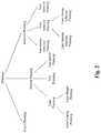
- Planningmay include, as shown in FIG. 2 , route planning, motion planning, or behavior planning.
- Route planningrefers to the effort to plan a route from a source to a destination based on certain considerations.
- Motion planningmay generally refer to the effort of planning the movement of a vehicle to achieve certain effect.
- the movement of the vehiclemay be planned in a way that complies with the traffic regulations or safety. Motion planning is then to determine what movement the vehicle needs to make to achieve that.
- Behavior planninggenerally refers to the effort to plan how the vehicle should behave in different situations, e.g., the vehicle behavior while crossing an intersection, the vehicle behavior in staying within or following a lane, or the vehicle behavior in making a turn. For instance, in terms of overtaking a slow moving front vehicle, certain vehicle behavior may be planned.
- Behavior planning and motion planningmay be related. For example, the planned vehicle behavior may need to be translated into motion in order to implement the behavior.
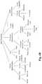
- Vehicle control 130 as shown in FIG. 1may involve various aspects of control. This is illustrated in FIG. 3 , which shows that vehicle control may involve, e.g., roadway specific control, motion specific control, mass specific control, geometry specific control, aerodynamic specific control, and tire specific control.
- vehicle controlmay involve, e.g., roadway specific control, motion specific control, mass specific control, geometry specific control, aerodynamic specific control, and tire specific control.
- Surrounding information 100 in FIG. 1may be used for vehicle planning.
- surrounding information 100includes, e.g., current location of the vehicle, intended destination, and/or traffic information.
- the conventional planning module 120may devise, e.g., a plan for a route from the current location to the destination.
- Known criteria used in route planningmay include, e.g., shortest distance, shortest time, use of highways, use of local roads, traffic, etc. Such criteria may be applied based on known information such as the distance of each road segment, known traffic patterns associated with roads, etc.
- the planning module 120may also perform motion planning, which is traditionally based on, e.g., rapidly exploring random trees (RRT) for state space or Markov Decision Process (MDP) for environmental modeling.
- the planning module 120may generate, based on the planned route/motion, planning data to be fed to the vehicle control module 130 so that the vehicle control module 130 can proceed to control the vehicle in a way as planned.
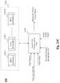
- the vehicle control module 130may then generate control signals 140 which may be sent to different parts of the vehicle to implement the planned vehicle movement.
- Vehicle controlis traditionally exercised based on generic vehicle kinematic models and/or different types of feedback controllers.
- Each human drivergenerally operates or controls a vehicle differently with diverse preferences. Human drivers also operate vehicles adaptively based on real time situations, which may arise out of the present conditions of the vehicle itself, the extrinsic environment conditions that serve to limit the ability of the vehicle to operate, and/or the reaction or response to the current vehicle movement from passengers in the vehicle. For example, with children in the vehicle, a human driver may elect, for safety, to avoid (route planning) a route that is curvy on a snowy day. A human driver may drive in different manners when different passengers are riding in the vehicle to ensure comfort of the passenger. Although a human driver generally controls a vehicle by following a lane by staying roughly in the middle of the lane, the behavior may change when faced with a right turn.
- the same human drivermay curve to the right side of the lane when the vehicle is approaching the point of the right turn.
- different human driversmay curve to the right in different ways.
- lane changing behaviormay also differ with respect to different vehicles in different surrounding situations. The existing technologies do not address those issues, let alone providing solutions.
- the teachings disclosed hereinrelate to methods, systems, and programming for online services. More particularly, the present teaching relates to methods, systems, and programming for developing a virtual agent that can have a dialog with a user.
- a method for human-like vehicle control for an autonomous vehicleis disclosed.
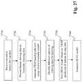
- Recorded human driving dataare first received, which include vehicle state data, vehicle control data, and environment data.
- a vehicle kinematic model based vehicle control signalis generated in accordance with a vehicle kinematic model based on a corresponding vehicle state and vehicle control data of the piece of recorded human driving data.
- a human-like vehicle control modelis obtained, via machine learning, based on the recorded human driving data as well as the vehicle kinematic model based vehicle control signal generated based on vehicle kinematic model.
- Such derived human-like vehicle control modelis to be used to generate a human-like vehicle control signal with respect to a target motion of an autonomous vehicle to achieve human-like vehicle control behavior.
- a system for human-like vehicle control in an autonomous vehiclecomprises A human-like vehicle control model generator which is configured for receiving recorded human driving data, wherein the recorded human driving data comprises vehicle state data, vehicle control data, and environment data, generating, for each piece of the recorded human driving data, a vehicle kinematic model based vehicle control signal based on a corresponding vehicle state and vehicle control data of the piece of recorded human driving data in accordance with a vehicle kinematic model, and obtaining a human-like vehicle control model via machine learning based on the recorded human driving data and the vehicle kinematic model based vehicle control signals generated based on the vehicle kinematic model.
- the human-like vehicle control modelis to be used to generate a human-like vehicle control signal with respect to a target motion of an autonomous vehicle to achieve human-like vehicle control behavior.
- a software productin accord with this concept, includes at least one machine-readable non-transitory medium and information carried by the medium.
- the information carried by the mediummay be executable program code data, parameters in association with the executable program code, and/or information related to a user, a request, content, or information related to a social group, etc.
- machine readable non-transitory mediumwherein the medium has information recorded thereon for human-like vehicle control for an autonomous vehicle, wherein the information, when read by the machine, causes the machine to perform various steps.
- Recorded human driving dataare first received, which include vehicle state data, vehicle control data, and environment data.
- a vehicle kinematic model based vehicle control signalis generated in accordance with a vehicle kinematic model based on a corresponding vehicle state and vehicle control data of the piece of recorded human driving data.
- a human-like vehicle control modelis obtained, via machine learning, based on the recorded human driving data as well as the vehicle kinematic model based vehicle control signal generated based on vehicle kinematic model.
- Such derived human-like vehicle control modelis to be used to generate a human-like vehicle control signal with respect to a target motion of an autonomous vehicle to achieve human-like vehicle control behavior.
- FIG. 1(Prior Art) shows some essential modules in autonomous driving
- FIG. 2illustrates exemplary types of planning in autonomous driving
- FIG. 3illustrates commonly known types of vehicle control
- FIG. 4Adepicts an autonomous driving vehicle with a planning module and a vehicle control module, according to an embodiment of the present teaching
- FIG. 4Billustrates exemplary types of real time data, according to an embodiment of the present teaching
- FIG. 5depicts an exemplary high level system diagram of a planning module, according to an embodiment of the present teaching
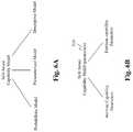
- FIG. 6Aillustrates exemplary ways to realizing a safe-aware capability model, according to an embodiment of the present teaching
- FIG. 6Billustrates an exemplary construct of a self-aware capability model with parameters, according to an embodiment of the present teaching
- FIG. 6Cillustrates exemplary types of intrinsic vehicle capability parameters, according to an embodiment of the present teaching
- FIG. 6Dillustrates exemplary types of extrinsic capability parameters, according to an embodiment of the present teaching
- FIG. 7depicts an exemplary high level system diagram of a mechanism for generating self-aware capability parameters to be considered for planning, according to an embodiment of the present teaching
- FIG. 8depicts an exemplary high level system diagram of a self-aware capability parameter generator, according to an embodiment of the present teaching
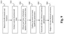
- FIG. 9is a flowchart of an exemplary process for generating self-aware capability parameters, according to an embodiment of the present teaching.
- FIG. 10depicts an exemplary high level system diagram of a route planning module, according to an embodiment of the present teaching
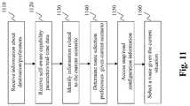
- FIG. 11is a flowchart of an exemplary process for route planning, according to an embodiment of the present teaching.
- FIG. 12depicts an exemplary high level system diagram of a global route planner, according to an embodiment of the present teaching
- FIG. 13is a flowchart of an exemplary process for a global route planner, according to an embodiment of the present teaching
- FIG. 14Adepicts an exemplary high level system diagram of a motion planning module, according to an embodiment of the present teaching
- FIG. 14Billustrates exemplary types of passenger models, according to an embodiment of the present teaching
- FIG. 14Cillustrates exemplary types of user reactions to be observed for motion planning, according to an embodiment of the present teaching
- FIG. 15depicts an exemplary high level system diagram of a passenger observation analyzer, according to an embodiment of the present teaching
- FIG. 16is a flowchart of an exemplary process of a passenger observation analyzer, according to an embodiment of the present teaching
- FIG. 17is a flowchart of an exemplary process for a motion planning module, according to an embodiment of the present teaching.
- FIG. 18depicts an exemplary high level system diagram of a model training mechanism for generating different models for motion planning, according to an embodiment of the present teaching
- FIG. 19illustrates different types of reactions to be observed and their roles in model training, according to an embodiment of the present teaching
- FIG. 20Aillustrates exemplary types of lane related planning, according to an embodiment of the present teaching
- FIG. 20Billustrates exemplary types of behavior related to lane following, according to an embodiment of the present teaching
- FIG. 20Cillustrates exemplary types of behavior related to lane changing, according to an embodiment of the present teaching
- FIG. 21depicts an exemplary high level system diagram of a lane planning module, according to an embodiment of the present teaching
- FIG. 22is a flowchart of an exemplary process for a lane planning module, according to an embodiment of the present teaching
- FIG. 23Aillustrates the traditional approach to generate vehicle control signals based on a vehicle kinematic model
- FIG. 23Bdepicts a high level system diagram of a vehicle control module that enables human-like vehicle control, according to an embodiment of the present teaching
- FIG. 23Cdepicts a high level system diagram of a vehicle control module that enables personalized human-like vehicle control, according to an embodiment of the present teaching
- FIG. 24depicts an exemplary high level system diagram of a human-like vehicle control unit, according to an embodiment of the present teaching
- FIG. 25is a flow chart of an exemplary process of a human-like vehicle control unit, according to an embodiment of the present teaching
- FIG. 26depicts an exemplary high level system diagram of a human-like vehicle control model generator, according to an embodiment of the present teaching
- FIG. 27is a flowchart of an exemplary process of a human-like vehicle control model generator, according to an embodiment of the present teaching
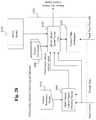
- FIG. 28depicts an exemplary high level system diagram of a human-like vehicle control signal generator, according to an embodiment of the present teaching
- FIG. 29is a flowchart of an exemplary process of a human-like vehicle control signal generator, according to an embodiment of the present teaching.
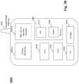
- FIG. 30depicts the architecture of a mobile device which can be used to implement a specialized system incorporating the present teaching.
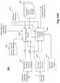
- FIG. 31depicts the architecture of a computer which can be used to implement a specialized system incorporating the present teaching.
- FIG. 4Ashows an autonomous vehicle with a vehicle planning/control mechanism 410 , according to an embodiment of the present teaching.
- the autonomous vehicle planning/control mechanism 410includes a planning module 440 and a vehicle control module 450 . Both modules take various types of information as input in order to achieve operations that are self-capability aware, human-like, personalized and adaptive to real time situations.
- both the planning module 440 and the vehicle control module 450receive historical manual driving data 430 in order to learn human like ways to handle the vehicle in different situations.
- These modulesalso receive real time data 480 in order to be aware of the dynamic situations surround the vehicle in order to adapt the operations accordingly. Furthermore, the planning module 440 accesses a self-aware capability model 490 which characterizes what limits the operational ability of the vehicle given the situation the vehicle is currently in.
- Real time data 480may include various types of information useful or relevant for planning and control of the vehicle.
- FIG. 4Billustrates exemplary types of real time data, according to an embodiment of the present invention.
- exemplary real time datamay include vehicle related data, time related data, passenger related data, weather related data, and data related to the nearby roads.
- Vehicle related datamay include, e.g., the motion state, position, or conditions of the vehicle at the time.
- the motion state of a vehiclemay involve, e.g., its current speed and driving direction.
- the real time position informationmay include, e.g., the current latitude, longitude, and altitude of the vehicle.
- the real time conditions of the vehiclemay include the functional state of the vehicle such as whether the vehicle is currently in a full or partial functional state or specific parameters under which different components of the vehicle are operating, etc.
- Real time data related to timemay generally include current date, time, or month.
- Passenger related datamay include various characteristics related to the passenger of the vehicle such as passenger reaction cues, which may include visual, acoustic, or behavior cues observed from the passenger, or conditions of the passenger such as mental state, physical state, or functional state of the passenger. The conditions of the passenger may be inferred based on the cues observed from the passenger reaction cues.
- Weather related datamay include the weather of the locale where the vehicle is currently situated.
- the road related datamay include information about the physical condition of the nearby road(s), e.g., wetness, steepness, or curviness of the road, or the local traffic condition such as congestion along the road.
- FIG. 5depicts an exemplary high level system diagram of the planning module 440 , according to an embodiment of the present teaching.
- the planningincludes, but not limited to, route planning, motion planning, and the planning of lane related behavior, including lane following, lane changing, etc.
- the planning module 440comprises a route planning module 550 , a motion planning module 560 , and a lane planning module 570 .
- Each of the modulesaims at operating in a self-capability aware, human-like, and personalized manner.
- Each of the modules 550 , 560 , and 570takes, in addition to the surrounding information 420 , historic human driving data 430 , real time data 480 , and the self-aware capability model 490 as inputs and generates their respective outputs to be used by the vehicle control module 450 to convert into the vehicle control signals 470 to control the vehicle.
- the route planning module 550generates the planned route information 520 as its output
- the motion planning module 560generates planned motion 530 as its output
- the lane planning module 570generates planned lane control information 540 as its output.
- Each of the planning modulesmay be triggered via some triggering signal.
- the route planning module 550may be activated via a route planning trigger signal; the motion planning module 560 may be activated upon receiving a motion planning trigger signal; while the lane planning module 570 may start to operate when a lane planning trigger signal is received.
- a trigger signalmay be manually provided (by, e.g., a driver or a passenger) or automatically generated based on, e.g., certain configuration or certain event.
- a drivermay manually activate the route planning module 550 or any other planning module for the route/motion/lane planning, much like what people do to manually start, e.g., cruise control in a car.
- the planning activitiesmay also be activated by a certain configuration or an event.
- the vehiclemay be configured to activate route planning whenever the vehicle accepts an input indicating the next destination. This may be regardless what the current location of the vehicle is.
- the planning modulesmay be always triggered on whenever the vehicle is on and depending on the situation, they may become engaged in different planning activities as needed. In different situations, they may also interact with each other in a manner called for by the situation.
- the lane planning module 570may determine to change lane in certain circumstance. Such a planned lane control is output by the lane planning module 570 and may be fed to the motion planning module 560 so that a specific path trajectory (planned motion) appropriate for carrying out the planned lane changing may be further planned by the motion planning module 560 .
- Output of a planning modulemay be fed into another within the planning module 440 for either further planning or for providing an input for the future planning of another.
- the output of the route planning module 550(planned route 520 ) may be fed to the motion planning module 560 so that the route information may influence how the vehicle motion is planned.
- the output (planned lane control 540 ) of the lane planning module 570may be fed to the motion planning module 560 so that the lane control behavior planned may be realized via planned motion control.
- the output of the motion planning module 560(the planned motion 530 ) may also be fed to the lane planning module 570 to influence the planning of the lane control behavior.
- the motion planning module 560may determine that the motion of the vehicle needs to be gentle due to the observation that the passenger of the vehicle prefers smooth motion. Such a determination is part of the motion planning and may be to be sent to the lane planning module 570 so that the lane control behavior of the vehicle may be carried out in a way that ensures smooth motion, e.g., change lane as little as possible.
- the route planning module 550 , the motion planning module 560 , and the lane planning module 570also access the self-aware capability model 490 and use it to determine the planning strategy in a manner that takes into account of what the vehicle is actually capable of in the current scenario.
- FIG. 6Aillustrates exemplary ways that the self-aware capability model 490 is realized, according to an embodiment of the present teaching.
- the self-aware capability model 490may be constructed as a probabilistic model, a parameterized model, or a descriptive model. Such a model may be trained based on, e.g., learning.
- the modelmay include a variety of parameters to be used to characterize factors that may influence or have an impact on the actual ability of the vehicle.
- the modelmay be implemented as a probabilistic model with parameters being estimated probabilistically.
- the modelmay also be implemented as a parameterized model with explicit model attributes applicable to different real world conditions.
- the model 490may also be provided as a descriptive model with enumerated conditions with values instantiated based on real time scenarios.
- the self-aware capability model 490 in any situationmay include various parameters, each of which is associated with some factors that may impact the actual ability of the vehicle so that the vehicle planning (route, motion, or lane) has to consider.
- self-aware capability model and self-aware capability parameterswill be used interchangeably.
- FIG. 6Billustrates an exemplary construct of the self-aware capability model or parameters 510 , according to an embodiment of the present teaching.
- self-aware capability parameters 510may include intrinsic capability parameters and extrinsic capability parameters.
- Intrinsic vehicle capability parametersmay refer to parameters associated with the vehicle itself which may impact what the vehicle is capable of in operation and such parameters may be determined based on either how the vehicle is manufactured or how the vehicle is at the time.
- Extrinsic capability parametersmay refer to the parameters or characteristics of the surrounding that are extrinsic to the vehicle but nevertheless may impact the way the vehicle can be operated.
- FIG. 6Cillustrates exemplary types of intrinsic vehicle capability parameters, according to an embodiment of the present teaching.
- intrinsic vehicle capability parametersmay include, but not limited to, characteristics of the vehicle in terms of, e.g., its engine, its safety measures, and its tires, etc.
- the intrinsic capability parametersmay specify the maximum speed the vehicle is capable of, the control that can be exercised on the engine, including cruise control or any restrictions on manual control of the engine.
- the intrinsic capability parametersmay include information on what sensors the vehicle is equipped with, specific parameters related to breaks, or information about the seats of the vehicle. For example, some vehicles may have seats that are backed by metal support (stronger) and some with only plastic support.
- the intrinsic capability parametersmay also specify the type of the tires of the vehicle (which may have a bearing on what operation can be done) and whether the vehicle currently has snow tires installed or equipped with anti-skip measures. Such intrinsic vehicle capability parameters may be used to assess what types of routes and motions may be possible and which types of vehicle behaviors may be achievable. Thus, making such intrinsic capability parameters available to the planning modules allows the planning modules to plan appropriately without exceeding what the vehicle is actually capable of.
- FIG. 6Dillustrates exemplary types of extrinsic capability parameters, according to an embodiment of the present teaching.
- extrinsic capability parametersspecify information that are external to the vehicle but nevertheless may impact the ability of planning and such extrinsic capability parameters are used to determine appropriate planning given the conditions external to the vehicle. The ultimate output from the planning modules may be determined within the confine of both intrinsic and extrinsic capability parameters.
- extrinsic capability parametersmay include parameters describing the conditions or situations the vehicle is in or may encounter, they likely will impact what should be planned. For example, the surrounding situations related to the road(s), either close to the vehicle or even relatively remote from the vehicle.
- the road condition related parametersmay indicate how crowded the road is (so that the driving speed cannot be planned to be fast), whether there are speed limits on the road (regulated minimum and maximum speeds as well as the actual permissible speed due to traffic), whether there is any accident along the road, or the surface condition of the road (so that the motion cannot be too swift), or whether the surface of the road presents certain conditions that will impede the ability of the vehicle in its planning.
- the extrinsic parametersmay include information about such nearby vehicles/objects, e.g., the nearby vehicle is a big truck or a bicycle, which may also impact how the planning decision is made.
- events occur along the road the vehicle is onmay also impact the planning. For instance, whether the vehicle is currently on a road that is in a school zone or whether there is a construction going on along the road the vehicle is currently on may also be important information to the planning modules for obvious reasons.
- the extrinsic capability parametersmay be acquired and updated continuously in time to support the planning modules to adapt their decisions based on external situations in real time. In some situations, the extrinsic capability parameters may also be predicted. For example, if the vehicle is driving on a road to the west in the afternoon, it may be predicted that there will be sun glare. Although such predicted extrinsic capability parameter may not be the real time information, it nevertheless will assist the planning module (e.g., the route planning module) to make an appropriate decision.
- the planning modulee.g., the route planning module
- the route planning module 550may accordingly decide to presently take the road heading to the north first and later take a road to head to the west after sun is down to avoid sun glare (safer).
- Such predicted extrinsic capability parametersmay be determined based on other information such as the current location of the vehicle and the intended destination of the vehicle.
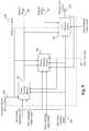
- FIG. 7depicts an exemplary high level system diagram for a mechanism 700 for generating self-aware capability parameters, according to an embodiment of the present teaching.
- the mechanism 700comprises a locale context determining unit 730 and a self-aware capability parameter generator 740 .
- the locale context determining unit 730is to gather information locale to where the vehicle is and/or will be (i.e., both where the vehicle is presently and where the vehicle will be on its way to the destination) based on, e.g., information about the current location of the vehicle and/or the destination the vehicle is heading to.
- the self-aware capability parameter generator 740is to generate both intrinsic and extrinsic capability parameters, e.g., on a continuous basis, based on information related to the vehicle and the locale context information determined based on, e.g., the current and future location of the vehicle.
- the locale context determining unit 730may retrieve information stored in a map configuration 750 and a road context configuration 760 based on the current location 720 and the destination information 710 .
- the locale context information related to the roadsmay include the surrounding or contextual information of the road the vehicle is currently on and/or the roads that the vehicle will be on subsequently.
- the map configuration 750may provide information about the roads from the current location to the intended destination, while the road context configuration 760 may provide some known or static information about the characteristics associated with roads, such as altitude, steepness, curviness of each road, etc. Such gathered static information about the roads may then be used by the self-aware capability parameter generator 740 .
- the road conditionsmay change over time. For example, roads may become icy or slippery due to changes in weather conditions.
- Such dynamically changing context information about the roadsmay be acquired separately by, e.g., the self-aware capability parameter generator 740 on a continuous basis and used in generating extrinsic capability parameters that are reflective of the real time situations.
- both the current location and the source-destination informationmay also be sent to the self-aware capability parameter generator 740 in order for it to gather real time information about road conditions to determine the extrinsic capability parameters.
- the vehicle information storage 750may store vehicle parameters configured when the vehicle was manufactured such as whether the vehicle is equipped with cruise control or certain types of sensors.
- the storage 750may also subsequently update information related to the parameters intrinsic to the vehicle. Such subsequent update may be generated due to, e.g., vehicle maintenance or repair or even update observed in real time.
- the self-aware capability parameter generator 740includes also the mechanism to collect continuously any dynamic update of the vehicle related parameters consistent with the actual intrinsic capability of the vehicle.
- FIG. 8depicts an exemplary high level system diagram of the self-aware capability parameter generator 740 , according to an embodiment of the present teaching.
- the self-aware capability parameter generator 740comprises a locale context information processor 810 , a situation parameter determiner 820 , a self-aware capability parameter updater 830 , and various updaters that continuously and dynamically gather information of different aspects related to decision making of the vehicle.
- Such dynamic information updatersinclude, e.g., vehicle capability parameter updater 860 - a , weather sensitive parameter updater 860 - b , traffic sensitive parameter updater 860 - c , orientation sensitive parameter updater 860 - d , road sensitive parameter updater 860 - e , . . . , and time sensitive parameter updater 860 - f.
- the locale context information processor 810processes the received information and, e.g., extracts information related to the current route the vehicle is on and sends such information to the self-aware capability parameter updater 830 .
- information related to the current routemay include steepness or curviness of the route or other types of static information such as the altitude and orientation of the route.
- the situation parameter determiner 820receives the current location 720 and, e.g., separates location and time information and sends the information to the self-aware capability parameter identifier 830 so that it may use that information to identify capability parameters specific to the location and the precise time.
- the self-aware capability parameter updater 830may access intrinsic capability models 840 and/or extrinsic capability models 850 to retrieve capability related parameter values specific to the current location and time.
- the intrinsic capability models 840may be configured to specify types of parameters relevant to the intrinsic capabilities of the vehicle and the current values thereof.
- the extrinsic capability models 850may be configured to specify types of parameters that have an impact on the ability of the vehicle to operate and their current values.
- the intrinsic and extrinsic capability models ( 840 and 850 )may regularly trigger the updaters ( 860 - a , . . . , 860 - f ) to gather real time information and update the values of the corresponding parameters based on such gathered real time information.
- the intrinsic capability models 840may be configured to have a mechanism to activate the vehicle capability parameter updater 860 - a to gather updated information related to the intrinsic capabilities of the vehicle.
- Such a mechanismmay specify different modes of triggering. For instance, it may be on a regular schedule, e.g., daily or hourly.
- the vehicle capability parameter updater 860 - amay accept real time vehicle information from the sensor(s) and update the values/states of the relevant capability parameter in the intrinsic capability models to reflect that real time status of the vehicle. For instance, if during the operation of the vehicle, the headlight or a break may become non-functional. Such information sensed in real time may be gathered by the vehicle capability parameter updater 860 - a and used to update the information stored in the intrinsic capability parameter storage 840 . Such updated information relates to the vehicle may then be used by the self-aware capability parameters generator 740 to generate intrinsic capability parameters.
- the extrinsic capability models 850may be configured to specify the update mechanism(s) for updating different types of extrinsic capability parameters.
- the update mechanismmay specify regularly scheduled update or update to be triggered by some events.
- Different types of extrinsic capability parametersmay be configured to be updated based on different triggering mechanisms. For example, for weather related extrinsic capability parameters or extrinsic capability parameters that may be keyed on weather, e.g., visibility in the vicinity of the vehicle, the update may be made regularly, e.g., every few minutes.
- traffic sensitive parameterse.g., the actual permissible speed which is usually direct result of the traffic condition, may also be updated regularly. Different types of parameters, although all regularly updated, may have different update schedule, which may range from every few seconds to every few minutes or every few hours.
- some extrinsic capability related parametersmay be made upon the occurrence of some events.
- an orientation sensitive parametere.g., whether sun glare exists
- the updatemay be triggered when the vehicle is heading in certain directions. If the direction of the vehicle is heading changes from north to north-west at some afternoon time, this may trigger the orientation sensitive parameter updater 860 - d to gather information related to sun glare and update the situation with regard to sun glare.
- the updatemay indicate that there is no sub glare, e.g., when it is a cloudy day. In some situations, the update may indicate that there is sun glare.
- such orientation sensitive informationis then used to update the value of the corresponding extrinsic capability parameter stored in the extrinsic capability parameter storage 850 .
- update of time sensitive parameterssuch as visibility of the vehicle due to time of the day, may be triggered based on detected location, time zone of the location, and the specific time of the day at the moment.
- the update of some of the capability parametersmay also be triggered by event related to the detected updates of other capability parameter values.
- the update of road sensitive parameterssuch as slippery road condition may be triggered when the update for the weather condition indicates that it started to rain or snow.
- the vehicle capability parameter updater 860 - areceives the static vehicle information from storage 750 and dynamic vehicle information update from real time vehicle information feed which may be from multiple sources. Examples of such sources include dealers, vehicle maintenance places, sensors on the vehicle reporting the status change of components, or other sources.
- the weather sensitive parameter updater 860 - bmay receive both dynamic weather update and the updates of other weather sensitive capability parameters, e.g., precipitation, visibility, fog, or any other parameters that relate to weather and have the potential to impact the operation of the vehicle.
- Weather related informationmay be from multiple data sources that feed real time data.
- the traffic sensitive parameter updater 860 - cmay receive both dynamic traffic reports and other information relating to the traffic that may influence the operation of the vehicle. Examples include the extent of the traffic jam (which may be used to determine whether the route of the vehicle needs to be re-planned) or the time of the accident that had caused the traffic (to estimate how long the delay will continue in order to determine whether to re-do the route planning). Traffic or traffic related information may be received from one or more sources for real time data feed.
- the orientation sensitive parameter updater 860 - dmay be configured to gather information along the road in the direction of the vehicle.
- Such orientation sensitive informationmay include sun glare in certain directions (e.g., east or west) or any potential situations in the direction of the road the vehicle is on (e.g., landslide situation ahead of the road).
- the road sensitive parameter updater 860 - emay, once triggered, gather information about various roads or road conditions with respect to the location of the vehicle, from one or more real time information feed sources. Such information may be related to the roads (e.g., open, close, detoured, school zone, etc.) or conditions thereof (e.g., slippery, icy, flooded, construction, etc.).
- the time sensitive parameter updater 860 - fmay be configured to collect from data source(s) real time data that depend on time. For example, the visibility of the road may depend on the time of day at the zone the vehicle is in.
- the collected real time datamay then be used to update the intrinsic capability models 840 and/or the extrinsic capability models 850 . Such updated data may be time stamped.
- the self-aware capability parameter updater 830may then access both the intrinsic and extrinsic capability models 840 and 850 to determine relevant capability parameters and the updated values thereof.
- the retrieved intrinsic/extrinsic capability parametersmay then be output so that they can be used by various planning modules as shown in FIG. 5 . Specifically such generated self-aware capability parameters 510 are used by the route planning module 550 for route planning, as will be discussed with reference to FIGS. 10-13 .
- the self-aware capability parametersare also used by the motion planning module 560 for personalized motion planning, which will be disclosed in detail with reference to FIGS. 14-19 .
- the self-aware capability parametersare also used by the lane planning module 570 for lane control, which will be detailed with reference to FIGS. 20-22 .
- FIG. 9is a flowchart of an exemplary process of the self-aware capability parameter generator 740 , according to an embodiment of the present teaching.
- the locale context informationis received at 910 and location and time information are extracted at 920 and used at 930 by different updaters to obtain information feeds from different sources related to various aspects of intrinsic and extrinsic capabilities.
- Such acquired informationis then used by different updaters at 940 to update the intrinsic capability parameters 840 and extrinsic capability parameters 850 .
- the self-aware capability parameter updater 830Based on the current location, time, and the received locale contextual information, the self-aware capability parameter updater 830 then identifies various intrinsic and extrinsic capability parameters 510 relevant to the vehicle at the present time to update, at 940 , the intrinsic/extrinsic capability parameters and generates, at 950 , the updated capability parameters. Such updated intrinsic/extrinsic capability parameters 510 are then output at 960 .
- Such dynamically gathered self-aware capability parametersare to be used in various vehicle behavior planning operations, including route planning, motion planning, and lane related vehicle behavior planning. For example, in human driving, choosing a route to a destination is often done with consideration of factors captured by the self-aware capability parameters. For example, a human driver may choose a route to a desired destination based on, e.g., what the vehicle is equipped with or capable of (intrinsic capability parameters). If the vehicle is in such a condition that it cannot handle steep road well, then such road needs to be avoided. In addition, a human driver may also consider other factors such as weather of the day, conditions of the roads considered, events known or scheduled at certain time of day (extrinsic capability parameters).
- Traditional approaches to route planningoften adopt some cost function so that the cost of a route selected is minimized.
- conventional route planningconsiders, e.g., optimization of distance traveled, minimization of time required to arrive the destination, or minimize the fuel used to get to the destination.
- conventional approachesmay also consider traffic conditions in optimizing the cost, e.g., high traffic route may decrease the speed leading to increased time and fuel to get to the destination.
- traffic conditionse.g., high traffic route may decrease the speed leading to increased time and fuel to get to the destination.
- Such optimization functionsoften assume that all vehicles can handle all routes in the same manner and all routes can be handled equally well. Such assumptions are often not true so that when autonomous vehicles apply such planning schemes, they often find unable to proceed or even become unsafe in some situations.
- the present teachingaims to achieve safe, realistic, and reliable route planning that is adaptive to the changing intrinsic and extrinsic capability related parameters.
- the self-aware capability parameters 510are considered by the planning module 450 in achieving different planning tasks, including the route planning module 550 , the motion planning module 560 , and the lane planning module 570 .
- FIG. 10depicts an exemplary high level system diagram of the route planning module 550 , according to an embodiment of the present teaching.
- the purpose of the route planning module 550is to plan a route based on desired destination in a self-aware manner in terms of both intrinsic and extrinsic capabilities.
- conventional route planning technologiesconsider mainly criteria such as shortest distance, shortest time, most use of highways/local ways, etc. without taking into account the dynamic intrinsic capability parameters and the real time extrinsic capability parameters.
- the route planning module 550comprises a route selection preference determiner 1030 and a global route planner 1020 .
- the route selection preference determiner 1030is to determine the preferences to be considered in selecting a route.
- the global route planner 1020is to select an appropriate route based on a variety of information, including the self-aware capability parameters 150 .
- the route planning activitiesmay be triggered based on the route planning trigger signal as shown.
- the global route planner 1020may gather various types of dynamic information relevant to the present route planning operation.
- the global route planner 1020may rely on information related to the source/current location and the destination desired. The planning is performed with respect to the source/current location and the destination.
- the destination informationmay be determined in different ways. For example, it may optionally be received from a driver/passenger via an interface unit 1010 .
- the global route planner 1020may also take real time data 480 as input and plans a route accordingly.
- real-time datainclude information related to real time vehicle related information (position), information about passenger observed in the vehicle, and road characteristics. Such real-time data provide surrounding information needed for the route planning.
- the global route planner 1020also receives the self-aware capability parameters 510 that inform the planner what is possible given the dynamic intrinsic and extrinsic situations at the time of the planning. For instance, intrinsic capability parameters may indicate that the vehicle is currently not able to run fast due to some mechanical problems so that the global route planner 1020 may take that into account to, e.g., plan a route that involves mainly local roads and may possibly pass some car repair shops.
- extrinsic capability parametersmay indicate that in the north direction of the current location of the vehicle, the sun glare is quite severe so that the global route planner may base that information to avoid a nearby route that is in the north direction before the sun is set.
- the real-time data 480 and the self-aware capability parameters 510provide information to the global route planner 1020 to enable it to plan a route that is appropriate given, e.g., the present time, the present location of the vehicle, the present weather, the present passenger's situation, and present road conditions.
- the global route planner 1020may also consider preference(s) to be applied in route planning. Such preferences may be specified by a driver/passenger via the user interface unit 1010 (which may be forwarded to the global route planner 1020 ) or may be obtained via other means (see disclosure below with reference to FIG. 12 ). In considering the preferences to be applied, information stored in route selection preference configuration 1050 may also be accessed and considered. Such route selection preference configuration may specify some general preference in route selection in different scenarios, e.g., avoid steep/curvy roads in raining/snow scenarios, avoid small streets at night, avoid roads with very few gas stations, etc.
- the global route planner 1020may forward relevant information received from real-time data 480 and self-aware capability parameters 510 to the route selection preference determiner 1030 , which is in turn used by the route selection determiner 1030 to retrieve certain route selection preference configuration from 1050 . For example, if it is currently snowing (from real-time data 480 ) and the vehicle has no snow tire (from the intrinsic capability parameter 510 ), such dynamic information may be forwarded from the global route planner 1020 to the route selection preference determiner 1030 so that selection preference configuration related to such dynamic scenarios may be retrieved from the route selection preference configuration 1050 (e.g., avoid steep/curvy road) and sends back to the global route planner 1020 so that it can be relied on in selecting an appropriate route.
- the route selection preference configuration 1050e.g., avoid steep/curvy road
- the global route planner 1020may also need to know additional information about the roads, such as what routes available from the current location of the vehicle to the intended destination.
- the map/road configuration 1060may also store characteristic information about each of the available roads/routes.
- characteristic information of the roads/routesmay include, but not limited to, geometric characteristics such as nature of the roads/routes (highway or not), dimension of the roads/routes, steepness/curviness, condition of the roads/routes, etc.
- the global route planner 1020may first determine the roads/routes available between the current location of the vehicle to the desired destination. To select an appropriate route to the destination, for such available roads/routes, their characteristic information may also be accessed by the global route planner 1020 so that selections may be made based on such characteristic information.
- the global route planner 1020may then select an appropriate route to the destination by matching the route selection preferences, determined by the route selection preference determiner 1030 , with the characteristic information of the available roads/routes. Details about the global route planner 1020 are provided with reference to FIGS. 12-13 .
- the global route planner 1020selects a planned route based on dynamic information from different sources, including real-time data 480 and self-aware capability parameters 510 .
- the current location of the vehicle and the destinationmay also change in time, just like the real-time data 480 and the self-aware capability parameters 510 .
- the real-time data associated with the current locationmay also change, e.g., from good weather associated with the previous spot to the raining condition associated with the current location. This may in turn lead to a change in terms of route selection preferences and ultimately, the route selected.
- the global route planner 1020may interact with the route selection preference determiner 1030 in a bi-directional manner and dynamic manner. Whenever there is a change that may warrant a re-determination of route selection preferences, the global route planner 1020 may then activate the route selection preference determiner 1030 to modify or re-generate the preferences to be used by the global route planner 1020 to determine an appropriate route given the situation.
- FIG. 11is a flowchart of an exemplary process for the route planning module 550 , according to an embodiment of the present teaching.
- Information about the destination of the vehicle and optionally about the preferencesis received at 1110 .
- Real-time data 480 as well as self-aware capability parameters 510are received by the global route planner 1020 at 1120 and various information related to the current scenario or situation of the vehicle may then be identified, at 1130 , from the received real-time data and the self-aware capability parameters. Based on the relevant information related to the current scenario, preferences specific to the current scenario are determined, at 1140 .
- the global route planner 1020accesses, at 1150 , information about available roads/routes with respect to the current location and the desired destination as well as the characteristic information of such available roads/routes. At 1160 , based on the specific preferences determined based on the current scenario as well as the roads/routes information, the global route planner 1020 selects a route appropriate for the current situation.
- FIG. 12depicts an exemplary high level system diagram of the global route planner 1020 , according to an embodiment of the present teaching.
- the global route planner 1020comprises a self-aware capability parameter analyzer 1205 , an intrinsic capability based filter generator 1210 , and a route selection engine 1230 .
- the global route planner 1020also comprises a destination updater 1225 for dynamically determine and update the current destination.
- the global route planner 1020also optionally include a mechanism for personalizing preferences of a driver/passenger so that the route in selecting a route.
- the route selection preference determiner 1030is to determine the preferences related to selecting a route based on the specific situation the vehicle is currently in, which differs from obtaining personalized preferences directed to a specific driver/passenger.
- the optional mechanism to determine personalized preferencescomprises a passenger driving data analyzer 1245 , a preference personalization module 1250 , and a passenger preference determiner 1240 .
- the passenger driving data analyzer 1245receives recorded human driving data 430 as input and analyzes or learns from such data to understand route preferences relevant to specific drivers/passengers. For example, from the recorded human driving data 430 , it may be learned that a specific driver prefers to drive on local roads instead of highway or historically chose to use highways at nights even though it involved much longer distance. It may also learn preferences of all drivers associated with the vehicle. For instance, multiple people (husband, wife, and a child of a household) may be associated with the vehicle, i.e., anyone of these people may operate the vehicle.
- the passenger driving data analyzer 1245may learn from the recorded human driving data 430 various types of information associated with the driving behavior of such drivers, which may enable the preference personalization module 1250 , upon receiving such driving behavior information, to establish personal preferences of each of such individuals.
- the preference personalization module 1250may then generate personalized preferences in terms of route choices. Such route related preferences may reflect not only route choices but also represent preferences of route choices in different situations such as specific time frames of a day, seasons, locations, etc. Such established preferences for each individual driver may then be stored in storage 1265 .
- the passenger preference determiner 1240receives the real-time data 480 and based on various types of information in the real-time data 480 (e.g., month/day/time, passenger information, locale weather, etc.), the passenger preference determiner 1240 may access, from the route selection preference storage 1265 , relevant preferences that can be applied in current route planning.
- the passenger preference determiner 1240may identify personalized route preferences in 1265 related to the current specific driver which are associated with the specific time frame and season of the year (e.g., a driver may prefer driving on highway in winter season). The personalized route selection preferences so identified may then be sent to the route selection engine 1230 so that personalized preferences of the driver/passenger at the time of the route planning can be considered in determining what route is to be selected.
- the route selection engine 1230may also take the preferences estimated by the route selection preference determiner 1030 as input and use that in its route selection operation.
- the route selection engine 1230may rely on the preferences from 1030 without considering the personalized preferences of a driver, i.e., it may rely on merely the preferences identified by the route selection preference determiner 1030 in its route selection.
- the route selection engine 1230may also receiving self-aware capability parameters 510 .
- the self-aware capability parameter analyzer 1205separates extrinsic capability parameters and intrinsic capability parameters and sends the extrinsic capability parameters to the route selection engine 1230 so that extrinsic conditions associated with the current situation the vehicle is in can be considered in selecting a route.
- the extrinsic capability parametersmay indicate that there is on-going construction on Route 7, the route selection engine 1230 may consider that and avoid Route 7. However, if the destination is currently set for a school on Route 7 and the driver's habit is to pick up children from the school each day at the present time (e.g., 3:30 pm), the route selection engine 1230 may elect to choose Route 7, given all things considered.
- intrinsic capability parametersmay also be considered in selecting an appropriate route.
- the intrinsic capability parametersare fed to the intrinsic capability based filter generator 1210 , which may create different filters 1215 based on the intrinsic capability parameters so that such filters may be utilized by the route selection engine to filter out routes that are not appropriate given the intrinsic capability parameters. For example, if the intrinsic capability parameters indicate that the vehicle has no snow tire, any routes that are steep and/or curvy may not be appropriate on a snowy day.
- the route selection engine 1230selects a route based on both the current location of the vehicle, tracked by a current location updater 1235 , and a destination, tracked by a destination updater 1225 . Depending on the situation, changed current location and destination may trigger the route selection engine 1230 to activate the route selection preference determiner 1030 to re-evaluate the preferences in route selection given the changed circumstance.
- FIG. 13is a flowchart of an exemplary process for the global route planner 1020 , according to an embodiment of the present teaching.
- self-aware capability parametersare received.
- Intrinsic capability parametersare used to generate, at 1320 , intrinsic capability based filter(s) so that certain routes can be filtered out as inappropriate given the intrinsic conditions of the vehicle.
- Extrinsic capability parametersare extracted, at 1330 , from the received self-aware capability parameters.
- real-time data 480are continuously received at 1340 and recorded human driving data are received at 1350 . Such data are then used to determine, at 1360 , personalized route selection preferences relevant to the current driver, current situation, and current time.
- self-aware capability parameters and/or the personalized preferences of the drivermay then be used to select a route appropriate given all factors considered.
- the selected routeis output.
- the route planningallows various types of information, such as real-time data and self-aware capability parameters, to be taken into account in route planning so that the planned routes are adaptive with respect to the vehicle condition at the time (via intrinsic capability parameters), the dynamic environment the vehicle is in at the time (via real-time data as well as extrinsic capability parameters), the passenger characteristics determined based on, e.g., dynamically updated real-time data (see FIG. 4B ), as well as passenger personalized preferences.
- informationmay also be utilized in other types of planning operations so that the planned vehicle activities are adapt to the real-time situation, personalized based on individual preferences, and allows the vehicle to behave more human driver like. Below, more details are provided, with respect to FIGS. 14-19 on personalized adaptive motion planning.
- Human driverscontrol their vehicle motion in a manner that is comfortable. In most situations, human drivers also pay attention to the feedback or reaction of passengers who ride with them in the vehicle and respond to the vehicle motion. For example, some human drivers may prefer start and stop the vehicle smoothly. Some human drivers who usually start and stop the vehicle fairly abruptly may adjust their driving when they observe that passengers sitting in their vehicle respond in a certain way. Such human behavior may play an important role in autonomous vehicles. It is commonly recognized that driving behavior changes from person to person and how such behavior is to be adjusted in the presence of others in the same vehicle may also differ from person to person.
- autonomous vehiclesmay adopt planning models that are trained to capture the characteristics of human driving behavior of the general population. Such generalized models do not customize the planning approach based on individual driver/passenger preferences or intents.
- the present teachingaims to provide personalized motion planning based on knowledge of the driver/passenger as well as the dynamic observations of driver/passenger response to vehicle motions.
- FIG. 14Adepicts an exemplary high level system diagram of the motion planning module 560 , according to an embodiment of the present teaching.
- the motion planning module 560aims at personalized, human-like, and adaptive motion planning, i.e., motions of the vehicle are planned in accordance with, e.g., general and personal likings, which may include what is known to be the preferences of a passenger and what is the reaction or feedback of a of a passenger of the current motion of the vehicle.
- the motion planning module 560may comprise a generic motion planner 1450 and a passenger motion adapter 1460 .
- the motion planning module 560may plan vehicle motion based on various considerations, including real-time situations the vehicle is in (e.g., on a curvy road, raining day, dim lighting, etc.), vehicle conditions (via intrinsic capability parameters), and personal preferences of the passenger in the vehicle (known preferences or dynamically determined based on driver feedback observed). Given those considerations, vehicle motion may be planned based on motion planning models, which may be invoked in a manner suitable for different scenarios. Motion planning models may include different models appropriate for the given situation in hand.
- FIG. 14Billustrates exemplary types of motion planning models, according to an embodiment of the present teaching.
- motion planning modelsmay include generic motion planning models ( 1450 in FIG. 14A ), sub-category models ( 1480 in FIG. 14A ), or personalized models ( 1430 in FIG. 14A ).
- the generic motion planner 1450may be preference based models or impact based models (see FIG. 14B ).
- a preference based modelmay be provided specifying preferred vehicle motion in different scenarios based on general knowledge about vehicle operation. For instance, when roads are slippery or icy, it is preferred to plan motions that are slower without sharp turns.
- An impact based modelmay specify which kind of motion may cause what type of impact and such specification may be used to guide motion planning to achieve or avoid certain impact.
- a sub-category model for motion planningmay be, as compared with the generic models, directed to a sub-category of vehicles or a sub-category of drivers/passengers.
- a sub-category modelmay be directed to sports cars and another sub-category model may be provided for vans.
- a sub-category modelmay be directed to teenager drivers and another sub-category model may be directed to senior citizens.
- Each sub-category modelis tuned or specialized so that the motion planning for a matching sub-category can be performed more accurately.
- motion planning modelsmay also include personalized models which may include individual models, each of which may specify preferences of each individual in terms of vehicle motions.
- a passenger's individual preference modelmay specify that the passenger prefers smooth vehicle motion and another passenger's individual preference model may specify some different preferences.
- Such generic, sub-category and individual models for motion planningmay be derived based on recorded human driving data so that the motion planned based on such models are more human-like.
- the motion planning module 560receives various types of information and utilizes different motion planning models.
- the received informationincludes planned route 520 from the route planning module, surround information 420 , real-time data 480 , and self-aware capability parameters 510 .
- the generic motion planner 1450determines the situation the vehicle is in (e.g., raining, dark, etc.) and accordingly invokes appropriate generic motion planning models in 1440 to retrieve general motion planning information.
- the generic motion planner 1450may also determine relevant sub-category of the vehicle and/or passenger so that associated sub-category motion planning models may be retrieved from 1480 and utilized for motion planning.
- the generic motion planning models 1440may specify general motion planning strategies, e.g., if it is a snowy day or the vehicle is on a curvy road, it is preferred to make the vehicle motion slower and steady.
- Each sub-category modelmay be provided to specify the generic motion planning strategies for the sub-category (e.g., a type of cars such as sports car or a sub-group of passengers such as senior citizens).
- the motion planned by the generic motion planner 1450may be further adjusted or adapted according to personalized preferences. In the illustrated embodiment, this is achieved by the passenger motion adapter 1460 .
- personalized preferencesmay be accessed from individual passenger models 1430 . If the identity of the passenger is known, the associated individual passenger model for the passenger may be retrieved from 1430 and the specified preferences in vehicle motion may be used to determine how to achieve personalized motion planning. For instance, an individual model for a particular passenger may indicate that the passenger prefers a smooth ride without taking risks.
- real-time data 480includes information related to passenger characteristics, which can be passenger condition, and/or passenger reaction cues.
- Passenger conditionmay refer to mental, physical, and functional state of the passenger.
- Information to be used in personalized motion planningmay also include other types of data collected related to the situation.
- a passenger observation analyzer 1420may collect various types of information and extract relevant indications and then send such indications to the passenger motion adapter 1460 so that such dynamic and personalized information can be taken into account in motion planning. Details about the passenger observation analyzer 1420 are provided with reference to FIGS. 15-16 .
- FIG. 14Cillustrates exemplary types of observations collected for consideration in motion planning, according to an embodiment of the present teaching.
- Observationsmay include explicit expression from, e.g., the passenger such as voice or text input which may explicitly indicate what the passenger desires. For instance, the passenger may shout “faster!” or “I am going to be late!” or “I really get there on time.” Such explicit expression detected may be relied on in motion planning.
- the observationsmay also include detected scenarios that may indicate something in terms of motion planning. Scenario information may include event involved (which may indicate the urgency of the passenger is faced with), the current state of the passenger (such as age, known health conditions, etc.), time of day which may imply certain task the passenger has at that time (e.g., pick up children from school) which requires certain safety level.
- Observationsmay also include observed physical reactions of the passenger which may be considered as relevant for motion planning.
- sensors inside the vehiclemay capture any data that may indicate the emotion of the passenger, the body language of the passenger, or the tone in passenger's voice, all of which may reflect the desire of the passenger in response to the current vehicle motion.
- the passengermay appear to be uneasy or even show anxiety, which may indicate that the vehicle motion is too rough for the passenger.
- a sharp tone in passenger's voicemay indicate the same.
- Certain physical behaviormay also suggest certain reaction from the passenger to the vehicle motion. For example, if the passenger is napping, yawning, looking sleepy, or reading, it may indicate that the passenger is comfortable with the vehicle motion. On the other hand, if it is observed that the passenger keeps checking watch, it may indicate that the passenger feels the vehicle is moving too slow.
- motion planningmay also be adaptive to the current situation characterized by, e.g., self-aware capability parameters and real-time situations such as weather, road conditions, etc.
- the passenger motion adapter 1460receives the extrinsic capability parameters from 1410 and plans motion accordingly. For example, if extrinsic capability parameters indicate that there is sun glare or foggy, motion may be planned accordingly (e.g., slow down).
- FIG. 15depicts an exemplary high level system diagram of the passenger observation analyzer 1420 , according to an embodiment of the present teaching.
- the passenger observation analyzer 1420is provided for obtaining the dynamic preferences of the passenger in terms of vehicle motion so that the motion planning can be adapted to the personal likings.
- the dynamic preferences of the passengerare derived based on analysis of the passenger's reaction cues to the current vehicle motion, observed via different sensors.
- the exemplary passenger observation analyzer 1420comprises a sensor activator 1500 , a plurality of in-situ sensors 1510 , a passenger detector 1520 , a passenger feature detector 1540 , a visual-based reaction cue estimator 1580 , an acoustic-based reaction cue estimator 1590 , a passenger expression detector 1560 , a passenger scenario detector 1570 , and a user reaction generator 1595 .
- the passenger observation analyzer 1420is provided to determine the reaction or feedback of the passenger to the current vehicle motion to determine whether the vehicle motion needs to be adjusted. For example, if passenger reaction indicates that the passenger is not happy about the current vehicle motion, an adjustment may be made in motion planning accordingly.
- the passenger reactionis to be estimated based on different cues, including visual, acoustic, text, or contextual scenarios.
- the sensor activator 1500activates the in-situ sensors 1510 to detect the passenger reaction.
- the in-situ sensors 1510comprise a plurality of sensors including visual sensors, acoustic sensors, infrared sensors, or communication sensors and the like that enable the detection of any expression of the passenger.
- the visual sensors included in the in-situ sensors 1510may comprise a plurality of spatially distributed (within the vehicle) camera devices that are capable of capturing, processing and fusing images of a scene from a variety of viewpoints into some form more useful individual images/videos.
- the visual sensorsmay capture a gesture or facial expression of the passenger, which may be used to estimate the reaction of the passenger.
- the in-situ sensorsmay be selectively activated. For instance, at night, in order to observe accurately the passenger's reaction, visual sensor may not work well and in this situation, infrared sensors may be activated instead.
- the passenger detector 1520receives sensor data and detects the passenger based on, passenger detection models 1530 .
- the detectionmay be based on either visual or acoustic information.
- the passenger detection models 1530may include both visual and acoustic models associated with the passenger and can be either individually invoked to detect the passenger based on a single modal data or both invoked to detect the passenger based on both visual and acoustic features.
- the passenger detection models 1530may include a face recognition model which can be used to detect the passenger based on video or pictorial data from one or more visual sensors.
- the passenger detection models 1530may also include a speaker based passenger detection model by which the passenger may be recognized based on his/her voice.
- the sensor datamay be continuously fed to the passenger feature detector 1540 to detect various passenger behavior features, which may include both visual and acoustic. For instance, certain body language may be detected that may reveal that the passenger is doing certain things, such as sleeping (napping), reading, yawning, or frequently checking his/her watch. Such detected passenger features may also include acoustic features. For instance, the passenger feature detector 1540 may detect that the passenger is saying “slow down.” Visual and acoustic cues may be simultaneously detected that reveal consistent reaction cues. For example, the passenger may constantly check the watch and say “faster!”
- the passenger featuresmay be detected based on visual and acoustic feature detection models 1550 .
- Such modelsmay guide the passenger feature detector 1540 in terms of what feature to detect and provide, for each feature to be detected, a corresponding model that can be used to detect the feature.
- Those modelsmay be personalized in the sense that what is to be detected may depend on the passenger. For instance, if the passenger is known to be mute, there is no reason to detect acoustic features associated with the passenger.
- Those feature detection modelsmay be adaptive so that once they are trained and deployed on the vehicle, they may be configured to receive scheduled or dynamic update so that the models are adaptive to the changing situations.
- the detected passenger visual featuresare then sent to the visual-based reaction cue estimator 1580 , which may then estimate the passenger's reaction cues based on such visual cues. For example, if it is detected that the passenger is checking on the watch, the visual based reaction estimator 1580 may the reaction cue may be that the passenger is not happy with the speed of the vehicle and becomes impatient. Such an estimated cue may also be derived based on, e.g., a personalized visual feature model in 1550 , which may be used to determine whether such a behavior (checking watch) is indicative of certain reaction cue associated with this particular passenger (may or may not be depending on the person).
- a personalized visual feature model in 1550may be used to determine whether such a behavior (checking watch) is indicative of certain reaction cue associated with this particular passenger (may or may not be depending on the person).
- the detected passenger acoustic featuresare sent to the acoustic based reaction cue estimator 1590 , which may then estimate the passenger's reaction cue based on such acoustic features. For example, if it is detected that the passenger is snoring, the acoustic based reaction cue estimator 1590 may estimate that the passenger is comfortable with or at least not unhappy with the current vehicle motion. Such an estimated cue may also be derived based on, e.g., a personalized acoustic feature model in 1550 , which may be used to determine whether such a behavior is indicative of certain reaction cue of this particular passenger.
- the visual based and acoustic based reaction cue estimators 1580 and 1590may be engaged in estimating the emotional state of the passenger. For example, from the body language observed from the passenger (e.g., restless or seems to be vomiting), it may indicate that the passenger feels uneasy which may be a cue of his/her reaction to the vehicle motion.
- the tone of the voice used when the passenger says “faster” or “slow down”may also be used to estimate a level of anxiety of the passenger which is a clue as to how unhappy the passenger is.
- Such estimated emotional statemay be used in evaluating the severity of the reaction that the passenger exhibits in response to the current vehicle motion and may be used to guide whether and/or how to adjust the motion planning.
- the source of observationmay be an input directly entered by the passenger via some communication interface (e.g., a touch screen display) within the vehicle.
- the passengermay input via the display interface in the vehicle that he/she wants the vehicle motion to be smoother. This may be detected by the passenger expression detector 1560 via different communication sensors, which could be textual or acoustic.
- the passenger scenario detector 1570is configured to detect any scenario parameters that may be relevant to motion planning. For instance, if it is known that each afternoon between 3:30 pm and 4:30 pm (time of day), the vehicle is used to pick up children from school (task in hand), this may place a restriction on motion planning. That is, the motion planned may need to be based on safety. Once detected, such a restriction may be configured to trump the estimated desire (of the passenger) to be faster in order to ensure safety of the children. Other scenario related factors may also be observed, e.g., the health and age of the passenger.
- such scenario parametersmay be used to void some detected desire of the passenger. For instance, if the current vehicle motion is already pretty fast and the passenger keeps demanding to be even faster, given the age and known health condition of the passenger, the motion planning module may use such information to make an appropriate motion planning decision.
- the various passenger reaction cuesdetected by the visual/acoustic based reaction cue estimators 1580 and 1590 , the passenger expression detector 1560 , and the passenger scenario detector 1570 , are then send to the user reaction generator 1595 , where the detected different parameters are selected and integrated to generate estimated user reaction and sent to the passenger motion adapter 1460 so that the motion planned by the generic motion planner 1450 may be adapted in accordance with the observed dynamic user reaction to the current vehicle motion.
- FIG. 16is a flowchart of an exemplary process for the passenger observation analyzer 1420 , according to an embodiment of the present teaching.
- appropriate sensorsare activated at 1610 .
- Information from activated sensorsis processed at 1620 .
- the passengeris detected, at 1630 , based on passenger detection models 1530 . Once the identity of the passenger is ascertained, different types of features associated with the passenger may be obtained.
- any explicit expression from the passengeris detected.
- the scenario parameters associated with the passengerare detected at 1660 . Such gathered explicit expression from and scenario parameters related to the passengers are then sent to the user reaction generator 1595 .
- Visual/acoustic features of the passengerare detected at 1650 and are used to estimate, at 1670 and 1680 respectively, the visual and acoustic reaction cues, which are then sent also to the passenger reaction generator 1595 .
- Different types of information so collectedare then all used by the passenger reaction generator 1595 to generate, at 1690 , the estimated user reaction.
- the estimated user reaction output by the passenger observation analyzer 1420is sent to the passenger motion adapter 1460 so that the real-time passenger reaction to the current vehicle motion may be considered in determining how to adapt the planned motion based on the dynamic feedback from the passenger.
- FIG. 17is a flowchart of an exemplary process for the motion planning module 560 , according to an embodiment of the present teaching.
- real-time data 480 and the self-aware capability parametersare received, respectively.
- the self-aware capability parametersare processed, at 1730 , and split into intrinsic and extrinsic capability parameters.
- the generic motion planner 1450Based on real time data and the intrinsic capability parameters, the generic motion planner 1450 generates, at 1740 , planned motion for the vehicle. Such planned motion is generated based on generic motion planning models 1440 as well as any applicable sub-category motion planning models 1480 .
- the generically planned motionmay then be adapted based on personalized information, which may include both known personal preferences and dynamically observed passenger reaction to the current vehicle motion.
- personalized informationmay include both known personal preferences and dynamically observed passenger reaction to the current vehicle motion.
- know passenger preferencesare identified, at 1750 , based on the individual passenger models 1430 .
- dynamic passenger reaction/feedbackis estimated, at 1760 , based on information gathered from different sources/sensors.
- the personal preferenceseither already known or estimated dynamically, are then used to personalize the motion planned, e.g., by adapting, at 1770 , the motion planned based on generic information.
- Such personalized planned motionis then output, at 1780 , as the planned motion 530 .
- various modelsare used in motion planning, some being generic, some being semi-generic (sub-category models are semi-generic), and some being personalized.
- the motion planning scheme as disclosed hereinalso aims at behaving in a manner that is more human-like. Being adaptive to the dynamic reaction of the passenger may be part of it.
- the models used by the motion planning module 560may also be generated to capture human-like behavior so that when they are applied in motion planning, the planned motion 530 will be more human-like.
- FIG. 18depicts an exemplary high level system diagram of a motion planning model training mechanism 1800 for generating those models, according to an embodiment of the present teaching.
- the motion planning model training mechanism (MPMTM) 1800comprises data pre-process portion and a model training portion.
- the data pre-processing portioncomprises a sub-category training data classifier 1820 , an individual training data extractor 1830 , and an observation segmenter 1850 .
- the model training portioncomprises a model training engine 1810 and an independent impact model training engine 1840 , and an independent impact model training engine 1840 .
- Recorded human driving data 430are utilized to train models so that the models can capture characteristics related to motion planning that are more human-like.
- the received recorded human driving dataare sent to the model training engine 1810 and the trained models are saved as the generic motion planning models 1440 .
- the recorded human driving data 430are classified by the sub-category training data segmenter 1820 into training data sets for the sub-categories and then fed to the model training engine 1810 for training. For each sub-category model, appropriate sub-category training data set is applied to derive the corresponding sub-category model and such trained sub-category models are then saved in 1480 .
- recorded human driving datamay be processed to generate different training sets by the individual training data extractor 1830 , each for an individual, and used by the model training engine 1810 to derive individual passenger models that characterize the preferences of the corresponding individuals.
- the individual passenger models 1430may also include models that characterize impact of vehicle motions on individual passengers observed from the reaction or feedback of passengers.
- the observed reaction/feedbackmay be positive or negative and can be used to influence how the motion should be planned in the future for passengers.
- FIG. 19illustrates different types of reactions observed and their roles in model training, according to an embodiment of the present teaching.
- passenger reaction/feedback that can be used to train impact based modelsmay include negative or position impact. Negative reaction (negative reinforcement) of a passenger to certain planned motion may be captured in a model so that similar motion may be avoided in the future as to this particular passenger.
- positive reaction to a planned motion or positive reinforcement observedmay also be captured in the model for future motion planning. Some reaction may be neutral which may also be captured by the individual passenger models.
- the real-time data 480may be segmented based on individuals and such segmented data may then be used to derive models that characterize how certain motions impact passengers.
- the mechanism 1800includes an observation classifier 1850 that segments the real-time data 480 according to individual passengers and fed such segmented training data sets to the independent impact model training engine 1840 to derive individual impact models. Such derived individual impact models are then stored as part of the individual passenger models 1430 .
- the planning module 440also includes lane planning module 570 , which may be directed to lane following and lane changing as illustrated in FIG. 20A .
- Lane followingmay refer to the behavior to stay in the lane while the vehicle is moving.
- Lane changingmay refer to the behavior to move from one lane the vehicle is currently in to an adjacent lane while the vehicle is moving.
- Lane planningmay refer to the planning of vehicle behavior in terms of either lane following or lane changing.
- FIG. 20Billustrates exemplary types of behavior related to lane following, according to an embodiment of the present teaching.
- the lane following behavior of individual vehiclesmay differ. For instance, as shown, when a vehicle merely tries to stay in a lane without turning, the vehicle may behave to stay in the middle of the lane. This is shown in FIG. 20B with respect to the vehicles in lane 2010 and 2020 . This may be referred to as normal behavior 2040 .
- the vehicle in lane 2030may behave differently.
- the lane planning module 570is configured to capture, e.g., via modeling, lane following behavior in different situations so that the autonomous driving vehicle may be controlled in a natural and human-like way.
- lane changingmay involve behavior of the vehicle when it moves from one lane to an adjacent lane while the vehicle is moving. Different passengers may exhibit different lane changing behaviors. From safety considerations, there may be desirable lane changing behaviors for different situations. Lane planning in terms of lane changing is to plan the vehicle movement with respect to the lanes in a manner that is safe, natural, human-like, and personalized.
- FIG. 20Cillustrates exemplary types of behavior related to lane changing, according to an embodiment of the present teaching. Illustrated are different lane changing behavior, i.e., changing from a current lane 2020 to the lane left to it (lane 2010 ) and changing from the current lane 2020 to the lane right to it (lane 2030 ). With respect to the lane changing from lane 2020 to lane 2010 , different lane changing behaviors may be characterized in terms of (1) how fast to make the change and (2) in what manner the vehicle is to move to the next lane. For instance, as shown in FIG.
- FIG. 20Bthere are illustrated three plans to move to the lane 2010 , which are left lane changing behavior 1 2060 , left lane changing behavior 2 2070 , and left lane changing behavior 3 2080 , representing respectively different speeds to move to lane 2010 .
- behavior 2060the vehicle is to move to lane 2010 fastest.
- behavior 2080the vehicle is to move to lane 2010 slowest.
- the speed to move to lane 2010 by behavior 2070is in the middle.
- there may also be different lane changing behaviore.g., right lane changing behavior 1 2065 , right lane changing behavior 2 2075 , and right lane changing behavior 2085 , as shown in FIG. 20B .
- the lane changing behaviormay also differ in terms of how the vehicle moves into the next lane.
- FIG. 20Bwhen the vehicle is to move from lane 2020 to lane 2010 by employing left lane changing behavior 1 2060 , there are different behaviors for the vehicle to adopt to ease into lane 2010 , e.g., by following a straight line 2061 , by following curve 2062 (cut in first and then straight out the vehicle), or by following curve 2063 (ease towards the edge of lane 2020 first and watch and then cut in when ready). So, with regard to lane changing, decisions as to vehicle behavior may be made at different levels.
- Different drivers/passengersmay exhibit different lane planning (include both lane following and lane changing) behaviors and in some situations, the same driver/passenger may behave differently under different circumstances. For instance, if there is no one on the street, a driver may decide to cut into the next lane quickly in lane change. When the street is crowded, the same driver may be more careful and decide to take time to gradually ease into the next lane.
- the lane planning module 570is configured to learn different human behaviors in different circumstances and use such learned knowledge/models to achieve lane planning in autonomous driving.
- the present teachingutilizes lane detection models and lane planning models for lane planning and control. Both models are trained based on large amount of training data, some labeled and some are as collected. For lane detection, lane detection models are obtained using training data with labeled lanes to derive supervised models for lane detection. Such supervised models are to be trained using a large set of training data covering a wide range of environmental conditions to ensure the representativeness and robustness of the trained models.
- lane planningFor lane planning, to achieve human-like lane planning behavior, large volume of human driving data are collected and used to train lane control models that, when used for lane planning, are to exhibit human-like behavior in maneuvering the vehicles. Although the lane detection models and the lane planning models are trained separately, in operation, the two sets of models are used in a cascade manner for inference in order to produce robust behavior in diverse types of environment or conditions with human-like operational behavior.
- the present teachingcan be configured to further personalize to create personalized human-like lane planning models. With such personalized human-like lane planning models, an autonomous driving vehicle may be operated during lane planning/control in an adaptive manner, depending on who is the passenger in the vehicle.
- FIG. 21depicts an exemplary high level system diagram of the lane planning module 570 , according to an embodiment of the present teaching.
- the lane planning module 570comprises two model training engines 2110 and 2140 for training lane detection models 2120 and lane planning models 2150 , respectively.
- Such trained modelsare then used, in lane planning, in a cascaded manner by a driving lane detector 2130 and a driving lane planning unit 2160 .
- the lane detection models 2120are supervised models and are trained using training data with labeled lanes. Such supervised training data are processed and used by the driving lane detection model training engine 2110 to obtain the driving lane detection models 2120 .
- the lane detection models 2120may correspond to a generic model, capturing the characteristics of lane detection in different situations.
- the lane detection model 2120may include different models, each of which may be for providing a model to detect lanes in a specific distinct situation. For example, some model(s) may be for detecting lanes in normal road conditions, some may be for detecting lanes when the road is wet, some may be for detecting lanes when the road has glare or reflection, some may even be for estimating lanes when the roads are covered with, e.g., snow or other types of visual obstructing objects.
- the lane detection modelsmay also provide separate models for different types of vehicle.
- some vehicleshave higher gravity so that cameras capturing the ground image in front of the vehicle may be installed at higher positions relative to the ground.
- the lane detection models for such vehiclesmay be different from the lane detection models for vehicles with cameras installed at a level closer to the ground level.
- Each type of modelmay be trained using appropriate labeled training data that are related to the corresponding scenario.
- the driving lane planning model training engine 2140takes recorded human driving data 430 as input and learns human-like behavior in terms of lane planning.
- human driving datamay be collected from a wide range of drivers/situations/conditions in order for the driving lane planning model training engine 2140 to learn and capture the characteristics of a wide range of human driving behavior in lane planning/control.
- the driving lane planning model training engine 2140may optionally take some supervised training data with labeled lanes as input, e.g., as seeds or some small set of data to drive the learning towards convergence more quickly.
- the driving lane planning model training engine 2140may learn and/or train models for both lane following and lane changing.
- a generic model in 2150 for generic human behaviormay be derived.
- the lane planning model training engine 2140may also learn and/or train multiple models for lane planning, each of which may be for different known situations, e.g., lane following or lane changing for specific subgroups of the general population, or for particular different driving environment scenarios (wet road, dark light, crowded road). Such models for subgroups of the general population may also be stored in 2150 .
- the human-like lane control models 2150may also be personalized and stored in 2150 .
- lane human driving data that meet the condition associated with each of different modelmay be extracted and used to train the models.
- lane planningincluding lane following and lane changing
- models for lane related behavior exhibited when driving on crowded roadsmay be learned based on human driving data related to lane driving behavior on crowded roads.
- the models for lane planningmay also be personalized.
- the driving lane planning model training engine 2140may derive a model for each individual passenger (e.g., with respect to each of lane following and lane changing) based on the passenger's past driving data.
- information from a personal profile associated with the passengermay also be used during learning in order to obtain a model that is more accurately reflect the preferences of the passenger.
- Such obtained different types of lane planning/control modelsmay then be stored in the driving lane control model storage 2150 .
- different models for different situationsmay be organized and indexed for easy identification and quick access in real time during the operation of the vehicle.
- the driving lane detection model training engine 2110 and the driving lane planning model training engine 2140may reside remotely from the vehicle and the learning may be performed in a centralized manner, i.e., they may be operating based on training data from different sources and the learning and update may be activated regularly.
- the trained modelsmay be sent to distributed vehicles.
- personalized models for lane planningmay be updated locally in each vehicle based on data acquired locally.
- each training enginemay comprise a plurality of sub training engines, each for a specific (set of) models for some specific purposes and each may be configured and implemented differently in order to deriving the most effective models.
- Each training engine ( 2110 and 2140 )may also include, in addition to learning, pre-processing mechanisms (not shown) for process the training data prior to being used by learning mechanism to derive trained models.
- the driving lane planning model training engine 2140may be configured to derive a generic model for the general population, a personalized model for the driver/passenger of the vehicle, a model for lane planning in day light condition, a model for lane planning in night light condition, a model for lane planning in wet road condition, and a model for lane planning for snowy day condition.
- the pre-processing mechanismmay then first group the received recorded human driving data 430 into different groups, each of which for one model planned so that the training engine may then use the appropriate training data group to learn the appropriate model.
- the modelsmay be continuously updated when the new training data arrive. The update of the models may be performed by re-learning based on all data received (batch mode) or by incremental mode.
- the modelsinclude the lane detection models 2120 and the driving lane control models 2150 , are generated, they are used to plan lane related behavior for an autonomous driving vehicle in a human-like manner and in some instances personalized.
- the obtained driving lane detection models 2120 and the driving lane control models 2150are applied in a cascade manner.
- sensor(s) installed in the vehicletake pictures/videos of the road the vehicle is currently driving on and send such sensor data to the driving lane detector 2130 .
- the driving lane detector 2130may also receive the self-aware capability parameters 510 .
- the driving lane detector 2130may determine various types of information, e.g., road condition, the vehicle's capabilities, etc., in order to determine how it may proceed in a way that is appropriate. For example, if it is night time of the day, which may be indicated in the extrinsic capability parameters, the driving lane detector 2130 may proceed to invoke a lane detection model that is trained for detecting lanes in dark light situation to achieve reliable performance.
- informatione.g., road condition, the vehicle's capabilities, etc.
- the driving lane detector 2130uses the appropriately invoked lane detection model(s), the driving lane detector 2130 estimates segments of the lanes from the sensor data and optionally the estimated position of the vehicle. Such estimated lane segments and the vehicle position are then sent to the driving lane planning unit 2160 , where appropriate driving lane planning model(s) may then be applied in a cascade manner for planning the lane control behavior of the vehicle.
- lane planningincludes both lane following and lane changing.
- lane planningis directed to either controlling the vehicle behavior in lane following or the vehicle behavior in lane changing.
- the operation contextmay provide some indication as to whether lane following or lane changing planning is needed. For instance, if the vehicle needs to exit, it may need first to get into an exit lane from a current lane that does not lead to the exit. In this case, lane changing is implied so that the task involved in lane planning is for lane changing.
- the passenger in the vehiclemay also provide an explicit lane control decision to indicate lane changing, e.g., by turning on the turn signal.
- an indication of lane changingmay also be from the vehicle itself, e.g., the engine may experience some problem so that the autonomous driving system may send a lane control decision signal to the driving lane planning unit 2160 , instructing to prepare for lane changing so that the vehicle can move to the emergency lane.
- the vehiclemay assume a default mode of lane following in absence of any indication of entering into a lane changing mode.
- the driving lane planning unit 2160receives, from different sources, various types of information (e.g., detected lanes, estimated vehicle position, lane planning decision, and self-aware capability parameters 510 ) and proceeds to lane planning accordingly. For example, if the lane control decision signal indicates that the current task is for lane following, models for lane following are to be retrieved and used for planning. If the current task is for lane changing, then models for lane changing are to be used.
- various types of informatione.g., detected lanes, estimated vehicle position, lane planning decision, and self-aware capability parameters 510 .
- the driving lane planning unit 2160may invoke the generic lane planning model from 2150 for the planning. It may also invoke different lane planning models that are appropriate for the situation in hand in order to enhance the performance. As discussed earlier, the self-aware capability parameters 510 provide both intrinsic and extrinsic capability parameters, which may indicate the weather condition, road condition, etc. which can be used by the driving lane planning unit 2160 to invoke appropriate lane planning models for the planning.
- personalized human-like models for the passenger in the event of a right turn from the current lanemay be retrieved from 2150 and used to plan the vehicle behavior as to how to ease into a position in the current right lane and then make a right turn.
- the driving lane planning unit 2160may appropriately access lane planning models trained for planning lane changing behavior on very wet roads. In some embodiments, such tasks may also be carried out using generic lane changing models. Based on selected models for the tasks in hand, the driving lane planning unit 2160 generates the planned lane control, which may then be sent to the vehicle control module 450 ( FIG. 4A ) so that the planned lane control behavior can be implemented.
- the driving lane planning unit 2160may also perform personalized lane planning.
- the passenger currently present in the vehiclemay be known, e.g., either via driver/passenger information sent to the driving lane planning unit 2160 or via detection of the passenger (now shown) from the sensor data.
- the driving lane planning unit 2160may appropriately invoke lane control models suitable for the passenger.
- Such invoked customized modelsmay be a model for a subgroup that the passenger belongs to or may be a model that is personalized for the passenger. Such customized models may then be used to control how the lane planning is performed in a personalized manner.
- FIG. 22is a flowchart of an exemplary process for the lane planning module 570 , according to an embodiment of the present teaching.
- training data with labeled lanesare first received at 2210 and such received supervised data are then used to obtain, at 2230 via training, driving lane detection models.
- driving lane planning modelsrecorded human driving data, and optionally together with personalized profile information, are received at 2220 and used to derive, at 2240 via training, lane planning models. Once the models are obtained, they may be dynamically updated based on newly arrived training data (now shown).
- the sensors on the vehicleacquire sensor data including imagery of the road ahead of the vehicle with lanes present.
- sensor dataare received at 2250 and are used to detect, at 2260 , lanes in front of the vehicle based on the lane detection models.
- the relative position of the vehiclemay also be optionally estimated.
- Such detected lanes and optionally estimated vehicle positionmay then be sent to the driving lane planning unit 2160 .
- various types of information received at 2270which include lane control decision, detected lanes, and self-aware capability parameters. Such information is used to determine the lane planning models to be used so that the lane planning can be achieved, at 2280 , based on appropriated selected lane planning models.
- the learned lane planning modelscapture the characteristics of human behavior in lane planning so that when such models are used in autonomous driving, the vehicle can be controlled in a human-like manner.
- the lane planning behavior of the vehiclecan be controlled in a manner that is familiar and comfortable for the passenger/driver in the vehicle.
- the output of the planning module 440includes the planned route 520 from the route planning module 550 , the planned motion 530 from the motion planning module 560 , and the planned lane control 540 from the lane planning module 570 (see FIG. 5 ).
- Such outputmay be sent to different parts of the autonomous driving vehicle in order to carry out the planned vehicle behavior.
- the planned route 520may be sent to the part of the vehicle that is responsible for guide the vehicle in terms of route control, e.g., such as the built in GPS.
- the planned motion 530 and the planned lane control 540may be sent to the vehicle control module 450 (in FIG. 4 ) so that the planned vehicle behavior as to motion and lane control may be carried out on the vehicle via the vehicle control module 450 .
- the vehicle control module 450aims at delivering the planned action. According to the present teaching, the vehicle control module 450 also aims at learning how to control the vehicle according to the knowledge in terms of how the vehicle behaves or responds to different control signals in different situations so that the vehicle can be controlled to achieve the desired effect, including the planned vehicle behavior.
- Traditional approachesapply machine learning based control and derive vehicle dynamics models from classical mechanics, which often fail to model a variety of situations that occurred in real world. As a consequence, it often leads to poor performance and in some situations, may cause dangerous consequences.
- the present teachingdiscloses an approach that enables both achieving accurate simulation and safety of the vehicle performance. Instead of directly learn the vehicle dynamics model from the historic data, classical mechanics model is used as backbone model and learn how to adjust the predicted result from the historic data. In addition, limitation to the adjustment to be made is specified as a way to prevent a prediction result that significantly deviates from the normal situations.
- FIG. 23Adepicts a system diagram of traditional approach for generating vehicle control signal.
- a vehicle kinematic model 2310is provided and used by a vehicle kinematic model (VKM) vehicle control signal generator 2320 based on the target motion and information about the current vehicle state. For example, if the current vehicle state is 30 miles per hour and the target motion is reaching 40 miles per hour in the next 5 seconds, the VKM vehicle control signal generator 2320 uses such information to determine, based on the vehicle kinematic model 2310 , what kind of vehicle control is to be applied so that the velocity acceleration can enable the vehicle to achieve the target motion.
- the approach as depicted in FIG. 23Ais based on the traditional vehicle kinematic models 2310 , which is merely a mechanical dynamic model.
- FIG. 23Bdepicts a high level system diagram of the vehicle control module 450 in FIG. 4A , according to an embodiment of the present teaching.
- the vehicle control module 450as disclosed herein aims at providing the ability of generating vehicle control signals that can enable human-like driving behavior for autonomous vehicles.
- the vehicle control module 450comprises a human-like vehicle control unit 2340 and a human-like vehicle control (HLVC) model 2330 .
- HLVChuman-like vehicle control
- the human-like vehicle control unit 2340receives recorded humanrecorded human driving data 430 to uses that for learning human like vehicle control and generate the HLVC model 2330 that characterizes vehicle control behavior that is humanlike.
- the human-like vehicle control unit 2340when the human-like vehicle control unit 2340 receives information related to a target motion and the current vehicle state, it generates a human-like vehicle control signal based on the HLVC model 2330 with respect to the real time situation associated with the vehicle (characterized by the real time data 480 ).
- the HLVC model 2330may be dynamically updated or re-trained so that it captures the characteristics of human vehicle control behavior in a variety of situations.
- the dynamic update of the HLVC model 2330may be triggered via a model update signal as shown in FIG. 23B .
- the model update signalmay be triggered manually or automatically when certain conditions are met, e.g., set up with regular update with a pre-determined internal or when additional data available for update amounts to a certain level.
- the HLVC model 2330may also be personalized. This is illustrated in FIG. 23C .
- the HLVC model 2330in this case may comprise a plurality of HLVC sub-models (e.g., 2330 - 1 , 2330 - 2 , . . . , 2330 -N), each of which may correspond to a sub-population with, e.g., similar characteristics, and trained based on a part of the recorded human driving data 430 that are related to the sub-population.
- a HLVC sub-modelmay be directed to sub-population for people who may prefer to drive cautiously so that the model may be derived based on training data in the recorded human driving data 430 from the driving record of a corresponding sub-population that exhibit cautious driving record.
- a HLVC sub-modelmay also be personalized (e.g., a sub-model is for an individual) if appropriate training data are applied to derive a personalized sub-model.
- FIG. 24depicts an exemplary internal high level architecture of the human-like vehicle control unit 2340 , which comprises a human-like vehicle control model generator 2410 and a human like vehicle control signal generator 2420 .
- the human like vehicle control model generator 2410takes recorded human driving data 430 as input and uses that information for learning and training the HLVC model 2330 .
- Exemplary types of data extracted from the recorded human driving data 430 for trainingmay include, e.g., the vehicle control data applied to the vehicle and the vehicle states, which may include both the vehicles states prior to and after the vehicle control data are applied.
- Data to be used for deriving the HLVC model 2330may also include environment data that characterize the surrounding condition under which the vehicle control data yielded the corresponding vehicle state.
- the environment datamay include various types of information, e.g., road condition, whether condition, vehicle type and condition.
- the environment datamay also include information about the passenger in the vehicle as well as characteristics of the passenger, e.g., gender, age, health situation, preferences, etc. All these different types of information from the human driving data may present some variables that may impact the passenger's vehicle control behavior. For instance, when the road is wet or slippery, human drivers may exhibit different vehicle control behavior in terms of break the vehicle (e.g., apply pressure on the brake more slowly) than that when the road is not slippery.
- the human-like vehicle control signal generator 2420When the HLVC model 2330 is generated, it can be used by the human-like vehicle control signal generator 2420 to generate a vehicle control signal, when it receives a desired target motion, to yield human-like vehicle control behavior in achieving the desired target motion.
- the vehicle control signal generator 2420obtains real time data 480 comprising information about the surrounding of the vehicle at the time of the desired target motion and use such information in invoking the HLVC model 2330 to generate a human-like vehicle control signal.
- a target motionmay be to accelerate, in 5 seconds, the vehicle to 40 miles per hour starting from the current velocity of 30 miles per hour.
- the real time data for that momentmay indicate that the road the vehicle is on has a deep slope and the road is slippery because it is currently raining.
- Such real time datais relevant and may be provided as environment data to the HLVC model 2330 .
- the human-like vehicle control signal generator 2420may invoke the HLVC model 2330 with such parameters in order to obtain an inferred human-like vehicle control signal that enables the autonomous vehicle to achieve the desired target motion in a manner similar to human driving.
- FIG. 25is a flowchart of an exemplary process of the human-like vehicle control unit 2340 , according to an embodiment of the present teaching.
- recorded human driving dataare received at 2510 to obtain training data, which are used in a training process, at 2520 , to derive, at 2530 , the HLVC model 2330 .
- Such generated HLVC model 2330is then used in operation when a requested target motion is received, at 2550 .
- the human-like vehicle control signal generator 2420obtains, at 2560 , the real time data 480 in order to extract information related to the vehicle at the time, including environment data, current vehicle state, etc.
- information related to the passengere.g., identification of the passenger or characteristics of the passenger
- the vehiclemay also be obtained (not shown) so that such information may be used to personalize the process of generating an appropriate human-like vehicle control signal.
- the information obtained by the human-like vehicle control signal generator 2420may then be applied to the HLVC model 2330 to generate, at 2570 , the human-like vehicle control signal in accordance with the HLVC model 2330 .
- one or more specific HLVC sub-models appropriate for the situationmay be invoked and used to generate personalized human-like vehicle control signal.
- the human-like vehicle control unit 2340may check, at 2540 , whether an update triggering signal is present. If an update signal is received, determined at 2540 , the human-like vehicle control model generator 2410 proceeds to step 2510 to gather training data and re-train or adaptively adjust the HLVC model 2330 based on the dynamically collected human driving data.
- FIG. 26depicts an exemplary high level system diagram of the human-like vehicle control model generator 2410 , according to an embodiment of the present teaching.
- the human-like vehicle control model generator 2410comprises a training data processing unit 2610 , a VKM vehicle control prediction engine 2630 , and a vehicle control model learning engine 2640 .
- the training data processing unit 2610takes the recorded human driving data 430 as input, processes the input to generate training data 2620 to be used to train the HLVC model 2330 .
- the recorded human driving data 430may include environment data 2620 - 1 , vehicle state data 2620 - 2 , and current vehicle control data 2620 - 3 .
- the environment data 2620 - 1may include information such as the road condition such as the slope of the road, angle of the turn, slippage of the surface condition, wetness of the road, etc.
- the environment datamay also include information related to limitations to the vehicle such as speed limit, time of the day, season, location, etc.
- Such environment datamay be used as contextual information in training so that the HLVC model 2330 may learn human like vehicle control behavior in different context conditions such that the trained model characterizes human-like vehicle control behaviors exhibited in different situations. If personalization is needed, the obtained training data may also be classified into different sub-groups of training data (not shown), each of which may be used to train an HLVC sub-model specific for passengers that belong to that group.
- the vehicle state data 2620 - 2may include information characterizing the state of the vehicle, including, e.g., position of the vehicle, velocity of the vehicle, roll/pitch/yaw of the vehicle, and steering angle of the vehicle, etc.
- the vehicle control data 2620 - 3may provide information characterizing the control applied to the vehicle, such as brake applied with a certain force, steering by turning the steering wheel by a certain angle, or throttle.
- the present teachingrather than training the HLVC model 2330 to generate the vehicle control signal directly, the present teaching combines or fuses the traditional kinematic model based prediction approach with learning model, created by learning from human driving data, as to how to adjust a vehicle control signal predicted using the traditional kinematic model so that the adjustment yields human-like vehicle control behavior.
- Such an integrated approachenables not only more accurate vehicle control but also human-like feel as to control of the vehicle.
- the vehicle state data 2620 - 2 and vehicle control data 2620 - 3are provided to the VKM vehicle control prediction engine 2630 to predict the motion achieved because of the control exercised.
- the VKM vehicle control prediction engine 2630performs the prediction based on based on the vehicle kinematic model 2310 , e.g., via traditional mechanical dynamics approach to generate VKM based prediction signal, as shown in FIG. 26 .
- the VKM based predictionis then sent to the vehicle control model learning engine 2640 to be combined with other information from the training data 2620 to learn.
- the vehicle control model learning engine 2640trains the HLVC model 2330 in, e.g., in an iterative process until the HLVC model 2330 converges. Once the model 2330 converges, it is used to derive human-like vehicle control signals given desired target motions.
- the vehicle control model learning engine 2640may be triggered by the model update signal. When it is activated, the vehicle control model learning engine 2640 invokes the training data processing unit 2610 and the VKM vehicle control prediction engine 2630 to initiate the training process. In some embodiment, any subsequent training based on additional human driving data may be performed in a derivative manner or in a batch mode, i.e., re-train the HLVC model 2330 .
- FIG. 27is a flowchart of an exemplary process for the human-like vehicle control model generator 2410 , according to an embodiment of the present teaching.
- Recorded human driving data 430are first received at 2710 .
- the received human driving dataare processed, at 2720 , to obtain training data.
- Some of the training dataare used, at 2730 , to generate VKM based prediction based on the traditional vehicle kinematic model 2310 .
- various aspects of the training dataare identified, at 2740 , and used, at 2750 , to train the HLVC model 2330 .
- the HLVC model 2330is created at 2760 .
- FIG. 28depicts an exemplary high level system diagram of the human-like vehicle control signal generator 2420 , according to an embodiment of the present teaching.
- the human-like vehicle control signal generator 2420aims to generate, for a specified target motion, a human-like vehicle control signal based on the HLVC model 2330 so that when the human-like vehicle control signal is used to control the vehicle, the vehicle exhibits human-like vehicle control behavior.
- the human-like vehicle control signal generator 2420comprises a VKM vehicle control signal inference engine 2810 , a context data determiner 2820 , and an HLVC model based fusion unit 2830 .
- the VKM vehicle control signal inference engine 2810obtains the current state of the vehicle and generates a VKM based vehicle control signal based on the vehicle kinematic model 2310 .
- the use of the traditional approach to generate an inferred vehicle control signal based merely on the vehicle kinematic model 2310aims at providing initially an inferred vehicle control signal based on purely on mechanical dynamics.
- the inferred VKM based vehicle control signalis to be further used as an input to the HLVC model based fusion unit 2830 , where the VKM based vehicle control signal is used as the initial inferred result to be fused with the HLVC based approach so that the VKM based vehicle control signal may be adjusted in accordance with the learned HLVC model 2330 .
- the HLVC model based fusion unit 2830may activate, upon receiving the target motion, the context data determiner 2820 to obtain any information related to the surrounding of the vehicle.
- the context data determiner 2820receives the real time data 480 and extracts relevant information such as environment data or passenger data, etc. and sends to the HLVC model based fusion unit 2830 .
- the HLVC model based fusion unit 2830accesses the HLVC model 2330 based on such input data to obtain a fused human-like vehicle control signal.
- the HLVC model 2330may be created by learning the discrepancies between VKM model based predictions and the observed information from the recorded human driving data 430 . As such, what the HLVC model 2330 captures and learns may correspond to adjustments to be made to the VKM based vehicle control signals to achieve human-like behavior. As discussed previously, as learning process may create overfitting situation, especially when the training data include outliers, to minimize the risks in vehicle control due to adjustment to the VKM based vehicle control signal, the human-like vehicle control signal generator 2420 may also optionally include preventative measures by limiting the adjustments to VKM vehicle control signals based on some fusion constraints 2840 , as shown in FIG. 28 . In this manner, the human-like vehicle control signal generated as a modified VKM based vehicle control signal can maximize the likelihood as to human behavior yet minimize the risks in vehicle control.
- information about the passenger in the vehiclemay also be extracted from real time data 480 and can be used to access personalized HLVC sub-model related to the passenger, which may be a HLVC sub-model for a group that the passenger belongs or a completely personalized HLVC sub-model for the passenger).
- personalized HLVC sub-modelmay allow the human-like vehicle control signal generator 2420 to generate personalized human-like vehicle control signal so that the vehicle control carried out based on it can be not only human-like but also to the personal liking of the passenger.
- FIG. 29is a flowchart of an exemplary process of the human-like vehicle control signal generator 2420 , according to an embodiment of the present teaching.
- Target motion information and the vehicle state dataare first received at 2910 .
- the vehicle kinematic model 2310is accessed, at 2920 , and used to infer, at 2930 , the VKM vehicle control signal.
- Such inferred control signal based on mechanical dynamic modelis sent to the HLVC model based fusion unit 2830 .
- the context data determiner 2820receives, at 2940 , real time data 480 and extracts, at 2950 , relevant information related to the vehicle.
- the HLVC model based fusion unit 2830uses the context information as well as the VKM vehicle control signal to infer the human-like vehicle control signal based on the HLVC model 2330 . Such inferred human-like vehicle control signal is then output, at 2970 , so that human-like vehicle control to achieve the target motion may be carried out in a human-like manner.
- FIG. 30depicts the architecture of a mobile device which can be used to realize a specialized system implementing the present teaching.
- This mobile device 3000includes, but is not limited to, a smart phone, a tablet, a music player, a handled gaming console, a global positioning system (GPS) receiver, and a wearable computing device (e.g., eyeglasses, wrist watch, etc.), or in any other form factor.
- GPSglobal positioning system
- the mobile device 3000 in this exampleincludes one or more central processing units (CPUs) 3040 , one or more graphic processing units (GPUs) 3030 , a memory 3060 , a communication platform 3010 , such as a wireless communication module, storage 3090 , one or more input/output (I/O) devices 3050 , a display or a projection 3020 - a for visual based presentation, and one or more multi-modal interface channels 3020 - b .
- the multi-modal channelsmay include acoustic channel or other media channels for signaling or communication. Any other suitable component, including but not limited to a system bus or a controller (not shown), may also be included in the mobile device 3000 .
- a mobile operating system 3070e.g., iOS, Android, Windows Phone, etc.
- one or more applications 3080may be loaded into the memory 3060 from the storage 3090 in order to be executed by the CPU 3040 .
- computer hardware platformsmay be used as the hardware platform(s) for one or more of the elements described herein.
- the hardware elements, operating systems and programming languages of such computersare conventional in nature, and it is presumed that those skilled in the art are adequately familiar therewith to adapt those technologies to the present teachings as described herein.
- a computer with user interface elementsmay be used to implement a personal computer (PC) or other type of work station or terminal device, although a computer may also act as a server if appropriately programmed. It is believed that those skilled in the art are familiar with the structure, programming and general operation of such computer equipment and as a result the drawings should be self-explanatory.
- FIG. 31depicts the architecture of a computing device which can be used to realize a specialized system implementing the present teaching.
- a specialized system incorporating the present teachinghas a functional block diagram illustration of a hardware platform which includes user interface elements.
- the computermay be a general purpose computer or a special purpose computer. Both can be used to implement a specialized system for the present teaching.
- This computer 3100may be used to implement any component or aspect of the present teachings, as described herein. Although only one such computer is shown, for convenience, the computer functions relating to the present teachings as described herein may be implemented in a distributed fashion on a number of similar platforms, to distribute the processing load.
- the computer 3100for example, includes COM ports 3150 connected to and from a network connected thereto to facilitate data communications.
- the computer 3100also includes a central processing unit (CPU) 3120 , in the form of one or more processors, for executing program instructions.
- the exemplary computer platformincludes an internal communication bus 3110 , program storage and data storage of different forms, e.g., disk 3170 , read only memory (ROM) 3130 , or random access memory (RAM) 3140 , for various data files to be processed and/or communicated by the computer, as well as possibly program instructions to be executed by the CPU.
- the computer 2600also includes an I/O component 3160 , supporting input/output flows between the computer and other components therein such as interface elements 3180 in different media forms.
- An exemplary type of interface elementmay correspond to different types of sensors 3180 - a deployed on the autonomous driving vehicle.
- Another type of interface elementmay correspond to a display or a projection 3180 - b for visual based communication.
- Theremay be additional components for other multi-modal interface channels such as acoustic device 3180 - c for audio based communications and/or component 2680 - d for signaling based on communication, e.g., signal that causes vibration on a vehicle component such as a car seat.
- the computer 3100may also receive programming and data via network communications.
- aspects of the methods of the present teachingsmay be embodied in programming.
- Program aspects of the technologymay be thought of as “products” or “articles of manufacture” typically in the form of executable code and/or associated data that is carried on or embodied in a type of machine readable medium.
- Tangible non-transitory “storage” type mediainclude any or all of the memory or other storage for the computers, processors or the like, or associated modules thereof, such as various semiconductor memories, tape drives, disk drives and the like, which may provide storage at any time for the software programming.
- All or portions of the softwaremay at times be communicated through a network such as the Internet or various other telecommunication networks.
- Such communicationsmay enable loading of the software from one computer or processor into another, for example, from a management server or host computer of a search engine operator or other enhanced ad server into the hardware platform(s) of a computing environment or other system implementing a computing environment or similar functionalities in connection with the present teachings.
- another type of media that may bear the software elementsincludes optical, electrical and electromagnetic waves, such as used across physical interfaces between local devices, through wired and optical landline networks and over various air-links.
- the physical elements that carry such waves, such as wired or wireless links, optical links or the like,also may be considered as media bearing the software.
- terms such as computer or machine “readable medium”refer to any medium that participates in providing instructions to a processor for execution.
- Non-volatile storage mediainclude, for example, optical or magnetic disks, such as any of the storage devices in any computer(s) or the like, which may be used to implement the system or any of its components as shown in the drawings.
- Volatile storage mediainclude dynamic memory, such as a main memory of such a computer platform.
- Tangible transmission mediainclude coaxial cables; copper wire and fiber optics, including the wires that form a bus within a computer system.
- Carrier-wave transmission mediamay take the form of electric or electromagnetic signals, or acoustic or light waves such as those generated during radio frequency (RF) and infrared (IR) data communications.
- Computer-readable mediatherefore include for example: a floppy disk, a flexible disk, hard disk, magnetic tape, any other magnetic medium, a CD-ROM, DVD or DVD-ROM, any other optical medium, punch cards paper tape, any other physical storage medium with patterns of holes, a RAM, a PROM and EPROM, a FLASH-EPROM, any other memory chip or cartridge, a carrier wave transporting data or instructions, cables or links transporting such a carrier wave, or any other medium from which a computer may read programming code and/or data. Many of these forms of computer readable media may be involved in carrying one or more sequences of one or more instructions to a physical processor for execution.
Landscapes
- Engineering & Computer Science (AREA)
- Physics & Mathematics (AREA)
- Theoretical Computer Science (AREA)
- Automation & Control Theory (AREA)
- General Physics & Mathematics (AREA)
- Mathematical Physics (AREA)
- Artificial Intelligence (AREA)
- Evolutionary Computation (AREA)
- Software Systems (AREA)
- Transportation (AREA)
- Mechanical Engineering (AREA)
- Data Mining & Analysis (AREA)
- Computing Systems (AREA)
- General Engineering & Computer Science (AREA)
- Health & Medical Sciences (AREA)
- Computational Linguistics (AREA)
- Aviation & Aerospace Engineering (AREA)
- Remote Sensing (AREA)
- Radar, Positioning & Navigation (AREA)
- Medical Informatics (AREA)
- Life Sciences & Earth Sciences (AREA)
- Molecular Biology (AREA)
- Biomedical Technology (AREA)
- Biophysics (AREA)
- General Health & Medical Sciences (AREA)
- Business, Economics & Management (AREA)
- Game Theory and Decision Science (AREA)
- Computer Vision & Pattern Recognition (AREA)
- Human Computer Interaction (AREA)
- Traffic Control Systems (AREA)
Abstract
Description
Claims (21)
Priority Applications (9)
| Application Number | Priority Date | Filing Date | Title |
|---|---|---|---|
| US15/845,423US11130497B2 (en) | 2017-12-18 | 2017-12-18 | Method and system for ensemble vehicle control prediction in autonomous driving vehicles |
| PCT/IB2017/058087WO2019122954A1 (en) | 2017-12-18 | 2017-12-19 | Method and system for ensemble vehicle control prediction in autonomous driving vehicles |
| EP17935271.1AEP3727978B1 (en) | 2017-12-18 | 2017-12-19 | Method and system for ensemble vehicle control prediction in autonomous driving vehicles |
| CN201780097497.5ACN111433102B (en) | 2017-12-18 | 2017-12-19 | Method and system for collective vehicle control prediction in an autonomous vehicle |
| EP17935809.8AEP3727962B1 (en) | 2017-12-18 | 2017-12-28 | Method and system for human-like vehicle control prediction in autonomous driving vehicles |
| CN201780097481.4ACN111433087B (en) | 2017-12-18 | 2017-12-28 | Method and system for human-like vehicle control prediction in autonomous vehicles |
| PCT/IB2017/058491WO2019122994A1 (en) | 2017-12-18 | 2017-12-28 | Method and system for human-like vehicle control prediction in autonomous driving vehicles |
| US15/856,163US10994741B2 (en) | 2017-12-18 | 2017-12-28 | Method and system for human-like vehicle control prediction in autonomous driving vehicles |
| US17/240,438US11643086B2 (en) | 2017-12-18 | 2021-04-26 | Method and system for human-like vehicle control prediction in autonomous driving vehicles |
Applications Claiming Priority (1)
| Application Number | Priority Date | Filing Date | Title |
|---|---|---|---|
| US15/845,423US11130497B2 (en) | 2017-12-18 | 2017-12-18 | Method and system for ensemble vehicle control prediction in autonomous driving vehicles |
Related Child Applications (1)
| Application Number | Title | Priority Date | Filing Date |
|---|---|---|---|
| US15/856,163ContinuationUS10994741B2 (en) | 2017-12-18 | 2017-12-28 | Method and system for human-like vehicle control prediction in autonomous driving vehicles |
Publications (2)
| Publication Number | Publication Date |
|---|---|
| US20190185013A1 US20190185013A1 (en) | 2019-06-20 |
| US11130497B2true US11130497B2 (en) | 2021-09-28 |
Family
ID=66813751
Family Applications (3)
| Application Number | Title | Priority Date | Filing Date |
|---|---|---|---|
| US15/845,423Active2038-01-23US11130497B2 (en) | 2017-12-18 | 2017-12-18 | Method and system for ensemble vehicle control prediction in autonomous driving vehicles |
| US15/856,163Active2038-03-12US10994741B2 (en) | 2017-12-18 | 2017-12-28 | Method and system for human-like vehicle control prediction in autonomous driving vehicles |
| US17/240,438Active2037-12-31US11643086B2 (en) | 2017-12-18 | 2021-04-26 | Method and system for human-like vehicle control prediction in autonomous driving vehicles |
Family Applications After (2)
| Application Number | Title | Priority Date | Filing Date |
|---|---|---|---|
| US15/856,163Active2038-03-12US10994741B2 (en) | 2017-12-18 | 2017-12-28 | Method and system for human-like vehicle control prediction in autonomous driving vehicles |
| US17/240,438Active2037-12-31US11643086B2 (en) | 2017-12-18 | 2021-04-26 | Method and system for human-like vehicle control prediction in autonomous driving vehicles |
Country Status (4)
| Country | Link |
|---|---|
| US (3) | US11130497B2 (en) |
| EP (2) | EP3727978B1 (en) |
| CN (2) | CN111433102B (en) |
| WO (2) | WO2019122954A1 (en) |
Cited By (5)
| Publication number | Priority date | Publication date | Assignee | Title |
|---|---|---|---|---|
| US20210245770A1 (en)* | 2017-12-18 | 2021-08-12 | Plusai Limited | Method and system for human-like vehicle control prediction in autonomous driving vehicles |
| US11273836B2 (en) | 2017-12-18 | 2022-03-15 | Plusai, Inc. | Method and system for human-like driving lane planning in autonomous driving vehicles |
| US11650586B2 (en) | 2017-12-18 | 2023-05-16 | Plusai, Inc. | Method and system for adaptive motion planning based on passenger reaction to vehicle motion in autonomous driving vehicles |
| US11654938B1 (en) | 2022-02-11 | 2023-05-23 | Plusai, Inc. | Methods and apparatus for disengaging an autonomous mode based on lateral error of an autonomous vehicle |
| US20230350399A1 (en)* | 2019-03-29 | 2023-11-02 | Tusimple, Inc. | Operational testing of autonomous vehicles |
Families Citing this family (52)
| Publication number | Priority date | Publication date | Assignee | Title |
|---|---|---|---|---|
| US10803324B1 (en)* | 2017-01-03 | 2020-10-13 | Waylens, Inc. | Adaptive, self-evolving learning and testing platform for self-driving and real-time map construction |
| US11052913B2 (en) | 2017-10-23 | 2021-07-06 | Uatc, Llc | Cargo trailer sensor assembly |
| US10935975B2 (en)* | 2017-12-22 | 2021-03-02 | Tusimple, Inc. | Method and system for modeling autonomous vehicle behavior |
| US11328210B2 (en) | 2017-12-29 | 2022-05-10 | Micron Technology, Inc. | Self-learning in distributed architecture for enhancing artificial neural network |
| US11086318B1 (en)* | 2018-03-21 | 2021-08-10 | Uatc, Llc | Systems and methods for a scenario tagger for autonomous vehicles |
| US10522038B2 (en) | 2018-04-19 | 2019-12-31 | Micron Technology, Inc. | Systems and methods for automatically warning nearby vehicles of potential hazards |
| US11011162B2 (en) | 2018-06-01 | 2021-05-18 | Soundhound, Inc. | Custom acoustic models |
| US11354406B2 (en) | 2018-06-28 | 2022-06-07 | Intel Corporation | Physics-based approach for attack detection and localization in closed-loop controls for autonomous vehicles |
| US11402227B2 (en) | 2018-08-14 | 2022-08-02 | GM Global Technology Operations LLC | Dynamic route adjustment |
| US11535262B2 (en) | 2018-09-10 | 2022-12-27 | Here Global B.V. | Method and apparatus for using a passenger-based driving profile |
| US11358605B2 (en)* | 2018-09-10 | 2022-06-14 | Here Global B.V. | Method and apparatus for generating a passenger-based driving profile |
| CN111045422A (en)* | 2018-10-11 | 2020-04-21 | 顾泽苍 | Control method for automatically driving and importing 'machine intelligence acquisition' model |
| US10852746B2 (en) | 2018-12-12 | 2020-12-01 | Waymo Llc | Detecting general road weather conditions |
| US11410475B2 (en) | 2019-01-31 | 2022-08-09 | Micron Technology, Inc. | Autonomous vehicle data recorders |
| US11373466B2 (en) | 2019-01-31 | 2022-06-28 | Micron Technology, Inc. | Data recorders of autonomous vehicles |
| US11644334B2 (en)* | 2019-02-07 | 2023-05-09 | Uber Technologies, Inc. | Route optimization system based on height parameter |
| US11260852B2 (en)* | 2019-03-26 | 2022-03-01 | GM Global Technology Operations LLC | Collision behavior recognition and avoidance |
| EP3747718B1 (en)* | 2019-06-04 | 2021-11-03 | Zenuity AB | Method of adapting tuning parameter settings of a system functionality for road vehicle speed adjustment control |
| US11458974B2 (en)* | 2019-07-08 | 2022-10-04 | Toyota Motor Engineering & Manufacturing North America, Inc. | Fleet-based average lane change and driver-specific behavior modelling for autonomous vehicle lane change operation |
| US11636334B2 (en) | 2019-08-20 | 2023-04-25 | Micron Technology, Inc. | Machine learning with feature obfuscation |
| US11755884B2 (en) | 2019-08-20 | 2023-09-12 | Micron Technology, Inc. | Distributed machine learning with privacy protection |
| US11392796B2 (en) | 2019-08-20 | 2022-07-19 | Micron Technology, Inc. | Feature dictionary for bandwidth enhancement |
| CN112406889B (en)* | 2019-08-22 | 2022-05-27 | 魔门塔(苏州)科技有限公司 | Vehicle prediction control method based on kinematics and processor |
| US11454971B2 (en)* | 2019-08-29 | 2022-09-27 | GM Global Technology Operations LLC | Methods and systems for learning user preferences for lane changes |
| KR102859893B1 (en)* | 2019-09-09 | 2025-09-16 | 현대자동차주식회사 | Apparatus and method for controlling autonomous driving |
| CN112572461B (en)* | 2019-09-30 | 2022-10-21 | 阿波罗智能技术(北京)有限公司 | Method, apparatus, device and storage medium for controlling vehicle |
| DE102019216150A1 (en)* | 2019-10-21 | 2021-04-22 | Robert Bosch Gmbh | Control system for a motor vehicle and a method for adapting the control system |
| US11868136B2 (en)* | 2019-12-19 | 2024-01-09 | Woven By Toyota, U.S., Inc. | Geolocalized models for perception, prediction, or planning |
| CN111079721B (en)* | 2020-03-23 | 2020-07-03 | 北京三快在线科技有限公司 | Method and device for predicting track of obstacle |
| JP7338653B2 (en)* | 2020-04-01 | 2023-09-05 | 株式会社デンソー | Presentation control device and presentation control program |
| CN113552869B (en)* | 2020-04-23 | 2023-07-07 | 华为技术有限公司 | Method for optimizing decision rule control, method for controlling vehicle running and related device |
| KR102841280B1 (en)* | 2020-04-29 | 2025-08-01 | 셴젠 인왕 인텔리전트 테크놀러지 컴퍼니 리미티드 | Method and device for recognizing lane change motion of a vehicle |
| US11433920B2 (en) | 2020-05-29 | 2022-09-06 | Robert Bosch Gmbh | Map-based prediction and mitigation of performance limitations for autonomous vehicles |
| US11312393B2 (en) | 2020-05-29 | 2022-04-26 | Robert Bosch Gmbh | Artificially falsifying sensor data to initiate a safety action for an autonomous vehicle |
| CN111679660B (en)* | 2020-06-16 | 2022-08-05 | 中国科学院深圳先进技术研究院 | A deep reinforcement learning method for unmanned driving integrating human-like driving behavior |
| US12272245B2 (en)* | 2020-07-24 | 2025-04-08 | Autobrains Technologies Ltd | Bypass assistance |
| US11927967B2 (en)* | 2020-08-31 | 2024-03-12 | Woven By Toyota, U.S., Inc. | Using machine learning models for generating human-like trajectories |
| US12219427B2 (en) | 2020-09-04 | 2025-02-04 | Uber Technologies, Inc. | Elevation-aware hotspot generation system |
| CN112092802A (en)* | 2020-09-25 | 2020-12-18 | 北京罗克维尔斯科技有限公司 | Vehicle control method and device and vehicle |
| CN112373482B (en)* | 2020-11-23 | 2021-11-05 | 浙江天行健智能科技有限公司 | Driving habit modeling method based on driving simulator |
| CN112634489B (en)* | 2020-12-09 | 2022-12-09 | 众安在线财产保险股份有限公司 | Vehicle state determination method, device and system based on mobile terminal |
| CN112835362B (en)* | 2020-12-29 | 2023-06-30 | 际络科技(上海)有限公司 | Automatic lane change planning method and device, electronic equipment and storage medium |
| US20220289240A1 (en)* | 2021-03-12 | 2022-09-15 | Toyota Motor Engineering & Manufacturing North America, Inc. | Connected vehicle maneuvering management for a set of vehicles |
| CN112947390B (en)* | 2021-04-02 | 2022-09-06 | 清华大学 | Safety control method and system for intelligent networked vehicles based on environmental risk assessment |
| US11851084B2 (en) | 2021-04-16 | 2023-12-26 | Toyota Research Institute, Inc. | Systems and methods for controlling an autonomous vehicle |
| CN115237510A (en)* | 2021-04-23 | 2022-10-25 | 沃尔沃汽车公司 | Recommendation providing apparatus, system and method for use in vehicles |
| USD985619S1 (en) | 2021-08-23 | 2023-05-09 | Waymo Llc | Display screen or portion thereof with graphical user interface |
| CN113568434B (en)* | 2021-08-26 | 2024-03-12 | 中国人民解放军空军军医大学 | Unmanned aerial vehicle flight control system |
| US20230202521A1 (en)* | 2021-12-27 | 2023-06-29 | Gm Cruise Holdings Llc | System and method of using an autolabeler to generate yield/assert labels based on on-road autonomous vehicle use |
| TWI832203B (en)* | 2022-04-08 | 2024-02-11 | 富智捷股份有限公司 | Verification system and verification method |
| CN117751589A (en)* | 2022-07-22 | 2024-03-22 | 北京小米移动软件有限公司 | Reception parameter adjustment method, device and storage medium |
| US12384427B2 (en) | 2023-02-01 | 2025-08-12 | Arriver Software Llc | Managing driver engagement |
Citations (98)
| Publication number | Priority date | Publication date | Assignee | Title |
|---|---|---|---|---|
| US20020116156A1 (en) | 2000-10-14 | 2002-08-22 | Donald Remboski | Method and apparatus for vehicle operator performance assessment and improvement |
| US6487501B1 (en) | 2001-06-12 | 2002-11-26 | Hyundai Motor Company | System for preventing lane deviation of vehicle and control method thereof |
| US6577334B1 (en) | 1998-02-18 | 2003-06-10 | Kabushikikaisha Equos Research | Vehicle control |
| US6859728B2 (en) | 2002-04-03 | 2005-02-22 | Matsushita Electric Industrial Co., Ltd. | Navigation system |
| US20050240328A1 (en) | 2004-04-23 | 2005-10-27 | Nissan Motor Co., Ltd. | Lane-keep control system and method for vehicle |
| US6980098B2 (en) | 2001-01-29 | 2005-12-27 | Sony Corporation | Information processing apparatus, information processing method and program executed in information processing apparatus |
| US20060089765A1 (en) | 2004-10-22 | 2006-04-27 | Pack Robert T | System and method for behavior based control of an autonomous vehicle |
| US20070010938A1 (en) | 2005-07-08 | 2007-01-11 | Aisin Aw Co., Ltd. | Navigation systems, methods, and programs |
| US20090005929A1 (en) | 2007-06-29 | 2009-01-01 | Aisin Aw Co., Ltd. | Vehicle behavior learning apparatuses, methods, and programs |
| US20100052948A1 (en) | 2008-08-27 | 2010-03-04 | Vian John L | Determining and providing vehicle conditions and capabilities |
| US20100250001A1 (en)* | 2009-03-24 | 2010-09-30 | Disney Enterprises | Systems and methods for tracking and balancing robots for imitating motion capture data |
| US20120083964A1 (en) | 2010-10-05 | 2012-04-05 | Google Inc. | Zone driving |
| US8190363B2 (en) | 2008-03-31 | 2012-05-29 | Aisin Aw Co., Ltd. | Driving support system, driving support method and computer program for setting and using facility entry difficulty levels |
| US20120271500A1 (en) | 2011-04-20 | 2012-10-25 | GM Global Technology Operations LLC | System and method for enabling a driver to input a vehicle control instruction into an autonomous vehicle controller |
| US20130231824A1 (en) | 2012-03-05 | 2013-09-05 | Florida A&M University | Artificial Intelligence Valet Systems and Methods |
| US8780195B1 (en) | 2011-08-31 | 2014-07-15 | The United States Of America As Represented By The Secretary Of The Navy | Fusion of multi-sensor information with operator-learned behavior for automatic and efficient recognition of objects and control of remote vehicles |
| US20150145664A1 (en) | 2013-11-28 | 2015-05-28 | Hyundai Mobis Co., Ltd. | Apparatus and method for generating virtual lane, and system system for controlling lane keeping of vehicle with the apparatus |
| US20150149017A1 (en) | 2013-11-22 | 2015-05-28 | Ford Global Technologies, Llc | Autonomous vehicle modes |
| US20150158486A1 (en) | 2013-12-11 | 2015-06-11 | Jennifer A. Healey | Individual driving preference adapted computerized assist or autonomous driving of vehicles |
| US20150166069A1 (en) | 2013-12-18 | 2015-06-18 | Ford Global Technologies, Llc | Autonomous driving style learning |
| US9090261B2 (en) | 2012-09-24 | 2015-07-28 | Yahoo Japan Corporation | Driving assist system, driving assist device, and driving assist method |
| US20150254008A1 (en) | 2014-03-10 | 2015-09-10 | Kaminario Technologies Ltd. | Raid random distribution scheme |
| US20150284010A1 (en) | 2013-09-16 | 2015-10-08 | Disney Enterprises, Inc. | Shared control of semi-autonomous vehicles including collision avoidance in multi-agent scenarios |
| US20150284008A1 (en) | 2014-04-02 | 2015-10-08 | Magna Electronics Inc. | Personalized driver assistance system for vehicle |
| US20160001781A1 (en) | 2013-03-15 | 2016-01-07 | Honda Motor Co., Ltd. | System and method for responding to driver state |
| US20160009295A1 (en)* | 2014-07-10 | 2016-01-14 | Hyundai Mobis Co., Ltd. | On-vehicle situation detection apparatus and method |
| US20160026182A1 (en) | 2014-07-25 | 2016-01-28 | Here Global B.V. | Personalized Driving of Autonomously Driven Vehicles |
| US9315191B2 (en) | 2012-04-12 | 2016-04-19 | Toyota Jidosha Kabushiki Kaisha | Driving assistance device |
| US9371099B2 (en)* | 2004-11-03 | 2016-06-21 | The Wilfred J. and Louisette G. Lagassey Irrevocable Trust | Modular intelligent transportation system |
| US20160364990A1 (en)* | 2015-06-10 | 2016-12-15 | Ecole Polytechnique Federale De Lausanne (Epfl) | Autonomous and non-autonomous dynamic model based navigation system for unmanned vehicles |
| US20170010618A1 (en) | 2015-02-10 | 2017-01-12 | Mobileye Vision Technologies Ltd. | Self-aware system for adaptive navigation |
| US20170015318A1 (en) | 2014-03-03 | 2017-01-19 | Inrix Inc. | Personalization of automated vehicle control |
| US20170057516A1 (en) | 2015-09-02 | 2017-03-02 | International Business Machines Corporation | Redirecting Self-Driving Vehicles to a Product Provider Based on Physiological States of Occupants of the Self-Driving Vehicles |
| US20170057507A1 (en) | 2015-08-24 | 2017-03-02 | International Business Machines Corporation | Automated Spatial Separation of Self-Driving Vehicles From Other Vehicles Based on Occupant Preferences |
| US20170096164A1 (en) | 2015-10-05 | 2017-04-06 | Delphi Technologies, Inc. | Humanized Steering Model For Automated Vehicles |
| US20170109644A1 (en)* | 2015-10-19 | 2017-04-20 | Ford Global Technologies, Llc | Probabilistic Inference Using Weighted-Integrals-And-Sums-By-Hashing For Object Tracking |
| US20170169208A1 (en)* | 2015-12-15 | 2017-06-15 | Nagravision S.A. | Methods and systems for validating an autonomous system that includes a dynamic-code module and a static-code module |
| US20170192437A1 (en) | 2016-01-04 | 2017-07-06 | Cruise Automation, Inc. | System and method for autonomous vehicle fleet routing |
| US20170234689A1 (en) | 2016-02-15 | 2017-08-17 | Allstate Insurance Company | Real Time Risk Assessment and Operational Changes with Semi-Autonomous Vehicles |
| US20170240096A1 (en) | 2016-02-22 | 2017-08-24 | Uber Technologies, Inc. | Intention signaling for an autonomous vehicle |
| US20170267256A1 (en) | 2016-03-15 | 2017-09-21 | Cruise Automation, Inc. | System and method for autonomous vehicle driving behavior modification |
| US20170284823A1 (en) | 2016-03-29 | 2017-10-05 | Toyota Motor Engineering & Manufacturing North America, Inc. | Apparatus and method transitioning between driving states during navigation for highly automated vechicle |
| WO2017189203A1 (en) | 2016-04-27 | 2017-11-02 | Pcms Holdings, Inc. | System and method for identifying and responding to passenger interest in autonomous vehicle events |
| US20170320500A1 (en) | 2016-05-03 | 2017-11-09 | Hyundai Motor Company | Path planning apparatus and method for autonomous vehicle |
| US9816827B1 (en) | 2015-09-09 | 2017-11-14 | Allstate Insurance Company | Altering autonomous or semi-autonomous vehicle operation based on route traversal values |
| US20170369052A1 (en)* | 2014-12-29 | 2017-12-28 | Robert Bosch Gmbh | Systems and methods for operating autonomous vehicles using personalized driving profiles |
| US20180022350A1 (en)* | 2016-07-25 | 2018-01-25 | Toyota Motor Engineering & Manufacturing North America, Inc. | Adaptive vehicle control systems and methods of altering a condition of a vehicle using the same |
| US20180035606A1 (en)* | 2016-08-05 | 2018-02-08 | Romello Burdoucci | Smart Interactive and Autonomous Robotic Property Maintenance Apparatus, System, and Method |
| US20180052000A1 (en) | 2016-08-19 | 2018-02-22 | Waymo Llc | Method and system for determining and dynamically updating a route and driving style for passenger comfort |
| US20180074493A1 (en)* | 2016-09-13 | 2018-03-15 | Toyota Motor Engineering & Manufacturing North America, Inc. | Method and device for producing vehicle operational data based on deep learning techniques |
| US20180074497A1 (en) | 2015-04-21 | 2018-03-15 | Panasonic Intellectual Property Management Co., Ltd. | Driving assistance method, driving assistance device using same, automatic driving control device, vehicle, and driving assistance program |
| US20180105186A1 (en) | 2015-04-21 | 2018-04-19 | Panasonic Intellectual Property Management Co., Ltd. | Information processing system, information processing method, and program |
| US20180113461A1 (en)* | 2016-10-20 | 2018-04-26 | Magna Electronics Inc. | Vehicle control system that learns different driving characteristics |
| US20180120843A1 (en) | 2016-11-03 | 2018-05-03 | Mitsubishi Electric Research Laboratories, Inc. | System and Method for Controlling Vehicle Using Neural Network |
| US20180130347A1 (en) | 2016-11-07 | 2018-05-10 | NextEv USA, Inc. | Method and system for collective autonomous operation database for autonomous vehicles |
| US20180141568A1 (en)* | 2016-11-21 | 2018-05-24 | Nio Usa, Inc. | Vehicle autonomy level selection based on user context |
| US20180157957A1 (en)* | 2015-07-23 | 2018-06-07 | Toyota Motor Europe | System and computer-based method for simulating a human-like control behaviour in an environmental context |
| US20180162409A1 (en)* | 2016-12-12 | 2018-06-14 | Hitachi, Ltd. | Driving Assistance Apparatus with Human Machine Interface System |
| US20180170392A1 (en)* | 2016-12-20 | 2018-06-21 | Baidu Usa Llc | Method and System to Recognize Individual Driving Preference for Autonomous Vehicles |
| US10011281B1 (en) | 2017-03-14 | 2018-07-03 | Hyundai Motor Company | Lane change device, system including the same, and method thereof |
| US20180186372A1 (en) | 2015-06-26 | 2018-07-05 | Denso Corporation | Lane departure prevention apparatus |
| US20180194354A1 (en) | 2015-08-06 | 2018-07-12 | Honda Motor Co., Ltd. | Vehicle control apparatus, vehicle control method, and vehicle control program |
| US20180197440A1 (en)* | 2017-01-09 | 2018-07-12 | Ford Motor Company | Method and device for evaluating driving behavior |
| US10059343B2 (en) | 2014-02-12 | 2018-08-28 | Jaguar Land Rover Limited | Apparatus and method for use in a vehicle |
| US20180259956A1 (en)* | 2015-09-30 | 2018-09-13 | Sony Corporation | Driving control apparatus, driving control method, and program |
| US20180284767A1 (en) | 2017-03-29 | 2018-10-04 | Mazda Motor Corporation | Vehicle drive assistance system |
| US20180284766A1 (en) | 2017-03-29 | 2018-10-04 | Mazda Motor Corporation | Vehicle drive assistance system |
| US20180284774A1 (en)* | 2015-09-30 | 2018-10-04 | Sony Corporation | Driving control apparatus, driving control method, and program |
| US20180281807A1 (en) | 2017-03-29 | 2018-10-04 | Mazda Motor Corporation | Vehicle drive assistance system |
| US20190022347A1 (en) | 2017-07-19 | 2019-01-24 | GM Global Technology Operations LLC | Motion sickness mitigation system and method |
| US20190049967A1 (en)* | 2017-08-08 | 2019-02-14 | Mando Corporation | Deep learning based self-driving car, deep learning based self-driving control device, and deep learning based self-driving control method |
| US20190051172A1 (en) | 2017-08-11 | 2019-02-14 | Here Global B.V. | Method and apparatus for providing a confidence-based road event message |
| US20190102656A1 (en) | 2017-09-29 | 2019-04-04 | Here Global B.V. | Method, apparatus, and system for providing quality assurance for training a feature prediction model |
| US10254759B1 (en)* | 2017-09-14 | 2019-04-09 | Waymo Llc | Interactive autonomous vehicle agent |
| US20190120640A1 (en) | 2017-10-19 | 2019-04-25 | rideOS | Autonomous vehicle routing |
| US10275664B2 (en) | 2015-10-21 | 2019-04-30 | Ford Global Technologies, Llc | Perception-based speed limit estimation and learning |
| US20190129422A1 (en)* | 2017-11-01 | 2019-05-02 | Florida Atlantic University Board Of Trustees | Adaptive driving mode in semi or fully autonomous vehicles |
| US20190168760A1 (en)* | 2017-12-01 | 2019-06-06 | Steering Solutions Ip Holding Corporation | Driving style evaluation system and method |
| US20190180527A1 (en)* | 2017-10-20 | 2019-06-13 | Appliedea, Inc. | Diagnostics, prognostics, and health management for vehicles using kinematic clusters, behavioral sensor data, and maintenance impact data |
| US20190187705A1 (en)* | 2017-12-18 | 2019-06-20 | PlusAI Corp | Method and system for personalized self capability aware route planning in autonomous driving vehicles |
| US20190187706A1 (en)* | 2017-12-18 | 2019-06-20 | PlusAI Corp | Method and system for human-like vehicle control prediction in autonomous driving vehicles |
| US20190187708A1 (en)* | 2017-12-18 | 2019-06-20 | PlusAI Corp | Method and system for adaptive motion planning based on passenger reaction to vehicle motion in autonomous driving vehicles |
| US20190187707A1 (en)* | 2017-12-18 | 2019-06-20 | PlusAI Corp | Method and system for personalized driving lane planning in autonomous driving vehicles |
| US20190213429A1 (en) | 2016-11-21 | 2019-07-11 | Roberto Sicconi | Method to analyze attention margin and to prevent inattentive and unsafe driving |
| US20190212749A1 (en) | 2018-01-07 | 2019-07-11 | Nvidia Corporation | Guiding vehicles through vehicle maneuvers using machine learning models |
| US20190258251A1 (en) | 2017-11-10 | 2019-08-22 | Nvidia Corporation | Systems and methods for safe and reliable autonomous vehicles |
| US20190294167A1 (en) | 2016-08-02 | 2019-09-26 | Pcms Holdings, Inc. | System and method for optimizing autonomous vehicle capabilities in route planning |
| US20190318267A1 (en) | 2018-04-12 | 2019-10-17 | Baidu Usa Llc | System and method for training a machine learning model deployed on a simulation platform |
| US20200019165A1 (en) | 2018-07-13 | 2020-01-16 | Kache.AI | System and method for determining a vehicles autonomous driving mode from a plurality of autonomous modes |
| US20200031361A1 (en) | 2018-07-25 | 2020-01-30 | Continental Powertrain USA, LLC | Autonomous Efficient Driving Strategy Using Behavior-Based Learning |
| US20200064839A1 (en) | 2018-08-24 | 2020-02-27 | Subaru Corporation | Travel control system for vehicle |
| US20200116499A1 (en) | 2018-10-16 | 2020-04-16 | Samsung Electronics Co., Ltd. | Vehicle localization method and apparatus |
| US10687031B2 (en) | 2017-08-30 | 2020-06-16 | Panasonic Intellectual Property Corporation Of America | Information processing method, information processing apparatus, and recording medium storing information processing program |
| US10699580B1 (en) | 2019-04-17 | 2020-06-30 | Guident Ltd. | Methods and systems for emergency handoff of an autonomous vehicle |
| US20200242421A1 (en) | 2019-01-30 | 2020-07-30 | Cobalt Industries Inc. | Multi-sensor data fusion for automotive systems |
| US20200278685A1 (en) | 2017-09-20 | 2020-09-03 | Nissan Motor Co., Ltd. | Travel Assistance Method and Travel Assistance Device |
| US20200377082A1 (en) | 2019-05-28 | 2020-12-03 | GM Global Technology Operations LLC | Method and apparatus for vision based lateral acceleration prediction |
| US20210009133A1 (en) | 2019-07-08 | 2021-01-14 | Toyota Motor Engineering & Manufacturing North America, Inc. | Fleet-based average lane change and driver-specific behavior modelling for autonomous vehicle lane change operation |
Family Cites Families (173)
| Publication number | Priority date | Publication date | Assignee | Title |
|---|---|---|---|---|
| US5184303A (en) | 1991-02-28 | 1993-02-02 | Motorola, Inc. | Vehicle route planning system |
| JP3431962B2 (en) | 1993-09-17 | 2003-07-28 | 本田技研工業株式会社 | Automatic traveling vehicle equipped with a lane marking recognition device |
| US6964023B2 (en) | 2001-02-05 | 2005-11-08 | International Business Machines Corporation | System and method for multi-modal focus detection, referential ambiguity resolution and mood classification using multi-modal input |
| US6587767B2 (en) | 2001-09-21 | 2003-07-01 | Detroit Diesel Corporation | Maintenance alert system for heavy-duty trucks |
| JP4016735B2 (en) | 2001-11-30 | 2007-12-05 | 株式会社日立製作所 | Lane mark recognition method |
| DE10240838A1 (en)* | 2002-09-04 | 2004-03-18 | Robert Bosch Gmbh | Motor vehicle accident reconstruction method, in which driving data for use in accident reconstruction is captured from existing onboard control electronics and used to generate a dynamic 3D kinematic model which is recorded |
| JP3885716B2 (en) | 2002-11-21 | 2007-02-28 | 日産自動車株式会社 | Recommended operation amount generator for vehicles |
| US7368037B2 (en) | 2003-05-21 | 2008-05-06 | Masonite Corporation | Refiner steam separation system for reduction of dryer emissions |
| JP3963181B2 (en) | 2003-12-03 | 2007-08-22 | トヨタ自動車株式会社 | Vehicle fault diagnosis system |
| JP2005339241A (en) | 2004-05-27 | 2005-12-08 | Nissan Motor Co Ltd | Model predictive control device and vehicle recommended operation amount generating device |
| JP4390631B2 (en) | 2004-06-02 | 2009-12-24 | トヨタ自動車株式会社 | Boundary line detection device |
| DE102004048010A1 (en) | 2004-10-01 | 2006-04-06 | Robert Bosch Gmbh | Method and device for driver assistance |
| US20070055431A1 (en) | 2005-09-07 | 2007-03-08 | Weiwen Deng | Method and apparatus for preview-based vehicle lateral control |
| JP4781104B2 (en)* | 2005-12-28 | 2011-09-28 | 国立大学法人名古屋大学 | Driving action estimation device and driving support device |
| JP4687563B2 (en) | 2006-05-23 | 2011-05-25 | 株式会社デンソー | Lane mark recognition device for vehicles |
| US7797108B2 (en) | 2006-10-19 | 2010-09-14 | Gm Global Technology Operations, Inc. | Collision avoidance system and method of aiding rearward vehicular motion |
| CN101011967A (en) | 2006-12-22 | 2007-08-08 | 东风汽车有限公司 | Parking warning system and motor vehicle using same |
| JP4453046B2 (en) | 2007-03-30 | 2010-04-21 | アイシン・エィ・ダブリュ株式会社 | Vehicle behavior learning apparatus and vehicle behavior learning program |
| JP4453764B2 (en) | 2008-02-22 | 2010-04-21 | トヨタ自動車株式会社 | Vehicle diagnostic device, vehicle diagnostic system, and diagnostic method |
| US8204277B2 (en) | 2008-07-18 | 2012-06-19 | GM Global Technology Operations LLC | Apparatus and method for camera-bases lane marker detection |
| US8909466B2 (en) | 2008-08-01 | 2014-12-09 | Environmental Systems Research Institute, Inc. | System and method for hybrid off-board navigation |
| US20100131148A1 (en) | 2008-11-26 | 2010-05-27 | Jaime Camhi | System and method for estimated driver intention for driver assistance system control |
| CN101596903B (en) | 2009-07-07 | 2012-02-15 | 清华大学 | Assisting method for transverse driving of multipurpose automobile and assisting system therefor |
| US8686845B2 (en) | 2010-02-25 | 2014-04-01 | Ford Global Technologies, Llc | Automotive vehicle and method for advising a driver therein |
| KR101340779B1 (en) | 2010-03-17 | 2013-12-11 | 주식회사 만도 | Method for setting basis following position and lane keeping control system |
| US8392116B2 (en) | 2010-03-24 | 2013-03-05 | Sap Ag | Navigation device and method for predicting the destination of a trip |
| US8894413B2 (en) | 2010-09-22 | 2014-11-25 | Telcordia Technologies, Inc. | Architecture, method, and program for generating realistic vehicular mobility patterns |
| US9751529B2 (en) | 2011-06-09 | 2017-09-05 | GM Global Technology Operations LLC | Lane sensing through lane marker identification for lane centering/keeping |
| JP5510471B2 (en) | 2012-01-20 | 2014-06-04 | トヨタ自動車株式会社 | Driving model creation device, driving model creation method, driving evaluation device, driving evaluation method, and driving support system |
| US9361409B2 (en)* | 2013-01-10 | 2016-06-07 | International Business Machines Corporation | Automatic driver modeling for integration of human-controlled vehicles into an autonomous vehicle network |
| US9008890B1 (en) | 2013-03-15 | 2015-04-14 | Google Inc. | Augmented trajectories for autonomous vehicles |
| US9103688B2 (en) | 2013-08-21 | 2015-08-11 | Continental Automotive Systems, Inc. | Adapting vehicle personality using analyzed driver performance metrics |
| US9409549B2 (en) | 2013-09-25 | 2016-08-09 | Ford Global Technologies, Llc | Autonomous vehicle window clearing |
| US9430882B2 (en) | 2013-10-11 | 2016-08-30 | Kenton Ho | Computerized vehicle maintenance management system with embedded stochastic modelling |
| US20150104757A1 (en)* | 2013-10-15 | 2015-04-16 | Mbfarr, Llc | Driving assessment and training method and apparatus |
| US9165477B2 (en) | 2013-12-06 | 2015-10-20 | Vehicle Data Science Corporation | Systems and methods for building road models, driver models, and vehicle models and making predictions therefrom |
| CN103646298B (en) | 2013-12-13 | 2018-01-02 | 中国科学院深圳先进技术研究院 | A kind of automatic Pilot method and system |
| US9355423B1 (en)* | 2014-01-24 | 2016-05-31 | Allstate Insurance Company | Reward system related to a vehicle-to-vehicle communication system |
| US9539999B2 (en) | 2014-02-28 | 2017-01-10 | Ford Global Technologies, Llc | Vehicle operator monitoring and operations adjustments |
| EP2915718B1 (en) | 2014-03-04 | 2018-07-11 | Volvo Car Corporation | Apparatus and method for continuously establishing a boundary for autonomous driving availability and an automotive vehicle comprising such an apparatus |
| EP2916190B1 (en)* | 2014-03-04 | 2019-05-08 | Volvo Car Corporation | Apparatus and method for prediction of time available for autonomous driving, in a vehicle having autonomous driving cap |
| CN103985250B (en) | 2014-04-04 | 2016-05-18 | 浙江工业大学 | The holographic road traffic state vision inspection apparatus of lightweight |
| WO2015166811A1 (en) | 2014-04-30 | 2015-11-05 | みこらった株式会社 | Automatic driving vehicle and program for automatic driving vehicle |
| US20170135257A1 (en) | 2014-06-18 | 2017-05-11 | Empire Technology Development Llc | Apparatus, methods, and systems for removing components from a circuit board |
| EP3169977A4 (en) | 2014-07-20 | 2018-05-16 | Helico Aerospace Industries SIA | Autonomous vehicle operation |
| US9798323B2 (en) | 2014-07-28 | 2017-10-24 | GM Global Technology Operations LLC | Crowd-sourced transfer-of-control policy for automated vehicles |
| EP2990991A1 (en)* | 2014-08-29 | 2016-03-02 | Honda Research Institute Europe GmbH | Method and system for using global scene context for adaptive prediction and corresponding program, and vehicle equipped with such system |
| JP6520506B2 (en) | 2014-09-03 | 2019-05-29 | 株式会社デンソー | Vehicle travel control system |
| CN104260725B (en) | 2014-09-23 | 2016-09-14 | 北京理工大学 | An Intelligent Driving System Containing a Driver Model |
| US12392623B2 (en) | 2014-10-22 | 2025-08-19 | Transportation Ip Holdings, Llc | Vehicle consumption monitoring system and method |
| CN104331953B (en) | 2014-10-29 | 2016-09-07 | 云南大学 | A kind of motor vehicle behavior data identification based on technology of Internet of things and management method |
| WO2016092796A1 (en) | 2014-12-12 | 2016-06-16 | Sony Corporation | Automatic driving control device and automatic driving control method, and program |
| EP4380115A3 (en)* | 2014-12-15 | 2024-06-26 | Polaris Industries Inc. | Autonomous ready vehicle |
| US10337874B2 (en) | 2014-12-30 | 2019-07-02 | Robert Bosch Gmbh | Route selection based on automatic-manual driving preference ratio |
| JP6052530B1 (en) | 2015-04-21 | 2016-12-27 | パナソニックIpマネジメント株式会社 | Information processing system, information processing method, and program |
| US9902401B2 (en) | 2015-05-10 | 2018-02-27 | Mobileye Vision Technologies Ltd. | Road profile along a predicted path |
| US9443153B1 (en)* | 2015-06-12 | 2016-09-13 | Volkswagen Ag | Automatic labeling and learning of driver yield intention |
| US20160378112A1 (en) | 2015-06-26 | 2016-12-29 | Intel Corporation | Autonomous vehicle safety systems and methods |
| US9934688B2 (en) | 2015-07-31 | 2018-04-03 | Ford Global Technologies, Llc | Vehicle trajectory determination |
| DE102015215079A1 (en) | 2015-08-06 | 2017-02-09 | Zf Friedrichshafen Ag | Takeover warning in autonomously controlled motor vehicle |
| DE102015215929A1 (en)* | 2015-08-20 | 2017-02-23 | Volkswagen Aktiengesellschaft | Apparatus, methods and computer program for providing information about a probable driving intention |
| US9933271B2 (en) | 2015-08-21 | 2018-04-03 | Gt Gettaxi Limited | System for directing a driver to a passenger based on a destination location specified by the driver |
| US9721472B2 (en) | 2015-09-22 | 2017-08-01 | Ford Global Technologies, Llc | Formulating lane level routing plans |
| US9815481B2 (en)* | 2015-09-28 | 2017-11-14 | GM Global Technology Operations LLC | Vehicle-user-interaction system |
| KR101748632B1 (en) | 2015-10-29 | 2017-06-20 | 한국과학기술연구원 | Robot control system and method for planning driving path of robot |
| US9632502B1 (en) | 2015-11-04 | 2017-04-25 | Zoox, Inc. | Machine-learning systems and techniques to optimize teleoperation and/or planner decisions |
| US9970780B2 (en) | 2015-11-19 | 2018-05-15 | GM Global Technology Operations LLC | Method and apparatus for fuel consumption prediction and cost estimation via crowd sensing in vehicle navigation system |
| CN105376112B (en) | 2015-11-24 | 2018-06-19 | 清华大学 | Heterogeneous network resource allocation method under intermediate processing constraint |
| US10202144B2 (en) | 2015-12-08 | 2019-02-12 | Ford Global Technologies, Llc | Vehicle curvature determination |
| US20170168689A1 (en)* | 2015-12-14 | 2017-06-15 | GM Global Technology Operations LLC | Systems and methods for providing vehicle-related information in accord with a pre-selected information-sharing mode |
| AU2017204701A1 (en) | 2016-01-03 | 2018-07-19 | Yosef Mintz | System and methods to apply robust predictive traffic load balancing control and robust cooperative safe driving for smart cities |
| GB2546565A (en) | 2016-01-20 | 2017-07-26 | Mahindra Reva Electric Vehicles Ltd | A method and system for trip planning for vehicles with limited on-board energy |
| CN106989752B (en) | 2016-01-20 | 2020-07-17 | 马亨德拉雷瓦电动汽车有限公司 | Method and system for planning a journey for a vehicle with limited on-board energy |
| US10315665B2 (en)* | 2016-01-29 | 2019-06-11 | Faraday & Future Inc. | System and method for driver pattern recognition, identification, and prediction |
| US9792575B2 (en) | 2016-03-11 | 2017-10-17 | Route4Me, Inc. | Complex dynamic route sequencing for multi-vehicle fleets using traffic and real-world constraints |
| US10124730B2 (en) | 2016-03-17 | 2018-11-13 | Ford Global Technologies, Llc | Vehicle lane boundary position |
| US9672734B1 (en) | 2016-04-08 | 2017-06-06 | Sivalogeswaran Ratnasingam | Traffic aware lane determination for human driver and autonomous vehicle driving system |
| US20170297586A1 (en) | 2016-04-13 | 2017-10-19 | Toyota Motor Engineering & Manufacturing North America, Inc. | System and method for driver preferences for autonomous vehicles |
| US10407078B2 (en)* | 2016-04-26 | 2019-09-10 | Sivalogeswaran Ratnasingam | Dynamic learning driving system and method |
| DE102016207356A1 (en) | 2016-04-29 | 2017-11-02 | Ford Global Technologies, Llc | Method for operating a motor vehicle |
| JP6368957B2 (en)* | 2016-05-10 | 2018-08-08 | 本田技研工業株式会社 | Vehicle control system, vehicle control method, and vehicle control program |
| US9760806B1 (en) | 2016-05-11 | 2017-09-12 | TCL Research America Inc. | Method and system for vision-centric deep-learning-based road situation analysis |
| WO2017203694A1 (en) | 2016-05-27 | 2017-11-30 | 日産自動車株式会社 | Driving control method and driving control device |
| WO2017210901A1 (en) | 2016-06-08 | 2017-12-14 | 驭势科技(北京)有限公司 | Speed planning method and apparatus and calculating apparatus for automatic driving of vehicle |
| CN106080590B (en)* | 2016-06-12 | 2018-04-03 | 百度在线网络技术(北京)有限公司 | The acquisition methods and device of control method for vehicle and device and decision model |
| CN107223101A (en)* | 2016-06-23 | 2017-09-29 | 驭势科技(北京)有限公司 | Vehicular automatic driving method and Vehicular automatic driving system |
| WO2018006262A1 (en) | 2016-07-05 | 2018-01-11 | 深圳市大疆创新科技有限公司 | Networking verification method and apparatus |
| US10065654B2 (en) | 2016-07-08 | 2018-09-04 | Toyota Motor Engineering & Manufacturing North America, Inc. | Online learning and vehicle control method based on reinforcement learning without active exploration |
| US10061316B2 (en) | 2016-07-08 | 2018-08-28 | Toyota Motor Engineering & Manufacturing North America, Inc. | Control policy learning and vehicle control method based on reinforcement learning without active exploration |
| EP3485337B1 (en) | 2016-09-23 | 2020-10-21 | Apple Inc. | Decision making for autonomous vehicle motion control |
| US10606276B2 (en) | 2016-09-30 | 2020-03-31 | Faraday & Future Inc. | User data-based autonomous vehicle system |
| JP6731619B2 (en) | 2016-10-26 | 2020-07-29 | パナソニックIpマネジメント株式会社 | Information processing system, information processing method, and program |
| CN106649983B (en)* | 2016-11-09 | 2019-11-08 | 吉林大学 | Modeling method of vehicle dynamics model for high-speed motion planning of unmanned vehicles |
| US11249544B2 (en) | 2016-11-21 | 2022-02-15 | TeleLingo | Methods and systems for using artificial intelligence to evaluate, correct, and monitor user attentiveness |
| JP6841843B2 (en) | 2016-11-29 | 2021-03-10 | 本田技研工業株式会社 | Vehicle control systems, vehicle control methods, and vehicle control programs |
| CN119705500A (en) | 2016-12-23 | 2025-03-28 | 御眼视觉技术有限公司 | System for navigating a host vehicle and autonomous vehicle |
| KR102513185B1 (en) | 2017-01-12 | 2023-03-23 | 모빌아이 비젼 테크놀로지스 엘티디. | rules-based navigation |
| US10286915B2 (en)* | 2017-01-17 | 2019-05-14 | Nio Usa, Inc. | Machine learning for personalized driving |
| WO2018134960A1 (en) | 2017-01-20 | 2018-07-26 | 本田技研工業株式会社 | Dialog processing server, control method for dialog processing server, and terminal |
| US11182629B2 (en) | 2017-01-31 | 2021-11-23 | The Regents Of The University Of California | Machine learning based driver assistance |
| CN106915354B (en)* | 2017-02-17 | 2019-03-29 | 大连毅无链信息技术有限公司 | Vehicle-mounted device for identifying driver and identification method |
| US10671076B1 (en) | 2017-03-01 | 2020-06-02 | Zoox, Inc. | Trajectory prediction of third-party objects using temporal logic and tree search |
| US10209718B2 (en) | 2017-03-14 | 2019-02-19 | Starsky Robotics, Inc. | Vehicle sensor system and method of use |
| CN110268456A (en) | 2017-03-14 | 2019-09-20 | 欧姆龙株式会社 | Driver monitoring device, driver monitoring method, learning device, and learning method |
| EP4357869A3 (en) | 2017-03-20 | 2024-06-12 | Mobileye Vision Technologies Ltd. | Trajectory selection for an autonomous vehicle |
| JP6575934B2 (en) | 2017-03-29 | 2019-09-18 | マツダ株式会社 | Vehicle driving support system and vehicle driving support method |
| US10705525B2 (en) | 2017-04-07 | 2020-07-07 | Nvidia Corporation | Performing autonomous path navigation using deep neural networks |
| US10332320B2 (en) | 2017-04-17 | 2019-06-25 | Intel Corporation | Autonomous vehicle advanced sensing and response |
| CN107200020B (en)* | 2017-05-11 | 2019-05-31 | 江苏大学 | It is a kind of based on mixing theoretical pilotless automobile self-steering control system and method |
| JP6901555B2 (en) | 2017-06-02 | 2021-07-14 | 本田技研工業株式会社 | Vehicle control devices and methods for controlling self-driving cars |
| CN106990714A (en)* | 2017-06-05 | 2017-07-28 | 李德毅 | Adaptive Control Method and device based on deep learning |
| US11042155B2 (en) | 2017-06-06 | 2021-06-22 | Plusai Limited | Method and system for closed loop perception in autonomous driving vehicles |
| US10259468B2 (en)* | 2017-06-15 | 2019-04-16 | Hitachi, Ltd. | Active vehicle performance tuning based on driver behavior |
| US10692371B1 (en) | 2017-06-20 | 2020-06-23 | Uatc, Llc | Systems and methods for changing autonomous vehicle operations based on user profiles |
| WO2019005547A1 (en) | 2017-06-28 | 2019-01-03 | Panasonic Intellectual Property Corporation Of America | Moving body control apparatus, moving body control method, and training method |
| EP3647140B1 (en) | 2017-06-30 | 2022-07-20 | Huawei Technologies Co., Ltd. | Vehicle control method, device, and apparatus |
| CN107340772B (en)* | 2017-07-11 | 2020-05-22 | 北京超星未来科技有限公司 | Unmanned-oriented anthropomorphic reference trajectory planning method |
| US10235881B2 (en) | 2017-07-28 | 2019-03-19 | Toyota Motor Engineering & Manufacturing North America, Inc. | Autonomous operation capability configuration for a vehicle |
| US10532749B2 (en) | 2017-08-11 | 2020-01-14 | Uatc, Llc | Systems and methods to adjust autonomous vehicle parameters in response to passenger feedback |
| US11112793B2 (en) | 2017-08-28 | 2021-09-07 | Motional Ad Llc | Mixed-mode driving of a vehicle having autonomous driving capabilities |
| US11460842B2 (en) | 2017-08-28 | 2022-10-04 | Motional Ad Llc | Mixed-mode driving of a vehicle having autonomous driving capabilities |
| US11243532B1 (en) | 2017-09-27 | 2022-02-08 | Apple Inc. | Evaluating varying-sized action spaces using reinforcement learning |
| US10902336B2 (en) | 2017-10-03 | 2021-01-26 | International Business Machines Corporation | Monitoring vehicular operation risk using sensing devices |
| US10739776B2 (en) | 2017-10-12 | 2020-08-11 | Honda Motor Co., Ltd. | Autonomous vehicle policy generation |
| US11093829B2 (en) | 2017-10-12 | 2021-08-17 | Honda Motor Co., Ltd. | Interaction-aware decision making |
| US11216004B2 (en) | 2017-11-07 | 2022-01-04 | Uatc, Llc | Map automation—lane classification |
| US11238989B2 (en) | 2017-11-08 | 2022-02-01 | International Business Machines Corporation | Personalized risk prediction based on intrinsic and extrinsic factors |
| US20190179317A1 (en) | 2017-12-13 | 2019-06-13 | Luminar Technologies, Inc. | Controlling vehicle sensors using an attention model |
| US10620627B2 (en) | 2017-12-19 | 2020-04-14 | PlusAI Corp | Method and system for risk control in switching driving mode |
| US10710590B2 (en) | 2017-12-19 | 2020-07-14 | PlusAI Corp | Method and system for risk based driving mode switching in hybrid driving |
| US10406978B2 (en) | 2017-12-19 | 2019-09-10 | PlusAI Corp | Method and system for adapting augmented switching warning |
| CN111527013B (en) | 2017-12-27 | 2024-02-23 | 宝马股份公司 | Vehicle lane change prediction |
| US10936886B2 (en) | 2017-12-29 | 2021-03-02 | PlusAI Corp | Method and system for stereo based vehicle pose estimation |
| WO2019133640A1 (en) | 2017-12-29 | 2019-07-04 | PlusAI Corp | Method and system for multiple stereo based depth estimation and collision warning/avoidance utilizing the same |
| US11328210B2 (en)* | 2017-12-29 | 2022-05-10 | Micron Technology, Inc. | Self-learning in distributed architecture for enhancing artificial neural network |
| US11392131B2 (en) | 2018-02-27 | 2022-07-19 | Nauto, Inc. | Method for determining driving policy |
| JP7114944B2 (en) | 2018-03-07 | 2022-08-09 | トヨタ自動車株式会社 | Fuel cell system installed in a vehicle |
| US11378956B2 (en) | 2018-04-03 | 2022-07-05 | Baidu Usa Llc | Perception and planning collaboration framework for autonomous driving |
| US11613249B2 (en) | 2018-04-03 | 2023-03-28 | Ford Global Technologies, Llc | Automatic navigation using deep reinforcement learning |
| US20190344797A1 (en) | 2018-05-10 | 2019-11-14 | GM Global Technology Operations LLC | Method and system for customizing a driving behavior of an autonomous vehicle |
| US10955842B2 (en) | 2018-05-24 | 2021-03-23 | GM Global Technology Operations LLC | Control systems, control methods and controllers for an autonomous vehicle |
| US10860023B2 (en)* | 2018-06-25 | 2020-12-08 | Mitsubishi Electric Research Laboratories, Inc. | Systems and methods for safe decision making of autonomous vehicles |
| US20200033869A1 (en) | 2018-07-27 | 2020-01-30 | GM Global Technology Operations LLC | Systems, methods and controllers that implement autonomous driver agents and a policy server for serving policies to autonomous driver agents for controlling an autonomous vehicle |
| US10845815B2 (en) | 2018-07-27 | 2020-11-24 | GM Global Technology Operations LLC | Systems, methods and controllers for an autonomous vehicle that implement autonomous driver agents and driving policy learners for generating and improving policies based on collective driving experiences of the autonomous driver agents |
| US11181921B2 (en) | 2018-09-14 | 2021-11-23 | Huawei Technologies Co., Ltd. | System and method for hierarchical planning in autonomous vehicles |
| US10902279B2 (en) | 2018-09-25 | 2021-01-26 | Honda Motor Co., Ltd. | Training saliency |
| US10940863B2 (en) | 2018-11-01 | 2021-03-09 | GM Global Technology Operations LLC | Spatial and temporal attention-based deep reinforcement learning of hierarchical lane-change policies for controlling an autonomous vehicle |
| US11403857B2 (en) | 2018-11-19 | 2022-08-02 | Nauto, Inc. | System and method for vehicle localization |
| US11023745B2 (en) | 2018-12-27 | 2021-06-01 | Beijing Didi Infinity Technology And Development Co., Ltd. | System for automated lane marking |
| US10850739B2 (en) | 2018-12-31 | 2020-12-01 | Sf Motors, Inc. | Automatic lane change with lane-biased strategy |
| US10915109B2 (en) | 2019-01-15 | 2021-02-09 | GM Global Technology Operations LLC | Control of autonomous vehicle based on pre-learned passenger and environment aware driving style profile |
| US11373466B2 (en)* | 2019-01-31 | 2022-06-28 | Micron Technology, Inc. | Data recorders of autonomous vehicles |
| US11410475B2 (en)* | 2019-01-31 | 2022-08-09 | Micron Technology, Inc. | Autonomous vehicle data recorders |
| US11630679B2 (en) | 2019-02-19 | 2023-04-18 | Optumsoft, Inc. | Using a lane-structured dynamic environment for rule-based automated control |
| US11169532B2 (en) | 2019-03-26 | 2021-11-09 | Intel Corporation | Computer-assisted (CA)/autonomous driving (AD) vehicle inference model creation |
| US11260852B2 (en)* | 2019-03-26 | 2022-03-01 | GM Global Technology Operations LLC | Collision behavior recognition and avoidance |
| WO2020210406A1 (en) | 2019-04-08 | 2020-10-15 | Lineage Logistics, LLC | Controlling automated pallet movers |
| US11774250B2 (en) | 2019-07-05 | 2023-10-03 | Nvidia Corporation | Using high definition maps for generating synthetic sensor data for autonomous vehicles |
| US20200101974A1 (en) | 2019-08-12 | 2020-04-02 | Lg Electronics Inc. | Device and method for selecting optimal travel route based on driving situation |
| US20210056863A1 (en) | 2019-08-19 | 2021-02-25 | Samsung Electronics Co., Ltd. | Hybrid models for dynamic agents in a simulation environment |
| US11392796B2 (en)* | 2019-08-20 | 2022-07-19 | Micron Technology, Inc. | Feature dictionary for bandwidth enhancement |
| US11577756B2 (en) | 2019-09-13 | 2023-02-14 | Ghost Autonomy Inc. | Detecting out-of-model scenarios for an autonomous vehicle |
| US11327492B2 (en)* | 2019-12-03 | 2022-05-10 | Mitsubishi Electric Research Laboratories, Inc. | Adaptive control of autonomous or semi-autonomous vehicle |
| US11891087B2 (en) | 2019-12-20 | 2024-02-06 | Uatc, Llc | Systems and methods for generating behavioral predictions in reaction to autonomous vehicle movement |
| CN113044037A (en) | 2019-12-28 | 2021-06-29 | 华为技术有限公司 | Control method, device and system of intelligent automobile |
| JP7120260B2 (en) | 2020-01-30 | 2022-08-17 | トヨタ自動車株式会社 | vehicle controller |
| US11132897B2 (en) | 2020-02-14 | 2021-09-28 | Gm Global Technology Operations, Llc | Methods, systems, and apparatuses for edge based notification through crowdsourced live fleet streamed communications |
| US11981349B2 (en) | 2020-02-19 | 2024-05-14 | Nvidia Corporation | Behavior planning for autonomous vehicles |
| US20210271988A1 (en) | 2020-02-28 | 2021-09-02 | Honda Motor Co., Ltd. | Reinforcement learning with iterative reasoning for merging in dense traffic |
| JP7477423B2 (en)* | 2020-04-20 | 2024-05-01 | 本田技研工業株式会社 | Driving assistance device, driving assistance method, and program |
| US11681296B2 (en) | 2020-12-11 | 2023-06-20 | Motional Ad Llc | Scenario-based behavior specification and validation |
| US12153444B2 (en)* | 2021-02-18 | 2024-11-26 | Lockheed Martin Corporation | Route planning among no-fly zones and terrain |
| US11878706B2 (en) | 2021-08-19 | 2024-01-23 | GM Global Technology Operations LLC | Driver command prediction |
- 2017
- 2017-12-18USUS15/845,423patent/US11130497B2/enactiveActive
- 2017-12-19WOPCT/IB2017/058087patent/WO2019122954A1/ennot_activeCeased
- 2017-12-19EPEP17935271.1Apatent/EP3727978B1/enactiveActive
- 2017-12-19CNCN201780097497.5Apatent/CN111433102B/enactiveActive
- 2017-12-28CNCN201780097481.4Apatent/CN111433087B/enactiveActive
- 2017-12-28USUS15/856,163patent/US10994741B2/enactiveActive
- 2017-12-28EPEP17935809.8Apatent/EP3727962B1/enactiveActive
- 2017-12-28WOPCT/IB2017/058491patent/WO2019122994A1/ennot_activeCeased
- 2021
- 2021-04-26USUS17/240,438patent/US11643086B2/enactiveActive
Patent Citations (119)
| Publication number | Priority date | Publication date | Assignee | Title |
|---|---|---|---|---|
| US6577334B1 (en) | 1998-02-18 | 2003-06-10 | Kabushikikaisha Equos Research | Vehicle control |
| US20020116156A1 (en) | 2000-10-14 | 2002-08-22 | Donald Remboski | Method and apparatus for vehicle operator performance assessment and improvement |
| US6980098B2 (en) | 2001-01-29 | 2005-12-27 | Sony Corporation | Information processing apparatus, information processing method and program executed in information processing apparatus |
| US6487501B1 (en) | 2001-06-12 | 2002-11-26 | Hyundai Motor Company | System for preventing lane deviation of vehicle and control method thereof |
| US6859728B2 (en) | 2002-04-03 | 2005-02-22 | Matsushita Electric Industrial Co., Ltd. | Navigation system |
| US20050240328A1 (en) | 2004-04-23 | 2005-10-27 | Nissan Motor Co., Ltd. | Lane-keep control system and method for vehicle |
| US20060089765A1 (en) | 2004-10-22 | 2006-04-27 | Pack Robert T | System and method for behavior based control of an autonomous vehicle |
| US9371099B2 (en)* | 2004-11-03 | 2016-06-21 | The Wilfred J. and Louisette G. Lagassey Irrevocable Trust | Modular intelligent transportation system |
| US20070010938A1 (en) | 2005-07-08 | 2007-01-11 | Aisin Aw Co., Ltd. | Navigation systems, methods, and programs |
| US7930096B2 (en) | 2005-07-08 | 2011-04-19 | Aisin Aw Co., Ltd. | Navigation systems, methods, and programs |
| US20090005929A1 (en) | 2007-06-29 | 2009-01-01 | Aisin Aw Co., Ltd. | Vehicle behavior learning apparatuses, methods, and programs |
| US8190363B2 (en) | 2008-03-31 | 2012-05-29 | Aisin Aw Co., Ltd. | Driving support system, driving support method and computer program for setting and using facility entry difficulty levels |
| US20100052948A1 (en) | 2008-08-27 | 2010-03-04 | Vian John L | Determining and providing vehicle conditions and capabilities |
| US20100250001A1 (en)* | 2009-03-24 | 2010-09-30 | Disney Enterprises | Systems and methods for tracking and balancing robots for imitating motion capture data |
| US8634980B1 (en)* | 2010-10-05 | 2014-01-21 | Google Inc. | Driving pattern recognition and safety control |
| US8965621B1 (en)* | 2010-10-05 | 2015-02-24 | Google Inc. | Driving pattern recognition and safety control |
| US20120083964A1 (en) | 2010-10-05 | 2012-04-05 | Google Inc. | Zone driving |
| US10572717B1 (en) | 2010-10-05 | 2020-02-25 | Waymo Llc | System and method for evaluating the perception system of an autonomous vehicle |
| US20120271500A1 (en) | 2011-04-20 | 2012-10-25 | GM Global Technology Operations LLC | System and method for enabling a driver to input a vehicle control instruction into an autonomous vehicle controller |
| US8780195B1 (en) | 2011-08-31 | 2014-07-15 | The United States Of America As Represented By The Secretary Of The Navy | Fusion of multi-sensor information with operator-learned behavior for automatic and efficient recognition of objects and control of remote vehicles |
| US20130231824A1 (en) | 2012-03-05 | 2013-09-05 | Florida A&M University | Artificial Intelligence Valet Systems and Methods |
| US20160327949A1 (en) | 2012-03-05 | 2016-11-10 | Florida A&M University | Artificial intelligence valet systems and methods |
| US9429943B2 (en) | 2012-03-05 | 2016-08-30 | Florida A&M University | Artificial intelligence valet systems and methods |
| US9315191B2 (en) | 2012-04-12 | 2016-04-19 | Toyota Jidosha Kabushiki Kaisha | Driving assistance device |
| US9090261B2 (en) | 2012-09-24 | 2015-07-28 | Yahoo Japan Corporation | Driving assist system, driving assist device, and driving assist method |
| US20160001781A1 (en) | 2013-03-15 | 2016-01-07 | Honda Motor Co., Ltd. | System and method for responding to driver state |
| US20150284010A1 (en) | 2013-09-16 | 2015-10-08 | Disney Enterprises, Inc. | Shared control of semi-autonomous vehicles including collision avoidance in multi-agent scenarios |
| US20150149017A1 (en) | 2013-11-22 | 2015-05-28 | Ford Global Technologies, Llc | Autonomous vehicle modes |
| US20150145664A1 (en) | 2013-11-28 | 2015-05-28 | Hyundai Mobis Co., Ltd. | Apparatus and method for generating virtual lane, and system system for controlling lane keeping of vehicle with the apparatus |
| US20150158486A1 (en) | 2013-12-11 | 2015-06-11 | Jennifer A. Healey | Individual driving preference adapted computerized assist or autonomous driving of vehicles |
| US20150166069A1 (en) | 2013-12-18 | 2015-06-18 | Ford Global Technologies, Llc | Autonomous driving style learning |
| US10059343B2 (en) | 2014-02-12 | 2018-08-28 | Jaguar Land Rover Limited | Apparatus and method for use in a vehicle |
| US20170015318A1 (en) | 2014-03-03 | 2017-01-19 | Inrix Inc. | Personalization of automated vehicle control |
| US20150254008A1 (en) | 2014-03-10 | 2015-09-10 | Kaminario Technologies Ltd. | Raid random distribution scheme |
| US20200094815A1 (en) | 2014-04-02 | 2020-03-26 | Magna Electronics Inc. | Method for controlling a vehicle in accordance with parameters preferred by an identified driver |
| US20170217428A1 (en) | 2014-04-02 | 2017-08-03 | Magna Electronics Inc. | Method for controlling a vehicle in accordance with parameters preferred by an identified driver |
| US20150284008A1 (en) | 2014-04-02 | 2015-10-08 | Magna Electronics Inc. | Personalized driver assistance system for vehicle |
| US20160009295A1 (en)* | 2014-07-10 | 2016-01-14 | Hyundai Mobis Co., Ltd. | On-vehicle situation detection apparatus and method |
| US9776644B2 (en)* | 2014-07-10 | 2017-10-03 | Hyundai Mobis Co., Ltd. | On-vehicle situation detection apparatus and method |
| US20160026182A1 (en) | 2014-07-25 | 2016-01-28 | Here Global B.V. | Personalized Driving of Autonomously Driven Vehicles |
| US20170369052A1 (en)* | 2014-12-29 | 2017-12-28 | Robert Bosch Gmbh | Systems and methods for operating autonomous vehicles using personalized driving profiles |
| US20170010618A1 (en) | 2015-02-10 | 2017-01-12 | Mobileye Vision Technologies Ltd. | Self-aware system for adaptive navigation |
| US20170008521A1 (en) | 2015-02-10 | 2017-01-12 | Mobileye Vision Technologies Ltd. | Autonomous vehicle speed calibration |
| US20180105186A1 (en) | 2015-04-21 | 2018-04-19 | Panasonic Intellectual Property Management Co., Ltd. | Information processing system, information processing method, and program |
| US20180074497A1 (en) | 2015-04-21 | 2018-03-15 | Panasonic Intellectual Property Management Co., Ltd. | Driving assistance method, driving assistance device using same, automatic driving control device, vehicle, and driving assistance program |
| US20160364990A1 (en)* | 2015-06-10 | 2016-12-15 | Ecole Polytechnique Federale De Lausanne (Epfl) | Autonomous and non-autonomous dynamic model based navigation system for unmanned vehicles |
| US20180186372A1 (en) | 2015-06-26 | 2018-07-05 | Denso Corporation | Lane departure prevention apparatus |
| US20180157957A1 (en)* | 2015-07-23 | 2018-06-07 | Toyota Motor Europe | System and computer-based method for simulating a human-like control behaviour in an environmental context |
| US20180194354A1 (en) | 2015-08-06 | 2018-07-12 | Honda Motor Co., Ltd. | Vehicle control apparatus, vehicle control method, and vehicle control program |
| US20170057507A1 (en) | 2015-08-24 | 2017-03-02 | International Business Machines Corporation | Automated Spatial Separation of Self-Driving Vehicles From Other Vehicles Based on Occupant Preferences |
| US20170057516A1 (en) | 2015-09-02 | 2017-03-02 | International Business Machines Corporation | Redirecting Self-Driving Vehicles to a Product Provider Based on Physiological States of Occupants of the Self-Driving Vehicles |
| US9816827B1 (en) | 2015-09-09 | 2017-11-14 | Allstate Insurance Company | Altering autonomous or semi-autonomous vehicle operation based on route traversal values |
| US20180284774A1 (en)* | 2015-09-30 | 2018-10-04 | Sony Corporation | Driving control apparatus, driving control method, and program |
| US20180259956A1 (en)* | 2015-09-30 | 2018-09-13 | Sony Corporation | Driving control apparatus, driving control method, and program |
| US20170096164A1 (en) | 2015-10-05 | 2017-04-06 | Delphi Technologies, Inc. | Humanized Steering Model For Automated Vehicles |
| WO2017062106A1 (en)* | 2015-10-05 | 2017-04-13 | Delphi Technologies, Inc. | Humanized steering model for automated vehicles |
| US20170109644A1 (en)* | 2015-10-19 | 2017-04-20 | Ford Global Technologies, Llc | Probabilistic Inference Using Weighted-Integrals-And-Sums-By-Hashing For Object Tracking |
| US10275664B2 (en) | 2015-10-21 | 2019-04-30 | Ford Global Technologies, Llc | Perception-based speed limit estimation and learning |
| US20180357409A1 (en)* | 2015-12-15 | 2018-12-13 | Nagravision S.A. | Methods and systems for validating an autonomous system that includes a dynamic-code module and a static-code module |
| US20170169208A1 (en)* | 2015-12-15 | 2017-06-15 | Nagravision S.A. | Methods and systems for validating an autonomous system that includes a dynamic-code module and a static-code module |
| US10073965B2 (en)* | 2015-12-15 | 2018-09-11 | Nagravision S.A. | Methods and systems for validating an autonomous system that includes a dynamic-code module and a static-code module |
| US20170192437A1 (en) | 2016-01-04 | 2017-07-06 | Cruise Automation, Inc. | System and method for autonomous vehicle fleet routing |
| US20170234689A1 (en) | 2016-02-15 | 2017-08-17 | Allstate Insurance Company | Real Time Risk Assessment and Operational Changes with Semi-Autonomous Vehicles |
| US20170240096A1 (en) | 2016-02-22 | 2017-08-24 | Uber Technologies, Inc. | Intention signaling for an autonomous vehicle |
| US20170267256A1 (en) | 2016-03-15 | 2017-09-21 | Cruise Automation, Inc. | System and method for autonomous vehicle driving behavior modification |
| US20170284823A1 (en) | 2016-03-29 | 2017-10-05 | Toyota Motor Engineering & Manufacturing North America, Inc. | Apparatus and method transitioning between driving states during navigation for highly automated vechicle |
| WO2017189203A1 (en) | 2016-04-27 | 2017-11-02 | Pcms Holdings, Inc. | System and method for identifying and responding to passenger interest in autonomous vehicle events |
| US20170320500A1 (en) | 2016-05-03 | 2017-11-09 | Hyundai Motor Company | Path planning apparatus and method for autonomous vehicle |
| US20180022350A1 (en)* | 2016-07-25 | 2018-01-25 | Toyota Motor Engineering & Manufacturing North America, Inc. | Adaptive vehicle control systems and methods of altering a condition of a vehicle using the same |
| US20190294167A1 (en) | 2016-08-02 | 2019-09-26 | Pcms Holdings, Inc. | System and method for optimizing autonomous vehicle capabilities in route planning |
| US20180035606A1 (en)* | 2016-08-05 | 2018-02-08 | Romello Burdoucci | Smart Interactive and Autonomous Robotic Property Maintenance Apparatus, System, and Method |
| US20180052000A1 (en) | 2016-08-19 | 2018-02-22 | Waymo Llc | Method and system for determining and dynamically updating a route and driving style for passenger comfort |
| US20180074493A1 (en)* | 2016-09-13 | 2018-03-15 | Toyota Motor Engineering & Manufacturing North America, Inc. | Method and device for producing vehicle operational data based on deep learning techniques |
| US20180113461A1 (en)* | 2016-10-20 | 2018-04-26 | Magna Electronics Inc. | Vehicle control system that learns different driving characteristics |
| US20180120843A1 (en) | 2016-11-03 | 2018-05-03 | Mitsubishi Electric Research Laboratories, Inc. | System and Method for Controlling Vehicle Using Neural Network |
| US9989964B2 (en) | 2016-11-03 | 2018-06-05 | Mitsubishi Electric Research Laboratories, Inc. | System and method for controlling vehicle using neural network |
| US10031523B2 (en) | 2016-11-07 | 2018-07-24 | Nio Usa, Inc. | Method and system for behavioral sharing in autonomous vehicles |
| US20180130347A1 (en) | 2016-11-07 | 2018-05-10 | NextEv USA, Inc. | Method and system for collective autonomous operation database for autonomous vehicles |
| US20180141568A1 (en)* | 2016-11-21 | 2018-05-24 | Nio Usa, Inc. | Vehicle autonomy level selection based on user context |
| US10467488B2 (en) | 2016-11-21 | 2019-11-05 | TeleLingo | Method to analyze attention margin and to prevent inattentive and unsafe driving |
| US20190213429A1 (en) | 2016-11-21 | 2019-07-11 | Roberto Sicconi | Method to analyze attention margin and to prevent inattentive and unsafe driving |
| US20180162409A1 (en)* | 2016-12-12 | 2018-06-14 | Hitachi, Ltd. | Driving Assistance Apparatus with Human Machine Interface System |
| US10507839B2 (en)* | 2016-12-12 | 2019-12-17 | Hitachi, Ltd. | Driving assistance apparatus with human machine interface system |
| US20180170392A1 (en)* | 2016-12-20 | 2018-06-21 | Baidu Usa Llc | Method and System to Recognize Individual Driving Preference for Autonomous Vehicles |
| US20180197440A1 (en)* | 2017-01-09 | 2018-07-12 | Ford Motor Company | Method and device for evaluating driving behavior |
| US10011281B1 (en) | 2017-03-14 | 2018-07-03 | Hyundai Motor Company | Lane change device, system including the same, and method thereof |
| US20180284767A1 (en) | 2017-03-29 | 2018-10-04 | Mazda Motor Corporation | Vehicle drive assistance system |
| US20180281807A1 (en) | 2017-03-29 | 2018-10-04 | Mazda Motor Corporation | Vehicle drive assistance system |
| US20180284766A1 (en) | 2017-03-29 | 2018-10-04 | Mazda Motor Corporation | Vehicle drive assistance system |
| US20190022347A1 (en) | 2017-07-19 | 2019-01-24 | GM Global Technology Operations LLC | Motion sickness mitigation system and method |
| US20190049967A1 (en)* | 2017-08-08 | 2019-02-14 | Mando Corporation | Deep learning based self-driving car, deep learning based self-driving control device, and deep learning based self-driving control method |
| US20190051172A1 (en) | 2017-08-11 | 2019-02-14 | Here Global B.V. | Method and apparatus for providing a confidence-based road event message |
| US10687031B2 (en) | 2017-08-30 | 2020-06-16 | Panasonic Intellectual Property Corporation Of America | Information processing method, information processing apparatus, and recording medium storing information processing program |
| US10254759B1 (en)* | 2017-09-14 | 2019-04-09 | Waymo Llc | Interactive autonomous vehicle agent |
| US20200278685A1 (en) | 2017-09-20 | 2020-09-03 | Nissan Motor Co., Ltd. | Travel Assistance Method and Travel Assistance Device |
| US20190102656A1 (en) | 2017-09-29 | 2019-04-04 | Here Global B.V. | Method, apparatus, and system for providing quality assurance for training a feature prediction model |
| US20190120640A1 (en) | 2017-10-19 | 2019-04-25 | rideOS | Autonomous vehicle routing |
| US10867455B2 (en)* | 2017-10-20 | 2020-12-15 | Appliedea, Inc. | Diagnostics, prognostics, and health management for vehicles using kinematic clusters, behavioral sensor data, and maintenance impact data |
| US20190180527A1 (en)* | 2017-10-20 | 2019-06-13 | Appliedea, Inc. | Diagnostics, prognostics, and health management for vehicles using kinematic clusters, behavioral sensor data, and maintenance impact data |
| US20190129422A1 (en)* | 2017-11-01 | 2019-05-02 | Florida Atlantic University Board Of Trustees | Adaptive driving mode in semi or fully autonomous vehicles |
| US20190258251A1 (en) | 2017-11-10 | 2019-08-22 | Nvidia Corporation | Systems and methods for safe and reliable autonomous vehicles |
| US20190168760A1 (en)* | 2017-12-01 | 2019-06-06 | Steering Solutions Ip Holding Corporation | Driving style evaluation system and method |
| US20190187708A1 (en)* | 2017-12-18 | 2019-06-20 | PlusAI Corp | Method and system for adaptive motion planning based on passenger reaction to vehicle motion in autonomous driving vehicles |
| US20190185012A1 (en)* | 2017-12-18 | 2019-06-20 | PlusAI Corp | Method and system for personalized motion planning in autonomous driving vehicles |
| US20190187705A1 (en)* | 2017-12-18 | 2019-06-20 | PlusAI Corp | Method and system for personalized self capability aware route planning in autonomous driving vehicles |
| US20190185013A1 (en)* | 2017-12-18 | 2019-06-20 | PlusAI Corp | Method and system for ensemble vehicle control prediction in autonomous driving vehicles |
| US20190187706A1 (en)* | 2017-12-18 | 2019-06-20 | PlusAI Corp | Method and system for human-like vehicle control prediction in autonomous driving vehicles |
| US20190187707A1 (en)* | 2017-12-18 | 2019-06-20 | PlusAI Corp | Method and system for personalized driving lane planning in autonomous driving vehicles |
| US20190212749A1 (en) | 2018-01-07 | 2019-07-11 | Nvidia Corporation | Guiding vehicles through vehicle maneuvers using machine learning models |
| US20190318267A1 (en) | 2018-04-12 | 2019-10-17 | Baidu Usa Llc | System and method for training a machine learning model deployed on a simulation platform |
| US20200019165A1 (en) | 2018-07-13 | 2020-01-16 | Kache.AI | System and method for determining a vehicles autonomous driving mode from a plurality of autonomous modes |
| US20200031371A1 (en) | 2018-07-25 | 2020-01-30 | Continental Powertrain USA, LLC | Driver Behavior Learning and Driving Coach Strategy Using Artificial Intelligence |
| US20200031361A1 (en) | 2018-07-25 | 2020-01-30 | Continental Powertrain USA, LLC | Autonomous Efficient Driving Strategy Using Behavior-Based Learning |
| US20200064839A1 (en) | 2018-08-24 | 2020-02-27 | Subaru Corporation | Travel control system for vehicle |
| US20200116499A1 (en) | 2018-10-16 | 2020-04-16 | Samsung Electronics Co., Ltd. | Vehicle localization method and apparatus |
| US20200242421A1 (en) | 2019-01-30 | 2020-07-30 | Cobalt Industries Inc. | Multi-sensor data fusion for automotive systems |
| US10699580B1 (en) | 2019-04-17 | 2020-06-30 | Guident Ltd. | Methods and systems for emergency handoff of an autonomous vehicle |
| US20200377082A1 (en) | 2019-05-28 | 2020-12-03 | GM Global Technology Operations LLC | Method and apparatus for vision based lateral acceleration prediction |
| US20210009133A1 (en) | 2019-07-08 | 2021-01-14 | Toyota Motor Engineering & Manufacturing North America, Inc. | Fleet-based average lane change and driver-specific behavior modelling for autonomous vehicle lane change operation |
Non-Patent Citations (37)
| Title |
|---|
| Al-Shihabi, T. et al., "A Framework for Modeling Human-Like Driving Behaviors for Autonomous Vehicles in Driving Simulators," Agents '01: Proceedings of the Fifth International Conference on Autonomous Agent, May 2001, pp. 286-291. |
| International Preliminary Report on Patentability dated Jul. 2, 2020 in International Application PCT/IB2017/058084. |
| International Preliminary Report on Patentability dated Jul. 2, 2020 in International Application PCT/IB2017/058085. |
| International Preliminary Report on Patentability dated Jul. 2, 2020 in International Application PCT/IB2017/058087. |
| International Preliminary Report on Patentability dated Jul. 2, 2020 in International Application PCT/IB2017/058489. |
| International Preliminary Report on Patentability dated Jul. 2, 2020 in International Application PCT/IB2017/058490. |
| International Preliminary Report on Patentability dated Jul. 2, 2020 in International Application PCT/IB2017/058491. |
| International Search Report and Written Opinion dated Apr. 12, 2018 in International Application PCT/IB2017/058489. |
| International Search Report and Written Opinion dated Apr. 23, 2018 in International Application PCT/IB2017/058491. |
| International Search Report and Written Opinion dated Apr. 25, 2018 in International Application PCT/IB2017/058084. |
| International Search Report and Written Opinion dated Apr. 6, 2018 in International Application PCT/IB2017/058490. |
| International Search Report and Written Opinion dated Mar. 29, 2018 in International Application PCT/IB2017/058085. |
| International Search Report and Written Opinion dated Mar. 30, 2018 in International Application PCT/IB2017/058087. |
| Notice of Allowance dated Jan. 7, 2021 in U.S. Appl. No. 15/856,163. |
| Office Action dated Apr. 1, 2021 in U.S. Appl. No. 15/856,728. |
| Office Action dated Apr. 13, 2021 in U.S. Appl. No. 15/857,000. |
| Office Action dated Apr. 14, 2021 in U.S. Appl. No. 15/845,173. |
| Office Action dated Apr. 14, 2021 in U.S. Appl. No. 15/845,294. |
| Office Action dated Apr. 14, 2021 in U.S. Appl. No. 15/856,113. |
| Office Action dated Apr. 16, 2020 in U.S. Appl. No. 15/845,294. |
| Office Action dated Apr. 16, 2020 in U.S. Appl. No. 15/856,728. |
| Office Action dated Apr. 9, 2020 in U.S. Appl. No. 15/857,000. |
| Office Action dated Aug. 17, 2020 in U.S. Appl. No. 15/856,163. |
| Office Action dated Dec. 16, 2020 in U.S. Appl. No. 15/857,000. |
| Office Action dated Feb. 2, 2021 in U.S. Appl. No. 15/845,337. |
| Office Action dated Jun. 19, 2019 in U.S. Appl. No. 15/857,000. |
| Office Action dated Mar. 2, 2020 in U.S. Appl. No. 15/856,163. |
| Office Action dated May 15, 2020 in U.S. Appl. No. 15/845,173. |
| Office Action dated May 15, 2020 in U.S. Appl. No. 15/856,113. |
| Office Action dated Oct. 2, 2019 in U.S. Appl. No. 15/845,173. |
| Office Action dated Oct. 28, 2020 in U.S. Appl. No. 15/845,294. |
| Office Action dated Oct. 28, 2020 in U.S. Appl. No. 15/856,728. |
| Office Action dated Oct. 3, 2019 in U.S. Appl. No. 15/856,113. |
| Office Action dated Oct. 7, 2020 in U.S. Appl. No. 15/845,173. |
| Office Action dated Oct. 7, 2020 in U.S. Appl. No. 15/856,113. |
| Office Action dated Sep. 15, 2020 in U.S. Appl. No. 15/845,337. |
| Office Action dated Sep. 4, 2019 in U.S. Appl. No. 15/856,163. |
Cited By (10)
| Publication number | Priority date | Publication date | Assignee | Title |
|---|---|---|---|---|
| US20210245770A1 (en)* | 2017-12-18 | 2021-08-12 | Plusai Limited | Method and system for human-like vehicle control prediction in autonomous driving vehicles |
| US11273836B2 (en) | 2017-12-18 | 2022-03-15 | Plusai, Inc. | Method and system for human-like driving lane planning in autonomous driving vehicles |
| US11299166B2 (en) | 2017-12-18 | 2022-04-12 | Plusai, Inc. | Method and system for personalized driving lane planning in autonomous driving vehicles |
| US11643086B2 (en)* | 2017-12-18 | 2023-05-09 | Plusai, Inc. | Method and system for human-like vehicle control prediction in autonomous driving vehicles |
| US11650586B2 (en) | 2017-12-18 | 2023-05-16 | Plusai, Inc. | Method and system for adaptive motion planning based on passenger reaction to vehicle motion in autonomous driving vehicles |
| US12060066B2 (en) | 2017-12-18 | 2024-08-13 | Plusai, Inc. | Method and system for human-like driving lane planning in autonomous driving vehicles |
| US12071142B2 (en) | 2017-12-18 | 2024-08-27 | Plusai, Inc. | Method and system for personalized driving lane planning in autonomous driving vehicles |
| US20230350399A1 (en)* | 2019-03-29 | 2023-11-02 | Tusimple, Inc. | Operational testing of autonomous vehicles |
| US12099351B2 (en)* | 2019-03-29 | 2024-09-24 | Tusimple, Inc. | Operational testing of autonomous vehicles |
| US11654938B1 (en) | 2022-02-11 | 2023-05-23 | Plusai, Inc. | Methods and apparatus for disengaging an autonomous mode based on lateral error of an autonomous vehicle |
Also Published As
| Publication number | Publication date |
|---|---|
| WO2019122954A1 (en) | 2019-06-27 |
| CN111433102B (en) | 2024-01-16 |
| US10994741B2 (en) | 2021-05-04 |
| EP3727962A1 (en) | 2020-10-28 |
| EP3727978C0 (en) | 2023-11-29 |
| CN111433102A (en) | 2020-07-17 |
| EP3727978B1 (en) | 2023-11-29 |
| WO2019122994A1 (en) | 2019-06-27 |
| US20190185013A1 (en) | 2019-06-20 |
| CN111433087A (en) | 2020-07-17 |
| EP3727978A4 (en) | 2021-07-28 |
| US20210245770A1 (en) | 2021-08-12 |
| US11643086B2 (en) | 2023-05-09 |
| CN111433087B (en) | 2023-01-06 |
| EP3727962B1 (en) | 2023-12-06 |
| EP3727962A4 (en) | 2021-08-04 |
| EP3727962C0 (en) | 2023-12-06 |
| EP3727978A1 (en) | 2020-10-28 |
| US20190187706A1 (en) | 2019-06-20 |
Similar Documents
| Publication | Publication Date | Title |
|---|---|---|
| US11643086B2 (en) | Method and system for human-like vehicle control prediction in autonomous driving vehicles | |
| US12071142B2 (en) | Method and system for personalized driving lane planning in autonomous driving vehicles | |
| US11650586B2 (en) | Method and system for adaptive motion planning based on passenger reaction to vehicle motion in autonomous driving vehicles | |
| US20190187705A1 (en) | Method and system for personalized self capability aware route planning in autonomous driving vehicles | |
| WO2019122952A1 (en) | Method and system for personalized motion planning in autonomous driving vehicles | |
| EP3729001B1 (en) | Method and system for human-like driving lane planning in autonomous driving vehicles | |
| EP3727979A1 (en) | Method and system for self capability aware route planning in autonomous driving vehicles |
Legal Events
| Date | Code | Title | Description |
|---|---|---|---|
| AS | Assignment | Owner name:PLUSAI CORP, CALIFORNIA Free format text:ASSIGNMENT OF ASSIGNORS INTEREST;ASSIGNORS:ZHOU, MIANWEI;ZHENG, HAO;LIU, DAVID WANQIAN;REEL/FRAME:044423/0508 Effective date:20171216 | |
| FEPP | Fee payment procedure | Free format text:ENTITY STATUS SET TO UNDISCOUNTED (ORIGINAL EVENT CODE: BIG.); ENTITY STATUS OF PATENT OWNER: SMALL ENTITY | |
| FEPP | Fee payment procedure | Free format text:ENTITY STATUS SET TO SMALL (ORIGINAL EVENT CODE: SMAL); ENTITY STATUS OF PATENT OWNER: SMALL ENTITY | |
| STPP | Information on status: patent application and granting procedure in general | Free format text:DOCKETED NEW CASE - READY FOR EXAMINATION | |
| STPP | Information on status: patent application and granting procedure in general | Free format text:NON FINAL ACTION MAILED | |
| STPP | Information on status: patent application and granting procedure in general | Free format text:RESPONSE TO NON-FINAL OFFICE ACTION ENTERED AND FORWARDED TO EXAMINER | |
| STPP | Information on status: patent application and granting procedure in general | Free format text:FINAL REJECTION MAILED | |
| STPP | Information on status: patent application and granting procedure in general | Free format text:DOCKETED NEW CASE - READY FOR EXAMINATION | |
| STPP | Information on status: patent application and granting procedure in general | Free format text:NON FINAL ACTION MAILED | |
| STPP | Information on status: patent application and granting procedure in general | Free format text:DOCKETED NEW CASE - READY FOR EXAMINATION | |
| AS | Assignment | Owner name:PLUSAI LIMITED, HONG KONG Free format text:ASSIGNMENT OF ASSIGNORS INTEREST;ASSIGNOR:PLUSAI CORP;REEL/FRAME:055453/0029 Effective date:20210225 | |
| STPP | Information on status: patent application and granting procedure in general | Free format text:NOTICE OF ALLOWANCE MAILED -- APPLICATION RECEIVED IN OFFICE OF PUBLICATIONS | |
| STPP | Information on status: patent application and granting procedure in general | Free format text:AWAITING TC RESP., ISSUE FEE NOT PAID | |
| STPP | Information on status: patent application and granting procedure in general | Free format text:NOTICE OF ALLOWANCE MAILED -- APPLICATION RECEIVED IN OFFICE OF PUBLICATIONS | |
| STPP | Information on status: patent application and granting procedure in general | Free format text:PUBLICATIONS -- ISSUE FEE PAYMENT RECEIVED | |
| STPP | Information on status: patent application and granting procedure in general | Free format text:PUBLICATIONS -- ISSUE FEE PAYMENT VERIFIED | |
| AS | Assignment | Owner name:PLUSAI, INC., CALIFORNIA Free format text:ASSIGNMENT OF ASSIGNORS INTEREST;ASSIGNOR:PLUSAI LIMITED;REEL/FRAME:056909/0574 Effective date:20210719 | |
| STCF | Information on status: patent grant | Free format text:PATENTED CASE | |
| CC | Certificate of correction | ||
| MAFP | Maintenance fee payment | Free format text:PAYMENT OF MAINTENANCE FEE, 4TH YR, SMALL ENTITY (ORIGINAL EVENT CODE: M2551); ENTITY STATUS OF PATENT OWNER: SMALL ENTITY Year of fee payment:4 |