US11129649B2 - Joint fusion implant and methods - Google Patents
Joint fusion implant and methodsDownload PDFInfo
- Publication number
- US11129649B2 US11129649B2US16/528,591US201916528591AUS11129649B2US 11129649 B2US11129649 B2US 11129649B2US 201916528591 AUS201916528591 AUS 201916528591AUS 11129649 B2US11129649 B2US 11129649B2
- Authority
- US
- United States
- Prior art keywords
- joint
- screw
- cavity
- zone
- blade
- Prior art date
- Legal status (The legal status is an assumption and is not a legal conclusion. Google has not performed a legal analysis and makes no representation as to the accuracy of the status listed.)
- Active, expires
Links
Images


Classifications
- A—HUMAN NECESSITIES
- A61—MEDICAL OR VETERINARY SCIENCE; HYGIENE
- A61B—DIAGNOSIS; SURGERY; IDENTIFICATION
- A61B17/00—Surgical instruments, devices or methods
- A61B17/56—Surgical instruments or methods for treatment of bones or joints; Devices specially adapted therefor
- A61B17/58—Surgical instruments or methods for treatment of bones or joints; Devices specially adapted therefor for osteosynthesis, e.g. bone plates, screws or setting implements
- A61B17/68—Internal fixation devices, including fasteners and spinal fixators, even if a part thereof projects from the skin
- A61B17/70—Spinal positioners or stabilisers, e.g. stabilisers comprising fluid filler in an implant
- A61B17/7055—Spinal positioners or stabilisers, e.g. stabilisers comprising fluid filler in an implant connected to sacrum, pelvis or skull
- A—HUMAN NECESSITIES
- A61—MEDICAL OR VETERINARY SCIENCE; HYGIENE
- A61B—DIAGNOSIS; SURGERY; IDENTIFICATION
- A61B17/00—Surgical instruments, devices or methods
- A61B17/56—Surgical instruments or methods for treatment of bones or joints; Devices specially adapted therefor
- A61B17/58—Surgical instruments or methods for treatment of bones or joints; Devices specially adapted therefor for osteosynthesis, e.g. bone plates, screws or setting implements
- A61B17/68—Internal fixation devices, including fasteners and spinal fixators, even if a part thereof projects from the skin
- A61B17/84—Fasteners therefor or fasteners being internal fixation devices
- A61B17/86—Pins or screws or threaded wires; nuts therefor
- A61B17/8625—Shanks, i.e. parts contacting bone tissue
- A—HUMAN NECESSITIES
- A61—MEDICAL OR VETERINARY SCIENCE; HYGIENE
- A61B—DIAGNOSIS; SURGERY; IDENTIFICATION
- A61B17/00—Surgical instruments, devices or methods
- A61B17/16—Instruments for performing osteoclasis; Drills or chisels for bones; Trepans
- A61B17/1613—Component parts
- A61B17/1615—Drill bits, i.e. rotating tools extending from a handpiece to contact the worked material
- A61B17/1617—Drill bits, i.e. rotating tools extending from a handpiece to contact the worked material with mobile or detachable parts
- A—HUMAN NECESSITIES
- A61—MEDICAL OR VETERINARY SCIENCE; HYGIENE
- A61B—DIAGNOSIS; SURGERY; IDENTIFICATION
- A61B17/00—Surgical instruments, devices or methods
- A61B17/16—Instruments for performing osteoclasis; Drills or chisels for bones; Trepans
- A61B17/1662—Instruments for performing osteoclasis; Drills or chisels for bones; Trepans for particular parts of the body
- A61B17/1671—Instruments for performing osteoclasis; Drills or chisels for bones; Trepans for particular parts of the body for the spine
- A—HUMAN NECESSITIES
- A61—MEDICAL OR VETERINARY SCIENCE; HYGIENE
- A61B—DIAGNOSIS; SURGERY; IDENTIFICATION
- A61B17/00—Surgical instruments, devices or methods
- A61B17/56—Surgical instruments or methods for treatment of bones or joints; Devices specially adapted therefor
- A61B17/58—Surgical instruments or methods for treatment of bones or joints; Devices specially adapted therefor for osteosynthesis, e.g. bone plates, screws or setting implements
- A61B17/68—Internal fixation devices, including fasteners and spinal fixators, even if a part thereof projects from the skin
- A61B17/84—Fasteners therefor or fasteners being internal fixation devices
- A61B17/86—Pins or screws or threaded wires; nuts therefor
- A61B17/8625—Shanks, i.e. parts contacting bone tissue
- A61B17/863—Shanks, i.e. parts contacting bone tissue with thread interrupted or changing its form along shank, other than constant taper
- A—HUMAN NECESSITIES
- A61—MEDICAL OR VETERINARY SCIENCE; HYGIENE
- A61B—DIAGNOSIS; SURGERY; IDENTIFICATION
- A61B17/00—Surgical instruments, devices or methods
- A61B17/56—Surgical instruments or methods for treatment of bones or joints; Devices specially adapted therefor
- A61B17/58—Surgical instruments or methods for treatment of bones or joints; Devices specially adapted therefor for osteosynthesis, e.g. bone plates, screws or setting implements
- A61B17/68—Internal fixation devices, including fasteners and spinal fixators, even if a part thereof projects from the skin
- A61B17/84—Fasteners therefor or fasteners being internal fixation devices
- A61B17/86—Pins or screws or threaded wires; nuts therefor
- A61B17/864—Pins or screws or threaded wires; nuts therefor hollow, e.g. with socket or cannulated
- A—HUMAN NECESSITIES
- A61—MEDICAL OR VETERINARY SCIENCE; HYGIENE
- A61B—DIAGNOSIS; SURGERY; IDENTIFICATION
- A61B17/00—Surgical instruments, devices or methods
- A61B17/56—Surgical instruments or methods for treatment of bones or joints; Devices specially adapted therefor
- A61B17/58—Surgical instruments or methods for treatment of bones or joints; Devices specially adapted therefor for osteosynthesis, e.g. bone plates, screws or setting implements
- A61B17/68—Internal fixation devices, including fasteners and spinal fixators, even if a part thereof projects from the skin
- A61B17/84—Fasteners therefor or fasteners being internal fixation devices
- A61B17/86—Pins or screws or threaded wires; nuts therefor
- A61B17/8695—Washers
- A—HUMAN NECESSITIES
- A61—MEDICAL OR VETERINARY SCIENCE; HYGIENE
- A61B—DIAGNOSIS; SURGERY; IDENTIFICATION
- A61B17/00—Surgical instruments, devices or methods
- A61B17/56—Surgical instruments or methods for treatment of bones or joints; Devices specially adapted therefor
- A61B17/58—Surgical instruments or methods for treatment of bones or joints; Devices specially adapted therefor for osteosynthesis, e.g. bone plates, screws or setting implements
- A61B17/88—Osteosynthesis instruments; Methods or means for implanting or extracting internal or external fixation devices
- A61B17/8802—Equipment for handling bone cement or other fluid fillers
- A61B17/8805—Equipment for handling bone cement or other fluid fillers for introducing fluid filler into bone or extracting it
- A61B17/8811—Equipment for handling bone cement or other fluid fillers for introducing fluid filler into bone or extracting it characterised by the introducer tip, i.e. the part inserted into or onto the bone
- A—HUMAN NECESSITIES
- A61—MEDICAL OR VETERINARY SCIENCE; HYGIENE
- A61B—DIAGNOSIS; SURGERY; IDENTIFICATION
- A61B17/00—Surgical instruments, devices or methods
- A61B2017/0046—Surgical instruments, devices or methods with a releasable handle; with handle and operating part separable
Definitions
- William W. Cross IIIis the inventor of the subject matter of U.S. patent application Ser. No. 14/790,480, filed on Jul. 2, 2015 and entitled SACROILIAC JOINT FUSION SCREW AND METHOD, published as U.S. Patent Application Publication no. US2016/0000488A1.
- William W. Cross IIIis an inventor of the subject matter of the present disclosure. The above-identified patent application publication is incorporated herein by reference.
- the present inventionrelates to implants and methods for joint fusion. More specifically, the invention relates to implants, instrumentation and methods for fusing a sacroiliac joint.
- the sacroiliac (SI) jointsare formed by the connection of the sacrum and the right and left iliac bones. While most of the spinal vertebrae are mobile, the sacrum is made up of five vertebrae that are fused together and do not move. The iliac bones are the two large bones that make up the pelvis. As a result, the SI joints connect the spine to the pelvis, and form the largest axial joints in the body. The sacrum and the iliac bones are held together and supported by a complex collection of strong ligaments. There is relatively little motion at the SI joints; there are normally less than 4 degrees of rotation and 2 mm of translation at these joints. Most of the motion in the area of the pelvis occurs either at the hips or the lumbar spine.
- SIsacroiliac
- Some causes of degeneration and/or pain in the SI jointsinclude osteoarthritis, pregnancy, leg length discrepancy, gout, rheumatoid arthritis, psoriatic arthritis, reactive arthritis, and ankylosing spondylitis.
- the systems and methods for sacroiliac joint fusion disclosed herecan be used to provide SI joint arthrodesis in a minimally invasive procedure.
- SI joint fusion using the systems and methods disclosed hereinmay provide advantages which can include a small incision, relatively short operating time with fewer steps, minimal blood loss, and a relatively short period of postoperative immobilization.
- the steps disclosed herein for creating a cavity in the joint, filling it with graft material, and inserting a fusion devicemay all be accomplished through a single access cannula in a single procedure.
- the size and configuration of the cutting instrumentallows insertion into a bone or joint through a relatively narrow pathway, and creation of an undercut cavity within the bone or joint.
- Implants for joint fusionare disclosed herein, including an embodiment for SI joint fusion having a design which is based on specific anatomical measurements of the ilium, sacrum, and SI joint space.
- An embodiment of the implantincludes a fusion zone specifically sized to span the SI joint and provide compression for long-term joint fixation, and a threaded engagement zone specifically sized to extend to and anchor in the body of the sacral vertebra.
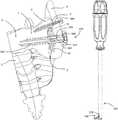
- FIG. 1illustrates a cross-sectional view of a natural sacroiliac joint and a cavity extending across the joint, the cavity filled with bone graft material, and the joint fused by a fusion device comprising a screw member and a washer, and a supplementary screw;
- FIG. 2Aillustrates a front view of a cutter which may be used to create the cavity of FIG. 1 , the cutter having a blade in a retracted configuration
- FIG. 2Bis a side view of the cutter of FIG. 2A , the side view rotated 90 degrees from the front view
- FIG. 2Cis a side view of the cutter of FIG. 2A , with the blade in an extended configuration
- FIG. 3is a partially exploded view of the cutter of FIG. 2A , the cutter including a handle assembly, a blade assembly, and an outer tube;
- FIG. 4Ais a front view of a blade shaft of the cutter of FIG. 2A ;
- FIG. 4Bis a side view of the blade shaft of FIG. 4A ;
- FIG. 4Cis a cross-sectional view of the blade shaft of FIG. 4B , taken along line A-A in FIG. 4B ;
- FIG. 5Ais a partially exploded side view of one end of a blade shaft assembly for the cutter of FIG. 2A , the assembly having a blade shaft, a blade holder, and a blade;
- FIG. 5Bis a partially exploded back view of the blade shaft assembly of FIG. 5A ;
- FIG. 6Ais a perspective view of the blade of FIG. 5A ;
- FIG. 6Bis a front view of the blade of FIG. 5A ;
- FIG. 6Cis a back view of the blade of FIG. 5A ;
- FIG. 6Dis a cross-sectional view of the blade of FIG. 5A taken along line E-E of FIG. 5A ;
- FIG. 7Ais a longitudinal side cross-sectional view of a shaft portion of the cutter of FIG. 2A with the blade in the retracted configuration
- FIG. 7Bis a longitudinal side cross-sectional view of the shaft portion of the cutter of FIG. 2A with the blade in the extended configuration
- FIG. 8Ais a perspective view of another embodiment of a blade for the cutter of FIG. 2A ;
- FIG. 8Bis a cross-sectional view of the blade of FIG. 8A taken approximately along line B-B of FIG. 8A ;
- FIG. 9Ais a perspective view of another embodiment of a blade for the cutter of FIG. 2A ;
- FIG. 9Bis a cross-sectional view of the blade of FIG. 9A taken approximately along line C-C of FIG. 9A ;
- FIG. 10is a view of a guide wire inserted to cross a joint of a first bone and a second bone at a procedure site, and a set of dilators mounted over the guide wire; in FIGS. 10-22 the first and second bones and the joint are depicted in cross-section in order to view the components of the invention in situ;
- FIG. 11is a view of the guide wire and dilators of FIG. 10 , with a cannula inserted over the guide wire and dilators and docked into the first bone;
- FIG. 12is a view of the cannula of FIG. 11 , with an impactor mounted on an end of the cannula;
- FIG. 13is a view of the cannula of FIG. 11 , with an support struts attached to the cannula;
- FIG. 14Ais a view of the cannula of FIG. 11 , with a sleeve partially received in a bore of the cannula;
- FIG. 14Bis a longitudinal cross-sectional view of the cannula, guide wire and sleeve of FIG. 14A ;
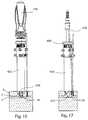
- FIG. 15is a view of the cannula and sleeve of FIG. 14A , with a drill inserted through the cannula and sleeve, and a passageway drilled across the joint;
- FIG. 16Ais a view of the cannula and sleeve of FIG. 14A , with the cutter of FIG. 2C inserted into the cannula and sleeve, the cutter blade in the extended configuration, and a circular cavity cut into the first bone and second bone across the joint;
- FIG. 16Bis a close-up view of the distal end of the sleeve and cutter of FIG. 16A , also showing a cutting radius r of the cutter and a diameter d of the cavity;
- FIG. 16Cis a cross-sectional view of the cutter shaft portion, cannula and sleeve of FIG. 16A cutting a cavity in a sacro-iliac joint;
- FIG. 17is a view of the cannula, sleeve and cavity of FIG. 16A , with a suction tool inserted through the cannula and sleeve and into the cavity;
- FIG. 18is a view of the cannula, sleeve and cavity of FIG. 16A , with a graft funnel mounted in the cannula, a tamp inserted through the graft funnel, and bone graft material in the cavity;
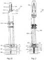
- FIG. 19is a view of the cannula, sleeve, cavity and bone graft material of FIG. 18 , with a drill inserted through the cannula and sleeve, and another passageway drilled across the joint deeper into the second bone;
- FIG. 20is a view of the cannula, sleeve, cavity, bone graft material and passageway of FIG. 19 , with a guide wire installed though the passageway and into the second bone and a length gauge mounted on the cannula;
- FIG. 21is a view of the cannula, sleeve, cavity, bone graft material, guide wire passageway and of FIG. 19 , with the fusion device of FIG. 1 implanted in the first bone and second bone, across the joint;
- FIG. 22is a view of the joint and fusion device of FIG. 21 , with a guide brace mounted over the guide wire and the supplementary screw inserted in the first bone and second bone, across the joint;
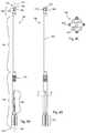
- FIG. 23Ais a side view of the fusion device of FIG. 1 ;
- FIG. 23Bis a perspective view of the fusion device of FIG. 1 ;
- FIG. 23Cis a cross-sectional view of the fusion device of FIG. 1 , taken along line F-F in FIG. 23A ;
- FIG. 23Dis an exploded view of the fusion device of FIG. 1 ;
- FIG. 24is a perspective view of the cannula of FIG. 11 ;
- FIG. 25is a perspective view of the sleeve of FIG. 14A ;
- FIG. 26is a perspective view of the length gauge of FIG. 20 ;
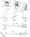
- FIG. 27is a perspective view of the graft funnel of FIG. 18 ;
- FIG. 28is a perspective view of the tamp of FIG. 18 ;
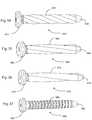
- FIG. 29is a perspective view of an alternate embodiment of a fusion device screw-type fastener
- FIG. 30is a perspective view of another alternate embodiment of a fusion device screw-type fastener
- FIG. 31is a perspective view of another alternate embodiment of a fusion device screw-type fastener
- FIG. 32is a perspective view of another alternate embodiment of a fusion device screw-type fastener
- FIG. 33is a perspective view of another alternate embodiment of a fusion device screw-type fastener
- FIG. 34is a perspective view of another alternate embodiment of a fusion device nail-type fastener
- FIG. 35is a perspective view of another alternate embodiment of a fusion device nail-type fastener
- FIG. 36is a perspective view of another alternate embodiment of a fusion device nail-type fastener
- FIG. 37is a perspective view of another alternate embodiment of a fusion device nail-type fastener
- FIG. 38Ais a view of an axial computer tomographic (CT) scan of a pelvis, showing an idealized trajectory for a sacro-iliac joint implant, and measurement segments along the trajectory; and
- FIG. 38Bis a black and white line tracing of the bony anatomy of the CT scan of FIG. 38A , showing the idealized trajectory for a sacro-iliac joint implant, and the measurement segments along the trajectory; and
- CTcomputer tomographic
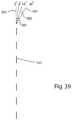
- FIG. 39depicts a longitudinal axis of the screw member of FIG. 1 , and a washer bore central axis of the washer of FIG. 1 at various degrees of angulation with respect to the screw member longitudinal axis.
- the present inventionrelates specifically to systems and methods for fusion of a sacroiliac joint, and more generally to systems and methods for creating a cavity in a bone or joint.
- frontis used herein to identify a relative frame of reference to a particular device or an individual element of a device.
- front or upper side of a device or elementmay be established on any desired side of the device or element.
- an implant for providing compression across a joint between a first bone portion and a second bone portion, wherein a cavity is located within the joint between the first bone portion and the second bone portioncomprises: a screw member having a screw head, and a screw body projecting distally from the screw head along a longitudinal axis to a screw distal end, the screw body comprising a non-threaded lag zone and a threaded engagement zone, the lag zone extending from the screw head distally to the engagement zone, the engagement zone extending from the lag zone to the screw distal end; and a washer member having a proximal side and a distal side, and a bore having a central bore axis; wherein the screw head is received in the washer member, and the screw body projects distally from the washer member; and an implant fusion zone having a length which is measured from the distal side of the washer member to a proximal end of the screw engagement zone, wherein the length of the implant
- Embodiments of this aspect of the disclosuremay include one or more of the following features:
- the washer memberfurther includes a semispherical capsule between the proximal side and the distal side, and the screw head is received in the semispherical capsule to permit polyaxial angulation of the washer member with respect to the screw member.
- the permitted polyaxial angulation of the washer member central bore axis with respect to the screw member longitudinal axisranges from at least ⁇ 8 degrees to at least +8 degrees.
- An annular grooveis formed between the screw head and the screw body, wherein the screw is smaller in diameter at the annular groove than at the lag zone or at the screw head.
- the washer memberis captive to the screw member.
- the screw membercomprises a central longitudinal bore extending from the screw head to the screw distal end.
- the lag zoneincludes at least one fenestration which opens into the central longitudinal bore. At least a portion of the fenestration is located within the implant fusion zone.
- An overall length of the implantmeasured from the distal side of the washer to the screw distal end when the washer central bore axis is coaxial with the screw member longitudinal axis, ranges from about 40 mm to about 110 mm.
- the implantcomprises at least two different surface finishes.
- the lag zone and at least a portion of the threaded engagement zonecomprise a roughened surface finish; the distal end of the screw member comprises a non-roughened surface finish; and the screw head and washer semispherical capsule comprise a non-roughened surface finish.
- the implantis a sacro-ilial fusion implant, wherein the joint is a sacroiliac joint, the first bone portion is an ilium, the second bone portion is a sacrum, and the cavity is located between the ilium and the sacrum; wherein, when the implant is installed across the sacroiliac joint, the distal side of the washer member is in contact with an exterior surface of the ilium, the implant fusion zone extends at least partially across the sacroiliac joint and the cavity, and the threaded engagement zone is at least partially embedded in the sacrum.
- a method for compressing a joint between a first bone portion and a second bone portion, wherein a cavity is located within the joint between the first bone portion and the second bone portioncomprises providing an implant comprising a screw member having a screw head and a screw body projecting distally from the screw head along a longitudinal axis to a screw distal end, the screw body comprising a non-threaded lag zone and a threaded engagement zone; and a washer member having a proximal side and a distal side, wherein the screw head is received in the washer member; wherein the implant further comprises a fusion zone having a length which is measured from the distal side of the washer member to a proximal end of the screw engagement zone, wherein the length of the implant fusion zone ranges from about 10 mm to about 26 mm; inserting the screw body engagement zone through the first bone portion and into the cavity; engaging the screw body engagement zone with the second bone portion; positioning at least a portion of the implant
- Embodiments of this aspect of the disclosuremay include one or more of the following features and/or methods:
- the lag zonecomprises a fenestration opening into a central longitudinal bore, and the method further comprises filling the fenestration with bone graft material. Filling the cavity with bone graft material.
- the washer membercomprises a bore having a central bore axis. Angling the washer member with respect to the screw member comprises angling the washer member central bore axis with respect to the screw member longitudinal axis within the range of at least ⁇ 8 degrees to at least +8 degrees.
- the implantis a sacro-ilial fusion implant and the joint is a sacro-iliac joint, and wherein the first bone portion is an ilium, and the second bone portion is a sacrum, and the cavity is located between the ilium and the sacrum. Positioning the fusion zone to extend into cavity, wherein the fusion zone crosses the first bone portion and extends into cavity. Positioning the fusion zone to contact the second bone portion.
- a system for compressing a joint between a first bone portion and a second bone portioncomprises an instrument for excising a cavity between the first bone portion and the second bone portion, the instrument having a handle and a blade assembly, wherein the blade assembly is movable between a retracted configuration and an extended configuration relative to an instrument longitudinal axis to define a cutting radius; and an implant for providing compression across the first bone portion, the cavity, and the second bone portion to fuse the joint, wherein the implant comprises: a screw member having a screw head, and a screw body projecting distally from the screw head along a longitudinal axis to a screw distal end, the screw body comprising a lag zone and a threaded engagement zone; a washer member having a proximal side and a distal side, wherein the screw head is received in the washer member, and the screw body projects distally from the washer member; and an implant fusion zone is defined to extend from the distal side of the washer member to a prox
- Embodiments of this aspect of the disclosuremay include one or more of the following features:
- the lag zoneis non-threaded and extends from the screw head distally to the engagement zone, and the engagement zone extends distally from the lag zone to the screw distal end.
- the screw bodycomprises a central longitudinal bore extending from the screw head to the screw distal end, and the lag zone comprises a fenestration opening into the central longitudinal bore.
- the washer membercomprises a semispherical capsule between the proximal side and the distal side, and the screw head is received in the semispherical capsule to permit polyaxial angulation of the washer member with respect to the screw member.
- the washercomprises a bore having a central bore axis, wherein the permitted polyaxial rotation angulation of the washer member central bore axis with respect to the screw member longitudinal axis ranges from at least ⁇ 8 degrees to at least +8 degrees.
- An overall length of the implantmeasured from the distal side of the washer to the screw distal end when the washer central bore axis is coaxial with the screw member longitudinal axis, ranges from about 40 mm to about 110 mm.
- the length of the implant fusion zoneranges from about 10 mm to about 37 mm.
- the implantis a sacro-ilial fusion implant, and the joint is a sacroiliac joint, the first bone portion is an ilium, the second bone portion is a sacrum, and the cavity is excised between the ilium and the sacrum.
- the implantWhen the implant is installed across the sacroiliac joint, the distal side of the washer member is in contact with an exterior surface of the ilium, the implant fusion zone extends at least partially across the sacroiliac joint and the cavity, and the threaded engagement zone is embedded in the sacrum.
- An outer diameter of the cavityis determined by the instrument cutting radius, and the maximum outer diameter of the implant is less than the cavity outer diameter.
- FIG. 1illustrates a natural sacroiliac joint fused by methods of the invention.
- the sacroiliac joint 2comprises the meeting of a sacrum 5 and an ilium 6 .
- a cavity 20is created between the sacrum 5 and the ilium 6 , and may be filled with bone graft material 15 .
- a fusion device 550is implanted across the joint 2 to provide compression and fuse the joint.
- the fusion devicemay be sized to extend through the ilium 6 , across the joint 2 and cavity 20 , and into the sacrum 5 , extending through the cortical bone 4 , the sacral ala 7 , and into the sacral vertebrae 9 of the sacrum 5 . It is appreciated that the instrumentation and methods disclosed herein may also be applied to provide fusion in any other joint, or to provide fusion between two or more bones or bone portions.
- FIGS. 2-9Bdisclose a cutting instrument, herein referred to as a cutter 100 , which may be used to create the cavity 20 in the joint 2 .
- cutter 100may applied to create a cavity within a bone or bones, and/or across a joint.
- cutter 100outwardly comprises a handle portion 102 , a shaft portion 104 , and a blade portion 106 .
- the handle portion 102may be gripped and moved to direct the shaft and blade portions 104 , 106 to a specific area such as a bone or joint, and manipulated to deploy a blade to create a cavity in the bone or joint.
- the cuttercomprises a proximal end 110 and a distal end 112 with a cutter central longitudinal axis 114 extending therebetween.
- the handle portion 102comprises a handle 120 and a knob 122 , and has a distal end 124 and a proximal end 126 .
- the shaft portion 104comprises an outer tubular member or outer tube 134 which extends distally from the handle portion 102 and terminates at the distal end 112 .
- Housed within the outer tube 134 , and handle 120is a blade shaft 140 .
- the blade shaft 140extends from the proximal end 110 of the cutter, through the knob 122 , handle 120 and outer tube 134 .
- a blade 150is modularly and pivotably connected to the blade shaft 140 via a blade retainer 142 .
- the blademay also be referred to as a cutting member, or a decorticator. In alternative embodiments, the blade may be monolithic with the blade shaft or may be permanently attached to the blade shaft.
- handle 120includes a handle outer surface 260 which can include gripping features 262 and indicia 264 .
- Indicator windows 266allow viewing of markings 176 from either side of the handle 120 .
- the knob 122includes a knob outer surface 270 which can include gripping features 272 and indicia.
- Blade shaft 140extends between a proximal end 160 and a distal end 162 along a shaft central longitudinal axis 164 .
- the shaft central longitudinal axis 164is coaxial with the cutter central longitudinal axis 114 .
- the blade shaft 140may be cannulated throughout, having a central bore 165 .
- the blade shaftcan include a proximal handle portion 180 , a shaft 182 , and a distal attachment portion 184 .
- the blade shaftmay include an engagement feature 166 which engages with the knob 122 , forming an actuation mechanism which controls extension and retraction of the blade 150 .
- the handle portion 180 of the blade shaft 140includes a longitudinal section 183 which is generally rectangular in cross-section.
- the rectangular sectionengages with the handle 120 to prevent rotation of the blade shaft 140 relative to the handle 120 .
- Indiciawhich may take the form of the markings 176 , are present on the blade shaft and positioned to be visible through a window in the handle 120 , allowing a practitioner to determine the diameter of the cavity being excised by the blade 150 .
- an attachment feature 178protrudes distally allowing for attachment of the blade holder 142 .
- the attachment feature 178is shaped as a boss 186 having an undercut 188 and paired angled projections or ears 190 to retain the blade holder 142 .
- the blade holdermay connect to the blade shaft in another connection mechanism, or may be permanently connected.
- the blade 150may be directly connected to the blade shaft 140 .
- outer tube 134includes a tubular body 280 extending between a proximal end 282 and a distal end 284 .
- the distal end 284 of the tubular body 280terminates in a distal end face 290 .
- Adjacent the distal end 284is a notch 292 which may be viewed fluoroscopically to ascertain the position of the distal end 112 of the cutter 100 during a procedure.
- a blade window 294functions as an opening to allow the blade 150 to protrude out of the tubular member for cutting procedures.
- a ramped surface 296 opposite and interior to the blade window 294guides the blade 150 as it is urged out of the window 294 , guiding the blade to project laterally relative to the cutter axis 114 .
- the ramped surface 296functions as a stop to prevent further distal movement of the blade 150 and hold it rigid relative to the cutter 100 .
- blade holder 142may be snapped on and off of blade shaft 140 .
- Blade holder 142includes a first or shaft end 300 and a second or blade end 302 .
- the shaft end 300is U-shaped, comprising a pair of connected sidewalls 304 , 306 separated by a gap 308 shaped to receive the blade shaft boss 186 .
- Each sidewallterminates in a tab 305 , 307 .
- the blade end 302includes a receiver boss 310 having a bore 312 , the bore extending perpendicular to the longitudinal axis of the blade holder 142 .
- the blade end 302terminates in a curved or ramped surface 316 sloping to an apex 314 .
- the ramped surface 316provides structural support and rigidity, and provides a physical stop to rotation of the blade relative to its holder 142 during cutting steps, and a physical stop to movement of the blade 150 relative to the cutter 100 during cutting steps.
- a pin ormay pivotably connect the blade 150 to the blade holder 142 via extending through the bore 312 . In another embodiment, another pivotable connection may connect the blade 150 to the blade holder 142 or directly to the blade shaft 140 .
- the blade 150includes a proximal or attachment end 330 , a distal end 332 , and a curved blade body 334 extending therebetween along a blade length.
- the attachment end 330includes first and second extensions 336 , 338 which project proximally from the blade body 334 , and include bores to receive a connecting pin.
- the body extensions 336 , 338are separated by a gap 339 shaped to receive the receiver boss 310 .
- the curved blade body 334may be reduced in its width relative to the first and second extensions 336 , 338 , as seen in FIGS. 6B and 6C .
- the blade body 334is shaped as a loop, looping from the extensions 336 , 338 at a blade front side 340 on a blade first leg 341 , forming a U-shaped terminal curve 342 at the distal end 332 , back to the extensions 336 , 338 at a blade back side 344 on a blade second leg 343 .
- the blade 150may also be described as lasso-shaped or banana-shaped.
- a curved void 346extends from the extensions 336 , 338 to the terminal curve 342 , separating the blade first leg 341 from the blade second leg 343 .
- the curved void 346provides passage for bone fragments and other materials moved by or encountered by the blade 150 during use.
- a blade first side 348extends between the first extension 336 and the distal end 332
- a blade second side 350extends between the second extension 338 and the distal end 332 , opposite the blade first side 348 .
- the blade first side 348includes portions of both the first and second legs 341 , 343 , as does the blade second side 350 .
- the first and second legs 341 , 343may be parallel to one another, separated by the width of the void 346 .
- a furrow or blade relief 352is recessed into the blade body, the blade relief 352 continuous from the blade front side 340 on first leg 341 onto the blade back side 344 on the second leg 343 .
- the blade relief 352is a rounded ridge 353 , which is also continuous from the first leg 341 on to the second leg 343 , and forms the boundary of the curved void 346 .
- the blade front side 340 and the blade back side 344each include a concave curvature along their respective lengths, the concave curvature centered along the midline of the blade length to reduce the contact area at the cutting surface and thus reduce the drag forces on the blade.
- the concave curvatureis a convex curvature.
- the blade first side 348terminates laterally in a first cutting edge 356
- the blade second side 350terminates laterally in a second cutting edge 358 which projects opposite from the first cutting edge.
- a curved cutting edge having an open ended U shapeis formed on either side of the blade 150 , enabling cutting to occur whether the cutter 100 is rotated clockwise or counter-clockwise.
- the blade 150is bilaterally symmetrical relative to a longitudinally extending midline, generally demarcated by the center of the blade relief 352 , between the first side 348 and the second side 350 .
- a first sloped surface 360slopes from the first cutting edge 356 to the ridge 353
- a second sloped surface 362slopes from the second cutting edge 358 to the ridge 353 .
- the sloped surfaces 360 , 362may facilitate movement of severed material toward the void 346 and away from the cutting edge to prevent clogging during operation of the cutter 100 .
- the blade bodymay include a single cutting edge, enabling unidirectional cutting when the cutter 100 is rotated in one direction. In another embodiment of the invention, rotation of the cutter 100 may be limited to a single direction.
- each leg 341 , 343is each generally V-shaped.
- the cutting edges 356 , 358form the opposing lateral tips of the V, and the blade relief 352 and ridge 353 form the bottom of the V.
- a cross-section of the entire blade to include both blade legsresults in twin V shapes which are back-to-back, or facing away from one another, and separated by the void 346 , as seen in FIG. 6D .
- each leg 341 , 343is curved in at least two planes: from the first side 348 to the second side 350 , and from the proximal end 330 to the distal end 332 .
- the shape of each legmay be described as an elongated hyperbolic paraboloid, or as an elongated saddle shape.
- the blade relief provided by the shape of the bladereduces friction as the blade is rotated during a cutting procedure.
- the blade 150is a monolithic entity composed of a rigid material, in order to provide sufficient rigidity during cutting processes to cleanly cut through softer tissues such as cartilage, and harder materials such as cancellous bone, and particularly, cortical bone.
- the blades disclosed hereinmay be composed of stainless steel.
- the blade 150may be provided in a variety of sizes, varying in length, width, curvature, and/or thickness. A practitioner may select the appropriate sized blade for the patient and attach the blade to the cutter 100 .
- the blade shaft 140 , blade holder 142 and blade 150form a blade assembly 155 .
- the blade assembly 155is modular and may be inserted and removed from the cutter 100 as needed, for example to change blades.
- the blade 150 and blade holder 142may be provided in a variety of shapes, lengths, widths, curvatures and/or angles in order to create the desired size and shape of cavity when the cutter is deployed.
- the radius of curvature between the proximal 330 and distal 332 ends of the blade 150vary, as may the radius of curvature between the first and second cutting edges 356 , 358 , in different embodiments of the blade.
- the length of the blade 150 from proximal 330 and distal 332 endsmay vary, as may the depth between the front side 340 and the back side 344 , and/or the width between the between the first side 348 and the second side 350 .
- the blade holder 142may be provided in a variety of lengths, and the angle of the ramped surface 314 may vary.
- FIGS. 7A and 7Bare cross-sectional views of the shaft 104 and blade 106 portions of cutter 100 .
- the outer tube 134may be attached to the handle portion 102 to form a housing assembly 145 .
- the blade 150may be attached to the blade holder 142 ; in some embodiments the blade and blade holder may be provided pre-assembled.
- the blade holder 142is snapped to the blade shaft 140 as described herein.
- the blade assembly 155can be inserted into the housing assembly 145 in a proximal to distal approach, with the blade 150 leading through knob 122 and handle 120 .
- the indicia on the blade shaft 140 and on the handle 120can provide guidance as to the proper orientation of the blade shaft about its longitudinal axis 164 as the blade assembly 155 is inserted.
- the blade 150rests inside blade window 294 at the distal end of the housing assembly 145 , and the blade 150 is generally longitudinally aligned to extend along the cutter axis 114 .
- the cutter distal end 290is positioned at the site.
- torquemay be applied to knob 122 to rotate it in a first direction such as clockwise, wherein the knob 122 engages the engagement feature 166 of blade shaft 140 to translate the blade assembly 155 distally along the device axis 114 .
- the blade 150is projected laterally away from device axis 114 and out of window 294 , biased by contact with ramped surface 296 , which functions as a curved guide surface during blade extension.
- the blade distal end 332moves along curved guide path 370 as the blade exits the window.
- the indicia 176are visible through the handle window 266 and may indicate the current cutting diameter of the instrument.
- rotation of the knobis ceased, and to perform a cutting step the entire cutter 100 may be rotated about its longitudinal axis 114 by applying torque to the handle, allowing the leading cutting edge 356 or 358 to cut through the bone or other material surrounding the exposed blade 150 .
- the cutting stepmay form a circular cavity in the procedure site.
- the knob 122may again be actuated to further extend the blade laterally out the window 294 , and the cutting step may be repeated. Extension and retraction of the blade may be ceased at any point along the curved path 370 .
- the blade 150is essentially immobilized relative to the cutter 100 ; independent movement of the blade 250 is prevented. If the blade 150 is less than fully extended, the blade 150 is rigidly held between the bone or joint being cut and the ramped surface 296 ; rotational movement of the blade 150 in concert with rotational movement of the cutter 100 is permitted but movement of the blade 150 , including pivotal, axial and rotational, relative to the shaft 140 and cutter 100 is prevented.
- the blade 150When the blade 150 is fully extended, the blade 150 is rigidly held between the opposing curved surfaces 316 and 296 in a locked position; rotational movement of the blade 150 in concert with rotational movement of the cutter 100 is permitted but movement of the blade 150 , including pivotal, axial and rotational, relative to the shaft 140 and cutter 100 is prevented.
- the longitudinal curvature of blade 150may match the curvature of guide path 370 .
- the concave curvature of the ramped surface 296matches the convex curvature of the blade second leg 343 and blade holder 142 when the blade 150 is fully extended out of the blade window, to provide structural support and rigidity, and to provide a physical stop to independent movement of the blade 150 relative to the shaft 140 and cutter 100 .
- the blade extension and cutting stepsmay be repeated as desired to create a cavity of a selected diameter at the procedure site.
- the knob 122may be turned in a second direction such as counter-clockwise to translate the blade shaft 140 proximally and retract the blade 150 into the window 294 , and the cutter may be withdrawn from the procedure site.
- the cutter 100may be inserted axially deeper into the procedure site and redeployed to deepen the circular cavity or create another cavity.
- the cutter 100may be rotated less than 360° to create a cavity that is less than a full circle.
- the cutter 100 described hereinmay be used in a procedure to fuse a sacro-iliac joint.
- the cutter 100may be deployed to create a cavity in the cartilage at the joint between the sacrum and the ilium, and/or in the hard cortical bone matter of the sacrum and/or ilium.
- Bone graft materialmay be inserted into the cavity, and a fusion device may be implanted across the joint to compress and fuse the joint.
- FIGS. 8A-9Balternative embodiments of a blade for cutter 100 are shown.
- FIGS. 8A and 8Bdisclose a blade 200 having a proximal or attachment end 201 , and a distal or working end 202 , and a curved blade body 204 extending therebetween along a blade length.
- An attachment portion 203is proximate the proximal end 201 .
- the description of the features of the attachment end of blade 150also applies to blades 200 and 250 .
- the blade body 204is shaped as a loop, looping from attachment end 201 at a blade front side 206 on a blade first leg 208 , forming a U-shaped terminal curve 210 at the distal end 202 , back to the attachment end 201 at a blade back side 212 on a blade second leg 214 .
- the blade 200may also be described as lasso-shaped or banana-shaped.
- a curved void 216extends from the attachment portion 203 to the terminal curve 210 , separating the blade first leg 208 from the blade second leg 214 .
- the curved void 216provides passage for bone fragments and other materials moved by or encountered by the blade 200 during use.
- a blade first side 218extends between the attachment end 201 and the distal end 202
- a blade second side 220extends between the attachment end 201 and the distal end 202 , opposite the blade first side 218 .
- the blade body 204is flat on a continuous outer surface 222 formed by the front side 206 of first leg 208 , around the terminal curve 210 , and the back side 212 of second leg 214 .
- the blade first side 218terminates laterally in a first cutting edge 224
- the blade second side 220terminates laterally in a second cutting edge 226 which projects opposite from the first cutting edge.
- a curved cutting edge having an open ended U shapeis formed on either side of the blade 200 , enabling cutting to occur whether the cutter 100 is rotated clockwise or counter-clockwise.
- the blade 200is bilaterally symmetrical relative to a longitudinally extending midline, generally demarcated by the midline center of the continuous outer surface 222 , between the first side 218 and the second side 220 .
- the first leg 208 and second leg 214are generally triangular, resulting in twin triangular shapes which are apex-to-apex, or facing away from one another, and separated by the void 216 .
- the other features of blade 150also apply to blade 200 , including the void, and the sloped surfaces extending from the cutting edges toward the void.
- FIGS. 9A-9Bdisclose another alternate embodiment of a blade for use with cutter 100 .
- the description, form and features of blade 150apply to blade 250 , with the exception of the cutting edges.
- Blade 250includes first 252 and second 254 cutting edges which are broken up by scallops or serrations 256 .
- the serrations 256may vary in size along different portions of the blade 250 , and may extend inward as far as the longitudinally extending midline of the blade. When deployed in cutter 100 , the serrations 256 may facilitate cutting through hard cortical bone material.
- a method of fusing a jointis set forth below. It is appreciated that although the method described is for a sacro-iliac joint, the method can be applied to any joint, or to fusion of any two bones or bone portions.
- the instruments and/or methods described hereinmay be applied to other procedures, including at least: intramedullary osteotomies for limb-lengthening, derotation, and/or malunion procedures; spinal disc space joint preparation for arthrodesis, arthroplasty and/or other procedures; and subtalar joint preparation for ankle fusion.
- the cutter 100may be advantageously used to cut both soft cancellous bone and hard cortical bone.
- FIGS. 10-27systems and methods for preparing a joint space and implanting a fusion implant are shown.
- the methodmay include one or more of the following steps described below. It is understood that in certain embodiments of the method, the steps may or may not be performed in the order set forth below, one or more of the steps may be omitted, one or more of the steps may be repeated, and/or additional steps may be performed. In other embodiments of the invention, the systems and methods described herein may be used to fuse two bone portions, or two bones.
- FIGS. 10-22include a stylized cross-sectional depiction of a meeting of an ilium 6 and a sacrum 5 at a sacro-iliac joint 2 .
- the portion of the ilium depictedmay include primarily hard cortical bone.
- the sacrum 5is depicted as having three strata; hard cortical sacral bone 4 , the sacral ala 7 and the sacral vertebral body 9 . It is appreciated that the natural joint 2 between the ilium 6 and sacrum 5 undulates, as do the strata of the sacrum 5 , with the natural anatomy of the bones; in the figures they are depicted as straight lines for clarity.
- a guide wireis introduced into a procedure site, in the example shown a sacro-iliac joint 2 between a sacrum 5 and an ilium 6 .
- the guide wireis introduced through the ilium, and into the joint space, so that the tip of the guide wire is in the joint space.
- the guide wiremay comprise a guide line, guide pin, k-wire, or another guiding line known in the art.
- the guide wiremay create an access passageway 8 through skin, muscle and other tissues from outside the patient to the sacro-iliac joint.
- a first guide wire comprising a 2 mm k-wiremay be introduced, removed, and a larger diameter guide wire 400 is introduced through the access passageway 8 created by the first guide wire.
- the guide wiremay be positioned so that a tip 402 of the larger diameter guide wire 400 protrudes through the ilium 6 across the joint 2 and into the bone 4 of the sacrum 5 .
- the guide wire 400may be a 3.2 mm k-wire.
- one or more cannulated dilators 404 , 406 , 408may be sequentially introduced over a proximal end 401 of the guide wire 400 toward the procedure site, to further increase the diameter of the access passageway 8 .
- three dilatorsare introduced sequentially, in ascending diameter size, over the guide wire 400 .
- Each dilatormay be inserted concentrically over the guide wire and previous dilator(s) until a distal end of the dilator, for example distal end 410 of dilator 408 contacts the ilium 6 .
- one or more steps of the methodmay be performed without utilizing guide wires.
- a computerized navigation systemmay be used to guide the instrumentation and steps of the system.
- an access cannula 420is introduced over the guide wire 400 and dilator(s).
- the access cannula 420includes a proximal end 422 and a distal end 424 , with a peripheral wall 426 extending therebetween, surrounding an internal bore 425 .
- the cannula 420may include one or more distally projecting teeth 428 which may protrude into the ilium 6 to dock the cannula to the ilium and stabilize the position of the cannula.
- the cannula 420may further include one or more brackets 430 or other attachment features to connect to stabilizing elements such as wires or struts.
- the brackets 430may be specifically shaped and/or angled to hold the stabilizing elements in a desired alignment.
- a portion of the peripheral wall 426includes internal threading 432 , and one or more access ports 434 may be formed in the peripheral wall 426 .
- the teeth 428may protrude several millimeters into the ilium, but in the embodiment shown, preferably do not extend into the joint 2 .
- an impactor 440may be connected to the proximal end 422 of the cannula 420 to drive the teeth 428 into the ilium and more securely fix the cannula in place.
- a mallet or other tool(not shown) may be used to apply axial force to the impactor 440 .
- one or more stabilizing guide wires 444may be connected to the brackets 430 and distal ends 445 of the guide wires 444 introduced into the ilium 6 , to further stabilize the position of the cannula 420 for subsequent steps of the method.
- the dilator(s) 404 , 406 , 408may be proximally withdrawn from the cannula, over the guide wire 400 .
- a sleeve 450is introduced over the guide wire 400 and into the proximal end of the cannula 420 .
- the sleeve 450includes a proximal end 452 , a distal end 454 and a sleeve body 456 surrounding a longitudinal sleeve bore 455 .
- a rim 458encircles the sleeve body 456 , and a portion of the sleeve body includes external threading 460 for engagement with the access cannula 420 , forming an adjustment mechanism with the cannula.
- the sleeve body 456may include a proximal section 462 , a neck 464 and a distal section 466 .
- the diameter of the sleeve bore 455may decrease from the proximal section 462 to the distal section 466 , tapering in the neck 464 .
- a flange 469projects outwardly from the distal section 466 and may stabilize the distal section with respect to the access cannula 420 .
- the sleeve 450may include indicia 468 so that as the sleeve 450 is engaged with the access cannula 420 , a precise distance to the cannula distal end 424 , and thus the procedure site, may be achieved.
- the combined axial length of the sleeve 450 and cannula 420may be adjusted along a continuum by rotation of the sleeve 450 . This adjustability allows precise placement of the cutter blade 150 at the joint 2 , and may prevent over-insertion of the cutter 100 or other instrumentation.
- At least one ball detentmay be received in a cannula access port 434 , and interact with a groove 463 formed on the exterior of the sleeve body 450 to provide tactile indication of the extent of the sleeve rotation.
- the reduced inner diameter of the sleeve distal section 466may precisely target instrumentation such as cutter 100 toward the procedure site.
- a drill 470is introduced over the guide wire 400 and through the sleeve bore 455 and cannula bore 425 .
- a first passageway 18is drilled through the ilium 6 , across the joint 2 , and into the sacrum, and replaces the access passageway 8 .
- the guide wire 400may be withdrawn from the access cannula 420 . Suction may be applied to remove material from the first passageway 18 .
- the cutter 100is introduced, with the shaft portion 104 inserted through the sleeve 450 , cannula 420 , and first passageway 18 .
- the cutter distal end 112may contact the sacrum 5 , and the blade 150 within blade window 294 are positioned past, or distal to, the distal end 424 of the cannula 420 .
- the blade 150is in the retracted configuration, so that it is contained within a diameter envelope of the outer tube 134 .
- the handle distal end 124may contact the rim 458 of the sleeve, limiting the insertion depth of the cutter 100 .
- the sleeve 450may be rotated as needed to adjust the depth of the cutter distal end 112 . Fluoroscopy may be utilized as desired to visualize notch 292 and blade window 294 , allowing precise placement of cutter 100 relative to the joint 2 at the procedure site.
- knob 122is rotated to deploy the cutter blade 150 laterally.
- first deployed distance rmeasured as the distance from the cutter longitudinal axis 114 to the blade distal end 332 , perpendicular to the axis 114 .
- the deployed distancerepresents the radius of a circle which may be cut by the cutter blade. The practitioner may check the deployed distance by reading the indicia 176 visible in the indicator window 266 .
- the indicia 176indicate the diameter of a circular cavity cut by the device.
- the diameter cut by the cutting device 100may range from 2 mm to 70 mm, and the cutting radius or deployed distance r may range from 1 mm to 35 mm.
- Blades 150 of varying lengthsmay be provided to attain the range of cutting diameters disclosed herein.
- torqueis applied to the handle 120 to rotate the entire cutter 100 about its longitudinal axis, thus sweeping the blade 150 in a circular path to perform a first cut.
- the cutting edge 356 or 358 at the leading side of the blade 150cuts into the surrounding bone and/or other tissue. Fragments of the bone and/or tissues are severed from the joint and are urged toward the void 346 , the leading sloped surface 360 or 362 facilitating movement of the tissue fragments away from the cutting edge and toward the void 346 .
- the blade 150cuts a cavity having a diameter determined by the distance between the cutter longitudinal axis and the blade distal end 332 at its deployed distance, or r.
- FIG. 7Billustrates the blade 150 at a fully deployed or fully extended configuration.
- the blade 150is held essentially immobile relative to the cutter 100 by contact with the opposing curved surfaces 296 and 316 , which act as stops to lock the blade in its extended position.
- the extended blade 150is held rigid by contact with the ramped surface 296 and contact with the bone or other tissue against which the blade is deployed.
- suctionmay be deployed in between cutting steps, or at other points during the procedures described herein, as needed to clear debris from the cavity and/or instrument.
- the cutter 100 or other instrumentmay be withdrawn from the cannula 420 .
- a suction tool 470may be inserted, until an opening 472 of the suction tool 470 is at a desired location in the cannula 420 or cavity 20 , or pathway 18 .
- the suction tool 470may be connected to a suction source, and suction is applied until the debris is removed. Fluid may be applied during the suction process.
- means for suctionmay be integrated into cutter 100 , eliminating the need for a separate suction tool.
- a graft funnel 480may be used to guide bone graft material into the cavity 20 .
- the graft funnelincludes a funnel portion 482 and a conduit 484 .
- a pair of openings 483 on opposite sides at the distal end of the conduit 484allow movement of the graft material out of the conduit.
- a plug 485 in the distal end of the conduitincludes guide surfaces that divert the graft material out of the opposing openings 483 .
- the graft funnelmay be inserted to extend through the sleeve 450 and cannula 420 with the distal end of the conduit 484 opening into the cavity 20 .
- Graft material 15is inserted into the funnel portion 482 .
- a tamp 486may be used to push the graft material distally through the conduit 484 toward the plug 485 , out the side openings 483 and into the cavity 20 .
- the tampmay include a handle 487 , a shaft 488 and a distal tamp face 489 .
- a tamping member with a solid distal tamp facemay be coupled to the blade holder 142 of the cutter 100 and deployed by rotation of the knob 122 to push the graft material through the conduit 484 and into the cavity 20 .
- the funnel 480may be selectively rotated to ensure that graft material exits the openings 483 into all or selected parts of the cavity 20 .
- a tunnelmay be drilled through the packed bone graft and across the cavity to prepare for insertion of a fusion device.
- a dilatorsuch as dilator 404 may be reintroduced into through sleeve 450 into cannula 420 , to provide a guide for a guide wire.
- the guide wire 400may also be reintroduced, and inserted through the ilium 6 , the cavity 20 and graft 15 , and into the sacrum 5 , extending through the hard cortical layer 4 , the sacral ala 7 and into the sacral vertebral body 9 .
- a drill 490is introduced over the guide wire 400 to drill a second passageway 28 also extending through the bone graft and cavity and into the sacrum 5 , to provide a passage for the fusion screw implant.
- both passageways 18 and 28may be drilled prior to cutting the graft cavity 20 with the cutter 100 .
- Length gauge 510can be used to determine the proper length for a fusion implant.
- Length gauge 510includes a support member 512 having a distal end 514 , a proximal end 516 , and a bore 515 ; and further includes a gauge 518 and set screw 520 .
- Set screw 520may include a ball detent.
- the gauge 518is partially cannulated, having a blind bore 519 shaped to receive the proximal end 401 of guide wire 400 , the blind bore having an end surface 521 .
- the gauge 518also includes a blind groove 22 . When assembled for use, the gauge 518 is received in bore 515 of the support member 512 .
- Set screw 520extends through an opening in the support member 512 and into the groove 522 .
- the screw length gauge 510is mounted on to cannula 420 , with the distal end 514 of the support member 512 resting on the proximal end 422 of the cannula.
- the guide wire 400 proximal end 401is received in the blind bore 519 of the gauge 518 .
- the gauge 518may be adjusted until the end surface 521 of the blind bore 519 rests on the proximal end 401 of the guide wire 400 .
- the proper implant lengthmay then be indicated by indicia 524 on the gauge 518 , read where the gauge 518 intersects the support member proximal end 516 .
- a properly sized fusion implant 550may be implanted into the prepared cavity 20 , crossing the cavity and joint 2 and engaging the sacrum 5 and ilium 6 .
- the fusion implant 550includes a screw member 552 and a washer member 554 .
- the screw member 552includes a head 566 and a distal tip 568 with a screw body 564 extending therebetween, extending along a screw longitudinal axis 557 .
- the head 566is preferably spherical and has a spherical center point 569 .
- Engagement features 567for example a hex feature as seen in FIGS.
- the screw member 552may include a bore or lumen 551 extending along its lengthwise dimension to allow for introduction over the guide wire 400 , and may include one or more fenestrations, or apertures 556 which open into lumen 551 for graft packing and bone through-growth.
- the lumen 551may be concentric about the axis 557 .
- a self-tapping threaded engagement zone 558is distal to a non-threaded lag zone 560 .
- An annular lip 559 projecting from the screw body 564may provide resistance to unintentional screw withdrawal, and may provide additional compression when the implant 550 is inserted across a joint.
- An undercut, or annular groove 561may encircle the screw member 552 at the junction of the screw head 566 and screw body 564 .
- the screw member 552is smaller in diameter at the annular groove 561 than at the lag zone 560 or at the screw head 566 .
- a distal annular surface 563encircles the screw body 564 between the lip 559 and the annular groove 561 , and is sloped relative to a transverse plane of the screw member.
- the lag zone 560may be non-threaded and cylindrical.
- the lack of exterior threading on the lag zone 560permits compression of the joint 2 between the engagement zone 558 , and the screw head 566 and/or washer 554 as the implant 550 is implanted across the joint 2 and into the sacrum 5 .
- the diameter of the lag zone 560is 10 mm; in another embodiment, the diameter of the lag zone 560 is 12 mm. In other embodiments of the disclosure, the diameter of the lag zone can range between about 6 mm and about 14 mm. In the context of the diameter of the lag zone, “about” is defined as +/ ⁇ 1 mm.
- the outer diameter of the washeris about 24 mm, and therefore a maximum outer diameter of the implant is about 24 mm. In the context of the outer diameter of the washer, “about” is defined as +/ ⁇ 8 mm. In an embodiment, the maximum outer diameter of the implant is less than the diameter of the prepared cavity 20 . In another embodiment, the maximum outer diameter of the implant is greater than the diameter of the prepared cavity 20 .
- the screw member 552may include internal threads 562 or other features for engagement with implantation and/or removal instrumentation.
- the engagement zone 558may be at least partially embedded in the sacrum 5 , extending into the body of the sacral vertebra 9 ; and the lag zone 560 may cross the ilium 6 , joint 2 , cavity 20 , and can extend into the sacrum 5 .
- the washer 554abuts the ilium 6 .
- the screw member 552may be sized so that the lag zone 560 is positioned to extend through the ilium, and the engagement zone 558 extends into the body of the sacral vertebra 9 upon implantation, permitting engagement in the region with improved bone quality including higher bone density.
- the washer 554includes an upper or proximal side 570 , a lower or distal side 572 , and a semispherical capsule 553 positioned between the upper and lower sides.
- the semispherical capsule 553has a spherical center point 571 and may be concavely curved, and circumscribes a bore 555 defining a central bore axis 582 .
- the semispherical capsule 553may retain the head 566 of the screw member 552 , and the screw body 554 protrudes distally from the bore 555 .
- the head 566may be recessed below the upper side 570 of the washer.
- An inner diameter of the washer 554 at the lower side 572may be approximately equal to the outer diameter of the screw member at the lip 559 .
- “approximately”is defined as the inner diameter of the washer 554 at the lower side 572 being equal to, or up to 5% smaller than, the outer diameter of the screw member at the lip 559 .
- the implant 550further includes a fusion zone 565 , which is defined as extending from the distal side 572 of the washer to the proximal end of the screw member engagement zone 558 , as shown in FIG. 23 .
- the fusion zone 565is non-threaded, and is a zone of compression and long-term fixation of the joint, between the washer and the threaded engagement zone.
- the sacral alais generally known to have lower bone mineral density (BMD), while the body of the sacral vertebra is known to have higher BMD.
- BMDbone mineral density
- the safe zone lengthextends between the boundaries (normal to the SI joint) of an area through which a sacral fixation implant may be inserted without impinging on neural structures or soft tissues.
- the safe zone dimensionmay be used to determine the diameter of the screw member engagement zone 558 .
- the ideal implant trajectory 690passes normal to the SI joint and crosses the safe zone 688 at the midpoint of the safe zone, and ultimately anchors in the denser sacral vertebral body 9 . Such a trajectory normal to the SI joint will provide the maximum compression during fusion, and passing through the middle of the safe zone allows the least risk to the patient.
- segment 692is the iliac width
- segment 694is the sacro-iliac joint space width
- segment 696is the sacral alar width
- segment 698is the sacral vertebral body width
- 688is the safe zone length. Summary results of the study are presented in Table 1 below.
- the average depth of the joint from the ilial outer surfaceis 21 mm.
- the length of the fusion zone 565measured with the washer in a neutral, coaxially aligned position relative to the screw member, was designed to be 23 mm for all screw members greater than or equal to 60 mm long, and 19 mm for all screw members less than 60 mm long, in order to provide optimal fit, engagement with high quality bone, and fusion, in the sacro-iliac joint.
- the shorter fusion zone on shorter screw membersfacilitates having sufficient remaining threaded length in the engagement zone for bone purchase.
- the overall length of the screw member 552may range between about 40 mm and about 110 mm. In the context of the overall length of the screw member 552 , “about” is defined as +/ ⁇ 2 mm. Screw members 552 may be available in 5 mm increments between 40 mm and 110 mm lengths, although a screw member of any intermediate length may also be provided.
- the length of the fusion zone 565may range from about 10 mm to about 37 mm long. In the context of the length of the fusion zone 565 , “about” is defined as +/ ⁇ 2 mm. For screw members 552 greater than or equal to 60 mm long, the fusion zone 565 may be 23 mm long. For screw members 552 less than 60 mm long, the fusion zone 565 may be 19 mm long.
- the diameter of the screw member engagement zone 558is 12 mm. This diameter is based on the safe zone measurements in Table 1; a 12 mm diameter allows 2 mm on either side of the screw member engagement zone 558 , while remaining within the safe zone average measurement of 17.9 mm.
- the semispherical connection between the head 566 and the washer member 554permits polyaxial orientation of the screw member 552 relative to the washer member 554 .
- the reduced diameter of the screw member at the annular groove 561 with respect to the screw body 564enables a greater range of motion for the washer member than if the screw member diameter were not reduced.
- the angled distal annular surface 563 of the screw body 564enables a greater range of motion for the washer member than if the distal annular surface were flat, or perpendicular to the longitudinal axis 557 .
- the washer/screw connectionprovides at least +/ ⁇ 8 degrees of angulation of the washer member relative to the screw member, as defined by the position of the central bore axis 582 of the washer bore 555 relative to the longitudinal axis 557 of the screw member.
- the range of motion of the central bore axis 582 relative to the longitudinal axis 557 of the screw memberis conical in shape, with the apex of the cone at the spherical center point 569 of the screw head 566 .
- the spherical center point 569is coincident with the spherical center point 571 of the washer capsule 553 .
- FIG. 39depicts the relationship of the central bore axis 582 of the washer bore 555 relative to the longitudinal axis 557 of the screw member at various degrees of angulation.
- the washer bore axis 582is coaxial with the screw member axis 557 , and the washer member is angled at 0 degrees relative to the screw member.
- the washer/screw connectionpermits at least +/ ⁇ 8 degrees of angulation of the washer member relative to the screw member.
- the washer/screw connectionpermits +/ ⁇ 9 degrees, +/ ⁇ 10 degrees, +/ ⁇ 11 degrees, +/ ⁇ 12, +/ ⁇ 13 degrees, +/ ⁇ 14 degrees, +/ ⁇ 15 degrees, +/ ⁇ 16 degrees, +/ ⁇ 17 degrees, +/ ⁇ 18 degrees, +/ ⁇ 19 degrees, +/ ⁇ 20 degrees, +/ ⁇ 21 degrees, +/ ⁇ 22 degrees, +/ ⁇ 23 degrees, +/ ⁇ 24 degrees, +/ ⁇ 25 degrees, +/ ⁇ 26 degrees, +/ ⁇ 27 degrees, +/ ⁇ 28 degrees, +/ ⁇ 29 degrees, or +/ ⁇ 30 degrees of angulation of the washer member relative to the screw member.
- the implant 550may include one or more surface finishes to promote engagement with bone.
- the lag zone 560 and/or the threaded engagement zone 558may be grit-blasted and/or include a hydroxyapatite coating or a non-hydroxyapatite coating to provide a roughened surface finish.
- the screw member tip 568may have a non-roughened surface finish for easier insertion into bone.
- the screw head 566 and washer capsule 553may each have a non-roughened surface finish to permit easy angulation of the washer with respect to the screw head.
- the screw head 566 and body 564 distal to and including the lip 559may be glass bead finished or polished to provide the non-roughened finish; the body 564 distal of the lip 559 to the tip 568 may be titanium anodized, and optionally coated with hydroxyapatite coating, to provide the roughened surface finish; and the tip may be glass bead blasted or polished to produce the non-roughened surface finish.
- an implant inserter 530may be used in a step to place and engage the fusion implant 550 in the prepared site, as shown in FIG. 21 .
- the inserter 530includes a handle portion 532 , a shaft portion 534 and an engagement tip 536 . Some or all of the inserter 530 may be cannulated.
- the engagement tip 536may include features to engage with the engagement features 567 of the head 566 to enable insertion and rotation of the screw member 552 .
- the inserter 530may further include a ratchet system or other mechanisms for implant rotation or deployment.
- the screw member 552may be coupled with the washer member 554 , with the head 566 received in the washer capsule 553 and the screw body 564 protruding distally.
- the implant 550may be placed over the proximal end 401 of the guide wire 400 , with the screw member tip 568 extending distally toward the joint or procedure site.
- the inserter engagement tip 536is coupled to the implant 550 , and the inserter may be moved to urge the implant 550 distally along the guide wire 400 toward the prepared site. As the implant 550 crosses the joint 2 and the cavity 20 and into passageway 28 , the threaded engagement zone 558 may engage in the sacrum 5 .
- the tip 568 and a portion of the engagement zone 558may be embedded in the sacral vertebral body 9 , which has a higher bone density than the sacral ala and may therefore provide better long-term biological fixation.
- the inserter 530may be rotated or otherwise deployed to rotate the implant 550 and secure it in the bone. Once the washer member 554 abuts the ilium 6 , the implant 550 may be further rotated to provide compressive force across the joint 2 .
- the washer member 554may be angled relative to the screw member 552 to permit maximum surface contact of the distal side of the washer member with the ilium.
- the fusion zone 565extends from the exterior ilium bone surface, through the ilium, and through the cavity and joint, and may contact the sacrum.
- the apertures 556are aligned with and open to the joint 2 and the cavity 20 , allowing for graft distribution into and through the implant 550 , and bone through-growth.
- a secondary or auxiliary screw 580may be deployed to extend across the joint 2 to further stabilize the joint.
- Auxiliary screw 580may be fully threaded and self-tapping.
- a guide brace 590may be mounted over guide wire 400 to assist in determining a trajectory for auxiliary screw 580 .
- the guide brace 590includes a bracket 592 , which may be angled.
- a guide wire 596is guided through the bracket 592 and into the procedure site, at an oblique angle relative to the longitudinal axis of the implant 550 and guide wire 400 .
- the auxiliary screw 580is introduced over guide wire 596 along the trajectory and through the ilium 6 and into the sacrum 5 , crossing the joint 2 .
- more than one fusion implant 550may be implanted.
- no auxiliary screw 580may be deployed, or multiple auxiliary screws may be deployed.
- an auxiliary screw 580may be implanted to extend parallel to the primary fusion implant 550 , and a guide brace with a parallel bracket may be used.
- FIGS. 29-37disclose alternate embodiments of fastener members which may be included in a fusion implant such as implant 550 .
- Any of the fastener membersmay be coupled with washer member 554 to form a fusion implant, or may be combined with other washer members, or may be used individually.
- Any of the fastener members disclosed hereinmay include surface roughening, grit-blasting, or coatings on all or a portion of the fastener member to promote bone engagement.
- Any of the fastener membersmay be cannulated, and may include fenestrations or windows for graft distribution or bone ingrowth.
- Fastener member 600includes head 602 , tip 603 , threaded portion 604 , lag portion 606 , and annular grooves 608 .
- Fastener member 600is a combination fastener, the threaded portion 604 having a double lead tip transitioning to a single lead toward the head 602 .
- the thread diameter of the threaded portion 604may taper moving from the lag portion 606 toward the tip 603 .
- Fastener member 610includes head 612 , tip 613 , threaded portion 614 , lag portion 616 , and annular grooves 618 .
- Fastener member 610is a double lead screw with dual threads of increasing height moving from the tip 613 toward the head 612 .
- Fastener member 620includes head 622 , tip 623 , threaded portion 624 , lag portion 626 , and annular grooves 628 .
- Fastener member 620is a single lead screw having tall threads to support cancellous bone.
- Fastener member 630includes head 632 , tip 633 , threaded portion 634 , lag portion 636 , and annular grooves 638 .
- Fastener member 630is a double lead screw having dual height threads which provide additional joint compression when the member 630 is implanted across a joint.
- Fastener member 640includes head 642 , tip 643 , threaded portion 644 , lag portion 646 , and annular grooves 648 .
- Fastener member 640includes double lead threading which may allow faster installation than fasteners with single lead threading.
- the annular grooves 608 , 618 , 628 , 638 , 648are tapered towards the respective fastener head to provide resistance to fastener withdrawal.
- the annular groovesmay also function as compression bands to grab bone and provide added compression across a joint as they are driven into bone.
- the lag portions 606 , 616 , 626 , 636 , 646may be proportioned to accommodate the width of a bone they are implanted in, such as an ilium.
- Fastener members 650 , 660 , 670 and 680may be used as supplementary or auxiliary implant to a fusion device such as 550 , to provide additional compression across a joint, and resistance to joint rotation.
- Fastener member 650includes a head 652 and tip 654 with spiral shaft 656 extending therebetween.
- the spiral shaft 656includes a fast hexagonal spiral which provides compression across the joint.
- Fastener member 660includes a head 662 and tip 664 with spiral shaft 666 extending therebetween.
- the spiral shaft 666includes a slow hexagonal spiral which provides compression across the joint.
- Fastener member 670includes a head 672 and tip 674 with spiral shaft 676 extending therebetween.
- the spiral shaft 676includes a slow square spiral which provides compression across the joint.
- Fastener member 680includes a head 682 and tip 684 with shaft 686 extending therebetween.
- the shaft 686comprises annular grooves which taper toward the head 682 , and which provide compression across the joint and resistance to withdrawal.
- the present inventionmay be embodied in other specific forms without departing from its spirit or essential characteristics.
- various alternative examples of systems and methods for joint fusion and for creating a cavity within a bone or jointare described.
- various features of the above-described examplescan be mixed and matched to form a variety of other combinations and alternatives.
- Not every instrument described hereinmay be used in a procedure such as a joint fusion.
- the steps of using the cutter instrumentmay be optional.
- the sleeve and/or cannulamay be optional.
- the instruments described hereinmay be used in other procedures not described herein.
Landscapes
- Health & Medical Sciences (AREA)
- Orthopedic Medicine & Surgery (AREA)
- Surgery (AREA)
- Life Sciences & Earth Sciences (AREA)
- Molecular Biology (AREA)
- Public Health (AREA)
- Engineering & Computer Science (AREA)
- Biomedical Technology (AREA)
- Heart & Thoracic Surgery (AREA)
- Medical Informatics (AREA)
- Veterinary Medicine (AREA)
- Animal Behavior & Ethology (AREA)
- General Health & Medical Sciences (AREA)
- Nuclear Medicine, Radiotherapy & Molecular Imaging (AREA)
- Neurology (AREA)
- Dentistry (AREA)
- Oral & Maxillofacial Surgery (AREA)
- Neurosurgery (AREA)
- Surgical Instruments (AREA)
- Prostheses (AREA)
- Materials For Medical Uses (AREA)
Abstract
Description
| TABLE 1 |
| Average measurements along Sacro- |
| Iliac Implant Trajectory, in mm |
| Iliac | Joint | Alar | Body | Safe Zone | ||
| Width | Width | Width | Width | Length | ||
| Average | 15.19 | 5.75 | 31.15 | 37.24 | 17.9 |
| Max | 22.9 | 14.5 | 42.9 | 46.2 | 22.2 |
| Min | 9.6 | 2.1 | 20.7 | 25 | 13.9 |
| St. Dev. | 2.1 | ||||
Claims (20)
Priority Applications (3)
| Application Number | Priority Date | Filing Date | Title |
|---|---|---|---|
| US16/528,591US11129649B2 (en) | 2016-04-25 | 2019-07-31 | Joint fusion implant and methods |
| US17/473,997US11883078B2 (en) | 2016-04-25 | 2021-09-13 | Joint fusion implant and methods |
| US18/426,013US20240164815A1 (en) | 2016-04-25 | 2024-01-29 | Joint fusion implant and methods |
Applications Claiming Priority (4)
| Application Number | Priority Date | Filing Date | Title |
|---|---|---|---|
| US15/137,848US9833321B2 (en) | 2016-04-25 | 2016-04-25 | Joint fusion instrumentation and methods |
| US15/137,804US10751071B2 (en) | 2016-04-25 | 2016-04-25 | Joint fusion instrumentation and methods |
| US15/420,849US10413332B2 (en) | 2016-04-25 | 2017-01-31 | Joint fusion implant and methods |
| US16/528,591US11129649B2 (en) | 2016-04-25 | 2019-07-31 | Joint fusion implant and methods |
Related Parent Applications (1)
| Application Number | Title | Priority Date | Filing Date |
|---|---|---|---|
| US15/420,849ContinuationUS10413332B2 (en) | 2016-04-25 | 2017-01-31 | Joint fusion implant and methods |
Related Child Applications (1)
| Application Number | Title | Priority Date | Filing Date |
|---|---|---|---|
| US17/473,997ContinuationUS11883078B2 (en) | 2016-04-25 | 2021-09-13 | Joint fusion implant and methods |
Publications (2)
| Publication Number | Publication Date |
|---|---|
| US20190350625A1 US20190350625A1 (en) | 2019-11-21 |
| US11129649B2true US11129649B2 (en) | 2021-09-28 |
Family
ID=60089175
Family Applications (4)
| Application Number | Title | Priority Date | Filing Date |
|---|---|---|---|
| US15/420,849Active2036-12-01US10413332B2 (en) | 2016-04-25 | 2017-01-31 | Joint fusion implant and methods |
| US16/528,591Active2037-01-02US11129649B2 (en) | 2016-04-25 | 2019-07-31 | Joint fusion implant and methods |
| US17/473,997Active2037-03-10US11883078B2 (en) | 2016-04-25 | 2021-09-13 | Joint fusion implant and methods |
| US18/426,013PendingUS20240164815A1 (en) | 2016-04-25 | 2024-01-29 | Joint fusion implant and methods |
Family Applications Before (1)
| Application Number | Title | Priority Date | Filing Date |
|---|---|---|---|
| US15/420,849Active2036-12-01US10413332B2 (en) | 2016-04-25 | 2017-01-31 | Joint fusion implant and methods |
Family Applications After (2)
| Application Number | Title | Priority Date | Filing Date |
|---|---|---|---|
| US17/473,997Active2037-03-10US11883078B2 (en) | 2016-04-25 | 2021-09-13 | Joint fusion implant and methods |
| US18/426,013PendingUS20240164815A1 (en) | 2016-04-25 | 2024-01-29 | Joint fusion implant and methods |
Country Status (6)
| Country | Link |
|---|---|
| US (4) | US10413332B2 (en) |
| EP (3) | EP3925548B1 (en) |
| JP (1) | JP2019514518A (en) |
| AU (3) | AU2017257368B2 (en) |
| CA (1) | CA3021327C (en) |
| WO (1) | WO2017189377A1 (en) |
Cited By (1)
| Publication number | Priority date | Publication date | Assignee | Title |
|---|---|---|---|---|
| US20240164815A1 (en)* | 2016-04-25 | 2024-05-23 | Rtg Scientific, Llc | Joint fusion implant and methods |
Families Citing this family (18)
| Publication number | Priority date | Publication date | Assignee | Title |
|---|---|---|---|---|
| CA2833543A1 (en) | 2011-05-05 | 2012-11-08 | Zyga Technology, Inc. | Sacroiliac fusion system |
| US10363140B2 (en) | 2012-03-09 | 2019-07-30 | Si-Bone Inc. | Systems, device, and methods for joint fusion |
| US11147688B2 (en) | 2013-10-15 | 2021-10-19 | Si-Bone Inc. | Implant placement |
| US9861375B2 (en)* | 2014-01-09 | 2018-01-09 | Zyga Technology, Inc. | Undercutting system for use in conjunction with sacroiliac fusion |
| US10045803B2 (en) | 2014-07-03 | 2018-08-14 | Mayo Foundation For Medical Education And Research | Sacroiliac joint fusion screw and method |
| US9662123B2 (en)* | 2014-07-31 | 2017-05-30 | Amendia, Inc. | Vertical cutter and method of use |
| US9833321B2 (en) | 2016-04-25 | 2017-12-05 | Imds Llc | Joint fusion instrumentation and methods |
| US11648037B2 (en)* | 2017-05-03 | 2023-05-16 | Advance Research System, Llc | Extension-ready spinal support system with vascular-safe pedicle screw |
| US11116519B2 (en) | 2017-09-26 | 2021-09-14 | Si-Bone Inc. | Systems and methods for decorticating the sacroiliac joint |
| ES3011907T3 (en) | 2018-03-28 | 2025-04-08 | Si Bone Inc | Threaded implants for use across bone segments |
| EP4613244A2 (en) | 2019-02-14 | 2025-09-10 | SI-Bone Inc. | Implants for spinal fixation and or fusion |
| JP7646654B2 (en) | 2019-11-21 | 2025-03-17 | エスアイ-ボーン・インコーポレイテッド | Rod coupling assembly for bone stabilization construct - Patent application |
| AU2020392121B2 (en) | 2019-11-27 | 2025-05-22 | Si-Bone, Inc. | Bone stabilizing implants and methods of placement across SI joints |
| EP4072452A4 (en) | 2019-12-09 | 2023-12-20 | SI-Bone, Inc. | Sacro-iliac joint stabilizing implants and methods of implantation |
| US11160562B2 (en)* | 2020-01-09 | 2021-11-02 | Arthrex, Inc. | Assemblies for preparation of surgical sites |
| EP4259015A4 (en) | 2020-12-09 | 2024-09-11 | SI-Bone, Inc. | SACROILIAC JOINT STABILIZATION IMPLANTS AND METHODS OF IMPLANTATION |
| US12295850B2 (en) | 2022-12-13 | 2025-05-13 | Spinal Simplicity, Llc | Systems, methods, and devices for lateral and posterior sacroiliac joint fusion |
| WO2025038769A1 (en) | 2023-08-15 | 2025-02-20 | Si-Bone Inc. | Pelvic stabilization implants, methods of use and manufacture |
Citations (274)
| Publication number | Priority date | Publication date | Assignee | Title |
|---|---|---|---|---|
| US644286A (en) | 1899-04-18 | 1900-02-27 | John Thomas Eyster | Nail. |
| US2136471A (en) | 1937-06-30 | 1938-11-15 | Rudolph H Schneider | Bone pin |
| US2168854A (en) | 1938-08-12 | 1939-08-08 | Arthur M Agnew | Nail or spike |
| US3025853A (en) | 1958-07-07 | 1962-03-20 | Christopher A Mason | Fixation device for fractured femur |
| US4103683A (en) | 1977-06-03 | 1978-08-01 | Neufeld John A | Sub-trochanteric nail |
| US4569338A (en) | 1984-02-09 | 1986-02-11 | Edwards Charles C | Sacral fixation device |
| US4612918A (en) | 1984-10-16 | 1986-09-23 | Barclay Slocum | Method of eliminating canine cauda equina syndrome |
| US4770376A (en) | 1987-03-19 | 1988-09-13 | Lindblom Erik M | Fastener device which functions as a rock dowel |
| US4787378A (en) | 1986-09-08 | 1988-11-29 | Sodhi Jitendra S | Self-retaining nail for fracture of neck of femur |
| US4898186A (en) | 1986-09-11 | 1990-02-06 | Gunze Limited | Osteosynthetic pin |
| EP0369603A1 (en) | 1988-10-17 | 1990-05-23 | Surgical Dynamics, Inc. | Fusion cage for bone joints |
| US4978349A (en) | 1989-08-03 | 1990-12-18 | Synthes (U.S.A.) | Fixation plate |
| US4992010A (en) | 1988-11-24 | 1991-02-12 | Fischerwerke Artur Fischer Gmbh & Co Kg | Device for forming an undercut in a drilled hole |
| US5000165A (en) | 1989-05-15 | 1991-03-19 | Watanabe Robert S | Lumbar spine rod fixation system |
| US5015255A (en) | 1989-05-10 | 1991-05-14 | Spine-Tech, Inc. | Spinal stabilization method |
| US5030220A (en) | 1990-03-29 | 1991-07-09 | Advanced Spine Fixation Systems Incorporated | Spine fixation system |
| US5034011A (en) | 1990-08-09 | 1991-07-23 | Advanced Spine Fixation Systems Incorporated | Segmental instrumentation of the posterior spine |
| US5192282A (en) | 1987-02-20 | 1993-03-09 | Klaus Draenert | Suction drainage-bone screw |
| US5242444A (en) | 1991-11-04 | 1993-09-07 | University Of Florida | Lumbosacral fixation and fusion method and device |
| US5253965A (en) | 1992-04-13 | 1993-10-19 | Progressive Tool & Industries Co. | Piercing fastener with adhesive |
| US5300074A (en) | 1990-12-17 | 1994-04-05 | Synthes (U.S.A.) | Two-part angle plate |
| US5304190A (en) | 1992-05-08 | 1994-04-19 | Ethicon, Inc. | Endoscopic cutting apparatus |
| US5306275A (en) | 1992-12-31 | 1994-04-26 | Bryan Donald W | Lumbar spine fixation apparatus and method |
| US5334205A (en) | 1993-06-30 | 1994-08-02 | The United States Of America As Represented By The Secretary Of The Air Force | Sacroiliac joint fixation guide |
| US5350391A (en) | 1992-10-19 | 1994-09-27 | Benedetto Iacovelli | Laparoscopic instruments |
| US5375957A (en) | 1992-09-29 | 1994-12-27 | John Lysaght (Australia) Limited | Impact drivable fastener |
| EP0641548A1 (en) | 1993-09-01 | 1995-03-08 | Société Anonyme TORNIER | Screw for lumbo-sacral fixator |
| US5445639A (en) | 1989-05-10 | 1995-08-29 | Spine-Tech, Inc. | Intervertebral reamer construction |
| EP0719114A1 (en) | 1992-09-10 | 1996-07-03 | H.D. Medical, Inc. | System and method for stabilizing bone segments |
| WO1996019945A1 (en) | 1994-12-26 | 1996-07-04 | Alexandre Worcel | Osteosynthesis device |
| US5591170A (en) | 1994-10-14 | 1997-01-07 | Genesis Orthopedics | Intramedullary bone cutting saw |
| US5593407A (en) | 1991-10-26 | 1997-01-14 | Reis; Nicolas D. | Internal ilio-lumbar fixator |
| AU675525B2 (en) | 1993-03-11 | 1997-02-06 | Sdgi Holdings, Inc. | System for stabilizing the spine |
| US5620456A (en) | 1995-10-20 | 1997-04-15 | Lasersurge, Inc. | Trocar assembly |
| US5632746A (en) | 1989-08-16 | 1997-05-27 | Medtronic, Inc. | Device or apparatus for manipulating matter |
| US5649947A (en) | 1990-11-09 | 1997-07-22 | Arthrotek, Inc. | Surgical instrument |
| US5690632A (en)* | 1995-11-30 | 1997-11-25 | Schwartz; Paul Steven | Osteosynthesis screw fastener having angularly adjustable threads and methods of use therefor |
| US5725581A (en) | 1992-10-29 | 1998-03-10 | Medevelop Ab | Anchoring element supporting prostheses or a joint mechanism for a reconstructed joint |
| US5741256A (en) | 1997-01-13 | 1998-04-21 | Synthes (U.S.A.) | Helical osteosynthetic implant |
| US5928239A (en) | 1998-03-16 | 1999-07-27 | University Of Washington | Percutaneous surgical cavitation device and method |
| US5968062A (en) | 1996-04-12 | 1999-10-19 | Surgical Dynamics, Inc. | Surgical cutting device removeably connected to a rotarty drive element |
| US5993477A (en) | 1998-06-25 | 1999-11-30 | Ethicon Endo-Surgery, Inc. | Ultrasonic bone anchor |
| US6030406A (en) | 1998-10-05 | 2000-02-29 | Origin Medsystems, Inc. | Method and apparatus for tissue dissection |
| US6036695A (en) | 1996-02-22 | 2000-03-14 | Smith & Nephew, Inc. | Surgical instrument |
| US6039761A (en) | 1997-02-12 | 2000-03-21 | Li Medical Technologies, Inc. | Intervertebral spacer and tool and method for emplacement thereof |
| US6053916A (en) | 1999-02-17 | 2000-04-25 | Moore; Michael R. | Sacroiliac implant |
| US6059785A (en) | 1993-12-07 | 2000-05-09 | Synthes (U.S.A.) | Bone fixation device |
| US6187007B1 (en) | 1996-07-31 | 2001-02-13 | Synthes (Usa) | Device for attaching fractured hip-joint heads |
| US6197028B1 (en) | 1990-10-05 | 2001-03-06 | Sdgi Holdings, Inc. | Sacral implant system |
| WO2001058629A1 (en) | 2000-02-09 | 2001-08-16 | Matsuda Medical Co.,Ltd | Drill for drilling lateral hole |
| EP1123056A1 (en) | 1998-10-19 | 2001-08-16 | Scient'x | Anterior osteosynthesis plate for lumbar vertebrae or sacral lumbar vertebra and instrument for positioning same |
| US6319253B1 (en) | 1998-03-05 | 2001-11-20 | Synthes (U.S.A) | Intramedullary nail with locking hole |
| US20010049527A1 (en) | 2000-02-16 | 2001-12-06 | Cragg Andrew H. | Methods and apparatus for performing therapeutic procedures in the spine |
| CA2414168A1 (en) | 2000-06-23 | 2002-01-03 | University Of Southern California | Percutaneous vertebral fusion system |
| US6358251B1 (en) | 2000-03-21 | 2002-03-19 | University Of Washington | Method and apparatus for forming a cavity in soft tissue or bone |
| US6379360B1 (en) | 1998-03-11 | 2002-04-30 | Synthes (Usa) | Spiral blade insertion instrument |
| WO2002034147A1 (en) | 2000-10-24 | 2002-05-02 | Sdgi Holdings, Inc. | Rotation locking driver for image guided instruments |
| US6383188B2 (en) | 2000-02-15 | 2002-05-07 | The Spineology Group Llc | Expandable reamer |
| US6409730B1 (en) | 2000-05-31 | 2002-06-25 | Synthes (Usa) | Humeral spiral blade |
| US20020082605A1 (en) | 1997-08-13 | 2002-06-27 | Kyphon Inc. | Systems and methods for injecting flowable materials into bones |
| US6428539B1 (en) | 2000-03-09 | 2002-08-06 | Origin Medsystems, Inc. | Apparatus and method for minimally invasive surgery using rotational cutting tool |
| US6440138B1 (en) | 1998-04-06 | 2002-08-27 | Kyphon Inc. | Structures and methods for creating cavities in interior body regions |
| US20020169507A1 (en)* | 2000-12-14 | 2002-11-14 | David Malone | Interbody spine fusion cage |
| WO2002091909A2 (en) | 1999-10-21 | 2002-11-21 | Sdgi Holdings, Inc | Devices and techniques for a posterior lateral disc space approach |
| US6565566B1 (en) | 2000-03-22 | 2003-05-20 | Spinal Concepts, Inc. | Sacral screw assembly and method |
| US20030181982A1 (en) | 2002-03-04 | 2003-09-25 | Spineology, Inc. | No-profile, lumbo-sacral fixation device and method |
| US20030191474A1 (en) | 2000-02-16 | 2003-10-09 | Cragg Andrew H. | Apparatus for performing a discectomy through a trans-sacral axial bore within the vertebrae of the spine |
| US6635059B2 (en) | 2001-01-03 | 2003-10-21 | Bernard L. Randall | Cannulated locking screw system especially for transiliac implant |
| US6645212B2 (en) | 2000-04-20 | 2003-11-11 | Synthes (U.S.A.) | Device for fixing implants on or in a bone |
| US6679886B2 (en) | 2000-09-01 | 2004-01-20 | Synthes (Usa) | Tools and methods for creating cavities in bone |
| US20040064058A1 (en) | 2001-10-24 | 2004-04-01 | Mckay William F. | Methods and instruments for treating pseudoarthrosis |
| US6726690B2 (en) | 2002-01-17 | 2004-04-27 | Concept Matrix, Llc | Diskectomy instrument and method |
| US6740090B1 (en) | 2000-02-16 | 2004-05-25 | Trans1 Inc. | Methods and apparatus for forming shaped axial bores through spinal vertebrae |
| US6746451B2 (en) | 2001-06-01 | 2004-06-08 | Lance M. Middleton | Tissue cavitation device and method |
| US6814734B2 (en) | 2001-06-18 | 2004-11-09 | Sdgi Holdings, Inc, | Surgical instrumentation and method for forming a passage in bone having an enlarged cross-sectional portion |
| US6821276B2 (en) | 1999-08-18 | 2004-11-23 | Intrinsic Therapeutics, Inc. | Intervertebral diagnostic and manipulation device |
| US6835197B2 (en) | 2001-10-17 | 2004-12-28 | Christoph Andreas Roth | Bone fixation system |
| US6863694B1 (en) | 2000-07-03 | 2005-03-08 | Osteotech, Inc. | Osteogenic implants derived from bone |
| US6899716B2 (en) | 2000-02-16 | 2005-05-31 | Trans1, Inc. | Method and apparatus for spinal augmentation |
| US20050137600A1 (en) | 2003-12-23 | 2005-06-23 | Jacobs Andrew M. | Articular cartilage repair implant delivery device and method of use |
| WO2005063951A1 (en) | 2003-12-25 | 2005-07-14 | Seishiro Murakami | Method of treating fat or oil |
| US20050159746A1 (en) | 2004-01-21 | 2005-07-21 | Dieter Grob | Cervical facet resurfacing implant |
| US6923813B2 (en) | 2003-09-03 | 2005-08-02 | Kyphon Inc. | Devices for creating voids in interior body regions and related methods |
| US20050177167A1 (en) | 2001-06-21 | 2005-08-11 | Karl-Heinz Hildinger & Helmut Muckter | Implantable screw for stabilization of a joint or a bone fracture |
| US20050182417A1 (en) | 2004-02-12 | 2005-08-18 | Pagano Paul J. | Surgical instrumentation and method for treatment of a spinal structure |
| US6938452B2 (en) | 2001-06-21 | 2005-09-06 | Black & Decker Inc. | Method and apparatus for fastening steel framing by crimping |
| US20050267482A1 (en) | 2004-04-22 | 2005-12-01 | Hyde Edward R Jr | Bone treatment method with implants and instrumentation |
| US20060054171A1 (en) | 2004-09-15 | 2006-03-16 | Bruce Dall | Method and apparatus of approaching a joint |
| US7041107B2 (en) | 2002-04-22 | 2006-05-09 | Inion Ltd. | Instrument |
| US20060111780A1 (en) | 2004-11-22 | 2006-05-25 | Orthopedic Development Corporation | Minimally invasive facet joint hemi-arthroplasty |
| US20060149247A1 (en) | 2002-10-29 | 2006-07-06 | Mathys Medizinaltechnik Ag | Device for the treatment of fractures of the femur |
| US20060155289A1 (en) | 2004-12-10 | 2006-07-13 | Stryker Trauma Gmbh | Apparatus for reaming bone cavities |
| US7077613B2 (en) | 2001-06-21 | 2006-07-18 | Black & Decker Inc. | Method and apparatus for fastening steel framing using helical features |
| US20060241629A1 (en) | 2005-04-07 | 2006-10-26 | Zimmer Technology, Inc. | Expandable reamer |
| US20060276816A1 (en) | 2005-06-06 | 2006-12-07 | Concept Matrix, Llc | Multi-Blade Curette Tool |
| WO2007016684A2 (en) | 2005-07-29 | 2007-02-08 | X-Sten, Corp. | Tools for percutaneous spinal ligament decompression and device for supporting same |
| US7179024B2 (en) | 2003-04-17 | 2007-02-20 | Stout Medical Group, L.P. | Tool with deployable cutting blade |
| AU2007200961A1 (en) | 2004-08-09 | 2007-03-29 | Trans1, Inc. | Prosthetic Nucleus Apparatus and Methods |
| US20070123889A1 (en) | 2005-10-14 | 2007-05-31 | Malandain Hugues F | Mechanical cavity-creation surgical device and methods and kits for using such devices |
| US7241297B2 (en) | 2002-11-08 | 2007-07-10 | Sdgi Holdings, Inc. | Transpedicular intervertebral disk access methods and devices |
| US7264622B2 (en) | 1993-06-10 | 2007-09-04 | Warsaw Orthopedic, Inc. | System for radial bone displacement |
| US20070255231A1 (en) | 2006-04-27 | 2007-11-01 | Sdgi Holdings, Inc. | Vented directional delivery cannula with openings of different shape for use with flowable materials and method for use thereof |
| US20070260270A1 (en) | 2000-02-16 | 2007-11-08 | Trans1 Inc. | Cutter for preparing intervertebral disc space |
| US20070270879A1 (en) | 2006-04-19 | 2007-11-22 | Depuy Spine, Inc. | Sacroiliac joint fusion alignment guide |
| WO2007142830A2 (en) | 2006-06-01 | 2007-12-13 | Osteo Innovations, Llc | Vertebral treatment device , system and methods of use |
| US20070299445A1 (en) | 2006-06-22 | 2007-12-27 | Shadduck John H | Spine treatment devices and methods |
| US20080009823A1 (en) | 2005-04-30 | 2008-01-10 | Mckay William F | Syringe devices and methods useful for delivering osteogenic material |
| US20080009861A1 (en) | 2003-03-10 | 2008-01-10 | Stark John G | Sacroiliac joint immobilization |
| US20080009875A1 (en) | 2006-07-07 | 2008-01-10 | Meera Sankaran | Medical device with dual expansion mechanism |
| WO2008021319A2 (en) | 2006-08-11 | 2008-02-21 | Abdou M Samy | Spinal motion preservation devices and methods of use |
| WO2008021656A2 (en) | 2006-07-21 | 2008-02-21 | Merlot Orthopedix, Inc. | Apparatus and method for body tissue fixation |
| WO2008054752A2 (en) | 2006-10-30 | 2008-05-08 | Dgimed Ortho, Inc. | Surgical cutting devices and methods |
| US20080114364A1 (en) | 2006-11-15 | 2008-05-15 | Aoi Medical, Inc. | Tissue cavitation device and method |
| US7410488B2 (en) | 2005-02-18 | 2008-08-12 | Smith & Nephew, Inc. | Hindfoot nail |
| WO2008103839A2 (en) | 2007-02-22 | 2008-08-28 | Spine View, Inc. | Expandable rotating device and method for tissue aspiration |
| US7429264B2 (en) | 2004-06-15 | 2008-09-30 | Warsaw Orthopedic, Inc. | Minimally invasive deployable cutting instrument |
| US20080243122A1 (en) | 2007-03-29 | 2008-10-02 | Kohm Andrew C | Apparatuses and methods for bone screw augmentation |
| US20080243126A1 (en) | 2007-03-26 | 2008-10-02 | Robert Gutierrez | Rotary angled scraper for spinal disc space preparation |
| US20080269754A1 (en) | 2007-03-06 | 2008-10-30 | Orthobond, Inc. | Preparation Tools and Methods of Using the Same |
| US20080294167A1 (en) | 2007-05-21 | 2008-11-27 | Brian Schumacher | Articulating cavitation device |
| US7473267B2 (en) | 2003-04-25 | 2009-01-06 | Warsaw Orthopedic, Inc. | System and method for minimally invasive posterior fixation |
| US20090054898A1 (en) | 2007-03-26 | 2009-02-26 | Joe Gleason | Articulating Shaper |
| WO2009029074A1 (en) | 2007-08-31 | 2009-03-05 | Ilion Medical Llc | Sacroiliac joint immobilzation |
| US7500977B2 (en) | 2003-10-23 | 2009-03-10 | Trans1 Inc. | Method and apparatus for manipulating material in the spine |
| US20090093883A1 (en) | 2007-10-05 | 2009-04-09 | Mauricio Rodolfo Carrasco | Interspinous implant |
| US20090138053A1 (en) | 2007-09-25 | 2009-05-28 | Zyga Technology, Inc. | Method and apparatus for facet joint stabilization |
| DE202009006906U1 (en) | 2009-05-13 | 2009-07-23 | Aesculap Ag | Facet joint implant |
| US20090198237A1 (en) | 2006-05-10 | 2009-08-06 | David Downey | Method for augmenting, reducing, and repairing bone with thermoplastic materials |
| US7575588B2 (en) | 2003-02-03 | 2009-08-18 | Warsaw Orthopedic Inc. | Midline occipital vertebral fixation system |
| US20090216238A1 (en) | 2008-02-27 | 2009-08-27 | Stark John G | Tools for performing less invasive orthopedic joint procedures |
| USD601711S1 (en) | 2008-11-25 | 2009-10-06 | Brain-Pad, Inc. | Dental appliance sanitizing device |
| US20090259261A1 (en) | 2004-08-09 | 2009-10-15 | Mark A Reiley | Systems and methods for the fixation or fusion of bone at or near a sacroiliac joint |
| US7608077B2 (en) | 2000-02-16 | 2009-10-27 | Trans1 Inc. | Method and apparatus for spinal distraction and fusion |
| WO2009143496A1 (en) | 2008-05-22 | 2009-11-26 | Trinity Orthopedics, Llc | Devices and methods for spinal reduction, displacement and resection |
| US20090319043A1 (en) | 2007-08-16 | 2009-12-24 | Mcdevitt Dennis | Helicoil interference fixation system for attaching a graft ligament to a bone |
| US20100030216A1 (en) | 2008-07-30 | 2010-02-04 | Arcenio Gregory B | Discectomy tool having counter-rotating nucleus disruptors |
| WO2010017631A1 (en) | 2008-08-15 | 2010-02-18 | Kinetic Spine Technologies Inc. | Dynamic pedicle screw |
| US7666207B2 (en) | 2000-12-08 | 2010-02-23 | Synthes Usa, Llc | Fixation device for bones |
| US7682394B2 (en) | 2005-06-08 | 2010-03-23 | Co-Ligne Ag | Method for repair of a spine and intervertebral implant |
| US7699849B2 (en) | 2002-01-17 | 2010-04-20 | Concept Matrix, Llc | Diskectomy instrument with disposable blade head |
| WO2010065015A1 (en) | 2008-12-04 | 2010-06-10 | Si-Bone, Inc. | Systems and methods for the fixation or fusion of bone at or near a sacroiliac joint |
| US20100168748A1 (en) | 2008-07-16 | 2010-07-01 | Knopp Peter G | Morselizer |
| US7780690B2 (en) | 2006-06-08 | 2010-08-24 | Recon Surgical, Inc. | Instruments and method for minimally invasive carpal tunnel release |
| US7828828B2 (en) | 2005-04-14 | 2010-11-09 | Warsaw Orthopedic, Inc | Intervertebral joint |
| US7833246B2 (en) | 2002-10-29 | 2010-11-16 | Kyphon SÀRL | Interspinous process and sacrum implant and method |
| WO2011014135A2 (en) | 2009-07-08 | 2011-02-03 | Tasarim Med Tibbi Mamuller Sanayi Ve Ticaret Limited Sirketi | Interlocked double sacrum screw system |
| US20110028978A1 (en) | 2002-11-08 | 2011-02-03 | Warsaw Orthopedic, Inc. | Transpedicular Intervertebral Disk Access Methods and Devices |
| US7914545B2 (en) | 2002-12-03 | 2011-03-29 | Arthrosurface, Inc | System and method for retrograde procedure |
| US20110082548A1 (en) | 2009-10-07 | 2011-04-07 | Zyga Technology, Inc. | Low friction resurfacing implant |
| US7922765B2 (en) | 2004-08-09 | 2011-04-12 | Si-Bone, Inc. | Systems and methods for the fixation or fusion of bone |
| US20110087294A1 (en) | 2004-08-09 | 2011-04-14 | SI Bone, Inc. | Systems and methods for the fusion of the sacral-iliac joint |
| US20110106170A1 (en)* | 2008-08-14 | 2011-05-05 | Doerr Timothy E | Tack for spine fixation |
| US20110118796A1 (en) | 2004-08-09 | 2011-05-19 | Reiley Mark A | Systems and methods for the fixation or fusion of bone |
| US7951163B2 (en) | 2003-11-20 | 2011-05-31 | Arthrosurface, Inc. | Retrograde excision system and apparatus |
| US20110166575A1 (en)* | 2010-01-04 | 2011-07-07 | Zyga Technology, Inc. | Sacroiliac fusion system |
| US20110172772A1 (en) | 2005-10-03 | 2011-07-14 | Samy Abdou | Devices and methods for inter-vertebral orthopedic device placement |
| US20110178552A1 (en) | 2005-04-25 | 2011-07-21 | Spineco, Inc. | Vertebral pars interarticularis clamp a new spine fixation device, instrumentation, and methodology |
| US8034055B2 (en) | 1999-12-13 | 2011-10-11 | Trans1 Inc. | Method and apparatus for providing access to a presacral space |
| US20110264229A1 (en) | 2010-01-13 | 2011-10-27 | Jcbd, Llc | Sacroiliac joint fixation system |
| US20110295272A1 (en) | 2010-05-28 | 2011-12-01 | Zyga Technology, Inc. | Radial deployment surgical tool |
| US8070750B2 (en) | 2004-03-05 | 2011-12-06 | Depuy Mitek, Inc. | Tunnel notcher and guidewire delivery device |
| US20110319899A1 (en) | 2010-06-24 | 2011-12-29 | O'neil Michael J | Flexible Vertebral Body Shavers |
| US8092505B2 (en) | 2008-01-28 | 2012-01-10 | Acumed Llc | Bone nail |
| US20120010624A1 (en) | 2009-12-07 | 2012-01-12 | O'halloran Damien | Methods and Apparatus For Treating Vertebral Fractures |
| US20120022568A1 (en) | 2010-03-03 | 2012-01-26 | Orthovita, Inc. | Instrument for Use in Bone and Method of Use |
| US20120022535A1 (en) | 2008-10-21 | 2012-01-26 | Ww Technology Ag | Method for fusing a human or animal joint as well as fusion device and tool set for carrying out the method |
| US20120029518A1 (en) | 2010-07-29 | 2012-02-02 | Warsaw Orthopedic, Inc | Lumbo-sacral implant system and method |
| US8109957B2 (en) | 2006-06-30 | 2012-02-07 | Depuy Spine, Inc. | Disc nucleus removal devices and methods |
| US8114084B2 (en) | 2007-03-07 | 2012-02-14 | Vertech, Inc. | Expandable blade device for stabilizing compression fractures |
| WO2012036872A2 (en) | 2010-09-16 | 2012-03-22 | University Of Florida Research Foundation, Inc. | Methods and apparatuses for spinal fusion |
| US8221424B2 (en) | 2004-12-20 | 2012-07-17 | Spinascope, Inc. | Surgical instrument for orthopedic surgery |
| US20120191191A1 (en) | 2011-01-21 | 2012-07-26 | Warsaw Orthopedic | Implant system and method for stabilization of a sacro-iliac joint |
| US8262710B2 (en) | 2006-10-24 | 2012-09-11 | Aesculap Implant Systems, Llc | Dynamic stabilization device for anterior lower lumbar vertebral fusion |
| US20120259366A1 (en) | 2011-04-08 | 2012-10-11 | Kyphon Sarl. | Lumbar-sacral implant |
| US20120259363A1 (en) | 2011-04-08 | 2012-10-11 | Kyphon Sarl | Viscoelastic lumbar-sacral implant |
| US20120271357A1 (en) | 2011-04-21 | 2012-10-25 | Warsaw Orthopedic, Inc. | Tools and methods for the preparation of the facet joint |
| US8298264B2 (en) | 2006-09-07 | 2012-10-30 | Warsaw Orthopedic, Inc | Systems and methods for use in spinal support |
| US8323293B2 (en) | 2007-12-28 | 2012-12-04 | Synthes Gmbh | Tack or drive screw for securing a prosthesis to bone and associated instrumentation and method |
| US20120323285A1 (en) | 2011-06-09 | 2012-12-20 | Zyga Technology, Inc. | Bone screw |
| WO2012174541A1 (en) | 2011-06-16 | 2012-12-20 | Zyga Technology, Inc. | Facet fusion system |
| US8353910B2 (en) | 2006-04-21 | 2013-01-15 | Synthes Usa, Llc | Hip helical implant |
| US20130018376A1 (en) | 2011-07-15 | 2013-01-17 | Samuel Yoon | Devices and Methods For the Preparation of Intervertebral Discs |
| US20130018427A1 (en) | 2011-07-15 | 2013-01-17 | Khiem Pham | Screw Implants For Bone Fusion |
| US8361003B2 (en) | 2009-09-01 | 2013-01-29 | Si-Bone, Inc. | Systems, devices, and methods for diagnosing and treating conditions of the spine |
| EP2560566A1 (en) | 2010-04-23 | 2013-02-27 | Fitzbionics Limited | Spinal implants and spinal fixings |
| US20130053902A1 (en) | 2011-08-24 | 2013-02-28 | Jeffrey L. Trudeau | Apparatus and methods for immobilization and fusion of a synovial joint |
| US8409205B2 (en) | 2009-07-14 | 2013-04-02 | Changzhou Kanghui Medical Innovation Co., Ltd. | Fixation device for intramedullary nail |
| US8414648B2 (en) | 2004-08-09 | 2013-04-09 | Si-Bone Inc. | Apparatus, systems, and methods for achieving trans-iliac lumbar fusion |
| US8425570B2 (en) | 2004-08-09 | 2013-04-23 | Si-Bone Inc. | Apparatus, systems, and methods for achieving anterior lumbar interbody fusion |
| US8439925B2 (en) | 2009-05-11 | 2013-05-14 | Trinity Orthopedics, Llc | Transiliac-transsacral method of performing lumbar spinal interventions |
| US8444693B2 (en) | 2004-08-09 | 2013-05-21 | Si-Bone Inc. | Apparatus, systems, and methods for achieving lumbar facet fusion |
| US20130138214A1 (en) | 2010-05-27 | 2013-05-30 | Flexmedex, LLC | Support device and method of use |
| US20130144343A1 (en) | 2011-11-01 | 2013-06-06 | Imds Corporation | Sacroiliac Fusion Cage |
| US8470004B2 (en) | 2004-08-09 | 2013-06-25 | Si-Bone Inc. | Apparatus, systems, and methods for stabilizing a spondylolisthesis |
| US20130165935A1 (en) | 2011-12-27 | 2013-06-27 | Jerry R. Griffiths | Expandable retrograde drill |
| US20130172736A1 (en) | 2012-01-03 | 2013-07-04 | Samy Abdou | Devices and methods for the diagnosis and treatment of sacro-iliac joint disease |
| US8480675B2 (en) | 2007-03-07 | 2013-07-09 | Vertech, Inc. | Betts osteotome |
| US20130197587A1 (en) | 2008-10-04 | 2013-08-01 | Samy Abdou | Device and method to access the anterior column of the spine |
| US20130218215A1 (en) | 2010-07-27 | 2013-08-22 | Tenon Medical, Inc. | Method for sacro-iliac stabilization |
| US8523865B2 (en) | 2005-07-22 | 2013-09-03 | Exactech, Inc. | Tissue splitter |
| US8523892B2 (en) | 2006-06-08 | 2013-09-03 | Recon Surgical, Inc. | Instruments and methods for minimally invasive carpal tunnel release |
| WO2013131493A1 (en) | 2012-03-08 | 2013-09-12 | 北京爱康宜诚医疗器材股份有限公司 | Sacrum artificial prosthesis |
| US20130238093A1 (en) | 2012-03-09 | 2013-09-12 | Richard G. Mauldin | Integrated implant |
| WO2013134652A2 (en) | 2012-03-08 | 2013-09-12 | Zyga Technology, Inc. | Method of repairing sacroiliac fusion |
| WO2013134778A1 (en) | 2012-03-09 | 2013-09-12 | Si-Bone Inc. | Impactor |
| US20130237988A1 (en) | 2012-03-09 | 2013-09-12 | Richard G. Mauldin | Revision tool and method |
| WO2013134775A1 (en) | 2012-03-09 | 2013-09-12 | Si-Bone Inc. | Guide pin |
| US20130245703A1 (en)* | 2012-03-02 | 2013-09-19 | Interventional Spine, Inc. | Method and apparatus for sacroiliac joint fixation |
| US20130245763A1 (en) | 2012-03-09 | 2013-09-19 | Richard G. Mauldin | Threaded implant |
| US8551171B2 (en) | 2007-10-12 | 2013-10-08 | Globus Medical, Inc. | Methods of stabilizing the sacroiliac joint |
| US20130267989A1 (en) | 2012-03-09 | 2013-10-10 | Richard G. Mauldin | Tissue dilator and protector |
| US8556902B2 (en) | 2002-12-03 | 2013-10-15 | Arthrosurface Incorporated | System and method for retrograde procedure |
| US8562651B2 (en) | 2011-03-30 | 2013-10-22 | Warsaw Orthopedic, Inc. | Sacroiliac terminal anchor device and method |
| US8568414B2 (en) | 2004-06-11 | 2013-10-29 | DePuy Synthes Products, LLC | Intramedullary rod with spiraling flutes |
| WO2013166496A1 (en) | 2012-05-04 | 2013-11-07 | Si-Bone Inc. | Fenestrated implant |
| US8591549B2 (en) | 2011-04-08 | 2013-11-26 | Warsaw Orthopedic, Inc. | Variable durometer lumbar-sacral implant |
| US20130338774A1 (en) | 2010-07-16 | 2013-12-19 | Ebi, Llc | Textured bone block implants |
| US20140012340A1 (en) | 2012-07-05 | 2014-01-09 | Warsaw Orthopedic, Inc. | Sacro-iliac joint implant system and method |
| US20140031935A1 (en) | 2010-01-13 | 2014-01-30 | Jcbd, Llc | Systems for and methods of fusing a sacroiliac joint |
| US20140031934A1 (en) | 2012-07-26 | 2014-01-30 | Warsaw Orthopedic, Inc. | Sacro-iliac joint implant system and method |
| EP2693990A1 (en) | 2011-04-08 | 2014-02-12 | Kyphon S.a.r.l. | Lumbar-sacral implant allowing variable angle fixation |
| US20140046380A1 (en) | 2012-08-09 | 2014-02-13 | Wilson Theophilo Asfora | Joint fusion |
| US20140074167A1 (en) | 2005-04-08 | 2014-03-13 | Paradigm Spine, Llc | Interspinous vertebral and lumbosacral stabilization devices and methods of use |
| US20140088707A1 (en) | 2010-01-13 | 2014-03-27 | Jcbd, Llc | Systems and methods of fusing a sacroiliac joint |
| US8696672B2 (en) | 2010-01-22 | 2014-04-15 | Baxano Surgical, Inc. | Abrading tool for preparing intervertebral disc spaces |
| US20140121707A1 (en) | 2007-07-17 | 2014-05-01 | IIion Medical LLC | Methods for delivery of screws for joint fusion |
| US20140135850A1 (en) | 2011-06-28 | 2014-05-15 | Spinologics, Inc. | Bone screw, and bone fixation system and method |
| US20140135927A1 (en) | 2012-11-12 | 2014-05-15 | Paul Pavlov | Interbody interference implant and instrumentation |
| US8734487B2 (en) | 2007-09-21 | 2014-05-27 | Jmea Corporation | Spinal fixation with selectively applied bone growth promoting agent |
| US20140171949A1 (en) | 2012-11-29 | 2014-06-19 | Symmetry Medical Manufacturing, Inc | Linear slide indicator |
| US8778026B2 (en) | 2012-03-09 | 2014-07-15 | Si-Bone Inc. | Artificial SI joint |
| US20140200618A1 (en) | 2010-01-13 | 2014-07-17 | Jcbd, Llc | Systems and methods for fusing a sacroiliac joint and anchoring an orthopedic appliance |
| US20140207240A1 (en) | 2013-01-24 | 2014-07-24 | Michael R. Stoffman | Percutaneous sacroiliac joint implant and method for surgically inserting and securing the implant into the sacroiliac joint |
| US8808293B2 (en) | 2011-01-21 | 2014-08-19 | DePuy Synthes Products, LLC | Trochanteric femoral nail augmentable |
| US20140257297A1 (en) | 2013-03-08 | 2014-09-11 | Arthrex, Inc. | Expandable reamer |
| WO2014137679A1 (en) | 2013-03-07 | 2014-09-12 | Warsaw Orthopedic, Inc. | Surgical implant system and method |
| WO2014140782A2 (en) | 2013-03-15 | 2014-09-18 | Wanderley José Guilherme De Pinho Velho | Polymer osteosynthesis/translaminar screw for surgical spine treatment |
| US20140277460A1 (en) | 2013-03-15 | 2014-09-18 | Orthocision, Inc. | Method and implant system for sacroiliac joint fixation and fusion |
| US20140276844A1 (en) | 2013-03-12 | 2014-09-18 | Smith & Nephew, Inc. | Retro guidewire reamer |
| US20140276846A1 (en) | 2013-03-15 | 2014-09-18 | Richard G. Mauldin | Systems and methods for implanting bone graft and implant |
| US20140277463A1 (en) | 2013-03-15 | 2014-09-18 | Scott A. Yerby | Long implant for sacroiliac joint fusion |
| US20140276851A1 (en) | 2013-03-15 | 2014-09-18 | Bret W. SCHNEIDER | Systems and methods for removing an implant |
| US20140277165A1 (en) | 2013-03-14 | 2014-09-18 | NuTech Spine, Inc. | Sacroiliac Joint Stabilization Method |
| US20140277204A1 (en) | 2013-03-14 | 2014-09-18 | Interventional Spine, Inc. | Method and apparatus for minimally invasive insertion of intervertebral implants |
| WO2014145725A2 (en) | 2013-03-15 | 2014-09-18 | Si-Bone Inc. | Implants for facet fusion |
| US8840631B2 (en) | 2009-10-29 | 2014-09-23 | Cook Medical Technologies Llc | Compartment syndrome treatment method and surgical instrument for same |
| US20140288605A1 (en) | 2013-03-15 | 2014-09-25 | Ali H. MESIWALA | Implants for spinal fixation or fusion |
| AU2014201339A1 (en) | 2013-03-13 | 2014-10-02 | K2M, Inc. | Fixation Implant and Method of Insertion |
| US8852241B2 (en) | 2011-08-04 | 2014-10-07 | Devin Datta | Surgical devices and methods providing sacroiliac stabilization |
| US20140324052A1 (en) | 2004-03-03 | 2014-10-30 | Boston Scientific Scimed, Inc. | Apparatus and methods for removing vertebral bone and disc tissue |
| US8882818B1 (en) | 2012-09-24 | 2014-11-11 | Vg Innovations, Llc | Method for deploying a fusion device for sacroiliac joint fusion |
| US20140336763A1 (en) | 2010-01-13 | 2014-11-13 | Jcbd, Llc | Systems for and methods of fusing a sacroiliac joint |
| US20140358188A1 (en) | 2013-05-28 | 2014-12-04 | Mind Rocket, Inc. | Orthopedic tamp and bone stabilization material delivery device |
| US20150005881A1 (en) | 2013-07-01 | 2015-01-01 | Robert A. Connor | Spinal Fusion Implant Enabling Diverse-Angle and Limited-Visibility Insertion |
| US20150012000A1 (en) | 2011-05-12 | 2015-01-08 | Nlt Spine Ltd. | Tissue Disruption Device and Corresponding Methods |
| US20150164514A1 (en) | 2013-12-12 | 2015-06-18 | Conventus Orthopaedics, Inc. | Tissue displacement tools and methods |
| US20150190149A1 (en) | 2014-01-09 | 2015-07-09 | Zyga Technology, Inc. | Undercutting system for use in conjunction with sacroiliac fusion |
| US9101366B2 (en) | 2007-05-02 | 2015-08-11 | Arthrex, Inc. | Flip retrograde cutting instrument |
| US9101371B2 (en) | 2010-11-03 | 2015-08-11 | Zyga Technology, Inc. | Method of repairing sacroiliac fusion |
| US9119678B2 (en)* | 2011-11-01 | 2015-09-01 | Synergy Disc Replacement Inc. | Facet fixation systems |
| US20150282817A1 (en) | 2010-04-12 | 2015-10-08 | K2M, Inc. | Expandable reamer and method of use |
| US20150289913A1 (en) | 2013-11-16 | 2015-10-15 | Rahul Vaidya | Method and Apparatus for Minimally Invasive Treatment of Unstable Pelvic Ring Injuries Combined with Hip Arthroplasty |
| US20160038201A1 (en) | 2014-08-11 | 2016-02-11 | Wright Medical Technology, Inc. | Flexible screw and methods for syndesmosis repair |
| US20160081810A1 (en) | 2014-09-18 | 2016-03-24 | Mark A. Reiley | Implants for bone fixation or fusion |
| US20160120661A1 (en) | 2014-10-24 | 2016-05-05 | Quandary Medical, Llc | Minimally invasive approaches, methods and apparatuses to accomplish sacroiliac fusion |
| US20160157897A1 (en)* | 2014-12-06 | 2016-06-09 | Rahul Vaidya | Method for Minimally Invasive Treatment of Unstable Pelvic Ring Injuries with an Internal Posterior Iliosacral Screw and Bone Plate |
| US9445855B2 (en) | 2011-04-27 | 2016-09-20 | Jiin-Huey Chern Lin | Method and apparatus for delivering cement paste into a bone cavity |
| US9445842B2 (en) | 2008-01-24 | 2016-09-20 | Globus Medical, Inc. | Facet fixation prosthesis |
| US20170007306A1 (en) | 2014-02-18 | 2017-01-12 | Clement Max Leonard WERNER | Bone fastening system |
| US20170007409A1 (en) | 2012-03-09 | 2017-01-12 | Richard G. Mauldin | Systems, device, and methods for joint fusion |
| US9700356B2 (en) | 2013-07-30 | 2017-07-11 | Jcbd, Llc | Systems for and methods of fusing a sacroiliac joint |
| US20170303972A1 (en) | 2016-04-25 | 2017-10-26 | Imds Llc | Joint fusion implant and methods |
| US20170303938A1 (en) | 2016-04-25 | 2017-10-26 | Imds Llc | Joint fusion instrumentation and methods |
| US10045803B2 (en) | 2014-07-03 | 2018-08-14 | Mayo Foundation For Medical Education And Research | Sacroiliac joint fusion screw and method |
Family Cites Families (3)
| Publication number | Priority date | Publication date | Assignee | Title |
|---|---|---|---|---|
| US7207994B2 (en)* | 2002-02-12 | 2007-04-24 | Pioneer Laboratories, Inc. | Cannulated bone screw |
| US10499960B2 (en)* | 2015-07-13 | 2019-12-10 | IntraFuse, LLC | Method of bone fixation |
| US10492838B2 (en)* | 2015-07-13 | 2019-12-03 | IntraFuse, LLC | Flexible bone implant |
- 2017
- 2017-01-31USUS15/420,849patent/US10413332B2/enactiveActive
- 2017-04-23EPEP21184120.0Apatent/EP3925548B1/enactiveActive
- 2017-04-23EPEP17722553.9Apatent/EP3448272B1/enactiveActive
- 2017-04-23WOPCT/US2017/029029patent/WO2017189377A1/ennot_activeCeased
- 2017-04-23AUAU2017257368Apatent/AU2017257368B2/enactiveActive
- 2017-04-23EPEP23198394.1Apatent/EP4278999A3/enactivePending
- 2017-04-23JPJP2018555734Apatent/JP2019514518A/enactivePending
- 2017-04-23CACA3021327Apatent/CA3021327C/enactiveActive
- 2019
- 2019-07-31USUS16/528,591patent/US11129649B2/enactiveActive
- 2021
- 2021-09-13USUS17/473,997patent/US11883078B2/enactiveActive
- 2022
- 2022-04-27AUAU2022202746Apatent/AU2022202746B2/enactiveActive
- 2023
- 2023-10-10AUAU2023248069Apatent/AU2023248069B2/enactiveActive
- 2024
- 2024-01-29USUS18/426,013patent/US20240164815A1/enactivePending
Patent Citations (342)
| Publication number | Priority date | Publication date | Assignee | Title |
|---|---|---|---|---|
| US644286A (en) | 1899-04-18 | 1900-02-27 | John Thomas Eyster | Nail. |
| US2136471A (en) | 1937-06-30 | 1938-11-15 | Rudolph H Schneider | Bone pin |
| US2168854A (en) | 1938-08-12 | 1939-08-08 | Arthur M Agnew | Nail or spike |
| US3025853A (en) | 1958-07-07 | 1962-03-20 | Christopher A Mason | Fixation device for fractured femur |
| US4103683A (en) | 1977-06-03 | 1978-08-01 | Neufeld John A | Sub-trochanteric nail |
| US4569338A (en) | 1984-02-09 | 1986-02-11 | Edwards Charles C | Sacral fixation device |
| US4612918A (en) | 1984-10-16 | 1986-09-23 | Barclay Slocum | Method of eliminating canine cauda equina syndrome |
| US4787378A (en) | 1986-09-08 | 1988-11-29 | Sodhi Jitendra S | Self-retaining nail for fracture of neck of femur |
| US4898186A (en) | 1986-09-11 | 1990-02-06 | Gunze Limited | Osteosynthetic pin |
| US5192282A (en) | 1987-02-20 | 1993-03-09 | Klaus Draenert | Suction drainage-bone screw |
| US4770376A (en) | 1987-03-19 | 1988-09-13 | Lindblom Erik M | Fastener device which functions as a rock dowel |
| EP0369603A1 (en) | 1988-10-17 | 1990-05-23 | Surgical Dynamics, Inc. | Fusion cage for bone joints |
| US4992010A (en) | 1988-11-24 | 1991-02-12 | Fischerwerke Artur Fischer Gmbh & Co Kg | Device for forming an undercut in a drilled hole |
| US5015255A (en) | 1989-05-10 | 1991-05-14 | Spine-Tech, Inc. | Spinal stabilization method |
| US5445639A (en) | 1989-05-10 | 1995-08-29 | Spine-Tech, Inc. | Intervertebral reamer construction |
| US5000165A (en) | 1989-05-15 | 1991-03-19 | Watanabe Robert S | Lumbar spine rod fixation system |
| US4978349A (en) | 1989-08-03 | 1990-12-18 | Synthes (U.S.A.) | Fixation plate |
| US5632746A (en) | 1989-08-16 | 1997-05-27 | Medtronic, Inc. | Device or apparatus for manipulating matter |
| US5030220A (en) | 1990-03-29 | 1991-07-09 | Advanced Spine Fixation Systems Incorporated | Spine fixation system |
| US5034011A (en) | 1990-08-09 | 1991-07-23 | Advanced Spine Fixation Systems Incorporated | Segmental instrumentation of the posterior spine |
| US6197028B1 (en) | 1990-10-05 | 2001-03-06 | Sdgi Holdings, Inc. | Sacral implant system |
| US5649947A (en) | 1990-11-09 | 1997-07-22 | Arthrotek, Inc. | Surgical instrument |
| US5300074A (en) | 1990-12-17 | 1994-04-05 | Synthes (U.S.A.) | Two-part angle plate |
| US5593407A (en) | 1991-10-26 | 1997-01-14 | Reis; Nicolas D. | Internal ilio-lumbar fixator |
| US5242444A (en) | 1991-11-04 | 1993-09-07 | University Of Florida | Lumbosacral fixation and fusion method and device |
| US5253965A (en) | 1992-04-13 | 1993-10-19 | Progressive Tool & Industries Co. | Piercing fastener with adhesive |
| US5304190A (en) | 1992-05-08 | 1994-04-19 | Ethicon, Inc. | Endoscopic cutting apparatus |
| EP0719114A1 (en) | 1992-09-10 | 1996-07-03 | H.D. Medical, Inc. | System and method for stabilizing bone segments |
| US5375957A (en) | 1992-09-29 | 1994-12-27 | John Lysaght (Australia) Limited | Impact drivable fastener |
| US5350391A (en) | 1992-10-19 | 1994-09-27 | Benedetto Iacovelli | Laparoscopic instruments |
| US5725581A (en) | 1992-10-29 | 1998-03-10 | Medevelop Ab | Anchoring element supporting prostheses or a joint mechanism for a reconstructed joint |
| US5306275A (en) | 1992-12-31 | 1994-04-26 | Bryan Donald W | Lumbar spine fixation apparatus and method |
| AU675525B2 (en) | 1993-03-11 | 1997-02-06 | Sdgi Holdings, Inc. | System for stabilizing the spine |
| US7264622B2 (en) | 1993-06-10 | 2007-09-04 | Warsaw Orthopedic, Inc. | System for radial bone displacement |
| US5334205A (en) | 1993-06-30 | 1994-08-02 | The United States Of America As Represented By The Secretary Of The Air Force | Sacroiliac joint fixation guide |
| EP0641548A1 (en) | 1993-09-01 | 1995-03-08 | Société Anonyme TORNIER | Screw for lumbo-sacral fixator |
| US6059785A (en) | 1993-12-07 | 2000-05-09 | Synthes (U.S.A.) | Bone fixation device |
| US5591170A (en) | 1994-10-14 | 1997-01-07 | Genesis Orthopedics | Intramedullary bone cutting saw |
| WO1996019945A1 (en) | 1994-12-26 | 1996-07-04 | Alexandre Worcel | Osteosynthesis device |
| US5620456A (en) | 1995-10-20 | 1997-04-15 | Lasersurge, Inc. | Trocar assembly |
| US5690632A (en)* | 1995-11-30 | 1997-11-25 | Schwartz; Paul Steven | Osteosynthesis screw fastener having angularly adjustable threads and methods of use therefor |
| US6036695A (en) | 1996-02-22 | 2000-03-14 | Smith & Nephew, Inc. | Surgical instrument |
| US5968062A (en) | 1996-04-12 | 1999-10-19 | Surgical Dynamics, Inc. | Surgical cutting device removeably connected to a rotarty drive element |
| US6187007B1 (en) | 1996-07-31 | 2001-02-13 | Synthes (Usa) | Device for attaching fractured hip-joint heads |
| US5908422A (en) | 1997-01-13 | 1999-06-01 | Synthes (U.S.A) | Helical osteosynthetic implant |
| US5741256A (en) | 1997-01-13 | 1998-04-21 | Synthes (U.S.A.) | Helical osteosynthetic implant |
| US6039761A (en) | 1997-02-12 | 2000-03-21 | Li Medical Technologies, Inc. | Intervertebral spacer and tool and method for emplacement thereof |
| US20020082605A1 (en) | 1997-08-13 | 2002-06-27 | Kyphon Inc. | Systems and methods for injecting flowable materials into bones |
| US6319253B1 (en) | 1998-03-05 | 2001-11-20 | Synthes (U.S.A) | Intramedullary nail with locking hole |
| US6379360B1 (en) | 1998-03-11 | 2002-04-30 | Synthes (Usa) | Spiral blade insertion instrument |
| US5928239A (en) | 1998-03-16 | 1999-07-27 | University Of Washington | Percutaneous surgical cavitation device and method |
| US20070198020A1 (en) | 1998-04-06 | 2007-08-23 | Kyphon Inc. | Apparatus and method for creating cavities in interior body regions |
| US6440138B1 (en) | 1998-04-06 | 2002-08-27 | Kyphon Inc. | Structures and methods for creating cavities in interior body regions |
| US7879038B2 (en) | 1998-04-06 | 2011-02-01 | Kyphon Sarl | Apparatus, kits, and methods for creating cavities in cancellous bone using an elongated loop structure or bristles |
| US7909827B2 (en) | 1998-04-06 | 2011-03-22 | Kyphon Sarl | Systems and methods for creating cavities in interior body regions |
| US5993477A (en) | 1998-06-25 | 1999-11-30 | Ethicon Endo-Surgery, Inc. | Ultrasonic bone anchor |
| US6030406A (en) | 1998-10-05 | 2000-02-29 | Origin Medsystems, Inc. | Method and apparatus for tissue dissection |
| EP1123056A1 (en) | 1998-10-19 | 2001-08-16 | Scient'x | Anterior osteosynthesis plate for lumbar vertebrae or sacral lumbar vertebra and instrument for positioning same |
| US6053916A (en) | 1999-02-17 | 2000-04-25 | Moore; Michael R. | Sacroiliac implant |
| US6821276B2 (en) | 1999-08-18 | 2004-11-23 | Intrinsic Therapeutics, Inc. | Intervertebral diagnostic and manipulation device |
| WO2002091909A2 (en) | 1999-10-21 | 2002-11-21 | Sdgi Holdings, Inc | Devices and techniques for a posterior lateral disc space approach |
| US8034055B2 (en) | 1999-12-13 | 2011-10-11 | Trans1 Inc. | Method and apparatus for providing access to a presacral space |
| WO2001058629A1 (en) | 2000-02-09 | 2001-08-16 | Matsuda Medical Co.,Ltd | Drill for drilling lateral hole |
| US6383188B2 (en) | 2000-02-15 | 2002-05-07 | The Spineology Group Llc | Expandable reamer |
| USRE42757E1 (en) | 2000-02-15 | 2011-09-27 | Spineology, Inc. | Expandable reamer |
| US6899716B2 (en) | 2000-02-16 | 2005-05-31 | Trans1, Inc. | Method and apparatus for spinal augmentation |
| US7608077B2 (en) | 2000-02-16 | 2009-10-27 | Trans1 Inc. | Method and apparatus for spinal distraction and fusion |
| US20030191474A1 (en) | 2000-02-16 | 2003-10-09 | Cragg Andrew H. | Apparatus for performing a discectomy through a trans-sacral axial bore within the vertebrae of the spine |
| US20010049527A1 (en) | 2000-02-16 | 2001-12-06 | Cragg Andrew H. | Methods and apparatus for performing therapeutic procedures in the spine |
| US20080091199A1 (en) | 2000-02-16 | 2008-04-17 | Trans1 Inc. | Methods and apparatus for performing therapeutic procedures in the spine |
| US6740090B1 (en) | 2000-02-16 | 2004-05-25 | Trans1 Inc. | Methods and apparatus for forming shaped axial bores through spinal vertebrae |
| US20070260270A1 (en) | 2000-02-16 | 2007-11-08 | Trans1 Inc. | Cutter for preparing intervertebral disc space |
| US6428539B1 (en) | 2000-03-09 | 2002-08-06 | Origin Medsystems, Inc. | Apparatus and method for minimally invasive surgery using rotational cutting tool |
| US6358251B1 (en) | 2000-03-21 | 2002-03-19 | University Of Washington | Method and apparatus for forming a cavity in soft tissue or bone |
| US6565566B1 (en) | 2000-03-22 | 2003-05-20 | Spinal Concepts, Inc. | Sacral screw assembly and method |
| US6645212B2 (en) | 2000-04-20 | 2003-11-11 | Synthes (U.S.A.) | Device for fixing implants on or in a bone |
| US6409730B1 (en) | 2000-05-31 | 2002-06-25 | Synthes (Usa) | Humeral spiral blade |
| CA2414168A1 (en) | 2000-06-23 | 2002-01-03 | University Of Southern California | Percutaneous vertebral fusion system |
| US6863694B1 (en) | 2000-07-03 | 2005-03-08 | Osteotech, Inc. | Osteogenic implants derived from bone |
| US6679886B2 (en) | 2000-09-01 | 2004-01-20 | Synthes (Usa) | Tools and methods for creating cavities in bone |
| US7476226B2 (en) | 2000-09-01 | 2009-01-13 | Synthes (U.S.A.) | Tools and methods for creating cavities in bone |
| WO2002034147A1 (en) | 2000-10-24 | 2002-05-02 | Sdgi Holdings, Inc. | Rotation locking driver for image guided instruments |
| US7666207B2 (en) | 2000-12-08 | 2010-02-23 | Synthes Usa, Llc | Fixation device for bones |
| US20020169507A1 (en)* | 2000-12-14 | 2002-11-14 | David Malone | Interbody spine fusion cage |
| US6635059B2 (en) | 2001-01-03 | 2003-10-21 | Bernard L. Randall | Cannulated locking screw system especially for transiliac implant |
| US20100241123A1 (en) | 2001-06-01 | 2010-09-23 | Lance Middleton | Tissue Cavitation Device and Method |
| US20040267269A1 (en) | 2001-06-01 | 2004-12-30 | Middleton Lance M. | Tissue cavitation device and method |
| US6746451B2 (en) | 2001-06-01 | 2004-06-08 | Lance M. Middleton | Tissue cavitation device and method |
| US20140303628A1 (en) | 2001-06-01 | 2014-10-09 | Cavitech, Llc | Tissue cavitation device and method |
| US7749225B2 (en) | 2001-06-18 | 2010-07-06 | Warsaw Orthopedic, Inc. | Surgical instrumentation and method for forming a passage in bone having an enlarged cross-sectional portion |
| US6814734B2 (en) | 2001-06-18 | 2004-11-09 | Sdgi Holdings, Inc, | Surgical instrumentation and method for forming a passage in bone having an enlarged cross-sectional portion |
| US6938452B2 (en) | 2001-06-21 | 2005-09-06 | Black & Decker Inc. | Method and apparatus for fastening steel framing by crimping |
| US20050177167A1 (en) | 2001-06-21 | 2005-08-11 | Karl-Heinz Hildinger & Helmut Muckter | Implantable screw for stabilization of a joint or a bone fracture |
| US7077613B2 (en) | 2001-06-21 | 2006-07-18 | Black & Decker Inc. | Method and apparatus for fastening steel framing using helical features |
| US7478987B2 (en) | 2001-06-21 | 2009-01-20 | Black & Decker Inc. | Method and apparatus for fastening steel framing using helical features |
| US7182765B2 (en) | 2001-10-17 | 2007-02-27 | Synthes (Usa) | Bone fixation system |
| US7306600B2 (en) | 2001-10-17 | 2007-12-11 | Synthes (U.S.A.) | Bone fixation system |
| US8551093B2 (en) | 2001-10-17 | 2013-10-08 | DePuy Synthes Products, LLC | Bone fixation system |
| US6835197B2 (en) | 2001-10-17 | 2004-12-28 | Christoph Andreas Roth | Bone fixation system |
| US20040064058A1 (en) | 2001-10-24 | 2004-04-01 | Mckay William F. | Methods and instruments for treating pseudoarthrosis |
| US6726690B2 (en) | 2002-01-17 | 2004-04-27 | Concept Matrix, Llc | Diskectomy instrument and method |
| US7699849B2 (en) | 2002-01-17 | 2010-04-20 | Concept Matrix, Llc | Diskectomy instrument with disposable blade head |
| US6939351B2 (en) | 2002-01-17 | 2005-09-06 | Concept Matrix, Llc | Diskectomy instrument and method |
| US20030181982A1 (en) | 2002-03-04 | 2003-09-25 | Spineology, Inc. | No-profile, lumbo-sacral fixation device and method |
| US7041107B2 (en) | 2002-04-22 | 2006-05-09 | Inion Ltd. | Instrument |
| US20060149247A1 (en) | 2002-10-29 | 2006-07-06 | Mathys Medizinaltechnik Ag | Device for the treatment of fractures of the femur |
| US7833246B2 (en) | 2002-10-29 | 2010-11-16 | Kyphon SÀRL | Interspinous process and sacrum implant and method |
| US7241297B2 (en) | 2002-11-08 | 2007-07-10 | Sdgi Holdings, Inc. | Transpedicular intervertebral disk access methods and devices |
| US20110028978A1 (en) | 2002-11-08 | 2011-02-03 | Warsaw Orthopedic, Inc. | Transpedicular Intervertebral Disk Access Methods and Devices |
| US7641658B2 (en) | 2002-11-08 | 2010-01-05 | Warsaw Orthopedic, Inc. | Transpedicular intervertebral disk access methods and devices |
| US7867233B2 (en) | 2002-11-08 | 2011-01-11 | Warsaw Orthopedic, Inc. | Transpedicular intervertebral disk access methods and devices |
| US8926615B2 (en) | 2002-12-03 | 2015-01-06 | Arthrosurface, Inc. | System and method for retrograde procedure |
| US7914545B2 (en) | 2002-12-03 | 2011-03-29 | Arthrosurface, Inc | System and method for retrograde procedure |
| US8556902B2 (en) | 2002-12-03 | 2013-10-15 | Arthrosurface Incorporated | System and method for retrograde procedure |
| US7575588B2 (en) | 2003-02-03 | 2009-08-18 | Warsaw Orthopedic Inc. | Midline occipital vertebral fixation system |
| US20080009861A1 (en) | 2003-03-10 | 2008-01-10 | Stark John G | Sacroiliac joint immobilization |
| US8734456B2 (en) | 2003-03-10 | 2014-05-27 | Ilion Medical Llc | Sacroiliac joint immobilization |
| US20140236310A1 (en) | 2003-03-10 | 2014-08-21 | Ilion Medical Llc | Sacroiliac joint immobilization |
| US20100131011A1 (en) | 2003-03-10 | 2010-05-27 | Ilion Medical, Inc. | Sacroiliac joint immobilization |
| US7179024B2 (en) | 2003-04-17 | 2007-02-20 | Stout Medical Group, L.P. | Tool with deployable cutting blade |
| US7473267B2 (en) | 2003-04-25 | 2009-01-06 | Warsaw Orthopedic, Inc. | System and method for minimally invasive posterior fixation |
| US6923813B2 (en) | 2003-09-03 | 2005-08-02 | Kyphon Inc. | Devices for creating voids in interior body regions and related methods |
| US7914535B2 (en) | 2003-10-23 | 2011-03-29 | Trans1 Inc. | Method and apparatus for manipulating material in the spine |
| US7588574B2 (en) | 2003-10-23 | 2009-09-15 | Trans1 Inc. | Kits for enabling axial access and procedures in the spine |
| US8052613B2 (en) | 2003-10-23 | 2011-11-08 | Trans1 Inc. | Spinal nucleus extraction tool |
| US7500977B2 (en) | 2003-10-23 | 2009-03-10 | Trans1 Inc. | Method and apparatus for manipulating material in the spine |
| US7951163B2 (en) | 2003-11-20 | 2011-05-31 | Arthrosurface, Inc. | Retrograde excision system and apparatus |
| US20050137600A1 (en) | 2003-12-23 | 2005-06-23 | Jacobs Andrew M. | Articular cartilage repair implant delivery device and method of use |
| WO2005063951A1 (en) | 2003-12-25 | 2005-07-14 | Seishiro Murakami | Method of treating fat or oil |
| US20050159746A1 (en) | 2004-01-21 | 2005-07-21 | Dieter Grob | Cervical facet resurfacing implant |
| US20050182417A1 (en) | 2004-02-12 | 2005-08-18 | Pagano Paul J. | Surgical instrumentation and method for treatment of a spinal structure |
| US20140324052A1 (en) | 2004-03-03 | 2014-10-30 | Boston Scientific Scimed, Inc. | Apparatus and methods for removing vertebral bone and disc tissue |
| US8070750B2 (en) | 2004-03-05 | 2011-12-06 | Depuy Mitek, Inc. | Tunnel notcher and guidewire delivery device |
| US20050267482A1 (en) | 2004-04-22 | 2005-12-01 | Hyde Edward R Jr | Bone treatment method with implants and instrumentation |
| US8568414B2 (en) | 2004-06-11 | 2013-10-29 | DePuy Synthes Products, LLC | Intramedullary rod with spiraling flutes |
| US7429264B2 (en) | 2004-06-15 | 2008-09-30 | Warsaw Orthopedic, Inc. | Minimally invasive deployable cutting instrument |
| US8202305B2 (en) | 2004-08-09 | 2012-06-19 | Si-Bone Inc. | Systems and methods for the fixation or fusion of bone |
| US8308779B2 (en) | 2004-08-09 | 2012-11-13 | Si-Bone, Inc. | Systems and methods for the fixation or fusion of bone |
| US20110118796A1 (en) | 2004-08-09 | 2011-05-19 | Reiley Mark A | Systems and methods for the fixation or fusion of bone |
| US8734462B2 (en) | 2004-08-09 | 2014-05-27 | Si-Bone Inc. | Systems and methods for the fixation or fusion of bone using compressive implants |
| US8470004B2 (en) | 2004-08-09 | 2013-06-25 | Si-Bone Inc. | Apparatus, systems, and methods for stabilizing a spondylolisthesis |
| US20090259261A1 (en) | 2004-08-09 | 2009-10-15 | Mark A Reiley | Systems and methods for the fixation or fusion of bone at or near a sacroiliac joint |
| US20140222150A1 (en) | 2004-08-09 | 2014-08-07 | Mark A. Reiley | Systems and methods for the fixation or fusion of bone |
| US8444693B2 (en) | 2004-08-09 | 2013-05-21 | Si-Bone Inc. | Apparatus, systems, and methods for achieving lumbar facet fusion |
| US8425570B2 (en) | 2004-08-09 | 2013-04-23 | Si-Bone Inc. | Apparatus, systems, and methods for achieving anterior lumbar interbody fusion |
| US20140249589A1 (en) | 2004-08-09 | 2014-09-04 | Mark A. Reiley | Systems and methods for the fixation or fusion of bone using compressive implants |
| US8414648B2 (en) | 2004-08-09 | 2013-04-09 | Si-Bone Inc. | Apparatus, systems, and methods for achieving trans-iliac lumbar fusion |
| US8388667B2 (en) | 2004-08-09 | 2013-03-05 | Si-Bone, Inc. | Systems and methods for the fixation or fusion of bone using compressive implants |
| US20110087294A1 (en) | 2004-08-09 | 2011-04-14 | SI Bone, Inc. | Systems and methods for the fusion of the sacral-iliac joint |
| US7922765B2 (en) | 2004-08-09 | 2011-04-12 | Si-Bone, Inc. | Systems and methods for the fixation or fusion of bone |
| US20140257298A1 (en) | 2004-08-09 | 2014-09-11 | Mark A. Reiley | Systems and methods for the fusion of the sacral-iliac joint |
| AU2007200961A1 (en) | 2004-08-09 | 2007-03-29 | Trans1, Inc. | Prosthetic Nucleus Apparatus and Methods |
| US9375323B2 (en) | 2004-08-09 | 2016-06-28 | Si-Bone Inc. | Apparatus, systems, and methods for achieving trans-iliac lumbar fusion |
| US20150005832A1 (en) | 2004-08-09 | 2015-01-01 | Mark A. Reiley | Systems and methods for the fixation or fusion of bone |
| US8920477B2 (en) | 2004-08-09 | 2014-12-30 | Si-Bone Inc. | Apparatus, systems, and methods for stabilizing a spondylolisthesis |
| US20140257415A1 (en) | 2004-08-09 | 2014-09-11 | Mark A. Reiley | Systems and methods for the fixation or fusion of bone at or near a sacroiliac joint |
| US8840623B2 (en) | 2004-08-09 | 2014-09-23 | Si-Bone Inc. | Systems and methods for the fixation or fusion of bone |
| US8858601B2 (en) | 2004-08-09 | 2014-10-14 | Si-Bone Inc. | Apparatus, systems, and methods for achieving lumbar facet fusion |
| US8840651B2 (en) | 2004-08-09 | 2014-09-23 | Si-Bone Inc. | Systems and methods for the fixation or fusion of bone |
| US20060054171A1 (en) | 2004-09-15 | 2006-03-16 | Bruce Dall | Method and apparatus of approaching a joint |
| US20060111780A1 (en) | 2004-11-22 | 2006-05-25 | Orthopedic Development Corporation | Minimally invasive facet joint hemi-arthroplasty |
| US20060155289A1 (en) | 2004-12-10 | 2006-07-13 | Stryker Trauma Gmbh | Apparatus for reaming bone cavities |
| US8221424B2 (en) | 2004-12-20 | 2012-07-17 | Spinascope, Inc. | Surgical instrument for orthopedic surgery |
| USRE44501E1 (en) | 2005-02-18 | 2013-09-17 | Smith & Nephew, Inc. | Hindfoot nail |
| US7410488B2 (en) | 2005-02-18 | 2008-08-12 | Smith & Nephew, Inc. | Hindfoot nail |
| US20060241629A1 (en) | 2005-04-07 | 2006-10-26 | Zimmer Technology, Inc. | Expandable reamer |
| US20140074167A1 (en) | 2005-04-08 | 2014-03-13 | Paradigm Spine, Llc | Interspinous vertebral and lumbosacral stabilization devices and methods of use |
| US7828828B2 (en) | 2005-04-14 | 2010-11-09 | Warsaw Orthopedic, Inc | Intervertebral joint |
| US20110178552A1 (en) | 2005-04-25 | 2011-07-21 | Spineco, Inc. | Vertebral pars interarticularis clamp a new spine fixation device, instrumentation, and methodology |
| US20080009823A1 (en) | 2005-04-30 | 2008-01-10 | Mckay William F | Syringe devices and methods useful for delivering osteogenic material |
| US20060276816A1 (en) | 2005-06-06 | 2006-12-07 | Concept Matrix, Llc | Multi-Blade Curette Tool |
| US7682394B2 (en) | 2005-06-08 | 2010-03-23 | Co-Ligne Ag | Method for repair of a spine and intervertebral implant |
| US8523865B2 (en) | 2005-07-22 | 2013-09-03 | Exactech, Inc. | Tissue splitter |
| WO2007016684A2 (en) | 2005-07-29 | 2007-02-08 | X-Sten, Corp. | Tools for percutaneous spinal ligament decompression and device for supporting same |
| US20110172772A1 (en) | 2005-10-03 | 2011-07-14 | Samy Abdou | Devices and methods for inter-vertebral orthopedic device placement |
| US20110098709A1 (en) | 2005-10-14 | 2011-04-28 | Kyphon Sarl | Mechanical cavity-creation surgical device and methods and kits for using such devices |
| US20070123889A1 (en) | 2005-10-14 | 2007-05-31 | Malandain Hugues F | Mechanical cavity-creation surgical device and methods and kits for using such devices |
| US20070270879A1 (en) | 2006-04-19 | 2007-11-22 | Depuy Spine, Inc. | Sacroiliac joint fusion alignment guide |
| US8353910B2 (en) | 2006-04-21 | 2013-01-15 | Synthes Usa, Llc | Hip helical implant |
| US20070255231A1 (en) | 2006-04-27 | 2007-11-01 | Sdgi Holdings, Inc. | Vented directional delivery cannula with openings of different shape for use with flowable materials and method for use thereof |
| US20090198237A1 (en) | 2006-05-10 | 2009-08-06 | David Downey | Method for augmenting, reducing, and repairing bone with thermoplastic materials |
| WO2007142830A2 (en) | 2006-06-01 | 2007-12-13 | Osteo Innovations, Llc | Vertebral treatment device , system and methods of use |
| US7780690B2 (en) | 2006-06-08 | 2010-08-24 | Recon Surgical, Inc. | Instruments and method for minimally invasive carpal tunnel release |
| US8523892B2 (en) | 2006-06-08 | 2013-09-03 | Recon Surgical, Inc. | Instruments and methods for minimally invasive carpal tunnel release |
| US20070299445A1 (en) | 2006-06-22 | 2007-12-27 | Shadduck John H | Spine treatment devices and methods |
| US8109957B2 (en) | 2006-06-30 | 2012-02-07 | Depuy Spine, Inc. | Disc nucleus removal devices and methods |
| US20080009875A1 (en) | 2006-07-07 | 2008-01-10 | Meera Sankaran | Medical device with dual expansion mechanism |
| WO2008021656A2 (en) | 2006-07-21 | 2008-02-21 | Merlot Orthopedix, Inc. | Apparatus and method for body tissue fixation |
| WO2008021319A2 (en) | 2006-08-11 | 2008-02-21 | Abdou M Samy | Spinal motion preservation devices and methods of use |
| US8298264B2 (en) | 2006-09-07 | 2012-10-30 | Warsaw Orthopedic, Inc | Systems and methods for use in spinal support |
| US8262710B2 (en) | 2006-10-24 | 2012-09-11 | Aesculap Implant Systems, Llc | Dynamic stabilization device for anterior lower lumbar vertebral fusion |
| WO2008054752A2 (en) | 2006-10-30 | 2008-05-08 | Dgimed Ortho, Inc. | Surgical cutting devices and methods |
| US20080114364A1 (en) | 2006-11-15 | 2008-05-15 | Aoi Medical, Inc. | Tissue cavitation device and method |
| US20140046330A1 (en) | 2006-11-15 | 2014-02-13 | Mark Goldin | Tissue cavitation device and method |
| WO2008103839A2 (en) | 2007-02-22 | 2008-08-28 | Spine View, Inc. | Expandable rotating device and method for tissue aspiration |
| US20080269754A1 (en) | 2007-03-06 | 2008-10-30 | Orthobond, Inc. | Preparation Tools and Methods of Using the Same |
| US8480675B2 (en) | 2007-03-07 | 2013-07-09 | Vertech, Inc. | Betts osteotome |
| US8114084B2 (en) | 2007-03-07 | 2012-02-14 | Vertech, Inc. | Expandable blade device for stabilizing compression fractures |
| US20090054898A1 (en) | 2007-03-26 | 2009-02-26 | Joe Gleason | Articulating Shaper |
| US20080243126A1 (en) | 2007-03-26 | 2008-10-02 | Robert Gutierrez | Rotary angled scraper for spinal disc space preparation |
| US20080243122A1 (en) | 2007-03-29 | 2008-10-02 | Kohm Andrew C | Apparatuses and methods for bone screw augmentation |
| US9101366B2 (en) | 2007-05-02 | 2015-08-11 | Arthrex, Inc. | Flip retrograde cutting instrument |
| US20140135772A1 (en) | 2007-05-21 | 2014-05-15 | Mark Goldin | Extendable cutting member |
| US8353911B2 (en) | 2007-05-21 | 2013-01-15 | Aoi Medical, Inc. | Extendable cutting member |
| US20080294167A1 (en) | 2007-05-21 | 2008-11-27 | Brian Schumacher | Articulating cavitation device |
| US20140121707A1 (en) | 2007-07-17 | 2014-05-01 | IIion Medical LLC | Methods for delivery of screws for joint fusion |
| US20090319043A1 (en) | 2007-08-16 | 2009-12-24 | Mcdevitt Dennis | Helicoil interference fixation system for attaching a graft ligament to a bone |
| WO2009029074A1 (en) | 2007-08-31 | 2009-03-05 | Ilion Medical Llc | Sacroiliac joint immobilzation |
| US8734487B2 (en) | 2007-09-21 | 2014-05-27 | Jmea Corporation | Spinal fixation with selectively applied bone growth promoting agent |
| US20090138053A1 (en) | 2007-09-25 | 2009-05-28 | Zyga Technology, Inc. | Method and apparatus for facet joint stabilization |
| US20090093883A1 (en) | 2007-10-05 | 2009-04-09 | Mauricio Rodolfo Carrasco | Interspinous implant |
| US20140012330A1 (en) | 2007-10-12 | 2014-01-09 | II Donald R. Johnson | Methods of Stabilizing the Sacroiliac Joint |
| US8551171B2 (en) | 2007-10-12 | 2013-10-08 | Globus Medical, Inc. | Methods of stabilizing the sacroiliac joint |
| US8323293B2 (en) | 2007-12-28 | 2012-12-04 | Synthes Gmbh | Tack or drive screw for securing a prosthesis to bone and associated instrumentation and method |
| US9445842B2 (en) | 2008-01-24 | 2016-09-20 | Globus Medical, Inc. | Facet fixation prosthesis |
| US8092505B2 (en) | 2008-01-28 | 2012-01-10 | Acumed Llc | Bone nail |
| US20090216238A1 (en) | 2008-02-27 | 2009-08-27 | Stark John G | Tools for performing less invasive orthopedic joint procedures |
| WO2009143496A1 (en) | 2008-05-22 | 2009-11-26 | Trinity Orthopedics, Llc | Devices and methods for spinal reduction, displacement and resection |
| US20100168748A1 (en) | 2008-07-16 | 2010-07-01 | Knopp Peter G | Morselizer |
| US20100030216A1 (en) | 2008-07-30 | 2010-02-04 | Arcenio Gregory B | Discectomy tool having counter-rotating nucleus disruptors |
| US20110106170A1 (en)* | 2008-08-14 | 2011-05-05 | Doerr Timothy E | Tack for spine fixation |
| WO2010017631A1 (en) | 2008-08-15 | 2010-02-18 | Kinetic Spine Technologies Inc. | Dynamic pedicle screw |
| US20130197587A1 (en) | 2008-10-04 | 2013-08-01 | Samy Abdou | Device and method to access the anterior column of the spine |
| US20120022535A1 (en) | 2008-10-21 | 2012-01-26 | Ww Technology Ag | Method for fusing a human or animal joint as well as fusion device and tool set for carrying out the method |
| USD601711S1 (en) | 2008-11-25 | 2009-10-06 | Brain-Pad, Inc. | Dental appliance sanitizing device |
| WO2010065015A1 (en) | 2008-12-04 | 2010-06-10 | Si-Bone, Inc. | Systems and methods for the fixation or fusion of bone at or near a sacroiliac joint |
| US8439925B2 (en) | 2009-05-11 | 2013-05-14 | Trinity Orthopedics, Llc | Transiliac-transsacral method of performing lumbar spinal interventions |
| DE202009006906U1 (en) | 2009-05-13 | 2009-07-23 | Aesculap Ag | Facet joint implant |
| WO2011014135A2 (en) | 2009-07-08 | 2011-02-03 | Tasarim Med Tibbi Mamuller Sanayi Ve Ticaret Limited Sirketi | Interlocked double sacrum screw system |
| US8409205B2 (en) | 2009-07-14 | 2013-04-02 | Changzhou Kanghui Medical Innovation Co., Ltd. | Fixation device for intramedullary nail |
| US8361003B2 (en) | 2009-09-01 | 2013-01-29 | Si-Bone, Inc. | Systems, devices, and methods for diagnosing and treating conditions of the spine |
| US20110082548A1 (en) | 2009-10-07 | 2011-04-07 | Zyga Technology, Inc. | Low friction resurfacing implant |
| US8840631B2 (en) | 2009-10-29 | 2014-09-23 | Cook Medical Technologies Llc | Compartment syndrome treatment method and surgical instrument for same |
| US20120010624A1 (en) | 2009-12-07 | 2012-01-12 | O'halloran Damien | Methods and Apparatus For Treating Vertebral Fractures |
| US20110166575A1 (en)* | 2010-01-04 | 2011-07-07 | Zyga Technology, Inc. | Sacroiliac fusion system |
| US9345488B2 (en) | 2010-01-04 | 2016-05-24 | Zyga Technology, Inc. | Method of cutting tissue |
| US9662124B2 (en) | 2010-01-04 | 2017-05-30 | Zyga Technology, Inc. | Sacroiliac fusion system |
| US9161763B2 (en) | 2010-01-04 | 2015-10-20 | Zyga Technology, Inc. | Sacroiliac fusion system |
| US9713478B2 (en) | 2010-01-04 | 2017-07-25 | Zyga Technology, Inc. | Method of performing sacroiliac fusion |
| US9113919B2 (en) | 2010-01-04 | 2015-08-25 | Zyga Technology, Inc. | Sacroiliac fusion system |
| US8348950B2 (en) | 2010-01-04 | 2013-01-08 | Zyga Technology, Inc. | Sacroiliac fusion system |
| US20140088707A1 (en) | 2010-01-13 | 2014-03-27 | Jcbd, Llc | Systems and methods of fusing a sacroiliac joint |
| US20120095560A1 (en) | 2010-01-13 | 2012-04-19 | Jcbd, Llc | Systems for and methods of fusing a sacroiliac joint |
| US20110264229A1 (en) | 2010-01-13 | 2011-10-27 | Jcbd, Llc | Sacroiliac joint fixation system |
| US20140200618A1 (en) | 2010-01-13 | 2014-07-17 | Jcbd, Llc | Systems and methods for fusing a sacroiliac joint and anchoring an orthopedic appliance |
| US20130035723A1 (en) | 2010-01-13 | 2013-02-07 | Jcbd, Llc | Sacroiliac joint fixation fusion system |
| US20140031935A1 (en) | 2010-01-13 | 2014-01-30 | Jcbd, Llc | Systems for and methods of fusing a sacroiliac joint |
| US20140336763A1 (en) | 2010-01-13 | 2014-11-13 | Jcbd, Llc | Systems for and methods of fusing a sacroiliac joint |
| US8696672B2 (en) | 2010-01-22 | 2014-04-15 | Baxano Surgical, Inc. | Abrading tool for preparing intervertebral disc spaces |
| US20120022568A1 (en) | 2010-03-03 | 2012-01-26 | Orthovita, Inc. | Instrument for Use in Bone and Method of Use |
| US20150282817A1 (en) | 2010-04-12 | 2015-10-08 | K2M, Inc. | Expandable reamer and method of use |
| EP2560566A1 (en) | 2010-04-23 | 2013-02-27 | Fitzbionics Limited | Spinal implants and spinal fixings |
| US20130138214A1 (en) | 2010-05-27 | 2013-05-30 | Flexmedex, LLC | Support device and method of use |
| US20110295272A1 (en) | 2010-05-28 | 2011-12-01 | Zyga Technology, Inc. | Radial deployment surgical tool |
| US20110319899A1 (en) | 2010-06-24 | 2011-12-29 | O'neil Michael J | Flexible Vertebral Body Shavers |
| US20130338774A1 (en) | 2010-07-16 | 2013-12-19 | Ebi, Llc | Textured bone block implants |
| US20130218215A1 (en) | 2010-07-27 | 2013-08-22 | Tenon Medical, Inc. | Method for sacro-iliac stabilization |
| US20130231746A1 (en) | 2010-07-27 | 2013-09-05 | Tenon Medical, Inc. | System for sacro-iliac stabilization |
| US20120029518A1 (en) | 2010-07-29 | 2012-02-02 | Warsaw Orthopedic, Inc | Lumbo-sacral implant system and method |
| WO2012036872A2 (en) | 2010-09-16 | 2012-03-22 | University Of Florida Research Foundation, Inc. | Methods and apparatuses for spinal fusion |
| US9149283B2 (en) | 2010-11-03 | 2015-10-06 | Zyga Technology, Inc. | Sacroiliac fusion system |
| US9101371B2 (en) | 2010-11-03 | 2015-08-11 | Zyga Technology, Inc. | Method of repairing sacroiliac fusion |
| US8808293B2 (en) | 2011-01-21 | 2014-08-19 | DePuy Synthes Products, LLC | Trochanteric femoral nail augmentable |
| US20150223847A1 (en) | 2011-01-21 | 2015-08-13 | Warsaw Orthopedic, Inc | Implant system and method for stabilization of a sacro-iliac joint |
| US20120191191A1 (en) | 2011-01-21 | 2012-07-26 | Warsaw Orthopedic | Implant system and method for stabilization of a sacro-iliac joint |
| US8562651B2 (en) | 2011-03-30 | 2013-10-22 | Warsaw Orthopedic, Inc. | Sacroiliac terminal anchor device and method |
| EP2693990A1 (en) | 2011-04-08 | 2014-02-12 | Kyphon S.a.r.l. | Lumbar-sacral implant allowing variable angle fixation |
| US20120259363A1 (en) | 2011-04-08 | 2012-10-11 | Kyphon Sarl | Viscoelastic lumbar-sacral implant |
| US20120259366A1 (en) | 2011-04-08 | 2012-10-11 | Kyphon Sarl. | Lumbar-sacral implant |
| US8591549B2 (en) | 2011-04-08 | 2013-11-26 | Warsaw Orthopedic, Inc. | Variable durometer lumbar-sacral implant |
| US20120271357A1 (en) | 2011-04-21 | 2012-10-25 | Warsaw Orthopedic, Inc. | Tools and methods for the preparation of the facet joint |
| US9445855B2 (en) | 2011-04-27 | 2016-09-20 | Jiin-Huey Chern Lin | Method and apparatus for delivering cement paste into a bone cavity |
| US20150012000A1 (en) | 2011-05-12 | 2015-01-08 | Nlt Spine Ltd. | Tissue Disruption Device and Corresponding Methods |
| US20120323285A1 (en) | 2011-06-09 | 2012-12-20 | Zyga Technology, Inc. | Bone screw |
| WO2012174541A1 (en) | 2011-06-16 | 2012-12-20 | Zyga Technology, Inc. | Facet fusion system |
| US20140135850A1 (en) | 2011-06-28 | 2014-05-15 | Spinologics, Inc. | Bone screw, and bone fixation system and method |
| US20150157377A1 (en) | 2011-07-15 | 2015-06-11 | Globus Medical, Inc. | Screw Implants For Bone Fusion |
| US20130018376A1 (en) | 2011-07-15 | 2013-01-17 | Samuel Yoon | Devices and Methods For the Preparation of Intervertebral Discs |
| US20130018427A1 (en) | 2011-07-15 | 2013-01-17 | Khiem Pham | Screw Implants For Bone Fusion |
| US20140379037A1 (en) | 2011-08-04 | 2014-12-25 | Devin Datta | Bone screw system and devices providing sacroiliac stabilization |
| US8852241B2 (en) | 2011-08-04 | 2014-10-07 | Devin Datta | Surgical devices and methods providing sacroiliac stabilization |
| US20130053902A1 (en) | 2011-08-24 | 2013-02-28 | Jeffrey L. Trudeau | Apparatus and methods for immobilization and fusion of a synovial joint |
| US9119678B2 (en)* | 2011-11-01 | 2015-09-01 | Synergy Disc Replacement Inc. | Facet fixation systems |
| US20130144343A1 (en) | 2011-11-01 | 2013-06-06 | Imds Corporation | Sacroiliac Fusion Cage |
| US20130165935A1 (en) | 2011-12-27 | 2013-06-27 | Jerry R. Griffiths | Expandable retrograde drill |
| US20130172736A1 (en) | 2012-01-03 | 2013-07-04 | Samy Abdou | Devices and methods for the diagnosis and treatment of sacro-iliac joint disease |
| US20130245703A1 (en)* | 2012-03-02 | 2013-09-19 | Interventional Spine, Inc. | Method and apparatus for sacroiliac joint fixation |
| WO2013134652A2 (en) | 2012-03-08 | 2013-09-12 | Zyga Technology, Inc. | Method of repairing sacroiliac fusion |
| WO2013131493A1 (en) | 2012-03-08 | 2013-09-12 | 北京爱康宜诚医疗器材股份有限公司 | Sacrum artificial prosthesis |
| US20130237988A1 (en) | 2012-03-09 | 2013-09-12 | Richard G. Mauldin | Revision tool and method |
| US20130238093A1 (en) | 2012-03-09 | 2013-09-12 | Richard G. Mauldin | Integrated implant |
| WO2013134775A1 (en) | 2012-03-09 | 2013-09-12 | Si-Bone Inc. | Guide pin |
| US20130245763A1 (en) | 2012-03-09 | 2013-09-19 | Richard G. Mauldin | Threaded implant |
| US8778026B2 (en) | 2012-03-09 | 2014-07-15 | Si-Bone Inc. | Artificial SI joint |
| WO2013134778A1 (en) | 2012-03-09 | 2013-09-12 | Si-Bone Inc. | Impactor |
| US20170007409A1 (en) | 2012-03-09 | 2017-01-12 | Richard G. Mauldin | Systems, device, and methods for joint fusion |
| US20130267989A1 (en) | 2012-03-09 | 2013-10-10 | Richard G. Mauldin | Tissue dilator and protector |
| US20130267836A1 (en) | 2012-03-09 | 2013-10-10 | Richard G. Mauldin | Guide pin |
| US20140330382A1 (en) | 2012-03-09 | 2014-11-06 | Richard G. Mauldin | Artificial si joint |
| US20130267961A1 (en) | 2012-03-09 | 2013-10-10 | Richard G. Mauldin | Impactor |
| WO2013166496A1 (en) | 2012-05-04 | 2013-11-07 | Si-Bone Inc. | Fenestrated implant |
| US20130296953A1 (en) | 2012-05-04 | 2013-11-07 | Richard G. Mauldin | Fenestrated implant |
| US20140012340A1 (en) | 2012-07-05 | 2014-01-09 | Warsaw Orthopedic, Inc. | Sacro-iliac joint implant system and method |
| US20140031934A1 (en) | 2012-07-26 | 2014-01-30 | Warsaw Orthopedic, Inc. | Sacro-iliac joint implant system and method |
| US20140046380A1 (en) | 2012-08-09 | 2014-02-13 | Wilson Theophilo Asfora | Joint fusion |
| US8882818B1 (en) | 2012-09-24 | 2014-11-11 | Vg Innovations, Llc | Method for deploying a fusion device for sacroiliac joint fusion |
| US20140135927A1 (en) | 2012-11-12 | 2014-05-15 | Paul Pavlov | Interbody interference implant and instrumentation |
| US20140171949A1 (en) | 2012-11-29 | 2014-06-19 | Symmetry Medical Manufacturing, Inc | Linear slide indicator |
| US20140207240A1 (en) | 2013-01-24 | 2014-07-24 | Michael R. Stoffman | Percutaneous sacroiliac joint implant and method for surgically inserting and securing the implant into the sacroiliac joint |
| WO2014137679A1 (en) | 2013-03-07 | 2014-09-12 | Warsaw Orthopedic, Inc. | Surgical implant system and method |
| US20140257297A1 (en) | 2013-03-08 | 2014-09-11 | Arthrex, Inc. | Expandable reamer |
| US20140276844A1 (en) | 2013-03-12 | 2014-09-18 | Smith & Nephew, Inc. | Retro guidewire reamer |
| AU2014201339A1 (en) | 2013-03-13 | 2014-10-02 | K2M, Inc. | Fixation Implant and Method of Insertion |
| US20140277165A1 (en) | 2013-03-14 | 2014-09-18 | NuTech Spine, Inc. | Sacroiliac Joint Stabilization Method |
| US20140277204A1 (en) | 2013-03-14 | 2014-09-18 | Interventional Spine, Inc. | Method and apparatus for minimally invasive insertion of intervertebral implants |
| WO2014140782A2 (en) | 2013-03-15 | 2014-09-18 | Wanderley José Guilherme De Pinho Velho | Polymer osteosynthesis/translaminar screw for surgical spine treatment |
| US20140276851A1 (en) | 2013-03-15 | 2014-09-18 | Bret W. SCHNEIDER | Systems and methods for removing an implant |
| WO2014145725A2 (en) | 2013-03-15 | 2014-09-18 | Si-Bone Inc. | Implants for facet fusion |
| US20140277463A1 (en) | 2013-03-15 | 2014-09-18 | Scott A. Yerby | Long implant for sacroiliac joint fusion |
| US20140277460A1 (en) | 2013-03-15 | 2014-09-18 | Orthocision, Inc. | Method and implant system for sacroiliac joint fixation and fusion |
| US20140288605A1 (en) | 2013-03-15 | 2014-09-25 | Ali H. MESIWALA | Implants for spinal fixation or fusion |
| US20140276846A1 (en) | 2013-03-15 | 2014-09-18 | Richard G. Mauldin | Systems and methods for implanting bone graft and implant |
| US20140358188A1 (en) | 2013-05-28 | 2014-12-04 | Mind Rocket, Inc. | Orthopedic tamp and bone stabilization material delivery device |
| US20150005881A1 (en) | 2013-07-01 | 2015-01-01 | Robert A. Connor | Spinal Fusion Implant Enabling Diverse-Angle and Limited-Visibility Insertion |
| US9700356B2 (en) | 2013-07-30 | 2017-07-11 | Jcbd, Llc | Systems for and methods of fusing a sacroiliac joint |
| US20150289913A1 (en) | 2013-11-16 | 2015-10-15 | Rahul Vaidya | Method and Apparatus for Minimally Invasive Treatment of Unstable Pelvic Ring Injuries Combined with Hip Arthroplasty |
| US20150164514A1 (en) | 2013-12-12 | 2015-06-18 | Conventus Orthopaedics, Inc. | Tissue displacement tools and methods |
| US20150190149A1 (en) | 2014-01-09 | 2015-07-09 | Zyga Technology, Inc. | Undercutting system for use in conjunction with sacroiliac fusion |
| US20170007306A1 (en) | 2014-02-18 | 2017-01-12 | Clement Max Leonard WERNER | Bone fastening system |
| US20180317988A1 (en) | 2014-07-03 | 2018-11-08 | Mayo Foundation For Medical Education And Research | Sacroiliac joint fusion screw and method |
| US10045803B2 (en) | 2014-07-03 | 2018-08-14 | Mayo Foundation For Medical Education And Research | Sacroiliac joint fusion screw and method |
| US20160038201A1 (en) | 2014-08-11 | 2016-02-11 | Wright Medical Technology, Inc. | Flexible screw and methods for syndesmosis repair |
| US20160081810A1 (en) | 2014-09-18 | 2016-03-24 | Mark A. Reiley | Implants for bone fixation or fusion |
| US20160120661A1 (en) | 2014-10-24 | 2016-05-05 | Quandary Medical, Llc | Minimally invasive approaches, methods and apparatuses to accomplish sacroiliac fusion |
| US20160157897A1 (en)* | 2014-12-06 | 2016-06-09 | Rahul Vaidya | Method for Minimally Invasive Treatment of Unstable Pelvic Ring Injuries with an Internal Posterior Iliosacral Screw and Bone Plate |
| US20170303938A1 (en) | 2016-04-25 | 2017-10-26 | Imds Llc | Joint fusion instrumentation and methods |
| WO2017189377A1 (en) | 2016-04-25 | 2017-11-02 | Imds Llc | Joint fusion implants, instruments, and methods |
| US9833321B2 (en) | 2016-04-25 | 2017-12-05 | Imds Llc | Joint fusion instrumentation and methods |
| US20170348108A1 (en) | 2016-04-25 | 2017-12-07 | Imds Llc | Joint fusion instrumentation and methods |
| US20180055645A1 (en) | 2016-04-25 | 2018-03-01 | Imds Llc | Joint fusion instrumentation and methods |
| US20180153698A1 (en) | 2016-04-25 | 2018-06-07 | Imds Llc | Joint fusion instrumentation and methods |
| US20170303972A1 (en) | 2016-04-25 | 2017-10-26 | Imds Llc | Joint fusion implant and methods |
Non-Patent Citations (5)
| Title |
|---|
| AO Surgery Reference. "Lag screw principles." May 10, 2011. Web. Accessed Mar. 9, 2018. |
| Cecil ML et al., 1996, Projection of the S2 Pedicle Onto the Posterolateral Surface of the Ilium, Spine, 21:7, pp. 875-878. (Year: 1996).* |
| Google Search Results for "orthopedic lag screw before Jul. 2, 2014." Web. Accessed Mar. 9, 2018. |
| Orthoped. "Lag Screw Fixation." Sep. 16, 2010. Web. Accessed Mar. 9, 2018. |
| Z. Zheng et al. "The application of a computer-assisted thermoplastic membrane navigation system in screw fixation of the sacroiliac joint—A clinical study." Injury, Int. J Care Injured. 43 (2012): 495-499. |
Cited By (1)
| Publication number | Priority date | Publication date | Assignee | Title |
|---|---|---|---|---|
| US20240164815A1 (en)* | 2016-04-25 | 2024-05-23 | Rtg Scientific, Llc | Joint fusion implant and methods |
Also Published As
| Publication number | Publication date |
|---|---|
| CA3021327C (en) | 2022-08-30 |
| US10413332B2 (en) | 2019-09-17 |
| US20210401472A1 (en) | 2021-12-30 |
| US20240164815A1 (en) | 2024-05-23 |
| EP3925548B1 (en) | 2023-09-20 |
| AU2023248069A1 (en) | 2023-11-02 |
| EP3925548A1 (en) | 2021-12-22 |
| JP2019514518A (en) | 2019-06-06 |
| EP4278999A3 (en) | 2024-04-03 |
| EP4278999A2 (en) | 2023-11-22 |
| AU2022202746A1 (en) | 2022-05-19 |
| US11883078B2 (en) | 2024-01-30 |
| WO2017189377A1 (en) | 2017-11-02 |
| AU2022202746B2 (en) | 2023-07-20 |
| AU2017257368B2 (en) | 2022-03-10 |
| US20190350625A1 (en) | 2019-11-21 |
| US20170303972A1 (en) | 2017-10-26 |
| EP3448272B1 (en) | 2021-07-14 |
| EP3448272A1 (en) | 2019-03-06 |
| AU2017257368A1 (en) | 2018-11-29 |
| AU2023248069B2 (en) | 2025-05-29 |
| CA3021327A1 (en) | 2017-11-02 |
Similar Documents
| Publication | Publication Date | Title |
|---|---|---|
| US11883078B2 (en) | Joint fusion implant and methods | |
| US10610244B2 (en) | Joint fusion instrumentation and methods | |
| US11980399B2 (en) | Implants for spinal fixation or fusion | |
| US20230089601A1 (en) | Method of placing an implant between bone portions | |
| US9700356B2 (en) | Systems for and methods of fusing a sacroiliac joint | |
| US10441318B2 (en) | Additively manufactured systems for low profile spinopelvic fixation and sacroiliac joint fusion for complex spinal deformities | |
| US9649138B2 (en) | Facet screw and method for spinal stabilization | |
| CA2392360C (en) | Screw delivery system and method | |
| US8986355B2 (en) | Facet fusion implant |
Legal Events
| Date | Code | Title | Description |
|---|---|---|---|
| AS | Assignment | Owner name:MAYO FOUNDATION FOR MEDICAL EDUCATION AND RESEARCH, MINNESOTA Free format text:ASSIGNMENT OF ASSIGNORS INTEREST;ASSIGNORS:SCHUMACHER, BRIAN SCOTT;SLATER, NICHOLAS;CROSS, WILLIAM W., III;REEL/FRAME:049923/0985 Effective date:20170127 Owner name:MAYO FOUNDATION FOR MEDICAL EDUCATION AND RESEARCH Free format text:ASSIGNMENT OF ASSIGNORS INTEREST;ASSIGNORS:SCHUMACHER, BRIAN SCOTT;SLATER, NICHOLAS;CROSS, WILLIAM W., III;REEL/FRAME:049923/0985 Effective date:20170127 Owner name:IMDS LLC, UTAH Free format text:ASSIGNMENT OF ASSIGNORS INTEREST;ASSIGNORS:SCHUMACHER, BRIAN SCOTT;SLATER, NICHOLAS;CROSS, WILLIAM W., III;REEL/FRAME:049923/0985 Effective date:20170127 | |
| FEPP | Fee payment procedure | Free format text:ENTITY STATUS SET TO UNDISCOUNTED (ORIGINAL EVENT CODE: BIG.); ENTITY STATUS OF PATENT OWNER: SMALL ENTITY | |
| FEPP | Fee payment procedure | Free format text:ENTITY STATUS SET TO SMALL (ORIGINAL EVENT CODE: SMAL); ENTITY STATUS OF PATENT OWNER: SMALL ENTITY | |
| STPP | Information on status: patent application and granting procedure in general | Free format text:APPLICATION DISPATCHED FROM PREEXAM, NOT YET DOCKETED | |
| STPP | Information on status: patent application and granting procedure in general | Free format text:DOCKETED NEW CASE - READY FOR EXAMINATION | |
| STPP | Information on status: patent application and granting procedure in general | Free format text:NOTICE OF ALLOWANCE MAILED -- APPLICATION RECEIVED IN OFFICE OF PUBLICATIONS | |
| STPP | Information on status: patent application and granting procedure in general | Free format text:PUBLICATIONS -- ISSUE FEE PAYMENT VERIFIED | |
| STCF | Information on status: patent grant | Free format text:PATENTED CASE | |
| AS | Assignment | Owner name:OSTEOCENTRIC SI FUSION, LLC, TEXAS Free format text:ASSIGNMENT OF ASSIGNORS INTEREST;ASSIGNOR:IMDS LLC;REEL/FRAME:066455/0157 Effective date:20231229 | |
| AS | Assignment | Owner name:OSTEOCENTRIC SI FUSION, LLC, TEXAS Free format text:ASSIGNMENT OF ASSIGNORS INTEREST;ASSIGNORS:IMDS LLC;MAYO FOUNDATION FOR MEDICAL EDUCATION AND RESEARCH;SIGNING DATES FROM 20240305 TO 20240307;REEL/FRAME:067098/0686 | |
| AS | Assignment | Owner name:SQUADRON MEDICAL FINANCE SOLUTIONS LLC, CONNECTICUT Free format text:SECURITY INTEREST;ASSIGNOR:OSTEOCENTRIC SI FUSION, LLC;REEL/FRAME:070307/0402 Effective date:20250217 | |
| MAFP | Maintenance fee payment | Free format text:PAYMENT OF MAINTENANCE FEE, 4TH YR, SMALL ENTITY (ORIGINAL EVENT CODE: M2551); ENTITY STATUS OF PATENT OWNER: SMALL ENTITY Year of fee payment:4 |