US11129630B2 - Retrieval of material from vessel lumens - Google Patents
Retrieval of material from vessel lumensDownload PDFInfo
- Publication number
- US11129630B2 US11129630B2US15/594,480US201715594480AUS11129630B2US 11129630 B2US11129630 B2US 11129630B2US 201715594480 AUS201715594480 AUS 201715594480AUS 11129630 B2US11129630 B2US 11129630B2
- Authority
- US
- United States
- Prior art keywords
- cover
- distal
- proximal
- connector
- region
- Prior art date
- Legal status (The legal status is an assumption and is not a legal conclusion. Google has not performed a legal analysis and makes no representation as to the accuracy of the status listed.)
- Active, expires
Links
Images


Classifications
- A—HUMAN NECESSITIES
- A61—MEDICAL OR VETERINARY SCIENCE; HYGIENE
- A61B—DIAGNOSIS; SURGERY; IDENTIFICATION
- A61B17/00—Surgical instruments, devices or methods
- A61B17/22—Implements for squeezing-off ulcers or the like on inner organs of the body; Implements for scraping-out cavities of body organs, e.g. bones; for invasive removal or destruction of calculus using mechanical vibrations; for removing obstructions in blood vessels, not otherwise provided for
- A61B17/221—Gripping devices in the form of loops or baskets for gripping calculi or similar types of obstructions
- A—HUMAN NECESSITIES
- A61—MEDICAL OR VETERINARY SCIENCE; HYGIENE
- A61B—DIAGNOSIS; SURGERY; IDENTIFICATION
- A61B17/00—Surgical instruments, devices or methods
- A61B17/22—Implements for squeezing-off ulcers or the like on inner organs of the body; Implements for scraping-out cavities of body organs, e.g. bones; for invasive removal or destruction of calculus using mechanical vibrations; for removing obstructions in blood vessels, not otherwise provided for
- A61B17/22031—Gripping instruments, e.g. forceps, for removing or smashing calculi
- A61B2017/22034—Gripping instruments, e.g. forceps, for removing or smashing calculi for gripping the obstruction or the tissue part from inside
- A—HUMAN NECESSITIES
- A61—MEDICAL OR VETERINARY SCIENCE; HYGIENE
- A61B—DIAGNOSIS; SURGERY; IDENTIFICATION
- A61B17/00—Surgical instruments, devices or methods
- A61B17/22—Implements for squeezing-off ulcers or the like on inner organs of the body; Implements for scraping-out cavities of body organs, e.g. bones; for invasive removal or destruction of calculus using mechanical vibrations; for removing obstructions in blood vessels, not otherwise provided for
- A61B2017/22094—Implements for squeezing-off ulcers or the like on inner organs of the body; Implements for scraping-out cavities of body organs, e.g. bones; for invasive removal or destruction of calculus using mechanical vibrations; for removing obstructions in blood vessels, not otherwise provided for for crossing total occlusions, i.e. piercing
- A—HUMAN NECESSITIES
- A61—MEDICAL OR VETERINARY SCIENCE; HYGIENE
- A61B—DIAGNOSIS; SURGERY; IDENTIFICATION
- A61B17/00—Surgical instruments, devices or methods
- A61B17/32—Surgical cutting instruments
- A61B17/3205—Excision instruments
- A61B17/3207—Atherectomy devices working by cutting or abrading; Similar devices specially adapted for non-vascular obstructions
- A61B2017/320716—Atherectomy devices working by cutting or abrading; Similar devices specially adapted for non-vascular obstructions comprising means for preventing embolism by dislodged material
- A—HUMAN NECESSITIES
- A61—MEDICAL OR VETERINARY SCIENCE; HYGIENE
- A61B—DIAGNOSIS; SURGERY; IDENTIFICATION
- A61B17/00—Surgical instruments, devices or methods
- A61B17/34—Trocars; Puncturing needles
- A61B17/3417—Details of tips or shafts, e.g. grooves, expandable, bendable; Multiple coaxial sliding cannulas, e.g. for dilating
- A61B17/3421—Cannulas
- A61B2017/3435—Cannulas using everted sleeves
- A—HUMAN NECESSITIES
- A61—MEDICAL OR VETERINARY SCIENCE; HYGIENE
- A61F—FILTERS IMPLANTABLE INTO BLOOD VESSELS; PROSTHESES; DEVICES PROVIDING PATENCY TO, OR PREVENTING COLLAPSING OF, TUBULAR STRUCTURES OF THE BODY, e.g. STENTS; ORTHOPAEDIC, NURSING OR CONTRACEPTIVE DEVICES; FOMENTATION; TREATMENT OR PROTECTION OF EYES OR EARS; BANDAGES, DRESSINGS OR ABSORBENT PADS; FIRST-AID KITS
- A61F2/00—Filters implantable into blood vessels; Prostheses, i.e. artificial substitutes or replacements for parts of the body; Appliances for connecting them with the body; Devices providing patency to, or preventing collapsing of, tubular structures of the body, e.g. stents
- A61F2/95—Instruments specially adapted for placement or removal of stents or stent-grafts
Definitions
- the present technologyrelates generally to devices and methods for removing obstructions from body lumens. Some embodiments of the present technology relate to devices and methods for removing clot material from blood vessels.
- an obstructionsuch as clot material
- An inherent risk in such proceduresis that mobilizing or otherwise disturbing the obstruction can potentially create further harm if the obstruction or a fragment thereof dislodges from the retrieval device. If all or a portion of the obstruction breaks free from the device and flows downstream, it is highly likely that the free material will become trapped in smaller and more tortuous anatomy. In many cases, the physician will no longer be able to use the same retrieval device to again remove the obstruction because the device may be too large and/or immobile to move the device to the site of the new obstruction.
- Procedures for treating ischemic stroke by restoring flow within the cerebral vasculatureare subject to the above concerns.
- the brainrelies on its arteries and veins to supply oxygenated blood from the heart and lungs and to remove carbon dioxide and cellular waste from brain tissue. Blockages that interfere with this blood supply eventually cause the brain tissue to stop functioning. If the disruption in blood occurs for a sufficient amount of time, the continued lack of nutrients and oxygen causes irreversible cell death (infarction). Accordingly, it is desirable to provide immediate medical treatment of an ischemic stroke.
- a physiciantypically advances a catheter from a remote part of the body (typically a leg) through the abdominal vasculature and into the cerebral region of the vasculature.
- the physiciandeploys a device for retrieval of the obstruction causing the blockage.
- Concerns about dislodged obstructions or the migration of dislodged fragmentsincreases the duration of the procedure at time when restoration of blood flow is paramount.
- a physicianmight be unaware of one or more fragments that dislodge from the initial obstruction and cause blockage of smaller more distal vessels.
- thrombectomiesi.e. clot removal
- the physiciandeploys a stent into the clot in an attempt to push the clot to the side of the vessel and re-establish blood flow.
- Tissue plasminogen activator (“tPA”)is often injected into the bloodstream through an intravenous line to break down a clot.
- tPAtissue plasminogen activator
- it takes time for the tPA to reach the clotbecause the tPA must travel through the vasculature and only begins to break up the clot once it reaches the clot material.
- tPAis also often administered to supplement the effectiveness of the stent.
- the physiciancan attempt to remove the stent while it is expanded against or enmeshed within the clot. In doing so, the physician must effectively drag the clot through the vasculature, in a proximal direction, into a guide catheter located within vessels in the patients neck (typically the carotid artery). While this procedure has been shown to be effective in the clinic and easy for the physician to perform, there remain some distinct disadvantages using this approach.
- the stentmay not sufficiently retain the clot as it pulls the clot to the catheter. In such a case, some or all of the clot might remain the vasculature.
- Another riskis that as the stent mobilizes the clot from the original blockage site, the clot might not adhere to the stent as the stent is withdrawn toward the catheter. This is a particular risk when passing through bifurcations and tortuous anatomy.
- blood flowcan carry the clot (or fragments of the clot) into a branching vessel at a bifurcation.
- the clotmay be “stripped” or “sheared” from the stent as the stent enters the guide catheter.
- simply dragging an expanded stentcan result in undesired trauma to the vessel.
- dragging a fixed metallic (or other) structurecan pull the arteries and/or strip the cellular lining from the vessel, causing further trauma such as a hemorrhagic stroke (leakage of blood from a cerebral vessel).
- the stentcan become lodged on plaque on the vessel walls resulting in further vascular damage.
- a clot retrieving devicethat includes an elongated shaft configured to be intravascularly positioned at or adjacent clot material within a blood vessel lumen, and a retrieval assembly coupled to a distal region of the elongated shaft.
- the retrieval assemblymay include a flexible cover and a capture structure. The retrieval assembly may be deployed within the blood vessel lumen at or near the clot material such that the capture structure engages or otherwise becomes enmeshed with at least a portion of the clot material and at least a portion of the cover presses outwardly against the blood vessel wall proximal of the capture structure.
- the retrieval assemblycan then be withdrawn to remove the clot retrieval device and associated clot material from the patient.
- the covermay have proximal, intermediate, and distal portions.
- the covermay be slideably coupled to the distal region of the elongated member at a connector.
- the covermay have an inner layer and an outer layer.
- the inner layermay have (a) a first cross-sectional dimension at the proximal portion of the cover, (b) a distally increasing cross-sectional dimension along the intermediate portion of the cover, and (c) a second cross-sectional dimension at the distal portion of the cover, wherein the second cross-sectional dimension is greater than the first cross-sectional dimension.
- the outer layermay have a cross-sectional dimension that is generally constant along the distal portion and the intermediate portion of the cover.
- a first portion of the inner layerWhen the capture structure is received in the cover, a first portion of the inner layer may be displaced radially outward to accommodate the capture structure, and a second portion of the inner layer, located distal of the first portion, may remain collapsed radially inward to form at least a partial closure distal of the capture structure.
- a clot retrieving devicecomprising:
- the clot retrieving device of Clause 9wherein at least some of the plurality of filaments are drawn-filled tube (“DFT”) wires comprising a radiopaque core material surrounded by a superelastic material.
- DFTdrawn-filled tube
- a clot retrieving devicecomprising:
- the clot retrieving device of Clause 22wherein at least some of the plurality of filaments are drawn-filled tube (“DFT”) wires comprising a radiopaque core material surrounded by a superelastic material.
- DFTdrawn-filled tube
- a device for removing material from a vesselcomprising:
- the clot retrieving device of Clause 29wherein the device having the everted cover is configured to be re-positioned within the vessel or positioned within a different vessel.
- a method for using a clot retrieval device to retrieve clot material from a blood vessel of a patientthe clot retrieval device including a capture structure and a cover having a first portion and a second portion, the method comprising:
- the wide regionfurther includes a third portion extending distally and radially outwardly from a distal terminus of the wide region, wherein the second portion of the wide region and the third portion of the wide region meet at a proximal edge of the wide region.
- a device for retrieving clot material from a blood vesselcomprising:
- the outer layer along the proximal portion of the coverhas a distal region and a proximal region extending proximally from the distal region to the connector, and wherein (a) the distal region has a generally constant cross-sectional dimension, and (b) a cross-sectional dimension of the proximal region decreases in a proximal direction.
- a system for retrieving clot material from a blood vesselcomprising:
- a system for retrieving clot material from a blood vesselcomprising:
- a device for retrieving clot material from a blood vessel lumencomprising:
- the connectoris a first connector and the device further comprises a second connector at least partially surrounding the proximal region of the capture structure, and wherein the inner band of the first connector has a first inner diameter and the second connector has a second inner diameter greater than or equal to the first inner diameter of the inner band.
- the coverincludes a plurality of interwoven wires, and a portion of the wires protrude proximally from a proximal terminus of the outer band, and wherein the device further comprises a jacket over the proximal terminus of the outer band and the protruding portion of the wires.
- any one of Clauses 70-85wherein the inner band and the outer band each include a proximal terminus, and the proximal terminus of the inner band extends proximally beyond the proximal terminus of the outer band, the device further comprising a jacket over the proximal terminus of the outer band and a portion of the inner band that extends proximal of the proximal terminus of the outer band.
- a device for retrieving clot material from a blood vessel lumencomprising:
- a method for retrieving clot material from a treatment site within a blood vessel lumencomprising:
- a device for retrieving clot material from a blood vessel lumencomprising:
- the device of Clause 100further comprising a jacket material over a proximal terminus of the inner band and a portion of the elongated shaft proximal of the proximal terminus of the inner band.
- the jacket materialis an inner jacket material
- the devicefurther comprising an outer jacket material over a proximal terminus of the outer band and at least a portion of the inner jacket material proximal of the proximal terminus of the outer band.
- the device of any of Clauses 100-104further comprising an inner jacket material and an outer jacket material, wherein the inner jacket material is over a proximal terminus of the inner band and the outer jacket material is over a proximal terminus of the outer band.
- the coverincludes a plurality of interwoven wires, and a portion of the wires protrude proximally from a proximal terminus of the outer band, and wherein the device further comprises a jacket material over the proximal terminus of the outer band and the protruding portion of the wires.
- the inner band and the outer bandeach include a proximal terminus, and the proximal terminus of the inner band extends proximally beyond the proximal terminus of the outer band, and wherein the device further comprises a jacket material over the proximal terminus of the outer band and a portion of the inner band proximal of the proximal terminus of the outer band.
- a device for retrieving clot material from a blood vessel lumencomprising:
- the device of Clause 116further comprising a jacket material over a proximal terminus of the inner band and at least a portion of the elongated shaft proximal of the proximal terminus of the inner band.
- the jacket materialis an inner jacket material
- the devicefurther comprising an outer jacket material over a proximal terminus of the outer band and at least a portion of the inner jacket material proximal of the proximal terminus of the outer band.
- the device of Clause 116further comprising an inner jacket material and an outer jacket material, wherein the inner jacket material covers a proximal terminus of the inner band and the outer jacket material covers a proximal terminus of the outer band.
- the coverincludes a plurality of interwoven wires, and a portion of the wires protrude proximally from a proximal terminus of the outer band, and wherein the device further comprises an inner jacket material and an outer jacket material, the inner jacket material covering a proximal terminus of the inner band and the outer jacket material covering a proximal terminus of the outer band and the portion of protruding wires.
- a method for retrieving clot material from a treatment site within a blood vessel lumencomprising:
- Clause 124further comprising an inner jacket material over a proximal terminus of the inner band, and an outer jacket material over a proximal terminus of the outer band.
- a device for retrieving clot material from a blood vessel lumencomprising:
- the connectoris a first connector
- the devicefurther comprises a second connector distal of the first connector along the elongated shaft, wherein the second connector at least partially surrounds the proximal region of the capture structure and the distal zone of the elongated shaft.
- the device of Clause 141wherein the portion of the elongated shaft is a first portion, and the device further comprises a buffer material positioned over a second portion of the elongated shaft proximal of the proximal terminus of the inner band.
- a device for retrieving clot material from a blood vessel lumencomprising:
- the device of Clause 145 or Clause 146wherein the connector includes an inner band and an outer band, and wherein the jacket is an outer sleeve, the device further comprising an inner sleeve over a proximal terminus of the inner band and a portion of the manipulation member proximal of the proximal terminus of the inner band.
- the connectorincludes an inner band and an outer band, and wherein the inner band is proximal of the proximal region of the interventional element and at least partially surrounds a portion of the distal zone of the manipulation member, and the outer band at least partially surrounds the inner band.
- a method for retrieving clot material from a treatment site within a blood vessel lumencomprising:
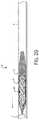
- FIG. 1Ais a side view of a distal portion of a clot retrieval device shown with a retrieval assembly in a first configuration in accordance with the present technology.
- FIG. 1Bis a side view of the distal portion of the clot retrieval device of FIG. 1A , shown with the retrieval assembly shown in a second, everted configuration.
- FIGS. 2A-2Gillustrate a method of removing clot material from a blood vessel lumen using the clot retrieval device shown in FIGS. 1A and 1B .
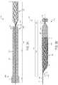
- FIG. 3Ais a side view of a distal portion of a clot retrieval device shown with a retrieval assembly shown in a first configuration in accordance with embodiments of the present technology.
- FIG. 3Bis a side view of the distal portion of the clot retrieval device of FIG. 3A , shown with the retrieval assembly in a second, everted configuration.
- FIGS. 3C and 3Dare enlarged side and isometric views, respectively, of a portion of the cover of FIGS. 3A and 3B in an everted configuration in accordance with some embodiments of the present technology.
- FIGS. 4A-4Nare side views of different end regions of covers in a first configuration in accordance with some embodiments of the present technology.
- FIGS. 5A and 5Billustrate a method of removing clot material from a blood vessel lumen using the clot retrieval device shown in FIGS. 3A and 3B .
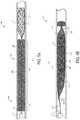
- FIG. 6Ais a side view of a distal portion of a clot retrieval device in accordance with some embodiments of the present technology.
- FIG. 6Bis an enlarged view of a portion of the cover shown in FIG. 6A .
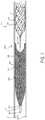
- FIG. 7is a side view of the clot retrieval device shown in FIG. 6A positioned in a blood vessel in an expanded state.
- FIGS. 8A-8Cillustrate a method of removing clot material from a blood vessel lumen using the clot retrieval device shown in FIG. 6A .
- FIG. 9Ais a cross-sectional side view of a distal portion of a clot retrieving device in accordance with some embodiments of the present technology.
- FIG. 9Bis a cross-sectional isometric view of the distal portion of the clot retrieving device shown in FIG. 9A .
- FIGS. 10 and 11are cross-sectional side views of the distal portion of a clot retrieving device in accordance with some embodiments of the present technology.
- FIG. 12Ais a cross-sectional side view of a distal portion of a clot retrieving device in accordance with some embodiments of the present technology.
- FIG. 12Bis a cross-sectional isometric view of the distal portion of the clot retrieving device shown in FIG. 12A .
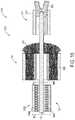
- FIGS. 13-15are cross-sectional side views of the distal portion of a clot retrieving device in accordance with some embodiments of the present technology.
- the present technologyprovides devices, systems, and methods for removing clot material from a blood vessel lumen. Although many of the embodiments are described below with respect to devices, systems, and methods for treating a cerebral or intracranial embolism, other applications and other embodiments in addition to those described herein are within the scope of the technology.
- the retrieval devices of the present technologymay be used to remove emboli from body lumens other than blood vessels (e.g., the digestive tract, etc.) and/or may be used to remove emboli from blood vessels outside of the brain (e.g., pulmonary blood vessels, blood vessels within the legs, etc.).
- the retrieval devices of the present technologymay be used to remove luminal obstructions other than clot material (e.g., plaque, resected tissue, foreign material, etc.).
- FIGS. 1A and 1Bare side views of a distal portion of some embodiments of a retrieval device or a clot retrieving device 10 (“device 10 ”) outside of a blood vessel in an expanded, relaxed (e.g., unconstrained) configuration in accordance with the present technology.
- the clot retrieving device 10is shown in first and second configurations in FIGS. 1A and 1B , respectively.
- the clot retrieving device 10includes an elongated shaft 12 (“shaft 12 ”) and a retrieval assembly 14 coupled to a distal region of the elongated shaft 12 via a connection assembly 300 .
- the retrieval assembly 14is configured to be intravascularly positioned at or adjacent clot material within a blood vessel lumen and includes a capture structure 100 and a flexible cover 200 . A portion of the cover is removed in FIGS. 1A and 1B for ease of viewing the capture structure 100 .
- the capture structure 100 and the cover 200are fixed to the elongated shaft 12 at generally the same location, or the capture structure 100 and cover 200 may be coupled to the shaft 12 at different locations and/or may be slidable with respect to the elongated shaft 12 .
- the capture structure 100has a low-profile configuration (not shown) when constrained within a delivery catheter (e.g., a microcatheter) and an expanded configuration for securing and/or engaging clot material or other obstructions within a blood vessel lumen (e.g., a cerebral blood vessel lumen) and/or for restoring blood flow within the blood vessel.
- the capture structure 100has a proximal portion 100 a coupled to the shaft 12 and a distal portion 100 b .
- the capture structure 100further includes an open cell framework or body 108 ( FIG. 1A ) and a coupling region 102 ( FIG. 1A ) extending proximally from the body 108 . In some embodiments, for example as shown in FIGS.
- a distal portion 100 b of the capture structure 100can be generally tubular (e.g., cylindrical), and the proximal portion 100 a of the capture structure 100 tapers proximally to the coupling region 102 .
- the distal terminus of the distal portion 100 bcoincides with a distal terminus 101 of the capture structure 100 and/or retrieval assembly 14 .
- the capture structure 100is a mesh structure formed of a superelastic material (e.g., Nitinol) or other resilient or self-expanding material configured to self-expand when released from the delivery catheter.
- the capture structure 100may be a stent and/or stentriever, such as Medtronic's SolitaireTM Revascularization Device, Stryker Neurovascular's Trevo® ProVueTM Stentriever, or other suitable devices.
- the capture structure 100may include a plurality of braided filaments. Examples of suitable capture structures 100 include any of those disclosed in U.S. Pat. No. 7,300,458, filed Nov.
- the cover 200includes a first end portion 200 a coupled to the shaft 12 via the connection assembly 300 , a free second end portion 200 b , and a cover wall 200 c extending between the first end portion 200 a and the second end portion 200 b .
- the term “free”refers to a portion of the cover 200 that is not fixed to the elongated shaft 12 and may move radially and/or longitudinally with respect to the shaft 12 .
- the cover 200is flexible such that it is movable between a first position ( FIG. 1A ) in which the free second end portion 200 b is proximal of the first end portion 200 a and a second position ( FIG.
- FIG. 1Bin which the cover 200 is inverted over the capture structure 100 such that a distal terminus 201 ( FIG. 1B ) of the cover 200 is at or distal to the distal terminus 101 of the capture structure 100 and/or to the first end portion 200 a .
- some embodiments of the cover 200may have a leading edge 204 that overlaps the coupling region 102 of the capture structure 100 but does not extend beyond the coupling region 102 to overlap the body 108 of the capture structure 100 .
- the leading edge 204 of the cover 200may also overlap all or a portion of the length of the body 108 when the cover 200 is in the first position. As shown in FIG.
- the cover wall 200 csurrounds the capture structure 100 .
- the cover 200can comprise a mesh and/or braid of a plurality of wires (e.g., filaments, threads, sutures, fibers or the like) that have been interwoven to form a structure having openings (e.g., a porous fabric).
- the mesh and/or braidcan be composed of metals, polymers, composites, and/or biologic materials.
- Polymer materialscan include Dacron, polyester, polypropylene, nylon, Teflon, polytetrafluoroethylene (PTFE), tetrafluoroethylene, polyethylene terephthalate, polyactic acid (PLA) silicone, polyurethane, polyethylene, polycarbonate, styrene, polyimide, PEBAX, Hytrel, polyvinyl chloride, high-density polyethylene, low-density polyethylene, polyether ether ketone (PEEK), rubber, latex, and/or other suitable polymers known in the art.
- PEEKpolyether ether ketone
- Other materials known in the art of elastic implantscan also be used.
- Metal materialscan include, but are not limited to, nickel-titanium alloys (e.g.
- the cover 200can be constructed solely from metallic materials without the inclusion of any polymer materials, solely from polymer materials without the inclusion of any metallic materials, or a combination of polymer and metallic materials.
- some or all of the wires of the cover 200are drawn-filled tube (“DFT”) wires having a radiopaque core (e.g., platinum, tantalum, gold, tungsten, etc.) surrounded by a superelastic material (e.g., Nitinol, a cobalt-chromium alloy, etc.).
- the radiopaque coremay comprise about 5% to about 50% (e.g., 10%, 15%, 20%, 25%, 30%, 35%, 40%, 45%) of the total-cross-sectional area of the individual wires.
- the cover 200may have 72-144 total wires (e.g., 72, 96 128, 144, etc.) Moreover, some or all of the wires may have a wire diameter of about 0.005 inches to about 0.015 inches (e.g., 0.008 inches, 0.01 inches, etc.). In some embodiments, all of the wires have the same diameter, and in other embodiments some of the wires have different diameters. Further details regarding cover embodiments in accordance with the present technology are described below with reference to FIGS. 3A-8C .
- FIGS. 2A-2Gillustrate a method of removing clot material from the lumen of a blood vessel V using the clot retrieving device 10 of the present technology.
- a guidewire 1may be advanced through the clot material CM such that a distal terminus of the guidewire 1 is distal of the clot material CM.
- a delivery catheter 2may be delivered over the guidewire 1 so that a distal portion of the delivery catheter 2 is positioned at or near the clot material CM.
- the delivery catheter 2may be advanced over the guidewire 1 through the clot material CM such that a distal terminus of the delivery catheter 2 is distal of the clot material CM.
- the guidewire 1may be withdrawn.
- the clot retrieving device 10may then be advanced through the delivery catheter 2 in a low-profile configuration until a distal terminus 101 of the capture structure 100 (shown schematically in FIG. 2B ) is at or adjacent the distal terminus of the delivery catheter 2 .
- the delivery catheter 2may then be pulled proximally relative to the clot retrieving device 10 to release the capture structure 100 , thereby allowing the capture structure 100 to self-expand within the clot material CM.
- the capture structure 100engages and/or secures the surrounding clot material CM, and in some embodiments may restore or improve blood flow through the clot material CM.
- the capture structure 100may be expanded distal of the clot material CM such that no portion of the capture structure 100 is engaging the clot material CM while the capture structure 100 is in the process of expanding toward the vessel wall.
- the capture structure 100is configured to expand into contact with the blood vessel wall, or the capture structure 100 may expand to a diameter that is less than that of the blood vessel lumen such that the capture structure 100 does not engage the entire circumference of the blood vessel wall.
- the delivery catheter 2may continue advancing proximally to release the cover 200 such that at least a portion of the cover wall 200 c expands into contact with the blood vessel wall and the cover 200 is in the first position.
- the retrieval assembly 14is in the first configuration.
- expansion of the cover 200provides sufficient friction against the walls of the vessel V to overcome the column strength of the cover wall 200 c , thereby causing the cover wall 200 c to remain in place and/or move less than the first end portion 200 a of the cover 200 so that the cover wall 200 c inverts over the proximally advancing capture structure 100 and any associated clot material CM.
- the capture structure 100moves proximally relative to the leading edge 204 of the cover 200 so that the length of the capture structure 100 coextensive with the cover 200 increases.
- the cover 200completely inverts from the first position over the capture structure 100 , thereby further securing any clot material held by or within the capture structure.
- the clot retrieving device 10may continue advancing proximally until the retrieval assembly 14 is positioned within the delivery catheter 2 .
- the delivery catheter 2 , device 10 , and associated clot material CMmay then be withdrawn from the patient.
- FIGS. 3A-8Cshow various embodiments of covers for use with the clot retrieving devices of the present technology.
- the covers discussed beloware described with reference to the clot retrieving device 10 shown in FIGS. 1A-2G , any of the covers disclosed herein may be used with any of the clot retrieval devices disclosed herein.
- any of the covers discussed belowmay be used with any of the connection assemblies discussed with reference to FIGS. 9A-15 .
- FIGS. 3A and 3Bare side views of a retrieval assembly 344 of a clot retrieving device 340 shown outside of a blood vessel in an expanded, relaxed (e.g., unconstrained) configuration in accordance with the present technology.
- the clot retrieving device 340 and retrieval assembly 344can include components that are generally similar in structure and function as those of the clot retrieving device 10 shown in FIGS. 1A-2G .
- the clot retrieving device 340includes the elongated shaft 12 and the connection assembly 300 .
- common acts and structureare identified by the same reference numbers, and only significant differences in operation and structure are described below.
- the retrieval assembly 344may include the capture structure 100 and a cover 350 coupled to the elongated shaft 12 by the connection assembly 300 .
- the capture structure 100 and the cover 350are fixed to the elongated shaft 12 at generally the same location, or the capture structure 100 and cover 200 may be coupled to the shaft 12 at different locations and/or may be slidable with respect to the elongated shaft 12 . Additional details regarding the connection assembly 300 and relative positions of the capture structure 100 and cover 350 are described in greater detail below with reference to FIGS. 9A-15 .
- the cover 350may be a mesh structure.
- the cover 350is a braided tube having one or more preset shapes.
- the cover 350can comprise a mesh and/or braid of a plurality of wires (e.g., filaments, threads, sutures, fibers or the like) that have been interwoven to form a structure having openings (e.g., a porous fabric).
- the mesh and/or braidcan be composed of metals, polymers, composites, and/or biologic materials.
- Polymer materialscan include Dacron, polyester, polypropylene, nylon, Teflon, polytetrafluoroethylene (PTFE), tetrafluoroethylene, polyethylene terephthalate, polyactic acid (PLA) silicone, polyurethane, polyethylene, polycarbonate, styrene, polyimide, PEBAX, Hytrel, polyvinyl chloride, high-density polyethylene, low-density polyethylene, polyether ether ketone (PEEK), rubber, latex, and/or other suitable polymers known in the art.
- PEEKpolyether ether ketone
- Other materials known in the art of elastic implantscan also be used.
- Metal materialscan include, but are not limited to, nickel-titanium alloys (e.g.
- the cover 350can be constructed solely from metallic materials without the inclusion of any polymer materials, solely from polymer materials without the inclusion of any metallic materials, or a combination of polymer and metallic materials.
- some or all of the wires of the cover 350are DFT wires having a radiopaque core (e.g., platinum, tantalum, gold, tungsten, etc.) surrounded by a superelastic material (e.g., Nitinol, a cobalt-chromium alloy, etc.).
- the radiopaque coremay comprise about 5% to about 50% (e.g., 10%, 15%, 20%, 25%, 30%, 35%, 40%, 45%) of the total-cross-sectional area of the individual wires.
- the cover 200may have 72-144 total wires (e.g., 72, 96 128, 144, etc.) Moreover, some or all of the wires may have a wire diameter of about 0.005 inches to about 0.015 inches (e.g., 0.008 inches, 0.01 inches, etc.). In some embodiments, all of the wires have the same diameter, and in other embodiments some of the wires have different diameters.
- the cover 350includes a first end portion 350 a coupled to the shaft 12 via the connection assembly 300 , a free second end portion 350 b , and a cover wall 350 c extending between the first end portion 350 a and the second end portion 350 b .
- the term “free”refers to a portion of the cover 350 that is not fixed to the elongated shaft 12 and may move radially and/or longitudinally with respect to the shaft 12 .
- the cover wall 350 cincludes a body portion 358 and an end portion 356 extending from the body portion 358 .
- the cover 350is flexible such that it is movable between a first position ( FIG.
- FIG. 3Ain which the free second end portion 350 b is proximal of the first end portion 350 a and a second position ( FIG. 3B ) in which the cover 350 is inverted over the capture structure 100 such that a distal terminus 345 ( FIG. 3B ) of the cover 350 is at or distal to the distal terminus 101 of the capture structure 100 .
- the cover 350when the cover 350 is in the first position in an expanded, relaxed state, the cover 350 may have a leading edge 354 that overlaps the coupling region 102 of the capture structure 100 but does not extend beyond the coupling region 102 to overlap the body 108 of the capture structure 100 .
- the leading edge 354 of the cover 350may alternatively overlap all or a portion of the length of the body 108 when the cover 350 is in the first position.
- the free second end portion 350 bis distal of the first end portion 350 a and distal of the distal terminus 101 of the capture structure 100 .
- the body portion 358 of the cover wall 350 cdefines an axially extending cavity 360 and the capture structure 100 is positioned within the cavity 360 .
- the end portion 356extends proximally from the body portion 358 , and each of the body portion 358 and/or the end portion 356 may have a generally tubular shape.
- the end portion 356has a cross-sectional dimension (e.g., cross-sectional area, diameter, etc.) that is greater than a cross-sectional dimension (e.g., cross-sectional area, diameter, etc.) of the body portion 358 .
- the body portion 358 and/or the end portion 356may have different shapes and/or relative sizes. As shown in FIG.
- the body portion 358when the cover 350 is in the second configuration, the body portion 358 may have a generally tubular shape, and at least a region of the end portion 356 may taper inwardly in a distal direction.
- the end portion 356may define a channel 362 extending therethrough that is continuous with the cavity 360 and terminates at an opening 364 .
- FIGS. 3C and 3Dare enlarged side and isometric views, respectively, of the end portion 356 of the cover 350 in the second configuration.
- the cover 350is shown without a braided pattern in FIGS. 3C and 3D for ease of viewing and describing the various regions of the end portion 356 .
- the end portion 356may be heat set to have a predetermined shape in the expanded, relaxed state such that at least a length of the end portion 356 distal to a distal terminus 101 of the capture structure 100 ( FIG. 1B ) tapers radially inwardly, thereby enclosing associated clot material and preventing or otherwise reducing the escape of particles from an interior region of the cover 350 .
- the end portion 356may have a preset shape in the second configuration such that the cover wall 350 c folds onto itself one or more times, thereby forming a first region 356 a extending distally and radially inwardly from the body portion 358 (visible in FIG. 3C only), a second region 356 b extending distally and radially outwardly from the first region 356 a , a broad or third region 356 c extending proximally from the second region 356 b , and an optional inverted or fourth region 356 d extending distally from the third region 356 c to a free edge 369 .
- the first region 356 a and the second region 356 bmay together form a neck 370 ( FIG.
- the channel 362has a cross-sectional dimension that may decrease then increase in a distal direction.
- the fourth region 356 ddefines the most radially outward portion of the end portion 356 .
- the second region 356 b and the third region 356 cmay together define a curved distal face 366 of the end portion 356 and/or cover 350 , and the third region 356 c and the fourth region 356 d may meet at a proximal, creased and/or folded edge 368 of the end portion 356 .
- the distal terminus 345 of the cover 350may coincide with the portion of the distal face 366 where the second region 356 b meets the third region 356 c .
- the free edge 369 of the fourth region 356 dis proximal of the distal face 366 .
- Overlapping portions of the neck 370 and third region 356 cmay be in contact with one another or may be separated by a distance d 1 ( FIG. 3C ), and overlapping portions of the third region 356 c and the fourth region 356 d may be in contact with one another or may be separated by a distance d 2 ( FIG. 3C ). In some embodiments distance d 1 is greater than distance d 2 .
- the end portion 356 of FIGS. 3B-3Dadvantageously facilitates manually retracting the cover 350 following an initial use of the cover and capture structure 100 .
- After an initial use of the retrieval device 340at which point it will have reached the configuration shown in FIG. 3B , it may be necessary to perform a “second pass” with the device so as to retrieve any clot that remain in the treatment area following the first pass.
- the cliniciancan grasp the end portion 356 gently between the thumb and forefinger and urge it in the proximal direction to begin the process of retraction.
- the cover 356can be retracted in this manner until it reaches the initial, or fully retracted, configuration shown in FIG. 3A .
- the capture structure 100can be cleaned of any retrieved thrombus and the device 340 can be used for a second pass, and any subsequent passes, until a satisfactory removal of thrombus has been achieved.
- the broadened and “curled-back” shape of the end portion 356facilitates manual retraction of the cover and subsequent re-use of the device 340 , which can be difficult with a device, such as the clot retrieving device 10 , that lacks such a feature.
- a devicesuch as the clot retrieving device 10
- FIG. 1Bwhen the cover forms a collapsed, inwardly tapered distal end in the everted or deployed configuration, it can be difficult to push it proximally or “peel back” the cover wall so as to reverse the process of everting.
- end portion 356allows it to be easily grasped and pushed proximally, while the curled-back shape of the cover wall in the end portion 356 helps to cause the cover to reverse or undo its everted configuration during retraction. Note that these functions and properties apply to the end portion 356 shown in FIGS. 3A-3D , as well as the end portions 356 shown in FIGS. 4A-4N .
- the end portion 356may have other shapes and/or configurations when the cover 350 is in the second configuration in an expanded, relaxed state.
- the end portion 356may be folded on itself more or fewer than two times.
- the end portion 356may not be folded on itself, or the end portion 356 may be folded on itself only one time such that the end portion 356 only includes the first through third regions 356 a - 356 c and does not include the fourth region 356 d as shown in FIG. 4A .
- the end portion 356may be folded on itself three times such that it includes a fifth region 356 e extending proximally from the fourth region 356 d ( FIG. 4F ).
- the free edge 369 of the fourth region 356 dmay be distal of the distal face 366 , and the fourth region 356 d may extend generally parallel to a longitudinal axis L of the end portion 356 .
- the fourth region 356 dmay extend distally and radially outwardly and be concave towards the third region 356 c ( FIG. 4C ), and in some embodiments the fourth region 356 d may extend distally and radially outwardly and be convex towards the third region 356 c ( FIG. 4D ).
- the fourth region 356 dmay extend distally and radially outwardly, then radially inwardly ( FIG.
- the portion of the cover 350 comprising the folded edge 368may extend radially outwardly generally perpendicular to the longitudinal axis L of the end portion 356 for a distance d.
- the folded edge 368may be proximal of the first region 356 a ( FIG. 4H ), or the folded edge 368 may be distal of the first region 356 a ( FIGS. 4I and 4M ).
- the neck 370may include an intermediate region 356 f between the first and second regions 356 a , 356 b that has a generally constant diameter ( FIG. 4J ).
- the second region 356 bextends distally from the first region 356 a generally parallel to the longitudinal axis L of the end portion 356 , then extends radially outwardly generally perpendicular to the longitudinal axis L so that the distal face 366 of the end portion 356 and/or cover 350 is generally flat (in contrast to the curved distal face 366 in FIG. 3C ).
- a cross-sectional dimension of the neck 370tapers in a distal direction then remains generally constant such that the neck 370 does not include a portion that extends radially outwardly.
- FIG. 4Ka cross-sectional dimension of the neck 370 tapers in a distal direction then remains generally constant such that the neck 370 does not include a portion that extends radially outwardly.
- the neck 370tapers down distally to a pinched portion 357 at or along which all or a portion of the cover wall comes together such that the channel 362 is at least partially blocked.
- the body portion 358may have a diameter D 1 that is greater than the diameter D 2 of the end portion 356 when the cover 350 is in a relaxed, expanded state ( FIG. 4M ).
- the diameter D 1 of the body portion 358is less than or equal to the diameter D 2 of the end portion 356 when the cover 350 is in a relaxed, expanded state ( FIG. 3B ).
- the end portion 356includes a transition region 356 i between the second region 356 b and the third region 356 c .
- the transition region 356 imay extend radially outwardly from the second region 356 b generally perpendicular to the longitudinal axis L of the end portion 356 (i.e., the transition region 356 i generally does not extend distally or proximally).
- At least a portion of the distal face 366 of the end portion 356 and/or cover 350is generally flat.
- at least a portion of the third region 356 cmay extend proximally and generally parallel to the longitudinal axis L of the end portion 356 (i.e., not radially outwardly as shown in FIG. 3C ).
- the clot retrieving device 340may be delivered through a delivery catheter 2 (e.g., a microcatheter) to a treatment site within a blood vessel lumen (e.g., a cerebral blood vessel) as described above with reference to FIGS. 2A and 2B .
- the delivery catheter 2may then be pulled proximally relative to the clot retrieving device 340 to release the capture structure 100 , thereby allowing the capture structure 100 to self-expand within the clot material CM as described above with reference to FIG. 2C .
- the delivery catheter 2may continue advancing proximally to release the cover 350 such that at least a portion of the cover wall 350 c expands into contact with the blood vessel wall and the cover 350 is in the first position.
- the end portion 356may have a cross-sectional dimension (e.g., cross-sectional area, diameter, etc.) that is greater than a cross-sectional dimension (e.g., cross-sectional area, diameter, etc.) of the body portion 358 . Accordingly, when the cover 350 is expanded within the blood vessel, both the body portion 358 and the end portion 356 may expand into contact with the blood vessel wall, but the end portion 356 exerts a greater radially outward force on the vessel wall V than the body portion 358 .
- a cross-sectional dimensione.g., cross-sectional area, diameter, etc.
- the end portion 356 of the cover 350resists proximal movement to a greater extent than the body portion 358 . In some embodiments, only the end portion 356 expands into contact with the blood vessel wall V.
- FIG. 5Bis a side view of the retrieval assembly 344 in the blood vessel in a second configuration and with the cover 350 in a second, inverted position.
- both the body portion 358 and the broad portion of the end portion 356e.g., the third and/or fourth regions 356 c , 356 d ( FIG. 3C )
- the neck 370see FIG. 3C
- captured clot material CMhaving a size greater than the diameter of the channel 362 is prevented from escaping the cavity 360 .
- FIG. 6Ais a cross-sectional side view of one embodiment of a retrieval assembly 602 of a clot retrieving device 600 shown outside of a blood vessel in an expanded, relaxed configuration in accordance with the present technology.
- the clot retrieving device 600 and retrieval assembly 602can include components that are generally similar in structure and function as those of the clot retrieving device 10 shown in FIGS. 1A-2G .
- the clot retrieving device 600includes the elongated shaft 12
- the retrieval assembly 602includes the capture structure 100 (only a portion shown for ease of illustration).
- common acts and structureare identified by the same reference numbers, and only significant differences in operation and structure are described below.
- the retrieval assembly 602may include the capture structure 100 and a cover 604 .
- the proximal region 100 a of the capture structure 100may be coupled to the shaft 12 by connector 607
- a proximal region 604 a of the cover 604may be coupled to the shaft 12 by connector 605 .
- Connector 605may be positioned along the shaft 12 proximal of connector 607 .
- the connector 607can be similar to the connector 1201 (and any variations thereof) described with respect to FIGS. 12A-15
- the connector 605can be similar to the connectors 901 , 1001 , 1101 (and any variations thereof) described with respect to FIGS. 9A-15 .
- the connector 607 and/or proximal region 100 a of the capture structure 100is fixed to the shaft 12
- the connector 605 and/or proximal region 604 a of the cover 604is slidably coupled to the shaft 12 .
- the connector 607 and/or proximal region 100 a of the capture structure 100is movable along the shaft 12 relative to the connector 605 and/or proximal region 604 a of the cover 604 .
- the clot retrieving device 600may include a stop 609 fixed to the shaft 12 proximal of connector 605 that prevents axial movement of connector 605 along the shaft 12 proximal of the stop 609 .
- the stop 609 and/or connector 607may have a shape and size that inhibit movement of the cover 604 and/or connector 605 .
- the stop 609 and/or connector 607can have an outer dimension that is larger than an interior dimension of connector 605 (or vice versa) such that movement of the connector 605 distally beyond connector 607 and/or proximally beyond stop 609 is inhibited or prevented.
- the stop 609may be formed integrally with the shaft 12 .
- the clot retrieving device 600may include more than one stop.
- the stop 609can comprise a radiopaque material.
- the cover 604 and/or connector 605can be fixedly attached to the shaft 12 .
- the cover 604 and/or connector 605can be fixedly attached to the shaft 12 by, for example, soldering, welding, crimping, adhesive(s), or a combination thereof.
- the cover 604 and/or connector 605can be rotatably coupled to the shaft 12 .
- the cover 604 and/or connector 605may be slidably and rotatably coupled to the shaft 12 .
- the connector 605may be fixed at a certain axial location along the shaft 12 but is still free to rotate about the shaft 12 .
- the capture structure 100 and/or connector 607can be slidably and/or rotatably coupled to the shaft 12 .
- the cover 604may be formed of a two-layer mesh structure having an inner layer 606 and an outer layer 608 .
- the inner layer 606may be continuous with the outer layer 608 at a distal terminus 611 of the cover 604 , and the proximal end portions of the inner and outer layer 606 , 608 may be fixed relative to one another at connector 605 .
- the cover 604may have a closed proximal region 604 a .
- the cover 604may include an opening 612 at its distal region 604 b , and the inner layer 606 may define a cavity 610 that extends distally from connector 605 along the length of the cover 604 and terminates at the opening 612 .
- the cavity 610 and/or opening 612may be configured to receive the elongated shaft 12 and the capture structure 100 therein.
- the cover 604may be formed of an inverted tubular braid such that the distal terminus 611 of the cover 604 may comprise a folded edge of the braid and the first and second ends of the tubular braid are adjacent one another at a proximal region 604 a of the cover 604 .
- the folded edgemay surround and define the opening 612 at the distal region 604 b of the cover 604 .
- the cover 604may include a plurality of wires (e.g., filaments, threads, sutures, fibers or the like) that have been interwoven to form a structure having openings (e.g., a porous fabric).
- the mesh and/or braidcan be composed of metals, polymers, composites, and/or biologic materials.
- Polymer materialscan include Dacron, polyester, polypropylene, nylon, Teflon, polytetrafluoroethylene (PTFE), tetrafluoroethylene, polyethylene terephthalate, polyactic acid (PLA) silicone, polyurethane, polyethylene, polycarbonate, styrene, polyimide, PEBAX, Hytrel, polyvinyl chloride, high-density polyethylene, low-density polyethylene, polyether ether ketone (PEEK), rubber, latex, and/or other suitable polymers known in the art.
- PEEKpolyether ether ketone
- Other materials known in the art of elastic implantscan also be used.
- Metal materialscan include, but are not limited to, nickel-titanium alloys (e.g.
- the cover 604can be constructed solely from metallic materials without the inclusion of any polymer materials, solely from polymer materials without the inclusion of any metallic materials, or a combination of polymer and metallic materials.
- some or all of the wires of the cover 604are DFT wires having a radiopaque core (e.g., platinum, tantalum, gold, tungsten, etc.) surrounded by a superelastic material (e.g., Nitinol, a cobalt-chromium alloy, etc.).
- the radiopaque coremay comprise about 5% to about 50% (e.g., 10%, 15%, 20%, 25%, 30%, 35%, 40%, 45%) of the total-cross-sectional area of the individual wires.
- the cover 200may have 72-144 total wires (e.g., 72, 96 128, 144, etc.) Moreover, some or all of the wires may have a wire diameter of about 0.005 inches to about 0.015 inches (e.g., 0.008 inches, 0.01 inches, etc.). In some embodiments, all of the wires have the same diameter, and in other embodiments some of the wires have different diameters.
- the cover 604may have a proximal portion 620 , an intermediate portion 632 , and a distal portion 634 .
- the proximal portion 620may extend from the connector 605 to a proximal terminus of the intermediate portion 632
- the intermediate portion 632may extend from a distal terminus of the proximal portion 620 to a proximal terminus of the distal portion 634
- the distal portion 634may extend from a distal terminus of the intermediate portion 632 to a distal terminus 611 of the cover 604 .
- the inner layer 606may have (a) a first cross-sectional dimension IL 1 at the proximal portion 620 of the cover 604 , (b) an increasing second cross-sectional dimension IL 2 along the intermediate portion 632 of the cover 604 , and (c) a third cross-sectional dimension IL 3 at the distal portion 634 of the cover 604 that is greater than the first cross-sectional dimension IL 1 .
- the first cross-sectional dimension IL 1 of the inner layer 606is generally constant along the proximal portion 620 of the cover 604
- the third cross-sectional dimension IL 3 of the inner layer 606is generally constant along the distal portion 634 of the cover 604 .
- FIG. 6Bis an enlarged view of a portion of the cover 604 shown in FIG. 6A .
- the inner layer 606is convex towards the cavity 610 along the intermediate portion 632 .
- the inner layer 606is concave towards the cavity 610 along the intermediate portion 632 .
- the inner layer 606has a proximal region 631 and a distal region 633 along the intermediate portion 632 .
- the proximal region 631is convex towards the cavity 610
- the distal region 633is concave towards the cavity 610 .
- the proximal region 631is concave towards the cavity 610
- the distal region 633is convex towards the cavity 610 .
- the outer layer 608 of the cover 604may have a first cross-sectional dimension OL 1 that is generally constant along the distal portion 634 and the intermediate portion 632 of the cover 604 .
- the first cross-sectional dimension OL 1 of the outer layer 608may be greater than an inner diameter of the portion of the blood vessel adjacent to the clot material such that, when the cover 604 is expanded within a portion of the blood vessel V (see FIG. 7 ), the outer layer 608 exerts a radially outward force on the blood vessel wall along at least the distal and intermediate portions 634 , 632 of the cover 604 .
- the outer layer 608 along the proximal portion 620 of the cover 604has a proximal region 622 and a distal region 624 .
- the proximal region 622may extend distally from the connector 605 to a proximal terminus of the distal region 624
- the distal region 624may extend distally from a distal terminus of the proximal region 622 to a proximal terminus of the intermediate portion 620 .
- a cross-sectional dimension of the proximal region 622decreases in a proximal direction, and the distal region 624 has a generally constant cross-sectional dimension.
- the cross-sectional dimension of the distal region 624may be substantially the same as the cross-sectional dimension along the distal and intermediate portions 632 , 634 of the cover 604 .
- FIG. 7is a side view of the retrieval assembly 602 positioned in a blood vessel V (e.g., a cerebral blood vessel) at a treatment site in an expanded state.
- the retrieval assembly 602may be delivered through a delivery catheter 2 (e.g., a microcatheter) to the treatment site as described above with reference to FIGS. 2A and 2B .
- the delivery catheter 2may then be pulled proximally relative to the retrieval assembly 602 to release the capture structure 100 , thereby allowing the capture structure 100 to self-expand within the clot material CM as described above with reference to FIG. 2C .
- the delivery catheter 2may continue advancing proximally to release the cover 604 such that at least a portion of the outer layer 608 expands into contact with the wall of the blood vessel V.
- the elongated shaft 12may be pulled proximally. Friction between the outer layer 608 and the vessel wall V holds the cover 604 in place within the blood vessel lumen and/or resists proximal movement to a greater degree than the capture structure 100 . As such, the elongated shaft 12 slides proximally through the cavity 610 and connector 605 and pulls the capture structure 100 proximally through the opening 612 at the distal region 604 b of the cover 604 , as shown in FIG. 8A . As shown in FIG.
- the capture structure 100forces the inner layer 806 radially outwardly along the portion of the inner layer 806 aligned with the capture structure 100 .
- the inner layer 606collapses radially inwardly distal of a distal terminus 101 of the capture structure 100 , thereby forming a narrowed or substantially or completely closed region 630 and enclosing the capture structure 100 within the inner layer 606 .
- Such narrowing or closure of the region 630helps prevent the escape of thrombus from the capture structure 100 and/or cover 604 during withdrawal of the device 600 from the blood vessel V.
- the clot retrieving device 600may continue advancing proximally until the retrieval assembly 602 is positioned within the delivery catheter 2 .
- the delivery catheter 2 , device 600 , and associated clot material CMmay then be withdrawn from the patient.
- the cover 604 of FIGS. 6A-8Ccan be easily retracted to the initial position shown in FIG. 6A to facilitate performing a second (and subsequent) “pass” to retrieve any thrombus that may remain in the treatment area following a first pass.
- the cover 604can be easily grasped, e.g. at the connector 605 , and retracted proximally to the position shown in FIG. 6A by sliding it along the shaft 12 . Because the cover 604 does not evert during the process of covering the capture structure 100 , there is no need to reverse any eversion during retraction. This in turn allows for a simpler retraction process. Following retraction of the cover 604 , the capture structure 100 can be cleaned of any thrombus and used in the second and subsequent passes.
- FIGS. 9A-15show various embodiments of connection assemblies for use with the clot retrieving devices of the present technology.
- the connection assemblies discussed beloware described with reference to the clot retrieving device 10 shown in FIGS. 1A-2G , any of the connection assemblies may be used with any of the clot retrieving devices, capture structures, and/or covers disclosed herein.
- any of the connection assemblies discussed belowmay be used with any of the covers discussed above with reference to FIGS. 3A-8C .
- only the first end portion 200 a of the cover 200 and proximal portion 100 a of the capture structure 100are shown in FIGS. 9A-15 for ease of illustration.
- FIGS. 9A and 9Bare side and isometric enlarged views, respectively, of one embodiment of a connection assembly 900 of a clot retrieving device 940 shown outside of a blood vessel in accordance with the present technology.
- the clot retrieving device 940can include components that are generally similar in structure and function as those of the clot retrieving device 10 shown in FIGS. 1A-2G .
- the clot retrieving device 940includes the elongated shaft 12 , the capture structure 100 , and the cover 200 .
- common acts and structureare identified by the same reference numbers, and only significant differences in operation and structure are described below.
- the coupling region 102 of the capture structure 100may include an opening 104 , and a coupling region 16 of the shaft 12 may extend through the opening 104 .
- the coupling region 16 of the shaft 12can include a first region 18 , a second region 20 (only visible in FIG. 9B ), and a bend 22 between the first and second regions 18 and 20 .
- the coupling region 16can form a hook such that the elongated shaft 12 is bent back on itself (e.g., approximately 180 degrees) and the second region 20 of the shaft 12 is proximal of the bend 22 and the opening 104 .
- the capture structure 100may be coupled to the shaft 12 via other connection means.
- the connection assembly 900may include a connector 901 that comprises an outer band 902 and an inner band 904 .
- the inner band 904is positioned around a portion of the elongated shaft 12 , and the outer band 902 is located radially outwardly of the inner band 904 . At least a portion of the outer band 902 may be axially aligned and/or overlap with at least a portion the length of the inner band 904 .
- the inner band 904is positioned around the interconnected coupling regions 16 and 102 of the shaft 12 and the capture structure 100 , respectively, and the first portion 200 a of the cover 200 is between the inner band 904 and the outer band 902 .
- the first portion 200 a of the covercan be clamped between the outer band 902 and the inner band 904 , or otherwise adhered to the outer and inner bands 902 , 904 .
- the outer and inner bands 902 , 904couple the cover 200 and the capture structure 100 to the shaft 12 , and fix the first end portion 200 a of the cover 200 and the proximal portion 100 a of the capture structure 100 relative to one another and to relative to the elongated shaft 12 .
- the connector 901may include more or fewer than two bands.
- Each of the inner band 904 and the outer band 902can be generally cylindrical, or the inner band 904 and/or the outer band 902 may have different shapes.
- the inner band 904can have a cross-sectional dimension that is about 0.027 inches or less, about 0.021 inches or less, and/or about 0.015 inches or less.
- the outer band 902can have a cross-sectional dimension that is greater than that of the inner band 904 .
- the outer band 902can have a cross-sectional dimension that is about 0.027 inches or less, 0.021 inches or less, and/or 0.015 inches or less.
- the inner band 904includes a proximal terminus 950 , a distal terminus 944 , and a length extending between the proximal terminus 950 and the distal terminus 944 .
- the outer band 902includes a proximal terminus 948 , a distal terminus 946 , and a length extending between the proximal terminus 948 and the distal terminus 946 .
- the proximal terminus 950 of the inner band 904defines the proximal terminus of the connector 901 (alone or in conjunction with the outer band 902 ) and/or the distal terminus 944 of the inner band 904 defines the distal terminus of the connector 901 (alone or in conjunction with the outer band 902 ).
- the proximal terminus 948 of the outer band 902defines the proximal terminus of the connector 901 (alone or in conjunction with the inner band 904 ) and/or the distal terminus 946 of the outer band 902 defines the distal terminus of the connector 901 (alone or in conjunction with the inner band 904 ).
- the inner band 904 and the outer band 902may have generally the same length, but the inner band 904 and the outer band 902 may have different lengths.
- the proximal terminus 950 of the inner band 904can be generally aligned with the proximal terminus 948 of the outer band 902 along a plane 952 approximately normal to the elongated shaft 12 such that the proximal terminus 950 of the inner band 904 and the proximal terminus 948 of the outer band 902 are within about 0.005 inches of each other.
- distal terminus 944 of the inner band 904can be generally aligned with the distal terminus 946 of the outer band 902 along a plane 958 approximately normal to the elongated shaft 12 such that the distal terminus 944 of the inner band 904 and the distal terminus 946 of the outer band 902 are within about 0.005 inches of each other.
- the outer and inner bands 902 , 904are generally coextensive along their entire respective lengths, but the outer and inner bands 902 , 904 may be offset along the longitudinal axis of the device 10 and/or may have different lengths such that the outer and inner bands 902 , 904 are generally coextensive along only a portion of one or both of their respective lengths.
- the inner band 904 and/or outer band 902can include a radiopaque material such as platinum, gold, tungsten, tantalum, platinum-iridium, and/or alloys of any of the foregoing materials.
- the inner band 904 and/or outer band 902may improve visualization of the retrieval assembly 14 .
- visualization of the connector 901can assist the physician in confirming the location of the retrieval assembly 14 , or more specifically, the capture structure 100 , which may be distal to or generally aligned with the inner band 904 and/or outer band 902 .
- the connector 901may be secured to the capture structure 100 and elongated shaft 12 by a crimp and/or a binding agent.
- the inner band 904may be secured to the capture structure 100 and/or the elongated shaft 12 by a crimp and/or a binding agent to fixedly attach the inner band 904 to the elongated shaft 12 .
- the outer band 902may be secured to the first end portion 200 a of the cover 200 by a crimp and/or a binding agent to fixedly attach the outer band 902 and the first end portion 200 a of the cover 200 to the inner band 904 , elongated shaft 12 , and/or capture structure 100 .
- Suitable binding agentsinclude an adhesive, solder, welding flux, brazing filler, or other materials known and/or used in the art.
- the outer band 902 , cover 200 , and inner band 904are not fixed at a single location along the elongated shaft 12 , but instead are configured to rotate and/or translate along or relative to the elongated shaft 12 .
- the clot retrieving device 10may include one or more stops (e.g., coils, bumpers, bands, second connectors, etc.) fixed at one or more locations along the elongated shaft 12 proximal and/or distal to the connector 901 , thereby restricting axial movement of connector 901 (and associated first end portion 200 a of the cover 200 and proximal portion 100 a of the capture structure 100 ) to a predetermined length of the elongated shaft 12 .
- stopse.g., coils, bumpers, bands, second connectors, etc.
- the ability of the retrieval assembly 14may be advantageous to relieve at least some of the tortious stress built up during the delivery of the clot retrieving device 10 through the vasculature.
- the device 10is often advanced from a remote part of the body and into the cerebral region of the vasculature. Along this path to a patient's treatment site, the device 10 may undergo many twists and turns that result in tortious stress being exerted on the device 10 . Such tortional stress can create difficulty when the device 10 deploys from a retracted state to an expanded state.
- the ability to rotate with respect to the elongated shaft 12can help relieve these stresses and improve control over deployment and positioning of the retrieval assembly 14 .
- the connector 901can be assembled directly over the elongated shaft 12 or over a sacrificial wire or tool.
- the outer band 902 , cover 200 , and inner band 904can be positioned sequentially over the elongated shaft 12 (e.g., the outer band 902 first, then the cover 200 , then the inner band 904 ). This can wedge the first end portion 200 a of the cover 200 between the outer band 902 and the inner band 904 .
- the first end portion 200 a of the cover 200thus presses outwardly against both the inner band 904 and outer band 902 , thereby creating a surface friction between (a) the cover 200 and (b) the outer surface of the inner band 904 and inner surface of the outer band 902 that is sufficient to secure the cover 200 between the inner and outer bands 904 and 902 .
- the outer band 902 , cover 200 , and inner band 904can be positioned sequentially (e.g., the outer band 902 first, then the cover 200 , then the inner band 904 ) over a sacrificial wire having a larger outer diameter than that of the elongated shaft 12 that the connector 980 is intended to be later inserted over.
- the outer band 902 , cover 200 , and inner band 904can be, for example, crimped together and the sacrificial wire can be removed.
- the outer band 902 , cover 200 , and inner band 904can then be slideably positioned over the elongated shaft 12 .
- the outer band 902 , cover 200 , and inner band 904may not be secured to the elongated shaft 12 and can be configured to move with respect to the elongated shaft 12 , as previously described.
- Assembly of the connector 901 over a sacrificial wire, tool or mandrel in this mannerallows for the connector 901 and cover 200 to be constructed separately from the shaft 12 and capture structure 100 , and subsequent joining of the connector 901 and cover 200 to the shaft in a separate manufacturing step or location. This in turn offers flexibility and efficiency in the manufacture of the retrieval device.
- the cover 200may have wires 960 (e.g., filaments) that protrude from the proximal terminus of the connector 901 .
- the protruding wires 960can be trimmed to be generally aligned with the plane 952 extending along the proximal terminus of the connector 901 . As such, the wires 960 can be trimmed to not protrude, or to protrude less, from the proximal terminus of the connector 901 .
- FIG. 10is a cross-sectional side view of some embodiments of a clot retrieving device 1040 having a connection assembly 1000 configured in accordance with the present technology.
- the connection assembly 1000can include components that are generally similar in structure and function as those of the connection assembly 900 in FIGS. 9A and 9B .
- the connection assembly 1000includes the connector 901 , the outer band 902 , and the inner band 904 of the connection assembly 900 , and all variations of the foregoing as described above.
- common acts and structureare identified by the same reference numbers, and only significant differences in operation and structure are described below.
- the connection assembly 1000 shown in FIG. 10includes first and second jackets 1020 and 1042 at a proximal portion of the connector 901 .
- the first jacket 1020e.g., an inner sleeve
- the second jacket 1042may be positioned over a proximal terminus 948 of the outer band 902 and the elongated shaft 12 proximal of the outer band 902 .
- the second jacket 1042is positioned radially outwardly of the first jacket 1020 .
- the connection assembly 1000may include only the first jacket 1020 , or only the second jacket 1042 (for example, as shown in FIG. 11 ).
- the proximal portion of the second jacket 1042directly contacts and is fixed to the elongated shaft 12
- the proximal portion of the first jacket 1020directly contacts and is fixed to the elongated shaft 12 at a position distal of the fixed portion of the second jacket 1042 .
- the second jacket 1042may extend along all (see 1046 ) or a portion of the outer surface of the outer band 902 .
- the first jacket 1020may extend along all or a portion of the inner band 904 .
- the first and/or second jackets 1020 and 1042may be indirectly coupled to the shaft 12 via an intermediate structure.
- the proximal portion of the first jacket 1020is adhered to and in direct contact with the shaft 12 and the proximal portion of the second jacket 1042 is adhered to and in direct contact with the proximal portion of the first jacket 1020 .
- the proximal portion of the first jacket 1020is positioned between the elongated shaft 12 and the proximal portion of the second jacket 1042 does not directly contact the elongated shaft 12 .
- the first and/or second jackets 1020 and 1042can include a polymer material, including fluoropolymers such as polytetrafluoroethylene (PTFE).
- the first and/or second jackets 1020 and 1042can also include polyimide, polyether ether ketone (PEEK), polyurethane, nylon, polyethylene, polyamide, or combinations thereof.
- the first and/or second jackets 1020 and 1042may also include elastic materials such as any heat-shrinkable material including but not limited to Pebax, polyurethane, silicone, and/or polyisoprene.
- the heat-shrinkable materialcan be applied over the device and heated such that the heat-shrinkable material is thermally bonded and compressed to adhere to the exterior of the inner and outer bands 904 and 902 and the elongated shaft 12 .
- the jacket(s)can take the form of a mass of adhesive, solder or other solidified liquid (rather than a pre-existing sheet, tube or other body of solid material) that is applied to the proximal terminus of the band(s) 902 and/or 904 so as to cover the wire ends.
- the first and/or second jackets 1020 , 1042may be advantageous for providing a smooth or otherwise atraumatic surface at the proximal edge of the connector 901 .
- the cover 200is composed of a plurality of wires and at least some of the wires protrude proximally from the proximal terminus 948 of the outer band 902 .
- the second jacket 1042covers the protruding ends of the wires to prevent the protruding ends from catching on the cover wall 200 c ( FIGS. 1A and 1B ) as the cover wall 200 c advances over the connector 980 while it inverts over the capture structure 100 and also to prevent trauma to the vessel walls.
- FIG. 11is a cross-sectional side view of clot retrieving device 1140 having a connection assembly 1100 in accordance with the present technology.
- the connection assembly 1100can include components that are generally similar in structure and function as those of the connection assemblies 900 and 1000 .
- the connection assembly 1100can include the outer band 902 that is generally similar to that discussed above with reference to FIGS. 9A and 9B .
- common acts and structureare identified by the same reference numbers, and only significant differences in operation and structure are described below.
- the connection assembly 1100includes a connector 1101 comprising the outer band 902 , an inner band 1104 having a proximal terminus 1150 extending proximally beyond the proximal terminus 948 of the outer band 902 , and a jacket 1142 extending between the outer band 902 and the inner band 1104 .
- the inner band 1104is generally similar to the inner band 904 described above with respect to FIGS. 9A and 9B , except the inner band 1104 has a length that is greater than that of the outer band 902 and extends proximally beyond the distal terminus 946 of the outer band 902 .
- the jacket 1142can be generally similar to the second jacket 1042 described above with respect to FIG. 10 , except the jacket 1142 has a proximal portion adhered to an outer surface of the inner band 1104 .
- the connector 1101 shown in FIG. 11may be configured to rotate about the longitudinal axis of the shaft 12 and/or translate along the length of the elongated shaft 12 .
- the connector 1101may be secured to the elongated shaft 12 by a crimp and is not configured to move with respect to the elongated shaft 12 .
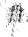
- FIGS. 12A and 12Bare cross-sectional side and isometric views of some embodiments of a clot retrieving device 1240 having a connection assembly 1200 in accordance with the present technology.
- the connection assembly 1200can include components that are generally similar in structure and function as those of the connection assembly 900 in FIGS. 9A and 9B .
- the connection assembly 1200can include the connector 901 having the outer band 902 and the inner band 904 that are generally similar to those discussed above with reference to FIGS. 9A and 9B .
- common acts and structureare identified by the same reference numbers, and only significant differences in operation and structure are described below.
- the connector 901referred to with respect to FIGS.
- the connection assembly 1200may include a second connector 1201 coupled to the elongated shaft 12 distal of and spaced apart from the first connector 901 .
- the first connector 901may abut or otherwise be adjacent to and in contact with the second connector 1201 .
- the first connector 901couples only the cover 200 (and not the capture structure 100 ) to the elongated shaft 12
- the second connector 1201couples the capture structure 100 to the shaft 12 .
- the second connector 1201may comprise a single band 1204 similar to any of the bands 902 , 904 , and 1104 described above with reference to FIGS. 9A-11 .
- the band 1204may have a generally cylindrical sidewall that defines a lumen 1208 therethrough.
- the second connector 1201 and/or band 1204may include a radiopaque material to improve visualization of the band 1204 and/or position of the proximal region 100 a of the capture structure 100 .
- the band 1204may have different shapes or components.
- the connector 1201may include more than one band.
- the connector 1201may include an outer band surrounding at least a portion of the band 1204 .
- the shaft 12extends through a channel 908 defined by an interior surface of the inner band 904 of the first connector 901 , and the second connector 1201 and/or band 1204 is positioned around the interconnected coupling regions 16 and 102 of the shaft 12 and the capture structure 100 , respectively.
- the second connector 1201fixes the proximal portion 100 a of the capture structure 100 to the elongated shaft 12 .
- the second connector 1201 and/or band 1204can be secured to the capture structure 100 and/or the elongated shaft 12 by a crimp and/or a binding agent.
- the binding agentmay fill any void within the lumen 1208 of the band 1204 and bond the second connector 1201 and/or band 1204 to the capture structure 100 and/or the elongated shaft 12 .
- the elongated shaft 12is slidably received through the channel 908 such that the connector 901 (and associated cover 200 ) is movable axially along the shaft 12 and/or free to rotate about the shaft 12 .
- the second connector 1201can have an outer diameter D 2 greater than an inner diameter D 1 of the inner band 904 .
- the second connector 1201may serve as a mechanical stop and prevent the second connector 1201 from moving proximal of the first connector 901 .
- the first connector 901is crimped or otherwise fixed to the shaft 12 such that the first connector 901 is not free to move axially and/or rotate.
- FIG. 13is a cross-sectional side view of some embodiments of a clot retrieving device 1340 having a connection assembly 1300 configured in accordance with present technology.
- the connection assembly 1300can include components that are generally similar in structure and function as those of the connection assembly 1200 in FIGS. 12A and 12B .
- the connection assembly 1300includes the first connector 901 and the second connector 1201 that are generally similar to those discussed above with reference to FIGS. 9A, 9B, 12A and 12B .
- common acts and structureare identified by the same reference numbers, and only significant differences in operation and structure are described below.
- connection assembly 13includes a jacket 1342 (e.g., an outer sleeve) positioned extending between the proximal terminus 948 of the outer band 902 and a portion of the elongated shaft 12 proximal of the outer band 902 .
- the connection assembly 1300may include more than one jacket (e.g., two jackets, three jackets, etc.).
- the connection assembly 1300may include a jacket extending proximally from the inner band 904 (such as jacket 1020 shown in FIG. 10 ) to the shaft 12 .
- the jacket 1342may include any of the materials discussed above with reference to jackets 1020 and 1042 . As shown in FIG.
- the proximal portion of the jacket 1342directly contacts and is fixed to the elongated shaft 12 , but alternatively the jacket 1342 may be indirectly coupled to the shaft 12 via an intermediate structure (not shown) such that the proximal portion of the jacket 1342 does not directly contact the elongated shaft 12 .
- the jacket 1342may extend along all (shown schematically in hashed lines) or a portion of the outer surface of the outer band 902 .
- connection assembly 1400may include the connection assembly 1100 of FIG. 11 , as well as the connector 1201 of FIGS. 12A and 12B .
- the connection assembly 1400includes a connector 1401 comprising the outer band 902 and the inner band 1104 .
- the inner band 1104may have a proximal terminus 1450 extending proximally beyond the proximal terminus 948 of the outer band 902 .
- the connection assembly 1400further includes a jacket 1142 extending between the outer band 902 and the inner band 1104 .
- the connector 1401may be configured to rotate about the longitudinal axis of the shaft 12 and/or translate along the length of the elongated shaft 12 , or alternatively the connector 1401 may be secured to the elongated shaft 12 by a crimp and is not configured to move with respect to the elongated shaft 12 .
- FIG. 15is a cross-sectional side view of a connection assembly 1500 configured in accordance with some embodiments of the present technology.
- the connection assembly 1500can include components that are generally similar in structure and function as those of the connection assembly 1200 in FIGS. 12A and 12B .
- the connection assembly 1500includes the first connector 901 and the second connector 1201 discussed above with reference to FIGS. 12A and 12B .
- the connection assembly 1500may further include a stop 1550 (e.g., a bumper, band or coil) fixed to the elongated shaft 12 and proximal of the connector 901 .
- the stop 1550can include an outer sleeve 1552 surrounding a coil 1554 positioned around the elongated shaft 12 .
- the stop 1550prevents the connector 901 from moving proximally past the stop 1550 .
- the stop 1550 and/or the coil 1554may also serve as a marker and include a radiopaque material.
- the coil 1554may be formed of a metal and/or polymer material, and the sleeve 1552 may be a metal band crimped around the coil 1554 and/or a polymer material that shrinks when heated.
- the stop 1550also provides mechanical support to the elongated shaft 12 over its length. As such, a particular length, diameter, and pitch of the stop 1550 can be selected to provide a desired flexibility/rigidity to the elongated shaft 12 .
Landscapes
- Health & Medical Sciences (AREA)
- Surgery (AREA)
- Life Sciences & Earth Sciences (AREA)
- Heart & Thoracic Surgery (AREA)
- Nuclear Medicine, Radiotherapy & Molecular Imaging (AREA)
- Vascular Medicine (AREA)
- Engineering & Computer Science (AREA)
- Biomedical Technology (AREA)
- Orthopedic Medicine & Surgery (AREA)
- Medical Informatics (AREA)
- Molecular Biology (AREA)
- Animal Behavior & Ethology (AREA)
- General Health & Medical Sciences (AREA)
- Public Health (AREA)
- Veterinary Medicine (AREA)
- Surgical Instruments (AREA)
Abstract
Description
- an elongated shaft having a distal region;
- a capture structure having a proximal portion coupled to the distal region of the elongated shaft and a distal portion having a distal terminus; and
- a cover having a first portion coupled to the distal region of the elongated shaft and a second portion extending from the first portion, the cover having a first configuration in which the second portion of the cover extends proximally from the first portion, and the cover having a second configuration in which the capture structure is at least partially ensheathed within the first portion of the cover and the second portion of the cover extends distally from the first portion, and in the second configuration the second portion has (a) a first region distal to a distal terminus of the capture structure, the first region tapering radially inwardly in a distal direction, and (b) a second region extending distally and radially outwardly from the first region.
- an elongated shaft having a distal region;
- a capture structure having a proximal portion coupled to the distal region of the elongated shaft and a distal portion having a distal terminus; and
- a cover coupled to the distal region of the elongated shaft, the cover having a first portion and a second portion extending from the first portion, wherein the cover has (a) a first configuration in which the second portion of the cover extends proximally from the first portion, and (b) a second configuration in which the capture structure is at least partially ensheathed within the first portion of the cover and the second portion extends distally from the first portion, and wherein, in the second configuration, the second portion has:
- a neck portion distal to the capture structure, the neck portion having a cross-sectional area that decreases then increases in a distal direction,
- a broad portion that curves radially outwardly and proximally from a distal region of the neck portion, and
- a channel extending through the neck portion that terminates at an opening at a distal face of the cover.
- an elongated shaft configured to position and advance a capture structure and a cover within the vessel,
- the capture structure configured to interlock with a portion of the material, and the cover configured to invert when advanced proximally and,
- when inverted, a first portion of the cover is configured to ensheath the capture structure and a second portion of the cover is configured to extend distally from the first portion, taper radially inward from a distal terminus of the capture structure to a narrow portion, and then curve radially outward from the narrow portion.
- expanding the clot retrieval device within the blood vessel lumen into a first configuration such that the second portion of the cover extends proximally from the first portion of the cover and the second portion of the cover contacts an interior surface of the vessel wall;
- moving the capture structure proximally relative to the cover to transform the clot retrieval device from the first configuration into a second configuration in which (a) the first portion of the cover surrounds the capture structure, and (b) the second portion extends distally from the first portion, the second portion tapering radially inward distal to a distal terminus of the capture structure to a narrow region, and then curves radially outwardly from the narrow region to form a wide region; and
- retaining at least a portion of the clot material within the cover and removing the clot material and clot retrieval device from the patient with the clot retrieval device in the second configuration.
- a first portion extending distally and radially outwardly from a distal terminus of the narrow region, and
- a second portion extending proximally from a distal terminus of the first portion of the wide region.
- an elongated member having a distal region configured to be intravascularly positioned at or near the clot material within the blood vessel; and
- a cover having a proximal portion, an intermediate portion, and a distal portion, the cover slideably coupled to the distal region of the elongated member at a connector, the cover having an inner layer and an outer layer continuous with the inner layer at the distal terminus of the cover, wherein the proximal end portions of each of the inner layer and the outer layer are fixed relative to one another at the connector, and wherein, at least when the cover is in an expanded, relaxed state:
- the inner layer has (a) a first cross-sectional dimension at the proximal portion of the cover, (b) a distally increasing cross-sectional dimension along the intermediate portion of the cover, and (c) a second cross-sectional dimension at the distal portion of the cover, wherein the second cross-sectional dimension is greater than the first cross-sectional dimension, and
- the outer layer has a cross-sectional dimension that is generally constant along the distal portion and the intermediate portion of the cover.
- the first cross-sectional dimension of the inner layer is generally constant along the proximal portion of the cover, and
- the second cross-sectional dimension of the inner layer is generally constant along the distal portion of the cover.
- an elongated member having a distal region configured to be intravascularly positioned at or near the clot material within the blood vessel;
- a capture structure having a proximal portion coupled to the distal region of the elongated member at a first connector; and
- a cover coupled to the distal region of the elongated member at a second connector, the second connector proximal of the first connector along the elongated member, wherein the cover has a first portion extending proximally from the distal terminus, a second portion extending proximally from first portion, and a third portion extending proximally from the second portion to the second connector,
- wherein the cover has an inner layer and an outer layer continuous with the inner layer at the distal terminus of the cover, each of the inner layer and the outer layer having proximal ends fixed at the second connector, and wherein, at least when the cover is in an expanded, relaxed state:
- the inner layer has a funnel-shaped region along the first portion of the cover and a neck region extending along the second and third portions of the cover, and
- the outer layer has a generally cylindrical shape along the first and second portions of the cover, and a decreasing cross-sectional dimension along the third portion of the cover.
- an elongated member having a distal region configured to be intravascularly positioned at or near the clot material within the blood vessel;
- a capture structure having a proximal portion coupled to the distal region of the elongated member; and
- a dual-layer cover coupled to the distal region of the elongated member at a location proximal of the capture structure, wherein the cover has a radially expansile outer layer that tends to self-expand toward an inner wall of the blood vessel, and an inner layer that tends to collapse inward toward the elongated member such that the inner layer is spaced radially inward from the outer layer; and
- the cover being slidable on the elongated member so that the capture structure can be received in the cover.
- the inner layer has (a) a first cross-sectional dimension at the proximal portion of the cover, (b) a distally increasing cross-sectional dimension along the intermediate portion of the cover, and (c) a second cross-sectional dimension at the distal portion of the cover, wherein the second cross-sectional dimension is greater than the first cross-sectional dimension, and
- the outer layer has a cross-sectional dimension that is generally constant along the distal portion and the intermediate portion of the cover.
- an elongated shaft having a distal zone;
- a capture structure having a proximal region coupled to the distal zone of the elongated shaft;
- a cover having a first portion coupled to the distal zone of the elongated shaft and a free second portion, the cover having a first position in which the second portion extends proximally from the first portion, and a second position inverted relative to the first position in which the second portion extends distally from the first portion such that the cover at least partially surrounds the capture structure; and
- a connector coupled to the elongated shaft proximal of the capture structure, the connector including an inner band and an outer band, wherein (a) the inner band at least partially surrounds a portion of the distal zone of the elongated shaft, (b) the outer band at least partially surrounds the inner band, and (c) the first portion of the cover is secured between the inner band and the outer band.
- an interventional element having an elongated proximal region;
- a manipulation member having a distal zone, wherein the proximal region of the interventional element is coupled to the distal zone of the manipulation member;
- a cover having a first portion coupled to the distal zone of the manipulation member and a free second portion, the cover having a first position in which the second portion extends proximally from the first portion, and a second position inverted relative to the first position in which the second portion extends distally from the first portion such that the cover at least partially surrounds the interventional element;
- an inner band proximal to the interventional element and at least partially surrounding a portion of the distal zone of the manipulation member; and
- an outer band at least partially surrounding the inner band, wherein the first portion of the cover is secured between the inner band and the outer band.
- providing a clot retrieving device including an elongated shaft having a distal zone and a retrieval assembly at the distal zone, the retrieval assembly having:
- a capture structure with a proximal region coupled to the distal zone of the elongated shaft,
- a cover having a first portion coupled to the distal zone of the elongated shaft and a free second portion, the cover having a first position in which the second portion extends proximally from the first portion, and a second position in which the second portion extends distally from the first portion such that the cover at least partially surrounds the capture structure, and
- a connector coupled to the elongated shaft proximal of the capture structure, the connector including an inner band and an outer band, wherein (a) the inner band at least partially surrounds the distal zone of the elongated shaft, (b) the outer band at least partially surrounds the inner band, and (c) the first portion of the cover is secured between the inner band and the outer band;
- intravascularly advancing the clot retrieving device within a delivery catheter to the treatment site such that the retrieval assembly is positioned proximate the clot material at the treatment site;
- deploying the retrieval assembly within the blood vessel lumen such that the capture structure expands at the clot material and the cover is in the first position; and
- withdrawing the retrieval assembly proximally through the delivery catheter to remove the clot material from the treatment site.
- an elongated shaft having a distal zone;
- a capture structure having a proximal region coupled to the distal zone of the elongated shaft;
- a cover having a first end portion coupled to the distal zone of the elongated shaft and a free second end portion, the cover having a first position in which the second end portion extends proximally from the first end portion, and a second position in which the second end portion extends distally from the first end portion such that the cover at least partially surrounds the capture structure and is inverted relative to the first position;
- a connector coupled to the distal zone of elongated shaft, the connector including an inner band and an outer band, wherein (a) the inner band at least partially surrounds the distal zone of the elongated shaft and a portion of the proximal region of the capture structure, (b) the outer band at least partially surrounds the inner band, and (c) the first end portion of the cover is secured between the inner band and the outer band.
- an interventional element having an elongated proximal region and an opening extending laterally through the proximal region;
- a manipulation member having a distal zone and a coupling element at the distal zone, wherein at least a portion of the coupling element extends through the opening at the proximal region of the interventional element;
- a cover having a first end portion coupled to the distal zone of the manipulation member and a free second end portion, wherein the cover has a first position in which the second end portion extends proximally from the first end portion, and a second position in which the second end portion extends distally from the first end portion such that the cover at least partially surrounds the interventional element and is inverted relative to the first position.
- an inner band at least partially surrounding the distal zone of the manipulation member and a portion of the proximal region of the interventional element; and
- an outer band at least partially surrounding the inner band, wherein the first end portion of the cover is secured between the inner band and the outer band.
- providing a clot retrieving device including an elongated shaft having a distal zone and a retrieval assembly at the distal zone, the retrieval assembly having:
- a capture structure with a proximal region coupled to the distal zone of the elongated shaft,
- a cover having a first end portion coupled to the distal zone of the elongated shaft and a free second end portion, the cover having a first position in which the second end portion extends proximally from the first end portion, and a second position in which the second end portion extends distally from the first end portion such that the cover at least partially surrounds the capture structure and is inverted relative to the first position, and
- a connector coupled to the distal zone of elongated shaft, the connector including an inner band and an outer band, wherein (a) the inner band at least partially surrounds the distal zone of the elongated shaft and the proximal region of the capture structure, (b) the outer band at least partially surrounds the inner band, and (c) the first end portion of the cover is secured between the inner band and the outer band;
- intravascularly advancing the clot retrieving device within a delivery catheter to the treatment site such that the retrieval assembly is positioned proximate the clot material at the treatment site;
- deploying the retrieval assembly within the blood vessel lumen such that the retrieval assembly expands to the first position; and
- withdrawing the retrieval assembly proximally through the delivery catheter to remove clot material from the treatment site.
- an elongated shaft having a distal zone;
- a capture structure having a proximal region coupled to the distal zone of the elongated shaft;
- a cover including a plurality of filaments, the cover having a first portion coupled to the distal zone of the elongated shaft and a free second portion, the cover having a first position in which the second portion extends proximally from the first portion, and a second position inverted relative to the first position in which the second portion extends distally from the first portion such that the cover at least partially surrounds the capture structure;
- a connector coupling the first portion of the cover to the distal zone of the elongated shaft, wherein at least a portion of the filaments protrude proximally from a proximal terminus of the connector; and
- a jacket at least partially over the proximal terminus of the connector and the protruding portion of the filaments, wherein the jacket prevents direct contact between the cover and the protruding portions of the filaments as the cover moves from the first position to the second position.
- the inner band at least partially surrounds a portion of the distal zone of the elongated shaft,
- the outer band at least partially surrounds the inner band, and
- the first portion of the cover is secured between the inner band and the outer band.
- an interventional element;
- a manipulation member having a distal zone;
- a cover having a first portion coupled to the distal zone of the manipulation member and a free second portion, the cover having a first position in which the second portion extends proximally from the first portion, and a second position inverted relative to the first position in which the second portion extends distally from the first portion such that the cover surrounds at least a portion of the interventional element;
- a connector coupling the first portion of the cover to the distal zone of the manipulation member, wherein at least a portion of the cover extends proximally from a proximal terminus of the connector; and
- a jacket extending from the proximal terminus of the connector and covering the extending portion of the cover, thereby preventing the extending portion of the cover from engaging the remaining portion of the cover as the cover moves from the first position to the second position.
- the interventional element includes an elongated proximal region and an opening extending laterally through the proximal region, and
- the manipulation member includes a coupling element at the distal zone of the manipulation member, wherein at least a portion of the coupling element extends through the opening of the interventional element.
- providing a clot retrieving device including an elongated shaft having a distal zone and a retrieval assembly at the distal zone, the retrieval assembly having:
- a capture structure with a proximal region coupled to the distal zone of the elongated shaft,
- a cover having a plurality of filaments, a first portion coupled to the distal zone of the elongated shaft and a free second portion, the cover having a first position in which the second portion extends proximally from the first portion, and a second position inverted relative to the first position in which the second portion extends distally from the first portion such that the cover at least partially surrounds the capture structure,
- a connector coupling the first portion of the cover to the distal zone of the elongated shaft, wherein at least a portion of the filaments protrude proximally from a proximal terminus of the connector, and
- a jacket at least partially over the proximal terminus of the connector and the protruding portion of the filaments;
- intravascularly advancing the clot retrieving device within a delivery catheter to the treatment site such that the retrieval assembly is positioned proximate the clot material at the treatment site;
- deploying the retrieval assembly within the blood vessel lumen such that the retrieval assembly expands to the first position; and
- withdrawing the retrieval assembly proximally through the delivery catheter to remove clot material from the treatment site.
- the inner band at least partially surrounds a portion of the distal zone of the elongated shaft,
- the outer band at least partially surrounds the inner band, and
- the first portion of the cover is secured between the inner band and the outer band.
Claims (11)
Priority Applications (4)
| Application Number | Priority Date | Filing Date | Title |
|---|---|---|---|
| US15/594,480US11129630B2 (en) | 2017-05-12 | 2017-05-12 | Retrieval of material from vessel lumens |
| PCT/US2018/032440WO2018209310A1 (en) | 2017-05-12 | 2018-05-11 | Retrieval of material from vessel lumens |
| EP18798208.7AEP3621533B1 (en) | 2017-05-12 | 2018-05-11 | Device for retrieval of material from vessel lumens |
| CN201880031301.7ACN110636805B (en) | 2017-05-12 | 2018-05-11 | Removal of material from a vascular lumen |
Applications Claiming Priority (1)
| Application Number | Priority Date | Filing Date | Title |
|---|---|---|---|
| US15/594,480US11129630B2 (en) | 2017-05-12 | 2017-05-12 | Retrieval of material from vessel lumens |
Publications (2)
| Publication Number | Publication Date |
|---|---|
| US20180325532A1 US20180325532A1 (en) | 2018-11-15 |
| US11129630B2true US11129630B2 (en) | 2021-09-28 |
Family
ID=64096765
Family Applications (1)
| Application Number | Title | Priority Date | Filing Date |
|---|---|---|---|
| US15/594,480Active2039-08-04US11129630B2 (en) | 2017-05-12 | 2017-05-12 | Retrieval of material from vessel lumens |
Country Status (1)
| Country | Link |
|---|---|
| US (1) | US11129630B2 (en) |
Families Citing this family (6)
| Publication number | Priority date | Publication date | Assignee | Title |
|---|---|---|---|---|
| US9358021B2 (en) | 2013-01-09 | 2016-06-07 | Covidien Lp | Connection of an endovascular intervention device to a manipulation member |
| WO2018232044A1 (en) | 2017-06-12 | 2018-12-20 | Covidien Lp | Tools for sheathing treatment devices and associated systems and methods |
| US10478322B2 (en)* | 2017-06-19 | 2019-11-19 | Covidien Lp | Retractor device for transforming a retrieval device from a deployed position to a delivery position |
| CN109223102B (en)* | 2018-11-28 | 2020-11-13 | 江苏爱源医疗科技股份有限公司 | A work mouth of pipe for surgery vascular blockage clearance |
| US11738188B2 (en)* | 2020-06-08 | 2023-08-29 | Covidien Lp | Connection of intravascular interventional elements and elongate manipulation members |
| US20210393277A1 (en)* | 2020-06-18 | 2021-12-23 | Neuravi Limited | Catheter mouth designs |
Citations (294)
| Publication number | Priority date | Publication date | Assignee | Title |
|---|---|---|---|---|
| US2918919A (en) | 1957-04-19 | 1959-12-29 | American Cystoscope Makers Inc | Combined ureteral stone remover and drain |
| US2943626A (en) | 1957-01-31 | 1960-07-05 | Dormia Enrico | Instruments for the extraction of foreign bodies |
| US3996938A (en) | 1975-07-10 | 1976-12-14 | Clark Iii William T | Expanding mesh catheter |
| US4347846A (en) | 1979-12-07 | 1982-09-07 | Porges | Surgical extractor |
| DE3501707A1 (en) | 1985-01-19 | 1986-07-24 | Georg 3008 Garbsen Pauldrach | Device for crushing concrements formed in hollow organs |
| US4611594A (en) | 1984-04-11 | 1986-09-16 | Northwestern University | Medical instrument for containment and removal of calculi |
| EP0200668A2 (en) | 1985-04-25 | 1986-11-05 | FOGARTY, Thomas J. | Apparatus and method for dislodging and removing occlusive objects from body passages |
| US4650466A (en) | 1985-11-01 | 1987-03-17 | Angiobrade Partners | Angioplasty device |
| US4657020A (en) | 1985-07-10 | 1987-04-14 | Jayco Pharmaceuticals | Method of using a foreign object protector hood |
| US4699147A (en) | 1985-09-25 | 1987-10-13 | Cordis Corporation | Intraventricular multielectrode cardial mapping probe and method for using same |
| US4790812A (en) | 1985-11-15 | 1988-12-13 | Hawkins Jr Irvin F | Apparatus and method for removing a target object from a body passsageway |
| US4807626A (en) | 1985-02-14 | 1989-02-28 | Mcgirr Douglas B | Stone extractor and method |
| US4832055A (en) | 1988-07-08 | 1989-05-23 | Palestrant Aubrey M | Mechanically locking blood clot filter |
| US4873978A (en) | 1987-12-04 | 1989-10-17 | Robert Ginsburg | Device and method for emboli retrieval |
| US4969891A (en) | 1989-03-06 | 1990-11-13 | Gewertz Bruce L | Removable vascular filter |
| US4998539A (en) | 1987-12-18 | 1991-03-12 | Delsanti Gerard L | Method of using removable endo-arterial devices to repair detachments in the arterial walls |
| US5034001A (en) | 1989-09-08 | 1991-07-23 | Advanced Cardiovascular Systems, Inc. | Method of repairing a damaged blood vessel with an expandable cage catheter |
| US5057114A (en) | 1990-09-18 | 1991-10-15 | Cook Incorporated | Medical retrieval basket |
| US5059178A (en) | 1988-08-03 | 1991-10-22 | Ya Wang D | Method of percutaneously removing a thrombus from a blood vessel by using catheters and system for removing a thrombus from a blood vessel by using catheters |
| US5102415A (en) | 1989-09-06 | 1992-04-07 | Guenther Rolf W | Apparatus for removing blood clots from arteries and veins |
| US5147400A (en) | 1989-05-10 | 1992-09-15 | United States Surgical Corporation | Connective tissue prosthesis |
| US5152777A (en) | 1989-01-25 | 1992-10-06 | Uresil Corporation | Device and method for providing protection from emboli and preventing occulsion of blood vessels |
| US5192286A (en) | 1991-07-26 | 1993-03-09 | Regents Of The University Of California | Method and device for retrieving materials from body lumens |
| US5300086A (en) | 1990-01-19 | 1994-04-05 | Pierre Gory | Device with a locating member for removably implanting a blood filter in a vein of the human body |
| WO1994009845A1 (en) | 1992-11-02 | 1994-05-11 | Localmed, Inc. | Intravascular catheter with infusion array |
| US5329942A (en) | 1990-08-14 | 1994-07-19 | Cook, Incorporated | Method for filtering blood in a blood vessel of a patient |
| WO1995009586A1 (en) | 1993-10-01 | 1995-04-13 | Emory University | Self-expanding intraluminal composite prosthesis |
| US5443478A (en) | 1992-09-02 | 1995-08-22 | Board Of Regents, The University Of Texas System | Multi-element intravascular occlusion device |
| US5449372A (en) | 1990-10-09 | 1995-09-12 | Scimed Lifesystems, Inc. | Temporary stent and methods for use and manufacture |
| US5458375A (en) | 1994-04-25 | 1995-10-17 | The Anspach Effort, Inc. | Rotary connector for fluid conduits |
| WO1996001591A1 (en) | 1994-07-08 | 1996-01-25 | Microvena Corporation | Method of forming medical devices; intravascular occlusion devices |
| US5490859A (en) | 1992-11-13 | 1996-02-13 | Scimed Life Systems, Inc. | Expandable intravascular occlusion material removal devices and methods of use |
| US5496330A (en) | 1993-02-19 | 1996-03-05 | Boston Scientific Corporation | Surgical extractor with closely angularly spaced individual filaments |
| US5509900A (en) | 1992-03-02 | 1996-04-23 | Kirkman; Thomas R. | Apparatus and method for retaining a catheter in a blood vessel in a fixed position |
| WO1996017634A2 (en) | 1994-11-30 | 1996-06-13 | Boston Scientific Corporation | Blood clot filtering |
| WO1996019941A1 (en) | 1994-12-23 | 1996-07-04 | New York Society For The Ruptured And Crippled Maintaining The Hospital For Special Surgery | Vena caval filter |
| US5653684A (en) | 1992-06-26 | 1997-08-05 | Schneider (Usa), Inc. | Catheter with expandable wire mesh tip |
| WO1997027893A1 (en) | 1996-02-02 | 1997-08-07 | Transvascular, Inc. | Methods and apparatus for blocking flow through blood vessels |
| WO1997027808A1 (en) | 1996-02-02 | 1997-08-07 | Regents Of The University Of California | Clot capture coil |
| US5658296A (en) | 1994-11-21 | 1997-08-19 | Boston Scientific Corporation | Method for making surgical retrieval baskets |
| WO1998003120A1 (en) | 1996-07-22 | 1998-01-29 | Applied Medical Resources Corporation | Access device with expandable containment member |
| US5733302A (en) | 1993-03-25 | 1998-03-31 | Hemodynamics, Inc. | Cardiovascular stent and retrieval apparatus |
| US5792156A (en) | 1995-06-27 | 1998-08-11 | Laboratoire Perouse Implant | Instrument for vascular surgery and its use |
| US5827324A (en) | 1997-03-06 | 1998-10-27 | Scimed Life Systems, Inc. | Distal protection device |
| US5941869A (en) | 1997-02-12 | 1999-08-24 | Prolifix Medical, Inc. | Apparatus and method for controlled removal of stenotic material from stents |
| US5947995A (en) | 1997-06-06 | 1999-09-07 | Samuels; Shaun Lawrence Wilkie | Method and apparatus for removing blood clots and other objects |
| US5968090A (en) | 1997-09-08 | 1999-10-19 | United States Surgical Corp. | Endovascular graft and method |
| US5971938A (en) | 1996-04-02 | 1999-10-26 | Hart; Charles C. | Access device with expandable containment member |
| US5972019A (en) | 1996-07-25 | 1999-10-26 | Target Therapeutics, Inc. | Mechanical clot treatment device |
| US5984957A (en) | 1997-08-12 | 1999-11-16 | Schneider (Usa) Inc | Radially expanded prostheses with axial diameter control |
| US6001118A (en) | 1997-03-06 | 1999-12-14 | Scimed Life Systems, Inc. | Distal protection device and method |
| US6033394A (en) | 1997-12-05 | 2000-03-07 | Intratherapeutics, Inc. | Catheter support structure |
| US6042598A (en) | 1997-05-08 | 2000-03-28 | Embol-X Inc. | Method of protecting a patient from embolization during cardiac surgery |
| US6066149A (en) | 1997-09-30 | 2000-05-23 | Target Therapeutics, Inc. | Mechanical clot treatment device with distal filter |
| US6066158A (en) | 1996-07-25 | 2000-05-23 | Target Therapeutics, Inc. | Mechanical clot encasing and removal wire |
| US6096053A (en) | 1996-05-03 | 2000-08-01 | Scimed Life Systems, Inc. | Medical retrieval basket |
| US6099534A (en) | 1997-10-01 | 2000-08-08 | Scimed Life Systems, Inc. | Releasable basket |
| WO2000053120A1 (en) | 1994-07-08 | 2000-09-14 | Microvena Corporation | Minimally invasive medical device deployment and retrieval system |
| US6146403A (en) | 1997-05-22 | 2000-11-14 | Scimed Life Systems, Inc. | Variable expansion force stent |
| WO2000072909A1 (en) | 1999-06-02 | 2000-12-07 | Concentric Medical, Inc. | Devices and methods for treating vascular malformations |
| US6159220A (en) | 1999-03-11 | 2000-12-12 | Scimed Life Systems, Inc. | Medical retrieval device |
| US6168603B1 (en) | 1995-02-02 | 2001-01-02 | Boston Scientific Corporation | Surgical extractor |
| US6174318B1 (en) | 1998-04-23 | 2001-01-16 | Scimed Life Systems, Inc. | Basket with one or more moveable legs |
| US6176873B1 (en) | 1997-06-25 | 2001-01-23 | Asahi Kogaku Kogyo Kabushiki Kaisha | Stent for endoscope |
| US6190394B1 (en) | 1999-11-05 | 2001-02-20 | Annex Medical, Inc. | Medical retrieval basket |
| US6217609B1 (en) | 1998-06-30 | 2001-04-17 | Schneider (Usa) Inc | Implantable endoprosthesis with patterned terminated ends and methods for making same |
| US6221006B1 (en) | 1998-02-10 | 2001-04-24 | Artemis Medical Inc. | Entrapping apparatus and method for use |
| WO2001032254A1 (en) | 1999-11-04 | 2001-05-10 | The Floundry Llc | Methods and devices for filtering fluid flow through a body structure |
| US6245088B1 (en) | 1997-07-07 | 2001-06-12 | Samuel R. Lowery | Retrievable umbrella sieve and method of use |
| US6248113B1 (en) | 1996-06-20 | 2001-06-19 | Ernesto Fina | Device for the electrolytic dissolution of urinary stones and related method of treatment of urinary calculosis |
| US6264664B1 (en) | 2000-03-10 | 2001-07-24 | General Science And Technology Corp. | Surgical basket devices |
| WO2001054622A1 (en) | 2000-01-31 | 2001-08-02 | Boston Scientific Limited | Braided stent having tapered filaments |
| WO2001067967A1 (en) | 2000-03-10 | 2001-09-20 | Radius Medical Technologies, Inc. | Surgical snare apparatus |
| US6309399B1 (en) | 1996-07-17 | 2001-10-30 | Scimed Life Systems, Inc. | Atherectomy device having trapping and excising means for removal of plaque from the aorta and other arteries |
| US20010044634A1 (en) | 2000-03-10 | 2001-11-22 | Don Michael T. Anthony | Vascular embolism prevention device employing filters |
| US20010051810A1 (en) | 1998-02-10 | 2001-12-13 | Dubrul William Richard | Tissue separation medical device and method |
| US20020002396A1 (en) | 2000-02-11 | 2002-01-03 | John Fulkerson | Apparatus and methods for delivery of intraluminal prostheses |
| US20020004667A1 (en) | 2000-05-24 | 2002-01-10 | Bruce Adams | Collapsible blood filter with optimal braid geometry |
| WO2002002162A2 (en) | 2000-06-29 | 2002-01-10 | Concentric Medical, Inc. | Systems, methods and devices for removing obstructions from a blood vessel |
| US6348056B1 (en) | 1999-08-06 | 2002-02-19 | Scimed Life Systems, Inc. | Medical retrieval device with releasable retrieval basket |
| US6350266B1 (en) | 1995-02-02 | 2002-02-26 | Scimed Life Systems, Inc. | Hybrid stone retrieval device |
| US20020026211A1 (en) | 1999-12-23 | 2002-02-28 | Farhad Khosravi | Vascular device having emboli and thrombus removal element and methods of use |
| US6364895B1 (en) | 1999-10-07 | 2002-04-02 | Prodesco, Inc. | Intraluminal filter |
| WO2002028291A2 (en) | 2000-09-29 | 2002-04-11 | Primus Medical, Inc. | Surgical snare apparatus |
| US6371971B1 (en) | 1999-11-15 | 2002-04-16 | Scimed Life Systems, Inc. | Guidewire filter and methods of use |
| US6383195B1 (en) | 1998-04-13 | 2002-05-07 | Endoline, Inc. | Laparoscopic specimen removal apparatus |
| US20020058904A1 (en) | 2000-11-08 | 2002-05-16 | Robert Boock | Thrombus removal device |
| US6391044B1 (en) | 1997-02-03 | 2002-05-21 | Angioguard, Inc. | Vascular filter system |
| US6402771B1 (en) | 1999-12-23 | 2002-06-11 | Guidant Endovascular Solutions | Snare |
| US20020072764A1 (en) | 2000-06-29 | 2002-06-13 | Concentric Medical, Inc. | Systems, method and devices for removing obstructions from a blood vessel |
| US6409750B1 (en) | 1999-02-01 | 2002-06-25 | Board Of Regents, The University Of Texas System | Woven bifurcated and trifurcated stents and methods for making the same |
| US6416505B1 (en) | 1998-05-05 | 2002-07-09 | Scimed Life Systems, Inc. | Surgical method and apparatus for positioning a diagnostic or therapeutic element within the body and pressure application probe for use with same |
| US6443972B1 (en) | 1997-11-19 | 2002-09-03 | Cordis Europa N.V. | Vascular filter |
| US20020123765A1 (en) | 2000-06-29 | 2002-09-05 | Concentric Medical, Inc. | Systems, methods and devices for removing obstructions from a blood vessel |
| US20020138094A1 (en) | 1999-02-12 | 2002-09-26 | Thomas Borillo | Vascular filter system |
| US6458139B1 (en) | 1999-06-21 | 2002-10-01 | Endovascular Technologies, Inc. | Filter/emboli extractor for use in variable sized blood vessels |
| US20020169474A1 (en) | 1999-03-08 | 2002-11-14 | Microvena Corporation | Minimally invasive medical device deployment and retrieval system |
| US20020188314A1 (en) | 2001-06-07 | 2002-12-12 | Microvena Corporation | Radiopaque distal embolic protection device |
| US6494884B2 (en) | 2001-02-09 | 2002-12-17 | Concentric Medical, Inc. | Methods and devices for delivering occlusion elements |
| US20020193825A1 (en) | 2001-06-18 | 2002-12-19 | Rex Medical | Multiple access vein filter |
| WO2003000334A1 (en) | 2001-06-26 | 2003-01-03 | Concentric Medical, Inc. | Balloon catheter |
| US6506204B2 (en) | 1996-01-24 | 2003-01-14 | Aga Medical Corporation | Method and apparatus for occluding aneurysms |
| US20030023265A1 (en) | 2001-07-13 | 2003-01-30 | Forber Simon John | Vascular protection system |
| US6514273B1 (en) | 2000-03-22 | 2003-02-04 | Endovascular Technologies, Inc. | Device for removal of thrombus through physiological adhesion |
| US20030040771A1 (en) | 1999-02-01 | 2003-02-27 | Hideki Hyodoh | Methods for creating woven devices |
| US20030050663A1 (en) | 2001-06-28 | 2003-03-13 | Stepan Khachin | Surgical device for retrieval of foreign objects from a body |
| US20030060782A1 (en) | 1998-06-04 | 2003-03-27 | Arani Bose | Endovascular thin film devices and methods for treating and preventing stroke |
| US6540768B1 (en) | 2000-02-09 | 2003-04-01 | Cordis Corporation | Vascular filter system |
| US6540657B2 (en) | 2000-12-28 | 2003-04-01 | Scimed Life Systems, Inc. | Apparatus and method for internally inducing a magnetic field in an aneurysm to embolize aneurysm with magnetically-controllable substance |
| US6551342B1 (en) | 2001-08-24 | 2003-04-22 | Endovascular Technologies, Inc. | Embolic filter |
| US20030093087A1 (en) | 2001-11-15 | 2003-05-15 | Jones Donald K. | Embolic coil retrieval system |
| US6575997B1 (en) | 1999-12-23 | 2003-06-10 | Endovascular Technologies, Inc. | Embolic basket |
| US6585753B2 (en) | 2001-03-28 | 2003-07-01 | Scimed Life Systems, Inc. | Expandable coil stent |
| US6592605B2 (en) | 1997-05-05 | 2003-07-15 | Board Of Regents, The University Of Texas System | Wire frame partial flow obstruction device for aneurysm treatment |
| US20030144687A1 (en) | 1999-05-07 | 2003-07-31 | Salviac Limited | Support frame for an embolic protection device |
| US20030153935A1 (en) | 2000-09-04 | 2003-08-14 | Claude Mialhe | Vascular occlusion device, apparatus and method for using same |
| US6610077B1 (en) | 2001-01-23 | 2003-08-26 | Endovascular Technologies, Inc. | Expandable emboli filter and thrombectomy device |
| US6616679B1 (en) | 1999-07-30 | 2003-09-09 | Incept, Llc | Rapid exchange vascular device for emboli and thrombus removal and methods of use |
| US20030171771A1 (en) | 2002-03-08 | 2003-09-11 | Anderson Kent D. | Vascular protection devices and methods of use |
| US6620148B1 (en) | 1999-08-04 | 2003-09-16 | Scimed Life Systems, Inc. | Filter flush system and methods of use |
| US20030176884A1 (en) | 2002-03-12 | 2003-09-18 | Marwane Berrada | Everted filter device |
| US20030195556A1 (en) | 2000-04-28 | 2003-10-16 | Stack Richard S. | System and device for minimizing embolic risk during an interventional procedure |
| US6635068B1 (en) | 1998-02-10 | 2003-10-21 | Artemis Medical, Inc. | Occlusion, anchoring, tensioning and flow direction apparatus and methods for use |
| US6636758B2 (en) | 2001-05-01 | 2003-10-21 | Concentric Medical, Inc. | Marker wire and process for using it |
| WO2003089039A1 (en) | 2002-04-20 | 2003-10-30 | Friedhelm Brassel | Medical retriever |
| US6645199B1 (en) | 1999-11-22 | 2003-11-11 | Scimed Life Systems, Inc. | Loop structures for supporting diagnostic and therapeutic elements contact with body tissue and expandable push devices for use with same |
| US6652505B1 (en) | 1999-08-03 | 2003-11-25 | Scimed Life Systems Inc. | Guided filter with support wire and methods of use |
| US6652548B2 (en) | 2000-03-31 | 2003-11-25 | Bacchus Vascular Inc. | Expansible shearing catheters for thrombus removal |
| US6660021B1 (en) | 1999-12-23 | 2003-12-09 | Advanced Cardiovascular Systems, Inc. | Intravascular device and system |
| US6663650B2 (en) | 2000-06-29 | 2003-12-16 | Concentric Medical, Inc. | Systems, methods and devices for removing obstructions from a blood vessel |
| US6673042B1 (en) | 1999-11-22 | 2004-01-06 | Wilfred J. Samson | Expandable venous cannula and method of use |
| US6679893B1 (en) | 2000-11-16 | 2004-01-20 | Chestnut Medical Technologies, Inc. | Grasping device and method of use |
| US6702782B2 (en) | 2001-06-26 | 2004-03-09 | Concentric Medical, Inc. | Large lumen balloon catheter |
| US20040073243A1 (en) | 2000-06-29 | 2004-04-15 | Concentric Medical, Inc., A Delaware Corporation | Systems, methods and devices for removing obstructions from a blood vessel |
| US6730104B1 (en) | 2000-06-29 | 2004-05-04 | Concentric Medical, Inc. | Methods and devices for removing an obstruction from a blood vessel |
| US6745080B2 (en) | 1999-11-22 | 2004-06-01 | Scimed Life Systems, Inc. | Helical and pre-oriented loop structures for supporting diagnostic and therapeutic elements in contact with body tissue |
| US6749619B2 (en) | 2001-11-20 | 2004-06-15 | The Cleveland Clinic Foundation | Apparatus and method for eliminating dislodged thrombus |
| US6755813B2 (en) | 2001-11-20 | 2004-06-29 | Cleveland Clinic Foundation | Apparatus and method for performing thrombolysis |
| US20040133232A1 (en) | 1998-05-01 | 2004-07-08 | Microvention, Inc. | Embolectomy catheters and methods for treating stroke and other small vessel thromboembolic disorders |
| US20040138692A1 (en) | 2003-01-13 | 2004-07-15 | Scimed Life Systems, Inc. | Embolus extractor |
| US20040153025A1 (en) | 2003-02-03 | 2004-08-05 | Seifert Paul S. | Systems and methods of de-endothelialization |
| US20040153118A1 (en) | 2003-01-30 | 2004-08-05 | Clubb Thomas L. | Embolic filters having multiple layers and controlled pore size |
| US20040172056A1 (en) | 2002-07-12 | 2004-09-02 | Guterman Lee R. | Bifurcated aneurysm buttress arrangement |
| US6800080B1 (en) | 1996-05-03 | 2004-10-05 | Scimed Life Systems, Inc. | Medical retrieval device |
| US20040199243A1 (en) | 2001-07-09 | 2004-10-07 | Ofer Yodfat | Filtering device and method for a venous furcation |
| US20040199201A1 (en) | 2003-04-02 | 2004-10-07 | Scimed Life Systems, Inc. | Embolectomy devices |
| US20040210116A1 (en) | 2003-04-16 | 2004-10-21 | Granit Medical Innovation, Inc. | Endoscopic retractor instrument and associated method |
| US20040267301A1 (en) | 1999-12-30 | 2004-12-30 | Boylan John F | Embolic protection devices |
| US20050004594A1 (en) | 2003-07-02 | 2005-01-06 | Jeffrey Nool | Devices and methods for aspirating from filters |
| US20050033348A1 (en) | 2000-06-29 | 2005-02-10 | Concentric Medical, Inc. | Systems, methods and devices for removing obstructions from a blood vessel |
| US6855155B2 (en) | 1998-07-24 | 2005-02-15 | Micrus Corporation | Intravascular flow modifier and reinforcement device |
| US20050038447A1 (en) | 2003-08-12 | 2005-02-17 | Scimed Life Systems, Inc. | Laser-cut clot puller |
| US20050043756A1 (en) | 2003-07-31 | 2005-02-24 | Vance Products Incorporated D/B/A Cook Urological Incorporated | Ureteral backstop filter and retrieval device |
| US20050043680A1 (en) | 2001-11-29 | 2005-02-24 | Jerome Segal | Mechanical apparatus and method for dilating and delivering a therapeutic agent to a site of treatment |
| US20050055047A1 (en) | 2003-09-04 | 2005-03-10 | Secant Medical, Llc | Endovascular snare for capture and removal of arterial emboli |
| US20050080356A1 (en) | 2003-10-14 | 2005-04-14 | Steven Dapolito | Steerable distal protection guidewire and methods of use |
| US20050085847A1 (en) | 2003-07-22 | 2005-04-21 | Galdonik Jason A. | Fiber based embolism protection device |
| US20050085826A1 (en) | 2003-10-21 | 2005-04-21 | Scimed Life Systems, Inc. | Unfolding balloon catheter for proximal embolus protection |
| US20050090858A1 (en) | 2001-01-25 | 2005-04-28 | Ev3 Inc. | Distal protection device with electrospun polymer fiber matrix |
| US6893431B2 (en) | 2001-10-15 | 2005-05-17 | Scimed Life Systems, Inc. | Medical device for delivering patches |
| US20050131450A1 (en) | 2003-12-15 | 2005-06-16 | Medtronic Vascular, Inc. | Embolic containment system with asymmetric frictional control |
| CN1640505A (en) | 2005-01-06 | 2005-07-20 | 东南大学 | Sine-wave tubular medical interventional stent |
| US20050171566A1 (en) | 2003-12-01 | 2005-08-04 | Terumo Kabushiki Kaisha | Wire for removing foreign matter in blood vessel and medical device using the wire |
| US6936059B2 (en) | 2001-01-16 | 2005-08-30 | Scimed Life Systems, Inc. | Endovascular guidewire filter and methods of use |
| US6939362B2 (en) | 2001-11-27 | 2005-09-06 | Advanced Cardiovascular Systems, Inc. | Offset proximal cage for embolic filtering devices |
| US6945977B2 (en) | 1999-12-06 | 2005-09-20 | Bacchus Vascular, Inc. | Systems and methods for clot disruption and retrieval |
| US20050209609A1 (en) | 2004-02-24 | 2005-09-22 | Board Of Regents, The University Of Texas System | Foreign body retrieval devices |
| US20050216050A1 (en) | 2000-06-29 | 2005-09-29 | Concentric Medical, Inc. | Systems, methods and devices for removing obstructions from a blood vessel |
| US20050216030A1 (en) | 2000-06-29 | 2005-09-29 | Concentric Medical, Inc. A Delaware Corporation | Systems, methods and devices for removing obstructions from a blood vessel |
| US6953465B2 (en) | 2002-03-25 | 2005-10-11 | Concentric Medical, Inc. | Containers and methods for delivering vaso-occluding filaments and particles |
| US20050234505A1 (en) | 2001-01-10 | 2005-10-20 | Roberto Diaz | Embolic coil introducer system |
| US20050234501A1 (en) | 2004-04-15 | 2005-10-20 | Barone David D | Braided intraluminal filter |
| US20050277978A1 (en) | 2004-06-09 | 2005-12-15 | Secant Medical, Llc | Three-dimensional coils for treatment of vascular aneurysms |
| US20050283166A1 (en) | 2004-06-17 | 2005-12-22 | Secant Medical, Llc | Expandible snare |
| US20060004404A1 (en) | 2001-06-28 | 2006-01-05 | Lithotech Medical Ltd. | Method for manufacturing a surgical device for extracting a foreign object |
| US20060009784A1 (en) | 2004-07-07 | 2006-01-12 | Percutaneous Systems, Inc. | Methods and apparatus for deploying conformed structures in body lumens |
| US20060030925A1 (en) | 2004-08-03 | 2006-02-09 | Medtronic Vascular, Inc. | Flexible resheathable stent design |
| US20060047286A1 (en) | 2004-08-31 | 2006-03-02 | Stephen West | Clot retrieval device |
| US20060058836A1 (en) | 2004-09-10 | 2006-03-16 | Arani Bose | System and method for treating ischemic stroke |
| US20060058837A1 (en) | 2004-09-10 | 2006-03-16 | Arani Bose | System and method for treating ischemic stroke |
| US7037320B2 (en) | 2001-12-21 | 2006-05-02 | Salviac Limited | Support frame for an embolic protection device |
| US20060095070A1 (en) | 1997-11-07 | 2006-05-04 | Paul Gilson | Embolic portection device |
| US7041126B2 (en) | 2003-05-23 | 2006-05-09 | Taewoong Medical Co., Ltd. | Flexible self-expandable stent and method of producing the same |
| US7058456B2 (en) | 2002-08-09 | 2006-06-06 | Concentric Medical, Inc. | Methods and devices for changing the shape of a medical device |
| US20060129166A1 (en) | 2004-12-15 | 2006-06-15 | Vance Products Incorporated, D/B/A Cook Urological Incorporated | Radiopaque manipulation devices |
| US20060155305A1 (en) | 2002-09-11 | 2006-07-13 | Franz Freudenthal | Extraction device |
| US20060190070A1 (en) | 2005-02-23 | 2006-08-24 | Dieck Martin S | Rail stent and methods of use |
| US7097653B2 (en) | 2000-01-04 | 2006-08-29 | Pfm Produkte Fur Die Medizin Aktiengesellschaft | Implant for the closing of defect openings in the body of a human or animal and a system for the placement of such an implant |
| US20060195137A1 (en) | 2000-06-29 | 2006-08-31 | Concentric Medical, Inc. A Delaware Corporation | Systems, methods and devices for removing obstructions from a blood vessel |
| US20060229638A1 (en) | 2005-03-29 | 2006-10-12 | Abrams Robert M | Articulating retrieval device |
| US20060253145A1 (en) | 2005-05-05 | 2006-11-09 | Lucas Paul R | Multi-functional thrombectomy device |
| WO2006122076A1 (en) | 2005-05-10 | 2006-11-16 | Boston Scientific Limited | Filter apparatus and methods of use |
| US20060271153A1 (en) | 2005-05-25 | 2006-11-30 | Chestnut Medical Technologies, Inc. | System and method for delivering and deploying an occluding device within a vessel |
| US20060276805A1 (en) | 2005-05-03 | 2006-12-07 | Yu Chun H | Vessel recanalizer |
| US20060282111A1 (en) | 2005-06-09 | 2006-12-14 | Baylor College Of Medicine | Segmented Embolectomy Catheter |
| US20060287668A1 (en) | 2005-06-16 | 2006-12-21 | Fawzi Natalie V | Apparatus and methods for intravascular embolic protection |
| US7169165B2 (en) | 2001-01-16 | 2007-01-30 | Boston Scientific Scimed, Inc. | Rapid exchange sheath for deployment of medical devices and methods of use |
| US7182771B1 (en) | 2001-12-20 | 2007-02-27 | Russell A. Houser | Vascular couplers, techniques, methods, and accessories |
| US20070112374A1 (en) | 2005-10-18 | 2007-05-17 | Cook Incorporated | Invertible filter for embolic protection |
| US20070118165A1 (en) | 2004-03-08 | 2007-05-24 | Demello Jonathan R | System and method for removal of material from a blood vessel using a small diameter catheter |
| US20070149996A1 (en) | 2005-12-28 | 2007-06-28 | Medtronic Vascular, Inc. | Low profile filter |
| US20070185500A1 (en) | 2006-02-03 | 2007-08-09 | Martin Brian B | Devices for restoring blood flow within blocked vasculature |
| JP2007522881A (en) | 2004-02-19 | 2007-08-16 | アプライド メディカル リソーシーズ コーポレイション | Embolization capture sheath |
| US20070265656A1 (en) | 2004-03-19 | 2007-11-15 | Aga Medical Corporation | Multi-layer braided structures for occluding vascular defects |
| WO2008036156A1 (en) | 2006-09-22 | 2008-03-27 | Gore Enterprise Holdings, Inc. | Cerebral vasculature device |
| US20080262528A1 (en) | 2007-04-17 | 2008-10-23 | Lazarus Effect, Inc. | Complex wire formed devices |
| US20090069828A1 (en) | 2007-04-17 | 2009-03-12 | Lazarus Effect, Inc. | Articulating retrieval devices |
| US20090105722A1 (en) | 2007-10-17 | 2009-04-23 | Mindframe, Inc. | Devices and methods for embolus removal during acute ischemic stroke |
| US20090105737A1 (en) | 2007-10-17 | 2009-04-23 | Mindframe, Inc. | Acute stroke revascularization/recanalization systems processes and products thereby |
| US20090125053A1 (en) | 2007-11-12 | 2009-05-14 | Mindframe, Inc. | Aneurysm neck bridging processes with revascularization systems methods and products thereby |
| WO2009086482A1 (en) | 2007-12-26 | 2009-07-09 | Lazarus Effect, Inc. | Retrieval systems and methods for use thereof |
| US20090192518A1 (en) | 2008-01-24 | 2009-07-30 | Boston Scientific Scimed, Inc. | Apparatus and method for loading and delivering a stent having improved handles to control relative catheter component movement |
| US20090287291A1 (en) | 2008-04-21 | 2009-11-19 | Becking Frank P | Embolic Device Delivery Systems |
| US20100100106A1 (en) | 2008-04-11 | 2010-04-22 | Mindframe, Inc. | Monorail neuro-microcatheter for delivery of medical devices to treat stroke, processes and products thereby |
| US20100174309A1 (en) | 2008-05-19 | 2010-07-08 | Mindframe, Inc. | Recanalization/revascularization and embolus addressing systems including expandable tip neuro-microcatheter |
| US20100185210A1 (en) | 2004-03-25 | 2010-07-22 | Hauser David L | Method of Capturing and Macerating Particles in a Blood Vessel |
| US20100256600A1 (en) | 2009-04-04 | 2010-10-07 | Ferrera David A | Neurovascular otw pta balloon catheter and delivery system |
| US7837702B2 (en) | 2005-12-21 | 2010-11-23 | Nexeon Medsystems, Inc. | Interventional catheter for retrograde use having embolic protection capability and methods of use |
| US20110152823A1 (en) | 2009-12-21 | 2011-06-23 | Acist Medical Systems, Inc. | Thrombus removal device and system |
| US20110160761A1 (en) | 2007-10-17 | 2011-06-30 | Mindframe, Inc. | Multiple layer embolus removal |
| WO2011091383A1 (en) | 2010-01-22 | 2011-07-28 | Lazarus Effect, Inc. | Retrieval systems and methods for use thereof |
| US20110319917A1 (en) | 2007-10-17 | 2011-12-29 | Mindframe, Inc. | Methods of managing neurovascular obstructions |
| US8088140B2 (en) | 2008-05-19 | 2012-01-03 | Mindframe, Inc. | Blood flow restorative and embolus removal methods |
| WO2012009675A2 (en) | 2010-07-15 | 2012-01-19 | Lazarus Effect, Inc. | Retrieval systems and methods for use thereof |
| US20120197285A1 (en) | 2009-03-06 | 2012-08-02 | Lazarus Effect, Inc. | Retrieval systems and methods for use thereof |
| WO2012162437A1 (en) | 2011-05-23 | 2012-11-29 | Lazarus Effect, Inc. | Retrieval systems and methods for use thereof |
| US20130030461A1 (en) | 2011-07-26 | 2013-01-31 | Marks Michael P | Intravascular thromboembolectomy device and method using the same |
| WO2013106146A1 (en) | 2012-01-10 | 2013-07-18 | Cook Medical Technologies Llc | Object capture device |
| US20130281788A1 (en) | 2011-08-05 | 2013-10-24 | Silk Road Medical, Inc. | Methods and systems for treatment of acute ischemic stroke |
| EP2319575B1 (en) | 2001-01-09 | 2013-11-06 | MicroVention, Inc. | Embolectomy catheter |
| US8603014B2 (en) | 2010-10-05 | 2013-12-10 | Cerevast Therapeutics, Inc. | Hands-free operator-independent transcranial ultrasound apparatus and methods |
| JP2014004219A (en) | 2012-06-26 | 2014-01-16 | Hamamatsu Photonics Kk | Thrombus removal device |
| US8837800B1 (en) | 2011-10-28 | 2014-09-16 | The Board Of Trustees Of The Leland Stanford Junior University | Automated detection of arterial input function and/or venous output function voxels in medical imaging |
| US20140277013A1 (en) | 2013-03-15 | 2014-09-18 | Microvention, Inc. | Multi-Component Obstruction Removal System And Method |
| US20140276403A1 (en) | 2013-03-13 | 2014-09-18 | DePuy Synthes Products, LLC | Ischemic stroke device |
| US20140276074A1 (en) | 2013-03-13 | 2014-09-18 | W.L. Gore & Associates, Inc. | Flexible Driveshafts with Bi-Directionally Balanced Torsional Stiffness Properties |
| US20140343595A1 (en) | 2011-05-13 | 2014-11-20 | Hermann Monstadt | Thrombectomy device |
| US20150112376A1 (en) | 2013-10-17 | 2015-04-23 | Covidien Lp | Mechanical thrombectomy with proximal occlusion |
| US9126018B1 (en) | 2014-09-04 | 2015-09-08 | Silk Road Medical, Inc. | Methods and devices for transcarotid access |
| WO2015141317A1 (en) | 2014-03-20 | 2015-09-24 | テルモ株式会社 | Foreign matter removal device |
| US9211132B2 (en) | 2012-06-27 | 2015-12-15 | MicoVention, Inc. | Obstruction removal system |
| US20150359547A1 (en) | 2014-06-13 | 2015-12-17 | Neuravi Limited | Devices and methods for removal of acute blockages from blood vessels |
| US20160015935A1 (en) | 2014-07-15 | 2016-01-21 | Stryker Corporation | Vascular access system and method of use |
| US20160015402A1 (en) | 2013-03-14 | 2016-01-21 | Neuravi Limited | Devices and methods for removal of acute blockages from blood vessels |
| US9265512B2 (en) | 2013-12-23 | 2016-02-23 | Silk Road Medical, Inc. | Transcarotid neurovascular catheter |
| US9308007B2 (en) | 2012-08-14 | 2016-04-12 | W. L. Gore & Associates, Inc. | Devices and systems for thrombus treatment |
| US20160106448A1 (en) | 2013-03-14 | 2016-04-21 | Neuravi Limited | Clot retrieval device for removing clot from a blood vessel |
| US20160151618A1 (en) | 2013-06-28 | 2016-06-02 | Koninklijke Philips N.V. | Transducer placement and registration for image-guided sonothrombolysis |
| US20160157985A1 (en) | 2014-12-03 | 2016-06-09 | Stryker Corporation, A Michigan Corporation | Apparatus and Methods for Removing an Obstruction from a Bodily Duct of a Patient |
| US20160199620A1 (en) | 2015-01-09 | 2016-07-14 | Mivi Neuroscience Inc. | Medical guidewires for tortuous vessels |
| US9445828B2 (en) | 2012-07-05 | 2016-09-20 | Cognition Medical Corp. | Methods, devices, and systems for postconditioning with clot removal |
| US20160296690A1 (en) | 2015-04-10 | 2016-10-13 | Silk Road Medical, Inc. | Methods and systems for establishing retrograde carotid arterial blood flow |
| US20160302808A1 (en) | 2015-04-16 | 2016-10-20 | Stryker Corporation | Embolectomy devices and methods |
| US20160375180A1 (en) | 2014-03-11 | 2016-12-29 | Terumo Kabushiki Kaisha | Method for producing medical device and medical device |
| US9539022B2 (en) | 2012-11-28 | 2017-01-10 | Microvention, Inc. | Matter conveyance system |
| US20170020542A1 (en)* | 2015-06-03 | 2017-01-26 | Covidien Lp | Flexible intravascular treatment devices and associated systems and methods of use |
| US9585741B2 (en) | 2013-02-22 | 2017-03-07 | NeuroVasc Technologies, Inc | Embolus removal device with blood flow restriction and related methods |
| US20170079767A1 (en) | 2015-09-21 | 2017-03-23 | Stryker Corporation | Embolectomy devices |
| US20170079766A1 (en) | 2015-09-21 | 2017-03-23 | Stryker Corporation | Embolectomy devices |
| US20170086862A1 (en) | 2013-03-14 | 2017-03-30 | Neuravi Limited | Clot retrieval devices |
| US20170100143A1 (en) | 2015-10-07 | 2017-04-13 | Stryker Corporation | Multiple barrel clot removal devices |
| US20170105743A1 (en) | 2014-06-13 | 2017-04-20 | Neuravi Limited | Devices and methods for removal of acute blockages from blood vessels |
| US9642635B2 (en) | 2013-03-13 | 2017-05-09 | Neuravi Limited | Clot removal device |
| US9655633B2 (en) | 2004-09-10 | 2017-05-23 | Penumbra, Inc. | System and method for treating ischemic stroke |
| US20170164963A1 (en) | 2015-12-14 | 2017-06-15 | Mayank Goyal | Systems and methods to improve perfusion pressure during endovascular intervention |
| US20170224953A1 (en) | 2016-02-10 | 2017-08-10 | Microvention, Inc. | Intravascular Treatment Site Access |
| US9737318B2 (en) | 2010-11-19 | 2017-08-22 | Phenox Gmbh | Thrombectomy device |
| US9770251B2 (en) | 2012-08-13 | 2017-09-26 | Microvention, Inc. | Shaped removal device |
| US20170281909A1 (en) | 2016-04-05 | 2017-10-05 | Stryker Corporation | Medical devices and methods of manufacturing same |
| US20170290599A1 (en) | 2014-09-23 | 2017-10-12 | Sung-Won YOUN | Intravascular device for removing thrombosis and recovering blood flow |
| US9801643B2 (en) | 2014-09-02 | 2017-10-31 | Cook Medical Technologies Llc | Clot retrieval catheter |
| WO2017192999A1 (en) | 2016-05-06 | 2017-11-09 | Mayo Foundation For Medical Education And Research | Internal carotid artery thrombectomy devices and methods |
| WO2018019829A1 (en) | 2016-07-26 | 2018-02-01 | Neuravi Limited | A clot retrieval system for removing occlusive clot from a blood vessel |
| WO2018033401A1 (en) | 2016-08-17 | 2018-02-22 | Neuravi Limited | A clot retrieval system for removing occlusive clot from a blood vessel |
| US20180049762A1 (en) | 2015-03-30 | 2018-02-22 | Koninklijke Philips N.V. | Ultrasonic transducer array for sonothrombolysis treatment and monitoring |
| WO2018046408A2 (en) | 2016-09-06 | 2018-03-15 | Neuravi Limited | A clot retrieval device for removing occlusive clot from a blood vessel |
| US20180084982A1 (en) | 2016-09-27 | 2018-03-29 | Hamamatsu Photonics K.K. | Monitoring device and method of operating the same |
| US20180116717A1 (en) | 2011-08-23 | 2018-05-03 | Yuval Taff | Thrombectomy Devices |
| US20180132876A1 (en) | 2016-11-16 | 2018-05-17 | Osama O. Zaidat | System and device for engulfing thrombi |
| US20180140314A1 (en) | 2016-11-23 | 2018-05-24 | Microvention, Inc. | Obstruction removal system |
| US20180140354A1 (en) | 2015-06-06 | 2018-05-24 | The Hong Kong University Of Science And Technology | Radio frequency electro-thrombectomy device |
| US20180140315A1 (en) | 2016-11-23 | 2018-05-24 | Microvention, Inc. | Obstruction removal system |
| US9993257B2 (en) | 2016-09-07 | 2018-06-12 | NeuroVarc Technologies Inc. | Clot retrieval device for ischemic stroke treatment |
| US10028782B2 (en) | 2008-11-03 | 2018-07-24 | Magneto Thrombectomy Solutions Ltd. | Method and apparatus for thrombus dissolution/thrombectomy by an electrode catheter device |
| US10029008B2 (en) | 2009-11-02 | 2018-07-24 | Pulse Therapeutics, Inc. | Therapeutic magnetic control systems and contrast agents |
| WO2018137030A1 (en) | 2017-01-26 | 2018-08-02 | Goyal Mayank | Thrombus retrieval stents and methods of using for treatment of ischemic stroke |
| WO2018137029A1 (en) | 2017-01-26 | 2018-08-02 | Goyal Mayank | Thrombus retrieval stents and methods of using for treatment of ischemic stroke |
| JP2018118132A (en) | 2018-04-25 | 2018-08-02 | 浜松ホトニクス株式会社 | Laser thrombolysis device |
| WO2018145212A1 (en) | 2017-02-09 | 2018-08-16 | Goyal Mayank | Catheter systems for accessing the brain for treatment of ischemic stroke |
| WO2018156813A1 (en) | 2017-02-24 | 2018-08-30 | Stryker Corporation | Embolectomy device having multiple semi-tubular clot engaging structures |
| KR20180102877A (en) | 2017-03-08 | 2018-09-18 | 대구가톨릭대학교산학협력단 | thrombus remove method by electromagnetic field make and control |
| WO2018172891A1 (en) | 2017-03-22 | 2018-09-27 | Magneto Thrombectomy Solutions Ltd. | Thrombectomy using both electrostatic and suction forces |
| WO2018187776A1 (en) | 2017-04-07 | 2018-10-11 | Palmera Medical, Inc. | Therapeutic organ cooling |
| US20200360033A1 (en) | 2017-05-12 | 2020-11-19 | Covidien Lp | Retrieval of material from vessel lumens |
- 2017
- 2017-05-12USUS15/594,480patent/US11129630B2/enactiveActive
Patent Citations (406)
| Publication number | Priority date | Publication date | Assignee | Title |
|---|---|---|---|---|
| US2943626A (en) | 1957-01-31 | 1960-07-05 | Dormia Enrico | Instruments for the extraction of foreign bodies |
| US2918919A (en) | 1957-04-19 | 1959-12-29 | American Cystoscope Makers Inc | Combined ureteral stone remover and drain |
| US3996938A (en) | 1975-07-10 | 1976-12-14 | Clark Iii William T | Expanding mesh catheter |
| US4347846A (en) | 1979-12-07 | 1982-09-07 | Porges | Surgical extractor |
| US4611594A (en) | 1984-04-11 | 1986-09-16 | Northwestern University | Medical instrument for containment and removal of calculi |
| DE3501707A1 (en) | 1985-01-19 | 1986-07-24 | Georg 3008 Garbsen Pauldrach | Device for crushing concrements formed in hollow organs |
| US4807626A (en) | 1985-02-14 | 1989-02-28 | Mcgirr Douglas B | Stone extractor and method |
| EP0200668A2 (en) | 1985-04-25 | 1986-11-05 | FOGARTY, Thomas J. | Apparatus and method for dislodging and removing occlusive objects from body passages |
| US4657020A (en) | 1985-07-10 | 1987-04-14 | Jayco Pharmaceuticals | Method of using a foreign object protector hood |
| US4699147A (en) | 1985-09-25 | 1987-10-13 | Cordis Corporation | Intraventricular multielectrode cardial mapping probe and method for using same |
| US4650466A (en) | 1985-11-01 | 1987-03-17 | Angiobrade Partners | Angioplasty device |
| US4790812A (en) | 1985-11-15 | 1988-12-13 | Hawkins Jr Irvin F | Apparatus and method for removing a target object from a body passsageway |
| US4873978A (en) | 1987-12-04 | 1989-10-17 | Robert Ginsburg | Device and method for emboli retrieval |
| US4998539A (en) | 1987-12-18 | 1991-03-12 | Delsanti Gerard L | Method of using removable endo-arterial devices to repair detachments in the arterial walls |
| US4832055A (en) | 1988-07-08 | 1989-05-23 | Palestrant Aubrey M | Mechanically locking blood clot filter |
| US5059178A (en) | 1988-08-03 | 1991-10-22 | Ya Wang D | Method of percutaneously removing a thrombus from a blood vessel by using catheters and system for removing a thrombus from a blood vessel by using catheters |
| US5152777A (en) | 1989-01-25 | 1992-10-06 | Uresil Corporation | Device and method for providing protection from emboli and preventing occulsion of blood vessels |
| US4969891A (en) | 1989-03-06 | 1990-11-13 | Gewertz Bruce L | Removable vascular filter |
| US5147400A (en) | 1989-05-10 | 1992-09-15 | United States Surgical Corporation | Connective tissue prosthesis |
| US5102415A (en) | 1989-09-06 | 1992-04-07 | Guenther Rolf W | Apparatus for removing blood clots from arteries and veins |
| US5034001A (en) | 1989-09-08 | 1991-07-23 | Advanced Cardiovascular Systems, Inc. | Method of repairing a damaged blood vessel with an expandable cage catheter |
| US5300086A (en) | 1990-01-19 | 1994-04-05 | Pierre Gory | Device with a locating member for removably implanting a blood filter in a vein of the human body |
| US5329942A (en) | 1990-08-14 | 1994-07-19 | Cook, Incorporated | Method for filtering blood in a blood vessel of a patient |
| US5057114A (en) | 1990-09-18 | 1991-10-15 | Cook Incorporated | Medical retrieval basket |
| US5449372A (en) | 1990-10-09 | 1995-09-12 | Scimed Lifesystems, Inc. | Temporary stent and methods for use and manufacture |
| US5192286A (en) | 1991-07-26 | 1993-03-09 | Regents Of The University Of California | Method and device for retrieving materials from body lumens |
| US5509900A (en) | 1992-03-02 | 1996-04-23 | Kirkman; Thomas R. | Apparatus and method for retaining a catheter in a blood vessel in a fixed position |
| US5653684A (en) | 1992-06-26 | 1997-08-05 | Schneider (Usa), Inc. | Catheter with expandable wire mesh tip |
| US5443478A (en) | 1992-09-02 | 1995-08-22 | Board Of Regents, The University Of Texas System | Multi-element intravascular occlusion device |
| WO1994009845A1 (en) | 1992-11-02 | 1994-05-11 | Localmed, Inc. | Intravascular catheter with infusion array |
| US5490859A (en) | 1992-11-13 | 1996-02-13 | Scimed Life Systems, Inc. | Expandable intravascular occlusion material removal devices and methods of use |
| US5496330A (en) | 1993-02-19 | 1996-03-05 | Boston Scientific Corporation | Surgical extractor with closely angularly spaced individual filaments |
| US5733302A (en) | 1993-03-25 | 1998-03-31 | Hemodynamics, Inc. | Cardiovascular stent and retrieval apparatus |
| US5741325A (en) | 1993-10-01 | 1998-04-21 | Emory University | Self-expanding intraluminal composite prosthesis |
| WO1995009586A1 (en) | 1993-10-01 | 1995-04-13 | Emory University | Self-expanding intraluminal composite prosthesis |
| US5458375A (en) | 1994-04-25 | 1995-10-17 | The Anspach Effort, Inc. | Rotary connector for fluid conduits |
| WO2000053120A1 (en) | 1994-07-08 | 2000-09-14 | Microvena Corporation | Minimally invasive medical device deployment and retrieval system |
| US20020062135A1 (en) | 1994-07-08 | 2002-05-23 | Microvena Corporation | Method and device for filtering body fluid |
| US20050203571A1 (en) | 1994-07-08 | 2005-09-15 | Ev3 Inc. | Method and device for filtering body fluid |
| WO1996001591A1 (en) | 1994-07-08 | 1996-01-25 | Microvena Corporation | Method of forming medical devices; intravascular occlusion devices |
| US6605102B1 (en) | 1994-07-08 | 2003-08-12 | Ev3, Inc. | Intravascular trap and method of trapping particles in bodily fluids |
| US5658296A (en) | 1994-11-21 | 1997-08-19 | Boston Scientific Corporation | Method for making surgical retrieval baskets |
| US5709704A (en) | 1994-11-30 | 1998-01-20 | Boston Scientific Corporation | Blood clot filtering |
| WO1996017634A2 (en) | 1994-11-30 | 1996-06-13 | Boston Scientific Corporation | Blood clot filtering |
| WO1996019941A1 (en) | 1994-12-23 | 1996-07-04 | New York Society For The Ruptured And Crippled Maintaining The Hospital For Special Surgery | Vena caval filter |
| US6383196B1 (en) | 1995-02-02 | 2002-05-07 | Scimed Life Systems, Inc. | Surgical extractor |
| US6168603B1 (en) | 1995-02-02 | 2001-01-02 | Boston Scientific Corporation | Surgical extractor |
| US20050055033A1 (en) | 1995-02-02 | 2005-03-10 | Boston Scientific Corporation. | Surgical extractor |
| US6872211B2 (en) | 1995-02-02 | 2005-03-29 | Scimed Life Systems, Inc. | Hybrid stone retrieval device |
| US20020151928A1 (en) | 1995-02-02 | 2002-10-17 | Scimed Life Systems, Inc. | Surgical extractor |
| US6350266B1 (en) | 1995-02-02 | 2002-02-26 | Scimed Life Systems, Inc. | Hybrid stone retrieval device |
| US5792156A (en) | 1995-06-27 | 1998-08-11 | Laboratoire Perouse Implant | Instrument for vascular surgery and its use |
| US6506204B2 (en) | 1996-01-24 | 2003-01-14 | Aga Medical Corporation | Method and apparatus for occluding aneurysms |
| US6436112B2 (en) | 1996-02-02 | 2002-08-20 | The Regents Of The University Of California | Method of using a clot capture coil |
| US6692509B2 (en) | 1996-02-02 | 2004-02-17 | Regents Of The University Of California | Method of using a clot capture coil |
| US6485497B2 (en) | 1996-02-02 | 2002-11-26 | The Regents Of The University Of California | Method of using a clot capture coil |
| US20030004542A1 (en) | 1996-02-02 | 2003-01-02 | Wensel Jeffrey P. | Clot capture coil |
| WO1997027893A1 (en) | 1996-02-02 | 1997-08-07 | Transvascular, Inc. | Methods and apparatus for blocking flow through blood vessels |
| US6530935B2 (en) | 1996-02-02 | 2003-03-11 | Regents Of The University Of California, The | Clot capture coil and method of using the same |
| US6638293B1 (en) | 1996-02-02 | 2003-10-28 | Transvascular, Inc. | Methods and apparatus for blocking flow through blood vessels |
| WO1997027808A1 (en) | 1996-02-02 | 1997-08-07 | Regents Of The University Of California | Clot capture coil |
| US6692508B2 (en) | 1996-02-02 | 2004-02-17 | The Regents Of The University Of California | Method of using a clot capture coil |
| US5895398A (en) | 1996-02-02 | 1999-04-20 | The Regents Of The University Of California | Method of using a clot capture coil |
| JP2007252951A (en) | 1996-02-02 | 2007-10-04 | Regents Of The Univ Of California | Clot capture coil, intravascular occlusion removal device, and clot capture coil device |
| US5971938A (en) | 1996-04-02 | 1999-10-26 | Hart; Charles C. | Access device with expandable containment member |
| US6800080B1 (en) | 1996-05-03 | 2004-10-05 | Scimed Life Systems, Inc. | Medical retrieval device |
| US6096053A (en) | 1996-05-03 | 2000-08-01 | Scimed Life Systems, Inc. | Medical retrieval basket |
| US6248113B1 (en) | 1996-06-20 | 2001-06-19 | Ernesto Fina | Device for the electrolytic dissolution of urinary stones and related method of treatment of urinary calculosis |
| US6309399B1 (en) | 1996-07-17 | 2001-10-30 | Scimed Life Systems, Inc. | Atherectomy device having trapping and excising means for removal of plaque from the aorta and other arteries |
| WO1998003120A1 (en) | 1996-07-22 | 1998-01-29 | Applied Medical Resources Corporation | Access device with expandable containment member |
| US5846251A (en) | 1996-07-22 | 1998-12-08 | Hart; Charles C. | Access device with expandable containment member |
| US6066158A (en) | 1996-07-25 | 2000-05-23 | Target Therapeutics, Inc. | Mechanical clot encasing and removal wire |
| US5972019A (en) | 1996-07-25 | 1999-10-26 | Target Therapeutics, Inc. | Mechanical clot treatment device |
| US6391044B1 (en) | 1997-02-03 | 2002-05-21 | Angioguard, Inc. | Vascular filter system |
| US5941869A (en) | 1997-02-12 | 1999-08-24 | Prolifix Medical, Inc. | Apparatus and method for controlled removal of stenotic material from stents |
| US6245089B1 (en) | 1997-03-06 | 2001-06-12 | Scimed Life Systems, Inc. | Distal protection device and method |
| US20010044632A1 (en) | 1997-03-06 | 2001-11-22 | Scimed Life Systems, Inc. | Distal protection device and method |
| US6872216B2 (en) | 1997-03-06 | 2005-03-29 | Scimed Life Systems, Inc. | Distal protection device and method |
| US5827324A (en) | 1997-03-06 | 1998-10-27 | Scimed Life Systems, Inc. | Distal protection device |
| US6001118A (en) | 1997-03-06 | 1999-12-14 | Scimed Life Systems, Inc. | Distal protection device and method |
| US6053932A (en) | 1997-03-06 | 2000-04-25 | Scimed Life Systems, Inc. | Distal protection device |
| US6592605B2 (en) | 1997-05-05 | 2003-07-15 | Board Of Regents, The University Of Texas System | Wire frame partial flow obstruction device for aneurysm treatment |
| US20010041909A1 (en) | 1997-05-08 | 2001-11-15 | Embol-X, Inc. | Methods of protecting a patient from embolization during surgery |
| US20060129180A1 (en) | 1997-05-08 | 2006-06-15 | Tsugita Ross S | Methods of protecting a patient from embolization during surgery |
| US6165200A (en) | 1997-05-08 | 2000-12-26 | Scimed Life Systems, Inc. | Percutaneous catheter and guidewire having filter and medical device deployment capabilities |
| US6042598A (en) | 1997-05-08 | 2000-03-28 | Embol-X Inc. | Method of protecting a patient from embolization during cardiac surgery |
| US6146403A (en) | 1997-05-22 | 2000-11-14 | Scimed Life Systems, Inc. | Variable expansion force stent |
| US5947995A (en) | 1997-06-06 | 1999-09-07 | Samuels; Shaun Lawrence Wilkie | Method and apparatus for removing blood clots and other objects |
| US6176873B1 (en) | 1997-06-25 | 2001-01-23 | Asahi Kogaku Kogyo Kabushiki Kaisha | Stent for endoscope |
| US6245088B1 (en) | 1997-07-07 | 2001-06-12 | Samuel R. Lowery | Retrievable umbrella sieve and method of use |
| US5984957A (en) | 1997-08-12 | 1999-11-16 | Schneider (Usa) Inc | Radially expanded prostheses with axial diameter control |
| US5968090A (en) | 1997-09-08 | 1999-10-19 | United States Surgical Corp. | Endovascular graft and method |
| US6066149A (en) | 1997-09-30 | 2000-05-23 | Target Therapeutics, Inc. | Mechanical clot treatment device with distal filter |
| US20020082558A1 (en) | 1997-09-30 | 2002-06-27 | Target Therapeutics, Inc. | Mechanical clot treatment device with distal filter |
| US6099534A (en) | 1997-10-01 | 2000-08-08 | Scimed Life Systems, Inc. | Releasable basket |
| US20060095070A1 (en) | 1997-11-07 | 2006-05-04 | Paul Gilson | Embolic portection device |
| US6443972B1 (en) | 1997-11-19 | 2002-09-03 | Cordis Europa N.V. | Vascular filter |
| US6033394A (en) | 1997-12-05 | 2000-03-07 | Intratherapeutics, Inc. | Catheter support structure |
| US6221006B1 (en) | 1998-02-10 | 2001-04-24 | Artemis Medical Inc. | Entrapping apparatus and method for use |
| US6635068B1 (en) | 1998-02-10 | 2003-10-21 | Artemis Medical, Inc. | Occlusion, anchoring, tensioning and flow direction apparatus and methods for use |
| US20010051810A1 (en) | 1998-02-10 | 2001-12-13 | Dubrul William Richard | Tissue separation medical device and method |
| US6695858B1 (en) | 1998-02-10 | 2004-02-24 | Artemis Medical, Inc. | Medical device and methods for use |
| US6383195B1 (en) | 1998-04-13 | 2002-05-07 | Endoline, Inc. | Laparoscopic specimen removal apparatus |
| US6174318B1 (en) | 1998-04-23 | 2001-01-16 | Scimed Life Systems, Inc. | Basket with one or more moveable legs |
| US20040133232A1 (en) | 1998-05-01 | 2004-07-08 | Microvention, Inc. | Embolectomy catheters and methods for treating stroke and other small vessel thromboembolic disorders |
| US6416505B1 (en) | 1998-05-05 | 2002-07-09 | Scimed Life Systems, Inc. | Surgical method and apparatus for positioning a diagnostic or therapeutic element within the body and pressure application probe for use with same |
| US20030060782A1 (en) | 1998-06-04 | 2003-03-27 | Arani Bose | Endovascular thin film devices and methods for treating and preventing stroke |
| US6217609B1 (en) | 1998-06-30 | 2001-04-17 | Schneider (Usa) Inc | Implantable endoprosthesis with patterned terminated ends and methods for making same |
| US6855155B2 (en) | 1998-07-24 | 2005-02-15 | Micrus Corporation | Intravascular flow modifier and reinforcement device |
| US20030040771A1 (en) | 1999-02-01 | 2003-02-27 | Hideki Hyodoh | Methods for creating woven devices |
| US6409750B1 (en) | 1999-02-01 | 2002-06-25 | Board Of Regents, The University Of Texas System | Woven bifurcated and trifurcated stents and methods for making the same |
| US7048014B2 (en) | 1999-02-01 | 2006-05-23 | Board Of Regents, The University Of Texas System | Methods for creating woven devices |
| US7399308B2 (en) | 1999-02-12 | 2008-07-15 | Cordis Corporation | Vascular filter system |
| US20020138094A1 (en) | 1999-02-12 | 2002-09-26 | Thomas Borillo | Vascular filter system |
| US7578830B2 (en) | 1999-03-08 | 2009-08-25 | Kusleika Richard S | Minimally invasive medical device deployment and retrieval system |
| US20020169474A1 (en) | 1999-03-08 | 2002-11-14 | Microvena Corporation | Minimally invasive medical device deployment and retrieval system |
| JP2002537943A (en) | 1999-03-08 | 2002-11-12 | マイクロベナ コーポレーション | Minimally invasive medical device placement and retrieval system |
| US20050090857A1 (en) | 1999-03-08 | 2005-04-28 | Ev3 Inc. | Minimally invasive medical device deployment and retrieval system |
| US6159220A (en) | 1999-03-11 | 2000-12-12 | Scimed Life Systems, Inc. | Medical retrieval device |
| US6302895B1 (en) | 1999-03-11 | 2001-10-16 | Scimed Life Systems, Inc. | Medical retrieval device and method of making |
| US20030144687A1 (en) | 1999-05-07 | 2003-07-31 | Salviac Limited | Support frame for an embolic protection device |
| US6964672B2 (en) | 1999-05-07 | 2005-11-15 | Salviac Limited | Support frame for an embolic protection device |
| WO2000072909A1 (en) | 1999-06-02 | 2000-12-07 | Concentric Medical, Inc. | Devices and methods for treating vascular malformations |
| US6746468B1 (en) | 1999-06-02 | 2004-06-08 | Concentric Medical, Inc. | Devices and methods for treating vascular malformations |
| US6458139B1 (en) | 1999-06-21 | 2002-10-01 | Endovascular Technologies, Inc. | Filter/emboli extractor for use in variable sized blood vessels |
| US7179273B1 (en) | 1999-06-21 | 2007-02-20 | Endovascular Technologies, Inc. | Filter/emboli extractor for use in variable sized blood vessels |
| US6616679B1 (en) | 1999-07-30 | 2003-09-09 | Incept, Llc | Rapid exchange vascular device for emboli and thrombus removal and methods of use |
| US7235061B2 (en) | 1999-08-03 | 2007-06-26 | Boston Scientific Scimed, Inc. | Guided filter with support wire and methods of use |
| US6652505B1 (en) | 1999-08-03 | 2003-11-25 | Scimed Life Systems Inc. | Guided filter with support wire and methods of use |
| US6620148B1 (en) | 1999-08-04 | 2003-09-16 | Scimed Life Systems, Inc. | Filter flush system and methods of use |
| US6348056B1 (en) | 1999-08-06 | 2002-02-19 | Scimed Life Systems, Inc. | Medical retrieval device with releasable retrieval basket |
| US6364895B1 (en) | 1999-10-07 | 2002-04-02 | Prodesco, Inc. | Intraluminal filter |
| US6890341B2 (en) | 1999-11-04 | 2005-05-10 | Concentric Medical, Inc. | Methods and devices for filtering fluid flow through a body structure |
| US6425909B1 (en) | 1999-11-04 | 2002-07-30 | Concentric Medical, Inc. | Methods and devices for filtering fluid flow through a body structure |
| WO2001032254A1 (en) | 1999-11-04 | 2001-05-10 | The Floundry Llc | Methods and devices for filtering fluid flow through a body structure |
| US6190394B1 (en) | 1999-11-05 | 2001-02-20 | Annex Medical, Inc. | Medical retrieval basket |
| US6371971B1 (en) | 1999-11-15 | 2002-04-16 | Scimed Life Systems, Inc. | Guidewire filter and methods of use |
| US6673042B1 (en) | 1999-11-22 | 2004-01-06 | Wilfred J. Samson | Expandable venous cannula and method of use |
| US6645199B1 (en) | 1999-11-22 | 2003-11-11 | Scimed Life Systems, Inc. | Loop structures for supporting diagnostic and therapeutic elements contact with body tissue and expandable push devices for use with same |
| US6745080B2 (en) | 1999-11-22 | 2004-06-01 | Scimed Life Systems, Inc. | Helical and pre-oriented loop structures for supporting diagnostic and therapeutic elements in contact with body tissue |
| US6945977B2 (en) | 1999-12-06 | 2005-09-20 | Bacchus Vascular, Inc. | Systems and methods for clot disruption and retrieval |
| US6660021B1 (en) | 1999-12-23 | 2003-12-09 | Advanced Cardiovascular Systems, Inc. | Intravascular device and system |
| US6913612B2 (en) | 1999-12-23 | 2005-07-05 | Endovascular Technologies, Inc. | Snare |
| US6592607B1 (en) | 1999-12-23 | 2003-07-15 | Endovascular Technologies, Inc. | Snare |
| US6402771B1 (en) | 1999-12-23 | 2002-06-11 | Guidant Endovascular Solutions | Snare |
| US6575997B1 (en) | 1999-12-23 | 2003-06-10 | Endovascular Technologies, Inc. | Embolic basket |
| US20020026211A1 (en) | 1999-12-23 | 2002-02-28 | Farhad Khosravi | Vascular device having emboli and thrombus removal element and methods of use |
| US7004956B2 (en) | 1999-12-23 | 2006-02-28 | Endovascular Technologies, Inc. | Embolic basket |
| US6641590B1 (en) | 1999-12-23 | 2003-11-04 | Endovascular Technologies, Inc. | Snare |
| US20040068288A1 (en) | 1999-12-23 | 2004-04-08 | Olin Palmer | Intravascular device and system |
| US20040267301A1 (en) | 1999-12-30 | 2004-12-30 | Boylan John F | Embolic protection devices |
| US7097653B2 (en) | 2000-01-04 | 2006-08-29 | Pfm Produkte Fur Die Medizin Aktiengesellschaft | Implant for the closing of defect openings in the body of a human or animal and a system for the placement of such an implant |
| WO2001054622A1 (en) | 2000-01-31 | 2001-08-02 | Boston Scientific Limited | Braided stent having tapered filaments |
| US6685738B2 (en) | 2000-01-31 | 2004-02-03 | Scimed Life Systems, Inc. | Braided endoluminal device having tapered filaments |
| US6540768B1 (en) | 2000-02-09 | 2003-04-01 | Cordis Corporation | Vascular filter system |
| US20020002396A1 (en) | 2000-02-11 | 2002-01-03 | John Fulkerson | Apparatus and methods for delivery of intraluminal prostheses |
| US20010044634A1 (en) | 2000-03-10 | 2001-11-22 | Don Michael T. Anthony | Vascular embolism prevention device employing filters |
| WO2001067967A1 (en) | 2000-03-10 | 2001-09-20 | Radius Medical Technologies, Inc. | Surgical snare apparatus |
| US6264664B1 (en) | 2000-03-10 | 2001-07-24 | General Science And Technology Corp. | Surgical basket devices |
| US6514273B1 (en) | 2000-03-22 | 2003-02-04 | Endovascular Technologies, Inc. | Device for removal of thrombus through physiological adhesion |
| US6652548B2 (en) | 2000-03-31 | 2003-11-25 | Bacchus Vascular Inc. | Expansible shearing catheters for thrombus removal |
| US20030195556A1 (en) | 2000-04-28 | 2003-10-16 | Stack Richard S. | System and device for minimizing embolic risk during an interventional procedure |
| US20020004667A1 (en) | 2000-05-24 | 2002-01-10 | Bruce Adams | Collapsible blood filter with optimal braid geometry |
| US6602271B2 (en) | 2000-05-24 | 2003-08-05 | Medtronic Ave, Inc. | Collapsible blood filter with optimal braid geometry |
| US20050033348A1 (en) | 2000-06-29 | 2005-02-10 | Concentric Medical, Inc. | Systems, methods and devices for removing obstructions from a blood vessel |
| US20060195137A1 (en) | 2000-06-29 | 2006-08-31 | Concentric Medical, Inc. A Delaware Corporation | Systems, methods and devices for removing obstructions from a blood vessel |
| US20040073243A1 (en) | 2000-06-29 | 2004-04-15 | Concentric Medical, Inc., A Delaware Corporation | Systems, methods and devices for removing obstructions from a blood vessel |
| US20020072764A1 (en) | 2000-06-29 | 2002-06-13 | Concentric Medical, Inc. | Systems, method and devices for removing obstructions from a blood vessel |
| US6730104B1 (en) | 2000-06-29 | 2004-05-04 | Concentric Medical, Inc. | Methods and devices for removing an obstruction from a blood vessel |
| US20050059995A1 (en) | 2000-06-29 | 2005-03-17 | Concentric Medical, Inc., A Delaware Corporation | Systems, methods and devices for removing obstructions from a blood vessel |
| US20020123765A1 (en) | 2000-06-29 | 2002-09-05 | Concentric Medical, Inc. | Systems, methods and devices for removing obstructions from a blood vessel |
| WO2002002162A2 (en) | 2000-06-29 | 2002-01-10 | Concentric Medical, Inc. | Systems, methods and devices for removing obstructions from a blood vessel |
| US20080109031A1 (en) | 2000-06-29 | 2008-05-08 | Concentric Medical, Inc., A Delaware Corporation | Systems, methods and devices for removing obstructions from a blood vessel |
| US20080183198A1 (en) | 2000-06-29 | 2008-07-31 | Concentric Medical, Inc. A Delaware Corporation | Systems, methods and devices for removing obstructions from a blood vessel |
| US20050085849A1 (en) | 2000-06-29 | 2005-04-21 | Concentric Medical, Inc., A Delaware Corporation | Systems, methods and devices for removing obstructions from a blood vessel |
| US20050216030A1 (en) | 2000-06-29 | 2005-09-29 | Concentric Medical, Inc. A Delaware Corporation | Systems, methods and devices for removing obstructions from a blood vessel |
| US20050216050A1 (en) | 2000-06-29 | 2005-09-29 | Concentric Medical, Inc. | Systems, methods and devices for removing obstructions from a blood vessel |
| US20050049619A1 (en) | 2000-06-29 | 2005-03-03 | Concentric Medical, Inc. | Systems, methods and devices for removing obstructions from a blood vessel |
| US7534252B2 (en) | 2000-06-29 | 2009-05-19 | Concentric Medical, Inc. | Systems, methods and devices for removing obstructions from a blood vessel |
| US20120143230A1 (en) | 2000-06-29 | 2012-06-07 | Ivan Sepetka | Systems, methods and devices for removing obstructions from a blood vessel |
| US20110166586A1 (en) | 2000-06-29 | 2011-07-07 | Concentric Medical, Inc. | Systems, methods and devices for removing obstructions from a blood vessel |
| US20100076452A1 (en) | 2000-06-29 | 2010-03-25 | Ivan Sepetka | Systems, methods and devices for removing obstructions from a blood vessel |
| US6824545B2 (en) | 2000-06-29 | 2004-11-30 | Concentric Medical, Inc. | Systems, methods and devices for removing obstructions from a blood vessel |
| US6663650B2 (en) | 2000-06-29 | 2003-12-16 | Concentric Medical, Inc. | Systems, methods and devices for removing obstructions from a blood vessel |
| US20050125024A1 (en) | 2000-06-29 | 2005-06-09 | Concentric Medical, Inc., A Delaware Corporation | Systems, methods and devices for removing obstructions from a blood vessel |
| US20030153935A1 (en) | 2000-09-04 | 2003-08-14 | Claude Mialhe | Vascular occlusion device, apparatus and method for using same |
| WO2002028291A2 (en) | 2000-09-29 | 2002-04-11 | Primus Medical, Inc. | Surgical snare apparatus |
| US20020058904A1 (en) | 2000-11-08 | 2002-05-16 | Robert Boock | Thrombus removal device |
| US6679893B1 (en) | 2000-11-16 | 2004-01-20 | Chestnut Medical Technologies, Inc. | Grasping device and method of use |
| US6540657B2 (en) | 2000-12-28 | 2003-04-01 | Scimed Life Systems, Inc. | Apparatus and method for internally inducing a magnetic field in an aneurysm to embolize aneurysm with magnetically-controllable substance |
| EP2319575B1 (en) | 2001-01-09 | 2013-11-06 | MicroVention, Inc. | Embolectomy catheter |
| US20050234505A1 (en) | 2001-01-10 | 2005-10-20 | Roberto Diaz | Embolic coil introducer system |
| US6936059B2 (en) | 2001-01-16 | 2005-08-30 | Scimed Life Systems, Inc. | Endovascular guidewire filter and methods of use |
| US7169165B2 (en) | 2001-01-16 | 2007-01-30 | Boston Scientific Scimed, Inc. | Rapid exchange sheath for deployment of medical devices and methods of use |
| US6610077B1 (en) | 2001-01-23 | 2003-08-26 | Endovascular Technologies, Inc. | Expandable emboli filter and thrombectomy device |
| US20050090858A1 (en) | 2001-01-25 | 2005-04-28 | Ev3 Inc. | Distal protection device with electrospun polymer fiber matrix |
| US6494884B2 (en) | 2001-02-09 | 2002-12-17 | Concentric Medical, Inc. | Methods and devices for delivering occlusion elements |
| US6905503B2 (en) | 2001-02-09 | 2005-06-14 | Concentric Medical, Inc. | Methods and devices for delivering occlusion elements |
| US6585753B2 (en) | 2001-03-28 | 2003-07-01 | Scimed Life Systems, Inc. | Expandable coil stent |
| US6636758B2 (en) | 2001-05-01 | 2003-10-21 | Concentric Medical, Inc. | Marker wire and process for using it |
| US20020188314A1 (en) | 2001-06-07 | 2002-12-12 | Microvena Corporation | Radiopaque distal embolic protection device |
| US20020193825A1 (en) | 2001-06-18 | 2002-12-19 | Rex Medical | Multiple access vein filter |
| US20040079429A1 (en) | 2001-06-26 | 2004-04-29 | Concentric Medical, Inc. | Balloon catherer |
| US6638245B2 (en) | 2001-06-26 | 2003-10-28 | Concentric Medical, Inc. | Balloon catheter |
| US6702782B2 (en) | 2001-06-26 | 2004-03-09 | Concentric Medical, Inc. | Large lumen balloon catheter |
| WO2003000334A1 (en) | 2001-06-26 | 2003-01-03 | Concentric Medical, Inc. | Balloon catheter |
| US7101380B2 (en) | 2001-06-28 | 2006-09-05 | Lithotech Medical Ltd. | Surgical device for retrieval of foreign objects from a body |
| US20030050663A1 (en) | 2001-06-28 | 2003-03-13 | Stepan Khachin | Surgical device for retrieval of foreign objects from a body |
| US20060004404A1 (en) | 2001-06-28 | 2006-01-05 | Lithotech Medical Ltd. | Method for manufacturing a surgical device for extracting a foreign object |
| US20040199243A1 (en) | 2001-07-09 | 2004-10-07 | Ofer Yodfat | Filtering device and method for a venous furcation |
| US20030023265A1 (en) | 2001-07-13 | 2003-01-30 | Forber Simon John | Vascular protection system |
| US6551342B1 (en) | 2001-08-24 | 2003-04-22 | Endovascular Technologies, Inc. | Embolic filter |
| US7004955B2 (en) | 2001-08-24 | 2006-02-28 | Endovascular Technologies, Inc. | Embolic filter |
| US6893431B2 (en) | 2001-10-15 | 2005-05-17 | Scimed Life Systems, Inc. | Medical device for delivering patches |
| US20030093087A1 (en) | 2001-11-15 | 2003-05-15 | Jones Donald K. | Embolic coil retrieval system |
| EP1312314A1 (en) | 2001-11-15 | 2003-05-21 | Cordis Neurovascular, Inc. | Vascular retrieval system eg for embolic coils |
| US6755813B2 (en) | 2001-11-20 | 2004-06-29 | Cleveland Clinic Foundation | Apparatus and method for performing thrombolysis |
| US6749619B2 (en) | 2001-11-20 | 2004-06-15 | The Cleveland Clinic Foundation | Apparatus and method for eliminating dislodged thrombus |
| US6939362B2 (en) | 2001-11-27 | 2005-09-06 | Advanced Cardiovascular Systems, Inc. | Offset proximal cage for embolic filtering devices |
| US20050043680A1 (en) | 2001-11-29 | 2005-02-24 | Jerome Segal | Mechanical apparatus and method for dilating and delivering a therapeutic agent to a site of treatment |
| US7182771B1 (en) | 2001-12-20 | 2007-02-27 | Russell A. Houser | Vascular couplers, techniques, methods, and accessories |
| US7037320B2 (en) | 2001-12-21 | 2006-05-02 | Salviac Limited | Support frame for an embolic protection device |
| US8105333B2 (en) | 2002-01-22 | 2012-01-31 | Concentric Medical, Inc. | Systems, methods and devices for removing obstructions from a blood vessel |
| WO2003061730A2 (en) | 2002-01-22 | 2003-07-31 | Concentric Medical, Inc. | Systems, methods and devices for removing obstructions from a blood vessel |
| US20080188885A1 (en) | 2002-01-22 | 2008-08-07 | Concentric Medical, Inc., A Delaware Corporation. | Systems, methods and devices for removing obstructions from a blood vessel |
| US20030171771A1 (en) | 2002-03-08 | 2003-09-11 | Anderson Kent D. | Vascular protection devices and methods of use |
| US20050283186A1 (en) | 2002-03-12 | 2005-12-22 | Ev3 Inc. | Everted filter device |
| US7621870B2 (en) | 2002-03-12 | 2009-11-24 | Ev3 Inc. | Everted filter device |
| US20030176884A1 (en) | 2002-03-12 | 2003-09-18 | Marwane Berrada | Everted filter device |
| US6953465B2 (en) | 2002-03-25 | 2005-10-11 | Concentric Medical, Inc. | Containers and methods for delivering vaso-occluding filaments and particles |
| WO2003089039A1 (en) | 2002-04-20 | 2003-10-30 | Friedhelm Brassel | Medical retriever |
| US20040172056A1 (en) | 2002-07-12 | 2004-09-02 | Guterman Lee R. | Bifurcated aneurysm buttress arrangement |
| US7058456B2 (en) | 2002-08-09 | 2006-06-06 | Concentric Medical, Inc. | Methods and devices for changing the shape of a medical device |
| US20060155305A1 (en) | 2002-09-11 | 2006-07-13 | Franz Freudenthal | Extraction device |
| US20040138692A1 (en) | 2003-01-13 | 2004-07-15 | Scimed Life Systems, Inc. | Embolus extractor |
| US20040153118A1 (en) | 2003-01-30 | 2004-08-05 | Clubb Thomas L. | Embolic filters having multiple layers and controlled pore size |
| US20070198051A1 (en) | 2003-01-30 | 2007-08-23 | Ev3 Inc. | Embolic filters having multiple layers and controlled pore size |
| US20040153025A1 (en) | 2003-02-03 | 2004-08-05 | Seifert Paul S. | Systems and methods of de-endothelialization |
| US20040199201A1 (en) | 2003-04-02 | 2004-10-07 | Scimed Life Systems, Inc. | Embolectomy devices |
| US20040210116A1 (en) | 2003-04-16 | 2004-10-21 | Granit Medical Innovation, Inc. | Endoscopic retractor instrument and associated method |
| US7041126B2 (en) | 2003-05-23 | 2006-05-09 | Taewoong Medical Co., Ltd. | Flexible self-expandable stent and method of producing the same |
| US20050004594A1 (en) | 2003-07-02 | 2005-01-06 | Jeffrey Nool | Devices and methods for aspirating from filters |
| US20050085847A1 (en) | 2003-07-22 | 2005-04-21 | Galdonik Jason A. | Fiber based embolism protection device |
| US20050043756A1 (en) | 2003-07-31 | 2005-02-24 | Vance Products Incorporated D/B/A Cook Urological Incorporated | Ureteral backstop filter and retrieval device |
| US20050038447A1 (en) | 2003-08-12 | 2005-02-17 | Scimed Life Systems, Inc. | Laser-cut clot puller |
| US20050055047A1 (en) | 2003-09-04 | 2005-03-10 | Secant Medical, Llc | Endovascular snare for capture and removal of arterial emboli |
| US20050080356A1 (en) | 2003-10-14 | 2005-04-14 | Steven Dapolito | Steerable distal protection guidewire and methods of use |
| US20050085826A1 (en) | 2003-10-21 | 2005-04-21 | Scimed Life Systems, Inc. | Unfolding balloon catheter for proximal embolus protection |
| US20050171566A1 (en) | 2003-12-01 | 2005-08-04 | Terumo Kabushiki Kaisha | Wire for removing foreign matter in blood vessel and medical device using the wire |
| US20050131450A1 (en) | 2003-12-15 | 2005-06-16 | Medtronic Vascular, Inc. | Embolic containment system with asymmetric frictional control |
| JP2007522881A (en) | 2004-02-19 | 2007-08-16 | アプライド メディカル リソーシーズ コーポレイション | Embolization capture sheath |
| US20050209609A1 (en) | 2004-02-24 | 2005-09-22 | Board Of Regents, The University Of Texas System | Foreign body retrieval devices |
| US20070118165A1 (en) | 2004-03-08 | 2007-05-24 | Demello Jonathan R | System and method for removal of material from a blood vessel using a small diameter catheter |
| US20070265656A1 (en) | 2004-03-19 | 2007-11-15 | Aga Medical Corporation | Multi-layer braided structures for occluding vascular defects |
| US20100185210A1 (en) | 2004-03-25 | 2010-07-22 | Hauser David L | Method of Capturing and Macerating Particles in a Blood Vessel |
| US20050234501A1 (en) | 2004-04-15 | 2005-10-20 | Barone David D | Braided intraluminal filter |
| US20050277978A1 (en) | 2004-06-09 | 2005-12-15 | Secant Medical, Llc | Three-dimensional coils for treatment of vascular aneurysms |
| US20050283166A1 (en) | 2004-06-17 | 2005-12-22 | Secant Medical, Llc | Expandible snare |
| US20060009784A1 (en) | 2004-07-07 | 2006-01-12 | Percutaneous Systems, Inc. | Methods and apparatus for deploying conformed structures in body lumens |
| US20070233236A1 (en) | 2004-08-03 | 2007-10-04 | Medtronic Vascular, Inc. | Flexible Resheathable Stent Design |
| US7240516B2 (en) | 2004-08-03 | 2007-07-10 | Medtronic Vascular, Inc. | Flexible resheathable stent design |
| US20060030925A1 (en) | 2004-08-03 | 2006-02-09 | Medtronic Vascular, Inc. | Flexible resheathable stent design |
| US20060047286A1 (en) | 2004-08-31 | 2006-03-02 | Stephen West | Clot retrieval device |
| US20060058836A1 (en) | 2004-09-10 | 2006-03-16 | Arani Bose | System and method for treating ischemic stroke |
| US20060058838A1 (en) | 2004-09-10 | 2006-03-16 | Arani Bose | System and method for treating ischemic stroke |
| US9119656B2 (en) | 2004-09-10 | 2015-09-01 | Penumbra, Inc. | System and method for treating ischemic stroke |
| US9655633B2 (en) | 2004-09-10 | 2017-05-23 | Penumbra, Inc. | System and method for treating ischemic stroke |
| US20060058837A1 (en) | 2004-09-10 | 2006-03-16 | Arani Bose | System and method for treating ischemic stroke |
| WO2006031410A2 (en) | 2004-09-10 | 2006-03-23 | Penumbra, Inc. | System and method for treating ischemic stroke |
| US20060129166A1 (en) | 2004-12-15 | 2006-06-15 | Vance Products Incorporated, D/B/A Cook Urological Incorporated | Radiopaque manipulation devices |
| CN1640505A (en) | 2005-01-06 | 2005-07-20 | 东南大学 | Sine-wave tubular medical interventional stent |
| US20060190070A1 (en) | 2005-02-23 | 2006-08-24 | Dieck Martin S | Rail stent and methods of use |
| US20060229638A1 (en) | 2005-03-29 | 2006-10-12 | Abrams Robert M | Articulating retrieval device |
| US20060276805A1 (en) | 2005-05-03 | 2006-12-07 | Yu Chun H | Vessel recanalizer |
| US20060253145A1 (en) | 2005-05-05 | 2006-11-09 | Lucas Paul R | Multi-functional thrombectomy device |
| WO2006122076A1 (en) | 2005-05-10 | 2006-11-16 | Boston Scientific Limited | Filter apparatus and methods of use |
| JP2008539958A (en) | 2005-05-10 | 2008-11-20 | ボストン サイエンティフィック リミテッド | Filter device and method of using the same |
| US20060271153A1 (en) | 2005-05-25 | 2006-11-30 | Chestnut Medical Technologies, Inc. | System and method for delivering and deploying an occluding device within a vessel |
| US20060282111A1 (en) | 2005-06-09 | 2006-12-14 | Baylor College Of Medicine | Segmented Embolectomy Catheter |
| US20060287668A1 (en) | 2005-06-16 | 2006-12-21 | Fawzi Natalie V | Apparatus and methods for intravascular embolic protection |
| US20070112374A1 (en) | 2005-10-18 | 2007-05-17 | Cook Incorporated | Invertible filter for embolic protection |
| US7837702B2 (en) | 2005-12-21 | 2010-11-23 | Nexeon Medsystems, Inc. | Interventional catheter for retrograde use having embolic protection capability and methods of use |
| US20070149996A1 (en) | 2005-12-28 | 2007-06-28 | Medtronic Vascular, Inc. | Low profile filter |
| US20070197103A1 (en) | 2006-02-03 | 2007-08-23 | Martin Brian B | Devices for restoring blood flow within blocked vasculature |
| WO2007092820A2 (en) | 2006-02-03 | 2007-08-16 | Lazarus Effect, Inc. | Methods and devices for restoring blood flow within blocked vasculature |
| US20070185501A1 (en) | 2006-02-03 | 2007-08-09 | Martin Brian B | Devices for restoring blood flow within blocked vasculature |
| US20070185500A1 (en) | 2006-02-03 | 2007-08-09 | Martin Brian B | Devices for restoring blood flow within blocked vasculature |
| US20070198030A1 (en) | 2006-02-03 | 2007-08-23 | Martin Brian B | Methods for restoring blood flow within blocked vasculature |
| US20070198029A1 (en) | 2006-02-03 | 2007-08-23 | Martin Brian B | Methods for restoring blood flow within blocked vasculature |
| US20070225749A1 (en) | 2006-02-03 | 2007-09-27 | Martin Brian B | Methods and devices for restoring blood flow within blocked vasculature |
| WO2008036156A1 (en) | 2006-09-22 | 2008-03-27 | Gore Enterprise Holdings, Inc. | Cerebral vasculature device |
| US20090069828A1 (en) | 2007-04-17 | 2009-03-12 | Lazarus Effect, Inc. | Articulating retrieval devices |
| WO2008131116A1 (en) | 2007-04-17 | 2008-10-30 | Lazarus Effect, Inc. | Complex wire formed devices |
| US20080262532A1 (en) | 2007-04-17 | 2008-10-23 | Lazarus Effect, Inc. | Complex wire formed devices |
| US20080262528A1 (en) | 2007-04-17 | 2008-10-23 | Lazarus Effect, Inc. | Complex wire formed devices |
| WO2009034456A2 (en) | 2007-09-10 | 2009-03-19 | Lazarus Effect, Inc. | Articulating retrieval devices |
| US20100318097A1 (en) | 2007-10-17 | 2010-12-16 | Mindframe, Inc. | Acute stroke revascularization/recanalization systems processes and products thereby |
| US20110160757A1 (en) | 2007-10-17 | 2011-06-30 | Mindframe, Inc. | Expandable tip assembly for thrombus management |
| US20110319917A1 (en) | 2007-10-17 | 2011-12-29 | Mindframe, Inc. | Methods of managing neurovascular obstructions |
| US20090105737A1 (en) | 2007-10-17 | 2009-04-23 | Mindframe, Inc. | Acute stroke revascularization/recanalization systems processes and products thereby |
| US20090105722A1 (en) | 2007-10-17 | 2009-04-23 | Mindframe, Inc. | Devices and methods for embolus removal during acute ischemic stroke |
| US8197493B2 (en) | 2007-10-17 | 2012-06-12 | Mindframe, Inc. | Method for providing progressive therapy for thrombus management |
| US8070791B2 (en) | 2007-10-17 | 2011-12-06 | Mindframe, Inc. | Multiple layer embolus removal |
| US20110160763A1 (en) | 2007-10-17 | 2011-06-30 | Mindframe, Inc. | Blood flow restoration and thrombus management methods |
| US20110160760A1 (en) | 2007-10-17 | 2011-06-30 | Mindframe, Inc. | System for providing progressive therapy for thrombus management |
| US20110160761A1 (en) | 2007-10-17 | 2011-06-30 | Mindframe, Inc. | Multiple layer embolus removal |
| US20110160742A1 (en) | 2007-10-17 | 2011-06-30 | Mindframe, Inc. | Method for providing progressive therapy for thrombus management |
| US20090125053A1 (en) | 2007-11-12 | 2009-05-14 | Mindframe, Inc. | Aneurysm neck bridging processes with revascularization systems methods and products thereby |
| US20100217187A1 (en) | 2007-11-12 | 2010-08-26 | Mindframe, Inc. | Rapid perfusion devices and methods |
| CN102036611A (en) | 2007-12-26 | 2011-04-27 | 拉撒路效应公司 | Retrieval systems and methods for use thereof |
| JP2011508635A (en) | 2007-12-26 | 2011-03-17 | ラザラス エフェクト, インコーポレイテッド | Recovery system and method of use |
| US20090299393A1 (en) | 2007-12-26 | 2009-12-03 | Lazarus Effect, Inc. | Retrieval systems and methods for use thereof |
| WO2009086482A1 (en) | 2007-12-26 | 2009-07-09 | Lazarus Effect, Inc. | Retrieval systems and methods for use thereof |
| US20090192518A1 (en) | 2008-01-24 | 2009-07-30 | Boston Scientific Scimed, Inc. | Apparatus and method for loading and delivering a stent having improved handles to control relative catheter component movement |
| US20100100106A1 (en) | 2008-04-11 | 2010-04-22 | Mindframe, Inc. | Monorail neuro-microcatheter for delivery of medical devices to treat stroke, processes and products thereby |
| US20090287291A1 (en) | 2008-04-21 | 2009-11-19 | Becking Frank P | Embolic Device Delivery Systems |
| US8088140B2 (en) | 2008-05-19 | 2012-01-03 | Mindframe, Inc. | Blood flow restorative and embolus removal methods |
| US20100174309A1 (en) | 2008-05-19 | 2010-07-08 | Mindframe, Inc. | Recanalization/revascularization and embolus addressing systems including expandable tip neuro-microcatheter |
| US10028782B2 (en) | 2008-11-03 | 2018-07-24 | Magneto Thrombectomy Solutions Ltd. | Method and apparatus for thrombus dissolution/thrombectomy by an electrode catheter device |
| US20120197285A1 (en) | 2009-03-06 | 2012-08-02 | Lazarus Effect, Inc. | Retrieval systems and methods for use thereof |
| US20100256600A1 (en) | 2009-04-04 | 2010-10-07 | Ferrera David A | Neurovascular otw pta balloon catheter and delivery system |
| US10029008B2 (en) | 2009-11-02 | 2018-07-24 | Pulse Therapeutics, Inc. | Therapeutic magnetic control systems and contrast agents |
| US20110152823A1 (en) | 2009-12-21 | 2011-06-23 | Acist Medical Systems, Inc. | Thrombus removal device and system |
| WO2011091383A1 (en) | 2010-01-22 | 2011-07-28 | Lazarus Effect, Inc. | Retrieval systems and methods for use thereof |
| US20110288572A1 (en) | 2010-01-22 | 2011-11-24 | Lazarus Effect, Inc. | Retrieval systems and methods for use thereof |
| WO2012009675A2 (en) | 2010-07-15 | 2012-01-19 | Lazarus Effect, Inc. | Retrieval systems and methods for use thereof |
| US8603014B2 (en) | 2010-10-05 | 2013-12-10 | Cerevast Therapeutics, Inc. | Hands-free operator-independent transcranial ultrasound apparatus and methods |
| US9737318B2 (en) | 2010-11-19 | 2017-08-22 | Phenox Gmbh | Thrombectomy device |
| US20140343595A1 (en) | 2011-05-13 | 2014-11-20 | Hermann Monstadt | Thrombectomy device |
| US20160354098A1 (en) | 2011-05-23 | 2016-12-08 | Lazarus Effect, Inc. | Retrieval Systems and Methods for Use Thereof |
| US20130317589A1 (en) | 2011-05-23 | 2013-11-28 | Lazarus Effect, Inc. | Retrieval systems and methods for use thereof |
| WO2012162437A1 (en) | 2011-05-23 | 2012-11-29 | Lazarus Effect, Inc. | Retrieval systems and methods for use thereof |
| US20130030461A1 (en) | 2011-07-26 | 2013-01-31 | Marks Michael P | Intravascular thromboembolectomy device and method using the same |
| US20130281788A1 (en) | 2011-08-05 | 2013-10-24 | Silk Road Medical, Inc. | Methods and systems for treatment of acute ischemic stroke |
| US20180116717A1 (en) | 2011-08-23 | 2018-05-03 | Yuval Taff | Thrombectomy Devices |
| US20170215902A1 (en) | 2011-10-05 | 2017-08-03 | Penumbra, Inc. | System and method for treating ischemic stroke |
| US8837800B1 (en) | 2011-10-28 | 2014-09-16 | The Board Of Trustees Of The Leland Stanford Junior University | Automated detection of arterial input function and/or venous output function voxels in medical imaging |
| WO2013106146A1 (en) | 2012-01-10 | 2013-07-18 | Cook Medical Technologies Llc | Object capture device |
| JP2014004219A (en) | 2012-06-26 | 2014-01-16 | Hamamatsu Photonics Kk | Thrombus removal device |
| US9211132B2 (en) | 2012-06-27 | 2015-12-15 | MicoVention, Inc. | Obstruction removal system |
| US9445828B2 (en) | 2012-07-05 | 2016-09-20 | Cognition Medical Corp. | Methods, devices, and systems for postconditioning with clot removal |
| US9770251B2 (en) | 2012-08-13 | 2017-09-26 | Microvention, Inc. | Shaped removal device |
| US9579119B2 (en) | 2012-08-14 | 2017-02-28 | W. L. Gore & Associates, Inc. | Devices and systems for thrombus treatment |
| US9308007B2 (en) | 2012-08-14 | 2016-04-12 | W. L. Gore & Associates, Inc. | Devices and systems for thrombus treatment |
| US9539022B2 (en) | 2012-11-28 | 2017-01-10 | Microvention, Inc. | Matter conveyance system |
| US9585741B2 (en) | 2013-02-22 | 2017-03-07 | NeuroVasc Technologies, Inc | Embolus removal device with blood flow restriction and related methods |
| US20140276403A1 (en) | 2013-03-13 | 2014-09-18 | DePuy Synthes Products, LLC | Ischemic stroke device |
| US20140276074A1 (en) | 2013-03-13 | 2014-09-18 | W.L. Gore & Associates, Inc. | Flexible Driveshafts with Bi-Directionally Balanced Torsional Stiffness Properties |
| US9642635B2 (en) | 2013-03-13 | 2017-05-09 | Neuravi Limited | Clot removal device |
| US20170086862A1 (en) | 2013-03-14 | 2017-03-30 | Neuravi Limited | Clot retrieval devices |
| US20160113663A1 (en) | 2013-03-14 | 2016-04-28 | Neuravi Limited | Clot retrieval device for removing clot from a blood vessel |
| US20160113665A1 (en) | 2013-03-14 | 2016-04-28 | Neuravi Limited | Clot retrieval device for removing clot from a blood vessel |
| US20160106449A1 (en) | 2013-03-14 | 2016-04-21 | Neuravi Limited | Clot retrieval device for removing clot from a blood vessel |
| US9445829B2 (en) | 2013-03-14 | 2016-09-20 | Neuravi Limited | Clot retrieval device for removing clot from a blood vessel |
| US20160106448A1 (en) | 2013-03-14 | 2016-04-21 | Neuravi Limited | Clot retrieval device for removing clot from a blood vessel |
| US20160015402A1 (en) | 2013-03-14 | 2016-01-21 | Neuravi Limited | Devices and methods for removal of acute blockages from blood vessels |
| US20140277013A1 (en) | 2013-03-15 | 2014-09-18 | Microvention, Inc. | Multi-Component Obstruction Removal System And Method |
| US20160151618A1 (en) | 2013-06-28 | 2016-06-02 | Koninklijke Philips N.V. | Transducer placement and registration for image-guided sonothrombolysis |
| US20150112376A1 (en) | 2013-10-17 | 2015-04-23 | Covidien Lp | Mechanical thrombectomy with proximal occlusion |
| US9492637B2 (en) | 2013-12-23 | 2016-11-15 | Silk Road Medical, Inc. | Transcarotid neurovascular catheter |
| US9265512B2 (en) | 2013-12-23 | 2016-02-23 | Silk Road Medical, Inc. | Transcarotid neurovascular catheter |
| US9561345B2 (en) | 2013-12-23 | 2017-02-07 | Route 92 Medical, Inc. | Methods and systems for treatment of acute ischemic stroke |
| US20180185614A1 (en) | 2013-12-23 | 2018-07-05 | Silk Road Medical, Inc. | Transcarotid Neurovascular Catheter |
| US9861783B2 (en) | 2013-12-23 | 2018-01-09 | Silk Road Medical, Inc. | Transcarotid neurovascular catheter |
| US20160375180A1 (en) | 2014-03-11 | 2016-12-29 | Terumo Kabushiki Kaisha | Method for producing medical device and medical device |
| WO2015141317A1 (en) | 2014-03-20 | 2015-09-24 | テルモ株式会社 | Foreign matter removal device |
| US20170105743A1 (en) | 2014-06-13 | 2017-04-20 | Neuravi Limited | Devices and methods for removal of acute blockages from blood vessels |
| US20150359547A1 (en) | 2014-06-13 | 2015-12-17 | Neuravi Limited | Devices and methods for removal of acute blockages from blood vessels |
| US20160015935A1 (en) | 2014-07-15 | 2016-01-21 | Stryker Corporation | Vascular access system and method of use |
| US9801643B2 (en) | 2014-09-02 | 2017-10-31 | Cook Medical Technologies Llc | Clot retrieval catheter |
| US9399118B2 (en) | 2014-09-04 | 2016-07-26 | Silk Road Medical, Inc. | Methods and devices for transcarotid access |
| US10039906B2 (en) | 2014-09-04 | 2018-08-07 | Silk Road Medical, Inc. | Methods and devices for transcarotid access |
| US9126018B1 (en) | 2014-09-04 | 2015-09-08 | Silk Road Medical, Inc. | Methods and devices for transcarotid access |
| US9241699B1 (en) | 2014-09-04 | 2016-01-26 | Silk Road Medical, Inc. | Methods and devices for transcarotid access |
| US20170290599A1 (en) | 2014-09-23 | 2017-10-12 | Sung-Won YOUN | Intravascular device for removing thrombosis and recovering blood flow |
| US20160157985A1 (en) | 2014-12-03 | 2016-06-09 | Stryker Corporation, A Michigan Corporation | Apparatus and Methods for Removing an Obstruction from a Bodily Duct of a Patient |
| US20160199620A1 (en) | 2015-01-09 | 2016-07-14 | Mivi Neuroscience Inc. | Medical guidewires for tortuous vessels |
| US20180049762A1 (en) | 2015-03-30 | 2018-02-22 | Koninklijke Philips N.V. | Ultrasonic transducer array for sonothrombolysis treatment and monitoring |
| US20160296690A1 (en) | 2015-04-10 | 2016-10-13 | Silk Road Medical, Inc. | Methods and systems for establishing retrograde carotid arterial blood flow |
| US20160302808A1 (en) | 2015-04-16 | 2016-10-20 | Stryker Corporation | Embolectomy devices and methods |
| US20170020542A1 (en)* | 2015-06-03 | 2017-01-26 | Covidien Lp | Flexible intravascular treatment devices and associated systems and methods of use |
| US20180140354A1 (en) | 2015-06-06 | 2018-05-24 | The Hong Kong University Of Science And Technology | Radio frequency electro-thrombectomy device |
| US20170079767A1 (en) | 2015-09-21 | 2017-03-23 | Stryker Corporation | Embolectomy devices |
| US20170079766A1 (en) | 2015-09-21 | 2017-03-23 | Stryker Corporation | Embolectomy devices |
| US20170100143A1 (en) | 2015-10-07 | 2017-04-13 | Stryker Corporation | Multiple barrel clot removal devices |
| US20170164963A1 (en) | 2015-12-14 | 2017-06-15 | Mayank Goyal | Systems and methods to improve perfusion pressure during endovascular intervention |
| US20170224953A1 (en) | 2016-02-10 | 2017-08-10 | Microvention, Inc. | Intravascular Treatment Site Access |
| US20170281909A1 (en) | 2016-04-05 | 2017-10-05 | Stryker Corporation | Medical devices and methods of manufacturing same |
| WO2017192999A1 (en) | 2016-05-06 | 2017-11-09 | Mayo Foundation For Medical Education And Research | Internal carotid artery thrombectomy devices and methods |
| WO2018019829A1 (en) | 2016-07-26 | 2018-02-01 | Neuravi Limited | A clot retrieval system for removing occlusive clot from a blood vessel |
| WO2018033401A1 (en) | 2016-08-17 | 2018-02-22 | Neuravi Limited | A clot retrieval system for removing occlusive clot from a blood vessel |
| WO2018046408A2 (en) | 2016-09-06 | 2018-03-15 | Neuravi Limited | A clot retrieval device for removing occlusive clot from a blood vessel |
| US9993257B2 (en) | 2016-09-07 | 2018-06-12 | NeuroVarc Technologies Inc. | Clot retrieval device for ischemic stroke treatment |
| US20180084982A1 (en) | 2016-09-27 | 2018-03-29 | Hamamatsu Photonics K.K. | Monitoring device and method of operating the same |
| US20180132876A1 (en) | 2016-11-16 | 2018-05-17 | Osama O. Zaidat | System and device for engulfing thrombi |
| US20180140314A1 (en) | 2016-11-23 | 2018-05-24 | Microvention, Inc. | Obstruction removal system |
| US20180140315A1 (en) | 2016-11-23 | 2018-05-24 | Microvention, Inc. | Obstruction removal system |
| WO2018137030A1 (en) | 2017-01-26 | 2018-08-02 | Goyal Mayank | Thrombus retrieval stents and methods of using for treatment of ischemic stroke |
| WO2018137029A1 (en) | 2017-01-26 | 2018-08-02 | Goyal Mayank | Thrombus retrieval stents and methods of using for treatment of ischemic stroke |
| WO2018145212A1 (en) | 2017-02-09 | 2018-08-16 | Goyal Mayank | Catheter systems for accessing the brain for treatment of ischemic stroke |
| WO2018156813A1 (en) | 2017-02-24 | 2018-08-30 | Stryker Corporation | Embolectomy device having multiple semi-tubular clot engaging structures |
| KR20180102877A (en) | 2017-03-08 | 2018-09-18 | 대구가톨릭대학교산학협력단 | thrombus remove method by electromagnetic field make and control |
| WO2018172891A1 (en) | 2017-03-22 | 2018-09-27 | Magneto Thrombectomy Solutions Ltd. | Thrombectomy using both electrostatic and suction forces |
| WO2018187776A1 (en) | 2017-04-07 | 2018-10-11 | Palmera Medical, Inc. | Therapeutic organ cooling |
| US20200360033A1 (en) | 2017-05-12 | 2020-11-19 | Covidien Lp | Retrieval of material from vessel lumens |
| JP2018118132A (en) | 2018-04-25 | 2018-08-02 | 浜松ホトニクス株式会社 | Laser thrombolysis device |
Also Published As
| Publication number | Publication date |
|---|---|
| US20180325532A1 (en) | 2018-11-15 |
Similar Documents
| Publication | Publication Date | Title |
|---|---|---|
| US10722257B2 (en) | Retrieval of material from vessel lumens | |
| US11517339B2 (en) | Flexible intravascular treatment devices and associated systems and methods of use | |
| US12396743B2 (en) | Retrieval systems and methods for use thereof | |
| US12310607B2 (en) | Retrieval systems and methods for use thereof | |
| US11684379B2 (en) | Retrieval of material from vessel lumens | |
| US11129630B2 (en) | Retrieval of material from vessel lumens | |
| US20200315828A1 (en) | Method And Apparatus For Stent Delivery | |
| US11304834B2 (en) | Retractor device for transforming a retrieval device from a deployed position to a delivery position | |
| US12213690B2 (en) | Securing element for resheathing an intravascular device and associated systems and methods | |
| US11191555B2 (en) | Retrieval of material from vessel lumens | |
| US11298145B2 (en) | Retrieval of material from vessel lumens | |
| EP3621533B1 (en) | Device for retrieval of material from vessel lumens |
Legal Events
| Date | Code | Title | Description |
|---|---|---|---|
| AS | Assignment | Owner name:COVIDIEN LP, MASSACHUSETTS Free format text:ASSIGNMENT OF ASSIGNORS INTEREST;ASSIGNORS:SKILLRUD, ERIK;DEEN, DANIEL;EPSTEIN, EVAN;AND OTHERS;SIGNING DATES FROM 20170612 TO 20170619;REEL/FRAME:042832/0850 | |
| STPP | Information on status: patent application and granting procedure in general | Free format text:DOCKETED NEW CASE - READY FOR EXAMINATION | |
| STPP | Information on status: patent application and granting procedure in general | Free format text:NON FINAL ACTION MAILED | |
| STPP | Information on status: patent application and granting procedure in general | Free format text:RESPONSE TO NON-FINAL OFFICE ACTION ENTERED AND FORWARDED TO EXAMINER | |
| STPP | Information on status: patent application and granting procedure in general | Free format text:FINAL REJECTION MAILED | |
| STCV | Information on status: appeal procedure | Free format text:NOTICE OF APPEAL FILED | |
| STCV | Information on status: appeal procedure | Free format text:APPEAL BRIEF (OR SUPPLEMENTAL BRIEF) ENTERED AND FORWARDED TO EXAMINER | |
| STPP | Information on status: patent application and granting procedure in general | Free format text:RESPONSE TO NON-FINAL OFFICE ACTION ENTERED AND FORWARDED TO EXAMINER | |
| STPP | Information on status: patent application and granting procedure in general | Free format text:NOTICE OF ALLOWANCE MAILED -- APPLICATION RECEIVED IN OFFICE OF PUBLICATIONS | |
| STPP | Information on status: patent application and granting procedure in general | Free format text:PUBLICATIONS -- ISSUE FEE PAYMENT VERIFIED | |
| STCF | Information on status: patent grant | Free format text:PATENTED CASE | |
| MAFP | Maintenance fee payment | Free format text:PAYMENT OF MAINTENANCE FEE, 4TH YEAR, LARGE ENTITY (ORIGINAL EVENT CODE: M1551); ENTITY STATUS OF PATENT OWNER: LARGE ENTITY Year of fee payment:4 |