US11129622B2 - Devices and methods for occlusion of an atrial appendage - Google Patents
Devices and methods for occlusion of an atrial appendageDownload PDFInfo
- Publication number
- US11129622B2 US11129622B2US15/154,695US201615154695AUS11129622B2US 11129622 B2US11129622 B2US 11129622B2US 201615154695 AUS201615154695 AUS 201615154695AUS 11129622 B2US11129622 B2US 11129622B2
- Authority
- US
- United States
- Prior art keywords
- frame
- elongate members
- center frame
- face portion
- anchors
- Prior art date
- Legal status (The legal status is an assumption and is not a legal conclusion. Google has not performed a legal analysis and makes no representation as to the accuracy of the status listed.)
- Active, expires
Links
Images


Classifications
- A—HUMAN NECESSITIES
- A61—MEDICAL OR VETERINARY SCIENCE; HYGIENE
- A61B—DIAGNOSIS; SURGERY; IDENTIFICATION
- A61B17/00—Surgical instruments, devices or methods
- A61B17/12—Surgical instruments, devices or methods for ligaturing or otherwise compressing tubular parts of the body, e.g. blood vessels or umbilical cord
- A61B17/12022—Occluding by internal devices, e.g. balloons or releasable wires
- A61B17/12027—Type of occlusion
- A61B17/12031—Type of occlusion complete occlusion
- A—HUMAN NECESSITIES
- A61—MEDICAL OR VETERINARY SCIENCE; HYGIENE
- A61B—DIAGNOSIS; SURGERY; IDENTIFICATION
- A61B17/00—Surgical instruments, devices or methods
- A61B17/12—Surgical instruments, devices or methods for ligaturing or otherwise compressing tubular parts of the body, e.g. blood vessels or umbilical cord
- A61B17/12022—Occluding by internal devices, e.g. balloons or releasable wires
- A61B17/12099—Occluding by internal devices, e.g. balloons or releasable wires characterised by the location of the occluder
- A61B17/12109—Occluding by internal devices, e.g. balloons or releasable wires characterised by the location of the occluder in a blood vessel
- A—HUMAN NECESSITIES
- A61—MEDICAL OR VETERINARY SCIENCE; HYGIENE
- A61B—DIAGNOSIS; SURGERY; IDENTIFICATION
- A61B17/00—Surgical instruments, devices or methods
- A61B17/12—Surgical instruments, devices or methods for ligaturing or otherwise compressing tubular parts of the body, e.g. blood vessels or umbilical cord
- A61B17/12022—Occluding by internal devices, e.g. balloons or releasable wires
- A61B17/12099—Occluding by internal devices, e.g. balloons or releasable wires characterised by the location of the occluder
- A61B17/12122—Occluding by internal devices, e.g. balloons or releasable wires characterised by the location of the occluder within the heart
- A—HUMAN NECESSITIES
- A61—MEDICAL OR VETERINARY SCIENCE; HYGIENE
- A61B—DIAGNOSIS; SURGERY; IDENTIFICATION
- A61B17/00—Surgical instruments, devices or methods
- A61B17/12—Surgical instruments, devices or methods for ligaturing or otherwise compressing tubular parts of the body, e.g. blood vessels or umbilical cord
- A61B17/12022—Occluding by internal devices, e.g. balloons or releasable wires
- A61B17/12131—Occluding by internal devices, e.g. balloons or releasable wires characterised by the type of occluding device
- A61B17/12168—Occluding by internal devices, e.g. balloons or releasable wires characterised by the type of occluding device having a mesh structure
- A61B17/12172—Occluding by internal devices, e.g. balloons or releasable wires characterised by the type of occluding device having a mesh structure having a pre-set deployed three-dimensional shape
- A—HUMAN NECESSITIES
- A61—MEDICAL OR VETERINARY SCIENCE; HYGIENE
- A61B—DIAGNOSIS; SURGERY; IDENTIFICATION
- A61B17/00—Surgical instruments, devices or methods
- A61B17/12—Surgical instruments, devices or methods for ligaturing or otherwise compressing tubular parts of the body, e.g. blood vessels or umbilical cord
- A61B17/12022—Occluding by internal devices, e.g. balloons or releasable wires
- A61B17/12131—Occluding by internal devices, e.g. balloons or releasable wires characterised by the type of occluding device
- A61B17/12168—Occluding by internal devices, e.g. balloons or releasable wires characterised by the type of occluding device having a mesh structure
- A61B17/12177—Occluding by internal devices, e.g. balloons or releasable wires characterised by the type of occluding device having a mesh structure comprising additional materials, e.g. thrombogenic, having filaments, having fibers or being coated
- A—HUMAN NECESSITIES
- A61—MEDICAL OR VETERINARY SCIENCE; HYGIENE
- A61B—DIAGNOSIS; SURGERY; IDENTIFICATION
- A61B17/00—Surgical instruments, devices or methods
- A61B17/0057—Implements for plugging an opening in the wall of a hollow or tubular organ, e.g. for sealing a vessel puncture or closing a cardiac septal defect
- A61B2017/00575—Implements for plugging an opening in the wall of a hollow or tubular organ, e.g. for sealing a vessel puncture or closing a cardiac septal defect for closure at remote site, e.g. closing atrial septum defects
- A61B2017/00579—Barbed implements
- A—HUMAN NECESSITIES
- A61—MEDICAL OR VETERINARY SCIENCE; HYGIENE
- A61B—DIAGNOSIS; SURGERY; IDENTIFICATION
- A61B17/00—Surgical instruments, devices or methods
- A61B17/0057—Implements for plugging an opening in the wall of a hollow or tubular organ, e.g. for sealing a vessel puncture or closing a cardiac septal defect
- A61B2017/00575—Implements for plugging an opening in the wall of a hollow or tubular organ, e.g. for sealing a vessel puncture or closing a cardiac septal defect for closure at remote site, e.g. closing atrial septum defects
- A61B2017/00592—Elastic or resilient implements
- A—HUMAN NECESSITIES
- A61—MEDICAL OR VETERINARY SCIENCE; HYGIENE
- A61B—DIAGNOSIS; SURGERY; IDENTIFICATION
- A61B17/00—Surgical instruments, devices or methods
- A61B17/0057—Implements for plugging an opening in the wall of a hollow or tubular organ, e.g. for sealing a vessel puncture or closing a cardiac septal defect
- A61B2017/00575—Implements for plugging an opening in the wall of a hollow or tubular organ, e.g. for sealing a vessel puncture or closing a cardiac septal defect for closure at remote site, e.g. closing atrial septum defects
- A61B2017/00597—Implements comprising a membrane
- A—HUMAN NECESSITIES
- A61—MEDICAL OR VETERINARY SCIENCE; HYGIENE
- A61B—DIAGNOSIS; SURGERY; IDENTIFICATION
- A61B17/00—Surgical instruments, devices or methods
- A61B17/0057—Implements for plugging an opening in the wall of a hollow or tubular organ, e.g. for sealing a vessel puncture or closing a cardiac septal defect
- A61B2017/00575—Implements for plugging an opening in the wall of a hollow or tubular organ, e.g. for sealing a vessel puncture or closing a cardiac septal defect for closure at remote site, e.g. closing atrial septum defects
- A61B2017/00632—Occluding a cavity, i.e. closing a blind opening
- A—HUMAN NECESSITIES
- A61—MEDICAL OR VETERINARY SCIENCE; HYGIENE
- A61B—DIAGNOSIS; SURGERY; IDENTIFICATION
- A61B17/00—Surgical instruments, devices or methods
- A61B2017/00831—Material properties
- A61B2017/00867—Material properties shape memory effect
- A—HUMAN NECESSITIES
- A61—MEDICAL OR VETERINARY SCIENCE; HYGIENE
- A61B—DIAGNOSIS; SURGERY; IDENTIFICATION
- A61B17/00—Surgical instruments, devices or methods
- A61B2017/00982—General structural features
- A61B2017/00986—Malecots, e.g. slotted tubes, of which the distal end is pulled to deflect side struts
- A—HUMAN NECESSITIES
- A61—MEDICAL OR VETERINARY SCIENCE; HYGIENE
- A61L—METHODS OR APPARATUS FOR STERILISING MATERIALS OR OBJECTS IN GENERAL; DISINFECTION, STERILISATION OR DEODORISATION OF AIR; CHEMICAL ASPECTS OF BANDAGES, DRESSINGS, ABSORBENT PADS OR SURGICAL ARTICLES; MATERIALS FOR BANDAGES, DRESSINGS, ABSORBENT PADS OR SURGICAL ARTICLES
- A61L31/00—Materials for other surgical articles, e.g. stents, stent-grafts, shunts, surgical drapes, guide wires, materials for adhesion prevention, occluding devices, surgical gloves, tissue fixation devices
- A61L31/04—Macromolecular materials
- A61L31/048—Macromolecular materials obtained by reactions only involving carbon-to-carbon unsaturated bonds
Definitions
- the present disclosurerelates to implantable medical devices that may be used to occlude apertures, conduits, spaces, organs, and other structures within a patient.
- Cardiac structuressuch as atrial appendages can contribute to cardiac blood flow disturbance, which is associated with a number of cardiac-related pathologies. For example, complications caused by blood flow disturbance within an appendage and associated with atrial fibrillation can contribute to embolic stroke.
- implantable medical devicesthat may be used to occlude apertures, conduits, space, organs and other structures within a patient, including structures within the heart.
- this disclosureprovides occlusion devices that can be deployed into a patient. Deployment may occur using transcatheter techniques, although various deployment techniques are contemplated.
- the devicesmay be deployed into an atrial appendage of the patient.
- the hearthas left and right atrial appendages.
- Various aspects of the present disclosureare directed toward occlusive devices that provide enhanced conformability of a frame of the device (including the occlusive face) relative to the atrial appendage walls under physiological conditions.
- the present disclosureis directed toward occlusive devices that may provide more complete and rapid closure of the appendages including improved sealing of the appendages around the ostium thereof, enhanced clinical outcomes including reduced thrombus formation, reduced occluder embolization, greater conformability, and enhanced clinical ease-of-use, patient safety, and overall efficacy.
- devices for placement in vessels, appendages, and openings in a bodymay include a unitary self-expanding frame having a proximal end, a distal end, and a longitudinal axis.
- the unitary self-expanding framemay include a face portion having a pre-loaded flat configuration and (i) a center frame portion arranged at the proximal end and (ii) a plurality of elongate members extending from the center frame portion, and a body portion.
- devicesmay include a membrane attached to the unitary self-expanding frame.
- the plurality of elongate membersmay be configured to bend or flex substantially in a plane orthogonal to the longitudinal axis and mitigate longitudinal movement of the face portion in response to a compressive force applied to the body portion of the unitary self-expanding frame.
- devices for placement in vessels, appendages, and openings in a body having an elongated configuration and a deployed configurationmay include a nitinol cut-tube frame having a proximal end and a distal end.
- the nitinol cut-tube framemay include a face portion having a center frame portion arranged at the proximal end and including a plurality of arcs arranged around a circumference of the center frame portion, and a plurality of elongate members extending from the center frame portion, and a body portion.
- the devicesmay also include a membrane attached to the nitinol cut-tube frame.
- the center frame portion and the plurality of elongate membersmay form a substantially uniform surface, and the center frame portion may be configured to provide an attachment point for a delivery system for the device.
- methods of reducing thrombus formation in treatment of left atrial appendage of a patientmay include positioning a transcatheter assembly through an ostium of the left atrial appendage.
- the methodsmay also include deploying a device from the transcatheter assembly, the device comprising: a unitary self-expanding frame having a proximal end, a distal end, and a longitudinal axis, the unitary self-expanding frame including a face portion having a center frame portion arranged at the proximal end and a plurality of elongate members extending from the center frame portion, a body portion arranged substantially orthogonal to the face portion, and a membrane attached to the unitary self-expanding frame, wherein the face portion and the membrane define an occlusive face of the device.
- the methodsmay include absorbing one or more forces from the left atrial appendage with thereby flexing the plurality of elongate members in a plane orthogonal to the longitudinal axis to mitigate longitudinal movement of the face portion in response thereto.
- FIG. 1Ais a cross-sectional view of a human heart in which a delivery system is positioned in preparation for deployment of an occlusive device into a LAA of the heart, in accordance with various aspects of the present disclosure.
- FIG. 1Bshows the configuration of FIG. 1A with the occlusive device deployed from the delivery system and positioned within the LAA, in accordance with various aspects of the present disclosure.
- FIG. 1Cshows the configuration of FIG. 1A with the occlusive device deployed from the delivery system and positioned within a vessel, in accordance with various aspects of the present disclosure.
- FIG. 2is a perspective view of an example frame for an occlusive device, in accordance with various aspects of the present disclosure.
- FIG. 3is a top view of an illustration of an example face portion of an occlusive device, in accordance with various aspects of the present disclosure.
- FIG. 4Ais a schematic representation of a top view of an example face portion of an occlusive device in a first configuration prior to a force being applied, in accordance with various aspects of the present disclosure.
- FIG. 4Bis a top view of an illustration of the example face portion, shown in FIG. 4A , in a second configuration in response to the force being applied, in accordance with various aspects of the present disclosure.
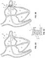
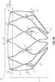
- FIG. 5Ais a side view of an illustration of another example frame of an occlusive device, in accordance with various aspects of the present disclosure.
- FIG. 5Bis a side view of the example frame of an occlusive device with a curvature in the face portion, in accordance with various aspects of the present disclosure.
- FIG. 6Ais a top view of an illustration of a portion of an example frame and center frame portion that may be included with an occlusive device, in accordance with various aspects of the present disclosure.
- FIG. 6Bis a perspective view of the example frame and center frame portion shown in FIG. 6A , prior to flattening and similar to the as-loaded condition in the delivery system in accordance with various aspects of the present disclosure.
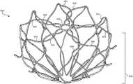
- FIG. 7is a perspective view of an example occlusive device, in accordance with various aspects of the present disclosure.
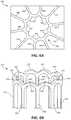
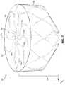
- FIG. 9Ais a perspective view of another example frame for an occlusive device in a shape set configuration, in accordance with various aspects of the present disclosure.
- FIG. 9Bis a side view of a strut cut pattern of the frame, shown in FIG. 9A , prior to deformation to the shape set configuration, in accordance with various aspects of the present disclosure.
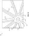
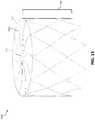
- FIG. 10is example flat pattern that can be used for forming a sheet material to create a frame of an occlusive device, in accordance with various aspects of the present disclosure.
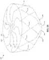
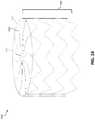
- FIG. 11is another example flat pattern that can be used for forming a sheet material to create a frame of an occlusive device, in accordance with various aspects of the present disclosure.
- FIG. 12is a top view of an example center frame portion that may be included with an occlusive device, in accordance with various aspects of the present disclosure.
- FIG. 13is a perspective view of an alternate design of an example frame for an occlusive device, in accordance with various aspects of the present disclosure.
- FIG. 14is a perspective view of an alternate design of another example frame for an occlusive device, in accordance with various aspects of the present disclosure.
- FIG. 15is a perspective view of an alternate design of another example frame for an occlusive device, in accordance with various aspects of the present disclosure.
- FIG. 16is a perspective view of an alternate design of another example frame for an occlusive device, in accordance with various aspects of the present disclosure.
- FIG. 17is a perspective view of an alternate design of another example frame for an occlusive device, in accordance with various aspects of the present disclosure.
- FIG. 18is a perspective view of an alternate design of another example frame for an occlusive device, in accordance with various aspects of the present disclosure.
- FIGS. 1A-Bare a cross-sectional views of a human heart 10 in which a delivery system 20 is positioned in preparation for deployment of an occlusive device 30 into an appendage 18 of the heart, in accordance with various aspects of the present disclosure.
- FIGS. 1A-Bshow a depiction of includes a right atrium 14 , a left atrium 16 , a right ventricle 32 , and a left ventricle 34 of the heart 10 .
- the appendage 18is located in the left atrium 16 of the heart 10 , and thus, the appendage 18 may be considered the left atrial appendage 18 .
- the occlusive device 30may be deployed in other appendages or openings within the human heart 10 or in other locations of the human body.
- the left atrial appendage 18may be considered a muscular pouch extending from the anterolateral wall 36 of the left atrium 16 of the heart 10 , which serves as a reservoir for the left atrium 16 .
- the left atrial appendage 18may contract rhythmically with the rest of the left atrium 16 during contraction of the heart 10 .
- the left atrial appendage 18contracts with the left atrium 16 and pumps blood that may gather or collect within the left atrial appendage 18 to circulate therefrom.
- the left atrial appendage 18may fail to sufficiently contract along with the left atrium 16 , which can allow blood to stagnate within the left atrial appendage 18 .
- Stagnant blood within the atrial appendage 18is susceptible to coagulating and forming a thrombus, which can dislodge from the atrial appendage 18 and ultimately result in an embolic stroke.
- the occlusive device 30may be delivered to the left atrial appendage 18 to help prevent and militate against blood stagnation within the left atrial appendage 18 .
- the occlusive device 30may be delivered to the left atrial appendage 18 by way of a minimally invasive transcatheter procedure. More specifically, the delivery system 20 may be navigated through a vena cava 12 , into the right atrium 14 , through an atrial septum 15 , and into the left atrium 16 towards the appendage 18 .
- the percutaneous access to the patient's vasculaturecan be at the patient's femoral vein, for example. It should be understood that this example technique is merely one example, and many other access techniques can also be performed to deploy the occlusive devices provided herein.
- the occlusive deviceis contained within a lumen of the delivery system 20 , and is configured in a collapsed low-profile delivery configuration.
- transcatheter systemsare generally shown and described, other delivery systems (e.g., thoracoscopic) are also contemplated.
- FIG. 1Bshows the configuration of FIG. 1A with the occlusive device 30 deployed from the delivery system 20 and positioned within the left atrial appendage 18 , in accordance with various aspects of the present disclosure.
- a control catheter 22may releasably couple to the occlusive device 30 , and is slidably disposed within the lumen of the delivery system 20 .
- the control catheter 22can be used by a clinician operator to make the occlusive device 30 deploy from the delivery system 20 . For example, after positioning the occlusive device 30 through an ostium 38 of the left atrial appendage 18 , the clinician operator can retract the delivery system 20 in relation to the control catheter 22 to unsheath and deploy the occlusive device 30 .
- the ostium 38may be considered a portion of the anterolateral wall 36 of the left atrium 16 from which a taper originates to form the pouch-like structure of the left atrial appendage 18 .
- the occlusive device 30may include an occlusive face 40 that is arranged near the ostium 38 of the left atrial appendage 18 .
- the control catheter 22may releasably couple to the occlusive device 30 via a hub or center frame portion or a plug (or the like) inserted into the center frame portion arranged centrally within the occlusive face 40 of the occlusive device 300 .
- the occlusive device 30can reconfigure to an expanded configuration.
- the occlusive device 30may expand to conform to the contours of the space defined within the left atrial appendage 18 .
- positioning of the occlusive device 30 relative to the ostium 38 of the left atrial appendage 18may be enhanced and ensures that the occlusive device 30 prevents thrombus from embolizing from the left atrial appendage 18 .
- the occlusive face 40may be arranged within the left atrial appendage 18 such that the occlusive face 40 connects portions of the anterolateral wall 36 on opposite sides of the ostium 38 to form a substantially uniform surface.
- bloodmay collect or stagnate along the face of a device implanted therein if the occlusive face is non-uniform (e.g., a device having a hub that protrudes beyond other portions of the occlusive face; a device having a occlusive face that is concave, partially concave, or includes depressions, a device having a occlusive face that is concave, partially concave, or includes depressions and a covering attached thereto that may drape or wrinkle as a result of the non-uniform face) relative to the ostium 38 of the left atrial appendage 18 or the occlusive face includes protuberances.
- non-uniforme.g., a device having a hub that protrudes beyond other portions of the occlusive face; a device having a occlusive face that is concave, partially concave, or includes depressions, a device having a occlusive face that is concave, partially concave, or includes depression
- thrombusmay occur along the face of the occlusive device as a non-uniform surface may alter/disrupt the blood flow within the left atrium 18 .
- a patientmay remain susceptible to blood coagulation and thrombus formation if an occlusive device includes a non-uniform surface as the result of improper positioning or the design of the device.
- the control catheter 22can be decoupled from the occlusive device 30 , and the delivery system 20 and control catheter 22 can be removed from the patient.
- the occlusive device 30deployed as shown, the space defined within the left atrial appendage 18 is essentially separated from the left atrium 16 by virtue of the physical barrier provided by the occlusive device 30 .
- stagnant blood within the LAA 18that is susceptible to coagulating and forming thrombi may be prevented from entering the left atrium 16 , and thereby prevented from potentially causing an embolic stroke.
- positioning of the occlusive face 40 of the occlusive device 30 relative to the ostium 38 of the left atrial appendage 18may help prevent blood collecting or stagnating along the face of the occlusive device 30 .
- FIG. 1Cshows the configuration of FIG. 1A with the occlusive device 30 deployed from the delivery system and positioned within a vessel between the vessel walls 42 , in accordance with various aspects of the present disclosure.
- FIG. 2is a perspective view of an example frame 200 for an occlusive device.
- the frame 200may include a proximal end 202 and a distal end 204 , and may be unitary and self-expanding.
- the frame 200may include a plurality of elongate members 206 and a center frame portion 208 arranged at the proximal end 202 of the frame 200 .
- the plurality of elongate members 206may extend from the center frame portion 208 . Together, the combination of the plurality of elongate members 206 and the center frame portion 208 form a face portion 220 .
- the frame 200may include a body portion 214 .
- the frame 200including the plurality of elongate members 206 and the center frame portion 208 , is shown in a pre-loaded flat configuration. In certain instances and as discussed in further detail relative to FIGS. 5A-B , the frame 200 may be slightly bowed as a result of being loaded into and deployed from a delivery system. In the pre-loaded flat configuration and as shown, the plurality of elongate members 206 and the center frame portion 208 (the face portion 220 ) form a substantially planar surface (e.g., between 0 mm and 1 mm outward deflection measured from transition portions 216 ). In certain instances, the center frame portion 208 is a hole having an inner and outer circumference and a plurality of elongate members 206 radiate outward from the outer circumference of the center frame portion 208 .
- the face portion 220may be formed by the center frame portion 208 and plurality of elongate members 206 .
- a boundary of the face portion 220may be considered to be at transition portions 216 of the frame 200 .
- the transition portions 216are arranged around a periphery of the face portion 220 .
- the transition portions 216transition the frame 200 between the plurality of elongate members 206 and the body portion 214 are external to the face portion 220 . More specifically, the body portion 214 of the frame 200 extends from the plurality of elongate members 206 , and the transition portions 216 transitions the plurality of elongate members 206 of the frame 200 to the body portion 214 of the frame 200 .
- transition portions 216may be configured as a landing zone that contact the walls of the appendage or vessel into which the frame 200 (as part of an occlusive device) is implanted.
- the transition portions 216may enhance conformability of the frame 200 relative to the walls of the appendage or vessel.
- the body portion 214may include any number of rows and cells.
- the body portion 214may bifurcate to form multiple cells in a row, or the body portion 214 may extend directly to the distal end 204 of the frame.
- the body portion 214may include cells formed of a five-sided shape, a six-sided shape, or other shapes such as, but not limited to, polygonal, square, rectangular, parallelogram-shaped, rhomboidal, trapezoidal, diamond-shaped, chevron-shaped, octagonal, triangular, and the like. Different shapes and arrangements of the body portion 214 are shown, for example, in FIGS. 13-18 .
- the plurality of elongate members 206are configured to flex and mitigate longitudinal movement (relative to a longitudinal axis 212 of the frame 200 ) of the face portion 220 in response to a compressive force applied to the body portion 214 of the frame 200 .
- the forceis applied to the transition portions 216 .
- the plurality of elongate members 206may enhance fatigue resistance of the frame 200 by functioning as stress relief features that absorb flexure and/or torque, and the like, in response to one or more forces being applied to the frame 200 .
- the plurality of elongate members 206 configured to mitigate movement of the face portion 220 substantially outward from the plane, and movement outward from the planemay include outward deflection of the face portion 220 .
- the face portion 220is a substantially uniform (proximal) surface formed by the plurality of elongate members 206 and the center frame portion 208 .
- the plurality of elongate members 206 and the center frame portion 208may include an equal and constant surface across the face portion 220 .
- the plurality of elongate members 206 and the center frame portion 208may be formed without protrusions outward from the face portion 220 .
- the plurality of elongate members 206 and the center frame portion 208may include approximately equal thickness (relative to the longitudinal axis 212 ) across the face portion 220 .
- the face portion 220 having a substantially uniform surface or a surface without protrusions outward therefrommay enhance performance of an occlusive device that includes the frame 200 by mitigating the opportunity for thrombus formation.
- the substantially uniform surface of the face portion 220may be planar.
- the plurality of elongate members 206are configured to bend or flex substantially in a plane (formed by the face portion 220 ) orthogonal to the longitudinal axis 212 to mitigate longitudinal movement (relative to the longitudinal axis 212 of the frame 200 ) of the face portion 220 in response to a compressive force applied to the body portion 214 of the frame 200 .
- the forcemay be considered a compressive force, and the compressive force may be applied to one or more locations on the body portion 214 of the frame 200 .
- the compressive forcemay be non-uniform relative to the frame 200 , and in other instances the force may be considered a radial force, which may be defined as a force, or a component of a force, that is directed inwardly from one or more locations relative to the frame 200 .
- the force applied to one or more locations on the body portion 214is directed along the body portion 214 toward the plurality of elongate members 206 .
- the plurality of elongate members 206may absorb the applied force(s), and balance and/or share the applied force(s) throughout the frame 200 .
- the plurality of elongate members 206bend or flex substantially in the plane orthogonal to the longitudinal axis 212 to mitigate movement of the face portion 220 (the combination of the plurality of elongate members 206 and the center frame portion 208 ) relative to the longitudinal axis 212 in response to a force applied to the frame 200 .
- the plurality of elongate members 206flex and mitigate movement of the face portion 220 independent of the shape or arrangement of the body portion 214 of the frame 200 .
- Mitigating movement of the face portion 220 of the frame 200may enhance performance of the frame 200 when implanted in a vessel or opening in a body. More specifically, when the frame 200 (or an occlusive device that includes the frame 200 ) is positioned within, for example, the contours of the space defined within a left atrial appendage (e.g., left atrial appendage 18 shown in FIGS. 1A-B or within a vessel as shown in FIG. 1C ), thrombosis may occur along an occlusive device in instances where a non-uniform surface alters a blood flow across the face of the device. Mitigating movement of the face portion 220 longitudinally decreases the opportunity for thrombus formation by avoiding disruption of the blood flow.
- a left atrial appendagee.g., left atrial appendage 18 shown in FIGS. 1A-B or within a vessel as shown in FIG. 1C
- Mitigating movement of the face portion 220longitudinally decreases the opportunity for thrombus
- the face portion 220 having a substantially uniform surface or a surface without protrusions outward therefromsimilarly enhances performance by avoiding disruption of the blood flow.
- occlusive devices having an occlusive face with depressionsmay not only disrupt blood flow by allowing blood to pool along the occlusive face but blood may collect within the depressions. Each of these instances may contribute to thrombus formation.
- such a device that includes depressions in the occlusive facemay utilize a membrane to attempt to provide a uniform surface.
- the membranemay dip within the depression or wrinkle as a result of the non-uniform surface, and therefore disrupt blood flow across the occlusive face.
- the frame 200 including a uniform face portion 220 and also mitigating against movement of the face portion 220 in response to forces applied to the frame 200may enhance performance of an occlusive device that includes the frame 200 by mitigating the opportunity for thrombus formation.
- the plurality of elongate members 206being configured to flex and mitigate movement of the face portion 220 longitudinally relative to the longitudinal axis 212 may enhance the conformability of the frame 200 . More specifically, the plurality of elongate members 206 may facilitate the ability of the frame 200 , and more particularly the body portion 214 , to conform to irregular tissue topographies and/or dynamically variable tissue topographies. When the frame 200 is implanted into variable tissue topography, force applied from the tissue topography may be directed to one or more locations on the body portion 214 and/or the transition portions 216 .
- this forceis directed along a length of the body portion 214 toward the plurality of elongate members 206 , and the plurality of elongate members 206 absorb the applied force(s), and balance and/or share the applied force(s) throughout the frame 200 .
- portions of the frame 200 that contact the variable tissue topographymay conform thereto (as opposed to a frame forcing the variable tissue topography to conform to the shape of the frame).
- the transition portions 216 of the frame 200may conform to the shape of an ostium when implanted.
- the frame 200(which may include a membrane attached thereto) may be positioned within a left atrial appendage to help prevent thrombus from embolizing from the left atrial appendage (e.g., as shown above in FIG. 1B ). After implantation, portions of the frame 200 that contact the left atrial appendage conform thereto, and forces that are applied via the left atrial appendage may be absorbed by the plurality of elongate members 206 .
- the plurality of elongate members 206are configured to maintain the face portion 220 on opposite sides of an ostium of the left atrial appendage to form and maintain a substantially uniform surface closing off the ostium while allowing the transition portions 216 and portions of the body portion 214 that contact the appendage are configured to conform to the shape of the appendage.
- conformability characteristicscan be advantageous for providing substantial occlusion (sealing) and durable occlusion. Conformability can also enhance the fatigue resistance of the occlusive devices. Further, occlusive devices with substantial conformability are less traumatic to the patient and may tend to resist in situ migration better than occlusive devices with less conformability. In some embodiments of the occlusive devices provided herein, some portions of the devices are designed to be more conformable than other portions of the same device. That is, the conformability of a single occlusive device can be designed to be different at various areas of the device. Additionally, in some embodiments frame material selection, heat treatments and other treatments can be used to attain a desired extent of conformability. In certain instances, the frame 200 may be formed from nitinol (NiTi). In certain more specific embodiments, the frame 200 may be formed from a single unitary piece of nitinol.
- the frame 200may be reconfigured to a low-profile (elongated) configuration for loading into a delivery catheter (e.g., such as the control catheter 22 shown in FIG. 1 -B) used for transcatheter deployment of the occlusive device.
- a delivery cathetere.g., such as the control catheter 22 shown in FIG. 1 -B
- the frame 200is configured to self-expand and reconfigure to the configuration shown in FIG. 2 .
- the frame 200may be expanded to conform to the contours of the space defined within the body (e.g., left atrial appendage 18 shown in FIGS. 1A-B or within a vessel as shown in FIG. 1C ).
- the center frame portion 208may serve as the connection point to a control catheter for transcatheter deployment of the occlusive device.
- the frame 200(and the occlusive device that includes the frame 200 ) may have a face portion 220 that is hubless (e.g., no addition structure or element beyond that of the center frame portion 208 , lacking in additional thickness beyond that of the center frame portion 208 , rimless, or lacking in dimension beyond a maximum thickness of the plurality of elongate members 206 and the center frame portion 208 ).
- the face portion 220 lacking a hube.g., such as any eyelet that extends beyond the face portion 220 ) provides for an approximately uniform surface formed by the plurality of elongate members 206 and the center frame portion 208 .
- FIG. 2The illustrative components shown in FIG. 2 are not intended to suggest any limitation as to the scope of use or functionality of embodiments of the disclosed subject matter. Neither should the illustrative components be interpreted as having any dependency or requirement related to any single component or combination of components illustrated therein. Additionally, any one or more of the components depicted in any of the FIG. 2 may be, in embodiments, integrated with various other components depicted therein (and/or components not illustrated), all of which are considered to be within the ambit of the disclosed subject matter.
- the frame 200 described with reference to FIG. 2may be used in connection with delivery system 20 (shown in FIGS. 1A-B ).
- the frame 200may form a portion of occlusive device 30 (e.g., with the plurality of elongate members 206 and the center frame portion 208 forming a portion of the occlusive face 40 ).
- the frame 200may include a membrane attached thereto (e.g., as shown and discussed with reference to FIG. 7 ).
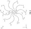
- FIG. 3is a top view of an illustration of an example face portion 300 of an occlusive device, in accordance with various aspects of the present disclosure.
- the face portion 300includes a plurality of elongate members 302 and a center frame portion 304 .
- the plurality of elongate members 302may extend from the center frame portion 304 and include a common curvature within the face portion 300 , which is formed substantially within a common plane (e.g., the x-y plane, as shown).
- the common curvaturemay provide for the plurality of elongate members 302 to be non-overlapping within the face portion 300 .
- the plurality of elongate members 302may have a zig-zag pattern (e.g., as shown in FIG. 8 ).
- the plurality of elongate members 302may include any number of curvature or semi-curved patterns. Other curvature patterns are shown, for example, in FIGS. 8-11 . As shown, each of the plurality of elongate members 302 includes multiple curved sections. For illustrative purposes, the curved sections are highlighted for one of the plurality of elongate members 302 in FIG. 3 .
- the plurality of elongate members 302may include a first curved section 306 , a second curved section 308 , and a third curved section 310 .
- the first curved section 306 and the third curved section 310are curved in a first direction
- the second curved section 308is curved in a second direction that is opposite that of the first direction.
- the plurality of elongate members 302may include a first inflection point 318 between the first curved section 306 and the second curved section 308 , and a second inflection point 320 between the second curved section 308 and the third curved section 310 .
- the first inflection point 318 and the second inflection point 320alter the curvature of the plurality of elongate members 302 .
- each of the first curved section 306 , the second curved section 308 , and the third curved section 310are arranged within the common plane.
- the plurality of elongate members 302 , and the curvature formed by the first curved section 306 , the second curved section 308 , and the third curved section 310occurs substantially within the x-y plane.
- each of the first curved section 306 , the second curved section 308 , and the third curved section 310are curved within the x-y plane.
- the center frame portion 304may also be arranged with the x-y plane.
- the plurality of elongate members 302 and the center frame portion 304may be arranged within a common plane.
- the plurality of elongate members 302are configured to flex and mitigate longitudinal movement (orthogonal to the x-y plane) of the face portion 300 in response to a compressive force applied to another portion of the occlusive device (e.g., as discussed above in detail with reference to FIG. 2 .).
- the plurality of elongate members 302are configured to flex or bend substantially within the x-y plane to mitigate longitudinal movement (orthogonal to the x-y plane) of the face portion 300 .
- each of the first curved section 306 , the second curved section 308 , and the third curved section 310may include equal radiuses of curvature.
- the first curved section 306 and the third curved section 310may include a first radius of curvature
- the second curved section 308may include a second (and different) radius of curvature.
- the (first) radius of curvature of the first curved section 306 and the third curved section 310may be larger than the (second) radius of curvature of the third curved section 310 .
- the first curved section 306 and the third curved section 310may include approximately equal lengths.
- the second curved section 308may include a length that is equal to or greater than the first curved section 306 and the third curved section 310 .
- the first curved section 306 and the third curved section 310may include lengths greater than the length of the second curved section 308 .
- the length of the second curved section 308is greater than the first curved section 306 and the third curved section 310 , which are substantially equal in length.
- the plurality of elongate members 302extend from the center frame portion 304 .
- a start point 312 for the plurality of elongate members 302is arranged at the center frame portion 304
- an end point 314 for the plurality of elongate members 302is arranged at a periphery of the face portion 300 .
- the start point 312 and the end point 314is shown for one of the plurality of elongate members 302 in FIG. 3 .
- the start point 312 and the end point 314may be symmetrically arranged with respect to the face portion 300 . More specifically, a tangent 316 formed between the start point 312 and the end point 314 may be substantially linear.
- the pattern of the curvature of the plurality of elongate members 302may be symmetric such that the plurality of elongate members 302 include a curvature (having one or more inflection points) in a direction from the start point 312 and back in another direction to the end point 314 .
- the face portion 300includes ten of the plurality of elongate members 302 .
- the face portion 300may include two, three, four, five, six, seven, eight, nine, eleven, twelve, thirteen, fourteen, fifteen, sixteen, or more than sixteen of the plurality of elongate members 302 .
- the center frame portion 304is shown to include ten peaks 322 that correspond to each of the plurality of elongate members 302 .
- the center frame portion 304may include an equal number of peaks to the number of the plurality of elongate members 302 included with the face portion 300 . In other instances, the center frame portion 304 may include a substantially circular shape.
- the illustrative components shown in FIG. 3are not intended to suggest any limitation as to the scope of use or functionality of embodiments of the disclosed subject matter. Neither should the illustrative components be interpreted as having any dependency or requirement related to any single component or combination of components illustrated therein.
- the face portion 300may be integrated with various other occlusive devices depicted herein (and/or components not illustrated), all of which are considered to be within the ambit of the disclosed subject matter.
- the face portion 300may be used in connection with the frame 200 shown in FIG. 2 .
- FIG. 4Ais a schematic representation of a top view of an example face portion 400 of an occlusive device in a first configuration prior to a force being applied, in accordance with various aspects of the present disclosure.
- the face portion 400includes a plurality of elongate members 402 a - j and a center frame portion 404 .
- the plurality of elongate members 402 a - jextend from the center frame portion 404 .
- the center frame portion 404 and the plurality of elongate members 402 a - jare arranged within an x-y plane.
- the plurality of elongate members 402 a - j and the center frame portion 404may be formed from a unitary frame.
- the unitary framemay be formed by laser cutting (e.g., a tube or flat sheet), etching, wire forming, or other processes.
- the face portion 400may be a substantially uniform surface or thickness.
- the plurality of elongate members 402 a - j and a center frame portion 404may include an equal and constant surface across the face portion 400 such that the face portion 400 is without protrusions (e.g., relative to the z-axis).
- the face portion 400 having a substantially uniform surface or a surface without protrusions outward therefrommay enhance performance of an occlusive device that includes the frame 400 by mitigating against the disruption of blood flow across the face portion 400 thereby reducing the opportunity for thrombus formation.
- a peripheral boundary 406 of the face portion 400is shown.
- the peripheral boundary 406may be considered a non-physical boundary that is formed by end portions of the plurality of elongate members 402 a - j (e.g., the face portion 220 formed around the transition portions 216 as shown in FIG. 2 ).
- the peripheral boundary 406may be a physical boundary formed by portions of a frame that form the face portion 400 .
- the face portion 400may include a membrane attached thereto. Membranes are attached to provide a barrier for thrombus being embolized from appendage or vessel as well as to enhance sealing.
- Membranes suitable for useinclude occlusive or semi-occlusive materials.
- Embodiments with semi-occlusive materialsmay allow passage of some fluids/blood components while inhibiting the passage of thrombus.
- the peripheral boundary 406may be formed by the boundary of the membrane.
- the face portion 400may be incorporated with an occlusive device (e.g., via the frame 200 shown and discussed above with reference to FIG. 2 ).
- the occlusive device that includes the face portion 400may include a longitudinal axis that is parallel to the z-axis shown in FIG. 4A .
- the occlusive device that includes the face portion 400has the center frame portion 404 and the plurality of elongate members 402 a - j arranged in a plane (the x-y plane) orthogonal to the longitudinal axis of the occlusive device.
- the face portion 400 of such an occlusive device(e.g., as shown in FIG. 2 ) may be considered a first portion of the occlusive device with a body portion of the occlusive device arranged substantially external and/or orthogonal to the face portion 400 and the x-y plane.
- the plurality of elongate members 402 a - j and the center frame portion 404are arranged in an initial configuration in which no forces are applied thereto.
- the plurality of elongate members 402 a - jmay be non-overlapping in the first configuration, and may include a common curvature.
- the plurality of elongate members 402 a - j and the center frame portion 404are uniform in addition to being arranged within the x-y plane.
- FIG. 4Bis a top view of an illustration of the face portion 400 in a second configuration in response to the force being applied, in accordance with various aspects of the present disclosure.
- the plurality of elongate members 402 a - jare configured to flex and mitigate movement of the face portion 400 relative to the x-y plane.
- the plurality of elongate members 402 a - jare configured to flex or bend substantially within the x-y plane to mitigate longitudinal movement of the face portion 400 relative to the x-y plane.
- the face portion 400may be incorporated with an occlusive device (e.g., via the frame 200 shown and discussed above with reference to FIG. 2 ).
- the applied forcemay be a compressive force applied to a portion of the occlusive device that is arranged external to the x-y plane.
- the compressive forcecorresponds to that associated with portions the device complying with body anatomy (e.g., the heart), including movement of the anatomy.
- the compressive forcemay be directed toward the occlusive device non-uniformly from one or more sides of occlusive device.
- the compressive forcemay be directed toward the occlusive device at an angle with respect to the z-axis from one or more sides of occlusive device.
- one or more of the plurality of elongate members 402 a - jflex/bend.
- the plurality of elongate members 402 a - jare configured such that one or more of the plurality of elongate members 402 a - j located nearest the compressive force bend to a greater degree than one or more of the plurality of elongate members 402 a - j that are located further therefrom.
- the plurality of elongate members 402 b - eflex/bend (within the x-y plane), whereas the plurality of elongate members 402 a and 402 f - j flex/bend to a lesser degree or not at all (within the x-y plane).
- the plurality of elongate members 402 a and 402 f - jmay pass the force applied along a length thereof to share the applied force among the plurality of elongate members 402 a and 402 f - j .
- the flexure of the plurality of elongate members 402 a - joccurs substantially within the x-y plane in order to mitigate movement of the plurality of elongate members 402 a - j and the center frame portion 404 external to the x-y plane (in the z direction or perpendicular to the x-y plane).
- an occlusive device that includes the face portion 400may be implanted into variable tissue topography.
- the forces applied from the tissue topographymay be directed to one or more locations.
- the face portion 400may be formed as part of a frame of the occlusive device, which may conform to the variable tissue topography.
- the occlusive devicemay be positioned within a left atrial appendage to help prevent thrombus from embolizing from the left atrial appendage (e.g., as shown above in FIG. 1B ). After implantation, forces that are applied via the left atrial appendage may be absorbed by the plurality of elongate members 402 a - j .
- the plurality of elongate members 402 a - jmaintain the face portion 400 within the x-y plane on opposite sides of an ostium of the left atrial appendage to form and maintain the uniformity of the face portion 400 to close off the ostium while allowing the remaining portions of the occlusive device to conform to the shape of the appendage in some embodiments. In other embodiments, only portions of the body portion of the occlusive device that contact the vessel or appendage are configured to conform.
- the peripheral boundary 406 of the face portion 400may conform to the shape of the ostium in response to forces applied via the left atrial appendage. For example and as shown comparing FIG. 4A and FIG.
- the peripheral boundary 406may alter its shape in response to forces applied to the occlusive device.
- the peripheral boundary 406maintains closure of the ostium of the left atrial appendage while the plurality of elongate members 402 a - j mitigate against movement of the face portion 400 and maintain the uniformity thereof to avoid thrombus formation.
- the face portion 400maintains the substantially uniform surface within the x-y plane. In certain instances, the face portion 400 also maintains a planar surface within the x-y plane.
- the plurality of elongate members 402 a - jmay also be non-overlapping in each of the first configuration ( FIG. 4A ) and the second configuration ( FIG. 4B ).
- FIGS. 4A-Bare not intended to suggest any limitation as to the scope of use or functionality of embodiments of the disclosed subject matter. Neither should the illustrative components be interpreted as having any dependency or requirement related to any single component or combination of components illustrated therein.
- the face portion 400may be integrated with various other occlusive devices depicted herein (and/or components not illustrated), all of which are considered to be within the ambit of the disclosed subject matter. For example, the face portion 400 may be used in connection with the frame 200 shown in FIG. 2 .
- FIG. 5Ais a side view of an illustration of another example frame 500 of an occlusive device, in accordance with various aspects of the present disclosure.
- the frame 500may include a face portion ( 502 a and 502 b ) and a body portion 504 .
- the face portion ( 502 a and 502 b )may include a center frame portion and a plurality of elongate members.
- the center frame portionmay be formed consistent with the aspects shown and described with reference to FIGS. 2-4 or FIGS. 6A-B , and the plurality of elongate members may be formed consistent with the aspects shown and described with reference to FIGS. 2-4 .
- the face portion 502 ais arranged at a proximal end 512 of the frame 500 .
- the face portion 502 amay be arranged in a plane 518 a that is perpendicular or orthogonal to a longitudinal axis 516 of the frame 500 .
- the plane 518 amay include an upper bound 520 a and a lower bound 522 a .
- the frame 500may also include transition portions 506 arranged between the face portion 502 a (and the plurality of elongate members) and the body portion 504 .
- the transition portions 506include a curvature to transition the frame 500 from the plane 518 to the body portion 504 .
- the face portion 502 amay be substantially planar (e.g., orthogonal to the longitudinal axis 516 of the frame 500 ).
- the face portion 502 amay include a uniform surface. More specifically, the face portion 502 a has a surface without protrusions external to that of the face portion 502 a.
- the frame 500may include a curvature in the face portion 502 b , in accordance with various aspects of the present disclosure.
- the curvaturemay result from the frame 500 being loaded and unloaded into a delivery system (e.g., as shown and discussed above in FIGS. 1A-B ).
- FIG. 5Ashows the frame 500 in a pre-loaded flat configuration. Once loaded and unloaded, a peak 532 of the curvature may be between approximately 1 mm and 3 mm higher or lower than transition portions 506 . In the pre-loaded flat configuration shown in FIG.
- the face portion is 502 ais substantially flat or planar (e.g., a peak of curvature of less than 1 mm as measured from the transition portions 506 ).
- the face portion 502 bis arranged within the plane 518 b .
- the plane 518 bmay be parallel to a peak 532 of the curvature of the face portion 502 b .
- the plane 518 bmay include an upper bound 520 b and a lower bound 522 b .
- the curvature of the face portion 502 bmay be outward from the frame 500 (as shown) or the curvature of the face portion 502 b may be inward.
- the face portion 502 bmay include a uniform surface. More specifically, the face portion 502 b has a surface without protrusions external to that of the face portion 502 b . More specifically, the face portion 502 b may be without protrusions relative to the surface of the face portion 502 b that includes the curvature.
- Both the face portion 502 a and the face portion 502 binclude a plurality of elongate members. As discussed in detail above (e.g., with reference to FIGS. 2-4 ), the plurality of elongate members are configured to are configured to flex or bend substantially within the plane ( 518 a and 518 b ) to mitigate movement of the face portion 502 a and face portion 502 b relative to the longitudinal axis 516 in response to a compressive force applied to the body portion 504 of the frame 500 .
- the plurality of elongate membersare configured to flex or bend substantially within the plane ( 518 a and 518 b ) to mitigate movement of the face portion ( 502 a or 502 b ) substantially outward from the plane ( 518 a and 518 b ), and movement outward from the plane ( 518 a or 518 b ) includes deflection of the face portion ( 502 a or 502 b ) of less than 15% outward (15% of an outer diameter of the body portion 214 ) in response to a the 25% compression of the body portion 504 .
- the 15% outward deflectionis represented by the upper bound ( 520 a and 520 b ) of the plane ( 518 a or 518 b ). More specifically, the face portion ( 502 a and 502 b ) deflects outward from the plane ( 518 a or 518 b ) if the deflection is greater than the upper bound ( 520 a and 520 b ).
- the plurality of elongate membersare configured to flex and mitigate movement of the face portion ( 502 a and 502 b ) substantially outward from the plane ( 518 a or 518 b ) in response to a compressive force applied to the body portion 504 of the frame 500 such that the face portion ( 502 a or 502 b ) remains within the upper bound ( 520 a and 520 b ) and the lower bound ( 522 a and 522 b ).
- the forcemay be considered a compressive force, and the compressive force may be applied to one or more locations on the body portion 504 of the frame 500 .
- the compressive forcemay be non-uniform relative to the frame 500 , and in other instances the force may be considered a radial force, which may be defined as a force, or a component of a force, that is directed inwardly from one or more locations relative to the body portion 504 .
- the frame 500may be implanted in a patient. More specifically, when the frame 500 (or an occlusive device that includes the frame 500 ) is positioned within, for example, the contours of the space defined within a left atrial appendage (e.g., left atrial appendage 18 shown in FIGS. 1A-B ), thrombus may occur along an occlusive device in instances where a non-uniform (e.g., having protrusions) surface alters a blood flow across the face of the device.
- a non-uniforme.g., having protrusions
- forces that are applied to the body portion 504 of the frame via the left atrial appendagemay be absorbed by the plurality of elongate members that are included in the face portion ( 502 a or 502 b ).
- the plurality of elongate membersare configured to mitigate movement of the face portion ( 502 a and 502 b ) longitudinally relative to the longitudinal axis 516 on opposite sides of an ostium of the left atrial appendage to form and maintain a substantially protrusion-free surface that closes off the ostium of the left atrial appendage while allowing the remaining portions (e.g., the body portion 504 ) of the occlusive device to conform to the shape of the appendage.
- the body portion 504 of the frame 500may be tapered toward a distal end 514 .
- the body portion 504 of the frame 500may include a first tapered section 508 and a second tapered section 510 .
- the first tapered section 508 and the second tapered section 510may decrease in circumference at different rates. For example and as shown in FIG. 5A and FIG. 5B , the first tapered section 508 decreases at a rate that is less than a rate at which the second tapered section 510 tapers.
- the first tapered section 508may taper at an angle between 0 and 10 degrees, or 0 to 20 degrees, or 0 to 30 degrees from the face portion ( 502 a and 502 b ).
- the second tapered section 510may taper at an angle between 40 and 75 degrees, 30 and 80 degrees, or 30 and 85 degrees.
- the frame 500may include a single taper or multiple tapered sections (first tapered section 508 and second tapered section 510 ) depending on the intended implantation for an occlusive device that includes the frame 500 .
- the first tapered section 508 and the second tapered section 510may be manufactured and sized to the specific anatomy of the left atrial appendage.
- Some embodiments of the frame 500are resistant to pleating.
- certain embodiments of occlusive devices provided hereingenerally exhibit more resistance to pleating when loading or reloading the devices into a delivery catheter.
- Pleatingis type of deformation such as the folding, curving, kinking, or overlapping of a portion of an occlusive device (e.g., the distal portion) that makes the device configured non-uniformly.
- Pleatingcan cause an occlusive device to experience structural entanglement and/or damage, resistance to loading, poor sealing performance, and the like.
- the “acorn” shape of the frame 500enhances the resistance of the frame 500 to pleating.
- these such embodimentsmay be better at prevention of patient trauma in part due to the acorn shape, a membrane with full or fuller coverage of the frame, improved conformability and sealing, better fatigue resistance, and the ePTFE material of the covering which enhances in growth.
- the body portion 504 of the frame 500may be another shape such as cylindrical, conical, frustoconical, hemispherical, a spherical cap, pyramidal, truncated pyramidal, and the like, and combinations thereof. Any and all combinations and sub-combinations of such varying shapes and varying geometries of shapes are envisioned and within the scope of this disclosure.
- the face portion ( 502 a or 502 b ), the body portion 504 , and the transition portions 506 of the frame 500are formed from a unitary and self-expanding structure.
- the frame 500may be constructed of a unitary piece of material. Therefore, it can be said that in some embodiments the frame 500 include a seamless construction.
- the material of the frame 500may be of a single thickness and/or width through the entirety of the frame 500 .
- the material of the frame 500may vary in thickness and/or width so as to facilitate variations in the radial force that is exerted by the frame 500 in specific regions thereof, to increase or decrease the stiffness or flexibility of the frame 500 in certain regions, to enhance migration resistance, and/or to control the process of loading (and/or reloading) the frame 500 into a delivery catheter in preparation for deployment (and/or repositioning and redeployment) of an occlusive device made of frame 500 .
- the frame 500can be constructed differently such that the frame 500 includes two or more portions that are formed separately of each other.
- NiTinitinol
- other materialssuch as stainless steel, L605 steel, polymers, MP35N steel, polymeric materials, Pyhnox, Elgiloy, or any other appropriate biocompatible material, and combinations thereof, can be used as the material of the frame 500 .
- the super-elastic properties and softness of NiTimay enhance the conformability of the frame 500 .
- NiTican be shape-set into a desired shape. That is, NiTi can be shape-set so that the frame 500 tends to self-expand into a desired shape when the frame 500 is unconstrained, such as when the frame 500 is deployed out from a delivery system.
- the frame 500(made of NiTi) may have a spring nature that allows the frame 500 to be elastically collapsed or “crushed” to a low-profile delivery configuration for loading in a delivery system (e.g., as shown and discussed with reference to FIG. 1A ), and then to reconfigure to the expanded configuration, as shown in FIG. 5A and FIG. 5B , upon emergence from the delivery system.
- the frame 500may be generally conformable, fatigue resistant, and elastic such that the frame 500 can conform to the topography of the surrounding tissue when the occlusive device is deployed in a patient.
- bioresorbable or bioabsorbable materialsmay be used for the frame 500 or a portion thereof, including for example, a bioresorbable or bioabsorbable polymer.
- some portions or the entirety of the frame 500are coated (e.g., sputter-coated) with a radiopaque coating for enhanced radiographic visibility.
- portions or the entirety of the frame 500can be coated with a noble metal such as, but not limited to, tantalum, platinum, and the like.
- the frame 500is formed from nitinol tubing or sheets of nitinol.
- the frame 500can be processed using various electro-polishing techniques. In some embodiments, such electro-polishing is performed while the frame 500 is in a cut-tube configuration (prior to diametrical expansion). In some embodiments, such electro-polishing is performed while the frame 500 is in a diametrically expanded and shape-set configuration. In some embodiments, the frame 500 can be processed using various heat treating techniques. The use of such techniques can enhance some desirable performance characteristics of the occlusive devices provided herein such as, but not limited to, increased conformability, increased fatigue resistance, and the reduction of patient trauma from the devices.
- the frame 500may also include one or more anchors 524 , 526 arranged with the body portion 504 . As shown in FIG. 5A and FIG. 5B , the frame includes a first group of anchors 524 and a second group of anchors 526 . Although a single one of each of the first group of anchors 524 and the second group of anchors is highlighted, each of the anchors 524 , 526 include an anchoring portion 528 (which may contact a vessel or appendage wall to hold the frame 500 and accompanying occlusive device in place) and an arm 530 .
- an anchoring portion 528which may contact a vessel or appendage wall to hold the frame 500 and accompanying occlusive device in place
- first group of anchors 524 and the second group of anchors 526may be arranged at the same height, relative to the distal end 514 , around a circumference of the frame 500 .
- the anchoring portions 528 of the first group of anchors 524is arranged at a first height, relative to the distal end 514
- the anchoring portions 528 of the second group of anchors 526is arranged at a second height, relative to the distal end 514 , with and the first height being greater than the second height.
- the heights of the anchoring portions 528 of the first group of anchors 524 and the second group of anchors 526may be altered by arranging the first group of anchors 524 and the second group of anchors 526 at different heights on the frame 500 . In other instances, the heights of the anchoring portions 528 of the first group of anchors 524 and the second group of anchors 526 may be altered by altering lengths of the arm 530 . More specifically and as shown, the arm 530 of the first group of anchors 524 may be shorter than the arm 530 of the second group of anchors 526 .
- the difference in height of the first group of anchors 524 and the second group of anchors 526may be the difference between the lengths of the arm 530 of the first group of anchors 524 and the arm 530 of the second group of anchors 526 .
- the first group of anchors 524 and the second group of anchors 526 and the remaining portions of the frame 500may be unitary. More specifically, the first group of anchors 524 and the second group of anchors 526 may also be formed from the same unitary piece of material as the remaining portions of the frame 500 .
- staggering the first group of anchors 524 and the second group of anchors 526may decrease the amount of force required to transition the frame 500 between the deployed configuration (as shown) and an elongated or delivery configuration via a delivery system.
- the framemay be positioned within the delivery system (e.g., as shown in FIG. 1A ) by withdrawing the frame 500 into a portion (delivery sheath) of the delivery system. In the process of withdrawing the frame 500 into the delivery system, the forced needed to position the frame 500 within the delivery system increases when contacting protrusions (such as anchors).
- staggering the first group of anchors 524 and the second group of anchors 526 at different heightsalso staggers the amount of forced needed to withdraw the anchors 524 and 526 into the delivery system by approximately half relative to a plurality of anchors located at the same height around a frame.
- the illustrative components shown in FIG. 5A and FIG. 5Bare not intended to suggest any limitation as to the scope of use or functionality of embodiments of the disclosed subject matter. Neither should the illustrative components be interpreted as having any dependency or requirement related to any single component or combination of components illustrated therein.
- the frame 500may be integrated with various other occlusive devices depicted herein (and/or components not illustrated), all of which are considered to be within the ambit of the disclosed subject matter.
- the frame 500may include a membrane attached thereto (e.g., as shown and discussed with reference to FIG. 7 ) or the frame 500 may be used in place of the frame 708 included with the occlusive device 700 .
- the face portions 220 , 300 , 400may be incorporated in place of the face portion ( 502 a or 502 b ).
- FIG. 6Ais a top view of an illustration of a portion of an example frame 600 and center frame portion 602 that may be included with an occlusive device, in accordance with various aspects of the present disclosure.
- the frame 600may be formed from a nitinol material in certain instances.
- the frame 600may be unitary and self-expanding.
- the center frame portion 602may include a plurality of arcs 604 arranged around a circumference of the center frame portion 602 .
- the center frame portion 602may be arranged as a center section of the frame 600 that may be used with an occlusive device, consistent with various aspects of the present disclosure.
- the frame 600may be formed from a unitary structure, such as a tube.
- the tubemay be cut in to form the frame 600 , which includes the center frame portion 602 and the plurality of arcs 604 .
- the frame 600also includes a plurality of elongate members 606 , which may form a face portion and a body portion of the frame 600 .
- the center frame portion 602 and the plurality of elongate members 606are substantially planar. Forming the frame 600 from a cut tube allows the center frame portion 602 to be substantially flat. In order to arrange the center frame portion 602 and the plurality of elongate members 606 from a tube to a planar configuration, the cut-tube must be flattened from a manufactured configuration as shown in FIG. 6B . As discussed in further detail below, the plurality of arcs 604 may be configured to distribute strain about the center frame portion 602 in transitioning from the manufactured configuration to the flattened configuration as shown in FIG. 6A .
- the plurality of arcs 604may be similarly configured to distribute strain about the center frame portion 602 in transitioning the frame 600 from an elongated configuration (e.g., the frame 600 disposed within a delivery system) and a deployed configuration.
- the portion of the frame 600 shown in FIG. 6Amay be a central section of a face portion (e.g., the face portions 220 , 300 , 400 shown in FIGS. 2-4 ).
- the center frame portion 602may be configured to attach to a delivery system (e.g., the delivery system discussed in FIGS. 1A-B ) for delivering an occlusive device that includes the frame 600 to a target location in a patient.
- a delivery systeme.g., the delivery system discussed in FIGS. 1A-B
- the frame 600may be withdrawn into the delivery system by way of the attachment to the center frame portion 602 from the deployed/flattened configuration shown in FIG. 6A , to an elongated configuration within the delivery system.
- the strains applied to the frame through the transitioning between configurationsare distributed by the plurality of arcs 604 about the center frame portion 602 .
- the plurality of elongate members 606may be configured to bend and mitigate movement of the center frame portion 602 and the plurality of elongate members 606 substantially outward from the planar profile shown in FIG. 6A .
- the plurality of elongate members 606may include a curvature to absorb forces that may be applied to portions of the frame 600 (not shown) external to the planar profile of the center frame portion 602 and the plurality of elongate members 606 .
- FIG. 6Bis a perspective view the frame 600 and the center frame portion 602 shown in FIG. 6A , prior to flattening in accordance with various aspects of the present disclosure.
- the frame 600is shown in a manufactured configuration after the frame is formed from, for example, a cut-tube or flat-sheet to include the plurality of arcs 604 .
- the plurality of arcs 604enhance the ability of the frame 600 to flatten into the planar profile shown in FIG. 6A .
- the plurality of arcs 604may provide flexibility during the transition of tube to flattened.
- the plurality of arcs 604may transition and distribute the strain that arises from flattening the frame 600 from the manufactured configuration about the center frame portion 602 .
- the curvature of the plurality of arcs 604provide an optimized area for the stresses to distribute as compared to a substantially circular or rectangular center area.
- the curvature of the plurality of arcs 604may be reversed from the curvature shown in FIG. 6A .
- widths of the plurality of arcs 604may be equal to widths of the plurality of elongate members 606 .
- widths of the plurality of arcs 604may be between 101% and 160% greater than widths of the plurality of elongate members 606 .
- FIGS. 6A-Bare not intended to suggest any limitation as to the scope of use or functionality of embodiments of the disclosed subject matter. Neither should the illustrative components be interpreted as having any dependency or requirement related to any single component or combination of components illustrated therein. Additionally, any one or more of the components depicted in any of the FIG. 6A-B may be, in embodiments, integrated with various other components depicted therein (and/or components not illustrated), all of which are considered to be within the ambit of the disclosed subject matter.
- the frame 600 described with reference to FIG. 6A-Bmay be used in connection with delivery system 20 and form a portion of occlusive device 30 , shown in FIGS.
- the frame 200may include a membrane attached thereto (e.g., as shown and discussed with reference to FIG. 7 ).
- FIG. 7is a perspective view of an example occlusive device 700 , in accordance with various aspects of the present disclosure.
- the occlusive device 700may include a center frame portion 702 , a plurality of elongate members 704 that extend from the center frame portion 702 , and a body portion 706 .
- the center frame portion 702 , the plurality of elongate members 704 , and the body portion 706collectively form a frame 708 of the occlusive device.
- the frame 708may be unitary (e.g., formed from a single structure, or a single piece of material) and self-expanding.
- center frame portion 702 and the plurality of elongate members 704are arranged in a common plane that is orthogonal to a longitudinal axis 712 of the occlusive device 700 .
- the center frame portion 702 and the plurality of elongate members 704may be within an x-y plane.
- the body portion 706 of the frame 708may be arranged external to the x-y plane.
- the plurality of elongate members 704may bend and mitigate movement of the center frame portion 702 and the plurality of elongate members 704 longitudinally relative to the x-y in response to a compressive force applied to the body portion 706 .
- the plurality of elongate members 704include a common curvature that extends from the center frame portion 702 of the frame 708 within the x-y plane.
- the occlusive device 700may also include a membrane arranged on the frame 708 .
- the occlusive device 700in combination with the center frame portion 702 and the plurality of elongate members 704 (the face portion of the frame 708 ) may together define an occlusive face of the occlusive device 700 .
- the center frame portion 702 and the plurality of elongate members 704being arranged within a common plane may enhance the attachment of the membrane 710 thereto.
- the center frame portion 702 and the plurality of elongate membersmay be planar.
- center frame portion 702 and the plurality of elongate members 704may be a substantially uniform (proximal) surface.
- the center frame portion 702 and the plurality of elongate members 704may include an equal and constant surface.
- the center frame portion 702 and the plurality of elongate members 704may be formed without protrusions outward therefrom.
- the center frame portion 702 and the plurality of elongate members 704may include approximately equal thickness (relative to y-axis) across the face portion 220 .
- the center frame portion 702 and the plurality of elongate members 704 having a substantially uniform surface or a surface without protrusions outward therefrommay enhance performance of the occlusive device 700 by mitigating the opportunity for thrombus formation.
- the membrane 710may cover the center frame portion 702 .
- the center frame portion 702may be an aperture in the frame 708 (e.g., as shown in FIGS. 2-4 and 6A ).
- the membrane 710may cover or partially cover the center frame portion 702 to seal off the face portion of the frame 708 .
- the membrane 710may partially extend within the center frame portion 702 to provide sealing.
- the membrane 710may be attached to the external portion of the frame 700 to entirely cover the frame 700 (e.g., such that the frame 700 , which may be composed of nitinol, is not exposed to blood or tissue in situ).
- the plurality of elongate members 704may be configured to bend and mitigate movement of the center frame portion 702 and the plurality of elongate members 704 longitudinally in response to a compressive force applied to the body portion 706 .
- the plurality of elongate members 704may facilitate the ability of the frame 708 to adapt and conform to irregular tissue topographies and/or dynamically variable tissue topographies. Forces may be applied from the tissue topography and directed to one or more locations on the body portion 706 .
- this forceis directed along a length of the body portion 706 toward the plurality of elongate members 704 , and the plurality of elongate members 704 deform and absorb the applied force(s), and balance and/or share the applied force(s) throughout the frame 708 .
- the occlusive device 700may be positioned within a left atrial appendage to help prevent thrombus from embolizing from the left atrial appendage (e.g., as shown above in FIG. 1B ). After implantation, the occlusive device 700 conforms to the left atrial appendage, and forces that are applied via the left atrial appendage may be absorbed by the plurality of elongate members 704 .
- the plurality of elongate members 704maintain a planar occlusive face in a common plane on opposite sides of an ostium of the left atrial appendage.
- the bending of the plurality of elongate members 704in response to forces applied to the body portion 706 , maintain a substantially uniform surface (substantially planar and/or without protrusions) and close off the ostium to help prevent thrombus from embolizing from the left atrial appendage and without disrupting blood flow along the occlusive face.
- the center frame portion 702 and the plurality of elongate members 704being arranged and the flex or bend being maintained within a common plane (e.g., planar) orthogonal to the longitudinal axis 712 may provide structural stability for the membrane 710 when the occlusive device 700 is implanted.
- thrombusmay occur along the face of the occlusive device 700 due to a non-uniform surface altering the blood flow.
- the center frame portion 702 and the plurality of elongate members 704may be uniform and not include protrusions. The lack of protrusions may also enhance the mitigation of thrombosis by not altering the blood flow.
- a patientmay remain susceptible to blood coagulation and thrombus formation if an occlusive device does not maintain a planar and/or uniform face.
- the membranemay conform to the non-planar face and/or non-uniform face and provide a device that has a non-uniform surface or a face that includes protrusions, which may alter blood flow thereacross.
- the center frame portion 702 and the plurality of elongate members 704may enhance structural stability of the membrane 710 , and maintain a planar and/or uniform occlusive face for the occlusive device 700 .
- the membrane 710may include a fluoropolymer, such as a polytetrafluoroethylene (PTFE) polymer or an expanded polytetrafluoroethylene (ePTFE) polymer.
- PTFEpolytetrafluoroethylene
- ePTFEexpanded polytetrafluoroethylene
- the membrane 710may be formed of a polyester, a silicone, a urethane, a polyethylene terephthalate, or another biocompatible polymer, or combinations thereof.
- bioresorbable or bioabsorbable materialsmay be used, for example a bioresorbable or bioabsorbable polymer.
- the membrane 710can comprise a fluoropolymer, such as described in one or more of U.S. Pat.
- the membrane 710can comprise Dacron, polyolefins, carboxy methylcellulose fabrics, polyurethanes, or other woven or film elastomers. In some embodiments, the membrane 710 can comprise knits or fibers. The membrane 710 may be woven or non-woven in various embodiments including wires for example. In some embodiments, the membrane 710 may be formed of a copolymer of fluoropolymers or blends thereof.
- the membrane 710is configured to inhibit, filter, modulate, or substantially modulate the passage of fluids and/or materials (such as blood and/or thrombus) through the membrane 710 .
- the membrane 710is configured to induce rapid tissue ingrowth therein.
- the membrane 710provides for a blood or body fluid impermeable membrane that occludes the flow of blood or bodily fluids through the membrane yet promotes the ingrowth and endothelialization.
- the membrane 710can have a microporous structure that provides a tissue ingrowth scaffold for durable occlusion and supplemental anchoring strength of the occlusive device 700 .
- the membrane 710is a porous member.
- Pores of the membrane 710may be sized to substantially, or in some examples completely, help prevent passage of blood, other bodily fluids, and emboli. In some implementations, the membrane 710 prevents or substantially prevents passage of blood, other bodily fluids, thrombi, emboli, or other bodily materials through the membrane 710 .
- the membrane 710is configured such that the desired modulation of fluid and/or blood component passage through the membrane 710 is immediate and does not rely on a thrombotic process.
- the membrane 710can be modified by one or more chemical or physical processes that enhance certain physical properties of the membrane 710 .
- a hydrophilic coatingmay be applied to the membrane 710 to improve the wettability and echo translucency of the membrane 710 .
- the membrane 710may be modified with chemical moieties that promote one or more of endothelial cell attachment, endothelial cell migration, endothelial cell proliferation, and resistance to thrombosis.
- the membrane 710may be modified with covalently attached heparin or impregnated with one or more drug substances that are released in situ to promote wound healing or reduce tissue inflammation.
- the drugmay be a corticosteroid, a human growth factor, an anti-mitotic agent, an antithrombotic agent, or dexamethasone sodium phosphate.
- the membrane 710is pre-perforated to modulate fluid flow through the membrane 710 , to create filtering properties, and/or to affect the propensity for tissue ingrowth to the membrane 710 .
- portions or all of the membrane 710are treated to make the membrane 710 elastic.
- the membraneis treated with silicone or elastic fluoropolymers to provide elasticity to portions or all of the membrane 710 .
- the membrane 710is treated to make the membrane 710 stiffer or to add surface texture.
- the membrane 710is treated with fluorinated ethylene propylene (FEP) to provide a stiffened membrane 710 or roughened surface on the membrane 710 .
- FEPfluorinated ethylene propylene
- Other membrane 710 material treatment techniquescan also be employed to provide beneficial mechanical properties and tissue response interactions. Such materials and techniques can be used for any of the occlusive devices provided herein.
- the membrane 710conforms to the contours of the frame 708 .
- the membrane 710may be attached to an outer periphery of the frame 708 and suspended therebetween (like a drum skin).
- the membrane 710is attached to selected regions of the frame 708 and not attached to other regions of the frame 708 . This technique can facilitate enhanced conformability of the occlusive device 700 to the topography of a patient's anatomy at the implant site, and/or enhanced catheter loading in some embodiments.
- the membrane 710is attached to all portions of the frame 708 .
- the membrane 710may include pleats, folds, crimps, openings, corrugations, and the like. In other embodiments pleats, folds, or the like on the membrane 710 are avoided on the center frame portion 702 and the plurality of elongate members 704 , as a result of the uniform surface thereof, which may minimizes blood flow disruptions thereacross.
- the membrane 710is an elastic member that can elastically stretch and retract to accommodate the expandability and loadability of the frame 708 . Such features and techniques can also be incorporated with other embodiments of occlusive devices provided herein.
- the membrane 710is attached to the frame 708 using an adhesive.
- FEPis used as an adhesive to attach the membrane 710 to the frame 708 , or portions thereof.
- an FEP coatingcan be applied to some or all portions of the frame 708 , and the FEP can act as a bonding agent to adhere the membrane 710 to the frame 708 .
- FIG. 7The illustrative components shown in FIG. 7 are not intended to suggest any limitation as to the scope of use or functionality of embodiments of the disclosed subject matter. Neither should the illustrative components be interpreted as having any dependency or requirement related to any single component or combination of components illustrated therein. Additionally, any one or more of the components depicted in any of the FIG. 7 may be, in embodiments, integrated with various other components depicted therein (and/or components not illustrated), all of which are considered to be within the ambit of the disclosed subject matter.
- the occlusive device 700 described with reference to FIG. 7may be used in connection with delivery system 20 (shown in FIGS. 1A-B ) in place of the occlusive device 30 .
- center frame portion 702 and the plurality of elongate members 704may be replaced with the center frame portion and the plurality of elongate members as described with reference to FIGS. 2-4 .
- the occlusive device 700may include anchors (e.g., as shown in FIGS. 5A-B ). Further yet, the center frame portion 702 may be replaced with the center frame portion 602 as shown in FIGS. 6A-B .
- FIG. 8is a perspective view of another example frame 800 for an occlusive device, in accordance with various aspects of the present disclosure.
- the frame 800may include a center frame portion 802 and a plurality of elongate members 804 .
- the center frame portion 802 and the plurality of elongate members 804are arranged within a common plane that is perpendicular to a longitudinal axis (not illustrated) of the frame 800 .
- the frame 800also includes a portion 806 that is non-planar with respect to the center frame portion 802 and the plurality of elongate members 804 .
- the plurality of elongate members 804may include a common formation. As shown, the plurality of elongate members 804 include a zig-zag pattern that act as a spring element and absorb and distributes forces that are applied to the frame 800 .
- the plurality of elongate members 804may enhance fatigue resistance of the frame 800 by functioning as stress relief features that absorb displacement, flexure and/or torque, and the like, in response to a force being applied to the frame 800 .
- the plurality of elongate members 804are configured to bend within the common plane to mitigate movement of the center frame portion 802 and the plurality of elongate members 804 in the longitudinal plane in response to a force applied to frame 800 .
- FIG. 9Ais a perspective view of another example frame 900 for an occlusive device in a shape set configuration, in accordance with various aspects of the present disclosure.
- the frame 900may include a center frame portion 902 and a plurality of elongate members 904 .
- the center frame portion 902 and the plurality of elongate members 904are arranged within a common plane that is perpendicular to a longitudinal axis (not illustrated) of the frame 900 .
- adjacent elongate members 904 of the plurality of elongate members 904are overlapping.
- the plurality of elongate members 904each include curvatures such that the plurality of elongate members 904 form common curvatures to provide the overlapping pattern shown.
- the center frame portion 902 and the plurality of elongate members 904may be considered to be arranged within the common plane, with the common plane being bounded by a thickness of the center frame portion 902 and the plurality of elongate members 904 forming a face of the frame 900 .
- the frame 900also includes a body portion 906 that is non-planar with respect to the center frame portion 902 and the plurality of elongate members 904 .
- the body portion 906may extend from the plurality of elongate members 904 .
- the plurality of elongate members 904may act as a spring element and absorb forces that are applied to the frame 900 .
- the plurality of elongate members 904may enhance fatigue resistance of the frame 900 by functioning as stress relief features that absorb displacement, flexure and/or torque, and the like, in response to a force being applied to the frame 900 .
- the plurality of elongate members 904are configured to bend within the common plane mitigate movement of the center frame portion 902 and the plurality of elongate members 904 longitudinally in response to a force applied to frame 900 .
- FIG. 9Bis a side view of a strut cut pattern 908 of the frame 900 , shown in FIG. 9A , prior to deformation to the shape set configuration, in accordance with various aspects of the present disclosure.
- the strut cut pattern 908Prior to forming the frame 900 into the shape set configuration shown in FIG. 9A , the strut cut pattern 908 may be formed by laser cutting a tube.
- the strut cut pattern 908includes the center frame portion 902 , the plurality of elongate members 904 , and the body portion 906 .
- the body portion 906may be arranged into an acorn-like shape, and adjacent sets of the plurality of elongate members 904 are overlaid with one another to form as illustrated by the arrows in FIG. 9B .
- FIG. 10is an example flat pattern 1000 that can be used for forming a sheet material to create a frame of an occlusive device, in accordance with various aspects of the present disclosure.
- a nitinol sheet materialmay be utilized.
- Pattern 1000results in occlusive device frames with no protuberances related to a center frame portion 1004 from the outer surface of the frames.
- the flat pattern 1000can also be used to form a plurality of elongate members with curved portions corresponding to material portions 1002 of pattern 1000 .
- a boundary 1006 shown in FIG. 10may correspond to a boundary of a face portion of the frame of an occlusive device.
- the flat pattern 1000 of FIG. 10can be used to form a plurality of elongate members corresponding to material portions 1002 of pattern 1000 that include curved portions (and other non-linear shapes). Such curved portions may be directed to enhancing fatigue resistance by providing elements such as, but not limited to, stress relief features, portions designed to absorb displacement, flexure and/or torque, and the like, and combinations of such features.
- the flat pattern 1000can also be used to form an occlusive device frame. Hence, it can be appreciated that by cutting a sheet material using a flat pattern, and by using the techniques described above, a wide variety of occlusive device frame design features are attainable.
- FIG. 11is another example flat pattern 1100 that can be used for forming a sheet material to create a frame of an occlusive device, in accordance with various aspects of the present disclosure.
- Pattern 1100results in occlusive device frames with no protuberances related to a center frame portion 1104 from the outer surface of the frames.
- the flat pattern 1100can also be used to form branch elongate members with curved portions corresponding to material portions 1102 of pattern 1100 .
- a boundary 1106 shown in FIG. 10may correspond to a boundary of a face portion of the frame of an occlusive device.
- the flat pattern 1100 of FIG. 11can be used to form a plurality of elongate members corresponding to portions of pattern 1100 that include wavy portions (and other non-linear shapes). Such wavy portions may be directed to enhancing fatigue resistance by providing elements such as, but not limited to, stress relief features, portions designed to absorb displacement, flexure and/or torque, and the like, and combinations of such features.
- wavy portionsmay be directed to enhancing fatigue resistance by providing elements such as, but not limited to, stress relief features, portions designed to absorb displacement, flexure and/or torque, and the like, and combinations of such features.
- FIG. 12is a top view of an example center frame portion 1202 that may be included with an occlusive device, in accordance with various aspects of the present disclosure.
- the center frame portion 1202does not protrude from the outer surface defined by the frame 1200 . Rather, the frame material that defines the center frame portion 1202 is flush with the outer surface defined by the frame 1200 .
- the center frame portion 1202is a hole having an inner and outer circumference and a plurality of elongate members 1204 radiate outward from the outer circumference of the center frame portion 1202 . Accordingly, the frame 1200 includes the center frame portion 1202 while not initiating or contributing to the potential for in situ flow disruptions and/or thrombus formation.
- the center frame portion 1202provides an attachment location that a delivery and/or retrieval device (e.g., a catheter and the like) can use to releasably couple with the frame 1200 .
- a delivery and/or retrieval devicee.g., a catheter and the like
- the center frame portion 1202defines a round through-hole (as shown).
- the center frame portion 1202defines structural features having a different shape such as, but not limited to, ovular, square, rectangular, triangular, key-hole shaped, reniform, and the like, and combinations thereof.
- the center frame portion 1202can include or define threads, one or more keyways, tabs, deformable elements, and the like, and combinations thereof.
- additional structure on the internal side of the frame 1200can be added in the region of the center frame portion 1202 that can be used for releasable attachment with a delivery and/or retrieval device.
- a collaror other physical member, e.g., a coiled member, a socket, screw fitting, etc.
- Such a collarcan have various physical shapes and features as desired to facilitate releasable attachment with a delivery and/or retrieval device.
- no through-holeis included as part of the occlusive device frame 1200 .
- Such features and techniquescan also be incorporated with other embodiments of occlusive devices provided herein.
- FIGS. 13-18describe and show alternate body portions that may be arranged with one or more of the face portions described above (e.g., face portions 220 , 300 , 400 , 502 a , 502 b ). Neither should the illustrative components be interpreted as having any dependency or requirement related to any single component or combination of components illustrated therein. Additionally, any one or more of the components depicted in any of FIGS. 13-18 may be, in embodiments, integrated with various other components depicted therein (and/or components not illustrated), all of which are considered to be within the ambit of the disclosed subject matter.
- FIG. 13is a perspective view of an alternate design of an example frame 1300 for an occlusive device, in accordance with various aspects of the present disclosure.
- the frame 1300includes a first set of cells 1302 and a second set of cells 1304 .
- the first set of cells 1302 and the second set of cells 1304may be substantially diamond shaped.
- the first set of cells 1302 and the second set of cells 1304may longitudinally overlap with one another to form the frame 1300 .
- the first set of cells 1302 and the second set of cells 1304may include equal areas, or one of the first set of cells 1302 and the second set of cells 1304 may be greater in area than the other of the first set of cells 1302 and the second set of cells 1304 .
- the frame 1300may also include a face portion 1306 .
- the face portion 1306may include a center frame portion 1308 and a plurality of elongate members 1310 .
- the plurality of elongate members 1310may enhance fatigue resistance of the frame 1300 by functioning as stress relief features that absorb displacement, flexure and/or torque, and the like, in response to a force being applied to the first set of cells 1302 and/or the second set of cells 1304 .
- the plurality of elongate members 1310may be configured to configured to flex or bend substantially within plane, in which the plurality of elongate members 1310 and the center frame portion 1308 are arranged, to mitigate longitudinal movement of the face portion 1306 substantially outward from the plane in response to a force applied to the first set of cells 1302 and/or the second set of cells 1304 .
- FIG. 13The illustrative components shown in FIG. 13 are not intended to suggest any limitation as to the scope of use or functionality of embodiments of the disclosed subject matter. Neither should the illustrative components be interpreted as having any dependency or requirement related to any single component or combination of components illustrated therein. In certain instances, for example, face portions 220 , 300 , 400 , 502 a or 502 b may be incorporated in place of the face portion 1306 .
- FIG. 14is a perspective view of an alternate design of another example frame 1400 for an occlusive device, in accordance with various aspects of the present disclosure.
- the frame 1400may include a body portion 1408 and a face portion 1406 that is used to block off the target location into which the body portion 1408 is implanted.
- the body portion 1408may be formed by a plurality of struts or wires that are interwoven together.
- the face portion 1406may include a center frame portion 1404 and a plurality of elongate members 1402 .
- the plurality of elongate members 1402may enhance fatigue resistance of the frame 1400 by functioning as stress relief features that absorb displacement, flexure and/or torque, and the like, in response to a force being applied to the body portion 1408 .
- the plurality of elongate members 1402may be configured to configured to flex or bend substantially within plane, in which the plurality of elongate members 1402 and the center frame portion 1404 are arranged, to mitigate longitudinal movement of the face portion 1406 substantially outward from the plane in response to a force applied to one or more portions of the body portion 1408 .
- FIG. 14The illustrative components shown in FIG. 14 are not intended to suggest any limitation as to the scope of use or functionality of embodiments of the disclosed subject matter. Neither should the illustrative components be interpreted as having any dependency or requirement related to any single component or combination of components illustrated therein. In certain instances, for example, face portions 220 , 300 , 400 , 502 a or 502 b may be incorporated in place of the face portion 1406 .
- FIG. 15is a perspective view of an alternate design of another example frame 1500 for an occlusive device, in accordance with various aspects of the present disclosure.
- the frame 1500may include a body portion 1508 and a face portion 1506 that is used to block off the target location into which the body portion 1508 is implanted.
- the body portion 1508may be a cylindrical shape formed by a plurality of struts or wires with diamond shaped cells that include approximately equal areas.
- the face portion 1506may include a center frame portion 1504 and a plurality of elongate members 1502 .
- the plurality of elongate members 1502may enhance fatigue resistance of the frame 1500 by functioning as stress relief features that absorb displacement, flexure and/or torque, and the like, in response to a force being applied to the body portion 1508 .
- the plurality of elongate members 1502may be configured to configured to flex or bend substantially within plane, in which the plurality of elongate members 1502 and the center frame portion 1504 are arranged, to mitigate longitudinal movement of the face portion 1506 substantially outward from the plane in response to a force applied to one or more portions of the body portion 1508 .
- FIG. 15The illustrative components shown in FIG. 15 are not intended to suggest any limitation as to the scope of use or functionality of embodiments of the disclosed subject matter. Neither should the illustrative components be interpreted as having any dependency or requirement related to any single component or combination of components illustrated therein. In certain instances, for example, face portions 220 , 300 , 400 , 502 a or 502 b may be incorporated in place of the face portion 1506 .
- FIG. 16is a perspective view of an alternate design of another example frame 1600 for an occlusive device, in accordance with various aspects of the present disclosure.
- the frame 1600may include a body portion 1608 and a face portion 1606 that is used to block off the target location into which the body portion 1608 is implanted.
- the body portion 1608may be a cylindrical shape formed by a plurality of struts or wires with a plurality of rows having zig-zag formation around a circumference of the body portion 1608 .
- the face portion 1606may include a center frame portion 1604 and a plurality of elongate members 1602 .
- the plurality of elongate members 1602may enhance fatigue resistance of the frame 1600 by functioning as stress relief features that absorb displacement, flexure and/or torque, and the like, in response to a force being applied to the body portion 1608 .
- the plurality of elongate members 1602may be configured to configured to flex or bend substantially within plane, in which the plurality of elongate members 1602 and the center frame portion 1604 are arranged, to mitigate longitudinal movement of the face portion 1606 substantially outward from the plane in response to a force applied to one or more portions of the body portion 1608 .
- FIG. 16The illustrative components shown in FIG. 16 are not intended to suggest any limitation as to the scope of use or functionality of embodiments of the disclosed subject matter. Neither should the illustrative components be interpreted as having any dependency or requirement related to any single component or combination of components illustrated therein. In certain instances, for example, face portions 220 , 300 , 400 , 502 a or 502 b may be incorporated in place of the face portion 1606 .
- FIG. 17is a perspective view of an alternate design of another example frame 1700 for an occlusive device, in accordance with various aspects of the present disclosure.
- the frame 1700may include a body portion 1708 and a face portion 1706 that is used to block off the target location into which the body portion 1708 is implanted.
- the body portion 1708may be a cylindrical shape formed by a plurality of struts or wires with approximately diamond shaped cells that include approximately different areas in each row.
- the face portion 1706may include a center frame portion 1704 and a plurality of elongate members 1702 .
- the plurality of elongate members 1702may enhance fatigue resistance of the frame 1700 by functioning as stress relief features that absorb displacement, flexure and/or torque, and the like, in response to a force being applied to the body portion 1708 .
- the plurality of elongate members 1702may be configured to configured to flex or bend substantially within plane, in which the plurality of elongate members 1702 and the center frame portion 1704 are arranged, to mitigate longitudinal movement of the face portion 1706 substantially outward from the plane in response to a force applied to one or more portions of the body portion 1708 .
- FIG. 17The illustrative components shown in FIG. 17 are not intended to suggest any limitation as to the scope of use or functionality of embodiments of the disclosed subject matter. Neither should the illustrative components be interpreted as having any dependency or requirement related to any single component or combination of components illustrated therein. In certain instances, for example, face portions 220 , 300 , 400 , 502 a or 502 b may be incorporated in place of the face portion 1706 .
- FIG. 18is a perspective view of an alternate design of another example frame 1800 for an occlusive device, in accordance with various aspects of the present disclosure.
- the frame 1800may include a body portion 1808 and a face portion 1806 that is used to block off the target location into which the body portion 1808 is implanted.
- the body portion 1808may be formed by a plurality of struts or wires that form a diamond shape row.
- the face portion 1806may include a center frame portion 1804 and a plurality of elongate members 1802 .
- the plurality of elongate members 1802may enhance fatigue resistance of the frame 1800 by functioning as stress relief features that absorb displacement, flexure and/or torque, and the like, in response to a force being applied to the body portion 1808 .
- the plurality of elongate members 1802may be configured to configured to flex or bend substantially within plane, in which the plurality of elongate members 1802 and the center frame portion 1804 are arranged, to mitigate longitudinal movement of the face portion 1806 substantially outward from the plane in response to a force applied to one or more portions of the body portion 1808 .
- FIG. 18The illustrative components shown in FIG. 18 are not intended to suggest any limitation as to the scope of use or functionality of embodiments of the disclosed subject matter. Neither should the illustrative components be interpreted as having any dependency or requirement related to any single component or combination of components illustrated therein. In certain instances, for example, face portions 220 , 300 , 400 , 502 a or 502 b may be incorporated in place of the face portion 1806 .
- certain embodiments of the occlusive devices provided hereinare more conformable (less stiff) than the commercially available occlusive devices. Such enhanced conformability can provide better sealing (more consistent contact between the occlusive device and surrounding tissue), improved fatigue resistance, less trauma to the patient, and more stable positioning, to provide some example benefits. It can also be said that the embodiments of the occlusive devices provided herein are not designed to “drive” tissue into conformance with the occlusive devices. Rather, the occlusive devices are generally intended to conform themselves to the native topography of the surrounding tissue.
- certain embodiments of the occlusive devices provided hereinare more capable of being recaptured and reloaded into a delivery sheath without causing damage to the surrounding tissue.
- the anchor members of the occlusive devicesare more capable of deflection during recapture and reloading.
- the anchor membersallow the occlusion device to fully reload into the delivery system without damage to the occlusion device and delivery system. Consequently, embodiments of the occlusive devices provided herein may be removed from tissue essentially atraumatically.
- the anchors of the occlusive devicesare capable of atraumatic deflection during recapture and reloading, the anchors provide stable in vivo positioning. Some geometric parameters of the anchors are significant in respect to migration resistance. Such factors include, the tip angle, number of anchors on an occlusive device, the tip length, and width and thickness of the elongate anchor member.
- LAA closure effectivenesscan be assessed by contrast injection and by color flow Doppler during transesophageal echocardiography (TEE).
- Contrast injectionis used procedurally to primarily assess the occlusive device position in relation to the surrounding tissue, but can also be utilized to give an indication of LAA closure. Fluoroscopic measurements can be taken where contrast passes past the occluder to quantify the size of the leak, however the maximum diameter of the leak can be difficult to assess with this method.
- Color flow Doppleris the preferred modality to measure leaks past a LAA occluder. The TEE probe position is varied until the maximum leak is seen. The image is captured, and a measurement of the leak is taken on the TEE workstation. “Substantial occlusion” and “substantial closure” in the context of TEE means that there is no discernable flow through or around the occlusive device.
- FIGS. 1-29 of Provisional Application No. 62/161,742relate to example occlusive devices and aspects thereof, and are specifically incorporated herein for their teachings and related structural aspects.
- occlusive device and frame embodimentshave been described herein. It should be understood that one or more of the features described in the context of a particular device may be combined with one or more features of any other device or multiple devices described herein. That is, the features of the occlusive devices and frames described herein may be mixed and matched to provide hybrid occlusive device and device frame embodiments, and such hybrid occlusive device and device frame embodiments are within the scope of this disclosure. In some examples, one or more features described with respect to a particular device or frame may replace or be substituted for one or more features of another device or frame. In some examples, one or more features described with respect to a particular device or frame may be added to or included with another device or frame.
- occlusive devices and occlusive device framesare scalable to a broad range of sizes so that the occlusive devices can be used in a variety of different anatomies, implant sites, and types of implementations.
Landscapes
- Health & Medical Sciences (AREA)
- Surgery (AREA)
- Life Sciences & Earth Sciences (AREA)
- Veterinary Medicine (AREA)
- Heart & Thoracic Surgery (AREA)
- Vascular Medicine (AREA)
- Public Health (AREA)
- General Health & Medical Sciences (AREA)
- Animal Behavior & Ethology (AREA)
- Biomedical Technology (AREA)
- Medical Informatics (AREA)
- Molecular Biology (AREA)
- Nuclear Medicine, Radiotherapy & Molecular Imaging (AREA)
- Engineering & Computer Science (AREA)
- Reproductive Health (AREA)
- Cardiology (AREA)
- Surgical Instruments (AREA)
- Chemical & Material Sciences (AREA)
- Chemical Kinetics & Catalysis (AREA)
- Epidemiology (AREA)
- Prostheses (AREA)
- Compounds Of Unknown Constitution (AREA)
Abstract
Description
Claims (30)
Priority Applications (3)
| Application Number | Priority Date | Filing Date | Title |
|---|---|---|---|
| US15/154,695US11129622B2 (en) | 2015-05-14 | 2016-05-13 | Devices and methods for occlusion of an atrial appendage |
| US17/400,830US11826052B2 (en) | 2015-05-14 | 2021-08-12 | Devices and methods for occlusion of an atrial appendage |
| US18/519,740US20240245407A1 (en) | 2015-05-14 | 2023-11-27 | Devices and methods for occlusion of an atrial appendage |
Applications Claiming Priority (2)
| Application Number | Priority Date | Filing Date | Title |
|---|---|---|---|
| US201562161742P | 2015-05-14 | 2015-05-14 | |
| US15/154,695US11129622B2 (en) | 2015-05-14 | 2016-05-13 | Devices and methods for occlusion of an atrial appendage |
Related Child Applications (1)
| Application Number | Title | Priority Date | Filing Date |
|---|---|---|---|
| US17/400,830ContinuationUS11826052B2 (en) | 2015-05-14 | 2021-08-12 | Devices and methods for occlusion of an atrial appendage |
Publications (2)
| Publication Number | Publication Date |
|---|---|
| US20160331382A1 US20160331382A1 (en) | 2016-11-17 |
| US11129622B2true US11129622B2 (en) | 2021-09-28 |
Family
ID=56027263
Family Applications (3)
| Application Number | Title | Priority Date | Filing Date |
|---|---|---|---|
| US15/154,695Active2036-09-17US11129622B2 (en) | 2015-05-14 | 2016-05-13 | Devices and methods for occlusion of an atrial appendage |
| US17/400,830Active2037-02-19US11826052B2 (en) | 2015-05-14 | 2021-08-12 | Devices and methods for occlusion of an atrial appendage |
| US18/519,740PendingUS20240245407A1 (en) | 2015-05-14 | 2023-11-27 | Devices and methods for occlusion of an atrial appendage |
Family Applications After (2)
| Application Number | Title | Priority Date | Filing Date |
|---|---|---|---|
| US17/400,830Active2037-02-19US11826052B2 (en) | 2015-05-14 | 2021-08-12 | Devices and methods for occlusion of an atrial appendage |
| US18/519,740PendingUS20240245407A1 (en) | 2015-05-14 | 2023-11-27 | Devices and methods for occlusion of an atrial appendage |
Country Status (10)
| Country | Link |
|---|---|
| US (3) | US11129622B2 (en) |
| EP (2) | EP3977945A1 (en) |
| JP (4) | JP2018515246A (en) |
| KR (1) | KR102140862B1 (en) |
| CN (2) | CN107847232B (en) |
| AU (3) | AU2016260549B2 (en) |
| CA (1) | CA2986047C (en) |
| ES (1) | ES2908460T3 (en) |
| HK (1) | HK1250897A1 (en) |
| WO (1) | WO2016183495A2 (en) |
Cited By (1)
| Publication number | Priority date | Publication date | Assignee | Title |
|---|---|---|---|---|
| US20240245407A1 (en)* | 2015-05-14 | 2024-07-25 | W. L. Gore & Associates, Inc. | Devices and methods for occlusion of an atrial appendage |
Families Citing this family (38)
| Publication number | Priority date | Publication date | Assignee | Title |
|---|---|---|---|---|
| US9744033B2 (en) | 2011-04-01 | 2017-08-29 | W.L. Gore & Associates, Inc. | Elastomeric leaflet for prosthetic heart valves |
| US10117765B2 (en) | 2011-06-14 | 2018-11-06 | W.L. Gore Associates, Inc | Apposition fiber for use in endoluminal deployment of expandable implants |
| US9554806B2 (en) | 2011-09-16 | 2017-01-31 | W. L. Gore & Associates, Inc. | Occlusive devices |
| US9877858B2 (en) | 2011-11-14 | 2018-01-30 | W. L. Gore & Associates, Inc. | External steerable fiber for use in endoluminal deployment of expandable devices |
| US9782282B2 (en) | 2011-11-14 | 2017-10-10 | W. L. Gore & Associates, Inc. | External steerable fiber for use in endoluminal deployment of expandable devices |
| US9375308B2 (en) | 2012-03-13 | 2016-06-28 | W. L. Gore & Associates, Inc. | External steerable fiber for use in endoluminal deployment of expandable devices |
| US11911258B2 (en) | 2013-06-26 | 2024-02-27 | W. L. Gore & Associates, Inc. | Space filling devices |
| CA3055567C (en) | 2017-03-08 | 2021-11-23 | W. L. Gore & Associates, Inc. | Steering wire attach for angulation |
| US11173023B2 (en)* | 2017-10-16 | 2021-11-16 | W. L. Gore & Associates, Inc. | Medical devices and anchors therefor |
| US11191547B2 (en) | 2018-01-26 | 2021-12-07 | Syntheon 2.0, LLC | Left atrial appendage clipping device and methods for clipping the LAA |
| US11331103B2 (en)* | 2018-03-29 | 2022-05-17 | Boston Scientific Scimed, Inc. | Occlusive medical device with fixation members |
| US20190328374A1 (en)* | 2018-04-25 | 2019-10-31 | Edwards Lifesciences Corporation | Trans-septal closure device |
| EP3801300A1 (en) | 2018-06-08 | 2021-04-14 | Boston Scientific Scimed, Inc. | Medical device with occlusive member |
| CN112714632B (en) | 2018-08-21 | 2024-08-30 | 波士顿科学医学有限公司 | Barbed protruding member for cardiovascular device |
| AU2018439076B2 (en) | 2018-08-31 | 2022-07-07 | W. L. Gore & Associates, Inc. | Apparatus, system, and method for steering an implantable medical device |
| WO2020091910A1 (en) | 2018-11-02 | 2020-05-07 | W. L. Gore & Associates, Inc. | Implantable ventricular assist devices and methods |
| CN113164173B (en)* | 2018-12-10 | 2025-01-14 | 波士顿科学医学有限公司 | Left atrial appendage implant with sealed pocket |
| AU2020211890B2 (en) | 2019-01-21 | 2022-10-20 | W. L. Gore & Associates, Inc. | Systems and methods for endoluminal device treatment |
| US20220211481A1 (en)* | 2019-04-22 | 2022-07-07 | Eolo Medical Inc. | Devices for the treatment of pulmonary disorders with implantable valves |
| US10925615B2 (en) | 2019-05-03 | 2021-02-23 | Syntheon 2.0, LLC | Recapturable left atrial appendage clipping device and methods for recapturing a left atrial appendage clip |
| CN114126540A (en) | 2019-07-17 | 2022-03-01 | 波士顿科学医学有限公司 | Continuously covered left atrial appendage implant |
| EP4563099A3 (en) | 2019-08-30 | 2025-08-06 | Boston Scientific Scimed, Inc. | Left atrial appendage implant with sealing disk |
| US11419611B2 (en)* | 2019-10-24 | 2022-08-23 | Virender K. Sharma | Left atrial appendage closure device and method |
| EP4057916B1 (en)* | 2019-11-15 | 2025-04-30 | W. L. Gore & Associates, Inc. | DEVICE FOR THE LEFT APPENDIX OF THE ATRIUM |
| WO2021195085A1 (en) | 2020-03-24 | 2021-09-30 | Boston Scientific Scimed, Inc. | Medical system for treating a left atrial appendage |
| US12167843B2 (en)* | 2020-07-07 | 2024-12-17 | St. Jude Medical, Cardiology Division, Inc. | Patent foramen ovale (PFO) tunnel filler |
| JP7627761B2 (en) | 2020-11-30 | 2025-02-06 | ボストン サイエンティフィック サイムド,インコーポレイテッド | Implantable passive mean pressure sensor |
| CN114617602A (en)* | 2020-12-10 | 2022-06-14 | 先健科技(深圳)有限公司 | Plugging device |
| US12023036B2 (en) | 2020-12-18 | 2024-07-02 | Boston Scientific Scimed, Inc. | Occlusive medical device having sensing capabilities |
| US12383201B2 (en) | 2021-02-03 | 2025-08-12 | Boston Scientific Scimed, Inc. | Medical system for treating a left atrial appendage |
| EP4358872A1 (en) | 2021-06-22 | 2024-05-01 | Boston Scientific Scimed, Inc. | Left atrial appendage implant |
| CN117615720A (en) | 2021-07-08 | 2024-02-27 | 波士顿科学医学有限公司 | Left auricle closing device |
| WO2023038929A1 (en) | 2021-09-08 | 2023-03-16 | Boston Scientific Scimed, Inc. | Occlusive implant with multi-sharpness split tip soft tissue anchors |
| WO2023069100A1 (en)* | 2021-10-21 | 2023-04-27 | Bard Peripheral Vascular, Inc. | Vascular occlusion devices and methods for occluding a vessel |
| US12262895B2 (en)* | 2022-02-03 | 2025-04-01 | Covidien Lp | Occlusive devices with spiral struts for treating vascular defects |
| GB2621411A (en)* | 2022-08-13 | 2024-02-14 | Univ Dublin | An endovascular occlusion device |
| US20240206879A1 (en)* | 2022-12-22 | 2024-06-27 | Covidien Lp | Occlusive devices with spiral struts for treating vascular defects |
| WO2025062386A1 (en)* | 2023-09-18 | 2025-03-27 | Design 33, Inc. | An occlusion device for preventing the passage of blood through an artery or vein |
Citations (450)
| Publication number | Priority date | Publication date | Assignee | Title |
|---|---|---|---|---|
| US654799A (en) | 1900-03-08 | 1900-07-31 | Morris H Levett | Display device. |
| US1851314A (en) | 1929-05-25 | 1932-03-29 | Belding Heminway Company | Spool for thread |
| US3625451A (en) | 1969-09-11 | 1971-12-07 | Sonoco Products Co | Textile yarn carrier with improved starting means |
| US3915167A (en) | 1974-05-23 | 1975-10-28 | Atlantic Design & Dev Corp | Intravenous clamp |
| US3953566A (en) | 1970-05-21 | 1976-04-27 | W. L. Gore & Associates, Inc. | Process for producing porous products |
| US4222126A (en) | 1978-12-14 | 1980-09-16 | The United States Of America As Represented By The Secretary Of The Department Of Health, Education & Welfare | Unitized three leaflet heart valve |
| US4265694A (en) | 1978-12-14 | 1981-05-05 | The United States Of America As Represented By The Department Of Health, Education And Welfare | Method of making unitized three leaflet heart valve |
| US4339831A (en) | 1981-03-27 | 1982-07-20 | Medtronic, Inc. | Dynamic annulus heart valve and reconstruction ring |
| US4340091A (en) | 1975-05-07 | 1982-07-20 | Albany International Corp. | Elastomeric sheet materials for heart valve and other prosthetic implants |
| US4349498A (en) | 1981-01-16 | 1982-09-14 | Carbomedics, Inc. | Radio-opaque markers for pyrolytic carbon prosthetic members |
| US4425908A (en) | 1981-10-22 | 1984-01-17 | Beth Israel Hospital | Blood clot filter |
| EP0150608A1 (en) | 1983-12-28 | 1985-08-07 | Shiley Inc. | Stent covering for tissue valves |
| US4626255A (en) | 1983-09-23 | 1986-12-02 | Christian Weinhold | Heart valve bioprothesis |
| US4655246A (en) | 1983-09-30 | 1987-04-07 | Essex Industries, Inc. | Regulated gas flow control valve |
| US4692369A (en) | 1984-12-11 | 1987-09-08 | Japan Gore-Tex, Inc. | Water-vapor-permeable, waterproof, highly elastic films |
| US4731074A (en) | 1985-02-26 | 1988-03-15 | Stichting voor de Technische Wetneschappen | Heart valve prosthesis, method for producing a heart valve prosthesis and mould applied thereby |
| EP0293090A2 (en) | 1987-04-28 | 1988-11-30 | BAXTER INTERNATIONAL INC. (a Delaware corporation) | Surgically implantable laminated plastics materials and processes for their production |
| EP0313263A2 (en) | 1987-10-19 | 1989-04-26 | W.L. Gore & Associates, Inc. | Rapid recoverable PTFE and a process for its manufacture |
| US4851000A (en) | 1987-07-31 | 1989-07-25 | Pacific Biomedical Holdings, Ltd. | Bioprosthetic valve stent |
| US4858810A (en) | 1987-04-30 | 1989-08-22 | Heart Technology, Inc. | Quick acting pin vise for use with angiographic guidewires |
| US4877661A (en) | 1987-10-19 | 1989-10-31 | W. L. Gore & Associates, Inc. | Rapidly recoverable PTFE and process therefore |
| US4955899A (en) | 1989-05-26 | 1990-09-11 | Impra, Inc. | Longitudinally compliant vascular graft |
| US5026513A (en) | 1987-10-19 | 1991-06-25 | W. L. Gore & Associates, Inc. | Process for making rapidly recoverable PTFE |
| US5071609A (en) | 1986-11-26 | 1991-12-10 | Baxter International Inc. | Process of manufacturing porous multi-expanded fluoropolymers |
| US5217486A (en) | 1992-02-18 | 1993-06-08 | Mitek Surgical Products, Inc. | Suture anchor and installation tool |
| US5325746A (en) | 1991-09-27 | 1994-07-05 | Cook Incorporated | Wire guide control handle |
| US5344427A (en) | 1992-08-07 | 1994-09-06 | Celsa L.G. (Societe Anonyme) | Filter with triangular fingers |
| WO1995005555A1 (en) | 1993-08-18 | 1995-02-23 | W. L. Gore & Associates, Inc. | A thin-wall polytetrafluoroethylene tube |
| US5397355A (en) | 1994-07-19 | 1995-03-14 | Stentco, Inc. | Intraluminal stent |
| EP0664107A1 (en) | 1994-01-19 | 1995-07-26 | NAZARI, Stefano | Vascular prosthesis and device for its application |
| EP0679372A2 (en) | 1994-04-25 | 1995-11-02 | Advanced Cardiovascular Systems, Inc. | Radiopaque stent markers |
| WO1995028899A1 (en) | 1994-04-22 | 1995-11-02 | Medtronic, Inc. | Stented bioprosthetic heart valve |
| US5476589A (en) | 1995-03-10 | 1995-12-19 | W. L. Gore & Associates, Inc. | Porpous PTFE film and a manufacturing method therefor |
| US5491704A (en) | 1993-10-21 | 1996-02-13 | Quantum Lerning Systems, Inc. | Interactive laser disc system |
| US5527338A (en) | 1992-09-02 | 1996-06-18 | Board Of Regents, The University Of Texas System | Intravascular device |
| WO1996018361A1 (en) | 1994-12-15 | 1996-06-20 | Endovascular Technologies, Inc. | Vascular graft and delivery catheter |
| US5534007A (en) | 1995-05-18 | 1996-07-09 | Scimed Life Systems, Inc. | Stent deployment catheter with collapsible sheath |
| US5549663A (en) | 1994-03-09 | 1996-08-27 | Cordis Corporation | Endoprosthesis having graft member and exposed welded end junctions, method and procedure |
| US5562726A (en) | 1991-10-25 | 1996-10-08 | Cook Incorporated | Expandable transluminal graft prosthesis for repair of aneurysm and method for implanting |
| WO1997010871A1 (en) | 1995-09-18 | 1997-03-27 | W.L. Gore & Associates, Inc. | A balloon catheter device |
| EP0773971A1 (en) | 1994-07-27 | 1997-05-21 | W.L. Gore & Associates, Inc. | High strength porous ptfe sheet material |
| JPH09241412A (en) | 1996-03-07 | 1997-09-16 | Sumitomo Electric Ind Ltd | Stretched polytetrafluoroethylene tube and method for producing the same |
| WO1997048350A1 (en) | 1996-06-20 | 1997-12-24 | Sulzer Vascutek Ltd. | Prosthetic repair of body passages |
| EP0815806A2 (en) | 1996-06-27 | 1998-01-07 | Cordis Corporation | Controlled porosity endovascular implant |
| US5707376A (en) | 1992-08-06 | 1998-01-13 | William Cook Europe A/S | Stent introducer and method of use |
| US5708044A (en) | 1994-09-02 | 1998-01-13 | W. L. Gore & Associates, Inc. | Polyetrafluoroethylene compositions |
| US5709704A (en) | 1994-11-30 | 1998-01-20 | Boston Scientific Corporation | Blood clot filtering |
| US5713948A (en) | 1995-07-19 | 1998-02-03 | Uflacker; Renan | Adjustable and retrievable graft and graft delivery system for stent-graft system |
| US5713917A (en) | 1995-10-30 | 1998-02-03 | Leonhardt; Howard J. | Apparatus and method for engrafting a blood vessel |
| US5718973A (en) | 1993-08-18 | 1998-02-17 | W. L. Gore & Associates, Inc. | Tubular intraluminal graft |
| US5720776A (en) | 1991-10-25 | 1998-02-24 | Cook Incorporated | Barb and expandable transluminal graft prosthesis for repair of aneurysm |
| US5725552A (en) | 1994-07-08 | 1998-03-10 | Aga Medical Corporation | Percutaneous catheter directed intravascular occlusion devices |
| US5759192A (en) | 1994-11-28 | 1998-06-02 | Advanced Cardiovascular Systems, Inc. | Method and apparatus for direct laser cutting of metal stents |
| WO1998026731A2 (en) | 1996-12-03 | 1998-06-25 | Atrium Medical Corporation | Multi-stage prosthesis |
| US5772884A (en) | 1993-01-25 | 1998-06-30 | Daikin Industries, Ltd. | Porous polytetrafluoroethylene film and process for preparation thereof |
| US5776141A (en) | 1995-08-28 | 1998-07-07 | Localmed, Inc. | Method and apparatus for intraluminal prosthesis delivery |
| US5782909A (en) | 1993-08-05 | 1998-07-21 | Endovascular Technologies, Inc. | Multicapsule intraluminal grafting system and method |
| US5824050A (en) | 1996-12-03 | 1998-10-20 | Atrium Medical Corporation | Prosthesis with in-wall modulation |
| US5843161A (en) | 1996-06-26 | 1998-12-01 | Cordis Corporation | Endoprosthesis assembly for percutaneous deployment and method of deploying same |
| US5843158A (en) | 1996-01-05 | 1998-12-01 | Medtronic, Inc. | Limited expansion endoluminal prostheses and methods for their use |
| US5843162A (en) | 1995-05-19 | 1998-12-01 | Inoue; Kanji | Appliance to be implanted, method of collapsing the appliance to be implanted and method of using the appliance to be implanted |
| EP0893108A2 (en) | 1997-07-18 | 1999-01-27 | Gore Enterprise Holdings, Inc. | Kink-resistant stent-graft |
| US5904703A (en) | 1996-05-08 | 1999-05-18 | Bard Connaught | Occluder device formed from an open cell foam material |
| US5935162A (en) | 1998-03-16 | 1999-08-10 | Medtronic, Inc. | Wire-tubular hybrid stent |
| US5961546A (en) | 1993-04-22 | 1999-10-05 | C.R. Bard, Inc. | Method and apparatus for recapture of hooked endoprosthesis |
| JPH11290448A (en) | 1998-04-06 | 1999-10-26 | Japan Gore Tex Inc | Medical tubing |
| WO1999065420A1 (en) | 1998-06-15 | 1999-12-23 | Gore Enterprise Holdings, Inc. | Remotely removable covering and support |
| US6010529A (en) | 1996-12-03 | 2000-01-04 | Atrium Medical Corporation | Expandable shielded vessel support |
| US6013093A (en) | 1995-11-28 | 2000-01-11 | Boston Scientific Corporation | Blood clot filtering |
| US6013854A (en) | 1994-06-17 | 2000-01-11 | Terumo Kabushiki Kaisha | Indwelling stent and the method for manufacturing the same |
| US6015431A (en) | 1996-12-23 | 2000-01-18 | Prograft Medical, Inc. | Endolumenal stent-graft with leak-resistant seal |
| US6019785A (en) | 1992-05-20 | 2000-02-01 | Boston Scientific Corporation | Device with a prosthesis implantable in the body of a patient |
| WO2000013613A1 (en) | 1998-09-04 | 2000-03-16 | Scimed Life Systems, Inc. | System for delivering bifurcation stents |
| US6042588A (en) | 1998-03-03 | 2000-03-28 | Scimed Life Systems, Inc | Stent delivery system |
| US6042606A (en) | 1997-09-29 | 2000-03-28 | Cook Incorporated | Radially expandable non-axially contracting surgical stent |
| GB2344054A (en) | 1998-11-28 | 2000-05-31 | Smiths Industries Plc | Catheter retainers and assemblies |
| WO2000041649A1 (en) | 1999-01-15 | 2000-07-20 | Scimed Life Systems, Inc. | Stents with temporary retaining bands |
| WO2000062716A1 (en) | 1999-04-16 | 2000-10-26 | Sulzer Carbomedics Inc. | Improved heart valve leaflet |
| US6143021A (en) | 1998-07-10 | 2000-11-07 | American Medical Systems, Inc. | Stent placement instrument and method of assembly |
| US6152144A (en) | 1998-11-06 | 2000-11-28 | Appriva Medical, Inc. | Method and device for left atrial appendage occlusion |
| US6165195A (en) | 1997-08-13 | 2000-12-26 | Advanced Cardiovascylar Systems, Inc. | Stent and catheter assembly and method for treating bifurcations |
| US6174331B1 (en) | 1999-07-19 | 2001-01-16 | Sulzer Carbomedics Inc. | Heart valve leaflet with reinforced free margin |
| US6190406B1 (en) | 1998-01-09 | 2001-02-20 | Nitinal Development Corporation | Intravascular stent having tapered struts |
| WO2001021109A1 (en) | 1999-09-23 | 2001-03-29 | Advanced Stent Technologies, Inc. | Differentially expanding stent and methods of use |
| US6214025B1 (en) | 1994-11-30 | 2001-04-10 | Boston Scientific Corporation | Self-centering, self-expanding and retrievable vena cava filter |
| WO2001030266A1 (en) | 1999-10-27 | 2001-05-03 | Atritech, Inc. | Filter apparatus for ostium of left atrial appendage |
| US6231561B1 (en) | 1999-09-20 | 2001-05-15 | Appriva Medical, Inc. | Method and apparatus for closing a body lumen |
| US6231581B1 (en) | 1998-12-16 | 2001-05-15 | Boston Scientific Corporation | Implantable device anchors |
| US6231589B1 (en) | 1999-03-22 | 2001-05-15 | Microvena Corporation | Body vessel filter |
| JP2001506902A (en) | 1996-12-23 | 2001-05-29 | ゴア エンタープライズ ホールディングス,インコーポレイティド | Implant deployment device |
| US6245012B1 (en) | 1999-03-19 | 2001-06-12 | Nmt Medical, Inc. | Free standing filter |
| US6245939B1 (en) | 1998-11-30 | 2001-06-12 | E. I. Du Pont De Nemours And Company | Process for producing highly pure aromatic carboxylic acids |
| US6261320B1 (en) | 1996-11-21 | 2001-07-17 | Radiance Medical Systems, Inc. | Radioactive vascular liner |
| US6264671B1 (en) | 1999-11-15 | 2001-07-24 | Advanced Cardiovascular Systems, Inc. | Stent delivery catheter and method of use |
| WO2001074272A2 (en) | 2000-03-30 | 2001-10-11 | Advanced Cardiovascular Systems, Inc. | Composite intraluminal prostheses |
| US20010037142A1 (en) | 2000-03-14 | 2001-11-01 | Cook Incorporated | Endovascular stent graft |
| US6322585B1 (en) | 1998-11-16 | 2001-11-27 | Endotex Interventional Systems, Inc. | Coiled-sheet stent-graft with slidable exo-skeleton |
| US20010051824A1 (en) | 2000-04-07 | 2001-12-13 | Hopkins Richard A. | Cardiac valve replacement |
| US6346117B1 (en) | 2000-03-02 | 2002-02-12 | Prodesco, Inc. | Bag for use in the intravascular treatment of saccular aneurysms |
| WO2002024119A1 (en) | 2000-09-21 | 2002-03-28 | St. Jude Medical, Inc. | Valved prostheses with reinforced polymer leaflets |
| WO2002024118A1 (en) | 2000-09-22 | 2002-03-28 | Edwards Lifesciences Corporation | Flexible heart valve having moveable commissures |
| WO2002028317A2 (en) | 2000-10-05 | 2002-04-11 | Scimed Life Systems, Inc. | Body sock for a stent delivery catheter |
| US6372870B1 (en) | 1997-06-23 | 2002-04-16 | Daikin Industries Ltd. | Tetrafluoroethylene copolymer and use thereof |
| US20020045936A1 (en) | 1999-04-16 | 2002-04-18 | Riyad Moe | Heart valve leaflet |
| US20020055773A1 (en) | 1999-07-12 | 2002-05-09 | Louis A. Campbell | Polymer heart valve with insert molded fabric sewing cuff |
| US20020099431A1 (en) | 2001-01-22 | 2002-07-25 | Armstrong Joseph R. | Deployment system for intraluminal devices |
| WO2002060506A1 (en) | 2000-11-17 | 2002-08-08 | Advanced Bio Prosthetic Surfaces, Ltd. | Device for in vivo delivery of bioactive agents and method of manufacture thereof |
| US6451051B2 (en) | 1999-04-26 | 2002-09-17 | William J. Drasler | Intravascular folded tubular endoprosthesis |
| US6451396B1 (en) | 1998-02-13 | 2002-09-17 | Gore Enterprise Holdings, Inc. | Flexure endurant composite elastomer compositions |
| US20020151953A1 (en) | 2001-04-11 | 2002-10-17 | Trivascular, Inc. | Delivery system and method for bifurcated endovascular graft |
| US6485513B1 (en) | 1999-10-08 | 2002-11-26 | The General Hospital Corporation | Percutaneous stent graft and method for vascular bypass |
| US6488701B1 (en) | 1998-03-31 | 2002-12-03 | Medtronic Ave, Inc. | Stent-graft assembly with thin-walled graft component and method of manufacture |
| US6491704B2 (en) | 1995-02-24 | 2002-12-10 | Heartport, Inc. | Devices and methods for performing a vascular anastomosis |
| WO2002100454A1 (en) | 2001-06-11 | 2002-12-19 | Boston Scientific Limited | COMPOSITE ePTFE/TEXTILE PROSTHESIS |
| US20020198594A1 (en) | 2000-04-06 | 2002-12-26 | Stefan Schreck | Minimally-invasive heart valves and methods of use |
| US20020198588A1 (en) | 1999-01-22 | 2002-12-26 | Armstrong Joseph R. | Covered endoprosthesis and delivery system |
| US20030004559A1 (en) | 1996-01-22 | 2003-01-02 | Scimed Life Systems, Inc. | PTFE vascular graft and method of manufacture |
| US20030023303A1 (en) | 1999-11-19 | 2003-01-30 | Palmaz Julio C. | Valvular prostheses having metal or pseudometallic construction and methods of manufacture |
| US6524335B1 (en) | 1997-12-10 | 2003-02-25 | William A. Cook Australia Pty. Ltd. | Endoluminal aortic stents |
| US20030040771A1 (en) | 1999-02-01 | 2003-02-27 | Hideki Hyodoh | Methods for creating woven devices |
| US6527779B1 (en) | 2000-07-10 | 2003-03-04 | Endotex Interventional Systems, Inc. | Stent delivery device |
| US20030055496A1 (en) | 2001-09-19 | 2003-03-20 | Cai Chad Q. | Polymer leaflet designs for medical devices |
| US20030055495A1 (en) | 2001-03-23 | 2003-03-20 | Pease Matthew L. | Rolled minimally-invasive heart valves and methods of manufacture |
| US20030055492A1 (en) | 1999-08-20 | 2003-03-20 | Shaolian Samuel M. | Transluminally implantable venous valve |
| US20030060871A1 (en) | 2001-09-25 | 2003-03-27 | Scimed Life Systems, Inc. | ePTFE covering for endovascular prostheses and method of manufacture |
| US20030057156A1 (en) | 2001-03-08 | 2003-03-27 | Dean Peterson | Atrial filter implants |
| US6541589B1 (en) | 2001-10-15 | 2003-04-01 | Gore Enterprise Holdings, Inc. | Tetrafluoroethylene copolymer |
| US6551350B1 (en) | 1996-12-23 | 2003-04-22 | Gore Enterprise Holdings, Inc. | Kink resistant bifurcated prosthesis |
| US6551303B1 (en) | 1999-10-27 | 2003-04-22 | Atritech, Inc. | Barrier device for ostium of left atrial appendage |
| US20030097175A1 (en) | 1999-12-08 | 2003-05-22 | O'connor Bernard | Heart valve prosthesis and method of manufacture |
| US20030098383A1 (en) | 2001-11-26 | 2003-05-29 | Lincoln Global, Inc. | Open shipyard wire feeder |
| US6572643B1 (en) | 2000-07-19 | 2003-06-03 | Vascular Architects, Inc. | Endoprosthesis delivery catheter assembly and method |
| US6572646B1 (en) | 2000-06-02 | 2003-06-03 | Advanced Cardiovascular Systems, Inc. | Curved nitinol stent for extremely tortuous anatomy |
| WO2003047468A1 (en) | 2001-10-11 | 2003-06-12 | Percutaneous Valve Technologies | Implantable prosthetic valve |
| US20030114917A1 (en) | 2001-12-14 | 2003-06-19 | Holloway Ken A. | Layered stent-graft and methods of making the same |
| US20030139806A1 (en) | 2001-06-11 | 2003-07-24 | Scimed Life Systems, Inc. | Composite ePTFE/textile prosthesis |
| US20030149467A1 (en) | 2001-11-09 | 2003-08-07 | Linder Richard J. | Methods, systems and devices for delivering stents |
| US6620190B1 (en) | 1994-05-06 | 2003-09-16 | Impra, Inc., A Subsidiary Of C.R. Bard, Inc. | Radially expandable polytetrafluoroethylene |
| US20030181942A1 (en) | 2002-01-25 | 2003-09-25 | Sutton Gregg S. | Atrial appendage blood filtration systems |
| US6626939B1 (en) | 1997-12-18 | 2003-09-30 | Boston Scientific Scimed, Inc. | Stent-graft with bioabsorbable structural support |
| US20030211264A1 (en) | 2002-05-09 | 2003-11-13 | Farnsworth Ted Ray | Expanded polytetrafluoroethylene (ePTFE)-reinforced perfluoroelastomers (FFKM) |
| US20030229394A1 (en) | 2002-06-06 | 2003-12-11 | Ogle Matthew F. | Processed tissue for medical device formation |
| WO2004000375A1 (en) | 2002-06-25 | 2003-12-31 | Boston Scientific Limited | Elastomerically recoverable eptfe for vascular grafts |
| US20040019374A1 (en) | 2002-05-10 | 2004-01-29 | Hikmat Hojeibane | Frame based unidirectional flow prosthetic implant |
| US20040024448A1 (en) | 2002-08-05 | 2004-02-05 | Chang James W. | Thermoplastic fluoropolymer-coated medical devices |
| US20040034366A1 (en) | 1999-11-08 | 2004-02-19 | Ev3 Sunnyvale, Inc., A California Corporation | Device for containing embolic material in the LAA having a plurality of tissue retention structures |
| US20040044361A1 (en) | 1998-11-06 | 2004-03-04 | Frazier Andrew G.C. | Detachable atrial appendage occlusion balloon |
| US20040054396A1 (en) | 2002-06-26 | 2004-03-18 | Cook Incorporated | Stent-graft fastening |
| US6712842B1 (en) | 1999-10-12 | 2004-03-30 | Allan Will | Methods and devices for lining a blood vessel and opening a narrowed region of a blood vessel |
| US6712836B1 (en) | 1999-05-13 | 2004-03-30 | St. Jude Medical Atg, Inc. | Apparatus and methods for closing septal defects and occluding blood flow |
| US20040073289A1 (en) | 2002-08-23 | 2004-04-15 | William A. Cook Australia Pty. Ltd. | Asymmetric stent graft attachment |
| US6726715B2 (en) | 2001-10-23 | 2004-04-27 | Childrens Medical Center Corporation | Fiber-reinforced heart valve prosthesis |
| US6730120B2 (en) | 1997-06-17 | 2004-05-04 | Medtronic, Inc. | Medical device for delivering a therapeutic substance and method therefor |
| US20040093070A1 (en) | 2002-05-10 | 2004-05-13 | Hikmat Hojeibane | Frame based unidirectional flow prosthetic implant |
| US6743210B2 (en) | 2001-02-15 | 2004-06-01 | Scimed Life Systems, Inc. | Stent delivery catheter positioning device |
| JP2004167239A (en) | 2002-11-06 | 2004-06-17 | Piolax Medical Device:Kk | Therapeutic tool for tubular organ |
| US20040122503A1 (en) | 2002-12-20 | 2004-06-24 | Campbell Carey V. | Implantable medical device assembly |
| US6755854B2 (en) | 2001-07-31 | 2004-06-29 | Advanced Cardiovascular Systems, Inc. | Control device and mechanism for deploying a self-expanding medical device |
| US6755857B2 (en) | 2001-12-12 | 2004-06-29 | Sulzer Carbomedics Inc. | Polymer heart valve with perforated stent and sewing cuff |
| US6755856B2 (en) | 1998-09-05 | 2004-06-29 | Abbott Laboratories Vascular Enterprises Limited | Methods and apparatus for stenting comprising enhanced embolic protection, coupled with improved protection against restenosis and thrombus formation |
| US6758858B2 (en) | 1995-03-10 | 2004-07-06 | Bard Peripheral Vascular, Inc. | Diametrically adaptable encapsulated stent and methods for deployment thereof |
| US20040138734A1 (en) | 2001-04-11 | 2004-07-15 | Trivascular, Inc. | Delivery system and method for bifurcated graft |
| US20040143315A1 (en) | 2003-01-17 | 2004-07-22 | Bruun Steven R. | Deployment system for an endoluminal device |
| US6770579B1 (en) | 1999-05-10 | 2004-08-03 | The Secretary Of State For Defense | Smart porous film or material |
| US6776604B1 (en) | 2001-12-20 | 2004-08-17 | Trivascular, Inc. | Method and apparatus for shape forming endovascular graft material |
| US20040167619A1 (en) | 2003-02-26 | 2004-08-26 | Cook Incorporated | Prosthesis adapted for placement under external imaging |
| US20040176839A1 (en) | 2000-06-01 | 2004-09-09 | Huynh Van Le | Low-profile heart valve sewing ring and method of use |
| US20040260393A1 (en) | 2000-09-20 | 2004-12-23 | Ample Medical, Inc. | Devices, systems, and methods for reshaping a heart valve annulus |
| US20050038470A1 (en) | 2003-08-15 | 2005-02-17 | Van Der Burg Erik J. | System and method for delivering a left atrial appendage containment device |
| US20050049667A1 (en) | 2003-09-03 | 2005-03-03 | Bolton Medical, Inc. | Self-aligning stent graft delivery system, kit, and method |
| US6866669B2 (en) | 2001-10-12 | 2005-03-15 | Cordis Corporation | Locking handle deployment mechanism for medical device and method |
| US20050070820A1 (en) | 2003-09-30 | 2005-03-31 | Scimed Life Systems, Inc. | Side loading wire torquing device |
| US20050080476A1 (en) | 2003-10-09 | 2005-04-14 | Gunderson Richard C. | Medical device delivery system |
| US20050085890A1 (en) | 2003-10-15 | 2005-04-21 | Cook Incorporated | Prosthesis deployment system retention device |
| US6884259B2 (en) | 2001-04-11 | 2005-04-26 | Boston Scientific Scimed, Inc. | Multi-length delivery system |
| US20050113861A1 (en) | 2003-11-25 | 2005-05-26 | Corcoran Michael P. | Left atrial appendage closure device |
| US20050125031A1 (en) | 2003-12-03 | 2005-06-09 | Pipenhagen Catherine A. | Vascular sealing device with high surface area sealing plug |
| US20050137682A1 (en) | 2003-12-22 | 2005-06-23 | Henri Justino | Stent mounted valve |
| US6926732B2 (en) | 2001-06-01 | 2005-08-09 | Ams Research Corporation | Stent delivery device and method |
| WO2005072652A1 (en) | 2004-01-27 | 2005-08-11 | Med Institute, Inc. | Anchoring barb for attachment to a medical prosthesis |
| US6939352B2 (en) | 2001-10-12 | 2005-09-06 | Cordis Corporation | Handle deployment mechanism for medical device and method |
| US6945990B2 (en) | 2003-08-16 | 2005-09-20 | Medtronic Vascular, Inc. | Double sheath deployment system |
| US6953332B1 (en) | 2000-11-28 | 2005-10-11 | St. Jude Medical, Inc. | Mandrel for use in forming valved prostheses having polymer leaflets by dip coating |
| US20050240257A1 (en) | 2002-05-20 | 2005-10-27 | Kawasumi Laboratories, Inc. | Stent and stent graft |
| US20050261765A1 (en) | 2000-09-07 | 2005-11-24 | Liddicoat John R | Fixation band for affixing a prosthetic heart valve to tissue |
| US6974471B2 (en) | 2001-10-26 | 2005-12-13 | Cook Incorporated | Prostheses for curved lumens |
| US20050283224A1 (en) | 2004-06-22 | 2005-12-22 | Scimed Life Systems, Inc. | Implantable medical devices with antimicrobial and biodegradable matrices |
| US20050288767A1 (en) | 2004-06-24 | 2005-12-29 | Scimed Life Systems, Inc. | Implantable prosthesis having reinforced attachment sites |
| WO2006000763A2 (en) | 2004-06-23 | 2006-01-05 | The University Court Of The University Of Glasgow | Biocompatible layered structures and methods for their manufacture |
| US20060004433A1 (en) | 2004-06-16 | 2006-01-05 | Cook Incorporated | Thoracic deployment device and stent graft |
| US20060015171A1 (en) | 2004-07-16 | 2006-01-19 | Armstrong Joseph R | Deployment system for intraluminal devices |
| US20060036311A1 (en) | 2002-08-23 | 2006-02-16 | Yasuhide Nakayama | Stent and process for producing the same |
| US20060058833A1 (en) | 2004-09-10 | 2006-03-16 | Daniel Vancamp | Diversion device to increase cerebral blood flow |
| US20060058889A1 (en) | 2004-09-10 | 2006-03-16 | Case Brian C | Prosthetic valve with pores |
| US7044134B2 (en) | 1999-11-08 | 2006-05-16 | Ev3 Sunnyvale, Inc | Method of implanting a device in the left atrial appendage |
| US7049380B1 (en) | 1999-01-19 | 2006-05-23 | Gore Enterprise Holdings, Inc. | Thermoplastic copolymer of tetrafluoroethylene and perfluoromethyl vinyl ether and medical devices employing the copolymer |
| US7052511B2 (en) | 2002-04-04 | 2006-05-30 | Scimed Life Systems, Inc. | Delivery system and method for deployment of foreshortening endoluminal devices |
| US20060135947A1 (en)* | 2000-10-27 | 2006-06-22 | Pulmonx | Occlusal stent and methods for its use |
| US7066951B2 (en) | 2000-02-02 | 2006-06-27 | Trivascular, Inc. | Delivery system and method for expandable intracorporeal device |
| US20060155366A1 (en) | 2005-01-10 | 2006-07-13 | Laduca Robert | Apparatus and method for deploying an implantable device within the body |
| US7083642B2 (en) | 2000-12-22 | 2006-08-01 | Avantec Vascular Corporation | Delivery of therapeutic capable agents |
| US20060190074A1 (en) | 2005-02-23 | 2006-08-24 | Boston Scientific Scimed, Inc. | Valve apparatus, system and method |
| US7105018B1 (en) | 2002-12-30 | 2006-09-12 | Advanced Cardiovascular Systems, Inc. | Drug-eluting stent cover and method of use |
| CN2820130Y (en) | 2006-01-16 | 2006-09-27 | 孔祥清 | Auricula sinistra blocking device capable of automatic positioning in auricula sinitra |
| US7122050B2 (en) | 1998-09-30 | 2006-10-17 | Bard Peripheral Vascular, Inc. | Delivery mechanism for implantable stent |
| US7128073B1 (en) | 1998-11-06 | 2006-10-31 | Ev3 Endovascular, Inc. | Method and device for left atrial appendage occlusion |
| US20060254569A1 (en) | 2005-05-16 | 2006-11-16 | Chipman Donald I | Ball cable clamp |
| US20060265053A1 (en) | 2005-05-17 | 2006-11-23 | Cook Incorporated | Prosthetic valve devices and methods of making and using such devices |
| US20060264980A1 (en) | 1999-08-09 | 2006-11-23 | Alexander Khairkhahan | System for improving cardiac function |
| WO2006127756A2 (en) | 2005-05-24 | 2006-11-30 | Edwards Lifesciences Corporation | Rapid deployment prosthetic heart valve |
| US20060276888A1 (en) | 2005-06-03 | 2006-12-07 | Arbor Surgical Technologies, Inc. | Apparatus and methods for making leaflets and valve prostheses including such leaflets |
| US20060276883A1 (en) | 2005-06-01 | 2006-12-07 | Cook Incorporated | Tapered and distally stented elephant trunk stent graft |
| US7147657B2 (en) | 2003-10-23 | 2006-12-12 | Aptus Endosystems, Inc. | Prosthesis delivery systems and methods |
| WO2007002320A1 (en) | 2005-06-27 | 2007-01-04 | The Cleveland Clinic Foundation | Apparatus for placement in the annulus of a tricuspid valve |
| US20070012624A1 (en) | 2005-07-18 | 2007-01-18 | Bacino John E | Porous PTFE materials and articles produced therefrom |
| US7169160B1 (en) | 1998-07-28 | 2007-01-30 | Medtronic, Inc. | Device for anchoring tubular element |
| US20070027528A1 (en) | 2005-07-29 | 2007-02-01 | Cook Incorporated | Elliptical implantable device |
| US20070027535A1 (en) | 2005-07-28 | 2007-02-01 | Cook Incorporated | Implantable thromboresistant valve |
| US20070060999A1 (en) | 2005-08-17 | 2007-03-15 | Michael Randall | Variable speed stent delivery system |
| US20070066993A1 (en) | 2005-09-16 | 2007-03-22 | Kreidler Marc S | Intracardiac cage and method of delivering same |
| US20070067021A1 (en) | 2005-09-21 | 2007-03-22 | Boston Scientific Scimed, Inc. | Venous valve, system, and method with sinus pocket |
| US7198636B2 (en) | 2003-01-17 | 2007-04-03 | Gore Enterprise Holdings, Inc. | Deployment system for an endoluminal device |
| US20070088424A1 (en) | 2005-09-21 | 2007-04-19 | William A. Cook Australia Pty Ltd. | Endoluminal delivery assembly |
| US7208003B2 (en) | 2002-09-20 | 2007-04-24 | Cordis Neurovascular, Inc. | Reattachable introducer for a medical device deployment system |
| US20070100427A1 (en) | 2005-11-02 | 2007-05-03 | Eric Perouse | Device for treating a blood vessel and associated treatment kit |
| US20070118209A1 (en) | 2000-10-26 | 2007-05-24 | Strecker Ernst P | Implantable valve system |
| US20070118210A1 (en) | 2005-11-18 | 2007-05-24 | Leonard Pinchuk | Trileaflet Heart Valve |
| CN2904980Y (en) | 2006-05-11 | 2007-05-30 | 中国人民解放军第二军医大学 | A left atrial appendage occluder |
| US20070129786A1 (en) | 2005-10-14 | 2007-06-07 | Bradley Beach | Helical stent |
| US20070162048A1 (en) | 2005-12-01 | 2007-07-12 | Chris Quinn | Method and apparatus for retrieving an embolized implant |
| US20070167955A1 (en) | 2005-01-10 | 2007-07-19 | Duke Fiduciary, Llc | Apparatus and method for deploying an implantable device within the body |
| FR2896405A1 (en) | 2006-01-24 | 2007-07-27 | Perouse Soc Par Actions Simpli | Bent blood vessel e.g. artery, treating device, has tubular endoprosthesis including axis that is inclined with respect to axis of stent when retaining loop formed by tie is in releasing configuration |
| US7252680B2 (en) | 2001-04-18 | 2007-08-07 | Alveolus, Inc. | Removable essentially cylindrical implants |
| WO2007092354A2 (en) | 2006-02-02 | 2007-08-16 | Sadra Medical, Inc. | Medical implant delivery and deployment tool |
| US20070198078A1 (en) | 2003-09-03 | 2007-08-23 | Bolton Medical, Inc. | Delivery system and method for self-centering a Proximal end of a stent graft |
| US20070198077A1 (en) | 2006-01-20 | 2007-08-23 | Cully Edward H | Device for rapid repair of body conduits |
| US20070208421A1 (en) | 2006-03-01 | 2007-09-06 | Boston Scientific Scimed, Inc. | Stent-graft having flexible geometries and methods of producing the same |
| US20070219467A1 (en) | 2006-03-20 | 2007-09-20 | Merit Medical Systems, Inc. | Torque device for a medical guidewire |
| US20070248640A1 (en) | 2006-04-20 | 2007-10-25 | Karabey Halil I | Occlusive implant and methods for hollow anatomical structure |
| US20070250153A1 (en) | 2006-04-21 | 2007-10-25 | Cully Edward H | Expandable covered stent with wide range of wrinkle-free deployed diameters |
| US20070250146A1 (en) | 2006-04-21 | 2007-10-25 | Cully Edward H | Expandable stent with wrinkle-free elastomeric cover |
| US20070249980A1 (en) | 2004-10-14 | 2007-10-25 | Vygon | Device for Fixing on the Skin a Catheter Exiting a Cutaneous Emergency Site |
| US20070254012A1 (en) | 2006-04-28 | 2007-11-01 | Ludwig Florian N | Controlled degradation and drug release in stents |
| US20070255390A1 (en) | 2006-04-27 | 2007-11-01 | William A. Cook Australia Pty. Ltd. | Rotary handle for controlled sequential deployment device |
| US20070270891A1 (en) | 2005-04-22 | 2007-11-22 | Mcguckin James F Jr | Closure device for left atrial appendage |
| US20070288087A1 (en) | 2006-05-30 | 2007-12-13 | Cook Incorporated | Artificial valve prosthesis |
| WO2008006003A2 (en) | 2006-07-07 | 2008-01-10 | Anthony Nunez | Methods and systems for monitoring an endoprosthetic implant |
| US20080027529A1 (en) | 2006-02-27 | 2008-01-31 | William A. Cook Australia Pty Ltd. | Retention of exposed stent loops |
| US20080033534A1 (en) | 2002-05-16 | 2008-02-07 | Cook Incorporated | Flexible Barb for Anchoring a Prosthesis |
| US20080039925A1 (en) | 2004-04-16 | 2008-02-14 | Shin Ishimaru | Stent Graft Indwelling Device And Fixed Chip |
| US7331992B2 (en) | 2002-02-20 | 2008-02-19 | Bard Peripheral Vascular, Inc. | Anchoring device for an endoluminal prosthesis |
| US20080051876A1 (en) | 2006-08-22 | 2008-02-28 | Advanced Cardiovascular Systems, Inc. | Intravascular stent |
| WO2008028964A2 (en) | 2006-09-07 | 2008-03-13 | Angiomed Gmbh & Co. Medizintechnik Kg | Helical implant having different ends |
| WO2008036870A2 (en) | 2006-09-21 | 2008-03-27 | Cleveny Technologies | A specially configured and surface modified medical device with certain design features that utilize the intrinsic properties of tungsten, zirconium, tantalum and/or niobium |
| US20080091261A1 (en) | 2006-10-13 | 2008-04-17 | Creighton University | Implantable valve prosthesis |
| WO2008049045A2 (en) | 2006-10-18 | 2008-04-24 | Innovational Holdings, Llc | Stent with flexible hinges |
| WO2008047092A1 (en) | 2006-10-16 | 2008-04-24 | Anson Medical Ltd | System and method for positioning a stent graft |
| US20080114440A1 (en) | 2006-11-13 | 2008-05-15 | Sage Medical Technologies, Inc | Methods and devices for deploying an implant in curved anatomy |
| US20080119943A1 (en) | 2006-11-16 | 2008-05-22 | Armstrong Joseph R | Stent having flexibly connected adjacent stent elements |
| US20080125711A1 (en) | 2006-08-07 | 2008-05-29 | Alpini Alfred A | Catheter balloons with integrated non-distensible seals |
| US20080133004A1 (en) | 2002-05-03 | 2008-06-05 | Massachusetts General Hospital | Involuted cylinder valve |
| US20080147111A1 (en) | 2005-01-03 | 2008-06-19 | Eric Johnson | Endoluminal Filter With Fixation |
| US7396359B1 (en) | 1998-05-29 | 2008-07-08 | Bypass, Inc. | Vascular port device |
| US20080178434A1 (en) | 2007-01-25 | 2008-07-31 | Panduit Corp. | Retained Tension Multiple Ball Lock Cable Tie |
| US20080200977A1 (en) | 2007-02-15 | 2008-08-21 | Cook Incorporated | Artificial Valve Prostheses with a Free Leaflet Portion |
| US20080208329A1 (en) | 2006-10-20 | 2008-08-28 | Gordon Bishop | Handle mechanism to adjust a medical device |
| US7419678B2 (en) | 2000-05-12 | 2008-09-02 | Cordis Corporation | Coated medical devices for the prevention and treatment of vascular disease |
| EP1977719A2 (en) | 1999-10-21 | 2008-10-08 | Boston Scientific Limited | Method of forming an implantable prosthetic valve |
| US20080269785A1 (en) | 2005-10-06 | 2008-10-30 | Merit Medical Systems, Inc. | Suture securement apparatus |
| US7448122B1 (en) | 2003-10-31 | 2008-11-11 | Advanced Cardiovascular Systems, Inc. | Method of compressing a polymeric layer of an expandable medical device |
| CN101304693A (en) | 2005-11-11 | 2008-11-12 | 奥特鲁泰克有限公司 | Plugging device for plugging auricle of heart and method for manufacturing the same |
| US20080319531A1 (en) | 1995-03-01 | 2008-12-25 | Boston Scientific Scimed, Inc. | Flexible and expandable stent |
| US20090004239A1 (en) | 2007-06-27 | 2009-01-01 | Sebastien Ladet | Dural repair material |
| US20090005854A1 (en) | 2007-06-29 | 2009-01-01 | Bin Huang | Stent having circumferentially deformable struts |
| US20090030499A1 (en) | 2006-02-28 | 2009-01-29 | C.R. Bard, Inc. | Flexible stretch stent-graft |
| US20090036976A1 (en) | 2007-08-02 | 2009-02-05 | Bradley Beach | Flexible stent |
| US20090043373A1 (en) | 2007-02-09 | 2009-02-12 | Duke Fiduciary, Llc | Vascular implants and methods of fabricating the same |
| US20090048656A1 (en) | 2005-11-09 | 2009-02-19 | Ning Wen | Delivery Device for Delivering a Self-Expanding Stent |
| US20090054723A1 (en) | 1999-08-09 | 2009-02-26 | Alexander Khairkhahan | Retrievable devices for improving cardiac function |
| US20090062838A1 (en) | 2007-08-27 | 2009-03-05 | Cook Incorporated | Spider device with occlusive barrier |
| US20090082844A1 (en) | 2007-09-26 | 2009-03-26 | Boston Scientific Corporation | System and method of pivoted stent deployment |
| WO2009038761A1 (en) | 2007-09-19 | 2009-03-26 | St. Jude Medical, Inc. | Fiber-reinforced synthetic sheets for prosthetic heart valve leaflets |
| WO2009045332A2 (en) | 2007-09-28 | 2009-04-09 | St. Jude Medical, Inc. | Prosthetic heart valves with flexible leaflets and leaflet edge clamping |
| US20090099640A1 (en) | 2006-03-30 | 2009-04-16 | Ning Weng | Axial Pullwire Tension Mechanism for Self-Expanding Stent |
| US20090099596A1 (en) | 2007-05-31 | 2009-04-16 | Rex Medical | Closure device for left atrial appendage |
| US20090112249A1 (en) | 2007-10-19 | 2009-04-30 | Coherex Medical, Inc. | Medical device for modification of left atrial appendage and related systems and methods |
| US7531611B2 (en) | 2005-07-05 | 2009-05-12 | Gore Enterprise Holdings, Inc. | Copolymers of tetrafluoroethylene |
| US20090157175A1 (en) | 2007-12-14 | 2009-06-18 | Edwards Lifesciences Corporation | Leaflet attachment frame for a prosthetic valve |
| US7555034B2 (en) | 2004-12-09 | 2009-06-30 | Electronics And Telecommunications Research Institute | Apparatus and method for detecting timing error based on cyclic correlation |
| EP2074953A1 (en) | 2007-12-28 | 2009-07-01 | AGA Medical Corporation | Percutaneous catheter directed intravascular occlusion devices |
| US20090182413A1 (en) | 2008-01-11 | 2009-07-16 | Burkart Dustin C | Stent having adjacent elements connected by flexible webs |
| US20090187197A1 (en) | 2007-08-03 | 2009-07-23 | Roeber Peter J | Knit PTFE Articles and Mesh |
| WO2009100210A1 (en) | 2008-02-05 | 2009-08-13 | Silk Road Medical, Inc. | Interventional catheter system and methods |
| WO2009102441A1 (en) | 2008-02-11 | 2009-08-20 | William A. Cook Australia Pty. Ltd. | Curve forming apparatus and curvable stent graft |
| US20090216321A1 (en) | 2004-10-06 | 2009-08-27 | Osborne Thomas A | Prosthetic valve with selectively positioned bioactive agent |
| US7601159B2 (en) | 2004-05-07 | 2009-10-13 | Usgi Medical, Inc. | Interlocking tissue anchor apparatus and methods |
| CN101554343A (en) | 2009-04-14 | 2009-10-14 | 上海英诺伟医疗器械有限公司 | Method for blocking up obstacle in coelom and blocking device thereof |
| US20090259291A1 (en) | 2008-04-09 | 2009-10-15 | William Cook Europe Aps | Stent-graft and apparatus and fitting method |
| US7611528B2 (en) | 2003-01-24 | 2009-11-03 | Medtronic Vascular, Inc. | Stent-graft delivery system |
| US7628803B2 (en) | 2001-02-05 | 2009-12-08 | Cook Incorporated | Implantable vascular device |
| WO2009148594A1 (en) | 2008-06-04 | 2009-12-10 | Gore Enterprise Holdings, Inc. | Controlled deployable medical device and method of making the same |
| WO2009149462A2 (en) | 2008-06-06 | 2009-12-10 | Edwards Lifesciences Corporation | Low profile transcatheter heart valve |
| WO2010001012A1 (en) | 2008-06-05 | 2010-01-07 | Laboratoires Perouse | Device for processing a blood circulation conduit |
| WO2010006783A1 (en) | 2008-07-17 | 2010-01-21 | W.L. Gore & Associates Gmbh | Polymer coatings comprising a complex of an ionic fluoropolyether and a counter ionic agent |
| US20100016943A1 (en) | 2001-12-20 | 2010-01-21 | Trivascular2, Inc. | Method of delivering advanced endovascular graft |
| US20100011564A1 (en) | 2008-04-29 | 2010-01-21 | Millwee Billie J | Prosthetic heart valve, prosthetic heart valve assembly and method for making same |
| US20100023114A1 (en) | 2008-07-24 | 2010-01-28 | Cook Incorporated | Valve device with biased leaflets |
| US20100023048A1 (en) | 2008-07-24 | 2010-01-28 | Aga Medical Corporation | Multi-layered medical device for treating a target site and associated method |
| US7655034B2 (en) | 2006-11-14 | 2010-02-02 | Medtronic Vascular, Inc. | Stent-graft with anchoring pins |
| US20100057195A1 (en) | 2008-08-29 | 2010-03-04 | Roeder Blayne A | Barbed anchors for wire stent |
| US7678123B2 (en) | 2003-07-14 | 2010-03-16 | Nmt Medical, Inc. | Tubular patent foramen ovale (PFO) closure device with catch system |
| WO2010030766A1 (en) | 2008-09-10 | 2010-03-18 | Ev3 Inc. | Stents and catheters having improved stent depoyment |
| WO2010041038A1 (en) | 2008-10-10 | 2010-04-15 | Veryan Medical Limited | A medical device |
| US20100094405A1 (en) | 2008-10-10 | 2010-04-15 | Orbusneich Medical, Inc. | Bioabsorbable Polymeric Medical Device |
| US20100094401A1 (en) | 2008-10-10 | 2010-04-15 | William Cook Europe, Aps | Curvable stent-graft and apparatus and fitting method |
| US20100094394A1 (en) | 2008-10-06 | 2010-04-15 | Bradley Beach | Reconstrainable stent delivery system |
| WO2010044854A1 (en) | 2008-10-16 | 2010-04-22 | Aptus Endosystems, Inc. | Devices, systems, and methods for endovascular staple and/or prosthesis delivery and implantation |
| US20100106240A1 (en) | 2008-10-20 | 2010-04-29 | IMDS, Inc. | Systems and Methods for Aneurysm Treatment and Vessel Occlusion |
| WO2010063795A1 (en) | 2008-12-03 | 2010-06-10 | Angiomed Gmbh & Co. Medizintechnik Kg | Catheter sheath for implant delivery |
| US20100159171A1 (en) | 2008-12-19 | 2010-06-24 | Norman Ernest Clough | PTFE Fabric Articles and Method of Making Same |
| WO2010081041A1 (en) | 2009-01-08 | 2010-07-15 | Coherex Medical, Inc. | Medical device for modification of left atrial appendage and related systems and methods |
| CN101780306A (en) | 2009-01-21 | 2010-07-21 | 王宏飞 | Medical inner support hollow tubular sac catheter |
| US20100190254A1 (en) | 2006-12-05 | 2010-07-29 | Nanyang Technological University | Three-dimensional porous hybrid scaffold and manufacture thereof |
| US7771455B2 (en) | 2007-08-31 | 2010-08-10 | Ken Christopher G M | Closure medical device |
| WO2010090699A1 (en) | 2009-01-19 | 2010-08-12 | Gore Enterprise Holdings, Inc. | Forced deployment sequence |
| WO2010105195A2 (en) | 2009-03-13 | 2010-09-16 | Bolton Medical, Inc. | System and method for deploying an endoluminal prosthesis at a surgical site |
| US20100248324A1 (en) | 2009-03-24 | 2010-09-30 | Ping Xu | Expandable Functional TFE Copolymer Fine Powder, the Expandable Functional Products Obtained Therefrom and Reaction of the Expanded Products |
| US7815591B2 (en) | 2004-09-17 | 2010-10-19 | Gi Dynamics, Inc. | Atraumatic gastrointestinal anchor |
| US7815763B2 (en) | 2001-09-28 | 2010-10-19 | Abbott Laboratories Vascular Enterprises Limited | Porous membranes for medical implants and methods of manufacture |
| US20100280591A1 (en) | 2009-04-30 | 2010-11-04 | Kyong-Min Shin | Drawstring for removal of stent |
| WO2010132707A1 (en) | 2009-05-14 | 2010-11-18 | Orbusneich Medical, Inc. | Self-expanding stent with polygon transition zone |
| US7846179B2 (en) | 2005-09-01 | 2010-12-07 | Ovalis, Inc. | Suture-based systems and methods for treating septal defects |
| US20110040366A1 (en) | 2008-03-02 | 2011-02-17 | Transcatheter Technologies Gmbh | Stent which is reduceable again in its diameter from an expanded state in a controlled manner |
| US20110039690A1 (en) | 2004-02-02 | 2011-02-17 | Nanosys, Inc. | Porous substrates, articles, systems and compositions comprising nanofibers and methods of their use and production |
| US20110054519A1 (en) | 2008-03-26 | 2011-03-03 | Malte Neuss | Device for closing defects in the vascular system |
| US20110054515A1 (en)* | 2009-08-25 | 2011-03-03 | John Bridgeman | Device and method for occluding the left atrial appendage |
| US20110064781A1 (en) | 2009-09-17 | 2011-03-17 | Cleek Robert L | Novel heparin entities and methods of use |
| US20110066221A1 (en) | 2007-11-15 | 2011-03-17 | Endogad Research Pty Limited | Hybrid intraluminal device |
| WO2011031981A1 (en) | 2009-09-11 | 2011-03-17 | Gi Dynamics, Inc. | Anchors with open heads |
| WO2011062858A1 (en) | 2009-11-18 | 2011-05-26 | Med Institute, Inc. | Stent graft and introducer assembly |
| WO2011065809A2 (en) | 2009-11-27 | 2011-06-03 | Universidad Nacional Autonoma De Mexico | Polymer matrix composite materials with reinforcing agents having different morphologies and procedures of synthesis thereof |
| US20110142804A1 (en) | 2009-11-25 | 2011-06-16 | Worcester Polytechnic Institute | Nanofiber scaffold |
| CN201879866U (en) | 2010-12-06 | 2011-06-29 | 王广义 | Meshed support used for occluding left auricular appendage |
| CN201930098U (en) | 2010-12-06 | 2011-08-17 | 王广义 | Left atrial appendage occluding umbrella |
| US20110218619A1 (en) | 2010-03-05 | 2011-09-08 | Edwards Lifesciences Corporation | Low-profile heart valve and delivery system |
| US8029563B2 (en) | 2004-11-29 | 2011-10-04 | Gore Enterprise Holdings, Inc. | Implantable devices with reduced needle puncture site leakage |
| US8029557B2 (en) | 2008-06-20 | 2011-10-04 | Vysera Biomedical Limited | Esophageal valve |
| US20110250689A1 (en) | 2008-10-09 | 2011-10-13 | Franciscus Petrus Thomas Baaijens | Multilayer preform obtained by electro-spinning, method for producing a preform as well as use thereof |
| US8062349B2 (en) | 2003-09-03 | 2011-11-22 | Bolton Medical, Inc. | Method for aligning a stent graft delivery system |
| US20110311746A1 (en) | 2010-06-02 | 2011-12-22 | The Regents Of The University Of Michigan | Scaffolds and methods of forming the same |
| US20120022638A1 (en) | 2008-12-17 | 2012-01-26 | Leewood Alan R | Barb for anchoring an implantable medical device within a body vessel |
| US20120046652A1 (en) | 2010-08-17 | 2012-02-23 | Sokel Justin W | Forced deployment sequence handle assembly with independent actuating mechanism |
| US20120058100A1 (en) | 2006-10-13 | 2012-03-08 | Shastri V Prasad | Modulation of drug release rate from electrospun fibers |
| US20120061314A1 (en) | 2009-04-13 | 2012-03-15 | Choi Wai-Ming | Porous Composite Membrane |
| US20120065667A1 (en) | 2010-07-02 | 2012-03-15 | Alex Javois | Left atrial appendage occlusion device |
| US20120078357A1 (en) | 2010-09-27 | 2012-03-29 | Edwards Lifesciences Corporation | Prosthetic Heart Valve Frame With Flexible Commissures |
| US8167935B2 (en) | 2000-11-21 | 2012-05-01 | Rex Medical, L.P. | Percutaneous aortic valve |
| US20120116496A1 (en) | 2010-11-05 | 2012-05-10 | Chuter Timothy A | Stent structures for use with valve replacements |
| US20120123530A1 (en) | 2004-01-23 | 2012-05-17 | Edwards Lifesciences Corporation | Prosthetic heart valve with dissimilar leaflets |
| US20120123529A1 (en) | 2010-10-05 | 2012-05-17 | Edwards Lifesciences Corporation | Prosthetic heart valve |
| US20120130475A1 (en) | 2010-11-16 | 2012-05-24 | Shaw Edward E | Sleeves for expandable medical devices |
| US20120130473A1 (en) | 2010-11-11 | 2012-05-24 | Norris Patrick M | Deployment of endoluminal devices |
| US20120130474A1 (en) | 2010-11-11 | 2012-05-24 | Buckley Kyle R | Deployment sleeve shortening mechanism |
| US20120129150A1 (en) | 2004-06-09 | 2012-05-24 | Pathogen Removal And Diagnostic Technologies Inc. | Particles embedded in a porous substrate for removing target analyte from a sample |
| WO2012068257A2 (en) | 2010-11-16 | 2012-05-24 | Gore Enterprise Holdings, Inc. | Apposition fiber for use in endoluminal deployment of expandable devices in tortuous anatomies |
| US20120143242A1 (en) | 2009-06-22 | 2012-06-07 | Masters Steven J | Sealing Device and Delivery System |
| US20120172965A1 (en) | 2010-12-31 | 2012-07-05 | Cook Medical Technologies Llc | Conformable prosthesis delivery system and method for deployment thereof |
| US20120172927A1 (en) | 2010-11-12 | 2012-07-05 | Campbell Benjamin D | Left atrial appendage occlusive devices |
| US8231650B2 (en) | 2002-10-17 | 2012-07-31 | W. L. Gore & Associates, Inc. | Embolic filter frame having looped support strut elements |
| EP2481381A1 (en) | 2011-01-28 | 2012-08-01 | Cook Medical Technologies LLC | Barbed anchor |
| WO2012109297A2 (en) | 2011-02-10 | 2012-08-16 | Atrial Innovations, Inc. | Atrial appendage occlusion and arrhythmia treatment |
| US8273105B2 (en) | 2008-02-20 | 2012-09-25 | Tyco Healthcare Group Lp | Compound barb medical device and method |
| US20120253453A1 (en) | 2011-04-01 | 2012-10-04 | Gore Enterprise Holdings, Inc. | Durable high strength polymer composite suitable for implant and articles produced therefrom |
| US8287583B2 (en) | 2005-01-10 | 2012-10-16 | Taheri Laduca Llc | Apparatus and method for deploying an implantable device within the body |
| US20120290082A1 (en) | 2011-05-10 | 2012-11-15 | Biotronik Ag | Mechanical transcatheter heart valve prosthesis |
| US20120296418A1 (en) | 2011-05-20 | 2012-11-22 | Edwards Lifesciences Corporation | Encapsulated heart valve |
| WO2012167131A1 (en) | 2011-06-01 | 2012-12-06 | W.L. Gore & Associates, Inc. | Durable multi-layer high strength polymer composite suitable for implant and articles produced therefrom |
| WO2012163257A1 (en) | 2011-06-01 | 2012-12-06 | 先健科技(深圳)有限公司 | Left atrial appendage occluder |
| US20120323270A1 (en) | 2011-06-17 | 2012-12-20 | Northwestern University | Left atrial appendage occluder |
| US20120323211A1 (en) | 2011-05-18 | 2012-12-20 | Ogle Matthew F | Coated Balloons for Blood Vessel Stabilization |
| CN102908174A (en) | 2012-10-15 | 2013-02-06 | 先健科技(深圳)有限公司 | Medical instrument for interventional therapy |
| US20130046371A1 (en) | 2011-04-28 | 2013-02-21 | Cook Medical Technologies Llc | Endoluminal prosthesis having multiple branches or fenestrations and methods of deployment |
| WO2013040431A1 (en) | 2011-09-16 | 2013-03-21 | W.L. Gore & Associates, Inc. | Occlusive devices with anchors extending from peripheral edge of the occlusive face |
| US20130073029A1 (en) | 2011-09-16 | 2013-03-21 | Edward E. Shaw | Medical device fixation anchors |
| US8424166B2 (en) | 2007-11-02 | 2013-04-23 | Band-It-Idex, Inc. | Dual locking band clamp and method of forming the same |
| US20130123896A1 (en) | 2011-11-14 | 2013-05-16 | W. L. Gore & Associates, Inc. | External steerable fiber for use in endoluminal deployment of expandable devices |
| US20130123908A1 (en) | 2010-03-17 | 2013-05-16 | Deep Vein Medical Inc. | Fatigue-resistant flow regulating device and manufacturing methods |
| US8449595B2 (en) | 2003-09-03 | 2013-05-28 | Bolton Medical, Inc. | Delivery systems for delivering and deploying stent grafts |
| EP2596754A1 (en) | 2011-11-23 | 2013-05-29 | Occlutech Holding AG | Medical implant and manufacturing method thereof |
| US20130138138A1 (en) | 2011-11-09 | 2013-05-30 | Boston Scientific Scimed, Inc. | Occlusion Device |
| US20130150947A1 (en) | 2010-03-11 | 2013-06-13 | J. Jordan Massey Kaufmann | Scaffold system to repair cardiovascular conditions |
| US20130158647A1 (en) | 2011-06-14 | 2013-06-20 | Patrick M. Norris | Apposition fiber for use in endoluminal deployment of expandable implants |
| US8469990B2 (en) | 2004-01-22 | 2013-06-25 | Rex Medical, L.P. | Vein filter |
| US20130178889A1 (en) | 2009-06-17 | 2013-07-11 | Coherex Medical, Inc. | Medical device for modification of left atrial appendage and related systems and methods |
| US20130184807A1 (en) | 2012-01-16 | 2013-07-18 | W. L. Gore & Associates, Inc. | Articles Including Expanded Polytetrafluoroethylene Membranes with Serpentine Fibrils and Having a Discontinuous Fluoropolymer Layer Thereon |
| US20130197631A1 (en) | 2011-04-01 | 2013-08-01 | W. L. Gore & Associates, Inc. | Durable multi-layer high strength polymer composite suitable for implant and articles produced therefrom |
| US8529597B2 (en) | 2006-08-09 | 2013-09-10 | Coherex Medical, Inc. | Devices for reducing the size of an internal tissue opening |
| US20130245742A1 (en) | 2012-03-13 | 2013-09-19 | W. L. Gore & Associates, Inc. | External steerable fiber for use in endoluminal deployment of expandable devices |
| US20130296912A1 (en) | 2010-05-23 | 2013-11-07 | Occlutech Holding Ag | Medical Implant And Manufacturing Method Thereof |
| US8585757B2 (en) | 2009-11-11 | 2013-11-19 | Efstathios-Andreas AGATHOS | Support system for bioprosthetic valves with commisural posts with heart-shaped openings |
| US20130310924A1 (en) | 2009-10-06 | 2013-11-21 | Adam Groothuis | Systems and methods for treating lumenal valves |
| US20130331929A1 (en) | 2011-09-09 | 2013-12-12 | Endoluminal Sciences Pty Ltd. | Means for Controlled Sealing of Endovascular Devices |
| JP2013545515A (en) | 2010-10-21 | 2013-12-26 | メドトロニック,インコーポレイテッド | Intraventricular low profile prosthetic mitral valve |
| US20140005773A1 (en) | 2011-02-18 | 2014-01-02 | David J. Wheatley | Heart Valve |
| US20140012303A1 (en) | 2010-05-23 | 2014-01-09 | Occlutech Holding Ag | Braided Medical Device And Manufacturing Method Thereof |
| US20140018841A1 (en) | 2012-07-13 | 2014-01-16 | Boston Scientific Scimed, Inc | Occlusion device for an atrial appendage |
| US8637144B2 (en) | 2007-10-04 | 2014-01-28 | W. L. Gore & Associates, Inc. | Expandable TFE copolymers, method of making, and porous, expended articles thereof |
| US20140031927A1 (en) | 2012-07-27 | 2014-01-30 | W. L. Gore & Associates, Inc. | Multi-frame prosthetic valve apparatus and methods |
| US20140135897A1 (en) | 2012-11-13 | 2014-05-15 | W. L. Gore & Associates, Inc. | Elastic Stent Graft |
| US20140135817A1 (en) | 2012-11-14 | 2014-05-15 | Boston Scientific Scimed, Inc. | Left atrial appendage closure implant |
| US20140142617A1 (en) | 2012-11-16 | 2014-05-22 | W.L. Gore & Associates, Inc. | Joint assembly for medical devices |
| US20140163673A1 (en) | 2011-04-01 | 2014-06-12 | W. L. Gore & Associates, Inc. | Prosthetic heart valve leaflet adapted for external imaging |
| US20140163671A1 (en) | 2011-04-01 | 2014-06-12 | W. L. Gore & Associates, Inc. | Leaflet and valve apparatus |
| US20140172080A1 (en) | 2012-12-19 | 2014-06-19 | W. L. Gore & Associates, Inc. | Truncated leaflet for heart valves |
| US20140172083A1 (en) | 2012-12-19 | 2014-06-19 | W. L. Gore & Associates, Inc. | Geometric prosthetic heart valves |
| US20140172066A1 (en) | 2012-12-19 | 2014-06-19 | W. L. Gore & Associates, Inc. | Medical balloon devices and methods |
| US20140172082A1 (en) | 2012-12-19 | 2014-06-19 | W. L. Gore & Associates, Inc. | Prosthetic heart valve with leaflet shelving |
| US20140172081A1 (en) | 2012-12-19 | 2014-06-19 | W. L. Gore & Associates, Inc. | Vertical coaptation zone in a planar portion of prosthetic heart valve leaflet |
| US20140180400A1 (en) | 2012-12-19 | 2014-06-26 | W. L. Gore & Associates, Inc. | Prosthetic valves, frames and leaflets and methods thereof |
| US20140180402A1 (en) | 2011-04-01 | 2014-06-26 | W. L. Gore & Associates, Inc. | Elastomeric leaflet for prosthetic heart valves |
| US20140188220A1 (en) | 2001-07-04 | 2014-07-03 | Medtronic Corevalve Llc | Heart Valve Assemblies |
| US8801746B1 (en) | 2004-05-04 | 2014-08-12 | Covidien Lp | System and method for delivering a left atrial appendage containment device |
| US20140253453A1 (en) | 2013-03-09 | 2014-09-11 | Jack Lo | Computer Display Object Controller |
| US20140288642A1 (en) | 2011-07-29 | 2014-09-25 | University of Pittsburg - of the Commonwealth System of Higher Education | Artificial valved conduits for cardiac reconstructive procedures and methods for their production |
| US20140296908A1 (en) | 2011-10-27 | 2014-10-02 | Occlutech Holding Ag | Medical Implant For Occluding An Opening In A Body And A Method Of Producing Such A Medical Implant |
| WO2014210263A1 (en) | 2013-06-26 | 2014-12-31 | W.L. Gore & Associates, Inc. | Occlusive device |
| US20150005809A1 (en)* | 2013-06-26 | 2015-01-01 | W. L. Gore & Associates, Inc. | Space filling devices |
| WO2015085138A1 (en) | 2013-12-06 | 2015-06-11 | W.L. Gore & Associates, Inc. | Asymmetric opening and closing prosthetic valve leaflet |
| US20150224231A1 (en) | 2011-04-01 | 2015-08-13 | W. L. Gore & Associates, Inc. | Coherent single layer high strength synthetic polymer composites for prosthetic valves |
| US20150223757A1 (en)* | 2012-08-31 | 2015-08-13 | Acutus Medical, Inc. | Catheter system and methods of medical uses of same, including diagnostic and treatment uses for the heart |
| WO2015132668A1 (en) | 2014-02-28 | 2015-09-11 | Highlife Sas | Transcatheter valve prosthesis |
| US20150257882A1 (en) | 2014-03-11 | 2015-09-17 | Highlife Sas | Transcatheter valve prosthesis |
| US20150265744A1 (en) | 2008-10-09 | 2015-09-24 | Technische Universiteit Eindhoven | Multilayer preform obtained by electro-spinning, method for producing a preform as well as use thereof |
| US20150306277A1 (en) | 2004-08-26 | 2015-10-29 | Pathak Holdings Llc | Biodegradable tissue composition with biodegradable cross-linkers |
| US20150305749A1 (en) | 2002-03-20 | 2015-10-29 | Spiration, Inc. | Removable anchored lung volume reduction devices and methods |
| US20150351904A1 (en) | 2014-06-06 | 2015-12-10 | Edwards Lifesciences Corporation | Prosthetic valve for replacing a mitral valve |
| US20160008133A9 (en) | 2008-05-12 | 2016-01-14 | Mo-Sci Corporation | Dynamic bioactive nanofiber scaffolding |
| US9254204B2 (en) | 2013-03-15 | 2016-02-09 | Cook Medical Technologies Llc | Stents having barbs protected during delivery |
| WO2016028591A1 (en) | 2014-08-18 | 2016-02-25 | W.L. Gore & Associates, Inc. | Frame with integral sewing cuff for prosthetic valves |
| US20160067374A1 (en) | 2009-01-16 | 2016-03-10 | Zeus Industrial Products, Inc. | Composite prosthetic devices |
| US20160074161A1 (en) | 2014-09-15 | 2016-03-17 | W. L. Gore & Associates, Inc. | Prosthetic heart valve with retention elements |
| US20160100939A1 (en) | 2014-10-13 | 2016-04-14 | W. L. Gore & Associates, Inc. | Valved conduit |
| US20160175095A1 (en) | 2014-12-18 | 2016-06-23 | W. L. Gore & Associates, Inc. | Prosthetic valved conduits with mechanically coupled leaflets |
| US20160317299A1 (en) | 2007-08-24 | 2016-11-03 | St. Jude Medical, Inc. | Prosthetic aortic heart valves |
| WO2016183495A2 (en) | 2015-05-14 | 2016-11-17 | W. L. Gore & Associates, Inc. | Devices and methods for occlusion of an atrial appendage |
| US9554900B2 (en) | 2011-04-01 | 2017-01-31 | W. L. Gore & Associates, Inc. | Durable high strength polymer composites suitable for implant and articles produced therefrom |
| US9743932B2 (en) | 2004-04-08 | 2017-08-29 | St. Jude Medical, Cardiology Division, Inc. | Flanged occlusion devices and methods |
| US20190110880A1 (en) | 2017-10-16 | 2019-04-18 | W. L. Gore & Associates, Inc. | Medical devices and anchors therefor |
| US20190114303A1 (en) | 2017-10-15 | 2019-04-18 | Aria Solutions, Inc. | System and method for applying extended regular expressions against arbitrary data objects |
| US20190258641A1 (en) | 2017-10-15 | 2019-08-22 | Aria Solutions, Inc. | System and method for object-oriented pattern matching in arbitrary data object streams |
Family Cites Families (8)
| Publication number | Priority date | Publication date | Assignee | Title |
|---|---|---|---|---|
| EP1309289A2 (en)* | 2000-08-18 | 2003-05-14 | Atritech, Inc. | Expandable implant devices for filtering blood flow from atrial appendages |
| CN202335893U (en)* | 2011-10-31 | 2012-07-18 | 上海形状记忆合金材料有限公司 | Left atrial appendage closure device |
| CA3095260C (en)* | 2012-01-31 | 2023-09-19 | Mitral Valve Technologies Sarl | Mitral valve docking devices, systems and methods |
| JP2016501116A (en)* | 2012-12-31 | 2016-01-18 | ボストン サイエンティフィック サイムド,インコーポレイテッドBoston Scientific Scimed,Inc. | Medical device having a fixed anchor |
| CN103099652B (en)* | 2013-02-19 | 2015-08-12 | 湖南埃普特医疗器械有限公司 | A kind of left atrial appendage occlusion device and a kind of induction system |
| EP3027124B1 (en)* | 2013-07-31 | 2022-01-12 | Embolic Acceleration, LLC | Devices for endovascular embolization |
| US9730701B2 (en)* | 2014-01-16 | 2017-08-15 | Boston Scientific Scimed, Inc. | Retrieval wire centering device |
| CN208958224U (en)* | 2017-05-23 | 2019-06-11 | 杭州诺茂医疗科技有限公司 | A left atrial appendage occluder with staggered connection structure |
- 2016
- 2016-05-13CACA2986047Apatent/CA2986047C/enactiveActive
- 2016-05-13EPEP21205564.4Apatent/EP3977945A1/enactivePending
- 2016-05-13ESES16724260Tpatent/ES2908460T3/enactiveActive
- 2016-05-13EPEP16724260.1Apatent/EP3294150B1/enactiveActive
- 2016-05-13KRKR1020177036097Apatent/KR102140862B1/enactiveActive
- 2016-05-13JPJP2017559422Apatent/JP2018515246A/ennot_activeWithdrawn
- 2016-05-13USUS15/154,695patent/US11129622B2/enactiveActive
- 2016-05-13HKHK18110315.7Apatent/HK1250897A1/enunknown
- 2016-05-13WOPCT/US2016/032487patent/WO2016183495A2/ennot_activeCeased
- 2016-05-13AUAU2016260549Apatent/AU2016260549B2/enactiveActive
- 2016-05-13CNCN201680040567.9Apatent/CN107847232B/enactiveActive
- 2016-05-13CNCN202210314470.XApatent/CN114652385A/enactivePending
- 2019
- 2019-09-17JPJP2019168131Apatent/JP2020006219A/enactivePending
- 2021
- 2021-08-12USUS17/400,830patent/US11826052B2/enactiveActive
- 2021-08-12AUAU2021215235Apatent/AU2021215235A1/ennot_activeAbandoned
- 2022
- 2022-07-06JPJP2022108913Apatent/JP2022132342A/ennot_activeWithdrawn
- 2023
- 2023-06-28AUAU2023204126Apatent/AU2023204126B2/enactiveActive
- 2023-11-27USUS18/519,740patent/US20240245407A1/enactivePending
- 2024
- 2024-05-09JPJP2024076672Apatent/JP2024103505A/enactivePending
Patent Citations (610)
| Publication number | Priority date | Publication date | Assignee | Title |
|---|---|---|---|---|
| US654799A (en) | 1900-03-08 | 1900-07-31 | Morris H Levett | Display device. |
| US1851314A (en) | 1929-05-25 | 1932-03-29 | Belding Heminway Company | Spool for thread |
| US3625451A (en) | 1969-09-11 | 1971-12-07 | Sonoco Products Co | Textile yarn carrier with improved starting means |
| US3953566A (en) | 1970-05-21 | 1976-04-27 | W. L. Gore & Associates, Inc. | Process for producing porous products |
| US3915167A (en) | 1974-05-23 | 1975-10-28 | Atlantic Design & Dev Corp | Intravenous clamp |
| US4340091A (en) | 1975-05-07 | 1982-07-20 | Albany International Corp. | Elastomeric sheet materials for heart valve and other prosthetic implants |
| US4222126A (en) | 1978-12-14 | 1980-09-16 | The United States Of America As Represented By The Secretary Of The Department Of Health, Education & Welfare | Unitized three leaflet heart valve |
| US4265694A (en) | 1978-12-14 | 1981-05-05 | The United States Of America As Represented By The Department Of Health, Education And Welfare | Method of making unitized three leaflet heart valve |
| US4349498A (en) | 1981-01-16 | 1982-09-14 | Carbomedics, Inc. | Radio-opaque markers for pyrolytic carbon prosthetic members |
| US4339831A (en) | 1981-03-27 | 1982-07-20 | Medtronic, Inc. | Dynamic annulus heart valve and reconstruction ring |
| US4425908A (en) | 1981-10-22 | 1984-01-17 | Beth Israel Hospital | Blood clot filter |
| US4626255A (en) | 1983-09-23 | 1986-12-02 | Christian Weinhold | Heart valve bioprothesis |
| US4655246A (en) | 1983-09-30 | 1987-04-07 | Essex Industries, Inc. | Regulated gas flow control valve |
| US5693083A (en) | 1983-12-09 | 1997-12-02 | Endovascular Technologies, Inc. | Thoracic graft and delivery catheter |
| EP0150608A1 (en) | 1983-12-28 | 1985-08-07 | Shiley Inc. | Stent covering for tissue valves |
| US4629459A (en) | 1983-12-28 | 1986-12-16 | Shiley Inc. | Alternate stent covering for tissue valves |
| US4692369A (en) | 1984-12-11 | 1987-09-08 | Japan Gore-Tex, Inc. | Water-vapor-permeable, waterproof, highly elastic films |
| US4731074A (en) | 1985-02-26 | 1988-03-15 | Stichting voor de Technische Wetneschappen | Heart valve prosthesis, method for producing a heart valve prosthesis and mould applied thereby |
| US5071609A (en) | 1986-11-26 | 1991-12-10 | Baxter International Inc. | Process of manufacturing porous multi-expanded fluoropolymers |
| EP0293090A2 (en) | 1987-04-28 | 1988-11-30 | BAXTER INTERNATIONAL INC. (a Delaware corporation) | Surgically implantable laminated plastics materials and processes for their production |
| US4858810A (en) | 1987-04-30 | 1989-08-22 | Heart Technology, Inc. | Quick acting pin vise for use with angiographic guidewires |
| US4851000A (en) | 1987-07-31 | 1989-07-25 | Pacific Biomedical Holdings, Ltd. | Bioprosthetic valve stent |
| JPH02645A (en) | 1987-10-19 | 1990-01-05 | W L Gore & Assoc Inc | Rapid recovery polytetrafluoroethylene and method for producing the same |
| US5026513A (en) | 1987-10-19 | 1991-06-25 | W. L. Gore & Associates, Inc. | Process for making rapidly recoverable PTFE |
| US4877661A (en) | 1987-10-19 | 1989-10-31 | W. L. Gore & Associates, Inc. | Rapidly recoverable PTFE and process therefore |
| EP0313263A2 (en) | 1987-10-19 | 1989-04-26 | W.L. Gore & Associates, Inc. | Rapid recoverable PTFE and a process for its manufacture |
| US4955899A (en) | 1989-05-26 | 1990-09-11 | Impra, Inc. | Longitudinally compliant vascular graft |
| US5325746A (en) | 1991-09-27 | 1994-07-05 | Cook Incorporated | Wire guide control handle |
| US5720776A (en) | 1991-10-25 | 1998-02-24 | Cook Incorporated | Barb and expandable transluminal graft prosthesis for repair of aneurysm |
| US5562726A (en) | 1991-10-25 | 1996-10-08 | Cook Incorporated | Expandable transluminal graft prosthesis for repair of aneurysm and method for implanting |
| US5217486A (en) | 1992-02-18 | 1993-06-08 | Mitek Surgical Products, Inc. | Suture anchor and installation tool |
| US6019785A (en) | 1992-05-20 | 2000-02-01 | Boston Scientific Corporation | Device with a prosthesis implantable in the body of a patient |
| US20020007208A1 (en) | 1992-05-20 | 2002-01-17 | Boston Scientific Corporation | Device with a prosthesis implantable in the body of a patient |
| US5707376A (en) | 1992-08-06 | 1998-01-13 | William Cook Europe A/S | Stent introducer and method of use |
| US5344427A (en) | 1992-08-07 | 1994-09-06 | Celsa L.G. (Societe Anonyme) | Filter with triangular fingers |
| US5527338A (en) | 1992-09-02 | 1996-06-18 | Board Of Regents, The University Of Texas System | Intravascular device |
| RU2124986C1 (en) | 1993-01-25 | 1999-01-20 | Дайкин Индастриз Лтд. | Porous polytetrafluoroethylene film and method of manufacturing thereof |
| US5772884A (en) | 1993-01-25 | 1998-06-30 | Daikin Industries, Ltd. | Porous polytetrafluoroethylene film and process for preparation thereof |
| US5961546A (en) | 1993-04-22 | 1999-10-05 | C.R. Bard, Inc. | Method and apparatus for recapture of hooked endoprosthesis |
| US5782909A (en) | 1993-08-05 | 1998-07-21 | Endovascular Technologies, Inc. | Multicapsule intraluminal grafting system and method |
| US5718973A (en) | 1993-08-18 | 1998-02-17 | W. L. Gore & Associates, Inc. | Tubular intraluminal graft |
| WO1995005555A1 (en) | 1993-08-18 | 1995-02-23 | W. L. Gore & Associates, Inc. | A thin-wall polytetrafluoroethylene tube |
| JPH09501759A (en) | 1993-08-18 | 1997-02-18 | ダブリュ.エル.ゴア アンド アソシエイツ,インコーポレイティド | Thin polytetrafluoroethylene tube |
| US6027779A (en) | 1993-08-18 | 2000-02-22 | W. L. Gore & Associates, Inc. | Thin-wall polytetrafluoroethylene tube |
| US5491704A (en) | 1993-10-21 | 1996-02-13 | Quantum Lerning Systems, Inc. | Interactive laser disc system |
| EP0664107A1 (en) | 1994-01-19 | 1995-07-26 | NAZARI, Stefano | Vascular prosthesis and device for its application |
| US5554183A (en) | 1994-01-19 | 1996-09-10 | Nazari; Stefano | Vascular prosthesis for the substitution or internal lining of blood vessels of medium or large diameter and device for its application |
| US5549663A (en) | 1994-03-09 | 1996-08-27 | Cordis Corporation | Endoprosthesis having graft member and exposed welded end junctions, method and procedure |
| US5824043A (en) | 1994-03-09 | 1998-10-20 | Cordis Corporation | Endoprosthesis having graft member and exposed welded end junctions, method and procedure |
| WO1995028899A1 (en) | 1994-04-22 | 1995-11-02 | Medtronic, Inc. | Stented bioprosthetic heart valve |
| JPH08126704A (en) | 1994-04-25 | 1996-05-21 | Advanced Cardeovascular Syst Inc | Radiopaque stent marker |
| EP0679372A2 (en) | 1994-04-25 | 1995-11-02 | Advanced Cardiovascular Systems, Inc. | Radiopaque stent markers |
| US6620190B1 (en) | 1994-05-06 | 2003-09-16 | Impra, Inc., A Subsidiary Of C.R. Bard, Inc. | Radially expandable polytetrafluoroethylene |
| US6013854A (en) | 1994-06-17 | 2000-01-11 | Terumo Kabushiki Kaisha | Indwelling stent and the method for manufacturing the same |
| US5725552A (en) | 1994-07-08 | 1998-03-10 | Aga Medical Corporation | Percutaneous catheter directed intravascular occlusion devices |
| US5397355A (en) | 1994-07-19 | 1995-03-14 | Stentco, Inc. | Intraluminal stent |
| EP0773971A1 (en) | 1994-07-27 | 1997-05-21 | W.L. Gore & Associates, Inc. | High strength porous ptfe sheet material |
| US5708044A (en) | 1994-09-02 | 1998-01-13 | W. L. Gore & Associates, Inc. | Polyetrafluoroethylene compositions |
| US5759192A (en) | 1994-11-28 | 1998-06-02 | Advanced Cardiovascular Systems, Inc. | Method and apparatus for direct laser cutting of metal stents |
| US5709704A (en) | 1994-11-30 | 1998-01-20 | Boston Scientific Corporation | Blood clot filtering |
| US6214025B1 (en) | 1994-11-30 | 2001-04-10 | Boston Scientific Corporation | Self-centering, self-expanding and retrievable vena cava filter |
| US6273900B1 (en) | 1994-11-30 | 2001-08-14 | Boston Scientific Corporation | Blood clot filtering |
| JP2002503114A (en) | 1994-12-15 | 2002-01-29 | エンドバスキュラー テクノロジーズ インコーポレイテッド | Vascular grafts and delivery catheters |
| WO1996018361A1 (en) | 1994-12-15 | 1996-06-20 | Endovascular Technologies, Inc. | Vascular graft and delivery catheter |
| US20020091439A1 (en) | 1994-12-15 | 2002-07-11 | Baker Steve G. | Graft assembly having support structure |
| US6491704B2 (en) | 1995-02-24 | 2002-12-10 | Heartport, Inc. | Devices and methods for performing a vascular anastomosis |
| US20080319531A1 (en) | 1995-03-01 | 2008-12-25 | Boston Scientific Scimed, Inc. | Flexible and expandable stent |
| US5476589A (en) | 1995-03-10 | 1995-12-19 | W. L. Gore & Associates, Inc. | Porpous PTFE film and a manufacturing method therefor |
| US6758858B2 (en) | 1995-03-10 | 2004-07-06 | Bard Peripheral Vascular, Inc. | Diametrically adaptable encapsulated stent and methods for deployment thereof |
| US5534007A (en) | 1995-05-18 | 1996-07-09 | Scimed Life Systems, Inc. | Stent deployment catheter with collapsible sheath |
| US5843162A (en) | 1995-05-19 | 1998-12-01 | Inoue; Kanji | Appliance to be implanted, method of collapsing the appliance to be implanted and method of using the appliance to be implanted |
| US5776186A (en) | 1995-07-19 | 1998-07-07 | Endotex Interventional Systems, Inc. | Adjustable and retrievable graft and graft delivery system for stent-graft system and methods of implantation |
| US5713948A (en) | 1995-07-19 | 1998-02-03 | Uflacker; Renan | Adjustable and retrievable graft and graft delivery system for stent-graft system |
| US5776141A (en) | 1995-08-28 | 1998-07-07 | Localmed, Inc. | Method and apparatus for intraluminal prosthesis delivery |
| WO1997010871A1 (en) | 1995-09-18 | 1997-03-27 | W.L. Gore & Associates, Inc. | A balloon catheter device |
| US5713917A (en) | 1995-10-30 | 1998-02-03 | Leonhardt; Howard J. | Apparatus and method for engrafting a blood vessel |
| US6013093A (en) | 1995-11-28 | 2000-01-11 | Boston Scientific Corporation | Blood clot filtering |
| US5843158A (en) | 1996-01-05 | 1998-12-01 | Medtronic, Inc. | Limited expansion endoluminal prostheses and methods for their use |
| US20030004559A1 (en) | 1996-01-22 | 2003-01-02 | Scimed Life Systems, Inc. | PTFE vascular graft and method of manufacture |
| JPH09241412A (en) | 1996-03-07 | 1997-09-16 | Sumitomo Electric Ind Ltd | Stretched polytetrafluoroethylene tube and method for producing the same |
| US5904703A (en) | 1996-05-08 | 1999-05-18 | Bard Connaught | Occluder device formed from an open cell foam material |
| WO1997048350A1 (en) | 1996-06-20 | 1997-12-24 | Sulzer Vascutek Ltd. | Prosthetic repair of body passages |
| US5843161A (en) | 1996-06-26 | 1998-12-01 | Cordis Corporation | Endoprosthesis assembly for percutaneous deployment and method of deploying same |
| EP0815806A2 (en) | 1996-06-27 | 1998-01-07 | Cordis Corporation | Controlled porosity endovascular implant |
| US5769884A (en) | 1996-06-27 | 1998-06-23 | Cordis Corporation | Controlled porosity endovascular implant |
| US6261320B1 (en) | 1996-11-21 | 2001-07-17 | Radiance Medical Systems, Inc. | Radioactive vascular liner |
| US6010529A (en) | 1996-12-03 | 2000-01-04 | Atrium Medical Corporation | Expandable shielded vessel support |
| WO1998026731A2 (en) | 1996-12-03 | 1998-06-25 | Atrium Medical Corporation | Multi-stage prosthesis |
| US5824050A (en) | 1996-12-03 | 1998-10-20 | Atrium Medical Corporation | Prosthesis with in-wall modulation |
| US6551350B1 (en) | 1996-12-23 | 2003-04-22 | Gore Enterprise Holdings, Inc. | Kink resistant bifurcated prosthesis |
| US6015431A (en) | 1996-12-23 | 2000-01-18 | Prograft Medical, Inc. | Endolumenal stent-graft with leak-resistant seal |
| JP2001506902A (en) | 1996-12-23 | 2001-05-29 | ゴア エンタープライズ ホールディングス,インコーポレイティド | Implant deployment device |
| US6352561B1 (en) | 1996-12-23 | 2002-03-05 | W. L. Gore & Associates | Implant deployment apparatus |
| US20020029077A1 (en) | 1996-12-23 | 2002-03-07 | Leopold Eric W. | Implant deployment apparatus |
| US6730120B2 (en) | 1997-06-17 | 2004-05-04 | Medtronic, Inc. | Medical device for delivering a therapeutic substance and method therefor |
| US6372870B1 (en) | 1997-06-23 | 2002-04-16 | Daikin Industries Ltd. | Tetrafluoroethylene copolymer and use thereof |
| EP0893108A2 (en) | 1997-07-18 | 1999-01-27 | Gore Enterprise Holdings, Inc. | Kink-resistant stent-graft |
| JP2004188219A (en) | 1997-08-13 | 2004-07-08 | Advanced Cardeovascular Syst Inc | Stent and stent delivery assembly |
| US6165195A (en) | 1997-08-13 | 2000-12-26 | Advanced Cardiovascylar Systems, Inc. | Stent and catheter assembly and method for treating bifurcations |
| US6042606A (en) | 1997-09-29 | 2000-03-28 | Cook Incorporated | Radially expandable non-axially contracting surgical stent |
| US6524335B1 (en) | 1997-12-10 | 2003-02-25 | William A. Cook Australia Pty. Ltd. | Endoluminal aortic stents |
| US6626939B1 (en) | 1997-12-18 | 2003-09-30 | Boston Scientific Scimed, Inc. | Stent-graft with bioabsorbable structural support |
| US6190406B1 (en) | 1998-01-09 | 2001-02-20 | Nitinal Development Corporation | Intravascular stent having tapered struts |
| US6451396B1 (en) | 1998-02-13 | 2002-09-17 | Gore Enterprise Holdings, Inc. | Flexure endurant composite elastomer compositions |
| US6673455B2 (en) | 1998-02-13 | 2004-01-06 | Gore Enterprise Holdings Inc. | Flexure endurant composite elastomer compositions |
| US20030012905A1 (en) | 1998-02-13 | 2003-01-16 | Zumbrum Michael Allen | Flexure endurant composite elastomer compositions |
| US6042588A (en) | 1998-03-03 | 2000-03-28 | Scimed Life Systems, Inc | Stent delivery system |
| US5935162A (en) | 1998-03-16 | 1999-08-10 | Medtronic, Inc. | Wire-tubular hybrid stent |
| US6488701B1 (en) | 1998-03-31 | 2002-12-03 | Medtronic Ave, Inc. | Stent-graft assembly with thin-walled graft component and method of manufacture |
| JPH11290448A (en) | 1998-04-06 | 1999-10-26 | Japan Gore Tex Inc | Medical tubing |
| US7396359B1 (en) | 1998-05-29 | 2008-07-08 | Bypass, Inc. | Vascular port device |
| JP2002518086A (en) | 1998-06-15 | 2002-06-25 | ゴア エンタープライズ ホールディングス,インコーポレイティド | Remotely removable covering and support |
| US6224627B1 (en) | 1998-06-15 | 2001-05-01 | Gore Enterprise Holdings, Inc. | Remotely removable covering and support |
| WO1999065420A1 (en) | 1998-06-15 | 1999-12-23 | Gore Enterprise Holdings, Inc. | Remotely removable covering and support |
| US6143021A (en) | 1998-07-10 | 2000-11-07 | American Medical Systems, Inc. | Stent placement instrument and method of assembly |
| US7169160B1 (en) | 1998-07-28 | 2007-01-30 | Medtronic, Inc. | Device for anchoring tubular element |
| WO2000013613A1 (en) | 1998-09-04 | 2000-03-16 | Scimed Life Systems, Inc. | System for delivering bifurcation stents |
| US7927365B2 (en) | 1998-09-05 | 2011-04-19 | Abbott Laboratories Vascular Enterprises Limited | Methods and apparatus for stenting comprising enhanced embolic protection coupled with improved protections against restenosis and thrombus formation |
| US20070213800A1 (en) | 1998-09-05 | 2007-09-13 | Abbott Laboratories Vascular Enterprises Limited | Method and apparatus for stenting comprising enhanced embolic protection coupled with improved protections against restenosis and thrombus formation |
| US6755856B2 (en) | 1998-09-05 | 2004-06-29 | Abbott Laboratories Vascular Enterprises Limited | Methods and apparatus for stenting comprising enhanced embolic protection, coupled with improved protection against restenosis and thrombus formation |
| US7811314B2 (en) | 1998-09-05 | 2010-10-12 | Abbott Laboratories Vascular Enterprises Limited | Methods and apparatus for stenting comprising enhanced embolic protection coupled with improved protections against restenosis and thrombus formation |
| US7927364B2 (en) | 1998-09-05 | 2011-04-19 | Abbott Laboratories Vascular Enterprises Limited | Methods and apparatus for stenting comprising enhanced embolic protection coupled with improved protections against restenosis and thrombus formation |
| US7122050B2 (en) | 1998-09-30 | 2006-10-17 | Bard Peripheral Vascular, Inc. | Delivery mechanism for implantable stent |
| US8080032B2 (en) | 1998-11-06 | 2011-12-20 | Atritech, Inc. | Method and device for left atrial appendage occlusion |
| US6152144A (en) | 1998-11-06 | 2000-11-28 | Appriva Medical, Inc. | Method and device for left atrial appendage occlusion |
| US20040044361A1 (en) | 1998-11-06 | 2004-03-04 | Frazier Andrew G.C. | Detachable atrial appendage occlusion balloon |
| US8523897B2 (en) | 1998-11-06 | 2013-09-03 | Atritech, Inc. | Device for left atrial appendage occlusion |
| CN1342056A (en) | 1998-11-06 | 2002-03-27 | 阿普利瓦医学股份有限公司 | Methods and devices for left atrial appendage occlusion |
| US7128073B1 (en) | 1998-11-06 | 2006-10-31 | Ev3 Endovascular, Inc. | Method and device for left atrial appendage occlusion |
| US8834519B2 (en) | 1998-11-06 | 2014-09-16 | Artritech, Inc. | Method and device for left atrial appendage occlusion |
| US20140046360A1 (en) | 1998-11-06 | 2014-02-13 | Atritech, Inc. | Device for left atrial appendage occlusion |
| US6322585B1 (en) | 1998-11-16 | 2001-11-27 | Endotex Interventional Systems, Inc. | Coiled-sheet stent-graft with slidable exo-skeleton |
| GB2344054A (en) | 1998-11-28 | 2000-05-31 | Smiths Industries Plc | Catheter retainers and assemblies |
| US6245939B1 (en) | 1998-11-30 | 2001-06-12 | E. I. Du Pont De Nemours And Company | Process for producing highly pure aromatic carboxylic acids |
| US6231581B1 (en) | 1998-12-16 | 2001-05-15 | Boston Scientific Corporation | Implantable device anchors |
| WO2000041649A1 (en) | 1999-01-15 | 2000-07-20 | Scimed Life Systems, Inc. | Stents with temporary retaining bands |
| US7462675B2 (en) | 1999-01-19 | 2008-12-09 | Gore Enterprise Holdings, Inc. | Thermoplastic copolymer of tetrafluoroethylene and perfluoromethyl vinyl ether and medical devices employing the copolymer |
| US7049380B1 (en) | 1999-01-19 | 2006-05-23 | Gore Enterprise Holdings, Inc. | Thermoplastic copolymer of tetrafluoroethylene and perfluoromethyl vinyl ether and medical devices employing the copolymer |
| US20020198588A1 (en) | 1999-01-22 | 2002-12-26 | Armstrong Joseph R. | Covered endoprosthesis and delivery system |
| US20030040771A1 (en) | 1999-02-01 | 2003-02-27 | Hideki Hyodoh | Methods for creating woven devices |
| US6245012B1 (en) | 1999-03-19 | 2001-06-12 | Nmt Medical, Inc. | Free standing filter |
| US6231589B1 (en) | 1999-03-22 | 2001-05-15 | Microvena Corporation | Body vessel filter |
| US6283994B1 (en) | 1999-04-16 | 2001-09-04 | Sulzer Carbomedics Inc. | Heart valve leaflet |
| US6666885B2 (en) | 1999-04-16 | 2003-12-23 | Carbomedics Inc. | Heart valve leaflet |
| US20020045936A1 (en) | 1999-04-16 | 2002-04-18 | Riyad Moe | Heart valve leaflet |
| WO2000062716A1 (en) | 1999-04-16 | 2000-10-26 | Sulzer Carbomedics Inc. | Improved heart valve leaflet |
| US6451051B2 (en) | 1999-04-26 | 2002-09-17 | William J. Drasler | Intravascular folded tubular endoprosthesis |
| US6770579B1 (en) | 1999-05-10 | 2004-08-03 | The Secretary Of State For Defense | Smart porous film or material |
| US6712836B1 (en) | 1999-05-13 | 2004-03-30 | St. Jude Medical Atg, Inc. | Apparatus and methods for closing septal defects and occluding blood flow |
| US20020055773A1 (en) | 1999-07-12 | 2002-05-09 | Louis A. Campbell | Polymer heart valve with insert molded fabric sewing cuff |
| US6174331B1 (en) | 1999-07-19 | 2001-01-16 | Sulzer Carbomedics Inc. | Heart valve leaflet with reinforced free margin |
| US20090054723A1 (en) | 1999-08-09 | 2009-02-26 | Alexander Khairkhahan | Retrievable devices for improving cardiac function |
| US20060264980A1 (en) | 1999-08-09 | 2006-11-23 | Alexander Khairkhahan | System for improving cardiac function |
| US20030055492A1 (en) | 1999-08-20 | 2003-03-20 | Shaolian Samuel M. | Transluminally implantable venous valve |
| US6328727B1 (en) | 1999-09-20 | 2001-12-11 | Appriva Medical, Inc. | Transluminal anastomosis method and apparatus |
| US6231561B1 (en) | 1999-09-20 | 2001-05-15 | Appriva Medical, Inc. | Method and apparatus for closing a body lumen |
| US6746472B2 (en) | 1999-09-20 | 2004-06-08 | Ev3 Sunnyvale, Inc. | Endoluminal anchor |
| WO2001021109A1 (en) | 1999-09-23 | 2001-03-29 | Advanced Stent Technologies, Inc. | Differentially expanding stent and methods of use |
| US6485513B1 (en) | 1999-10-08 | 2002-11-26 | The General Hospital Corporation | Percutaneous stent graft and method for vascular bypass |
| US6712842B1 (en) | 1999-10-12 | 2004-03-30 | Allan Will | Methods and devices for lining a blood vessel and opening a narrowed region of a blood vessel |
| EP1977719A2 (en) | 1999-10-21 | 2008-10-08 | Boston Scientific Limited | Method of forming an implantable prosthetic valve |
| US6730108B2 (en) | 1999-10-27 | 2004-05-04 | Atritech, Inc. | Barrier device for ostium of left atrial appendage |
| US20120283773A1 (en) | 1999-10-27 | 2012-11-08 | Atritech, Inc. | Barrier device for ostium of left atrial appendage |
| US6551303B1 (en) | 1999-10-27 | 2003-04-22 | Atritech, Inc. | Barrier device for ostium of left atrial appendage |
| US6689150B1 (en) | 1999-10-27 | 2004-02-10 | Atritech, Inc. | Filter apparatus for ostium of left atrial appendage |
| US6949113B2 (en) | 1999-10-27 | 2005-09-27 | Atritech, Inc. | Barrier device for ostium of left atrial appendage |
| US8685055B2 (en) | 1999-10-27 | 2014-04-01 | Atritech, Inc. | Filter apparatus for ostium of left atrial appendage |
| JP2011005292A (en) | 1999-10-27 | 2011-01-13 | Atritech Inc | Filter apparatus for ostium of left atrial appendage |
| US6652556B1 (en) | 1999-10-27 | 2003-11-25 | Atritech, Inc. | Filter apparatus for ostium of left atrial appendage |
| WO2001030266A1 (en) | 1999-10-27 | 2001-05-03 | Atritech, Inc. | Filter apparatus for ostium of left atrial appendage |
| US6994092B2 (en) | 1999-11-08 | 2006-02-07 | Ev3 Sunnyvale, Inc. | Device for containing embolic material in the LAA having a plurality of tissue retention structures |
| US20040034366A1 (en) | 1999-11-08 | 2004-02-19 | Ev3 Sunnyvale, Inc., A California Corporation | Device for containing embolic material in the LAA having a plurality of tissue retention structures |
| US7044134B2 (en) | 1999-11-08 | 2006-05-16 | Ev3 Sunnyvale, Inc | Method of implanting a device in the left atrial appendage |
| US6264671B1 (en) | 1999-11-15 | 2001-07-24 | Advanced Cardiovascular Systems, Inc. | Stent delivery catheter and method of use |
| US20030023303A1 (en) | 1999-11-19 | 2003-01-30 | Palmaz Julio C. | Valvular prostheses having metal or pseudometallic construction and methods of manufacture |
| US20110049757A1 (en) | 1999-12-08 | 2011-03-03 | Aortech International Plc | Heart valve prosthesis and method of manufacture |
| US7833565B2 (en) | 1999-12-08 | 2010-11-16 | Aortech International Plc | Heart valve prosthesis and method of manufacture |
| US20060290027A1 (en) | 1999-12-08 | 2006-12-28 | O'connor Bernard | Heart valve prosthesis and method of manufacture |
| US20030097175A1 (en) | 1999-12-08 | 2003-05-22 | O'connor Bernard | Heart valve prosthesis and method of manufacture |
| US7066951B2 (en) | 2000-02-02 | 2006-06-27 | Trivascular, Inc. | Delivery system and method for expandable intracorporeal device |
| US6346117B1 (en) | 2000-03-02 | 2002-02-12 | Prodesco, Inc. | Bag for use in the intravascular treatment of saccular aneurysms |
| US20010037142A1 (en) | 2000-03-14 | 2001-11-01 | Cook Incorporated | Endovascular stent graft |
| US6436132B1 (en) | 2000-03-30 | 2002-08-20 | Advanced Cardiovascular Systems, Inc. | Composite intraluminal prostheses |
| WO2001074272A2 (en) | 2000-03-30 | 2001-10-11 | Advanced Cardiovascular Systems, Inc. | Composite intraluminal prostheses |
| US8709077B2 (en) | 2000-04-06 | 2014-04-29 | Edwards Lifesciences Corporation | Methods of implanting minimally-invasive prosthetic heart valves |
| US8349000B2 (en) | 2000-04-06 | 2013-01-08 | Edwards Lifesciences Corporation | Minimally-invasive heart valves |
| US20020198594A1 (en) | 2000-04-06 | 2002-12-26 | Stefan Schreck | Minimally-invasive heart valves and methods of use |
| US20010051824A1 (en) | 2000-04-07 | 2001-12-13 | Hopkins Richard A. | Cardiac valve replacement |
| US7419678B2 (en) | 2000-05-12 | 2008-09-02 | Cordis Corporation | Coated medical devices for the prevention and treatment of vascular disease |
| US20040176839A1 (en) | 2000-06-01 | 2004-09-09 | Huynh Van Le | Low-profile heart valve sewing ring and method of use |
| US6572646B1 (en) | 2000-06-02 | 2003-06-03 | Advanced Cardiovascular Systems, Inc. | Curved nitinol stent for extremely tortuous anatomy |
| US6527779B1 (en) | 2000-07-10 | 2003-03-04 | Endotex Interventional Systems, Inc. | Stent delivery device |
| US7033368B2 (en) | 2000-07-10 | 2006-04-25 | Endotex Interventional Systems, Inc. | Stent delivery device |
| US6572643B1 (en) | 2000-07-19 | 2003-06-03 | Vascular Architects, Inc. | Endoprosthesis delivery catheter assembly and method |
| US20050261765A1 (en) | 2000-09-07 | 2005-11-24 | Liddicoat John R | Fixation band for affixing a prosthetic heart valve to tissue |
| US20040260393A1 (en) | 2000-09-20 | 2004-12-23 | Ample Medical, Inc. | Devices, systems, and methods for reshaping a heart valve annulus |
| EP1318775A1 (en) | 2000-09-21 | 2003-06-18 | St. Jude Medical, Inc. | Valved prostheses with reinforced polymer leaflets |
| JP2004510471A (en) | 2000-09-21 | 2004-04-08 | セント・ジュード・メディカル・インコーポレーテッド | Valve prostheses with enhanced polymer leaflets |
| WO2002024119A1 (en) | 2000-09-21 | 2002-03-28 | St. Jude Medical, Inc. | Valved prostheses with reinforced polymer leaflets |
| WO2002024118A1 (en) | 2000-09-22 | 2002-03-28 | Edwards Lifesciences Corporation | Flexible heart valve having moveable commissures |
| WO2002028317A2 (en) | 2000-10-05 | 2002-04-11 | Scimed Life Systems, Inc. | Body sock for a stent delivery catheter |
| US20070118209A1 (en) | 2000-10-26 | 2007-05-24 | Strecker Ernst P | Implantable valve system |
| US20060135947A1 (en)* | 2000-10-27 | 2006-06-22 | Pulmonx | Occlusal stent and methods for its use |
| WO2002060506A1 (en) | 2000-11-17 | 2002-08-08 | Advanced Bio Prosthetic Surfaces, Ltd. | Device for in vivo delivery of bioactive agents and method of manufacture thereof |
| US8167935B2 (en) | 2000-11-21 | 2012-05-01 | Rex Medical, L.P. | Percutaneous aortic valve |
| US6953332B1 (en) | 2000-11-28 | 2005-10-11 | St. Jude Medical, Inc. | Mandrel for use in forming valved prostheses having polymer leaflets by dip coating |
| US7083642B2 (en) | 2000-12-22 | 2006-08-01 | Avantec Vascular Corporation | Delivery of therapeutic capable agents |
| US20020099431A1 (en) | 2001-01-22 | 2002-07-25 | Armstrong Joseph R. | Deployment system for intraluminal devices |
| US6827731B2 (en) | 2001-01-22 | 2004-12-07 | Gore Enterprise Holdings, Inc. | Deployment system for intraluminal devices |
| US7628803B2 (en) | 2001-02-05 | 2009-12-08 | Cook Incorporated | Implantable vascular device |
| US6743210B2 (en) | 2001-02-15 | 2004-06-01 | Scimed Life Systems, Inc. | Stent delivery catheter positioning device |
| US20030057156A1 (en) | 2001-03-08 | 2003-03-27 | Dean Peterson | Atrial filter implants |
| US20030055495A1 (en) | 2001-03-23 | 2003-03-20 | Pease Matthew L. | Rolled minimally-invasive heart valves and methods of manufacture |
| US6884259B2 (en) | 2001-04-11 | 2005-04-26 | Boston Scientific Scimed, Inc. | Multi-length delivery system |
| US20030004560A1 (en) | 2001-04-11 | 2003-01-02 | Trivascular, Inc. | Delivery system and method for bifurcated graft |
| US20020151953A1 (en) | 2001-04-11 | 2002-10-17 | Trivascular, Inc. | Delivery system and method for bifurcated endovascular graft |
| US20040138734A1 (en) | 2001-04-11 | 2004-07-15 | Trivascular, Inc. | Delivery system and method for bifurcated graft |
| US7252680B2 (en) | 2001-04-18 | 2007-08-07 | Alveolus, Inc. | Removable essentially cylindrical implants |
| US6926732B2 (en) | 2001-06-01 | 2005-08-09 | Ams Research Corporation | Stent delivery device and method |
| WO2002100454A1 (en) | 2001-06-11 | 2002-12-19 | Boston Scientific Limited | COMPOSITE ePTFE/TEXTILE PROSTHESIS |
| US20030139806A1 (en) | 2001-06-11 | 2003-07-24 | Scimed Life Systems, Inc. | Composite ePTFE/textile prosthesis |
| US20140188220A1 (en) | 2001-07-04 | 2014-07-03 | Medtronic Corevalve Llc | Heart Valve Assemblies |
| US6755854B2 (en) | 2001-07-31 | 2004-06-29 | Advanced Cardiovascular Systems, Inc. | Control device and mechanism for deploying a self-expanding medical device |
| US20030055496A1 (en) | 2001-09-19 | 2003-03-20 | Cai Chad Q. | Polymer leaflet designs for medical devices |
| US6562069B2 (en) | 2001-09-19 | 2003-05-13 | St. Jude Medical, Inc. | Polymer leaflet designs for medical devices |
| US20030060871A1 (en) | 2001-09-25 | 2003-03-27 | Scimed Life Systems, Inc. | ePTFE covering for endovascular prostheses and method of manufacture |
| US7815763B2 (en) | 2001-09-28 | 2010-10-19 | Abbott Laboratories Vascular Enterprises Limited | Porous membranes for medical implants and methods of manufacture |
| WO2003047468A1 (en) | 2001-10-11 | 2003-06-12 | Percutaneous Valve Technologies | Implantable prosthetic valve |
| US6866669B2 (en) | 2001-10-12 | 2005-03-15 | Cordis Corporation | Locking handle deployment mechanism for medical device and method |
| US6939352B2 (en) | 2001-10-12 | 2005-09-06 | Cordis Corporation | Handle deployment mechanism for medical device and method |
| US6541589B1 (en) | 2001-10-15 | 2003-04-01 | Gore Enterprise Holdings, Inc. | Tetrafluoroethylene copolymer |
| US6726715B2 (en) | 2001-10-23 | 2004-04-27 | Childrens Medical Center Corporation | Fiber-reinforced heart valve prosthesis |
| US6974471B2 (en) | 2001-10-26 | 2005-12-13 | Cook Incorporated | Prostheses for curved lumens |
| US20030149467A1 (en) | 2001-11-09 | 2003-08-07 | Linder Richard J. | Methods, systems and devices for delivering stents |
| US20030098383A1 (en) | 2001-11-26 | 2003-05-29 | Lincoln Global, Inc. | Open shipyard wire feeder |
| US6705563B2 (en) | 2001-11-26 | 2004-03-16 | Lincoln Global, Inc. | Open shipyard wire feeder |
| US6755857B2 (en) | 2001-12-12 | 2004-06-29 | Sulzer Carbomedics Inc. | Polymer heart valve with perforated stent and sewing cuff |
| US20030114917A1 (en) | 2001-12-14 | 2003-06-19 | Holloway Ken A. | Layered stent-graft and methods of making the same |
| US6776604B1 (en) | 2001-12-20 | 2004-08-17 | Trivascular, Inc. | Method and apparatus for shape forming endovascular graft material |
| US20100016943A1 (en) | 2001-12-20 | 2010-01-21 | Trivascular2, Inc. | Method of delivering advanced endovascular graft |
| US20030181942A1 (en) | 2002-01-25 | 2003-09-25 | Sutton Gregg S. | Atrial appendage blood filtration systems |
| US7887580B2 (en) | 2002-02-20 | 2011-02-15 | Bard Peripheral Vascular, Inc. | Anchoring device for an endoluminal prosthesis |
| US7331992B2 (en) | 2002-02-20 | 2008-02-19 | Bard Peripheral Vascular, Inc. | Anchoring device for an endoluminal prosthesis |
| US8241350B2 (en) | 2002-02-20 | 2012-08-14 | Bard Peripheral Vascular, Inc. | Anchoring device for an endoluminal prosthesis |
| US20150305749A1 (en) | 2002-03-20 | 2015-10-29 | Spiration, Inc. | Removable anchored lung volume reduction devices and methods |
| US7052511B2 (en) | 2002-04-04 | 2006-05-30 | Scimed Life Systems, Inc. | Delivery system and method for deployment of foreshortening endoluminal devices |
| US20080133004A1 (en) | 2002-05-03 | 2008-06-05 | Massachusetts General Hospital | Involuted cylinder valve |
| US20030211264A1 (en) | 2002-05-09 | 2003-11-13 | Farnsworth Ted Ray | Expanded polytetrafluoroethylene (ePTFE)-reinforced perfluoroelastomers (FFKM) |
| US20040019374A1 (en) | 2002-05-10 | 2004-01-29 | Hikmat Hojeibane | Frame based unidirectional flow prosthetic implant |
| US20040093070A1 (en) | 2002-05-10 | 2004-05-13 | Hikmat Hojeibane | Frame based unidirectional flow prosthetic implant |
| US20080033534A1 (en) | 2002-05-16 | 2008-02-07 | Cook Incorporated | Flexible Barb for Anchoring a Prosthesis |
| US20050240257A1 (en) | 2002-05-20 | 2005-10-27 | Kawasumi Laboratories, Inc. | Stent and stent graft |
| US20030229394A1 (en) | 2002-06-06 | 2003-12-11 | Ogle Matthew F. | Processed tissue for medical device formation |
| US7789908B2 (en) | 2002-06-25 | 2010-09-07 | Boston Scientific Scimed, Inc. | Elastomerically impregnated ePTFE to enhance stretch and recovery properties for vascular grafts and coverings |
| WO2004000375A1 (en) | 2002-06-25 | 2003-12-31 | Boston Scientific Limited | Elastomerically recoverable eptfe for vascular grafts |
| US20060259133A1 (en) | 2002-06-25 | 2006-11-16 | Scimed Life Systems, Inc. | Elastomerically impregnated ePTFE to enhance stretch and recovery properties for vascular grafts and coverings |
| US20040024442A1 (en) | 2002-06-25 | 2004-02-05 | Scimed Life Systems, Inc. | Elastomerically impregnated ePTFE to enhance stretch and recovery properties for vascular grafts and coverings |
| JP2005530549A (en) | 2002-06-25 | 2005-10-13 | ボストン サイエンティフィック リミテッド | Elastically recoverable ePTFE for vascular grafts |
| US20040054396A1 (en) | 2002-06-26 | 2004-03-18 | Cook Incorporated | Stent-graft fastening |
| US8048440B2 (en) | 2002-08-05 | 2011-11-01 | Gore Enterprise Holdings, Inc. | Thermoplastic fluoropolymer-coated medical devices |
| US20040024448A1 (en) | 2002-08-05 | 2004-02-05 | Chang James W. | Thermoplastic fluoropolymer-coated medical devices |
| US20040073289A1 (en) | 2002-08-23 | 2004-04-15 | William A. Cook Australia Pty. Ltd. | Asymmetric stent graft attachment |
| US20060036311A1 (en) | 2002-08-23 | 2006-02-16 | Yasuhide Nakayama | Stent and process for producing the same |
| US7208003B2 (en) | 2002-09-20 | 2007-04-24 | Cordis Neurovascular, Inc. | Reattachable introducer for a medical device deployment system |
| US8231650B2 (en) | 2002-10-17 | 2012-07-31 | W. L. Gore & Associates, Inc. | Embolic filter frame having looped support strut elements |
| JP2004167239A (en) | 2002-11-06 | 2004-06-17 | Piolax Medical Device:Kk | Therapeutic tool for tubular organ |
| US20040122503A1 (en) | 2002-12-20 | 2004-06-24 | Campbell Carey V. | Implantable medical device assembly |
| US7105018B1 (en) | 2002-12-30 | 2006-09-12 | Advanced Cardiovascular Systems, Inc. | Drug-eluting stent cover and method of use |
| US20040143315A1 (en) | 2003-01-17 | 2004-07-22 | Bruun Steven R. | Deployment system for an endoluminal device |
| US7198636B2 (en) | 2003-01-17 | 2007-04-03 | Gore Enterprise Holdings, Inc. | Deployment system for an endoluminal device |
| US7611528B2 (en) | 2003-01-24 | 2009-11-03 | Medtronic Vascular, Inc. | Stent-graft delivery system |
| US20040167619A1 (en) | 2003-02-26 | 2004-08-26 | Cook Incorporated | Prosthesis adapted for placement under external imaging |
| US8157810B2 (en) | 2003-02-26 | 2012-04-17 | Cook Medical Technologies Llc | Prosthesis adapted for placement under external imaging |
| US20120253450A1 (en) | 2003-02-26 | 2012-10-04 | Cook Medical Technologies Llc | Prosthesis Adapted for Placement Under External Imaging |
| JP2007502689A (en) | 2003-05-12 | 2007-02-15 | カーディオキネティックス・インコーポレイテッド | System to improve heart function |
| US7678123B2 (en) | 2003-07-14 | 2010-03-16 | Nmt Medical, Inc. | Tubular patent foramen ovale (PFO) closure device with catch system |
| US20050038470A1 (en) | 2003-08-15 | 2005-02-17 | Van Der Burg Erik J. | System and method for delivering a left atrial appendage containment device |
| US6945990B2 (en) | 2003-08-16 | 2005-09-20 | Medtronic Vascular, Inc. | Double sheath deployment system |
| US20110313503A1 (en) | 2003-09-03 | 2011-12-22 | Bolton Medical, Inc. | Delivery System and Method for Self-Centering a Proximal End of a Stent Graft |
| US8449595B2 (en) | 2003-09-03 | 2013-05-28 | Bolton Medical, Inc. | Delivery systems for delivering and deploying stent grafts |
| US8062349B2 (en) | 2003-09-03 | 2011-11-22 | Bolton Medical, Inc. | Method for aligning a stent graft delivery system |
| US20120143305A1 (en) | 2003-09-03 | 2012-06-07 | Bolton Medical, Inc. | Vascular repair devices |
| US20070198078A1 (en) | 2003-09-03 | 2007-08-23 | Bolton Medical, Inc. | Delivery system and method for self-centering a Proximal end of a stent graft |
| US20050049667A1 (en) | 2003-09-03 | 2005-03-03 | Bolton Medical, Inc. | Self-aligning stent graft delivery system, kit, and method |
| US20050070820A1 (en) | 2003-09-30 | 2005-03-31 | Scimed Life Systems, Inc. | Side loading wire torquing device |
| US7967829B2 (en) | 2003-10-09 | 2011-06-28 | Boston Scientific Scimed, Inc. | Medical device delivery system |
| US20050080476A1 (en) | 2003-10-09 | 2005-04-14 | Gunderson Richard C. | Medical device delivery system |
| US20050085890A1 (en) | 2003-10-15 | 2005-04-21 | Cook Incorporated | Prosthesis deployment system retention device |
| JP2007518465A (en) | 2003-10-16 | 2007-07-12 | トライバスキュラー・インコーポレイテッド | Delivery system and method for branch grafts |
| US7147657B2 (en) | 2003-10-23 | 2006-12-12 | Aptus Endosystems, Inc. | Prosthesis delivery systems and methods |
| US7448122B1 (en) | 2003-10-31 | 2008-11-11 | Advanced Cardiovascular Systems, Inc. | Method of compressing a polymeric layer of an expandable medical device |
| US20050113861A1 (en) | 2003-11-25 | 2005-05-26 | Corcoran Michael P. | Left atrial appendage closure device |
| US7566336B2 (en) | 2003-11-25 | 2009-07-28 | Cardia, Inc. | Left atrial appendage closure device |
| US20050125031A1 (en) | 2003-12-03 | 2005-06-09 | Pipenhagen Catherine A. | Vascular sealing device with high surface area sealing plug |
| US20050137682A1 (en) | 2003-12-22 | 2005-06-23 | Henri Justino | Stent mounted valve |
| US8469990B2 (en) | 2004-01-22 | 2013-06-25 | Rex Medical, L.P. | Vein filter |
| US20120123530A1 (en) | 2004-01-23 | 2012-05-17 | Edwards Lifesciences Corporation | Prosthetic heart valve with dissimilar leaflets |
| US8029559B2 (en) | 2004-01-27 | 2011-10-04 | Cook Medical Technologies Llc | Anchoring barb for attachment to a medical prosthesis |
| US7572289B2 (en) | 2004-01-27 | 2009-08-11 | Med Institute, Inc. | Anchoring barb for attachment to a medical prosthesis |
| WO2005072652A1 (en) | 2004-01-27 | 2005-08-11 | Med Institute, Inc. | Anchoring barb for attachment to a medical prosthesis |
| US20110039690A1 (en) | 2004-02-02 | 2011-02-17 | Nanosys, Inc. | Porous substrates, articles, systems and compositions comprising nanofibers and methods of their use and production |
| US9743932B2 (en) | 2004-04-08 | 2017-08-29 | St. Jude Medical, Cardiology Division, Inc. | Flanged occlusion devices and methods |
| US20080039925A1 (en) | 2004-04-16 | 2008-02-14 | Shin Ishimaru | Stent Graft Indwelling Device And Fixed Chip |
| US9314249B2 (en) | 2004-05-04 | 2016-04-19 | Covidien Lp | System and method for delivering a left atrial appendage containment device |
| US8801746B1 (en) | 2004-05-04 | 2014-08-12 | Covidien Lp | System and method for delivering a left atrial appendage containment device |
| US20140350592A1 (en) | 2004-05-04 | 2014-11-27 | Covidien Lp | System and method for delivering a left atrial appendage containment device |
| US7601159B2 (en) | 2004-05-07 | 2009-10-13 | Usgi Medical, Inc. | Interlocking tissue anchor apparatus and methods |
| US20120129150A1 (en) | 2004-06-09 | 2012-05-24 | Pathogen Removal And Diagnostic Technologies Inc. | Particles embedded in a porous substrate for removing target analyte from a sample |
| US20060004433A1 (en) | 2004-06-16 | 2006-01-05 | Cook Incorporated | Thoracic deployment device and stent graft |
| WO2006007389A1 (en) | 2004-06-16 | 2006-01-19 | Cook Incorprated | Thoracic deployment device and stent graft |
| US20050283224A1 (en) | 2004-06-22 | 2005-12-22 | Scimed Life Systems, Inc. | Implantable medical devices with antimicrobial and biodegradable matrices |
| WO2006000763A2 (en) | 2004-06-23 | 2006-01-05 | The University Court Of The University Of Glasgow | Biocompatible layered structures and methods for their manufacture |
| US20050288767A1 (en) | 2004-06-24 | 2005-12-29 | Scimed Life Systems, Inc. | Implantable prosthesis having reinforced attachment sites |
| US20060015171A1 (en) | 2004-07-16 | 2006-01-19 | Armstrong Joseph R | Deployment system for intraluminal devices |
| WO2006019626A2 (en) | 2004-07-16 | 2006-02-23 | Gore Enterprise Holdings, Inc. | Deployment system for intraluminal devices |
| JP2008506459A (en) | 2004-07-16 | 2008-03-06 | ゴア エンタープライズ ホールディングス,インコーポレイティド | Intraluminal device deployment system |
| US20150306277A1 (en) | 2004-08-26 | 2015-10-29 | Pathak Holdings Llc | Biodegradable tissue composition with biodegradable cross-linkers |
| US20060058833A1 (en) | 2004-09-10 | 2006-03-16 | Daniel Vancamp | Diversion device to increase cerebral blood flow |
| US20060058889A1 (en) | 2004-09-10 | 2006-03-16 | Case Brian C | Prosthetic valve with pores |
| US7815591B2 (en) | 2004-09-17 | 2010-10-19 | Gi Dynamics, Inc. | Atraumatic gastrointestinal anchor |
| US20090216321A1 (en) | 2004-10-06 | 2009-08-27 | Osborne Thomas A | Prosthetic valve with selectively positioned bioactive agent |
| US20070249980A1 (en) | 2004-10-14 | 2007-10-25 | Vygon | Device for Fixing on the Skin a Catheter Exiting a Cutaneous Emergency Site |
| US8029563B2 (en) | 2004-11-29 | 2011-10-04 | Gore Enterprise Holdings, Inc. | Implantable devices with reduced needle puncture site leakage |
| US7555034B2 (en) | 2004-12-09 | 2009-06-30 | Electronics And Telecommunications Research Institute | Apparatus and method for detecting timing error based on cyclic correlation |
| US20080147111A1 (en) | 2005-01-03 | 2008-06-19 | Eric Johnson | Endoluminal Filter With Fixation |
| US20060155366A1 (en) | 2005-01-10 | 2006-07-13 | Laduca Robert | Apparatus and method for deploying an implantable device within the body |
| US8287583B2 (en) | 2005-01-10 | 2012-10-16 | Taheri Laduca Llc | Apparatus and method for deploying an implantable device within the body |
| US20070167955A1 (en) | 2005-01-10 | 2007-07-19 | Duke Fiduciary, Llc | Apparatus and method for deploying an implantable device within the body |
| US20060190074A1 (en) | 2005-02-23 | 2006-08-24 | Boston Scientific Scimed, Inc. | Valve apparatus, system and method |
| WO2006091382A1 (en) | 2005-02-23 | 2006-08-31 | Boston Scientific Limited | Valve apparatus, system and method |
| JP2008531117A (en) | 2005-02-23 | 2008-08-14 | ボストン サイエンティフィック リミティド | Valve related apparatus, system and method |
| US20070270891A1 (en) | 2005-04-22 | 2007-11-22 | Mcguckin James F Jr | Closure device for left atrial appendage |
| US20060254569A1 (en) | 2005-05-16 | 2006-11-16 | Chipman Donald I | Ball cable clamp |
| US20060265053A1 (en) | 2005-05-17 | 2006-11-23 | Cook Incorporated | Prosthetic valve devices and methods of making and using such devices |
| US8475512B2 (en) | 2005-05-17 | 2013-07-02 | Cook Medical Technologies Llc | Prosthetic valve devices and methods of making and using such devices |
| WO2006127756A2 (en) | 2005-05-24 | 2006-11-30 | Edwards Lifesciences Corporation | Rapid deployment prosthetic heart valve |
| US20060276883A1 (en) | 2005-06-01 | 2006-12-07 | Cook Incorporated | Tapered and distally stented elephant trunk stent graft |
| US7238200B2 (en) | 2005-06-03 | 2007-07-03 | Arbor Surgical Technologies, Inc. | Apparatus and methods for making leaflets and valve prostheses including such leaflets |
| US20060276888A1 (en) | 2005-06-03 | 2006-12-07 | Arbor Surgical Technologies, Inc. | Apparatus and methods for making leaflets and valve prostheses including such leaflets |
| WO2007002320A1 (en) | 2005-06-27 | 2007-01-04 | The Cleveland Clinic Foundation | Apparatus for placement in the annulus of a tricuspid valve |
| US7531611B2 (en) | 2005-07-05 | 2009-05-12 | Gore Enterprise Holdings, Inc. | Copolymers of tetrafluoroethylene |
| US7306729B2 (en) | 2005-07-18 | 2007-12-11 | Gore Enterprise Holdings, Inc. | Porous PTFE materials and articles produced therefrom |
| US20070012624A1 (en) | 2005-07-18 | 2007-01-18 | Bacino John E | Porous PTFE materials and articles produced therefrom |
| WO2007016251A2 (en) | 2005-07-28 | 2007-02-08 | Cook Incorporated | Implantable thromboresistant valve |
| US20070027535A1 (en) | 2005-07-28 | 2007-02-01 | Cook Incorporated | Implantable thromboresistant valve |
| US20070027528A1 (en) | 2005-07-29 | 2007-02-01 | Cook Incorporated | Elliptical implantable device |
| US20070060999A1 (en) | 2005-08-17 | 2007-03-15 | Michael Randall | Variable speed stent delivery system |
| US7935141B2 (en) | 2005-08-17 | 2011-05-03 | C. R. Bard, Inc. | Variable speed stent delivery system |
| US7846179B2 (en) | 2005-09-01 | 2010-12-07 | Ovalis, Inc. | Suture-based systems and methods for treating septal defects |
| US20070066993A1 (en) | 2005-09-16 | 2007-03-22 | Kreidler Marc S | Intracardiac cage and method of delivering same |
| US20070067021A1 (en) | 2005-09-21 | 2007-03-22 | Boston Scientific Scimed, Inc. | Venous valve, system, and method with sinus pocket |
| US20070088424A1 (en) | 2005-09-21 | 2007-04-19 | William A. Cook Australia Pty Ltd. | Endoluminal delivery assembly |
| US20080269785A1 (en) | 2005-10-06 | 2008-10-30 | Merit Medical Systems, Inc. | Suture securement apparatus |
| US20070129786A1 (en) | 2005-10-14 | 2007-06-07 | Bradley Beach | Helical stent |
| US20070100427A1 (en) | 2005-11-02 | 2007-05-03 | Eric Perouse | Device for treating a blood vessel and associated treatment kit |
| US20090048656A1 (en) | 2005-11-09 | 2009-02-19 | Ning Wen | Delivery Device for Delivering a Self-Expanding Stent |
| CN101304693A (en) | 2005-11-11 | 2008-11-12 | 奥特鲁泰克有限公司 | Plugging device for plugging auricle of heart and method for manufacturing the same |
| US20070118210A1 (en) | 2005-11-18 | 2007-05-24 | Leonard Pinchuk | Trileaflet Heart Valve |
| US20070162048A1 (en) | 2005-12-01 | 2007-07-12 | Chris Quinn | Method and apparatus for retrieving an embolized implant |
| CN2820130Y (en) | 2006-01-16 | 2006-09-27 | 孔祥清 | Auricula sinistra blocking device capable of automatic positioning in auricula sinitra |
| US20070198077A1 (en) | 2006-01-20 | 2007-08-23 | Cully Edward H | Device for rapid repair of body conduits |
| FR2896405A1 (en) | 2006-01-24 | 2007-07-27 | Perouse Soc Par Actions Simpli | Bent blood vessel e.g. artery, treating device, has tubular endoprosthesis including axis that is inclined with respect to axis of stent when retaining loop formed by tie is in releasing configuration |
| WO2007092354A2 (en) | 2006-02-02 | 2007-08-16 | Sadra Medical, Inc. | Medical implant delivery and deployment tool |
| US20080027529A1 (en) | 2006-02-27 | 2008-01-31 | William A. Cook Australia Pty Ltd. | Retention of exposed stent loops |
| US20090030499A1 (en) | 2006-02-28 | 2009-01-29 | C.R. Bard, Inc. | Flexible stretch stent-graft |
| US20070208421A1 (en) | 2006-03-01 | 2007-09-06 | Boston Scientific Scimed, Inc. | Stent-graft having flexible geometries and methods of producing the same |
| US20070219467A1 (en) | 2006-03-20 | 2007-09-20 | Merit Medical Systems, Inc. | Torque device for a medical guidewire |
| US20090099640A1 (en) | 2006-03-30 | 2009-04-16 | Ning Weng | Axial Pullwire Tension Mechanism for Self-Expanding Stent |
| US20070248640A1 (en) | 2006-04-20 | 2007-10-25 | Karabey Halil I | Occlusive implant and methods for hollow anatomical structure |
| US20070250146A1 (en) | 2006-04-21 | 2007-10-25 | Cully Edward H | Expandable stent with wrinkle-free elastomeric cover |
| US20070250153A1 (en) | 2006-04-21 | 2007-10-25 | Cully Edward H | Expandable covered stent with wide range of wrinkle-free deployed diameters |
| US20120172968A1 (en) | 2006-04-27 | 2012-07-05 | William A. Cook Australila Pty. Ltd. | Controlled sequential deployment |
| US20070255390A1 (en) | 2006-04-27 | 2007-11-01 | William A. Cook Australia Pty. Ltd. | Rotary handle for controlled sequential deployment device |
| US20070254012A1 (en) | 2006-04-28 | 2007-11-01 | Ludwig Florian N | Controlled degradation and drug release in stents |
| CN2904980Y (en) | 2006-05-11 | 2007-05-30 | 中国人民解放军第二军医大学 | A left atrial appendage occluder |
| US20070288087A1 (en) | 2006-05-30 | 2007-12-13 | Cook Incorporated | Artificial valve prosthesis |
| WO2008006003A2 (en) | 2006-07-07 | 2008-01-10 | Anthony Nunez | Methods and systems for monitoring an endoprosthetic implant |
| JP2009542421A (en) | 2006-07-07 | 2009-12-03 | アンソニー・ヌネズ | Method and system for monitoring an endoprosthesis implant |
| US20080033527A1 (en) | 2006-07-07 | 2008-02-07 | Anthony Nunez | Methods and systems for monitoring an endoprosthetic implant |
| US20080125711A1 (en) | 2006-08-07 | 2008-05-29 | Alpini Alfred A | Catheter balloons with integrated non-distensible seals |
| US8529597B2 (en) | 2006-08-09 | 2013-09-10 | Coherex Medical, Inc. | Devices for reducing the size of an internal tissue opening |
| US20080051876A1 (en) | 2006-08-22 | 2008-02-28 | Advanced Cardiovascular Systems, Inc. | Intravascular stent |
| WO2008028964A2 (en) | 2006-09-07 | 2008-03-13 | Angiomed Gmbh & Co. Medizintechnik Kg | Helical implant having different ends |
| WO2008036870A2 (en) | 2006-09-21 | 2008-03-27 | Cleveny Technologies | A specially configured and surface modified medical device with certain design features that utilize the intrinsic properties of tungsten, zirconium, tantalum and/or niobium |
| US20080091261A1 (en) | 2006-10-13 | 2008-04-17 | Creighton University | Implantable valve prosthesis |
| US20120058100A1 (en) | 2006-10-13 | 2012-03-08 | Shastri V Prasad | Modulation of drug release rate from electrospun fibers |
| WO2008047092A1 (en) | 2006-10-16 | 2008-04-24 | Anson Medical Ltd | System and method for positioning a stent graft |
| US20110125252A1 (en) | 2006-10-16 | 2011-05-26 | Robert William Goddard | System and method for positioning a stent graft |
| WO2008049045A2 (en) | 2006-10-18 | 2008-04-24 | Innovational Holdings, Llc | Stent with flexible hinges |
| US20080208329A1 (en) | 2006-10-20 | 2008-08-28 | Gordon Bishop | Handle mechanism to adjust a medical device |
| US20080114440A1 (en) | 2006-11-13 | 2008-05-15 | Sage Medical Technologies, Inc | Methods and devices for deploying an implant in curved anatomy |
| WO2008063464A2 (en) | 2006-11-13 | 2008-05-29 | Sage Medical Technologies, Inc. | Methods and devices for deploying an implant in curved anatomy |
| US7655034B2 (en) | 2006-11-14 | 2010-02-02 | Medtronic Vascular, Inc. | Stent-graft with anchoring pins |
| US20080119943A1 (en) | 2006-11-16 | 2008-05-22 | Armstrong Joseph R | Stent having flexibly connected adjacent stent elements |
| US20100190254A1 (en) | 2006-12-05 | 2010-07-29 | Nanyang Technological University | Three-dimensional porous hybrid scaffold and manufacture thereof |
| US20080178434A1 (en) | 2007-01-25 | 2008-07-31 | Panduit Corp. | Retained Tension Multiple Ball Lock Cable Tie |
| US20090043373A1 (en) | 2007-02-09 | 2009-02-12 | Duke Fiduciary, Llc | Vascular implants and methods of fabricating the same |
| US20080200977A1 (en) | 2007-02-15 | 2008-08-21 | Cook Incorporated | Artificial Valve Prostheses with a Free Leaflet Portion |
| US20090099596A1 (en) | 2007-05-31 | 2009-04-16 | Rex Medical | Closure device for left atrial appendage |
| JP2010527742A (en) | 2007-05-31 | 2010-08-19 | レックス メディカル リミテッド パートナーシップ | Left atrial appendage closure device |
| US20090004239A1 (en) | 2007-06-27 | 2009-01-01 | Sebastien Ladet | Dural repair material |
| US20090005854A1 (en) | 2007-06-29 | 2009-01-01 | Bin Huang | Stent having circumferentially deformable struts |
| WO2009017827A1 (en) | 2007-08-02 | 2009-02-05 | Flexible Stenting Solutions, Inc. | Flexible stent |
| JP2010535075A (en) | 2007-08-02 | 2010-11-18 | フレキシブル ステンティング ソリューションズ,インク. | Flexible stent |
| US20090036976A1 (en) | 2007-08-02 | 2009-02-05 | Bradley Beach | Flexible stent |
| US20090187197A1 (en) | 2007-08-03 | 2009-07-23 | Roeber Peter J | Knit PTFE Articles and Mesh |
| US20160317299A1 (en) | 2007-08-24 | 2016-11-03 | St. Jude Medical, Inc. | Prosthetic aortic heart valves |
| US20090062838A1 (en) | 2007-08-27 | 2009-03-05 | Cook Incorporated | Spider device with occlusive barrier |
| US7771455B2 (en) | 2007-08-31 | 2010-08-10 | Ken Christopher G M | Closure medical device |
| WO2009038761A1 (en) | 2007-09-19 | 2009-03-26 | St. Jude Medical, Inc. | Fiber-reinforced synthetic sheets for prosthetic heart valve leaflets |
| US20100249922A1 (en) | 2007-09-19 | 2010-09-30 | St Jude Medical Inc. | Fiber-reinforced synthetic sheets for prosthetic heart valve leaflets |
| US20090082844A1 (en) | 2007-09-26 | 2009-03-26 | Boston Scientific Corporation | System and method of pivoted stent deployment |
| US7803186B1 (en) | 2007-09-28 | 2010-09-28 | St. Jude Medical, Inc. | Prosthetic heart valves with flexible leaflets and leaflet edge clamping |
| WO2009045332A2 (en) | 2007-09-28 | 2009-04-09 | St. Jude Medical, Inc. | Prosthetic heart valves with flexible leaflets and leaflet edge clamping |
| US8637144B2 (en) | 2007-10-04 | 2014-01-28 | W. L. Gore & Associates, Inc. | Expandable TFE copolymers, method of making, and porous, expended articles thereof |
| US20090112249A1 (en) | 2007-10-19 | 2009-04-30 | Coherex Medical, Inc. | Medical device for modification of left atrial appendage and related systems and methods |
| US8424166B2 (en) | 2007-11-02 | 2013-04-23 | Band-It-Idex, Inc. | Dual locking band clamp and method of forming the same |
| US20110066221A1 (en) | 2007-11-15 | 2011-03-17 | Endogad Research Pty Limited | Hybrid intraluminal device |
| US20090157175A1 (en) | 2007-12-14 | 2009-06-18 | Edwards Lifesciences Corporation | Leaflet attachment frame for a prosthetic valve |
| US20090171386A1 (en) | 2007-12-28 | 2009-07-02 | Aga Medical Corporation | Percutaneous catheter directed intravascular occlusion devices |
| EP2074953A1 (en) | 2007-12-28 | 2009-07-01 | AGA Medical Corporation | Percutaneous catheter directed intravascular occlusion devices |
| WO2009088905A1 (en) | 2008-01-04 | 2009-07-16 | Crux Biomedical, Inc. | Endoluminal filter with fixation |
| JP2011509117A (en) | 2008-01-04 | 2011-03-24 | クラックス・バイオメディカル,インコーポレーテッド | Intraluminal filter having a fixation device |
| CN101965161A (en) | 2008-01-04 | 2011-02-02 | 克拉克斯生物医学公司 | Endoluminal filter with fixation |
| US20090182413A1 (en) | 2008-01-11 | 2009-07-16 | Burkart Dustin C | Stent having adjacent elements connected by flexible webs |
| WO2009100210A1 (en) | 2008-02-05 | 2009-08-13 | Silk Road Medical, Inc. | Interventional catheter system and methods |
| US7976575B2 (en) | 2008-02-11 | 2011-07-12 | William A. Cook Australia Pty. Ltd. | Curve forming apparatus and curvable stent graft |
| JP2011511693A (en) | 2008-02-11 | 2011-04-14 | ウイリアム エー クック オーストラリア ピィティワイ リミテッド | Curvature device and bendable stent graft |
| WO2009102441A1 (en) | 2008-02-11 | 2009-08-20 | William A. Cook Australia Pty. Ltd. | Curve forming apparatus and curvable stent graft |
| US20090216308A1 (en) | 2008-02-11 | 2009-08-27 | William A. Cook Australia Pty. Ltd. | Curve forming apparatus and curvable stent graft |
| US8273105B2 (en) | 2008-02-20 | 2012-09-25 | Tyco Healthcare Group Lp | Compound barb medical device and method |
| US20110040366A1 (en) | 2008-03-02 | 2011-02-17 | Transcatheter Technologies Gmbh | Stent which is reduceable again in its diameter from an expanded state in a controlled manner |
| US20110054519A1 (en) | 2008-03-26 | 2011-03-03 | Malte Neuss | Device for closing defects in the vascular system |
| JP2011516202A (en) | 2008-04-09 | 2011-05-26 | ウィリアム クック ユーロープ アーペーエス | Stent graft and device and attachment method |
| US20090259291A1 (en) | 2008-04-09 | 2009-10-15 | William Cook Europe Aps | Stent-graft and apparatus and fitting method |
| WO2009126227A2 (en) | 2008-04-09 | 2009-10-15 | William Cook Europe Aps | Stent-graft and apparatus and fitting method |
| US20100011564A1 (en) | 2008-04-29 | 2010-01-21 | Millwee Billie J | Prosthetic heart valve, prosthetic heart valve assembly and method for making same |
| US20160008133A9 (en) | 2008-05-12 | 2016-01-14 | Mo-Sci Corporation | Dynamic bioactive nanofiber scaffolding |
| WO2009148594A1 (en) | 2008-06-04 | 2009-12-10 | Gore Enterprise Holdings, Inc. | Controlled deployable medical device and method of making the same |
| WO2010001012A1 (en) | 2008-06-05 | 2010-01-07 | Laboratoires Perouse | Device for processing a blood circulation conduit |
| US20110130821A1 (en) | 2008-06-05 | 2011-06-02 | Witold Styrc | Device for treating a blood flow conduit |
| WO2009149462A2 (en) | 2008-06-06 | 2009-12-10 | Edwards Lifesciences Corporation | Low profile transcatheter heart valve |
| US8029557B2 (en) | 2008-06-20 | 2011-10-04 | Vysera Biomedical Limited | Esophageal valve |
| WO2010006783A1 (en) | 2008-07-17 | 2010-01-21 | W.L. Gore & Associates Gmbh | Polymer coatings comprising a complex of an ionic fluoropolyether and a counter ionic agent |
| US20100023114A1 (en) | 2008-07-24 | 2010-01-28 | Cook Incorporated | Valve device with biased leaflets |
| US20100023048A1 (en) | 2008-07-24 | 2010-01-28 | Aga Medical Corporation | Multi-layered medical device for treating a target site and associated method |
| US20130023981A1 (en) | 2008-08-29 | 2013-01-24 | William Kurt Dierking | Barbed anchor |
| US20100057195A1 (en) | 2008-08-29 | 2010-03-04 | Roeder Blayne A | Barbed anchors for wire stent |
| WO2010024881A1 (en) | 2008-08-29 | 2010-03-04 | Med Institute, Inc. | Barbed anchors for implantable medical device |
| WO2010030766A1 (en) | 2008-09-10 | 2010-03-18 | Ev3 Inc. | Stents and catheters having improved stent depoyment |
| US20100094394A1 (en) | 2008-10-06 | 2010-04-15 | Bradley Beach | Reconstrainable stent delivery system |
| US20110250689A1 (en) | 2008-10-09 | 2011-10-13 | Franciscus Petrus Thomas Baaijens | Multilayer preform obtained by electro-spinning, method for producing a preform as well as use thereof |
| US9109310B2 (en) | 2008-10-09 | 2015-08-18 | Technische Universiteit Eindhoven | Multilayer preform obtained by electro-spinning, method for producing a preform as well as use thereof |
| US20150265744A1 (en) | 2008-10-09 | 2015-09-24 | Technische Universiteit Eindhoven | Multilayer preform obtained by electro-spinning, method for producing a preform as well as use thereof |
| US20150283297A1 (en) | 2008-10-09 | 2015-10-08 | Technische Universiteit Eindhoven | Multilayer preform obtained by electro-spinning, method for producing a preform as well as use thereof |
| US20100094405A1 (en) | 2008-10-10 | 2010-04-15 | Orbusneich Medical, Inc. | Bioabsorbable Polymeric Medical Device |
| US20100094401A1 (en) | 2008-10-10 | 2010-04-15 | William Cook Europe, Aps | Curvable stent-graft and apparatus and fitting method |
| WO2010041038A1 (en) | 2008-10-10 | 2010-04-15 | Veryan Medical Limited | A medical device |
| US7998189B2 (en) | 2008-10-10 | 2011-08-16 | Cook Medical Technologies Llc | Curvable stent-graft and apparatus and fitting method |
| WO2010044854A1 (en) | 2008-10-16 | 2010-04-22 | Aptus Endosystems, Inc. | Devices, systems, and methods for endovascular staple and/or prosthesis delivery and implantation |
| US20100106240A1 (en) | 2008-10-20 | 2010-04-29 | IMDS, Inc. | Systems and Methods for Aneurysm Treatment and Vessel Occlusion |
| WO2010063795A1 (en) | 2008-12-03 | 2010-06-10 | Angiomed Gmbh & Co. Medizintechnik Kg | Catheter sheath for implant delivery |
| US20120022630A1 (en) | 2008-12-03 | 2012-01-26 | C.R. Bard, Inc. | Catheter sheath for implant delivery |
| US20120022638A1 (en) | 2008-12-17 | 2012-01-26 | Leewood Alan R | Barb for anchoring an implantable medical device within a body vessel |
| US20100159171A1 (en) | 2008-12-19 | 2010-06-24 | Norman Ernest Clough | PTFE Fabric Articles and Method of Making Same |
| WO2010081041A1 (en) | 2009-01-08 | 2010-07-15 | Coherex Medical, Inc. | Medical device for modification of left atrial appendage and related systems and methods |
| US20160067374A1 (en) | 2009-01-16 | 2016-03-10 | Zeus Industrial Products, Inc. | Composite prosthetic devices |
| WO2010090699A1 (en) | 2009-01-19 | 2010-08-12 | Gore Enterprise Holdings, Inc. | Forced deployment sequence |
| US20100211052A1 (en) | 2009-01-19 | 2010-08-19 | Brown Harold A | Forced deployment sequence |
| CN101780306A (en) | 2009-01-21 | 2010-07-21 | 王宏飞 | Medical inner support hollow tubular sac catheter |
| WO2010105195A2 (en) | 2009-03-13 | 2010-09-16 | Bolton Medical, Inc. | System and method for deploying an endoluminal prosthesis at a surgical site |
| US20100248324A1 (en) | 2009-03-24 | 2010-09-30 | Ping Xu | Expandable Functional TFE Copolymer Fine Powder, the Expandable Functional Products Obtained Therefrom and Reaction of the Expanded Products |
| US20120061314A1 (en) | 2009-04-13 | 2012-03-15 | Choi Wai-Ming | Porous Composite Membrane |
| CN101554343A (en) | 2009-04-14 | 2009-10-14 | 上海英诺伟医疗器械有限公司 | Method for blocking up obstacle in coelom and blocking device thereof |
| US20100280591A1 (en) | 2009-04-30 | 2010-11-04 | Kyong-Min Shin | Drawstring for removal of stent |
| WO2010132707A1 (en) | 2009-05-14 | 2010-11-18 | Orbusneich Medical, Inc. | Self-expanding stent with polygon transition zone |
| US20130178889A1 (en) | 2009-06-17 | 2013-07-11 | Coherex Medical, Inc. | Medical device for modification of left atrial appendage and related systems and methods |
| US20120143242A1 (en) | 2009-06-22 | 2012-06-07 | Masters Steven J | Sealing Device and Delivery System |
| US20110054515A1 (en)* | 2009-08-25 | 2011-03-03 | John Bridgeman | Device and method for occluding the left atrial appendage |
| WO2011031981A1 (en) | 2009-09-11 | 2011-03-17 | Gi Dynamics, Inc. | Anchors with open heads |
| US20110064781A1 (en) | 2009-09-17 | 2011-03-17 | Cleek Robert L | Novel heparin entities and methods of use |
| US20130310924A1 (en) | 2009-10-06 | 2013-11-21 | Adam Groothuis | Systems and methods for treating lumenal valves |
| US8585757B2 (en) | 2009-11-11 | 2013-11-19 | Efstathios-Andreas AGATHOS | Support system for bioprosthetic valves with commisural posts with heart-shaped openings |
| WO2011062858A1 (en) | 2009-11-18 | 2011-05-26 | Med Institute, Inc. | Stent graft and introducer assembly |
| US20110142804A1 (en) | 2009-11-25 | 2011-06-16 | Worcester Polytechnic Institute | Nanofiber scaffold |
| WO2011065809A2 (en) | 2009-11-27 | 2011-06-03 | Universidad Nacional Autonoma De Mexico | Polymer matrix composite materials with reinforcing agents having different morphologies and procedures of synthesis thereof |
| US20110218619A1 (en) | 2010-03-05 | 2011-09-08 | Edwards Lifesciences Corporation | Low-profile heart valve and delivery system |
| US20130150947A1 (en) | 2010-03-11 | 2013-06-13 | J. Jordan Massey Kaufmann | Scaffold system to repair cardiovascular conditions |
| US20130123908A1 (en) | 2010-03-17 | 2013-05-16 | Deep Vein Medical Inc. | Fatigue-resistant flow regulating device and manufacturing methods |
| US20130296912A1 (en) | 2010-05-23 | 2013-11-07 | Occlutech Holding Ag | Medical Implant And Manufacturing Method Thereof |
| US20140012303A1 (en) | 2010-05-23 | 2014-01-09 | Occlutech Holding Ag | Braided Medical Device And Manufacturing Method Thereof |
| US20110311746A1 (en) | 2010-06-02 | 2011-12-22 | The Regents Of The University Of Michigan | Scaffolds and methods of forming the same |
| US20120065667A1 (en) | 2010-07-02 | 2012-03-15 | Alex Javois | Left atrial appendage occlusion device |
| US20120046652A1 (en) | 2010-08-17 | 2012-02-23 | Sokel Justin W | Forced deployment sequence handle assembly with independent actuating mechanism |
| US20120078357A1 (en) | 2010-09-27 | 2012-03-29 | Edwards Lifesciences Corporation | Prosthetic Heart Valve Frame With Flexible Commissures |
| US20120123529A1 (en) | 2010-10-05 | 2012-05-17 | Edwards Lifesciences Corporation | Prosthetic heart valve |
| JP2013545515A (en) | 2010-10-21 | 2013-12-26 | メドトロニック,インコーポレイテッド | Intraventricular low profile prosthetic mitral valve |
| US20120116496A1 (en) | 2010-11-05 | 2012-05-10 | Chuter Timothy A | Stent structures for use with valve replacements |
| US20120130474A1 (en) | 2010-11-11 | 2012-05-24 | Buckley Kyle R | Deployment sleeve shortening mechanism |
| JP2014502180A (en) | 2010-11-11 | 2014-01-30 | ダブリュ.エル.ゴア アンド アソシエイツ,インコーポレイティド | Deployment of intraluminal devices |
| US20120130473A1 (en) | 2010-11-11 | 2012-05-24 | Norris Patrick M | Deployment of endoluminal devices |
| US20120172927A1 (en) | 2010-11-12 | 2012-07-05 | Campbell Benjamin D | Left atrial appendage occlusive devices |
| JP2014501563A (en) | 2010-11-16 | 2014-01-23 | ダブリュ.エル.ゴア アンド アソシエイツ,インコーポレイティド | Stretchable medical device sleeve |
| WO2012068257A2 (en) | 2010-11-16 | 2012-05-24 | Gore Enterprise Holdings, Inc. | Apposition fiber for use in endoluminal deployment of expandable devices in tortuous anatomies |
| JP2014501565A (en) | 2010-11-16 | 2014-01-23 | ダブリュ.エル.ゴア アンド アソシエイツ,インコーポレイティド | A juxtaposed fiber member used for intraluminal deployment of stretchable devices in serpentine anatomy |
| CN103347467A (en) | 2010-11-16 | 2013-10-09 | W.L.戈尔及同仁股份有限公司 | Apposition fiber for use in endoluminal deployment of expandable devices in tortuous anatomies |
| US20120130475A1 (en) | 2010-11-16 | 2012-05-24 | Shaw Edward E | Sleeves for expandable medical devices |
| US20120296360A1 (en) | 2010-11-16 | 2012-11-22 | Norris Patrick M | Apposition fiber for use in endoluminal deployment of expandable devices in tortuous anatomies |
| CN201879866U (en) | 2010-12-06 | 2011-06-29 | 王广义 | Meshed support used for occluding left auricular appendage |
| CN201930098U (en) | 2010-12-06 | 2011-08-17 | 王广义 | Left atrial appendage occluding umbrella |
| US20120172965A1 (en) | 2010-12-31 | 2012-07-05 | Cook Medical Technologies Llc | Conformable prosthesis delivery system and method for deployment thereof |
| EP2481381A1 (en) | 2011-01-28 | 2012-08-01 | Cook Medical Technologies LLC | Barbed anchor |
| US20120283585A1 (en) | 2011-02-10 | 2012-11-08 | Werneth Randell L | Atrial Appendage Occlusion and Arrhythmia Treatment |
| WO2012109297A2 (en) | 2011-02-10 | 2012-08-16 | Atrial Innovations, Inc. | Atrial appendage occlusion and arrhythmia treatment |
| US20140005773A1 (en) | 2011-02-18 | 2014-01-02 | David J. Wheatley | Heart Valve |
| US20120253453A1 (en) | 2011-04-01 | 2012-10-04 | Gore Enterprise Holdings, Inc. | Durable high strength polymer composite suitable for implant and articles produced therefrom |
| US20180200050A1 (en) | 2011-04-01 | 2018-07-19 | W. L. Gore & Associates, Inc. | Durable multi-layer high strength polymer composite suitable for implant and articles produced therefrom |
| US20150224231A1 (en) | 2011-04-01 | 2015-08-13 | W. L. Gore & Associates, Inc. | Coherent single layer high strength synthetic polymer composites for prosthetic valves |
| US20170319338A1 (en) | 2011-04-01 | 2017-11-09 | W. L. Gore & Associates, Inc. | Elastomeric leaflet for prosthetic heart valves |
| US20150257876A1 (en) | 2011-04-01 | 2015-09-17 | W. L. Gore & Associates, Inc. | Durable multi-layer high strength polymer composite suitable for implant and articles produced therefrom |
| US20150135537A1 (en) | 2011-04-01 | 2015-05-21 | W. L. Gore & Associates, Inc. | Methods of making a durable multi-layer high strength polymer composite suitable for prosthetic valves |
| US8961599B2 (en) | 2011-04-01 | 2015-02-24 | W. L. Gore & Associates, Inc. | Durable high strength polymer composite suitable for implant and articles produced therefrom |
| US20120323315A1 (en) | 2011-04-01 | 2012-12-20 | Bruchman William C | Durable multi-layer high strength polymer composite suitable for implant and articles produced therefrom |
| US9801712B2 (en) | 2011-04-01 | 2017-10-31 | W. L. Gore & Associates, Inc. | Coherent single layer high strength synthetic polymer composites for prosthetic valves |
| US8945212B2 (en) | 2011-04-01 | 2015-02-03 | W. L. Gore & Associates, Inc. | Durable multi-layer high strength polymer composite suitable for implant and articles produced therefrom |
| US20150257875A1 (en) | 2011-04-01 | 2015-09-17 | W.L. Gore & Associates, Inc. | Durable high strength polymer composite suitable for implant and articles produced therefrom |
| US10470878B2 (en) | 2011-04-01 | 2019-11-12 | W. L. Gore & Associates, Inc. | Durable high strength polymer composites suitable for implant and articles produced therefrom |
| US9795475B2 (en) | 2011-04-01 | 2017-10-24 | W.L. Gore & Associates, Inc. | Durable high strength polymer composite suitable for implant and articles produced therefrom |
| US9770327B2 (en) | 2011-04-01 | 2017-09-26 | W. L. Gore & Associates, Inc. | Methods of making a prosthetic valve with a durable high strength polymer composite leaflet |
| US20180008406A1 (en) | 2011-04-01 | 2018-01-11 | W. L. Gore & Associates, Inc. | Coherent single layer high strength synthetic polymer composites for prosthetic valves |
| US9744033B2 (en) | 2011-04-01 | 2017-08-29 | W.L. Gore & Associates, Inc. | Elastomeric leaflet for prosthetic heart valves |
| US20190269506A1 (en) | 2011-04-01 | 2019-09-05 | W. L. Gore & Associates, Inc. | Durable high strength composite prosthetic valve leaflets |
| US20140163673A1 (en) | 2011-04-01 | 2014-06-12 | W. L. Gore & Associates, Inc. | Prosthetic heart valve leaflet adapted for external imaging |
| US20140163671A1 (en) | 2011-04-01 | 2014-06-12 | W. L. Gore & Associates, Inc. | Leaflet and valve apparatus |
| US20130166021A1 (en) | 2011-04-01 | 2013-06-27 | W. L. Gore & Associates, Inc. | Durable multi-layer high strength polymer composite suitable for implant and articles produced therefrom |
| US9554900B2 (en) | 2011-04-01 | 2017-01-31 | W. L. Gore & Associates, Inc. | Durable high strength polymer composites suitable for implant and articles produced therefrom |
| US10342658B2 (en) | 2011-04-01 | 2019-07-09 | W. L. Gore & Associates, Inc. | Methods of making durable multi-layer high strength polymer composite suitable for implant and articles produced therefrom |
| US10022219B2 (en) | 2011-04-01 | 2018-07-17 | W. L. Gore & Associates, Inc. | Durable multi-layer high strength polymer composite suitable for implant and articles produced therefrom |
| WO2012135603A2 (en) | 2011-04-01 | 2012-10-04 | W.L. Gore & Associates, Inc. | Durable high strength polymer composite suitable for implant and articles produced therefrom |
| US20130197631A1 (en) | 2011-04-01 | 2013-08-01 | W. L. Gore & Associates, Inc. | Durable multi-layer high strength polymer composite suitable for implant and articles produced therefrom |
| US20140180402A1 (en) | 2011-04-01 | 2014-06-26 | W. L. Gore & Associates, Inc. | Elastomeric leaflet for prosthetic heart valves |
| US20130046371A1 (en) | 2011-04-28 | 2013-02-21 | Cook Medical Technologies Llc | Endoluminal prosthesis having multiple branches or fenestrations and methods of deployment |
| US20120290082A1 (en) | 2011-05-10 | 2012-11-15 | Biotronik Ag | Mechanical transcatheter heart valve prosthesis |
| US20120323211A1 (en) | 2011-05-18 | 2012-12-20 | Ogle Matthew F | Coated Balloons for Blood Vessel Stabilization |
| US20120296418A1 (en) | 2011-05-20 | 2012-11-22 | Edwards Lifesciences Corporation | Encapsulated heart valve |
| WO2012163257A1 (en) | 2011-06-01 | 2012-12-06 | 先健科技(深圳)有限公司 | Left atrial appendage occluder |
| WO2012167131A1 (en) | 2011-06-01 | 2012-12-06 | W.L. Gore & Associates, Inc. | Durable multi-layer high strength polymer composite suitable for implant and articles produced therefrom |
| US20130158647A1 (en) | 2011-06-14 | 2013-06-20 | Patrick M. Norris | Apposition fiber for use in endoluminal deployment of expandable implants |
| US20120323270A1 (en) | 2011-06-17 | 2012-12-20 | Northwestern University | Left atrial appendage occluder |
| US20140288642A1 (en) | 2011-07-29 | 2014-09-25 | University of Pittsburg - of the Commonwealth System of Higher Education | Artificial valved conduits for cardiac reconstructive procedures and methods for their production |
| US20130331929A1 (en) | 2011-09-09 | 2013-12-12 | Endoluminal Sciences Pty Ltd. | Means for Controlled Sealing of Endovascular Devices |
| US20130245666A1 (en) | 2011-09-16 | 2013-09-19 | Coby C. Larsen | Occlusive devices |
| US20140379019A1 (en) | 2011-09-16 | 2014-12-25 | W. L. Gore & Associates, Inc. | Occlusive devices |
| US20170181751A1 (en) | 2011-09-16 | 2017-06-29 | W. L. Gore & Associates, Inc. | Occlusive devices |
| US9597086B2 (en) | 2011-09-16 | 2017-03-21 | W. L. Gore & Associates, Inc. | Occlusive devices |
| US20130073029A1 (en) | 2011-09-16 | 2013-03-21 | Edward E. Shaw | Medical device fixation anchors |
| US8870947B2 (en) | 2011-09-16 | 2014-10-28 | W.L. Gore & Associates, Inc. | Medical device fixation anchors |
| US20150051695A1 (en) | 2011-09-16 | 2015-02-19 | W.L. Gore & Associates, Inc. | Medical device fixation anchors |
| WO2013040431A1 (en) | 2011-09-16 | 2013-03-21 | W.L. Gore & Associates, Inc. | Occlusive devices with anchors extending from peripheral edge of the occlusive face |
| US9554806B2 (en) | 2011-09-16 | 2017-01-31 | W. L. Gore & Associates, Inc. | Occlusive devices |
| US20140296909A1 (en) | 2011-10-27 | 2014-10-02 | Occlutech Holding Ag | Medical Implant, A Kit And A Method Of Manufacturing A 3D Fabric Of Strands For Forming A Medical Implant |
| US20140296908A1 (en) | 2011-10-27 | 2014-10-02 | Occlutech Holding Ag | Medical Implant For Occluding An Opening In A Body And A Method Of Producing Such A Medical Implant |
| JP2014533970A (en) | 2011-11-09 | 2014-12-18 | ボストン サイエンティフィック サイムド,インコーポレイテッドBoston Scientific Scimed,Inc. | Occlusion device |
| US20130138138A1 (en) | 2011-11-09 | 2013-05-30 | Boston Scientific Scimed, Inc. | Occlusion Device |
| US20130123896A1 (en) | 2011-11-14 | 2013-05-16 | W. L. Gore & Associates, Inc. | External steerable fiber for use in endoluminal deployment of expandable devices |
| JP2014533189A (en) | 2011-11-14 | 2014-12-11 | ダブリュ.エル.ゴア アンド アソシエイツ,インコーポレイティドW.L. Gore & Associates, Incorporated | Externally manipulable fiber for use with expandable devices in intraluminal deployment |
| EP2596754A1 (en) | 2011-11-23 | 2013-05-29 | Occlutech Holding AG | Medical implant and manufacturing method thereof |
| US20130184807A1 (en) | 2012-01-16 | 2013-07-18 | W. L. Gore & Associates, Inc. | Articles Including Expanded Polytetrafluoroethylene Membranes with Serpentine Fibrils and Having a Discontinuous Fluoropolymer Layer Thereon |
| US20130245742A1 (en) | 2012-03-13 | 2013-09-19 | W. L. Gore & Associates, Inc. | External steerable fiber for use in endoluminal deployment of expandable devices |
| WO2013137977A1 (en) | 2012-03-13 | 2013-09-19 | W.L. Gore & Associates, Inc. | External steerable fiber for use in endoluminal deployment of expandable devices |
| US20140018841A1 (en) | 2012-07-13 | 2014-01-16 | Boston Scientific Scimed, Inc | Occlusion device for an atrial appendage |
| US20140031927A1 (en) | 2012-07-27 | 2014-01-30 | W. L. Gore & Associates, Inc. | Multi-frame prosthetic valve apparatus and methods |
| US20150223757A1 (en)* | 2012-08-31 | 2015-08-13 | Acutus Medical, Inc. | Catheter system and methods of medical uses of same, including diagnostic and treatment uses for the heart |
| CN102908174A (en) | 2012-10-15 | 2013-02-06 | 先健科技(深圳)有限公司 | Medical instrument for interventional therapy |
| US20140135897A1 (en) | 2012-11-13 | 2014-05-15 | W. L. Gore & Associates, Inc. | Elastic Stent Graft |
| WO2014078531A1 (en) | 2012-11-14 | 2014-05-22 | Boston Scientific Scimed, Inc. | Left atrial appendage closure implant |
| US20140135817A1 (en) | 2012-11-14 | 2014-05-15 | Boston Scientific Scimed, Inc. | Left atrial appendage closure implant |
| WO2014078078A1 (en) | 2012-11-16 | 2014-05-22 | W. L. Gore & Associates, Inc. | Join assembly for medical devices |
| US20140142617A1 (en) | 2012-11-16 | 2014-05-22 | W.L. Gore & Associates, Inc. | Joint assembly for medical devices |
| US20150305862A1 (en) | 2012-12-19 | 2015-10-29 | W. L. Gore & Associates, Inc. | Methods for improved prosthetic heart valve with leaflet shelving |
| US20140172066A1 (en) | 2012-12-19 | 2014-06-19 | W. L. Gore & Associates, Inc. | Medical balloon devices and methods |
| US20140172081A1 (en) | 2012-12-19 | 2014-06-19 | W. L. Gore & Associates, Inc. | Vertical coaptation zone in a planar portion of prosthetic heart valve leaflet |
| US20150366663A1 (en) | 2012-12-19 | 2015-12-24 | W. L. Gore & Associates, Inc. | Truncated leaflet for prosthetic heart valves |
| US20140172080A1 (en) | 2012-12-19 | 2014-06-19 | W. L. Gore & Associates, Inc. | Truncated leaflet for heart valves |
| US20140172082A1 (en) | 2012-12-19 | 2014-06-19 | W. L. Gore & Associates, Inc. | Prosthetic heart valve with leaflet shelving |
| US20140172083A1 (en) | 2012-12-19 | 2014-06-19 | W. L. Gore & Associates, Inc. | Geometric prosthetic heart valves |
| US20140180400A1 (en) | 2012-12-19 | 2014-06-26 | W. L. Gore & Associates, Inc. | Prosthetic valves, frames and leaflets and methods thereof |
| US20140253453A1 (en) | 2013-03-09 | 2014-09-11 | Jack Lo | Computer Display Object Controller |
| US9254204B2 (en) | 2013-03-15 | 2016-02-09 | Cook Medical Technologies Llc | Stents having barbs protected during delivery |
| US20150005809A1 (en)* | 2013-06-26 | 2015-01-01 | W. L. Gore & Associates, Inc. | Space filling devices |
| US20150005810A1 (en) | 2013-06-26 | 2015-01-01 | W. L. Gore & Associates, Inc. | Space filling devices |
| WO2014210263A1 (en) | 2013-06-26 | 2014-12-31 | W.L. Gore & Associates, Inc. | Occlusive device |
| US9504565B2 (en) | 2013-12-06 | 2016-11-29 | W. L. Gore & Associates, Inc. | Asymmetric opening and closing prosthetic valve leaflet |
| US20170042674A1 (en) | 2013-12-06 | 2017-02-16 | W. L. Gore & Associates, Inc. | Asymmetric opening and closing prosthetic valve leaflet |
| WO2015085138A1 (en) | 2013-12-06 | 2015-06-11 | W.L. Gore & Associates, Inc. | Asymmetric opening and closing prosthetic valve leaflet |
| DE102014102725A1 (en) | 2014-02-28 | 2015-09-17 | Highlife Sas | Transcatheter valve prosthesis |
| WO2015132668A1 (en) | 2014-02-28 | 2015-09-11 | Highlife Sas | Transcatheter valve prosthesis |
| US20150257882A1 (en) | 2014-03-11 | 2015-09-17 | Highlife Sas | Transcatheter valve prosthesis |
| US20150351904A1 (en) | 2014-06-06 | 2015-12-10 | Edwards Lifesciences Corporation | Prosthetic valve for replacing a mitral valve |
| WO2016028591A1 (en) | 2014-08-18 | 2016-02-25 | W.L. Gore & Associates, Inc. | Frame with integral sewing cuff for prosthetic valves |
| WO2016044223A1 (en) | 2014-09-15 | 2016-03-24 | W.L. Gore & Associates, Inc. | Prosthetic heart valve with retention elements |
| US20160074161A1 (en) | 2014-09-15 | 2016-03-17 | W. L. Gore & Associates, Inc. | Prosthetic heart valve with retention elements |
| US20160100939A1 (en) | 2014-10-13 | 2016-04-14 | W. L. Gore & Associates, Inc. | Valved conduit |
| US20160175096A1 (en) | 2014-12-18 | 2016-06-23 | W. L. Gore & Associates, Inc. | Prosthetic valves with mechanically coupled leaflets |
| US20160175095A1 (en) | 2014-12-18 | 2016-06-23 | W. L. Gore & Associates, Inc. | Prosthetic valved conduits with mechanically coupled leaflets |
| US20160331382A1 (en) | 2015-05-14 | 2016-11-17 | W. L. Gore & Associates, Inc. | Devices and methods for occlusion of an atrial appendage |
| WO2016183495A2 (en) | 2015-05-14 | 2016-11-17 | W. L. Gore & Associates, Inc. | Devices and methods for occlusion of an atrial appendage |
| US20190114303A1 (en) | 2017-10-15 | 2019-04-18 | Aria Solutions, Inc. | System and method for applying extended regular expressions against arbitrary data objects |
| US20190258641A1 (en) | 2017-10-15 | 2019-08-22 | Aria Solutions, Inc. | System and method for object-oriented pattern matching in arbitrary data object streams |
| US20190110880A1 (en) | 2017-10-16 | 2019-04-18 | W. L. Gore & Associates, Inc. | Medical devices and anchors therefor |
Non-Patent Citations (37)
| Title |
|---|
| European Search Report and Search Opinion Received for EP Application No. 19179823.0, dated Oct. 1, 2019, 10 pages. |
| European Search Report for European Application No. 16155556.0 dated Aug. 1, 2016, 10 pages. |
| European Search Report from EP17166472.5, dated Nov. 7, 2017, 7 pages. |
| International Preliminary Report on Patentability for PCT/US2012/055445 dated Mar 18, 2014, 9 pages. |
| International Preliminary Report on Patentability for PCT/US2012/055537, dated Mar 18, 2014, 10 pages. |
| International Preliminary Report on Patentability from PCT/US2015/045002, dated Mar. 2, 2017, 11 pages. |
| International Preliminary Report on Patentability received for PCT Patent Application No. PCT/US2012/031417, dated Oct. 10, 2013, 5 pages. |
| International Preliminary Report on Patentability received for PCT Patent Application No. PCT/US2012/040529, dated Dec. 12, 2013, 13 pages. |
| International Preliminary Report on Patentability received for PCT Patent Application No. PCT/US2014/016550, dated Sep. 24, 2015, 16 pages. |
| International Preliminary Report on Patentability received for PCT Patent Application No. PCT/US2014/016581, dated Sep. 24, 2015, 8 pages. |
| International Preliminary Report on Patentability received for PCT Patent Application No. PCT/US2014/016794, dated Sep. 24, 2015, 7 pages. |
| International Preliminary Report on Patentability received for PCT Patent Application No. PCT/US2014/016807, dated Sep. 24, 2015, 8 pages. |
| International Preliminary Report on Patentability received for PCT Patent Application No. PCT/US2014/017118, dated Sep. 24, 2015, 9 pages. |
| International Preliminary Report on Patentability received for PCT Patent Application No. PCT/US2014/044258, dated Jan. 7, 2016, 7 pages. |
| International Preliminary Report on Patentability received for PCT Patent Application No. PCT/US2015/042530, dated Aug. 24, 2017, 9 pages. |
| International Preliminary Report on Patentability received for PCT Patent Application No. PCT/US2016/032487, dated Nov. 23, 2017, 13 pages. |
| International Search Report & Written Opinion in International Application No. PCT/US2012/055445, dated Dec. 5, 2012, 15 pages. |
| International Search Report and Written dated May 30, 2014, corresponding Opinion for PCT/US2014/016807 to U.S. Appl. No. 14/181,965, 4 pages. |
| International Search Report and Written Opinion for PCT/US2012/031417 dated Oct. 18, 2012, corresponding to U.S. Appl. No. 13/078,774. |
| International Search Report and Written Opinion for PCT/US2012/040529 dated Nov. 14, 2012 corresponding to U.S. Appl. No. 13/485,823. |
| International Search Report and Written Opinion for PCT/US2012/055537, dated Dec. 5, 2012, 5 pages. |
| International Search Report and Written Opinion for PCT/US2012/061928 dated Jan. 22, 2013, corresponding to U.S. Appl. No. 13/658,597, 8 pages. |
| International Search Report and Written Opinion for PCT/US2013/022404 dated May 8, 2013, corresponding to U.S. Appl. No. 13/743,118, 7 pages. |
| International Search Report and Written Opinion for PCT/US2014/016550 dated Jul. 2, 2014, corresponding to U.S. Appl. No. 13/798,595; 9 pages. |
| International Search Report and Written Opinion for PCT/US2014/016581 dated Apr. 8, 2014, corresponding to U.S. Appl. No. 13/801,701; 4 pages. |
| International Search Report and Written Opinion for PCT/US2014/066153 dated Feb. 17, 2015, corresponding to U.S. Appl. No. 14/084,592, 5 pages. |
| International Search Report and Written Opinion for PCT/US2015/042530 dated Oct. 6, 2015, corresponding to U.S. Appl. No. 14/622,599, 3 pages. |
| International Search Report and Written Opinion from PCT/US2016/032487, dated Dec. 14, 2016, 20 pages. |
| International Search Report and Written Opinion received for PCT Patent Application No. PCT/US2014/017118, dated Jun. 6, 2014, 12 pages. |
| International Search Report for PCT/US2014/016794 dated Jun. 6, 2014, corresponding to U.S. Appl. No. 14/182,044, 6 pages. |
| International Search Report for PCT/US2014/044258 dated Oct. 29, 2014, corresponding to U.S. Appl. No. 14/315,246, p. 4. |
| International Written Opinion received for PCT Patent Application No. PCT/US14/044258, dated Oct. 29, 2014, 5 pages. |
| International Written Opinion received for PCT Patent Application No. PCT/US2014/016794, dated Jun. 6, 2014, 5 pages. |
| Nakayama, Yasuhide. Microporous Stent Achieves Brain Aneurysm Occlusion Without Disturbing Branching Flow. NeuroNews Nov. 2012; 8:1-2. |
| Nishi S, Nakayama Y, Ishibashi-Ueda H, Okamoto Y, Yoshida M. Development of microporous self-expanding stent grafts for treating cerebral aneurysms: designing micropores to control intimal hyperplasia. J Artif Organs 2011; 14:348-356. |
| Search Report and Written Opinion from PCT/US2018/056031, dated Feb. 1, 2019, 18. |
| Ueda et al, Incomplete Endograft Apposition to the Aortic Arch: Bird-Beak Configuration Increases Risk of Endoleak Formation after Thoracic Endovascular Aortic Repair, Radiology: vol. 255 No. 2; May 2010, pp. 645-652. |
Cited By (1)
| Publication number | Priority date | Publication date | Assignee | Title |
|---|---|---|---|---|
| US20240245407A1 (en)* | 2015-05-14 | 2024-07-25 | W. L. Gore & Associates, Inc. | Devices and methods for occlusion of an atrial appendage |
Also Published As
| Publication number | Publication date |
|---|---|
| WO2016183495A4 (en) | 2017-03-09 |
| JP2018515246A (en) | 2018-06-14 |
| CN107847232A (en) | 2018-03-27 |
| HK1250897A1 (en) | 2019-01-18 |
| US20220054143A1 (en) | 2022-02-24 |
| WO2016183495A3 (en) | 2017-01-19 |
| KR20180018567A (en) | 2018-02-21 |
| US20160331382A1 (en) | 2016-11-17 |
| JP2020006219A (en) | 2020-01-16 |
| ES2908460T3 (en) | 2022-04-29 |
| EP3294150A2 (en) | 2018-03-21 |
| JP2022132342A (en) | 2022-09-08 |
| CN107847232B (en) | 2022-05-10 |
| AU2023204126B2 (en) | 2024-12-05 |
| WO2016183495A2 (en) | 2016-11-17 |
| AU2016260549A1 (en) | 2017-12-14 |
| CA2986047C (en) | 2020-11-10 |
| US11826052B2 (en) | 2023-11-28 |
| AU2021215235A1 (en) | 2021-09-02 |
| AU2023204126A1 (en) | 2023-07-13 |
| AU2016260549B2 (en) | 2021-05-13 |
| JP2024103505A (en) | 2024-08-01 |
| EP3977945A1 (en) | 2022-04-06 |
| CN114652385A (en) | 2022-06-24 |
| KR102140862B1 (en) | 2020-08-03 |
| CA2986047A1 (en) | 2016-11-17 |
| US20240245407A1 (en) | 2024-07-25 |
| EP3294150B1 (en) | 2021-12-15 |
Similar Documents
| Publication | Publication Date | Title |
|---|---|---|
| US11826052B2 (en) | Devices and methods for occlusion of an atrial appendage | |
| US20220031442A1 (en) | Medical devices and anchors therefor | |
| CN105658148B (en) | Filling device | |
| EP4057916B1 (en) | DEVICE FOR THE LEFT APPENDIX OF THE ATRIUM |
Legal Events
| Date | Code | Title | Description |
|---|---|---|---|
| AS | Assignment | Owner name:W. L. GORE & ASSOCIATES, INC., DELAWARE Free format text:ASSIGNMENT OF ASSIGNORS INTEREST;ASSIGNORS:CENTER, CHARLES J.;FOX, AARON D.;KOREY, NATHAN C.;AND OTHERS;SIGNING DATES FROM 20160825 TO 20170501;REEL/FRAME:042772/0551 | |
| STPP | Information on status: patent application and granting procedure in general | Free format text:FINAL REJECTION MAILED | |
| STPP | Information on status: patent application and granting procedure in general | Free format text:DOCKETED NEW CASE - READY FOR EXAMINATION | |
| STPP | Information on status: patent application and granting procedure in general | Free format text:NON FINAL ACTION MAILED | |
| STPP | Information on status: patent application and granting procedure in general | Free format text:RESPONSE TO NON-FINAL OFFICE ACTION ENTERED AND FORWARDED TO EXAMINER | |
| STPP | Information on status: patent application and granting procedure in general | Free format text:FINAL REJECTION MAILED | |
| STPP | Information on status: patent application and granting procedure in general | Free format text:DOCKETED NEW CASE - READY FOR EXAMINATION | |
| STPP | Information on status: patent application and granting procedure in general | Free format text:NON FINAL ACTION MAILED | |
| STPP | Information on status: patent application and granting procedure in general | Free format text:FINAL REJECTION MAILED | |
| STPP | Information on status: patent application and granting procedure in general | Free format text:RESPONSE AFTER FINAL ACTION FORWARDED TO EXAMINER | |
| STPP | Information on status: patent application and granting procedure in general | Free format text:ADVISORY ACTION MAILED | |
| STPP | Information on status: patent application and granting procedure in general | Free format text:DOCKETED NEW CASE - READY FOR EXAMINATION | |
| STPP | Information on status: patent application and granting procedure in general | Free format text:NOTICE OF ALLOWANCE MAILED -- APPLICATION RECEIVED IN OFFICE OF PUBLICATIONS | |
| STPP | Information on status: patent application and granting procedure in general | Free format text:AWAITING TC RESP., ISSUE FEE NOT PAID | |
| STPP | Information on status: patent application and granting procedure in general | Free format text:NOTICE OF ALLOWANCE MAILED -- APPLICATION RECEIVED IN OFFICE OF PUBLICATIONS | |
| STPP | Information on status: patent application and granting procedure in general | Free format text:PUBLICATIONS -- ISSUE FEE PAYMENT VERIFIED | |
| STCF | Information on status: patent grant | Free format text:PATENTED CASE | |
| MAFP | Maintenance fee payment | Free format text:PAYMENT OF MAINTENANCE FEE, 4TH YEAR, LARGE ENTITY (ORIGINAL EVENT CODE: M1551); ENTITY STATUS OF PATENT OWNER: LARGE ENTITY Year of fee payment:4 |