US11129617B2 - Tissue anchor for securing tissue layers - Google Patents
Tissue anchor for securing tissue layersDownload PDFInfo
- Publication number
- US11129617B2 US11129617B2US16/107,067US201816107067AUS11129617B2US 11129617 B2US11129617 B2US 11129617B2US 201816107067 AUS201816107067 AUS 201816107067AUS 11129617 B2US11129617 B2US 11129617B2
- Authority
- US
- United States
- Prior art keywords
- proximal
- diameter
- tissue
- anchor
- configuration
- Prior art date
- Legal status (The legal status is an assumption and is not a legal conclusion. Google has not performed a legal analysis and makes no representation as to the accuracy of the status listed.)
- Active, expires
Links
Images


Classifications
- A—HUMAN NECESSITIES
- A61—MEDICAL OR VETERINARY SCIENCE; HYGIENE
- A61B—DIAGNOSIS; SURGERY; IDENTIFICATION
- A61B17/00—Surgical instruments, devices or methods
- A61B17/11—Surgical instruments, devices or methods for performing anastomosis; Buttons for anastomosis
- A61B17/1114—Surgical instruments, devices or methods for performing anastomosis; Buttons for anastomosis of the digestive tract, e.g. bowels or oesophagus
- A—HUMAN NECESSITIES
- A61—MEDICAL OR VETERINARY SCIENCE; HYGIENE
- A61B—DIAGNOSIS; SURGERY; IDENTIFICATION
- A61B17/00—Surgical instruments, devices or methods
- A61B17/11—Surgical instruments, devices or methods for performing anastomosis; Buttons for anastomosis
- A—HUMAN NECESSITIES
- A61—MEDICAL OR VETERINARY SCIENCE; HYGIENE
- A61B—DIAGNOSIS; SURGERY; IDENTIFICATION
- A61B17/00—Surgical instruments, devices or methods
- A61B17/12—Surgical instruments, devices or methods for ligaturing or otherwise compressing tubular parts of the body, e.g. blood vessels or umbilical cord
- A61B17/12009—Implements for ligaturing other than by clamps or clips, e.g. using a loop with a slip knot
- A—HUMAN NECESSITIES
- A61—MEDICAL OR VETERINARY SCIENCE; HYGIENE
- A61B—DIAGNOSIS; SURGERY; IDENTIFICATION
- A61B17/00—Surgical instruments, devices or methods
- A61B17/34—Trocars; Puncturing needles
- A61B17/3468—Trocars; Puncturing needles for implanting or removing devices, e.g. prostheses, implants, seeds, wires
- A—HUMAN NECESSITIES
- A61—MEDICAL OR VETERINARY SCIENCE; HYGIENE
- A61M—DEVICES FOR INTRODUCING MEDIA INTO, OR ONTO, THE BODY; DEVICES FOR TRANSDUCING BODY MEDIA OR FOR TAKING MEDIA FROM THE BODY; DEVICES FOR PRODUCING OR ENDING SLEEP OR STUPOR
- A61M25/00—Catheters; Hollow probes
- A61M25/10—Balloon catheters
- A61M25/1002—Balloon catheters characterised by balloon shape
- A—HUMAN NECESSITIES
- A61—MEDICAL OR VETERINARY SCIENCE; HYGIENE
- A61B—DIAGNOSIS; SURGERY; IDENTIFICATION
- A61B17/00—Surgical instruments, devices or methods
- A61B17/34—Trocars; Puncturing needles
- A61B17/3478—Endoscopic needles, e.g. for infusion
- A—HUMAN NECESSITIES
- A61—MEDICAL OR VETERINARY SCIENCE; HYGIENE
- A61B—DIAGNOSIS; SURGERY; IDENTIFICATION
- A61B17/00—Surgical instruments, devices or methods
- A61B2017/00004—(bio)absorbable, (bio)resorbable or resorptive
- A—HUMAN NECESSITIES
- A61—MEDICAL OR VETERINARY SCIENCE; HYGIENE
- A61B—DIAGNOSIS; SURGERY; IDENTIFICATION
- A61B17/00—Surgical instruments, devices or methods
- A61B17/00234—Surgical instruments, devices or methods for minimally invasive surgery
- A61B2017/00238—Type of minimally invasive operation
- A61B2017/00278—Transorgan operations, e.g. transgastric
- A—HUMAN NECESSITIES
- A61—MEDICAL OR VETERINARY SCIENCE; HYGIENE
- A61B—DIAGNOSIS; SURGERY; IDENTIFICATION
- A61B17/00—Surgical instruments, devices or methods
- A61B17/00234—Surgical instruments, devices or methods for minimally invasive surgery
- A61B2017/00292—Surgical instruments, devices or methods for minimally invasive surgery mounted on or guided by flexible, e.g. catheter-like, means
- A61B2017/0034—Surgical instruments, devices or methods for minimally invasive surgery mounted on or guided by flexible, e.g. catheter-like, means adapted to be inserted through a working channel of an endoscope
- A—HUMAN NECESSITIES
- A61—MEDICAL OR VETERINARY SCIENCE; HYGIENE
- A61B—DIAGNOSIS; SURGERY; IDENTIFICATION
- A61B17/00—Surgical instruments, devices or methods
- A61B2017/00831—Material properties
- A61B2017/00867—Material properties shape memory effect
- A—HUMAN NECESSITIES
- A61—MEDICAL OR VETERINARY SCIENCE; HYGIENE
- A61B—DIAGNOSIS; SURGERY; IDENTIFICATION
- A61B17/00—Surgical instruments, devices or methods
- A61B17/11—Surgical instruments, devices or methods for performing anastomosis; Buttons for anastomosis
- A61B2017/1103—Approximator
- A—HUMAN NECESSITIES
- A61—MEDICAL OR VETERINARY SCIENCE; HYGIENE
- A61B—DIAGNOSIS; SURGERY; IDENTIFICATION
- A61B17/00—Surgical instruments, devices or methods
- A61B17/11—Surgical instruments, devices or methods for performing anastomosis; Buttons for anastomosis
- A61B2017/1139—Side-to-side connections, e.g. shunt or X-connections
- A—HUMAN NECESSITIES
- A61—MEDICAL OR VETERINARY SCIENCE; HYGIENE
- A61B—DIAGNOSIS; SURGERY; IDENTIFICATION
- A61B17/00—Surgical instruments, devices or methods
- A61B17/34—Trocars; Puncturing needles
- A61B2017/348—Means for supporting the trocar against the body or retaining the trocar inside the body
- A61B2017/3482—Means for supporting the trocar against the body or retaining the trocar inside the body inside
- A61B2017/3484—Anchoring means, e.g. spreading-out umbrella-like structure
- A61B2017/3486—Balloon
- A—HUMAN NECESSITIES
- A61—MEDICAL OR VETERINARY SCIENCE; HYGIENE
- A61F—FILTERS IMPLANTABLE INTO BLOOD VESSELS; PROSTHESES; DEVICES PROVIDING PATENCY TO, OR PREVENTING COLLAPSING OF, TUBULAR STRUCTURES OF THE BODY, e.g. STENTS; ORTHOPAEDIC, NURSING OR CONTRACEPTIVE DEVICES; FOMENTATION; TREATMENT OR PROTECTION OF EYES OR EARS; BANDAGES, DRESSINGS OR ABSORBENT PADS; FIRST-AID KITS
- A61F2/00—Filters implantable into blood vessels; Prostheses, i.e. artificial substitutes or replacements for parts of the body; Appliances for connecting them with the body; Devices providing patency to, or preventing collapsing of, tubular structures of the body, e.g. stents
- A61F2/82—Devices providing patency to, or preventing collapsing of, tubular structures of the body, e.g. stents
- A—HUMAN NECESSITIES
- A61—MEDICAL OR VETERINARY SCIENCE; HYGIENE
- A61M—DEVICES FOR INTRODUCING MEDIA INTO, OR ONTO, THE BODY; DEVICES FOR TRANSDUCING BODY MEDIA OR FOR TAKING MEDIA FROM THE BODY; DEVICES FOR PRODUCING OR ENDING SLEEP OR STUPOR
- A61M25/00—Catheters; Hollow probes
- A61M25/0067—Catheters; Hollow probes characterised by the distal end, e.g. tips
- A61M25/0082—Catheter tip comprising a tool
- A61M2025/0096—Catheter tip comprising a tool being laterally outward extensions or tools, e.g. hooks or fibres
- A—HUMAN NECESSITIES
- A61—MEDICAL OR VETERINARY SCIENCE; HYGIENE
- A61M—DEVICES FOR INTRODUCING MEDIA INTO, OR ONTO, THE BODY; DEVICES FOR TRANSDUCING BODY MEDIA OR FOR TAKING MEDIA FROM THE BODY; DEVICES FOR PRODUCING OR ENDING SLEEP OR STUPOR
- A61M25/00—Catheters; Hollow probes
- A61M25/01—Introducing, guiding, advancing, emplacing or holding catheters
- A61M25/09—Guide wires
- A61M2025/09125—Device for locking a guide wire in a fixed position with respect to the catheter or the human body
- A—HUMAN NECESSITIES
- A61—MEDICAL OR VETERINARY SCIENCE; HYGIENE
- A61M—DEVICES FOR INTRODUCING MEDIA INTO, OR ONTO, THE BODY; DEVICES FOR TRANSDUCING BODY MEDIA OR FOR TAKING MEDIA FROM THE BODY; DEVICES FOR PRODUCING OR ENDING SLEEP OR STUPOR
- A61M25/00—Catheters; Hollow probes
- A61M25/10—Balloon catheters
- A61M2025/1043—Balloon catheters with special features or adapted for special applications
- A61M2025/1059—Balloon catheters with special features or adapted for special applications having different inflatable sections mainly depending on the response to the inflation pressure, e.g. due to different material properties
Definitions
- the present inventionrelates generally to medical methods and devices.
- the present inventionrelates to tissue anchors and methods for their use in fastening adjacent tissue layers in medical procedures.
- tissue approximationis useful in many medical procedures for a variety of purposes.
- tissue appositionmay be performed by a number of conventional procedures, such as suturing, gluing, energy-mediated fusion, and the like.
- tissue fastenerswhich are positioned through penetrations in adjacent tissue layers and deployed to physically hold or anchor the tissue layers together.
- tissue-anchoring systemshave been devised over the years.
- Many prior art tissue anchorsinclude expandable cage structures, often referred to as malecotts, or “molybolts,” at opposite ends of a shaft, where the cages are expanded and deployed on each side of the layered tissues to be anchored together.
- One exemplary tissue anchor employing expandable structural elements on each side of a shaft for anchoring the esophagus to the stomach wallis described in commonly-owned, copending U.S. patent publication no. 2005/0228413.
- the mechanical tissue fastenersmay provide or define a central lumen or passage, typically to allow for drainage from one body lumen or cavity into another.
- Such fastenersare often referred to as “stents,” with an exemplary stent for draining a pseudocyst described in U.S. Pat. No. 6,620,122.
- the '122 stenthas a barbell-like configuration with open cuffs at each end.
- the cuffsare not reinforced and do not provide significant strength for holding adjacent tissue structures together, particularly when the tissue structures tend to separate as the patient moves about.
- tissue anchors of the prior arthave often been either too rigid, providing good attachment but presenting substantial risk of tissue necrosis or adhesion, or too weak, presenting little risk of tissue damage but allowing leakage and movement at the point of tissue penetration.
- tissue anchors and methodsfor their deployment and use, where the anchors can provide firm attachment of tissue while minimizing the risk of necrosis and other damage to the tissue.
- the tissue anchorsshould preferably be suitable for attachment both with and without a central lumen for fistula formation.
- the tissue anchorsshould be deliverable endoscopically to a wide variety of body lumens for a wide variety of purposes. Additionally, it would be desirable if the tissue anchors were removable, both during initial implantation procedures as well as in a subsequent procedure(s) many weeks, months, or even years following the initial implantation. At least some of these objectives will be met by the inventions described hereinbelow.
- US 2003/069533describes an endoscopic transduodenal biliary drainage system which is introduced through a penetration, made by a trans-orally advanced catheter having a needle which is advanced from the duodenum into the gall bladder.
- U.S. Pat. No. 6,620,122describes a system for placing a self-expanding stent from the stomach into a pseudocyst using a needle and an endoscope.
- US 2005/0228413, commonly assigned with the present applicationdescribes a tissue-penetrating device for endoscopy or endosonography-guided (ultrasonic) procedures where an anchor may be placed to form an anastomosis between body lumens, including the intestine, stomach, and gallbladder. See also U.S.
- Tissue anchorscomprise a body formed from a woven filament braid.
- the filamentwill typically be a metal wire, more typically being a nickel-titanium or other super-elastic or shape memory metal wire.
- a filamentcould be formed from a polymeric material, such as polypropylene, polyethylene, polyester, nylon, PTFE, or the like.
- a bio-absorbable or bio-degradable materialtypically a biodegradable polymer, such as poly-L-lactic acid (PLLA), could find use.
- PLLApoly-L-lactic acid
- the bodywill have both an elongated tubular configuration and a foreshortened configuration where proximal and distal ends of the body expand radially (as the body is foreshortened) into double-walled flange structures.
- double-walled flange structuresare formed as a portion of the body, typically an end-most portion but optionally some portion spaced inwardly from the end, moves inwardly (toward the middle) so that a pair of adjacent body segments within the portion are drawn together at their bases so that a midline or a crest line bends and expands radially to form a pair of adjacent annular rings which define the double-walled flange structure.
- the bodywill further have a cylindrical saddle region between the flange structures.
- the flange structuresengage the outer surfaces of adjacent tissue layers and the saddle region typically resides within a penetration through the tissue layers.
- the wiresWhen formed from shaped memory metal wires, such as nitinol or eligiloy, the wires will have a relatively small diameter, typically in the range from 0.001 inch to 0.02 inch, usually from 0.002 inch to 0.01 inch, where the braid will include from as few as 10 to as many as 200 wires, more commonly being from 20 wires to 100 wires. In exemplary cases, the wires will be round having diameters in the range from 0.003 into the 0.007 inch with a total of from 24 to 60 wires.
- the wiresare braided into a tubular geometry by conventional techniques, and the tubular geometry will be heat-treated to impart the desired shape memory.
- the braided tubewill be formed into the desired final (deployed) configuration with the flanges at each end.
- a flanged configurationwill then be heat set or formed into the braid so that, in the absence of a radially constraining or axially elongating force, the anchor will assume the foreshortened configuration with the flanges at each end.
- Such foreshortened-memory configurationswill allow the anchor to be delivered in a constrained configuration (either radially or axially elongated) and thereafter released from constraint so that the body assumes the flanged configuration at the target site.
- the woven filament braidwill be heatset into the elongated tubular configuration and shifted into the foreshortened, flanged configuration by applying an axial compressive force.
- Such axial compressionwill foreshorten and radially expand the flanges.
- the flangesmay be preferentially formed by providing sleeves, tubes, rods, filaments, tethers, or the like, which apply force to the tube to create the flanges while leaving the cylindrical saddle region unexpanded or expanded to a lesser degree.
- the bodymay have weakened regions, reinforced regions, or be otherwise modified so that the desired flange geometries are formed when a force is applied to cause axial foreshortening.
- the tissue anchorswill be adapted to be delivered by a delivery device, typically an endoscopic delivery catheter, usually having a small diameter in the range from 1 mm to 8 mm, usually from 2 mm to 5 mm.
- a delivery devicetypically an endoscopic delivery catheter
- the elongated tubular configuration of the anchor bodywill usually have a diameter less than that of the catheter diameter, usually from 0.8 mm to 7.5 mm, more usually from 0.8 mm to 4.5 mm, where the double-walled flanged structures will be expandable significantly, usually being in the range from 3 mm to 70 mm, more usually in the range from 5 mm to 40 mm.
- the cylindrical saddle region of the anchorwill often not increase in diameter during deployment, but may optionally increase to a diameter from 2 mm to 50 mm, more usually from 5 mm to 20 mm.
- the lumen or passage through the deployed tissue anchorcan have a variety of diameters, typically from as small as 0.2 mm to as large as 40 mm, more usually being in the range from 1 mm to 20 mm, and typically having a diameter which is slightly smaller than the expanded diameter of the cylindrical saddle region.
- the length of the bodymay also vary significantly. Typically, when in the elongated tubular configuration, the body will have a length in the range from 7 mm to 100 mm, usually from 12 mm to 70 mm.
- the bodyWhen deployed, the body will be foreshortened, typically by at least 20%, more typically by at least 40% and often by 70% or greater.
- the foreshortened lengthwill typically be in the range from 2 mm to 80 mm, usually in the range from 2.5 mm to 60 mm, and more usually being in the range from 3 mm to 40 mm.
- the body of the tissue anchormay consist of the woven filament braid with no other coverings or layers. In other instances, however, the tissue anchor may further comprise a membrane or other covering formed over at least a portion of the body. Often, the membrane is intended to prevent or inhibit tissue ingrowth to allow the device to be removed after having been implanted for weeks, months, or longer.
- Suitable membrane materialsinclude polytetrafluoroethylene (PTFE), expanded PTFE (ePTFE), silicone, polypropylene, urethane polyether block amides (PEBA), polyethyleneterephthalate (PET), polyethylene, C-Flex® thermoplastic elastomer, Krator® SEBS and SBS polymers, and the like.
- Such membranesmay be formed over the entire portion of the anchor body or only a portion thereof, may be formed over the exterior or interior of the body, and will typically be elastomeric so that the membrane conforms to the body in both the elongated and foreshortened configurations.
- the membranemay be formed over only the central saddle region, in which case it would not have to be elastomeric when the central saddle region does not radially expand.
- the strength of the double-walled flanged structureswill depend on the number, size, stiffness, and weave pattern(s) of the individual wires used to form the tubular anchor body. For example, a design with a large number of nitinol wires, for example 48, but a relatively small wire diameter, for example 0.006 inches, will form a braid structure with a saddle region which remains flexible and double-walled flanges which are relatively firm. Use of fewer wires, for example 16, and a larger wire diameter, for example 0.016 inches, will form a braid structure with a relatively rigid saddle region and relatively stiff, non-flexible flanges. Usually, the more flexible design is desirable.
- the double-walled flange structureshave a preselected bending stiffness in the range from 1 g/mm to 100 g/mm, preferably in the range from 4 g/mm to 40 g/mm.
- the central saddle regionhave a preselected bending stiffness in the range from 1 g/mm to 100 g/mm, preferably from 10 g/mm to 100 g/mm.
- the bending stiffness of the flangecan be determined by the following test.
- the distal flangeis secured in a fixture.
- the outer diameter of the flangeis pulled in a direction parallel to the axis of the tissue anchor using a hook attached to a Chatillon force gage.
- the saddle of anchoris held in a hole in a fixture and force (grams) and deflection (mm) are measured and recorded.
- the bending stiffness of the flangecan be determined by the following test.
- the distal flangeis secured in a fixture.
- the outer diameter of the flangeis pulled in a direction perpendicular to axis of the tissue anchor using a hook attached to a Chatillon force gage.
- the saddle of anchoris held in a hole in a fixture and force (grams) and deflection (mm) are measured and recorded.
- the self-expanding anchor bodiesWhile it will usually be preferred to form the self-expanding anchor bodies from shape memory alloys, other designs could employ elastic tethers which join the ends of the body together. Thus, the bodies could have a low elasticity, where the force for axially compressing the ends comes from the elastic tethers. Such designs may be particularly suitable when polymeric or other less elastic materials are being used for the body of the anchor.
- the tissue anchorsmay comprise a lock which maintains the body in a foreshortened configuration.
- the lockmay comprise a rod or a cylinder within the body which latches to both ends of the body when the body is foreshortened.
- the lockcould comprise one, two, or more axial members which clamp over the lumen of the anchor body when the body is foreshortened.
- the tissue anchorcould comprise a sleeve formed over a portion of the cylindrical saddle region.
- the sleevewill both maintain the diameter of the central saddle region and will limit the inward extension of the flanges, help forming the flanges as the anchor body is axially foreshortened.
- the body of the tissue anchorwill be expanded by applying an axial compression to the ends of the body (i.e., drawing the ends toward each other, not by self-expansion).
- the body in such embodimentswill be pre-shaped or pre-formed to assume its elongated tubular configuration when not subjected to axial compression. Only by applying an axially compressive force will the flanges be formed at the ends.
- the forcemay be applied in a variety of ways.
- at least one axial memberwill be attached to one end of the body, where the axial member can be pulled to foreshorten the body.
- the axial membermay comprise a plurality of tethers.
- the tetherswill lie over the exterior of the body in the saddle region lying within a lumen of the body within the flange regions.
- the axial membermay comprise a rod or cylinder which is disposed within the lumen of the body.
- the cylindermay be attached at one end of the body and pulled toward the other end to deploy the flanges. When the body is fully deployed, the cylinder may be attached to the other end of the body, thus providing an open lumen through the body.
- the flangesare deployed by applying an axial compression to the body, it will usually be necessary to provide a lock to hold the body in the foreshortened configuration. A variety of specific lock structures are described hereinbelow.
- tissue anchorsin another aspect of the present invention, systems for delivering the tissue anchor are provided.
- the self-expanding tissue anchorsmay be delivered using a delivery catheter comprising a sheath which covers the tissue anchor body, or a mandrel which extends through a central lumen of the anchor body, to hold the body in its elongated tubular configuration.
- a delivery cathetercomprising a sheath which covers the tissue anchor body, or a mandrel which extends through a central lumen of the anchor body, to hold the body in its elongated tubular configuration.
- the delivery catheterwill comprise an actuator which releasably holds the tissue anchor and which includes a mechanism for engaging and pulling (axially tensioning) the axial member to expand the flanges and deploy the anchor.
- methods for approximating tissuecomprising forming aligned penetrations in two or more adjacent tissue layers.
- the tissue anchoris then advanced through the penetrations, where the tissue anchor comprises a body formed from the woven filament braid.
- the bodyis in an elongated tubular configuration while being advanced and is subsequently foreshortened to cause a distal end and a proximal end of the body to each deform into double-walled flange structures on opposite sides of the adjacent tissue layers.
- a cylindrical saddle regionremains on the anchor body between the deployed flanges, where the flanges are able to press against the tissue layers to provide the approximating force.
- the bodywill be foreshortened to a degree selected to apply sufficient pressure to the tissues to hold them together without causing significant tissue injury or necrosis.
- the applied pressurewill be in the range from 0.005 g/mm 2 to 5 g/mm 2 , usually from 0.2 g/mm 2 to 1 g/mm 2 .
- the methods of the present inventionare useful for holding a wide variety of adjacent tissue layers together, where the tissues are typically selected from the group consisting of the esophagus, stomach, duodenum, small intestine, large intestine, bile duct, pancreatic duct, gallbladder, pancreas, pancreatic pseudocyst, liver, diaphragm, and cms muscle and adjoining tissues.
- the anchoris typically formed and advanced by positioning a catheter near a target location on the tissue wall within a body lumen. The penetrating element is then advanced from the catheter to form the penetrations, and the catheter is advanced through the penetrations to position the tissue anchor therethrough prior to foreshortening.
- Foreshorteningmay comprise either of the approaches described above.
- foreshorteningmay comprise releasing the elongated tubular body from constraint so that the flanges self-expand.
- the foreshorteningmay comprise applying an axial tension to the anchor body to draw the ends closer, thus deploying the flanges radially outwardly.
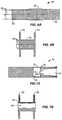
- FIG. 1illustrates a first exemplary tissue anchor constructed in accordance with the principles of the present invention.
- FIGS. 1A-1Cillustrate formation of a double-walled anchor structure in an end of the tissue anchor.
- FIGS. 2A-2Cillustrate alternate distal end constructions of the tissue anchor of FIG. 1 , taken along line 2 - 2 thereof.
- FIGS. 3A-3Fillustrate alternative deployments and modifications to the exemplary tissue anchor of FIG. 1 .
- FIGS. 4A and 4Billustrate the tissue anchor employing elastic tethers for deployment.
- FIGS. 5A and 5Billustrate a tissue anchor having latching elements.
- FIGS. 6A and 6Billustrate a tissue anchor having tethers for applying an axial force for foreshortening and deployment.
- FIGS. 7A and 7Billustrate a tissue anchor having an internal cylinder for applying an axially compressive force and latching the anchor in its deployed configuration.
- FIGS. 8A and 8Billustrate another stent design having tethers to effect foreshortening and radial expansion.
- FIG. 9illustrates a stent having a one-way flow valve according to the present invention.
- FIG. 10illustrates a patient's anatomy including cross sections of the gallbladder and duodenum.
- FIG. 11illustrates an exemplary system for penetrating the intestinal and gallbladder walls
- FIGS. 12A-12Gillustrate the method of the present invention for establishing a flow path between the gallbladder and the intestines in accordance with the principles of the present invention.
- the body 12comprises a woven filament braid, as discussed in more detail above, and is illustrated in its elongated tubular configuration.
- the body 12will be formed from a super elastic material, typically nitinol or eligiloy, and will be heat set, so that in the absence of radial constraint or an axially elongating force, the body will revert to its memory configuration having double-walled flanges formed at each end.
- One of the flanges 16is shown in broken line in FIG. 1 , while FIGS. 3A-3F illustrate various configurations of the flanges 16 .
- the double-walled flange structure 16forms as the end of tubular body 12 axially foreshortens.
- the end of the tubular body 12is maintained in its tubular configuration, as shown in FIG. 1A .
- Maintenance of the tubular configurationcan be achieved in various ways, such as using an external tubular sheath or other restraint (not shown), by using a mandrel or other elongate structure which is advanced through an inside lumen or passage 18 of the body to engage the end and/or occupy the entire lumen in order to maintain the tubular configuration, or the like.
- the pre-formed or memory shape of the double-walled flange structurewill begin to form, as shown in FIG.
- tubular body 12may have preformed scoring or other weakened regions which preferentially allow the woven braid to bend in the manner illustrated in FIGS. 1A-1C .
- the end caps 14will be provided when it is desired to constrain the end of the anchor body 12 to prevent the end(s) from expanding.
- the end cap 14will have a solid face, as shown in FIG. 2A , which will close the inside lumen or passage 18 to prevent or inhibit the flow of body fluids therethrough.
- the end cap 14 amay be formed with a passage 20 therethrough to allow for its flow through lumen 18 ( FIG. 2B ).
- the tissue anchor 10may not include any end caps, allowing the end to expand in certain embodiments.
- FIGS. 3 A through 3 Fvarious deployment configurations for the tissue anchor 10 will be described (where the tissue anchor 10 is assumed to have the same elongated starting length in each illustrated deployment).
- the flanges 16expand radially while a central saddle region 22 does not expand.
- the central saddle region 22does not significantly expand but has a somewhat greater deployed length than that of the embodiment of FIG. 3 A, resulting in flanges 16 having a slightly smaller diameters.
- FIG. 3Balso illustrates a covering or membrane 24 over the entire exterior of the tissue anchor 10 , thus inhibiting tissue ingrowth and/or minimizing fluid leakage when the anchor is implanted.
- tissue anchor 10includes the open end caps 14 a providing an open lumen 18 therethrough.
- a tissue anchor 10 having a central saddle region 22 with a significantly expanded diameteris illustrated.
- the tissue anchor 10 having open ends 26(that is, they are free from the end cap as illustrated in Fig. C) is illustrated.
- Passages 26are shown to have generally the same diameter as the tubular body 22 in its non-deployed configuration.
- open ends 28are shown having diameters which are significantly greater than the non-deployed diameter of the anchor body.
- the central saddle region 22 of FIG. 3Fis also significantly greater than the diameter of the non-deployed tissue anchor.
- the tissue anchors of the present inventionmay have a wide variety of configurations with different lengths, saddle region diameters, flange diameters, open lumens, closed lumens, membrane-covered surfaces, partially membrane-covered surfaces, and the like.
- tissue anchor 30having an alternative construction is illustrated.
- the body 32 of tissue anchor 30is not pre-shaped, forming the enlarged flanges as a result of axial shortening.
- elastic tethers 34are provided which apply the axially compressive force to foreshorten the ends and form double-walled flanges 36 , as illustrated in FIG. 4B .
- the resulting shapemay be controlled by providing reinforcement over a central saddle region 38 to prevent that region from axially foreshortening and/or radially expanding.
- the central saddle region 38could be fused together to prevent deformation.
- the tissue anchorcan be deployed through a tissue tract while the exterior is radially constrained or the or the ends axially lengthened.
- the elastic tethersWhen released from the radial constraint, or axial tension, the elastic tethers will foreshorten the ends, forming double walled flanges where the saddle size (flange diameter, saddle length, saddle diameter) will conform exactly to the anatomy.
- the geometrywill be “self-adjusting”. Reinforcement over the central saddle region is not necessary but could be utilized if desired for other purposes.
- a tissue anchor 40comprises a tubular body 42 which has both an elongated tubular configuration (as shown in FIG. 5 A) and an axially foreshortened configuration with double-walled flanges 44 , as shown in FIG. 5B .
- the tubular body 44could either be of the self-expanding type or, alternatively, could require an axial compressive force to foreshorten the body into the configuration of FIG. 5B .
- the tissue anchor 40will be provided with a locking structure including a plurality of axial bars 46 which lock over the ends of the deployed tissue anchor 40 , as illustrated in FIG. 5B .
- a tissue anchor 50comprises an anchor body 52 which requires an axially compressive force in order to foreshorten the body to form the double-walled flanges 54 , as shown in FIG. 6B .
- the axially compressive forceis provided by a plurality of tethers 56 which extend through a lumen or central passage 58 of the body 52 through the flange region and which then extend outwardly over the central saddle region 60 before passing back into the interior of the body.
- the central saddle region 60may radially expand to an extent which depends on the braid configuration, the size and compliance of the lumen through which the device passes, and the force applied to the tethers.
- the tethersmay be locked in place, typically by a locking device 64 , such as crimping pledgets, use of a unidirectional slide or other ratcheting lock device, or use of a slip-knot or a sliding element that relies on friction to secure its position.
- a tissue anchor 70as illustrated in FIGS. 7A and 7B , comprises an anchor body 72 having a locking cylinder 74 in one end of the lumen or central passage 76 .
- the anchor body 72may be axially foreshortened by drawing on the free end of the locking cylinder 74 and pulling the cylinder in the direction of the arrow until a locking end 78 of the cylinder engages the far end of the deployed flange 80 .
- the cylinder 74act as an element to foreshorten the anchor body 72 , it also acts as the lock to hold the anchor body open and provides a smooth cylindrical surface for the lumen to permit fluid flow or provide other access.
- the locking end 78 of the cylinder 74may be provided with notches or other apertures to allow that end to be collapsed within the lumen 76 and to snap back open as it is pulled past the flange 80 to which it will lock.
- an exemplary tissue anchor or stent 150comprises a counterwound, braided stent body, typically formed from a polymer such as polypropylene, polyester, nylon, or PEEK; a metal, such stainless steel, nitinol, or eligiloy; a bioabsorbable material, such as polyglycolic acid, lactic acid, caprolactone, polydioxanone, cat or bovine intestine; a natural fiber, such as silk or cotton; or mixtures, composites, or co-constructions of any of the above.
- a polymersuch as polypropylene, polyester, nylon, or PEEK
- a metalsuch stainless steel, nitinol, or eligiloy
- a bioabsorbable materialsuch as polyglycolic acid, lactic acid, caprolactone, polydioxanone, cat or bovine intestine
- a natural fibersuch as silk or cotton
- Tethers 166are provided which are connected at the remote end 168 of the stent, and which, when drawn in the direction away from the duodenum or other originating body lumen, will foreshorten the stent to create the flanges 154 , as described previously. Drawing the tethers 166 in the proximal direction opens and maintains the central lumen 172 of deployed stent 150 to provide the luminal conduit which allows flow between anatomical lumens, such as the gallbladder, GB and intestine. A reduced diameter central region 170 is located between the flanges 154 .
- the width of the central region 170may be controlled optionally by placing a restraining element, such as a cylinder or struts 172 over the stent to prevent radial expansion.
- a restraining elementsuch as a cylinder or struts 172
- the stent 150will automatically adjust to the thickness of the luminal walls. A restraint is not needed since the tissue geometry, particularly the tract dilation either before or after anchor placement, will provide a barrier which will restrain expansion of the central region and determine the length of the saddle region.
- the stent 150can have proximal and distal ends connected centrally by an extensible material allowing the deployed stent to facilitate apposition of opposing luminal walls and minimize pressure necrosis.
- a one-way flow element 180such as a flat valve, within the interior of the stent 150 .
- the one-way flow control elementcan then allow drainage from the gallbladder into the intestines while substantially inhibiting or blocking reflux flow back from the stomach into the gallbladder.
- the flow control element 180could serve as a restraint to define the central region 170 of the stent when expanded.
- Alternative valve designsinclude a sock valve placed within the interior or at the proximal end of the foreshortened anchor, a “duck bill” valve, a flapper valve, a spring-loaded ball valve, or other spring-loaded element, such as a tapered pin or plug.
- the biliary system of a patient( FIG. 10 ) includes the gallbladder GB which is connected to the cystic duct CD which feeds into the common bile duct CBD.
- the common bile ductfeeds bile into the descending part of the duodenum DD. While the present invention will be described with particular reference to attachment between the gallbladder GB and the descending duodenum DD, the principles apply to connecting a variety of other luminal structures, including the esophagus, the cms, the fundus, the bile duct, the intestines, and the like.
- FIG. 11a system for connecting luminal walls and placing a stent to establish a flow path therebetween is illustrated.
- This system 100is particularly useful for connecting a wall of the gallbladder to an intestinal wall, such as the duodenal wall or a stomach wall, but it will be appreciated that the system can find other uses in establishing other anastomotic connections, such as between the biliary duct including but not limited to the common bile duct, cystic duct and/or the pancreatic duct and the stomach, intestine or any part of the gastrointestinal tract.
- System 100can also be used to create a connection to any fluid collection including but not limited to a pancreatic pseudocyst, abdominal fluid collections including ascites, pleural effusions and abscesses in any accessible location or the like. System 100 is also useful to create a connection between the urinary bladder and any part of the gastrointestinal tract.
- the luminal wall connection system of the present inventioncomprises a catheter 112 including a catheter body 114 having a distal end 116 and a proximal end 118 .
- the catheter body 114has a lumen extending therethrough, with a distal port 120 of the lumen being visible in FIG. 11 .
- An inflatable balloon 122is mounted on the distal end of the catheter body 114 and an inflation lumen (not shown) is provided in the wall of the catheter body and connected to an inflation port 124 near the proximal end of the catheter body 114 .
- a needle 126 having a sharpened distal tip 128is received within the lumen of the catheter body 114 and is slidably received so that it can be selectively advanced from and/or retracted into the distal port 120 , as illustrated in FIG. 11 .
- a handle or grip 130is provided at the proximal end of the needle 126 to facilitate manipulation.
- An outer tubular member 136is coaxially received over the catheter body 114 and includes a distal end 138 having a distal port 140 through which the catheter body 114 projects. Proximal end 142 of the outer tubular body 136 is connected to handle 144 . Catheter body 114 extends through the handle, allowing the catheter of balloon 122 to be selectively extended and retracted relative to both the outer tube 136 and needle 126 .
- the expandable tissue anchor/stent 150is carried near the distal end 138 of the outer tubular body 136 .
- the stentis optionally expanded in a variety of ways, including balloon expansion, self-expansion (where the stent would be released from constraint), heat-induced expansion of heat-sensitive alloy, such as nitinol, or the like.
- the stent 150will comprise a polymer braid which may be foreshortened to induce radial expansion. This particular design was described in more detail above with reference to FIGS. 8A and 8B .
- the handle 144will include a thumb slide 152 for effecting expansion of the stent 150 typically by pulling on tethers attached to the stent, as described below.
- a variety of other expansion mechanismscould be employed, for example, by pushing on the proximal end of the stents with rods or other pushing elements while a distal portion of the stent remains constrained.
- an endoscope Ewill usually be trans-orally introduced so that it is within the intestines and can image the gallbladder to locate a target site for the anastomotic connection, as illustrated in FIG. 12 A.
- the endoscopewill usually include at least a light source LS and a fiber optic image cable, or in some instances a CCD or other miniature camera, or ultrasound transducer.
- the endoscopewill also include a conventional working channel WC, as illustrated in broken line in FIG. 12A .
- the luminal wall connection system 100will be introduced through the working channel WC so that the distal end 116 of the catheter 114 is brought adjacent to the walls GBW and IW.
- the needle 126may then be advanced through the walls to form an initial penetration.
- the uninflated balloon 122will be advanced into the penetration, usually over the needle 126 , as shown in FIG. 12C .
- the balloonmay then be inflated, typically assuming a standard hot dog, top hat or dog bone pattern, said top hat having the distal end where the proximal and distal ends are wider (e.g., have a larger diameter) than the central and distal regions. Proximal movement of the top-hat balloon will pull the GBW and the IW walls together. The penetration P is thus expanded prior to placement of the stent 150 .
- the penetration Pcan be expanded using a tapered dilator 160 which may be advanced directly over the needle through the endoscope.
- a tapered dilatormay be formed as a distal extension of the outer tubular member 136 (not shown).
- the outer tubular member 136will be advanced so that the stent 150 is located in the expanded penetration.
- a stent 150is then expanded, as shown in FIG. 12F , typically by foreshortening, as will be described in more detail below.
- the proximal and distal ends of the stent 150will be expanded or flared to form relatively large flange regions 154 which act to tightly hold the gallbladder wall GBW and intestinal wall 1 W together to promote tissue knitting or ingrowth to inhibit leakage from either the gallbladder or the intestines.
- the stent 150forms a central lumen 152 ( FIG.
- An alternate methodis to follow the needle 126 with the simultaneous movement of the outer tubular member 136 with stent 150 and balloon 122 .
- the stentis then released from constraint, with proximal and distal flanges now expanding and holding the lumens together, this followed by balloon expansion of the saddle region of the stent by balloon 122 which is inside the partially collapsed saddle region.
- This post-expansion methodallows the anchor stent to hold the tissues together during tract dilation which is desirable.
- FIG. 11 new versionwill have stent on balloon is under saddle only.
Landscapes
- Health & Medical Sciences (AREA)
- Life Sciences & Earth Sciences (AREA)
- Surgery (AREA)
- Heart & Thoracic Surgery (AREA)
- Public Health (AREA)
- Animal Behavior & Ethology (AREA)
- Biomedical Technology (AREA)
- Veterinary Medicine (AREA)
- General Health & Medical Sciences (AREA)
- Engineering & Computer Science (AREA)
- Molecular Biology (AREA)
- Medical Informatics (AREA)
- Nuclear Medicine, Radiotherapy & Molecular Imaging (AREA)
- Physiology (AREA)
- Anesthesiology (AREA)
- Biophysics (AREA)
- Pulmonology (AREA)
- Child & Adolescent Psychology (AREA)
- Hematology (AREA)
- Pathology (AREA)
- Reproductive Health (AREA)
- Vascular Medicine (AREA)
- Prostheses (AREA)
- Surgical Instruments (AREA)
Abstract
Description
Claims (20)
Priority Applications (3)
| Application Number | Priority Date | Filing Date | Title |
|---|---|---|---|
| US16/107,067US11129617B2 (en) | 2008-05-12 | 2018-08-21 | Tissue anchor for securing tissue layers |
| US16/693,732US11129618B2 (en) | 2008-05-12 | 2019-11-25 | Tissue anchor for securing tissue layers |
| US17/412,360US20210378672A1 (en) | 2008-05-12 | 2021-08-26 | Tissue anchor for securing tissue layers |
Applications Claiming Priority (5)
| Application Number | Priority Date | Filing Date | Title |
|---|---|---|---|
| US5246008P | 2008-05-12 | 2008-05-12 | |
| US12/427,215US8454632B2 (en) | 2008-05-12 | 2009-04-21 | Tissue anchor for securing tissue layers |
| US13/892,958US10076330B2 (en) | 2008-05-12 | 2013-05-13 | Tissue anchor for securing tissue layers |
| US15/331,249US10390833B2 (en) | 2008-05-12 | 2016-10-21 | Tissue anchor for securing tissue layers |
| US16/107,067US11129617B2 (en) | 2008-05-12 | 2018-08-21 | Tissue anchor for securing tissue layers |
Related Parent Applications (1)
| Application Number | Title | Priority Date | Filing Date |
|---|---|---|---|
| US15/331,249ContinuationUS10390833B2 (en) | 2008-05-12 | 2016-10-21 | Tissue anchor for securing tissue layers |
Related Child Applications (1)
| Application Number | Title | Priority Date | Filing Date |
|---|---|---|---|
| US16/693,732ContinuationUS11129618B2 (en) | 2008-05-12 | 2019-11-25 | Tissue anchor for securing tissue layers |
Publications (2)
| Publication Number | Publication Date |
|---|---|
| US20180353184A1 US20180353184A1 (en) | 2018-12-13 |
| US11129617B2true US11129617B2 (en) | 2021-09-28 |
Family
ID=41267407
Family Applications (5)
| Application Number | Title | Priority Date | Filing Date |
|---|---|---|---|
| US12/427,254AbandonedUS20090281379A1 (en) | 2008-05-12 | 2009-04-21 | System and method for transluminal access |
| US15/331,249ActiveUS10390833B2 (en) | 2008-05-12 | 2016-10-21 | Tissue anchor for securing tissue layers |
| US16/107,067Active2029-10-14US11129617B2 (en) | 2008-05-12 | 2018-08-21 | Tissue anchor for securing tissue layers |
| US16/693,732ActiveUS11129618B2 (en) | 2008-05-12 | 2019-11-25 | Tissue anchor for securing tissue layers |
| US17/412,360PendingUS20210378672A1 (en) | 2008-05-12 | 2021-08-26 | Tissue anchor for securing tissue layers |
Family Applications Before (2)
| Application Number | Title | Priority Date | Filing Date |
|---|---|---|---|
| US12/427,254AbandonedUS20090281379A1 (en) | 2008-05-12 | 2009-04-21 | System and method for transluminal access |
| US15/331,249ActiveUS10390833B2 (en) | 2008-05-12 | 2016-10-21 | Tissue anchor for securing tissue layers |
Family Applications After (2)
| Application Number | Title | Priority Date | Filing Date |
|---|---|---|---|
| US16/693,732ActiveUS11129618B2 (en) | 2008-05-12 | 2019-11-25 | Tissue anchor for securing tissue layers |
| US17/412,360PendingUS20210378672A1 (en) | 2008-05-12 | 2021-08-26 | Tissue anchor for securing tissue layers |
Country Status (4)
| Country | Link |
|---|---|
| US (5) | US20090281379A1 (en) |
| EP (2) | EP2276390A4 (en) |
| JP (3) | JP2011521680A (en) |
| WO (1) | WO2009140212A1 (en) |
Families Citing this family (76)
| Publication number | Priority date | Publication date | Assignee | Title |
|---|---|---|---|---|
| US12303105B2 (en) | 2004-04-12 | 2025-05-20 | Boston Scientific Scimed, Inc. | Luminal structure anchoring devices and methods |
| US8425539B2 (en) | 2004-04-12 | 2013-04-23 | Xlumena, Inc. | Luminal structure anchoring devices and methods |
| JP5111112B2 (en) | 2004-12-08 | 2012-12-26 | エックスルミナ, インコーポレイテッド | Device for performing needle-guided therapy |
| US8777967B2 (en) | 2005-06-09 | 2014-07-15 | Xlumena, Inc. | Methods and devices for anchoring to tissue |
| US8784437B2 (en) | 2005-06-09 | 2014-07-22 | Xlumena, Inc. | Methods and devices for endosonography-guided fundoplexy |
| US8454632B2 (en) | 2008-05-12 | 2013-06-04 | Xlumena, Inc. | Tissue anchor for securing tissue layers |
| US9173760B2 (en) | 2009-04-03 | 2015-11-03 | Metamodix, Inc. | Delivery devices and methods for gastrointestinal implants |
| US8702641B2 (en) | 2009-04-03 | 2014-04-22 | Metamodix, Inc. | Gastrointestinal prostheses having partial bypass configurations |
| ES2503553T3 (en) | 2009-04-03 | 2014-10-07 | Metamodix, Inc. | Modular Gastrointestinal Prosthesis |
| US9278019B2 (en) | 2009-04-03 | 2016-03-08 | Metamodix, Inc | Anchors and methods for intestinal bypass sleeves |
| US9364259B2 (en) | 2009-04-21 | 2016-06-14 | Xlumena, Inc. | System and method for delivering expanding trocar through a sheath |
| JP5535313B2 (en) | 2009-05-29 | 2014-07-02 | エックスルミナ, インコーポレイテッド | Device and method for deploying a stent across adjacent tissue layers |
| AU2010271294B2 (en) | 2009-07-10 | 2015-09-03 | Metamodix, Inc. | External anchoring configurations for modular gastrointestinal prostheses |
| US9314595B2 (en) | 2009-12-03 | 2016-04-19 | John Gurley | Central venous access system |
| US9125800B2 (en)* | 2010-09-27 | 2015-09-08 | Avent, Inc. | Stoma length indicator assembly and positioning system |
| US9668811B2 (en)* | 2010-11-16 | 2017-06-06 | Boston Scientific Scimed, Inc. | Minimally invasive access for renal nerve ablation |
| EP4032486A1 (en) | 2010-11-16 | 2022-07-27 | TVA Medical, Inc. | Devices for forming a fistula |
| US10758262B2 (en)* | 2011-06-20 | 2020-09-01 | Medtronic, Inc. | Medical assemblies and methods for implantation of multiple medical leads through a single entry |
| US10779855B2 (en) | 2011-08-05 | 2020-09-22 | Route 92 Medical, Inc. | Methods and systems for treatment of acute ischemic stroke |
| EP4101399B1 (en) | 2011-08-05 | 2025-04-09 | Route 92 Medical, Inc. | System for treatment of acute ischemic stroke |
| US10092726B2 (en) | 2012-02-09 | 2018-10-09 | Bluegrass Vascular Technologies, Inc. | Occlusion access system |
| JP6360042B2 (en) | 2012-05-17 | 2018-07-18 | ボストン サイエンティフィック サイムド,インコーポレイテッドBoston Scientific Scimed,Inc. | Method and device for access across adjacent tissue layers |
| US9486276B2 (en) | 2012-10-11 | 2016-11-08 | Tva Medical, Inc. | Devices and methods for fistula formation |
| US9492644B2 (en) | 2012-12-21 | 2016-11-15 | Avent, Inc. | Dilation device for placing catheter tubes |
| WO2014113483A1 (en) | 2013-01-15 | 2014-07-24 | Metamodix, Inc. | System and method for affecting intestinal microbial flora |
| ES2980140T3 (en) | 2013-02-21 | 2024-09-30 | Boston Scient Scimed Inc | Devices for forming an anastomosis |
| CN105228683B (en) | 2013-03-14 | 2022-06-10 | Tva医疗公司 | Fistula-forming device and method for forming fistula |
| US9375550B2 (en) | 2013-03-15 | 2016-06-28 | St. Jude Medical, Atrial Fibrillation Division, Inc. | Catheter actuators providing mechanical advantage |
| KR101494286B1 (en) | 2013-11-14 | 2015-02-17 | (주) 태웅메디칼 | Device for Expending Lumen in Body |
| US9265512B2 (en) | 2013-12-23 | 2016-02-23 | Silk Road Medical, Inc. | Transcarotid neurovascular catheter |
| US10695534B2 (en) | 2014-03-14 | 2020-06-30 | Tva Medical, Inc. | Fistula formation devices and methods therefor |
| US9820761B2 (en) | 2014-03-21 | 2017-11-21 | Route 92 Medical, Inc. | Rapid aspiration thrombectomy system and method |
| EP3360488B1 (en) | 2014-05-28 | 2020-03-18 | Boston Scientific Scimed, Inc. | Catheter with radiofrequency cutting tip and heated balloon |
| WO2016033374A1 (en) | 2014-08-27 | 2016-03-03 | Tva Medical, Inc. | Cryolipopysis devices and methods therefor |
| CN119949953A (en) | 2015-02-04 | 2025-05-09 | 92号医疗公司 | Intravascular access system, dilator and system including dilator |
| US10426497B2 (en) | 2015-07-24 | 2019-10-01 | Route 92 Medical, Inc. | Anchoring delivery system and methods |
| US10603040B1 (en) | 2015-02-09 | 2020-03-31 | Tva Medical, Inc. | Methods for treating hypertension and reducing blood pressure with formation of fistula |
| WO2016141295A1 (en) | 2015-03-05 | 2016-09-09 | Merit Medical Systems, Inc. | Vascular prosthesis deployment device and method of use |
| US11147699B2 (en) | 2015-07-24 | 2021-10-19 | Route 92 Medical, Inc. | Methods of intracerebral implant delivery |
| US10449336B2 (en)* | 2015-08-11 | 2019-10-22 | The Spectranetics Corporation | Temporary occlusions balloon devices and methods for preventing blood flow through a vascular perforation |
| US10470906B2 (en) | 2015-09-15 | 2019-11-12 | Merit Medical Systems, Inc. | Implantable device delivery system |
| JP7219090B2 (en) | 2016-01-15 | 2023-02-07 | ティーブイエー メディカル, インコーポレイテッド | Systems and methods for gluing vessels |
| US10874422B2 (en) | 2016-01-15 | 2020-12-29 | Tva Medical, Inc. | Systems and methods for increasing blood flow |
| CN114042224B (en) | 2016-01-15 | 2024-09-17 | Tva医疗公司 | Device and method for advancing a wire |
| WO2017124062A1 (en) | 2016-01-15 | 2017-07-20 | Tva Medical, Inc. | Devices and methods for forming a fistula |
| US10856892B2 (en) | 2016-02-29 | 2020-12-08 | Bluegrass Vascular Technologies, Inc. | Catheter systems, kits, and methods for gaining access to a vessel |
| US9622897B1 (en) | 2016-03-03 | 2017-04-18 | Metamodix, Inc. | Pyloric anchors and methods for intestinal bypass sleeves |
| WO2017201424A1 (en) | 2016-05-19 | 2017-11-23 | Metamodix, Inc. | Pyloric anchor retrieval tools and methods |
| WO2018017981A1 (en) | 2016-07-22 | 2018-01-25 | Route 92 Medical, Inc. | Endovascular interventions in neurovascular anatomy |
| BR202016018370U2 (en)* | 2016-08-09 | 2018-02-20 | Itm S/A Ind De Tecnologias Medicas | fetal surgery access trocar |
| CN109982652B (en) | 2016-09-25 | 2022-08-05 | Tva医疗公司 | Vascular stent device and method |
| CN115054413A (en) | 2016-09-29 | 2022-09-16 | 美国医疗设备有限公司 | Method of adjusting effective length of stent and prosthesis delivery catheter assembly |
| WO2018136950A1 (en)* | 2017-01-23 | 2018-07-26 | Uroviu Corporation | Handheld surgical endoscope |
| US11628078B2 (en) | 2017-03-15 | 2023-04-18 | Merit Medical Systems, Inc. | Transluminal delivery devices and related kits and methods |
| EP4467111A3 (en) | 2017-03-15 | 2025-03-05 | Merit Medical Systems, Inc. | Transluminal stents |
| USD836194S1 (en) | 2017-03-21 | 2018-12-18 | Merit Medical Systems, Inc. | Stent deployment device |
| WO2018175591A1 (en)* | 2017-03-22 | 2018-09-27 | Boston Scientific Scimed, Inc. | Retrievable access valve |
| EP4238539A3 (en) | 2017-10-25 | 2023-10-18 | Boston Scientific Scimed, Inc. | Stent with atraumatic spacer |
| CN111315319B (en) | 2017-11-01 | 2022-10-18 | 波士顿科学国际有限公司 | Esophageal stent comprising valve member |
| US10888691B2 (en) | 2018-04-24 | 2021-01-12 | Olympus Corporation | Stent delivery method |
| WO2019226563A1 (en) | 2018-05-21 | 2019-11-28 | Boston Scientific Scimed, Inc. | Cauterizing device for use with stents |
| CN112930208A (en)* | 2018-06-01 | 2021-06-08 | 恩多Rx有限责任公司 | Dilation device and method of use thereof |
| US11678970B2 (en)* | 2018-12-04 | 2023-06-20 | Boston Scientific Scimed, Inc. | Device for anastomotic bypass |
| CN109620534B (en)* | 2019-02-01 | 2024-05-14 | 无锡市人民医院 | 20G crystal back-bag bearing auxiliary apparatus |
| EP3920855B1 (en)* | 2019-02-07 | 2025-07-23 | NXT Biomedical, LLC | Rivet shunt |
| USD952854S1 (en)* | 2019-02-28 | 2022-05-24 | Olympus Corporation | Stent |
| EP3996575A4 (en)* | 2019-07-12 | 2023-11-08 | Grumpy Innovation, Inc. | Access device |
| EP4017384A1 (en) | 2019-08-22 | 2022-06-29 | Edwards Lifesciences Corporation | Puncture needles |
| CR20220218A (en) | 2019-11-14 | 2022-08-22 | Edwards Lifesciences Corp | Transcatheter medical implant delivery |
| EP4185239A4 (en) | 2020-07-24 | 2024-08-07 | Merit Medical Systems, Inc. | ESOPHAGEAL STENT PROSTHESES AND RELATED METHODS |
| WO2022076893A1 (en) | 2020-10-09 | 2022-04-14 | Route 92 Medical, Inc. | Aspiration catheter systems and methods of use |
| CA3194910A1 (en) | 2020-10-26 | 2022-05-05 | Tiffany ETHRIDGE | Esophageal stents with helical thread |
| DE102021210108A1 (en) | 2021-09-14 | 2023-03-16 | B. Braun Melsungen Aktiengesellschaft | Introducer assembly for an invasive medical component |
| KR20250133744A (en)* | 2023-01-06 | 2025-09-08 | 보스톤 싸이엔티픽 싸이메드 인코포레이티드 | Anti-dislodgement stent |
| WO2024196924A1 (en)* | 2023-03-20 | 2024-09-26 | Boston Scientific Scimed, Inc. | Devices, systems, and methods for holding anatomical structures in apposition |
| WO2025164296A1 (en)* | 2024-02-01 | 2025-08-07 | 公立大学法人名古屋市立大学 | Instrument for drainage and use thereof |
Citations (8)
| Publication number | Priority date | Publication date | Assignee | Title |
|---|---|---|---|---|
| US5709713A (en) | 1995-03-31 | 1998-01-20 | Cardiovascular Concepts, Inc. | Radially expansible vascular prosthesis having reversible and other locking structures |
| WO2001072367A1 (en) | 2000-03-27 | 2001-10-04 | Aga Medical Corporation | Retrievable self expanding shunt |
| US20030097172A1 (en)* | 2000-03-27 | 2003-05-22 | Ilan Shalev | Narrowing implant |
| US20060206123A1 (en)* | 2004-08-27 | 2006-09-14 | Rox Medical, Inc. | Device and method for establishing an artificial arterio-venous fistula |
| US20070265656A1 (en)* | 2004-03-19 | 2007-11-15 | Aga Medical Corporation | Multi-layer braided structures for occluding vascular defects |
| US20090062841A1 (en) | 2004-03-19 | 2009-03-05 | Aga Medical Corporation | Device for occluding vascular defects |
| US20090143713A1 (en) | 2007-11-30 | 2009-06-04 | Jacques Van Dam | Biliary Shunts, Delivery Systems, Methods of Using the Same and Kits Therefor |
| US20090281557A1 (en) | 2008-05-12 | 2009-11-12 | Xlumena, Inc. | Tissue anchor for securing tissue layers |
Family Cites Families (172)
| Publication number | Priority date | Publication date | Assignee | Title |
|---|---|---|---|---|
| US3039468A (en)* | 1959-01-07 | 1962-06-19 | Joseph L Price | Trocar and method of treating bloat |
| US3717151A (en)* | 1971-03-11 | 1973-02-20 | R Collett | Flesh penetrating apparatus |
| US3874388A (en)* | 1973-02-12 | 1975-04-01 | Ochsner Med Found Alton | Shunt defect closure system |
| US4587972A (en)* | 1984-07-16 | 1986-05-13 | Morantte Jr Bernardo D | Device for diagnostic and therapeutic intravascular intervention |
| US4920967A (en)* | 1986-07-18 | 1990-05-01 | Pfizer Hospital Products Group, Inc. | Doppler tip wire guide |
| US4990139A (en)* | 1986-09-10 | 1991-02-05 | Jang G David | Tandem independently inflatable/deflatable multiple diameter balloon angioplasty catheter systems |
| JPH0755222B2 (en)* | 1986-12-12 | 1995-06-14 | オリンパス光学工業株式会社 | Treatment tool |
| US4917097A (en)* | 1987-10-27 | 1990-04-17 | Endosonics Corporation | Apparatus and method for imaging small cavities |
| US5180392A (en)* | 1988-02-01 | 1993-01-19 | Einar Skeie | Anastomotic device |
| DE69020075T2 (en)* | 1989-08-09 | 1995-11-16 | Bard Inc C R | Catheter guide and guidewire for rapid catheter replacement. |
| US5211651A (en)* | 1989-08-18 | 1993-05-18 | Evi Corporation | Catheter atherotome |
| US5024655A (en)* | 1989-09-05 | 1991-06-18 | Freeman Andrew B | Epidural catheter apparatus and associated method |
| US5207229A (en)* | 1989-12-21 | 1993-05-04 | Advanced Biomedical Devices, Inc. | Flexibility steerable guidewire with inflatable balloon |
| US5197971A (en)* | 1990-03-02 | 1993-03-30 | Bonutti Peter M | Arthroscopic retractor and method of using the same |
| IL94138A (en) | 1990-04-19 | 1997-03-18 | Instent Inc | Device for the treatment of constricted fluid conducting ducts |
| ATE121303T1 (en)* | 1990-10-04 | 1995-05-15 | Schneider Europ Ag | BALLOON DILATION CATHETER. |
| CA2052310A1 (en)* | 1990-10-09 | 1992-04-10 | Thomas L. Foster | Surgical access sheath |
| DE69123982T2 (en)* | 1990-11-20 | 1997-12-04 | Innerdyne Medical Inc | STRETCH MAINTENANCE GUIDE ELEMENT AND DILATATOR |
| DE4100568A1 (en) | 1991-01-11 | 1992-07-16 | Fehling Guido | DEVICE FOR MONITORING A PATIENT FOR REPELLATION REACTIONS OF AN IMPLANTED ORGAN |
| US5221258A (en)* | 1991-01-22 | 1993-06-22 | Shturman Technologies, Inc. | Introduction balloon catheter |
| US5275610A (en)* | 1991-05-13 | 1994-01-04 | Cook Incorporated | Surgical retractors and method of use |
| US5183464A (en)* | 1991-05-17 | 1993-02-02 | Interventional Thermodynamics, Inc. | Radially expandable dilator |
| US5713870A (en)* | 1991-11-27 | 1998-02-03 | Yoon; Inbae | Retractable safety penetrating instrument with laterally extendable spring strip |
| US5395349A (en)* | 1991-12-13 | 1995-03-07 | Endovascular Technologies, Inc. | Dual valve reinforced sheath and method |
| US5209727A (en)* | 1992-01-29 | 1993-05-11 | Interventional Technologies, Inc. | Guide wire with integral angioplasty balloon |
| US5707362A (en)* | 1992-04-15 | 1998-01-13 | Yoon; Inbae | Penetrating instrument having an expandable anchoring portion for triggering protrusion of a safety member and/or retraction of a penetrating member |
| US5458131A (en) | 1992-08-25 | 1995-10-17 | Wilk; Peter J. | Method for use in intra-abdominal surgery |
| EP0596162B1 (en)* | 1992-11-06 | 2002-08-21 | Texas Instruments Incorporated | hypodermic needle with a protrusion |
| US5304198A (en)* | 1992-11-13 | 1994-04-19 | Target Therapeutics | Single-lumen balloon catheter having a directional valve |
| US5972000A (en)* | 1992-11-13 | 1999-10-26 | Influence Medical Technologies, Ltd. | Non-linear anchor inserter device and bone anchors |
| US5431676A (en)* | 1993-03-05 | 1995-07-11 | Innerdyne Medical, Inc. | Trocar system having expandable port |
| US5370682A (en)* | 1993-04-26 | 1994-12-06 | Meadox Medicals, Inc. | Solid woven tubular prosthesis |
| US5897567A (en)* | 1993-04-29 | 1999-04-27 | Scimed Life Systems, Inc. | Expandable intravascular occlusion material removal devices and methods of use |
| US5725552A (en)* | 1994-07-08 | 1998-03-10 | Aga Medical Corporation | Percutaneous catheter directed intravascular occlusion devices |
| US5843127A (en) | 1994-08-22 | 1998-12-01 | Le Medical Technologies, Inc. | Fixation device and method for installing same |
| US5620457A (en)* | 1994-11-23 | 1997-04-15 | Medinol Ltd. | Catheter balloon |
| US5904697A (en)* | 1995-02-24 | 1999-05-18 | Heartport, Inc. | Devices and methods for performing a vascular anastomosis |
| US5681345A (en) | 1995-03-01 | 1997-10-28 | Scimed Life Systems, Inc. | Sleeve carrying stent |
| US5495851A (en)* | 1995-03-23 | 1996-03-05 | Roanoke Gastroenterology, P.C. | Use of endoscopic ultrasound and stimulated bilary drainage in the diagnosis of cholecystitis and microlithiasis |
| US6575967B1 (en)* | 1995-03-24 | 2003-06-10 | The Board Of Regents Of The University Of Nebraska | Method and systems for volumetric tissue ablation |
| US5868740A (en)* | 1995-03-24 | 1999-02-09 | Board Of Regents-Univ Of Nebraska | Method for volumetric tissue ablation |
| US5857999A (en)* | 1995-05-05 | 1999-01-12 | Imagyn Medical Technologies, Inc. | Small diameter introducer for laparoscopic instruments |
| RU2157146C2 (en) | 1995-06-13 | 2000-10-10 | ВИЛЬЯМ КУК Европа, A/S | Device for performing implantation in blood vessels and hollow organs |
| ATE440559T1 (en)* | 1995-10-13 | 2009-09-15 | Medtronic Vascular Inc | DEVICE FOR INTERSTITIAL TRANSVASCULAR PROCEDURES |
| DE69633411T2 (en) | 1995-10-13 | 2005-10-20 | Transvascular, Inc., Menlo Park | METHOD AND DEVICE FOR PREVENTING ARTERIAL ATTRACTIONS AND / OR FOR CARRYING OUT OTHER TRANSVASCULAR INTERVENTIONS |
| US5709671A (en)* | 1995-10-16 | 1998-01-20 | Ethicon Endo-Surgery, Inc. | Trocar having an improved tip configuration |
| US5620456A (en)* | 1995-10-20 | 1997-04-15 | Lasersurge, Inc. | Trocar assembly |
| WO1997016119A1 (en)* | 1995-10-30 | 1997-05-09 | Children's Medical Center Corporation | Self-centering umbrella-type septal closure device |
| US5632762A (en)* | 1995-11-09 | 1997-05-27 | Hemodynamics, Inc. | Ostial stent balloon |
| CA2244080A1 (en) | 1996-02-02 | 1997-08-07 | Transvascular, Inc. | Methods and apparatus for blocking flow through blood vessels |
| US5893856A (en)* | 1996-06-12 | 1999-04-13 | Mitek Surgical Products, Inc. | Apparatus and method for binding a first layer of material to a second layer of material |
| US6007544A (en) | 1996-06-14 | 1999-12-28 | Beth Israel Deaconess Medical Center | Catheter apparatus having an improved shape-memory alloy cuff and inflatable on-demand balloon for creating a bypass graft in-vivo |
| US6358264B2 (en)* | 1996-07-24 | 2002-03-19 | Surgical Design Corporation | Surgical instruments with movable member |
| US6007522A (en) | 1996-09-13 | 1999-12-28 | Boston Scientific Corporation | Single operator exchange biliary catheter |
| US6379319B1 (en)* | 1996-10-11 | 2002-04-30 | Transvascular, Inc. | Systems and methods for directing and snaring guidewires |
| US6682536B2 (en)* | 2000-03-22 | 2004-01-27 | Advanced Stent Technologies, Inc. | Guidewire introducer sheath |
| JP4118354B2 (en)* | 1996-12-04 | 2008-07-16 | オリンパス株式会社 | Organ lifting device |
| US6017352A (en)* | 1997-09-04 | 2000-01-25 | Kensey Nash Corporation | Systems for intravascular procedures and methods of use |
| ES2368847T3 (en)* | 1997-09-26 | 2011-11-22 | Cryolife, Inc. | SUTURE ANASTOMOSIS DEVICE. |
| US6074416A (en) | 1997-10-09 | 2000-06-13 | St. Jude Medical Cardiovascular Group, Inc. | Wire connector structures for tubular grafts |
| DE69839888D1 (en) | 1997-11-12 | 2008-09-25 | Genesis Technologies Llc | DEVICE FOR REMOVING OCCLUSIONS IN BIOLOGICAL PASSES |
| EP1685808B1 (en)* | 1998-01-30 | 2016-09-14 | St.Jude Medical ATG, Inc. | Device for use in closing septal defects and an installation assembly for such device |
| US5944738A (en) | 1998-02-06 | 1999-08-31 | Aga Medical Corporation | Percutaneous catheter directed constricting occlusion device |
| US7027398B2 (en)* | 2001-04-12 | 2006-04-11 | General Instrument Corporation | Method and apparatus for monitoring voice conversations from customer premises equipment |
| ATE371409T1 (en)* | 1998-05-21 | 2007-09-15 | Christopher J Walshe | SYSTEM FOR FIXING TISSUE |
| US6113609A (en) | 1998-05-26 | 2000-09-05 | Scimed Life Systems, Inc. | Implantable tissue fastener and system for treating gastroesophageal reflux disease |
| KR20010052459A (en) | 1998-05-29 | 2001-06-25 | 바이-패스, 인크. | Methods and devices for vascular surgery |
| US6402770B1 (en)* | 1998-06-01 | 2002-06-11 | Avatar Design & Development, Inc. | Method and apparatus for placing and maintaining a percutaneous tube into a body cavity |
| US6156064A (en)* | 1998-08-14 | 2000-12-05 | Schneider (Usa) Inc | Stent-graft-membrane and method of making the same |
| JP3581591B2 (en) | 1999-02-25 | 2004-10-27 | ペンタックス株式会社 | Drainage tube indwelling device for endoscope |
| US6290728B1 (en) | 1998-09-10 | 2001-09-18 | Percardia, Inc. | Designs for left ventricular conduit |
| US6152144A (en) | 1998-11-06 | 2000-11-28 | Appriva Medical, Inc. | Method and device for left atrial appendage occlusion |
| US6508252B1 (en)* | 1998-11-06 | 2003-01-21 | St. Jude Medical Atg, Inc. | Medical grafting methods and apparatus |
| US6022359A (en)* | 1999-01-13 | 2000-02-08 | Frantzen; John J. | Stent delivery system featuring a flexible balloon |
| US6231515B1 (en)* | 1999-01-13 | 2001-05-15 | Scimed Life Systems, Inc. | Safety mechanism and method to prevent rotating imaging guide device from exiting a catheter |
| CA2360587A1 (en) | 1999-01-15 | 2000-07-20 | Darin C. Gittings | Methods and devices for forming vascular anastomoses |
| US7018401B1 (en)* | 1999-02-01 | 2006-03-28 | Board Of Regents, The University Of Texas System | Woven intravascular devices and methods for making the same and apparatus for delivery of the same |
| CA2372149A1 (en) | 1999-05-03 | 2000-11-09 | Dean F. Carson | Methods and devices for placing a conduit in fluid communication with a target vessel |
| US6428550B1 (en)* | 1999-05-18 | 2002-08-06 | Cardica, Inc. | Sutureless closure and deployment system for connecting blood vessels |
| US6241758B1 (en)* | 1999-05-28 | 2001-06-05 | Advanced Cardiovascular Systems, Inc. | Self-expanding stent delivery system and method of use |
| EP1210014A1 (en)* | 1999-09-07 | 2002-06-05 | Microvena Corporation | Retrievable septal defect closure device |
| US6964674B1 (en)* | 1999-09-20 | 2005-11-15 | Nuvasive, Inc. | Annulotomy closure device |
| CA2383595A1 (en) | 1999-09-20 | 2001-03-29 | Erik J. Van Der Burg | Method and apparatus for closing a body lumen |
| US6929658B1 (en) | 2000-03-09 | 2005-08-16 | Design & Performance-Cyprus Limited | Stent with cover connectors |
| US6315708B1 (en) | 2000-03-31 | 2001-11-13 | Cordis Corporation | Stent with self-expanding end sections |
| US8105351B2 (en)* | 2001-05-18 | 2012-01-31 | C.R. Bard, Inc. | Method of promoting tissue adhesion |
| US6322580B1 (en)* | 2000-09-01 | 2001-11-27 | Angiolink Corporation | Wound site management and wound closure device |
| US6736828B1 (en)* | 2000-09-29 | 2004-05-18 | Scimed Life Systems, Inc. | Method for performing endoluminal fundoplication and apparatus for use in the method |
| US6620122B2 (en) | 2001-04-26 | 2003-09-16 | Scimed Life Systems, Inc. | Gastric pseudocyst drainage and stent delivery system for use therein |
| US6535764B2 (en)* | 2001-05-01 | 2003-03-18 | Intrapace, Inc. | Gastric treatment and diagnosis device and method |
| US7115136B2 (en)* | 2001-06-20 | 2006-10-03 | Park Medical Llc | Anastomotic device |
| US20030040803A1 (en)* | 2001-08-23 | 2003-02-27 | Rioux Robert F. | Maintaining an open passageway through a body lumen |
| US6675809B2 (en) | 2001-08-27 | 2004-01-13 | Richard S. Stack | Satiation devices and methods |
| US6776784B2 (en)* | 2001-09-06 | 2004-08-17 | Core Medical, Inc. | Clip apparatus for closing septal defects and methods of use |
| US6702835B2 (en)* | 2001-09-07 | 2004-03-09 | Core Medical, Inc. | Needle apparatus for closing septal defects and methods for using such apparatus |
| US7736336B2 (en)* | 2001-09-13 | 2010-06-15 | Allegiance Corporation | Paracentesis device having multiple detachable components |
| US7892247B2 (en)* | 2001-10-03 | 2011-02-22 | Bioconnect Systems, Inc. | Devices and methods for interconnecting vessels |
| JP2003116982A (en) | 2001-10-10 | 2003-04-22 | Medicos Hirata:Kk | System for drainage of gallbladder through duodenum under endoscope |
| US6893431B2 (en)* | 2001-10-15 | 2005-05-17 | Scimed Life Systems, Inc. | Medical device for delivering patches |
| WO2003034206A2 (en) | 2001-10-18 | 2003-04-24 | Matsushita Electric Industrial Co., Ltd. | Host network interface device and drive network interface device |
| US7169161B2 (en)* | 2001-11-06 | 2007-01-30 | Possis Medical, Inc. | Guidewire having occlusive device and repeatably crimpable proximal end |
| US7182771B1 (en)* | 2001-12-20 | 2007-02-27 | Russell A. Houser | Vascular couplers, techniques, methods, and accessories |
| US7637919B2 (en) | 2002-01-30 | 2009-12-29 | Olympus Corporation | Anastomosis system for performing anastomosis in body |
| US7377897B1 (en)* | 2002-05-02 | 2008-05-27 | Kunkel Sanford S | Portal device |
| AU2003245344A1 (en)* | 2002-05-28 | 2003-12-12 | Endobionics, Inc. | Methods and apparatus for aspiration and priming of inflatable structures in catheters |
| US7182756B2 (en)* | 2002-05-29 | 2007-02-27 | Wilson-Cook Medical, Inc. | Device for directing a wire guide |
| US7309334B2 (en)* | 2002-07-23 | 2007-12-18 | Von Hoffmann Gerard | Intracranial aspiration catheter |
| US20040044364A1 (en) | 2002-08-29 | 2004-03-04 | Devries Robert | Tissue fasteners and related deployment systems and methods |
| US9149602B2 (en) | 2005-04-22 | 2015-10-06 | Advanced Cardiovascular Systems, Inc. | Dual needle delivery system |
| US8021359B2 (en) | 2003-02-13 | 2011-09-20 | Coaptus Medical Corporation | Transseptal closure of a patent foramen ovale and other cardiac defects |
| JP4477382B2 (en) | 2003-03-04 | 2010-06-09 | オリンパス株式会社 | Endoscopic intraperitoneal treatment system |
| US20050049675A1 (en) | 2003-03-28 | 2005-03-03 | Board Of Regents, The University Of Texas System | Medical devices and related methods |
| US6846323B2 (en) | 2003-05-15 | 2005-01-25 | Advanced Cardiovascular Systems, Inc. | Intravascular stent |
| WO2004110239A2 (en) | 2003-06-11 | 2004-12-23 | The Procter & Gamble Company | Cleaning pads |
| EP2481356B1 (en) | 2003-07-14 | 2013-09-11 | W.L. Gore & Associates, Inc. | Tubular patent foramen ovale (PFO) closure device with catch system |
| US20050070821A1 (en)* | 2003-07-31 | 2005-03-31 | Deal Stephen E. | System and method for introducing a prosthesis |
| US7309341B2 (en) | 2003-09-30 | 2007-12-18 | Ethicon Endo-Surgery, Inc. | Single lumen anastomosis applier for self-deploying fastener |
| US20050075654A1 (en)* | 2003-10-06 | 2005-04-07 | Brian Kelleher | Methods and devices for soft tissue securement |
| WO2005055834A1 (en)* | 2003-11-20 | 2005-06-23 | Nmt Medical, Inc. | Device, with electrospun fabric, for a percutaneous transluminal procedure, and methods thereof |
| JP4396242B2 (en) | 2003-11-28 | 2010-01-13 | 富士ゼロックス株式会社 | Document link structure information creation apparatus and method |
| US7361180B2 (en)* | 2004-05-07 | 2008-04-22 | Usgi Medical, Inc. | Apparatus for manipulating and securing tissue |
| US8747453B2 (en) | 2008-02-18 | 2014-06-10 | Aga Medical Corporation | Stent/stent graft for reinforcement of vascular abnormalities and associated method |
| US20060142790A1 (en)* | 2004-03-23 | 2006-06-29 | Michael Gertner | Methods and devices to facilitate connections between body lumens |
| US20050228413A1 (en) | 2004-04-12 | 2005-10-13 | Binmoeller Kenneth F | Automated transluminal tissue targeting and anchoring devices and methods |
| US8425539B2 (en) | 2004-04-12 | 2013-04-23 | Xlumena, Inc. | Luminal structure anchoring devices and methods |
| AU2005253930B2 (en)* | 2004-05-11 | 2011-04-28 | Oregon Health And Science University | Interfacial stent and method of maintaining patency of surgical fenestrations |
| US8475476B2 (en)* | 2004-06-01 | 2013-07-02 | Cook Medical Technologies Llc | System and method for accessing a body cavity |
| US8206417B2 (en) | 2004-06-09 | 2012-06-26 | Usgi Medical Inc. | Apparatus and methods for optimizing anchoring force |
| US20060062996A1 (en)* | 2004-09-22 | 2006-03-23 | Yun-Chao Yeh | Resin matrix composite with aluminum for lubrication in drilling |
| US9326756B2 (en)* | 2006-05-17 | 2016-05-03 | St. Jude Medical, Atrial Fibrillation Division, Inc. | Transseptal catheterization assembly and methods |
| ITMI20042129A1 (en)* | 2004-11-05 | 2005-02-05 | Ethicon Endo Surgery Inc | DEVICE AND METHOD FOR OBESITY THERAPY |
| JP5111112B2 (en)* | 2004-12-08 | 2012-12-26 | エックスルミナ, インコーポレイテッド | Device for performing needle-guided therapy |
| WO2006065665A1 (en) | 2004-12-13 | 2006-06-22 | Robert Hunt Carpenter, Dvm, Pc | Multi-wall expandable device capable of drug delivery |
| US9301862B2 (en) | 2005-01-28 | 2016-04-05 | Boston Scientific Scimed, Inc. | Stent retrieval member and devices and methods for retrieving or repositioning a stent |
| US7942890B2 (en)* | 2005-03-15 | 2011-05-17 | Tyco Healthcare Group Lp | Anastomosis composite gasket |
| US7534247B2 (en)* | 2005-05-03 | 2009-05-19 | Ethicon Endo-Surgery, Inc. | Sheathless anastomotic ring applier device |
| EP1906844A1 (en)* | 2005-07-25 | 2008-04-09 | Endogun Medical Systems Ltd. | Anastomosis device and system |
| US8790396B2 (en)* | 2005-07-27 | 2014-07-29 | Medtronic 3F Therapeutics, Inc. | Methods and systems for cardiac valve delivery |
| US20070078297A1 (en)* | 2005-08-31 | 2007-04-05 | Medtronic Vascular, Inc. | Device for Treating Mitral Valve Regurgitation |
| CN2845770Y (en) | 2005-09-09 | 2006-12-13 | 沈刚 | Medical rack |
| US20070123934A1 (en)* | 2005-09-26 | 2007-05-31 | Whisenant Brian K | Delivery system for patent foramen ovale closure device |
| US9265605B2 (en) | 2005-10-14 | 2016-02-23 | Boston Scientific Scimed, Inc. | Bronchoscopic lung volume reduction valve |
| US20070123840A1 (en)* | 2005-10-18 | 2007-05-31 | Usgi Medical, Inc. | Instrument assisted abdominal access |
| US8100938B2 (en) | 2005-11-14 | 2012-01-24 | Occlutech Holding Ag | Occlusion device for occluding an atrial auricula and method for producing same |
| CN100362971C (en) | 2005-11-16 | 2008-01-23 | 程英升 | Cardia stent |
| US20070123917A1 (en)* | 2005-11-29 | 2007-05-31 | Ortiz Mark S | Anastomotic device promoting tissue necrosis |
| WO2007086073A2 (en)* | 2006-01-30 | 2007-08-02 | Vision - Sciences Inc. | Controllable endoscope |
| US8376981B2 (en) | 2006-03-02 | 2013-02-19 | Michael D. Laufer | Gastrointestinal implant and methods for use |
| US20070260273A1 (en)* | 2006-05-08 | 2007-11-08 | Ethicon Endo-Surgery, Inc. | Endoscopic Translumenal Surgical Systems |
| US7993302B2 (en)* | 2006-05-09 | 2011-08-09 | Stephen Hebert | Clot retrieval device |
| CN2925418Y (en) | 2006-05-20 | 2007-07-25 | 张丽云 | Improved gullet stand |
| WO2008005510A2 (en) | 2006-07-06 | 2008-01-10 | Synecor, Llc | Systems and methods for restoring function of diseased bowel |
| US8870916B2 (en)* | 2006-07-07 | 2014-10-28 | USGI Medical, Inc | Low profile tissue anchors, tissue anchor systems, and methods for their delivery and use |
| US7918784B2 (en)* | 2006-08-18 | 2011-04-05 | Microaire Surgical Instruments, Inc. | Endoscopic surgical tool with retractable blade for carpal tunnel release |
| US20080051626A1 (en)* | 2006-08-28 | 2008-02-28 | Olympus Medical Systems Corp. | Fistulectomy method between first duct and second duct, ultrasonic endoscope, catheter with balloon, magnet retaining device, and magnet set |
| WO2008036384A2 (en) | 2006-09-21 | 2008-03-27 | Synecor, Llc | Stomach wall closure devices |
| US20080077180A1 (en)* | 2006-09-26 | 2008-03-27 | Nmt Medical, Inc. | Scaffold for tubular septal occluder device and techniques for attachment |
| DE102006050385A1 (en)* | 2006-10-05 | 2008-04-10 | pfm Produkte für die Medizin AG | Implantable mechanism for use in human and/or animal body for e.g. closing atrium septum defect, has partial piece that is folded back on another partial piece from primary form into secondary form of carrying structure |
| US9005242B2 (en) | 2007-04-05 | 2015-04-14 | W.L. Gore & Associates, Inc. | Septal closure device with centering mechanism |
| US7685099B2 (en)* | 2007-06-28 | 2010-03-23 | Microsoft Corporation | Forecasting time-independent search queries |
| EP2178445B1 (en)* | 2007-07-17 | 2012-10-03 | Cook Medical Technologies LLC | Rivet introduction system |
| US20090082803A1 (en)* | 2007-09-26 | 2009-03-26 | Aga Medical Corporation | Braided vascular devices having no end clamps |
| US9743918B2 (en) | 2008-01-18 | 2017-08-29 | St. Jude Medical, Cardiology Division, Inc. | Percutaneous catheter directed intravascular occlusion device |
| US8052741B2 (en) | 2009-03-23 | 2011-11-08 | Medtronic Vascular, Inc. | Branch vessel prosthesis with a roll-up sealing assembly |
| ES2503553T3 (en) | 2009-04-03 | 2014-10-07 | Metamodix, Inc. | Modular Gastrointestinal Prosthesis |
| EP2421468B1 (en) | 2009-04-20 | 2016-12-07 | Rox Medical, Inc. | Device for establishing an artificial arterio-venous fistula |
| JP5535313B2 (en)* | 2009-05-29 | 2014-07-02 | エックスルミナ, インコーポレイテッド | Device and method for deploying a stent across adjacent tissue layers |
| WO2011031587A1 (en) | 2009-09-10 | 2011-03-17 | Boston Scientific Scimed, Inc. | Endoprosthesis with filament repositioning or retrieval member and guard structure |
| EP2485689B1 (en) | 2009-10-09 | 2020-03-18 | Boston Scientific Scimed, Inc. | Stomach bypass |
| US8920482B2 (en) | 2011-06-30 | 2014-12-30 | Cook Medical Technologies Llc | Stent delivery system |
| KR101311756B1 (en) | 2011-07-06 | 2013-09-26 | 신경민 | A Stent |
| US10285702B2 (en) | 2013-04-24 | 2019-05-14 | Trustees Of Tufts College | Bioresorbable biopolymer anastomosis devices |
- 2009
- 2009-04-21USUS12/427,254patent/US20090281379A1/ennot_activeAbandoned
- 2009-05-11EPEP09747296.3Apatent/EP2276390A4/ennot_activeWithdrawn
- 2009-05-11JPJP2011509593Apatent/JP2011521680A/enactivePending
- 2009-05-11WOPCT/US2009/043496patent/WO2009140212A1/enactiveApplication Filing
- 2009-05-11EPEP16165596.4Apatent/EP3106108B1/enactiveActive
- 2016
- 2016-10-21USUS15/331,249patent/US10390833B2/enactiveActive
- 2018
- 2018-01-17JPJP2018005740Apatent/JP2018057945A/enactivePending
- 2018-08-21USUS16/107,067patent/US11129617B2/enactiveActive
- 2019
- 2019-11-25USUS16/693,732patent/US11129618B2/enactiveActive
- 2020
- 2020-01-06JPJP2020000250Apatent/JP2020142058A/enactivePending
- 2021
- 2021-08-26USUS17/412,360patent/US20210378672A1/enactivePending
Patent Citations (12)
| Publication number | Priority date | Publication date | Assignee | Title |
|---|---|---|---|---|
| US5709713A (en) | 1995-03-31 | 1998-01-20 | Cardiovascular Concepts, Inc. | Radially expansible vascular prosthesis having reversible and other locking structures |
| WO2001072367A1 (en) | 2000-03-27 | 2001-10-04 | Aga Medical Corporation | Retrievable self expanding shunt |
| US20030097172A1 (en)* | 2000-03-27 | 2003-05-22 | Ilan Shalev | Narrowing implant |
| JP2003527939A (en) | 2000-03-27 | 2003-09-24 | エイジーエイ メディカル コーポレイション | Recoverable self-expanding flow divider |
| US20070265656A1 (en)* | 2004-03-19 | 2007-11-15 | Aga Medical Corporation | Multi-layer braided structures for occluding vascular defects |
| US20090062841A1 (en) | 2004-03-19 | 2009-03-05 | Aga Medical Corporation | Device for occluding vascular defects |
| US20060206123A1 (en)* | 2004-08-27 | 2006-09-14 | Rox Medical, Inc. | Device and method for establishing an artificial arterio-venous fistula |
| US20090143713A1 (en) | 2007-11-30 | 2009-06-04 | Jacques Van Dam | Biliary Shunts, Delivery Systems, Methods of Using the Same and Kits Therefor |
| US20090281557A1 (en) | 2008-05-12 | 2009-11-12 | Xlumena, Inc. | Tissue anchor for securing tissue layers |
| WO2009140195A1 (en) | 2008-05-12 | 2009-11-19 | Xlumena, Inc. | Tissue anchor for securing tissue layers |
| JP2011519709A (en) | 2008-05-12 | 2011-07-14 | エクスルメナ, インコーポレイテッド | Tissue anchor for anchoring tissue layers |
| JP2015142790A (en) | 2008-05-12 | 2015-08-06 | エクスルメナ, インコーポレイテッド | Tissue anchor for anchoring tissue layers |
Also Published As
| Publication number | Publication date |
|---|---|
| JP2020142058A (en) | 2020-09-10 |
| US20180353184A1 (en) | 2018-12-13 |
| JP2011521680A (en) | 2011-07-28 |
| EP3106108B1 (en) | 2021-05-05 |
| US20210378672A1 (en) | 2021-12-09 |
| EP2276390A4 (en) | 2013-10-02 |
| US10390833B2 (en) | 2019-08-27 |
| EP2276390A1 (en) | 2011-01-26 |
| JP2018057945A (en) | 2018-04-12 |
| US20170035427A1 (en) | 2017-02-09 |
| EP3106108A1 (en) | 2016-12-21 |
| US20200085439A1 (en) | 2020-03-19 |
| US20090281379A1 (en) | 2009-11-12 |
| WO2009140212A1 (en) | 2009-11-19 |
| US11129618B2 (en) | 2021-09-28 |
Similar Documents
| Publication | Publication Date | Title |
|---|---|---|
| US11129618B2 (en) | Tissue anchor for securing tissue layers | |
| US10076330B2 (en) | Tissue anchor for securing tissue layers | |
| US12310832B2 (en) | Biliary stents and methods | |
| US9119715B2 (en) | Collapsible/expandable prosthetic heart valve delivery system and methods | |
| US12376977B2 (en) | Stent graft device with anchoring members having adjustable geometries | |
| US10420661B2 (en) | Stents and stent deployment devices |
Legal Events
| Date | Code | Title | Description |
|---|---|---|---|
| FEPP | Fee payment procedure | Free format text:ENTITY STATUS SET TO UNDISCOUNTED (ORIGINAL EVENT CODE: BIG.); ENTITY STATUS OF PATENT OWNER: LARGE ENTITY | |
| STPP | Information on status: patent application and granting procedure in general | Free format text:DOCKETED NEW CASE - READY FOR EXAMINATION | |
| AS | Assignment | Owner name:XLUMENA, INC., CALIFORNIA Free format text:ASSIGNMENT OF ASSIGNORS INTEREST;ASSIGNORS:SANDER, FIONA M.;ALLEN, MICHAEL P.;YUREK, MATTEW;AND OTHERS;SIGNING DATES FROM 20180926 TO 20181106;REEL/FRAME:048377/0012 | |
| AS | Assignment | Owner name:XLUMENA, INC., CALIFORNIA Free format text:ASSIGNMENT OF ASSIGNORS INTEREST;ASSIGNORS:SANDER, FIONA M.;ALLEN, MICHAEL P.;YUREK, MATTHEW;AND OTHERS;SIGNING DATES FROM 20090423 TO 20131111;REEL/FRAME:049914/0481 | |
| STPP | Information on status: patent application and granting procedure in general | Free format text:NON FINAL ACTION MAILED | |
| STPP | Information on status: patent application and granting procedure in general | Free format text:FINAL REJECTION MAILED | |
| STPP | Information on status: patent application and granting procedure in general | Free format text:RESPONSE AFTER FINAL ACTION FORWARDED TO EXAMINER | |
| STPP | Information on status: patent application and granting procedure in general | Free format text:ADVISORY ACTION MAILED | |
| STPP | Information on status: patent application and granting procedure in general | Free format text:DOCKETED NEW CASE - READY FOR EXAMINATION | |
| STPP | Information on status: patent application and granting procedure in general | Free format text:NOTICE OF ALLOWANCE MAILED -- APPLICATION RECEIVED IN OFFICE OF PUBLICATIONS | |
| AS | Assignment | Owner name:BOSTON SCIENTIFIC SCIMED, INC., MINNESOTA Free format text:ASSIGNMENT OF ASSIGNORS INTEREST;ASSIGNOR:XLUMENA, INC.;REEL/FRAME:056974/0377 Effective date:20150402 | |
| STPP | Information on status: patent application and granting procedure in general | Free format text:PUBLICATIONS -- ISSUE FEE PAYMENT VERIFIED | |
| STCF | Information on status: patent grant | Free format text:PATENTED CASE | |
| MAFP | Maintenance fee payment | Free format text:PAYMENT OF MAINTENANCE FEE, 4TH YEAR, LARGE ENTITY (ORIGINAL EVENT CODE: M1551); ENTITY STATUS OF PATENT OWNER: LARGE ENTITY Year of fee payment:4 |