US11128367B2 - Method and system for optimizing communication in leaky wave distributed transceiver environments - Google Patents
Method and system for optimizing communication in leaky wave distributed transceiver environmentsDownload PDFInfo
- Publication number
- US11128367B2 US11128367B2US16/377,847US201916377847AUS11128367B2US 11128367 B2US11128367 B2US 11128367B2US 201916377847 AUS201916377847 AUS 201916377847AUS 11128367 B2US11128367 B2US 11128367B2
- Authority
- US
- United States
- Prior art keywords
- distributed
- distributed transceiver
- transceiver
- operable
- phase
- Prior art date
- Legal status (The legal status is an assumption and is not a legal conclusion. Google has not performed a legal analysis and makes no representation as to the accuracy of the status listed.)
- Active
Links
Images


Classifications
- H—ELECTRICITY
- H04—ELECTRIC COMMUNICATION TECHNIQUE
- H04B—TRANSMISSION
- H04B7/00—Radio transmission systems, i.e. using radiation field
- H04B7/02—Diversity systems; Multi-antenna system, i.e. transmission or reception using multiple antennas
- H04B7/04—Diversity systems; Multi-antenna system, i.e. transmission or reception using multiple antennas using two or more spaced independent antennas
- H04B7/06—Diversity systems; Multi-antenna system, i.e. transmission or reception using multiple antennas using two or more spaced independent antennas at the transmitting station
- H04B7/0697—Diversity systems; Multi-antenna system, i.e. transmission or reception using multiple antennas using two or more spaced independent antennas at the transmitting station using spatial multiplexing
- H—ELECTRICITY
- H04—ELECTRIC COMMUNICATION TECHNIQUE
- H04B—TRANSMISSION
- H04B17/00—Monitoring; Testing
- H04B17/20—Monitoring; Testing of receivers
- H04B17/26—Monitoring; Testing of receivers using historical data, averaging values or statistics
- H—ELECTRICITY
- H04—ELECTRIC COMMUNICATION TECHNIQUE
- H04B—TRANSMISSION
- H04B17/00—Monitoring; Testing
- H04B17/30—Monitoring; Testing of propagation channels
- H04B17/309—Measuring or estimating channel quality parameters
- H—ELECTRICITY
- H04—ELECTRIC COMMUNICATION TECHNIQUE
- H04B—TRANSMISSION
- H04B17/00—Monitoring; Testing
- H04B17/30—Monitoring; Testing of propagation channels
- H04B17/309—Measuring or estimating channel quality parameters
- H04B17/336—Signal-to-interference ratio [SIR] or carrier-to-interference ratio [CIR]
- H—ELECTRICITY
- H04—ELECTRIC COMMUNICATION TECHNIQUE
- H04B—TRANSMISSION
- H04B17/00—Monitoring; Testing
- H04B17/30—Monitoring; Testing of propagation channels
- H04B17/382—Monitoring; Testing of propagation channels for resource allocation, admission control or handover
- H—ELECTRICITY
- H04—ELECTRIC COMMUNICATION TECHNIQUE
- H04B—TRANSMISSION
- H04B7/00—Radio transmission systems, i.e. using radiation field
- H04B7/02—Diversity systems; Multi-antenna system, i.e. transmission or reception using multiple antennas
- H04B7/022—Site diversity; Macro-diversity
- H04B7/024—Co-operative use of antennas of several sites, e.g. in co-ordinated multipoint or co-operative multiple-input multiple-output [MIMO] systems
- H—ELECTRICITY
- H04—ELECTRIC COMMUNICATION TECHNIQUE
- H04B—TRANSMISSION
- H04B7/00—Radio transmission systems, i.e. using radiation field
- H04B7/02—Diversity systems; Multi-antenna system, i.e. transmission or reception using multiple antennas
- H04B7/04—Diversity systems; Multi-antenna system, i.e. transmission or reception using multiple antennas using two or more spaced independent antennas
- H04B7/0413—MIMO systems
- H04B7/0456—Selection of precoding matrices or codebooks, e.g. using matrices antenna weighting
- H—ELECTRICITY
- H04—ELECTRIC COMMUNICATION TECHNIQUE
- H04B—TRANSMISSION
- H04B7/00—Radio transmission systems, i.e. using radiation field
- H04B7/02—Diversity systems; Multi-antenna system, i.e. transmission or reception using multiple antennas
- H04B7/04—Diversity systems; Multi-antenna system, i.e. transmission or reception using multiple antennas using two or more spaced independent antennas
- H04B7/06—Diversity systems; Multi-antenna system, i.e. transmission or reception using multiple antennas using two or more spaced independent antennas at the transmitting station
- H04B7/0613—Diversity systems; Multi-antenna system, i.e. transmission or reception using multiple antennas using two or more spaced independent antennas at the transmitting station using simultaneous transmission
- H04B7/0615—Diversity systems; Multi-antenna system, i.e. transmission or reception using multiple antennas using two or more spaced independent antennas at the transmitting station using simultaneous transmission of weighted versions of same signal
- H04B7/0617—Diversity systems; Multi-antenna system, i.e. transmission or reception using multiple antennas using two or more spaced independent antennas at the transmitting station using simultaneous transmission of weighted versions of same signal for beam forming
- H—ELECTRICITY
- H04—ELECTRIC COMMUNICATION TECHNIQUE
- H04B—TRANSMISSION
- H04B7/00—Radio transmission systems, i.e. using radiation field
- H04B7/02—Diversity systems; Multi-antenna system, i.e. transmission or reception using multiple antennas
- H04B7/04—Diversity systems; Multi-antenna system, i.e. transmission or reception using multiple antennas using two or more spaced independent antennas
- H04B7/06—Diversity systems; Multi-antenna system, i.e. transmission or reception using multiple antennas using two or more spaced independent antennas at the transmitting station
- H04B7/0686—Hybrid systems, i.e. switching and simultaneous transmission
- H04B7/0689—Hybrid systems, i.e. switching and simultaneous transmission using different transmission schemes, at least one of them being a diversity transmission scheme
- H—ELECTRICITY
- H04—ELECTRIC COMMUNICATION TECHNIQUE
- H04B—TRANSMISSION
- H04B7/00—Radio transmission systems, i.e. using radiation field
- H04B7/02—Diversity systems; Multi-antenna system, i.e. transmission or reception using multiple antennas
- H04B7/04—Diversity systems; Multi-antenna system, i.e. transmission or reception using multiple antennas using two or more spaced independent antennas
- H04B7/08—Diversity systems; Multi-antenna system, i.e. transmission or reception using multiple antennas using two or more spaced independent antennas at the receiving station
- H04B7/0868—Hybrid systems, i.e. switching and combining
- H04B7/0871—Hybrid systems, i.e. switching and combining using different reception schemes, at least one of them being a diversity reception scheme
- H—ELECTRICITY
- H04—ELECTRIC COMMUNICATION TECHNIQUE
- H04B—TRANSMISSION
- H04B7/00—Radio transmission systems, i.e. using radiation field
- H04B7/02—Diversity systems; Multi-antenna system, i.e. transmission or reception using multiple antennas
- H04B7/10—Polarisation diversity; Directional diversity
- H—ELECTRICITY
- H04—ELECTRIC COMMUNICATION TECHNIQUE
- H04B—TRANSMISSION
- H04B7/00—Radio transmission systems, i.e. using radiation field
- H04B7/02—Diversity systems; Multi-antenna system, i.e. transmission or reception using multiple antennas
- H04B7/12—Frequency diversity
- H—ELECTRICITY
- H04—ELECTRIC COMMUNICATION TECHNIQUE
- H04L—TRANSMISSION OF DIGITAL INFORMATION, e.g. TELEGRAPHIC COMMUNICATION
- H04L12/00—Data switching networks
- H04L12/64—Hybrid switching systems
- H04L12/6418—Hybrid transport
- H—ELECTRICITY
- H04—ELECTRIC COMMUNICATION TECHNIQUE
- H04L—TRANSMISSION OF DIGITAL INFORMATION, e.g. TELEGRAPHIC COMMUNICATION
- H04L5/00—Arrangements affording multiple use of the transmission path
- H04L5/003—Arrangements for allocating sub-channels of the transmission path
- H04L5/0048—Allocation of pilot signals, i.e. of signals known to the receiver
- H—ELECTRICITY
- H04—ELECTRIC COMMUNICATION TECHNIQUE
- H04L—TRANSMISSION OF DIGITAL INFORMATION, e.g. TELEGRAPHIC COMMUNICATION
- H04L7/00—Arrangements for synchronising receiver with transmitter
- H04L7/02—Speed or phase control by the received code signals, the signals containing no special synchronisation information
- H04L7/033—Speed or phase control by the received code signals, the signals containing no special synchronisation information using the transitions of the received signal to control the phase of the synchronising-signal-generating means, e.g. using a phase-locked loop
- H—ELECTRICITY
- H04—ELECTRIC COMMUNICATION TECHNIQUE
- H04W—WIRELESS COMMUNICATION NETWORKS
- H04W24/00—Supervisory, monitoring or testing arrangements
- H04W24/02—Arrangements for optimising operational condition
- H—ELECTRICITY
- H04—ELECTRIC COMMUNICATION TECHNIQUE
- H04W—WIRELESS COMMUNICATION NETWORKS
- H04W4/00—Services specially adapted for wireless communication networks; Facilities therefor
- H—ELECTRICITY
- H04—ELECTRIC COMMUNICATION TECHNIQUE
- H04W—WIRELESS COMMUNICATION NETWORKS
- H04W76/00—Connection management
- H04W76/10—Connection setup
- H04W76/15—Setup of multiple wireless link connections
- H—ELECTRICITY
- H04—ELECTRIC COMMUNICATION TECHNIQUE
- H04W—WIRELESS COMMUNICATION NETWORKS
- H04W84/00—Network topologies
- H—ELECTRICITY
- H04—ELECTRIC COMMUNICATION TECHNIQUE
- H04B—TRANSMISSION
- H04B7/00—Radio transmission systems, i.e. using radiation field
- H04B7/02—Diversity systems; Multi-antenna system, i.e. transmission or reception using multiple antennas
- H04B7/04—Diversity systems; Multi-antenna system, i.e. transmission or reception using multiple antennas using two or more spaced independent antennas
- H04B7/0413—MIMO systems
- H—ELECTRICITY
- H04—ELECTRIC COMMUNICATION TECHNIQUE
- H04W—WIRELESS COMMUNICATION NETWORKS
- H04W16/00—Network planning, e.g. coverage or traffic planning tools; Network deployment, e.g. resource partitioning or cells structures
- H04W16/02—Resource partitioning among network components, e.g. reuse partitioning
- H04W16/10—Dynamic resource partitioning
Definitions
- Certain embodiments of the inventionrelate to wireless communication systems. More specifically, certain embodiments of the invention relate to a method and system for optimizing communication in leaky wave distributed transceiver environments.
- Millimeter Wave (mmWave) devicesare being utilized for high throughput wireless communications at very high carrier frequencies.
- standards bodiessuch as, for example, 60 GHz wireless standard, WirelessHD, WiGig, and WiFi IEEE 802.11ad that utilize high frequencies such as the 60 GHz frequency spectrum for high throughput wireless communications.
- the 60 GHz spectrum bandmay be used for unlicensed short range data links such as data links within a range of 1.7 km, with data throughputs up to 6 Gbits/s.
- These higher frequenciesmay provide smaller wavelengths and enable the use of small high gain antennas. However, these higher frequencies may experience high propagation loss.
- a system and/or methodis provided for optimizing communication in leaky wave distributed transceiver environments, substantially as shown in and/or described in connection with at least one of the figures, as set forth more completely in the claims.
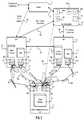
- FIG. 1is a block diagram of an exemplary system for providing connectivity to a plurality of distributed transceivers via a plurality of distributed access points, in accordance with an exemplary embodiment of the invention.
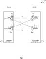
- FIG. 2is a block diagram illustrating distributed transceivers utilized for wireless communication in access points and a mobile communication device, in accordance with an exemplary embodiment of the invention.
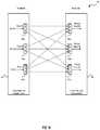
- FIG. 3is a block diagram illustrating distributed transceivers utilized for wireless communication in access points in which the access points utilize different link protocols and/or operating modes, in accordance with an exemplary embodiment of the invention.
- FIG. 4is a block diagram of an exemplary beamforming implementation of a distributed transceiver device comprising corresponding receive portions of two transceivers, each of which receives the same data stream, in accordance with an exemplary embodiment of the invention.
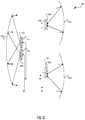
- FIG. 5is a block diagram of an exemplary propagation model for a leaky wave distributed transceiver environment, in accordance with an exemplary embodiment of the invention.
- FIG. 6Ais a block diagram of an exemplary propagation model for a leaky wave distributed transceiver environment with poor phase condition prior to displacement of transceivers and/or antenna elements, in accordance with an exemplary embodiment of the invention.
- FIG. 6Bis a block diagram of an exemplary propagation model for a leaky wave distributed transceiver environment with improved phase condition subsequent to displacement of transceivers and/or antenna elements, in accordance with an exemplary embodiment of the invention.
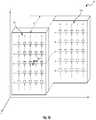
- FIG. 7Ais a diagram that illustrates a two-dimensional (2D) 5 ⁇ 5 antenna element array deployed at a transceiver in a 2 ⁇ 2 distributed transceiver system, in accordance with an exemplary embodiment of the invention.
- FIG. 7Bis a diagram that illustrates electronic movement of the phase center a two-dimensional 5 ⁇ 5 antenna element array deployed at a transceiver in a 2 ⁇ 2 distributed transceiver system, in accordance with an exemplary embodiment of the invention.
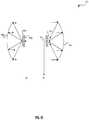
- FIG. 7Cis a diagram that illustrates a three-dimensional (3D) 5 ⁇ 5 antenna element array deployed at a transceiver in a 2 ⁇ 2 distributed transceiver system, in accordance with an exemplary embodiment of the invention.
- FIG. 7Dis a diagram that illustrates electronic movement of the phase center of a three-dimensional 5 ⁇ 5 antenna element array deployed at a transceiver in a 2 ⁇ 2 distributed transceiver system, in accordance with an exemplary embodiment of the invention.
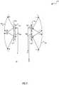
- FIG. 7Eis a diagram that illustrates electronic movement of the phase center of a three-dimensional 5 ⁇ 5 antenna element array deployed at a transceiver in a 2 ⁇ 2 distributed transceiver system, in accordance with an exemplary embodiment of the invention.
- FIG. 8Ais a diagram that illustrates a plot of the occupied/available signal bandwidth versus the frequency, in accordance with an exemplary embodiment of the invention.
- FIG. 8Bis a diagram that illustrates a plot of the phase condition versus the frequency prior to displacement of the transceiver, in accordance with an exemplary embodiment of the invention.
- FIG. 8Cis a diagram that illustrates a plot of the phase condition versus the frequency after displacement of the transceiver, in accordance with an exemplary embodiment of the invention.
- FIG. 8Dis a diagram that illustrates a plot of the normalized capacity versus the frequency after displacement of the transceiver, in accordance with an exemplary embodiment of the invention.
- FIG. 10is a diagram illustrating exemplary use of transceivers for communication links that utilize dishes, in accordance with an exemplary embodiment of the invention.
- FIG. 11is a diagram that illustrates the use of a single larger dish to transmit two data streams utilizing orthogonal polarization, in accordance with an exemplary embodiment of the invention.
- FIG. 12is a diagram that illustrates the use of a single larger dish to transmit two data streams by two distributed transceivers utilizing similar polarization and receiving two corresponding data streams by two distributed transceivers with separate dishes, in accordance with an exemplary embodiment of the invention.
- FIG. 13is a diagram that illustrates the use of different polarizations by two distributed transceivers at two separate dishes to transmit four data streams and receiving four corresponding data streams by two distributed transceivers at two separate dishes, in accordance with an exemplary embodiment of the invention.
- FIG. 14is a diagram that illustrates the use of different relative polarizations by four distributed transceivers at a single dish to transmit four data streams and receiving four corresponding data streams by four distributed transceivers at a single dish, in accordance with an exemplary embodiment of the invention.
- FIG. 15is a block diagram of an exemplary propagation model for a leaky wave distributed transceiver environment where the channel matrix is asymmetric, in accordance with an exemplary embodiment of the invention.
- FIG. 16is a block diagram of an exemplary propagation model for a leaky wave distributed 3 ⁇ 3 transceiver environment where the channel matrix is asymmetric, in accordance with an exemplary embodiment of the invention.
- FIG. 17is a flow chart illustrating exemplary steps for optimizing communication in leaky wave distributed transceiver environments, in accordance with an exemplary embodiment of the invention.
- a communication devicemay comprise a plurality of distributed transceivers and one or more corresponding antenna arrays.
- a processorsuch as a central processor, a network management engine and/or a coordinate entity may be operable to configure a first distributed transceiver of the plurality of distributed transceivers to receive signals comprising one or more first data streams via one or more first communication links.
- the processormay be operable to configure a second distributed transceiver of the plurality of distributed transceivers to receive signals comprising one or more second data streams via one or more second communication links.
- the processormay be operable to determine a channel response matrix associated with communication of the one or more first data streams via the one or more first communication links and/or the one or more second data streams via the one or more second communication links.
- the processormay be operable to optimize one or both of link capacity and/or link reliability of the one or more first communication links and/or the one or more second communication links based on the determined channel response matrix.
- the processormay be operable to determine a range of phase conditions over which the optimization may be acceptable.
- the processormay adjust a phase sum corresponding to the one or more first communication links and/or one or more of the second communication links, based on the determined range of the phase conditions over which the optimization is acceptable.
- the processormay be operable to adjust the determined range of the phase condition based on signal to noise ratio on the one or more first communication links and/or via the one or more second communication links.
- the processormay determine the range of the phase conditions over which the optimization may be acceptable based on one or more of training signals and/or pilot signals, which may be communicated via the one or more first communication links and/or via the one or more second communication links.
- the processormay be operable to dynamically and/or adaptively displace (mechanically through a motor or electronically in some exemplary embodiments of the invention) the first distributed transceiver, an antenna communicatively coupled to the first distributed transceiver, the second distributed transceiver and/or an antenna communicatively coupled to the second distributed transceiver to satisfy the determined range of the phase conditions over which the optimization is acceptable.
- the displacement of the first distributed transceiver, the antenna communicatively coupled to the first distributed transceiver, the second distributed transceiver and/or the antenna communicatively coupled to the second distributed transceivermay occur spatially in the x-coordinate, the y-coordinate and/or the z-coordinate.
- the processormay be operable to dynamically and/or adaptively control adjustment of a phase center of an antenna communicatively coupled to the first distributed transceiver and/or adjustment of a phase center of an antenna communicatively coupled to the second distributed transceiver to satisfy the determined range of said phase conditions over which the optimization is acceptable.
- one or more first data streams and the one or more second data streamscomprise different polarizations.
- one or more first data streams and one or more of the second data streamsmay comprise similar polarizations.
- FIG. 1is a block diagram of an exemplary system for providing connectivity to a plurality of distributed transceivers via a plurality of distributed access points, in accordance with an exemplary embodiment of the invention.
- the mmWave and wireless communication network 10may comprise a gateway 20 and a plurality of access points 26 a , 26 b , . . . , 26 n .
- the mmWave and wireless communication network 12may comprise a gateway 22 , a gateway 24 , a plurality of access points 36 a , 36 b , . . .
- FIG. 1also shows a plurality of mobile communication devices 30 a , 30 b , 30 c , . . . , 30 n , a plurality of mobile communication devices 42 a , 42 b , 42 c , . . . , 42 , and a coordinating entity 38 .
- the Internet 18may host a plurality of resources such as the server 18 a .
- FIG. 1also shows a mobile entity 31 , curved reflective surfaces 29 a , 41 a , 41 b , refractive surfaces 29 b , 41 d and flat reflective surface 29 c , 41 c.
- the mmWave and wireless communication network 10may comprise a plurality of mmWave and other wireless communication enabled network devices and/or interfaces that enable communication amongst a plurality of devices utilizing wireless communication.
- the mmWave and wireless communication network 10may comprise one or more mmWave enabled network devices that enable the communication traffic and/or control data via a plurality of mobile communication devices.
- the mmWave and wireless communication network 10may comprise the plurality of access points 26 a , 26 b , . . .
- the mmWave and wireless communication network 10may also be operable to provide access to the Internet 18 via the service provider network 14 .
- the mmWave and wireless communication network 10may also comprise devices that may be operable to communicate via wireless wide area network (WWAN), wireless medium area network (WMAN), wireless local area network (WLAN), wireless personal area network (WPAN) and/or other wireless technologies.
- WWANwireless wide area network
- WMANwireless medium area network
- WLANwireless local area network
- WPANwireless personal area network
- the mmWave and wireless communication network 12may comprise a plurality of mmWave and other wireless communication enabled network devices and/or interfaces that enable communication amongst a plurality of devices utilizing wireless communication.
- the mmWave and wireless communication network 12may comprise one or more mmWave enabled network devices that enable the communication traffic and/or control data via a plurality of mobile communication devices.
- the mmWave and wireless communication network 12may comprise the plurality of access points 36 a , 36 b , . . .
- the mmWave and wireless communication network 12may also be operable to provide access to the Internet 18 via the service provider network 16 .
- the mmWave and wireless communication network 12may also comprise devices that may be operable to communicate via wireless wide area network (WWAN), wireless medium area network (WMAN), wireless local area network (WLAN), wireless personal area network (WPAN) and/or other wireless technologies.
- WWANwireless wide area network
- WMANwireless medium area network
- WLANwireless local area network
- WPANwireless personal area network
- the service provider network 14may comprise suitable devices and/or interfaces that may enable communication devices, which are communicatively coupled to the mmWave and wireless communication network 10 , to access one or more other networks such as the Internet 18 and the mmWave and wireless communication network 12 .
- the service provider network 14may enable the mobile communication devices 30 a , 30 b , 30 c , . . . , 30 n to access devices and/or services on the Internet 18 .
- the service provider network 14may also enable the mobile communication devices 30 a , 30 b , 30 c , . . .
- the service provider network 16may enable the mobile communication devices 42 a , 42 b , 42 c , . . . , 42 n to access the mmWave and wireless communication network 10 and communicate with one or more of the mobile communication devices 30 a , 30 b , 30 c , . . . , 30 n via the Internet 18 and the service provider network 14 and/or via the gateway 20 .
- the service provider network 14may comprise, for example, a broadband connectivity (or another distributed mmWave connectivity) to the mmWave and wireless communication network 10 .
- the service provider network 14may comprise a cable service provider, an digital subscriber line (DSL) or variants thereof service provider, a fiber optic service provider, a hybrid fiber coaxial service provider, a WWAN service provider, a WMAN, and/or a satellite service provider
- the service provider network 16may comprise suitable devices and/or interfaces that may enable communication devices, which are communicatively coupled to the mmWave and wireless communication network 12 , to access one or more other network such as the Internet 18 and the mmWave and wireless communication network 10 .
- the service provider network 16may enable the mobile communication devices 42 a , 42 b , 42 c , . . . , 42 n to access devices and/or services on the Internet 18 .
- the service provider network 16may enable the mobile communication devices 42 a , 42 b , 42 c , . . .
- the service provider network 16may comprise, for example, a broadband or other high speed connectivity to the mmWave and wireless communication network 12 .
- the service provider network 16may comprise a cable service provider, a digital subscriber line (DSL) or variants hereof service provider, a fiber optic service provider, a hybrid fiber coaxial service provider, a WWAN service provider, a WMAN, and/or a satellite service provider.
- DSLdigital subscriber line
- the Internet 18may comprise suitable devices and/or interfaces that enable the interconnection of a plurality of networks and/or devices.
- the Internet 18may enable the interconnection of the service provider network 14 , the service provider network 16 , the mmWave and wireless communication network 10 , the mmWave and wireless communication network 12 .
- Each of the plurality of access points 26 a , 26 b , . . . , 26 nmay comprise suitable logic, circuitry, interfaces and/or code that may be operable to provide access to the mmWave and wireless communication network 10 for one or more of the mobile communication devices 30 a , 30 b , 30 c , . . . , 30 n when they are within operating range of a corresponding one or more of the plurality of access points 26 a , 26 b , . . . , 26 n .
- each of the plurality of access points 26 a , 26 b , . . . , 26 nmay also be operable to handle communication of traffic and/or control data among one or more other access points in the mmWave and wireless communication network 10 , the coordinating entity 28 and/or the gateway 20 .
- each of the plurality of access points 26 a , 26 b , . . . , 26 nmay communicate with the coordinating entity 28 in order to handle the routing and/or processing of data for one or more of the mobile communication devices 30 a , 30 b , 30 c , . . . , 30 n.
- Each of the plurality of access points 36 a , 36 b , . . . , 36 nmay comprise suitable logic, circuitry, interfaces and/or code that may be operable to provide access to the mmWave and wireless communication network 12 for one or more of the mobile communication devices 42 a , 42 b , 42 c , . . . , 42 n when they are within operating range of a corresponding one or more of the plurality of access points 36 a , 36 b , . . . , 36 n .
- each of the plurality of access points 36 a , 36 b , . . . , 36 nmay also be operable to handle communication of traffic and/or control data among one or more other access points in the mmWave and wireless communication network 12 , the coordinating entity 38 and/or the gateways 22 , 24 .
- each of the plurality of access points 36 a , 36 b , . . . , 36 nmay communicate with the coordinating entity 38 in order to handle the routing and/or processing of data for one or more of the mobile communication devices 42 a , 42 b , 42 c , . . . , 42 n.
- the coordinating entity 28may comprise suitable logic, circuitry, interfaces and/or code that may be operable to control, coordinate and/or manage the handling and routing of traffic and/or control data within the mmWave and wireless communication network 10 .
- the coordinating entity 28may be operable to control the type and/or amount of links, the number of distributed transceivers, configuration of the distributed transceivers' interfaces and/or components including RF front ends and/or antenna arrays, which may be utilized by one or more of the access points 26 a , 26 b , . . . , 26 n to handle traffic for one or more of the mobile communication devices 30 a , 30 b , 30 c , . . . , 30 n .
- the coordinating entity 28may be operable to control the allocation and de-allocation of bandwidth to facilitate communication of traffic in order to provide and/or guarantee a particular class of service (CoS) and/or Quality of Service (QoS) for the mobile communication devices 30 a , 30 b , 30 c , . . . , 30 n .
- the coordinating entity 28may be operable to coordinate amongst the gateway 20 and/or one or more of the access points 26 a , 26 b , . . . , 26 n in order to route traffic to and from the gateway 20 and the mobile communication devices 30 a , 30 b , 30 c , . . . , 30 n .
- the coordinating entity 28is illustrated as a separate entity from the gateway 20 , and the access points 26 a , 26 b , . . . , 26 n , the invention is not limited in this regard. Accordingly, the coordinating entity 28 may be integrated in the gateway 20 or in one of the access points 26 a , 26 b , . . . , 26 n . In some embodiments of the invention, the functionality of the coordinating entity 28 may be split amongst a plurality of devices such as two or more of the gateway 20 , and/or the access points 26 a , 26 b , . . . , 26 n.
- the coordinating entity 38may comprise suitable logic, circuitry, interfaces and/or code that may be operable to control, coordinate and/or manage the handling and routing of traffic and/or control data within the mmWave and wireless communication network 12 .
- the coordinating entity 38may be operable to control the type and/or amount of links, communication protocols, the number of distributed transceivers, configuration of the distributed transceivers' interfaces and/or components including RF front ends and/or antenna arrays, which may be utilized by one or more of the access points 36 a , 36 b , . . . , 36 n to handle traffic for one or more of the mobile communication devices 42 a , 42 b , 42 c , . . . , 42 n .
- the coordinating entity 38may be operable to control the allocation and de-allocation of bandwidth to facilitate communication of traffic in order to provide and/or guarantee a particular class of service (CoS) and/or Quality of Service (QoS) for the mobile communication devices 42 a , 42 b , 42 c , . . . , 42 n .
- the coordinating entity 38may be operable to coordinate amongst the gateways 22 , 24 and/or one or more of the access points 36 a , 36 b , . . . , 36 n in order to route traffic to and from the gateways 22 , 24 and the mobile communication devices 42 a , 42 b , 42 c , . . . , 42 n .
- the coordinating entity 38is illustrated as a separate entity from the gateways 22 , 24 , and the access points 36 a , 36 b , . . . , 36 n , the invention is not limited in this regard. Accordingly, the coordinating entity 38 may be integrated in one of the gateways 22 , 24 or in one of the access points 36 a , 36 b , . . . , 36 n . In some embodiments of the invention, the functionality of the coordinating entity 38 may be split amongst a plurality of devices such as two or more of the gateways 20 , 24 and/or the access points 36 a , 36 b , . . . , 36 n.
- Each of the plurality of mobile communication devices 30 a , 30 b , 30 c , . . . , 30 nmay comprise suitable logic, circuitry, interfaces and/or code that may be operable to communicate with the service provider network 14 via the mmWave and wireless communication network 10 .
- each of the plurality of mobile communication devices 30 a , 30 b , 30 c , . . . , 30 nmay comprise a plurality of distributed transceivers such as mmWave transceiver devices that may be operable to communicate with the access points 26 a , 26 b , . . . , 26 n in the mmWave and wireless communication network 10 .
- the plurality of mobile communication devices 30 a , 30 b , 30 c , . . . , 30 nmay be collectively referenced as mobile communication devices 30 .
- Each of the plurality of mobile communication devices 30 a , 30 b , 30 c , . . . , 30 nmay be operable to communicate utilizing, for example, 60 GHz wireless standard, WirelessHD, WiGig, WiFi IEEE 802.11ad, and/or other mmWave technology or standard.
- each of the plurality of mobile communication devices 30 a , 30 b , 30 c , . . . , 30 nmay comprise one or more transmitter and/or receiver devices, which may be operable to communicate utilizing technologies such as, for example, wireless personal area network (WPAN), a wireless local area network (WLAN), wireless medium area network (WMAN) and/or wireless wide area network (WWAN) technologies.
- WPANwireless personal area network
- WLANwireless local area network
- WMANwireless medium area network
- WWANwireless wide area network
- one or more of the plurality of mobile communication devices 30 a , 30 b , 30 c , . . . , 30 nmay comprise one or more transmitter and/or receiver devices, which may be operable to communicate utilizing WiFi, WiMax, Bluetooth, ZigBee, Bluetooth Low Energy (BLE), 3GPP, 4G LTE, WiMAX or other technologies.
- radiossuch as mmWave radios may be utilized at very high carrier frequencies for high throughput wireless communications.
- the plurality of mobile communication devices 42 a , 42 b , 42 c , . . . , 42 nmay be communicatively coupled to the mmWave and wireless communication network 12 .
- the plurality of mobile communication devices 42 a , 42 b , 42 c , . . . , 42 nmay be collectively referenced as mobile communication devices 42 .
- Each of the plurality of mobile communication devices 42 a , 42 b , 42 c , . . . , 42 nmay be operable to communicate utilizing, for example, 60 GHz wireless standard, WirelessHD, WiGig, WiFi IEEE 802.11ad, and/or other mmWave technology or standard.
- the plurality of mobile communication devices 42 a , 42 b , 42 c , . . . , 42 nmay be communicatively coupled to the mmWave and wireless communication network 12 .
- the mobile communication device 42 amay comprise a tablet
- the mobile communication device 42 bmay comprise a Smartphone
- the mobile communication device 42 cmay comprise a personal computer PC, laptop or ultrabook
- the mobile communication device 42 nmay comprise a television.
- the gateway 20may comprise suitable logic, circuitry, interfaces and/or code that are operable to process and/or route traffic and/or control data between the service provider network 14 and the mmWave and wireless communication network 10 .
- the gateway 20may be operable to handle the processing and/or routing of traffic and/or control data between the service provider network 14 and one or more of the access points 26 a , 26 b , . . . , 26 n and/or the coordinating entity 28 for one or more of the plurality of mobile communication devices 30 a , 30 b , 30 c , . . . , 30 n .
- the gateway 20may comprise, for example, a modulation and/or demodulation (modem) device that may be operable to provide modulation and/or demodulation of the information that is communicated between the service provider network 14 and the mmWave and wireless communication network 10 .
- the gateway 20may comprise a cable modem, a DSL modem, a HFC modem, a cable set top box (STB), a satellite STB and/or other similar type of device.
- the gateway 20may be operable to handle any technology that may be utilized by one or more of the cable service provider, the digital subscriber line (DSL) service provider, the fiber optic service provider, the hybrid fiber coaxial (HFC) service provider, the WWAN service provider, the WMAN, and/or the satellite service provider.
- the gateway 20may comprise server functionality.
- the gateway 20may also enable communication amongst one or more of the mobile communication devices 30 a , 30 b , 30 c , . . . , 30 n and one or more of the mobile communication devices 42 a , 42 b , 42 c , . . . , 42 n via the mmWave and wireless communication network 10 and the service provider network 14 and/or via the service providers 14 , 16 and the Internet 18 .
- the gateway 22may comprise suitable logic, circuitry, interfaces and/or code that are operable to process and/or route traffic and/or control data between the service provider network 14 and the mmWave and wireless communication network 12 .
- the gateway 22may be operable to handle the processing and/or routing of traffic and/or control data between the service provider network 14 and one or more of the access points 36 a , 36 b , . . . , 36 n and/or the coordinating entity 38 for one or more of the plurality of mobile communication devices 42 a , 42 b , 42 c , . . . , 42 n .
- the gateway 22may comprise, for example, a modulation and/or demodulation (modem) device that may be operable to provide modulation and/or demodulation of the information that is communicated between the service provider network 14 and the mmWave and wireless communication network 12 .
- the gateway 22may comprise a cable modem, a DSL modem, a HFC modem, a cable set top box (STB), a satellite STB and/or other similar type of device.
- the gateway 22may be operable to handle any technology that may be utilized by one or more of the cable service provider, the digital subscriber line (DSL) service provider, the fiber optic service provider, the hybrid fiber coaxial (HFC) service provider, the WWAN service provider, the WMAN, and/or the satellite service provider.
- the gateway 22may comprise a server functionality.
- the gateway 22may also enable communication amongst one or more of the mobile communication devices 30 a , 30 b , 30 c , . . . , 30 n and one or more of the mobile communication devices 42 a , 42 b , 42 c , . . . , 42 n via the mmWave and wireless communication networks 10 , 12 and the service provider network 14 and/or via the service providers 14 , 16 and the Internet 18 .
- the gateway 24may comprise suitable logic, circuitry, interfaces and/or code that are operable to process and/or route traffic and/or control data between the service provider network 16 and the mmWave and wireless communication network 12 .
- the gateway 24may be operable to handle the processing and/or routing of traffic and/or control data between the service provider network 16 and one or more of the access points 36 a , 36 b , . . . , 36 n and/or the coordinating entity 38 for one or more of the plurality of mobile communication devices 42 a , 42 b , 42 c , . . . , 42 n .
- the gateway 24may comprise, for example, a modulation and/or demodulation (modem) device that may be operable to provide modulation and/or demodulation of the information that is communicated between the service provider network 16 and the mmWave and wireless communication network 12 .
- the gateway 24may comprise a cable modem, a DSL modem, a HFC modem, a cable set top box (STB), a satellite STB and/or other similar type of device.
- the gateway 24may be operable to handle any technology that may be utilized by one or more of the cable service provider, the digital subscriber line (DSL) service provider, the fiber optic service provider, the hybrid fiber coaxial (HFC) service provider, the WWAN service provider, the WMAN, and/or the satellite service provider.
- the gateway 24may comprise a server functionality.
- the gateway 24may also enable communication amongst one or more of the mobile communication devices 30 a , 30 b , 30 c , . . . , 30 n and one or more of the mobile communication devices 42 a , 42 b , 42 c , . . . , 42 n via the mmWave and wireless communication networks 10 , 12 , the service provider networks 14 , 16 and the Internet 18 .
- the curved reflective surface 29 a , the refractive surface 29 b and the flat reflective surface 29 cmay be located within the operating environment of the mmWave and wireless communication network 10 .
- One or more of the curved reflective surface 29 a , the refractive surface 29 b and/or the flat reflective surface 29 cmay be objects and/or portions thereof, which may exist within the environment or may be intentionally placed within the environment to be utilized to optimize communication between devices in the mmWave and wireless communication network 10 and the mobile communication devices 30 a , 30 b , 30 c , . . . , 30 n.
- the curved reflective surfaces 41 a , 41 b , the refractive surface 41 d and the flat reflective surface 41 cmay be located within the operating environment of the mmWave and wireless communication network 12 .
- One or more of the curved reflective surfaces 41 a , 41 b , the refractive surface 41 d and the flat reflective surface 41 cmay be objects and/or portions thereof, which may exist within the environment or may be intentionally placed within the environment to be utilized to optimize communication between devices in the mmWave and wireless communication network 12 and the mobile communication devices 42 a , 42 b , 42 c , . . . , 42 n.
- the mobile entity 31may comprise a plurality of distributed transceivers and/or one or more corresponding antenna arrays that are communicatively coupled to one or more of the plurality of distributed transceivers.
- the distributed transceiversmay be configured to handle communication of one or more data streams among one or more of a plurality of wireless communication networks such as the mmWave and wireless communication networks 10 , 12 , one or more other mobile entities and/or one or more mobile communication devices 30 a , 30 b , 30 c , . . . , 30 n , 42 a , 42 b , 42 c , . . . , 42 n .
- the mobile entitymay comprise a car, a truck, an omnibus (bus), a trailer, a mobile home, train, bus, a forklift, construction equipment, a boat, a ship, an aircraft or any other vehicle.
- One or more of the plurality of distributed transceivers in the mobile entity 31may be configured to operate as a relay node and/or a repeater node.
- a location, speed and/or trajectory of the mobile entity 31may be determined and one or more of the plurality of distributed transceivers and/or one or more corresponding antenna arrays may be configured based on the determined location, speed and/or trajectory.
- One or more of the plurality of distributed transceivers in the mobile entity 31may be dynamically and/or adaptively controlled to utilize one or more modes of operation to communicate the one or more data streams and/or to split the communication of the one or more data streams amongst a portion of the plurality of distributed transceivers in the mobile entity 31 .
- Exemplary modes of operationmay comprise a spatial diversity mode, a frequency diversity mode, a spatial multiplexing mode, a frequency multiplexing mode and/or a MIMO mode.
- Trafficmay be backhauled from the mobile entity 31 via one or more wireless communication links to one or more of the plurality of mmWave and wireless communication networks 10 , 12 .
- One or more of the plurality of distributed transceivers in the mobile entity 31may be configured to utilize different types of communication links, modulation schemes, constellations, protocols, frequencies, wireless standards and/or bandwidths to handle the communication of the one or more data streams and/or to handle different types of data traffic. Additional details on mobile entities such as the mobile entity 31 may be found in United States Application Ser. No. 13/919,922, which was filed on Jun. 17, 2013, now published as U.S. Pat. No. 9,197,982, which is hereby incorporated herein in its entirety.
- each of the mobile communication devices 30 a , 30 b , 30 c , . . . , 30 n , the mobile communication devices 42 a , 42 b , 42 c , . . . , 42 n , the access points 26 a , 26 b , . . . , 26 n and/or the access points 36 a , 36 b , . . . , 36 nmay be operable to dynamically configure its distributed transceivers and/or antenna arrays to operate based on various factors.
- Exemplary factorscomprise link throughput/reliability requirements and/or budgets, spectrum availability, propagation conditions, location of reflectors or refractors in the environment, geometry of the environment, positions of the transmitter/receivers, link quality, device capabilities, device locations, usage of resources, resource availability, target throughput, application QoS requirements and/or traffic types.
- the characteristics and geometry of the environmentmay include the presence of naturally reflective and/or refractive surfaces and/or the presence of obstructive elements in the environment.
- the environment within the operating environment of the mmWave and wireless communication network 10may comprise the curved reflective surface 29 a , the refractive surface 29 b and the flat reflective surface 29 c .
- the environment within the operating environment of the mmWave and wireless communication network 12may comprise the curved reflective surfaces 41 a , 41 b , the refractive surface 41 d and the flat reflective surface 41 c .
- the access points 26 a , 26 b , . . . , 26 nmay be operable to utilize one or more of the curved reflective surface 29 a , the refractive surface 29 b and/or the flat reflective surface 29 c in the operating environment of the mmWave and wireless communication network 10 to optimize communication of wireless signals.
- the mobile communication device 30 amay be operable to utilize the reflective properties of the curved reflective surface 29 a to communicate with the access point 26 n .
- the mobile communication device 30 cmay utilize the flat reflective surface 29 c and the refractive surface 29 b to communicate with the access point 26 n .
- the mobile communication device 30 nmay utilize the flat reflective surface 29 c to communicate with the access point 26 b.
- One or more of the distributed transceivers in one or more of the plurality of mobile communication devices 42 a , 42 b , 42 c , . . . , 42 n and/or the access points 36 a , 36 b , . . . , 36 nmay be operable to utilize one or more of the curved reflective surfaces 41 a , 41 b , the refractive surface 41 d and/or the flat reflective surface 41 c in the operating environment of the mmWave and wireless communication network 12 to optimize communication of wireless signals.
- the mobile communication device 42 amay be operable to utilize the reflective properties of the curved reflective surface 41 a to communicate with the access point 36 n .
- the mobile communication device 42 bmay be operable to utilize the reflective properties of the curved reflective surface 41 b to communicate with the access point 36 n .
- the mobile communication device 42 cmay utilize the flat reflective surface 41 c to communicate with the access point 36 n .
- the mobile communication device 42 nmay utilize multi-hop communication which utilizes the flat reflective surface 41 c and the refractive surface 41 d to communicate with the access point 36 b.
- One or more of the distributed transceivers in mobile entity 31may be operable to utilize (1) the curved reflective surface 29 a , the refractive surface 29 b and the flat reflective surface 29 c within the operating environment of the mmWave and wireless communication network 10 and/or (2) the curved reflective surfaces 41 a , 41 b , the refractive surface 41 d and the flat reflective surface 41 c within the operating environment of the mmWave and wireless communication network 12 , to optimize communication of wireless signals.
- one or more of the distributed transceivers in the mobile entity 31may be operable to utilize the flat reflective surface 29 c to communicate with the access point 26 b .
- one or more of the distributed transceivers in the mobile entity 31may be operable to utilize the curved reflective surface 41 a to communicate with the access point 36 n .
- one or more of the distributed transceivers in the mobile entity 31may be operable to utilize the flat reflective surface 29 c to communicate with the access point 26 b and also utilize the curved reflective surface 41 a to communicate with the access point 41 a.
- a processor in each of the mobile communication devices 30 a , 30 b , 30 c , . . . , 30 n , the mobile communication devices 42 a , 42 b , 42 c , . . . , 42 n , the access points 26 a , 26 b , . . . , 26 n and/or the access points 36 a , 36 b , . . . , 36 nmay be operable to dynamically configure and coordinate operation of the distributed transceivers and/or antenna arrays to operate in different modes based on the different factors.
- Exemplary factorsmay comprise, for example, propagation environment conditions, link quality, device capabilities, device locations, usage of resources, resource availability, target throughput, and application QoS requirements.
- a mobile communication device that has data to be transmittedmay dynamically sense the environment to determine the current characteristics of the environment, which may include the presence of blocking objects, reflectors, and/or refractors.
- the characteristics of corresponding transmitted and/or received signals communicated by one or more distributed transceiversmay be analyzed by one or more distributed transceivers in order to sense the surrounding environment. For example, the analysis may determine transmitted and/or received signal strength, frequency changes, phase changes, angle of transmission, angle of arrival and/or other characteristics of the transmitted and/or received signals in order to sense the environment.
- the mobile communication device that has data to be transmittedmay be operable to configure its transmitter and/or antenna arrays to spread and transmit a narrow beam in one or more directions, where reflectors, refractors, naturally reflecting elements and/or naturally refractive elements may create multiple paths to a receiving mobile communication device.
- Each communication pathmay comprise a different frequency, polarization, bandwidth, protocol, and/or coding thereby providing link robustness.
- the transmitter in a transmitting mobile communication devicemay be operable to use the same frequency channel or different frequency channels to transmit the same data stream or separate data streams.
- the coordinating entities 28 , 38may be operable to coordinate the configuration of the distributed transceivers and/or antenna arrays in one or more of the mobile communication devices 30 a , 30 b , 30 c , . . . , 30 n , the mobile communication devices 42 a , 42 b , 42 c , . . . , 42 n , the access points 26 a , 26 b , . . . , 26 n and/or the access points 36 a , 36 b , . . . , 36 n .
- the coordinating entities 28 , 38may be operable to dynamically collect information from one or more of the mobile communication devices 30 a , 30 b , 30 c , . . . , 30 n , the mobile communication devices 42 a , 42 b , 42 c , . . . , 42 n , the access points 26 a , 26 b , . . . , 26 n and/or the access points 36 a , 36 b , . . . , 36 n .
- the coordinating entities 28 , 38may aggregate the collected information and determine an optimal configuration for transmitters, receivers and/or antenna array elements in one or more of the mobile communication devices 30 a , 30 b , 30 c , . . . , 30 n , the mobile communication devices 42 a , 42 b , 42 c , . . . , 42 n , the access points 26 a , 26 b , . . . , 26 n and/or the access points 36 a , 36 b , . . . , 36 n .
- the coordinating entities 28 , 38may communicate the determined optimal configuration for the transmitters, receivers and/or antenna array elements in the corresponding mobile communication devices 30 a , 30 b , 30 c , . . . , 30 n , the mobile communication devices 42 a , 42 b , 42 c , . . . , 42 n , the access points 26 a , 26 b , . . . , 26 n and/or the access points 36 a , 36 b , . . . , 36 n .
- the mobile communication devices 42 a , 42 b , 42 c , . . . , 42 n , the access points 26 a , 26 b , . . . , 26 n and/or the access points 36 a , 36 b , . . . , 36 nmay then configure their transmitters, receivers and/or antenna array elements accordingly.
- the coordinating entities 28 , 38may be separate dedicated hardware/software units performing the coordinating functions. Coordinating entities 28 , 38 may be integrated into another entity in the network and reuse its hardware/software resources (e.g., embedded in access points 36 a , 36 b ). Furthermore, coordinating entities 28 , 38 may be implemented as all-software entities running on a generic processor or a remote processor. Furthermore, the functions of coordinating entities 28 , 38 may be distributed over several entities in the network.
- a communication devicecomprising a plurality of distributed transceivers and one or more corresponding antenna arrays, a first distributed transceiver is configured to receive signals comprising one or more first data streams and a second distributed transceiver is configured to receive signals comprising one or more second data streams.
- One or more components within a receive processing chain of the first distributed transceiver and/or one or more components within a receive processing chain of the second distributed transceivermay be adjusted to maximize beamforming gain for the one or more first data streams and/or one or more of the second data streams.
- a phase of the one or more first data streams and/or the one or more second data streamsmay be adjusted by the one or more components within the receive processing chain of the first distributed transceiver and/or one or more components within a receive processing chain of the second distributed transceiver.
- the one or more first data streams and/or the one or more second data streamsmay be combined in the RF domain.
- the combined one or more first data streams and/or the one or more second data streamsmay be converted from the RF domain to the intermediate frequency (IF) domain.
- the one or more first data streams and/or the one or more second data streamsmay be coherently combined in the IF domain.
- a communication devicecomprising a plurality of distributed transceivers and one or more corresponding antenna arrays
- a first distributed transceiver of the plurality of distributed transceiversmay be configured to transmit signals comprising one or more first data streams.
- a second distributed transceiver of the plurality of distributed transceiversmay also be configured to transmit signals comprising one or more second data streams.
- One or more components within a transmit processing chain of the first distributed transceiver and/or one or more components within a transmit processing chain of the second distributed transceivermay be adjusted based on a determined mode of operation for the first distributed transceiver and/or the second distributed transceiver.
- the first distributed transceiver and/or the second distributed transceivermay be dynamically switched between a first mode of operation and a second mode of operation based on a signal to noise ratio (SNR) associated with the first distributed transceiver and/or the second distributed transceiver.
- SNRsignal to noise ratio
- One or more selectors within the first distributed transceiver and/or the second distributed transceivermay be configured to transmit one or more first data streams and one or more second data streams from the first distributed transceiver and/or the second distributed transceiver in a spatial multiplexing mode based on the determined mode of operation.
- the one or more selectors within the first distributed transceiver and/or the second distributed transceivermay be configured to transmit the one or more first data streams or the one or more second data streams from the first distributed transceiver and/or the second distributed transceiver in a spatial multiplexing single beam single stream operating mode.
- One or more phase adjustment parameters for one or more components within the first distributed transceiver and/or the second distributed transceivermay be configured based on the determined mode of operation for the first distributed transceiver and/or the second distributed transceiver. Additional details may be found in United application Ser. No. 13/919,932, which was filed on Jun. 17, 2013, now granted as U.S. Pat. No. 10,020,861, which is hereby incorporated herein by reference in its entirety.
- the reference to 60 GHz wireless connectivityis intended to include all mmWave frequency bands (any carrier frequency above 10 GHz, e.g., 38.6-40 GHz, 59-67 GHz, 71-76 GHz, 92-95 GHz bands). Furthermore, all or a subset of embodiments are applicable to sub-10 GHz carrier frequency operations as well (e.g., 5 GHz and 2.4 GHz ISM bands and UWB 3-10 GHz bands).
- FIG. 2is a block diagram illustrating distributed transceivers utilized for wireless communication in access points and a mobile communication device in accordance with an exemplary embodiment of the invention.
- access points 102 , 112there are shown access points 102 , 112 , a mobile communication device 129 , a coordinating entity 108 and a gateway 110 .
- the access points 102 , 112are also referenced as AP1 and AP2, respectively.
- the mobile communication device 129is also referenced as M1.
- a single mobile communication device 129is shown, the invention is not limited in this regard. Accordingly, a plurality of mobile and/or non-mobile communication devices may also be present without departing from the spirit and/or scope of the invention.
- FIG. 1is a block diagram illustrating distributed transceivers utilized for wireless communication in access points and a mobile communication device in accordance with an exemplary embodiment of the invention.
- FIG. 2there are shown access points 102 , 112 , a mobile communication device 129 , a
- the blocking object 118blocks line or sight communication between the distributed transceiver 133 n in the mobile communication device 129 and the distributed transceiver 114 n in the access point 112 .
- the refractive surface 119 amay be substantially similar to the refractive surfaces 29 b , 41 d , which are shown and described with respect to FIG. 1 , for example.
- the flat reflective surface 119 bmay be substantially similar to the flat refractive surfaces 29 c , 41 c , which are shown and described with respect to FIG. 1 , for example.
- the curved reflective surface 119 cmay be substantially similar to the curved reflective surfaces 29 a , 41 a , 41 b , which are shown and described with respect to FIG. 1 , for example.
- the access point 102may be substantially similar to any of the access points 26 a , 26 b , . . . , 26 n and/or the access points 36 a , 36 b , . . . , 36 n , which are shown and described with respect to FIG. 1 , for example. Notwithstanding, as shown in FIG. 2 , the access point 102 (AP1) may comprise a central processor 106 and a plurality of distributed transceiver devices 104 a , . . . , 104 n . The distributed transceiver devices 104 a , . . . , 104 n may comprise a corresponding plurality of antenna arrays 105 a , . . .
- the access point 102may be communicatively coupled to the coordinating entity 108 via a communication link 154 , which may comprise a wired, wireless, optical and/or other type of communication link.
- the access point 102may also be communicatively coupled to the access point 112 via a communication link 158 , which may comprise a wired, wireless, optical and/or other type of communication link.
- the access point 102may optionally be coupled to the gateway 110 via an optional direct communication link 157 , which may comprise a wired, wireless, optical, HFC, and/or other type of direct communication link.
- the plurality of distributed transceiver devices 104 a , . . . , 104 n in the access point 102may comprise suitable logic, circuitry, interfaces and/or code that may be operable to handle communication utilizing WPAN, WLAN, WMAN, WWAN and/or mmWave technologies, standards and/or protocols.
- Each of the plurality of antenna arrays 105 a , . . . , 105 n in the plurality of distributed transceiver devices 104 a , . . . , 104 nmay comprise suitable logic, circuitry, interfaces and/or code that may be operable to communicate wireless signals.
- each of the plurality of antenna arrays 105 a , . . . , 105 n in the plurality of distributed transceiver devices 104 a , . . . , 104 nmay be operable to transmit and/or receive wireless signals corresponding to the WPAN, WLAN, WMAN, WWAN and/or mmWave technologies, standards and/or protocols.
- the central processor 106 in the access point 102may comprise suitable logic, circuitry, interfaces and/or code that may be operable to control and/or manage operation of the access point 102 .
- the central processor 106may be operable to configure and/or manage the communication links that are handled by the access point 102 .
- the central processor 106may be operable to configure and/or manage the communication links 154 , 158 , and 151 a , . . . , 151 n .
- the central processor 106may be operable to configure and/or manage the plurality of distributed transceivers 104 a , . . . , 104 n and the corresponding antenna arrays 105 a , . . .
- the central processor 106may be operable to monitor and/or collect information from various devices within the access point 102 and communicate data associated with the monitoring and/or collecting to the coordinating entity 108 .
- the coordinating entity 108may utilize the resulting communicated data to configure the operation of one or both of the access points 102 and 112 .
- the coordinating entity 108may aggregate resulting data received from the access points 102 and 112 and utilize the corresponding aggregated data to configure the plurality of distributed transceivers 104 a , . . . , 104 n and/or 114 a , . . .
- the coordinating entity 108may also utilized the corresponding aggregated data to inform the mobile communication device 129 how to configure, for example, its plurality of distributed transceivers 133 a , . . . , 133 n and/or antenna arrays 134 a , . . . , 134 n , respectively.
- the central processor 106may operate and/or control the distributed transceivers 104 a , . . . , 104 n in any of the distributed modes of operation such as spatial multiplexing, spatial diversity, frequency multiplexing, frequency diversity, and MIMO processing, according to embodiments in U.S. application Ser. Nos. 13/473,096, 13/473,144, 13/473,105, 13/473,160, 13/473,180, 13/473,113, 13/473,083, each of which is hereby incorporated by reference in its entirety.
- the central processor 106 in the access point 102may also be operable to control one or more of the one or more of the distributed transceivers 104 a , . . . , 104 n to sense the surrounding environment and determine objects that may block transmission for one or more of the distributed transceivers 104 a , . . . , 104 n .
- the characteristics of corresponding transmitted and/or received signalsmay be analyzed by one or more of the distributed transceivers 104 a , . . . , 104 n in order to sense the surrounding environment.
- the analysismay determine transmitted and/or received signal strength, frequency changes, phase changes, angle of transmission, angle of arrival and/or other characteristics of the transmitted and/or received signals in order to sense the environment.
- the central processor 106 in the access point 102may also be operable to control one or more of the one or more of the distributed transceivers 104 a , . . . , 104 n to sense the surrounding environment and determine objects that may possess reflective and/or refractive properties based on the characteristics of corresponding transmitted and/or received signals.
- the results of the sensingmay be utilized to enhance and/or optimize communication by one or more of the distributed transceivers 104 a , . . . , 104 n .
- the central processor 106 in the access point 102may be operable to receive the sensed information of the surrounding environment from one or more of the distributed transceivers 104 a , . . . , 104 n and communicate the corresponding sensed information of the surrounding environment to the coordinating entity 108 .
- the central processor 106 in the access point 102may be operable to determine the presence of the refractive surface 119 a based on the analysis of corresponding transmitted and/or received signals and communicate the presence of the refractive surface 119 a to the coordinating entity 108 .
- the central processor 106 in the access point 102may also be operable to provide spatial and/or temporal information regarding the refractive surface 119 a to the coordinating entity 108 .
- the access point 112may be substantially similar to any of the access points 26 a , 26 b , . . . , 26 n and/or the access points 36 a , 36 b , . . . , 36 n , which are shown and described with respect to FIG. 1 , for example. Notwithstanding, as shown in FIG. 2 , the access point 112 (AP2) may comprise a central processor 116 and a plurality of distributed transceiver devices 114 a , . . . , 114 n . The plurality of distributed transceiver devices 114 a , . . . , 114 n may comprise a corresponding plurality of antenna arrays 115 a , .
- the access point 112may be communicatively coupled to the coordinating entity 108 via a communication link 156 , which may comprise a wired, wireless, optical and/or other type of communication link.
- the access point 112may also be communicatively coupled to the access point 102 via the communication link 158 , which may comprise a wired, wireless, optical and/or other type of communication link.
- the access point 112may also be communicatively coupled to the gateway 110 via a wired, wireless, optical and/or other type of communication link.
- the plurality of distributed transceiver devices 114 a , . . . , 114 n in the access point 112may comprise suitable logic, circuitry, interfaces and/or code that may be operable to handle communication utilizing WPAN, WLAN, WMAN, WWAN and/or mmWave technologies, standards and/or protocols.
- Each of the plurality of antenna arrays 115 a , . . . , 115 n in the plurality of distributed transceiver devices 114 a , . . . , 114 nmay comprise suitable logic, circuitry, interfaces and/or code that may be operable to communicate wireless signals.
- the plurality of distributed transceiver devices 114 a , . . . , 114 nmay be operable to transmit and/or receive wireless signals corresponding to the WPAN, WLAN, WMAN, WWAN and/or mmWave technologies, standards and/or protocols.
- the central processor 116 in the access point 112may comprise suitable logic, circuitry, interfaces and/or code that may be operable to control and/or manage operation of the access point 112 .
- the central processor 116may be operable to configure and/or manage the communication links that are handled by the access point 112 .
- the central processor 116may be operable to configure and/or manage the communication links 156 , 158 , and 152 .
- the central processor 106may be operable to configure and/or manage the plurality of distributed transceivers 114 a , . . . , 114 n and the corresponding antenna arrays 115 a , . . . , 115 n , which are in the access point 112 .
- the central processor 116may be operable to monitor and/or collect information from various devices within the access point 112 and communicate data associated with the monitoring and/or collecting to the coordinating entity 108 .
- the coordinating entity 108may utilize the resulting communicated data to configure the operation of one or both of the access points 102 and 112 .
- the coordinating entity 108may aggregate resulting data received from the access points 102 , 112 and utilize the corresponding aggregated data to configure the plurality of distributed transceivers 114 a , . . . , 114 n and/or the plurality of distributed transceivers 104 a , . . . , 104 n , and/or the corresponding antenna arrays 115 a , . .
- the coordinating entity 108may also utilize the corresponding aggregated data to inform the mobile communication device 129 how to configure, for example, its plurality of distributed transceivers 133 a , . . . , 133 n and/or antenna arrays 134 a , . . . , 134 n.
- the central processor 116 in the access point 112may also be operable to control one or more of the distributed transceivers 114 a , . . . , 114 n to sense the surrounding environment and determine objects that may block transmission for one or more of the distributed transceivers 114 a , . . . , 114 n .
- the characteristics of corresponding transmitted and/or received signalsmay be analyzed by one or more of the distributed transceivers 114 a , . . . , 114 n in order to sense the surrounding environment.
- the analysismay determine transmitted and/or received signal strength, frequency changes, phase changes, angle of transmission, angle of arrival and/or other characteristics of the transmitted and/or received signals in order to sense the environment.
- the central processor 116 in the access point 112may also be operable to control one or more of the distributed transceivers 114 a , . . . , 114 n to sense the surrounding environment and determine objects that may possess reflective and/or refractive properties based on analysis of the characteristics of the corresponding transmitted and/or received signals.
- the results of the sensingmay be utilized to enhance and/or optimize communication by one or more of the distributed transceivers 114 a , . . . , 114 n .
- the central processor 116 in the access point 112may be operable to communicate sensed information of the surrounding environment to the coordinating entity 108 .
- the central processor 116 in the access point 112may be operable to determined the presence of the flat reflective surface 119 b and/or the curved reflective surface 119 c based on the analysis of corresponding transmitted and/or received signals and communicate the presence of the flat reflective surface 119 b and/or the curved reflective surface 119 c to the coordinating entity 108 .
- the central processor 116 in the access point 112may also be operable to provide spatial and/or temporal information regarding the flat reflective surface 119 b and/or the curved reflective surface 119 c to the coordinating entity 108 .
- the mobile communication device 129may be substantially similar to any of the mobile communication devices 30 a , 30 b , 30 c , . . . , 30 n , the mobile communication devices 42 a , 42 b , 42 c , . . . , 42 n , which are shown and described with respect to FIG. 1 , for example. Notwithstanding, as shown in FIG. 2 , the mobile communication device 129 may comprise a central processor 131 and a plurality of distributed transceiver devices 133 a , . . . , 133 n . The plurality of distributed transceiver devices 133 a , . . .
- the mobile communication device 129may comprise one or more transmitters, receivers and/or transceivers that may be operable to handle a plurality of wired and/or wireless communication technologies, standards and/or protocols.
- the one or more transmitters, receivers and/or transceiversmay be operable to handle IEEE 802.3, WPAN, WLAN, WMAN, WWAN and/or mmWave technologies, standards and/or protocols.
- the mobile communication device 129may comprise a mobile entity such as the mobile entity 31 of FIG. 1 .
- the central processor 131 in the mobile communication device 129may comprise suitable logic, circuitry, interfaces and/or code that may be operable to control and/or manage operation of the mobile communication device 129 .
- the central processor 131may be operable to configure and/or manage the communication links for the mobile communication device 129 .
- the central processor 131may be operable to configure and/or manage the communication links 153 , 151 a , . . . , 151 n , and 152 .
- the central processor 131may be operable to configure and/or manage the plurality of distributed transceivers 133 a , . . . , 133 n and the corresponding antenna arrays 134 a , . . .
- the central processor 131may be operable to monitor and/or collect information from various devices, for example, other transmitters, receivers and/or transceivers, within the mobile communication device 129 and communicate data associated with the monitoring and/or collecting to the coordinating entity 108 .
- the coordinating entity 108may utilize the resulting communicated data to configure the operation of one or both of the access points 102 and 112 .
- the coordinating entity 108may aggregate resulting data received from the mobile communication device 129 and/or the access points 102 , 112 and utilize the corresponding aggregated data to configure the plurality of distributed transceivers 114 a , . . .
- the coordinating entity 108may also utilize the corresponding aggregated data to inform the mobile communication device 129 how to configure, for example, its plurality of distributed transceivers 133 a , . . . , 133 n and/or antenna arrays 134 a , . . . , 134 n.
- Each of the plurality of distributed transceiver devices 133 a , . . . , 133 nmay comprise in the mobile communication device 129 may suitable logic, circuitry, interfaces and/or code that may be operable to handle WPAN, WLAN, WMAN, WWAN and/or mmWave technologies, standards and/or protocols.
- Each of the plurality of antenna arrays 134 a , . . . , 134 n in the plurality of distributed transceiver devices 133 a , . . . , 133 nmay comprise suitable logic, circuitry, interfaces and/or code that may be operable to communicate wireless signals.
- 134 n in the plurality of distributed transceiver devices 133 a , . . . , 133 nmay be operable to transmit and/or receive wireless signals corresponding to the WPAN, WLAN, WMAN, WWAN and/or mmWave technologies, standards and/or protocols.
- the central processor 131 in the mobile communication device 129may also be operable to sense the surrounding environment and determine objects that may block transmission for one or more of the distributed transceivers 133 a , . . . , 133 n .
- the central processor 131 in the mobile communication device 129may also be operable to control one or more of the distributed transceivers 133 a , . . . , 133 n to sense the surrounding environment in order determine objects that may possess reflective and/or refractive properties, which may be utilized to enhance and/or optimize communication by one or more of the distributed transceivers 133 a , . . . , 133 n .
- the characteristics of corresponding transmitted and/or received signalsmay be analyzed by one or more of the distributed transceivers 133 a , . . . , 133 n in order to sense the surrounding environment.
- the analysismay determine transmitted and/or received signal strength, frequency changes, phase changes, angle of transmission, angle of arrival and/or other characteristics of the transmitted and/or received signals in order to sense the environment.
- the central processor 131 in the mobile communication device 129may be operable to receive sensed information of the surrounding environment from one or more of the distributed transceivers 133 a , . . . , 133 n and communicate the corresponding sensed information of the surrounding environment to the coordinating entity 108 .
- the central processor 131 in the mobile communication device 129may be operable to control one or more of the distributed transceivers 133 a , . . . , 133 n to sense the presence of the refractive surface 119 a , the flat reflective surface 119 b and/or the curved reflective surface 119 c based on the analysis of the corresponding transmitted and/or received signals and communicate the presence of the refractive surface 119 a , the flat reflective surface 119 b and/or the curved reflective surface 119 c to the coordinating entity 108 .
- central processor 131 in the mobile communication device 129may also be operable to provide spatial and/or temporal information regarding the refractive surface 119 a , the flat reflective surface 119 b and/or the curved reflective surface 119 c to the coordinating entity 108 .
- the coordinating entity 108may be substantially similar to any of the coordinating entities 28 , 38 , which are shown and described with respect to FIG. 1 , for example. Notwithstanding, as shown in FIG. 2 , the coordinating entity 108 may comprise a processor 108 a , memory 108 b , a wireless interface 108 c and a wired interface 108 d . Although not shown, the coordinating entity 108 may comprise other interfaces such as an optical interface, a HFC interface and/or other communication interfaces. The coordinating entity 108 may be communicatively coupled to the access points 102 (AP1), 112 (AP2) via the communication links 154 , 156 , respectively.
- AP1access points 102
- AP2access points 102
- the communication links 154 , 156may comprise wired, wireless (cellular, WLAN, WiMax, LTE), optical, HFC, point-to-point, and/or other types of communication links.
- the link between the coordinating entity 108 and access points 102 , 112may be utilized to transport both control data (settings, reports, configurations) as well as traffic comprising data streams intended for the user of mobile communication device 129 .
- the coordinating entity 108may utilize the communication links 154 , 156 to handle different data traffic categories.
- the communication links 154 and/or 156may be utilized to transport control information and/or commands between the coordinating entity 108 and the access point 102 and/or access point 112 , respectively.
- the communication links 154 and/or 156may be utilized to transport information bits intended for and/or generated by the mobile communication device 129 .
- the communication links 154 and/or 156may be utilized to transport raw analog to digital conversion (ADC) and/or digital to analog conversion (DAC) data between the access points 102 , 112 and the central processors 106 , 116 in the access points 102 , 112 , respectively.
- ADCanalog to digital conversion
- DACdigital to analog conversion
- communication and/or signal processing operations required to decode datamay be performed jointly at coordinating entity 108 on the combination of ADC samples received from access points 102 and 112 .
- the coordinating entity 108may comprise suitable logic, circuitry, interfaces and/or code that may be operable to coordinate and/or manage operation of the access points 102 , 112 , the gateway 110 and/or the mobile communication device 129 .
- the coordinating entity 108may be operable to coordinate operation of the access points 102 , 112 in order to maximize and/or optimize the system performance within a mmWave and wireless communication network such as the mmWave and wireless communication networks 10 , 12 .
- the coordinating entitymay be located in the access point 102 , the access point 112 , the gateway 110 , or in a separate device location. In some embodiments of the invention, the functions performed by the access point 112 may be split among a plurality of devices.
- one or more of the functions performed by the coordinating entity 108may be split amongst two or more of the access point 102 , the access point 112 and/or the gateway 110 .
- the coordinating entity 108may reside in a remote location and/or may be hosted remotely.
- the coordinating entity 108may be operable to manage the combination of transceiver resources within the access points 102 , 112 and maximize or optimize the performance of the corresponding wireless links 151 a , . . . , 151 n and 152 from the combination of the plurality of distributed transceivers 104 a , . . . , 104 n and 114 a , . . . , 114 n in the access points 102 , 112 , respectively, to the mobile communication device 129 .
- the coordinating entity 108may be operable to provide coordinate operation of the plurality of distributed transceivers 104 a , . . .
- the coordinating entity 108may be operable to combine or aggregate transceiver resources in the access points 102 , 112 in order to program or configure the resulting pooled transceiver resources to provide better performance over the communication links 151 a , . . . , 151 n and 152 .
- the coordinating entity 108may be operable to program or configure the resulting pooled transceiver resources to provide different levels of coordination based on system restrictions and/or capabilities and/or based on channel characteristics, QoS, CoS, traffic type and so on.
- the coordinating entity 108may be operable to receive surrounding environment information from one or more of the access points 102 , 112 and/or the mobile communication device 129 .
- the coordinating entity 108may be operable to utilize the process and/or aggregate the surrounding environment information from one or more of the access points 102 , 112 and/or the mobile communication device 129 and utilize the resulting information to configure one or more of the distributed transceivers in one or more of the access points 102 , 112 and/or the mobile communication device 129 .
- the coordinating entity 108may be operable to receive sensed information of the surrounding environment of the access point 102 from the central processor 106 .
- the coordinating entity 108may be operable to utilize the received sensed information of the surrounding environment of the access point 102 , as well as information associated with the surrounding environment of the access point 112 and/or the surrounding environment of the mobile communication device 129 to configure one or more of the distributed transceivers in one or more of the access points 102 , 112 and/or the mobile communication device 129 in order to optimize communication by one or more of the transceivers 104 a , . . . , 104 n and/or one or more of the antenna arrays 105 a , . . . , 105 n , which are in access point 102 .
- the coordinating entity 108may be operable to receive sensed information of the surrounding environment of the access point 112 from the central processor 116 .
- the coordinating entity 108may be operable to utilize the received sensed information of the surrounding environment of the access point 112 , as well as information associated with the surrounding environment of the access point 102 and/or the surrounding environment of the mobile communication device 129 to configure one or more of the distributed transceivers in one or more of the access points 102 , 112 and/or the mobile communication device 129 in order to optimize communication by one or more of the transceivers 114 a , . . . , 114 n and/or one or more of the antenna arrays 115 a , . . . , 115 n , which are in access point 112 .
- the coordinating entity 108may be operable to receive sensed information of the surrounding environment of the mobile communication device 129 from the central processor 131 .
- the coordinating entity 108may be operable to utilize the received sensed information of the surrounding environment of the mobile communication device 129 , as well as information associated with the surrounding environment of the access point 102 and/or the surrounding environment of the access point 112 to configure one or more of the distributed transceivers in one or more of the access points 102 , 112 and/or the mobile communication device 129 in order to optimize communication by one or more of the transceivers 133 a , . . . , 133 n and/or one or more of the antenna arrays 134 a , . . . , 134 n , which are in mobile communication device 129 .
- the coordinating entity 108may be operable to determine the optimal beamforming patterns and modes of operation, which may be best for the access point 102 , the access point 112 and/or the mobile communication device 129 . Exemplary modes of operation may comprise spatial multiplexing, spatial diversity and frequency diversity. Once the coordinating entity 108 determines the beamforming patterns and/or modes of operation, the coordinating entity 108 may be operable to communicate corresponding information to the access point 102 , the access point 112 and/or the mobile communication device 129 . The access point 102 , the access point 112 and/or the mobile communication device 129 may utilize the corresponding information to configure its plurality of distributed transceivers and/or antenna arrays accordingly.
- the coordinating entity 108may be operable to configure the beam patterns for the access point 102 by taking into account the beam patterns that may be utilized by the access point 112 and/or the mobile communication device 129 in order to mitigate cross interference between the data streams for the access point 102 and the access point 112 .
- the processor 108 a in the coordinating entity 108may comprise suitable logic, circuitry, interfaces and/or code that may be operable to execute the operations of the coordinating entity 108 .
- the memory 108 b in the coordinating entity 108may comprise suitable logic, circuitry, interfaces and/or code that may be operable to store operating data, control information and/or data, which may be utilized by the coordinating entity 108 .
- the wireless interface 108 c in the coordinating entity 108may comprise suitable logic, circuitry, interfaces and/or code that may be operable to handle communication between the coordinating entity 108 and the gateway 110 , the access point 102 and/or the access point 112 .
- the mobile communication device 129in instances where the mobile communication device 129 may be within operating range of the coordinating entity 108 , the mobile communication device 129 may be operable to communicate with the coordinating entity 108 via, for example, the wireless interface 108 c.
- the wired interface 108 d in the coordinating entity 108may comprise suitable logic, circuitry, interfaces and/or code that may be operable to handle communication between the coordinating entity 108 and the gateway 110 , the access point 102 and/or the access point 112 .
- the gateway 110may be substantially similar to any of the gateways 20 , 22 , 24 , which are shown and described with respect to FIG. 1 , for example.
- the gateway 110may be communicatively coupled to the coordinating entity 108 via the link 155 .
- the link 155may comprise a wired and/or wireless communication link.
- the wired interface 108 d and/or the wireless interface 108 cmay be operable to handle communication via the communication link 155 .
- the gateway 110may be coupled to one or more service provider networks, for example, the service provider networks 14 , 16 , which are illustrated in and described with respect to FIG. 1 , for example.
- the gateway 110may optionally be coupled to the access point 102 via an optional direct communication link 157 .
- the optional direct communication link 157may comprise a wired, wireless, optical, HFC, and/or other type of direct communication link.
- the distributed transceiver devices 104 a , . . . , 104 n and 114 a , . . . , 114 nare integrated in separate physical devices such as the access points 102 , 112 , respectively.
- the access point 102comprises a plurality of distributed transceivers 104 a , . . . , 104 n and the access point 112 comprises a plurality of access points 114 a , . . . , 114 n .
- the plurality of distributed transceiver devices 104 a , . . . , 104 n and 114 a , . . . , 114 nmay be integrated in a single physical device such as the access point 102 or the access point 112 .
- the coordinating entity 108may be operable to coordinate the operation of the access point 102 and the access point 112 as a single virtual access point entity.
- the coordinating entity 108may combine the plurality of distributed transceiver devices 104 a , . . . , 104 n and 114 a , . . . , 114 n and treat the combined plurality of distributed transceiver devices 104 a , . . . , 104 n and 114 a , . . . , 114 n as the single virtual access point entity.
- the mobile communication device 129may be operable to access one or more of the combined plurality of distributed transceiver devices 104 a , . . . , 104 n and 114 a , . . . , 114 n in the single virtual access point entity without knowledge that the combined plurality of distributed transceiver devices 104 a , . . . , 104 n and 114 a , . . . , 114 n are in separate physical access points, namely, access points 102 , 112 .
- the single virtual access point entitymay provide, for example, more reliable service and higher throughput or bandwidth to the mobile communication device 129 than one or both of the access points 102 , 112 since the resulting communication resources are coordinated as one by the coordinating entity 108 .
- the coordinating entity 108may be operable to dynamically monitor and/or analyze the link quality (e.g., SNR or capacity) between the different transceivers within the access points 102 , 112 and the mobile communication device 129 .
- the link qualitymay be determined based on the signal to noise ratio (SNR), signal to interference noise ratio (SINR), carrier to noise interference ratio (CINR), link capacity, throughput, bit error rate (BER), packet error rate (PER) and/or other parameters.
- the coordinating entity 108may be operable to allocate, de-allocate, reallocate, distribute and/or redistribute the overall capacity and/or throughput target to optimize communication by the access points 102 , the access point 112 and/or the mobile communication device 129 .
- the coordinating entity 108may be operable to communicate information to the central processors 106 , 116 and the central processors 106 , 116 may utilize this information to configure the corresponding plurality of distributed transceivers 104 a , . . . , 104 n and/or 114 a , . . . , 114 n and/or the antenna arrays 105 a , . . . , 105 n and/or 115 a , . . . , 115 n in the access point 102 and access point 112 , respectively.
- transceiver 104 awithin the access point 102 may experience a good channel condition (high SNR)
- a higher throughput data streammay be passed through the transceiver 104 a for communication with the mobile mmWave enable communication device 129 .
- capacity distribution techniquessuch as water filling may also be utilized to optimize communication.
- overall throughput to mobile mmWave enable communication device 129may be partitioned and/or distributed over a plurality of different communication paths or communication links via the access points 102 , 112 and/or one or more of the corresponding plurality of distributed transceivers 104 a , . . . , 104 n and/or 114 a , . . . , 114 n .
- the coordinating entity 108 and/or the central processors 106 , 116 in the access points 102 , 112may be operable to determine the quality of each of the communication paths or communication links.
- the communication paths or communication links with higher SNRmay be configured by the coordinating entity 108 and/or the central processors 106 , 116 to carry a higher portion of the overall throughput while the communication paths or communication links with poorer SNR may be configured to carry a smaller portion of the overall traffic.
- the coordinating entity 108may be operable to determine that the one or more of the plurality of distributed transceivers 104 a , . . . , 104 n and/or 114 a , . . . , 114 n and/or the antenna arrays 105 a , . . . , 105 n and/or 115 a , . . .
- each of the plurality of distributed transceivers 104 a , . . . , 104 n and/or 114 a , . . . , 114 n and/or the antenna arrays 105 a , . . . , 105 n and/or 115 a , . . . , 115 nshould be configured to operate in a spatial and/or frequency diversity mode.
- each of the plurality of distributed transceivers 104 a , . . . , 104 n and/or 114 a , . . . , 114 n in the access points 102 , 112 , respectively,may be configured to transmit the same data stream in order to achieve better reliability and/or quality of transmission.
- the followingdepicts an example for rate distribution over multiple access points.
- the coordinating entityrealizes effective SNR values of a1 ⁇ P1, a2 ⁇ P2, a3 ⁇ P3 corresponding to links 151 n , 151 a , and 152 , respectively.
- P1, P2, and P3represent the transmit power used for links 151 n , 151 a , and 152 , respectively.
- a1, a2, a3are scaling factors that are functions of the propagation environment (path loss, antenna pattern gains, etc.). A larger scaling factor represents a link with higher quality.
- different rate distribution policiesmay be used by the coordinating entity 108 to provide a total combined capacity or throughput C0 to mobile device 129 .
- C1, C2, C3represent the partial throughput over links 151 n , 151 a , and 152 respectively
- the optimization problemis to find a combination of P1, P2, P3 that optimize a cost/merit function (e.g., minimize sum power P1+P2+P3) for a given total achieved capacity C0.
- a cost/merit functione.g., minimize sum power P1+P2+P3
- the coordinating entity 108may be operable to determine whether different beamforming methodologies may be utilized for different ones of the plurality of distributed transceivers 104 a , . . . , 104 n and/or 114 a , . . . , 114 n in the access points 102 , 112 , respectively.
- the coordinating entity 108may be operable to determine that a narrower or a sharper beam pattern may be utilized by distributed transceivers with higher throughput streams, and a wider beam pattern may be utilized by transceivers with lower throughput data streams and/or data streams that may require higher fidelity.
- the coordinating entity 108may determine that the access point 102 should configure the distributed transceiver 104 a with a wide beam pattern to accommodate a low throughput stream (but with higher fidelity) and configure the distributed transceiver 104 n with a narrow sharp beam pattern to accommodate a high throughput stream.
- the backhaul connection from the access points 102 , 112may comprise a wired, wireless, optical and/or other type of connection.
- the communication links 154 , 156 , 157are backhaul communication links that provide access to resources and/or services on the Internet 18 ( FIG. 1 ) via the gateway 110 .
- the mobile communication device 129may want to download data from an external resource such as a database in the server 18 a on the Internet 18 .
- the coordinating entity 108may be operable to split the corresponding traffic from the server 18 a to the mobile communication device 129 into a plurality of data streams.
- the coordinating entity 108may be operable to route a portion of the corresponding data stream from the server 18 a to the access point 102 while a remaining portion of the corresponding data stream may be routed from the server 18 a to the access point 112 via the gateway 110 and one or more of the backhaul communication links 154 , 156 , 157 .
- the mobile communication device 129may be operable to reconstruct the original downloaded data stream by aggregating the different portions of the corresponding data streams that are received via the access points 102 , 112 .
- the coordinating entity 108may be operable to control various operations, functions and/or resources of the access points 102 , 112 .
- the coordinating entity 108may be operable to control and/or manage the configuration and/or reconfiguration of the various operations, functions and/or resources of the access points 102 , 112 .
- the coordinating entity 108may be operable to control and/or manage, for example, the various modes of operation, beam patterns, and/or the data splitting ratio between a plurality of access points such as the access points 102 , 112 .
- the coordinating entity 108may be operable to control various operations, functions and/or resources of the access points 102 , 112 in a static manner and/or in a dynamic manner as, for example, the channel conditions and/or throughput demands change.
- the static and/or dynamic control of the various operations, functions and/or resources of the access points 102 , 112may be applied on, for example, a packet-by-packet, frame-by-frame, and/or session-by-session basis.
- the coordinating entity 108may configure the access point 102 to communicate data to the mobile communication device 129 utilizing a first carrier frequency and modulation scheme such as LTE over a 2 GHz carrier frequency.
- the coordinating entity 108may reconfigure the access point 102 to communicate data to the mobile communication device 129 utilizing a second carrier frequency and modulation scheme such as, OFDM over a 60 GHz carrier frequency.
- the coordinating entity 108may configure the access point 102 to communicate data to the mobile communication device 129 utilizing a first carrier frequency and modulation scheme such as LTE over a 2 GHz carrier frequency.
- the coordinating entity 108may configure the access point 112 to communicate data to the mobile communication device 129 utilizing a second carrier frequency and modulation scheme such as, OFDM over a 60 GHz carrier frequency.
- the coordinating entity 108may configure the access point 102 to communicate data to the mobile communication device 129 utilizing a first carrier frequency and modulation scheme such as LTE over a 2 GHz carrier frequency.
- the coordinating entity 108may reconfigure the access point 102 to communicate data to the mobile communication device 129 utilizing a second carrier frequency and modulation scheme such as, OFDM over a 60 GHz carrier frequency.
- the coordinating entity 108may configure the access point 102 to communicate data to the mobile communication device 129 utilizing a first carrier frequency and modulation scheme such as, LTE over a 2 GHz carrier frequency.
- the coordinating entity 108may configure the access point 112 to communicate data to the mobile communication device 129 utilizing a second carrier frequency and modulation scheme such as, OFDM over a 60 GHz carrier frequency.
- the point at which the session may be transferred from one access point to another access pointmay be determined by the coordinating entity 108 based on, for example, location information of mobile communication device 129 and/or the access points 102 , 112 .
- the location of one or more reflecting and/or refracting objects and/or structures within the communication environmentmay be utilized by the coordinating entity 108 to determine the characteristics of the beams and/or the transceiver settings that should be utilized in order to optimize communication.
- the coordinating entity 108may be operable to utilize the locations of the mobile communication device 129 , the access point 102 and/or the access point 112 in order to provide an initial configuration of network parameters and/or settings for the distributed transceivers beam patterns and directions, power levels, individual stream data rates, and so on.
- the coordinating entity 108may also operate in an adaptive manner in which it may be trained over time as it builds up a history of good settings for different locations, different devices, different environment conditions and so on, as more users connect to the communication network.
- the mobile communication device 129is located at a position specified by the coordinates (x1, y1, z1) and/or its spatial orientation.
- the coordinating entity 108may be operable to utilize various positioning techniques such as triangulation in order to estimate the position and/or orientation of the mobile communication device 129 .
- the coordinating entity 108may be operable to utilize various training and estimation/optimization methods to determine the optimal configuration and/or settings for the plurality of distributed transceivers 104 a , . . . , 104 n , 114 a , . . . , 114 n , and/or the antenna arrays 105 a , . . .
- These settingsmay comprise, for example, activate access points, activate transceivers, beam-forming settings, transmit power levels for each of the plurality of distributed transceivers, orientation of the antenna arrays and/or corresponding antenna array elements, and so on.
- the coordinating entity 108may be operable to store these optimal settings along with the location data (e.g. x1, y1, z1) in a database within the memory 108 b .
- the databasewhich may be stored in the memory 108 b , may also be utilized by the system to improve the accuracy of location finding algorithms over time. In this case, the reverse of the above procedure may be utilized for positioning improvement.
- the coordinating entity 108utilizes the close correlation between location and optimal settings to map optimal settings to a location value.
- the coordinating entity 108may be operable to store, in the database in the memory 108 b , information, which indicates that for the mobile communication device 129 at location (x1, y1, z1), the optimal network settings (eg S1) leads to the best link performance.
- the coordinating entity 108may be operable to conclude that the mobile communication device is within the vicinity of location (x1, y1, z1).
- the information stored in the database in the memory 108 bmay be based on ongoing measurements and analysis of current and/or stored data.
- exemplary location techniquesmay comprise global navigation satellite system (GNSS) such as global positioning system (GPS), triangulation, and/or a known location of a neighboring device such as a WiFi access point.
- GNSSglobal navigation satellite system
- GPSglobal positioning system
- the location datamay be utilized by the coordinating entity 108 to identify a possible set of distributed transceivers that may be better suited for multi-stream operations, such as multiplexing in the same frequency channel, by demonstrating good phase condition properties.
- the role of the coordinating entity 108 in configuring resourcesmay be shared or combined with the role of a medium access controller (MAC).
- MACmedium access controller
- the information collected and/or utilized by the coordinating entity 108may also be used by the MAC controller to improve other MAC functionalities.
- the data demodulationmay be performed by each central baseband processors 106 , 116 , which may be located within the access points 102 , 112 , respectively.
- the final information data streams, after signal processing and decoding are done,may be communicated from the access points 102 , 112 . This may minimize the backhaul throughput out of the access points 102 , 112 .
- the raw data out of analog-digital converters corresponding to different distributed transceivers within the access points 102 , 112 or the data after some partial digital signal processingmay be transported to the coordinating entity 108 for processing.
- the coordinating entity 108may be operable to complete the remaining digital and/or baseband processing on the samples collected from one or more of the distributed transceivers 104 a , . . . , 104 n , 114 a , . . . , 114 n within access points 102 , 112 , respectively.
- This configurationmay require a higher throughput for the backhaul communication links 154 , 156 from access points 102 , 112 to the coordinating entity 108 as raw data is being communication over the backhaul links 154 , 156 .
- Thismay be suitable in instances when the backhaul communication links 154 , 156 between the access points 102 , 112 and the coordinating entity 108 comprise a very high throughput such as optical links and/or high throughput Ethernet connections.
- the coordinating entity 108may be operable to perform joint processing and/or decoding of the streams that are captured by the various spatially-separated plurality of distributed transceivers 104 a , . . . , 104 n , 114 a , . . .
- the coordinating entity 108may process the captured samples from the plurality of distributed transceivers 104 a , 114 a jointly in an optimal fashion, for example, maximal ratio combining (MRC) after co-phasing the two corresponding sequence of samples.
- MRCmaximal ratio combining
- the joint processingmay be extended to other modes of operation such as spatial multiplexing, spatial diversity, frequency diversity, multiple input multiple output (MIMO) processing, and so on.
- Thismay be useful when attempts to achieve the phase condition between the distributed transceivers within a single access point becomes difficult due to the particular spatial separation of the distributed transceivers within the single access point.
- the coordinating entity 108may be operable to identify distributed transceivers across a plurality of devices such as the access points 102 , 112 , which may be operable to better to meet the optimal phase condition requirements.
- the coordinating entity 108is operable to collect the samples from the corresponding distributed transceivers, for example distributed transceivers 104 a , 114 a , in different access points 102 , 112 and performs the joint processing of the corresponding sequences in order to maximize the multiplexed capacity and/or throughput.
- the mobile communication device 129may be operable to receive its overall target data stream through aggregation of partial streams, which may be transmitted concurrently over a plurality of different access-points.
- the mobile communication device 129may be operable to receive the overall target data stream through aggregation of partial streams, which may be transmitted concurrently from the access point 102 and the access point 112 .
- the mobile communication device 129may be operable to receive its overall target data stream from the same distributed transceivers within the access point 102 and the access point 112 and/or from different distributed transceivers within the access point 102 and the access point 112 .
- the corresponding partial data streamsmay be communicated over the same frequency by relying on the spatial separation of the access points 102 , 112 and/or the beam pattern separations associated with antenna arrays for the corresponding distributed transceivers.
- the coordinating entitymay monitor the cross-interference between all these concurrent co-channel links 151 n , 151 a , 152 , 153 (due to cross-leakage between the antenna patterns). As long as antenna patterns can be adjusted to keep the cross-interference below a threshold, the coordinating entity 108 continues operating the network in spatial multiplexing mode (for maximal frequency reuse).
- the coordinating entity 108may decide to switch to frequency multiplexing to prevent a drop in throughput. If the frequency multiplexing mode is used, those partial data streams are sent over different carrier frequencies (at the same time).
- a hybrid combinationmay be configured by the coordinating entity 108 where links 151 a and 152 are operated in the same frequency (since spatial separation is sufficiently large due to angles of arrival difference), but link 151 n is operated at a different frequency than link 151 a (since the cross-interference is expected to be large given the positions of the devices).
- methods and policiesmay be adopted to operate the distributed transceivers in the modes of spatial multiplexing, spatial diversity, frequency multiplexing, frequency diversity, and MIMO processing, according to embodiments in U.S. application Ser. Nos. 13/473,096, 13/473,144, 13/473,105, 13/473,160, 13/473,180, 13/473,113, 13/473,083, which are hereby incorporated herein by reference in its entirety.
- Various aspects of the inventionmay comprise a coordinating entity 108 , which is operable to communicate with a plurality of network devices such as the access points 102 , 112 .
- Each of the plurality of network devices such as the access points 102 , 112may comprise a plurality of distributed transceivers 104 a , . . . , 104 n , 114 a , . . . , 114 n and one or more corresponding antenna arrays 105 a , . . . , 105 n , 115 a , . . . , 115 n , respectively.
- the coordinating entity 108may be operable to receive information from one or more of the plurality of network devices such as the access points 102 , 112 and/or from one or more communication devices such as the mobile communication device 129 , which are communicatively coupled to the one or more of the plurality of network devices such as the access points 102 , 112 .
- Exemplary received informationcomprises location information, propagation environment characteristics, physical environment characteristics and/or link quality.
- the coordinating entity 108may be operable to coordinate communication of data streams for one or more of the plurality of distributed transceivers 104 a , . . . , 104 n , 114 a , . . . , 114 n and one or more corresponding antenna arrays 105 a , . . . , 105 n , 115 a , . . . , 115 n , respectively, for the plurality of network devices such as the access points 102 , 112 based on the received information.
- Exemplary network devicesmay comprise access points, routers, switching devices, gateways, and/or set top boxes.
- the coordinating entity 108may be integrated within one of the plurality of network devices such as the access points 102 , 112 or may be located external to the plurality of network devices. In some embodiments of the invention, one or more functions performed by the coordinating entity 108 are split between the coordinating entity and one or more of the plurality of network devices such as the access points 102 , 112 .
- the coordinating entity 108may be operable to dynamically and/or adaptively control adjustment of one or more configuration settings for the one or more of the plurality of distributed transceivers 104 a , . . . , 104 n , 114 a , . . . , 114 n and one or more corresponding antenna arrays 105 a , . . . , 105 n , 115 a , . . . , 115 n , respectively, for one or more of the plurality of network devices such as the access points 102 , 112 , based on the received information.
- the coordinating entity 108may also be operable to store the received information to generate a history of received information.
- the coordinating entity 108may aggregate the history of the received information with current information that may be received from one or more of the plurality of network devices such as the access points 102 , 112 , and/or from the one or more communication devices such as the mobile communication device 129 .
- the coordinating entity 108may also be operable to dynamically and/or adaptively control adjustment of one or more configuration settings for the one or more of the plurality of distributed transceivers 104 a , . . . , 104 n , 114 a , . . . , 114 n and one or more corresponding antenna arrays 105 a , . . . , 105 n , 115 a , . . . , 115 n , respectively, for one or more of the plurality of network devices such as the access points 102 , 112 based on the aggregated history of received information and current received information.
- the coordinating entity 108may also be operable to dynamically and/or adaptively control two or more of the plurality of distributed transceivers in a network device such as the access point 102 to utilize different modes of operation and/or to split the communication of the data streams amongst one or more of the plurality of distributed transceivers 104 a , . . . , 104 n in a corresponding plurality of network devices.
- Exemplary modes of operationmay comprise a spatial diversity mode, a frequency diversity mode, a spatial multiplexing mode, a frequency multiplexing mode and a multiple-input-multiple-output (MIMO) mode of operation.
- the coordinating entity 108may be operable to backhauling traffic from one or more of the network devices via one or more wired and/or wireless communication links.
- the distributed transceiversfor example, the distributed transceivers 104 a , . . . , 104 n , 114 a , . . . , 114 n may be configured to switch between spatial diversity mode, frequency diversity mode, multiplexing mode and MIMO mode based on, for example corresponding propagation environment conditions, link quality, device capabilities, device locations, resource availability and/or usage, latency requirements, target throughput and/or link budgets, application QoS requirements, class of service, and/or traffic type.
- the coordinating entitymay also be operable to control two or more of the plurality of distributed transceivers 104 a , . . . , 104 n , 114 a , . . . , 114 n in a network device such as the access points 102 , 112 to utilize different modulation schemes, constellations, protocols, frequencies, wireless standards and/or bandwidths to handle different types of data traffic and/or control traffic based on the received information.
- a communication devicesuch as the mobile communication device 129 , which comprises a plurality of distributed transceivers 133 a , . . . , 133 n and one or more corresponding antenna arrays 134 a , . . . , 134 n may be operable to determine characteristics of one or more objects such as the object 118 , 119 a , 119 b , 119 c that are sensed within surrounding communication environment of the communication device 129 .
- the communication device 129may configure one or more of the plurality of distributed transceivers distributed transceivers 133 a , . . . , 133 n and/or one or more corresponding antenna arrays 134 a , .
- exemplary characteristicsmay comprise reflective property and/or refractive property of the sensed one or more objects within the surrounding communication environment of the communication device.
- the communication device 129may be operable to store the determined characteristics, corresponding temporal information and/or spatial information for the sensed one or more objects, and/or signal propagation characteristics within the surrounding communication environment of the communication device.
- a map of the surrounding communication environment of the communication device 129may also be generated based on the stored determined characteristics, corresponding temporal information and/or spatial information, and/or signal propagation characteristics.
- the communication device 129may be operable to dynamically update the stored determined characteristics, corresponding temporal information and/or spatial information, and/or signal propagation characteristics, and/or the map based on additional information acquired by the communication device 129 , information received from one or more other communication devices such as the access points 102 , 112 , and/or information received from one or more network devices such as the coordinating entity 108 .
- the communication device 129may be operable to communicate surrounding communication environment data comprising the determined characteristics, the corresponding temporal information and/or spatial information for the sensed one or more objects, and/or the signal propagation characteristics, from the communication device 129 to a coordinating device such as the coordinating entity 108 .
- the coordinating devicesuch as the coordinating entity 108 may be operable to process and/or aggregate the communicated surrounding communication environment data with other corresponding data for the communication environment, which is received from one or more other communication devices and/or one or more network devices to generate resulting data for the surrounding communication environment.
- the coordinating devicesuch as the coordinating entity 108 may also communicate the resulting data for the surrounding communication environment from the coordinating device such as the coordinating entity 108 to the communication device 129 , the one or more other communication devices such as the access points 102 , 112 , and/or the one or more network devices.
- the communication device 129may be operable to receive the communicated resulting data for the surrounding communication environment from the coordinating device such as the coordinating entity 108 .
- the communication device 129may be operable to adjust configuration of one or more of the plurality of distributed transceivers 133 a , . . . , 133 n and/or one or more corresponding antenna arrays 134 a , . . . , 134 n based on the received resulting data for the surrounding communication environment.
- the communication device 129may be operable to determine one or more communication paths for communicating one or more of the data streams within the surrounding communication environment.
- the communication device 129may be operable to configure one or more of the plurality of distributed transceivers 133 a , . . .
- One or more of the determined communication pathswhich may be utilized for communicating the one or more data streams within the surrounding communication environment, may utilize a reflective surface and/or a refractive surface of the sensed one or more objects within the surrounding communication environment.
- FIG. 3is a block diagram illustrating distributed transceivers utilized for wireless communication in access points in which the access points utilize different link protocols and/or operating modes, in accordance with an exemplary embodiment of the invention.
- FIG. 3there are shown access points 102 , 112 , a mobile communication device 129 , a coordinating entity 108 and a gateway 110 .
- the access points 102 , 112 , the mobile communication device 129 , the coordinating entity 108 and the gateway 110may be substantially similar to the corresponding components, which are shown in and described with respect to FIG. 2 , for example.
- the components within each of the access points 102 , 112 , the mobile communication device 129 and the coordinating entity 108may be substantially similar to the corresponding components, which are shown in and described with respect to FIG. 2 , for example.
- the communication links 151 a , . . . , 151 n , 152 , 153 , 154 , 155 , 156 , 157 and 158may be substantially similar to the corresponding components, which are shown in and described with respect to FIG. 2 , for example.
- FIG. 3also shows a refractive surface 119 a , a flat reflective surface 119 b and a curved reflective surface 119 c.
- the refractive surface 119 amay be substantially similar to the refractive surfaces 29 b , 41 d , which are shown and described with respect to FIG. 1 , for example.
- the flat reflective surface 119 bmay be substantially similar to the flat refractive surfaces 29 c , 41 c , which are shown and described with respect to FIG. 1 , for example.
- the curved reflective surface 119 cmay be substantially similar to the curved reflective surfaces 29 a , 41 a , 41 b , which are shown and described with respect to FIG. 1 , for example.
- the access point 102may also comprise a network management engine (NME) 107 .
- the network management engine 107may be operable to manage communication resources within the access point 102 .
- the network management engine 107may be operable to coordinate managing of the communication resources for the access point 102 with the coordinating entity 108 and/or the network management engine 117 in the access point 112 .
- the network management engine 107may be operable to communicate surrounding environment information for the access point 102 to the network management engine 108 e in the coordinating entity 108 .
- the network management engine 108 e in the coordinating entity 108may be operable to process and analyze the surrounding environment information and utilize the resulting information to coordinate, oversee and/or manage the operation of one or more of the network management engines 107 , 117 in order to configure one or more of the distributed transceivers in one or more of the access points 102 , 112 and/or the mobile communication device 129 .
- the access point 112may also comprise a network management engine 117 .
- the network management engine 117may be operable to manage communication resources within the access point 112 .
- the network management engine 117may be operable to coordinate managing of the communication resources for the access point 112 with the coordinating entity 108 and/or the network management engine 107 in the access point 102 .
- the network management engine 117may be operable to communicate surrounding environment information for the access point 112 to the network management engine 108 e in the coordinating entity 108 .
- the network management engine 108 e in the coordinating entity 108may be operable to process and analyze the surrounding environment information and utilize the resulting information to coordinate, oversee and/or manage the operation of one or more of the network management engines 107 , 117 in order to configure one or more of the distributed transceivers in one or more of the access points 102 , 112 and/or the mobile communication device 129 .
- the coordinating entity 108may also comprise an optional network management engine 108 e .
- the network management engine 108 ewhich may be optional, may be operable to coordinate, oversee and/or manage the operation of one or more of the network management engines in the network.
- the optional network management engine 108 emay be operable to coordinate, oversee and/or manage operation of the network management engine 107 in the access point 102 and/or the network management engine 117 in the access point 112 .
- the optional network management engine 108 emay be operable to coordinate operation of the communication resources within the access points 102 , 112 .
- some or all of the functions that are handled by the network management engines 107 , 117may be coordinated by the network management engine 108 e .
- the optional network management engine 108 emay be operable to utilize information from the gateway 110 , the access point 102 , the access point 112 , the mobile communication device 129 , and/or from within the coordinating entity 108 to coordinate, oversee and/or manage the operation of one or more of the network management engines in the network.
- the network management engine 108 e in the coordinating entity 108may be operable to utilize process and/or aggregate the surrounding environment information from one or more of the network management engines 107 , 117 in the access points 102 , 112 , respectively, and/or from the mobile communication device 129 .
- the network management engine 108 e in the coordinating entity 108may be operable to utilize the resulting information to coordinate, oversee and/or manage the operation of one or more of the network management engines in network in order to configure one or more of the distributed transceivers in one or more of the access points 102 , 112 and/or the mobile communication device 129 .
- Methods of operating distributed transceivers in spatial multiplexing, frequency multiplexing, spatial diversity, and frequency diversity,are disclosed in U.S. application Ser. Nos.
- the network management engine 108 e in the coordinating entity 108may be operable to receive sensed information for the surrounding environments of the access points 102 , 112 from the central processors 106 , 116 , respectively.
- the network management engine 108 e in the coordinating entity 108may be operable to utilize the received sensed information of the surrounding environment of the access points 102 , 112 , as well as information associated with the surrounding environment of the mobile communication device 129 to determine configuration information for one or more of the distributed transceivers in one or more of the access points 102 , 112 and/or the mobile communication device 129 .
- the network management engine 108 e in the coordinating entity 108may be operable to communicate the determined configuration information to the access points 102 , 112 and/or the mobile communication device 129 .
- the central processors 106 , 116 and/or the 131 in the access points 102 , 112 and/or the mobile communication device 129may utilize the determined information to configure one or more of the transceivers 104 a , . . . , 104 n and/or one or more of the antenna arrays 105 a , . . . , 105 n , which are in access point 102 , one or more of the transceivers 114 a , . . .
- the determined informationmay be utilized to configure the corresponding transceivers and/or antenna arrays to utilize one or more of the refractive surface 119 a , the flat reflective surface 119 b and/or the curved reflective surface 119 c in order to optimize communication.
- the determined informationmay also be utilized to configure the corresponding transceivers and/or antenna arrays to avoid any objects that may block the communication of signals from one or more of the corresponding transceivers and/or antenna arrays.
- the distributed transceivers within a unit or device such as the access points 102 , 112 and/or the mobile communication device 129may be operable to support different carrier frequencies and/or modulation schemes through the same distributed transceiver implementation.
- some of the distributed transceivers within a unit or device such as the access points 102 , 112 and/or the mobile communication device 129may be enabled to operate at certain carrier frequency ranges and/or utilize certain modulation schemes, while other distributed transceivers within the unit or device may be enabled to operate at other carrier frequency ranges and/or utilize different modulation schemes.
- information associated with the environment surrounding the access points 102 , 112 and/or the mobile communication device 129may be utilized to determine the carrier frequency ranges and/or the modulation schemes, which are employed.
- the distributed transceiver 104 a and the distributed transceiver 104 nwhich are both within the access point 102 may be operable to utilize different carrier frequencies and/or modulation schemes.
- the distributed transceiver 104 amay be operable to utilize a lower carrier frequency such as 2 GHz based on cellular, such as LTE, or WLAN modulation and/or constellations and protocols such as code division multiple access (CDMA) and variants thereof, orthogonal frequency division multiplexing (OFDM) in 2 GHz carrier frequency with different channel bandwidths, for example, 5 MHz, 10 MHz and/or 20 MHz.
- CDMAcode division multiple access
- OFDMorthogonal frequency division multiplexing
- Other distributed transceivers in the access point 102 or the access point 112may be operable to utilize higher carrier frequencies such as 60 GHz based on WiGig, 802.11ad modulations, constellations, and/or protocols, for example, single-carrier modulation or OFDM.
- the distributed transceiver 114 a in the access point 112may be operable to utilize a 60 GHz WiGig modulation, constellations, and/or protocols.
- the access points 102 , 112may comprise reconfigurable and/or programmable components, which may be reconfigured and/or programmed to support higher and/or lower carrier frequencies and/or different modulation, constellations and/or protocols over the same distributed transceivers.
- information received from the access points 102 , 112 and/or the mobile communication device 129 associated with their corresponding surrounding environmentmay be utilized to determine the frequencies, modulation, constellations, and/or protocols, which are utilized by the distributed transceivers.
- Each of the network management engines 107 , 117 in the access points 102 , 112may be operable to manage the resources within each of the corresponding access points 102 , 112 .
- the network management engine 107 in the access point 102may be operable to manage, for example, the carrier frequencies, beam patterns, protocols and/or modulation schemes that are utilized by the plurality of distributed transceivers 104 a , . . . , 104 n , which are located in the access point 102 .
- the network management engine 117 in the access point 112may be operable to manage, for example, the carrier frequencies, beam patterns, protocols and/or modulation schemes that are utilized by the plurality of distributed transceivers 114 a , . . . , 114 n , which are located in the access point 112 .
- network management enginesare shown only in the access points 102 , 112 , and the coordinating entity 108 , the invention is not limited in this regard. Accordingly, a network management engine may reside in other components within the network. For example, a network management engine may be located in the gateway 110 .
- the optional network management engine 108 emay be operable to coordinate operation of the distributed network management engines 107 , 117 , which may be located in the access points 102 , 112 , respectively.
- the network management engines 107 , 117 and/or the optional network management engine 108 emay be operable to dynamically and/or adaptively reassign and/or reactivate transceiver resources in the access points 102 , 112 to different carrier frequencies, modulation schemes and/or protocol schemes.
- the network management engines 107 , 117 and/or the optional network management engine 108 emay be operable to reconfigure the plurality of distributed transceivers 104 a , . . . , 104 n and/or 114 a , . . . , 114 n , which are located in the access points 102 , 112 , respectively.
- one or more of the network management engines 107 , 117 and/or the optional network management engine 108 emay be operable to configure and/or activate some of the plurality of distributed transceivers of the transceivers 104 a , . . . , 104 n and 114 a , . . . , 114 n , which are located in the access points 102 , 112 , respectively, to operate at lower carrier frequencies while others of the plurality of distributed transceivers 104 a , . . . , 104 n and 114 a , . . . , 114 n may be configured and/or activated to operate at higher carrier frequencies. Accordingly, one or more of the network management engines 107 , 117 and/or the optional network management engine 108 e may be operable to optimize the overall link throughput and/or performance for the data being transported and/or aggregated over the plurality of carrier frequencies.
- one or more of the network management engines 107 , 117 and/or the optional network management engine 108 emay configure one or more the plurality of distributed transceivers 104 a , . . . , 104 n and 114 a , . . . , 114 n to operate at, for example, a 2 GHz carrier frequency and there may be a request for higher capacity and/or throughput
- one or more of the network management engines, 107 , 117 and/or the optional network management engine 108 emay be operable to establish additional streams over, for example, a 60 GHz carrier frequency, in parallel, utilizing additional available transceiver resources.
- one or more of the network management enginesmay be operable to reassign at least a portion of the resources used for 2 GHz carrier frequency to the 60 GHz carrier frequency and provide the requested capacity over at least a portion of the 60 GHz carrier frequencies.
- one or more of the network management enginesfor example, the network management engines 107 , 117 and/or the optional network management engine 108 e may be operable to reassign all of the resources used for 2 GHz carrier frequency to the 60 GHz carrier frequency and provide the requested capacity over only the 60 GHz carrier frequencies.
- the network management engine 107 , the network management engine 117 and/or the optional network management engine 108 emay be operable to assign different traffic types and/or class of traffic for transporting over different carrier frequencies depending on the requirements of each traffic type and/or class. For example, critical but low throughput control traffic may be assigned to be transported over lower carrier frequencies, for example, LTE in the 2 GHz carrier frequency range, while high throughput video streaming traffic may be assigned to be transported concurrently over higher carrier frequencies such as one or more mmWave links in the 60 GHz carrier frequency range.
- critical but low throughput control trafficmay be assigned to be transported over lower carrier frequencies, for example, LTE in the 2 GHz carrier frequency range
- high throughput video streaming trafficmay be assigned to be transported concurrently over higher carrier frequencies such as one or more mmWave links in the 60 GHz carrier frequency range.
- the network management engine 107 , the network management engine 117 and/or the optional network management engine 108 emay be operable to assign corresponding traffic for transporting over different carrier frequencies.
- the network management engine 107 , the network management engine 117 and/or the optional network management engine 108 emay be operable to utilize the location and/or orientation of the mobile communication device 129 and/or the locations of one or more of the access points 102 , 112 to determine the carrier frequencies to activate and/or utilize to provide the requested link throughput.
- the network management engine 107 , the network management engine 117 and/or the optional network management engine 108 emay be operable to utilize past history of link quality per carrier frequency versus the corresponding location of a mobile communication device such as the mobile communication device 129 to determine the carrier frequencies to activate and/or utilize the requested link throughput.
- Locations with history of good 60 GHz propagation conditionsmay utilize one or more of 60 GHz carrier frequencies. Locations with poorer 60 GHz propagation properties may rely more on lower carrier frequencies such as LTE at 2 GHz carrier frequency.
- additional sensorsmay be used to sense and/or acquire other data from the environment and that other data may be utilized to establish the link from better initial settings for the plurality of distributed transceivers 104 a , . . . , 104 n , and 114 a , . . . , 114 n .
- the sensed and/or acquired datamay comprise, for example, time, date, temperature, atmospheric conditions, and so on.
- the history and location informationmay be stored in the memory 108 b of the coordinating entity 108 .
- a combination of coarse and fine positioning methodsmay be utilized.
- a coarse methode.g., based on WiFi signal
- a finer methode.g., based on mmWave signal
- the network management engine 107may utilize a pricing scheme for allocation of carrier frequencies. While certain carrier frequencies can be allocated and/or utilized for users requesting free service, other carrier frequencies, for example, carrier frequencies with better quality, throughput, latency and/or capacity characteristics, may be allocated for premium users or users that are paying a fee.
- the activation of higher quality servicesfor example, through certain carrier frequencies may be done by users on a per-demand basis. In such cases, the user may activate an application running on a communication device such as one of the communication devices 30 a , 30 b , 30 c , . . . , 30 n , 42 a , 42 b , 42 c , . . . , 42 n to enable a higher quality service.
- the higher quality servicemay require a higher payment by the user.
- FIG. 4is a block diagram of an exemplary beamforming implementation of a distributed transceiver device comprising corresponding receive portions of two transceivers, each of which receives the same data stream, in accordance with an exemplary embodiment of the invention.
- a distributed transceiver device 400comprising receiver portions 402 , 422 of distributed transceivers Tx/Rx 1, TX/Rx 2.
- the receiver portion 402 of the transceiver Tx/Rx 1may comprise antennas 404 a , 404 b , low noise amplifiers (LNAs) 406 a , 406 b , phase shifters 408 a , 408 b , a radio frequency (RF) combiner 410 and a RF to intermediate frequency (IF) conversion module 412 .
- the path comprising the antenna 404 a , the low noise amplifier 406 a , the phase shifter 408 a , the radio frequency (RF) combiner 410 and the RF to intermediate frequency (IF) conversion module 412may comprise a first receive processing path or chain within the receiver portion 402 of the distributed transceiver Tx/Rx 1.
- the path comprising the antenna 404 b , the low noise amplifier 406 b , the phase shifter 408 b , the radio frequency (RF) combiner 410 and the RF to intermediate frequency (IF) conversion module 412may comprise a second receive processing path or chain within the receiver portion 402 of the distributed transceiver Tx/Rx 1.
- RFradio frequency
- IFintermediate frequency
- FIG. 4Although two antennas 404 a , 404 b , two low noise amplifiers (LNAs) 406 a , 406 b , and two phase shifters 408 a , 408 b are illustrated in FIG. 4 , the invention is not necessarily limited in this regard. Accordingly, the number of antennas, low noise amplifiers, phase shifters, RF combiners and/or RF-to-IF conversion modules may vary depending on, for example, implementation and/or other factors, without departing from the spirit and/or scope of the invention.
- LNAslow noise amplifiers
- the receiver portion 422 of the transceiver Tx/Rx 2may comprise antennas 424 a , 424 b , low noise amplifiers (LNAs) 426 a , 426 b , phase shifters 428 a , 428 b , a radio frequency (RF) combiner 430 and a RF to intermediate frequency (IF) conversion module 432 .
- the path comprising the antenna 424 a , the low noise amplifier 426 a , the phase shifter 428 a , the radio frequency (RF) combiner 430 and the RF to intermediate frequency (IF) conversion module 432may comprise a first receive processing path or chain within the receiver portion 422 of the distributed transceiver Tx/Rx 2.
- the path comprising the antenna 424 b , the low noise amplifier 426 b , the phase shifter 428 b , the radio frequency (RF) combiner 430 and the RF to intermediate frequency (IF) conversion module 432may comprise a second receive processing path or chain within the receiver portion 422 of the distributed transceiver Tx/Rx 2.
- RFradio frequency
- IFintermediate frequency
- FIG. 4Although two antennas 424 a , 424 b , two low noise amplifiers (LNAs) 426 a , 426 b , and two phase shifters 428 a , 428 b are illustrated in FIG. 4 , the invention is not necessarily limited in this regard. Accordingly, the number of antennas, low noise amplifiers, phase shifters, RF combiners and/or RF-to-IF conversion modules may vary depending on, for example, implementation and/or other factors, without departing from the spirit and/or scope of the invention.
- LNAslow noise amplifiers
- Each of the antennas 404 a , 404 b within the receiver portion 402 of the distributed transceiver Tx/Rx 1may comprise suitable logic, circuitry, interfaces and/or code that may be operable to receive and/or transmit wireless signals.
- each of the antennas 404 a , 404 bmay comprise, for example, one or more antenna arrays that may be operable to receive and/or transmit the wireless signals.
- the one or more antenna arraysmay comprise one or more antenna array elements that may be configured and/or adjusted to transmit and/or receive the wireless signals.
- one or more of the antenna arrays and/or antenna array elementsmay be dynamically and/or adaptively adjusted to provide beamforming of the signals, to adjust directionality and/or various characteristics of the signals.
- each of the antennas 404 a , 404 bmay be operable to receive a data stream, namely, data 1 from a first direction.
- Each of the low noise amplifiers (LNAs) 406 a , 406 b within the receiver portion 402 of the distributed transceiver Tx/Rx 1may comprise suitable logic, circuitry, interfaces and/or code that may be operable to provide low noise amplification of the signals that are received by the antennas 404 a , 404 b , respectively.
- Each of the phase shifters 408 a , 408 b within the receiver portion 402 of the distributed transceiver Tx/Rx 1may comprise suitable logic, circuitry, interfaces and/or code that may be operable to adjust the phase of the signals that are output by the low noise amplifiers (LNAs) 406 a , 406 b , respectively.
- LNAslow noise amplifiers
- the radio frequency (RF) combiner 410 within the receiver portion 402 of the distributed transceiver Tx/Rx 1may comprise suitable logic, circuitry, interfaces and/or code that may be operable to combine the resulting phase shifted signals that may be received from the phase shifters 408 a , 408 b , respectively.
- the RF to intermediate frequency (IF) conversion module 412 within the receiver portion 402 of the distributed transceiver Tx/Rx 1may comprise suitable logic, circuitry, interfaces and/or code that may be operable to convert the output combined RF signals, which are generated by the RF combiner 410 .
- the RF-to-IF conversion module 412may comprise, for example, one or more mixers, synthesizers and/or local oscillator generators, which may be operable to mix and/or otherwise convert the combined RF signals, which are generated by the RF combiner 410 , to corresponding IF signals.
- the corresponding IF signalsmay comprise an intermediate frequency representation of the data stream, namely, data 2 .
- Each of the antennas 424 a , 424 b within the receiver portion 422 of the distributed transceiver Tx/Rx 2may comprise suitable logic, circuitry, interfaces and/or code that may be operable to receive and/or transmit wireless signals.
- each of the antennas 424 a , 424 bmay comprise, for example, one or more antenna arrays that may be operable to receive and/or transmit the wireless signals.
- the one or more antenna arraysmay comprise one or more antenna array elements that may be configured and/or adjusted to transmit and/or receive the wireless signals.
- one or more of the antenna arrays and/or antenna array elementsmay be dynamically and/or adaptively adjusted to provide beamforming of the signals, to adjust directionality and/or various characteristics of the signals.
- each of the antennas 424 a , 424 bmay be operable to receive a data stream, namely, data 2 from a second direction, which may be different from the first direction.
- Each of the low noise amplifiers (LNAs) 426 a , 426 b within the receiver portion 422 of the distributed transceiver Tx/Rx 2may comprise suitable logic, circuitry, interfaces and/or code that may be operable to provide low noise amplification of the signals that are received by the antennas 424 a , 424 b , respectively.
- Each of the phase shifters 428 a , 428 b within the receiver portion 422 of the distributed transceiver Tx/Rx 2may comprise suitable logic, circuitry, interfaces and/or code that may be operable to adjust the phase of the signals that are output by the low noise amplifiers (LNAs) 426 a , 426 b , respectively.
- LNAslow noise amplifiers
- the radio frequency (RF) combiner 430 within the receiver portion 422 of the distributed transceiver Tx/Rx 2may comprise suitable logic, circuitry, interfaces and/or code that may be operable to combine the resulting phase shifted signals that may be received from the phase shifters 428 a , 428 b , respectively.
- the RF to intermediate frequency (IF) conversion module 432 within the receiver portion 422 of the distributed transceiver Tx/Rx 2may comprise suitable logic, circuitry, interfaces and/or code that may be operable to convert the output combined RF signals, which are generated by the RF combiner 430 .
- the RF-to-IF conversion module 432may comprise, for example, one or more mixers, synthesizers and/or local oscillator generators, which may be operable to mix and/or otherwise convert the combined RF signals, which are generated by the RF combiner 430 , to corresponding IF signals.
- the corresponding IF signalsmay comprise an intermediate frequency representation of the data stream, namely, data 2 .
- a plurality of phase shiftersmay be utilized by each of the receiver portion 402 of the distributed transceiver Tx/Rx 1 and the receiver portion 422 of the distributed transceiver Tx/Rx 2.
- the plurality of phase shiftersmay be operable to improve receiver beamforming gain for the plurality of antennas in the distributed transceivers.
- phase shifters 408 a , 408 b in the receiver portion 402 of the distributed transceiver Tx/Rx 1 and the phase shifters 428 a , 428 b in the receiver portion 422 of the distributed transceiver Tx/Rx 2are operable to improve the beamforming gain for the plurality of antennas 404 a , 404 b and the plurality of antennas 424 a , 424 b in the distributed transceiver Tx/Rx 1 and the distributed transceiver Tx/Rx 2, respectively.
- the phase shifters 408 a , 408 b , in the receiver portion 402 of the distributed transceiver Tx/Rx 1may be dynamically and/or adaptively configured or adjusted to maximize beamforming gain on the data stream, namely, data 1 .
- the phase shifters 428 a , 428 b , in the receiver portion 422 of the distributed transceiver Tx/Rx 2may be dynamically and/or adaptively configured or adjusted to maximize beamforming gain on the data stream, namely, data 2 .
- the receive beamforming gain for each of the receiver portion 402 of the distributed transceiver Tx/Rx 1 and the receiver portion 422 of the distributed transceiver Tx/Rx 2may be equivalent to the beamforming gain for the combined antennas.
- FIG. 5is a block diagram of an exemplary propagation model for a leaky wave distributed transceiver environment, in accordance with an exemplary embodiment of the invention.
- a propagation model 500comprising a transmit side of a distributed transceiver device 502 and a receive side of a distributed transceiver device 522 .
- the transmit side of the distributed transceiver device 502comprises distributed transmitter portions 504 a , 504 b .
- the receive side of the distributed transceiver device 522comprises distributed receiver portions 524 a , 524 b .
- the transceivers 504 a , 504 b , 524 a , 524 bmay each deploy a programmable phased antenna array or directional single antenna (e.g., horn-shaped antenna). Although a 2 ⁇ 2 system of distributed transceivers is illustrated, the invention is not necessarily limited in this regard.
- each distributed transceivermay be operable to transmit a different data stream.
- the distributed transmitter portion 504 a in the transmit side of the distributed transceiver device 502may be operable to transmit data stream samples, namely S1 and the distributed transmitter portion 504 b in the transmit side of the distributed transceiver device 502 may be operable to transmit data stream samples, namely S2.
- the distributed transmitter portion 504 amay be operable to transmit the data stream samples, S1, at a power level P, where they are received by the distributed receiver portions 524 a , 524 b in the receive side of the distributed transceiver device 522 .
- the distributed transmitter portion 504 bmay be operable to transmit the data stream samples, S2, at a power level P, where they are received by the distributed receiver portions 524 a , 524 b in the receive side of the distributed transceiver device 522 .
- the streams S1 and S2may carry independent information bits (no inter-coding).
- a coding schemee.g., space-time-block coding, Alamouti coding, channel coding such as LDPC, turbo coding
- the interdependency and/or redundancy between the streams S1 and S2may be used for additional reliability and robustness and/or coding/diversity gain.
- the transmitted streams S1 and S2may be generated based on single-carrier (SC) modulation or orthogonal-frequency-division-multiplexing (OFDM) before feeding into antennas.
- SCsingle-carrier
- OFDMorthogonal-frequency-division-multiplexing
- a central processorsuch as the central processor 106 , a network management engine such as the NME 107 and/or a coordinating entity such as the coordinating entity 108 may be operable to determine and/or identify beamforming patterns through one or more reflectors and/or refractors or through line-of-sight, which may be utilized to mitigate or minimize any leakage and/or interference between the different data streams samples S1, S2 during transmission by the distributed transmitter portions 504 a , 504 b and/or reception by the distributed receiver portions 524 a , 524 b .
- the central processor, the network management engine and/or the coordinating entitymay be operable to determine line-of-sight paths, reflective paths and/or refractive paths, which may be utilized to mitigate or minimize the leakage and/or interference between the data stream samples S1, S2.
- one or more of the central processor, the network management engine and/or the coordinating entitymay be operable to utilize various methods to optimize system performance and/or throughput in order to mitigate the residual interference.
- the factor “a”is a non-zero parameter that is utilized to model cross interference between the two data stream samples S1, S2.
- the distributed transceiversmay be operable to utilize training and/or pilot sequences to estimate the factor “a” as part of a channel estimation process.
- the estimated channel and the factor “a”may be available at both the transmit side of the distributed transceiver device 502 and at the receive side of the distributed transceiver device 522 .
- the channel gain for a communication path between the distributed transmitter portion 504 a and the distributed receiver portion 524 a for the data stream samples S1may be represented as 1-a.
- the channel gain for a communication path between the distributed transmitter portion 504 a and the distributed receiver portion 524 b for the data stream samples S1may be represented as a.
- the channel gain for a communication path between the distributed transmitter portion 504 b and the distributed receiver portion 524 a for the data stream samples S2may be represented as a.
- the channel gain for a communication path between the distributed transmitter portion 504 b and the distributed receiver portion 524 b for the data stream samples S2may be represented as 1-a.
- the signal received by the distributed receiver portion 524 amay be represented as R1 and the signal received by the distributed receiver portion 524 b may be represented as R2.
- the transfer function for the exemplary propagation model for the leaky wave distributed transceiver environmentmay be represented by the following exemplary expression:
- [ R ⁇ ⁇ 1 R ⁇ ⁇ 2 ]H ⁇ [ S ⁇ ⁇ 1 S ⁇ ⁇ 2 ] + [ n ⁇ ⁇ 1 n ⁇ ⁇ 2 ]
- (S1, S2)represent the data stream samples that are transmitted from the transmit side of the distributed transceiver device 502
- (R1, R2)represent the data stream samples that are received at receive side of the distributed transceiver device 522
- His the 2 ⁇ 2 channel matrix with complex elements.
- the data stream samples S1, S2may be selected from constellation points for the data streams to be transmitted and data stream samples R1, R2 may correspond to the transmitted constellation points that are received at the receive side of the distributed transceiver device 522 .
- the samples S1, S2may be selected from an OFDM modulator output and be repeated for all subcarriers at the OFDM modulator output.
- the corresponding receive samples R1, R2may be taken from an OFDM demodulator output.
- the channel matrix Hmay be represented by the following exemplary expression:
- Hh ⁇ [ ( 1 - a ) ⁇ e j ⁇ ⁇ ⁇ ⁇ ⁇ 11 ( a ) ⁇ e j ⁇ ⁇ ⁇ ⁇ ⁇ 12 ( a ) ⁇ e j ⁇ ⁇ ⁇ ⁇ 21 ( 1 - a ) ⁇ e j ⁇ ⁇ ⁇ ⁇ ⁇ 22 ]
- the scalar hrepresents the channel gain, which may be a real number with no phase component (in general, a complex number)
- (n1, n2)may represent the receiver noise sources, which are added at the receive side of the distributed transceiver device 522 .
- the MIMO channel capacity, C, of the above systemmay be represented by the following exemplary expression:
- A[ ( 1 - a ) ⁇ e j ⁇ ⁇ ⁇ ⁇ ⁇ 11 ( a ) ⁇ e j ⁇ ⁇ ⁇ ⁇ ⁇ 12 ( a ) ⁇ e j ⁇ ⁇ ⁇ ⁇ 21 ( 1 - a ) ⁇ e j ⁇ ⁇ ⁇ ⁇ 22 ⁇ ]
- the capacity Cmay be represented by the following exemplary expression:
- a pre-coding scheme at the transmitter side of the distributed transceiver and a post-processing scheme at the receiver side of the distributed transceivermay be utilized to achieve the above optimal capacity.
- the corresponding singular value decomposition (SVD) of channel matrix Hmay be represented by the following exemplary expression:
- the matrices U and Vare available at both the transmitter and the receiver sides. Both matrices are calculated using the channel matrix H (using various matrix operation techniques such as singular-value-decomposition or eigenvalue decomposition). Different channel estimation methods may be used to estimate (or track and fine-tune) the channel response matrix H by means of pilot training. If the channel is estimated at the receiver side, the receiver would then feedback the estimated channel values (or the singular value decomposition values) back to the transmitter.
- the channel elements of Hmay be updated periodically based on the rate of variation in the environment.
- a central processorsuch as the central processor 106
- a network management enginesuch as the NME 107
- a coordinating entitysuch as the coordinating entity 108
- STBCspace-timing block codes
- Alamouti codesAlamouti codes and/or beamforming at the maximum eigenvector direction
- Each phase element ⁇ ijmay be proportional to the distance between the corresponding transmitter side of the distributed transceiver and receiver side of the distributed transceiver.
- the corresponding wavelength difference in distance between the transmitter side of the distributed transceiver and the receiver side of the distributed transceivertranslates to a phase rotation of 360°.
- a phase sum exactly equal to (2n+1) ⁇ 180°may be preferred for maximum capacity.
- phase condition sufficiently close to (2n+1) ⁇ 180°may realize most of the capacity improvement.
- a phase sum between (2n+1) ⁇ 180° ⁇ 45° and (2n+1) ⁇ 180°+45°may be considered sufficient.
- the system optimization through displacement of transceiversmay be considered complete.
- FIG. 6Ais a block diagram of an exemplary propagation model for a leaky wave distributed transceiver environment with poor phase condition prior to displacement of transceivers and/or antenna elements, in accordance with an exemplary embodiment of the invention.
- a propagation model 600comprising a transmit side of a distributed transceiver device 602 and a receive side of a distributed transceiver device 622 .
- the transmit side of the distributed transceiver device 602comprises distributed transmitter portions 604 a , 604 b .
- the receive side of the distributed transceiver device 622comprises distributed receiver portions 624 a , 624 b .
- a 2 ⁇ 2 system of distributed transceiversis illustrated, the invention is not limited in this regard.
- each distributed transceivermay be operable to transmit a different data stream.
- the distributed transmitter portion 604 a in the transmit side of the distributed transceiver device 602may be operable to transmit data stream samples, namely S1, at a power level P over a distance d11, where they are received by the distributed receiver portion 624 a in the receive side of the distributed transceiver device 622 .
- the distributed transmitter portion 604 a in the transmit side of the distributed transceiver device 602may also be operable to transmit data stream samples, namely S1, at a power level P over a distance d12, where they are received by the distributed receiver portion 624 b in the receive side of the distributed transceiver device 622 .
- the distributed transmitter portion 604 b in the transmit side of the distributed transceiver device 602may be operable to transmit data stream samples, namely S2, at a power level P over a distance d21, where they are received by the distributed receiver portion 624 a in the receive side of the distributed transceiver device 622 .
- the distributed transmitter portion 604 b in the transmit side of the distributed transceiver device 602may also be operable to transmit data stream samples, namely S2, at a power level P over a distance d22, where they are received by the distributed receiver portion 624 b in the receive side of the distributed transceiver device 622 .
- the distributed transmitter portions 604 a , 604 b in the transmit side of the distributed transceiver device 602 and the distributed receiver portions 624 a , 624 b in the receive side of the distributed transceiver device 622results in poor phase condition. Accordingly, one or more of the distributed transmitter portions 604 a , 604 b and/or the distributed receiver portions 624 a , 624 b may be dithered or displaced to improve the phase condition.
- FIG. 6Bis a block diagram of an exemplary propagation model for a leaky wave distributed transceiver environment with improved phase condition subsequent to displacement of transceivers and/or antenna elements, in accordance with an exemplary embodiment of the invention.
- a propagation model 601comprising a transmit side of a distributed transceiver device 602 and a receive side of a distributed transceiver device 622 .
- the transmit side of the distributed transceiver device 602comprises distributed transmitter portions 604 a , 604 b .
- the receive side of the distributed transceiver device 622comprises distributed receiver portions 624 a , 624 b .
- a 2 ⁇ 2 system of distributed transceiversis illustrated, the invention is not necessarily limited in this regard.
- each distributed transceivermay be operable to transmit a different data stream.
- the distributed transmitter portion 604 a in the transmit side of the distributed transceiver device 602may be operable to transmit data stream samples, namely S1, at a power level P over a distance d11, where they are received by the distributed receiver portion 624 a in the receive side of the distributed transceiver device 622 .
- the distributed transmitter portion 604 a in the transmit side of the distributed transceiver device 602may also be operable to transmit data stream samples, namely S1, at a power level P over a distance d12, where they are received by the distributed receiver portion 624 b in the receive side of the distributed transceiver device 622 .
- one or more of a central processorsuch as for example the central processor 106
- a network management enginesuch as for example the NME 107
- a coordinating entitysuch as for example the coordinating entity 108
- the distributed transmitter portion 604 b in the transmit side of the distributed transceiver device 602is moved so that the distances d′21 and d′22 are achieved.
- the distributed transmitter portion 604 b in the transmit side of the distributed transceiver device 602may be operable to transmit data stream samples, namely S2, at a power level P over a distance d′21, where they are received by the distributed receiver portion 624 a in the receive side of the distributed transceiver device 622 .
- the distributed transmitter portion 604 b in the transmit side of the distributed transceiver device 602may also be operable to transmit data stream samples, namely S2, at a power level P over a distance d′22, where they are received by the distributed receiver portion 624 b in the receive side of the distributed transceiver device 622 .
- FIG. 6A and FIG. 6Bare exaggerated for ease of demonstration.
- d 11k 11 ⁇
- d 12k 12 ⁇
- d 21k 21 ⁇
- d 22k 22 ⁇
- ⁇represents the wavelength of the carrier wave and the scaling factors may be any real number, not necessarily an integer.
- One or more of the distributed transceivers or distributed transmitter portionsmay be physically moved or displaced in order to meet the phase condition.
- the distributed transmitter portion 604 b transporting the data stream S2is dithered or displaced to result in new distances d′21, d′22 to distributed received portion 624 a , 624 b , respectively, as illustrated in FIG. 6B .
- the distances represented by d11, d12are maintained and remains the same while the distances d21, d22 are changed and now becomes d′21, d′22, respectively.
- (K12 ⁇ K11+K21 ⁇ K22)360°was not an odd integer multiple of 180°
- the new phase sum(K12 ⁇ K11+K′21 ⁇ K′22360°) attempts to become an odd integer multiple of 180°.
- the dithering or displacement of transceiversmay be done in one or more spatial directions, namely X, Y and/or Z directions.
- any of the 4 entities 604 a , 604 b , 624 a , 624 bmay be displaced to satisfy the optimal phase condition.
- the phase conditionmay not be strictly targeted and/or optimized to be exactly equal to (2n+1) ⁇ 180°. Accordingly, it may be shown that within a range around this value, the distributed capacity may be substantially higher than the corresponding non-distributed case. Therefore, a value ⁇ may be utilized by the central processor 106 , the network management engine 107 and/or the coordinating entity 108 to define a range for the phase sum in phase condition equation. In this regard, the central processor 106 , the network management engine 107 and/or the coordinating entity 108 attempts to only bring the phase sum ⁇ 12 ⁇ 11 + ⁇ 21 ⁇ 22 within the range of ⁇ (2n+1) ⁇ 180° ⁇ , (2n+1) ⁇ 180°+ ⁇ .
- a typical value for ⁇may be 90°.
- the inventionis not limited in this regard. Accordingly, for instances with higher signal to noise ratio, smaller values for ⁇ may be utilized to maximize the corresponding link capacity. Therefore, in some embodiments of the invention, the central processor 106 , the network management engine 107 and/or the coordinating entity 108 may utilize a signal to noise ratio, which may be dependent on ⁇ to define the optimal range for the phase sum. For example, a look-up table (LUT), which may comprise smaller/tighter values for ⁇ , which may map to higher signal to noise ratio values.
- LUTlook-up table
- the dithering or displacement of distributed transceivers and/corresponding antennas in order to satisfy a particular phase conditionmay be done statically or dynamically.
- a static configuration and/or placementmay be sufficient.
- dithering or displacement of the distributed transceivers and/or antennasmay not degrade the phase condition substantially.
- the central processor 106 , the network management engine 107 and/or the coordinating entity 108may be operable to utilize adaptive and/or dynamic adjustment of antenna placements to provide a particular phase condition.
- training and/or pilot sequencessuch as symbols and/or packets may be communicated between the distributed transmitter portions 604 a , 604 b and the receiver portions 624 a , 624 b , sequentially or in parallel, in order to estimate the channel phases ⁇ 12 , ⁇ 11 , ⁇ 21 , ⁇ 22 and evaluate and/or optimize the phase condition.
- the trainingmay be done during the initial stages of communication and/or dynamically during communication.
- the receivers 624 a , 624 bmay be used to measure a phase difference rather than absolute phases.
- transmitter 604 atransmits a training sequence (while transmitter 604 b is inactive).
- Two receivers 624 a and 624 breceive two corresponding sequences. Instead of measuring absolute frequencies, the two received signals are used to measure the phase difference theta11-theta12 directly. The above process may be repeated with transmitter 604 b sending data and 604 a being inactive. Then phase difference theta21-theta22 is measured. The sum or subtraction of the above two phase differences leads to the overall target phase condition.
- different antenna polarizationsmay be utilized by the pairs of (1) distributed transmitter portions 604 a and distributed receiver portions 624 a , and (2) distributed transmitter portions 604 b and distributed receiver portions 624 b .
- the polarization switchingmay occur dynamically and/or adaptively. In instances where the phase condition may be satisfied, then the same polarization may be used by both distributed transmitter portions 604 a , 604 b in order to take advantage of cross leaking power between the corresponding transmission paths.
- the distributed transmitter portions 604 a , 604 bmay switch to orthogonal polarizations to mitigate the effects of the cross leaking power.
- the phase conditionnamely the combination of ⁇ 12 , ⁇ 11 , ⁇ 21 , ⁇ 22 , which may be defined as ⁇ 12 ⁇ 11 + ⁇ 21 ⁇ 22
- FIG. 6Billustrates the mechanical movement of an antenna array to implement phase adjustments
- FIGS. 7 A- 7 Dprovide electronic adjustment of the phase center, namely, the phase combination condition ⁇ 12 ⁇ 11 + ⁇ 21 ⁇ 22 .
- the adjustment of the antenna and/or antenna arraysmay comprise electronic adjustment of the phase center of the antenna array and/or mechanical movement of an antenna array.
- an antenna arraymay comprise a larger number of antenna array elements and the effective phase center of the antenna may be moved by selecting different sets of active antenna array elements for transmission or reception.
- different sets of antenna array elementsmay be selected and/or activated in order to electronically or virtually move the phase center or equivalent location of the antenna array.
- the different sets of antenna array elementsmay comprise a different phase condition ( ⁇ 12 ⁇ 11 + ⁇ 21 ⁇ 22 ).
- the configuration with the closest phase condition to (2n+1) ⁇ 180°may be selected and utilized for the communication link.
- FIG. 7Ais a diagram that illustrates a two-dimensional (2D) 5 ⁇ 5 antenna element array deployed at a transceiver in a 2 ⁇ 2 distributed transceiver system, in accordance with an exemplary embodiment of the invention.
- a 2D antenna array 700comprising a set of antenna elements 702 .
- the set of antenna array elements 702comprises five (5) rows of antenna array elements and five (5) columns of antenna array elements.
- the columns of antenna array elementsare referenced as c1, c2, c3, c4 and c5.
- the rows of antenna array elementsare referenced as r1, r2, r3, r4 and r5.
- the element 700may substitute the antenna arrays used at any of the transceivers 604 a , 604 b , 624 a , 624 b in FIG. 6B .
- each of the antenna array elements in set of antenna elements 702 in the 2D antenna array 700may be electronically selected or activated or may be electronically deselected or deactivated.
- one or more of the antenna array elements in set of antenna elements 702may be activated or deactivated in order to electronically move the phase center or equivalent location of the array in the 2D space.
- FIG. 7Bis a diagram that illustrates electronic movement of the phase center a two-dimensional 5 ⁇ 5 antenna element array deployed at a transceiver in a 2 ⁇ 2 distributed transceiver system, in accordance with an exemplary embodiment of the invention.
- a 2D antenna array 710comprising a set of antenna elements 710 - 1 .
- the set of antenna array elements 710 - 1comprises five (5) rows of antenna array elements and five (5) columns of antenna array elements.
- the columns of antenna array elementsare referenced as c1, c2, c3, c4 and c5.
- the rows of antenna array elementsare referenced as r1, r2, r3, r4 and r5.
- the antenna array elements in row r1 and the antenna array elements in column c1are deselected and/or deactivated and the remaining antenna array elements in the set of antenna elements 710 - 1 are selected and/or activated.
- the antenna array elements (r1,c1), (r1,c2), (r1,c3), (r1,c4), (r1,c5), (r2,c1), (r3,c1), (r4,c1) and (r5,c1)are deselected and/or deactivated.
- the antenna array elements (r2,c2), (r2,c3), (r2,c4), (r2,c5), (r3,c2), (r3,c3), (r3,c4), (r3,c5), (r4,c2), (r4,c3), (r4,c4), (r4,c5), (r5,c2), (r5,c3), (r5,c4), and (r5,c5)are selected and/or activated.
- the corresponding phase centeris referenced as 710 - 1 c.
- the set of antenna array elements 710 - 2comprises five (5) rows of antenna array elements and five (5) columns of antenna array elements.
- the columns of antenna array elementsare referenced as c1, c2, c3, c4 and c5.
- the rows of antenna array elementsare referenced as r1, r2, r3, r4 and r5.
- the antenna array elements in row r5 and the antenna array elements in column c5are deselected and/or deactivated and the remaining antenna array elements in the set of antenna elements 710 - 2 are selected and/or activated.
- the antenna array elements (r1,c5), (r2,c5), (r3,c5), (r4,c5), (r5,c5), (r5,c1), (r5,c2), (r5,c3) and (r5,c4)are deselected and/or deactivated.
- the antenna array elements (r1,c1), (r1,c2), (r1, c3), (r1,c4), (r2,c1), (r2,c2), (r2,c3), (r2,c4), (r3,c1), (r3,c2), (r3,c3), (r3,c4), (r4,c1), (r4,c2), (r4,c3) and (r4,c4)are selected and/or activated.
- the corresponding phase centeris referenced as 710 - 2 c.
- the set of antenna array elements 710 - 3comprises five (5) rows of antenna array elements and five (5) columns of antenna array elements.
- the columns of antenna array elementsare referenced as c1, c2, c3, c4 and c5.
- the rows of antenna array elementsare referenced as r1, r2, r3, r4 and r5.
- the antenna array elements in row r2 and the antenna array elements in column c1are deselected and/or deactivated and the remaining antenna array elements in the set of antenna elements 710 - 3 are selected and/or activated.
- the antenna array elements (r1,c1), (r2,c1), (r3,c1), (r4,c1), (r5,c1) (r2,c2), (r2,c3), (r2,c4), and (r2,c5)are deselected and/or deactivated.
- the antenna array elements (r1,c2), (r1,c3), (r1,c4), (r1,c5), (r3,c2), (r3,c3), (r3,c4), (r3,c5), (r4,c2), (r4,c3), (r4,c4), (r4,c5), (r5,c2), (r5,c3), (r5,c4), and (r5,c5)are selected and/or activated.
- the corresponding phase centeris referenced as 710 - 3 c.
- the set of antenna array elements 710 - 4comprises five (5) rows of antenna array elements and five (5) columns of antenna array elements.
- the columns of antenna array elementsare referenced as c1, c2, c3, c4 and c5.
- the rows of antenna array elementsare referenced as r1, r2, r3, r4 and r5.
- the antenna array elements in row r3 and the antenna array elements in column c1are deselected and/or deactivated and the remaining antenna array elements in the set of antenna elements 710 - 4 are selected and/or activated.
- the antenna array elements (r1,c1), (r2,c1), (r3,c1), (r4,c1), (r5,c1), (r3,c2), (r3,c3), (r3,c4), and (r3,c5)are deselected and/or deactivated.
- the antenna array elements (r1,c2), (r1,c3), (r1,c4), (r1,c5), (r2,c2), (r2,c3), (r2,c4), (r2,c5), (r4,c2), (r4,c3), (r4,c4), (r4,c5), (r5,c2), (r5,c3), (r5,c4), and (r5,c5)are selected and/or activated.
- the corresponding phase centeris referenced as 710 - 4 c.
- two or more sets of antenna elementsmay be placed in different planes at different depth levels.
- the antenna arraymay comprise a three-dimensional (3D) configuration where the antenna elements are placed on a 3D grid.
- the phase centermay be moved and adjusted in the depth direction.
- Each set of antenna array configurationmay result in a different value for ( ⁇ 12 ⁇ 11 + ⁇ 21 ⁇ 22 ).
- the configuration with the closest phase condition to (2n+1) ⁇ 180°may be selected and utilized for the communication link.
- FIG. 7Cis a diagram that illustrates a three-dimensional (3D) 5 ⁇ 5 antenna element array deployed at a transceiver in a 2 ⁇ 2 distributed transceiver system, in accordance with an exemplary embodiment of the invention.
- a 3D antenna array 720comprising a plurality of sets of antenna elements 720 - 1 , 720 - 2 .
- Each of the sets of antenna array elements 720 - 1 , 720 - 2comprises five (5) rows of antenna array elements and five (5) columns of antenna array elements.
- the columns of antenna array elementsare referenced as c1, c2, c3, c4 and c5.
- the rows of antenna array elementsare referenced as r1, r2, r3, r4 and r5.
- the set of antenna array 720 - 2is placed at a plane in the z coordinate. In this regard, the set of antenna array 720 - 2 is placed at different depth level in the z plane or coordinate.
- each of the antenna array elements in sets of antenna elements 720 - 1 , 720 - 2 in the 3D antenna array 720may be electronically selected or activated or may be electronically deselected or deactivated.
- one or more of the antenna array elements in sets of antenna elements 720 - 1 , 720 - 2may be activated or deactivated in order to electronically move the phase center or equivalent location of the array in the 3D space or x,y,z coordinates.
- FIG. 7Dis a diagram that illustrates electronic movement of the phase center of a three-dimensional 5 ⁇ 5 antenna element array deployed at a transceiver in a 2 ⁇ 2 distributed transceiver system, in accordance with an exemplary embodiment of the invention.
- a 3D antenna array 730comprising a plurality of sets of antenna elements 730 - 1 , 730 - 2 .
- the set of antenna array elements 730 - 1comprises five (5) rows of antenna array elements and five (5) columns of antenna array elements.
- the columns of antenna array elementsare referenced as c1, c2, c3, c4 and c5.
- the rows of antenna array elementsare referenced as r1, r2, r3, r4 and r5.
- the antenna array elements in column c1are deselected and/or deactivated and the remaining antenna array elements in the set of antenna elements 730 - 1 are selected and/or activated.
- the antenna array elements (r1,c1), (r2,c1), (r3,c1), (r4,c1) and (r5,c1)are deselected and/or deactivated.
- the antenna array elements (r1,c2), (r1,c3), (r1,c4), (r1,c5), (r2,c2), (r2,c3), (r2,c4), (r2,c5), (r3,c2), (r3,c3), (r3,c4), (r3,c5), (r4,c2), (r4,c3), (r4,c4), (r4,c5), (r5,c2), (r5,c3), (r5,c4), and (r5,c5)are selected and/or activated.
- the set of antenna array elements 730 - 2comprises five (5) rows of antenna array elements and five (5) columns of antenna array elements.
- the columns of antenna array elementsare referenced as c1, c2, c3, c4 and c5.
- the rows of antenna array elementsare referenced as r1, r2, r3, r4 and r5.
- the antenna array elements in set of antenna array elements 730 - 2are deselected and/or deactivated.
- the corresponding phase center for the 3D antenna array 730is referenced as 730 - 3 c .
- Other selections and/or de-selections of the antenna array elements in the plurality of sets of antenna array elements 730 - 1 , 730 - 2may be done in order to electronically or virtually move the phase center for the 3D antenna array 730 without departing from the spirit and scope of the various embodiments of the invention.
- FIG. 7Eis a diagram that illustrates electronic movement of the phase center of a three-dimensional 5 ⁇ 5 antenna element array deployed at a transceiver in a 2 ⁇ 2 distributed transceiver system, in accordance with an exemplary embodiment of the invention.
- a 3D antenna array 740comprising a plurality of sets of antenna elements 740 - 1 , 740 - 2 .
- the set of antenna array elements 740 - 1comprises five (5) rows of antenna array elements and five (5) columns of antenna array elements.
- the columns of antenna array elementsare referenced as c1, c2, c3, c4 and c5.
- the rows of antenna array elementsare referenced as r1, r2, r3, r4 and r5.
- the antenna array elements in column c1 and column c2are deselected and/or deactivated and the remaining antenna array elements in the set of antenna elements 740 - 1 are selected and/or activated.
- the antenna array elements (r1,c1), (r2,c1), (r3,c1), (r4,c1), (r5,c1), (r1,c2), (r2,c2), (r3,c2), (r4,c2), and (r5,c2)are deselected and/or deactivated.
- the antenna array elements (r1,c3), (r1,c4), (r1,c5), (r2,c3), (r2,c4), (r2,c5), (r3,c3), (r3,c4), (r3,c5), (r4,c3), (r4,c4), (r4,c5), (r5,c3), (r5,c4), and (r5,c5)are selected and/or activated.
- the set of antenna array elements 740 - 2comprises five (5) rows of antenna array elements and five (5) columns of antenna array elements.
- the columns of antenna array elementsare referenced as c1, c2, c3, c4 and c5.
- the rows of antenna array elementsare referenced as r1, r2, r3, r4 and r5.
- the antenna array elements in column c4 and column c5are deselected and/or deactivated and the remaining antenna array elements in the set of antenna elements 740 - 2 are selected and/or activated.
- the antenna array elements (r1,c4), (r2,c4), (r3,c4), (r4,c4), (r5,c4), (r1,c5), (r2,c5), (r3,c5), (r4,c5), and (r5,c5)are deselected and/or deactivated.
- the antenna array elements (r1,c1), (r1,c2), (r1,c3), (r2,c1), (r2,c2), (r2,c3), (r3,c1), (r3,c2), (r3,c3), (r4,c1), (r4,c2), (r4,c3), (r5,c1), (r5,c2), and (r5,c3)are selected and/or activated.
- the corresponding phase center for the 3D antenna array 740is referenced as 740 - 3 c .
- Other selections and/or de-selections of the antenna array elements in the plurality of sets of antenna array elements 740 - 1 , 740 - 2may be done in order to electronically or virtually move the phase center for the 3D antenna array 740 without departing from the spirit and scope of the various embodiments of the invention.
- phase condition ⁇ 12 ⁇ 11 + ⁇ 21 ⁇ 22may be a function of carrier frequency due to its dependency on the wavelength. Therefore, for a wideband waveform, the optimum value of (2n+1) ⁇ 180° may not be guaranteed for all frequencies across the occupied/utilized bandwidth.
- FIGS. 8A-8Cillustrate a wideband scenario and the process of phase condition optimization and consequently capacity optimization.
- FIG. 8Ais a diagram that illustrates a plot of the occupied/available signal bandwidth versus the frequency, in accordance with an exemplary embodiment of the invention.
- a plot 800 of the occupied/available signal bandwidth versus the frequencyoccupies a frequency between fL and fH with a center frequency of f0.
- the bandwidth that may be available for transmissionmay cover the spectrum between the frequency fL and frequency fH and is centered at the frequency f0.
- FIG. 8Bis a diagram that illustrates a plot of the phase condition versus the frequency prior to displacement of the transceiver, in accordance with an exemplary embodiment of the invention.
- a plot 802 of the phase condition versus the frequency prior to displacement of the transceiveroccupies a frequency between fL and fH with a center frequency of f0 as shown in FIG. 8A .
- the phase condition ⁇ 12 ⁇ 11 + ⁇ 21 ⁇ 22may generally be a function of frequency and varies across the spectrum between the frequency fL and the frequency fH.
- the phase conditionmay be optimized and brought as close as possible to (2n+1) ⁇ 180° through displacement of transceivers. Only one frequency point between fL and fH will be able to meet the phase condition perfectly.
- FIG. 8Cis a diagram that illustrates a plot of the phase condition versus the frequency after displacement of the transceiver, in accordance with an exemplary embodiment of the invention.
- a plot 804 of the phase condition versus the frequency after displacement of the transceiveroccupies a frequency between fL and fH with a center frequency of f0 as shown in FIGS. 8A-8B .
- the phase condition ⁇ 12 ⁇ 11 + ⁇ 21 ⁇ 22may be a function of frequency and may vary across the spectrum between the frequency fL and the frequency fH.
- the phase conditionmay be optimized and brought as close as possible to (2n+1) ⁇ 180° through displacement of transceivers. Only one frequency point, namely fp, between fL and fH will be able to meet the phase condition perfectly.
- the position of the frequency point, namely fp, in the range of frequency ⁇ fL,fH ⁇is an optimization parameter and may be selected to maximize the overall capacity of the wideband channel.
- the frequency point fpmay be selected to be the midpoint between fL and fH.
- the spectrum of fL to fHmay be split and partitioned into several smaller sub-channels where each sub-channel may be considered a narrow-band waveform.
- the corresponding 2 ⁇ 2 leaky formulation and previously discussed embodiments of the inventionmay be applied to each of the narrow-band sub-channels.
- FIG. 8Dis a diagram that illustrates a plot of the normalized capacity versus the frequency after displacement of the transceiver, in accordance with an exemplary embodiment of the invention.
- a plot 806 of the normalized capacity versus the frequency after displacement of the transceiveris shown.
- the normalized capacityis a function of the phase condition ⁇ 12 ⁇ 11 + ⁇ 21 ⁇ 22 .
- the normalized capacity, per sub-channel, as a function of frequencywill peak at the frequency point fp.
- the systemmay be configured to shift the frequency point fp in the range ⁇ fL,fH ⁇ , effectively moving the frequency point with highest normalized capacity in that range based on other system parameters and requirements.
- the total link capacitycomprises the aggregation of all individual capacities of these narrow-band sub-channels. Since the capacity per sub-channel may not be the same for different sub-channels in the band, in some embodiments, the central processor 106 , the network management engine 107 and/or the coordinating entity 108 may be operable to allocate unequal transmit power per sub-channel to maximize the total aggregated capacity given the same total transmit power budget over all sub-channels. Various methods and/or techniques such a water-filling or any other distribution of power over the sub-channels may be used by the system. The implementation of sub-channelization may be performed through frequency-domain-multiplexing (FDM) or orthogonal-frequency-domain-multiplexing (OFDM).
- FDMfrequency-domain-multiplexing
- OFDMorthogonal-frequency-domain-multiplexing
- FIG. 9is a diagram illustrating an exemplary model for utilizing distributed transceivers for communication links that utilizes dishes, in accordance with an exemplary embodiment of the invention.
- a model 900 for utilizing distributed transceivers for communication links that utilizes dishescomprises a portion 900 - 1 and a portion 900 - 2 .
- portion 900 - 1 of FIG. 9there is shown a dish at a transmitter portion of a transceiver 902 a and a dish at a receiver portion of a transceiver 902 b .
- the dish at the transmitter portion of the transceiver 902 ais operable to transmit signals at a power level 2 P.
- the dish at the transmitter portion of the transceiver 902 amay represent a dish with an antenna array placed at its focal point for transmission.
- the dish at the receiver portion of the transceiver 902 bmay represent a dish with an antenna array placed its focal point for reception.
- the main difference between FIG. 9 and FIG. 5 modelsis that in FIG. 5 , the cross leakage of 504 a at 524 b reduces the received power at 524 a .
- the cross leakage of 906 a at 908 bdoesn't degrade the received power at 906 b .
- one of these modelsmay be more applicable (e.g., antenna array implementation vs. dish implementation). Although the models are slightly different, all embodiments of the invention are applicable to both models.
- the dish at the transmitter portion of a transceiver 902 amay be replaced by two smaller dishes and two input feeds.
- the dish at the receiver portion of a transceiver 902 bmay also be replaced by two smaller dishes each with a corresponding output. This is illustrated in the portion 900 - 2 of FIG. 9 .
- a first dish at a transmitter portion of a transceiver 906 aa second dish at a transmitter portion of a transceiver 908 a , a first dish at a receiver portion of a transceiver 906 b and a second dish at a receiver portion of a transceiver 908 b .
- the first dish at the transmitter portion of a transceiver 906 ais operable to transmit signals at a power level P and the second dish at the transmitter portion of the transceiver 906 a is operable to transmit signals at a power level P.
- the total transmit powermay be kept the same or it may be different (e.g., still transmit P from each dish).
- the number next to each of the communication linkdenotes the corresponding channel gain in absolute/linear terms.
- the factor rmay be close to 1 but may typically be less than 1 in instances when the transmitter and receiver sides are spaced sufficiently far apart.
- FIG. 10is a diagram illustrating exemplary use of transceivers for communication links that utilize dishes, in accordance with an exemplary embodiment of the invention.
- a communication system 1000comprising a dish 1002 a , a transmitter portion of a transceiver 1004 a , an antenna array 1005 a , a dish 1020 a , a receiver portion of a transceiver 1024 a and an antenna array 1025 a .
- the antenna array 1005 amay be located at the focal point of the dish 1002 a .
- the antenna array 1025 amay be located at the focal point of the dish 1020 a.
- a non-distributed single-stream scenariois illustrated.
- the various embodiments described above for leaky distributed transceiversmay also be applied to this dish scenario since the system model governing both scenarios are fundamentally similar.
- the area of each dish in a 2-dish scenariois half the size of the 1-dish scenario.
- the effective gain of the path between the receiver and the transmitter for the 2 ⁇ dish scenariomay be 1 ⁇ 2 the single dish scenario, which is 6 dB less than the gain for the single-dish scenario.
- C_1DThe capacity of the single dish setup illustrated in FIG. 8 , C_1D, may be given by the following exemplary expression:
- A1 / 2 ⁇ [ 1 ⁇ ⁇ e j ⁇ ⁇ ⁇ ⁇ ⁇ 11 re j ⁇ ⁇ ⁇ ⁇ 12 re j ⁇ ⁇ ⁇ ⁇ 21 1 ⁇ ⁇ e j ⁇ ⁇ ⁇ ⁇ 22 ] 2 ⁇ 2 (factor of 1 ⁇ 2 times the 2 ⁇ 2 matrix) where ⁇ ij is the propagation phase between ith transmitter and jth receiver.
- ⁇ ijrepresents the channel response phase between transmitter i and receiver j, and define ⁇ as ⁇ 12 ⁇ 11 + ⁇ 21 ⁇ 22 . It may be shown that the MIMO capacity may be given by the following exemplary expression:
- the techniques utilized herein for leaky distributed transceiversmay also be applied to the distributed dish scenario.
- embodiments of the phase condition and the singular-value-decomposition methodmay be applied to this distributed dish scenario.
- Various embodiments of the mechanical movement of the phase centermay be applied to the dish itself and/or the antenna array at the dish's focal point.
- Various embodiments of the electronic movement of the phase centermay also be applied to the antenna array at the focal point of the dish.
- a single larger dishmay be utilized for both data streams, thereby maximizing the dish's transmit and/or receive antenna gain.
- Different polarizationsmay be utilized by each feed to eliminate cross interference and avoid the need for meeting the phase condition.
- FIG. 11is a diagram that illustrates the use of a single larger dish to transmit two data streams utilizing orthogonal polarization, in accordance with an exemplary embodiment of the invention.
- a communication system 1100comprising a dish 1102 a , a transmitter portion of a distributed transceiver 1104 a , a transmitter portion of a distributed transceiver 1104 b , an antenna array 1105 a , an antenna array 1105 b , a dish 1120 a , a receiver portion of a distributed transceiver 1124 a , a receiver portion of a distributed transceiver 1124 b , an antenna array 1125 a and an antenna array 1125 b .
- the antenna arrays 1105 a , 1105 bmay be located at the focal point of the dish 1102 a .
- the antenna arrays 1125 a , 1125 bmay be located at the focal point of the dish 1120 a.
- the transmitter portion of a distributed transceiver 1104 a and the antenna array 1105 amay be operable to transmit a data stream S1 via the dish 1102 a .
- the transmitter portion of a distributed transceiver 1104 b and the antenna array 1105 bis operable to transmit a data stream S2 via the dish 1102 a .
- the receiver portion of a distributed transceiver 1124 a and the antenna array 1125 amay be operable to receive the corresponding data stream R1 via the dish 1120 a .
- the receiver portion of a distributed transceiver 1124 b and the antenna array 1125 bmay be operable to receive the corresponding data stream R2 via the dish 1120 a .
- the data streams S1, S2may be communicated utilizing orthogonal polarizations and the corresponding received data streams R1 and R2, respectively, may be received on corresponding polarizations.
- this configurationmay default to a 2 ⁇ 2 system with a MIMO matrix, which may be similar to the general case, and given by the following exemplary expression:
- A1 / 2 ⁇ [ 1 ⁇ ⁇ e j ⁇ ⁇ ⁇ ⁇ ⁇ 11 re j ⁇ ⁇ ⁇ ⁇ 12 re j ⁇ ⁇ ⁇ ⁇ 21 1 ⁇ ⁇ e j ⁇ ⁇ ⁇ ⁇ 22 ] 2 ⁇ 2 (factor of 1 ⁇ 2 times the 2 ⁇ 2 matrix) where the value of r is relatively small when orthogonal polarizations is used. In most practical cases, the value of r will be less than ⁇ 10 dB. For such small values of r, the phase sum condition may be no longer necessary or critical to optimize capacity. Therefore, no phase condition optimization may be deployed for this embodiment of the invention. However, MIMO techniques, for example, singular-value-decomposition method or other methods, may be utilized to take into account the impact of the leakage ratio r.
- the distributed dish methodmay be applied to distributed transceivers with the same polarization.
- two transceiversmay configured to share the same dish, allowing for a larger dish size, while two other transceivers use separate dishes, allowing for relative movement/placement of them in the system.
- FIG. 12is a diagram that illustrates the use of a single larger dish to transmit two data streams by two distributed transceivers utilizing similar polarization and receiving two corresponding data streams by two distributed transceivers with separate dishes, in accordance with an exemplary embodiment of the invention.
- a communication system 1200comprising a dish 1202 a , a transmitter portion of a distributed transceiver 1204 a , a transmitter portion of a distributed transceiver 1204 b , an antenna array 1205 a , an antenna array 1205 b , a dish 1220 a , a receiver portion of a distributed transceiver 1224 a , a receiver portion of a distributed transceiver 1224 b , an antenna array 1225 a and an antenna array 1225 b and a dish 1220 b .
- the antenna arrays 1205 a , 1205 bmay be located at the focal point of the dish 1202 a .
- the antenna array 1225 amay be located at the focal point of the dish 1220 a and the antenna array 1225 b may be located at the focal point of the dish 1220 b.
- the transmitter portion of a distributed transceiver 1204 a and the antenna array 1205 amay be operable to transmit a data stream S1 via the dish 1202 a .
- the transmitter portion of a distributed transceiver 1204 b and the antenna array 1205 bmay be operable to transmit a data stream S2 via the dish 1202 a .
- the receiver portion of a distributed transceiver 1224 a and the antenna array 1225 amay be operable to receive the corresponding data stream R1 via the dish 1220 a .
- the receiver portion of a distributed transceiver 1224 b and the antenna array 1225 bmay be operable to receive the corresponding data stream R2 via the dish 1220 b .
- the data streams S1, S2may be communicated utilizing the same polarizations and the corresponding received data streams R1 and R2, respectively, may be received on the same polarizations.
- the phase conditionmay be tuned and/or enforced by moving one or both of the receiver side dishes 1220 a , 1220 b and/or one or both of receiver side antenna arrays 1225 a , 1225 b.
- orthogonal polarizationsmay be utilized within a dish, by two transceivers, while another two orthogonal polarizations may be utilized by another adjacent dish, by two transceivers. While the relative polarizations between the two sets may not be fully orthogonal, the relative polarization may be kept at somewhere between 0 and 90°.
- FIG. 13is a diagram that illustrates the use of different polarizations by two distributed transceivers at two separate dishes to transmit four data streams and receiving four corresponding data streams by two distributed transceivers at two separate dishes, in accordance with an exemplary embodiment of the invention.
- a communication system 1300comprising a transmit side 1301 a and a receive side 1301 b .
- the transmit side 1301 acomprises a dish 1302 a , a transmitter portion of a distributed transceiver 1304 a , a transmitter portion of a distributed transceiver 1304 b , an antenna array 1305 a , an antenna array 1305 b , a dish 1302 b , a transmitter portion of a distributed transceiver 1304 c , a transmitter portion of a distributed transceiver 1304 d , an antenna array 1305 c , an antenna array 1305 d .
- the antenna arrays 1305 a , 1305 bmay be located at the focal point of the dish 1302 a .
- the antenna arrays 1305 c , 1305 dmay be located at the focal point of the dish 1302 b .
- the receive side 1301 bcomprises a dish 1320 a , a receiver portion of a distributed transceiver 1324 a , a receiver portion of a distributed transceiver 1324 b , an antenna array 1325 a , an antenna array 1325 b , a dish 1320 b , a receiver portion of a distributed transceiver 1324 c , a receiver portion of a distributed transceiver 1324 d , an antenna array 1325 c , an antenna array 1325 d .
- the antenna arrays 1325 a , 1325 bmay be located at the focal point of the dish 1320 a .
- the antenna arrays 1325 c , 1325 dmay be located at the focal point of the dish 1320 b.
- the transmitter portion of a distributed transceiver 1304 a and the antenna array 1305 amay be operable to transmit a data stream S1 via the dish 1302 a .
- the transmitter portion of a distributed transceiver 1304 b and the antenna array 1305 bmay be operable to transmit a data stream S2 via the dish 1302 a .
- the transmitter portion of a distributed transceiver 1304 c and the antenna array 1305 cmay be operable to transmit a data stream S3 via the dish 1302 b .
- the transmitter portion of a distributed transceiver 1304 d and the antenna array 1305 dmay be operable to transmit a data stream S4 via the dish 1302 b.
- the receiver portion of a distributed transceiver 1324 a and the antenna array 1325 amay be operable to receive a data stream S1, which corresponds to the transmitted data stream R1, via the dish 1320 a .
- the receiver portion of a distributed transceiver 1324 b and the antenna array 1325 bmay be operable to receive a data stream S2, which corresponds to the transmitted data stream R2, via the dish 1320 a .
- the receiver portion of a distributed transceiver 1324 c and the antenna array 1325 cmay be operable to receive a data stream S3 which corresponds to the transmitted data stream R3, via the dish 1320 b .
- the receiver portion of a distributed transceiver 1324 d and the antenna array 1325 dmay be operable to receive a data stream S4, which corresponds to the transmitted data stream R4, via the dish 1320 b.
- the data streams 51 , S2may be communicated utilizing orthogonal polarizations and the corresponding received data streams R1 and R2, respectively, may be received on orthogonal polarizations.
- the data streams S3, S4may be communicated utilizing orthogonal polarizations and the corresponding received data streams R3 and R4, respectively, may be received on orthogonal polarizations.
- the phase conditionmay be tuned and/or enforced by moving one or both of the receiver side 1301 b dishes 1320 a , 1320 b and/or one or more of receiver side 1301 b antenna arrays 1325 a , 1325 b , 1325 c , 1325 d.
- the set of transmit portions of the distributed transceivers 1304 a , 1304 bmay utilize polarizations 0 and 90°, hence achieving good orthogonality with minimal interference between the data streams S1 and S2.
- the set of receive portions of the distributed transceivers 1324 a , 1324 bmay utilize polarizations 0 and 90°.
- the set of transmit portions of the distributed transceivers 1304 c , 1304 dmay utilize polarizations 45° and 135°. This may provide good isolation between the data streams S3 and S4.
- the set of receive portions of the distributed transceivers 1324 c , 1324 dmay utilize polarizations 45° and 135°. Due to the proximity of dishes 1302 a , 1302 b , there will be leakage from the data streams S1, S2 at the receiver portion of the distributed transceivers 1324 c , 1324 d and leakage from the data streams S3, S4 at the receiver portions of the distributed transceivers 1324 a , 1423 b .
- pairs of transmitter portions of the distributed transceivers ( 1304 a , 1304 b ) and ( 1304 c , 1304 d ), and pairs of the receiver portions of the distributed transceivers ( 1324 a , 1324 b ) and ( 1324 c , 1324 d )may be considered sufficiently close.
- the propagation phase between 1304 a -to- 1324 c , 1304 b -to- 1324 c , 1304 a -to- 1324 d , and 1304 b -to- 1324 dmay be considered to be similar.
- phase relation between the set of transmitter portions of the distributed transceivers 1304 a , 1304 b and the set of receive portions of the distributed transceivers 1324 a , 1324 bis not critical since they use orthogonal polarization and the cross-interference between them may be negligible.
- the leakagemay be modeled as a 2 ⁇ 2 system in which the phase may be defined as follows:
- ⁇ 11is the phase between (TX1/TX2) and (RX1/RX2);
- ⁇ 12is the phase between (TX1/TX2) and (RX3/RX4);
- ⁇ 21is the phase between (TX3/TX4) and (RX1/RX2);
- ⁇ 22is the phase between (TX3/TX4) and (RX3/RX4).
- phase condition ⁇ 12 ⁇ 11 + ⁇ 21 ⁇ 22 from previous embodiments of the inventionmay be applied and optimized here by adjusting the effective placement of the transceivers and/or dishes.
- An advantage for this configurationis that due to lower leakage ratio, for example, 45° difference in cross-polarizations, the capacity degradation due to the phase condition may be less severe and will be more readily achievable since less displacement and/or spacing may be needed.
- the phase conditionmay be in the range of ⁇ (2n+1) ⁇ 180° ⁇ , (2n+1) ⁇ 180°+ ⁇ with a larger ⁇ .
- a common dishmay be utilized on the transmit side 1301 a and a common dish may be utilized on the receive side 1301 b in order to, for example, maximize the dish gain for each of the distributed transceivers.
- 4 data streamsare transported over 4 transmitters.
- Semi-orthogonal polarizationsare used by TX1, TX2, TX3, and TX4 (e.g., polarizations offsets of 0°, 45°, 90°, 135° respectively). This arrangement ensures that cross-leakage between the transceivers is less than a threshold, hence making the phase condition requirement less critical.
- FIG. 14is a diagram that illustrates the use of different relative polarizations by four distributed transceivers at a single dish to transmit four data streams and receiving four corresponding data streams by four distributed transceivers at a single dish, in accordance with an exemplary embodiment of the invention.
- a communication system 1400comprising a transmit side 1401 a and a receive side 1401 b .
- the transmit side 1401 amay comprise a dish 1402 a , a transmitter portion of a distributed transceiver 1404 a , a transmitter portion of a distributed transceiver 1404 b , a transmitter portion of a distributed transceiver 1404 c , a transmitter portion of a distributed transceiver 1404 d , an antenna array 1405 a , an antenna array 1405 b , an antenna array 1405 c , an antenna array 1405 d .
- the antenna arrays 1405 a , 1405 b , 1405 c , 1405 dmay be located at the focal point of the dish 1402 a .
- the receive side 1401 bmay comprise a dish 1420 a , a transmitter portion of a distributed transceiver 1424 a , a transmitter portion of a distributed transceiver 1424 b , a transmitter portion of a distributed transceiver 1424 c , a transmitter portion of a distributed transceiver 1424 d , an antenna array 1425 a , an antenna array 1425 b , an antenna array 1425 c , an antenna array 1425 d .
- the antenna arrays 1425 a , 1425 b , 1425 c , 1425 dmay be located at the focal point of the dish 1420 a.
- the transmitter portion of the distributed transceiver 1404 a and the antenna array 1405 amay be operable to transmit a data stream 51 via the dish 1402 a .
- the transmitter portion of a distributed transceiver 1404 b and the antenna array 1405 bmay be operable to transmit a data stream S2 via the dish 1402 a .
- the transmitter portion of a distributed transceiver 1404 c and the antenna array 1405 cmay be operable to transmit a data stream S3 via the dish 1402 a .
- the transmitter portion of a distributed transceiver 1404 d and the antenna array 1405 dmay be operable to transmit a data stream S4 via the dish 1402 a.
- the receiver portion of a distributed transceiver 1424 a and the antenna array 1425 amay be operable to receive a data stream S1, which corresponds to the transmitted data stream R1, via the dish 1420 a .
- the receiver portion of a distributed transceiver 1424 b and the antenna array 1425 bmay be operable to receive a data stream S2, which corresponds to the transmitted data stream R2, via the dish 1420 a .
- the receiver portion of a distributed transceiver 1424 c and the antenna array 1425 cmay be operable to receiver a data stream S3 which corresponds to the transmitted data stream R3, via the dish 1420 a .
- the receiver portion of a distributed transceiver 1424 d and the antenna array 1425 dmay be operable to receiver a data stream S4, which corresponds to the transmitted data stream R4, via the dish 1420 a.
- the data streams 51 , S2, S3, S4may be communicated utilizing semi-orthogonal polarizations and the corresponding received data streams R1, R2, R3, R4, respectively, may be received on corresponding orthogonal polarizations.
- the transmitter portions of the distributed transceivers 1404 a , 1404 b , 1404 c , 1404 dmay be operable to transmit the data streams S1, S2, S3, S4 utilizing polarizations of 0°, 45°, 90° and 135°, respectively. This arrangement ensures that cross-leakage between the distributed transceivers may be less than a threshold, thereby making the phase condition requirement less critical.
- FIG. 15is a block diagram of an exemplary propagation model for a leaky wave distributed transceiver environment where the channel matrix is asymmetric, in accordance with an exemplary embodiment of the invention.
- a propagation model 1500comprising a transmit side of a distributed transceiver device 1502 and a receive side of a distributed transceiver device 1522 .
- the transmit side of the distributed transceiver device 1502comprises distributed transmitter portions 1504 a , 1504 b .
- the receive side of the distributed transceiver device 1522comprises distributed receiver portions 1524 a , 1524 b .
- a 2 ⁇ 2 system of distributed transceiversis illustrated, the invention is not limited in this regard.
- each of the factors a12 and a21may comprise a non-zero parameter that may be utilized to model cross interference between the two data stream samples S1, S2.
- the distributed transceiversmay be operable to utilize training and/or pilot sequences to estimate each of the factors a12, a21 during, for example, channel estimation.
- the estimated channel and the factor “a”may be available at both the transmit side of the distributed transceiver device 1502 and at the receive side of the distributed transceiver device 1522 .
- the channel gain for a communication path between the distributed transmitter portion 1504 a and the distributed receiver portion 1524 a for the data stream samples S1may be represented as 1-a12.
- the channel gain for a communication path between the distributed transmitter portion 1504 a and the distributed receiver portion 1524 b for the data stream samples S1may be represented as a12.
- the channel gain for a communication path between the distributed transmitter portion 1504 b and the distributed receiver portion 1524 a for the data stream samples S2may be represented as a21.
- the channel gain for a communication path between the distributed transmitter portion 1504 b and the distributed receiver portion 1524 b for the data stream samples S2may be represented as 1-a21.
- the signal received by the distributed receiver portion 1524 amay be represented as R1 and the signal received by the distributed receiver portion 1524 b may be represented as R2.
- the system transfer functionmay be represented by the following exemplary expression:
- [ R ⁇ ⁇ 1 R ⁇ ⁇ 2 ]H ⁇ [ S ⁇ ⁇ 1 S2 ] + [ n ⁇ ⁇ 1 n ⁇ ⁇ 2 ]
- (S1, S2)are the data stream samples, which may be selected from constellation points, that are transmitted from the transmit portion of the distributed transceiver
- (R1, R2)are the data stream samples, which may correspond to the transmitted constellation points that are received at the receive portions of the distributed transceivers 1524 a , 1524 b.
- the channel matrix His given as:
- Hh ⁇ [ ( 1 - a ⁇ ⁇ 12 ) ⁇ e j ⁇ ⁇ ⁇ 11 ( a ⁇ ⁇ 12 ) ⁇ e j ⁇ ⁇ ⁇ 12 ( a ⁇ ⁇ 21 ) ⁇ e j ⁇ ⁇ ⁇ 21 ( 1 - a ⁇ ⁇ 21 ) ⁇ e j ⁇ ⁇ ⁇ 22 ]
- his a scalar that represents the channel gain, that is a real number with no phase component
- (n1, n2)represents the receiver noise sources additive at the receive portions of the distributed transceivers 1524 a , 1524 b.
- the MIMO channel capacity, C, of the above systemmay be represented by the following exemplary expression:
- A[ ( 1 - a ⁇ ⁇ 12 ) ⁇ e j ⁇ ⁇ ⁇ 11 ( a ⁇ ⁇ 12 ) ⁇ e j ⁇ ⁇ ⁇ 12 ( a ⁇ ⁇ 21 ) ⁇ e j ⁇ ⁇ ⁇ 21 ( 1 - a ⁇ ⁇ 21 ) ⁇ e j ⁇ ⁇ ⁇ 22 ]
- the available system parametersmay be tuned to maximize the MIMO capacity, which is defined above.
- MIMO capacitywhich is defined above.
- the corresponding position of one or more of the distributed transceiversis (or are) to be optimized in order to optimize system capacity optimization. It should be noted that in the symmetric case, only one transceiver placement was tuned in order to optimize system capacity.
- the locations of the transmitter portions of the distributed transceivers 1504 a , 1504 b and the receiver portion of the distributed transceivers 1524 a , 1524 b in the 3D coordinate space (x,y,z)are denoted by (x1,y1,z1), (x2,y2,z2), (x3,y3,z3), (x4,y4,z4), respectively.
- one or more of the aforementioned 3D position(s)is (or are) mechanically and/or electronically tunable to optimize performance.
- the systemmay be operable to utilize one or more searching algorithms, for example, brute-force, adaptive, iterative, and/or sub-optimal algorithm, in order to find an optimized configuration, which may be represented by the following exemplary expression:
- a look up tablemay comprise values, which may be utilized for the optimization.
- the noise variancemay be known in the above optimization.
- An optimal or sub-optimal solutionmay be determined over the location parameters and the resulting phase values ⁇ 12 , ⁇ 11 , ⁇ 21 , ⁇ 22 may be estimated and/or measured.
- the channel matrix Amay then be determined. Similar to the symmetric scenario, a pre-coding scheme at the transmit portion of the distributed transceiver and a post-processing scheme at the receive portion of the distributed transceiver may be utilized to achieve the above optimal capacity.
- the singular value decomposition of the channel matrix Hmay be represented by the following exemplary expression:
- the matrices U and Vmay be available at both the transmit side of the distributed transceivers and the receive side of the distributed transceivers. Both matrices are calculated using the channel matrix H.
- different channel estimation methodsmay be utilized to estimate, track and/or fine-tune the channel response matrix H by, for example, pilot training.
- the receiver portion of the distributed transceiver 1522may be operable to feedback the estimated channel values or the singular value decomposition values back to the transmitter portion of the distributed transceiver 1502 .
- the channel elements of channel response matrix Hmay be updated periodically based on, for example, the rate of variation in the environment.
- the system modelmay be represented by the following exemplary expression:
- FIG. 16is a block diagram of an exemplary propagation model for a leaky wave distributed 3 ⁇ 3 transceiver environment where the channel matrix is asymmetric, in accordance with an exemplary embodiment of the invention.
- a propagation model 1600comprising a transmit side of a distributed transceiver device 1602 and a receive side of a distributed transceiver device 1622 .
- the transmit side of the distributed transceiver device 1602comprises distributed transmitter portions 1604 a , 1604 b , 1604 c .
- the receive side of the distributed transceiver device 1622comprises distributed receiver portions 1624 a , 1624 b , 1624 .
- a 3 ⁇ 3 system of distributed transceiversis illustrated, the invention is not limited in this regard. Accordingly, the principles may be applied to a 4 ⁇ 4 system of distributed transceivers and so on.
- the propagation channel responsesare modified for a 3 ⁇ 3 scenario.
- b ijdenotes the channel gain between the transmitter i and the receiver j.
- ⁇ ijdenotes the channel phase between the transmitter i and the receiver j.
- the corresponding system transfer functionmay be represented by the following exemplary expression:
- [ R ⁇ ⁇ 1 R ⁇ ⁇ 2 R ⁇ ⁇ 3 ]H ⁇ [ S ⁇ ⁇ 1 S ⁇ ⁇ 2 S ⁇ ⁇ 3 ] + [ n ⁇ ⁇ 1 n ⁇ ⁇ 2 n ⁇ ⁇ 3 ]
- (S1, S2, S3)are the data stream samples, which may be selected from constellation points, that are transmitted from the transmit portion of the distributed transceiver
- (R1, R2, R3)are the data stream samples, which may correspond to the transmitted constellation points that are received at the receive portion of the distributed transceiver.
- the channel matrix Hmay be given by the following exemplary expression:
- Hh ⁇ [ b ⁇ ⁇ 11 ⁇ e j ⁇ ⁇ ⁇ 11 b ⁇ ⁇ 12 ⁇ e j ⁇ ⁇ ⁇ 12 b ⁇ ⁇ 13 ⁇ e j ⁇ ⁇ ⁇ 13 b ⁇ ⁇ 21 ⁇ e j ⁇ ⁇ ⁇ 21 b ⁇ ⁇ 22 ⁇ e j ⁇ ⁇ ⁇ 22 b ⁇ ⁇ 23 ⁇ e j ⁇ ⁇ ⁇ 23 b ⁇ ⁇ 31 ⁇ e j ⁇ ⁇ ⁇ 31 b ⁇ ⁇ 32 ⁇ e j ⁇ ⁇ ⁇ 32 b ⁇ ⁇ 33 ⁇ e j ⁇ ⁇ ⁇ 33 ]
- his a scalar that represents the channel gain, that is a real number with no phase component and (n1, n2, n3) represents the receiver noise sources additive at the receive portion of the distributed transceivers.
- the MIMO channel capacity, C, of the above systemmay be represented by the following exemplary expression:
- A[ b ⁇ ⁇ 11 ⁇ e j ⁇ ⁇ ⁇ 11 b ⁇ ⁇ 12 ⁇ e j ⁇ ⁇ ⁇ 12 b ⁇ ⁇ 13 ⁇ e j ⁇ ⁇ ⁇ 13 b ⁇ ⁇ 21 ⁇ e j ⁇ ⁇ ⁇ 21 b ⁇ ⁇ 22 ⁇ e j ⁇ ⁇ ⁇ 22 b ⁇ ⁇ 23 ⁇ e j ⁇ ⁇ ⁇ 23 b ⁇ ⁇ 31 ⁇ e j ⁇ ⁇ ⁇ 31 b ⁇ ⁇ 32 ⁇ e j ⁇ ⁇ ⁇ 32 b ⁇ ⁇ 33 ⁇ e j ⁇ ⁇ ⁇ 33 ]
- the available system parametersmay be tuned to maximize the MIMO capacity that was defined above.
- the position of the transceiversmay be moved in order to optimize the capacity. In the symmetric case, only a limited number of the placement for the transceivers may be tuned in order to optimize the capacity.
- (x,y,z) locations of transmit portion of the distributed transceivers 1604 a , 1604 b , 1604 c and the receive portion of the distributed transceivers 1624 a , 1624 b , 1624 care denoted by (x1,y1,z1), (x2,y2,z2), (x3,y3,z3), (x4,y4,z4), (x5,y5,z5), (x6,y6,z6), respectively.
- a subset or all of these locationsmay be tunable mechanically and/or electronically for the purpose of optimizing performance.
- only the z dimensionmay be tuned and/or tunable.
- the systemmay utilize a searching method, for example, brute-force, adaptive, iterative, and/or sub-optimal method to find a configuration for the optimization problem, which may be represented by the following exemplary expression:
- noise varianceis also known.
- the corresponding values of ⁇ 11, ⁇ 12, ⁇ 13, ⁇ 21, ⁇ 22, ⁇ 23, ⁇ 31, ⁇ 32, ⁇ 33may be derived, for example, through triangulation and then the matrix A and
- detI + h 2 ⁇ n 2 ⁇ AA * ) may be calculated.
- the set of locations that results in the best capacitymay be selected as the optimal configuration.
- the resulting phase values 011, ⁇ 12, ⁇ 13, ⁇ 21, ⁇ 22, ⁇ 23, ⁇ 31, ⁇ 32, ⁇ 33may be estimated and/or measured.
- the resulting optimal channel matrix Ais known. Similar to the symmetric scenario, a pre-coding scheme at transmit portion of the distributed transceiver 1602 and a post-processing scheme at receive portion of the distributed transceiver 1622 may be utilized to achieve the above optimal capacity. It may be shown that the singular value decomposition of channel matrix H becomes:
- the transmitted symbols(S1, S2, S3) may be generated from three independent symbols (S′1, S′2, S′3) through the following pre-coding before being transmitted over the three transmitters:
- the received symbolsmay be processed to generate three new symbols (R′1,R′2,R′3) as represented by the following exemplary expression:
- the unitary matrices U and Vare available at both the transmit portion of the distributed transceiver 1602 and the receive portion of the distributed transceiver 1622 . Both matrices may be calculated using the channel matrix H. Different channel estimation methods may be utilized to estimate, track and/or fine-tune the channel response matrix H, utilizing, for example, pilot training. If the channel is estimated at the receive portion of the distributed transceiver 1622 , the receive portion of the distributed transceiver 1622 may be operable to feedback the estimated channel values or the singular value decomposition values to the transmitter portion of the distributed transceiver 1602 .
- the channel elements of the channel response matrix Hmay be updated periodically based on, for example, the rate of variation in the environment. Based on the above pre-coding and post-processing, the system model may be represented by the following exemplary expression:
- FIG. 17is a flow chart illustrating exemplary steps for optimizing communication in leaky wave distributed transceiver environments, in accordance with an exemplary embodiment of the invention.
- a flow chart 1700comprising exemplary steps 1702 through 1708 .
- the channel matrixmay be determined.
- exemplary techniquessuch as singular value decomposition, space-time block coding, beamforming and so on may be utilized to extract the optimized link capacity and/or link reliability.
- the range of phase conditions that will provide optimized link capacity and/or link reliabilitymay be determined.
- the phase conditionmay be enforced by (1) mechanically moving transceivers and/or antenna elements; (2) electronically moving phase center to enforce phase condition; and/or (3) utilizing polarization
- circuits and circuitryrefer to physical electronic components (i.e. hardware) and any software and/or firmware (“code”) which may configure the hardware, be executed by the hardware, and or otherwise be associated with the hardware.
- codesoftware and/or firmware
- a particular processor and memorymay comprise a first “circuit” when executing a first one or more lines of code and may comprise a second “circuit” when executing a second one or more lines of code.
- and/ormeans any one or more of the items in the list joined by “and/or”.
- x and/or ymeans any element of the three-element set ⁇ (x), (y), (x, y) ⁇ .
- x, y, and/or zmeans any element of the seven-element set ⁇ (x), (y), (z), (x, y), (x, z), (y, z), (x, y, z) ⁇ .
- exemplarymeans serving as a non-limiting example, instance, or illustration.
- e.g.and “for example” set off lists of one or more non-limiting examples, instances, or illustrations.
- circuitryis “operable” to perform a function whenever the circuitry comprises the necessary hardware and code (if any is necessary) to perform the function, regardless of whether performance of the function is disabled, or not enabled, by some user-configurable setting.
- inventionsmay provide a computer readable device and/or a non-transitory computer readable medium, and/or a machine readable device and/or a non-transitory machine readable medium, having stored thereon, a machine code and/or a computer program having at least one code section executable by a machine and/or a computer, thereby causing the machine and/or computer to perform the steps as described herein for optimizing communication in leaky wave distributed transceiver environments.
- the present inventionmay be realized in hardware, software, or a combination of hardware and software.
- the present inventionmay be realized in a centralized fashion in at least one computer system, or in a distributed fashion where different elements are spread across several interconnected computer systems. Any kind of computer system or other apparatus adapted for carrying out the methods described herein is suited.
- a typical combination of hardware and softwaremay be a general-purpose computer system with a computer program that, when being loaded and executed, controls the computer system such that it carries out the methods described herein.
- the present inventionmay also be embedded in a computer program product, which comprises all the features enabling the implementation of the methods described herein, and which when loaded in a computer system is able to carry out these methods.
- Computer program in the present contextmeans any expression, in any language, code or notation, of a set of instructions intended to cause a system having an information processing capability to perform a particular function either directly or after either or both of the following: a) conversion to another language, code or notation; b) reproduction in a different material form.
Landscapes
- Engineering & Computer Science (AREA)
- Signal Processing (AREA)
- Computer Networks & Wireless Communication (AREA)
- Physics & Mathematics (AREA)
- Electromagnetism (AREA)
- Quality & Reliability (AREA)
- Probability & Statistics with Applications (AREA)
- Mobile Radio Communication Systems (AREA)
Abstract
Description
where (S1, S2) represent the data stream samples that are transmitted from the transmit side of the distributed
where the scalar h represents the channel gain, which may be a real number with no phase component (in general, a complex number), and (n1, n2) may represent the receiver noise sources, which are added at the receive side of the distributed
where B represents the spectrum that is utilized, σn2represents the noise variance at each receiver, and matrix A represents:
The capacity C may be represented by the following exemplary expression:
where the factor of 2 before the log function represents a multiplexing gain, which indicates that two streams may be effectively transported over this system. The invention is not limited to two (2) data streams and transceivers and various generalizations may be applicable to three (3) or more data streams and/or transceivers. In cases where h is a complex number, then the term h{circumflex over ( )}2 may be replaced by magnitude(h){circumflex over ( )}2 or |h|{circumflex over ( )}2.
where matrices U and V are unitary matrices. Using the above structure, the transmitted symbols
are generated from two independent symbols
through the following pre-coding before being transmitted over the two transmit antennas:
At the receiver side, the received symbols
may be processed to generate two new symbols
which may be represented by the following exemplary expression:
Consequently, the symbol S′1 may be decoded from R′1 (with no interference from S′2) and the symbol S′2 may be decoded from R′2 (with no interference from S′1). This enables the system to transport two streams of data with no cross-interference with no loss in SNR (since noise terms n′1/n′2 have the same variance as the original noise terms n1/n2.
may be applied to translate this capacity improvement into a diversity improvement.
d11=k11·λ,d12=k12·λ,d21=k21·λ,d22=k22·λ,
where λ represents the wavelength of the carrier wave and the scaling factors may be any real number, not necessarily an integer. The corresponding phases may be represented by the following exemplary expression:
θ11=k11·360°,θ12=k12·360°,θ21=k21·360°,θ22=k22·360°.
The phase condition may be represented by the following expression:
θ12−θ11+θ21−θ22=(K12−K11+K21−K22)360°,
where it is not an odd integer multiple of 180°. One or more of the distributed transceivers or distributed transmitter portions may be physically moved or displaced in order to meet the phase condition. For example, assume that the distributed
θ12−θ11+θ21−θ22=(K12−K11+K′21−K′22)360°.
Although (K12−K11+K21−K22)360° was not an odd integer multiple of 180°, by new values for K′21, K′22, the new phase sum (K12−K11+K′21−K′22360°) attempts to become an odd integer multiple of 180°. The dithering or displacement of transceivers may be done in one or more spatial directions, namely X, Y and/or Z directions. In general, any of the 4
where σn2may represent the noise power at the receiving dish. It may be shown that the MIMO capacity of the 2-dish scenario illustrated in
where (P may represent the transmit power to each dish to keep the total transmit power the same for the single-dish and the 2-dish scenarios, and where
(factor of ½ times the 2×2 matrix) where θij is the propagation phase between ith transmitter and jth receiver.
where θ may be defined as θ12−θ11+θ21−θ22assuming θijrepresents the channel response phase between transmitter i and receiver j. Then the maximum capacity occurs at θ=180° and may be given by the following exemplary expression:
(factor of ½ times the 2×2 matrix) where the value of r is relatively small when orthogonal polarizations is used. In most practical cases, the value of r will be less than −10 dB. For such small values of r, the phase sum condition may be no longer necessary or critical to optimize capacity. Therefore, no phase condition optimization may be deployed for this embodiment of the invention. However, MIMO techniques, for example, singular-value-decomposition method or other methods, may be utilized to take into account the impact of the leakage ratio r.
where (S1, S2) are the data stream samples, which may be selected from constellation points, that are transmitted from the transmit portion of the distributed transceiver, (R1, R2) are the data stream samples, which may correspond to the transmitted constellation points that are received at the receive portions of the distributed
where h is a scalar that represents the channel gain, that is a real number with no phase component and (n1, n2) represents the receiver noise sources additive at the receive portions of the distributed
where B is the spectrum used, a is the noise variance at each receiver, and the matrix A may be represented by the:
where the parameters a12, a21, and h are known and measured through channel estimation and may be considered constant over different values of locations for ease of finding the optimum solution. Based on relations between a12, a21, the above optimization problem may not easily lead to a closed-form equation for optimal parameters (as is doable in symmetric case). With no loss of generality, in the absence of a closed-form optimization equation, iterative and/or brute-force search methods may be used to find the optimal conditions for the above optimization problem. In some embodiments of the invention, a look up table (LUT) may comprise values, which may be utilized for the optimization. Furthermore, the noise variance may be known in the above optimization.
where matrices U and V may comprise unitary matrices and γ1, γ2may determine the effective SNR for each data stream, which may no longer be the same. Using the above model, the transmitted symbols
may be generated from two independent symbols
through the following pre-coding, before being transmitted over the two transmit dishes:
At the receiver side of the distributed transceiver, the received symbols
may be processed to generate two new symbols
which may be given by the following exemplary expression:
Consequently, the symbol S′1 may be decoded from R′1, with no interference from S′2) and symbol S′2 may be decoded from R′2 with no interference from S′1. Accordingly, this may enable the system to transport two streams of data with no cross-interference.
where (S1, S2, S3) are the data stream samples, which may be selected from constellation points, that are transmitted from the transmit portion of the distributed transceiver, (R1, R2, R3) are the data stream samples, which may correspond to the transmitted constellation points that are received at the receive portion of the distributed transceiver.
where h is a scalar that represents the channel gain, that is a real number with no phase component and (n1, n2, n3) represents the receiver noise sources additive at the receive portion of the distributed transceivers.
where B is the spectrum used, 64 is the noise variance at each receiver, I is the 3×3 identity matrix and matrix A represents:
The available system parameters may be tuned to maximize the MIMO capacity that was defined above. The position of the transceivers may be moved in order to optimize the capacity. In the symmetric case, only a limited number of the placement for the transceivers may be tuned in order to optimize the capacity. Assume (x,y,z) locations of transmit portion of the distributed
where the parameters bij and h are known and measured through propagation channel estimation and may be considered constant over different values of locations for ease of finding the optimum solution. Furthermore, noise variance is also known. For each set of:
(x1,y1,z1),(x2,y2,z2),(x3,y3,z3),(x4,y4,z4),(x5,y5,z5),(x6,y6,z6)
the corresponding values of θ11, θ12, θ13, θ21, θ22, θ23, θ31, θ32, θ33 may be derived, for example, through triangulation and then the matrix A and
may be calculated. The set of locations that results in the best capacity may be selected as the optimal configuration.
where the matrices U and V are unitary matrices and γ1, γ2, γ3determines the effective SNR for each stream, which may take on different values. Using the above model, the transmitted symbols (S1, S2, S3) may be generated from three independent symbols (S′1, S′2, S′3) through the following pre-coding before being transmitted over the three transmitters:
At the receiver portion of the distributed
Consequently, the symbol S′1 may be decoded from R′1, with no interference from S′2 and S′3 and so forth. The above techniques may be extended or applied to different number of transceivers.
Claims (24)
Priority Applications (1)
| Application Number | Priority Date | Filing Date | Title |
|---|---|---|---|
| US16/377,847US11128367B2 (en) | 2012-08-08 | 2019-04-08 | Method and system for optimizing communication in leaky wave distributed transceiver environments |
Applications Claiming Priority (5)
| Application Number | Priority Date | Filing Date | Title |
|---|---|---|---|
| US201261680872P | 2012-08-08 | 2012-08-08 | |
| US201261725005P | 2012-11-11 | 2012-11-11 | |
| US13/919,972US9548805B2 (en) | 2012-08-08 | 2013-06-17 | Method and system for optimizing communication in leaky wave distributed transceiver environments |
| US15/372,417US10277299B2 (en) | 2012-08-08 | 2016-12-08 | Method and system for optimizing communication using reflectors in distributed transceiver environments |
| US16/377,847US11128367B2 (en) | 2012-08-08 | 2019-04-08 | Method and system for optimizing communication in leaky wave distributed transceiver environments |
Related Parent Applications (1)
| Application Number | Title | Priority Date | Filing Date |
|---|---|---|---|
| US15/372,417ContinuationUS10277299B2 (en) | 2012-08-08 | 2016-12-08 | Method and system for optimizing communication using reflectors in distributed transceiver environments |
Publications (2)
| Publication Number | Publication Date |
|---|---|
| US20190296820A1 US20190296820A1 (en) | 2019-09-26 |
| US11128367B2true US11128367B2 (en) | 2021-09-21 |
Family
ID=50066136
Family Applications (14)
| Application Number | Title | Priority Date | Filing Date |
|---|---|---|---|
| US13/919,922Active2033-09-11US9197982B2 (en) | 2012-08-08 | 2013-06-17 | Method and system for distributed transceivers for distributed access points connectivity |
| US13/919,972Active2034-03-19US9548805B2 (en) | 2012-08-08 | 2013-06-17 | Method and system for optimizing communication in leaky wave distributed transceiver environments |
| US13/919,932Active2035-05-02US10020861B2 (en) | 2012-08-08 | 2013-06-17 | Method and system for distributed transceivers and mobile device connectivity |
| US13/919,967Active2033-09-15US9226092B2 (en) | 2012-08-08 | 2013-06-17 | Method and system for a distributed configurable transceiver architecture and implementation |
| US13/919,958Active2033-06-28US9253587B2 (en) | 2012-08-08 | 2013-06-17 | Method and system for intelligently controlling propagation environments in distributed transceiver communications |
| US14/940,130ActiveUS9680554B2 (en) | 2012-08-08 | 2015-11-12 | Method and system for distributed transceivers for distributed access points connectivity |
| US14/980,338ActiveUS9923620B2 (en) | 2012-08-08 | 2015-12-28 | Method and system for a distributed configurable transceiver architecture and implementation |
| US15/372,417Active2033-08-30US10277299B2 (en) | 2012-08-08 | 2016-12-08 | Method and system for optimizing communication using reflectors in distributed transceiver environments |
| US15/595,919Active2033-10-15US10615863B2 (en) | 2012-08-08 | 2017-05-15 | Method and system for distributed transceivers for distributed access points connectivity |
| US15/893,626AbandonedUS20180234158A1 (en) | 2012-08-08 | 2018-02-10 | Method and system for a distributed configurable transceiver architecture and implementation |
| US16/016,619AbandonedUS20180375564A1 (en) | 2012-08-08 | 2018-06-24 | Method and system for distributed transceivers and mobile device connectivity |
| US16/129,423ActiveUS10608727B2 (en) | 2012-08-08 | 2018-09-12 | Method and system for a distributed configurable transceiver architecture and implementation |
| US16/231,903ActiveUS10735079B2 (en) | 2012-08-08 | 2018-12-24 | Method and system for distributed transceivers and mobile device connectivity |
| US16/377,847ActiveUS11128367B2 (en) | 2012-08-08 | 2019-04-08 | Method and system for optimizing communication in leaky wave distributed transceiver environments |
Family Applications Before (13)
| Application Number | Title | Priority Date | Filing Date |
|---|---|---|---|
| US13/919,922Active2033-09-11US9197982B2 (en) | 2012-08-08 | 2013-06-17 | Method and system for distributed transceivers for distributed access points connectivity |
| US13/919,972Active2034-03-19US9548805B2 (en) | 2012-08-08 | 2013-06-17 | Method and system for optimizing communication in leaky wave distributed transceiver environments |
| US13/919,932Active2035-05-02US10020861B2 (en) | 2012-08-08 | 2013-06-17 | Method and system for distributed transceivers and mobile device connectivity |
| US13/919,967Active2033-09-15US9226092B2 (en) | 2012-08-08 | 2013-06-17 | Method and system for a distributed configurable transceiver architecture and implementation |
| US13/919,958Active2033-06-28US9253587B2 (en) | 2012-08-08 | 2013-06-17 | Method and system for intelligently controlling propagation environments in distributed transceiver communications |
| US14/940,130ActiveUS9680554B2 (en) | 2012-08-08 | 2015-11-12 | Method and system for distributed transceivers for distributed access points connectivity |
| US14/980,338ActiveUS9923620B2 (en) | 2012-08-08 | 2015-12-28 | Method and system for a distributed configurable transceiver architecture and implementation |
| US15/372,417Active2033-08-30US10277299B2 (en) | 2012-08-08 | 2016-12-08 | Method and system for optimizing communication using reflectors in distributed transceiver environments |
| US15/595,919Active2033-10-15US10615863B2 (en) | 2012-08-08 | 2017-05-15 | Method and system for distributed transceivers for distributed access points connectivity |
| US15/893,626AbandonedUS20180234158A1 (en) | 2012-08-08 | 2018-02-10 | Method and system for a distributed configurable transceiver architecture and implementation |
| US16/016,619AbandonedUS20180375564A1 (en) | 2012-08-08 | 2018-06-24 | Method and system for distributed transceivers and mobile device connectivity |
| US16/129,423ActiveUS10608727B2 (en) | 2012-08-08 | 2018-09-12 | Method and system for a distributed configurable transceiver architecture and implementation |
| US16/231,903ActiveUS10735079B2 (en) | 2012-08-08 | 2018-12-24 | Method and system for distributed transceivers and mobile device connectivity |
Country Status (1)
| Country | Link |
|---|---|
| US (14) | US9197982B2 (en) |
Families Citing this family (110)
| Publication number | Priority date | Publication date | Assignee | Title |
|---|---|---|---|---|
| US9037094B2 (en) | 2011-10-17 | 2015-05-19 | Golba Llc | Method and system for high-throughput and low-power communication links in a distributed transceiver network |
| US9197982B2 (en) | 2012-08-08 | 2015-11-24 | Golba Llc | Method and system for distributed transceivers for distributed access points connectivity |
| US9479233B2 (en)* | 2012-11-08 | 2016-10-25 | Intel Corporation | Apparatus, system and method of multi-input-multi-output (MIMO) beamformed communication with space block coding |
| US9338661B2 (en)* | 2013-04-09 | 2016-05-10 | Maxlinear, Inc. | Spatial routing among microwave backhaul transceivers |
| US9525524B2 (en) | 2013-05-31 | 2016-12-20 | At&T Intellectual Property I, L.P. | Remote distributed antenna system |
| US9999038B2 (en) | 2013-05-31 | 2018-06-12 | At&T Intellectual Property I, L.P. | Remote distributed antenna system |
| US20190386625A1 (en)* | 2013-07-03 | 2019-12-19 | Wilson Electronics, Llc | Multiple-port signal booster |
| CN103491129B (en)* | 2013-07-05 | 2017-07-14 | 华为技术有限公司 | A kind of service node collocation method, pool of service nodes Register and system |
| US9265000B2 (en)* | 2013-09-10 | 2016-02-16 | Broadcom Corporation | Wireless communication device with throughput allocation and methods for use therewith |
| WO2015037048A1 (en)* | 2013-09-10 | 2015-03-19 | 富士通株式会社 | Wireless communication system, base-station device, and wireless communication method for wireless communication system |
| US20150089382A1 (en)* | 2013-09-26 | 2015-03-26 | Wu-chi Feng | Application context migration framework and protocol |
| KR102171178B1 (en)* | 2013-12-11 | 2020-10-28 | 삼성전자 주식회사 | Method and apparatus for selecting a beam in a wireless communication system using multi-antenna |
| DE102014200226A1 (en)* | 2014-01-09 | 2015-07-09 | Bayerische Motoren Werke Aktiengesellschaft | Central communication unit of a motor vehicle |
| KR102175707B1 (en)* | 2014-01-20 | 2020-11-06 | 한국전자통신연구원 | Method of beamforming and 3D antenna array |
| US9479240B1 (en)* | 2014-01-31 | 2016-10-25 | Quantenna Communications, Inc. | Composite beamforming to coordinate concurrent WLAN links |
| US9955382B2 (en)* | 2014-02-17 | 2018-04-24 | Telefonaktiebolaget Lm Ericsson (Publ) | Handling of wireless backhaul links |
| US9877259B2 (en) | 2014-03-31 | 2018-01-23 | Huawei Technologies Co., Ltd. | Dynamic energy-efficient transmit point (TP) muting for virtual radio access network (V-RAN) |
| US10145871B2 (en)* | 2014-04-29 | 2018-12-04 | Significs And Elements, Llc | Systems and methods for joint angle-frequency determination |
| US9961506B2 (en)* | 2014-05-20 | 2018-05-01 | Invensense, Inc. | Systems and methods for determining position using a geofeature |
| CA2987714A1 (en)* | 2014-06-01 | 2015-12-10 | bluField, Inc. | Content distribution via object motion tracking using wireless communications |
| US10778334B2 (en)* | 2014-06-06 | 2020-09-15 | Vivint, Inc. | Fiber/wireless hybrid solution |
| US9306639B2 (en)* | 2014-07-29 | 2016-04-05 | Nxp, B.V. | Cooperative antenna-diversity radio receiver |
| CN104092506B (en)* | 2014-07-31 | 2017-01-11 | 北京智谷睿拓技术服务有限公司 | Wireless communication method and device |
| US9668204B2 (en) | 2014-09-19 | 2017-05-30 | Qualcomm Inc. | Collaborative demand-based dual-mode Wi-Fi network control to optimize wireless power and performance |
| US10484924B2 (en)* | 2014-11-07 | 2019-11-19 | Kyocera Corporation | Core network apparatus, radio terminal, and base station |
| KR20160056165A (en)* | 2014-11-11 | 2016-05-19 | 삼성전자주식회사 | Image input apparatus, display apparagus and operation method of the same |
| US10020577B2 (en)* | 2014-11-25 | 2018-07-10 | Qualcomm Incorporated | Technique for detection of line-of-sight transmissions using millimeter wave communication devices |
| US9819560B2 (en)* | 2014-12-24 | 2017-11-14 | Mediatek Inc. | Dynamic data distribution method in private network and associated electronic device |
| CN106465439B (en)* | 2015-01-30 | 2020-01-10 | 华为技术有限公司 | Multi-stream aggregation method, device and system |
| US9936352B2 (en)* | 2015-02-02 | 2018-04-03 | Qualcomm, Incorporated | Techniques for estimating distance between wireless communication devices |
| EP3096479A1 (en) | 2015-05-20 | 2016-11-23 | Nxp B.V. | Signal processing using quantized symbols |
| US9538331B2 (en) | 2015-06-03 | 2017-01-03 | Vivint, Inc. | Narrow beam mesh network |
| US9491764B1 (en) | 2015-06-03 | 2016-11-08 | Vivint, Inc. | Mesh network adjustment |
| US10419286B2 (en)* | 2015-07-16 | 2019-09-17 | Arris Enterprises Llc | Wireless transmission of network parameters |
| US10230433B2 (en) | 2015-07-27 | 2019-03-12 | Qualcomm Incorporated | Techniques for improving coverage of communication devices |
| US10782385B2 (en)* | 2015-09-23 | 2020-09-22 | Intel IP Corporation | Apparatus and method for high accuracy distance and orientation measurement |
| CN105243207B (en)* | 2015-09-29 | 2018-05-22 | 北京航空航天大学 | A kind of antenna arrangement optimization on single-frequency point based on particle cluster algorithm |
| CN105224743B (en)* | 2015-09-29 | 2018-09-28 | 北京航空航天大学 | A kind of antenna arrangement optimization on full frequency band based on particle cluster algorithm |
| US10268533B1 (en) | 2015-09-30 | 2019-04-23 | Groupon, Inc. | System and method for error detection and monitoring of object-asset pairs |
| US10638479B2 (en) | 2015-11-17 | 2020-04-28 | Futurewei Technologies, Inc. | System and method for multi-source channel estimation |
| US9800384B2 (en)* | 2015-11-17 | 2017-10-24 | Futurewei Technologies, Inc. | System and method for multi-source channel estimation |
| US10348437B2 (en)* | 2015-11-18 | 2019-07-09 | Luxtera, Inc. | Method and system for cassette based wavelength division multiplexing |
| US11139884B1 (en)* | 2015-12-08 | 2021-10-05 | Sprint Spectrum L.P. | Differential distribution of wireless relay backhaul traffic among carriers based on whether traffic is control-plane with relay base station or rather user-plane with relay-served device |
| CN105490732B (en)* | 2015-12-11 | 2018-06-22 | 泛太通信导航有限公司 | MIMO satellite service system and method for providing MIMO satellite service |
| US10271220B2 (en)* | 2016-02-12 | 2019-04-23 | Microsoft Technology Licensing, Llc | Wireless communication using a central controller |
| US9876556B2 (en) | 2016-02-22 | 2018-01-23 | Applied Minds, Llc | Portable deployable underground communication systems, devices and methods |
| US10439663B2 (en)* | 2016-04-06 | 2019-10-08 | Qualcomm Incorporated | Methods and apparatus for phase noise estimation in data symbols for millimeter wave communications |
| US10534894B2 (en)* | 2016-04-15 | 2020-01-14 | BR Invention Holding, LLC | Mobile medicine communication platform and methods and uses thereof |
| TWI640172B (en)* | 2016-05-12 | 2018-11-01 | 國立臺灣大學 | System and selecting method for flexible allocations of antenna sub-arrays in multiple input multiple output systems |
| US9997844B2 (en) | 2016-08-15 | 2018-06-12 | Microsoft Technology Licensing, Llc | Contactless millimeter wave coupler, an electronic apparatus and a connector cable |
| US10477449B2 (en)* | 2016-08-26 | 2019-11-12 | Veniam, Inc. | Systems and methods for route selection in a network of moving things, for example including autonomous vehicles |
| CN106230493B (en)* | 2016-09-30 | 2019-08-06 | 清华大学深圳研究生院 | A kind of selection of multiuser MIMO uplink antenna and user scheduling method |
| WO2018061202A1 (en)* | 2016-09-30 | 2018-04-05 | 富士通株式会社 | Base station determination program, device, and method |
| US10863474B2 (en)* | 2016-10-21 | 2020-12-08 | Qualcomm Incorporated | Millimeter-wavelength network map for use in a beamforming procedure |
| US11245479B2 (en)* | 2016-12-13 | 2022-02-08 | Telefonaktiebolaget Lm Ericsson (Publ) | Antenna performance evaluation determining obstacle information based on performance and reference performance maps |
| JP6581071B2 (en)* | 2016-12-19 | 2019-09-25 | アンリツ株式会社 | MIMO system testing apparatus and testing method |
| US10090893B2 (en)* | 2016-12-22 | 2018-10-02 | Futurewei Technologies, Inc. | Frequency division multiple antenna distribution |
| US10361761B2 (en)* | 2017-01-11 | 2019-07-23 | Qualcomm Incorporated | Fast training on multi-antenna systems |
| CN110463085A (en)* | 2017-03-31 | 2019-11-15 | 英特尔Ip公司 | The technology determined for channel status |
| KR102245947B1 (en)* | 2017-04-26 | 2021-04-29 | 한국전자통신연구원 | Transceiver in a wireless communication system |
| US10605609B2 (en)* | 2017-05-03 | 2020-03-31 | Microsoft Technology Licensing, Llc | Coupled interactive devices |
| US10321332B2 (en) | 2017-05-30 | 2019-06-11 | Movandi Corporation | Non-line-of-sight (NLOS) coverage for millimeter wave communication |
| US9973266B1 (en) | 2017-06-12 | 2018-05-15 | Ast & Science, Llc | System and method for high throughput fractionated satellites (HTFS) for direct connectivity to and from end user devices and terminals using flight formations of small or very small satellites |
| US10979133B2 (en) | 2017-06-12 | 2021-04-13 | Ast & Science, Llc | System and method for high throughput fractionated satellites (HTFS) for direct connectivity to and from end user devices and terminals using flight formations of small or very small satellites |
| WO2019010143A1 (en)* | 2017-07-01 | 2019-01-10 | Ruckus Wireless, Inc. | Antenna-parameter control in a distributed system |
| EP3649756A1 (en)* | 2017-07-01 | 2020-05-13 | Ruckus Wireless, Inc. | Antenna-parameter control in a distributed system |
| US10433260B1 (en)* | 2018-07-02 | 2019-10-01 | Arris Enterprises Llc | Antenna-parameter control in a distributed system |
| US10686883B2 (en)* | 2017-07-07 | 2020-06-16 | Hewlett Packard Enterprise Development Lp | Bluetooth low energy devices |
| US10484078B2 (en) | 2017-07-11 | 2019-11-19 | Movandi Corporation | Reconfigurable and modular active repeater device |
| CN110892688B (en)* | 2017-07-13 | 2022-08-05 | 弗劳恩霍夫应用研究促进协会 | Interference-free geographical area mapping using slowly varying channel covariance matrices |
| US10440584B1 (en)* | 2017-09-25 | 2019-10-08 | Amazon Technologies, Inc. | Millimeter-wave radio architecture for multi-channel concurrent operation |
| US10834782B2 (en)* | 2017-11-07 | 2020-11-10 | Qualcomm Incorporated | Techniques for low-band anchored high-band connections in wireless communications |
| US10348371B2 (en) | 2017-12-07 | 2019-07-09 | Movandi Corporation | Optimized multi-beam antenna array network with an extended radio frequency range |
| US10862559B2 (en) | 2017-12-08 | 2020-12-08 | Movandi Corporation | Signal cancellation in radio frequency (RF) device network |
| US10517087B2 (en)* | 2017-12-18 | 2019-12-24 | Yaozhong Liu | Method and system for millimeter wave (mmWave) to microwave multiple-in multiple-out (MIMO) relay |
| US10524267B2 (en)* | 2018-01-11 | 2019-12-31 | Cisco Technology, Inc. | Traffic and mobility aware virtual access points |
| US10236952B1 (en)* | 2018-01-17 | 2019-03-19 | B. G. Negev Technologies And Applications Ltd., At Ben-Gurion University | Energy-efficient power and offset allocation of spatial multiplexing in multimode fiber |
| US11088457B2 (en) | 2018-02-26 | 2021-08-10 | Silicon Valley Bank | Waveguide antenna element based beam forming phased array antenna system for millimeter wave communication |
| US10637159B2 (en) | 2018-02-26 | 2020-04-28 | Movandi Corporation | Waveguide antenna element-based beam forming phased array antenna system for millimeter wave communication |
| FR3078833B1 (en)* | 2018-03-08 | 2021-05-07 | St Microelectronics Sa | WIRELESS CONNECTOR |
| JP6913649B2 (en)* | 2018-03-09 | 2021-08-04 | 株式会社東芝 | Electronic devices, on-board devices and wireless communication methods |
| US10868592B2 (en) | 2018-05-03 | 2020-12-15 | Cable Television Laboratories, Inc. | Methods and systems for wireless communication in a reflective environment |
| US20190356464A1 (en)* | 2018-05-21 | 2019-11-21 | Phazr, Inc. | Methods and Systems for Communication Using Dual Connectivity Wireless Transceiver |
| US10727960B2 (en)* | 2018-06-08 | 2020-07-28 | Inscape Data, Inc. | System and methods of detecting human presence in the vicinity of a radio frequency receiver system |
| EP3808007A1 (en)* | 2018-06-12 | 2021-04-21 | Telefonaktiebolaget Lm Ericsson (Publ) | Technique for robotic device control |
| CN108923831B (en)* | 2018-08-15 | 2020-08-28 | 中国联合网络通信集团有限公司 | A kind of precoding method and device for transmitting signal |
| US10764904B2 (en) | 2018-10-23 | 2020-09-01 | At&T Intellectual Property I, L.P. | Channel allocation |
| US10972318B2 (en)* | 2018-10-31 | 2021-04-06 | Hughes Network Systems, Llc | Data stream processing device with reconfigurable data stream processing resources and data stream processing method |
| US10728849B2 (en)* | 2018-11-01 | 2020-07-28 | Cisco Technology, Inc. | Traffic indicator map for networks with multiple access points |
| US10972886B2 (en) | 2018-12-04 | 2021-04-06 | Cypress Semiconductor Corporation | Dynamic antenna array pattern switching in wireless systems |
| CN109640339B (en)* | 2018-12-21 | 2021-09-24 | 京信网络系统股份有限公司 | Method, device, system and storage medium for managing multiple Bluetooth antenna devices |
| US10855362B2 (en)* | 2018-12-28 | 2020-12-01 | Kymeta Corporation | Combiner for use in a satellite communication system |
| US10530451B1 (en)* | 2019-01-23 | 2020-01-07 | Toyota Jidosha Kabushiki Kaisha | Modifying a millimeter wave radio based on a beam alignment feedback |
| US12004144B2 (en)* | 2019-05-03 | 2024-06-04 | Huawei Technologies Co., Ltd. | Multi-band single mac communication system |
| DE102019208098B3 (en)* | 2019-06-04 | 2020-08-13 | Continental Automotive Gmbh | Motor vehicle with an antenna network |
| US10887851B1 (en)* | 2019-07-24 | 2021-01-05 | Cisco Technology, Inc. | Dynamic transmission power in wireless mesh networks using supervised and semi-supervised learning |
| CN110503244B (en)* | 2019-07-29 | 2022-04-15 | 武汉大学 | Enteromorpha disaster coverage area-oriented networking optimization monitoring method adopting multiple observation means |
| US11265883B1 (en)* | 2019-09-12 | 2022-03-01 | T-Mobile Innovations Llc | Dedicating antenna elements to specific wireless devices |
| US20210080567A1 (en)* | 2019-09-18 | 2021-03-18 | Lumineye, Inc. | Through-wall radar sensors networked together to create 2d and 3d combined views of an area |
| US11716123B2 (en)* | 2019-10-09 | 2023-08-01 | The Trustees Of Columbia University In The City Of New York | Systems, methods, and media for recovering data symbols in multiple-input, multiple-output receivers |
| US11424549B1 (en)* | 2019-11-27 | 2022-08-23 | Hrl Laboratories, Llc | Wireless coverage control thin film and wireless access system including the same |
| US11349936B2 (en)* | 2020-05-28 | 2022-05-31 | Citrix Systems, Inc. | System and related methods providing channel switching between appliances |
| TWI759870B (en)* | 2020-09-21 | 2022-04-01 | 國立清華大學 | Multi-resolution beam pattern design method of antenna array system |
| CN114531186B (en)* | 2020-11-23 | 2025-03-28 | 华为技术有限公司 | A beam alignment method, information transmission method and related equipment |
| US11575858B2 (en)* | 2021-02-26 | 2023-02-07 | Comcast Cable Communications, Llc | Video device with electromagnetically reflective elements |
| US12003311B2 (en) | 2021-03-29 | 2024-06-04 | Nec Corporation | Dynamic control of an unmanned aerial vehicle using a reconfigurable intelligent surface |
| CN115189745A (en)* | 2021-04-02 | 2022-10-14 | 华为技术有限公司 | A kind of signal forwarding method and device |
| CN116599556A (en)* | 2022-02-07 | 2023-08-15 | 中国移动通信有限公司研究院 | Implementation method and network equipment of a non-cellular wireless access network |
| CN114580159B (en)* | 2022-02-23 | 2024-09-17 | 中国电子科技集团公司第五十四研究所 | Deep space measurement and control antenna array scalable layout optimization design method |
| US20230422143A1 (en)* | 2022-06-28 | 2023-12-28 | At&T Intellectual Property I, L.P. | Using a reflective surface to reflect a signal from access point equipment to signal receiving equipment |
Citations (312)
| Publication number | Priority date | Publication date | Assignee | Title |
|---|---|---|---|---|
| US3618097A (en) | 1963-06-17 | 1971-11-02 | Raytheon Co | Antenna array system |
| US3835469A (en) | 1972-11-02 | 1974-09-10 | Hughes Aircraft Co | Optical limited scan antenna system |
| US4799062A (en) | 1987-04-27 | 1989-01-17 | Axonn Corporation | Radio position determination method and apparatus |
| US5473602A (en) | 1994-03-04 | 1995-12-05 | Nova-Net Communications, Inc. | Wireless radio packet switching network |
| US5479651A (en) | 1993-03-24 | 1995-12-26 | Fujitsu Limited | Disc drive controller to detect defects in read/write circuits for a disc drive |
| US5525990A (en) | 1983-03-17 | 1996-06-11 | The United States Of America As Represented By The Secretary Of The Navy | Coherent antenna sidelobe suppression system |
| US5561850A (en) | 1992-04-29 | 1996-10-01 | Televerket | Method and arrangement for reducing fading between a base station and mobile units |
| US5598173A (en) | 1994-05-17 | 1997-01-28 | Space Engineering S.P.A. | Shaped-beam or scanned beams reflector or lens antenna |
| US5666124A (en) | 1995-12-14 | 1997-09-09 | Loral Aerospace Corp. | High gain array antenna system |
| US5771017A (en) | 1993-08-12 | 1998-06-23 | Northern Telecom Limited | Base station antenna arrangement |
| US5883602A (en) | 1996-06-05 | 1999-03-16 | Apti, Inc. | Wideband flat short foci lens antenna |
| US5905473A (en) | 1997-03-31 | 1999-05-18 | Resound Corporation | Adjustable array antenna |
| US5936577A (en) | 1996-10-18 | 1999-08-10 | Kabushiki Kaisha Toshiba | Adaptive antenna |
| US5940033A (en) | 1998-01-20 | 1999-08-17 | The United States Of America As Represented By The Secretary Of The Army | Apparatus, methods and computer program for evaluating multiple null forming antenna processors and jammers |
| US6018316A (en) | 1997-01-24 | 2000-01-25 | Ail Systems, Inc. | Multiple beam antenna system and method |
| US6307502B1 (en) | 1998-12-30 | 2001-10-23 | Agence Spatiale Europeene | Radiometry system with an aperture synthesis type antenna and its application to hyper-frequency imaging |
| US20020034958A1 (en) | 2000-06-05 | 2002-03-21 | Gerald Oberschmidt | Indoor wireless system using active reflector |
| US6405018B1 (en) | 1999-01-11 | 2002-06-11 | Metawave Communications Corporation | Indoor distributed microcell |
| US6433920B1 (en) | 2000-04-27 | 2002-08-13 | Jds Uniphase Corporation | Raman-based utility optical amplifier |
| US20020132600A1 (en) | 2001-01-17 | 2002-09-19 | Rudrapatna Ashok N. | Structure for multiple antenna configurations |
| US6456252B1 (en) | 2000-10-23 | 2002-09-24 | The Boeing Company | Phase-only reconfigurable multi-feed reflector antenna for shaped beams |
| US6487417B1 (en) | 1999-11-24 | 2002-11-26 | Verizon Laboratories Inc. | Method and system for characterizing propagation of radiofrequency signal |
| US20020193074A1 (en) | 2001-06-14 | 2002-12-19 | Hewlett-Packard Company | Service system usage control |
| US20020196186A1 (en) | 2001-06-25 | 2002-12-26 | Harris Corporation | Method and system for calibrating wireless location systems |
| US20030012208A1 (en) | 2001-06-29 | 2003-01-16 | Bernheim Henrik F. | System and method for virtual sector provisioning and network configuration |
| US20030090418A1 (en) | 2001-11-09 | 2003-05-15 | Howell James M. | Beamformer for multi-beam broadcast antenna |
| US6577631B1 (en) | 1998-06-10 | 2003-06-10 | Merlot Communications, Inc. | Communication switching module for the transmission and control of audio, video, and computer data over a single network fabric |
| US20030125040A1 (en) | 2001-11-06 | 2003-07-03 | Walton Jay R. | Multiple-access multiple-input multiple-output (MIMO) communication system |
| US20030129989A1 (en) | 2002-01-08 | 2003-07-10 | Aziz Gholmieh | Method and apparatus for controlling communications of data from multiple base stations to a mobile station in a communication system |
| US6600776B1 (en) | 1997-02-24 | 2003-07-29 | At&T Wireless Services, Inc. | Vertical adaptive antenna array for a discrete multitone spread spectrum communications system |
| US20030236109A1 (en) | 2002-04-17 | 2003-12-25 | Nec Corporation | Cellular telephone |
| US6718159B1 (en) | 1999-02-03 | 2004-04-06 | Matsushita Electric Industrial Co., Ltd. | Radio communication system and method |
| US20040077379A1 (en) | 2002-06-27 | 2004-04-22 | Martin Smith | Wireless transmitter, transceiver and method |
| US20040077354A1 (en) | 2002-10-21 | 2004-04-22 | Hong Kong Applied Science And Technology Research Institute Co. Ltd. | Systems and methods for managing wireless communications using link space information |
| US20040082356A1 (en) | 2002-10-25 | 2004-04-29 | Walton J. Rodney | MIMO WLAN system |
| US20040095907A1 (en)* | 2000-06-13 | 2004-05-20 | Agee Brian G. | Method and apparatus for optimization of wireless multipoint electromagnetic communication networks |
| US20040110469A1 (en) | 2000-01-14 | 2004-06-10 | Judd Mano D. | Repeaters for wireless communication systems |
| US20040116129A1 (en) | 2002-12-13 | 2004-06-17 | Arlynn Wilson | System and method for controlling transceivers based on a location indicator |
| US20040127174A1 (en) | 2002-12-30 | 2004-07-01 | Motorola, Inc. | Method and system for minimizing overlap nulling in switched beams |
| US20040166808A1 (en) | 2002-04-16 | 2004-08-26 | Yasuhiro Hasegawa | Adaptive array antenna receiving apparatus and antenna array calibration method |
| US6802035B2 (en) | 2000-09-19 | 2004-10-05 | Intel Corporation | System and method of dynamically optimizing a transmission mode of wirelessly transmitted information |
| US6804491B1 (en) | 1999-03-31 | 2004-10-12 | Matsushita Electric Industrial Co., Ltd. | Mobile communication system and repeater used in the mobile communication system |
| US20040204114A1 (en) | 2002-11-04 | 2004-10-14 | James Brennan | Forced beam switching in wireless communication systems having smart antennas |
| US20050048964A1 (en) | 2003-08-25 | 2005-03-03 | Cohen Alain J. | Wireless link simulation with generic caching |
| US20050069252A1 (en) | 2003-09-30 | 2005-03-31 | Hwang Seong-Taek | Dual-port broadband light source with independently controllable output powers |
| US20050088358A1 (en) | 2002-07-29 | 2005-04-28 | Toyon Research Corporation | Reconfigurable parasitic control for antenna arrays and subarrays |
| US20050134517A1 (en) | 2003-12-18 | 2005-06-23 | Kathrein-Werke Kg | Antenna having at least one dipole or an antenna element arrangement similar to a dipole |
| US20050136943A1 (en) | 2003-10-07 | 2005-06-23 | Banerjee Debarag N. | Location-assisted wireless communication |
| US20050181755A1 (en) | 2004-02-13 | 2005-08-18 | Pioneer Corporation | Receiver, method of receiving, and computer product |
| US20050232216A1 (en) | 2004-04-14 | 2005-10-20 | Webster Mark A | Dual mode communication systems and methods |
| US20050237971A1 (en) | 2004-02-23 | 2005-10-27 | Kabushiki Kaisha Toshiba | Adaptive MIMO systems |
| US20050243756A1 (en) | 2004-04-30 | 2005-11-03 | Samsung Electronics Co., Ltd. | Apparatus and method for implementing virtual MIMO antennas in a mobile ad hoc network |
| US20050270227A1 (en) | 2003-07-03 | 2005-12-08 | Stephens Scott A | Positioning system with intentional multi-path signal |
| US6992622B1 (en) | 2004-10-15 | 2006-01-31 | Interdigital Technology Corporation | Wireless communication method and antenna system for determining direction of arrival information to form a three-dimensional beam used by a transceiver |
| US20060025178A1 (en) | 2004-07-30 | 2006-02-02 | Hong Kong Applied Science And Technology Research Institute Co., Ltd. | WLAN access point with extended coverage area |
| US20060063494A1 (en) | 2004-10-04 | 2006-03-23 | Xiangdon Zhang | Remote front-end for a multi-antenna station |
| US7020482B2 (en) | 2002-01-23 | 2006-03-28 | Qualcomm Incorporated | Reallocation of excess power for full channel-state information (CSI) multiple-input, multiple-output (MIMO) systems |
| US7058367B1 (en) | 2003-01-31 | 2006-06-06 | At&T Corp. | Rate-adaptive methods for communicating over multiple input/multiple output wireless systems |
| US20060205342A1 (en) | 2005-03-11 | 2006-09-14 | Mckay David L Sr | Remotely controllable and reconfigurable wireless repeater |
| US20060246922A1 (en) | 2005-04-28 | 2006-11-02 | Northrop Grumman Corporation | Systems and methods for condition and location monitoring of mobile entities |
| US20060267839A1 (en) | 2005-05-24 | 2006-11-30 | Leo Vaskelainen | Control of radiation pattern in wireless telecommunications system |
| US20070001924A1 (en) | 2005-06-30 | 2007-01-04 | Sony Corporation | Antenna device, wireless communication apparatus using the same, and control method of controlling wireless communication apparatus |
| US20070040025A1 (en) | 2004-12-20 | 2007-02-22 | Altierre Corporation | Low power wireless display tag systems and methods |
| US7187949B2 (en) | 2001-01-19 | 2007-03-06 | The Directv Group, Inc. | Multiple basestation communication system having adaptive antennas |
| US20070052519A1 (en) | 2005-09-02 | 2007-03-08 | Gm Global Technology Operations, Inc. | Wireless sensing system |
| US20070066254A1 (en) | 2005-09-16 | 2007-03-22 | Kabushiki Kaisha Toshiba | Analog signal processing circuit and communication device therewith |
| US7206294B2 (en) | 2001-08-15 | 2007-04-17 | Meshnetworks, Inc. | Movable access points and repeaters for minimizing coverage and capacity constraints in a wireless communications network and a method for using the same |
| US20070093270A1 (en) | 2005-10-26 | 2007-04-26 | Isaac Lagnado | Systems and methods for managing antenna use |
| US20070100548A1 (en)* | 2003-08-04 | 2007-05-03 | David Small | System & method for determining attitude using spatial shift key (ssk) modulation signatures |
| US20070115800A1 (en) | 2005-10-20 | 2007-05-24 | Fonseka John P | Uplink modulation and receiver structures for asymmetric OFDMA systems |
| US20070116012A1 (en) | 2005-10-14 | 2007-05-24 | Samsung Electronics Co., Ltd. | Data service apparatus and method in heterogeneous wireless networks |
| US20070127360A1 (en)* | 2005-12-05 | 2007-06-07 | Song Hyung-Kyu | Method of adaptive transmission in an orthogonal frequency division multiplexing system with multiple antennas |
| US20070160014A1 (en) | 2003-12-30 | 2007-07-12 | Telefonaktiebolaget Lm Ericsson (Publ) | Method and system for wireless communication networks using cooperative relaying |
| US7248217B2 (en) | 2005-08-31 | 2007-07-24 | Tzero Technologies, Inc. | Average EIRP control of multiple antenna transmission signals |
| US7260141B2 (en) | 2001-02-28 | 2007-08-21 | Itt Manufacturing Enterprises, Inc. | Integrated beamformer/modem architecture |
| US20070280310A1 (en) | 2006-06-02 | 2007-12-06 | The Boeing Company | Laser intra-cavity electronic wavelength tuner |
| US20080026763A1 (en) | 2006-07-25 | 2008-01-31 | Samsung Electronics Co., Ltd. | System and method for providing SOHO BTS coverage based on angle of arrival of mobile station signals |
| US20080025208A1 (en) | 2006-07-28 | 2008-01-31 | Michael Tin Yau Chan | Wide-area wireless network topology |
| US7333455B1 (en) | 2004-04-27 | 2008-02-19 | Piping Hot Networks Ltd | Multiple input multiple output (MIMO) wireless communications system |
| EP1890441A2 (en) | 2006-08-18 | 2008-02-20 | Fujitsu Ltd. | Radio relay system and radio relay station |
| US7339979B1 (en) | 2003-02-11 | 2008-03-04 | Calamp Corp. | Adaptive beamforming methods and systems that enhance performance and reduce computations |
| WO2008027531A2 (en) | 2006-09-01 | 2008-03-06 | Qualcomm Incorporated | Repeater having dual receiver or transmitter antenna configuration with adaptation for increased isolation |
| US20080076370A1 (en) | 2006-09-27 | 2008-03-27 | Kotecha Jayesh H | Methods for optimal collaborative MIMO-SDMA |
| US7363058B2 (en) | 2002-10-01 | 2008-04-22 | Trango Systems, Inc. | Wireless point multipoint system |
| US20080117961A1 (en) | 2006-11-22 | 2008-05-22 | Samsung Electronics Co.; Ltd | Method and apparatus of adaptively allocating transmission power for beamforming combined with orthogonal space-time block codes based on symbol error rate in distributed wireless communication system |
| US20080167049A1 (en) | 1996-09-09 | 2008-07-10 | Tracbeam Llc | Wireless location using signal fingerprinting and other location estimators |
| US20080166975A1 (en) | 2007-01-09 | 2008-07-10 | Samsung Electronics Co., Ltd. | Apparatus and method for cooperative transmission in multi-antenna relay wireless communication system |
| US20080212582A1 (en) | 2004-04-05 | 2008-09-04 | Wireless Audio Ip B.V | Wireless Audio Transmission System and Method |
| US7424225B1 (en) | 2003-11-17 | 2008-09-09 | Bbn Technologies Corp. | Systems and methods for implementing contention-based optical channel access |
| US20080225758A1 (en) | 2007-03-02 | 2008-09-18 | Qualcomm Incorporated | Automatic Gain Control and Filtering Techniques for Use in On-Channel Repeater |
| US20080258993A1 (en) | 2007-03-16 | 2008-10-23 | Rayspan Corporation | Metamaterial Antenna Arrays with Radiation Pattern Shaping and Beam Switching |
| US20080261509A1 (en) | 2007-04-23 | 2008-10-23 | Robi Sen | Distributed Wireless Communications for Tactical Network Dominance |
| US20080303701A1 (en)* | 2007-06-08 | 2008-12-11 | Jianzhong Zhang | CDD precoding for open loop su mimo |
| US20080305820A1 (en) | 2007-06-07 | 2008-12-11 | Motorola, Inc. | METHOD AND APPARATUS FOR ARBITRATING ONE OR MORE MEDIA STREAMS WITHIN A SINGLE PoC SESSION |
| US20080309555A1 (en) | 2007-06-14 | 2008-12-18 | Yung-Chi Fan | Method for setting smart antenna and system thereof |
| US20080315944A1 (en) | 2005-09-20 | 2008-12-25 | Raytheon Company | Spatially-fed high power amplifier with shaped reflectors |
| US20090009392A1 (en) | 2005-04-29 | 2009-01-08 | Lockheed Martin Corporation | Shared phased array cluster beamformer |
| US20090010215A1 (en) | 2007-07-02 | 2009-01-08 | Samsung Electronics Co., Ltd. | Method of allocating wireless resource for space division multiple access communication and wireless resource allocation system of enabling the method |
| US7480486B1 (en) | 2003-09-10 | 2009-01-20 | Sprint Spectrum L.P. | Wireless repeater and method for managing air interface communications |
| US20090028120A1 (en) | 2007-07-26 | 2009-01-29 | Lg-Nortel Co., Ltd. | Method and apparatus for providing neighborhood ap information in a wireless lan system |
| US20090029645A1 (en) | 2007-07-25 | 2009-01-29 | Teenay Wireless, Inc. | Multi-Tier Backhaul Network System with Traffic Differentiation and Advanced Processing Capabilities and Methods Therefor |
| US20090093265A1 (en)* | 2005-05-25 | 2009-04-09 | Ryohei Kimura | Radio transmitting apparatus, radio receiving apparatus and radio transmitting method |
| US20090092120A1 (en) | 2007-10-09 | 2009-04-09 | Ntt Docomo, Inc. | Radio communication system, radio communication method and base station |
| US20090136227A1 (en) | 2007-11-15 | 2009-05-28 | Hugh Lambert | Mirror |
| US20090156227A1 (en) | 2007-12-18 | 2009-06-18 | At&T Mobility Ii Llc | Optimal utilization of multiple transceivers in a wireless environment |
| US20090161235A1 (en) | 2007-12-20 | 2009-06-25 | Border John N | Compact folded thin lens |
| US20090175214A1 (en) | 2008-01-02 | 2009-07-09 | Interdigital Technology Corporation | Method and apparatus for cooperative wireless communications |
| US20090191910A1 (en) | 2008-01-25 | 2009-07-30 | Qualcomm, Incorporated | Power headroom management in wireless communication systems |
| US20090195455A1 (en)* | 2008-02-04 | 2009-08-06 | Samsung Electronics Co., Ltd. | Apparatus and method for beamforming in a multi-antenna system |
| US7574236B1 (en) | 2006-06-06 | 2009-08-11 | Nextel Communications Inc. | System and method of operating an antenna in MIMO and beamforming modes |
| US20090224137A1 (en) | 2008-01-25 | 2009-09-10 | Michael Hoermann | Light barrier |
| US20090233545A1 (en) | 2008-03-11 | 2009-09-17 | Ilan Sutskover | Bidirectional iterative beam forming |
| US20090296846A1 (en)* | 2006-11-17 | 2009-12-03 | Tsuguo Maru | Mimo communication system having deterministic channels and method |
| US20090325479A1 (en) | 2008-06-25 | 2009-12-31 | Qualcomm Incorporated | Relay antenna indexing for shared antenna communication |
| US20100042881A1 (en)* | 2008-08-15 | 2010-02-18 | Freescale Semiconductor, Inc. | Management of ARQ Detection Threshold in Communication Networks |
| US20100046655A1 (en)* | 2008-08-19 | 2010-02-25 | Samsung Electronics Co., Ltd. | Apparatus and method for transmitting and receiving in a multi-antenna system |
| US7689216B2 (en) | 2005-11-16 | 2010-03-30 | Research In Motion Limited | Scanning and decoding methods and apparatus for mobile communication devices |
| US7688909B2 (en) | 2005-07-07 | 2010-03-30 | Fujitsu Limited | Radio communication system, radio communication method, radio transmitter and radio receiver |
| US20100080197A1 (en) | 2008-09-29 | 2010-04-01 | Nortel Networks Limited | Method and system for gigabit wireless transmission |
| US20100090898A1 (en) | 2008-10-15 | 2010-04-15 | Lockheed Martin Corporation | Element independent routerless beamforming |
| US20100105403A1 (en) | 2007-02-16 | 2010-04-29 | Telefonaktiebolaget L M Ericsson (Publ) | Method For Repetitive Transmissions |
| US7710319B2 (en) | 2006-02-14 | 2010-05-04 | Sibeam, Inc. | Adaptive beam-steering methods to maximize wireless link budget and reduce delay-spread using multiple transmit and receive antennas |
| US20100117890A1 (en) | 2008-11-10 | 2010-05-13 | Motorola, Inc. | Antenna reciprocity calibration |
| US20100124895A1 (en) | 2008-11-19 | 2010-05-20 | Harris Corporation | Systems and methods for compensating for transmission phasing errors in a communications system using a receive signal |
| US20100136922A1 (en) | 2008-12-02 | 2010-06-03 | Broadcom Corporation | Configurable rf sections for receiver and transmitter and methods for use therewith |
| US20100149039A1 (en) | 2007-05-25 | 2010-06-17 | Rambus Inc. | Multi-antenna beam-forming system for transmitting constant envelope signals decomposed from a variable envelope signal |
| US20100167639A1 (en) | 2008-12-31 | 2010-07-01 | Chris Ranson | System and method for feedback cancellation in repeaters |
| US20100172309A1 (en) | 2004-07-30 | 2010-07-08 | Antonio Forenza | System and method for distributed input distributed output wireless communications |
| US20100208776A1 (en) | 2007-08-07 | 2010-08-19 | Electronic And Telecommunications Research Institute | Method for connecting base station and repeater for spatial division multiple access and repeating method thereof |
| US20100220012A1 (en) | 2006-10-05 | 2010-09-02 | Ivan Reede | System and method to range using multi-carrier phasing synchronization |
| US20100266061A1 (en)* | 2007-12-28 | 2010-10-21 | Samsung Electronics Co., Ltd. | Method and device for pre-coding in multiple input multiple output system |
| US20100265925A1 (en) | 2009-04-17 | 2010-10-21 | Yong Liu | Segmented Beamforming |
| US20100267415A1 (en) | 2007-11-12 | 2010-10-21 | Panasonic Corporation | Portable wireless device |
| US20100273504A1 (en) | 2009-04-22 | 2010-10-28 | Trueposition, Inc. | Network Autonomous Wireless Location System |
| US20100284446A1 (en) | 2009-05-06 | 2010-11-11 | Fenghao Mu | Method and Apparatus for MIMO Repeater Chains in a Wireless Communication Network |
| US20100291918A1 (en) | 2008-01-18 | 2010-11-18 | Shigeto Suzuki | Radio communication system, reception device, mobile station device, transmission device, base station device, transmission/reception device control method, and transmission/reception device control program |
| US20100304770A1 (en) | 2009-06-01 | 2010-12-02 | Qualcomm Incorporated | Coexistence manager for controlling operation of multiple radios |
| US20100304680A1 (en) | 2009-05-29 | 2010-12-02 | Motorola, Inc. | Method and apparatus for utilizing a transmission polarization to reduce interference with a primary incumbent signal |
| US20100328157A1 (en) | 2009-06-26 | 2010-12-30 | Src, Inc. | Radar architecture |
| US20110002410A1 (en) | 2004-04-02 | 2011-01-06 | Antonio Forenza | System and method for power control and antenna grouping in a distributed-input-distributed-output (DIDO) network |
| US20110003610A1 (en) | 2008-03-06 | 2011-01-06 | Toumaz Technology Limited | Monitoring and Tracking of Wireless Sensor Devices |
| US7890114B2 (en) | 2002-09-27 | 2011-02-15 | Samsung Electronics Co., Ltd. | Telecommunication system with transmit and multi-user diversity |
| US20110045764A1 (en) | 2007-11-30 | 2011-02-24 | Ntt Docomo, Inc. | Radio communication system |
| US7904117B2 (en) | 2005-08-12 | 2011-03-08 | Sibeam | Wireless communication device using adaptive beamforming |
| US20110063181A1 (en) | 2009-09-16 | 2011-03-17 | Michael Clyde Walker | Passive repeater for wireless communications |
| US20110069773A1 (en) | 2009-09-23 | 2011-03-24 | Ayelet Doron | Method of identifying a precoding matrix corresponding to a wireless network channel and method of approximating a capacity of a wireless network channel in a wireless network |
| US7920889B2 (en) | 2005-06-01 | 2011-04-05 | Panasonic Corporation | Transmitting apparatus, receiving apparatus and transmission power control method |
| US20110081875A1 (en) | 2009-10-02 | 2011-04-07 | Sharp Laboratories Of America, Inc. | Antenna port mode and transmission mode transitions |
| US20110105167A1 (en) | 2008-06-20 | 2011-05-05 | Xueming Pan | Method for Transmitting and Receiving Uplink Sounding Reference Signal, Base Station and Mobile Terminal |
| US20110105032A1 (en) | 2008-07-16 | 2011-05-05 | Nec Corporation | Control method of wireless communication system, wireless communication system, transmitting apparatus, and receiving apparatus |
| US20110136478A1 (en) | 2009-12-09 | 2011-06-09 | Hafedh Trigui | Self-optimizing networks for fixed wireless access |
| US20110140954A1 (en) | 2008-05-15 | 2011-06-16 | Joaquim Fortuny-Guasch | Radar-imaging of a scene in the far-field of a one-or two-dimensional radar array |
| US20110142104A1 (en) | 2008-07-16 | 2011-06-16 | Telefonaktiebolaget L M Ericsson (Publ) | Base and Repeater Stations |
| US20110149835A1 (en) | 2008-02-26 | 2011-06-23 | Shusaku Shimada | Multi-hop wireless communication system |
| US20110164510A1 (en)* | 2010-01-05 | 2011-07-07 | Jun Zheng | Method and system for selecting a user group using quantized channel state information feedbacks from mimo capable mobile devices |
| US7986742B2 (en) | 2002-10-25 | 2011-07-26 | Qualcomm Incorporated | Pilots for MIMO communication system |
| US20110190005A1 (en) | 2010-01-29 | 2011-08-04 | Samsung Electronics Co., Ltd. | Method and apparatus for determining location of user equipment in a communication system |
| US20110194504A1 (en) | 2009-08-12 | 2011-08-11 | Qualcomm Incorporated | Method and apparatus for supporting single-user multiple-input multiple-output (su-mimo) and multi-user mimo (mu-mimo) |
| US20110212684A1 (en) | 2008-10-30 | 2011-09-01 | Electronics And Telecommunications Research Institute | Data transmission and reception method in cooperative communication system |
| US8014366B2 (en) | 2003-08-27 | 2011-09-06 | Wavion Ltd. | WLAN capacity enhancement using SDM |
| US20110222616A1 (en) | 2010-03-11 | 2011-09-15 | Nec Laboratories America, Inc. | MIMO Transmission with Rank Adaptation for Multi-Gigabit 60 GHz Wireless |
| US8045638B2 (en) | 2004-03-05 | 2011-10-25 | Telefonaktiebolaget Lm Ericsson (Publ) | Method and apparatus for impairment correlation estimation in a wireless communication receiver |
| US20110268037A1 (en) | 2009-01-07 | 2011-11-03 | Iwatsu Electric Co., Ltd. | Multi-antenna wireless communication method and multi-antenna wireless communication device |
| US20110299441A1 (en) | 2010-06-07 | 2011-12-08 | Entropic Communications, Inc. | Method and Apparatus for Real Time Multiplexing with Transmitter and Antenna Array Elements |
| US20120002742A1 (en) | 2010-07-01 | 2012-01-05 | Jung-Fu Cheng | Mimo channel state information estimation with coupled iterative two-stage ranking |
| US8098752B2 (en) | 2007-07-31 | 2012-01-17 | Samsung Electronics Co., Ltd. | Apparatus and method for supporting a plurality of MIMO modes in a wireless communication system |
| US20120015603A1 (en) | 2010-07-14 | 2012-01-19 | Qualcomm Incorporated | Method in a wireless repeater employing an antenna array including vertical and horizontal feeds for interference reduction |
| US20120034924A1 (en) | 2010-08-06 | 2012-02-09 | Amit Kalhan | Control channel architecture |
| US8121235B1 (en)* | 2008-04-01 | 2012-02-21 | Marvell International Ltd. | Dimension reduction for codebook search |
| US8126408B2 (en) | 2008-01-22 | 2012-02-28 | Provigent Ltd | Multi-mode wireless communication link |
| US20120057508A1 (en) | 2010-08-26 | 2012-03-08 | Mehran Moshfeghi | Method and System for Distributed Communication |
| US8140122B2 (en) | 2009-02-26 | 2012-03-20 | Samsung Electronics Co., Ltd. | Apparatus and method for changing communication mode in multi-antenna system considering channel environment |
| US20120083306A1 (en) | 2010-09-30 | 2012-04-05 | Ahmadreza Rofougaran | Method and system for antenna switching for 60 ghz distributed communication |
| US20120083225A1 (en) | 2010-09-30 | 2012-04-05 | Ahmadreza Rofougaran | Method and system for a 60 ghz communication device comprising multi-location antennas for pseudo-beamforming |
| US20120083223A1 (en) | 2010-09-30 | 2012-04-05 | Hon Hai Precision Industry Co., Ltd. | Electronic device for accessing wireless network and method for saving resources for the device |
| US20120082072A1 (en) | 2010-09-30 | 2012-04-05 | Ying Shen | Systems and methods for combining signals from multiple active wireless receivers |
| US20120083207A1 (en) | 2010-09-30 | 2012-04-05 | Ahmadreza Rofougaran | Method and System for 60 GHZ Distributed Communication |
| US20120083233A1 (en) | 2010-09-30 | 2012-04-05 | Ahmadreza Rofougaran | Method and system for communication via subbands in a 60 ghz distributed communication system |
| US20120082070A1 (en) | 2010-10-01 | 2012-04-05 | Clear Wireless, Llc | Enabling coexistence between wireless networks |
| US8160601B2 (en) | 2007-06-21 | 2012-04-17 | Elektrobit Wireless Communications Ltd. | Method for optimizing spatial modulation in a wireless link and network element thereto |
| US20120093209A1 (en) | 2010-10-14 | 2012-04-19 | Georg Schmidt | Crest factor reduction method and circuit for a multi-carrier signal |
| WO2012055468A1 (en) | 2010-10-29 | 2012-05-03 | Telefonaktiebolaget L M Ericsson (Publ) | Self-interference suppression control for a relay node |
| US8175184B2 (en) | 2007-11-05 | 2012-05-08 | Lg Electronics Inc. | Method for transmitting beam forming information and a method for tracking position of a mobile station in multi input multi output system using codebook-based beam forming scheme |
| US20120120884A1 (en) | 2008-09-22 | 2012-05-17 | Panasonic Corporation | Wireless communication apparatus, wireless communication system, and wireless communication method |
| US20120129543A1 (en) | 2010-11-19 | 2012-05-24 | Patel Biren R | Selectively formatting media during a group communication session |
| US20120131650A1 (en) | 2010-11-18 | 2012-05-24 | Gutt Gregory M | Spot beam based authentication |
| US8190102B2 (en) | 2009-05-19 | 2012-05-29 | Broadcom Corporation | Programmable antenna with configuration control and methods for use therewith |
| US20120149300A1 (en) | 2010-12-13 | 2012-06-14 | Avery Dennison Corporation | Portable radio-frequency repeater |
| US8203978B2 (en) | 2002-10-25 | 2012-06-19 | Qualcomm Incorporated | Multi-mode terminal in a wireless MIMO system |
| US20120184203A1 (en) | 2011-01-19 | 2012-07-19 | Tulino Antonia M | Interference Coordination for Communication Network |
| US20120184219A1 (en) | 2011-01-19 | 2012-07-19 | Qualcomm Incorporated | Method and apparatus for learning of the parameters of a fingerprint prediction map model |
| US20120194385A1 (en) | 2011-01-28 | 2012-08-02 | George Schmidt | Antenna array and method for operating antenna array |
| US20120206299A1 (en) | 2011-02-10 | 2012-08-16 | International Business Machines Corporation | Millimeter-wave communications using a reflector |
| US20120224651A1 (en)* | 2011-03-03 | 2012-09-06 | Yutaka Murakami | Signal generation method and signal generation apparatus |
| US20120230274A1 (en) | 2009-12-21 | 2012-09-13 | Fujitsu Limited | Feedback interval control |
| US20120238202A1 (en) | 2009-11-16 | 2012-09-20 | Soongsil University Research Consortium Techno-Park | Relay station data transmission method |
| US8280445B2 (en) | 2008-02-13 | 2012-10-02 | Samsung Electronics Co., Ltd. | System and method for antenna training of beamforming vectors by selective use of beam level training |
| US8279132B2 (en) | 2007-04-11 | 2012-10-02 | Electronics And Telecommunications Research Institute | Multi-mode antenna and method of controlling mode of the antenna |
| US20120250659A1 (en) | 2011-04-04 | 2012-10-04 | Qualcomm Incorporated | System and method for enabling softer handover by user equipment in a non-dedicated channel state |
| US20120257516A1 (en) | 2011-04-05 | 2012-10-11 | Cisco Technology, Inc. | Multi-Receiver Combining for Distributed Antenna Systems with Code Division Multiple Access Radio Frequency Uplink Sources |
| US20120259547A1 (en) | 2009-08-03 | 2012-10-11 | Clayton Richard Morlock | Methods of pre-processing probe data |
| US8314736B2 (en) | 2008-03-31 | 2012-11-20 | Golba Llc | Determining the position of a mobile device using the characteristics of received signals and a reference database |
| US8320304B2 (en) | 2010-06-04 | 2012-11-27 | Alcatel Lucent | Method and access point for allocating whitespace spectrum |
| US20120314570A1 (en) | 2004-04-02 | 2012-12-13 | Antonio Forenza | System and methods to compensate for doppler effects in distributed-input distributed-output wireless systems |
| US8364188B2 (en) | 2010-06-04 | 2013-01-29 | Alcatel Lucent | Method and controller for allocating whitespace spectrum |
| US20130027240A1 (en) | 2010-03-05 | 2013-01-31 | Sazzadur Chowdhury | Radar system and method of manufacturing same |
| US20130027250A1 (en) | 2011-06-16 | 2013-01-31 | Huawei Technologies Co., Ltd. | Method and apparatus for aligning phased array antenna, and phased array antenna |
| US8369791B2 (en) | 2009-09-22 | 2013-02-05 | Telefonaktiebolaget L M Ericsson (Publ) | Multi-user beamforming with inter-cell interference suppression |
| US20130040558A1 (en) | 2011-01-14 | 2013-02-14 | Telefonaktiebolaget Lm Ericsson (Publ) | Method and Device for Distinguish Between Relay Types |
| US20130039342A1 (en) | 2011-08-12 | 2013-02-14 | Telefonaktiebolaget L M Ericsson (Publ) | User Equipment, Network Node, Second Network Node and Methods Therein |
| US20130044028A1 (en) | 2011-08-17 | 2013-02-21 | CBF Networks, Inc. | Intelligent backhaul radio and antenna system |
| US8385452B2 (en) | 2008-10-24 | 2013-02-26 | Qualcomm Incorporated | Method and apparatus for separable channel state feedback in a wireless communication system |
| US8385305B1 (en) | 2012-04-16 | 2013-02-26 | CBF Networks, Inc | Hybrid band intelligent backhaul radio |
| US20130057447A1 (en) | 2010-03-18 | 2013-03-07 | Alcatel Lucent | Calibration of active antenna arrays for mobile telecommunications |
| US8396157B2 (en) | 2009-05-14 | 2013-03-12 | Futurewei Technologies, Inc. | Probability based MIMO mode selection and switching system and method for wireless systems |
| US20130072112A1 (en) | 2011-09-21 | 2013-03-21 | Fredrik Gunnarsson | System and method for operating a repeater |
| US20130072113A1 (en) | 2010-03-19 | 2013-03-21 | Kt Corporation | Power control method in two-way relay network |
| US20130089123A1 (en) | 2011-10-06 | 2013-04-11 | Massachusetts Institute Of Technology | Coherent transmission from distributed wireless transmitters |
| US20130095747A1 (en) | 2011-10-17 | 2013-04-18 | Mehran Moshfeghi | Method and system for a repeater network that utilizes distributed transceivers with array processing |
| US20130114468A1 (en) | 2011-11-07 | 2013-05-09 | Dennis Hui | Dynamic space division duplex (sdd) wireless communications with multiple antennas using self-interference cancellation |
| US8457798B2 (en) | 2006-03-14 | 2013-06-04 | Jamie Hackett | Long-range radio frequency receiver-controller module and wireless control system comprising same |
| US8462047B1 (en) | 2012-04-20 | 2013-06-11 | Huawei Technologies Co., Ltd. | Antenna, base station, and beam processing method |
| US20130155891A1 (en) | 2011-12-19 | 2013-06-20 | Esmael Hejazi Dinan | Beamforming Signaling in a Wireless Network |
| US20130272220A1 (en) | 2012-04-16 | 2013-10-17 | Samsung Electronics Co., Ltd. | Methods and apparatus for flexible beam communications in random access in system with large number of antennas |
| US20130272437A1 (en) | 2012-04-13 | 2013-10-17 | Xr Communications, Llc | Directed mimo communications |
| US8570988B2 (en) | 2002-10-25 | 2013-10-29 | Qualcomm Incorporated | Channel calibration for a time division duplexed communication system |
| US20130286962A1 (en) | 2000-09-01 | 2013-10-31 | Robert W. Heath, Jr. | Wireless communications system that supports multiple modes of operation |
| US20130287139A1 (en) | 2011-04-29 | 2013-10-31 | Yuan Zhu | System and method of rank adaptation in mimo communication system |
| US8588193B1 (en)* | 2009-02-03 | 2013-11-19 | Sibeam, Inc. | Enhanced wireless data rates using multiple beams |
| US20130322561A1 (en) | 2012-05-29 | 2013-12-05 | Magnolia Broadband Inc. | Beamformer phase optimization for a multi-layer mimo system augmented by radio distribution network |
| US20130324055A1 (en) | 2012-05-29 | 2013-12-05 | Magnolia Broadband Inc. | Beamformer configurable for connecting a variable number of antennas and radio circuits |
| US20130343235A1 (en) | 2012-06-25 | 2013-12-26 | Samsung Electronics Co., Ltd | Full-duplex wireless communication system using polarization |
| US8620301B1 (en) | 2007-05-30 | 2013-12-31 | Steven Ray Hessel | Radiated wave measurement with supporting calibration |
| US20140003338A1 (en) | 2011-10-06 | 2014-01-02 | Massachusetts Institute Of Technology | Coherent transmission from distributed wireless transmitters using legacy receivers |
| US20140010319A1 (en) | 2012-07-09 | 2014-01-09 | Qualcomm Incorporated | Methods and apparatus for simplified beamforming |
| US20140016573A1 (en) | 2012-07-12 | 2014-01-16 | Samsung Electronics Co., Ltd. | Apparatus and method for random access with multiple antennas in a wireless network |
| US8644262B1 (en) | 2010-05-20 | 2014-02-04 | Marvell International Ltd. | Method and apparatus for estimating a channel quality indicator (CQI) for multiple input multiple output (MIMO) systems |
| US20140035731A1 (en) | 2012-07-31 | 2014-02-06 | Motorola Solutions, Inc. | Method and apparatus for improving reception of an rfid tag response |
| US20140044041A1 (en) | 2012-08-08 | 2014-02-13 | Golba Llc | Method and system for distributed transceivers for distributed access points connectivity |
| US8654815B1 (en) | 2004-04-02 | 2014-02-18 | Rearden, Llc | System and method for distributed antenna wireless communications |
| US20140072078A1 (en) | 2012-08-29 | 2014-03-13 | Vadim Sergeyevich Sergeyev | Device, system and method of wireless communication utilizing one or more antenna arrays |
| US20140079165A1 (en) | 2012-05-29 | 2014-03-20 | Magnolia Broadband Inc. | System and method for discrete gain control in hybrid mimo rf beamforming for multi layer mimo base station |
| US20140077875A1 (en) | 2012-09-14 | 2014-03-20 | Aviacomm Inc. | High efficiency and high linearity adaptive power amplifier for signals with high papr |
| US20140086191A1 (en) | 2011-05-16 | 2014-03-27 | Kongsberg Seatex As | Method and System for Maritime High Speed Broadband Communication Networking |
| US20140104124A1 (en) | 2012-10-17 | 2014-04-17 | Samsung Electronics Co., Ltd. | Controlled lens antenna apparatus and system |
| US20140125539A1 (en) | 2012-11-05 | 2014-05-08 | Alcatel-Lucent Usa Inc. | Low Band And High Band Dipole Designs For Triple Band Antenna Systems And Related Methods |
| US8744513B2 (en) | 2010-06-29 | 2014-06-03 | Qualcomm Incorporated | Interaction between maximum power reduction and power scaling in wireless networks |
| US8750264B2 (en) | 2000-11-22 | 2014-06-10 | Genghiscomm Holdings, LLC | Cooperative wireless networks |
| US20140161018A1 (en) | 2014-02-18 | 2014-06-12 | Juo-Yu Lee | Multi-user mimo via frequency re-use in smart antennas |
| US20140198696A1 (en) | 2013-01-15 | 2014-07-17 | Samsung Electronics Co., Ltd | Apparatus and method for discontinuous receive in communication systems with large number of antennas |
| US8787469B2 (en) | 2007-04-04 | 2014-07-22 | Samsung Electronics Co., Ltd. | Method for codebook design and beamforming vector selection in per-user unitary rate control (PU2RC) system |
| US20140266866A1 (en) | 2013-03-12 | 2014-09-18 | Nokia Corporation | Steerable transmit, steerable receive frequency modulated continuous wave radar transceiver |
| US8854255B1 (en) | 2011-03-28 | 2014-10-07 | Lockheed Martin Corporation | Ground moving target indicating radar |
| US8885628B2 (en) | 2005-08-08 | 2014-11-11 | Qualcomm Incorporated | Code division multiplexing in a single-carrier frequency division multiple access system |
| US20150011160A1 (en) | 2013-07-08 | 2015-01-08 | Research In Motion Limited | Docking station connectivity monitor/controller |
| US20150042744A1 (en) | 2011-02-28 | 2015-02-12 | Soryn Technologies Llc | System & Method for Real-Time Video Communications |
| US20150091706A1 (en) | 2013-09-30 | 2015-04-02 | Sergey Chemishkian | Real-time wireless power transfer control for passive backscattering devices |
| US20150123496A1 (en) | 2013-05-10 | 2015-05-07 | DvineWave Inc. | Wireless powered house |
| US9065515B2 (en) | 2010-10-04 | 2015-06-23 | Vodafone Ip Licensing Limited | Method and system for enhanced transmission in mobile communication networks |
| US20150229133A1 (en) | 2012-09-19 | 2015-08-13 | Duke University | Subscription based miso and mimo wireless energy transfer |
| US20150241020A1 (en) | 2012-09-14 | 2015-08-27 | Lg Innotek Co., Ltd. | Optical Member and Display Device Having the Same |
| US20150296344A1 (en) | 2014-04-09 | 2015-10-15 | Telefonaktiebolaget L M Ericsson (Publ) | Determining position of a wireless device using remote radio head devices |
| US20150303950A1 (en) | 2001-04-26 | 2015-10-22 | Genghiscomm Holdings, LLC | Distributed Software-Defined Radio |
| US20150318897A1 (en) | 2008-09-30 | 2015-11-05 | Searete Llc | Beam power with receiver priority selection |
| US20150341098A1 (en) | 2012-11-26 | 2015-11-26 | Agence Spatiale Europeenne | Beam-Forming Network For An Array Antenna And Array Antenna Comprising The Same |
| US20160014613A1 (en) | 2014-06-30 | 2016-01-14 | Vish PONNAMPALAM | Methods and tools for assisting in the configuration of a wireless radio network |
| US9252908B1 (en) | 2012-04-12 | 2016-02-02 | Tarana Wireless, Inc. | Non-line of sight wireless communication system and method |
| US20160054440A1 (en) | 2014-08-25 | 2016-02-25 | Younis Technologies, Inc. | Indoor position location using delayed scanned directional reflectors |
| US9277510B2 (en) | 2009-10-23 | 2016-03-01 | Telefonaktiebolaget L M Ericsson (Publ) | Methods and arrangements in a communication network system |
| US20160094092A1 (en) | 2014-09-25 | 2016-03-31 | Supply, Inc. | Wireless Power Transmission |
| US20160192400A1 (en) | 2014-12-30 | 2016-06-30 | Electronics And Telecommunications Research Institute | Method for transmitting and receiving random access channel signal in wireless communication system |
| US20160203347A1 (en) | 2015-01-09 | 2016-07-14 | Imsar Llc | Low-frequency receiving for radio frequency identificaiton |
| WO2016115545A2 (en) | 2015-01-16 | 2016-07-21 | Ping Liang | Beamforming in a mu-mimo wireless communication system with relays |
| US20160219567A1 (en) | 2015-01-22 | 2016-07-28 | Korea Advanced Institute Of Science And Technology | Joint pattern beam sectorization method and apparatuses performing the same |
| US9456354B2 (en) | 2012-04-12 | 2016-09-27 | Tarana Wireless, Inc. | Non-line of sight wireless communication system and method |
| US20160285481A1 (en) | 2015-03-25 | 2016-09-29 | Intel IP Corporation | Phased array weighting for power efficiency improvement with high peak-to-average power ratio signals |
| US20170062944A1 (en) | 2015-08-27 | 2017-03-02 | Commscope Technologies Llc | Lensed antennas for use in cellular and other communications systems |
| US20170078897A1 (en) | 2015-09-14 | 2017-03-16 | Red Point Positioning Corporation | Method to estimate and compensate for nlos bias in time difference of arrival estimate |
| US20170201437A1 (en) | 2012-10-09 | 2017-07-13 | Adaptive Spectrum And Signal Alignment, Inc. | Method and system for connectivity diagnostics in communications systems |
| US20170212208A1 (en) | 2016-01-25 | 2017-07-27 | Samsung Electronics Co., Ltd. | Apparatus and method for determining properties of channel |
| US9736637B2 (en) | 2005-09-13 | 2017-08-15 | Taiwan Semiconductor Manufacturing Company, Ltd. | Position determination of mobile stations in a wireless network |
| US20170237290A1 (en) | 2016-02-17 | 2017-08-17 | Integrated Device Technology, Inc. | Wireless power transfers with frequency range scanning |
| US20170264014A1 (en) | 2016-03-11 | 2017-09-14 | Huawei Technologies Canada Co., Ltd. | Antenna array structures |
| US20170288727A1 (en) | 2003-08-22 | 2017-10-05 | Theodore S. Rappaport | Broadband repeater with security for ultrawideband technologies |
| US9787103B1 (en) | 2013-08-06 | 2017-10-10 | Energous Corporation | Systems and methods for wirelessly delivering power to electronic devices that are unable to communicate with a transmitter |
| US20170324480A1 (en) | 2014-11-26 | 2017-11-09 | University Of Leeds | Passive optical-based data center networks |
| US20170332249A1 (en) | 2016-05-11 | 2017-11-16 | Mediatek Inc. | Methods and Apparatus for Generating Beam Pattern with Wider Beam Width in Phased Antenna Array |
| US20170339625A1 (en) | 2012-10-05 | 2017-11-23 | Dali Wireless, Inc. | Das integrated digital off-air repeater |
| US9829563B2 (en) | 2012-10-08 | 2017-11-28 | Huawei Technologies Co., Ltd. | Positioning method and apparatus |
| US20170353338A1 (en) | 2016-06-06 | 2017-12-07 | Intel Corporation | Phased array antenna cell with adaptive quad polarization |
| US20180026586A1 (en) | 2016-07-20 | 2018-01-25 | Qualcomm Incorporated | Digital pre-distortion for multi-antenna systems |
| US20180027471A1 (en) | 2015-08-13 | 2018-01-25 | Huawei Technologies Co., Ltd. | Communication method and communications device |
| US20180041270A1 (en) | 2015-04-10 | 2018-02-08 | Viasat, Inc. | Beamformer for end-to-end beamforming communications system |
| US20180048390A1 (en) | 2014-01-10 | 2018-02-15 | Palmer Labs, Llc | Diverged-beam communications system |
| US20180063139A1 (en) | 2016-08-23 | 2018-03-01 | Guardtime Ip Holdings Limited | System and Method for Secure Transmission of Streamed Data Frames |
| US20180090992A1 (en) | 2009-12-22 | 2018-03-29 | View, Inc. | Window antennas for emitting radio frequency signals |
| US20180109303A1 (en) | 2015-07-01 | 2018-04-19 | Samsung Electronics Co., Ltd | Apparatus and method for selecting beam in wireless communication system |
| US20180115305A1 (en) | 2016-10-25 | 2018-04-26 | Qualcomm Incorporated | Methods and apparatus supporting controlled transmission and reception of messages |
| US20180176799A1 (en) | 2015-06-16 | 2018-06-21 | Andrew Wireless Systems Gmbh | Telecommunication systems with distributed base station functionality |
| US20180183152A1 (en) | 2016-12-22 | 2018-06-28 | Isotropic Systems Ltd | System and method for providing a compact, flat, microwave lens with wide angular field of regard and wideband operation |
| US20180220416A1 (en) | 2016-04-13 | 2018-08-02 | Qualcomm Incorporated | System and method for beam management |
| US10090887B1 (en) | 2017-12-08 | 2018-10-02 | Movandi Corporation | Controlled power transmission in radio frequency (RF) device network |
| US20190020402A1 (en) | 2017-07-11 | 2019-01-17 | Movandi Corporation | Active repeater device for operational mode based beam pattern changes for communication with a plurality of user equipment |
| US10199717B2 (en) | 2016-11-18 | 2019-02-05 | Movandi Corporation | Phased array antenna panel having reduced passive loss of received signals |
| US20190089434A1 (en) | 2016-03-07 | 2019-03-21 | Satixfy Uk Limited | Digital beam forming system and method |
| US10320090B2 (en) | 2014-03-21 | 2019-06-11 | Huawei Technologies Co., Ltd. | Array antenna |
| US10348371B2 (en) | 2017-12-07 | 2019-07-09 | Movandi Corporation | Optimized multi-beam antenna array network with an extended radio frequency range |
| US20190230626A1 (en) | 2016-10-13 | 2019-07-25 | Telefonaktiebolaget Lm Ericsson (Publ) | A wireless device, a network node and methods therein for optimizing paging in a communications network |
| US20200076491A1 (en) | 2017-03-17 | 2020-03-05 | Guangdong Oppo Mobile Telecommunications Corp., Ltd. | Wireless communication method and device |
| US20200145079A1 (en) | 2016-05-11 | 2020-05-07 | Idac Holdings, Inc. | Systems and methods for beamformed uplink transmission |
| US20200204249A1 (en) | 2017-04-28 | 2020-06-25 | Kt Corporation | Radio relay apparatus and operating method therefor |
| US20200412519A1 (en) | 2019-06-30 | 2020-12-31 | Mixcomm, Inc. | Repeater methods and apparatus |
Family Cites Families (2)
| Publication number | Priority date | Publication date | Assignee | Title |
|---|---|---|---|---|
| US6795686B2 (en)* | 2001-12-05 | 2004-09-21 | Quicksilver Technology | Method and system for increasing availability and proximity of base stations for cellular communications via mobile base stations |
| US8059586B2 (en)* | 2009-06-04 | 2011-11-15 | Motorola Mobility, Inc. | Mobility management entity tracking for group mobility in wireless communication network |
- 2013
- 2013-06-17USUS13/919,922patent/US9197982B2/enactiveActive
- 2013-06-17USUS13/919,972patent/US9548805B2/enactiveActive
- 2013-06-17USUS13/919,932patent/US10020861B2/enactiveActive
- 2013-06-17USUS13/919,967patent/US9226092B2/enactiveActive
- 2013-06-17USUS13/919,958patent/US9253587B2/enactiveActive
- 2015
- 2015-11-12USUS14/940,130patent/US9680554B2/enactiveActive
- 2015-12-28USUS14/980,338patent/US9923620B2/enactiveActive
- 2016
- 2016-12-08USUS15/372,417patent/US10277299B2/enactiveActive
- 2017
- 2017-05-15USUS15/595,919patent/US10615863B2/enactiveActive
- 2018
- 2018-02-10USUS15/893,626patent/US20180234158A1/ennot_activeAbandoned
- 2018-06-24USUS16/016,619patent/US20180375564A1/ennot_activeAbandoned
- 2018-09-12USUS16/129,423patent/US10608727B2/enactiveActive
- 2018-12-24USUS16/231,903patent/US10735079B2/enactiveActive
- 2019
- 2019-04-08USUS16/377,847patent/US11128367B2/enactiveActive
Patent Citations (386)
| Publication number | Priority date | Publication date | Assignee | Title |
|---|---|---|---|---|
| US3618097A (en) | 1963-06-17 | 1971-11-02 | Raytheon Co | Antenna array system |
| US3835469A (en) | 1972-11-02 | 1974-09-10 | Hughes Aircraft Co | Optical limited scan antenna system |
| US5525990A (en) | 1983-03-17 | 1996-06-11 | The United States Of America As Represented By The Secretary Of The Navy | Coherent antenna sidelobe suppression system |
| US4799062A (en) | 1987-04-27 | 1989-01-17 | Axonn Corporation | Radio position determination method and apparatus |
| US5561850A (en) | 1992-04-29 | 1996-10-01 | Televerket | Method and arrangement for reducing fading between a base station and mobile units |
| US5479651A (en) | 1993-03-24 | 1995-12-26 | Fujitsu Limited | Disc drive controller to detect defects in read/write circuits for a disc drive |
| US5771017A (en) | 1993-08-12 | 1998-06-23 | Northern Telecom Limited | Base station antenna arrangement |
| US5473602A (en) | 1994-03-04 | 1995-12-05 | Nova-Net Communications, Inc. | Wireless radio packet switching network |
| US5598173A (en) | 1994-05-17 | 1997-01-28 | Space Engineering S.P.A. | Shaped-beam or scanned beams reflector or lens antenna |
| US5666124A (en) | 1995-12-14 | 1997-09-09 | Loral Aerospace Corp. | High gain array antenna system |
| US5883602A (en) | 1996-06-05 | 1999-03-16 | Apti, Inc. | Wideband flat short foci lens antenna |
| US20080167049A1 (en) | 1996-09-09 | 2008-07-10 | Tracbeam Llc | Wireless location using signal fingerprinting and other location estimators |
| US5936577A (en) | 1996-10-18 | 1999-08-10 | Kabushiki Kaisha Toshiba | Adaptive antenna |
| US6018316A (en) | 1997-01-24 | 2000-01-25 | Ail Systems, Inc. | Multiple beam antenna system and method |
| US6600776B1 (en) | 1997-02-24 | 2003-07-29 | At&T Wireless Services, Inc. | Vertical adaptive antenna array for a discrete multitone spread spectrum communications system |
| US5905473A (en) | 1997-03-31 | 1999-05-18 | Resound Corporation | Adjustable array antenna |
| US5940033A (en) | 1998-01-20 | 1999-08-17 | The United States Of America As Represented By The Secretary Of The Army | Apparatus, methods and computer program for evaluating multiple null forming antenna processors and jammers |
| US6577631B1 (en) | 1998-06-10 | 2003-06-10 | Merlot Communications, Inc. | Communication switching module for the transmission and control of audio, video, and computer data over a single network fabric |
| US6307502B1 (en) | 1998-12-30 | 2001-10-23 | Agence Spatiale Europeene | Radiometry system with an aperture synthesis type antenna and its application to hyper-frequency imaging |
| US6405018B1 (en) | 1999-01-11 | 2002-06-11 | Metawave Communications Corporation | Indoor distributed microcell |
| US6718159B1 (en) | 1999-02-03 | 2004-04-06 | Matsushita Electric Industrial Co., Ltd. | Radio communication system and method |
| US6804491B1 (en) | 1999-03-31 | 2004-10-12 | Matsushita Electric Industrial Co., Ltd. | Mobile communication system and repeater used in the mobile communication system |
| US6487417B1 (en) | 1999-11-24 | 2002-11-26 | Verizon Laboratories Inc. | Method and system for characterizing propagation of radiofrequency signal |
| US20040110469A1 (en) | 2000-01-14 | 2004-06-10 | Judd Mano D. | Repeaters for wireless communication systems |
| US6433920B1 (en) | 2000-04-27 | 2002-08-13 | Jds Uniphase Corporation | Raman-based utility optical amplifier |
| US20020034958A1 (en) | 2000-06-05 | 2002-03-21 | Gerald Oberschmidt | Indoor wireless system using active reflector |
| US7248841B2 (en) | 2000-06-13 | 2007-07-24 | Agee Brian G | Method and apparatus for optimization of wireless multipoint electromagnetic communication networks |
| US20040095907A1 (en)* | 2000-06-13 | 2004-05-20 | Agee Brian G. | Method and apparatus for optimization of wireless multipoint electromagnetic communication networks |
| US20130286962A1 (en) | 2000-09-01 | 2013-10-31 | Robert W. Heath, Jr. | Wireless communications system that supports multiple modes of operation |
| US6802035B2 (en) | 2000-09-19 | 2004-10-05 | Intel Corporation | System and method of dynamically optimizing a transmission mode of wirelessly transmitted information |
| US6456252B1 (en) | 2000-10-23 | 2002-09-24 | The Boeing Company | Phase-only reconfigurable multi-feed reflector antenna for shaped beams |
| US8750264B2 (en) | 2000-11-22 | 2014-06-10 | Genghiscomm Holdings, LLC | Cooperative wireless networks |
| US20020132600A1 (en) | 2001-01-17 | 2002-09-19 | Rudrapatna Ashok N. | Structure for multiple antenna configurations |
| US7187949B2 (en) | 2001-01-19 | 2007-03-06 | The Directv Group, Inc. | Multiple basestation communication system having adaptive antennas |
| US7260141B2 (en) | 2001-02-28 | 2007-08-21 | Itt Manufacturing Enterprises, Inc. | Integrated beamformer/modem architecture |
| US20160094318A1 (en) | 2001-04-26 | 2016-03-31 | Genghiscomm Holdings, LLC | Single-Carrier OFDMA |
| US20150303950A1 (en) | 2001-04-26 | 2015-10-22 | Genghiscomm Holdings, LLC | Distributed Software-Defined Radio |
| US10355720B2 (en) | 2001-04-26 | 2019-07-16 | Genghiscomm Holdings, LLC | Distributed software-defined radio |
| US20020193074A1 (en) | 2001-06-14 | 2002-12-19 | Hewlett-Packard Company | Service system usage control |
| US20020196186A1 (en) | 2001-06-25 | 2002-12-26 | Harris Corporation | Method and system for calibrating wireless location systems |
| US20030012208A1 (en) | 2001-06-29 | 2003-01-16 | Bernheim Henrik F. | System and method for virtual sector provisioning and network configuration |
| US7206294B2 (en) | 2001-08-15 | 2007-04-17 | Meshnetworks, Inc. | Movable access points and repeaters for minimizing coverage and capacity constraints in a wireless communications network and a method for using the same |
| US20060121946A1 (en) | 2001-11-06 | 2006-06-08 | Walton Jay R | Multiple-access multiple-input multiple-output (MIMO) communication system |
| US7636573B2 (en) | 2001-11-06 | 2009-12-22 | Qualcomm Incorporated | Multiple-access multiple-input multiple-output (MIMO) communication system |
| US20030125040A1 (en) | 2001-11-06 | 2003-07-03 | Walton Jay R. | Multiple-access multiple-input multiple-output (MIMO) communication system |
| US20030090418A1 (en) | 2001-11-09 | 2003-05-15 | Howell James M. | Beamformer for multi-beam broadcast antenna |
| US20030129989A1 (en) | 2002-01-08 | 2003-07-10 | Aziz Gholmieh | Method and apparatus for controlling communications of data from multiple base stations to a mobile station in a communication system |
| US7020482B2 (en) | 2002-01-23 | 2006-03-28 | Qualcomm Incorporated | Reallocation of excess power for full channel-state information (CSI) multiple-input, multiple-output (MIMO) systems |
| US20040166808A1 (en) | 2002-04-16 | 2004-08-26 | Yasuhiro Hasegawa | Adaptive array antenna receiving apparatus and antenna array calibration method |
| US20030236109A1 (en) | 2002-04-17 | 2003-12-25 | Nec Corporation | Cellular telephone |
| US20140241296A1 (en) | 2002-05-14 | 2014-08-28 | Genghiscomm Holdings, LLC | Cooperative Wireless Networks |
| US20170026218A1 (en) | 2002-05-14 | 2017-01-26 | Genghiscomm Holdings, LLC | Pre-Coding in Multi-User MIMO |
| US20040077379A1 (en) | 2002-06-27 | 2004-04-22 | Martin Smith | Wireless transmitter, transceiver and method |
| US20050088358A1 (en) | 2002-07-29 | 2005-04-28 | Toyon Research Corporation | Reconfigurable parasitic control for antenna arrays and subarrays |
| US7890114B2 (en) | 2002-09-27 | 2011-02-15 | Samsung Electronics Co., Ltd. | Telecommunication system with transmit and multi-user diversity |
| US7363058B2 (en) | 2002-10-01 | 2008-04-22 | Trango Systems, Inc. | Wireless point multipoint system |
| US20040077354A1 (en) | 2002-10-21 | 2004-04-22 | Hong Kong Applied Science And Technology Research Institute Co. Ltd. | Systems and methods for managing wireless communications using link space information |
| US8570988B2 (en) | 2002-10-25 | 2013-10-29 | Qualcomm Incorporated | Channel calibration for a time division duplexed communication system |
| US20040082356A1 (en) | 2002-10-25 | 2004-04-29 | Walton J. Rodney | MIMO WLAN system |
| US8203978B2 (en) | 2002-10-25 | 2012-06-19 | Qualcomm Incorporated | Multi-mode terminal in a wireless MIMO system |
| US7986742B2 (en) | 2002-10-25 | 2011-07-26 | Qualcomm Incorporated | Pilots for MIMO communication system |
| US20040204114A1 (en) | 2002-11-04 | 2004-10-14 | James Brennan | Forced beam switching in wireless communication systems having smart antennas |
| US20040116129A1 (en) | 2002-12-13 | 2004-06-17 | Arlynn Wilson | System and method for controlling transceivers based on a location indicator |
| US20040127174A1 (en) | 2002-12-30 | 2004-07-01 | Motorola, Inc. | Method and system for minimizing overlap nulling in switched beams |
| US7058367B1 (en) | 2003-01-31 | 2006-06-06 | At&T Corp. | Rate-adaptive methods for communicating over multiple input/multiple output wireless systems |
| US7339979B1 (en) | 2003-02-11 | 2008-03-04 | Calamp Corp. | Adaptive beamforming methods and systems that enhance performance and reduce computations |
| US20050270227A1 (en) | 2003-07-03 | 2005-12-08 | Stephens Scott A | Positioning system with intentional multi-path signal |
| US20070100548A1 (en)* | 2003-08-04 | 2007-05-03 | David Small | System & method for determining attitude using spatial shift key (ssk) modulation signatures |
| US20170288727A1 (en) | 2003-08-22 | 2017-10-05 | Theodore S. Rappaport | Broadband repeater with security for ultrawideband technologies |
| US20050048964A1 (en) | 2003-08-25 | 2005-03-03 | Cohen Alain J. | Wireless link simulation with generic caching |
| US8014366B2 (en) | 2003-08-27 | 2011-09-06 | Wavion Ltd. | WLAN capacity enhancement using SDM |
| US7480486B1 (en) | 2003-09-10 | 2009-01-20 | Sprint Spectrum L.P. | Wireless repeater and method for managing air interface communications |
| US20050069252A1 (en) | 2003-09-30 | 2005-03-31 | Hwang Seong-Taek | Dual-port broadband light source with independently controllable output powers |
| US20050136943A1 (en) | 2003-10-07 | 2005-06-23 | Banerjee Debarag N. | Location-assisted wireless communication |
| US7424225B1 (en) | 2003-11-17 | 2008-09-09 | Bbn Technologies Corp. | Systems and methods for implementing contention-based optical channel access |
| US20050134517A1 (en) | 2003-12-18 | 2005-06-23 | Kathrein-Werke Kg | Antenna having at least one dipole or an antenna element arrangement similar to a dipole |
| US20070160014A1 (en) | 2003-12-30 | 2007-07-12 | Telefonaktiebolaget Lm Ericsson (Publ) | Method and system for wireless communication networks using cooperative relaying |
| US20050181755A1 (en) | 2004-02-13 | 2005-08-18 | Pioneer Corporation | Receiver, method of receiving, and computer product |
| US20050237971A1 (en) | 2004-02-23 | 2005-10-27 | Kabushiki Kaisha Toshiba | Adaptive MIMO systems |
| US8045638B2 (en) | 2004-03-05 | 2011-10-25 | Telefonaktiebolaget Lm Ericsson (Publ) | Method and apparatus for impairment correlation estimation in a wireless communication receiver |
| US20110002410A1 (en) | 2004-04-02 | 2011-01-06 | Antonio Forenza | System and method for power control and antenna grouping in a distributed-input-distributed-output (DIDO) network |
| US8654815B1 (en) | 2004-04-02 | 2014-02-18 | Rearden, Llc | System and method for distributed antenna wireless communications |
| US20120314570A1 (en) | 2004-04-02 | 2012-12-13 | Antonio Forenza | System and methods to compensate for doppler effects in distributed-input distributed-output wireless systems |
| US20140133435A1 (en) | 2004-04-02 | 2014-05-15 | Antonio Forenza | System and method for distributed antenna wireless communications |
| US20080212582A1 (en) | 2004-04-05 | 2008-09-04 | Wireless Audio Ip B.V | Wireless Audio Transmission System and Method |
| US20050232216A1 (en) | 2004-04-14 | 2005-10-20 | Webster Mark A | Dual mode communication systems and methods |
| US7333455B1 (en) | 2004-04-27 | 2008-02-19 | Piping Hot Networks Ltd | Multiple input multiple output (MIMO) wireless communications system |
| US20050243756A1 (en) | 2004-04-30 | 2005-11-03 | Samsung Electronics Co., Ltd. | Apparatus and method for implementing virtual MIMO antennas in a mobile ad hoc network |
| US20100172309A1 (en) | 2004-07-30 | 2010-07-08 | Antonio Forenza | System and method for distributed input distributed output wireless communications |
| US20060025178A1 (en) | 2004-07-30 | 2006-02-02 | Hong Kong Applied Science And Technology Research Institute Co., Ltd. | WLAN access point with extended coverage area |
| US20060063494A1 (en) | 2004-10-04 | 2006-03-23 | Xiangdon Zhang | Remote front-end for a multi-antenna station |
| US6992622B1 (en) | 2004-10-15 | 2006-01-31 | Interdigital Technology Corporation | Wireless communication method and antenna system for determining direction of arrival information to form a three-dimensional beam used by a transceiver |
| US20070040025A1 (en) | 2004-12-20 | 2007-02-22 | Altierre Corporation | Low power wireless display tag systems and methods |
| US20060205342A1 (en) | 2005-03-11 | 2006-09-14 | Mckay David L Sr | Remotely controllable and reconfigurable wireless repeater |
| US20060246922A1 (en) | 2005-04-28 | 2006-11-02 | Northrop Grumman Corporation | Systems and methods for condition and location monitoring of mobile entities |
| US20090009392A1 (en) | 2005-04-29 | 2009-01-08 | Lockheed Martin Corporation | Shared phased array cluster beamformer |
| US20060267839A1 (en) | 2005-05-24 | 2006-11-30 | Leo Vaskelainen | Control of radiation pattern in wireless telecommunications system |
| US20090093265A1 (en)* | 2005-05-25 | 2009-04-09 | Ryohei Kimura | Radio transmitting apparatus, radio receiving apparatus and radio transmitting method |
| US7920889B2 (en) | 2005-06-01 | 2011-04-05 | Panasonic Corporation | Transmitting apparatus, receiving apparatus and transmission power control method |
| US20070001924A1 (en) | 2005-06-30 | 2007-01-04 | Sony Corporation | Antenna device, wireless communication apparatus using the same, and control method of controlling wireless communication apparatus |
| US7688909B2 (en) | 2005-07-07 | 2010-03-30 | Fujitsu Limited | Radio communication system, radio communication method, radio transmitter and radio receiver |
| US8885628B2 (en) | 2005-08-08 | 2014-11-11 | Qualcomm Incorporated | Code division multiplexing in a single-carrier frequency division multiple access system |
| US7904117B2 (en) | 2005-08-12 | 2011-03-08 | Sibeam | Wireless communication device using adaptive beamforming |
| US7248217B2 (en) | 2005-08-31 | 2007-07-24 | Tzero Technologies, Inc. | Average EIRP control of multiple antenna transmission signals |
| US20070052519A1 (en) | 2005-09-02 | 2007-03-08 | Gm Global Technology Operations, Inc. | Wireless sensing system |
| US9736637B2 (en) | 2005-09-13 | 2017-08-15 | Taiwan Semiconductor Manufacturing Company, Ltd. | Position determination of mobile stations in a wireless network |
| US20070066254A1 (en) | 2005-09-16 | 2007-03-22 | Kabushiki Kaisha Toshiba | Analog signal processing circuit and communication device therewith |
| US20080315944A1 (en) | 2005-09-20 | 2008-12-25 | Raytheon Company | Spatially-fed high power amplifier with shaped reflectors |
| US20070116012A1 (en) | 2005-10-14 | 2007-05-24 | Samsung Electronics Co., Ltd. | Data service apparatus and method in heterogeneous wireless networks |
| US20070115800A1 (en) | 2005-10-20 | 2007-05-24 | Fonseka John P | Uplink modulation and receiver structures for asymmetric OFDMA systems |
| US20070093270A1 (en) | 2005-10-26 | 2007-04-26 | Isaac Lagnado | Systems and methods for managing antenna use |
| US7689216B2 (en) | 2005-11-16 | 2010-03-30 | Research In Motion Limited | Scanning and decoding methods and apparatus for mobile communication devices |
| US20070127360A1 (en)* | 2005-12-05 | 2007-06-07 | Song Hyung-Kyu | Method of adaptive transmission in an orthogonal frequency division multiplexing system with multiple antennas |
| US7710319B2 (en) | 2006-02-14 | 2010-05-04 | Sibeam, Inc. | Adaptive beam-steering methods to maximize wireless link budget and reduce delay-spread using multiple transmit and receive antennas |
| US8457798B2 (en) | 2006-03-14 | 2013-06-04 | Jamie Hackett | Long-range radio frequency receiver-controller module and wireless control system comprising same |
| US20070280310A1 (en) | 2006-06-02 | 2007-12-06 | The Boeing Company | Laser intra-cavity electronic wavelength tuner |
| US7574236B1 (en) | 2006-06-06 | 2009-08-11 | Nextel Communications Inc. | System and method of operating an antenna in MIMO and beamforming modes |
| US20080026763A1 (en) | 2006-07-25 | 2008-01-31 | Samsung Electronics Co., Ltd. | System and method for providing SOHO BTS coverage based on angle of arrival of mobile station signals |
| US20080025208A1 (en) | 2006-07-28 | 2008-01-31 | Michael Tin Yau Chan | Wide-area wireless network topology |
| EP1890441A3 (en) | 2006-08-18 | 2013-03-06 | Fujitsu Ltd. | Radio relay system and radio relay station |
| EP1890441A2 (en) | 2006-08-18 | 2008-02-20 | Fujitsu Ltd. | Radio relay system and radio relay station |
| WO2008027531A3 (en) | 2006-09-01 | 2008-12-04 | Qualcomm Inc | Repeater having dual receiver or transmitter antenna configuration with adaptation for increased isolation |
| WO2008027531A2 (en) | 2006-09-01 | 2008-03-06 | Qualcomm Incorporated | Repeater having dual receiver or transmitter antenna configuration with adaptation for increased isolation |
| US20080076370A1 (en) | 2006-09-27 | 2008-03-27 | Kotecha Jayesh H | Methods for optimal collaborative MIMO-SDMA |
| US20100220012A1 (en) | 2006-10-05 | 2010-09-02 | Ivan Reede | System and method to range using multi-carrier phasing synchronization |
| US20090296846A1 (en)* | 2006-11-17 | 2009-12-03 | Tsuguo Maru | Mimo communication system having deterministic channels and method |
| US20080117961A1 (en) | 2006-11-22 | 2008-05-22 | Samsung Electronics Co.; Ltd | Method and apparatus of adaptively allocating transmission power for beamforming combined with orthogonal space-time block codes based on symbol error rate in distributed wireless communication system |
| US20080166975A1 (en) | 2007-01-09 | 2008-07-10 | Samsung Electronics Co., Ltd. | Apparatus and method for cooperative transmission in multi-antenna relay wireless communication system |
| US20100105403A1 (en) | 2007-02-16 | 2010-04-29 | Telefonaktiebolaget L M Ericsson (Publ) | Method For Repetitive Transmissions |
| US20080225758A1 (en) | 2007-03-02 | 2008-09-18 | Qualcomm Incorporated | Automatic Gain Control and Filtering Techniques for Use in On-Channel Repeater |
| US7911985B2 (en) | 2007-03-02 | 2011-03-22 | Qualcomm Incorporated | Automatic gain control and filtering techniques for use in on-channel repeater |
| US20080258993A1 (en) | 2007-03-16 | 2008-10-23 | Rayspan Corporation | Metamaterial Antenna Arrays with Radiation Pattern Shaping and Beam Switching |
| US8787469B2 (en) | 2007-04-04 | 2014-07-22 | Samsung Electronics Co., Ltd. | Method for codebook design and beamforming vector selection in per-user unitary rate control (PU2RC) system |
| US8279132B2 (en) | 2007-04-11 | 2012-10-02 | Electronics And Telecommunications Research Institute | Multi-mode antenna and method of controlling mode of the antenna |
| US20080261509A1 (en) | 2007-04-23 | 2008-10-23 | Robi Sen | Distributed Wireless Communications for Tactical Network Dominance |
| US20100149039A1 (en) | 2007-05-25 | 2010-06-17 | Rambus Inc. | Multi-antenna beam-forming system for transmitting constant envelope signals decomposed from a variable envelope signal |
| US8482462B2 (en) | 2007-05-25 | 2013-07-09 | Rambus Inc. | Multi-antenna beam-forming system for transmitting constant envelope signals decomposed from a variable envelope signal |
| US8620301B1 (en) | 2007-05-30 | 2013-12-31 | Steven Ray Hessel | Radiated wave measurement with supporting calibration |
| US20080305820A1 (en) | 2007-06-07 | 2008-12-11 | Motorola, Inc. | METHOD AND APPARATUS FOR ARBITRATING ONE OR MORE MEDIA STREAMS WITHIN A SINGLE PoC SESSION |
| US20080303701A1 (en)* | 2007-06-08 | 2008-12-11 | Jianzhong Zhang | CDD precoding for open loop su mimo |
| US20080309555A1 (en) | 2007-06-14 | 2008-12-18 | Yung-Chi Fan | Method for setting smart antenna and system thereof |
| US8160601B2 (en) | 2007-06-21 | 2012-04-17 | Elektrobit Wireless Communications Ltd. | Method for optimizing spatial modulation in a wireless link and network element thereto |
| US20090010215A1 (en) | 2007-07-02 | 2009-01-08 | Samsung Electronics Co., Ltd. | Method of allocating wireless resource for space division multiple access communication and wireless resource allocation system of enabling the method |
| US20090029645A1 (en) | 2007-07-25 | 2009-01-29 | Teenay Wireless, Inc. | Multi-Tier Backhaul Network System with Traffic Differentiation and Advanced Processing Capabilities and Methods Therefor |
| US20090028120A1 (en) | 2007-07-26 | 2009-01-29 | Lg-Nortel Co., Ltd. | Method and apparatus for providing neighborhood ap information in a wireless lan system |
| US8098752B2 (en) | 2007-07-31 | 2012-01-17 | Samsung Electronics Co., Ltd. | Apparatus and method for supporting a plurality of MIMO modes in a wireless communication system |
| US20100208776A1 (en) | 2007-08-07 | 2010-08-19 | Electronic And Telecommunications Research Institute | Method for connecting base station and repeater for spatial division multiple access and repeating method thereof |
| US20090092120A1 (en) | 2007-10-09 | 2009-04-09 | Ntt Docomo, Inc. | Radio communication system, radio communication method and base station |
| US8175184B2 (en) | 2007-11-05 | 2012-05-08 | Lg Electronics Inc. | Method for transmitting beam forming information and a method for tracking position of a mobile station in multi input multi output system using codebook-based beam forming scheme |
| US20100267415A1 (en) | 2007-11-12 | 2010-10-21 | Panasonic Corporation | Portable wireless device |
| US20090136227A1 (en) | 2007-11-15 | 2009-05-28 | Hugh Lambert | Mirror |
| US20110045764A1 (en) | 2007-11-30 | 2011-02-24 | Ntt Docomo, Inc. | Radio communication system |
| US9185601B2 (en) | 2007-12-18 | 2015-11-10 | At&T Mobility Ii Llc | Optimal utilization of multiple transceivers in a wireless environment |
| US20090156227A1 (en) | 2007-12-18 | 2009-06-18 | At&T Mobility Ii Llc | Optimal utilization of multiple transceivers in a wireless environment |
| US20090161235A1 (en) | 2007-12-20 | 2009-06-25 | Border John N | Compact folded thin lens |
| US20100266061A1 (en)* | 2007-12-28 | 2010-10-21 | Samsung Electronics Co., Ltd. | Method and device for pre-coding in multiple input multiple output system |
| US20090175214A1 (en) | 2008-01-02 | 2009-07-09 | Interdigital Technology Corporation | Method and apparatus for cooperative wireless communications |
| US20100291918A1 (en) | 2008-01-18 | 2010-11-18 | Shigeto Suzuki | Radio communication system, reception device, mobile station device, transmission device, base station device, transmission/reception device control method, and transmission/reception device control program |
| US8126408B2 (en) | 2008-01-22 | 2012-02-28 | Provigent Ltd | Multi-mode wireless communication link |
| US20090224137A1 (en) | 2008-01-25 | 2009-09-10 | Michael Hoermann | Light barrier |
| US20090191910A1 (en) | 2008-01-25 | 2009-07-30 | Qualcomm, Incorporated | Power headroom management in wireless communication systems |
| US20090195455A1 (en)* | 2008-02-04 | 2009-08-06 | Samsung Electronics Co., Ltd. | Apparatus and method for beamforming in a multi-antenna system |
| US8280445B2 (en) | 2008-02-13 | 2012-10-02 | Samsung Electronics Co., Ltd. | System and method for antenna training of beamforming vectors by selective use of beam level training |
| US20110149835A1 (en) | 2008-02-26 | 2011-06-23 | Shusaku Shimada | Multi-hop wireless communication system |
| US8228188B2 (en) | 2008-03-06 | 2012-07-24 | Toumaz Technology Limted | Monitoring and tracking of wireless sensor devices |
| US20110003610A1 (en) | 2008-03-06 | 2011-01-06 | Toumaz Technology Limited | Monitoring and Tracking of Wireless Sensor Devices |
| US20090233545A1 (en) | 2008-03-11 | 2009-09-17 | Ilan Sutskover | Bidirectional iterative beam forming |
| US8314736B2 (en) | 2008-03-31 | 2012-11-20 | Golba Llc | Determining the position of a mobile device using the characteristics of received signals and a reference database |
| US8121235B1 (en)* | 2008-04-01 | 2012-02-21 | Marvell International Ltd. | Dimension reduction for codebook search |
| US20110140954A1 (en) | 2008-05-15 | 2011-06-16 | Joaquim Fortuny-Guasch | Radar-imaging of a scene in the far-field of a one-or two-dimensional radar array |
| US20110105167A1 (en) | 2008-06-20 | 2011-05-05 | Xueming Pan | Method for Transmitting and Receiving Uplink Sounding Reference Signal, Base Station and Mobile Terminal |
| US20090325479A1 (en) | 2008-06-25 | 2009-12-31 | Qualcomm Incorporated | Relay antenna indexing for shared antenna communication |
| US20110142104A1 (en) | 2008-07-16 | 2011-06-16 | Telefonaktiebolaget L M Ericsson (Publ) | Base and Repeater Stations |
| US20110105032A1 (en) | 2008-07-16 | 2011-05-05 | Nec Corporation | Control method of wireless communication system, wireless communication system, transmitting apparatus, and receiving apparatus |
| US20100042881A1 (en)* | 2008-08-15 | 2010-02-18 | Freescale Semiconductor, Inc. | Management of ARQ Detection Threshold in Communication Networks |
| US20100046655A1 (en)* | 2008-08-19 | 2010-02-25 | Samsung Electronics Co., Ltd. | Apparatus and method for transmitting and receiving in a multi-antenna system |
| US20120120884A1 (en) | 2008-09-22 | 2012-05-17 | Panasonic Corporation | Wireless communication apparatus, wireless communication system, and wireless communication method |
| US20100080197A1 (en) | 2008-09-29 | 2010-04-01 | Nortel Networks Limited | Method and system for gigabit wireless transmission |
| US20150318897A1 (en) | 2008-09-30 | 2015-11-05 | Searete Llc | Beam power with receiver priority selection |
| US20100090898A1 (en) | 2008-10-15 | 2010-04-15 | Lockheed Martin Corporation | Element independent routerless beamforming |
| US8385452B2 (en) | 2008-10-24 | 2013-02-26 | Qualcomm Incorporated | Method and apparatus for separable channel state feedback in a wireless communication system |
| US20110212684A1 (en) | 2008-10-30 | 2011-09-01 | Electronics And Telecommunications Research Institute | Data transmission and reception method in cooperative communication system |
| US20100117890A1 (en) | 2008-11-10 | 2010-05-13 | Motorola, Inc. | Antenna reciprocity calibration |
| US20100124895A1 (en) | 2008-11-19 | 2010-05-20 | Harris Corporation | Systems and methods for compensating for transmission phasing errors in a communications system using a receive signal |
| US20100136922A1 (en) | 2008-12-02 | 2010-06-03 | Broadcom Corporation | Configurable rf sections for receiver and transmitter and methods for use therewith |
| US20100167639A1 (en) | 2008-12-31 | 2010-07-01 | Chris Ranson | System and method for feedback cancellation in repeaters |
| US20110268037A1 (en) | 2009-01-07 | 2011-11-03 | Iwatsu Electric Co., Ltd. | Multi-antenna wireless communication method and multi-antenna wireless communication device |
| US8588193B1 (en)* | 2009-02-03 | 2013-11-19 | Sibeam, Inc. | Enhanced wireless data rates using multiple beams |
| US8140122B2 (en) | 2009-02-26 | 2012-03-20 | Samsung Electronics Co., Ltd. | Apparatus and method for changing communication mode in multi-antenna system considering channel environment |
| US20100265925A1 (en) | 2009-04-17 | 2010-10-21 | Yong Liu | Segmented Beamforming |
| US20100273504A1 (en) | 2009-04-22 | 2010-10-28 | Trueposition, Inc. | Network Autonomous Wireless Location System |
| US20100284446A1 (en) | 2009-05-06 | 2010-11-11 | Fenghao Mu | Method and Apparatus for MIMO Repeater Chains in a Wireless Communication Network |
| US8396157B2 (en) | 2009-05-14 | 2013-03-12 | Futurewei Technologies, Inc. | Probability based MIMO mode selection and switching system and method for wireless systems |
| US8190102B2 (en) | 2009-05-19 | 2012-05-29 | Broadcom Corporation | Programmable antenna with configuration control and methods for use therewith |
| US20100304680A1 (en) | 2009-05-29 | 2010-12-02 | Motorola, Inc. | Method and apparatus for utilizing a transmission polarization to reduce interference with a primary incumbent signal |
| US20100304770A1 (en) | 2009-06-01 | 2010-12-02 | Qualcomm Incorporated | Coexistence manager for controlling operation of multiple radios |
| US20100328157A1 (en) | 2009-06-26 | 2010-12-30 | Src, Inc. | Radar architecture |
| US20120259547A1 (en) | 2009-08-03 | 2012-10-11 | Clayton Richard Morlock | Methods of pre-processing probe data |
| US20110194504A1 (en) | 2009-08-12 | 2011-08-11 | Qualcomm Incorporated | Method and apparatus for supporting single-user multiple-input multiple-output (su-mimo) and multi-user mimo (mu-mimo) |
| US20110063181A1 (en) | 2009-09-16 | 2011-03-17 | Michael Clyde Walker | Passive repeater for wireless communications |
| US8369791B2 (en) | 2009-09-22 | 2013-02-05 | Telefonaktiebolaget L M Ericsson (Publ) | Multi-user beamforming with inter-cell interference suppression |
| US20110069773A1 (en) | 2009-09-23 | 2011-03-24 | Ayelet Doron | Method of identifying a precoding matrix corresponding to a wireless network channel and method of approximating a capacity of a wireless network channel in a wireless network |
| US20110081875A1 (en) | 2009-10-02 | 2011-04-07 | Sharp Laboratories Of America, Inc. | Antenna port mode and transmission mode transitions |
| US9277510B2 (en) | 2009-10-23 | 2016-03-01 | Telefonaktiebolaget L M Ericsson (Publ) | Methods and arrangements in a communication network system |
| US20120238202A1 (en) | 2009-11-16 | 2012-09-20 | Soongsil University Research Consortium Techno-Park | Relay station data transmission method |
| US20110136478A1 (en) | 2009-12-09 | 2011-06-09 | Hafedh Trigui | Self-optimizing networks for fixed wireless access |
| US20120230274A1 (en) | 2009-12-21 | 2012-09-13 | Fujitsu Limited | Feedback interval control |
| US20180090992A1 (en) | 2009-12-22 | 2018-03-29 | View, Inc. | Window antennas for emitting radio frequency signals |
| US20110164510A1 (en)* | 2010-01-05 | 2011-07-07 | Jun Zheng | Method and system for selecting a user group using quantized channel state information feedbacks from mimo capable mobile devices |
| US20110190005A1 (en) | 2010-01-29 | 2011-08-04 | Samsung Electronics Co., Ltd. | Method and apparatus for determining location of user equipment in a communication system |
| US20130027240A1 (en) | 2010-03-05 | 2013-01-31 | Sazzadur Chowdhury | Radar system and method of manufacturing same |
| US20110222616A1 (en) | 2010-03-11 | 2011-09-15 | Nec Laboratories America, Inc. | MIMO Transmission with Rank Adaptation for Multi-Gigabit 60 GHz Wireless |
| US20130057447A1 (en) | 2010-03-18 | 2013-03-07 | Alcatel Lucent | Calibration of active antenna arrays for mobile telecommunications |
| US20130072113A1 (en) | 2010-03-19 | 2013-03-21 | Kt Corporation | Power control method in two-way relay network |
| US8644262B1 (en) | 2010-05-20 | 2014-02-04 | Marvell International Ltd. | Method and apparatus for estimating a channel quality indicator (CQI) for multiple input multiple output (MIMO) systems |
| US8320304B2 (en) | 2010-06-04 | 2012-11-27 | Alcatel Lucent | Method and access point for allocating whitespace spectrum |
| US8364188B2 (en) | 2010-06-04 | 2013-01-29 | Alcatel Lucent | Method and controller for allocating whitespace spectrum |
| US20110299441A1 (en) | 2010-06-07 | 2011-12-08 | Entropic Communications, Inc. | Method and Apparatus for Real Time Multiplexing with Transmitter and Antenna Array Elements |
| US8744513B2 (en) | 2010-06-29 | 2014-06-03 | Qualcomm Incorporated | Interaction between maximum power reduction and power scaling in wireless networks |
| US20120002742A1 (en) | 2010-07-01 | 2012-01-05 | Jung-Fu Cheng | Mimo channel state information estimation with coupled iterative two-stage ranking |
| US20120015603A1 (en) | 2010-07-14 | 2012-01-19 | Qualcomm Incorporated | Method in a wireless repeater employing an antenna array including vertical and horizontal feeds for interference reduction |
| US20120034924A1 (en) | 2010-08-06 | 2012-02-09 | Amit Kalhan | Control channel architecture |
| US20120057508A1 (en) | 2010-08-26 | 2012-03-08 | Mehran Moshfeghi | Method and System for Distributed Communication |
| US20120083306A1 (en) | 2010-09-30 | 2012-04-05 | Ahmadreza Rofougaran | Method and system for antenna switching for 60 ghz distributed communication |
| US20120083225A1 (en) | 2010-09-30 | 2012-04-05 | Ahmadreza Rofougaran | Method and system for a 60 ghz communication device comprising multi-location antennas for pseudo-beamforming |
| US20120083233A1 (en) | 2010-09-30 | 2012-04-05 | Ahmadreza Rofougaran | Method and system for communication via subbands in a 60 ghz distributed communication system |
| US20120083207A1 (en) | 2010-09-30 | 2012-04-05 | Ahmadreza Rofougaran | Method and System for 60 GHZ Distributed Communication |
| US20120083223A1 (en) | 2010-09-30 | 2012-04-05 | Hon Hai Precision Industry Co., Ltd. | Electronic device for accessing wireless network and method for saving resources for the device |
| US20120082072A1 (en) | 2010-09-30 | 2012-04-05 | Ying Shen | Systems and methods for combining signals from multiple active wireless receivers |
| US20120082070A1 (en) | 2010-10-01 | 2012-04-05 | Clear Wireless, Llc | Enabling coexistence between wireless networks |
| US9065515B2 (en) | 2010-10-04 | 2015-06-23 | Vodafone Ip Licensing Limited | Method and system for enhanced transmission in mobile communication networks |
| US20120093209A1 (en) | 2010-10-14 | 2012-04-19 | Georg Schmidt | Crest factor reduction method and circuit for a multi-carrier signal |
| WO2012055468A1 (en) | 2010-10-29 | 2012-05-03 | Telefonaktiebolaget L M Ericsson (Publ) | Self-interference suppression control for a relay node |
| US20120131650A1 (en) | 2010-11-18 | 2012-05-24 | Gutt Gregory M | Spot beam based authentication |
| US20120129543A1 (en) | 2010-11-19 | 2012-05-24 | Patel Biren R | Selectively formatting media during a group communication session |
| US20120149300A1 (en) | 2010-12-13 | 2012-06-14 | Avery Dennison Corporation | Portable radio-frequency repeater |
| US20130040558A1 (en) | 2011-01-14 | 2013-02-14 | Telefonaktiebolaget Lm Ericsson (Publ) | Method and Device for Distinguish Between Relay Types |
| US20120184219A1 (en) | 2011-01-19 | 2012-07-19 | Qualcomm Incorporated | Method and apparatus for learning of the parameters of a fingerprint prediction map model |
| US20120184203A1 (en) | 2011-01-19 | 2012-07-19 | Tulino Antonia M | Interference Coordination for Communication Network |
| US20120194385A1 (en) | 2011-01-28 | 2012-08-02 | George Schmidt | Antenna array and method for operating antenna array |
| US20120206299A1 (en) | 2011-02-10 | 2012-08-16 | International Business Machines Corporation | Millimeter-wave communications using a reflector |
| US20150042744A1 (en) | 2011-02-28 | 2015-02-12 | Soryn Technologies Llc | System & Method for Real-Time Video Communications |
| US20120224651A1 (en)* | 2011-03-03 | 2012-09-06 | Yutaka Murakami | Signal generation method and signal generation apparatus |
| US8854255B1 (en) | 2011-03-28 | 2014-10-07 | Lockheed Martin Corporation | Ground moving target indicating radar |
| US20120250659A1 (en) | 2011-04-04 | 2012-10-04 | Qualcomm Incorporated | System and method for enabling softer handover by user equipment in a non-dedicated channel state |
| US20120257516A1 (en) | 2011-04-05 | 2012-10-11 | Cisco Technology, Inc. | Multi-Receiver Combining for Distributed Antenna Systems with Code Division Multiple Access Radio Frequency Uplink Sources |
| US20130287139A1 (en) | 2011-04-29 | 2013-10-31 | Yuan Zhu | System and method of rank adaptation in mimo communication system |
| US20140086191A1 (en) | 2011-05-16 | 2014-03-27 | Kongsberg Seatex As | Method and System for Maritime High Speed Broadband Communication Networking |
| US20130027250A1 (en) | 2011-06-16 | 2013-01-31 | Huawei Technologies Co., Ltd. | Method and apparatus for aligning phased array antenna, and phased array antenna |
| US20130039342A1 (en) | 2011-08-12 | 2013-02-14 | Telefonaktiebolaget L M Ericsson (Publ) | User Equipment, Network Node, Second Network Node and Methods Therein |
| US20130044028A1 (en) | 2011-08-17 | 2013-02-21 | CBF Networks, Inc. | Intelligent backhaul radio and antenna system |
| US20130072112A1 (en) | 2011-09-21 | 2013-03-21 | Fredrik Gunnarsson | System and method for operating a repeater |
| US20130089123A1 (en) | 2011-10-06 | 2013-04-11 | Massachusetts Institute Of Technology | Coherent transmission from distributed wireless transmitters |
| US20140003338A1 (en) | 2011-10-06 | 2014-01-02 | Massachusetts Institute Of Technology | Coherent transmission from distributed wireless transmitters using legacy receivers |
| US9112648B2 (en) | 2011-10-17 | 2015-08-18 | Golba Llc | Method and system for centralized distributed transceiver management |
| US20170338921A1 (en) | 2011-10-17 | 2017-11-23 | Golba Llc | Method and system for high-throughput and low-power communication links in a distributed transceiver network |
| US20130095747A1 (en) | 2011-10-17 | 2013-04-18 | Mehran Moshfeghi | Method and system for a repeater network that utilizes distributed transceivers with array processing |
| US9698948B2 (en) | 2011-10-17 | 2017-07-04 | Golba Llc | Method and system for high-throughput and low-power communication links in a distributed transceiver network |
| US9686060B2 (en) | 2011-10-17 | 2017-06-20 | Golba Llc | Method and system for MIMO transmission in a distributed transceiver network |
| US9660777B2 (en) | 2011-10-17 | 2017-05-23 | Golba Llc | Method and system for utilizing multiplexing to increase throughput in a network of distributed transceivers with array processing |
| US20170126374A1 (en) | 2011-10-17 | 2017-05-04 | Golba Llc | Method and system for centralized or distributed resource management in a distributed transceiver network |
| US9602257B2 (en) | 2011-10-17 | 2017-03-21 | Golba Llc | Method and system for centralized distributed transceiver management |
| US20170279573A1 (en) | 2011-10-17 | 2017-09-28 | Golba Llc | Method and system for utilizing multiplexing to increase throughput in a network of distributed transceivers with array processing |
| US9780928B2 (en) | 2011-10-17 | 2017-10-03 | Golba Llc | Method and system for providing diversity in a network that utilizes distributed transceivers and array processing |
| US20190319754A1 (en) | 2011-10-17 | 2019-10-17 | Golba Llc | Method and System for a Repeater Network That Utilizes Distributed Transceivers With Array Processing |
| US20190319756A1 (en) | 2011-10-17 | 2019-10-17 | Golba Llc | Method and System for a Repeater Network That Utilizes Distributed Transceivers With Array Processing |
| US20130094544A1 (en) | 2011-10-17 | 2013-04-18 | Mehran Moshfeghi | Method and system for mimo transmission in a distributed transceiver network |
| US20130094522A1 (en) | 2011-10-17 | 2013-04-18 | Mehran Moshfeghi | Method and system for utilizing multiplexing to increase throughput in a network of distributed transceivers with array processing |
| US9438389B2 (en) | 2011-10-17 | 2016-09-06 | Golba Llc | Method and system for centralized or distributed resource management in a distributed transceiver network |
| US20190319755A1 (en) | 2011-10-17 | 2019-10-17 | Golba Llc | Method and System for a Repeater Network That Utilizes Distributed Transceivers With Array Processing |
| US8780943B2 (en) | 2011-10-17 | 2014-07-15 | Golba Llc | Method and system for utilizing multiplexing to increase throughput in a network of distributed transceivers with array processing |
| US20170317801A1 (en) | 2011-10-17 | 2017-11-02 | Golba Llc | Method and system for mimo transmission in a distributed transceiver network |
| US20160197665A1 (en) | 2011-10-17 | 2016-07-07 | Golba Llc | Method and system for mimo transmission in a distributed transceiver network |
| US8817678B2 (en) | 2011-10-17 | 2014-08-26 | Golba Llc | Method and system for centralized or distributed resource management in a distributed transceiver network |
| US20180091270A1 (en) | 2011-10-17 | 2018-03-29 | Golba Llc | Method and system for providing diversity in a network that utilizes distributed transceivers with array processing |
| US10277370B2 (en) | 2011-10-17 | 2019-04-30 | Golba Llc | Method and system for utilizing multiplexing to increase throughput in a network of distributed transceivers with array processing |
| US20170230099A1 (en) | 2011-10-17 | 2017-08-10 | Golba Llc | Method and system for centralized distributed transceiver management |
| US20130094440A1 (en) | 2011-10-17 | 2013-04-18 | Mehran Moshfeghi | Method and system for centralized or distributed resource management in a distributed transceiver network |
| US20150003307A1 (en) | 2011-10-17 | 2015-01-01 | Golba Llc | Method and system for utilizing multiplexing to increase throughput in a network of distributed transceivers with array processing |
| US20190123866A1 (en) | 2011-10-17 | 2019-04-25 | Golba Llc | Method and system for a repeater network that utilizes distributed transceivers with array processing |
| US20150031407A1 (en) | 2011-10-17 | 2015-01-29 | Golba Llc | Method and system for centralized or distributed resource management in a distributed transceiver network |
| WO2013058998A2 (en) | 2011-10-17 | 2013-04-25 | Golba Llc | Method and system for centralized distributed transceiver management |
| US10103853B2 (en) | 2011-10-17 | 2018-10-16 | Golba Llc | Method and system for a repeater network that utilizes distributed transceivers with array processing |
| US10084576B2 (en) | 2011-10-17 | 2018-09-25 | Golba Llc | Method and system for centralized or distributed resource management in a distributed transceiver network |
| US9037094B2 (en) | 2011-10-17 | 2015-05-19 | Golba Llc | Method and system for high-throughput and low-power communication links in a distributed transceiver network |
| WO2013058999A2 (en) | 2011-10-17 | 2013-04-25 | Golba Llc | Method and system for utilizing multiplexing to increase throughput in a network of distributed transceivers with array processing |
| US20130095770A1 (en) | 2011-10-17 | 2013-04-18 | Mehran Moshfeghi | Method and system for high-throughput and low-power communication links in a distributed transceiver network |
| US20130094439A1 (en) | 2011-10-17 | 2013-04-18 | Mehran Moshfeghi | Method and system for centralized distributed transceiver management |
| US20160043838A1 (en) | 2011-10-17 | 2016-02-11 | Golba Llc | Method and system for centralized distributed transceiver management |
| US10069608B2 (en) | 2011-10-17 | 2018-09-04 | Golba Llc | Method and system for MIMO transmission in a distributed transceiver network |
| US20130095874A1 (en) | 2011-10-17 | 2013-04-18 | Mehran Moshfeghi | Method and system for providing diversity in a network that utilizes distributed transceivers and array processing |
| US9225482B2 (en) | 2011-10-17 | 2015-12-29 | Golba Llc | Method and system for MIMO transmission in a distributed transceiver network |
| US20150318905A1 (en) | 2011-10-17 | 2015-11-05 | Golba Llc | Method and system for high-throughput and low-power communication links in a distributed transceiver network |
| US20130114468A1 (en) | 2011-11-07 | 2013-05-09 | Dennis Hui | Dynamic space division duplex (sdd) wireless communications with multiple antennas using self-interference cancellation |
| US20130155891A1 (en) | 2011-12-19 | 2013-06-20 | Esmael Hejazi Dinan | Beamforming Signaling in a Wireless Network |
| US9456354B2 (en) | 2012-04-12 | 2016-09-27 | Tarana Wireless, Inc. | Non-line of sight wireless communication system and method |
| US9252908B1 (en) | 2012-04-12 | 2016-02-02 | Tarana Wireless, Inc. | Non-line of sight wireless communication system and method |
| US20130272437A1 (en) | 2012-04-13 | 2013-10-17 | Xr Communications, Llc | Directed mimo communications |
| US8385305B1 (en) | 2012-04-16 | 2013-02-26 | CBF Networks, Inc | Hybrid band intelligent backhaul radio |
| US20130272220A1 (en) | 2012-04-16 | 2013-10-17 | Samsung Electronics Co., Ltd. | Methods and apparatus for flexible beam communications in random access in system with large number of antennas |
| US8462047B1 (en) | 2012-04-20 | 2013-06-11 | Huawei Technologies Co., Ltd. | Antenna, base station, and beam processing method |
| US20140079165A1 (en) | 2012-05-29 | 2014-03-20 | Magnolia Broadband Inc. | System and method for discrete gain control in hybrid mimo rf beamforming for multi layer mimo base station |
| US20130322561A1 (en) | 2012-05-29 | 2013-12-05 | Magnolia Broadband Inc. | Beamformer phase optimization for a multi-layer mimo system augmented by radio distribution network |
| US20130324055A1 (en) | 2012-05-29 | 2013-12-05 | Magnolia Broadband Inc. | Beamformer configurable for connecting a variable number of antennas and radio circuits |
| US20130343235A1 (en) | 2012-06-25 | 2013-12-26 | Samsung Electronics Co., Ltd | Full-duplex wireless communication system using polarization |
| US20140010319A1 (en) | 2012-07-09 | 2014-01-09 | Qualcomm Incorporated | Methods and apparatus for simplified beamforming |
| US20140016573A1 (en) | 2012-07-12 | 2014-01-16 | Samsung Electronics Co., Ltd. | Apparatus and method for random access with multiple antennas in a wireless network |
| US20140035731A1 (en) | 2012-07-31 | 2014-02-06 | Motorola Solutions, Inc. | Method and apparatus for improving reception of an rfid tag response |
| US20160211905A1 (en) | 2012-08-08 | 2016-07-21 | Golba Llc | Method and system for a distributed configurable transceiver architecture and implementation |
| US20140044041A1 (en) | 2012-08-08 | 2014-02-13 | Golba Llc | Method and system for distributed transceivers for distributed access points connectivity |
| US9923620B2 (en) | 2012-08-08 | 2018-03-20 | Golba Llc | Method and system for a distributed configurable transceiver architecture and implementation |
| US20160142114A1 (en) | 2012-08-08 | 2016-05-19 | Golba Llc | Method and system for distributed transceivers for distributed access points connectivity |
| US20140044042A1 (en) | 2012-08-08 | 2014-02-13 | Golba Llc | Method and system for intelligently controlling propagation environments in distributed transceiver communications |
| US20140044043A1 (en) | 2012-08-08 | 2014-02-13 | Golba Llc | Method and system for optimizing communication in leaky wave distributed transceiver environments |
| US9253587B2 (en) | 2012-08-08 | 2016-02-02 | Golba Llc | Method and system for intelligently controlling propagation environments in distributed transceiver communications |
| US20170317734A1 (en) | 2012-08-08 | 2017-11-02 | Golba Llc | Method and system for distributed transceivers for distributed access points connectivity |
| US10020861B2 (en) | 2012-08-08 | 2018-07-10 | Golba Llc | Method and system for distributed transceivers and mobile device connectivity |
| US9548805B2 (en) | 2012-08-08 | 2017-01-17 | Golba Llc | Method and system for optimizing communication in leaky wave distributed transceiver environments |
| US9226092B2 (en) | 2012-08-08 | 2015-12-29 | Golba Llc | Method and system for a distributed configurable transceiver architecture and implementation |
| US20140045541A1 (en) | 2012-08-08 | 2014-02-13 | Golba Llc | Method and system for distributed transceivers and mobile device connectivity |
| US20140045478A1 (en) | 2012-08-08 | 2014-02-13 | Golba Llc | Method and system for a distributed configurable transceiver architecture and implementation |
| US20180234158A1 (en) | 2012-08-08 | 2018-08-16 | Golba Llc | Method and system for a distributed configurable transceiver architecture and implementation |
| US9680554B2 (en) | 2012-08-08 | 2017-06-13 | Golba Llc | Method and system for distributed transceivers for distributed access points connectivity |
| US9197982B2 (en) | 2012-08-08 | 2015-11-24 | Golba Llc | Method and system for distributed transceivers for distributed access points connectivity |
| US20170156069A1 (en) | 2012-08-08 | 2017-06-01 | Golba Llc | Method and system for optimizing communication in leaky wave distributed transceiver environments |
| US20140072078A1 (en) | 2012-08-29 | 2014-03-13 | Vadim Sergeyevich Sergeyev | Device, system and method of wireless communication utilizing one or more antenna arrays |
| US20140077875A1 (en) | 2012-09-14 | 2014-03-20 | Aviacomm Inc. | High efficiency and high linearity adaptive power amplifier for signals with high papr |
| US20150241020A1 (en) | 2012-09-14 | 2015-08-27 | Lg Innotek Co., Ltd. | Optical Member and Display Device Having the Same |
| US20150229133A1 (en) | 2012-09-19 | 2015-08-13 | Duke University | Subscription based miso and mimo wireless energy transfer |
| US20170339625A1 (en) | 2012-10-05 | 2017-11-23 | Dali Wireless, Inc. | Das integrated digital off-air repeater |
| US9829563B2 (en) | 2012-10-08 | 2017-11-28 | Huawei Technologies Co., Ltd. | Positioning method and apparatus |
| US20170201437A1 (en) | 2012-10-09 | 2017-07-13 | Adaptive Spectrum And Signal Alignment, Inc. | Method and system for connectivity diagnostics in communications systems |
| US20140104124A1 (en) | 2012-10-17 | 2014-04-17 | Samsung Electronics Co., Ltd. | Controlled lens antenna apparatus and system |
| US20140125539A1 (en) | 2012-11-05 | 2014-05-08 | Alcatel-Lucent Usa Inc. | Low Band And High Band Dipole Designs For Triple Band Antenna Systems And Related Methods |
| US20150341098A1 (en) | 2012-11-26 | 2015-11-26 | Agence Spatiale Europeenne | Beam-Forming Network For An Array Antenna And Array Antenna Comprising The Same |
| US20140198696A1 (en) | 2013-01-15 | 2014-07-17 | Samsung Electronics Co., Ltd | Apparatus and method for discontinuous receive in communication systems with large number of antennas |
| US20140266866A1 (en) | 2013-03-12 | 2014-09-18 | Nokia Corporation | Steerable transmit, steerable receive frequency modulated continuous wave radar transceiver |
| US20150123496A1 (en) | 2013-05-10 | 2015-05-07 | DvineWave Inc. | Wireless powered house |
| US20150011160A1 (en) | 2013-07-08 | 2015-01-08 | Research In Motion Limited | Docking station connectivity monitor/controller |
| US9787103B1 (en) | 2013-08-06 | 2017-10-10 | Energous Corporation | Systems and methods for wirelessly delivering power to electronic devices that are unable to communicate with a transmitter |
| US20150091706A1 (en) | 2013-09-30 | 2015-04-02 | Sergey Chemishkian | Real-time wireless power transfer control for passive backscattering devices |
| US20180048390A1 (en) | 2014-01-10 | 2018-02-15 | Palmer Labs, Llc | Diverged-beam communications system |
| US20140161018A1 (en) | 2014-02-18 | 2014-06-12 | Juo-Yu Lee | Multi-user mimo via frequency re-use in smart antennas |
| US10320090B2 (en) | 2014-03-21 | 2019-06-11 | Huawei Technologies Co., Ltd. | Array antenna |
| US20150296344A1 (en) | 2014-04-09 | 2015-10-15 | Telefonaktiebolaget L M Ericsson (Publ) | Determining position of a wireless device using remote radio head devices |
| US20160014613A1 (en) | 2014-06-30 | 2016-01-14 | Vish PONNAMPALAM | Methods and tools for assisting in the configuration of a wireless radio network |
| US20160054440A1 (en) | 2014-08-25 | 2016-02-25 | Younis Technologies, Inc. | Indoor position location using delayed scanned directional reflectors |
| US20160094092A1 (en) | 2014-09-25 | 2016-03-31 | Supply, Inc. | Wireless Power Transmission |
| US20170324480A1 (en) | 2014-11-26 | 2017-11-09 | University Of Leeds | Passive optical-based data center networks |
| US20160192400A1 (en) | 2014-12-30 | 2016-06-30 | Electronics And Telecommunications Research Institute | Method for transmitting and receiving random access channel signal in wireless communication system |
| US20160203347A1 (en) | 2015-01-09 | 2016-07-14 | Imsar Llc | Low-frequency receiving for radio frequency identificaiton |
| WO2016115545A2 (en) | 2015-01-16 | 2016-07-21 | Ping Liang | Beamforming in a mu-mimo wireless communication system with relays |
| WO2016115545A3 (en) | 2015-01-16 | 2016-10-13 | Ping Liang | Beamforming in a mu-mimo wireless communication system with relays |
| US20170257155A1 (en) | 2015-01-16 | 2017-09-07 | RF DSP Inc. | Beamforming in a mu-mimo wireless communication system with relays |
| US20160219567A1 (en) | 2015-01-22 | 2016-07-28 | Korea Advanced Institute Of Science And Technology | Joint pattern beam sectorization method and apparatuses performing the same |
| US20160285481A1 (en) | 2015-03-25 | 2016-09-29 | Intel IP Corporation | Phased array weighting for power efficiency improvement with high peak-to-average power ratio signals |
| US20180041270A1 (en) | 2015-04-10 | 2018-02-08 | Viasat, Inc. | Beamformer for end-to-end beamforming communications system |
| US20180176799A1 (en) | 2015-06-16 | 2018-06-21 | Andrew Wireless Systems Gmbh | Telecommunication systems with distributed base station functionality |
| US20180109303A1 (en) | 2015-07-01 | 2018-04-19 | Samsung Electronics Co., Ltd | Apparatus and method for selecting beam in wireless communication system |
| US20180027471A1 (en) | 2015-08-13 | 2018-01-25 | Huawei Technologies Co., Ltd. | Communication method and communications device |
| US20170062944A1 (en) | 2015-08-27 | 2017-03-02 | Commscope Technologies Llc | Lensed antennas for use in cellular and other communications systems |
| US20170078897A1 (en) | 2015-09-14 | 2017-03-16 | Red Point Positioning Corporation | Method to estimate and compensate for nlos bias in time difference of arrival estimate |
| US20170212208A1 (en) | 2016-01-25 | 2017-07-27 | Samsung Electronics Co., Ltd. | Apparatus and method for determining properties of channel |
| US20170237290A1 (en) | 2016-02-17 | 2017-08-17 | Integrated Device Technology, Inc. | Wireless power transfers with frequency range scanning |
| US20190089434A1 (en) | 2016-03-07 | 2019-03-21 | Satixfy Uk Limited | Digital beam forming system and method |
| US20170264014A1 (en) | 2016-03-11 | 2017-09-14 | Huawei Technologies Canada Co., Ltd. | Antenna array structures |
| US10069555B2 (en) | 2016-04-13 | 2018-09-04 | Qualcomm Incorporated | System and method for beam management |
| US20180220416A1 (en) | 2016-04-13 | 2018-08-02 | Qualcomm Incorporated | System and method for beam management |
| US20170332249A1 (en) | 2016-05-11 | 2017-11-16 | Mediatek Inc. | Methods and Apparatus for Generating Beam Pattern with Wider Beam Width in Phased Antenna Array |
| US20200145079A1 (en) | 2016-05-11 | 2020-05-07 | Idac Holdings, Inc. | Systems and methods for beamformed uplink transmission |
| US20170353338A1 (en) | 2016-06-06 | 2017-12-07 | Intel Corporation | Phased array antenna cell with adaptive quad polarization |
| US20180026586A1 (en) | 2016-07-20 | 2018-01-25 | Qualcomm Incorporated | Digital pre-distortion for multi-antenna systems |
| US20180063139A1 (en) | 2016-08-23 | 2018-03-01 | Guardtime Ip Holdings Limited | System and Method for Secure Transmission of Streamed Data Frames |
| US20190230626A1 (en) | 2016-10-13 | 2019-07-25 | Telefonaktiebolaget Lm Ericsson (Publ) | A wireless device, a network node and methods therein for optimizing paging in a communications network |
| US20180115305A1 (en) | 2016-10-25 | 2018-04-26 | Qualcomm Incorporated | Methods and apparatus supporting controlled transmission and reception of messages |
| US10199717B2 (en) | 2016-11-18 | 2019-02-05 | Movandi Corporation | Phased array antenna panel having reduced passive loss of received signals |
| US20180183152A1 (en) | 2016-12-22 | 2018-06-28 | Isotropic Systems Ltd | System and method for providing a compact, flat, microwave lens with wide angular field of regard and wideband operation |
| US20200076491A1 (en) | 2017-03-17 | 2020-03-05 | Guangdong Oppo Mobile Telecommunications Corp., Ltd. | Wireless communication method and device |
| US20200204249A1 (en) | 2017-04-28 | 2020-06-25 | Kt Corporation | Radio relay apparatus and operating method therefor |
| US20190020402A1 (en) | 2017-07-11 | 2019-01-17 | Movandi Corporation | Active repeater device for operational mode based beam pattern changes for communication with a plurality of user equipment |
| US10560179B2 (en) | 2017-07-11 | 2020-02-11 | Movandi Corporation | Active repeater device for operational mode based beam pattern changes for communication with a plurality of user equipment |
| US10348371B2 (en) | 2017-12-07 | 2019-07-09 | Movandi Corporation | Optimized multi-beam antenna array network with an extended radio frequency range |
| US10587313B2 (en) | 2017-12-07 | 2020-03-10 | Movandi Corporation | Optimized multi-beam antenna array network with an extended radio frequency range |
| US10090887B1 (en) | 2017-12-08 | 2018-10-02 | Movandi Corporation | Controlled power transmission in radio frequency (RF) device network |
| US10666326B2 (en) | 2017-12-08 | 2020-05-26 | Movandi Corporation | Controlled power transmission in radio frequency (RF) device network |
| US20200412519A1 (en) | 2019-06-30 | 2020-12-31 | Mixcomm, Inc. | Repeater methods and apparatus |
Non-Patent Citations (283)
| Title |
|---|
| Baggett, Benjamin M.W. Optimization of Aperiodically Spaced Phased Arrays for Wideband Applications. MS Thesis. Virginia Polytechnic Institute and State University, 2011. pp. 1-137. |
| Corrected Notice of Allowability for U.S. Appl. No. 15/256,222 dated Jul. 10, 2020. |
| Corrected Notice of Allowability for U.S. Appl. No. 15/904,521 dated May 6, 2019. |
| Corrected Notice of Allowability for U.S. Appl. No. 16/111,326 dated Mar. 9, 2020. |
| Corrected Notice of Allowability for U.S. Appl. No. 16/125,757 dated Mar. 11, 2021. |
| Corrected Notice of Allowability for U.S. Appl. No. 16/204,397 dated Mar. 11, 2021. |
| Corrected Notice of Allowability for U.S. Appl. No. 16/377,980 dated Jul. 22, 2020. |
| Corrected Notice of Allowability for U.S. Appl. No. 16/526,544 dated Jul. 16, 2020. |
| Corrected Notice of Allowability for U.S. Appl. No. 16/684,789 dated Jan. 11, 2021. |
| Corrected Notice of Allowance for U.S. Appl. No. 13/473,180 dated Jun. 11, 2014. |
| Corrected Notice of Allowance for U.S. Appl. No. 15/256,222 dated Oct. 28, 2020. |
| Corrected Notice of Allowance for U.S. Appl. No. 15/607,743 dated May 10, 2019. |
| Corrected Notice of Allowance for U.S. Appl. No. 15/616,911 dated Dec. 12, 2019. |
| Corrected Notice of Allowance for U.S. Appl. No. 15/616,911 dated Jan. 24, 2020. |
| Corrected Notice of Allowance for U.S. Appl. No. 15/616,911 dated Oct. 31, 2019. |
| Corrected Notice of Allowance for U.S. Appl. No. 15/836,198 dated May 22, 2020. |
| Corrected Notice of Allowance for U.S. Appl. No. 15/836,198 dated Oct. 2, 2020. |
| Corrected Notice of Allowance for U.S. Appl. No. 15/904,521 dated Jan. 8, 2020. |
| Corrected Notice of Allowance for U.S. Appl. No. 15/904,521 dated Jun. 21, 2019. |
| Corrected Notice of Allowance for U.S. Appl. No. 15/904,521 dated Mar. 12, 2020. |
| Corrected Notice of Allowance for U.S. Appl. No. 15/904,521 dated May 10, 2019. |
| Corrected Notice of Allowance for U.S. Appl. No. 15/904,521. |
| Corrected Notice of Allowance for U.S. Appl. No. 16/031,007 dated Aug. 5, 2019. |
| Corrected Notice of Allowance for U.S. Appl. No. 16/031,007 dated Jul. 8, 2019. |
| Corrected Notice of Allowance for U.S. Appl. No. 16/031,007 dated Oct. 22, 2019. |
| Corrected Notice of Allowance for U.S. Appl. No. 16/031,007 dated Sep. 16, 2019. |
| Corrected Notice of Allowance for U.S. Appl. No. 16/032,617 dated Jan. 9, 2020. |
| Corrected Notice of Allowance for U.S. Appl. No. 16/032,617 dated Oct. 28, 2019. |
| Corrected Notice of Allowance for U.S. Appl. No. 16/032,668 dated Dec. 30, 2019. |
| Corrected Notice of Allowance for U.S. Appl. No. 16/032,668 dated Mar. 23, 2020. |
| Corrected Notice of Allowance for U.S. Appl. No. 16/111,326 dated Apr. 23, 2020. |
| Corrected Notice of Allowance for U.S. Appl. No. 16/125,757 dated Dec. 31, 2020. |
| Corrected Notice of Allowance for U.S. Appl. No. 16/125,757 dated Feb. 1, 2021. |
| Corrected Notice of Allowance for U.S. Appl. No. 16/125,757 dated Jul. 16, 2021. |
| Corrected Notice of Allowance for U.S. Appl. No. 16/125,757 dated Jun. 28, 2021. |
| Corrected Notice of Allowance for U.S. Appl. No. 16/129,413 dated Nov. 27, 2020. |
| Corrected Notice of Allowance for U.S. Appl. No. 16/129,423 dated Jan. 23, 2020. |
| Corrected Notice of Allowance for U.S. Appl. No. 16/129,423 dated Nov. 7, 2019. |
| Corrected Notice of Allowance for U.S. Appl. No. 16/153,735 dated Nov. 18, 2020. |
| Corrected Notice of Allowance for U.S. Appl. No. 16/204,397 dated Apr. 28, 2021. |
| Corrected Notice of Allowance for U.S. Appl. No. 16/204,397 dated Jun. 7, 2021. |
| Corrected Notice of Allowance for U.S. Appl. No. 16/233,044 dated Jun. 11, 2021. |
| Corrected Notice of Allowance for U.S. Appl. No. 16/294,025 dated May 18, 2020. |
| Corrected Notice of Allowance for U.S. Appl. No. 16/354,390 dated Apr. 9, 2021. |
| Corrected Notice of Allowance for U.S. Appl. No. 16/354,390 dated Jul. 13, 2021. |
| Corrected Notice of Allowance for U.S. Appl. No. 16/354,390 dated Jun. 3, 2021. |
| Corrected Notice of Allowance for U.S. Appl. No. 16/364,956 dated Jan. 6, 2021. |
| Corrected Notice of Allowance for U.S. Appl. No. 16/364,956 dated Jun. 23, 2021. |
| Corrected Notice of Allowance for U.S. Appl. No. 16/364,956 dated May 6, 2021. |
| Corrected Notice of Allowance for U.S. Appl. No. 16/377,980 dated Oct. 5, 2020. |
| Corrected Notice of Allowance for U.S. Appl. No. 16/382,386 dated Dec. 30, 2019. |
| Corrected Notice of Allowance for U.S. Appl. No. 16/382,386 dated Feb. 6, 2020. |
| Corrected Notice of Allowance for U.S. Appl. No. 16/388,043 dated Apr. 15, 2021. |
| Corrected Notice of Allowance for U.S. Appl. No. 16/388,043 dated Dec. 24, 2020. |
| Corrected Notice of Allowance for U.S. Appl. No. 16/388,043 dated Dec. 30, 2020. |
| Corrected Notice of Allowance for U.S. Appl. No. 16/388,043 dated Feb. 8, 2021. |
| Corrected Notice of Allowance for U.S. Appl. No. 16/391,628 dated Jul. 30, 2021. |
| Corrected Notice of Allowance for U.S. Appl. No. 16/391,628 dated Jun. 29, 2021. |
| Corrected Notice of Allowance for U.S. Appl. No. 16/398,156 dated Aug. 13, 2021. |
| Corrected Notice of Allowance for U.S. Appl. No. 16/526,544 dated Aug. 25, 2020. |
| Corrected Notice of Allowance for U.S. Appl. No. 16/526,544 dated May 13, 2020. |
| Corrected Notice of Allowance for U.S. Appl. No. 16/526,544 dated Sep. 25, 2020. |
| Corrected Notice of Allowance for U.S. Appl. No. 16/675,290 dated Dec. 16, 2020. |
| Corrected Notice of Allowance for U.S. Appl. No. 16/684,789 dated Nov. 20, 2020. |
| Corrected Notice of Allowance for U.S. Appl. No. 16/689,758 dated Apr. 29, 2021. |
| Corrected Notice of Allowance for U.S. Appl. No. 16/689,758 dated Apr. 7, 2021. |
| Corrected Notice of Allowance for U.S. Appl. No. 16/689,758 dated Jul. 6, 2021. |
| Corrected Notice of Allowance for U.S. Appl. No. 16/689,758 dated May 27, 2021. |
| Corrected Notice of Allowance for U.S. Appl. No. 16/866,536 dated Apr. 29, 2021. |
| Corrected Notice of Allowance for U.S. Appl. No. 16/927,470 dated Apr. 26, 2021. |
| Corrected Notice of Allowance for U.S. Appl. No. 16/927,470 dated Feb. 2, 2021. |
| Corrected Notice of Allowance for U.S. Appl. No. 16/927,470 dated Jan. 26, 2021. |
| Corrected Notice of Allowance in U.S. Appl. No. 15/607,743 dated Apr. 3, 2019. |
| Corrected Notice of Allowance in U.S. Appl. No. 15/835,971 dated Jul 23, 2018. |
| Dennis R Morgan et al., "A same-frequency cellular repeater using adaptive feedback cancellation," Global Communications Conference (GLOBECOM), 2012 IEEE, IEEE, (2012) XP032375270, pp. 3825-3830, 2012. |
| DENNIS R. MORGAN ; ZHENGXIANG MA: "A same-frequency cellular repeater using adaptive feedback cancellation", GLOBAL COMMUNICATIONS CONFERENCE (GLOBECOM), 2012 IEEE, IEEE, 3 December 2012 (2012-12-03), pages 3825 - 3830, XP032375270, ISBN: 978-1-4673-0920-2, DOI: 10.1109/GLOCOM.2012.6503713 |
| Ex Parte Quayle Action for U.S. Appl. No. 16/032,668 dated Jul. 10, 2019. |
| Examiner's Answer to Appeal Brief for U.S. Appl. No. 13/473,144 dated Jul. 26, 2017. |
| Examiner's Answer to Appeal Brief for U.S. Appl. No. 13/473,160 dated Dec. 24, 2015. |
| Examiner's Answer to Appeal Brief for U.S. Appl. No. 13/919,932 dated Jan. 10, 2017. |
| Final Office Action for U.S. Appl. No. 13/473,144 dated Aug. 14, 2014. |
| Final Office Action for U.S. Appl. No. 13/473,144 dated Jul. 28, 2016. |
| Final Office Action for U.S. Appl. No. 13/919,932 dated Oct. 23, 2015. |
| Final Office Action for U.S. Appl. No. 13/919,972 dated Jan. 21, 2016. |
| Final Office Action for U.S. Appl. No. 14/940,130 dated Oct. 14, 2016. |
| Final Office Action for U.S. Appl. No. 15/256,222 dated Oct. 4, 2019. |
| Final Office Action for U.S. Appl. No. 16/125,757 dated Dec. 2, 2019. |
| Final Office Action for U.S. Appl. No. 16/125,757 dated Jul. 15, 2020. |
| Final Office Action for U.S. Appl. No. 16/129,413 dated Aug. 13, 2019. |
| Final Office Action for U.S. Appl. No. 16/233,044 dated Apr. 19, 2021. |
| Final Office Action for U.S. Appl. No. 16/364,956 dated Oct. 2, 2020. |
| Final Office Action for U.S. Appl. No. 16/377,847 dated Jul. 13, 2020. |
| Final Office Action for U.S. Appl. No. 16/377,980 dated Mar. 4, 2020. |
| Final Office Action for U.S. Appl. No. 16/388,043 dated Apr. 15, 2020. |
| Final Office Action for U.S. Appl. No. 16/398,156 dated Apr. 19, 2021. |
| Final Office Action for U.S. Appl. No. 16/526,544 dated Feb. 12, 2020. |
| Final Office Action for U.S. Appl. No. 16/666,680 dated Jun. 29, 2020. |
| Final Office Action for U.S. Appl. No. 17/011,042 dated Jul. 2, 2021. |
| Final Office Action for U.S. Application Serial No. dated Oct. 22, 2014. |
| International Preliminary Report on Patentability for International Application No. PCT/US2018/064184 dated Jan. 21, 2021. |
| International Preliminary Report on Patentability for International Patent PCT/US2012/058839, 5 pages, dated Apr. 22, 2014. |
| International Preliminary Report on Patentability for International Patent PCT/US2012/058839, dated Apr. 22, 2014. |
| International Preliminary Report on Patentability for International Patent PCT/US2012/058842, 5 pages, dated Apr. 22, 2014. |
| International Search Report and the Written Opinion of the International Searching Authority in International application No. PCT/US12/58839, 6 pages, dated Apr. 4, 2013. |
| International Search Report and the Written Opinion of the International Searching Authority in International application No. PCT/US12/58842, 6 pages, dated Jan. 4, 2013. |
| International Search Report in PCT/US2018/064184 dated Jul. 1, 2019. |
| Invitation to Pay Additional Fees and, Where Applicable, Protest Fee, with Partial Search Report for PCT Appl No. PCT/US2018/064184 dated Apr. 10, 2019. |
| K. Han and K. Huang, "Wirelessly Powered Backscatter Communication networks: Modeling, Coverage and Capacity," Apr. 9, 2016, Arxiv.com. |
| List of References and considered by Applicant for U.S. Appl. No. 14/325,218 dated Apr. 21, 2017. |
| Misc Communication from USPTO for U.S. Appl. No. 16/382,386 dated Oct. 8, 2019. |
| Morgan et al., "A Same-Frequency Cellular Repeater Using Adaptive Feedback Cancellation," IEEE, Mar. 12, 2012, pp. 3825-3830. |
| Non-Final Office Action for U.S. Appl. No. 13/473,083 dated Mar. 3, 2014. |
| Non-Final Office Action for U.S. Appl. No. 13/473,096 dated Apr. 23, 2014. |
| Non-Final Office Action for U.S. Appl. No. 13/473,096 dated Dec. 9, 2013. |
| Non-Final Office Action for U.S. Appl. No. 13/473,096 dated Nov. 3, 2014. |
| Non-Final Office Action for U.S. Appl. No. 13/473,105 dated Nov. 25, 2013. |
| Non-Final Office Action for U.S. Appl. No. 13/473,113 dated Oct. 2, 2014. |
| Non-Final Office Action for U.S. Appl. No. 13/473,144 dated Feb. 6, 2014. |
| Non-Final Office Action for U.S. Appl. No. 13/473,144 dated Feb. 9, 2015. |
| Non-Final Office Action for U.S. Appl. No. 13/473,144 dated Oct. 7, 2015. |
| Non-Final Office Action for U.S. Appl. No. 13/473,160 dated Jan. 15, 2014. |
| Non-Final Office Action for U.S. Appl. No. 13/473,180 dated Sep. 12, 2013. |
| Non-Final Office Action for U.S. Appl. No. 13/919,922 dated Jan. 30, 2015. |
| Non-Final Office Action for U.S. Appl. No. 13/919,932 dated Feb. 6, 2015. |
| Non-Final Office Action for U.S. Appl. No. 13/919,958 dated Jan. 5, 2015. |
| Non-Final Office Action for U.S. Appl. No. 13/919,967 dated Feb. 9, 2015. |
| Non-Final Office Action for U.S. Appl. No. 13/919,972 dated Jun. 4, 2015. |
| Non-Final Office Action for U.S. Appl. No. 14/455,859 dated Nov. 13, 2015. |
| Non-Final Office Action for U.S. Appl. No. 14/709,136 dated Sep. 28, 2016. |
| Non-Final Office Action for U.S. Appl. No. 14/813,058 dated Jun. 10, 2016. |
| Non-Final Office Action for U.S. Appl. No. 14/940,130 dated Apr. 6, 2016. |
| Non-Final Office Action for U.S. Appl. No. 14/980,281 dated Apr. 20, 2016. |
| Non-Final Office Action for U.S. Appl. No. 14/980,338 dated Mar. 14, 2017. |
| Non-Final Office Action for U.S. Appl. No. 15/229,135 dated Dec. 21, 2017. |
| Non-Final Office Action for U.S. Appl. No. 15/256,222 dated Aug. 27, 2018. |
| Non-Final Office Action for U.S. Appl. No. 15/256,222 dated Mar. 21, 2019. |
| Non-Final Office Action for U.S. Appl. No. 15/372,417 dated May 3, 2018. |
| Non-Final Office Action for U.S. Appl. No. 15/441,209 dated Jul. 3, 2018. |
| Non-Final Office Action for U.S. Appl. No. 15/595,940 dated Nov. 17, 2017. |
| Non-Final Office Action for U.S. Appl. No. 15/616,911 dated Jan. 3, 2019. |
| Non-Final Office Action for U.S. Appl. No. 15/706,759 dated Jun. 12, 2018. |
| Non-Final Office Action for U.S. Appl. No. 15/893,626 dated Jun. 12, 2018. |
| Non-Final Office Action for U.S. Appl. No. 16/016,619 dated Sep. 25, 2018. |
| Non-Final Office Action for U.S. Appl. No. 16/101,044 dated Dec. 26, 2018. |
| Non-Final Office Action for U.S. Appl. No. 16/125,757 dated Aug. 9, 2019. |
| Non-Final Office Action for U.S. Appl. No. 16/125,757 dated Mar. 23, 2020. |
| Non-Final Office Action for U.S. Appl. No. 16/129,413 dated Feb. 12, 2020. |
| Non-Final Office Action for U.S. Appl. No. 16/129,413 dated Feb. 4, 2019. |
| Non-Final Office Action for U.S. Appl. No. 16/129,423 dated Feb. 4, 2019. |
| Non-Final Office Action for U.S. Appl. No. 16/153,735 dated May 13, 2020. |
| Non-Final Office Action for U.S. Appl. No. 16/204,397 dated Sep. 17, 2020. |
| Non-Final Office Action for U.S. Appl. No. 16/231,903 dated Sep. 18, 2019. |
| Non-Final Office Action for U.S. Appl. No. 16/233,044 dated Oct. 14, 2020. |
| Non-Final Office Action for U.S. Appl. No. 16/294,025 dated Sep. 12, 2019. |
| Non-Final Office Action for U.S. Appl. No. 16/364,956 dated Apr. 10, 2020. |
| Non-Final Office Action for U.S. Appl. No. 16/377,980 dated Aug. 21, 2019. |
| Non-Final Office Action for U.S. Appl. No. 16/388,043 dated Aug. 3, 2020. |
| Non-Final Office Action for U.S. Appl. No. 16/388,043 dated Dec. 27, 2019. |
| Non-Final Office Action for U.S. Appl. No. 16/398,156 dated Oct. 15, 2020. |
| Non-Final Office Action for U.S. Appl. No. 16/451,998 dated Sep. 11, 2020. |
| Non-Final Office Action for U.S. Appl. No. 16/452,023 dated Sep. 9, 2020. |
| Non-Final Office Action for U.S. Appl. No. 16/461,980 dated Sep. 21, 2020. |
| Non-Final Office Action for U.S. Appl. No. 16/526,544 dated Sep. 18, 2019. |
| Non-Final Office Action for U.S. Appl. No. 16/666,680 dated Feb. 19, 2020. |
| Non-Final Office Action for U.S. Appl. No. 16/666,680 dated Nov. 13, 2020. |
| Non-Final Office Action for U.S. Appl. No. 16/675,290 dated Apr. 30, 2020. |
| Non-Final Office Action for U.S. Appl. No. 16/689,758 dated Sep. 29, 2020. |
| Non-Final Office Action for U.S. Appl. No. 16/819,388 dated Jul. 2, 2020. |
| Non-Final Office Action for U.S. Appl. No. 16/866,536 dated Sep. 1, 2020. |
| Non-Final Office Action for U.S. Appl. No. 16/941,690 dated Nov. 12, 2020. |
| Non-Final Office Action for U.S. Appl. No. 17/011,042 dated Mar. 23, 2021. |
| Non-Final Office Action for U.S. Appl. No. 17/091,520 dated Jul. 8, 2021. |
| Non-Final Office Action in U.S. Appl. No. 15/432,091 dated Nov. 22, 2017. |
| Non-Final Office Action in U.S. Appl. No. 15/836,198 dated Oct. 31, 2019. |
| Non-Final Office Action in U.S. Appl. No. 16/111,326 dated Mar. 1, 2019. |
| Notice of Allowability for U.S. Appl. No. 15/607,750 dated Jan. 11, 2021. |
| Notice of Allowability for U.S. Appl. No. 16/129,413 dated Feb. 18, 2021. |
| Notice of Allowability for U.S. Appl. No. 16/129,413 dated Jan. 6, 2021. |
| Notice of Allowability for U.S. Appl. No. 16/129,413 dated Nov. 9, 2020. |
| Notice of Allowability for U.S. Appl. No. 16/388,043 dated Mar. 11, 2021. |
| Notice of Allowability for U.S. Appl. No. 16/819,388 dated Apr. 28, 2021. |
| Notice of Allowability for U.S. Appl. No. 16/819,388 dated Apr. 5, 2021. |
| Notice of Allowability for U.S. Appl. No. 16/819,388 dated May 27, 2021. |
| Notice of Allowance for U.S. Appl. No. 13/473,083 dated Jan. 7, 2015. |
| Notice of Allowance for U.S. Appl. No. 13/473,096 dated Apr. 17, 2015. |
| Notice of Allowance for U.S. Appl. No. 13/473,105 dated Jun. 10, 2014. |
| Notice of Allowance for U.S. Appl. No. 13/473,113 dated Aug. 10, 2015. |
| Notice of Allowance for U.S. Appl. No. 13/473,160 dated May 25, 2017. |
| Notice of Allowance for U.S. Appl. No. 13/473,180 dated May 1, 2014. |
| Notice of Allowance for U.S. Appl. No. 13/919,922 dated Oct. 27, 2015. |
| Notice of Allowance for U.S. Appl. No. 13/919,932 dated Feb. 28, 2018. |
| Notice of Allowance for U.S. Appl. No. 13/919,958 dated Sep. 2, 2015. |
| Notice of Allowance for U.S. Appl. No. 13/919,967 dated Jul. 29, 2019. |
| Notice of Allowance for U.S. Appl. No. 13/919,972 dated Dec. 20, 2016. |
| Notice of Allowance for U.S. Appl. No. 14/325,218 dated Dec. 19, 2016. |
| Notice of Allowance for U.S. Appl. No. 14/455,859 dated Apr. 20, 2016. |
| Notice of Allowance for U.S. Appl. No. 14/709,136 dated Feb. 16, 2017. |
| Notice of Allowance for U.S. Appl. No. 14/813,058 dated Nov. 7, 2016. |
| Notice of Allowance for U.S. Appl. No. 14/940,130 dated Feb. 1, 2017. |
| Notice of Allowance for U.S. Appl. No. 14/980,281 dated Feb. 7, 2017. |
| Notice of Allowance for U.S. Appl. No. 14/980,338 dated Feb. 22, 2018. |
| Notice of Allowance for U.S. Appl. No. 15/229,135 dated May 22, 2018. |
| Notice of Allowance for U.S. Appl. No. 15/256,222 dated Apr. 3, 2020. |
| Notice of Allowance for U.S. Appl. No. 15/372,417 dated Dec. 7, 2018. |
| Notice of Allowance for U.S. Appl. No. 15/441,209 dated Dec. 28, 2018. |
| Notice of Allowance for U.S. Appl. No. 15/472,148 dated Dec. 10, 2018. |
| Notice of Allowance for U.S. Appl. No. 15/595,919 dated Jun. 5, 2019. |
| Notice of Allowance for U.S. Appl. No. 15/595,919 dated Oct. 25, 2019. |
| Notice of Allowance for U.S. Appl. No. 15/595,940 dated May 1, 2018. |
| Notice of Allowance for U.S. Appl. No. 15/607,750 dated Jun. 1, 2020. |
| Notice of Allowance for U.S. Appl. No. 15/616,911 dated Jul. 24, 2019. |
| Notice of Allowance for U.S. Appl. No. 15/836,198 dated Apr. 17, 2020. |
| Notice of Allowance for U.S. Appl. No. 15/904,521 dated Sep. 20, 2019. |
| Notice of Allowance for U.S. Appl. No. 16/031,007 dated May 2, 2019. |
| Notice of Allowance for U.S. Appl. No. 16/032,668 dated Sep. 20, 2019. |
| Notice of Allowance for U.S. Appl. No. 16/111,326 dated Oct. 10, 2019. |
| Notice of Allowance for U.S. Appl. No. 16/125,757 dated Oct. 28, 2020. |
| Notice of Allowance for U.S. Appl. No. 16/129,413 dated Aug. 12, 2020. |
| Notice of Allowance for U.S. Appl. No. 16/129,423 dated Jul. 15, 2019. |
| Notice of Allowance for U.S. Appl. No. 16/129,423 dated Nov. 27, 2019. |
| Notice of Allowance for U.S. Appl. No. 16/153,735 dated Jul. 2, 2020. |
| Notice of Allowance for U.S. Appl. No. 16/204,397 dated Jan. 12, 2021. |
| Notice of Allowance for U.S. Appl. No. 16/231,903 dated Mar. 24, 2020. |
| Notice of Allowance for U.S. Appl. No. 16/233,044 dated Jun. 4, 2021. |
| Notice of Allowance for U.S. Appl. No. 16/294,025 dated Jan. 13, 2020. |
| Notice of Allowance for U.S. Appl. No. 16/354,390 dated Feb. 25, 2021. |
| Notice of Allowance for U.S. Appl. No. 16/364,956 dated Dec. 11, 2020. |
| Notice of Allowance for U.S. Appl. No. 16/377,980 dated Apr. 14, 2020. |
| Notice of Allowance for U.S. Appl. No. 16/382,386 dated Jul. 24, 2019. |
| Notice of Allowance for U.S. Appl. No. 16/388,043 dated May 7, 2021. |
| Notice of Allowance for U.S. Appl. No. 16/388,043 dated Nov. 5, 2020. |
| Notice of Allowance for U.S. Appl. No. 16/391,628 dated Mar. 17, 2021. |
| Notice of Allowance for U.S. Appl. No. 16/398,156 dated Jul. 6, 2021. |
| Notice of Allowance for U.S. Appl. No. 16/451,980 dated Mar. 23, 2021. |
| Notice of Allowance for U.S. Appl. No. 16/451,998 dated Jan. 14, 2021. |
| Notice of Allowance for U.S. Appl. No. 16/452,023 dated Nov. 16, 2020. |
| Notice of Allowance for U.S. Appl. No. 16/526,544 dated Apr. 9, 2020. |
| Notice of Allowance for U.S. Appl. No. 16/666,680 dated Mar. 2, 2021. |
| Notice of Allowance for U.S. Appl. No. 16/675,290 dated Aug. 10, 2020. |
| Notice of Allowance for U.S. Appl. No. 16/684,789 dated Jul. 10, 2020. |
| Notice of Allowance for U.S. Appl. No. 16/689,758 dated Jan. 22, 2021. |
| Notice of Allowance for U.S. Appl. No. 16/819,388 dated Jan. 25, 2021. |
| Notice of Allowance for U.S. Appl. No. 16/866,536 dated Jan. 29, 2021. |
| Notice of Allowance for U.S. Appl. No. 16/927,470 dated Oct. 29, 2020. |
| Notice of Allowance for U.S. Appl. No. 16/941,690 dated May 5, 2021. |
| Notice of Allowance in U.S. Appl. No. 15/432,091 dated Apr. 11, 2018. |
| Notice of Allowance in U.S. Appl. No. 15/607,743 dated Jan. 22, 2019. |
| Notice of Allowance in U.S. Appl. No. 15/834,894 dated Feb. 20, 2019. |
| Notice of Allowance in U.S. Appl. No. 15/835,971 dated May 29, 2018. |
| Notice of Allowance in U.S. Appl. No. 15/904,521 dated Mar. 20, 2019. |
| Notice of Allowance issued in U.S. Appl. No. 16/129,423 dated Jul. 15, 2019. |
| Patent Board Decision—Examiner Affirmed for U.S. Appl. No. 13/473,144 dated Jun. 4, 2018. |
| Patent Board Decision—Examiner Affirmed in Part for U.S. Appl. No. 13/473,160 dated Feb. 21, 2017. |
| Patent Board Decision—Examiner Reversed for U.S. Appl. No. 13/919,932 dated Dec. 19, 2017. |
| Response to Rule 312 Communication for U.S. Appl. No. 15/834,894 dated Apr. 19, 2019; Miscellaneous Communication to Applicant for U.S. Appl. No. 15/834,894 dated Apr. 19, 2019. |
| Restriction Requirement for U.S. Appl. No. 15/893,626 dated Aug. 12, 2016. |
| Shimin Gong et al., "Backscatter Relay Communications Powered by Wireless Energy Beamforming," IEEE Trans. on Communication, 2018. |
| Supplemental Notice of Allowability for U.S. Appl. No. 16/153,735 dated Jan. 11, 2021. |
| Supplemental Notice of Allowability for U.S. Appl. No. 16/153,735 dated Jul. 22, 2020. |
| Supplemental Notice of Allowance for U.S. Appl. No. 16/032,668 dated Feb. 14, 2020. |
| Supplemental Notice of Allowance for U.S. Appl. No. 16/129,423 dated Mar. 3, 2020. |
| Supplemental Notice of Allowance for U.S. Appl. No. 16/153,735 dated Feb. 24, 2021. |
| Supplemental Notice of Allowance for U.S. Appl. No. 16/153,735 dated Oct. 9, 2020. |
| Supplemental Notice of Allowance for U.S. Appl. No. 16/231,903 dated Apr. 30, 2020. |
| Supplemental Notice of Allowance for U.S. Appl. No. 16/231,903 dated Jul. 1, 2020. |
| Supplemental Notice of Allowance for U.S. Appl. No. 16/294,025 dated Mar. 25, 2020. |
| Supplemental Notice of Allowance for U.S. Appl. No. 16/451,980 dated Aug. 6, 2021. |
| Supplemental Notice of Allowance for U.S. Appl. No. 16/451,980 dated Jun. 30, 2021. |
| Supplemental Notice of Allowance for U.S. Appl. No. 16/451,980 dated May 18, 2021. |
| Supplemental Notice of Allowance for U.S. Appl. No. 16/451,998 dated Jun. 24, 2021. |
| Supplemental Notice of Allowance for U.S. Appl. No. 16/451,998 dated Mar. 2, 2021. |
| Supplemental Notice of Allowance for U.S. Appl. No. 16/451,998 dated May 18, 2021. |
| Supplemental Notice of Allowance for U.S. Appl. No. 16/452,023 dated Apr. 30, 2021. |
| Supplemental Notice of Allowance for U.S. Appl. No. 16/452,023 dated Feb. 18, 2021. |
| Supplemental Notice of Allowance for U.S. Appl. No. 16/666,680 dated Jul. 9, 2021. |
| Supplemental Notice of Allowance for U.S. Appl. No. 16/666,680 dated Jun. 10, 2021. |
| Supplemental Notice of Allowance for U.S. Appl. No. 16/866,536 dated Jul. 21, 2021. |
| Supplemental Notice of Allowance for U.S. Appl. No. 16/866,536 dated Jun. 7, 2021. |
| Supplemental Notice of Allowance for U.S. Appl. No. 16/866,536 dated Mar. 17, 2021. |
| Supplemental Notice of Allowance for U.S. Appl. No. 16/941,690 dated Aug. 9, 2021. |
| Supplemental Notice of Allowance for U.S. Appl. No. 16/941,690 dated May 18, 2021. |
| USPTO Miscellaneous communication for U.S. Appl. No. 15/834,894 dated Apr. 19, 2019. |
| Zeng et al., "Joint relay selection and beamforming for mmWave fronthauling network," 2017 IEEE/CIC International Conference on Communications in China, dated Oct. 22, 2017, 6 pages. |
Also Published As
| Publication number | Publication date |
|---|---|
| US20140045478A1 (en) | 2014-02-13 |
| US20170317734A1 (en) | 2017-11-02 |
| US10615863B2 (en) | 2020-04-07 |
| US20190296820A1 (en) | 2019-09-26 |
| US20180375564A1 (en) | 2018-12-27 |
| US10608727B2 (en) | 2020-03-31 |
| US9197982B2 (en) | 2015-11-24 |
| US10020861B2 (en) | 2018-07-10 |
| US20140044042A1 (en) | 2014-02-13 |
| US20140044041A1 (en) | 2014-02-13 |
| US9923620B2 (en) | 2018-03-20 |
| US20160211905A1 (en) | 2016-07-21 |
| US20190222292A1 (en) | 2019-07-18 |
| US9548805B2 (en) | 2017-01-17 |
| US9253587B2 (en) | 2016-02-02 |
| US20140045541A1 (en) | 2014-02-13 |
| US9226092B2 (en) | 2015-12-29 |
| US20190097713A1 (en) | 2019-03-28 |
| US20170156069A1 (en) | 2017-06-01 |
| US9680554B2 (en) | 2017-06-13 |
| US20140044043A1 (en) | 2014-02-13 |
| US10735079B2 (en) | 2020-08-04 |
| US10277299B2 (en) | 2019-04-30 |
| US20180234158A1 (en) | 2018-08-16 |
| US20160142114A1 (en) | 2016-05-19 |
Similar Documents
| Publication | Publication Date | Title |
|---|---|---|
| US11128367B2 (en) | Method and system for optimizing communication in leaky wave distributed transceiver environments | |
| US11108512B2 (en) | Method and system for centralized or distributed resource management in a distributed transceiver network | |
| US9231672B2 (en) | Multiple-input multiple-output (MIMO) communication system | |
| US9867192B2 (en) | System and method for beam selection using multiple frequencies | |
| US9445282B2 (en) | Transceiver architecture for multiple antenna systems | |
| JP6902566B2 (en) | Multi-input multi-output communication system | |
| US10742274B2 (en) | Radio communication device | |
| US20160119018A1 (en) | Leakage Cancellation For a Multiple-Input Multiple-Output Transceiver | |
| EP4082126A1 (en) | Beam management and antenna calibration in mimo systems | |
| US10804975B2 (en) | Hybrid beamforming-based open-loop MIMO transmission method and apparatus therefor | |
| WO2015199262A1 (en) | Method for reporting precoding matrix index for high-frequency band communication in wireless communication system, and apparatus therefor | |
| WO2021054983A1 (en) | Devices and methods for facilitating beamforming communications in wireless devices | |
| WO2022214389A2 (en) | Flexible antenna port mapping for retaining channel reciprocity in full-duplex wireless communication systems | |
| JP7096877B2 (en) | A controller, control method, and program that appropriately selects a relay device for relay transmission. |
Legal Events
| Date | Code | Title | Description |
|---|---|---|---|
| FEPP | Fee payment procedure | Free format text:ENTITY STATUS SET TO UNDISCOUNTED (ORIGINAL EVENT CODE: BIG.); ENTITY STATUS OF PATENT OWNER: SMALL ENTITY | |
| FEPP | Fee payment procedure | Free format text:ENTITY STATUS SET TO SMALL (ORIGINAL EVENT CODE: SMAL); ENTITY STATUS OF PATENT OWNER: SMALL ENTITY | |
| STPP | Information on status: patent application and granting procedure in general | Free format text:NON FINAL ACTION MAILED | |
| STPP | Information on status: patent application and granting procedure in general | Free format text:RESPONSE TO NON-FINAL OFFICE ACTION ENTERED AND FORWARDED TO EXAMINER | |
| STPP | Information on status: patent application and granting procedure in general | Free format text:RESPONSE AFTER FINAL ACTION FORWARDED TO EXAMINER | |
| STPP | Information on status: patent application and granting procedure in general | Free format text:DOCKETED NEW CASE - READY FOR EXAMINATION | |
| STPP | Information on status: patent application and granting procedure in general | Free format text:NON FINAL ACTION MAILED | |
| STPP | Information on status: patent application and granting procedure in general | Free format text:RESPONSE TO NON-FINAL OFFICE ACTION ENTERED AND FORWARDED TO EXAMINER | |
| STPP | Information on status: patent application and granting procedure in general | Free format text:NOTICE OF ALLOWANCE MAILED -- APPLICATION RECEIVED IN OFFICE OF PUBLICATIONS | |
| STPP | Information on status: patent application and granting procedure in general | Free format text:NOTICE OF ALLOWANCE MAILED -- APPLICATION RECEIVED IN OFFICE OF PUBLICATIONS Free format text:AWAITING TC RESP., ISSUE FEE NOT PAID | |
| STPP | Information on status: patent application and granting procedure in general | Free format text:AWAITING TC RESP., ISSUE FEE NOT PAID | |
| STPP | Information on status: patent application and granting procedure in general | Free format text:NOTICE OF ALLOWANCE MAILED -- APPLICATION RECEIVED IN OFFICE OF PUBLICATIONS | |
| STPP | Information on status: patent application and granting procedure in general | Free format text:PUBLICATIONS -- ISSUE FEE PAYMENT RECEIVED | |
| STPP | Information on status: patent application and granting procedure in general | Free format text:AWAITING TC RESP, ISSUE FEE PAYMENT RECEIVED | |
| STPP | Information on status: patent application and granting procedure in general | Free format text:PUBLICATIONS -- ISSUE FEE PAYMENT VERIFIED | |
| STPP | Information on status: patent application and granting procedure in general | Free format text:AWAITING TC RESP., ISSUE FEE NOT PAID | |
| STPP | Information on status: patent application and granting procedure in general | Free format text:PUBLICATIONS -- ISSUE FEE PAYMENT VERIFIED | |
| STCF | Information on status: patent grant | Free format text:PATENTED CASE | |
| AS | Assignment | Owner name:PELTBEAM, INC, CALIFORNIA Free format text:ASSIGNMENT OF ASSIGNORS INTEREST;ASSIGNOR:GOLBA, LLC;REEL/FRAME:067151/0336 Effective date:20240403 | |
| MAFP | Maintenance fee payment | Free format text:PAYMENT OF MAINTENANCE FEE, 4TH YR, SMALL ENTITY (ORIGINAL EVENT CODE: M2551); ENTITY STATUS OF PATENT OWNER: SMALL ENTITY Year of fee payment:4 |