US11128267B2 - Trans-impedance amplifier for ultrasound device and related apparatus and methods - Google Patents
Trans-impedance amplifier for ultrasound device and related apparatus and methodsDownload PDFInfo
- Publication number
- US11128267B2 US11128267B2US16/178,117US201816178117AUS11128267B2US 11128267 B2US11128267 B2US 11128267B2US 201816178117 AUS201816178117 AUS 201816178117AUS 11128267 B2US11128267 B2US 11128267B2
- Authority
- US
- United States
- Prior art keywords
- current
- stage
- variable
- ultrasound
- variable current
- Prior art date
- Legal status (The legal status is an assumption and is not a legal conclusion. Google has not performed a legal analysis and makes no representation as to the accuracy of the status listed.)
- Active, expires
Links
- 238000002604ultrasonographyMethods0.000titleclaimsabstractdescription88
- 238000000034methodMethods0.000titleclaimsdescription12
- 230000003247decreasing effectEffects0.000claimsdescription9
- 230000007423decreaseEffects0.000claimsdescription7
- 239000004065semiconductorSubstances0.000claimsdescription4
- 238000012935AveragingMethods0.000description12
- 239000000758substrateSubstances0.000description8
- 238000010586diagramMethods0.000description7
- 239000003990capacitorSubstances0.000description5
- 230000009467reductionEffects0.000description5
- 230000003321amplificationEffects0.000description3
- 230000000295complement effectEffects0.000description3
- 238000003199nucleic acid amplification methodMethods0.000description3
- 239000000523sampleSubstances0.000description3
- 230000004075alterationEffects0.000description2
- 238000005516engineering processMethods0.000description2
- 230000006872improvementEffects0.000description2
- 238000012986modificationMethods0.000description2
- 230000004048modificationEffects0.000description2
- XUIMIQQOPSSXEZ-UHFFFAOYSA-NSiliconChemical compound[Si]XUIMIQQOPSSXEZ-UHFFFAOYSA-N0.000description1
- 230000008901benefitEffects0.000description1
- 238000010276constructionMethods0.000description1
- 230000001419dependent effectEffects0.000description1
- 230000010354integrationEffects0.000description1
- 229910052710siliconInorganic materials0.000description1
- 239000010703siliconSubstances0.000description1
Images


Classifications
- H—ELECTRICITY
- H03—ELECTRONIC CIRCUITRY
- H03F—AMPLIFIERS
- H03F3/00—Amplifiers with only discharge tubes or only semiconductor devices as amplifying elements
- H03F3/04—Amplifiers with only discharge tubes or only semiconductor devices as amplifying elements with semiconductor devices only
- H03F3/16—Amplifiers with only discharge tubes or only semiconductor devices as amplifying elements with semiconductor devices only with field-effect devices
- H—ELECTRICITY
- H03—ELECTRONIC CIRCUITRY
- H03F—AMPLIFIERS
- H03F1/00—Details of amplifiers with only discharge tubes, only semiconductor devices or only unspecified devices as amplifying elements
- H03F1/08—Modifications of amplifiers to reduce detrimental influences of internal impedances of amplifying elements
- H03F1/083—Modifications of amplifiers to reduce detrimental influences of internal impedances of amplifying elements in transistor amplifiers
- H03F1/086—Modifications of amplifiers to reduce detrimental influences of internal impedances of amplifying elements in transistor amplifiers with FET's
- A—HUMAN NECESSITIES
- A61—MEDICAL OR VETERINARY SCIENCE; HYGIENE
- A61B—DIAGNOSIS; SURGERY; IDENTIFICATION
- A61B5/00—Measuring for diagnostic purposes; Identification of persons
- A61B5/68—Arrangements of detecting, measuring or recording means, e.g. sensors, in relation to patient
- A61B5/6801—Arrangements of detecting, measuring or recording means, e.g. sensors, in relation to patient specially adapted to be attached to or worn on the body surface
- A—HUMAN NECESSITIES
- A61—MEDICAL OR VETERINARY SCIENCE; HYGIENE
- A61B—DIAGNOSIS; SURGERY; IDENTIFICATION
- A61B8/00—Diagnosis using ultrasonic, sonic or infrasonic waves
- A61B8/44—Constructional features of the ultrasonic, sonic or infrasonic diagnostic device
- A61B8/4444—Constructional features of the ultrasonic, sonic or infrasonic diagnostic device related to the probe
- G—PHYSICS
- G01—MEASURING; TESTING
- G01S—RADIO DIRECTION-FINDING; RADIO NAVIGATION; DETERMINING DISTANCE OR VELOCITY BY USE OF RADIO WAVES; LOCATING OR PRESENCE-DETECTING BY USE OF THE REFLECTION OR RERADIATION OF RADIO WAVES; ANALOGOUS ARRANGEMENTS USING OTHER WAVES
- G01S7/00—Details of systems according to groups G01S13/00, G01S15/00, G01S17/00
- G01S7/52—Details of systems according to groups G01S13/00, G01S15/00, G01S17/00 of systems according to group G01S15/00
- G01S7/52017—Details of systems according to groups G01S13/00, G01S15/00, G01S17/00 of systems according to group G01S15/00 particularly adapted to short-range imaging
- G01S7/52023—Details of receivers
- G01S7/52025—Details of receivers for pulse systems
- H—ELECTRICITY
- H03—ELECTRONIC CIRCUITRY
- H03F—AMPLIFIERS
- H03F3/00—Amplifiers with only discharge tubes or only semiconductor devices as amplifying elements
- H03F3/45—Differential amplifiers
- H03F3/45071—Differential amplifiers with semiconductor devices only
- H03F3/45076—Differential amplifiers with semiconductor devices only characterised by the way of implementation of the active amplifying circuit in the differential amplifier
- H03F3/45179—Differential amplifiers with semiconductor devices only characterised by the way of implementation of the active amplifying circuit in the differential amplifier using MOSFET transistors as the active amplifying circuit
- H03F3/45183—Long tailed pairs
- A—HUMAN NECESSITIES
- A61—MEDICAL OR VETERINARY SCIENCE; HYGIENE
- A61B—DIAGNOSIS; SURGERY; IDENTIFICATION
- A61B8/00—Diagnosis using ultrasonic, sonic or infrasonic waves
- A61B8/52—Devices using data or image processing specially adapted for diagnosis using ultrasonic, sonic or infrasonic waves
- A61B8/5207—Devices using data or image processing specially adapted for diagnosis using ultrasonic, sonic or infrasonic waves involving processing of raw data to produce diagnostic data, e.g. for generating an image
- H—ELECTRICITY
- H03—ELECTRONIC CIRCUITRY
- H03F—AMPLIFIERS
- H03F2200/00—Indexing scheme relating to amplifiers
- H03F2200/408—Indexing scheme relating to amplifiers the output amplifying stage of an amplifier comprising three power stages
- H—ELECTRICITY
- H03—ELECTRONIC CIRCUITRY
- H03F—AMPLIFIERS
- H03F2200/00—Indexing scheme relating to amplifiers
- H03F2200/555—A voltage generating circuit being realised for biasing different circuit elements
- H—ELECTRICITY
- H03—ELECTRONIC CIRCUITRY
- H03F—AMPLIFIERS
- H03F2203/00—Indexing scheme relating to amplifiers with only discharge tubes or only semiconductor devices as amplifying elements covered by H03F3/00
- H03F2203/45—Indexing scheme relating to differential amplifiers
- H03F2203/45471—Indexing scheme relating to differential amplifiers the CSC comprising one or more extra current sources
- H—ELECTRICITY
- H03—ELECTRONIC CIRCUITRY
- H03F—AMPLIFIERS
- H03F2203/00—Indexing scheme relating to amplifiers with only discharge tubes or only semiconductor devices as amplifying elements covered by H03F3/00
- H03F2203/45—Indexing scheme relating to differential amplifiers
- H03F2203/45504—Indexing scheme relating to differential amplifiers the CSC comprising more than one switch
- H—ELECTRICITY
- H03—ELECTRONIC CIRCUITRY
- H03F—AMPLIFIERS
- H03F2203/00—Indexing scheme relating to amplifiers with only discharge tubes or only semiconductor devices as amplifying elements covered by H03F3/00
- H03F2203/45—Indexing scheme relating to differential amplifiers
- H03F2203/45631—Indexing scheme relating to differential amplifiers the LC comprising one or more capacitors, e.g. coupling capacitors
- H—ELECTRICITY
- H03—ELECTRONIC CIRCUITRY
- H03F—AMPLIFIERS
- H03F2203/00—Indexing scheme relating to amplifiers with only discharge tubes or only semiconductor devices as amplifying elements covered by H03F3/00
- H03F2203/45—Indexing scheme relating to differential amplifiers
- H03F2203/45634—Indexing scheme relating to differential amplifiers the LC comprising one or more switched capacitors
- H—ELECTRICITY
- H03—ELECTRONIC CIRCUITRY
- H03F—AMPLIFIERS
- H03F2203/00—Indexing scheme relating to amplifiers with only discharge tubes or only semiconductor devices as amplifying elements covered by H03F3/00
- H03F2203/45—Indexing scheme relating to differential amplifiers
- H03F2203/45646—Indexing scheme relating to differential amplifiers the LC comprising an extra current source
- H—ELECTRICITY
- H03—ELECTRONIC CIRCUITRY
- H03F—AMPLIFIERS
- H03F2203/00—Indexing scheme relating to amplifiers with only discharge tubes or only semiconductor devices as amplifying elements covered by H03F3/00
- H03F2203/45—Indexing scheme relating to differential amplifiers
- H03F2203/45648—Indexing scheme relating to differential amplifiers the LC comprising two current sources, which are not cascode current sources
- H—ELECTRICITY
- H03—ELECTRONIC CIRCUITRY
- H03F—AMPLIFIERS
- H03F2203/00—Indexing scheme relating to amplifiers with only discharge tubes or only semiconductor devices as amplifying elements covered by H03F3/00
- H03F2203/45—Indexing scheme relating to differential amplifiers
- H03F2203/45674—Indexing scheme relating to differential amplifiers the LC comprising one current mirror
- H—ELECTRICITY
- H03—ELECTRONIC CIRCUITRY
- H03F—AMPLIFIERS
- H03F2203/00—Indexing scheme relating to amplifiers with only discharge tubes or only semiconductor devices as amplifying elements covered by H03F3/00
- H03F2203/45—Indexing scheme relating to differential amplifiers
- H03F2203/45686—Indexing scheme relating to differential amplifiers the LC comprising one or more potentiometers, which are not shunting potentiometers
- H—ELECTRICITY
- H03—ELECTRONIC CIRCUITRY
- H03F—AMPLIFIERS
- H03F2203/00—Indexing scheme relating to amplifiers with only discharge tubes or only semiconductor devices as amplifying elements covered by H03F3/00
- H03F2203/45—Indexing scheme relating to differential amplifiers
- H03F2203/45692—Indexing scheme relating to differential amplifiers the LC comprising one or more resistors in series with a capacitor coupled to the LC by feedback
- H—ELECTRICITY
- H03—ELECTRONIC CIRCUITRY
- H03F—AMPLIFIERS
- H03F2203/00—Indexing scheme relating to amplifiers with only discharge tubes or only semiconductor devices as amplifying elements covered by H03F3/00
- H03F2203/45—Indexing scheme relating to differential amplifiers
- H03F2203/45726—Indexing scheme relating to differential amplifiers the LC comprising more than one switch, which are not cross coupled
Definitions
- the present applicationrelates to ultrasound devices having an amplifier for amplifying received ultrasound signals.
- Ultrasound probesoften include one or more ultrasound sensors which sense ultrasound signals and produce corresponding electrical signals.
- the electrical signalsare processed in the analog or digital domain.
- ultrasound imagesare generated from the processed electrical signals.
- an ultrasound apparatuscomprising an ultrasound sensor and a variable current trans-impedance amplifier (TIA).
- the variable current TIAis coupled to the ultrasound sensor and configured to receive and amplify an output signal from the ultrasound sensor.
- the variable current TIAhas a variable current source.
- a methodcomprising acquiring an ultrasound signal with an ultrasound sensor during an acquisition period and outputting, from the ultrasound sensor, an analog electrical signal representing the ultrasound signal.
- the methodfurther comprises amplifying the electrical signal with a variable current trans-impedance amplifier (TIA), including varying a current of the variable current TIA during the acquisition period.
- TIAvariable current trans-impedance amplifier
- a methodcomprising acquiring an ultrasound signal with an ultrasound sensor during an acquisition period and outputting, from the ultrasound sensor, an analog electrical signal representing the ultrasound signal.
- the methodfurther comprises amplifying the electrical signal with a variable current trans-impedance amplifier (TIA), including decreasing a noise floor of the variable current TIA during the acquisition period.
- TIAvariable current trans-impedance amplifier
- FIG. 1is a block diagram of an ultrasound device including an amplifier for amplifying an ultrasound signal, according to a non-limiting embodiment of the present application.
- FIG. 2illustrates the amplifier of FIG. 1 in greater detail, coupled to the ultrasonic transducer and averaging circuit of FIG. 1 , according to a non-limiting embodiment of the present application.
- FIG. 3Ais a circuit diagram illustrating an implementation of the amplifier of FIG. 2 , according to a non-limiting embodiment of the present application.
- FIG. 3Bis a circuit diagram of an implementation of one variable impedance circuit of FIG. 3A , according to a non-limiting embodiment of the present application.
- FIG. 3Cis a circuit diagram of an implementation of another variable impedance circuit of FIG. 3A , according to a non-limiting embodiment of the present application
- FIG. 4is a graph illustrating the behavior of two variable current sources of an amplifier during an acquisition period, as may be implemented by the amplifier of FIGS. 2 and 3A , according to a non-limiting embodiment of the present application.
- FIG. 5is a graph illustrating an electrical signal representing an ultrasound signal, and a noise floor of an amplifier during an acquisition period, according to a non-limiting embodiment of the present application.
- An ultrasound devicemay include one or more ultrasonic transducers configured to receive ultrasound signals and produce electrical output signals. Thus, the ultrasonic transducers may be operated as ultrasound sensors.
- the ultrasound devicemay include one or more amplifiers for amplifying the electrical output signals. The power consumed by, the noise generated by, and the linear signal amplification quality provided by, the amplifier may depend on an amount of current consumed by the amplifier.
- the amplifierhas a variable current source. The variable current source is adjusted during acquisition of an ultrasound signal to maintain the noise level of the amplifier below the signal level and to maintain linear amplification, while at the same time reducing the amount of power consumed by the amplifier.
- the amplifieris a TIA.
- FIG. 1illustrates a circuit for processing received ultrasound signals, according to a non-limiting embodiment of the present application.
- the circuit 100includes N ultrasonic transducers 102 a . . . 102 n , wherein N is an integer.
- the ultrasonic transducersare sensors in some embodiments, producing electrical signals representing received ultrasound signals.
- the ultrasonic transducersmay also transmit ultrasound signals in some embodiments.
- the ultrasonic transducersmay be capacitive micromachined ultrasonic transducers (CMUTs) in some embodiments.
- the ultrasonic transducersmay be piezoelectric micromachined ultrasonic transducers (PMUTs) in some embodiments. Further alternative types of ultrasonic transducers may be used in other embodiments.
- the circuit 100further comprises N circuitry channels 104 a . . . 104 n .
- the circuitry channelsmay correspond to a respective ultrasonic transducer 102 a . . . 102 n .
- the number of ultrasonic transducers 102 a . . . 102 nmay be greater than the number of circuitry channels.
- the circuitry channels 104 a . . . 104 nmay include transmit circuitry, receive circuitry, or both.
- the transmit circuitrymay include transmit decoders 106 a . . . 106 n coupled to respective pulsers 108 a . . . 108 n .
- the pulsers 108 a . . . 108 nmay control the respective ultrasonic transducers 102 a . . . 102 n to emit ultrasound signals.
- the receive circuitry of the circuitry channels 104 a . . . 104 nmay receive the electrical signals output from respective ultrasonic transducers 102 a . . . 102 n .
- each circuitry channel 104 a . . . 104 nincludes a respective receive switch 110 a . . . 110 n and an amplifier 112 a . . . 112 n .
- the receive switches 110 a . . . 110 nmay be controlled to activate/deactivate readout of an electrical signal from a given ultrasonic transducer 102 a . . . 102 n . More generally, the receive switches 110 a . . .
- the amplifiers 112 a . . . 112 nmay be TIAs in some embodiments.
- One or more of the amplifiers 112 a . . . 112 nmay be variable current amplifiers. As will be described further below, the current of the amplifiers may be varied during an acquisition period, thus adjusting the power consumption, noise level, and linearity of the amplifiers.
- the amplifiers 112 a . . . 112 nmay output analog signals.
- the circuit 100further comprises an averaging circuit 114 , which is also referred to herein as a summer or a summing amplifier.
- the averaging circuit 114is a buffer or an amplifier.
- the averaging circuit 114may receive output signals from one or more of the amplifiers 112 a . . . 112 n and may provide an averaged output signal.
- the averaged output signalmay be formed in part by adding or subtracting the signals from the various amplifiers 112 a . . . 112 n .
- the averaging circuit 114may include a variable feedback resistance. The value of the variable feedback resistance may be adjusted dynamically based upon the number of amplifiers 112 a . . .
- variable resistancemay include N resistance settings. That is, the variable resistance may have a number of resistance settings corresponding to the number of circuitry channels 104 a . . . 104 n .
- the average output signalmay also be formed in part by application of the selected resistance to the combined signal received at the inputs of the averaging circuit 114 .
- the averaging circuit 114is coupled to an auto-zero block 116 .
- the auto-zero block 116is coupled to a programmable gain amplifier 118 which includes an attenuator 120 and a fixed gain amplifier 122 .
- the programmable gain amplifier 118is coupled to an ADC 126 via ADC drivers 124 .
- the ADC drivers 124include a first ADC driver 125 a and a second ADC driver 125 b .
- the ADC 126digitizes the signal(s) from the averaging circuit 114 .
- FIG. 1illustrates a number of components as part of a circuit of an ultrasound device
- the various aspects described hereinare not limited to the exact components or configuration of components illustrated.
- aspects of the present applicationrelate to the amplifiers 112 a . . . 112 n , and the components illustrated downstream of those amplifiers in circuit 100 are optional in some embodiments.
- the components of FIG. 1may be located on a single substrate or on different substrates.
- the ultrasonic transducers 102 a . . . 102 nmay be on a first substrate 128 a and the remaining illustrated components may be on a second substrate 128 b .
- the first and/or second substratesmay be semiconductor substrates, such as silicon substrates.
- the components of FIG. 1may be on a single substrate.
- the ultrasonic transducers 102 a . . . 102 n and the illustrated circuitrymay be monolithically integrated on the same semiconductor die. Such integration may be facilitated by using CMUTs as the ultrasonic transducers.
- the components of FIG. 1form part of an ultrasound probe.
- the ultrasound probemay be handheld.
- the components of FIG. 1form part of an ultrasound patch configured to be worn by a patient.
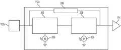
- FIG. 2illustrates a non-limiting example of the amplifier 112 a of FIG. 1 in greater detail. The same configuration may be used for the other amplifiers 112 n of FIG. 1 .
- the ultrasonic transducer 102 a and averaging circuit 114are also illustrated, while for simplicity the receive switch 110 a is omitted.
- the amplifier 112 ais implemented as a two-stage operational amplifier (“op-amp” for short).
- the first stage 202is coupled to the ultrasonic transducer 102 a .
- the second stage 204is coupled between the first stage 202 and the averaging circuit 114 .
- the second stage 204provides the output signal of the amplifier 112 a , in this non-limiting example.
- the first stage 202 and second stage 204each have a variable current source.
- the variable current source 203is provided for the first stage 202 and sinks a current I 1 .
- the variable current source 205is provided for the second stage 204 and sinks a current I 2 .
- the variable current sources 203 and 205are illustrated as distinct from the respective stages 202 and 204 , they may be considered part of the respective stages.
- the noise and linearity of the amplified signalmay be controlled independently.
- the noise of the amplifier 112 ais impacted primarily by the first stage 202 .
- the linearity of the amplifier 112 ais impacted primarily by the second stage 204 .
- the samemay be true for a multi-stage amplifier having two or more stages, such that the noise of the amplifier is impacted primarily by the first stage and the linearity of the amplifier is impacted primarily by the last stage.
- the noise and linearity of the amplified signalmay vary in importance during acquisition of an ultrasound signal, referred to herein as an acquisition period, the noise and linearity of the amplified signal may vary in importance.
- the amplifier 112 a of FIG. 2is designed to allow for independent and variable control of noise and linearity.
- the controlmay be provided via the variable current sources 203 and 205 .
- the variable current source 203may be controlled to sink a relatively small amount of current, while the current source 205 may be controlled to sink a relatively large amount of current.
- the second stage 204may operate to control the linearity of the amplified signal produced by the amplifier 112 a , while the first stage 202 may control the noise of the amplified signal 202 to a lesser extent than that to which it is capable.
- the current sunk by the variable current source 203may be increased while the current sunk by the variable current source 205 may be decreased.
- the first stage 202may operate to control the noise of the amplifier 112 a to a greater extent.
- the second stage 204may operate to control the linearity of the amplifier 112 a to a lesser extent.
- dynamic current biasing of the amplifier 112 a , and first stage 202 and second stage 204 more specifically,may be implemented to control the power, noise, and linearity characteristics of the amplifier during an acquisition period.
- the dynamic control of current sources 203 and 205may be achieved using a digital controller, an example being shown in FIG. 3A .
- the variable current sources 203 and 205may each include two or more programmable current settings. The greater the number of settings, the greater the control over the current sunk by the current sources 203 and 205 .
- the amplifier 112 aalso includes a variable feedback impedance 206 .
- the variable feedback impedanceis a variable RC feedback circuit.
- An example of the variable RC feedback circuitis illustrated in FIG. 3A and described in connection with that figure.
- the feedback impedancedetermines the transimpedance gain of the transimpedance amplifier, such that the input current signal may be converted into an output voltage of varying amplitude.
- an embodiment of the applicationprovides a multi-stage TIA having two or more independently controllable variable current sources, with a variable feedback impedance.
- the variable current sourcesmay allow for dynamic current biasing of the TIA, for example during an acquisition period.
- the power consumption, noise, and linearity of the amplifiermay be adjusted during the acquisition period.
- FIG. 3Ais a circuit diagram illustrating an implementation of the amplifier 112 a of FIG. 2 , according to a non-limiting embodiment of the present application.
- the amplifier 300has an input 302 and an output 304 .
- the input 302may be coupled to an ultrasonic transducer or a receive switch, as described previously in connection with FIGS. 1 and 2 , and may receive an electrical signal representing an ultrasound signal received by the ultrasonic transducer.
- the output 304may provide an amplified output signal of the amplifier 112 a , and may be coupled to an averaging circuit or other component to which it is desired to provide the amplified output signal.
- the amplifier 300includes a first stage 306 and a second stage 308 , which may be implementations of the first stage 202 and second stage 204 of FIG. 2 , respectively.
- the first stage 306includes an NMOS transistor 310 having a gate configured to receive the signal at input 302 .
- PMOS transistor 312 and PMOS transistor 314have their gates coupled, with the drain of PMOS transistor 312 coupled to the drain of NMOS transistor 310 .
- the gate of transistor 312is coupled to its drain.
- Transistors 312 and 314are also configured to receive a power supply voltage VDDA.
- the first stage 306further comprises NMOS transistor 316 having a gate configured to receive a bias voltage provided by an RC circuit.
- the RC circuitincludes two resistors, of value R, with a capacitor C b coupled in parallel with one of the resistors.
- the other resistorreceives the power supply voltage VDDA.
- the drain of PMOS transistor 314is coupled to the drain of NMOS transistor 316 .
- An example value for Ris 50 kOhm and an example value for C b is 10 pF, although alternatives for both are possible, such as +/ ⁇ 20% of those values listed, or any value or range of values within such ranges.
- the second stage 308includes a PMOS transistor 318 configured to receive the output of the first stage 306 .
- the gate of PMOS transistor 318is coupled to a node between transistors 314 and 316 of the first stage 306 .
- the source of PMOS transistor 318receives VDDA.
- a variable impedance circuit 320is also provided in the second stage 308 .
- the variable impedance circuit 320includes a variable capacitor C C in series with a variable resistor R Z , and thus is a variable RC circuit in this embodiment.
- Variable impedance circuit 320may provide stable operation of the amplifier 300 when the gain of the amplifier, or the currents of the currents sources, are varied.
- variable impedance circuitmay be provided to maintain stable operation of the amplifier 300 for all the current magnitudes sunk by the variable current sources 321 and 325 . That is, the values of C C and R Z may be adjusted during operation of the amplifier 300 to account for the different current settings programmed by the digital controller 330
- variable current sourceis provided for each of the stages 306 and 308 .
- the variable current source 321 for the first stage 306includes three parallel connected current sources 322 a , 322 b , and 322 c .
- Current source 322 asinks a current I A
- current source 322 bsinks a current 2 I A
- current source 322 csinks a current 4 I A .
- the current sources 322 a - 322 care coupled to the first stage 306 by respective switches 324 a , 324 b , and 324 c , which effectively provides 3 bits (8 states) of control of the current.
- the current I Amay equal 100 microAmps or +/ ⁇ 20% of that value, or any value or range of values within such ranges, as examples.
- the variable current source 325 for the second stage 308includes three parallel connected current sources 326 a , 326 b , and 326 c .
- Current source 326 asinks a current I B
- current source 326 bsinks a current 2 I B
- current source 326 csinks a current 4 I B .
- the current sources 326 a - 326 care coupled to the second stage 308 by respective switches 328 a , 328 b , and 328 c , which effectively provides 3 bits (8 states) of control of the current.
- the current I Bmay equal 50 microAmps or +/ ⁇ 20% of that value, or any value or range of values within such ranges, as examples.
- variable current sourceseach include three parallel-coupled current sources
- variable current sourcesmay be implemented in various manners, including alternative manners to those illustrated. For example, more or fewer than three current sources may be coupled in parallel to create a variable current source. Also, the magnitudes of the current sources may be different than those illustrated in FIG. 3A . Any suitable magnitudes may be provided to allow for operation over a desired range of currents.
- a digital controller 330is provided to control operation of the variable current sources 321 and 325 .
- the digital controllerprovides control signals to (digitally) program the currents of the variable current sources.
- the digital controller 330provides one or more switching signals S 1 to control operation of the switches 324 a - 324 c , and one or more switching signals S 2 to control operation of the switches 328 a - 328 c .
- the amount of current sunk by the variable current sourcesmay be varied independently during operation of the amplifier 300 , for example during an acquisition period.
- the digital controller 330decreases the current sunk by variable current source 325 during the acquisition period and increases the current sunk by variable current source 321 during the acquisition period through suitable operation of the switching signals S 1 and S 2 .
- the digital controller 330may be any suitable type of controller.
- the digital controllermay include integrated circuitry.
- the digital controller 330may include or be part of an application specific integrated circuit (ASIC).
- ASICapplication specific integrated circuit
- the digital controller 330may not be specific to the amplifier 300 .
- a digital controllermay be provided to control more than one component of the circuit of FIG. 1 , one of which may be the amplifiers 112 a . . . 112 n.
- the amplifier 300further includes a variable feedback impedance 332 formed by variable capacitor C f and variable resistor R f .
- the capacitor C f and resistor R fmay be coupled between the output 304 and the input 302 , and may be in parallel with each other.
- the variable feedback impedance 332may control the gain of the amplifier 300 .
- the values of C f and R fmay be adjusted to vary the amplifier's gain.
- variable feedback impedance 332 and the variable impedance circuit 320may be controlled in any suitable manner.
- the digital controller 330may set the values of the feedback impedances. However, alternatives manners of control may be used.
- first and second stagesmay include more, fewer, or different components than those illustrated.
- FIG. 3Bis a circuit diagram of an implementation of the variable impedance circuit 320 of FIG. 3A , according to a non-limiting embodiment of the present application.
- the variable impedance circuit 320includes a number of switches 340 a . . . 340 n configured in parallel and configured to receive respective control signals SWa . . . SWn.
- the digital controller 330may provide the control signals SWa . . . SWn, although alternatives may be used.
- Each switchis coupled in series with a respective capacitor C C and resistor R Z .
- the impedance of the variable impedance circuit 320may be adjusted during an acquisition period through suitable provision of the control signals SWa . . . SWn.
- any suitable number of parallel signal pathsmay be provided, so that the illustrated example of two parallel signal paths is non-limiting.
- the number of parallel signal paths and the capacitance and resistive values providedmay be selected to provide sufficient control of the feedback impedance to account for the variable operation of the amplifier across the range of operating scenarios resulting from the variation of the variable current sources.
- appropriate settings of variable impedance circuit 320may be selected.
- a lookup tablemay be utilized to determine the appropriate settings of variable impedance circuit 320 based on a given gain set by variable feedback impedance 332 .
- C C and R Zmay be selected to provide desired operating characteristics.
- R Zmay be equal to 3 kOhms in some embodiments, and C C may be equal to 300 fF.
- Alternatives for bothare possible. For example, they may assume values within +/ ⁇ 20% of those values listed, or any value or range of values within such ranges.
- FIG. 3Cis a circuit diagram of an implementation of the variable impedance circuit 332 of FIG. 3A , according to a non-limiting embodiment of the present application.
- the variable impedance circuit 332includes a number of complementary switches 350 a , 350 b . . . 350 n . Each switch receives respective control signals SLa, SLb . . . SLn and SHa, SHb . . . SHn.
- the control signalsmay be provided by the digital controller 330 in some embodiments, although alternatives may be used.
- the complementary switchesare coupled to respective parallel-connected RC circuits C f , R f . While three complementary switches are shown in FIG. 3C , any suitable number may be provided to allow for sufficient control of the gain of the amplifier 300 .
- C f and R fmay be selected to provide desired operating characteristics.
- R fmay be equal to 180 kOhms in some embodiments, and C f may be equal to 84 fF.
- Alternatives for bothare possible. For example, they may assume values within +/ ⁇ 20% of those values listed, or any value or range of values within such ranges.
- FIG. 4is a graph illustrating the behavior of two variable current sources of a variable current amplifier during an acquisition period, as may be implemented by the amplifier of FIGS. 2 and 3A , which again may be a TIA.
- the illustrated behaviormay be implemented by the variable current sources 203 and 205 of FIG. 2 .
- the x-axisrepresents time during an acquisition period, ranging from t 0 to t 8 .
- the y-axisrepresents the current of the current source, having values ranging from I 0 to I 8 .
- the values of t 0 -t 8 and I 0 -I 8may be any suitable values for operation of a given ultrasound system, as the various aspects described herein are not limited to implementation of any specific time or current values.
- the number of time intervals during an acquisition periodis non-limiting, as more or fewer may be implemented.
- the number of current values which may be implementedis non-limiting, as more or fewer may be implemented.
- Curve 402represents the current of a variable current source of a second stage of a variable current amplifier. Thus, curve 402 may represent the current of current source 205 of FIG. 2 .
- Curve 404represents the current of a variable current source of a first stage of the variable current amplifier. Thus, curve 404 may represent the current of current source 203 of FIG. 2 .
- FIG. 4illustrates that the currents of the first and second stages of the variable current amplifier move in opposing directions during the acquisition period. That is, curve 402 decreases moving from time t 0 to time t 8 , while curve 404 increases during the same time.
- the first and second stages of the variable current amplifiermay impact different characteristics of the variable current amplifier behavior, such as noise and linearity.
- the impact of the two stages of the variable current amplifiermay vary during the acquisition period. That is, the impact of the second stage may be greater initially, up to time t 4 , while the impact of the first stage may be greater thereafter, from time t 4 to time t 8 .
- the currents of the two stages of a two-stage op-amp being used to implement a variable current amplifiermay be controlled by digital codes.
- the current values I 0 -I 7 of FIG. 4may correspond to different digital codes set by a digital controller, such as digital controller 330 of FIG. 3A .
- FIG. 4illustrates that the currents in the first and second stages of the amplifier switch at the same times, not all embodiments are limited in this respect.
- the current in the second stagecould be adjusted at times offset from those at which the current in the first stage is adjusted.
- the currents of the two stagesneed not be adjusted the same number of times during an acquisition period.
- an aspect of the present applicationprovides an amplifier with a variable current source which is controlled to adjust the noise of the amplifier during an acquisition period.
- FIG. 5illustrates an example of such operation.
- the voltage of an electrical signal 502 output by an ultrasonic transducer, and thus representing a detected ultrasound signal,is illustrated as a function of time.
- Dashed line 504represents the noise floor of an amplifier used to amplify the electrical signal 502 , and may correspond to the noise floor of an amplifier of the types described herein, such as amplifier 112 a .
- the noise floor of the amplifieris decreased.
- Such a decrease in the noise floormay be achieved by controlling the current sunk by a variable current source of the amplifier in the manner described previously herein.
- the variable current source 203may be increased during the acquisition period to decrease the noise floor of the amplifier 112 a .
- the noise floormay be adjusted to a level which provides an acceptable signal-to-noise ratio (SNR).
- SNRsignal-to-noise ratio
- FIG. 5also illustrates a constant noise floor 506 . It can be seen that while the constant noise floor 506 is at the same level as dashed line 504 toward the end of the acquisition period, the constant noise floor 506 is lower than the value of the dashed line 504 up to that point. As has been described herein, the noise level of an amplifier may be dependent on the current consumed by the amplifier, and in such situations it should be appreciated that operating with a constant noise floor 506 requires significantly more current (and therefore power) than operating according to dashed line 504 . Thus, aspects of the present application providing for a variable current amplifier to amplify ultrasound signals may provide substantial power savings compared to amplifiers operating with a constant noise level.
- the amount of power savingsmay be significant.
- the amplifiers 112 a . . . 112 nmay consume a significant amount of power.
- the amplifiers 112 a . . . 112 nmay consume more power than any other components of the circuit 100 . Accordingly, reducing the power consumption of the amplifiers 112 a . . . 112 n may provide a significant reduction in power of the circuit 100 .
- utilizing variable current amplifiers of the types described hereinmay provide up to a 25% power reduction, up to a 40% power reduction, up to a 50% power reduction, or any range or value within such ranges, in terms of the operation of the amplifier.
- the resulting power reduction for the circuit 100may be up to 10%, up to 20%, up to 25%, or any range or value within such ranges.
- certain embodiments described hereinhave focused on two-stage amplifiers.
- the techniques described hereinmay apply to multi-stage amplifiers having two or more stages.
- the first stagemay predominantly control the noise of the amplifier, while the last stage may predominantly control the linearity of the amplifier.
- some aspectsmay be embodied as one or more methods.
- the acts performed as part of the method(s)may be ordered in any suitable way. Accordingly, embodiments may be constructed in which acts are performed in an order different than illustrated, which may include performing some acts simultaneously, even though shown as sequential acts in illustrative embodiments.
- the phrase “at least one,” in reference to a list of one or more elements,should be understood to mean at least one element selected from any one or more of the elements in the list of elements, but not necessarily including at least one of each and every element specifically listed within the list of elements and not excluding any combinations of elements in the list of elements.
- the term “between” used in a numerical contextis to be inclusive unless indicated otherwise.
- “between A and B”includes A and B unless indicated otherwise.
Landscapes
- Engineering & Computer Science (AREA)
- Health & Medical Sciences (AREA)
- Life Sciences & Earth Sciences (AREA)
- Power Engineering (AREA)
- Physics & Mathematics (AREA)
- Public Health (AREA)
- Animal Behavior & Ethology (AREA)
- Veterinary Medicine (AREA)
- General Health & Medical Sciences (AREA)
- Biophysics (AREA)
- Pathology (AREA)
- Biomedical Technology (AREA)
- Heart & Thoracic Surgery (AREA)
- Medical Informatics (AREA)
- Molecular Biology (AREA)
- Surgery (AREA)
- Remote Sensing (AREA)
- General Physics & Mathematics (AREA)
- Computer Networks & Wireless Communication (AREA)
- Radar, Positioning & Navigation (AREA)
- Nuclear Medicine, Radiotherapy & Molecular Imaging (AREA)
- Radiology & Medical Imaging (AREA)
- Amplifiers (AREA)
- Ultra Sonic Daignosis Equipment (AREA)
- Transducers For Ultrasonic Waves (AREA)
- Computer Vision & Pattern Recognition (AREA)
Abstract
Description
Claims (20)
Priority Applications (4)
| Application Number | Priority Date | Filing Date | Title |
|---|---|---|---|
| US16/178,117US11128267B2 (en) | 2015-12-02 | 2018-11-01 | Trans-impedance amplifier for ultrasound device and related apparatus and methods |
| US17/331,538US11863133B2 (en) | 2015-12-02 | 2021-05-26 | Trans-impedance amplifier for ultrasound device and related apparatus and methods |
| US18/389,875US12231097B2 (en) | 2015-12-02 | 2023-12-20 | Trans-impedance amplifier for ultrasound device and related apparatus and methods |
| US19/045,765US20250183859A1 (en) | 2015-12-02 | 2025-02-05 | Trans-impedance amplifier for ultrasound device and related apparatus and methods |
Applications Claiming Priority (2)
| Application Number | Priority Date | Filing Date | Title |
|---|---|---|---|
| US14/957,395US10187020B2 (en) | 2015-12-02 | 2015-12-02 | Trans-impedance amplifier for ultrasound device and related apparatus and methods |
| US16/178,117US11128267B2 (en) | 2015-12-02 | 2018-11-01 | Trans-impedance amplifier for ultrasound device and related apparatus and methods |
Related Parent Applications (1)
| Application Number | Title | Priority Date | Filing Date |
|---|---|---|---|
| US14/957,395ContinuationUS10187020B2 (en) | 2015-12-02 | 2015-12-02 | Trans-impedance amplifier for ultrasound device and related apparatus and methods |
Related Child Applications (1)
| Application Number | Title | Priority Date | Filing Date |
|---|---|---|---|
| US17/331,538ContinuationUS11863133B2 (en) | 2015-12-02 | 2021-05-26 | Trans-impedance amplifier for ultrasound device and related apparatus and methods |
Publications (2)
| Publication Number | Publication Date |
|---|---|
| US20190140603A1 US20190140603A1 (en) | 2019-05-09 |
| US11128267B2true US11128267B2 (en) | 2021-09-21 |
Family
ID=58797744
Family Applications (5)
| Application Number | Title | Priority Date | Filing Date |
|---|---|---|---|
| US14/957,395Active2037-02-14US10187020B2 (en) | 2015-12-02 | 2015-12-02 | Trans-impedance amplifier for ultrasound device and related apparatus and methods |
| US16/178,117Active2036-12-14US11128267B2 (en) | 2015-12-02 | 2018-11-01 | Trans-impedance amplifier for ultrasound device and related apparatus and methods |
| US17/331,538Active2036-09-16US11863133B2 (en) | 2015-12-02 | 2021-05-26 | Trans-impedance amplifier for ultrasound device and related apparatus and methods |
| US18/389,875ActiveUS12231097B2 (en) | 2015-12-02 | 2023-12-20 | Trans-impedance amplifier for ultrasound device and related apparatus and methods |
| US19/045,765PendingUS20250183859A1 (en) | 2015-12-02 | 2025-02-05 | Trans-impedance amplifier for ultrasound device and related apparatus and methods |
Family Applications Before (1)
| Application Number | Title | Priority Date | Filing Date |
|---|---|---|---|
| US14/957,395Active2037-02-14US10187020B2 (en) | 2015-12-02 | 2015-12-02 | Trans-impedance amplifier for ultrasound device and related apparatus and methods |
Family Applications After (3)
| Application Number | Title | Priority Date | Filing Date |
|---|---|---|---|
| US17/331,538Active2036-09-16US11863133B2 (en) | 2015-12-02 | 2021-05-26 | Trans-impedance amplifier for ultrasound device and related apparatus and methods |
| US18/389,875ActiveUS12231097B2 (en) | 2015-12-02 | 2023-12-20 | Trans-impedance amplifier for ultrasound device and related apparatus and methods |
| US19/045,765PendingUS20250183859A1 (en) | 2015-12-02 | 2025-02-05 | Trans-impedance amplifier for ultrasound device and related apparatus and methods |
Country Status (10)
| Country | Link |
|---|---|
| US (5) | US10187020B2 (en) |
| EP (1) | EP3384687B1 (en) |
| JP (1) | JP6850293B2 (en) |
| KR (1) | KR20180089465A (en) |
| CN (1) | CN108370484B (en) |
| AU (2) | AU2016364736A1 (en) |
| CA (1) | CA3006064A1 (en) |
| ES (1) | ES2879688T3 (en) |
| TW (1) | TWI715688B (en) |
| WO (1) | WO2017095981A1 (en) |
Cited By (1)
| Publication number | Priority date | Publication date | Assignee | Title |
|---|---|---|---|---|
| US12231097B2 (en) | 2015-12-02 | 2025-02-18 | Bfly Operations, Inc. | Trans-impedance amplifier for ultrasound device and related apparatus and methods |
Families Citing this family (26)
| Publication number | Priority date | Publication date | Assignee | Title |
|---|---|---|---|---|
| US9492144B1 (en) | 2015-12-02 | 2016-11-15 | Butterfly Network, Inc. | Multi-level pulser and related apparatus and methods |
| US10175347B2 (en) | 2015-12-02 | 2019-01-08 | Butterfly Network, Inc. | Ultrasound receiver circuitry and related apparatus and methods |
| US10082488B2 (en) | 2015-12-02 | 2018-09-25 | Butterfly Network, Inc. | Time gain compensation circuit and related apparatus and methods |
| US9705518B2 (en) | 2015-12-02 | 2017-07-11 | Butterfly Network, Inc. | Asynchronous successive approximation analog-to-digital converter and related methods and apparatus |
| US10624613B2 (en) | 2016-01-15 | 2020-04-21 | Butterfly Network, Inc. | Ultrasound signal processing circuitry and related apparatus and methods |
| US10009036B2 (en)* | 2016-09-09 | 2018-06-26 | Samsung Electronics Co., Ltd | System and method of calibrating input signal to successive approximation register (SAR) analog-to-digital converter (ADC) in ADC-assisted time-to-digital converter (TDC) |
| TW201905487A (en)* | 2017-06-20 | 2019-02-01 | 美商蝴蝶網路公司 | Amplifier with built-in time gain compensation for ultrasonic applications |
| CN110771044A (en) | 2017-06-20 | 2020-02-07 | 蝴蝶网络有限公司 | Conversion of analog signals to digital signals in ultrasound devices |
| CA3064584A1 (en) | 2017-06-20 | 2018-12-27 | Butterfly Network, Inc. | Single-ended trans-impedance amplifier (tia) for ultrasound device |
| WO2018236778A1 (en)* | 2017-06-20 | 2018-12-27 | Butterfly Network, Inc. | MULTI-STAGE TRANSMITTED AMPLIFIER (TIA) FOR AN ULTRASONIC DEVICE |
| JP7128649B2 (en)* | 2018-04-27 | 2022-08-31 | 富士フイルムヘルスケア株式会社 | Ultrasound diagnostic equipment and probe used therefor |
| EP3788798B1 (en) | 2018-05-03 | 2023-07-05 | BFLY Operations, Inc. | Ultrasonic transducers with pressure ports |
| JP7128693B2 (en)* | 2018-09-10 | 2022-08-31 | 富士フイルムヘルスケア株式会社 | Ultrasound diagnostic equipment and probe used therefor |
| TW202034624A (en) | 2018-11-09 | 2020-09-16 | 美商蝴蝶網路公司 | Trans-impedance amplifier (tia) for ultrasound devices |
| CN110057921B (en)* | 2019-04-11 | 2021-07-02 | 成都华芯微医疗科技有限公司 | Three-dimensional ultrasonic imaging system |
| US11558062B2 (en)* | 2019-07-25 | 2023-01-17 | Bfly Operations, Inc. | Methods and apparatuses for turning on and off an ADC driver in an ultrasound device |
| WO2021055721A1 (en) | 2019-09-19 | 2021-03-25 | Butterfly Network, Inc. | Symmetric receiver switch for ultrasound devices |
| AU2020351768A1 (en) | 2019-09-27 | 2022-05-12 | Bfly Operations, Inc. | Methods and apparatuses for monitoring fetal heartbeat and uterine contraction signals |
| WO2021211822A1 (en) | 2020-04-16 | 2021-10-21 | Bfly Operations, Inc. | Methods and circuitry for built-in self-testing of circuitry and/or transducers in ultrasound devices |
| US11808897B2 (en) | 2020-10-05 | 2023-11-07 | Bfly Operations, Inc. | Methods and apparatuses for azimuthal summing of ultrasound data |
| FR3118549A1 (en)* | 2020-12-28 | 2022-07-01 | Easii Ic | Programmable transimpedance amplifier |
| US11504093B2 (en)* | 2021-01-22 | 2022-11-22 | Exo Imaging, Inc. | Equalization for matrix based line imagers for ultrasound imaging systems |
| US12156762B2 (en) | 2021-04-01 | 2024-12-03 | Bfly Operations, Inc. | Apparatuses and methods for configuring ultrasound devices |
| WO2023133100A2 (en)* | 2022-01-04 | 2023-07-13 | Bfly Operations, Inc. | Ultrasound devices configured to change from default mode to power save mode and methods associated with the same |
| KR102404283B1 (en)* | 2022-02-15 | 2022-06-02 | (주)에프와이디 | Readout circuit for microphone sensor |
| CN117714940B (en)* | 2024-02-05 | 2024-04-19 | 江西斐耳科技有限公司 | AUX power amplifier link noise floor optimization method and system |
Citations (76)
| Publication number | Priority date | Publication date | Assignee | Title |
|---|---|---|---|---|
| US3274821A (en) | 1962-10-24 | 1966-09-27 | Automation Ind Inc | Ultrasonic testing apparatus having improved resolution |
| US3367173A (en) | 1964-02-21 | 1968-02-06 | Haffrel Instr Inc | Device for sonic and ultrasonic internal scanning of solid and fluid media |
| US3787803A (en) | 1972-11-29 | 1974-01-22 | Raytheon Co | High performance meter depth sounder for automatically indicating depth without manual adjustment |
| US4098130A (en) | 1977-03-11 | 1978-07-04 | General Electric Company | Energy reflection flaw detection system |
| US4504747A (en) | 1983-11-10 | 1985-03-12 | Motorola, Inc. | Input buffer circuit for receiving multiple level input voltages |
| US4512350A (en) | 1983-04-22 | 1985-04-23 | Irex Corporation | Time gain control signal generator for an ultrasonic diagnostic system |
| US4783819A (en) | 1986-02-18 | 1988-11-08 | U.S. Philips Corporation | Automatically controlled amplifier arrangement |
| US4819071A (en) | 1987-04-17 | 1989-04-04 | Olympus Optical Co., Ltd. | Solid state imaging apparatus |
| US5057719A (en) | 1990-06-27 | 1991-10-15 | Sverdrup Technology, Inc. | Passively forced current sharing among transistors |
| JPH0462494A (en) | 1990-06-29 | 1992-02-27 | Matsushita Electric Ind Co Ltd | Ultrasonic body sensing device |
| JPH0685585A (en) | 1992-08-31 | 1994-03-25 | Sony Corp | Gain control type amplifier circuit |
| FR2726408A1 (en) | 1994-10-26 | 1996-05-03 | Suisse Electronique Microtech | Impedance transformer amplifier esp. for heavy capacitive load |
| US5622177A (en) | 1993-07-08 | 1997-04-22 | Siemens Aktiengesellschaft | Ultrasound imaging system having a reduced number of lines between the base unit and the probe |
| US5844445A (en) | 1995-10-27 | 1998-12-01 | Hitachi, Ltd. | Feedback type pre-amplifier |
| JPH11261764A (en) | 1998-03-09 | 1999-09-24 | Ricoh Co Ltd | Variable gain amplifier |
| JP2002125969A (en) | 2000-10-12 | 2002-05-08 | Medison Co Ltd | Pulse generating circuit and electric signal integrated circuit in ultrasonic diagnostic system |
| US6404281B1 (en) | 2000-11-14 | 2002-06-11 | Sirenza Microdevices, Inc. | Wide dynamic range transimpedance amplifier |
| US20050203392A1 (en) | 2004-02-26 | 2005-09-15 | Siemens Medical Solutions Usa, Inc. | Receive circuit for minimizing channels in ultrasound imaging |
| US20050206412A1 (en) | 2004-03-16 | 2005-09-22 | Micrel, Incorporated | High frequency differential power amplifier |
| JP2006061695A (en) | 2004-08-27 | 2006-03-09 | General Electric Co <Ge> | System and method for adjusting gain in ultrasound probe |
| CN1832338A (en) | 2005-03-12 | 2006-09-13 | 安捷伦科技有限公司 | Transimpedance amplifier with signal amplification circuit that performs power signal regulation |
| JP2006345481A (en) | 2005-05-12 | 2006-12-21 | Matsushita Electric Ind Co Ltd | Amplifying device and optical disk drive device |
| US20070001764A1 (en) | 2005-06-30 | 2007-01-04 | Yunteng Huang | Signal dependent biasing scheme for an amplifier |
| US7176720B1 (en) | 2003-03-14 | 2007-02-13 | Cypress Semiconductor Corp. | Low duty cycle distortion differential to CMOS translator |
| US7256654B2 (en) | 2005-04-12 | 2007-08-14 | Raytheon Company | Amplifying a signal using a current shared power amplifier |
| US20070242567A1 (en) | 2005-12-07 | 2007-10-18 | Daft Christopher M | Multi-dimensional CMUT array with integrated beamformation |
| US20070287923A1 (en) | 2006-05-15 | 2007-12-13 | Charles Adkins | Wrist plethysmograph |
| US7313053B2 (en) | 2003-03-06 | 2007-12-25 | General Electric Company | Method and apparatus for controlling scanning of mosaic sensor array |
| JP2008042521A (en) | 2006-08-07 | 2008-02-21 | Matsushita Electric Ind Co Ltd | Current glitch reduction circuit |
| EP1932479A1 (en) | 2005-10-03 | 2008-06-18 | Olympus Medical Systems Corp. | Electrostatic capacity type ultrasonic oscillation device and its control method |
| US20080225639A1 (en) | 2007-03-14 | 2008-09-18 | Kabushiki Kaisha Toshiba | Ultrasonic imaging apparatus |
| US7449958B1 (en) | 2005-08-17 | 2008-11-11 | Marvell International Ltd. | Open loop DC control for a transimpedance feedback amplifier |
| US20090140810A1 (en) | 2007-12-04 | 2009-06-04 | Chang Sun Kim | Variable Gain Amplifier |
| US20090250729A1 (en) | 2004-09-15 | 2009-10-08 | Lemmerhirt David F | Capacitive micromachined ultrasonic transducer and manufacturing method |
| US7605660B1 (en)* | 2007-11-12 | 2009-10-20 | Rf Micro Devices, Inc. | Linear multi-stage transimpedance amplifier |
| US20090289716A1 (en) | 2008-05-23 | 2009-11-26 | Freescale Semiconductor, Inc. | Amplifier circuit having dynamically biased configuration |
| US20100026343A1 (en) | 2008-07-31 | 2010-02-04 | Jianan Yang | Clocked single power supply level shifter |
| JP2010022761A (en) | 2008-07-24 | 2010-02-04 | Ge Medical Systems Global Technology Co Llc | Ultrasonic imaging apparatus |
| JP2010034855A (en) | 2008-07-29 | 2010-02-12 | Sharp Corp | Automatic gain control circuit, tuner, television receiver, and set top box |
| JP2010042146A (en) | 2008-08-13 | 2010-02-25 | Ge Medical Systems Global Technology Co Llc | Ultrasonic imaging apparatus |
| US20100152587A1 (en) | 2008-12-17 | 2010-06-17 | General Electric Company | Systems and methods for operating a two-dimensional transducer array |
| JP2010167167A (en) | 2009-01-26 | 2010-08-05 | Fujifilm Corp | Optical ultrasonic tomographic imaging apparatus and optical ultrasonic tomographic imaging method |
| JP2010193329A (en) | 2009-02-20 | 2010-09-02 | Hitachi Ltd | Semiconductor integrated circuit device |
| US20100237807A1 (en) | 2009-03-18 | 2010-09-23 | Lemmerhirt David F | System and method for biasing cmut elements |
| US20100317972A1 (en) | 2009-06-16 | 2010-12-16 | Charles Edward Baumgartner | Ultrasound transducer with improved acoustic performance |
| US20110055447A1 (en) | 2008-05-07 | 2011-03-03 | Signostics Limited | Docking system for medical diagnostic scanning using a handheld device |
| US8089309B2 (en) | 2009-06-26 | 2012-01-03 | Bae Systems Information And Electronic Systems Integration Inc. | Transimpedance amplifier input stage mixer |
| US20120262221A1 (en) | 2009-12-30 | 2012-10-18 | Stmicroelectronics S.R.L. | Low voltage isolation switch, in particular for a transmission channel for ultrasound applications |
| JP2012528685A (en) | 2009-06-02 | 2012-11-15 | サンプリファイ システムズ インコーポレイテッド | Ultrasonic signal compression |
| US20130064043A1 (en) | 2011-03-04 | 2013-03-14 | Georgia Tech Research Corporation | Compact, energy-efficient ultrasound imaging probes using cmut arrays with integrated electronics |
| US20130106485A1 (en) | 2011-10-28 | 2013-05-02 | Texas Instruments Incorporated | Level shifter |
| US20130187697A1 (en) | 2012-01-23 | 2013-07-25 | Ben Choy | Multi-level high voltage pulser integrated circuit using low voltage mosfets |
| US20130314154A1 (en) | 2012-05-28 | 2013-11-28 | Sony Corporation | Signal processing apparatus and method and communication apparatus |
| CN103607130A (en) | 2013-11-26 | 2014-02-26 | 徐州中矿大传动与自动化有限公司 | Three-level pulse extension control method and three-level pulse extension device of DSPACE based on FPGA |
| US8662395B2 (en) | 2008-10-14 | 2014-03-04 | Dolphitech As | Ultrasonic imaging apparatus for reading and decoding machine-readable matrix symbols |
| US20140078866A1 (en) | 2012-04-27 | 2014-03-20 | Panasonic Corporation | Beamforming method and ultrasonic diagnostic apparatus |
| US8766721B1 (en) | 2012-12-31 | 2014-07-01 | Texas Instruments Incorporated | Time gain compensation |
| US20140288428A1 (en) | 2013-03-15 | 2014-09-25 | Butterfly Network, Inc. | Monolithic ultrasonic imaging devices, systems and methods |
| US8852103B2 (en) | 2011-10-17 | 2014-10-07 | Butterfly Network, Inc. | Transmissive imaging and related apparatus and methods |
| JP2014198234A (en) | 2013-03-09 | 2014-10-23 | キヤノン株式会社 | Detection circuit, driving method, probe, and subject information acquiring apparatus |
| JP2014204195A (en) | 2013-04-02 | 2014-10-27 | 富士通株式会社 | Gain control circuit and ultrasonic image device |
| TW201445554A (en) | 2013-04-04 | 2014-12-01 | Semiconductor Energy Lab | Pulse generation circuit and semiconductor device |
| US20150032002A1 (en) | 2013-07-23 | 2015-01-29 | Butterfly Network, Inc. | Interconnectable ultrasound transducer probes and related methods and apparatus |
| JP2015033123A (en) | 2013-08-07 | 2015-02-16 | ルネサスエレクトロニクス株式会社 | Semiconductor device |
| JP2015056890A (en) | 2013-09-12 | 2015-03-23 | 富士通セミコンダクター株式会社 | Mixed signal circuit |
| US20150297193A1 (en) | 2014-04-18 | 2015-10-22 | Butterfly Network, Inc. | Ultrasonic Imaging Compression Methods and Apparatus |
| US9229097B2 (en) | 2014-04-18 | 2016-01-05 | Butterfly Network, Inc. | Architecture of single substrate ultrasonic imaging devices, related apparatuses, and methods |
| US9473136B1 (en) | 2015-12-02 | 2016-10-18 | Butterfly Network, Inc. | Level shifter and related methods and apparatus |
| US9492144B1 (en) | 2015-12-02 | 2016-11-15 | Butterfly Network, Inc. | Multi-level pulser and related apparatus and methods |
| US20170160388A1 (en) | 2015-12-02 | 2017-06-08 | Butterfly Network, Inc. | Ultrasound receiver circuitry and related apparatus and methods |
| US20170160239A1 (en) | 2015-12-02 | 2017-06-08 | Butterfly Network, Inc. | Time gain compensation circuit and related apparatus and methods |
| US20170163225A1 (en) | 2015-12-02 | 2017-06-08 | Butterfly Network, Inc. | Trans-impedance amplifier for ultrasound device and related apparatus and methods |
| US20170163276A1 (en) | 2015-12-02 | 2017-06-08 | Butterfly Network, Inc. | Asynchronous successive approximation analog-to-digital converter and related methods and apparatus |
| US20170202541A1 (en) | 2016-01-15 | 2017-07-20 | Butterfly Network, Inc. | Ultrasound signal processing circuitry and related apparatus and methods |
| US20190336111A1 (en) | 2016-09-13 | 2019-11-07 | Butterfly Network, Inc. | Analog-to-digital drive circuitry having built-in time gain compensation functionality for ultrasound applications |
| US20200150252A1 (en) | 2018-11-09 | 2020-05-14 | Butterfly Network, Inc. | Trans-impedance amplifier (tia) for ultrasound devices |
Family Cites Families (4)
| Publication number | Priority date | Publication date | Assignee | Title |
|---|---|---|---|---|
| JPH0685585U (en) | 1993-05-11 | 1994-12-06 | 吉晃 西村 | Remote control device |
| US5942940A (en) | 1997-07-21 | 1999-08-24 | International Business Machines Corporation | Low voltage CMOS differential amplifier |
| WO2006130499A2 (en)* | 2005-05-27 | 2006-12-07 | Cidra Corporation | An apparatus and method for fiscal measuring of an aerated fluid |
| JP6205261B2 (en) | 2013-12-13 | 2017-09-27 | ルネサスエレクトロニクス株式会社 | Semiconductor device |
- 2015
- 2015-12-02USUS14/957,395patent/US10187020B2/enactiveActive
- 2016
- 2016-12-01AUAU2016364736Apatent/AU2016364736A1/ennot_activeAbandoned
- 2016-12-01WOPCT/US2016/064314patent/WO2017095981A1/ennot_activeCeased
- 2016-12-01EPEP16871463.2Apatent/EP3384687B1/enactiveActive
- 2016-12-01CACA3006064Apatent/CA3006064A1/enactivePending
- 2016-12-01KRKR1020187018520Apatent/KR20180089465A/ennot_activeCeased
- 2016-12-01ESES16871463Tpatent/ES2879688T3/enactiveActive
- 2016-12-01JPJP2018528646Apatent/JP6850293B2/enactiveActive
- 2016-12-01CNCN201680070174.2Apatent/CN108370484B/enactiveActive
- 2016-12-01TWTW105139673Apatent/TWI715688B/ennot_activeIP Right Cessation
- 2018
- 2018-11-01USUS16/178,117patent/US11128267B2/enactiveActive
- 2021
- 2021-05-03AUAU2021202768Apatent/AU2021202768A1/ennot_activeAbandoned
- 2021-05-26USUS17/331,538patent/US11863133B2/enactiveActive
- 2023
- 2023-12-20USUS18/389,875patent/US12231097B2/enactiveActive
- 2025
- 2025-02-05USUS19/045,765patent/US20250183859A1/enactivePending
Patent Citations (97)
| Publication number | Priority date | Publication date | Assignee | Title |
|---|---|---|---|---|
| US3274821A (en) | 1962-10-24 | 1966-09-27 | Automation Ind Inc | Ultrasonic testing apparatus having improved resolution |
| US3367173A (en) | 1964-02-21 | 1968-02-06 | Haffrel Instr Inc | Device for sonic and ultrasonic internal scanning of solid and fluid media |
| US3787803A (en) | 1972-11-29 | 1974-01-22 | Raytheon Co | High performance meter depth sounder for automatically indicating depth without manual adjustment |
| US4098130A (en) | 1977-03-11 | 1978-07-04 | General Electric Company | Energy reflection flaw detection system |
| US4512350A (en) | 1983-04-22 | 1985-04-23 | Irex Corporation | Time gain control signal generator for an ultrasonic diagnostic system |
| US4504747A (en) | 1983-11-10 | 1985-03-12 | Motorola, Inc. | Input buffer circuit for receiving multiple level input voltages |
| US4783819A (en) | 1986-02-18 | 1988-11-08 | U.S. Philips Corporation | Automatically controlled amplifier arrangement |
| US4819071A (en) | 1987-04-17 | 1989-04-04 | Olympus Optical Co., Ltd. | Solid state imaging apparatus |
| US5057719A (en) | 1990-06-27 | 1991-10-15 | Sverdrup Technology, Inc. | Passively forced current sharing among transistors |
| JPH0462494A (en) | 1990-06-29 | 1992-02-27 | Matsushita Electric Ind Co Ltd | Ultrasonic body sensing device |
| JPH0685585A (en) | 1992-08-31 | 1994-03-25 | Sony Corp | Gain control type amplifier circuit |
| US5622177A (en) | 1993-07-08 | 1997-04-22 | Siemens Aktiengesellschaft | Ultrasound imaging system having a reduced number of lines between the base unit and the probe |
| FR2726408A1 (en) | 1994-10-26 | 1996-05-03 | Suisse Electronique Microtech | Impedance transformer amplifier esp. for heavy capacitive load |
| US5844445A (en) | 1995-10-27 | 1998-12-01 | Hitachi, Ltd. | Feedback type pre-amplifier |
| JPH11261764A (en) | 1998-03-09 | 1999-09-24 | Ricoh Co Ltd | Variable gain amplifier |
| JP2002125969A (en) | 2000-10-12 | 2002-05-08 | Medison Co Ltd | Pulse generating circuit and electric signal integrated circuit in ultrasonic diagnostic system |
| US6404281B1 (en) | 2000-11-14 | 2002-06-11 | Sirenza Microdevices, Inc. | Wide dynamic range transimpedance amplifier |
| US7313053B2 (en) | 2003-03-06 | 2007-12-25 | General Electric Company | Method and apparatus for controlling scanning of mosaic sensor array |
| US7176720B1 (en) | 2003-03-14 | 2007-02-13 | Cypress Semiconductor Corp. | Low duty cycle distortion differential to CMOS translator |
| US20050203392A1 (en) | 2004-02-26 | 2005-09-15 | Siemens Medical Solutions Usa, Inc. | Receive circuit for minimizing channels in ultrasound imaging |
| US20050206412A1 (en) | 2004-03-16 | 2005-09-22 | Micrel, Incorporated | High frequency differential power amplifier |
| JP2006061695A (en) | 2004-08-27 | 2006-03-09 | General Electric Co <Ge> | System and method for adjusting gain in ultrasound probe |
| US20090250729A1 (en) | 2004-09-15 | 2009-10-08 | Lemmerhirt David F | Capacitive micromachined ultrasonic transducer and manufacturing method |
| CN1832338A (en) | 2005-03-12 | 2006-09-13 | 安捷伦科技有限公司 | Transimpedance amplifier with signal amplification circuit that performs power signal regulation |
| US7256654B2 (en) | 2005-04-12 | 2007-08-14 | Raytheon Company | Amplifying a signal using a current shared power amplifier |
| JP2006345481A (en) | 2005-05-12 | 2006-12-21 | Matsushita Electric Ind Co Ltd | Amplifying device and optical disk drive device |
| US20070001764A1 (en) | 2005-06-30 | 2007-01-04 | Yunteng Huang | Signal dependent biasing scheme for an amplifier |
| US7449958B1 (en) | 2005-08-17 | 2008-11-11 | Marvell International Ltd. | Open loop DC control for a transimpedance feedback amplifier |
| EP1932479A1 (en) | 2005-10-03 | 2008-06-18 | Olympus Medical Systems Corp. | Electrostatic capacity type ultrasonic oscillation device and its control method |
| US20070242567A1 (en) | 2005-12-07 | 2007-10-18 | Daft Christopher M | Multi-dimensional CMUT array with integrated beamformation |
| US20070287923A1 (en) | 2006-05-15 | 2007-12-13 | Charles Adkins | Wrist plethysmograph |
| JP2008042521A (en) | 2006-08-07 | 2008-02-21 | Matsushita Electric Ind Co Ltd | Current glitch reduction circuit |
| US20080225639A1 (en) | 2007-03-14 | 2008-09-18 | Kabushiki Kaisha Toshiba | Ultrasonic imaging apparatus |
| US7605660B1 (en)* | 2007-11-12 | 2009-10-20 | Rf Micro Devices, Inc. | Linear multi-stage transimpedance amplifier |
| US20090140810A1 (en) | 2007-12-04 | 2009-06-04 | Chang Sun Kim | Variable Gain Amplifier |
| KR101024849B1 (en) | 2007-12-04 | 2011-03-31 | 주식회사 하이볼릭 | Variable gain amplifier |
| US20110055447A1 (en) | 2008-05-07 | 2011-03-03 | Signostics Limited | Docking system for medical diagnostic scanning using a handheld device |
| US20090289716A1 (en) | 2008-05-23 | 2009-11-26 | Freescale Semiconductor, Inc. | Amplifier circuit having dynamically biased configuration |
| JP2010022761A (en) | 2008-07-24 | 2010-02-04 | Ge Medical Systems Global Technology Co Llc | Ultrasonic imaging apparatus |
| JP2010034855A (en) | 2008-07-29 | 2010-02-12 | Sharp Corp | Automatic gain control circuit, tuner, television receiver, and set top box |
| US20100026343A1 (en) | 2008-07-31 | 2010-02-04 | Jianan Yang | Clocked single power supply level shifter |
| JP2010042146A (en) | 2008-08-13 | 2010-02-25 | Ge Medical Systems Global Technology Co Llc | Ultrasonic imaging apparatus |
| US8662395B2 (en) | 2008-10-14 | 2014-03-04 | Dolphitech As | Ultrasonic imaging apparatus for reading and decoding machine-readable matrix symbols |
| US20100152587A1 (en) | 2008-12-17 | 2010-06-17 | General Electric Company | Systems and methods for operating a two-dimensional transducer array |
| JP2010167167A (en) | 2009-01-26 | 2010-08-05 | Fujifilm Corp | Optical ultrasonic tomographic imaging apparatus and optical ultrasonic tomographic imaging method |
| JP2010193329A (en) | 2009-02-20 | 2010-09-02 | Hitachi Ltd | Semiconductor integrated circuit device |
| US20100237807A1 (en) | 2009-03-18 | 2010-09-23 | Lemmerhirt David F | System and method for biasing cmut elements |
| JP2012528685A (en) | 2009-06-02 | 2012-11-15 | サンプリファイ システムズ インコーポレイテッド | Ultrasonic signal compression |
| US20100317972A1 (en) | 2009-06-16 | 2010-12-16 | Charles Edward Baumgartner | Ultrasound transducer with improved acoustic performance |
| US8089309B2 (en) | 2009-06-26 | 2012-01-03 | Bae Systems Information And Electronic Systems Integration Inc. | Transimpedance amplifier input stage mixer |
| US20120262221A1 (en) | 2009-12-30 | 2012-10-18 | Stmicroelectronics S.R.L. | Low voltage isolation switch, in particular for a transmission channel for ultrasound applications |
| US20130064043A1 (en) | 2011-03-04 | 2013-03-14 | Georgia Tech Research Corporation | Compact, energy-efficient ultrasound imaging probes using cmut arrays with integrated electronics |
| US8852103B2 (en) | 2011-10-17 | 2014-10-07 | Butterfly Network, Inc. | Transmissive imaging and related apparatus and methods |
| US20130106485A1 (en) | 2011-10-28 | 2013-05-02 | Texas Instruments Incorporated | Level shifter |
| US20130187697A1 (en) | 2012-01-23 | 2013-07-25 | Ben Choy | Multi-level high voltage pulser integrated circuit using low voltage mosfets |
| US20140078866A1 (en) | 2012-04-27 | 2014-03-20 | Panasonic Corporation | Beamforming method and ultrasonic diagnostic apparatus |
| US20130314154A1 (en) | 2012-05-28 | 2013-11-28 | Sony Corporation | Signal processing apparatus and method and communication apparatus |
| JP2013247536A (en) | 2012-05-28 | 2013-12-09 | Sony Corp | Signal processing device and method, and communication apparatus |
| US8766721B1 (en) | 2012-12-31 | 2014-07-01 | Texas Instruments Incorporated | Time gain compensation |
| JP2014198234A (en) | 2013-03-09 | 2014-10-23 | キヤノン株式会社 | Detection circuit, driving method, probe, and subject information acquiring apparatus |
| US20140288428A1 (en) | 2013-03-15 | 2014-09-25 | Butterfly Network, Inc. | Monolithic ultrasonic imaging devices, systems and methods |
| JP2014204195A (en) | 2013-04-02 | 2014-10-27 | 富士通株式会社 | Gain control circuit and ultrasonic image device |
| TW201445554A (en) | 2013-04-04 | 2014-12-01 | Semiconductor Energy Lab | Pulse generation circuit and semiconductor device |
| US20150032002A1 (en) | 2013-07-23 | 2015-01-29 | Butterfly Network, Inc. | Interconnectable ultrasound transducer probes and related methods and apparatus |
| JP2015033123A (en) | 2013-08-07 | 2015-02-16 | ルネサスエレクトロニクス株式会社 | Semiconductor device |
| JP2015056890A (en) | 2013-09-12 | 2015-03-23 | 富士通セミコンダクター株式会社 | Mixed signal circuit |
| US9112521B2 (en) | 2013-09-12 | 2015-08-18 | Socionext Inc. | Mixed-signal circuitry |
| CN103607130A (en) | 2013-11-26 | 2014-02-26 | 徐州中矿大传动与自动化有限公司 | Three-level pulse extension control method and three-level pulse extension device of DSPACE based on FPGA |
| US20150297193A1 (en) | 2014-04-18 | 2015-10-22 | Butterfly Network, Inc. | Ultrasonic Imaging Compression Methods and Apparatus |
| US9229097B2 (en) | 2014-04-18 | 2016-01-05 | Butterfly Network, Inc. | Architecture of single substrate ultrasonic imaging devices, related apparatuses, and methods |
| US20170160388A1 (en) | 2015-12-02 | 2017-06-08 | Butterfly Network, Inc. | Ultrasound receiver circuitry and related apparatus and methods |
| US10014871B2 (en) | 2015-12-02 | 2018-07-03 | Butterfly Network, Inc. | Asynchronous successive approximation analog-to-digital converter and related methods and apparatus |
| US9473136B1 (en) | 2015-12-02 | 2016-10-18 | Butterfly Network, Inc. | Level shifter and related methods and apparatus |
| US20170160387A1 (en) | 2015-12-02 | 2017-06-08 | Butterfly Network, Inc. | Multi-level pulser and related apparatus and methods |
| US20170160239A1 (en) | 2015-12-02 | 2017-06-08 | Butterfly Network, Inc. | Time gain compensation circuit and related apparatus and methods |
| US20170163225A1 (en) | 2015-12-02 | 2017-06-08 | Butterfly Network, Inc. | Trans-impedance amplifier for ultrasound device and related apparatus and methods |
| US20170163276A1 (en) | 2015-12-02 | 2017-06-08 | Butterfly Network, Inc. | Asynchronous successive approximation analog-to-digital converter and related methods and apparatus |
| US9705518B2 (en) | 2015-12-02 | 2017-07-11 | Butterfly Network, Inc. | Asynchronous successive approximation analog-to-digital converter and related methods and apparatus |
| US10707886B2 (en) | 2015-12-02 | 2020-07-07 | Butterfly Network, Inc. | Asynchronous successive approximation analog-to-digital converter and related methods and apparatus |
| US20170264307A1 (en) | 2015-12-02 | 2017-09-14 | Butterfly Network, Inc. | Asynchronous successive approximation analog-to-digital converter and related methods and apparatus |
| US20170307739A1 (en) | 2015-12-02 | 2017-10-26 | Butterfly Network, Inc. | Multi-level pulser and related apparatus and methods |
| US9933516B2 (en) | 2015-12-02 | 2018-04-03 | Butterfly Network, Inc. | Multi-level pulser and related apparatus and methods |
| US9958537B2 (en) | 2015-12-02 | 2018-05-01 | Butterfly Networks, Inc. | Multi-level pulser and related apparatus and methods |
| US9492144B1 (en) | 2015-12-02 | 2016-11-15 | Butterfly Network, Inc. | Multi-level pulser and related apparatus and methods |
| US20180210073A1 (en) | 2015-12-02 | 2018-07-26 | Butterfly Network, Inc. | Multi-level pulser and related apparatus and methods |
| US20180262200A1 (en) | 2015-12-02 | 2018-09-13 | Butterfly Network, Inc. | Asynchronous successive approximation analog-to-digital converter and related methods and apparatus |
| US10082488B2 (en) | 2015-12-02 | 2018-09-25 | Butterfly Network, Inc. | Time gain compensation circuit and related apparatus and methods |
| US20180364200A1 (en) | 2015-12-02 | 2018-12-20 | Butterfly Network, Inc. | Time gain compensation circuit and related apparatus and methods |
| US10175347B2 (en) | 2015-12-02 | 2019-01-08 | Butterfly Network, Inc. | Ultrasound receiver circuitry and related apparatus and methods |
| US10187020B2 (en) | 2015-12-02 | 2019-01-22 | Butterfly Network, Inc. | Trans-impedance amplifier for ultrasound device and related apparatus and methods |
| US20190086525A1 (en) | 2015-12-02 | 2019-03-21 | Butterfly Network, Inc. | Ultrasound receiver circuitry and related apparatus and methods |
| US10277236B2 (en) | 2015-12-02 | 2019-04-30 | Butterfly Network, Inc. | Asynchronous successive approximation analog-to-digital converter and related methods and apparatus |
| US20190253061A1 (en) | 2015-12-02 | 2019-08-15 | Butterfly Network, Inc. | Asynchronous successive approximation analog-to-digital converter and related methods and apparatus |
| US10624613B2 (en) | 2016-01-15 | 2020-04-21 | Butterfly Network, Inc. | Ultrasound signal processing circuitry and related apparatus and methods |
| US20170202541A1 (en) | 2016-01-15 | 2017-07-20 | Butterfly Network, Inc. | Ultrasound signal processing circuitry and related apparatus and methods |
| US20190336111A1 (en) | 2016-09-13 | 2019-11-07 | Butterfly Network, Inc. | Analog-to-digital drive circuitry having built-in time gain compensation functionality for ultrasound applications |
| US20200150252A1 (en) | 2018-11-09 | 2020-05-14 | Butterfly Network, Inc. | Trans-impedance amplifier (tia) for ultrasound devices |
Non-Patent Citations (28)
| Title |
|---|
| Agarwal et al., Single-Chip Solution for Ultrasound Imaging Systems: Initial Results. 2007 IEEE Ultrasonics Symposium. Oct. 1, 2007;1563-6. |
| Chen et al., Ultrasonic Imaging Front-End Design for CMUT: A 3-Level 30Vpp Pulse-Shaping Pulser with Improved Efficiency and a Noise-Optimized Receiver. IEEE Asian Solid-State Circuits Conference. Nov. 12-14, 2012; 173-6. |
| Cheng et al., An Efficient Electrical Addressing Method Using Through-Wafer Vias for Two-Dimensional Ultrasonic Arrays. 2000 IEEE Ultrasonics Symposium. 2000;2:1179-82. |
| Cheng et al., CMUT-in-CMOS ultrasonic transducer arrays with on-chip electronics. Transducers 2009. IEEE. Jun. 21, 2009;1222-5. |
| Cheng et al., Electrical Through-Wafer Interconnects with Sub-PicoFarad Parasitic Capacitance. 2001 Microelectromechan Syst Conf. Aug. 24, 2001;18-21. |
| Daft et al., 5F-3 A Matrix Transducer Design with Improved Image Quality and Acquisition Rate. 2007 IEEE Ultrasonics Symposium. Oct. 1, 2007;411-5. |
| Daft et al., Microfabricated Ultrasonic Transducers Monolithically Integrated with High Voltage Electronics. 2004 IEEE Ultrasonics Symposium. Aug. 23, 2004;1:493-6. |
| EP 16871463.2, Jun. 4, 2019, Extended European Search Report. |
| EP 16871466.5, May 28, 2019, Extended European Search Report. |
| EP 16871486.3, Jun. 18, 2019, Extended European Search Report. |
| EP 16871492.1, Jul. 18, 2019, Extended European Search Report. |
| EP 16871500.1, Jun. 17, 2019, Extended European Search Report. |
| Extended European Search Report dated Jul. 18, 2019 in connection with European Application No. 16871492.1. |
| Extended European Search Report dated Jun. 17, 2019 in connection with European Application No. 16871500.1. |
| Extended European Search Report dated Jun. 18, 2019 in connection with European Application No. 16871486.3. |
| Extended European Search Report dated Jun. 4, 2019 in connection with European Application No. 16871463.2. |
| Extended European Search Report dated May 28, 2019 in connection with European Application No. 16871466.5. |
| Gurun et al., Front-end CMOS electronics for monolithic integration with CMUT arrays: circuit design and initial experimental results. Proc Ultrason Symp. 2008;390-3. |
| International Preliminary Report on Patentablility dated Jun. 14, 2018 in connection with International Application No. PCT/US2016/064314. |
| International Search Report and Written Opinion dated Feb. 7, 2017 for Application No. PCT/US2016/064314. |
| International Search Report and Written Opinion dated Jan. 29, 2020 for Application No. PCT/US2019/060399. |
| Khuri-Yakub et al., Miniaturized Ultrasound Imaging Probes Enabled by CMUT Arrays with Integrated Frontend Electronic Circuits. Conf Proc IEEE Eng Med Biol Soc. 2010;1:5987-90. doi:10.1109/IEMBS.2010.5627580. Epub Dec. 6, 2010. 13 pages. |
| Kim et al., Design and Test of A Fully Controllable 64x128 2-D CMUT Array Integrated with Reconfigurable Frontend ASICs for Volumetric Ultrasound Imaging. IEEE. International Ultrasonics Symposium Proceedings. Oct. 7-10, 2012;77-80. doi: 10.1109/ULTSYM.2012.0019. |
| Orozco, Programmable-Gain Transimpedance Amplifiers Maximize Dynamic Range in Spectroscopy Systems. Analog Dialogue. May 2013;47(05):1-5. |
| PCT/US2019/060399, Jan. 29, 2020, International Search Report and Written Opinion. |
| Reyes et al., A 2GS/s 6-bit CMOS time-interleaved ADC for analysis of mixed-signal calibration techniques. Analog Integrated Circuits and Signal Processing. Springer New York LLC. Jul. 3, 2015; 85(1):3-16. |
| Taiwanese Office Action dated Jan. 19, 2018 in connection with Taiwanese Application No. 105139662. |
| Um et al., An Analog-digital-hybrid single-chip RX beamformer with non-uniform sampling for 2D-CMUT ultrasound imaging to achieve wide dynamic range of delay and small chip area. IEEE International Solid State Circuits Conference. IEEE Service Center. Feb. 9, 2014; pp. 427-7. |
Cited By (1)
| Publication number | Priority date | Publication date | Assignee | Title |
|---|---|---|---|---|
| US12231097B2 (en) | 2015-12-02 | 2025-02-18 | Bfly Operations, Inc. | Trans-impedance amplifier for ultrasound device and related apparatus and methods |
Also Published As
| Publication number | Publication date |
|---|---|
| EP3384687A4 (en) | 2019-07-03 |
| JP6850293B2 (en) | 2021-03-31 |
| US20170163225A1 (en) | 2017-06-08 |
| US20210384872A1 (en) | 2021-12-09 |
| JP2019504540A (en) | 2019-02-14 |
| AU2016364736A1 (en) | 2018-06-14 |
| AU2021202768A1 (en) | 2021-05-27 |
| US20240120891A1 (en) | 2024-04-11 |
| CA3006064A1 (en) | 2017-06-08 |
| EP3384687B1 (en) | 2021-06-02 |
| WO2017095981A1 (en) | 2017-06-08 |
| US12231097B2 (en) | 2025-02-18 |
| US20190140603A1 (en) | 2019-05-09 |
| ES2879688T3 (en) | 2021-11-22 |
| CN108370484A (en) | 2018-08-03 |
| TW201739522A (en) | 2017-11-16 |
| CN108370484B (en) | 2020-10-16 |
| US10187020B2 (en) | 2019-01-22 |
| TWI715688B (en) | 2021-01-11 |
| KR20180089465A (en) | 2018-08-08 |
| US20250183859A1 (en) | 2025-06-05 |
| EP3384687A1 (en) | 2018-10-10 |
| US11863133B2 (en) | 2024-01-02 |
Similar Documents
| Publication | Publication Date | Title |
|---|---|---|
| US12231097B2 (en) | Trans-impedance amplifier for ultrasound device and related apparatus and methods | |
| US11662447B2 (en) | Trans-impedance amplifier (TIA) for ultrasound devices | |
| US11545946B2 (en) | Amplifier with built in time gain compensation for ultrasound applications | |
| US10340866B2 (en) | Single-ended trans-impedance amplifier (TIA) for ultrasound device | |
| US11324484B2 (en) | Multi-stage trans-impedance amplifier (TIA) for an ultrasound device |
Legal Events
| Date | Code | Title | Description |
|---|---|---|---|
| FEPP | Fee payment procedure | Free format text:ENTITY STATUS SET TO UNDISCOUNTED (ORIGINAL EVENT CODE: BIG.); ENTITY STATUS OF PATENT OWNER: LARGE ENTITY | |
| AS | Assignment | Owner name:BUTTERFLY NETWORK, INC., CONNECTICUT Free format text:ASSIGNMENT OF ASSIGNORS INTEREST;ASSIGNORS:CHEN, KAILIANG;FIFE, KEITH G.;SANCHEZ, NEVADA J.;AND OTHERS;SIGNING DATES FROM 20160125 TO 20160210;REEL/FRAME:047442/0151 | |
| FEPP | Fee payment procedure | Free format text:ENTITY STATUS SET TO SMALL (ORIGINAL EVENT CODE: SMAL); ENTITY STATUS OF PATENT OWNER: LARGE ENTITY | |
| STPP | Information on status: patent application and granting procedure in general | Free format text:APPLICATION DISPATCHED FROM PREEXAM, NOT YET DOCKETED | |
| STPP | Information on status: patent application and granting procedure in general | Free format text:DOCKETED NEW CASE - READY FOR EXAMINATION | |
| STPP | Information on status: patent application and granting procedure in general | Free format text:NON FINAL ACTION MAILED | |
| FEPP | Fee payment procedure | Free format text:ENTITY STATUS SET TO UNDISCOUNTED (ORIGINAL EVENT CODE: BIG.); ENTITY STATUS OF PATENT OWNER: LARGE ENTITY | |
| STPP | Information on status: patent application and granting procedure in general | Free format text:RESPONSE TO NON-FINAL OFFICE ACTION ENTERED AND FORWARDED TO EXAMINER | |
| STPP | Information on status: patent application and granting procedure in general | Free format text:NOTICE OF ALLOWANCE MAILED -- APPLICATION RECEIVED IN OFFICE OF PUBLICATIONS | |
| STPP | Information on status: patent application and granting procedure in general | Free format text:NOTICE OF ALLOWANCE MAILED -- APPLICATION RECEIVED IN OFFICE OF PUBLICATIONS | |
| AS | Assignment | Owner name:BFLY OPERATIONS, INC., CONNECTICUT Free format text:CHANGE OF NAME;ASSIGNOR:BUTTERFLY NETWORK, INC.;REEL/FRAME:057226/0931 Effective date:20210212 | |
| STPP | Information on status: patent application and granting procedure in general | Free format text:PUBLICATIONS -- ISSUE FEE PAYMENT VERIFIED | |
| STCF | Information on status: patent grant | Free format text:PATENTED CASE | |
| FEPP | Fee payment procedure | Free format text:ENTITY STATUS SET TO SMALL (ORIGINAL EVENT CODE: SMAL); ENTITY STATUS OF PATENT OWNER: SMALL ENTITY | |
| MAFP | Maintenance fee payment | Free format text:PAYMENT OF MAINTENANCE FEE, 4TH YR, SMALL ENTITY (ORIGINAL EVENT CODE: M2551); ENTITY STATUS OF PATENT OWNER: SMALL ENTITY Year of fee payment:4 |