US11126199B2 - Learning based speed planner for autonomous driving vehicles - Google Patents
Learning based speed planner for autonomous driving vehiclesDownload PDFInfo
- Publication number
- US11126199B2 US11126199B2US15/954,366US201815954366AUS11126199B2US 11126199 B2US11126199 B2US 11126199B2US 201815954366 AUS201815954366 AUS 201815954366AUS 11126199 B2US11126199 B2US 11126199B2
- Authority
- US
- United States
- Prior art keywords
- adv
- model
- speed
- feature vector
- path
- Prior art date
- Legal status (The legal status is an assumption and is not a legal conclusion. Google has not performed a legal analysis and makes no representation as to the accuracy of the status listed.)
- Active, expires
Links
- 239000013598vectorSubstances0.000claimsabstractdescription77
- 238000002379ultrasonic velocimetryMethods0.000claimsabstract5
- 238000000034methodMethods0.000claimsdescription32
- 238000012545processingMethods0.000claimsdescription22
- 230000015654memoryEffects0.000claimsdescription17
- 230000006399behaviorEffects0.000abstractdescription6
- 210000004027cellAnatomy0.000description38
- 230000008447perceptionEffects0.000description34
- 230000001133accelerationEffects0.000description24
- 238000010586diagramMethods0.000description15
- 238000004891communicationMethods0.000description11
- 238000010801machine learningMethods0.000description11
- 230000004807localizationEffects0.000description10
- 230000008569processEffects0.000description7
- 230000006870functionEffects0.000description6
- 230000005540biological transmissionEffects0.000description5
- 230000002085persistent effectEffects0.000description5
- 238000012517data analyticsMethods0.000description4
- 230000003287optical effectEffects0.000description4
- 230000001413cellular effectEffects0.000description3
- 230000000694effectsEffects0.000description3
- 230000033001locomotionEffects0.000description3
- 238000012549trainingMethods0.000description3
- 230000008859changeEffects0.000description2
- 238000013480data collectionMethods0.000description2
- 230000001419dependent effectEffects0.000description2
- 238000013461designMethods0.000description2
- 238000005516engineering processMethods0.000description2
- 230000005291magnetic effectEffects0.000description2
- 210000004457myocytus nodalisAnatomy0.000description2
- 230000002093peripheral effectEffects0.000description2
- 230000004044responseEffects0.000description2
- 230000009471actionEffects0.000description1
- 238000003491arrayMethods0.000description1
- 230000004888barrier functionEffects0.000description1
- 230000010267cellular communicationEffects0.000description1
- 230000000295complement effectEffects0.000description1
- 238000004590computer programMethods0.000description1
- 238000010276constructionMethods0.000description1
- 230000003111delayed effectEffects0.000description1
- 238000001514detection methodMethods0.000description1
- 235000019800disodium phosphateNutrition0.000description1
- 238000009429electrical wiringMethods0.000description1
- 229910000078germaneInorganic materials0.000description1
- 238000003384imaging methodMethods0.000description1
- 238000013507mappingMethods0.000description1
- 238000005259measurementMethods0.000description1
- 230000007246mechanismEffects0.000description1
- 229910044991metal oxideInorganic materials0.000description1
- 150000004706metal oxidesChemical class0.000description1
- 238000012986modificationMethods0.000description1
- 230000004048modificationEffects0.000description1
- 230000010076replicationEffects0.000description1
- 230000004043responsivenessEffects0.000description1
- 239000004065semiconductorSubstances0.000description1
- 230000035945sensitivityEffects0.000description1
- 239000007787solidSubstances0.000description1
- 230000003068static effectEffects0.000description1
- 239000000126substanceSubstances0.000description1
- 238000010897surface acoustic wave methodMethods0.000description1
- 230000001360synchronised effectEffects0.000description1
Images


Classifications
- G—PHYSICS
- G05—CONTROLLING; REGULATING
- G05D—SYSTEMS FOR CONTROLLING OR REGULATING NON-ELECTRIC VARIABLES
- G05D1/00—Control of position, course, altitude or attitude of land, water, air or space vehicles, e.g. using automatic pilots
- G05D1/02—Control of position or course in two dimensions
- G05D1/021—Control of position or course in two dimensions specially adapted to land vehicles
- G05D1/0268—Control of position or course in two dimensions specially adapted to land vehicles using internal positioning means
- G05D1/0274—Control of position or course in two dimensions specially adapted to land vehicles using internal positioning means using mapping information stored in a memory device
- B—PERFORMING OPERATIONS; TRANSPORTING
- B60—VEHICLES IN GENERAL
- B60W—CONJOINT CONTROL OF VEHICLE SUB-UNITS OF DIFFERENT TYPE OR DIFFERENT FUNCTION; CONTROL SYSTEMS SPECIALLY ADAPTED FOR HYBRID VEHICLES; ROAD VEHICLE DRIVE CONTROL SYSTEMS FOR PURPOSES NOT RELATED TO THE CONTROL OF A PARTICULAR SUB-UNIT
- B60W40/00—Estimation or calculation of non-directly measurable driving parameters for road vehicle drive control systems not related to the control of a particular sub unit, e.g. by using mathematical models
- B60W40/10—Estimation or calculation of non-directly measurable driving parameters for road vehicle drive control systems not related to the control of a particular sub unit, e.g. by using mathematical models related to vehicle motion
- B60W40/105—Speed
- B—PERFORMING OPERATIONS; TRANSPORTING
- B60—VEHICLES IN GENERAL
- B60W—CONJOINT CONTROL OF VEHICLE SUB-UNITS OF DIFFERENT TYPE OR DIFFERENT FUNCTION; CONTROL SYSTEMS SPECIALLY ADAPTED FOR HYBRID VEHICLES; ROAD VEHICLE DRIVE CONTROL SYSTEMS FOR PURPOSES NOT RELATED TO THE CONTROL OF A PARTICULAR SUB-UNIT
- B60W50/00—Details of control systems for road vehicle drive control not related to the control of a particular sub-unit, e.g. process diagnostic or vehicle driver interfaces
- B60W50/0098—Details of control systems ensuring comfort, safety or stability not otherwise provided for
- B—PERFORMING OPERATIONS; TRANSPORTING
- B60—VEHICLES IN GENERAL
- B60W—CONJOINT CONTROL OF VEHICLE SUB-UNITS OF DIFFERENT TYPE OR DIFFERENT FUNCTION; CONTROL SYSTEMS SPECIALLY ADAPTED FOR HYBRID VEHICLES; ROAD VEHICLE DRIVE CONTROL SYSTEMS FOR PURPOSES NOT RELATED TO THE CONTROL OF A PARTICULAR SUB-UNIT
- B60W60/00—Drive control systems specially adapted for autonomous road vehicles
- B60W60/001—Planning or execution of driving tasks
- B60W60/0011—Planning or execution of driving tasks involving control alternatives for a single driving scenario, e.g. planning several paths to avoid obstacles
- G—PHYSICS
- G05—CONTROLLING; REGULATING
- G05D—SYSTEMS FOR CONTROLLING OR REGULATING NON-ELECTRIC VARIABLES
- G05D1/00—Control of position, course, altitude or attitude of land, water, air or space vehicles, e.g. using automatic pilots
- G05D1/0088—Control of position, course, altitude or attitude of land, water, air or space vehicles, e.g. using automatic pilots characterized by the autonomous decision making process, e.g. artificial intelligence, predefined behaviours
- G—PHYSICS
- G05—CONTROLLING; REGULATING
- G05D—SYSTEMS FOR CONTROLLING OR REGULATING NON-ELECTRIC VARIABLES
- G05D1/00—Control of position, course, altitude or attitude of land, water, air or space vehicles, e.g. using automatic pilots
- G05D1/02—Control of position or course in two dimensions
- G05D1/021—Control of position or course in two dimensions specially adapted to land vehicles
- G05D1/0212—Control of position or course in two dimensions specially adapted to land vehicles with means for defining a desired trajectory
- G05D1/0214—Control of position or course in two dimensions specially adapted to land vehicles with means for defining a desired trajectory in accordance with safety or protection criteria, e.g. avoiding hazardous areas
- G—PHYSICS
- G05—CONTROLLING; REGULATING
- G05D—SYSTEMS FOR CONTROLLING OR REGULATING NON-ELECTRIC VARIABLES
- G05D1/00—Control of position, course, altitude or attitude of land, water, air or space vehicles, e.g. using automatic pilots
- G05D1/02—Control of position or course in two dimensions
- G05D1/021—Control of position or course in two dimensions specially adapted to land vehicles
- G05D1/0212—Control of position or course in two dimensions specially adapted to land vehicles with means for defining a desired trajectory
- G05D1/0221—Control of position or course in two dimensions specially adapted to land vehicles with means for defining a desired trajectory involving a learning process
- G—PHYSICS
- G05—CONTROLLING; REGULATING
- G05D—SYSTEMS FOR CONTROLLING OR REGULATING NON-ELECTRIC VARIABLES
- G05D1/00—Control of position, course, altitude or attitude of land, water, air or space vehicles, e.g. using automatic pilots
- G05D1/02—Control of position or course in two dimensions
- G05D1/021—Control of position or course in two dimensions specially adapted to land vehicles
- G05D1/0212—Control of position or course in two dimensions specially adapted to land vehicles with means for defining a desired trajectory
- G05D1/0223—Control of position or course in two dimensions specially adapted to land vehicles with means for defining a desired trajectory involving speed control of the vehicle
- G—PHYSICS
- G05—CONTROLLING; REGULATING
- G05D—SYSTEMS FOR CONTROLLING OR REGULATING NON-ELECTRIC VARIABLES
- G05D1/00—Control of position, course, altitude or attitude of land, water, air or space vehicles, e.g. using automatic pilots
- G05D1/02—Control of position or course in two dimensions
- G05D1/021—Control of position or course in two dimensions specially adapted to land vehicles
- G05D1/0231—Control of position or course in two dimensions specially adapted to land vehicles using optical position detecting means
- G05D1/0234—Control of position or course in two dimensions specially adapted to land vehicles using optical position detecting means using optical markers or beacons
- G05D1/0236—Control of position or course in two dimensions specially adapted to land vehicles using optical position detecting means using optical markers or beacons in combination with a laser
- G—PHYSICS
- G05—CONTROLLING; REGULATING
- G05D—SYSTEMS FOR CONTROLLING OR REGULATING NON-ELECTRIC VARIABLES
- G05D1/00—Control of position, course, altitude or attitude of land, water, air or space vehicles, e.g. using automatic pilots
- G05D1/02—Control of position or course in two dimensions
- G05D1/021—Control of position or course in two dimensions specially adapted to land vehicles
- G05D1/0231—Control of position or course in two dimensions specially adapted to land vehicles using optical position detecting means
- G05D1/0238—Control of position or course in two dimensions specially adapted to land vehicles using optical position detecting means using obstacle or wall sensors
- G05D1/024—Control of position or course in two dimensions specially adapted to land vehicles using optical position detecting means using obstacle or wall sensors in combination with a laser
- G—PHYSICS
- G05—CONTROLLING; REGULATING
- G05D—SYSTEMS FOR CONTROLLING OR REGULATING NON-ELECTRIC VARIABLES
- G05D1/00—Control of position, course, altitude or attitude of land, water, air or space vehicles, e.g. using automatic pilots
- G05D1/02—Control of position or course in two dimensions
- G05D1/021—Control of position or course in two dimensions specially adapted to land vehicles
- G05D1/0231—Control of position or course in two dimensions specially adapted to land vehicles using optical position detecting means
- G05D1/0242—Control of position or course in two dimensions specially adapted to land vehicles using optical position detecting means using non-visible light signals, e.g. IR or UV signals
- G—PHYSICS
- G05—CONTROLLING; REGULATING
- G05D—SYSTEMS FOR CONTROLLING OR REGULATING NON-ELECTRIC VARIABLES
- G05D1/00—Control of position, course, altitude or attitude of land, water, air or space vehicles, e.g. using automatic pilots
- G05D1/02—Control of position or course in two dimensions
- G05D1/021—Control of position or course in two dimensions specially adapted to land vehicles
- G05D1/0231—Control of position or course in two dimensions specially adapted to land vehicles using optical position detecting means
- G05D1/0246—Control of position or course in two dimensions specially adapted to land vehicles using optical position detecting means using a video camera in combination with image processing means
- G—PHYSICS
- G05—CONTROLLING; REGULATING
- G05D—SYSTEMS FOR CONTROLLING OR REGULATING NON-ELECTRIC VARIABLES
- G05D1/00—Control of position, course, altitude or attitude of land, water, air or space vehicles, e.g. using automatic pilots
- G05D1/02—Control of position or course in two dimensions
- G05D1/021—Control of position or course in two dimensions specially adapted to land vehicles
- G05D1/0255—Control of position or course in two dimensions specially adapted to land vehicles using acoustic signals, e.g. ultra-sonic singals
- G—PHYSICS
- G05—CONTROLLING; REGULATING
- G05D—SYSTEMS FOR CONTROLLING OR REGULATING NON-ELECTRIC VARIABLES
- G05D1/00—Control of position, course, altitude or attitude of land, water, air or space vehicles, e.g. using automatic pilots
- G05D1/02—Control of position or course in two dimensions
- G05D1/021—Control of position or course in two dimensions specially adapted to land vehicles
- G05D1/0257—Control of position or course in two dimensions specially adapted to land vehicles using a radar
- G—PHYSICS
- G05—CONTROLLING; REGULATING
- G05D—SYSTEMS FOR CONTROLLING OR REGULATING NON-ELECTRIC VARIABLES
- G05D1/00—Control of position, course, altitude or attitude of land, water, air or space vehicles, e.g. using automatic pilots
- G05D1/02—Control of position or course in two dimensions
- G05D1/021—Control of position or course in two dimensions specially adapted to land vehicles
- G05D1/0259—Control of position or course in two dimensions specially adapted to land vehicles using magnetic or electromagnetic means
- G—PHYSICS
- G05—CONTROLLING; REGULATING
- G05D—SYSTEMS FOR CONTROLLING OR REGULATING NON-ELECTRIC VARIABLES
- G05D1/00—Control of position, course, altitude or attitude of land, water, air or space vehicles, e.g. using automatic pilots
- G05D1/02—Control of position or course in two dimensions
- G05D1/021—Control of position or course in two dimensions specially adapted to land vehicles
- G05D1/0276—Control of position or course in two dimensions specially adapted to land vehicles using signals provided by a source external to the vehicle
- G05D1/0278—Control of position or course in two dimensions specially adapted to land vehicles using signals provided by a source external to the vehicle using satellite positioning signals, e.g. GPS
- G—PHYSICS
- G05—CONTROLLING; REGULATING
- G05D—SYSTEMS FOR CONTROLLING OR REGULATING NON-ELECTRIC VARIABLES
- G05D1/00—Control of position, course, altitude or attitude of land, water, air or space vehicles, e.g. using automatic pilots
- G05D1/02—Control of position or course in two dimensions
- G05D1/021—Control of position or course in two dimensions specially adapted to land vehicles
- G05D1/0276—Control of position or course in two dimensions specially adapted to land vehicles using signals provided by a source external to the vehicle
- G05D1/028—Control of position or course in two dimensions specially adapted to land vehicles using signals provided by a source external to the vehicle using a RF signal
- B—PERFORMING OPERATIONS; TRANSPORTING
- B60—VEHICLES IN GENERAL
- B60W—CONJOINT CONTROL OF VEHICLE SUB-UNITS OF DIFFERENT TYPE OR DIFFERENT FUNCTION; CONTROL SYSTEMS SPECIALLY ADAPTED FOR HYBRID VEHICLES; ROAD VEHICLE DRIVE CONTROL SYSTEMS FOR PURPOSES NOT RELATED TO THE CONTROL OF A PARTICULAR SUB-UNIT
- B60W50/00—Details of control systems for road vehicle drive control not related to the control of a particular sub-unit, e.g. process diagnostic or vehicle driver interfaces
- B60W2050/0001—Details of the control system
- B60W2050/0002—Automatic control, details of type of controller or control system architecture
- B60W2050/0008—Feedback, closed loop systems or details of feedback error signal
- B—PERFORMING OPERATIONS; TRANSPORTING
- B60—VEHICLES IN GENERAL
- B60W—CONJOINT CONTROL OF VEHICLE SUB-UNITS OF DIFFERENT TYPE OR DIFFERENT FUNCTION; CONTROL SYSTEMS SPECIALLY ADAPTED FOR HYBRID VEHICLES; ROAD VEHICLE DRIVE CONTROL SYSTEMS FOR PURPOSES NOT RELATED TO THE CONTROL OF A PARTICULAR SUB-UNIT
- B60W50/00—Details of control systems for road vehicle drive control not related to the control of a particular sub-unit, e.g. process diagnostic or vehicle driver interfaces
- B60W2050/0062—Adapting control system settings
- B60W2050/0075—Automatic parameter input, automatic initialising or calibrating means
- B60W2050/0077—
- B—PERFORMING OPERATIONS; TRANSPORTING
- B60—VEHICLES IN GENERAL
- B60W—CONJOINT CONTROL OF VEHICLE SUB-UNITS OF DIFFERENT TYPE OR DIFFERENT FUNCTION; CONTROL SYSTEMS SPECIALLY ADAPTED FOR HYBRID VEHICLES; ROAD VEHICLE DRIVE CONTROL SYSTEMS FOR PURPOSES NOT RELATED TO THE CONTROL OF A PARTICULAR SUB-UNIT
- B60W2556/00—Input parameters relating to data
- B60W2556/45—External transmission of data to or from the vehicle
- G05D2201/0213—
Definitions
- Embodiments of the present disclosurerelate generally to operating autonomous vehicles. More particularly, embodiments of the disclosure relate to speed planning for navigating an autonomous driving vehicles (ADVs) in the presence of potential obstacles.
- ADVsautonomous driving vehicles
- Speed planningis important when navigating an autonomous driving vehicle (ADV) around one or more obstacles on the ADV's chosen route.
- ADVautonomous driving vehicle
- speed planning methodsuse dynamic programming or quadratic programming to optimize speed for an ADV.
- the prior art methodsare computationally very expensive and difficult to match to human driving behaviors.
- FIG. 1is a block diagram illustrating a networked system for implementing a learning based speed planner for autonomous driving vehicles (ADVs), according to one embodiment.
- ADVsautonomous driving vehicles
- FIG. 2is a block diagram illustrating an example of an autonomous vehicle for implementing a learning based speed planner for autonomous driving vehicles (ADVs), according to one embodiment.
- ADVsautonomous driving vehicles
- FIG. 3is a block diagram illustrating an example of a perception and planning system in an ADV that implements a learning based speed planner for autonomous driving vehicles (ADVs), according to one embodiment.
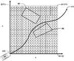
- FIG. 4illustrates an example ADV path through a segment of an ADV route, navigated by a human driver, in view of a plurality of obstacles along the path for implementing a learning based speed planner for autonomous driving vehicles (ADVs) according to one embodiment.
- ADVsautonomous driving vehicles
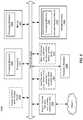
- FIG. 5is a block diagram illustrating a method of implementing a learning based speed planner for autonomous driving vehicles (ADVs), according to one embodiment.
- FIG. 6is a block diagram illustrating a method of recording human driving in an ADV for implementing a learning based speed planner for autonomous driving vehicles (ADVs), according to one embodiment.
- FIG. 7is a block diagram illustrating a remote server training speed models from human driver data of ADVs for implementing a learning based speed planner for autonomous driving vehicles (ADVs), according to one embodiment.
- FIG. 8is a block diagram illustration a method of improving ADV navigation by implementing a learning based speed planner for autonomous driving vehicles (ADVs), according to one embodiment.
- FIG. 9is a block diagram illustrating a data processing system according to one embodiment.
- initial speed datais collected from an ADV driven by a human driver, in view of one or more obstacles and a segment of a navigation route (termed, “a path”).
- the ADVis set to human driving mode. In human driving mode a control system of the ADV is bypassed so that a human can control the ADV.
- Other ADV logicremains enabled and operational.
- a pathis determined by a planning module of the ADV.
- One or more obstacles along the pathare determined by a perception module of the ADV.
- a station-time (S-T) graphis generated and a K ⁇ P grid of cells that encompass the path and at least a portion of the obstacle(s). Cells that coincide with an obstacle are set to a first value, e.g. 1.
- Other cellsare set to a second value, e.g. 0.
- the grid of cellsis transformed to a feature vector, F, of length K ⁇ P.
- the ADVrecords an initial speed v 0 , chosen by the human driver, recorded at the starting point of the path, at grid cell (0,0).
- the initial speed, v 0 , and feature vector, Fare recorded as a driving record for transmission to a remote server.
- driving recordsare transmitted to the remote server in real-time or near real-time.
- driving recordscan be stored at the ADV for transmission to the remote server at a later time.
- a method of machine-learning one or more speed modelsis implemented on a remote server.
- the remote serverreceives and stores a large plurality of driving records from a large plurality of ADVs driving in driven by human drivers in human driving mode.
- the driving recordseach include a feature vector, F, representing one or more obstacles to an ADV along portion of a navigation route (a “path”), and an initial speed v 0 chosen by a human driver at a first point in the path.
- the feature vector, Frepresents a K ⁇ P grid of cells that encompass the path and at least a portion of the one of more obstacles on the path.
- the remote servercan select a plurality, N, of driving records from the large plurality of driving records and use machine learning to train an initial speed model W MODEL .
- the remote servercan transmit the speed model W MODEL to one or more ADVs.
- W MODELcan be represented as a speed model vector.
- an ADVcan receive a speed models, W MODEL , from a remote server.
- the ADVcan determine a path that the ADV is to navigate, in view of one or more obstacles along the path.
- the ADVcan map the obstacles into a K ⁇ P grid of cells each having a value.
- the ADVcan set a grid cell value to 1 if the grid cell coincides with an obstacle. Otherwise the grid cell is set to 0.
- the ADVcan then generate a feature vector, F′, of K ⁇ P length from the grid cells.
- v 0can be determined from the dot product of F′ transpose (F′ T ) and W MODEL .
- the ADVcan then autonomously navigate the path, beginning at speed v 0 , at the initial point of the path, in view of the obstacles represented by feature vector F′.
- W MODELcan be, alternatively, trained to determine an initial acceleration a 0 .
- An initial acceleration a 0 for navigating the pathcan be determined from the dot product of F′ transpose (F′ T ) and W MODEL .
- FIG. 1is a block diagram illustrating a networked system for implementing a learning based speed planner for autonomous driving vehicles (ADVs), according to one embodiment.
- network configuration 100includes autonomous vehicle 101 that may be communicatively coupled to one or more servers 103 - 104 over a network 102 . Although there is one autonomous vehicle shown, multiple autonomous vehicles can be coupled to each other and/or coupled to servers 103 - 104 over network 102 .
- Network 102may be any type of networks such as a local area network (LAN), a wide area network (WAN) such as the Internet, a cellular network, a satellite network, or a combination thereof, wired or wireless.
- LANlocal area network
- WANwide area network
- Server(s) 103 - 104may be any kind of servers or a cluster of servers, such as Web or cloud servers, application servers, backend servers, or a combination thereof.
- Servers 103 - 104may be data analytics servers, content servers, traffic information servers, map and point of interest (MPOI) severs, or location servers, etc.
- MPOImap and point of interest
- An autonomous vehiclerefers to a vehicle that can be configured to operate in an autonomous mode in which the vehicle navigates through an environment with little or no input from a driver.
- Such an autonomous vehiclecan include a sensor system having one or more sensors that are configured to detect information about the environment in which the vehicle operates. The vehicle and its associated controller(s) use the detected information to navigate through the environment.
- Autonomous vehicle 101can operate in a manual mode, a full autonomous mode, or a partial autonomous mode.
- autonomous vehicle 101includes, but is not limited to, perception and planning system 110 , vehicle control system 111 , wireless communication system 112 , user interface system 113 , infotainment system 114 , and sensor system 115 .
- Autonomous vehicle 101may further include certain common components included in ordinary vehicles, such as, an engine, wheels, steering wheel, transmission, etc., which may be controlled by vehicle control system 111 and/or perception and planning system 110 using a variety of communication signals and/or commands, such as, for example, acceleration signals or commands, deceleration signals or commands, steering signals or commands, braking signals or commands, etc.
- Components 110 - 115may be communicatively coupled to each other via an interconnect, a bus, a network, or a combination thereof.
- components 110 - 115may be communicatively coupled to each other via a controller area network (CAN) bus.
- CANcontroller area network
- a CAN busis a vehicle bus standard designed to allow microcontrollers and devices to communicate with each other in applications without a host computer. It is a message-based protocol, designed originally for multiplex electrical wiring within automobiles, but is also used in many other contexts.
- sensor system 115includes, but it is not limited to, one or more cameras 211 , global positioning system (GPS) unit 212 , inertial measurement unit (IMU) 213 , radar unit 214 , and a light detection and range (LIDAR) unit 215 .
- GPS system 212may include a transceiver operable to provide information regarding the position of the autonomous vehicle.
- IMU unit 213may sense position and orientation changes of the autonomous vehicle based on inertial acceleration.
- Radar unit 214may represent a system that utilizes radio signals to sense objects within the local environment of the autonomous vehicle. In some embodiments, in addition to sensing objects, radar unit 214 may additionally sense the speed and/or heading of the objects.
- LIDAR unit 215may sense objects in the environment in which the autonomous vehicle is located using lasers.
- LIDAR unit 215could include one or more laser sources, a laser scanner, and one or more detectors, among other system components.
- Cameras 211may include one or more devices to capture images of the environment surrounding the autonomous vehicle. Cameras 211 may be still cameras and/or video cameras. Cameras 211 may include an infra-red camera.
- a cameramay be mechanically movable, for example, by mounting the camera on a rotating and/or tilting a platform.
- Sensor system 115may further include other sensors, such as, a sonar sensor, an infrared sensor, a steering sensor, a throttle sensor, a braking sensor, and an audio sensor (e.g., microphone).
- An audio sensormay be configured to capture sound from the environment surrounding the autonomous vehicle.
- a steering sensormay be configured to sense the steering angle of a steering wheel, wheels of the vehicle, or a combination thereof.
- a throttle sensor and a braking sensorsense the throttle position and braking position of the vehicle, respectively. In some situations, a throttle sensor and a braking sensor may be integrated as an integrated throttle/braking sensor.
- vehicle control system 111includes, but is not limited to, steering unit 201 , throttle unit 202 (also referred to as an acceleration unit), and braking unit 203 .
- Steering unit 201is to adjust the direction or heading of the vehicle.
- Throttle unit 202is to control the speed of the motor or engine that in turn control the speed and acceleration of the vehicle.
- Braking unit 203is to decelerate the vehicle by providing friction to slow the wheels or tires of the vehicle.
- Control system 111can include logic to detect failure of each control in the control system 111 , as described below with reference to FIG. 3 .
- wireless communication system 112is to allow communication between autonomous vehicle 101 and external systems, such as devices, sensors, other vehicles, etc.
- wireless communication system 112can wirelessly communicate with one or more devices directly or via a communication network, such as servers 103 - 104 over network 102 .
- Wireless communication system 112can use any cellular communication network or a wireless local area network (WLAN), e.g., using WiFi to communicate with another component or system.
- Wireless communication system 112could communicate directly with a device (e.g., a mobile device of a passenger, a display device, a speaker within vehicle 101 ), for example, using an infrared link, Bluetooth, etc.
- User interface system 113may be part of peripheral devices implemented within vehicle 101 including, for example, a keyword, a touch screen display device, a microphone, and a speaker, etc.
- Perception and planning system 110includes the necessary hardware (e.g., processor(s), memory, storage) and software (e.g., operating system, planning and routing programs) to receive information from sensor system 115 , control system 111 , wireless communication system 112 , and/or user interface system 113 , process the received information, plan a route or path from a starting point to a destination point, and then drive vehicle 101 based on the planning and control information.
- Perception and planning system 110may be integrated with vehicle control system 111 .
- Perception and planning system 110obtains the trip related data.
- perception and planning system 110may obtain location and route information from an MPOI server, which may be a part of servers 103 - 104 .
- the location serverprovides location services and the MPOI server provides map services and the POIs of certain locations.
- such location and MPOI informationmay be cached locally in a persistent storage device of perception and planning system 110 .
- perception and planning system 110may also obtain real-time traffic information from a traffic information system or server (TIS).
- TIStraffic information system
- servers 103 - 104may be operated by a third party entity.
- the functionalities of servers 103 - 104may be integrated with perception and planning system 110 .
- perception and planning system 110can plan an optimal route and drive vehicle 101 , for example, via control system 111 , according to the planned route to reach the specified destination safely and efficiently.
- An optimal routecan include a plurality of segment, each of which can be optimized by the perception and planning system 110 by determining an optimal path curve for the segment from a plurality of candidate path curves for the segment, each generated by the perception and planning system 110 .
- Server 103may be a data analytics system to perform data analytics services for a variety of clients.
- data analytics system 103includes data collector 121 and machine learning engine 122 .
- Data collector 121collects driving statistics 123 from a variety of vehicles, either autonomous vehicles or regular vehicles driven by human drivers.
- Driving statistics 123include information indicating the driving commands (e.g., throttle, brake, steering commands) issued and responses of the vehicles (e.g., speeds, accelerations, decelerations, directions) captured by sensors of the vehicles at different points in time.
- Driving statistics 123may further include information describing the driving environments at different points in time, such as, for example, routes (including starting and destination locations), MPOIs, road conditions, weather conditions, etc.
- driving statisticscan include driving records when the ADV is in human driver mode. Human driving mode bypasses the ADV control system logic so that a human driver can control the ADV.
- driving recordscan be used to learn human driving judgments using machine learning engine 122 .
- a navigation pathcan be determined for a segment of an ADV driving route which the human driver will navigate. The path can have one or more obstacles.
- a grid of cellscan be generated that encompasses the path and at least a portion of the obstacle(s). Cells that coincide with an obstacle can be set to 1, and all other cells set to 0.
- the grid of cellscan be represented as a feature vector, F.
- the feature vector F and initial ADV speed, v 0 , and/or initial acceleration a 0can be stored as driving records and transmitted to a remote server, such as server 103 , with a machine learning algorithm 124 using machine learning engine 122 .
- machine learning engine 122Based on driving statistics 123 , machine learning engine 122 generates or trains a set of rules, algorithms, and/or predictive models 124 for a variety of purposes, including multi-level alarming algorithms for an alarm system to alarm drivers of the autonomous driving vehicles. For example, machine learning engine 122 can train a speed model, W MODEL , 124 using a large plurality of ADV driving statistics 123 . The trained speed model W MODEL 124 can be downloaded to one or more ADVs to improve initial speed selection v 0 or an initial acceleration a 0 when an ADV begins navigating a path having feature vector, F.
- FIG. 3is a block diagram illustrating an example of a perception and planning system in an ADV that implements a learning based speed planner for autonomous driving vehicles (ADVs), according to one embodiment.
- System 300may be implemented as a part of autonomous vehicle 101 of FIG. 1 including, but is not limited to, perception and planning system 110 , control system 111 , and sensor system 115 .
- perception and planning system 110includes, but is not limited to, localization module 301 , perception module 302 , prediction module 303 , decision module 304 , planning module 305 , control module 306 , routing module 307 , speed data collector 308 , and speed planning module 309 .
- Localization module 301can include map and route data 311 and routing module 307 .
- modules 301 - 309may be implemented in software, hardware, or a combination thereof.
- these modulesmay be installed in persistent storage device 352 , loaded into memory 351 , and executed by one or more processors (not shown). Note that some or all of these modules may be communicatively coupled to or integrated with some or all modules of vehicle control system 111 of FIG. 2 . Some of modules 301 - 309 may be integrated together as an integrated module.
- Localization module 301determines a current location of autonomous vehicle 300 (e.g., leveraging GPS unit 212 ) and manages any data related to a trip or route of a user. Localization module 301 may be referred to as a map and route module. A user may log in and specify a starting location and a destination of a trip, for example, via a user interface. Localization module 301 communicates with other components of autonomous vehicle 300 , such as map and route information 311 , to obtain the trip related data. For example, localization module 301 may obtain location and route information from a location server and a map and POI (MPOI) server.
- MPOImap and POI
- a location serverprovides location services and an MPOI server provides map services and the POIs of certain locations, which may be cached as part of map and route information 311 .
- MPOI serverprovides map services and the POIs of certain locations, which may be cached as part of map and route information 311 .
- localization module 301may also obtain real-time traffic information from a traffic information system or server.
- a perception of the surrounding environmentis determined by perception module 302 .
- the perception informationmay represent what an ordinary driver would perceive surrounding a vehicle in which the driver is driving.
- the perceptioncan include the lane configuration (e.g., straight or curve lanes), traffic light signals, a relative position of another vehicle, a pedestrian, a building, crosswalk, or other traffic related signs (e.g., stop signs, yield signs), etc., for example, in a form of an object.
- Perception module 302may include a computer vision system or functionalities of a computer vision system to process and analyze images captured by one or more cameras in order to identify objects and/or features in the environment of autonomous vehicle.
- the objectscan include traffic signals, road way boundaries, other vehicles, pedestrians, and/or obstacles, etc.
- the computer vision systemmay use an object recognition algorithm, video tracking, and other computer vision techniques.
- the computer vision systemcan map an environment, track objects, and estimate the speed of objects, etc.
- Perception module 302can also detect objects based on other sensors data provided by other sensors such as a radar and/or LIDAR.
- prediction module 303predicts what the object will behave under the circumstances. The prediction is performed based on the perception data perceiving the driving environment at the point in time in view of a set of map/rout information 311 and traffic rules 312 . For example, if the object is a vehicle at an opposing direction and the current driving environment includes an intersection, prediction module 303 will predict whether the vehicle will likely move straight forward or make a turn. If the perception data indicates that the intersection has no traffic light, prediction module 303 may predict that the vehicle may have to fully stop prior to enter the intersection. If the perception data indicates that the vehicle is currently at a left-turn only lane or a right-turn only lane, prediction module 303 may predict that the vehicle will more likely make a left turn or right turn respectively.
- decision module 304makes a decision regarding how to handle the object. For example, for a particular object (e.g., another vehicle in a crossing route) as well as its metadata describing the object (e.g., a speed, direction, turning angle), decision module 304 decides how to encounter the object (e.g., overtake, yield, stop, pass). Decision module 304 may make such decisions according to a set of rules such as traffic rules or driving rules 312 , which may be stored in persistent storage device 352 .
- rulessuch as traffic rules or driving rules 312
- planning module 305plans a path or route for the autonomous vehicle, as well as driving parameters (e.g., distance, speed, and/or turning angle), using a reference line provided by routing module 307 as a basis. That is, for a given object, decision module 304 decides what to do with the object, while planning module 305 determines how to do it. For example, for a given object, decision module 304 may decide to pass the object, while planning module 305 may determine whether to pass on the left side or right side of the object.
- driving parameterse.g., distance, speed, and/or turning angle
- Planning and control datais generated by planning module 305 including information describing how vehicle 300 would move in a next moving cycle (e.g., next route/path segment). For example, the planning and control data may instruct vehicle 300 to move 10 meters at a speed of 30 mile per hour (mph), then change to a right lane at the speed of 25 mph.
- a next moving cyclee.g., next route/path segment.
- the planning and control datamay instruct vehicle 300 to move 10 meters at a speed of 30 mile per hour (mph), then change to a right lane at the speed of 25 mph.
- control module 306controls and drives the autonomous vehicle, by sending proper commands or signals to vehicle control system 111 , according to a route or path defined by the planning and control data.
- the planning and control datainclude sufficient information to drive the vehicle from a first point to a second point of a route or path using appropriate vehicle settings or driving parameters (e.g., throttle, braking, and turning commands) at different points in time along the path or route.
- the planning phaseis performed in a number of planning cycles, also referred to as command cycles, such as, for example, in every time interval of 100 milliseconds (ms).
- command cyclessuch as, for example, in every time interval of 100 milliseconds (ms).
- one or more control commandswill be issued based on the planning and control data. That is, for every 100 ms, planning module 305 plans a next route segment or path segment, for example, including a target position and the time required for the ADV to reach the target position. Alternatively, planning module 305 may further specify the specific speed, direction, and/or steering angle, etc.
- planning module 305plans a route segment or path segment for the next predetermined period of time such as 5 seconds.
- planning module 305plans a target position for the current cycle (e.g., next 5 seconds) based on a target position planned in a previous cycle.
- Control module 306then generates one or more control commands (e.g., throttle, brake, steering control commands) based on the planning and control data of the current cycle.
- Control module 306can be bypassed such that a human driver can control the ADV while other logic of the ADV remains operational.
- Decision module 304 and planning module 305may be integrated as an integrated module.
- Decision module 304 /planning module 305may include a navigation system or functionalities of a navigation system to determine a driving path for the autonomous vehicle.
- the navigation systemmay determine a series of speeds and directional headings to effect movement of the autonomous vehicle along a path that substantially avoids perceived obstacles while generally advancing the autonomous vehicle along a roadway-based path leading to an ultimate destination.
- the destinationmay be set according to user inputs via user interface system 113 .
- the navigation systemmay update the driving path dynamically while the autonomous vehicle is in operation.
- the navigation systemcan incorporate data from a GPS system and one or more maps so as to determine the driving path for the autonomous vehicle.
- Decision module 304 /planning module 305may further include a collision avoidance system or functionalities of a collision avoidance system to identify, evaluate, and avoid or otherwise negotiate potential obstacles in the environment of the autonomous vehicle.
- the collision avoidance systemmay effect changes in the navigation of the autonomous vehicle by operating one or more subsystems in control system 111 to undertake swerving maneuvers, turning maneuvers, braking maneuvers, etc.
- the collision avoidance systemmay automatically determine feasible obstacle avoidance maneuvers on the basis of surrounding traffic patterns, road conditions, etc.
- the collision avoidance systemmay be configured such that a swerving maneuver is not undertaken when other sensor systems detect vehicles, construction barriers, etc. in the region adjacent the autonomous vehicle that would be swerved into.
- the collision avoidance systemmay automatically select the maneuver that is both available and maximizes safety of occupants of the autonomous vehicle.
- the collision avoidance systemmay select an avoidance maneuver predicted to cause the least amount of acceleration in a passenger cabin of the autonomous vehicle.
- Routing module 307is configured to provide one or more routes or paths from a starting point to a destination point. For a given trip from a start location to a destination location, for example, received from a user, routing module 307 obtains route and map information 311 and determines all possible routes or paths from the starting location to reach the destination location. Routing module 307 may generate a reference line in a form of a topographic map for each of the routes it determines from the starting location to reach the destination location. A reference line refers to an ideal route or path without any interference from others such as other vehicles, obstacles, or traffic condition. That is, if there is no other vehicle, pedestrians, or obstacles on the road, an ADV should exactly or closely follows the reference line.
- the topographic mapsare then provided to decision module 304 and/or planning module 305 .
- Decision module 304 and/or planning module 305examine all of the possible routes to select and modify one of the most optimal route in view of other data provided by other modules such as traffic conditions from localization module 301 , driving environment perceived by perception module 302 , and traffic condition predicted by prediction module 303 .
- the actual path or route for controlling the ADVmay be close to or different from the reference line provided by routing module 307 dependent upon the specific driving environment at the point in time.
- Examining all of the possible routescan include, for a route selected from the possible route, determining a segment of the selected route, and determining a plurality of candidate path curves for navigating the segment of the selected route.
- Navigating a driving segmentcan include determining an initial speed, v 0 , for the ADV when beginning the path.
- the initial speed v 0can depend upon one or more obstacles on the path.
- Speed data collected while a human is driving in human driver modecan be used to train one or more speed models, using machine learning, to emulate human decision making for the initial speed v 0 .
- Speed data collector 308records certain driving conditions into driving records.
- an ADVcan navigate along a path having one or more obstacles.
- the pathcan be represented as a station-time (S-T) graph comprising a grid of cells of values that encompass the path and at least a portion of the one or more obstacles.
- the one or more obstacles to the ADVcan be incorporated into the grid of cells by, e.g., setting a grid cell value to 1 where the grid cell coincides with an obstacle, and otherwise setting the grid cell to 0.
- the grid of cellscan be represented as a feature vector, F.
- Speed data collector 308can record the feature vector F and initial speed v 0 into a driving record. Speed data collector 308 can record a driving record for each of multiple paths along a driving route. In an embodiment, a feature vector F and initial driving speed v 0 , and/or initial acceleration a 0 , can be determined more than once for each segment of a driving route. In an embodiment, a new feature vector F and initial speed v 0 and/or initial acceleration a 0 , can be recorded in response to a change in the one or more obstacles on the path, such as an obstacle entering or leaving the area comprising the grid of cells encompassing the path. Recorded driving records can be transmitted from the ADV to a remote server in real-time or near real-time.
- recorded driving recordscan be transmitted to the remote server in a batch at a specified time or upon an event, such as the ADV reaching a destination on route.
- the remote servere.g. server 103 of FIG. 1
- Speed planningcan be performed by speed planning module 309 .
- Speed planning module 309can receive a speed model, W MODEL , from remote server 103 .
- a speed model W MODELis used by speed planning module 309 to determine an initial speed v 0 or initial acceleration a 0 to begin driving an ADV on a path in autonomous driving mode, in view of one or more obstacles to the ADV represented in a feature vector, F′.
- Speed planning module 309can use feature vector F′ and speed model W MODEL to determine an initial speed v 0 or acceleration a 0 to start driving on the path.
- the initial speed v 0 or initial acceleration a 0can be determined by computing the dot product of F′ transpose (F′ T ) and W MODEL .
- components as shown and described abovemay be implemented in software, hardware, or a combination thereof.
- such componentscan be implemented as software installed and stored in a persistent storage device, which can be loaded and executed in a memory by a processor (not shown) to carry out the processes or operations described throughout this application.
- such componentscan be implemented as executable code programmed or embedded into dedicated hardware such as an integrated circuit (e.g., an application specific IC or ASIC), a digital signal processor (DSP), or a field programmable gate array (FPGA), which can be accessed via a corresponding driver and/or operating system from an application.
- an integrated circuite.g., an application specific IC or ASIC
- DSPdigital signal processor
- FPGAfield programmable gate array
- such componentscan be implemented as specific hardware logic in a processor or processor core as part of an instruction set accessible by a software component via one or more specific instructions.
- FIG. 4illustrates an example ADV path through a segment of an ADV route, in view of a plurality of obstacles along the path for implementing a learning based speed planner for autonomous driving vehicles (ADVs) according to one embodiment.
- a driving path 410is shown passing between a first obstacle 401 and a second obstacle 402 .
- Obstacles 401 and 402can be determined by perception module 302 perceiving the obstacles and prediction module 303 predicting the obstacle behavior.
- planning module 305can determine path 410 to navigate around the obstacles 401 and 402 .
- the obstaclescan be represented in a grid of cells that encompass the path and at least a portion of the obstacles 401 and 402 . Grid cells that coincide with an obstacle can be set to a value of 1 and remaining grid cells can be set to a value of 0.
- the gridcan be of size K ⁇ P cells.
- the grid of cellscan be represented as a feature vector F, having length K ⁇ P.
- FIG. 4can be applied to a data collection scenario wherein the ADV is in human driver mode, the feature vector F is generated, and a human driver selects an initial speed, v 0 , to begin driving the path, starting at point (0,0) on the grid of cells. Driving data records are recorded by speed data collector 308 .
- FIG. 4can also be applied to a speed planning scenario, wherein the ADV is in autonomous driving mode, and a feature vector F′ and speed model W MODEL are used by speed planning module 309 to determine initial speed v 0 or initial acceleration a 0 for navigating the path 410 in autonomous driving mode.
- FIG. 5is a flow diagram illustrating a method 500 of implementing a learning based speed planner for autonomous driving vehicles (ADVs), according to one embodiment.
- an ADV 101can be set into human driving mode. Human driving mode bypasses the control module 306 so that the human driver can control the ADV, while all other ADV logic continues to be active.
- the ADV planning module 305can generate a path that the human driver is to navigate.
- Perception module 302 and prediction module 303can detect one or more obstacles to the ADV along the path and predict the behavior of the obstacles.
- ADV logiccan generate a grid of cells encompassing the path and at least a portion of the obstacles. Grid cells that coincide with an obstacle can be set to a value of 1. Remaining grid cells can be set to 0.
- the grid of cellscan be represented as a feature vector, F.
- the human driverbegins driving ADV on the path at an initial speed of v 0 .
- Speed data collection module 308can record the feature vector and initial speed v 0 and/or initial acceleration a 0 into a driving record.
- the driving recordcan be transmitted to a remote server.
- the transmission of one or more driving recordscan be in real-time, near real-time, or can be delayed until a later time. Operations 505 through 515 are described in additional detail below, with reference to FIG. 6 .
- the remote servercan query driving records received from a large plurality of ADVs, each driving record including a feature vector F and initial speed v 0 and/or acceleration a 0 , for a large plurality of driving paths and obstacles.
- Remote servere.g. server 103
- remote servercan transmit, or otherwise make available for download, a speed model, W MODEL , to one or more ADVs.
- speed model W MODEL and feature vector F′can be used to determine an initial speed v 0 or initial acceleration a 0 to begin navigating the ADV on the path in autonomous driving mode.
- computing v 0includes computing the dot product of the transpose of feature vector F′ (F′ T ) and W MODEL . Operations 525 and 530 are described in more detail, below, with reference to FIG. 8 .
- FIG. 6is a flow diagram illustrating a method 600 of recording human driving data in an ADV for implementing a learning based speed planner for autonomous driving vehicles (ADVs), according to one embodiment.
- the ADVis set into human driver mode.
- human driver modethe control unit 306 is bypassed so that the human driver can perform control functions such as steering, braking, and throttle control.
- Other modules of ADV logicremain operational.
- the ADV the planning module 305 plans a route for navigation and routing module 307can provide a path comprising a portion of the route.
- Perception module 302can detect one or more obstacles along the path and prediction module 303 can predict behavior of the one or more obstacles.
- the ADVmaps the one or more obstacles into a K ⁇ P grid of cells that encompasses the path and at least a portion of the one or more obstacles.
- a grid cell that coincides with an obstaclecan have a value of 1 and otherwise have a value of 0.
- the ADV speed data collector 308records the initial speed v 0 and/or initial acceleration a 0 , selected by the human driver, as the ADV begins navigating the path through the obstacles.
- ADV logiccan convert the grid of cells into a feature vector F having dimension K ⁇ P, and store the feature vector F in a driving record in association with initial speed v 0 and/or initial acceleration a 0 .
- the ADVcan transmit speed driving records, each comprising a feature vector F and an initial speed v 0 and/or initial acceleration a 0 to a remote server for machine learning of one or more speed models, W MODEL .
- FIG. 7is a flow diagram illustrating a method 700 of a remote server training a speed model W MODEL from human driver data of ADVs for implementing a learning based speed planning module 309 for autonomous driving vehicles (ADVs), according to one embodiment.
- Speed model W MODELcan be represented as a vector.
- W MODELis used to mean a speed model in any representation, including as a vector.
- the serverselects N ADV driving records generated during human driver mode of a large plurality of ADVs.
- Each driving recordcan comprise a feature vector, F, and an initial speed v 0 and/or an initial acceleration a 0 .
- the feature vectorrepresents a mapping of one or more obstacles to an ADV on a path.
- the initial speed v 0was chosen by the human driver when beginning to drive along the path.
- selecting driving recordscan include selecting driving records having identical, or substantially identical, feature vectors F such that a speed model W MODEL is trained for a specific set of obstacle(s). Such an embodiment may be used under a variety of situations, such as when the set of obstacles poses a known difficult or risky driving situation.
- a particular W MODELmay be stored in association with a representative corresponding F MODEL for which W MODEL was generated, so that the particular W MODEL corresponding to F MODEL may be determined in an ADV driving situation wherein the ADV feature vector, F′, corresponds to F MODEL .
- the serveruses the selected driving records to train speed model, W MODEL .
- servergenerates the speed model W MODEL as a vector of length K ⁇ P for use by an ADV in autonomous driving mode to determine an initial speed v 0 for driving a path having a feature vector F′.
- servertransmits speed model W MODEL to one or more ADVs for use in speed planning for navigating a path of an ADV in autonomous driving mode.
- FIG. 8is a flow diagram illustration a method 800 of improving ADV navigation by implementing a learning based speed planner for autonomous driving vehicles (ADVs), according to one embodiment.
- Method 800is practiced by an ADV in autonomous driving mode.
- an ADVreceives from a remote server a speed model, W MODEL .
- W MODELwas trained by the remote server from a large plurality of driving records each having a feature vector and initial speed v 0 and/or initial acceleration a 0 .
- the ADV perception and planning modulescan determine a path that is a segment of route for the ADV to navigate, and one or more obstacles to the ADV along the segment of the route (or “path”).
- a grid of K ⁇ P cellscan be generated that encompass the path and at least a portion of the obstacles. Grid cells that coincide with an obstacle can be set to a value of 1, while other grid cells are set to a value of 0.
- the grid of cellscan be generated into a feature vector, F′, representing the obstacles.
- feature vector F′ and speed model W MODELare used by speed planning module 309 to calculate initial speed v 0 for beginning to navigate the path.
- Initial speed v 0is calculated using the dot product of the transpose of F′ (F′ T ) and W MODEL .
- the ADVin autonomous mode, begins navigating the path at speed v 0 , starting at point (0,0) of the K ⁇ P grid of cells that were used to generate feature vector F′.
- FIG. 9is a block diagram illustrating an example of a data processing system which may be used with one embodiment of the disclosure.
- system 1500may represent any of data processing systems described above performing any of the processes or methods described above, such as, for example, perception and planning system 110 or any of servers 103 - 104 of FIG. 1 .
- System 1500can include many different components. These components can be implemented as integrated circuits (ICs), portions thereof, discrete electronic devices, or other modules adapted to a circuit board such as a motherboard or add-in card of the computer system, or as components otherwise incorporated within a chassis of the computer system.
- ICsintegrated circuits
- System 1500is intended to show a high level view of many components of the computer system. However, it is to be understood that additional components may be present in certain implementations and furthermore, different arrangement of the components shown may occur in other implementations.
- System 1500may represent a desktop, a laptop, a tablet, a server, a mobile phone, a media player, a personal digital assistant (PDA), a Smartwatch, a personal communicator, a gaming device, a network router or hub, a wireless access point (AP) or repeater, a set-top box, or a combination thereof.
- PDApersonal digital assistant
- APwireless access point
- system 1500shall also be taken to include any collection of machines or systems that individually or jointly execute a set (or multiple sets) of instructions to perform any one or more of the methodologies discussed herein.
- system 1500includes processor 1501 , memory 1503 , and devices 1505 - 1508 connected via a bus or an interconnect 1510 .
- Processor 1501may represent a single processor or multiple processors with a single processor core or multiple processor cores included therein.
- Processor 1501may represent one or more general-purpose processors such as a microprocessor, a central processing unit (CPU), or the like. More particularly, processor 1501 may be a complex instruction set computing (CISC) microprocessor, reduced instruction set computing (RISC) microprocessor, very long instruction word (VLIW) microprocessor, or processor implementing other instruction sets, or processors implementing a combination of instruction sets.
- CISCcomplex instruction set computing
- RISCreduced instruction set computing
- VLIWvery long instruction word
- Processor 1501may also be one or more special-purpose processors such as an application specific integrated circuit (ASIC), a cellular or baseband processor, a field programmable gate array (FPGA), a digital signal processor (DSP), a network processor, a graphics processor, a communications processor, a cryptographic processor, a co-processor, an embedded processor, or any other type of logic capable of processing instructions.
- ASICapplication specific integrated circuit
- FPGAfield programmable gate array
- DSPdigital signal processor
- network processora graphics processor
- communications processora cryptographic processor
- co-processora co-processor
- embedded processoror any other type of logic capable of processing instructions.
- Processor 1501which may be a low power multi-core processor socket such as an ultra-low voltage processor, may act as a main processing unit and central hub for communication with the various components of the system. Such processor can be implemented as a system on chip (SoC). Processor 1501 is configured to execute instructions for performing the operations and steps discussed herein.
- System 1500may further include a graphics interface that communicates with optional graphics subsystem 1504 , which may include a display controller, a graphics processor, and/or a display device.
- graphics subsystem 1504may include a display controller, a graphics processor, and/or a display device.
- Processor 1501may communicate with memory 1503 , which in one embodiment can be implemented via multiple memory devices to provide for a given amount of system memory.
- Memory 1503may include one or more volatile storage (or memory) devices such as random access memory (RAM), dynamic RAM (DRAM), synchronous DRAM (SDRAM), static RAM (SRAM), or other types of storage devices.
- RAMrandom access memory
- DRAMdynamic RAM
- SDRAMsynchronous DRAM
- SRAMstatic RAM
- Memory 1503may store information including sequences of instructions that are executed by processor 1501 , or any other device. For example, executable code and/or data of a variety of operating systems, device drivers, firmware (e.g., input output basic system or BIOS), and/or applications can be loaded in memory 1503 and executed by processor 1501 .
- BIOSinput output basic system
- An operating systemcan be any kind of operating systems, such as, for example, Robot Operating System (ROS), Windows® operating system from Microsoft®, Mac OS®/iOS® from Apple, Android® from Google®, LINUX, UNIX, or other real-time or embedded operating systems.
- ROSRobot Operating System
- Windows® operating systemfrom Microsoft®
- Mac OS®/iOS®from Apple
- Android®from Google®
- LINUXLINUX
- UNIXor other real-time or embedded operating systems.
- System 1500may further include 10 devices such as devices 1505 - 1508 , including network interface device(s) 1505 , optional input device(s) 1506 , and other optional 10 device(s) 1507 .
- Network interface device 1505may include a wireless transceiver and/or a network interface card (NIC).
- the wireless transceivermay be a WiFi transceiver, an infrared transceiver, a Bluetooth transceiver, a WiMax transceiver, a wireless cellular telephony transceiver, a satellite transceiver (e.g., a global positioning system (GPS) transceiver), or other radio frequency (RF) transceivers, or a combination thereof.
- the NICmay be an Ethernet card.
- Input device(s) 1506may include a mouse, a touch pad, a touch sensitive screen (which may be integrated with display device 1504 ), a pointer device such as a stylus, and/or a keyboard (e.g., physical keyboard or a virtual keyboard displayed as part of a touch sensitive screen).
- input device 1506may include a touch screen controller coupled to a touch screen.
- the touch screen and touch screen controllercan, for example, detect contact and movement or break thereof using any of a plurality of touch sensitivity technologies, including but not limited to capacitive, resistive, infrared, and surface acoustic wave technologies, as well as other proximity sensor arrays or other elements for determining one or more points of contact with the touch screen.
- IO devices 1507may include an audio device.
- An audio devicemay include a speaker and/or a microphone to facilitate voice-enabled functions, such as voice recognition, voice replication, digital recording, and/or telephony functions.
- Other IO devices 1507may further include universal serial bus (USB) port(s), parallel port(s), serial port(s), a printer, a network interface, a bus bridge (e.g., a PCI-PCI bridge), sensor(s) (e.g., a motion sensor such as an accelerometer, gyroscope, a magnetometer, a light sensor, compass, a proximity sensor, etc.), or a combination thereof.
- USBuniversal serial bus
- sensor(s)e.g., a motion sensor such as an accelerometer, gyroscope, a magnetometer, a light sensor, compass, a proximity sensor, etc.
- Devices 1507may further include an imaging processing subsystem (e.g., a camera), which may include an optical sensor, such as a charged coupled device (CCD) or a complementary metal-oxide semiconductor (CMOS) optical sensor, utilized to facilitate camera functions, such as recording photographs and video clips.
- an imaging processing subsysteme.g., a camera
- an optical sensorsuch as a charged coupled device (CCD) or a complementary metal-oxide semiconductor (CMOS) optical sensor, utilized to facilitate camera functions, such as recording photographs and video clips.
- CCDcharged coupled device
- CMOScomplementary metal-oxide semiconductor
- Certain sensorsmay be coupled to interconnect 1510 via a sensor hub (not shown), while other devices such as a keyboard or thermal sensor may be controlled by an embedded controller (not shown), dependent upon the specific configuration or design of system 1500 .
- a mass storagemay also couple to processor 1501 .
- this mass storagemay be implemented via a solid state device (SSD).
- SSDsolid state device
- the mass storagemay primarily be implemented using a hard disk drive (HDD) with a smaller amount of SSD storage to act as a SSD cache to enable non-volatile storage of context state and other such information during power down events so that a fast power up can occur on re-initiation of system activities.
- a flash devicemay be coupled to processor 1501 , e.g., via a serial peripheral interface (SPI). This flash device may provide for non-volatile storage of system software, including BIOS as well as other firmware of the system.
- Storage device 1508may include computer-accessible storage medium 1509 (also known as a machine-readable storage medium or a computer-readable medium) on which is stored one or more sets of instructions or software (e.g., module, unit, and/or logic 1528 ) embodying any one or more of the methodologies or functions described herein.
- Processing module/unit/logic 1528may represent any of the components described above, such as, for example, planning module 305 , control module 306 , and/or speed data collector 308 , and speed planning module 309 .
- Processing module/unit/logic 1528may also reside, completely or at least partially, within memory 1503 and/or within processor 1501 during execution thereof by data processing system 1500 , memory 1503 and processor 1501 also constituting machine-accessible storage media.
- Processing module/unit/logic 1528may further be transmitted or received over a network via network interface device 1505 .
- Computer-readable storage medium 1509may also be used to store the some software functionalities described above persistently. While computer-readable storage medium 1509 is shown in an exemplary embodiment to be a single medium, the term “computer-readable storage medium” should be taken to include a single medium or multiple media (e.g., a centralized or distributed database, and/or associated caches and servers) that store the one or more sets of instructions. The terms “computer-readable storage medium” shall also be taken to include any medium that is capable of storing or encoding a set of instructions for execution by the machine and that cause the machine to perform any one or more of the methodologies of the present disclosure. The term “computer-readable storage medium” shall accordingly be taken to include, but not be limited to, solid-state memories, and optical and magnetic media, or any other non-transitory machine-readable medium.
- Processing module/unit/logic 1528can be implemented as discrete hardware components or integrated in the functionality of hardware components such as ASICS, FPGAs, DSPs or similar devices.
- processing module/unit/logic 1528can be implemented as firmware or functional circuitry within hardware devices.
- processing module/unit/logic 1528can be implemented in any combination hardware devices and software components.
- system 1500is illustrated with various components of a data processing system, it is not intended to represent any particular architecture or manner of interconnecting the components; as such details are not germane to embodiments of the present disclosure. It will also be appreciated that network computers, handheld computers, mobile phones, servers, and/or other data processing systems which have fewer components or perhaps more components may also be used with embodiments of the disclosure.
- Embodiments of the disclosurealso relate to an apparatus for performing the operations herein.
- a computer programis stored in a non-transitory computer readable medium.
- a machine-readable mediumincludes any mechanism for storing information in a form readable by a machine (e.g., a computer).
- a machine-readable (e.g., computer-readable) mediumincludes a machine (e.g., a computer) readable storage medium (e.g., read only memory (“ROM”), random access memory (“RAM”), magnetic disk storage media, optical storage media, flash memory devices).
- processing logicthat comprises hardware (e.g. circuitry, dedicated logic, etc.), software (e.g., embodied on a non-transitory computer readable medium), or a combination of both.
- processing logiccomprises hardware (e.g. circuitry, dedicated logic, etc.), software (e.g., embodied on a non-transitory computer readable medium), or a combination of both.
- Embodiments of the present disclosureare not described with reference to any particular programming language. It will be appreciated that a variety of programming languages may be used to implement the teachings of embodiments of the disclosure as described herein.
Landscapes
- Engineering & Computer Science (AREA)
- Physics & Mathematics (AREA)
- Radar, Positioning & Navigation (AREA)
- Automation & Control Theory (AREA)
- Remote Sensing (AREA)
- General Physics & Mathematics (AREA)
- Aviation & Aerospace Engineering (AREA)
- Electromagnetism (AREA)
- Transportation (AREA)
- Mechanical Engineering (AREA)
- Human Computer Interaction (AREA)
- Optics & Photonics (AREA)
- Evolutionary Computation (AREA)
- Artificial Intelligence (AREA)
- Business, Economics & Management (AREA)
- Game Theory and Decision Science (AREA)
- Medical Informatics (AREA)
- Health & Medical Sciences (AREA)
- Mathematical Physics (AREA)
- Computer Vision & Pattern Recognition (AREA)
- Multimedia (AREA)
- Acoustics & Sound (AREA)
- Traffic Control Systems (AREA)
- Control Of Driving Devices And Active Controlling Of Vehicle (AREA)
Abstract
Description
Claims (18)
Priority Applications (3)
| Application Number | Priority Date | Filing Date | Title |
|---|---|---|---|
| US15/954,366US11126199B2 (en) | 2018-04-16 | 2018-04-16 | Learning based speed planner for autonomous driving vehicles |
| CN201910053854.9ACN110389585B (en) | 2018-04-16 | 2019-01-21 | Learning-based speed planner for autonomous vehicles |
| JP2019026730AJP6748244B2 (en) | 2018-04-16 | 2019-02-18 | A learning-based speed planning device for use in autonomous vehicles. |
Applications Claiming Priority (1)
| Application Number | Priority Date | Filing Date | Title |
|---|---|---|---|
| US15/954,366US11126199B2 (en) | 2018-04-16 | 2018-04-16 | Learning based speed planner for autonomous driving vehicles |
Publications (2)
| Publication Number | Publication Date |
|---|---|
| US20190317520A1 US20190317520A1 (en) | 2019-10-17 |
| US11126199B2true US11126199B2 (en) | 2021-09-21 |
Family
ID=68161760
Family Applications (1)
| Application Number | Title | Priority Date | Filing Date |
|---|---|---|---|
| US15/954,366Active2038-12-25US11126199B2 (en) | 2018-04-16 | 2018-04-16 | Learning based speed planner for autonomous driving vehicles |
Country Status (3)
| Country | Link |
|---|---|
| US (1) | US11126199B2 (en) |
| JP (1) | JP6748244B2 (en) |
| CN (1) | CN110389585B (en) |
Families Citing this family (27)
| Publication number | Priority date | Publication date | Assignee | Title |
|---|---|---|---|---|
| US11077756B2 (en)* | 2017-11-23 | 2021-08-03 | Intel Corporation | Area occupancy determining device |
| US10816985B2 (en)* | 2018-04-17 | 2020-10-27 | Baidu Usa Llc | Method on moving obstacle representation for trajectory planning |
| FR3086073B1 (en)* | 2018-09-19 | 2020-12-11 | Transdev Group | ELECTRONIC DEVICE FOR DETERMINING AN EMERGENCY STOP TRACK OF AN AUTONOMOUS VEHICLE, VEHICLE AND ASSOCIATED PROCESS |
| US11269336B2 (en)* | 2018-09-21 | 2022-03-08 | Tata Consultancy Services Limited | Method and system for free space detection in a cluttered environment |
| US20220017106A1 (en)* | 2018-12-26 | 2022-01-20 | Mitsubishi Electric Corporation | Moving object control device, moving object control learning device, and moving object control method |
| US10809736B2 (en)* | 2018-12-27 | 2020-10-20 | Baidu Usa Llc | ST-graph learning based decision for autonomous driving vehicle |
| US10928827B2 (en)* | 2019-01-07 | 2021-02-23 | Toyota Research Institute, Inc. | Systems and methods for generating a path for a vehicle |
| US10843728B2 (en)* | 2019-01-31 | 2020-11-24 | StradVision, Inc. | Method and device for delivering steering intention of autonomous driving module or driver to steering apparatus of subject vehicle more accurately |
| JP7207256B2 (en)* | 2019-10-15 | 2023-01-18 | トヨタ自動車株式会社 | vehicle control system |
| CN110794839B (en)* | 2019-11-07 | 2022-04-29 | 中国第一汽车股份有限公司 | Automatic driving control method for special-shaped intersection and vehicle |
| WO2021147071A1 (en)* | 2020-01-23 | 2021-07-29 | Baidu.Com Times Technology (Beijing) Co., Ltd. | Cross-platform control profiling for autonomous vehicle control |
| US12282328B2 (en)* | 2020-03-05 | 2025-04-22 | Aurora Operations, Inc. | Systems and methods for using attention masks to improve motion planning |
| US11760381B1 (en)* | 2020-03-24 | 2023-09-19 | Gm Cruise Holdings Llc | Contextually-aware dynamic safety envelope for autonomous vehicles |
| US11560159B2 (en)* | 2020-03-25 | 2023-01-24 | Baidu Usa Llc | Group and combine obstacles for autonomous driving vehicles |
| JP7369077B2 (en)* | 2020-03-31 | 2023-10-25 | 本田技研工業株式会社 | Vehicle control device, vehicle control method, and program |
| US11787440B2 (en)* | 2020-08-04 | 2023-10-17 | Baidu Usa Llc | Lane boundary and vehicle speed based nudge decision |
| US12189387B2 (en) | 2020-11-25 | 2025-01-07 | Zoox, Inc. | Object uncertainty models to assist with drivable area determinations |
| US11945469B2 (en)* | 2020-11-25 | 2024-04-02 | Zoox, Inc. | Object uncertainty models |
| US11851062B2 (en)* | 2020-12-09 | 2023-12-26 | Waymo Llc | Physics-informed optimization for autonomous driving systems |
| KR102614256B1 (en)* | 2021-02-02 | 2023-12-15 | 우석대학교 산학협력단 | 3D vector coordinate system for autonomous driving |
| US12384410B2 (en) | 2021-03-05 | 2025-08-12 | The Research Foundation For The State University Of New York | Task-motion planning for safe and efficient urban driving |
| CN113076697B (en)* | 2021-04-20 | 2022-11-29 | 潍柴动力股份有限公司 | Construction method, related device and computer storage medium of typical driving conditions |
| US12085952B2 (en)* | 2021-09-14 | 2024-09-10 | Waymo Llc | Flow-based motion planning blueprint for autonomous vehicles |
| CN113665590B (en) | 2021-09-24 | 2024-04-19 | 阿波罗智联(北京)科技有限公司 | Method, device, equipment, medium and vehicle for controlling vehicle |
| KR102753529B1 (en)* | 2022-04-14 | 2025-01-21 | 주식회사 베스텔라랩 | VECTOR-BASED DYNAMIC MAP FOR NAVIGATING and supporting autonomous car |
| US20240351605A1 (en)* | 2023-04-24 | 2024-10-24 | Zoox, Inc. | Navigating around blocking objects |
| KR20250065508A (en)* | 2023-11-03 | 2025-05-13 | 삼성전자주식회사 | Method and apparatus for learning autonomous driving decision algorithms |
Citations (68)
| Publication number | Priority date | Publication date | Assignee | Title |
|---|---|---|---|---|
| US4727365A (en)* | 1983-08-30 | 1988-02-23 | General Electric Company | Advanced video object generator |
| US5170441A (en)* | 1990-03-14 | 1992-12-08 | Hitachi Denshi Kabushiki Kaisha | Apparatus for detecting registration error using the image signal of the same screen |
| US20010014124A1 (en)* | 1998-01-30 | 2001-08-16 | Tsuyoshi Nishikawa | Motion vector estimation circuit and method |
| US20020181706A1 (en)* | 2001-06-05 | 2002-12-05 | Yuuki Matsumura | Digital watermark embedding device and digital watermark embedding method |
| US20040204792A1 (en)* | 2003-03-14 | 2004-10-14 | Taylor Charles E. | Robotic vacuum with localized cleaning algorithm |
| US20050000543A1 (en)* | 2003-03-14 | 2005-01-06 | Taylor Charles E. | Robot vacuum with internal mapping system |
| US20050010331A1 (en)* | 2003-03-14 | 2005-01-13 | Taylor Charles E. | Robot vacuum with floor type modes |
| US20050189471A1 (en)* | 2004-02-06 | 2005-09-01 | Sharp Kabushiki Kaisha | Mobile body surrounding surveillance apparatus, mobile body surrounding surveillance method, control program, and readable recording medium |
| US20050273967A1 (en)* | 2004-03-11 | 2005-12-15 | Taylor Charles E | Robot vacuum with boundary cones |
| US20060171562A1 (en)* | 2005-02-01 | 2006-08-03 | Sharp Kabushiki Kaisha | Mobile body surrounding surveillance apparatus, mobile body surrounding surveillance method, control program and computer-readable recording medium |
| US20060293792A1 (en)* | 2005-06-17 | 2006-12-28 | Honda Motor Co., Ltd. | Path generator for mobile object |
| US20070027612A1 (en)* | 2005-07-26 | 2007-02-01 | Barfoot Timothy D | Traffic management system for a passageway environment |
| US20070156286A1 (en)* | 2005-12-30 | 2007-07-05 | Irobot Corporation | Autonomous Mobile Robot |
| US20080027591A1 (en)* | 2006-07-14 | 2008-01-31 | Scott Lenser | Method and system for controlling a remote vehicle |
| US20080046125A1 (en)* | 2006-08-18 | 2008-02-21 | Samsung Electronics Co., Ltd. | Method of dividing coverage area for robot and device thereof |
| US20090141027A1 (en)* | 2007-08-07 | 2009-06-04 | Satoshi Sato | Image processing device and image processing method |
| US20100211244A1 (en)* | 2009-02-18 | 2010-08-19 | Jeong Woo-Yeon | Apparatus and method for generating and using a grid map path |
| US7788614B1 (en)* | 2007-09-04 | 2010-08-31 | Altera Corporation | Method and apparatus for performing analytic placement techniques on logic devices with restrictive areas |
| US20110026811A1 (en)* | 2009-07-31 | 2011-02-03 | Hirokazu Kameyama | Image processing apparatus and method, data processing apparatus and method, and program and recording medium |
| US20110289028A1 (en)* | 2009-02-03 | 2011-11-24 | Nec Corporation | Pattern recognition device, pattern recognition method, and pattern recognition program |
| US20120221237A1 (en)* | 2011-02-25 | 2012-08-30 | Dongguk University Industry-Academic Cooperation Foundation | Apparatus and method of cell-based path planning for mobile body |
| US20130129148A1 (en)* | 2010-08-03 | 2013-05-23 | Panasonic Corporation | Object detection device, object detection method, and program |
| JP2014137743A (en) | 2013-01-17 | 2014-07-28 | Denso It Laboratory Inc | Information providing system |
| US20150293216A1 (en)* | 2014-04-15 | 2015-10-15 | GM Global Technology Operations LLC | Method and system for detecting, tracking and estimating stationary roadside objects |
| US20150353083A1 (en)* | 2013-01-14 | 2015-12-10 | Robert Bosch Gmbh | Creation of an obstacle map |
| US20160021386A1 (en)* | 2014-06-17 | 2016-01-21 | Imagination Technologies Limited | Biasing Selection of Motion Estimation Vectors |
| JP2016115334A (en) | 2014-12-10 | 2016-06-23 | ホンダ リサーチ インスティテュート ヨーロッパ ゲーエムベーハーHonda Research Institute Europe GmbH | Method and system for adaptive ray-based scene analysis of semantic traffic spaces, and vehicle equipped with such system |
| US20160297072A1 (en)* | 2015-04-09 | 2016-10-13 | Irobot Corporation | Restricting movement of a mobile robot |
| US20170116487A1 (en)* | 2015-10-22 | 2017-04-27 | Kabushiki Kaisha Toshiba | Apparatus, method and program for generating occupancy grid map |
| JP2017162438A (en) | 2016-03-11 | 2017-09-14 | パナソニック インテレクチュアル プロパティ コーポレーション オブ アメリカPanasonic Intellectual Property Corporation of America | Risk prediction method |
| US9798327B2 (en)* | 2016-01-08 | 2017-10-24 | King Fahd University Of Petroleum And Minerals | Apparatus and method for deploying sensors |
| US20170329347A1 (en)* | 2016-05-11 | 2017-11-16 | Brain Corporation | Systems and methods for training a robot to autonomously travel a route |
| JP2018026009A (en) | 2016-08-10 | 2018-02-15 | パナソニック インテレクチュアル プロパティ コーポレーション オブ アメリカPanasonic Intellectual Property Corporation of America | Dynamic map configuration method, dynamic map configuration system and mobile terminal |
| US9946266B2 (en)* | 2013-08-08 | 2018-04-17 | Israel Aerospace Industries Ltd. | Classification of environment elements |
| US20180107226A1 (en)* | 2016-10-17 | 2018-04-19 | Mediatek Inc. | Path planning method and related navigation device |
| US20180143647A1 (en)* | 2016-11-23 | 2018-05-24 | Baidu Usa Llc | Algorithm and infrastructure for robust and efficient vehicle localization |
| US20180246520A1 (en)* | 2017-02-28 | 2018-08-30 | Toyota Jidosha Kabushiki Kaisha | Observability Grid-Based Autonomous Environment Search |
| US20180267540A1 (en)* | 2017-03-17 | 2018-09-20 | Kabushiki Kaisha Toshiba | Movement control system, movement control device, and computer-implemented program for movement control |
| US20180314265A1 (en)* | 2017-04-27 | 2018-11-01 | Toyota Jidosha Kabushiki Kaisha | Environment arrangement robot and control program thereof |
| US20180339710A1 (en)* | 2017-05-24 | 2018-11-29 | Toyota Jidosha Kabushiki Kaisha | Vehicle system |
| US20190087667A1 (en)* | 2017-09-20 | 2019-03-21 | Delphi Technologies, Llc | A device and a method for distinguishing between traversable and nontraversable objects |
| US20190113927A1 (en)* | 2017-10-18 | 2019-04-18 | Luminar Technologies, Inc. | Controlling an Autonomous Vehicle Using Cost Maps |
| US20190150357A1 (en)* | 2017-01-08 | 2019-05-23 | Dolly Y. Wu PLLC | Monitoring and control implement for crop improvement |
| US10303178B1 (en)* | 2017-12-15 | 2019-05-28 | Waymo Llc | Collision mitigation static occupancy grid |
| US10309790B2 (en)* | 2015-10-28 | 2019-06-04 | Honda Motor Co., Ltd. | Automatic driving system |
| US10311324B1 (en)* | 2018-10-26 | 2019-06-04 | StradVision, Inc. | Learning method, learning device for detecting objectness by detecting bottom lines and top lines of nearest obstacles and testing method, testing device using the same |
| US20190258878A1 (en)* | 2018-02-18 | 2019-08-22 | Nvidia Corporation | Object detection and detection confidence suitable for autonomous driving |
| US20190265711A1 (en)* | 2018-02-23 | 2019-08-29 | Tata Consultancy Services Limited | Context based path planning for vector navigation in hexagonal spatial maps |
| US20190354106A1 (en)* | 2018-05-17 | 2019-11-21 | University Of Connecticut | System and Method for Complete Coverage of Unknown Environments |
| JP2019204509A (en)* | 2018-05-24 | 2019-11-28 | バイドゥ ユーエスエー エルエルシーBaidu USA LLC | Determination of driving route for automatic driving for avoiding moving obstacle |
| US10496104B1 (en)* | 2017-07-05 | 2019-12-03 | Perceptin Shenzhen Limited | Positional awareness with quadocular sensor in autonomous platforms |
| US20190371052A1 (en)* | 2018-05-31 | 2019-12-05 | Toyota Research Institute, Inc. | Inferring locations of 3d objects in a spatial environment |
| US10509947B1 (en)* | 2017-04-11 | 2019-12-17 | Zoox, Inc. | Converting multi-dimensional data for image analysis |
| US20190384309A1 (en)* | 2018-06-18 | 2019-12-19 | Zoox, Inc. | Occlusion aware planning |
| US20190384302A1 (en)* | 2018-06-18 | 2019-12-19 | Zoox, Inc. | Occulsion aware planning and control |
| US20200023192A1 (en)* | 2017-03-06 | 2020-01-23 | Oh & Lee Medical Robot, Inc. | Region division method for laser treatment, and laser treatment method and apparatus using the same |
| US10572717B1 (en)* | 2010-10-05 | 2020-02-25 | Waymo Llc | System and method for evaluating the perception system of an autonomous vehicle |
| US10571926B1 (en)* | 2016-08-29 | 2020-02-25 | Trifo, Inc. | Autonomous platform guidance systems with auxiliary sensors and obstacle avoidance |
| US10571925B1 (en)* | 2016-08-29 | 2020-02-25 | Trifo, Inc. | Autonomous platform guidance systems with auxiliary sensors and task planning |
| US20200074233A1 (en)* | 2018-09-04 | 2020-03-05 | Luminar Technologies, Inc. | Automatically generating training data for a lidar using simulated vehicles in virtual space |
| US10593042B1 (en)* | 2017-04-11 | 2020-03-17 | Zoox, Inc. | Perspective conversion for multi-dimensional data analysis |
| EP3626568A1 (en)* | 2018-07-27 | 2020-03-25 | Baidu USA LLC | Adjusting speeds along a path for autonomous driving vehicles |
| US20200103523A1 (en)* | 2018-09-28 | 2020-04-02 | Zoox, Inc. | Radar Spatial Estimation |
| EP3339126B1 (en)* | 2016-12-20 | 2020-04-29 | Baidu USA LLC | Method and system to recognize individual driving preference for autonomous vehicles |
| US20200148215A1 (en)* | 2018-11-14 | 2020-05-14 | Nima MOHAJERIN | Method and system for generating predicted occupancy grid maps |
| CN111176268A (en)* | 2018-10-23 | 2020-05-19 | 百度(美国)有限责任公司 | A two-step reference line smoothing method that mimics human driving behavior for autonomous vehicles |
| US20200264626A1 (en)* | 2017-09-27 | 2020-08-20 | Intel Corporation | Autonomous robots and methods of operating the same |
| US20210064040A1 (en)* | 2019-08-30 | 2021-03-04 | Peyman Yadmellat | System and method for predictive path planning in autonomous vehicles |
Family Cites Families (19)
| Publication number | Priority date | Publication date | Assignee | Title |
|---|---|---|---|---|
| JPH10100737A (en)* | 1996-09-27 | 1998-04-21 | Honda Motor Co Ltd | Self-driving car |
| JP4159711B2 (en)* | 1999-11-16 | 2008-10-01 | 本田技研工業株式会社 | Self-supporting moving body and moving plan inspection device |
| US8005677B2 (en)* | 2003-05-09 | 2011-08-23 | Cisco Technology, Inc. | Source-dependent text-to-speech system |
| ES2374544T3 (en)* | 2005-09-30 | 2012-02-17 | Saab Ab | PROCEDURE FOR PLANNING THE SPEED OF A SHIP ALONG A ROUTE. |
| US8050863B2 (en)* | 2006-03-16 | 2011-11-01 | Gray & Company, Inc. | Navigation and control system for autonomous vehicles |
| US7979174B2 (en)* | 2007-09-28 | 2011-07-12 | Honeywell International Inc. | Automatic planning and regulation of the speed of autonomous vehicles |
| CN101650189B (en)* | 2008-08-14 | 2012-07-04 | 恩斯迈电子(深圳)有限公司 | Method for planning walking path and navigation method for avoiding dynamic barrier |
| CN102254192B (en)* | 2011-07-13 | 2013-07-31 | 北京交通大学 | Method and system for semi-automatic marking of three-dimensional (3D) model based on fuzzy K-nearest neighbor |
| CN103217981A (en)* | 2013-04-18 | 2013-07-24 | 东南大学 | Four-rotor aircraft speed control method based on integral variable structure control |
| US9766625B2 (en)* | 2014-07-25 | 2017-09-19 | Here Global B.V. | Personalized driving of autonomously driven vehicles |
| US9778056B2 (en)* | 2014-09-30 | 2017-10-03 | General Electric Company | System and method for displaying planned speed values |
| CN104298114A (en)* | 2014-10-29 | 2015-01-21 | 西南科技大学 | Self-adaptive robust S-shaped speed planning algorithm |
| CN104391902A (en)* | 2014-11-12 | 2015-03-04 | 清华大学 | Maximum entropy topic model-based online document classification method and device |
| CN104699102B (en)* | 2015-02-06 | 2017-07-18 | 东北大学 | A kind of unmanned plane and intelligent vehicle collaborative navigation and investigation monitoring system and method |
| US9818043B2 (en)* | 2015-06-24 | 2017-11-14 | Microsoft Technology Licensing, Llc | Real-time, model-based object detection and pose estimation |
| WO2017210901A1 (en)* | 2016-06-08 | 2017-12-14 | 驭势科技(北京)有限公司 | Speed planning method and apparatus and calculating apparatus for automatic driving of vehicle |
| CN106828493B (en)* | 2017-02-20 | 2019-03-29 | 北理慧动(常熟)车辆科技有限公司 | A kind of automatic driving vehicle layer-stepping longitudinal direction planning control system and method |
| CN107168335B (en)* | 2017-06-28 | 2020-06-23 | 大连海事大学 | Water surface unmanned ship path tracking guidance method considering hybrid multi-target obstacle avoidance |
| CN107331182A (en)* | 2017-07-13 | 2017-11-07 | 北京航空航天大学 | Automatic Pilot method for controlling driving speed under a kind of net connection environment towards continuous signal intersection |
- 2018
- 2018-04-16USUS15/954,366patent/US11126199B2/enactiveActive
- 2019
- 2019-01-21CNCN201910053854.9Apatent/CN110389585B/enactiveActive
- 2019-02-18JPJP2019026730Apatent/JP6748244B2/ennot_activeExpired - Fee Related
Patent Citations (71)
| Publication number | Priority date | Publication date | Assignee | Title |
|---|---|---|---|---|
| US4727365A (en)* | 1983-08-30 | 1988-02-23 | General Electric Company | Advanced video object generator |
| US4727365B1 (en)* | 1983-08-30 | 1999-10-05 | Lockheed Corp | Advanced video object generator |
| US5170441A (en)* | 1990-03-14 | 1992-12-08 | Hitachi Denshi Kabushiki Kaisha | Apparatus for detecting registration error using the image signal of the same screen |
| US20010014124A1 (en)* | 1998-01-30 | 2001-08-16 | Tsuyoshi Nishikawa | Motion vector estimation circuit and method |
| US20020181706A1 (en)* | 2001-06-05 | 2002-12-05 | Yuuki Matsumura | Digital watermark embedding device and digital watermark embedding method |
| US20040204792A1 (en)* | 2003-03-14 | 2004-10-14 | Taylor Charles E. | Robotic vacuum with localized cleaning algorithm |
| US20050000543A1 (en)* | 2003-03-14 | 2005-01-06 | Taylor Charles E. | Robot vacuum with internal mapping system |
| US20050010331A1 (en)* | 2003-03-14 | 2005-01-13 | Taylor Charles E. | Robot vacuum with floor type modes |
| US20050189471A1 (en)* | 2004-02-06 | 2005-09-01 | Sharp Kabushiki Kaisha | Mobile body surrounding surveillance apparatus, mobile body surrounding surveillance method, control program, and readable recording medium |
| US20050273967A1 (en)* | 2004-03-11 | 2005-12-15 | Taylor Charles E | Robot vacuum with boundary cones |
| US20060171562A1 (en)* | 2005-02-01 | 2006-08-03 | Sharp Kabushiki Kaisha | Mobile body surrounding surveillance apparatus, mobile body surrounding surveillance method, control program and computer-readable recording medium |
| US20060293792A1 (en)* | 2005-06-17 | 2006-12-28 | Honda Motor Co., Ltd. | Path generator for mobile object |
| US20070027612A1 (en)* | 2005-07-26 | 2007-02-01 | Barfoot Timothy D | Traffic management system for a passageway environment |
| US20070156286A1 (en)* | 2005-12-30 | 2007-07-05 | Irobot Corporation | Autonomous Mobile Robot |
| US20080027591A1 (en)* | 2006-07-14 | 2008-01-31 | Scott Lenser | Method and system for controlling a remote vehicle |
| US20080046125A1 (en)* | 2006-08-18 | 2008-02-21 | Samsung Electronics Co., Ltd. | Method of dividing coverage area for robot and device thereof |
| US20090141027A1 (en)* | 2007-08-07 | 2009-06-04 | Satoshi Sato | Image processing device and image processing method |
| US7788614B1 (en)* | 2007-09-04 | 2010-08-31 | Altera Corporation | Method and apparatus for performing analytic placement techniques on logic devices with restrictive areas |
| US20110289028A1 (en)* | 2009-02-03 | 2011-11-24 | Nec Corporation | Pattern recognition device, pattern recognition method, and pattern recognition program |
| US20100211244A1 (en)* | 2009-02-18 | 2010-08-19 | Jeong Woo-Yeon | Apparatus and method for generating and using a grid map path |
| US20110026811A1 (en)* | 2009-07-31 | 2011-02-03 | Hirokazu Kameyama | Image processing apparatus and method, data processing apparatus and method, and program and recording medium |
| US20130129148A1 (en)* | 2010-08-03 | 2013-05-23 | Panasonic Corporation | Object detection device, object detection method, and program |
| US10572717B1 (en)* | 2010-10-05 | 2020-02-25 | Waymo Llc | System and method for evaluating the perception system of an autonomous vehicle |
| US20120221237A1 (en)* | 2011-02-25 | 2012-08-30 | Dongguk University Industry-Academic Cooperation Foundation | Apparatus and method of cell-based path planning for mobile body |
| US20150353083A1 (en)* | 2013-01-14 | 2015-12-10 | Robert Bosch Gmbh | Creation of an obstacle map |
| JP2014137743A (en) | 2013-01-17 | 2014-07-28 | Denso It Laboratory Inc | Information providing system |
| US9946266B2 (en)* | 2013-08-08 | 2018-04-17 | Israel Aerospace Industries Ltd. | Classification of environment elements |
| US20150293216A1 (en)* | 2014-04-15 | 2015-10-15 | GM Global Technology Operations LLC | Method and system for detecting, tracking and estimating stationary roadside objects |
| US20160021386A1 (en)* | 2014-06-17 | 2016-01-21 | Imagination Technologies Limited | Biasing Selection of Motion Estimation Vectors |
| JP2016115334A (en) | 2014-12-10 | 2016-06-23 | ホンダ リサーチ インスティテュート ヨーロッパ ゲーエムベーハーHonda Research Institute Europe GmbH | Method and system for adaptive ray-based scene analysis of semantic traffic spaces, and vehicle equipped with such system |
| US20160297072A1 (en)* | 2015-04-09 | 2016-10-13 | Irobot Corporation | Restricting movement of a mobile robot |
| US20170116487A1 (en)* | 2015-10-22 | 2017-04-27 | Kabushiki Kaisha Toshiba | Apparatus, method and program for generating occupancy grid map |
| US10309790B2 (en)* | 2015-10-28 | 2019-06-04 | Honda Motor Co., Ltd. | Automatic driving system |
| US9798327B2 (en)* | 2016-01-08 | 2017-10-24 | King Fahd University Of Petroleum And Minerals | Apparatus and method for deploying sensors |
| JP2017162438A (en) | 2016-03-11 | 2017-09-14 | パナソニック インテレクチュアル プロパティ コーポレーション オブ アメリカPanasonic Intellectual Property Corporation of America | Risk prediction method |
| US20170329347A1 (en)* | 2016-05-11 | 2017-11-16 | Brain Corporation | Systems and methods for training a robot to autonomously travel a route |
| JP2018026009A (en) | 2016-08-10 | 2018-02-15 | パナソニック インテレクチュアル プロパティ コーポレーション オブ アメリカPanasonic Intellectual Property Corporation of America | Dynamic map configuration method, dynamic map configuration system and mobile terminal |
| US10571925B1 (en)* | 2016-08-29 | 2020-02-25 | Trifo, Inc. | Autonomous platform guidance systems with auxiliary sensors and task planning |
| US10571926B1 (en)* | 2016-08-29 | 2020-02-25 | Trifo, Inc. | Autonomous platform guidance systems with auxiliary sensors and obstacle avoidance |
| US20180107226A1 (en)* | 2016-10-17 | 2018-04-19 | Mediatek Inc. | Path planning method and related navigation device |
| US10579065B2 (en)* | 2016-11-23 | 2020-03-03 | Baidu Usa Llc | Algorithm and infrastructure for robust and efficient vehicle localization |
| US20180143647A1 (en)* | 2016-11-23 | 2018-05-24 | Baidu Usa Llc | Algorithm and infrastructure for robust and efficient vehicle localization |
| EP3339126B1 (en)* | 2016-12-20 | 2020-04-29 | Baidu USA LLC | Method and system to recognize individual driving preference for autonomous vehicles |
| US20190150357A1 (en)* | 2017-01-08 | 2019-05-23 | Dolly Y. Wu PLLC | Monitoring and control implement for crop improvement |
| US20180246520A1 (en)* | 2017-02-28 | 2018-08-30 | Toyota Jidosha Kabushiki Kaisha | Observability Grid-Based Autonomous Environment Search |
| US20200023192A1 (en)* | 2017-03-06 | 2020-01-23 | Oh & Lee Medical Robot, Inc. | Region division method for laser treatment, and laser treatment method and apparatus using the same |
| US20180267540A1 (en)* | 2017-03-17 | 2018-09-20 | Kabushiki Kaisha Toshiba | Movement control system, movement control device, and computer-implemented program for movement control |
| US10509947B1 (en)* | 2017-04-11 | 2019-12-17 | Zoox, Inc. | Converting multi-dimensional data for image analysis |
| US10593042B1 (en)* | 2017-04-11 | 2020-03-17 | Zoox, Inc. | Perspective conversion for multi-dimensional data analysis |
| US20180314265A1 (en)* | 2017-04-27 | 2018-11-01 | Toyota Jidosha Kabushiki Kaisha | Environment arrangement robot and control program thereof |
| US20180339710A1 (en)* | 2017-05-24 | 2018-11-29 | Toyota Jidosha Kabushiki Kaisha | Vehicle system |
| US10496104B1 (en)* | 2017-07-05 | 2019-12-03 | Perceptin Shenzhen Limited | Positional awareness with quadocular sensor in autonomous platforms |
| US20190087667A1 (en)* | 2017-09-20 | 2019-03-21 | Delphi Technologies, Llc | A device and a method for distinguishing between traversable and nontraversable objects |
| US20200264626A1 (en)* | 2017-09-27 | 2020-08-20 | Intel Corporation | Autonomous robots and methods of operating the same |
| US20190113927A1 (en)* | 2017-10-18 | 2019-04-18 | Luminar Technologies, Inc. | Controlling an Autonomous Vehicle Using Cost Maps |
| US10303178B1 (en)* | 2017-12-15 | 2019-05-28 | Waymo Llc | Collision mitigation static occupancy grid |
| US20190258878A1 (en)* | 2018-02-18 | 2019-08-22 | Nvidia Corporation | Object detection and detection confidence suitable for autonomous driving |
| US20190265711A1 (en)* | 2018-02-23 | 2019-08-29 | Tata Consultancy Services Limited | Context based path planning for vector navigation in hexagonal spatial maps |
| US20190354106A1 (en)* | 2018-05-17 | 2019-11-21 | University Of Connecticut | System and Method for Complete Coverage of Unknown Environments |
| JP2019204509A (en)* | 2018-05-24 | 2019-11-28 | バイドゥ ユーエスエー エルエルシーBaidu USA LLC | Determination of driving route for automatic driving for avoiding moving obstacle |
| US20190371052A1 (en)* | 2018-05-31 | 2019-12-05 | Toyota Research Institute, Inc. | Inferring locations of 3d objects in a spatial environment |
| US20190384309A1 (en)* | 2018-06-18 | 2019-12-19 | Zoox, Inc. | Occlusion aware planning |
| US20190384302A1 (en)* | 2018-06-18 | 2019-12-19 | Zoox, Inc. | Occulsion aware planning and control |
| EP3626568A1 (en)* | 2018-07-27 | 2020-03-25 | Baidu USA LLC | Adjusting speeds along a path for autonomous driving vehicles |
| US20200074266A1 (en)* | 2018-09-04 | 2020-03-05 | Luminar Technologies, Inc. | Automatically generating training data for a lidar using simulated vehicles in virtual space |
| US20200074233A1 (en)* | 2018-09-04 | 2020-03-05 | Luminar Technologies, Inc. | Automatically generating training data for a lidar using simulated vehicles in virtual space |
| US20200103523A1 (en)* | 2018-09-28 | 2020-04-02 | Zoox, Inc. | Radar Spatial Estimation |
| CN111176268A (en)* | 2018-10-23 | 2020-05-19 | 百度(美国)有限责任公司 | A two-step reference line smoothing method that mimics human driving behavior for autonomous vehicles |
| US10311324B1 (en)* | 2018-10-26 | 2019-06-04 | StradVision, Inc. | Learning method, learning device for detecting objectness by detecting bottom lines and top lines of nearest obstacles and testing method, testing device using the same |
| US20200148215A1 (en)* | 2018-11-14 | 2020-05-14 | Nima MOHAJERIN | Method and system for generating predicted occupancy grid maps |
| US20210064040A1 (en)* | 2019-08-30 | 2021-03-04 | Peyman Yadmellat | System and method for predictive path planning in autonomous vehicles |
Non-Patent Citations (5)
| Title |
|---|
| "Conversion of 2d array in to vector," MathWorks MATLAB Answers, Jul. 20, 2012, 3 pages. |
| "Convert 2d array to vector," Stack Overflow, 2014, 2 pages. |
| Artificial Intelligence for Vehicle-to-Everything: A Survey, Jan. 7, 2019, Tong et al. , IEEE Access (vol. 7, pp. 10823-10843).* |
| Human-driver speed profile modeling for autonomous vehicle's velocity strategy on curvy paths, Jun. 1, 2016, Geng et al. , 2016 IEEE Intelligent Vehicles Symposium (IV) (pp. 755-760).* |
| Mapping for Autonomous Driving: Opportunities and Challenges, Oct. 2, 2020, Wong et al., IEEE Intelligent Transportation Systems Magazine (vol. 13, Issue: 1, pp. 91-106).* |
Also Published As
| Publication number | Publication date |
|---|---|
| JP6748244B2 (en) | 2020-08-26 |
| CN110389585A (en) | 2019-10-29 |
| US20190317520A1 (en) | 2019-10-17 |
| CN110389585B (en) | 2023-01-03 |
| JP2019182401A (en) | 2019-10-24 |
Similar Documents
| Publication | Publication Date | Title |
|---|---|---|
| US11126199B2 (en) | Learning based speed planner for autonomous driving vehicles | |
| US11328219B2 (en) | System and method for training a machine learning model deployed on a simulation platform | |
| US10782699B2 (en) | Real-time perception adjustment and driving adaption based on surrounding vehicles' behavior for autonomous driving vehicles | |
| US10884422B2 (en) | Method for generating trajectories for autonomous driving vehicles (ADVS) | |
| US10289110B2 (en) | Method to dynamically adjusting steering rates of autonomous vehicles | |
| US11199846B2 (en) | Learning-based dynamic modeling methods for autonomous driving vehicles | |
| US10824153B2 (en) | Cost design for path selection in autonomous driving technology | |
| US10807599B2 (en) | Driving scenario based lane guidelines for path planning of autonomous driving vehicles | |
| US11545033B2 (en) | Evaluation framework for predicted trajectories in autonomous driving vehicle traffic prediction | |
| EP3315388B1 (en) | Spring system-based change lane approach for autonomous vehicles | |
| US10569651B2 (en) | Speed control and steering control assistant based on pitch status and roll status of autonomous driving vehicle | |
| US10606273B2 (en) | System and method for trajectory re-planning of autonomous driving vehicles | |
| US10908608B2 (en) | Method and system for stitching planning trajectories from consecutive planning cycles for smooth control execution of autonomous driving vehicles | |
| US20190317507A1 (en) | Automatic data labelling for autonomous driving vehicles | |
| US10549749B2 (en) | Post collision analysis-based vehicle action optimization for autonomous driving vehicles | |
| US10054945B2 (en) | Method for determining command delays of autonomous vehicles | |
| US10272778B2 (en) | Method and system for determining unit gain of speed control for autonomous driving vehicles | |
| US20180178791A1 (en) | Method to dynamically adjusting speed control rates of autonomous vehicles | |
| US20190235513A1 (en) | Method and system for generating reference lines for autonomous driving vehicles using multiple threads | |
| US11591019B2 (en) | Control dominated three-point turn planning for autonomous driving vehicles | |
| US11136023B2 (en) | Method for determining exiting intersection of moving objects for autonomous driving vehicles | |
| US11214251B2 (en) | Speed control command auto-calibration system for autonomous vehicles | |
| US10788839B2 (en) | Planning-control collaboration design for low cost autonomous driving technology |
Legal Events
| Date | Code | Title | Description |
|---|---|---|---|
| AS | Assignment | Owner name:BAIDU USA LLC, CALIFORNIA Free format text:ASSIGNMENT OF ASSIGNORS INTEREST;ASSIGNORS:ZHANG, LIANGLIANG;LI, DONG;HU, JIANGTAO;AND OTHERS;REEL/FRAME:045556/0321 Effective date:20180413 | |
| FEPP | Fee payment procedure | Free format text:ENTITY STATUS SET TO UNDISCOUNTED (ORIGINAL EVENT CODE: BIG.); ENTITY STATUS OF PATENT OWNER: LARGE ENTITY | |
| STPP | Information on status: patent application and granting procedure in general | Free format text:RESPONSE TO NON-FINAL OFFICE ACTION ENTERED AND FORWARDED TO EXAMINER | |
| STPP | Information on status: patent application and granting procedure in general | Free format text:NON FINAL ACTION MAILED | |
| STPP | Information on status: patent application and granting procedure in general | Free format text:RESPONSE TO NON-FINAL OFFICE ACTION ENTERED AND FORWARDED TO EXAMINER | |
| STPP | Information on status: patent application and granting procedure in general | Free format text:NOTICE OF ALLOWANCE MAILED -- APPLICATION RECEIVED IN OFFICE OF PUBLICATIONS | |
| STPP | Information on status: patent application and granting procedure in general | Free format text:AWAITING TC RESP., ISSUE FEE NOT PAID | |
| STPP | Information on status: patent application and granting procedure in general | Free format text:NOTICE OF ALLOWANCE MAILED -- APPLICATION RECEIVED IN OFFICE OF PUBLICATIONS | |
| STPP | Information on status: patent application and granting procedure in general | Free format text:PUBLICATIONS -- ISSUE FEE PAYMENT VERIFIED | |
| STCF | Information on status: patent grant | Free format text:PATENTED CASE | |
| MAFP | Maintenance fee payment | Free format text:PAYMENT OF MAINTENANCE FEE, 4TH YEAR, LARGE ENTITY (ORIGINAL EVENT CODE: M1551); ENTITY STATUS OF PATENT OWNER: LARGE ENTITY Year of fee payment:4 |