US11125951B2 - Fiber optic connector, fiber optic connector and cable assembly, and methods for manufacturing - Google Patents
Fiber optic connector, fiber optic connector and cable assembly, and methods for manufacturingDownload PDFInfo
- Publication number
- US11125951B2 US11125951B2US16/511,609US201916511609AUS11125951B2US 11125951 B2US11125951 B2US 11125951B2US 201916511609 AUS201916511609 AUS 201916511609AUS 11125951 B2US11125951 B2US 11125951B2
- Authority
- US
- United States
- Prior art keywords
- ferrule
- fiber optic
- hub
- fiber
- assembly
- Prior art date
- Legal status (The legal status is an assumption and is not a legal conclusion. Google has not performed a legal analysis and makes no representation as to the accuracy of the status listed.)
- Active
Links
- 239000000835fiberSubstances0.000titleclaimsabstractdescription287
- 238000004519manufacturing processMethods0.000titleclaimsdescription38
- 238000000034methodMethods0.000titledescription56
- 230000004927fusionEffects0.000claimsabstractdescription26
- 239000000463materialSubstances0.000claimsdescription111
- 238000002347injectionMethods0.000claimsdescription20
- 239000007924injectionSubstances0.000claimsdescription20
- 229920001187thermosetting polymerPolymers0.000claimsdescription4
- 239000013307optical fiberSubstances0.000abstractdescription253
- 239000011241protective layerSubstances0.000description63
- 230000008569processEffects0.000description43
- 230000000712assemblyEffects0.000description27
- 238000000429assemblyMethods0.000description27
- 239000002131composite materialSubstances0.000description25
- 239000010410layerSubstances0.000description23
- 238000005253claddingMethods0.000description21
- 238000000465mouldingMethods0.000description21
- 238000010276constructionMethods0.000description17
- 238000005498polishingMethods0.000description16
- 238000001723curingMethods0.000description10
- 239000000428dustSubstances0.000description10
- 238000001746injection mouldingMethods0.000description10
- 230000003287optical effectEffects0.000description10
- 238000012545processingMethods0.000description10
- 239000011521glassSubstances0.000description9
- 239000011247coating layerSubstances0.000description8
- 238000007526fusion splicingMethods0.000description8
- 239000004593EpoxySubstances0.000description7
- 238000003780insertionMethods0.000description7
- 230000037431insertionEffects0.000description7
- 238000004891communicationMethods0.000description6
- 238000005516engineering processMethods0.000description6
- 238000007517polishing processMethods0.000description6
- 239000000853adhesiveSubstances0.000description5
- 230000001070adhesive effectEffects0.000description5
- 238000004140cleaningMethods0.000description5
- 238000011109contaminationMethods0.000description5
- 230000005855radiationEffects0.000description5
- 239000012815thermoplastic materialSubstances0.000description5
- 239000000919ceramicSubstances0.000description4
- 238000000576coating methodMethods0.000description4
- 239000012943hotmeltSubstances0.000description4
- 230000009467reductionEffects0.000description4
- 229920006362Teflon®Polymers0.000description3
- 150000001252acrylic acid derivativesChemical class0.000description3
- 238000004873anchoringMethods0.000description3
- 239000004760aramidSubstances0.000description3
- 229920003235aromatic polyamidePolymers0.000description3
- 230000005540biological transmissionEffects0.000description3
- 238000010891electric arcMethods0.000description3
- 238000007689inspectionMethods0.000description3
- 230000007246mechanismEffects0.000description3
- 239000004033plasticSubstances0.000description3
- 229920003023plasticPolymers0.000description3
- 238000012360testing methodMethods0.000description3
- 229920001169thermoplasticPolymers0.000description3
- 239000004416thermosoftening plasticSubstances0.000description3
- 230000007704transitionEffects0.000description3
- NIXOWILDQLNWCW-UHFFFAOYSA-MAcrylateChemical compound[O-]C(=O)C=CNIXOWILDQLNWCW-UHFFFAOYSA-M0.000description2
- 239000004831Hot glueSubstances0.000description2
- 239000004696Poly ether ether ketoneSubstances0.000description2
- 239000004952PolyamideSubstances0.000description2
- 239000004734Polyphenylene sulfideSubstances0.000description2
- 230000004323axial lengthEffects0.000description2
- 230000009286beneficial effectEffects0.000description2
- 150000001875compoundsChemical class0.000description2
- 238000001816coolingMethods0.000description2
- 238000004132cross linkingMethods0.000description2
- 239000011243crosslinked materialSubstances0.000description2
- 230000007547defectEffects0.000description2
- 125000003700epoxy groupChemical group0.000description2
- 239000011152fibreglassSubstances0.000description2
- 238000011049fillingMethods0.000description2
- 238000013007heat curingMethods0.000description2
- 230000014759maintenance of locationEffects0.000description2
- 239000002184metalSubstances0.000description2
- 229910052751metalInorganic materials0.000description2
- 229920002647polyamidePolymers0.000description2
- 229920000647polyepoxidePolymers0.000description2
- 229920002530polyetherether ketonePolymers0.000description2
- 229920000642polymerPolymers0.000description2
- 229920000069polyphenylene sulfidePolymers0.000description2
- 229920001296polysiloxanePolymers0.000description2
- 238000002360preparation methodMethods0.000description2
- 230000002787reinforcementEffects0.000description2
- 230000001629suppressionEffects0.000description2
- 150000003673urethanesChemical class0.000description2
- 229920002943EPDM rubberPolymers0.000description1
- 239000004809TeflonSubstances0.000description1
- 229920004738ULTEM®Polymers0.000description1
- 238000013459approachMethods0.000description1
- 230000008901benefitEffects0.000description1
- 230000015556catabolic processEffects0.000description1
- 239000011248coating agentSubstances0.000description1
- 230000000295complement effectEffects0.000description1
- 238000009833condensationMethods0.000description1
- 238000007796conventional methodMethods0.000description1
- 238000005520cutting processMethods0.000description1
- 230000003247decreasing effectEffects0.000description1
- 238000006731degradation reactionMethods0.000description1
- 238000013461designMethods0.000description1
- 238000009826distributionMethods0.000description1
- 230000000694effectsEffects0.000description1
- 239000012776electronic materialSubstances0.000description1
- 229920006351engineering plasticPolymers0.000description1
- 230000002708enhancing effectEffects0.000description1
- 238000005530etchingMethods0.000description1
- 239000012530fluidSubstances0.000description1
- 229920002313fluoropolymerPolymers0.000description1
- 239000004811fluoropolymerSubstances0.000description1
- 238000009434installationMethods0.000description1
- 230000002452interceptive effectEffects0.000description1
- 238000010030laminatingMethods0.000description1
- 238000011068loading methodMethods0.000description1
- 230000013011matingEffects0.000description1
- 238000005259measurementMethods0.000description1
- 150000002739metalsChemical class0.000description1
- 239000012778molding materialSubstances0.000description1
- 239000004417polycarbonateSubstances0.000description1
- 229920000515polycarbonatePolymers0.000description1
- 230000002028prematureEffects0.000description1
- 238000007639printingMethods0.000description1
- 239000011253protective coatingSubstances0.000description1
- 230000001681protective effectEffects0.000description1
- 239000012779reinforcing materialSubstances0.000description1
- 229920005989resinPolymers0.000description1
- 239000011347resinSubstances0.000description1
- 238000000926separation methodMethods0.000description1
- 238000007493shaping processMethods0.000description1
- 229920002379silicone rubberPolymers0.000description1
- 235000013599spicesNutrition0.000description1
- 238000005507sprayingMethods0.000description1
- 239000011800void materialSubstances0.000description1
Images


Classifications
- G—PHYSICS
- G02—OPTICS
- G02B—OPTICAL ELEMENTS, SYSTEMS OR APPARATUS
- G02B6/00—Light guides; Structural details of arrangements comprising light guides and other optical elements, e.g. couplings
- G02B6/24—Coupling light guides
- G02B6/36—Mechanical coupling means
- G02B6/38—Mechanical coupling means having fibre to fibre mating means
- G02B6/3807—Dismountable connectors, i.e. comprising plugs
- G02B6/3833—Details of mounting fibres in ferrules; Assembly methods; Manufacture
- G02B6/3846—Details of mounting fibres in ferrules; Assembly methods; Manufacture with fibre stubs
- B—PERFORMING OPERATIONS; TRANSPORTING
- B29—WORKING OF PLASTICS; WORKING OF SUBSTANCES IN A PLASTIC STATE IN GENERAL
- B29D—PRODUCING PARTICULAR ARTICLES FROM PLASTICS OR FROM SUBSTANCES IN A PLASTIC STATE
- B29D11/00—Producing optical elements, e.g. lenses or prisms
- B29D11/0074—Production of other optical elements not provided for in B29D11/00009- B29D11/0073
- B29D11/0075—Connectors for light guides
- G—PHYSICS
- G02—OPTICS
- G02B—OPTICAL ELEMENTS, SYSTEMS OR APPARATUS
- G02B6/00—Light guides; Structural details of arrangements comprising light guides and other optical elements, e.g. couplings
- G02B6/24—Coupling light guides
- G02B6/255—Splicing of light guides, e.g. by fusion or bonding
- G02B6/2551—Splicing of light guides, e.g. by fusion or bonding using thermal methods, e.g. fusion welding by arc discharge, laser beam, plasma torch
- G—PHYSICS
- G02—OPTICS
- G02B—OPTICAL ELEMENTS, SYSTEMS OR APPARATUS
- G02B6/00—Light guides; Structural details of arrangements comprising light guides and other optical elements, e.g. couplings
- G02B6/24—Coupling light guides
- G02B6/36—Mechanical coupling means
- G02B6/38—Mechanical coupling means having fibre to fibre mating means
- G02B6/3807—Dismountable connectors, i.e. comprising plugs
- G02B6/381—Dismountable connectors, i.e. comprising plugs of the ferrule type, e.g. fibre ends embedded in ferrules, connecting a pair of fibres
- G02B6/3818—Dismountable connectors, i.e. comprising plugs of the ferrule type, e.g. fibre ends embedded in ferrules, connecting a pair of fibres of a low-reflection-loss type
- G02B6/3821—Dismountable connectors, i.e. comprising plugs of the ferrule type, e.g. fibre ends embedded in ferrules, connecting a pair of fibres of a low-reflection-loss type with axial spring biasing or loading means
- G—PHYSICS
- G02—OPTICS
- G02B—OPTICAL ELEMENTS, SYSTEMS OR APPARATUS
- G02B6/00—Light guides; Structural details of arrangements comprising light guides and other optical elements, e.g. couplings
- G02B6/24—Coupling light guides
- G02B6/36—Mechanical coupling means
- G02B6/38—Mechanical coupling means having fibre to fibre mating means
- G02B6/3807—Dismountable connectors, i.e. comprising plugs
- G02B6/381—Dismountable connectors, i.e. comprising plugs of the ferrule type, e.g. fibre ends embedded in ferrules, connecting a pair of fibres
- G02B6/3825—Dismountable connectors, i.e. comprising plugs of the ferrule type, e.g. fibre ends embedded in ferrules, connecting a pair of fibres with an intermediate part, e.g. adapter, receptacle, linking two plugs
- G—PHYSICS
- G02—OPTICS
- G02B—OPTICAL ELEMENTS, SYSTEMS OR APPARATUS
- G02B6/00—Light guides; Structural details of arrangements comprising light guides and other optical elements, e.g. couplings
- G02B6/24—Coupling light guides
- G02B6/36—Mechanical coupling means
- G02B6/38—Mechanical coupling means having fibre to fibre mating means
- G02B6/3807—Dismountable connectors, i.e. comprising plugs
- G02B6/3833—Details of mounting fibres in ferrules; Assembly methods; Manufacture
- G02B6/3851—Ferrules having keying or coding means
- G—PHYSICS
- G02—OPTICS
- G02B—OPTICAL ELEMENTS, SYSTEMS OR APPARATUS
- G02B6/00—Light guides; Structural details of arrangements comprising light guides and other optical elements, e.g. couplings
- G02B6/24—Coupling light guides
- G02B6/36—Mechanical coupling means
- G02B6/38—Mechanical coupling means having fibre to fibre mating means
- G02B6/3807—Dismountable connectors, i.e. comprising plugs
- G02B6/3833—Details of mounting fibres in ferrules; Assembly methods; Manufacture
- G02B6/3855—Details of mounting fibres in ferrules; Assembly methods; Manufacture characterised by the method of anchoring or fixing the fibre within the ferrule
- G02B6/3861—Adhesive bonding
- G—PHYSICS
- G02—OPTICS
- G02B—OPTICAL ELEMENTS, SYSTEMS OR APPARATUS
- G02B6/00—Light guides; Structural details of arrangements comprising light guides and other optical elements, e.g. couplings
- G02B6/24—Coupling light guides
- G02B6/36—Mechanical coupling means
- G02B6/38—Mechanical coupling means having fibre to fibre mating means
- G02B6/3807—Dismountable connectors, i.e. comprising plugs
- G02B6/3869—Mounting ferrules to connector body, i.e. plugs
- G02B6/387—Connector plugs comprising two complementary members, e.g. shells, caps, covers, locked together
- G—PHYSICS
- G02—OPTICS
- G02B—OPTICAL ELEMENTS, SYSTEMS OR APPARATUS
- G02B6/00—Light guides; Structural details of arrangements comprising light guides and other optical elements, e.g. couplings
- G02B6/24—Coupling light guides
- G02B6/36—Mechanical coupling means
- G02B6/38—Mechanical coupling means having fibre to fibre mating means
- G02B6/3807—Dismountable connectors, i.e. comprising plugs
- G02B6/3869—Mounting ferrules to connector body, i.e. plugs
- G02B6/3871—Ferrule rotatable with respect to plug body, e.g. for setting rotational position ; Fixation of ferrules after rotation
- G—PHYSICS
- G02—OPTICS
- G02B—OPTICAL ELEMENTS, SYSTEMS OR APPARATUS
- G02B6/00—Light guides; Structural details of arrangements comprising light guides and other optical elements, e.g. couplings
- G02B6/24—Coupling light guides
- G02B6/36—Mechanical coupling means
- G02B6/38—Mechanical coupling means having fibre to fibre mating means
- G02B6/3807—Dismountable connectors, i.e. comprising plugs
- G02B6/3873—Connectors using guide surfaces for aligning ferrule ends, e.g. tubes, sleeves, V-grooves, rods, pins, balls
- G02B6/3885—Multicore or multichannel optical connectors, i.e. one single ferrule containing more than one fibre, e.g. ribbon type
- B—PERFORMING OPERATIONS; TRANSPORTING
- B29—WORKING OF PLASTICS; WORKING OF SUBSTANCES IN A PLASTIC STATE IN GENERAL
- B29K—INDEXING SCHEME ASSOCIATED WITH SUBCLASSES B29B, B29C OR B29D, RELATING TO MOULDING MATERIALS OR TO MATERIALS FOR MOULDS, REINFORCEMENTS, FILLERS OR PREFORMED PARTS, e.g. INSERTS
- B29K2063/00—Use of EP, i.e. epoxy resins or derivatives thereof, as moulding material
- B—PERFORMING OPERATIONS; TRANSPORTING
- B29—WORKING OF PLASTICS; WORKING OF SUBSTANCES IN A PLASTIC STATE IN GENERAL
- B29K—INDEXING SCHEME ASSOCIATED WITH SUBCLASSES B29B, B29C OR B29D, RELATING TO MOULDING MATERIALS OR TO MATERIALS FOR MOULDS, REINFORCEMENTS, FILLERS OR PREFORMED PARTS, e.g. INSERTS
- B29K2105/00—Condition, form or state of moulded material or of the material to be shaped
- B29K2105/0097—Glues or adhesives, e.g. hot melts or thermofusible adhesives
- B—PERFORMING OPERATIONS; TRANSPORTING
- B29—WORKING OF PLASTICS; WORKING OF SUBSTANCES IN A PLASTIC STATE IN GENERAL
- B29K—INDEXING SCHEME ASSOCIATED WITH SUBCLASSES B29B, B29C OR B29D, RELATING TO MOULDING MATERIALS OR TO MATERIALS FOR MOULDS, REINFORCEMENTS, FILLERS OR PREFORMED PARTS, e.g. INSERTS
- B29K2105/00—Condition, form or state of moulded material or of the material to be shaped
- B29K2105/25—Solid
- B29K2105/253—Preform
- G—PHYSICS
- G02—OPTICS
- G02B—OPTICAL ELEMENTS, SYSTEMS OR APPARATUS
- G02B6/00—Light guides; Structural details of arrangements comprising light guides and other optical elements, e.g. couplings
- G02B6/24—Coupling light guides
- G02B6/36—Mechanical coupling means
- G02B6/38—Mechanical coupling means having fibre to fibre mating means
- G02B6/3807—Dismountable connectors, i.e. comprising plugs
- G02B6/3833—Details of mounting fibres in ferrules; Assembly methods; Manufacture
- G02B6/3865—Details of mounting fibres in ferrules; Assembly methods; Manufacture fabricated by using moulding techniques
- G—PHYSICS
- G02—OPTICS
- G02B—OPTICAL ELEMENTS, SYSTEMS OR APPARATUS
- G02B6/00—Light guides; Structural details of arrangements comprising light guides and other optical elements, e.g. couplings
- G02B6/24—Coupling light guides
- G02B6/36—Mechanical coupling means
- G02B6/38—Mechanical coupling means having fibre to fibre mating means
- G02B6/3807—Dismountable connectors, i.e. comprising plugs
- G02B6/3887—Anchoring optical cables to connector housings, e.g. strain relief features
- G02B6/38875—Protection from bending or twisting
- G—PHYSICS
- G02—OPTICS
- G02B—OPTICAL ELEMENTS, SYSTEMS OR APPARATUS
- G02B6/00—Light guides; Structural details of arrangements comprising light guides and other optical elements, e.g. couplings
- G02B6/24—Coupling light guides
- G02B6/36—Mechanical coupling means
- G02B6/38—Mechanical coupling means having fibre to fibre mating means
- G02B6/3807—Dismountable connectors, i.e. comprising plugs
- G02B6/3887—Anchoring optical cables to connector housings, e.g. strain relief features
- G02B6/3888—Protection from over-extension or over-compression
- Y—GENERAL TAGGING OF NEW TECHNOLOGICAL DEVELOPMENTS; GENERAL TAGGING OF CROSS-SECTIONAL TECHNOLOGIES SPANNING OVER SEVERAL SECTIONS OF THE IPC; TECHNICAL SUBJECTS COVERED BY FORMER USPC CROSS-REFERENCE ART COLLECTIONS [XRACs] AND DIGESTS
- Y10—TECHNICAL SUBJECTS COVERED BY FORMER USPC
- Y10T—TECHNICAL SUBJECTS COVERED BY FORMER US CLASSIFICATION
- Y10T29/00—Metal working
- Y10T29/49—Method of mechanical manufacture
- Y10T29/49002—Electrical device making
- Y10T29/49117—Conductor or circuit manufacturing
- Y10T29/49194—Assembling elongated conductors, e.g., splicing, etc.
Definitions
- the present disclosurerelates generally to optical fiber communication systems. More particularly, the present disclosure relates to fiber optic connectors, fiber optic connector and cable assemblies and methods for manufacturing.
- Fiber optic communication systemsare becoming prevalent in part because service providers want to deliver high bandwidth communication capabilities (e.g., data and voice) to customers.
- Fiber optic communication systemsemploy a network of fiber optic cables to transmit large volumes of data and voice signals over relatively long distances.
- Optical fiber connectorsare an important part of most fiber optic communication systems. Fiber optic connectors allow two optical fibers to be quickly optically connected and disconnected.
- a typical fiber optic connectorincludes a ferrule assembly supported at a front end of a connector housing.
- the ferrule assemblyincludes a ferrule and a hub mounted to a rear end of the ferrule.
- a springis used to bias the ferrule assembly in a forward direction relative to the connector housing.
- the ferrulefunctions to support an end portion of at least one optical fiber (in the case of a multi-fiber ferrule, the ends of multiple fibers are supported).
- the ferrulehas a front end face at which a polished end of the optical fiber is located.
- optical fiber optic connectorsWith the fiber optic connectors connected, their respective optical fibers are coaxially aligned such that the end faces of the optical fibers directly oppose one another. In this way, an optical signal can be transmitted from optical fiber to optical fiber through the aligned end faces of the optical fibers.
- alignment between two fiber optic connectorsis provided through the use of a fiber optic adapter that receives the connectors, aligns the ferrules and mechanically holds the connectors in a connected orientation relative to one another.
- a fiber optic connectoris often secured to the end of a corresponding fiber optic cable by anchoring a tensile strength structure (e.g., strength members such as aramid yarns, fiberglass reinforced rods, etc.) of the cable to the connector housing of the connector.
- Anchoringis typically accomplished through the use of conventional techniques such as crimps or adhesive.
- Anchoring the tensile strength structure of the cable to the connector housingis advantageous because it allows tensile load applied to the cable to be transferred from the strength members of the cable directly to the connector housing. In this way, the tensile load is not transferred to the ferrule assembly of the fiber optic connector.
- Fiber optic connectors of the type described abovecan be referred to as pull-proof connectors.
- the tensile strength layer of the fiber optic cablecan be anchored to the hub of the ferrule assembly.
- Connectorsare typically installed on fiber optic cables in the factory through a direct termination process.
- a direct termination processthe connector is installed on the fiber optic cable by securing an end portion of an optical fiber of the fiber optic cable within a ferrule of the connector. After the end portion of the optical fiber has been secured within the ferrule, the end face of the ferrule and the end face of the optical fiber are polished and otherwise processed to provide an acceptable optical interface at the end of the optical fiber.
- a direct terminationis preferred because it is fairly simple and does not have losses of the type associated with a spliced connection.
- a number of factorsare important with respect to the design of a fiber optic connector.
- One aspectrelates to ease of manufacturing and assembly.
- Another aspectrelates to connector size and compatibility with legacy equipment.
- Still another aspectrelates to the ability to provide high signal quality connections with minimal signal degradation.
- the present disclosurerelates to fiber optic connectors having in-body fusion splices.
- the connectorsare configured to be fully compatible with legacy equipment such as standard patch panels and standard fiber optic adapters.
- such connectorscan include factory fusion splices.
- the connectorsare in full compliance with Telcordia GR-326 or similar stringent industry or customer specifications (e.g., TIA-EIA 568-C.3; IEC 61753-X; and IEC 61755-X).
- the connectorsare in compliance with Telcordia GR-326 or similar stringent industry or customer specifications with respect to length and side load testing. In certain embodiments, such connectors are less than or equal to the GR-326 requirement of 57 millimeters in length.
- an injection molding processis used in which ultraviolet (UV) light curable material is introduced into a mold cavity formed by a pair of molding blocks wherein the material is cured by a UV light while still within the mold cavity.
- UVultraviolet
- the processis used to form an overmolded part onto a component.
- the componentis a ferrule in a fiber optic connector.
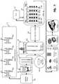
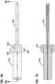
- FIG. 1is a front, perspective, cross-sectional view of a ferrule assembly in accordance with the principles of the present disclosure
- FIG. 2is a rear, perspective view of the ferrule assembly of FIG. 1 ;
- FIG. 3is a longitudinal cross-sectional view of the ferrule assembly of FIG. 1 with a dust cap installed on the ferrule;
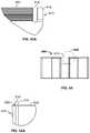
- FIG. 4is a cross-sectional view taken along section line 4 - 4 of FIG. 3 , the cross-sectional view shows a bare fiber portion of an optical fiber of the ferrule assembly;
- FIG. 5is a cross-sectional view taken along section line 5 - 5 of FIG. 3 , the cross-section shows a coated fiber portion of the ferrule assembly
- FIG. 6is a cross-sectional view showing an alternative configuration for the coated fiber portion of FIG. 5 ;
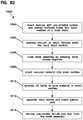
- FIG. 7is a flow chart illustrating a process sequence for manufacturing the ferrule assembly of FIG. 1 ;
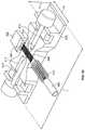
- FIG. 8is a side view showing the ferrule assembly of FIG. 1 in the process of being polished at a polishing table;
- FIG. 9is a top view of the ferrule assembly and polishing table of FIG. 8 ;
- FIG. 10shows the ferrule assembly of FIG. 1 in the process of being tuned with respect to core concentricity
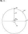
- FIG. 11is an end view of the ferrule assembly of FIG. 1 with the ferrule marked for the purpose of core concentricity tuning;
- FIG. 12is a graph used as a tool for determining the direction of core offset established during core concentricity tuning
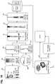
- FIG. 13is a front, perspective, cross-sectional view of a fiber optic connector and cable assembly in accordance with the principles of the present disclosure
- FIG. 14is another cross-sectional view of the fiber optic connector and cable assembly of FIG. 13 , the connector is shown without a dust cap;
- FIG. 15is a longitudinal, cross-sectional view of the fiber optic connector and cable assembly of FIG. 13 ;
- FIG. 16is a flow chart illustrating a sequence of steps for factory manufacturing the fiber optic connector and cable assembly of FIG. 13 ;
- FIG. 17shows the ferrule assembly of FIG. 1 being held for stripping, cleaning and laser cleaving
- FIG. 18shows the fiber optic cable of the fiber optic connector and cable assembly of FIG. 13 with its optical fiber being held for stripping, cleaning and laser cleaving;
- FIG. 19shows the optical fiber of the ferrule assembly of FIG. 1 in coarse alignment of the optical fiber of the fiber optic cable
- FIG. 20shows the ferrule fiber precisely aligned with the fiber optic cable fiber, the aligned fibers are shown at an arc treatment station, arc shielding is also shown;
- FIG. 21shows the arrangement of FIG. 20 with the shielding lowered to protect the ferrule and coated portions of the fibers when the arc treatment device is activated to form a fusion splice between the aligned optical fibers;
- FIG. 22shows the arrangement of FIG. 21 after an initial protective overcoat or over mold layer has been formed over the fusion splice
- FIG. 23shows the arrangement of FIG. 22 after a hub has been over molded over the rear portion of the ferrule of the ferrule assembly and also over the splice between the aligned fibers;
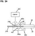
- FIG. 24is a cross-sectional view illustrating a mold for forming the over molded hub of FIG. 23 ;
- FIG. 25is a perspective view of the ferrule assembly of FIG. 1 spliced to the fiber optic cable and over molded with the hub;
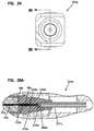
- FIG. 26is a front end view of another fiber optic connector in accordance with the principles of the present disclosure.
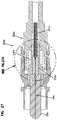
- FIG. 27is a cross-sectional view taken along section line 27 - 27 of FIG. 26 ;
- FIG. 27Ais an enlarged view of a portion of FIG. 27 ;
- FIG. 28is a front end view of a further fiber optic connector in accordance with the principles of the present disclosure.
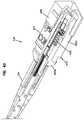
- FIG. 29is a cross-sectional view taken along section line 29 - 29 of FIG. 28 ;
- FIG. 29Ais an enlarged view of a portion of FIG. 29 ;
- FIG. 30is a front end view of another fiber optic connector in accordance with the principles of the present disclosure.
- FIG. 31is a cross-sectional view taken along section line 31 - 31 of FIG. 30 ;
- FIG. 31Ais an enlarged view of a portion of FIG. 31 ;
- FIG. 32is a front end view of a further fiber optic connector in accordance with the principles of the present disclosure.
- FIG. 33is a cross-sectional view taken along section line 33 - 33 of FIG. 32 ;
- FIG. 33Ais an enlarged view of a portion of FIG. 33 ;
- FIG. 34is a front end view of another fiber optic connector in accordance with the principles of the present disclosure.
- FIG. 35is a cross-sectional view taken along section line 35 - 35 of FIG. 34 ;
- FIG. 35Ais an enlarged view of a portion of FIG. 35 ;
- FIGS. 36-40show an example manufacturing sequence for splicing a fiber stub of a ferrule to a fiber of a cable and for enclosing the splice and a portion of the ferrule within a composite hub suitable for use in any of the fiber optic connectors disclosed herein;
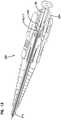
- FIG. 41illustrates a multi-fiber ferrule suitable for use with multi-fiber connectors in accordance with the principles of the present disclosure, the multi-fiber ferrule is shown supporting an optical fiber stub having a plurality of optical fibers;
- FIG. 42illustrates a multi-fiber optical connector incorporating the multi-fiber ferrule of FIG. 41 ;
- FIGS. 43-48illustrate a sequence of steps for preparing a multi-fiber optical cable for splicing to the optical fiber stub of the multi-fiber ferrule of FIG. 41 ;
- FIGS. 49-51show a sequence of process steps for preparing the optical fiber stub of the multi-fiber ferrule of FIG. 41 for splicing to the multi-fiber cable of FIGS. 43-48 ;
- FIG. 52is a perspective view of a fusion splicing tray in accordance with the principles of the present disclosure for use in fusion splicing the multi-fiber cable of FIGS. 43-48 to the fiber stub of the ferrule of FIG. 41 ;
- FIG. 53is a top view of the fusion splicing tray of FIG. 52 ;
- FIG. 53Ais an enlarged view of a portion of FIG. 53 ;
- FIG. 54is a cross-sectional view taken along section line 54 - 54 of FIG. 53 ;
- FIG. 54Ais an enlarged view of a portion of FIG. 54 ;
- FIGS. 55-62show a sequence of steps for assembling the multi-fiber connector of FIG. 42 after the fiber stub of the multi-fiber ferrule of FIG. 41 has been spliced to the multi-fiber cable of FIGS. 43-48 ;
- FIGS. 63-67show an alternative embodiment showing a manufacturing sequence for splicing a fiber stub of a ferrule to a fiber of a cable and for enclosing the splice and a portion of the ferrule within a composite hub suitable for use in any of the fiber optic connectors disclosed herein according to the principles of the present invention
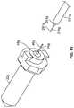
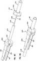
- FIG. 68is a pre-assembled depiction of a ferrule and flange according to the principles of the present invention.
- FIG. 69is a side view of FIG. 68 ;
- FIG. 70is a cross-sectional view taken along section line 70 - 70 of FIG. 69 ;
- FIG. 71is a top view of FIG. 68 ;
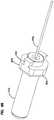
- FIG. 72is a perspective view of the ferrule assembly of FIGS. 63-65 spliced to the fiber optic cable and over molded with the hub;
- FIG. 73is a side view of FIG. 72 ;
- FIG. 74is a cross-sectional view taken along section line 74 - 74 of FIG. 73 ;
- FIG. 75is a front perspective view of an embodiment of a mold assembly according to the principles of the present disclosure.
- FIG. 76is a side view of the mold assembly shown in FIG. 75
- FIG. 77is a bottom perspective view of the mold assembly shown in FIG. 75 ;
- FIG. 78is a cross-sectional view of the mold assembly shown in FIG. 75 ;
- FIG. 79is an enlarged cross-sectional view from a portion of the mold assembly view depicted in FIG. 78 ;
- FIG. 80is a top view of a cavity portion of an upper part of the mold assembly shown in FIG. 75 ;
- FIG. 81is a top view of a cavity portion of a lower part of the mold assembly shown in FIG. 75 ;
- FIG. 82is a flow chart of an injection molding process usable with the mold assembly shown in FIG. 75 ;
- FIG. 83is an exploded view of another ferrule and hub assembly in accordance with the principles of the present disclosure.
- FIG. 84is a partially assembled view of the ferrule and hub assembly of FIG. 83 ;
- FIG. 85is a side view of the ferrule assembly of FIG. 83 with a front hub portion over molded over the ferrule;
- FIG. 86is a rear, perspective view of the ferrule assembly and front hub portion of FIG. 85 ;
- FIG. 87is an exploded view of a further ferrule and hub assembly in accordance with the principles of the present disclosure.
- FIG. 88shows the ferrule and hub assembly of FIG. 87 in a partially assembled configuration
- FIG. 89is a perspective view of a shell of the ferrule and hub assembly of FIGS. 87 and 88 ;
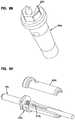
- FIG. 90is an exploded view of still another ferrule and hub assembly in accordance with the principles of the present disclosure.
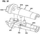
- FIG. 91shows an alternative hub shell that can be used with the ferrule and front hub portion of the embodiment of FIGS. 87 and 88 ;
- FIG. 92is an exploded view illustrating an LC-style connector incorporating the ferrule and hub assembly of FIGS. 83 and 84 ;
- FIG. 93is a cross-sectional view of the connector of FIG. 92 .
- FIGS. 1 and 2illustrate a ferrule assembly 20 in accordance with the principles of the present disclosure.
- the ferrule assembly 20includes a ferrule 22 and an optical fiber stub 24 secured to the ferrule 22 .
- the optical fiber stub 24can be referred to as a “first optical fiber.”
- the ferrule 22includes a front end 26 positioned opposite from a rear end 28 .
- the front end 26preferably includes an end face 30 at which an interface end 32 of the optical fiber stub 24 is located.
- the ferrule 22defines a ferrule bore 34 that extends through the ferrule 22 from the front end 26 to the rear end 28 .
- the optical fiber stub 24includes a first portion 36 secured within the ferrule bore 34 and a second portion 38 that extends rearwardly from the rear end 28 of the ferrule 22 .
- the second portion 38can be referred to as a “pigtail” or as a “free end portion.”
- the ferrule 22is preferably constructed of a relatively hard material capable of protecting and supporting the first portion 36 of the optical fiber stub 24 .
- the ferrule 22has a ceramic construction.
- the ferrule 22can be made of alternative materials such as Ultem, thermoplastic materials such as Polyphenylene sulfide (PPS), other engineering plastics or various metals.
- the ferrule 22has a length L 1 in the range of 5-15 millimeters (mm), or in the range of 8-12 mm.
- the first portion 36 of the optical fiber stub 24is preferably secured by an adhesive (e.g., epoxy) within the ferrule bore 34 of the ferrule 22 .
- the interface end 32preferably includes a polished end face accessible at the front end 32 of the ferrule 22 .
- the ferrule bore 34has a stepped-configuration with a first bore segment 40 having a first diameter d 1 and a second bore segment 42 having a second diameter d 2 .
- the second diameter d 2is larger than the first diameter d 1 .
- a diameter step 44provides a transition from the first diameter d 1 to the second diameter d 2 .
- the first bore segment 40extends from the front end 26 of the ferrule 22 to the diameter step 44 .
- the second bore segment 42extends from the diameter step 44 toward the rear end 28 of the ferrule 22 .
- the ferrule bore 34also includes a conical transition 39 that extends from the second bore segment 42 to the rear end 28 of the ferrule 22 .
- the first diameter d 1is about 125.5 microns with a tolerance of +1 micron.
- the second diameter d 2can be about 250 microns so as to accommodate a coated optical fiber, or about 900 microns so as to accommodate a coated and buffered optical fiber.
- d 1is in the range of 230-260 microns and d 2 is in the range of 500-1100 microns.
- the first portion 36 of the optical fiber stub 24includes a bare fiber segment 46 that fits within the first bore segment 40 of the ferrule 22 and a coated fiber segment 48 that fits within the second bore segment 42 of the ferrule 22 .
- the bare fiber segment 46is preferably bare glass and, as shown at FIG. 4 , includes a core 47 surrounded by a cladding layer 49 .
- the bare fiber segment 46has an outer diameter that is no more than 0.4 microns smaller than the first diameter d 1 .
- the coated fiber segment 48includes one or more coating layers 51 surrounding the cladding layer 49 (see FIG. 5 ).
- the coating layer or layers 51can include a polymeric material such as acrylate having an outer diameter in the range of about 230-260 microns.
- the coating layer/layers 51can be surrounded by a buffer layer 53 (e.g., a tight or loose buffer layer) (see FIG. 6 ) having an outer diameter in the range of about 500-1100 microns.
- the second portion 38 of the optical fiber stub 24preferably has a length L 2 that is relatively short.
- the length L 2 of the second portion 38is less than the length L 1 of the ferrule 22 .
- the length L 2is no more than 20 mm, or is no more than 15 mm, or is no more than 10 mm.
- the length L 2 of the second portion 38is in the range of 1-20 mm, or in the range of 1-15 mm, or in the range of 1-10 mm, or in the range of 2-10 mm, or in the range of 1-5 mm, or in the range of 2-5 mm, or less than 5 mm, or less than 3 mm, or in the range of 1-3 mm.
- FIG. 7outlines a process for manufacturing the ferrule assembly 20 of FIGS. 1-3 .
- the manufacturing processbegins at step 100 where the ferrule 22 is fed to a processing station or location. It will be appreciated that the ferrule 22 can be fed by an automated feed mechanism such as a bowl feed mechanism.
- the inner diameter of the ferrule 22is preferably measured (see step 102 ).
- the first diameter d 1 defined by the first bore segment 40 of the ferrule bore 34is preferably measured.
- An automated ferrule handlere.g., a gripper/holder 37 as shown schematically at FIG. 8 ) can receive the ferrule 22 from the automated feed mechanism and can hold and/or manipulate the ferrule 22 during measurement.
- an optical fiber suitable for insertion within the ferruleis selected (see step 104 ).
- a plurality of fiber spools 60 a - 60 dis provided at the processing station.
- Each of the fiber spools 60 a - 60 dincludes a separate optical fiber 62 a - 62 d .
- Each of the optical fibers 62 a - 62 dpreferably has a different cladding outer diameter. It is desirable to select the optical fiber 62 a - 62 d having a cladding outer diameter that is closest to the measured diameter d 1 of the ferrule 22 .
- the measured first diameter d 1is no more than 0.4 microns larger than the cladding outer diameter of the selected optical fiber 62 a - 62 d.
- each of the optical fibers 62 a - 62 dhas an outer cladding diameter manufactured within a tolerance of +/ ⁇ 0.7 microns and also has a core-to-cladding concentricity offset less than or equal to 0.5 microns (i.e., the center of the core is offset from the center of the cladding diameter by no more than 0.5 microns).
- the ferrule 22is also preferably manufactured to relatively precise tolerance specifications.
- the diameter d 1 of the ferrulehas a dimension of 125.5 microns plus 1.0 micron, minus 0.0 microns.
- the ferrule 22can have a fiber bore to outer diameter concentricity offset less than or equal to 1 micron (i.e., the center of the ferrule bore is offset from the center of the outer diameter of the ferrule by no more than 1 micron).
- four fibers of known diameters of 125.3 microns, 125.6 microns, 125.9 microns, and 126.2 micronscould be employed to match the ferrule inner diameter to within 0.2 to 0.3 microns.
- this fiber selection processit is possible for all of the ferrule assemblies 20 output from the manufacturing process to have a measured first diameter d 1 that is no more than 0.4 microns larger than the cladding outer diameter of the selected optical fiber 62 a - 62 d . Those that fall outside of the tolerance can be rejected, but because of the process only a relatively small number may fall outside of the tolerance thereby enhancing the cost effectiveness of the process.
- the ferrule assemblies 20 manufactured and output according to the processcan have measured first diameters d 1 that on average are no more than 0.4 microns larger than the cladding outer diameters of the selected optical fiber 62 a - 62 d.
- the optical fiberis cut to length to form the stub optical fiber 24 (see step 106 ).
- the cut optical fiber 24has a length less than 40 microns.
- the optical fiber 24has a length less than 30 microns, or less than 25 microns, or less than 20 microns, or less than 15 microns.
- the cut optical fiberhas a length in the range of 12-25 microns.
- the optical fiber 24is stripped.
- the bare fiber segment 46is exposed.
- the bare fiber segment 46preferably includes a glass core 47 and cladding 49 as shown at FIG. 4 .
- the cutting and stripping stepscan be automated.
- optical fiber 24After stripping of the optical fiber 24 , epoxy is dispensed into the ferrule bore 34 of the ferrule 22 (see step 110 ), and the optical fiber 24 is inserted into the ferrule bore 34 . Because of the relatively tight tolerance between the first diameter d 1 of the bare fiber segment 46 of the optical fiber stub 24 and the first portion 36 of the fiber bore 34 , surface tension between the epoxy within the ferrule bore 34 and the optical fiber stub 24 provides a self-centering function that assists in centering the bare fiber segment 46 within the first bore segment 40 . Such fiber insertion is indicated at step 112 of the process. The optical fiber stub 24 is inserted into the ferrule bore 34 through the rear end 28 of the ferrule 22 .
- the optical fiber stub 24is oriented such that the bare fiber segment 46 leads the optical fiber stub 24 through the ferrule 22 .
- an end portion of the bare fiber segment 46projects outwardly from the end face 34 of the ferrule 22 .
- the epoxy delivery and fiber insertion stepscan be automated. During such steps, the ferrule can be held by the automated ferrule handler.
- the ferrule assembly 20is cured (e.g., oven cured), cooled and cleaved. It is noted that the curing process is particularly efficient because the ferrule 22 can be directly heated and the heat does not need to pass through a connector body or other structure surrounding the ferrule 22 . Similarly, the cooling process is efficient since only the ferrule 22 and the optical fiber stub 24 need to be cooled. Cleaving can be conducted using a laser or a mechanical cleaving tool. The curing, cooling and cleaving steps can be automated.
- the cleaved interface end 32 of the optical fiber 24can be polished as indicated at step 116 .
- the polishing processcan include multiple polishing steps using different polishing pads and polishing compounds having different degrees of abrasiveness. Because the ferrule assembly 20 is not connected to an extended length of cable, downward vertical polishing pressure can be applied without side loading from a cable. The absence of an extended length of cable coupled to the ferrule 22 also allows the ferrule assembly 20 to be rotated about its axis 76 during the polishing process. In certain embodiments, the ferrule assembly 20 can be rotated about its axis 76 at a rate of at least 10 rotations per minute, or at least 50 rotations per minute, or at least 100 rotations per minute, or at least 500 rotations per minute.
- FIGS. 8 and 9show the ferrule end face 30 and the interface end 32 of to the optical fiber 24 being polished using a rotating polishing table 70 that rotates about an axis 72 .
- a polishing pad 74can be provided on the rotating polishing table 70 .
- the polishing table 70may oscillate, reciprocate, move along a random orbit path, or otherwise move. Additionally, during the polishing process, it may be desirable to rotate the ferrule 22 about its axis of rotation 76 as described above.
- a mechanical polishing processis used to polish the end face 30 of the ferrule and the interface end 32 of the optical fiber stub 24 .
- a lasercan be used to both cleave and polish/process the interface end 32 of the optical fiber stub 24 .
- polishing stepscan be automated.
- the ferrule 22can be held by the automated ferrule handler.
- the automated handlercan include a rotational drive 35 for rotating the ferrule 22 about its axis 76 during polishing or other steps disclosed herein here rotation of the ferrule 22 about its center axis is desired.
- tuningis a process where an offset direction of the core 47 is established and an indication of the core offset direction is provided on the ferrule 22 .
- the indication of the core offset directioncan include any number of techniques such as printing a mark on the ferrule 22 , etching a mark on the ferrule 22 , or otherwise marking the ferrule 22 .
- the core offset directionis the direction in which the core 47 is offset from a centerline (e.g., axis 76 ) of the ferrule 22 .
- the ferrule assembly 20can be tuned by shining a light 80 through a rear end of the optical fiber stub 24 such that the light is conveyed through the optical fiber stub 24 and out the interface end 32 of the optical fiber stub 24 .
- a camera 82 or other structurecan be used to view and monitor the light output through the fiber core 47 at the end 32 so as to determine the core position.
- the ferrule assembly 20is then rotated about its axis 76 while the light 80 continues to be directed through the optical fiber stub 24 and the camera 82 continues to view the end 32 of the optical fiber stub 24 .
- the core 47 of the optical fiber stub 24changes elevations relative to a horizontal line H (see FIG. 11 ) that intersects the centerline 76 of the ferrule 22 .
- FIG. 12is a graph illustrating the height of the core 47 relative to the horizontal line H as the ferrule 22 is rotated about its centerline axis 76 .
- the maximum core height 89is indicative of an offset direction 91 of the core 47 relative to the axis 76 of the ferrule assembly 20 .
- the axis 76 of the ferrule assembly 20is defined by the outer diameter of the ferrule 22 .
- the markingcould be offset 180° from the core offset direction 91 or at other locations on the ferrule 22 .
- the marking 93is used to orient the core offset a desired location relative to the connector body.
- the core offset direction 91is oriented at the twelve o'clock position relative to the connector body.
- the marking 93can also be used to orient the core offset relative to a hub that is subsequently mounted on the ferrule 22 .
- the hubcan include a keying structure for ensuring that the ferrule is mounted at a desired rotational position within the connector body such that the core offset is oriented at a desired rotational position relative to the connector body.
- tuningcan be provided at an infinite number of increments (i.e., the marking location can be chosen from an infinite number of rotational/circumferential positions about the centerline of the ferrule) to provide precise alignment of the marking 93 with the core offset direction 91 .
- the marking locationcan be chosen from a discrete number of rotational/circumferential positions about the centerline of the ferrule, where the number of discrete rotational/circumferential positions is at least 6, or at least 12, or at least 18, or at least 24, or at least 30.
- the ferrule assembly 20is tuned after at least a portion of the hub is mounted on the ferrule and the hub can define a discrete number of rotational/circumferential positions.
- a core offset markingcan be provided on the hub.
- the tuning stepcan be automated and rotation of the ferrule 22 during tuning can be achieved by the automated ferrule handler.
- the polishing processis completed at step 116 and various inspections are conducted at step 118 .
- the inspectionscan include a corporate workmanship standard inspection in which the end 32 of the optical fiber stub 24 is inspected with a microscope to insure that there are no unacceptable scratches, pits or chips on the end face.
- the end face 32 of the optical fiber stub 24 and the end face 30 of the ferrule 22can also be inspected and analyzed to insure the end faces comply with certain geometry specifications for the end faces.
- a continuity checkcan be conducted by which a light is shined through the optical fiber stub 24 to make sure the optical fiber stub 24 is capable of transmitting light.
- a dust capcan be installed on the ferrule 22 and the ferrule assembly 20 can be packaged at shown at step 120 .
- the various steps described abovecan be automated.
- FIGS. 13-15illustrate a fiber optic cable and connector assembly 200 in accordance with the principles of the present disclosure.
- the fiber optic cable and connector assembly 200includes a fiber optic connector 202 having a connector body 204 .
- the connector bodyhas a front end 206 and a back end 208 .
- the ferrule assembly 20is positioned at least partially within the connector body 204 .
- the ferrule assembly 20is positioned with the ferrule 22 positioned adjacent to the front end 206 of the connector body 204 .
- the fiber optic connector 202further includes a boot 210 mounted adjacent the back end 208 of the connector body 204 .
- the word “adjacent”means at or near.
- the connector 202is compatible with existing connectors, fiber optic adapter, patch panels and fiber optic cables.
- the fiber optic cable and connector assembly 200further includes a fiber optic cable 212 that extends through the boot 210 .
- the fiber optic cable 212includes a jacket 214 and an optical fiber 216 positioned within the jacket 214 .
- the optical fiber 216can be referred to as a “second optical fiber.”
- the optical fiber 216is optically connected at a fusion splice 217 to the optical fiber 24 of the ferrule assembly 20 .
- the fusion splice 217is positioned at a splice location 218 spaced from the rear end 28 (i.e., the base) of the ferrule 22 .
- the splice location 218is within the connector body 204 and is positioned no more than 20 mm from the rear end 28 of the ferrule 22 .
- the fusion splice 217is preferably a factory fusion splice.
- a “factory fusion splice”is a splice performed at a manufacturing facility as part of a manufacturing process.
- the fiber optic connector 202fully complies with Telcordia GR-326 or similar stringent industry or customer specifications. In other examples, the splice can be a field splice.
- the connector body 204includes a front piece 220 and a rear piece 222 .
- the front piece 220forms a front interface end of the fiber optic connector 202 and the rear piece 222 is configured to allow strength members 224 (e.g., aramid yarn, fiberglass or other strength members capable of providing tensile reinforcement to the fiber optic cable 212 ) of the fiber optic cable 212 are anchored.
- the strength members 224can be secured to the rear piece 222 of the connector body 204 with a mechanical retainer such as a crimp sleeve. In other embodiments, adhesive or other means can be used to secure the strength members 224 to the connector body 204 .
- the front and rear pieces 220 , 222 of the connector body 204interconnect together by a connection such as a snap-fit connection, an adhesive connection or other type of connection.
- a connectionsuch as a snap-fit connection, an adhesive connection or other type of connection.
- a spring 228 and a hub 230are captured between the front and rear pieces 220 , 222 .
- the hub 230is secured over the rear end 28 of the ferrule 22 .
- the hub 230also covers the splice location 218 such that the fusion splice 217 is located within the hub 230 .
- an intermediate layer 232(e.g., a coating layer, an over mold layer, or other layer) is provided between the fusion splice 217 and the hub 230 .
- the spring 228is captured within a spring pocket 229 defined by the rear piece 222 and functions to bias the hub 230 and the ferrule assembly 20 which is carried with the hub 230 in a forward direction relative to the connector body 204 .
- the hub 230is a structure secured on the ferrule 22 such that the ferrule 22 and the hub 230 move together as a unit. In certain embodiments, the hub 230 provides structure against which the bias of the spring 228 can be applied to bias the hub 230 and the ferrule 22 forwardly relative to the connector body 204 .
- the hub 230also includes structure that interferes with an internal structure (e.g., a stop) of the connector body 204 to limit the forward movement of the ferrule 22 and to prevent the ferrule 22 from being pushed out of the front of the connector body 204 by the spring 228 .
- the hub 230 and the splice location 218can be positioned within the spring pocket 229 .
- the boot 210 , the rear piece 222 and the spring 228all can have internal dimensions (e.g., inner diameters) larger than an outer dimension (e.g., an outer diameter) of the cable 212 such that during assembly/manufacturing the boot 210 , the rear piece 222 and the spring 228 can be slid back over the jacket 212 to provide space/clearance for splicing and application of the hub over the spice 217 .
- internal dimensionse.g., inner diameters
- an outer dimensione.g., an outer diameter
- the fiber optic connector 202is shown as a standard SC-type connector. As such, the fiber optic connector 202 is adapted to be received within an SC-type fiber optic adapter that is used to couple two of the fiber optic connectors together to provide an optical connection there between.
- the fiber optic connector 202includes a release sleeve 236 that is slidably mounted on the connector body 204 . When the fiber optic connector 202 is inserted within a fiber optic adapter, shoulders of the connector body 204 are engaged by latches of the fiber optic adapter to retain the fiber optic connector 202 within the fiber optic adapter.
- the release sleeve 236is slid rearwardly relative to the connector body 204 thereby causing the latches of the fiber optic adapter to disengage from the shoulders of the connector body 204 such that the fiber optic connector 202 can be withdrawn from the fiber optic adapter.
- An example fiber optic adapteris disclosed at U.S. Pat. No. 5,317,663, which is hereby incorporated by reference in its entirety.
- the splice location 218is relatively close to the rear end 28 of the ferrule 22 .
- the splice location 218is no more than 15 mm from the ferrule 22 .
- the splice location 218is no more than 10 mm from the ferrule 22 .
- the splice location 218is no more than 5 mm from the ferrule 22 .
- the splice locationis spaced 1-20 mm from the ferrule 22 , or 1-15 mm from the ferrule 22 or spaced 1-10 mm from the ferrule 22 , or 1-5 mm from the ferrule 22 , or 2-10 mm from the ferrule 22 , or 2-5 mm from the ferrule 22 , or 1-3 mm from the ferrule 22 , or less than 4 mm from the ferrule 22 , or less than 3 mm from the ferrule 22 , or 1-4 mm from the ferrule 22 , or 2-3 mm from the ferrule 22 .
- the splice location 218(i.e., the interface between the two optical fibers 24 , 216 ) is preferably located in the region that would normally be occupied by a hub.
- the splice locationis provided between the base of the ferrule 22 and the rear end of the spring 228 .
- the splice location 218is within the spring chamber 229 .
- the spring 228biases the ferule 20 toward a forward-most position (i.e., a distal-most position or non-connected position) and during a connection with another connector the spring 228 allows the ferrule 22 to move rearwardly from the forward-most position, against the bias of the spring 228 , to a rearward position (i.e., proximal position or connected positioned).
- the splice location 218is positioned between forward and rearward ends 228 a , 228 b of the spring 228 when the ferrule is in the forward-most position, and is also positioned between the forward and rearward ends 228 a , 228 b of the spring 228 when the ferrule 22 is in the rearward position.
- the hub 230has a polymeric construction that has been over molded over the rear end of the ferrule 22 and over the splice location 218 .
- the fiber optic connector 202has a length L 3 that is less than 57 mm. It will be appreciated that the length L 3 of the fiber optic connector 202 is measured from the front end 26 of the ferrule 22 to a rear end 240 of the boot 210 .
- a portion 231 of the hub 230 that extends rearward of the ferrule 22has a length L 4 that is shorter than the length L 1 of the ferrule 22 .
- the splice location 218is within 5 mm of the rear end of the ferrule 22 . Providing the splice location 218 within 5 mm of the rear end of the ferrule 22 assists in designing the fiber optic connector in compliance with standard industry or customer side load and connector length specifications (e.g., GR-326 side load and length requirements).
- the boot 210is shown press-fit over the rear piece 222 of the connector body 204 . Specifically, the boot 210 is press-fit over the location where the strength members 224 are attached to the connector body 204 . It will be appreciated that the boot 210 has a tapered, flexible configuration that provides the optical fiber 216 with bend radius protection when a side load is applied to the fiber optic connector 202 through the fiber optic cable 212 .
- the fusion splice 217is a factory fusion splice having a splice related insertion loss of 0.1 decibels or less, 0.05 decibels or less, or 0.02 decibels or less in the 1260 nanometer to 1630 nanometer signal wavelength range.
- an active alignment systemcan be utilized to accurately align the optical fibers 216 , 24 .
- Example active alignment systemsare sold by Sumitomo, Furukawa, Vytran, 3SAE, and Fujikura.
- the active alignment systemcan ensure that the centers of the cores of the optical fibers 216 , 24 being spliced are offset by no more than 0.01 microns by the alignment system prior to splicing.
- the alignment systemcan utilize cameras that view the cores of the optical fibers 216 , 24 along viewing lines that are perpendicular to one another (e.g., a top view and a side view).
- the optical fiber stub 24can be manufactured using a precision fiber having tightly toleranced parameters such as core to cladding concentricity and cladding outer diameter variation.
- the optical fiber stub 24can be different (e.g., can have a different construction, different mechanical characteristics, different physical attributes, different optical performance characteristics, different degrees of precision, etc.) than the optical fiber 216 of the fiber optic cable.
- the optical fiber stub 24can be a more precisely manufactured optical fiber than the optical fiber 216 of the fiber optic cable 212 (i.e., the stub fiber is manufactured according to tighter tolerances than the cable optical fiber 216 ).
- the optical fiber stub 24can have better average core to cladding concentricity than the optical fiber 216 .
- the outer diameter of the cladding of the optical fiber stub 24can be more precisely toleranced that the outer diameter of the cladding of the optical fiber 216 .
- the optical fiber stub 24can have a different (e.g., lower) fiber cut-off wavelength than the optical fiber 216 .
- the optical fiber stub 24can have different cladding mode suppression characteristics as compared to the optical fiber 216 .
- the optical fiber stub 24can have a construction adapted to provide enhanced cladding mode suppression for suppressing modal interference.
- Example optical fibers having constructions adapted to reduce/suppress modal interferenceare disclosed at U.S. Pat. Nos. 6,498,888; 5,241,613; and 4,877,306, which are hereby incorporated by reference in their entireties.
- the fiber optic cable and connector assembly 200 of the present disclosureincludes various features that provide excellent performance despite the presence of an internal splice. Such features include: a) precise core-to-core alignment of the spliced optical fibers; b) precise centering of the optical fiber stub 24 within the ferrule bore 34 , precise tuning of the core offset direction within the connector body, and precise centering of the ferrule bore 34 within the ferrule 22 .
- the fiber optic connector 202can be in full compliance with the requirements of Telcordia GR-326.
- Specific sections of Telcordia GR-326 in which the fiber optic connector 202 can be in complianceinclude sections pertaining to transmission with applied load, installation tests, and the post-condensation thermal cycle test.
- FIG. 16shows a process for manufacturing a patch cord formed by mounting fiber optic connectors 202 on opposite ends of the fiber optic cable 212 .
- the fiber optic cable 212is coiled and the components of the fiber optic connectors 202 are staged.
- the ends of the jacket 214 of the fiber optic cable 212are then cut and slit, and the strength layer 224 is trimmed.
- end portions of the optical fiber 216extend outwardly from each end of the jacket 214 .
- the end portions of the optical fiber 216are then stripped, cleaned and cleaved (e.g., laser cleaved) (see step 304 ).
- the end portions of the optical fiber 216can be gripped in a holder 217 (e.g., a holding clip or other structure) (see FIG. 18 ).
- ferrule assemblies 20are fed (e.g., bowl fed) to a holder 240 or holders which grip/hold the ferrule 22 .
- An example holder 240is shown at FIG. 17 .
- the ferrules 22are oriented within the holders 240 with the tuning marks 93 at the twelve o'clock position so that the ferrule assemblies 20 can be subsequently loaded into their corresponding connector bodies 204 at the twelve o'clock position. In this way, it is ensured that the core offset direction is oriented at the uppermost position/sector of each connector. While the twelve o'clock position is preferred, the core offset direction can be established within the connector body at other rotational positions as well.
- ferrule assemblies 20are prepared for each end of the patch cable.
- the optical fiber stub 24 of each ferrule assembly 20is coarsely aligned with a corresponding end portion of optical fiber 216 (see FIG. 19 ), and then precisely aligned (see FIG. 20 ).
- Precise alignment of the optical fiberscan be accomplished using an active alignment device.
- the fiber 216is held within the holders 217 with an end portion of the fiber 216 projecting outwardly from one end of the holder 217 (as shown at FIGS. 20-23 , the cable 212 projecting from the opposite end of the holder 217 has been omitted).
- the ferrule 22is held within a pocket of the holder 240 while the fiber 24 projects from the base of the ferrule 222 and is not contacted directly by the holder 240 or any other structure.
- the holder 240can include a clip or other structure having two or more pieces that clamp and hold the ferrule 22 during active alignment of the fibers 216 , 24 .
- the pocket of the holder 240can include an internal structure (e.g., a V-groove, semi-circular groove, etc. for aligning/positioning the ferrule 22 ).
- the end portions of the fibersare preferable unsupported (e.g., not in direct contact with a structure such as a v-groove).
- the fiber 24projects less than 5 mm from the base end of the ferrule 22 .
- This relatively short lengthfacilitates the active alignment process.
- the center axis of the fiber 24is angled no more than 0.1 degrees relative to the center line of the ferrule. This also assists the active alignment process. While ideally there is no angular offset between the center axis of the fiber 24 and the ferrule 22 , the short stub length of the fiber 24 assist in minimizing the effect during active alignment of any angular offset that may exist.
- Roboticsare preferably used to manipulate the holders 240 , 217 to achieve axial alignment between the cores of the fibers 24 , 216 .
- the splice locationcan be provided in close proximity to the base of the ferrule 22 (e.g., within 5 mm of the base). In certain embodiments, only splices in which the centers of the cores of the optical fibers 216 , 24 being spliced are offset by no more than 0.01 microns are acceptable, and splices falling outside of this parameter are rejected. In other embodiments, the average core offset for fibers spliced by the process is less than 0.01 microns.
- a shielding unit 250is lowered over the splice location 218 and a fusion splice machine 251 (e.g., an arc treatment machine) is used to fuse the optical fibers 24 , 216 together.
- the shielding unit 250includes shielding portions for shielding the ferrule 22 and coated portions of the optical fibers 24 , 216 intended to be spliced together.
- the shielding structure 250can have a ceramic construction, Polyether ether ketone (PEEK) construction, another heat resistant plastic construction or other type of heat resistant construction.
- the shielding structure 250includes a gap g through which an arc or other energy source from the fusion splice machine 251 can pass to fusion splice the optical fibers 24 , 216 together.
- the gap gis 1-3 mm, or 2-2.5 mm.
- FIG. 20shows the shielding structure 250 in the raised orientation and FIG. 21 shows the shielding structure in a shielding position.
- the shielding structurecan include side walls 253 that protect the sides of the ferrule 22 and extend along the lengths of optical fibers 24 , 216 , and cross-walls 255 that extend between the side walls 253 .
- the cross-walls 255extend across to the optical fibers 24 , 216 (e.g., transverse to the optic fibers 24 , 216 ) and include slots 257 for receiving the optical fibers 24 , 216 .
- the side walls 253also protect the portions of the fibers 24 , 216 adjacent the splice location and the holders 214 , 240 .
- the cross-walls 255protect the fibers 24 , 216 , the rear end 28 of the ferrule 22 and the holders 214 , 240 .
- a bridge sectionextends across the gap g between the cross-walls 255 .
- Step 310 of FIG. 16is representative of the alignment, shielding and fusion splicing operations.
- a protective layer 232can be placed, applied or otherwise provided over the optical fibers 24 , 216 in the region between the rear end 28 of the ferrule 22 and a buffered/coated portion of the optical fiber 216 .
- the protective layer 232extends completely from the rear end 28 of the ferrule 22 to a coated and buffered portion of the optical fiber 216 .
- the coated and buffered portion of the optical fiber 216includes coatings in the form of a 220-260 micron acrylate layers which cover the glass portion of the optical fiber, and a buffer layer 221 (e.g., a loose or tight buffer tube) having an outer diameter ranging from 500-1,100 microns.
- the protective layer 232is shown extending over the splice location 218 completely from the rear end 28 of the ferrule 22 to the buffer layer of the optical fiber 216 .
- the protective layer 232is generally cylindrical (see FIG. 15 ) and has a diameter slightly larger than the buffer layer and generally the same as a major diameter of the conical transition 39 of the ferrule bore 34 .
- the protective layer 232can have a truncated conical configuration (see FIG. 22 ) with a major diameter generally equal to the outer diameter of the ferrule 22 and a minor diameter generally equal to the outer diameter of the buffer layer of the optical fiber 216 .
- the protective layer 232can be applied using an over molding technique. Alternatively, coating, spraying, laminating or other techniques can be used to apply the protective layer.
- the protective layer 232is made of a material that is softer (e.g., has a lower hardness) than the material used to manufacture the hub 230 .
- the unstripped portion of the optical fiber 216has an inner coating layer that surrounds the cladding layer, and the protective layer 232 has mechanical attributes such as softness/hardness that substantially match or are comparable to the mechanical attributes of the inner coating layer of the unstripped portion of the optical fiber 216 .
- the protective layer 232can be made of a thermoplastic material, a thermoset material (a material where cross-linking is established during heat curing), other types of cross-linked materials or other materials.
- Example materialsinclude acrylates, epoxies, urethanes, silicones and other materials.
- the materialscan be UV curable (i.e., the materials cure when exposed to ultraviolet radiation/light).
- One example materialincludes a UV curable splicing compound such as DSM-200 which is sold by DSM Desotech, Inc. of Elgin Ill.
- an injection molding processe.g., a thermoplastic injection molding process
- the hub 230is preferably over molded over the protective layer 232 as shown at FIG. 23 .
- the hub 230is preferably over molded over the rear end 28 of the ferrule 22 and also over the splice location 218 .
- FIG. 24shows a mold assembly 400 mold pieces 400 a , 400 b having an inner shape that matches the outer shape of the hub 230 .
- the mold assembly 410 shown in FIGS. 75-81may also be used to form the hub 230 .
- a polymeric materialis injected from an injection machine 403 into a cavity 401 defined by the mold pieces 400 a , 400 b to over mold the polymeric material over the splice location 218 and the rear end 28 of the ferrule 22 .
- the hub 230is molded by injecting a UV curable material into the mold, and the mold pieces 400 a , 400 b are made of a UV transmissive material (e.g., Teflon) such that UV light/radiation can be transmitted through the mold pieces 400 a , 400 b for curing the hub 230 within the mold.
- a UV transmissive materiale.g., Teflon
- the hub 230is shaped to include a flange 260 that engages the spring 228 . Additionally, the hub 230 is configured to support the rear end 28 of the ferrule 22 within the connector body 204 . Furthermore, a forward end or flange 263 of the hub 230 is configured to engage a shoulder 261 within the connector body 204 to halt forward movement of the ferrule assembly 20 caused by the forward bias provided by the spring 228 . In this way, the flange 263 functions to retain the ferrule 22 within the connector body 202 .
- Step 312 of FIG. 16is representative of the over molding operations.
- the hub 230can be made of a thermoplastic material, a thermoset material (a material where cross-linking is established during heat curing), other types of cross-linked materials, or other materials.
- Example materialsinclude acrylates, epoxies, urethanes, silicones and other materials. At least some of the materials can be UV curable (i.e., the materials cure when exposed to ultraviolet radiation/light).
- an injection molding processe.g., a thermoplastic injection molding process
- a hot melt materialcan be injected into the mold to form the hub 230 .
- hot melt materialse.g., hot melt thermoplastic materials
- UV curable materialsallows the hub over molding process to be conducted at relatively low pressures (e.g., less than 1000 pounds per square inch (psi)) and at relatively low temperatures (e.g., less than 300 degrees Celsius).
- curingcan take place at temperatures less than 200 degrees Celsius, or less than 100 degrees Celsius, or at room temperature, and at pressures less than 100 psi or at pressures less than 10 or 5 psi.
- the other components of the fiber optic connectors 202are assembled over the ferrule assembly 20 and the hub 230 (see step 314 at FIG. 16 ). Additionally, the strength members of the fiber optic cable 212 are attached to the rear ends of the connector bodies 204 of the fiber optic connectors 202 . A continuity check can be conducted for the patch cable and dust caps are positioned over the ferrules 22 (see step 316 at FIG. 16 ). Finally, the patch cords are packaged and labeled (see step 318 of FIG. 16 ). It will be appreciated that any and/or all of the above connector manufacturing steps can be automated. Robotics can improve the consistency and quality of the connectorization process and automation can assist in lowering labor related costs.
- FIGS. 26, 27 and 27Aillustrate another fiber optic cable and connector assembly 200 a in accordance with the principles of the present disclosure.
- the fiber optic cable and connector assembly 200 aincludes a fiber optic connector 202 a having a connector body 204 a in which a ferrule 22 a is mounted.
- the ferrule 22 asupports an optical fiber stub 24 a having a bare optical fiber segment 46 a spliced to a bare fiber segment 291 a of an optical fiber 216 a of an optical cable.
- the optical fiber 216 aincludes a coated portion 293 a .
- a loose buffer tube 221 asurrounds and protects at least a portion of the coated portion 293 a of the optical fiber 216 a .
- the bare fiber segment 46 ais spliced to the bare fiber segment 291 a at a splice location 218 a .
- a generally cylindrical protective layer 232 ais coated or overmolded over the splice location 218 a . More specifically, the protective layer 232 a is shown extending from a rearward end of the ferrule 22 a to a forward end of the buffer tube 221 a .
- the protective layer 232 afully encapsulates the bare fiber segments 46 a , 291 a and also encapsulates a portion of a coated fiber segment 48 a of the optical fiber stub 24 a and a portion of the coated portion 293 a of the optical fiber 216 a .
- the protective layer 232 afurther encapsulates the forward end of the loose buffer tube 221 a .
- some of the material forming the protective layer 232 aflows around the exterior of the buffer tube 221 a and also flows inside the buffer tube 221 a between the interior of the buffer tube 221 a and the coated portion 293 a of the optical fiber 216 a .
- a hub 230 ais over molded around the rearward end of the ferrule 22 and encapsulates and protects the protective layer 232 a as well as the splice location 218 a within the protective layer 232 a .
- the hub 230 ais bonded or otherwise secured/attached to the ferrule 22 a .
- a spring 228 abiases the hub 230 a and the ferrule 222 a in a forward direction.
- the hub 232 aextends from the rearward end of the ferrule 22 a to the loose buffer tube 221 a and fully encapsulates the protective layer 232 a .
- a rearward portion of the hub 232 asurrounds and bonds to an exterior surface of the buffer tube 221 a to prevent the buffer tube 221 a from being pulled from the connector. Because both the protective layer 232 a and the hub 230 a are bonded or otherwise attached to the buffer tube 221 a , the buffer tube 221 a has enhanced pull-out characteristics. Such characteristics are further enhanced if the protective layer 232 a is bonded to both the outside and the inside of the buffer tube 221 a.
- FIGS. 28, 29 and 29Ashow another fiber optic cable and connector assembly 200 b having the same basic construction as the fiber optic cable and connector assembly 200 a except a protective layer 232 b has been lengthened to increase the contact length between the protective layer 232 b and a buffer tube 221 b , and a hub 230 b has been modified to accommodate the lengthened protective layer 232 b .
- the portion of the protective layer 232 b attached to the buffer tube 221 bis longer than the portion of the hub 232 b that engages and is bonded to or attached to the buffer tube 221 b .
- the embodiment of FIGS. 28, 29 and 29 ais particularly advantageous for applications where the protective layer 232 has better adhesion characteristics with respect to the buffer tube 221 as compared to the material of the hub 230 b .
- the embodiment of FIGS. 27, 28 and 28Ais preferred for embodiments where the material of the hub 230 a has enhanced bonding characteristics with respect to the buffer tube 221 a as compared to the material of the protective layer 232 a .
- the rear portion of the hubengages and circumferentially surrounds (i.e., shuts-off against) the buffer tube.
- FIGS. 30, 31 and 31Ashow a further fiber optic cable and connector assembly 200 c in accordance with the principles of the present disclosure.
- the fiber optic cable end connector assembly 200 chas structure adapted to enhance retention of a buffer tube 221 c within a fiber optic connector 202 c .
- the fiber optic connector 202 cincludes a crimp ring 295 mechanically crimped adjacent a forward end of the buffer tube 221 c .
- the crimp ring 295includes a recess or receptacle in the form of an annular groove 296 that extends around a perimeter of the crimp ring 295 .
- the fiber optic connector 202 cfurther includes a hub 230 c over molded over the crimp ring 295 and the forward end of the buffer tube 221 c .
- the hub 230 cincludes an annular projection 297 that projects radially inwardly into the annular groove 296 of the crimp ring 295 .
- the mechanical interlockresists relative axial movement between the crimp ring 295 .
- the crimp ringhas a forward end that abuts against a protective layer 232 c that protects a splice location 218 c between an optical fiber stub 24 c and an optical fiber 216 .
- the optical fiber stub 24 chas forward ends supported in a ferrule 22 c and rearward end portions that project rearwardly from the ferrule 22 c .
- the optical fiber 216 ccorresponds to a fiber optic cable.
- the protective layer 232 cprotects a bare fiber segment 291 c and a coated portion 293 c of the optical fiber 216 c as well as a coated fiber segment 48 c and a bare fiber segment 46 c of the optical fiber stub 24 c .
- the hub 230 csurrounds and is coupled to (i.e., boded to, affixed to, attached to) a rearward end of the ferrule 22 c and fully encloses the protective layer 232 c , the forward end of the buffer tube 221 c and the crimp ring 295 .
- a rearward end of the hub 230 cforms an annular buffer tube contact surface that shuts off against an exterior of the buffer tube 221 c at a location rearward of the crimp ring 295 .
- FIGS. 32, 33 and 33 ashow a further fiber optic cable and connector assembly 200 d in accordance with the principles of the present disclosure where a hub 230 d of a fiber optic connector 202 d does not engage a corresponding buffer tube 221 d of the fiber optic cable and connector assembly 200 d .
- the fiber optic cable and connector assembly 200 dincludes an elongated protective layer 232 d that encapsulates a forward end of the buffer tube 221 d and also encapsulates the splice location 218 d .
- the protective layer 232 ddefines an annular groove 298 that extends around its perimeter at a location adjacent the splice location 218 d .
- the hub 230 dis over molded over the protective layer 232 d and includes an annular projection 299 that fills and fits within the annular groove 298 . This way, a mechanical interlock is formed between the protection layer 232 d and the hub 230 d to prevent a relative axial movement between the hub 230 d and the protective layer 232 d .
- the protective layer 232 dis preferably affixed or otherwise bonded to the exterior surface of the buffer tube 221 d and also can fill a portion of the buffer tube 221 d so as to bond with an interior surface of the buffer tube 221 d .
- the protective layer 232 dprojects rearwardly beyond a rearward end of the hub 230 d .
- the rearward end of the hub 230 dcircumferentially surrounds and contacts the protective layer 232 d but does not contact the buffer tube 221 d .
- a mold for forming the hub 230 dis configured to shut-off around the protective layer 232 d rather than the buffer tube 221 d .
- more than one inner lock structurecan be provided between the hub 230 d and the protective layer 232 d .
- the inner lock structurescan be provided at different locations along the length of the protective layer 232 d .
- the protective layer 232 dhas an outer diameter larger than an outer diameter of the buffer tube 221 d.
- FIGS. 34, 35 and 35 ashow another fiber optic cable and connector assembly 200 e in accordance with the principles of the present disclosure.
- the fiber optic cable and connector assembly 200 eincludes a fiber optic connector 202 e having a ferrule 22 e supporting an optical fiber stub 24 e .
- the fiber optic cable and connector assembly 200 ealso includes an optical fiber 216 e spliced to the optical fiber stub 24 e at a splice location 218 e .
- the optical fiber 216corresponds to an optical cable having a buffer tube 221 e .
- the optical fiber stub 24 eincludes a coated fiber segment 48 e and a bare fiber segment 46 c (i.e., a bare glass segment).
- the optical fiber 216includes a bare fiber segment 291 e and a coated portion 293 e .
- a protective layer 232 eextends from a rear end of the ferrule 22 e to a forward end of the buffer tube 221 e .
- the protective layer 232 eis generally cylindrical and has a maximum outer diameter that is smaller than an inner diameter of the buffer tube 221 e .
- the protective layer 232 eprotects the splice location 218 e and the bare fiber segments 46 e and 291 e .
- the protective layer 232 ealso encapsulates portions of the coated fiber segment 48 e and the coated portion 293 e .
- a hub 230 eis over molded over the rear end of the ferrule 22 e , and over the forward end of the buffer tube 221 e .
- the protective layer 232 eis fully enclosed or encapsulated within the hub 230 e .
- a mold used to form the hub 230 ecloses on the buffer tube 221 e . This way, the rear portion of the hub 230 e circumferentially surrounds and is affixed to an outer surface of the buffer tube 221 e .
- a front portion of the hub 230 ecircumferentially surrounds and is coupled to the rear end of the ferrule 22 e.
- FIGS. 36-40show a sequence for splicing an optical fiber stub 24 f supported by a ferrule 22 f to an optical fiber 216 f of a fiber optic cable.
- the optical fiber stub 24 fincludes a bare fiber segment 46 f and a coated fiber segment 48 f .
- the optical fiber 216 fincludes a bare fiber segment 291 f and a coated portion 293 f .
- the fiber optic cablealso includes a buffer tube 221 f that surrounds the coated portion 293 f of the optical fiber 216 f .
- FIG. 36shows the optical fiber 216 f coaxially aligned with the optical fiber stub 24 f in preparation for splicing.
- FIG. 37shows the optical fiber stub 24 f spliced the optical fiber 216 f .
- FIG. 38shows a protective layer 232 f over molded or otherwise applied over a splice location 218 f between the optical fiber 216 f and the optical fiber stub 24 f
- the protective layer 232 fextends from a rearward end of the ferrule 22 f to a forward end of the buffer tube 221 f .
- FIG. 39shows a hub frame 300 (e.g., a case or framework) mounted over the rearward end of the ferrule 22 f and the forward end of the protective layer 232 f .
- the hub frame 300is preferably a pre-molded part that can be inserted over the ferrule 22 f .
- the hub frame 300is manufactured of a relatively hard plastic material such as a polyamide material. As shown at FIG. 39 , the hub frame 300 includes a forward ring 302 that mounts over the ferrule 22 f and a rearward ring 304 positioned over the protective layer 232 f . A plurality of axial ribs 306 connect the forward ring 302 to the rearward ring 304 . An inner diameter of the forward ring 302 preferably closely matches the size of the outer diameter of the ferrule 22 f A front end of the forward ring 302 can include a plurality of chamfered surfaces 308 adapted for seating within a connector body when the assembly is spring biased to a forward position within a connector.
- a plurality of openings 310are defined between the axial ribs 206 .
- two axial ribs 206 spaced about 180° apart from one anotherare provided between the forward and rearward rings 302 , 304 .
- more than two axial ribs 306can be provided.
- the rearward ring 304has an inner diameter that is substantially larger than an outer diameter of the protective layer 232 f .
- an annular gap 312is defined between the inner surface of the rearward ring 304 and the outer surface of the protective layer 232 f
- the hub frame 300can be made of a material that is harder and more robust that the material used to form a rear portion of the hub.
- the hub frame 300can be over molded on the ferrule 22 f and can include an inner portion that fills or fits within a slot/recess 23 f of the ferrule 22 f to enhance retention of the hub frame 300 on the ferrule 22 f
- the hub frame 300can be over molded using an over molding process having higher process temperatures and pressures than an over molding process used to form a portion of the hub (e.g., hub portion 314 ) that covers the splice location. In this way, the hub is provided with a robust construction without exposing the splice location to high processing temperatures and pressures.
- an over molded hub portion 314can be over molded within and over the hub frame 300 to form a composite hub 230 f that is coupled to the ferrule 22 f and contains the splice location 218 f
- the over molded portion 314preferably fills void regions between the axial ribs 306 and also fills the annular gap 312 between the rearward ring 304 and the protective layer 232 f .
- the over molded hub portion 314completely encapsulates the protective layer 232 f and includes a rearward portion that closes around the buffer tube 221 f .
- the hub frame 300 and the over molded hub portion 314cooperate to define the composite hub 230 f that is anchored to the ferrule 22 f .
- the over molded hub portionflows into the gaps between the annular ribs 306 of the hub frame 300 and bonds to an exterior surface of the ferrule and functions to lock the hub frame 300 in place relative to the ferrule 22 f .
- the axial ribs 306are shown embedded within the over molded hub portion 314 and a portion of the over molded hub portion forms a ring 316 that surrounds the axial ribs 306 .
- the ring 316abuts against a backside of the forward ring 302 and has an exterior surface that is generally flush with an exterior surface of the forward ring 302 .
- the front end of the forward ring 302is not covered by the over molded portion 314 . In this way, the forward end of the forward ring 302 forms a front nose of the composite hub 230 f.
- the composite hub 230 fcan be used in any of the fiber optic connectors in accordance with the principles of the present disclosure.
- the over molded hub portion 314is formed of a hot melt adhesive or other material that can be applied and cured at relatively low molding temperatures and pressures.
- the overmolded hub portion 314is made of a material having different material properties than the material of the hub frame 300 .
- the overmolded hub portion 314can be softer or more resilient than the hub frame 300 .
- the composite nature of the hub 230 fsimplifies the molding operation.
- the composite construction of the composite hub 230 frelies on the hub frame 300 to provide mechanical strength and precision.
- the composite construction of the composite hub 230 frelies on the over molded hub portion 314 for securement of the composite hub 230 f to the ferrule 22 f , for securement of the composite hub 230 f to the buffer tube 221 f and for providing additional protection with respect to the splice location 218 f and the bare fiber segments 46 f , 291 f.
- FIG. 41shows a multi-fiber ferrule 422 supporting a plurality of optical fiber stub having a plurality of optical fibers 424 .
- the ferrule 422can include openings 427 in which alignment pins can be mounted to configure the ferrule 422 as a male component.
- the optical fibers 424are preferably aligned along a row within the ferrule 422 and have end faces that are polished and accessible at a forward end 426 of the ferrule 422 .
- Rear portions 438 of the optical fibers 424project rearwardly from a rear end 428 of the ferrule 422 .
- the optical fibers 424can be precision optical fibers having different properties or characteristics than the optical fibers of the fiber optic cable to which the optical fiber stub is to be spliced.
- the optical fibers 424 of the optical fiber stubare spliced to the optical fibers of the cable at a location in close proximity to the rear end 428 of the ferrule 422 .
- the splice locationis within 10 millimeters of the rear end 428 of the ferrule 422 .
- the splice locationis within 5 millimeters of the rear end of 428 of the ferrule 422 .
- the splice locationis in the range of 2-5 millimeters of the rear end 428 of the ferrule 422 .
- FIG. 42shows the ferrule 422 mounted within a multi-fiber fiber optic connector 430 .
- the connector 430includes a connector body 432 having a front piece 432 a and a rear piece 432 b .
- a boot 434is mounted to a rear end of the rear piece 432 b of the connector body 432 .
- the front end 426 of the ferrule 422is accessible at the front end of the connector body 432 .
- a removable dust cap 435is shown mounted over the front end 426 of the ferrule 422 .
- a release sleeve 437is mounted over the connector body 432 .
- a spring 439biases the ferrule 422 in a forward direction.
- the dust cap 435is removed thereby allowing the front end of the connector to be inserted within a corresponding fiber optic adapter (e.g., an MPO adapter).
- a corresponding fiber optic adaptere.g., an MPO adapter
- the fiber optic connector 430e.g., an MPO connector
- the fiber optic connector 430snaps within the fiber optic adapter.
- the release sleeve 437By pulling back on the release sleeve 437 , the fiber optic connector 430 can be released from the fiber optic adapter.
- FIGS. 43-48show a sequence of steps for preparing a multi-fiber fiber optic cable 440 to be spliced to the optical fibers 424 of the ferrule 422 of FIG. 41 .
- the multi-fiber cable 440can include a plurality of optical fibers 442 positioned within a jacket 444 .
- a strength layer 446 for providing tensile reinforcement to the cable 440can be positioned between the jacket 444 and the optical fibers 442 .
- the strength layer 446is made of a tensile reinforcing material such as aramid yarn.
- the outer jacket 444has been stripped to expose about 25-35 millimeters of the optical fibers 442 .
- the strength layer 446is shown separated from the fibers 442 and folded back over the jacket 444 .
- the optical fibers 442have been sorted and arranged into a row.
- a material such as tape 448can be used to hold the coated optical fibers 442 in the desired order.
- the optical fibers 442include twelve fibers arranged in a planar 12 ⁇ 1 array. In other embodiments, other types of instant adhesive can be used to secure the optical fibers 442 in the desired order sequence.
- FIG. 44shows the strength layer 446 trimmed to a suitable length for securement to the multi-fiber connector 430 .
- the strength layer 446is trimmed to a length of about 4-6 millimeters.
- FIG. 45shows a thermoplastic over molded section 450 is molded over the ordered optical fibers 442 .
- the over molded section 450is separated from the cable jacket 444 by a distance d 1 in the range of about 9-13 millimeters.
- the over molded section 450has a length d 2 of about 3-6 millimeters.
- d 1can equal about 11 millimeters and d 2 can equal about 4.5 millimeters.
- FIG. 46shows the spring 439 of the multi-fiber connector 430 inserted over the optical fibers 442 of the cable 440 .
- FIG. 47shows coatings of the optical fibers 442 stripped from the optical fibers 442 . In this way, bare glass portions of the optical fibers 442 are exposed. In certain embodiments, the bare glass portions can start at a point spaced a distance d 3 of about 15-17 millimeters from the end of the cable jacket 444 . After the stripping step, the bare optical fibers can be cleaned and inspected for defects.
- FIG. 48shows the optical fibers 442 after the optical fibers 442 have been cleaved (e.g., laser cleaved).
- the bare fiber portions of the optical fibers 442have a length d 4 of about 5 millimeters.
- the fiber optic cable 440is ready to be spliced to the optical fibers 424 supported by the multi-fiber ferrule 422 .
- the assembly of the multi-fiber ferrule 422 and the optical fibers 424is shown at FIG. 49 .
- the ferrule 422can be bowl fed and picked and placed at the output of the bowl. It will be appreciated that the front end 426 of the ferrule 422 has been preprocessed and the end faces of the optical fibers 424 at the front end 426 have been pre-polished. Additionally, in the bowl, the end face 426 is preferably protected by a dust cap.
- An automated systemcan scan and read information provided on the ferrule 422 (or on the dust cap) that identifies the ferrule 422 .
- the automated systemcan also remove the packed dust cap, rotate the ferrule 422 in a vision system to accurately find the window on the ferrule, and can accurately position the ferrule in a gripper/carrier without touching or damaging the front face 426 of the ferrule 422 .
- FIGS. 50 and 51show steps for preparing the optical fibers 424 of the multi-fiber ferrule 422 for splicing to the optical fibers of the multi-fiber cable 440 .
- coatings of the optical fibers 424are stripped to expose bare glass portions of the optical fibers 424 as shown at FIG. 50 .
- the optical fiberscan be cleaned and inspected for defects.
- the bare optical fibersare then cleaved to a length d 5 of preferably 5 millimeters or less. As shown at FIG.
- buffered portions of the optical fibersproject outwardly from the rear side of the ferrule 422 by a distance less than about 1 millimeter.
- a boot 450is shown schematically positioned within the ferrule 422 adjacent the rear end 428 .
- the boot 450is configured to provide bend radius protection and strain relief to the optical fibers 424 adjacent the rear end 428 of the ferrule 422 .
- the boot 450projects no more than 2 millimeters rearwardly from the rear end 428 of the ferrule 422 .
- a rear end of the bootis flush with the rear end 428 of the ferrule 422 .
- the rear end of the boot 450can be recessed within the ferrule 422 so as to be forwardly offset from the rear end 428 of the ferrule. This way, the boot 450 provides protection of the optical fibers 424 without interfering with subsequent splicing operations that take place in close proximity to the rear end 428 of the ferrule 422 .
- FIG. 52shows the stub optical fibers 424 of the ferrule 422 being fusion spliced to the optical fibers 442 of the multi-fiber cable 440 .
- a fusion splicing tray 600is used to provide alignment of the optical fibers 442 , 424 and to protect various components from exposure to the fusion splicing arc.
- the trayhas a length L, a width W and a height H.
- the width Wextends in a direction parallel to the optical fibers 442 , 424 when the optical fibers 442 , 424 are supported on the tray 600 . As shown at FIG.
- the tray 600when viewed in top plan view, has a narrowed, waist region 602 (i.e., a narrowed region or a waist region) at an intermediate location along the length L.
- the narrow, waist region 602has a reduced width W 1 that is smaller than the width w of the tray 600 at the ends of the tray 600 .
- the narrow region 602is provided by notches 603 that extend into a main body of the tray 600 at opposite sides of the tray 600 . In other embodiments, only one of the notches may be provided to form the narrowed region 602 .
- the narrowed region 602corresponds to a splicing region/zone 613 where the optical fibers 442 , 424 are routed across the tray 600 and fusion spliced together.
- Alignment structures in the form of v-grooves 604are provided at a top side of the tray 600 adjacent the narrowed region 602 for supporting the optical fibers 442 , 424 and for coaxially aligning the optical fibers 442 , 424 .
- active alignment equipmentof the type previously described can also be used to coaxially align the optical fibers.
- the narrowed region 602provides clearance for allowing the optical fibers 442 to be spliced to the optical fibers 424 in close proximity to the rear end 428 of the ferrule 422 .
- the tray 600also includes structure for preventing debris from contaminating the splicing region 613 .
- arc/fusion splicing electrodes 610fit within a slot 612 that extends along the length L of the tray 600 .
- the slot 612narrows to a narrowed portion 615 as the slot passes the region where the v-grooves 604 support the optical fibers 442 , 424 .
- the narrowed portion 615corresponds to the spicing region 613 .
- the electrodes 610are positioned on opposite sides of the splicing region 613 of the tray 600 .
- Contamination reduction slots 616are positioned adjacent to each of the sets of v-grooves 604 . Specifically, the contamination reduction slots 616 are positioned between the v-grooves 604 and the narrowed portion 165 of the slot 612 . Preferably, the contamination reduction slots 616 extend completely through the height H of the tray 600 and allow contamination to fall through the tray 600 rather than contaminating the ends of the fibers prior to splicing. Rails 618 are positioned between the contamination reduction slots 616 and the narrowed portion 615 of the slot 612 .
- the rails 618are preferably slightly recessed relative to the depth of the v-grooves 604 .
- top sides 620 of the rail 16are positioned lower than valleys 622 of the v-grooves 604 .
- the depth of the slot 612extends substantially below the top sides 620 of the rails 618 .
- the rails 618function to catch debris before the debris enters the slot 612 .
- the slot 612is preferably deep enough for an electric arc to be passed between the electrodes 610 and used to heat and fuse together the ends of the optical fibers 442 , 424 .
- the tray 600By recessing the electrode 610 within the slot 612 , the tray 600 functions to shield the ferrule 422 and other components from heat associated with the arc.
- a short burst of electric arcPrior to fusing the ends of the optical fibers together via the arc generated across the electrodes 610 , a short burst of electric arc can be used to clean the splice zone.
- the v-groovescan be defined in a ceramic portion of the tray 600 (or the tray can be fully made of ceramic or like materials) and can be used to provide final alignment of the optical fibers 442 , 424 .
- the tray 600can also protect the areas outside the splice zone from unwanted exposure to the electric arc.
- the arc provided between the electrode 610reflows the glass of the optical fibers and thereby provides a splice thereinbetween.
- alternative heat sourcesmay be used as well.
- the componentsare removed from the tray 600 and the fusion splice area is preferably over molded with a protective coating material such as an ultraviolet cured polymer.
- a protective coating materialsuch as an ultraviolet cured polymer.
- the ultraviolet cured polymeris preferably cured to ensure that it is stable to temperatures exceeding 100° C.
- the ferrule 422is then configured to be a female component (see FIG. 56 ) or a male component (see FIG. 57 ).
- a spring clipcan be mounted adjacent the back side of the ferrule as needed for either the female configuration or the male configuration of the connector.
- the ferrule 424 and the springare loaded into the front portion 432 a of the connector housing 432 (see FIG. 58 ) and the rear portion 432 b of the connector housing 432 is secured to the front portion 432 a thereby retaining the spring and ferrule therein (see FIG. 59 ).
- the strength layer 446 of the cable 440is then secured (e.g., crimped with crimp ring 460 ) to a rear stub 462 of the rear portion 432 b of the connector housing 432 (see FIGS. 59 and 60 ).
- the boot 434is installed over the crimp band as shown at FIG. 61 and the dust cap 435 is installed over the front end of the connector 430 as shown at FIG. 62 .
- FIGS. 63-67show a sequence for splicing an optical fiber stub 24 g supported by a ferrule 22 g to an optical fiber 216 g of a fiber optic cable.
- the optical fiber stub 24 gincludes a bare fiber segment 46 g and a coated fiber segment 48 g .
- the optical fiber 216 gincludes a bare fiber segment 291 g and a coated portion 293 g .
- the fiber optic cablealso includes a buffer tube 221 g that surrounds the coated portion 293 g of the optical fiber 216 g .
- FIG. 63shows the optical fiber 216 g coaxially aligned with the optical fiber stub 24 g in preparation for splicing.
- FIG. 64shows the optical fiber stub 24 g spliced to the optical fiber 216 g .
- FIG. 65shows a protective layer 232 g over molded or otherwise applied over a splice location 218 g between the optical fiber 216 g and the optical fiber stub 24 g .
- the protective layer 232 gextends from a rearward end of the ferrule 22 g to a forward end of the buffer tube 221 g .
- FIG. 66shows a body 500 having a front hub portion 502 and a rear hub portion 504 .
- the front hub portion 502includes flat sides 506 and an inter lock portion 508 , such as a dove tail.
- the front hub portion 502 of the body 500can be manufactured of a relatively hard plastic material such as a polyamide material. As shown at FIG. 66 , the front hub portion 502 is pre-molded (e.g., overmolded) over the ferrule 22 g prior to the optical fiber stub 24 g being spliced to the optical fiber 216 g . Marking can be placed on the flat sides 506 of the front hub portion 502 to aid in tuning. In certain embodiments, the front hub portion 502 has 6 or 8 flats. The flat 506 closest to the core offset direction can be marked for later identification when the ferrule 22 g assembly is loaded in a connector body. Thus, the marked flat 506 can be used to identify (either manually or automatically) the core offset direction of the ferrule 22 g.
- the rear hub portion 504can be over molded within and over the front hub portion 502 to form a composite hub 230 g that is coupled to the ferrule 22 g and contains the splice location 218 g .
- the rear hub portion 504is overmolded to encapsulate the dove tail of the front hub portion 502 and the protective layer 232 g .
- the rear hub portion 504completely encapsulates the protective layer 232 g and includes a rearward portion that closes around the buffer tube 221 g .
- FIG. 67shows an alternative embodiment of the rear hub portion 504 .
- the ferrule 22 gis shown without the rear hub portion 504 and the buffer tube 221 g removed.
- FIGS. 69-70are side and cross-sectional views of FIG. 68 .
- FIG. 71is a top view of FIG. 69 and
- FIG. 72is a perspective view of the alternative embodiment.
- FIGS. 73-74are side and cross-sectional view of FIG. 72 .
- the composite hub 230 gcan be used in any of the fiber optic connectors in accordance with the principles of the present disclosure.
- the rear hub portion 504is formed of a hot melt adhesive that can be applied and cured at relatively low molding temperatures and pressures.
- Rear hub portion 504can also be formed from a UV curable material (i.e., the materials cure when exposed to ultraviolet radiation/light), for example, UV curable acrylates, such as OPTOCASTTM 3761 manufactured by Electronic Materials, Inc. of Breckenridge, Colo.; ULTRA LIGHT-WELD® 3099 manufactured by Dymax Corporation of Torrington, Conn.; and 3MTM SCOTCH-WELDTM manufactured by 3M of St. Paul, Minn.
- UV curable materialsare advantageous in that curing can occur at room temperatures and at generally lower pressures (e.g. less than 30 kpsi, and generally between 20-30 kpsi).
- pressurese.g. less than 30 kpsi, and generally between 20-30 kpsi.
- an injection molding processcan be used to apply and form the rear hub portion 504 from a UV curable material about the protective layer 232 g and the front hub portion 502 .
- the rear hub portion 504is made of a material having different material properties than the material of the front hub portion 502 .
- the rear hub portion 504can be softer or more resilient than the front hub portion 502 .
- the composite nature of the hub 230 gsimplifies the molding operation.
- the front hub portion 502can be over molded using an over molding process having higher temperatures and pressures than the over molding process used to form the rear hub portion 504 .
- the front hub portioncan interlock with the ferrule 22 g.
- the composite construction of the composite hub 230 grelies on the front hub portion 502 to provide mechanical strength and precision and for securement of the composite hub 230 g to the ferrule 22 g (e.g., the front hub portion 502 is bonded to the ferrule 22 g ). In some embodiments, the composite construction of the composite hub 230 g relies on the rear hub portion 504 for securement of the composite hub 230 g to the buffer tube 221 g and for providing additional protection with respect to the splice location 218 g and the bare fiber segments 46 g , 291 g.
- the front hub portion 504can be mounted (e.g., over molded) on the ferrule 22 g prior to polishing, cleaning, cleaving, stripping, tuning, active alignment and splicing of the ferrule assembly. In this way, the front hub portion 504 can be used to facilitate handling and positioning of the ferrule 22 g during the various processing steps. In one example, a flat of the front hub portion 504 can be marked for tuning purposes.
- the rear hub portion 504can be overmolded to encapsulate the dove tail of the front hub portion 502 and the protective layer 232 g in an injection mold assembly 700 , as shown in FIGS. 75-81 .
- mold assembly 700includes an upper mold assembly 702 and a lower mold assembly 704 .
- the upper mold assembly 702includes an upper mold block 706 attached to and operated by the mold assembly 700 via an upper frame piece 708 .
- the lower mold assembly 704includes a lower mold block 710 attached to and operated by the mold assembly 700 via a lower frame piece 712 .
- the actuation of the frame pieces 708 , 712may be manual or automatic.
- the upper and lower mold blocks 706 , 710are formed from a UV light transmissive material, such as DupontTM TEFLON® FEP 100 Fluoropolymer Resin. This material has been found to have sufficient UV light transmission characteristics above 300 nm wavelengths at thicknesses corresponding to those used for mold blocks 706 , 710 (e.g. about 50-75% transmissivity for material thicknesses between 1-2 millimeters at UV wavelengths of 365 nm at an initial intensity of about 1.7-2.0 watts/square centimeter). Also, TEFLON® has beneficial properties that allow for the mold blocks 706 , 710 to be molded with complex mold cavity shapes while also being resistant to adhesion to the cured material in the mold cavities. This material also allows for the mold blocks 706 , 710 to have mating surfaces that are sufficiently formed to avoid undesirable flashing on the molded part.
- a UV light transmissive materialsuch as DupontTM TEFLON® FEP 100 Fluoropolymer Resin. This
- the upper mold block 706 and the lower mold block 710may have a plurality of cooperating cavity portions 714 , 716 for forming the rear hub portion 504 .
- the upper mold block 706has an upper cavity portion 714 that cooperates with a lower cavity portion 716 on the lower mold block 710 .
- the upper cavity portion 714includes a mold cavity portion 714 a , a ferrule securing portion 714 b , and a buffer tube pocket portion 714 c
- lower cavity portion 716includes a mold cavity portion 716 a , a ferrule securing portion 716 b , and a buffer tube pocket portion 716 c .
- the upper and lower cavity portions 714 , 716form a mold cavity with portions 714 a , 716 a , and secure the ferrule 22 g with portions 714 b , 716 b .
- the buffer tube pockets 714 c , 716 ccreate a passageway for buffer tube 221 g during the molding process.
- mold blocks 706 , 710may include upper and lower vacuum channels 724 , 726 , connected to a vacuum source (not shown), for securing the ferrules 22 g against portions 714 b , 716 b to prevent unwanted movement during the molding process.
- channels 724 , 726extend along the mold blocks 706 , 710 to each of the cavity portions 714 b , 716 b .
- the contours of the mold cavity portions 714 a , 716 amatch the shape of the full formed rear hub portion 504 shown in FIGS. 67 and 72-74 .
- there are twelve pairs of cooperating mold cavity portions 714 , 716such that twelve rear hub portions 504 may be formed simultaneously by the mold assembly 700 .
- the mold assembly 700further includes a series of injection needles 718 .
- more than one injection needlemay be provided for each mold cavity.
- the injection needles 718are for injecting uncured material for the rear hub portion 504 into the mold cavities formed once the mold blocks 706 , 710 have been pressed against each other.
- the lower mold block 710includes passageways 752 which provide a fluid communication path between the injection needles 718 and the corresponding mold cavities. It is noted that the injection needles 718 may be made from a material that is non-transmissive to UV light, such as a metal, in order to prevent unwanted or premature curing within the injection needle 718 .
- a valve 720 having a passageway 722is provided within the passageway 752 of the lower mold block 710 .
- the valve 720is made from a material that is non-transmissive to UV light, such as opaque silicone or EPDM rubber. Such a material will help to prevent uncured material within the valve 720 and/or injection needle 718 from being undesirably cured during the molding process.
- the valve 720is configured as a one-way valve such that uncured material may flow into the mold cavity through passageway 722 , but may not flow from the mold cavity back into the injection needle 718 .
- valve 720is made from a flexible polymeric material and is configured such that passageway 722 opens when a threshold pressure exerted by the uncured material within injection needle 718 is exceeded, and closes when pressure is sufficiently reduced.
- valve 720is a slit-type valve. It is noted that FIGS. 78-79 show the valve 720 in an open position with the passageway 722 being shown with an exaggerated size for the purpose of clarity. The combined features of valve 720 also result in a molded rear hub portion 504 that is free from legs or runners that would normally need to be removed from a molded product after the molding process.
- each injection needle 718may be configured to be inserted through its respective valve 720 and into the cavity area 716 a , 714 a when injecting molding material into the cavities. In such a configuration, the injection needles 718 may be retracted out of the mold cavities after the cavities are sufficiently filled and before the curing process begins. It is also noted that mold assembly 700 may also be configured to draw a slight vacuum on the uncured material within the injection needles 718 after filling the mold cavity to help ensure that uncured material is removed further away from the area of UV light exposure.
- the mold assembly 700further includes a plurality of UV light fixtures 728 ( 728 a , 728 b , 728 c ).
- the UV light fixtures 728are for directing UV light towards the mold cavity portions 714 b , 716 b such that UV sensitive material within the cavities can be cured during the molding process.
- three UV lightsare arranged to direct UV light onto each mold cavity from various angles. It is noted that more or fewer UV lights could be used.
- the UV light fixtures 728include LED bulbs that emit 365 nanometer (nm) ultraviolet light at 3 watts per square centimeter.
- a total of 14 sets of UV light fixtures 728 a , 728 b , 728 care provided for the twelve mold cavities. While 12 sets directly expose light on a particular mold cavity, an additional set of UV light fixtures is provided at each end of the mold blocks 706 , 708 to ensure that the outermost mold cavities are exposed to the same level of UV light as the inner mold cavities.
- the upper mold block 708has a plurality of cavities 730 for receiving UV lights 728 a .
- the UV lights 728 aare oriented to direct light downward onto the upper cavity portion 714 b .
- the lower mold block 710has recesses 732 and 734 for receiving UV lights 728 b and 728 c , respectively.
- the recesses 732 and 734are disposed angles due to the presence of the injection needles 718 , valves 720 , and the ejector pins (discussed later).
- valves 720 and injection needles 718may not UV light transmissive, that UV lights 728 b and 728 c must be oriented to ensure the mold cavity is sufficiently exposed to UV light around these components.
- the UV lightsare able to cure the molded material within the mold cavities while the mold blocks 706 , 710 are closed together.
- the mold assembly 700may be provided with an ejector assembly 736 .
- the ejector assembly 736includes an upper ejector assembly 738 located in the upper mold assembly 702 and a lower ejector assembly 740 in the lower mold assembly 704 .
- each of the ejector assemblies 738 , 740includes a plurality of ejector pins 740 , 742 connected to a common support rail 744 , 746 .
- the number of ejector pins 738corresponds to the number of mold cavities. Accordingly, the upper mold block has a passageway 748 for the ejector pins 740 while the lower mold block has a passageway 750 for the ejector pins 742 .
- the ejector pins 740 , 742are driven into the passageways 748 , 742 until they contact and dislodge the ferrule portion 22 g located within cavity portions 714 b , 716 b .
- the support rails 744 , 746 that drive the pins 740 , 742may be either manually or automatically actuated.
- the ejector pins 740 , 742may be manufactured from a UV light transmissive material so as to minimize interference with the curing process.
- UV light transmissive materials for the ejector pins 740 , 742are transparent glass and polycarbonate. It is also noted that the ejector pins can be removed or partially retracted away from the cavities in the mold blocks 706 , 710 during the curing process to reduce interference with UV light transmission.
- an injection molding process 1000is shown in which mold assembly 700 may be used to form an overmolded ferrule and composite hub.
- a first step 1002ferrules with pre-molded collars, which may be spliced to buffered fibers of cable assemblies, are positioned over the cavities in the mold assembly.
- a vacuumis turned on to hold the ferrules and prevent unwanted movement in either axial or rotational modes. It is noted that the vacuum may be active before the ferrules with pre-molded collars are positioned over the cavities.
- a third step 1006once all of the desired cavities in the mold are filled, the mold blocks of the mold assembly are closed together.
- EFD or similar dispensing unitsare used to deliver UV material into the mold cavities under low pressure through the injection needles and associated valves.
- the amount of material injectedmay be calculated or empirically determined using trials to optimize the fill volume without causing unwanted flash or other protrusions.
- the UV lightsare activated and turned on at an intensity and duration optimized to fully cure the materials with a minimum cycle time.
- the cycle timeis about 10 seconds when using a 365 nm UV light at 3 watts per square centimeter.
- the intensity of the UV lightis initially low, for example for the first 5 seconds of a 10 second cycle, and is then raised to a higher value.
- the mold blocksare separated. Ejector pins may be also be used during separation at the location of the ferrule to dislodge the overmolded ferrule and hub.
- the overmolded ferrule and hubis withdrawn from the mold assembly. It is noted that other injection molding applications may be used with the above described mold assembly and process, and that the disclosure is not limited to injection molding parts and components relating to optical fiber technology.
- FIGS. 83 and 84show another ferrule assembly 20 h and hub 230 h in accordance with the principles of the present disclosure.
- the ferrule assembly 20 hincludes a ferrule 22 h supporting an optical fiber stub 24 h .
- the optical fiber stub 24 his fusion spliced to an optical fiber 216 h of a fiber optic cable 212 h at a splice location 218 h .
- the hub 230 hmounts to the rear end of the ferrule 22 h and covers the splice location 218 h .
- the hub 230 hincludes a front hub portion 502 h and a rear hub portion 504 h .
- the rear hub portion 504 hincludes an outer hub shell 900 defining an interior cavity 902 .
- the outer hub shell 900includes an axial/longitudinal slot 904 that allows the outer hub shell 900 to be inserted laterally over the optical fiber stub 24 h and the optical fiber 216 h at the splice location 218 h after the optical fiber stub 24 h has been spliced to the optical fiber 216 h .
- the outer hub shell 900also includes a port 906 for allowing the outer hub shell 900 to be filled with an over mold material (e.g., a UV curable material, a hot melt material, a thermoplastic material, an epoxy material, a thermoset material, or other materials).
- an over mold materiale.g., a UV curable material, a hot melt material, a thermoplastic material, an epoxy material, a thermoset material, or other materials.
- the over mold material 908is not shown at FIGS. 83 and 84 , but is depicted at FIG. 93 .
- the outer hub shell 900can function as a mold for shaping the over mold material 908 around the splice location 218 h and along the lengths of the optical fiber 216 h and the optical fiber stub 24 h .
- a temporary mold piececan be used to cover the axial slot 904 as the over mold material 908 is injected into the outer hub shell 900 through the port 906 .
- the outer hub shell 900remains a permanent part of the hub 230 h after the over mold material 908 has been injected therein.
- the front hub portion 502 hcan be over molded on the ferrule 22 h or otherwise mounted on the ferrule 22 h . Portions of the front hub portion 502 h can interlock with corresponding slots or other openings in the side of the ferrule 22 h to limit axial movement of the front hub portion 502 h relative to the ferrule 22 h .
- the front hub portion 502 hincludes a front end 910 and a rear end 912 .
- the rear end 912is forwardly offset from a rear end 28 h of the hub 230 h . In this way, the rear end 28 h of the hub 230 h projects rearwardly from the rear end 912 of the front hub portion 502 h .
- the front hub portion 502 his made of a harder, more rugged material than the over mold material 908 .
- the front hub portion 502 hcan be over molded on the ferrule 22 h using a higher temperature and/or higher pressure molding process as compared to the molding process used to install the over mold material 908 in the outer hub shell 900 .
- the front hub portion 502 hcan include a series of flats 914 used for indexing or otherwise rotationally positioning the ferrule assembly 20 h in a connector such as the LC connector 990 of FIGS. 92 and 93 .
- the front hub portion 502 hcan also include front chamfered sections 916 for seating the hub 230 h within the connector 990 .
- the front hub portion 502 hcan be over molded on the ferrule 22 h prior to stripping, cleaning, cleaving, active alignment, and splicing operations. In this way, the front hub portion 502 h can be used to facilitate handling of the ferrule assembly 20 h during the various operations described above.
- the front end 910 of the front hub portion 502 hcan abut against a stop, side wall or other structure of the ferrule holder (e.g., see ferrule holder 240 of FIG. 19 ) to ensure the ferrule 22 h is positioned at a precise axial position relative to the ferrule holder.
- the front hub portion 502 hcan be used as a positive stop for controlling axial positioning of the ferrule 22 h during the various operations described above.
- the outer hub shell 900abuts against the rear end of the front hub portion 502 h .
- the outer hub shell 900can include open regions 918 (internal cavities, internal slots, internal recesses, etc.) that axially overlap the rear end 28 h of the ferrule 22 h for allowing the over mold material 908 to fill this region and axially overlap the rear end 28 h of the ferrule 22 h .
- this type of configurationcan provide better securement of the ferrule 22 h .
- the outer hub shell 900is a molded polymeric part such as an injection molded part.
- the outer hub shell 900can be made of a material that is harder and more durable/robust than the over mold material 908 so as to reinforce the rear hub portion 504 h and to protect and contain the over mold material 908 .
- the outer hub shell 900can be manufactured of a material that is transmissive with respect to UV light such that the over mold material 908 can be cured by transmitting UV light/radiation through the outer hub shell 900 .
- FIGS. 87 and 88show another ferrule assembly 20 i and hub 230 i in accordance with the principles of the present disclosure.
- the ferrule assembly 20 i and hub 230 ican have the same construction as the ferrule assembly 20 h and hub 230 h except the hub 230 i includes an outer hub shell 900 i having a male end 920 that fits within a female receptacle 922 defined at a back side of a front hub portion 502 i .
- the male end 920 and the female receptacle 922can have complementary shapes.
- the male end 920 and the female receptacle 922each include a series of flats that prevent relative rotation between the outer hub shell 900 i and the front hub portion 502 i .
- the male end 920 of the outer hub shell 900 iis best shown at FIG. 89 .
- FIG. 90shows a further ferrule assembly 20 j and hub 230 j in accordance with the principles of the present disclosure.
- the ferrule assembly 20 j and the hub 230 jhave the same basic configuration as the ferrule assembly 20 h and hub 230 h except the hub 230 j includes an outer hub shell 900 j having a two-piece construction.
- the two pieces of the outer hub shell 900 jmate together with a splice location 218 j captured thereinbetween to form the outer hub shell 900 j.
- FIG. 91shows an alternative outer hub shell 900 k that can be used with the ferrule assembly 20 i and front hub portion 502 i of FIGS. 87 and 88 .
- the outer hub shell 900 kincludes two intermating half-pieces 950 that cooperate to define an internal chamber/cavity 902 k for receiving overmold material.
- a port 906 k for filling the chamber/cavity 902 k with overmold materialis defined by at least one of the half-pieces 950 .
- the half-pieces 950cooperate to define a male end 920 k at the front end of the outer hub shell 900 k .
- Alignment featuressuch as posts 956 and corresponding openings 958 ensure proper alignment between the half-pieces 950 of the outer hub shell 900 k during assembly.
- FIGS. 92 and 93show the connector 990 that includes the ferrule assembly 20 h and the hub 230 h .
- the connector 990includes a main connector body 991 having a standard LC-style form factor and mechanical latching arrangement.
- the connector 990also includes a spring 992 for biasing the ferrule assembly 20 h and the hub 230 h in a forward direction such that the chamfered section 916 of the hub 230 h seats within the main connector body 991 .
- the connector 990further includes a rear housing 993 that retains the spring within the main connector body 991 .
- the connector 990further includes a crimp 996 for securing cable strength members to the rear housing 993 , and a boot 998 for providing strain relief and fiber bend radius control at the cable-to-connector interface.
- ferrule assembly manufacturing process and the fiber optic cable and connector manufacturing processWhile it is preferred for both the ferrule assembly manufacturing process and the fiber optic cable and connector manufacturing process to be fully automated, it will be appreciated that certain steps of either of the processes can be performed manually. Additionally, while it is preferred for the splicing technology and processing disclosed herein to be used in a factory setting, such technology and processing can also be used away from the factory in the field for field splicing applications (e.g., at a customer location). In other words, the fusion splice, splice protection, over molding, strength member fixation and assembly of the connector part or parts can be performed outside a factory, for example, at a customer site.
- a significant aspect of the methodrelates to the centralized manufacturing of large quantities of ferrule assemblies each having a ferrule supporting a stub fiber.
- the volume of ferrule assemblies manufactured at a given centralized manufacturing locationcan exceed a volume of 500,000; 1,000,000; 2,000,000; or 3,000,000 ferrule assemblies.
- the ferrule assembliescan be made efficiently and considerable capital investment can be made in premium quality manufacturing equipment and processes.
- the ferrule assembliescan be manufactured in a factory location using the highly precise polishing technology and equipment.
- ferrule assembliesextremely high levels of optical performance.
- the large volumes of ferrule assemblies manufactured at a given centralized locationprovide the manufacturing efficiency for making this type of operation feasible. Examples of such high quality manufacturing operations and equipment are disclosed throughout the present disclosure.
- the centralized manufacturingalso enables substantial investment in automation.
- the methodalso relates to distributing ferrule assemblies manufactured at a centralized location to regional factories/mass production locations located closer to the intended point of sales.
- the relative small size of ferrule assembliesallows large volumes of such ferrule assemblies to be effectively shipped at relatively low costs. High costs associated with extensive shipment of cable can be significantly reduced.
- connectorized fiber optic cable assembliescan be effectively and efficiently mass produced in a factory environment by splicing the ferrule assemblies to cables as described herein.
- the high level of precision provided in the ferrules, optical fibers, splicing techniques and manufacturing processes used at the central locationeffectively compensates for any losses associated with adding splices to the mass produced fiber optic connector assemblies.
- the high volumes of ferrule assemblies manufactured at the centralized locationsprovide the justification for making the capital expenditures necessary to provide the level of equipment quality, automation and manufacturing precision to make this manufacturing and distribution system feasible.
- ferrule assembliesto be manufactured in large volumes at manufacturing locations where process is most cost effective.
- the ferrule assemblieswhich are small in size, can be efficiently shipped in bulk to factory/assembly locations closer to customer locations where the ferrule assemblies can be spliced to fiber optic cables and final connector assembly can take place. In this way, shipping of the cable itself (which tends to be larger in size and weight) can be minimized. Also, final assembly can be made closer to customer locations thereby decreasing lead times. Global supply chains can also be enhanced.
Landscapes
- Physics & Mathematics (AREA)
- General Physics & Mathematics (AREA)
- Optics & Photonics (AREA)
- Engineering & Computer Science (AREA)
- Plasma & Fusion (AREA)
- Health & Medical Sciences (AREA)
- Manufacturing & Machinery (AREA)
- Ophthalmology & Optometry (AREA)
- Mechanical Engineering (AREA)
- Mechanical Coupling Of Light Guides (AREA)
Abstract
Description
Claims (20)
Priority Applications (3)
| Application Number | Priority Date | Filing Date | Title |
|---|---|---|---|
| US16/511,609US11125951B2 (en) | 2012-02-20 | 2019-07-15 | Fiber optic connector, fiber optic connector and cable assembly, and methods for manufacturing |
| US17/479,022US20220075125A1 (en) | 2012-02-20 | 2021-09-20 | Fiber optic connector, fiber optic connector and cable assembly, and methods for manufacturing |
| US18/482,144US20240168241A1 (en) | 2012-02-20 | 2023-10-06 | Fiber optic connector, fiber optic connector and cable assembly, and methods for manufacturing |
Applications Claiming Priority (8)
| Application Number | Priority Date | Filing Date | Title |
|---|---|---|---|
| US201261600915P | 2012-02-20 | 2012-02-20 | |
| US201261661667P | 2012-06-19 | 2012-06-19 | |
| US201261666683P | 2012-06-29 | 2012-06-29 | |
| US201261691621P | 2012-08-21 | 2012-08-21 | |
| US13/772,059US9016953B2 (en) | 2012-02-20 | 2013-02-20 | Fiber optic connector, fiber optic connector and cable assembly, and methods for manufacturing |
| US14/684,911US9470850B2 (en) | 2012-02-20 | 2015-04-13 | Fiber optic connector, fiber optic connector and cable assembly, and methods for manufacturing |
| US15/295,475US10353154B2 (en) | 2012-02-20 | 2016-10-17 | Fiber optic connector, fiber optic connector and cable assembly, and methods for manufacturing |
| US16/511,609US11125951B2 (en) | 2012-02-20 | 2019-07-15 | Fiber optic connector, fiber optic connector and cable assembly, and methods for manufacturing |
Related Parent Applications (1)
| Application Number | Title | Priority Date | Filing Date |
|---|---|---|---|
| US15/295,475ContinuationUS10353154B2 (en) | 2012-02-20 | 2016-10-17 | Fiber optic connector, fiber optic connector and cable assembly, and methods for manufacturing |
Related Child Applications (1)
| Application Number | Title | Priority Date | Filing Date |
|---|---|---|---|
| US17/479,022ContinuationUS20220075125A1 (en) | 2012-02-20 | 2021-09-20 | Fiber optic connector, fiber optic connector and cable assembly, and methods for manufacturing |
Publications (2)
| Publication Number | Publication Date |
|---|---|
| US20200012054A1 US20200012054A1 (en) | 2020-01-09 |
| US11125951B2true US11125951B2 (en) | 2021-09-21 |
Family
ID=49006355
Family Applications (6)
| Application Number | Title | Priority Date | Filing Date |
|---|---|---|---|
| US13/772,059ActiveUS9016953B2 (en) | 2012-02-20 | 2013-02-20 | Fiber optic connector, fiber optic connector and cable assembly, and methods for manufacturing |
| US14/684,911ActiveUS9470850B2 (en) | 2012-02-20 | 2015-04-13 | Fiber optic connector, fiber optic connector and cable assembly, and methods for manufacturing |
| US15/295,475ActiveUS10353154B2 (en) | 2012-02-20 | 2016-10-17 | Fiber optic connector, fiber optic connector and cable assembly, and methods for manufacturing |
| US16/511,609ActiveUS11125951B2 (en) | 2012-02-20 | 2019-07-15 | Fiber optic connector, fiber optic connector and cable assembly, and methods for manufacturing |
| US17/479,022AbandonedUS20220075125A1 (en) | 2012-02-20 | 2021-09-20 | Fiber optic connector, fiber optic connector and cable assembly, and methods for manufacturing |
| US18/482,144PendingUS20240168241A1 (en) | 2012-02-20 | 2023-10-06 | Fiber optic connector, fiber optic connector and cable assembly, and methods for manufacturing |
Family Applications Before (3)
| Application Number | Title | Priority Date | Filing Date |
|---|---|---|---|
| US13/772,059ActiveUS9016953B2 (en) | 2012-02-20 | 2013-02-20 | Fiber optic connector, fiber optic connector and cable assembly, and methods for manufacturing |
| US14/684,911ActiveUS9470850B2 (en) | 2012-02-20 | 2015-04-13 | Fiber optic connector, fiber optic connector and cable assembly, and methods for manufacturing |
| US15/295,475ActiveUS10353154B2 (en) | 2012-02-20 | 2016-10-17 | Fiber optic connector, fiber optic connector and cable assembly, and methods for manufacturing |
Family Applications After (2)
| Application Number | Title | Priority Date | Filing Date |
|---|---|---|---|
| US17/479,022AbandonedUS20220075125A1 (en) | 2012-02-20 | 2021-09-20 | Fiber optic connector, fiber optic connector and cable assembly, and methods for manufacturing |
| US18/482,144PendingUS20240168241A1 (en) | 2012-02-20 | 2023-10-06 | Fiber optic connector, fiber optic connector and cable assembly, and methods for manufacturing |
Country Status (20)
| Country | Link |
|---|---|
| US (6) | US9016953B2 (en) |
| EP (3) | EP4109155B1 (en) |
| JP (1) | JP2015508188A (en) |
| KR (1) | KR20140126393A (en) |
| CN (2) | CN104246565B (en) |
| AP (1) | AP2014007949A0 (en) |
| CA (1) | CA2864886A1 (en) |
| CL (1) | CL2014002213A1 (en) |
| CO (1) | CO7141439A2 (en) |
| EC (1) | ECSP14019047A (en) |
| ES (3) | ES2775232T3 (en) |
| IN (1) | IN2014KN01743A (en) |
| MX (2) | MX357669B (en) |
| NZ (1) | NZ629040A (en) |
| PE (1) | PE20142200A1 (en) |
| PH (1) | PH12014501873A1 (en) |
| RU (1) | RU2014138122A (en) |
| SG (1) | SG11201405020TA (en) |
| WO (1) | WO2013126429A2 (en) |
| ZA (1) | ZA201406828B (en) |
Cited By (2)
| Publication number | Priority date | Publication date | Assignee | Title |
|---|---|---|---|---|
| US20220075125A1 (en)* | 2012-02-20 | 2022-03-10 | Commscope Technologies Llc | Fiber optic connector, fiber optic connector and cable assembly, and methods for manufacturing |
| US20230168441A1 (en)* | 2021-11-30 | 2023-06-01 | Corning Research & Development Corporation | Unjacketed fiber optic cable assembly, and cable assembly including connector with travel limited ferrule |
Families Citing this family (105)
| Publication number | Priority date | Publication date | Assignee | Title |
|---|---|---|---|---|
| US9276673B2 (en) | 2008-04-24 | 2016-03-01 | Commscope Technologies Llc | Methods and systems for testing a fiber optic network |
| KR101038195B1 (en)* | 2010-07-08 | 2011-06-01 | 박찬설 | Fiber Optic Connector and How to Assemble It |
| RU2611105C2 (en) | 2011-10-07 | 2017-02-21 | Адс Телекоммьюникейшнз, Инк. | Fibre-optic cartridge, system and method |
| CN104011572B (en) | 2011-11-23 | 2016-03-16 | Adc电信公司 | Multi-fiber fiber optic connector |
| RU2619816C2 (en) | 2012-02-07 | 2017-05-18 | Тайко Электроникс Райхем Бвба | Cable terminal assembly and method for fixing fiber-optic cable to connector |
| US8899845B2 (en)* | 2012-05-15 | 2014-12-02 | Panduit Corp. | Fiber optic connector |
| US8939654B2 (en) | 2012-09-27 | 2015-01-27 | Adc Telecommunications, Inc. | Ruggedized multi-fiber fiber optic connector with sealed dust cap |
| US9897764B2 (en) | 2012-09-28 | 2018-02-20 | Commscope Technologies Llc | Molded ferrules for optical fibers |
| WO2014070511A1 (en)* | 2012-10-29 | 2014-05-08 | Adc Telecommunications, Inc. | System for testing passive optical lines |
| CN104823090B (en) | 2012-11-30 | 2017-04-05 | 泰科电子公司 | Fiber optic connectors with field-installable outer connector housings |
| WO2014121034A1 (en) | 2013-02-01 | 2014-08-07 | Commscope, Inc. Of North Carolina | Transitioning multi-core fiber to plural single core fibers |
| WO2014164880A1 (en)* | 2013-03-11 | 2014-10-09 | Adc Telecommunications, Inc. | Fiber optic connector and fiber optic cable assembly with fiber optic cable anchored to boot of fiber optic connector |
| CA2919003A1 (en) | 2013-07-22 | 2015-01-29 | Adc Telecommunications, Inc. | Fiber optic cable and connector assembly including integrated enhanced functionality |
| AU2014293291B2 (en) | 2013-07-22 | 2018-06-14 | Commscope Asia Holdings B.V. | Expanded beam fiber optic connector, and cable assembly, and methods for manufacturing |
| CN104635303B (en) | 2013-11-07 | 2017-01-04 | 泰科电子(上海)有限公司 | Fiber optic connector assembly and manufacture method thereof |
| CN104635304B (en)* | 2013-11-07 | 2017-01-18 | 泰科电子(上海)有限公司 | Optical fiber connector insert and manufacturing method thereof and optical fiber connector |
| CN104849816B (en) | 2014-02-14 | 2017-01-11 | 泰科电子(上海)有限公司 | Optical fiber connector and assembly method therefor |
| CN104849815B (en) | 2014-02-14 | 2017-01-18 | 泰科电子(上海)有限公司 | Optical fiber connector and assembly method therefor |
| US9720185B2 (en) | 2014-05-23 | 2017-08-01 | Commscope Technologies Llc | Systems and method for processing optical cable assemblies |
| CN105445860B (en)* | 2014-06-24 | 2018-06-26 | 泰科电子(上海)有限公司 | Traction component, optical fiber connector and its manufacturing method and assemble method |
| CN105445862B (en) | 2014-07-09 | 2018-01-19 | 泰科电子(上海)有限公司 | The joints of optical fibre and its on-site assembly method |
| EP3172603A1 (en)* | 2014-07-21 | 2017-05-31 | TE Connectivity Nederland B.V. | Fiber optic connector and fiber optic cable assembly with fiber optic cable anchored to boot of fiber optic connector |
| US9266771B1 (en)* | 2014-07-31 | 2016-02-23 | Corning Optical Communications LLC | Electric arc apparatus for processing an optical fiber, and related systems and methods |
| ES2841133T3 (en)* | 2014-08-06 | 2021-07-07 | Prysmian Spa | Fiber optic connector set |
| US10209459B2 (en) | 2014-09-26 | 2019-02-19 | Commscope Telecommunications (Shanghai) Co., Ltd. | Optical fiber connector and assembly method therefor |
| WO2016071530A1 (en)* | 2014-11-07 | 2016-05-12 | Commscope Asia Holdings B.V. | Devices, systems and methods for use in fiber measurements, such as multi-mode fiber geometry measurements |
| CN105717576B (en) | 2014-12-04 | 2019-07-12 | 泰科电子(上海)有限公司 | System and method for protecting fibre junction head |
| US10345536B2 (en)* | 2015-01-06 | 2019-07-09 | Commscope Telecommunications (Shanghai) Co., Ltd. | Optical fiber connector and method of attaching and detaching same |
| US9753233B2 (en)* | 2015-03-27 | 2017-09-05 | Alcatel-Lucent Usa Inc. | Method and apparatus for making an optical fiber array |
| US9448369B1 (en)* | 2015-04-28 | 2016-09-20 | Senko Advanced Components, Inc. | Ingress protected optical fiber connector having small diameter (mini-IP connector) |
| US9482825B1 (en)* | 2015-04-28 | 2016-11-01 | Senko Advanced Components, Inc | Ingress protected optical fiber connector having small diameter (mini-IP connector) |
| WO2017031376A1 (en) | 2015-08-20 | 2017-02-23 | Commscope Technologies Llc | Ferrule assembly with sacrificial optical fiber |
| EP3345026B1 (en) | 2015-08-31 | 2020-10-14 | Commscope Technologies LLC | Splice-on fiber optic connector |
| WO2017046062A1 (en)* | 2015-09-14 | 2017-03-23 | CommScope Connectivity Belgium BVBA | Ferrule housing with integrated boot |
| CN105301705B (en)* | 2015-11-19 | 2017-04-12 | 德州振飞光纤技术有限公司 | Manufacture technology and processing equipment of polarization-maintaining LC/UPC connector |
| CN105372767B (en)* | 2015-11-27 | 2017-12-19 | 中航光电科技股份有限公司 | A kind of connector compound formulation |
| US10620385B2 (en) | 2015-11-30 | 2020-04-14 | Commscope Technologies Llc | Fiber optic connector and assembly thereof |
| US10641970B2 (en) | 2015-12-16 | 2020-05-05 | Commscope Technologies Llc | Field installed fiber optic connector |
| DE102015122950B4 (en)* | 2015-12-30 | 2024-06-06 | Fraunhofer-Gesellschaft zur Förderung der angewandten Forschung e.V. | Composite anchor |
| EP3417326B1 (en) | 2016-04-01 | 2024-07-31 | IPG Photonics Corporation | Optic fiber cable connector |
| US10782484B2 (en)* | 2016-06-20 | 2020-09-22 | Commscope Technologies Llc | Ferrule-less fiber optic connector |
| US10761269B2 (en) | 2016-07-29 | 2020-09-01 | Commscope Technologies Llc | Thermal flash conditioner for fusion splicing; and methods |
| AU2017315132B2 (en)* | 2016-08-26 | 2022-09-08 | CommScope Connectivity Belgium BVBA | Light weight fiber optic splice and fiber management system |
| EP3535613B1 (en)* | 2016-11-07 | 2024-03-20 | Commscope Technologies LLC | Method of manufacturing flexible fiber optic circuits |
| US10451830B2 (en)* | 2016-12-29 | 2019-10-22 | Corning Optical Communications LLC | Fiber optic cable assembly and fabrication method using sequentially arranged boots for multi-fiber ferrule |
| EP3602155A1 (en) | 2017-03-21 | 2020-02-05 | Corning Research & Development Corporation | Fiber optic cable assembly with thermoplastically overcoated fusion splice, and related method and apparatus |
| US12271040B2 (en) | 2017-06-28 | 2025-04-08 | Corning Research & Development Corporation | Fiber optic extender ports, assemblies and methods of making the same |
| US11668890B2 (en) | 2017-06-28 | 2023-06-06 | Corning Research & Development Corporation | Multiports and other devices having optical connection ports with securing features and methods of making the same |
| US10359577B2 (en) | 2017-06-28 | 2019-07-23 | Corning Research & Development Corporation | Multiports and optical connectors with rotationally discrete locking and keying features |
| US10712519B2 (en)* | 2017-06-28 | 2020-07-14 | Corning Research & Development Corporation | High fiber count pre-terminated optical distribution assembly |
| CN111051945B (en) | 2017-06-28 | 2023-12-29 | 康宁研究与开发公司 | Compact fiber optic connector, cable assembly and method of making the same |
| US11300746B2 (en) | 2017-06-28 | 2022-04-12 | Corning Research & Development Corporation | Fiber optic port module inserts, assemblies and methods of making the same |
| US10663671B2 (en) | 2017-09-29 | 2020-05-26 | Corning Research & Development Corporation | Integrated fiber-ferrule, fiber optic assembly incorporating same, and fabrication method |
| EP3698186A4 (en)* | 2017-10-20 | 2021-07-21 | Commscope Technologies LLC | Ferrule optical connectors with a displaced core for bonding optical fibers |
| US10534151B2 (en)* | 2017-11-03 | 2020-01-14 | Ofs Fitel, Llc | Systems and techniques for splicing together optical fiber ribbon cables having different core-to-core spacings |
| US10481344B2 (en) | 2017-11-21 | 2019-11-19 | Lumentum Operations Llc | High density optical fiber feedthrough |
| US10324262B1 (en)* | 2017-12-07 | 2019-06-18 | Wei Min Wang | Field terminable fiber optic connectors |
| CN112888978B (en) | 2018-09-07 | 2023-01-13 | 康宁公司 | Optical fiber fanout assembly with ribbonized interface for multi-way fusion splicing and method of making same |
| US10976492B2 (en) | 2018-09-07 | 2021-04-13 | Corning Incorporated | Cable with overcoated non-coplanar groups of fusion spliced optical fibers, and fabrication method |
| JP7035214B2 (en) | 2018-10-11 | 2022-03-14 | 株式会社フジクラ | Fiber optic cable |
| US11016247B2 (en) | 2018-10-11 | 2021-05-25 | Senko Advanced Components Inc | Mechanical splice protective sleeve for securing a splice area formed by splicing a plural of optical fibers |
| US11971586B2 (en)* | 2018-11-21 | 2024-04-30 | Commscope Technologies Llc | Fiber optic connector end face encapsulant forming and curing device |
| US10935733B2 (en)* | 2019-01-30 | 2021-03-02 | Intri-Plex Technologies Inc. | Retention apparatus and method for terminating a jacketed cable |
| US11719884B2 (en) | 2019-01-30 | 2023-08-08 | Fujikura Ltd. | Optical fiber alignment tool and method of setting optical fibers in fiber holder |
| WO2020242847A1 (en) | 2019-05-31 | 2020-12-03 | Corning Research & Development Corporation | Multiports and other devices having optical connection ports with sliding actuators and methods of making the same |
| CN110333578A (en)* | 2019-07-04 | 2019-10-15 | 中天宽带技术有限公司 | A kind of production method and fiber active linker of high-performance optical fiber flexible jumper |
| US11360265B2 (en) | 2019-07-31 | 2022-06-14 | Corning Research & Development Corporation | Fiber optic cable assembly with overlapping bundled strength members, and fabrication method and apparatus |
| US11294133B2 (en) | 2019-07-31 | 2022-04-05 | Corning Research & Development Corporation | Fiber optic networks using multiports and cable assemblies with cable-to-connector orientation |
| RU197174U1 (en)* | 2019-08-20 | 2020-04-08 | Российская Федерация, от имени которой выступает Государственная корпорация по атомной энергии "Росатом" (Госкорпорация "Росатом") | FIBER OPTICAL CONNECTOR CONNECTOR |
| US11079553B2 (en)* | 2019-08-22 | 2021-08-03 | Cotsworks, Llc | Field installable rugged optical terminus |
| US10916391B1 (en) | 2019-09-23 | 2021-02-09 | Glen Payne | Arc flash detection systems and components thereof |
| US11487073B2 (en) | 2019-09-30 | 2022-11-01 | Corning Research & Development Corporation | Cable input devices having an integrated locking feature and assemblies using the cable input devices |
| EP3805827B1 (en) | 2019-10-07 | 2025-07-30 | Corning Research & Development Corporation | Fiber optic terminals and fiber optic networks having variable ratio couplers |
| EP4041383A4 (en) | 2019-10-29 | 2023-10-18 | IPG Photonics Corporation | FIBER OPTICAL CABLE CONNECTOR |
| US11650388B2 (en) | 2019-11-14 | 2023-05-16 | Corning Research & Development Corporation | Fiber optic networks having a self-supporting optical terminal and methods of installing the optical terminal |
| EP4062218A4 (en) | 2019-11-20 | 2024-07-03 | CommScope Technologies LLC | SYSTEM AND METHOD FOR INSERTING A FIBER OPTIC CONNECTOR HAVING AN INFLATABLE SECTION AND A NON-INFLATABLE SECTION |
| US11327242B2 (en)* | 2019-11-27 | 2022-05-10 | Corning Research & Development Corporation | Optical fiber connector assembly with ferrule microhole interference fit and related methods |
| US11467350B2 (en) | 2019-11-29 | 2022-10-11 | Corning Research & Development Corporation | Method for making a low-loss fiber optic connector |
| US11536921B2 (en) | 2020-02-11 | 2022-12-27 | Corning Research & Development Corporation | Fiber optic terminals having one or more loopback assemblies |
| AU2020437884B2 (en) | 2020-03-24 | 2023-07-13 | Fujikura Ltd. | Jig for fusion splicer, and heating method |
| WO2021237127A1 (en) | 2020-05-21 | 2021-11-25 | US Conec, Ltd | Ferrule seating features for a fiber optic connector |
| US12085755B2 (en) | 2020-06-16 | 2024-09-10 | Corning Research & Development Corporation | Laser cleaving and polishing of doped optical fibers |
| JP1678192S (en)* | 2020-07-15 | 2021-02-01 | ||
| US11604320B2 (en) | 2020-09-30 | 2023-03-14 | Corning Research & Development Corporation | Connector assemblies for telecommunication enclosures |
| US11886009B2 (en) | 2020-10-01 | 2024-01-30 | Corning Research & Development Corporation | Coating fusion spliced optical fibers and subsequent processing methods thereof |
| US11754786B2 (en) | 2020-10-29 | 2023-09-12 | Corning Research & Development Corporation | Multi-fiber splice protector and cable assembly with intra-connector splices, and fabrication method |
| AU2021368055A1 (en) | 2020-10-30 | 2023-06-08 | Corning Research & Development Corporation | Female fiber optic connectors having a rocker latch arm and methods of making the same |
| CN112099152B (en)* | 2020-11-10 | 2021-07-30 | 杭州克林曼科技有限公司 | Optical cable connecting structure for human bionics signal monitoring conversion system |
| US11514257B2 (en) | 2020-11-24 | 2022-11-29 | Corning Research & Development Corporation | Method of marking a fiber optic connector for low-loss optical connections |
| US11808983B2 (en) | 2020-11-24 | 2023-11-07 | Corning Research & Development Corporation | Multi-fiber splice protector with compact splice-on furcation housing |
| US11994722B2 (en) | 2020-11-30 | 2024-05-28 | Corning Research & Development Corporation | Fiber optic adapter assemblies including an adapter housing and a locking housing |
| US11880076B2 (en) | 2020-11-30 | 2024-01-23 | Corning Research & Development Corporation | Fiber optic adapter assemblies including a conversion housing and a release housing |
| US11927810B2 (en) | 2020-11-30 | 2024-03-12 | Corning Research & Development Corporation | Fiber optic adapter assemblies including a conversion housing and a release member |
| US11686913B2 (en) | 2020-11-30 | 2023-06-27 | Corning Research & Development Corporation | Fiber optic cable assemblies and connector assemblies having a crimp ring and crimp body and methods of fabricating the same |
| US11867947B2 (en) | 2021-04-30 | 2024-01-09 | Corning Research & Development Corporation | Cable assembly having routable splice protectors |
| US11947167B2 (en) | 2021-05-26 | 2024-04-02 | Corning Research & Development Corporation | Fiber optic terminals and tools and methods for adjusting a split ratio of a fiber optic terminal |
| US20230086950A1 (en)* | 2021-09-20 | 2023-03-23 | Ofs Fitel, Llc | Splice-on optical connectors for multicore fibers |
| US11640032B1 (en) | 2022-01-05 | 2023-05-02 | John Marmo | Splice-on fiber optic connector holder |
| US20230236356A1 (en)* | 2022-01-25 | 2023-07-27 | Corning Research & Development Corporation | Single-mode optical fiber with dyed thin coating |
| JP7300770B1 (en)* | 2022-03-31 | 2023-06-30 | 株式会社精工技研 | Optical fiber cable with optical connector, method for manufacturing optical fiber cable with optical connector, optical connector |
| JP7300778B1 (en) | 2022-08-09 | 2023-06-30 | 株式会社精工技研 | Optical fiber cable with optical connector, method for manufacturing optical fiber cable with optical connector, optical connector |
| CN115632709A (en)* | 2022-11-14 | 2023-01-20 | 江苏苏美达机电有限公司 | Optical cable assembly and optical cable testing method |
| WO2024182615A1 (en)* | 2023-03-02 | 2024-09-06 | Commscope Technologies Llc | Precision length fiber optic cable |
| WO2025049614A2 (en)* | 2023-08-28 | 2025-03-06 | Afl Telecommunications Llc | Blowable connectors and cables |
| US20250130373A1 (en)* | 2023-10-18 | 2025-04-24 | Belden Canada Ulc | Fiber optic connector configured to prevent movement of a reinforcing portion of a fiber optic cable during field termination of the fiber optic cable |
Citations (186)
| Publication number | Priority date | Publication date | Assignee | Title |
|---|---|---|---|---|
| US2027962A (en) | 1933-03-03 | 1936-01-14 | Nat Carbon Co Inc | Production of articles from plastic compositions |
| US3086242A (en) | 1960-07-15 | 1963-04-23 | Raychem Corp | Process and apparatus for producing materials having plastic memory |
| US3597372A (en) | 1960-10-31 | 1971-08-03 | Raychem Corp | Products and process for production of the same |
| US3777048A (en) | 1971-09-22 | 1973-12-04 | Kaiser Aluminium Chem Corp | Molding process for splicing cable and product formed thereby |
| US4220394A (en) | 1977-06-22 | 1980-09-02 | Societe Anonyme Dite: Compagnie Generale D'electricite | Optical fibre connector |
| US4372768A (en) | 1981-04-27 | 1983-02-08 | Gte Automatic Electric Laboratories, Inc. | Method of splicing ends of optical fibers |
| US4389428A (en) | 1982-03-15 | 1983-06-21 | International Telephone And Telegraph Corporation | Method of rejacketing a fusion splice in an ultraviolet light curable resin jacketed optical fiber |
| US4410469A (en) | 1980-11-28 | 1983-10-18 | Tokyo Shibaura Denki Kabushiki Kaisha | Method for manufacturing a module for a fiber optic link |
| US4410561A (en) | 1981-07-31 | 1983-10-18 | Bell Telephone Laboratories, Incorporated | Method of forming coated optical fiber |
| EP0125398A1 (en) | 1983-03-09 | 1984-11-21 | Amphenol Corporation | Fiber optic connector |
| GB2148537A (en) | 1983-10-13 | 1985-05-30 | Bicc Plc | Optical fibre splicing |
| JPS619612A (en) | 1984-06-22 | 1986-01-17 | アイ テイ テイ インダストリ−ズ インコ−ポレ−テツド | Method and apparatus for forming mold of fiber optic connector ferrule |
| US4598974A (en) | 1985-08-15 | 1986-07-08 | International Business Machines Corporation | Optical fiber connector having integral electrodes for use in fusion splicing |
| US4662307A (en) | 1985-05-31 | 1987-05-05 | Corning Glass Works | Method and apparatus for recoating optical waveguide fibers |
| JPS63172106A (en) | 1987-01-09 | 1988-07-15 | Sumitomo Electric Ind Ltd | optical connector |
| US4798431A (en) | 1986-12-04 | 1989-01-17 | Itt Corporation | Optic fiber contact |
| US4877306A (en) | 1987-09-30 | 1989-10-31 | Corning Glass Works | Coated optical waveguide fibers |
| US4877303A (en)* | 1988-09-22 | 1989-10-31 | Northern Telecom Limited | Fiber optic connector element & method for its use |
| US4902095A (en) | 1986-12-17 | 1990-02-20 | Focas Limited | Optical fibre cable connector |
| US4920366A (en) | 1989-05-31 | 1990-04-24 | Amp Incorporated | Construction of an optical fiber with a connector |
| US4964688A (en)* | 1988-09-22 | 1990-10-23 | Northern Telecom Limited | Fiber optic connector element and method for its use |
| US5022735A (en) | 1989-11-07 | 1991-06-11 | The Charles Stark Draper Laboratory, Inc. | Fiber splice coating system |
| US5034170A (en) | 1989-11-07 | 1991-07-23 | Bell Communications Research, Inc. | High-precision adjustable injection molding of single-mode fiber optic connectors |
| US5040867A (en) | 1990-03-21 | 1991-08-20 | Siecor Corporation | Slide fit optical connector having end cap to prevent rotation |
| US5042901A (en) | 1990-07-31 | 1991-08-27 | Siecor Corporation | Preconnectorized optical splice closure |
| US5046813A (en) | 1988-09-07 | 1991-09-10 | Fujikura Ltd. | Method and apparatus for aligning a plurality of single-fiber cables, and method of simultaneously fusion-splicing such cables |
| US5093048A (en) | 1989-08-07 | 1992-03-03 | Grumman Aerospace Corporation | Rejacketing a spliced fiber optic cable |
| US5127084A (en) | 1990-10-30 | 1992-06-30 | Seikoh Giken Co., Ltd. | Variable light attenuator of multiple-fiber ribbons |
| US5127820A (en) | 1989-11-07 | 1992-07-07 | Bell Communications Research, Inc. | High-precision adjustable injection molding of single-mode fiber optic connectors |
| US5212752A (en) | 1992-05-27 | 1993-05-18 | At&T Bell Laboratories | Optical fiber ferrule connector having enhanced provisions for tuning |
| US5222171A (en) | 1991-10-21 | 1993-06-22 | Jozef Straus | Fused optical fiber splice element |
| US5241613A (en) | 1992-01-31 | 1993-08-31 | Northern Telecom Limited | Optical fiber coupling/connector element |
| US5263105A (en) | 1992-05-29 | 1993-11-16 | E. I. Du Pont De Nemours And Company | Connector assembly for connecting an optical fiber cable to a socket |
| DE4307272C1 (en) | 1993-03-04 | 1994-04-14 | Siemens Ag | Optical coupling cable incorporating tension restraint - includes strain relieving block incorporating optical fibre conductor splice points |
| US5309536A (en) | 1991-06-18 | 1994-05-03 | Sumitomo Electric Industries, Ltd. | Process for producing an optical fiber coupler |
| US5317663A (en) | 1993-05-20 | 1994-05-31 | Adc Telecommunications, Inc. | One-piece SC adapter |
| US5367594A (en) | 1992-09-01 | 1994-11-22 | The Whitaker Corporation | Fiber optic splicer-connector |
| US5375183A (en) | 1993-05-25 | 1994-12-20 | The Whitaker Corporation | Overmolded alignment ferrule |
| JPH07234344A (en) | 1993-12-28 | 1995-09-05 | Mitsubishi Electric Corp | Optical semiconductor module and assembling method thereof |
| US5465313A (en) | 1994-06-29 | 1995-11-07 | Molex Incorporated | Optical fiber connector and method of fabricating same |
| US5495545A (en) | 1994-10-24 | 1996-02-27 | International Business Machines Corporation | Method for extending bandwidth of large core fiber optic transmission links |
| JPH08234042A (en) | 1995-03-01 | 1996-09-13 | Furukawa Electric Co Ltd:The | Optical fiber fusion splicer |
| JPH08262271A (en) | 1995-03-24 | 1996-10-11 | Hirose Electric Co Ltd | Dustproof cap for optical fiber connector |
| DE19517750A1 (en) | 1995-05-15 | 1996-11-21 | Siemens Ag | Optical waveguide connector for cable |
| US5582671A (en) | 1994-06-27 | 1996-12-10 | Fiberlign Division Of Preformed Line Products (Canada) Ltd. | Method of manufacturing a fusion splicing block for optical fiber splicing |
| US5677976A (en) | 1995-08-25 | 1997-10-14 | Seikoh Giken Co., Ltd. | Optical attenuation fiber assembly |
| US5729622A (en) | 1995-08-02 | 1998-03-17 | Lucent Technologies Inc. | Automatic inspection system for contactlessly measuring an offset of a central feature of an object |
| US5748819A (en)* | 1995-04-05 | 1998-05-05 | Siecor Corporation | Field installable optical fiber connector and an associated method of fabrication |
| US5815619A (en) | 1996-12-10 | 1998-09-29 | Bloom; Cary | Fiber optic connector hermetically terminated |
| US5832162A (en) | 1995-12-15 | 1998-11-03 | Tii Industries, Inc. | Multiple fiber fusion splice protection sleeve |
| US5852694A (en) | 1996-07-10 | 1998-12-22 | Mitsubishi Cable Industries, Ltd. | High power fiber optic connector |
| US5909528A (en) | 1995-10-31 | 1999-06-01 | Sumitomo Electric Industries, Ltd. | Optical connector and assembly method thereof |
| US5963692A (en) | 1997-02-13 | 1999-10-05 | Diamond Sa | Plug for an optical fiber plug connector and method of its manufacture |
| US5963698A (en) | 1995-03-07 | 1999-10-05 | Siemens Aktiengesellschaft | Splicing device for welding optical fibers |
| JPH11287929A (en) | 1998-04-03 | 1999-10-19 | Sanwa Denki Kogyo Co Ltd | Optical connector plug |
| US6011616A (en) | 1998-10-02 | 2000-01-04 | Lucent Technologies, Inc. | Systems and methods for measuring the concentricity of a core to a ferrule |
| US6068410A (en) | 1997-12-22 | 2000-05-30 | Siecor Corporation | Splice housing assembly and associated assembly method for mechanically decoupling a ferrule from a splice body |
| US6120193A (en) | 1997-12-22 | 2000-09-19 | Siecor Corporation | Splice house subassembly and associated connector |
| US6152609A (en) | 1998-02-20 | 2000-11-28 | Siemens Aktiengesellschaft | Plug connector for light waveguides and method for the manufacture thereof |
| US6155146A (en)* | 1999-07-28 | 2000-12-05 | Lucent Technologies Inc. | Optical fiber connector tuning wrench |
| US6173097B1 (en) | 1998-07-01 | 2001-01-09 | Siecor Operations, Llc | Field installable multifiber connector |
| US6179482B1 (en) | 1997-01-16 | 2001-01-30 | Fujikura, Ltd. | Optical connector and housing for optical connector |
| EP1072914A2 (en) | 1999-07-28 | 2001-01-31 | Lucent Technologies Inc. | Optical fiber connector tuning tool for eccentricity optimisation |
| US6186672B1 (en) | 1997-06-16 | 2001-02-13 | Nippon Telegraph And Telephone Corporation | Optical connector |
| WO2001027673A1 (en) | 1999-10-14 | 2001-04-19 | Cidra Corporation | Method and apparatus for recoating a fiber optic splice |
| US6247850B1 (en)* | 1998-11-02 | 2001-06-19 | The Whitaker Corporation | Multiple fiber splice element and connector |
| US6264372B1 (en) | 1998-01-08 | 2001-07-24 | Pirelli Cavi E Sistemi S.P.A. | Polarization-maintaining connector |
| EP1122564A2 (en) | 2000-01-31 | 2001-08-08 | Molex Incorporated | Ferrule for an optical fiber and manufacturing method thereof |
| US6273619B1 (en) | 1998-12-14 | 2001-08-14 | Lucent Technologies Inc. | Alignment sleeves for interconnecting optical ferrules of dissimilar size, and methods for making same |
| US6283640B1 (en) | 1999-04-01 | 2001-09-04 | Lucent Technologies Inc. | Tunable optical fiber buildout |
| US6340249B1 (en) | 1999-09-13 | 2002-01-22 | Alcoa Fujikura Limited | Connector assembly and method of securing fiber optic cable to connector |
| US6341191B1 (en) | 1998-07-07 | 2002-01-22 | Seikoh Giken Co., Ltd. | Variable attenuation type optical power attenuator with latching ratchet |
| JP2002040290A (en) | 2000-07-28 | 2002-02-06 | Nippon Telegr & Teleph Corp <Ntt> | Fiber array component and method of manufacturing the same |
| CA2354718A1 (en) | 2000-09-06 | 2002-03-06 | Steve Martin | Molded optical fiber ferrule and method of making the same |
| JP2002082257A (en) | 2000-09-06 | 2002-03-22 | Sumitomo Electric Ind Ltd | Optical connectors and optical connector parts |
| EP1197311A1 (en) | 2000-10-13 | 2002-04-17 | Sumitomo Electric Industries, Ltd. | Molding die, method of reinforcing optical fiber junction, and optical fiber cable |
| US6419810B1 (en) | 1998-11-26 | 2002-07-16 | Tetsuo Tanaka | Method of manufacturing an optical fiber connector |
| US6439780B1 (en)* | 2000-08-31 | 2002-08-27 | Corning Cable Systems Llc | Field-installable fiber optic ribbon connector and installation tool |
| US6447172B1 (en) | 1999-04-01 | 2002-09-10 | Fitel Usa Corp. | Sleeve holder for optical fiber buildout |
| US20020126961A1 (en) | 2000-01-17 | 2002-09-12 | Ken Hirabayashi | Ferrule and optical connector |
| US20020131720A1 (en) | 2001-03-15 | 2002-09-19 | Paul Chudoba | Method of fabricating holding devices for fiber optic connector ferrules |
| WO2002079840A1 (en) | 2001-04-02 | 2002-10-10 | Tyco Electronics Corpporation | Optical fiber assembly with adjustable fiber radial orientation |
| US6498888B1 (en) | 1998-04-22 | 2002-12-24 | Institut National D'optique | High-attenuation fiber with cladding mode suppression for all-fiber optical attenuator |
| US6520689B2 (en) | 2001-07-17 | 2003-02-18 | Corning Incorporated | Optical fiber splicing method and device |
| US20030044143A1 (en) | 2001-08-30 | 2003-03-06 | Trentelman Jackson P. | Internal fiber feature to assist core centering |
| US6532327B1 (en) | 2001-03-13 | 2003-03-11 | 3M Innovative Properties Company | Refractive index grating manufacturing process |
| US6550279B1 (en) | 2000-09-01 | 2003-04-22 | Corning Incorporated | Process for drawing optical fiber from a multiple crucible apparatus with a thermal gradient |
| US20030103733A1 (en) | 2001-11-30 | 2003-06-05 | Fleenor Paul A. | Fiber optic component marking with fiber optic indicia |
| US20030142947A1 (en) | 2002-01-31 | 2003-07-31 | Holman Ryan Robert | Variable attenuator for optical fiber applications |
| EP1336882A2 (en) | 2002-02-14 | 2003-08-20 | Sumitomo Electric Industries, Ltd. | Optical fiber array |
| US20030174974A1 (en) | 2002-02-27 | 2003-09-18 | Kyocera Corporation | Optical communication part and method of fabricating the same |
| US6648520B2 (en) | 2001-09-28 | 2003-11-18 | Corning Cable Systems Llc | Fiber optic plug |
| US20040017981A1 (en) | 1997-09-11 | 2004-01-29 | Jovanovich Stevan Bogdan | Capillary valve, connector, and router |
| US20040062480A1 (en) | 2002-09-26 | 2004-04-01 | Cronk Bryon J. | Stable recoated fiber bragg grating |
| US6715933B1 (en) | 1999-07-19 | 2004-04-06 | Ccs Technology, Inc. | Optical-fiber connector and method of connection to the end of an optical-fiber-cable |
| US6719927B2 (en) | 1998-08-07 | 2004-04-13 | Sumitomo Electric Industries, Ltd. | Optical connector ferrule, mold therefor, method of manufacturing optical connector ferrule, and method of inspecting optical connector ferrule |
| US6728452B2 (en) | 2000-09-29 | 2004-04-27 | Sumitomo Electric Industries, Ltd. | Optical cable, method of installing optical cable, and optical transmission line |
| US6738552B2 (en) | 2001-01-22 | 2004-05-18 | Gregory Hirsch | Pressed capillary optics |
| US20040101254A1 (en) | 2002-08-08 | 2004-05-27 | Tyco Electronics | Optical fiber connector with ferrule radial orientation control |
| US6742936B1 (en) | 2000-11-06 | 2004-06-01 | Corning Cable Systems Llc | Low-loss intermatable ferrules for optical fibers and a method of fabrication thereof |
| TW592934B (en) | 2002-12-30 | 2004-06-21 | Ind Tech Res Inst | Method for forming optic fiber connector with thermosetting material |
| US20040151437A1 (en) | 2003-01-30 | 2004-08-05 | Marrs Samuel M. | Tunable fiber optic connector |
| JP2004286899A (en) | 2003-03-20 | 2004-10-14 | Hitachi Printing Solutions Ltd | Method for manufacturing optical fiber array |
| US6811323B2 (en) | 2000-06-12 | 2004-11-02 | Krone Gmbh | Assembly and method for use in terminating an optical fiber or fibers |
| US6827508B2 (en) | 2001-05-24 | 2004-12-07 | Fiber Optic Network Solutions Corporation | Optical fiber fusion system |
| US20040264875A1 (en)* | 2003-06-24 | 2004-12-30 | Ilya Makhlin | Rotationally adjustable fiber optic connector |
| US6840687B2 (en) | 2001-02-07 | 2005-01-11 | Fitel Usa Corp. | Systems and methods for low-loss splicing of optical fibers |
| US6856748B1 (en) | 2003-09-30 | 2005-02-15 | Corning Cable Systems Llc | Interconnection enclosure having a connector port and preterminated optical connector |
| US20050042387A1 (en) | 2003-08-21 | 2005-02-24 | 3M Innovative Properties Company | Filament coating process and apparatus |
| US6908236B2 (en) | 2002-01-31 | 2005-06-21 | Sumitomo Electric Industries, Ltd. | Method for molding optical fiber fusion spliced portion and optical fiber with molded fusion spliced portion |
| US6918703B2 (en)* | 2002-06-12 | 2005-07-19 | Molex Incorporated | System for terminating optical fibers in a fiber optic connector |
| US20050175308A1 (en) | 2003-12-15 | 2005-08-11 | Elkins Robert B.Ii | Pre-connectorized fiber optic distribution cable |
| US20050213891A1 (en) | 2004-03-26 | 2005-09-29 | Hardcastle David S | Small form factor optical connector with thermoplastic adhesive |
| US20050238292A1 (en) | 2004-03-24 | 2005-10-27 | Barnes Brandon A | Field installable optical fiber connector having plastic splice holder and metal ferrule holder |
| US6962446B2 (en) | 2000-06-05 | 2005-11-08 | Huber & Suhner Ag | Method for fabricating an optical plug connector, device for carrying out the method, and plug connector for use in such a method |
| US6964578B2 (en) | 2002-07-11 | 2005-11-15 | International Business Machines Corporation | Cable connector retaining assembly, system, and method of assembling same |
| US20050276549A1 (en) | 2004-06-10 | 2005-12-15 | Fujikura Ltd. | Optical fiber fusion splicer and optical fiber loading device |
| US6979133B2 (en) | 2004-01-26 | 2005-12-27 | John Mezzalingua Associates, Inc. | Epoxy bonded fiber optic connector and method of constructing same |
| US20060002662A1 (en)* | 2004-06-30 | 2006-01-05 | Tyco Electronics Corporation | Small form factor, field-installable connector |
| WO2006032153A1 (en) | 2004-09-24 | 2006-03-30 | Reichle & De-Massari Ag | Inner housing for a fibre-optic plug connector |
| US20060103039A1 (en) | 2004-11-15 | 2006-05-18 | Shields Jeff L | Heat shrink device and method |
| US7088893B2 (en) | 2003-11-26 | 2006-08-08 | Corning Cable Systems Llc | Pre-connectorized fiber optic distribution cable having multifiber connector |
| US7090406B2 (en) | 2000-05-26 | 2006-08-15 | Corning Cable Systems Llc | Preconnectorized fiber optic drop cables and assemblies |
| US7104702B2 (en)* | 2004-03-24 | 2006-09-12 | Corning Cable Systems Llc | Field installable optical fiber connector |
| US20060233506A1 (en) | 2005-04-19 | 2006-10-19 | Michael Noonan | Fiber breakout with integral connector |
| US7140786B2 (en) | 2004-11-30 | 2006-11-28 | Sumitomo Electric Industries, Ltd. | Method for fusion splicing optical fibers and fusion splicer |
| US20070104445A1 (en)* | 2005-10-24 | 2007-05-10 | 3M Innovative Properties Company | Fiber termination platform for optical connectors |
| US7216512B2 (en) | 2003-10-31 | 2007-05-15 | Corning Cable Systems, Llc | Method of making an optical fiber by laser cleaving |
| US20070110371A1 (en)* | 2002-01-30 | 2007-05-17 | Adc Telecommunications, Inc. | Fiber Optic Connector and Method |
| US7220061B2 (en) | 2002-06-24 | 2007-05-22 | Diamond Sa | Connector-plug part for an optical plug-in connection, method for connecting a connector-plug part to the end of an optical waveguide cable and device for carrying out said method |
| US7241056B1 (en)* | 2006-06-13 | 2007-07-10 | Panduit Corp. | Reversible fiber optic connector |
| US7264410B1 (en) | 2006-03-16 | 2007-09-04 | Corning Cable Systems Llc | Dual function splice component for mechanical splice connector |
| US7264402B2 (en) | 2005-03-10 | 2007-09-04 | Corning Cable Systems Llc | Multi-fiber optic receptacle and plug assembly |
| US7298941B2 (en) | 2005-02-16 | 2007-11-20 | Applied Materials, Inc. | Optical coupling to IC chip |
| US20070274657A1 (en)* | 2005-12-15 | 2007-11-29 | Billman Bradley S | Apparatus and methods for verifying an acceptable splice termination |
| US20080019642A1 (en) | 2006-02-17 | 2008-01-24 | Anthony Kewitsch | Protective Fiber Optic Union Adapters |
| US7329049B2 (en) | 2005-12-27 | 2008-02-12 | Corning Cable Systems Llc | Splice connector for verifying an acceptable splice termination |
| US20080069500A1 (en) | 2006-09-18 | 2008-03-20 | Weston Lee Harness | Fiber optic overmold method and product |
| US20080095504A1 (en) | 2006-08-07 | 2008-04-24 | Seikoh Giken Co., Ltd. | Optical Connector Component and Optical Connector Using the Same |
| JP2008116840A (en) | 2006-11-07 | 2008-05-22 | Sumitomo Electric Ind Ltd | Optical fiber fusion splicer |
| US20080131056A1 (en) | 2006-04-18 | 2008-06-05 | Isenhour Micah C | Loopback device utilizing bend insensitive optical fiber |
| US20080193089A1 (en) | 2007-02-13 | 2008-08-14 | Fujikura Ltd. | Optical connector connecting method and structure |
| US20080219624A1 (en)* | 2007-03-08 | 2008-09-11 | Panduit Corp. | Fiber optic connector with double-clad stub fiber |
| WO2009011799A1 (en) | 2007-07-16 | 2009-01-22 | Corning Cable Systems Llc | Fusion-splice fiber optic connectors and related tools |
| US20090022457A1 (en) | 2007-07-16 | 2009-01-22 | De Jong Michael | Fusion-splice fiber optic connectors and related tools |
| US20090148109A1 (en) | 2007-01-25 | 2009-06-11 | Fujikura Ltd. | Optical connector |
| US20090162019A1 (en) | 2006-09-06 | 2009-06-25 | Afl Telecommunications Llc | Spliced-on connector system and method, splicer, and connector holder for producing the same |
| US7572065B2 (en) | 2007-01-24 | 2009-08-11 | Adc Telecommunications, Inc. | Hardened fiber optic connector |
| US20090207402A1 (en) | 2006-11-09 | 2009-08-20 | Karsten Contag | Method for Detecting a Core of an Optical Fiber and Method and Apparatus for Connecting Optical Fibers |
| US7594764B2 (en) | 2004-03-29 | 2009-09-29 | Corning Cable Systems Llc | Field-installable fusion spliced fiber optic connector kits and methods therefor |
| US7708476B2 (en)* | 2008-07-18 | 2010-05-04 | Corning Cable Systems Llc | Index-matching gel for nano-engineered optical fibers and mechanical splice assemblies and connectors using same |
| US20100124394A1 (en)* | 2008-11-19 | 2010-05-20 | David Wayne Meek | Process for connecting fibers and connected optical assembly |
| US20100129031A1 (en) | 2008-11-25 | 2010-05-27 | Danley Jeffrey D | Optical Ferrule Assemblies and Methods of Making the Same |
| US7744286B2 (en) | 2007-12-11 | 2010-06-29 | Adc Telecommunications, Inc. | Hardened fiber optic connection system with multiple configurations |
| US7756370B2 (en) | 2005-05-31 | 2010-07-13 | Yonezawa Electric Wire Co., Ltd. | Method of producing a ferrule with an optical fiber |
| US7764402B2 (en) | 2006-03-17 | 2010-07-27 | Seiko Epson Corporation | Fast generation of dither matrix |
| WO2010090211A1 (en) | 2009-02-05 | 2010-08-12 | 日本航空電子工業株式会社 | Optical connector apparatus |
| US20100272397A1 (en) | 2009-04-27 | 2010-10-28 | Yasunari Komaki | Optical connector |
| US20100284653A1 (en) | 2006-11-13 | 2010-11-11 | Yoshikyo Tamekuni | Optical connector |
| US20100303425A1 (en) | 2009-05-29 | 2010-12-02 | Ziwei Liu | Protected Fiber Optic Assemblies and Methods for Forming the Same |
| US20100322568A1 (en) | 2009-05-19 | 2010-12-23 | Adc Telecommunications, Inc. | Mechanical interface between a fiber optic cable and a fiber optic connector |
| US7860363B2 (en) | 2007-09-14 | 2010-12-28 | Seikoh Giken Co., Ltd. | Optical connector kit |
| US20110002586A1 (en)* | 2009-04-06 | 2011-01-06 | Ponharith Nhep | Fiber optic connector and method for assembling |
| US20110097432A1 (en) | 2009-10-23 | 2011-04-28 | Hon Hai Precision Industry Co., Ltd. | Injection mold |
| US20110103753A1 (en) | 2006-12-01 | 2011-05-05 | Wouters Vincent A | Quick terminated fiber optic termini and fiber optic cable, and method for making |
| JP2011095410A (en) | 2009-10-28 | 2011-05-12 | Sei Optifrontier Co Ltd | Method of assembling optical connector |
| JP2011107590A (en) | 2009-11-20 | 2011-06-02 | Fujikura Ltd | Optical transmitter with connector, optical connector, and method of assembling the optical connector |
| US20110176774A1 (en) | 2010-01-15 | 2011-07-21 | Barnes Brandon A | Optical fiber handler for a fiber optic connection termination system |
| WO2011087944A1 (en) | 2010-01-15 | 2011-07-21 | Corning Cable Systems Llc | Fiber optic connector of a fiber optic connection termination system |
| WO2011087942A1 (en) | 2010-01-15 | 2011-07-21 | Corning Cable Systems Llc | An optical fiber stripper for a fiber optic connection termination system |
| US20110188813A1 (en) | 2010-02-04 | 2011-08-04 | Thomas Marcouiller | Fiber Optic Dust Cap and Connector for Terminating Multi-Fiber Optical Cables |
| US20110226019A1 (en) | 2005-12-30 | 2011-09-22 | Wei-Ping Huang | Automatic core-alignment for fusion splicing double-clad fibers |
| US20110243510A1 (en)* | 2010-04-06 | 2011-10-06 | Olympus Corporation | Optical device |
| US8041166B2 (en) | 2008-10-28 | 2011-10-18 | Adc Telecommunications, Inc. | Flat drop cable |
| US20110280525A1 (en) | 2010-05-14 | 2011-11-17 | Adc Telecommunications, Inc. | Splice Enclosure Arrangement for Fiber Optic Cables |
| US20110311185A1 (en) | 2010-05-19 | 2011-12-22 | Adc Telecommunications, Inc. | In-line splice with integrated splice holder |
| WO2012005407A1 (en) | 2010-07-08 | 2012-01-12 | Park Chan Soul | Optical fibre connector and an assembly method for the same |
| US20120177328A1 (en) | 2010-12-09 | 2012-07-12 | Adc Telecommunications, Inc. | Splice enclosure arrangement for fiber optic cables |
| US20120219258A1 (en) | 2011-02-25 | 2012-08-30 | Ortronics, Inc. | Field Termination Optical Fiber Connectors and Splicers |
| US20120237172A1 (en)* | 2011-03-17 | 2012-09-20 | Verizon Patent And Licensing Inc. | Optical-fiber mechanical splicer using heat-shrink ferrule |
| US20120243832A1 (en) | 2009-10-28 | 2012-09-27 | Sumitomo Electric Industries, Ltd. | Optical connector |
| US20130008594A1 (en) | 2011-07-06 | 2013-01-10 | Kenichiro Takeuchi | Apparatus and Method for Mass Producing Optical Fiber Splice-On Connector Subunits |
| US20130136857A1 (en) | 2011-11-30 | 2013-05-30 | Her Majesty The Queen In Right Of Canada, As Represented By The Minister Of Industry | Method and apparatus for recoating an optical fiber having a non-uniform diameter |
| US20140086534A1 (en) | 2012-09-27 | 2014-03-27 | Adc Telecommunications, Inc. | Ruggedized multi-fiber fiber optic connector with sealed dust cap |
| US20140321813A1 (en) | 2011-11-23 | 2014-10-30 | Yu Lu | Multi-fiber fiber optic connector |
| US9016953B2 (en)* | 2012-02-20 | 2015-04-28 | Adc Telecommunications, Inc. | Fiber optic connector, fiber optic connector and cable assembly, and methods for manufacturing |
Family Cites Families (70)
| Publication number | Priority date | Publication date | Assignee | Title |
|---|---|---|---|---|
| US4049480A (en)* | 1975-10-10 | 1977-09-20 | Nipak, Inc. | Method and apparatus for forming a joint in a confined space between two abutting ends of conduit liners |
| JPS5814327Y2 (en)* | 1980-02-23 | 1983-03-22 | 第一電子工業株式会社 | Optical fiber cable connector |
| JPS58120713U (en) | 1982-02-06 | 1983-08-17 | 株式会社中西歯科器械製作所 | Switch operation mechanism of light source circuit in optical air turbine handpiece |
| US4738507A (en)* | 1985-05-31 | 1988-04-19 | American Telephone And Telegraph Company, At&T Technologies, Inc. | Optical fiber connectors and methods of making |
| ATE71740T1 (en)* | 1985-06-20 | 1992-02-15 | Diamond Sa | METHOD AND APPARATUS FOR CENTERING THE CORE OF AN OPTICAL FIBER IN AN OPTICAL TERMINAL. |
| US4714316A (en)* | 1985-08-20 | 1987-12-22 | Aster Associates | Optical fiber unit having protective assembly |
| JPS6319780A (en)* | 1986-07-10 | 1988-01-27 | 矢崎総業株式会社 | Formation of covered layer at connection of wire |
| US4997247A (en)* | 1987-09-17 | 1991-03-05 | Aster Corporation | Fiber optic coupler and method for making same |
| JPH0237307A (en)* | 1988-07-27 | 1990-02-07 | Nippon Electric Glass Co Ltd | Permanent optical fiber connector |
| US5140661A (en)* | 1991-08-06 | 1992-08-18 | G & H Technology, Inc. | Optical fiber terminus |
| US5157751A (en)* | 1992-01-14 | 1992-10-20 | Litton Systems, Inc. | Fiber optic splice protector and method for making same |
| US5416881A (en)* | 1992-08-20 | 1995-05-16 | Nippon Sheet Glass Co., Ltd. | Optical fiber and optical waveguide connecting device |
| US5436994A (en)* | 1993-02-26 | 1995-07-25 | Ott; Conrad L. | Ferrule holder for fiber optic connector |
| DE4307273C2 (en)* | 1993-03-04 | 1995-03-16 | Siemens Ag | Optical coupling part |
| US5343544A (en)* | 1993-07-02 | 1994-08-30 | Minnesota Mining And Manufacturing Company | Integrated optical fiber coupler and method of making same |
| US5710851A (en)* | 1995-11-06 | 1998-01-20 | Amphenol Corporation | Strain relief system for a fiber optic connector |
| JPH11305068A (en)* | 1998-04-22 | 1999-11-05 | Seiko Instruments Inc | Cylindrical body for ferrule, and the ferrule |
| US6234685B1 (en)* | 1999-05-13 | 2001-05-22 | Lucent Technologies Inc. | Quick connect fiber optic connector having a deformable barrel |
| GB2357857B (en)* | 1999-12-27 | 2003-06-18 | Yazaki Corp | Connector having pivotably accommodated optic fibre ferrule |
| US6783597B2 (en)* | 2001-03-13 | 2004-08-31 | 3M Innovative Properties Company | Filament recoating apparatus and method |
| US6549712B2 (en)* | 2001-05-10 | 2003-04-15 | 3M Innovative Properties Company | Method of recoating an optical fiber |
| JP4829424B2 (en)* | 2001-05-31 | 2011-12-07 | キヤノン株式会社 | Solar cell array and photovoltaic power generation system |
| US7490997B2 (en)* | 2001-06-12 | 2009-02-17 | Robert Verhagen | Integrated bend limiter for fiber optic connectors |
| JP3856109B2 (en)* | 2001-08-28 | 2006-12-13 | 日本電気硝子株式会社 | Capillary tube for optical fiber, ferrule for optical connector, and capillary tube with optical fiber |
| US7413688B2 (en)* | 2001-09-17 | 2008-08-19 | Kenneth Noddings | Fabrication of optical devices and assemblies |
| WO2004017115A1 (en)* | 2002-07-04 | 2004-02-26 | Sjoeberg Anders | Fiberoptical ferrule |
| JP2004045928A (en)* | 2002-07-15 | 2004-02-12 | Seikoh Giken Co Ltd | Optical attenuator and ferrule with optical fiber used for the same |
| CN1250991C (en)* | 2002-10-08 | 2006-04-12 | 株式会社藤仓 | Optical fibre axial alignment method and relative equipment, optical fibre welding method and relative equipment |
| US6676299B1 (en)* | 2002-11-08 | 2004-01-13 | Stratos Lightwave, Inc. | Device having multiple optical fibers |
| JP4226941B2 (en)* | 2003-04-07 | 2009-02-18 | 三和電気工業株式会社 | Field assembly optical connector assembly method |
| US6931194B2 (en)* | 2003-12-08 | 2005-08-16 | Weatherford/Lamb, Inc. | Methods and apparatus for forming an optical cable splice |
| US7120347B2 (en)* | 2004-01-27 | 2006-10-10 | Corning Cable Systems Llc | Multi-port optical connection terminal |
| US7204644B2 (en)* | 2004-03-24 | 2007-04-17 | Corning Cable Systems Llc | Field installable optical fiber connector |
| US7270487B2 (en)* | 2004-04-30 | 2007-09-18 | Corning Cable Systems Llc | Field installable optical fiber connector |
| US7127143B2 (en)* | 2004-05-24 | 2006-10-24 | Corning Cable Systems Llc | Distribution cable assembly having overmolded mid-span access location |
| US7155093B2 (en)* | 2004-05-24 | 2006-12-26 | Corning Cable Systems Llc | Distribution cable having overmolded mid-span access location with preferential bending |
| US7450804B2 (en)* | 2004-05-24 | 2008-11-11 | Corning Cable Systems Llc | Distribution cable assembly having overmolded mid-span access location |
| US7330621B2 (en)* | 2004-05-24 | 2008-02-12 | Corning Cable Systems Llc | Flexible optical closure and other flexible optical assemblies |
| US7177504B2 (en)* | 2004-09-30 | 2007-02-13 | Intel Corporation | Manufacturable connectorization process for optical chip-to-chip interconnects |
| US7266274B2 (en)* | 2004-11-03 | 2007-09-04 | Corning Cable Systems Llc | Pre-connectorized fiber optic distribution cable having overmolded access location |
| JP2006184271A (en)* | 2004-12-01 | 2006-07-13 | Kyocera Corp | Core eccentricity measuring method, core eccentricity measuring apparatus, and optical connector plug manufacturing method using the same |
| US7277614B2 (en)* | 2004-12-03 | 2007-10-02 | Corning Cable Systems Llc | Tether assembly having individual connector ports |
| JP2008535037A (en)* | 2005-04-04 | 2008-08-28 | モレックス インコーポレーテッド | Ferrule having multi-fiber MT type connector, V-groove lens array, and manufacturing method |
| US7680384B2 (en)* | 2006-01-26 | 2010-03-16 | Corning Cable Systems Llc | Installation tool with integrated visual fault indicator for field-installable mechanical splice connector |
| JP2007241093A (en)* | 2006-03-10 | 2007-09-20 | Tyco Electronics Amp Kk | Optical connector |
| US7658553B2 (en)* | 2006-03-14 | 2010-02-09 | Corning Cable Systems Llc | Mechanical splice connector with sequential splice and strain relief |
| US8582938B2 (en)* | 2006-05-11 | 2013-11-12 | Corning Cable Systems Llc | Fiber optic distribution cables and structures therefore |
| US7466891B2 (en)* | 2006-06-13 | 2008-12-16 | Panduit Corp. | Activation tool for a fiber optic connector |
| US7228047B1 (en)* | 2006-06-16 | 2007-06-05 | Molex Incorporated | Breakout and connector assemblies for use with high count fiber optic cables |
| US7572064B2 (en)* | 2006-07-24 | 2009-08-11 | Corning Cable Systems Llc | Optical fiber mechanical splice connector |
| US7677812B2 (en)* | 2006-07-31 | 2010-03-16 | Tyco Electronics Corporation | Strain relief boot for cable connector |
| US7272282B1 (en)* | 2006-07-31 | 2007-09-18 | Corning Cable Systems. Llc. | Fiber optic cables and assemblies suitable for distribution |
| US7738759B2 (en)* | 2007-03-16 | 2010-06-15 | 3M Innovative Properties Company | Optical fiber cable inlet device |
| US7918612B1 (en)* | 2007-05-29 | 2011-04-05 | Agiltron, Inc. | Method and apparatus for mechanically splicing optic fibers |
| JP2009008939A (en)* | 2007-06-28 | 2009-01-15 | Kyocera Corp | Optical fiber holding member and optical connector using the same |
| JP4967144B2 (en)* | 2008-01-28 | 2012-07-04 | 住電オプコム株式会社 | Optical connector |
| US8391658B2 (en)* | 2008-05-28 | 2013-03-05 | Adc Telecommunications, Inc. | Fiber optic cable with jacket embedded with reinforcing members |
| US20090252458A1 (en)* | 2008-04-02 | 2009-10-08 | Tyco Electronics Corporation | Optical attenuator |
| US8376631B2 (en)* | 2008-08-19 | 2013-02-19 | Belden Cdt (Canada) Inc. | Slide actuated field installable fiber optic connector |
| US8333519B2 (en)* | 2008-08-29 | 2012-12-18 | Adc Telecommunications, Inc. | Splice of fiber optic cables |
| US8132971B2 (en)* | 2008-09-30 | 2012-03-13 | Corning Cable Systems Llc | Methods for centering optical fibers inside a connector ferrule and optical fiber connector |
| CN106130646B (en)* | 2009-03-05 | 2019-04-30 | Adc电信公司 | Methods, systems and apparatus for integrating wireless technologies into fiber optic networks |
| CN102414593B (en)* | 2009-04-23 | 2014-09-24 | 3M创新有限公司 | Collar Bodies for Field-Terminable Optical Connectors |
| CN104199151B (en)* | 2010-01-14 | 2016-03-16 | 株式会社藤仓 | The assemble method of optical connector, optical connector and pin clamping element |
| JP5398560B2 (en) | 2010-01-25 | 2014-01-29 | 株式会社フジクラ | Optical connector and assembly method thereof |
| US8267596B2 (en)* | 2010-08-23 | 2012-09-18 | Corning Cable Systems Llc | Fiber optic cable assemblies with fiber access apertures and methods of assembly |
| US20140037250A1 (en)* | 2011-01-04 | 2014-02-06 | 3M Innovative Properties Company | Field installed optical fiber connector for jacketed fiber cable and termination method |
| JP5799471B2 (en)* | 2011-02-18 | 2015-10-28 | Seiオプティフロンティア株式会社 | Method of reinforcing fusion part and fusion splicer |
| JP2013020027A (en)* | 2011-07-08 | 2013-01-31 | Fujitsu Ltd | Optical transmission line and method of manufacturing the same |
| US9429732B2 (en)* | 2013-05-03 | 2016-08-30 | Corning Cable Systems Llc | Fiber optic cable crimp assemblies employing integrally connected cable strain relief boots, and related fiber optic connectors, cables, and methods |
- 2013
- 2013-02-20RURU2014138122Apatent/RU2014138122A/ennot_activeApplication Discontinuation
- 2013-02-20JPJP2014558801Apatent/JP2015508188A/enactivePending
- 2013-02-20CNCN201380020530.6Apatent/CN104246565B/enactiveActive
- 2013-02-20CACA2864886Apatent/CA2864886A1/ennot_activeAbandoned
- 2013-02-20NZNZ629040Apatent/NZ629040A/ennot_activeIP Right Cessation
- 2013-02-20EPEP22187535.4Apatent/EP4109155B1/enactiveActive
- 2013-02-20MXMX2016004437Apatent/MX357669B/enunknown
- 2013-02-20MXMX2014009947Apatent/MX338237B/enactiveIP Right Grant
- 2013-02-20WOPCT/US2013/026904patent/WO2013126429A2/enactiveApplication Filing
- 2013-02-20CNCN201710140703.8Apatent/CN107132622B/ennot_activeExpired - Fee Related
- 2013-02-20SGSG11201405020TApatent/SG11201405020TA/enunknown
- 2013-02-20EPEP13751305.7Apatent/EP2817668B8/enactiveActive
- 2013-02-20USUS13/772,059patent/US9016953B2/enactiveActive
- 2013-02-20ININ1743KON2014patent/IN2014KN01743A/enunknown
- 2013-02-20ESES13751305Tpatent/ES2775232T3/enactiveActive
- 2013-02-20ESES22187535Tpatent/ES3025207T3/enactiveActive
- 2013-02-20PEPE2014001292Apatent/PE20142200A1/ennot_activeApplication Discontinuation
- 2013-02-20EPEP19218077.6Apatent/EP3650898B1/enactiveActive
- 2013-02-20KRKR1020147026313Apatent/KR20140126393A/ennot_activeWithdrawn
- 2013-02-20ESES19218077Tpatent/ES2929472T3/enactiveActive
- 2013-02-20APAP2014007949Apatent/AP2014007949A0/enunknown
- 2014
- 2014-08-19PHPH12014501873Apatent/PH12014501873A1/enunknown
- 2014-08-20CLCL2014002213Apatent/CL2014002213A1/enunknown
- 2014-09-16COCO14205405Apatent/CO7141439A2/enunknown
- 2014-09-17ECECIEPI201419047Apatent/ECSP14019047A/enunknown
- 2014-09-18ZAZA2014/06828Apatent/ZA201406828B/enunknown
- 2015
- 2015-04-13USUS14/684,911patent/US9470850B2/enactiveActive
- 2016
- 2016-10-17USUS15/295,475patent/US10353154B2/enactiveActive
- 2019
- 2019-07-15USUS16/511,609patent/US11125951B2/enactiveActive
- 2021
- 2021-09-20USUS17/479,022patent/US20220075125A1/ennot_activeAbandoned
- 2023
- 2023-10-06USUS18/482,144patent/US20240168241A1/enactivePending
Patent Citations (229)
| Publication number | Priority date | Publication date | Assignee | Title |
|---|---|---|---|---|
| US2027962A (en) | 1933-03-03 | 1936-01-14 | Nat Carbon Co Inc | Production of articles from plastic compositions |
| US3086242A (en) | 1960-07-15 | 1963-04-23 | Raychem Corp | Process and apparatus for producing materials having plastic memory |
| US3597372A (en) | 1960-10-31 | 1971-08-03 | Raychem Corp | Products and process for production of the same |
| US3777048A (en) | 1971-09-22 | 1973-12-04 | Kaiser Aluminium Chem Corp | Molding process for splicing cable and product formed thereby |
| US4220394A (en) | 1977-06-22 | 1980-09-02 | Societe Anonyme Dite: Compagnie Generale D'electricite | Optical fibre connector |
| US4410469A (en) | 1980-11-28 | 1983-10-18 | Tokyo Shibaura Denki Kabushiki Kaisha | Method for manufacturing a module for a fiber optic link |
| US4372768A (en) | 1981-04-27 | 1983-02-08 | Gte Automatic Electric Laboratories, Inc. | Method of splicing ends of optical fibers |
| US4410561A (en) | 1981-07-31 | 1983-10-18 | Bell Telephone Laboratories, Incorporated | Method of forming coated optical fiber |
| US4389428A (en) | 1982-03-15 | 1983-06-21 | International Telephone And Telegraph Corporation | Method of rejacketing a fusion splice in an ultraviolet light curable resin jacketed optical fiber |
| EP0125398A1 (en) | 1983-03-09 | 1984-11-21 | Amphenol Corporation | Fiber optic connector |
| GB2148537A (en) | 1983-10-13 | 1985-05-30 | Bicc Plc | Optical fibre splicing |
| JPS619612A (en) | 1984-06-22 | 1986-01-17 | アイ テイ テイ インダストリ−ズ インコ−ポレ−テツド | Method and apparatus for forming mold of fiber optic connector ferrule |
| US4711752A (en) | 1984-06-22 | 1987-12-08 | Itt Corporation | Method and apparatus for molding fiber optic connector ferrule |
| US4662307A (en) | 1985-05-31 | 1987-05-05 | Corning Glass Works | Method and apparatus for recoating optical waveguide fibers |
| US4598974A (en) | 1985-08-15 | 1986-07-08 | International Business Machines Corporation | Optical fiber connector having integral electrodes for use in fusion splicing |
| US4798431A (en) | 1986-12-04 | 1989-01-17 | Itt Corporation | Optic fiber contact |
| US4902095A (en) | 1986-12-17 | 1990-02-20 | Focas Limited | Optical fibre cable connector |
| JPS63172106A (en) | 1987-01-09 | 1988-07-15 | Sumitomo Electric Ind Ltd | optical connector |
| US4877306A (en) | 1987-09-30 | 1989-10-31 | Corning Glass Works | Coated optical waveguide fibers |
| US5046813A (en) | 1988-09-07 | 1991-09-10 | Fujikura Ltd. | Method and apparatus for aligning a plurality of single-fiber cables, and method of simultaneously fusion-splicing such cables |
| US4877303A (en)* | 1988-09-22 | 1989-10-31 | Northern Telecom Limited | Fiber optic connector element & method for its use |
| US4964688A (en)* | 1988-09-22 | 1990-10-23 | Northern Telecom Limited | Fiber optic connector element and method for its use |
| US4920366A (en) | 1989-05-31 | 1990-04-24 | Amp Incorporated | Construction of an optical fiber with a connector |
| US5093048A (en) | 1989-08-07 | 1992-03-03 | Grumman Aerospace Corporation | Rejacketing a spliced fiber optic cable |
| US5034170A (en) | 1989-11-07 | 1991-07-23 | Bell Communications Research, Inc. | High-precision adjustable injection molding of single-mode fiber optic connectors |
| US5022735A (en) | 1989-11-07 | 1991-06-11 | The Charles Stark Draper Laboratory, Inc. | Fiber splice coating system |
| US5127820A (en) | 1989-11-07 | 1992-07-07 | Bell Communications Research, Inc. | High-precision adjustable injection molding of single-mode fiber optic connectors |
| US5040867A (en) | 1990-03-21 | 1991-08-20 | Siecor Corporation | Slide fit optical connector having end cap to prevent rotation |
| US5042901A (en) | 1990-07-31 | 1991-08-27 | Siecor Corporation | Preconnectorized optical splice closure |
| US5127084A (en) | 1990-10-30 | 1992-06-30 | Seikoh Giken Co., Ltd. | Variable light attenuator of multiple-fiber ribbons |
| US5309536A (en) | 1991-06-18 | 1994-05-03 | Sumitomo Electric Industries, Ltd. | Process for producing an optical fiber coupler |
| US5222171A (en) | 1991-10-21 | 1993-06-22 | Jozef Straus | Fused optical fiber splice element |
| US5241613A (en) | 1992-01-31 | 1993-08-31 | Northern Telecom Limited | Optical fiber coupling/connector element |
| US5212752A (en) | 1992-05-27 | 1993-05-18 | At&T Bell Laboratories | Optical fiber ferrule connector having enhanced provisions for tuning |
| US5263105A (en) | 1992-05-29 | 1993-11-16 | E. I. Du Pont De Nemours And Company | Connector assembly for connecting an optical fiber cable to a socket |
| US5367594A (en) | 1992-09-01 | 1994-11-22 | The Whitaker Corporation | Fiber optic splicer-connector |
| DE4307272C1 (en) | 1993-03-04 | 1994-04-14 | Siemens Ag | Optical coupling cable incorporating tension restraint - includes strain relieving block incorporating optical fibre conductor splice points |
| US5317663A (en) | 1993-05-20 | 1994-05-31 | Adc Telecommunications, Inc. | One-piece SC adapter |
| US5375183A (en) | 1993-05-25 | 1994-12-20 | The Whitaker Corporation | Overmolded alignment ferrule |
| JPH07234344A (en) | 1993-12-28 | 1995-09-05 | Mitsubishi Electric Corp | Optical semiconductor module and assembling method thereof |
| US5582671A (en) | 1994-06-27 | 1996-12-10 | Fiberlign Division Of Preformed Line Products (Canada) Ltd. | Method of manufacturing a fusion splicing block for optical fiber splicing |
| US5465313A (en) | 1994-06-29 | 1995-11-07 | Molex Incorporated | Optical fiber connector and method of fabricating same |
| US5495545A (en) | 1994-10-24 | 1996-02-27 | International Business Machines Corporation | Method for extending bandwidth of large core fiber optic transmission links |
| JPH08234042A (en) | 1995-03-01 | 1996-09-13 | Furukawa Electric Co Ltd:The | Optical fiber fusion splicer |
| US5963698A (en) | 1995-03-07 | 1999-10-05 | Siemens Aktiengesellschaft | Splicing device for welding optical fibers |
| JPH08262271A (en) | 1995-03-24 | 1996-10-11 | Hirose Electric Co Ltd | Dustproof cap for optical fiber connector |
| US5748819A (en)* | 1995-04-05 | 1998-05-05 | Siecor Corporation | Field installable optical fiber connector and an associated method of fabrication |
| DE19517750A1 (en) | 1995-05-15 | 1996-11-21 | Siemens Ag | Optical waveguide connector for cable |
| US5729622A (en) | 1995-08-02 | 1998-03-17 | Lucent Technologies Inc. | Automatic inspection system for contactlessly measuring an offset of a central feature of an object |
| US5677976A (en) | 1995-08-25 | 1997-10-14 | Seikoh Giken Co., Ltd. | Optical attenuation fiber assembly |
| US5909528A (en) | 1995-10-31 | 1999-06-01 | Sumitomo Electric Industries, Ltd. | Optical connector and assembly method thereof |
| US5832162A (en) | 1995-12-15 | 1998-11-03 | Tii Industries, Inc. | Multiple fiber fusion splice protection sleeve |
| US5852694A (en) | 1996-07-10 | 1998-12-22 | Mitsubishi Cable Industries, Ltd. | High power fiber optic connector |
| US5815619A (en) | 1996-12-10 | 1998-09-29 | Bloom; Cary | Fiber optic connector hermetically terminated |
| US6179482B1 (en) | 1997-01-16 | 2001-01-30 | Fujikura, Ltd. | Optical connector and housing for optical connector |
| US5963692A (en) | 1997-02-13 | 1999-10-05 | Diamond Sa | Plug for an optical fiber plug connector and method of its manufacture |
| US6186672B1 (en) | 1997-06-16 | 2001-02-13 | Nippon Telegraph And Telephone Corporation | Optical connector |
| US20040017981A1 (en) | 1997-09-11 | 2004-01-29 | Jovanovich Stevan Bogdan | Capillary valve, connector, and router |
| US6068410A (en) | 1997-12-22 | 2000-05-30 | Siecor Corporation | Splice housing assembly and associated assembly method for mechanically decoupling a ferrule from a splice body |
| US6120193A (en) | 1997-12-22 | 2000-09-19 | Siecor Corporation | Splice house subassembly and associated connector |
| US6264372B1 (en) | 1998-01-08 | 2001-07-24 | Pirelli Cavi E Sistemi S.P.A. | Polarization-maintaining connector |
| US6152609A (en) | 1998-02-20 | 2000-11-28 | Siemens Aktiengesellschaft | Plug connector for light waveguides and method for the manufacture thereof |
| JPH11287929A (en) | 1998-04-03 | 1999-10-19 | Sanwa Denki Kogyo Co Ltd | Optical connector plug |
| US6498888B1 (en) | 1998-04-22 | 2002-12-24 | Institut National D'optique | High-attenuation fiber with cladding mode suppression for all-fiber optical attenuator |
| US6173097B1 (en) | 1998-07-01 | 2001-01-09 | Siecor Operations, Llc | Field installable multifiber connector |
| US6341191B1 (en) | 1998-07-07 | 2002-01-22 | Seikoh Giken Co., Ltd. | Variable attenuation type optical power attenuator with latching ratchet |
| US6719927B2 (en) | 1998-08-07 | 2004-04-13 | Sumitomo Electric Industries, Ltd. | Optical connector ferrule, mold therefor, method of manufacturing optical connector ferrule, and method of inspecting optical connector ferrule |
| US6011616A (en) | 1998-10-02 | 2000-01-04 | Lucent Technologies, Inc. | Systems and methods for measuring the concentricity of a core to a ferrule |
| US6247850B1 (en)* | 1998-11-02 | 2001-06-19 | The Whitaker Corporation | Multiple fiber splice element and connector |
| US6419810B1 (en) | 1998-11-26 | 2002-07-16 | Tetsuo Tanaka | Method of manufacturing an optical fiber connector |
| US20020146214A1 (en) | 1998-11-26 | 2002-10-10 | Tetsuo Tanaka | Optical fiber connector, ferrule used therefor and method for manufacturing ferrule |
| US6273619B1 (en) | 1998-12-14 | 2001-08-14 | Lucent Technologies Inc. | Alignment sleeves for interconnecting optical ferrules of dissimilar size, and methods for making same |
| US6283640B1 (en) | 1999-04-01 | 2001-09-04 | Lucent Technologies Inc. | Tunable optical fiber buildout |
| US6447172B1 (en) | 1999-04-01 | 2002-09-10 | Fitel Usa Corp. | Sleeve holder for optical fiber buildout |
| US6715933B1 (en) | 1999-07-19 | 2004-04-06 | Ccs Technology, Inc. | Optical-fiber connector and method of connection to the end of an optical-fiber-cable |
| US6155146A (en)* | 1999-07-28 | 2000-12-05 | Lucent Technologies Inc. | Optical fiber connector tuning wrench |
| EP1072914A2 (en) | 1999-07-28 | 2001-01-31 | Lucent Technologies Inc. | Optical fiber connector tuning tool for eccentricity optimisation |
| US6340249B1 (en) | 1999-09-13 | 2002-01-22 | Alcoa Fujikura Limited | Connector assembly and method of securing fiber optic cable to connector |
| WO2001027673A1 (en) | 1999-10-14 | 2001-04-19 | Cidra Corporation | Method and apparatus for recoating a fiber optic splice |
| US6595697B2 (en) | 2000-01-17 | 2003-07-22 | Seiko Instruments Inc. | Ferrule and optical connector and method of making same |
| US20020126961A1 (en) | 2000-01-17 | 2002-09-12 | Ken Hirabayashi | Ferrule and optical connector |
| TW571134B (en) | 2000-01-31 | 2004-01-11 | Molex Inc | Ferrule for an optical fiber and manufacturing method thereof |
| EP1122564A2 (en) | 2000-01-31 | 2001-08-08 | Molex Incorporated | Ferrule for an optical fiber and manufacturing method thereof |
| US6726370B2 (en) | 2000-01-31 | 2004-04-27 | Molex Incorporated | Ferrule for an optical fiber and manufacturing method thereof |
| US20010017963A1 (en) | 2000-01-31 | 2001-08-30 | Akihiro Shimotsu | Ferrule for an optical fiber and manufacturing method thereof |
| US7090406B2 (en) | 2000-05-26 | 2006-08-15 | Corning Cable Systems Llc | Preconnectorized fiber optic drop cables and assemblies |
| US6962446B2 (en) | 2000-06-05 | 2005-11-08 | Huber & Suhner Ag | Method for fabricating an optical plug connector, device for carrying out the method, and plug connector for use in such a method |
| US6811323B2 (en) | 2000-06-12 | 2004-11-02 | Krone Gmbh | Assembly and method for use in terminating an optical fiber or fibers |
| JP2002040290A (en) | 2000-07-28 | 2002-02-06 | Nippon Telegr & Teleph Corp <Ntt> | Fiber array component and method of manufacturing the same |
| US6439780B1 (en)* | 2000-08-31 | 2002-08-27 | Corning Cable Systems Llc | Field-installable fiber optic ribbon connector and installation tool |
| US6550279B1 (en) | 2000-09-01 | 2003-04-22 | Corning Incorporated | Process for drawing optical fiber from a multiple crucible apparatus with a thermal gradient |
| JP2002082257A (en) | 2000-09-06 | 2002-03-22 | Sumitomo Electric Ind Ltd | Optical connectors and optical connector parts |
| CA2354718A1 (en) | 2000-09-06 | 2002-03-06 | Steve Martin | Molded optical fiber ferrule and method of making the same |
| US6728452B2 (en) | 2000-09-29 | 2004-04-27 | Sumitomo Electric Industries, Ltd. | Optical cable, method of installing optical cable, and optical transmission line |
| US20020044749A1 (en) | 2000-10-13 | 2002-04-18 | Sumitomo Electric Industries, Ltd. | Molding die, method of reinforcing optical fiber junction, and optical fiber cable |
| EP1197311A1 (en) | 2000-10-13 | 2002-04-17 | Sumitomo Electric Industries, Ltd. | Molding die, method of reinforcing optical fiber junction, and optical fiber cable |
| US6742936B1 (en) | 2000-11-06 | 2004-06-01 | Corning Cable Systems Llc | Low-loss intermatable ferrules for optical fibers and a method of fabrication thereof |
| US6738552B2 (en) | 2001-01-22 | 2004-05-18 | Gregory Hirsch | Pressed capillary optics |
| US6840687B2 (en) | 2001-02-07 | 2005-01-11 | Fitel Usa Corp. | Systems and methods for low-loss splicing of optical fibers |
| US6532327B1 (en) | 2001-03-13 | 2003-03-11 | 3M Innovative Properties Company | Refractive index grating manufacturing process |
| US6503422B2 (en) | 2001-03-15 | 2003-01-07 | Nuvisions International | Method of fabricating holding devices for fiber optic connector ferrules |
| US20020131720A1 (en) | 2001-03-15 | 2002-09-19 | Paul Chudoba | Method of fabricating holding devices for fiber optic connector ferrules |
| WO2002079840A1 (en) | 2001-04-02 | 2002-10-10 | Tyco Electronics Corpporation | Optical fiber assembly with adjustable fiber radial orientation |
| US6827508B2 (en) | 2001-05-24 | 2004-12-07 | Fiber Optic Network Solutions Corporation | Optical fiber fusion system |
| US6520689B2 (en) | 2001-07-17 | 2003-02-18 | Corning Incorporated | Optical fiber splicing method and device |
| US20030044143A1 (en) | 2001-08-30 | 2003-03-06 | Trentelman Jackson P. | Internal fiber feature to assist core centering |
| US20040047566A1 (en) | 2001-09-28 | 2004-03-11 | Mcdonald A. John | Fiber optic plug |
| US6648520B2 (en) | 2001-09-28 | 2003-11-18 | Corning Cable Systems Llc | Fiber optic plug |
| US6923579B2 (en) | 2001-11-30 | 2005-08-02 | Corning Cable Systems Llc | Fiber optic component marking with fiber optic indicia |
| US20030103733A1 (en) | 2001-11-30 | 2003-06-05 | Fleenor Paul A. | Fiber optic component marking with fiber optic indicia |
| US20070110371A1 (en)* | 2002-01-30 | 2007-05-17 | Adc Telecommunications, Inc. | Fiber Optic Connector and Method |
| US20030142947A1 (en) | 2002-01-31 | 2003-07-31 | Holman Ryan Robert | Variable attenuator for optical fiber applications |
| US6707980B2 (en) | 2002-01-31 | 2004-03-16 | Fitel Usa Corp. | Variable attenuator for optical fiber applications |
| US6908236B2 (en) | 2002-01-31 | 2005-06-21 | Sumitomo Electric Industries, Ltd. | Method for molding optical fiber fusion spliced portion and optical fiber with molded fusion spliced portion |
| EP1336882A2 (en) | 2002-02-14 | 2003-08-20 | Sumitomo Electric Industries, Ltd. | Optical fiber array |
| US20030174974A1 (en) | 2002-02-27 | 2003-09-18 | Kyocera Corporation | Optical communication part and method of fabricating the same |
| US6918703B2 (en)* | 2002-06-12 | 2005-07-19 | Molex Incorporated | System for terminating optical fibers in a fiber optic connector |
| US7220061B2 (en) | 2002-06-24 | 2007-05-22 | Diamond Sa | Connector-plug part for an optical plug-in connection, method for connecting a connector-plug part to the end of an optical waveguide cable and device for carrying out said method |
| US6964578B2 (en) | 2002-07-11 | 2005-11-15 | International Business Machines Corporation | Cable connector retaining assembly, system, and method of assembling same |
| US6955479B2 (en) | 2002-08-08 | 2005-10-18 | Tyco Electronics Corporation | Optical fiber connector with ferrule radial orientation control |
| US20040101254A1 (en) | 2002-08-08 | 2004-05-27 | Tyco Electronics | Optical fiber connector with ferrule radial orientation control |
| WO2004028993A1 (en) | 2002-09-26 | 2004-04-08 | 3M Innovative Properties Company | Stable recoated fiber bragg grating |
| US20040062480A1 (en) | 2002-09-26 | 2004-04-01 | Cronk Bryon J. | Stable recoated fiber bragg grating |
| TW592934B (en) | 2002-12-30 | 2004-06-21 | Ind Tech Res Inst | Method for forming optic fiber connector with thermosetting material |
| US20040151437A1 (en) | 2003-01-30 | 2004-08-05 | Marrs Samuel M. | Tunable fiber optic connector |
| JP2004286899A (en) | 2003-03-20 | 2004-10-14 | Hitachi Printing Solutions Ltd | Method for manufacturing optical fiber array |
| US20040264875A1 (en)* | 2003-06-24 | 2004-12-30 | Ilya Makhlin | Rotationally adjustable fiber optic connector |
| US20050042387A1 (en) | 2003-08-21 | 2005-02-24 | 3M Innovative Properties Company | Filament coating process and apparatus |
| US6856748B1 (en) | 2003-09-30 | 2005-02-15 | Corning Cable Systems Llc | Interconnection enclosure having a connector port and preterminated optical connector |
| US7216512B2 (en) | 2003-10-31 | 2007-05-15 | Corning Cable Systems, Llc | Method of making an optical fiber by laser cleaving |
| US7088893B2 (en) | 2003-11-26 | 2006-08-08 | Corning Cable Systems Llc | Pre-connectorized fiber optic distribution cable having multifiber connector |
| US20050175308A1 (en) | 2003-12-15 | 2005-08-11 | Elkins Robert B.Ii | Pre-connectorized fiber optic distribution cable |
| US7016592B2 (en) | 2003-12-15 | 2006-03-21 | Corning Cable Systems Llc | Fiber optic communications network comprising pre-connectorized fiber optic distribution cable |
| US6979133B2 (en) | 2004-01-26 | 2005-12-27 | John Mezzalingua Associates, Inc. | Epoxy bonded fiber optic connector and method of constructing same |
| US7104702B2 (en)* | 2004-03-24 | 2006-09-12 | Corning Cable Systems Llc | Field installable optical fiber connector |
| US20050238292A1 (en) | 2004-03-24 | 2005-10-27 | Barnes Brandon A | Field installable optical fiber connector having plastic splice holder and metal ferrule holder |
| US20050213891A1 (en) | 2004-03-26 | 2005-09-29 | Hardcastle David S | Small form factor optical connector with thermoplastic adhesive |
| US7594764B2 (en) | 2004-03-29 | 2009-09-29 | Corning Cable Systems Llc | Field-installable fusion spliced fiber optic connector kits and methods therefor |
| US20050276549A1 (en) | 2004-06-10 | 2005-12-15 | Fujikura Ltd. | Optical fiber fusion splicer and optical fiber loading device |
| US20060002662A1 (en)* | 2004-06-30 | 2006-01-05 | Tyco Electronics Corporation | Small form factor, field-installable connector |
| WO2006032153A1 (en) | 2004-09-24 | 2006-03-30 | Reichle & De-Massari Ag | Inner housing for a fibre-optic plug connector |
| US20060103039A1 (en) | 2004-11-15 | 2006-05-18 | Shields Jeff L | Heat shrink device and method |
| US7140786B2 (en) | 2004-11-30 | 2006-11-28 | Sumitomo Electric Industries, Ltd. | Method for fusion splicing optical fibers and fusion splicer |
| US7298941B2 (en) | 2005-02-16 | 2007-11-20 | Applied Materials, Inc. | Optical coupling to IC chip |
| US7264402B2 (en) | 2005-03-10 | 2007-09-04 | Corning Cable Systems Llc | Multi-fiber optic receptacle and plug assembly |
| US20060233506A1 (en) | 2005-04-19 | 2006-10-19 | Michael Noonan | Fiber breakout with integral connector |
| US7756370B2 (en) | 2005-05-31 | 2010-07-13 | Yonezawa Electric Wire Co., Ltd. | Method of producing a ferrule with an optical fiber |
| US20070104445A1 (en)* | 2005-10-24 | 2007-05-10 | 3M Innovative Properties Company | Fiber termination platform for optical connectors |
| US20070104425A1 (en)* | 2005-10-24 | 2007-05-10 | 3M Innovative Properties Company | Optical connector and fiber distribution unit |
| US7280733B2 (en)* | 2005-10-24 | 2007-10-09 | 3M Innovative Properties Company | Fiber termination platform for optical connectors |
| US20070274657A1 (en)* | 2005-12-15 | 2007-11-29 | Billman Bradley S | Apparatus and methods for verifying an acceptable splice termination |
| US7329049B2 (en) | 2005-12-27 | 2008-02-12 | Corning Cable Systems Llc | Splice connector for verifying an acceptable splice termination |
| US20110226019A1 (en) | 2005-12-30 | 2011-09-22 | Wei-Ping Huang | Automatic core-alignment for fusion splicing double-clad fibers |
| US20100104243A1 (en) | 2006-02-17 | 2010-04-29 | Telescent Inc. | Protective fiber optic union adapters |
| US7665901B2 (en) | 2006-02-17 | 2010-02-23 | Telescent Inc. | Protective fiber optic union adapters |
| US20080019642A1 (en) | 2006-02-17 | 2008-01-24 | Anthony Kewitsch | Protective Fiber Optic Union Adapters |
| US7264410B1 (en) | 2006-03-16 | 2007-09-04 | Corning Cable Systems Llc | Dual function splice component for mechanical splice connector |
| US7764402B2 (en) | 2006-03-17 | 2010-07-27 | Seiko Epson Corporation | Fast generation of dither matrix |
| US20080131056A1 (en) | 2006-04-18 | 2008-06-05 | Isenhour Micah C | Loopback device utilizing bend insensitive optical fiber |
| US8714835B2 (en)* | 2006-06-13 | 2014-05-06 | Panduit Corp. | Reversible fiber optic connector |
| US8231282B2 (en)* | 2006-06-13 | 2012-07-31 | Panduit Corp. | Reversible fiber optic connector |
| US8052333B2 (en)* | 2006-06-13 | 2011-11-08 | Panduit Corp. | Reversible fiber optic connector |
| US8348519B2 (en)* | 2006-06-13 | 2013-01-08 | Panduit Corp. | Reversible fiber optic connector |
| US8496384B2 (en)* | 2006-06-13 | 2013-07-30 | Panduit Corp. | Reversible fiber optic connector |
| US7891882B2 (en)* | 2006-06-13 | 2011-02-22 | Panduit Corp. | Reversible fiber optic connector |
| US7241056B1 (en)* | 2006-06-13 | 2007-07-10 | Panduit Corp. | Reversible fiber optic connector |
| US7507031B2 (en) | 2006-08-07 | 2009-03-24 | Seikoh Giken Co., Ltd. | Optical connector component and optical connector using the same |
| US20080095504A1 (en) | 2006-08-07 | 2008-04-24 | Seikoh Giken Co., Ltd. | Optical Connector Component and Optical Connector Using the Same |
| US20090162019A1 (en) | 2006-09-06 | 2009-06-25 | Afl Telecommunications Llc | Spliced-on connector system and method, splicer, and connector holder for producing the same |
| US8043013B2 (en) | 2006-09-06 | 2011-10-25 | Afl Telecommunications Llc | Spliced-on connector system and method, splicer, and connector holder for producing the same |
| US20080069500A1 (en) | 2006-09-18 | 2008-03-20 | Weston Lee Harness | Fiber optic overmold method and product |
| JP2008116840A (en) | 2006-11-07 | 2008-05-22 | Sumitomo Electric Ind Ltd | Optical fiber fusion splicer |
| US20090207402A1 (en) | 2006-11-09 | 2009-08-20 | Karsten Contag | Method for Detecting a Core of an Optical Fiber and Method and Apparatus for Connecting Optical Fibers |
| US20100284653A1 (en) | 2006-11-13 | 2010-11-11 | Yoshikyo Tamekuni | Optical connector |
| US20110103753A1 (en) | 2006-12-01 | 2011-05-05 | Wouters Vincent A | Quick terminated fiber optic termini and fiber optic cable, and method for making |
| US7572065B2 (en) | 2007-01-24 | 2009-08-11 | Adc Telecommunications, Inc. | Hardened fiber optic connector |
| US20090148109A1 (en) | 2007-01-25 | 2009-06-11 | Fujikura Ltd. | Optical connector |
| US7628549B2 (en) | 2007-01-25 | 2009-12-08 | Fujikura Ltd. | Optical connector |
| US20080193089A1 (en) | 2007-02-13 | 2008-08-14 | Fujikura Ltd. | Optical connector connecting method and structure |
| US20080219624A1 (en)* | 2007-03-08 | 2008-09-11 | Panduit Corp. | Fiber optic connector with double-clad stub fiber |
| WO2009011799A1 (en) | 2007-07-16 | 2009-01-22 | Corning Cable Systems Llc | Fusion-splice fiber optic connectors and related tools |
| US8408811B2 (en)* | 2007-07-16 | 2013-04-02 | Corning Cable Systems Llc | Fusion-splice fiber optic connectors and related tools |
| US20090022457A1 (en) | 2007-07-16 | 2009-01-22 | De Jong Michael | Fusion-splice fiber optic connectors and related tools |
| US7860363B2 (en) | 2007-09-14 | 2010-12-28 | Seikoh Giken Co., Ltd. | Optical connector kit |
| US7744286B2 (en) | 2007-12-11 | 2010-06-29 | Adc Telecommunications, Inc. | Hardened fiber optic connection system with multiple configurations |
| US7762726B2 (en) | 2007-12-11 | 2010-07-27 | Adc Telecommunications, Inc. | Hardened fiber optic connection system |
| US20100266242A1 (en) | 2007-12-11 | 2010-10-21 | Adc Telecommunications, Inc. | Hardened Fiber Optic Connection System with Multiple Configurations |
| US20100266244A1 (en) | 2007-12-11 | 2010-10-21 | Adc Telecommunications, Inc. | Hardened Fiber Optic Connector Compatible with Hardened and Non-Hardened Fiber Optic Adapters |
| US20100290741A1 (en) | 2007-12-11 | 2010-11-18 | Adc Telecommunications, Inc. | Hardened Fiber Optic Connection System |
| US7942590B2 (en) | 2007-12-11 | 2011-05-17 | Adc Telecommunications, Inc. | Hardened fiber optic connector and cable assembly with multiple configurations |
| US7744288B2 (en) | 2007-12-11 | 2010-06-29 | Adc Telecommunications, Inc. | Hardened fiber optic connector compatible with hardened and non-hardened fiber optic adapters |
| US7708476B2 (en)* | 2008-07-18 | 2010-05-04 | Corning Cable Systems Llc | Index-matching gel for nano-engineered optical fibers and mechanical splice assemblies and connectors using same |
| US8041166B2 (en) | 2008-10-28 | 2011-10-18 | Adc Telecommunications, Inc. | Flat drop cable |
| US20100124394A1 (en)* | 2008-11-19 | 2010-05-20 | David Wayne Meek | Process for connecting fibers and connected optical assembly |
| US20100129031A1 (en) | 2008-11-25 | 2010-05-27 | Danley Jeffrey D | Optical Ferrule Assemblies and Methods of Making the Same |
| WO2010090211A1 (en) | 2009-02-05 | 2010-08-12 | 日本航空電子工業株式会社 | Optical connector apparatus |
| US20110002586A1 (en)* | 2009-04-06 | 2011-01-06 | Ponharith Nhep | Fiber optic connector and method for assembling |
| US20100272397A1 (en) | 2009-04-27 | 2010-10-28 | Yasunari Komaki | Optical connector |
| US20100322568A1 (en) | 2009-05-19 | 2010-12-23 | Adc Telecommunications, Inc. | Mechanical interface between a fiber optic cable and a fiber optic connector |
| US20100303425A1 (en) | 2009-05-29 | 2010-12-02 | Ziwei Liu | Protected Fiber Optic Assemblies and Methods for Forming the Same |
| US20110097432A1 (en) | 2009-10-23 | 2011-04-28 | Hon Hai Precision Industry Co., Ltd. | Injection mold |
| JP2011095410A (en) | 2009-10-28 | 2011-05-12 | Sei Optifrontier Co Ltd | Method of assembling optical connector |
| US20120243832A1 (en) | 2009-10-28 | 2012-09-27 | Sumitomo Electric Industries, Ltd. | Optical connector |
| JP2011107590A (en) | 2009-11-20 | 2011-06-02 | Fujikura Ltd | Optical transmitter with connector, optical connector, and method of assembling the optical connector |
| US20110173817A1 (en) | 2010-01-15 | 2011-07-21 | Barnes Brandon A | Optical fiber stripper for a fiber optic connection termination system |
| WO2011087942A1 (en) | 2010-01-15 | 2011-07-21 | Corning Cable Systems Llc | An optical fiber stripper for a fiber optic connection termination system |
| US20110176780A1 (en) | 2010-01-15 | 2011-07-21 | Barnes Brandon A | Fiber optic connector of a fiber optic connection termination system |
| WO2011087944A1 (en) | 2010-01-15 | 2011-07-21 | Corning Cable Systems Llc | Fiber optic connector of a fiber optic connection termination system |
| WO2011087941A1 (en) | 2010-01-15 | 2011-07-21 | Corning Cable Systems Llc | Optical fiber handler for a fiber optic connection termination system |
| US20110176774A1 (en) | 2010-01-15 | 2011-07-21 | Barnes Brandon A | Optical fiber handler for a fiber optic connection termination system |
| US20110188813A1 (en) | 2010-02-04 | 2011-08-04 | Thomas Marcouiller | Fiber Optic Dust Cap and Connector for Terminating Multi-Fiber Optical Cables |
| US20110243510A1 (en)* | 2010-04-06 | 2011-10-06 | Olympus Corporation | Optical device |
| US8876409B2 (en)* | 2010-04-06 | 2014-11-04 | Olympus Corporation | Optical device |
| US20110280525A1 (en) | 2010-05-14 | 2011-11-17 | Adc Telecommunications, Inc. | Splice Enclosure Arrangement for Fiber Optic Cables |
| US8388242B2 (en) | 2010-05-19 | 2013-03-05 | Adc Telecommunications, Inc. | In-line splice with integrated splice holder |
| US20110311185A1 (en) | 2010-05-19 | 2011-12-22 | Adc Telecommunications, Inc. | In-line splice with integrated splice holder |
| US20120288238A1 (en) | 2010-07-08 | 2012-11-15 | Chan Soul Park | Optical fibre connector and an assembly method for the same |
| WO2012005407A1 (en) | 2010-07-08 | 2012-01-12 | Park Chan Soul | Optical fibre connector and an assembly method for the same |
| US20120177328A1 (en) | 2010-12-09 | 2012-07-12 | Adc Telecommunications, Inc. | Splice enclosure arrangement for fiber optic cables |
| US20120219258A1 (en) | 2011-02-25 | 2012-08-30 | Ortronics, Inc. | Field Termination Optical Fiber Connectors and Splicers |
| US20120237172A1 (en)* | 2011-03-17 | 2012-09-20 | Verizon Patent And Licensing Inc. | Optical-fiber mechanical splicer using heat-shrink ferrule |
| US20130008594A1 (en) | 2011-07-06 | 2013-01-10 | Kenichiro Takeuchi | Apparatus and Method for Mass Producing Optical Fiber Splice-On Connector Subunits |
| US20140321813A1 (en) | 2011-11-23 | 2014-10-30 | Yu Lu | Multi-fiber fiber optic connector |
| US20130136857A1 (en) | 2011-11-30 | 2013-05-30 | Her Majesty The Queen In Right Of Canada, As Represented By The Minister Of Industry | Method and apparatus for recoating an optical fiber having a non-uniform diameter |
| US9016953B2 (en)* | 2012-02-20 | 2015-04-28 | Adc Telecommunications, Inc. | Fiber optic connector, fiber optic connector and cable assembly, and methods for manufacturing |
| US9470850B2 (en)* | 2012-02-20 | 2016-10-18 | Commscope Technologies Llc | Fiber optic connector, fiber optic connector and cable assembly, and methods for manufacturing |
| US10353154B2 (en) | 2012-02-20 | 2019-07-16 | Commscope Technologies Llc | Fiber optic connector, fiber optic connector and cable assembly, and methods for manufacturing |
| US20140086534A1 (en) | 2012-09-27 | 2014-03-27 | Adc Telecommunications, Inc. | Ruggedized multi-fiber fiber optic connector with sealed dust cap |
| US8939654B2 (en) | 2012-09-27 | 2015-01-27 | Adc Telecommunications, Inc. | Ruggedized multi-fiber fiber optic connector with sealed dust cap |
Non-Patent Citations (20)
| Title |
|---|
| "Considerations for Optical Fiber Termination," AEN 89, Revision 3, Corning Cable Systems LLC, pp. 1-7 (Copyright 2008). |
| "FuseConnect™ Fusion Spliced Field-terminated SC Connector," AFL Telecommunications, 6 pages (Copyright 2007). |
| Abe, K. et al., "Modal interference in a short fiber section: fiber length, splice loss, cutoff, and wavelength dependences," Optical Fiber Communication Conference, p. 139, No. ThA3 (Feb. 1991). |
| De Jong, M., "Cleave and crimp fiber optic connector for field installation," Optical Fiber Communication Conference, 1990 Technical Digest Series, vol. 1, Conference Edition, 3 pages (Jan. 1990). |
| Duff, D.G. et al., "Measurements of modal noise in single-mode lightwave systems," Conference on Optical Fiber Communication, Paper No. TU01, 5 pages (Feb. 1985). |
| Extended European Search Report for Application No. 13751305.7 dated Aug. 28, 2015. |
| Extended European Search Report for Application No. 19218077.6 dated Mar. 18, 2020. |
| FuseConnect™ ST Installation & Assembly Instructions, 14 pages (Mar. 2, 2011). |
| Goodwin, J.C. et al., "Modal Noise in Short Fiber Sections," Journal of Lightwave Technology, vol. 9, No. 8, pp. 954-958 (Aug. 1991). |
| Harris, D. et al., "Azimuthal Dependence of Modal Interference in Closely Spaced Single-Mode Fiber Joints," IEEE Photonics Technology Letters, vol. 6, No. 10, pp. 1235-1237 (Oct. 1994). |
| Harris, D.O. et al., "Characterizing Modal Interference in Field Installable Single-Mode Fiber Connectors Incorporating Short Fiber Stubs," Technical Digest—Symposium on Optical Fiber Measurements, NIST Special Publication 864, pp. 35-38 (Sep. 1994). |
| Heckmann, S., "Modal noise in single-mode fibres operated slightly above cutoff," Electronics Letters, vol. 17, No. 14, pp. 499-500 (Jul. 1981). |
| International Search Report and Written Opinion for PCT/US2013/026904 dated Aug. 14, 2013. |
| Li, M-J. et al., "Optical Fiber Design for Field Mountable Connectors," Journal of Lightwave Technology, vol. 18, No. 3, pp. 314-319 (Mar. 2000). |
| Lynx2 CustomFit® MPO Splice-On Connector, http://www.sumitoelectric.com/products/fusionsplicers/lynx_mpo/, 2 pages (Copyright 2011). |
| Ohzawa, K. et al., "Development of new optical fiber fusion splicer for factory use," International Wire & Cable Symposium Proceedings, pp. 644-649 (1999). |
| Olson, G. et al., "Modal Noise in Single-Mode Fiber-Optic Systems with Closely Spaced Splices," Fiber and Integrated Optics, vol. 9, pp. 237-244 (1990). |
| Partial International Search for PCT/US2013/026904 dated May 31, 2013. |
| Throckmorton, R. et al., "Modal Interference in Field Installable Single-Mode Fiber-Optic Connectors," Proc. 10th National Fiber Optic Engineers Conference, vol. 3, pp. 399-406 (1994). |
| Yablon, Andrew D., "Optical Fusion Splicing" Section 6.6.1; 5 pp. |
Cited By (3)
| Publication number | Priority date | Publication date | Assignee | Title |
|---|---|---|---|---|
| US20220075125A1 (en)* | 2012-02-20 | 2022-03-10 | Commscope Technologies Llc | Fiber optic connector, fiber optic connector and cable assembly, and methods for manufacturing |
| US20240168241A1 (en)* | 2012-02-20 | 2024-05-23 | Commscope Technologies Llc | Fiber optic connector, fiber optic connector and cable assembly, and methods for manufacturing |
| US20230168441A1 (en)* | 2021-11-30 | 2023-06-01 | Corning Research & Development Corporation | Unjacketed fiber optic cable assembly, and cable assembly including connector with travel limited ferrule |
Also Published As
Similar Documents
| Publication | Publication Date | Title |
|---|---|---|
| US20220075125A1 (en) | Fiber optic connector, fiber optic connector and cable assembly, and methods for manufacturing | |
| US20160363732A1 (en) | Fiber optic connector, fiber optic connector and cable assembly, and methods for manufacturing | |
| EP2937722B1 (en) | Methods of terminating one or more optical fibers | |
| CN103988106B (en) | Ferrule with encapsulated protruding fiber | |
| CN101228466A (en) | Multi-fiber MT-type connector and ferrule including V-groove lens array and method of manufacture | |
| US9791657B2 (en) | Methods of removing coating material from optical fibers | |
| AU2013203887B2 (en) | Fiber optic connector, fiber optic connector and cable assembly, and methods for manufacturing | |
| AU2015202687B2 (en) | Fiber optic connector, fiber optic connector and cable assembly, and methods for manufacturing | |
| WO2018042812A1 (en) | Optical connector | |
| Satake et al. | US Conec Spreads MT Connector |
Legal Events
| Date | Code | Title | Description |
|---|---|---|---|
| FEPP | Fee payment procedure | Free format text:ENTITY STATUS SET TO UNDISCOUNTED (ORIGINAL EVENT CODE: BIG.); ENTITY STATUS OF PATENT OWNER: LARGE ENTITY | |
| STPP | Information on status: patent application and granting procedure in general | Free format text:DOCKETED NEW CASE - READY FOR EXAMINATION | |
| STPP | Information on status: patent application and granting procedure in general | Free format text:NON FINAL ACTION MAILED | |
| STPP | Information on status: patent application and granting procedure in general | Free format text:RESPONSE TO NON-FINAL OFFICE ACTION ENTERED AND FORWARDED TO EXAMINER | |
| STPP | Information on status: patent application and granting procedure in general | Free format text:NOTICE OF ALLOWANCE MAILED -- APPLICATION RECEIVED IN OFFICE OF PUBLICATIONS | |
| STPP | Information on status: patent application and granting procedure in general | Free format text:PUBLICATIONS -- ISSUE FEE PAYMENT VERIFIED | |
| STPP | Information on status: patent application and granting procedure in general | Free format text:PUBLICATIONS -- ISSUE FEE PAYMENT VERIFIED | |
| STCF | Information on status: patent grant | Free format text:PATENTED CASE | |
| AS | Assignment | Owner name:JPMORGAN CHASE BANK, N.A., NEW YORK Free format text:ABL SECURITY AGREEMENT;ASSIGNORS:ARRIS ENTERPRISES LLC;COMMSCOPE TECHNOLOGIES LLC;COMMSCOPE, INC. OF NORTH CAROLINA;REEL/FRAME:058843/0712 Effective date:20211112 Owner name:JPMORGAN CHASE BANK, N.A., NEW YORK Free format text:TERM LOAN SECURITY AGREEMENT;ASSIGNORS:ARRIS ENTERPRISES LLC;COMMSCOPE TECHNOLOGIES LLC;COMMSCOPE, INC. OF NORTH CAROLINA;REEL/FRAME:058875/0449 Effective date:20211112 | |
| AS | Assignment | Owner name:WILMINGTON TRUST, DELAWARE Free format text:SECURITY INTEREST;ASSIGNORS:ARRIS SOLUTIONS, INC.;ARRIS ENTERPRISES LLC;COMMSCOPE TECHNOLOGIES LLC;AND OTHERS;REEL/FRAME:060752/0001 Effective date:20211115 | |
| AS | Assignment | Owner name:APOLLO ADMINISTRATIVE AGENCY LLC, NEW YORK Free format text:SECURITY INTEREST;ASSIGNORS:ARRIS ENTERPRISES LLC;COMMSCOPE TECHNOLOGIES LLC;COMMSCOPE INC., OF NORTH CAROLINA;AND OTHERS;REEL/FRAME:069889/0114 Effective date:20241217 | |
| AS | Assignment | Owner name:COMMSCOPE TECHNOLOGIES LLC, NORTH CAROLINA Free format text:RELEASE OF SECURITY INTEREST AT REEL/FRAME 058875/0449;ASSIGNOR:JPMORGAN CHASE BANK, N.A., AS COLLATERAL AGENT;REEL/FRAME:069743/0057 Effective date:20241217 Owner name:COMMSCOPE, INC. OF NORTH CAROLINA, NORTH CAROLINA Free format text:RELEASE OF SECURITY INTEREST AT REEL/FRAME 058875/0449;ASSIGNOR:JPMORGAN CHASE BANK, N.A., AS COLLATERAL AGENT;REEL/FRAME:069743/0057 Effective date:20241217 Owner name:ARRIS ENTERPRISES LLC (F/K/A ARRIS ENTERPRISES, INC.), NORTH CAROLINA Free format text:RELEASE OF SECURITY INTEREST AT REEL/FRAME 058875/0449;ASSIGNOR:JPMORGAN CHASE BANK, N.A., AS COLLATERAL AGENT;REEL/FRAME:069743/0057 Effective date:20241217 | |
| MAFP | Maintenance fee payment | Free format text:PAYMENT OF MAINTENANCE FEE, 4TH YEAR, LARGE ENTITY (ORIGINAL EVENT CODE: M1551); ENTITY STATUS OF PATENT OWNER: LARGE ENTITY Year of fee payment:4 |