US11125461B2 - Smart vent system with local and central control - Google Patents
Smart vent system with local and central controlDownload PDFInfo
- Publication number
- US11125461B2 US11125461B2US16/007,642US201816007642AUS11125461B2US 11125461 B2US11125461 B2US 11125461B2US 201816007642 AUS201816007642 AUS 201816007642AUS 11125461 B2US11125461 B2US 11125461B2
- Authority
- US
- United States
- Prior art keywords
- local
- temperature input
- control
- energy
- manipulation device
- Prior art date
- Legal status (The legal status is an assumption and is not a legal conclusion. Google has not performed a legal analysis and makes no representation as to the accuracy of the status listed.)
- Active, expires
Links
- 238000000034methodMethods0.000claimsdescription45
- 238000004891communicationMethods0.000description10
- 230000003936working memoryEffects0.000description8
- 230000008569processEffects0.000description5
- 238000005516engineering processMethods0.000description4
- 238000010438heat treatmentMethods0.000description4
- 238000009434installationMethods0.000description4
- 230000003287optical effectEffects0.000description4
- 230000001143conditioned effectEffects0.000description3
- 238000010276constructionMethods0.000description3
- 230000015654memoryEffects0.000description3
- 230000004044responseEffects0.000description3
- 238000004378air conditioningMethods0.000description2
- 230000008859changeEffects0.000description2
- 230000003247decreasing effectEffects0.000description2
- 238000007726management methodMethods0.000description2
- 238000012986modificationMethods0.000description2
- 230000004048modificationEffects0.000description2
- 230000001133accelerationEffects0.000description1
- 230000003466anti-cipated effectEffects0.000description1
- 230000008901benefitEffects0.000description1
- 230000005540biological transmissionEffects0.000description1
- 238000004364calculation methodMethods0.000description1
- 230000010267cellular communicationEffects0.000description1
- 230000006835compressionEffects0.000description1
- 238000007906compressionMethods0.000description1
- 238000004590computer programMethods0.000description1
- 230000006837decompressionEffects0.000description1
- 238000010586diagramMethods0.000description1
- 238000005485electric heatingMethods0.000description1
- 230000007613environmental effectEffects0.000description1
- 230000006870functionEffects0.000description1
- 230000003116impacting effectEffects0.000description1
- 230000007246mechanismEffects0.000description1
- 230000003068static effectEffects0.000description1
- 230000036561sun exposureEffects0.000description1
- 238000009423ventilationMethods0.000description1
Images


Classifications
- F—MECHANICAL ENGINEERING; LIGHTING; HEATING; WEAPONS; BLASTING
- F24—HEATING; RANGES; VENTILATING
- F24F—AIR-CONDITIONING; AIR-HUMIDIFICATION; VENTILATION; USE OF AIR CURRENTS FOR SCREENING
- F24F11/00—Control or safety arrangements
- F24F11/50—Control or safety arrangements characterised by user interfaces or communication
- F24F11/54—Control or safety arrangements characterised by user interfaces or communication using one central controller connected to several sub-controllers
- F—MECHANICAL ENGINEERING; LIGHTING; HEATING; WEAPONS; BLASTING
- F24—HEATING; RANGES; VENTILATING
- F24F—AIR-CONDITIONING; AIR-HUMIDIFICATION; VENTILATION; USE OF AIR CURRENTS FOR SCREENING
- F24F11/00—Control or safety arrangements
- F24F11/0001—Control or safety arrangements for ventilation
- F—MECHANICAL ENGINEERING; LIGHTING; HEATING; WEAPONS; BLASTING
- F24—HEATING; RANGES; VENTILATING
- F24F—AIR-CONDITIONING; AIR-HUMIDIFICATION; VENTILATION; USE OF AIR CURRENTS FOR SCREENING
- F24F11/00—Control or safety arrangements
- F24F11/50—Control or safety arrangements characterised by user interfaces or communication
- F24F11/56—Remote control
- F24F11/58—Remote control using Internet communication
- F—MECHANICAL ENGINEERING; LIGHTING; HEATING; WEAPONS; BLASTING
- F24—HEATING; RANGES; VENTILATING
- F24F—AIR-CONDITIONING; AIR-HUMIDIFICATION; VENTILATION; USE OF AIR CURRENTS FOR SCREENING
- F24F11/00—Control or safety arrangements
- F24F11/70—Control systems characterised by their outputs; Constructional details thereof
- F24F11/72—Control systems characterised by their outputs; Constructional details thereof for controlling the supply of treated air, e.g. its pressure
- F24F11/79—Control systems characterised by their outputs; Constructional details thereof for controlling the supply of treated air, e.g. its pressure for controlling the direction of the supplied air
- F—MECHANICAL ENGINEERING; LIGHTING; HEATING; WEAPONS; BLASTING
- F24—HEATING; RANGES; VENTILATING
- F24F—AIR-CONDITIONING; AIR-HUMIDIFICATION; VENTILATION; USE OF AIR CURRENTS FOR SCREENING
- F24F2110/00—Control inputs relating to air properties
- F24F2110/10—Temperature
Definitions
- HVACHeating, ventilation, and air conditioning
- HVAC systemsgenerally operate by distributing conditioned (e.g., heated/cooled) air taken from return ducts and pushed through delivery ducts to an environment such as a home or office building.
- a thermostattypically controls the length of time that the HVAC system will provide conditioned air to the environment to maintain a setpoint temperature that is centrally controlled.
- an energy system incorporated within an environmentmay include a local control for receiving a local temperature input corresponding to an enclosure within the environment.
- the energy systemmay also include an airway manipulation device situated within or within a threshold distance of the enclosure.
- the airway manipulation devicemay be configured to modify at least one aperture separating two volumes.
- the energy systemmay also include a central control for receiving a central temperature input for an area that includes the enclosure.
- the energy systemmay further include one or more processors programmed to control the airway manipulation device based at least in part on the local temperature input and a central temperature input.
- a method for controlling an energy system incorporated within an environmentmay include receiving, from a local control, a local temperature input corresponding to an enclosure within the environment. The method may also include receiving, from a central control, a central temperature input for an area that includes the enclosure. The method may further include controlling an airway manipulation device based at least in part on the local temperature input and a central temperature input. The airway manipulation device may be situated within or within a threshold distance of the enclosure. The airway manipulation device may be configured to modify at least one aperture separating two volumes.
- the airway manipulation devicemay communicate with the one or more processors using an ethernet connection.
- the airway manipulation devicemay receive power to modify the at least one aperture through the ethernet connection.
- the energy systemmay also include a plurality of local controls that includes the local control, where the local controls are located in enclosures that are within a threshold distance of the enclosure.
- the processor operations and/or methodmay further include sending a coordinated control to a plurality of airway manipulation devices corresponding to the plurality of local controls, where the coordinated control compensates for sunlight exposure.
- the processor operations and/or methodmay further include receiving a plurality of local temperature inputs from the local controls and adjust the central temperature input for the area based on the plurality of local temperature inputs.
- the processor operations and/or methodmay further include operating an energy virtualization layer that receives commands from a plurality of energy control devices and controls the flow of energy between a plurality of energy producing devices and a plurality of energy consuming devices.
- Controlling the airway manipulation devicemay include moving a plurality of panels to modify the at least one aperture.
- the local temperature inputmay be averaged with the central temperature input.
- the local temperature inputmay override the central temperature input.
- FIG. 1illustrates an energy virtualization system, according to some embodiments.
- FIG. 2illustrates an environment incorporating an energy virtualization system, according to some embodiments.
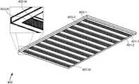
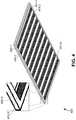
- FIG. 3illustrates a first airflow manipulation device, according to some embodiments.
- FIG. 4illustrates a second airflow manipulation device, according to some embodiments.
- FIG. 5illustrates a third airflow manipulation device, according to some embodiments.
- FIG. 6illustrates multiple airflow manipulation devices situated in series with each other, according to some embodiments.
- FIG. 7illustrates a simplified computer system, according to some embodiments.
- FIG. 8illustrates a flowchart of a method for controlling an energy system, according to some embodiments.
- Embodiments of the present disclosureare related to systems and methods for efficient energy use within a building and comfort of occupants. Some embodiments may use a traditional Building Management System (BMS), Smart Home system, or Smart Office, Smart Building system. Some embodiments include an energy virtualization system linked to one or more smart vents.
- the energy virtualization systemmay manage usage and consumption of various energy producers and consumers based on inputs from various controllers.
- the energy virtualization systemcontrols a smart vent (also referred to herein as an “airway manipulation device”) in response to a signal generated by a local control.
- the signal generated by the local controlmay indicate that a user desires to increase or decrease the temperature in a certain location, e.g., a room, an office, a hallway, etc.
- a virtual layer of the energy virtualization systemmay receive the signal generated by the local control, and may, in response, generate a control signal that is sent to the airway manipulation device situated within or near the certain location.
- FIG. 1illustrates an energy virtualization system 100 , according to some embodiments.
- energy virtualization system 100includes a virtual layer 105 for managing one or more energy producers 110 , one or more energy consumers 112 , and one or more devices 114 .
- Virtual layer 105may include various interfaces, such as an energy producer interface 120 for communicating with energy producers 110 , an energy consumer interface 122 for communicating with energy consumers 112 , and a controller interface 124 for communicating with devices 114 .
- Virtual layer 105may be implemented in hardware and/or software (e.g., computer code), among other possibilities.
- Virtual layer 105may perform various calculations and/or algorithms for generating control signals which may be sent to energy consumers 112 . The control signals may be generated based on signals received from energy producers 110 and/or devices 114 .
- FIG. 2illustrates an environment 200 incorporating energy virtualization system 100 , according to some embodiments.
- Energy virtualization system 100may include virtual layer 105 communicatively linked to a plurality of local controls 232 and a plurality of airway manipulation devices 230 situated in different rooms 230 within environment 200 .
- local control 232 - 1 and airway manipulation device 230 - 1may be situated within or near room 234 - 1 , and may be communicatively linked, either via a wired or wireless connection, to virtual layer 105 .
- each of local controls 232may comprise an adjustable temperature controller (e.g., a thermostat) that allows an occupant of a particular room to specify a desired temperature (e.g., 70 degrees Fahrenheit).
- a desired temperaturee.g. 70 degrees Fahrenheit
- energy virtualization system 100may include a central control 236 situated within environment 200 that comprises an adjustable temperature controller (e.g., a thermostat) that allows a user to specify a desired temperature for an area or region within environment 200 .
- central control 236may be situated within a hallway of environment 200 and may allow a user to specify a temperature for each of rooms 234 or some combination of rooms 234 (e.g., rooms 234 - 1 , 234 - 2 , and 234 - 3 , or rooms on a single side of the hallway).
- FIG. 2illustrates the airflow manipulation device used in conjunction with a virtualize energy system, other embodiments are not so limited.
- the airflow manipulation devicecan be integrated with a traditional Building Management System (BMS) or any other system for managing and manipulating the environment of an enclosure.
- BMSBuilding Management System
- the “local control”may include many different devices, such as mobile devices, personal devices, smart phones, tablet computers, Internet of Things (IoT) devices, and so forth.
- IoTInternet of Things
- airflow manipulation deviceand “smart vent” may be used interchangeably herein.
- the goal of the airflow manipulation device with both local and central controlis to provide more granular control of HVAC systems and temperatures within a targeted area. This corresponds to a higher resolution in temperature control from a spatial perspective.
- large air-handling systemscontrolled the supply of air on a floor in a building as part of a large central HVAC system. They provided conditioned air at a particular volume and flow rate (CFM) to a number of Variable Air Volume (VAV) devices.
- CFMvolume and flow rate
- VAVVariable Air Volume
- a number of offices or areas of the buildingmay be served from a single VAV, and thus the air at the VAV does not represent the temperature required in a particular office based on occupant commands or environmental factors, such as sun exposure or building envelope construction.
- the airflow manipulation device described hereinsolves these and other technology problems by reducing the quantity of VAVs required, or even eliminating them in some circumstances. These also reduce the size of the infrastructure required in ceilings, as large VAVs can be replaced by small, in-line airflow manipulation devices.
- an in-line mechanismthat incorporates an air damper, sensors, a heating element, a control interface, power circuitry, and so forth may be inserted into the air flow duct as an airflow manipulation device.
- one airflow manipulation devicecan be easily integrated into the round, flexible ducting that is used to feed the HVAC registers as commonly found in commercial buildings. Because these are installed internally, the airflow manipulation devices negate the need to have aesthetic components as part of the HVAC system. By adjusting the air in line, it also minimizes the perceived noise of constricted air (e.g., whistling) and provides an opportunity to place silencers for such purposes in the ducting itself.
- Typical HVAC systemsare balanced by manually opening/closing dampers as part of the building commissioning process during construction to regulate the flow of air entering a room or space based on the volume of the space being served.
- the airflow manipulation devices described hereincan be integrated with sensors, such as static pressure, volume flow sensors, temperature sensors, and so forth.
- the airflow manipulation devicecan provide feedback based on the micro zone (e.g., the individual office) served by the airflow manipulation device.
- the airflow manipulation devicecan communicate with the VAV and/or air handler to reduce the airflow for the zone or reduce the fan speed respectively. This ensures the desired temperature is achieved in the target office without impacting neighboring zones or wasting energy.
- the airflow manipulation devicemay include an in-line heating element that can be used to micro-control the air flowing from the VAV into the office.
- the supply air from the VAVmay be delivered at a lowest-common temperature across a range of offices in a zone, and the electric heating element can serve to increase the temperature air supply in each particular office, based on sensor inputs within that office.
- configurationscan use chilled beams, AC coils, and/or other mechanical air conditioning systems locally at the airflow manipulation device to reduce the temperature for a single office.
- PoEPower over Ethernet
- the airflow manipulation devicemay also provide a resource profile for a virtualized energy layer, or may simply provide a standard BMS interface.
- FIG. 3illustrates an airflow manipulation device 300 , according to some embodiments.
- Airflow manipulation device 300may correspond to any of airway manipulation devices 230 , and may be positioned along a wall, floor, and/or ceiling of any of rooms 234 .
- Airflow manipulation device 300may include a plurality of modifiable apertures 303 which are formed by the positioning of a plurality of panels 301 positioned in parallel with each other. Each of panels 301 may be positioned to form an angle 302 with respect to the chassis of airflow manipulation device 300 .
- Airflow manipulation device 300may receive a control signal from virtual layer 105 and may modify apertures 303 via movement of panels 301 .
- each of panels 301are moved and positioned in unison such that each of angles 302 remain identical to each other.
- different portions of panels 301may be moved and positioned differently such that different angles 302 may be unique.
- panels 301may be positioned such that half of angles 302 are set to 90 degrees and the other half of angles 302 are set to 0 degrees.
- a third of angles 302may be set to 90 degrees
- a third of angles 302may be set to 45 degrees
- a third of angles 302may be set to 0 degrees.
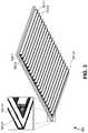
- FIG. 4illustrates an airflow manipulation device 400 , according to some embodiments.
- Airflow manipulation device 400may correspond to any of airway manipulation devices 230 , and may be positioned along a wall, floor, and/or ceiling of any of rooms 234 .
- Airflow manipulation device 400may include a plurality of modifiable apertures 403 which are formed by the positioning of a plurality of sliding panels 401 positioned in parallel with each other. Each of panels 401 may be positioned to form an openness ratio 402 .
- Airflow manipulation device 400may receive a control signal and may modify apertures 403 via movement (e.g., sliding) of panels 401 .
- each of panels 401are moved and positioned in unison such that each of openness ratios 402 remain identical to each other.
- different portions of panels 401may be moved and positioned differently such that different openness ratios 402 may be different.
- panels 401may be positioned such that half of openness ratios 402 are set to 100% and the other half of openness ratios 402 are set to 0%.
- a third of openness ratios 402may be set to 100%, a third of openness ratios 402 may be set to 50%, and a third of openness ratios 402 may be set to 0%.
- FIG. 5illustrates an airflow manipulation device 500 , according to some embodiments.
- Airflow manipulation device 500may correspond to any of airway manipulation devices 230 , and may be positioned along a wall, floor, and/or ceiling of any of rooms 234 .
- Airflow manipulation device 500may include a modifiable aperture 503 which is formed by the positioning of a rotatable panel 501 situated within an airway 510 .
- Panel 501may be positioned to form angle 502 with respect to a direction perpendicular to airway 510 .
- airflow manipulation device 500may include a vent 504 which may separate airway 510 from the rest of room 234 .
- airflow manipulation device 500receives a control signal from virtual layer 105 and may modify aperture 503 via movement of panel 501 .
- FIG. 6illustrates two airflow manipulation devices 600 situated in series with each other, according to some embodiments.
- Airflow manipulation devices 600may correspond to any of airway manipulation devices 230 , and may be positioned along a wall, floor, and/or ceiling of any of rooms 234 .
- Each of airflow manipulation devices 600may include a modifiable aperture 603 which is formed by the positioning of a sliding panel 601 situated within an airway 610 .
- each of airflow manipulation devices 600may include a vent 604 which may separate airway 610 from the rest of rooms 234 .
- Each of panels 601may be positioned to form an openness ratio 602 .
- Each of airflow manipulation devices 600may receive a control signal from virtual layer 105 and may modify apertures 603 via movement (e.g., sliding) of panels 601 .
- virtual layer 105is configured to generate and output a control signal to each the airway manipulation device described herein, such as airway manipulation devices 300 , 400 , 500 , and/or 600 .
- the control signalmay including instructions to modify an aperture, either directly or indirectly, by specifying a specific numerical aperture state (e.g., 100% open, 45 degrees open, etc.), or by specifying a percentage of increased or decreased change (e.g., 10% more open, 20% more closed, etc.).
- the control signalmay be generated based on at least a first input signal received from the local control and a second input signal received from the central control.
- an average of the two signalsmay be used as a target temperature when generating the control signal.
- the control signalmay be generated exclusively based on the first signal received from the local control to override any second input signal received from the central control.
- a usermay operate their local control to regulate the airflow of the smart vents in their office without changing the temperature of the air that is being delivered to the smart vent from the central HVAC system. This allows users to maintain local control over the temperature in their rooms to some degree without requiring a change in air temperature or air delivery volume from the central HVAC system.
- the smart vents in a region of the buildingcan receive coordinated controls from the central control. For example, when the sun begins to set later in the day, one side of the building may be exposed to more sunlight energy than the other side of the building. If both sides of the building are supplied by the same HVAC system, lowering the temperature on the side of the building exposed to the sunlight may result in temperatures that are too cold for the other side of the building.
- a series of control signalscan be coordinated from the central control to reduce the cool airflow in rooms on the side of the building that are not exposed to the sun, while simultaneously increasing the airflow in rooms on the side of the building that are exposed to the sun.
- the central controlcan monitor the local control inputs received in each room having a smart vent.
- the central controlcan aggregate these local control inputs and determine whether changes need to be made to the operation of the HVAC system in a corresponding region of the building. For example, if all of the rooms on a specific floor of the building submit local control inputs during a time window, the central control can determine that the overall air temperature delivered by the HVAC system to that specific floor should be changed to correspond to the local control inputs provided by the users. Thus, when enough local control inputs indicate that a central control input may be required in the region, the central control can respond accordingly. Instead of throttling or increasing the airflow in individual rooms, the central control can respond by increasing/decreasing the airflow/temperature to that region and set the smart vents therein back to a normal setting.
- FIG. 7illustrates a simplified computer system 700 , according to some embodiments.
- a computer system 700 as illustrated in FIG. 7may be incorporated into devices such as a portable electronic device, mobile phone, or other device as described herein.
- FIG. 7provides a schematic illustration of one embodiment of a computer system 700 that can perform some or all of the steps of the methods provided by various embodiments. It should be noted that FIG. 7 is meant only to provide a generalized illustration of various components, any or all of which may be utilized as appropriate. FIG. 7 , therefore, broadly illustrates how individual system elements may be implemented in a relatively separated or relatively more integrated manner.
- the computer system 700is shown comprising hardware elements that can be electrically coupled via a bus 705 , or may otherwise be in communication, as appropriate.
- the hardware elementsmay include one or more processors 710 , including without limitation one or more general-purpose processors and/or one or more special-purpose processors such as digital signal processing chips, graphics acceleration processors, and/or the like; one or more input devices 715 , which can include without limitation a mouse, a keyboard, a camera, and/or the like; and one or more output devices 720 , which can include without limitation a display device, a printer, and/or the like.
- processors 710including without limitation one or more general-purpose processors and/or one or more special-purpose processors such as digital signal processing chips, graphics acceleration processors, and/or the like
- input devices 715which can include without limitation a mouse, a keyboard, a camera, and/or the like
- output devices 720which can include without limitation a display device, a printer, and/or the like.
- the computer system 700may further include and/or be in communication with one or more non-transitory storage devices 725 , which can comprise, without limitation, local and/or network accessible storage, and/or can include, without limitation, a disk drive, a drive array, an optical storage device, a solid-state storage device, such as a random access memory (“RAM”), and/or a read-only memory (“ROM”), which can be programmable, flash-updateable, and/or the like.
- RAMrandom access memory
- ROMread-only memory
- Such storage devicesmay be configured to implement any appropriate data stores, including without limitation, various file systems, database structures, and/or the like.
- the computer system 700might also include a communications subsystem 730 , which can include without limitation a modem, a network card (wireless or wired), an infrared communication device, a wireless communication device, and/or a chipset such as a BluetoothTM device, an 802.11 device, a WiFi device, a WiMax device, cellular communication facilities, etc., and/or the like.
- the communications subsystem 730may include one or more input and/or output communication interfaces to permit data to be exchanged with a network such as the network described below to name one example, other computer systems, television, and/or any other devices described herein.
- a portable electronic device or similar devicemay communicate image and/or other information via the communications subsystem 730 .
- a portable electronic devicee.g. the first electronic device
- may be incorporated into the computer system 700e.g., an electronic device as an input device 715 .
- the computer system 700will further comprise a working memory 735 , which can include a RAM or ROM device, as described above.
- the computer system 700also can include software elements, shown as being currently located within the working memory 735 , including an operating system 740 , device drivers, executable libraries, and/or other code, such as one or more application programs 745 , which may comprise computer programs provided by various embodiments, and/or may be designed to implement methods, and/or configure systems, provided by other embodiments, as described herein.
- an operating system 740operating system 740
- device driversexecutable libraries
- application programs 745which may comprise computer programs provided by various embodiments, and/or may be designed to implement methods, and/or configure systems, provided by other embodiments, as described herein.
- application programs 745may comprise computer programs provided by various embodiments, and/or may be designed to implement methods, and/or configure systems, provided by other embodiments, as described herein.
- application programs 745may comprise computer programs provided by various embodiments, and/or may be designed to implement methods, and/or configure systems, provided by other embodiments, as described herein.
- code and/or instructionscan be used to configure and/or adapt a general purpose computer or other device to perform one or more operations in accordance with the described methods.
- a set of these instructions and/or codemay be stored on a non-transitory computer-readable storage medium, such as the storage device(s) 725 described above.
- the storage mediummight be incorporated within a computer system, such as computer system 700 .
- the storage mediummight be separate from a computer system e.g., a removable medium, such as a compact disc, and/or provided in an installation package, such that the storage medium can be used to program, configure, and/or adapt a general purpose computer with the instructions/code stored thereon.
- These instructionsmight take the form of executable code, which is executable by the computer system 700 and/or might take the form of source and/or installable code, which, upon compilation and/or installation on the computer system 700 e.g., using any of a variety of generally available compilers, installation programs, compression/decompression utilities, etc., then takes the form of executable code.
- some embodimentsmay employ a computer system such as the computer system 700 to perform methods in accordance with various embodiments of the technology. According to a set of embodiments, some or all of the procedures of such methods are performed by the computer system 700 in response to processor 710 executing one or more sequences of one or more instructions, which might be incorporated into the operating system 740 and/or other code, such as an application program 745 , contained in the working memory 735 . Such instructions may be read into the working memory 735 from another computer-readable medium, such as one or more of the storage device(s) 725 . Merely by way of example, execution of the sequences of instructions contained in the working memory 735 might cause the processor(s) 710 to perform one or more procedures of the methods described herein. Additionally or alternatively, portions of the methods described herein may be executed through specialized hardware.
- machine-readable mediumand “computer-readable medium,” as used herein, refer to any medium that participates in providing data that causes a machine to operate in a specific fashion.
- various computer-readable mediamight be involved in providing instructions/code to processor(s) 710 for execution and/or might be used to store and/or carry such instructions/code.
- a computer-readable mediumis a physical and/or tangible storage medium.
- Such a mediummay take the form of a non-volatile media or volatile media.
- Non-volatile mediainclude, for example, optical and/or magnetic disks, such as the storage device(s) 725 .
- Volatile mediainclude, without limitation, dynamic memory, such as the working memory 735 .
- Common forms of physical and/or tangible computer-readable mediainclude, for example, a floppy disk, a flexible disk, hard disk, magnetic tape, or any other magnetic medium, a CD-ROM, any other optical medium, punchcards, papertape, any other physical medium with patterns of holes, a RAM, a PROM, EPROM, a FLASH-EPROM, any other memory chip or cartridge, or any other medium from which a computer can read instructions and/or code.
- Various forms of computer-readable mediamay be involved in carrying one or more sequences of one or more instructions to the processor(s) 710 for execution.
- the instructionsmay initially be carried on a magnetic disk and/or optical disc of a remote computer.
- a remote computermight load the instructions into its dynamic memory and send the instructions as signals over a transmission medium to be received and/or executed by the computer system 700 .
- the communications subsystem 730 and/or components thereofgenerally will receive signals, and the bus 705 then might carry the signals and/or the data, instructions, etc. carried by the signals to the working memory 735 , from which the processor(s) 710 retrieves and executes the instructions.
- the instructions received by the working memory 735may optionally be stored on a non-transitory storage device 725 either before or after execution by the processor(s) 710 .
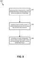
- FIG. 8illustrates a flowchart of a method for controlling an energy system, according to some embodiments.
- the methodmay include receiving a local temperature input from a local control that corresponds to an enclosure within the environment ( 802 ).
- the local controlmay be a local thermostat in a room, the environment may be a building or home, and the enclosure may be an office or room within the environment.
- the local controlcan be transmitted via a wired or wireless connection to a central control.
- the methodmay also include receiving a central temperature input from a central control for an area that includes the enclosure ( 804 ).
- the central temperature inputmay be a temperature setpoint that contributes to governing the control of multiple airway manipulation devices within the enclosure.
- the area that includes the enclosuremay include a floor in a home, a floor in an office building, or a collection of offices that are within a threshold distance of each other, such as 50 feet, 75 feet, and so forth.
- the methodmay further include controlling an airway manipulation device based at least in part on the local temperature input and the central temperature input ( 806 ).
- the airway manipulation devicemay be situated within or within a threshold distance of the enclosure.
- the threshold distancemay include 2 feet, 5 feet, 10 feet, or 20 feet.
- the airway manipulation devicemay include a smart vent that is located above a room.
- the airway manipulation devicemay be configured to modify at least one aperture separating two volumes.
- the two volumesmay include a volume of an air duct that is separated from a volume of the enclosure.
- the airway manipulation devicemay be powered using an ethernet connection and may communicate with the one or more processors using an ethernet connection.
- the airway manipulation devicemay be controlled through a virtualization layer that is executed by the one or more processors as described above.
- the local temperature inputcan override the central temperature input, while in other embodiments the local temperature input can be averaged with the central temperature input.
- configurationsmay be described as a process which is depicted as a schematic flowchart or block diagram. Although each may describe the operations as a sequential process, many of the operations can be performed in parallel or concurrently. In addition, the order of the operations may be rearranged. A process may have additional steps not included in the figure.
- examples of the methodsmay be implemented by hardware, software, firmware, middleware, microcode, hardware description languages, or any combination thereof. When implemented in software, firmware, middleware, or microcode, the program code or code segments to perform the necessary tasks may be stored in a non-transitory computer-readable medium such as a storage medium. Processors may perform the described tasks.
Landscapes
- Engineering & Computer Science (AREA)
- Chemical & Material Sciences (AREA)
- Combustion & Propulsion (AREA)
- Mechanical Engineering (AREA)
- General Engineering & Computer Science (AREA)
- Human Computer Interaction (AREA)
- Air Conditioning Control Device (AREA)
Abstract
Description
Claims (20)
Priority Applications (1)
| Application Number | Priority Date | Filing Date | Title |
|---|---|---|---|
| US16/007,642US11125461B2 (en) | 2017-06-13 | 2018-06-13 | Smart vent system with local and central control |
Applications Claiming Priority (2)
| Application Number | Priority Date | Filing Date | Title |
|---|---|---|---|
| US201762519027P | 2017-06-13 | 2017-06-13 | |
| US16/007,642US11125461B2 (en) | 2017-06-13 | 2018-06-13 | Smart vent system with local and central control |
Publications (2)
| Publication Number | Publication Date |
|---|---|
| US20180356114A1 US20180356114A1 (en) | 2018-12-13 |
| US11125461B2true US11125461B2 (en) | 2021-09-21 |
Family
ID=64564020
Family Applications (1)
| Application Number | Title | Priority Date | Filing Date |
|---|---|---|---|
| US16/007,642Active2039-02-12US11125461B2 (en) | 2017-06-13 | 2018-06-13 | Smart vent system with local and central control |
Country Status (1)
| Country | Link |
|---|---|
| US (1) | US11125461B2 (en) |
Families Citing this family (3)
| Publication number | Priority date | Publication date | Assignee | Title |
|---|---|---|---|---|
| US10147984B2 (en) | 2015-07-31 | 2018-12-04 | SynCells, Inc. | Portable and modular energy storage for multiple applications |
| US11394573B2 (en) | 2017-06-13 | 2022-07-19 | SynCells, Inc. | Energy virtualization layer with a universal smart gateway |
| US10850713B2 (en) | 2017-10-20 | 2020-12-01 | SynCells, Inc. | Robotics for rotating energy cells in vehicles |
Citations (124)
| Publication number | Priority date | Publication date | Assignee | Title |
|---|---|---|---|---|
| US2938686A (en) | 1957-02-04 | 1960-05-31 | Boeing Co | Aircraft electronic equipment assembly |
| US4407445A (en)* | 1979-03-09 | 1983-10-04 | Constantine Vivian | Ceiling construction for a heating, ventilation and air conditioning system |
| US5756227A (en) | 1994-11-18 | 1998-05-26 | Honda Giken Kogyo Kabushiki Kaisha | Battery assembly with temperature control mechanism |
| US5803357A (en)* | 1997-02-19 | 1998-09-08 | Coleman Safety And Security Products, Inc. | Thermostat with remote temperature sensors and incorporating a measured temperature feature for averaging ambient temperatures at selected sensors |
| US6122603A (en) | 1998-05-29 | 2000-09-19 | Powerweb, Inc. | Multi-utility energy control system with dashboard |
| US20020136042A1 (en) | 2000-03-29 | 2002-09-26 | David Layden | System for detecting defective battery packs |
| US20030099883A1 (en) | 2001-10-10 | 2003-05-29 | Rosibel Ochoa | Lithium-ion battery with electrodes including single wall carbon nanotubes |
| US20050007042A1 (en) | 2003-02-12 | 2005-01-13 | Moore Daniel S. | Battery-powered air handling system for subsurface aeration |
| US7059769B1 (en) | 1997-06-27 | 2006-06-13 | Patrick Henry Potega | Apparatus for enabling multiple modes of operation among a plurality of devices |
| US20060276938A1 (en) | 2005-06-06 | 2006-12-07 | Equinox Energy Solutions, Inc. | Optimized energy management system |
| US20070127346A1 (en) | 2005-12-01 | 2007-06-07 | International Business Machines Corporation | Removable media battery pack for powering a media accessor of an automated data-storage library |
| US20070162245A1 (en) | 2006-01-11 | 2007-07-12 | Honeywell International Inc. | Remote remediation monitoring system |
| US20070181547A1 (en) | 2006-02-09 | 2007-08-09 | Illinois Tool Works Inc. | Method and apparatus for welding with battery power |
| US20070267999A1 (en) | 2003-02-13 | 2007-11-22 | Poweready | Multi-chemistry chargers |
| US20080072289A1 (en) | 2004-07-09 | 2008-03-20 | Osamu Aoki | Unauthorized Connection Detection System and Unauthorized Connection Detection Method |
| US20080197199A1 (en) | 2002-12-12 | 2008-08-21 | Symbol Technologies, Inc. | Battery pack with integrated human interface devices |
| US20090072991A1 (en) | 2007-09-19 | 2009-03-19 | Oki Electric Industry Co., Ltd. | Gateway device allowing home network appliances to be introduced and controlled over a network and a control method therefor |
| US20090096416A1 (en) | 2005-12-06 | 2009-04-16 | Toyota Jidosha Kabushiki Kaisha | Charging Device, Electric Vehicle Equipped With the Charging Device and Charging Control Method |
| US20090251925A1 (en) | 2004-12-08 | 2009-10-08 | Sanken Electric Co., Ltd. | Current resonant dc-dc converter of multi-output type |
| US20090264063A1 (en)* | 2006-05-30 | 2009-10-22 | Barton Tinsley | Gear Drive Damper |
| US20090314382A1 (en) | 2005-11-04 | 2009-12-24 | Peter David Capizzo | System for replenishing energy sources onboard different types of automatic vehicles |
| US20100007515A1 (en) | 2008-07-10 | 2010-01-14 | Sony Corporation | Information processing apparatus and connected device status display method |
| US20100017045A1 (en) | 2007-11-30 | 2010-01-21 | Johnson Controls Technology Company | Electrical demand response using energy storage in vehicles and buildings |
| US20100030083A1 (en) | 2008-07-28 | 2010-02-04 | University Of Washington | Assessment of tissue response to stress |
| US20100104927A1 (en) | 2008-10-29 | 2010-04-29 | Scott Albright | Temperature-controlled battery configuration |
| US20100104935A1 (en) | 2008-10-28 | 2010-04-29 | Weston Arthur Hermann | Heat dissipation for large battery packs |
| US20100245103A1 (en) | 2009-03-31 | 2010-09-30 | Pvt Solar, Inc. | Healthy home graphical user interface method and device |
| US20100315197A1 (en) | 2009-07-23 | 2010-12-16 | James Solomon | Authorization in a networked electric vehicle charging system |
| US20110014501A1 (en) | 2006-02-09 | 2011-01-20 | Scheucher Karl F | Fail safe serviceable high voltage battery pack |
| US20110106294A1 (en) | 2009-10-30 | 2011-05-05 | John Bean Technologies Corporation | Automatic battery exchange system for mobile vehicles |
| US20110106279A1 (en) | 2009-10-30 | 2011-05-05 | Samsung Electronics Co., Ltd. | Method and apparatus for controlling home network system using mobile terminal |
| US7949435B2 (en) | 2006-08-10 | 2011-05-24 | V2Green, Inc. | User interface and user control in a power aggregation system for distributed electric resources |
| US20110149720A1 (en) | 2009-12-17 | 2011-06-23 | Verizon Patent And Licensing, Inc. | System for and method of performing residential gateway diagnostics and corrective actions |
| US20110204720A1 (en) | 2007-11-30 | 2011-08-25 | Johnson Controls Technology Company | Efficient usage, storage, and sharing of energy in buildings, vehicles, and equipment |
| US20110234165A1 (en) | 2010-03-29 | 2011-09-29 | Dennis Palatov | Modular Charging System for Multi-Cell Series-Connected Battery Packs |
| US8045970B2 (en) | 2005-07-06 | 2011-10-25 | Huawei Technologies Co., Ltd. | Gateway for remote control and system and method for implementing remote control |
| US20110261057A1 (en) | 2008-12-18 | 2011-10-27 | Abb Technology Ag | Method and device to supervise a power network |
| US20110302078A1 (en) | 2010-06-02 | 2011-12-08 | Bryan Marc Failing | Managing an energy transfer between a vehicle and an energy transfer system |
| US20120039503A1 (en) | 2010-08-12 | 2012-02-16 | Honeywell International Inc. | System and method for constructing a three dimensional operational graphic from a two dimensional building control subsystem drawing |
| KR101146492B1 (en) | 2010-07-01 | 2012-05-21 | 에스비리모티브 주식회사 | Battery Pack |
| US20120169511A1 (en) | 2011-01-04 | 2012-07-05 | Greenwave Reality, Pte Ltd. | Multi-Mode Display |
| US20120316671A1 (en) | 2008-02-05 | 2012-12-13 | Unlimited Range Electric Car Systems Company | Battery charging and transfer system for electrically powered vehicles |
| US8359112B2 (en) | 2006-01-13 | 2013-01-22 | Emerson Process Management Power & Water Solutions, Inc. | Method for redundant controller synchronization for bump-less failover during normal and program mismatch conditions |
| US20130026972A1 (en) | 2011-07-26 | 2013-01-31 | Gogoro, Inc. | Apparatus, method and article for authentication, security and control of power storage devices, such as batteries, based on user profiles |
| US20130059182A1 (en) | 2011-08-31 | 2013-03-07 | Sony Corporation | Power storage apparatus and electric vehicle |
| US20130064250A1 (en) | 2011-09-09 | 2013-03-14 | Kt Corporation | Remotely accessing and controlling user equipment in a private network |
| US8473111B1 (en) | 2005-10-11 | 2013-06-25 | American Grid, Inc | Interconnected premises equipment for energy management |
| US20130164567A1 (en) | 2011-06-24 | 2013-06-27 | Seektech, Inc. | Modular battery pack apparatus, systems, and methods |
| US20130166081A1 (en) | 2011-01-28 | 2013-06-27 | Sunverge Energy, Inc. | Distributed energy services management system |
| US20130205372A1 (en) | 2005-08-10 | 2013-08-08 | Microsoft Corporation | Authorization of device access to network services |
| US20130214763A1 (en) | 2010-07-09 | 2013-08-22 | Sony Corporation | Power control device and power control method |
| US20130288083A1 (en) | 2012-04-27 | 2013-10-31 | Electrochem Solutions, Inc. | Fire suppressent battery pack |
| US20130297084A1 (en) | 2010-07-09 | 2013-11-07 | Sony Corporation | Power control device and power control method |
| US20130315197A1 (en) | 2010-12-14 | 2013-11-28 | Lg Electronics Inc. | Method for transmitting and method for receiving a channel state information reference signal in a distributed multi-node system |
| US20140015469A1 (en) | 2010-03-11 | 2014-01-16 | Virgil L. Beaston | Battery Management System For A Distributed Energy Storage System, and Applications Thereof |
| US20140081465A1 (en) | 2012-09-15 | 2014-03-20 | Honeywell International Inc. | Remote access gateway configurable control system |
| US20140097797A1 (en) | 2011-05-13 | 2014-04-10 | Enerdel, Inc. | Energy storage system |
| US20140136007A1 (en) | 2012-11-12 | 2014-05-15 | Kevin J. Williams | Personal energy system |
| US8830676B2 (en) | 2009-04-24 | 2014-09-09 | Akasol Gmbh | Battery management system |
| US20140303835A1 (en)* | 2013-04-03 | 2014-10-09 | Toyota Motor Engineering & Manufacturing North America, Inc. | Vehicle Temperature Control Systems |
| US8865337B2 (en) | 2008-03-24 | 2014-10-21 | Lightening Energy | Modular battery, an interconnector for such batteries and methods related to modular batteries |
| US20140336837A1 (en) | 2011-12-14 | 2014-11-13 | Kyocera Corporation | Display terminal, power control system, and display method |
| US20140377623A1 (en) | 2013-06-21 | 2014-12-25 | Ioxus, Inc. | Energy storage device assembly |
| WO2014207658A1 (en) | 2013-06-26 | 2014-12-31 | Automobili Lamborghini S.P.A. | Charge/discharge device for a pack of supercapacitors |
| US20150037649A1 (en) | 2013-07-30 | 2015-02-05 | Johnson Controls Technology Company | Remanufacturing methods for battery module |
| US20150042285A1 (en) | 2012-03-02 | 2015-02-12 | ropa development GmbH | Supply network component for a supply network |
| US20150048684A1 (en) | 2013-08-06 | 2015-02-19 | Bedrock Automation Platforms Inc. | Secure power supply for an industrial control system |
| US20150056475A1 (en) | 2013-08-26 | 2015-02-26 | Jason D. Adrian | Scalable highly available modular battery system |
| US20150073608A1 (en) | 2008-04-25 | 2015-03-12 | Versify Solutions, Inc. | System and method for managing and monitoring renewable energy power generation |
| EP2861473A1 (en) | 2012-06-13 | 2015-04-22 | Allison Transmission, Inc. | Energy storage system for hybrid electric vehicle |
| EP2876702A1 (en) | 2013-11-22 | 2015-05-27 | Lan Yang Energy Technology Co., Ltd. | Lithium ion batteries |
| US20150236936A1 (en) | 2014-02-19 | 2015-08-20 | Steven Waldbusser | Monitoring gateway systems and methods for openflow type networks |
| US20150261198A1 (en) | 2006-07-12 | 2015-09-17 | Imprenditore Pty Limited | Monitoring Apparatus and System |
| US9187004B1 (en) | 2015-04-03 | 2015-11-17 | Harold William Davis | Electric vehicle carousel battery exchange/charging system |
| US20150333512A1 (en) | 2012-08-16 | 2015-11-19 | Robert Bosch Gmbh | Charging and Discharging of DC Microgrid Energy Storage |
| US20150350818A1 (en) | 2014-05-30 | 2015-12-03 | Geoffrey Granville Hammett | Method and System for Wireless Communication in a Lighting Application |
| US20160003918A1 (en) | 2014-04-01 | 2016-01-07 | Kabushiki Kaisha Toshiba | Monitoring apparatus, control apparatus, and control system |
| US20160033946A1 (en) | 2014-07-31 | 2016-02-04 | Honeywell International Inc. | Building management system analysis |
| US20160065383A1 (en) | 2014-08-27 | 2016-03-03 | Proeasy Network Solutions Co., Ltd. | Home control gateway and gateway connection method thereof |
| US9300141B2 (en) | 2010-11-18 | 2016-03-29 | John J. Marhoefer | Virtual power plant system and method incorporating renewal energy, storage and scalable value-based optimization |
| US20160093843A1 (en) | 2014-09-26 | 2016-03-31 | Powertree Services, Inc. | Systems and methods for a modular battery pack |
| US20160093848A1 (en) | 2014-09-30 | 2016-03-31 | Johnson Controls Technology Company | Modular approach for advanced battery modules having different electrical characteristics |
| US20160094056A1 (en) | 2014-09-30 | 2016-03-31 | Johnson Controls Technology Company | Battery module short circuit protection |
| US20160105513A1 (en) | 2014-10-14 | 2016-04-14 | Lear Corporation | Vehicle Gateway Module Having Cellular Data Network Connectivity |
| US20160129801A1 (en) | 2010-12-22 | 2016-05-12 | Ford Global Technologies, Llc | Vehicle and method for authenticating a charge station |
| US20160149758A1 (en) | 2014-11-21 | 2016-05-26 | Hitachi, Ltd. | Network system, method of managing network system and gateway apparatus |
| US9361141B2 (en) | 2008-12-23 | 2016-06-07 | Citrix Systems, Inc. | Systems and methods for controlling, by a hypervisor, access to physical resources |
| US9434270B1 (en) | 2011-04-22 | 2016-09-06 | Angel A. Penilla | Methods and systems for electric vehicle (EV) charging, charging unit (CU) interfaces, auxiliary batteries, and remote access and user notifications |
| US9438573B2 (en) | 2014-11-12 | 2016-09-06 | Smartlabs, Inc. | Systems and methods to securely install network devices using physical confirmation |
| US20160265224A1 (en)* | 2015-03-10 | 2016-09-15 | Cisco Technology, Inc. | Network-enabled ceiling support structure |
| US20160277216A1 (en) | 2015-03-16 | 2016-09-22 | Schweitzer Engineering Laboratories, Inc. | Network access gateway |
| US9467939B2 (en) | 2012-04-02 | 2016-10-11 | Nokia Solutions And Networks Oy | Gateway selection for mobile communications network architecture optimization |
| US20160329710A1 (en) | 2013-07-26 | 2016-11-10 | Orison, Inc. | Building management and appliance control system |
| US20160330200A1 (en) | 2006-12-29 | 2016-11-10 | Kip Prod P1 Lp | Multi-services application gateway and system employing the same |
| US20170033408A1 (en) | 2015-07-31 | 2017-02-02 | Gerard O'Hora | Portable and modular energy storage with authentication protections for electric vehicles |
| US20170034257A1 (en) | 2014-08-20 | 2017-02-02 | At&T Intellectual Property I, L.P. | Virtual Zones for Open Systems Interconnection Layer 4 Through Layer 7 Services in a Cloud Computing System |
| US20170045868A1 (en)* | 2014-04-25 | 2017-02-16 | Somfy Sas | Method for controlling and/or monitoring at least one actuator |
| US20170085438A1 (en) | 2004-07-07 | 2017-03-23 | Sciencelogic, Inc. | Network management device and method for discovering and managing network connected databases |
| US9711989B2 (en) | 2011-12-12 | 2017-07-18 | Samsung Electronics Co., Ltd. | Power consumption control apparatus and power consumption control method |
| US9716718B2 (en) | 2013-12-31 | 2017-07-25 | Wells Fargo Bank, N.A. | Operational support for network infrastructures |
| US20170242411A1 (en) | 2016-02-18 | 2017-08-24 | Johnson Controls Technology Company | Hvac and building management system with deconstructed media flow graphical user interface |
| US20170279170A1 (en) | 2015-07-31 | 2017-09-28 | SynCells, Inc. | Portable and modular energy storage for multiple applications |
| US9817376B1 (en) | 2012-05-19 | 2017-11-14 | Growing Energy Labs, Inc. | Adaptive energy storage operating system for multiple economic services |
| US9960637B2 (en) | 2015-07-04 | 2018-05-01 | Sunverge Energy, Inc. | Renewable energy integrated storage and generation systems, apparatus, and methods with cloud distributed energy management services |
| US9980779B2 (en) | 2013-12-16 | 2018-05-29 | Lim Innovations, Inc. | Method and system for assembly of a modular prosthetic socket based on residual limb metrics |
| US20180152322A1 (en) | 2012-08-14 | 2018-05-31 | Nicira, Inc. | Method and system for virtual and physical network integration |
| US20180176819A1 (en) | 2014-08-08 | 2018-06-21 | Parallel Wireless, Inc. | Congestion and Overload Reduction |
| US20180183903A1 (en) | 2015-10-20 | 2018-06-28 | Parallel Wireless, Inc. | X2 Protocol Programmability |
| US20180181434A1 (en) | 2016-12-22 | 2018-06-28 | Vmware, Inc. | Remote operation authorization between pairs of sites with pre-established trust |
| US20180191742A1 (en) | 2007-06-12 | 2018-07-05 | Icontrol Networks, Inc. | Communication protocols in integrated systems |
| US20180288136A1 (en) | 2015-08-29 | 2018-10-04 | Vmware, Inc. | Enterprise connectivity to the hybrid cloud |
| US20180302326A1 (en) | 2013-09-04 | 2018-10-18 | Nicira, Inc. | Multiple active l3 gateways for logical networks |
| US20180309818A1 (en) | 2017-04-21 | 2018-10-25 | Johnson Controls Technology Company | Building management system with distributed data collection and gateway services |
| US20180359109A1 (en) | 2017-06-13 | 2018-12-13 | SynCells, Inc. | Energy virtualization layer with a universal smart gateway |
| US20180356867A1 (en) | 2017-06-13 | 2018-12-13 | SynCells, Inc. | Energy virtualization layer for commercial and residential installations |
| WO2018231932A1 (en) | 2017-06-13 | 2018-12-20 | SynCells, Inc. | Energy virtualization layer with a universal smart gateway and modular energy storage |
| US20190028573A1 (en) | 2014-04-03 | 2019-01-24 | Centurylink Intellectual Property Llc | System and Method for Implementing Extension of Customer LAN at Provider Network Service Point |
| US20190044703A1 (en) | 2017-12-28 | 2019-02-07 | Ned M. Smith | Device identity and algorithm management blockchains |
| US20190058628A1 (en) | 2015-09-30 | 2019-02-21 | Orange | System for restoring services provided by a residential gateway |
| US20190118782A1 (en) | 2017-10-20 | 2019-04-25 | SynCells, Inc. | Robotics for rotating energy cells in vehicles |
| US20190132145A1 (en) | 2017-06-13 | 2019-05-02 | SynCells, Inc. | Energy virtualization layer with a universal smart gateway |
| US20190149433A1 (en) | 2017-11-10 | 2019-05-16 | International Business Machines Corporation | Accessing gateway management console |
| US20190149402A1 (en) | 2017-11-10 | 2019-05-16 | International Business Machines Corporation | Accessing gateway management console |
| US20190149514A1 (en) | 2017-09-27 | 2019-05-16 | Citrix Systems, Inc. | Secure Single Sign On And Conditional Access For Client Applications |
- 2018
- 2018-06-13USUS16/007,642patent/US11125461B2/enactiveActive
Patent Citations (139)
| Publication number | Priority date | Publication date | Assignee | Title |
|---|---|---|---|---|
| US2938686A (en) | 1957-02-04 | 1960-05-31 | Boeing Co | Aircraft electronic equipment assembly |
| US4407445A (en)* | 1979-03-09 | 1983-10-04 | Constantine Vivian | Ceiling construction for a heating, ventilation and air conditioning system |
| US5756227A (en) | 1994-11-18 | 1998-05-26 | Honda Giken Kogyo Kabushiki Kaisha | Battery assembly with temperature control mechanism |
| US5803357A (en)* | 1997-02-19 | 1998-09-08 | Coleman Safety And Security Products, Inc. | Thermostat with remote temperature sensors and incorporating a measured temperature feature for averaging ambient temperatures at selected sensors |
| US7059769B1 (en) | 1997-06-27 | 2006-06-13 | Patrick Henry Potega | Apparatus for enabling multiple modes of operation among a plurality of devices |
| US6122603A (en) | 1998-05-29 | 2000-09-19 | Powerweb, Inc. | Multi-utility energy control system with dashboard |
| US20020136042A1 (en) | 2000-03-29 | 2002-09-26 | David Layden | System for detecting defective battery packs |
| US20030099883A1 (en) | 2001-10-10 | 2003-05-29 | Rosibel Ochoa | Lithium-ion battery with electrodes including single wall carbon nanotubes |
| US20080197199A1 (en) | 2002-12-12 | 2008-08-21 | Symbol Technologies, Inc. | Battery pack with integrated human interface devices |
| US20050007042A1 (en) | 2003-02-12 | 2005-01-13 | Moore Daniel S. | Battery-powered air handling system for subsurface aeration |
| US20070267999A1 (en) | 2003-02-13 | 2007-11-22 | Poweready | Multi-chemistry chargers |
| US20170085438A1 (en) | 2004-07-07 | 2017-03-23 | Sciencelogic, Inc. | Network management device and method for discovering and managing network connected databases |
| US20080072289A1 (en) | 2004-07-09 | 2008-03-20 | Osamu Aoki | Unauthorized Connection Detection System and Unauthorized Connection Detection Method |
| US20090251925A1 (en) | 2004-12-08 | 2009-10-08 | Sanken Electric Co., Ltd. | Current resonant dc-dc converter of multi-output type |
| US20060276938A1 (en) | 2005-06-06 | 2006-12-07 | Equinox Energy Solutions, Inc. | Optimized energy management system |
| US8045970B2 (en) | 2005-07-06 | 2011-10-25 | Huawei Technologies Co., Ltd. | Gateway for remote control and system and method for implementing remote control |
| US20130205372A1 (en) | 2005-08-10 | 2013-08-08 | Microsoft Corporation | Authorization of device access to network services |
| US8473111B1 (en) | 2005-10-11 | 2013-06-25 | American Grid, Inc | Interconnected premises equipment for energy management |
| US20090314382A1 (en) | 2005-11-04 | 2009-12-24 | Peter David Capizzo | System for replenishing energy sources onboard different types of automatic vehicles |
| US20070127346A1 (en) | 2005-12-01 | 2007-06-07 | International Business Machines Corporation | Removable media battery pack for powering a media accessor of an automated data-storage library |
| US20090096416A1 (en) | 2005-12-06 | 2009-04-16 | Toyota Jidosha Kabushiki Kaisha | Charging Device, Electric Vehicle Equipped With the Charging Device and Charging Control Method |
| US20070162245A1 (en) | 2006-01-11 | 2007-07-12 | Honeywell International Inc. | Remote remediation monitoring system |
| US8359112B2 (en) | 2006-01-13 | 2013-01-22 | Emerson Process Management Power & Water Solutions, Inc. | Method for redundant controller synchronization for bump-less failover during normal and program mismatch conditions |
| US20070181547A1 (en) | 2006-02-09 | 2007-08-09 | Illinois Tool Works Inc. | Method and apparatus for welding with battery power |
| US20110014501A1 (en) | 2006-02-09 | 2011-01-20 | Scheucher Karl F | Fail safe serviceable high voltage battery pack |
| US20090264063A1 (en)* | 2006-05-30 | 2009-10-22 | Barton Tinsley | Gear Drive Damper |
| US20150261198A1 (en) | 2006-07-12 | 2015-09-17 | Imprenditore Pty Limited | Monitoring Apparatus and System |
| US7949435B2 (en) | 2006-08-10 | 2011-05-24 | V2Green, Inc. | User interface and user control in a power aggregation system for distributed electric resources |
| US20160330200A1 (en) | 2006-12-29 | 2016-11-10 | Kip Prod P1 Lp | Multi-services application gateway and system employing the same |
| US20180191742A1 (en) | 2007-06-12 | 2018-07-05 | Icontrol Networks, Inc. | Communication protocols in integrated systems |
| US20090072991A1 (en) | 2007-09-19 | 2009-03-19 | Oki Electric Industry Co., Ltd. | Gateway device allowing home network appliances to be introduced and controlled over a network and a control method therefor |
| US20110204720A1 (en) | 2007-11-30 | 2011-08-25 | Johnson Controls Technology Company | Efficient usage, storage, and sharing of energy in buildings, vehicles, and equipment |
| US20100017045A1 (en) | 2007-11-30 | 2010-01-21 | Johnson Controls Technology Company | Electrical demand response using energy storage in vehicles and buildings |
| US20120316671A1 (en) | 2008-02-05 | 2012-12-13 | Unlimited Range Electric Car Systems Company | Battery charging and transfer system for electrically powered vehicles |
| US8865337B2 (en) | 2008-03-24 | 2014-10-21 | Lightening Energy | Modular battery, an interconnector for such batteries and methods related to modular batteries |
| US20150073608A1 (en) | 2008-04-25 | 2015-03-12 | Versify Solutions, Inc. | System and method for managing and monitoring renewable energy power generation |
| US20100007515A1 (en) | 2008-07-10 | 2010-01-14 | Sony Corporation | Information processing apparatus and connected device status display method |
| US20100030083A1 (en) | 2008-07-28 | 2010-02-04 | University Of Washington | Assessment of tissue response to stress |
| US20100104935A1 (en) | 2008-10-28 | 2010-04-29 | Weston Arthur Hermann | Heat dissipation for large battery packs |
| US20100104927A1 (en) | 2008-10-29 | 2010-04-29 | Scott Albright | Temperature-controlled battery configuration |
| US20110261057A1 (en) | 2008-12-18 | 2011-10-27 | Abb Technology Ag | Method and device to supervise a power network |
| US9361141B2 (en) | 2008-12-23 | 2016-06-07 | Citrix Systems, Inc. | Systems and methods for controlling, by a hypervisor, access to physical resources |
| US20100245103A1 (en) | 2009-03-31 | 2010-09-30 | Pvt Solar, Inc. | Healthy home graphical user interface method and device |
| US8816870B2 (en) | 2009-03-31 | 2014-08-26 | Pvt Solar, Inc. | Healthy home graphical user interface method and device |
| US8830676B2 (en) | 2009-04-24 | 2014-09-09 | Akasol Gmbh | Battery management system |
| US20100315197A1 (en) | 2009-07-23 | 2010-12-16 | James Solomon | Authorization in a networked electric vehicle charging system |
| US20110106294A1 (en) | 2009-10-30 | 2011-05-05 | John Bean Technologies Corporation | Automatic battery exchange system for mobile vehicles |
| US20110106279A1 (en) | 2009-10-30 | 2011-05-05 | Samsung Electronics Co., Ltd. | Method and apparatus for controlling home network system using mobile terminal |
| US20110149720A1 (en) | 2009-12-17 | 2011-06-23 | Verizon Patent And Licensing, Inc. | System for and method of performing residential gateway diagnostics and corrective actions |
| US20140015469A1 (en) | 2010-03-11 | 2014-01-16 | Virgil L. Beaston | Battery Management System For A Distributed Energy Storage System, and Applications Thereof |
| US20110234165A1 (en) | 2010-03-29 | 2011-09-29 | Dennis Palatov | Modular Charging System for Multi-Cell Series-Connected Battery Packs |
| US20110302078A1 (en) | 2010-06-02 | 2011-12-08 | Bryan Marc Failing | Managing an energy transfer between a vehicle and an energy transfer system |
| KR101146492B1 (en) | 2010-07-01 | 2012-05-21 | 에스비리모티브 주식회사 | Battery Pack |
| US20130214763A1 (en) | 2010-07-09 | 2013-08-22 | Sony Corporation | Power control device and power control method |
| US20130297084A1 (en) | 2010-07-09 | 2013-11-07 | Sony Corporation | Power control device and power control method |
| US8406477B2 (en) | 2010-08-12 | 2013-03-26 | Honeywell International Inc. | System and method for constructing a three dimensional operational graphic from a two dimensional building control subsystem drawing |
| US20120039503A1 (en) | 2010-08-12 | 2012-02-16 | Honeywell International Inc. | System and method for constructing a three dimensional operational graphic from a two dimensional building control subsystem drawing |
| US9300141B2 (en) | 2010-11-18 | 2016-03-29 | John J. Marhoefer | Virtual power plant system and method incorporating renewal energy, storage and scalable value-based optimization |
| US20130315197A1 (en) | 2010-12-14 | 2013-11-28 | Lg Electronics Inc. | Method for transmitting and method for receiving a channel state information reference signal in a distributed multi-node system |
| US20160129801A1 (en) | 2010-12-22 | 2016-05-12 | Ford Global Technologies, Llc | Vehicle and method for authenticating a charge station |
| US20120169511A1 (en) | 2011-01-04 | 2012-07-05 | Greenwave Reality, Pte Ltd. | Multi-Mode Display |
| US8907811B2 (en) | 2011-01-04 | 2014-12-09 | Greenwave Systems Pte. Ltd. | Multi-mode display |
| US20130166081A1 (en) | 2011-01-28 | 2013-06-27 | Sunverge Energy, Inc. | Distributed energy services management system |
| US9434270B1 (en) | 2011-04-22 | 2016-09-06 | Angel A. Penilla | Methods and systems for electric vehicle (EV) charging, charging unit (CU) interfaces, auxiliary batteries, and remote access and user notifications |
| US20140097797A1 (en) | 2011-05-13 | 2014-04-10 | Enerdel, Inc. | Energy storage system |
| US20130164567A1 (en) | 2011-06-24 | 2013-06-27 | Seektech, Inc. | Modular battery pack apparatus, systems, and methods |
| US20130026972A1 (en) | 2011-07-26 | 2013-01-31 | Gogoro, Inc. | Apparatus, method and article for authentication, security and control of power storage devices, such as batteries, based on user profiles |
| US20130059182A1 (en) | 2011-08-31 | 2013-03-07 | Sony Corporation | Power storage apparatus and electric vehicle |
| US20130064250A1 (en) | 2011-09-09 | 2013-03-14 | Kt Corporation | Remotely accessing and controlling user equipment in a private network |
| US9711989B2 (en) | 2011-12-12 | 2017-07-18 | Samsung Electronics Co., Ltd. | Power consumption control apparatus and power consumption control method |
| US20140336837A1 (en) | 2011-12-14 | 2014-11-13 | Kyocera Corporation | Display terminal, power control system, and display method |
| US20150042285A1 (en) | 2012-03-02 | 2015-02-12 | ropa development GmbH | Supply network component for a supply network |
| US9467939B2 (en) | 2012-04-02 | 2016-10-11 | Nokia Solutions And Networks Oy | Gateway selection for mobile communications network architecture optimization |
| US20130288083A1 (en) | 2012-04-27 | 2013-10-31 | Electrochem Solutions, Inc. | Fire suppressent battery pack |
| US9817376B1 (en) | 2012-05-19 | 2017-11-14 | Growing Energy Labs, Inc. | Adaptive energy storage operating system for multiple economic services |
| EP2861473A1 (en) | 2012-06-13 | 2015-04-22 | Allison Transmission, Inc. | Energy storage system for hybrid electric vehicle |
| US20180152322A1 (en) | 2012-08-14 | 2018-05-31 | Nicira, Inc. | Method and system for virtual and physical network integration |
| US20150333512A1 (en) | 2012-08-16 | 2015-11-19 | Robert Bosch Gmbh | Charging and Discharging of DC Microgrid Energy Storage |
| US20140081465A1 (en) | 2012-09-15 | 2014-03-20 | Honeywell International Inc. | Remote access gateway configurable control system |
| US20180248968A1 (en) | 2012-09-15 | 2018-08-30 | Honeywell International Inc. | Remote access gateway configurable control system |
| US20140136007A1 (en) | 2012-11-12 | 2014-05-15 | Kevin J. Williams | Personal energy system |
| US20140303835A1 (en)* | 2013-04-03 | 2014-10-09 | Toyota Motor Engineering & Manufacturing North America, Inc. | Vehicle Temperature Control Systems |
| US20140377623A1 (en) | 2013-06-21 | 2014-12-25 | Ioxus, Inc. | Energy storage device assembly |
| WO2014207658A1 (en) | 2013-06-26 | 2014-12-31 | Automobili Lamborghini S.P.A. | Charge/discharge device for a pack of supercapacitors |
| US20160329710A1 (en) | 2013-07-26 | 2016-11-10 | Orison, Inc. | Building management and appliance control system |
| US20150037649A1 (en) | 2013-07-30 | 2015-02-05 | Johnson Controls Technology Company | Remanufacturing methods for battery module |
| US20150048684A1 (en) | 2013-08-06 | 2015-02-19 | Bedrock Automation Platforms Inc. | Secure power supply for an industrial control system |
| US20150056475A1 (en) | 2013-08-26 | 2015-02-26 | Jason D. Adrian | Scalable highly available modular battery system |
| US20180302326A1 (en) | 2013-09-04 | 2018-10-18 | Nicira, Inc. | Multiple active l3 gateways for logical networks |
| EP2876702A1 (en) | 2013-11-22 | 2015-05-27 | Lan Yang Energy Technology Co., Ltd. | Lithium ion batteries |
| US9980779B2 (en) | 2013-12-16 | 2018-05-29 | Lim Innovations, Inc. | Method and system for assembly of a modular prosthetic socket based on residual limb metrics |
| US9716718B2 (en) | 2013-12-31 | 2017-07-25 | Wells Fargo Bank, N.A. | Operational support for network infrastructures |
| US20150236936A1 (en) | 2014-02-19 | 2015-08-20 | Steven Waldbusser | Monitoring gateway systems and methods for openflow type networks |
| US20160003918A1 (en) | 2014-04-01 | 2016-01-07 | Kabushiki Kaisha Toshiba | Monitoring apparatus, control apparatus, and control system |
| US20190028573A1 (en) | 2014-04-03 | 2019-01-24 | Centurylink Intellectual Property Llc | System and Method for Implementing Extension of Customer LAN at Provider Network Service Point |
| US20170045868A1 (en)* | 2014-04-25 | 2017-02-16 | Somfy Sas | Method for controlling and/or monitoring at least one actuator |
| US20150350818A1 (en) | 2014-05-30 | 2015-12-03 | Geoffrey Granville Hammett | Method and System for Wireless Communication in a Lighting Application |
| US20160033946A1 (en) | 2014-07-31 | 2016-02-04 | Honeywell International Inc. | Building management system analysis |
| US20180176819A1 (en) | 2014-08-08 | 2018-06-21 | Parallel Wireless, Inc. | Congestion and Overload Reduction |
| US20170034257A1 (en) | 2014-08-20 | 2017-02-02 | At&T Intellectual Property I, L.P. | Virtual Zones for Open Systems Interconnection Layer 4 Through Layer 7 Services in a Cloud Computing System |
| US20160065383A1 (en) | 2014-08-27 | 2016-03-03 | Proeasy Network Solutions Co., Ltd. | Home control gateway and gateway connection method thereof |
| US20160093843A1 (en) | 2014-09-26 | 2016-03-31 | Powertree Services, Inc. | Systems and methods for a modular battery pack |
| US20160093848A1 (en) | 2014-09-30 | 2016-03-31 | Johnson Controls Technology Company | Modular approach for advanced battery modules having different electrical characteristics |
| US20160094056A1 (en) | 2014-09-30 | 2016-03-31 | Johnson Controls Technology Company | Battery module short circuit protection |
| US20160105513A1 (en) | 2014-10-14 | 2016-04-14 | Lear Corporation | Vehicle Gateway Module Having Cellular Data Network Connectivity |
| US9438573B2 (en) | 2014-11-12 | 2016-09-06 | Smartlabs, Inc. | Systems and methods to securely install network devices using physical confirmation |
| US20160149758A1 (en) | 2014-11-21 | 2016-05-26 | Hitachi, Ltd. | Network system, method of managing network system and gateway apparatus |
| US20160265224A1 (en)* | 2015-03-10 | 2016-09-15 | Cisco Technology, Inc. | Network-enabled ceiling support structure |
| US20160277216A1 (en) | 2015-03-16 | 2016-09-22 | Schweitzer Engineering Laboratories, Inc. | Network access gateway |
| US9187004B1 (en) | 2015-04-03 | 2015-11-17 | Harold William Davis | Electric vehicle carousel battery exchange/charging system |
| US9960637B2 (en) | 2015-07-04 | 2018-05-01 | Sunverge Energy, Inc. | Renewable energy integrated storage and generation systems, apparatus, and methods with cloud distributed energy management services |
| US20170033338A1 (en) | 2015-07-31 | 2017-02-02 | Gerard O'Hora | Portable and modular energy storage with adjustable waveform characteristics for electric vehicles |
| US10147984B2 (en) | 2015-07-31 | 2018-12-04 | SynCells, Inc. | Portable and modular energy storage for multiple applications |
| US9819060B2 (en) | 2015-07-31 | 2017-11-14 | Gerard O'Hora | Portable and modular energy storage with adjustable waveform characteristics for electric vehicles |
| US20170279170A1 (en) | 2015-07-31 | 2017-09-28 | SynCells, Inc. | Portable and modular energy storage for multiple applications |
| US20190103641A1 (en) | 2015-07-31 | 2019-04-04 | SynCells, Inc. | Portable and modular energy storage for multiple applications |
| US20170033408A1 (en) | 2015-07-31 | 2017-02-02 | Gerard O'Hora | Portable and modular energy storage with authentication protections for electric vehicles |
| US9912015B2 (en) | 2015-07-31 | 2018-03-06 | Gerard O'Hora | Portable and modular energy storage with authentication protections for electric vehicles |
| US9680188B2 (en) | 2015-07-31 | 2017-06-13 | Gerard O'Hora | Portable and modular energy storage for multiple applications and electric vehicles |
| CN108352537A (en) | 2015-07-31 | 2018-07-31 | 新塞尔斯有限公司 | Portable and modular energy storage for multiple applications and electric vehicles |
| WO2017023869A1 (en) | 2015-07-31 | 2017-02-09 | O'hora Gerard | Portable and modular energy storage for multiple applications and electric vehicles |
| US20170033337A1 (en) | 2015-07-31 | 2017-02-02 | Gerard O'Hora | Portable and modular energy storage for multiple applications and electric vehicles |
| US20180288136A1 (en) | 2015-08-29 | 2018-10-04 | Vmware, Inc. | Enterprise connectivity to the hybrid cloud |
| US20190058628A1 (en) | 2015-09-30 | 2019-02-21 | Orange | System for restoring services provided by a residential gateway |
| US20180183903A1 (en) | 2015-10-20 | 2018-06-28 | Parallel Wireless, Inc. | X2 Protocol Programmability |
| US20170242411A1 (en) | 2016-02-18 | 2017-08-24 | Johnson Controls Technology Company | Hvac and building management system with deconstructed media flow graphical user interface |
| US20180181434A1 (en) | 2016-12-22 | 2018-06-28 | Vmware, Inc. | Remote operation authorization between pairs of sites with pre-established trust |
| US20180309818A1 (en) | 2017-04-21 | 2018-10-25 | Johnson Controls Technology Company | Building management system with distributed data collection and gateway services |
| US10203738B2 (en) | 2017-06-13 | 2019-02-12 | SynCells, Inc. | Energy virtualization layer for commercial and residential installations |
| WO2018231932A1 (en) | 2017-06-13 | 2018-12-20 | SynCells, Inc. | Energy virtualization layer with a universal smart gateway and modular energy storage |
| US20180356867A1 (en) | 2017-06-13 | 2018-12-13 | SynCells, Inc. | Energy virtualization layer for commercial and residential installations |
| US20180359109A1 (en) | 2017-06-13 | 2018-12-13 | SynCells, Inc. | Energy virtualization layer with a universal smart gateway |
| US20190132145A1 (en) | 2017-06-13 | 2019-05-02 | SynCells, Inc. | Energy virtualization layer with a universal smart gateway |
| US20190149514A1 (en) | 2017-09-27 | 2019-05-16 | Citrix Systems, Inc. | Secure Single Sign On And Conditional Access For Client Applications |
| US20190118782A1 (en) | 2017-10-20 | 2019-04-25 | SynCells, Inc. | Robotics for rotating energy cells in vehicles |
| WO2019079817A1 (en) | 2017-10-20 | 2019-04-25 | Ohora Gerard | Robotics for rotating energy cells in vehicles |
| US20190149433A1 (en) | 2017-11-10 | 2019-05-16 | International Business Machines Corporation | Accessing gateway management console |
| US20190149402A1 (en) | 2017-11-10 | 2019-05-16 | International Business Machines Corporation | Accessing gateway management console |
| US20190044703A1 (en) | 2017-12-28 | 2019-02-07 | Ned M. Smith | Device identity and algorithm management blockchains |
Non-Patent Citations (21)
| Title |
|---|
| European Search Report for EP16833691 dated Dec. 14, 2018, all pages. |
| International Preliminary Report on Patentability for PCT/US16/45048 dated Feb. 6, 2018, all pages. |
| International Preliminary Report on Patentability for PCT/US2018/037258 dated Aug. 1, 2019, all pages. |
| International Search Report and Written Opinion for PCT/US16/45048 dated Dec. 15, 2016, all pages. |
| International Search Report and Written Opinion for PCT/US18/056941 dated Jan. 2, 2019, all pages. |
| International Search Report and Written Opinion for PCT/US18/37258 dated Jul. 3, 2018, 11 pages. |
| MBEAM, "First Updated Module," 18 pages. Retrieved from http://www.modularexchange.com/?p=314 Access on Jul. 1, 2016. |
| MBEAM, "The Modular Battery Exchange System: A Common Sense Approach to Full Adoption of Clean Electric Transportation," 10 pages. Retrieved from http://www.modularexchange.com/?page_id=141 Accessed on Jul. 1, 2016. |
| U.S. Appl. No. 15/225,620, filed Aug. 1, 2016, Non-Final Rejection dated Nov. 9, 2016, all pages. |
| U.S. Appl. No. 15/225,620, filed Aug. 1, 2016, Notice of Allowance dated Apr. 11, 2017, all pages. |
| U.S. Appl. No. 15/225,656, filed Aug. 1, 2016, Non-Final Rejection dated Nov. 30, 2016, all pages. |
| U.S. Appl. No. 15/225,656, filed Aug. 1, 2016, Notice of Allowance dated Jul. 5, 2017, all pages. |
| U.S. Appl. No. 15/225,680, filed Aug. 1, 2016, First Action Interview dated Mar. 27, 2017, all pages. |
| U.S. Appl. No. 15/225,680, filed Aug. 1, 2016, Notice of Allowance dated Aug. 25, 2017, all pages. |
| U.S. Appl. No. 15/225,680, filed Aug. 1, 2016, Pre-Interview first office action dated Nov. 30, 2016, all pages. |
| U.S. Appl. No. 15/621,268, filed Jun. 13, 2017, Non-Final Rejection dated Jan. 24, 2018, all pages. |
| U.S. Appl. No. 15/621,268, filed Jun. 13, 2017, Notice of Allowance dated Sep. 24, 2018, all pages. |
| U.S. Appl. No. 15/621,364, filed Jun. 13, 2017, Non-Final Rejection dated Dec. 15, 2017, all pages. |
| U.S. Appl. No. 15/621,364, filed Jun. 13, 2017, Notice of Allowance dated Oct. 18, 2018, all pages. |
| U.S. Appl. No. 15/811,659, filed Nov. 13, 2017, Final Rejection dated Aug. 27, 2019, all pages. |
| U.S. Appl. No. 15/811,659, filed Nov. 13, 2017, Non-Final Rejection dated Feb. 25, 2019, all pages. |
Also Published As
| Publication number | Publication date |
|---|---|
| US20180356114A1 (en) | 2018-12-13 |
Similar Documents
| Publication | Publication Date | Title |
|---|---|---|
| US10634376B2 (en) | System and method for controlling an HVAC system | |
| US11188103B2 (en) | Microzone HVAC system with precision air device and precision air aggregator | |
| JP5535320B2 (en) | Air conditioning control device, air conditioning control method and program | |
| US20140207291A1 (en) | User interface screens for zoned hvac systems, a controller employing the screens and a method of operating a zoned hvac system | |
| US20160085248A1 (en) | Conditioning an indoor environment | |
| US11421904B2 (en) | Systems and methods for smart multi-zone control | |
| US11125461B2 (en) | Smart vent system with local and central control | |
| US20190257545A1 (en) | System and method for multi-zone climate control | |
| US10635060B2 (en) | Systems and methods for variable control and operation of HVAC components | |
| WO2015089295A2 (en) | Comfortable, energy-efficient control of a heating, ventilation, and air conditioning system | |
| JP7004508B2 (en) | Air conditioning control device, air conditioner, air conditioning system, air conditioning control method and program | |
| US10739031B2 (en) | System and method using mobile device for automatic control on heating, ventilation and air conditioning | |
| US11940166B2 (en) | Air conditioning system for transferring air in an air-conditioned room | |
| US20210048214A1 (en) | Hvac system, hvac method and computer program of hvac system with relative control | |
| US11187430B2 (en) | Lighting control for chilled beam | |
| US20140031990A1 (en) | Hvac controller and a hvac system employing designated comfort sensors with program schedule events | |
| KR20230072206A (en) | Apparatus and method for recovering thermal energy in a room | |
| US20200292190A1 (en) | Systems and methods for primary and secondary temperature control | |
| WO2021060066A1 (en) | System controller and air-conditioning system | |
| US20150330656A1 (en) | Multi-zone indoor climate control and a method of using the same | |
| JP2018136040A (en) | Air conditioning system utilizing ceiling surface | |
| JP2017116231A (en) | Air conditioning system | |
| US12152803B2 (en) | Lighting control for chilled beam | |
| US20230151996A1 (en) | Device and method for recovering thermal energy in room | |
| CN117053366A (en) | Control method of air conditioner, air conditioner and computer readable storage medium |
Legal Events
| Date | Code | Title | Description |
|---|---|---|---|
| FEPP | Fee payment procedure | Free format text:ENTITY STATUS SET TO UNDISCOUNTED (ORIGINAL EVENT CODE: BIG.); ENTITY STATUS OF PATENT OWNER: SMALL ENTITY | |
| FEPP | Fee payment procedure | Free format text:ENTITY STATUS SET TO SMALL (ORIGINAL EVENT CODE: SMAL); ENTITY STATUS OF PATENT OWNER: SMALL ENTITY | |
| STPP | Information on status: patent application and granting procedure in general | Free format text:DOCKETED NEW CASE - READY FOR EXAMINATION | |
| STPP | Information on status: patent application and granting procedure in general | Free format text:NON FINAL ACTION MAILED | |
| STPP | Information on status: patent application and granting procedure in general | Free format text:RESPONSE TO NON-FINAL OFFICE ACTION ENTERED AND FORWARDED TO EXAMINER | |
| STCV | Information on status: appeal procedure | Free format text:NOTICE OF APPEAL FILED | |
| STPP | Information on status: patent application and granting procedure in general | Free format text:DOCKETED NEW CASE - READY FOR EXAMINATION | |
| STPP | Information on status: patent application and granting procedure in general | Free format text:NOTICE OF ALLOWANCE MAILED -- APPLICATION RECEIVED IN OFFICE OF PUBLICATIONS | |
| STPP | Information on status: patent application and granting procedure in general | Free format text:PUBLICATIONS -- ISSUE FEE PAYMENT VERIFIED | |
| STCF | Information on status: patent grant | Free format text:PATENTED CASE | |
| MAFP | Maintenance fee payment | Free format text:PAYMENT OF MAINTENANCE FEE, 4TH YR, SMALL ENTITY (ORIGINAL EVENT CODE: M2551); ENTITY STATUS OF PATENT OWNER: SMALL ENTITY Year of fee payment:4 |