US11125167B2 - Fundamental gear system architecture - Google Patents
Fundamental gear system architectureDownload PDFInfo
- Publication number
- US11125167B2 US11125167B2US16/291,392US201916291392AUS11125167B2US 11125167 B2US11125167 B2US 11125167B2US 201916291392 AUS201916291392 AUS 201916291392AUS 11125167 B2US11125167 B2US 11125167B2
- Authority
- US
- United States
- Prior art keywords
- turbine
- fan
- fan drive
- gear
- gear system
- Prior art date
- Legal status (The legal status is an assumption and is not a legal conclusion. Google has not performed a legal analysis and makes no representation as to the accuracy of the status listed.)
- Active, expires
Links
- 238000005461lubricationMethods0.000claimsabstractdescription63
- 239000000314lubricantSubstances0.000claimsabstractdescription40
- 230000009467reductionEffects0.000claimsabstractdescription12
- 230000003068static effectEffects0.000claimsdescription13
- 230000004044responseEffects0.000claimsdescription4
- 239000012530fluidSubstances0.000claims2
- 230000001502supplementing effectEffects0.000claims2
- 239000007789gasSubstances0.000description32
- 230000008878couplingEffects0.000description11
- 238000010168coupling processMethods0.000description11
- 238000005859coupling reactionMethods0.000description11
- 239000000446fuelSubstances0.000description6
- 230000001141propulsive effectEffects0.000description6
- 230000006872improvementEffects0.000description3
- 230000004323axial lengthEffects0.000description2
- 238000001816coolingMethods0.000description2
- 230000006735deficitEffects0.000description2
- 230000000712assemblyEffects0.000description1
- 238000000429assemblyMethods0.000description1
- 230000005540biological transmissionEffects0.000description1
- 230000008859changeEffects0.000description1
- 238000002485combustion reactionMethods0.000description1
- 230000007423decreaseEffects0.000description1
- 230000018109developmental processEffects0.000description1
- 238000012986modificationMethods0.000description1
- 230000004048modificationEffects0.000description1
- 239000013589supplementSubstances0.000description1
- 230000001052transient effectEffects0.000description1
Images


Classifications
- F—MECHANICAL ENGINEERING; LIGHTING; HEATING; WEAPONS; BLASTING
- F02—COMBUSTION ENGINES; HOT-GAS OR COMBUSTION-PRODUCT ENGINE PLANTS
- F02C—GAS-TURBINE PLANTS; AIR INTAKES FOR JET-PROPULSION PLANTS; CONTROLLING FUEL SUPPLY IN AIR-BREATHING JET-PROPULSION PLANTS
- F02C7/00—Features, components parts, details or accessories, not provided for in, or of interest apart form groups F02C1/00 - F02C6/00; Air intakes for jet-propulsion plants
- F02C7/36—Power transmission arrangements between the different shafts of the gas turbine plant, or between the gas-turbine plant and the power user
- F—MECHANICAL ENGINEERING; LIGHTING; HEATING; WEAPONS; BLASTING
- F02—COMBUSTION ENGINES; HOT-GAS OR COMBUSTION-PRODUCT ENGINE PLANTS
- F02C—GAS-TURBINE PLANTS; AIR INTAKES FOR JET-PROPULSION PLANTS; CONTROLLING FUEL SUPPLY IN AIR-BREATHING JET-PROPULSION PLANTS
- F02C7/00—Features, components parts, details or accessories, not provided for in, or of interest apart form groups F02C1/00 - F02C6/00; Air intakes for jet-propulsion plants
- F02C7/06—Arrangements of bearings; Lubricating
- F—MECHANICAL ENGINEERING; LIGHTING; HEATING; WEAPONS; BLASTING
- F01—MACHINES OR ENGINES IN GENERAL; ENGINE PLANTS IN GENERAL; STEAM ENGINES
- F01D—NON-POSITIVE DISPLACEMENT MACHINES OR ENGINES, e.g. STEAM TURBINES
- F01D25/00—Component parts, details, or accessories, not provided for in, or of interest apart from, other groups
- F01D25/18—Lubricating arrangements
- F—MECHANICAL ENGINEERING; LIGHTING; HEATING; WEAPONS; BLASTING
- F02—COMBUSTION ENGINES; HOT-GAS OR COMBUSTION-PRODUCT ENGINE PLANTS
- F02C—GAS-TURBINE PLANTS; AIR INTAKES FOR JET-PROPULSION PLANTS; CONTROLLING FUEL SUPPLY IN AIR-BREATHING JET-PROPULSION PLANTS
- F02C3/00—Gas-turbine plants characterised by the use of combustion products as the working fluid
- F02C3/04—Gas-turbine plants characterised by the use of combustion products as the working fluid having a turbine driving a compressor
- F02C3/107—Gas-turbine plants characterised by the use of combustion products as the working fluid having a turbine driving a compressor with two or more rotors connected by power transmission
- F—MECHANICAL ENGINEERING; LIGHTING; HEATING; WEAPONS; BLASTING
- F02—COMBUSTION ENGINES; HOT-GAS OR COMBUSTION-PRODUCT ENGINE PLANTS
- F02C—GAS-TURBINE PLANTS; AIR INTAKES FOR JET-PROPULSION PLANTS; CONTROLLING FUEL SUPPLY IN AIR-BREATHING JET-PROPULSION PLANTS
- F02C9/00—Controlling gas-turbine plants; Controlling fuel supply in air- breathing jet-propulsion plants
- F—MECHANICAL ENGINEERING; LIGHTING; HEATING; WEAPONS; BLASTING
- F02—COMBUSTION ENGINES; HOT-GAS OR COMBUSTION-PRODUCT ENGINE PLANTS
- F02K—JET-PROPULSION PLANTS
- F02K3/00—Plants including a gas turbine driving a compressor or a ducted fan
- F02K3/02—Plants including a gas turbine driving a compressor or a ducted fan in which part of the working fluid by-passes the turbine and combustion chamber
- F02K3/04—Plants including a gas turbine driving a compressor or a ducted fan in which part of the working fluid by-passes the turbine and combustion chamber the plant including ducted fans, i.e. fans with high volume, low pressure outputs, for augmenting the jet thrust, e.g. of double-flow type
- F02K3/06—Plants including a gas turbine driving a compressor or a ducted fan in which part of the working fluid by-passes the turbine and combustion chamber the plant including ducted fans, i.e. fans with high volume, low pressure outputs, for augmenting the jet thrust, e.g. of double-flow type with front fan
- F—MECHANICAL ENGINEERING; LIGHTING; HEATING; WEAPONS; BLASTING
- F05—INDEXING SCHEMES RELATING TO ENGINES OR PUMPS IN VARIOUS SUBCLASSES OF CLASSES F01-F04
- F05D—INDEXING SCHEME FOR ASPECTS RELATING TO NON-POSITIVE-DISPLACEMENT MACHINES OR ENGINES, GAS-TURBINES OR JET-PROPULSION PLANTS
- F05D2260/00—Function
- F05D2260/40—Transmission of power
- F05D2260/403—Transmission of power through the shape of the drive components
- F05D2260/4031—Transmission of power through the shape of the drive components as in toothed gearing
- Y—GENERAL TAGGING OF NEW TECHNOLOGICAL DEVELOPMENTS; GENERAL TAGGING OF CROSS-SECTIONAL TECHNOLOGIES SPANNING OVER SEVERAL SECTIONS OF THE IPC; TECHNICAL SUBJECTS COVERED BY FORMER USPC CROSS-REFERENCE ART COLLECTIONS [XRACs] AND DIGESTS
- Y02—TECHNOLOGIES OR APPLICATIONS FOR MITIGATION OR ADAPTATION AGAINST CLIMATE CHANGE
- Y02T—CLIMATE CHANGE MITIGATION TECHNOLOGIES RELATED TO TRANSPORTATION
- Y02T50/00—Aeronautics or air transport
- Y02T50/60—Efficient propulsion technologies, e.g. for aircraft
Definitions
- a gas turbine enginetypically includes a fan section, a compressor section, a combustor section and a turbine section. Air entering the compressor section is compressed and delivered into the combustion section where it is mixed with fuel and ignited to generate a high-speed exhaust gas flow. The high-speed exhaust gas flow expands through the turbine section to drive the compressor and the fan section.
- the compressor sectiontypically includes low and high pressure compressors, and the turbine section includes low and high pressure turbines.
- the high pressure turbinedrives the high pressure compressor through an outer shaft to form a high spool
- the low pressure turbinedrives the low pressure compressor through an inner shaft to form a low spool.
- a speed reduction devicesuch as an epicyclical gear assembly may be utilized to drive the fan section such that the fan section may rotate at a speed different than the turbine section so as to increase the overall propulsive efficiency of the engine.
- the efficiency at which the gear assembly transfers poweris a consideration in the development of a gear driven fan. Power or energy not transferred through the gearbox typically results in the generation of heat that is removed with a lubrication system. The more heat generated, the larger and heavier the lubrication system.
- a fan drive gear system for a gas turbine engineincludes a gear system that provides a speed reduction between a fan drive turbine and a fan.
- a lubrication systemconfigures to provide lubricant to the gear system and to remove thermal energy produced by the gear system.
- the lubrication systemincludes a capacity for removing thermal energy greater than zero and less than about 2% of power input into the gear system during operation of the engine.
- the gear systemtransfers power input from the fan drive turbine to the fan at an efficiency greater than about 98% and less than 100%.
- the lubrication systemincludes a capacity for removing thermal energy equal to less than about 1% of power input into the gear system.
- the lubrication systemincludes a main lubrication system configured to provide lubricant to the gear system and an auxiliary lubrication system configured to provide lubricant to the gear system responsive to an interruption of lubricant flow from the main lubrication system.
- the gear systemis flexibly supported for movement relative to a static structure of the engine.
- a load limiteris configured to limit movement of the gear system relative to the static structure of the engine responsive to an unbalanced condition.
- the gear systemincludes a sun gear that is configured to be driven by the fan drive turbine, a non-rotatable carrier, a plurality of star gears that are supported on the carrier and that are configured to be driven by the sun gear, and a ring gear circumscribing the plurality of star gears.
- any of the foregoing fan drive gear systemsincludes a first flexible coupling between an input shaft that is configured to be driven by the fan drive turbine and the sun gear, and a second flexible coupling between a fixed structure and the carrier.
- the gear systemincludes a sun gear that is configured to be driven by the fan drive turbine, a rotatable carrier, a plurality of planet gears that are supported on the carrier and that are configured to be driven by the sun gear, and a ring gear circumscribing the plurality of planet gears.
- any of the foregoing fan drive gear systemsincludes a first flexible coupling between an input shaft that is configured to be driven by the fan drive turbine and the sun gear, and a second flexible coupling between a fixed structure and the ring gear.
- a gas turbine engineincludes a fan including a plurality of fan blades rotatable about an axis, a fan drive turbine, a gear system that provides a speed reduction between the fan drive turbine and the fan, the gear system configured to transfer power input from the fan drive turbine to the fan at an efficiency greater than about 98% and less than 100%, and a lubrication system configured to provide lubricant to the gear system and to remove thermal energy from the gear system produced by the gear system during operation of the engine.
- the lubrication systemincludes a capacity for removing thermal energy equal to less than about 2% of power input into the gear system during operation of the engine.
- the lubrication systemincludes a capacity for removing thermal energy equal to less than about 1% of power input into the gear system during operation of the engine.
- the lubrication systemincludes a main lubrication system configured to provide lubricant to the gear system and an auxiliary lubrication system configured to provide lubricant to the gear system responsive to an interruption of lubricant flow from the main lubrication system.
- the gear systemincludes a sun gear that is configured to be driven by the fan drive turbine, a non-rotatable carrier, a plurality of star gears that are supported on the carrier and that are configured to be driven by the sun gear, and a ring gear circumscribing the plurality of star gears.
- the gear systemis flexibly supported for accommodating movement relative to an engine static structure.
- any of the foregoing gas turbine enginesincludes a first flexible coupling between an input shaft that is configured to be driven by the fan drive turbine and the sun gear, and a second flexible coupling between the engine static structure and the carrier.
- the gear systemincludes a sun gear that is configured to be driven by the fan drive turbine, a rotatable carrier, a plurality of planet gears that are supported on the carrier and that are configured to be driven by the sun gear, and a ring gear circumscribing the plurality of planet gears.
- the gear systemis flexibly supported for accommodating movement relative to an engine static structure.
- any of the foregoing gas turbine enginesincludes a first flexible coupling between an input shaft that is configured to be driven by the fan drive turbine and the sun gear, and a second flexible coupling between the engine static structure and the ring gear.
- the gear systemincludes a gear reduction having a gear ratio greater than about 2.3.
- the fandelivers a first portion of air into a bypass duct and a second portion of air into a compressor of the gas turbine engine.
- a bypass ratiowhich is defined as the first portion divided by the second portion, is greater than about 10.0.
- FIG. 1is a schematic view of an example gas turbine engine.
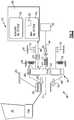
- FIG. 2is a schematic view of an example fan drive gear system including star epicyclical geared architecture.
- FIG. 3is a schematic view of an example fan drive gear system including planetary epicyclical geared architecture.
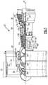
- FIG. 1schematically illustrates an example gas turbine engine 20 that includes a fan section 22 , a compressor section 24 , a combustor section 26 and a turbine section 28 .
- Alternative enginesmight include an augmenter section (not shown) among other systems or features.
- the fan section 22drives air along a bypass flow path B while the compressor section 24 draws air in along a core flow path C where air is compressed and communicated to a combustor section 26 .
- the combustor section 26air is mixed with fuel and ignited to generate a high pressure exhaust gas stream that expands through the turbine section 28 where energy is extracted and utilized to drive the fan section 22 and the compressor section 24 .
- turbofan gas turbine enginedepicts a turbofan gas turbine engine
- the concepts described hereinare not limited to use with turbofans as the teachings may be applied to other types of turbine engines; for example a turbine engine including a three-spool architecture in which three spools concentrically rotate about a common axis and where a low spool enables a low pressure turbine to drive a fan via a gearbox, an intermediate spool that enables an intermediate pressure turbine to drive a first compressor of the compressor section, and a high spool that enables a high pressure turbine to drive a high pressure compressor of the compressor section.
- the example engine 20generally includes a low speed spool 30 and a high speed spool 32 mounted for rotation about an engine central longitudinal axis A relative to an engine static structure 36 via several bearing systems 38 . It should be understood that various bearing systems 38 at various locations may alternatively or additionally be provided.
- the low speed spool 30generally includes an inner shaft 40 that connects a fan 42 and a low pressure (or first) compressor section 44 to a low pressure (or first) turbine section 46 .
- the inner shaft 40drives the fan 42 through a speed change device, such as a geared architecture 48 , to drive the fan 42 at a lower speed than the low speed spool 30 .
- the high-speed spool 32includes an outer shaft 50 that interconnects a high pressure (or second) compressor section 52 and a high pressure (or second) turbine section 54 .
- the inner shaft 40 and the outer shaft 50are concentric and rotate via the bearing systems 38 about the engine central longitudinal axis A.
- a combustor 56is arranged between the high pressure compressor 52 and the high pressure turbine 54 .
- the high pressure turbine 54includes at least two stages to provide a double stage high pressure turbine 54 .
- the high pressure turbine 54includes only a single stage.
- a “high pressure” compressor or turbineexperiences a higher pressure than a corresponding “low pressure” compressor or turbine.
- the example low pressure turbine 46has a pressure ratio that is greater than about 5.
- the pressure ratio of the example low pressure turbine 46is measured prior to an inlet of the low pressure turbine 46 as related to the pressure measured at the outlet of the low pressure turbine 46 prior to an exhaust nozzle.
- a mid-turbine frame 58 of the engine static structure 36is arranged generally between the high pressure turbine 54 and the low pressure turbine 46 .
- the mid-turbine frame 58further supports bearing systems 38 in the turbine section 28 as well as setting airflow entering the low pressure turbine 46 .
- the core airflow Cis compressed by the low pressure compressor 44 then by the high pressure compressor 52 mixed with fuel and ignited in the combustor 56 to produce high speed exhaust gases that are then expanded through the high pressure turbine 54 and low pressure turbine 46 .
- the mid-turbine frame 58includes vanes 60 , which are in the core airflow path and function as an inlet guide vane for the low pressure turbine 46 . Utilizing the vane 60 of the mid-turbine frame 58 as the inlet guide vane for low pressure turbine 46 decreases the length of the low pressure turbine 46 without increasing the axial length of the mid-turbine frame 58 . Reducing or eliminating the number of vanes in the low pressure turbine 46 shortens the axial length of the turbine section 28 . Thus, the compactness of the gas turbine engine 20 is increased and a higher power density may be achieved.
- the disclosed gas turbine engine 20 in one exampleis a high-bypass geared aircraft engine.
- the gas turbine engine 20includes a bypass ratio greater than about six (6), with an example embodiment being greater than about ten (10).
- the example geared architecture 48is an epicyclical gear train, such as a planetary gear system, star gear system or other known gear system, with a gear reduction ratio of greater than about 2.3.
- the gas turbine engine 20includes a bypass ratio greater than about ten (10:1) and the fan diameter is significantly larger than an outer diameter of the low pressure compressor 44 . It should be understood, however, that the above parameters are only exemplary of one embodiment of a gas turbine engine including a geared architecture and that the present disclosure is applicable to other gas turbine engines.
- the fan section 22 of the engine 20is designed for a particular flight condition—typically cruise at about 0.8 Mach and about 35,000 feet.
- TSFCThrust Specific Fuel Consumption
- Low fan pressure ratiois the pressure ratio across the fan blade alone, without a Fan Exit Guide Vane (“FEGV”) system.
- the low fan pressure ratio as disclosed herein according to one non-limiting embodimentis less than about 1.50. In another non-limiting embodiment, the low fan pressure ratio is less than about 1.45.
- Low corrected fan tip speedis the actual fan tip speed in ft/sec divided by an industry standard temperature correction of [(Tram ° R)/518.7) 0.5 ].
- the “Low corrected fan tip speed”, as disclosed herein according to one non-limiting embodiment,is less than about 1150 ft/second.
- the example gas turbine engineincludes the fan 42 that comprises in one non-limiting embodiment less than about 26 fan blades. In another non-limiting embodiment, the fan section 22 includes less than about 20 fan blades. Moreover, in one disclosed embodiment the low pressure turbine 46 includes no more than about 6 turbine rotors schematically indicated at 34 . In another non-limiting example embodiment, the low pressure turbine 46 includes about 3 turbine rotors. A ratio between the number of fan blades 42 and the number of low pressure turbine rotors is between about 3.3 and about 8.6. The example low pressure turbine 46 provides the driving power to rotate the fan section 22 and therefore the relationship between the number of turbine rotors 34 in the low pressure turbine 46 and the number of blades 42 in the fan section 22 disclose an example gas turbine engine 20 with increased power transfer efficiency.
- the example gas turbine engineincludes a lubrication system 98 .
- the lubrication system 98provides lubricant flow to the rotating components of the gas turbine engine including the bearing assemblies 38 and the geared architecture 48 .
- the lubrication system 98further provides for the removal of heat generated in the various bearing systems and the geared architecture 48 .
- the example lubrication system 98includes a main system 80 that provides lubrication during normal operating conditions of the gas turbine engine.
- An auxiliary system 82is also included to supplement operation of the main lubrication system 80 .
- the size and weight of the lubrication system 90is directly related to its capacity for removing heat from the geared architecture 48 . The greater the need for removal of heat, the larger and heavier the lubrication system 98 becomes. The amount of heat generated by the geared architecture 48 is therefore an important consideration in the configuration of a fan drive gear system.
- the example geared architecture 48is part of a fan drive gear system 70 .
- the example geared architecture 48comprises a gear assembly 65 that includes a sun gear 62 driven by a fan drive turbine 46 .
- the fan drive turbineis the low pressure turbine 46 .
- the sun gear 62in turn drives intermediate gears 64 mounted on a carrier 74 by journal bearings.
- the carrier 74is grounded to the static engine structure 36 and therefore the intermediate gears 64 do not orbit about the sun gear 62 .
- the intermediate gears 64intermesh and drive a ring gear 66 coupled to a fan shaft 68 to drive the fan 42 .
- the gear assembly 65is flexibly mounted such that it may be isolated from vibrational and transient movement that could disturb alignment between the gears 62 , 64 and 66 .
- flexible mounts 76support the carrier 74 and accommodate relative movement between the gear assembly 65 and the static structure 36 .
- the example flexible mount 76includes a spring rate that accommodates deflections that occur during normal operation of the fan drive gear system 70 .
- the flexible coupling 72also includes a spring rate that allows a defined amount of deflection and misalignment such that components of the gear assembly 65 are not driven out of alignment.
- a load limiting device 78is provided as part of the gear box mounting structure.
- the load limiter 78constrains movement of the gear box 65 .
- the limiter 78further provides a stop that reacts to unbalanced loads on the gear box 65 . Accordingly, the limiter prevents radial unbalanced loads and/or torsional overloads from damaging the gas turbine engine 20 .
- the example fan drive gear system 70is supported by a lubrication system 98 .
- the lubrication system 98provides for lubrication and cooling of the gears 62 , 64 and 66 along with bearings supporting rotation of the gears. It is desirable to circulate lubricant as quickly as possible to maintain a desired temperature. Power transmission efficiency through the gear box 65 is detrimentally affected by elevated temperatures.
- the lubricant system 98includes a main system 80 that provides the desired lubricant flow through a plurality of conduits schematically illustrated by the line 88 to and from the gear box 65 .
- the main oil system 80also transmits heat, schematically by arrows 92 , away from the gear box 65 to maintain a desired temperature.
- the lubrication system 98also includes the auxiliary oil system 82 that supplies oil flow to the gear box 65 in response to a temporary interruption in lubricant flow from the main oil system 80 .
- the efficiency of the example gear box 65 and overall geared architecture 48is a function of the power input, schematically indicated by arrow 94 , through the shaft 40 relative to power output, schematically indicated by arrows 96 , to the fan shaft 68 .
- Power input 94 compared to the amount of power output 96is a measure of gear box efficiency.
- the example gear box 65operates at an efficiency of greater than about 98%. In another disclosed example, the example gear box 65 operates at an efficiency greater than about 99%.
- the disclosed efficiencyis a measure of the amount of power 94 that is specifically transferred to the fan shaft 68 to rotate the fan 42 . Power that is not transmitted through the gear box 65 is lost as heat and reduces the overall efficiency of the fan drive gear system 70 . Any deficit between the input power 94 and output power 96 results in the generation of heat. Accordingly, in this example, the deficit of between 1-2% between the input power 94 and output power 96 generates heat. In other words, between 1% and 2% of the input power 94 is converted to heat energy that must be accommodated by the lubrication system 98 to maintain a working lubricant temperature within operational limits.
- the example lubricant system 98provides for the removal of thermal energy equal to or less than about 2% of the input power 94 from the low pressure turbine 46 .
- the efficiency of the gear box 65is greater than about 99% such that only 1% of power input from the low pressure turbine 46 is transferred into heat energy that must be handled by the lubricant system 98 .
- the main oil systemincludes a heat exchanger 90 that accommodates heat 92 that is generated within the gear box 65 .
- the heat exchanger 90is an example of one element of the lubrication system 98 that is scaled to the desired capacity for removing thermal energy.
- other elementssuch as for example lubricant pumps, conduit size along with overall lubricant quantity within the lubrication system 98 would also be increased in size and weight to provide increased cooling capacity. Accordingly, it is desirable to increase power transfer efficiency to reduce required overall heat transfer capacity of lubrication system 98 .
- the high efficiency of the example gear box 65enables a relatively small and light lubricant system 98 .
- the example lubricant system 98includes features that can accommodate thermal energy generated by no more than about 2% of the input power 94 .
- the lubrication system 98has an overall maximum capacity for removing thermal energy equal to no more than about 2% of the input power provided by the low pressure turbine 46 .
- Lubrication systemsthat are required to remove greater than about 2% of input power 94 require larger lubricant systems 98 that can detrimentally impact overall engine efficiency and detract from the propulsion efficiencies provided by the reduction in fan speed.
- another example epicyclical gear box 85comprises a planetary configuration.
- planet gears 84are supported on a carrier 86 that is rotatable about the engine axis A.
- the sun gear 62remains driven by the inner shaft 40 and the low pressure turbine 46 .
- the ring gear 66is mounted to a fixed structure 36 such that it does not rotate about the axis. Accordingly, rotation of the sun gear 62 drives the planet gears 84 within the ring gear 66 .
- the planet gears 84are supported on the rotatable carrier 86 that in turn drives the fan shaft 68 .
- the fan shaft 68 and the sun gear 62rotate in a common direction, while the planet gears 84 individually rotate in a direction opposite to the sun gear 62 but collectively rotate about the sun gear 62 in the same direction as the rotation of the sun gear 62 .
- the example planetary gear box illustrated in FIG. 3includes the ring gear 66 that is supported by flexible mount 76 .
- the flexible mount 76allows some movement of the gearbox 85 to maintain a desired alignment between meshing teeth of the gears 62 , 84 , 66 .
- the limiter 78prevents movement of the planetary gear box 85 beyond desired limits to prevent potential damage caused by radial imbalances and/or torsional loads.
- the example low pressure turbine 46inputs power 94 to drive the gear box 85 .
- the example gear box 85transmits more than about 98% of the input power 94 to the fan drive shaft 68 as output power 96 .
- the gear box 85transmits more than about 99% of the input power 94 to the fan drive shaft 68 as output power 96 .
- the difference between the input power 94 and the output power 96is converted into heat energy that is removed by the lubrication system 98 .
- the lubrication system 98has a capacity of removing no more heat 92 than is generated by about 2% of the input power 94 from the low pressure turbine 46 .
- the lubrication system 98has a capacity of removing no more heat 92 than is generated by about 1% of the input power 94 . Accordingly, the efficiency provided by the example gear box 85 enables the lubrication system 98 to be of size that does not detract from the propulsive efficiency realized by turning the fan section 22 and low pressure turbine 46 at separate and nearer optimal speeds.
- the example fan drive gear systemprovides for the improvement and realization of propulsive efficiencies by limiting losses in the form of thermal energy, thereby enabling utilization of a lower capacity and sized lubrication system.
Landscapes
- Engineering & Computer Science (AREA)
- Chemical & Material Sciences (AREA)
- Combustion & Propulsion (AREA)
- Mechanical Engineering (AREA)
- General Engineering & Computer Science (AREA)
- General Details Of Gearings (AREA)
- Retarders (AREA)
- Structures Of Non-Positive Displacement Pumps (AREA)
- Gear Transmission (AREA)
Abstract
Description
Claims (20)
Priority Applications (2)
| Application Number | Priority Date | Filing Date | Title |
|---|---|---|---|
| US16/291,392US11125167B2 (en) | 2012-05-31 | 2019-03-04 | Fundamental gear system architecture |
| US17/408,607US11773786B2 (en) | 2012-05-31 | 2021-08-23 | Fundamental gear system architecture |
Applications Claiming Priority (5)
| Application Number | Priority Date | Filing Date | Title |
|---|---|---|---|
| US201261653731P | 2012-05-31 | 2012-05-31 | |
| US13/557,614US8572943B1 (en) | 2012-05-31 | 2012-07-25 | Fundamental gear system architecture |
| PCT/US2013/041761WO2014028085A2 (en) | 2012-05-31 | 2013-05-20 | Fundamental gear system architecture |
| US14/190,159US10221770B2 (en) | 2012-05-31 | 2014-02-26 | Fundamental gear system architecture |
| US16/291,392US11125167B2 (en) | 2012-05-31 | 2019-03-04 | Fundamental gear system architecture |
Related Parent Applications (1)
| Application Number | Title | Priority Date | Filing Date |
|---|---|---|---|
| US14/190,159ContinuationUS10221770B2 (en) | 2012-05-31 | 2014-02-26 | Fundamental gear system architecture |
Related Child Applications (1)
| Application Number | Title | Priority Date | Filing Date |
|---|---|---|---|
| US17/408,607ContinuationUS11773786B2 (en) | 2012-05-31 | 2021-08-23 | Fundamental gear system architecture |
Publications (2)
| Publication Number | Publication Date |
|---|---|
| US20190195140A1 US20190195140A1 (en) | 2019-06-27 |
| US11125167B2true US11125167B2 (en) | 2021-09-21 |
Family
ID=49487663
Family Applications (5)
| Application Number | Title | Priority Date | Filing Date |
|---|---|---|---|
| US13/557,614Expired - Fee RelatedUS8572943B1 (en) | 2012-05-31 | 2012-07-25 | Fundamental gear system architecture |
| US14/190,159ActiveUS10221770B2 (en) | 2012-05-31 | 2014-02-26 | Fundamental gear system architecture |
| US15/872,111AbandonedUS20180156134A1 (en) | 2012-05-31 | 2018-01-16 | Gear system architecture for gas turbine engine |
| US16/291,392Active2033-03-16US11125167B2 (en) | 2012-05-31 | 2019-03-04 | Fundamental gear system architecture |
| US17/408,607Active2033-04-01US11773786B2 (en) | 2012-05-31 | 2021-08-23 | Fundamental gear system architecture |
Family Applications Before (3)
| Application Number | Title | Priority Date | Filing Date |
|---|---|---|---|
| US13/557,614Expired - Fee RelatedUS8572943B1 (en) | 2012-05-31 | 2012-07-25 | Fundamental gear system architecture |
| US14/190,159ActiveUS10221770B2 (en) | 2012-05-31 | 2014-02-26 | Fundamental gear system architecture |
| US15/872,111AbandonedUS20180156134A1 (en) | 2012-05-31 | 2018-01-16 | Gear system architecture for gas turbine engine |
Family Applications After (1)
| Application Number | Title | Priority Date | Filing Date |
|---|---|---|---|
| US17/408,607Active2033-04-01US11773786B2 (en) | 2012-05-31 | 2021-08-23 | Fundamental gear system architecture |
Country Status (8)
| Country | Link |
|---|---|
| US (5) | US8572943B1 (en) |
| EP (1) | EP2751410A4 (en) |
| JP (1) | JP5711431B2 (en) |
| CN (2) | CN106968802B (en) |
| BR (1) | BR112014007754B1 (en) |
| CA (1) | CA2852141C (en) |
| RU (2) | RU2016148904A (en) |
| WO (1) | WO2014028085A2 (en) |
Cited By (2)
| Publication number | Priority date | Publication date | Assignee | Title |
|---|---|---|---|---|
| US12435645B2 (en) | 2023-10-10 | 2025-10-07 | Ge Avio S.R.L. | Lubrication system for a turbine engine |
| US12442314B2 (en) | 2023-10-10 | 2025-10-14 | Ge Avio S.R.L. | Lubrication system for a turbine engine |
Families Citing this family (73)
| Publication number | Priority date | Publication date | Assignee | Title |
|---|---|---|---|---|
| US10287914B2 (en) | 2012-01-31 | 2019-05-14 | United Technologies Corporation | Gas turbine engine with high speed low pressure turbine section and bearing support features |
| US10125693B2 (en) | 2012-04-02 | 2018-11-13 | United Technologies Corporation | Geared turbofan engine with power density range |
| US20150308351A1 (en)* | 2012-05-31 | 2015-10-29 | United Technologies Corporation | Fundamental gear system architecture |
| US8572943B1 (en)* | 2012-05-31 | 2013-11-05 | United Technologies Corporation | Fundamental gear system architecture |
| EP2971734B1 (en) | 2013-03-15 | 2022-11-30 | Raytheon Technologies Corporation | Geared architecture turbofan engine thermal management system and method |
| SG10201705204XA (en)* | 2013-09-24 | 2017-07-28 | United Technologies Corp | Fundamental gear system architecture |
| WO2015094607A1 (en)* | 2013-12-20 | 2015-06-25 | United Technologies Corporation | Geared turbofan with improved gear system maintainability |
| EP3617479B1 (en)* | 2014-01-20 | 2023-04-26 | Raytheon Technologies Corporation | Geared gas turbine engine with reduced oil tank size |
| EP3102807B1 (en) | 2014-01-20 | 2022-04-20 | Raytheon Technologies Corporation | Auxiliary oil system for geared gas turbine engine |
| US10196926B2 (en) | 2014-04-11 | 2019-02-05 | United Technologies Corporation | Lubricating a rotating component during forward and/or reverse rotation |
| FR3020658B1 (en)* | 2014-04-30 | 2020-05-15 | Safran Aircraft Engines | LUBRICATION OIL RECOVERY HOOD FOR TURBOMACHINE EQUIPMENT |
| US9869190B2 (en) | 2014-05-30 | 2018-01-16 | General Electric Company | Variable-pitch rotor with remote counterweights |
| US10072510B2 (en) | 2014-11-21 | 2018-09-11 | General Electric Company | Variable pitch fan for gas turbine engine and method of assembling the same |
| EP3109416A1 (en)* | 2015-06-22 | 2016-12-28 | United Technologies Corporation | Fundamental gear system architecture |
| US10578017B2 (en) | 2015-06-23 | 2020-03-03 | United Technologies Corporation | Windmill and negative-G oil system for geared turbofan engines |
| US10119465B2 (en) | 2015-06-23 | 2018-11-06 | United Technologies Corporation | Geared turbofan with independent flexible ring gears and oil collectors |
| FR3039132B1 (en)* | 2015-07-20 | 2017-08-11 | Airbus Operations Sas | HORIZONTAL AXIS PROPELLER PROPELLER ASSEMBLY FOR AIRCRAFT |
| US10495004B2 (en) | 2015-09-17 | 2019-12-03 | General Electric Company | Multi-directional gearbox deflection limiter for a gas turbine engine |
| EP3359791B1 (en)* | 2015-10-05 | 2020-11-25 | Safran Aircraft Engines | Turbine engine with fan and reduction of speed on the shaft of the power turbine |
| US10100653B2 (en) | 2015-10-08 | 2018-10-16 | General Electric Company | Variable pitch fan blade retention system |
| US10281025B2 (en) | 2015-10-19 | 2019-05-07 | United Technologies Corporation | Fixed support and oil collector system for ring gear |
| US10590854B2 (en)* | 2016-01-26 | 2020-03-17 | United Technologies Corporation | Geared gas turbine engine |
| IT201600071644A1 (en)* | 2016-07-08 | 2018-01-08 | Nuovo Pignone Tecnologie Srl | VARIABLE SPEED TRANSMISSION WITH AUXILIARY DRIVE AND SYSTEM THAT USES IT |
| US20180171815A1 (en)* | 2016-12-16 | 2018-06-21 | United Technologies Corporation | Traction drive transmission for gas turbine engine accessory gearbox |
| US10669948B2 (en) | 2017-01-03 | 2020-06-02 | Raytheon Technologies Corporation | Geared turbofan with non-epicyclic gear reduction system |
| EP3354882B1 (en) | 2017-01-30 | 2021-03-17 | GE Avio S.r.l. | Method and system of connecting a turbine engine gearbox to engine core |
| EP3354847B1 (en) | 2017-01-30 | 2023-03-08 | GE Avio S.r.l. | Flexible coupling shaft for turbine engine |
| FR3071547B1 (en)* | 2017-09-27 | 2019-09-13 | Safran Aircraft Engines | ASSEMBLY OF A BEARING SUPPORT AND BEARINGS OF A ROTOR SHAFT IN A TURBOMACHINE |
| GB201807265D0 (en)* | 2018-05-03 | 2018-06-20 | Rolls Royce Plc | Oil tank system |
| US11236672B2 (en)* | 2018-06-14 | 2022-02-01 | Raytheon Technologies Corporation | Oil thermal management system for cold weather operations of a gas turbine engine |
| FR3082553B1 (en)* | 2018-06-18 | 2020-09-25 | Safran Aircraft Engines | AIRCRAFT TURBOMACHINE ASSEMBLY INCLUDING AN IMPROVED BLOWER DRIVE REDUCER LUBRICATION SYSTEM IN THE EVENT OF BLOWER AUTOTATION |
| EP3587774B1 (en)* | 2018-06-27 | 2025-05-07 | Rolls-Royce plc | Gas turbine |
| US11578667B2 (en) | 2018-08-30 | 2023-02-14 | Rolls-Royce Corporation | Efficiency-based machine control |
| EP3620652A1 (en)* | 2018-09-06 | 2020-03-11 | Siemens Gamesa Renewable Energy A/S | Treating a wind turbine drive train |
| US11041444B2 (en)* | 2018-11-02 | 2021-06-22 | Pratt & Whitney Canada Corp. | Gas turbine engine with differential gearbox |
| US20200158213A1 (en)* | 2018-11-21 | 2020-05-21 | United Technologies Corporation | Hybrid electric propulsion with superposition gearbox |
| FR3088968B1 (en)* | 2018-11-27 | 2021-12-03 | Safran Aircraft Engines | Double-flow turbojet arrangement with epicyclic or planetary reduction gear |
| US10634233B1 (en) | 2018-11-29 | 2020-04-28 | Rolls-Royce Corporation | Efficiency based gearbox cooling control |
| US11168617B2 (en)* | 2019-01-30 | 2021-11-09 | Raytheon Technologies Corporation | Electric enhanced transmission for multi-spool load-sharing turbofan engine |
| CN110286699B (en)* | 2019-05-28 | 2020-12-15 | 东南大学 | An optimal speed scheduling method for unmanned aerial vehicles based on actual model in wireless sensor network data collection |
| US11162575B2 (en) | 2019-11-20 | 2021-11-02 | Raytheon Technologies Corporation | Geared architecture for gas turbine engine |
| IT202000000652A1 (en) | 2020-01-15 | 2021-07-15 | Ge Avio Srl | TURBOMACHINE AND GEAR GROUP |
| FR3108683B1 (en)* | 2020-03-27 | 2022-11-25 | Safran Aircraft Engines | Aircraft turbomachine |
| US11242770B2 (en) | 2020-04-02 | 2022-02-08 | General Electric Company | Turbine center frame and method |
| GB202005022D0 (en) | 2020-04-06 | 2020-05-20 | Rolls Royce Plc | Gearboxes for aircraft gas turbine engines |
| GB202005025D0 (en) | 2020-04-06 | 2020-05-20 | Rolls Royce Plc | Gearboxes for aircraft gas turbine engines |
| GB202005028D0 (en) | 2020-04-06 | 2020-05-20 | Rolls Royce Plc | Gearboxes for aircraft gas turbine engines |
| GB202005033D0 (en) | 2020-04-06 | 2020-05-20 | Rolls Royce Plc | Gearboxes for aircraft gas turbine engines |
| US11674440B2 (en)* | 2021-02-09 | 2023-06-13 | Raytheon Technologies Corporation | Geared gas turbine engine with combined spray bar and scavenge component |
| US11236735B1 (en) | 2021-04-02 | 2022-02-01 | Ice Thermal Harvesting, Llc | Methods for generating geothermal power in an organic Rankine cycle operation during hydrocarbon production based on wellhead fluid temperature |
| US11486370B2 (en) | 2021-04-02 | 2022-11-01 | Ice Thermal Harvesting, Llc | Modular mobile heat generation unit for generation of geothermal power in organic Rankine cycle operations |
| US11493029B2 (en) | 2021-04-02 | 2022-11-08 | Ice Thermal Harvesting, Llc | Systems and methods for generation of electrical power at a drilling rig |
| US11644015B2 (en) | 2021-04-02 | 2023-05-09 | Ice Thermal Harvesting, Llc | Systems and methods for generation of electrical power at a drilling rig |
| US12312981B2 (en) | 2021-04-02 | 2025-05-27 | Ice Thermal Harvesting, Llc | Systems and methods utilizing gas temperature as a power source |
| US11293414B1 (en) | 2021-04-02 | 2022-04-05 | Ice Thermal Harvesting, Llc | Systems and methods for generation of electrical power in an organic rankine cycle operation |
| US11480074B1 (en) | 2021-04-02 | 2022-10-25 | Ice Thermal Harvesting, Llc | Systems and methods utilizing gas temperature as a power source |
| US11592009B2 (en) | 2021-04-02 | 2023-02-28 | Ice Thermal Harvesting, Llc | Systems and methods for generation of electrical power at a drilling rig |
| US11326550B1 (en) | 2021-04-02 | 2022-05-10 | Ice Thermal Harvesting, Llc | Systems and methods utilizing gas temperature as a power source |
| US11421663B1 (en) | 2021-04-02 | 2022-08-23 | Ice Thermal Harvesting, Llc | Systems and methods for generation of electrical power in an organic Rankine cycle operation |
| US11674435B2 (en) | 2021-06-29 | 2023-06-13 | General Electric Company | Levered counterweight feathering system |
| US11795964B2 (en) | 2021-07-16 | 2023-10-24 | General Electric Company | Levered counterweight feathering system |
| US11655768B2 (en)* | 2021-07-26 | 2023-05-23 | General Electric Company | High fan up speed engine |
| US11767790B2 (en) | 2021-08-23 | 2023-09-26 | General Electric Company | Object direction mechanism for turbofan engine |
| US11739689B2 (en) | 2021-08-23 | 2023-08-29 | General Electric Company | Ice reduction mechanism for turbofan engine |
| FR3138926A1 (en)* | 2022-04-21 | 2024-02-23 | Franck GROLLEAU | High power density radial gear counter-rotating fan module for turbofan |
| US12180861B1 (en) | 2022-12-30 | 2024-12-31 | Ice Thermal Harvesting, Llc | Systems and methods to utilize heat carriers in conversion of thermal energy |
| US20250075659A1 (en)* | 2023-08-30 | 2025-03-06 | Rtx Corporation | Tower shaft driven planetary fan drive gear lubrication system |
| CN119801729A (en)* | 2023-10-10 | 2025-04-11 | 通用电气阿维奥有限责任公司 | Lubrication systems for turbine engines |
| US12385430B2 (en) | 2023-11-30 | 2025-08-12 | General Electric Company | Gas turbine engine with forward swept outlet guide vanes |
| US12209557B1 (en) | 2023-11-30 | 2025-01-28 | General Electric Company | Gas turbine engine with forward swept outlet guide vanes |
| US12228037B1 (en) | 2023-12-04 | 2025-02-18 | General Electric Company | Guide vane assembly with fixed and variable pitch inlet guide vanes |
| US12292004B1 (en)* | 2024-01-12 | 2025-05-06 | Rtx Corporation | Component mounting and drive in a geared turbofan architecture |
| US12313021B1 (en) | 2024-03-14 | 2025-05-27 | General Electric Company | Outer nacelle with inlet guide vanes and acoustic treatment |
Citations (108)
| Publication number | Priority date | Publication date | Assignee | Title |
|---|---|---|---|---|
| SU198845A1 (en) | В. И. Смородов, Н. С. Авученков , Б. Лотырев | TRANSMISSION MECHANISM DEVICE | ||
| US2258792A (en) | 1941-04-12 | 1941-10-14 | Westinghouse Electric & Mfg Co | Turbine blading |
| US2826255A (en)* | 1951-06-14 | 1958-03-11 | Gen Motors Corp | Propeller drives |
| US2936655A (en) | 1955-11-04 | 1960-05-17 | Gen Motors Corp | Self-aligning planetary gearing |
| US3021731A (en) | 1951-11-10 | 1962-02-20 | Wilhelm G Stoeckicht | Planetary gear transmission |
| US3194487A (en) | 1963-06-04 | 1965-07-13 | United Aircraft Corp | Noise abatement method and apparatus |
| US3287906A (en) | 1965-07-20 | 1966-11-29 | Gen Motors Corp | Cooled gas turbine vanes |
| US3352178A (en) | 1965-11-15 | 1967-11-14 | Gen Motors Corp | Planetary gearing |
| US3412560A (en) | 1966-08-03 | 1968-11-26 | Gen Motors Corp | Jet propulsion engine with cooled combustion chamber, fuel heater, and induced air-flow |
| US3664612A (en) | 1969-12-22 | 1972-05-23 | Boeing Co | Aircraft engine variable highlight inlet |
| US3747343A (en) | 1972-02-10 | 1973-07-24 | United Aircraft Corp | Low noise prop-fan |
| US3754484A (en) | 1971-01-08 | 1973-08-28 | Secr Defence | Gearing |
| US3820719A (en) | 1972-05-09 | 1974-06-28 | Rolls Royce 1971 Ltd | Gas turbine engines |
| US3892358A (en) | 1971-03-17 | 1975-07-01 | Gen Electric | Nozzle seal |
| US3932058A (en) | 1974-06-07 | 1976-01-13 | United Technologies Corporation | Control system for variable pitch fan propulsor |
| US3935558A (en) | 1974-12-11 | 1976-01-27 | United Technologies Corporation | Surge detector for turbine engines |
| US3988889A (en) | 1974-02-25 | 1976-11-02 | General Electric Company | Cowling arrangement for a turbofan engine |
| US4020632A (en)* | 1975-07-17 | 1977-05-03 | The United States Of America As Represented By The United States National Aeronautics And Space Administration Office Of General Counsel-Code Gp | Oil cooling system for a gas turbine engine |
| GB1516041A (en) | 1977-02-14 | 1978-06-28 | Secr Defence | Multistage axial flow compressor stators |
| US4130872A (en) | 1975-10-10 | 1978-12-19 | The United States Of America As Represented By The Secretary Of The Air Force | Method and system of controlling a jet engine for avoiding engine surge |
| GB2041090A (en) | 1979-01-31 | 1980-09-03 | Rolls Royce | By-pass gas turbine engines |
| US4284174A (en) | 1979-04-18 | 1981-08-18 | Avco Corporation | Emergency oil/mist system |
| US4289360A (en) | 1979-08-23 | 1981-09-15 | General Electric Company | Bearing damper system |
| US4358969A (en)* | 1977-05-18 | 1982-11-16 | Silvestri Giovanni J | High pressure air turbine and gear train system |
| US4423333A (en)* | 1982-02-02 | 1983-12-27 | Rossman Wendell E | Horizontal axis wind energy conversion system with aerodynamic blade pitch control |
| US4478551A (en) | 1981-12-08 | 1984-10-23 | United Technologies Corporation | Turbine exhaust case design |
| US4649114A (en) | 1979-10-05 | 1987-03-10 | Intermedicat Gmbh | Oxygen permeable membrane in fermenter for oxygen enrichment of broth |
| US4696156A (en) | 1986-06-03 | 1987-09-29 | United Technologies Corporation | Fuel and oil heat management system for a gas turbine engine |
| GB2204642A (en) | 1987-05-06 | 1988-11-16 | Mtu Muenchen Gmbh | Reduction gear lubrication in a propfan turbo propulsion unit |
| US4979362A (en) | 1989-05-17 | 1990-12-25 | Sundstrand Corporation | Aircraft engine starting and emergency power generating system |
| US5102379A (en) | 1991-03-25 | 1992-04-07 | United Technologies Corporation | Journal bearing arrangement |
| US5141400A (en) | 1991-01-25 | 1992-08-25 | General Electric Company | Wide chord fan blade |
| US5317877A (en) | 1992-08-03 | 1994-06-07 | General Electric Company | Intercooled turbine blade cooling air feed system |
| US5361580A (en) | 1993-06-18 | 1994-11-08 | General Electric Company | Gas turbine engine rotor support system |
| US5433674A (en) | 1994-04-12 | 1995-07-18 | United Technologies Corporation | Coupling system for a planetary gear train |
| US5447411A (en) | 1993-06-10 | 1995-09-05 | Martin Marietta Corporation | Light weight fan blade containment system |
| US5466198A (en) | 1993-06-11 | 1995-11-14 | United Technologies Corporation | Geared drive system for a bladed propulsor |
| US5524847A (en) | 1993-09-07 | 1996-06-11 | United Technologies Corporation | Nacelle and mounting arrangement for an aircraft engine |
| US5634767A (en) | 1996-03-29 | 1997-06-03 | General Electric Company | Turbine frame having spindle mounted liner |
| EP0791383A1 (en) | 1996-02-26 | 1997-08-27 | Japan Gore-Tex, Inc. | An assembly for deaeration of liquids |
| US5677060A (en) | 1994-03-10 | 1997-10-14 | Societe Europeenne De Propulsion | Method for protecting products made of a refractory material against oxidation, and resulting protected products |
| US5720694A (en)* | 1995-08-22 | 1998-02-24 | Hyundai Motor Company | Hydraulic control system for automatic transmission system |
| US5778659A (en) | 1994-10-20 | 1998-07-14 | United Technologies Corporation | Variable area fan exhaust nozzle having mechanically separate sleeve and thrust reverser actuation systems |
| US5809843A (en)* | 1997-01-07 | 1998-09-22 | Bbn Corporation | Active cancellation of noise at gear mesh frequencies for a gear assembly under load |
| US5857836A (en) | 1996-09-10 | 1999-01-12 | Aerodyne Research, Inc. | Evaporatively cooled rotor for a gas turbine engine |
| US5915917A (en) | 1994-12-14 | 1999-06-29 | United Technologies Corporation | Compressor stall and surge control using airflow asymmetry measurement |
| US5975841A (en) | 1997-10-03 | 1999-11-02 | Thermal Corp. | Heat pipe cooling for turbine stators |
| US5985470A (en) | 1998-03-16 | 1999-11-16 | General Electric Company | Thermal/environmental barrier coating system for silicon-based materials |
| US6223616B1 (en)* | 1999-12-22 | 2001-05-01 | United Technologies Corporation | Star gear system with lubrication circuit and lubrication method therefor |
| US6223872B1 (en)* | 1997-08-26 | 2001-05-01 | Luk Getriebe-Systeme Gmbh | Hydrodynamic torque converter |
| EP1142850A1 (en) | 2000-04-06 | 2001-10-10 | General Electric Company | Thermal/environmental barrier coating for silicon-containing materials |
| US6315815B1 (en) | 1999-12-16 | 2001-11-13 | United Technologies Corporation | Membrane based fuel deoxygenator |
| US6318070B1 (en) | 2000-03-03 | 2001-11-20 | United Technologies Corporation | Variable area nozzle for gas turbine engines driven by shape memory alloy actuators |
| US6330525B1 (en)* | 1997-12-31 | 2001-12-11 | Innovation Management Group, Inc. | Method and apparatus for diagnosing a pump system |
| US6387456B1 (en) | 1999-04-15 | 2002-05-14 | General Electric Company | Silicon based substrate with environmental/thermal barrier layer |
| US6517341B1 (en) | 1999-02-26 | 2003-02-11 | General Electric Company | Method to prevent recession loss of silica and silicon-containing materials in combustion gas environments |
| US6607165B1 (en) | 2002-06-28 | 2003-08-19 | General Electric Company | Aircraft engine mount with single thrust link |
| US6709492B1 (en) | 2003-04-04 | 2004-03-23 | United Technologies Corporation | Planar membrane deoxygenator |
| US6789522B2 (en)* | 2001-07-23 | 2004-09-14 | John Seymour | Engine for aeronautical applications |
| US6814541B2 (en) | 2002-10-07 | 2004-11-09 | General Electric Company | Jet aircraft fan case containment design |
| US6883303B1 (en) | 2001-11-29 | 2005-04-26 | General Electric Company | Aircraft engine with inter-turbine engine frame |
| US20050257528A1 (en)* | 2004-05-19 | 2005-11-24 | Dunbar Donal S Jr | Retractable afterburner for jet engine |
| US7021042B2 (en) | 2002-12-13 | 2006-04-04 | United Technologies Corporation | Geartrain coupling for a turbofan engine |
| US20060228206A1 (en) | 2005-04-07 | 2006-10-12 | General Electric Company | Low solidity turbofan |
| GB2426792A (en) | 2005-04-01 | 2006-12-06 | David Richard Hopkins | Fan with conical hub |
| US20070036655A1 (en)* | 2003-03-21 | 2007-02-15 | Soren Damgaard | Methods of moving the rotating means of a wind turbine during transportation or stand still, method of controlling the moving of the rotating means, nacelle, auxiliary device, control and monitoring system and use hereof |
| WO2007038674A1 (en) | 2005-09-28 | 2007-04-05 | Entrotech Composites, Llc | Braid-reinforced composites and processes for their preparation |
| US7219490B2 (en) | 2000-09-05 | 2007-05-22 | D-Star Engineering | Nested core gas turbine engine |
| US20080003096A1 (en) | 2006-06-29 | 2008-01-03 | United Technologies Corporation | High coverage cooling hole shape |
| US7328580B2 (en) | 2004-06-23 | 2008-02-12 | General Electric Company | Chevron film cooled wall |
| JP2008038902A (en) | 2006-07-12 | 2008-02-21 | Kawasaki Heavy Ind Ltd | Power generation / starter device with traction transmission mechanism |
| US20080116009A1 (en) | 2006-11-22 | 2008-05-22 | United Technologies Corporation | Lubrication system with extended emergency operability |
| US20080317588A1 (en) | 2007-06-25 | 2008-12-25 | Grabowski Zbigniew M | Managing spool bearing load using variable area flow nozzle |
| RU2346176C1 (en) | 2007-06-04 | 2009-02-10 | Открытое акционерное общество "Авиадвигатель" | Bypass gas turbine engine with fan driven by simple coaxial inner gearing reduction gear |
| RU2347928C1 (en) | 2007-06-04 | 2009-02-27 | Открытое акционерное общество "Авиадвигатель" | Gas turbine engine single-row blower reduction gear drive |
| US20090056343A1 (en) | 2007-08-01 | 2009-03-05 | Suciu Gabriel L | Engine mounting configuration for a turbofan gas turbine engine |
| RU2358375C2 (en) | 2007-07-24 | 2009-06-10 | Государственное образовательное учреждение высшего профессионального образования Военная академия Ракетных войск стратегического назначения имени Петра Великого | Electric drive based on resilient engagement planetary cycloidal reduction gear |
| US7591754B2 (en) | 2006-03-22 | 2009-09-22 | United Technologies Corporation | Epicyclic gear train integral sun gear coupling design |
| US7632064B2 (en) | 2006-09-01 | 2009-12-15 | United Technologies Corporation | Variable geometry guide vane for a gas turbine engine |
| US20090314881A1 (en) | 2008-06-02 | 2009-12-24 | Suciu Gabriel L | Engine mount system for a turbofan gas turbine engine |
| US7658060B2 (en) | 2006-07-19 | 2010-02-09 | United Technologies Corporation | Lubricant cooling exchanger dual intake duct |
| US7662059B2 (en) | 2006-10-18 | 2010-02-16 | United Technologies Corporation | Lubrication of windmilling journal bearings |
| US20100105516A1 (en)* | 2006-07-05 | 2010-04-29 | United Technologies Corporation | Coupling system for a star gear train in a gas turbine engine |
| US20100148396A1 (en) | 2007-04-17 | 2010-06-17 | General Electric Company | Methods of making articles having toughened and untoughened regions |
| US20100198534A1 (en)* | 2009-01-30 | 2010-08-05 | Roger Hala | System and method for monitoring the condition of a gear assembly |
| US20100212281A1 (en) | 2009-02-26 | 2010-08-26 | United Technologies Corporation | Auxiliary pump system for fan drive gear system |
| US20100218483A1 (en) | 2009-02-27 | 2010-09-02 | United Technologies Corporation | Controlled fan stream flow bypass |
| US20100236216A1 (en)* | 2006-10-12 | 2010-09-23 | Michael Winter | Turbofan engine with variable area fan nozzle and low spool generator for emergency power generation and method for providing emergency power |
| US7806651B2 (en) | 2004-04-02 | 2010-10-05 | Mtu Aero Engines Gmbh | Method for designing a low-pressure turbine of an aircraft engine, and low-pressure turbine |
| US7828682B2 (en) | 2006-05-11 | 2010-11-09 | Hansen Transmissions International N.V. | Gearbox for a wind turbine |
| US20100296947A1 (en)* | 2009-05-22 | 2010-11-25 | United Technologies Corporation | Apparatus and method for providing damper liquid in a gas turbine |
| US20100331139A1 (en) | 2009-06-25 | 2010-12-30 | United Technologies Corporation | Epicyclic gear system with superfinished journal bearing |
| US7926260B2 (en) | 2006-07-05 | 2011-04-19 | United Technologies Corporation | Flexible shaft for gas turbine engine |
| EP2327859A2 (en) | 2009-11-30 | 2011-06-01 | United Technologies Corporation | Mounting system for a planetary gear train in a gas turbine engine |
| US20110159797A1 (en) | 2009-12-31 | 2011-06-30 | Willem Beltman | Quiet System Cooling Using Coupled Optimization Between Integrated Micro Porous Absorbers And Rotors |
| US7997868B1 (en) | 2008-11-18 | 2011-08-16 | Florida Turbine Technologies, Inc. | Film cooling hole for turbine airfoil |
| US20110293423A1 (en) | 2010-05-28 | 2011-12-01 | General Electric Company | Articles which include chevron film cooling holes, and related processes |
| US20120124964A1 (en) | 2007-07-27 | 2012-05-24 | Hasel Karl L | Gas turbine engine with improved fuel efficiency |
| US8205432B2 (en) | 2007-10-03 | 2012-06-26 | United Technologies Corporation | Epicyclic gear train for turbo fan engine |
| EP2532841A2 (en) | 2011-06-08 | 2012-12-12 | United Technologies Corporation | Flexible support structure for a geared architecture gas turbine engine |
| US20130116937A1 (en)* | 2010-10-08 | 2013-05-09 | Keith Calhoun | System and method for detecting fault conditions in a drivetrain using torque oscillation data |
| US20130192266A1 (en) | 2012-01-31 | 2013-08-01 | United Technologies Corporation | Geared turbofan gas turbine engine architecture |
| US8508059B2 (en)* | 2011-08-25 | 2013-08-13 | Von L. Burton | Thrust reaction utilization method and system |
| US8568099B2 (en)* | 2010-12-17 | 2013-10-29 | Vestas Wind Systems A/S | Apparatus for harvesting energy from a gearbox to power an electrical device and related methods |
| US8572943B1 (en)* | 2012-05-31 | 2013-11-05 | United Technologies Corporation | Fundamental gear system architecture |
| US20140154054A1 (en) | 2006-07-05 | 2014-06-05 | United Technologies Corporation | Oil baffle for gas turbine fan drive gear system |
| US20150096303A1 (en) | 2012-01-31 | 2015-04-09 | United Technologies Corporation | Gas turbine engine with high speed low pressure turbine section |
| US9840969B2 (en)* | 2012-05-31 | 2017-12-12 | United Technologies Corporation | Gear system architecture for gas turbine engine |
Family Cites Families (196)
| Publication number | Priority date | Publication date | Assignee | Title |
|---|---|---|---|---|
| US3111005A (en) | 1963-11-19 | Jet propulsion plant | ||
| US2426792A (en) | 1943-10-29 | 1947-09-02 | Du Pont | Process for preparing a mercury oxide catalyst |
| US2608821A (en) | 1949-10-08 | 1952-09-02 | Gen Electric | Contrarotating turbojet engine having independent bearing supports for each turbocompressor |
| US2748623A (en) | 1952-02-05 | 1956-06-05 | Boeing Co | Orbit gear controlled reversible planetary transmissions |
| US3033002A (en) | 1957-11-08 | 1962-05-08 | Fairfield Shipbuilding And Eng | Marine propulsion steam turbine installations |
| US3185857A (en) | 1960-02-01 | 1965-05-25 | Lear Siegler Inc | Control apparatus for the parallel operation of alternators |
| US3363419A (en) | 1965-04-27 | 1968-01-16 | Rolls Royce | Gas turbine ducted fan engine |
| US3390527A (en)* | 1967-07-19 | 1968-07-02 | Avco Corp | High bypass ratio turbofan |
| GB1135129A (en) | 1967-09-15 | 1968-11-27 | Rolls Royce | Gas turbine engine |
| GB1309721A (en) | 1971-01-08 | 1973-03-14 | Secr Defence | Fan |
| US3765623A (en) | 1971-10-04 | 1973-10-16 | Mc Donnell Douglas Corp | Air inlet |
| US3779345A (en) | 1972-05-22 | 1973-12-18 | Gen Electric | Emergency lubrication supply system |
| US3861139A (en) | 1973-02-12 | 1975-01-21 | Gen Electric | Turbofan engine having counterrotating compressor and turbine elements and unique fan disposition |
| US3843277A (en) | 1973-02-14 | 1974-10-22 | Gen Electric | Sound attenuating inlet duct |
| SE402147B (en) | 1975-12-05 | 1978-06-19 | United Turbine Ab & Co | GAS TURBINE SYSTEM WITH THREE IN THE SAME GAS PASSAGE ORGANIZED COAXIAL TURBINE ROTORS |
| US4136286A (en) | 1977-07-05 | 1979-01-23 | Woodward Governor Company | Isolated electrical power generation system with multiple isochronous, load-sharing engine-generator units |
| US4240250A (en) | 1977-12-27 | 1980-12-23 | The Boeing Company | Noise reducing air inlet for gas turbine engines |
| US4233555A (en) | 1979-04-05 | 1980-11-11 | Dyna Technology, Inc. | Alternating current generator for providing three phase and single phase power at different respective voltages |
| US4220171A (en) | 1979-05-14 | 1980-09-02 | The United States Of America As Represented By The Administrator Of The National Aeronautics And Space Administration | Curved centerline air intake for a gas turbine engine |
| US4405892A (en) | 1979-07-19 | 1983-09-20 | Brunswick Corporation | Regulator for a generator energized battery |
| GB2080486B (en) | 1980-07-15 | 1984-02-15 | Rolls Royce | Shafts |
| GB2130340A (en) | 1981-03-28 | 1984-05-31 | Rolls Royce | Gas turbine rotor assembly |
| FR2506840A1 (en) | 1981-05-29 | 1982-12-03 | Onera (Off Nat Aerospatiale) | TURBOREACTOR WITH CONTRA-ROTATING WHEELS |
| US4660376A (en) | 1984-04-27 | 1987-04-28 | General Electric Company | Method for operating a fluid injection gas turbine engine |
| US5252905A (en) | 1985-12-23 | 1993-10-12 | York International Corporation | Driving system for single phase A-C induction motor |
| US4722357A (en) | 1986-04-11 | 1988-02-02 | United Technologies Corporation | Gas turbine engine nacelle |
| GB8630754D0 (en) | 1986-12-23 | 1987-02-04 | Rolls Royce Plc | Turbofan gas turbine engine |
| GB2207191B (en) | 1987-07-06 | 1992-03-04 | Gen Electric | Gas turbine engine |
| US4808076A (en) | 1987-12-15 | 1989-02-28 | United Technologies Corporation | Rotor for a gas turbine engine |
| US4879624A (en) | 1987-12-24 | 1989-11-07 | Sundstrand Corporation | Power controller |
| US5168208A (en) | 1988-05-09 | 1992-12-01 | Onan Corporation | Microprocessor based integrated generator set controller apparatus and method |
| FR2644844B1 (en) | 1989-03-23 | 1994-05-06 | Snecma | SUSPENSION OF THE LOW PRESSURE TURBINE ROTOR OF A DOUBLE BODY TURBOMACHINE |
| GB2234035B (en)* | 1989-07-21 | 1993-05-12 | Rolls Royce Plc | A reduction gear assembly and a gas turbine engine |
| US5081832A (en) | 1990-03-05 | 1992-01-21 | Rolf Jan Mowill | High efficiency, twin spool, radial-high pressure, gas turbine engine |
| US5058617A (en) | 1990-07-23 | 1991-10-22 | General Electric Company | Nacelle inlet for an aircraft gas turbine engine |
| US5046306A (en)* | 1990-07-23 | 1991-09-10 | General Motors Corporation | Secondary oil system |
| US5182464A (en) | 1991-01-09 | 1993-01-26 | Techmatics, Inc. | High speed transfer switch |
| US5160251A (en) | 1991-05-13 | 1992-11-03 | General Electric Company | Lightweight engine turbine bearing support assembly for withstanding radial and axial loads |
| GB9306898D0 (en) | 1993-04-01 | 1993-05-26 | Ang Swee C | Implantable prosthetic patellar components |
| GB9313905D0 (en) | 1993-07-06 | 1993-08-25 | Rolls Royce Plc | Shaft power transfer in gas turbine engines |
| US5307622A (en) | 1993-08-02 | 1994-05-03 | General Electric Company | Counterrotating turbine support assembly |
| US5388964A (en) | 1993-09-14 | 1995-02-14 | General Electric Company | Hybrid rotor blade |
| JPH07286503A (en) | 1994-04-20 | 1995-10-31 | Hitachi Ltd | High efficiency gas turbine |
| US5625276A (en) | 1994-09-14 | 1997-04-29 | Coleman Powermate, Inc. | Controller for permanent magnet generator |
| JP3489106B2 (en) | 1994-12-08 | 2004-01-19 | 株式会社サタケ | Brushless three-phase synchronous generator |
| US5729059A (en) | 1995-06-07 | 1998-03-17 | Kilroy; Donald G. | Digital no-break power transfer system |
| US5754033A (en) | 1996-03-13 | 1998-05-19 | Alaska Power Systems Inc. | Control system and circuits for distributed electrical-power generating stations |
| US5734255A (en) | 1996-03-13 | 1998-03-31 | Alaska Power Systems Inc. | Control system and circuits for distributed electrical power generating stations |
| US5806303A (en) | 1996-03-29 | 1998-09-15 | General Electric Company | Turbofan engine with a core driven supercharged bypass duct and fixed geometry nozzle |
| DE69738593T2 (en) | 1996-06-24 | 2009-04-23 | Sanyo Electric Co., Ltd., Moriguchi | Power supply system with system connection |
| GB2322914B (en) | 1997-03-05 | 2000-05-24 | Rolls Royce Plc | Ducted fan gas turbine engine |
| US5949153A (en) | 1997-03-06 | 1999-09-07 | Consolidated Natural Gas Service Company, Inc. | Multi-engine controller |
| US5791789A (en) | 1997-04-24 | 1998-08-11 | United Technologies Corporation | Rotor support for a turbine engine |
| FR2775734B1 (en)* | 1998-03-05 | 2000-04-07 | Snecma | METHOD AND DEVICE FOR REVERSE DRIVE FOR A MOTOR WITH VERY HIGH DILUTION RATES |
| US6209311B1 (en) | 1998-04-13 | 2001-04-03 | Nikkiso Company, Ltd. | Turbofan engine including fans with reduced speed |
| JP2002512337A (en) | 1998-04-16 | 2002-04-23 | 3カー−ヴァルナー・トゥルボズュステームズ・ゲーエムベーハー | Internal combustion engine with turbocharge |
| US6230480B1 (en) | 1998-08-31 | 2001-05-15 | Rollins, Iii William Scott | High power density combined cycle power plant |
| US6104171A (en) | 1998-11-23 | 2000-08-15 | Caterpillar Inc. | Generator set with redundant bus sensing and automatic generator on-line control |
| US6260351B1 (en) | 1998-12-10 | 2001-07-17 | United Technologies Corporation | Controlled spring rate gearbox mount |
| US6196790B1 (en)* | 1998-12-17 | 2001-03-06 | United Technologies Corporation | Seal assembly for an intershaft seal in a gas turbine engine |
| USH2032H1 (en) | 1999-10-01 | 2002-07-02 | The United States Of America As Represented By The Secretary Of The Air Force | Integrated fan-core twin spool counter-rotating turbofan gas turbine engine |
| US6668629B1 (en) | 1999-11-26 | 2003-12-30 | General Electric Company | Methods and apparatus for web-enabled engine-generator systems |
| US6631310B1 (en) | 2000-09-15 | 2003-10-07 | General Electric Company | Wireless engine-generator systems digital assistant |
| US6555929B1 (en) | 2000-10-24 | 2003-04-29 | Kohler Co. | Method and apparatus for preventing excessive reaction to a load disturbance by a generator set |
| US6657416B2 (en) | 2001-06-15 | 2003-12-02 | Generac Power Systems, Inc. | Control system for stand-by electrical generator |
| US6653821B2 (en) | 2001-06-15 | 2003-11-25 | Generac Power Systems, Inc. | System controller and method for monitoring and controlling a plurality of generator sets |
| JP2003097669A (en) | 2001-09-27 | 2003-04-03 | Jatco Ltd | Torque split type continuously variable transmission with infinite gear ratio |
| US6669393B2 (en) | 2001-10-10 | 2003-12-30 | General Electric Co. | Connector assembly for gas turbine engines |
| US6639331B2 (en) | 2001-11-30 | 2003-10-28 | Onan Corporation | Parallel generator power system |
| US6663530B2 (en) | 2001-12-14 | 2003-12-16 | Pratt & Whitney Canada Corp. | Zero twist carrier |
| US6735954B2 (en) | 2001-12-21 | 2004-05-18 | Pratt & Whitney Canada Corp. | Offset drive for gas turbine engine |
| US6914763B2 (en) | 2002-01-15 | 2005-07-05 | Wellspring Heritage, Llc | Utility control and autonomous disconnection of distributed generation from a power distribution system |
| WO2003073179A1 (en) | 2002-02-25 | 2003-09-04 | General Electric Company | Method and apparatus for node electronics unit architecture |
| US6732502B2 (en)* | 2002-03-01 | 2004-05-11 | General Electric Company | Counter rotating aircraft gas turbine engine with high overall pressure ratio compressor |
| US6619030B1 (en) | 2002-03-01 | 2003-09-16 | General Electric Company | Aircraft engine with inter-turbine engine frame supported counter rotating low pressure turbine rotors |
| US6966174B2 (en) | 2002-04-15 | 2005-11-22 | Paul Marius A | Integrated bypass turbojet engines for air craft and other vehicles |
| US20030235523A1 (en) | 2002-06-24 | 2003-12-25 | Maxim Lyubovsky | Method for methane oxidation and, apparatus for use therewith |
| US6763653B2 (en) | 2002-09-24 | 2004-07-20 | General Electric Company | Counter rotating fan aircraft gas turbine engine with aft booster |
| US6847297B2 (en) | 2003-01-06 | 2005-01-25 | General Electric Company | Locator devices and methods for centrally controlled power distribution systems |
| CN101208509A (en) | 2003-04-28 | 2008-06-25 | 马里厄斯·A·保罗 | Turbo rocket engine with real Carnot cycle |
| US7055306B2 (en) | 2003-04-30 | 2006-06-06 | Hamilton Sundstrand Corporation | Combined stage single shaft turbofan engine |
| US6895741B2 (en) | 2003-06-23 | 2005-05-24 | Pratt & Whitney Canada Corp. | Differential geared turbine engine with torque modulation capability |
| US7104918B2 (en) | 2003-07-29 | 2006-09-12 | Pratt & Whitney Canada Corp. | Compact epicyclic gear carrier |
| US7019495B2 (en) | 2003-08-28 | 2006-03-28 | C.E. Neihoff & Co. | Inter-regulator control of multiple electric power sources |
| GB0321139D0 (en) | 2003-09-10 | 2003-10-08 | Short Brothers Plc | A device |
| US7216475B2 (en) | 2003-11-21 | 2007-05-15 | General Electric Company | Aft FLADE engine |
| FR2866387B1 (en) | 2004-02-12 | 2008-03-14 | Snecma Moteurs | AERODYNAMIC ADAPTATION OF THE BACK BLOW OF A DOUBLE BLOWER TURBOREACTOR |
| US7338259B2 (en) | 2004-03-02 | 2008-03-04 | United Technologies Corporation | High modulus metallic component for high vibratory operation |
| GB0406174D0 (en) | 2004-03-19 | 2004-04-21 | Rolls Royce Plc | Turbine engine arrangement |
| US7144349B2 (en) | 2004-04-06 | 2006-12-05 | Pratt & Whitney Canada Corp. | Gas turbine gearbox |
| US7168949B2 (en) | 2004-06-10 | 2007-01-30 | Georgia Tech Research Center | Stagnation point reverse flow combustor for a combustion system |
| DE102004042739A1 (en) | 2004-09-03 | 2006-03-09 | Mtu Aero Engines Gmbh | Fan for an aircraft engine and aircraft engine |
| US7409819B2 (en) | 2004-10-29 | 2008-08-12 | General Electric Company | Gas turbine engine and method of assembling same |
| US7458202B2 (en) | 2004-10-29 | 2008-12-02 | General Electric Company | Lubrication system for a counter-rotating turbine engine and method of assembling same |
| US7269938B2 (en) | 2004-10-29 | 2007-09-18 | General Electric Company | Counter-rotating gas turbine engine and method of assembling same |
| US7195446B2 (en) | 2004-10-29 | 2007-03-27 | General Electric Company | Counter-rotating turbine engine and method of assembling same |
| US7334392B2 (en) | 2004-10-29 | 2008-02-26 | General Electric Company | Counter-rotating gas turbine engine and method of assembling same |
| GB0425137D0 (en) | 2004-11-13 | 2004-12-15 | Rolls Royce Plc | Blade |
| DE602004027766D1 (en) | 2004-12-01 | 2010-07-29 | United Technologies Corp | HYDRAULIC SEAL FOR A GEARBOX OF A TOP TURBINE ENGINE |
| US7309210B2 (en) | 2004-12-17 | 2007-12-18 | United Technologies Corporation | Turbine engine rotor stack |
| FR2879720B1 (en) | 2004-12-17 | 2007-04-06 | Snecma Moteurs Sa | COMPRESSION-EVAPORATION SYSTEM FOR LIQUEFIED GAS |
| CN1332500C (en) | 2005-02-04 | 2007-08-15 | 艾纯 | Small-sized dipolar single-phase generator |
| US20060177302A1 (en) | 2005-02-04 | 2006-08-10 | Berry Henry M | Axial flow compressor |
| US7845902B2 (en) | 2005-02-15 | 2010-12-07 | Massachusetts Institute Of Technology | Jet engine inlet-fan system and design method |
| US7476086B2 (en) | 2005-04-07 | 2009-01-13 | General Electric Company | Tip cambered swept blade |
| US7151332B2 (en) | 2005-04-27 | 2006-12-19 | Stephen Kundel | Motor having reciprocating and rotating permanent magnets |
| US7500365B2 (en) | 2005-05-05 | 2009-03-10 | United Technologies Corporation | Accessory gearbox |
| US7594388B2 (en) | 2005-06-06 | 2009-09-29 | General Electric Company | Counterrotating turbofan engine |
| US7513102B2 (en) | 2005-06-06 | 2009-04-07 | General Electric Company | Integrated counterrotating turbofan |
| US8220245B1 (en) | 2005-08-03 | 2012-07-17 | Candent Technologies, Inc. | Multi spool gas turbine system |
| US7493753B2 (en) | 2005-10-19 | 2009-02-24 | General Electric Company | Gas turbine engine assembly and methods of assembling same |
| US7685808B2 (en) | 2005-10-19 | 2010-03-30 | General Electric Company | Gas turbine engine assembly and methods of assembling same |
| US7513103B2 (en) | 2005-10-19 | 2009-04-07 | General Electric Company | Gas turbine engine assembly and methods of assembling same |
| JP4910375B2 (en) | 2005-11-22 | 2012-04-04 | 日本精工株式会社 | Continuously variable transmission |
| DE102006001984A1 (en) | 2006-01-16 | 2007-07-19 | Robert Bosch Gmbh | Method and device for providing a supply voltage by means of parallel-connected generator units |
| US7610763B2 (en) | 2006-05-09 | 2009-11-03 | United Technologies Corporation | Tailorable design configuration topologies for aircraft engine mid-turbine frames |
| US7600370B2 (en) | 2006-05-25 | 2009-10-13 | Siemens Energy, Inc. | Fluid flow distributor apparatus for gas turbine engine mid-frame section |
| JP4911344B2 (en) | 2006-07-04 | 2012-04-04 | 株式会社Ihi | Turbofan engine |
| US7704178B2 (en) | 2006-07-05 | 2010-04-27 | United Technologies Corporation | Oil baffle for gas turbine fan drive gear system |
| US7765788B2 (en) | 2006-07-06 | 2010-08-03 | United Technologies Corporation | Cooling exchanger duct |
| US7594404B2 (en) | 2006-07-27 | 2009-09-29 | United Technologies Corporation | Embedded mount for mid-turbine frame |
| US7594405B2 (en) | 2006-07-27 | 2009-09-29 | United Technologies Corporation | Catenary mid-turbine frame design |
| US7694505B2 (en) | 2006-07-31 | 2010-04-13 | General Electric Company | Gas turbine engine assembly and method of assembling same |
| US8939864B2 (en) | 2006-08-15 | 2015-01-27 | United Technologies Corporation | Gas turbine engine lubrication |
| WO2008105815A2 (en) | 2006-08-22 | 2008-09-04 | Rolls-Royce North American Technologies, Inc. | Gas turbine engine with intermediate speed booster |
| US7815417B2 (en) | 2006-09-01 | 2010-10-19 | United Technologies Corporation | Guide vane for a gas turbine engine |
| US7816813B2 (en) | 2006-09-28 | 2010-10-19 | Asco Power Technologies, L.P. | Method and apparatus for parallel engine generators |
| EP2066872B1 (en) | 2006-10-12 | 2014-06-18 | United Technologies Corporation | Method and device to avoid turbofan instability in a gas turbine engine. |
| US7832193B2 (en) | 2006-10-27 | 2010-11-16 | General Electric Company | Gas turbine engine assembly and methods of assembling same |
| US7841165B2 (en) | 2006-10-31 | 2010-11-30 | General Electric Company | Gas turbine engine assembly and methods of assembling same |
| US7966806B2 (en) | 2006-10-31 | 2011-06-28 | General Electric Company | Turbofan engine assembly and method of assembling same |
| US8205427B2 (en) | 2006-11-09 | 2012-06-26 | United Technologies Corporation | Interdependent lubrication systems in a turbine engine |
| US7841163B2 (en) | 2006-11-13 | 2010-11-30 | Hamilton Sundstrand Corporation | Turbofan emergency generator |
| US8215454B2 (en) | 2006-11-22 | 2012-07-10 | United Technologies Corporation | Lubrication system with tolerance for reduced gravity |
| US7882693B2 (en) | 2006-11-29 | 2011-02-08 | General Electric Company | Turbofan engine assembly and method of assembling same |
| US7797946B2 (en) | 2006-12-06 | 2010-09-21 | United Technologies Corporation | Double U design for mid-turbine frame struts |
| US20080148708A1 (en) | 2006-12-20 | 2008-06-26 | General Electric Company | Turbine engine system with shafts for improved weight and vibration characteristic |
| US20080148881A1 (en) | 2006-12-21 | 2008-06-26 | Thomas Ory Moniz | Power take-off system and gas turbine engine assembly including same |
| US7716914B2 (en) | 2006-12-21 | 2010-05-18 | General Electric Company | Turbofan engine assembly and method of assembling same |
| US7791235B2 (en) | 2006-12-22 | 2010-09-07 | General Electric Company | Variable magnetic coupling of rotating machinery |
| FR2912181B1 (en) | 2007-02-07 | 2009-04-24 | Snecma Sa | GAS TURBINE WITH HP AND BP TURBINES CONTRA-ROTATIVES |
| US7721549B2 (en) | 2007-02-08 | 2010-05-25 | United Technologies Corporation | Fan variable area nozzle for a gas turbine engine fan nacelle with cam drive ring actuation system |
| US7942079B2 (en) | 2007-02-16 | 2011-05-17 | Hamilton Sundstrand Corporation | Multi-speed gearbox for low spool driven auxiliary component |
| US8015828B2 (en) | 2007-04-03 | 2011-09-13 | General Electric Company | Power take-off system and gas turbine engine assembly including same |
| FR2915175B1 (en) | 2007-04-20 | 2009-07-17 | Airbus France Sa | ENGINE ATTACHING MACHINE FOR AN AIRCRAFT HAVING A REAR ENGINE ATTACHMENT BEAM DEPORTEE FROM THE HOUSING |
| US7557544B2 (en) | 2007-04-23 | 2009-07-07 | Cummins Power Generation Ip, Inc. | Zero crossing detection for an electric power generation system |
| US20080318066A1 (en) | 2007-05-11 | 2008-12-25 | Asml Holding N.V. | Optical Component Fabrication Using Coated Substrates |
| US8262817B2 (en) | 2007-06-11 | 2012-09-11 | Honeywell International Inc. | First stage dual-alloy turbine wheel |
| US8104265B2 (en) | 2007-06-28 | 2012-01-31 | United Technologies Corporation | Gas turbines with multiple gas flow paths |
| US7882691B2 (en) | 2007-07-05 | 2011-02-08 | Hamilton Sundstrand Corporation | High to low pressure spool summing gearbox for accessory power extraction and electric start |
| KR100876254B1 (en) | 2007-07-20 | 2008-12-26 | 삼성에스디아이 주식회사 | Pouch Type Secondary Battery |
| US8347633B2 (en) | 2007-07-27 | 2013-01-08 | United Technologies Corporation | Gas turbine engine with variable geometry fan exit guide vane system |
| US7942635B1 (en) | 2007-08-02 | 2011-05-17 | Florida Turbine Technologies, Inc. | Twin spool rotor assembly for a small gas turbine engine |
| US8074440B2 (en) | 2007-08-23 | 2011-12-13 | United Technologies Corporation | Gas turbine engine with axial movable fan variable area nozzle |
| US9957918B2 (en) | 2007-08-28 | 2018-05-01 | United Technologies Corporation | Gas turbine engine front architecture |
| US8973374B2 (en) | 2007-09-06 | 2015-03-10 | United Technologies Corporation | Blades in a turbine section of a gas turbine engine |
| US8075261B2 (en) | 2007-09-21 | 2011-12-13 | United Technologies Corporation | Gas turbine engine compressor case mounting arrangement |
| US8104289B2 (en) | 2007-10-09 | 2012-01-31 | United Technologies Corp. | Systems and methods involving multiple torque paths for gas turbine engines |
| US7656060B2 (en) | 2007-10-31 | 2010-02-02 | Caterpillar Inc. | Power system with method for adding multiple generator sets |
| US8015798B2 (en) | 2007-12-13 | 2011-09-13 | United Technologies Corporation | Geared counter-rotating gas turbofan engine |
| EP2235329A4 (en) | 2007-12-20 | 2018-02-21 | GKN Aerospace Sweden AB | Gas turbine engine |
| US8826641B2 (en)* | 2008-01-28 | 2014-09-09 | United Technologies Corporation | Thermal management system integrated pylon |
| JP5419251B2 (en) | 2008-02-20 | 2014-02-19 | 富士フイルム株式会社 | Fine particle production method and fine particle production apparatus |
| US7762086B2 (en) | 2008-03-12 | 2010-07-27 | United Technologies Corporation | Nozzle extension assembly for ground and flight testing |
| US20090265049A1 (en) | 2008-04-22 | 2009-10-22 | Honeywell International, Inc. | Aircraft system emissions and noise estimation mechanism |
| GB0807775D0 (en) | 2008-04-29 | 2008-06-04 | Romax Technology Ltd | Methods for model-based diagnosis of gearbox |
| DE102008023990A1 (en) | 2008-05-16 | 2009-11-19 | Rolls-Royce Deutschland Ltd & Co Kg | Two-shaft engine for an aircraft gas turbine |
| US8807477B2 (en) | 2008-06-02 | 2014-08-19 | United Technologies Corporation | Gas turbine engine compressor arrangement |
| US8210800B2 (en) | 2008-06-12 | 2012-07-03 | United Technologies Corporation | Integrated actuator module for gas turbine engine |
| US8973364B2 (en) | 2008-06-26 | 2015-03-10 | United Technologies Corporation | Gas turbine engine with noise attenuating variable area fan nozzle |
| US20100005810A1 (en) | 2008-07-11 | 2010-01-14 | Rob Jarrell | Power transmission among shafts in a turbine engine |
| US8266889B2 (en) | 2008-08-25 | 2012-09-18 | General Electric Company | Gas turbine engine fan bleed heat exchanger system |
| US8166748B2 (en) | 2008-11-21 | 2012-05-01 | General Electric Company | Gas turbine engine booster having rotatable radially inwardly extending blades and non-rotatable vanes |
| US8061969B2 (en) | 2008-11-28 | 2011-11-22 | Pratt & Whitney Canada Corp. | Mid turbine frame system for gas turbine engine |
| US8091371B2 (en) | 2008-11-28 | 2012-01-10 | Pratt & Whitney Canada Corp. | Mid turbine frame for gas turbine engine |
| US20100132377A1 (en) | 2008-11-28 | 2010-06-03 | Pratt & Whitney Canada Corp. | Fabricated itd-strut and vane ring for gas turbine engine |
| US8177488B2 (en) | 2008-11-29 | 2012-05-15 | General Electric Company | Integrated service tube and impingement baffle for a gas turbine engine |
| US8106633B2 (en) | 2008-12-18 | 2012-01-31 | Caterpillar Inc. | Generator set control system |
| US8191352B2 (en) | 2008-12-19 | 2012-06-05 | General Electric Company | Geared differential speed counter-rotatable low pressure turbine |
| US8216108B2 (en) | 2009-02-05 | 2012-07-10 | Friede & Goldman, Ltd. | Gear assembly with tapered flex pin |
| GB0903423D0 (en) | 2009-03-02 | 2009-04-08 | Rolls Royce Plc | Variable drive gas turbine engine |
| FR2944558B1 (en) | 2009-04-17 | 2014-05-02 | Snecma | DOUBLE BODY GAS TURBINE ENGINE PROVIDED WITH SUPPLEMENTARY BP TURBINE BEARING. |
| US8246503B2 (en) | 2009-06-10 | 2012-08-21 | United Technologies Corporation | Epicyclic gear system with improved lubrication system |
| US8375695B2 (en) | 2009-06-30 | 2013-02-19 | General Electric Company | Aircraft gas turbine engine counter-rotatable generator |
| US8176725B2 (en) | 2009-09-09 | 2012-05-15 | United Technologies Corporation | Reversed-flow core for a turbofan with a fan drive gear system |
| US8457126B2 (en) | 2009-10-14 | 2013-06-04 | Vss Monitoring, Inc. | System, method and apparatus for distributing captured data packets including tunneling identifiers |
| JP5282731B2 (en) | 2009-12-22 | 2013-09-04 | 株式会社安川電機 | Power converter |
| US9006930B2 (en) | 2010-07-08 | 2015-04-14 | Delta Electronics Inc. | Power supply having converters with serially connected inputs and parallel connected outputs |
| US8366385B2 (en) | 2011-04-15 | 2013-02-05 | United Technologies Corporation | Gas turbine engine front center body architecture |
| US9133729B1 (en) | 2011-06-08 | 2015-09-15 | United Technologies Corporation | Flexible support structure for a geared architecture gas turbine engine |
| US9631558B2 (en) | 2012-01-03 | 2017-04-25 | United Technologies Corporation | Geared architecture for high speed and small volume fan drive turbine |
| US8172717B2 (en) | 2011-06-08 | 2012-05-08 | General Electric Company | Compliant carrier wall for improved gearbox load sharing |
| US9498823B2 (en) | 2011-11-07 | 2016-11-22 | United Technologies Corporation | Metal casting apparatus, cast work piece and method therefor |
| BR102012027097B1 (en) | 2011-11-23 | 2022-01-04 | United Technologies Corporation | GAS TURBINE ENGINE |
| US8935913B2 (en) | 2012-01-31 | 2015-01-20 | United Technologies Corporation | Geared turbofan gas turbine engine architecture |
| US8756908B2 (en) | 2012-05-31 | 2014-06-24 | United Technologies Corporation | Fundamental gear system architecture |
- 2012
- 2012-07-25USUS13/557,614patent/US8572943B1/ennot_activeExpired - Fee Related
- 2013
- 2013-05-20BRBR112014007754-1Apatent/BR112014007754B1/enactiveIP Right Grant
- 2013-05-20CNCN201710217558.9Apatent/CN106968802B/enactiveActive
- 2013-05-20CNCN201380002920.0Apatent/CN103987941B/enactiveActive
- 2013-05-20JPJP2014533493Apatent/JP5711431B2/enactiveActive
- 2013-05-20CACA2852141Apatent/CA2852141C/enactiveActive
- 2013-05-20EPEP13829380.8Apatent/EP2751410A4/ennot_activeCeased
- 2013-05-20RURU2016148904Apatent/RU2016148904A/ennot_activeApplication Discontinuation
- 2013-05-20RURU2014113686Apatent/RU2608511C2/enactive
- 2013-05-20WOPCT/US2013/041761patent/WO2014028085A2/enactiveApplication Filing
- 2014
- 2014-02-26USUS14/190,159patent/US10221770B2/enactiveActive
- 2018
- 2018-01-16USUS15/872,111patent/US20180156134A1/ennot_activeAbandoned
- 2019
- 2019-03-04USUS16/291,392patent/US11125167B2/enactiveActive
- 2021
- 2021-08-23USUS17/408,607patent/US11773786B2/enactiveActive
Patent Citations (118)
| Publication number | Priority date | Publication date | Assignee | Title |
|---|---|---|---|---|
| SU198845A1 (en) | В. И. Смородов, Н. С. Авученков , Б. Лотырев | TRANSMISSION MECHANISM DEVICE | ||
| US2258792A (en) | 1941-04-12 | 1941-10-14 | Westinghouse Electric & Mfg Co | Turbine blading |
| US2826255A (en)* | 1951-06-14 | 1958-03-11 | Gen Motors Corp | Propeller drives |
| US3021731A (en) | 1951-11-10 | 1962-02-20 | Wilhelm G Stoeckicht | Planetary gear transmission |
| US2936655A (en) | 1955-11-04 | 1960-05-17 | Gen Motors Corp | Self-aligning planetary gearing |
| US3194487A (en) | 1963-06-04 | 1965-07-13 | United Aircraft Corp | Noise abatement method and apparatus |
| US3287906A (en) | 1965-07-20 | 1966-11-29 | Gen Motors Corp | Cooled gas turbine vanes |
| US3352178A (en) | 1965-11-15 | 1967-11-14 | Gen Motors Corp | Planetary gearing |
| US3412560A (en) | 1966-08-03 | 1968-11-26 | Gen Motors Corp | Jet propulsion engine with cooled combustion chamber, fuel heater, and induced air-flow |
| US3664612A (en) | 1969-12-22 | 1972-05-23 | Boeing Co | Aircraft engine variable highlight inlet |
| US3754484A (en) | 1971-01-08 | 1973-08-28 | Secr Defence | Gearing |
| US3892358A (en) | 1971-03-17 | 1975-07-01 | Gen Electric | Nozzle seal |
| US3747343A (en) | 1972-02-10 | 1973-07-24 | United Aircraft Corp | Low noise prop-fan |
| US3820719A (en) | 1972-05-09 | 1974-06-28 | Rolls Royce 1971 Ltd | Gas turbine engines |
| US3988889A (en) | 1974-02-25 | 1976-11-02 | General Electric Company | Cowling arrangement for a turbofan engine |
| US3932058A (en) | 1974-06-07 | 1976-01-13 | United Technologies Corporation | Control system for variable pitch fan propulsor |
| US3935558A (en) | 1974-12-11 | 1976-01-27 | United Technologies Corporation | Surge detector for turbine engines |
| US4020632A (en)* | 1975-07-17 | 1977-05-03 | The United States Of America As Represented By The United States National Aeronautics And Space Administration Office Of General Counsel-Code Gp | Oil cooling system for a gas turbine engine |
| US4130872A (en) | 1975-10-10 | 1978-12-19 | The United States Of America As Represented By The Secretary Of The Air Force | Method and system of controlling a jet engine for avoiding engine surge |
| GB1516041A (en) | 1977-02-14 | 1978-06-28 | Secr Defence | Multistage axial flow compressor stators |
| US4358969A (en)* | 1977-05-18 | 1982-11-16 | Silvestri Giovanni J | High pressure air turbine and gear train system |
| GB2041090A (en) | 1979-01-31 | 1980-09-03 | Rolls Royce | By-pass gas turbine engines |
| US4284174A (en) | 1979-04-18 | 1981-08-18 | Avco Corporation | Emergency oil/mist system |
| US4289360A (en) | 1979-08-23 | 1981-09-15 | General Electric Company | Bearing damper system |
| US4649114A (en) | 1979-10-05 | 1987-03-10 | Intermedicat Gmbh | Oxygen permeable membrane in fermenter for oxygen enrichment of broth |
| US4478551A (en) | 1981-12-08 | 1984-10-23 | United Technologies Corporation | Turbine exhaust case design |
| US4423333A (en)* | 1982-02-02 | 1983-12-27 | Rossman Wendell E | Horizontal axis wind energy conversion system with aerodynamic blade pitch control |
| US4696156A (en) | 1986-06-03 | 1987-09-29 | United Technologies Corporation | Fuel and oil heat management system for a gas turbine engine |
| GB2204642A (en) | 1987-05-06 | 1988-11-16 | Mtu Muenchen Gmbh | Reduction gear lubrication in a propfan turbo propulsion unit |
| US4979362A (en) | 1989-05-17 | 1990-12-25 | Sundstrand Corporation | Aircraft engine starting and emergency power generating system |
| US5141400A (en) | 1991-01-25 | 1992-08-25 | General Electric Company | Wide chord fan blade |
| US5102379A (en) | 1991-03-25 | 1992-04-07 | United Technologies Corporation | Journal bearing arrangement |
| US5317877A (en) | 1992-08-03 | 1994-06-07 | General Electric Company | Intercooled turbine blade cooling air feed system |
| US5447411A (en) | 1993-06-10 | 1995-09-05 | Martin Marietta Corporation | Light weight fan blade containment system |
| US5466198A (en) | 1993-06-11 | 1995-11-14 | United Technologies Corporation | Geared drive system for a bladed propulsor |
| US5361580A (en) | 1993-06-18 | 1994-11-08 | General Electric Company | Gas turbine engine rotor support system |
| US5524847A (en) | 1993-09-07 | 1996-06-11 | United Technologies Corporation | Nacelle and mounting arrangement for an aircraft engine |
| US5677060A (en) | 1994-03-10 | 1997-10-14 | Societe Europeenne De Propulsion | Method for protecting products made of a refractory material against oxidation, and resulting protected products |
| US5433674A (en) | 1994-04-12 | 1995-07-18 | United Technologies Corporation | Coupling system for a planetary gear train |
| US5778659A (en) | 1994-10-20 | 1998-07-14 | United Technologies Corporation | Variable area fan exhaust nozzle having mechanically separate sleeve and thrust reverser actuation systems |
| US5915917A (en) | 1994-12-14 | 1999-06-29 | United Technologies Corporation | Compressor stall and surge control using airflow asymmetry measurement |
| US5720694A (en)* | 1995-08-22 | 1998-02-24 | Hyundai Motor Company | Hydraulic control system for automatic transmission system |
| EP0791383A1 (en) | 1996-02-26 | 1997-08-27 | Japan Gore-Tex, Inc. | An assembly for deaeration of liquids |
| US5634767A (en) | 1996-03-29 | 1997-06-03 | General Electric Company | Turbine frame having spindle mounted liner |
| US5857836A (en) | 1996-09-10 | 1999-01-12 | Aerodyne Research, Inc. | Evaporatively cooled rotor for a gas turbine engine |
| US5809843A (en)* | 1997-01-07 | 1998-09-22 | Bbn Corporation | Active cancellation of noise at gear mesh frequencies for a gear assembly under load |
| US6223872B1 (en)* | 1997-08-26 | 2001-05-01 | Luk Getriebe-Systeme Gmbh | Hydrodynamic torque converter |
| US20010015308A1 (en)* | 1997-08-26 | 2001-08-23 | Luk Getriebe-Systeme Gmbh | Hydrodynamic torque converter |
| US6354413B2 (en)* | 1997-08-26 | 2002-03-12 | Luk Lamellen Und Kupplungsbau Gmbh | Hydrodynamic torque converter |
| US5975841A (en) | 1997-10-03 | 1999-11-02 | Thermal Corp. | Heat pipe cooling for turbine stators |
| US6330525B1 (en)* | 1997-12-31 | 2001-12-11 | Innovation Management Group, Inc. | Method and apparatus for diagnosing a pump system |
| US5985470A (en) | 1998-03-16 | 1999-11-16 | General Electric Company | Thermal/environmental barrier coating system for silicon-based materials |
| US6517341B1 (en) | 1999-02-26 | 2003-02-11 | General Electric Company | Method to prevent recession loss of silica and silicon-containing materials in combustion gas environments |
| US6387456B1 (en) | 1999-04-15 | 2002-05-14 | General Electric Company | Silicon based substrate with environmental/thermal barrier layer |
| US6315815B1 (en) | 1999-12-16 | 2001-11-13 | United Technologies Corporation | Membrane based fuel deoxygenator |
| US6223616B1 (en)* | 1999-12-22 | 2001-05-01 | United Technologies Corporation | Star gear system with lubrication circuit and lubrication method therefor |
| US6318070B1 (en) | 2000-03-03 | 2001-11-20 | United Technologies Corporation | Variable area nozzle for gas turbine engines driven by shape memory alloy actuators |
| EP1142850A1 (en) | 2000-04-06 | 2001-10-10 | General Electric Company | Thermal/environmental barrier coating for silicon-containing materials |
| US7219490B2 (en) | 2000-09-05 | 2007-05-22 | D-Star Engineering | Nested core gas turbine engine |
| US6789522B2 (en)* | 2001-07-23 | 2004-09-14 | John Seymour | Engine for aeronautical applications |
| US6883303B1 (en) | 2001-11-29 | 2005-04-26 | General Electric Company | Aircraft engine with inter-turbine engine frame |
| US6607165B1 (en) | 2002-06-28 | 2003-08-19 | General Electric Company | Aircraft engine mount with single thrust link |
| US6814541B2 (en) | 2002-10-07 | 2004-11-09 | General Electric Company | Jet aircraft fan case containment design |
| US7021042B2 (en) | 2002-12-13 | 2006-04-04 | United Technologies Corporation | Geartrain coupling for a turbofan engine |
| US7600971B2 (en)* | 2003-03-21 | 2009-10-13 | Vestas Wind Systems A/S | Methods of moving the rotating means of a wind turbine during transportation or stand still, method of controlling the moving of the rotating means, nacelle, auxiliary device, control and monitoring system and use hereof |
| US20070036655A1 (en)* | 2003-03-21 | 2007-02-15 | Soren Damgaard | Methods of moving the rotating means of a wind turbine during transportation or stand still, method of controlling the moving of the rotating means, nacelle, auxiliary device, control and monitoring system and use hereof |
| US20100013239A1 (en)* | 2003-03-21 | 2010-01-21 | Damgaard Soeren | Method Of Moving The Rotating Means Of A Wind Turbine During Transportation Or Stand Still, Method Of Controlling The Moving Of The Rotating Means, Nacelle, Auxiliary Device, Control And Monitoring System And Use Hereof |
| US6709492B1 (en) | 2003-04-04 | 2004-03-23 | United Technologies Corporation | Planar membrane deoxygenator |
| US7806651B2 (en) | 2004-04-02 | 2010-10-05 | Mtu Aero Engines Gmbh | Method for designing a low-pressure turbine of an aircraft engine, and low-pressure turbine |
| US20050257528A1 (en)* | 2004-05-19 | 2005-11-24 | Dunbar Donal S Jr | Retractable afterburner for jet engine |
| US7328580B2 (en) | 2004-06-23 | 2008-02-12 | General Electric Company | Chevron film cooled wall |
| GB2426792A (en) | 2005-04-01 | 2006-12-06 | David Richard Hopkins | Fan with conical hub |
| US20060228206A1 (en) | 2005-04-07 | 2006-10-12 | General Electric Company | Low solidity turbofan |
| US7374403B2 (en) | 2005-04-07 | 2008-05-20 | General Electric Company | Low solidity turbofan |
| WO2007038674A1 (en) | 2005-09-28 | 2007-04-05 | Entrotech Composites, Llc | Braid-reinforced composites and processes for their preparation |
| US7824305B2 (en) | 2006-03-22 | 2010-11-02 | United Technologies Corporation | Integral sun gear coupling |
| US7591754B2 (en) | 2006-03-22 | 2009-09-22 | United Technologies Corporation | Epicyclic gear train integral sun gear coupling design |
| US7828682B2 (en) | 2006-05-11 | 2010-11-09 | Hansen Transmissions International N.V. | Gearbox for a wind turbine |
| US20080003096A1 (en) | 2006-06-29 | 2008-01-03 | United Technologies Corporation | High coverage cooling hole shape |
| US7926260B2 (en) | 2006-07-05 | 2011-04-19 | United Technologies Corporation | Flexible shaft for gas turbine engine |
| US20100105516A1 (en)* | 2006-07-05 | 2010-04-29 | United Technologies Corporation | Coupling system for a star gear train in a gas turbine engine |
| US20140154054A1 (en) | 2006-07-05 | 2014-06-05 | United Technologies Corporation | Oil baffle for gas turbine fan drive gear system |
| JP2008038902A (en) | 2006-07-12 | 2008-02-21 | Kawasaki Heavy Ind Ltd | Power generation / starter device with traction transmission mechanism |
| US7658060B2 (en) | 2006-07-19 | 2010-02-09 | United Technologies Corporation | Lubricant cooling exchanger dual intake duct |
| US7632064B2 (en) | 2006-09-01 | 2009-12-15 | United Technologies Corporation | Variable geometry guide vane for a gas turbine engine |
| US20100236216A1 (en)* | 2006-10-12 | 2010-09-23 | Michael Winter | Turbofan engine with variable area fan nozzle and low spool generator for emergency power generation and method for providing emergency power |
| US7662059B2 (en) | 2006-10-18 | 2010-02-16 | United Technologies Corporation | Lubrication of windmilling journal bearings |
| US20080116009A1 (en) | 2006-11-22 | 2008-05-22 | United Technologies Corporation | Lubrication system with extended emergency operability |
| US20100148396A1 (en) | 2007-04-17 | 2010-06-17 | General Electric Company | Methods of making articles having toughened and untoughened regions |
| RU2347928C1 (en) | 2007-06-04 | 2009-02-27 | Открытое акционерное общество "Авиадвигатель" | Gas turbine engine single-row blower reduction gear drive |
| RU2346176C1 (en) | 2007-06-04 | 2009-02-10 | Открытое акционерное общество "Авиадвигатель" | Bypass gas turbine engine with fan driven by simple coaxial inner gearing reduction gear |
| US20080317588A1 (en) | 2007-06-25 | 2008-12-25 | Grabowski Zbigniew M | Managing spool bearing load using variable area flow nozzle |
| RU2358375C2 (en) | 2007-07-24 | 2009-06-10 | Государственное образовательное учреждение высшего профессионального образования Военная академия Ракетных войск стратегического назначения имени Петра Великого | Electric drive based on resilient engagement planetary cycloidal reduction gear |
| US20120124964A1 (en) | 2007-07-27 | 2012-05-24 | Hasel Karl L | Gas turbine engine with improved fuel efficiency |
| US20090056343A1 (en) | 2007-08-01 | 2009-03-05 | Suciu Gabriel L | Engine mounting configuration for a turbofan gas turbine engine |
| US8205432B2 (en) | 2007-10-03 | 2012-06-26 | United Technologies Corporation | Epicyclic gear train for turbo fan engine |
| US8684303B2 (en)* | 2008-06-02 | 2014-04-01 | United Technologies Corporation | Gas turbine engine compressor arrangement |
| US20090314881A1 (en) | 2008-06-02 | 2009-12-24 | Suciu Gabriel L | Engine mount system for a turbofan gas turbine engine |
| US7997868B1 (en) | 2008-11-18 | 2011-08-16 | Florida Turbine Technologies, Inc. | Film cooling hole for turbine airfoil |
| US20100198534A1 (en)* | 2009-01-30 | 2010-08-05 | Roger Hala | System and method for monitoring the condition of a gear assembly |
| US7970556B2 (en)* | 2009-01-30 | 2011-06-28 | General Electric | System and method for monitoring the condition of a gear assembly |
| US20100212281A1 (en) | 2009-02-26 | 2010-08-26 | United Technologies Corporation | Auxiliary pump system for fan drive gear system |
| US20100218483A1 (en) | 2009-02-27 | 2010-09-02 | United Technologies Corporation | Controlled fan stream flow bypass |
| US20100296947A1 (en)* | 2009-05-22 | 2010-11-25 | United Technologies Corporation | Apparatus and method for providing damper liquid in a gas turbine |
| US20100331139A1 (en) | 2009-06-25 | 2010-12-30 | United Technologies Corporation | Epicyclic gear system with superfinished journal bearing |
| EP2327859A2 (en) | 2009-11-30 | 2011-06-01 | United Technologies Corporation | Mounting system for a planetary gear train in a gas turbine engine |
| US8672801B2 (en)* | 2009-11-30 | 2014-03-18 | United Technologies Corporation | Mounting system for a planetary gear train in a gas turbine engine |
| US20110159797A1 (en) | 2009-12-31 | 2011-06-30 | Willem Beltman | Quiet System Cooling Using Coupled Optimization Between Integrated Micro Porous Absorbers And Rotors |
| US20110293423A1 (en) | 2010-05-28 | 2011-12-01 | General Electric Company | Articles which include chevron film cooling holes, and related processes |
| US20130116937A1 (en)* | 2010-10-08 | 2013-05-09 | Keith Calhoun | System and method for detecting fault conditions in a drivetrain using torque oscillation data |
| US8568099B2 (en)* | 2010-12-17 | 2013-10-29 | Vestas Wind Systems A/S | Apparatus for harvesting energy from a gearbox to power an electrical device and related methods |
| EP2532841A2 (en) | 2011-06-08 | 2012-12-12 | United Technologies Corporation | Flexible support structure for a geared architecture gas turbine engine |
| US8508059B2 (en)* | 2011-08-25 | 2013-08-13 | Von L. Burton | Thrust reaction utilization method and system |
| US20130192266A1 (en) | 2012-01-31 | 2013-08-01 | United Technologies Corporation | Geared turbofan gas turbine engine architecture |
| US20150096303A1 (en) | 2012-01-31 | 2015-04-09 | United Technologies Corporation | Gas turbine engine with high speed low pressure turbine section |
| WO2014028085A2 (en) | 2012-05-31 | 2014-02-20 | United Technologies Corporation | Fundamental gear system architecture |
| US8572943B1 (en)* | 2012-05-31 | 2013-11-05 | United Technologies Corporation | Fundamental gear system architecture |
| US9840969B2 (en)* | 2012-05-31 | 2017-12-12 | United Technologies Corporation | Gear system architecture for gas turbine engine |
Non-Patent Citations (209)
| Title |
|---|
| "Civil Turbojet/Turbofan Specifications", Jet Engine Specification Database (Apr. 3, 2005). |
| "Press release. The GE90 engine. Retreived from: https://www.geaviation.com/commercial/engines/ge90-engine; https://www.geaviation.com/press-release/ge90-engine-family/ge90-115b-fan-completing-blade-testing-schedule-first-engine-test; and https://www.geaviation.com/press-release/ge90-engine-family/ge'scomposite-fan-blade-revolution-turns-20-years-old". |
| About GasTurb. Retrieved Jun. 26, 2018 from: http://gasturb.de/about-gasturb.html. |
| Agarwal, B.D and Broutman, L.J. (1990). Analysis and performance of fiber composites, 2nd Edition. John Wiley & Sons, Inc. New York: New York. pp. 1-30, 50-51, 56-58, 60-61, 64-71, 87-89, 324-329, 436-437. |
| AGMA Standard (1997). Design and selection of components for enclosed gear drives. Iexandria, VA: American Gear Manufacturers Association. pp. 1-48. |
| AGMA Standard (1999). Flexible couplings—Mass elastic properties and other characteristics. Alexandria, VA: American Gear Manufacturers Association. pp. 1-46. |
| AGMA Standard (2006). Design manual for enclosed epicyclic gear drives. Alexandria, VA: American Gear Manufacturers Association. pp. 1-104. |
| Ahmad, F. and Mizramoghadam, A.V. (1999). Single v. two stage high pressure turbine design of modern aero engines. ASME. Prestend at the International Gast Turbine & Aeroengine Congress & Exhibition. Indianapolis, Indiana. Jun. 7-10, 1999. pp. 1-9. |
| Amezketa, M., Iriarte, X., Ros, J., and Pintor, J. (2009). Dynamic model of a helical gear pair with backlash and angle0varying mesh stiffness. Multibody Dynamics 2009, ECCOMAS Thematic Conference. 2009. pp. 1-36. |
| Anderson, N.E., Loewenthal, S.H., and Black, J.D. (1984). An analytical method to predict efficiency of aircraft gearboxes. NASA Technical Memorandum prepared for the Twentieth Joint Propulsion Conference. Cincinnati, OH. Jun. 11-13, 1984. pp. 1-25. |
| Anderson, N.E., Loewenthal, S.H., and Black, J.D. (1986). An analytical method to predict efficiency of aircraft gearboxes. ASME J. Mech., Trans., and Automation, Sep. 1, 1986. pp. 424-432. |
| Avco Lycoming Divison. ALF 502L Maintenance Manual. Apr. 1981. pp. 1-118. |
| Aviadvigatel D-110. Jane's Aero-engines, Aero-engines—Turbofan. Jun. 1, 2010. |
| Baker, R.W. (2000). Membrane technology and applications. New York, NY: McGraw-Hill. pp. 87-153. |
| Bessarabov, D.G., Jacobs, E.P., Sanderson, R.D., and Beckman, I.N. (1996). Use of nonporous polymeric flat-sheet gas-separation membranes in a membrane-liquid contactor: experimental studies. Journal of Membrane Sciences, vol. 113. 1996. pp. 275-284. |
| Bill Gunston, "Pratt & Whitney PW8000," Jane's Aero-Engines (JA, No. 7), Mar. 1, 2000, pp. 510-512. |
| Bornstein, N. (1993). Oxidation of advanced intermetallic compounds. Journal de Physique IV, 1993, 03 (C9), pp. C9-367-C9-373. |
| Brennan, P.J. and Kroliczek, E.J. (1979). Heat pipe design handbook. Prepared for National Aeronautics and Space Administration by B & K Engineering, Inc. Jun. 1979. pp. 1-348. |
| Brines, G.L. (1990). The turbofan of tomorrow. Mechanical Engineering: The Journal of the American Society of Mechanical Engineers, 108(8), 65-67. |
| Bucknell, R.L. (1973). Influence of fuels and lubricants on turbine engine design and performance, fuel and lubricant analyses. Final Technical Report, Mar. 1971-Mar. 1973. pp. 1-252. |
| Bunker, R.S. (2005). A review of shaped hole turbine film-cooling technology. Journal of Heat Transfer vol. 127. Apr. 2005. pp. 441-453. |
| Carney, K., Pereira, M. Revilock, and Matheny, P. (2003). Jet engine fan blade containment using two alternate geometries. 4th European LS-DYNA Users Conference. pp. 1-10. |
| Cheryan, M. (1998). Ultrafiltration and microfiltration handbook. Lancaster, PA: Tecnomic Publishing Company, Inc. pp. 171-236. |
| Ciepluch, C. (1977). Quiet clean short-haul experimental engine (QCSEE) under-the-wing (UTW) final design report. Prepared for NASA. NASA-CP-134847. Retreived from: https://ntrs.nasa.gov/archive/nasa/casi.ntrs.nasa.gov/19800075257.pdf. |
| Clarke, D.R. and Levi, C.G. (2003). Materials design for the next generation thermal barrier coatings. Annual. Rev. Mater. Res. vol. 33. 2003. pp. 383-417. |
| Cramoisi, G. Ed. (2012). Death in the Potomac: The crash of Air Florida Flight 90. Air Crash Investigations. Accident Report NTSB/AAR-82-8. p. 45-47. |
| Cusick, M. (1981). Avco Lycoming's ALF 502 high bypass fan engine. Society of Automotive Engineers, inc. Business Aircraft Meeting & Exposition. Wichita, Kansas. Apr. 7-10, 1981. pp. 1-9. |
| Dale Rauch, "Design Study of an Air Pump and Integral Lift Engine ALF-504 Using the Lycoming 502 Core," NASA Report, Jul. 31, 1972. |
| Daly, M. Ed. (2007). Jane's Aero-Engine. Issue Twenty-three. Mar. 2008. p. 707-712. |
| Daly, M. Ed. (2010). Jane's Aero-Engine. Issue Twenty-seven. Mar. 2010. p. 633-636. |
| Damerau, J. (2014) What is the mesh stiffness of gears? Screen shot of query submitted by Vahid Dabbagh, answered by Dr. Jochan Damerau, Research General Manager at Bosch Corp., Japan. Retrieved from: https://www.researchgate.net/post/What_is_the_mesh_stiffness_of_gears. |
| Darrah, S. (1987). Jet fuel deoxygenation. Interim Report for Period Mar. 1987-Jul. 1988. pp. 1-22. |
| Dassault Falcon 900EX Easy Systems Summary. Retrieved from: http://www.smartcockpit.com/docs/F900EX-Engines.pdf pp. 1-31. |
| Datasheet. CF6-80C2 high-bypass turbofan engines. Retreived from https://geaviation.com/sites/default/files/datasheet-CF6-80C2.pdf. |
| Datasheet. CFM56-5B for the Airbus A320ceo family and CFM56-7B for the Boeing 737 family. https://www.cfmaeroengines.com/. |
| Datasheet. Genx™ high bypass turbofan engines. Retreived from: https://www.geaviation.com/sites/default/files/datasheet-genx.pdf. |
| Davies, D. and Miller, D.C. (1971). A variable pitch fan for an ultra quiet demonstrator engine. 1976 Spring Convention: Seeds for Success in Civil Aircraft Design in the Next Two Decades. pp. 1-18. |
| Decker, S. and Clough, R. (2016). GE wins shot at voiding pratt patent in jet-engine clash. Bloomberg Technology. Retrieved from: https://www.bloomberg.com/news/articles/2016-06-30/ge-wins-shot-to-invalidate-pratt-airplane-engine-patent-in-u-s. |
| Declaration of Dr. Magdy Attia. In re U.S. Appl. No. 8,313,280. Executed Oct. 21, 2016. pp. 1-88. |
| Declaration of Dr. Magdy Attia. In re U.S. Pat. No. 8,517,668. Executed Dec. 8, 2016. pp. 1-81. |
| Declaration of John Eaton, Ph.D. In re U.S. Pat. No. 8,869,568. Executed Mar. 28, 2016. pp. 1-87. |
| Declaration of Reza Abhari, Ph.D. In re U.S. Pat. No. 8,844,265. Executed Jun. 28, 2016. pp. 1-91. |
| Declaration of Reza Abhari. In re U.S. Pat. No. 8,448,895. Executed Nov. 28. pp. 1-81. |
| Declaration of Reza Abhari. In re U.S. Pat. No. 8,695,920, claims 1-4, 7-14, 17 and 19. Executed Nov. 29. pp. 1-102. |
| Declaration of Reza Abhari. In re U.S. Pat. No. 8,695,920. Executed Nov. 30. pp. 1-67. |
| Defeo, A. and Kulina, M. (1977). Quiet clean short-haul experimental engine (QCSEE) main reduction gears detailed design final report. Prepared for NASA. NASA-CR-134872. Jul. 1977. pp. 1-221. |
| Dickey, T.A. and Dobak, E.R. (1972). The evolution and development status of ALF 502 turbofan engine. National Aerospace Engineering and Manufacturing Meeting. San Diego, California. Oct. 2-5, 1972. pp. 1-12. |
| Drago, R.J. (1974). Heavy-lift helicopter brings up drive ideas. Power Transmission Design. Mar. 1987. pp. 1-15. |
| Drago, R.J. and Margasahayam, R.N. (1987). Stress analysis of planet gears with integral bearings; 3D finite—element model development and test validation. 1987 MSC NASTRAN World Users Conference. Los Angeles, CA. Mar. 1987. pp. 1-14. |
| Dudley, D.W., Ed. (1954). Handbook of practical gear design. Lancaster, PA: Technomic Publishing Company, Inc. pp. 3.96-102 and 8.12-18. |
| Dudley, D.W., Ed. (1962). Gear handbook. New York, NY: McGraw-Hill. pp. 14-17 (TOC, Preface, and Index). |
| Dudley, D.W., Ed. (1962). Gear handbook. New York, NY: McGraw-Hill. pp. 3.14-18 and 12.7-12.21. |
| Dudley, D.W., Ed. (1994). Practical gear design. New York, NY: McGraw-Hill. pp. 119-124. |
| Edkins, D.P., Hirschkron, R., and Lee, R. (1972). TF34 turbofan quiet engine study. Final Report prepared for NASA. NASA-CR-120914. Jan. 1, 1972. pp. 1-99. |
| Edwards, T. and Zabarnick, S. (1993). Supercritical fuel deposition mechanisms. Ind. Eng. Chem. Res. vol. 32. 1993. pp. 3117-3122. |
| El-Sayad, A.F. (2008). Aircraft propulsion and gas turbine engines. Boca Raton, FL: CRC Press. pp. 215-219 and 855-860. |
| European Search Report for European Application No. 20173980.2 dated Nov. 16, 2020. |
| Faghri, A. (1995). Heat pipe and science technology. Washington, D.C: Taylor & Francis. pp. 1-60. |
| Falchetti, F., Quiniou, H., and Verdier, L. (1994). Aerodynamic design and 3D Navier-Stokes analysis of a high specific flow fan. ASME. Presented at the International Gas Turbine and Aeroengine Congress and Exposition. The Hague, Netherlands. Jun. 13-16, 1994. pp. 1-10. |
| File History for U.S. Appl. No. 12/131,876. |
| Fledderjohn, K.R. (1983). The TFE731-5: Evolution of a decade of business jet service. SAE Technical Paper Series. Business Aircraft Meeting & Exposition. Wichita, Kansas. Apr. 12-15, 1983. pp. 1-12. |
| Frankenfeld, J.W. and Taylor, W.F. (1980). Deposit fromation from deoxygenated hydrocarbons. 4. Studies in pure compound systems. Ind. Eng. Chem., Prod. Res. Dev., vol. 19(1). 1978. pp. 65-70. |
| Garret TFE731 Turbofan Engine (CAT C). Chapter 79: Lubrciation System. TTFE731 Issue 2. 2010. pp. 1-24. |
| Gates, D. Bombardier flies at higher market. Seattle Times. Jul. 13, 2008. pp. C6. |
| Gibala, R., Ghosh, A.K., Van Aken, D.C., Srolovitz, D.J., Basu, A., Chang, H., . . . Yang, W. (1992). Mechanical behavior and interface design of MoSi2-based alloys and composites. Materials Science and Engineering, A155, 1992. pp. 147-158. |
| Gliebe, P.R. and Janardan, B.A. (2003). Ultra-high bypass engine aeroacoustic study. NASA/CR-2003-21252. GE Aircraft Engines, Cincinnati, Ohio. Oct. 2003. pp. 1-103. |
| Grady, J.E., Weir, D.S., Lamoureux, M.G., and Martinez, M.M. (2007). Engine noise research in NASA's quiet aircraft technology project. Papers from the International Symposium on Air Breathing Engines (ISABE). 2007. |
| Gray, D.E. (1978). Energy efficient engine preliminary design and integration studies. Prepared for NASA. NASA CR-135396. Nov. 1978. pp. 1-366. |
| Gray, D.E. and Gardner, W.B. (1983). Energy efficient engine program technology benefit/cost study—vol. 2. NASA CR-174766. Oct. 1983. pp. 1-118. |
| Griffiths, B. (2005). Composite fan blade containment case. Modern Machine Shop. Retrieved from: http://www.mmsonline.com/articles/composite-fan-blade-containment-case pp. 1-4. |
| Gunston, B. (Ed.) (2000). Jane's aero-engines, Issue seven. Coulsdon, Surrey, UK: Jane's Information Group Limited. pp. 510-512. |
| Guynn, M. D., Berton, J.J., Fisher, K. L., Haller, W.J., Tong, M. T., and Thurman, D.R. (2011). Refined exploration of turbofan design options for an advanced single-aisle transport. NASA/TM-2011-216883. pp. 1-27. |
| Hall, C.A. and Crichton, D. (2007). Engine design studies for a silent aircraft. Journal of Turbomachinery, 129, 479-487. |
| Han, J., Dutta, S., and Ekkad, S.V. (2000). Gas turbine heat transfer and cooling technology. New York, NY: Taylor & Francis. pp. 1-25, 129-157, and 160-249. |
| Haque, A. and Shamsuzzoha, M., Hussain, F., and Dean, D. (2003). S20-glass/epoxy polymer nanocomposites: Manufacturing, structures, thermal and mechanical properties. Journal of Composite Materials, 37(20), 1821-1837. |
| Hazlett, R.N. (1991). Thermal oxidation stability of aviation turbine fuels. Philadelphia, PA: ASTM. pp. 1-163. |
| Heingartner, P., MBA, D., Brown, D. (2003). Determining power losses in the helical gear mesh; Case Study. ASME 2003 Design Engineering Technical Conferences. Chicago, IL. Sep. 2-6, 2003. pp. 1-7. |
| Hemighaus, G., Boval, T., Bacha, J., Barnes, F., Franklin, M., Gibbs, L., . . . Morris, J. (2007). Aviation fuels: Technical review. Chevron Products Company. pp. 1-94. Retrieved from: https://www.cgabusinessdesk.com/document/aviation_tech_review.pdf. |
| Hendricks, E.S. and Tong, M.T. (2012). Performance and weight estimates for an advanced open rotor engine. NASA/TM-2012-217710. pp. 1-13. |
| Hess, C. (1998). Pratt & Whitney develops geared turbofan. Flug Revue 43(7). Oct. 1998. |
| Hill, P.G., Peterson, C.R. (1965). Mechanics and thermodynamics of propulsion. Addison-Wesley Publishing Company, Inc. pp. 307-308. |
| Hill, P.G., Peterson, C.R. (1992). Mechanics and thermodynamics of propulsion, 2nd Edition. Addison-Wesley Publishing Company, Inc. pp. 400-406. |
| Honeywell Learjet 31 and 35/36 TFE731-2 to 2C Engine Upgrade Program. Sep. 2005. pp. 1-4. |
| Honeywell LF502. Jane's Aero-engines, Aero-engines—Turbofan. Aug. 17, 2016. |
| Honeywell LF502. Jane's Aero-engines, Aero-engines—Turbofan. Feb. 9, 2012. |
| Honeywell LF507. Jane's Aero-engines, Aero-engines—Turbofan. Feb. 9, 2012. |
| Honeywell Sabreliner 65 TFE731-3 to-3D Engine Upgrade Program. Oct. 2005. pp. 1-4. |
| Honeywell TFE731 Pilot Tips. pp. 1-143. |
| Honeywell TFE731. Jane's Aero-engines, Aero-engines—Turbofan. Jul. 18, 2012. |
| Honeywell TFE731-5AR to-5BR Engine Conversion Program. Sep. 2005. pp. 1-4. |
| Horikoshi, S. and Serpone, N. (2013). Introduction to nanoparticles. Microwaves in nanoparticle synthesis. Wiley-VCH Verlag GmbH & Co. KGaA. pp. 1-24. |
| Huang, H., Sobel, D.R., and Spadaccini, L.J. (2002). Endothermic heat-sink of hydrocarbon fuels for scramjet cooling. AIAA/ASME/SAE/ASEE, Jul. 2002. pp. 1-7. |
| Hughes, C. (2002). Aerodynamic performance of scale-model turbofan outlet guide vanes designed for low noise. Prepared for the 40th Aerospace Sciences Meeting and Exhibit. Reno, NV. NASA/TM-2001-211352. Jan. 14-17, 2002. pp. 1-38. |
| Hughes, C. (2010). Geared turbofan technology. NASA Environmentally Responsible Aviation Project. Green Aviation Summit. NASA Ames Research Center. Sep. 8-9, 2010. pp. 1-8. |
| Ivchenko-Progress AI-727M. Jane's Aero-engines, Aero-engines—Turbofan. Nov. 27, 2011. |
| Ivchenko-Progress D-436. Jane's Aero-engines, Aero-engines—Turbofan. Feb. 8, 2012. |
| Ivchenko-Progress D-727. Jane's Aero-engines, Aero-engines—Turbofan. Feb. 7, 2007. |
| Jacobson, N.S. (1993). Corrosion of silicon-based ceramics in combustion environments. J. Am. Ceram. Soc. 76(1). pp. 3-28. |
| Jeng, Y.-L., Lavernia, E.J. (1994). Processing of molybdenum disilicide. J. of Mat. Sci. vol. 29. 1994. pp. 2557-2571. |
| Jorgensen, P.J., Wadsworth, M.E., and Cutler, I.B. (1961). Effects of water vapor on oxidation of silicon carbide. J. Am. Ceram. Soc. 44(6). pp. 248-261. |
| Kahn, H., Tayebi, N., Ballarini, R., Mullen, R.L., Heuer, A.H. (2000). Fracture toughness of polysilicon MEMS devices. Sensors and Actuators vol. 82. 2000. pp. 274-280. |
| Kandebo, S. W., "Pratt & Whitney Launches Geared Turbofan Engine," Aviation Week and Space Technology, McGraw-Hill Company, New York, NY, vol. 148, No. 8, Feb. 23, 1992, pp. 32-34. |
| Kandebo, S.W. (1993). Geared-turbofan engine design targets cost, complexity. Aviation Week & Space Technology, 148(8). Start p. 32. |
| Kaplan, B., Nicke, E., Voss, C. (2006), Design of a highly efficient low-noise fan for ultra-high bypass engines. Proceedings of GT2006 for ASME Turbo Expo 2006: Power for Land, Sea and Air. Barcelona, SP. May 8-11, 2006. pp. 1-10. |
| Kasuba, R. and August, R. (1984). Gear mesh stiffness and load sharing in planetary gearing. American Society of Mechanical Engineers, Design Engineering Technical Conference, Cambridge, MA. Oct. 7-10, 1984. pp. 1-6. |
| Kerrebrock, J.L. (1977). Aircraft engines and gas turbines. Cambridge, MA: The MIT Press. p. 11. |
| Knip, Jr., G. (1987). Analysis of an advanced technology subsonic turbofan incorporating revolutionary materials. Nasa Technical Memorandum. May 1987. pp. 1-23. |
| Kojima, Y., Usuki, A. Kawasumi, M., Okada, A., Fukushim, Y., Kurauchi, T., and Kamigaito, O. (1992). Mechanical properties of nylon 6-clay hybrid. Journal of Materials Research, 8(5), 1185-1189. |
| Kollar, L.P. and Springer, G.S. (2003). Mechanics of composite structures. Cambridge, UK: Cambridge University Press. p. 465. |
| Krantz, T.L. (1990). Experimental and analytical evaluation of efficiency of helicopter planetary stage. NASA Technical Paper. Nov. 1990. pp. 1-19. |
| Krenkel, W., Naslain, R., and Schneider, H. Eds. (2001). High temperature ceramic matrix composites pp. 224-229. Weinheim, DE: Wiley-VCH Verlag GmbH. |
| Kurzke, J. (2001). GasTurb 9: A porgram to calculate design and off-design performance of gas turbines. Retrieved from: https://www.scribd.com/document/92384867/GasTurb9Manual. |
| Kurzke, J. (2008). Preliminary Design, Aero-engine design: From state of the art turbofans towards innovative architectures. pp. 1-72. |
| Kurzke, J. (2009). Fundamental differences between conventional and geared turbofans. Proceedings of ASME Turbo Expo: Power for Land, Sea, and Air. 2009, Orlando, Florida. pp. 145-153. |
| Kurzke, J. (2012). GasTurb 12: Design and off-design performance of gas turbines. Retrieved from: https://www.scribd.com/document/153900429/GasTurb-12. |
| Langston, L. and Faghri, A. Heat pipe turbine vane cooling. Prepared for Advanced Turbine Systems Annual Program Review. Morgantown, West Virginia. Oct. 17-19, 1995. pp. 3-9. |
| Lau, K., Gu, C., and Hui, D. (2005). A critical review on nanotube and nanotube/nanoclay related polymer composite materials. Composites: Part B 37(2006) 425-436. |
| Leckie, F.A. and Dal Bello, D.J. (2009). Strength and stiffness of engineering systems. Mechanical Engineering Series. Springer. pp. 1-3. |
| Lee, K.N. (2000). Current status of environmental barrier coatings for Si-Based ceramics. Surface and Coatings Technology 133-134, 2000. pp. 1-7. |
| Lewicki, D.G., Black, J.D., Savage, M., and Coy, J.J. (1985). Fatigue life analysis of a turboprop reduction gearbox. NASA Technical Memorandum. Prepared for the Design Technical Conference (ASME). Sep. 11-13, 1985. pp. 1-26. |
| Lord, W.K., Macmartin, D.G., and Tillman, T.G. (2000). Flow control opportunities in gas turbine engines. American Institute of Aeronautics and Astronautics. pp. 1-15. |
| Lynwander, P. (1983). Gear drive systems: Design and application. New York, New York: Marcel Dekker, Inc. pp. 145, 355-358. |
| Macisaac, B. and Langston, R. (2011). Gas turbine propulsion systems. Chichester, West Sussex: John Wiley & Sons, Ltd. pp. 260-265. |
| Mancuso, J.R. and Corcoran, J.P. (2003). What are the differences in high performance flexible couplings for turbomachinery? Proceedings of the Thirty-Second Turbomachinery Symposium. 2003. pp. 189-2007. |
| Manual. Student's Guide to Learning SolidWorks Software. Dassault Systemes—SolidWorks Corporation. pp. 1-156. |
| Matsumoto, T., Toshiro, U., Kishida, A., Tsutomu, F., Maruyama, I., and Akashi, M. (1996). Novel functional polymers: Poly (dimethylsiloxane)—polyamide multiblock copolymer. VII. Oxygen permeability of aramid-silicone membranes in a gas-membrane-liquid system. Journal of Applied Polymer Science, vol. 64(6). May 9, 1997. pp. 1153-1159. |
| Mattingly, J.D. (1996). Elements of gas turbine propulsion. New York, New York: McGraw-Hill, Inc. pp. 1-18, 60-62, 85-87, 95-104, 121-123, 223-234, 242-245, 278-280, 303-309, 323-326, 462-479, 517-520, 563-565, 673-675, 682-685, 697-699, 703-705, 802-805, 862-864, and 923-925. |
| Mattingly, J.D. (1996). Elements of gas turbine propulsion. New York, New York: McGraw-Hill, Inc. pp. 1-18, 60-62, 85-87, 95-104, 121-123, 223-234, 242-245, 278-285, 303-309, 323-326, 462-479, 517-520, 563-565, 630-632, 668-670, 673-675, 682-685, 697-705, 726-727, 731-732, 802-805, 828-830 and appendices. |
| Mattingly, J.D. (1996). Elements of gas turbine propulsion. New York, New York: McGraw-Hill, Inc. pp. 8-15. |
| McArdle, J.G. (1979). Static test-stand performance of the YF-102 turbofan engine with several exhaust configurations for the quiet short-haul research aircraft (QSRA). Nasa Technical Paper. Nov. 1979. pp. 1-68. |
| McArdle, J.G. and Moore, A.S. (1979). Static test-stand performance of the YF-102 turobfan engine with several exhaust configurations for the Quiet Short-Haul Research Aircraft (QSRA). Prepared for NASA. NASA-TP-1556. Nov. 1979. pp. 1-68. |
| McCune, M.E. (1993). Initial test results of 40,000 horsepower fan drive gear system for advanced ducted propulsion systems. AIAA 29th Joint Conference and Exhibit. Jun. 28-30, 1993. pp. 1-10. |
| McMillian, A. (2008) Material development for fan blade containment casing. Abstract. p. 1. Conference on Engineering and Physics: Synergy for Success 2006. Journal of Physics: Conference Series vol. 105. London, UK. Oct. 5, 2006. |
| Merriam-Webster's collegiate dictionary, 10th Ed. (2001). p. 1125-1126. |
| Merriam-Webster's collegiate dictionary, 11th Ed. (2009). p. 824. |
| Meyer, A.G. (1988). Transmission development of TEXTRON Lycoming's geared fan engine. Technical Paper. Oct. 1988. pp. 1-12. |
| Middleton, P. (1971). 614: VFW's jet feederliner. Flight International, Nov. 4, 1971. p. 725, 729-732. |
| Moxon, J. How to save fuel in tomorrow's engines. Flight International. Jul. 30, 1983. 3873(124). pp. 272-273. |
| Muhlstein, C.L., Stach, E.A., and Ritchie, R.O. (2002). A reaction-layer mechanism for the delayed failure of micron-scale polycrystalline silicon structural films subjected to high-cycle fatigue loading. Acta Materialia vol. 50. 2002. pp. 3579-3595. |
| Munt, R. (1981). Aircraft technology assessment: Progress in low emissions engine. Technical Report. May 1981. pp. 1-171. |
| Nanocor Technical Data for Epoxy Nanocomposites using Nanomer 1.30E Nanoclay. Nnacor, Inc. Oct. 2004. |
| NASA Conference Publication. Quiet, powered-lift propulsion. Cleveland, Ohio. Nov. 14-15, 1978. pp. 1-420. |
| Norton, M. and Karczub, D. (2003). Fundamentals of noise and vibration analysis for engineers. Press Syndicate of the University of Cambridge. New York: New York. p. 524. |
| Oates, G.C. (Ed). (1989). Aircraft propulsion systems and technology and design. Washington, D.C.: American Institute of Aeronautics, Inc. pp. 341-344. |
| Parker, R.G. and Lin, J. (2001). Modeling, modal properties, and mesh stiffness variation instabilities of planetary gears. Prepared for NASA. NASA/CR-2001-210939. May 2001. pp. 1-111. |
| Petrovic, J.J., Castro, R.G., Vaidya, R.U., Peters, M.I., Mendoza, D., Hoover, R.C., and Gallegos, D.E. (2001). Molybdenum disilicide materials for glass melting sensor sheaths. Ceramic Engineering and Science Proceedings. vol. 22(3). 2001. pp. 59-64. |
| Philip P Walsh, "Gas Turbine Performance", 2004, John Wiley and Sons, Blackwell Science, Second Edition, p. 214, subheading"5.11.6 Radial flow turbines versus axial flow turbines" (Year: 2004). |
| Power Technology, "GE's H-Series Breaks 60% Fuel Efficiency Barrier", 2007, retrieved from https://www.power-technology.com/features/feature 1084/ (Year: 2007). |
| Princeton, "Composite Materials", https://www.princeton.edu/-humcomp/bikes/design/desi_30.htm, on Oct. 9. 2019 (Year: 1997). |
| Product Brochure. Garrett TFE731. Allied Signal. Copyright 1987. pp. 1-24. |
| Pyrograf-III Carbon Nanofiber. Product guide. Retrieved Dec. 1, 2015 from: http://pyrografproducts.com/Merchant5/merchant.mvc?Screen=cp_nanofiber. |
| Ramsden, J.M. (Ed). (1978). The new European airliner. Flight International, 113(3590). Jan. 7, 1978. pp. 39-43. |
| Ratna, D. (2009). Handbook of thermoset resins. Shawbury, UK: iSmithers. pp. 187-216. |
| Rauch, D. (1972). Design study of an air pump and integral lift engine ALF-504 using the Lycoming 502 core. Prepare for NASA. Jul. 1972. pp. 1-182. |
| Reshotko, M., Karchmer, A., Penko, P.F. (1977). Core noise measurements on a YF-102 turbofan engine. NASA TM X-73587. Prepared for Aerospace Sciences Meeting sponsored by the American Institute of Aeronautics and Astronautics. Jan. 24-26, 2977. |
| Reynolds, C.N. (1985). Advanced prop-fan engine technology (APET) single- and counter-rotation gearbox/pitch change mechanism. Prepared for NASA. NASA CR-168114 (vol. I). Jul. 1985. pp. 1-295. |
| Riegler, C., and Bichlmaier, C. (2007). The geared turbofan technology—Opportunities, challenges and readiness status. Porceedings CEAS. Sep. 10-13 2007. Berlin, Germany. pp. 1-12. |
| Rolls-Royce M45H. Jane's Aero-engines, Aero-engines—Turbofan. Feb. 24, 2010. |
| Roux, E. (2007). Turbofan and turbojet engines database handbook. Editions Elodie Roux. Blagnac: France. pp. 1-595. |
| Salemme, C.T. and Murphy, G.C. (1979). Metal spar/superhybrid shell composite fan blades. Prepared for NASA. NASA-CR-159594. Aug. 1979. pp. 1-127. |
| Savelle, S.A. and Garrard, G.D. (1996). Application of transient and dynamic simulations to the U.S. Army T55-L-712 helicopter engine. The American Society of Mechanical Engineers. Presented Jun. 10-13, 1996. pp. 1-8. |
| Schaefer, J.W., Sagerser, D.R., and Stakolich, E.G. (1977). Dynamics of high-bypass-engine thrust reversal using a variable-pitch fan. Technical Report prepare for NASA. NASA-TM-X-3524. May 1, 1977. pp. 1-33. |
| Seader, J.D. and Henley, E.J. (1998). Separation process principles. New York, NY: John Wiley & Sons, Inc. pp. 722-726 and 764-771. |
| Shah, D.M. (1992). MoSi2 and other silicides as high temperature structural materials. Superalloys 1992. The Minerals, Metals, & Materials Society. pp. 409-422. |
| Shorter Oxford English dictionary, fith Edition. (2007). vol. 2, N-Z. p. 1888. |
| Silverstein, C.C., Gottschlich, J.M., and Meininger, M. The feasibility of heat pipe turbine vane cooling. Presented at the International Gas Turbine and Aeroengine Congress and Exposition, The Hague, Netherlands. Jun. 13-16, 1994.pp. 1-7. |
| Singh, A. (2005). Application of a system level model to study the planetary load sharing behavior. Jounal of Mechanical Design. vol. 127. May 2005. pp. 469-476. |
| Smith-Boyd, L. and Pike, J. (1986). Expansion of epicyclic gear dynamic analysis program. Prepared for NASA. NASA CR-179563. Aug. 1986. pp. 1-98. |
| Spadaccini, L.J., and Huang, H. (2002). On-line fuel deoxygenation for coke suppression. ASME, Jun. 2002. pp. 1-7. |
| Spadaccini, L.J., Sobel, D.R., and Huang, H. (2001). Deposit formation and mitigation in aircraft fuels. Journal of Eng. for Gas Turbine and Power, vol. 123. Oct. 2001. pp. 741-746. |
| Summons to Attend Oral Proceedings for European Application No. 17175088.8 dated Nov. 22, 2019. |
| Sundaram, S.K., Hsu, J-Y., Speyer, R.F. (1994). Molten glass corrosion resistance of immersed combustion-heating tube materials in soda-lime-silicate glass. J. Am. Ceram. Soc. 77(6). pp. 1613-1623. |
| Sundaram, S.K., Hsu, J-Y., Speyer, R.F. (1995). Molten glass corrosion resistance of immersed combustion-heating tube materials in e-glass. J. Am. Ceram. Soc. 78(7). pp. 1940-1946. |
| Suzuki, Y., Morgan, P.E.D., and Niihara, K. (1998). Improvement in mechanical properties of powder-processed MoSi2 by the addition of Sc2O3 and Y2O3. J. Am. Ceram. Soci. 81(12). pp. 3141-3149. |
| Sweetman, B. and Sutton, O. (1998). Pratt & Whitney's surprise leap. Interavia Business & Technology, 53.621, p. 25. |
| Taylor, W.F. (1974). Deposit formation from deoxygenated hydrocarbons. I. General features. Ind. Eng. Chem., Prod. Res. Develop., vol. 13(2). 1974. pp. 133-138. |
| Taylor, W.F. (1974). Deposit formation from deoxygenated hydrocarbons. II Effect of trace sulfur compounds. Ind. Eng. Chem., Prod. Res. Dev., vol. 15(1). 1974. pp. 64-68. |
| Taylor, W.F. and Frankenfeld, J.W. (1978). Deposit fromation from deoxygenated hydrocarbons. 3. Effects of trace nitrogen and oxygen compounds. Ind. Eng. Chem., Prod. Res. Dev., vol. 17(1). 1978. pp. 86-90. |
| Team CCJ, "Turbine blade,vane cooling—a primer", 2018, https://www.ccj-online.com/turbine-blade-vane-cooling-a-primer/retrieved on Oct. 9, 2019 (Year: 2018). |
| Technical Data. Teflon. WS Hampshire Inc. Retrieved from: http://catalog.wshampshire.com/Asset/psg_teflon_ptfe.pdf. |
| The Singapore Search Report and Written Opinion for SG Application No. 10201705204X, dated Feb. 22, 2019. |
| Thulin, R.D., Howe, D.C., and Singer, I.D. (1982). Energy efficient engine: High pressure turbine detailed design report. Prepared for NASA. NASA CR-165608. Received Aug. 9, 1984. pp. 1-178. |
| Trembley, Jr., H.F. (1977). Determination of effects of ambient conditions on aircraft engine emissions. ALF 502 combustor rig testing and engine verification test. Prepared for Environmental Protection Agency. Sep. 1977. pp. 1-256. |
| Trembley, Jr., H.F. (1977). Determination of effects of ambient conditions on aircraft engine emissions. Prepared for Environmental Protection Agency. Ann Arbor, Michigan. Sep. 1977 pp. 1-256. |
| Tsirlin, M., Pronin, Y.E., Florina, E.K., Mukhametov, S. Kh., Khatsernov, M.A., Yun, H.M., . . . Kroke, E. (2001). Experimental investigation of multifunctional interphase coatings on SiC fibers for non-oxide high temperature resistant CMCs. High Temperature Ceramic Matrix Composites. 4th Int'l Conf. on High Temp. Ceramic Matrix Composites. Oct. 1-3, 2001. pp. 149-156. |
| Tummers, B. (2006). DataThief III. Retreived from: https://datathief.org/DatathiefManual.pdf pp. 1-52. |
| Turbomeca Aubisque. Jane's Aero-engines, Aero-engines—Turbofan. Nov. 2, 2009. |
| Turner, M. G., Norris, A., and Veres, J.P. (2004). High-fidelity three-dimensional simulation of the GE90. NASA/TM-2004-212981. pp. 1-18. |
| Type Certificate Data Sheet No. E6NE. Department of Transportation Federal Aviation Administration. Jun. 7, 2002. pp. 1-10. |
| U.S. Department of Transportation: Federal Aviation Administration Advisory Circular. Runway overrun prevention. Dated: Nov. 6, 2007. p. 1-8 and Appendix 1 p. 1-15, Appendix 2 p. 1-6, Appendix 3 p. 1-3, and Appendix 4 p. 1-5. |
| U.S. Department of Transportation: Federal Aviation Administration Advisory Circular. Standard operating procedures for flight deck crewmembers. Dated: Feb. 27, 2003 . . . p. 1-6 and Appendices. |
| U.S. Department of Transportation: Federal Aviation Administration Type Certificate Data Sheet No. E6WE. Dated: May 9, 2000. p. 1-9. |
| Vasudevan, A.K. and Petrovic, J.J. (1992). A comparative overview of molybedenum disilicide composites. Materials Science and Engineering, A155, 1992. pp. 1-17. |
| Waters, M.H. and Schairer, E.T. (1977). Analysis of turbofan propulsion system weight and dimension. NASA Technical Memorandum. Jan. 1977. pp. 1-65. |
| Waters, M.N. and Schairer, E.T. (1977). Analysis of turbofan propulsion system weight and dimension. NASA Technical Memorandum. Jan. 1977. pp. 1-65. |
| Webster, J.D., Westwood, M.E., Hayes, F.H., Day, R.J., Taylor, R., Duran, A., . . . Vogel, W.D. (1998). Oxidation protection coatings for C/SiC based on yttrium silicate. Journal of European Ceramic Society vol. 18. 1998. pp. 2345-2350. |
| Wendus, B.E., Stark, D.F., Holler, R.P., and Funkhouser, M.E. (2003). Follow-on technology requirement study for advanced subsonic transport. NASA/CR-2003-212467. pp. 1-37. |
| Whitaker, R. (1982). ALF 502: plugging the turbofan gap. Flight International, p. 237-241, Jan. 30, 1982. |
| Wikipedia. Stiffness. Retrieved Jun. 28, 2018 from: https://en.wikipedia.org/wiki/Stiffness. |
| Wikipedia. Torsion spring. Retreived Jun. 29, 2018 from: https://en.wikipedia.org/wiki/Torsion_spring. |
| Wilfert, G. (2008). Geared fan. Aero-Engine Design: From State of the Art Turbofans Towards Innovative Architectures, von Karman Institute for Fluid Dynamics, Belgium, Mar. 3-7, 2008. pp. 1-26. |
| Willis, W.S. (1979). Quiet clean short-haul experimental engine (QCSEE) final report NASA/CR-159473 pp. 1-289. |
| Winn, A. (Ed). (1990). Wide Chord Fan Club. Flight International, 4217(137). May 23-29, 1990. pp. 34-38. |
| Wright, G.H. and Russell, J.G. (1990). The M.45SD-02 variable pitch geared fan engine demonstrator test and evaluation experience. Aeronautical Journal., vol. 84(836). Sep. 1980. pp. 268-277. |
| Xie, M. (2008). Intelligent engine systems: Smart case system. NASA/CR-2008-215233. pp. 1-31. |
| Xu, Y., Cheng, L., Zhang, L., Ying, H., and Zhou, W. (1999). Oxidation behavior and mechanical properties of C/SiC composites with Si—MoSi2 oxidation protection coating. J. of Mat. Sci. vol. 34. 1999. pp. 6009-6014. |
| Zalud, T. (1998). Gears put a new spin on turbofan performance. Machine Design, 70(20), p. 104. |
| Zamboni, G. and Xu, L. (2009). Fan root aerodynamics for large bypass gas turbine engines: Influence on the engine performance and 3D design. Proceedings of ASME Turbo Expo 2009: Power for Land, Sea and Air. Jun. 8-12, 2009, Orlando, Florida, USA. pp. 1-12. |
| Zhao, J.C. and Westbrook, J.H. (2003). Ultrahigh-temperature materials for jet engines. MRS Bulletin. vol. 28(9). Sep. 2003. pp. 622-630. |
Cited By (2)
| Publication number | Priority date | Publication date | Assignee | Title |
|---|---|---|---|---|
| US12435645B2 (en) | 2023-10-10 | 2025-10-07 | Ge Avio S.R.L. | Lubrication system for a turbine engine |
| US12442314B2 (en) | 2023-10-10 | 2025-10-14 | Ge Avio S.R.L. | Lubrication system for a turbine engine |
Also Published As
| Publication number | Publication date |
|---|---|
| JP2014528537A (en) | 2014-10-27 |
| CN106968802B (en) | 2018-10-23 |
| US20210381442A1 (en) | 2021-12-09 |
| US20190195140A1 (en) | 2019-06-27 |
| BR112014007754A2 (en) | 2017-04-04 |
| US11773786B2 (en) | 2023-10-03 |
| US20180156134A1 (en) | 2018-06-07 |
| JP5711431B2 (en) | 2015-04-30 |
| US20140178180A1 (en) | 2014-06-26 |
| CA2852141A1 (en) | 2014-02-20 |
| WO2014028085A3 (en) | 2014-05-15 |
| EP2751410A4 (en) | 2014-11-26 |
| BR112014007754B1 (en) | 2022-04-19 |
| US10221770B2 (en) | 2019-03-05 |
| CA2852141C (en) | 2015-10-27 |
| US8572943B1 (en) | 2013-11-05 |
| RU2016148904A (en) | 2018-11-02 |
| CN103987941A (en) | 2014-08-13 |
| CN106968802A (en) | 2017-07-21 |
| WO2014028085A2 (en) | 2014-02-20 |
| RU2608511C2 (en) | 2017-01-19 |
| CN103987941B (en) | 2017-05-03 |
| RU2014113686A (en) | 2015-10-20 |
| RU2016148904A3 (en) | 2020-04-21 |
| EP2751410A2 (en) | 2014-07-09 |
Similar Documents
| Publication | Publication Date | Title |
|---|---|---|
| US11773786B2 (en) | Fundamental gear system architecture | |
| US9840969B2 (en) | Gear system architecture for gas turbine engine | |
| US8756908B2 (en) | Fundamental gear system architecture | |
| US10066734B2 (en) | Gear driven gas turbine engine assembly | |
| US11339723B2 (en) | Geared turbofan high gearbox power density | |
| US11486269B2 (en) | Gas turbine engine shaft bearing configuration | |
| US8814503B2 (en) | Flexible support structure for a geared architecture gas turbine engine | |
| US20140090386A1 (en) | Geared turbofan with fan and core mounted accessory gearboxes | |
| US20210018008A1 (en) | Thermally protected motor/generator for gas turbine engine | |
| US20150369128A1 (en) | Auxiliary lubricant supply pump stage integral with main lubricant pump stage | |
| US9726083B2 (en) | Load balanced journal bearing pin for planetary gear | |
| EP3109416A1 (en) | Fundamental gear system architecture | |
| EP2956649A1 (en) | Gas turbine engine geared architecture | |
| CA2854728C (en) | Fundamental gear system architecture |
Legal Events
| Date | Code | Title | Description |
|---|---|---|---|
| FEPP | Fee payment procedure | Free format text:ENTITY STATUS SET TO UNDISCOUNTED (ORIGINAL EVENT CODE: BIG.); ENTITY STATUS OF PATENT OWNER: LARGE ENTITY | |
| AS | Assignment | Owner name:RAYTHEON TECHNOLOGIES CORPORATION, MASSACHUSETTS Free format text:CHANGE OF NAME;ASSIGNOR:UNITED TECHNOLOGIES CORPORATION;REEL/FRAME:054062/0001 Effective date:20200403 | |
| STPP | Information on status: patent application and granting procedure in general | Free format text:NON FINAL ACTION MAILED | |
| AS | Assignment | Owner name:RAYTHEON TECHNOLOGIES CORPORATION, CONNECTICUT Free format text:CORRECTIVE ASSIGNMENT TO CORRECT THE AND REMOVE PATENT APPLICATION NUMBER 11886281 AND ADD PATENT APPLICATION NUMBER 14846874. TO CORRECT THE RECEIVING PARTY ADDRESS PREVIOUSLY RECORDED AT REEL: 054062 FRAME: 0001. ASSIGNOR(S) HEREBY CONFIRMS THE CHANGE OF ADDRESS;ASSIGNOR:UNITED TECHNOLOGIES CORPORATION;REEL/FRAME:055659/0001 Effective date:20200403 | |
| STPP | Information on status: patent application and granting procedure in general | Free format text:RESPONSE TO NON-FINAL OFFICE ACTION ENTERED AND FORWARDED TO EXAMINER | |
| STPP | Information on status: patent application and granting procedure in general | Free format text:NOTICE OF ALLOWANCE MAILED -- APPLICATION RECEIVED IN OFFICE OF PUBLICATIONS | |
| STPP | Information on status: patent application and granting procedure in general | Free format text:AWAITING TC RESP., ISSUE FEE NOT PAID | |
| STPP | Information on status: patent application and granting procedure in general | Free format text:NOTICE OF ALLOWANCE MAILED -- APPLICATION RECEIVED IN OFFICE OF PUBLICATIONS | |
| STCF | Information on status: patent grant | Free format text:PATENTED CASE | |
| AS | Assignment | Owner name:RTX CORPORATION, CONNECTICUT Free format text:CHANGE OF NAME;ASSIGNOR:RAYTHEON TECHNOLOGIES CORPORATION;REEL/FRAME:064714/0001 Effective date:20230714 | |
| MAFP | Maintenance fee payment | Free format text:PAYMENT OF MAINTENANCE FEE, 4TH YEAR, LARGE ENTITY (ORIGINAL EVENT CODE: M1551); ENTITY STATUS OF PATENT OWNER: LARGE ENTITY Year of fee payment:4 |