US11125157B2 - Advanced inlet design - Google Patents
Advanced inlet designDownload PDFInfo
- Publication number
- US11125157B2 US11125157B2US15/880,496US201815880496AUS11125157B2US 11125157 B2US11125157 B2US 11125157B2US 201815880496 AUS201815880496 AUS 201815880496AUS 11125157 B2US11125157 B2US 11125157B2
- Authority
- US
- United States
- Prior art keywords
- inlet
- bulkhead
- acoustic panel
- turbofan engine
- inner barrel
- Prior art date
- Legal status (The legal status is an assumption and is not a legal conclusion. Google has not performed a legal analysis and makes no representation as to the accuracy of the status listed.)
- Active, expires
Links
- 239000012530fluidSubstances0.000claimsabstractdescription49
- 239000002131composite materialSubstances0.000claimsdescription21
- 230000007704transitionEffects0.000claimsdescription20
- 230000013011matingEffects0.000claimsdescription12
- 239000000446fuelSubstances0.000claimsdescription9
- 238000000034methodMethods0.000claimsdescription9
- 238000002955isolationMethods0.000claimsdescription6
- 230000005540biological transmissionEffects0.000claimsdescription5
- 229920001169thermoplasticPolymers0.000claimsdescription4
- 229920001187thermosetting polymerPolymers0.000claimsdescription4
- 239000004416thermosoftening plasticSubstances0.000claimsdescription4
- 238000011144upstream manufacturingMethods0.000claimsdescription4
- 238000005086pumpingMethods0.000claims3
- 230000009467reductionEffects0.000abstractdescription3
- 229910052782aluminiumInorganic materials0.000description10
- XAGFODPZIPBFFR-UHFFFAOYSA-NaluminiumChemical compound[Al]XAGFODPZIPBFFR-UHFFFAOYSA-N0.000description10
- 239000000463materialSubstances0.000description8
- 239000012528membraneSubstances0.000description8
- XLYOFNOQVPJJNP-UHFFFAOYSA-NwaterSubstancesOXLYOFNOQVPJJNP-UHFFFAOYSA-N0.000description7
- 238000004590computer programMethods0.000description6
- 238000004519manufacturing processMethods0.000description5
- LYCAIKOWRPUZTN-UHFFFAOYSA-NEthylene glycolChemical compoundOCCOLYCAIKOWRPUZTN-UHFFFAOYSA-N0.000description4
- 230000008901benefitEffects0.000description4
- 229910052751metalInorganic materials0.000description4
- 239000002184metalSubstances0.000description4
- RTAQQCXQSZGOHL-UHFFFAOYSA-NTitaniumChemical compound[Ti]RTAQQCXQSZGOHL-UHFFFAOYSA-N0.000description3
- 239000010936titaniumSubstances0.000description3
- 229910052719titaniumInorganic materials0.000description3
- 238000005299abrasionMethods0.000description2
- -1but not limited toInorganic materials0.000description2
- 210000004027cellAnatomy0.000description2
- 210000002421cell wallAnatomy0.000description2
- 210000003850cellular structureAnatomy0.000description2
- 239000011248coating agentSubstances0.000description2
- 238000000576coating methodMethods0.000description2
- 230000003247decreasing effectEffects0.000description2
- 230000008030eliminationEffects0.000description2
- 238000003379elimination reactionMethods0.000description2
- WGCNASOHLSPBMP-UHFFFAOYSA-NhydroxyacetaldehydeNatural productsOCC=OWGCNASOHLSPBMP-UHFFFAOYSA-N0.000description2
- 238000012986modificationMethods0.000description2
- 230000004048modificationEffects0.000description2
- OKTJSMMVPCPJKN-UHFFFAOYSA-NCarbonChemical compound[C]OKTJSMMVPCPJKN-UHFFFAOYSA-N0.000description1
- 229920000049Carbon (fiber)Polymers0.000description1
- 239000004593EpoxySubstances0.000description1
- 241000238631HexapodaSpecies0.000description1
- 239000004677NylonSubstances0.000description1
- 239000004917carbon fiberSubstances0.000description1
- 230000002301combined effectEffects0.000description1
- 238000002485combustion reactionMethods0.000description1
- 238000009826distributionMethods0.000description1
- 230000000694effectsEffects0.000description1
- 238000000605extractionMethods0.000description1
- 230000008014freezingEffects0.000description1
- 238000007710freezingMethods0.000description1
- 229910002804graphiteInorganic materials0.000description1
- 239000010439graphiteSubstances0.000description1
- 239000000077insect repellentSubstances0.000description1
- 239000012212insulatorSubstances0.000description1
- 239000000155meltSubstances0.000description1
- VNWKTOKETHGBQD-UHFFFAOYSA-NmethaneChemical compoundCVNWKTOKETHGBQD-UHFFFAOYSA-N0.000description1
- 239000000203mixtureSubstances0.000description1
- 229920001778nylonPolymers0.000description1
- 239000003973paintSubstances0.000description1
- 230000002093peripheral effectEffects0.000description1
- 239000004033plasticSubstances0.000description1
- 229920003023plasticPolymers0.000description1
- 229920000642polymerPolymers0.000description1
- 239000011148porous materialSubstances0.000description1
- 230000002028prematureEffects0.000description1
- 230000001846repelling effectEffects0.000description1
Images


Classifications
- B—PERFORMING OPERATIONS; TRANSPORTING
- B64—AIRCRAFT; AVIATION; COSMONAUTICS
- B64D—EQUIPMENT FOR FITTING IN OR TO AIRCRAFT; FLIGHT SUITS; PARACHUTES; ARRANGEMENT OR MOUNTING OF POWER PLANTS OR PROPULSION TRANSMISSIONS IN AIRCRAFT
- B64D15/00—De-icing or preventing icing on exterior surfaces of aircraft
- B64D15/02—De-icing or preventing icing on exterior surfaces of aircraft by ducted hot gas or liquid
- B64D15/06—Liquid application
- B64D15/08—Liquid application exuded from surface
- F—MECHANICAL ENGINEERING; LIGHTING; HEATING; WEAPONS; BLASTING
- F02—COMBUSTION ENGINES; HOT-GAS OR COMBUSTION-PRODUCT ENGINE PLANTS
- F02C—GAS-TURBINE PLANTS; AIR INTAKES FOR JET-PROPULSION PLANTS; CONTROLLING FUEL SUPPLY IN AIR-BREATHING JET-PROPULSION PLANTS
- F02C7/00—Features, components parts, details or accessories, not provided for in, or of interest apart form groups F02C1/00 - F02C6/00; Air intakes for jet-propulsion plants
- F02C7/04—Air intakes for gas-turbine plants or jet-propulsion plants
- F02C7/047—Heating to prevent icing
- B—PERFORMING OPERATIONS; TRANSPORTING
- B64—AIRCRAFT; AVIATION; COSMONAUTICS
- B64D—EQUIPMENT FOR FITTING IN OR TO AIRCRAFT; FLIGHT SUITS; PARACHUTES; ARRANGEMENT OR MOUNTING OF POWER PLANTS OR PROPULSION TRANSMISSIONS IN AIRCRAFT
- B64D33/00—Arrangement in aircraft of power plant parts or auxiliaries not otherwise provided for
- B64D33/02—Arrangement in aircraft of power plant parts or auxiliaries not otherwise provided for of combustion air intakes
- F—MECHANICAL ENGINEERING; LIGHTING; HEATING; WEAPONS; BLASTING
- F02—COMBUSTION ENGINES; HOT-GAS OR COMBUSTION-PRODUCT ENGINE PLANTS
- F02C—GAS-TURBINE PLANTS; AIR INTAKES FOR JET-PROPULSION PLANTS; CONTROLLING FUEL SUPPLY IN AIR-BREATHING JET-PROPULSION PLANTS
- F02C7/00—Features, components parts, details or accessories, not provided for in, or of interest apart form groups F02C1/00 - F02C6/00; Air intakes for jet-propulsion plants
- F02C7/04—Air intakes for gas-turbine plants or jet-propulsion plants
- F02C7/045—Air intakes for gas-turbine plants or jet-propulsion plants having provisions for noise suppression
- B—PERFORMING OPERATIONS; TRANSPORTING
- B64—AIRCRAFT; AVIATION; COSMONAUTICS
- B64D—EQUIPMENT FOR FITTING IN OR TO AIRCRAFT; FLIGHT SUITS; PARACHUTES; ARRANGEMENT OR MOUNTING OF POWER PLANTS OR PROPULSION TRANSMISSIONS IN AIRCRAFT
- B64D15/00—De-icing or preventing icing on exterior surfaces of aircraft
- B64D15/20—Means for detecting icing or initiating de-icing
- B64D15/22—Automatic initiation by icing detector
- B—PERFORMING OPERATIONS; TRANSPORTING
- B64—AIRCRAFT; AVIATION; COSMONAUTICS
- B64D—EQUIPMENT FOR FITTING IN OR TO AIRCRAFT; FLIGHT SUITS; PARACHUTES; ARRANGEMENT OR MOUNTING OF POWER PLANTS OR PROPULSION TRANSMISSIONS IN AIRCRAFT
- B64D29/00—Power-plant nacelles, fairings or cowlings
- B—PERFORMING OPERATIONS; TRANSPORTING
- B64—AIRCRAFT; AVIATION; COSMONAUTICS
- B64D—EQUIPMENT FOR FITTING IN OR TO AIRCRAFT; FLIGHT SUITS; PARACHUTES; ARRANGEMENT OR MOUNTING OF POWER PLANTS OR PROPULSION TRANSMISSIONS IN AIRCRAFT
- B64D33/00—Arrangement in aircraft of power plant parts or auxiliaries not otherwise provided for
- F—MECHANICAL ENGINEERING; LIGHTING; HEATING; WEAPONS; BLASTING
- F02—COMBUSTION ENGINES; HOT-GAS OR COMBUSTION-PRODUCT ENGINE PLANTS
- F02K—JET-PROPULSION PLANTS
- F02K3/00—Plants including a gas turbine driving a compressor or a ducted fan
- F02K3/02—Plants including a gas turbine driving a compressor or a ducted fan in which part of the working fluid by-passes the turbine and combustion chamber
- F02K3/04—Plants including a gas turbine driving a compressor or a ducted fan in which part of the working fluid by-passes the turbine and combustion chamber the plant including ducted fans, i.e. fans with high volume, low pressure outputs, for augmenting the jet thrust, e.g. of double-flow type
- F02K3/06—Plants including a gas turbine driving a compressor or a ducted fan in which part of the working fluid by-passes the turbine and combustion chamber the plant including ducted fans, i.e. fans with high volume, low pressure outputs, for augmenting the jet thrust, e.g. of double-flow type with front fan
- B—PERFORMING OPERATIONS; TRANSPORTING
- B64—AIRCRAFT; AVIATION; COSMONAUTICS
- B64D—EQUIPMENT FOR FITTING IN OR TO AIRCRAFT; FLIGHT SUITS; PARACHUTES; ARRANGEMENT OR MOUNTING OF POWER PLANTS OR PROPULSION TRANSMISSIONS IN AIRCRAFT
- B64D33/00—Arrangement in aircraft of power plant parts or auxiliaries not otherwise provided for
- B64D33/02—Arrangement in aircraft of power plant parts or auxiliaries not otherwise provided for of combustion air intakes
- B64D2033/0206—Arrangement in aircraft of power plant parts or auxiliaries not otherwise provided for of combustion air intakes comprising noise reduction means, e.g. acoustic liners
- B—PERFORMING OPERATIONS; TRANSPORTING
- B64—AIRCRAFT; AVIATION; COSMONAUTICS
- B64D—EQUIPMENT FOR FITTING IN OR TO AIRCRAFT; FLIGHT SUITS; PARACHUTES; ARRANGEMENT OR MOUNTING OF POWER PLANTS OR PROPULSION TRANSMISSIONS IN AIRCRAFT
- B64D33/00—Arrangement in aircraft of power plant parts or auxiliaries not otherwise provided for
- B64D33/02—Arrangement in aircraft of power plant parts or auxiliaries not otherwise provided for of combustion air intakes
- B64D2033/0233—Arrangement in aircraft of power plant parts or auxiliaries not otherwise provided for of combustion air intakes comprising de-icing means
- B—PERFORMING OPERATIONS; TRANSPORTING
- B64—AIRCRAFT; AVIATION; COSMONAUTICS
- B64D—EQUIPMENT FOR FITTING IN OR TO AIRCRAFT; FLIGHT SUITS; PARACHUTES; ARRANGEMENT OR MOUNTING OF POWER PLANTS OR PROPULSION TRANSMISSIONS IN AIRCRAFT
- B64D33/00—Arrangement in aircraft of power plant parts or auxiliaries not otherwise provided for
- B64D33/02—Arrangement in aircraft of power plant parts or auxiliaries not otherwise provided for of combustion air intakes
- B64D2033/0266—Arrangement in aircraft of power plant parts or auxiliaries not otherwise provided for of combustion air intakes specially adapted for particular type of power plants
- B64D2033/0286—Arrangement in aircraft of power plant parts or auxiliaries not otherwise provided for of combustion air intakes specially adapted for particular type of power plants for turbofan engines
- F—MECHANICAL ENGINEERING; LIGHTING; HEATING; WEAPONS; BLASTING
- F05—INDEXING SCHEMES RELATING TO ENGINES OR PUMPS IN VARIOUS SUBCLASSES OF CLASSES F01-F04
- F05D—INDEXING SCHEME FOR ASPECTS RELATING TO NON-POSITIVE-DISPLACEMENT MACHINES OR ENGINES, GAS-TURBINES OR JET-PROPULSION PLANTS
- F05D2220/00—Application
- F05D2220/30—Application in turbines
- F05D2220/32—Application in turbines in gas turbines
- F05D2220/323—Application in turbines in gas turbines for aircraft propulsion, e.g. jet engines
- F—MECHANICAL ENGINEERING; LIGHTING; HEATING; WEAPONS; BLASTING
- F05—INDEXING SCHEMES RELATING TO ENGINES OR PUMPS IN VARIOUS SUBCLASSES OF CLASSES F01-F04
- F05D—INDEXING SCHEME FOR ASPECTS RELATING TO NON-POSITIVE-DISPLACEMENT MACHINES OR ENGINES, GAS-TURBINES OR JET-PROPULSION PLANTS
- F05D2260/00—Function
- F05D2260/96—Preventing, counteracting or reducing vibration or noise
- Y—GENERAL TAGGING OF NEW TECHNOLOGICAL DEVELOPMENTS; GENERAL TAGGING OF CROSS-SECTIONAL TECHNOLOGIES SPANNING OVER SEVERAL SECTIONS OF THE IPC; TECHNICAL SUBJECTS COVERED BY FORMER USPC CROSS-REFERENCE ART COLLECTIONS [XRACs] AND DIGESTS
- Y02—TECHNOLOGIES OR APPLICATIONS FOR MITIGATION OR ADAPTATION AGAINST CLIMATE CHANGE
- Y02T—CLIMATE CHANGE MITIGATION TECHNOLOGIES RELATED TO TRANSPORTATION
- Y02T50/00—Aeronautics or air transport
- Y02T50/60—Efficient propulsion technologies, e.g. for aircraft
Definitions
- the present disclosuredescribes a novel inlet for an aircraft engine.
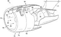
- FIG. 1is a schematic view of an exemplary aircraft engine 60 .
- Engine 60includes a nacelle 62 that generally includes a fan section 64 , a compressor section 66 , a combustion section 68 , and a turbine section 70 .
- Engine 60is typically attached to the wings, fuselage, or tail of an aircraft through appropriate mountings, for example, a pylon 71 .
- Nacelle 62includes an engine inlet 72 having an outer barrel 74 and an inner barrel 76 .
- acoustic panel or panels 10are arranged to form at least a portion of inner barrel 76 such that the inner barrel 76 defines an air intake duct 78 for supplying air 55 to the fan 64 , which subsequently is directed both to the bypass duct and engine core, comprising the compressor 66 , combustor 68 and turbine 70 .
- Acoustic panel 10facilitates reducing noise created by the fan 64 and the compressor 66 .
- FIG. 2is a cross section 200 of the inlet in FIG. 1 , illustrating the aluminum lipskin 202 , a first insulated aluminum bulkhead 204 connecting the outer barrel 74 and the inner barrel 76 , and a second bulkhead 206 connecting the outer barrel 74 and the inner barrel 76 at the location of the fan cowl interface 208 forward of the engine A-flange.
- FIG. 2further illustrates the outer barrel 74 comprises a sandwich of composite materials 210
- the inner barrel 76includes the acoustic panel 212 , thermal isolation 214 between the first insulated aluminum bulkhead 204 and the acoustic panel 212 , and metallic attach flange 216 bolted to the acoustic panel 212 .
- Acoustic panel 212extends into the fan case 224 .
- a Fasteners 218attach the metallic (e.g., aluminum) lipskin 202 to the outer barrel 74 , and the step and gap interface between the metallic lipskin 202 and composite outer barrel 74 creates a premature laminar to turbulent aerodynamic transition 220 .
- the aircraft nacelle 62includes an anti-ice system 250 utilizing engine bleed air 252 (engine anti-ice (EAI) system).
- Engine bleed air fed from the engine 60swirls around the inside of the engine inlet 72 in the region 222 forward of the first insulated aluminum bulkhead 204 , providing heat that melts ice on the engine inlet 72 .
- the bleed air systemhas a number of limitations. Firstly, the inlet structure must accommodate high internal temperatures and pressures, which are exacerbated by a variety of failure modes and dispatch considerations. This can result in added weight and cost to the inlet, e.g.
- the engine idle power settingmust be increased when the EAI system is operating, so that bleed flow extraction does not exceed engine capability in this condition.
- providing the EAI bleed aircauses the engine turbine temperatures to increase. However, the maximum thrust available is limited by the maximum allowed turbine temperature, and therefore the maximum thrust available is decreased when the EAI system is operating.
- Fluid ice protection systemsmay be used to prevent ice build up on aerodynamic surfaces.
- the fluid ice protection systemutilizes Direct Current (DC) motor driven pumps to deliver the anti-icing fluid to the relevant surfaces, wherein the anti-icing fluid (typically glycol-based fluid) mixes with water droplets, lowering the freezing point of the water droplets so that the water droplets cannot freeze.
- DCDirect Current
- glycol-based fluidtypically glycol-based fluid
- the mixture of glycol-based fluid and water dropletsthen flow off the aircraft together.
- the nacellecomprises an inner barrel and an outer barrel configured to form an inlet cowl.
- the inlet cowlincludes a lipskin disposed at a forward end of the inlet cowl and between the inner barrel and the outer barrel, and a bulkhead disposed between the inner and outer barrels.
- the outer barrelends at the bulkhead or extends aft of the bulkhead so as to connect with a fan cowl.
- the inner barrelincludes an acoustic panel extending forward of the bulkhead.
- the acoustic panelconnects with, overlaps with, or extends onto/into the lipskin or leading edge of the inlet cowl.
- the acoustic panelextends forward of the bulkhead such that a tangent to an aerodynamic line of the acoustic panel, at a forward most edge of the acoustic panel, is at an angle no less than 10 degrees relative to a direction parallel the longitudinal axis of the turbofan engine.
- Example 2the acoustic panel of Example 1 has a forward most edge at a distance along the lipskin in a range of 0-18 inches from a forward most point on the inlet cowl.
- the nacelle of one or any combination of previous examplesincludes a porous panel on the lipskin, wherein ice-protection fluid flowing or weeping from the porous panel reduces or prevents ice build-up on the acoustic panel on the lipskin.
- Example 4the inlet cowl of one or any combination of previous examples includes a second bulkhead disposed between the inner and outer barrels and positioned aft of the other bulkhead.
- Example 5there is only single bulkhead connecting the outer barrel and the inner barrel.
- Example 6the nacelle of Example 5 includes a fan cowl connected to the inlet cowl.
- the inlet cowlincludes an aerodynamic transition (e.g., laminar to turbulent flow transition) at a location between the lipskin and the fan cowl, and the single bulkhead is disposed between the inner and outer barrels at a location forward of the aerodynamic transition.
- aerodynamic transitione.g., laminar to turbulent flow transition
- Example 7the inner barrel of Example 5 has an interface with a fan case, and the outer barrel has a length extending a distance in a range of 2-24 inches aft of the forward most edge of the engine fan case, thereby extending a laminar to turbulent transition aft of the forward most edge of the engine fan case.
- the nacelle of Example 5includes an outer mating surface between the bulkhead and the outer barrel, wherein the outer mating surface is aft of an inner mating surface between the bulkhead and the inner barrel.
- Example 9the bulkhead of Example 8 includes a bend towards the outer mating surface.
- Example 10the bulkhead of Example 5 is positioned in the aft half of the inlet cowl, closer to the nearest interface between the inlet cowl and the fan case than to the forward-most point 418 on the lipskin.
- Example 11the nacelle of one or any combination of previous examples, an angle of the aerodynamic line at an upstream edge of the outer barrel is no less than 25 degrees from the longitudinal axis of the turbofan engine.
- the acoustic panel of one or any combination of previous examplesincludes a flange integral with the acoustic panel and/or the inner barrel and, wherein the flange attaches the inner barrel to a fan case.
- the acoustic panel of one or any combination of previous examplescomprises a perforated sheet and a layer sandwiching a cellular structure including cells separated by cell walls.
- the acoustic panelextends from the lipskin to any position between the lipskin and the fan case or even extends aft of a forward most edge of the fan case so as to be disposed on or in the fan case.
- Example 14the turbofan engine of one or any combination of previous examples is a direct drive turbofan engine, where there is no gearbox or transmission disposed between the low pressure shaft and the fan.
- the turbofan engine of one or any combination of previous examplesis a geared turbofan engine where a gearbox or transmission is disposed between the low pressure shaft and the fan.
- the fancomprises fan blades having a leading edge and an average diameter D measured from tip to tip of the fan blades at the leading edge
- the inlet cowlhas a length L 1 varying around a circumference of the turbofan engine
- L 1is defined as the perpendicular distance from a forward most point on the lipskin to a plane defined by/including the leading edge of the fan blades
- the average of the lengths L 1is defined as L 1 avg
- L 1 avg/Dis in a range of 0.2-0.4.
- FIG. 1is a schematic of a turbofan engine.
- FIG. 2illustrates a cross-section of a conventional engine inlet.
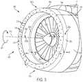
- FIG. 3illustrates a nacelle according to one or more embodiments of the present disclosure.
- FIG. 4A and FIG. 4Billustrates a cross-section of an engine inlet according to one example.
- FIG. 5illustrates a cross-section of an engine inlet according to another example.
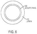
- FIG. 6illustrates an acoustic panel on an inlet according to one or more examples.
- FIG. 7illustrates an anti-ice system used with the inlets according to embodiments of the present disclosure.
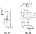
- FIG. 8A and FIG. 8Billustrate dimensions of the inlets according to embodiments of the present disclosure.
- FIG. 9illustrates a turbofan engine that may be combined the inlets according to embodiments of the present disclosure.
- FIG. 10Aillustrates a method of making an inlet according to one or more embodiments of the present disclosure.
- FIG. 10Billustrates a method of operating an engine combined with the inlets according to embodiments of the present disclosure.
- FIG. 11is an example computer hardware environment for controlling the engine combined with the inlets according to embodiments of the present disclosure.
- FIG. 3illustrates a nacelle 300 for a turbofan engine 302 , or an assembly ( 350 ) comprising a turbofan engine 302 , wherein the nacelle 300 comprises an inlet 300 b connected to a fan cowl 304 .
- the inlet 300 bcomprises an inlet cowl 306 and the inlet cowl 306 is connected to the fan cowl 304 .
- the nacelle 300is disposed around the turbofan engine 302 having a fan 310 and a longitudinal axis 312 about which the fan 310 rotates 314 .
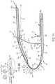
- FIG. 4A and FIG. 5illustrate a cross-section 400 , 500 of the inlet 300 b along the line 316 in FIG. 3 , illustrating an inner barrel ( 402 , 502 ) and an outer barrel ( 404 , 504 ) configured to form the inlet cowl ( 306 ).
- the inner barrel 402 , 502is combined with or includes an acoustic panel 406 , 506 .
- the inlet cowl 306further includes a lipskin 410 , 510 disposed at a forward end 412 , 512 of the inlet cowl 306 and disposed between the inner barrel 402 , 502 and an outer barrel 404 , 504 .
- One or more bulkheads 414 , 514 , 516are disposed between the inner barrel 402 and outer barrel 404 such that the acoustic panel 406 , 506 extends forward of the bulkheads 414 , 514 , 516 . More specifically, the acoustic panel 406 , 506 extends (e.g., continuously) from the fan case then forward of the bulkhead 414 , 514 into the what would be the lipskin 202 area of the exemplar inlet of FIG. 2 .
- the aerodynamic line 578 of the forward most edge 416 , 524 of the acoustic treatment or acoustic panel 406 , 506(or a tangent 576 to an aerodynamic line 578 of the acoustic panel 406 , 506 at the forward most edge 416 , 524 ) is at an angle 582 no less than 1 degree, no less than 5 degrees, or no less than 10 degrees relative to the longitudinal axis 312 of the engine 302 (or relative to a direction 584 parallel to the longitudinal axis 312 ).
- FIG. 4Aillustrates an example where the inlet cowl 306 includes a single bulkhead 414 (the only bulkhead connecting the outer barrel 404 and the inner barrel 402 ).
- FIG. 5illustrates an example wherein the inlet cowl 306 includes an additional bulkhead 516 disposed between the inner barrel 502 and the outer barrel 504 and positioned aft of the other bulkhead 514 .
- Example materials for the bulkhead ( 414 , 514 )include, but are not limited to, at least one material selected from metal, plastic, polymer, carbon fiber, and a composite comprising graphite and epoxy.
- the acoustic panel 406 , 506extends any length from the lipskin 410 to any position between the lipskin 410 and the fan case 454 and may even extend aft of a forward most edge 928 , 462 of the fan case 454 , 904 (see also FIG. 9 ) so as to be disposed on or in the fan case 454 , 904 .
- the forward most edge 416 , 524is at a joint or interface between the acoustic panel 406 , 506 and the lipskin 410 , 510 .
- FIG. 4Aillustrates the bulkhead 414 positioned in the aft half of the length L or L 1 of the inlet cowl 306 , closer to the nearest interface 440 between the inlet cowl 306 and the fan case 904 , 454 than to the forward-most point 418 on the lipskin 410 .
- the bulkhead 414is inclined and includes an incline, curve, or a bend 452 , so that the outer attach point or outer mating surface 424 between the bulkhead 414 and the outer barrel 404 is aft of the inner attach point or inner mating surface 426 between the bulkhead 414 and the inner barrel 402 .
- the bulkhead 414curves or bends aft to so as to provide stiffness to the bulkhead 414 and additional support for the outer barrel 404 .
- the outer mating surface 424is between the end 456 of the outer barrel 404 and a position 460 that is 25% of L or L 1 forward of the interface 440 with fan case 454 .
- the outer attach surface or outer mating surface 424is between the bulkhead 414 and a flange 458 integrated with or connected with the outer barrel 404 and the inner mating surface 426 is between the bulkhead 414 and an integrated flange 442 that is integral with the inner barrel 402 .
- the flanges 442 , 458may have dimensions determined by load requirements.
- the inlet cowl 306includes an aerodynamic transition 420 a , 420 b , 524 a , 524 b (e.g., comprising a a laminar to turbulent transition) at a location between the lipskin 410 , 510 and the fan cowl 304 or on the portion of the inlet cowl that extends past the forward most part of the fan case 454 .
- the transitionoccurs due to the natural tendency of a boundary to undergo a transition, rather than because of a roughness element such as a step-gap interface.
- the bulkhead 414 , 514is disposed between the inner barrel 402 , 502 and the outer barrel 404 , 504 at a location forward of the aerodynamic transition 420 b .
- the inner barrel 402 , 502has an interface 440 with the fan case 454 and the outer barrel 404 has a length L 3 extending aft of the interface 440 .
- the length L 3is in a range of 2-24 inches aft of the forward most edge 928 , 462 of the engine fan case 454 , extending the aerodynamic transition 420 b comprising a laminar to turbulent transition aft of the forward most edge 928 , 462 of the engine fan case 454 , aft of the bulkhead 414 , and aft of the interface 440 .
- the portion of the outer barrel 404 extending aft of the bulkhead 414is intended to allow the laminar boundary layer to continue past the bulkhead 414 .
- FIG. 4A and FIG. 5further illustrate the acoustic panel 406 including (or integrated with) integrated flange 442 for attaching the inner barrel 402 to the fan case 454 .
- the acoustic panel 406 and the fan case 454overlap and the acoustic panel 406 extends past a forward most edge 462 of the fan case 454 (or the acoustic panel 406 extends past an interface 440 with the fan case 454 ).
- FIG. 4A and FIG. 5illustrate the outer barrel 404 , 504 comprises an integrally stiffened composite material 434 .
- integrally stiffened composite material/panelinclude, but are not limited to, a composite sandwich (e.g., a thicker honeycomb core 408 , 508 sandwiched between an outer cowl 408 a and an inner cowl 408 b ), a hat stiffened material, and a blade stiffened material.
- the composite sandwichcomprises a thermoset composite or thermoplastic.
- the outer cowl 408 amay comprise an integral coating that replaces paint and/or that is insect repellent and/or abrasion resistant.
- Example materials for the bulkhead 414include at least one material selected from metal (e.g., aluminum, titanium), a thermoset composite, and a thermoplastic.
- FIGS. 4A and 4Billustrate components of a Fluid Ice Protection System (FIPS) (porous panel 430 , cavity 430 b , and porous membrane 430 c in the cavity 430 b ) combined with the inlet 300 b .
- the lipskin 410comprises or is combined with the porous panel 430 .
- the lipskin 410comprises outer edge wall 432 (e.g., leading edge skin)
- the porous panel 430is the outer edge wall 432
- the cavity 430 bis between the outer edge wall 432 and an inner wall 436 of the inlet 300 b.
- outer edge wall 432 or leading edge skincomprises metal including, but not limited to, aluminum or titanium and inner wall 436 comprises metal such as, but not limited to, aluminum or titanium, or a composite laminate.
- the composite laminateinclude, but are not limited to, a thermoset composite or a thermoplastic.
- perforations, small holes, or orifices in the external porous panel 430 or outer edge wall 432allow ice protection fluid to weep/flow from the cavity 430 b out onto the outer surface of the lipskin 410 and thereafter run back onto the acoustic panel 406 , 506 and outer barrel 404 , 504 , e.g., so as to prevent ice build up at the forward most edge 416 and regions along at least the forward portion 490 of the acoustic panel 406 , 506 .
- the porous membrane 430 c inside the cavity 430 bensures that the ice protection fluid is evenly distributed through the porous panel 430 .
- FIG. 4A , FIG. 4B , and FIG. 5further illustrate a bonded or fastened joint or interface 428 , 530 between the outer cowl 408 a (of the outer barrel 404 ) and the lipskin 410 .
- the joint or interface 428is a laminar flow compatible joint, so that the aerolines over the lipskin 410 and the outer barrel 404 are designed to achieve an extended run of laminar flow over the inlet cowl 306 .
- the joint or interface 428bonds composite laminate (of the outer cowl 408 a of the outer barrel 404 ) with the composite laminate of the lipskin 410 .
- FIG. 4Afurther illustrates an example wherein the angle 550 of the aerodynamic line 570 at the upstream edge E (at joint or interface 428 with the lipskin 410 ) of the outer barrel 404 is no less than 25 degrees (e.g., 30 degrees) from a line or direction 546 parallel to the longitudinal axis 312 of the turbofan engine 302 .
- the acoustic panel 406is any noise dampener, insulator, or attenuator having a structure (e.g., liner, panel, or non-panel structure, or other acoustic treatment) facilitating reduction of noise generated by the fan 310 and compressor.
- a structuree.g., liner, panel, or non-panel structure, or other acoustic treatment
- Example structuresinclude, but are not limited to, an acoustic panel or acoustic liner as described in U.S. Pat. Nos. 4,235,303, 8,820,477, 6,173,807, and 4,265,955.
- FIG. 4A and FIG. 5illustrate the acoustic panel 406 comprises a core 446 between a perforated or non-perforated layer 448 and an inner layer 450 .
- core 446comprises a cellular structure (e.g., honeycomb structure) including cells separated by cell walls.
- inner layer 450is integral with or forms the integrated flange 442 .
- FIG. 4A , FIG. 5 and FIG. 6illustrate an example wherein the acoustic panel 406 is visible on the lipskin 410 when viewing the lipskin head on (front view).
- the acoustic panel 406is on the curved convex surface S of the lipskin 410 , or on a portion of the lipskin 410 such that water droplets 534 impinging 536 onto the lipskin 410 and the acoustic panel 406 , from a direction parallel 538 to the longitudinal axis 312 of the turbofan engine 302 , are incident on the acoustic panel 406 at a non-zero angle 540 with respect to the surface 556 of the acoustic panel following the inner barrel 402 .
- FIG. 7is a schematic view of an aircraft 700 , illustrating a portion of the fuselage 702 and the wings 704 of the aircraft 700 .
- the aircraft 700includes a fluid ice protection system (FIPS) 706 , 706 b including a reservoir(s) 708 a , 708 b , a computer and electrical system 710 , porous panel 430 , porous membrane 712 , 714 , and hydraulic distribution system including (e.g., nylon) tubing, conduits, or ducting 716 distributing the ice protection fluid 718 from the reservoir 708 a , 708 b to the porous membrane 712 and porous panel 430 on/in the lipskin 410 and the porous membrane 714 or porous panel on/in the wing 704 .
- FIPSfluid ice protection system
- Ice protection fluidweeps or flows through orifices 318 or pores on the porous panel 430 combined with lipskin 410 , 510 or in outer edge wall 432 .
- the ice protection system 706 , 706 bmay recover at least some of the ice protection fluid 718 through apertures in a downstream region of the engine inlet 300 b , and return the ice protection fluid 718 to the reservoir 708 a , 708 b.
- FIG. 7Also shown is an ice/icing conditions detector 722 .
- the ice/icing conditions detector 722detects the buildup of ice 720 on the aerodynamic surface of the inlet 300 b or wing 704 or detects that the aircraft is flying in conditions that would cause icing.
- computer or electrical systems 710 onboard the aircraft 700monitor the ice detector 722 and automatically activate the anti-icing systems 706 , 706 b if icing and/or icing conditions are detected.
- an ice protection system 706 bcomprises a reservoir 708 b and pump 724 dedicated to one or more of the inlets 300 b .
- the pump 724is connected to the reservoir 708 b so as to pump ice protection fluid 718 from the reservoir 708 b to the porous panel 430 on the inlet 300 b .
- the pump 724 and reservoir 708 bare mounted on the inlet(s) 300 b or fan case.
- there are separate and independent ice protection systems 706 b(each including a reservoir 708 b and pump 724 ) on each inlet 300 b or fan case on the aircraft 700 .
- FIGS. 3, 4, and 5further illustrate the porous panel 430 combined/integrated/included with or attached to the lipskin 410 , 510 or leading edge of the inlet 300 b and nacelle 300 .
- Ice protection fluid 718flows from the porous panel 430 and porous membrane 712 , 430 c onto/into the lipskin 410 , 510 or leading outer edge wall 432 surface so as to reduce or prevent ice build-up 720 on the leading outer edge wall 432 or lipskin 410 , 510 and on the acoustic panel 406 .
- a porous membrane 712 , 430 cis positioned in the lipskin 410 in a cavity 430 b between the leading outer edge wall 432 and the inner sheet or wall 436 .
- the fluid 718runs back from the porous panel 430 onto the acoustic panel 406 so as to reduce or prevent ice build-up 720 at the forward most edge 416 , 524 of the acoustic panel 406 , 506 and regions along at least the forward portion 490 of the acoustic panel 406 , 506 .
- the porous panel 430 or porous membrane 712extends onto, into, or is integral with the acoustic panel 406 .
- Ice protection fluid 718 weeping or flowing out of the plurality of orifices 318 or outlets in outer edge wall 432 onto the surface of the lipskin 410 or outer edge wall 432can travel in the direction of arrow I toward an inward-facing downstream surface 320 b of the nacelle 300 or in the direction of arrow J toward an outward-facing downstream surface 320 a of the nacelle 300 .
- the inward-facing downstream surface 320 b of the nacelle 300may include an aperture 324 .
- the aperture 324could be arranged as a continuous aperture or as a series of spaced-apart apertures.
- Ice protection fluid traveling toward the aperture 324can be drawn into the aperture 324 in the direction of arrow K and water carried by the ice protection fluid can continue into the engine in the direction of arrow M.
- the outward-facing downstream surface 320 a of the nacelle 300may include an aperture 326 .
- the aperture 326could be arranged as a continuous aperture or as a series of spaced-apart apertures. Ice protection fluid traveling toward the aperture 326 can be drawn into the aperture 326 in the direction of arrow L and water carried by the ice protection fluid can continue aft in the direction of arrow N.
- the turbofan engines 302 used with the ice protection system 706are smaller and more efficient, thereby enabling more efficient and lighter aircraft.
- One or more examples of the ice protection systemenable the use of engines with very high bypass ratios and small cores because anti-ice bleed flow is reduced or eliminated.
- the use of the fluid ice protection systemwhich prevents ice build up on the acoustic panel, allows the acoustic panel to be extended forward, compared to the example of FIG. 2 , thereby reducing the noise of the inlet/turbofan assembly.
- FIG. 8Ais a schematic illustrating the inlet 300 b or inlet cowl 306 having a shorter length as compared to a conventional engine inlet 72 .
- FIG. 8Aalso indicates the location 800 of the cross-sections in FIG. 2 and FIG. 4A (location of the cross-sections in FIGS. 4A and 5 are also shown by line 316 in FIG. 3 ).
- FIG. 8Bis a cross sectional schematic illustrating the dimensions of the inlet cowl 306 or inlet 300 b and fan.
- a length L 1is defined between plane A (comprising the forward-most point 418 on the lipskin) and plane C defined by/containing/including the leading edge 802 of the fan blades 370 of the fan 310 . More specifically, L 1 is the perpendicular distance to plane C from the forward most point 418 .
- the length L 1varies around the circumference (Circ) of the engine 302 , in which case the average of the lengths L 1 is defined as L 1 avg and is termed the inlet length or inlet cowl length. In one or more embodiments, L 1 avg is in a range of 6-70 inches.
- FIG. 8Bfurther illustrates D is the average diameter of the fan 310 , measured tip T 1 to tip T 2 at the leading edge 802 (e.g., in a range of 60-160 inches). In one or more examples L 1 avg/D is 0.4 or less or in a range of 0.2-0.4 (e.g., 0.3).
- a combined effect of the shortened inlet or inlet cowlis to reduced drag, weight, and fuel consumption of the engine and aircraft.
- FIG. 9illustrates an example turbofan engine used in combination with the nacelles described herein.
- the turbofan engine 302comprises a fan 310 , a low pressure (LP) compressor 900 , a fan case 454 , 904 , an engine casing 906 , a High Pressure (HP) compressor 908 , a HP turbine 910 , a LP turbine 912 , and a LP shaft 914 connecting the LP compressor 900 and the LP turbine 912 .
- the turbofan engine 302is a geared turbofan engine where a gearbox 920 (e.g., planetary reduction gearbox) or transmission 918 is disposed between the low pressure shaft 914 and the fan 310 .
- the turbofan engine 302is a direct drive turbofan engine where there is no gearbox 920 or transmission 918 disposed between the low pressure shaft 914 and the fan 310 .
- the engine 302has a bypass ratio (bypass flow:core flow) in a range of 9:1 to 15:1 (e.g., in a range of 10:1 up to 14:1), e.g., the ratio of amount of air flowing outside the engine core 926 to the amount of air 924 flowing inside the engine core.
- the turbofan enginegenerates thrust in a range of 20,000 pounds (lbs)-120,000 lbs.
- FIG. 10Aillustrates a method of fabricating an inlet 300 b for a turbofan engine 302 .
- the methodmay comprise the following steps.
- Block 1000represents combining an inner barrel 402 , 502 with an acoustic panel 406 , 506 .
- Block 1002represents disposing the inner barrel 402 , 502 and an outer barrel 404 , 504 to form an inlet cowl 306 .
- Block 1004represents disposing a lipskin 410 , 510 and porous panel 430 at a forward end 412 , 512 of the inlet cowl 306 .
- the stepcomprises attaching/combining the porous panel 430 to/with the lipskin 410 , 510 or forming the lipskin 410 , 510 comprising the porous panel 430 .
- Block 1006represents disposing a bulkhead 414 , 514 between the inner barrel 402 , 502 and the outer barrel 404 , 504 such that the acoustic panel 406 , 506 extends forward of the bulkhead 414 , 514 .
- the acoustic panel 406 , 506is positioned such that a tangent 576 to an aerodynamic line 578 of the acoustic panel 406 , 506 , at a forward most edge 416 , 524 of the acoustic panel 406 , 506 , is at an angle 582 no less than 10 degrees relative to the longitudinal axis 312 of the turbofan engine 302 .
- Block 1008represents the end result, an inlet 300 b.
- FIG. 10Billustrates a method for operating/assembling an aircraft and/or increasing fuel efficiency of a turbofan engine.
- Block 1010represents disposing or obtaining the turbofan engine 302 in a nacelle 300 comprising an inlet 300 b connected to a fan case 454 as described herein.
- the nacelle 300comprises an inner barrel 402 , 502 and an outer barrel 404 , 504 configured to form an inlet cowl 306 , wherein the inner barrel 402 , 502 includes an acoustic panel 406 , 506 and the inlet cowl 306 includes a lipskin 410 , 510 and a bulkhead 414 .
- the lipskin 410 , 510is disposed at a forward end 412 , 512 of the inlet cowl 306 .
- a porous panel 430is combined with the lipskin 410 , 510 .
- the stepfurther comprises mounting the nacelle 300 and turbofan engine 302 on an aircraft 700 .
- Block 1012represents operating a fluid ice protection system 706 comprising the porous panel 430 combined with the lipskin 410 when the aircraft 700 encounters icing conditions.
- Ice protection fluid 718 flowing from the porous panel 430 as part of a FIPS 706 , 706 breduces or prevents ice build-up 720 on the acoustic panel 406 , 506 at the forward most edge 416 , 524 of the acoustic panel 406 , 506 and regions along at least the forward portion of the acoustic panel 406 , 506
- Block 1014represents operating the aircraft 700 and reducing fuel consumption of the turbofan engine 302 during operation of the aircraft as compared to the aircraft that does not utilize the novel inlets 300 b and inlet cowls 306 described herein.
- the stepmay comprise operating the turbofan engine 302 with reduced fuel consumption as compared to the turbofan engine 302 disposed in the nacelle 300 without the fluid ice protection system 706 (e.g., as compared to turbofan engine using an engine bleed air for ice protection).
- the stepmay further comprise operating the turbofan engine with reduced fuel consumption as compared to the engine having an inlet dimensioned such that L 1 avg/D is greater than 0.4.
- FIG. 11illustrates an exemplary system 1100 used to implement processing elements needed to control the ice-protection system and/or the engines described herein.
- the computer 1102comprises a processor 1104 (general purpose processor 1104 A and special purpose processor 1104 B) and a memory, such as random access memory (RAM) 1106 .
- the computer 1102operates under control of an operating system 1108 stored in the memory 1106 , and interfaces with the user/other computers to accept inputs and commands (e.g., analog or digital signals) and to present results through an input/output (I/O) module 1110 .
- the computer program application 1112accesses and manipulates data stored in the memory 1106 of the computer 1102 .
- the operating system 1108 and the computer program 1112are comprised of instructions which, when read and executed by the computer 1102 , cause the computer 1102 to perform the operations herein described.
- instructions implementing the operating system 1108 and the computer program 1112are tangibly embodied in the memory 1106 , thereby making one or more computer program products or articles of manufacture capable of reducing fuel consumption of the engine and/or controlling ice protection fluid flow in accordance with the capabilities of the inlet structures and ice-protection systems described herein.
- the terms “article of manufacture,” “program storage device” and “computer program product” as used hereinare intended to encompass a computer program accessible from any computer readable device or media.
- the state-of-the-art inlet for the Boeing 747-8has an inlet length/fan diameter of 0.55, a metallic structure with laminar-to turbulent transition located at an aft end of the inlet lip, an insulated aluminum forward bulkhead, an acoustic panel, and a thermal isolation (aft of the inlet lip) between the insulated aluminum forward bulkhead and the acoustic panel.
- the step and gap at the interface between the lipskin and outer barrellimits the extent of attainable laminar flow.
- the state of the art Boeing 747-8uses a conventional anti-ice system using pressurized hot engine bleed air in the inlet area forward of the bulkhead.
- a low temperature fluid ice protection system(instead of a conventional anti-ice system using pressurized hot engine bleed air) enables an innovative compact structural concept having an inlet length/fan diameter of 0.4 or less (e.g. 0.32).
- the use of a shortened inletis surprising and unexpected because shortened inlets have less area availability for the acoustic attenuation structure and limit the length of the run of laminar flow.
- the inlet structures presented hereinaddress these problems by extending the acoustic treatment onto the leading edge of the inlet (in one example providing more than 20% additional acoustic treatment) and moving the laminar-to-turbulent transition goal aft from the leading edge area.
- the extension of acoustic treatment into the leading edge areais enabled by the advanced low power anti-ice/de-ice system (fluid protection system) compatible with compact inlet and acoustic liners.
- the extended run of laminar flow(moving the laminar-to-turbulent transition goal area aft) is enabled by a laminar flow compatible joint at the interface between the lipskin and outer barrel, by extending the outer barrel aft of the interface with the fan case, and/or by the elimination of the forward bulkhead.
Landscapes
- Engineering & Computer Science (AREA)
- Chemical & Material Sciences (AREA)
- Combustion & Propulsion (AREA)
- Aviation & Aerospace Engineering (AREA)
- Mechanical Engineering (AREA)
- General Engineering & Computer Science (AREA)
- Structures Of Non-Positive Displacement Pumps (AREA)
- Transition And Organic Metals Composition Catalysts For Addition Polymerization (AREA)
Abstract
Description
- A technical effect of the FIPS system on the inlet lipskin is that thermal protection is not required. Elimination of the forward bulkhead and the EAI hot air cavity forward of the bulkhead eliminates the need for thermal isolation, thereby enabling increased use of composite materials in the area aft of the lipskin, decreasing weight of the inlet, and allowing the use of insect repelling and abrasion resistant coating. Thus, in one or more embodiments, the forward most bulkhead414 (or only bulkhead414) disposed between the
inner barrel outer barrel - The use of fan case attach flanges integral to the composite acoustic panel (instead of a metallic flange bolted to the acoustic panel) enables weight efficient attachment of the inlet to the fan case. The flange integral to the acoustic panel also maximizes the acoustic treatment in the inlet.
- The laminar flow compatible joint enables an extended run of laminar flow to be obtained from a metallic lipskin and a composite outer barrel.
- The portion of the outer barrel extending aft of the bulkhead is intended to allow the laminar boundary layer to continue past the bulkhead.
- The portion of the outer barrel extending past the foremost point of the fan case is intended to allow the laminar boundary layer to continue past this point.
- The use of the FIPS allows the interface between the outer barrel and the lipskin to be further forward, or at a
steeper angle 550 because the ice protection fluid runs back from the porous panel to protect the surface aft of the porous panel. Accordingly, theangle 550 is steeper as compared to the angle290 (e.g., 17 degrees) in the configuration inFIG. 2 using an EAI that relies on the hot air in the cavity forward of the bulkhead. However, the angle can vary around the circumference of the inlet. - The use of the fluid ice protection system also allows the acoustic panel to extend forward onto the leading edge surface so that the acoustic panel can be viewed from the front view of the inlet. In one or more examples, a tangent576 to an
aerodynamic line 578 of theacoustic panel most edge 416 of theacoustic panel angle 582 no less than 10 degrees relative to thelongitudinal axis 312 of theturbofan engine 302. When the fluid ice protection system is operating, the fluid weeping or flowing from the porous panel flows or runs back onto the acoustic panel, thereby preventing ice from building up on both the porous panel and the acoustic panel (including at the forwardmost edge acoustic panel 406,506). - Thus, the present disclosure describes novel inlet structures that unexpectedly and surprisingly maximize the acoustic treatment in a short inlet, while minimizing the weight, drag and fuel consumption of the inlet/engine assembly.
- A technical effect of the FIPS system on the inlet lipskin is that thermal protection is not required. Elimination of the forward bulkhead and the EAI hot air cavity forward of the bulkhead eliminates the need for thermal isolation, thereby enabling increased use of composite materials in the area aft of the lipskin, decreasing weight of the inlet, and allowing the use of insect repelling and abrasion resistant coating. Thus, in one or more embodiments, the forward most bulkhead414 (or only bulkhead414) disposed between the
Claims (21)
Priority Applications (11)
| Application Number | Priority Date | Filing Date | Title |
|---|---|---|---|
| US15/880,496US11125157B2 (en) | 2017-09-22 | 2018-01-25 | Advanced inlet design |
| RU2018129316ARU2727820C2 (en) | 2017-09-22 | 2018-08-10 | Improved design of the input device |
| CA3217063ACA3217063A1 (en) | 2017-09-22 | 2018-08-15 | Advanced inlet design |
| CA3014342ACA3014342C (en) | 2017-09-22 | 2018-08-15 | Advanced inlet design |
| CN201811078898.9ACN109533355B (en) | 2017-09-22 | 2018-09-17 | Advanced entry design |
| BR102018069077-9ABR102018069077B1 (en) | 2017-09-22 | 2018-09-19 | INLET FOR A TURBOFAN ENGINE, ASSEMBLY, AND, METHOD FOR OPERATING A TURBOFAN ENGINE |
| EP18195816.6AEP3459855B1 (en) | 2017-09-22 | 2018-09-20 | Advanced inlet design |
| EP20179810.5AEP3757013B1 (en) | 2017-09-22 | 2018-09-20 | Advanced inlet design |
| ES18195816TES2848750T3 (en) | 2017-09-22 | 2018-09-20 | Advanced entry design |
| JP2018177173AJP7223536B2 (en) | 2017-09-22 | 2018-09-21 | Advanced inlet design |
| US17/397,835US11982229B2 (en) | 2017-09-22 | 2021-08-09 | Advanced inlet design |
Applications Claiming Priority (2)
| Application Number | Priority Date | Filing Date | Title |
|---|---|---|---|
| US201762562232P | 2017-09-22 | 2017-09-22 | |
| US15/880,496US11125157B2 (en) | 2017-09-22 | 2018-01-25 | Advanced inlet design |
Related Child Applications (1)
| Application Number | Title | Priority Date | Filing Date |
|---|---|---|---|
| US17/397,835ContinuationUS11982229B2 (en) | 2017-09-22 | 2021-08-09 | Advanced inlet design |
Publications (2)
| Publication Number | Publication Date |
|---|---|
| US20190093557A1 US20190093557A1 (en) | 2019-03-28 |
| US11125157B2true US11125157B2 (en) | 2021-09-21 |
Family
ID=63667833
Family Applications (2)
| Application Number | Title | Priority Date | Filing Date |
|---|---|---|---|
| US15/880,496Active2039-02-24US11125157B2 (en) | 2017-09-22 | 2018-01-25 | Advanced inlet design |
| US17/397,835ActiveUS11982229B2 (en) | 2017-09-22 | 2021-08-09 | Advanced inlet design |
Family Applications After (1)
| Application Number | Title | Priority Date | Filing Date |
|---|---|---|---|
| US17/397,835ActiveUS11982229B2 (en) | 2017-09-22 | 2021-08-09 | Advanced inlet design |
Country Status (8)
| Country | Link |
|---|---|
| US (2) | US11125157B2 (en) |
| EP (2) | EP3459855B1 (en) |
| JP (1) | JP7223536B2 (en) |
| CN (1) | CN109533355B (en) |
| BR (1) | BR102018069077B1 (en) |
| CA (2) | CA3217063A1 (en) |
| ES (1) | ES2848750T3 (en) |
| RU (1) | RU2727820C2 (en) |
Cited By (8)
| Publication number | Priority date | Publication date | Assignee | Title |
|---|---|---|---|---|
| US20230044591A1 (en)* | 2021-08-06 | 2023-02-09 | Raytheon Technologies Corporation | Artificial ice for an aircraft component |
| US11685507B2 (en)* | 2018-09-05 | 2023-06-27 | Airbus Operations S.A.S. | Sound-absorbing panel with a cellular core and a de-icing system |
| EP4306419A1 (en)* | 2022-07-15 | 2024-01-17 | The Boeing Company | Aircraft fluid ice protection system |
| US12077320B2 (en) | 2022-07-15 | 2024-09-03 | The Boeing Company | Method for producing a perforated nacelle inlet assembly |
| US12085016B2 (en) | 2021-05-04 | 2024-09-10 | The Boeing Company | Nacelle inlet structures, engine assemblies and vehicles including the same, and related methods |
| US12163440B2 (en) | 2022-07-15 | 2024-12-10 | The Boeing Company | Nacelle inlet assembly with composite lipskin |
| US12281587B2 (en) | 2022-07-15 | 2025-04-22 | The Boeing Company | Nacelle inlet assembly that promotes laminar flow |
| US12441478B2 (en) | 2023-01-27 | 2025-10-14 | Rohr, Inc. | Air inlet bulkhead assembly for an aircraft propulsion system |
Families Citing this family (22)
| Publication number | Priority date | Publication date | Assignee | Title |
|---|---|---|---|---|
| FR3060650B1 (en)* | 2016-12-20 | 2019-05-31 | Airbus Operations | AIR INTAKE STRUCTURE FOR AN AIRCRAFT NACELLE |
| US11125157B2 (en) | 2017-09-22 | 2021-09-21 | The Boeing Company | Advanced inlet design |
| US10507548B2 (en) | 2017-09-29 | 2019-12-17 | The Boeing Company | Method for additive manufacturing nacelle inlet lipskins |
| GB201810885D0 (en) | 2018-07-03 | 2018-08-15 | Rolls Royce Plc | High efficiency gas turbine engine |
| US10589869B2 (en)* | 2018-07-25 | 2020-03-17 | General Electric Company | Nacelle inlet lip fuse structure |
| FR3095417B1 (en)* | 2019-04-26 | 2021-09-24 | Safran Nacelles | Nacelle air inlet and nacelle having such an air inlet |
| FR3095418B1 (en)* | 2019-04-26 | 2021-09-24 | Safran Nacelles | Nacelle air inlet and nacelle having such an air inlet |
| FR3095419B1 (en)* | 2019-04-26 | 2021-10-01 | Safran Nacelles | Acoustic panel nacelle air inlet |
| CN112193420A (en)* | 2020-08-31 | 2021-01-08 | 中电科芜湖通用航空产业技术研究院有限公司 | Micropore seepage liquid structure, aircraft anti-icing system and aircraft |
| RU2748665C1 (en)* | 2020-09-28 | 2021-05-28 | федеральное государственное автономное образовательное учреждение высшего образования "Пермский национальный исследовательский политехнический университет" | Method for removing icing on aerodynamic surfaces |
| FR3129662A1 (en)* | 2021-11-29 | 2023-06-02 | Airbus Operations (S.A.S.) | Aircraft propulsion assembly comprising at least one device for cleaning an air inlet of a nacelle by spraying a cleaning liquid |
| US20230167774A1 (en)* | 2021-12-01 | 2023-06-01 | Rohr, Inc. | Attachment ring insulator systems, methods, and assemblies |
| CN114162336B (en)* | 2021-12-14 | 2024-01-05 | 北京机电工程研究所 | Stealth air inlet channel of aircraft radar and preparation method thereof |
| CN114166460B (en)* | 2022-02-11 | 2022-04-19 | 中国空气动力研究与发展中心低速空气动力研究所 | Aircraft air inlet passage test device and system and hot gas anti-icing test stability judgment method |
| CN114576009B (en)* | 2022-03-16 | 2024-08-02 | 中国航发沈阳发动机研究所 | Waveguide fluid is inhaled to aeroengine import department |
| CN114771871B (en)* | 2022-06-14 | 2022-10-04 | 中国空气动力研究与发展中心低速空气动力研究所 | Method for debugging icing sensor of air inlet channel, sensor and control system |
| US20240017845A1 (en)* | 2022-07-15 | 2024-01-18 | The Boeing Company | Nacelle inlet assembly with acoustic panel |
| US12116932B2 (en)* | 2022-08-12 | 2024-10-15 | General Electric Company | Nacelle inlet duct for a ducted fan engine |
| CN115492684B (en)* | 2022-09-13 | 2025-09-30 | 中国航发沈阳发动机研究所 | A composite anti-icing structure for jet pre-cooling device |
| CN116331498A (en)* | 2023-04-11 | 2023-06-27 | 中国直升机设计研究所 | Flow-adjustable hot gas anti-icing system for helicopter air inlet channel |
| US12209557B1 (en)* | 2023-11-30 | 2025-01-28 | General Electric Company | Gas turbine engine with forward swept outlet guide vanes |
| US12385430B2 (en) | 2023-11-30 | 2025-08-12 | General Electric Company | Gas turbine engine with forward swept outlet guide vanes |
Citations (128)
| Publication number | Priority date | Publication date | Assignee | Title |
|---|---|---|---|---|
| GB2112339A (en) | 1981-11-13 | 1983-07-20 | T K S | Porous panel |
| GB2130158A (en) | 1982-11-15 | 1984-05-31 | Fiber Materials | Deicing aircraft surfaces |
| US5313202A (en) | 1991-01-04 | 1994-05-17 | Massachusetts Institute Of Technology | Method of and apparatus for detection of ice accretion |
| US5523959A (en) | 1994-04-25 | 1996-06-04 | The United States Of America As Represented By The Administrator Of The National Aeronautics And Space Administration | Ice detector and deicing fluid effectiveness monitoring system |
| US5589822A (en) | 1992-10-20 | 1996-12-31 | Robotic Vision Systems, Inc. | System for detecting ice or snow on surface which specularly reflects light |
| US5760711A (en) | 1996-04-26 | 1998-06-02 | Icg Technologies, Llc | Icing detection system |
| US5838239A (en) | 1992-10-20 | 1998-11-17 | Robotic Vision Systems, Inc. | System for detecting ice or snow on surface which specularly reflects light |
| WO1999016034A1 (en) | 1997-09-19 | 1999-04-01 | Icg Technologies, Llc | Substance detection system and method |
| US5921501A (en) | 1993-07-14 | 1999-07-13 | Northrop Grumman Corporation | Aircraft ice detecting system |
| US6010095A (en) | 1997-08-20 | 2000-01-04 | New Avionics Corporation | Icing detector for aircraft |
| US6178740B1 (en) | 1999-02-25 | 2001-01-30 | The Boeing Company | Turbo fan engine nacelle exhaust system with concave primary nozzle plug |
| US6207940B1 (en) | 1997-11-13 | 2001-03-27 | Forschungszentrum Karlsruhe Gmbh | Microwave de-icing system for aircrafts |
| US6286370B1 (en) | 1999-02-03 | 2001-09-11 | Naveen Neil Sinha | Method using ultrasound for detecting materials on metal surfaces |
| US6371411B1 (en) | 1999-11-23 | 2002-04-16 | The Boeing Company | Method and apparatus for aircraft inlet ice protection |
| US20020139900A1 (en)* | 2001-02-15 | 2002-10-03 | Alain Porte | Process for de-icing an air intake cowling of a reaction motor and device for practicing the same |
| US6642490B2 (en) | 2000-04-03 | 2003-11-04 | Forschungzentrum Karlsruhe Gmbh | Compact millimeterwave system for De-icing and for preventing the formation of ice on the outer surfaces of shell structures exposed to meterological influences |
| US6688558B2 (en) | 1999-11-23 | 2004-02-10 | The Boeing Company | Method and apparatus for aircraft inlet ice protection |
| US20040036630A1 (en) | 2002-08-22 | 2004-02-26 | Jamieson James R. | Advanced warning ice detection system for aircraft |
| EP1495963A2 (en) | 2003-07-08 | 2005-01-12 | Rohr, Inc. | Method and apparatus for noise abatement and ice protection of an aircraft engine nacelle inlet lip |
| US20050087720A1 (en) | 2002-10-28 | 2005-04-28 | Samuels William D. | Deicing/anti-icing fluids |
| US20050263646A1 (en) | 2004-05-26 | 2005-12-01 | The Boeing Company | Detection system and method for ice and other debris |
| US7370525B1 (en) | 2006-10-31 | 2008-05-13 | Swan International Sensors Pty. Ltd. | Inflight ice detection system |
| US7377109B2 (en) | 2004-04-09 | 2008-05-27 | The Boeing Company | Apparatus and method for reduction of jet noise from turbofan engines having separate bypass and core flows |
| US7439877B1 (en) | 2007-05-18 | 2008-10-21 | Philip Onni Jarvinen | Total impedance and complex dielectric property ice detection system |
| WO2010012899A2 (en) | 2008-07-30 | 2010-02-04 | Aircelle | Assembly of components connected by a device that maintains the integrity of the surface of one of the components |
| US20100328644A1 (en) | 2007-11-07 | 2010-12-30 | Yuesheng Lu | Object Detection and Tracking System |
| US7870929B2 (en) | 2008-04-29 | 2011-01-18 | The Boeing Company | Engine assembly, acoustical liner and associated method of fabrication |
| RU2411161C2 (en) | 2005-06-22 | 2011-02-10 | Эрбюс Франс | Aircraft engine nacelle anti-icing system with resistive layer |
| US7923668B2 (en)* | 2006-02-24 | 2011-04-12 | Rohr, Inc. | Acoustic nacelle inlet lip having composite construction and an integral electric ice protection heater disposed therein |
| US7933002B2 (en) | 2005-07-21 | 2011-04-26 | Airbus Deutschland Gmbh | Method and lidar system for measuring air turbulences on board aircraft and for airports and wind farms |
| US8144325B2 (en) | 2009-07-23 | 2012-03-27 | Rosemount Aerospace, Inc. | In-flight multiple field of view detector for supercooled airborne water droplets |
| US8152461B2 (en)* | 2008-11-19 | 2012-04-10 | Mra Systems, Inc. | Integrated inlet design |
| US20120085868A1 (en) | 2010-10-12 | 2012-04-12 | Lumen International Inc. | Aircraft icing detector |
| US20120274938A1 (en) | 2011-04-29 | 2012-11-01 | Rosemount Aerospace Inc. | Apparatus and method for detecting aircraft icing conditions |
| US8325338B1 (en) | 2009-08-02 | 2012-12-04 | The Blue Sky Group | Detection of aircraft icing |
| US20130020433A1 (en) | 2011-07-24 | 2013-01-24 | Hoisington Zachary C | Reduced flow field velocity for a propulsor |
| US20130113926A1 (en) | 2010-07-02 | 2013-05-09 | Huazhong University Of Science & Technology | Detecting device for detecting icing by image and detecting method thereof |
| US8439308B2 (en) | 2010-11-19 | 2013-05-14 | The Boeing Company | Spring loaded pressure relief door |
| US8517601B2 (en) | 2010-09-10 | 2013-08-27 | Ultra Electronics Limited | Ice detection system and method |
| US8532961B2 (en) | 2010-10-29 | 2013-09-10 | The Boeing Company | Method and system to account for angle of attack effects in engine noise shielding tests |
| FR2990928A1 (en) | 2012-05-24 | 2013-11-29 | Snecma | Nacelle for gas turbine engine that is utilized for aircraft, has transverse partition arranged to be fixed with upstream support, and reinforcement element connecting transverse partition to downstream support |
| US20130320145A1 (en) | 2010-03-14 | 2013-12-05 | Titan Logix Corp. | System and method for measuring and metering deicing fluid from a tank using a refractometer module |
| US20140001284A1 (en) | 2011-10-03 | 2014-01-02 | Airbus Operations Sas | Panel for the acoustic treatment comprising hot air ducts and at least one stabilization chamber |
| US8651415B1 (en) | 2012-02-08 | 2014-02-18 | The Boeing Company | Engine cowl and inlet cover |
| US20140055611A1 (en) | 2012-08-27 | 2014-02-27 | Ojo Technology, Inc | Track-mount wireless camera fixture |
| US20140117106A1 (en) | 2012-10-31 | 2014-05-01 | The Boeing Company | Thrust reversers and methods to provide reverse thrust |
| US8757551B2 (en) | 2012-06-04 | 2014-06-24 | Zamir Margalit | Foreign object damage protection device and system for aircraft |
| US8820477B1 (en) | 2013-07-29 | 2014-09-02 | The Boeing Company | Acoustic panel |
| US8910482B2 (en) | 2011-02-02 | 2014-12-16 | The Boeing Company | Aircraft engine nozzle |
| US20150044028A1 (en)* | 2012-12-20 | 2015-02-12 | United Technologies Corporation | Low pressure ratio fan engine having a dimensional relationship between inlet and fan size |
| US20150044030A1 (en) | 2013-08-12 | 2015-02-12 | The Boeing Company | Long-Duct, Mixed-Flow Nozzle System for a Turbofan Engine |
| US20150108233A1 (en) | 2013-10-18 | 2015-04-23 | The Boeing Company | Anti-Icing System for Aircraft |
| US20150113999A1 (en) | 2013-10-31 | 2015-04-30 | The Boeing Company | Inlet System for a Precooler |
| US9021813B2 (en) | 2011-07-18 | 2015-05-05 | The Boeing Company | Cable-actuated variable area fan nozzle with elastomeric seals |
| US20150260104A1 (en) | 2014-03-15 | 2015-09-17 | The Boeing Company | One piece inlet lip skin design |
| US20150260099A1 (en) | 2014-03-13 | 2015-09-17 | The Boeing Company | Enhanced temperature control anti-ice nozzle |
| US9145801B2 (en) | 2013-07-01 | 2015-09-29 | The Boeing Company | Systems and methods for acoustic resonance mitigation |
| US20150274304A1 (en) | 2014-03-31 | 2015-10-01 | The Boeing Company | Structure and Method for Reducing Air Flow in a Wall Volume of an Aircraft |
| US9168716B2 (en) | 2012-09-14 | 2015-10-27 | The Boeing Company | Metallic sandwich structure having small bend radius |
| US20150314882A1 (en)* | 2014-04-30 | 2015-11-05 | The Boeing Company | Aircraft engine nacelle bulkheads and methods of assembling the same |
| US9242735B1 (en) | 2014-08-28 | 2016-01-26 | The Boeing Company | Detecting inflight icing conditions on aircraft |
| US20160024963A1 (en) | 2014-04-30 | 2016-01-28 | The Boeing Company | Noise attenuating lipskin assembly and methods of assembling the same |
| US20160061115A1 (en) | 2014-09-03 | 2016-03-03 | The Boeing Company | Core cowl for a turbofan engine |
| US9284726B2 (en) | 2014-04-04 | 2016-03-15 | The Boeing Company | Pyramid waffle core structure and method of fabrication |
| US20160102610A1 (en)* | 2013-06-28 | 2016-04-14 | Aircelle | De-icing and conditioning device for an aircraft |
| US9347321B2 (en) | 2014-08-01 | 2016-05-24 | The Boeing Company | Methods for optimized engine balancing based on flight data |
| US20160236798A1 (en) | 2015-02-13 | 2016-08-18 | The Boeing Company | Aircraft engine inlet assembly apparatus |
| US9429680B2 (en) | 2014-08-07 | 2016-08-30 | The Boeing Company | Ice crystal icing engine event probability estimation apparatus, system, and method |
| US9469408B1 (en) | 2009-09-03 | 2016-10-18 | The Boeing Company | Ice protection system and method |
| US20160311542A1 (en) | 2015-04-16 | 2016-10-27 | The Boeing Company | Weeping ferrofluid anti-ice system |
| US20160341150A1 (en) | 2015-05-21 | 2016-11-24 | The Boeing Company | Thrust Reverser System and Method with Flow Separation-Inhibiting Blades |
| US9511873B2 (en) | 2012-03-09 | 2016-12-06 | The Boeing Company | Noise-reducing engine nozzle system |
| US20160356180A1 (en) | 2015-06-03 | 2016-12-08 | The Boeing Company | Nacelle inlet having an angle or curved aft bulkhead |
| US20160363097A1 (en) | 2015-06-09 | 2016-12-15 | The Boeing Company | Thrust Reverser Apparatus and Method |
| US20170008635A1 (en) | 2015-07-07 | 2017-01-12 | The Boeing Company | Jet engine anti-icing and noise-attenuating air inlets |
| US9546004B1 (en) | 2014-03-17 | 2017-01-17 | The Boeing Company | Water and ice detection and quantitative assessment system for ingression prone areas in an aircraft |
| US20170022903A1 (en) | 2015-07-21 | 2017-01-26 | The Boeing Company | Sound attenuation apparatus and method |
| US20170057644A1 (en) | 2015-08-25 | 2017-03-02 | The Boeing Company | Synergetic noise absorption and anti-icing for aircrafts |
| US20170057618A1 (en) | 2015-08-25 | 2017-03-02 | The Boeing Company | Synergetic noise absorption and anti-icing for aircrafts |
| US9604438B2 (en) | 2014-04-30 | 2017-03-28 | The Boeing Company | Methods and apparatus for noise attenuation in an engine nacelle |
| US9617918B2 (en) | 2014-01-13 | 2017-04-11 | The Boeing Company | Bracket for mounting/removal of actuators for active vibration control |
| US9623977B2 (en) | 2014-03-20 | 2017-04-18 | The Boeing Company | Hybrid structure including built-up sandwich structure and monolithic SPF/DB structure |
| US9640164B2 (en) | 2015-02-27 | 2017-05-02 | The Boeing Company | Sound attenuation using a cellular core |
| US20170122257A1 (en) | 2015-10-30 | 2017-05-04 | The Boeing Company | Nacelle-integrated air-driven augmentor fan for increasing propulsor bypass ratio & efficiency |
| US20170158341A1 (en) | 2015-12-03 | 2017-06-08 | The Boeing Company | Methods and apparatus to vary an air intake of aircraft engines |
| US20170158336A1 (en) | 2015-12-02 | 2017-06-08 | The Boeing Company | Aircraft ice detection systems and methods |
| US20170166777A1 (en) | 2014-05-30 | 2017-06-15 | The Boeing Company | Ice adhesion reducing polymers |
| US20170166314A1 (en) | 2015-12-09 | 2017-06-15 | The Boeing Company | System and method for aircraft ice detection within a zone of non-detection |
| US9696238B2 (en) | 2014-09-16 | 2017-07-04 | The Boeing Company | Systems and methods for icing flight tests |
| US20170190431A1 (en) | 2016-01-04 | 2017-07-06 | The Boeing Company | Apparatuses and methods for anti-icing of speed measurement probes |
| US20170198658A1 (en) | 2016-01-11 | 2017-07-13 | The Boeing Company | Thrust reverser |
| US20170204291A1 (en) | 2014-05-30 | 2017-07-20 | The Boeing Company | Ice adhesion reducing prepolymers and polymers |
| US20170210478A1 (en) | 2016-01-21 | 2017-07-27 | The Boeing Company | Aircraft and associated method for providing electrical energy to an anti-icing system |
| US9719466B2 (en) | 2014-09-17 | 2017-08-01 | The Boeing Company | System and method for improved thrust reverser with increased reverse thrust and reduced noise |
| US9732700B2 (en) | 2013-10-24 | 2017-08-15 | The Boeing Company | Methods and apparatus for passive thrust vectoring and plume deflection |
| US20170233090A1 (en)* | 2016-02-12 | 2017-08-17 | Rohr, Inc. | Inlet assembly for a turbofan engine |
| US20170233106A1 (en) | 2014-10-24 | 2017-08-17 | Vestergaard Company A/S | Method of sampling de-icing fluid and system for sampling de-icing fluid |
| US9741331B1 (en) | 2016-06-01 | 2017-08-22 | The Boeing Company | Sound-attenuating composite structure |
| US9776731B1 (en) | 2016-09-29 | 2017-10-03 | The Boeing Company | Methods and apparatus for detecting aircraft surface deformations |
| US20170283078A1 (en) | 2016-03-29 | 2017-10-05 | Sikorsky Aircraft Corporation | Icing detection systems |
| US9803586B1 (en) | 2016-05-31 | 2017-10-31 | The Boeing Company | Secondary systems and methods of control for variable area fan nozzles |
| US20170313428A1 (en) | 2016-05-02 | 2017-11-02 | The Boeing Company | Systems and methods for preventing ice formation on portions of an aircraft |
| US20180009547A1 (en) | 2016-07-06 | 2018-01-11 | The Boeing Company | Laser Projected Engine Hazard Zone Systems And Methods |
| US20180018952A1 (en) | 2016-07-18 | 2018-01-18 | The Boeing Company | Acoustic panels that include multi-layer facesheets |
| US20180016981A1 (en) | 2016-07-18 | 2018-01-18 | The Boeing Company | Acoustic paneling |
| US20180033978A1 (en) | 2016-07-29 | 2018-02-01 | Semiconductor Energy Laboratory Co., Ltd. | Separation method, display device, display module, and electronic device |
| US20180029719A1 (en) | 2016-07-28 | 2018-02-01 | The Boeing Company | Drag reducing liner assembly and methods of assembling the same |
| US20180058373A1 (en) | 2016-08-29 | 2018-03-01 | The Boeing Company | Blocker door assembly having a thermoplastic blocker door for use in a turbine engine |
| US20180079511A1 (en) | 2016-09-22 | 2018-03-22 | The Boeing Company | Turbofan engine fluid ice protection delivery system |
| US20180079512A1 (en) | 2016-09-22 | 2018-03-22 | The Boeing Company | Fluid ice protection system flow conductivity sensor |
| US20180086473A1 (en) | 2016-09-28 | 2018-03-29 | The Boeing Company | Nacelle fan cowl tangential restraint |
| US20180119640A1 (en) | 2016-11-03 | 2018-05-03 | The Boeing Company | Fan nacelle trailing edge |
| US20180155042A1 (en) | 2016-12-05 | 2018-06-07 | The Boeing Company | Composite Fan Cowl with a Core Having Tailored Thickness |
| US20180162541A1 (en) | 2016-12-14 | 2018-06-14 | The Boeing Company | Variable incident nacelle apparatus and methods |
| US20180202313A1 (en) | 2017-01-17 | 2018-07-19 | The Boeing Company | Flexible band electrical component mounts and methods |
| US10077740B2 (en) | 2015-10-16 | 2018-09-18 | The Boeing Company | Folding door thrust reversers for aircraft engines |
| US20180339785A1 (en) | 2017-05-25 | 2018-11-29 | The Boeing Company | Composite structure assembly having an interconnected layered core |
| US20180371995A1 (en) | 2017-06-26 | 2018-12-27 | The Boeing Company | Rotating devices for mitigation of adverse flow conditions in an ultra-short nacelle inlet |
| US20180371996A1 (en) | 2017-06-26 | 2018-12-27 | The Boeing Company | Translating turning vanes for a nacelle inet |
| US10173780B2 (en) | 2016-01-26 | 2019-01-08 | The Boeing Company | Aircraft liquid heat exchanger anti-icing system |
| US10173248B2 (en) | 2017-03-17 | 2019-01-08 | The Boeing Company | Acoustic panel cleaning |
| US20190009983A1 (en) | 2017-07-10 | 2019-01-10 | Air-Flo Manufacturing Co., Inc. | Shield for three compartment rear load packer |
| US10184425B2 (en) | 2016-01-28 | 2019-01-22 | The Boeing Company | Fiber optic sensing for variable area fan nozzles |
| US20190031363A1 (en) | 2017-07-28 | 2019-01-31 | The Boeing Company | System and method for operating a boundary layer ingestion fan |
| US10273883B2 (en) | 2016-02-26 | 2019-04-30 | The Boeing Company | Engine accessory drives systems and methods |
| US10309341B2 (en) | 2016-01-15 | 2019-06-04 | The Boeing Company | Thrust reverser cascade systems and methods |
| US10343094B2 (en) | 2014-01-22 | 2019-07-09 | Wintersteiger Ag | Apparatus for separating a granular material from a conveying air stream |
| US10431516B2 (en) | 2004-11-16 | 2019-10-01 | Rohm Co., Ltd. | Semiconductor device and method for manufacturing semiconductor device |
Family Cites Families (30)
| Publication number | Priority date | Publication date | Assignee | Title |
|---|---|---|---|---|
| GB673987A (en)* | 1949-08-23 | 1952-06-18 | Bristol Aeroplane Co Ltd | Improvements in or relating to air intakes, more particularly for aeroplanes |
| US4265955A (en) | 1978-05-01 | 1981-05-05 | The Boeing Company | Honeycomb core with internal septum and method of making same |
| US4235303A (en) | 1978-11-20 | 1980-11-25 | The Boeing Company | Combination bulk absorber-honeycomb acoustic panels |
| AU581684B2 (en)* | 1984-10-08 | 1989-03-02 | Short Brothers Plc | Duct for hot air |
| US5088277A (en) | 1988-10-03 | 1992-02-18 | General Electric Company | Aircraft engine inlet cowl anti-icing system |
| US6173807B1 (en) | 1998-04-13 | 2001-01-16 | The Boeing Company | Engine nacelle acoustic panel with integral wedge fairings and an integral forward ring |
| US6920958B2 (en)* | 2003-10-17 | 2005-07-26 | The Boeing Company | Annular acoustic panel |
| US7503425B2 (en) | 2006-10-02 | 2009-03-17 | Spirit Aerosystems, Inc. | Integrated inlet attachment |
| FR2908738B1 (en)* | 2006-11-16 | 2009-12-04 | Airbus France | AIRCRAFT ATTACK RIDGE. |
| FR2912781B1 (en)* | 2007-02-20 | 2009-04-10 | Airbus France Sas | COATING FOR ACOUSTIC TREATMENT INCORPORATING THE FUNCTION OF TREATING FROST WITH HOT AIR |
| FR2917067B1 (en)* | 2007-06-08 | 2009-08-21 | Airbus France Sas | COATING FOR ACOUSTIC TREATMENT INCORPORATING THE FUNCTION OF TREATING FROST WITH HOT AIR |
| FR2925463B1 (en)* | 2007-12-21 | 2010-04-23 | Airbus France | STRUCTURE FOR ACOUSTIC TREATMENT MORE PARTICULARLY ADAPTED TO AIR INTAKE OF AN AIRCRAFT NACELLE |
| FR2925877B1 (en)* | 2007-12-26 | 2009-12-04 | Aircelle Sa | INSTALLATION OF GUIDING SYSTEM ON AN AIRCRAFT NACELLE. |
| FR2936219B1 (en)* | 2008-09-23 | 2010-09-17 | Airbus France | FUSELAGE STRUCTURE FOR COMBINED FASTENING OF INSULATION MATTRESSES AND EQUIPMENT, AIRCRAFT INCORPORATING SUCH A STRUCTURE. |
| WO2010086560A2 (en) | 2009-02-02 | 2010-08-05 | Airbus Operations Sas | Aircraft nacelle including an optimised acoustic processing system |
| FR2943624B1 (en)* | 2009-03-27 | 2011-04-15 | Airbus France | AIRCRAFT NACELLE COMPRISING AN ENHANCED EXTERIOR WALL |
| CN202624640U (en)* | 2012-05-11 | 2012-12-26 | 中国航空工业集团公司西安飞机设计研究所 | Ice prevention cavity for air inlet channel |
| US9920653B2 (en)* | 2012-12-20 | 2018-03-20 | United Technologies Corporation | Low pressure ratio fan engine having a dimensional relationship between inlet and fan size |
| US9370827B2 (en)* | 2013-08-28 | 2016-06-21 | The Boeing Company | System and method for forming perforations in a barrel section |
| US9663238B2 (en) | 2013-11-11 | 2017-05-30 | The Boeing Company | Nacelle inlet lip skin with pad-up defining a developable surface having parallel ruling lines |
| EP2883688B1 (en) | 2013-12-13 | 2021-09-22 | Safran Aero Boosters SA | Composite annular casing of a turbomachine compressor and method for its manufacture |
| CN107532514B (en)* | 2015-03-10 | 2020-11-03 | Mra系统有限责任公司 | Acoustic liner for use in turbine engines |
| US9908620B2 (en)* | 2015-05-15 | 2018-03-06 | Rohr, Inc. | Multi-zone active laminar flow control system for an aircraft propulsion system |
| US9874228B2 (en)* | 2015-05-15 | 2018-01-23 | Rohr, Inc. | Nacelle inlet with extended outer barrel |
| US10167085B2 (en)* | 2016-01-27 | 2019-01-01 | General Electric Company | Nozzle and vane system for nacelle anti-icing |
| US10113602B2 (en) | 2016-06-12 | 2018-10-30 | The Boeing Company | Load controlling bolted flange deformable spacers |
| US10494116B2 (en) | 2017-07-27 | 2019-12-03 | Rolls-Royce North American Technologies Inc. | Heat shield for signature suppression system |
| US11125157B2 (en) | 2017-09-22 | 2021-09-21 | The Boeing Company | Advanced inlet design |
| US10940955B2 (en) | 2017-11-27 | 2021-03-09 | Rohr, Inc. | Acoustic panel with structural septum |
| US11084600B2 (en) | 2018-10-03 | 2021-08-10 | Rohr, Inc. | Nacelle inlet with reinforcement structure |
- 2018
- 2018-01-25USUS15/880,496patent/US11125157B2/enactiveActive
- 2018-08-10RURU2018129316Apatent/RU2727820C2/enactive
- 2018-08-15CACA3217063Apatent/CA3217063A1/enactivePending
- 2018-08-15CACA3014342Apatent/CA3014342C/enactiveActive
- 2018-09-17CNCN201811078898.9Apatent/CN109533355B/enactiveActive
- 2018-09-19BRBR102018069077-9Apatent/BR102018069077B1/enactiveIP Right Grant
- 2018-09-20ESES18195816Tpatent/ES2848750T3/enactiveActive
- 2018-09-20EPEP18195816.6Apatent/EP3459855B1/enactiveActive
- 2018-09-20EPEP20179810.5Apatent/EP3757013B1/enactiveActive
- 2018-09-21JPJP2018177173Apatent/JP7223536B2/enactiveActive
- 2021
- 2021-08-09USUS17/397,835patent/US11982229B2/enactiveActive
Patent Citations (138)
| Publication number | Priority date | Publication date | Assignee | Title |
|---|---|---|---|---|
| GB2112339A (en) | 1981-11-13 | 1983-07-20 | T K S | Porous panel |
| GB2130158A (en) | 1982-11-15 | 1984-05-31 | Fiber Materials | Deicing aircraft surfaces |
| US5313202A (en) | 1991-01-04 | 1994-05-17 | Massachusetts Institute Of Technology | Method of and apparatus for detection of ice accretion |
| US5589822A (en) | 1992-10-20 | 1996-12-31 | Robotic Vision Systems, Inc. | System for detecting ice or snow on surface which specularly reflects light |
| US5617076A (en) | 1992-10-20 | 1997-04-01 | Robotic Vision Systems, Inc. | System for detecting ice or snow on surface which specularly reflects light |
| US5838239A (en) | 1992-10-20 | 1998-11-17 | Robotic Vision Systems, Inc. | System for detecting ice or snow on surface which specularly reflects light |
| US5921501A (en) | 1993-07-14 | 1999-07-13 | Northrop Grumman Corporation | Aircraft ice detecting system |
| US5523959A (en) | 1994-04-25 | 1996-06-04 | The United States Of America As Represented By The Administrator Of The National Aeronautics And Space Administration | Ice detector and deicing fluid effectiveness monitoring system |
| US6052056A (en) | 1996-04-26 | 2000-04-18 | Icg Technologies, Llc | Substance detection system and method |
| US5760711A (en) | 1996-04-26 | 1998-06-02 | Icg Technologies, Llc | Icing detection system |
| US6010095A (en) | 1997-08-20 | 2000-01-04 | New Avionics Corporation | Icing detector for aircraft |
| WO1999016034A1 (en) | 1997-09-19 | 1999-04-01 | Icg Technologies, Llc | Substance detection system and method |
| US6207940B1 (en) | 1997-11-13 | 2001-03-27 | Forschungszentrum Karlsruhe Gmbh | Microwave de-icing system for aircrafts |
| US6286370B1 (en) | 1999-02-03 | 2001-09-11 | Naveen Neil Sinha | Method using ultrasound for detecting materials on metal surfaces |
| US6178740B1 (en) | 1999-02-25 | 2001-01-30 | The Boeing Company | Turbo fan engine nacelle exhaust system with concave primary nozzle plug |
| US6371411B1 (en) | 1999-11-23 | 2002-04-16 | The Boeing Company | Method and apparatus for aircraft inlet ice protection |
| US6457676B1 (en) | 1999-11-23 | 2002-10-01 | The Boeing Company | Method and apparatus for aircraft inlet ice protection |
| US6688558B2 (en) | 1999-11-23 | 2004-02-10 | The Boeing Company | Method and apparatus for aircraft inlet ice protection |
| US6642490B2 (en) | 2000-04-03 | 2003-11-04 | Forschungzentrum Karlsruhe Gmbh | Compact millimeterwave system for De-icing and for preventing the formation of ice on the outer surfaces of shell structures exposed to meterological influences |
| US20020139900A1 (en)* | 2001-02-15 | 2002-10-03 | Alain Porte | Process for de-icing an air intake cowling of a reaction motor and device for practicing the same |
| US20040036630A1 (en) | 2002-08-22 | 2004-02-26 | Jamieson James R. | Advanced warning ice detection system for aircraft |
| US6819265B2 (en) | 2002-08-22 | 2004-11-16 | Rosemount Aerospace Inc. | Advanced warning ice detection system for aircraft |
| US20050087720A1 (en) | 2002-10-28 | 2005-04-28 | Samuels William D. | Deicing/anti-icing fluids |
| EP1495963A2 (en) | 2003-07-08 | 2005-01-12 | Rohr, Inc. | Method and apparatus for noise abatement and ice protection of an aircraft engine nacelle inlet lip |
| US7588212B2 (en)* | 2003-07-08 | 2009-09-15 | Rohr Inc. | Method and apparatus for noise abatement and ice protection of an aircraft engine nacelle inlet lip |
| US7377109B2 (en) | 2004-04-09 | 2008-05-27 | The Boeing Company | Apparatus and method for reduction of jet noise from turbofan engines having separate bypass and core flows |
| US7836700B2 (en) | 2004-04-09 | 2010-11-23 | Krishnamurthy Viswanathan | Apparatus and method for reduction of jet noise from turbofan engines having separate bypass and core flaws |
| US20050263646A1 (en) | 2004-05-26 | 2005-12-01 | The Boeing Company | Detection system and method for ice and other debris |
| US10431516B2 (en) | 2004-11-16 | 2019-10-01 | Rohm Co., Ltd. | Semiconductor device and method for manufacturing semiconductor device |
| RU2411161C2 (en) | 2005-06-22 | 2011-02-10 | Эрбюс Франс | Aircraft engine nacelle anti-icing system with resistive layer |
| US7933002B2 (en) | 2005-07-21 | 2011-04-26 | Airbus Deutschland Gmbh | Method and lidar system for measuring air turbulences on board aircraft and for airports and wind farms |
| US7923668B2 (en)* | 2006-02-24 | 2011-04-12 | Rohr, Inc. | Acoustic nacelle inlet lip having composite construction and an integral electric ice protection heater disposed therein |
| US7370525B1 (en) | 2006-10-31 | 2008-05-13 | Swan International Sensors Pty. Ltd. | Inflight ice detection system |
| US7439877B1 (en) | 2007-05-18 | 2008-10-21 | Philip Onni Jarvinen | Total impedance and complex dielectric property ice detection system |
| US20100328644A1 (en) | 2007-11-07 | 2010-12-30 | Yuesheng Lu | Object Detection and Tracking System |
| US7870929B2 (en) | 2008-04-29 | 2011-01-18 | The Boeing Company | Engine assembly, acoustical liner and associated method of fabrication |
| WO2010012899A2 (en) | 2008-07-30 | 2010-02-04 | Aircelle | Assembly of components connected by a device that maintains the integrity of the surface of one of the components |
| US20110131945A1 (en) | 2008-07-30 | 2011-06-09 | Aircelle | Assembly of components connected by a device that maintains the integrity of the surface of one of the components |
| US8152461B2 (en)* | 2008-11-19 | 2012-04-10 | Mra Systems, Inc. | Integrated inlet design |
| US8144325B2 (en) | 2009-07-23 | 2012-03-27 | Rosemount Aerospace, Inc. | In-flight multiple field of view detector for supercooled airborne water droplets |
| US8325338B1 (en) | 2009-08-02 | 2012-12-04 | The Blue Sky Group | Detection of aircraft icing |
| US9469408B1 (en) | 2009-09-03 | 2016-10-18 | The Boeing Company | Ice protection system and method |
| US20130320145A1 (en) | 2010-03-14 | 2013-12-05 | Titan Logix Corp. | System and method for measuring and metering deicing fluid from a tank using a refractometer module |
| US20130113926A1 (en) | 2010-07-02 | 2013-05-09 | Huazhong University Of Science & Technology | Detecting device for detecting icing by image and detecting method thereof |
| US8517601B2 (en) | 2010-09-10 | 2013-08-27 | Ultra Electronics Limited | Ice detection system and method |
| US9676485B2 (en) | 2010-09-10 | 2017-06-13 | Ultra Electronics Limited | Ice detection system and method |
| US20120085868A1 (en) | 2010-10-12 | 2012-04-12 | Lumen International Inc. | Aircraft icing detector |
| US8462354B2 (en) | 2010-10-12 | 2013-06-11 | Lumen International Inc. | Aircraft icing detector |
| US8532961B2 (en) | 2010-10-29 | 2013-09-10 | The Boeing Company | Method and system to account for angle of attack effects in engine noise shielding tests |
| US8439308B2 (en) | 2010-11-19 | 2013-05-14 | The Boeing Company | Spring loaded pressure relief door |
| US8910482B2 (en) | 2011-02-02 | 2014-12-16 | The Boeing Company | Aircraft engine nozzle |
| US20120274938A1 (en) | 2011-04-29 | 2012-11-01 | Rosemount Aerospace Inc. | Apparatus and method for detecting aircraft icing conditions |
| US9021813B2 (en) | 2011-07-18 | 2015-05-05 | The Boeing Company | Cable-actuated variable area fan nozzle with elastomeric seals |
| US20130020433A1 (en) | 2011-07-24 | 2013-01-24 | Hoisington Zachary C | Reduced flow field velocity for a propulsor |
| US20140001284A1 (en) | 2011-10-03 | 2014-01-02 | Airbus Operations Sas | Panel for the acoustic treatment comprising hot air ducts and at least one stabilization chamber |
| US8651415B1 (en) | 2012-02-08 | 2014-02-18 | The Boeing Company | Engine cowl and inlet cover |
| US9511873B2 (en) | 2012-03-09 | 2016-12-06 | The Boeing Company | Noise-reducing engine nozzle system |
| FR2990928A1 (en) | 2012-05-24 | 2013-11-29 | Snecma | Nacelle for gas turbine engine that is utilized for aircraft, has transverse partition arranged to be fixed with upstream support, and reinforcement element connecting transverse partition to downstream support |
| US8757551B2 (en) | 2012-06-04 | 2014-06-24 | Zamir Margalit | Foreign object damage protection device and system for aircraft |
| US20140055611A1 (en) | 2012-08-27 | 2014-02-27 | Ojo Technology, Inc | Track-mount wireless camera fixture |
| US9168716B2 (en) | 2012-09-14 | 2015-10-27 | The Boeing Company | Metallic sandwich structure having small bend radius |
| US20140117106A1 (en) | 2012-10-31 | 2014-05-01 | The Boeing Company | Thrust reversers and methods to provide reverse thrust |
| US20150044028A1 (en)* | 2012-12-20 | 2015-02-12 | United Technologies Corporation | Low pressure ratio fan engine having a dimensional relationship between inlet and fan size |
| US20160102610A1 (en)* | 2013-06-28 | 2016-04-14 | Aircelle | De-icing and conditioning device for an aircraft |
| US9145801B2 (en) | 2013-07-01 | 2015-09-29 | The Boeing Company | Systems and methods for acoustic resonance mitigation |
| US8820477B1 (en) | 2013-07-29 | 2014-09-02 | The Boeing Company | Acoustic panel |
| US20150044030A1 (en) | 2013-08-12 | 2015-02-12 | The Boeing Company | Long-Duct, Mixed-Flow Nozzle System for a Turbofan Engine |
| US20150108233A1 (en) | 2013-10-18 | 2015-04-23 | The Boeing Company | Anti-Icing System for Aircraft |
| US9732700B2 (en) | 2013-10-24 | 2017-08-15 | The Boeing Company | Methods and apparatus for passive thrust vectoring and plume deflection |
| US20150113999A1 (en) | 2013-10-31 | 2015-04-30 | The Boeing Company | Inlet System for a Precooler |
| US9617918B2 (en) | 2014-01-13 | 2017-04-11 | The Boeing Company | Bracket for mounting/removal of actuators for active vibration control |
| US10343094B2 (en) | 2014-01-22 | 2019-07-09 | Wintersteiger Ag | Apparatus for separating a granular material from a conveying air stream |
| US20150260099A1 (en) | 2014-03-13 | 2015-09-17 | The Boeing Company | Enhanced temperature control anti-ice nozzle |
| US20150260104A1 (en) | 2014-03-15 | 2015-09-17 | The Boeing Company | One piece inlet lip skin design |
| US9546004B1 (en) | 2014-03-17 | 2017-01-17 | The Boeing Company | Water and ice detection and quantitative assessment system for ingression prone areas in an aircraft |
| US9623977B2 (en) | 2014-03-20 | 2017-04-18 | The Boeing Company | Hybrid structure including built-up sandwich structure and monolithic SPF/DB structure |
| US20150274304A1 (en) | 2014-03-31 | 2015-10-01 | The Boeing Company | Structure and Method for Reducing Air Flow in a Wall Volume of an Aircraft |
| US9284726B2 (en) | 2014-04-04 | 2016-03-15 | The Boeing Company | Pyramid waffle core structure and method of fabrication |
| US20160024963A1 (en) | 2014-04-30 | 2016-01-28 | The Boeing Company | Noise attenuating lipskin assembly and methods of assembling the same |
| US20150314882A1 (en)* | 2014-04-30 | 2015-11-05 | The Boeing Company | Aircraft engine nacelle bulkheads and methods of assembling the same |
| US9604438B2 (en) | 2014-04-30 | 2017-03-28 | The Boeing Company | Methods and apparatus for noise attenuation in an engine nacelle |
| US20170204291A1 (en) | 2014-05-30 | 2017-07-20 | The Boeing Company | Ice adhesion reducing prepolymers and polymers |
| US20170166777A1 (en) | 2014-05-30 | 2017-06-15 | The Boeing Company | Ice adhesion reducing polymers |
| US9347321B2 (en) | 2014-08-01 | 2016-05-24 | The Boeing Company | Methods for optimized engine balancing based on flight data |
| US9429680B2 (en) | 2014-08-07 | 2016-08-30 | The Boeing Company | Ice crystal icing engine event probability estimation apparatus, system, and method |
| US9242735B1 (en) | 2014-08-28 | 2016-01-26 | The Boeing Company | Detecting inflight icing conditions on aircraft |
| US20160061115A1 (en) | 2014-09-03 | 2016-03-03 | The Boeing Company | Core cowl for a turbofan engine |
| US9696238B2 (en) | 2014-09-16 | 2017-07-04 | The Boeing Company | Systems and methods for icing flight tests |
| US9719466B2 (en) | 2014-09-17 | 2017-08-01 | The Boeing Company | System and method for improved thrust reverser with increased reverse thrust and reduced noise |
| US20170233106A1 (en) | 2014-10-24 | 2017-08-17 | Vestergaard Company A/S | Method of sampling de-icing fluid and system for sampling de-icing fluid |
| US20160236798A1 (en) | 2015-02-13 | 2016-08-18 | The Boeing Company | Aircraft engine inlet assembly apparatus |
| US9640164B2 (en) | 2015-02-27 | 2017-05-02 | The Boeing Company | Sound attenuation using a cellular core |
| US20160311542A1 (en) | 2015-04-16 | 2016-10-27 | The Boeing Company | Weeping ferrofluid anti-ice system |
| US20160341150A1 (en) | 2015-05-21 | 2016-11-24 | The Boeing Company | Thrust Reverser System and Method with Flow Separation-Inhibiting Blades |
| US20160356180A1 (en) | 2015-06-03 | 2016-12-08 | The Boeing Company | Nacelle inlet having an angle or curved aft bulkhead |
| EP3103723A1 (en) | 2015-06-03 | 2016-12-14 | The Boeing Company | Nacelle inlet having an angle or curved aft bulkhead |
| US20160363097A1 (en) | 2015-06-09 | 2016-12-15 | The Boeing Company | Thrust Reverser Apparatus and Method |
| US20170008635A1 (en) | 2015-07-07 | 2017-01-12 | The Boeing Company | Jet engine anti-icing and noise-attenuating air inlets |
| US20170022903A1 (en) | 2015-07-21 | 2017-01-26 | The Boeing Company | Sound attenuation apparatus and method |
| US20170057644A1 (en) | 2015-08-25 | 2017-03-02 | The Boeing Company | Synergetic noise absorption and anti-icing for aircrafts |
| US20170057618A1 (en) | 2015-08-25 | 2017-03-02 | The Boeing Company | Synergetic noise absorption and anti-icing for aircrafts |
| US10077740B2 (en) | 2015-10-16 | 2018-09-18 | The Boeing Company | Folding door thrust reversers for aircraft engines |
| US20170122257A1 (en) | 2015-10-30 | 2017-05-04 | The Boeing Company | Nacelle-integrated air-driven augmentor fan for increasing propulsor bypass ratio & efficiency |
| US20170158336A1 (en) | 2015-12-02 | 2017-06-08 | The Boeing Company | Aircraft ice detection systems and methods |
| US20170158341A1 (en) | 2015-12-03 | 2017-06-08 | The Boeing Company | Methods and apparatus to vary an air intake of aircraft engines |
| US20170166314A1 (en) | 2015-12-09 | 2017-06-15 | The Boeing Company | System and method for aircraft ice detection within a zone of non-detection |
| US20170190431A1 (en) | 2016-01-04 | 2017-07-06 | The Boeing Company | Apparatuses and methods for anti-icing of speed measurement probes |
| US20170198658A1 (en) | 2016-01-11 | 2017-07-13 | The Boeing Company | Thrust reverser |
| US10309341B2 (en) | 2016-01-15 | 2019-06-04 | The Boeing Company | Thrust reverser cascade systems and methods |
| US20170210478A1 (en) | 2016-01-21 | 2017-07-27 | The Boeing Company | Aircraft and associated method for providing electrical energy to an anti-icing system |
| US10173780B2 (en) | 2016-01-26 | 2019-01-08 | The Boeing Company | Aircraft liquid heat exchanger anti-icing system |
| US10184425B2 (en) | 2016-01-28 | 2019-01-22 | The Boeing Company | Fiber optic sensing for variable area fan nozzles |
| US20170233090A1 (en)* | 2016-02-12 | 2017-08-17 | Rohr, Inc. | Inlet assembly for a turbofan engine |
| US10273883B2 (en) | 2016-02-26 | 2019-04-30 | The Boeing Company | Engine accessory drives systems and methods |
| US20170283078A1 (en) | 2016-03-29 | 2017-10-05 | Sikorsky Aircraft Corporation | Icing detection systems |
| US20170313428A1 (en) | 2016-05-02 | 2017-11-02 | The Boeing Company | Systems and methods for preventing ice formation on portions of an aircraft |
| US9803586B1 (en) | 2016-05-31 | 2017-10-31 | The Boeing Company | Secondary systems and methods of control for variable area fan nozzles |
| US9741331B1 (en) | 2016-06-01 | 2017-08-22 | The Boeing Company | Sound-attenuating composite structure |
| US20180009547A1 (en) | 2016-07-06 | 2018-01-11 | The Boeing Company | Laser Projected Engine Hazard Zone Systems And Methods |
| US20180016981A1 (en) | 2016-07-18 | 2018-01-18 | The Boeing Company | Acoustic paneling |
| US20180018952A1 (en) | 2016-07-18 | 2018-01-18 | The Boeing Company | Acoustic panels that include multi-layer facesheets |
| US20180029719A1 (en) | 2016-07-28 | 2018-02-01 | The Boeing Company | Drag reducing liner assembly and methods of assembling the same |
| US20180033978A1 (en) | 2016-07-29 | 2018-02-01 | Semiconductor Energy Laboratory Co., Ltd. | Separation method, display device, display module, and electronic device |
| US20180058373A1 (en) | 2016-08-29 | 2018-03-01 | The Boeing Company | Blocker door assembly having a thermoplastic blocker door for use in a turbine engine |
| US20180079511A1 (en) | 2016-09-22 | 2018-03-22 | The Boeing Company | Turbofan engine fluid ice protection delivery system |
| US20180079512A1 (en) | 2016-09-22 | 2018-03-22 | The Boeing Company | Fluid ice protection system flow conductivity sensor |
| US20180086473A1 (en) | 2016-09-28 | 2018-03-29 | The Boeing Company | Nacelle fan cowl tangential restraint |
| US9776731B1 (en) | 2016-09-29 | 2017-10-03 | The Boeing Company | Methods and apparatus for detecting aircraft surface deformations |
| US20180119640A1 (en) | 2016-11-03 | 2018-05-03 | The Boeing Company | Fan nacelle trailing edge |
| US20180155042A1 (en) | 2016-12-05 | 2018-06-07 | The Boeing Company | Composite Fan Cowl with a Core Having Tailored Thickness |
| US20180162541A1 (en) | 2016-12-14 | 2018-06-14 | The Boeing Company | Variable incident nacelle apparatus and methods |
| US20180202313A1 (en) | 2017-01-17 | 2018-07-19 | The Boeing Company | Flexible band electrical component mounts and methods |
| US10173248B2 (en) | 2017-03-17 | 2019-01-08 | The Boeing Company | Acoustic panel cleaning |
| US20180339785A1 (en) | 2017-05-25 | 2018-11-29 | The Boeing Company | Composite structure assembly having an interconnected layered core |
| US20180371996A1 (en) | 2017-06-26 | 2018-12-27 | The Boeing Company | Translating turning vanes for a nacelle inet |
| US20180371995A1 (en) | 2017-06-26 | 2018-12-27 | The Boeing Company | Rotating devices for mitigation of adverse flow conditions in an ultra-short nacelle inlet |
| US20190009983A1 (en) | 2017-07-10 | 2019-01-10 | Air-Flo Manufacturing Co., Inc. | Shield for three compartment rear load packer |
| US20190031363A1 (en) | 2017-07-28 | 2019-01-31 | The Boeing Company | System and method for operating a boundary layer ingestion fan |
Non-Patent Citations (5)
| Title |
|---|
| Extended European Search Report dated Feb. 21, 2019 for European Application No. 18195816.6. |
| Extended European Search Report dated Nov. 9, 2020 for European Patent Application No. 20179810.5. |
| https://en.wikipedia.org/wiki/VFW-Fokker_614, Aug. 1, 2017, 7 pages. |
| Russian Office Action (with English Translation) dated Dec. 12, 2019 for Russian Patent Appln No. 2018129316/06(047171). |
| Russian Office Action dated Jul. 12, 2019 for Russian Application No. 2018129316/06. |
Cited By (11)
| Publication number | Priority date | Publication date | Assignee | Title |
|---|---|---|---|---|
| US11685507B2 (en)* | 2018-09-05 | 2023-06-27 | Airbus Operations S.A.S. | Sound-absorbing panel with a cellular core and a de-icing system |
| US12085016B2 (en) | 2021-05-04 | 2024-09-10 | The Boeing Company | Nacelle inlet structures, engine assemblies and vehicles including the same, and related methods |
| US12338744B2 (en) | 2021-05-04 | 2025-06-24 | The Boeing Company | Nacelle inlet structures, engine assemblies and vehicles including the same, and related methods |
| US20230044591A1 (en)* | 2021-08-06 | 2023-02-09 | Raytheon Technologies Corporation | Artificial ice for an aircraft component |
| US11591096B1 (en)* | 2021-08-06 | 2023-02-28 | Raytheon Technologies Corporation | Artificial ice for an aircraft component |
| EP4306419A1 (en)* | 2022-07-15 | 2024-01-17 | The Boeing Company | Aircraft fluid ice protection system |
| US12077320B2 (en) | 2022-07-15 | 2024-09-03 | The Boeing Company | Method for producing a perforated nacelle inlet assembly |
| US12163440B2 (en) | 2022-07-15 | 2024-12-10 | The Boeing Company | Nacelle inlet assembly with composite lipskin |
| US12227297B2 (en) | 2022-07-15 | 2025-02-18 | The Boeing Company | Aircraft fluid ice protection system |
| US12281587B2 (en) | 2022-07-15 | 2025-04-22 | The Boeing Company | Nacelle inlet assembly that promotes laminar flow |
| US12441478B2 (en) | 2023-01-27 | 2025-10-14 | Rohr, Inc. | Air inlet bulkhead assembly for an aircraft propulsion system |
Also Published As
| Publication number | Publication date |
|---|---|
| RU2018129316A3 (en) | 2020-02-10 |
| CN109533355A (en) | 2019-03-29 |
| CA3014342A1 (en) | 2019-03-22 |
| EP3459855A1 (en) | 2019-03-27 |
| EP3757013A1 (en) | 2020-12-30 |
| EP3459855B1 (en) | 2020-11-04 |
| US20190093557A1 (en) | 2019-03-28 |
| JP2019074078A (en) | 2019-05-16 |
| US11982229B2 (en) | 2024-05-14 |
| US20210363921A1 (en) | 2021-11-25 |
| BR102018069077A2 (en) | 2019-05-28 |
| CA3217063A1 (en) | 2019-03-22 |
| BR102018069077B1 (en) | 2023-10-24 |
| CA3014342C (en) | 2023-12-12 |
| RU2018129316A (en) | 2020-02-10 |
| EP3757013B1 (en) | 2024-05-15 |
| ES2848750T3 (en) | 2021-08-11 |
| JP7223536B2 (en) | 2023-02-16 |
| RU2727820C2 (en) | 2020-07-24 |
| CN109533355B (en) | 2023-07-14 |
Similar Documents
| Publication | Publication Date | Title |
|---|---|---|
| US11982229B2 (en) | Advanced inlet design | |
| JP4293599B2 (en) | Internal anti-icing device for turbofan engine | |
| US5297765A (en) | Turbine engine nacelle laminar flow control arrangement | |
| EP3461743B1 (en) | Combined fluid ice protection and electronics cooling system | |
| EP3628586B1 (en) | Active laminar flow control plenum panel arrangement | |
| US5779196A (en) | Ram air drive laminar flow control system | |
| EP4306420B1 (en) | Nacelle inlet assembly with acoustic panel | |
| US11524770B2 (en) | Active laminar flow control plenum panel arrangements and installation methods | |
| US11396366B2 (en) | Active laminar flow control structural plenums fastened | |
| EP4306418B1 (en) | Nacelle inlet assembly with composite lipskin | |
| US12227297B2 (en) | Aircraft fluid ice protection system | |
| US11492998B2 (en) | Flexible aft cowls for aircraft | |
| CN117401169A (en) | Aircraft fluid anti-icing system | |
| CN117401151A (en) | Nacelle inlet assembly with composite lip skin | |
| CN117401168A (en) | Nacelle exit assembly with acoustic panel |
Legal Events
| Date | Code | Title | Description |
|---|---|---|---|
| FEPP | Fee payment procedure | Free format text:ENTITY STATUS SET TO UNDISCOUNTED (ORIGINAL EVENT CODE: BIG.); ENTITY STATUS OF PATENT OWNER: LARGE ENTITY | |
| AS | Assignment | Owner name:THE BOEING COMPANY, ILLINOIS Free format text:ASSIGNMENT OF ASSIGNORS INTEREST;ASSIGNORS:THOMAS, HOLLY J.;RIEDEL, BRIAN L.;CURAUDEAU, ALEXANDRE D.;AND OTHERS;REEL/FRAME:045348/0274 Effective date:20180124 | |
| STPP | Information on status: patent application and granting procedure in general | Free format text:DOCKETED NEW CASE - READY FOR EXAMINATION | |
| STPP | Information on status: patent application and granting procedure in general | Free format text:NON FINAL ACTION MAILED | |
| STPP | Information on status: patent application and granting procedure in general | Free format text:RESPONSE TO NON-FINAL OFFICE ACTION ENTERED AND FORWARDED TO EXAMINER | |
| STPP | Information on status: patent application and granting procedure in general | Free format text:RESPONSE TO NON-FINAL OFFICE ACTION ENTERED AND FORWARDED TO EXAMINER | |
| STPP | Information on status: patent application and granting procedure in general | Free format text:NOTICE OF ALLOWANCE MAILED -- APPLICATION RECEIVED IN OFFICE OF PUBLICATIONS | |
| STPP | Information on status: patent application and granting procedure in general | Free format text:AWAITING TC RESP., ISSUE FEE NOT PAID | |
| STPP | Information on status: patent application and granting procedure in general | Free format text:NOTICE OF ALLOWANCE MAILED -- APPLICATION RECEIVED IN OFFICE OF PUBLICATIONS | |
| STPP | Information on status: patent application and granting procedure in general | Free format text:NOTICE OF ALLOWANCE MAILED -- APPLICATION RECEIVED IN OFFICE OF PUBLICATIONS | |
| STPP | Information on status: patent application and granting procedure in general | Free format text:PUBLICATIONS -- ISSUE FEE PAYMENT RECEIVED | |
| STPP | Information on status: patent application and granting procedure in general | Free format text:PUBLICATIONS -- ISSUE FEE PAYMENT VERIFIED | |
| STCF | Information on status: patent grant | Free format text:PATENTED CASE | |
| MAFP | Maintenance fee payment | Free format text:PAYMENT OF MAINTENANCE FEE, 4TH YEAR, LARGE ENTITY (ORIGINAL EVENT CODE: M1551); ENTITY STATUS OF PATENT OWNER: LARGE ENTITY Year of fee payment:4 |