US11124116B2 - System and process for viewing in blind spots - Google Patents
System and process for viewing in blind spotsDownload PDFInfo
- Publication number
- US11124116B2 US11124116B2US16/101,474US201816101474AUS11124116B2US 11124116 B2US11124116 B2US 11124116B2US 201816101474 AUS201816101474 AUS 201816101474AUS 11124116 B2US11124116 B2US 11124116B2
- Authority
- US
- United States
- Prior art keywords
- camera
- screen
- view
- coupled
- viewing system
- Prior art date
- Legal status (The legal status is an assumption and is not a legal conclusion. Google has not performed a legal analysis and makes no representation as to the accuracy of the status listed.)
- Active
Links
Images


Classifications
- B—PERFORMING OPERATIONS; TRANSPORTING
- B60—VEHICLES IN GENERAL
- B60R—VEHICLES, VEHICLE FITTINGS, OR VEHICLE PARTS, NOT OTHERWISE PROVIDED FOR
- B60R1/00—Optical viewing arrangements; Real-time viewing arrangements for drivers or passengers using optical image capturing systems, e.g. cameras or video systems specially adapted for use in or on vehicles
- B60R1/20—Real-time viewing arrangements for drivers or passengers using optical image capturing systems, e.g. cameras or video systems specially adapted for use in or on vehicles
- B60R1/22—Real-time viewing arrangements for drivers or passengers using optical image capturing systems, e.g. cameras or video systems specially adapted for use in or on vehicles for viewing an area outside the vehicle, e.g. the exterior of the vehicle
- B60R1/23—Real-time viewing arrangements for drivers or passengers using optical image capturing systems, e.g. cameras or video systems specially adapted for use in or on vehicles for viewing an area outside the vehicle, e.g. the exterior of the vehicle with a predetermined field of view
- B60R1/24—Real-time viewing arrangements for drivers or passengers using optical image capturing systems, e.g. cameras or video systems specially adapted for use in or on vehicles for viewing an area outside the vehicle, e.g. the exterior of the vehicle with a predetermined field of view in front of the vehicle
- B—PERFORMING OPERATIONS; TRANSPORTING
- B60—VEHICLES IN GENERAL
- B60R—VEHICLES, VEHICLE FITTINGS, OR VEHICLE PARTS, NOT OTHERWISE PROVIDED FOR
- B60R1/00—Optical viewing arrangements; Real-time viewing arrangements for drivers or passengers using optical image capturing systems, e.g. cameras or video systems specially adapted for use in or on vehicles
- B—PERFORMING OPERATIONS; TRANSPORTING
- B60—VEHICLES IN GENERAL
- B60R—VEHICLES, VEHICLE FITTINGS, OR VEHICLE PARTS, NOT OTHERWISE PROVIDED FOR
- B60R11/00—Arrangements for holding or mounting articles, not otherwise provided for
- B60R11/04—Mounting of cameras operative during drive; Arrangement of controls thereof relative to the vehicle
- B—PERFORMING OPERATIONS; TRANSPORTING
- B60—VEHICLES IN GENERAL
- B60R—VEHICLES, VEHICLE FITTINGS, OR VEHICLE PARTS, NOT OTHERWISE PROVIDED FOR
- B60R11/00—Arrangements for holding or mounting articles, not otherwise provided for
- B60R2011/0001—Arrangements for holding or mounting articles, not otherwise provided for characterised by position
- B60R2011/0003—Arrangements for holding or mounting articles, not otherwise provided for characterised by position inside the vehicle
- B60R2011/0019—Side or rear panels
- B60R2011/0022—Pillars
- B—PERFORMING OPERATIONS; TRANSPORTING
- B60—VEHICLES IN GENERAL
- B60R—VEHICLES, VEHICLE FITTINGS, OR VEHICLE PARTS, NOT OTHERWISE PROVIDED FOR
- B60R2300/00—Details of viewing arrangements using cameras and displays, specially adapted for use in a vehicle
- B60R2300/10—Details of viewing arrangements using cameras and displays, specially adapted for use in a vehicle characterised by the type of camera system used
- B60R2300/105—Details of viewing arrangements using cameras and displays, specially adapted for use in a vehicle characterised by the type of camera system used using multiple cameras
- B—PERFORMING OPERATIONS; TRANSPORTING
- B60—VEHICLES IN GENERAL
- B60R—VEHICLES, VEHICLE FITTINGS, OR VEHICLE PARTS, NOT OTHERWISE PROVIDED FOR
- B60R2300/00—Details of viewing arrangements using cameras and displays, specially adapted for use in a vehicle
- B60R2300/80—Details of viewing arrangements using cameras and displays, specially adapted for use in a vehicle characterised by the intended use of the viewing arrangement
- B60R2300/802—Details of viewing arrangements using cameras and displays, specially adapted for use in a vehicle characterised by the intended use of the viewing arrangement for monitoring and displaying vehicle exterior blind spot views
- B60R2300/8026—Details of viewing arrangements using cameras and displays, specially adapted for use in a vehicle characterised by the intended use of the viewing arrangement for monitoring and displaying vehicle exterior blind spot views in addition to a rear-view mirror system
Definitions
- One embodimentrelates to a display and video system for viewing blind spots which is configured to expand the viewing area for operators of autos, or motor vehicles, planes, or boats. Sometimes viewers encounter blind spots and cannot see around obstructions limiting the visibility required for the operation of the vehicle. Therefore, there is a need to have additional viewing areas for users so that people can see in the blind spots.
- a viewing systemcoupled to a device such as a motor vehicle, a plane, or a boat having a frame, having a roof, at least one support, and a body with the at least one support supporting the roof over the body.
- the systemcan comprise a first set of cameras at least one screen coupled to the support.
- the first set of camerasare also coupled to the at least one support and wherein said at least one screen is in communication with the first set of cameras, wherein said at least one screen displays images presented by the first set of cameras.
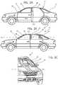
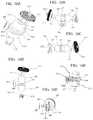
- FIG. 1Ais a side view of one embodiment
- FIG. 1Bis a top view of the embodiment shown in FIG. 1A ;
- FIG. 1Cshows an opposite side view of the embodiment shown in FIG. 1A ;
- FIG. 2Ais a side cut-away view of another embodiment
- FIG. 2Bis a side view of the embodiment shown in FIG. 2A ;
- FIG. 2Cis a front view of the embodiment shown in FIG. 2A ;
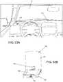
- FIG. 3Ais a front view of an auto of the embodiment of either FIG. 1A or FIG. 2 A;
- FIG. 3Bis a front inside view of another embodiment
- FIG. 4Ais an inside view of an auto of the embodiment of either FIG. 1A or FIG. 2A ;
- FIG. 4Bis another view of the inside of the automobile.
- FIG. 5is a view of an embodiment coupled to a rear view mirror
- FIG. 6is another view of the embodiment coupled to the rear view mirror
- FIG. 7is a side view of the embodiment of FIG. 5 ;
- FIG. 8is a view of a side view mirror with a camera on it
- FIG. 9is a side view of the side view mirror with the camera on it.
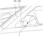
- FIG. 10Ais a front perspective view of a side view mirror with a camera on it;
- FIG. 10Bis a side cross-sectional view of a mirror
- FIG. 11is a side view of the screen with arms
- FIG. 12is a front perspective view of the screen of FIG. 11 ;
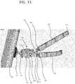
- FIG. 13is a side view of the screen of FIG. 11 ;
- FIG. 14is a back view of the screen of FIG. 11 ;
- FIG. 15is a side view of a portion of the device of FIG. 11 ;
- FIG. 16Ais a side view of the adjustable connection of FIG. 15 ;
- FIG. 16Bis a side perspective view of a portion of the adjustable connection of FIG. 15 ;
- FIG. 16Cis a side view of a portion of the adjustable connection of FIG. 15 ;
- FIG. 16Dis a side view of the adjustable connector of FIG. 16A ;
- FIG. 16Eshows an end view of the adjustable connector of FIG. 16A ;
- FIG. 16Fshows a side see-thru view of the embodiment shown in FIG. 16A ;
- FIG. 17shows a side view of the adjustable connector in a see-thru view
- FIG. 18Ais a back view of the screen
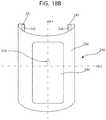
- FIG. 18Bis a front view of the cuff type connection of a screen
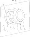
- FIG. 19is a side exploded view of a camera for use with a motor vehicle and with the screens described below;
- FIG. 20is a view of an interior of an automobile having the screens installed
- FIG. 21is an inside view of an auto having the screens installed inside
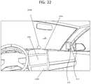
- FIG. 22is another view of an interior of an auto with the screens installed inside;
- FIG. 23Ais a side interior view of another embodiment
- FIG. 23Bis a side interior view of another embodiment
- FIG. 23Cis a side interior view of another embodiment
- FIG. 23Dis a side interior view of another embodiment
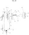
- FIG. 24Ais a view of a cockpit of an airplane or boat
- FIG. 24Bis a side view of a cockpit of an airplane or boat
- FIG. 25is a view of a new embodiment which discloses a screen and camera combination
- FIG. 26shows a side exploded view of the screen and camera combination
- FIG. 27shows a back perspective view of a screen and camera combination
- FIG. 28shows a back perspective view of a screen and camera combination in an exploded view
- FIG. 29shows a back view of the screen
- FIG. 30shows a side cross-sectional view of a screen and camera combination
- FIG. 31shows a side cross-sectional view of a screen and camera combination with internal wiring
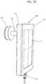
- FIG. 32shows a side view of a screen and camera combination with multiple cameras for a single screen
- FIG. 33is a front view of a camera and mirror combination with multiple cameras installed on a side mirror of an automobile;
- FIG. 34is a side view of an adapter which can be placed on a side of a support for an auto or on a mirror;
- FIG. 35shows a side support which allows for a camera with an adjustable angle seat being insertable therein;
- FIG. 36shows a screen and multi-camera installation
- FIG. 37is a schematic block diagram of the electronic components for the screen and camera combination
- FIG. 38is a schematic block diagram of the electronic components in communication with a central device such as a server;
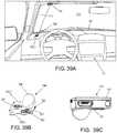
- FIG. 39Ais a view of another embodiment from an inside of a vehicle.
- FIG. 39Bis a view of a projector of FIG. 39A ;
- FIG. 39Cis a view of another projector of FIG. 39A ;
- FIG. 40Ais a front view of a vehicle with the embodiment of FIG. 39A ;
- FIG. 40Bis a front view of the projector of FIG. 39A ;
- FIG. 40Cis another embodiment of a projector
- FIG. 41Ais a view of an inside of a vehicle with another embodiment
- FIG. 41Bis a view of the display system associated with FIG. 41A ;
- FIG. 42Ais a view of the vehicle having the system of FIG. 41A ;
- FIG. 42Bis a view of the display system of FIG. 41B ;
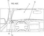
- FIG. 42Cis a view of the inside of a vehicle having another embodiment
- FIG. 43Ais a view of an inside of a vehicle having another embodiment
- FIG. 43Bis a view of the display system of FIG. 43A ;
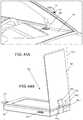
- FIG. 44Ais a view from outside the vehicle of the embodiment of FIG. 43A ;
- FIG. 44Bis a back view of the display system of FIG. 43B ;
- FIG. 45is a view from an inside of a vehicle with another embodiment
- FIG. 46is a view from outside the vehicle of the embodiment of FIG. 45 ;
- FIG. 47is a view from an inside of the vehicle of another embodiment.
- FIG. 48is a view from outside of the vehicle of the embodiment of FIG. 47 ;
- FIG. 49is a view from inside the vehicle of another embodiment
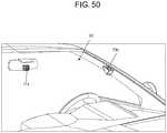
- FIG. 50is a view from outside the vehicle of the embodiment of FIG. 49 ;
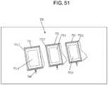
- FIG. 51is a view of an embodiment that can be used with the embodiment of FIG. 50 ;
- FIG. 52is a backside view of the displays shown in FIG. 51 ;
- FIG. 53Ais a view of the inside of a vehicle having another embodiment
- FIG. 53Bis a view of the display component of FIG. 53A ;
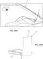
- FIG. 54Ais a view of the embodiment shown in FIGS. 53A and 53B
- FIG. 54Bis a view of the component shown in FIGS. 53A, 53B, and 54A ;
- FIG. 55is a view of the electronic network of components that can be used with any one of the above embodiments;
- FIG. 56Ais a block diagram of a camera system
- FIG. 56Bis a view of a lens system
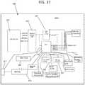
- FIG. 57is a flow chart for identifying objects
- FIG. 58Ais a view of another embodiment
- FIG. 58Bis a top view of a screen
- FIG. 58Cis a top view of an auto of the embodiment of FIG. 58A ;
- FIG. 59is a top view of another embodiment of the automobile.
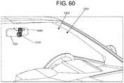
- FIG. 60is another view of the auto of FIG. 59 .
- FIG. 61is a side view of a cleaning system for a camera on a side view mirror
- FIG. 62is a side cross-sectional view of the cleaning system for a camera lens or cover.
- FIG. 63is a close-up view of a cleaning system for a camera.
- FIG. 64is an inside view of a side nirror with a cleaning system
- FIG. 65is a view of a cover having heating fields disposed therein;
- FIG. 66is a top view of an automobile having a particular headlight and side light combination.
- FIG. 67is a close-up view of a headlight and sidelight combination.
- FIG. 1 Ais a side view of one embodiment.
- This embodiment 10shows an automobile 12 having a frame comprising a body 18 , a roof 16 , and supports 14 and 15 .
- Supports 14 and 15support the roof over the body.
- Windowssuch as front windshield 19 are positioned between supports 14 . 1 and 14 . 2 .
- Support 14comprises both supports 14 . 1 and 14 . 2 .
- Support 15comprises both supports 15 . 1 and 15 . 2 .
- There is also a rear support 17which is also useful in supporting roof 16 over body 18 .
- Side windows 21 and 23are interspersed between roof 16 and body 18 as well.
- FIG. 1Bis a top view of the embodiment shown in FIG. 1 A.
- windshield 19as well as back windshield 25 .
- the top of roof 16is also shown.
- the two sides of the autowith supports 14 . 1 and 14 . 2 each having multiple cameras such as at least one camera.
- an additional support 14 . 2which has additional cameras 32 , 34 , and 36 as well.
- There is also a dashed dotted line 30 . 1which bisects the auto wherein in this view a front end of the auto is to the left side of the line and back end of the auto is to the right side of the line.
- Supports 14 . 1 and 14 . 2sit at the front end of the auto.
- FIG. 1Cshows the opposite side from FIG. 1A showing cameras 32 , 34 , 36 and support 15 . 2 as well.
- These cameras 22 , 24 , 26 , and 32 , 34 and 36are positioned between a front windshield of the auto 12 .
- FIG. 2Ashows a side view of an automobile wherein this design shows another embodiment 11 which shows a screen 40 which shows the images or view inside of an automobile.
- This viewalso shows cameras 22 , 24 , and 26 coupled to supports 14 .
- This viewis a cut-away side view showing the interior of the vehicle. The positioning of this screen is in a middle section of the automobile on the support frame between the front seat of the auto and the back seat.
- the screen or display 40is coupled to the frame section using a support structure such as that shown in FIG. 2A .
- FIG. 2Bis a side view of the embodiment shown in FIG. 2A .
- This viewshows the exterior view.
- This exterior viewshows additional cameras 52 , 54 , and 56 which are coupled to support 15 . 1 while as shown screen or display 40 is coupled to support 15 . 2 .
- Cameras 52 , 54 , and 56are in communication with an associated screen such as screen 40 shown on an associated support such as support 15 . 1 .
- the screenis located just inside of the cameras.
- This viewalso shows a bisecting line 30 . 2 on FIG. 2B which extends substantially horizontally and which forms a bisecting line bisecting the auto so that a bottom half is shown below the bisecting line and a top half is shown above the bisecting line.
- the cameras and associated displaysare shown in a top half of the auto.
- cameras 22 , 24 , and 26 and the associated displayare shown in the top front section of the auto to cover blind spots in the top front viewing region of the auto.
- FIG. 2Cshows a front view of the auto of the embodiment 11 which shows cameras 22 , 24 , and 26 on support 14 . 1 while cameras 32 , 34 , and 36 are positioned on support 14 . 2 .
- This viewshows a bisecting line 30 . 3 which bisects the auto and extends in a substantially horizontal plane.
- this line 30 . 3is a top half of the auto and below this line is a bottom half of the auto.
- FIG. 3Ais an inside view of an auto of the embodiment of either FIG. 1 A or FIG. 2A .
- a video screen 62 , or screen 220See FIG. 22 positioned on the inside surface of support 14 . 1 (See FIG. 1B ).
- This screenis in communication with associated cameras 22 , 24 , and 26 as well as camera 120 positioned on the side view mirror on that side of the car.
- Screen 64 , or 220is coupled to support 14 . 2 .
- Screen 64is associated with cameras 32 , 34 , and 36 as well as camera 120 on the side view mirror of that side of the car.
- dashed dotted lines 65 . 1 and 65 . 2Dashed line 65 .
- the screens 62 and 64are positioned on both the right half and the left half of the auto and generally or substantially on the top half of the auto along the supports 14 . 1 and 14 . 2 and adjacent to the windshield 19 .
- FIG. 3Bshows a front inside view of at least one screen 62 , or 220 , with a housing 80 .
- the turn screw 82fixes the housing section 83 around ball joint 87 .
- Ball joint 87is coupled to shaft 88 .
- Shaft 88is coupled to plate 84 .
- Plate 84is coupled to inside frame 86 via screws.
- the screen systemis coupled to inside section 86 of frame 14 . 1 so that this adjustable section makes the screen 62 adjustable in movement.
- This adjustable omnidirectional systemis similar to that shown in FIGS. 11-13 as well.
- FIG. 4Ais an inside view of an auto of the embodiment of either FIG. 1 A or FIG. 2A .
- This viewshows screens 62 and 64 associated with respective cameras 22 , 24 , and 26 , or cameras 32 , 34 , and 36 .
- Screens 62 and 64are similar to screens 220 and are coupled to the auto adjacent to supports 14 . 1 and 14 . 2 .
- This viewalso shows the screens positioned on either side of bisecting line 65 . 1 in generally the top half of the auto.
- FIG. 4Bshows an inside view of an auto of the embodiment of FIG. 1 A or FIG. 2A .
- bisecting line 65 . 1as well as bisecting line 65 . 2 .
- Bisecting line 65 . 1is substantially vertical while bisecting line 65 . 2 is substantially horizontal.
- screenssuch as screens 72 or 74 which can be positioned inside of frames 14 . 1 and 14 . 2 and be used to display images from a camera.
- These imagescan be even three dimensional images created by multiple cameras such as cameras 22 , 24 , 26 , 32 , 34 , 36 , or cameras 100 or 120 which can be used to present an image that has depth and also be used to provide the user with an ability to judge the distance that a pedestrian or an automobile may be positioned from the automobile.
- FIG. 5is a side perspective view of a camera mounted on a rearview mirror.
- a camera system 100which includes a camera body 102 , and a lens section 104 the camera body 102 is coupled to a bracket such as a support bracket 106 .
- Bracket 106is coupled to a mounting body 108 .
- Body 108is coupled to rearview mirror 110 .
- Mounting body 108can be coupled to a windshield or windscreen.
- camera 100including camera body 102 can be positioned in front of rearview mirror 110 so that the user has blind spot recordability and visibility of this rearview mirror.
- FIGS. 6 and 7show alternate views as well.
- FIG. 8is a front view of a side view mirror 122 side view mirror 122 includes a camera 120 .
- a cablesuch as cable or line 254 (See FIG. 19 ) can be fed along arm 119 into the body of the automobile 12 . The cable can then be coupled into the vehicle's electrical system as well as into the screens such as screens 62 , 64 , 72 , 74 , 220 , or 249 .
- FIG. 9shows a side exploded view of this camera 120 .
- Camerassuch as camera 120 can be placed in any region.
- side view mirror 122includes a mounting surface which is configured to receive mounting flange 121 .
- This camera 120can be positioned so that it is adjustable in angle and orientation.
- Coupled to mounting flange 121is a lens body 123 .
- a lens cover 126is configured to cover over lens body 123 .
- Lens cover 126includes a lens flange 125 , and lens cover section 127 .
- Lens cover 126is configured to cover over the camera, and protect it from the environment.
- FIG. 10Ashows an alternate view of the side view mirror.
- side view mirror 122includes camera 120 , wherein side view mirror 122 is coupled to arm 119 , which is coupled to automobile body 18 .
- a cable or linecan feed from body 18 through arm 119 to camera 120 from the electrical and communications system of the auto.
- FIG. 10Bshows a side cross-sectional view of a camera system for a side view mirror 122 .
- This viewshows an inner shell 120 . 2 disposed inside of an outer shell 120 . 1 .
- Inner shell 120 . 2rotates within outer shell 120 . 1 .
- a drive motor 120 . 5is coupled to the camera body 120 . 4 .
- Wheels 120 . 7 and 120 . 8are coupled to drive motor 120 . 5 and are used to selectively drive the angle of vision or attack, i.e. the direction of the camera lens 120 . 3 to a particular direction.
- Drive motor 120 . 5is driven by cable 120 . 6 .
- Cable 120 . 6is powered by a battery or electrical system within the automobile.
- FIG. 11is a side perspective view of a screen system 200 .
- Screen system 200includes a front screen 202 , a screen body 204 coupled to the front screen 202 . Coupled to screen body 204 is a bracket such as a support bracket comprising of at least a screw adjuster 213 . Screw adjuster 213 is configured to be screwed into the backend of screen body 204 . Screen body 204 is configured to hold the electronic components of the screen.
- Screw adjuster 213includes is threaded screw end 211 . 1 . Coupled to screw adjuster 213 is an adjustable mounting arm 203 . Adjustable mounting arm 203 includes an adjustable section 219 , which includes a clamp body section 206 , a clamp arm 208 . 1 , a first end 211 , and a second end 217 . Second end 217 extends towards arms 210 and 212 . Coupled between arms 210 and 212 and second end 217 is rotatable T connection 218 . Rotatable T connection 218 includes screws or couplings 207 and 209 . Arm, 210 is coupled to rotatable T connection 218 via screws or couplings 207 .
- Rotatable T connection 218can be selectively secured via a screw such the T clamp screw 218 . 1 .
- This screen systemcan be used in place of any of the screen systems mentioned herein such that these arms can wrap around supports 14 . 1 or 14 . 2 or 15 . 1 or 15 . 1 .
- the screencan then be selectively coupled to a camera such as any one of the cameras mentioned herein such as cameras 22 , 24 , 26 , 32 , 34 , 36 , 52 , 54 , 56 , 100 , 120 , 250 , 390 , 580 .
- Arm 210includes a plurality of different sections, wherein each section is coupled together via a hinge.
- hinge flanges 210 . 1 and 210 . 3coupled to each other via an intermediate hinge section 210 . 2 .
- These hingesallow for a flexible rotatable multidimensional arm which can then be wrapped around a column, a post or any other body support section of an automobile.
- arm 212includes hinge connectors 212 . 1 , and 212 . 3 , which comprise flanges, and a hinge section 212 . 2 .
- Positioned at the end of arm 212are openings 216 .
- position at the end of arm 210is opening 214 .
- Openings 216 and 214are configured to be wrapped around and coupled to a post or body section of a moving vehicle such as an airplane a boat, a motor vehicle or any other device. These openings allow the screws to be screwed into a column or body of an automobile.
- FIG. 12shows the upright view of this device showing a front view of screen 200 as well as openings 216 . 1 and 216 . 2 which are configured to receive a fastener.
- opening 214can be inserted between openings 216 . 1 and 216 . 2 to tie the ends together.
- FIG. 13shows the adjustable section 219 .
- Adjustable section 219includes a body 215 which includes a first body part 215 . 1 and second body part 215 . 2 .
- body 215which includes a first body part 215 . 1 and second body part 215 . 2 .
- clamp body section 206 and clamp arm 208are also positioned at the adjustable section 219 .
- FIG. 14shows a side transparent view of this adjustable section 219 .
- FIG. 15also shows the side transparent view as well.
- FIGS. 16A-16Fshow adjustable body section 219 , which includes clamp 208 , and clamp arm 208 . 1 .
- clamp 208When clamp 208 is rotated in a predetermined manner it drives clamp arm 208 . 1 into clamp body section 206 .
- FIGS. 16B through 16Eshow different views of adjustable section 219 with first body part 215 . 1 and second body part 215 . 2 removed. As shown in these views, there are a plurality of ball joints 236 , and 238 , positioned within a clamp seat 237 . As clamp arm 208 . 1 is driven into clamp seat, 237 , it exerts pressure on ball joints 238 , and or 236 which one position within first body part 215 . 1 , and second body part 215 .
- FIG. 17also shows a view of this adjustable section 219 in a substantially transparent view.
- This viewshows arms 210 and 212 coupled to T connection 218 .
- FIG. 18Adiscloses arms 210 and 212 which are coupled to adjustable section 219 , in which are selectively fixed in place via clamp 208 .
- This viewis as a back view of screen display 224 .
- FIG. 18Bis a view of a frame type attachment for a screen.
- This cuff type attachmentincludes a body section 246 which is formed from any suitable material such as metal or plastic.
- the bodycan be made so that it is at least partially or substantially flexible so that it can be expanded and then selectively snap around a semi-circular or circular column such as a support or frame in a car or plane cockpit such as supports 14 . 1 , 14 . 2 , 15 . 1 or 15 . 2 .
- the body section 246is coupled to flanges 242 and 244 which have attachment elements 242 and 244 .
- Attachment elements or flanges 242 and 244comprise at least one of the following: screws, fasteners, hook and loop fastener, clips, etc.
- Screen 249is coupled to body section 246 .
- a camera 248is disposed on an opposite side of screen 249 .
- This body section 246is bisected via a first axis 240 . 1 which comprises a longitudinal axis. Longitudinal axis 240 . 1 bisects this body section such that screen 249 is positioned in a substantially central region. In addition, this body section is substantially C-shaped or rounded so that it can fit around vertical columns or posts.
- Axis 240 . 2is a latitudinal axis and bisects body section 246 as well. In at least one embodiment, the extension of body section 246 is longer than the extension along the latitudinal axis.
- Screen 249can be used in place of any of the other screens mentioned herein and in combination with any of the other cameras mentioned herein.
- the body section 246which is made from flexible material snaps around a column or post the flanges 241 , and 243 hold the body section in place.
- FIG. 19is an exploded view of a camera system 250 .
- Camera system 250can be coupled selectively to screen display 220 .
- a lens front 258which is coupled to a second lens section 257
- second lens section 257is coupled to focal adjuster 256 .
- Focal adjuster 256is configured to be rotated to selectively focus the camera.
- First lens section 255sits in lens seat, 251 .
- Lens seat 251is coupled to camera body 252 .
- Coupled to a backend of camera bodyis cable 254 .
- this camera system 250includes multileveled lens sections 255 and 257 .
- the cameracan be focused selectively in a number of different ways.
- This cameracan be positioned inside of the car on the rearview mirror or outside the car on the supports or on the side view mirror.
- Cable 254can extend through the arm of a side view mirror. As indicated above to connect into the system components of an automobile and also to a screen such as screen 220 .
- FIG. 20shows the inside of an automobile.
- screens 220Positioned along columns 14 . 1 , 14 . 2 are screens 220 .
- Screens 220 or screen 62 or 64can be coupled to camera system 250 .
- the screenscan be coupled to camera 120 shown in FIG. 8 .
- FIG. 21shows the inside of an automobile which shows screen 220 positioned inside of column 14 . 1 .
- FIG. 22shows screen 220 positioned along column 14 . 2 .
- FIG. 22also shows a screen 220 a which can be used to display one of the fields of the cameras as well.
- Other screens 220 b or 220 ccan also be used.
- a projector 220 dcan sit on the dashboard and project an image of the view of the camera onto the windshield 19 as well.
- FIG. 23Ashows an inside view of another embodiment.
- a screen or screen unit 220which has a screen face 220 . 1 .
- an arm 272Coupled to the screen face is an arm 272 and a camera head 270 .
- a cameraInside of the camera head 270 is a camera which is electronically coupled to screen unit 220 .
- an anchor 260which is configured to anchor the screen to an auto such as to a windshield 19 .
- Anchor 260comprises a suction head which can be adhered to windshield 19 via a suction force.
- Arm 262 as well as arm 272are both bendable and adjustable in an accordion-like manner by using sufficient force but are otherwise substantially rigid.
- FIG. 23Bis an inside view of another embodiment which also discloses the anchor 260 , the arm 262 , the camera head 270 , and the camera arm 272 .
- an adjustment body 280which includes a ball joint 284 disposed inside of the body 280 .
- a lock 282which can comprise a screw lock which when loosened allows for the ball in the ball joint 284 to move and to be adjusted. When the lock 282 is tightened it locks the ball in the ball joint in place.
- FIG. 23Cshows another embodiment which includes the features of FIG. 23B but also includes the following additional features, a post 290 and a mounting plate 292 .
- Mounting plate 292is configured to be mounted to a support such as support 14 . 1 .
- FIG. 23Dshows another embodiment which shows a mounting plate 295 which is different than mounting plate 292 in that mounting plate 295 is configured to have multiple screws such as four screws. In this view there are three screws 296 , 297 , and 298 shown.
- the mounting platesuch as mounting plate 292 or 295 are configured to semi-permanently mount the screen to a car.
- Anchors 285 and 260are configured to also mount the screen and the camera to the car but in a non-destructive manner.
- FIG. 23Athere is only one mounting point via anchor 260 .
- FIG. 23Bthere are two mounting points shown by anchors 260 and 280 . These two mounting points allow for a compressive fit for the screen mounting system between the windshield 19 and the dashboard.
- the embodiments 23 C and 23 Dallow for three mounting points allowing for the compression coming from three different angles and allowing further security in mounting the screen.
- the screencan be mounted to a car or auto in a safe and reliable manner.
- FIG. 24Ais a view of a cockpit for a boat or a plane.
- the cockpit design 370includes a windshield 379 , as well as screens or displays 382 and 384 mounted on supports 386 and 388 respectively.
- there is a front panel of a cockpit dashboardwhich has a steering wheel as well as a plurality of screens 372 , 374 , 376 , 378 , 394 , and 396 . Any one of these screens 372 , 374 , 378 , 394 , and 396 can display the information associated with cameras.
- there is a bisecting line 380 . 1which divides the cockpit substantially longitudinally in half.
- these displays 382 and 384are positioned in a top half of the cockpit as shown by the bisecting line 380 . 2 which divides the cockpit laterally into two sections.
- FIG. 24Bis a view of an outer portion of the plane 391 which has the cockpit shown in FIG. 24A .
- This viewthere is a body 397 with a windshield 379 .
- the body of the planeis bisected latitudinally by dashed line 391 . 2 .
- This viewshows that camera 390 is positioned in the top half of the plane along support 386 .
- Another opposite camerais positioned on the other support 388 .
- bisecting line 391 . 2bisects the plane along a substantially horizontal axis
- bisecting line 391 . 1extends vertically and starts at the beginning region of a plane cabin which is positioned towards a front end of a plane.
- all of the screens, adjusting mechanismssuch as that shown in FIGS. 11-17 .
- FIG. 25discloses another new embodiment 500 which includes a screen assembly 510 , a camera assembly 580 , and a channel 570 connecting the camera assembly 580 with the screen assembly 510 .
- Screen assembly 510includes at least a screen body or housing 512 , and a screen itself 511 .
- Screen 511is housed inside of screen body 512 .
- Behind screen 511are electronic components shown in FIG. 36 .
- a cable 520can be coupled to screen assembly 510 through a port not shown herein.
- camera assembly 580can be positioned on one side of a support such as supports 14 . 1 14 . 2 , 15 . 1 , 15 . 2 while the screen assembly 510 can be positioned on the opposite side of the support 14 . 1 14 . 2 , 15 . 1 , 15 . 2 .
- Channel 570then extends through the door to bridge between the two assemblies.
- FIG. 26shows a side perspective exploded view of the device shown in FIG. 25 .
- screen assembly 510with screen 511 disposed inside of screen housing 512 .
- cable 520coupled to a bottom section of the screen.
- a coupling or support bracket 550includes a bracket body, as well as at least four different bracket prongs 552 , 553 , 554 , and 555 . These bracket prongs extend out from the bracket body that are formed as substantially L-shaped hooks.
- a screw 558is coupled to coupling bracket 550 .
- a cable slot 559is configured to receive a cable 560 .
- Cable 560is configured to be coupled to the electronic components shown in greater detail in FIG. 36 .
- Cable 560extends inside of channel 570 all the way to camera assembly 580 .
- a screw hole 571 in channel 570is configured to receive screw 558 .
- cable 560can slide through cable slot 559 , wherein cable 560 is then connected to the electronic components inside of the screen body 512 of screen assembly 510 .
- screw 558can be screwed into screwhole 571 to secure camera assembly 580 to connection bracket 550 .
- Connection bracket 550can then be coupled to screen body 512 as shown in FIG. 31 .
- FIG. 27shows a side-back perspective view of the embodiment shown in FIG. 25 .
- connection bracket 550is shown fitting into slot or recessed receptacle 521 .
- channel 570is shown extending from camera assembly 580 .
- Camera assembly 580includes a camera 581 , a camera face 582 and side walls 583 .
- Camera assembly 580can also include a covering such as a glass or transparent covering.
- connection bracket 550is fit snugly inside of recessed receptacle 521 .
- FIG. 28is a side exploded view which is similar structure shown in FIG. 27 .
- bracket 550is shown removed from screen body 512 .
- Prongs 554 , and 553are shown extending out from bracket 550 wherein these prongs 551 , 552 , 553 , and 554 can be configured to extend into prong openings such as prong openings 522 . 1 , 522 . 2 , 522 . 3 , and 522 . 4 .
- Cable 560can extend in through slot 559 and then extend through opening 524 .
- FIG. 29is a back view of the screen assembly 510 .
- opening 524is also shown.
- opening 529is also configured to receive a cable 520 .
- Cable 520can be in the form of a power and communications cable such as a power over Ethernet cable (POE) which can supply both power and communications to and from a screen/camera and back to a central on board computer such as that shown in FIG. 38 .
- POEpower over Ethernet cable
- FIG. 30shows a side cross-sectional view of the system as it is coupled to a post in a car frame such as post 14 , 15 or post 590 .
- Post 590can be any type of post similar to the posts 14 . 1 , 14 . 2 , 15 . 1 and 15 . 2 .
- post 590can also represent the surface of a rear view mirror or side view mirror as well.
- a screen 511disposed inside of a screen housing 510 .
- there is a motherboard 600 awhich is in communication with screen 511 .
- a cable or line 560is in communication with motherboard 600 a and extends to camera motherboard 593 disposed inside of a camera 580 .
- FIG. 31shows another embodiment which shows the same components of FIG. 30 however it includes an additional line 594 forming a power line for powering the components.
- This power linecan be used as a feed for feeding the power from the auto such as through an automobile electrical system.
- FIG. 32shows a side view of a multiple camera installation which is similar to FIG. 31 , however this embodiment includes an additional line 594 , an additional camera housing 580 a , a base motherboard 593 a , and an additional camera chip 601 a .
- multiple camerascan be associated with a single screen.
- the single screencan include at least one button, either included in a touch screen or an additional button 511 a which can serve as a toggle button for the device toggling between different cameras.
- the two or more camerascan serve as a means for creating a three dimensional view on the screen 510 .
- buttons or virtual buttons as part of the screen software which are presented on the screen itselfcan be used to point and aim the cameras such as cameras 580 , 580 a , 580 b , 580 c (See FIG. 33 ), which are all cameras configured to be electronically driven, as well as at least cameras 22 , 24 , 26 , and 32 , 34 , 36 , 100 , 120 by any suitable means such as through the drive system shown in FIG. 10B .
- FIG. 33shows the different cameras which can be installed for example on a side view mirror 122 (See FIG. 10B ).
- the camerascan be in the form of multiple different cameras feeding into a single screen, at least one of the cameras such as camera 580 c can be positioned at a side position on mirror 122 so that it extends the viewing out laterally for users to see to the side of the car and even into blindspots of a rear view mirror.
- These camerascan also be driven such as via the drive system shown in FIG. 10B .
- FIG. 34is a side perspective view of an adapter which includes a block adapter forming a mounting bracket 595 which can be pre-molded and pre-formed into a particular shape or structure which then allows the existing curvature of a structure of the automobile to be compensated for via this structure. Coupled to this block adapter 595 is a camera body 580 which is seated inside of this adapter structure. Any type of combination of camera and screen system can be used herein with this adapter.
- FIG. 35is a side perspective view of the block 595 which is configured to receive the camera body 580 .
- a camera seat 596which includes an adapter device 597 which allows the camera to be rotated relative to a horizontal axis 598 to position and point the camera inside of the camera body.
- the camera seat 596can be adjusted or rotated to either loosen or tighten the adapter device 597 to allow for the camera to be selectively positioned at a particular angle.
- there is at least one curved surface 595 apositioned substantially opposite a surface supporting the camera 580 .
- the drive mechanism shown in FIG. 10Bcan be used with this type camera as well.
- FIG. 36shows a screen 510 which can be connected to any one of cameras 580 , 580 a , and 580 b through a wireless connection.
- FIG. 37shows the preferred embodiment of the apparatus.
- This embodiment of electronic components 600includes camera chip 601 , CPU 602 , data converter 603 , display driver chip 604 , LCD display 605 , flash chip 606 and micro SDCard 607 which can include 530 shown in FIG. 31 .
- Camera chip 601is one of several types.
- the chipprovides an integrated lens, 640 ⁇ 480 full color pixel array sensor or any other suitable resolution, control electronics, an 8 bit data output bus and a control bus.
- CPU 602sends commands to the camera chip to initialize it and to control the capture and format of data.
- CPU 602selects a format that is compatible with display driver 604 to reduce the amount and convolution of data required to display a good image.
- Data from the camera chipis ported to both CPU 602 and to the display driver chip 604 , via data converter 603 .
- the display driver 604can accept data in several widths (8 bit, 16 bit, 24 bit) and formats (RGB656, RGB888, etc).
- the current embodimentprograms camera chip 601 to send image data in the RGB656 format, which consists of 2 bytes containing 5 bits of red color information, 6 bits of green color information and 5 bits of blue color information.
- Display driver 604can accept this data in 16 bit format; since the camera chip outputs the data in 8 bit widths, data converter 603 is used to convert the 8 bit data into 16 bit RGB656 format data.
- Display driver 604contains sufficient memory to store at least one frame of display data.
- the display driver 604has many registers to control the appearance of the LCD display 605 , so it is connected to CPU 602 using the same bus as data converter 603 .
- CPU 602programs these registers before beginning the image display and also writes a command to display driver 604 at the start of every display frame to describe where the forthcoming data from data converter 603 is to be displayed on LCD display 605 .
- a frame of datais defined by signals VSYNC and HSYNC and CPIXCLK.
- VSYNCis set high when an image frame is to be output from camera chip 601 .
- Each line of the imageis qualified by HSYNC which goes high when valid pixel data is available on the data outputs of camera chip 601 .
- HSYNCgoes low when the line of data ends and signals that a new line of data is about to begin.
- CPIXCLKpulse high frq each byte of data sent by camera chip 601 .
- CPU 602can either accept this data (to save frame(s) to micro SDCard 607 , or can send this data to display driver chip 604 via data converter 603 .
- CPU 602monitors signal VSYNC from camera chip 601 .
- CPU 602programs display driver 604 with the addresses of the data that is to be written to the LCD display.
- CPU 602activates data converter 603 .
- Data converter 603accepts HSYNC and CPIXCLK and uses these signals, along with the data signals from the camera chip to assemble a 16 bit wide RGB656 word and subsequently write that word to display driver chip 604 .
- Display driver chip 604takes these RGB656 and stores them sequentially into its internal frame memory.
- Display driver chip 604uses the frame memory to generate the signals DVSYNC, DHSYNC, PIXCLK and the 24 bit data (8 bits each of red, green and blue) for display on LCD display 605 .
- CPU 602continues to monitor signal VSYNC from camera chip 601 .
- VSYNCgoes low, the frame has been completed and CPU 602 turns the data converter off and begins looking for a new frame of data.
- LCD Display 605incorporates a touch screen interface for the apparatus. This interface permits the user to capture an image or a video from the camera chip to micro SDCard 607 . This image can be used for identification or verification of events. Flash chip 606 holds images that can be displayed on a portion of LCD display 605 and includes virtual buttons, help instructions, or general information for the operation of the apparatus.
- CPU 602can generate information that can be displayed on LCD screen 605 instead of video or as an adjunct to the video display.
- coupled to CPUare other optional components.
- the optional componentsinclude a WIFI chip 609 which can be used to allow the camera and CPU 602 communicate with another computer network.
- a battery 610there can be a battery 610 .
- an Ethernet connection port 611which is coupled to CPU 602 .
- Other optional componentscan include a sensor 618 .
- Sensor 618can be any one of the following sensors: RFID sensor, a motion sensor, a door ajar sensor, a fingerprint scanner, a thermal sensor, and a proximity sensor alarm.
- a sim card 616and a biometric reader 617 .
- This audio speaker and microphonecan be embedded into the screen assembly 510 .
- the electronics shown in FIG. 37can be used in any one of the camera and screen combinations disclosed herein.
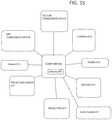
- FIG. 38is a schematic block diagram of the embodiment of either FIG. 1A, 2A, 3 , or 4 .
- cameras 22 , 24 , and 26which are coupled to aggregator 400 .
- Aggregator 400is coupled to video compression device 410 .
- Video compression device 410has an output to at least one screen 62 , 64 , or 40 , or screens 72 , 74 , or screens 220 , or 249 .
- a video recorder 420is coupled to aggregator 400 which is configured to selectively record video signals taken in from aggregator 400 .
- the devicecan serve as a black box video recorder as well.
- the cameras and screens for the embodiment of FIG. 5can also be included in this block diagram as well.
- a first device 401which acts as a recorder for the information such as speed, orientation, GPS provided by GPS system 618 A, and other coordinates to serve for additional black box recording.
- another device 402which allows for the device to be coupled to or at least in communication with an outside cloud storage device.
- this deviceincludes a wireless communication element such as a SIM card such as SIM card 616 or other wireless communication device.
- a communication device 403which is configured to communicate with an automobile to automatically stop an automobile.
- This device 403can be preset with certain instances such as when it views a pedestrian in a cross walk or other obstruction.
- Device 403can be wired into the auto's onboard computer to automatically brake the auto to stop the auto from hitting a person or object. This viewing device could then automatically either shut the auto down or disable the accelerator to prevent a party in a crosswalk from being hit.
- this device 403reads the visual information from aggregator 400 and then processes the images from this information. Once it reads the information from this aggregator 400 and recognizes this information it then sends this information onto the automobile computer to either disable the auto or to disable the accelerator.
- another camera control device 404is configured to control the cameras such as cameras 22 , 24 , and 26 or cameras 32 , 34 , and 36 , 52 , 54 , 56 or cameras 100 , 120 , 250 or 580 .
- Each of these camerascan have in their body devices to control focus, pan, tilt, zoom, etc.
- Device 404is thus configured to control the pan, tilt, zoom, a focus of each of these cameras and is configured to communicate through aggregator 400 so that each of these individual cameras is controlled.
- the controls of these camerascan be located in the dashboard of the auto, or on the steering wheel of the auto or on any one of the screens described above.
- the onboard auto computercoupled to aggregator 400 , is the onboard auto computer which communicates with this aggregator all of the information from the auto including the state of the auto.
- any controls located on the autocan be fed through the auto's onboard computer 405 through to the video aggregator 400 , and then onto any one of the devices 401 , 402 , 403 , or 404 .
- the aggregator 400 and also the components coupled either directly or indirectly to the aggregator 400are coupled to the auto's onboard computer 405 , in a communicative manner as well as in an electrically powered manner so that information and electrical power is passed between these components.
- Each of these camerascan also be controlled by camera control device or lens 404 so that these cameras can render infrared, thermal, night vision or any other type of view known in the art and requested by the user.
- each of these componentscan communicate with each other via a wired connection.
- each of these componentssuch as the cameras 22 , 24 , 26 , 32 , 34 , 36 , 52 , 54 , 56 , 100 , 120 , 250 , 580 can include an associated wireless transceiver also communicate in a wireless manner with any one of the suitable screens such as screens 249 , 220 , 72 , 74 , 62 , 64 , 40 or 511 also selectively having a wireless transceiver.
- the communicationcan be via wireless internet protocols such as WIFI, bluetooth or any other suitable wireless communication protocol.
- the systemis designed to allow for communication and control from multiple different cameras to multiple different screens either in a wired or wireless manner to allow the user to see in different blind spots.
- the systemallows for the mounting and positioning of multiple different screens or cameras wherein these screens and cameras can be positioned around a moving vehicle.
- FIG. 39Ashows a view of an auto 10 which includes a dashboard surface 701 which has at least one projector 700 positioned on it. There is also another projector 710 coupled to the auto, in this case to the visor of the auto. In addition, there is a reflective and/or translucent film 712 which can be made of any suitable material such as a substantially translucent and/or transparent polymer which is adhered to the windshield 711 of the auto. The adhesive can be in the form of a static adhesive or an actual chemical based adhesive.
- an induction plate 701 . 1which is used to selectively charge or at least provide energy to the projector. The induction plate is configured to be powered by the auto while extending a charge to the device through electrical transfer of energy.
- FIG. 39Bshows a back perspective view of a projector 700 .
- the projector 700includes a body section 701 , a connector 703 disposed in the body section.
- the connectorcan be any suitable connector such as a HDMI connector.
- the HDMI connectorcan serve as both a power connector as well as a media connector.
- Extending out from the bodyis a projector lens 704 .
- a card reader connection 705is also disposed inside of body section 702 .
- FIG. 39Bshows the view of the projector 710 which is essentially the same as projector 700 .
- There is also shown a security hole 108 . 1which allows the device to be clamped down on the dashboard of a vehicle.
- FIG. 40Ashows the view of projector 710 positioned on a visor of an auto 10 .
- Reflective film 712is positioned on the windshield 711 .
- a rear view mirror 718which also includes a camera 719 positioned on the rear view mirror.
- the camerais configured to feed images to the projector 700 or to the projector 710 .
- Both projectors 700 and 710can operate independently to display images on film 712 or they can be synchronized to display a single composite image on film 712 .
- the film 712can have a strip around it, wherein the strip forms a guide for the projector to provide its images on the film. This strip can be in the form of an electromagnetic strip which provides feedback for the projector to guide the direction and focus of the projector onto the film.
- FIG. 40Bshows another perspective view of the projector 700 which shows lens 704 positioned in body 702 .
- feet 709configured to seat the body onto a dashboard such as dashboard 701 .
- this projectorcan also include a laser range finder 708 which is configured to send a beam out to the film to provide a distance or range for the beam to focus the projector.
- FIG. 40Cshows another embodiment, which shows a bulbous short-throw projector lens 704 . 2 which is used to provide a wide angle projection of the image onto the film.
- This fish-eye lensis bulbous and allows the image to extend in a wide angle direction, particularly both above and below the projector.
- FIG. 41Ashows a view of another three dimensional projection plane 720 positioned on dashboard 701 .
- Three dimensional projection plane 720includes a base section 722 which forms a mounting surface for different projectors 724 , 725 , 726 , and 727 . These projectors can project onto a reflective surface on base section 722 which is essentially a planar base surface which is configured to create a reflective surface along with the surface of the car body.
- the intersecting images of the projectors 724 , 725 , 726 and 727are configured to create three dimensional 3-D images positioned around the car 730 .
- the surface 723 of the base section 722can be flat.
- the surface of the base sectioncan be formed from multiple differently angled reflective surfaces.
- the car body projectedwould simply be a three dimensional holographic image.
- FIG. 42Ashows the projection plane 720 positioned on the dashboard of an auto. This view also shows camera 719 positioned on rear view mirror 718 . In addition, an additional camera can be positioned on side view mirror 731 as well. This additional camera can either work in conjunction with camera 719 or in the alternative to camera 719 .
- FIG. 42Bshows a front perspective side view of the three dimensional projector plane 720 .
- this viewshows the reflective surface 723 on base section 722
- This reflective surfacecan have different angles of extension such that base section is not entirely planar.
- the different projectors 724 , 725 , 726 and 727can be used to project on these different angled surfaces to create images and reflections of images to create the appearance of a three dimensional image.
- FIG. 43Ashows a view of an auto which has another embodiment 740 positioned on a dashboard surface 701 . This embodiment is shown in greater detail in FIG. 43B .
- FIG. 43Bshows an image of an embodiment which is a screen 742 which is housed inside of a housing 741 .
- a reflective screen 743which extends up at an angle from screen 742 .
- This reflective screen 743is configured to reflect the image shown in screen 742 .
- This screenacts as a projector displaying the image from the screen up to the reflective screen 743 .
- screen 742is configured to create a reflective image the image presented on the screen is modified to be readable by the user on screen 743 .
- this deviceis connected to a cable 744 via a suitable cable connection, such as an Ethernet connection which is configured to provide both power and communication to the device.
- the surface of the reflective screen 743is made from a substantially transparent or semi-reflective surface. In another embodiment it could be a reflective screen. Thus, as shown by the dash-dotted lines there is another backup screen which can be used as well.
- This back up screen 743 . 1is a solid backed screen which folds down separately from screen 743 .
- This back up screen 743 . 1is on a separate hinge 746 . 2 shown in FIG. 44B .
- FIG. 44Ashows the device 740 positioned on a user's dashboard. This view also shows side mirror 731 having a camera 732 positioned thereon. This camera as indicated above can work along with camera 719 or any other camera in the auto or this camera can work independent of this camera.
- FIG. 44Bshows a back view of the device 740 which includes a body section 741 , screen 743 , a hinge 746 which has three main parts.
- FIG. 45shows another embodiment which shows a projector 700 which is configured to project onto a screen of reflective film 713 on a windshield 711 of an auto 10 .
- FIG. 46shows the reverse view of the projector 700 with the reflective film 713 .
- This viewalso shows side view mirror 731 with camera 732 .
- the film 713is shown as smaller than film 712 such that the image required to show the necessary information may not need to be as large as shown with film 712 .
- the film or 712 or 713can be of any suitable size.
- FIG. 47shows an auto 10 having another embodiment 760 having a smaller screen 761 . This device is positioned on the dashboard 701 .
- FIG. 48shows an opposite view of the device having smaller screen 761 .
- This devicecan be in the form of a portable phone such as a smart phone.
- FIG. 49shows another device 770 which is positioned on a windshield of auto 10 .
- This device 770is shown in greater detail in FIGS. 50-52 .
- FIG. 50there is a device 770 which has a recess.
- FIG. 51shows different versions of screens 770 . These different screens have a screen surface 771 . 1 , 772 . 1 , and 773 . 1 . These screens also have respectively different screen bodies 771 . 2 , 772 . 2 , and 773 . 2 .
- FIG. 52shows the opposite sides of these bodies.
- screen 771includes a first camera 771 . 3 and a recessed section 771 . 4 .
- This recessed sectionincludes a side shielding panel 771 . 5 .
- Screen 772includes two different cameras 772 . 3 , and 772 . 4 and a recessed section 772 . 5 .
- Screen 773includes camera 773 . 3 .
- This designincludes a recessed portion 773 . 4 and a side wall 773 . 5 .
- These different designsare configured to allow these screens and systems to record activities at different angles when positioned on a windshield of an auto.
- Each of these camerasare pivotable or rotatable in different directions to allow for different views by the user.
- the camerasare movable by hand.
- the camerasare movable by remote control using a touch screen such as the touch display screen or by other remote control devices such as a joystick.
- FIG. 53Ashows a view of another embodiment 780 which includes a curved screen 781 which is attached to a body 782 of a screen 783 . There is also a cable connection 784 coupled to the body section 782 .
- FIG. 54Ashows a back view of the device 780 while FIG. 54B shows a view of the screen 781 which is curved.
- This screenis curved to help create a three dimensional (3-D) image on the screen due to the concavity of the reflective screen.
- this viewalso shows a card connection 786 disposed inside of body 782 .
- FIG. 55shows an alternative embodiment for a computerized network of components which is designed to fit any one of the above identified embodiments.
- a computer 800which is configured to coordinate the information taken in by any one of cameras 810 .
- this computerincludes a memory 801 which is configured to store both images and moving images taken by at least one camera such as cameras 810 .
- Cameras 810can be any one of the above identified cameras such as for example camera 719 or camera 732 shown in FIG. 42A or FIG. 44A respectively.
- sensors 812which can be placed around the vehicle and which can be used to determine the presence of an object along with the cameras 810 .
- sensorscan send an infrared beam, a wifi signal or any other type of suitable signal which determines the presence of objects around the vehicle.
- projectors 814which can be any form of suitable projector listed above such as but not limited to the projector device 700 or 710 .
- screens 815which can take the form of any suitable screen mentioned above in any one of the above embodiments.
- coupled to computer 800is a power supply 816 which is configured to power computer 800 .
- a projection sensor 817which can represent projection sensor 708 which is used to allow the projector to properly focus the image based upon a distance from the screen.
- Communication modulescan include any one of a wifi or bluetooth communication module 818 or a cellular communication module 819 . These communication modules allow the information from computer 800 to be communicated to other components such as to a smart phone or to a server.
- FIG. 56Ashows a block diagram for a design for a camera which can be an example of a camera that can be used as any of the above mentioned cameras such as cameras 100 , 120 and substituted for the corresponding components in FIG. 37 .
- a camera chip and discrete lens 831which is coupled to and in communication with a central processing unit (CPU) 832 .
- This CPU 832is coupled to a ram storage 833 , and also to external or removable storage in the form of an external flash 836 , and an optional micro SDCard 837 .
- a display driver chip 834which is also in communication with an LCD display 835 .
- LCD displayis also in communication with CPU as well.
- the pictures as well as motion videocan be recorded either in memory on the memory 801 of computer 800 or it can be recorded on the SD Card 837 or on the external flash 836 .
- the cameracan be a CMOS e2v camera with any suitable resolution such as HD resolution of 1280 ⁇ 1024, an 8 bit resolution depth and 1.3 megapixel in memory.
- the Sensor modelcan be a EV&6560BB or EV76560B.
- the lenscan have a focal length of 4.2 mm and a relative aperture of F3.0 to create a relative sensor size of 1/2.5′′ with a total length of approximately 21.50 mm with an angle of view of 69 degrees ⁇ 51 degrees.
- FIG. 56Bshows a lens 840 with its holder or mount 841 having a mount size of M12 ⁇ 0.5 mm. It is noted that this camera and lens system is simply one embodiment which is a preferred embodiment but the claims are not to be limited to any of the specifications cited herein.
- FIG. 57is a flow chart showing the steps for controlling an automobile or vehicle using for example the components listed above including but not limited to the components listed or referenced in FIG. 55 or even FIG. 56 .
- FIG. 56starts with step S 820 which includes reading the surroundings of the environment using any one of the cameras 810 or sensors 812 for example.
- other componentssuch as the wifi communication module 818 or the cellular communication module 819 can be used to track location or distance to other objects in the surrounding area.
- any one of the cameras 810can also be used to identify the objects in the surrounding area. All of these components can feed information into computer 800 which is then configured to read these visual images and sensory clues to identify the objects surrounding the vehicle.
- step S 821the system, in particular the computer can identify visual triggers in step S 821 to identify whether the objects are of concern for the driver and to identify the distance that the vehicle is from these proposed objects.
- step S 822the system can also identify audio triggers as well to determine from this information the operations around the vehicle.
- the sensors 812can be audio sensors as well.
- step S 823the system can identify the physical trigger via sensors as well.
- This physical triggercan be for example physical contact by an object on the vehicle which causes the sensors such as sensors 812 to react.
- these sensorscan be in the form of tactile sensors as well.
- the system comprising computer 800can send a warning which can be an indication sent from a projector 814 or information sent to a screen 815 as well.
- this warningcan also be in the form of an audio warning as well either through a voice warning or through a beep generated through the vehicles audio system 811 .
- step S 825the system can provide a communication of the trigger such as an image of a body on a screen, or a voice indication of the location of the body or shape of the body or type of the body.
- step S 826the system can communicate with the vehicle's navigation system to identify on the navigation system the location of any of the potential triggers as well.
- step S 827the system including computer 800 can stop the vehicle from moving to prevent any accidents by the user.
- any one of the above cameras in any one of the above embodimentscan be used in any one of the other embodiments.
- any one of the above screens in any one of the above embodimentscan be used with the other embodiments.
- any one of the above components with any one of the above embodimentsshould be construed as optional unless stated as being required within the system.
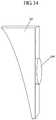
- Another embodimentincludes a design having another screen which is a curved screen 2002 which is configured to fit around a post 2001 of an automobile 1000 .
- the screen 2002covers substantially all of the post or the entire post.
- To power the screen 2002there is a cable 2006 which extends down into the automobile 1000 and which is connected to the internal computer system of the automobile.
- the screen 2002is therefore connected to the automobile for power as well as for communication with an associated camera such as camera system 250 or any other camera system disclosed herein.
- FIG. 58Bshows a top view of a curved screen 2012 which shows connection points having connectors 2004 , and 2010 which are configured to secure the screen 2002 to a post.
- These connectorscan be an array of any suitable kind of connectors known in the art such as male based connectors, female based connectors, a hook and loop fastener, a post, an adhesive, a rivet, a screw, a nut and bolt a nail or any other type of suitable connector or fastener.
- Connected to the back face of the screenis at least one motherboard 2008 which is connected to cable 2006 .
- Motherboard 2008receives power from cable 2006 as well as communication from cable 2006 to receive signals from a camera such as any one of the cameras disclosed herein.
- the screenis positioned on post 2001 so as to provide an image of the field behind this post.
- this field of vision shown by the field of vision 2020is shown in dashed dotted lines.
- This field of vision for the camerasthen compensates for the loss of vision for the driver because the post such as post 2001 is blocking the field of view for the driver.
- This field of visionis at least substantially bound by the latitudinal line bisecting the auto 1000 i and the longitudinal line 1000 ii of the auto forming a front left quadrant of view off of the automobile. Other quadrants can also be covered such as a front right quadrant in field of vision 2021 as well.
- Different arrays of camerascan be used such as cameras 2100 , 2102 and 2014 which are positioned in the front right post, to provide the field of vision of the front right field of vision 2021 .
- cameras 2016 , 2108 and 2110 embedded in a front left postare configured to provide the field of vision in the field 2020 .
- FIG. 59shows side view mirrors 2003 a and 2003 b which have embedded cameras 2005 a and 2005 b which are also configured to provide for the respective viewing fields 2020 and 2021 for automobile 1000 shown in FIG. 58C .
- this viewalso shows an additional camera 1090 which is angled to point upward so that a driver can have a view of a light above him.
- the camerais angled off of the rear view mirror 1091 so that a driver who is sitting behind the wheel of an automobile who has pulled up to a stop light but whose view is blocked by an auto's roof can still have access to the state of the light by viewing in a screen, such as the rear view mirror, the field of vision of the camera 1090 .
- This field of visioncan be such that it is the field of vision directly above the automobile, such as automobile 1000 .
- FIG. 60discloses a view of an auto 1000 which has a camera 1090 which is positioned to point up from a rear-view mirror 1091 and which is positioned to point through windshield 1094 and towards a position above the field of vision of camera 1092 which is also positioned on rear view mirror 1091 as well.
- camera 1090forms a part of a base for mounting rear view mirror 1091 to windshield 1094 .
- the camerais configured to provide the driver with a full view of a traffic light when the driver is positioned under the traffic light thereby allowing the driver to relax and not strain to look when the light turns green when stopped at a stop light.
- FIG. 61shows a new embodiment which discloses a blower system 1200 positioned adjacent to a camera 120 on a side view mirror 122 .
- the camera cleaning systemcan comprise any suitable cleaning system such as a blower or a wiper.
- side view mirror 122is shown connected to a post or column 18 via arm 119 .
- the blower system 1200can be used to clear any debris, condensation, water or other impingement from a front screen of the camera 120 .
- the blower system 1200can be in the form of a bent arm extending out from the side view mirror housing such as housing 122 shown in FIG. 62 .
- the blower systemcan be configured to blow down on a screen or front cover for camera 120 .
- camera 120can have a wiper 1210 which is configured to wipe any impingement or any other type of debris, or condensation from the front of this screen.
- Wiper 1210extends out from housing 122 and is driven by a drive arm which is disposed inside of housing 122 .
- FIG. 62there is an additional camera cleaning system configured to clean a cover of a camera such as a glass or transparent cover.
- the cleaning systemcomprises a blower system comprising a blower 1211 which is configured to clean the inside of the camera housing and the inside surface of a camera cover (see for example cover 580 d in FIG. 64 ) by blowing on the inside surface of the cover.
- a blower systemcomprising a blower 1211 which is configured to clean the inside of the camera housing and the inside surface of a camera cover (see for example cover 580 d in FIG. 64 ) by blowing on the inside surface of the cover.
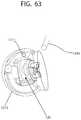
- FIG. 63shows a more close up view of the blower system and the housing wherein there is shown exterior blower 1200 and interior blower 1211 .
- Interior blower 1211is positioned inside of camera housing 1212 while blower 1200 is coupled to an exterior body such as a mirror housing and is configured to blow on the outside of a camera cover such as cover 580 d.
- blower ventsdisposed adjacent to camera housings.
- Each of these blower ventsis fed by a main blower system which is powered by a power line.
- the main bloweris configured to provide air blown through these vents to clear any debris or other obstruction for any one of cameras or even camera as well.
- the main blower systemcan blow air or other gas or even cleaning fluid onto the outside cover of a camera via blower vent or the inside surface of the outside cover by blowing inside of the housing of a camera (See FIG. 62 ) and onto the inside surface of the cover to clear any debris or condensation.
- the heating fieldsare in the form of resistance wires which are heated by power generated by the automobile.
- the heating wiressuch as wires are configured to receive power from the automobile electrical system.
- the wiresare heated by electrical power flowing through the lines, the resistance in the lines resulting in causing them to heat up. Once these lines are heated they can be used to clear any condensation or moisture or frozen material from either the front or outside of the cover, or the inside of the cover. In this way the cover on the camera does not remain fogged if any condensation forms on it.
- a first light fixturehas two sides, that are substantially perpendicular to each other a first side and a second side. Inside of first side is a first light. Inside of second side is a second light 45004 . With light, second light is a front light fixture which is primarily to light the road and surrounding area in front of the auto. The side light fixture is primarily to light a region to a side of the auto.
- first sidehas a first light
- second sidehas a light
- first sidehouses a front light
- second sidehouses side light
- the side lightcan be activated in at least one of the following ways.
- First the side lightcan be switched on by the user with a selective switch disposed inside of the auto.
- the side lightswould provide a consistent stream of white light (non turn signal light) to light up a side of the automobile.
- the side lightcould be activated once the steering wheel is rotated past a pre-set point.
- Another way that the light could be activatedis by the camera such as camera 120 recognizing either a party (person) in a crosswalk adjacent to an automobile or another car adjacent to the automobile. This light could then be used to notify a person in the cross-walk that the car was about to turn.
- the bright light provided by the automobile directed towards the side of the automobilecould then serve to let the driver know of the
Landscapes
- Engineering & Computer Science (AREA)
- Mechanical Engineering (AREA)
- Multimedia (AREA)
- Fittings On The Vehicle Exterior For Carrying Loads, And Devices For Holding Or Mounting Articles (AREA)
- Closed-Circuit Television Systems (AREA)
Abstract
Description
Claims (17)
Priority Applications (5)
| Application Number | Priority Date | Filing Date | Title |
|---|---|---|---|
| US16/101,474US11124116B2 (en) | 2014-12-12 | 2018-08-12 | System and process for viewing in blind spots |
| PCT/US2019/042698WO2020018965A1 (en) | 2018-07-19 | 2019-07-19 | System and process for viewing in blind spots |
| CN201980061419.9ACN112930282A (en) | 2018-07-19 | 2019-07-19 | System and process for viewing in blind spots |
| EP19837648.5AEP3837139A4 (en) | 2018-07-19 | 2019-07-19 | System and process for viewing in blind spots |
| US17/150,653US11518309B2 (en) | 2014-12-12 | 2021-01-15 | System and process for viewing in blind spots |
Applications Claiming Priority (5)
| Application Number | Priority Date | Filing Date | Title |
|---|---|---|---|
| US201462091346P | 2014-12-12 | 2014-12-12 | |
| US201562181170P | 2015-06-17 | 2015-06-17 | |
| PCT/US2015/065255WO2016094801A1 (en) | 2014-12-12 | 2015-12-11 | System and process for viewing in blind spots |
| US14/898,129US10046703B2 (en) | 2014-12-12 | 2015-12-11 | System and process for viewing in blind spots |
| US16/101,474US11124116B2 (en) | 2014-12-12 | 2018-08-12 | System and process for viewing in blind spots |
Related Parent Applications (4)
| Application Number | Title | Priority Date | Filing Date |
|---|---|---|---|
| PCT/US2015/065255Continuation-In-PartWO2016094801A1 (en) | 2014-12-12 | 2015-12-11 | System and process for viewing in blind spots |
| US14/898,129Continuation-In-PartUS10046703B2 (en) | 2014-12-12 | 2015-12-11 | System and process for viewing in blind spots |
| US16/040,359Continuation-In-PartUS10967791B2 (en) | 2014-12-12 | 2018-07-19 | System and process for viewing in blind spots |
| US17/150,653Continuation-In-PartUS11518309B2 (en) | 2014-12-12 | 2021-01-15 | System and process for viewing in blind spots |
Related Child Applications (3)
| Application Number | Title | Priority Date | Filing Date |
|---|---|---|---|
| US16/040,359Continuation-In-PartUS10967791B2 (en) | 2014-12-12 | 2018-07-19 | System and process for viewing in blind spots |
| PCT/US2019/042698Continuation-In-PartWO2020018965A1 (en) | 2014-12-12 | 2019-07-19 | System and process for viewing in blind spots |
| US17/150,653Continuation-In-PartUS11518309B2 (en) | 2014-12-12 | 2021-01-15 | System and process for viewing in blind spots |
Publications (2)
| Publication Number | Publication Date |
|---|---|
| US20190039517A1 US20190039517A1 (en) | 2019-02-07 |
| US11124116B2true US11124116B2 (en) | 2021-09-21 |
Family
ID=65232086
Family Applications (1)
| Application Number | Title | Priority Date | Filing Date |
|---|---|---|---|
| US16/101,474ActiveUS11124116B2 (en) | 2014-12-12 | 2018-08-12 | System and process for viewing in blind spots |
Country Status (1)
| Country | Link |
|---|---|
| US (1) | US11124116B2 (en) |
Families Citing this family (6)
| Publication number | Priority date | Publication date | Assignee | Title |
|---|---|---|---|---|
| US20220363194A1 (en)* | 2021-05-11 | 2022-11-17 | Magna Electronics Inc. | Vehicular display system with a-pillar display |
| DE102023117606B3 (en) | 2023-07-04 | 2024-08-29 | Dr. Ing. H.C. F. Porsche Aktiengesellschaft | Exterior mirrors and vehicle |
| CN116749881A (en)* | 2023-07-19 | 2023-09-15 | 烟台艾睿光电科技有限公司 | Visual field blind area compensation method and system and storage medium |
| GB2630829B (en)* | 2023-10-23 | 2025-08-27 | Portable Multimedia Ltd | Security System |
| GB2635040A (en) | 2023-10-23 | 2025-04-30 | Portable Multimedia Ltd | Operation modes for an in-vehicle security system |
| GB2634896A (en) | 2023-10-23 | 2025-04-30 | Portable Multimedia Ltd | Vehicle security device |
Citations (116)
| Publication number | Priority date | Publication date | Assignee | Title |
|---|---|---|---|---|
| US3625562A (en) | 1968-02-23 | 1971-12-07 | Daimler Benz Ag | Center support column for motor vehicles roofs |
| US4892386A (en) | 1986-01-23 | 1990-01-09 | Yazaki Corporation | On-vehicle head up display device with double images angularly separated less than a monocular resolving power |
| US5096287A (en) | 1990-03-15 | 1992-03-17 | Aisin Seiki K.K. | Video camera for an automobile |
| US5221068A (en) | 1990-11-19 | 1993-06-22 | Blue Sky Research, Inc. | Vehicular mirror mount |
| US5281985A (en) | 1992-05-19 | 1994-01-25 | Michael Chan | Video viewing system for a vehicle |
| US5415554A (en) | 1993-10-28 | 1995-05-16 | Prince Corporation | Trim panel connecting link |
| US5428512A (en)* | 1993-06-18 | 1995-06-27 | Mouzas; Alexander A. | Sidelighting arrangement and method |
| US5727960A (en) | 1995-10-23 | 1998-03-17 | Zehrung; Raymond E. | Hinge for passing power |
| EP0990834A1 (en) | 1998-09-29 | 2000-04-05 | A-109 Company Limited | Camera mounting |
| US6078355A (en) | 1996-10-25 | 2000-06-20 | Zengel; John A. | Vehicle periphery monitoring system |
| US6086136A (en) | 1998-02-21 | 2000-07-11 | Daimlerchrysler Ag | Roof construction for a motor vehicle |
| US6115651A (en) | 1998-01-15 | 2000-09-05 | Cruz; Diogenes J. | Large vehicle blindspot monitor |
| US6122865A (en) | 1997-03-13 | 2000-09-26 | Steelcase Development Inc. | Workspace display |
| US6281804B1 (en) | 1996-09-27 | 2001-08-28 | Daimlerchrysler Ag | Display arranged in a motor vehicle |
| US20020003571A1 (en)* | 2000-03-02 | 2002-01-10 | Kenneth Schofield | Video mirror systems incorporating an accessory module |
| US20030095185A1 (en) | 2001-11-19 | 2003-05-22 | Naifeh Bill R. | Electronic door viewer and method of use |
| US20030151563A1 (en) | 2002-02-08 | 2003-08-14 | Kulas Charles J. | Reduction of blind spots by using display screens |
| US20030214733A1 (en)* | 2002-05-14 | 2003-11-20 | Murakami Corporation | Camera built-in type rearview mirror device |
| EP1378395A1 (en) | 2002-07-02 | 2004-01-07 | Kia Motors Co., Ltd. | A monitoring system for monitoring a dead zone related to a front pillar of a vehicle |
| US6758510B1 (en) | 2003-04-04 | 2004-07-06 | Collins & Aikman Products Co. | Vehicle A-pillar trim components with integrated rear-view mirrors |
| GB2397189A (en) | 2003-01-11 | 2004-07-14 | Frederick Victor Sean Nicolas | Forward looking road monitoring system for vehicles |
| US6772057B2 (en) | 1995-06-07 | 2004-08-03 | Automotive Technologies International, Inc. | Vehicular monitoring systems using image processing |
| US20040211868A1 (en) | 2003-04-24 | 2004-10-28 | Holmes Joseph T. | Webcam mount for flexible positioning |
| US6854786B2 (en) | 2001-12-18 | 2005-02-15 | Accra Teknik Ab | A-pillar and roof side section housing a seal for vehicle of sash-less door type |
| US6856873B2 (en) | 1995-06-07 | 2005-02-15 | Automotive Technologies International, Inc. | Vehicular monitoring systems using image processing |
| US6859148B2 (en) | 2002-10-30 | 2005-02-22 | Ford Global Technologies, Llc | Blind spot warning system for an automotive vehicle |
| WO2005028256A2 (en) | 2003-09-03 | 2005-03-31 | Daimlerchrysler Ag | Visualisation of the dead angle behind an a-pillar of a vehicle |
| JP2005204132A (en) | 2004-01-16 | 2005-07-28 | Honda Motor Co Ltd | Driving assistance device |
| US20050206780A1 (en)* | 2004-03-18 | 2005-09-22 | Sony Corporation | Camera |
| US6954152B1 (en) | 2002-11-22 | 2005-10-11 | Matthews Frederick L | Side view mirror and camera assembly |
| WO2006027563A1 (en) | 2004-09-06 | 2006-03-16 | Mch Technology Limited | View enhancing system for a vehicle |
| US7049945B2 (en) | 2000-05-08 | 2006-05-23 | Automotive Technologies International, Inc. | Vehicular blind spot identification and monitoring system |
| US20060119705A1 (en) | 2004-12-06 | 2006-06-08 | Arbl Co., Ltd. | Apparatus for creating effectively transparent A-pillars on vehicle |
| US20060197019A1 (en)* | 2004-07-07 | 2006-09-07 | Nissan Motor Co., Ltd. | Object detection apparatus, especially for vehicles |
| US20060221183A1 (en) | 2005-04-01 | 2006-10-05 | Sham John C | Security surveillance viewing and recording assembly with wireless transmission |
| US20070035385A1 (en)* | 2005-08-12 | 2007-02-15 | Shunji Miyahara | Single camera system and method for range and lateral position measurement of a preceding vehicle |
| US20070053551A1 (en)* | 2005-09-07 | 2007-03-08 | Hitachi, Ltd. | Driving support apparatus |
| EP1770002A1 (en) | 2005-09-29 | 2007-04-04 | Ford Global Technologies, LLC | A-pillar for a vehicle |
| US20070080267A1 (en) | 2005-10-06 | 2007-04-12 | Harald Richter | Apparatus support device with suction retaining structure |
| US20070084500A1 (en) | 2005-09-01 | 2007-04-19 | Chen Chi G | Double-jointed mounting for solar panel |
| CN1962315A (en) | 2006-11-20 | 2007-05-16 | 林丰富 | Automobile A-pillar Elimination Device for Visual Impairment |
| WO2007081894A2 (en) | 2006-01-05 | 2007-07-19 | Fowler Suzette M | Video door viewer |
| US20070170321A1 (en) | 2006-01-24 | 2007-07-26 | Smed Ole F | Flat panel monitor mount with low profile ball and socket swivel and tilter mount |
| US20080055411A1 (en) | 2006-09-06 | 2008-03-06 | Dong Wook Lee | External Monitoring System for Securing Driver's Field of Vision for Vehicles |
| US20080099655A1 (en) | 2006-10-31 | 2008-05-01 | Goodman Robert J | Camera mounting systems |
| US20080117298A1 (en) | 2006-11-21 | 2008-05-22 | Torres David J | Covert camera apparatus for a doorframe and method |
| US20080136915A1 (en) | 2006-12-06 | 2008-06-12 | Sony Corporation | Wall mount camera |
| US20080203308A1 (en) | 2007-02-28 | 2008-08-28 | Yoo Sang Keun | Car side mirror equipped with thermal infrared camera |
| US20090091618A1 (en) | 2007-10-05 | 2009-04-09 | Anderson Leroy E | Electronic viewer for peephole |
| US7520616B2 (en) | 2004-01-16 | 2009-04-21 | Kabushiki Kaisha Honda Lock | Vehicular visual assistance system |
| CN101415110A (en) | 2008-11-19 | 2009-04-22 | 符巨章 | System for monitoring dynamic vehicle |
| CN101428591A (en) | 2007-11-09 | 2009-05-13 | 索尼株式会社 | Camera mounting structure, camera mounting method and exterior panel component of a vehicle |
| DE202010002887U1 (en) | 2009-02-27 | 2010-07-01 | Richter, Harald | Holding device for mobile phones, navigation devices or similar devices |
| US20100315507A1 (en)* | 2008-02-06 | 2010-12-16 | Eads Defence And Security Systems | Surveillance system including a large number of cameras |
| US20100321408A1 (en)* | 2009-06-19 | 2010-12-23 | Sean Miceli | Viewpoint Compensation for Curved Display Surfaces in Projector-Based Display Systems |
| CN201736897U (en) | 2010-08-04 | 2011-02-09 | 胡喆 | A column vision blind area eliminator |
| US20110090073A1 (en) | 2008-06-24 | 2011-04-21 | Toyota Jidosha Kabushiki Kaisha | Blind spot display device and driving support device |
| US8004425B2 (en) | 2009-09-30 | 2011-08-23 | Gentex Corporation | Blind spot detection system and method using preexisting vehicular imaging devices |
| US20110233966A1 (en) | 2010-03-25 | 2011-09-29 | Benteler Automobiltechnik Gmbh | Automobile column |
| US20110267466A1 (en) | 2010-04-30 | 2011-11-03 | Brester Robert R | Front end mounted video camera for vehicle |
| US20120105638A1 (en)* | 2006-11-07 | 2012-05-03 | Rosco Inc. | Camera system for large vehicles |
| US8179435B2 (en) | 2005-09-28 | 2012-05-15 | Nissan Motor Co., Ltd. | Vehicle surroundings image providing system and method |
| US20120117745A1 (en)* | 2009-09-29 | 2012-05-17 | Denso Corporation | On-board optical sensor cover and on-board optical sensor apparatus |
| CN202325286U (en) | 2011-11-15 | 2012-07-11 | 上海剑豪传动机械有限公司 | Key sleeve of power head |
| US20120314075A1 (en) | 2010-02-24 | 2012-12-13 | Sung Ho Cho | Left/right rearview device for a vehicle |
| US8345095B2 (en) | 2005-10-07 | 2013-01-01 | Nissan Motor Co., Ltd. | Blind spot image display apparatus and method thereof for vehicle |
| CN102887113A (en) | 2012-10-30 | 2013-01-23 | 王博 | Auxiliary safe driving device |
| US20130096820A1 (en) | 2011-10-14 | 2013-04-18 | Continental Automotive Systems, Inc. | Virtual display system for a vehicle |
| CN103129473A (en) | 2011-11-30 | 2013-06-05 | 昆达电脑科技(昆山)有限公司 | Front-view device |
| US20130169469A1 (en) | 2011-06-07 | 2013-07-04 | Shinji Mitsuta | Dump truck |
| US20130193173A1 (en)* | 2008-08-28 | 2013-08-01 | Anthony P. Bonito | Golf car and mounting system for a display device incorporated therein |
| US20130274999A1 (en)* | 2012-04-16 | 2013-10-17 | Volvo Car Corporation | Vehicle safety illumination arrangement and method |
| CN103358996A (en) | 2013-08-13 | 2013-10-23 | 吉林大学 | Automobile A pillar perspective vehicle-mounted display device |
| CN203358473U (en) | 2013-06-21 | 2013-12-25 | 安徽森力汽车电子有限公司 | Fast installing structure of automobile loudspeaker |
| CN103481829A (en) | 2013-10-08 | 2014-01-01 | 胡连精密股份有限公司 | Visibility safety aids for car cockpits |
| CN103863205A (en) | 2014-04-03 | 2014-06-18 | 深圳市德赛微电子技术有限公司 | Auxiliary installation method of camera of vehicle-mounted panoramic system and auxiliary system with same used |
| CN203739757U (en) | 2013-11-20 | 2014-07-30 | 廉德盛 | Non-blind area display device for car A-pillar |
| US20140285666A1 (en)* | 2011-11-01 | 2014-09-25 | Magna Mirrors Of America, Inc. | Vision system with door mounted exterior mirror and display |
| WO2014162260A1 (en) | 2013-04-03 | 2014-10-09 | David Slater | Apparatus, systems and methods for supporting a tablet device used with a camera |
| TWM487864U (en) | 2014-03-14 | 2014-10-11 | Chi-Yuan Wen | Vision dead angle display device for vehicle front pillar |
| US20150002633A1 (en) | 2012-03-13 | 2015-01-01 | Fujifilm Corporation | Imaging apparatus having projector and control method thereof |
| US20150002642A1 (en) | 2013-07-01 | 2015-01-01 | RWD Consulting, LLC | Vehicle visibility improvement system |
| US20150040953A1 (en) | 2013-08-12 | 2015-02-12 | Asmo Co., Ltd. | Cleaning device for on-vehicle optical sensor |
| US20150241010A1 (en)* | 2014-02-25 | 2015-08-27 | Koito Manufaturing Co., Ltd. | Vehicle lamp |
| US9126533B2 (en) | 2007-02-23 | 2015-09-08 | Aisin Aw Co., Ltd. | Driving support method and driving support device |
| US20150282346A1 (en)* | 2014-03-31 | 2015-10-01 | Prophet Signs, Inc. | Support assembly for vehicle mounted display |
| CN204807898U (en) | 2015-06-27 | 2015-11-25 | 陈燕萍 | Multifunctional mobile phone auto heterodyne hack lever |
| CN204821328U (en) | 2015-08-12 | 2015-12-02 | 江苏博众汽车部件有限公司 | A post field of vision perspective screen |
| CN105172680A (en) | 2015-08-12 | 2015-12-23 | 江苏博众汽车部件有限公司 | A-column view perspective screen |
| CN105253070A (en) | 2015-11-01 | 2016-01-20 | 卡桑德电子科技(扬州)有限公司 | Arm type vehicle-mounted intelligent bracket of mobile communication equipment |
| CN105329175A (en) | 2015-11-26 | 2016-02-17 | 重庆奥科伦实业发展有限公司 | Multifunctional external information observation device in car |
| US20160050399A1 (en) | 2014-08-15 | 2016-02-18 | Building 10 Technology Inc. | Wireless Peephole Camera and Door Status Indicator |
| CN105564311A (en) | 2014-10-09 | 2016-05-11 | 周海鸥 | Video display device adhered and coated on front column and rear column of vehicle cab to eliminate blind area |
| US20160134815A1 (en) | 2013-07-30 | 2016-05-12 | Toyota Jidosha Kabushiki Kaisha | Driving assist device |
| CN205239322U (en) | 2015-12-15 | 2016-05-18 | 吉林省寰旗科技股份有限公司 | Public transit road conditions monitored control system |
| US20160159282A1 (en) | 2013-09-18 | 2016-06-09 | Asahi Glass Company, Limited | Laminated glass and vehicular display device |
| WO2016094882A1 (en) | 2014-12-12 | 2016-06-16 | Hoyda Serge B | Mounting system for a camera |
| WO2016094801A1 (en) | 2014-12-12 | 2016-06-16 | Hoyda Serge B | System and process for viewing in blind spots |
| US20160264064A1 (en) | 2015-03-12 | 2016-09-15 | Magna Electronics Inc. | Vehicle camera with replaceable cover |
| US20160272119A1 (en) | 2014-02-26 | 2016-09-22 | Toyota Jidosha Kabushiki Kaisha | Image projecting device and driving support device |
| US20170026555A1 (en) | 2014-12-12 | 2017-01-26 | Serge B. HOYDA | Mounting system for a camera |
| US20170057430A1 (en) | 2014-04-30 | 2017-03-02 | Spheredyne Co., Ltd. | Multifunctional panel assembly and vehicle, electronic product and building using same |
| US9654687B2 (en) | 2014-12-24 | 2017-05-16 | Agamemnon Varonos | Panoramic windshield viewer system |
| US9686876B2 (en) | 2013-04-11 | 2017-06-20 | Komatsu Ltd. | Display for construction machine and construction machine |
| US20170182943A1 (en) | 2014-04-19 | 2017-06-29 | Daimler Ag | Motor Vehicle Having a Rear View Device with No Wing Mirrors |
| US20170318267A1 (en) | 2016-05-02 | 2017-11-02 | Hyundai Motor Company | Method and apparatus for controlling operation of side and rear monitoring camera system |
| US20170313288A1 (en) | 2016-04-14 | 2017-11-02 | Ford Global Technologies, Llc | Exterior vehicle camera protection and cleaning mechanisms |
| CN206644753U (en) | 2017-04-28 | 2017-11-17 | 李甲钦 | Automobile A column loudspeaker support base |
| US9845053B2 (en) | 2014-05-20 | 2017-12-19 | Panasonic Intellectual Property Management Co., Ltd. | Image display system and display used in image display system |
| US20180009393A1 (en) | 2015-03-25 | 2018-01-11 | Kasai Kogyo Co., Ltd. | Vehicle interior component |
| US20180072156A1 (en) | 2016-09-14 | 2018-03-15 | WITH International, Inc. | A-Pillar Video Monitor System |
| US20180134217A1 (en) | 2015-05-06 | 2018-05-17 | Magna Mirrors Of America, Inc. | Vehicle vision system with blind zone display and alert system |
| US9994154B1 (en) | 2016-12-09 | 2018-06-12 | Toyota Motor Engineering & Manufacturing North America, Inc. | Apparatuses and methods for making an object appear transparent |
| US10026910B2 (en) | 2014-12-03 | 2018-07-17 | Panasonic Intellectual Property Management Co., Ltd. | Display apparatus comprising flexible display panel |
| US20180225972A1 (en) | 2017-02-07 | 2018-08-09 | Seiko Epson Corporation | Image display system and riding device |
| US10061186B2 (en) | 2016-11-01 | 2018-08-28 | Hyundai Motor Company | Mounting structure for image display apparatus |
- 2018
- 2018-08-12USUS16/101,474patent/US11124116B2/enactiveActive
Patent Citations (126)
| Publication number | Priority date | Publication date | Assignee | Title |
|---|---|---|---|---|
| US3625562A (en) | 1968-02-23 | 1971-12-07 | Daimler Benz Ag | Center support column for motor vehicles roofs |
| US4892386A (en) | 1986-01-23 | 1990-01-09 | Yazaki Corporation | On-vehicle head up display device with double images angularly separated less than a monocular resolving power |
| US5096287A (en) | 1990-03-15 | 1992-03-17 | Aisin Seiki K.K. | Video camera for an automobile |
| US5221068A (en) | 1990-11-19 | 1993-06-22 | Blue Sky Research, Inc. | Vehicular mirror mount |
| US5281985A (en) | 1992-05-19 | 1994-01-25 | Michael Chan | Video viewing system for a vehicle |
| US5428512A (en)* | 1993-06-18 | 1995-06-27 | Mouzas; Alexander A. | Sidelighting arrangement and method |
| US5415554A (en) | 1993-10-28 | 1995-05-16 | Prince Corporation | Trim panel connecting link |
| US6772057B2 (en) | 1995-06-07 | 2004-08-03 | Automotive Technologies International, Inc. | Vehicular monitoring systems using image processing |
| US6856873B2 (en) | 1995-06-07 | 2005-02-15 | Automotive Technologies International, Inc. | Vehicular monitoring systems using image processing |
| US5727960A (en) | 1995-10-23 | 1998-03-17 | Zehrung; Raymond E. | Hinge for passing power |
| US6281804B1 (en) | 1996-09-27 | 2001-08-28 | Daimlerchrysler Ag | Display arranged in a motor vehicle |
| US6078355A (en) | 1996-10-25 | 2000-06-20 | Zengel; John A. | Vehicle periphery monitoring system |
| US6122865A (en) | 1997-03-13 | 2000-09-26 | Steelcase Development Inc. | Workspace display |
| US20020124479A1 (en) | 1997-03-13 | 2002-09-12 | Branc Joseph R. | Workspace display |
| US6115651A (en) | 1998-01-15 | 2000-09-05 | Cruz; Diogenes J. | Large vehicle blindspot monitor |
| US6086136A (en) | 1998-02-21 | 2000-07-11 | Daimlerchrysler Ag | Roof construction for a motor vehicle |
| EP0990834A1 (en) | 1998-09-29 | 2000-04-05 | A-109 Company Limited | Camera mounting |
| US20020003571A1 (en)* | 2000-03-02 | 2002-01-10 | Kenneth Schofield | Video mirror systems incorporating an accessory module |
| US7049945B2 (en) | 2000-05-08 | 2006-05-23 | Automotive Technologies International, Inc. | Vehicular blind spot identification and monitoring system |
| US20030095185A1 (en) | 2001-11-19 | 2003-05-22 | Naifeh Bill R. | Electronic door viewer and method of use |
| US6854786B2 (en) | 2001-12-18 | 2005-02-15 | Accra Teknik Ab | A-pillar and roof side section housing a seal for vehicle of sash-less door type |
| US6809704B2 (en) | 2002-02-08 | 2004-10-26 | Charles J. Kulas | Reduction of blind spots by using display screens |
| US20030151563A1 (en) | 2002-02-08 | 2003-08-14 | Kulas Charles J. | Reduction of blind spots by using display screens |
| US20030214733A1 (en)* | 2002-05-14 | 2003-11-20 | Murakami Corporation | Camera built-in type rearview mirror device |
| EP1378395A1 (en) | 2002-07-02 | 2004-01-07 | Kia Motors Co., Ltd. | A monitoring system for monitoring a dead zone related to a front pillar of a vehicle |
| US6859148B2 (en) | 2002-10-30 | 2005-02-22 | Ford Global Technologies, Llc | Blind spot warning system for an automotive vehicle |
| US6954152B1 (en) | 2002-11-22 | 2005-10-11 | Matthews Frederick L | Side view mirror and camera assembly |
| GB2397189A (en) | 2003-01-11 | 2004-07-14 | Frederick Victor Sean Nicolas | Forward looking road monitoring system for vehicles |
| US6758510B1 (en) | 2003-04-04 | 2004-07-06 | Collins & Aikman Products Co. | Vehicle A-pillar trim components with integrated rear-view mirrors |
| US20040211868A1 (en) | 2003-04-24 | 2004-10-28 | Holmes Joseph T. | Webcam mount for flexible positioning |
| WO2005028256A2 (en) | 2003-09-03 | 2005-03-31 | Daimlerchrysler Ag | Visualisation of the dead angle behind an a-pillar of a vehicle |
| JP2005204132A (en) | 2004-01-16 | 2005-07-28 | Honda Motor Co Ltd | Driving assistance device |
| US7520616B2 (en) | 2004-01-16 | 2009-04-21 | Kabushiki Kaisha Honda Lock | Vehicular visual assistance system |
| US20050206780A1 (en)* | 2004-03-18 | 2005-09-22 | Sony Corporation | Camera |
| US20060197019A1 (en)* | 2004-07-07 | 2006-09-07 | Nissan Motor Co., Ltd. | Object detection apparatus, especially for vehicles |
| WO2006027563A1 (en) | 2004-09-06 | 2006-03-16 | Mch Technology Limited | View enhancing system for a vehicle |
| US20060119705A1 (en) | 2004-12-06 | 2006-06-08 | Arbl Co., Ltd. | Apparatus for creating effectively transparent A-pillars on vehicle |
| US20060221183A1 (en) | 2005-04-01 | 2006-10-05 | Sham John C | Security surveillance viewing and recording assembly with wireless transmission |
| US20070035385A1 (en)* | 2005-08-12 | 2007-02-15 | Shunji Miyahara | Single camera system and method for range and lateral position measurement of a preceding vehicle |
| US20070084500A1 (en) | 2005-09-01 | 2007-04-19 | Chen Chi G | Double-jointed mounting for solar panel |
| US20070053551A1 (en)* | 2005-09-07 | 2007-03-08 | Hitachi, Ltd. | Driving support apparatus |
| US8179435B2 (en) | 2005-09-28 | 2012-05-15 | Nissan Motor Co., Ltd. | Vehicle surroundings image providing system and method |
| EP1770002A1 (en) | 2005-09-29 | 2007-04-04 | Ford Global Technologies, LLC | A-pillar for a vehicle |
| US20070080267A1 (en) | 2005-10-06 | 2007-04-12 | Harald Richter | Apparatus support device with suction retaining structure |
| US8345095B2 (en) | 2005-10-07 | 2013-01-01 | Nissan Motor Co., Ltd. | Blind spot image display apparatus and method thereof for vehicle |
| WO2007081894A2 (en) | 2006-01-05 | 2007-07-19 | Fowler Suzette M | Video door viewer |
| US20070170321A1 (en) | 2006-01-24 | 2007-07-26 | Smed Ole F | Flat panel monitor mount with low profile ball and socket swivel and tilter mount |
| US20080055411A1 (en) | 2006-09-06 | 2008-03-06 | Dong Wook Lee | External Monitoring System for Securing Driver's Field of Vision for Vehicles |
| US20080099655A1 (en) | 2006-10-31 | 2008-05-01 | Goodman Robert J | Camera mounting systems |
| US20120105638A1 (en)* | 2006-11-07 | 2012-05-03 | Rosco Inc. | Camera system for large vehicles |
| US8624716B2 (en) | 2006-11-07 | 2014-01-07 | Rosco Inc. | Camera system for large vehicles |
| CN1962315A (en) | 2006-11-20 | 2007-05-16 | 林丰富 | Automobile A-pillar Elimination Device for Visual Impairment |
| US20080117298A1 (en) | 2006-11-21 | 2008-05-22 | Torres David J | Covert camera apparatus for a doorframe and method |
| US20080136915A1 (en) | 2006-12-06 | 2008-06-12 | Sony Corporation | Wall mount camera |
| US9126533B2 (en) | 2007-02-23 | 2015-09-08 | Aisin Aw Co., Ltd. | Driving support method and driving support device |
| US20080203308A1 (en) | 2007-02-28 | 2008-08-28 | Yoo Sang Keun | Car side mirror equipped with thermal infrared camera |
| US20090091618A1 (en) | 2007-10-05 | 2009-04-09 | Anderson Leroy E | Electronic viewer for peephole |
| US8480315B2 (en) | 2007-11-09 | 2013-07-09 | Sony Corporation | Camera mounting structure, camera mounting method and exterior panel component of a vehicle |
| US20100231719A1 (en)* | 2007-11-09 | 2010-09-16 | Sony Corporation | Camera Mounting Structure, Camera Mounting Method and Exterior Panel Component of a Vehicle |
| CN101428591A (en) | 2007-11-09 | 2009-05-13 | 索尼株式会社 | Camera mounting structure, camera mounting method and exterior panel component of a vehicle |
| US20100315507A1 (en)* | 2008-02-06 | 2010-12-16 | Eads Defence And Security Systems | Surveillance system including a large number of cameras |
| US20110090073A1 (en) | 2008-06-24 | 2011-04-21 | Toyota Jidosha Kabushiki Kaisha | Blind spot display device and driving support device |
| US8339252B2 (en) | 2008-06-24 | 2012-12-25 | Toyota Jidosha Kabushiki Kaisha | Blind spot display device and driving support device |
| US20130193173A1 (en)* | 2008-08-28 | 2013-08-01 | Anthony P. Bonito | Golf car and mounting system for a display device incorporated therein |
| CN101415110A (en) | 2008-11-19 | 2009-04-22 | 符巨章 | System for monitoring dynamic vehicle |
| DE202010002887U1 (en) | 2009-02-27 | 2010-07-01 | Richter, Harald | Holding device for mobile phones, navigation devices or similar devices |
| US20100321408A1 (en)* | 2009-06-19 | 2010-12-23 | Sean Miceli | Viewpoint Compensation for Curved Display Surfaces in Projector-Based Display Systems |
| US20120117745A1 (en)* | 2009-09-29 | 2012-05-17 | Denso Corporation | On-board optical sensor cover and on-board optical sensor apparatus |
| US8004425B2 (en) | 2009-09-30 | 2011-08-23 | Gentex Corporation | Blind spot detection system and method using preexisting vehicular imaging devices |
| US20120314075A1 (en) | 2010-02-24 | 2012-12-13 | Sung Ho Cho | Left/right rearview device for a vehicle |
| US20110233966A1 (en) | 2010-03-25 | 2011-09-29 | Benteler Automobiltechnik Gmbh | Automobile column |
| US20110267466A1 (en) | 2010-04-30 | 2011-11-03 | Brester Robert R | Front end mounted video camera for vehicle |
| CN201736897U (en) | 2010-08-04 | 2011-02-09 | 胡喆 | A column vision blind area eliminator |
| US20130169469A1 (en) | 2011-06-07 | 2013-07-04 | Shinji Mitsuta | Dump truck |
| WO2013055513A1 (en) | 2011-10-14 | 2013-04-18 | Continental Automotive Systems, Inc. | Virtual display system for a vehicle |
| US20130096820A1 (en) | 2011-10-14 | 2013-04-18 | Continental Automotive Systems, Inc. | Virtual display system for a vehicle |
| US20140285666A1 (en)* | 2011-11-01 | 2014-09-25 | Magna Mirrors Of America, Inc. | Vision system with door mounted exterior mirror and display |
| CN202325286U (en) | 2011-11-15 | 2012-07-11 | 上海剑豪传动机械有限公司 | Key sleeve of power head |
| CN103129473A (en) | 2011-11-30 | 2013-06-05 | 昆达电脑科技(昆山)有限公司 | Front-view device |
| US20150002633A1 (en) | 2012-03-13 | 2015-01-01 | Fujifilm Corporation | Imaging apparatus having projector and control method thereof |
| US20130274999A1 (en)* | 2012-04-16 | 2013-10-17 | Volvo Car Corporation | Vehicle safety illumination arrangement and method |
| CN102887113A (en) | 2012-10-30 | 2013-01-23 | 王博 | Auxiliary safe driving device |
| US20160062217A1 (en) | 2013-04-03 | 2016-03-03 | David Slater | Apparatus, Systems and Methods for Supporting a Tablet Device used with a Camera |
| WO2014162260A1 (en) | 2013-04-03 | 2014-10-09 | David Slater | Apparatus, systems and methods for supporting a tablet device used with a camera |
| US9686876B2 (en) | 2013-04-11 | 2017-06-20 | Komatsu Ltd. | Display for construction machine and construction machine |
| CN203358473U (en) | 2013-06-21 | 2013-12-25 | 安徽森力汽车电子有限公司 | Fast installing structure of automobile loudspeaker |
| US20150002642A1 (en) | 2013-07-01 | 2015-01-01 | RWD Consulting, LLC | Vehicle visibility improvement system |
| US20160134815A1 (en) | 2013-07-30 | 2016-05-12 | Toyota Jidosha Kabushiki Kaisha | Driving assist device |
| US20150040953A1 (en) | 2013-08-12 | 2015-02-12 | Asmo Co., Ltd. | Cleaning device for on-vehicle optical sensor |
| CN103358996A (en) | 2013-08-13 | 2013-10-23 | 吉林大学 | Automobile A pillar perspective vehicle-mounted display device |
| US20160159282A1 (en) | 2013-09-18 | 2016-06-09 | Asahi Glass Company, Limited | Laminated glass and vehicular display device |
| CN103481829A (en) | 2013-10-08 | 2014-01-01 | 胡连精密股份有限公司 | Visibility safety aids for car cockpits |
| CN203739757U (en) | 2013-11-20 | 2014-07-30 | 廉德盛 | Non-blind area display device for car A-pillar |
| US20150241010A1 (en)* | 2014-02-25 | 2015-08-27 | Koito Manufaturing Co., Ltd. | Vehicle lamp |
| US20160272119A1 (en) | 2014-02-26 | 2016-09-22 | Toyota Jidosha Kabushiki Kaisha | Image projecting device and driving support device |
| US20150258937A1 (en) | 2014-03-14 | 2015-09-17 | Chi-Yuan Wen | Vehicle with blind spot monitor device |
| TWM487864U (en) | 2014-03-14 | 2014-10-11 | Chi-Yuan Wen | Vision dead angle display device for vehicle front pillar |
| US20150282346A1 (en)* | 2014-03-31 | 2015-10-01 | Prophet Signs, Inc. | Support assembly for vehicle mounted display |
| CN103863205A (en) | 2014-04-03 | 2014-06-18 | 深圳市德赛微电子技术有限公司 | Auxiliary installation method of camera of vehicle-mounted panoramic system and auxiliary system with same used |
| US20170182943A1 (en) | 2014-04-19 | 2017-06-29 | Daimler Ag | Motor Vehicle Having a Rear View Device with No Wing Mirrors |
| US20170057430A1 (en) | 2014-04-30 | 2017-03-02 | Spheredyne Co., Ltd. | Multifunctional panel assembly and vehicle, electronic product and building using same |
| US9845053B2 (en) | 2014-05-20 | 2017-12-19 | Panasonic Intellectual Property Management Co., Ltd. | Image display system and display used in image display system |
| US20160050399A1 (en) | 2014-08-15 | 2016-02-18 | Building 10 Technology Inc. | Wireless Peephole Camera and Door Status Indicator |
| CN105564311A (en) | 2014-10-09 | 2016-05-11 | 周海鸥 | Video display device adhered and coated on front column and rear column of vehicle cab to eliminate blind area |
| US10026910B2 (en) | 2014-12-03 | 2018-07-17 | Panasonic Intellectual Property Management Co., Ltd. | Display apparatus comprising flexible display panel |
| US20160288713A1 (en) | 2014-12-12 | 2016-10-06 | Serge B. HOYDA | System and process for viewing in blind spots |
| WO2016094882A1 (en) | 2014-12-12 | 2016-06-16 | Hoyda Serge B | Mounting system for a camera |
| US20170026555A1 (en) | 2014-12-12 | 2017-01-26 | Serge B. HOYDA | Mounting system for a camera |
| WO2016094801A1 (en) | 2014-12-12 | 2016-06-16 | Hoyda Serge B | System and process for viewing in blind spots |
| US9654687B2 (en) | 2014-12-24 | 2017-05-16 | Agamemnon Varonos | Panoramic windshield viewer system |
| US20160264064A1 (en) | 2015-03-12 | 2016-09-15 | Magna Electronics Inc. | Vehicle camera with replaceable cover |
| US20180009393A1 (en) | 2015-03-25 | 2018-01-11 | Kasai Kogyo Co., Ltd. | Vehicle interior component |
| US20180134217A1 (en) | 2015-05-06 | 2018-05-17 | Magna Mirrors Of America, Inc. | Vehicle vision system with blind zone display and alert system |
| CN204807898U (en) | 2015-06-27 | 2015-11-25 | 陈燕萍 | Multifunctional mobile phone auto heterodyne hack lever |
| CN204821328U (en) | 2015-08-12 | 2015-12-02 | 江苏博众汽车部件有限公司 | A post field of vision perspective screen |
| CN105172680A (en) | 2015-08-12 | 2015-12-23 | 江苏博众汽车部件有限公司 | A-column view perspective screen |
| CN105253070A (en) | 2015-11-01 | 2016-01-20 | 卡桑德电子科技(扬州)有限公司 | Arm type vehicle-mounted intelligent bracket of mobile communication equipment |
| CN105329175A (en) | 2015-11-26 | 2016-02-17 | 重庆奥科伦实业发展有限公司 | Multifunctional external information observation device in car |
| CN205239322U (en) | 2015-12-15 | 2016-05-18 | 吉林省寰旗科技股份有限公司 | Public transit road conditions monitored control system |
| US20170313288A1 (en) | 2016-04-14 | 2017-11-02 | Ford Global Technologies, Llc | Exterior vehicle camera protection and cleaning mechanisms |
| US20170318267A1 (en) | 2016-05-02 | 2017-11-02 | Hyundai Motor Company | Method and apparatus for controlling operation of side and rear monitoring camera system |
| US20180072156A1 (en) | 2016-09-14 | 2018-03-15 | WITH International, Inc. | A-Pillar Video Monitor System |
| US10061186B2 (en) | 2016-11-01 | 2018-08-28 | Hyundai Motor Company | Mounting structure for image display apparatus |
| US9994154B1 (en) | 2016-12-09 | 2018-06-12 | Toyota Motor Engineering & Manufacturing North America, Inc. | Apparatuses and methods for making an object appear transparent |
| US20180225972A1 (en) | 2017-02-07 | 2018-08-09 | Seiko Epson Corporation | Image display system and riding device |
| CN206644753U (en) | 2017-04-28 | 2017-11-17 | 李甲钦 | Automobile A column loudspeaker support base |
Non-Patent Citations (23)
| Title |
|---|
| Chinese Office Action in Chinese Patent Application No. 201780043676.0, dated Apr. 17, 2020 with English translation. |
| Chinese Office Action in Chinese Patent Application No. 201780043676.0, dated Mar. 4, 2021 with English translation. |
| English translation of Extended European Search Report in EP Application No. 17800141.8 dated Jan. 23, 2020. |
| Final Office Action in U.S. Appl. No. 14/898,129 dated Mar. 27, 2018. |
| Final Office Action in U.S. Appl. No. 14/898,130 dated Nov. 15, 2017. |
| Final Office Action in U.S. Appl. No. 15/161,173 dated Apr. 24, 2017. |
| Final Office Action in U.S. Appl. No. 15/161,173 dated Nov. 13, 2017. |
| Final Office Action in U.S. Appl. No. 15/161,189 dated Mar. 9, 2017. |
| International Preliminary Report on Patentability and Written Opinion of the International Searching Authority of PCT/US2015/065255 dated Jun. 22, 2017. |
| International Preliminary Report on Patentability and Written Opinion of the International Searching Authority of PCT/US2015/065407 dated Jun. 22, 2017. |
| International Search Report and Written Opinion of the International Searching Authority with Notice of Transmittal of the International Search Report and Written Opinion of PCT/US2017/027972, dated Jun. 29, 2017. |
| International Search Report of PCT/US2015/065255, dated Mar. 29, 2016. |
| International Search Report of PCT/US2015/065407, dated Feb. 25, 2016. |
| International Search Report of PCT/US2019/042698, dated Nov. 25, 2019. |
| Non-Final Office Action in U.S. Appl. No. 14/898,129 dated Oct. 12, 2017. |
| Non-Final Office Action in U.S. Appl. No. 14/898,130 dated Jul. 31, 2017. |
| Non-Final Office Action in U.S. Appl. No. 15/161,173 dated Jan. 30, 2017. |
| Non-Final Office Action in U.S. Appl. No. 15/161,173 dated Sep. 6, 2017. |
| Non-Final Office Action in U.S. Appl. No. 15/161,189 dated Nov. 3, 2016. |
| Notice of Allowance in U.S. Appl. No. 14/898,129 dated Jun. 27, 2018 with Corrected Notice of Allowability dated Jul. 11, 2018. |
| Notice of Allowance in U.S. Appl. No. 14/898,130 dated Aug. 10, 2018. |
| Notice of Allowance in U.S. Appl. No. 15/161,173 dated Sep. 13, 2018 with Corrected Notice of Allowability dated Sep. 14, 2018. |
| Notice of Allowance in U.S. Appl. No. 15/161,189 dated Aug. 7, 2017 with Corrected Notice of Allowability dated Aug. 16, 2017. |
Also Published As
| Publication number | Publication date |
|---|---|
| US20190039517A1 (en) | 2019-02-07 |
Similar Documents
| Publication | Publication Date | Title |
|---|---|---|
| US10967791B2 (en) | System and process for viewing in blind spots | |
| US11124116B2 (en) | System and process for viewing in blind spots | |
| US11518309B2 (en) | System and process for viewing in blind spots | |
| US10166924B2 (en) | Vehicle vision system with display by a mirror | |
| US20130155236A1 (en) | Camera-mirror system for motor vehicle | |
| JP5093611B2 (en) | Vehicle periphery confirmation device | |
| US10125918B2 (en) | Mounting system for a camera | |
| US20130033604A1 (en) | Camera unit mounting method and camera unit | |
| WO2020018965A1 (en) | System and process for viewing in blind spots | |
| EP3837139A1 (en) | System and process for viewing in blind spots | |
| JP2020106874A (en) | System | |
| KR20040033675A (en) | Backside watching device for vehicle | |
| TWM562412U (en) | Panorama detection system of vehicle | |
| JP4058983B2 (en) | In-vehicle omnidirectional camera | |
| CN216331763U (en) | Intelligent automobile electronic rearview mirror equipment of integrated panorama function and BSD function | |
| KR102457633B1 (en) | Apparatus for real-time road condition check of vehicle front on the right outdoor side | |
| JP2006516501A (en) | Vehicle with catadioptric camera | |
| KR101867085B1 (en) | Dual camera type side camera and Rear image acquisition system for vehicle containing the same | |
| KR20150104859A (en) | Omnidirectional surveillance system using reflector | |
| KR100892502B1 (en) | Car rear surveillance system | |
| JP2005193838A (en) | Vehicle periphery display device | |
| JPH07249196A (en) | Rear confirmation system | |
| KR20020026741A (en) | Apparatus for monitoring controlled the inside and outside of the vehicle and method thereof | |
| US20230303001A1 (en) | Rear-View Camera Assembly | |
| JP3055660U (en) | Perimeter monitoring device for automobiles |
Legal Events
| Date | Code | Title | Description |
|---|---|---|---|
| FEPP | Fee payment procedure | Free format text:ENTITY STATUS SET TO UNDISCOUNTED (ORIGINAL EVENT CODE: BIG.); ENTITY STATUS OF PATENT OWNER: SMALL ENTITY | |
| FEPP | Fee payment procedure | Free format text:ENTITY STATUS SET TO SMALL (ORIGINAL EVENT CODE: SMAL); ENTITY STATUS OF PATENT OWNER: SMALL ENTITY | |
| AS | Assignment | Owner name:SERGE B. HOYDA, NEW YORK Free format text:ASSIGNMENT OF ASSIGNORS INTEREST;ASSIGNORS:HOYDA, SERGE B.;HINES, ZACHARY BERNARD;REEL/FRAME:047081/0818 Effective date:20180906 | |
| STPP | Information on status: patent application and granting procedure in general | Free format text:NON FINAL ACTION MAILED | |
| STPP | Information on status: patent application and granting procedure in general | Free format text:RESPONSE TO NON-FINAL OFFICE ACTION ENTERED AND FORWARDED TO EXAMINER | |
| STPP | Information on status: patent application and granting procedure in general | Free format text:FINAL REJECTION MAILED | |
| STPP | Information on status: patent application and granting procedure in general | Free format text:DOCKETED NEW CASE - READY FOR EXAMINATION | |
| STPP | Information on status: patent application and granting procedure in general | Free format text:NON FINAL ACTION MAILED | |
| STPP | Information on status: patent application and granting procedure in general | Free format text:NON FINAL ACTION MAILED | |
| STPP | Information on status: patent application and granting procedure in general | Free format text:FINAL REJECTION MAILED | |
| STPP | Information on status: patent application and granting procedure in general | Free format text:NOTICE OF ALLOWANCE MAILED -- APPLICATION RECEIVED IN OFFICE OF PUBLICATIONS | |
| STPP | Information on status: patent application and granting procedure in general | Free format text:AWAITING TC RESP., ISSUE FEE NOT PAID | |
| STPP | Information on status: patent application and granting procedure in general | Free format text:NOTICE OF ALLOWANCE MAILED -- APPLICATION RECEIVED IN OFFICE OF PUBLICATIONS | |
| STPP | Information on status: patent application and granting procedure in general | Free format text:PUBLICATIONS -- ISSUE FEE PAYMENT RECEIVED | |
| STPP | Information on status: patent application and granting procedure in general | Free format text:PUBLICATIONS -- ISSUE FEE PAYMENT VERIFIED | |
| STCF | Information on status: patent grant | Free format text:PATENTED CASE | |
| FEPP | Fee payment procedure | Free format text:MAINTENANCE FEE REMINDER MAILED (ORIGINAL EVENT CODE: REM.); ENTITY STATUS OF PATENT OWNER: SMALL ENTITY |