US11123558B2 - Auricular nerve stimulation to address patient disorders, and associated systems and methods - Google Patents
Auricular nerve stimulation to address patient disorders, and associated systems and methodsDownload PDFInfo
- Publication number
- US11123558B2 US11123558B2US17/115,665US202017115665AUS11123558B2US 11123558 B2US11123558 B2US 11123558B2US 202017115665 AUS202017115665 AUS 202017115665AUS 11123558 B2US11123558 B2US 11123558B2
- Authority
- US
- United States
- Prior art keywords
- patient
- signal
- person
- electrical signal
- electrical
- Prior art date
- Legal status (The legal status is an assumption and is not a legal conclusion. Google has not performed a legal analysis and makes no representation as to the accuracy of the status listed.)
- Active
Links
Images


Classifications
- A—HUMAN NECESSITIES
- A61—MEDICAL OR VETERINARY SCIENCE; HYGIENE
- A61N—ELECTROTHERAPY; MAGNETOTHERAPY; RADIATION THERAPY; ULTRASOUND THERAPY
- A61N1/00—Electrotherapy; Circuits therefor
- A61N1/18—Applying electric currents by contact electrodes
- A61N1/32—Applying electric currents by contact electrodes alternating or intermittent currents
- A61N1/36—Applying electric currents by contact electrodes alternating or intermittent currents for stimulation
- A61N1/36014—External stimulators, e.g. with patch electrodes
- A61N1/3603—Control systems
- A61N1/36034—Control systems specified by the stimulation parameters
- A—HUMAN NECESSITIES
- A61—MEDICAL OR VETERINARY SCIENCE; HYGIENE
- A61N—ELECTROTHERAPY; MAGNETOTHERAPY; RADIATION THERAPY; ULTRASOUND THERAPY
- A61N1/00—Electrotherapy; Circuits therefor
- A61N1/02—Details
- A61N1/04—Electrodes
- A61N1/0404—Electrodes for external use
- A61N1/0408—Use-related aspects
- A61N1/0456—Specially adapted for transcutaneous electrical nerve stimulation [TENS]
- A—HUMAN NECESSITIES
- A61—MEDICAL OR VETERINARY SCIENCE; HYGIENE
- A61N—ELECTROTHERAPY; MAGNETOTHERAPY; RADIATION THERAPY; ULTRASOUND THERAPY
- A61N1/00—Electrotherapy; Circuits therefor
- A61N1/02—Details
- A61N1/04—Electrodes
- A61N1/0404—Electrodes for external use
- A61N1/0472—Structure-related aspects
- A—HUMAN NECESSITIES
- A61—MEDICAL OR VETERINARY SCIENCE; HYGIENE
- A61N—ELECTROTHERAPY; MAGNETOTHERAPY; RADIATION THERAPY; ULTRASOUND THERAPY
- A61N1/00—Electrotherapy; Circuits therefor
- A61N1/18—Applying electric currents by contact electrodes
- A61N1/32—Applying electric currents by contact electrodes alternating or intermittent currents
- A61N1/36—Applying electric currents by contact electrodes alternating or intermittent currents for stimulation
- A61N1/36014—External stimulators, e.g. with patch electrodes
- A61N1/36021—External stimulators, e.g. with patch electrodes for treatment of pain
- A—HUMAN NECESSITIES
- A61—MEDICAL OR VETERINARY SCIENCE; HYGIENE
- A61N—ELECTROTHERAPY; MAGNETOTHERAPY; RADIATION THERAPY; ULTRASOUND THERAPY
- A61N1/00—Electrotherapy; Circuits therefor
- A61N1/18—Applying electric currents by contact electrodes
- A61N1/32—Applying electric currents by contact electrodes alternating or intermittent currents
- A61N1/36—Applying electric currents by contact electrodes alternating or intermittent currents for stimulation
- A61N1/36036—Applying electric currents by contact electrodes alternating or intermittent currents for stimulation of the outer, middle or inner ear
- A—HUMAN NECESSITIES
- A61—MEDICAL OR VETERINARY SCIENCE; HYGIENE
- A61N—ELECTROTHERAPY; MAGNETOTHERAPY; RADIATION THERAPY; ULTRASOUND THERAPY
- A61N1/00—Electrotherapy; Circuits therefor
- A61N1/02—Details
- A61N1/04—Electrodes
- A61N1/05—Electrodes for implantation or insertion into the body, e.g. heart electrode
- A61N1/0526—Head electrodes
- A—HUMAN NECESSITIES
- A61—MEDICAL OR VETERINARY SCIENCE; HYGIENE
- A61N—ELECTROTHERAPY; MAGNETOTHERAPY; RADIATION THERAPY; ULTRASOUND THERAPY
- A61N1/00—Electrotherapy; Circuits therefor
- A61N1/18—Applying electric currents by contact electrodes
- A61N1/32—Applying electric currents by contact electrodes alternating or intermittent currents
- A61N1/36—Applying electric currents by contact electrodes alternating or intermittent currents for stimulation
- A61N1/36014—External stimulators, e.g. with patch electrodes
- A61N1/36025—External stimulators, e.g. with patch electrodes for treating a mental or cerebral condition
Definitions
- the present technologyis directed generally to auricular nerve stimulation techniques for addressing patient disorders, and associated systems and methods.
- Electrical energy applicationto nerves or other neural tissue for the treatment of medical conditions has been used for many decades. Cardiac pacemakers are one of the earliest and most widespread examples of electrical stimulation to treat medical conditions, with wearable pacemakers dating from the late 1950s and early 1960s. In addition, electrical stimulation has been applied to the spinal cord and peripheral nerves, including the vagal nerve. More specifically, electrical stimulation has been applied transcutaneously to the vagal nerves to address various patient indications.
- transcutaneous vagus nerve stimulationthat are compact, light, comfortable for the patient, without stimulation-induced perceptions, consistently positionable in the same location, and able to consistently deliver electrical current over a relatively wide area to accommodate anatomical differences.
- FIG. 1is a partially schematic side view of a human ear, illustrating a representative target region for stimulation in accordance with embodiments of the present technology.
- FIG. 2is a partially schematic illustration of a system having earpieces, a signal generator, and an external controller arranged in accordance with representative embodiments of the present technology.
- FIGS. 3A and 3Billustrate an earpiece having electrodes positioned to apply stimulation in a clinical setting, in accordance with representative embodiments of the present technology.
- FIG. 4is a partially schematic illustration of a system having a signal generator positioned within a housing that fits around the patient's neck, in accordance with embodiments of the present technology.
- FIGS. 5A and 5Bare further illustrations of portions of the representative system shown in FIG. 4 .
- FIGS. 6A and 6Bare partially schematic isometric illustrations of an earpiece carrying two electrodes in accordance with representative embodiments of the present technology.
- FIG. 7is a partially schematic illustration of an earpiece that includes custom-fit components in accordance with embodiments of the present technology.
- FIGS. 8A and 8Bare partially schematic rear and side views, respectively, of a system having a signal generator integrated with two earpieces, in accordance with representative embodiments of the present technology.
- FIGS. 9A and 9Billustrate a system that includes multiple earpieces, each with an integrated signal generator, in accordance with embodiments of the present technology.
- FIGS. 10A-10Cillustrate a technique for manufacturing an electrode to provide auricular stimulation in accordance with representative embodiments of the present technology.
- FIGS. 11A-11Cillustrate a representative technique for manufacturing larger volumes of electrodes in accordance with representative embodiments of the present technology.
- FIG. 12is a schematic illustration of a representative wave form in accordance with embodiments of the present technology.
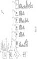
- FIGS. 13 and 14illustrate representative clinical processes for demonstrating use of the stimulation devices configured in accordance with embodiments of the present technology.
- Heading 1.0“Introduction”) below. Definitions of selected terms are provided under Heading 2.0 (“Definitions”). Representative treatment systems and their characteristics are described under Heading 3.0 (“Representative Systems”). Representative signal delivery parameters are described under Heading 4.0, representative indications and effects are described under Heading 5.0, representative clinical evaluations are described under Heading 6.0, representative pharmacological supplements are described under Heading 7.0, and further representative embodiments are described under Heading 8.0.
- the present technologyis directed generally to auricular nerve stimulation to address patient disorders, and associated systems and methods.
- electrical signalsare delivered to the auricular branches of the vagal nerve transcutaneously to address any of a variety of patient disorders, including for, example rheumatoid arthritis, migraine headache, and asthma. Further disorders treatable by these techniques are described later herein.
- the electrical signalsare generally provided at frequencies ranging from about 15 kHz to about 50 kHz.
- the frequency of the signalis selected to be above the patient's auditory limit, so as to avoid inducing potentially unwanted side effects via the patient's hearing faculties.
- the physiological location to which the electrical signals are deliveredis deliberately selected to generate primarily or exclusively afferent signals. Accordingly, the effect of the stimulation can be limited to reducing the effects and/or the underlying causes of the patient disorder, via stimulation that targets particular brain regions, without the signals inadvertently stimulating other (e.g., peripheral) nerves of the patient.
- the terms “modulate,” “modulation,” “stimulate,” and “stimulation”refer generally to signals that have an inhibitory, excitatory, and/or other effect on a target neural population. Accordingly, a “stimulator,” “electrical stimulation” and “electrical therapy signals” can have any of the foregoing effects on certain neural populations, via electrical communication (e.g., interaction) with the target neural population(s).
- auricular nerveincludes the auricular branch of the vagal nerve (sometimes referred to as Arnold's nerve or aVN), as well as other auricular nerves, for example, the greater auricular nerve, and/or the trigeminal nerve.
- therapeutically-effective amountrefers to the amount of a biologically active agent needed to initiate and/or maintain the desired beneficial result.
- the amount of the biologically active agent employedwill be that amount necessary to achieve the desired result. In practice, this will vary widely depending upon the particular biologically active agent being delivered, the site of delivery, and the dissolution and release kinetics for delivery of the biologically active agent (including whether the agent is delivered topically, orally, and/or in another manner), and the patient's individual response to dosing.
- paresthesiarefers generally to an induced sensation of numbness, tingling, prickling (“pins and needles”), burning, skin crawling, and/or itchiness.
- the computing devices on/in which the described technology can be implementedmay include one or more central processing units, memory, input devices (e.g., input ports), output devices (e.g., display devices), storage devices, and network devices (e.g., network interfaces).
- the memory and storage devicesare computer-readable media that may store instructions that implement the technology.
- the computer-(or machine-) readable mediaare tangible media.
- the data structures and message structuresmay be stored or transmitted via an intangible data transmission medium, such as a signal on a communications link.
- Various suitable communications linksmay be used, including but not limited to a local area network and/or a wide-area network.
- FIG. 1illustrates the general physiology of the external portion of a human ear 180 , indicating a representative target region 195 at which the electrical signals are applied.
- the external ear 180includes the helix 181 partially encircling the triangular fossa 182 and the scaphoid fossa 184 , and terminating at the lobule or lobe 190 .
- the concha 191is positioned inwardly from the antihelix 185 , and includes the cymba concha 192 and cavum concha 193 , bounded by the tragus 187 and separated from the cymba concha 192 by the helix crus 186 .
- the skin 196 of the external ear 180extends into the external ear canal 194 , which terminates at the ear drum (not visible in FIG. 1 ).
- the auricular branch of the vagus nerve 197innervates the ear 180 , and the target region 195 is generally over and/or adjacent the auricular branch 197 .
- the target region 195is positioned primarily at the concha 191 and can extend at least partially into the ear canal 194 .
- Devices configured in accordance with embodiments of the present technologyare configured not only to deliver electrical therapy signals to the target region 195 , but to provide a comfortable, repeatable, and in at least some embodiments, patient-specific, structures and therapy signals for doing so.
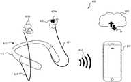
- FIG. 2is a partially schematic illustration of a representative system 100 for transcutaneously delivering electrical therapy signals to the auricular branches of the patient's vagus nerves, in accordance with representative embodiments of the present technology.
- the system 100includes a signal generator 110 coupled to one or more earpieces 120 (shown as a left earpiece 120 a and a right earpiece 120 b ), and an external controller 130 .
- the signal generator 110can include a housing 111 that encloses or partially encloses signal generating circuitry 114 .
- the signal generating circuitry 114can be controlled by an internal controller 108 , e.g., a processor 113 that accesses instructions stored in a memory 112 .
- the signal generator 110can include a signal transmission port 115 for communicating with the earpieces 120 , e.g., transmitting an electrical therapy signal to the earpieces 120 , and optionally, receiving feedback or other communications from the earpieces 120 .
- the electrical therapy signalis in electrical communication with the target neural population to create a desired effect on the target neural population.
- a communications transceiver 116provides for communication between the signal generator 110 and the external controller 130 .
- the earpieces 120can be coupled to the signal generator 110 via one or more earpiece links 121 .
- the earpiece link 121includes a wired link e.g., a cable or other elongated conductor.
- the earpiece link 121can include a wireless connection.
- the earpiece link or links 121can be connected to each of the earpieces 120 to provide the same input to each, or differentiated inputs to each.
- the earpiece link(s) 121can also direct communications (e.g., patient data) back to the signal generator 110 , e.g., from sensors carried by the earpieces 120 .
- the signal generator 110can be configured to rest on any suitable surface (e.g., a table top), or can be carried by the patient in the patient's hand or in a holster or in another suitable manner.
- the signal generator 110can be powered by a power source 117 , e.g., one or more batteries (e.g., rechargeable batteries) and/or an external power source.
- the signal generator 110is controlled by the external controller 130 via a controller link 132 .
- the external controller 130can include a cellular phone or other mobile device (e.g., a smartwatch), and can access a specific phone-based app 131 to provide controls to the signal generator 110 .
- a physician or other suitable practitionercan set the stimulation parameters at the signal generator 110 via the external controller 130 , and the patient and/or the practitioner can update the signal delivery parameters via the same or a different external controller 130 .
- the practitionermay have control over more parameters than the patient does, for example, to better control possible patient outcomes.
- the practitioner(and/or others) may direct or otherwise affect the internal controller 108 remotely via the external controller 130 and/or other devices, e.g., a backend device as described further with reference to FIG. 4 .
- FIGS. 3A and 3Billustrate a representative earpiece 320 by itself ( FIG. 3A ) and in position on the patient's ear 180 ( FIG. 3B ).
- the earpiece 320includes two electrodes 322 , and an earpiece link 321 for communication with the associated signal generator.
- the two electrodes 322are positioned to provide a transcutaneous, bipolar signal to the patient's ear.
- the earpiece 320is positioned at the patient's ear 180 , with a portion of the earpiece 320 extending behind the helix 181 for support, and with the electrodes 322 positioned at the target region 195 , e.g., against the patient's skin 196 at the concha 191 .
- This positioninghas been demonstrated in a clinical setting to provide effective therapy for the patient.
- other earpiece configurationscan provide additional positioning precision and/or patient comfort.
- FIG. 4is a partially schematic illustration of a representative system 400 configured in accordance with the present technology.
- the system 400includes a signal generator 410 that has a generally horseshoe-shaped housing 411 so as to fit comfortably around the patient's neck when in use, and may accordingly be referred to herein as a neckpiece.
- the housing 411can in turn include the internal components described above with reference to FIG. 2 .
- Two earpiece links 421(e.g., in the form of flexible cables) connect the signal generator 410 to corresponding earpieces 420 a , 420 b , which each carry two electrodes 422 .
- the signal generator 410can be controlled by an external controller 430 via a wireless controller link 432 .
- the external controller 430can accordingly be used to set and/or adjust the signal delivery parameters in accordance with which the signal generator 410 provides therapeutic electrical signals to the earpieces 420 .
- the external controller 430can also communicate with a backend device 440 (e.g., a server or other suitable device located on the cloud or other medium) via a backend link 441 . Accordingly, the external controller 430 can exchange data with the backend 440 .
- the external controller 430can provide the backend 440 with information about the patient's condition (e.g., obtained from feedback sensors included in the system 400 ), and/or a schedule of the signal delivery parameters selected by the patient or practitioner over the course of time.
- the backend 440can be used to provide updates to the phone-based app or other software contained on the external controller 430 .
- the allocation of processing tasks and/or data storage between the internal controller 108 ( FIG. 2 ), the external controller 430 and the backend 440can be selected to suit the preferences of the patient, practitioner, and/or others.
- FIGS. 5A and 5Bfurther illustrate features of the system 400 described above with reference to FIG. 4 .
- FIG. 5Aillustrates the signal generator 410 as including an input device 418 and an output device 419 .
- the input device 418can include a button or other element to activate or deactivate the signal generator 410 .
- the output device 419can include an LED or other element to indicate when the signal generator 410 is on.
- the input device 418 and/or the output device 419can be used to perform other suitable functions.
- the output device 419can provide an audible tone or other alert if the earpiece(s) 120 are not correctly positioned.
- the input device 418can accept user inputs (as described above), or can be a sensor, e.g., a proximity sensor that detects contact with the patient's skin, via an impedance measurement or otherwise and is coupled to the output device 419 to provide the alert.
- the frequency of the alert tonecan be patient-specific because, as described later, different patients may have different hearing ranges.
- FIG. 5Bschematically illustrates a portion of the signal generator 410 , with part of the housing 411 cut away to illustrate a printed circuit board 409 .
- the printed circuit board 409can carry the internal components described above with reference to FIG. 2 , and is coupled to the earpiece link 421 .
- FIGS. 6A and 6Billustrate front and rear views, respectively, of a representative earpiece 620 configured to fit a variety of patient physiologies.
- the earpiece 620includes two electrodes 622 positioned to provide transcutaneous stimulation to the target region 195 ( FIG. 1 ).
- the earpiece 620includes features configured to provide for patient comfort and to securely, yet removably, keep the electrodes 622 in position at the target region.
- the earpiece 620can include a bulging, flexible portion 670 that provides for snug contact between the electrodes 622 and the patient's skin at the target region. This approach can make device placement more consistent and repeatable across a patient population.
- the earpieces shown in FIGS. 6A and 6Bmay be fungible items that are replaced periodically due to normal wear. Accordingly, the earpieces can be configured to separate from the rest of the system for replacement.
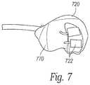
- FIG. 7illustrates another representative earpiece 720 having electrodes 722 .
- the electrodes 722can have a shape other than the circular shape shown in FIGS. 6A and 6B .
- the electrodes 722can have a rectangular shape.
- the electrode 722can have an ovoid shape or other shape that is specific to one or more patients, e.g., based on patient physiology.
- the earpiece 720 shown in FIG. 7can be custom-made to fit a particular patient. For example, comparing the earpiece 720 shown in FIG. 7 with the earpiece 620 shown in FIG. 6A , it is evident that the flexible portion 770 of the custom-made earpiece 720 is larger and bulges outwardly more than the corresponding flexible portion 670 shown in FIG. 6A . The custom earpiece 720 can accordingly fit better in the particular patient's ear.
- Representative techniques for forming the earpiece 720can include making a mold of the patient's ear and, for at least a portion of the earpiece, duplicating the contours of the mold so as to fit in the patient's ear.
- many of the processescan be performed digitally, e.g., using 3-D imaging techniques to identify the contours of the patient's ear, and 3-D additive manufacturing techniques or computer-controlled subtractive manufacturing techniques to form the earpiece contours.
- the earpiecemay be constructed from materials that are soft and moldable (e.g., 10-60 on the Shore A hardness scale). Accordingly, the earpiece can form a tight and/or “snug” fit in the patient's ear to position the electrodes at the target region (e.g., the concha, and in particular cases, the cymba concha).
- the custom fitmay be achieved via moldable plastic materials.
- the custom fitmay be achieved by the use of materials with appropriate stickiness of tackiness that can mold to and remain tightly and snug on the outer area of the patient's ear and target the concha without the discomfort or suboptimal connections found in devices that can only be secured by entering the ear canal.
- the conformal nature of the earpiececan produce an electrode-to-skin contact area in a range of from 20% to 100% of the exposed electrode surface area. This intimate contact can further reduce the likelihood for generating paresthesia, because less energy is required to be delivered to the electrode to achieve a therapeutic effect.
- An advantage of a custom earpieceis that it is likely to be more comfortable and/or provide more effective therapy than a standard-size earpiece. Conversely, the standard-sized earpiece is likely to be less expensive to manufacture. Accordingly, in some instances, patients and practitioners can use standard earpieces where practical, and custom earpieces as needed.
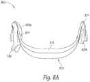
- FIGS. 8A and 8Billustrate another representative system 800 having a signal generator 810 , earpieces 820 a , 820 b , and earpiece links 821 , all of which are integrated to provide a unitary, single-piece device.
- the signal generator 810can include a housing 811 that houses the earpiece links 821 (in addition to the signal generating circuitry), and directly supports the earpieces 820 a , 820 b .
- the earpieces 820 a , 820 bcan be removable from the housing 811 for periodic replacement (as discussed above), but the housing 811 can nevertheless provide a more robust support for the earpieces than the flexible cable described above with reference to FIG. 2 .
- the patientuses a one-piece configuration as shown in FIGS. 8A and 8B , or other configurations shown herein, can depend on patient preferences, and the degree to which the system provides consistent, effective treatment for the particular patient.
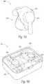
- FIGS. 9A and 9Billustrate a further representative system 900 in which the signal generator 910 is integrated with the earpiece 920 in a single housing 911 .
- each earpieceincludes a dedicated signal generator 910 .
- the signal generators 910can communicate with each other (e.g., wirelessly) to provide for consistent treatment.
- An advantage of the approach shown in FIG. 9Ais that it may be more comfortable and/or less cumbersome than devices that have the signal generators positioned some distance away from the earpieces. Conversely, devices with the signal generator positioned away from the earpieces may provide more stability for the earpieces, and/or increased patient comfort.
- FIG. 9Billustrates a representative charging station 950 for charging the signal generator 910 shown in FIG. 9A .
- the charging station 950can include a base 952 having multiple ports 951 (e.g., one port for each earpiece 920 ) and an optional cover 953 to protect the earpieces 920 during charging.
- the earpieces 920can be charged inductively so as to avoid the need for direct mechanical contact between electrical elements of the signal generator 910 and electrical elements of the charging station 950 .
- the charging station 950itself can receive power via a conventional wall outlet, battery, and/or other suitable source.
- FIGS. 10A-10Cillustrate a representative technique for manufacturing electrodes in accordance with embodiments of the present technology.
- a representative electrode 1022includes a backing 1023 , e.g., a fabric and/or textile with an acrylic adhesive, and/or a non-fabric (e.g., vinyl).
- the earpiece link 1021can include an insulated conductive wire with individual wire strands 1024 that are spread apart and placed against the backing 1023 .
- additional adhesive 1026is then used to secure the wire strands 1024 and backing 1023 to a conductive material 1025 (removed in FIG. 10B ) that contacts the patient's skin.
- FIG. 10Cis a partially schematic, cut-away illustration of the electrode 1022 illustrating the sandwich construction of the backing 1023 , the wire strands 1024 , and the conductive material 1025 .
- the conductive material 1025can include a conductive silicone and/or other polymer (e.g., a silicone impregnated with one or more conductive materials), which is comfortable to place against the patient's skin 196 .
- the practitioner or patientcan brush an electrically conductive solution 1029 on the conductive material 1025 .
- the solutionneed not be adhesive because the force used to keep the electrode 1022 in place is a mechanical force provided by other portions of the earpiece structure, which are in contact with the patient's skin.
- the conductive material 1025can be roughened or otherwise textured so as to retain the solution 1029 for the duration of a treatment period. As discussed in further detail below under Heading 4.0, individual treatment periods are relatively short in duration.
- the foregoing electrode design and production processallows a user (patient and/or practitioner) to adjust the surface properties to help better retain the solution 1029 between the electrode 1022 and the skin surface (e.g., via roughening, as described above). Further, the design can facilitate tuning the impedance across the electrode surface by arranging the conductor wires (e.g., formed from metal or carbon) in certain shapes. The electrodes described herein may also be designed to reduce current “hotspots” by features in the mold. In some embodiments, the electrode together with the earpiece housing or enclosure can include a built-in mechanism to apply the solution 1029 on the electrode surface before and/or after each use.
- the earpiece as a wholecan also maintain intimate contact with the skin at its functional surfaces by using features of the patient's ear as a lever, for example, providing intimate electrical contact at the cymba concha by pushing off the inside of the antitragus, or via alignment with the ear canal.
- FIGS. 11A-11Cillustrate a technique for larger scale production of the electrodes 1022 .
- FIGS. 11A-11Cillustrate top, bottom and cross-sectional views, respectively, of an intermediate stage of production in which the conductive material 1025 is positioned against a layer of foil 1027 (not visible in FIG. 11A ) so that portions of the conductive material 1025 project through openings 1028 to hold the conductive material 1025 in place.
- the foil 1027provides an electrical path to the electrodes 1022 .
- six (rectangular) electrodesare formed together and then separated prior to installation on corresponding earpieces.
- the representative systems described abovedeliver electrical signals to the patient in accordance with selected signal delivery parameters.
- the signal delivery parameterscan include the characteristics defining or describing the signal, and the location to which the signal is delivered.
- the signalis biphasic and is applied at a frequency in a range of about 15 kHz to about 50 kHz.
- FIG. 12is a schematic illustration of a representative signal 1260 .
- the signal(e.g., the signal wave form) includes anodic pulses 1261 and cathodic pulses 1262 separated by an interphase spacing 1264 . Individual pairs of anodic and cathodic pulses 1261 , 1262 can be separated from neighboring pairs by an interpulse spacing 1265 .
- Each pulsecan have a pulse width 1263 , which can be the same for anodic pulses 1261 as for cathodic pulses 1262 , or different, depending upon the embodiment.
- the repeating period of the signal 1266is made up of the anodic pulse 1261 , the cathodic pulse 1262 , the interphase spacing 1264 , and the interpulse spacing 1265 .
- the inverse of the period 1266corresponds to the frequency of the signal.
- At least a portion of the signal 1260has signal delivery parameters in the following ranges:
- the signal 1260(e.g., the values of the foregoing parameters) remain constant for the duration that the signal is delivered.
- one or all of the foregoing parameterscan vary, with the average value remaining in the foregoing ranges.
- the frequencycan be varied, while the average frequency remains within the foregoing range of about 15 kHz to about 50 kHz.
- Representative varying waveformsinclude Gaussian and/other non-linear waveforms.
- the average frequencycorresponds to the inverse of the average period of the signal taken over multiple periods.
- an individual periodis the sum of the anodic pulse width (e.g., a first pulse width), the cathodic pulse width (e.g., a second pulse width) of a neighboring pulse, the interphase spacing, and the interpulse spacing.
- the signalhas parameters within the foregoing ranges. Accordingly, in some embodiments, the signal may deviate from the foregoing ranges so long as doing so does not significantly impact the efficacy of the therapy and/or the comfort of the patient.
- the electrical therapy signalis typically delivered to the patient over the course of one or more sessions that have a limited duration.
- an individual sessiontypically lasts no longer than sixty minutes and is typically at least two seconds in duration.
- the durationranges from about two seconds to about thirty minutes, and in a further particular embodiment, the duration is from five minutes to twenty minutes, or about fifteen minutes.
- the patientcan receive treatment sessions at most once per day, at most twice per day, or at other suitable intervals, depending, for example, on the patient's response to the therapy. In a representative embodiment, the patient receives therapy in two 15 minute sessions, spaced apart by about 12 hours.
- the electrical therapy signalmay be referred to herein as a non-sensory response therapy signal.
- Undesirable sensory responsesinclude, in addition to or in lieu of paresthesia, a sensation of heat and/or pressure, and/or side effects related to the patient's hearing faculties.
- the frequency of the signalcan be deliberately selected to be above the patient's upper hearing threshold.
- the therapy signalWhile it is not believed that the therapy signal generates sound waves, it may nevertheless trigger an auditory response, e.g., a sensation of “ringing,” possibly through mechanical, bone, and/or far-field electrical conduction, and/or interactions with native mechanical acoustic damping systems, e.g., the tensor tympani muscle.
- the typical upper hearing threshold for a patientis at or below 15 kHz and accordingly, a signal having a frequency in the range of about 15 kHz to about 50 kHz can provide paresthesia-free stimulation, without triggering auditory effects. Because the upper threshold differs from patient to patient, the signal frequency can be selected on a patient-by-patient basis.
- patients having a reduced upper thresholdcan potentially receive a beneficial effect from stimulation toward the lower end of the above frequency range, or even below the above frequency range.
- the patient's upper auditory thresholdmay change over time.
- lower frequenciesmay consume less power, which can in turn allow the device applying the stimulation to be smaller, and/or to undergo fewer recharging cycles.
- the electrodes applying the stimulationare positioned to target the auricular branches of the patient's vagal nerve. It is expected that, by targeting the auricular branches, the effect of the signals will be limited to an afferent effect (e.g., affecting the brain) and not an efferent effect (e.g., affecting other peripheral nerves).
- An advantage of this arrangementis that the likelihood for inducing unwanted side effects is limited, and instead, the stimulation is focused on producing an effect on the patient's brain to provide a therapeutic result.
- Embodiments of the present technologyare suitable for treating a variety of patient indications.
- Representative indicationsinclude: (1) inflammatory indications (e.g., arthritis, rheumatoid arthritis, fibromyalgia, irritable bowel syndrome, Crohn's disease, asthma, psoriasis, Sjogren's Syndrome, autoimmune nephropathy (e.g., arthritis, rheumatoid arthritis, fibromyalgia, irritable bowel syndrome, Crohn's disease, asthma, psoriasis, Sjogren's Syndrome, autoimmune nephropathy (e.g.
- ⁇ indicationse.g., depression, post-partum depression, Alzheimer's disease, migraine, headaches, cluster headaches, epilepsy, and mood disorders
- sleep-related indicationse.g., insomnia, failure to achieve deep sleep, REM sleep behavior disorder, and parasomnia
- functional enhancemente.g., memory enhancement, associative learning
- pulmonary dysfunctionsasthma, allergic rhinitis, allergic bronchitis, exercise induced bronchoconstriction.
- the efficacy of the presently disclosed therapeutic techniquemay be correlated with changes in the brain's functioning.
- Representative affected areas of the brainmay include the insular cortex, the cingulate, the hypothalamus, subsets of the thalamic nuclear complex, the amygdala complex, bed nucleus of the stria terminalis, medial temporal lobe (hippocampus, parahippocampal gyrus and entorhinal cortex), elements of the basal ganglia (putamen, globus pallidus, caudate nucleus) and/or the prefrontal and/or orbital frontal cortex.
- fMRIfunctional magnetic resonance imaging
- the electrical therapy signalmay reduce at least one pro-inflammatory marker and/or increase at least one anti-inflammatory biomarker.
- the electrical therapy signaldoes not generate paresthesia in the patient. Paresthesia can contaminate the benefits of neurostimulation by causing competing brain signals that detract from the desired therapeutic effects. This may occur in part because paresthesia introduces confounding information in neuroimaging analysis such as functional magnetic resonance imaging and electroencephalography. Paresthesia-inducing stimulation modulates somatosensory neural circuits instead of solely targeting vagal neural circuits, which limits the interpretation of neuroimaging results. For example, modulation of the insula (a cortical region) is commonly cited as biomarker for vagus nerve stimulation efficacy. However, the insula is also implicated in pain/noxious stimulus processing and can be modulated via somatosensory pathways.
- paresthesia-inducing stimulationcan have a contaminating and/or contra-indicated impact.
- eliminating paresthesia from the treatment regimencan improve not only patient comfort and willingness to engage in the therapy, but also the ability of the practitioner to assess the efficacy of the therapy and make adjustment.
- Vorso Corp.the assignee of the present application, is currently conducting multiple prospective, multi-center pilot studies to research the safety, tolerability, and efficacy of devices configured in accordance with the present technology.
- One studyis directed to patients with moderate to severe active rheumatoid arthritis, as shown in FIG. 13 , and another is directed to patients with episodic migraine, as shown in FIG. 14 .
- the clinical process 1300includes an enrollment process 1301 (commencing about 35 days before treatment) and a screening process 1303 (starting at 8 days before treatment).
- enrollment process 1301comprising about 35 days before treatment
- screening process 1303starting at 8 days before treatment.
- patient eligibilityis determined.
- the inclusion/exclusion criteria for patients enrolled in the studyare those who have inadequate response to DMARDs (disease-modifying anti-rheumatic drugs), and who fail one biologic treatment, or are biologic naive.
- the studycommences (block 1307 ) with a number of patient metrics identified as a baseline. As indicated in FIG.
- the metricscan include the patient's medication intake, DAS28-CRP score, the patient's sleep characteristics, HAQ-DI score, ACR, and blood characteristics (including CRP (C-reactive proteins), analytics, CK, RF, and anti-CCP).
- the patientis also trained to use the device.
- the patient's progressis then tracked after one week (block 1309 ), two weeks (block 1311 ), four weeks (block 1313 ), eight weeks, (block 1315 ), and twelve weeks (block 1317 ).
- the patient metrics indicated in FIG. 13are measured and tracked.
- Vorso Corp.is also conducting fMRI (functional MRI) studies and the early results indicate that the therapy causes functional connectivity changes in brain regions associated with the regulation of inflammation.
- Vorso Corp.has also begun a study directed to safety and efficacy of devices in accordance with the foregoing description applied to patients with episodic migraine.
- the objective of the studyis to observe and evaluate the effect of the therapy on migraine and/or associated symptoms, in subjects who suffer four to fourteen migraine days per month.
- the clinical process 1400includes patient enrollment (block 1401 ), and eligibility determination (block 1403 ), with the study commencing at block 1405 .
- the primary metric during the studyis the patient's migraine diary, in which the patient records migraine events. In this study, the patient undergoes a one-month baseline period, during which the patient tracks migraine activity in the absence of an electrical therapy signal.
- the baseline diary recordingsare evaluated and, using an ear mold, the patient is outfitted with a custom earpiece, or two custom earpieces.
- the patientis trained to use the device.
- the remaining processesinclude evaluation at periodic intervals, including a one-month evaluation (block 1411 ), a two-month evaluation via telephone (block 1413 ), a three-month diary evaluation (block 1415 ), a four-month evaluation via telephone (block 1417 ), a five-month evaluation via telephone (block 1419 ), and final visit at six months (block 1421 ) during which the patient's diary evaluation is completed. Preliminary results are positive.
- the foregoing electrical therapy signalcan be provided as part of an overall treatment regimen that also includes administering a pharmacological/biological substance to the patient.
- the pharmacological/biological supplementwill increase the efficacy and/or duration of the electrical therapy, and/or that the electrical therapy can improve on the results obtained via a pharmacological treatment.
- the electrical therapy signalcan improve the therapeutic “window” for medication, which corresponds to the difference between efficacy and toxicity.
- Some of these pharmacological/biological drugshave severe dose-depending effects and it is expected that the electrical therapy can reduce the amount of drug needed by the patient and in effect limiting the side effects.
- the treatment regimencan include administering an effective amount of a pharmaceutical selected from, but not limited to, the following groups
- embodiments of the earpieces described aboveinclude pairs of electrodes that deliver bipolar signals.
- an individual earpiececan include a single, monopolar electrode, with a return electrode positioned remotely from the earpiece, or the earpiece can include more than two electrodes.
- the neckpiececan have configurations other than those specifically shown in the foregoing Figures.
- the amplitude at which the electrical therapy signal is deliveredcan be provided in the form of a step function that remains constant throughout the duration of the therapy, in some embodiments. In other embodiments, the amplitude of the signal can be ramped up gradually (e.g., over multiple incremental steps), for example, if the patient experiences sensory side effects, such as discomfort, when the amplitude is increased in a single step.
- the present technologyincludes methods for programming the systems for use.
- a physician or other practitionere.g., a company representative
- the patientmay have the ability to modify at least some of the parameters, for example, via the external controller.
- the communication pathways between the earpiece and the signal generator, and between the signal generator and the external controllercan be in two directions.
- the signal generatorcan receive information from the earpieces and/or other elements of the system and take actions based on that information.
- the earpiececan include a proximity sensor that indicates if the earpiece becomes dislodged or mispositioned during a treatment session.
- the systemcan further include a small speaker or other auditory feedback element that indicates to the patient that the position of the earpiece should be adjusted.
- the external controllercan track attributes of each treatment session, for example, the number of treatment sessions, the duration of the treatment sessions, the time of day of the treatment sessions and/or other data relevant to correlating the patient's response with the attributes of the treatment sessions.
- the systemcan include a wearable signal generator, e.g., in the form of a neckpiece or integrated with the earpieces (as described above), or in the form of a headband or other wearable.
- the earpiece(s)can include speakers to provide music and/or other audio input to the user (e.g., via the external controller).
- the systemcan include at least one sensor capable of sensing a body signal.
- the sensormay be selected from, without limitation, a cardiac sensor, a blood oxygenation sensor, a cardiorespiratory sensor, a respiratory sensor, and a temperature sensor.
- the electrodesthemselves can operate as sensors to detect proximity to the patient's skin, and/or impedance.
- One or more processors of the systemdetermine a body parameter based on the body signal.
- the processorcan calculate a heart rate, heart rate variability, parasympathetic tone, sympathetic tone, or sympathetic-parasympathetic balance from a cardiac signal; a pulse oximetry value from a blood oxygenation signal; a breathing rate or end tidal volume from a respiratory signal; and/or a sleep and/or exertional level from an accelerometer, gyroscope and/or GPS device coupled to the patient's body.
- the systemcan then use the body parameter to adjust one or more parameters in accordance with which the electrical signal is delivered (or not delivered). For example, the signal may be turned off if the patient's heart rate falls below a predetermined lower limit, or if activity levels become elevated or depressed.
- the senoris located on the skin of a lateral surface of the ear (i.e., the side of the ear facing toward the patient). In another embodiment, the sensor is externally located on the skin of the patient's head below the mastoid. In still further embodiments, the sensor can be positioned at a different location, and can be carried by the earpiece(s), the neckpiece, and/or another portion of the system.
- the electrical therapy signalcan be applied to just a single ear, or to both ears.
- the signalcan be the same for both, or at least one signal delivery parameter can differ for a signal applied to the right ear, as compared to a signal applied to the left ear.
- the signal(s)can be applied simultaneously or sequentially to each ear.
- the systemcan exploit the known difference in left versus right vagus nerves as principally an inflow or outflow system of the NTS (nucleus tractus solitarius), respectively.
- Afferent fibersaccessible in the tragal somatic representation of the vagus as well as sympathetic afferent neural inflows, will potentially enable the therapy signals in accordance with the present technology to impact visceral sensory signal integration at higher CNS (central nervous system) structures, including the NTS, RVLN (rostroventrolateral reticular nucleus), trigeminal nucleus, locus coeruleus, parabrachial nucleus, hypothalamus, subsets of the thalamus, and/or cortical structures related to autonomic functioning and/or the dorsal motor nucleus.
- CNScentral nervous system
- the therapy signalcan include waveforms other than that shown in FIG. 12 , e.g., a triangular waveform or a sinusoidal waveform.
- the therapy signalcan be applied continuously (e.g., a 100% duty cycle), or in accordance with a lower duty cycle, e.g., a 50% duty cycle or other duty cycle.
- the signalcan vary, as described above.
- the signalcan vary in an irregular, non-periodic manner, e.g., with bi-phasic pulses having a total duration of 50 us repeated randomly at from one microsecond to 100 microsecond intervals.
- the irregular waveformcan be characterized by the average number of zero crossing (as defined by a change in polarity) of the signal.
- the average number of zero crossings for any given second of the stimulation signalis 40,000 for a 20 kHz signal with bi-phasic rectangular pulses.
- the signalcan also be applied either simultaneously or alternatingly to other peripheral nerves to further enhance the therapeutic effect.
- the patient and/or practitionercan modify therapeutic doses of stimulation through a software application (an “app”) for a mobile electronic device (such as an iPhone or an Android-based mobile device) based on clinician guidelines and patients' adherence to the app.
- the systemcan include verbal response options to provide patients with verbal statements about the status of the therapy, feedback, and/or instructions; the ability to modulate the maximum amplitude (and/or other parameters) of the therapy for the user based on conditioning and/or other sensor responses; monitoring the count of the therapy doses by the app (and/or system hardware); and/or enable the patient to purchase a therapy session using the app or a companion device; enable clinicians to monitor the patients' conditions and responses to therapy over the internet; and/or allowing clinicians to change the parameters of the therapy via internet-enabled communications.
- Representative targets for the electrical therapy signalinclude the antihelix, tragus, antitragus, helix, scapha, triangular fossa, lobule, and/or a lateral surface of the ear (i.e., the side of the ear facing the patient), although it is expected that stimulation provided to the concha will produce superior results.
- the systemcan include a respiratory sensor that monitors the patient's respiratory exhalation and (a) activates the stimulator approximately at the start of each exhalation phase and (b) deactivates the stimulator approximately at the end of the each exhalation phase.
- the respiratory sensorcan use motion or acoustic monitoring technology to identify the start and end of each exhalation phase.
- the respiratory sensorcan be integrated in a chest or stomach belt, or integrated into a face mask. Further, the respiratory sensor can be have a band-aid-type form factor, and can placed on the patient's neck.
- the respiratory sensorcan include an optical sensor, such as a photoplethysmogram (PPG) sensor that is integrated with the earpiece.
- PPGphotoplethysmogram
- the disclosed electrical therapycan be applied alone or in combination with a pharmacological/biologic treatment.
- the therapycan be combined with still further therapy types (e.g., electrical stimulation at another location of the body) in addition to or in lieu of a combination with pharmacological/biologic treatments.
- a system for treating a patientcomprising:
- the signal generatorincludes a neckpiece positionable to be supported by the patient around the patient's neck, and wherein the system further comprises an earpiece link coupled between the neckpiece and the at least one earpiece.
- the at least one earpieceincludes a first earpiece shaped to fit the patient's right ear and a second earpiece shaped to fit the patient's left ear.
- a system for treating a patientcomprising:
- the signal generatorincludes a neckpiece positionable to be supported by the patient around the patient's neck, and wherein the system further comprises an earpiece link coupled between the neckpiece and the at least one earpiece.
- a method for treating a patientcomprising:
- applying an electrical therapy signalincludes applying the electrical therapy signal to only one of the patient's ears.
- applying an electrical therapy signalincludes applying at least one electrical therapy signal to both of the patient's ears.
- applying the electrical signalincludes applying the electrical signal to address an inflammatory condition of the patient.
- applying the electrical signalincludes applying the electrical signal to address a sleep disorder of the patient.
- applying the electrical signalincludes applying the electrical signal to address a neurological indication of the patient.
- applying the electrical signalincludes applying the electrical signal to enhance the patient's functioning.
- applying the electrical signalincludes applying the electrical signal to address a headache and/or migraine indication of the patient.
- applying the electrical signalincludes applying the electrical signal over the course of at most two sessions per day.
- auricular nerveincludes an auricular branch of the patient's vagal nerve.
- a method for making a patient treatment devicecomprising:
- example 55The method of example 53, further comprising forming the contoured outer surface of the at least one earpiece based at least in part on a patient-specific physiologic feature of the patient's ear.
- example 56The method of example 53, further comprising forming at least part of the at least one earpiece using an additive manufacturing technique.
Landscapes
- Health & Medical Sciences (AREA)
- Life Sciences & Earth Sciences (AREA)
- Engineering & Computer Science (AREA)
- Biomedical Technology (AREA)
- Nuclear Medicine, Radiotherapy & Molecular Imaging (AREA)
- Radiology & Medical Imaging (AREA)
- Animal Behavior & Ethology (AREA)
- General Health & Medical Sciences (AREA)
- Public Health (AREA)
- Veterinary Medicine (AREA)
- Biophysics (AREA)
- Heart & Thoracic Surgery (AREA)
- Otolaryngology (AREA)
- Pain & Pain Management (AREA)
- Child & Adolescent Psychology (AREA)
- Developmental Disabilities (AREA)
- Hospice & Palliative Care (AREA)
- Neurology (AREA)
- Psychiatry (AREA)
- Psychology (AREA)
- Social Psychology (AREA)
- Electrotherapy Devices (AREA)
Abstract
Description
- Frequency: about 15 kHz to about 50 kHz, or about 20 kHz to about 50 kHz or 20 kHz
- Amplitude: about 0.1 mA to about 10 mA, or about 1 mA to about 5 mA, or about 2 mA to about 4 mA
- Pulse width: about 5 microseconds to about 30 microseconds, e.g., about 20 microseconds
- Interphase spacing: about one to about 10 microseconds
- Interpulse spacing: about one to about 15 microseconds
- Duty cycle: on-period of 0.1 seconds-15 minutes
- off-period of 0.1 seconds-15 minutes
- DAS28-CRP (Disease Activity Score 28, using the C-Reactive Protein)
- ECG (electrocardiogram)
- CRP (C-Reactive Protein)
- MRI (Magnetic Resonance Imaging
- HAQ-DI (Health Assessment Questionnaire Disability Index)
- CK (creatine kinase)
- RF (rheumatoid factor)
- Anti-CCP (Anti-cyclic citrullinated peptide)
- csDMARD (conventional synthetic disease modifying antirheumatic arthritis drug) group including, but not limited to, methotrexate, sulfasalazine, leflunomide, hydroxychloroquine, gold salts;
- bDMARD (biological disease modifying antirheumatic arthritis drug) group including, but not limited to, abatacept, adalimumab, anakinra, etanercept, golimumab, infliximab, rituximab and tocilizumab;
- tsDMARD (targeted synthetic disease modifying antirheumatic arthritis drug) group including, but not limited to, tofacitinib, baricitinib, filgotinib, peficitinib, decernotinib and upadacitinib; and/or
- CGRP (calcitonin gene-related peptide) inhibitor drug group including, but not limited to, erenumab, fremanezumab, galcanezumab and Eptinezumab.
- Agents useful in the treatment of asthma include inhaled corticosteroids, leukotriene modifiers, long-acting beta agonists (LABAs), theophylline, short-acting beta agonists such as albuterol, ipratropium (Atrovent®), intravenous corticosteroids (for serious asthma attacks), allergy shots (immunotherapy), and omalizumab (Xolair®).
- a signal generator having instructions to generate an electrical therapy signal, at least a portion of the electrical therapy signal having:
- a frequency at or above the patient's auditory frequency limit;
- an amplitude in an amplitude range from about 0.1 mA to about 10 mA; and
- a pulse width in a pulse width range from 5 microseconds to 30 microseconds; and
- at least one earpiece having a contoured outer surface shaped to fit against the skin of the patient's external ear, external ear canal, or both, the at least one earpiece carrying at least two transcutaneous electrodes positioned to be in electrical communication with an auricular nerve of the patient.
- a signal generator having instructions to generate an electrical therapy signal, at least a portion of the electrical therapy signal having:
- a signal generator having instructions to generate an electrical therapy signal, at least a portion of the electrical therapy signal having:
- an average frequency at or above the patient's auditory frequency limit, wherein the average frequency is the inverse of the average period of the signal over multiple periods, and wherein individual periods are the sum of a first pulse width of a first pulse at a first polarity, neighboring, second pulse at a second polarity opposite the first polarity, an interphase period between the first and second pulses, and an interpulse period between the second pulse and the next pulse of the first polarity;
- an amplitude in an amplitude range from 0.1 mA to 10 mA; and
- a pulse width in a pulse width range from 5 microseconds to 30 microseconds; and
- at least one earpiece having a contoured outer surface shaped to fit against the skin of the patient's external ear, external ear canal, or both, the at least one earpiece carrying at least two transcutaneous electrodes positioned to be in electrical communication with an auricular nerve of then patient.
- a signal generator having instructions to generate an electrical therapy signal, at least a portion of the electrical therapy signal having:
- applying an electrical therapy signal to an auricular nerve of the patient via a plurality of transcutaneous electrodes carried by an earpiece positioned against the skin of the patient's external ear, external ear canal, or both; and
- wherein at least a portion of the electrical therapy signal has:
- a frequency at or above the patient's auditory frequency limit;
- an amplitude in an amplitude range from 0.1 mA to 10 mA; and
- a pulse width in a pulse width range from 5 microseconds to 30 microseconds.
- programming a signal generator to produce an electrical therapy signal, at least a portion of the electrical therapy signal having:
- a frequency at or above the patient's auditory threshold;
- an amplitude in an amplitude range from about 0.1 mA to about 10 mA; and
- a pulse width in a pulse width range from about 5 microseconds to about 30 microseconds; and
- coupling the signal generator to at least one earpiece having a contoured outer surface shaped to fit against the skin of the patient's external ear, external ear canal, or both, the at least one earpiece carrying at least two transcutaneous electrodes positioned to be in electrical communication with an auricular nerve of the patient.
- programming a signal generator to produce an electrical therapy signal, at least a portion of the electrical therapy signal having:
Claims (14)
Priority Applications (1)
| Application Number | Priority Date | Filing Date | Title |
|---|---|---|---|
| US17/115,665US11123558B2 (en) | 2018-09-24 | 2020-12-08 | Auricular nerve stimulation to address patient disorders, and associated systems and methods |
Applications Claiming Priority (6)
| Application Number | Priority Date | Filing Date | Title |
|---|---|---|---|
| US201862735492P | 2018-09-24 | 2018-09-24 | |
| US201862785205P | 2018-12-26 | 2018-12-26 | |
| US201962891203P | 2019-08-23 | 2019-08-23 | |
| US16/581,139US10835747B2 (en) | 2018-09-24 | 2019-09-24 | Auricular nerve stimulation to address patient disorders, and associated systems and methods |
| US17/066,404US11376430B2 (en) | 2018-09-24 | 2020-10-08 | Auricular nerve stimulation to address patient disorders, and associated systems and methods |
| US17/115,665US11123558B2 (en) | 2018-09-24 | 2020-12-08 | Auricular nerve stimulation to address patient disorders, and associated systems and methods |
Related Parent Applications (1)
| Application Number | Title | Priority Date | Filing Date |
|---|---|---|---|
| US17/066,404ContinuationUS11376430B2 (en) | 2018-09-24 | 2020-10-08 | Auricular nerve stimulation to address patient disorders, and associated systems and methods |
Publications (2)
| Publication Number | Publication Date |
|---|---|
| US20210085972A1 US20210085972A1 (en) | 2021-03-25 |
| US11123558B2true US11123558B2 (en) | 2021-09-21 |
Family
ID=69883864
Family Applications (5)
| Application Number | Title | Priority Date | Filing Date |
|---|---|---|---|
| US16/581,139ActiveUS10835747B2 (en) | 2018-09-24 | 2019-09-24 | Auricular nerve stimulation to address patient disorders, and associated systems and methods |
| US16/818,977ActiveUS10806928B2 (en) | 2018-09-24 | 2020-03-13 | Auricular nerve stimulation to address patient disorders, and associated systems and methods |
| US17/066,404ActiveUS11376430B2 (en) | 2018-09-24 | 2020-10-08 | Auricular nerve stimulation to address patient disorders, and associated systems and methods |
| US17/115,665ActiveUS11123558B2 (en) | 2018-09-24 | 2020-12-08 | Auricular nerve stimulation to address patient disorders, and associated systems and methods |
| US17/805,220Active2040-03-10US12186557B2 (en) | 2018-09-24 | 2022-06-02 | Auricular nerve stimulation to address patient disorders, and associated systems and methods |
Family Applications Before (3)
| Application Number | Title | Priority Date | Filing Date |
|---|---|---|---|
| US16/581,139ActiveUS10835747B2 (en) | 2018-09-24 | 2019-09-24 | Auricular nerve stimulation to address patient disorders, and associated systems and methods |
| US16/818,977ActiveUS10806928B2 (en) | 2018-09-24 | 2020-03-13 | Auricular nerve stimulation to address patient disorders, and associated systems and methods |
| US17/066,404ActiveUS11376430B2 (en) | 2018-09-24 | 2020-10-08 | Auricular nerve stimulation to address patient disorders, and associated systems and methods |
Family Applications After (1)
| Application Number | Title | Priority Date | Filing Date |
|---|---|---|---|
| US17/805,220Active2040-03-10US12186557B2 (en) | 2018-09-24 | 2022-06-02 | Auricular nerve stimulation to address patient disorders, and associated systems and methods |
Country Status (6)
| Country | Link |
|---|---|
| US (5) | US10835747B2 (en) |
| EP (1) | EP3857916A4 (en) |
| JP (1) | JP2022502139A (en) |
| CN (1) | CN113711623A (en) |
| AU (1) | AU2019346417A1 (en) |
| WO (1) | WO2020068830A1 (en) |
Cited By (1)
| Publication number | Priority date | Publication date | Assignee | Title |
|---|---|---|---|---|
| WO2024084306A1 (en)* | 2022-10-21 | 2024-04-25 | Fundacion Cardiovascular De Colombia | Portable vagus-nerve electrostimulation device synchronised with the breathing cycle |
Families Citing this family (31)
| Publication number | Priority date | Publication date | Assignee | Title |
|---|---|---|---|---|
| US12201427B2 (en) | 2012-06-14 | 2025-01-21 | Medibotics Llc | Headband with brain activity sensors |
| BR112015017042B1 (en) | 2013-01-21 | 2022-03-03 | Cala Health, Inc | Device to treat tremor |
| US9662269B2 (en) | 2013-10-22 | 2017-05-30 | Innovative Health Solutions, Inc. | Systems and methods for auricular peripheral nerve field stimulation |
| CA2949843A1 (en) | 2014-06-02 | 2015-12-10 | Cala Health, Inc. | Systems and methods for peripheral nerve stimulation to treat tremor |
| EP4342516A3 (en) | 2015-06-10 | 2024-07-10 | Cala Health, Inc. | Systems and methods for peripheral nerve stimulation to treat tremor with detachable therapy and monitoring units |
| WO2017053847A1 (en) | 2015-09-23 | 2017-03-30 | Cala Health, Inc. | Systems and methods for peripheral nerve stimulation in the finger or hand to treat hand tremors |
| CA3011993C (en) | 2016-01-21 | 2024-05-14 | Cala Health, Inc. | Systems, methods and devices for peripheral neuromodulation for treating diseases related to overactive bladder |
| CA3033662A1 (en) | 2016-08-25 | 2018-03-01 | Cala Health, Inc. | Systems and methods for treating cardiac dysfunction through peripheral nerve stimulation |
| EP3606604A4 (en) | 2017-04-03 | 2020-12-16 | Cala Health, Inc. | SYSTEMS, METHODS AND DEVICES FOR PERIPHERAL NEUROMODULATION FOR THE TREATMENT OF DISEASES RELATED TO OVERACTIVE BLADDER |
| EP3740274A4 (en) | 2018-01-17 | 2021-10-27 | Cala Health, Inc. | Systems and methods for treating inflammatory bowel disease through peripheral nerve stimulation |
| CA3096494A1 (en)* | 2018-04-26 | 2020-02-20 | Innovative Health Solutions, Inc. | Auricular nerve field stimulation device |
| AU2019346417A1 (en) | 2018-09-24 | 2021-04-15 | Nextsense, Inc. | Auricular nerve stimulation to address patient disorders, and associated systems and methods |
| US12251560B1 (en) | 2019-08-13 | 2025-03-18 | Cala Health, Inc. | Connection quality determination for wearable neurostimulation systems |
| US11890468B1 (en) | 2019-10-03 | 2024-02-06 | Cala Health, Inc. | Neurostimulation systems with event pattern detection and classification |
| US12390659B2 (en)* | 2019-11-12 | 2025-08-19 | Lew Lim | Apparatus and method for photobiomodulation-based alternative to electrical vagus nerve stimulation and deep brain stimulation related to movement disorders |
| GB202011522D0 (en)* | 2020-07-24 | 2020-09-09 | Afferent Medical Solutions Ltd | Neuromodulation for the treatment of circulatory system diseases |
| WO2022031874A1 (en)* | 2020-08-06 | 2022-02-10 | The Feinstein Institutes For Medical Research | Compact auricular stimulation device |
| KR102438009B1 (en)* | 2020-08-28 | 2022-08-30 | 고려대학교 산학협력단 | Close contact type Nerve stimulator |
| KR102438007B1 (en)* | 2020-08-28 | 2022-08-30 | 고려대학교 산학협력단 | Adjustable and detachable nerve stimulator |
| TR202022374A1 (en)* | 2020-12-30 | 2022-07-21 | Vagustim Saglik Teknolojileri Anonim Sirketi | A SYSTEM AND METHOD IN THE TREATMENT OF DISEASES AND DISEASES, IN WHICH THE AURICULAR VAGUS NERVE IS EXCITTED WITH DISCRETE DIRECT CURRENT |
| US12324926B2 (en) | 2021-06-07 | 2025-06-10 | Neuraxis, Inc. | Device and method for eradicating pathogens in nasal passages |
| CN113577564B (en)* | 2021-07-29 | 2024-03-08 | 英特格拉医疗保健仪器研发公司 | Ear vagus nerve stimulation device and method for stimulating ear vagus nerve |
| KR102604276B1 (en)* | 2021-11-26 | 2023-11-23 | 주식회사 뉴라이브 | Control method of complex stimulation and complex stimulation device |
| KR102604287B1 (en)* | 2021-11-26 | 2023-11-23 | 주식회사 뉴라이브 | Control method of vagus nerve stimulation |
| WO2023149857A1 (en)* | 2022-02-04 | 2023-08-10 | Vagustim Saglik Teknolojileri As | System where treatment of diseases and disorders is realized by electrical stimulation of nerves and method of operation for said system |
| WO2024038263A1 (en)* | 2022-08-14 | 2024-02-22 | Earswitch Ltd | Ear apparatus |
| GB202211871D0 (en)* | 2022-08-14 | 2022-09-28 | Earswitch Ltd | Method and device effecting differential stimulation to locations of ear tissues |
| WO2024071994A1 (en)* | 2022-09-26 | 2024-04-04 | 주식회사 뉴라이브 | Motion sickness prevention and mitigation electronic device |
| JP1753085S (en)* | 2022-10-11 | 2023-09-14 | Image for icon | |
| WO2024164003A1 (en)* | 2023-02-03 | 2024-08-08 | Washington University | Transcutaneous auricular vagal nerve stimulation for enhanced learning |
| EP4578487A1 (en)* | 2023-12-28 | 2025-07-02 | Xana Stim Sárl | A system for bilateral auricular nerve stimulation of the vagus nerve |
Citations (135)
| Publication number | Priority date | Publication date | Assignee | Title |
|---|---|---|---|---|
| US4702254A (en) | 1983-09-14 | 1987-10-27 | Jacob Zabara | Neurocybernetic prosthesis |
| US4867164A (en) | 1983-09-14 | 1989-09-19 | Jacob Zabara | Neurocybernetic prosthesis |
| US5025807A (en) | 1983-09-14 | 1991-06-25 | Jacob Zabara | Neurocybernetic prosthesis |
| US5215086A (en) | 1991-05-03 | 1993-06-01 | Cyberonics, Inc. | Therapeutic treatment of migraine symptoms by stimulation |
| US5231988A (en) | 1991-08-09 | 1993-08-03 | Cyberonics, Inc. | Treatment of endocrine disorders by nerve stimulation |
| US5263480A (en) | 1991-02-01 | 1993-11-23 | Cyberonics, Inc. | Treatment of eating disorders by nerve stimulation |
| US5269303A (en) | 1991-02-22 | 1993-12-14 | Cyberonics, Inc. | Treatment of dementia by nerve stimulation |
| US5299569A (en) | 1991-05-03 | 1994-04-05 | Cyberonics, Inc. | Treatment of neuropsychiatric disorders by nerve stimulation |
| US5330515A (en) | 1992-06-17 | 1994-07-19 | Cyberonics, Inc. | Treatment of pain by vagal afferent stimulation |
| US5335657A (en) | 1991-05-03 | 1994-08-09 | Cyberonics, Inc. | Therapeutic treatment of sleep disorder by nerve stimulation |
| US5458625A (en) | 1994-05-04 | 1995-10-17 | Kendall; Donald E. | Transcutaneous nerve stimulation device and method for using same |
| US5540730A (en) | 1995-06-06 | 1996-07-30 | Cyberonics, Inc. | Treatment of motility disorders by nerve stimulation |
| US5707400A (en) | 1995-09-19 | 1998-01-13 | Cyberonics, Inc. | Treating refractory hypertension by nerve stimulation |
| US5713923A (en) | 1996-05-13 | 1998-02-03 | Medtronic, Inc. | Techniques for treating epilepsy by brain stimulation and drug infusion |
| US20020090099A1 (en) | 2001-01-08 | 2002-07-11 | Hwang Sung-Gul | Hands-free, wearable communication device for a wireless communication system |
| US6587719B1 (en) | 1999-07-01 | 2003-07-01 | Cyberonics, Inc. | Treatment of obesity by bilateral vagus nerve stimulation |
| US6610713B2 (en) | 2000-05-23 | 2003-08-26 | North Shore - Long Island Jewish Research Institute | Inhibition of inflammatory cytokine production by cholinergic agonists and vagus nerve stimulation |
| US6622041B2 (en) | 2001-08-21 | 2003-09-16 | Cyberonics, Inc. | Treatment of congestive heart failure and autonomic cardiovascular drive disorders |
| US20060095088A1 (en)* | 2004-10-21 | 2006-05-04 | Dirk De Ridder | New stimulation design for neuromodulation |
| US20060100672A1 (en) | 2004-11-05 | 2006-05-11 | Litvak Leonid M | Method and system of matching information from cochlear implants in two ears |
| US20060122675A1 (en) | 2004-12-07 | 2006-06-08 | Cardiac Pacemakers, Inc. | Stimulator for auricular branch of vagus nerve |
| US20060178703A1 (en) | 2004-12-27 | 2006-08-10 | Huston Jared M | Treating inflammatory disorders by electrical vagus nerve stimulation |
| US20060206165A1 (en) | 2005-03-14 | 2006-09-14 | Jaax Kristen N | Occipital nerve stimulation to treat headaches and other conditions |
| US7167750B2 (en) | 2003-02-03 | 2007-01-23 | Enteromedics, Inc. | Obesity treatment with electrically induced vagal down regulation |
| US20070027504A1 (en) | 2005-07-27 | 2007-02-01 | Cyberonics, Inc. | Cranial nerve stimulation to treat a hearing disorder |
| US20070250145A1 (en) | 2005-01-26 | 2007-10-25 | Cerbomed Gmbh | Device for the transdermal stimulation of a nerve of the human body |
| US20080021517A1 (en) | 2006-07-18 | 2008-01-24 | Cerbomed Gmbh | Audiological transmission system |
| US20080021520A1 (en) | 2006-07-18 | 2008-01-24 | Cerbomed Gmbh | System for the transcutaneous stimulation of a nerve in the human body |
| US20080051852A1 (en) | 2006-01-21 | 2008-02-28 | Cerbomed Gmbh | Device and method for the transdermal stimulation of a nerve of the human body |
| US7346395B2 (en) | 2003-06-19 | 2008-03-18 | Advanced Neuromodulation Systems, Inc. | Method of treating depression, mood disorders and anxiety disorders using neuromodulation |
| US20080082153A1 (en) | 2006-09-29 | 2008-04-03 | Peter Gadsby | Medical electrode |
| US20080249594A1 (en) | 2006-05-20 | 2008-10-09 | Cerbomed Gmbh | Device for applying a transcutaneous stimulus or for transcutaneous measuring of a parameter |
| US20090287035A1 (en) | 2008-05-13 | 2009-11-19 | Cerbomed Gmbh | Method to enhance neural tissue operation |
| US20100160996A1 (en) | 2008-12-18 | 2010-06-24 | Electrocore, Inc. | Methods and apparatus for electrical stimulation treatment using esophageal balloon and electrode |
| US7784583B1 (en) | 2005-04-25 | 2010-08-31 | The United States Of America As Represented By The Secretary Of The Air Force | Deep insertion vented earpiece system |
| US7801601B2 (en) | 2006-01-27 | 2010-09-21 | Cyberonics, Inc. | Controlling neuromodulation using stimulus modalities |
| US20110046432A1 (en) | 2005-11-10 | 2011-02-24 | Electrocore Inc. | Non-invasive treatment of bronchial constriction |
| US20110125203A1 (en) | 2009-03-20 | 2011-05-26 | ElectroCore, LLC. | Magnetic Stimulation Devices and Methods of Therapy |
| US20110166624A1 (en) | 2005-01-26 | 2011-07-07 | Cerbomed Gmbh | Device for the transdermal stimulation of a nerve of the human body |
| US20110230701A1 (en) | 2009-03-20 | 2011-09-22 | ElectroCore, LLC. | Electrical and magnetic stimulators used to treat migraine/sinus headache and comorbid disorders |
| US20110230938A1 (en) | 2009-03-20 | 2011-09-22 | ElectroCore, LLC. | Device and methods for non-invasive electrical stimulation and their use for vagal nerve stimulation |
| US20110238141A1 (en) | 2006-09-21 | 2011-09-29 | Lockheed Martin Corporation | Miniature method and apparatus for optical stimulation of nerves and other animal tissue |
| US20110276107A1 (en) | 2005-11-10 | 2011-11-10 | ElectroCore, LLC. | Electrical and magnetic stimulators used to treat migraine/sinus headache, rhinitis, sinusitis, rhinosinusitis, and comorbid disorders |
| US20110276112A1 (en) | 2009-03-20 | 2011-11-10 | ElectroCore, LLC. | Devices and methods for non-invasive capacitive electrical stimulation and their use for vagus nerve stimulation on the neck of a patient |
| US8108047B2 (en) | 2005-11-08 | 2012-01-31 | Newlife Sciences Llc | Device and method for the treatment of pain with electrical energy |
| US20120029601A1 (en) | 2009-03-20 | 2012-02-02 | ElectroCore, LLC. | Devices and methods for non-invasive capacitive electrical stimulation and their use for vagus nerve stimulation on the neck of a patient |
| US20120029591A1 (en) | 2009-03-20 | 2012-02-02 | ElectroCore, LLC. | Devices and methods for non-invasive capacitive electrical stimulation and their use for vagus nerve stimulation on the neck of a patient |
| US8391970B2 (en) | 2007-08-27 | 2013-03-05 | The Feinstein Institute For Medical Research | Devices and methods for inhibiting granulocyte activation by neural stimulation |
| US20130066392A1 (en) | 2009-03-20 | 2013-03-14 | ElectroCore, LLC. | Non-invasive magnetic or electrical nerve stimulation to treat or prevent dementia |
| US20130079862A1 (en) | 2010-05-28 | 2013-03-28 | Cerbomed Gmbh | Electrode arrangement |
| US8428719B2 (en) | 2009-04-03 | 2013-04-23 | The General Hospital Corporation | Systems and methods for respiratory-gated auricular vagal afferent nerve stimulation |
| US20130131753A1 (en) | 2009-03-20 | 2013-05-23 | ElectroCore, LLC. | Non-invasive magnetic or electrical nerve stimulation to treat gastroparesis, functional dyspepsia, and other functional gastrointestinal disorders |
| US20130184792A1 (en) | 2009-03-20 | 2013-07-18 | ElectroCore, LLC. | Non-invasive magnetic or electrical nerve stimulation to treat or prevent autism spectrum disorders and other disorders of psychological development |
| US8509905B2 (en) | 2009-04-22 | 2013-08-13 | Nevro Corporation | Selective high frequency spinal cord modulation for inhibiting pain with reduced side effects, and associated systems and methods |
| US20130245486A1 (en) | 2009-03-20 | 2013-09-19 | ElectroCore, LLC. | Devices and methods for monitoring non-invasive vagus nerve stimulation |
| US20130253413A1 (en) | 2012-03-26 | 2013-09-26 | Jacob A. Levine | Devices and methods for modulation of bone erosion |
| US20130310909A1 (en) | 2005-11-10 | 2013-11-21 | ElectroCore, LLC | Systems and methods for vagal nerve stimulation |
| US20130317580A1 (en) | 2005-11-10 | 2013-11-28 | ElectroCore, LLC | Vagal nerve stimulation to avert or treat stroke or transient ischemic attack |
| US8615309B2 (en) | 2006-03-29 | 2013-12-24 | Catholic Healthcare West | Microburst electrical stimulation of cranial nerves for the treatment of medical conditions |
| US20140046406A1 (en) | 2011-04-19 | 2014-02-13 | Cerbomed Gmbh | Device and method for applying a transcutaneous electrical stimulation to the surface of a section of the human ear |
| US8666502B2 (en) | 2012-03-02 | 2014-03-04 | Cerbomed Gmbh | Electrode arrangement |
| US8729129B2 (en) | 2004-03-25 | 2014-05-20 | The Feinstein Institute For Medical Research | Neural tourniquet |
| US20140142654A1 (en) | 2009-03-20 | 2014-05-22 | ElectroCore, LLC. | Medical self-treatment using non-invasive vagus nerve stimulation |
| US8774926B2 (en) | 2007-11-05 | 2014-07-08 | Nevro Corporation | Multi-frequency neural treatments and associated systems and methods |
| US20140206945A1 (en) | 2013-01-22 | 2014-07-24 | Cyberonics, Inc. | Cranial nerve stimulation to treat depression disorders |
| US20140256592A1 (en) | 2011-10-11 | 2014-09-11 | Sequenta, Inc. | Determining responsiveness of autoimmune patients to dmard treatment |
| US20140257438A1 (en) | 2011-08-31 | 2014-09-11 | ElectroCore, LLC | Systems and methods for vagal nerve stimulation |
| US8843210B2 (en) | 2009-03-20 | 2014-09-23 | ElectroCore, LLC | Non-invasive vagal nerve stimulation to treat disorders |
| US20140324118A1 (en) | 2013-04-28 | 2014-10-30 | ElectroCore, LLC | Devices and methods for treating medical disorders with evoked potentials and vagus nerve stimulation |
| US8885861B2 (en) | 2011-04-30 | 2014-11-11 | Cerbomed Gmbh | Device for the combined application of a transcutaneous electrical stimulus and emission of an acoustic signal |
| US20140336730A1 (en) | 2010-08-19 | 2014-11-13 | ElectroCore, LLC | Devices and methods for non-invasive electrical stimulation and their use for vagal nerve stimulation on the neck of a patient |
| US8892207B2 (en) | 2011-04-20 | 2014-11-18 | Medtronic, Inc. | Electrical therapy for facilitating inter-area brain synchronization |
| US8914114B2 (en) | 2000-05-23 | 2014-12-16 | The Feinstein Institute For Medical Research | Inhibition of inflammatory cytokine production by cholinergic agonists and vagus nerve stimulation |
| US8918178B2 (en) | 2009-03-20 | 2014-12-23 | ElectroCore, LLC | Non-invasive vagal nerve stimulation to treat disorders |
| US20150018926A1 (en) | 2013-07-10 | 2015-01-15 | Cerbomed Gmbh | Stimulation device |
| US20150018925A1 (en) | 2013-07-10 | 2015-01-15 | Cerbomed Gmbh | Stimulation device |
| US8983628B2 (en) | 2009-03-20 | 2015-03-17 | ElectroCore, LLC | Non-invasive vagal nerve stimulation to treat disorders |
| US8983629B2 (en) | 2009-03-20 | 2015-03-17 | ElectroCore, LLC | Non-invasive vagal nerve stimulation to treat disorders |
| US20150088212A1 (en) | 2004-10-21 | 2015-03-26 | Advanced Neuromodulation Systems, Inc. | Stimulation design for neuromodulation |
| US20150112405A1 (en) | 2013-10-22 | 2015-04-23 | Christopher R. Brown | Systems and methods for auricular peripheral nerve field stimulation |
| US20150142082A1 (en) | 2013-11-15 | 2015-05-21 | ElectroCore, LLC | Systems and methods of biofeedback using nerve stimulation |
| US20150165195A1 (en) | 2013-12-17 | 2015-06-18 | Cerbomed Gmbh | Device for the application of a transcutaneous electrical stimulation stimulus |
| US20150241447A1 (en) | 2009-11-17 | 2015-08-27 | Ralph J. ZITNIK | Vagus nerve stimulation screening test |
| US9119953B2 (en) | 2005-11-10 | 2015-09-01 | ElectroCore, LLC | Non-invasive treatment of a medical condition by vagus nerve stimulation |
| US20150265830A1 (en) | 2011-03-10 | 2015-09-24 | ElectroCore, LLC | Electrical and magnetic stimulators used to treat migraine/sinus headache, rhinitis, sinusitis, rhinosinusitis, and comorbid disorders |
| US9179222B2 (en) | 2013-06-06 | 2015-11-03 | Cochlear Limited | Signal processing for hearing prostheses |
| US9211409B2 (en) | 2008-03-31 | 2015-12-15 | The Feinstein Institute For Medical Research | Methods and systems for reducing inflammation by neuromodulation of T-cell activity |
| US20150360030A1 (en) | 2014-06-13 | 2015-12-17 | Nervana, LLC | Transcutaneous Electrostimulator and Methods for Electric Stimulation |
| US20160022987A1 (en) | 2014-07-27 | 2016-01-28 | Cerbomed Gmbh | Device and method for the application of a transcutaneous electrical stimulation stimulus |
| US20160050503A1 (en) | 2014-08-13 | 2016-02-18 | Sivantos Pte. Ltd. | Method for integrating hearing aid components, and element for a hearing aid |
| EP2129352B1 (en) | 2007-03-13 | 2016-03-09 | The Feinstein Institute for Medical Research | Treatment of inflammation by non-invasive stimulation |
| US20160096016A1 (en) | 2008-03-31 | 2016-04-07 | Kevin J. Tracey | Methods and systems for reducing inflammation by neuromodulation and administration of an anti-inflammatory drug |
| US20160114165A1 (en) | 2014-10-24 | 2016-04-28 | Jacob A. Levine | Systems and methods for stimulating and/or monitoring loci in the brain to treat inflammation and to enhance vagus nerve stimulation |
| US9339641B2 (en) | 2006-01-17 | 2016-05-17 | Emkinetics, Inc. | Method and apparatus for transdermal stimulation over the palmar and plantar surfaces |
| US20160144175A1 (en) | 2009-03-20 | 2016-05-26 | ElectroCore, LLC | Medical self-treatment using non-invasive vagus nerve stimulation |
| US9358381B2 (en) | 2011-03-10 | 2016-06-07 | ElectroCore, LLC | Non-invasive vagal nerve stimulation to treat disorders |
| US9399134B2 (en) | 2011-03-10 | 2016-07-26 | ElectroCore, LLC | Non-invasive vagal nerve stimulation to treat disorders |
| US9415220B1 (en) | 2012-07-31 | 2016-08-16 | Synchromax, Inc. | Auricular stimulation for inflammatory parasympathetic diseases |
| US20160250464A1 (en) | 2015-02-27 | 2016-09-01 | Cerbomed Gmbh | Device for the application of a transcutaneous electric stimulation stimulus |
| US20160279023A1 (en) | 2015-03-27 | 2016-09-29 | Elwha LLC, a limited liability company of the State of Delaware | User interface method and system for ear stimulation |
| US20160279435A1 (en) | 2015-03-27 | 2016-09-29 | Elwha LLC, a limited liability company of the State of Delaware | Ear stimulation with neural feedback sensing |
| US20160279024A1 (en) | 2015-03-27 | 2016-09-29 | Elwha LLC, a limited liability company of the State of Delaware | Neural stimulation method and system with audio output |
| US20160279021A1 (en) | 2015-03-27 | 2016-09-29 | Elwha Llc | Vibratory ear stimulation system and method |
| US20160279025A1 (en) | 2015-03-27 | 2016-09-29 | Elwha LLC, a limited liability company of the State of Delaware | Recommendation method and system for treatments including ear stimulation |
| US20160279022A1 (en) | 2015-03-27 | 2016-09-29 | Elwha Llc | Method and system for controlling ear stimulation |
| US20160310070A1 (en) | 2015-04-21 | 2016-10-27 | Cyberonics, Inc. | Evaluation of efficacy of epilepsy therapy |
| US20170027812A1 (en) | 2015-03-27 | 2017-02-02 | Elwha Llc | Nerve stimulation system and related controller |
| US20170043160A1 (en) | 2015-03-27 | 2017-02-16 | Elwha Llc | Controlling ear stimulation in response to electrical contact sensing |
| US20170087364A1 (en)* | 2014-06-13 | 2017-03-30 | Nervana, LLC | Transcutaneous electrostimulator and methods for electric stimulation |
| US20170113057A1 (en) | 2015-03-27 | 2017-04-27 | Elwha Llc | Multi-factor control of ear stimulation |
| US20170113042A1 (en) | 2015-03-27 | 2017-04-27 | Elwha Llc | Controlling ear stimulation in response to image analysis |
| US20170203103A1 (en) | 2016-01-20 | 2017-07-20 | Jacob A. Levine | Control of vagal stimulation |
| US20170296807A1 (en) | 2016-04-15 | 2017-10-19 | Innovative Health Solutions, Inc. | Methods of treating disease using auricular peripheral nerve field stimulation |
| US20170368329A1 (en) | 2015-01-04 | 2017-12-28 | Thync Global, Inc. | Methods and apparatuses for transdermal stimulation of the outer ear |
| US9861816B2 (en) | 2009-09-03 | 2018-01-09 | Murdoch Childrens Research Institute | Transcutaneous stimulation method and system |
| US20180021564A1 (en) | 2015-03-27 | 2018-01-25 | Elwha Llc | Nerve stimulation system, subsystem, headset, and earpiece |
| WO2018039458A1 (en) | 2016-08-25 | 2018-03-01 | Cala Health, Inc. | Systems and methods for treating cardiac dysfunction through peripheral nerve stimulation |
| WO2018039467A1 (en) | 2016-08-25 | 2018-03-01 | The Regents Of The University Of Michigan | Inhibitors of-bcr-abl mutants and use thereof |
| US20180168905A1 (en) | 2016-12-16 | 2018-06-21 | Elwha LLC, a limited liability company of the State of Delaware | System and method for enhancing learning of a motor task |
| US20180169412A1 (en) | 2016-12-16 | 2018-06-21 | Elwha Llc | System and method for enhancing learning relating to a sound pattern |
| US20180169411A1 (en) | 2016-12-16 | 2018-06-21 | Elwha Llc | Prompting system and method for enhancing learning with neural modulation |
| US20190001129A1 (en) | 2013-01-21 | 2019-01-03 | Cala Health, Inc. | Multi-modal stimulation for treating tremor |
| WO2019005774A1 (en) | 2017-06-26 | 2019-01-03 | Vorso Corp. | Peripheral nerve stimulation device for affecting parasympathetic and sympathetic activity to achieve therapeutic effects |
| US20190046794A1 (en)* | 2015-03-27 | 2019-02-14 | Equility Llc | Multi-factor control of ear stimulation |
| US10258796B2 (en) | 2010-11-30 | 2019-04-16 | Nevro Corp. | Extended pain relief via high frequency spinal cord modulation, and associated systems and methods |
| WO2019143790A1 (en) | 2018-01-17 | 2019-07-25 | Cala Health, Inc. | Systems and methods for treating inflammatory bowel disease through peripheral nerve stimulation |
| US10493277B2 (en) | 2011-09-08 | 2019-12-03 | Nevro Corp. | Selective high frequency spinal cord modulation for inhibiting pain, including cephalic and/or total body pain with reduced side effects, and associated systems and methods |
| US20200094054A1 (en) | 2018-09-24 | 2020-03-26 | Vivek Sharma | Auricular nerve stimulation to address patient disorders, and associated systems and methods |
| US20200093400A1 (en) | 2015-07-31 | 2020-03-26 | Cala Health, Inc. | Systems, devices, and method for the treatment of osteoarthritis |
| US10603482B2 (en) | 2015-09-23 | 2020-03-31 | Cala Health, Inc. | Systems and methods for peripheral nerve stimulation in the finger or hand to treat hand tremors |
| US10625074B2 (en) | 2013-01-21 | 2020-04-21 | Cala Health, Inc. | Devices and methods for controlling tremor |
| US10765856B2 (en) | 2015-06-10 | 2020-09-08 | Cala Health, Inc. | Systems and methods for peripheral nerve stimulation to treat tremor with detachable therapy and monitoring units |
| WO2020185601A1 (en) | 2019-03-08 | 2020-09-17 | Cala Health, Inc. | Wearable peripheral nerve stimulation for the treatment of diseases utilizing rhythmic biological processes |
| US10814130B2 (en) | 2016-07-08 | 2020-10-27 | Cala Health, Inc. | Dry electrodes for transcutaneous nerve stimulation |
| US10905879B2 (en) | 2014-06-02 | 2021-02-02 | Cala Health, Inc. | Methods for peripheral nerve stimulation |
Family Cites Families (8)
| Publication number | Priority date | Publication date | Assignee | Title |
|---|---|---|---|---|
| BRPI0914310A2 (en) | 2008-06-20 | 2015-10-13 | Medrelife Inc | systems, apparatus, and methods for providing non-transcranial electrotherapy |
| WO2012082960A2 (en) | 2010-12-14 | 2012-06-21 | The Regents Of The University Of California | Devices, systems and methods for the treatment of medical disorders |
| CA2819346C (en)* | 2010-11-30 | 2020-01-21 | Ian A. Cook | Pulse generator for cranial nerve stimulation |
| US9440070B2 (en) | 2012-11-26 | 2016-09-13 | Thyne Global, Inc. | Wearable transdermal electrical stimulation devices and methods of using them |
| US9242085B2 (en) | 2013-06-28 | 2016-01-26 | Boston Scientific Neuromodulation Corporation | Transcutaneous electrical stimulation for treating neurological disorders |
| US20160263376A1 (en) | 2013-11-27 | 2016-09-15 | The Governing Council Of The University Of Toronto | Systems and methods for improved treatment of overactive bladder |
| US10348724B2 (en)* | 2014-04-07 | 2019-07-09 | Barco N.V. | Ad hoc one-time pairing of remote devices using online audio fingerprinting |
| WO2019014250A1 (en)* | 2017-07-11 | 2019-01-17 | The General Hospital Corporation | Systems and methods for respiratory-gated nerve stimulation |
- 2019
- 2019-09-24AUAU2019346417Apatent/AU2019346417A1/ennot_activeAbandoned
- 2019-09-24CNCN201980077313.8Apatent/CN113711623A/enactivePending
- 2019-09-24USUS16/581,139patent/US10835747B2/enactiveActive
- 2019-09-24JPJP2021516587Apatent/JP2022502139A/enactivePending
- 2019-09-24WOPCT/US2019/052699patent/WO2020068830A1/ennot_activeCeased
- 2019-09-24EPEP19866172.0Apatent/EP3857916A4/ennot_activeWithdrawn
- 2020
- 2020-03-13USUS16/818,977patent/US10806928B2/enactiveActive
- 2020-10-08USUS17/066,404patent/US11376430B2/enactiveActive
- 2020-12-08USUS17/115,665patent/US11123558B2/enactiveActive
- 2022
- 2022-06-02USUS17/805,220patent/US12186557B2/enactiveActive
Patent Citations (148)
| Publication number | Priority date | Publication date | Assignee | Title |
|---|---|---|---|---|
| US4702254A (en) | 1983-09-14 | 1987-10-27 | Jacob Zabara | Neurocybernetic prosthesis |
| US4867164A (en) | 1983-09-14 | 1989-09-19 | Jacob Zabara | Neurocybernetic prosthesis |
| US5025807A (en) | 1983-09-14 | 1991-06-25 | Jacob Zabara | Neurocybernetic prosthesis |
| US5263480A (en) | 1991-02-01 | 1993-11-23 | Cyberonics, Inc. | Treatment of eating disorders by nerve stimulation |
| US5269303A (en) | 1991-02-22 | 1993-12-14 | Cyberonics, Inc. | Treatment of dementia by nerve stimulation |
| US5215086A (en) | 1991-05-03 | 1993-06-01 | Cyberonics, Inc. | Therapeutic treatment of migraine symptoms by stimulation |
| US5299569A (en) | 1991-05-03 | 1994-04-05 | Cyberonics, Inc. | Treatment of neuropsychiatric disorders by nerve stimulation |
| US5335657A (en) | 1991-05-03 | 1994-08-09 | Cyberonics, Inc. | Therapeutic treatment of sleep disorder by nerve stimulation |
| US5231988A (en) | 1991-08-09 | 1993-08-03 | Cyberonics, Inc. | Treatment of endocrine disorders by nerve stimulation |
| US5330515A (en) | 1992-06-17 | 1994-07-19 | Cyberonics, Inc. | Treatment of pain by vagal afferent stimulation |
| US5458625A (en) | 1994-05-04 | 1995-10-17 | Kendall; Donald E. | Transcutaneous nerve stimulation device and method for using same |
| US5540730A (en) | 1995-06-06 | 1996-07-30 | Cyberonics, Inc. | Treatment of motility disorders by nerve stimulation |
| US5707400A (en) | 1995-09-19 | 1998-01-13 | Cyberonics, Inc. | Treating refractory hypertension by nerve stimulation |
| US5713923A (en) | 1996-05-13 | 1998-02-03 | Medtronic, Inc. | Techniques for treating epilepsy by brain stimulation and drug infusion |
| US6587719B1 (en) | 1999-07-01 | 2003-07-01 | Cyberonics, Inc. | Treatment of obesity by bilateral vagus nerve stimulation |
| US6610713B2 (en) | 2000-05-23 | 2003-08-26 | North Shore - Long Island Jewish Research Institute | Inhibition of inflammatory cytokine production by cholinergic agonists and vagus nerve stimulation |
| US8914114B2 (en) | 2000-05-23 | 2014-12-16 | The Feinstein Institute For Medical Research | Inhibition of inflammatory cytokine production by cholinergic agonists and vagus nerve stimulation |
| US20020090099A1 (en) | 2001-01-08 | 2002-07-11 | Hwang Sung-Gul | Hands-free, wearable communication device for a wireless communication system |
| US6622041B2 (en) | 2001-08-21 | 2003-09-16 | Cyberonics, Inc. | Treatment of congestive heart failure and autonomic cardiovascular drive disorders |
| US7167750B2 (en) | 2003-02-03 | 2007-01-23 | Enteromedics, Inc. | Obesity treatment with electrically induced vagal down regulation |
| US7346395B2 (en) | 2003-06-19 | 2008-03-18 | Advanced Neuromodulation Systems, Inc. | Method of treating depression, mood disorders and anxiety disorders using neuromodulation |
| US20160250097A9 (en) | 2004-03-25 | 2016-09-01 | The Feinstein Institute For Medical Research | Treatment of inflammation by non-invasive stimulation |
| US8729129B2 (en) | 2004-03-25 | 2014-05-20 | The Feinstein Institute For Medical Research | Neural tourniquet |
| US20060095088A1 (en)* | 2004-10-21 | 2006-05-04 | Dirk De Ridder | New stimulation design for neuromodulation |
| US20150088212A1 (en) | 2004-10-21 | 2015-03-26 | Advanced Neuromodulation Systems, Inc. | Stimulation design for neuromodulation |
| US20060100672A1 (en) | 2004-11-05 | 2006-05-11 | Litvak Leonid M | Method and system of matching information from cochlear implants in two ears |
| US20060122675A1 (en) | 2004-12-07 | 2006-06-08 | Cardiac Pacemakers, Inc. | Stimulator for auricular branch of vagus nerve |
| US20060178703A1 (en) | 2004-12-27 | 2006-08-10 | Huston Jared M | Treating inflammatory disorders by electrical vagus nerve stimulation |
| US20070250145A1 (en) | 2005-01-26 | 2007-10-25 | Cerbomed Gmbh | Device for the transdermal stimulation of a nerve of the human body |
| US20110166624A1 (en) | 2005-01-26 | 2011-07-07 | Cerbomed Gmbh | Device for the transdermal stimulation of a nerve of the human body |
| US20060206165A1 (en) | 2005-03-14 | 2006-09-14 | Jaax Kristen N | Occipital nerve stimulation to treat headaches and other conditions |
| US7784583B1 (en) | 2005-04-25 | 2010-08-31 | The United States Of America As Represented By The Secretary Of The Air Force | Deep insertion vented earpiece system |
| US20070027504A1 (en) | 2005-07-27 | 2007-02-01 | Cyberonics, Inc. | Cranial nerve stimulation to treat a hearing disorder |
| US8108047B2 (en) | 2005-11-08 | 2012-01-31 | Newlife Sciences Llc | Device and method for the treatment of pain with electrical energy |
| US20110276107A1 (en) | 2005-11-10 | 2011-11-10 | ElectroCore, LLC. | Electrical and magnetic stimulators used to treat migraine/sinus headache, rhinitis, sinusitis, rhinosinusitis, and comorbid disorders |
| US20110046432A1 (en) | 2005-11-10 | 2011-02-24 | Electrocore Inc. | Non-invasive treatment of bronchial constriction |
| US20130317580A1 (en) | 2005-11-10 | 2013-11-28 | ElectroCore, LLC | Vagal nerve stimulation to avert or treat stroke or transient ischemic attack |
| US9119953B2 (en) | 2005-11-10 | 2015-09-01 | ElectroCore, LLC | Non-invasive treatment of a medical condition by vagus nerve stimulation |
| US20130310909A1 (en) | 2005-11-10 | 2013-11-21 | ElectroCore, LLC | Systems and methods for vagal nerve stimulation |
| US9339641B2 (en) | 2006-01-17 | 2016-05-17 | Emkinetics, Inc. | Method and apparatus for transdermal stimulation over the palmar and plantar surfaces |
| US20100057154A1 (en) | 2006-01-21 | 2010-03-04 | Cerbomed Gmbh | Device and method for the transdermal stimulation of a nerve of the human body |
| US20080051852A1 (en) | 2006-01-21 | 2008-02-28 | Cerbomed Gmbh | Device and method for the transdermal stimulation of a nerve of the human body |
| US7801601B2 (en) | 2006-01-27 | 2010-09-21 | Cyberonics, Inc. | Controlling neuromodulation using stimulus modalities |
| US8615309B2 (en) | 2006-03-29 | 2013-12-24 | Catholic Healthcare West | Microburst electrical stimulation of cranial nerves for the treatment of medical conditions |
| US7797042B2 (en) | 2006-05-20 | 2010-09-14 | Cerbomed Gmbh | Device for applying a transcutaneous stimulus or for transcutaneous measuring of a parameter |
| US20080249594A1 (en) | 2006-05-20 | 2008-10-09 | Cerbomed Gmbh | Device for applying a transcutaneous stimulus or for transcutaneous measuring of a parameter |
| US20080021517A1 (en) | 2006-07-18 | 2008-01-24 | Cerbomed Gmbh | Audiological transmission system |
| US20080021520A1 (en) | 2006-07-18 | 2008-01-24 | Cerbomed Gmbh | System for the transcutaneous stimulation of a nerve in the human body |
| US20110238141A1 (en) | 2006-09-21 | 2011-09-29 | Lockheed Martin Corporation | Miniature method and apparatus for optical stimulation of nerves and other animal tissue |
| US20080082153A1 (en) | 2006-09-29 | 2008-04-03 | Peter Gadsby | Medical electrode |
| EP2129352B1 (en) | 2007-03-13 | 2016-03-09 | The Feinstein Institute for Medical Research | Treatment of inflammation by non-invasive stimulation |
| US8391970B2 (en) | 2007-08-27 | 2013-03-05 | The Feinstein Institute For Medical Research | Devices and methods for inhibiting granulocyte activation by neural stimulation |
| US8774926B2 (en) | 2007-11-05 | 2014-07-08 | Nevro Corporation | Multi-frequency neural treatments and associated systems and methods |
| US9662490B2 (en) | 2008-03-31 | 2017-05-30 | The Feinstein Institute For Medical Research | Methods and systems for reducing inflammation by neuromodulation and administration of an anti-inflammatory drug |
| US9211409B2 (en) | 2008-03-31 | 2015-12-15 | The Feinstein Institute For Medical Research | Methods and systems for reducing inflammation by neuromodulation of T-cell activity |
| US20160096016A1 (en) | 2008-03-31 | 2016-04-07 | Kevin J. Tracey | Methods and systems for reducing inflammation by neuromodulation and administration of an anti-inflammatory drug |
| US20090287035A1 (en) | 2008-05-13 | 2009-11-19 | Cerbomed Gmbh | Method to enhance neural tissue operation |
| US20100160996A1 (en) | 2008-12-18 | 2010-06-24 | Electrocore, Inc. | Methods and apparatus for electrical stimulation treatment using esophageal balloon and electrode |
| US9248286B2 (en) | 2009-03-20 | 2016-02-02 | ElectroCore, LLC | Medical self-treatment using non-invasive vagus nerve stimulation |
| US20160144175A1 (en) | 2009-03-20 | 2016-05-26 | ElectroCore, LLC | Medical self-treatment using non-invasive vagus nerve stimulation |
| US20130131753A1 (en) | 2009-03-20 | 2013-05-23 | ElectroCore, LLC. | Non-invasive magnetic or electrical nerve stimulation to treat gastroparesis, functional dyspepsia, and other functional gastrointestinal disorders |
| US8983629B2 (en) | 2009-03-20 | 2015-03-17 | ElectroCore, LLC | Non-invasive vagal nerve stimulation to treat disorders |
| US20110230938A1 (en) | 2009-03-20 | 2011-09-22 | ElectroCore, LLC. | Device and methods for non-invasive electrical stimulation and their use for vagal nerve stimulation |
| US20110230701A1 (en) | 2009-03-20 | 2011-09-22 | ElectroCore, LLC. | Electrical and magnetic stimulators used to treat migraine/sinus headache and comorbid disorders |
| US20110125203A1 (en) | 2009-03-20 | 2011-05-26 | ElectroCore, LLC. | Magnetic Stimulation Devices and Methods of Therapy |
| US20140142654A1 (en) | 2009-03-20 | 2014-05-22 | ElectroCore, LLC. | Medical self-treatment using non-invasive vagus nerve stimulation |
| US8983628B2 (en) | 2009-03-20 | 2015-03-17 | ElectroCore, LLC | Non-invasive vagal nerve stimulation to treat disorders |
| US8918178B2 (en) | 2009-03-20 | 2014-12-23 | ElectroCore, LLC | Non-invasive vagal nerve stimulation to treat disorders |
| US20130066392A1 (en) | 2009-03-20 | 2013-03-14 | ElectroCore, LLC. | Non-invasive magnetic or electrical nerve stimulation to treat or prevent dementia |
| US20130245486A1 (en) | 2009-03-20 | 2013-09-19 | ElectroCore, LLC. | Devices and methods for monitoring non-invasive vagus nerve stimulation |
| US8843210B2 (en) | 2009-03-20 | 2014-09-23 | ElectroCore, LLC | Non-invasive vagal nerve stimulation to treat disorders |
| US20120029591A1 (en) | 2009-03-20 | 2012-02-02 | ElectroCore, LLC. | Devices and methods for non-invasive capacitive electrical stimulation and their use for vagus nerve stimulation on the neck of a patient |
| US20130184792A1 (en) | 2009-03-20 | 2013-07-18 | ElectroCore, LLC. | Non-invasive magnetic or electrical nerve stimulation to treat or prevent autism spectrum disorders and other disorders of psychological development |
| US20120029601A1 (en) | 2009-03-20 | 2012-02-02 | ElectroCore, LLC. | Devices and methods for non-invasive capacitive electrical stimulation and their use for vagus nerve stimulation on the neck of a patient |
| US20110276112A1 (en) | 2009-03-20 | 2011-11-10 | ElectroCore, LLC. | Devices and methods for non-invasive capacitive electrical stimulation and their use for vagus nerve stimulation on the neck of a patient |
| US8428719B2 (en) | 2009-04-03 | 2013-04-23 | The General Hospital Corporation | Systems and methods for respiratory-gated auricular vagal afferent nerve stimulation |
| US10603494B2 (en) | 2009-04-22 | 2020-03-31 | Nevro Corp. | Selective high frequency spinal cord modulation for inhibiting pain with reduced side effects, and associated systems and methods |
| US8509905B2 (en) | 2009-04-22 | 2013-08-13 | Nevro Corporation | Selective high frequency spinal cord modulation for inhibiting pain with reduced side effects, and associated systems and methods |
| US9861816B2 (en) | 2009-09-03 | 2018-01-09 | Murdoch Childrens Research Institute | Transcutaneous stimulation method and system |
| US20150241447A1 (en) | 2009-11-17 | 2015-08-27 | Ralph J. ZITNIK | Vagus nerve stimulation screening test |
| US20130079862A1 (en) | 2010-05-28 | 2013-03-28 | Cerbomed Gmbh | Electrode arrangement |
| US20140336730A1 (en) | 2010-08-19 | 2014-11-13 | ElectroCore, LLC | Devices and methods for non-invasive electrical stimulation and their use for vagal nerve stimulation on the neck of a patient |
| US20180318597A1 (en) | 2010-08-19 | 2018-11-08 | Electrocore, Inc. | Non-invasive treatment of bronchial constriction |
| US10258796B2 (en) | 2010-11-30 | 2019-04-16 | Nevro Corp. | Extended pain relief via high frequency spinal cord modulation, and associated systems and methods |
| US9399134B2 (en) | 2011-03-10 | 2016-07-26 | ElectroCore, LLC | Non-invasive vagal nerve stimulation to treat disorders |
| US9358381B2 (en) | 2011-03-10 | 2016-06-07 | ElectroCore, LLC | Non-invasive vagal nerve stimulation to treat disorders |
| US20150265830A1 (en) | 2011-03-10 | 2015-09-24 | ElectroCore, LLC | Electrical and magnetic stimulators used to treat migraine/sinus headache, rhinitis, sinusitis, rhinosinusitis, and comorbid disorders |
| US20140046406A1 (en) | 2011-04-19 | 2014-02-13 | Cerbomed Gmbh | Device and method for applying a transcutaneous electrical stimulation to the surface of a section of the human ear |
| US8892207B2 (en) | 2011-04-20 | 2014-11-18 | Medtronic, Inc. | Electrical therapy for facilitating inter-area brain synchronization |
| US8885861B2 (en) | 2011-04-30 | 2014-11-11 | Cerbomed Gmbh | Device for the combined application of a transcutaneous electrical stimulus and emission of an acoustic signal |
| US20140257438A1 (en) | 2011-08-31 | 2014-09-11 | ElectroCore, LLC | Systems and methods for vagal nerve stimulation |
| US10493277B2 (en) | 2011-09-08 | 2019-12-03 | Nevro Corp. | Selective high frequency spinal cord modulation for inhibiting pain, including cephalic and/or total body pain with reduced side effects, and associated systems and methods |
| US20140256592A1 (en) | 2011-10-11 | 2014-09-11 | Sequenta, Inc. | Determining responsiveness of autoimmune patients to dmard treatment |
| US8666502B2 (en) | 2012-03-02 | 2014-03-04 | Cerbomed Gmbh | Electrode arrangement |
| US8688239B2 (en) | 2012-03-02 | 2014-04-01 | Cerbomed Gmbh | Electrode arrangement |
| US20130253413A1 (en) | 2012-03-26 | 2013-09-26 | Jacob A. Levine | Devices and methods for modulation of bone erosion |
| US9415220B1 (en) | 2012-07-31 | 2016-08-16 | Synchromax, Inc. | Auricular stimulation for inflammatory parasympathetic diseases |
| US10625074B2 (en) | 2013-01-21 | 2020-04-21 | Cala Health, Inc. | Devices and methods for controlling tremor |
| US20190001129A1 (en) | 2013-01-21 | 2019-01-03 | Cala Health, Inc. | Multi-modal stimulation for treating tremor |
| US20140206945A1 (en) | 2013-01-22 | 2014-07-24 | Cyberonics, Inc. | Cranial nerve stimulation to treat depression disorders |
| US20140324118A1 (en) | 2013-04-28 | 2014-10-30 | ElectroCore, LLC | Devices and methods for treating medical disorders with evoked potentials and vagus nerve stimulation |
| US9179222B2 (en) | 2013-06-06 | 2015-11-03 | Cochlear Limited | Signal processing for hearing prostheses |
| US20150018926A1 (en) | 2013-07-10 | 2015-01-15 | Cerbomed Gmbh | Stimulation device |
| US20150018925A1 (en) | 2013-07-10 | 2015-01-15 | Cerbomed Gmbh | Stimulation device |
| US20150112405A1 (en) | 2013-10-22 | 2015-04-23 | Christopher R. Brown | Systems and methods for auricular peripheral nerve field stimulation |
| US10010479B2 (en) | 2013-10-22 | 2018-07-03 | Innovative Health Solutions, Inc. | System and method for auricular peripheral nerve field stimulation |
| US20150142082A1 (en) | 2013-11-15 | 2015-05-21 | ElectroCore, LLC | Systems and methods of biofeedback using nerve stimulation |
| US20150165195A1 (en) | 2013-12-17 | 2015-06-18 | Cerbomed Gmbh | Device for the application of a transcutaneous electrical stimulation stimulus |
| US10905879B2 (en) | 2014-06-02 | 2021-02-02 | Cala Health, Inc. | Methods for peripheral nerve stimulation |
| US10130809B2 (en) | 2014-06-13 | 2018-11-20 | Nervana, LLC | Transcutaneous electrostimulator and methods for electric stimulation |
| US20150360030A1 (en) | 2014-06-13 | 2015-12-17 | Nervana, LLC | Transcutaneous Electrostimulator and Methods for Electric Stimulation |
| US20170087364A1 (en)* | 2014-06-13 | 2017-03-30 | Nervana, LLC | Transcutaneous electrostimulator and methods for electric stimulation |
| US20160022987A1 (en) | 2014-07-27 | 2016-01-28 | Cerbomed Gmbh | Device and method for the application of a transcutaneous electrical stimulation stimulus |
| US20160050503A1 (en) | 2014-08-13 | 2016-02-18 | Sivantos Pte. Ltd. | Method for integrating hearing aid components, and element for a hearing aid |
| US20160114165A1 (en) | 2014-10-24 | 2016-04-28 | Jacob A. Levine | Systems and methods for stimulating and/or monitoring loci in the brain to treat inflammation and to enhance vagus nerve stimulation |
| US20170368329A1 (en) | 2015-01-04 | 2017-12-28 | Thync Global, Inc. | Methods and apparatuses for transdermal stimulation of the outer ear |
| US20160250464A1 (en) | 2015-02-27 | 2016-09-01 | Cerbomed Gmbh | Device for the application of a transcutaneous electric stimulation stimulus |
| US20160279024A1 (en) | 2015-03-27 | 2016-09-29 | Elwha LLC, a limited liability company of the State of Delaware | Neural stimulation method and system with audio output |
| US20170113057A1 (en) | 2015-03-27 | 2017-04-27 | Elwha Llc | Multi-factor control of ear stimulation |
| US20170027812A1 (en) | 2015-03-27 | 2017-02-02 | Elwha Llc | Nerve stimulation system and related controller |
| US20160279025A1 (en) | 2015-03-27 | 2016-09-29 | Elwha LLC, a limited liability company of the State of Delaware | Recommendation method and system for treatments including ear stimulation |
| US20180021564A1 (en) | 2015-03-27 | 2018-01-25 | Elwha Llc | Nerve stimulation system, subsystem, headset, and earpiece |
| US20170043160A1 (en) | 2015-03-27 | 2017-02-16 | Elwha Llc | Controlling ear stimulation in response to electrical contact sensing |
| US20170113042A1 (en) | 2015-03-27 | 2017-04-27 | Elwha Llc | Controlling ear stimulation in response to image analysis |
| US20160279022A1 (en) | 2015-03-27 | 2016-09-29 | Elwha Llc | Method and system for controlling ear stimulation |
| US20190046794A1 (en)* | 2015-03-27 | 2019-02-14 | Equility Llc | Multi-factor control of ear stimulation |
| US20160279023A1 (en) | 2015-03-27 | 2016-09-29 | Elwha LLC, a limited liability company of the State of Delaware | User interface method and system for ear stimulation |
| US20160279021A1 (en) | 2015-03-27 | 2016-09-29 | Elwha Llc | Vibratory ear stimulation system and method |
| US20160279435A1 (en) | 2015-03-27 | 2016-09-29 | Elwha LLC, a limited liability company of the State of Delaware | Ear stimulation with neural feedback sensing |
| US20160310070A1 (en) | 2015-04-21 | 2016-10-27 | Cyberonics, Inc. | Evaluation of efficacy of epilepsy therapy |
| US10765856B2 (en) | 2015-06-10 | 2020-09-08 | Cala Health, Inc. | Systems and methods for peripheral nerve stimulation to treat tremor with detachable therapy and monitoring units |
| US20200093400A1 (en) | 2015-07-31 | 2020-03-26 | Cala Health, Inc. | Systems, devices, and method for the treatment of osteoarthritis |
| US10603482B2 (en) | 2015-09-23 | 2020-03-31 | Cala Health, Inc. | Systems and methods for peripheral nerve stimulation in the finger or hand to treat hand tremors |
| US20170203103A1 (en) | 2016-01-20 | 2017-07-20 | Jacob A. Levine | Control of vagal stimulation |
| US20170296807A1 (en) | 2016-04-15 | 2017-10-19 | Innovative Health Solutions, Inc. | Methods of treating disease using auricular peripheral nerve field stimulation |
| US10814130B2 (en) | 2016-07-08 | 2020-10-27 | Cala Health, Inc. | Dry electrodes for transcutaneous nerve stimulation |
| WO2018039458A1 (en) | 2016-08-25 | 2018-03-01 | Cala Health, Inc. | Systems and methods for treating cardiac dysfunction through peripheral nerve stimulation |
| WO2018039467A1 (en) | 2016-08-25 | 2018-03-01 | The Regents Of The University Of Michigan | Inhibitors of-bcr-abl mutants and use thereof |
| US20180168905A1 (en) | 2016-12-16 | 2018-06-21 | Elwha LLC, a limited liability company of the State of Delaware | System and method for enhancing learning of a motor task |
| US20180169412A1 (en) | 2016-12-16 | 2018-06-21 | Elwha Llc | System and method for enhancing learning relating to a sound pattern |
| US20180169411A1 (en) | 2016-12-16 | 2018-06-21 | Elwha Llc | Prompting system and method for enhancing learning with neural modulation |
| US20200261722A1 (en) | 2017-06-26 | 2020-08-20 | Vorso Corp. | Peripheral nerve stimulation device for affecting parasympathetic and sympathetic activity to achieve therapeutic effects |
| WO2019005774A1 (en) | 2017-06-26 | 2019-01-03 | Vorso Corp. | Peripheral nerve stimulation device for affecting parasympathetic and sympathetic activity to achieve therapeutic effects |
| WO2019143790A1 (en) | 2018-01-17 | 2019-07-25 | Cala Health, Inc. | Systems and methods for treating inflammatory bowel disease through peripheral nerve stimulation |
| US20200094054A1 (en) | 2018-09-24 | 2020-03-26 | Vivek Sharma | Auricular nerve stimulation to address patient disorders, and associated systems and methods |
| US10806928B2 (en) | 2018-09-24 | 2020-10-20 | Vorso Corp. | Auricular nerve stimulation to address patient disorders, and associated systems and methods |
| US10835747B2 (en) | 2018-09-24 | 2020-11-17 | Vorso Corp. | Auricular nerve stimulation to address patient disorders, and associated systems and methods |
| WO2020185601A1 (en) | 2019-03-08 | 2020-09-17 | Cala Health, Inc. | Wearable peripheral nerve stimulation for the treatment of diseases utilizing rhythmic biological processes |
Non-Patent Citations (11)
| Title |
|---|
| "Hearing Range," wikipedia.com, https://en.wikipedia.org/wiki/Hearing_range, 8 pages , accessed Oct. 9, 2020. |
| Berthoud HR, Neuhuber WL. Functional and chemical anatomy of the afferent vagal system. Auton Neurosci Basic Clin 2000;85:1-17. |
| Diener et al., "Non-invasive vagus nerve stimulation (nVNS) for the preventive treatment of episodic migraine: The multicentre, double-blind, randomised, sham-controlled PREMIUM trial," Cephalalgia, 39(12): 1475-1487, 2019. |
| Evrengül H, Dursunoglu D, Cobankara V, et al. Heart rate variability in patients with rheumatoid arthritis. Rheumatol Int 2004;24:198-202. |
| Fox D. The electric cure. An experimental procedure is exposing the links between the nervous andimmune systems. Could it be the start of a revolution? Nature. 2017;545:20-2. |
| Genovese MC, Gaylis N, Sikes D et al. Safety and efficacy of neurostimulation with a miniaturised vagus nerve stimulation device in patients with multidrug-refractory rheumatoid arthritis: a two-stage multicentre, randomised pilot study. Lancet Rheumatol 2020 Epub Jul. 28, 2020. |
| ISA, PCT Application No. PCTUS2019/052699, International Search Report and Written Opinion dated Dec. 2, 2019, 21 pages. |
| Koopman FA, Chavan SS, Miljko S et al. Vagus nerve stimulation inhibits cytokine production and attenuates disease severity in rheumatoid arthritis. Proc Natl Acad Sci 2016;113:8284-9. |
| Koopman FA, van Maanen MA, Vervoordeldonk MJ, et al. Balancing the autonomic nervous system to reduce inflammation in rheumatoid arthritis. J Intern Med Jul. 2017;282:64-75. |
| Van Vollenhoven RF et al. (2012) Tofacitinib or adalimumab versus placebo in rheumatoid arthritis. N Engl J Med. 367(6):508-519. |
| Yu et al., "Low-level transcutaneous electrical stimulation of the auricular branch of the vagus nerve: a noninvasive approach to treat the initial phase of atrial fibrillation", Heart Rhythm, Mar. 2013;10(3):428-35. |
Cited By (1)
| Publication number | Priority date | Publication date | Assignee | Title |
|---|---|---|---|---|
| WO2024084306A1 (en)* | 2022-10-21 | 2024-04-25 | Fundacion Cardiovascular De Colombia | Portable vagus-nerve electrostimulation device synchronised with the breathing cycle |
Also Published As
| Publication number | Publication date |
|---|---|
| US10806928B2 (en) | 2020-10-20 |
| CN113711623A (en) | 2021-11-26 |
| US20200215327A1 (en) | 2020-07-09 |
| US20210085972A1 (en) | 2021-03-25 |
| AU2019346417A1 (en) | 2021-04-15 |
| US12186557B2 (en) | 2025-01-07 |
| US11376430B2 (en) | 2022-07-05 |
| JP2022502139A (en) | 2022-01-11 |
| US20230145581A1 (en) | 2023-05-11 |
| EP3857916A4 (en) | 2022-06-15 |
| WO2020068830A1 (en) | 2020-04-02 |
| US20200094054A1 (en) | 2020-03-26 |
| US10835747B2 (en) | 2020-11-17 |
| US20210031036A1 (en) | 2021-02-04 |
| EP3857916A1 (en) | 2021-08-04 |
Similar Documents
| Publication | Publication Date | Title |
|---|---|---|
| US12186557B2 (en) | Auricular nerve stimulation to address patient disorders, and associated systems and methods | |
| US20210187296A1 (en) | Auricular nerve stimulation to affect brain function and/or improve wellness, and associated systems and methods | |
| US20210346696A1 (en) | Peripheral nerve stimulation device for affecting parasympathetic and sympathetic activity to achieve therapeutic effects | |
| US20200297999A1 (en) | Systems and methods for applying electrical energy to treat psoriasis | |
| US10967182B2 (en) | Devices and methods for reducing inflammation using electrical stimulation | |
| EP3996807B1 (en) | Systems for delivering therapy using an auricular stimulation device | |
| US20230364413A1 (en) | Systems and methods for optimizing nerve stimulation | |
| JP2022505493A (en) | Nerve stimulation to treat migraine and other headache conditions | |
| US20230233855A1 (en) | Adjustable auricular nerve stimulation devices, and associated systems and methods | |
| US20210213286A1 (en) | Devices and methods for treating cognitive dysfunction and depression using electrical stimulation | |
| US20240216682A1 (en) | Systems and methods for optimizing nerve stimulation therapy | |
| US20250152939A1 (en) | Systems and methods for promoting general wellness | |
| US20250099753A1 (en) | Wearable treatment device for non-invasive nerve stimulation | |
| EP4389192A1 (en) | Neural stimulation system for supporting speech and language skills of a user, especially of a user having aphasia | |
| WO2024093757A1 (en) | Neurostimulation device and system for transcutaneous auricular branch vagus nerve stimulation |
Legal Events
| Date | Code | Title | Description |
|---|---|---|---|
| FEPP | Fee payment procedure | Free format text:ENTITY STATUS SET TO UNDISCOUNTED (ORIGINAL EVENT CODE: BIG.); ENTITY STATUS OF PATENT OWNER: SMALL ENTITY | |
| FEPP | Fee payment procedure | Free format text:ENTITY STATUS SET TO SMALL (ORIGINAL EVENT CODE: SMAL); ENTITY STATUS OF PATENT OWNER: SMALL ENTITY | |
| AS | Assignment | Owner name:NESOS CORP., CALIFORNIA Free format text:CHANGE OF NAME;ASSIGNOR:VORSO CORP.;REEL/FRAME:055254/0526 Effective date:20201116 Owner name:VORSO CORP., CALIFORNIA Free format text:ASSIGNMENT OF ASSIGNORS INTEREST;ASSIGNORS:SHARMA, VIVEK K.;ALATARIS, KONSTANTINOS;HEIT, GARY;AND OTHERS;SIGNING DATES FROM 20200407 TO 20200903;REEL/FRAME:055178/0967 | |
| STPP | Information on status: patent application and granting procedure in general | Free format text:RESPONSE TO NON-FINAL OFFICE ACTION ENTERED AND FORWARDED TO EXAMINER | |
| STPP | Information on status: patent application and granting procedure in general | Free format text:NOTICE OF ALLOWANCE MAILED -- APPLICATION RECEIVED IN OFFICE OF PUBLICATIONS | |
| STPP | Information on status: patent application and granting procedure in general | Free format text:PUBLICATIONS -- ISSUE FEE PAYMENT VERIFIED | |
| STCF | Information on status: patent grant | Free format text:PATENTED CASE | |
| AS | Assignment | Owner name:NESOS LLC, CALIFORNIA Free format text:ASSIGNMENT OF ASSIGNORS INTEREST;ASSIGNOR:NESOS CORP.;REEL/FRAME:061226/0120 Effective date:20220831 Owner name:NEXTSENSE, INC., CALIFORNIA Free format text:ASSIGNMENT OF ASSIGNORS INTEREST;ASSIGNOR:NESOS LLC;REEL/FRAME:061226/0401 Effective date:20220920 | |
| MAFP | Maintenance fee payment | Free format text:PAYMENT OF MAINTENANCE FEE, 4TH YR, SMALL ENTITY (ORIGINAL EVENT CODE: M2551); ENTITY STATUS OF PATENT OWNER: SMALL ENTITY Year of fee payment:4 |