US11123186B2 - Steerable delivery system and components - Google Patents
Steerable delivery system and componentsDownload PDFInfo
- Publication number
- US11123186B2 US11123186B2US16/027,974US201816027974AUS11123186B2US 11123186 B2US11123186 B2US 11123186B2US 201816027974 AUS201816027974 AUS 201816027974AUS 11123186 B2US11123186 B2US 11123186B2
- Authority
- US
- United States
- Prior art keywords
- delivery system
- distal
- proximal
- prosthesis
- capsule
- Prior art date
- Legal status (The legal status is an assumption and is not a legal conclusion. Google has not performed a legal analysis and makes no representation as to the accuracy of the status listed.)
- Active, expires
Links
Images


Classifications
- A—HUMAN NECESSITIES
- A61—MEDICAL OR VETERINARY SCIENCE; HYGIENE
- A61F—FILTERS IMPLANTABLE INTO BLOOD VESSELS; PROSTHESES; DEVICES PROVIDING PATENCY TO, OR PREVENTING COLLAPSING OF, TUBULAR STRUCTURES OF THE BODY, e.g. STENTS; ORTHOPAEDIC, NURSING OR CONTRACEPTIVE DEVICES; FOMENTATION; TREATMENT OR PROTECTION OF EYES OR EARS; BANDAGES, DRESSINGS OR ABSORBENT PADS; FIRST-AID KITS
- A61F2/00—Filters implantable into blood vessels; Prostheses, i.e. artificial substitutes or replacements for parts of the body; Appliances for connecting them with the body; Devices providing patency to, or preventing collapsing of, tubular structures of the body, e.g. stents
- A61F2/02—Prostheses implantable into the body
- A61F2/24—Heart valves ; Vascular valves, e.g. venous valves; Heart implants, e.g. passive devices for improving the function of the native valve or the heart muscle; Transmyocardial revascularisation [TMR] devices; Valves implantable in the body
- A61F2/2427—Devices for manipulating or deploying heart valves during implantation
- A61F2/2439—Expansion controlled by filaments
- A—HUMAN NECESSITIES
- A61—MEDICAL OR VETERINARY SCIENCE; HYGIENE
- A61F—FILTERS IMPLANTABLE INTO BLOOD VESSELS; PROSTHESES; DEVICES PROVIDING PATENCY TO, OR PREVENTING COLLAPSING OF, TUBULAR STRUCTURES OF THE BODY, e.g. STENTS; ORTHOPAEDIC, NURSING OR CONTRACEPTIVE DEVICES; FOMENTATION; TREATMENT OR PROTECTION OF EYES OR EARS; BANDAGES, DRESSINGS OR ABSORBENT PADS; FIRST-AID KITS
- A61F2/00—Filters implantable into blood vessels; Prostheses, i.e. artificial substitutes or replacements for parts of the body; Appliances for connecting them with the body; Devices providing patency to, or preventing collapsing of, tubular structures of the body, e.g. stents
- A61F2/02—Prostheses implantable into the body
- A61F2/24—Heart valves ; Vascular valves, e.g. venous valves; Heart implants, e.g. passive devices for improving the function of the native valve or the heart muscle; Transmyocardial revascularisation [TMR] devices; Valves implantable in the body
- A61F2/2427—Devices for manipulating or deploying heart valves during implantation
- A61F2/243—Deployment by mechanical expansion
- A—HUMAN NECESSITIES
- A61—MEDICAL OR VETERINARY SCIENCE; HYGIENE
- A61F—FILTERS IMPLANTABLE INTO BLOOD VESSELS; PROSTHESES; DEVICES PROVIDING PATENCY TO, OR PREVENTING COLLAPSING OF, TUBULAR STRUCTURES OF THE BODY, e.g. STENTS; ORTHOPAEDIC, NURSING OR CONTRACEPTIVE DEVICES; FOMENTATION; TREATMENT OR PROTECTION OF EYES OR EARS; BANDAGES, DRESSINGS OR ABSORBENT PADS; FIRST-AID KITS
- A61F2/00—Filters implantable into blood vessels; Prostheses, i.e. artificial substitutes or replacements for parts of the body; Appliances for connecting them with the body; Devices providing patency to, or preventing collapsing of, tubular structures of the body, e.g. stents
- A61F2/02—Prostheses implantable into the body
- A61F2/24—Heart valves ; Vascular valves, e.g. venous valves; Heart implants, e.g. passive devices for improving the function of the native valve or the heart muscle; Transmyocardial revascularisation [TMR] devices; Valves implantable in the body
- A61F2/2427—Devices for manipulating or deploying heart valves during implantation
- A61F2/2436—Deployment by retracting a sheath
- A—HUMAN NECESSITIES
- A61—MEDICAL OR VETERINARY SCIENCE; HYGIENE
- A61F—FILTERS IMPLANTABLE INTO BLOOD VESSELS; PROSTHESES; DEVICES PROVIDING PATENCY TO, OR PREVENTING COLLAPSING OF, TUBULAR STRUCTURES OF THE BODY, e.g. STENTS; ORTHOPAEDIC, NURSING OR CONTRACEPTIVE DEVICES; FOMENTATION; TREATMENT OR PROTECTION OF EYES OR EARS; BANDAGES, DRESSINGS OR ABSORBENT PADS; FIRST-AID KITS
- A61F2/00—Filters implantable into blood vessels; Prostheses, i.e. artificial substitutes or replacements for parts of the body; Appliances for connecting them with the body; Devices providing patency to, or preventing collapsing of, tubular structures of the body, e.g. stents
- A61F2/02—Prostheses implantable into the body
- A61F2/24—Heart valves ; Vascular valves, e.g. venous valves; Heart implants, e.g. passive devices for improving the function of the native valve or the heart muscle; Transmyocardial revascularisation [TMR] devices; Valves implantable in the body
- A61F2/2442—Annuloplasty rings or inserts for correcting the valve shape; Implants for improving the function of a native heart valve
- A61F2/2466—Delivery devices therefor
- A—HUMAN NECESSITIES
- A61—MEDICAL OR VETERINARY SCIENCE; HYGIENE
- A61M—DEVICES FOR INTRODUCING MEDIA INTO, OR ONTO, THE BODY; DEVICES FOR TRANSDUCING BODY MEDIA OR FOR TAKING MEDIA FROM THE BODY; DEVICES FOR PRODUCING OR ENDING SLEEP OR STUPOR
- A61M25/00—Catheters; Hollow probes
- A61M25/0043—Catheters; Hollow probes characterised by structural features
- A61M25/0054—Catheters; Hollow probes characterised by structural features with regions for increasing flexibility
- A—HUMAN NECESSITIES
- A61—MEDICAL OR VETERINARY SCIENCE; HYGIENE
- A61M—DEVICES FOR INTRODUCING MEDIA INTO, OR ONTO, THE BODY; DEVICES FOR TRANSDUCING BODY MEDIA OR FOR TAKING MEDIA FROM THE BODY; DEVICES FOR PRODUCING OR ENDING SLEEP OR STUPOR
- A61M25/00—Catheters; Hollow probes
- A61M25/01—Introducing, guiding, advancing, emplacing or holding catheters
- A61M25/0105—Steering means as part of the catheter or advancing means; Markers for positioning
- A61M25/0133—Tip steering devices
- A61M25/0147—Tip steering devices with movable mechanical means, e.g. pull wires
- A—HUMAN NECESSITIES
- A61—MEDICAL OR VETERINARY SCIENCE; HYGIENE
- A61F—FILTERS IMPLANTABLE INTO BLOOD VESSELS; PROSTHESES; DEVICES PROVIDING PATENCY TO, OR PREVENTING COLLAPSING OF, TUBULAR STRUCTURES OF THE BODY, e.g. STENTS; ORTHOPAEDIC, NURSING OR CONTRACEPTIVE DEVICES; FOMENTATION; TREATMENT OR PROTECTION OF EYES OR EARS; BANDAGES, DRESSINGS OR ABSORBENT PADS; FIRST-AID KITS
- A61F2/00—Filters implantable into blood vessels; Prostheses, i.e. artificial substitutes or replacements for parts of the body; Appliances for connecting them with the body; Devices providing patency to, or preventing collapsing of, tubular structures of the body, e.g. stents
- A61F2/02—Prostheses implantable into the body
- A61F2/24—Heart valves ; Vascular valves, e.g. venous valves; Heart implants, e.g. passive devices for improving the function of the native valve or the heart muscle; Transmyocardial revascularisation [TMR] devices; Valves implantable in the body
- A61F2/2412—Heart valves ; Vascular valves, e.g. venous valves; Heart implants, e.g. passive devices for improving the function of the native valve or the heart muscle; Transmyocardial revascularisation [TMR] devices; Valves implantable in the body with soft flexible valve members, e.g. tissue valves shaped like natural valves
- A61F2/2418—Scaffolds therefor, e.g. support stents
- A—HUMAN NECESSITIES
- A61—MEDICAL OR VETERINARY SCIENCE; HYGIENE
- A61F—FILTERS IMPLANTABLE INTO BLOOD VESSELS; PROSTHESES; DEVICES PROVIDING PATENCY TO, OR PREVENTING COLLAPSING OF, TUBULAR STRUCTURES OF THE BODY, e.g. STENTS; ORTHOPAEDIC, NURSING OR CONTRACEPTIVE DEVICES; FOMENTATION; TREATMENT OR PROTECTION OF EYES OR EARS; BANDAGES, DRESSINGS OR ABSORBENT PADS; FIRST-AID KITS
- A61F2/00—Filters implantable into blood vessels; Prostheses, i.e. artificial substitutes or replacements for parts of the body; Appliances for connecting them with the body; Devices providing patency to, or preventing collapsing of, tubular structures of the body, e.g. stents
- A61F2/95—Instruments specially adapted for placement or removal of stents or stent-grafts
- A61F2/9517—Instruments specially adapted for placement or removal of stents or stent-grafts handle assemblies therefor
- A—HUMAN NECESSITIES
- A61—MEDICAL OR VETERINARY SCIENCE; HYGIENE
- A61F—FILTERS IMPLANTABLE INTO BLOOD VESSELS; PROSTHESES; DEVICES PROVIDING PATENCY TO, OR PREVENTING COLLAPSING OF, TUBULAR STRUCTURES OF THE BODY, e.g. STENTS; ORTHOPAEDIC, NURSING OR CONTRACEPTIVE DEVICES; FOMENTATION; TREATMENT OR PROTECTION OF EYES OR EARS; BANDAGES, DRESSINGS OR ABSORBENT PADS; FIRST-AID KITS
- A61F2/00—Filters implantable into blood vessels; Prostheses, i.e. artificial substitutes or replacements for parts of the body; Appliances for connecting them with the body; Devices providing patency to, or preventing collapsing of, tubular structures of the body, e.g. stents
- A61F2/95—Instruments specially adapted for placement or removal of stents or stent-grafts
- A61F2002/9534—Instruments specially adapted for placement or removal of stents or stent-grafts for repositioning of stents
- A—HUMAN NECESSITIES
- A61—MEDICAL OR VETERINARY SCIENCE; HYGIENE
- A61F—FILTERS IMPLANTABLE INTO BLOOD VESSELS; PROSTHESES; DEVICES PROVIDING PATENCY TO, OR PREVENTING COLLAPSING OF, TUBULAR STRUCTURES OF THE BODY, e.g. STENTS; ORTHOPAEDIC, NURSING OR CONTRACEPTIVE DEVICES; FOMENTATION; TREATMENT OR PROTECTION OF EYES OR EARS; BANDAGES, DRESSINGS OR ABSORBENT PADS; FIRST-AID KITS
- A61F2/00—Filters implantable into blood vessels; Prostheses, i.e. artificial substitutes or replacements for parts of the body; Appliances for connecting them with the body; Devices providing patency to, or preventing collapsing of, tubular structures of the body, e.g. stents
- A61F2/95—Instruments specially adapted for placement or removal of stents or stent-grafts
- A61F2/962—Instruments specially adapted for placement or removal of stents or stent-grafts having an outer sleeve
- A61F2/966—Instruments specially adapted for placement or removal of stents or stent-grafts having an outer sleeve with relative longitudinal movement between outer sleeve and prosthesis, e.g. using a push rod
- A61F2002/9665—Instruments specially adapted for placement or removal of stents or stent-grafts having an outer sleeve with relative longitudinal movement between outer sleeve and prosthesis, e.g. using a push rod with additional retaining means
- A—HUMAN NECESSITIES
- A61—MEDICAL OR VETERINARY SCIENCE; HYGIENE
- A61F—FILTERS IMPLANTABLE INTO BLOOD VESSELS; PROSTHESES; DEVICES PROVIDING PATENCY TO, OR PREVENTING COLLAPSING OF, TUBULAR STRUCTURES OF THE BODY, e.g. STENTS; ORTHOPAEDIC, NURSING OR CONTRACEPTIVE DEVICES; FOMENTATION; TREATMENT OR PROTECTION OF EYES OR EARS; BANDAGES, DRESSINGS OR ABSORBENT PADS; FIRST-AID KITS
- A61F2210/00—Particular material properties of prostheses classified in groups A61F2/00 - A61F2/26 or A61F2/82 or A61F9/00 or A61F11/00 or subgroups thereof
- A61F2210/0076—Particular material properties of prostheses classified in groups A61F2/00 - A61F2/26 or A61F2/82 or A61F9/00 or A61F11/00 or subgroups thereof multilayered, e.g. laminated structures
- A—HUMAN NECESSITIES
- A61—MEDICAL OR VETERINARY SCIENCE; HYGIENE
- A61M—DEVICES FOR INTRODUCING MEDIA INTO, OR ONTO, THE BODY; DEVICES FOR TRANSDUCING BODY MEDIA OR FOR TAKING MEDIA FROM THE BODY; DEVICES FOR PRODUCING OR ENDING SLEEP OR STUPOR
- A61M25/00—Catheters; Hollow probes
- A61M25/0043—Catheters; Hollow probes characterised by structural features
- A61M25/005—Catheters; Hollow probes characterised by structural features with embedded materials for reinforcement, e.g. wires, coils, braids
Definitions
- Certain embodiments disclosed hereinrelate generally to prostheses for implantation within a lumen or body cavity and delivery systems for a prosthesis.
- the prostheses and delivery systemsrelate to replacement heart valves, such as replacement mitral heart valves.
- Human heart valveswhich include the aortic, pulmonary, mitral and tricuspid valves, function essentially as one-way valves operating in synchronization with the pumping heart.
- the valvesallow blood to flow downstream, but block blood from flowing upstream.
- Diseased heart valvesexhibit impairments such as narrowing of the valve or regurgitation, which inhibit the valve's ability to control blood flow.
- Such impairmentsreduce the heart's blood-pumping efficiency and can be a debilitating and life threatening condition.
- valve insufficiencycan lead to conditions such as heart hypertrophy and dilation of the ventricle.
- extensive effortshave been made to develop methods and apparatuses to repair or replace impaired heart valves.
- Prosthesesexist to correct problems associated with impaired heart valves.
- mechanical and tissue-based heart valve prosthesescan be used to replace impaired native heart valves.
- substantial efforthas been dedicated to developing replacement heart valves, particularly tissue-based replacement heart valves that can be delivered with less trauma to the patient than through open heart surgery.
- Replacement valvesare being designed to be delivered through minimally invasive procedures and even percutaneous procedures.
- Such replacement valvesoften include a tissue-based valve body that is connected to an expandable frame that is then delivered to the native valve's annulus.
- prosthesesincluding but not limited to replacement heart valves that can be compacted for delivery and then controllably expanded for controlled placement has proven to be particularly challenging.
- An additional challengerelates to the ability of such prostheses to be secured relative to intralumenal tissue, e.g., tissue within any body lumen or cavity, in an atraumatic manner.
- Delivering a prosthesis to a desired location in the human bodycan also be challenging. Attaining access to perform procedures in the heart or in other anatomical locations may require delivery of devices percutaneously through tortuous vasculature or through open or semi-open surgical procedures. The ability to control the deployment of the prosthesis at the desired location can also be challenging.
- Embodiments of the present disclosureare directed to a prosthesis, such as but not limited to a replacement heart valve. Further embodiments are directed to delivery systems, devices and/or methods of use to deliver and/or controllably deploy a prosthesis, such as but not limited to a replacement heart valve, to a desired location within the body. In some embodiments, a replacement heart valve and methods for delivering a replacement heart valve to a native heart valve, such as a mitral valve, are provided.
- a delivery system and methodare provided for delivering a replacement heart valve to a native mitral valve location.
- the delivery system and methodmay utilize a transseptal approach.
- components of the delivery systemfacilitate bending of the delivery system to steer a prosthesis from the septum to a location within the native mitral valve.
- a capsuleis provided for containing the prosthesis for delivery to the native mitral valve location.
- the delivery system and methodmay be adapted for delivery of implants to locations other than the native mitral valve.
- the present disclosureincludes, but is not limited to, the following embodiments.
- Embodiment 1A delivery system for delivering an expandable implant to a body location, the delivery system comprising an outer sheath assembly comprising an outer shaft having an outer lumen and a proximal end and a distal end, wherein the outer sheath assembly comprises an implant retention area configured to retain the expandable implant in a compressed configuration, and an inner assembly located within the outer lumen, the inner assembly comprising an inner shaft having an inner lumen and a proximal end and a distal end, wherein the inner assembly comprises an inner retention member configured to be releasably attached to the expandable implant, and wherein the delivery system is configured to be bent at least at one location to facilitate delivery of the expandable implant to the body location.
- Embodiment 2The delivery system of Embodiment 1, wherein the delivery system further comprises a nose cone assembly located within the inner lumen, the nose cone assembly comprising a nose cone shaft having a guide wire lumen, a proximal and distal end, and a nose cone at the distal end.
- a nose cone assemblylocated within the inner lumen, the nose cone assembly comprising a nose cone shaft having a guide wire lumen, a proximal and distal end, and a nose cone at the distal end.
- Embodiment 3The delivery system of any one of Embodiments 1-2, wherein the delivery system is configured to form a proximal bend and a distal bend.
- Embodiment 4The delivery system of any one of Embodiments 1-3, wherein the outer shaft comprises a series of slots that rotate around a circumference of the outer shaft from the proximal end to the distal end.
- Embodiment 5The delivery system of any one of Embodiments 1-4, wherein at least a portion of the outer shaft comprises a braided tube attached radially on top of a slotted hypotube.
- Embodiment 6The delivery system of any one of Embodiments 1-5, wherein the outer shaft comprises a capsule at a distal end of the outer shaft forming the implant retention area, the capsule comprising at least 100 circumferentially extending slots along its length.
- Embodiment 7The delivery system of any one of Embodiments 1-5, wherein the outer shaft comprises a capsule at a distal end of the outer shaft forming the implant retention area, wherein the capsule comprises a flarable distal section configured to radially expand.
- Embodiment 8The delivery system of any one of Embodiments 1-7, wherein the inner shaft comprises an outer retention ring slideable along the inner shaft and at least one tab, wherein the at least one tab is moveable between a radially flared position and a radially compressed position, and wherein when the at least one tab is in the radially compressed position, the outer retention ring can slide over the at least one tab, and wherein when the at least one tab is in the radially flared position, the outer retention ring is prevented from moving proximally over the at least one tab.
- Embodiment 9The delivery system of Embodiment 2, wherein the inner shaft comprises at least one collar at least partially surrounding the inner shaft, wherein the at least one tab is located on the collar, and wherein the collar is configured to translate along the inner shaft.
- Embodiment 10The delivery system of any one of Embodiments 1-9, wherein the delivery system further comprises a steerable sheath surrounding the outer sheath assembly, wherein the steerable sheath is configured to form a first bend at a proximal bend location and a second bend at a distal bend location.
- Embodiment 11The delivery system of Embodiment 3, wherein the steerable sheath comprises a plurality of circumferential slots, a proximal pull wire attached at the proximal bend location, and a distal pull wire attached at the distal bend location, wherein a proximal force on the proximal pull wire forms the first bend and a proximal force on the distal pull wire forms the second bend.
- Embodiment 12The delivery system of Embodiment 3, wherein when a proximal force is applied to the distal pull wire, the delivery system is only bent at the second bend location.
- Embodiment 13The delivery system of Embodiment 3, wherein the steerable sheath comprises a pair of pull wires, wherein the pair of pull wires are circumferentially spaced apart at a proximal end portion of the steerable sheath and are circumferentially adjacent at a distal end portion of the steerable sheath.
- Embodiment 14The delivery system of Embodiment 4, further comprising a third pull wire located circumferentially between the pair of pull wires at the proximal end portion, wherein the third pull wire meets the pair of pull wires in the distal end portion.
- Embodiment 15The delivery system of Embodiment 3, wherein the steerable sheath comprises a pair of pull wires, wherein the pull wires are circumferentially adjacent at a proximal end portion of the steerable sheath and are circumferentially spaced apart at a distal end portion of the steerable sheath.
- Embodiment 16The delivery system of any one of Embodiments 1-15, wherein the outer sheath assembly comprises an axial runner containing a pull wire having an untensioned configuration and a tensioned configuration, wherein the outer sheath assembly can bend when the pull wire is in the untensioned configuration and wherein the outer sheath assembly cannot bend when the pull wire is in the tensioned configuration.
- Embodiment 17The delivery system of Embodiment 7, further comprising four of the axial runners spaced approximately 90 degrees apart, each of the four axial runners containing a pull wire having the untensioned configuration and the tensioned configuration, wherein each of the pull wires can be independently placed under tension.
- Embodiment 18The delivery system of Embodiment 1, wherein the outer sheath assembly comprises a helical backbone having a plurality of circumferentially extending slots along a length of the outer sheath assembly.
- Embodiment 19The delivery system of Embodiment 8, wherein the helical backbone is longitudinally thicker at a first circumferential portion than at a second circumferential portion.
- Embodiment 20The delivery system of Embodiment 8, wherein the first circumferential portion is approximately a first circumferential half and the second circumferential portion is approximately a second circumferential half.
- Embodiment 21The delivery system of Embodiment 1, wherein the outer sheath assembly comprises a pull wire, wherein the pull wire extends longitudinally straight at a proximal portion of the outer sheath assembly, and wherein the pull wire extends distally and circumferentially at a distal portion of the outer sheath assembly.
- Embodiment 22The delivery system of any one of Embodiments 1-21, wherein the outer sheath assembly comprises a longitudinally extending slot on at least a portion of an inner surface of the outer sheath assembly, and wherein the inner retention member comprises a tab configured to mate with and follow along the longitudinally extending slot.
- Embodiment 23The delivery system of Embodiment 10, wherein the slot extends circumferentially along at least a portion of the inner surface of the outer sheath assembly.
- Embodiment 24The delivery system of any one of Embodiments 1-23, wherein the inner retention member comprises a plurality of longitudinally extending slots, and wherein the inner retention member comprises a plurality of rotatable flaps each configured to rotatably cover one of the plurality of longitudinally extending slots.
- Embodiment 25The delivery system of any one of Embodiments 1-7, wherein the outer sheath assembly further comprises an outer retention ring configured to cover the inner retention member, wherein the outer retention ring is attached to the outer sheath assembly with at least one suture.
- Embodiment 26The delivery system of Embodiment 12, wherein an initial retraction of the outer sheath assembly uncovers the inner retention member from the outer sheath assembly while the outer retention ring remains over the inner retention member, and wherein further proximal retraction of the outer sheath assembly provides tension on the at least one suture to uncover the inner retention member from the outer retention ring.
- Embodiment 27The delivery system of Embodiment 1, wherein the outer sheath assembly comprises a distal section having a plurality of longitudinally spaced apart circumferential rings.
- Embodiment 28The delivery system of Embodiment 1, wherein a distal end of the outer sheath assembly comprises a capsule forming the implant retention area, the capsule having an outer polymer layer, a high melting temperature polymer layer radially inwards of the outer polymer layer, a metal layer radially inwards of the high melting temperature polymer layer, and a liner radially inwards of the metal layer, wherein the high temperature polymer layer comprises a polymer layer having a melting temperature of at least 150° C.
- Embodiment 29The delivery system of Embodiment 14, wherein the high melting temperature polymer layer comprises PTFE or ePTFE.
- Embodiment 30A delivery system for delivering an expandable implant to a body location, the delivery system comprising an outer sheath assembly comprising an outer shaft having an outer lumen and a proximal end and a distal end, wherein the outer sheath assembly comprises an implant retention area configured to retain the expandable implant in a compressed configuration, an inner assembly located within the outer lumen, the inner assembly comprising an inner shaft having an inner lumen and a proximal end and a distal end, wherein the inner assembly comprises an inner retention member configured to be releasably attached to the expandable implant, a rail assembly located within the inner lumen, the rail assembly comprising a rail shaft having a lumen and a proximal end and a distal end, wherein the rail assembly comprises one or more pull wires attached on an inner surface of the rail configured to provide an axial force on the rail shaft to steer the rail assembly, and a nose cone assembly located within the rail lumen, the nose cone assembly comprising a nose cone shaft having a guide wire lume
- Embodiment 31The delivery system of Embodiment 15, wherein the rail is configured to form two bends, a proximal bend and a distal bend.
- Embodiment 32The delivery system of any one of Embodiments 30-31, wherein the outer shaft comprises a series of slots that rotate around a circumference of the outer shaft from a proximal end to a distal end.
- Embodiment 33The delivery system of any one of Embodiments 30-32, further comprising a proximal pull wire and a distal pull wire, wherein the proximal pull wire attaches to the rail shaft at a location proximal to an attachment point of the distal pull wire.
- Embodiment 34The delivery system of any one of Embodiments 30-33, wherein the outer shaft comprises a braided tube attached onto a slotted hypotube.
- Embodiment 35The delivery system of any one of Embodiments 1-34, wherein the outer shaft comprises a capsule on a distal end of the outer shaft, the capsule comprising over 100 slots along its length and a flarable distal section.
- Embodiment 36The delivery system of any one of Embodiments 30-35, further comprising a handle, wherein the handle is configured to move the outer sheath assembly, inner sheath assembly, and nose cone assembly along the rail assembly.
- Embodiment 37The delivery system of any one of Embodiments 30-36, wherein the inner shaft comprises a plurality of slots on a distal end of the inner shaft.
- Embodiment 38The delivery system of any one of Embodiments 30-37, further comprising the expandable implant, wherein the expandable implant is restrained between the inner retention member and the outer shaft.
- Embodiment 39A delivery system comprising an outer sheath assembly and/or an inner assembly and means for bending of the delivery system to facilitate delivery of an expandable implant to a body location.
- a delivery systemcomprising one or more of the features described above or described further below.
- a delivery systemmay comprise a capsule having one or more of the features as described herein.
- a delivery systemmay comprise a shaft having one or more of the features described herein.
- a delivery systemmay comprise a steerable outer sheath and collapsible capsule having one or more of the features as described herein.
- a delivery systemmay comprise axial runners having one or more of the features as described herein.
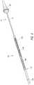
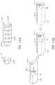
- FIG. 1shows an embodiment of a delivery system.
- FIG. 2Ashows a partial cross-sectional view of the distal end of the delivery system of FIG. 1 loaded with the valve prosthesis of FIG. 3A .
- FIG. 2Bshows a partial cross-sectional view of the distal end of the delivery system of FIG. 1 without the valve prosthesis of FIG. 3A .
- FIG. 2Cshows a partial cross-sectional view of the distal end of the delivery system of FIG. 1 without the valve prosthesis of FIG. 3A and including an outer retention ring.
- FIG. 3Ashows a side view of an embodiment of a valve prosthesis that may be delivered using the delivery systems described herein.
- FIG. 3Bshows a side view of an embodiment of an aortic valve prosthesis that may be delivered using the delivery systems described herein.
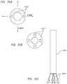
- FIG. 4shows a perspective view of the distal end of the delivery system of FIG. 1 .
- FIG. 5show components of the delivery system of FIG. 4 with the outer sheath assembly moved proximally and out of view.
- FIG. 6show components of the delivery system of FIG. 5 with the inner assembly moved proximally and out of view.
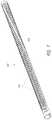
- FIG. 7illustrates an embodiment of an outer hypotube.
- FIGS. 8-13illustrate an embodiment of a combination laser-cut and braid outer hypotube.
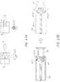
- FIG. 14illustrates an embodiment of an inner hypotube.
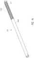
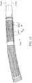
- FIG. 15illustrates an embodiment of a rail hypotube.
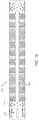
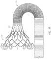
- FIGS. 16-21illustrate embodiments of a capsule construction.
- FIG. 22illustrates an embodiment of a delivery system handle.
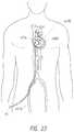
- FIG. 23illustrates a schematic representation of a transfemoral delivery approach.
- FIG. 24illustrates a schematic representation of a valve prosthesis positioned within a native mitral valve.
- FIG. 25shows the valve prosthesis frame located within a heart.
- FIGS. 26-28show steps of a method for delivery of the valve prosthesis to an anatomical location.
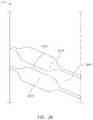
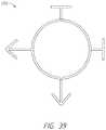
- FIGS. 29A-Billustrate the methodology of the rail delivery system.
- FIGS. 30-31illustrate a torsional pull wire.
- FIG. 32illustrates an embodiment of a steerable integrated sheath.
- FIGS. 33-33Aillustrate an embodiment of a pull wire lumen.
- FIGS. 34A-Cillustrate various pull wire configurations.
- FIGS. 35A-Cillustrates embodiments of axial runners.
- FIGS. 36-39illustrate embodiments of a capsule having improved flexibility and compression resistance.
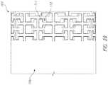
- FIG. 40illustrates a flat cut pattern of an embodiment of a capsule with improved recoiling.
- FIG. 41illustrates an embodiment of a capsule with improved recoiling.
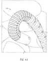
- FIGS. 42-44illustrate embodiments of a capsule with improved recoiling.
- FIG. 45Aillustrates a standard hypotube construction
- FIG. 45Billustrates an improved hypotube construction including an additional high temperature polymer layer.
- FIG. 46Aillustrates an embodiment of an overmolded inner retention member.
- FIG. 46Billustrates an embodiment of a track and pin capsule and inner retention member.
- FIG. 47Aillustrates an angled inner retention member groove structure
- FIG. 47Billustrates an inner retention ring including attachment flaps.
- FIGS. 48A-Dillustrate embodiments of a tethered outer retention member.
- FIG. 49illustrates an embodiment of an outer retention ring backstop.
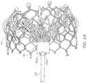
- FIG. 50shows a side view of an embodiment of a valve prosthesis that may be delivered using the delivery systems described herein.
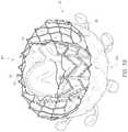
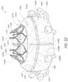
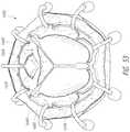
- FIG. 51A-53show views of an embodiment of a valve prosthesis that may be delivered using the delivery systems described herein.
- FIG. 1illustrates an embodiment of a delivery device, system, or assembly 10 .
- the delivery systemcan be used deploy a prosthesis, such as a replacement heart valve, within the body.
- Replacement heart valvescan be delivered to a patient's heart mitral valve annulus or other heart valve location in various manners, such as by open surgery, minimally-invasive surgery, and percutaneous or transcatheter delivery through the patient's vasculature.
- Example transfemoral approachesmay be found in U.S. Pat. Pub. No. 2015/0238315, filed Feb. 20, 2015, the entirety of which is hereby incorporated by reference in its entirety. While the delivery system 10 is described in connection with a percutaneous delivery approach, and more specifically a transfemoral delivery approach, it should be understood that features of delivery system 10 can be applied to other delivery system, including delivery systems for a transapical delivery approach.
- the delivery system 10can be used to deploy a prosthesis, such as a replacement heart valve as described elsewhere in this specification, within the body.
- the delivery system 10can receive and/or cover portions of the prosthesis such as a first end 301 and second end 303 of the prosthesis 70 illustrated in FIG. 3A below.
- the delivery system 10may be used to deliver an expandable implant or prosthesis 70 , where the prosthesis 70 includes the first end 301 and the second end 303 , and wherein the second 303 end is configured to be deployed or expanded before the first end 301 .
- FIG. 2Afurther shows an example of the prosthesis 70 that can be inserted into the delivery system 10 , specifically into the implant retention area 16 .
- the prosthesisis shown with only the bare metal frame illustrated.
- the implant or prosthesis 70can take any number of different forms. A particular example of frame for a prosthesis is shown in FIG. 3A , though it will be understood that other designs can also be used.
- the prosthesis 70can include one or more sets of anchors, such as distal (or ventricular) anchors 80 extending proximally when the prosthesis frame is in an expanded configuration and proximal (or atrial) anchors 82 extending distally when the prosthesis frame is in an expanded configuration.
- the prosthesiscan further include struts 72 which may end in mushroom-shaped tabs 74 at the first end 301 . Further discussion can be found in U.S. Patent Pub. No. 2015/0328000, hereby incorporated by reference in its entirety.
- the delivery system 10can be used in conjunction with a replacement aortic valve, such as shown in FIG. 3B .
- the delivery system 10can be modified to support and delivery the replacement aortic valve.
- the procedures and structures discussed belowcan similarly be used for a replacement mitral and replacement aortic valve.
- the delivery system 10can be relatively flexible. In some embodiments, the delivery system 10 is particularly suitable for delivering a replacement heart valve to a mitral valve location through a transseptal approach (e.g., between the right atrium and left atrium via a transseptal puncture).
- a transseptal approache.g., between the right atrium and left atrium via a transseptal puncture.
- the delivery system 10can include a shaft assembly 12 comprising a proximal end 11 and a distal end 13 , wherein a handle 14 is coupled to the proximal end of the assembly 12 .
- the shaft assembly 12can be used to hold the prosthesis for advancement of the same through the vasculature to a treatment location.
- the delivery system 10can further comprise a relatively rigid live-on sheath 51 surrounding the shaft assembly 12 that can prevent unwanted motion of the shaft assembly 12 .
- the shaft assembly 12can include an implant retention area 16 (shown in FIGS. 2A-B with FIG. 2A showing the prosthesis 70 and FIG. 2B with the prosthesis 70 removed) at its distal end that can be used for this purpose.
- the shaft assembly 12can hold an expandable prosthesis in a compressed state at implant retention area 16 for advancement of the prosthesis 70 within the body.
- the shaft assembly 12may then be used to allow controlled expansion of the prosthesis 70 at the treatment location.
- the implant retention area 16is shown in FIGS. 2A-B at the distal end of the delivery system, but may also be at other locations.
- the prosthesis 70may be rotated in the implant retention area 16 , such as through the rotation of the inner shaft assembly 18 discussed herein.
- the distal end of the delivery system 10can include one or more subassemblies such as an outer sheath assembly 12 , inner shaft assembly 18 , a rail assembly 20 , and nose cone assembly 31 as will be described in more detail below.
- subassembliessuch as an outer sheath assembly 12 , inner shaft assembly 18 , a rail assembly 20 , and nose cone assembly 31 as will be described in more detail below.
- embodiments of the disclosed delivery systemcan utilize a steerable rail in the rail assembly 20 for steering the distal end of the delivery system 10 , allowing the implant to be properly located in a patient's body.
- the steerable railcan be, for example, a rail shaft that extends through the delivery system 10 from the handle generally to the distal end.
- a usercan manipulate the bending of the distal end of the rail, thereby bending the rail in a particular direction.
- the railhas more than one bend along its length, thereby providing multiple directions of bending.
- the railAs the rail is bent, it presses against the other assemblies to bend them as well, and thus the other assemblies of the delivery system 10 can be configured to steer along with the rail as a cooperating single unit, thus providing for full steerability of the distal end of the delivery system.
- the prosthesis 70can be advanced along the rail and released into the body.
- the delivery systemcan include an outer sheath assembly 22 forming a radially outer covering, or sheath, to surround an implant retention area 16 and prevent the implant from radially expanding.
- the inner shaft assembly 18can be composed an inner shaft with its distal end attached to inner retention member or inner retention ring 40 for axially retaining the prosthesis.
- the inner shaft assembly 18can be located within a lumen of the outer sheath assembly 22 .
- the rail assembly 20can be configured for steerability, as mentioned above and further described below.
- the rail assembly 20can be located within a lumen of the inner shaft assembly 18 .
- the most radially-inward assemblyis the nose cone assembly 31 which includes the nose cone shaft 27 having its distal end connected to the nose cone 28 .
- the nose cone assembly 31is preferably located within a lumen of the rail shaft assembly 20 .
- the nose cone assembly 31can include a lumen for a guide wire to pass therethrough.
- the shaft assembly 12and more specifically the nose cone assembly 31 , inner assembly 18 , rail assembly 20 , and outer sheath assembly 22 , can be collectively configured to deliver a prosthesis 70 positioned within the implant retention area 16 (shown in FIG. 2A ) to a treatment location.
- One or more of the subassembliescan then be moved to allow the prosthesis 70 to be released at the treatment location.
- one or more of the subassembliesmay be movable with respect to one or more of the other subassemblies.
- the handle 14can include various control mechanisms that can be used to control the movement of the various subassemblies as will also be described in more detail below.
- the prosthesis 70can be controllably loaded onto the delivery system 10 and then later deployed within the body. Further, the handle 14 can provide steering to the rail assembly 20 , providing for bending/flexing/steering of the distal end of the delivery system 10 .
- the inner retention member 40 and the outer sheath assembly 22can cooperate to hold the prosthesis 70 in a compacted configuration.
- the inner retention member 40is shown engaging struts 72 at the proximal end 301 of the prosthesis 70 in FIG. 2A .
- slots located between radially extending teeth on the inner retention member 40can receive and engage the struts 72 which may end in mushroom-shaped tabs 74 on the proximal end of the prosthesis 70 .
- the outer sheath assembly 22can be positioned over the inner retention member 40 so that the first end 301 of the prosthesis 70 is trapped there between, securely attaching it to the delivery system 10 between the outer sheath assembly 22 and the inner retention member 40 .
- the distal anchors 80can be located in a delivered configuration where the distal anchors 80 point generally distally (as illustrated, axially away from the main body of the prosthesis frame and away from the handle of the delivery system).
- the distal anchors 80can be restrained in this delivered configuration by the outer sheath assembly 22 . Accordingly, when the outer sheath 22 is withdrawn proximally, the distal anchors 80 can flip positions (e.g., bend approximately 180 degrees) to a deployed configuration (e.g., pointing generally proximally).
- FIG. 2Aalso shows the proximal anchors 82 extending distally in their delivered configuration within the outer sheath assembly 22 . In other embodiments, the distal anchors 80 can be held to point generally proximally in the delivered configuration and compressed against the body of the prosthesis frame.
- the delivery system 10may be provided to users with a prosthesis 70 preinstalled.
- the prosthesis 70can be loaded onto the delivery system shortly before use, such as by a physician or nurse.
- an outer retention member (or ring) 42may be incorporated into the delivery system 10 , as shown in FIG. 2C .
- the outer retention member 42may be attached to a mid shaft 43 which can be attached at a proximal end to the handle 14 .
- the outer retention member 42can advantageously provide further stability to the prosthesis 70 when in the compressed position.
- the outer retention member 42can be positioned over the inner retention member 40 so that the first end 301 of the prosthesis 70 is trapped therebetween, which securely attaches it to the delivery system 10 .
- the outer retention member 42can encircle a portion of the prosthesis 70 , in particular the first end 301 , thus preventing the prosthesis 70 from expanding. Further, the mid shaft 43 can be translated proximally with respect to the inner assembly 18 into the outer sheath assembly 22 , thus exposing a first end 301 of the prosthesis 70 held within the outer retention member 42 . In this way the outer retention member 42 can be used to help secure a prosthesis 70 to or release it from the delivery system 10 .
- the outer retention member 42can have a cylindrical or elongate tubular shape, and may be referred to as an outer retention ring.
- the mid shaft 43itself can be made of, for example, high density polyethylene (HDPE), as well as other appropriate materials as described herein.
- the mid shaft 43can be formed of a longitudinally pre-compressed HDPE tube, which can provide certain benefits.
- the pre-compressed HDPE tubecan apply a force distally onto the outer retention member 42 , thus preventing accidental, inadvertent, and/or premature release of the prosthesis 70 .
- the distal force by the mid shaft 43keeps the distal end of the outer retention member 42 distal to the inner retention member 40 , thus preventing the outer retention member 42 from moving proximal to the inner retention member 40 before it is desired by a user to release the prosthesis 70 .
- FIGS. 4-6illustrate further views of delivery system 10 with different assemblies translated proximally and described in detail.
- the outer sheath assembly 22can include an outer proximal shaft 102 directly attached to the handle 14 at its proximal end and an outer hypotube 104 attached at its distal end. A capsule 106 can then be attached generally at the distal end of the outer hypotube 104 . These components of the outer sheath assembly 22 can form a lumen for the other subassemblies to pass through.
- the outer proximal shaft 102may be a tube and is preferably formed of a plastic, but could also be a metal hypotube or other material.
- the outer hypotube 104can be a metal hypotube which in some embodiments may be cut or have slots, as discussed in detail below.
- the outer hypotube 104can be covered or encapsulated with a layer of ePTFE, PTFE, or other material so that the outer surface of the outer hypotube 104 is generally smooth.
- the capsule 106can be a tube formed of a plastic or metal material.
- the capsule 106is formed of ePTFE or PTFE. In some embodiments, this capsule 106 is relatively thick to prevent tearing and to help maintain a self-expanding implant in a compacted configuration.
- the material of the capsule 106is the same material as the coating on the outer hypotube 104 . As shown, the capsule 106 can have a diameter larger than the outer hypotube 104 , though in some embodiments the capsule 106 may have a similar diameter as the hypotube 104 .
- the capsule 106can be configured to retain the prosthesis 70 in the compressed position within the capsule 106 .
- the outer sheath assembly 22is configured to be slidable over the inner assembly 18 , the rail assembly 20 , and the nose cone assembly 31 .
- FIG. 5shows a similar view as FIG. 4 , but with the outer sheath assembly 22 removed, thereby exposing the inner shaft assembly 18 .
- the inner shaft assembly 18can include an inner shaft 122 generally attached at its proximal end to the handle 14 , and an inner retention ring 40 located at the distal end of the inner shaft 122 .
- the inner shaft 122itself can include an inner proximal shaft 124 directly attached to the handle 14 at a proximal end and an inner hypotube 126 attached to the distal end of the inner proximal shaft 124 .
- the inner retention ring 40can be attached generally at the distal end of the inner hypotube 126 .
- These components of the inner shaft assembly 18can form a lumen for the other subassemblies to pass through.
- the inner proximal shaft 124can comprise a tube, such as a hypodermic tube or hypotube (not shown).
- the tubecan be made from one of any number of different materials including nitinol, cobalt chromium, stainless steel, and/or medical grade plastics.
- the tubecan be a single piece tube or multiple pieces connected together. A tube comprising multiple pieces can provide different characteristics along different sections of the tube, such as rigidity and flexibility.
- the inner hypotube 126can be a metal hypotube, which in some embodiments may be cut or have slots as discussed in detail below.
- the tube 126can be covered or encapsulated with a layer of ePTFE, PTFE, or other material so that the outer surface of the inner hypotube 126 is generally smooth.
- the inner retention member 40can be configured as a prosthesis retention mechanism that can be used to engage with the prosthesis, as discussed with respect to FIG. 2A .
- the inner retention member 40may be a ring and can include a plurality of slots configured to engage with struts 72 on the prosthesis 70 .
- the inner retention member 40can also be considered to be part of the implant retention area 16 , and may be at the proximal end of the implant retention area 16 .
- the capsuleWith struts or other parts of a prosthesis 70 engaged with the inner retention member 40 , the capsule can cover both the prosthesis and the inner retention member 40 to secure the prosthesis on the delivery system 10 .
- the prosthesis 70can be sandwiched between the inner retention member 40 of the inner shaft assembly 18 and the capsule 106 of the outer sheath assembly 22 .
- the inner shaft assembly 18is disposed so as to be slidable over the rail assembly 20 and the nose cone assembly 31 .
- the rail assemblycan include a rail shaft 132 (or rail) generally attached at its proximal end to the handle 14 .
- the rail shaft 132can be made up of a rail proximal shaft 134 directly attached to the handle at a proximal end and a rail hypotube 136 attached to the distal end of the rail proximal shaft 134 .
- the rail hypotube 136can further include an atraumatic rail tip at its distal end.
- Attached to an inner surface of the rail hypotube 136are one or more pull wires which can be used apply forces to the rail hypotube 136 and steer the rail assembly 20 .
- the pull wirescan extend distally from the knobs in the handle 14 , discussed below, to the rail hypotube 136 .
- pull wirescan be attached at different longitudinal locations along the rail hypotube 136 , thus providing for multiple bending regions in the rail hypotube 136 , thereby allowing for multidimensional steering.
- two distal pull wires 138can extend to a distal section of the rail hypotube 136 and two proximal pull wires 140 can extend to a proximal section of the rail hypotube 136 .
- other numbers of pull wirescan be used and the particular number of pull wires is not limiting.
- a single pull wirecan extend to a distal location and a single pull wire can extend to a proximal location.
- ring-like structures attached inside the rail hypotube 136known as pull wire connectors, may be provided as attachment locations for the pull wires.
- the rail assembly 20can include a distal pull wire connector and a proximal pull wire connector.
- the pull wirescan directly connect to an inner surface of the rail hypotube 136 .
- the distal pull wires 138can be connected (either on its own or through a connector) generally at the distal end of the rail hypotube 136 .
- the proximal pull wires 140can connect (either on its own or through a connector) at a location approximately one quarter, one third, or one half of the length up the rail hypotube 136 from the proximal end.
- the distal pull wires 138can pass through small diameter pull wire lumens attached on the inside of the rail hypotube 136 . This can prevent the wires 138 from pulling on the rail hypotube 136 at a location proximal to the distal connection.
- these lumenscan be attached to an outer surface of the nose cone shaft 31 distal to a location at which the proximal pull wires 140 attach to the rail hypotube 136 .
- the wirescan be spaced approximately 180 degrees from one another to allow for steering in opposite directions.
- the wirescan be spaced approximately 180 degrees from one another to allow for steering in both directions.
- the pair of distal pull wires 138 and the pair of proximal pull wires 140can be spaced approximately 90 degrees from each other.
- the pair of distal pull wires 138 and the pair of proximal pull wires 140can be spaced approximately 0 degrees from each other.
- other locations for the pull wirescan be used as well, and the particular location of the pull wires is not limiting.
- the rail assembly 20is disposed so as to be slidable over the nose cone assembly 31 .
- the nose cone assembly 31Moving further inwardly from the rail assembly is the nose cone assembly 31 also seen in FIG. 6 .
- Thismay be a nose cone shaft 27 , and in some embodiments, may have a nose cone 28 on its distal end.
- the nose cone 28can be made of polyurethane for atraumatic entry and to minimize injury to surrounding vasculature.
- the nose cone 28can also be radiopaque to provide for visibility under fluoroscopy.
- the nose cone shaft 27may include a lumen sized and configured to slidably accommodate a guide wire so that the delivery system 10 can be advanced over the guide wire through the vasculature.
- embodiments of the system 10 discussed hereinmay be constructed for use without a guide wire and thus the nose cone shaft 27 can be solid.
- the nose cone shaft 27may be connected from the nose cone 28 to the handle, or may be formed of different segments such as the other assemblies. Further, the nose cone shaft 27 can be formed of different materials, such as plastic or metal, similar to those described in detail above.
- One or more spacer sleevescan be used between different assemblies of the delivery system 10 .
- a first spacer sleevecan be located concentrically between the inner shaft assembly 18 and the rail assembly 20 , generally between the inner and rail hypotubes 126 / 136 .
- a second spacer sleevecan be located concentrically between the rail assembly 20 and the nose cone assembly 30 , generally longitudinally within the rail hypotube 136 .
- only one spacer sleevemay be used (either the first spacer sleeve or the second spacer sleeve).
- both spacer sleevescan be used.
- no spacer sleevesare used.
- the spacer sleevecan be made of a polymer material such as braided Pebax® and can be lined, for example with PTFE, on the inner diameter, though the particular material is not limiting.
- the spacer sleevecan advantageously reduce friction between the steerable rail assembly 20 and its surrounding assemblies.
- the spacer sleevescan act as a buffer between the rail assembly 20 and the inner/nose cone assembly 18 / 30 .
- the spacer sleevecan take up any gap in radius between the assemblies, preventing compressing or snaking of the assemblies during steering.
- the spacer sleevecan be mechanically contained by the other lumens and components, and is thus not physically attached to any of the other components, allowing the spacer sleeve to be “floating” in that area.
- the floating aspect of the spacer sleeveallows it to move where needed during deflection and provide a support and/or lubricious bear surface/surfaces. Accordingly, the floating aspect allows the delivery system 10 to maintain flex forces.
- the spacer sleevecan be connected to other components.
- the outer sheath assembly 22 , the inner assembly 18 , and the rail assembly 20can contain an outer hypotube 104 , an inner hypotube 126 , and a rail hypotube 136 , respectively.
- Each of these hypotubescan be laser cut to include a number of circumferential (i.e., transverse) slots, thereby creating a bending pathway for the delivery system to follow. While different slot assemblies are discussed below, it will be understood that any of the three hypotubes can have any of the slot configurations discussed below.
- FIGS. 7-15show the different hypotubes in isolated format.
- the outer hypotube 104shown in FIG. 7 (distal end towards the right), can include a number slots 103 transverse to its lumen axis along most of the length of the outer hypotube 104 .
- Each of the slotscan extend partially or almost entirely around the circumference of the outer hypotube 104 , thereby forming a single spine 105 of material extending between the proximal and distal ends of the outer hypotube 104 .
- the outer hypotube 104can contain more than one spine, such as two, three, or four spines.
- the slotscan extend generally from the proximal end of the outer hypotube 104 to the distal end of the hypotube 104 , allowing the entirety of the outer hypotube 104 to more easily bend with the rail assembly 20 .
- the slot locationsmay be staggered such that the spine 105 circumferentially rotates while progressing from the proximal end to the distal end of the outer hypotube 104 .
- the distal end of the spine 105can be approximately 30°, 45°, 90°, 135°, or 180° offset from the proximal end of the spine 105 .
- the spine 105remains in the same circumferential location from the proximal end to approximately halfway the length of the outer hypotube 104 . At this point, the spine 105 can begin to circumferentially turn around the outer hypotube 104 .
- the curve of the spinehelps direct the outer hypotube 105 during steering of the rail assembly 20 .
- the spine 105generally follows the typical bend formed by the rail assembly 20 when entering the heart and directing towards the mitral valve, thus relieving some of the forces that may occur if the spine 105 was straight.
- the spine 105 of the outer hypotube 104may be straight, and the particular configuration of the spine is not limiting.
- FIGS. 8-13illustrate another embodiment of the outer hypotube 104 (distal end towards the right for FIGS. 8-10 ).
- a hybrid materialmay accomplish universal flexibility with high compressive/tensile strength.
- a combination of a braid and a lasercutcan be used to overcome shortcomings of earlier hypotube designs.
- the braided materiale.g., tube, hypotube, cover, jacket
- the interlaced materialscan be strands of material, such as strands of flexible material.
- the braidcan be formed of metal, plastic, polymer, ceramic, etc. and the particular material does not limit the disclosure.
- Braided materialssuch as the braided tube 1100 shown in FIG. 9 can be advantageous in tension, but they can significantly neck when subjected to high of tension, and are unsatisfactory in compression.
- slotted (or lasercut) hypotubessuch as the slotted hypotube 1102 shown in FIG. 10 or above in FIG. 7 , can be excellent for use in compression and may not neck down when elongated.
- slotted hypotubeshave limited strength under tension. Accordingly, it can be advantageous to use a combination of a braided material in conjunction with a lasercut hypotube, thereby advantageously providing both tension and compression benefits.
- the braided tubecan be attached to the lasercut hypotube at one or more of the proximal and distal ends, such as through mechanical or chemical attachment means.
- the braided tube 1100can be located radially outward or radially inwardly of the lasercut hypotube 1102 .
- the use of the braided tube 1100allows for the hypotube 1102 to have an alternating cut pattern as shown in FIG. 10 .
- the alternating cut patternallows the lasercut hypotube to bend in all directions, which allows for “universal bending”.
- other cut patternssuch as disclosed herein, can be used as well.
- the braided tube 1100can lock onto the lasercut hypotube 1102 when pulled (e.g., when put under a tension force).
- the hypotube 1102can essential act as a set diameter, thereby preventing the braided tube 1100 from necking down and increasing its ability to transmit tensile forces. This can make the tensile response and strength extremely favorable, and the lasercut hypotube 1102 can provide compression strength.
- a coilcould be used instead of a lasercut hypotube 1102 , and the hypotube can be any number of slotted tubes/configurations with advantageous compression properties.
- FIGS. 12-13illustrate the advantageous bending qualities of the capsule.
- a portion of the outer sheath assembly 22can be formed from the combination braided tube and lasercut hypotube 1102 .
- all of the outer sheath assembly 22can be formed from the combination braided tube and lasercut hypotube 1102 .
- a portion of the outer sheath assembly 22 directly proximal of the capsule 106can be formed from the combination braided tube and lasercut hypotube 1102 .
- the inner hypotube 126also contains a number of slots 1402 (distal end towards the right). However, unlike the outer hypotube 104 , the inner hypotube 126 in some embodiments does not contain slots along a majority of its length to form an unslotted portion 1400 , although it may contain slots in some iterations. This allows the inner hypotube 126 to be more rigid as the inner hypotube 126 can experience high compressive loads and the enhanced rigidity of the spiral spine prevents coiling. Further, it allows the inner assembly 18 to direct the other assemblies to extend straight when advanced over the rail assembly 20 , as discussed below.
- the inner hypotube 126can contain slots 1402 transverse to its luminal axis along the distal 1 ⁇ 4, 1 ⁇ 3, or 1 ⁇ 2 of its length starting generally from the distal end.
- each circumferential position locationcan have two slots spanning less than 180 degrees, thereby forming two spines 127 in the inner hypotube, unlike the single spine of the outer hypotube 104 .
- These spines 127can be spaced approximately 180 degrees apart, though in some embodiments different angles can be used depending on the desired bend. However, in some embodiments a single spine or more than two spines can be used.
- the additional spinescan provide additional rigidity to the inner assembly 18 .
- the inner hypotube 126can contain a single slot pattern 1402 forming the dual spines as discussed above.
- the inner hypotube 126can contain two different slot patterns.
- the slotsmay be configured for only one direction of bend (for example, only along an X axis), making this section strong and robust but less flexible.
- slots in section proximalcan be configured to includes multiple bending axis (for example, along both X and Y axes), thus providing the inner hypotube 126 with more flexibility for steering.
- the configuration of the inner hypotube 126creates forces that tend to straighten (e.g., not bend). Thus, when the inner hypotube 126 is advanced over the rail hypotube 136 , it will achieve a generally straight configuration.
- FIG. 15illustrates an embodiment of the rail hypotube 136 (distal end towards the right).
- the rail hypotube 136can also contain a number of transverse slots.
- the rail hypotube 136can generally be broken into a number of different sections. At the most proximal end is an uncut (or unslotted) hypotube section 131 . This can take up approximately one quarter to one third of the rail hypotube 136 . Moving distally, the next section is the proximal slotted hypotube section 133 . This section includes a number of transverse slots cut into the rail hypotube. Generally, two slots are cut around each circumferential location forming almost half of the circumference.
- two backbonesare formed between the slots extending up the length of the hypotube 136 .
- Thisis the section that can be guided by the proximal pull wires 140 .
- Moving further distallyis the location 137 where the proximal pull wires 140 connect, and thus slots can be avoided.
- This section 137is just distal of the proximally slotted section 133 .
- distal slotted hypotube section 135Distally following the proximal pull wire connection area is the distal slotted hypotube section 135 .
- This sectionis similar to the proximal slotted hypotube section 133 but has significantly more slots formed along an equivalent length.
- the distally slotted hypotube section 135provides easier bending than the proximally slotted hypotube section 133 .
- the proximal slotted section 133can be configured to experience a bend of approximately 90 degrees with a half inch radius whereas the distal slotted section 135 can bend at approximately 180 degrees within a half inch.
- the spines of the distally slotted hypotube section 135are offset from the spines of the proximally slotted hypotube section 133 . Accordingly, the two sections will achieve different bend patterns, allowing for three-dimensional steering of the rail assembly 20 .
- the spinescan be offset by approximately 30, 45, or 90 degrees, although the particular offset is not limiting.
- distal pull wire connection area 139which is again a non-slotted section of the rail hypotube 136 .
- the capsule 106can be formed from one or more materials, such as PTFE, ePTFE, PEBAX, ULTEM, PEEK, urethane, nitinol, stainless steel, and/or any other biocompatible material.
- the capsule 106is formed from one or more materials.
- the capsule 106is compliant and flexible while still maintaining a sufficient degree of radial strength to maintain a replacement valve within the capsule 106 without substantial radial deformation, which could increase friction between the capsule 106 and a replacement valve 70 contained therein.
- the capsule 106also preferably has sufficient column strength to resist buckling of the capsule, and sufficient tear resistance to reduce or eliminate the possibility of the replacement valve tearing the capsule 106 .
- Flexibility of the capsule 106can be advantageous, particularly for a transseptal approach.
- the capsule 106can flex to follow the curved member without applying significant forces upon the curved member, which may cause the curved member to decrease in radius. More specifically, the capsule 106 can bend and/or kink as it is being retracted along such a curved member such that the radius of the curved member is substantially unaffected.
- FIGS. 16-21show embodiments of a capsule 106 that can be used with embodiments of the delivery system 10 .
- the capsule 106may include any of the materials and properties discussed above. With many implant capsules, compression resistance and flexibility are typically balanced together, as improved flexibility can lead to worse compression resistance. Thus, there tends to be a choice made between compression resistance and flexibility. However, disclosed are embodiments of a capsule that can achieve both high compression resistance as well as high flexibility.
- a metal hypotubecan provide radial strength and compression resistance, while specific slots/cuts in the hypotube can enable the flexibility of the capsule 106 .
- a thin liner and a jacketcan surround the capsule 106 , such as a polymer or elastomer layer, to prevent any negative interactions between the implant 70 and the capsule 106 .
- the capsule 106can include a significantly large number of slots (e.g., cuts, holes) 109 that extend transverse to the axial length of the capsule (distal end is towards the left in FIG. 16 and towards the right in FIG. 17 ).
- the capsule 106can include over 50, over 100, or 150, over 200, over 250, or over 300 cuts extending down the axial length of the capsule 106 . While the flexibility could be accomplished with fewer cuts, the large number of cuts makes the open portions of the capsule 106 relatively small, so the risk of the prosthesis 70 having a negative interaction with the capsule 106 drops considerably.
- the capsule 106can include one or more spines 111 , where there are no slots 109 .
- the capsule 106can have a single spine.
- the capsule 106can have dual spine.
- the capsule 106can have more than two spines, such as three, four, or five spines. Having two spines can be advantageous as it improves the compression strength while decreasing the size of cuts necessary to accomplish the same bend in a single spine configuration.
- the spine 111can be generally straight.
- the spine 111can have a substantially helical shape.
- the spine 111can rotate or change position around the circumference, thus allowing for different bending directions.
- FIG. 17illustrates a prosthesis 70 within the capsule 106 , though the particular location of the prosthesis 70 is not limiting.
- FIG. 18illustrates the bending ability of the capsule 106 with a prosthesis 70 partially expanded.
- the distal end of the capsule 106can flare (e.g., expand) outwardly when a radially outward force is applied, and thus can be a flarable section 107 (also shown in FIG. 19 ).
- the capsule 106can have a flarable section 107 at its distal end. In some embodiments, it may not.
- the flaringcan be accomplished either by using a flexible polymer distal portion, or by a combination of a flexible polymer and lasercut as discussed below, and can be advantageous for recrimping the prosthesis 70 in a controlled manner. This can also eliminate the severity of the point of deployment when the valve expands aggressively, preventing damage to the distal end of the capsule 106 .
- the flarable section 107can flare outwardly so that a distal end of the capsule 106 is at least 1, 2, 3, 4, 5, 10, 15, 20% or more of the diameter of the remainder of the capsule 106 . In some embodiments, the flarable section 107 can flare outwards less than 2, 3, 4, 5, 10, 15, or 20% the diameter of the remainder of the capsule 106 .
- FIGS. 20-21illustrate a closer view of the distal end of the capsule 106 (distal end towards the right).
- the distal endcan include a flarable portion 107 that includes a number of laser cut configurations, similar to a puzzle pattern.
- the flarable portion 107can contain a number of generally T-shaped portions 111 extending into slots 113 that are larger than the T-shaped portions 111 ; however, the particular configuration is not limiting.
- the portionsare described as T-shaped, they could include other shapes and configurations, such as t-shaped, triangular, circular, rectangular, or other polygons, and the particular shape is not limiting.
- the T-shaped portions 111can vary in size/dimensions/shape to allow further spacing for the portions. Thus, the T-shaped portions 111 can slide/move within the slots 113 based on the excess room in the slots 113 , allowing the flarable portion 107 to flare outwardly as shown in FIG. 21 .
- the slots 113can include extra room for the T-shaped portions 111 in the circumferential direction, the longitudinal direction, or both. Once the T-shaped portions 111 abut against the outer edges of the slots 113 , flaring can stop. Further, the T-shaped portions 111 can have sufficient rigidity that they do not pop radially out of the slots 113 .
- expansioncan occur through a number of longitudinally extending cuts around a circumference of the distal end of the capsule 106 , such as shown in FIG. 19 .
- the longitudinal cutscan end in an enlarged cut for improved flexibility, though this is not required.
- slotssuch as the circular slots shown in FIG. 18 , can be included on the capsule 106 to provide further flexibility.
- the handle 14is located at the proximal end of the delivery system 10 and is shown in FIG. 22 . It can include a number of actuators, such as rotatable knobs, that can manipulate different components of the delivery system.
- the operation of the handle 10is described with reference to delivery of a replacement mitral valve prosthesis, though the handle 10 and delivery system 10 can be used to deliver other devices as well.
- the handle 14is generally composed of two housings, a rail housing 202 and a delivery housing 204 , the rail housing 202 being circumferentially disposed around the delivery housing 204 .
- the inner surface of the rail housing 202can include a screwable section configured to mate with an outer surface of the delivery housing 204 .
- the delivery housing 204is configured to slide (e.g., screw) within the rail housing 202 , as detailed below.
- the rail housing 202generally surrounds about one half the length of the delivery housing 204 , and thus the delivery housing 204 extends both proximally and distally outside of the rail housing 202 .
- the rail housing 202can contain two rotatable knobs, a distal pull wire knob 206 and a proximal pull wire knob 208 .
- the number of rotatable knobs on the rail housing 202can vary depending on the number of pull wires used.
- Rotation of the distal pull wire knob 206can provide a proximal force, thereby providing axial tension on the distal pull wires 138 and causing the distal slotted section 135 of the rail hypotube 136 to bend.
- the distal pull wire knob 206can be rotated in either direction, allowing for bending in either direction.
- Rotation of the proximal pull wire knob 208can provide a proximal force, and thus axial tension, on the proximal pull wires 140 , thereby causing the proximal slotted section 133 of the rail hypotube 136 to bend.
- the proximal pull wire knob 108can be rotated in either direction, allowing for bending in either direction.
- both knobsare actuated, there can be two bends in the rail hypotube 136 , thereby allowing for three dimensional steering of the rail shaft 132 , and thus the distal end of the delivery system 10 .
- the proximal end of the rail shaft 132is connected on an internal surface of the rail housing 202 .
- the bending of the rail shaft 132can be used to position the system, in particular the distal end, at the desired patient location, such as at the native mitral valve.
- rotation of the pull wire knobs 206 / 208can help steer the distal end of the delivery system 10 through the septum and left atrium and into the left ventricle so that the prosthesis 70 is located at the native mitral valve.
- the proximal ends of the inner shaft assembly 19 , outer sheath assembly 22 , and nose cone shaft assembly 30can be connected to an inner surface of the delivery housing 204 of the handle 14 . Thus, they can move axially relative to the rail assembly 20 and rail housing 202 .
- a rotatable outer sheath knob 210can be located on the distal end of the delivery housing 204 , being distal to the rail housing 202 . Rotation of the outer sheath knob 210 will pull the outer sheath assembly 22 in an axial direction proximally, thus pulling the capsule 106 away from the implant 70 and releasing the implant 70 . The distal end 303 of the implant 70 can be released first, followed by release of the proximal end 301 of the implant 70 as the outer sheath knob 210 is continued to rotate.
- a rotatable depth knob 212Located on the proximal end of the delivery housing 204 , and thus proximal to the rail housing 202 , can be a rotatable depth knob 212 . As the depth knob 212 is rotated, the entirety of the delivery housing 204 moves distally or proximally with respect to the rail housing 202 which will remain in the same location. Thus, at the distal end of the delivery system 10 , the inner shaft assembly 18 , outer sheath assembly 22 , and nose cone shaft assembly 30 move proximally or distally with respect to the rail assembly 20 . Accordingly, the rail shaft 132 can be aligned at a particular direction, and the other assemblies can move distally or proximally with respect to the rail shaft 132 for final positioning.
- the componentscan be advanced approximately 1, 2, 3, 5, 6, 7, 8, 9, or 10 cm along the rail shaft 132 .
- the componentscan be advanced more than approximately 1, 2, 3, 5, 6, 7, 8, 9, or 10 cm along the rail shaft 132 .
- the capsule 106can then be withdrawn, releasing the implant 70 .
- the assemblies other than the rail assembly 20can then be withdrawn back over the rail shaft 132 by rotating the depth knob 212 in the opposite direction.
- the delivery system 10can be used in a method for percutaneous delivery of a replacement mitral valve to treat patients with moderate to severe mitral regurgitation.
- the below methodsare merely examples of the how the delivery system may be used. It will be understood that the delivery systems described herein can be used as part of other methods as well.
- the delivery system 10can be placed in the ipsilateral femoral vein 1074 and advanced toward the right atrium 1076 .
- a transseptal puncture using known techniquescan then be performed to obtain access to the left atrium 1078 .
- the delivery system 10can then be advanced in to the left atrium 1078 and then to the left ventricle 1080 .
- FIG. 23shows the delivery system 10 extending from the ipsilateral femoral vein 1074 to the left atrium 1078 .
- a guide wireis not necessary to position the delivery system 10 in the proper position, although in other embodiments, one or more guide wires may be used.
- a usercan be able to steer the delivery system 10 through the complex areas of the heart in order to position a replacement mitral valve in line with the native mitral valve.
- This taskcan be performed with or without the use of a guide wire with the above disclosed system.
- the distal end of the delivery systemcan be advanced into the left atrium 1078 .
- a usercan then manipulate the rail assembly 20 to target the distal end of the delivery system 10 to the appropriate area.
- a usercan then continue to pass the bent delivery system 10 through the transseptal puncture and into the left atrium 1078 .
- a usercan then further manipulate the delivery system 10 to create an even greater bend in the rail assembly 20 .
- a usercan torque the entire delivery system 10 to further manipulate and control the position of the delivery system 10 .
- a usercan then place the replacement mitral valve in the proper location.
- Thiscan advantageously allow delivery of a replacement valve to an in situ implantation site, such as a native mitral valve, via a wider variety of approaches, such as a transseptal approach.
- FIG. 24illustrates a schematic representation of a portion of an embodiment of a replacement heart valve (prosthesis 70 ) positioned within a native mitral valve of a heart 83 . Further details regarding how the prosthesis 70 may be positioned at the native mitral valve are described in U.S. patent application Ser. No. 14/716,507, filed May 19, 2015, published as U.S. 2015/0328000, the entirety of which is hereby incorporated by reference, including but not limited to FIGS. 13A-15 and paragraphs [0036]-[0045].
- a portion of the native mitral valveis shown schematically and represents typical anatomy, including a left atrium 1078 positioned above an annulus 106 and a left ventricle 1080 positioned below the annulus 106 .
- the left atrium 1078 and left ventricle 1080communicate with one another through a mitral annulus 106 .
- Also shown schematically in FIG. 24is a native mitral leaflet 108 having chordae tendineae 110 that connect a downstream end of the mitral leaflet 108 to the papillary muscle of the left ventricle 1080 .
- the portion of the prosthesis 70 disposed upstream of the annulus 106can be referred to as being positioned supra-annularly.
- the portion generally within the annulus 106is referred to as positioned intra-annularly.
- the portion downstream of the annulus 106is referred to as being positioned sub-annularly (toward the left ventricle 1080 ).
- the replacement heart valve(e.g., prosthesis 70 ) can be positioned so that the mitral annulus 106 is located between the distal anchors 80 and the proximal anchors 82 .
- the prosthesis 70can be positioned such that ends or tips of the distal anchors 80 contact the annulus 106 as shown, for example, in FIG. 24 .
- the prosthesis 70can be positioned such that ends or tips of the distal anchors 80 do not contact the annulus 106 .
- the prosthesis 70can be positioned such that the distal anchors 80 do not extend around the leaflet 108 .
- the replacement heart valve 70can be positioned so that the ends or tips of the distal anchors 80 are on a ventricular side of the mitral annulus 106 and the ends or tips of the proximal anchors 82 are on an atrial side of the mitral annulus 106 .
- the distal anchors 80can be positioned such that the ends or tips of the distal anchors 80 are on a ventricular side of the native leaflets beyond a location where chordae tendineae 110 connect to free ends of the native leaflets.
- the distal anchors 80may extend between at least some of the chordae tendineae 110 and, in some situations such as those shown in FIG. 24 , can contact or engage a ventricular side of the annulus 106 .
- the distal anchors 80may not contact the annulus 106 , though the distal anchors 80 may still contact the native leaflet 108 . In some situations, the distal anchors 80 can contact tissue of the left ventricle 104 beyond the annulus 106 and/or a ventricular side of the leaflets.
- the distal anchors 80(along with the frame) can be moved toward the ventricular side of the annulus 106 with the distal anchors 80 extending between at least some of the chordae tendineae 110 to provide tension on the chordae tendineae 110 .
- the degree of tension provided on the chordae tendineae 110can differ. For example, little to no tension may be present in the chordae tendineae 110 where the leaflet 108 is shorter than or similar in size to the distal anchors 80 . A greater degree of tension may be present in the chordae tendineae 110 where the leaflet 108 is longer than the distal anchors 80 and, as such, takes on a compacted form and is pulled proximally.
- chordae tendineae 110An even greater degree of tension may be present in the chordae tendineae 110 where the leaflets 108 are even longer relative to the distal anchors 80 .
- the leaflet 108can be sufficiently long such that the distal anchors 80 do not contact the annulus 106 .
- the proximal anchors 82can be positioned such that the ends or tips of the proximal anchors 82 are adjacent the atrial side of the annulus 106 and/or tissue of the left atrium 1078 beyond the annulus 106 . In some situations, some or all of the proximal anchors 82 may only occasionally contact or engage atrial side of the annulus 106 and/or tissue of the left atrium 1078 beyond the annulus 106 . For example, as illustrate in FIG. 24 , the proximal anchors 82 may be spaced from the atrial side of the annulus 106 and/or tissue of the left atrium 1078 beyond the annulus 106 . The proximal anchors 82 could provide axial stability for the prosthesis 70 .
- FIG. 25illustrates the prosthesis 70 implanted in the heart.
- the illustrated replacement heart valveincludes both proximal and distal anchors, it will be appreciated that proximal and distal anchors are not required in all cases.
- a replacement heart valve with only distal anchorsmay be capable of securely maintaining the replacement heart valve in the annulus. This is because the largest forces on the replacement heart valve are directed toward the left atrium during systole. As such, the distal anchors are most important for anchoring the replacement heart valve in the annulus and preventing migration.
- FIGS. 26-28illustrate the release mechanism of the delivery system 10 .
- the prosthesis 70can be located within the system 10 , similar to as shown in FIG. 2A .
- the distal end 303 of the prosthesis 70and specifically the distal anchors 80 , are restrained within the capsule 106 of the outer sheath assembly 22 , thus preventing expansion of the prosthesis 70 .
- the distal anchors 80can extend distally when positioned in the capsule.
- the proximal end 301 of the prosthesis 70is restrained within the capsule 106 and within a portion of the inner retention member 40 and thus is generally constrained between the capsule 106 and the inner retention member 40 .
- the system 10can first be positioned to a particular location in a patient's body, such as at the native mitral valve, through the use of the steering mechanisms discussed herein or other techniques.
- a usercan thread a guide wire into a patient to the desired location.
- the guide wirepasses through the lumen of the nose cone assembly 30 , and thus the delivery system 10 can be generally advanced through the patient's body following the guide wire.
- the delivery system 10can be advanced by the user manually moving the handle 14 in an axial direction. In some embodiments, the delivery system 10 can be placed into a stand while operating the handle 14 controls.
- the usercan begin the steering operation of the rail assembly 20 using the distal pull wire knob 206 and/or the proximal pull wire knob 208 .
- the usercan provide flexing/bending of the rail assembly 20 (either on the distal end or the proximal end), thus bending the distal end of the delivery system 10 into the desired configuration.
- the usercan provide multiple bends in the rail assembly 20 to direct the delivery system 10 towards the mitral valve.
- the usercan also rotate and/or move the handle 14 itself in a stand for further fine tuning of the distal end of the delivery system 10 .
- the usercan continually turn the proximal and/or distal pull wire knobs 208 / 206 , as well as moving the handle 14 itself, to orient the delivery system 10 for release of the prosthesis 70 in the body.
- the usercan rotate the depth knob 212 .
- rotation of this knob 212advances the inner shaft assembly 18 , outer sheath assembly 22 , and nose cone assembly 30 over/through the rail assembly 20 . Due to the rigidity of, for example, the inner shaft assembly 18 , these assemblies proceed straight forward in the direction aligned by the rail assembly 20 .
- the usercan rotate the outer sheath knob 210 , which translates the outer sheath assembly 22 (and thus the capsule 106 ) in a proximal direction towards the handle 14 as shown in FIG. 26 .
- the prosthesis 70is uncovered in the body, allowing for the beginning of expansion.
- the distal anchors 80can flip proximally and the distal end 303 begins to expand radially outwardly.
- the nose coneis positioned in the left ventricle, preferably aligning the prosthesis 70 such that it is generally perpendicular to the plane of the mitral annulus.
- the distal anchors 80expand radially outwardly within the left ventricle.
- the distal anchors 80can be located above the papillary heads, but below the mitral annulus and mitral leaflets.
- the distal anchors 80may contact and/or extend between the chordae in the left ventricle, as well as contact the leaflets, as they expand radially.
- the distal anchors 80may not contact and/or extend between the chordae or contact the leaflets.
- the distal ends of the distal anchors 80may be at or below where the chordae connect to the free edge of the native leaflets.
- outer sheath assembly 22can be further moved relatively away from the nose cone 28 to further uncover the prosthesis 70 .
- the distal end 303 of the prosthesis 70is expanded outwardly.
- the proximal end 301 of the prosthesis 70can remain covered by the capsule 106 during this step such that the proximal end 301 remains in a radially compacted state.
- the system 10may be withdrawn proximally so that the distal anchors 80 capture and engage the leaflets of the mitral valve, or may be moved proximally to reposition the prosthesis 70 .
- the system 10may be torqued, which may cause the distal anchors 80 to put tension on the chordae through which at least some of the distal anchors may extend between.
- the distal anchors 80do not apply tension on the chordae.
- the distal anchors 80may capture the native leaflet and be between the chordae without any further movement of the system 10 after withdrawing the outer sheath assembly 22 .
- the system 10may be moved proximally or distally to cause the distal or ventricular anchors 80 to properly capture the native mitral valve leaflets.
- the tips of the ventricular anchors 80may be moved proximally to engage a ventricular side of the native annulus, so that the native leaflets are positioned between the anchors 80 and the body of the prosthesis 70 .
- the prosthesis 70is in its final position, there may or may not be tension on the chordae, though the distal anchors 80 can be located between at least some of the chordae.
- the distal end 303 of the prosthesis 70will remain in the outer retention ring 42 after retraction of the capsule 106 .
- the outer retention ring 42can then be retracted proximally to release the distal end 303 of the prosthesis 70 .
- capsule 106can be further moved relatively proximally to expose the inner retention member 40 , thus beginning the expansion of the proximal end 301 of the prosthesis 70 .
- the proximal end 301 of the prosthesis 70may be expanded within the left atrium.
- the capsule 106can continue to be moved proximally such that the proximal end 310 of the prosthesis 70 can radially expand to its fully expanded configuration. After expansion and release of the prosthesis 70 , the nose cone 28 can be withdrawn through the center of the expanded prosthesis 70 and into the outer sheath assembly 22 . The system 10 can then be removed from the patient.
- FIGS. 29A-Billustrate the advancement of the different assemblies over the rail assembly 20 .
- FIG. 29Aillustrates the assemblies in their proximalmost position over the rail assembly 20 .
- FIG. 29Billustrates the assemblies in their distalmost position as compared to the rail assembly 20 .
- the assembliessnake along the rail assembly 20 and extend distally away.
- the prosthesis 70can be delivered under fluoroscopy so that a user can view certain reference points for proper positioning of the prosthesis 70 . Further, echocardiography can be used for proper positioning of the prosthesis 70 .
- the access site into the patientcan be dilated. Further, a dilator can be flushed with, for example, heparinized saline prior to use.
- the delivery system 10can then be inserted over a guide wire. In some embodiments, any flush ports on the delivery system 10 can be pointed vertically. Further, if an introducer tube is used, integrated or otherwise, this can be stabilized.
- the delivery system 10can be advanced through the septum until a distal end of the delivery system 10 is positioned across the septum into the left atrium 1078 . Thus, the distal end of the delivery system 10 can be located in the left atrium 1078 . In some embodiments, the delivery system 10 can be rotated, such as under fluoroscopy, into a desired position. The rail can be flex so that direct a distal end of the delivery system 10 towards the septum and mitral valve. The position of the delivery system 10 , and the prosthesis 70 inside, can be verified using echocardiography and fluoroscopic guidance.
- the prosthesis 70can be located, prior to release, above the mitral annulus 106 , in line with the mitral annulus 106 , or below the mitral annulus 106 . In some embodiments, the prosthesis 70 can be located, prior to expansion, fully above the mitral annulus 106 , in line with the mitral annulus 106 , just below the mitral annulus 106 , or fully below the mitral annulus 106 . In some embodiments, the prosthesis 70 can be located, prior to expansion, partially above the mitral annulus 106 , in line with the mitral annulus 106 , or partially below the mitral annulus 106 . In some embodiments, a pigtail catheter can be introduced into the heart to perform a ventriculogram for proper viewing.
- the position of the mitral plane and the height of any papillary muscles on the fluoroscopy monitorcan be marked to indicate an example target landing zone. If needed, the delivery system 10 can be unflexed, reduced in rotation, and retracted to reduce tension on the delivery system 10 as well as reduce contact with the left ventricular wall, the left atrial wall, and/or the mitral annulus 106 .
- the delivery system 10can be positioned to be coaxial to the mitral annulus 106 , or at least as much as possible, while still reducing contact with the left ventricular wall, the left atrial wall, and/or the mitral annulus 106 and reducing delivery system tension.
- An echo probecan be positioned to view the anterior mitral leaflet (AML), the posterior mitral leaflet (PML) (leaflets 108 ), mitral annulus 106 , and outflow tract. Using fluoroscopy and echo imaging, the prosthesis 1010 can be confirmed to be positioned at a particular depth and coaxiality with the mitral annulus 106 .
- the outer sheath assembly 22can be retracted to expose the ventricular anchors 80 , thereby releasing them. In some embodiments, once exposed, the outer sheath assembly 22 can be reversed in direction to relieve tension on the outer sheath assembly 22 . In some embodiments, reversing the direction could also serve to partially or fully capture the prosthesis 70 .
- the distal anchors 80can be released in the left atrium 1078 . Further, the proximal anchors 82 , if included in the prosthesis 70 , are not yet exposed. Moreover, the body of the prosthesis 70 has not undergone any expansion at this point. However, in some embodiments, one or more of the distal anchors 80 can be released in either the left atrium 1078 (e.g., super-annular release) or generally aligned with the mitral valve annulus 106 (e.g., intra-annular release), or just below the mitral valve annulus 106 (e.g., sub-annular release). In some embodiments, all of the distal anchors 80 can be released together.
- a subset of the distal anchors 80can be released while at a first position and another subset of the distal anchors 80 can be released while at a second position.
- some of the distal anchors 80can be released in the left atrium 1078 and some of the distal anchors 80 can be released while generally aligned with the mitral valve annulus 106 or just below the mitral valve annulus 106 .
- the distal anchors 80may be released at 1 inch, 3 ⁇ 4 inch, 1 ⁇ 2 inch, 1 ⁇ 4 inch, 1 ⁇ 8 inch, 1/10 inch or 1/20 inch below the mitral valve annulus 106 . In some embodiments, the distal anchors 80 the may be released at less than 1 inch, 3 ⁇ 4 inch, 1 ⁇ 2 inch, 1 ⁇ 4 inch, 1 ⁇ 8 inch, 1/10 inch or 1/20 inch below the mitral valve annulus 106 . This may allow the distal anchors 80 to snake through the chordae upon release. This can advantageously allow the prosthesis 70 to slightly contract when making the sharp turn down toward the mitral valve. In some embodiments, this may eliminate the need for a guide wire assisting to cross the mitral valve. In some embodiments, the guide wire may be withdrawn into the delivery system 10 before or following release of the distal anchors 80 .
- the distal anchors 80can be released immediately after crossing the septum, and then the final trajectory of the delivery system 10 can be determined. Thus, the delivery system 10 can cross the septum, release the ventricular anchors 80 , establish a trajectory, and move into the left ventricle to capture the leaflets.
- the distal anchors 80can flip from extending distally to extending proximally. This flip can be approximately 180°. Accordingly, in some embodiments, the distal anchors 80 can be flipped in either the left atrium 1078 (e.g., super-annular flip), generally aligned with the mitral valve annulus 106 (e.g., intra-annular flip), or just below the mitral valve annulus 106 (e.g., sub-annular flip).
- the proximal anchors 82if any, can remain within the delivery system 10 . In some embodiments, all of the distal anchors 80 can be flipped together.
- a subset of the distal anchors 80can be flipped while at a first position and another subset of the distal anchors 80 can be released while at a second position.
- some of the distal anchors 80can be flipped in the left atrium 1078 and some of the distal anchors 80 can be flipped while generally aligned with the mitral valve annulus 106 or just below the mitral valve annulus 106 .
- the distal anchors 80may be positioned in line with the annulus 106 or just below the annulus 106 in the non-flipped position. In some embodiments, the distal anchors 80 may be position in line with the annulus 106 or just below the annulus 106 in the flipped position. In some embodiments, prior to flipping the distalmost portion of the prosthesis 70 can be located within or below the mitral valve annulus 106 , such as just below the mitral valve annulus 106 . However, flipping the anchors can cause, without any other movement of the delivery system 10 , the distalmost portion of the prosthesis 70 /anchors 80 to move upwards, moving it into the left atrium 1078 or moving it in line with the mitral annulus 106 .
- the distal anchors 80can begin flipping at the annulus 106 but be fully within the left atrium 1078 upon flipping. In some embodiments the distal anchors 80 can begin flipping below the annulus 106 but be fully within the annulus 106 upon flipping.
- the distal anchors 80can be proximal (e.g., toward the left atrium 1078 ) of a free edge of the mitral leaflets 108 upon release and flipping. In some embodiments, the distal anchors 80 can be aligned with (e.g., toward the left atrium 1078 ) a free edge of the mitral leaflets 108 upon release and flipping. In some embodiments, the distal anchors 80 can be proximal (e.g., toward the left atrium 1078 ) of a free edge of the mitral valve annulus 106 upon release and flipping. In some embodiments, the distal anchors 80 can be aligned with (e.g., toward the left atrium 1078 ) a free edge of the mitral valve annulus 106 upon release and flipping.
- the distal anchors 80can be released/flipped above where the chordae 110 attach to the free edge of the native leaflets 108 . In some embodiments the distal anchors 80 can be released/flipped above where some the chordae 110 attach to the free edge of the native leaflets 108 . In some embodiments the distal anchors 80 can be released/flipped above where all the chordae 110 attach to the free edge of the native leaflets 108 . In some embodiments, the distal anchors 80 can be released/flipped above the mitral valve annulus 106 . In some embodiments, the distal anchors 80 can be released/flipped above the mitral valve leaflets 108 .
- the distal anchors 80can be released/flipped generally in line with the mitral valve annulus 106 . In some embodiments, the distal anchors 80 can be released/flipped generally in line with the mitral valve leaflets 108 . In some embodiments, the tips of the distal anchors 80 can be released/flipped generally in line with the mitral valve annulus 106 . In some embodiments, the tips of the distal anchors 80 can be released/flipped generally in line with the mitral valve leaflets 108 . In some embodiments the distal anchors 80 can be released/flipped below where some the chordae 110 attach to the free edge of the native leaflets 108 .
- the distal anchors 80can be released/flipped below where all the chordae 110 attach to the free edge of the native leaflets 108 . In some embodiments, the distal anchors 80 can be released/flipped below the mitral valve annulus 106 . In some embodiments, the distal anchors 1024 can be released/flipped below the mitral valve leaflets 108 .
- the delivery system 10can be translated towards the left ventricle 1080 through the mitral valve annulus 106 so that the distal anchors 80 enter the left ventricle 1080 .
- the distal anchors 80can compress when passing through the mitral valve annulus 106 .
- the prosthesis 70can compress when passing through the mitral valve annulus 106 .
- the prosthesis 70does not compress when it passes through the mitral annulus 106 .
- the distal anchors 80can be delivered anywhere in the left ventricle 1080 between the leaflets 108 and the papillary heads.
- the distal anchors 80are fully expanded prior to passing through the mitral valve annulus 106 . In some embodiments, the distal anchors 80 are partially expanded prior to passing through the mitral valve annulus 106 and continued operation of the delivery system 10 can fully expand the distal anchors 80 in the left ventricle 1080 .
- the distal anchors 80When the distal anchors 80 enter the left ventricle 1080 , the distal anchors 80 can pass through the chordae 110 and move behind the mitral valve leaflets 108 , thereby capturing the leaflets 108 . In some embodiments, the distal anchors 80 and/or other parts of the prosthesis 1010 can push the chordae 110 and/or the mitral valve leaflets 108 outwards.
- the delivery system 10can then be repositioned as needed so that the ends of the left distal anchors 80 are at the same level of the free edge of the native mitral valve leaflets 108 .
- the delivery system 10can also be positioned to be coaxial to the mitral annulus 106 if possible while still reducing contact with the left ventricular wall, the left atrial wall, and/or the annulus 106 .
- only the distal anchors 80are released in the left atrium 1078 before the prosthesis 70 is move to a position within, or below, the annulus.
- the distal end of the prosthesis 70can be further expanded in the left atrium 1078 .
- a portion of the prosthesis 70can be exposed and allowed to expand in the left atrium 1078 .
- This partially exposed prosthesis 1010can then be passed through the annulus 106 into the left ventricle 1080 .
- the proximal anchors, if anycan be exposed.
- the entirety of the prosthesis 70can be expanded within the left atrium 1078 .
- the delivery system 10can include a leader element (not shown) which passes through the annulus 106 prior to the prosthesis 70 passing through the annulus 106 .
- the leader elementcan include an expandable member, such as an expandable balloon, which can help maintain the shape, or expand, the annulus 106 .
- the leader elementcan have a tapered or rounded shape (e.g., conical, frustoconical, semispherical) to facilitate positioning through and expansion of the annulus 106 .
- the delivery system 10can include an engagement element (not shown) which can apply a force on the prosthesis 70 to force the prosthesis 70 through the annulus 106 .
- the engagement elementcan include an expandable member, such as an expandable balloon, positioned within or above the prosthesis 70 .
- a usercan re-orient the prosthesis 70 prior to passing the prosthesis 70 through the annulus 106 .
- a usercan re-orient the prosthesis 70 such that it passes through the annulus 106 sideways.
- the prosthesiscan be partially expanded in the ventricle 1080 .
- the distal endcan be allowed to expand to capture the leaflets 108 . If the distal end is already expanded, no more expansion may take place or the distal end can be further expanded.
- the PML and AML 106can be captured, for example by adjusting the depth and angle of the prosthesis 70 . If a larger prosthesis diameter is needed to capture the leaflets 106 , the outer sheath assembly 22 can be retracted until the desired diameter of the prosthesis 70 is achieved. Capture of the leaflets 106 can be confirmed through echo imaging. In some embodiments, a user can confirm that the prosthesis 70 is still in the appropriate depth and has not advanced into the left ventricle 1080 . The position can be adjusted as needed.
- the system 10can be pulled backwards (e.g., towards the left atrium 1078 ) to fully capture the leaflets 108 . In some embodiments, the system 10 does not need to be pulled backwards to capture the leaflets 108 .
- systolic pressurecan push the leaflets 108 upwards to be captured by the distal anchors 80 . In some embodiments, systolic pressure can push the entire prosthesis 70 up towards the mitral annulus 106 after the leaflets 108 are captured and the prosthesis 70 is fully or partially released.
- a usercan rotate the delivery system 10 and/or prosthesis 70 prior to and/or while pulling the delivery system 10 backwards. In some instances, this can beneficially engage a greater number of chordae tendineae.
- the outer sheath assembly 22can be further retracted to fully expand the prosthesis.
- the delivery system 10can be maneuvered to be coaxial and height relative to the mitral annulus 106 , such as by flexing, translating, or rotating the delivery system 10 .
- the prosthesis 70can be repositioned to capture the free edge of the native mitral valve leaflets 108 . Once full engagement of the leaflets 108 is confirmed, the prosthesis 70 can be set perpendicular (or generally perpendicular) to the mitral annular plane.
- mid shaft assembly 21can be withdrawn.
- the mid shaft assembly 21can then be reversed in direction to relieve any tension on the delivery system 10 .
- proximal anchors 82may not be released from the system 10 until the distal anchors 80 have captured the leaflets 108 . In some embodiments, proximal anchors 82 may be released from the system 10 prior to the distal anchors 80 capturing the leaflets 108 . In some embodiments, the proximal anchors 82 can be released when the distal anchors 80 are super or intra annular and the expanded prosthesis 70 (either partially or fully expanded) can be translated through the mitral annulus 106 .
- the proximal anchors 82could be released when the distal anchors 80 are sub-annular and the entire prosthesis 70 can be pulled up into the left atrium 1078 such that the proximal anchors 82 are supra-annular prior to release. In some embodiments, the proximal anchors 82 could be intra-annular prior to release and the systolic pressure could push the prosthesis 70 atrially such that the proximal anchors 82 end up supra-annular.
- the leaflet capture and positioning of the prosthesis 70can be confirmed, along with the relatively perpendicular position with respect to the mitral annular plane.
- the nosecone 28can then be withdrawn until it is within the prosthesis 70 .
- the mid shaft assembly 21can be further retracted until the prosthesis 70 is released from the delivery system 10 .
- Proper positioning of the prosthesis 70can be confirmed using TEE and fluoroscopic imaging.
- the delivery system 10can be centralized within the prosthesis 70 .
- the nosecone 28 and delivery system 10can then be retracted into the left atrium 1078 and removed.
- This intra-super annulus releasecan have a number of advantages. For example, this allows the distal anchors 82 to be properly aligned when contacting the chordae 110 . If the distal anchors 82 were released in the left ventricle 1080 , this could cause misalignment or damage to heart tissue, such as the leaflets 108 or chordae 110 .
- the delivery system 10can be translated into the left ventricle 1080 prior to release of the prosthesis 70 .
- the distal end of the prosthesis 70and thus the distal anchors 82 , can be released and flipped partially, or fully within the left ventricle 1080 .
- the anchors 70can be released/flipped below the mitral annulus 106 , just below the mitral annulus 106 , and/or below the free edges of the leaflets 108 .
- the anchors 70can be released above the papillary heads. Similar methodology as discussed above can then be used to properly position the prosthesis 70 and remove the delivery system 10 to deliver the prosthesis 1010 .
- the distal anchors 82can be released without expanding the prosthesis initially in the ventricle 1080 .
- FIGS. 30-31illustrate embodiments of a modified pull wire configuration that may be utilized with the delivery systems described herein or in other delivery systems.
- the pull wiresmay be attached to different assemblies, such as the outer sheath assembly 22 , the inner assembly 18 , or the rail assembly 20 . While FIG. 30 shows the pull wires wrapped around an outer surface of a shaft, such as the rail 136 , in some embodiments the pull wires can be located within a lumen of the shaft. Discussed above are embodiments of a delivery system 10 that can have multiple pull wires attached at different locations in order to provide multi-plane bending.
- two pull wirescan be attached at two points at generally the same circumferential area, as shown in FIG. 30 (distal end towards the right).
- a first pull wire 402can extend directly along the delivery system 10 from the handle 14 to the distal end and attached to the rail hypotube 136 . This wire 402 can create a single plane of deflection.
- a second pull wire 404can then be offset from the first section and wrapped around the outer diameter of the rail hypotube 136 .
- the second pull wire 404can be approximately 45, 90, 135, etc. off-set from the first wire 402 .
- the second wire 404may wrap fully around the outer diameter, or may only partially wrap around the diameter, such as shown in FIG. 30 .
- the second wire 404may extend straight for a portion of the tube, and then start to circumferentially curve around the tube. Thus, when forces are applied to the second wire 404 , this creates a torsional force and thereby a twisting effect which provides for the second pulling plane.
- FIG. 31illustrates the curve that can be achieved using the two pull wire embodiment. As shown, two bends can appear, allowing for maneuvering in a patient's vascular system.
- more than two pull wirescan be used to create the curve shown in FIG. 31 , including multiple straight and/or multiple curved wires.
- an integrated sheathcan be used for steering of the delivery system 10 such as shown in FIG. 32 .
- the integrated sheath 3502can extend from the handle to radially surround the outer sheath assembly 22 . This integrated sheath 3502 can be used in conjunction with, or as a replacement to, the rail assembly 20 .
- FIG. 32shows the integrated sheath 3502 located over the outer sheath assembly 22 .
- the distalmost bend of the integrated sheath 3502can allow for at least 180 degrees of bending.
- the proximalmost bend of the integrated sheath 3502can allow for at least 90 degrees of bending.
- the proximalmost bend and the distalmost bendcan be made independently or at the same time.
- kinking/crushing/ovalizationcan be avoided during bending/deflection.
- the integrated sheath 3502can be atraumatic, especially for vessel structure.
- the integrated sheath 3502can extend distally so that its distal end is located proximal to the capsule 3504 . It can be advantageous for the integrated sheath 3502 to extend as distally as possible for more precise steering. In some embodiments, the integrated sheath 3502 can cover the capsule 3504 during deployment, where it could then be retracted. In other embodiments, the integrated sheath 3502 can extend to approximately a proximalmost portion of the capsule 3504 . In other embodiments, the integrated sheath 3502 can be spaced proximally from the capsule 3504 . Thus, when the capsule 3504 is retracted to release the implant 70 , it may impact the integrated sheath 3502 , causing bending or changing the position of the integrated sheath 3502 . In some embodiments, the integrated sheath 3502 can be formed of a flexible distal portion 3501 connected at a proximal end to a rigid proximal portion 3503 .
- FIGS. 33-34Cillustrate various configurations of the steerable integrated sheath 3502 , which can be used with the above described delivery system 10 or in other delivery systems. Further, the solutions and pull wire configurations discussed below can be incorporated into the rail assembly 20 .
- a “laser-cut solution”, shown in FIG. 33can be used for steering the integrated sheath 3502 .
- the integrated sheath 3502can be a lasercut hypotube having a number of cuts along its length and pull wires 3506 extending through. Slots can form a spine 3505 in the tube. However, the spine 3505 can be partially (or fully) cut out forming a channel, and a lumen 3509 can be attached into the cut out.
- the distal pull wire 3506 Acan then extend through the lumen 3509 and towards the distal end.
- the proximal pull wire 3506 Bremains within an inner lumen of the integrated sheath 3502 . Accordingly, when the distal pull wire 3506 A is pulled, it only affects the distal end of the integrated sheath 3502 and would not affect the proximal portion.
- a different solutioncan be used which can steer the integrated sheath 3502 .
- Thiscan be a “polymer solution” as plastic/polymer/braid/coil materials can be used in conjunction with or instead of a metal lasercut hypotube.
- the polymer solutioncan utilize a number of different wire configurations that can achieve the bending.
- FIG. 34A-Cillustrates different wire configurations that can be used (distal end towards the left) in the integrated sheath 3502 .
- the first configuration shown in FIG. 34Aincludes a ring 3507 at the distal end of the integrated sheath 3502 (not shown).
- the configurationcan include two wires 3506 extending down a length of the integrated sheath 3502 spaced apart approximately 180 degrees. They can then meet together approximately midway 3508 through the integrated sheath 3502 and extend to the distal ring 3507 . Accordingly, pulling both wires 3506 gives a single plane bend (bent towards the top in FIG. 34A ). If either of the wires 3506 are relaxed, the integrated sheath 3502 will bend in the direction of the wire still under tension at a proximal section, and thus the integrated sheath 3502 can bend in both directions.
- the wires 3506can be connected for about 40 mm from the ring 3507 , can separate away from each other for about 10 mm, and can separately extend for 20 mm or more to connect to the handle 14 .
- FIG. 34Bthis is generally the same configuration as FIG. 34A , but a third wire 3510 , extending approximately 90 degrees (or about mid-way) between the two offset wires 3506 .
- the third wire 3510can connect with the other two wires 3506 when they come together. This will achieve generally the same performance as FIG. 34A , but the extra wire 3510 will provide more strength and resolution.
- the wires 3506can be connected for about 40 mm from the ring 3507 , can separate away from each other for about 10 mm, and can separately extend for 20 mm or more to connect to the handle 14 .
- the third wire 3510may extend 30 mm or more to the handle 14 .
- FIG. 34Chas a configuration generally the opposite of FIG. 34A . More specifically, the two wires 3506 extend together on the proximal end and then split apart 3508 to approximately 180 degrees separated at the distal end to attach to the ring 3507 . Accordingly, pulling both wires still causes an upward bend, but relaxing one wire creates a distal bend instead of the proximal bend of FIG. 34A . In some embodiments, the wires 3506 can be separated for about 40 mm from the ring 3507 , can connect towards each other for about 10 mm, and can connectedly extend for 20 mm or more to connect to the handle 14 .
- a delivery systemcan use a flexible shaft with a number of wires which can act as axial runners as shown in FIG. 35 -C.
- the wirescan extend through separate lumens in the shaft as shown in the figure.
- the shaftcan be any of the shafts discussed herein, such as in the outer sheath assembly 22 , the rail assembly 20 , the inner assembly 18 , or the integrated sheath 3502 .
- one or more wirescan be used.
- the drawback of adding spines or runners to a shaft, as done previously,is that they create a directional bias. Sometimes the bias is so extreme that the shaft is practically incapable of bending in one or more directions.
- two axial runners 3402 arranged as shown in FIG. 35Awill only be able to bend along the y-axis and not the x-axis. If bent on the y-axis, the runners 3402 are taking the same curve and flexibility is unhindered. However, if bent on the x-axis, the runner on the inner curve and the runner on the outer curve have different arc lengths, causing them to lock up on each other. Further, adding four large axial runners, shown in FIG. 35B , causes the shaft to lose most of its flexibility.
- the wires 3404can extend along a length of the shaft 3406 and exit the proximal and distal ends of the shaft 3406 .
- the wires 3404can be permanently affixed in the handle 14 , such as at a knob, or can be hand tensioned.
- four axial wirescan be used (separated by 90 degrees or about 90 degrees), though other numbers of wires, such as 1, 2, 3, 4, 5, 6, 7, or 8 wires, and positioning can be used as well.
- the wires 3404can be configured to have two configurations, free floating and tensioned, which can be operated at the handle 14 . When free floating, the wires 3404 have no tension in them. Thus, the shaft 3406 can be configured to bend in any direction as needed, and thus can have “universal flexibility”. However, when the wires 3404 are placed under tension (or locked), they force the shaft 3406 into a straight rigid configuration along that wire with the wires bearing the load, allowing for high ultimate tensile strength. In some embodiments, each of the wires 3404 can be individually tensioned and released, or multiple wires 3404 can be tensioned and released at the same time.
- the capsule 106can be both flexible and resistant to compression during use of the delivery system 10 .
- flexibilitycan allow the capsule 106 to retract back over the delivery system 10 curvature while deploying the prosthesis 70
- the compression resistancecan allow for controlled deployment of the prosthesis 70 and the potential to reposition or recapture the prosthesis 70 .
- Embodiments of the disclosuredescribe a capsule 106 which has both the flexibility and compression resistance.
- FIGS. 36-39illustrate an embodiment of a capsule 106 construction that can be used with embodiments of the disclosure.
- the covering material of the capsule 106can be the same as described above.
- the capsule 106can have a generally spiral (e.g., coil, revolving) backbone(s)/spine(s) extending a longitudinal length, or a partial longitudinal length, of the capsule 106 .
- the capsule 106can be made of a number of attached separate rings having the below-described features.
- the capsule 106can have thicker/stronger sections at its ends in order to provide additional support to the prosthesis 70 during deployment.
- Embodiments of the capsule 106can be a metal, polymer, or ceramic and the particular material does not limit the disclosure.
- the capsule 106can be laser cut to form the below-discussed design.
- FIG. 36illustrates a two-dimensional view of a cut pattern of the capsule 106 .
- the capsulecan contain a thin portion 3602 and a thick portion 3604 formed by the cut pattern (e.g., empty spaces or gaps with no material) 3606 .
- the thick portion 3604can have a thickness of 1.5, 2.0, 2.5, 3.0, 3.5, or 4.0 (or about 1.5, about 2.0, about 2.5, about 3.0, about 3.5, or about 4.0) times the thickness of the thin portion 3602 .
- the thick portion 3604can have a thickness of greater than 1.5, 2.0, 2.5, 3.0, 3.5, or 4.0 (or greater than about 1.5, about 2.0, about 2.5, about 3.0, about 3.5, or about 4.0) times the thickness of the thin portion 3602 . In some embodiments, the thick portion 3604 can have a thickness of less than 1.5, 2.0, 2.5, 3.0, 3.5, or 4.0 (or less than about 1.5, about 2.0, about 2.5, about 3.0, about 3.5, or about 4.0) times the thickness of the thin portion 3602 . However, the particular thickness is not limiting.
- FIGS. 37-38show a three dimensional view of the capsule 106 .
- the backbone of the materialcan spiral between the proximal and distal ends with repeating patterns of thick portions 3604 and thin portions 3602 , thereby forming a tube shape with a lumen running through it.
- every “rotation” around the capsule 106can contain one thick portion 3604 and one thin portion 3602 .
- the capsule 106can be designed such that for each ring of the spiral/coil (e.g., each approximately 360°), part of the spiral is a thin portion 3602 and part of the spiral is a thick portion 3604 .
- greater or less than 360°can include both the thin portion 3602 and the thick portion 3604 .
- multiple thin portions 3602 and thick portions 3604can be used in a single turn to provide further bending axes.
- all of the thick portions 3604can be circumferentially aligned throughout a length of the capsule 106 , such as shown in FIG. 38 .
- the thick portions 3604can change alignment from the distal to the proximal end.
- approximately halfcan be thick portion 3604 and half can be thin portion 3602 .
- greater than halfcan be thick portion 3604 .
- less than halfcan be thick portion 3604 .
- greater than halfcan be thin portion 3602 .
- less than halfcan be thin portion 3602 .
- the capsule 106can be modified to provide a desired bending pattern.
- the particular design of the capsule 106 disclosed hereincan, in particular, allow for forward flexibility in two planes (in particular bending along the thin portion 3602 ). Further, the capsule 106 can bottom out when flexed backwards or under compression, due to the adjacent thick portions 3604 . In this way, the coil can achieve the flexibility and compression requirements. This is generally illustrated in FIG. 39 , where the capsule 106 can have greater bending in the direction of the thin portions 3602 (shown by the arrows) and less bending ability in the thick sections 3604 (shown by the blocked lines). With this design, the capsule 106 can bend towards the thin portions 3602 uninhibited, but the thick portions 3604 bottom out under compression. In this way, the capsule 106 achieves the flexibility and compression requirements.
- the capsule 106can achieve uniform, intra-ring pitch variation, allowing flexibility in two planes while maintaining compression resistance.
- the capsule 106can have additional degrees of freedom, such as along 1, 2, 3, 4, 5, or 6 planes of freedom, but adding further thin portions 3602 .
- the capsule 106can bend at a particular angle or curvature by varying the location of the thin portions 3602 .
- Embodiments of a capsule 106 with a particular cut/slot patternthat can have reduced recoiling. Further, the cut configuration can allow for improved amount of flex cycles.
- Embodiments of the disclosed capsule 106can include features in conjunction with those discussed above. The configuration discussed herein can also apply to hypotube 104 , or other components/shafts in the disclosed delivery system 10 .
- FIGS. 40 and 41illustrate an embodiment of a cut pattern on a capsule 106 , with FIG. 40 showing the flat pattern and FIG. 41 illustrating the pattern in a tube.
- the cut patterncan minimize strain while retaining a tight bend radius and tubing sizing, while preventing binding of any outer layer, such as a polymer later, on the edges.
- the capsule 106can be bent into a small radius with a large tubing while also recoiling back to its original straight configuration (for example, 0.5′′ radius and 180° bending with 0.246′′ outer diameter tubing). Thus, plastic deformation during bending can be minimized.
- a “half-spring” dual-spine cut patterncan effectively distribute strain away from the spines.
- the spines 4002can be approximately spaced 180° apart, though this positioning is not limiting and can be adjusted with respect to one another. Further, more spines can be included, and the number of spines is not limiting.
- the capsule 106can have two different cut patterns, each cut pattern located circumferentially between the spines 4002 .
- the first cut patternis an open cut pattern 4004 and the second cut pattern is a spring cut pattern 4010 , thus forming the “half-spring” dual-spine.
- the open cut pattern 4004includes a pair of arc cuts 4004 located circumferentially spaced away between the spines 4002 .
- the arc cuts 4004can be generally circumferentially adjacent to the spines 4002 .
- the arc cuts 4004can have their openings facing towards one another as shown in FIG. 40 .
- the arc cuts 4004can include enlarged end portions 4005 .
- the slot 4006can vary in longitudinal thickness between the arc cuts 4004 .
- the slot 4006can be thinnest near the arc cuts 4004 and be longitudinally thickest at the midpoint between the arc cuts 4004 .
- the thickest dimension of the slot 4006is approximately 1.1, 1.3, 1.5, 1.7, 2.0, 2.5, or 3.0 times the thickness of the thinnest portion of the slot 4006 .
- the thickest dimension of the slot 4006is greater than 1.1, 1.3, 1.5, 1.7, 2.0, 2.5, or 3.0 times the thickness of the thinnest portion of the slot 4006 .
- the thickest dimension of the slot 4006is less than 1.3, 1.5, 1.7, 2.0, 2.5, or 3.0 times the thickness of the thinnest portion of the slot 4006 .
- the slot 4006can be formed of generally curved lines, and thus having two elongated arc cuts facing to form the slot. In some embodiments, the slot 4006 can be formed of generally straight lines.
- the spring cut pattern 4010can also include two arc cuts 4012 spaced circumferentially apart, similar to that discussed above. However, instead of being connected by the slot 4006 , the arc cuts 4012 are not connected to one another. Each pair of arc cuts 4012 includes a pair of circumferentially extending cuts 4014 spaced longitudinally apart. Each cut 4014 extends in the opposite direction from the arc cut 4012 . The cut 4014 can extend at least 70%, 75%, 80%, 85%, 90%, or 95% of the circumferentially distance between the pair of arc cuts 4012 .
- each cut 4014can extend from the arc cut 4012 spaced apart from the midpoint, such as approximately 15, 25, or 30% from an end the arc cut 4012 , thereby preventing overlap of the cuts 4014 and keeping them longitudinally spaced apart.
- the cuts 4014are generally line cuts and do not change longitudinal thickness.
- FIG. 41illustrates the capsule 106 in bending action. As shown, strain can be distributed from the spine 4002 into the spring cut pattern 4010 . Further, bending of the capsule 106 allows the different cuts to open up to allow for bending.
- FIGS. 42 and 43illustrate the spine in the unbent ( FIG. 42 ) and bent ( FIG. 43 ) configuration.
- the cut pattern discussed abovecan distribute part of the strain on the spines to the material between the cut and the strain relief. In this way, the strain is effectively distributed, reducing plastic deformation even at extreme bend radii and increasing recoil force.
- the spring elementpartially fills the open cut, reducing the chance of an outer layer binding on the cut edge.
- manufacture of the delivery system 10can encounter a situation wherein an outer “jacket” layer covering the hypotube 104 (or any of the other tubes), such as a polymer/rubber/plastic coating, flows onto and around the interior reinforced layer, thereby reducing flexibility.
- the jacket layercan flow into gaps/slots/cuts/braids, limiting flexibility. This can be particularly problematic in the outer hypotube 104 , though it can affect other components/shafts/tubes as well and the particular component is not limiting.
- Embodiments of the disclosurecan avoid such an issue by including an additional layer into the delivery system 10 .
- a high melting temperature and/or a high flexibility polymer layercan be added above the typical shaft reinforcement layer but below the typical outer jacket layer. This additional layer can prevent the outer jacket material from flowing into typical shaft reinforcement layers (braid, coil, axial runners, pull wires, etc.) during typical shaft reflow processing, which significantly increases shaft flexibility while maintaining standard reinforced shaft performance features.
- a smooth outer diametere.g., polymer material
- FIG. 45Aillustrates a standard reinforced shaft construction.
- the polymer jacket (e.g., outer layer) 4502is constrained and melted onto the reinforced inner layer 4506 , such as hypotube 104 .
- thiscan significantly reduce shaft flexibility, leading to breakage of certain components during use.
- FIG. 45Billustrate a reinforced shaft with reflow prevention layer as described herein.
- an additional layer 4504can be located radially on top of the outer hypotube 104 and/or reinforced inner layer 4506 , whether the braid, laser cut, or combination of the two discussed above, but below the jacket layer 4502 .
- This featurecan be used on any of the shafts discussed herein, including the capsule 106 .
- a PTFE tape reflow prevention layer 4504can be used for high melting temperature, low surface friction, ultra-thin, and high flexibility.
- the additional layer 4504 materialcan be PTFE, ePTFE, or other high melting temperature polymer, such as having a melting temperature greater than 100, 110, 120, 130, 140, or 150° C., and the particular material is not limiting.
- the reflow prevention layer 4504may be shorter than the hypotube 104 /capsule 106 /jacket 4502 length, or whichever tube/portion is being covered.
- the reflow prevention layer 4504may be greater than the hypotube 104 /capsule 106 /jacket 4502 length.
- the reflow prevention layer 4504may be the same longitudinal length as the hypotube 104 /capsule 106 /jacket 4502 length.
- the reflow prevention layer 4505can advantageously prevent the outer jacket material 4502 from flowing onto and/or around the interior reinforced layer and components 4506 (e.g., braid, coil, axial runners, pull wires).
- prosthesis attachment mechanismsthat can be incorporated into the above.
- multiple of the disclosedcan be incorporated into the delivery system 10 .
- certain components disclosed hereincan be incorporated.
- the delivery system 10can include an inner retention member 40 , an outer retention member 42 , and an outer capsule 106 to attach the prosthesis 70 to the delivery system 10 .
- itcan be advantageous to remove the outer retention member 42 and/or the mid shaft 43 to conserve space.
- FIG. 46Aillustrates an embodiment where an oversizing of the inner retention member 40 can be used in conjunction with the outer capsule 106 to retain the prosthesis 70 during deployment.
- the standard inner retention member 40 discussed abovecan be used. However, an additional material can then coat/overmold/cover the inner retention member 40 to increase the radial thickness of the inner retention member 40 . This can allow an outer radius of the expanded inner retention member 40 to be close to or in contact with a radially inner surface of the capsule 42 .
- this modificationcan be achieved through machining or dip-coating the inner retention member 40 in a softer material 4602 in order to provide a better locking seal against the capsule.
- a softer materialare a soft rubber or plastic, such as for a polymer overmold. Some examples of softer material are silicone, EPDM, or Pebax®.
- the soft material 4602can cover a portion of or all of the inner retention member 40 . In some embodiments, the soft material 4602 can only cover the radial outer surface of the inner retention member 40 .
- the soft material 4602can be configured to still allow the capsule 106 and inner retention member 40 to translate with respect to one another. Thus, the softer material could interfere and compress with the capsule 106 causing increased friction.
- the capsule 106can have an inner surface with the softer material, and the inner retention member 40 may be made of a harder plastic, and or may be oversized.
- the capsule 106can be reinforced to provide further strengthening against the radially expanding force of the prosthesis 70 .
- a distal end of the capsule 106can include a reinforcing material.
- a ring 4604 formed of a stronger material than the capsule 106can be added on the distal end of the capsule 106 .
- This ring 4604can be added onto the distal end of the capsule 106 .
- the ring 4604is attached radially inward of the capsule 106 so that the capsule 106 is not further distally extended.
- the ring 4604is attached radially outward of the capsule 106 .
- the ring 4604can be made of metal, hard plastic, or other material to strengthen the capsule 106 .
- the ring 4604can be used to stage deployment of the prosthesis 70 , depending on the location and interference during use.
- an additional spine 4606can be used instead of or in conjunction with the above. As shown in FIG. 46A , the spine 4606 can extend along a portion or all of the longitudinal length of the capsule 106 . In some embodiments, multiple spines 4606 can be used. The spine 4606 can be lasercut in some embodiments. In some embodiments, the spine 4606 can be fluorinated ethylene propylene, metal, or other stiff material, and the particular material is not limiting. In some embodiments, the capsule 106 can include a number of rings 4608 extending around a circumference of the capsule 106 . They can be made of similar or different material than the spine 4606 . The rings 4608 and spine 4606 can be used with each other or separately.
- 1, 2, 3, 4, 5, or 6 rings 4608can be used.
- the rings 4608can extend fully or partially around a circumference of the capsule 106 .
- the rings/spine 4608 / 4606can be located radially inwards or radially outwards, or both, of the capsule 106 .
- one or more wires or stiff material axial runnerscan be added to the capsule 106 similar as discussed above.
- FIG. 46Billustrates another modification, which includes a track and pin mechanism.
- the capsule 106can include a track 4610 that extends along at least a portion of the inner surface of the longitudinal length of the capsule 106 .
- the inner retention member 40can include a pin/protrusion/extension 4612 on its outer surface.
- the pin 4612can be configured to mate with the track 4610 and follow along the track 4610 when the capsule 106 is withdrawn.
- the track 4610can be located on an outer surface of the capsule 106 in some embodiments, and the pin 4612 can extend through the capsule 106 .
- the track 4610can include a portion 4611 that changes direction and moves circumferentially, or both circumferentially and longitudinally, such as shown in FIG. 46B .
- the inner retention member 40can be rotated in order to release the prosthesis 70 . This can be done by a user or automatically during operation. Other locking or release prevention mechanisms can be used as well.
- the inner retention member 40 geometrycan be modified to lock the prosthesis 70 into the delivery system 10 without the need for an outer retention member 42 .
- the modificationcan be adding an angle to the inner retention ring 40 grooves such that the prosthesis 70 is held to the inner retention ring 40 while under tension.
- the angled section of the inner retention ring 40can extend to partially cover the locking tab 74 of the prosthesis 70 . Accordingly, this restricts radially outward motion of the locking tab 74 until the inner retention ring is transition distally to uncover the locking tab 74 .
- FIG. 47Billustrates another modification of the inner retention member 40 that can be used in conjunction with, or in alternative to, any of the configurations discussed above.
- the inner retention member 40can be modified to include fins/flaps 4710 extending from a circumferentially outside surface.
- the flaps 4710can be rotatably connected to the inner retention member 40 in some embodiments, such as at a pivot point 4712 .
- the flaps 4710are flexible and can flex/bend outwards once released from the capsule 106 .
- the flaps 4710can be made of a soft material, for example a polymer, plastic, rubber, etc. such that as the inner retention member 40 and the capsule 106 transition so that the inner retention member 40 extends distal of the capsule 106 , the flaps 4710 fold over the grooves and lock the prosthesis 70 into place.
- FIG. 47Billustrates the inner retention member 40 in the closed (left) and released (right) position.
- the delivery system 10can also include a two-layer twist lock mechanism.
- the ring 40 or the capsule 106can be twisted to block the grooves in the ring 40 .
- the groovescan be covered and lock the prosthesis 70 into place.
- the twistingcould be activated by the user or could occur automatically as the inner retention ring 40 is transitioned with respect to the capsule 106 .
- the outer retention member 42can be tethered to the base of the capsule 106 , which eliminates the mid shaft while retaining the current valve attachment mechanism. As shown in FIG. 48A , the outer retention member 42 can be free floating within the capsule 106 . In some embodiments, the outer retention member 42 may follow tracks or otherwise be movably connected to the capsule 106 . The outer retention member 42 can be attached to the capsule 106 through the use of at least one suture 4802 attached at a proximal end of the outer retention member 42 . In some embodiments, two sutures 4802 located circumferentially opposite can be used.
- the suture 4802can attach to the capsule 106 , such as at an internal proximal portion of the capsule 106 , for example where the capsule 106 reduces in diameter.
- the suture 4802when in the retracted position, can be slackly held within the capsule 106 .
- the suture 4802can be extended to be tight between the capsule 106 and the outer retention member 42 .
- the outer retention member 42can be outside of the capsule 106 retaining the proximal end of the prosthesis 70 .
- a spring 4804can be used in addition to or instead of the sutures 4802 .
- the spring 4804can be attached between a proximal end of the outer retention member 42 and the capsule 106 .
- the spring 4804can provide active forward pressure on the outer retention member 42 to ensure the prosthesis 70 remains attached.
- the spring 4804would compress during loading and stretch during deployment.
- FIG. 49illustrates another prosthesis attachment mechanism which can utilize an outer retention ring backstop or locking feature. As shown, the outer sheath assembly 22 has been removed, and there is no mid shaft in this embodiment. Therefore, the inner shaft 122 can be more clearly seen.
- the inner shaft 112can include a number of tabs/protrusions/extensions/backstops/locking features 4902 .
- the tabs 4902can extend directly from the inner shaft 112 .
- the delivery system 10can include an additional collar 4904 , which can fully or partially surround the inner shaft 112 .
- the collar 4904can be permanently attached to the inner shaft 112 .
- the collar 4904may be movable along the inner shaft 112 .
- the tabs 4902may have a radially compacted and a radially extended position. In the radially compacted position, an outer retention ring 42 can slide distally over the tabs 4902 . Once the outer retention ring 42 has moved distally over the tabs 4902 , the tabs may extend radially outwards, as shown in FIG. 49 .
- the tabs 4902 in the radially extended positionmay be larger than an inner diameter of the outer retention ring 42 , thus preventing the outer retention ring 42 from moving proximally once the outer retention ring 42 has passed over the tabs 4902 .
- advancing the outer retention ring 42 distally over the tabs 4902can collapse the tabs 4902 radially inwards to allow the outer retention ring 42 to pass over them.
- the tabs 4902can prevent inadvertent release of the prosthesis 70 , such as when the delivery system 10 is flexed or there is a length change of any of the shafts.
- the tabs 4902can be translated to their radially compressed position by an operator in order to proximally translate the outer retention ring 42 .
- suturesmay be attached to the tabs 4902 .
- an operatormay pull proximally on the sutures, such as by hand or through a knob on the handle, to compact the tabs 4902 .
- the outer retention ring 42can automatically move proximally to release a portion of the prosthesis 70 .
- the collar 4904may be withdrawn proximally, again by an operator such as the use of a suture or pull wire, to allow the outer retention ring 42 to be withdrawn proximally.
- the tabs 4902may be a laser cut of a tube in some embodiments.
- the tabs 4902may be radially compressible inwards, e.g., becoming more parallel to the inner shaft 112 .
- the tabs 4902can extend at an angle away from the inner shaft 112 in a distal direction.
- an angled between the tab 4902 and the inner shaft 112 or collar 4904 in an extended positioncan be 5, 10, 15, 20, 25, 30, 35, 40, 45, 50, 55, 60, 65, 70, 75, 80, 85, or 90 degrees
- tabs 4902there may be 1, 2, 3, 4, 5, or 6 tabs 4902 .
- the tabs 4902may be evenly spaced around a circumference of the inner shaft 112 or collar 4904 . In some embodiments, the tabs 4902 are not evenly spaced.
- FIGS. 50-53illustrate alternative embodiments of a prosthesis that can used with the disclosed delivery systems 10 and methodology discussed herein.
- FIG. 50illustrates one alternate embodiment of a prosthesis. Reference numbering of FIG. 50 are the same as discussed above with respect to FIG. 3A and further discussion can be found with respect to FIGS. 39-41 of U.S. Pat. Pub. No. 2018/0055629, hereby incorporated by reference in its entirety.
- FIGS. 51A-53illustrates another alternate embodiment of a prosthesis, and further discussion can be found with respect to FIG. 33-35 of U.S. Pat. Pub. No. 2018/0055629 except that an outer frame anchoring feature is described in this publication. These embodiments can have similar or the same features to the prostheses discussed herein.
- the prosthesismay be a single frame prosthesis. In some embodiments, the prosthesis may be a dual frame prosthesis. In some embodiments for use as a replacement mitral valve, the prosthesis includes distal or ventricular anchors similar to those described above (see, for example, anchoring feature 1524 described below), but does not include proximal or atrial anchors.
- the prosthesis 1500can include an inner frame 1520 , an outer frame 1540 , a valve body 1560 , and one or more skirts, such as an outer skirt 1580 and an inner skirt 1590 .
- the inner frame 1520can include an inner frame body 1522 and an inner frame anchoring feature 1524 .
- the inner frame body 1522can have an upper region 1522 a , an intermediate region 1522 b , and a lower region 1522 c .
- the inner frame body 1522can have a generally bulbous shape such that the diameters of the upper region 1522 a and the lower region 1522 c are less than the diameter of the intermediate region 1522 b .
- the diameter of the upper region 1522 acan be less than the diameter of the lower region 1522 c .
- This larger diametercan reduce the radial distance between the connection and the tip or end of the inner frame anchoring feature 1524 .
- Thiscan beneficially enhance fatigue resistance of the inner frame anchoring feature 1524 by reducing the length of the cantilever.
- the illustrated inner frame body 1522is bulbous, it is to be understood that the diameters of the upper region 1522 a , the intermediate region 1522 b , and/or the lower region 1522 c can be the same such that the inner frame body 1522 is generally cylindrical along one or more regions. Moreover, while the illustrated embodiment includes a lower region 1522 a having a greater diameter than the upper region 1522 c , it is to be understood that the diameters of the upper and lower regions 1522 a , 1522 c can be the same or the diameter of the upper region 1522 a can be greater than the diameter of the lower region 1522 c .
- inner frame body 1522has been described and illustrated as being cylindrical or having circular cross-sections, it is to be understood that all or a portion of the inner frame body 1522 can have a non-circular cross-section such as, but not limited to, a D-shape, an oval or an otherwise ovoid cross-sectional shape.
- the outer frame 1540can be attached to the inner frame 1520 using any suitable fastener and/or other technique.
- the outer frame 1540is illustrated as a separate component from the inner frame 1520 , it is to be understood that the frames 1520 , 1540 can be unitarily or monolithically formed.
- the outer frame 1540can include an outer frame body 1542 .
- the outer frame body 1542can have an upper region 1542 a , an intermediate region 1542 b , and a lower region 1542 c .
- the outer frame body 1542can have an enlarged shape with the intermediate region 1542 b and the lower region 1542 c being larger than the upper region 1542 a .
- the enlarged shape of the outer frame body 1542can advantageously allow the outer frame body 1542 to engage a native valve annulus, native valve leaflets, or other tissue of the body cavity, while spacing the upper end from the heart or vessel wall.
- the upper region 1542 a of the outer frame body 1542can include a first section 1546 a and a second section 1546 b .
- the first section 1546 acan be sized and/or shaped to generally match the size and/or shape of the inner frame 1520 .
- the first section 1546 acan have a curvature which matches a curvature of the upper region 1522 a of the inner frame body 1522 .
- the second section 1546 bcan extend radially outwardly away from the inner frame 1520 .
- the transition between the first section 1546 a and the second section 1546 bcan incorporate a bend such that the second section 1546 b extends radially outwardly at a greater angle relative to the longitudinal axis.
- the intermediate region 1542 b of the outer frame body 1542can extend generally downwardly from the outwardly-extending section 1546 b of the upper region 1542 a .
- the intermediate region 1542 bcan have a generally constant diameter from an upper end to a lower end such that the intermediate region 1542 b forms a generally cylindrical shape.
- the lower region 1542 c of the outer frame body 1542can extend generally downwardly from the lower end of the intermediate region 1542 b .
- the lower region 1542 c of the outer frame body 1542can have a generally constant diameter from an upper end to a lower end such that the lower region 1542 c forms a generally cylindrical shape.
- the diameters of the intermediate region 1542 b and the lower region 1542 care generally equivalent such that the intermediate region 1542 b and the lower region 1542 c together form a generally cylindrical shape.
- the intermediate and lower regions 1542 b , 1542 chave been described as cylindrical, it is to be understood that the diameters of the upper end, the lower end, and/or the portion therebetween can be different.
- a diameter of the portion between the upper end and the lower endcan be larger than the upper end and the lower end such that the intermediate region 1542 b and/or lower region 1542 c forms a generally bulbous shape.
- the diameter of the lower endcan be larger than the diameter of the upper end.
- the diameter of the upper endcan be larger than the diameter of the lower end.
- outer frame body 1542has been described and illustrated as being cylindrical or having circular cross-sections, it is to be understood that all or a portion of the outer frame body 1542 can be have a non-circular cross-section such as, but not limited to, a D-shape, an oval or an otherwise ovoid cross-sectional shape.
- the outer frame 1540such as the outer frame body 1542 can be used to attach or secure the prosthesis 1500 to a native valve, such as a native mitral valve.
- a native valvesuch as a native mitral valve.
- the intermediate region 1542 b of the outer frame body 1542 and/or the outer anchoring feature 1544can be positioned to contact or engage a native valve annulus, tissue beyond the native valve annulus, native leaflets, and/or other tissue at or around the implantation location during one or more phases of the cardiac cycle, such as systole and/or diastole.
- the outer frame body 1542can be sized and positioned relative to the inner frame anchoring feature 1524 such that tissue of the body cavity positioned between the outer frame body 1542 and the inner frame anchoring feature 1524 , such as native valve leaflets and/or a native valve annulus, can be engaged or pinched to further secure the prosthesis 1500 to the tissue.
- tissue of the body cavity positioned between the outer frame body 1542 and the inner frame anchoring feature 1524such as native valve leaflets and/or a native valve annulus
- valve body 1560is attached to the inner frame 1520 within an interior of the inner frame body 1522 .
- the valve body 1560functions as a one-way valve to allow blood flow in a first direction through the valve body 1560 and inhibit blood flow in a second direction through the valve body 1560 .
- the valve body 1560can include a plurality of valve leaflets 1562 , for example three leaflets 1562 , which are joined at commissures.
- the valve body 1560can include one or more intermediate components 1564 .
- the intermediate components 1564can be positioned between a portion of, or the entirety of, the leaflets 1562 and the inner frame 1520 such that at least a portion of the leaflets 1542 are coupled to the frame 1520 via the intermediate component 1564 . In this manner, a portion of, or the entirety of, the portion of the valve leaflets 1562 at the commissures and/or an arcuate edge of the valve leaflets 1562 are not directly coupled or attached to the inner frame 1520 and are indirectly coupled or “float” within the inner frame 1520 .
- valve leaflets 1562can be spaced radially inward from an inner surface of the inner frame 1520 .
- the valve leaflets 1562can be attached to non-cylindrical frames 1520 and/or frames 1520 having a diameter larger than that of the diameter of the valve leaflets 1562 .
- the outer skirt 1580can be attached to the inner frame 1520 and/or outer frame 1540 .
- the outer skirt 1580can be positioned around and secured to a portion of, or the entirety of, the exterior of the outer frame 1540 .
- the skirt 1580can also be secured to a portion of the valve body 1560 such as, but not limited to, the intermediate components 1564 .
- the skirt 1580can be attached to an inflow region of the intermediate components 1564 .
- the outer skirt 1580can follow the contours of the outer frame 1540 ; however, it is to be understood that at least a portion of the skirt 1580 can be spaced apart from at least a portion of both the inner frame 1520 and the outer frame 1540 .
- the inner skirt 1590can be attached to the valve body 1560 and the outer skirt 1580 .
- a first end of the inner skirt 1590can be coupled to the valve body 1560 along portions of the valve body 1560 which are proximate the inner frame 1520 .
- a second end of the inner skirt 1590can be attached to the lower region of the outer skirt 1580 .
- a smooth surfacecan be formed under each of the leaflets. This can beneficially enhance hemodynamics by allowing blood to more freely circulate and reducing areas of stagnation.
- the inner skirt 1590can beneficially reduce contact between the outer frame body 1542 and the inner frame body 1522 .
- the prosthesis 1500has been described as including an inner frame 1520 , an outer frame 1540 , a valve body 1560 , and skirts 1580 , 1590 , it is to be understood that the prosthesis 1500 need not include all components.
- the prosthesis 1500can include the inner frame 1520 , the outer frame 1540 , and the valve body 1560 while omitting the skirt 1580 .
- the components of the prosthesis 1500have been described and illustrated as separate components, it is to be understood that one or more components of the prosthesis 1500 can be integrally or monolithically formed.
- the inner frame 1520 and the outer frame 1540can be integrally or monolithically formed as a single component.
- FIG. 51Billustrates an alternate embodiment of FIG. 51A with modifications to the design of the skirts (or cloth) 1580 / 1590 .
- the skirts 1580 / 1590can contact both the inner frame 1520 and outer frame 1540 .
- the skirts 1580 / 1590can start on the inside of the outer 1540 , transition to the outside of the outer frame 1540 , then attach to the bottom of the outside of the inner frame 1520 , then proceed up along the outside of the inner frame 1520 .
- closing the skirts 1580 / 1590this could avoid/reduce clot formation/embolization.
- the prosthesis 1600can include an inner frame 1620 , an outer frame 1640 , a valve body 1660 , and one or more skirts, such as an outer skirt 1680 and an inner skirt 1690 .
- the outer frame 1640can be attached to the inner frame 1620 using any known fasteners and/or techniques. Although the outer frame 1640 is illustrated as a separate component from the inner frame 1620 , it is to be understood that the frames 1620 , 1640 can be unitarily or monolithically formed.
- the outer frame 1640can include an outer frame body 1642 .
- the outer frame body 1642can have an upper region 1642 a , an intermediate region 1642 b , and a lower region 1642 c .
- At least a portion of the upper region 1642 a of the outer frame body 1642can be sized and/or shaped to generally match the size and/or shape of an upper region 1622 a of the inner frame 1620 .
- the upper region 1642 a of the outer frame body 1642can include one or more struts which generally match the size and/or shape of struts of the inner frame 1620 . This can locally reinforce a portion of the prosthesis 1600 by effectively increasing the wall thickness of the combined struts.
- the outer frame body 1642When in an expanded configuration such as in a fully expanded configuration, the outer frame body 1642 can have a shape similar to that of outer frame body 1542 described above in connection with FIG. 51A . As shown, the intermediate region 1642 b and the lower region 1642 c can have a diameter which is larger than the diameter of the upper region 1642 a .
- the upper region 1642 a of the outer frame body 1642can have a decreasing diameter from a lower end to an upper end such that the upper region 1642 a is inclined or curved radially inwards towards the longitudinal axis of the prosthesis 1600 .
- outer frame body 1642has been described and illustrated as being cylindrical or having circular cross-sections, it is to be understood that all or a portion of the outer frame body 1642 can be have a non-circular cross-section such as, but not limited to, a D-shape, an oval or an otherwise ovoid cross-sectional shape.
- the outer frame body 1642can include a plurality of struts with at least some of the struts forming cells 1646 a - c .
- Any number of configurations of strutscan be used, such as rings of undulating struts shown forming ellipses, ovals, rounded polygons, and teardrops, but also chevrons, diamonds, curves, and various other shapes.
- the upper row of cells 1646 acan have an irregular octagonal shape such as a “heart” shape. This additional space can beneficially allow the outer frame 1640 to retain a smaller profile when crimped.
- the cell 1646 acan be formed via a combination of struts. As shown in the illustrated embodiment, the upper portion of cells 1646 a can be formed from a set of circumferentially-expansible struts 1648 a having a zig-zag or undulating shape forming a repeating “V” shape.
- the struts 1648 acan extend radially outwardly from an upper end to a lower end. These struts can generally match the size and/or shape of struts of the inner frame 1620 .
- the middle portion of cells 1646 acan be formed from a set of struts 1648 b extending downwardly from bottom ends of each of the “V” shapes.
- the struts 1648 bcan extend radially outwardly from an upper end to a lower end.
- the portion of the cells 1646 a extending upwardly from the bottom end of struts 1648 bmay be considered to be a substantially non-foreshortening portion of the outer frame 1640 .
- the lower portion of cells 1646 acan be formed from a set of circumferentially-expansible struts 1648 c having a zig-zag or undulating shape forming a repeating “V” shape.
- the struts 1648 ccan incorporate a curvature such that the lower end of struts 1648 c extend more parallel with the longitudinal axis than the upper end of the struts 1648 c .
- One or more of the upper ends or tips of the circumferentially-expansible struts 1648 ccan be a “free” apex which is not connected to a strut.
- every other upper end or tip of circumferentially-expansible struts 1648 bis a free apex.
- every upper apex along the upper endcan be connected to a strut.
- the middle and/or lower rows of cells 1646 b - ccan have a different shape from the cells 1646 a of the first row.
- the middle row of cells 1646 b and the lower row of cells 1646 ccan have a diamond or generally diamond shape.
- the diamond or generally diamond shapecan be formed via a combination of struts.
- the upper portion of cells 1646 bcan be formed from the set of circumferentially-expansible struts 1648 c such that cells 1646 b share struts with cells 1646 a .
- the lower portion of cells 1646 bcan be formed from a set of circumferentially-expansible struts 1648 d .
- one or more of the circumferentially-expansible struts 1648 dcan extend generally in a downward direction generally parallel to the longitudinal axis of the outer frame 1640 .
- the upper portion of cells 1646 ccan be formed from the set of circumferentially-expansible struts 1648 d such that cells 1646 c share struts with cells 1646 b .
- the lower portion of cells 1646 ccan be formed from a set of circumferentially-expansible struts 1648 e .
- Circumferentially-expansible struts 1648 ecan extend generally in a downward direction.
- each of the cells 1646 a - ccan be shown as having the same shape as other cells 1646 a - c of the same row, it is to be understood that the shapes of cells 1646 a - c within a row can differ. Moreover, it is to be understood that any number of rows of cells can be used and any number of cells may be contained in the rows.
- the outer frame 1600can include a set of eyelets 1650 .
- the upper set of eyelets 1650can extend from an upper region 1642 a of the outer frame body 1642 .
- the upper set of eyelets 1650can extend from an upper portion of cells 1646 a , such as the upper apices of cells 1646 a .
- the upper set of eyelets 1650can be used to attach the outer frame 1640 to the inner frame 1620 .
- the inner frame 1620can include one or more eyelets which correspond to the eyelets 1650 .
- the inner frame 1620 and outer frame 1640can be attached together via eyelets 1650 and corresponding eyelets on the inner frame 1620 .
- the inner frame 1620 and outer frame 1640can be sutured together through said eyelets or attached via other means, such as mechanical fasteners (e.g., screws, rivets, and the like).
- the set of eyelets 1650can include two eyelets extending in series from each “V” shaped strut. This can reduce the likelihood that the outer frame 1640 twists along an axis of the eyelet. However, it is to be understood that some “V” shaped struts may not include an eyelet. Moreover, it is to be understood that a fewer or greater number of eyelets can extend from a “V” shaped strut.
- the outer frame 1640can include a set of locking tabs 1652 extending from at or proximate an upper end of the upper region 1642 a . As shown, the locking tabs 1652 can extend upwardly from the set of eyelets 1650 .
- the outer frame 1640can include twelve locking tabs 1652 , however, it is to be understood that a greater number or lesser number of locking tabs can be used.
- the locking tabs 1652can include a longitudinally-extending strut 1652 a . At an upper end of the strut 1652 a , the locking tab 1652 can include an enlarged head 1652 b .
- the enlarged head 1652 bcan have a semi-circular or semi-elliptical shape forming a “mushroom” shape with the strut 1652 a .
- the locking tab 1652can include an eyelet 1652 c which can be positioned through the enlarged head 1652 b . It is to be understood that the locking tab 1652 can include an eyelet at other locations, or can include more than a single eyelet.
- the locking tab 1652can be advantageously used with multiple types of delivery systems.
- the shape of the struts 1652 a and the enlarged head 1652 bcan be used to secure the outer frame 1640 to a “slot” based delivery system, such as the inner retention member 40 described above.
- the eyelets 1652 c and/or eyelets 1650can be used to secure the outer frame 1640 to a “tether” based delivery system such as those which utilize sutures, wires, or fingers to control delivery of the outer frame 1640 and the prosthesis 1600 . This can advantageously facilitate recapture and repositioning of the outer frame 1640 and the prosthesis 1600 in situ.
- the outer frame 1640such as the outer frame body 1642 can be used to attach or secure the prosthesis 1600 to a native valve, such as a native mitral valve.
- a native valvesuch as a native mitral valve.
- the intermediate region 1642 b of the outer frame body 1642 and/or the outer anchoring feature 1644can be positioned to contact or engage a native valve annulus, tissue beyond the native valve annulus, native leaflets, and/or other tissue at or around the implantation location during one or more phases of the cardiac cycle, such as systole and/or diastole.
- the outer frame body 1642can be sized and positioned relative to the inner frame anchoring feature 1624 such that tissue of the body cavity positioned between the outer frame body 1642 and the inner frame anchoring feature 1624 , such as native valve leaflets and/or a native valve annulus, can be engaged or pinched to further secure the prosthesis 1600 to the tissue.
- the inner frame anchoring feature 1624includes nine anchors; however, it is to be understood that a fewer or greater number of anchors can be used. In some embodiments, the number of individual anchors can be chosen as a multiple of the number of commissures for the valve body 1660 .
- the inner frame anchoring feature 1624can have three individual anchors (1:1 ratio), six individual anchors (2:1 ratio), nine individual anchors (3:1 ratio), twelve individual anchors (4:1 ratio), fifteen individual anchors (5:1 ratio), or any other multiple of three.
- the number of individual anchorsdoes not correspond to the number of commissures of the valve body 1660 .
- valve body 1660is attached to the inner frame 1620 within an interior of the inner frame body 1622 .
- the valve body 1660functions as a one-way valve to allow blood flow in a first direction through the valve body 1660 and inhibit blood flow in a second direction through the valve body 1660 .
- the valve body 1660can include a plurality of valve leaflets 1662 , for example three leaflets 1662 , which are joined at commissures.
- the valve body 1660can include one or more intermediate components 1664 .
- the intermediate components 1664can be positioned between a portion of, or the entirety of, the leaflets 1662 and the inner frame 1620 such that at least a portion of the leaflets 1642 are coupled to the frame 1620 via the intermediate component 1664 . In this manner, a portion of, or the entirety of, the portion of the valve leaflets 1662 at the commissures and/or an arcuate edge of the valve leaflets 1662 are not directly coupled or attached to the inner frame 1620 and are indirectly coupled or “float” within the inner frame 1620 .
- the outer skirt 1680can be attached to the inner frame 1620 and/or outer frame 1640 .
- the outer skirt 1680can be positioned around and secured to a portion of, or the entirety of, the exterior of the outer frame 1640 .
- the inner skirt 1690can be attached to the valve body 1660 and the outer skirt 1680 .
- a first end of the inner skirt 1690can be coupled to the valve body 1660 along portions of the valve body 1660 which are proximate the inner frame 1620 .
- a second end of the inner skirt 1690can be attached to the lower region of the outer skirt 1680 .
- a smooth surfacecan be formed along under each of the leaflets. This can beneficially enhance hemodynamics by allowing blood to more freely circulate and reducing areas of stagnation.
- the prosthesis 1600has been described as including an inner frame 1620 , an outer frame 1640 , a valve body 1660 , and skirts 1680 , 1690 , it is to be understood that the prosthesis 1600 need not include all components.
- the prosthesis 1600can include the inner frame 1620 , the outer frame 1640 , and the valve body 1660 while omitting the skirt 1680 .
- the components of the prosthesis 1600have been described and illustrated as separate components, it is to be understood that one or more components of the prosthesis 1600 can be integrally or monolithically formed.
- the inner frame 1620 and the outer frame 1640can be integrally or monolithically formed as a single component.
- the above recited rangescan be specific ranges, and not within a particular % of the value. For example, within less than or equal to 10 wt./vol. % of, within less than or equal to 5 wt./vol. % of, within less than or equal to 1 wt./vol. % of, within less than or equal to 0.1 wt./vol. % of, and within less than or equal to 0.01 wt./vol. % of the stated amount.
Landscapes
- Health & Medical Sciences (AREA)
- Cardiology (AREA)
- Life Sciences & Earth Sciences (AREA)
- Engineering & Computer Science (AREA)
- Biomedical Technology (AREA)
- General Health & Medical Sciences (AREA)
- Veterinary Medicine (AREA)
- Heart & Thoracic Surgery (AREA)
- Public Health (AREA)
- Animal Behavior & Ethology (AREA)
- Oral & Maxillofacial Surgery (AREA)
- Transplantation (AREA)
- Vascular Medicine (AREA)
- Hematology (AREA)
- Anesthesiology (AREA)
- Pulmonology (AREA)
- Biophysics (AREA)
- Mechanical Engineering (AREA)
- Prostheses (AREA)
- Vehicle Body Suspensions (AREA)
- Chain Conveyers (AREA)
Abstract
Description
Claims (13)
Priority Applications (2)
| Application Number | Priority Date | Filing Date | Title |
|---|---|---|---|
| US16/027,974US11123186B2 (en) | 2017-07-06 | 2018-07-05 | Steerable delivery system and components |
| US17/469,817US20210401575A1 (en) | 2017-07-06 | 2021-09-08 | Steerable delivery system and components |
Applications Claiming Priority (3)
| Application Number | Priority Date | Filing Date | Title |
|---|---|---|---|
| US201762529394P | 2017-07-06 | 2017-07-06 | |
| US201862635421P | 2018-02-26 | 2018-02-26 | |
| US16/027,974US11123186B2 (en) | 2017-07-06 | 2018-07-05 | Steerable delivery system and components |
Related Child Applications (1)
| Application Number | Title | Priority Date | Filing Date |
|---|---|---|---|
| US17/469,817ContinuationUS20210401575A1 (en) | 2017-07-06 | 2021-09-08 | Steerable delivery system and components |
Publications (2)
| Publication Number | Publication Date |
|---|---|
| US20190008639A1 US20190008639A1 (en) | 2019-01-10 |
| US11123186B2true US11123186B2 (en) | 2021-09-21 |
Family
ID=64903949
Family Applications (5)
| Application Number | Title | Priority Date | Filing Date |
|---|---|---|---|
| US16/028,172Active2038-12-23US10813757B2 (en) | 2017-07-06 | 2018-07-05 | Steerable rail delivery system |
| US16/027,974Active2038-07-08US11123186B2 (en) | 2017-07-06 | 2018-07-05 | Steerable delivery system and components |
| US17/071,745Active2040-05-10US11883287B2 (en) | 2017-07-06 | 2020-10-15 | Steerable rail delivery system |
| US17/469,817PendingUS20210401575A1 (en) | 2017-07-06 | 2021-09-08 | Steerable delivery system and components |
| US18/516,780PendingUS20240081994A1 (en) | 2017-07-06 | 2023-11-21 | Steerable rail delivery system |
Family Applications Before (1)
| Application Number | Title | Priority Date | Filing Date |
|---|---|---|---|
| US16/028,172Active2038-12-23US10813757B2 (en) | 2017-07-06 | 2018-07-05 | Steerable rail delivery system |
Family Applications After (3)
| Application Number | Title | Priority Date | Filing Date |
|---|---|---|---|
| US17/071,745Active2040-05-10US11883287B2 (en) | 2017-07-06 | 2020-10-15 | Steerable rail delivery system |
| US17/469,817PendingUS20210401575A1 (en) | 2017-07-06 | 2021-09-08 | Steerable delivery system and components |
| US18/516,780PendingUS20240081994A1 (en) | 2017-07-06 | 2023-11-21 | Steerable rail delivery system |
Country Status (6)
| Country | Link |
|---|---|
| US (5) | US10813757B2 (en) |
| EP (3) | EP4112009A1 (en) |
| CN (3) | CN110996855B (en) |
| CA (1) | CA3067150A1 (en) |
| ES (1) | ES2923913T3 (en) |
| WO (2) | WO2019010321A1 (en) |
Families Citing this family (128)
| Publication number | Priority date | Publication date | Assignee | Title |
|---|---|---|---|---|
| US20090276040A1 (en) | 2008-05-01 | 2009-11-05 | Edwards Lifesciences Corporation | Device and method for replacing mitral valve |
| US12220538B2 (en) | 2008-12-08 | 2025-02-11 | Scientia Vascular, Inc. | Micro-fabricated intravascular devices having varying diameters |
| US8366767B2 (en) | 2009-03-30 | 2013-02-05 | Causper Medical Inc. | Methods and devices for transapical delivery of a sutureless valve prosthesis |
| CA2961053C (en) | 2009-04-15 | 2019-04-30 | Edwards Lifesciences Cardiaq Llc | Vascular implant and delivery system |
| NZ596179A (en) | 2009-04-29 | 2014-05-30 | Cleveland Clinic Foundation | Apparatus and method for replacing a diseased cardiac valve |
| US8652203B2 (en) | 2010-09-23 | 2014-02-18 | Cardiaq Valve Technologies, Inc. | Replacement heart valves, delivery devices and methods |
| US8449599B2 (en) | 2009-12-04 | 2013-05-28 | Edwards Lifesciences Corporation | Prosthetic valve for replacing mitral valve |
| US8870950B2 (en) | 2009-12-08 | 2014-10-28 | Mitral Tech Ltd. | Rotation-based anchoring of an implant |
| US11653910B2 (en) | 2010-07-21 | 2023-05-23 | Cardiovalve Ltd. | Helical anchor implantation |
| US9554897B2 (en) | 2011-04-28 | 2017-01-31 | Neovasc Tiara Inc. | Methods and apparatus for engaging a valve prosthesis with tissue |
| US9308087B2 (en) | 2011-04-28 | 2016-04-12 | Neovasc Tiara Inc. | Sequentially deployed transcatheter mitral valve prosthesis |
| US9345573B2 (en) | 2012-05-30 | 2016-05-24 | Neovasc Tiara Inc. | Methods and apparatus for loading a prosthesis onto a delivery system |
| US9439763B2 (en) | 2013-02-04 | 2016-09-13 | Edwards Lifesciences Corporation | Prosthetic valve for replacing mitral valve |
| US20140277427A1 (en) | 2013-03-14 | 2014-09-18 | Cardiaq Valve Technologies, Inc. | Prosthesis for atraumatically grasping intralumenal tissue and methods of delivery |
| US11259923B2 (en) | 2013-03-14 | 2022-03-01 | Jc Medical, Inc. | Methods and devices for delivery of a prosthetic valve |
| US11406497B2 (en) | 2013-03-14 | 2022-08-09 | Jc Medical, Inc. | Heart valve prosthesis |
| CA2905422A1 (en) | 2013-03-14 | 2014-10-02 | Cardiovantage Medical, Inc. | Embolic protection devices and methods of use |
| US9532870B2 (en) | 2014-06-06 | 2017-01-03 | Edwards Lifesciences Corporation | Prosthetic valve for replacing a mitral valve |
| EP3174502B1 (en) | 2014-07-30 | 2022-04-06 | Cardiovalve Ltd | Apparatus for implantation of an articulatable prosthetic valve |
| GB2536538B (en) | 2014-09-17 | 2018-07-18 | Cardiomech As | Anchor for implantation in body tissue |
| KR20170066470A (en) | 2014-09-28 | 2017-06-14 | 카디오키네틱스 인크. | Apparatuses for treating cardiac dysfunction |
| US10531951B2 (en) | 2014-11-26 | 2020-01-14 | Edwards Lifesciences Corporation | Transcatheter prosthetic heart valve and delivery system |
| CN110141399B (en) | 2015-02-05 | 2021-07-27 | 卡迪尔维尔福股份有限公司 | Prosthetic valve with axial sliding frame |
| WO2016153918A1 (en) | 2015-03-20 | 2016-09-29 | Cardiokinetix, Inc. | Systems and methods for delivering an implantable device |
| CN109091272B (en) | 2015-11-06 | 2021-10-22 | 麦克尔有限公司 | mitral valve prosthesis |
| CA3007660A1 (en) | 2015-12-15 | 2017-06-22 | Neovasc Tiara Inc. | Transseptal delivery system |
| US11833034B2 (en) | 2016-01-13 | 2023-12-05 | Shifamed Holdings, Llc | Prosthetic cardiac valve devices, systems, and methods |
| US10433952B2 (en) | 2016-01-29 | 2019-10-08 | Neovasc Tiara Inc. | Prosthetic valve for avoiding obstruction of outflow |
| US10531866B2 (en) | 2016-02-16 | 2020-01-14 | Cardiovalve Ltd. | Techniques for providing a replacement valve and transseptal communication |
| US11207502B2 (en) | 2016-07-18 | 2021-12-28 | Scientia Vascular, Llc | Guidewire devices having shapeable tips and bypass cuts |
| US11052228B2 (en) | 2016-07-18 | 2021-07-06 | Scientia Vascular, Llc | Guidewire devices having shapeable tips and bypass cuts |
| US10646689B2 (en) | 2016-07-29 | 2020-05-12 | Cephea Valve Technologies, Inc. | Mechanical interlock for catheters |
| ES2966345T3 (en) | 2017-05-26 | 2024-04-22 | Scientia Vascular Inc | Microfabricated medical device with a non-helical cutting arrangement |
| US11793633B2 (en) | 2017-08-03 | 2023-10-24 | Cardiovalve Ltd. | Prosthetic heart valve |
| CA3073834A1 (en) | 2017-08-25 | 2019-02-28 | Neovasc Tiara Inc. | Sequentially deployed transcatheter mitral valve prosthesis |
| US10918268B2 (en)* | 2017-08-29 | 2021-02-16 | Opcom Inc. | Insert tube and endoscope using the same |
| US20190083242A1 (en)* | 2017-09-19 | 2019-03-21 | Cardiovalve Ltd. | Systems and methods for implanting a prosthetic valve within a native heart valve |
| CN209864177U (en) | 2018-01-07 | 2019-12-31 | 苏州杰成医疗科技有限公司 | heart valve prosthesis |
| AU2019205321A1 (en) | 2018-01-07 | 2020-07-23 | Jc Medical, Inc. | Prosthetic heart valve delivery system |
| CN117481869A (en) | 2018-01-25 | 2024-02-02 | 爱德华兹生命科学公司 | Delivery system for assisting in recapture and repositioning of replacement valves after deployment |
| US11305095B2 (en) | 2018-02-22 | 2022-04-19 | Scientia Vascular, Llc | Microfabricated catheter having an intermediate preferred bending section |
| US11051934B2 (en) | 2018-02-28 | 2021-07-06 | Edwards Lifesciences Corporation | Prosthetic mitral valve with improved anchors and seal |
| WO2019195860A2 (en) | 2018-04-04 | 2019-10-10 | Vdyne, Llc | Devices and methods for anchoring transcatheter heart valve |
| AU2019325548B2 (en) | 2018-08-21 | 2025-06-26 | Shifamed Holdings, Llc | Prosthetic cardiac valve devices, systems, and methods |
| US10595994B1 (en) | 2018-09-20 | 2020-03-24 | Vdyne, Llc | Side-delivered transcatheter heart valve replacement |
| US12186187B2 (en) | 2018-09-20 | 2025-01-07 | Vdyne, Inc. | Transcatheter deliverable prosthetic heart valves and methods of delivery |
| US11344413B2 (en) | 2018-09-20 | 2022-05-31 | Vdyne, Inc. | Transcatheter deliverable prosthetic heart valves and methods of delivery |
| US10321995B1 (en) | 2018-09-20 | 2019-06-18 | Vdyne, Llc | Orthogonally delivered transcatheter heart valve replacement |
| US11278437B2 (en) | 2018-12-08 | 2022-03-22 | Vdyne, Inc. | Compression capable annular frames for side delivery of transcatheter heart valve replacement |
| US11071627B2 (en) | 2018-10-18 | 2021-07-27 | Vdyne, Inc. | Orthogonally delivered transcatheter heart valve frame for valve in valve prosthesis |
| US11931525B2 (en) | 2018-10-04 | 2024-03-19 | Edwards Lifesciences Corporation | Stabilizer for a delivery system |
| CN113260337A (en) | 2018-10-05 | 2021-08-13 | 施菲姆德控股有限责任公司 | Prosthetic heart valve devices, systems, and methods |
| WO2020079142A1 (en) | 2018-10-19 | 2020-04-23 | Biotronik Ag | Tavi catheter capsule with internal support |
| CN113056302B (en) | 2018-10-19 | 2023-03-28 | 施菲姆德控股有限责任公司 | Adjustable medical device |
| US11109969B2 (en) | 2018-10-22 | 2021-09-07 | Vdyne, Inc. | Guidewire delivery of transcatheter heart valve |
| CN113271890B (en) | 2018-11-08 | 2024-08-30 | 内奥瓦斯克迪亚拉公司 | Ventricular deployment of transcatheter mitral valve prosthesis |
| US20220015906A1 (en) | 2018-11-29 | 2022-01-20 | Cardiomech As | Device for Heart Repair |
| US10653522B1 (en) | 2018-12-20 | 2020-05-19 | Vdyne, Inc. | Proximal tab for side-delivered transcatheter heart valve prosthesis |
| US11253359B2 (en) | 2018-12-20 | 2022-02-22 | Vdyne, Inc. | Proximal tab for side-delivered transcatheter heart valves and methods of delivery |
| WO2020146842A1 (en) | 2019-01-10 | 2020-07-16 | Vdyne, Llc | Anchor hook for side-delivery transcatheter heart valve prosthesis |
| US12011555B2 (en) | 2019-01-15 | 2024-06-18 | Scientia Vascular, Inc. | Guidewire with core centering mechanism |
| US11273032B2 (en) | 2019-01-26 | 2022-03-15 | Vdyne, Inc. | Collapsible inner flow control component for side-deliverable transcatheter heart valve prosthesis |
| US11185409B2 (en) | 2019-01-26 | 2021-11-30 | Vdyne, Inc. | Collapsible inner flow control component for side-delivered transcatheter heart valve prosthesis |
| US20200261219A1 (en)* | 2019-02-14 | 2020-08-20 | 4C Medical Technologies, Inc. | Hydrophilic skirt for paravalvular leak mitigation and fit and apposition optimization for prosthetic heart valve implants |
| SG11202108429PA (en)* | 2019-02-20 | 2021-09-29 | Edwards Lifesciences Corp | Counterflexing steerable catheter for transcatheter heart valve therapy |
| WO2020181154A2 (en) | 2019-03-05 | 2020-09-10 | Vdyne, Inc. | Tricuspid regurgitation control devices for orthogonal transcatheter heart valve prosthesis |
| CA3132873A1 (en) | 2019-03-08 | 2020-09-17 | Neovasc Tiara Inc. | Retrievable prosthesis delivery system |
| US10758346B1 (en) | 2019-03-14 | 2020-09-01 | Vdyne, Inc. | A2 clip for side-delivered transcatheter mitral valve prosthesis |
| US10631983B1 (en) | 2019-03-14 | 2020-04-28 | Vdyne, Inc. | Distal subannular anchoring tab for side-delivered transcatheter valve prosthesis |
| US11076956B2 (en) | 2019-03-14 | 2021-08-03 | Vdyne, Inc. | Proximal, distal, and anterior anchoring tabs for side-delivered transcatheter mitral valve prosthesis |
| US11173027B2 (en) | 2019-03-14 | 2021-11-16 | Vdyne, Inc. | Side-deliverable transcatheter prosthetic valves and methods for delivering and anchoring the same |
| EP3941391B1 (en) | 2019-03-19 | 2024-12-04 | Shifamed Holdings, LLC | Prosthetic cardiac valve devices, systems |
| JP7712873B2 (en) | 2019-03-25 | 2025-07-24 | インキュービー8・メディカル・テクノロジーズ・リミテッド・ライアビリティ・カンパニー | Artificial Heart Valves |
| CA3135753C (en) | 2019-04-01 | 2023-10-24 | Neovasc Tiara Inc. | Controllably deployable prosthetic valve |
| US11491006B2 (en) | 2019-04-10 | 2022-11-08 | Neovasc Tiara Inc. | Prosthetic valve with natural blood flow |
| ES2982566T3 (en) | 2019-04-23 | 2024-10-16 | Edwards Lifesciences Corp | Motorized implant delivery system |
| CA3138875A1 (en) | 2019-05-04 | 2020-11-12 | Vdyne, Inc. | Cinch device and method for deployment of a side-delivered prosthetic heart valve in a native annulus |
| US11779742B2 (en) | 2019-05-20 | 2023-10-10 | Neovasc Tiara Inc. | Introducer with hemostasis mechanism |
| JP7520897B2 (en) | 2019-06-20 | 2024-07-23 | ニオバスク ティアラ インコーポレイテッド | Thin prosthetic mitral valve |
| CN114502102A (en)* | 2019-07-29 | 2022-05-13 | 爱德华兹生命科学公司 | Delivery systems for medical implants |
| EP4480458A3 (en) | 2019-08-20 | 2025-04-09 | Vdyne, Inc. | Delivery devices for side-deliverable transcatheter prosthetic valves |
| CN120531525A (en) | 2019-08-26 | 2025-08-26 | 维迪内股份有限公司 | Laterally deliverable transcatheter prosthetic valve and method for its delivery and anchoring |
| WO2021080782A1 (en)* | 2019-10-23 | 2021-04-29 | Edwards Lifesciences Corporation | Systems and methods for tricuspid valve treatment |
| CN115151219A (en)* | 2020-01-16 | 2022-10-04 | 爱德华兹生命科学公司 | Deflectable shaft for a conveyor system |
| US11234813B2 (en) | 2020-01-17 | 2022-02-01 | Vdyne, Inc. | Ventricular stability elements for side-deliverable prosthetic heart valves and methods of delivery |
| US12343485B2 (en) | 2020-01-23 | 2025-07-01 | Scientia Vascular, Inc. | High torque guidewire device |
| US12178975B2 (en) | 2020-01-23 | 2024-12-31 | Scientia Vascular, Inc. | Guidewire having enlarged, micro-fabricated distal section |
| EP4096589A1 (en) | 2020-01-28 | 2022-12-07 | Edwards Lifesciences Corporation | Apparatus and methods for loading and deploying implants from delivery apparatuses |
| EP4591910A3 (en)* | 2020-03-31 | 2025-09-17 | Edwards Lifesciences Corporation | High flexibility implant catheter with low compression |
| EP4424279A3 (en) | 2020-04-09 | 2024-11-20 | Edwards Lifesciences Corporation | Steerable delivery apparatus for an implantable medical device |
| CN111467083B (en)* | 2020-05-11 | 2025-05-16 | 上海纽脉医疗科技有限公司 | A delivery tube of a tissue clamping device and a valve repair device |
| WO2021228099A1 (en)* | 2020-05-11 | 2021-11-18 | Shanghai Newmed Medical Co., Ltd. | Delivery pipes, guide pipes and tissue repair devices |
| CN111437072B (en)* | 2020-05-11 | 2024-12-24 | 上海纽脉医疗科技有限公司 | Mitral valve repair device |
| EP4410248A3 (en)* | 2020-05-28 | 2024-10-23 | Medtronic Vascular Inc. | Prosthesis delivery device |
| WO2021252321A1 (en)* | 2020-06-08 | 2021-12-16 | Edwards Lifesciences Corporation | Capsule for a delivery apparatus for a prosthetic medical device |
| EP4438098A3 (en)* | 2020-06-10 | 2024-12-18 | Edwards Lifesciences Corporation | Release mechanism for a delivery apparatus for an implantable medical device |
| CN113367774B (en)* | 2020-07-06 | 2022-07-19 | 杭州启明医疗器械股份有限公司 | Interventional instrument delivery system |
| US11759343B2 (en) | 2020-07-06 | 2023-09-19 | Venus Medtech (Hangzhou) Inc. | Distal end structure of sheath for delivering interventional instrument and sheath |
| CN116456937A (en) | 2020-08-31 | 2023-07-18 | 施菲姆德控股有限责任公司 | Prosthetic Valve Delivery System |
| CA3193742A1 (en)* | 2020-09-03 | 2022-03-10 | inQB8 Medical Technologies, LLC | Delivery systems and methods for prosthetic heart valve |
| US12232770B2 (en) | 2020-09-15 | 2025-02-25 | Medtronic, Inc. | Deflectable delivery system for implant delivery |
| US12296112B2 (en)* | 2020-10-05 | 2025-05-13 | Scientia Vascular, Inc. | Microfabricated catheter devices with high axial strength |
| US12329635B2 (en) | 2020-12-04 | 2025-06-17 | Shifamed Holdings, Llc | Flared prosthetic cardiac valve delivery devices and systems |
| EP4247297A1 (en) | 2020-12-18 | 2023-09-27 | Edwards Lifesciences Corporation | Storage jar assembly for aprosthetic heart valve |
| WO2022140228A1 (en)* | 2020-12-22 | 2022-06-30 | Medtronic, Inc. | Delivery system with a torqueable catheter shaft |
| CA3210790A1 (en) | 2021-02-11 | 2022-08-18 | Edwards Lifesciences Corporation | Delivery systems for replacement heart valves |
| US20240148504A1 (en) | 2021-03-19 | 2024-05-09 | Biotronik Ag | Catheter device for delivering a medical implant allowing resheathing of the implant |
| US12201521B2 (en) | 2021-03-22 | 2025-01-21 | Shifamed Holdings, Llc | Anchor position verification for prosthetic cardiac valve devices |
| JP2024515349A (en) | 2021-04-21 | 2024-04-09 | エドワーズ ライフサイエンシーズ コーポレイション | Fabric for transplantation |
| CN113712706B (en)* | 2021-06-10 | 2025-08-05 | 宁波健世科技股份有限公司 | A rotatable positioning device |
| CN113730037B (en)* | 2021-09-30 | 2023-03-24 | 杭州端佑医疗科技有限公司 | Delivery system for valve repair and application thereof |
| CN113855335B (en)* | 2021-10-26 | 2024-07-26 | 金仕生物科技(常熟)有限公司 | Outer tube at far end easy to pass through bow and conveying system |
| EP4422552A1 (en) | 2021-10-27 | 2024-09-04 | Edwards Lifesciences Corporation | System and method for crimping and loading a prosthetic heart valve |
| EP4398845A1 (en) | 2021-11-04 | 2024-07-17 | Edwards Lifesciences Corporation | Adaptable heart valve delivery systems |
| EP4433127A1 (en) | 2021-11-17 | 2024-09-25 | Edwards Lifesciences Corporation | Prosthetic valve delivery apparatus with strain relief nosecone |
| CN118382408A (en) | 2021-11-19 | 2024-07-23 | 爱德华兹生命科学公司 | Heart valve repair device |
| KR20240108429A (en)* | 2021-11-23 | 2024-07-09 | 아비오메드, 인크. | Systems and methods for cannula fiber lumen strain relief |
| JP2025506149A (en) | 2022-02-09 | 2025-03-07 | エドワーズ ライフサイエンシーズ コーポレイション | Systems and methods for force reduction in delivery systems - Patents.com |
| US20230255766A1 (en)* | 2022-02-11 | 2023-08-17 | Boston Scientific Scimed, Inc. | Sheath with collapsible capsule |
| WO2023200706A1 (en) | 2022-04-15 | 2023-10-19 | Edwards Lifesciences Corporation | Methods and apparatus for removal of valve repair devices |
| KR20250023392A (en) | 2022-06-15 | 2025-02-18 | 에드워즈 라이프사이언시스 코포레이션 | Universal stabilizer for transmission systems |
| AU2023290167A1 (en) | 2022-06-16 | 2024-11-21 | Edwards Lifesciences Corporation | Prosthetic heart valve that reduces native annulus |
| EP4565167A1 (en) | 2022-08-04 | 2025-06-11 | Edwards Lifesciences Corporation | Mechanized actuation of catheters |
| WO2024145164A1 (en) | 2022-12-29 | 2024-07-04 | Edwards Lifesciences Corporation | Delivery systems and tether assemblies for prosthetic valves |
| WO2025075955A1 (en) | 2023-10-02 | 2025-04-10 | Edwards Lifesciences Corporation | Textiles and implantable medical devices using the same |
| WO2025117321A1 (en) | 2023-11-27 | 2025-06-05 | Edwards Lifesciences Corporation | Transcatheter heart valve delivery system solutions |
| WO2025122773A1 (en) | 2023-12-08 | 2025-06-12 | Edwards Lifesciences Corporation | Heart valve delivery systems and packaging solutions |
| WO2025129111A1 (en) | 2023-12-15 | 2025-06-19 | Edwards Lifesciences Corporation | Shape memory devices and delivery systems |
Citations (451)
| Publication number | Priority date | Publication date | Assignee | Title |
|---|---|---|---|---|
| GB1264471A (en) | 1968-01-12 | 1972-02-23 | ||
| US3657744A (en) | 1970-05-08 | 1972-04-25 | Univ Minnesota | Method for fixing prosthetic implants in a living body |
| US3671979A (en) | 1969-09-23 | 1972-06-27 | Univ Utah | Catheter mounted artificial heart valve for implanting in close proximity to a defective natural heart valve |
| GB1315844A (en) | 1970-05-12 | 1973-05-02 | Nat Res Dev | Prosthetic cardiac valve |
| US3739402A (en) | 1970-10-15 | 1973-06-19 | Cutter Lab | Bicuspid fascia lata valve |
| US4056854A (en) | 1976-09-28 | 1977-11-08 | The United States Of America As Represented By The Department Of Health, Education And Welfare | Aortic heart valve catheter |
| US4079468A (en) | 1976-01-01 | 1978-03-21 | Domingo Santo Liotta | Low profile gluteraldehyde-fixed porcine aortic prosthetic device |
| US4204283A (en) | 1977-05-05 | 1980-05-27 | National Research Development Corporation | Prosthetic valve |
| US4222126A (en) | 1978-12-14 | 1980-09-16 | The United States Of America As Represented By The Secretary Of The Department Of Health, Education & Welfare | Unitized three leaflet heart valve |
| US4265694A (en) | 1978-12-14 | 1981-05-05 | The United States Of America As Represented By The Department Of Health, Education And Welfare | Method of making unitized three leaflet heart valve |
| US4339831A (en) | 1981-03-27 | 1982-07-20 | Medtronic, Inc. | Dynamic annulus heart valve and reconstruction ring |
| US4340977A (en) | 1980-09-19 | 1982-07-27 | Brownlee Richard T | Catenary mitral valve replacement |
| US4470157A (en) | 1981-04-27 | 1984-09-11 | Love Jack W | Tricuspid prosthetic tissue heart valve |
| US4477930A (en) | 1982-09-28 | 1984-10-23 | Mitral Medical International, Inc. | Natural tissue heat valve and method of making same |
| US4490859A (en) | 1982-01-20 | 1985-01-01 | University Of Sheffield | Artificial heart valves |
| US4553545A (en) | 1981-09-16 | 1985-11-19 | Medinvent S.A. | Device for application in blood vessels or other difficultly accessible locations and its use |
| US4777951A (en) | 1986-09-19 | 1988-10-18 | Mansfield Scientific, Inc. | Procedure and catheter instrument for treating patients for aortic stenosis |
| US4865600A (en) | 1981-08-25 | 1989-09-12 | Baxter International Inc. | Mitral valve holder |
| US4994077A (en) | 1989-04-21 | 1991-02-19 | Dobben Richard L | Artificial heart valve for implantation in a blood vessel |
| US5326371A (en) | 1991-01-24 | 1994-07-05 | Autogenics | Rapid assembly, concentric mating stent, tissue heart valve with enhanced clamping and tissue alignment |
| US5332402A (en) | 1992-05-12 | 1994-07-26 | Teitelbaum George P | Percutaneously-inserted cardiac valve |
| US5370685A (en) | 1991-07-16 | 1994-12-06 | Stanford Surgical Technologies, Inc. | Endovascular aortic valve replacement |
| US5411552A (en) | 1990-05-18 | 1995-05-02 | Andersen; Henning R. | Valve prothesis for implantation in the body and a catheter for implanting such valve prothesis |
| US5415667A (en) | 1990-06-07 | 1995-05-16 | Frater; Robert W. M. | Mitral heart valve replacements |
| US5554185A (en) | 1994-07-18 | 1996-09-10 | Block; Peter C. | Inflatable prosthetic cardiovascular valve for percutaneous transluminal implantation of same |
| US5573520A (en)* | 1991-09-05 | 1996-11-12 | Mayo Foundation For Medical Education And Research | Flexible tubular device for use in medical applications |
| US5697382A (en) | 1994-05-05 | 1997-12-16 | Autogenics | Heart valve assembly method |
| WO1997049355A1 (en) | 1996-06-24 | 1997-12-31 | Adiam Medizintechnik Gmbh & Co. Kg | Mitral valve prosthesis |
| US5840081A (en) | 1990-05-18 | 1998-11-24 | Andersen; Henning Rud | System and method for implanting cardiac valves |
| US5855601A (en) | 1996-06-21 | 1999-01-05 | The Trustees Of Columbia University In The City Of New York | Artificial heart valve and method and device for implanting the same |
| US5944690A (en) | 1997-03-17 | 1999-08-31 | C.R. Bard, Inc. | Slidable control mechanism for steerable catheter |
| US5957949A (en) | 1997-05-01 | 1999-09-28 | World Medical Manufacturing Corp. | Percutaneous placement valve stent |
| US6113631A (en) | 1996-06-24 | 2000-09-05 | Adiam Medizintechnik Gmbh & Co. Kg | Mitral valve prosthesis |
| CA2304325A1 (en) | 1999-04-08 | 2000-10-08 | Cordis Corporation | Stent with variable wall thickness |
| WO2000061034A1 (en) | 1999-04-09 | 2000-10-19 | Endotex Interventional Systems, Inc. | Coiled-sheet stent-graft with slidable exo-skeleton |
| US6251093B1 (en) | 1991-07-16 | 2001-06-26 | Heartport, Inc. | Methods and apparatus for anchoring an occluding member |
| US20010007956A1 (en) | 1996-12-31 | 2001-07-12 | Brice Letac | Valve prosthesis for implantation in body channels |
| US6312465B1 (en) | 1999-07-23 | 2001-11-06 | Sulzer Carbomedics Inc. | Heart valve prosthesis with a resiliently deformable retaining member |
| EP1171059A1 (en) | 1999-04-23 | 2002-01-16 | St. Jude Medical Cardiovascular Group, Inc. | Artificial heart valve attachment apparatus |
| US20020032481A1 (en) | 2000-09-12 | 2002-03-14 | Shlomo Gabbay | Heart valve prosthesis and sutureless implantation of a heart valve prosthesis |
| US6358277B1 (en) | 2000-06-21 | 2002-03-19 | The International Heart Institute Of Montana Foundation | Atrio-ventricular valvular device |
| US20020045929A1 (en) | 2000-10-13 | 2002-04-18 | Juan-Carlos Diaz | Stent delivery system with hydraulic deployment |
| US20020052644A1 (en) | 1998-12-11 | 2002-05-02 | Shaolian Samuel M. | Implantable vascular graft |
| US20020072710A1 (en)* | 2000-12-08 | 2002-06-13 | Medtronic, Inc. | Medical device delivery catheter with distal locator |
| US6440164B1 (en) | 1999-10-21 | 2002-08-27 | Scimed Life Systems, Inc. | Implantable prosthetic valve |
| US6458153B1 (en) | 1999-12-31 | 2002-10-01 | Abps Venture One, Ltd. | Endoluminal cardiac and venous valve prostheses and methods of manufacture and delivery thereof |
| EP1255510A1 (en) | 2000-01-31 | 2002-11-13 | Cook Biotech, Inc. | Stent valves and uses of same |
| US6482228B1 (en) | 2000-11-14 | 2002-11-19 | Troy R. Norred | Percutaneous aortic valve replacement |
| EP1281375A2 (en) | 2001-08-03 | 2003-02-05 | Philipp Bonhoeffer | Implantation device and method for an endoprosthesis |
| US6527800B1 (en) | 2000-06-26 | 2003-03-04 | Rex Medical, L.P. | Vascular device and method for valve leaflet apposition |
| US20030105517A1 (en) | 2001-12-05 | 2003-06-05 | White Geoffrey Hamilton | Non-foreshortening stent |
| US20030120333A1 (en) | 2001-12-20 | 2003-06-26 | The Cleveland Clinic Foundation | Furcated endovascular prosthesis |
| US20030130729A1 (en) | 2002-01-04 | 2003-07-10 | David Paniagua | Percutaneously implantable replacement heart valve device and method of making same |
| US6610088B1 (en) | 2000-05-03 | 2003-08-26 | Shlomo Gabbay | Biologically covered heart valve prosthesis |
| US20030176914A1 (en) | 2003-01-21 | 2003-09-18 | Rabkin Dmitry J. | Multi-segment modular stent and methods for manufacturing stents |
| US6622367B1 (en) | 1998-02-03 | 2003-09-23 | Salient Interventional Systems, Inc. | Intravascular device and method of manufacture and use |
| US6629534B1 (en) | 1999-04-09 | 2003-10-07 | Evalve, Inc. | Methods and apparatus for cardiac valve repair |
| US20030199971A1 (en) | 2002-04-23 | 2003-10-23 | Numed, Inc. | Biological replacement valve assembly |
| WO2003092554A1 (en) | 2002-05-03 | 2003-11-13 | The General Hospital Corporation | Involuted endovascular valve and method of construction |
| US20030220683A1 (en) | 2002-05-22 | 2003-11-27 | Zarouhi Minasian | Endoluminal device having barb assembly and method of using same |
| EP1369098A1 (en) | 2002-06-07 | 2003-12-10 | Medtronic AVE Inc. | Controlled deployment delivery system |
| US6676698B2 (en) | 2000-06-26 | 2004-01-13 | Rex Medicol, L.P. | Vascular device with valve for approximating vessel wall |
| US6695878B2 (en) | 2000-06-26 | 2004-02-24 | Rex Medical, L.P. | Vascular device for valve leaflet apposition |
| US6712836B1 (en) | 1999-05-13 | 2004-03-30 | St. Jude Medical Atg, Inc. | Apparatus and methods for closing septal defects and occluding blood flow |
| US6716207B2 (en) | 2001-05-22 | 2004-04-06 | Scimed Life Systems, Inc. | Torqueable and deflectable medical device shaft |
| WO2004030569A2 (en) | 2002-10-01 | 2004-04-15 | Ample Medical, Inc. | Devices, systems, and methods for reshaping a heart valve annulus |
| US6729356B1 (en) | 2000-04-27 | 2004-05-04 | Endovascular Technologies, Inc. | Endovascular graft for providing a seal with vasculature |
| US6730118B2 (en) | 2001-10-11 | 2004-05-04 | Percutaneous Valve Technologies, Inc. | Implantable prosthetic valve |
| US6746422B1 (en) | 2000-08-23 | 2004-06-08 | Norborn Medical, Inc. | Steerable support system with external ribs/slots that taper |
| US6749560B1 (en) | 1999-10-26 | 2004-06-15 | Circon Corporation | Endoscope shaft with slotted tube |
| US20040117009A1 (en) | 2002-09-23 | 2004-06-17 | Cali Douglas S. | Prosthetic mitral valve |
| US20040133273A1 (en) | 2002-11-15 | 2004-07-08 | Cox Daniel L. | Apparatuses and methods for heart valve repair |
| US6767362B2 (en) | 2000-04-06 | 2004-07-27 | Edwards Lifesciences Corporation | Minimally-invasive heart valves and methods of use |
| GB2398245A (en) | 2003-02-06 | 2004-08-18 | Great Ormond Street Hospital F | Valve Prosthesis and Implantation |
| US6780200B2 (en) | 2000-09-19 | 2004-08-24 | Adiam Life Science Ag | Prosthetic mitral heart valve |
| US6790229B1 (en) | 1999-05-25 | 2004-09-14 | Eric Berreklouw | Fixing device, in particular for fixing to vascular wall tissue |
| US6790230B2 (en) | 2001-04-30 | 2004-09-14 | Universitatsklinikum Freiburg | Vascular implant |
| US20040193193A1 (en)* | 1999-06-22 | 2004-09-30 | Ndo Surgical, Inc., A Massachusetts Corporation | Tissue reconfiguration |
| US20040210304A1 (en) | 1999-11-17 | 2004-10-21 | Corevalve, S.A. | Prosthetic valve for transluminal delivery |
| US20040210307A1 (en) | 2003-04-18 | 2004-10-21 | Alexander Khairkhahan | Percutaneous transcatheter heart valve replacement |
| US20040215325A1 (en) | 1996-03-05 | 2004-10-28 | Penn Ian M. | Expandable stent |
| EP1472996A1 (en) | 2003-04-30 | 2004-11-03 | Medtronic Vascular, Inc. | Percutaneously delivered temporary valve |
| US20040225353A1 (en) | 2003-05-05 | 2004-11-11 | Rex Medical | Percutaneous aortic valve |
| US20040236411A1 (en) | 2001-07-19 | 2004-11-25 | The Cleveland Clinic Foundation | Prosthetic cardiac valve and method for making same |
| EP1259194B1 (en) | 2000-03-03 | 2005-02-09 | Cook Incorporated | Bulbous valve and stent for treating vascular reflux |
| WO2005011534A1 (en) | 2003-07-31 | 2005-02-10 | Cook Incorporated | Prosthetic valve devices and methods of making such devices |
| US20050033398A1 (en) | 2001-07-31 | 2005-02-10 | Jacques Seguin | Assembly for setting a valve prosthesis in a corporeal duct |
| US20050043682A1 (en) | 2003-08-22 | 2005-02-24 | Cannuflow Incorporated | Flexible inflow/outflow cannula and flexible instrument port |
| US20050070844A1 (en)* | 2003-09-30 | 2005-03-31 | Mina Chow | Deflectable catheter assembly and method of making same |
| US6875231B2 (en) | 2002-09-11 | 2005-04-05 | 3F Therapeutics, Inc. | Percutaneously deliverable heart valve |
| US20050075727A1 (en) | 2001-10-29 | 2005-04-07 | Wheatley David John | Mitral valve prosthesis |
| US20050090887A1 (en) | 2003-10-22 | 2005-04-28 | Pryor Jack D. | Delivery system for long self-expanding stents |
| US20050090890A1 (en) | 2003-09-12 | 2005-04-28 | Wu Patrick P. | Delivery system for medical devices |
| US20050096738A1 (en) | 2003-10-06 | 2005-05-05 | Cali Douglas S. | Minimally invasive valve replacement system |
| US20050107872A1 (en) | 2003-11-17 | 2005-05-19 | Mensah Eugene A. | Implantable heart valve prosthetic devices having intrinsically conductive polymers |
| US20050137686A1 (en) | 2003-12-23 | 2005-06-23 | Sadra Medical, A Delaware Corporation | Externally expandable heart valve anchor and method |
| US20050137682A1 (en) | 2003-12-22 | 2005-06-23 | Henri Justino | Stent mounted valve |
| US20050137687A1 (en) | 2003-12-23 | 2005-06-23 | Sadra Medical | Heart valve anchor and method |
| US20050137693A1 (en) | 2003-12-23 | 2005-06-23 | Haug Ulrich R. | Methods and apparatus for endovascularly replacing a patient's heart valve |
| US20050137691A1 (en) | 2003-12-23 | 2005-06-23 | Sadra Medical | Two piece heart valve and anchor |
| US20050159811A1 (en) | 2001-12-27 | 2005-07-21 | Ernest Lane | Bioprosthetic heart valve |
| US20050182486A1 (en) | 2004-02-13 | 2005-08-18 | Shlomo Gabbay | Support apparatus and heart valve prosthesis for sutureless implantation |
| US20050216079A1 (en) | 2000-09-20 | 2005-09-29 | Ample Medical, Inc. | Heart valve annulus device and method of using same |
| US20050234546A1 (en) | 2004-02-05 | 2005-10-20 | Alan Nugent | Transcatheter delivery of a replacement heart valve |
| US20050283231A1 (en) | 2004-06-16 | 2005-12-22 | Haug Ulrich R | Everting heart valve |
| US20060020327A1 (en) | 2004-05-05 | 2006-01-26 | Lashinski Randall T | Nonstented heart valves with formed in situ support |
| US20060052867A1 (en) | 2004-09-07 | 2006-03-09 | Medtronic, Inc | Replacement prosthetic heart valve, system and method of implant |
| US20060058872A1 (en) | 2003-12-23 | 2006-03-16 | Amr Salahieh | Methods and apparatus for endovascular heart valve replacement comprising tissue grasping elements |
| US7018406B2 (en) | 1999-11-17 | 2006-03-28 | Corevalve Sa | Prosthetic valve for transluminal delivery |
| US20060095115A1 (en) | 2004-05-10 | 2006-05-04 | Youssef Bladillah | Stent and method of manufacturing same |
| US20060100687A1 (en) | 2004-11-10 | 2006-05-11 | Creganna Technologies Limited | Elongate tubular member for use in medical device shafts |
| WO2006070372A2 (en) | 2004-12-30 | 2006-07-06 | Ventor Technologies, Ltd. | Fluid flow prosthetic device |
| US20060173537A1 (en) | 2001-03-23 | 2006-08-03 | Jibin Yang | Rolled minimally invasive heart valves |
| WO2006085225A1 (en) | 2005-02-10 | 2006-08-17 | Sorin Biomedica Cardio S.R.L. | Cardiac-valve prosthesis |
| WO2006089236A1 (en) | 2005-02-18 | 2006-08-24 | The Cleveland Clinic Foundation | Apparatus and methods for replacing a cardiac valve |
| US20060212110A1 (en) | 2003-03-17 | 2006-09-21 | Osborne Thomas A | Vascular valve with removable support component |
| US20060241745A1 (en) | 2005-04-21 | 2006-10-26 | Solem Jan O | Blood flow controlling apparatus |
| US20060259135A1 (en) | 2005-04-20 | 2006-11-16 | The Cleveland Clinic Foundation | Apparatus and method for replacing a cardiac valve |
| US20060265056A1 (en) | 2005-05-13 | 2006-11-23 | Corevalve, Inc. | Heart valve prosthesis and methods of manufacture and use |
| WO2006127765A1 (en) | 2005-05-24 | 2006-11-30 | Corevalve, Inc. | A non-cylindrical prosthetic valve system for transluminal delivery |
| US20060287717A1 (en) | 2005-05-24 | 2006-12-21 | Rowe Stanton J | Methods for rapid deployment of prosthetic heart valves |
| EP1734903A1 (en) | 2004-03-11 | 2006-12-27 | Percutaneous Cardiovascular Solutions Pty Limited | Percutaneous heart valve prosthesis |
| US20060293745A1 (en) | 2004-01-23 | 2006-12-28 | Carpentier Alain F | Anatomically approximate prosthetic mitral heart valve |
| US20070005131A1 (en) | 2005-06-13 | 2007-01-04 | Taylor David M | Heart valve delivery system |
| WO2007025028A1 (en) | 2005-08-25 | 2007-03-01 | The Cleveland Clinic Foundation | Percutaneous atrioventricular valve and method of use |
| US20070050021A1 (en) | 2005-08-25 | 2007-03-01 | Derrick Johnson | Four-leaflet stented mitral heart valve |
| US7186265B2 (en) | 2003-12-10 | 2007-03-06 | Medtronic, Inc. | Prosthetic cardiac valves and systems and methods for implanting thereof |
| US7192440B2 (en) | 2003-10-15 | 2007-03-20 | Xtent, Inc. | Implantable stent delivery devices and methods |
| US7198646B2 (en) | 2000-02-28 | 2007-04-03 | Fraunhofer-Gesellschaft Zur Forderung Der Angewandten Forschung E.V. | Device for fastening and anchoring cardiac valve prostheses |
| US20070100432A1 (en) | 2005-10-24 | 2007-05-03 | Cook Incorporated | Removable covering for implantable frame projections |
| WO2007058857A2 (en) | 2005-11-10 | 2007-05-24 | Arshad Quadri | Balloon-expandable, self-expanding, vascular prosthesis connecting stent |
| US20070129794A1 (en) | 2005-10-05 | 2007-06-07 | Fidel Realyvasquez | Method and apparatus for prosthesis attachment using discrete elements |
| US20070142906A1 (en) | 2005-11-04 | 2007-06-21 | Jen. Cardiotec Gmbh | Self-expandable medical instrument for treating defects in a patient's heart |
| EP1827558A2 (en) | 2004-12-17 | 2007-09-05 | Biocardia, Inc. | Steerable guide catheters and methods for their use |
| US20070213813A1 (en) | 2005-12-22 | 2007-09-13 | Symetis Sa | Stent-valves for valve replacement and associated methods and systems for surgery |
| US7276078B2 (en) | 2004-06-30 | 2007-10-02 | Edwards Lifesciences Pvt | Paravalvular leak detection, sealing, and prevention |
| EP1239901B1 (en) | 1999-12-22 | 2007-10-24 | Precision Vascular Systems, Inc. | Torquable guiding member system |
| WO2007123658A1 (en) | 2006-03-28 | 2007-11-01 | Medtronic, Inc. | Prosthetic cardiac valve formed from pericardium material and methods of making same |
| US20070255394A1 (en) | 2006-04-28 | 2007-11-01 | Medtronic, Inc. | Method and apparatus for cardiac valve replacement |
| DE102006052564B3 (en) | 2006-11-06 | 2007-12-13 | Georg Lutter | Mitral valve stent for surgical implantation and fixation of heart valve prosthesis to heart, has stent clips arranged distally, where one of stent clips forms section that is externally rolled in unfolded condition of stent |
| US20080021546A1 (en) | 2006-07-18 | 2008-01-24 | Tim Patz | System for deploying balloon-expandable heart valves |
| WO2008013915A2 (en) | 2006-07-28 | 2008-01-31 | Arshad Quadri | Percutaneous valve prosthesis and system and method for implanting same |
| US20080065011A1 (en)* | 2006-09-08 | 2008-03-13 | Philippe Marchand | Integrated heart valve delivery system |
| US20080071366A1 (en) | 2006-09-19 | 2008-03-20 | Yosi Tuval | Axial-force fixation member for valve |
| US20080082164A1 (en) | 2006-10-02 | 2008-04-03 | Friedman Robert S | Sutureless heart valve attachment |
| US20080082165A1 (en) | 2006-09-28 | 2008-04-03 | Heart Leaflet Technologies, Inc. | Delivery Tool For Percutaneous Delivery Of A Prosthesis |
| US20080097581A1 (en) | 1998-03-30 | 2008-04-24 | Shanley John F | Expandable medical device with beneficial agent concentration gradient |
| US7381219B2 (en) | 2003-12-23 | 2008-06-03 | Sadra Medical, Inc. | Low profile heart valve and delivery system |
| WO2008070797A2 (en) | 2006-12-06 | 2008-06-12 | Medtronic Corevalve, Inc. | System and method for transapical delivery of an annulus anchored self-expanding valve |
| US20080147179A1 (en) | 2006-12-19 | 2008-06-19 | St. Jude Medical, Inc. | Prosthetic heart valve including stent structure and tissue leaflets, and related methods |
| US20080147183A1 (en) | 2006-12-14 | 2008-06-19 | Mikolaj Styrc | Endovalve |
| US20080177381A1 (en) | 2007-01-19 | 2008-07-24 | The Cleveland Clinic Foundation | Method for implanting a cardiovascular valve |
| US20080183273A1 (en) | 2007-01-19 | 2008-07-31 | Thierry Mesana | Stented heart valve devices and methods for atrioventricular valve replacement |
| US20080208328A1 (en) | 2007-02-23 | 2008-08-28 | Endovalve, Inc. | Systems and Methods For Placement of Valve Prosthesis System |
| WO2008103722A2 (en) | 2007-02-23 | 2008-08-28 | Endovalve, Inc. | Mitral valve system |
| US20080228254A1 (en) | 2007-02-16 | 2008-09-18 | Ryan Timothy R | Delivery systems and methods of implantation for replacement prosthetic heart valves |
| US7429269B2 (en) | 2003-07-08 | 2008-09-30 | Ventor Technologies Ltd. | Aortic prosthetic devices |
| WO2008125153A1 (en) | 2007-04-13 | 2008-10-23 | Jenavalve Technology Inc. | Medical device for treating a heart valve insufficiency or stenosis |
| US7445631B2 (en) | 2003-12-23 | 2008-11-04 | Sadra Medical, Inc. | Methods and apparatus for endovascularly replacing a patient's heart valve |
| US7462191B2 (en) | 2004-06-30 | 2008-12-09 | Edwards Lifesciences Pvt, Inc. | Device and method for assisting in the implantation of a prosthetic valve |
| WO2008150529A1 (en) | 2007-06-04 | 2008-12-11 | St. Jude Medical, Inc. | Prosthetic heart valves |
| US20090005863A1 (en) | 2006-02-16 | 2009-01-01 | Goetz Wolfgang | Minimally invasive heart valve replacement |
| WO2009026563A2 (en) | 2007-08-23 | 2009-02-26 | Direct Flow Medical, Inc. | Translumenally implantable heart valve with formed in place support |
| WO2009033469A1 (en) | 2007-09-13 | 2009-03-19 | Georg Lutter | Heart valve stent |
| WO2009045331A1 (en) | 2007-09-28 | 2009-04-09 | St. Jude Medical, Inc. | Two-stage collapsible/expandable prosthetic heart valves and anchoring systems |
| WO2009053497A1 (en) | 2007-10-25 | 2009-04-30 | Symetis Sa | Stents, valved-stents and methods and systems for delivery thereof |
| US20090138079A1 (en) | 2007-10-10 | 2009-05-28 | Vector Technologies Ltd. | Prosthetic heart valve for transfemoral delivery |
| US7553324B2 (en) | 2003-10-14 | 2009-06-30 | Xtent, Inc. | Fixed stent delivery devices and methods |
| US20090171456A1 (en) | 2007-12-28 | 2009-07-02 | Kveen Graig L | Percutaneous heart valve, system, and method |
| US20090182413A1 (en) | 2008-01-11 | 2009-07-16 | Burkart Dustin C | Stent having adjacent elements connected by flexible webs |
| WO2009091509A1 (en) | 2008-01-16 | 2009-07-23 | St. Jude Medical, Inc. | Delivery and retrieval systems for collapsible/expandable prosthetic heart valves |
| US20090188964A1 (en) | 2006-06-01 | 2009-07-30 | Boris Orlov | Membrane augmentation, such as of for treatment of cardiac valves, and fastening devices for membrane augmentation |
| WO2009094500A1 (en) | 2008-01-24 | 2009-07-30 | Medtronic Vascular Inc. | Infundibular reducer device delivery system and related methods |
| US20090270972A1 (en) | 2006-05-23 | 2009-10-29 | All-Vascular Pty Ltd. | Endovenous valve transfer stent |
| US20090276040A1 (en) | 2008-05-01 | 2009-11-05 | Edwards Lifesciences Corporation | Device and method for replacing mitral valve |
| US20090276027A1 (en) | 2008-05-01 | 2009-11-05 | Medtronic Vasscular, Inc. | Stent Graft Delivery System and Method of Use |
| US20090281618A1 (en) | 2008-04-23 | 2009-11-12 | Medtronic, Inc. | Prosthetic Heart Valve Devices and Methods of Valve Replacement |
| US20090287296A1 (en) | 2008-05-16 | 2009-11-19 | Sorin Biomedica Cardio S.R.L. | Atraumatic prosthetic heart valve prosthesis |
| US7621948B2 (en) | 2003-07-21 | 2009-11-24 | The Trustees Of The University Of Pennsylvania | Percutaneous heart valve |
| US20090292350A1 (en) | 2008-01-24 | 2009-11-26 | Medtronic, Inc. | Stents for Prosthetic Heart Valves |
| EP2124826A1 (en) | 2007-02-15 | 2009-12-02 | Medtronic, Inc. | Multi-layered stents and methods of implanting |
| WO2010005524A2 (en) | 2008-06-30 | 2010-01-14 | Bolton Medical, Inc. | Abdominal aortic aneurysms: systems and methods of use |
| WO2010008549A1 (en) | 2008-07-15 | 2010-01-21 | St. Jude Medical, Inc. | Axially anchoring collapsible and re-expandable prosthetic heart valves for various disease states |
| US20100049313A1 (en)* | 2008-08-22 | 2010-02-25 | Edwards Lifesciences Corporation | Prosthetic heart valve and delivery apparatus |
| US20100069882A1 (en) | 2008-09-18 | 2010-03-18 | Boston Scientific Scimed, Inc. | Medical device with preferential bending |
| EP1935377B1 (en) | 2006-12-19 | 2010-03-24 | Sorin Biomedica Cardio S.R.L. | Instrument for in situ deployment of cardiac valve prostheses |
| WO2010037141A1 (en) | 2008-09-29 | 2010-04-01 | Cardiaq Valve Technologies, Inc. | Heart valve |
| WO2010040009A1 (en) | 2008-10-01 | 2010-04-08 | Cardiaq Valve Technologies, Inc. | Delivery system for vascular implant |
| US20100114305A1 (en) | 2008-10-30 | 2010-05-06 | Wei-Chang Kang | Implantable Valvular Prosthesis |
| WO2010057262A1 (en) | 2008-11-21 | 2010-05-27 | Percutaneous Cardiovascular Solutions Pty Limited | Heart valve prosthesis and method |
| US7748389B2 (en) | 2003-12-23 | 2010-07-06 | Sadra Medical, Inc. | Leaflet engagement elements and methods for use thereof |
| US20100191326A1 (en) | 2007-06-26 | 2010-07-29 | Alkhatib Yousef F | Apparatus and method for implanting collapsible/expandable prosthetic heart valves |
| US20100217382A1 (en) | 2009-02-25 | 2010-08-26 | Edwards Lifesciences | Mitral valve replacement with atrial anchoring |
| US20100249911A1 (en) | 2007-11-05 | 2010-09-30 | St Jude Medical Inc. | Collapsible/expandable prosthetic heart valves with non-expanding stent posts and retrieval features |
| US20100249894A1 (en) | 2009-03-31 | 2010-09-30 | Edwards Lifesciences Corporation | Prosthetic heart valve system |
| US7806919B2 (en) | 2008-04-01 | 2010-10-05 | Medtronic Vascular, Inc. | Double-walled stent system |
| US20100256723A1 (en) | 2009-04-03 | 2010-10-07 | Medtronic Vascular, Inc. | Prosthetic Valve With Device for Restricting Expansion |
| US7824443B2 (en) | 2003-12-23 | 2010-11-02 | Sadra Medical, Inc. | Medical implant delivery and deployment tool |
| US20100305685A1 (en) | 2009-06-02 | 2010-12-02 | Millwee Billie J | Stented prosthetic heart valves |
| WO2011008538A1 (en) | 2009-06-29 | 2011-01-20 | Med Institute, Inc. | Slotted pusher rod for flexible delivery system |
| WO2011025945A1 (en) | 2009-08-27 | 2011-03-03 | Medtronic Inc. | Transcatheter valve delivery systems and methods |
| WO2011057087A1 (en) | 2009-11-05 | 2011-05-12 | The Trustees University Of Pennsylvania | Valve prosthesis |
| US7959672B2 (en) | 2003-12-23 | 2011-06-14 | Sadra Medical | Replacement valve and anchor |
| US7972378B2 (en) | 2008-01-24 | 2011-07-05 | Medtronic, Inc. | Stents for prosthetic heart valves |
| US7981151B2 (en) | 2007-10-15 | 2011-07-19 | Edwards Lifesciences Corporation | Transcatheter heart valve with micro-anchors |
| US7993392B2 (en) | 2006-12-19 | 2011-08-09 | Sorin Biomedica Cardio S.R.L. | Instrument and method for in situ deployment of cardiac valve prostheses |
| US20110208298A1 (en) | 2010-02-24 | 2011-08-25 | Medtronic Ventor Technologies Ltd | Mitral Prosthesis and Methods for Implantation |
| US8016877B2 (en) | 1999-11-17 | 2011-09-13 | Medtronic Corevalve Llc | Prosthetic valve for transluminal delivery |
| WO2011111047A2 (en) | 2010-03-10 | 2011-09-15 | Mitraltech Ltd. | Prosthetic mitral valve with tissue anchors |
| US20110264196A1 (en) | 2010-04-23 | 2011-10-27 | Medtronic, Inc. | Stents for Prosthetic Heart Valves |
| WO2011137531A1 (en) | 2010-05-05 | 2011-11-10 | Neovasc Inc. | Transcatheter mitral valve prosthesis |
| US8070800B2 (en) | 2006-05-05 | 2011-12-06 | Children's Medical Center Corporation | Transcatheter heart valve prostheses |
| US8080054B2 (en) | 2003-10-02 | 2011-12-20 | Edwards Lifesciences Corporation | Implantable prosthetic valve with non-laminar flow |
| US20110313515A1 (en) | 2010-06-21 | 2011-12-22 | Arshad Quadri | Replacement heart valve |
| EP2398543A1 (en) | 2009-02-20 | 2011-12-28 | Boston Scientific Scimed, Inc. | Asymmetric dual directional steerable catheter sheath |
| US20120016192A1 (en) | 2010-09-20 | 2012-01-19 | Jansen Lex P | Cannulotome |
| US20120022639A1 (en) | 2010-07-21 | 2012-01-26 | Hacohen Gil | Guide wires with commissural anchors to advance a prosthetic valve |
| US8109996B2 (en) | 2004-03-03 | 2012-02-07 | Sorin Biomedica Cardio, S.R.L. | Minimally-invasive cardiac-valve prosthesis |
| US20120041550A1 (en) | 2003-12-23 | 2012-02-16 | Sadra Medical, Inc. | Methods and Apparatus for Endovascular Heart Valve Replacement Comprising Tissue Grasping Elements |
| US8137398B2 (en) | 2008-10-13 | 2012-03-20 | Medtronic Ventor Technologies Ltd | Prosthetic valve having tapered tip when compressed for delivery |
| US8136218B2 (en) | 2008-04-29 | 2012-03-20 | Medtronic, Inc. | Prosthetic heart valve, prosthetic heart valve assembly and method for making same |
| US20120078360A1 (en) | 2010-09-23 | 2012-03-29 | Nasser Rafiee | Prosthetic devices, systems and methods for replacing heart valves |
| US8157852B2 (en) | 2008-01-24 | 2012-04-17 | Medtronic, Inc. | Delivery systems and methods of implantation for prosthetic heart valves |
| US20120101572A1 (en) | 2010-10-21 | 2012-04-26 | Medtronic, Inc. | Mitral Bioprosthesis with Low Ventricular Profile |
| US8167934B2 (en) | 2006-09-28 | 2012-05-01 | Laboratoires Perouse | Implant which is intended to be placed in a blood vessel |
| US20120123529A1 (en) | 2010-10-05 | 2012-05-17 | Edwards Lifesciences Corporation | Prosthetic heart valve |
| US8182530B2 (en) | 2004-10-02 | 2012-05-22 | Christoph Hans Huber | Methods and devices for repair or replacement of heart valves or adjacent tissue without the need for full cardiopulmonary support |
| US8219229B2 (en) | 2006-03-02 | 2012-07-10 | Edwards Lifesciences Corporation | Virtual heart valve |
| US8220121B2 (en) | 2007-09-14 | 2012-07-17 | Cook Medical Technologies Llc | Device for loading a self-expandable prosthesis into a sheath |
| CA2827556A1 (en) | 2011-01-11 | 2012-07-19 | Hans Reiner Figulla | Prosthetic valve for replacing an atrioventricular heart valve |
| US8236045B2 (en) | 2006-12-22 | 2012-08-07 | Edwards Lifesciences Corporation | Implantable prosthetic valve assembly and method of making the same |
| US8246678B2 (en) | 2003-12-23 | 2012-08-21 | Sadra Medicl, Inc. | Methods and apparatus for endovascularly replacing a patient's heart valve |
| US8246675B2 (en) | 2003-12-23 | 2012-08-21 | Laboratoires Perouse | Kit for implanting in a duct |
| US20120215303A1 (en) | 2009-09-29 | 2012-08-23 | Cardiaq Valve Technologies, Inc. | Replacement heart valve and method |
| US20120253131A1 (en)* | 2011-03-29 | 2012-10-04 | Tyco Healthcare Group Lp | Articulating Surgical Access System For Laparoscopic Surgery |
| US8287584B2 (en) | 2005-11-14 | 2012-10-16 | Sadra Medical, Inc. | Medical implant deployment tool |
| US20120271398A1 (en) | 2009-11-02 | 2012-10-25 | Symetis Sa | Aortic bioprosthesis and systems for delivery thereof |
| US20120290062A1 (en) | 2006-11-07 | 2012-11-15 | Mcnamara Edward | Intra-atrial implants made of non-braided material |
| US8313525B2 (en) | 2008-03-18 | 2012-11-20 | Medtronic Ventor Technologies, Ltd. | Valve suturing and implantation procedures |
| US8323335B2 (en) | 2008-06-20 | 2012-12-04 | Edwards Lifesciences Corporation | Retaining mechanisms for prosthetic valves and methods for using |
| US20120310328A1 (en) | 2011-05-31 | 2012-12-06 | Edwards Lifesciences Corporation | System and method for treating valve insufficiency or vessel dilatation |
| WO2012177942A2 (en) | 2011-06-21 | 2012-12-27 | Hanson Gifford, Iii | Prosthetic heart valve devices and associated systems and methods |
| US20130006294A1 (en) | 2005-12-30 | 2013-01-03 | C.R. Bard Inc. | Embolus blood clot filter with bio-resorbable coated filter members |
| US8353953B2 (en) | 2009-05-13 | 2013-01-15 | Sorin Biomedica Cardio, S.R.L. | Device for the in situ delivery of heart valves |
| US20130030519A1 (en)* | 2011-07-27 | 2013-01-31 | Edwards Lifesciences Corporation | Delivery systems for prosthetic heart valve |
| US20130035759A1 (en) | 2011-08-05 | 2013-02-07 | Yossi Gross | Techniques for percutaneous mitral valve replacement and sealing |
| WO2013028387A2 (en) | 2011-08-11 | 2013-02-28 | Tendyne Holdings, Inc. | Improvements for prosthetic valves and related inventions |
| US8414644B2 (en) | 2009-04-15 | 2013-04-09 | Cardiaq Valve Technologies, Inc. | Vascular implant and delivery system |
| US8444689B2 (en) | 2009-03-30 | 2013-05-21 | Causper Medical Inc. | Valve prosthesis with movably attached claspers with apex |
| US8449599B2 (en) | 2009-12-04 | 2013-05-28 | Edwards Lifesciences Corporation | Prosthetic valve for replacing mitral valve |
| WO2013075215A1 (en) | 2011-11-23 | 2013-05-30 | Neovasc Inc. | Sequentially deployed transcatheter mitral valve prosthesis |
| US8454685B2 (en) | 2008-06-06 | 2013-06-04 | Edwards Lifesciences Corporation | Low profile transcatheter heart valve |
| US8460368B2 (en) | 2008-02-29 | 2013-06-11 | Edwards Lifesciences Corporation | Expandable member for deploying a prosthetic device |
| US8470023B2 (en) | 2007-02-05 | 2013-06-25 | Boston Scientific Scimed, Inc. | Percutaneous valve, system, and method |
| US8475521B2 (en) | 2007-09-07 | 2013-07-02 | Sorin Group Italia S.R.L. | Streamlined delivery system for in situ deployment of cardiac valve prostheses |
| US8475523B2 (en) | 2010-02-17 | 2013-07-02 | Medtronic, Inc. | Distal tip assembly for a heart valve delivery catheter |
| US8479380B2 (en) | 2009-08-28 | 2013-07-09 | Medtronic 3F Therapeutics, Inc. | Crimping device and method of use |
| US8491650B2 (en) | 2010-04-08 | 2013-07-23 | Medtronic, Inc. | Transcatheter prosthetic heart valve delivery system and method with stretchable stability tube |
| US8512401B2 (en) | 2010-04-12 | 2013-08-20 | Medtronic, Inc. | Transcatheter prosthetic heart valve delivery system with funnel recapturing feature and method |
| US8511244B2 (en) | 2008-04-23 | 2013-08-20 | Medtronic, Inc. | Methods and apparatuses for assembly of a pericardial prosthetic heart valve |
| WO2013120181A1 (en) | 2012-02-14 | 2013-08-22 | Neovasc Inc. | Methods and apparatus for engaging a valve prosthesis with tissue |
| US8518106B2 (en) | 2010-02-17 | 2013-08-27 | Medtronic, Inc. | Catheter assembly with valve crimping accessories |
| US8518096B2 (en) | 2002-09-03 | 2013-08-27 | Lifeshield Sciences Llc | Elephant trunk thoracic endograft and delivery system |
| US20130253635A1 (en) | 2008-02-26 | 2013-09-26 | Jenavalve Technology, Inc. | Stent for the positioning and anchoring of a valvular prosthesis in an implantation site in the heart of a patient |
| US20130253642A1 (en) | 2012-03-22 | 2013-09-26 | Stephen Brecker | Replacement heart valve |
| US8562663B2 (en) | 2010-10-26 | 2013-10-22 | Medtronic Ventor Technologies Ltd. | Devices and methods for loading a prosthesis onto a delivery system |
| US8579963B2 (en) | 2010-04-13 | 2013-11-12 | Medtronic, Inc. | Transcatheter prosthetic heart valve delivery device with stability tube and method |
| WO2013175468A2 (en) | 2012-05-20 | 2013-11-28 | Tel Hashomer Medical Research Infrastructure And Services Ltd. | Prosthetic mitral valve |
| US20130331929A1 (en) | 2011-09-09 | 2013-12-12 | Endoluminal Sciences Pty Ltd. | Means for Controlled Sealing of Endovascular Devices |
| US20130338766A1 (en) | 2012-06-19 | 2013-12-19 | Boston Scientific Scimed, Inc. | Replacement Heart Valve |
| US20130345786A1 (en) | 2008-06-20 | 2013-12-26 | Vysera Biomedical Limited | Valve device |
| US8617236B2 (en) | 2004-11-05 | 2013-12-31 | Sadra Medical, Inc. | Medical devices and delivery systems for delivering medical devices |
| US20140018912A1 (en) | 2011-01-11 | 2014-01-16 | Symetis Sa | Method and Apparatus Useful for Transcatheter Aortic Valve Implantation |
| US20140025163A1 (en) | 2011-01-25 | 2014-01-23 | Emory University | Systems, devices and methods for surgical and precutaneous replacement of a valve |
| WO2014018432A2 (en) | 2012-07-27 | 2014-01-30 | W. L. Gore & Associates, Inc. | Multi-frame prosthetic valve apparatus and methods |
| US20140031922A1 (en)* | 2012-07-25 | 2014-01-30 | Medtronic Vascular Galway, Limited | Delivery Catheter With Distal Moving Capsule for Transapical Prosthetic Heart Valve Delivery |
| US8640521B2 (en) | 2007-07-12 | 2014-02-04 | Sorin Group Italia S.R.L. | Expandable prosthetic valve crimping device |
| US8652201B2 (en) | 2006-04-26 | 2014-02-18 | The Cleveland Clinic Foundation | Apparatus and method for treating cardiovascular diseases |
| US8652145B2 (en) | 2011-12-14 | 2014-02-18 | Edwards Lifesciences Corporation | System and method for crimping a prosthetic valve |
| US8652203B2 (en) | 2010-09-23 | 2014-02-18 | Cardiaq Valve Technologies, Inc. | Replacement heart valves, delivery devices and methods |
| US8679174B2 (en) | 2005-01-20 | 2014-03-25 | JenaValve Technology, GmbH | Catheter for the transvascular implantation of prosthetic heart valves |
| US8679404B2 (en) | 2010-03-05 | 2014-03-25 | Edwards Lifesciences Corporation | Dry prosthetic heart valve packaging system |
| US20140088565A1 (en) | 2005-05-12 | 2014-03-27 | Covidien Lp | Implant delivery system with interlocked rx port orientation |
| US8685086B2 (en) | 2006-02-18 | 2014-04-01 | The Cleveland Clinic Foundation | Apparatus and method for replacing a diseased cardiac valve |
| US20140100651A1 (en) | 2012-02-21 | 2014-04-10 | California Institute Of Technology | Medical Device Fastener Mechanisms |
| US8721714B2 (en) | 2008-09-17 | 2014-05-13 | Medtronic Corevalve Llc | Delivery system for deployment of medical devices |
| US20140135909A1 (en)* | 2012-11-14 | 2014-05-15 | Medtronic Vascular Galway Limited | Valve Prosthesis Deployment Assembly and Method |
| US8728155B2 (en) | 2011-03-21 | 2014-05-20 | Cephea Valve Technologies, Inc. | Disk-based valve apparatus and method for the treatment of valve dysfunction |
| US8728154B2 (en) | 2007-08-24 | 2014-05-20 | St. Jude Medical, Inc. | Prosthetic aortic heart valves |
| US8740976B2 (en) | 2010-04-21 | 2014-06-03 | Medtronic, Inc. | Transcatheter prosthetic heart valve delivery system with flush report |
| US8740974B2 (en) | 1999-01-27 | 2014-06-03 | Medtronic, Inc. | Cardiac valve procedure methods and devices |
| US8747458B2 (en) | 2007-08-20 | 2014-06-10 | Medtronic Ventor Technologies Ltd. | Stent loading tool and method for use thereof |
| US20140163668A1 (en) | 2010-09-23 | 2014-06-12 | Nasser Rafiee | Methods and systems for delivering prostheses using rail techniques |
| US20140172083A1 (en) | 2012-12-19 | 2014-06-19 | W. L. Gore & Associates, Inc. | Geometric prosthetic heart valves |
| US20140172077A1 (en) | 2012-12-19 | 2014-06-19 | W. L. Gore & Associates, Inc. | Multi-frame prosthetic heart valve |
| EP2745805A1 (en) | 2003-12-23 | 2014-06-25 | Sadra Medical, Inc. | Repositionable heart valve |
| US8764818B2 (en) | 2011-07-20 | 2014-07-01 | Boston Scientific Scimed, Inc. | Heart valve replacement |
| EP2749254A1 (en) | 2003-12-23 | 2014-07-02 | Sadra Medical, Inc. | Repositionable heart valve |
| US8771344B2 (en) | 2010-04-09 | 2014-07-08 | Medtronic, Inc. | Transcatheter heart valve delivery system with reduced area moment of inertia |
| EP2750630A1 (en) | 2011-10-19 | 2014-07-09 | Twelve, Inc. | Devices, systems and methods for heart valve replacement |
| US20140194981A1 (en) | 2013-01-10 | 2014-07-10 | Medtronic CV Luxembourg S.a.r.l. | Anti-Paravalvular Leakage Components for a Transcatheter Valve Prosthesis |
| US8778020B2 (en) | 2011-11-08 | 2014-07-15 | Boston Scientific Scimed, Inc. | Replacement heart valve leaflet stitching method and device |
| WO2014110019A1 (en) | 2013-01-08 | 2014-07-17 | Medtronic Inc. | Valve prosthesis and method for delivery |
| US8784478B2 (en) | 2006-10-16 | 2014-07-22 | Medtronic Corevalve, Inc. | Transapical delivery system with ventruculo-arterial overlfow bypass |
| US8784481B2 (en) | 2007-09-28 | 2014-07-22 | St. Jude Medical, Inc. | Collapsible/expandable prosthetic heart valves with native calcified leaflet retention features |
| US8784337B2 (en) | 2010-03-31 | 2014-07-22 | Boston Scientific Scimed, Inc. | Catheter with an improved flexural rigidity profile |
| US20140207231A1 (en) | 2013-01-24 | 2014-07-24 | Mitraltech Ltd. | Anchoring of prosthetic valve supports |
| US8790387B2 (en) | 2008-10-10 | 2014-07-29 | Edwards Lifesciences Corporation | Expandable sheath for introducing an endovascular delivery device into a body |
| US20140214160A1 (en) | 2009-03-17 | 2014-07-31 | Mitrassist Medical Ltd. | Heart valve prosthesis with collapsible valve and method of delivery thereof |
| US8795357B2 (en) | 2011-07-15 | 2014-08-05 | Edwards Lifesciences Corporation | Perivalvular sealing for transcatheter heart valve |
| US20140222136A1 (en) | 2013-02-04 | 2014-08-07 | Edwards Lifesciences Corporation | Prosthetic valve for replacing mitral valve |
| US20140222139A1 (en) | 2008-10-10 | 2014-08-07 | Edwards Lifesciences Corporation | Expandable introducer sheath |
| WO2014121042A1 (en) | 2013-02-01 | 2014-08-07 | Medtronic CV Luxembourg S.a.r.l. | Anti-paravalvular leakage component for a transcatheter valve prosthesis |
| US20140222142A1 (en) | 2012-08-13 | 2014-08-07 | Medtronic, Inc. | Heart Valve Prosthesis |
| US8808356B2 (en) | 2008-07-15 | 2014-08-19 | St. Jude Medical, Inc. | Collapsible and re-expandable prosthetic heart valve cuff designs and complementary technological applications |
| US8828079B2 (en) | 2007-07-26 | 2014-09-09 | Boston Scientific Scimed, Inc. | Circulatory valve, system and method |
| US20140257467A1 (en) | 2013-03-11 | 2014-09-11 | Neovasc Tiara Inc. | Prosthetic valve with anti-pivoting mechanism |
| US8834564B2 (en) | 2006-09-19 | 2014-09-16 | Medtronic, Inc. | Sinus-engaging valve fixation member |
| EP2777617A1 (en) | 2013-03-15 | 2014-09-17 | CardiAQ Valve Technologies, Inc. | Prosthesis with outer skirt |
| US20140277422A1 (en) | 2013-03-14 | 2014-09-18 | Cardiaq Valve Technologies, Inc. | Prosthesis with outer skirt |
| WO2014139545A1 (en) | 2012-03-22 | 2014-09-18 | Symetis Sa | Improvements relating to transcatheter stent-valves |
| US20140277390A1 (en) | 2013-03-14 | 2014-09-18 | CardiAQ Value Technologies, Inc. | Prosthesis for atraumatically grasping intralumenal tissue and methods of delivery |
| WO2014145338A1 (en) | 2013-03-15 | 2014-09-18 | Navigate Cardiac Structures, Inc. | Catheter-guided replacement valves apparatus and methods |
| US20140277427A1 (en) | 2013-03-14 | 2014-09-18 | Cardiaq Valve Technologies, Inc. | Prosthesis for atraumatically grasping intralumenal tissue and methods of delivery |
| WO2014149865A1 (en) | 2013-03-15 | 2014-09-25 | Medtronic Vascular Galway | Stented prosthetic heart valve and methods for making |
| US20140296975A1 (en) | 2013-04-02 | 2014-10-02 | Tendyne Holdlings, Inc. | Inflatable Annular Sealing Device for Prosthetic Mitral Valve |
| US20140296973A1 (en) | 2005-07-27 | 2014-10-02 | Medtronic 3F Therapeutics, Inc. | Methods and systems for cardiac valve delivery |
| WO2014164364A1 (en) | 2013-03-13 | 2014-10-09 | Aortic Innovations, Llc | Dual frame stent and valve devices and implantation |
| US20140303719A1 (en) | 2011-06-24 | 2014-10-09 | Inceptus Medical, Llc | Percutaneously implantable artificial heart valve system and associated methods and devices |
| WO2014163706A1 (en) | 2013-03-12 | 2014-10-09 | St. Jude Medical, Cardiology Division, Inc. | Paravalvular leak protection |
| US8858620B2 (en) | 2003-12-23 | 2014-10-14 | Sadra Medical Inc. | Methods and apparatus for endovascularly replacing a heart valve |
| US20140309728A1 (en) | 2005-11-16 | 2014-10-16 | Edwards Lifesciences Corporation | Transapical method of delivering prosthetic heart valve |
| US8870950B2 (en) | 2009-12-08 | 2014-10-28 | Mitral Tech Ltd. | Rotation-based anchoring of an implant |
| US8870948B1 (en) | 2013-07-17 | 2014-10-28 | Cephea Valve Technologies, Inc. | System and method for cardiac valve repair and replacement |
| US20140324160A1 (en) | 2010-03-05 | 2014-10-30 | Edwards Lifesciences Corporation | Low-profile heart valve and delivery system |
| US20140324164A1 (en) | 2011-08-05 | 2014-10-30 | Mitraltech Ltd. | Techniques for percutaneous mitral valve replacement and sealing |
| US8876893B2 (en) | 2010-04-27 | 2014-11-04 | Medtronic, Inc. | Transcatheter prosthetic heart valve delivery device with passive trigger release |
| US20140330372A1 (en) | 2013-05-03 | 2014-11-06 | Medtronic, Inc. | Medical Devices for Implanting in a Valve and Associated Methods |
| US20140330371A1 (en) | 2013-05-03 | 2014-11-06 | Medtronic, Inc. | Prosthetic valves and associated appartuses, systems and methods |
| US20140330368A1 (en) | 2013-05-03 | 2014-11-06 | Medtronic, Inc. | Valve Delivery Tool |
| US20140336754A1 (en) | 2006-04-29 | 2014-11-13 | Medtronic, Inc. | Multiple Component Prosthetic Heart Valve Assemblies and Methods for Delivering Them |
| US20140343670A1 (en) | 2013-05-20 | 2014-11-20 | Edwards Lifesciences Corporation | Prosthetic heart valve delivery apparatus |
| US20140343669A1 (en) | 2013-04-04 | 2014-11-20 | Neovasc Tiara Inc. | Methods and apparatus for delivering a prosthetic valve to a beating heart |
| US20140350668A1 (en) | 2013-03-13 | 2014-11-27 | Symetis Sa | Prosthesis Seals and Methods for Sealing an Expandable Prosthesis |
| US20140350666A1 (en) | 2008-12-23 | 2014-11-27 | Sorin Group Italia S.R.L. | Expandable prosthetic valve having anchoring appendages |
| US20140358223A1 (en) | 2011-09-22 | 2014-12-04 | Mehr Medical Llc | Prostheses |
| WO2014194178A1 (en) | 2013-05-30 | 2014-12-04 | Mark Christianson | Structural members for prosthetic mitral valves |
| US20140364939A1 (en) | 2013-06-11 | 2014-12-11 | Medtronic, Inc. | Delivery System with Inline Sheath |
| US20140364943A1 (en) | 2010-09-27 | 2014-12-11 | Edwards Lifesciences Corporation | Methods of delivery of flexible heart valves |
| US20140371842A1 (en) | 2013-06-12 | 2014-12-18 | Edwards Lifesciences Corporation | Cardiac implant with integrated suture fasteners |
| US20140371844A1 (en) | 2013-06-18 | 2014-12-18 | St. Jude Medical, Cardiology Division, Inc. | Transcatheter mitral valve and delivery system |
| US20140371848A1 (en) | 2010-04-27 | 2014-12-18 | Medtronic Vascular, Inc. | Transcatheter prosthetic heart valve delivery device with biased release features |
| US20140371847A1 (en) | 2009-12-15 | 2014-12-18 | Edwards Lifesciences Corporation | Expansion device and method for treating vascular passageways |
| WO2014204807A1 (en) | 2013-06-19 | 2014-12-24 | Aga Medical Corporation | Collapsible valve having paravalvular leak protection |
| WO2014210124A1 (en) | 2013-06-25 | 2014-12-31 | Mark Christianson | Thrombus management and structural compliance features for prosthetic heart valves |
| US20150005863A1 (en) | 2013-06-26 | 2015-01-01 | St. Jude Medical, Cardiology Division, Inc. | Puckering Seal for Reduced Paravalvular Leakage |
| US8926693B2 (en) | 2010-02-17 | 2015-01-06 | Medtronic, Inc. | Heart valve delivery catheter with safety button |
| US8926694B2 (en) | 2012-03-28 | 2015-01-06 | Medtronic Vascular Galway Limited | Dual valve prosthesis for transcatheter valve implantation |
| US20150018944A1 (en) | 2013-07-11 | 2015-01-15 | Medtronic, Inc. | Valve Positioning Device |
| US8945209B2 (en) | 2011-05-20 | 2015-02-03 | Edwards Lifesciences Corporation | Encapsulated heart valve |
| US20150039083A1 (en) | 2011-09-22 | 2015-02-05 | Mehr Medical Llc | Devices, systems and methods for repairing lumenal systems |
| US8961593B2 (en) | 2008-02-28 | 2015-02-24 | Medtronic, Inc. | Prosthetic heart valve systems |
| US8974524B2 (en) | 2009-09-21 | 2015-03-10 | Medtronic, Inc. | Stented transcatheter prosthetic heart valve delivery system and method |
| US20150073539A1 (en)* | 2013-09-12 | 2015-03-12 | St. Jude Medical, Cardiology Division, Inc. | Alignment of an implantable medical device |
| US8986375B2 (en) | 2013-03-12 | 2015-03-24 | Medtronic, Inc. | Anti-paravalvular leakage component for a transcatheter valve prosthesis |
| US8998980B2 (en) | 2010-04-09 | 2015-04-07 | Medtronic, Inc. | Transcatheter prosthetic heart valve delivery system with recapturing feature and method |
| US9005273B2 (en) | 2003-12-23 | 2015-04-14 | Sadra Medical, Inc. | Assessing the location and performance of replacement heart valves |
| US9011524B2 (en) | 2009-04-24 | 2015-04-21 | Medtronic, Inc. | Prosthetic heart valves and methods of attaching same |
| US9011521B2 (en) | 2003-12-23 | 2015-04-21 | Sadra Medical, Inc. | Methods and apparatus for endovascularly replacing a patient's heart valve |
| US9011523B2 (en) | 2011-06-20 | 2015-04-21 | Jacques Seguin | Prosthetic leaflet assembly for repairing a defective cardiac valve and methods of using the same |
| US20150127093A1 (en)* | 2013-09-10 | 2015-05-07 | Edwards Lifesciences Corporation | Magnetic retaining mechanisms for prosthetic valves |
| US9034032B2 (en) | 2011-10-19 | 2015-05-19 | Twelve, Inc. | Prosthetic heart valve devices, prosthetic mitral valves and associated systems and methods |
| US20150142103A1 (en) | 2012-07-28 | 2015-05-21 | Tendyne Holdings, Inc. | Multi-component designs for heart valve retrieval device, sealing structures and stent assembly |
| WO2015077274A1 (en) | 2013-11-19 | 2015-05-28 | St. Jude Medical, Cardiology Division, Inc. | Sealing structures for paravalvular leak protection |
| US20150148731A1 (en) | 2009-09-04 | 2015-05-28 | Edward I. McNamara | Methods and devices for intra-atrial shunts having adjustable sizes |
| US9055937B2 (en) | 2011-04-01 | 2015-06-16 | Edwards Lifesciences Corporation | Apical puncture access and closure system |
| US20150196390A1 (en) | 2014-01-15 | 2015-07-16 | Jianlu Ma | Device and Method for Mitral Valve Regurgitation Treatment |
| EP2898858A1 (en) | 2014-01-24 | 2015-07-29 | St. Jude Medical, Cardiology Division, Inc. | Stationary intra-annular halo designs for paravalvular leak (pvl) reduction - passive channel filling cuff designs |
| US20150238315A1 (en) | 2014-02-21 | 2015-08-27 | Cardiaq Valve Technologies, Inc. | Prosthesis, delivery device and methods of use |
| US20150272737A1 (en) | 2014-03-26 | 2015-10-01 | St. Jude Medical, Cardiology Division, Inc. | Transcatheter mitral valve stent frames |
| US20150297346A1 (en) | 2014-04-17 | 2015-10-22 | Medtronic Vascular Galway | Hinged transcatheter prosthetic heart valve delivery system |
| US9173737B2 (en) | 2008-04-23 | 2015-11-03 | Medtronic, Inc. | Stented heart valve devices |
| US9186249B2 (en) | 2012-08-10 | 2015-11-17 | Sorin Group Italia S.R.L. | Valve prosthesis and kit |
| US20150328000A1 (en) | 2014-05-19 | 2015-11-19 | Cardiaq Valve Technologies, Inc. | Replacement mitral valve with annular flap |
| US20150335429A1 (en) | 2011-10-19 | 2015-11-26 | Twelve, Inc. | Prosthetic heart valve devices, prosthetic mitral valves and associated systems and methods |
| US20150351903A1 (en) | 2011-10-19 | 2015-12-10 | Twelve, Inc. | Devices, systems and methods for heart valve replacement |
| US20150359629A1 (en) | 2014-06-12 | 2015-12-17 | Caisson Interventional, LLC | Two stage anchor and mitral valve assembly |
| US20160000591A1 (en) | 2013-03-18 | 2016-01-07 | Venus Medtech (Hangzhou), Inc. | Stent and securely-installed artificial valve replacement device having same |
| EP2967858A2 (en) | 2013-03-15 | 2016-01-20 | Twelve, Inc. | Prosthetic heart valve devices, prosthetic mitral valves and associated systems and methods |
| US20160022961A1 (en)* | 2004-12-17 | 2016-01-28 | Biocardia, Inc. | Devices and Methods for Accessing the Vasculature of a Patient |
| US20160030170A1 (en) | 2013-03-12 | 2016-02-04 | St. Jude Medical, Cardiology Division, Inc. | Self-actuating sealing portions for a paravalvular leak protection |
| WO2016016899A1 (en) | 2014-07-30 | 2016-02-04 | Mitraltech Ltd. | Articulatable prosthetic valve |
| US20160045311A1 (en)* | 2014-08-15 | 2016-02-18 | Direct Flow Medical, Inc. | Prosthetic implant delivery device |
| US9277993B2 (en) | 2011-12-20 | 2016-03-08 | Boston Scientific Scimed, Inc. | Medical device delivery systems |
| US9277990B2 (en) | 2012-05-04 | 2016-03-08 | St. Jude Medical, Cardiology Division, Inc. | Hypotube shaft with articulation mechanism |
| US20160074160A1 (en) | 2013-05-30 | 2016-03-17 | Tendyne Holdings, Inc. | Structural members for prosthetic mitral valves |
| US9295551B2 (en) | 2007-04-13 | 2016-03-29 | Jenavalve Technology Gmbh | Methods of implanting an endoprosthesis |
| US20160100746A1 (en)* | 2013-06-20 | 2016-04-14 | Olympus Corporation | Endoscope, overtube, and endoscope system |
| EP2168536B1 (en) | 2003-03-12 | 2016-04-27 | Cook Medical Technologies LLC | Prosthetic valve that permits retrograde flow |
| US20160113765A1 (en) | 2014-10-23 | 2016-04-28 | Caisson Interventional, LLC | Systems and methods for heart valve therapy |
| US20160113768A1 (en) | 2014-10-23 | 2016-04-28 | Caisson Interventional, LLC | Systems and methods for heart valve therapy |
| US20160158010A1 (en) | 2013-07-31 | 2016-06-09 | Transcatheter Technologies Gmbh | Handle assembly for implant delivery apparatus comprising a force limiter, a displacement limiter and/or a brake frame assembly |
| US20160166383A1 (en) | 2013-07-16 | 2016-06-16 | Transcatheter Technologies Gmbh | Set comprising an apparatus and a medical implant |
| US20160184097A1 (en) | 2013-07-31 | 2016-06-30 | Transcatheter Technologies Gmbh | Handle assembly for implant delivery apparatus comprising a force limiter, a displacement limiter and/or a brake frame assembly |
| US20160199206A1 (en) | 2013-07-31 | 2016-07-14 | Transcatheter Technologies Gmbh | Handle assembly for implant delivery apparatus comprising a force limiter, a displacement limiter and/or a brake frame assembly |
| US20160213473A1 (en) | 2012-11-13 | 2016-07-28 | Mitraltech Ltd. | Percutaneously-deliverable mechanical valve |
| US20160235529A1 (en) | 2013-10-05 | 2016-08-18 | Sino Medical Sciences Technology, Inc. | Device and Method for Mitral Valve Regurgitation Treatment |
| US9445897B2 (en) | 2012-05-01 | 2016-09-20 | Direct Flow Medical, Inc. | Prosthetic implant delivery device with introducer catheter |
| US20160279386A1 (en) | 2013-11-12 | 2016-09-29 | St. Jude Medical, Cardiology Division, Inc. | Introducer with Steerable Distal Tip Section |
| US9456877B2 (en) | 2006-12-01 | 2016-10-04 | Boston Scientific Scimed, Inc. | Direct drive instruments and methods of use |
| US20160317301A1 (en)* | 2015-04-30 | 2016-11-03 | Edwards Lifesciences Cardiaq Llc | Replacement mitral valve, delivery system for replacement mitral valve and methods of use |
| US20170035567A1 (en) | 2015-08-07 | 2017-02-09 | Medtronic Vascular, Inc. | System and method for deflecting a delivery catheter |
| US20170056171A1 (en)* | 2015-08-28 | 2017-03-02 | Edwards Lifesciences Cardiaq Llc | Steerable delivery system for replacement mitral valve and methods of use |
| US20170128209A1 (en) | 2011-10-19 | 2017-05-11 | Twelve, Inc. | Prosthetic heart valve devices, prosthetic mitral valves and associated systems and methods |
| EP2262451B1 (en) | 2008-03-02 | 2017-05-24 | Venus MedTech (HangZhou), Inc. | Stent, which can be decreased in diameter again in a controlled manner from the expanded state |
| US20170165064A1 (en) | 2015-12-15 | 2017-06-15 | Neovasc Tiara Inc. | Transseptal delivery system |
| EP3184083A1 (en) | 2010-05-27 | 2017-06-28 | Medtronic Vascular Galway | Catheter assembly with prosthesis crimping and prosthesis retaining accessories |
| US9700329B2 (en) | 2006-02-27 | 2017-07-11 | Biomet Manufacturing, Llc | Patient-specific orthopedic instruments |
| US9700411B2 (en) | 2010-08-17 | 2017-07-11 | St. Jude Medical, Inc. | Delivery system for collapsible heart valve |
| US20170216023A1 (en) | 2016-01-29 | 2017-08-03 | Neovasc Tiara Inc. | Prosthetic valve for avoiding obstruction of outflow |
| US20170216575A1 (en) | 2010-10-29 | 2017-08-03 | Medtronic, Inc. | Telescoping catheter delivery system for left heart endocardial device placement |
| US20170258614A1 (en) | 2016-03-10 | 2017-09-14 | Medtronic Vascular, Inc. | Steerable catheter with multiple bending radii via a steering mechanism with telescoping tubular components |
| US9795479B2 (en) | 2012-12-27 | 2017-10-24 | Venus Medtech (Hangzhou), Inc. | Apparatus and set for folding or unfolding a medical implant comprising a clamping mechanism, implant and method |
| US20170325954A1 (en) | 2016-05-13 | 2017-11-16 | St. Jude Medical, Cardiology Division, Inc. | Mitral valve delivery device |
| US9833313B2 (en) | 2013-03-11 | 2017-12-05 | St. Jude Medical, Cardiology Division, Inc. | Transcatheter valve replacement |
| US20170348096A1 (en) | 2016-06-02 | 2017-12-07 | Medtronic Vascular, Inc. | Transcatheter valve delivery system with septum hole closure tip assembly |
| US20170367823A1 (en) | 2015-02-05 | 2017-12-28 | Mitraltech Ltd. | Prosthetic Heart Valve with Compressible Frames |
| US9861473B2 (en) | 2005-04-15 | 2018-01-09 | Boston Scientific Scimed Inc. | Valve apparatus, system and method |
| US9861477B2 (en) | 2015-01-26 | 2018-01-09 | Boston Scientific Scimed Inc. | Prosthetic heart valve square leaflet-leaflet stitch |
| US9861476B2 (en) | 2003-12-23 | 2018-01-09 | Boston Scientific Scimed Inc. | Leaflet engagement elements and methods for use thereof |
| EP3057541B1 (en) | 2013-10-15 | 2018-01-10 | Boston Scientific Scimed, Inc. | Methods and systems for loading and delivering a stent |
| US9867698B2 (en) | 2013-01-08 | 2018-01-16 | Medtronic, Inc. | Valve prosthesis and method for delivery |
| EP2446915B1 (en) | 2010-11-02 | 2018-01-24 | Cook Medical Technologies LLC | Introducer assembly and dilator tip therefor |
| US20180021129A1 (en) | 2016-07-21 | 2018-01-25 | Edwards Lifesciences Corporation | Replacement heart valve prosthesis |
| US9877830B2 (en) | 2014-03-14 | 2018-01-30 | Venus Medtech (Hangzhou) Inc. | Heart valve assembly comprising twofold sealing |
| US20180028787A1 (en)* | 2016-07-29 | 2018-02-01 | Sean A. McNiven | Combination steerable catheter and systems |
| US9889029B2 (en) | 2012-09-21 | 2018-02-13 | Shanghai Microport Cardioflow Medtech Co., Ltd. | Implant delivery system |
| US9895225B2 (en) | 2012-03-23 | 2018-02-20 | Sorin Group Italia S.R.L. | Collapsible valve prosthesis |
| US20180049873A1 (en)* | 2016-08-19 | 2018-02-22 | Edwards Lifesciences Corporation | Steerable delivery system for replacement mitral valve and methods of use |
| US20180055629A1 (en) | 2016-08-26 | 2018-03-01 | Edwards Lifesciences Corporation | Multi-portion replacement heart valve prosthesis |
| US20180055636A1 (en) | 2016-08-29 | 2018-03-01 | Francisco Valencia | Methods of Steering and Delivery of Intravascular Devices |
| EP3142603B1 (en) | 2014-05-14 | 2018-03-07 | Sorin Group Italia S.r.l. | Implant device and implantation kit |
| EP3037064B1 (en) | 2014-12-23 | 2018-03-14 | Venus MedTech (HangZhou), Inc. | Minimally invasive mitral valve replacement with brim |
| EP3294220A1 (en) | 2015-05-14 | 2018-03-21 | Cephea Valve Technologies, Inc. | Cardiac valve delivery devices and systems |
| US9925045B2 (en) | 2013-10-21 | 2018-03-27 | Medtronic Vascular Galway | Systems, devices and methods for transcatheter valve delivery |
| EP3046511B1 (en) | 2013-09-16 | 2018-03-28 | Symetis SA | Method and apparatus for compressing/loading stent-valves |
| US20180085218A1 (en) | 2013-03-01 | 2018-03-29 | St. Jude Medical, Cardiology Division, Inc. | Transapical mitral valve replacement |
| US20180110534A1 (en) | 2013-05-09 | 2018-04-26 | Gyrus Acmi, Inc. D/B/A Olympus Surgical Technologies America | Oscillating lithotripter |
| US10065015B2 (en)* | 2014-09-01 | 2018-09-04 | Clph, Llc | Catheter devices and methods for making them |
| US10076638B2 (en)* | 2014-12-05 | 2018-09-18 | Edwards Lifesciences Corporation | Steerable catheter with pull wire |
| US20190298557A1 (en)* | 2018-03-29 | 2019-10-03 | Medtronic Vascular, Inc. | Prosthesis delivery system with tip travel limiter and method of use |
Family Cites Families (16)
| Publication number | Priority date | Publication date | Assignee | Title |
|---|---|---|---|---|
| US20060135962A1 (en)* | 2004-09-09 | 2006-06-22 | Kick George F | Expandable trans-septal sheath |
| US20080188928A1 (en)* | 2005-09-16 | 2008-08-07 | Amr Salahieh | Medical device delivery sheath |
| EP2035723A4 (en)* | 2006-06-20 | 2011-11-30 | Aortx Inc | Torque shaft and torque drive |
| WO2008121888A1 (en)* | 2007-03-30 | 2008-10-09 | Onset Medical Corporation | Expandable trans-septal sheath |
| US8439970B2 (en)* | 2009-07-14 | 2013-05-14 | Edwards Lifesciences Corporation | Transapical delivery system for heart valves |
| US9492264B2 (en)* | 2010-12-30 | 2016-11-15 | Claret Medical, Inc. | Embolic protection device for protecting the cerebral vasculature |
| US9155619B2 (en)* | 2011-02-25 | 2015-10-13 | Edwards Lifesciences Corporation | Prosthetic heart valve delivery apparatus |
| US9480818B2 (en)* | 2011-08-22 | 2016-11-01 | Boston Scientific Scimed, Inc. | Rotatable tip for endoscopic medical devices |
| EP3656434B1 (en)* | 2011-11-08 | 2021-10-20 | Valtech Cardio, Ltd. | Controlled steering functionality for implant-delivery tool |
| US20140052109A1 (en)* | 2012-08-19 | 2014-02-20 | Diros Technology Inc. | Steerable Multifunction Catheter Probe with High Guidability and Reversible Rigidity |
| US20180085027A1 (en)* | 2015-04-28 | 2018-03-29 | Imricor Medical Systems, Inc. | Mr compatible puncture catheter |
| US11033715B2 (en)* | 2015-05-18 | 2021-06-15 | Biosense Webster (Israel) Ltd. | Catheter with adjustable deflection |
| US10321996B2 (en)* | 2015-11-11 | 2019-06-18 | Edwards Lifesciences Corporation | Prosthetic valve delivery apparatus having clutch mechanism |
| US10610666B2 (en)* | 2015-12-28 | 2020-04-07 | Covidien Lp | Multi-filament catheter |
| EP3743017A4 (en)* | 2018-01-25 | 2021-12-01 | Cephea Valve Technologies, Inc. | Cardiac valve delivery devices and systems |
| EP3784174B8 (en)* | 2018-04-24 | 2024-12-11 | Caisson Interventional, LLC | Systems for heart valve therapy |
- 2018
- 2018-07-05EPEP22172487.5Apatent/EP4112009A1/enactivePending
- 2018-07-05CNCN201880051428.5Apatent/CN110996855B/enactiveActive
- 2018-07-05USUS16/028,172patent/US10813757B2/enactiveActive
- 2018-07-05CNCN201880051360.0Apatent/CN110996854B/enactiveActive
- 2018-07-05ESES18828261Tpatent/ES2923913T3/enactiveActive
- 2018-07-05EPEP18828261.0Apatent/EP3648709B1/enactiveActive
- 2018-07-05USUS16/027,974patent/US11123186B2/enactiveActive
- 2018-07-05CNCN202210406961.7Apatent/CN114748212A/enactivePending
- 2018-07-05EPEP18827389.0Apatent/EP3648708A4/enactivePending
- 2018-07-05WOPCT/US2018/040941patent/WO2019010321A1/ennot_activeCeased
- 2018-07-05WOPCT/US2018/040917patent/WO2019010303A1/ennot_activeCeased
- 2018-07-05CACA3067150Apatent/CA3067150A1/enactivePending
- 2020
- 2020-10-15USUS17/071,745patent/US11883287B2/enactiveActive
- 2021
- 2021-09-08USUS17/469,817patent/US20210401575A1/enactivePending
- 2023
- 2023-11-21USUS18/516,780patent/US20240081994A1/enactivePending
Patent Citations (616)
| Publication number | Priority date | Publication date | Assignee | Title |
|---|---|---|---|---|
| GB1264471A (en) | 1968-01-12 | 1972-02-23 | ||
| US3671979A (en) | 1969-09-23 | 1972-06-27 | Univ Utah | Catheter mounted artificial heart valve for implanting in close proximity to a defective natural heart valve |
| US3657744A (en) | 1970-05-08 | 1972-04-25 | Univ Minnesota | Method for fixing prosthetic implants in a living body |
| GB1315844A (en) | 1970-05-12 | 1973-05-02 | Nat Res Dev | Prosthetic cardiac valve |
| US3739402A (en) | 1970-10-15 | 1973-06-19 | Cutter Lab | Bicuspid fascia lata valve |
| US4079468A (en) | 1976-01-01 | 1978-03-21 | Domingo Santo Liotta | Low profile gluteraldehyde-fixed porcine aortic prosthetic device |
| US4056854A (en) | 1976-09-28 | 1977-11-08 | The United States Of America As Represented By The Department Of Health, Education And Welfare | Aortic heart valve catheter |
| US4204283A (en) | 1977-05-05 | 1980-05-27 | National Research Development Corporation | Prosthetic valve |
| US4222126A (en) | 1978-12-14 | 1980-09-16 | The United States Of America As Represented By The Secretary Of The Department Of Health, Education & Welfare | Unitized three leaflet heart valve |
| US4265694A (en) | 1978-12-14 | 1981-05-05 | The United States Of America As Represented By The Department Of Health, Education And Welfare | Method of making unitized three leaflet heart valve |
| US4340977A (en) | 1980-09-19 | 1982-07-27 | Brownlee Richard T | Catenary mitral valve replacement |
| US4339831A (en) | 1981-03-27 | 1982-07-20 | Medtronic, Inc. | Dynamic annulus heart valve and reconstruction ring |
| US4470157A (en) | 1981-04-27 | 1984-09-11 | Love Jack W | Tricuspid prosthetic tissue heart valve |
| US4865600A (en) | 1981-08-25 | 1989-09-12 | Baxter International Inc. | Mitral valve holder |
| US4553545A (en) | 1981-09-16 | 1985-11-19 | Medinvent S.A. | Device for application in blood vessels or other difficultly accessible locations and its use |
| US4490859A (en) | 1982-01-20 | 1985-01-01 | University Of Sheffield | Artificial heart valves |
| US4477930A (en) | 1982-09-28 | 1984-10-23 | Mitral Medical International, Inc. | Natural tissue heat valve and method of making same |
| US4777951A (en) | 1986-09-19 | 1988-10-18 | Mansfield Scientific, Inc. | Procedure and catheter instrument for treating patients for aortic stenosis |
| US4994077A (en) | 1989-04-21 | 1991-02-19 | Dobben Richard L | Artificial heart valve for implantation in a blood vessel |
| US5840081A (en) | 1990-05-18 | 1998-11-24 | Andersen; Henning Rud | System and method for implanting cardiac valves |
| US5411552A (en) | 1990-05-18 | 1995-05-02 | Andersen; Henning R. | Valve prothesis for implantation in the body and a catheter for implanting such valve prothesis |
| US7618446B2 (en) | 1990-05-18 | 2009-11-17 | Edwards Lifesciences Ag | Valve prosthesis for implantation in the body and a catheter for implanting such valve prosthesis |
| US6582462B1 (en) | 1990-05-18 | 2003-06-24 | Heartport, Inc. | Valve prosthesis for implantation in the body and a catheter for implanting such valve prosthesis |
| US6168614B1 (en) | 1990-05-18 | 2001-01-02 | Heartport, Inc. | Valve prosthesis for implantation in the body |
| US5415667A (en) | 1990-06-07 | 1995-05-16 | Frater; Robert W. M. | Mitral heart valve replacements |
| US5326371A (en) | 1991-01-24 | 1994-07-05 | Autogenics | Rapid assembly, concentric mating stent, tissue heart valve with enhanced clamping and tissue alignment |
| US6251093B1 (en) | 1991-07-16 | 2001-06-26 | Heartport, Inc. | Methods and apparatus for anchoring an occluding member |
| US5370685A (en) | 1991-07-16 | 1994-12-06 | Stanford Surgical Technologies, Inc. | Endovascular aortic valve replacement |
| US5545214A (en) | 1991-07-16 | 1996-08-13 | Heartport, Inc. | Endovascular aortic valve replacement |
| US5573520A (en)* | 1991-09-05 | 1996-11-12 | Mayo Foundation For Medical Education And Research | Flexible tubular device for use in medical applications |
| US5332402A (en) | 1992-05-12 | 1994-07-26 | Teitelbaum George P | Percutaneously-inserted cardiac valve |
| US5697382A (en) | 1994-05-05 | 1997-12-16 | Autogenics | Heart valve assembly method |
| US5554185A (en) | 1994-07-18 | 1996-09-10 | Block; Peter C. | Inflatable prosthetic cardiovascular valve for percutaneous transluminal implantation of same |
| US20040215325A1 (en) | 1996-03-05 | 2004-10-28 | Penn Ian M. | Expandable stent |
| US5855601A (en) | 1996-06-21 | 1999-01-05 | The Trustees Of Columbia University In The City Of New York | Artificial heart valve and method and device for implanting the same |
| US6113631A (en) | 1996-06-24 | 2000-09-05 | Adiam Medizintechnik Gmbh & Co. Kg | Mitral valve prosthesis |
| WO1997049355A1 (en) | 1996-06-24 | 1997-12-31 | Adiam Medizintechnik Gmbh & Co. Kg | Mitral valve prosthesis |
| US6086612A (en) | 1996-06-24 | 2000-07-11 | Adiam Medizintechnik Gmbh & Co. Kg | Mitral valve prosthesis |
| US7585321B2 (en) | 1996-12-31 | 2009-09-08 | Edwards Lifesciences Pvt, Inc. | Methods of implanting a prosthetic heart valve within a native heart valve |
| US20010007956A1 (en) | 1996-12-31 | 2001-07-12 | Brice Letac | Valve prosthesis for implantation in body channels |
| US6908481B2 (en) | 1996-12-31 | 2005-06-21 | Edwards Lifesciences Pvt, Inc. | Value prosthesis for implantation in body channels |
| US5944690A (en) | 1997-03-17 | 1999-08-31 | C.R. Bard, Inc. | Slidable control mechanism for steerable catheter |
| US5957949A (en) | 1997-05-01 | 1999-09-28 | World Medical Manufacturing Corp. | Percutaneous placement valve stent |
| US6622367B1 (en) | 1998-02-03 | 2003-09-23 | Salient Interventional Systems, Inc. | Intravascular device and method of manufacture and use |
| US20080097581A1 (en) | 1998-03-30 | 2008-04-24 | Shanley John F | Expandable medical device with beneficial agent concentration gradient |
| US20020052644A1 (en) | 1998-12-11 | 2002-05-02 | Shaolian Samuel M. | Implantable vascular graft |
| US20140236288A1 (en) | 1999-01-27 | 2014-08-21 | Medtronic, Inc. | Valve prostheses |
| US8740974B2 (en) | 1999-01-27 | 2014-06-03 | Medtronic, Inc. | Cardiac valve procedure methods and devices |
| US20020016623A1 (en) | 1999-04-08 | 2002-02-07 | Kula John S. | Stent with variable wall thickness |
| CA2304325A1 (en) | 1999-04-08 | 2000-10-08 | Cordis Corporation | Stent with variable wall thickness |
| JP2002540889A (en) | 1999-04-09 | 2002-12-03 | エンドテックス・インターベンショナル・システムズ・インコーポレイテッド | Spiral sheet implant with slidable exoskeleton |
| WO2000061034A1 (en) | 1999-04-09 | 2000-10-19 | Endotex Interventional Systems, Inc. | Coiled-sheet stent-graft with slidable exo-skeleton |
| US6629534B1 (en) | 1999-04-09 | 2003-10-07 | Evalve, Inc. | Methods and apparatus for cardiac valve repair |
| EP1171059A1 (en) | 1999-04-23 | 2002-01-16 | St. Jude Medical Cardiovascular Group, Inc. | Artificial heart valve attachment apparatus |
| US6712836B1 (en) | 1999-05-13 | 2004-03-30 | St. Jude Medical Atg, Inc. | Apparatus and methods for closing septal defects and occluding blood flow |
| US7524330B2 (en) | 1999-05-25 | 2009-04-28 | Eric Berreklouw | Fixing device, in particular for fixing to vascular wall tissue |
| US6790229B1 (en) | 1999-05-25 | 2004-09-14 | Eric Berreklouw | Fixing device, in particular for fixing to vascular wall tissue |
| US20040193193A1 (en)* | 1999-06-22 | 2004-09-30 | Ndo Surgical, Inc., A Massachusetts Corporation | Tissue reconfiguration |
| US6312465B1 (en) | 1999-07-23 | 2001-11-06 | Sulzer Carbomedics Inc. | Heart valve prosthesis with a resiliently deformable retaining member |
| US6440164B1 (en) | 1999-10-21 | 2002-08-27 | Scimed Life Systems, Inc. | Implantable prosthetic valve |
| US6749560B1 (en) | 1999-10-26 | 2004-06-15 | Circon Corporation | Endoscope shaft with slotted tube |
| US7329278B2 (en) | 1999-11-17 | 2008-02-12 | Corevalve, Inc. | Prosthetic valve for transluminal delivery |
| US20070043435A1 (en) | 1999-11-17 | 2007-02-22 | Jacques Seguin | Non-cylindrical prosthetic valve system for transluminal delivery |
| US20040210304A1 (en) | 1999-11-17 | 2004-10-21 | Corevalve, S.A. | Prosthetic valve for transluminal delivery |
| US8998979B2 (en) | 1999-11-17 | 2015-04-07 | Medtronic Corevalve Llc | Transcatheter heart valves |
| US7892281B2 (en) | 1999-11-17 | 2011-02-22 | Medtronic Corevalve Llc | Prosthetic valve for transluminal delivery |
| US8016877B2 (en) | 1999-11-17 | 2011-09-13 | Medtronic Corevalve Llc | Prosthetic valve for transluminal delivery |
| US8721708B2 (en) | 1999-11-17 | 2014-05-13 | Medtronic Corevalve Llc | Prosthetic valve for transluminal delivery |
| US7018406B2 (en) | 1999-11-17 | 2006-03-28 | Corevalve Sa | Prosthetic valve for transluminal delivery |
| EP1239901B1 (en) | 1999-12-22 | 2007-10-24 | Precision Vascular Systems, Inc. | Torquable guiding member system |
| US8221493B2 (en) | 1999-12-31 | 2012-07-17 | Abps Venture One, Ltd. | Endoluminal cardiac and venous valve prostheses and methods of manufacture and delivery thereof |
| US6458153B1 (en) | 1999-12-31 | 2002-10-01 | Abps Venture One, Ltd. | Endoluminal cardiac and venous valve prostheses and methods of manufacture and delivery thereof |
| US6652578B2 (en) | 1999-12-31 | 2003-11-25 | Abps Venture One, Ltd. | Endoluminal cardiac and venous valve prostheses and methods of manufacture and delivery thereof |
| EP1255510A1 (en) | 2000-01-31 | 2002-11-13 | Cook Biotech, Inc. | Stent valves and uses of same |
| US7198646B2 (en) | 2000-02-28 | 2007-04-03 | Fraunhofer-Gesellschaft Zur Forderung Der Angewandten Forschung E.V. | Device for fastening and anchoring cardiac valve prostheses |
| EP1259194B1 (en) | 2000-03-03 | 2005-02-09 | Cook Incorporated | Bulbous valve and stent for treating vascular reflux |
| US6767362B2 (en) | 2000-04-06 | 2004-07-27 | Edwards Lifesciences Corporation | Minimally-invasive heart valves and methods of use |
| US6729356B1 (en) | 2000-04-27 | 2004-05-04 | Endovascular Technologies, Inc. | Endovascular graft for providing a seal with vasculature |
| US6610088B1 (en) | 2000-05-03 | 2003-08-26 | Shlomo Gabbay | Biologically covered heart valve prosthesis |
| US6358277B1 (en) | 2000-06-21 | 2002-03-19 | The International Heart Institute Of Montana Foundation | Atrio-ventricular valvular device |
| US6527800B1 (en) | 2000-06-26 | 2003-03-04 | Rex Medical, L.P. | Vascular device and method for valve leaflet apposition |
| US6695878B2 (en) | 2000-06-26 | 2004-02-24 | Rex Medical, L.P. | Vascular device for valve leaflet apposition |
| US20040186561A1 (en) | 2000-06-26 | 2004-09-23 | Mcguckin James F. | Vascular device for valve leaflet apposition |
| US6676698B2 (en) | 2000-06-26 | 2004-01-13 | Rex Medicol, L.P. | Vascular device with valve for approximating vessel wall |
| US20110029067A1 (en) | 2000-06-26 | 2011-02-03 | Mcguckin Jr James F | Vascular device with valve for approximating vessel wall |
| US6746422B1 (en) | 2000-08-23 | 2004-06-08 | Norborn Medical, Inc. | Steerable support system with external ribs/slots that taper |
| US20020032481A1 (en) | 2000-09-12 | 2002-03-14 | Shlomo Gabbay | Heart valve prosthesis and sutureless implantation of a heart valve prosthesis |
| US7803185B2 (en) | 2000-09-12 | 2010-09-28 | Shlomo Gabbay | Method of implantation of a heart valve prosthesis through a tubular catheter |
| US6780200B2 (en) | 2000-09-19 | 2004-08-24 | Adiam Life Science Ag | Prosthetic mitral heart valve |
| US20050216079A1 (en) | 2000-09-20 | 2005-09-29 | Ample Medical, Inc. | Heart valve annulus device and method of using same |
| US20020045929A1 (en) | 2000-10-13 | 2002-04-18 | Juan-Carlos Diaz | Stent delivery system with hydraulic deployment |
| US6482228B1 (en) | 2000-11-14 | 2002-11-19 | Troy R. Norred | Percutaneous aortic valve replacement |
| US20020072710A1 (en)* | 2000-12-08 | 2002-06-13 | Medtronic, Inc. | Medical device delivery catheter with distal locator |
| US20060173537A1 (en) | 2001-03-23 | 2006-08-03 | Jibin Yang | Rolled minimally invasive heart valves |
| US6790230B2 (en) | 2001-04-30 | 2004-09-14 | Universitatsklinikum Freiburg | Vascular implant |
| US6716207B2 (en) | 2001-05-22 | 2004-04-06 | Scimed Life Systems, Inc. | Torqueable and deflectable medical device shaft |
| US20040236411A1 (en) | 2001-07-19 | 2004-11-25 | The Cleveland Clinic Foundation | Prosthetic cardiac valve and method for making same |
| US20050033398A1 (en) | 2001-07-31 | 2005-02-10 | Jacques Seguin | Assembly for setting a valve prosthesis in a corporeal duct |
| US8579965B2 (en) | 2001-08-03 | 2013-11-12 | Jenavalve Technology, Inc. | Methods of implanting an implantation device |
| EP1281375A2 (en) | 2001-08-03 | 2003-02-05 | Philipp Bonhoeffer | Implantation device and method for an endoprosthesis |
| US8585756B2 (en) | 2001-08-03 | 2013-11-19 | Jenavalve Technology, Inc. | Methods of treating valves |
| US8216301B2 (en) | 2001-08-03 | 2012-07-10 | Philipp Bonhoeffer | Implant implantation unit |
| US8303653B2 (en) | 2001-08-03 | 2012-11-06 | Philipp Bonhoeffer | Implant implantation unit and procedure for implanting the unit |
| US7510575B2 (en) | 2001-10-11 | 2009-03-31 | Edwards Lifesciences Corporation | Implantable prosthetic valve |
| US6730118B2 (en) | 2001-10-11 | 2004-05-04 | Percutaneous Valve Technologies, Inc. | Implantable prosthetic valve |
| US7393360B2 (en) | 2001-10-11 | 2008-07-01 | Edwards Lifesciences Pvt, Inc. | Implantable prosthetic valve |
| US6893460B2 (en) | 2001-10-11 | 2005-05-17 | Percutaneous Valve Technologies Inc. | Implantable prosthetic valve |
| US20050075727A1 (en) | 2001-10-29 | 2005-04-07 | Wheatley David John | Mitral valve prosthesis |
| US20030105517A1 (en) | 2001-12-05 | 2003-06-05 | White Geoffrey Hamilton | Non-foreshortening stent |
| US20030120333A1 (en) | 2001-12-20 | 2003-06-26 | The Cleveland Clinic Foundation | Furcated endovascular prosthesis |
| US20050159811A1 (en) | 2001-12-27 | 2005-07-21 | Ernest Lane | Bioprosthetic heart valve |
| US20030130729A1 (en) | 2002-01-04 | 2003-07-10 | David Paniagua | Percutaneously implantable replacement heart valve device and method of making same |
| US20030199971A1 (en) | 2002-04-23 | 2003-10-23 | Numed, Inc. | Biological replacement valve assembly |
| WO2003092554A1 (en) | 2002-05-03 | 2003-11-13 | The General Hospital Corporation | Involuted endovascular valve and method of construction |
| US20030220683A1 (en) | 2002-05-22 | 2003-11-27 | Zarouhi Minasian | Endoluminal device having barb assembly and method of using same |
| EP1369098A1 (en) | 2002-06-07 | 2003-12-10 | Medtronic AVE Inc. | Controlled deployment delivery system |
| US8518096B2 (en) | 2002-09-03 | 2013-08-27 | Lifeshield Sciences Llc | Elephant trunk thoracic endograft and delivery system |
| US6875231B2 (en) | 2002-09-11 | 2005-04-05 | 3F Therapeutics, Inc. | Percutaneously deliverable heart valve |
| US20040117009A1 (en) | 2002-09-23 | 2004-06-17 | Cali Douglas S. | Prosthetic mitral valve |
| WO2004030569A2 (en) | 2002-10-01 | 2004-04-15 | Ample Medical, Inc. | Devices, systems, and methods for reshaping a heart valve annulus |
| US20040133273A1 (en) | 2002-11-15 | 2004-07-08 | Cox Daniel L. | Apparatuses and methods for heart valve repair |
| US20030176914A1 (en) | 2003-01-21 | 2003-09-18 | Rabkin Dmitry J. | Multi-segment modular stent and methods for manufacturing stents |
| GB2398245A (en) | 2003-02-06 | 2004-08-18 | Great Ormond Street Hospital F | Valve Prosthesis and Implantation |
| EP2168536B1 (en) | 2003-03-12 | 2016-04-27 | Cook Medical Technologies LLC | Prosthetic valve that permits retrograde flow |
| US20060212110A1 (en) | 2003-03-17 | 2006-09-21 | Osborne Thomas A | Vascular valve with removable support component |
| US20040210307A1 (en) | 2003-04-18 | 2004-10-21 | Alexander Khairkhahan | Percutaneous transcatheter heart valve replacement |
| EP1472996A1 (en) | 2003-04-30 | 2004-11-03 | Medtronic Vascular, Inc. | Percutaneously delivered temporary valve |
| US20040225353A1 (en) | 2003-05-05 | 2004-11-11 | Rex Medical | Percutaneous aortic valve |
| US7201772B2 (en) | 2003-07-08 | 2007-04-10 | Ventor Technologies, Ltd. | Fluid flow prosthetic device |
| US7442204B2 (en) | 2003-07-08 | 2008-10-28 | Ventor Technologies, Ltd. | Fluid flow prosthetic device |
| US7429269B2 (en) | 2003-07-08 | 2008-09-30 | Ventor Technologies Ltd. | Aortic prosthetic devices |
| US7621948B2 (en) | 2003-07-21 | 2009-11-24 | The Trustees Of The University Of Pennsylvania | Percutaneous heart valve |
| US8118866B2 (en) | 2003-07-21 | 2012-02-21 | The Trustees Of The University Of Pennsylvania | Method for heart valve implantation |
| WO2005011534A1 (en) | 2003-07-31 | 2005-02-10 | Cook Incorporated | Prosthetic valve devices and methods of making such devices |
| US20050043682A1 (en) | 2003-08-22 | 2005-02-24 | Cannuflow Incorporated | Flexible inflow/outflow cannula and flexible instrument port |
| US20050090890A1 (en) | 2003-09-12 | 2005-04-28 | Wu Patrick P. | Delivery system for medical devices |
| US20050070844A1 (en)* | 2003-09-30 | 2005-03-31 | Mina Chow | Deflectable catheter assembly and method of making same |
| US8080054B2 (en) | 2003-10-02 | 2011-12-20 | Edwards Lifesciences Corporation | Implantable prosthetic valve with non-laminar flow |
| US20050096738A1 (en) | 2003-10-06 | 2005-05-05 | Cali Douglas S. | Minimally invasive valve replacement system |
| US7553324B2 (en) | 2003-10-14 | 2009-06-30 | Xtent, Inc. | Fixed stent delivery devices and methods |
| US7192440B2 (en) | 2003-10-15 | 2007-03-20 | Xtent, Inc. | Implantable stent delivery devices and methods |
| US20050090887A1 (en) | 2003-10-22 | 2005-04-28 | Pryor Jack D. | Delivery system for long self-expanding stents |
| US20050107872A1 (en) | 2003-11-17 | 2005-05-19 | Mensah Eugene A. | Implantable heart valve prosthetic devices having intrinsically conductive polymers |
| US7186265B2 (en) | 2003-12-10 | 2007-03-06 | Medtronic, Inc. | Prosthetic cardiac valves and systems and methods for implanting thereof |
| US20050137682A1 (en) | 2003-12-22 | 2005-06-23 | Henri Justino | Stent mounted valve |
| EP2926766B1 (en) | 2003-12-23 | 2016-02-24 | Boston Scientific Scimed, Inc. | Repositionable heart valve |
| US7445631B2 (en) | 2003-12-23 | 2008-11-04 | Sadra Medical, Inc. | Methods and apparatus for endovascularly replacing a patient's heart valve |
| US20060058872A1 (en) | 2003-12-23 | 2006-03-16 | Amr Salahieh | Methods and apparatus for endovascular heart valve replacement comprising tissue grasping elements |
| US20150012085A1 (en) | 2003-12-23 | 2015-01-08 | Sadra Medical, Inc. | Repositionable Heart Valve and Method |
| US9005273B2 (en) | 2003-12-23 | 2015-04-14 | Sadra Medical, Inc. | Assessing the location and performance of replacement heart valves |
| EP2749254A1 (en) | 2003-12-23 | 2014-07-02 | Sadra Medical, Inc. | Repositionable heart valve |
| US8182528B2 (en) | 2003-12-23 | 2012-05-22 | Sadra Medical, Inc. | Locking heart valve anchor |
| EP2745805A1 (en) | 2003-12-23 | 2014-06-25 | Sadra Medical, Inc. | Repositionable heart valve |
| US8858620B2 (en) | 2003-12-23 | 2014-10-14 | Sadra Medical Inc. | Methods and apparatus for endovascularly replacing a heart valve |
| US20070010876A1 (en) | 2003-12-23 | 2007-01-11 | Amr Salahieh | Externally Expandable Heart Valve Anchor and Method |
| US8246675B2 (en) | 2003-12-23 | 2012-08-21 | Laboratoires Perouse | Kit for implanting in a duct |
| US7748389B2 (en) | 2003-12-23 | 2010-07-06 | Sadra Medical, Inc. | Leaflet engagement elements and methods for use thereof |
| US20120041550A1 (en) | 2003-12-23 | 2012-02-16 | Sadra Medical, Inc. | Methods and Apparatus for Endovascular Heart Valve Replacement Comprising Tissue Grasping Elements |
| US8246678B2 (en) | 2003-12-23 | 2012-08-21 | Sadra Medicl, Inc. | Methods and apparatus for endovascularly replacing a patient's heart valve |
| US9011521B2 (en) | 2003-12-23 | 2015-04-21 | Sadra Medical, Inc. | Methods and apparatus for endovascularly replacing a patient's heart valve |
| US8048153B2 (en) | 2003-12-23 | 2011-11-01 | Sadra Medical, Inc. | Low profile heart valve and delivery system |
| US20050137691A1 (en) | 2003-12-23 | 2005-06-23 | Sadra Medical | Two piece heart valve and anchor |
| US7381219B2 (en) | 2003-12-23 | 2008-06-03 | Sadra Medical, Inc. | Low profile heart valve and delivery system |
| US20050137693A1 (en) | 2003-12-23 | 2005-06-23 | Haug Ulrich R. | Methods and apparatus for endovascularly replacing a patient's heart valve |
| US7959672B2 (en) | 2003-12-23 | 2011-06-14 | Sadra Medical | Replacement valve and anchor |
| US8828078B2 (en) | 2003-12-23 | 2014-09-09 | Sadra Medical, Inc. | Methods and apparatus for endovascular heart valve replacement comprising tissue grasping elements |
| US20050137687A1 (en) | 2003-12-23 | 2005-06-23 | Sadra Medical | Heart valve anchor and method |
| US9861476B2 (en) | 2003-12-23 | 2018-01-09 | Boston Scientific Scimed Inc. | Leaflet engagement elements and methods for use thereof |
| US8252052B2 (en) | 2003-12-23 | 2012-08-28 | Sadra Medical, Inc. | Methods and apparatus for endovascularly replacing a patient's heart valve |
| US20050137686A1 (en) | 2003-12-23 | 2005-06-23 | Sadra Medical, A Delaware Corporation | Externally expandable heart valve anchor and method |
| EP2985006A1 (en) | 2003-12-23 | 2016-02-17 | Boston Scientific Scimed, Inc. | Repositionable heart valve |
| US7824443B2 (en) | 2003-12-23 | 2010-11-02 | Sadra Medical, Inc. | Medical implant delivery and deployment tool |
| US8951299B2 (en) | 2003-12-23 | 2015-02-10 | Sadra Medical, Inc. | Medical devices and delivery systems for delivering medical devices |
| US20060293745A1 (en) | 2004-01-23 | 2006-12-28 | Carpentier Alain F | Anatomically approximate prosthetic mitral heart valve |
| US20050234546A1 (en) | 2004-02-05 | 2005-10-20 | Alan Nugent | Transcatheter delivery of a replacement heart valve |
| US20050182486A1 (en) | 2004-02-13 | 2005-08-18 | Shlomo Gabbay | Support apparatus and heart valve prosthesis for sutureless implantation |
| US8109996B2 (en) | 2004-03-03 | 2012-02-07 | Sorin Biomedica Cardio, S.R.L. | Minimally-invasive cardiac-valve prosthesis |
| EP1734903A1 (en) | 2004-03-11 | 2006-12-27 | Percutaneous Cardiovascular Solutions Pty Limited | Percutaneous heart valve prosthesis |
| US8979922B2 (en) | 2004-03-11 | 2015-03-17 | Percutaneous Cardiovascular Solutions Pty Limited | Percutaneous heart valve prosthesis |
| US20150157458A1 (en) | 2004-03-11 | 2015-06-11 | Percutaneous Cardiovascular Solutions Pty Limited | Percutaneous heart valve prosthesis |
| EP2308425A1 (en) | 2004-03-11 | 2011-04-13 | Percutaneous Cardiovascular Solutions Pty Limited | Percutaneous Heart Valve Prosthesis |
| US20060020327A1 (en) | 2004-05-05 | 2006-01-26 | Lashinski Randall T | Nonstented heart valves with formed in situ support |
| US20060095115A1 (en) | 2004-05-10 | 2006-05-04 | Youssef Bladillah | Stent and method of manufacturing same |
| US20050283231A1 (en) | 2004-06-16 | 2005-12-22 | Haug Ulrich R | Everting heart valve |
| US8992608B2 (en) | 2004-06-16 | 2015-03-31 | Sadra Medical, Inc. | Everting heart valve |
| US8668733B2 (en) | 2004-06-16 | 2014-03-11 | Sadra Medical, Inc. | Everting heart valve |
| US7462191B2 (en) | 2004-06-30 | 2008-12-09 | Edwards Lifesciences Pvt, Inc. | Device and method for assisting in the implantation of a prosthetic valve |
| US7276078B2 (en) | 2004-06-30 | 2007-10-02 | Edwards Lifesciences Pvt | Paravalvular leak detection, sealing, and prevention |
| US7628805B2 (en) | 2004-06-30 | 2009-12-08 | Edwards Lifesciences Pvt, Inc. | Paravalvular leak detection, sealing and prevention |
| US20080161911A1 (en) | 2004-09-07 | 2008-07-03 | Revuelta Jose M | Replacement prosthetic heart valve, system and method of implant |
| US8591570B2 (en) | 2004-09-07 | 2013-11-26 | Medtronic, Inc. | Prosthetic heart valve for replacing previously implanted heart valve |
| US20060052867A1 (en) | 2004-09-07 | 2006-03-09 | Medtronic, Inc | Replacement prosthetic heart valve, system and method of implant |
| US20140052242A1 (en) | 2004-09-07 | 2014-02-20 | Medtronic, Inc. | Replacement prosthetic heart valve, system and method of implant |
| US8182530B2 (en) | 2004-10-02 | 2012-05-22 | Christoph Hans Huber | Methods and devices for repair or replacement of heart valves or adjacent tissue without the need for full cardiopulmonary support |
| US8617236B2 (en) | 2004-11-05 | 2013-12-31 | Sadra Medical, Inc. | Medical devices and delivery systems for delivering medical devices |
| US20060100687A1 (en) | 2004-11-10 | 2006-05-11 | Creganna Technologies Limited | Elongate tubular member for use in medical device shafts |
| US8939960B2 (en) | 2004-12-17 | 2015-01-27 | Biocardia, Inc. | Steerable guide catheters and methods for their use |
| US20160022961A1 (en)* | 2004-12-17 | 2016-01-28 | Biocardia, Inc. | Devices and Methods for Accessing the Vasculature of a Patient |
| EP1827558A2 (en) | 2004-12-17 | 2007-09-05 | Biocardia, Inc. | Steerable guide catheters and methods for their use |
| WO2006070372A2 (en) | 2004-12-30 | 2006-07-06 | Ventor Technologies, Ltd. | Fluid flow prosthetic device |
| US20140214153A1 (en) | 2005-01-20 | 2014-07-31 | Jenavalve Technology Gmbh | Methods of implanting an endoprosthesis |
| US8679174B2 (en) | 2005-01-20 | 2014-03-25 | JenaValve Technology, GmbH | Catheter for the transvascular implantation of prosthetic heart valves |
| WO2006085225A1 (en) | 2005-02-10 | 2006-08-17 | Sorin Biomedica Cardio S.R.L. | Cardiac-valve prosthesis |
| EP2319458A1 (en) | 2005-02-10 | 2011-05-11 | Sorin Biomedica Cardio S.r.l. | Cardiac-valve prosthesis |
| WO2006089236A1 (en) | 2005-02-18 | 2006-08-24 | The Cleveland Clinic Foundation | Apparatus and methods for replacing a cardiac valve |
| US20060195183A1 (en) | 2005-02-18 | 2006-08-31 | The Cleveland Clinic Foundation | Apparatus and methods for replacing a cardiac valve |
| US9861473B2 (en) | 2005-04-15 | 2018-01-09 | Boston Scientific Scimed Inc. | Valve apparatus, system and method |
| US20060259135A1 (en) | 2005-04-20 | 2006-11-16 | The Cleveland Clinic Foundation | Apparatus and method for replacing a cardiac valve |
| US20140309732A1 (en) | 2005-04-21 | 2014-10-16 | Edwards Lifesciences Corporation | Blood flow controlling apparatus |
| US8758432B2 (en) | 2005-04-21 | 2014-06-24 | Edwards Lifesciences Ag | Blood flow controlling apparatus |
| US20060241745A1 (en) | 2005-04-21 | 2006-10-26 | Solem Jan O | Blood flow controlling apparatus |
| US20140088565A1 (en) | 2005-05-12 | 2014-03-27 | Covidien Lp | Implant delivery system with interlocked rx port orientation |
| US20060265056A1 (en) | 2005-05-13 | 2006-11-23 | Corevalve, Inc. | Heart valve prosthesis and methods of manufacture and use |
| US8226710B2 (en) | 2005-05-13 | 2012-07-24 | Medtronic Corevalve, Inc. | Heart valve prosthesis and methods of manufacture and use |
| US7914569B2 (en) | 2005-05-13 | 2011-03-29 | Medtronics Corevalve Llc | Heart valve prosthesis and methods of manufacture and use |
| US20060287717A1 (en) | 2005-05-24 | 2006-12-21 | Rowe Stanton J | Methods for rapid deployment of prosthetic heart valves |
| US8500798B2 (en) | 2005-05-24 | 2013-08-06 | Edwards Lifesciences Corporation | Rapid deployment prosthetic heart valve |
| JP2008541865A (en) | 2005-05-24 | 2008-11-27 | コアヴァルヴ,インコーポレイテッド | Non-cylindrical prosthetic valve system for transluminal delivery |
| WO2006127765A1 (en) | 2005-05-24 | 2006-11-30 | Corevalve, Inc. | A non-cylindrical prosthetic valve system for transluminal delivery |
| US20070005131A1 (en) | 2005-06-13 | 2007-01-04 | Taylor David M | Heart valve delivery system |
| US9028545B2 (en) | 2005-06-13 | 2015-05-12 | Edwards Lifesciences Corporation | Method of delivering a prosthetic heart valve |
| US20140296973A1 (en) | 2005-07-27 | 2014-10-02 | Medtronic 3F Therapeutics, Inc. | Methods and systems for cardiac valve delivery |
| WO2007025028A1 (en) | 2005-08-25 | 2007-03-01 | The Cleveland Clinic Foundation | Percutaneous atrioventricular valve and method of use |
| US20070050021A1 (en) | 2005-08-25 | 2007-03-01 | Derrick Johnson | Four-leaflet stented mitral heart valve |
| US20070129794A1 (en) | 2005-10-05 | 2007-06-07 | Fidel Realyvasquez | Method and apparatus for prosthesis attachment using discrete elements |
| US20070100432A1 (en) | 2005-10-24 | 2007-05-03 | Cook Incorporated | Removable covering for implantable frame projections |
| US20070142906A1 (en) | 2005-11-04 | 2007-06-21 | Jen. Cardiotec Gmbh | Self-expandable medical instrument for treating defects in a patient's heart |
| WO2007058857A2 (en) | 2005-11-10 | 2007-05-24 | Arshad Quadri | Balloon-expandable, self-expanding, vascular prosthesis connecting stent |
| US8092520B2 (en) | 2005-11-10 | 2012-01-10 | CardiAQ Technologies, Inc. | Vascular prosthesis connecting stent |
| US8287584B2 (en) | 2005-11-14 | 2012-10-16 | Sadra Medical, Inc. | Medical implant deployment tool |
| US20140309728A1 (en) | 2005-11-16 | 2014-10-16 | Edwards Lifesciences Corporation | Transapical method of delivering prosthetic heart valve |
| US20070213813A1 (en) | 2005-12-22 | 2007-09-13 | Symetis Sa | Stent-valves for valve replacement and associated methods and systems for surgery |
| US20150018938A1 (en) | 2005-12-22 | 2015-01-15 | Symetis Sa | Stent-valves for valve replacement and associated methods and systems for surgery |
| US20130006294A1 (en) | 2005-12-30 | 2013-01-03 | C.R. Bard Inc. | Embolus blood clot filter with bio-resorbable coated filter members |
| US20090005863A1 (en) | 2006-02-16 | 2009-01-01 | Goetz Wolfgang | Minimally invasive heart valve replacement |
| US7947075B2 (en) | 2006-02-16 | 2011-05-24 | Transcatheter Technologies Gmbh | Minimally invasive heart valve replacement |
| US8685086B2 (en) | 2006-02-18 | 2014-04-01 | The Cleveland Clinic Foundation | Apparatus and method for replacing a diseased cardiac valve |
| US9700329B2 (en) | 2006-02-27 | 2017-07-11 | Biomet Manufacturing, Llc | Patient-specific orthopedic instruments |
| US8219229B2 (en) | 2006-03-02 | 2012-07-10 | Edwards Lifesciences Corporation | Virtual heart valve |
| US9331328B2 (en) | 2006-03-28 | 2016-05-03 | Medtronic, Inc. | Prosthetic cardiac valve from pericardium material and methods of making same |
| US8075615B2 (en) | 2006-03-28 | 2011-12-13 | Medtronic, Inc. | Prosthetic cardiac valve formed from pericardium material and methods of making same |
| WO2007123658A1 (en) | 2006-03-28 | 2007-11-01 | Medtronic, Inc. | Prosthetic cardiac valve formed from pericardium material and methods of making same |
| US8652201B2 (en) | 2006-04-26 | 2014-02-18 | The Cleveland Clinic Foundation | Apparatus and method for treating cardiovascular diseases |
| US20070255394A1 (en) | 2006-04-28 | 2007-11-01 | Medtronic, Inc. | Method and apparatus for cardiac valve replacement |
| US20140336754A1 (en) | 2006-04-29 | 2014-11-13 | Medtronic, Inc. | Multiple Component Prosthetic Heart Valve Assemblies and Methods for Delivering Them |
| US8070800B2 (en) | 2006-05-05 | 2011-12-06 | Children's Medical Center Corporation | Transcatheter heart valve prostheses |
| US20090270972A1 (en) | 2006-05-23 | 2009-10-29 | All-Vascular Pty Ltd. | Endovenous valve transfer stent |
| US20090188964A1 (en) | 2006-06-01 | 2009-07-30 | Boris Orlov | Membrane augmentation, such as of for treatment of cardiac valves, and fastening devices for membrane augmentation |
| US20080021546A1 (en) | 2006-07-18 | 2008-01-24 | Tim Patz | System for deploying balloon-expandable heart valves |
| US20090306768A1 (en) | 2006-07-28 | 2009-12-10 | Cardiaq Valve Technologies, Inc. | Percutaneous valve prosthesis and system and method for implanting same |
| WO2008013915A2 (en) | 2006-07-28 | 2008-01-31 | Arshad Quadri | Percutaneous valve prosthesis and system and method for implanting same |
| US20080065011A1 (en)* | 2006-09-08 | 2008-03-13 | Philippe Marchand | Integrated heart valve delivery system |
| US8876894B2 (en) | 2006-09-19 | 2014-11-04 | Medtronic Ventor Technologies Ltd. | Leaflet-sensitive valve fixation member |
| US20140379077A1 (en) | 2006-09-19 | 2014-12-25 | Medtronic, Inc. | Sinus-Engaging Valve Fixation Member |
| US8747460B2 (en) | 2006-09-19 | 2014-06-10 | Medtronic Ventor Technologies Ltd. | Methods for implanting a valve prothesis |
| US8876895B2 (en) | 2006-09-19 | 2014-11-04 | Medtronic Ventor Technologies Ltd. | Valve fixation member having engagement arms |
| US8771346B2 (en) | 2006-09-19 | 2014-07-08 | Medtronic Ventor Technologies Ltd. | Valve prosthetic fixation techniques using sandwiching |
| US8052750B2 (en) | 2006-09-19 | 2011-11-08 | Medtronic Ventor Technologies Ltd | Valve prosthesis fixation techniques using sandwiching |
| US8771345B2 (en) | 2006-09-19 | 2014-07-08 | Medtronic Ventor Technologies Ltd. | Valve prosthesis fixation techniques using sandwiching |
| US8834564B2 (en) | 2006-09-19 | 2014-09-16 | Medtronic, Inc. | Sinus-engaging valve fixation member |
| US9138312B2 (en) | 2006-09-19 | 2015-09-22 | Medtronic Ventor Technologies Ltd. | Valve prostheses |
| US20080071366A1 (en) | 2006-09-19 | 2008-03-20 | Yosi Tuval | Axial-force fixation member for valve |
| US8167934B2 (en) | 2006-09-28 | 2012-05-01 | Laboratoires Perouse | Implant which is intended to be placed in a blood vessel |
| US20080082165A1 (en) | 2006-09-28 | 2008-04-03 | Heart Leaflet Technologies, Inc. | Delivery Tool For Percutaneous Delivery Of A Prosthesis |
| US20080082164A1 (en) | 2006-10-02 | 2008-04-03 | Friedman Robert S | Sutureless heart valve attachment |
| US8784478B2 (en) | 2006-10-16 | 2014-07-22 | Medtronic Corevalve, Inc. | Transapical delivery system with ventruculo-arterial overlfow bypass |
| DE102006052564B3 (en) | 2006-11-06 | 2007-12-13 | Georg Lutter | Mitral valve stent for surgical implantation and fixation of heart valve prosthesis to heart, has stent clips arranged distally, where one of stent clips forms section that is externally rolled in unfolded condition of stent |
| US20120290062A1 (en) | 2006-11-07 | 2012-11-15 | Mcnamara Edward | Intra-atrial implants made of non-braided material |
| US9456877B2 (en) | 2006-12-01 | 2016-10-04 | Boston Scientific Scimed, Inc. | Direct drive instruments and methods of use |
| US20140214154A1 (en) | 2006-12-06 | 2014-07-31 | Medtronic Corevalve Llc | Methods for delivering a self-expanding valve |
| US8747459B2 (en) | 2006-12-06 | 2014-06-10 | Medtronic Corevalve Llc | System and method for transapical delivery of an annulus anchored self-expanding valve |
| WO2008070797A2 (en) | 2006-12-06 | 2008-06-12 | Medtronic Corevalve, Inc. | System and method for transapical delivery of an annulus anchored self-expanding valve |
| US20080147183A1 (en) | 2006-12-14 | 2008-06-19 | Mikolaj Styrc | Endovalve |
| EP2238947A2 (en) | 2006-12-19 | 2010-10-13 | Sorin Biomedica Cardio S.r.l. | Instrument for in situ deployment of cardiac valve prostheses |
| US20080147179A1 (en) | 2006-12-19 | 2008-06-19 | St. Jude Medical, Inc. | Prosthetic heart valve including stent structure and tissue leaflets, and related methods |
| US7993392B2 (en) | 2006-12-19 | 2011-08-09 | Sorin Biomedica Cardio S.R.L. | Instrument and method for in situ deployment of cardiac valve prostheses |
| EP1935377B1 (en) | 2006-12-19 | 2010-03-24 | Sorin Biomedica Cardio S.R.L. | Instrument for in situ deployment of cardiac valve prostheses |
| US8236045B2 (en) | 2006-12-22 | 2012-08-07 | Edwards Lifesciences Corporation | Implantable prosthetic valve assembly and method of making the same |
| US20080177381A1 (en) | 2007-01-19 | 2008-07-24 | The Cleveland Clinic Foundation | Method for implanting a cardiovascular valve |
| US20080183273A1 (en) | 2007-01-19 | 2008-07-31 | Thierry Mesana | Stented heart valve devices and methods for atrioventricular valve replacement |
| US8470023B2 (en) | 2007-02-05 | 2013-06-25 | Boston Scientific Scimed, Inc. | Percutaneous valve, system, and method |
| EP2124826A1 (en) | 2007-02-15 | 2009-12-02 | Medtronic, Inc. | Multi-layered stents and methods of implanting |
| US20080228254A1 (en) | 2007-02-16 | 2008-09-18 | Ryan Timothy R | Delivery systems and methods of implantation for replacement prosthetic heart valves |
| US20080208328A1 (en) | 2007-02-23 | 2008-08-28 | Endovalve, Inc. | Systems and Methods For Placement of Valve Prosthesis System |
| US8070802B2 (en) | 2007-02-23 | 2011-12-06 | The Trustees Of The University Of Pennsylvania | Mitral valve system |
| WO2008103722A2 (en) | 2007-02-23 | 2008-08-28 | Endovalve, Inc. | Mitral valve system |
| US7753949B2 (en) | 2007-02-23 | 2010-07-13 | The Trustees Of The University Of Pennsylvania | Valve prosthesis systems and methods |
| WO2008125153A1 (en) | 2007-04-13 | 2008-10-23 | Jenavalve Technology Inc. | Medical device for treating a heart valve insufficiency or stenosis |
| US9295551B2 (en) | 2007-04-13 | 2016-03-29 | Jenavalve Technology Gmbh | Methods of implanting an endoprosthesis |
| WO2008150529A1 (en) | 2007-06-04 | 2008-12-11 | St. Jude Medical, Inc. | Prosthetic heart valves |
| US20100191326A1 (en) | 2007-06-26 | 2010-07-29 | Alkhatib Yousef F | Apparatus and method for implanting collapsible/expandable prosthetic heart valves |
| US8640521B2 (en) | 2007-07-12 | 2014-02-04 | Sorin Group Italia S.R.L. | Expandable prosthetic valve crimping device |
| US20140379068A1 (en) | 2007-07-26 | 2014-12-25 | Boston Scientific Scimed, Inc. | Circulatory Valve, System and Method |
| US8828079B2 (en) | 2007-07-26 | 2014-09-09 | Boston Scientific Scimed, Inc. | Circulatory valve, system and method |
| US8747458B2 (en) | 2007-08-20 | 2014-06-10 | Medtronic Ventor Technologies Ltd. | Stent loading tool and method for use thereof |
| US20140230515A1 (en) | 2007-08-20 | 2014-08-21 | Medtronic Ventor Technologies Ltd. | Stent loading tool and method for use thereof |
| WO2009026563A2 (en) | 2007-08-23 | 2009-02-26 | Direct Flow Medical, Inc. | Translumenally implantable heart valve with formed in place support |
| US8728154B2 (en) | 2007-08-24 | 2014-05-20 | St. Jude Medical, Inc. | Prosthetic aortic heart valves |
| US8475521B2 (en) | 2007-09-07 | 2013-07-02 | Sorin Group Italia S.R.L. | Streamlined delivery system for in situ deployment of cardiac valve prostheses |
| US8486137B2 (en) | 2007-09-07 | 2013-07-16 | Sorin Group Italia S.R.L. | Streamlined, apical delivery system for in situ deployment of cardiac valve prostheses |
| US9078749B2 (en) | 2007-09-13 | 2015-07-14 | Georg Lutter | Truncated cone heart valve stent |
| WO2009033469A1 (en) | 2007-09-13 | 2009-03-19 | Georg Lutter | Heart valve stent |
| US20110004296A1 (en) | 2007-09-13 | 2011-01-06 | Georg Lutter | Heart Valve Stent |
| US8220121B2 (en) | 2007-09-14 | 2012-07-17 | Cook Medical Technologies Llc | Device for loading a self-expandable prosthesis into a sheath |
| US9364321B2 (en) | 2007-09-28 | 2016-06-14 | St. Jude Medical, Inc. | Collapsible/expandable prosthetic heart valves with native calcified leaflet retention features |
| US8784481B2 (en) | 2007-09-28 | 2014-07-22 | St. Jude Medical, Inc. | Collapsible/expandable prosthetic heart valves with native calcified leaflet retention features |
| US8961595B2 (en) | 2007-09-28 | 2015-02-24 | St. Jude Medical, Inc. | Two-stage collapsible/expandable prosthetic heart valves and anchoring systems |
| WO2009045331A1 (en) | 2007-09-28 | 2009-04-09 | St. Jude Medical, Inc. | Two-stage collapsible/expandable prosthetic heart valves and anchoring systems |
| US20090138079A1 (en) | 2007-10-10 | 2009-05-28 | Vector Technologies Ltd. | Prosthetic heart valve for transfemoral delivery |
| US7981151B2 (en) | 2007-10-15 | 2011-07-19 | Edwards Lifesciences Corporation | Transcatheter heart valve with micro-anchors |
| WO2009053497A1 (en) | 2007-10-25 | 2009-04-30 | Symetis Sa | Stents, valved-stents and methods and systems for delivery thereof |
| US8647381B2 (en) | 2007-10-25 | 2014-02-11 | Symetis Sa | Stents, valved-stents, and methods and systems for delivery thereof |
| US20140277402A1 (en) | 2007-10-25 | 2014-09-18 | Symetis Sa | Stents, valved-stents and methods and systems for delivery thereof |
| US20100249911A1 (en) | 2007-11-05 | 2010-09-30 | St Jude Medical Inc. | Collapsible/expandable prosthetic heart valves with non-expanding stent posts and retrieval features |
| EP2237746A2 (en) | 2007-12-28 | 2010-10-13 | Boston Scientific Limited | Percutaneous heart valve, system, and method |
| US20090171456A1 (en) | 2007-12-28 | 2009-07-02 | Kveen Graig L | Percutaneous heart valve, system, and method |
| US20090182413A1 (en) | 2008-01-11 | 2009-07-16 | Burkart Dustin C | Stent having adjacent elements connected by flexible webs |
| US9180004B2 (en) | 2008-01-16 | 2015-11-10 | St. Jude Medical, Inc. | Delivery and retrieval systems for collapsible/expandable prosthetic heart valves |
| WO2009091509A1 (en) | 2008-01-16 | 2009-07-23 | St. Jude Medical, Inc. | Delivery and retrieval systems for collapsible/expandable prosthetic heart valves |
| US7972378B2 (en) | 2008-01-24 | 2011-07-05 | Medtronic, Inc. | Stents for prosthetic heart valves |
| US20090292350A1 (en) | 2008-01-24 | 2009-11-26 | Medtronic, Inc. | Stents for Prosthetic Heart Valves |
| US8157852B2 (en) | 2008-01-24 | 2012-04-17 | Medtronic, Inc. | Delivery systems and methods of implantation for prosthetic heart valves |
| US9339382B2 (en) | 2008-01-24 | 2016-05-17 | Medtronic, Inc. | Stents for prosthetic heart valves |
| US20140142694A1 (en) | 2008-01-24 | 2014-05-22 | Medtronic, Inc. | Stents For Prosthetic Heart Valves |
| US8673000B2 (en) | 2008-01-24 | 2014-03-18 | Medtronic, Inc. | Stents for prosthetic heart valves |
| WO2009094500A1 (en) | 2008-01-24 | 2009-07-30 | Medtronic Vascular Inc. | Infundibular reducer device delivery system and related methods |
| US20130253635A1 (en) | 2008-02-26 | 2013-09-26 | Jenavalve Technology, Inc. | Stent for the positioning and anchoring of a valvular prosthesis in an implantation site in the heart of a patient |
| US8961593B2 (en) | 2008-02-28 | 2015-02-24 | Medtronic, Inc. | Prosthetic heart valve systems |
| US9161834B2 (en) | 2008-02-29 | 2015-10-20 | Edwards Lifesciences Corporation | Expandable member for deploying a prosthetic device |
| US8460368B2 (en) | 2008-02-29 | 2013-06-11 | Edwards Lifesciences Corporation | Expandable member for deploying a prosthetic device |
| EP2262451B1 (en) | 2008-03-02 | 2017-05-24 | Venus MedTech (HangZhou), Inc. | Stent, which can be decreased in diameter again in a controlled manner from the expanded state |
| US9681968B2 (en) | 2008-03-02 | 2017-06-20 | Venus Medtech (Hangzhou), Inc. | Stent which is reduceable again in its diameter from an expanded state in a controlled manner |
| US8313525B2 (en) | 2008-03-18 | 2012-11-20 | Medtronic Ventor Technologies, Ltd. | Valve suturing and implantation procedures |
| US8845718B2 (en) | 2008-03-18 | 2014-09-30 | Medtronic Ventor Technologies, Ltd. | Valve suturing and implantation procedures |
| US20140371845A1 (en) | 2008-03-18 | 2014-12-18 | Medtronic Ventor Technologies, Ltd. | Valve Suturing and Implantation Procedures |
| US7806919B2 (en) | 2008-04-01 | 2010-10-05 | Medtronic Vascular, Inc. | Double-walled stent system |
| EP2285317A1 (en) | 2008-04-01 | 2011-02-23 | Medtronic Vascular Inc. | Double-walled stent system |
| US7815673B2 (en) | 2008-04-01 | 2010-10-19 | Medtronic Vascular, Inc. | Double-walled stent system |
| US8511244B2 (en) | 2008-04-23 | 2013-08-20 | Medtronic, Inc. | Methods and apparatuses for assembly of a pericardial prosthetic heart valve |
| US9173737B2 (en) | 2008-04-23 | 2015-11-03 | Medtronic, Inc. | Stented heart valve devices |
| US20090281618A1 (en) | 2008-04-23 | 2009-11-12 | Medtronic, Inc. | Prosthetic Heart Valve Devices and Methods of Valve Replacement |
| US8136218B2 (en) | 2008-04-29 | 2012-03-20 | Medtronic, Inc. | Prosthetic heart valve, prosthetic heart valve assembly and method for making same |
| US20090276027A1 (en) | 2008-05-01 | 2009-11-05 | Medtronic Vasscular, Inc. | Stent Graft Delivery System and Method of Use |
| WO2009134701A2 (en) | 2008-05-01 | 2009-11-05 | Edwards Lifesciences Corporation | Device and method for replacing mitral valve |
| US20090276040A1 (en) | 2008-05-01 | 2009-11-05 | Edwards Lifesciences Corporation | Device and method for replacing mitral valve |
| US20130053950A1 (en) | 2008-05-01 | 2013-02-28 | Edwards Lifesciences Corporation | Device and method for replacing mitral valve |
| US20090287296A1 (en) | 2008-05-16 | 2009-11-19 | Sorin Biomedica Cardio S.R.L. | Atraumatic prosthetic heart valve prosthesis |
| US8454685B2 (en) | 2008-06-06 | 2013-06-04 | Edwards Lifesciences Corporation | Low profile transcatheter heart valve |
| US8597348B2 (en) | 2008-06-20 | 2013-12-03 | Edwards Lifesciences Corporation | Retaining mechanisms for prosthetic valves |
| US20130345786A1 (en) | 2008-06-20 | 2013-12-26 | Vysera Biomedical Limited | Valve device |
| US8323335B2 (en) | 2008-06-20 | 2012-12-04 | Edwards Lifesciences Corporation | Retaining mechanisms for prosthetic valves and methods for using |
| WO2010005524A2 (en) | 2008-06-30 | 2010-01-14 | Bolton Medical, Inc. | Abdominal aortic aneurysms: systems and methods of use |
| US8808356B2 (en) | 2008-07-15 | 2014-08-19 | St. Jude Medical, Inc. | Collapsible and re-expandable prosthetic heart valve cuff designs and complementary technological applications |
| EP2815723A1 (en) | 2008-07-15 | 2014-12-24 | St. Jude Medical, Inc. | Collapsible and re-expandable prosthetic heart valve cuff designs and complementary technological applications |
| US20140350663A1 (en) | 2008-07-15 | 2014-11-27 | St. Jude Medical, Inc. | Collapsible and re-expandable prosthetic heart valve cuff designs and complementary technological applications |
| US9220594B2 (en) | 2008-07-15 | 2015-12-29 | St. Jude Medical, Inc. | Collapsible and re-expandable prosthetic heart valve cuff designs and complementary technological applications |
| US9351832B2 (en) | 2008-07-15 | 2016-05-31 | St. Jude Medical, Inc. | Collapsible and re-expandable prosthetic heart valve cuff designs and complementary technological applications |
| US9289296B2 (en) | 2008-07-15 | 2016-03-22 | St. Jude Medical, Inc. | Collapsible and re-expandable prosthetic heart valve cuff designs and complementary technological applications |
| US9351831B2 (en) | 2008-07-15 | 2016-05-31 | St. Jude Medical, Inc. | Collapsible and re-expandable prosthetic heart valve cuff designs and complementary technological applications |
| EP2815725A1 (en) | 2008-07-15 | 2014-12-24 | St. Jude Medical, Inc. | Collapsible and re-expandable prosthetic heart valve cuff designs and complementary technological applications |
| WO2010008549A1 (en) | 2008-07-15 | 2010-01-21 | St. Jude Medical, Inc. | Axially anchoring collapsible and re-expandable prosthetic heart valves for various disease states |
| US8652202B2 (en) | 2008-08-22 | 2014-02-18 | Edwards Lifesciences Corporation | Prosthetic heart valve and delivery apparatus |
| WO2010022138A2 (en) | 2008-08-22 | 2010-02-25 | Edwards Lifesciences Corporation | Prosthetic heart valve and delivery apparatus |
| US20100049313A1 (en)* | 2008-08-22 | 2010-02-25 | Edwards Lifesciences Corporation | Prosthetic heart valve and delivery apparatus |
| US8721714B2 (en) | 2008-09-17 | 2014-05-13 | Medtronic Corevalve Llc | Delivery system for deployment of medical devices |
| US20140214155A1 (en) | 2008-09-17 | 2014-07-31 | Medtronic Corevalve Llc | Methods For Deployment Of Medical Devices |
| US20100069882A1 (en) | 2008-09-18 | 2010-03-18 | Boston Scientific Scimed, Inc. | Medical device with preferential bending |
| US20130131788A1 (en) | 2008-09-29 | 2013-05-23 | Cardiaq Valve Technologies, Inc. | Body cavity prosthesis |
| US8403983B2 (en) | 2008-09-29 | 2013-03-26 | Cardiaq Valve Technologies, Inc. | Heart valve |
| WO2010037141A1 (en) | 2008-09-29 | 2010-04-01 | Cardiaq Valve Technologies, Inc. | Heart valve |
| US8911455B2 (en) | 2008-10-01 | 2014-12-16 | Cardiaq Valve Technologies, Inc. | Delivery system for vascular implant |
| WO2010040009A1 (en) | 2008-10-01 | 2010-04-08 | Cardiaq Valve Technologies, Inc. | Delivery system for vascular implant |
| US8790387B2 (en) | 2008-10-10 | 2014-07-29 | Edwards Lifesciences Corporation | Expandable sheath for introducing an endovascular delivery device into a body |
| US20140379067A1 (en) | 2008-10-10 | 2014-12-25 | Edwards Lifesciences Corporation | Expandable sheath for introducing an endovascular delivery device into a body |
| US20140222139A1 (en) | 2008-10-10 | 2014-08-07 | Edwards Lifesciences Corporation | Expandable introducer sheath |
| US8137398B2 (en) | 2008-10-13 | 2012-03-20 | Medtronic Ventor Technologies Ltd | Prosthetic valve having tapered tip when compressed for delivery |
| US20100114305A1 (en) | 2008-10-30 | 2010-05-06 | Wei-Chang Kang | Implantable Valvular Prosthesis |
| US20120101571A1 (en) | 2008-11-21 | 2012-04-26 | Percutaneous Cardiovascular Solutions Pty Limited | Heart valve prosthesis and method |
| WO2010057262A1 (en) | 2008-11-21 | 2010-05-27 | Percutaneous Cardiovascular Solutions Pty Limited | Heart valve prosthesis and method |
| US20140350666A1 (en) | 2008-12-23 | 2014-11-27 | Sorin Group Italia S.R.L. | Expandable prosthetic valve having anchoring appendages |
| US8500733B2 (en) | 2009-02-20 | 2013-08-06 | Boston Scientific Scimed, Inc. | Asymmetric dual directional steerable catheter sheath |
| EP2398543A1 (en) | 2009-02-20 | 2011-12-28 | Boston Scientific Scimed, Inc. | Asymmetric dual directional steerable catheter sheath |
| US9326815B2 (en) | 2009-02-20 | 2016-05-03 | Boston Scientific Scimed Inc. | Asymmetric dual directional steerable catheter sheath |
| US20100217382A1 (en) | 2009-02-25 | 2010-08-26 | Edwards Lifesciences | Mitral valve replacement with atrial anchoring |
| US8252051B2 (en) | 2009-02-25 | 2012-08-28 | Edwards Lifesciences Corporation | Method of implanting a prosthetic valve in a mitral valve with pulmonary vein anchoring |
| US9078751B2 (en) | 2009-03-17 | 2015-07-14 | Mitrassist Medical Ltd. | Heart valve prosthesis with collapsible valve and method of delivery thereof |
| US20140214160A1 (en) | 2009-03-17 | 2014-07-31 | Mitrassist Medical Ltd. | Heart valve prosthesis with collapsible valve and method of delivery thereof |
| US8444689B2 (en) | 2009-03-30 | 2013-05-21 | Causper Medical Inc. | Valve prosthesis with movably attached claspers with apex |
| US20100249894A1 (en) | 2009-03-31 | 2010-09-30 | Edwards Lifesciences Corporation | Prosthetic heart valve system |
| US20100256723A1 (en) | 2009-04-03 | 2010-10-07 | Medtronic Vascular, Inc. | Prosthetic Valve With Device for Restricting Expansion |
| US8414644B2 (en) | 2009-04-15 | 2013-04-09 | Cardiaq Valve Technologies, Inc. | Vascular implant and delivery system |
| US8795356B2 (en) | 2009-04-15 | 2014-08-05 | Cardiaq Valve Technologies, Inc. | Vascular implant |
| US9011524B2 (en) | 2009-04-24 | 2015-04-21 | Medtronic, Inc. | Prosthetic heart valves and methods of attaching same |
| US8353953B2 (en) | 2009-05-13 | 2013-01-15 | Sorin Biomedica Cardio, S.R.L. | Device for the in situ delivery of heart valves |
| US20120059454A1 (en) | 2009-06-02 | 2012-03-08 | Medtronic, Inc. | Stented Prosthetic Heart Valves |
| US20100305685A1 (en) | 2009-06-02 | 2010-12-02 | Millwee Billie J | Stented prosthetic heart valves |
| WO2011008538A1 (en) | 2009-06-29 | 2011-01-20 | Med Institute, Inc. | Slotted pusher rod for flexible delivery system |
| US8414645B2 (en) | 2009-08-27 | 2013-04-09 | Medtronic, Inc. | Transcatheter valve delivery systems and methods |
| WO2011025945A1 (en) | 2009-08-27 | 2011-03-03 | Medtronic Inc. | Transcatheter valve delivery systems and methods |
| US8479380B2 (en) | 2009-08-28 | 2013-07-09 | Medtronic 3F Therapeutics, Inc. | Crimping device and method of use |
| US20150148731A1 (en) | 2009-09-04 | 2015-05-28 | Edward I. McNamara | Methods and devices for intra-atrial shunts having adjustable sizes |
| US8974524B2 (en) | 2009-09-21 | 2015-03-10 | Medtronic, Inc. | Stented transcatheter prosthetic heart valve delivery system and method |
| US20120215303A1 (en) | 2009-09-29 | 2012-08-23 | Cardiaq Valve Technologies, Inc. | Replacement heart valve and method |
| US20130144378A1 (en) | 2009-09-29 | 2013-06-06 | Cardiaq Valve Technologies, Inc. | Method of securing an intralumenal frame assembly |
| US20120271398A1 (en) | 2009-11-02 | 2012-10-25 | Symetis Sa | Aortic bioprosthesis and systems for delivery thereof |
| EP2496182A1 (en) | 2009-11-05 | 2012-09-12 | The Trustees Of The University Of Pennsylvania | Valve prosthesis |
| WO2011057087A1 (en) | 2009-11-05 | 2011-05-12 | The Trustees University Of Pennsylvania | Valve prosthesis |
| US9289291B2 (en) | 2009-11-05 | 2016-03-22 | The Trustees Of The University Of Pennsylvania | Valve prosthesis |
| US9084676B2 (en) | 2009-12-04 | 2015-07-21 | Edwards Lifesciences Corporation | Apparatus for treating a mitral valve |
| US8585755B2 (en) | 2009-12-04 | 2013-11-19 | Edwards Lifesciences Corporation | Prosthetic apparatus for implantation at mitral valve |
| US8449599B2 (en) | 2009-12-04 | 2013-05-28 | Edwards Lifesciences Corporation | Prosthetic valve for replacing mitral valve |
| US20150045880A1 (en) | 2009-12-08 | 2015-02-12 | Mitraltech Ltd. | Implant for rotation-based anchoring |
| US8870950B2 (en) | 2009-12-08 | 2014-10-28 | Mitral Tech Ltd. | Rotation-based anchoring of an implant |
| US20140371847A1 (en) | 2009-12-15 | 2014-12-18 | Edwards Lifesciences Corporation | Expansion device and method for treating vascular passageways |
| US8518106B2 (en) | 2010-02-17 | 2013-08-27 | Medtronic, Inc. | Catheter assembly with valve crimping accessories |
| US8475523B2 (en) | 2010-02-17 | 2013-07-02 | Medtronic, Inc. | Distal tip assembly for a heart valve delivery catheter |
| US8926693B2 (en) | 2010-02-17 | 2015-01-06 | Medtronic, Inc. | Heart valve delivery catheter with safety button |
| US20110208297A1 (en) | 2010-02-24 | 2011-08-25 | Medtronic Ventor Technologies Ltd. | Mitral Prosthesis and Methods for Implantation |
| US20110208298A1 (en) | 2010-02-24 | 2011-08-25 | Medtronic Ventor Technologies Ltd | Mitral Prosthesis and Methods for Implantation |
| US20140324160A1 (en) | 2010-03-05 | 2014-10-30 | Edwards Lifesciences Corporation | Low-profile heart valve and delivery system |
| US8679404B2 (en) | 2010-03-05 | 2014-03-25 | Edwards Lifesciences Corporation | Dry prosthetic heart valve packaging system |
| US20110224785A1 (en) | 2010-03-10 | 2011-09-15 | Hacohen Gil | Prosthetic mitral valve with tissue anchors |
| WO2011111047A2 (en) | 2010-03-10 | 2011-09-15 | Mitraltech Ltd. | Prosthetic mitral valve with tissue anchors |
| US20150157457A1 (en) | 2010-03-10 | 2015-06-11 | Mitraltech Ltd. | Axially-shortening prosthetic valve |
| US8784337B2 (en) | 2010-03-31 | 2014-07-22 | Boston Scientific Scimed, Inc. | Catheter with an improved flexural rigidity profile |
| US8491650B2 (en) | 2010-04-08 | 2013-07-23 | Medtronic, Inc. | Transcatheter prosthetic heart valve delivery system and method with stretchable stability tube |
| US8771344B2 (en) | 2010-04-09 | 2014-07-08 | Medtronic, Inc. | Transcatheter heart valve delivery system with reduced area moment of inertia |
| US8998980B2 (en) | 2010-04-09 | 2015-04-07 | Medtronic, Inc. | Transcatheter prosthetic heart valve delivery system with recapturing feature and method |
| US8986372B2 (en) | 2010-04-12 | 2015-03-24 | Medtronic, Inc. | Transcatheter prosthetic heart valve delivery system with funnel recapturing feature and method |
| US8512401B2 (en) | 2010-04-12 | 2013-08-20 | Medtronic, Inc. | Transcatheter prosthetic heart valve delivery system with funnel recapturing feature and method |
| US8579963B2 (en) | 2010-04-13 | 2013-11-12 | Medtronic, Inc. | Transcatheter prosthetic heart valve delivery device with stability tube and method |
| US8740976B2 (en) | 2010-04-21 | 2014-06-03 | Medtronic, Inc. | Transcatheter prosthetic heart valve delivery system with flush report |
| US20110264196A1 (en) | 2010-04-23 | 2011-10-27 | Medtronic, Inc. | Stents for Prosthetic Heart Valves |
| US20140100653A1 (en) | 2010-04-23 | 2014-04-10 | Medtronic Corevalve Llc | Stents For Prosthetic Heart Valves |
| US20140371848A1 (en) | 2010-04-27 | 2014-12-18 | Medtronic Vascular, Inc. | Transcatheter prosthetic heart valve delivery device with biased release features |
| US8876893B2 (en) | 2010-04-27 | 2014-11-04 | Medtronic, Inc. | Transcatheter prosthetic heart valve delivery device with passive trigger release |
| US9241790B2 (en) | 2010-05-05 | 2016-01-26 | Neovasc Tiara Inc. | Transcatheter mitral valve prosthesis |
| US8579964B2 (en) | 2010-05-05 | 2013-11-12 | Neovasc Inc. | Transcatheter mitral valve prosthesis |
| EP2566416A1 (en) | 2010-05-05 | 2013-03-13 | Neovasc Inc. | Transcatheter mitral valve prosthesis |
| WO2011137531A1 (en) | 2010-05-05 | 2011-11-10 | Neovasc Inc. | Transcatheter mitral valve prosthesis |
| US20140039611A1 (en) | 2010-05-05 | 2014-02-06 | Neovasc Inc. | Transcatheter mitral valve prosthesis |
| US9248014B2 (en) | 2010-05-05 | 2016-02-02 | Neovasc Tiara Inc. | Transcatheter mitral valve prosthesis |
| EP3184083A1 (en) | 2010-05-27 | 2017-06-28 | Medtronic Vascular Galway | Catheter assembly with prosthesis crimping and prosthesis retaining accessories |
| US20110313515A1 (en) | 2010-06-21 | 2011-12-22 | Arshad Quadri | Replacement heart valve |
| US20120022639A1 (en) | 2010-07-21 | 2012-01-26 | Hacohen Gil | Guide wires with commissural anchors to advance a prosthetic valve |
| US9700411B2 (en) | 2010-08-17 | 2017-07-11 | St. Jude Medical, Inc. | Delivery system for collapsible heart valve |
| US20120016192A1 (en) | 2010-09-20 | 2012-01-19 | Jansen Lex P | Cannulotome |
| US8652203B2 (en) | 2010-09-23 | 2014-02-18 | Cardiaq Valve Technologies, Inc. | Replacement heart valves, delivery devices and methods |
| US20140163668A1 (en) | 2010-09-23 | 2014-06-12 | Nasser Rafiee | Methods and systems for delivering prostheses using rail techniques |
| US20120078360A1 (en) | 2010-09-23 | 2012-03-29 | Nasser Rafiee | Prosthetic devices, systems and methods for replacing heart valves |
| US20140364943A1 (en) | 2010-09-27 | 2014-12-11 | Edwards Lifesciences Corporation | Methods of delivery of flexible heart valves |
| US20120123529A1 (en) | 2010-10-05 | 2012-05-17 | Edwards Lifesciences Corporation | Prosthetic heart valve |
| US20120101572A1 (en) | 2010-10-21 | 2012-04-26 | Medtronic, Inc. | Mitral Bioprosthesis with Low Ventricular Profile |
| US8562663B2 (en) | 2010-10-26 | 2013-10-22 | Medtronic Ventor Technologies Ltd. | Devices and methods for loading a prosthesis onto a delivery system |
| US20170216575A1 (en) | 2010-10-29 | 2017-08-03 | Medtronic, Inc. | Telescoping catheter delivery system for left heart endocardial device placement |
| EP2446915B1 (en) | 2010-11-02 | 2018-01-24 | Cook Medical Technologies LLC | Introducer assembly and dilator tip therefor |
| US20140018912A1 (en) | 2011-01-11 | 2014-01-16 | Symetis Sa | Method and Apparatus Useful for Transcatheter Aortic Valve Implantation |
| US9125738B2 (en) | 2011-01-11 | 2015-09-08 | Hans Reiner Figulla | Prosthetic valve for replacing an atrioventricular heart valve |
| CA2827556A1 (en) | 2011-01-11 | 2012-07-19 | Hans Reiner Figulla | Prosthetic valve for replacing an atrioventricular heart valve |
| US20140025163A1 (en) | 2011-01-25 | 2014-01-23 | Emory University | Systems, devices and methods for surgical and precutaneous replacement of a valve |
| US8728155B2 (en) | 2011-03-21 | 2014-05-20 | Cephea Valve Technologies, Inc. | Disk-based valve apparatus and method for the treatment of valve dysfunction |
| US20120253131A1 (en)* | 2011-03-29 | 2012-10-04 | Tyco Healthcare Group Lp | Articulating Surgical Access System For Laparoscopic Surgery |
| US9055937B2 (en) | 2011-04-01 | 2015-06-16 | Edwards Lifesciences Corporation | Apical puncture access and closure system |
| US20140052237A1 (en) | 2011-04-28 | 2014-02-20 | Neovasc, Inc. | Methods and apparatus for engaging a valve prosthesis with tissue |
| US20130211508A1 (en) | 2011-04-28 | 2013-08-15 | Neovasc Inc. | Sequentially deployed transcatheter mitral valve prosthesis |
| US8945209B2 (en) | 2011-05-20 | 2015-02-03 | Edwards Lifesciences Corporation | Encapsulated heart valve |
| US20120310328A1 (en) | 2011-05-31 | 2012-12-06 | Edwards Lifesciences Corporation | System and method for treating valve insufficiency or vessel dilatation |
| US9011523B2 (en) | 2011-06-20 | 2015-04-21 | Jacques Seguin | Prosthetic leaflet assembly for repairing a defective cardiac valve and methods of using the same |
| US20130310928A1 (en) | 2011-06-21 | 2013-11-21 | Foundry Newco Xii, Inc. | Prosthetic heart valve devices and associated systems and methods |
| WO2012177942A2 (en) | 2011-06-21 | 2012-12-27 | Hanson Gifford, Iii | Prosthetic heart valve devices and associated systems and methods |
| US20150327994A1 (en) | 2011-06-21 | 2015-11-19 | Twelve, Inc. | Prosthetic heart valve devices and associated systems and methods |
| US20140303719A1 (en) | 2011-06-24 | 2014-10-09 | Inceptus Medical, Llc | Percutaneously implantable artificial heart valve system and associated methods and devices |
| US20140343671A1 (en) | 2011-07-15 | 2014-11-20 | Edwards Lifesciences Corporation | Perivalvular sealing for transcatheter heart valve |
| US8795357B2 (en) | 2011-07-15 | 2014-08-05 | Edwards Lifesciences Corporation | Perivalvular sealing for transcatheter heart valve |
| US8764818B2 (en) | 2011-07-20 | 2014-07-01 | Boston Scientific Scimed, Inc. | Heart valve replacement |
| US20130030520A1 (en) | 2011-07-27 | 2013-01-31 | Walter Lee | Delivery systems for prosthetic heart valve |
| US20130030519A1 (en)* | 2011-07-27 | 2013-01-31 | Edwards Lifesciences Corporation | Delivery systems for prosthetic heart valve |
| US20140324164A1 (en) | 2011-08-05 | 2014-10-30 | Mitraltech Ltd. | Techniques for percutaneous mitral valve replacement and sealing |
| US20130035759A1 (en) | 2011-08-05 | 2013-02-07 | Yossi Gross | Techniques for percutaneous mitral valve replacement and sealing |
| WO2013028387A2 (en) | 2011-08-11 | 2013-02-28 | Tendyne Holdings, Inc. | Improvements for prosthetic valves and related inventions |
| US20130331929A1 (en) | 2011-09-09 | 2013-12-12 | Endoluminal Sciences Pty Ltd. | Means for Controlled Sealing of Endovascular Devices |
| US20150039083A1 (en) | 2011-09-22 | 2015-02-05 | Mehr Medical Llc | Devices, systems and methods for repairing lumenal systems |
| US20140358223A1 (en) | 2011-09-22 | 2014-12-04 | Mehr Medical Llc | Prostheses |
| US9039757B2 (en) | 2011-10-19 | 2015-05-26 | Twelve, Inc. | Prosthetic heart valve devices, prosthetic mitral valves and associated systems and methods |
| US20150335429A1 (en) | 2011-10-19 | 2015-11-26 | Twelve, Inc. | Prosthetic heart valve devices, prosthetic mitral valves and associated systems and methods |
| US9034033B2 (en) | 2011-10-19 | 2015-05-19 | Twelve, Inc. | Prosthetic heart valve devices, prosthetic mitral valves and associated systems and methods |
| US20170128209A1 (en) | 2011-10-19 | 2017-05-11 | Twelve, Inc. | Prosthetic heart valve devices, prosthetic mitral valves and associated systems and methods |
| EP2750630A1 (en) | 2011-10-19 | 2014-07-09 | Twelve, Inc. | Devices, systems and methods for heart valve replacement |
| US20150328001A1 (en) | 2011-10-19 | 2015-11-19 | Twelve, Inc. | Prosthetic heart valve devices, prosthetic mitral valves and associated systems and methods |
| US20150351903A1 (en) | 2011-10-19 | 2015-12-10 | Twelve, Inc. | Devices, systems and methods for heart valve replacement |
| US9034032B2 (en) | 2011-10-19 | 2015-05-19 | Twelve, Inc. | Prosthetic heart valve devices, prosthetic mitral valves and associated systems and methods |
| US8778020B2 (en) | 2011-11-08 | 2014-07-15 | Boston Scientific Scimed, Inc. | Replacement heart valve leaflet stitching method and device |
| WO2013075215A1 (en) | 2011-11-23 | 2013-05-30 | Neovasc Inc. | Sequentially deployed transcatheter mitral valve prosthesis |
| US8652145B2 (en) | 2011-12-14 | 2014-02-18 | Edwards Lifesciences Corporation | System and method for crimping a prosthetic valve |
| US9277993B2 (en) | 2011-12-20 | 2016-03-08 | Boston Scientific Scimed, Inc. | Medical device delivery systems |
| WO2013120181A1 (en) | 2012-02-14 | 2013-08-22 | Neovasc Inc. | Methods and apparatus for engaging a valve prosthesis with tissue |
| US20140100651A1 (en) | 2012-02-21 | 2014-04-10 | California Institute Of Technology | Medical Device Fastener Mechanisms |
| US20160038281A1 (en) | 2012-03-22 | 2016-02-11 | Symetis Sa | Improvements relating to transcatheter stent-valves |
| US20130253642A1 (en) | 2012-03-22 | 2013-09-26 | Stephen Brecker | Replacement heart valve |
| WO2014139545A1 (en) | 2012-03-22 | 2014-09-18 | Symetis Sa | Improvements relating to transcatheter stent-valves |
| US9895225B2 (en) | 2012-03-23 | 2018-02-20 | Sorin Group Italia S.R.L. | Collapsible valve prosthesis |
| US8926694B2 (en) | 2012-03-28 | 2015-01-06 | Medtronic Vascular Galway Limited | Dual valve prosthesis for transcatheter valve implantation |
| US9445897B2 (en) | 2012-05-01 | 2016-09-20 | Direct Flow Medical, Inc. | Prosthetic implant delivery device with introducer catheter |
| US9277990B2 (en) | 2012-05-04 | 2016-03-08 | St. Jude Medical, Cardiology Division, Inc. | Hypotube shaft with articulation mechanism |
| WO2013175468A2 (en) | 2012-05-20 | 2013-11-28 | Tel Hashomer Medical Research Infrastructure And Services Ltd. | Prosthetic mitral valve |
| US20150173897A1 (en) | 2012-05-20 | 2015-06-25 | Tel Hashomer Medical Research Infrastructure And Services Ltd. | Prosthetic mitral valve |
| WO2013192305A2 (en) | 2012-06-19 | 2013-12-27 | Boston Scientific Scimed, Inc. | Replacement heart valve |
| US20130338766A1 (en) | 2012-06-19 | 2013-12-19 | Boston Scientific Scimed, Inc. | Replacement Heart Valve |
| US20140031922A1 (en)* | 2012-07-25 | 2014-01-30 | Medtronic Vascular Galway, Limited | Delivery Catheter With Distal Moving Capsule for Transapical Prosthetic Heart Valve Delivery |
| WO2014018432A2 (en) | 2012-07-27 | 2014-01-30 | W. L. Gore & Associates, Inc. | Multi-frame prosthetic valve apparatus and methods |
| US20150142103A1 (en) | 2012-07-28 | 2015-05-21 | Tendyne Holdings, Inc. | Multi-component designs for heart valve retrieval device, sealing structures and stent assembly |
| US9186249B2 (en) | 2012-08-10 | 2015-11-17 | Sorin Group Italia S.R.L. | Valve prosthesis and kit |
| US20140222142A1 (en) | 2012-08-13 | 2014-08-07 | Medtronic, Inc. | Heart Valve Prosthesis |
| US9889029B2 (en) | 2012-09-21 | 2018-02-13 | Shanghai Microport Cardioflow Medtech Co., Ltd. | Implant delivery system |
| US20160213473A1 (en) | 2012-11-13 | 2016-07-28 | Mitraltech Ltd. | Percutaneously-deliverable mechanical valve |
| US20140135909A1 (en)* | 2012-11-14 | 2014-05-15 | Medtronic Vascular Galway Limited | Valve Prosthesis Deployment Assembly and Method |
| WO2014099655A1 (en) | 2012-12-19 | 2014-06-26 | W. L. Gore & Associates, Inc. | Multi-frame prosthetic heart valve |
| US20140172083A1 (en) | 2012-12-19 | 2014-06-19 | W. L. Gore & Associates, Inc. | Geometric prosthetic heart valves |
| US20140172077A1 (en) | 2012-12-19 | 2014-06-19 | W. L. Gore & Associates, Inc. | Multi-frame prosthetic heart valve |
| US9795479B2 (en) | 2012-12-27 | 2017-10-24 | Venus Medtech (Hangzhou), Inc. | Apparatus and set for folding or unfolding a medical implant comprising a clamping mechanism, implant and method |
| US9867698B2 (en) | 2013-01-08 | 2018-01-16 | Medtronic, Inc. | Valve prosthesis and method for delivery |
| WO2014110019A1 (en) | 2013-01-08 | 2014-07-17 | Medtronic Inc. | Valve prosthesis and method for delivery |
| US9066801B2 (en) | 2013-01-08 | 2015-06-30 | Medtronic, Inc. | Valve prosthesis and method for delivery |
| WO2014110171A2 (en) | 2013-01-10 | 2014-07-17 | Medtronic CV Luxembourg S.a.r.l. | Anti-paravalvular leakage components for a transcatheter valve prosthesis |
| US20140194981A1 (en) | 2013-01-10 | 2014-07-10 | Medtronic CV Luxembourg S.a.r.l. | Anti-Paravalvular Leakage Components for a Transcatheter Valve Prosthesis |
| US20140207231A1 (en) | 2013-01-24 | 2014-07-24 | Mitraltech Ltd. | Anchoring of prosthetic valve supports |
| US20150351906A1 (en) | 2013-01-24 | 2015-12-10 | Mitraltech Ltd. | Ventricularly-anchored prosthetic valves |
| WO2014121042A1 (en) | 2013-02-01 | 2014-08-07 | Medtronic CV Luxembourg S.a.r.l. | Anti-paravalvular leakage component for a transcatheter valve prosthesis |
| US20140222136A1 (en) | 2013-02-04 | 2014-08-07 | Edwards Lifesciences Corporation | Prosthetic valve for replacing mitral valve |
| US20180085218A1 (en) | 2013-03-01 | 2018-03-29 | St. Jude Medical, Cardiology Division, Inc. | Transapical mitral valve replacement |
| US9833313B2 (en) | 2013-03-11 | 2017-12-05 | St. Jude Medical, Cardiology Division, Inc. | Transcatheter valve replacement |
| US20140257467A1 (en) | 2013-03-11 | 2014-09-11 | Neovasc Tiara Inc. | Prosthetic valve with anti-pivoting mechanism |
| US20160030170A1 (en) | 2013-03-12 | 2016-02-04 | St. Jude Medical, Cardiology Division, Inc. | Self-actuating sealing portions for a paravalvular leak protection |
| WO2014163706A1 (en) | 2013-03-12 | 2014-10-09 | St. Jude Medical, Cardiology Division, Inc. | Paravalvular leak protection |
| US8986375B2 (en) | 2013-03-12 | 2015-03-24 | Medtronic, Inc. | Anti-paravalvular leakage component for a transcatheter valve prosthesis |
| US20160030169A1 (en) | 2013-03-13 | 2016-02-04 | Aortic Innovations, Llc | Dual frame stent and valve devices and implantation |
| US20140350668A1 (en) | 2013-03-13 | 2014-11-27 | Symetis Sa | Prosthesis Seals and Methods for Sealing an Expandable Prosthesis |
| WO2014164364A1 (en) | 2013-03-13 | 2014-10-09 | Aortic Innovations, Llc | Dual frame stent and valve devices and implantation |
| US20140277427A1 (en) | 2013-03-14 | 2014-09-18 | Cardiaq Valve Technologies, Inc. | Prosthesis for atraumatically grasping intralumenal tissue and methods of delivery |
| US20140277422A1 (en) | 2013-03-14 | 2014-09-18 | Cardiaq Valve Technologies, Inc. | Prosthesis with outer skirt |
| US20140277390A1 (en) | 2013-03-14 | 2014-09-18 | CardiAQ Value Technologies, Inc. | Prosthesis for atraumatically grasping intralumenal tissue and methods of delivery |
| US20160030171A1 (en) | 2013-03-15 | 2016-02-04 | Navigate Caediac Structures, Inc. | Catheter-guided replacement valves apparatus and methods |
| EP2777617A1 (en) | 2013-03-15 | 2014-09-17 | CardiAQ Valve Technologies, Inc. | Prosthesis with outer skirt |
| WO2014145338A1 (en) | 2013-03-15 | 2014-09-18 | Navigate Cardiac Structures, Inc. | Catheter-guided replacement valves apparatus and methods |
| WO2014149865A1 (en) | 2013-03-15 | 2014-09-25 | Medtronic Vascular Galway | Stented prosthetic heart valve and methods for making |
| EP2967858A2 (en) | 2013-03-15 | 2016-01-20 | Twelve, Inc. | Prosthetic heart valve devices, prosthetic mitral valves and associated systems and methods |
| US20160000591A1 (en) | 2013-03-18 | 2016-01-07 | Venus Medtech (Hangzhou), Inc. | Stent and securely-installed artificial valve replacement device having same |
| US20140296975A1 (en) | 2013-04-02 | 2014-10-02 | Tendyne Holdlings, Inc. | Inflatable Annular Sealing Device for Prosthetic Mitral Valve |
| US20140343669A1 (en) | 2013-04-04 | 2014-11-20 | Neovasc Tiara Inc. | Methods and apparatus for delivering a prosthetic valve to a beating heart |
| US20140330371A1 (en) | 2013-05-03 | 2014-11-06 | Medtronic, Inc. | Prosthetic valves and associated appartuses, systems and methods |
| US20140330372A1 (en) | 2013-05-03 | 2014-11-06 | Medtronic, Inc. | Medical Devices for Implanting in a Valve and Associated Methods |
| US20140330368A1 (en) | 2013-05-03 | 2014-11-06 | Medtronic, Inc. | Valve Delivery Tool |
| US20180110534A1 (en) | 2013-05-09 | 2018-04-26 | Gyrus Acmi, Inc. D/B/A Olympus Surgical Technologies America | Oscillating lithotripter |
| US20140343670A1 (en) | 2013-05-20 | 2014-11-20 | Edwards Lifesciences Corporation | Prosthetic heart valve delivery apparatus |
| WO2014194178A1 (en) | 2013-05-30 | 2014-12-04 | Mark Christianson | Structural members for prosthetic mitral valves |
| US20160074160A1 (en) | 2013-05-30 | 2016-03-17 | Tendyne Holdings, Inc. | Structural members for prosthetic mitral valves |
| US20140364939A1 (en) | 2013-06-11 | 2014-12-11 | Medtronic, Inc. | Delivery System with Inline Sheath |
| US20140371842A1 (en) | 2013-06-12 | 2014-12-18 | Edwards Lifesciences Corporation | Cardiac implant with integrated suture fasteners |
| WO2014205064A1 (en) | 2013-06-18 | 2014-12-24 | St. Jude Medical, Cardiology Division, Inc. | Transcatheter mitral valve and delivery system |
| US20140371844A1 (en) | 2013-06-18 | 2014-12-18 | St. Jude Medical, Cardiology Division, Inc. | Transcatheter mitral valve and delivery system |
| US20160143732A1 (en) | 2013-06-19 | 2016-05-26 | Aga Medical Corporation | Collapsible valve having paravalvular leak protection |
| WO2014204807A1 (en) | 2013-06-19 | 2014-12-24 | Aga Medical Corporation | Collapsible valve having paravalvular leak protection |
| US20160100746A1 (en)* | 2013-06-20 | 2016-04-14 | Olympus Corporation | Endoscope, overtube, and endoscope system |
| WO2014210124A1 (en) | 2013-06-25 | 2014-12-31 | Mark Christianson | Thrombus management and structural compliance features for prosthetic heart valves |
| US20160106537A1 (en) | 2013-06-25 | 2016-04-21 | Tendyne Holdings, Inc | Thrombus management and structural compliance features for prosthetic heart valves |
| US20150005863A1 (en) | 2013-06-26 | 2015-01-01 | St. Jude Medical, Cardiology Division, Inc. | Puckering Seal for Reduced Paravalvular Leakage |
| US20150018944A1 (en) | 2013-07-11 | 2015-01-15 | Medtronic, Inc. | Valve Positioning Device |
| US20160166383A1 (en) | 2013-07-16 | 2016-06-16 | Transcatheter Technologies Gmbh | Set comprising an apparatus and a medical implant |
| US8870948B1 (en) | 2013-07-17 | 2014-10-28 | Cephea Valve Technologies, Inc. | System and method for cardiac valve repair and replacement |
| US20160158010A1 (en) | 2013-07-31 | 2016-06-09 | Transcatheter Technologies Gmbh | Handle assembly for implant delivery apparatus comprising a force limiter, a displacement limiter and/or a brake frame assembly |
| US20160199206A1 (en) | 2013-07-31 | 2016-07-14 | Transcatheter Technologies Gmbh | Handle assembly for implant delivery apparatus comprising a force limiter, a displacement limiter and/or a brake frame assembly |
| US20160184097A1 (en) | 2013-07-31 | 2016-06-30 | Transcatheter Technologies Gmbh | Handle assembly for implant delivery apparatus comprising a force limiter, a displacement limiter and/or a brake frame assembly |
| US20150127093A1 (en)* | 2013-09-10 | 2015-05-07 | Edwards Lifesciences Corporation | Magnetic retaining mechanisms for prosthetic valves |
| US20150073539A1 (en)* | 2013-09-12 | 2015-03-12 | St. Jude Medical, Cardiology Division, Inc. | Alignment of an implantable medical device |
| EP3046511B1 (en) | 2013-09-16 | 2018-03-28 | Symetis SA | Method and apparatus for compressing/loading stent-valves |
| US20160235529A1 (en) | 2013-10-05 | 2016-08-18 | Sino Medical Sciences Technology, Inc. | Device and Method for Mitral Valve Regurgitation Treatment |
| EP3057541B1 (en) | 2013-10-15 | 2018-01-10 | Boston Scientific Scimed, Inc. | Methods and systems for loading and delivering a stent |
| US9925045B2 (en) | 2013-10-21 | 2018-03-27 | Medtronic Vascular Galway | Systems, devices and methods for transcatheter valve delivery |
| US20160279386A1 (en) | 2013-11-12 | 2016-09-29 | St. Jude Medical, Cardiology Division, Inc. | Introducer with Steerable Distal Tip Section |
| WO2015077274A1 (en) | 2013-11-19 | 2015-05-28 | St. Jude Medical, Cardiology Division, Inc. | Sealing structures for paravalvular leak protection |
| US20150196390A1 (en) | 2014-01-15 | 2015-07-16 | Jianlu Ma | Device and Method for Mitral Valve Regurgitation Treatment |
| EP2898858A1 (en) | 2014-01-24 | 2015-07-29 | St. Jude Medical, Cardiology Division, Inc. | Stationary intra-annular halo designs for paravalvular leak (pvl) reduction - passive channel filling cuff designs |
| US20150209141A1 (en) | 2014-01-24 | 2015-07-30 | St. Jude Medical, Cardiology Division, Inc. | Stationary intra-annular halo designs for paravalvular leak (pvl) reduction-passive channel filling cuff designs |
| US20150238315A1 (en) | 2014-02-21 | 2015-08-27 | Cardiaq Valve Technologies, Inc. | Prosthesis, delivery device and methods of use |
| US9877830B2 (en) | 2014-03-14 | 2018-01-30 | Venus Medtech (Hangzhou) Inc. | Heart valve assembly comprising twofold sealing |
| WO2015148241A1 (en) | 2014-03-26 | 2015-10-01 | St. Jude Medical, Cardiology Division, Inc. | Transcatheter mitral valve stent frames |
| US20150272737A1 (en) | 2014-03-26 | 2015-10-01 | St. Jude Medical, Cardiology Division, Inc. | Transcatheter mitral valve stent frames |
| US20150297346A1 (en) | 2014-04-17 | 2015-10-22 | Medtronic Vascular Galway | Hinged transcatheter prosthetic heart valve delivery system |
| EP3142603B1 (en) | 2014-05-14 | 2018-03-07 | Sorin Group Italia S.r.l. | Implant device and implantation kit |
| US20150328000A1 (en) | 2014-05-19 | 2015-11-19 | Cardiaq Valve Technologies, Inc. | Replacement mitral valve with annular flap |
| US20150359629A1 (en) | 2014-06-12 | 2015-12-17 | Caisson Interventional, LLC | Two stage anchor and mitral valve assembly |
| WO2016016899A1 (en) | 2014-07-30 | 2016-02-04 | Mitraltech Ltd. | Articulatable prosthetic valve |
| US20160045311A1 (en)* | 2014-08-15 | 2016-02-18 | Direct Flow Medical, Inc. | Prosthetic implant delivery device |
| US10065015B2 (en)* | 2014-09-01 | 2018-09-04 | Clph, Llc | Catheter devices and methods for making them |
| US20160113765A1 (en) | 2014-10-23 | 2016-04-28 | Caisson Interventional, LLC | Systems and methods for heart valve therapy |
| US20160113766A1 (en) | 2014-10-23 | 2016-04-28 | Caisson Interventional, LLC | Systems and methods for heart valve therapy |
| US20160113768A1 (en) | 2014-10-23 | 2016-04-28 | Caisson Interventional, LLC | Systems and methods for heart valve therapy |
| US10076638B2 (en)* | 2014-12-05 | 2018-09-18 | Edwards Lifesciences Corporation | Steerable catheter with pull wire |
| EP3037064B1 (en) | 2014-12-23 | 2018-03-14 | Venus MedTech (HangZhou), Inc. | Minimally invasive mitral valve replacement with brim |
| US9861477B2 (en) | 2015-01-26 | 2018-01-09 | Boston Scientific Scimed Inc. | Prosthetic heart valve square leaflet-leaflet stitch |
| US20170367823A1 (en) | 2015-02-05 | 2017-12-28 | Mitraltech Ltd. | Prosthetic Heart Valve with Compressible Frames |
| US20160317301A1 (en)* | 2015-04-30 | 2016-11-03 | Edwards Lifesciences Cardiaq Llc | Replacement mitral valve, delivery system for replacement mitral valve and methods of use |
| EP3294220A1 (en) | 2015-05-14 | 2018-03-21 | Cephea Valve Technologies, Inc. | Cardiac valve delivery devices and systems |
| US20170035567A1 (en) | 2015-08-07 | 2017-02-09 | Medtronic Vascular, Inc. | System and method for deflecting a delivery catheter |
| US20170056171A1 (en)* | 2015-08-28 | 2017-03-02 | Edwards Lifesciences Cardiaq Llc | Steerable delivery system for replacement mitral valve and methods of use |
| US20170165064A1 (en) | 2015-12-15 | 2017-06-15 | Neovasc Tiara Inc. | Transseptal delivery system |
| US20170216023A1 (en) | 2016-01-29 | 2017-08-03 | Neovasc Tiara Inc. | Prosthetic valve for avoiding obstruction of outflow |
| US20170258614A1 (en) | 2016-03-10 | 2017-09-14 | Medtronic Vascular, Inc. | Steerable catheter with multiple bending radii via a steering mechanism with telescoping tubular components |
| US20170325954A1 (en) | 2016-05-13 | 2017-11-16 | St. Jude Medical, Cardiology Division, Inc. | Mitral valve delivery device |
| US20170348096A1 (en) | 2016-06-02 | 2017-12-07 | Medtronic Vascular, Inc. | Transcatheter valve delivery system with septum hole closure tip assembly |
| US20180021129A1 (en) | 2016-07-21 | 2018-01-25 | Edwards Lifesciences Corporation | Replacement heart valve prosthesis |
| US20180028787A1 (en)* | 2016-07-29 | 2018-02-01 | Sean A. McNiven | Combination steerable catheter and systems |
| US20180049873A1 (en)* | 2016-08-19 | 2018-02-22 | Edwards Lifesciences Corporation | Steerable delivery system for replacement mitral valve and methods of use |
| US20180055629A1 (en) | 2016-08-26 | 2018-03-01 | Edwards Lifesciences Corporation | Multi-portion replacement heart valve prosthesis |
| US20180055636A1 (en) | 2016-08-29 | 2018-03-01 | Francisco Valencia | Methods of Steering and Delivery of Intravascular Devices |
| US20190298557A1 (en)* | 2018-03-29 | 2019-10-03 | Medtronic Vascular, Inc. | Prosthesis delivery system with tip travel limiter and method of use |
Non-Patent Citations (52)
| Title |
|---|
| "CardiAQTM Valve Technologies reports Successful First-in-Human Trans-Apical implantation of its Second Generation Transcatheter Mitral Valve," CardiAQ Valve Technologies Press Release, May 20, 2014. |
| "Company Overview," at TVT on Jun. 25, 2009. |
| "Update," Applicant believes this may have been presented on Jun. 6, 2010 at TVT. |
| Backer, Ole De, MD, et al., "Percutaneous Transcatheter Mitral Valve Replacement—An Overview of Devices in Preclinical and Early Clinical Evaluation," Contemporary Reviews in Interventional Cardiology, Circ Cardiovasc Interv. 2014;7:400-409, Applicant believes this may have been available as early as Jun. 2014. |
| Bavaria, Joseph E. M.D. et al.: "Transcatheter Mitral Valve Implantation: The Future Gold Standard for MR?," Applicant requests the Examiner to consider this reference to be prior art as of Dec. 2010. |
| Bavaria, Joseph E. M.D.: "CardiAQ Valve Technologies: Transcatheter Mitral Valve Implantation," Sep. 21, 2009. |
| Berreklouw, Eric, PhD, et al., "Sutureless Mitral Valve Replacement With Bioprostheses and Nitinol Attachment Rings: Feasibility In Acute Pig Experiments," The Journal of Thoracic and Cardiovascular Surgery, vol. 142, No. 2, Aug. 2011 in 7 pages, Applicant believes this may have been available online as early as Feb. 7, 2011. |
| BioSpace, "CardiAQ Valve Technologies (CVT) Reports Cardiovascular Medicine Milestone: First-In-Humannonsurgical Percutaneous Implantation of a Bioprosthetic Mitral Heart Valve," Jun. 14, 2012, p. 1, http://www.biospace.com/News/cardiaq-valve-technologies-cvt-reports/263900. |
| BioSpace, "CardiAQ Valve Technologies (CVT) Reports First-In-Human Percutaneous Transfemoral, Transseptal Implantation With Its Second Generation Transcatheter Bioprosthetic Mitral Heart Valve," Jun. 23, 2015, p. 1, http://www.biospace.com/News/cardiaq-valve-technologies-cvt-reports-first- in/382370. |
| Boudjemline, Younes, et al., "Steps Toward the Percutaneous Replacement of Atrioventricular Valves," JACC, vol. 46, No. 2, Jul. 19, 2005:360-5. |
| CardiAQ Valve Technologies, "Innovations in Heart Valve Therapy," In3 San Francisco, Jun. 18, 2008, PowerPoint presentation in 19 slides. |
| Chiam, Paul T.L., et al., "Percutaneous Transcatheter Aortic Valve Implantation: Assessing Results, Judging Outcomes, and Planning Trials," JACC: Cardiovascular Interventions, The American College of Cardiology Foundation, vol. 1, No. 4, Aug. 2008:341-50. |
| Condado, Jose Antonio, et al., "Percutaneous Treatment of Heart Valves," Rev Esp Cardio. 2006;59(12):1225-31, Applicant believes this may have been available as early as Dec. 2006. |
| Dave Fornell, "Transcatheter Mitral Valve replacement Devices in Development," Diagnostic and Interventional Cardiology, Dec. 30, 2014, p. 3, <http://www.dicardiology.com/article/transcatheter-mitral-valve-replacement-devices-development>. |
| Engager System, Precise Valve Positioning, Transcatheter Aortic Valve Implantation System, Transcatheter Aortic Valve Replacement—TAVR I Medtronic Engager, http://www.medtronic-engager.com/home/transcatheter-aortic-valve-repl., 2014 Medtronic, Inc. in 2 pages. Applicant believes this may have been available online as early as Aug. 25, 2013. |
| Fanning, Jonathon P., et al., "Transcatheter Aortic Valve Implantation (TAVI): Valve Design and Evolution," International Journal of Cardiology 168 (2013) 1822-1831, Applicant believes this may have been available as early as Oct. 3, 2013. |
| Feldman, Ted, MD. "Prospects for Percutaneous Valve Therapies," Circulation 2007;116:2866-2877. Applicant believes that this may be available as early as Dec. 11, 2007. |
| Fitzgerald, Peter J. M.D., "Tomorrow's Technology: Percutaneous Mitral Valve Replacement, Chordal Shortening, and Beyond," Transcatheter Valve Therapies (TVT) Conference. Seattle, WA. Applicant believes this may have been available as early as Jun. 7, 2010. |
| Grube, E. et al, "Percutaneous aortic valve replacement for severe aortic stenosis in high-risk patients using the second- and current third-generation self-expanding CoreValve prosthesis: device success and 30-day clinical outcome." J Am Coll Cardiol. Jul. 3, 2007;50(1):69-76. Epub Jun. 6, 2007. |
| Horvath et al.: "Transapical Aortic Valve Replacement under Real-time Magnetic Resonance Imaging Guidance: Experimental Results with Balloon-Expandable and Self-Expanding Stents," http://www.ncbi.nlm.nih.gov/pmc/articles/PMC3038190/. Jun. 2011. |
| Karimi, Houshang, et al., "Percutaneous Valve Therapies," SIS 2007 Yearbook, Chapter 11, pp. 1-11. |
| Kronemyer, Bob, "CardiAQ Valve Technologies: Percutaneous Mitral Valve Replacement," Start Up—Windhover Review of Emerging Medical Ventures, vol. 14, Issue No. 6, Jun. 2009, pp. 48-49. |
| Leon, Martin B., et al., "Transcatheter Aortic Valve Replacement in Patients with Critical Aortic Stenosis: Rationale, Device Descriptions, Early Clinical Experiences, and Perspectives," Semin. Thorac. Cardiovasc. Surg. 18:165-174, 2006 in 10 pages, Applicant believes this may have been available as early as the Summer of 2006. |
| Lutter, Georg, et al., "Off-Pump Transapical Mitral Valve Replacement," European Journal of Cardio-thoracic Surgery 36 (2009) 124-128, Applicant believes this may have been available as early as Apr. 25, 2009. |
| Ma, Liang, et al., "Double-Crowned Valved Stents for Off-Pump Mitral Valve Replacement," European Journal of Cardio-thoracic Surgery 28 (2005) 194-199, Applicant believes this may have been available as early as Aug. 2005. |
| Mack, Michael M.D., "Advantages and Limitations of Surgical Mitral Valve Replacement; Lessons for the Transcatheter Approach," Applicant believes this may have been available as early as Jun. 7, 2010. Applicant believes this may have been presented at the Texas Cardiovascular Innovative Ventures (TCIV) Conference in Dallas, TX on Dec. 8, 2010. |
| Mack, Michael, M.D., "Antegrade Transcatheter Mitral valve Implantation: A Short-term Experience in Swine Model," Applicant believes this may have been presented on May 2011 at TVT. |
| Mack, Michael, M.D., "Antegrade Transcatheter Mitral valve Implantation: On-Going Experience in Swine Model," Applicant believes this may have been presented on Nov. 2011 at TCT. |
| Masson, Jean-Bernard, et al., "Percutaneous Treatment of Mitral Regurgitation," Circulation: Cardiovascular Interventions, 2:140-146, Applicant believes this may have been available as early as Apr. 14, 2009. |
| Neovasc corporate presentation, Oct. 2009, available at http://www.neovasc.com/investors/documents/Neovasc-Corporate-Presentation-October-2009.pdf. |
| NJ350: Vote for Your Favorite New Jersey Innovations, Jun. 27, 2014, http://www.kilmerhouse.com/2014/06/nj350-vote-for-your-favorite-new-jersey-innovations/. |
| Ostrovsky, Gene, "Transcatheter Mitral Valve Implantation Technology from CardiAQ," medGadget, Jan. 15, 2010, available at: http://www.medgadget.com/2010/01/transcatheter_mitral_valve_implantation_technology_from_cardiaq.html. |
| Piazza, Nicoló, MD, et al., "Anatomy of the Aortic Valvar Complex and Its Implications for Transcatheter Implantation of the Aortic Valve," Contemporary Reviews in Interventional Cardiology, Circ. Cardiovasc. Intervent., 2008;1:74-81, Applicant believes this may have been available as early as Aug. 2008. |
| Pluth, James R., M.D., et al., "Aortic and Mitral Valve Replacement with Cloth-Covered Braunwald-Cutter Prosthesis, A Three-Year Follow-up," The Annals of Thoracic Surgery, vol. 20, No. 3, Sep. 1975, pp. 239-248. |
| Preston-Maher, Georgia L., et al., "A Technical Review of Minimally Invasive Mitral Valve Replacements," Cardiovascular Engineering and Technology, vol. 6, No. 2, Jun. 2015, pp. 174-184. Applicant believes this may have been available as early as Nov. 25, 2014. |
| Quadri, Arshad M.D., "Transcatheter Mitral Valve Implantation (TMVI) (An Acute In Vivo Study)," Applicant believes this may have been presented on Sep. 22, 2010 at TCT. |
| Raiz, J. Brent, "In3 Company Overview," Jun. 24, 2009. |
| Ratz, J. Brent et al., "Any experiences making an expandable stent frame?" Arch-Pub.com, Architecture Forums: Modeling, Multiple forum postings from Feb. 3, 2009 to Feb. 4, 2009, http://www.arch-pub.com. |
| Ratz, J. Brent, "LSI EMT Spotlight," May 15, 2009. |
| Ruiz, Carlos E., "Overview of Novel Transcatheter Valve Technologies," Applicant believes this may have been presented on May 27, 2010 at EuroPCR. |
| Seidel, Wolfgang, et al., "A Mitral Valve Prosthesis and a Study of Thrombosis on Heart Valves in Dogs," JSR—vol. II, No. 3—May, 1962, submitted for publication Oct. 9, 1961. |
| Sondergaard, Lars, "CardiAQ TMVR FIH—Generation 2," Applicants believe this may have been presented in 2014 at the TVT symposium. |
| Sondergaard, Lars, et al., "Transcatheter Mitral Valve Implantation: CardiAQ™," Applicant believes this may have been presented at EuroPCR 2013. |
| Sondergaard, Lars, et al., "Transcatheter Mitral Valve Implantation: CardiAQ™," Applicant believes this may have been presented at TCT 2013. |
| Spillner, J. et al., "New Sutureless ‘Atrial- Mitral-Valve Prosthesis’ for Minimally Invasive Mitral Valve Therapy," Textile Research Journal, 2010, in 7 pages, Applicant believes this may have been available as early as Aug. 9, 2010. |
| Taramasso et al.: "New devices for TAVI: technologies and initial clinical experiences" http://www.nature.com/hrcardio/journal/v11/n3/full/nrcardio.2013.221.html?message-global=remove#access. Jan. 21, 2014. |
| The Journal of the American College of Cardiology, "Transapical Mitral Implantation of the Tiara Bioprosthesis Pre-Clinical Results," Feb. 2014, <http://interventions.onlinejacc.org/article.aspx?articleid=1831234>. |
| Treede et al.: "Transapical transcatheter aortic valve implantation using the JenaValve™ system: acute and 30-day results of the multicentre CE-mark study." http://ejcts.oxfordjournals.org/content/41/6/e131.long. Apr. 16, 2012. |
| Van Mieghem, et al., "Anatomy of the Mitral Valvular Complez and Its Implications for Transcatheter Interventions for Mitral Regurgitation," J. Am. Coll. Cardiol., 56:617-626 (Aug. 17, 2010). |
| Vu, Duc-Thang, et al., "Novel Sutureless Mitral Valve Implantation Method Involving a Bayonet Insertion and Release Mechanism: A Proof of Concept Study in Pigs," The Journal of Thoracic and Cardiovascular Surgery, vol. 143, No. 4, 985-988, Apr. 2012, Applicant believes this may have been available online as early as Feb. 13, 2012. |
| Wayback Machine, Cleveland Clinic Lerner Research Institute, Transcatheter Mitral Stent/Valve Prosthetic, https:// web.archive.org/web/20130831094624/http://mds.clevelandclinic.org/Portfolio.aspx?n=331, indicated as archived on Aug. 31, 2013. |
| Webb, John G., et al., "Transcatheter Aortic Valve Implantation: The Evolution of Prostheses, Delivery Systems and Approaches," Archives of Cardiovascular Disease (2012) 105, 153-159. Applicant believes this may have been available as early as Mar. 16, 2012. |
Also Published As
| Publication number | Publication date |
|---|---|
| US20190008639A1 (en) | 2019-01-10 |
| US20210022863A1 (en) | 2021-01-28 |
| US11883287B2 (en) | 2024-01-30 |
| EP3648708A4 (en) | 2021-03-31 |
| CN110996854B (en) | 2022-12-16 |
| EP4112009A1 (en) | 2023-01-04 |
| EP3648708A1 (en) | 2020-05-13 |
| US20210401575A1 (en) | 2021-12-30 |
| EP3648709A4 (en) | 2021-05-19 |
| WO2019010303A1 (en) | 2019-01-10 |
| US20240081994A1 (en) | 2024-03-14 |
| WO2019010321A1 (en) | 2019-01-10 |
| US20190008640A1 (en) | 2019-01-10 |
| CN110996854A (en) | 2020-04-10 |
| CA3067150A1 (en) | 2019-01-10 |
| CN110996855B (en) | 2022-05-06 |
| ES2923913T3 (en) | 2022-10-03 |
| CN110996855A (en) | 2020-04-10 |
| US10813757B2 (en) | 2020-10-27 |
| CN114748212A (en) | 2022-07-15 |
| EP3648709A1 (en) | 2020-05-13 |
| EP3648709B1 (en) | 2022-05-11 |
Similar Documents
| Publication | Publication Date | Title |
|---|---|---|
| US20210401575A1 (en) | Steerable delivery system and components | |
| US20220142777A1 (en) | Delivery system for medical implant | |
| US20220331102A1 (en) | Delivery system for replacement heart valve | |
| US12161553B2 (en) | Steerable delivery system for replacement mitral valve and methods of use | |
| CN109789017B (en) | Steerable delivery system for replacing a mitral valve and methods of use | |
| CN110072492A (en) | Deployment systems, tools, and methods for delivering anchoring devices for prosthetic valves | |
| HK40029712B (en) | Steerable rail delivery system |
Legal Events
| Date | Code | Title | Description |
|---|---|---|---|
| FEPP | Fee payment procedure | Free format text:ENTITY STATUS SET TO UNDISCOUNTED (ORIGINAL EVENT CODE: BIG.); ENTITY STATUS OF PATENT OWNER: LARGE ENTITY | |
| AS | Assignment | Owner name:EDWARDS LIFESCIENCES CORPORATION, CALIFORNIA Free format text:ASSIGNMENT OF ASSIGNORS INTEREST;ASSIGNORS:LANDON, DAVID ROBERT;COOPER, ALEXANDER H.;SANCHEZ, JULIO CESAR;AND OTHERS;SIGNING DATES FROM 20180723 TO 20180928;REEL/FRAME:047006/0124 | |
| STPP | Information on status: patent application and granting procedure in general | Free format text:DOCKETED NEW CASE - READY FOR EXAMINATION | |
| STPP | Information on status: patent application and granting procedure in general | Free format text:NON FINAL ACTION MAILED | |
| STPP | Information on status: patent application and granting procedure in general | Free format text:RESPONSE TO NON-FINAL OFFICE ACTION ENTERED AND FORWARDED TO EXAMINER | |
| STPP | Information on status: patent application and granting procedure in general | Free format text:FINAL REJECTION MAILED | |
| STPP | Information on status: patent application and granting procedure in general | Free format text:RESPONSE AFTER FINAL ACTION FORWARDED TO EXAMINER | |
| STPP | Information on status: patent application and granting procedure in general | Free format text:ADVISORY ACTION MAILED | |
| STPP | Information on status: patent application and granting procedure in general | Free format text:NON FINAL ACTION MAILED | |
| STPP | Information on status: patent application and granting procedure in general | Free format text:RESPONSE TO NON-FINAL OFFICE ACTION ENTERED AND FORWARDED TO EXAMINER | |
| STPP | Information on status: patent application and granting procedure in general | Free format text:FINAL REJECTION MAILED | |
| STPP | Information on status: patent application and granting procedure in general | Free format text:RESPONSE AFTER FINAL ACTION FORWARDED TO EXAMINER | |
| STPP | Information on status: patent application and granting procedure in general | Free format text:NOTICE OF ALLOWANCE MAILED -- APPLICATION RECEIVED IN OFFICE OF PUBLICATIONS | |
| STPP | Information on status: patent application and granting procedure in general | Free format text:PUBLICATIONS -- ISSUE FEE PAYMENT VERIFIED | |
| STCF | Information on status: patent grant | Free format text:PATENTED CASE | |
| MAFP | Maintenance fee payment | Free format text:PAYMENT OF MAINTENANCE FEE, 4TH YEAR, LARGE ENTITY (ORIGINAL EVENT CODE: M1551); ENTITY STATUS OF PATENT OWNER: LARGE ENTITY Year of fee payment:4 |