US11123178B2 - Power calculator for an ophthalmic apparatus with corrective meridians having extended tolerance or operation band - Google Patents
Power calculator for an ophthalmic apparatus with corrective meridians having extended tolerance or operation bandDownload PDFInfo
- Publication number
- US11123178B2 US11123178B2US15/467,372US201715467372AUS11123178B2US 11123178 B2US11123178 B2US 11123178B2US 201715467372 AUS201715467372 AUS 201715467372AUS 11123178 B2US11123178 B2US 11123178B2
- Authority
- US
- United States
- Prior art keywords
- power
- meridian
- extended
- ophthalmic apparatus
- cylinder
- Prior art date
- Legal status (The legal status is an assumption and is not a legal conclusion. Google has not performed a legal analysis and makes no representation as to the accuracy of the status listed.)
- Active, expires
Links
Images


Classifications
- A—HUMAN NECESSITIES
- A61—MEDICAL OR VETERINARY SCIENCE; HYGIENE
- A61F—FILTERS IMPLANTABLE INTO BLOOD VESSELS; PROSTHESES; DEVICES PROVIDING PATENCY TO, OR PREVENTING COLLAPSING OF, TUBULAR STRUCTURES OF THE BODY, e.g. STENTS; ORTHOPAEDIC, NURSING OR CONTRACEPTIVE DEVICES; FOMENTATION; TREATMENT OR PROTECTION OF EYES OR EARS; BANDAGES, DRESSINGS OR ABSORBENT PADS; FIRST-AID KITS
- A61F2/00—Filters implantable into blood vessels; Prostheses, i.e. artificial substitutes or replacements for parts of the body; Appliances for connecting them with the body; Devices providing patency to, or preventing collapsing of, tubular structures of the body, e.g. stents
- A61F2/02—Prostheses implantable into the body
- A61F2/14—Eye parts, e.g. lenses or corneal implants; Artificial eyes
- A61F2/16—Intraocular lenses
- A61F2/1613—Intraocular lenses having special lens configurations, e.g. multipart lenses; having particular optical properties, e.g. pseudo-accommodative lenses, lenses having aberration corrections, diffractive lenses, lenses for variably absorbing electromagnetic radiation, lenses having variable focus
- A61F2/1637—Correcting aberrations caused by inhomogeneities; correcting intrinsic aberrations, e.g. of the cornea, of the surface of the natural lens, aspheric, cylindrical, toric lenses
- A61F2/1645—Toric lenses
- A—HUMAN NECESSITIES
- A61—MEDICAL OR VETERINARY SCIENCE; HYGIENE
- A61B—DIAGNOSIS; SURGERY; IDENTIFICATION
- A61B3/00—Apparatus for testing the eyes; Instruments for examining the eyes
- A61B3/0016—Operational features thereof
- A61B3/0025—Operational features thereof characterised by electronic signal processing, e.g. eye models
- A—HUMAN NECESSITIES
- A61—MEDICAL OR VETERINARY SCIENCE; HYGIENE
- A61F—FILTERS IMPLANTABLE INTO BLOOD VESSELS; PROSTHESES; DEVICES PROVIDING PATENCY TO, OR PREVENTING COLLAPSING OF, TUBULAR STRUCTURES OF THE BODY, e.g. STENTS; ORTHOPAEDIC, NURSING OR CONTRACEPTIVE DEVICES; FOMENTATION; TREATMENT OR PROTECTION OF EYES OR EARS; BANDAGES, DRESSINGS OR ABSORBENT PADS; FIRST-AID KITS
- A61F2/00—Filters implantable into blood vessels; Prostheses, i.e. artificial substitutes or replacements for parts of the body; Appliances for connecting them with the body; Devices providing patency to, or preventing collapsing of, tubular structures of the body, e.g. stents
- A61F2/02—Prostheses implantable into the body
- A61F2/14—Eye parts, e.g. lenses or corneal implants; Artificial eyes
- A61F2/16—Intraocular lenses
- A61F2/1613—Intraocular lenses having special lens configurations, e.g. multipart lenses; having particular optical properties, e.g. pseudo-accommodative lenses, lenses having aberration corrections, diffractive lenses, lenses for variably absorbing electromagnetic radiation, lenses having variable focus
- A61F2/1624—Intraocular lenses having special lens configurations, e.g. multipart lenses; having particular optical properties, e.g. pseudo-accommodative lenses, lenses having aberration corrections, diffractive lenses, lenses for variably absorbing electromagnetic radiation, lenses having variable focus having adjustable focus; power activated variable focus means, e.g. mechanically or electrically by the ciliary muscle or from the outside
- A—HUMAN NECESSITIES
- A61—MEDICAL OR VETERINARY SCIENCE; HYGIENE
- A61F—FILTERS IMPLANTABLE INTO BLOOD VESSELS; PROSTHESES; DEVICES PROVIDING PATENCY TO, OR PREVENTING COLLAPSING OF, TUBULAR STRUCTURES OF THE BODY, e.g. STENTS; ORTHOPAEDIC, NURSING OR CONTRACEPTIVE DEVICES; FOMENTATION; TREATMENT OR PROTECTION OF EYES OR EARS; BANDAGES, DRESSINGS OR ABSORBENT PADS; FIRST-AID KITS
- A61F2/00—Filters implantable into blood vessels; Prostheses, i.e. artificial substitutes or replacements for parts of the body; Appliances for connecting them with the body; Devices providing patency to, or preventing collapsing of, tubular structures of the body, e.g. stents
- A61F2/02—Prostheses implantable into the body
- A61F2/14—Eye parts, e.g. lenses or corneal implants; Artificial eyes
- A61F2/16—Intraocular lenses
- A61F2/1613—Intraocular lenses having special lens configurations, e.g. multipart lenses; having particular optical properties, e.g. pseudo-accommodative lenses, lenses having aberration corrections, diffractive lenses, lenses for variably absorbing electromagnetic radiation, lenses having variable focus
- A61F2/1654—Diffractive lenses
- G—PHYSICS
- G02—OPTICS
- G02B—OPTICAL ELEMENTS, SYSTEMS OR APPARATUS
- G02B27/00—Optical systems or apparatus not provided for by any of the groups G02B1/00 - G02B26/00, G02B30/00
- G02B27/0012—Optical design, e.g. procedures, algorithms, optimisation routines
- G—PHYSICS
- G02—OPTICS
- G02C—SPECTACLES; SUNGLASSES OR GOGGLES INSOFAR AS THEY HAVE THE SAME FEATURES AS SPECTACLES; CONTACT LENSES
- G02C7/00—Optical parts
- G—PHYSICS
- G02—OPTICS
- G02C—SPECTACLES; SUNGLASSES OR GOGGLES INSOFAR AS THEY HAVE THE SAME FEATURES AS SPECTACLES; CONTACT LENSES
- G02C7/00—Optical parts
- G02C7/02—Lenses; Lens systems ; Methods of designing lenses
- G02C7/04—Contact lenses for the eyes
- G02C7/041—Contact lenses for the eyes bifocal; multifocal
- G02C7/042—Simultaneous type
- G—PHYSICS
- G02—OPTICS
- G02C—SPECTACLES; SUNGLASSES OR GOGGLES INSOFAR AS THEY HAVE THE SAME FEATURES AS SPECTACLES; CONTACT LENSES
- G02C7/00—Optical parts
- G02C7/02—Lenses; Lens systems ; Methods of designing lenses
- G02C7/06—Lenses; Lens systems ; Methods of designing lenses bifocal; multifocal ; progressive
- G—PHYSICS
- G06—COMPUTING OR CALCULATING; COUNTING
- G06F—ELECTRIC DIGITAL DATA PROCESSING
- G06F30/00—Computer-aided design [CAD]
- G—PHYSICS
- G06—COMPUTING OR CALCULATING; COUNTING
- G06F—ELECTRIC DIGITAL DATA PROCESSING
- G06F30/00—Computer-aided design [CAD]
- G06F30/20—Design optimisation, verification or simulation
- G—PHYSICS
- G06—COMPUTING OR CALCULATING; COUNTING
- G06F—ELECTRIC DIGITAL DATA PROCESSING
- G06F7/00—Methods or arrangements for processing data by operating upon the order or content of the data handled
- G06F7/38—Methods or arrangements for performing computations using exclusively denominational number representation, e.g. using binary, ternary, decimal representation
- G06F7/48—Methods or arrangements for performing computations using exclusively denominational number representation, e.g. using binary, ternary, decimal representation using non-contact-making devices, e.g. tube, solid state device; using unspecified devices
- G06F7/544—Methods or arrangements for performing computations using exclusively denominational number representation, e.g. using binary, ternary, decimal representation using non-contact-making devices, e.g. tube, solid state device; using unspecified devices for evaluating functions by calculation
- G06F7/548—Trigonometric functions; Co-ordinate transformations
- A—HUMAN NECESSITIES
- A61—MEDICAL OR VETERINARY SCIENCE; HYGIENE
- A61B—DIAGNOSIS; SURGERY; IDENTIFICATION
- A61B3/00—Apparatus for testing the eyes; Instruments for examining the eyes
- A61B3/02—Subjective types, i.e. testing apparatus requiring the active assistance of the patient
- A61B3/028—Subjective types, i.e. testing apparatus requiring the active assistance of the patient for testing visual acuity; for determination of refraction, e.g. phoropters
- A61B3/036—Subjective types, i.e. testing apparatus requiring the active assistance of the patient for testing visual acuity; for determination of refraction, e.g. phoropters for testing astigmatism
- G—PHYSICS
- G02—OPTICS
- G02B—OPTICAL ELEMENTS, SYSTEMS OR APPARATUS
- G02B27/00—Optical systems or apparatus not provided for by any of the groups G02B1/00 - G02B26/00, G02B30/00
- G02B27/0075—Optical systems or apparatus not provided for by any of the groups G02B1/00 - G02B26/00, G02B30/00 with means for altering, e.g. increasing, the depth of field or depth of focus
- G—PHYSICS
- G02—OPTICS
- G02C—SPECTACLES; SUNGLASSES OR GOGGLES INSOFAR AS THEY HAVE THE SAME FEATURES AS SPECTACLES; CONTACT LENSES
- G02C2202/00—Generic optical aspects applicable to one or more of the subgroups of G02C7/00
- G02C2202/02—Mislocation tolerant lenses or lens systems
- G—PHYSICS
- G02—OPTICS
- G02C—SPECTACLES; SUNGLASSES OR GOGGLES INSOFAR AS THEY HAVE THE SAME FEATURES AS SPECTACLES; CONTACT LENSES
- G02C2202/00—Generic optical aspects applicable to one or more of the subgroups of G02C7/00
- G02C2202/10—Optical elements and systems for visual disorders other than refractive errors, low vision
- G—PHYSICS
- G02—OPTICS
- G02C—SPECTACLES; SUNGLASSES OR GOGGLES INSOFAR AS THEY HAVE THE SAME FEATURES AS SPECTACLES; CONTACT LENSES
- G02C2202/00—Generic optical aspects applicable to one or more of the subgroups of G02C7/00
- G02C2202/20—Diffractive and Fresnel lenses or lens portions
- G—PHYSICS
- G02—OPTICS
- G02C—SPECTACLES; SUNGLASSES OR GOGGLES INSOFAR AS THEY HAVE THE SAME FEATURES AS SPECTACLES; CONTACT LENSES
- G02C2202/00—Generic optical aspects applicable to one or more of the subgroups of G02C7/00
- G02C2202/22—Correction of higher order and chromatic aberrations, wave front measurement and calculation
Definitions
- This applicationis directed to providing correction for astigmatism, including provision to extend operable tolerance band of an ophthalmic apparatus to improve patient outcomes.
- Ophthalmic lensessuch as spectacles, contact lenses and intraocular lenses, may be configured to provide both spherical and cylinder power.
- the cylinder power of a lensis used to correct the rotational asymmetric aberration of astigmatism of the cornea or eye, since astigmatism cannot be corrected by adjusting the spherical power of the lens alone.
- Lenses that are configured to correct astigmatismare commonly referred to as toric lenses.
- a toric lensis characterized by a base spherical power (which may be positive, negative, or zero) and a cylinder power that is added to the base spherical power of the lens for correcting astigmatism of the eye.
- Toric lensestypically have at least one surface that can be described by an asymmetric toric shape having two different curvature values in two orthogonal axes, wherein the toric lens is characterized by a “low power meridian” with a constant power equal to the base spherical power and an orthogonal “high power meridian” with a constant power equal to the base spherical power plus the cylinder power of the lens.
- Intraocular lenseswhich are used to replace or supplement the natural lens of an eye, may also be configured to have a cylinder power for reducing or correcting astigmatism of the cornea or eye.
- Existing toric lensesare designed to correct astigmatic effects caused by the corneal astigmatism by providing maximum cylindrical power that exactly matches the cylinder axis.
- Anchorsare used to maintain the toric lenses at a desired orientations once implanted in the eye.
- existing toric lensesthemselves are not designed to account for misalignments of the lens that may occur during the surgical implantation the lens in the eye or to account for unintended post-surgery movements of the lens in the eye.
- interocular lensesthat are tolerant to misalignments of lenses when implanted into the eye.
- power calculatorfor such interocular lenses.
- an ophthalmic apparatuse.g., a toric lens
- an ophthalmic apparatusincludes one or more angularly-varying phase members, each varying depths of focus of the apparatus so as to provide an extended tolerance to misalignments of the apparatus when implanted in an eye. That is, the ophthalmic apparatus establishes a band of operational meridian over the intended correction meridian.
- the ophthalmic apparatusincludes a multi-zonal lens body having a plurality of optical zones, where the multi-zonal lens body forms the angularly-varying phase member.
- the angularly-varying phase memberhas a center at a first meridian (e.g., the intended correction meridian) that directs light to a first point of focus (e.g., at the retina of the eye).
- a first meridiane.g., the intended correction meridian
- the angularly-varying phase memberdirects light to points of focus of varying depths and nearby to the first point of focus such that rotational offsets of the multi-zonal lens body from the center of the first meridian directs light from the nearby points of focus to the first point of focus.
- the angularly-varying phase memberincludes a combination of angularly and zonally diffractive (or refractive) phase structure.
- This structurein some embodiments, has a height profile (in relation to the face of the lens) that gradually varies along the angular position (i.e., at nearby meridian of the first meridian up) to provide off-axis operation up to a pre-defined angular position (e.g., about ⁇ 5° or more from the first meridian).
- OPDoptical path difference
- each step heights t 1 (r) and t 2 (r)corresponds to a respective maximum and a minimum height (i.e., the peak and trough) of the angularly-varying phase member.
- the angularly and zonally diffractive phase structurevaries along each meridian between the first meridian (which has the step height t 1 (r)) and meridian that are, in some embodiments, about 45 degrees and about ⁇ 45 degrees to the first meridian.
- the angularly-varying phase memberestablishes the band of operational meridian across a range selected from the group consisting of about ⁇ 4 degrees, about ⁇ 5 degrees, about ⁇ 6 degrees, about ⁇ 7 degrees, about ⁇ 8 degrees, about ⁇ 9 degrees, about ⁇ 10 degrees, about ⁇ 11 degrees, about ⁇ 12 degrees, about ⁇ 13, degrees, about ⁇ 14 degrees, and about ⁇ 15 degrees.
- the multi-zonal lens bodyforms a second angularly-varying phase member at a second meridian that is orthogonal to the first meridian.
- the second angularly-varying phase memberin some embodiments, varies along each meridian nearby to the center of the second meridian i) between the second meridian and meridians that are, in some embodiments, about 45 degrees and about ⁇ 45 degrees to the second meridian.
- the first and second angularly-varying phase membersform a butterfly pattern.
- the first angularly-varying phase member and the second angularly-varying phase memberform a double angularly varying efficiency bifocal optics.
- the multi-zonal lens bodyincludes at least three optical zones that forms an angularly varying efficiency trifocal optics. In some embodiments, the multi-zonal lens body includes at least four optical zones that forms an angularly varying efficiency quadric optics.
- the angularly-varying phase member at the first meridiancomprises a monofocal lens.
- the second angularly-varying phase member at the second meridiancomprises a second monofocal lens.
- each of the meridians located at about 45 degrees and about ⁇ 45 degrees to the first meridiancomprises a bifocal lens.
- each of the angularly-varying phase structure of the multi-zonal lens body at the meridians located at about 45 degrees and about ⁇ 45 degreescomprises a first optical zone, a second optical zone, and a third optical zone, wherein the first optical zone has a first point of focus and each of the second optical zone and the third optical zone has a respective point of focus nearby to the first point of focus, and wherein the first optical zone has a first light transmission efficiency (e.g., about 50%) and each of the second optical zone and the third optical zone has a respective light transmission efficiency (e.g., about 25% each) that is less than the first light transmission efficiency.
- first light transmission efficiencye.g. 50%
- each of the second optical zone and the third optical zonehas a respective light transmission efficiency (e.g., about 25% each) that is less than the first light transmission efficiency.
- the ophthalmic apparatusincludes a plurality of alignment markings, including a first set of alignment markings and a second set of alignment markings.
- the first set of alignment markingscorresponds to the center of the first meridian
- the second set of alignment markingscorresponds to the band of operational meridian.
- a rotationally-tolerant ophthalmic apparatuse.g., toric interocular lens
- the ophthalmic apparatusincludes a multi-zonal lens body having a plurality of optical zones, where the multi-zonal lens body forms the angularly-varying phase member.
- the angularly-varying phase memberhas a center at an astigmatism correction meridian that directs light to a first point of focus (e.g., on the retina).
- the portion of the angularly-varying phase member at such angular positionsdirects light to points of focus of varying depths and nearby to the first point of focus such that rotational offsets of the multi-zonal lens body from the center of the astigmatism correction meridian directs light from the nearby points of focus to the first point of focus.
- a rotationally-tolerant ophthalmic apparatusfor correcting astigmatism.
- the ophthalmic apparatusincludes an astigmatism correcting meridian that corresponds to a peak cylinder power associated with a correction of an astigmatism.
- the rotationally-tolerant ophthalmic apparatusincludes a plurality of exterior alignment markings, including a first set of alignment markings and a second set of alignment markings. The first set of alignment markings corresponds to the astigmatism correcting meridian, and the second set of alignment markings corresponds to an operation band of the rotationally-tolerant ophthalmic apparatus.
- the embodiment disclosed hereinfurther includes a system that performs a power calculator to determine the spherical equivalent (SE) and cylinder power for an extended tolerant toric lens and ophthalmic apparatuses having the extended band of operational meridian.
- this power calculatoris selectable to account for the extended depth of focus, the extended depth of focus, the extended tolerance of astigmatism associated with the improved toric lens and ophthalmic apparatuses.
- the power calculatoris configured to predict the SE and IOL for the extended tolerant IOL, including an IOL configured to provide an extended range of vision or ERV IOL including ERV toric IOL, an IOL configured to provide an extended depth of focus or EDOF IOL including toric EDOF IOL, and an IOL configured to provide an extended tolerance of astigmatism (effect) or ETA IOL.
- a methodfor determining optical configuration (e.g. IOL spherical equivalent and cylinder power) of a rotationally-extended tolerant ophthalmic apparatus for the selection thereof.
- the methodincludes receiving, by a processor, measurement data associated with an eye of a patient; determining, by the processor, using a conventional power calculator, a spherical equivalent and cylinder power using the measurement data for an ophthalmic apparatus selected from the group consisting of an implantable rotationally-extended tolerant ophthalmic apparatus, an implantable extended range of vision (ERV) ophthalmic apparatus, and an implantable extended depth of focus (EDOF) ophthalmic apparatus; determining, by the processor, a refractive or residual cylinder (RC) power associated with a random residual astigmatism power for the ophthalmic apparatus, wherein the random residual astigmatism power is associated with a pre-determined rotational misalignment for the apparatus once implanted; in response to a manifest refraction spherical equivalent
- the incremental RCis about 0.1 RC, about 0.2 RC, about 0.3 RC, about 0.4 RC, about 0.5 RC, about 0.6 RC, about 0.7 RC, about 0.8 RC, about 0.9 RC.
- the implantable ophthalmic apparatuscomprises the implantable rotationally-extended tolerant ophthalmic apparatus.
- the implantable ophthalmic apparatuscomprises the implantable extended range of vision (ERV) ophthalmic apparatus.
- EUVimplantable extended range of vision
- implantable ophthalmic apparatuscomprises the implantable extended depth of focus (EDOF) ophthalmic apparatus.
- EEOFimplantable extended depth of focus
- the pre-determined rotational misalignmentis a maximum expected rotational misalignment value determined for the given implantable ophthalmic apparatus.
- the maximum expected rotational misalignment valueis a maximum misaligned angle from an intended meridian, selected from the group consisting of ⁇ 2°, ⁇ 3°, ⁇ 4°, ⁇ 5°, ⁇ 6°, ⁇ 7°, ⁇ 8°, ⁇ 9°, and ⁇ 10°.
- the methodfurther includes modifying the spherical equivalent by a value corresponding to the residual refractive error, wherein the residual refractive error is expressed in spherical equivalent.
- the acceptable range of visual acuitycomprises an uncorrected visual acuity (UCVA) state.
- UCVAuncorrected visual acuity
- the methodfurther includes determining, by the processor, a potential manifest refraction spherical equivalent parameter and manifest residual cylinder tolerance level.
- a non-transitory computer readable mediumhaving instructions stored thereon, wherein the instructions, when executed by a processor, cause the processor to: receive measurement data associated with an eye of a patient; determine using a conventional power calculator, a spherical equivalent and cylinder power using the measurement data for an ophthalmic apparatus selected from the group consisting of an implantable rotationally-extended tolerant ophthalmic apparatus, an implantable extended range of vision (ERV) ophthalmic apparatus, and an implantable extended depth of focus (EDOF) ophthalmic apparatus; determine a refractive or residual cylinder (RC) power associated with a random residual astigmatism power for the ophthalmic apparatus, wherein the random residual astigmatism power is associated with a pre-determined rotational misalignment for the apparatus once implanted; in response to a manifest refraction spherical equivalent (MRSE) parameter or manifest residential cylinder being outside an acceptable range of visual acuity, modify the spherical
- MRSEmanifest refraction
- the implantable ophthalmic apparatuscomprises the implantable rotationally-extended tolerant ophthalmic apparatus.
- the implantable ophthalmic apparatuscomprises the implantable extended range of vision (ERV) ophthalmic apparatus.
- EUVimplantable extended range of vision
- the implantable ophthalmic apparatuscomprises the implantable extended depth of focus (EDOF) ophthalmic apparatus.
- EEOFimplantable extended depth of focus
- the pre-determined rotational misalignmentis a maximum expected rotational misalignment value determined for the given implantable ophthalmic apparatus.
- the maximum expected rotational misalignment valueis a maximum misaligned angle from an intended meridian, selected from the group consisting of ⁇ 2°, ⁇ 3°, ⁇ 4°, ⁇ 5°, ⁇ 6°, ⁇ 7°, ⁇ 8°, ⁇ 9°, and ⁇ 10°.
- the instructionswhen executed by the processor, cause the processor to: modify the spherical equivalent by a value corresponding to the residual refractive error, wherein the residual refractive error is expressed in spherical equivalent.
- the acceptable range of visual acuitycomprises an uncorrected visual acuity (UCVA) state.
- UCVAuncorrected visual acuity
- the instructionswhen executed by the processor, cause the processor to: determine a potential manifest refraction spherical equivalent parameter and manifest residual cylinder tolerance level.
- the incremental RCis about 0.1 RC, about 0.2 RC, about 0.3 RC, about 0.4 RC, about 0.5 RC, about 0.6 RC, about 0.7 RC, about 0.8 RC, about 0.9 RC.
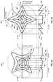
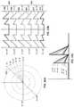
- FIGS. 1A and 1Bare diagrams of an exemplary ophthalmic apparatus (e.g., an interocular toric lens) that includes angularly-varying phase members (reflective, diffractive, or both) that provide an extended rotational tolerance of the apparatus in accordance with an illustrative embodiment.
- an exemplary ophthalmic apparatuse.g., an interocular toric lens
- phase membersreflective, diffractive, or both
- FIGS. 2A, 2B, and 2Cillustrate a plurality of exemplary height profiles of the anterior or posterior face of the ophthalmic apparatus of FIGS. 1A-1B in accordance with an illustrative embodiment.
- FIG. 3is a schematic drawing of a top view of a human eye, in which the natural lens of the eye has been removed and replaced with an ophthalmic apparatus that includes angularly-varying phase members in accordance with an illustrative embodiment.
- FIGS. 4A and 4Bare plots illustrating performance of a conventional toric lens designed to apply maximum cylinder power at a corrective meridian when subjected to rotational misalignment.
- FIGS. 5 and 6show plots of off-axis performances of an exemplary ophthalmic apparatus (diffractive and refractive) that includes angularly-varying phase members in accordance with an illustrative embodiment.
- FIGS. 7A and 7Bare diagrams of an exemplary ophthalmic apparatus that includes angularly-varying phase members in accordance with another illustrative embodiment.
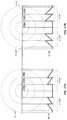
- FIGS. 8 and 9are diagrams illustrating height profiles of exemplary ophthalmic apparatuses of FIGS. 1 and 7 in accordance with the illustrative embodiments.
- FIG. 10is a diagram of an exemplary multi-focal lens ophthalmic apparatus that includes angularly-varying phase members in accordance with an illustrative embodiment.
- FIG. 11is a diagram illustrating the multi-focal lens ophthalmic apparatus of FIG. 10 configured as a bifocal lens in accordance with an illustrative embodiment.
- FIG. 12is a diagram illustrating the multi-focal lens ophthalmic apparatus of FIG. 10 configured as a tri-focal lens in accordance with an illustrative embodiment.
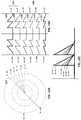
- FIG. 13is a diagram of an exemplary ophthalmic apparatus that includes angularly-varying phase members in accordance with another illustrative embodiment.
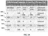
- FIG. 14is a table of the ophthalmic apparatus of FIG. 13 configured as a tri-focal lens in accordance with an illustrative embodiment.
- FIGS. 15A and 15Bare diagrams of an exemplary ophthalmic apparatus that includes angularly-varying phase members and an asymmetric height profile in accordance with an illustrative embodiment.
- FIGS. 16A, 16B and 16Cillustrate a plurality of exemplary height profiles of the ophthalmic apparatus of FIG. 15 in accordance with an illustrative embodiment.
- FIGS. 17A and 17Bare diagrams of an exemplary ophthalmic apparatus that includes angularly-varying phase members and a symmetric height profile in accordance with another illustrative embodiment.
- FIGS. 18A, 18B and 18Cillustrate a plurality of exemplary height profiles of the anterior or posterior face of the ophthalmic apparatus of FIG. 17 in accordance with an illustrative embodiment.
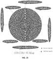
- FIGS. 19A and 19Bare diagrams illustrating a top and bottom view of an ophthalmic apparatus of FIG. 13 with extended tolerance band markers in accordance with an illustrative embodiment.
- FIG. 20is a flow chart of a method to determine the spherical equivalent (SE) and cylinder power for toric lenses and ophthalmic apparatuses having the extended band of operational meridian, an extended depth of focus, or extended range of vision, in accordance with an illustrative embodiment.
- SEspherical equivalent
- FIG. 21illustrates an example toric calculator that can be configured to receive a selection of an IOL model in accordance with an illustrative embodiment.
- FIG. 22illustrates an exemplary computer that can be used determining optical configuration (e.g. IOL spherical equivalent and cylinder power) of a rotationally-extended tolerant ophthalmic apparatus for the selection thereof.
- optical configuratione.g. IOL spherical equivalent and cylinder power
- Embodiments of the present inventionare generally directed to toric lenses or surface shapes, and/or related methods and systems for fabrication and use thereof.
- Toric lenses according to embodiments of the present disclosurefind particular use in or on the eyes of human or animal subjects.
- Embodiments of the present disclosureare illustrated below with particular reference to intraocular lenses; however, other types of lenses fall within the scope of the present disclosure.
- Embodiments of the present disclosureprovide improved ophthalmic lens (including, for example, contact lenses, and interocular lenses, corneal lenses and the like) and include monofocal diffractive lenses, bifocal diffractive lenses, and multifocal diffractive lenses.
- optical powermeans the ability of a lens or optics, or portion thereof, to converge or diverge light to provide a focus (real or virtual), and is commonly specified in units of reciprocal meters (m ⁇ 1 ) or Diopters (D).
- optical powermeans the optical power of the intraocular lens when disposed within a media having a refractive index of 1.336 (generally considered to be the refractive index of the aqueous and vitreous humors of the human eye), unless otherwise specified.
- the optical power of a lens or opticis from a reference plane associated with the lens or optic (e.g., a principal plane of an optic).
- a cylinder powerrefers to the power required to correct for astigmatism resulting from imperfections of the cornea and/or surgically induced astigmatism.
- the terms “about” or “approximately”, when used in reference to a linear dimensionmean within plus or minus one percent (1%) of the value of the referenced linear dimension.
- FIGS. 1A and 1Bare diagrams of an exemplary ophthalmic apparatus 100 (e.g., an interocular toric lens) that includes angularly-varying phase members (reflective, diffractive, or both) configured to provided extended rotational tolerance in accordance with an illustrative embodiment.
- exemplary ophthalmic apparatus 100e.g., an interocular toric lens
- phase membersreflective, diffractive, or both
- the angularly-varying phase membershas a center structure that applies cylinder power at a corrective meridian (e.g., the high power meridian).
- Off-center structures of the angularly-varying phase membersextends from the center structure in a gradually varying manner to apply cylinder power to a band of meridians surrounding the corrective meridian enabling the ophthalmic apparatus to operate off-axis (or off-meridian) to the corrective meridian (e.g., the astigmatism meridian).
- These meridiansmay be referred to as a dynamic meridian.
- the angularly-varying phase membersincludes an optimized combination of angularly and zonally diffractive (or refractive) phase structure located at each meridian to vary the extended depth of focus to a plurality of nearby focus points. Light directed to such nearby focus points are thus directed to the desired focus point when the ophthalmic apparatus is subjected to a rotational offset from a primary intended axis of alignment, thereby extending the rotational tolerance of the apparatus to an extended tolerance band.
- this extended tolerance astigmatism banddelivers cylinder power to correct for the astigmatism for a range of meridians (e.g., up to ⁇ 5° or more), thereby eliminating any need for additional corrective measures (e.g., supplemental corrective devices or another surgical interference) when the implanted ophthalmic apparatus is not perfectly aligned to the desired astigmatism meridian in the eye.
- additional corrective measurese.g., supplemental corrective devices or another surgical interference
- the angularly-varying phase membersenable an extended band of the corrective meridian (e.g., up to 10° or more) that has minimal, and/or clinically acceptable, degradation of the visual acuity and modulation transfer function when the ophthalmic apparatus is subject to rotational misalignment between the astigmatic axis and a center axis of the corrective meridian.
- an extended band of the corrective meridiane.g., up to 10° or more
- the angularly-varying phase membersenable an extended band of the corrective meridian (e.g., up to 10° or more) that has minimal, and/or clinically acceptable, degradation of the visual acuity and modulation transfer function when the ophthalmic apparatus is subject to rotational misalignment between the astigmatic axis and a center axis of the corrective meridian.
- an exemplified toric intraocular lensincludes dynamic meridian or angularly varying efficiency quadric optics.
- an exemplified toric IOLincludes dynamic meridian or angularly varying efficiency trifocal optics.
- an exemplified toric IOLincludes double dynamic meridian or angularly varying efficiency bifocal optics.
- the bifocal or trifocal featuremay be disposed on one optical surface or on both optical surfaces of a single optical lens or on any surfaces of a multiple optical elements working together as a system.
- the angularly-varying phase membersis formed in a multiple-zone structure (shown as zones 120 a , 120 b , 120 c ), each having a spatially-varying “butterfly” shaped structure centered around the optical axis 106 .
- the first corrective meridian 110focuses light that passes therethrough to a first foci (i.e., point of focus) and is intended to align with the astigmatic axis of the eye.
- the angularly-varying phase membersfocus light that passes therethrough to a plurality of foci near the first foci.
- both the heights of the lens and the spatial sizes, at each zonevaries among the different axes to form the angularly-varying phase member.
- the height profile of the lensvaries at each axis as the first height profile gradually transitions (e.g., as shown by the curved profile 122 ) into the second height profile.
- the first and second height profiles 116 and 118are illustrated relative to one another in a simplified format. It should be appreciated that the height profiles are superimposed on a lens having a curvature, as for example, illustrated in FIG. 3 .
- height profiles hereinare illustrated in a simplified form (e.g., as a straight line).
- the height profiles for each zonemay have other shapes—such as convex, concave, or combinations thereof.
- the second corrective meridian 112focuses light to a second set of foci.
- the height profiles at axes nearby to the first high power meridianhave a similar height profile, as the first high power meridian.
- the height profilevaries in a continuous gradual manner (e.g., having a sine and cosine relationship) along the radial direction. This can be observed in FIGS. 2B and 2C .
- This variation of the height profile along the radial axisprovides a lens region that focuses light at the desired foci and other foci nearby.
- FIG. 3is a schematic drawing of a top view of a human eye 302 , in which the natural lens of the eye has been removed and replaced with an intraocular lens 100 (shown in simplified form in the upper portion of FIG. 3 and in greater detail in the lower portion of FIG. 3 ).
- Light enters from the left of FIG. 3and passes through the cornea 304 , the anterior chamber 306 , the iris 308 , and enters the capsular bag 310 .
- the natural lensoccupies essentially the entire interior of the capsular bag 310 .
- the capsular bag 310houses the intraocular lens 100 , in addition to a fluid that occupies the remaining volume and equalizes the pressure in the eye.
- the intraocular lenscomprises an optic 101 and may include one or more haptics 326 that are attached to the optic 101 and may serve to center the optic 101 in the eye and/or couple the optic 101 to the capsular bag 310 and/or zonular fibers 320 of the eye.
- the optic 101has an anterior surface 334 and a posterior surface 336 , each having a particular shape that contributes to the refractive properties of the lens. Either or both of these lens surfaces may optionally have an element made integral with or attached to the surfaces.
- the refractive and/or diffractive elements on the anterior and/or posterior surfacesin some embodiments, have anamorphic or toric features that can generate astigmatism to offset the astigmatism from a particular cornea in an eye.
- the optics 101in some embodiments, comprises the interocular lens 100 .
- the interocular lens 101includes angularly-varying phase members (reflective, diffractive, or both) that focus at a plurality of focus points that are offset radially to one another so as to provide an extended tolerance to misalignments of the lens 100 when implanted into the eye 302 . That is, when the center axis of a corrective meridian is exactly matched to the desired astigmatic axis, only a first portion of the cylinder axis is focused at the desired point of focus ( 338 ) (e.g., at the retina) while second portions of the cylinder axis focuses at other points ( 340 ) nearby that are radially offset to the desired point of focus ( 338 ).
- phase membersreflective, diffractive, or both
- the second portion of the cylinder axisfocuses the light to the desired point of focus.
- Artificial lensescan correct for certain visual impairments such as an inability of the natural lens to focus at near, intermediate or far distances; and/or astigmatism.
- Intraocular toric lenseshave the potential for correcting astigmatism while also correcting for other vision impairments such as cataract, presbyopia, etc.
- intraocular toric lensesmay not adequately correct astigmatism due to rotational misalignment of the corrective meridian of the lenses with the astigmatic meridian.
- the corrective meridian of the implanted toric lensescan be rotationally misaligned to the astigmatic meridian, in some instances, by as much as 10 degrees.
- toric lenses that are designed to provide maximum correction (e.g., 1 D to 9 D) at the astigmatic meridianare subject to significant reduction in effectiveness of the correction due to any misalignment from the corrective meridian.
- FIG. 4includes plots that illustrated the above-discussed degraded performance of conventional toric lens when subjected to rotational misalignment.
- This conventional toric lensis configured to provide 6.00 Diopters cylinder powers at the IOL plane, 4.11 Diopters cylinder power at the corneal plane, and a corneal astigmatism correction range (i.e., preoperative corneal astigmatism to predicted effects) between 4.00 and 4.75 Diopters.
- a plot of undesired meridian power(also referred to as a residual meridian power (“OC”)) (shown along the y-axis) added due to the rotational misalignments (shown along the x-axis) of the toric IOL is shown, including the residual powers for a negative 10-degree misalignment (shown as line 402 ), a 0-degree misalignment (shown as line 404 ), and a positive 10-degree misalignment (shown as line 406 ).
- OCresidual meridian power
- the undesired added meridian powervaries between a maximum of ⁇ 0.75 Diopters at around the 45-degree meridian angle (shown as 408 ) and at about the 135-degree meridian angle (shown as 410 ).
- this undesired added meridian poweris outside the tolerance of a healthy human eye, which can tolerant undesired effects up to about 0.4 Diopters (e.g., at the cornea plane) for normal visual acuity (i.e., “20/20 vision”). Because the undesired effects exceeds the astigmatism tolerance of the human eye, corrective prescription glasses, or further surgical operation to correct the implant misalignment, may be necessary to mitigate the effects of the misalignment of such toric IOLs.
- This undesired meridian powermay be expressed as Equation 1 below.
- ⁇is the correction meridian (also referred to as the cylindrical power axis) (in degrees); C is the astigmatic power (at the IOL plane) to be corrected at meridian ⁇ (in Diopters); and a is the magnitude of rotational misalignment of the cylindrical power axis to the astigmatic axis (in degrees).
- FIG. 4Bshows a plot illustrating the tolerance of a toric IOL to misalignment (shown in the y-axis) and a corresponding cylindrical power that may be applied (shown in the x-axis) for each misalignment to not exceed the astigmatism tolerance of the human eye (i.e., degrade the overall visual acuity).
- the tolerance to misalignmentmay be calculated as
- FIGS. 5 and 6shows plots illustrating modular transfer functions (MTFs) in white light for two toric IOLs (shown as 502 a and 502 b ) each configured with angularly-varying phase members when subjected to off-axis rotations.
- FIG. 5illustrates the performance for a refractive toric IOL
- FIG. 6illustrates performance for a diffractive toric IOL.
- the cylinder power of the lens configured with angularly varying phase memberprovides an extended tolerance of misalignment up to 10 degrees and more of off-axis rotation.
- the modulation transfer functionMTF
- the MTF of a toric IOL without the angularly varying phase memberis near zero.
- the MTF at 3.5 degrees misalignment for a conventional toric lensis near zero.
- MTFis a modulation of the amplitude and phase functions of an image formed by the white light on a specified plane, for example, the retina of the human eye, and characterizes the sensitivity of the lens.
- an ophthalmic apparatusthat includes angularly varying phase members has a lower maximum cylinder range (as compared to lens without such structure). Rather, the angularly varying phase members applies the cylinder power to a band surrounding the corrective meridian, thereby providing a continuous band that makes the lens may tolerant due to misalignment. As shown, in this embodiment, the sensitivity of the ophthalmic apparatus with the angularly varying phase member is less by 20% as compared to a lens without the angularly varying phase member.
- the modulation transfer function (MTF) degradation for the ophthalmic apparatus configured with the angularly varying phase memberis still acceptable.
- the ophthalmic apparatus configured with the angularly varying phase memberis configured as a monofocal toric lens with 4.0 Diopters cylindrical power.
- the MTFis at 100 lp/-mm and has a spatial frequency equivalent to 30 c/degree for an emmetropia eye with 20/20 visual acuity.
- the performance of the toric IOL with the angularly varying phase member at 5 degrees off-meridianhas comparable MTF performance to a similar toric IOL without the structure at 2 degrees of misalignment.
- FIG. 7is a diagram of an ophthalmic apparatus 100 (e.g., an interocular toric lens) that includes angularly-varying phase members (reflective, diffractive, or both) that disperse light therethrough to a plurality of foci that are offset radially to one another so as to provide an extended tolerance to misalignments of the lens 100 when implanted in an eye in accordance with another illustrative embodiment.
- the apparatus 100has an asymmetric height profile 702 in which the maximum height of the face 704 of the apparatus differs between the different zones (see zones 120 b and 120 c ).
- the asymmetric height profilemay be configured to direct light to a plurality foci.
- the apparatus 100 with the asymmetric height profile 702may be used for as a trifocal lens.
- the apparatus with the asymmetric height profile 702is used for a quad-focal lens.
- the apparatus 100 with the asymmetric height profile 702is used for a double bi-focal lens.
- the apparatus 100 with the asymmetric height profile 702is used for a mono-focal lens.
- the apparatus 100 with the asymmetric height profile 702is used for a combined bi-focal and tri-focal lens.
- the apparatus 100 with the asymmetric height profile 702is used for an anterior bifocal and a posterior tri-focal lens. In some embodiments, the apparatus 100 with the asymmetric height profile 702 is used for a posterior bifocal and an anterior tri-focal lens.
- FIGS. 8 and 9illustrate a plurality of height profiles of the angularly-varying phase member of the lens in accordance with various illustrative embodiments.
- the height profileis symmetric at each meridian in that the maximum height (shown as 802 , 804 , and 806 ) at the face of the lens are the same.
- the height profileis asymmetric in that the maximum height at the face of the lens are different.
- FIG. 10illustrates an example multi-focal interocular lens 1000 configured with angularly varying phase member in accordance with an illustrative embodiment.
- the lensis refractive. In other embodiments, the lens is diffractive.
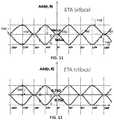
- FIGS. 11 and 12are diagrams illustrating added cylindrical power, from the angularly varying phase members, in the radial and angular position in accordance with the illustrative embodiments.
- FIG. 11illustrates added cylinder power by the angularly varying phase member for a multi-focal interocular lens configured as a bifocal.
- the added power to the non-peak corrective meridianincreases the tolerance of the IOL to misalignment from the corrective axis.
- FIG. 12illustrates a trifocal interocular lens with the angularly varying phase member in accordance with an illustrative embodiment.
- a trifocal optics 1202is added. The trifocal 1202 does not have an angularly varying phase member.
- FIG. 13illustrates an ophthalmic apparatus 1300 having angularly varying phase member to extend tolerance of ocular astigmatism by varying extended depth of focus at each meridian through an optimized combination of angularly and zonally diffractive phase structure on each meridian in accordance with an illustrative embodiment.
- the ophthalmic apparatus 1300includes a first corrective meridian 90°*N o ⁇ ° (variable 01), where ⁇ is the extended tolerance of the first corrective meridian, and N is an integer.
- the meridiansincludes 0° ( 1402 ), ⁇ 90° ( 1404 ), and 180° ( 1406 ).
- ⁇is ⁇ 3°, ⁇ 3.25°, ⁇ 3.5°, ⁇ 3.75°, ⁇ 4°, ⁇ 4°, ⁇ 4.25°, ⁇ 4.5°, ⁇ 4.75°, ⁇ 5°, ⁇ 5.25°, ⁇ 5.5°, ⁇ 5.75°, or ⁇ 6°.
- ⁇is ⁇ 5°
- the IOLwould have a dynamic and optimized efficiency for correcting astigmatic effects that can tolerate misalignment of the cylindrical axis up to 10 (variable 08) degrees.
- FIG. 14illustrates a table for a trifocal IOL configured with the angularly varying phase member.
- the light transmission efficiency at a first corrective foci 1402is about 100% while other foci along the same meridian is about 0%.
- the light transmission efficiencyvaries for three point of focus (shown as 1408 a , 1408 b , and 1408 c ) (e.g., at the front of the retina, at the retina, and behind the retina) of the optics at this meridian.
- the meridiansincludes ⁇ 45° and ⁇ 90°. As shown in FIG.
- the light transmission efficiencyis about 25% (variable 03), and the optics includes added power that matches the ocular astigmatic power corresponding to the human astigmatism tolerance level.
- the second foci ( 1408 b )e.g., at the retina
- the light transmission efficiencyis about 50% (variable 04) efficiency.
- the third foci ( 1408 c )e.g., behind the retina
- the opticsinclude added power having the same magnitude as the first foci though with an opposite sign.
- the focus on the retinahas efficiency between 0.5% and 100% (variable 06,) and the other focus not on the retina has efficiency between 0% and 25% (variable 07).
- T 1 (r, ⁇ )The thickness profile T 1 (r, ⁇ ) for the IOL may be characterized by Equation 2 below.
- T 1 ( r , ⁇ )t 1 ( r )
- t 1 (r) and t 2 (r)are step heights for each zone, and they each matches an optical path difference (OPD) from 0 to 2 ⁇ , where ⁇ is the design wavelength at zonal radius r.
- FIGS. 15, 16A, 16B, 16C, 17, 18A, 18B, and 18Cdepict the ophthalmic apparatus with angularly varying phase members in accordance with another illustrative embodiment.
- the angularly varying phase memberis located with a fixed-size zone and varies only along the angular position.
- the ophthalmic apparatusincludes a plurality of zones 1502 (shown as 1502 a , 1504 b , and 1504 c ).
- FIG. 17illustrates ophthalmic apparatus having a height profile across the multiple zones (shown as 1702 a , 1702 b , and 1702 c ) in which the height of the face of the lens angularly varies with the meridian axes.
- the ophthalmic apparatusincludes a plurality of alignment markings, including a first set of alignment markings 1302 and a second set of alignment markings 1304 , that indicate the corrective meridian of the lens.
- the second set of alignment markings 1304may include corresponding sets of markets to define a tolerance band for the lens.
- the second set of alignment markings 1304is located at ⁇ 5° radial offset from the first set of alignment markings 1302 .
- FIGS. 19A and 19Bdepicts an ophthalmic apparatus with an extended tolerance astigmatic band.
- the ophthalmic apparatusincludes the second set of alignment markings 1304 as discussed in relation to FIG. 13 .
- the present technologymay be used, for example, in the Tecnis toric intraocular lens product line as manufactured by Abbott Medical Optics, Inc. (Santa Ana, Calif.).
- the above disclosed angularly varying phase membermay be used for multifocal toric, extended range toric, and other categorized IOLs for extended tolerance of astigmatism caused by factors including the cylindrical axis misalignment.
- the above disclosed angularly varying phase membermay be applied to spectacle, contact lens, corneal inlay, anterior chamber IOL, or any other visual device or system.
- Extended Depth of FocusIntraocular lenses
- extended focusor extended depth of focus
- the reference opticmay have biconvex or biconcave surfaces, which may have equal radii of curvature, and an optical power or focal length that may be equal to an optical power or focal length of the test optic.
- the depth of focus for the test optic and the reference opticare determined under the same aperture conditions and under equivalent illumination conditions. Examples of extended depth of focus lenses are described in U.S. Publication No. 2011/0166652, filed Jul.
- EDOFis attributable to a particular surface feature, structure, or mask associated with the test optic
- the reference opticmay be made of the same material, and have the same structure, as the test optic, except without the particular feature, structure, or mask.
- a test opticis a refractive or diffractive multifocal optic including a mask for extending the depth of focus of at least one of the foci formed by the test optic
- a suitable reference opticmay be made of the same material(s) as the test optic and have the same structure as the test optic (e.g., surface shapes/curvatures, thickness, aperture, echelette geometry, and the like), but without the mask.
- the EDOF elementmay produce a depth of focus for each meridian.
- the depth of focusmay indicate a good focus for each meridian at a broader range of foci.
- good focusmay be a focus that proves useful for vision, and that may be measured using a point spread function, defocus curves, a modulation transfer function (MTF), or by analysis of the Zernike polynomial understood to those skilled in the pertinent arts.
- MTFmodulation transfer function
- ERV IOLExtended Range of Vision (ERV) Intraocular lens
- ERV IOLare a class of IOL lenses that provide patients with a continuous range of vision including far, intermediate, and near distances with reduced incidence of halo and glare comparable to a monofocal lens.
- the ERV IOLis also configured to increase the distance over which an object appears in focus without sacrificing the patient's visual clarity or contrast when compared with standard monofocal IOLs that provide improved distance vision only.
- MRSEmanifest refraction spherical equivalent
- MTFModulation Transfer Function
- MTFis an optical measurement of the modulation of the amplitude and phase functions of an image formed by white light on a specified plane, commonly a detector such as the retina of the human eye.
- MTFdescribes the contrast sensitivity of a lens system and may be used, for example, to predict or determine good focus, such as by simulation, and/or may be measured of the eye.
- MTFmay be characterized as a contrast between alternating bright and dark bars in an image. A value of “1” MTF indicates that the bright bars are completely bright and dark bars are completely dark. A value of “0” MTF indicates that the bright bars and dark bars are equally gray.
- MTFmay have a dependence on spatial frequency that is inversely related to the width of the alternating bright and dark bars in an image.
- an MTFmay be measured using white light or may use green light, such as approximately 550 nm wavelength light.
- the MTF in white lightcan be determined using, but not limited to, theoretical modeling and calculation in an eye model, or a MTF test bench following the MTF definition; experimental lab measurement using a MTF test bench; and in-vivo measurement of a patient's eye using a diagnosis instrument.
- “Spherical equivalent power”is an average dioptric power or average power for a lens.
- the power of a spectacle or toric lensis defined as the reciprocal of the distance from the position, for example, on the back surface of the lens where the line of sight passes through to the focal point in the eyeball.
- Light rays passing through the periphery of the lensform a plurality of focal points due to astigmatism.
- SE targetedis the planned post-operative refractive or residual sphere equivalent of, for example, a planned cataract surgery for an eye to receive an implant. It is typically determined by a doctor with tools like a toric calculator, personalized IOL power calculator, or pre- and/or in-surgery instrument.
- White lighta spectrum of light with different wavelengths commonly visible to the human eye such as the photopic or mesopic or even scotopic light.
- the wavelength rangetypically ranges from 380 nm to 750 nm.
- the rangecan be from 400 nm to 700 nm.
- the other filtered white lightcan be different.
- the transmission of each wavelengthcan be different, from 0% to 100% if normalized.
- an IOL calculatoris disclosed to determine the spherical equivalent (SE) and cylinder power for toric lenses and ophthalmic apparatuses having the extended band of operational meridian, such as the rotational extended tolerant toric intraocular lens (hereinafter “ETA toric IOL”), described herein.
- SEspherical equivalent
- ETA toric IOLthe rotational extended tolerant toric intraocular lens
- the IOL calculatormay also be used for an extended rotational tolerant toric intraocular lens (hereinafter “ETA toric IOL”), an extended depth of field intraocular lens (hereinafter “EDOF IOL”), an extended depth of field toric intraocular lens (hereinafter “EDOF toric IOL”), an extended range of vision intraocular lens (hereinafter “ERV IOL”), and an extended range of vision toric intraocular lens (ERV toric IOL).
- ETA toric IOLan extended rotational tolerant toric intraocular lens
- EEOF IOLextended depth of field intraocular lens
- EEOF toric IOLextended depth of field toric intraocular lens
- ERP IOLextended range of vision intraocular lens
- ERP toric IOLextended range of vision toric intraocular lens
- the exemplified IOL calculatordetermines a spherical equivalent and cylinder power to correctively apply to the toric lenses and ophthalmic apparatuses that beneficially minimize the residual refractive error associated therewith.
- the errormay be minimized for both the spherical equivalent and the cylinder power.
- the IOL calculatorseeks to minimize the intended corrective power for a given angle of misalignment, whereby the remaining available corrective power may be allocated to other angles of operation (i.e., at other angles of misalignment).
- the ETA toric IOLhas a reduced peak modulation transfer function at zero degree misalignment, but maintains the performance of the lens across a range of misalignments such as up to 10 degrees.
- a supplemental corrective lense.g., spectacle or contact lens
- a second surgical procedure being neededcan be reduced.
- the exemplified IOL calculatordetermines an initial spherical equivalent and/or cylinder power for an ophthalmic device to be used for a given eye and recursively adjusts the spherical equivalent and cylinder power to be in the range of benefit of the extended band of operational meridian.
- a trade-offis optimally achieved in which the expected residual refractive error is minimized, for a pre-defined range of angles of misalignment.
- the pre-defined range of anglesmay be expressed as a maximum misaligned angle expected, based on clinical data, for a class of toric lens, for example, having a given haptics or anchoring configuration.
- Examples of these range of anglesinclude ⁇ 2°, ⁇ 3°, ⁇ 4°, ⁇ 5°, ⁇ 6°, ⁇ 7°, ⁇ 8°, 9° and ⁇ 10° of misalignment. In some embodiments, greater than ⁇ 10° of misalignment may be used.
- FIG. 20is a flow chart of a method to determine the spherical equivalent (SE) and cylinder power for toric lenses and ophthalmic apparatuses having the extended band of operational meridian, an extended depth of focus, or extended range of vision.
- SEspherical equivalent
- Step 1In a workspace that presents visual representation of a calculator, the method, in some embodiments, includes presenting a list of IOL model (e.g., ETA IOL, ERV IOL, and EDOF IOL). As shown in FIG. 20 , a selection of an IOL is received along with either measurements parameters collected at a keratometry measurement device or a graphical user interface configured to receive keratometry and/or biometry information ( 2002 ), for example, from a user such as a physician or clinician.
- IOL modele.g., ETA IOL, ERV IOL, and EDOF IOL.
- FIG. 21illustrates an example toric calculator that can be configured to receive a selection of an IOL model.
- Table 1illustrates a listing of example IOL models that may be displayed for selection in the IOL calculator.
- Extended Depth of Focus Intraocular LensEEOF IOL
- EEOFExtended Depth of Focus
- Toric Intraocular LensEEOF toric IOL
- EV IOLExtended Range of Vision Intraocular Lens
- ETA IOLExtended Tolerant (Rotational) Astigmatism Intraocular Lens
- ETA IOLExtended Tolerant (Rotational) Astigmatism Toric Intraocular Lens
- Step 2Perform a calculation for the selected IOL model using one of known lens power calculation technique or calculator ( 2004 ).
- An example of an IOL calculatoris the AMO Toric Calculator “Tecnis® Toric Aspheric IOL”, provided by Abbott Medical Optics, Inc. (Santa Clara, Calif.)
- FIG. 20illustrates a graphical user interface of an AMO Toric Calculator.
- the graphical user interfacehas inputs to receive inputs for keratometry and/or biometry data for a given patient or class of patients, to determine cylinder power and spherical equivalents for the patient (or class thereof).
- the output of the calculationincludes spherical equivalent and cylinder power parameters ( 2006 ).
- the manifest refractive spherical equivalent (MRSE) and residual cylinder power (MRC)are also determined and are used to determine, for example, if the distance image is sufficient for each meridian ( 2008 ). If the MRSE and MRC are within acceptable ranges, for example, the distance image are good enough at each meridian ( 2008 ), the calculated spherical equivalent and cylinder power may be presented to the user ( 2010 ).
- IOL calculatorsmay use formulas such as Haigis L formula (“Haigis L”); the double K method with the Wang, Koch and Maloney (“DoubleK_WKM”) correction; the HofferQ formula; SRK optimized formula; SRK/T formula; and the Holladay1 formula. Further descriptions of these power calculator techniques are illustrated in Table 2 and are provided, for example, in U.S. application Ser. No. 14/148,420, title “Apparatus, System, and Method for Intraocular Lens Power Calculation Using a Regression Formula Incorporating Corneal Spherical Aberration,” the text of which is incorporated by reference herein in its entirety.
- SRK P140.8232 ⁇ 2.651 * AXL ⁇ 1.3102 * K + 4.767704 Optimized where P represents the IOL power to implant; AXL represents the axial length measured prior to the surgery; and K represents the corneal power also measured in the cataract preoperative stage.
- Step 3Predict random residual astigmatism power for the residual cylinder ( 2012 ).
- the possible range of the refractive or residual cylinder (RC)can be calculated.
- Equation 1the residual meridian power
- the residual meridian powercan be calculated using an expected maximum value for ⁇ . In the above example, if a given lens is designed to be tolerant up to 10 degrees of misalignment, a can be specified as 10 degrees.
- the random residual cylindercan be randomly selected value, for example, up to 1.5 diopters. The selection may be based on Monte Carlo simulation, or other statistically derived simulations.
- the random residual astigmatism powercan be a maximum value (such as 1.5 diopters) selected for a given intraocular designs design. In such embodiments, it should be appreciated that other powers may be selected based on the lens and the underlying pathology of the patient.
- Step 4Add 1 ⁇ 2 residual cylinder (RC) (myopia), for example, determined in Step 3 , to the targeted spherical equivalent (SE) ( 2014 ).
- the goalis to cause, post-operatively, the far end vision of SE value+1 ⁇ 2 RC to be the distance vision. It is contemplated that other RC values may be used.
- the new targeted SEcan be calculated as 0+1 ⁇ 2 (1.5 D), which results in a value of 0.75 Diopters.
- This additionis intended to cause the image of a distant object to be clear in any meridian, when using EDOF/ETA features described herein.
- the residual cylinderis a negative parameter (i.e., “ ⁇ 1 ⁇ 2RC”) (e.g., for hyperopia) based on the convention used by the user.
- a 5-degree misalignment of the toric lens from the intended corrective meridiancan cause a residual (refractive) of 0.75 Diopters RC and about 0.4 Diopters SE for distance vision.
- the residual cylinderis outside the range of tolerance of a healthy human eye (e.g., the astigmatism tolerance of a typical human eye is about 0.4 D at the cornea plane to produce a 20/20 vision)
- a supplemental corrective lenssuch as a spectacle or contact lens
- use of a supplemental corrective lensmay still be needed to achieve normal visual acuity (i.e., 20/20 vision).
- a patientmay still need to need to wear supplemental eyewear (e.g., spectacle or contact lens) to have 20/20 vision or to correct for some visual effects (e.g., halo or glare) at 20/20 vision.
- supplemental eyeweare.g., spectacle or contact lens
- the resultin this example, will be 0.2 D RC with ⁇ 0.4 D SE.
- Step 5Re-run the calculation and add the residual refraction through focus and meridian three-dimensional flow (e.g., 2014 , 2004 , and 2008 ).
- thishas the effect of providing an enhanced modulation transfer function through focus and additional through meridian at each focus plane. That is, after the update to the targeted SE, the corresponding other residuals (refractions) can be again simulated and calculated at each meridian at a position focused, at the positions in the front (myopia) of the focused position, which can be combined to generate the through focus and meridian refractions.
- the corresponding MTFsare the through focus and meridian MTFs.
- the through focus positionscan be represented by the visual object in the interested distance, manifest refractions, or image focus positions relative to the retina.
- the through focus performancecan be represented by the MTF values at a given spatial frequency or a contrast or VA (simulated). This is the method of referred to as “3D flow.”
- Step 6Heighted the designed feature or benefit in the above range. That is, adjust the height profile of the lens (e.g., the lens height profile for a given angular phase member), for example, for a given zone.
- the height profile of the lense.g., the lens height profile for a given angular phase member
- Step 7Output the spherical equivalent and power cylinder if all the powers at each meridians are in an acceptable ranges for the defined set of distance ( 2010 ).
- the manifest refraction spherical equivalent (MRSE) parameter and/or manifest residual cylinder (MRC)are calculated by using, for example, a conventional clinic VA letter chart test with trial glasses.
- Step 8If all the powers at meridians are not in the desired range (e.g., as determined in Step 7 ) ( 2008 ), add residual cylinder power and repeat Steps 5 - 8 .
- the use of minimum added powerallows the toric lenses and ophthalmic apparatuses to operate both in range of the IOL benefit—thereby potentially minimizing the residual refractive error, including SE and cylinder power—and maximizing the spectacle or contact lenses (CL) independence.
- the benefits of the ETA IOL and ETA toric IOL as described in FIGS. 5 and 6can be maximally realized with intended post-operation vision achieving the uncorrected visual acuity of 20/20 vision.
- the above disclosed new solutionscan also be used for power calculations for multifocal toric, extended range toric, or other categorized IOLs for extended tolerance of astigmatism caused by factors including the cylindrical axis mi-alignment
- the above mentioned solutioncan also be applied to power calculation for spectacle, contact lens, corneal inlay, anterior chamber IOL, or any other visual device or system.
- FIG. 22illustrates an exemplary computer that can be used for determining optical configuration (e.g. IOL spherical equivalent and cylinder power) of a rotationally-extended tolerant ophthalmic apparatus for the selection thereof.
- the computer of FIG. 22may comprise all or a portion of the IOL calculator, as described herein.
- “computer”may include a plurality of computers.
- the computersmay include one or more hardware components such as, for example, a processor 2221 , a random access memory (RAM) module 2222 , a read-only memory (ROM) module 2223 , a storage 2224 , a database 2225 , one or more input/output (I/O) devices 2226 , and an interface 2227 .
- RAMrandom access memory
- ROMread-only memory
- controller 2220may include one or more software components such as, for example, a computer-readable medium including computer executable instructions for performing a method associated with the exemplary embodiments. It is contemplated that one or more of the hardware components listed above may be implemented using software.
- storage 2224may include a software partition associated with one or more other hardware components. It is understood that the components listed above are exemplary only and not intended to be limiting.
- Processor 2221may include one or more processors, each configured to execute instructions and process data to perform one or more functions associated with a computer for indexing images.
- Processor 2221may be communicatively coupled to RAM 2222 , ROM 2223 , storage 2224 , database 2225 , I/O devices 2226 , and interface 2227 .
- Processor 2221may be configured to execute sequences of computer program instructions to perform various processes.
- the computer program instructionsmay be loaded into RAM 2222 for execution by processor 2221 .
- processorrefers to a physical hardware device that executes encoded instructions for performing functions on inputs and creating outputs.
- RAM 2222 and ROM 2223may each include one or more devices for storing information associated with operation of processor 2221 .
- ROM 2223may include a memory device configured to access and store information associated with controller 2220 , including information associated with IOL lenses and their parameters.
- RAM 2222may include a memory device for storing data associated with one or more operations of processor 2221 .
- ROM 2223may load instructions into RAM 2222 for execution by processor 2221 .
- Storage 2224may include any type of mass storage device configured to store information that processor 2221 may need to perform processes consistent with the disclosed embodiments.
- storage 2224may include one or more magnetic and/or optical disk devices, such as hard drives, CD-ROMs, DVD-ROMs, or any other type of mass media device.
- Database 2225may include one or more software and/or hardware components that cooperate to store, organize, sort, filter, and/or arrange data used by controller 2220 and/or processor 2221 .
- database 2225may store hardware and/or software configuration data associated with input-output hardware devices and controllers, as described herein. It is contemplated that database 2225 may store additional and/or different information than that listed above.
- I/O devices 2226may include one or more components configured to communicate information with a user associated with controller 2220 .
- I/O devicesmay include a console with an integrated keyboard and mouse to allow a user to maintain a database of images, update associations, and access digital content.
- I/O devices 2226may also include a display including a graphical user interface (GUI) for outputting information on a monitor.
- GUIgraphical user interface
- I/O devices 2226may also include peripheral devices such as, for example, a printer for printing information associated with controller 2220 , a user-accessible disk drive (e.g., a USB port, a floppy, CD-ROM, or DVD-ROM drive, etc.) to allow a user to input data stored on a portable media device, a microphone, a speaker system, or any other suitable type of interface device.
- peripheral devicessuch as, for example, a printer for printing information associated with controller 2220 , a user-accessible disk drive (e.g., a USB port, a floppy, CD-ROM, or DVD-ROM drive, etc.) to allow a user to input data stored on a portable media device, a microphone, a speaker system, or any other suitable type of interface device.
- Interface 2227may include one or more components configured to transmit and receive data via a communication network, such as the Internet, a local area network, a workstation peer-to-peer network, a direct link network, a wireless network, or any other suitable communication platform.
- interface 2227may include one or more modulators, demodulators, multiplexers, demultiplexers, network communication devices, wireless devices, antennas, modems, and any other type of device configured to enable data communication via a communication network.
Landscapes
- Health & Medical Sciences (AREA)
- Ophthalmology & Optometry (AREA)
- Physics & Mathematics (AREA)
- Engineering & Computer Science (AREA)
- General Health & Medical Sciences (AREA)
- General Physics & Mathematics (AREA)
- Life Sciences & Earth Sciences (AREA)
- Veterinary Medicine (AREA)
- Animal Behavior & Ethology (AREA)
- Public Health (AREA)
- Biomedical Technology (AREA)
- Heart & Thoracic Surgery (AREA)
- Optics & Photonics (AREA)
- Theoretical Computer Science (AREA)
- Cardiology (AREA)
- Oral & Maxillofacial Surgery (AREA)
- Transplantation (AREA)
- Vascular Medicine (AREA)
- General Engineering & Computer Science (AREA)
- Pure & Applied Mathematics (AREA)
- Computational Mathematics (AREA)
- Mathematical Analysis (AREA)
- Mathematical Optimization (AREA)
- Evolutionary Computation (AREA)
- Computer Hardware Design (AREA)
- Geometry (AREA)
- Biophysics (AREA)
- Medical Informatics (AREA)
- Surgery (AREA)
- Molecular Biology (AREA)
- Signal Processing (AREA)
- Computing Systems (AREA)
- Mathematical Physics (AREA)
- Eyeglasses (AREA)
- Prostheses (AREA)
- Architecture (AREA)
- Software Systems (AREA)
Abstract
Description
where α is the magnitude of rotational misalignment (in degrees). The calculation may be reduced to
As shown, for a misalignment of 5 degrees, which is routinely observed in IOL implantations, the correction effectiveness of such IOL implants can only be maintained for a toric IOL with 3.75 Diopters or less. That is, a toric IOL having cylinder power above 3.75 Diopters would exhibit degraded visual acuity due to the residual power exceeding the astigmatism tolerance of a human eye. This effect is worsen with further degrees of misalignment. For example, at about 10 degrees, the effectiveness of a toric IOL is greatly reduced where only 1.5 Diopters cylinder power or less can be applied so as to not detrimentally effect the visual acuity. Given that cylinder power of convention toric IOLs may range between 1.00 Diopters and 9.00 Diopters, these toric IOLs are reduced in effectiveness post-operation due to the misalignments of cylinder axis.
T1(r,θ)=t1(r)|COS2(θ)|+t2(r)|SIN2(θ)| (Equation 2)
| TABLE 1 | |
| 1 | Extended Depth of Focus Intraocular Lens (EDOF IOL) |
| 2 | Extended Depth of Focus (EDOF) Toric Intraocular Lens |
| (EDOF toric IOL) | |
| 3 | Extended Range of Vision Intraocular Lens (ERV IOL) |
| 4 | Extended Range of Vision Toric Intraocular Lens (ERV toric IOL) |
| 5 | Extended Tolerant (Rotational) Astigmatism Intraocular Lens |
| (ETA IOL) | |
| 6 | Extended Tolerant (Rotational) Astigmatism Toric Intraocular Lens |
| (ETA toric IOL) | |
| TABLE 2 | |
| HofferQ | P = 2.057938 + 0.944393 * HofferQ + 4.671033 |
| SRK | P = 140.8232 − 2.651 * AXL − 1.3102 * K + 4.767704 |
| Optimized | where P represents the IOL power to implant; AXL |
| represents the axial length measured prior to the | |
| surgery; and K represents the corneal power also | |
| measured in the cataract preoperative stage. | |
| SRK/T | P = 1.70056 + 0.955562 * SRK/T |
| Holladay1 | P = 2.787859 + 0.888706 * Holladay + 9.695131 |
where C is the astigmatic power at the IOL plane to be corrected at meridian theta and the α is the misalignment of the cylindrical power axis. In some embodiments, for a given astigmatism power, the residual meridian power can be calculated using an expected maximum value for α. In the above example, if a given lens is designed to be tolerant up to 10 degrees of misalignment, a can be specified as 10 degrees.
Claims (11)
Priority Applications (1)
| Application Number | Priority Date | Filing Date | Title |
|---|---|---|---|
| US15/467,372US11123178B2 (en) | 2016-03-23 | 2017-03-23 | Power calculator for an ophthalmic apparatus with corrective meridians having extended tolerance or operation band |
Applications Claiming Priority (4)
| Application Number | Priority Date | Filing Date | Title |
|---|---|---|---|
| US201662312338P | 2016-03-23 | 2016-03-23 | |
| US201662312321P | 2016-03-23 | 2016-03-23 | |
| US201662363428P | 2016-07-18 | 2016-07-18 | |
| US15/467,372US11123178B2 (en) | 2016-03-23 | 2017-03-23 | Power calculator for an ophthalmic apparatus with corrective meridians having extended tolerance or operation band |
Publications (2)
| Publication Number | Publication Date |
|---|---|
| US20170273779A1 US20170273779A1 (en) | 2017-09-28 |
| US11123178B2true US11123178B2 (en) | 2021-09-21 |
Family
ID=58461514
Family Applications (3)
| Application Number | Title | Priority Date | Filing Date |
|---|---|---|---|
| US15/467,963ActiveUS10646329B2 (en) | 2016-03-23 | 2017-03-23 | Ophthalmic apparatus with corrective meridians having extended tolerance band |
| US15/467,372Active2037-08-23US11123178B2 (en) | 2016-03-23 | 2017-03-23 | Power calculator for an ophthalmic apparatus with corrective meridians having extended tolerance or operation band |
| US16/871,296Active2037-04-30US11291538B2 (en) | 2016-03-23 | 2020-05-11 | Ophthalmic apparatus with corrective meridians having extended tolerance band |
Family Applications Before (1)
| Application Number | Title | Priority Date | Filing Date |
|---|---|---|---|
| US15/467,963ActiveUS10646329B2 (en) | 2016-03-23 | 2017-03-23 | Ophthalmic apparatus with corrective meridians having extended tolerance band |
Family Applications After (1)
| Application Number | Title | Priority Date | Filing Date |
|---|---|---|---|
| US16/871,296Active2037-04-30US11291538B2 (en) | 2016-03-23 | 2020-05-11 | Ophthalmic apparatus with corrective meridians having extended tolerance band |
Country Status (5)
| Country | Link |
|---|---|
| US (3) | US10646329B2 (en) |
| EP (3) | EP3932368B1 (en) |
| AU (2) | AU2017237095B2 (en) |
| CA (2) | CA3018545A1 (en) |
| WO (2) | WO2017165623A1 (en) |
Cited By (2)
| Publication number | Priority date | Publication date | Assignee | Title |
|---|---|---|---|---|
| WO2023137462A1 (en)* | 2022-01-14 | 2023-07-20 | Ast Products, Inc. | Aspheric phase-ring structured lens designs, manufacture, and uses thereof |
| US11963868B2 (en) | 2020-06-01 | 2024-04-23 | Ast Products, Inc. | Double-sided aspheric diffractive multifocal lens, manufacture, and uses thereof |
Families Citing this family (13)
| Publication number | Priority date | Publication date | Assignee | Title |
|---|---|---|---|---|
| US12383393B2 (en) | 2014-05-12 | 2025-08-12 | Gholam A. Peyman | Ablatable corneal inlay for correction of refractive errors and/or presbyopia |
| AU2018306502B2 (en)* | 2017-07-24 | 2024-04-04 | Alcon Inc. | Ophthalmic lens having morphed sinusoidal phase shift structures |
| CN109725441A (en)* | 2017-10-28 | 2019-05-07 | 郑克立 | A kind of holographic glasses piece |
| WO2020031321A1 (en)* | 2018-08-09 | 2020-02-13 | 株式会社ニコン | Ophthalmic lens and method for manufacturing ophthalmic lens |
| CN109214945B (en)* | 2018-10-11 | 2022-07-05 | 中石化石油工程技术服务有限公司 | A method and system for calculating the buried depth of a single well formation interface |
| CN111291458B (en)* | 2018-11-20 | 2023-05-26 | 核工业西南物理研究院 | A Method for Determining 3D Coordinates of ECRH System Antenna Focusing Mirror Profile |
| EP4524992A3 (en)* | 2019-01-22 | 2025-06-04 | Alcon Inc. | Systems and methods for intraocular lens selection using emmetropia zone prediction |
| US11596513B2 (en) | 2020-03-23 | 2023-03-07 | Gholam Peyman | Optical implant and methods of implantation |
| US11980542B2 (en)* | 2020-03-23 | 2024-05-14 | Gholam Peyman | Optical implant and methods of implantation |
| CN111513917B (en)* | 2020-05-22 | 2022-03-22 | 杭州明视康眼科医院有限公司 | Transposition adjusting method for astigmatism type ICL postoperative residual astigmatism and method for estimating diopter after transposition adjustment |
| US11126012B1 (en) | 2020-10-01 | 2021-09-21 | Michael Walach | Broadview natural addition lens |
| CN115755417A (en)* | 2022-09-14 | 2023-03-07 | 南京师范大学 | Control and imaging system of a symmetrical butterfly beam |
| DE102023106207A1 (en) | 2023-03-13 | 2024-09-19 | Carl Zeiss Meditec Ag | Ophthalmic lens with extended depth of field and method for producing a lens design |
Citations (296)
| Publication number | Priority date | Publication date | Assignee | Title |
|---|---|---|---|---|
| US2077092A (en) | 1936-01-13 | 1937-04-13 | Broder Simon | Ophthalmic lens |
| US3305294A (en) | 1964-12-03 | 1967-02-21 | Optical Res & Dev Corp | Two-element variable-power spherical lens |
| US3367734A (en) | 1963-02-22 | 1968-02-06 | Vockenhuber Karl | Supplementary objective with continuously variable magnification |
| US3735685A (en) | 1971-05-07 | 1973-05-29 | Polaroid Corp | Reflective imaging apparatus |
| US4010496A (en) | 1975-10-01 | 1977-03-08 | Neefe Charles W | Bifocal lens which positions within the anterior chamber |
| US4056311A (en) | 1973-08-16 | 1977-11-01 | American Optical Corporation | Progressive power ophthalmic lens having a plurality of viewing zones with non-discontinuous variations therebetween |
| US4162122A (en) | 1977-09-14 | 1979-07-24 | Cohen Allen L | Zonal bifocal contact lens |
| US4210391A (en) | 1977-09-14 | 1980-07-01 | Cohen Allen L | Multifocal zone plate |
| DE8107675U1 (en) | 1981-03-03 | 1981-07-30 | Porsche Design Produkte Vertriebsgesellschaft mbH, 5020 Salzburg | "TRIANGLE RULER" |
| US4319564A (en) | 1980-01-03 | 1982-03-16 | Karickhoff John R | Instrument for measurement of the diameter of the anterior chamber of the eye |
| US4338005A (en) | 1978-12-18 | 1982-07-06 | Cohen Allen L | Multifocal phase place |
| US4340283A (en) | 1978-12-18 | 1982-07-20 | Cohen Allen L | Phase shift multifocal zone plate |
| US4370760A (en) | 1981-03-25 | 1983-02-01 | Kelman Charles D | Anterior chamber intraocular lens |
| US4377873A (en) | 1980-10-30 | 1983-03-29 | Reichert Jr Henry L | Intraocular lens |
| US4402579A (en) | 1981-07-29 | 1983-09-06 | Lynell Medical Technology Inc. | Contact-lens construction |
| US4403353A (en) | 1981-06-25 | 1983-09-13 | Tennant Jerald L | Anterior chamber implant lens |
| US4404694A (en) | 1982-03-18 | 1983-09-20 | Kelman Charles D | Intraocular lens |
| US4409691A (en) | 1981-11-02 | 1983-10-18 | Levy Chauncey F | Focussable intraocular lens |
| US4424597A (en) | 1981-05-13 | 1984-01-10 | Inprohold Establishment | Posterior chamber implant lens |
| US4446581A (en) | 1981-09-02 | 1984-05-08 | Blake L W | Intraocular lens with free-ended sizing prong |
| US4480340A (en) | 1981-02-18 | 1984-11-06 | Shepard Dennis D | Intraocular lens with resilient support means |
| US4500382A (en) | 1983-06-10 | 1985-02-19 | Transilwrap Company, Inc. | Method of manufacture of resin film precision biomedical article |
| US4504982A (en) | 1982-08-05 | 1985-03-19 | Optical Radiation Corporation | Aspheric intraocular lens |
| US4551864A (en) | 1983-08-18 | 1985-11-12 | Iolab Corporation | Anterior chamber lens |
| US4556998A (en) | 1983-08-04 | 1985-12-10 | Siepser Steven B | Artificial intraocular lenses and method for their surgical implantation |
| US4560383A (en) | 1983-10-27 | 1985-12-24 | Leiske Larry G | Anterior chamber intraocular lens |
| DE3439551A1 (en) | 1984-10-29 | 1986-04-30 | Inprohold Establishment, Vaduz | ONE-PIECE IMPLANTING LENS |
| US4593981A (en) | 1983-05-06 | 1986-06-10 | Master Contact Lens Labs Inc. | Bifocal contact lens |
| WO1986003961A1 (en) | 1984-12-31 | 1986-07-17 | Antti Vannas | Intraocular lens |
| US4605409A (en) | 1984-05-21 | 1986-08-12 | Kelman Charles D | Intraocular lens with miniature optic having expandable and contractible glare-reducing means |
| US4605411A (en) | 1984-09-27 | 1986-08-12 | Moskovsky Nauchno-Issledovatelsky Institut Mikrokhirurgii Glaza | Anterior-chamber intraocular prosthetic lens |
| US4629462A (en) | 1984-07-13 | 1986-12-16 | Feaster Fred T | Intraocular lens with coiled haptics |
| US4629460A (en) | 1984-06-25 | 1986-12-16 | Dyer Robert L | Intraocular lens |
| US4636049A (en) | 1983-09-20 | 1987-01-13 | University Optical Products Co. | Concentric bifocal contact lens |
| US4637697A (en) | 1982-10-27 | 1987-01-20 | Pilkington P.E. Limited | Multifocal contact lenses utilizing diffraction and refraction |
| US4642112A (en) | 1981-04-29 | 1987-02-10 | Pilkington P.E. Limited | Artificial eye lenses |
| US4655565A (en) | 1984-02-23 | 1987-04-07 | Pilkington P.E. Limited | Ophthalmic lenses with diffractive power |
| EP0226400A2 (en) | 1985-12-04 | 1987-06-24 | Allergan, Inc | Intraocular lens |
| US4676791A (en) | 1985-08-01 | 1987-06-30 | Surgidev Corporation | Intraocular lens and method for making same |
| US4676792A (en) | 1986-08-26 | 1987-06-30 | Donald Praeger | Method and artificial intraocular lens device for the phakic treatment of myopia |
| EP0227357A2 (en) | 1985-12-09 | 1987-07-01 | Allergan, Inc | Intraocular lens and method of manufacture |
| US4681102A (en) | 1985-09-11 | 1987-07-21 | Bartell Michael T | Apparatus and method for insertion of an intra-ocular lens |
| US4687484A (en) | 1983-12-12 | 1987-08-18 | Kaplan Linda J | Anterior chamber intraocular lens |
| US4687485A (en) | 1985-08-23 | 1987-08-18 | Barnes-Hind, Inc. | Intraocular lens with leg means having compressible regions and/or color |
| USRE32525E (en) | 1980-04-01 | 1987-10-20 | Universal intraocular lens and a method of measuring an eye chamber size | |
| US4725277A (en) | 1986-05-14 | 1988-02-16 | Precision-Cosmet Co., Inc. | Intraocular lens with tapered haptics |
| US4734095A (en) | 1983-08-04 | 1988-03-29 | Siepser Steven B | Self-centering artificial introaocular lens |
| US4778462A (en) | 1987-08-24 | 1988-10-18 | Grendahl Dennis T | Multiple element zone of focus artificial lens |
| US4781717A (en) | 1985-07-24 | 1988-11-01 | Grendahl Dennis T | Intraocular lens |
| US4787904A (en) | 1984-07-06 | 1988-11-29 | Severin Sanford L | Hydrophillic intraocular lens |
| US4787903A (en) | 1985-07-24 | 1988-11-29 | Grendahl Dennis T | Intraocular lens |
| US4795462A (en) | 1987-08-24 | 1989-01-03 | Grendahl Dennis T | Cylindrically segmented zone of focus artificial lens |
| US4798609A (en) | 1987-08-24 | 1989-01-17 | Grendahl Dennis T | Radially segmented zone of focus artificial lens |
| US4798608A (en) | 1987-08-24 | 1989-01-17 | Grendahl Dennis T | Laminated zone of focus artificial lens |
| US4828558A (en) | 1987-07-28 | 1989-05-09 | Kelman Charles D | Laminate optic with interior Fresnel lens |
| US4834748A (en) | 1987-09-29 | 1989-05-30 | Allergan, Inc. | Method and apparatus for removing corneal tissue |
| US4863539A (en) | 1987-11-06 | 1989-09-05 | Optical Radiation Corporation | Haptic attachment for intraocular lenses |
| CN1035363A (en) | 1987-11-12 | 1989-09-06 | 艾伦·L·科恩 | Lens with phase channel |
| EP0343067A1 (en) | 1988-05-19 | 1989-11-23 | ESSILOR INTERNATIONAL Compagnie Générale d'Optique | Diffractive lens with a composite profile |
| US4898461A (en) | 1987-06-01 | 1990-02-06 | Valdemar Portney | Multifocal ophthalmic lens |
| CN1039487A (en) | 1988-07-20 | 1990-02-07 | 艾伦·L·科恩 | Multifocal optical device |
| US4932970A (en) | 1988-05-17 | 1990-06-12 | Allergan, Inc. | Ophthalmic lens |
| US4995714A (en) | 1988-08-26 | 1991-02-26 | Cohen Allen L | Multifocal optical device with novel phase zone plate and method for making |
| US4997442A (en) | 1989-05-04 | 1991-03-05 | Alcon Laboratories, Inc. | Bicomposite intraocular lenses |
| US5016977A (en) | 1989-02-06 | 1991-05-21 | Essilor International-Compagnie Generale | Optical lens for correcting astigmatism |
| US5019097A (en) | 1989-11-22 | 1991-05-28 | Allergan, Inc. | Corneal onlay lenses and methods for attaching same |
| WO1991009336A1 (en) | 1989-12-07 | 1991-06-27 | Leonard Seidner | Corneal contact lenses |
| US5047052A (en) | 1987-11-06 | 1991-09-10 | Seymour Dubroff | Anterior chamber intraocular lens with four point fixation |
| US5054905A (en) | 1987-11-12 | 1991-10-08 | Cohen Allen L | Progressive intensity phase bifocal |
| US5056908A (en) | 1987-11-12 | 1991-10-15 | Cohen Allen L | Optic zone phase channels |
| US5066301A (en) | 1990-10-09 | 1991-11-19 | Wiley Robert G | Variable focus lens |
| EP0457553A2 (en) | 1990-05-14 | 1991-11-21 | Iolab Corporation | Multifocal multizone diffractive ophthalmic lenses |
| US5071432A (en) | 1988-05-11 | 1991-12-10 | Laboratoires Domilens | Anterior chamber intraocular implant |
| US5078742A (en) | 1989-08-28 | 1992-01-07 | Elie Dahan | Posterior chamber lens implant |
| US5089023A (en) | 1990-03-22 | 1992-02-18 | Massachusetts Institute Of Technology | Diffractive/refractive lens implant |
| US5117306A (en) | 1990-07-17 | 1992-05-26 | Cohen Allen L | Diffraction bifocal with adjusted chromaticity |
| US5120120A (en) | 1990-07-27 | 1992-06-09 | Cohen Allen L | Multifocal optical device with spurious order suppression and method for manufacture of same |
| US5121980A (en) | 1989-04-19 | 1992-06-16 | Cohen Allen L | Small aperture multifocal |
| US5121979A (en) | 1986-05-14 | 1992-06-16 | Cohen Allen L | Diffractive multifocal optical device |
| US5133749A (en) | 1991-05-13 | 1992-07-28 | Nordan Lee T | Centrating haptics |
| US5144483A (en) | 1986-05-14 | 1992-09-01 | Cohen Allen L | Diffractive multifocal optical device |
| US5147395A (en) | 1991-07-16 | 1992-09-15 | Allergan Inc. | Small incision endocapsulator IOL |
| US5147397A (en) | 1990-07-03 | 1992-09-15 | Allergan, Inc. | Intraocular lens and method for making same |
| US5173723A (en) | 1990-10-02 | 1992-12-22 | Volk Donald A | Aspheric ophthalmic accommodating lens design for intraocular lens and contact lens |
| WO1992022264A1 (en) | 1991-06-18 | 1992-12-23 | Allergan, Inc. | Multifocal ophthalmic lens |
| US5184405A (en) | 1991-12-18 | 1993-02-09 | Jonathan Cress | Method and device for fitting toric contact lenses |
| WO1993003409A1 (en) | 1991-08-09 | 1993-02-18 | Capricornia Contact Lens Pty. Ltd. | Toric lens with axis mislocation latitude |
| US5197981A (en) | 1992-04-23 | 1993-03-30 | Alcon Surgical, Inc. | Intraocular lens having haptic of specific curvature and proportion |
| US5201763A (en) | 1992-02-28 | 1993-04-13 | Allergan, Inc. | Thin intraocular lens |
| US5203790A (en) | 1991-11-12 | 1993-04-20 | Henry H. McDonald | Foldable plastic optical lens with reduced thickness light blocking segments, and anchoring means |
| US5217491A (en) | 1990-12-27 | 1993-06-08 | American Cyanamid Company | Composite intraocular lens |
| US5225997A (en) | 1990-06-05 | 1993-07-06 | Sygnus Controls Inc. | Automatic monitoring and remote reporting device |
| US5229797A (en) | 1990-08-08 | 1993-07-20 | Minnesota Mining And Manufacturing Company | Multifocal diffractive ophthalmic lenses |
| US5258025A (en) | 1990-11-21 | 1993-11-02 | Fedorov Svjatoslav N | Corrective intraocular lens |
| US5278592A (en) | 1991-05-30 | 1994-01-11 | Robert Marie | Ophthalmic lens |
| WO1995007487A1 (en) | 1993-09-09 | 1995-03-16 | Scientific Optics, Inc. | Asymmetric aspheric contact lens |
| US5408281A (en) | 1993-04-26 | 1995-04-18 | Ciba-Geigy | Multifocal contact lens |
| US5433745A (en) | 1993-10-13 | 1995-07-18 | Allergan, Inc. | Corneal implants and methods for producing same |
| US5476513A (en) | 1992-02-28 | 1995-12-19 | Allergan, Inc. | Intraocular lens |
| US5479220A (en) | 1991-10-09 | 1995-12-26 | Seiko Epson Corporation | Eyeglass lens |
| US5567365A (en) | 1993-06-14 | 1996-10-22 | Allergan, Inc. | Method of producing repositionable intraocular lenses |
| US5620720A (en) | 1994-11-29 | 1997-04-15 | Allergan | Cast molding of intraocular lenses |
| US5628796A (en) | 1994-07-04 | 1997-05-13 | Suzuki; Taketoshi | Intraocular lens |
| US5652638A (en) | 1995-05-04 | 1997-07-29 | Johnson & Johnson Vision Products, Inc. | Concentric annular ring lens designs for astigmatism |
| FR2745711A1 (en) | 1996-03-05 | 1997-09-12 | Ioltechnologie Production | FLEXIBLE IMPLANT FORMING INTRAOCULAR LENS FOR POSTERIOR CHAMBER |
| US5691800A (en) | 1995-01-23 | 1997-11-25 | Nikon Corporation | Ophthalmologic apparatus |
| US5699142A (en) | 1994-09-01 | 1997-12-16 | Alcon Laboratories, Inc. | Diffractive multifocal ophthalmic lens |
| US5716403A (en) | 1995-12-06 | 1998-02-10 | Alcon Laboratories, Inc. | Single piece foldable intraocular lens |
| US5748282A (en) | 1993-01-27 | 1998-05-05 | Pilkington Barnes Hind, Inc. | Multifocal contact lens |
| US5760871A (en) | 1993-01-06 | 1998-06-02 | Holo-Or Ltd. | Diffractive multi-focal lens |
| US5796462A (en) | 1995-05-04 | 1998-08-18 | Johnson & Johnson Vision Products, Inc. | Aspheric toric lens designs |
| US5801807A (en) | 1995-08-08 | 1998-09-01 | Nikon Corporation | Ophthalmic illumination device having adjustable transmittance member and microscope for operation using the same |
| WO1998056315A1 (en) | 1997-06-13 | 1998-12-17 | Chiron Vision Corporation | Intraocular lens |
| WO1999005499A1 (en) | 1997-07-24 | 1999-02-04 | Innotech, Inc. | Image quality mapper for progressive eyeglasses |
| EP0926531A1 (en) | 1997-12-16 | 1999-06-30 | ESSILOR INTERNATIONAL Compagnie Générale d'Optique | Multifocal ophthalmic lenses having a spherical aberration depending on the addition and the ametropia |
| EP0949529A2 (en) | 1998-04-10 | 1999-10-13 | Menicon Co., Ltd. | Toric multifocal lens having different astigmatism corrective optical powers in respective vision correction regions, and method of producing the same |
| US5968094A (en) | 1995-09-18 | 1999-10-19 | Emmetropia, Inc. | Compound intraocular lens |
| EP0957331A2 (en) | 1998-05-13 | 1999-11-17 | Tormek AB | Angle gauge for grinding sharp-edged tools |
| US6015435A (en) | 1996-10-24 | 2000-01-18 | International Vision, Inc. | Self-centering phakic intraocular lens |
| WO2000019906A1 (en) | 1998-10-05 | 2000-04-13 | Koninklijke Philips Electronics N.V. | Multiple angle needle guide |
| US6051024A (en) | 1995-10-06 | 2000-04-18 | Cumming; J. Stuart | Intraocular lenses with fixated haptics |
| US6055111A (en) | 1997-06-27 | 2000-04-25 | Fuji Photo Optical Co., Ltd. | Plastic lens and method of making a plastic lens |
| US6126283A (en) | 1998-10-29 | 2000-10-03 | Eastman Kodak Company | Format flexible ink jet printing |
| US6126286A (en) | 1996-05-21 | 2000-10-03 | Allergan | Enhanced monofocal ophthalmic lens |
| US6129759A (en) | 1997-12-10 | 2000-10-10 | Staar Surgical Company, Inc. | Frosted haptic intraocular lens |
| US6179870B1 (en) | 1996-05-03 | 2001-01-30 | Corneal Laboratoires | Flexible intraocular implant formed in one piece |
| WO2001011418A1 (en) | 1999-08-11 | 2001-02-15 | Johnson & Johnson Vision Care, Inc. | System and method of integrating corneal topographic data and ocular wavefront data with primary ametropia measurements to create a soft contact lens |
| US6210005B1 (en) | 1999-02-04 | 2001-04-03 | Valdemar Portney | Multifocal ophthalmic lens with reduced halo size |
| US6235055B1 (en) | 1999-08-09 | 2001-05-22 | Milton W. Chu | Intraocular lens having colored haptics for anterior/posterior orientation, and method for implanting it |
| WO2001035868A1 (en) | 1999-11-19 | 2001-05-25 | Corneal Industrie | Ring for capsular bag and assembly formed by same and its injector |
| US6261321B1 (en) | 1999-09-01 | 2001-07-17 | Robert E. Kellan | Phakic or aphakic intraocular lens assembly |
| WO2001054569A1 (en) | 2000-01-24 | 2001-08-02 | Bioshape Ag | Device and method for detecting the radius or an equivalent variable of the chamber angle of an eye |
| WO2001063344A1 (en) | 2000-02-22 | 2001-08-30 | Holo Or Ltd. | Simultaneous multifocal contact lens and method of utilizing same for treating visual disorders |
| US6286956B1 (en) | 1998-10-19 | 2001-09-11 | Mencion Co., Ltd. | Multifocal ocular lens including intermediate vision correction region between near and distant vision correction regions |
| WO2001082839A1 (en) | 2000-05-03 | 2001-11-08 | Advanced Medical Optics, Inc. | Accommodating, reduced add power multifocal intraocular lenses |
| US6319282B1 (en) | 1997-06-09 | 2001-11-20 | Morcher Gmbh | Capsular equatorial ring |
| WO2001089424A1 (en) | 2000-05-23 | 2001-11-29 | Pharmacia Groningen Bv | Methods of obtaining ophthalmic lenses providing the eye with reduced aberrations |
| US20010051825A1 (en) | 1999-12-27 | 2001-12-13 | Peterson Norman D. | Temporary lenses and method for providing correct lens power |
| US6338559B1 (en) | 2000-04-28 | 2002-01-15 | University Of Rochester | Apparatus and method for improving vision and retinal imaging |
| WO2002021194A2 (en) | 2000-09-08 | 2002-03-14 | Florida Optical Engineering, Inc. | Multifocal ophthalmic lens with induced aperture |
| US6419697B1 (en) | 2000-07-07 | 2002-07-16 | Charles David Kelman | Clip-on optic assembly |
| US20020118337A1 (en) | 1996-03-21 | 2002-08-29 | Perrott Colin Maurice | Single vision lenses |
| US6457826B1 (en) | 1998-08-06 | 2002-10-01 | John B. W. Lett | Multifocal aspheric lens |
| US6464355B1 (en) | 1997-09-02 | 2002-10-15 | Thieberger Gil | Ophthalmic lens synthesized from its specification |
| US20020173846A1 (en) | 2001-02-01 | 2002-11-21 | Larry Blake | Two part "L"- or "S"-shaped phakic IOL |
| US6488708B2 (en) | 1999-04-09 | 2002-12-03 | Faezeh Sarfarazi | Open chamber, elliptical, accommodative intraocular lens system |
| US6491721B2 (en) | 1998-04-15 | 2002-12-10 | Alcon Manufacturing, Ltd. | Toric intraocular lens material |
| US20020196412A1 (en) | 2001-05-31 | 2002-12-26 | Marc Abitbol | Aberration correction spectacle lens |
| US20020196408A1 (en) | 1995-03-03 | 2002-12-26 | Sujal Bhalakia | Production of optical elements |
| WO2003009053A1 (en) | 2001-07-20 | 2003-01-30 | Ocular Sciences, Inc. | Contact or intraocular lens and method for its preparation |
| US6527389B2 (en) | 1987-06-01 | 2003-03-04 | Advanced Medical Optics, Inc. | Multifocal ophthalmic lens |
| US6537317B1 (en) | 2000-05-03 | 2003-03-25 | Advanced Medical Optics, Inc. | Binocular lens systems |
| US6536899B1 (en) | 1999-07-14 | 2003-03-25 | Bifocon Optics Gmbh | Multifocal lens exhibiting diffractive and refractive powers |
| CN1406120A (en) | 1998-10-27 | 2003-03-26 | Minu通讯系统有限责任公司 | Lens conversion system for teledioptic or diffractive configurations |
| US6547822B1 (en) | 2000-05-03 | 2003-04-15 | Advanced Medical Optics, Inc. | Opthalmic lens systems |
| US20030076478A1 (en) | 2001-10-19 | 2003-04-24 | Bausch & Lomb Incorporated | Presbyopic vision improvement |
| US6557992B1 (en) | 2001-10-26 | 2003-05-06 | Hewlett-Packard Development Company, L.P. | Method and apparatus for decorating an imaging device |
| US6598606B2 (en) | 2000-05-24 | 2003-07-29 | Pharmacia Groningen Bv | Methods of implanting an intraocular lens |
| US6609793B2 (en) | 2000-05-23 | 2003-08-26 | Pharmacia Groningen Bv | Methods of obtaining ophthalmic lenses providing the eye with reduced aberrations |
| US20030171808A1 (en) | 2002-03-05 | 2003-09-11 | Phillips Andrew F. | Accommodating intraocular lens |
| US20040021824A1 (en) | 2002-07-31 | 2004-02-05 | Ming Ye | Toric multifocal contact lenses |
| US20040021825A1 (en) | 2002-07-31 | 2004-02-05 | Richardson Gary A. | Smoothly blended optical surfaces |
| US6705729B2 (en) | 2000-12-22 | 2004-03-16 | Pharmacia Groningen Bv | Methods of obtaining ophthalmic lenses providing the eye with reduced aberrations |
| US20040054358A1 (en) | 2002-03-28 | 2004-03-18 | Cox Ian G. | System and method for predictive ophthalmic correction |
| US6709102B2 (en) | 2001-01-16 | 2004-03-23 | Arthur G. Duppstadt | Multifocal contact lens and method of making the same |
| US20040068317A1 (en) | 2002-10-07 | 2004-04-08 | Knight Patricia M. | Anterior chamber intraocular lens with size and position indicators |
| WO2004034129A1 (en) | 2002-10-04 | 2004-04-22 | Carl Zeiss Ag | Method for production of a lens and lens produced thus |
| US20040080710A1 (en) | 2002-10-24 | 2004-04-29 | Wooley C. Benjamin | Ophthalmic lenses with reduced chromatic blur |
| US20040085515A1 (en) | 2002-10-31 | 2004-05-06 | Roffman Jeffrey H. | Pupil regulated multifocal contact lenses |
| EP1424049A1 (en) | 2002-11-29 | 2004-06-02 | Pharmacia Groningen B.V. | Multifocal ophthalmic lens |
| US20040106992A1 (en) | 2002-11-08 | 2004-06-03 | Lang Alan J. | Multi-zonal monofocal intraocular lens for correcting optical aberrations |
| US20040111153A1 (en) | 2002-10-25 | 2004-06-10 | Randall Woods | Capsular intraocular lens implant having a refractive liquid therein |
| US20040150789A1 (en) | 2003-01-30 | 2004-08-05 | Jones Larry G. | Multifocal ophthalmic lenses |
| US20040150790A1 (en) | 2003-02-04 | 2004-08-05 | Roffman Jeffrey H. | Multifocal contact lens pairs |
| US20040156014A1 (en) | 2002-11-29 | 2004-08-12 | Piers Patricia Ann | Multifocal ophthalmic lens |
| US20040167622A1 (en) | 2001-03-26 | 2004-08-26 | Sunalp Murad A. | Temporary refractive intraocular lens and methods of use |
| US6802605B2 (en) | 2001-12-11 | 2004-10-12 | Bausch And Lomb, Inc. | Contact lens and method for fitting and design |
| WO2004090611A2 (en) | 2003-03-31 | 2004-10-21 | Bausch & Lomb Incorporated | Intraocular lens and method for reducing aberrations in an ocular system |
| US6808262B2 (en) | 1998-12-16 | 2004-10-26 | Novartis Ag | Multifocal contact lens with aspheric surface |
| WO2004096014A2 (en) | 2003-04-28 | 2004-11-11 | University Of Rochester | Metrics to predict subjective impact of eye's wave aberration |
| US6830332B2 (en) | 2001-04-11 | 2004-12-14 | Advanced Medical Optics, Inc. | Ophthalmic lens |
| US6846326B2 (en) | 2001-01-25 | 2005-01-25 | Visiogen, Inc. | Connection geometry for intraocular lens system |
| WO2005019906A1 (en) | 2003-08-20 | 2005-03-03 | Novartis Ag | Ophthalmic lens with optimal power profile |
| US20050096226A1 (en) | 2002-06-13 | 2005-05-05 | David Stock | Composition comprising a cyclohexanedione herbicide and an adjuvant |
| US6899425B2 (en) | 2003-10-28 | 2005-05-31 | Johnson & Johnson Vision Care, Inc. | Multifocal ophthalmic lenses |
| US20050122474A1 (en) | 2003-12-04 | 2005-06-09 | Koretz Jane F. | Apparatus and method for accommodative stimulation of an eye and simultaneous ipsilateral accommodative imaging |
| US20050125056A1 (en) | 2003-12-09 | 2005-06-09 | Jim Deacon | Foldable intraocular lens and method of making |
| US20050128432A1 (en) | 2003-12-16 | 2005-06-16 | Altmann Griffith E. | Multifocal contact lens and method of manufacture thereof |
| US6923539B2 (en) | 2003-05-12 | 2005-08-02 | Alcon, Inc. | Aspheric lenses |
| US20050251254A1 (en) | 2000-06-02 | 2005-11-10 | Brady Daniel G | Method of implanting accommodating intraocular lenses |
| US20050267575A1 (en) | 2001-01-25 | 2005-12-01 | Nguyen Tuan A | Accommodating intraocular lens system with aberration-enhanced performance |
| US20060009816A1 (en) | 1998-06-03 | 2006-01-12 | Neurocontrol Corporation | Percutaneous intramuscular stimulation system |
| US20060030938A1 (en) | 2003-03-31 | 2006-02-09 | Altmann Griffith E | Aspheric lenses and lens family |
| WO2006025726A1 (en) | 2004-09-02 | 2006-03-09 | Vu Medisch Centrum | Artificial intraocular lens |
| US20060055877A1 (en) | 2002-10-08 | 2006-03-16 | Nikon-Essilor Co., Ltd. | Glasses lens designing method, production method for glasses lens and computer program |
| US20060066808A1 (en) | 2004-09-27 | 2006-03-30 | Blum Ronald D | Ophthalmic lenses incorporating a diffractive element |
| WO2006032263A2 (en) | 2004-09-23 | 2006-03-30 | Geuder Ag | Device for measuring the anterior chamber of an eye |
| US20060068453A1 (en) | 1996-11-20 | 2006-03-30 | Yale University | Survivin, a protein that inhibits cellular apoptosis, and its modulation |
| US7036931B2 (en) | 2003-01-29 | 2006-05-02 | Novartis Ag | Ophthalmic lenses |
| WO2006047698A1 (en) | 2004-10-25 | 2006-05-04 | Advanced Medical Optics, Inc. | Ophthalmic lens with multiple phase plates |
| US7048760B2 (en) | 1995-02-15 | 2006-05-23 | Medevec Licensing B.V. | Accommodating intraocular lens having T-shaped haptics |
| US20060109421A1 (en) | 2004-11-22 | 2006-05-25 | Ming Ye | Series of aspherical contact lenses |
| US20060116763A1 (en) | 2004-12-01 | 2006-06-01 | Simpson Michael J | Contrast-enhancing aspheric intraocular lens |
| US20060116765A1 (en) | 2000-08-04 | 2006-06-01 | Blake Larry W | Refractive corrective lens (RCL) |
| US20060116764A1 (en) | 2004-12-01 | 2006-06-01 | Simpson Michael J | Apodized aspheric diffractive lenses |
| US7061693B2 (en) | 2004-08-16 | 2006-06-13 | Xceed Imaging Ltd. | Optical method and system for extended depth of focus |
| US7073906B1 (en) | 2005-05-12 | 2006-07-11 | Valdemar Portney | Aspherical diffractive ophthalmic lens |
| CN1833192A (en) | 2003-06-16 | 2006-09-13 | 阿波罗光学系统有限责任公司 | Bifocal Multilevel Diffractive Lens for Vision Correction |
| US20060238702A1 (en) | 1999-04-30 | 2006-10-26 | Advanced Medical Optics, Inc. | Ophthalmic lens combinations |
| US20060244904A1 (en) | 2005-04-05 | 2006-11-02 | Xin Hong | Intraocular lens |
| US20060244916A1 (en) | 2003-02-12 | 2006-11-02 | Michel Guillon | Method for designing custom lenses for improved vision and correspondence lenses |
| DE102005022683A1 (en) | 2005-05-17 | 2006-11-23 | Holschbach, Andreas, Dr. | Lens such as contact lens for compensating for aberration, has freeform rear surface compensated by freeform front surface taking account of refractive indices of media |
| US20060279700A1 (en) | 2005-06-14 | 2006-12-14 | Advanced Vision Engineering, Inc. | Multitask vision architecture for refractive vision corrections |
| US7156516B2 (en) | 2004-08-20 | 2007-01-02 | Apollo Optical Systems Llc | Diffractive lenses for vision correction |
| US20070052920A1 (en) | 1999-07-02 | 2007-03-08 | Stewart Wilber C | Electro-active ophthalmic lens having an optical power blending region |
| US7188949B2 (en) | 2004-10-25 | 2007-03-13 | Advanced Medical Optics, Inc. | Ophthalmic lens with multiple phase plates |
| US20070129803A1 (en) | 2005-12-06 | 2007-06-07 | C&C Vision International Limited | Accommodative Intraocular Lens |
| US20070171362A1 (en) | 2004-12-01 | 2007-07-26 | Simpson Michael J | Truncated diffractive intraocular lenses |
| US20070182924A1 (en) | 2006-02-09 | 2007-08-09 | Alcon Manufacturing, Ltd. | Pseudo-accommodative IOL having multiple diffractive patterns |
| US7287852B2 (en) | 2003-06-30 | 2007-10-30 | Fiala Werner J | Intra-ocular lens or contact lens exhibiting large depth of focus |
| US7293873B2 (en) | 2002-12-06 | 2007-11-13 | Visx, Incorporated | Presbyopia correction using patient data |
| US20070268453A1 (en)* | 2006-05-17 | 2007-11-22 | Alcon Manufacturing, Ltd. | Correction of higher order aberrations in intraocular lenses |
| WO2007133384A2 (en) | 2006-05-08 | 2007-11-22 | Valdemar Portney | Aspheric multifocal diffractive ophthalmic lens |
| EP1310267B1 (en) | 2001-11-09 | 2008-01-16 | Optikon 2000 S.p.a. | Infusion-suction cassette with two suction-pumps |
| US20080018910A1 (en) | 2000-02-11 | 2008-01-24 | Advanced Medical Optics, Inc. | System and method of measuring and mapping three dimensional structures |
| US20080030677A1 (en) | 2006-08-02 | 2008-02-07 | Alcon Manufacturing, Ltd. | Apodized diffractive IOL with frustrated diffractive region |
| WO2008045847A2 (en) | 2006-10-10 | 2008-04-17 | Novartis Ag | A lens having an optically controlled peripheral portion and a method for designing and manufacturing the lens |
| US7365917B2 (en) | 2004-08-16 | 2008-04-29 | Xceed Imaging Ltd. | Optical method and system for extended depth of focus |
| US20080161914A1 (en) | 2006-12-29 | 2008-07-03 | Advanced Medical Optics, Inc. | Pre-stressed haptic for accommodating intraocular lens |
| WO2008083283A2 (en) | 2006-12-29 | 2008-07-10 | Advanced Medical Optics, Inc. | Multifocal accommodating intraocular lens |
| US7425068B2 (en) | 2005-06-07 | 2008-09-16 | Oculus Optikgeraete Gmbh | Method for operating an ophthalmological analysis system |
| US20080231809A1 (en) | 2003-09-23 | 2008-09-25 | Wolfgang Haigis | Method for Measuring Intraocular Lens |
| US7441894B2 (en) | 2006-02-09 | 2008-10-28 | Alcon Manufacturing, Ltd. | Pseudo-accommodative IOL having diffractive zones with varying areas |
| US20080273169A1 (en) | 2007-03-29 | 2008-11-06 | Blum Ronald D | Multifocal Lens Having a Progressive Optical Power Region and a Discontinuity |
| US20080291393A1 (en) | 2007-05-21 | 2008-11-27 | Menezes Edgar V | Ophthalmic lenses for prevention of myopia progression |
| US7475986B2 (en) | 2002-12-06 | 2009-01-13 | Amo Manufacturing Usa, Llc | Compound modulation transfer function for laser surgery and other optical applications |
| WO2009020963A1 (en) | 2007-08-07 | 2009-02-12 | Novartis Ag | Toric contact lens with improved posterior surface design |
| US20090051876A1 (en) | 2005-08-19 | 2009-02-26 | Wavelight Ag | Presbyopia Correction Program |
| WO2009029515A1 (en) | 2007-08-27 | 2009-03-05 | Advanced Medical Optics, Inc. | Multizonal aspheric lens with extended depth of focus |
| US20090088840A1 (en) | 2007-10-02 | 2009-04-02 | Simpson Michael J | Zonal diffractive multifocal intraocular lenses |
| WO2009076670A1 (en) | 2007-12-13 | 2009-06-18 | Advanced Medical Optics, Inc. | Customized multifocal ophthalmic lens |
| US20090164008A1 (en) | 2007-12-21 | 2009-06-25 | Xin Hong | Lens surface with combined diffractive, toric, and aspheric components |
| US20090210054A1 (en) | 2008-02-15 | 2009-08-20 | Amo Regional Holdings | System, ophthalmic lens, and method for extending depth of focus |
| WO2009105567A1 (en) | 2008-02-21 | 2009-08-27 | Advanced Medical Optics, Inc. | Toric intraocular lens with spatially-variant astigmatism |
| US20090234448A1 (en) | 2007-08-27 | 2009-09-17 | Advanced Medical Optics, Inc. | Intraocular lens having extended depth of focus |
| US20090275929A1 (en) | 2008-04-30 | 2009-11-05 | Amo Development, Llc | System and method for controlling measurement in an eye during ophthalmic procedure |
| US7616330B2 (en) | 2006-04-07 | 2009-11-10 | AMO Wavefront Sciences, LLP | Geometric measurement system and method of measuring a geometric characteristic of an object |
| US7615073B2 (en) | 2003-12-09 | 2009-11-10 | Advanced Medical Optics, Inc. | Foldable intraocular lens and method of making |
| WO2009137491A1 (en) | 2008-05-06 | 2009-11-12 | Alcon, Inc. | Aspheric toric intraocular lens |
| US20090303465A1 (en) | 2008-06-05 | 2009-12-10 | Julie Ann Clements | Multi-imaging automated inspection methods and systems for wet ophthalmic lenses |
| US20090323020A1 (en) | 2008-02-21 | 2009-12-31 | Abbott Medical Optics Inc. | Toric intraocular lens with modified power characteristics |
| WO2010009254A1 (en) | 2008-07-15 | 2010-01-21 | Alcon, Inc. | Extended depth of focus (edof) lens to increase pseudo-accommodation by utilizing pupil dynamics |
| US20100016965A1 (en) | 2008-07-15 | 2010-01-21 | Xin Hong | Accommodative IOL with Toric Optic and Extended Depth of Focus |
| US20100082017A1 (en) | 2008-09-26 | 2010-04-01 | Advanced Medical Optics, Inc. | Laser modification of intraocular lens |
| US7713299B2 (en) | 2006-12-29 | 2010-05-11 | Abbott Medical Optics Inc. | Haptic for accommodating intraocular lens |
| US20100161048A1 (en) | 2008-12-19 | 2010-06-24 | Schaper Jr Dale T | Radially segmented apodized diffractive multifocal design for ocular implant |
| US20100220185A1 (en) | 2009-02-24 | 2010-09-02 | Visionxtreme Pte Ltd | Object Inspection System |
| US7794497B2 (en) | 2003-03-21 | 2010-09-14 | Abbott Medical Optics Inc. | Ophthalmic sizing devices and methods |
| US20100274234A1 (en) | 2007-10-29 | 2010-10-28 | Junzhong Liang | Methods and Devices for Refractive Treatments of Presbyopia |
| US20100315589A1 (en) | 2009-06-16 | 2010-12-16 | Valdemar Portney | Toric ophthalmic lens |
| US7857451B2 (en) | 2003-12-12 | 2010-12-28 | Indiana University Research And Technology Corporation | System and method for optimizing clinical optic prescriptions |
| US7871162B2 (en) | 2008-04-24 | 2011-01-18 | Amo Groningen B.V. | Diffractive multifocal lens having radially varying light distribution |
| US20110166652A1 (en) | 2007-08-27 | 2011-07-07 | Amo Groningen B.V. | Toric lens with decreased sensitivity to cylinder power and rotation and method of using the same |
| US7993398B2 (en) | 2007-04-24 | 2011-08-09 | Abbott Medical Optics Inc. | Angle indicator for capsular bag size measurement |
| US20110205486A1 (en) | 2010-02-25 | 2011-08-25 | Abbott Medical Optics, Inc. | Toric optic for ophthalmic use |
| US20120140166A1 (en) | 2010-12-07 | 2012-06-07 | Abbott Medical Optics Inc. | Pupil dependent diffractive lens for near, intermediate, and far vision |
| US20120147321A1 (en)* | 2010-12-08 | 2012-06-14 | Valdemar Portney | Contra-Aspheric Toric Ophthalmic Lens |
| WO2012083143A1 (en) | 2010-12-17 | 2012-06-21 | Abbott Medical Optics Inc. | Ophthalmic lens, systems and methods having at least one rotationally asymmetric diffractive structure |
| WO2012085917A1 (en) | 2010-12-23 | 2012-06-28 | Xceed Imaging Ltd. | Toric ophthalmic lens having extended depth of focus |
| US20120249955A1 (en) | 2011-03-24 | 2012-10-04 | Sarver Edwin J | Retro-illumination and eye front surface feature registration for corneal topography and ocular wavefront system |
| WO2012154597A1 (en)* | 2011-05-06 | 2012-11-15 | Croma-Pharma Gmbh | Tolerant toric intraocular lens |
| US20120310337A1 (en)* | 2011-05-31 | 2012-12-06 | Carl Zeiss Meditec Ag | Method and arrangement for selecting an iol and/or the surgical parameters within the framework of the iol implantation on the eye |
| US20120320334A1 (en) | 2010-03-03 | 2012-12-20 | Arthur Ho | Corneal remodelling contact lenses and methods of treating refractive error using corneal remodelling |
| US20130050637A1 (en) | 2011-08-26 | 2013-02-28 | Jeffrey H. Roffman | Translating presbyopic contact lens pair |
| US20130307965A1 (en) | 2012-02-10 | 2013-11-21 | Johnson & Johnson Vision Care, Inc. | Method and apparatus for measuring the wavefront of an ophthalmic device |
| US20140016088A1 (en) | 2011-03-31 | 2014-01-16 | Essilor International (Compagnie Generale D'optique) | Progressive ophthalmic lens |
| US20140135919A1 (en) | 2012-11-09 | 2014-05-15 | Staar Surgical Company | Free-form progressive multifocal refractive lens for cataract and refractive surgery |
| US8740382B1 (en) | 2010-09-30 | 2014-06-03 | Cognex Corporation | System and method for automatically tracking a contact lens in a wearer's eye |
| US20140160436A1 (en) | 2012-12-06 | 2014-06-12 | Abbott Medical Optics Inc. | System and method for evaluating intraocular lens performance |
| US8764822B2 (en)* | 2004-04-06 | 2014-07-01 | Novartis Ag | Method of calculating the required power of a toric implant |
| US20140268042A1 (en) | 2013-03-15 | 2014-09-18 | Amo Development, Llc. | System and method for eye orientation |
| US20140293426A1 (en) | 2011-05-18 | 2014-10-02 | Carl Zeiss Ag | Lens with an Extended Range of Focus |
| US8862447B2 (en)* | 2010-04-30 | 2014-10-14 | Amo Groningen B.V. | Apparatus, system and method for predictive modeling to design, evaluate and optimize ophthalmic lenses |
| WO2015022215A1 (en) | 2013-08-13 | 2015-02-19 | Carl Zeiss Meditec Ag | Eye lens having a toric refractive surface profile and a surface structure that is stepped in a radial direction |
| US20150062529A1 (en) | 2013-08-29 | 2015-03-05 | Abbott Medical Optics Inc. | Systems and methods for providing astigmatism correction |
| US20150138350A1 (en) | 2013-11-20 | 2015-05-21 | Luneau Technology Operations | Device for acquisition and measurement of geometric data of at least one motif associated with a spectacle frame glass and associated method |
| US20150250583A1 (en) | 2014-03-10 | 2015-09-10 | Amo Groningen B.V. | Intraocular lens that improves overall vision where there is a local loss of retinal function |
| US20150320547A1 (en)* | 2014-04-21 | 2015-11-12 | Amo Groningen B.V. | Ophthalmic devices, system and methods that improve peripheral vision |
| US20150362746A1 (en) | 2014-06-13 | 2015-12-17 | Pegavision Corporation | Toric lens |
| US20150359625A1 (en) | 2013-01-15 | 2015-12-17 | Jagrat Natavar DAVE | Toric-diffractive lens |
| US9241627B2 (en) | 2013-04-30 | 2016-01-26 | Oculus Optikgeraete Gmbh | Method and analysis system for eye examinations |
| US9393108B2 (en) | 2010-12-15 | 2016-07-19 | Amo Groningen B.V. | Apparatus, system, and method for intraocular lens power calculation using a regression formula incorporating corneal spherical aberration |
| WO2016123167A1 (en) | 2015-01-28 | 2016-08-04 | The United States Of America, As Represented By The Secretary, Department Of Health & Human Services | Confocal laser method and device for measurement of optical properties of toric intraocular lenses |
| US20160299355A1 (en) | 2013-10-04 | 2016-10-13 | Ophtec B.V. | Ophthalmic Lens for Correcting Astigmatism |
| US9491431B2 (en) | 2013-01-24 | 2016-11-08 | Yuchen Zhou | Method and apparatus to produce re-focusable vision by direct retinal projection with mirror array |
| US20190243162A1 (en)* | 2016-09-29 | 2019-08-08 | Sifi S.P.A. | Lens for astigmatism |
- 2017
- 2017-03-23EPEP21191869.3Apatent/EP3932368B1/enactiveActive
- 2017-03-23CACA3018545Apatent/CA3018545A1/enactivePending
- 2017-03-23CACA3018570Apatent/CA3018570A1/enactivePending
- 2017-03-23USUS15/467,963patent/US10646329B2/enactiveActive
- 2017-03-23AUAU2017237095Apatent/AU2017237095B2/enactiveActive
- 2017-03-23EPEP17716687.3Apatent/EP3432830B1/enactiveActive
- 2017-03-23USUS15/467,372patent/US11123178B2/enactiveActive
- 2017-03-23WOPCT/US2017/023772patent/WO2017165623A1/ennot_activeCeased
- 2017-03-23WOPCT/US2017/023897patent/WO2017165700A1/ennot_activeCeased
- 2017-03-23AUAU2017238487Apatent/AU2017238487B2/enactiveActive
- 2017-03-23EPEP17715020.8Apatent/EP3432768B1/enactiveActive
- 2020
- 2020-05-11USUS16/871,296patent/US11291538B2/enactiveActive
Patent Citations (334)
| Publication number | Priority date | Publication date | Assignee | Title |
|---|---|---|---|---|
| US2077092A (en) | 1936-01-13 | 1937-04-13 | Broder Simon | Ophthalmic lens |
| US3367734A (en) | 1963-02-22 | 1968-02-06 | Vockenhuber Karl | Supplementary objective with continuously variable magnification |
| US3305294A (en) | 1964-12-03 | 1967-02-21 | Optical Res & Dev Corp | Two-element variable-power spherical lens |
| US3735685A (en) | 1971-05-07 | 1973-05-29 | Polaroid Corp | Reflective imaging apparatus |
| US4056311A (en) | 1973-08-16 | 1977-11-01 | American Optical Corporation | Progressive power ophthalmic lens having a plurality of viewing zones with non-discontinuous variations therebetween |
| US4010496A (en) | 1975-10-01 | 1977-03-08 | Neefe Charles W | Bifocal lens which positions within the anterior chamber |
| US4162122A (en) | 1977-09-14 | 1979-07-24 | Cohen Allen L | Zonal bifocal contact lens |
| US4210391A (en) | 1977-09-14 | 1980-07-01 | Cohen Allen L | Multifocal zone plate |
| US4338005A (en) | 1978-12-18 | 1982-07-06 | Cohen Allen L | Multifocal phase place |
| US4340283A (en) | 1978-12-18 | 1982-07-20 | Cohen Allen L | Phase shift multifocal zone plate |
| US4319564A (en) | 1980-01-03 | 1982-03-16 | Karickhoff John R | Instrument for measurement of the diameter of the anterior chamber of the eye |
| USRE32525F1 (en) | 1980-04-01 | 1989-05-09 | Universal intraocular lens and a method of measuring an eye chamber size | |
| USRE32525E (en) | 1980-04-01 | 1987-10-20 | Universal intraocular lens and a method of measuring an eye chamber size | |
| US4377873A (en) | 1980-10-30 | 1983-03-29 | Reichert Jr Henry L | Intraocular lens |
| US4480340A (en) | 1981-02-18 | 1984-11-06 | Shepard Dennis D | Intraocular lens with resilient support means |
| DE8107675U1 (en) | 1981-03-03 | 1981-07-30 | Porsche Design Produkte Vertriebsgesellschaft mbH, 5020 Salzburg | "TRIANGLE RULER" |
| US4370760A (en) | 1981-03-25 | 1983-02-01 | Kelman Charles D | Anterior chamber intraocular lens |
| US4642112A (en) | 1981-04-29 | 1987-02-10 | Pilkington P.E. Limited | Artificial eye lenses |
| US4424597A (en) | 1981-05-13 | 1984-01-10 | Inprohold Establishment | Posterior chamber implant lens |
| US4403353A (en) | 1981-06-25 | 1983-09-13 | Tennant Jerald L | Anterior chamber implant lens |
| US4402579A (en) | 1981-07-29 | 1983-09-06 | Lynell Medical Technology Inc. | Contact-lens construction |
| US4446581A (en) | 1981-09-02 | 1984-05-08 | Blake L W | Intraocular lens with free-ended sizing prong |
| US4409691A (en) | 1981-11-02 | 1983-10-18 | Levy Chauncey F | Focussable intraocular lens |
| US4404694A (en) | 1982-03-18 | 1983-09-20 | Kelman Charles D | Intraocular lens |
| US4504982A (en) | 1982-08-05 | 1985-03-19 | Optical Radiation Corporation | Aspheric intraocular lens |
| US4637697A (en) | 1982-10-27 | 1987-01-20 | Pilkington P.E. Limited | Multifocal contact lenses utilizing diffraction and refraction |
| US4593981A (en) | 1983-05-06 | 1986-06-10 | Master Contact Lens Labs Inc. | Bifocal contact lens |
| US4500382A (en) | 1983-06-10 | 1985-02-19 | Transilwrap Company, Inc. | Method of manufacture of resin film precision biomedical article |
| US4556998A (en) | 1983-08-04 | 1985-12-10 | Siepser Steven B | Artificial intraocular lenses and method for their surgical implantation |
| US4734095A (en) | 1983-08-04 | 1988-03-29 | Siepser Steven B | Self-centering artificial introaocular lens |
| US4551864A (en) | 1983-08-18 | 1985-11-12 | Iolab Corporation | Anterior chamber lens |
| US4636049A (en) | 1983-09-20 | 1987-01-13 | University Optical Products Co. | Concentric bifocal contact lens |
| US4560383A (en) | 1983-10-27 | 1985-12-24 | Leiske Larry G | Anterior chamber intraocular lens |
| US4687484A (en) | 1983-12-12 | 1987-08-18 | Kaplan Linda J | Anterior chamber intraocular lens |
| US4655565A (en) | 1984-02-23 | 1987-04-07 | Pilkington P.E. Limited | Ophthalmic lenses with diffractive power |
| US4605409A (en) | 1984-05-21 | 1986-08-12 | Kelman Charles D | Intraocular lens with miniature optic having expandable and contractible glare-reducing means |
| US4629460A (en) | 1984-06-25 | 1986-12-16 | Dyer Robert L | Intraocular lens |
| US4787904A (en) | 1984-07-06 | 1988-11-29 | Severin Sanford L | Hydrophillic intraocular lens |
| US4629462A (en) | 1984-07-13 | 1986-12-16 | Feaster Fred T | Intraocular lens with coiled haptics |
| US4605411A (en) | 1984-09-27 | 1986-08-12 | Moskovsky Nauchno-Issledovatelsky Institut Mikrokhirurgii Glaza | Anterior-chamber intraocular prosthetic lens |
| US4673406A (en) | 1984-10-29 | 1987-06-16 | Inprohold Establishment | One-piece implantation lens |
| DE3439551A1 (en) | 1984-10-29 | 1986-04-30 | Inprohold Establishment, Vaduz | ONE-PIECE IMPLANTING LENS |
| WO1986003961A1 (en) | 1984-12-31 | 1986-07-17 | Antti Vannas | Intraocular lens |
| US4781717A (en) | 1985-07-24 | 1988-11-01 | Grendahl Dennis T | Intraocular lens |
| US4787903A (en) | 1985-07-24 | 1988-11-29 | Grendahl Dennis T | Intraocular lens |
| US4676791A (en) | 1985-08-01 | 1987-06-30 | Surgidev Corporation | Intraocular lens and method for making same |
| US4687485A (en) | 1985-08-23 | 1987-08-18 | Barnes-Hind, Inc. | Intraocular lens with leg means having compressible regions and/or color |
| US4681102A (en) | 1985-09-11 | 1987-07-21 | Bartell Michael T | Apparatus and method for insertion of an intra-ocular lens |
| EP0226400A2 (en) | 1985-12-04 | 1987-06-24 | Allergan, Inc | Intraocular lens |
| EP0227357A2 (en) | 1985-12-09 | 1987-07-01 | Allergan, Inc | Intraocular lens and method of manufacture |
| US5144483A (en) | 1986-05-14 | 1992-09-01 | Cohen Allen L | Diffractive multifocal optical device |
| US4725277A (en) | 1986-05-14 | 1988-02-16 | Precision-Cosmet Co., Inc. | Intraocular lens with tapered haptics |
| US5121979A (en) | 1986-05-14 | 1992-06-16 | Cohen Allen L | Diffractive multifocal optical device |
| US4676792A (en) | 1986-08-26 | 1987-06-30 | Donald Praeger | Method and artificial intraocular lens device for the phakic treatment of myopia |
| US4898461A (en) | 1987-06-01 | 1990-02-06 | Valdemar Portney | Multifocal ophthalmic lens |
| US5225858A (en) | 1987-06-01 | 1993-07-06 | Valdemar Portney | Multifocal ophthalmic lens |
| US6527389B2 (en) | 1987-06-01 | 2003-03-04 | Advanced Medical Optics, Inc. | Multifocal ophthalmic lens |
| US4828558A (en) | 1987-07-28 | 1989-05-09 | Kelman Charles D | Laminate optic with interior Fresnel lens |
| US4798608A (en) | 1987-08-24 | 1989-01-17 | Grendahl Dennis T | Laminated zone of focus artificial lens |
| US4778462A (en) | 1987-08-24 | 1988-10-18 | Grendahl Dennis T | Multiple element zone of focus artificial lens |
| US4798609A (en) | 1987-08-24 | 1989-01-17 | Grendahl Dennis T | Radially segmented zone of focus artificial lens |
| US4795462A (en) | 1987-08-24 | 1989-01-03 | Grendahl Dennis T | Cylindrically segmented zone of focus artificial lens |
| US4834748A (en) | 1987-09-29 | 1989-05-30 | Allergan, Inc. | Method and apparatus for removing corneal tissue |
| US5047052A (en) | 1987-11-06 | 1991-09-10 | Seymour Dubroff | Anterior chamber intraocular lens with four point fixation |
| US4863539A (en) | 1987-11-06 | 1989-09-05 | Optical Radiation Corporation | Haptic attachment for intraocular lenses |
| US5054905A (en) | 1987-11-12 | 1991-10-08 | Cohen Allen L | Progressive intensity phase bifocal |
| CN1035363A (en) | 1987-11-12 | 1989-09-06 | 艾伦·L·科恩 | Lens with phase channel |
| US5056908A (en) | 1987-11-12 | 1991-10-15 | Cohen Allen L | Optic zone phase channels |
| US5071432A (en) | 1988-05-11 | 1991-12-10 | Laboratoires Domilens | Anterior chamber intraocular implant |
| US4932970A (en) | 1988-05-17 | 1990-06-12 | Allergan, Inc. | Ophthalmic lens |
| EP0343067A1 (en) | 1988-05-19 | 1989-11-23 | ESSILOR INTERNATIONAL Compagnie Générale d'Optique | Diffractive lens with a composite profile |
| US5114220A (en) | 1988-05-19 | 1992-05-19 | Essilor International, Compagnie Generale D'optique | Multiple contour diffractive lens |
| JPH0255314A (en) | 1988-07-20 | 1990-02-23 | Allen L Cohen | Multi-focus optical device |
| CN1039487A (en) | 1988-07-20 | 1990-02-07 | 艾伦·L·科恩 | Multifocal optical device |
| EP0681198A1 (en) | 1988-07-20 | 1995-11-08 | Allen L. Dr. Cohen | Multifocal ophthalmic lens |
| US4995715A (en) | 1988-07-20 | 1991-02-26 | Cohen Allen L | Diffractive multifocal optical device |
| US4995714A (en) | 1988-08-26 | 1991-02-26 | Cohen Allen L | Multifocal optical device with novel phase zone plate and method for making |
| US5016977A (en) | 1989-02-06 | 1991-05-21 | Essilor International-Compagnie Generale | Optical lens for correcting astigmatism |
| US5121980A (en) | 1989-04-19 | 1992-06-16 | Cohen Allen L | Small aperture multifocal |
| US4997442A (en) | 1989-05-04 | 1991-03-05 | Alcon Laboratories, Inc. | Bicomposite intraocular lenses |
| US5078742A (en) | 1989-08-28 | 1992-01-07 | Elie Dahan | Posterior chamber lens implant |
| US5019097A (en) | 1989-11-22 | 1991-05-28 | Allergan, Inc. | Corneal onlay lenses and methods for attaching same |
| WO1991009336A1 (en) | 1989-12-07 | 1991-06-27 | Leonard Seidner | Corneal contact lenses |
| US5089023A (en) | 1990-03-22 | 1992-02-18 | Massachusetts Institute Of Technology | Diffractive/refractive lens implant |
| EP0457553A2 (en) | 1990-05-14 | 1991-11-21 | Iolab Corporation | Multifocal multizone diffractive ophthalmic lenses |
| US5096285A (en) | 1990-05-14 | 1992-03-17 | Iolab Corporation | Multifocal multizone diffractive ophthalmic lenses |
| US5225997A (en) | 1990-06-05 | 1993-07-06 | Sygnus Controls Inc. | Automatic monitoring and remote reporting device |
| US5147397A (en) | 1990-07-03 | 1992-09-15 | Allergan, Inc. | Intraocular lens and method for making same |
| US5117306A (en) | 1990-07-17 | 1992-05-26 | Cohen Allen L | Diffraction bifocal with adjusted chromaticity |
| US5120120A (en) | 1990-07-27 | 1992-06-09 | Cohen Allen L | Multifocal optical device with spurious order suppression and method for manufacture of same |
| US5229797A (en) | 1990-08-08 | 1993-07-20 | Minnesota Mining And Manufacturing Company | Multifocal diffractive ophthalmic lenses |
| US5173723A (en) | 1990-10-02 | 1992-12-22 | Volk Donald A | Aspheric ophthalmic accommodating lens design for intraocular lens and contact lens |
| US5066301A (en) | 1990-10-09 | 1991-11-19 | Wiley Robert G | Variable focus lens |
| US5258025A (en) | 1990-11-21 | 1993-11-02 | Fedorov Svjatoslav N | Corrective intraocular lens |
| US5217491A (en) | 1990-12-27 | 1993-06-08 | American Cyanamid Company | Composite intraocular lens |
| US5133749A (en) | 1991-05-13 | 1992-07-28 | Nordan Lee T | Centrating haptics |
| US5278592A (en) | 1991-05-30 | 1994-01-11 | Robert Marie | Ophthalmic lens |
| WO1992022264A1 (en) | 1991-06-18 | 1992-12-23 | Allergan, Inc. | Multifocal ophthalmic lens |
| US5147395A (en) | 1991-07-16 | 1992-09-15 | Allergan Inc. | Small incision endocapsulator IOL |
| WO1993003409A1 (en) | 1991-08-09 | 1993-02-18 | Capricornia Contact Lens Pty. Ltd. | Toric lens with axis mislocation latitude |
| US5479220A (en) | 1991-10-09 | 1995-12-26 | Seiko Epson Corporation | Eyeglass lens |
| US5203790A (en) | 1991-11-12 | 1993-04-20 | Henry H. McDonald | Foldable plastic optical lens with reduced thickness light blocking segments, and anchoring means |
| US5184405A (en) | 1991-12-18 | 1993-02-09 | Jonathan Cress | Method and device for fitting toric contact lenses |
| US5201763A (en) | 1992-02-28 | 1993-04-13 | Allergan, Inc. | Thin intraocular lens |
| US5476513A (en) | 1992-02-28 | 1995-12-19 | Allergan, Inc. | Intraocular lens |
| US5197981A (en) | 1992-04-23 | 1993-03-30 | Alcon Surgical, Inc. | Intraocular lens having haptic of specific curvature and proportion |
| US5760871A (en) | 1993-01-06 | 1998-06-02 | Holo-Or Ltd. | Diffractive multi-focal lens |
| US5748282A (en) | 1993-01-27 | 1998-05-05 | Pilkington Barnes Hind, Inc. | Multifocal contact lens |
| US5408281A (en) | 1993-04-26 | 1995-04-18 | Ciba-Geigy | Multifocal contact lens |
| US5571177A (en) | 1993-06-14 | 1996-11-05 | Allergan | IOL structured for post-operative re-positioning and method for post-operative IOL re-positioning |
| US5567365A (en) | 1993-06-14 | 1996-10-22 | Allergan, Inc. | Method of producing repositionable intraocular lenses |
| WO1995007487A1 (en) | 1993-09-09 | 1995-03-16 | Scientific Optics, Inc. | Asymmetric aspheric contact lens |
| US5433745A (en) | 1993-10-13 | 1995-07-18 | Allergan, Inc. | Corneal implants and methods for producing same |
| US5628796A (en) | 1994-07-04 | 1997-05-13 | Suzuki; Taketoshi | Intraocular lens |
| US5699142A (en) | 1994-09-01 | 1997-12-16 | Alcon Laboratories, Inc. | Diffractive multifocal ophthalmic lens |
| US5620720A (en) | 1994-11-29 | 1997-04-15 | Allergan | Cast molding of intraocular lenses |
| US5691800A (en) | 1995-01-23 | 1997-11-25 | Nikon Corporation | Ophthalmologic apparatus |
| US7048760B2 (en) | 1995-02-15 | 2006-05-23 | Medevec Licensing B.V. | Accommodating intraocular lens having T-shaped haptics |
| US20020196408A1 (en) | 1995-03-03 | 2002-12-26 | Sujal Bhalakia | Production of optical elements |
| US5652638A (en) | 1995-05-04 | 1997-07-29 | Johnson & Johnson Vision Products, Inc. | Concentric annular ring lens designs for astigmatism |
| US5796462A (en) | 1995-05-04 | 1998-08-18 | Johnson & Johnson Vision Products, Inc. | Aspheric toric lens designs |
| US5801807A (en) | 1995-08-08 | 1998-09-01 | Nikon Corporation | Ophthalmic illumination device having adjustable transmittance member and microscope for operation using the same |
| US5968094A (en) | 1995-09-18 | 1999-10-19 | Emmetropia, Inc. | Compound intraocular lens |
| US6051024A (en) | 1995-10-06 | 2000-04-18 | Cumming; J. Stuart | Intraocular lenses with fixated haptics |
| US5716403A (en) | 1995-12-06 | 1998-02-10 | Alcon Laboratories, Inc. | Single piece foldable intraocular lens |
| FR2745711A1 (en) | 1996-03-05 | 1997-09-12 | Ioltechnologie Production | FLEXIBLE IMPLANT FORMING INTRAOCULAR LENS FOR POSTERIOR CHAMBER |
| US20020118337A1 (en) | 1996-03-21 | 2002-08-29 | Perrott Colin Maurice | Single vision lenses |
| US6179870B1 (en) | 1996-05-03 | 2001-01-30 | Corneal Laboratoires | Flexible intraocular implant formed in one piece |
| US6126286A (en) | 1996-05-21 | 2000-10-03 | Allergan | Enhanced monofocal ophthalmic lens |
| US6015435A (en) | 1996-10-24 | 2000-01-18 | International Vision, Inc. | Self-centering phakic intraocular lens |
| US20060068453A1 (en) | 1996-11-20 | 2006-03-30 | Yale University | Survivin, a protein that inhibits cellular apoptosis, and its modulation |
| US6319282B1 (en) | 1997-06-09 | 2001-11-20 | Morcher Gmbh | Capsular equatorial ring |
| US5928282A (en) | 1997-06-13 | 1999-07-27 | Bausch & Lomb Surgical, Inc. | Intraocular lens |
| WO1998056315A1 (en) | 1997-06-13 | 1998-12-17 | Chiron Vision Corporation | Intraocular lens |
| US6055111A (en) | 1997-06-27 | 2000-04-25 | Fuji Photo Optical Co., Ltd. | Plastic lens and method of making a plastic lens |
| WO1999005499A1 (en) | 1997-07-24 | 1999-02-04 | Innotech, Inc. | Image quality mapper for progressive eyeglasses |
| US6464355B1 (en) | 1997-09-02 | 2002-10-15 | Thieberger Gil | Ophthalmic lens synthesized from its specification |
| US6129759A (en) | 1997-12-10 | 2000-10-10 | Staar Surgical Company, Inc. | Frosted haptic intraocular lens |
| EP0926531A1 (en) | 1997-12-16 | 1999-06-30 | ESSILOR INTERNATIONAL Compagnie Générale d'Optique | Multifocal ophthalmic lenses having a spherical aberration depending on the addition and the ametropia |
| US6142625A (en) | 1998-04-10 | 2000-11-07 | Menicon Co., Ltd. | Toric multifocal lens having different astigmatism corrective optical powers in respective vision correction regions, and method of producing the same |
| EP0949529A2 (en) | 1998-04-10 | 1999-10-13 | Menicon Co., Ltd. | Toric multifocal lens having different astigmatism corrective optical powers in respective vision correction regions, and method of producing the same |
| US6491721B2 (en) | 1998-04-15 | 2002-12-10 | Alcon Manufacturing, Ltd. | Toric intraocular lens material |
| EP0957331A2 (en) | 1998-05-13 | 1999-11-17 | Tormek AB | Angle gauge for grinding sharp-edged tools |
| US20060009816A1 (en) | 1998-06-03 | 2006-01-12 | Neurocontrol Corporation | Percutaneous intramuscular stimulation system |
| US6457826B1 (en) | 1998-08-06 | 2002-10-01 | John B. W. Lett | Multifocal aspheric lens |
| WO2000019906A1 (en) | 1998-10-05 | 2000-04-13 | Koninklijke Philips Electronics N.V. | Multiple angle needle guide |
| US6286956B1 (en) | 1998-10-19 | 2001-09-11 | Mencion Co., Ltd. | Multifocal ocular lens including intermediate vision correction region between near and distant vision correction regions |
| CN1406120A (en) | 1998-10-27 | 2003-03-26 | Minu通讯系统有限责任公司 | Lens conversion system for teledioptic or diffractive configurations |
| US6126283A (en) | 1998-10-29 | 2000-10-03 | Eastman Kodak Company | Format flexible ink jet printing |
| US6808262B2 (en) | 1998-12-16 | 2004-10-26 | Novartis Ag | Multifocal contact lens with aspheric surface |
| US6210005B1 (en) | 1999-02-04 | 2001-04-03 | Valdemar Portney | Multifocal ophthalmic lens with reduced halo size |
| US6488708B2 (en) | 1999-04-09 | 2002-12-03 | Faezeh Sarfarazi | Open chamber, elliptical, accommodative intraocular lens system |
| US20060238702A1 (en) | 1999-04-30 | 2006-10-26 | Advanced Medical Optics, Inc. | Ophthalmic lens combinations |
| US20070052920A1 (en) | 1999-07-02 | 2007-03-08 | Stewart Wilber C | Electro-active ophthalmic lens having an optical power blending region |
| US6536899B1 (en) | 1999-07-14 | 2003-03-25 | Bifocon Optics Gmbh | Multifocal lens exhibiting diffractive and refractive powers |
| US6235055B1 (en) | 1999-08-09 | 2001-05-22 | Milton W. Chu | Intraocular lens having colored haptics for anterior/posterior orientation, and method for implanting it |
| WO2001011418A1 (en) | 1999-08-11 | 2001-02-15 | Johnson & Johnson Vision Care, Inc. | System and method of integrating corneal topographic data and ocular wavefront data with primary ametropia measurements to create a soft contact lens |
| US6261321B1 (en) | 1999-09-01 | 2001-07-17 | Robert E. Kellan | Phakic or aphakic intraocular lens assembly |
| WO2001035868A1 (en) | 1999-11-19 | 2001-05-25 | Corneal Industrie | Ring for capsular bag and assembly formed by same and its injector |
| US20010051825A1 (en) | 1999-12-27 | 2001-12-13 | Peterson Norman D. | Temporary lenses and method for providing correct lens power |
| WO2001054569A1 (en) | 2000-01-24 | 2001-08-02 | Bioshape Ag | Device and method for detecting the radius or an equivalent variable of the chamber angle of an eye |
| US7455407B2 (en) | 2000-02-11 | 2008-11-25 | Amo Wavefront Sciences, Llc | System and method of measuring and mapping three dimensional structures |
| US20080018910A1 (en) | 2000-02-11 | 2008-01-24 | Advanced Medical Optics, Inc. | System and method of measuring and mapping three dimensional structures |
| WO2001063344A1 (en) | 2000-02-22 | 2001-08-30 | Holo Or Ltd. | Simultaneous multifocal contact lens and method of utilizing same for treating visual disorders |
| US6338559B1 (en) | 2000-04-28 | 2002-01-15 | University Of Rochester | Apparatus and method for improving vision and retinal imaging |
| US6554859B1 (en) | 2000-05-03 | 2003-04-29 | Advanced Medical Optics, Inc. | Accommodating, reduced ADD power multifocal intraocular lenses |
| US6537317B1 (en) | 2000-05-03 | 2003-03-25 | Advanced Medical Optics, Inc. | Binocular lens systems |
| WO2001082839A1 (en) | 2000-05-03 | 2001-11-08 | Advanced Medical Optics, Inc. | Accommodating, reduced add power multifocal intraocular lenses |
| US6547822B1 (en) | 2000-05-03 | 2003-04-15 | Advanced Medical Optics, Inc. | Opthalmic lens systems |
| WO2001089424A1 (en) | 2000-05-23 | 2001-11-29 | Pharmacia Groningen Bv | Methods of obtaining ophthalmic lenses providing the eye with reduced aberrations |
| US6609793B2 (en) | 2000-05-23 | 2003-08-26 | Pharmacia Groningen Bv | Methods of obtaining ophthalmic lenses providing the eye with reduced aberrations |
| US20090036980A1 (en) | 2000-05-23 | 2009-02-05 | Amo Groningen Bv | Methods of obtaining ophthalmic lenses providing the eye with reduced aberrations |
| US6598606B2 (en) | 2000-05-24 | 2003-07-29 | Pharmacia Groningen Bv | Methods of implanting an intraocular lens |
| US20050251254A1 (en) | 2000-06-02 | 2005-11-10 | Brady Daniel G | Method of implanting accommodating intraocular lenses |
| US6419697B1 (en) | 2000-07-07 | 2002-07-16 | Charles David Kelman | Clip-on optic assembly |
| US20060116765A1 (en) | 2000-08-04 | 2006-06-01 | Blake Larry W | Refractive corrective lens (RCL) |
| WO2002021194A2 (en) | 2000-09-08 | 2002-03-14 | Florida Optical Engineering, Inc. | Multifocal ophthalmic lens with induced aperture |
| US6474814B1 (en) | 2000-09-08 | 2002-11-05 | Florida Optical Engineering, Inc | Multifocal ophthalmic lens with induced aperture |
| US6705729B2 (en) | 2000-12-22 | 2004-03-16 | Pharmacia Groningen Bv | Methods of obtaining ophthalmic lenses providing the eye with reduced aberrations |
| US7137702B2 (en) | 2000-12-22 | 2006-11-21 | Amo Groningen B.V. | Methods of obtaining ophthalmic lenses providing the eye with reduced aberrations |
| US6709102B2 (en) | 2001-01-16 | 2004-03-23 | Arthur G. Duppstadt | Multifocal contact lens and method of making the same |
| US6846326B2 (en) | 2001-01-25 | 2005-01-25 | Visiogen, Inc. | Connection geometry for intraocular lens system |
| US20050267575A1 (en) | 2001-01-25 | 2005-12-01 | Nguyen Tuan A | Accommodating intraocular lens system with aberration-enhanced performance |
| US20020173846A1 (en) | 2001-02-01 | 2002-11-21 | Larry Blake | Two part "L"- or "S"-shaped phakic IOL |
| US20040167622A1 (en) | 2001-03-26 | 2004-08-26 | Sunalp Murad A. | Temporary refractive intraocular lens and methods of use |
| US6830332B2 (en) | 2001-04-11 | 2004-12-14 | Advanced Medical Optics, Inc. | Ophthalmic lens |
| US20020196412A1 (en) | 2001-05-31 | 2002-12-26 | Marc Abitbol | Aberration correction spectacle lens |
| US6533416B1 (en) | 2001-07-20 | 2003-03-18 | Ocular Sciences, Inc. | Contact or intraocular lens and method for its preparation |
| WO2003009053A1 (en) | 2001-07-20 | 2003-01-30 | Ocular Sciences, Inc. | Contact or intraocular lens and method for its preparation |
| US20030076478A1 (en) | 2001-10-19 | 2003-04-24 | Bausch & Lomb Incorporated | Presbyopic vision improvement |
| US6557992B1 (en) | 2001-10-26 | 2003-05-06 | Hewlett-Packard Development Company, L.P. | Method and apparatus for decorating an imaging device |
| EP1310267B1 (en) | 2001-11-09 | 2008-01-16 | Optikon 2000 S.p.a. | Infusion-suction cassette with two suction-pumps |
| US6802605B2 (en) | 2001-12-11 | 2004-10-12 | Bausch And Lomb, Inc. | Contact lens and method for fitting and design |
| US20030171808A1 (en) | 2002-03-05 | 2003-09-11 | Phillips Andrew F. | Accommodating intraocular lens |
| US20040054358A1 (en) | 2002-03-28 | 2004-03-18 | Cox Ian G. | System and method for predictive ophthalmic correction |
| US20050096226A1 (en) | 2002-06-13 | 2005-05-05 | David Stock | Composition comprising a cyclohexanedione herbicide and an adjuvant |
| US20040021824A1 (en) | 2002-07-31 | 2004-02-05 | Ming Ye | Toric multifocal contact lenses |
| US20040021825A1 (en) | 2002-07-31 | 2004-02-05 | Richardson Gary A. | Smoothly blended optical surfaces |
| US6923540B2 (en) | 2002-07-31 | 2005-08-02 | Novartis Ag | Toric multifocal contact lenses |
| WO2004034129A1 (en) | 2002-10-04 | 2004-04-22 | Carl Zeiss Ag | Method for production of a lens and lens produced thus |
| US20040068317A1 (en) | 2002-10-07 | 2004-04-08 | Knight Patricia M. | Anterior chamber intraocular lens with size and position indicators |
| US20060055877A1 (en) | 2002-10-08 | 2006-03-16 | Nikon-Essilor Co., Ltd. | Glasses lens designing method, production method for glasses lens and computer program |
| US20040080710A1 (en) | 2002-10-24 | 2004-04-29 | Wooley C. Benjamin | Ophthalmic lenses with reduced chromatic blur |
| US6851803B2 (en) | 2002-10-24 | 2005-02-08 | C. Benjamin Wooley | Ophthalmic lenses with reduced chromatic blur |
| US20040111153A1 (en) | 2002-10-25 | 2004-06-10 | Randall Woods | Capsular intraocular lens implant having a refractive liquid therein |
| US20040085515A1 (en) | 2002-10-31 | 2004-05-06 | Roffman Jeffrey H. | Pupil regulated multifocal contact lenses |
| US20040106992A1 (en) | 2002-11-08 | 2004-06-03 | Lang Alan J. | Multi-zonal monofocal intraocular lens for correcting optical aberrations |
| US20040156014A1 (en) | 2002-11-29 | 2004-08-12 | Piers Patricia Ann | Multifocal ophthalmic lens |
| EP1424049B1 (en) | 2002-11-29 | 2009-06-03 | AMO Groningen B.V. | Multifocal ophthalmic lens |
| EP1424049A1 (en) | 2002-11-29 | 2004-06-02 | Pharmacia Groningen B.V. | Multifocal ophthalmic lens |
| US7377640B2 (en) | 2002-11-29 | 2008-05-27 | Amo Groningen, B.V. | Multifocal ophthalmic lens |
| US7475986B2 (en) | 2002-12-06 | 2009-01-13 | Amo Manufacturing Usa, Llc | Compound modulation transfer function for laser surgery and other optical applications |
| US7293873B2 (en) | 2002-12-06 | 2007-11-13 | Visx, Incorporated | Presbyopia correction using patient data |
| US7036931B2 (en) | 2003-01-29 | 2006-05-02 | Novartis Ag | Ophthalmic lenses |
| US20040150789A1 (en) | 2003-01-30 | 2004-08-05 | Jones Larry G. | Multifocal ophthalmic lenses |
| US6986578B2 (en) | 2003-01-30 | 2006-01-17 | Johnson & Johnson Vision Care, Inc. | Multifocal ophthalmic lenses |
| US20040150790A1 (en) | 2003-02-04 | 2004-08-05 | Roffman Jeffrey H. | Multifocal contact lens pairs |
| US20060244916A1 (en) | 2003-02-12 | 2006-11-02 | Michel Guillon | Method for designing custom lenses for improved vision and correspondence lenses |
| US7794497B2 (en) | 2003-03-21 | 2010-09-14 | Abbott Medical Optics Inc. | Ophthalmic sizing devices and methods |
| US20060030938A1 (en) | 2003-03-31 | 2006-02-09 | Altmann Griffith E | Aspheric lenses and lens family |
| US20050203619A1 (en) | 2003-03-31 | 2005-09-15 | Altmann Griffith E. | Aspheric lenses and lens family |
| WO2004090611A2 (en) | 2003-03-31 | 2004-10-21 | Bausch & Lomb Incorporated | Intraocular lens and method for reducing aberrations in an ocular system |
| WO2004096014A2 (en) | 2003-04-28 | 2004-11-11 | University Of Rochester | Metrics to predict subjective impact of eye's wave aberration |
| US6923539B2 (en) | 2003-05-12 | 2005-08-02 | Alcon, Inc. | Aspheric lenses |
| CN1833192A (en) | 2003-06-16 | 2006-09-13 | 阿波罗光学系统有限责任公司 | Bifocal Multilevel Diffractive Lens for Vision Correction |
| US7287852B2 (en) | 2003-06-30 | 2007-10-30 | Fiala Werner J | Intra-ocular lens or contact lens exhibiting large depth of focus |
| WO2005019906A1 (en) | 2003-08-20 | 2005-03-03 | Novartis Ag | Ophthalmic lens with optimal power profile |
| US20080231809A1 (en) | 2003-09-23 | 2008-09-25 | Wolfgang Haigis | Method for Measuring Intraocular Lens |
| US6899425B2 (en) | 2003-10-28 | 2005-05-31 | Johnson & Johnson Vision Care, Inc. | Multifocal ophthalmic lenses |
| US20050122474A1 (en) | 2003-12-04 | 2005-06-09 | Koretz Jane F. | Apparatus and method for accommodative stimulation of an eye and simultaneous ipsilateral accommodative imaging |
| US7615073B2 (en) | 2003-12-09 | 2009-11-10 | Advanced Medical Optics, Inc. | Foldable intraocular lens and method of making |
| US20050125056A1 (en) | 2003-12-09 | 2005-06-09 | Jim Deacon | Foldable intraocular lens and method of making |
| US7857451B2 (en) | 2003-12-12 | 2010-12-28 | Indiana University Research And Technology Corporation | System and method for optimizing clinical optic prescriptions |
| US20050128432A1 (en) | 2003-12-16 | 2005-06-16 | Altmann Griffith E. | Multifocal contact lens and method of manufacture thereof |
| US8764822B2 (en)* | 2004-04-06 | 2014-07-01 | Novartis Ag | Method of calculating the required power of a toric implant |
| US7061693B2 (en) | 2004-08-16 | 2006-06-13 | Xceed Imaging Ltd. | Optical method and system for extended depth of focus |
| US7365917B2 (en) | 2004-08-16 | 2008-04-29 | Xceed Imaging Ltd. | Optical method and system for extended depth of focus |
| US7156516B2 (en) | 2004-08-20 | 2007-01-02 | Apollo Optical Systems Llc | Diffractive lenses for vision correction |
| WO2006025726A1 (en) | 2004-09-02 | 2006-03-09 | Vu Medisch Centrum | Artificial intraocular lens |
| WO2006032263A2 (en) | 2004-09-23 | 2006-03-30 | Geuder Ag | Device for measuring the anterior chamber of an eye |
| US20060066808A1 (en) | 2004-09-27 | 2006-03-30 | Blum Ronald D | Ophthalmic lenses incorporating a diffractive element |
| US7455404B2 (en) | 2004-10-25 | 2008-11-25 | Advanced Medical Optics, Inc. | Ophthalmic lens with multiple phase plates |
| US7188949B2 (en) | 2004-10-25 | 2007-03-13 | Advanced Medical Optics, Inc. | Ophthalmic lens with multiple phase plates |
| WO2006047698A1 (en) | 2004-10-25 | 2006-05-04 | Advanced Medical Optics, Inc. | Ophthalmic lens with multiple phase plates |
| US20060109421A1 (en) | 2004-11-22 | 2006-05-25 | Ming Ye | Series of aspherical contact lenses |
| US20060116764A1 (en) | 2004-12-01 | 2006-06-01 | Simpson Michael J | Apodized aspheric diffractive lenses |
| US20060116763A1 (en) | 2004-12-01 | 2006-06-01 | Simpson Michael J | Contrast-enhancing aspheric intraocular lens |
| WO2006060480A2 (en) | 2004-12-01 | 2006-06-08 | Alcon, Inc. | Apodized aspheric diffractive lenses |
| US20070171362A1 (en) | 2004-12-01 | 2007-07-26 | Simpson Michael J | Truncated diffractive intraocular lenses |
| WO2006060477A2 (en) | 2004-12-01 | 2006-06-08 | Alcon, Inc. | Contrast-enhancing aspheric intraocular lens |
| US20060244904A1 (en) | 2005-04-05 | 2006-11-02 | Xin Hong | Intraocular lens |
| US7073906B1 (en) | 2005-05-12 | 2006-07-11 | Valdemar Portney | Aspherical diffractive ophthalmic lens |
| DE102005022683A1 (en) | 2005-05-17 | 2006-11-23 | Holschbach, Andreas, Dr. | Lens such as contact lens for compensating for aberration, has freeform rear surface compensated by freeform front surface taking account of refractive indices of media |
| US7425068B2 (en) | 2005-06-07 | 2008-09-16 | Oculus Optikgeraete Gmbh | Method for operating an ophthalmological analysis system |
| US20060279700A1 (en) | 2005-06-14 | 2006-12-14 | Advanced Vision Engineering, Inc. | Multitask vision architecture for refractive vision corrections |
| US20090051876A1 (en) | 2005-08-19 | 2009-02-26 | Wavelight Ag | Presbyopia Correction Program |
| US20070129803A1 (en) | 2005-12-06 | 2007-06-07 | C&C Vision International Limited | Accommodative Intraocular Lens |
| WO2007067872A2 (en) | 2005-12-06 | 2007-06-14 | C & C Vision International Limited | Accommodative intraocular lens |
| US7441894B2 (en) | 2006-02-09 | 2008-10-28 | Alcon Manufacturing, Ltd. | Pseudo-accommodative IOL having diffractive zones with varying areas |
| WO2007092948A1 (en) | 2006-02-09 | 2007-08-16 | Alcon Research, Ltd. | Pseudo-accomodative iol having multiple diffractive patterns |
| US20070182924A1 (en) | 2006-02-09 | 2007-08-09 | Alcon Manufacturing, Ltd. | Pseudo-accommodative IOL having multiple diffractive patterns |
| US7616330B2 (en) | 2006-04-07 | 2009-11-10 | AMO Wavefront Sciences, LLP | Geometric measurement system and method of measuring a geometric characteristic of an object |
| WO2007133384A2 (en) | 2006-05-08 | 2007-11-22 | Valdemar Portney | Aspheric multifocal diffractive ophthalmic lens |
| US20070268453A1 (en)* | 2006-05-17 | 2007-11-22 | Alcon Manufacturing, Ltd. | Correction of higher order aberrations in intraocular lenses |
| US7879089B2 (en)* | 2006-05-17 | 2011-02-01 | Alcon, Inc. | Correction of higher order aberrations in intraocular lenses |
| US20080030677A1 (en) | 2006-08-02 | 2008-02-07 | Alcon Manufacturing, Ltd. | Apodized diffractive IOL with frustrated diffractive region |
| WO2008045847A2 (en) | 2006-10-10 | 2008-04-17 | Novartis Ag | A lens having an optically controlled peripheral portion and a method for designing and manufacturing the lens |
| WO2008083283A2 (en) | 2006-12-29 | 2008-07-10 | Advanced Medical Optics, Inc. | Multifocal accommodating intraocular lens |
| US7713299B2 (en) | 2006-12-29 | 2010-05-11 | Abbott Medical Optics Inc. | Haptic for accommodating intraocular lens |
| US20090012609A1 (en) | 2006-12-29 | 2009-01-08 | Advanced Medical Optics, Inc. | Multifocal accommodating intraocular lens |
| US20080161914A1 (en) | 2006-12-29 | 2008-07-03 | Advanced Medical Optics, Inc. | Pre-stressed haptic for accommodating intraocular lens |
| US20080273169A1 (en) | 2007-03-29 | 2008-11-06 | Blum Ronald D | Multifocal Lens Having a Progressive Optical Power Region and a Discontinuity |
| US7993398B2 (en) | 2007-04-24 | 2011-08-09 | Abbott Medical Optics Inc. | Angle indicator for capsular bag size measurement |
| US20080291393A1 (en) | 2007-05-21 | 2008-11-27 | Menezes Edgar V | Ophthalmic lenses for prevention of myopia progression |
| WO2009020963A1 (en) | 2007-08-07 | 2009-02-12 | Novartis Ag | Toric contact lens with improved posterior surface design |
| EP2182891B1 (en) | 2007-08-27 | 2014-04-09 | Abbott Medical Optics Inc. | Multizonal aspheric lens with extended depth of focus |
| US20090234448A1 (en) | 2007-08-27 | 2009-09-17 | Advanced Medical Optics, Inc. | Intraocular lens having extended depth of focus |
| WO2009029515A1 (en) | 2007-08-27 | 2009-03-05 | Advanced Medical Optics, Inc. | Multizonal aspheric lens with extended depth of focus |
| US20090062911A1 (en) | 2007-08-27 | 2009-03-05 | Amo Groningen Bv | Multizonal lens with extended depth of focus |
| US20110166652A1 (en) | 2007-08-27 | 2011-07-07 | Amo Groningen B.V. | Toric lens with decreased sensitivity to cylinder power and rotation and method of using the same |
| US9216080B2 (en)* | 2007-08-27 | 2015-12-22 | Amo Groningen B.V. | Toric lens with decreased sensitivity to cylinder power and rotation and method of using the same |
| US20090088840A1 (en) | 2007-10-02 | 2009-04-02 | Simpson Michael J | Zonal diffractive multifocal intraocular lenses |
| US20100274234A1 (en) | 2007-10-29 | 2010-10-28 | Junzhong Liang | Methods and Devices for Refractive Treatments of Presbyopia |
| WO2009076670A1 (en) | 2007-12-13 | 2009-06-18 | Advanced Medical Optics, Inc. | Customized multifocal ophthalmic lens |
| US20090164008A1 (en) | 2007-12-21 | 2009-06-25 | Xin Hong | Lens surface with combined diffractive, toric, and aspheric components |
| US20090210054A1 (en) | 2008-02-15 | 2009-08-20 | Amo Regional Holdings | System, ophthalmic lens, and method for extending depth of focus |
| US20090323020A1 (en) | 2008-02-21 | 2009-12-31 | Abbott Medical Optics Inc. | Toric intraocular lens with modified power characteristics |
| WO2009105567A1 (en) | 2008-02-21 | 2009-08-27 | Advanced Medical Optics, Inc. | Toric intraocular lens with spatially-variant astigmatism |
| US7871162B2 (en) | 2008-04-24 | 2011-01-18 | Amo Groningen B.V. | Diffractive multifocal lens having radially varying light distribution |
| US20090275929A1 (en) | 2008-04-30 | 2009-11-05 | Amo Development, Llc | System and method for controlling measurement in an eye during ophthalmic procedure |
| US20090279048A1 (en) | 2008-05-06 | 2009-11-12 | Xin Hong | Aspheric toric intraocular lens |
| WO2009137491A1 (en) | 2008-05-06 | 2009-11-12 | Alcon, Inc. | Aspheric toric intraocular lens |
| US20090303465A1 (en) | 2008-06-05 | 2009-12-10 | Julie Ann Clements | Multi-imaging automated inspection methods and systems for wet ophthalmic lenses |
| CN102099729A (en) | 2008-07-15 | 2011-06-15 | 爱尔康公司 | Extended Depth of Focus (EDOF) Lenses Using Pupil Dynamics to Add Pseudo-accommodation |
| WO2010009254A1 (en) | 2008-07-15 | 2010-01-21 | Alcon, Inc. | Extended depth of focus (edof) lens to increase pseudo-accommodation by utilizing pupil dynamics |
| US20100016965A1 (en) | 2008-07-15 | 2010-01-21 | Xin Hong | Accommodative IOL with Toric Optic and Extended Depth of Focus |
| US8241354B2 (en) | 2008-07-15 | 2012-08-14 | Novartis Ag | Extended depth of focus (EDOF) lens to increase pseudo-accommodation by utilizing pupil dynamics |
| WO2010009257A1 (en) | 2008-07-15 | 2010-01-21 | Alcon, Inc. | Accommodative iol with toric optic and extended depth of focus |
| US20100082017A1 (en) | 2008-09-26 | 2010-04-01 | Advanced Medical Optics, Inc. | Laser modification of intraocular lens |
| US20100161048A1 (en) | 2008-12-19 | 2010-06-24 | Schaper Jr Dale T | Radially segmented apodized diffractive multifocal design for ocular implant |
| US20100220185A1 (en) | 2009-02-24 | 2010-09-02 | Visionxtreme Pte Ltd | Object Inspection System |
| US20100315589A1 (en) | 2009-06-16 | 2010-12-16 | Valdemar Portney | Toric ophthalmic lens |
| US20110205486A1 (en) | 2010-02-25 | 2011-08-25 | Abbott Medical Optics, Inc. | Toric optic for ophthalmic use |
| US20120320334A1 (en) | 2010-03-03 | 2012-12-20 | Arthur Ho | Corneal remodelling contact lenses and methods of treating refractive error using corneal remodelling |
| US8862447B2 (en)* | 2010-04-30 | 2014-10-14 | Amo Groningen B.V. | Apparatus, system and method for predictive modeling to design, evaluate and optimize ophthalmic lenses |
| US8740382B1 (en) | 2010-09-30 | 2014-06-03 | Cognex Corporation | System and method for automatically tracking a contact lens in a wearer's eye |
| US20120140166A1 (en) | 2010-12-07 | 2012-06-07 | Abbott Medical Optics Inc. | Pupil dependent diffractive lens for near, intermediate, and far vision |
| US20120147321A1 (en)* | 2010-12-08 | 2012-06-14 | Valdemar Portney | Contra-Aspheric Toric Ophthalmic Lens |
| US9393108B2 (en) | 2010-12-15 | 2016-07-19 | Amo Groningen B.V. | Apparatus, system, and method for intraocular lens power calculation using a regression formula incorporating corneal spherical aberration |
| WO2012083143A1 (en) | 2010-12-17 | 2012-06-21 | Abbott Medical Optics Inc. | Ophthalmic lens, systems and methods having at least one rotationally asymmetric diffractive structure |
| WO2012085917A1 (en) | 2010-12-23 | 2012-06-28 | Xceed Imaging Ltd. | Toric ophthalmic lens having extended depth of focus |
| US20120249955A1 (en) | 2011-03-24 | 2012-10-04 | Sarver Edwin J | Retro-illumination and eye front surface feature registration for corneal topography and ocular wavefront system |
| US20140016088A1 (en) | 2011-03-31 | 2014-01-16 | Essilor International (Compagnie Generale D'optique) | Progressive ophthalmic lens |
| WO2012154597A1 (en)* | 2011-05-06 | 2012-11-15 | Croma-Pharma Gmbh | Tolerant toric intraocular lens |
| US20140293426A1 (en) | 2011-05-18 | 2014-10-02 | Carl Zeiss Ag | Lens with an Extended Range of Focus |
| US20120310337A1 (en)* | 2011-05-31 | 2012-12-06 | Carl Zeiss Meditec Ag | Method and arrangement for selecting an iol and/or the surgical parameters within the framework of the iol implantation on the eye |
| US20130050637A1 (en) | 2011-08-26 | 2013-02-28 | Jeffrey H. Roffman | Translating presbyopic contact lens pair |
| US20130307965A1 (en) | 2012-02-10 | 2013-11-21 | Johnson & Johnson Vision Care, Inc. | Method and apparatus for measuring the wavefront of an ophthalmic device |
| US20140135919A1 (en) | 2012-11-09 | 2014-05-15 | Staar Surgical Company | Free-form progressive multifocal refractive lens for cataract and refractive surgery |
| US20140160436A1 (en) | 2012-12-06 | 2014-06-12 | Abbott Medical Optics Inc. | System and method for evaluating intraocular lens performance |
| US20150359625A1 (en) | 2013-01-15 | 2015-12-17 | Jagrat Natavar DAVE | Toric-diffractive lens |
| US9491431B2 (en) | 2013-01-24 | 2016-11-08 | Yuchen Zhou | Method and apparatus to produce re-focusable vision by direct retinal projection with mirror array |
| US20140268042A1 (en) | 2013-03-15 | 2014-09-18 | Amo Development, Llc. | System and method for eye orientation |
| US9241627B2 (en) | 2013-04-30 | 2016-01-26 | Oculus Optikgeraete Gmbh | Method and analysis system for eye examinations |
| US20160157997A1 (en) | 2013-08-13 | 2016-06-09 | Carl Zeiss Meditec Ag | Eye lens having a toric refractive surface profile and a surface structure that is stepped in a radial direction |
| WO2015022215A1 (en) | 2013-08-13 | 2015-02-19 | Carl Zeiss Meditec Ag | Eye lens having a toric refractive surface profile and a surface structure that is stepped in a radial direction |
| US20150062529A1 (en) | 2013-08-29 | 2015-03-05 | Abbott Medical Optics Inc. | Systems and methods for providing astigmatism correction |
| US20160299355A1 (en) | 2013-10-04 | 2016-10-13 | Ophtec B.V. | Ophthalmic Lens for Correcting Astigmatism |
| US20150138350A1 (en) | 2013-11-20 | 2015-05-21 | Luneau Technology Operations | Device for acquisition and measurement of geometric data of at least one motif associated with a spectacle frame glass and associated method |
| US20150250583A1 (en) | 2014-03-10 | 2015-09-10 | Amo Groningen B.V. | Intraocular lens that improves overall vision where there is a local loss of retinal function |
| US20150320547A1 (en)* | 2014-04-21 | 2015-11-12 | Amo Groningen B.V. | Ophthalmic devices, system and methods that improve peripheral vision |
| US20150362746A1 (en) | 2014-06-13 | 2015-12-17 | Pegavision Corporation | Toric lens |
| WO2016123167A1 (en) | 2015-01-28 | 2016-08-04 | The United States Of America, As Represented By The Secretary, Department Of Health & Human Services | Confocal laser method and device for measurement of optical properties of toric intraocular lenses |
| US20190243162A1 (en)* | 2016-09-29 | 2019-08-08 | Sifi S.P.A. | Lens for astigmatism |
Non-Patent Citations (80)
| Title |
|---|
| 3D Flow, accessed via the website for 3D flow, Overview page (Year: 2020).* |
| Abelman H., et al. "Tolerance and Nature of Residual Refraction in Symmetric Power Space as Principal Lens Powers and Meridians Change," Computational and Mathematical Methods in Medicine, 2014, vol. 2014, pp. 1-12. |
| Alfonso J.F., et al., "Prospective Study of the Acri.LISA Bifocal Intraocular Lens," Journal of Cataract Refractive Surgery, Nov. 2007, vol. 33 (11), pp. 1930-1935. |
| Alio J.L., et al., "Phakic Anterior Chamber Lenses for the Correction of Myopia: A 7-Year Cumulative Analysis of Complications in 263 Cases," Ophthalmology, Mar. 1999, vol. 106 (3), pp. 458-466. |
| Alpins, Noel, James KY Ong, and George Stamatelatos. "Refractive surprise after toric intraocular lens implantation: graph analysis." Journal of Cataract & Refractive Surgery 40.2 (2014): 283-294. (Year: 2014).* |
| Apple D.J., et al., "Anterior Chamber Lenses Part 1: Complications and Pathology and a Review of Designs," Journal of Cataract Refractive Surgery, Mar. 1987, vol. 13 (2), pp. 157-174. |
| Apple D.J., et al., Eds., "Intraocular Lenses: Evolution, Designs, Complications and Pathology," in: New Concepts in Intraocular Lens Implantation, Williams & Wilkins publisher, Jan. 1989, vol. 22 (36), pp. 205-221. |
| Apple D.J., et al., Eds., "Intraocular Lenses: Evolution, Designs, Complications and Pathology," in: New Concepts in Intraocular Lens Implantation, Williams & Wilkins publisher, Jan. 1989, vol. 36 (1), pp. 21-36. |
| Bachernegg, Alexander, et al. "Rotational stability and visual outcome after implantation of a new toric intraocular lens for the correction of corneal astigmatism during cataract surgery." Journal of Cataract & Refractive Surgery 39.9 (2013): 1390-1398. (Year: 2013).* |
| Baikoff G., et al., "Angle-fixated Anterior Chamber Phakic Intraocular Lens for Myopia 7 to -19 Diopters," Journal of Refractive Surgery, May-Jun. 1998, vol. 14 (3), pp. 282-292. |
| Baumeister M., et al., "Tilt and Decentration of Spherical and Aspheric Intraocular Lenses: Effect on Higher-Order Aberrations," Journal of Cataract & Refractive Surgery, 2009, vol. 35 (6), pp. 1006-1012. |
| Bonfadini, Gustavo, et al. "Optimization of intraocular lens constant improves refractive outcomes in combined endothelial keratoplasty and cataract surgery." Ophthalmology 120.2 (2013): 234-239. (Year: 2013).* |
| Brown W.L., "Revisions to Tolerances in Cylinder Axis and in Progressive Addition Lens Power in ANSI Z80.1-2005," Optometry, 2006, vol. 77 (7), pp. 343-349. |
| Canovas C., et al., "Customized Eye Models for Determining Optimized Intraocular Lenses Power," Biomedical Optics Express, Jun. 1, 2011, vol. 2 (6), pp. 1649-1662. |
| Canovas C., et al., "Hybrid Adaptive-Optics Visual Simulator," Optical Letters, Jan. 15, 2010, vol. 35 (2), pp. 196-198. |
| Canovas, Carmen, and Pablo Artal. "Customized eye models for determining optimized intraocular lenses power." Biomedical optics express 2.6 (2011): 1649-1662. (Year: 2011).* |
| Cheng X., et al., "Predicting Subjective Judgment of Best Focus with Objective Image Quality Metrics," Journal of Vision, Apr. 2004, vol. 4 (4), pp. 310-321. |
| CILCO Advertisement Brochure, Oct. 1982, 3 pages. |
| Cohen A.L., "Practical Design of a Bifocal Hologram Contact Lens or Intraocular Lens," Applied Optics, Jul. 1, 1992, vol. 31 (19), pp. 3750-3754. |
| Covert, Douglas J., Christopher R. Henry, and Steven B. Koenig. "Intraocular lens power selection in the second eye of patients undergoing bilateral, sequential cataract extraction." Ophthalmology 117.1 (2010): 49-54. (Year: 2010).* |
| De Almeida M.S., et al., "Different Schematic Eyes and their Accuracy to the in Vivo Eye: A Quantitative Comparison Study," Brazilian Journal of Physics, Jun. 2007, vol. 37 (2A), 10 pages. |
| Diffractive Lenses for Extended Depth of Focus and Presbyopic Correction, Presentation from Wavefront Congress held on Feb. 15, 2008, Rochester, New York. |
| Doskolovich L.L., et al., "Special Diffractive Lenses," Lens and Optical Systems Design, Apr. 1992, vol. 1780, pp. 393-402. |
| Egger J.R., "Use of Fresnel Lenses in Optical Systems: Some Advantages and Limitations," in: Atomic and Molecular Spectroscopy, vol. 193, Paul R. Yoder, Jr., ed., SPIE Proceedings, the International Society for Optical Engineering, 1979, pp. 63-69. |
| Einighammer, Jens, et al. "The individual virtual eye: a computer model for advanced intraocular lens calculation." Journal of optometry 2.2 (2009): 70-82. (Year: 2009).* |
| Eom, Youngsub, et al. "Use of corneal power-specific constants to improve the accuracy of the SRK/T formula." Ophthalmology 120.3 (2013): 477-481. (Year: 2013).* |
| Fam, Han Bor, and Kooi Ling Lim. "Meridional analysis for calculating the expected spherocylindrical refraction in eyes with toric intraocular lenses." Journal of Cataract & Refractive Surgery 33.12 (2007): 2072-2076. (Year: 2007).* |
| Farberov, "Manufacturing Fresnel Lenses for Cameras," Soviet Journal of Optical Technology, 1983, vol. 50 (3), pp. 186-188. |
| Gobin, Laure, Marie-José Tassignon, and Danny Mathysen. "Spherotoric bag-in-the-lens intraocular lens: Power calculation and predictive misalignment nomogram." Journal of Cataract & Refractive Surgery 37.6 (2011): 1020-1030. (Year: 2011).* |
| Gupta P.A., "Theoretical Analysis of the Fresnel lens as a Function of Design Parameters," Applied Energy, 1981, vol. 9 (4), pp. 301-310. |
| Herven Abelman and Shirley Abelman, "Tolerance and Nature of Residual Refraction in Symmetric Power Space as Principal Lens Powers and Meridians Change," Computational and Mathematical Methods in Medicine, vol. 2014, Article ID 492383, 8 pages, 2014. https://doi.org/10.1155/2014/492383. (Year: 2014).* |
| Hill W., Potvin R., "Monte Carlo simulation of expected outcomes with the AcrySof® toric intraocular lens", BMC Ophthalmology 2008; 8:22. doi: 10.1186/1471-2415-8-22. (Year: 2008).* |
| Hong, Xin, and Xiaoxiao Zhang. "Optimizing distance image quality of an aspheric multifocal intraocular lens using a comprehensive statistical design approach." Optics Express 16.25 (2008): 20920-20934. (Year: 2008).* |
| Huang, David, et al. "Optical coherence tomography-based corneal power measurement and intraocular lens power calculation following laser vision correction (an American Ophthalmological Society thesis)." Transactions of the American Ophthalmological Society 111 (2013): 34. (Year: 2013).* |
| International Search Report and Written Opinion for Application No. PCT/US2017/023772, dated Jul. 21, 2017, 14 pages. |
| International Search Report and Written Opinion for Application No. PCT/US2017/023836, dated Jun. 19, 2017, 12 pages. |
| International Search Report and Written Opinion for Application No. PCT/US2017/023864, dated Jul. 6, 2017, 15 pages. |
| International Search Report and Written Opinion for Application No. PCT/US2017/023888, dated Jul. 24, 2017, 14 pages. |
| International Search Report and Written Opinion for Application No. PCT/US2017/023897, dated Jul. 11, 2017, 17 pages. |
| International Search Report and Written Opinion for Application No. PCT/US2018/023946, dated Jun. 12, 2018, 16 pages. |
| Kim J.H., et al., "The Analysis of Predicted Capsular Bag Diameter using Modified Model of Capsule Measuring Ring in Asians," Clinical and Experimental Ophthalmology, Apr. 2008, vol. 36 (3), pp. 238-244. |
| Krall, Eva M., et al. "Vector analysis of astigmatism correction after toric intraocular lens implantation." Journal of Cataract & Refractive Surgery 41.4 (2015): 790-799. (Year: 2015).* |
| Latkany, Robert A., et al. "Intraocular lens calculations after refractive surgery." Journal of Cataract & Refractive Surgery 31.3 (2005): 562-570. (Year: 2005).* |
| Liou H.L., et al., "Anatomically Accurate, Finite Model Eye for Optical Modeling," Journal of Optical Society of America, Aug. 1997, vol. 14 (8), pp. 1684-1695. |
| Liou H.L., et al., "The Prediction of Spherical Aberration with Schematic Eyes," Ophthalmic and Physiological Optics, Jan. 1996, vol. 16 (4), pp. 348-354. |
| Ma, Joseph JK, and Santos S. Tseng. "Simple method for accurate alignment in toric phakic and aphakic intraocular lens implantation." Journal of Cataract & Refractive Surgery 34.10 (2008): 1631-1636. (Year: 2008).* |
| Marinho A., "Results are Encouraging for Phakic IOLs, but More Work is needed," Refractive Surgery, Feb. 2000, p. 12, 15. |
| Marsack J.D., et al., "Metrics of Optical Quality Derived from Wave Aberrations Predict Visual Performance," Journal of Vision, Apr. 2004, vol. 4 (4), pp. 322-328. |
| Menapace R., "The Capsular Tension Rings," Journal of Cataract & Refractive Surgery, Dec. 10, 2008, Chap. 3, pp. 27-44. |
| Monsoriu J.A., et al., "Devil's Lenses," Optics Express, Oct. 17, 2007, vol. 15 (21), pp. 13858-13864. |
| Næser, Kristian. "Assessment and statistics of surgically induced astigmatism." Acta ophthalmologies 86.thesis1 (2008): 1-28. (Year : 2008).* |
| Narváez, Julio, et al. "Accuracy of intraocular lens power prediction using the Hoffer Q, Holladay 1, Holladay 2, and SRK/T formulas." Journal of Cataracts Refractive Surgery32.12 (2006): 2050-2053. (Year: 2006).* |
| Navarro R., et al., "Accommodation-Dependent Model of the Human Eye with Aspherics," Journal of the Optical Society of America, Aug. 1985, vol. 2 (8), pp. 1273-1281. |
| Nio Y.K., et al., "Effect of Intraocular Lens Implantation on Visual Acuity, Contrast Sensitivity, and Depth of Focus," Journal of Cataract and Refractive Surgery, Nov. 2003, vol. 29 (11), pp. 2073-2081. |
| Norrby S., et al., "Model Eyes for Evaluation of Intraocular Lenses," Applied Optics, Sep. 7, 2007, vol. 46 (26), pp. 6595-6605. |
| Olsen T., "Simple Method to Calculate the Surgically Induced Refractive Change," Journal of Cataract & Refractive Surgery, Mar. 1993, vol. 19 (2), pp. 319-320. |
| Olsen, Thomas, and Peter Hoffmann. "C constant: new concept for ray tracing-assisted intraocular lens power calculation." Journal of Cataract & Refractive Surgery 40.5 (2014): 764-773. (Year: 2014).* |
| Orr, Peggy R., et al. "Manifest refraction versus autorefraction for patients with subfoveal choroidal neovascularization." Investigative ophthalmology & visual science 42.2 (2001): 447-452. (Year: 2001).* |
| Packer, Mark. "Enhancements after premium IOL cataract surgery: tips, tricks, and outcomes." Current Ophthalmology Reports 2.1 (2014): 34-40. (Year: 2014).* |
| Patel, Sudi, Larysa Tutchenko, and Oleksiy Voytsekhivskyy. "An Evaluation of Unexpected Refractive Outcomes Following Toric IOL Implantation for Astigmatism: A Sector Subtraction Graphical Method for Calculating the Effective Astigmatic Correction.", 2016, ResearchGate (Year: 2016).* |
| Piers P.A., et al., "Eye Models for the Prediction of Contrast Vision in Patients with New Intraocular Lens Designs," Optics Letters, Apr. 1, 2004, vol. 29 (7), pp. 733-735. |
| Piers P.A., et al., "Theoretical Comparison of Aberration-Correcting Customized and Aspheric Intraocular Lenses," Journal of Refractive Surgery, Apr. 2007, vol. 23 (4), pp. 374-384. |
| Praeger D.L., "Praeger Technique for the Insertion of the Copeland Radial IOL Posterior Chamber Placement," Copeland Lens, 1982, 7 pages. |
| Retzlaff, John A., Donald R. Sanders, and Manus C. Kraff. "Development of the SRK/T intraocular lens implant power calculation formula." Journal of Cataract & Refractive Surgery 16.3 (1990): 333-340. (Year: 1990).* |
| Rita Mencucci et al., Clinical outcomes and rotational stability of a 4-haptic toric intraocular lens in myopic eyes, Journal of Cataract & Refractive Surgery, vol. 40, Issue 9, 2014, pp. 1479-1487, ISSN 0886-3350, https://doi.org/10.1016/j.jcrs.2 (Year: 2014).* |
| Roach et al., "Toric IOLs: Four Options for Addressing Residual Astigmatism", EyeNet Magazine, accessed online at American Academy of Ophthalmology, Apr. 2012 (Year: 2012).* |
| Savini, Giacomo, et al. "Influence of intraocular lens haptic design on refractive error." Journal of Cataract & Refractive Surgery 40.9 (2014): 1473-1478. (Year: 2014).* |
| Schuster, Alexander K., et al. "Intraocular lens calculation adjustment after laser refractive surgery using Scheimpflug imaging." Journal of Cataract & Refractive Surgery 42.2 (2016): 226-231. (Year: 2016).* |
| Siedlecki D., et al., "Radial Gradient index Intraocular Lens: a Theoretical Model," Journal of Modern Optics, Feb. 20-Mar. 10, 2008, vol. 55 (4-5), pp. 639-647. |
| Strenn K., et al., "Capsular bag Shrinkage after Implantation of an Open-Loop Silicone Lens and a Poly(methyl methacrylate) Capsule Tension Ring," Journal of Cataract and Refractive Surgery, Dec. 1997, vol. 23 (10), pp. 1543-1547. |
| Tang, Maolong, et al. "Intraocular lens power calculation after previous myopic laser vision correction based on corneal power measured by Fourier-domain optical coherence tomography." Journal of Cataract & Refractive Surgery 38.4 (2012): 589-594. (Year: 2012).* |
| Tehrani M., et al., "Capsule Measuring Ring to Predict Capsular Bag Diameter and Follow its Course after Foldable Intraocular Lens Implantation," Journal of Cataract Refractive Surgery, Nov. 2003, vol. 29 (11), pp. 2127-2134. |
| Terwee T., et al., "Visualization of the Retinal Image in an Eye Model With Spherical and Aspheric, Diffractive, and Refractive Multifocal Intraocular Lenses," Journal of Refractive Surgery, Mar. 2008, vol. 24 (3), pp. 223-232. |
| Tseng, Santos S., and Joseph JK Ma. "Calculating the optimal rotation of a misaligned toric intraocular lens." Journal of Cataract & Refractive Surgery 34.10 (2008): 1767-1772. (Year: 2008).* |
| Van Den Berg T.J., "Analysis of Intraocular Straylight, Especially in Relation to Age," Optometry and Vision Science, Feb. 1995, vol. 72 (2), pp. 52-59. |
| Van Meeteren A., "Calculations on the Optical Modulation Transfer Function of the Human Eye for White Light," Optica Acta, May 1974, vol. 21 (5), pp. 395-412. |
| Vanderwerf D., et al., "Approximating the Fresnel Lens," Electro Optical Systems Design, 1982, pp. 47-52. |
| Vass C., et al., "Prediction of Pseudophakic Capsular bag Diameter based on Biometric Variables," Journal of Cataract and Refractive Surgery, Oct. 1999, vol. 25 (10), pp. 1376-1381. |
| Villegas E.A., et al., "Correlation between Optical and Psychophy, Sical Parameters as a Function of Defocus," Optometry and Vision Science, Jan. 1, 2002, vol. 79 (1), pp. 60-67. |
| Wisse, Robert PL, et al. "Validation of an Independent Web-Based Tool for Measuring Visual Acuity and Refractive Error (the Manifest versus Online Refractive Evaluation Trial): Prospective Open-Label Noninferiority Clinical Trial." Journal of medical Internet research 21.11 (2019): e14808. (Year: 2019).* |
Cited By (2)
| Publication number | Priority date | Publication date | Assignee | Title |
|---|---|---|---|---|
| US11963868B2 (en) | 2020-06-01 | 2024-04-23 | Ast Products, Inc. | Double-sided aspheric diffractive multifocal lens, manufacture, and uses thereof |
| WO2023137462A1 (en)* | 2022-01-14 | 2023-07-20 | Ast Products, Inc. | Aspheric phase-ring structured lens designs, manufacture, and uses thereof |
Also Published As
| Publication number | Publication date |
|---|---|
| US10646329B2 (en) | 2020-05-12 |
| WO2017165623A1 (en) | 2017-09-28 |
| US11291538B2 (en) | 2022-04-05 |
| AU2017237095A1 (en) | 2018-11-08 |
| US20170273779A1 (en) | 2017-09-28 |
| EP3432768A1 (en) | 2019-01-30 |
| EP3432768B1 (en) | 2020-04-29 |
| CA3018545A1 (en) | 2017-09-28 |
| US20200268506A1 (en) | 2020-08-27 |
| AU2017238487B2 (en) | 2022-03-03 |
| AU2017238487A1 (en) | 2018-11-01 |
| CA3018570A1 (en) | 2017-09-28 |
| EP3432830A1 (en) | 2019-01-30 |
| EP3432830B1 (en) | 2021-09-22 |
| AU2017237095B2 (en) | 2022-08-04 |
| EP3932368A1 (en) | 2022-01-05 |
| US20170273781A1 (en) | 2017-09-28 |
| WO2017165700A1 (en) | 2017-09-28 |
| EP3932368B1 (en) | 2025-02-26 |
Similar Documents
| Publication | Publication Date | Title |
|---|---|---|
| US11123178B2 (en) | Power calculator for an ophthalmic apparatus with corrective meridians having extended tolerance or operation band | |
| US11281025B2 (en) | Ophthalmic apparatus with corrective meridians having extended tolerance band by modifying refractive powers in uniform meridian distribution | |
| US9216080B2 (en) | Toric lens with decreased sensitivity to cylinder power and rotation and method of using the same | |
| US8894204B2 (en) | Ophthalmic lens, systems and methods having at least one rotationally asymmetric diffractive structure | |
| CA2821968A1 (en) | Ophthalmic lens, systems and methods having at least one rotationally asymmetric diffractive structure |
Legal Events
| Date | Code | Title | Description |
|---|---|---|---|
| AS | Assignment | Owner name:JOHNSON & JOHNSON SURGICAL VISION, INC., CALIFORNIA Free format text:CHANGE OF NAME;ASSIGNOR:ABBOTT MEDICAL OPTICS INC.;REEL/FRAME:047101/0584 Effective date:20180209 Owner name:JOHNSON & JOHNSON SURGICAL VISION, INC., CALIFORNI Free format text:CHANGE OF NAME;ASSIGNOR:ABBOTT MEDICAL OPTICS INC.;REEL/FRAME:047101/0584 Effective date:20180209 | |
| STPP | Information on status: patent application and granting procedure in general | Free format text:NON FINAL ACTION MAILED | |
| STPP | Information on status: patent application and granting procedure in general | Free format text:RESPONSE TO NON-FINAL OFFICE ACTION ENTERED AND FORWARDED TO EXAMINER | |
| STPP | Information on status: patent application and granting procedure in general | Free format text:FINAL REJECTION MAILED | |
| STPP | Information on status: patent application and granting procedure in general | Free format text:DOCKETED NEW CASE - READY FOR EXAMINATION | |
| STPP | Information on status: patent application and granting procedure in general | Free format text:NON FINAL ACTION MAILED | |
| STPP | Information on status: patent application and granting procedure in general | Free format text:RESPONSE TO NON-FINAL OFFICE ACTION ENTERED AND FORWARDED TO EXAMINER | |
| STPP | Information on status: patent application and granting procedure in general | Free format text:ADVISORY ACTION MAILED | |
| STPP | Information on status: patent application and granting procedure in general | Free format text:DOCKETED NEW CASE - READY FOR EXAMINATION | |
| STPP | Information on status: patent application and granting procedure in general | Free format text:NON FINAL ACTION MAILED | |
| STPP | Information on status: patent application and granting procedure in general | Free format text:RESPONSE TO NON-FINAL OFFICE ACTION ENTERED AND FORWARDED TO EXAMINER | |
| STPP | Information on status: patent application and granting procedure in general | Free format text:NOTICE OF ALLOWANCE MAILED -- APPLICATION RECEIVED IN OFFICE OF PUBLICATIONS | |
| AS | Assignment | Owner name:ABBOTT MEDICAL OPTICS INC., CALIFORNIA Free format text:ASSIGNMENT OF ASSIGNORS INTEREST;ASSIGNOR:ZHAO, HUAWEI;REEL/FRAME:057147/0883 Effective date:20210720 | |
| STPP | Information on status: patent application and granting procedure in general | Free format text:PUBLICATIONS -- ISSUE FEE PAYMENT VERIFIED | |
| STCF | Information on status: patent grant | Free format text:PATENTED CASE | |
| MAFP | Maintenance fee payment | Free format text:PAYMENT OF MAINTENANCE FEE, 4TH YEAR, LARGE ENTITY (ORIGINAL EVENT CODE: M1551); ENTITY STATUS OF PATENT OWNER: LARGE ENTITY Year of fee payment:4 |