US11123174B2 - External steerable fiber for use in endoluminal deployment of expandable devices - Google Patents
External steerable fiber for use in endoluminal deployment of expandable devicesDownload PDFInfo
- Publication number
- US11123174B2 US11123174B2US15/691,299US201715691299AUS11123174B2US 11123174 B2US11123174 B2US 11123174B2US 201715691299 AUS201715691299 AUS 201715691299AUS 11123174 B2US11123174 B2US 11123174B2
- Authority
- US
- United States
- Prior art keywords
- medical device
- expandable medical
- expandable implant
- steering
- expandable
- Prior art date
- Legal status (The legal status is an assumption and is not a legal conclusion. Google has not performed a legal analysis and makes no representation as to the accuracy of the status listed.)
- Active, expires
Links
- 239000000835fiberSubstances0.000titledescription9
- 239000007943implantSubstances0.000claimsabstractdescription209
- 230000008878couplingEffects0.000claimsabstractdescription37
- 238000010168coupling processMethods0.000claimsabstractdescription37
- 238000005859coupling reactionMethods0.000claimsabstractdescription37
- 238000011282treatmentMethods0.000claimsabstractdescription32
- -1polyethylenePolymers0.000claimsdescription25
- 238000000034methodMethods0.000claimsdescription11
- 230000007246mechanismEffects0.000claimsdescription5
- 229920001343polytetrafluoroethylenePolymers0.000claimsdescription5
- 239000004810polytetrafluoroethyleneSubstances0.000claimsdescription5
- 229920002635polyurethanePolymers0.000claimsdescription5
- 239000004814polyurethaneSubstances0.000claimsdescription5
- 239000004677NylonSubstances0.000claimsdescription4
- 239000004698PolyethyleneSubstances0.000claimsdescription4
- 239000004743PolypropyleneSubstances0.000claimsdescription4
- 229920001778nylonPolymers0.000claimsdescription4
- 229920001558organosilicon polymerPolymers0.000claimsdescription4
- 229920003229poly(methyl methacrylate)Polymers0.000claimsdescription4
- 229920002401polyacrylamidePolymers0.000claimsdescription4
- 229920000515polycarbonatePolymers0.000claimsdescription4
- 239000004417polycarbonateSubstances0.000claimsdescription4
- 229920000573polyethylenePolymers0.000claimsdescription4
- 239000004926polymethyl methacrylateSubstances0.000claimsdescription4
- 229920006324polyoxymethylenePolymers0.000claimsdescription4
- 229920001155polypropylenePolymers0.000claimsdescription4
- 229920000915polyvinyl chloridePolymers0.000claimsdescription4
- 239000004800polyvinyl chlorideSubstances0.000claimsdescription4
- 210000005166vasculatureAnatomy0.000abstractdescription47
- 238000005452bendingMethods0.000abstractdescription24
- 239000000463materialSubstances0.000description20
- 229920000785ultra high molecular weight polyethylenePolymers0.000description7
- 230000017531blood circulationEffects0.000description6
- 230000002093peripheral effectEffects0.000description6
- 229920000295expanded polytetrafluoroethylenePolymers0.000description5
- 239000004699Ultra-high molecular weight polyethyleneSubstances0.000description4
- 239000004760aramidSubstances0.000description4
- 229920006231aramid fiberPolymers0.000description4
- 238000006073displacement reactionMethods0.000description4
- 238000012986modificationMethods0.000description4
- 230000004048modificationEffects0.000description4
- 229910001000nickel titaniumInorganic materials0.000description4
- HLXZNVUGXRDIFK-UHFFFAOYSA-Nnickel titaniumChemical compound[Ti].[Ti].[Ti].[Ti].[Ti].[Ti].[Ti].[Ti].[Ti].[Ti].[Ti].[Ni].[Ni].[Ni].[Ni].[Ni].[Ni].[Ni].[Ni].[Ni].[Ni].[Ni].[Ni].[Ni].[Ni]HLXZNVUGXRDIFK-UHFFFAOYSA-N0.000description4
- 229920001494TechnoraPolymers0.000description3
- 239000000788chromium alloySubstances0.000description3
- 229910052751metalInorganic materials0.000description3
- 239000002184metalSubstances0.000description3
- 150000002739metalsChemical class0.000description3
- 229920005594polymer fiberPolymers0.000description3
- 238000001228spectrumMethods0.000description3
- 229910001220stainless steelInorganic materials0.000description3
- 239000004950technoraSubstances0.000description3
- 230000001225therapeutic effectEffects0.000description3
- AEMRFAOFKBGASW-UHFFFAOYSA-NGlycolic acidChemical compoundOCC(O)=OAEMRFAOFKBGASW-UHFFFAOYSA-N0.000description2
- 230000000712assemblyEffects0.000description2
- 238000000429assemblyMethods0.000description2
- 230000008901benefitEffects0.000description2
- 239000003814drugSubstances0.000description2
- JVTAAEKCZFNVCJ-UHFFFAOYSA-Nlactic acidChemical compoundCC(O)C(O)=OJVTAAEKCZFNVCJ-UHFFFAOYSA-N0.000description2
- 238000002560therapeutic procedureMethods0.000description2
- 210000001519tissueAnatomy0.000description2
- 238000011144upstream manufacturingMethods0.000description2
- 230000002792vascularEffects0.000description2
- VOXZDWNPVJITMN-ZBRFXRBCSA-N17β-estradiolChemical compoundOC1=CC=C2[C@H]3CC[C@](C)([C@H](CC4)O)[C@@H]4[C@@H]3CCC2=C1VOXZDWNPVJITMN-ZBRFXRBCSA-N0.000description1
- UEJJHQNACJXSKW-UHFFFAOYSA-N2-(2,6-dioxopiperidin-3-yl)-1H-isoindole-1,3(2H)-dioneChemical compoundO=C1C2=CC=CC=C2C(=O)N1C1CCC(=O)NC1=OUEJJHQNACJXSKW-UHFFFAOYSA-N0.000description1
- 239000005541ACE inhibitorSubstances0.000description1
- 241000283690Bos taurusSpecies0.000description1
- 102000013925CD34 antigenHuman genes0.000description1
- 108050003733CD34 antigenProteins0.000description1
- OKTJSMMVPCPJKN-UHFFFAOYSA-NCarbonChemical compound[C]OKTJSMMVPCPJKN-UHFFFAOYSA-N0.000description1
- 102000008186CollagenHuman genes0.000description1
- 108010035532CollagenProteins0.000description1
- HKVAMNSJSFKALM-GKUWKFKPSA-NEverolimusChemical compoundC1C[C@@H](OCCO)[C@H](OC)C[C@@H]1C[C@@H](C)[C@H]1OC(=O)[C@@H]2CCCCN2C(=O)C(=O)[C@](O)(O2)[C@H](C)CC[C@H]2C[C@H](OC)/C(C)=C/C=C/C=C/[C@@H](C)C[C@@H](C)C(=O)[C@H](OC)[C@H](O)/C(C)=C/[C@@H](C)C(=O)C1HKVAMNSJSFKALM-GKUWKFKPSA-N0.000description1
- 229940123457Free radical scavengerDrugs0.000description1
- 108010017080Granulocyte Colony-Stimulating FactorProteins0.000description1
- 102000004269Granulocyte Colony-Stimulating FactorHuman genes0.000description1
- 229940121710HMGCoA reductase inhibitorDrugs0.000description1
- HTTJABKRGRZYRN-UHFFFAOYSA-NHeparinChemical compoundOC1C(NC(=O)C)C(O)OC(COS(O)(=O)=O)C1OC1C(OS(O)(=O)=O)C(O)C(OC2C(C(OS(O)(=O)=O)C(OC3C(C(O)C(O)C(O3)C(O)=O)OS(O)(=O)=O)C(CO)O2)NS(O)(=O)=O)C(C(O)=O)O1HTTJABKRGRZYRN-UHFFFAOYSA-N0.000description1
- 102000000380Matrix Metalloproteinase 1Human genes0.000description1
- 108010016113Matrix Metalloproteinase 1Proteins0.000description1
- 102100029438Nitric oxide synthase, inducibleHuman genes0.000description1
- 101710089543Nitric oxide synthase, inducibleProteins0.000description1
- 108091008606PDGF receptorsProteins0.000description1
- 229930012538PaclitaxelNatural products0.000description1
- 102000011653Platelet-Derived Growth Factor ReceptorsHuman genes0.000description1
- 229920002732PolyanhydridePolymers0.000description1
- 229920001710PolyorthoesterPolymers0.000description1
- QJJXYPPXXYFBGM-LFZNUXCKSA-NTacrolimusChemical compoundC1C[C@@H](O)[C@H](OC)C[C@@H]1\C=C(/C)[C@@H]1[C@H](C)[C@@H](O)CC(=O)[C@H](CC=C)/C=C(C)/C[C@H](C)C[C@H](OC)[C@H]([C@H](C[C@H]2C)OC)O[C@@]2(O)C(=O)C(=O)N2CCCC[C@H]2C(=O)O1QJJXYPPXXYFBGM-LFZNUXCKSA-N0.000description1
- 108010019530Vascular Endothelial Growth FactorsProteins0.000description1
- 102000005789Vascular Endothelial Growth FactorsHuman genes0.000description1
- 239000000853adhesiveSubstances0.000description1
- 230000001070adhesive effectEffects0.000description1
- 210000003484anatomyAnatomy0.000description1
- 239000002333angiotensin II receptor antagonistSubstances0.000description1
- 229940125364angiotensin receptor blockerDrugs0.000description1
- 229940044094angiotensin-converting-enzyme inhibitorDrugs0.000description1
- 238000013459approachMethods0.000description1
- 210000001367arteryAnatomy0.000description1
- QVGXLLKOCUKJST-UHFFFAOYSA-Natomic oxygenChemical compound[O]QVGXLLKOCUKJST-UHFFFAOYSA-N0.000description1
- 239000012867bioactive agentSubstances0.000description1
- 239000008280bloodSubstances0.000description1
- 210000004369bloodAnatomy0.000description1
- 229910052799carbonInorganic materials0.000description1
- 239000011248coating agentSubstances0.000description1
- 238000000576coating methodMethods0.000description1
- 229920001436collagenPolymers0.000description1
- 230000006378damageEffects0.000description1
- 229960003722doxycyclineDrugs0.000description1
- XQTWDDCIUJNLTR-CVHRZJFOSA-Ndoxycycline monohydrateChemical compoundO.O=C1C2=C(O)C=CC=C2[C@H](C)[C@@H]2C1=C(O)[C@]1(O)C(=O)C(C(N)=O)=C(O)[C@@H](N(C)C)[C@@H]1[C@H]2OXQTWDDCIUJNLTR-CVHRZJFOSA-N0.000description1
- 229940079593drugDrugs0.000description1
- 230000002828effect on organs or tissueEffects0.000description1
- 229960005309estradiolDrugs0.000description1
- 229930182833estradiolNatural products0.000description1
- 229960005167everolimusDrugs0.000description1
- 229920002313fluoropolymerPolymers0.000description1
- 239000004811fluoropolymerSubstances0.000description1
- 229960002897heparinDrugs0.000description1
- 229920000669heparinPolymers0.000description1
- 239000002471hydroxymethylglutaryl coenzyme A reductase inhibitorSubstances0.000description1
- 238000003780insertionMethods0.000description1
- 230000037431insertionEffects0.000description1
- 230000002452interceptive effectEffects0.000description1
- HPNSFSBZBAHARI-UHFFFAOYSA-Nmicophenolic acidNatural productsOC1=C(CC=C(C)CCC(O)=O)C(OC)=C(C)C2=C1C(=O)OC2HPNSFSBZBAHARI-UHFFFAOYSA-N0.000description1
- HPNSFSBZBAHARI-RUDMXATFSA-Nmycophenolic acidChemical compoundOC1=C(C\C=C(/C)CCC(O)=O)C(OC)=C(C)C2=C1C(=O)OC2HPNSFSBZBAHARI-RUDMXATFSA-N0.000description1
- 229960000951mycophenolic acidDrugs0.000description1
- 229910052760oxygenInorganic materials0.000description1
- 239000001301oxygenSubstances0.000description1
- 229960001592paclitaxelDrugs0.000description1
- 210000003516pericardiumAnatomy0.000description1
- 229940096701plain lipid modifying drug hmg coa reductase inhibitorsDrugs0.000description1
- 229920001308poly(aminoacid)Polymers0.000description1
- 229920001610polycaprolactonePolymers0.000description1
- 229920000728polyesterPolymers0.000description1
- 229920000642polymerPolymers0.000description1
- 229920001296polysiloxanePolymers0.000description1
- 239000002243precursorSubstances0.000description1
- 239000002516radical scavengerSubstances0.000description1
- ZAHRKKWIAAJSAO-UHFFFAOYSA-NrapamycinNatural productsCOCC(O)C(=C/C(C)C(=O)CC(OC(=O)C1CCCCN1C(=O)C(=O)C2(O)OC(CC(OC)C(=CC=CC=CC(C)CC(C)C(=O)C)C)CCC2C)C(C)CC3CCC(O)C(C3)OC)CZAHRKKWIAAJSAO-UHFFFAOYSA-N0.000description1
- 102000005962receptorsHuman genes0.000description1
- 108020003175receptorsProteins0.000description1
- QFJCIRLUMZQUOT-HPLJOQBZSA-NsirolimusChemical compoundC1C[C@@H](O)[C@H](OC)C[C@@H]1C[C@@H](C)[C@H]1OC(=O)[C@@H]2CCCCN2C(=O)C(=O)[C@](O)(O2)[C@H](C)CC[C@H]2C[C@H](OC)/C(C)=C/C=C/C=C/[C@@H](C)C[C@@H](C)C(=O)[C@H](OC)[C@H](O)/C(C)=C/[C@@H](C)C(=O)C1QFJCIRLUMZQUOT-HPLJOQBZSA-N0.000description1
- 229960002930sirolimusDrugs0.000description1
- 229960001967tacrolimusDrugs0.000description1
- QJJXYPPXXYFBGM-SHYZHZOCSA-NtacrolimusNatural productsCO[C@H]1C[C@H](CC[C@@H]1O)C=C(C)[C@H]2OC(=O)[C@H]3CCCCN3C(=O)C(=O)[C@@]4(O)O[C@@H]([C@H](C[C@H]4C)OC)[C@@H](C[C@H](C)CC(=C[C@@H](CC=C)C(=O)C[C@H](O)[C@H]2C)C)OCQJJXYPPXXYFBGM-SHYZHZOCSA-N0.000description1
- RCINICONZNJXQF-MZXODVADSA-NtaxolChemical compoundO([C@@H]1[C@@]2(C[C@@H](C(C)=C(C2(C)C)[C@H](C([C@]2(C)[C@@H](O)C[C@H]3OC[C@]3([C@H]21)OC(C)=O)=O)OC(=O)C)OC(=O)[C@H](O)[C@@H](NC(=O)C=1C=CC=CC=1)C=1C=CC=CC=1)O)C(=O)C1=CC=CC=C1RCINICONZNJXQF-MZXODVADSA-N0.000description1
- 229960003433thalidomideDrugs0.000description1
- 229940124597therapeutic agentDrugs0.000description1
- 230000000451tissue damageEffects0.000description1
- 231100000827tissue damageToxicity0.000description1
- 230000007704transitionEffects0.000description1
- 238000013519translationMethods0.000description1
- YYSFXUWWPNHNAZ-PKJQJFMNSA-NumirolimusChemical compoundC1[C@@H](OC)[C@H](OCCOCC)CC[C@H]1C[C@@H](C)[C@H]1OC(=O)[C@@H]2CCCCN2C(=O)C(=O)[C@](O)(O2)[C@H](C)CC[C@H]2C[C@H](OC)/C(C)=C/C=C/C=C/[C@@H](C)C[C@@H](C)C(=O)[C@H](OC)[C@H](O)/C(C)=C/[C@@H](C)C(=O)C1YYSFXUWWPNHNAZ-PKJQJFMNSA-N0.000description1
- 150000003673urethanesChemical class0.000description1
- 210000003462veinAnatomy0.000description1
- 229950009819zotarolimusDrugs0.000description1
- CGTADGCBEXYWNE-JUKNQOCSSA-NzotarolimusChemical compoundN1([C@H]2CC[C@@H](C[C@@H](C)[C@H]3OC(=O)[C@@H]4CCCCN4C(=O)C(=O)[C@@]4(O)[C@H](C)CC[C@H](O4)C[C@@H](/C(C)=C/C=C/C=C/[C@@H](C)C[C@@H](C)C(=O)[C@H](OC)[C@H](O)/C(C)=C/[C@@H](C)C(=O)C3)OC)C[C@H]2OC)C=NN=N1CGTADGCBEXYWNE-JUKNQOCSSA-N0.000description1
Images


Classifications
- A—HUMAN NECESSITIES
- A61—MEDICAL OR VETERINARY SCIENCE; HYGIENE
- A61F—FILTERS IMPLANTABLE INTO BLOOD VESSELS; PROSTHESES; DEVICES PROVIDING PATENCY TO, OR PREVENTING COLLAPSING OF, TUBULAR STRUCTURES OF THE BODY, e.g. STENTS; ORTHOPAEDIC, NURSING OR CONTRACEPTIVE DEVICES; FOMENTATION; TREATMENT OR PROTECTION OF EYES OR EARS; BANDAGES, DRESSINGS OR ABSORBENT PADS; FIRST-AID KITS
- A61F2/00—Filters implantable into blood vessels; Prostheses, i.e. artificial substitutes or replacements for parts of the body; Appliances for connecting them with the body; Devices providing patency to, or preventing collapsing of, tubular structures of the body, e.g. stents
- A61F2/02—Prostheses implantable into the body
- A61F2/04—Hollow or tubular parts of organs, e.g. bladders, tracheae, bronchi or bile ducts
- A61F2/06—Blood vessels
- A61F2/07—Stent-grafts
- A—HUMAN NECESSITIES
- A61—MEDICAL OR VETERINARY SCIENCE; HYGIENE
- A61F—FILTERS IMPLANTABLE INTO BLOOD VESSELS; PROSTHESES; DEVICES PROVIDING PATENCY TO, OR PREVENTING COLLAPSING OF, TUBULAR STRUCTURES OF THE BODY, e.g. STENTS; ORTHOPAEDIC, NURSING OR CONTRACEPTIVE DEVICES; FOMENTATION; TREATMENT OR PROTECTION OF EYES OR EARS; BANDAGES, DRESSINGS OR ABSORBENT PADS; FIRST-AID KITS
- A61F2/00—Filters implantable into blood vessels; Prostheses, i.e. artificial substitutes or replacements for parts of the body; Appliances for connecting them with the body; Devices providing patency to, or preventing collapsing of, tubular structures of the body, e.g. stents
- A61F2/95—Instruments specially adapted for placement or removal of stents or stent-grafts
- A61F2/958—Inflatable balloons for placing stents or stent-grafts
- A—HUMAN NECESSITIES
- A61—MEDICAL OR VETERINARY SCIENCE; HYGIENE
- A61F—FILTERS IMPLANTABLE INTO BLOOD VESSELS; PROSTHESES; DEVICES PROVIDING PATENCY TO, OR PREVENTING COLLAPSING OF, TUBULAR STRUCTURES OF THE BODY, e.g. STENTS; ORTHOPAEDIC, NURSING OR CONTRACEPTIVE DEVICES; FOMENTATION; TREATMENT OR PROTECTION OF EYES OR EARS; BANDAGES, DRESSINGS OR ABSORBENT PADS; FIRST-AID KITS
- A61F2/00—Filters implantable into blood vessels; Prostheses, i.e. artificial substitutes or replacements for parts of the body; Appliances for connecting them with the body; Devices providing patency to, or preventing collapsing of, tubular structures of the body, e.g. stents
- A61F2/95—Instruments specially adapted for placement or removal of stents or stent-grafts
- A61F2/962—Instruments specially adapted for placement or removal of stents or stent-grafts having an outer sleeve
- A61F2/97—Instruments specially adapted for placement or removal of stents or stent-grafts having an outer sleeve the outer sleeve being splittable
- A—HUMAN NECESSITIES
- A61—MEDICAL OR VETERINARY SCIENCE; HYGIENE
- A61F—FILTERS IMPLANTABLE INTO BLOOD VESSELS; PROSTHESES; DEVICES PROVIDING PATENCY TO, OR PREVENTING COLLAPSING OF, TUBULAR STRUCTURES OF THE BODY, e.g. STENTS; ORTHOPAEDIC, NURSING OR CONTRACEPTIVE DEVICES; FOMENTATION; TREATMENT OR PROTECTION OF EYES OR EARS; BANDAGES, DRESSINGS OR ABSORBENT PADS; FIRST-AID KITS
- A61F2/00—Filters implantable into blood vessels; Prostheses, i.e. artificial substitutes or replacements for parts of the body; Appliances for connecting them with the body; Devices providing patency to, or preventing collapsing of, tubular structures of the body, e.g. stents
- A61F2/95—Instruments specially adapted for placement or removal of stents or stent-grafts
- A61F2/9517—Instruments specially adapted for placement or removal of stents or stent-grafts handle assemblies therefor
- A—HUMAN NECESSITIES
- A61—MEDICAL OR VETERINARY SCIENCE; HYGIENE
- A61F—FILTERS IMPLANTABLE INTO BLOOD VESSELS; PROSTHESES; DEVICES PROVIDING PATENCY TO, OR PREVENTING COLLAPSING OF, TUBULAR STRUCTURES OF THE BODY, e.g. STENTS; ORTHOPAEDIC, NURSING OR CONTRACEPTIVE DEVICES; FOMENTATION; TREATMENT OR PROTECTION OF EYES OR EARS; BANDAGES, DRESSINGS OR ABSORBENT PADS; FIRST-AID KITS
- A61F2/00—Filters implantable into blood vessels; Prostheses, i.e. artificial substitutes or replacements for parts of the body; Appliances for connecting them with the body; Devices providing patency to, or preventing collapsing of, tubular structures of the body, e.g. stents
- A61F2/95—Instruments specially adapted for placement or removal of stents or stent-grafts
- A61F2002/9505—Instruments specially adapted for placement or removal of stents or stent-grafts having retaining means other than an outer sleeve, e.g. male-female connector between stent and instrument
- A61F2002/9511—Instruments specially adapted for placement or removal of stents or stent-grafts having retaining means other than an outer sleeve, e.g. male-female connector between stent and instrument the retaining means being filaments or wires
- A—HUMAN NECESSITIES
- A61—MEDICAL OR VETERINARY SCIENCE; HYGIENE
- A61F—FILTERS IMPLANTABLE INTO BLOOD VESSELS; PROSTHESES; DEVICES PROVIDING PATENCY TO, OR PREVENTING COLLAPSING OF, TUBULAR STRUCTURES OF THE BODY, e.g. STENTS; ORTHOPAEDIC, NURSING OR CONTRACEPTIVE DEVICES; FOMENTATION; TREATMENT OR PROTECTION OF EYES OR EARS; BANDAGES, DRESSINGS OR ABSORBENT PADS; FIRST-AID KITS
- A61F2210/00—Particular material properties of prostheses classified in groups A61F2/00 - A61F2/26 or A61F2/82 or A61F9/00 or A61F11/00 or subgroups thereof
- A61F2210/0076—Particular material properties of prostheses classified in groups A61F2/00 - A61F2/26 or A61F2/82 or A61F9/00 or A61F11/00 or subgroups thereof multilayered, e.g. laminated structures
- A—HUMAN NECESSITIES
- A61—MEDICAL OR VETERINARY SCIENCE; HYGIENE
- A61F—FILTERS IMPLANTABLE INTO BLOOD VESSELS; PROSTHESES; DEVICES PROVIDING PATENCY TO, OR PREVENTING COLLAPSING OF, TUBULAR STRUCTURES OF THE BODY, e.g. STENTS; ORTHOPAEDIC, NURSING OR CONTRACEPTIVE DEVICES; FOMENTATION; TREATMENT OR PROTECTION OF EYES OR EARS; BANDAGES, DRESSINGS OR ABSORBENT PADS; FIRST-AID KITS
- A61F2250/00—Special features of prostheses classified in groups A61F2/00 - A61F2/26 or A61F2/82 or A61F9/00 or A61F11/00 or subgroups thereof
- A61F2250/0058—Additional features; Implant or prostheses properties not otherwise provided for
- A61F2250/0096—Markers and sensors for detecting a position or changes of a position of an implant, e.g. RF sensors, ultrasound markers
- A61F2250/0098—Markers and sensors for detecting a position or changes of a position of an implant, e.g. RF sensors, ultrasound markers radio-opaque, e.g. radio-opaque markers
Definitions
- the present disclosurerelates generally to endoluminal devices and, more specifically, to expandable endoluminal devices steerable within the vasculature of a patient.
- Endoluminal therapiestypically involve the insertion of a delivery catheter to transport an implantable prosthetic device into the vasculature through a small, often percutaneous, access site in a remote vessel. Once access to the vasculature is achieved, the delivery catheter is used to mediate endoluminal delivery and subsequent deployment of the device via one of several techniques. In this fashion, the device can be remotely implanted to achieve a therapeutic outcome.
- endoluminal treatmentsare distinguished by their “minimally invasive” nature.
- Expandable endoluminal devicescan be comprised of a graft or a stent component with or without a graft covering over the stent interstices. They can be designed to expand when a restraint is removed or to be balloon-expanded from their delivery diameter, through a range of intermediary diameters, up to a maximal, pre-determined functional diameter.
- FIG. 1illustrates a side view of a catheter assembly having an expandable implant
- FIGS. 2A and 2Billustrate perspective views of catheter assemblies having expandable implants
- FIGS. 3A-3B and 3C-3Dillustrate cross-sectional and perspective views, respectively, of catheter assemblies having expandable implants
- FIG. 4A-4Dillustrates various profile views of a distal end of an expandable implant
- FIGS. 5A-5Dillustrate perspective views of a catheter assembly having an expandable implant
- FIG. 6illustrates a perspective view of an expandable implant
- FIGS. 7A-7Hillustrate cross-sectional views of an expandable implant and sleeve
- FIG. 8illustrates a cross-sectional view of catheter assembly having an expandable implant
- FIG. 9illustrates a side view of a catheter assembly having an expandable implant
- FIG. 10Aillustrates a side view of a catheter assembly having an expandable implant
- FIGS. 10B-10Dillustrate inner curve, outer curve, and open views respectively of the expandable implant and steering lines illustrated in FIG. 10A ;
- FIGS. 11A-11Billustrate additional embodiments of expandable implants having steering lines.
- distalrefers to a location that is, or a portion of an endoluminal device (such as a stent-graft) that when implanted is, further downstream with respect to blood flow than another portion of the device.
- distalrefers to the direction of blood flow or further downstream in the direction of blood flow.
- proximalrefers to a location that is, or a portion of an endoluminal device that when implanted is, further upstream with respect to blood flow than another portion of the device.
- proximallyrefers to the direction opposite to the direction of blood flow or upstream from the direction of blood flow.
- proximal and distaland because the present disclosure is not limited to peripheral and/or central approaches, this disclosure should not be narrowly construed with respect to these terms. Rather, the devices and methods described herein can be altered and/or adjusted relative to the anatomy of a patient.
- leadingrefers to a relative location on a device which is closer to the end of the device that is inserted into and progressed through the vasculature of a patient.
- trailingrefers to a relative location on a device which is closer to the end of the device that is located outside of the vasculature of a patient.
- a catheter assemblywhich utilizes one or more flexible sleeves that (i) releasably constrain an expandable implant, such as an expandable endoluminal stent graft, toward a dimension suitable for endoluminal delivery of the implant to a treatment site, such as a vascular member in a patient's body; and (ii) further constrain the implant to an outer peripheral dimension that is larger than the dimension suitable for endoluminal delivery but smaller than an unconstrained or fully deployed outer peripheral dimension, thereby facilitating selective axial and/or rotational positioning or other manipulation of the implant at the treatment site prior to full deployment and expansion of the implant.
- an expandable implantsuch as an expandable endoluminal stent graft
- Various embodiments of the present disclosurecomprise a catheter assembly configured to deliver an expandable implant to a treatment area of the vasculature of a patient.
- the catheter assemblyincludes at least one steering line that allows for selective bending of the expandable implant within the vasculature.
- a catheter assembly 100 in accordance with the present disclosurecomprises an expandable implant 106 .
- Expandable implant 106can comprise any endoluminal device suitable for delivery to the treatment area of a vasculature. Such devices may include, for example, stents, grafts, and stent grafts.
- expandable implantcan include one or more stent components with one or more graft members disposed over and/or under the stent, which can dilate from a delivery diameter, through a range of larger intermediary diameters, and toward a maximal, pre-determined functional diameter
- expandable implant 106comprises one or more stent components made of nitinol and a graft member made of ePTFE.
- stent component(s) and graft member(s)are within the scope of the present disclosure.
- stent componentscan have various configurations such as, for example, rings, cut tubes, wound wires (or ribbons) or flat patterned sheets rolled into a tubular form.
- Stent componentscan be formed from metallic, polymeric or natural materials and can comprise conventional medical grade materials such as nylon, polyacrylamide, polycarbonate, polyethylene, polyformaldehyde, polymethylmethacrylate, polypropylene, polytetrafluoroethylene, polytrifluorochlorethylene, polyvinylchloride, polyurethane, elastomeric organosilicon polymers; metals such as stainless steels, cobalt-chromium alloys and nitinol and biologically derived materials such as bovine arteries/veins, pericardium and collagen.
- Stent componentscan also comprise bioresorbable materials such as poly(amino acids), poly(anhydrides), poly(caprolactones), poly(lactic/glycolic acid) polymers, poly(hydroxybutyrates) and poly(orthoesters). Any expandable stent component configuration which can be delivered by a catheter is in accordance with the present disclosure.
- graft membersinclude, for example, expanded polytetrafluoroethylene (ePTFE), polyester, polyurethane, fluoropolymers, such as perfouorelastomers and the like, polytetrafluoroethylene, silicones, urethanes, ultra high molecular weight polyethylene, aramid fibers, and combinations thereof.
- a graft member materialcan include high strength polymer fibers such as ultra high molecular weight polyethylene fibers (e.g., Spectra®, Dyneema Purity®, etc.) or aramid fibers (e.g., Technora®, etc.).
- the graft membermay include a bioactive agent.
- an ePTFE graftincludes a carbon component along a blood contacting surface thereof. Any graft member which can be delivered by a catheter is in accordance with the present disclosure.
- a stent component and/or graft membercan comprise a therapeutic coating.
- the interior and/or exterior of the stent component and/or graft membercan be coated with, for example, a CD34 antigen.
- any number of drugs or therapeutic agentscan be used to coat the graft member, including, for example heparin, sirolimus, paclitaxel, everolimus, ABT-578, mycophenolic acid, tacrolimus, estradiol, oxygen free radical scavenger, biolimus A9, anti-CD34 antibodies, PDGF receptor blockers, MMP-1 receptor blockers, VEGF, G-CSF, HMG-CoA reductase inhibitors, stimulators of iNOS and eNOS, ACE inhibitors, ARBs, doxycycline, and thalidomide, among others.
- drugs or therapeutic agentscan be used to coat the graft member, including, for example heparin, sirolimus, paclitaxel, everolimus, ABT-578, mycophenolic acid, tacrolimus, estradiol, oxygen free radical scavenger, biolimus A9, anti-CD34 antibodies, PDGF receptor blockers, MMP-1 receptor blockers
- expandable implant 106can comprise a radially collapsed configuration suitable for delivery to the treatment area of the vasculature of a patient. Expandable implant 106 can be constrained toward a radially collapsed configuration and releasably mounted onto a delivery device such as catheter shaft 102 . The diameter of the expandable implant 106 in the collapsed configuration is small enough for the implant to be delivered through the vasculature to the treatment area. In various embodiments, the diameter of the collapsed configuration is small enough to minimize the crossing profile of catheter assembly 100 and reduce or prevent tissue damage to the patient. In the collapsed configuration, the expandable implant 106 can be guided by catheter shaft 102 through the vasculature.
- expandable implant 106can comprise a radially expanded configuration suitable for implanting the device in the treatment area of a patient's vasculature.
- the diameter of expandable implant 106can be approximately the same as the vessel to be repaired.
- the diameter of expandable implant 106 in the expanded configurationcan be slightly larger than the vessel to be treated to provide a traction fit within the vessel.
- expandable implant 106can comprise a self-expandable device, such as a self-expandable stent graft. Such devices dilate from a radially collapsed configuration to a radially expanded configuration when unrestrained.
- expandable implant 106can comprise a device that is expanded with the assistance of a secondary device such as, for example, a balloon.
- catheter assembly 100can comprise a plurality of expandable implants 106 . The use of a catheter assembly with any number of expandable implants is within the scope of the present disclosure.
- Various medical devices in accordance with the disclosurecomprise a sleeve or multiple sleeves.
- the sleeve or sleevesmay constrain an expandable implant device in a collapsed configuration for endoluminal delivery of the implant to a treatment portion of the vasculature of a patient.
- the term “constrain”may mean (i) to limit the expansion, either through self-expansion or assisted by a device, of the diameter of an expandable implant or (ii) to cover or surround but not otherwise restrain an expandable implant (e.g., for storage or biocompatibility reasons and/or to provide protection to the expandable implant and/or the vasculature).
- Catheter assembly 100for example, comprises a sleeve 104 which surrounds and constrains expandable implant 106 toward a reduced diameter or collapsed configuration.
- the sleeve or sleevescan be removed in order to allow the expandable implant to expand toward a functional diameter and achieve a desired therapeutic outcome.
- the sleeve or sleevescan remain coupled to the implant or otherwise implanted while not interfering with the expandable implant.
- an expandable implantis constrained by a single sleeve which circumferentially surrounds the expandable implant.
- catheter assembly 200comprises a sleeve 204 .
- sleeve 204circumferentially surrounds expandable implant 206 and constrains it toward a collapsed configuration, in which the diameter is less than the diameter of an unconstrained or otherwise deployed implant.
- sleeve 204may constrain expandable implant 206 toward a collapsed configuration for delivery within the vasculature.
- an expandable implantis constrained by a plurality of sleeves which circumferentially surround the expandable implant, which allow the expandable implant to be deployed and held at intermediate configurations larger than the collapsed configuration and smaller than the deployed configuration.
- the plurality of sleevescan comprise at least two sleeves which circumferentially surround each other.
- sleevescan be tubular and serve to constrain an expandable implant.
- sleevesare formed from a sheet of one or more materials wrapped or folded about the expandable implant. While the illustrative embodiments herein are described as comprising one or more tubular sleeves, sleeves of any non-tubular shape that corresponds to an underlying expandable implant or that are otherwise appropriately shaped for a given application are also within the scope of the present disclosure.
- sleevesare formed by wrapping or folding the sheet of material(s) such that two parallel edges of the sheet are substantially aligned. Said alignment may or may not be parallel to or coaxial with the catheter shaft of a catheter assembly. In various embodiments, the edges of the sheet of material(s) do not contact each other.
- the edges of the sheet of material(s)do contact each other and are coupled with a coupling member (as described below) an adhesive, or the like.
- the edges of the sheet of material(s)are aligned so that the edges of the same side of the sheet or sheets (e.g., the front or back of the sheet) are in contact with each other.
- the edges of opposite sides of the sheet of material(s)are in contact with each other, such that the edges overlap each other, such that a portion of one side of the sheet is in contact with a portion of the other side. Said another way, the front of the sheet may overlap the rear of the sheet, or vice versa.
- sleevescomprise materials similar to those used to form a graft member.
- a precursor flexible sheet used to make the sleevecan be formed from a flattened, thin wall ePTFE tube.
- the thin wall tubecan incorporate “rip-stops” in the form of longitudinal high strength fibers attached or embedded into the sheet or tube wall.
- the sheet of material(s) used to form the sleeve(s)can comprise a series of openings, such that the openings extend from one edge of the sheet to the other.
- a coupling membercan be woven or stitched through the series of openings in the sheet of material(s), securing each of the two edges together and forming a tube.
- coupling member 124secures the edges of sleeve 104 such that sleeve 104 maintains expandable implant 106 toward a reduced diameter or outer peripheral dimension suitable for endoluminal delivery.
- the coupling membercan comprise a woven fiber. In other embodiments, the coupling member can comprise a monofilament fiber. Any type of string, cord, thread, fiber, or wire which is capable of maintaining a sleeve in a tubular shape is within the scope of the present disclosure.
- a single coupling membercan be used to constrain the diameter of one or more sleeves. In other embodiments, multiple coupling members can be used to constrain the diameter of one or more sleeves.
- the expandable implantcan be deployed within the vasculature of a patient.
- An expandable implant in a collapsed configurationcan be introduced to a vasculature and directed by a catheter assembly to a treatment area of the vasculature. Once in position in the treatment area of the vasculature, the expandable implant can be expanded to an expanded configuration.
- the coupling member or memberscan be disengaged from the sleeve or sleeves from outside of the body of the patient, which allows the sleeve(s) to open and the expandable implant to expand.
- the expandable implantcan be self-expanding, or the implant can be expanded by an expanding device, such as a balloon.
- the coupling member or memberscan be disengaged from the sleeve or sleeves by a mechanical mechanism operated from outside of the body of the patient.
- the member or memberscan be disengaged by applying sufficient tension to the member or members.
- a translatable elementcan be attached to the coupling member or members outside of the body. Displacement of the translatable elements, such as rotation of a dial or rotational member or translation of a handle or knob, may provide sufficient tension to displace and disengage the coupling member or members.
- catheter assembly 200can be used to deliver an implant expandable implant 206 to a treatment area of a vasculature.
- Expandable implant 206has a collapsed diameter for delivery, and sleeve 204 circumferentially surrounds expandable implant 206 and is held closed by coupling member 224 .
- bending of expandable implant 206can be controlled prior to full expansion (e.g., at an intermediate diameter) to help facilitate delivery to the desired position.
- an expandable implantmay further comprise an intermediate configuration.
- the diameter of the expandable implantis constrained in a diameter smaller than the expanded configuration and larger than the collapsed configuration.
- the diameter of the expandable device in the intermediate configurationcan be about 50% of the diameter of the expandable device in the expanded configuration.
- any diameter of the intermediate configuration which is less than the diameter of the expanded configuration and larger than the collapsed configurationis within the scope of the invention.
- the expandable implantcan be expanded from the collapsed configuration toward the intermediate configuration once the implant has been delivered near the treatment area of the vasculature of a patient.
- the intermediate configurationmay, among other things, assist in properly orienting and locating the expandable implant within the treatment area of the vasculature.
- an expandable implantcan be concentrically surrounded by two sleeves having different diameters.
- a primary sleeveconstrains the expandable implant toward the collapsed configuration.
- a secondary sleeveconstrains the expandable implant toward the intermediate configuration.
- the expandable implantcan be self-expanding, or the implant can be expanded by a device, such as a balloon.
- a catheter assembly 200comprises an expandable implant 206 and sleeve 204 .
- Secondary sleeve 204constrains expandable implant 206 toward an intermediate configuration.
- Secondary sleeve 204is held in position around expandable implant 206 by secondary coupling member 224 .
- Catheter assembly 200further comprises a primary sleeve 208 , which constrains expandable implant 206 toward a collapsed configuration for delivery to the vasculature of a patient.
- Primary sleeve 208is held in position around expandable implant 206 by primary coupling member 234 .
- primary coupling member 234is disengaged from primary sleeve 208 , which releases primary sleeve 208 and allows expanded implant 206 to expand toward a larger diameter.
- secondary sleeve 204constrains the expandable implant 206 toward the intermediate configuration.
- expandable implant 206can be oriented and adjusted (e.g., by bending and torsional rotation) to a desired location within the treatment area of the vasculature.
- catheter assembly 300comprises an expandable implant 306 , a monosleeve 304 , a primary coupling member 334 , and a secondary coupling member 324 .
- Monosleeve 304further comprises a plurality of secondary holes 332 .
- secondary coupling member 324is stitched or woven through secondary holes 332 , constricting monosleeve 304 and expandable implant 306 to the diameter of an intermediate configuration.
- the diameter of expandable implant 306is less than the expanded diameter and larger than the diameter of the collapsed configuration.
- expandable implant 306can be oriented and adjusted (e.g., by bending and torsional rotation) to a desired location within the treatment area of the vasculature.
- Monosleeve 304further comprises a plurality of primary holes 330 .
- primary coupling member 334is stitched or woven through primary holes 330 , constricting monosleeve 304 and expandable implant 306 toward the collapsed configuration.
- the diameter or outer peripheral dimension of the collapsed configurationis selected to allow for endoluminal delivery of the expandable implant 306 to the treatment area of the vasculature of a patient.
- primary coupling member 334can be disengaged from monosleeve 304 , allowing expandable implant 306 to be expanded toward the intermediate configuration.
- Expandable implant 306can be oriented and adjusted (e.g., by bending and torsionally rotating) to a desired location within the treatment area of the vasculature.
- secondary coupling member 324can be disengaged from monosleeve 304 , and expandable implant 306 can be expanded toward the expanded configuration.
- constraining membersfor example, primary and secondary members
- sleevesfor example, primary and secondary sleeves
- the use of any number and/or configuration of constraining members and any number of sleevesis within the scope of the present disclosure.
- the expandable implantmay be allowed to partially expand toward the intermediate and expanded configurations by partially selectively disengaging the secondary and primary coupling members from the monosleeve, respectively.
- the catheter assemblyfurther comprises a steering line.
- tensioncan be applied to the steering line to displace the steering line and bend the expandable implant.
- Bending the expandable implantmay, among other things, assist in travelling through curved or tortuous regions of vasculature. Bending the expandable implant may also allow the implant to conform to curvatures in the vasculature of a patient.
- steering line 220passes from the outside of the body of a patient, through catheter shaft 202 , and is releasably coupled to expandable implant 206 .
- steering line 220can be threaded through expandable implant 206 such that tension applied to steering line 220 from outside of the body of the patient causes expandable implant 206 to bend in a desired manner.
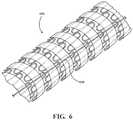
- an expandable implant 606is illustrated.
- Steering line 620is threaded along the surface of expandable implant 606 .
- steering line 220can comprise metallic, polymeric or natural materials and can comprise conventional medical grade materials such as nylon, polyacrylamide, polycarbonate, polyethylene, polyformaldehyde, polymethylmethacrylate, polypropylene, polytetrafluoroethylene, polytrifluorochlorethylene, polyvinylchloride, polyurethane, elastomeric organosilicon polymers; metals such as stainless steels, cobalt-chromium alloys and nitinol.
- conventional medical grade materialssuch as nylon, polyacrylamide, polycarbonate, polyethylene, polyformaldehyde, polymethylmethacrylate, polypropylene, polytetrafluoroethylene, polytrifluorochlorethylene, polyvinylchloride, polyurethane, elastomeric organosilicon polymers
- metalssuch as stainless steels, cobalt-chromium alloys and nitinol.
- Elongated members or lock wirescan also be formed from high strength polymer fibers such as ultra high molecular weight polyethylene fibers (e.g., Spectra®, Dyneema Purity®, etc.) or aramid fibers (e.g., Technora®, etc.).
- high strength polymer fiberssuch as ultra high molecular weight polyethylene fibers (e.g., Spectra®, Dyneema Purity®, etc.) or aramid fibers (e.g., Technora®, etc.).
- an expandable implantcan comprise a stent 705 and a graft member 707 , which are surrounded by sleeve 704 .
- a steering line 720can be threaded through stent 705 , graft member 707 , and/or sleeve 704 in a variety of different patterns. Such patterns may, among other benefits, facilitate the bending of the expandable implant by applying tension to (and corresponding displacement of) steering line 720 from outside of the body.
- such patternsmay reduce or prevent steering line 720 from damaging tissue within the vasculature of the patient by limiting or preventing “bowstringing.”
- Bowstringingoccurs when a string or thread travels in a direct line between two points on the inside of a curve in an expandable graft. This may cause the string or thread to come into contact with and potentially damage tissue in the vasculature.
- Bowstringing and its effects on tissuemay also be reduced and/or minimized by sleeve 704 as sleeve 704 surrounds steering line 720 during bending and prior to full expansion of the expandable implant.
- steering line 720can be woven through any combination of stent 705 , graft member 707 , and sleeve 704 .
- a segment of a patternis described.
- a steering linecan be woven between a stent, graft member, and sleeve in any combination of these patterns.
- the steering linemay interact with an expandable implant and one or more sleeves in any manner which allows steering line 720 to bend the expandable implant in a desired manner.
- steering line 720is threaded between the inner wall of sleeve 704 and stent 705 .
- steering line 720passes between a first apex 751 of stent 705 and the outer wall of graft member 707 , passes between second apex 742 and the inner wall of sleeve 704 , extends into and through the wall of graft member 707 , reenters graft member 707 , passes between a third apex 753 of stent 705 and the inner wall of sleeve 704 , and passes between a fourth apex 754 and the inner wall of sleeve 704 .
- steering line 720passes between first apex 751 and the outer wall of graft member 707 , then between second apex 752 and the inner wall of sleeve 704 .
- steering line 720passes between first apex 751 and the outer wall of graft member 707 , extends through the outer wall of graft member 707 , reenters graft member 707 , and passes between third apex 753 and the outer wall of graft member 707
- steering line 720passes between the outside wall of graft member 707 and stent 705 .
- steering line 720passes from the inner wall of graft member 707 , through to the outer wall of graft member 707 between first apex 751 and second apex 752 , back through to the outer wall of graft member 707 , and back through to the inner wall of graft member 707 between third apex 753 and fourth apex 754 .
- steering line 720is disposed against the inner wall of graft member 707 .
- FIGS. 7B-7Gillustrate example patterns in which a steering line may interact with an expandable implant. Any way in which a steering line interacts with an expandable implant to facilitate bending of the implant is within the scope of the present disclosure.
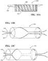
- a catheter assemblycan comprise more than one steering line.
- catheter assembly 900comprises two steering lines 920 .
- steering lines 920can be woven through the surface of expandable implant 906 .
- steering lines 920may exit catheter shaft 902 and engage expandable implant 906 near the proximal end of expandable implant 906 .
- steering lines 920may travel across and remain substantially in contact with the surface of expandable implant 906 from the proximal end to the distal end. Steering line 920 may then disengage the surface of expandable implant 906 and become secured to catheter assembly 900 .
- steering lines 920traverse and interact with the surface of expandable implant 906 in a pattern which facilitates controllable bending of expandable implant 906 .
- steering lines 920may traverse the surface of expandable implant 906 such that, across a significant portion of expandable implant 906 , both steering lines 920 are parallel to and in close proximity with each other.
- Such a configurationallows the tension applied to steering lines 920 to work together to form a bend or curvature in the same segment of expandable implant 906 .
- Any configuration of steering lines 920 and surface of expandable implant 906which allows for selective and controllable bending of expandable implant 906 is within the scope of the present disclosure.
- one or more steering linesare configured to enable selective and controllable bending of an expandable implant, for example as described above, and also to enable non-concentric, temporary engagement of an expandable implant in relation to a catheter assembly.
- a portion of the inner surface of an expandable implantcan be temporarily engaged distal to a catheter assembly.
- Such a portioncan be that which will exhibit the longest radius of curvature during selective and controllable bending of the expandable implant, whether during and/or after its delivery and deployment.
- Such a portioncan thus be an outer curve portion of an expandable implant.
- one or more steering linescan begin and terminate at distal and proximal ends respectively along an edge of an expandable implant which will exhibit the longest radius of curvature during selective and controllable bending. Between the distal and proximal ends, the one or more steering lines can transition toward and along an edge of an expandable implant which will exhibit the shortest radius of curvature during selective and controllable bending.
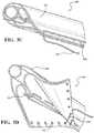
- a catheter assembly 1000is illustrated as having a catheter shaft 1002 temporarily engaged distal to an outer curve portion of the inner surface of an expandable implant 1006 by two steering lines 1020 , each comprising a helical pattern.
- steering lines 1020can be woven through the surface of expandable implant 1006 .
- steering lines 1020may exit catheter shaft 1002 and engage expandable implant 1006 near the distal end of expandable implant 1006 .
- steering lines 1020may travel across and remain substantially in contact with the surface of expandable implant 1006 from the distal end to the proximal end. Steering line 1020 may then disengage the surface of expandable implant 1006 and become secured to catheter assembly 1000 .
- each steering line 1020begins near the distal end on the outer curve of expandable implant 1006 and terminates proximal thereto on the inner curve of expandable implant 1006 .
- Each steering line 1020continues in a direction substantially parallel to the central axis of expandable implant 1006 toward the proximal end on the inner curve of expandable implant 1006 , where it circumferentially traverses expandable implant 1006 back to its outer curve. As illustrated in FIGS.
- each steering line 1020mirrors the other across a sagittal plane through the central axis of expandable implant 1006 .
- steering lines 1020cooperate to enable selective and controllable bending of expandable implant 1006 , and also to enable non-concentric, temporary engagement of expandable implant 1006 in relation to catheter shaft 1002 .
- Any configuration of steering lines 1020 and surface of expandable implant 1006 which allows for selective and controllable bending and non-concentric, temporary engagement of expandable implant 1006is within the scope of the present disclosure.
- the helical pattern of the steering line 1120begins on the exterior of expandable implant 1106 near the distal end on the outer curve of expandable implant 1106 and terminates proximal thereto on the inner curve of expandable implant 1106 .
- the steering line 1120continues on the inner curve in a direction substantially parallel to the central axis of expandable implant 1106 and toward the proximal end on the inner curve of expandable implant 1106 . From the proximal end, the steering line 1120 enters expandable implant 1106 and returns to the distal end at the outer curve of expandable implant 1106 , where it is locked with a distal pin.
- FIG. 11Billustrates a similar configuration, where like tensile forces F are applied to the steering line 1120 , but where the steering line 1120 is threaded and locked in an opposite configuration.
- steering linesmay traverse a path across and/or through the surface of expandable implant that is at least partially parallel to and substantially covered by one or more sleeves.
- the catheter assemblymay further comprise a lock wire.
- the lock wiremay secure a steering line or lines to the catheter assembly.
- catheter assembly 800comprises a catheter shaft 802 , expandable implant 806 , two steering lines 820 , and a lock wire 880 .
- Lock wire 880passes from outside of the body of the patient, through catheter shaft 802 , and exits at a point near catheter tip 818 . At this point, it interacts with steering lines 820 , then reenters catheter shaft 802 and continues to catheter tip 818 .
- lock wire 880releasably couples steering lines 820 to catheter assembly 800 . Any manner in which lock wire 880 may interact with steering line or lines 820 to maintain a releasable coupling between steering line or lines 820 and catheter assembly 800 is within the scope of the present disclosure.
- each steering linemay further comprise an end loop.
- each steering line 920comprises an end loop 922 .
- Lock wire 980may pass through each end loop 922 , securing each steering line 920 to catheter assembly 900 . Any method of securing steering line or lines 920 to catheter assembly 900 is within the scope of the invention.
- lock wirescan be formed from metallic, polymeric or natural materials and can comprise conventional medical grade materials such as nylon, polyacrylamide, polycarbonate, polyethylene, polyformaldehyde, polymethylmethacrylate, polypropylene, polytetrafluoroethylene, polytrifluorochlorethylene, polyvinylchloride, polyurethane, elastomeric organosilicon polymers; metals such as stainless steels, cobalt-chromium alloys and nitinol.
- conventional medical grade materialssuch as nylon, polyacrylamide, polycarbonate, polyethylene, polyformaldehyde, polymethylmethacrylate, polypropylene, polytetrafluoroethylene, polytrifluorochlorethylene, polyvinylchloride, polyurethane, elastomeric organosilicon polymers
- metalssuch as stainless steels, cobalt-chromium alloys and nitinol.
- Elongated members or lock wirescan also be formed from high strength polymer fibers such as ultra high molecular weight polyethylene fibers (e.g., Spectra®, Dyneema Purity®, etc.) or aramid fibers (e.g., Technora®, etc.).
- high strength polymer fiberssuch as ultra high molecular weight polyethylene fibers (e.g., Spectra®, Dyneema Purity®, etc.) or aramid fibers (e.g., Technora®, etc.).
- a catheter assembly used to deliver an expandable implantcomprises a catheter shaft, an expandable implant, one or more sleeves, one or more steering lines, and a lock wire.
- the expandable implantis capable of bending, through tension applied to the one or more steering lines and corresponding displacement, to conform to curvature in the vasculature of a patient.
- a catheter assembly 500comprising an expandable implant 506 is illustrated.
- Catheter assembly 500further comprises two steering lines 520 , a lock wire 580 , a primary coupling member 524 , and a secondary coupling member 534 .
- Primary coupling member 524is releasably coupled to primary sleeve 504 .
- Secondary coupling member 534is releasably coupled to secondary sleeve 508 .
- Catheter assembly 500is inserted into the vasculature of a patient, and expandable implant 506 is advanced to a treatment area of the vasculature.
- primary coupling member 524can be disengaged from primary sleeve 504 , allowing expandable implant 506 to be expanded to an intermediate configuration.
- sleeve 504can be removed from the vasculature once primary coupling member 524 has been disengaged.
- tensioncan be applied to steering lines 520 , causing expandable implant 506 to bend in a desired manner.
- expandable implant 506can bend in a direction aligned with the location of steering lines 520 . Once expandable implant 506 has been sufficiently bent, consistent tension is applied to steering lines 520 to maintain the degree of bending.
- tensioncan be applied to steering lines 520 by pulling the lines from the outside of the body of the patient.
- steering lines 520can be connected to one or more dials or other mechanisms for applying the tension at the trailing end of catheter shaft 502 .
- the dialcan be used to apply a desired tension, as well as maintain the correct amount of tension once a desired angle of bending of expandable implant 506 has been achieved.
- Various embodimentsmay also comprise an indicator, scale, gradient, or the like which demonstrates the amount of tension or displacement of the steering line, and/or the amount of bending in expandable implant 506 .
- the catheter assemblycan comprise one more additional markings (e.g., on a handle) that allow a user to determine the orientation of the steering line with respect to the vasculature.
- the implantcan be rotated for final positioning in the treatment area of the vasculature.
- lock wire 580is engaged with steering lines 520 such that torsional rotation of the catheter shaft causes expandable implant 506 to rotate within the vasculature.
- any configuration of catheter assembly 500 which allows for rotation of expandable implant 506is within the scope of the present disclosure.
- an expandable implantmay further comprise one or more radiopaque markers.
- one or more radiopaque markersform a band around the distal end of the expandable implant.
- the radiopaque markersmay assist in deployment of an expandable implant by providing increased visibility when observing the expandable implant with a radiographic device, such as an x-ray machine. Any arrangement of radiopaque markers which assists in deployment of an expandable implant is within the scope of the present disclosure.
- radiopaque markersmay assist in orienting the expandable implant by providing a profile view of the distal end of the expandable implant.
- a profile view of the distal end of the expandable implantFor example, with reference to FIG. 4 , a number of potential profiles 491 - 495 of the distal end of an expandable implant 406 are illustrated.
- radiopaque markers located in the distal end of expandable implant 406provide a profile view of the distal end of expandable implant 406 when viewed by a radiographic device.
- profile viewscan be used to properly orient expandable implant 406 by assisting a user in determining the degree of rotation and/or orientation of a bend in expandable implant 406 .
- profile 491represents a distal end of an expandable implant 406 having an orientation substantially orthogonal to a radiographic image capture device, such as an x-ray camera.
- Profile 492represents a distal end of an expandable implant having an orientation less orthogonal than profile 491 .
- Profile 493represents a distal end of an expandable implant 406 having an orientation less orthogonal than profile 492 .
- profile 494represents a distal end of an expandable implant 406 having an orientation parallel to a radiographic image capture device.
- secondary coupling member 534can be disengaged from secondary sleeve 508 . Once secondary coupling member 534 is disengaged from secondary sleeve 508 , expandable implant 506 can be expanded to a final position and diameter within the treatment area. In various exemplary embodiments, secondary sleeve 508 is removed from the vasculature. In other exemplary embodiments, secondary sleeve 508 remains in position circumferentially surrounding a portion of expandable implant 506 .
- lock wire 580can be disengaged from catheter assembly 500 .
- lock wire 580is disengaged by applying sufficient tension to the lock wire 580 from outside of the body of the patient.
- steering lines 520can be released from coupling with catheter shaft 502 and can be removed from expandable implant 506 and catheter assembly 500 .
- catheter assembly 500is fully disengaged from expandable implant 506 , and can be removed from the vasculature of the patient.
Landscapes
- Health & Medical Sciences (AREA)
- Engineering & Computer Science (AREA)
- Biomedical Technology (AREA)
- Cardiology (AREA)
- Oral & Maxillofacial Surgery (AREA)
- Transplantation (AREA)
- Heart & Thoracic Surgery (AREA)
- Vascular Medicine (AREA)
- Life Sciences & Earth Sciences (AREA)
- Animal Behavior & Ethology (AREA)
- General Health & Medical Sciences (AREA)
- Public Health (AREA)
- Veterinary Medicine (AREA)
- Gastroenterology & Hepatology (AREA)
- Pulmonology (AREA)
- Prostheses (AREA)
- Media Introduction/Drainage Providing Device (AREA)
- Materials For Medical Uses (AREA)
Abstract
Description
Claims (16)
Priority Applications (3)
| Application Number | Priority Date | Filing Date | Title |
|---|---|---|---|
| US15/691,299US11123174B2 (en) | 2012-03-13 | 2017-08-30 | External steerable fiber for use in endoluminal deployment of expandable devices |
| US17/470,447US12076227B2 (en) | 2012-03-13 | 2021-09-09 | External steerable fiber for use in endoluminal deployment of expandable devices |
| US18/796,079US20240390132A1 (en) | 2012-03-13 | 2024-08-06 | External steerable fiber for use in endoluminal deployment of expandable devices |
Applications Claiming Priority (4)
| Application Number | Priority Date | Filing Date | Title |
|---|---|---|---|
| US201261610372P | 2012-03-13 | 2012-03-13 | |
| US13/743,118US9375308B2 (en) | 2012-03-13 | 2013-01-16 | External steerable fiber for use in endoluminal deployment of expandable devices |
| US14/084,428US9770322B2 (en) | 2012-03-13 | 2013-11-19 | External steerable fiber for use in endoluminal deployment of expandable devices |
| US15/691,299US11123174B2 (en) | 2012-03-13 | 2017-08-30 | External steerable fiber for use in endoluminal deployment of expandable devices |
Related Parent Applications (1)
| Application Number | Title | Priority Date | Filing Date |
|---|---|---|---|
| US14/084,428ContinuationUS9770322B2 (en) | 2012-03-13 | 2013-11-19 | External steerable fiber for use in endoluminal deployment of expandable devices |
Related Child Applications (1)
| Application Number | Title | Priority Date | Filing Date |
|---|---|---|---|
| US17/470,447ContinuationUS12076227B2 (en) | 2012-03-13 | 2021-09-09 | External steerable fiber for use in endoluminal deployment of expandable devices |
Publications (2)
| Publication Number | Publication Date |
|---|---|
| US20180036113A1 US20180036113A1 (en) | 2018-02-08 |
| US11123174B2true US11123174B2 (en) | 2021-09-21 |
Family
ID=49158371
Family Applications (5)
| Application Number | Title | Priority Date | Filing Date |
|---|---|---|---|
| US13/743,118Active2034-07-06US9375308B2 (en) | 2012-03-13 | 2013-01-16 | External steerable fiber for use in endoluminal deployment of expandable devices |
| US14/084,428Active2033-04-08US9770322B2 (en) | 2012-03-13 | 2013-11-19 | External steerable fiber for use in endoluminal deployment of expandable devices |
| US15/691,299Active2033-06-26US11123174B2 (en) | 2012-03-13 | 2017-08-30 | External steerable fiber for use in endoluminal deployment of expandable devices |
| US17/470,447Active2033-07-05US12076227B2 (en) | 2012-03-13 | 2021-09-09 | External steerable fiber for use in endoluminal deployment of expandable devices |
| US18/796,079PendingUS20240390132A1 (en) | 2012-03-13 | 2024-08-06 | External steerable fiber for use in endoluminal deployment of expandable devices |
Family Applications Before (2)
| Application Number | Title | Priority Date | Filing Date |
|---|---|---|---|
| US13/743,118Active2034-07-06US9375308B2 (en) | 2012-03-13 | 2013-01-16 | External steerable fiber for use in endoluminal deployment of expandable devices |
| US14/084,428Active2033-04-08US9770322B2 (en) | 2012-03-13 | 2013-11-19 | External steerable fiber for use in endoluminal deployment of expandable devices |
Family Applications After (2)
| Application Number | Title | Priority Date | Filing Date |
|---|---|---|---|
| US17/470,447Active2033-07-05US12076227B2 (en) | 2012-03-13 | 2021-09-09 | External steerable fiber for use in endoluminal deployment of expandable devices |
| US18/796,079PendingUS20240390132A1 (en) | 2012-03-13 | 2024-08-06 | External steerable fiber for use in endoluminal deployment of expandable devices |
Country Status (11)
| Country | Link |
|---|---|
| US (5) | US9375308B2 (en) |
| EP (2) | EP2825137B1 (en) |
| JP (2) | JP6346165B2 (en) |
| KR (1) | KR20140139554A (en) |
| CN (2) | CN104244876B (en) |
| AU (1) | AU2013232766B2 (en) |
| BR (1) | BR112014022291B1 (en) |
| CA (2) | CA2866687C (en) |
| ES (2) | ES2748099T3 (en) |
| RU (1) | RU2014141048A (en) |
| WO (1) | WO2013137977A1 (en) |
Cited By (5)
| Publication number | Priority date | Publication date | Assignee | Title |
|---|---|---|---|---|
| US11324615B2 (en) | 2011-11-14 | 2022-05-10 | W. L. Gore & Associates, Inc. | External steerable fiber for use in endoluminal deployment of expandable devices |
| US11382781B2 (en) | 2011-11-14 | 2022-07-12 | W. L. Gore & Associates, Inc. | External steerable fiber for use in endoluminal deployment of expandable devices |
| US12076227B2 (en) | 2012-03-13 | 2024-09-03 | W. L. Gore & Associates, Inc. | External steerable fiber for use in endoluminal deployment of expandable devices |
| US12310869B2 (en) | 2017-03-08 | 2025-05-27 | W. L. Gore & Associates, Inc. | Steering wire attach for angulation |
| US12409054B2 (en) | 2018-08-31 | 2025-09-09 | W. L. Gore & Associates, Inc. | Pivot delivery system for implantable medical device |
Families Citing this family (101)
| Publication number | Priority date | Publication date | Assignee | Title |
|---|---|---|---|---|
| WO2009148607A1 (en) | 2008-06-04 | 2009-12-10 | Gore Enterprise Holdings, Inc. | Controlled deployable medical device and method of making the same |
| CA2727000C (en) | 2008-06-04 | 2014-01-07 | Gore Enterprise Holdings, Inc. | Controlled deployable medical device and method of making the same |
| US8858610B2 (en) | 2009-01-19 | 2014-10-14 | W. L. Gore & Associates, Inc. | Forced deployment sequence |
| US8870950B2 (en) | 2009-12-08 | 2014-10-28 | Mitral Tech Ltd. | Rotation-based anchoring of an implant |
| US20110224785A1 (en) | 2010-03-10 | 2011-09-15 | Hacohen Gil | Prosthetic mitral valve with tissue anchors |
| US9763657B2 (en) | 2010-07-21 | 2017-09-19 | Mitraltech Ltd. | Techniques for percutaneous mitral valve replacement and sealing |
| US11653910B2 (en) | 2010-07-21 | 2023-05-23 | Cardiovalve Ltd. | Helical anchor implantation |
| AU2012225575B9 (en) | 2011-03-08 | 2015-08-20 | W. L. Gore & Associates, Inc. | Medical device for use with a stoma |
| US9744033B2 (en) | 2011-04-01 | 2017-08-29 | W.L. Gore & Associates, Inc. | Elastomeric leaflet for prosthetic heart valves |
| US10117765B2 (en) | 2011-06-14 | 2018-11-06 | W.L. Gore Associates, Inc | Apposition fiber for use in endoluminal deployment of expandable implants |
| WO2013021374A2 (en) | 2011-08-05 | 2013-02-14 | Mitraltech Ltd. | Techniques for percutaneous mitral valve replacement and sealing |
| US20140324164A1 (en) | 2011-08-05 | 2014-10-30 | Mitraltech Ltd. | Techniques for percutaneous mitral valve replacement and sealing |
| EP2739214B1 (en) | 2011-08-05 | 2018-10-10 | Cardiovalve Ltd | Percutaneous mitral valve replacement and sealing |
| US8852272B2 (en) | 2011-08-05 | 2014-10-07 | Mitraltech Ltd. | Techniques for percutaneous mitral valve replacement and sealing |
| US10213329B2 (en) | 2011-08-12 | 2019-02-26 | W. L. Gore & Associates, Inc. | Evertable sheath devices, systems, and methods |
| US9554806B2 (en) | 2011-09-16 | 2017-01-31 | W. L. Gore & Associates, Inc. | Occlusive devices |
| US9687371B2 (en)* | 2012-02-14 | 2017-06-27 | W. L. Gore & Associates, Inc. | Endoprosthesis having aligned legs for ease of cannulation |
| US9283072B2 (en) | 2012-07-25 | 2016-03-15 | W. L. Gore & Associates, Inc. | Everting transcatheter valve and methods |
| US10376360B2 (en) | 2012-07-27 | 2019-08-13 | W. L. Gore & Associates, Inc. | Multi-frame prosthetic valve apparatus and methods |
| US9387105B2 (en) | 2012-11-12 | 2016-07-12 | W.L. Gore & Associates, Inc | Sleeves for expandable medical devices and methods of making the same |
| US8628571B1 (en) | 2012-11-13 | 2014-01-14 | Mitraltech Ltd. | Percutaneously-deliverable mechanical valve |
| US9101469B2 (en) | 2012-12-19 | 2015-08-11 | W. L. Gore & Associates, Inc. | Prosthetic heart valve with leaflet shelving |
| US9144492B2 (en) | 2012-12-19 | 2015-09-29 | W. L. Gore & Associates, Inc. | Truncated leaflet for prosthetic heart valves, preformed valve |
| US10966820B2 (en) | 2012-12-19 | 2021-04-06 | W. L. Gore & Associates, Inc. | Geometric control of bending character in prosthetic heart valve leaflets |
| US10321986B2 (en) | 2012-12-19 | 2019-06-18 | W. L. Gore & Associates, Inc. | Multi-frame prosthetic heart valve |
| US9737398B2 (en) | 2012-12-19 | 2017-08-22 | W. L. Gore & Associates, Inc. | Prosthetic valves, frames and leaflets and methods thereof |
| US10039638B2 (en) | 2012-12-19 | 2018-08-07 | W. L. Gore & Associates, Inc. | Geometric prosthetic heart valves |
| US9968443B2 (en) | 2012-12-19 | 2018-05-15 | W. L. Gore & Associates, Inc. | Vertical coaptation zone in a planar portion of prosthetic heart valve leaflet |
| US9907641B2 (en) | 2014-01-10 | 2018-03-06 | W. L. Gore & Associates, Inc. | Implantable intraluminal device |
| US20150351906A1 (en) | 2013-01-24 | 2015-12-10 | Mitraltech Ltd. | Ventricularly-anchored prosthetic valves |
| US9763819B1 (en) | 2013-03-05 | 2017-09-19 | W. L. Gore & Associates, Inc. | Tapered sleeve |
| CN105473105B (en)* | 2013-03-15 | 2019-03-22 | 心脏结构导航公司 | Catheter-guided valve replacement device and method |
| DE102013106463A1 (en)* | 2013-06-20 | 2014-12-24 | Jotec Gmbh | stent graft |
| US11911258B2 (en) | 2013-06-26 | 2024-02-27 | W. L. Gore & Associates, Inc. | Space filling devices |
| WO2015077229A1 (en)* | 2013-11-19 | 2015-05-28 | W.L. Gore & Associates, Inc. | External steerable fiber for use in endoluminal deployment of expandable devices |
| US10966850B2 (en) | 2014-03-06 | 2021-04-06 | W. L. Gore & Associates, Inc. | Implantable medical device constraint and deployment apparatus |
| US11439396B2 (en) | 2014-05-02 | 2022-09-13 | W. L. Gore & Associates, Inc. | Occluder and anastomosis devices |
| US10363040B2 (en) | 2014-05-02 | 2019-07-30 | W. L. Gore & Associates, Inc. | Anastomosis devices |
| US11712230B2 (en) | 2014-05-02 | 2023-08-01 | W. L. Gore & Associates, Inc. | Occluder and anastomosis devices |
| US20160045300A1 (en)* | 2014-05-16 | 2016-02-18 | Terumo Kabushiki Kaisha | Method and apparatus for treating urethral stricture |
| US10076644B2 (en) | 2014-05-16 | 2018-09-18 | Terumo Kabushiki Kaisha | Method and apparatus for treating urethral stricture |
| US9883937B2 (en)* | 2014-05-16 | 2018-02-06 | Terumo Kabushiki Kaisha | Method and apparatus for treating urethral stricture |
| EP3174502B1 (en) | 2014-07-30 | 2022-04-06 | Cardiovalve Ltd | Apparatus for implantation of an articulatable prosthetic valve |
| BR112017003339A2 (en) | 2014-08-18 | 2017-11-28 | Gore & Ass | integral seamed structure for protective valves |
| US9827094B2 (en) | 2014-09-15 | 2017-11-28 | W. L. Gore & Associates, Inc. | Prosthetic heart valve with retention elements |
| US10206801B2 (en) | 2014-12-29 | 2019-02-19 | Cook Medical Technologies Llc | Trigger wire arrangements for endografts |
| US9974651B2 (en) | 2015-02-05 | 2018-05-22 | Mitral Tech Ltd. | Prosthetic valve with axially-sliding frames |
| CN110141399B (en) | 2015-02-05 | 2021-07-27 | 卡迪尔维尔福股份有限公司 | Prosthetic valve with axial sliding frame |
| CA2986047C (en) | 2015-05-14 | 2020-11-10 | W. L. Gore & Associates, Inc. | Devices and methods for occlusion of an atrial appendage |
| US10531866B2 (en) | 2016-02-16 | 2020-01-14 | Cardiovalve Ltd. | Techniques for providing a replacement valve and transseptal communication |
| US20190231525A1 (en) | 2016-08-01 | 2019-08-01 | Mitraltech Ltd. | Minimally-invasive delivery systems |
| USD800908S1 (en) | 2016-08-10 | 2017-10-24 | Mitraltech Ltd. | Prosthetic valve element |
| CA3031187A1 (en) | 2016-08-10 | 2018-02-15 | Cardiovalve Ltd. | Prosthetic valve with concentric frames |
| JP6940594B2 (en) | 2016-08-24 | 2021-09-29 | ダブリュ.エル.ゴア アンド アソシエイツ,インコーポレイティドW.L. Gore & Associates, Incorporated | Sleeve for dilated medical devices |
| AU2017326087B2 (en) | 2016-09-15 | 2020-03-26 | W. L. Gore & Associates, Inc. | Staged deployment of expandable implant |
| EP3534837A1 (en) | 2017-02-24 | 2019-09-11 | Bolton Medical, Inc. | Constrainable stent graft, delivery system and methods of use |
| WO2018156848A1 (en) | 2017-02-24 | 2018-08-30 | Bolton Medical, Inc. | Vascular prosthesis with crimped adapter and methods of use |
| WO2018156854A1 (en)* | 2017-02-24 | 2018-08-30 | Bolton Medical, Inc. | Radially adjustable stent graft delivery system |
| ES2954897T3 (en)* | 2017-02-24 | 2023-11-27 | Bolton Medical Inc | Constrained Wrap Stent Graft Delivery System |
| WO2018156849A1 (en) | 2017-02-24 | 2018-08-30 | Bolton Medical, Inc. | Vascular prosthesis with fenestration ring and methods of use |
| ES2863978T3 (en) | 2017-02-24 | 2021-10-13 | Bolton Medical Inc | System for radially constricting a stent graft |
| WO2018156850A1 (en) | 2017-02-24 | 2018-08-30 | Bolton Medical, Inc. | Stent graft with fenestration lock |
| WO2018156851A1 (en) | 2017-02-24 | 2018-08-30 | Bolton Medical, Inc. | Vascular prosthesis with moveable fenestration |
| EP3932373B1 (en) | 2017-02-24 | 2022-12-21 | Bolton Medical, Inc. | Delivery system for radially constricting a stent graft |
| WO2018156847A1 (en) | 2017-02-24 | 2018-08-30 | Bolton Medical, Inc. | Delivery system and method to radially constrict a stent graft |
| US11724075B2 (en) | 2017-04-18 | 2023-08-15 | W. L. Gore & Associates, Inc. | Deployment constraining sheath that enables staged deployment by device section |
| US10749698B2 (en)* | 2017-05-18 | 2020-08-18 | Vmware, Inc. | Feature-aware software usage metering |
| US10575948B2 (en) | 2017-08-03 | 2020-03-03 | Cardiovalve Ltd. | Prosthetic heart valve |
| US11246704B2 (en) | 2017-08-03 | 2022-02-15 | Cardiovalve Ltd. | Prosthetic heart valve |
| US11793633B2 (en) | 2017-08-03 | 2023-10-24 | Cardiovalve Ltd. | Prosthetic heart valve |
| US10537426B2 (en) | 2017-08-03 | 2020-01-21 | Cardiovalve Ltd. | Prosthetic heart valve |
| US10888421B2 (en) | 2017-09-19 | 2021-01-12 | Cardiovalve Ltd. | Prosthetic heart valve with pouch |
| US12064347B2 (en) | 2017-08-03 | 2024-08-20 | Cardiovalve Ltd. | Prosthetic heart valve |
| WO2019055577A1 (en) | 2017-09-12 | 2019-03-21 | W. L. Gore & Associates, Inc. | Leaflet frame attachment for prosthetic valves |
| CN111163728B (en) | 2017-09-27 | 2022-04-29 | W.L.戈尔及同仁股份有限公司 | Prosthetic valve with mechanically coupled leaflets |
| CN111132636B (en) | 2017-09-27 | 2022-04-08 | W.L.戈尔及同仁股份有限公司 | Prosthetic valve with expandable frame and related systems and methods |
| EP3694450B1 (en) | 2017-10-11 | 2023-08-02 | W. L. Gore & Associates, Inc. | Implantable medical device constraint and deployment apparatus |
| US11090153B2 (en) | 2017-10-13 | 2021-08-17 | W. L. Gore & Associates, Inc. | Telescoping prosthetic valve and delivery system |
| US11173023B2 (en) | 2017-10-16 | 2021-11-16 | W. L. Gore & Associates, Inc. | Medical devices and anchors therefor |
| EP3703618A1 (en) | 2017-10-31 | 2020-09-09 | W. L. Gore & Associates, Inc. | Prosthetic heart valve |
| US11154397B2 (en) | 2017-10-31 | 2021-10-26 | W. L. Gore & Associates, Inc. | Jacket for surgical heart valve |
| CN111295158A (en) | 2017-10-31 | 2020-06-16 | W.L.戈尔及同仁股份有限公司 | Medical valve and valve leaflet for promoting tissue ingrowth |
| JP7072062B2 (en) | 2017-10-31 | 2022-05-19 | ダブリュ.エル.ゴア アンド アソシエイツ,インコーポレイティド | Transcatheter placement system and related methods |
| CN110121319B (en) | 2017-10-31 | 2023-05-09 | 波顿医疗公司 | Distal torque component, delivery system, and method of use thereof |
| GB201720803D0 (en) | 2017-12-13 | 2018-01-24 | Mitraltech Ltd | Prosthetic Valve and delivery tool therefor |
| GB201800399D0 (en) | 2018-01-10 | 2018-02-21 | Mitraltech Ltd | Temperature-control during crimping of an implant |
| US12194251B2 (en) | 2018-05-01 | 2025-01-14 | Magellan Biomedical Inc. | System and method for device steering, tracking, and navigation of devices for interventional procedures |
| CN119424058A (en) | 2018-06-04 | 2025-02-14 | 波士顿科学国际有限公司 | Removable bracket |
| EP3801379B1 (en) | 2018-06-05 | 2025-10-08 | Boston Scientific Scimed, Inc. | Stent with selectively curved region |
| CN112996463A (en)* | 2018-07-03 | 2021-06-18 | 艾奎登医疗公司 | Vascular and aortic grafts and deployment tools |
| CN109259890B (en)* | 2018-07-27 | 2019-08-30 | 北京航空航天大学 | A covered stent |
| ES3003887T3 (en)* | 2018-09-12 | 2025-03-11 | Gore & Ass | Low profile delivery system with lock wire lumen |
| USD926322S1 (en) | 2018-11-07 | 2021-07-27 | W. L. Gore & Associates, Inc. | Heart valve cover |
| US12090072B2 (en)* | 2018-11-13 | 2024-09-17 | Icad Endovascular Llc | Systems and methods for delivery retrievable stents |
| WO2020171819A1 (en) | 2019-02-22 | 2020-08-27 | W. L. Gore & Associates, Inc. | Actuation line storage systems and methods |
| US11497601B2 (en) | 2019-03-01 | 2022-11-15 | W. L. Gore & Associates, Inc. | Telescoping prosthetic valve with retention element |
| KR102229857B1 (en)* | 2019-05-14 | 2021-03-18 | 울산대학교 산학협력단 | Stent transfer Device and manufacturing method |
| JP7401681B2 (en) | 2019-12-18 | 2023-12-19 | ダブリュ.エル.ゴア アンド アソシエイツ,インコーポレイティド | Fiber slack reservoir in deployment system handle |
| US12357459B2 (en) | 2020-12-03 | 2025-07-15 | Cardiovalve Ltd. | Transluminal delivery system |
| CN116710030A (en)* | 2020-12-28 | 2023-09-05 | W.L.戈尔及同仁股份有限公司 | Sleeve pullback mechanism |
| KR20250016788A (en)* | 2023-07-26 | 2025-02-04 | 주식회사 이엔에스 | Intramedullary fixation implants manufactured by 3d printing |
Citations (255)
| Publication number | Priority date | Publication date | Assignee | Title |
|---|---|---|---|---|
| US1355373A (en) | 1920-08-09 | 1920-10-12 | White Dell Joseph | Lock-nut |
| US1506432A (en) | 1923-03-26 | 1924-08-26 | Harry B Kimmel | Fire pot |
| US1851314A (en) | 1929-05-25 | 1932-03-29 | Belding Heminway Company | Spool for thread |
| US3625451A (en) | 1969-09-11 | 1971-12-07 | Sonoco Products Co | Textile yarn carrier with improved starting means |
| US3915167A (en) | 1974-05-23 | 1975-10-28 | Atlantic Design & Dev Corp | Intravenous clamp |
| US3953566A (en) | 1970-05-21 | 1976-04-27 | W. L. Gore & Associates, Inc. | Process for producing porous products |
| US4503569A (en) | 1983-03-03 | 1985-03-12 | Dotter Charles T | Transluminally placed expandable graft prosthesis |
| US4512338A (en) | 1983-01-25 | 1985-04-23 | Balko Alexander B | Process for restoring patency to body vessels |
| US4655246A (en) | 1983-09-30 | 1987-04-07 | Essex Industries, Inc. | Regulated gas flow control valve |
| US4858810A (en) | 1987-04-30 | 1989-08-22 | Heart Technology, Inc. | Quick acting pin vise for use with angiographic guidewires |
| US4990155A (en) | 1989-05-19 | 1991-02-05 | Wilkoff Howard M | Surgical stent method and apparatus |
| US5037427A (en) | 1987-03-25 | 1991-08-06 | Terumo Kabushiki Kaisha | Method of implanting a stent within a tubular organ of a living body and of removing same |
| US5147370A (en) | 1991-06-12 | 1992-09-15 | Mcnamara Thomas O | Nitinol stent for hollow body conduits |
| US5211658A (en) | 1991-11-05 | 1993-05-18 | New England Deaconess Hospital Corporation | Method and device for performing endovascular repair of aneurysms |
| US5217486A (en) | 1992-02-18 | 1993-06-08 | Mitek Surgical Products, Inc. | Suture anchor and installation tool |
| US5221261A (en) | 1990-04-12 | 1993-06-22 | Schneider (Usa) Inc. | Radially expandable fixation member |
| US5276276A (en) | 1988-07-18 | 1994-01-04 | Gunn Dennis R | Coil transducer |
| US5325746A (en) | 1991-09-27 | 1994-07-05 | Cook Incorporated | Wire guide control handle |
| US5344427A (en) | 1992-08-07 | 1994-09-06 | Celsa L.G. (Societe Anonyme) | Filter with triangular fingers |
| EP0664107A1 (en) | 1994-01-19 | 1995-07-26 | NAZARI, Stefano | Vascular prosthesis and device for its application |
| EP0679372A2 (en) | 1994-04-25 | 1995-11-02 | Advanced Cardiovascular Systems, Inc. | Radiopaque stent markers |
| US5491704A (en) | 1993-10-21 | 1996-02-13 | Quantum Lerning Systems, Inc. | Interactive laser disc system |
| US5527338A (en) | 1992-09-02 | 1996-06-18 | Board Of Regents, The University Of Texas System | Intravascular device |
| WO1996018361A1 (en) | 1994-12-15 | 1996-06-20 | Endovascular Technologies, Inc. | Vascular graft and delivery catheter |
| US5562726A (en) | 1991-10-25 | 1996-10-08 | Cook Incorporated | Expandable transluminal graft prosthesis for repair of aneurysm and method for implanting |
| WO1997048350A1 (en) | 1996-06-20 | 1997-12-24 | Sulzer Vascutek Ltd. | Prosthetic repair of body passages |
| US5707376A (en) | 1992-08-06 | 1998-01-13 | William Cook Europe A/S | Stent introducer and method of use |
| US5709704A (en) | 1994-11-30 | 1998-01-20 | Boston Scientific Corporation | Blood clot filtering |
| US5713948A (en) | 1995-07-19 | 1998-02-03 | Uflacker; Renan | Adjustable and retrievable graft and graft delivery system for stent-graft system |
| US5713917A (en) | 1995-10-30 | 1998-02-03 | Leonhardt; Howard J. | Apparatus and method for engrafting a blood vessel |
| US5720776A (en) | 1991-10-25 | 1998-02-24 | Cook Incorporated | Barb and expandable transluminal graft prosthesis for repair of aneurysm |
| US5725552A (en) | 1994-07-08 | 1998-03-10 | Aga Medical Corporation | Percutaneous catheter directed intravascular occlusion devices |
| WO1998027894A1 (en) | 1996-12-23 | 1998-07-02 | Gore Enterprise Holdings, Inc. | Implant deployment apparatus |
| US5776141A (en) | 1995-08-28 | 1998-07-07 | Localmed, Inc. | Method and apparatus for intraluminal prosthesis delivery |
| US5782909A (en) | 1993-08-05 | 1998-07-21 | Endovascular Technologies, Inc. | Multicapsule intraluminal grafting system and method |
| US5843162A (en) | 1995-05-19 | 1998-12-01 | Inoue; Kanji | Appliance to be implanted, method of collapsing the appliance to be implanted and method of using the appliance to be implanted |
| US5873906A (en) | 1994-09-08 | 1999-02-23 | Gore Enterprise Holdings, Inc. | Procedures for introducing stents and stent-grafts |
| US5904703A (en) | 1996-05-08 | 1999-05-18 | Bard Connaught | Occluder device formed from an open cell foam material |
| US5961546A (en) | 1993-04-22 | 1999-10-05 | C.R. Bard, Inc. | Method and apparatus for recapture of hooked endoprosthesis |
| WO1999065420A1 (en) | 1998-06-15 | 1999-12-23 | Gore Enterprise Holdings, Inc. | Remotely removable covering and support |
| US6013093A (en) | 1995-11-28 | 2000-01-11 | Boston Scientific Corporation | Blood clot filtering |
| US6015431A (en) | 1996-12-23 | 2000-01-18 | Prograft Medical, Inc. | Endolumenal stent-graft with leak-resistant seal |
| US6019785A (en) | 1992-05-20 | 2000-02-01 | Boston Scientific Corporation | Device with a prosthesis implantable in the body of a patient |
| WO2000013613A1 (en) | 1998-09-04 | 2000-03-16 | Scimed Life Systems, Inc. | System for delivering bifurcation stents |
| US6042588A (en) | 1998-03-03 | 2000-03-28 | Scimed Life Systems, Inc | Stent delivery system |
| US6042602A (en) | 1997-06-04 | 2000-03-28 | Wells; Charles A. | Apparatus for effecting traction on the spine and method of using the same |
| GB2344054A (en) | 1998-11-28 | 2000-05-31 | Smiths Industries Plc | Catheter retainers and assemblies |
| US6143021A (en) | 1998-07-10 | 2000-11-07 | American Medical Systems, Inc. | Stent placement instrument and method of assembly |
| US6152144A (en) | 1998-11-06 | 2000-11-28 | Appriva Medical, Inc. | Method and device for left atrial appendage occlusion |
| US6165195A (en) | 1997-08-13 | 2000-12-26 | Advanced Cardiovascylar Systems, Inc. | Stent and catheter assembly and method for treating bifurcations |
| US6203550B1 (en) | 1998-09-30 | 2001-03-20 | Medtronic, Inc. | Disposable delivery device for endoluminal prostheses |
| WO2001021109A1 (en) | 1999-09-23 | 2001-03-29 | Advanced Stent Technologies, Inc. | Differentially expanding stent and methods of use |
| US6214025B1 (en) | 1994-11-30 | 2001-04-10 | Boston Scientific Corporation | Self-centering, self-expanding and retrievable vena cava filter |
| US6231561B1 (en) | 1999-09-20 | 2001-05-15 | Appriva Medical, Inc. | Method and apparatus for closing a body lumen |
| US6231589B1 (en) | 1999-03-22 | 2001-05-15 | Microvena Corporation | Body vessel filter |
| US6231581B1 (en) | 1998-12-16 | 2001-05-15 | Boston Scientific Corporation | Implantable device anchors |
| US6264671B1 (en) | 1999-11-15 | 2001-07-24 | Advanced Cardiovascular Systems, Inc. | Stent delivery catheter and method of use |
| US20010037142A1 (en) | 2000-03-14 | 2001-11-01 | Cook Incorporated | Endovascular stent graft |
| US6312454B1 (en) | 1996-06-13 | 2001-11-06 | Nitinol Devices & Components | Stent assembly |
| US6322585B1 (en) | 1998-11-16 | 2001-11-27 | Endotex Interventional Systems, Inc. | Coiled-sheet stent-graft with slidable exo-skeleton |
| US6346117B1 (en) | 2000-03-02 | 2002-02-12 | Prodesco, Inc. | Bag for use in the intravascular treatment of saccular aneurysms |
| WO2002028317A2 (en) | 2000-10-05 | 2002-04-11 | Scimed Life Systems, Inc. | Body sock for a stent delivery catheter |
| US20020099431A1 (en) | 2001-01-22 | 2002-07-25 | Armstrong Joseph R. | Deployment system for intraluminal devices |
| US6451051B2 (en) | 1999-04-26 | 2002-09-17 | William J. Drasler | Intravascular folded tubular endoprosthesis |
| US20020151953A1 (en)* | 2001-04-11 | 2002-10-17 | Trivascular, Inc. | Delivery system and method for bifurcated endovascular graft |
| US6475234B1 (en) | 1998-10-26 | 2002-11-05 | Medinol, Ltd. | Balloon expandable covered stents |
| US6485513B1 (en) | 1999-10-08 | 2002-11-26 | The General Hospital Corporation | Percutaneous stent graft and method for vascular bypass |
| US6491704B2 (en) | 1995-02-24 | 2002-12-10 | Heartport, Inc. | Devices and methods for performing a vascular anastomosis |
| US6524335B1 (en) | 1997-12-10 | 2003-02-25 | William A. Cook Australia Pty. Ltd. | Endoluminal aortic stents |
| US6527779B1 (en) | 2000-07-10 | 2003-03-04 | Endotex Interventional Systems, Inc. | Stent delivery device |
| US6551303B1 (en) | 1999-10-27 | 2003-04-22 | Atritech, Inc. | Barrier device for ostium of left atrial appendage |
| US6551350B1 (en) | 1996-12-23 | 2003-04-22 | Gore Enterprise Holdings, Inc. | Kink resistant bifurcated prosthesis |
| WO2003034948A1 (en) | 2001-10-26 | 2003-05-01 | Cook Incorporated | Prostheses for curved lumens |
| US20030098383A1 (en) | 2001-11-26 | 2003-05-29 | Lincoln Global, Inc. | Open shipyard wire feeder |
| US6572643B1 (en) | 2000-07-19 | 2003-06-03 | Vascular Architects, Inc. | Endoprosthesis delivery catheter assembly and method |
| US6572646B1 (en) | 2000-06-02 | 2003-06-03 | Advanced Cardiovascular Systems, Inc. | Curved nitinol stent for extremely tortuous anatomy |
| US20030149467A1 (en) | 2001-11-09 | 2003-08-07 | Linder Richard J. | Methods, systems and devices for delivering stents |
| US20030181942A1 (en) | 2002-01-25 | 2003-09-25 | Sutton Gregg S. | Atrial appendage blood filtration systems |
| WO2003101518A1 (en)* | 2002-05-29 | 2003-12-11 | William A. Cook Australia Pty. Ltd. | Trigger wire system for a prosthesis deployment device |
| US6689150B1 (en) | 1999-10-27 | 2004-02-10 | Atritech, Inc. | Filter apparatus for ostium of left atrial appendage |
| US20040034366A1 (en) | 1999-11-08 | 2004-02-19 | Ev3 Sunnyvale, Inc., A California Corporation | Device for containing embolic material in the LAA having a plurality of tissue retention structures |
| US20040054396A1 (en) | 2002-06-26 | 2004-03-18 | Cook Incorporated | Stent-graft fastening |
| US6712842B1 (en) | 1999-10-12 | 2004-03-30 | Allan Will | Methods and devices for lining a blood vessel and opening a narrowed region of a blood vessel |
| US6712836B1 (en) | 1999-05-13 | 2004-03-30 | St. Jude Medical Atg, Inc. | Apparatus and methods for closing septal defects and occluding blood flow |
| US20040063805A1 (en) | 2002-09-19 | 2004-04-01 | Pacetti Stephen D. | Coatings for implantable medical devices and methods for fabrication thereof |
| US20040073289A1 (en) | 2002-08-23 | 2004-04-15 | William A. Cook Australia Pty. Ltd. | Asymmetric stent graft attachment |
| US6733521B2 (en) | 2001-04-11 | 2004-05-11 | Trivascular, Inc. | Delivery system and method for endovascular graft |
| US6743210B2 (en) | 2001-02-15 | 2004-06-01 | Scimed Life Systems, Inc. | Stent delivery catheter positioning device |
| JP2004167239A (en) | 2002-11-06 | 2004-06-17 | Piolax Medical Device:Kk | Therapeutic tool for tubular organ |
| US20040122503A1 (en) | 2002-12-20 | 2004-06-24 | Campbell Carey V. | Implantable medical device assembly |
| US6755854B2 (en) | 2001-07-31 | 2004-06-29 | Advanced Cardiovascular Systems, Inc. | Control device and mechanism for deploying a self-expanding medical device |
| US20040138734A1 (en) | 2001-04-11 | 2004-07-15 | Trivascular, Inc. | Delivery system and method for bifurcated graft |
| US20040143315A1 (en) | 2003-01-17 | 2004-07-22 | Bruun Steven R. | Deployment system for an endoluminal device |
| US20050038470A1 (en) | 2003-08-15 | 2005-02-17 | Van Der Burg Erik J. | System and method for delivering a left atrial appendage containment device |
| US20050049667A1 (en) | 2003-09-03 | 2005-03-03 | Bolton Medical, Inc. | Self-aligning stent graft delivery system, kit, and method |
| US6866669B2 (en) | 2001-10-12 | 2005-03-15 | Cordis Corporation | Locking handle deployment mechanism for medical device and method |
| US20050070820A1 (en) | 2003-09-30 | 2005-03-31 | Scimed Life Systems, Inc. | Side loading wire torquing device |
| US20050080476A1 (en) | 2003-10-09 | 2005-04-14 | Gunderson Richard C. | Medical device delivery system |
| US20050085890A1 (en) | 2003-10-15 | 2005-04-21 | Cook Incorporated | Prosthesis deployment system retention device |
| US6884259B2 (en) | 2001-04-11 | 2005-04-26 | Boston Scientific Scimed, Inc. | Multi-length delivery system |
| US20050125031A1 (en) | 2003-12-03 | 2005-06-09 | Pipenhagen Catherine A. | Vascular sealing device with high surface area sealing plug |
| US6911039B2 (en) | 2002-04-23 | 2005-06-28 | Medtronic Vascular, Inc. | Integrated mechanical handle with quick slide mechanism |
| US6926732B2 (en) | 2001-06-01 | 2005-08-09 | Ams Research Corporation | Stent delivery device and method |
| WO2005072652A1 (en) | 2004-01-27 | 2005-08-11 | Med Institute, Inc. | Anchoring barb for attachment to a medical prosthesis |
| US6939352B2 (en) | 2001-10-12 | 2005-09-06 | Cordis Corporation | Handle deployment mechanism for medical device and method |
| US6945990B2 (en) | 2003-08-16 | 2005-09-20 | Medtronic Vascular, Inc. | Double sheath deployment system |
| US20050240257A1 (en) | 2002-05-20 | 2005-10-27 | Kawasumi Laboratories, Inc. | Stent and stent graft |
| US20060004433A1 (en) | 2004-06-16 | 2006-01-05 | Cook Incorporated | Thoracic deployment device and stent graft |
| US20060015171A1 (en) | 2004-07-16 | 2006-01-19 | Armstrong Joseph R | Deployment system for intraluminal devices |
| US20060058833A1 (en) | 2004-09-10 | 2006-03-16 | Daniel Vancamp | Diversion device to increase cerebral blood flow |
| US7044134B2 (en) | 1999-11-08 | 2006-05-16 | Ev3 Sunnyvale, Inc | Method of implanting a device in the left atrial appendage |
| US7049380B1 (en) | 1999-01-19 | 2006-05-23 | Gore Enterprise Holdings, Inc. | Thermoplastic copolymer of tetrafluoroethylene and perfluoromethyl vinyl ether and medical devices employing the copolymer |
| US7052511B2 (en) | 2002-04-04 | 2006-05-30 | Scimed Life Systems, Inc. | Delivery system and method for deployment of foreshortening endoluminal devices |
| US7066951B2 (en) | 2000-02-02 | 2006-06-27 | Trivascular, Inc. | Delivery system and method for expandable intracorporeal device |
| US20060155366A1 (en) | 2005-01-10 | 2006-07-13 | Laduca Robert | Apparatus and method for deploying an implantable device within the body |
| US7081132B2 (en) | 2002-05-16 | 2006-07-25 | Cook Incorporated | Flexible barb for anchoring a prosthesis |
| US20060198866A1 (en) | 2002-08-05 | 2006-09-07 | Chang James W | Thermoplastic fluoropolymer-coated medical devices |
| US7122050B2 (en) | 1998-09-30 | 2006-10-17 | Bard Peripheral Vascular, Inc. | Delivery mechanism for implantable stent |
| US7128073B1 (en) | 1998-11-06 | 2006-10-31 | Ev3 Endovascular, Inc. | Method and device for left atrial appendage occlusion |
| US20060254569A1 (en) | 2005-05-16 | 2006-11-16 | Chipman Donald I | Ball cable clamp |
| US20060264980A1 (en) | 1999-08-09 | 2006-11-23 | Alexander Khairkhahan | System for improving cardiac function |
| US7147661B2 (en) | 2001-12-20 | 2006-12-12 | Boston Scientific Santa Rosa Corp. | Radially expandable stent |
| US7147657B2 (en) | 2003-10-23 | 2006-12-12 | Aptus Endosystems, Inc. | Prosthesis delivery systems and methods |
| US20070016281A1 (en) | 2005-07-13 | 2007-01-18 | Cook Incorporated | Introducer for self-expandable medical device |
| US7169160B1 (en) | 1998-07-28 | 2007-01-30 | Medtronic, Inc. | Device for anchoring tubular element |
| US20070066993A1 (en) | 2005-09-16 | 2007-03-22 | Kreidler Marc S | Intracardiac cage and method of delivering same |
| US7198636B2 (en) | 2003-01-17 | 2007-04-03 | Gore Enterprise Holdings, Inc. | Deployment system for an endoluminal device |
| US20070088424A1 (en) | 2005-09-21 | 2007-04-19 | William A. Cook Australia Pty Ltd. | Endoluminal delivery assembly |
| US7208003B2 (en) | 2002-09-20 | 2007-04-24 | Cordis Neurovascular, Inc. | Reattachable introducer for a medical device deployment system |
| US20070100427A1 (en) | 2005-11-02 | 2007-05-03 | Eric Perouse | Device for treating a blood vessel and associated treatment kit |
| US20070162048A1 (en) | 2005-12-01 | 2007-07-12 | Chris Quinn | Method and apparatus for retrieving an embolized implant |
| US20070167955A1 (en) | 2005-01-10 | 2007-07-19 | Duke Fiduciary, Llc | Apparatus and method for deploying an implantable device within the body |
| FR2896405A1 (en) | 2006-01-24 | 2007-07-27 | Perouse Soc Par Actions Simpli | Bent blood vessel e.g. artery, treating device, has tubular endoprosthesis including axis that is inclined with respect to axis of stent when retaining loop formed by tie is in releasing configuration |
| US7252680B2 (en) | 2001-04-18 | 2007-08-07 | Alveolus, Inc. | Removable essentially cylindrical implants |
| WO2007092354A2 (en) | 2006-02-02 | 2007-08-16 | Sadra Medical, Inc. | Medical implant delivery and deployment tool |
| US20070198077A1 (en) | 2006-01-20 | 2007-08-23 | Cully Edward H | Device for rapid repair of body conduits |
| US20070198078A1 (en) | 2003-09-03 | 2007-08-23 | Bolton Medical, Inc. | Delivery system and method for self-centering a Proximal end of a stent graft |
| US20070219467A1 (en) | 2006-03-20 | 2007-09-20 | Merit Medical Systems, Inc. | Torque device for a medical guidewire |
| US20070225797A1 (en) | 2006-03-24 | 2007-09-27 | Medtronic Vascular, Inc. | Prosthesis With Adjustable Opening for Side Branch Access |
| US20070248640A1 (en) | 2006-04-20 | 2007-10-25 | Karabey Halil I | Occlusive implant and methods for hollow anatomical structure |
| US20070249980A1 (en) | 2004-10-14 | 2007-10-25 | Vygon | Device for Fixing on the Skin a Catheter Exiting a Cutaneous Emergency Site |
| US20070255390A1 (en) | 2006-04-27 | 2007-11-01 | William A. Cook Australia Pty. Ltd. | Rotary handle for controlled sequential deployment device |
| US20070270891A1 (en) | 2005-04-22 | 2007-11-22 | Mcguckin James F Jr | Closure device for left atrial appendage |
| US20080027529A1 (en) | 2006-02-27 | 2008-01-31 | William A. Cook Australia Pty Ltd. | Retention of exposed stent loops |
| US20080039925A1 (en) | 2004-04-16 | 2008-02-14 | Shin Ishimaru | Stent Graft Indwelling Device And Fixed Chip |
| US7331992B2 (en) | 2002-02-20 | 2008-02-19 | Bard Peripheral Vascular, Inc. | Anchoring device for an endoluminal prosthesis |
| WO2008047092A1 (en) | 2006-10-16 | 2008-04-24 | Anson Medical Ltd | System and method for positioning a stent graft |
| US20080114440A1 (en) | 2006-11-13 | 2008-05-15 | Sage Medical Technologies, Inc | Methods and devices for deploying an implant in curved anatomy |
| US20080147111A1 (en) | 2005-01-03 | 2008-06-19 | Eric Johnson | Endoluminal Filter With Fixation |
| US7396359B1 (en) | 1998-05-29 | 2008-07-08 | Bypass, Inc. | Vascular port device |
| US20080178434A1 (en) | 2007-01-25 | 2008-07-31 | Panduit Corp. | Retained Tension Multiple Ball Lock Cable Tie |
| US20080208329A1 (en) | 2006-10-20 | 2008-08-28 | Gordon Bishop | Handle mechanism to adjust a medical device |
| US20080269785A1 (en) | 2005-10-06 | 2008-10-30 | Merit Medical Systems, Inc. | Suture securement apparatus |
| US20080294234A1 (en)* | 2007-05-11 | 2008-11-27 | William A. Cook Australia Pty. Ltd. | Stent grafts for the thoracic aorta |
| US20090048656A1 (en) | 2005-11-09 | 2009-02-19 | Ning Wen | Delivery Device for Delivering a Self-Expanding Stent |
| US20090054723A1 (en) | 1999-08-09 | 2009-02-26 | Alexander Khairkhahan | Retrievable devices for improving cardiac function |
| US20090062838A1 (en) | 2007-08-27 | 2009-03-05 | Cook Incorporated | Spider device with occlusive barrier |
| US20090082844A1 (en) | 2007-09-26 | 2009-03-26 | Boston Scientific Corporation | System and method of pivoted stent deployment |
| US20090099640A1 (en) | 2006-03-30 | 2009-04-16 | Ning Weng | Axial Pullwire Tension Mechanism for Self-Expanding Stent |
| US20090099596A1 (en) | 2007-05-31 | 2009-04-16 | Rex Medical | Closure device for left atrial appendage |
| US20090112249A1 (en) | 2007-10-19 | 2009-04-30 | Coherex Medical, Inc. | Medical device for modification of left atrial appendage and related systems and methods |
| US7555034B2 (en) | 2004-12-09 | 2009-06-30 | Electronics And Telecommunications Research Institute | Apparatus and method for detecting timing error based on cyclic correlation |
| US20090171386A1 (en) | 2007-12-28 | 2009-07-02 | Aga Medical Corporation | Percutaneous catheter directed intravascular occlusion devices |
| US7566336B2 (en) | 2003-11-25 | 2009-07-28 | Cardia, Inc. | Left atrial appendage closure device |
| WO2009102441A1 (en) | 2008-02-11 | 2009-08-20 | William A. Cook Australia Pty. Ltd. | Curve forming apparatus and curvable stent graft |
| US7601159B2 (en) | 2004-05-07 | 2009-10-13 | Usgi Medical, Inc. | Interlocking tissue anchor apparatus and methods |
| CN101554343A (en) | 2009-04-14 | 2009-10-14 | 上海英诺伟医疗器械有限公司 | Method for blocking up obstacle in coelom and blocking device thereof |
| US20090259291A1 (en) | 2008-04-09 | 2009-10-15 | William Cook Europe Aps | Stent-graft and apparatus and fitting method |
| US7611528B2 (en) | 2003-01-24 | 2009-11-03 | Medtronic Vascular, Inc. | Stent-graft delivery system |
| WO2009148594A1 (en) | 2008-06-04 | 2009-12-10 | Gore Enterprise Holdings, Inc. | Controlled deployable medical device and method of making the same |
| WO2010001012A1 (en) | 2008-06-05 | 2010-01-07 | Laboratoires Perouse | Device for processing a blood circulation conduit |
| US20100016943A1 (en) | 2001-12-20 | 2010-01-21 | Trivascular2, Inc. | Method of delivering advanced endovascular graft |
| US20100023048A1 (en) | 2008-07-24 | 2010-01-28 | Aga Medical Corporation | Multi-layered medical device for treating a target site and associated method |
| US7655034B2 (en) | 2006-11-14 | 2010-02-02 | Medtronic Vascular, Inc. | Stent-graft with anchoring pins |
| EP1915113B1 (en) | 2005-08-17 | 2010-03-03 | C.R. Bard, Inc. | Variable speed stent delivery system |
| US20100057195A1 (en) | 2008-08-29 | 2010-03-04 | Roeder Blayne A | Barbed anchors for wire stent |
| WO2010041038A1 (en) | 2008-10-10 | 2010-04-15 | Veryan Medical Limited | A medical device |
| US20100094401A1 (en) | 2008-10-10 | 2010-04-15 | William Cook Europe, Aps | Curvable stent-graft and apparatus and fitting method |
| US20100094394A1 (en) | 2008-10-06 | 2010-04-15 | Bradley Beach | Reconstrainable stent delivery system |
| WO2010044854A1 (en) | 2008-10-16 | 2010-04-22 | Aptus Endosystems, Inc. | Devices, systems, and methods for endovascular staple and/or prosthesis delivery and implantation |
| US20100114290A1 (en) | 2008-10-31 | 2010-05-06 | William Cook Europe Aps | Introducer for Deploying a Stent Graft in a Curved Lumen |
| WO2010063795A1 (en) | 2008-12-03 | 2010-06-10 | Angiomed Gmbh & Co. Medizintechnik Kg | Catheter sheath for implant delivery |
| WO2010081041A1 (en) | 2009-01-08 | 2010-07-15 | Coherex Medical, Inc. | Medical device for modification of left atrial appendage and related systems and methods |
| CN101780306A (en) | 2009-01-21 | 2010-07-21 | 王宏飞 | Medical inner support hollow tubular sac catheter |
| US7771455B2 (en) | 2007-08-31 | 2010-08-10 | Ken Christopher G M | Closure medical device |
| WO2010090699A1 (en) | 2009-01-19 | 2010-08-12 | Gore Enterprise Holdings, Inc. | Forced deployment sequence |
| WO2010105195A2 (en) | 2009-03-13 | 2010-09-16 | Bolton Medical, Inc. | System and method for deploying an endoluminal prosthesis at a surgical site |
| US7815591B2 (en) | 2004-09-17 | 2010-10-19 | Gi Dynamics, Inc. | Atraumatic gastrointestinal anchor |
| US20100280591A1 (en) | 2009-04-30 | 2010-11-04 | Kyong-Min Shin | Drawstring for removal of stent |
| US7837724B2 (en) | 2002-02-11 | 2010-11-23 | Anson Medical Ltd. | Control device for medical catheters |
| US7846179B2 (en) | 2005-09-01 | 2010-12-07 | Ovalis, Inc. | Suture-based systems and methods for treating septal defects |
| US20110040366A1 (en) | 2008-03-02 | 2011-02-17 | Transcatheter Technologies Gmbh | Stent which is reduceable again in its diameter from an expanded state in a controlled manner |
| US20110054519A1 (en) | 2008-03-26 | 2011-03-03 | Malte Neuss | Device for closing defects in the vascular system |
| US20110054515A1 (en) | 2009-08-25 | 2011-03-03 | John Bridgeman | Device and method for occluding the left atrial appendage |
| WO2011031981A1 (en) | 2009-09-11 | 2011-03-17 | Gi Dynamics, Inc. | Anchors with open heads |
| US20110066221A1 (en) | 2007-11-15 | 2011-03-17 | Endogad Research Pty Limited | Hybrid intraluminal device |
| US7938851B2 (en) | 2005-06-08 | 2011-05-10 | Xtent, Inc. | Devices and methods for operating and controlling interventional apparatus |
| WO2011062858A1 (en) | 2009-11-18 | 2011-05-26 | Med Institute, Inc. | Stent graft and introducer assembly |
| US8062349B2 (en) | 2003-09-03 | 2011-11-22 | Bolton Medical, Inc. | Method for aligning a stent graft delivery system |
| US20110288624A1 (en) | 2010-05-24 | 2011-11-24 | Roeder Blayne A | Variable diameter trigger wire |
| US20120022638A1 (en) | 2008-12-17 | 2012-01-26 | Leewood Alan R | Barb for anchoring an implantable medical device within a body vessel |
| US20120046652A1 (en) | 2010-08-17 | 2012-02-23 | Sokel Justin W | Forced deployment sequence handle assembly with independent actuating mechanism |
| WO2012068257A2 (en) | 2010-11-16 | 2012-05-24 | Gore Enterprise Holdings, Inc. | Apposition fiber for use in endoluminal deployment of expandable devices in tortuous anatomies |
| US20120130475A1 (en) | 2010-11-16 | 2012-05-24 | Shaw Edward E | Sleeves for expandable medical devices |
| US20120130474A1 (en) | 2010-11-11 | 2012-05-24 | Buckley Kyle R | Deployment sleeve shortening mechanism |
| US20120130473A1 (en) | 2010-11-11 | 2012-05-24 | Norris Patrick M | Deployment of endoluminal devices |
| US20120172965A1 (en) | 2010-12-31 | 2012-07-05 | Cook Medical Technologies Llc | Conformable prosthesis delivery system and method for deployment thereof |
| US8231650B2 (en) | 2002-10-17 | 2012-07-31 | W. L. Gore & Associates, Inc. | Embolic filter frame having looped support strut elements |
| EP2481381A1 (en) | 2011-01-28 | 2012-08-01 | Cook Medical Technologies LLC | Barbed anchor |
| US8257431B2 (en) | 2006-11-01 | 2012-09-04 | Boston Scientific Scimed, Inc. | Multi-furcated ePTFE grafts and stent-graft prostheses and methods of making the same |
| US8262671B2 (en) | 2003-03-14 | 2012-09-11 | Oscor Inc. | Vascular introducer having hemostatic valve with integral seal |
| US8273105B2 (en) | 2008-02-20 | 2012-09-25 | Tyco Healthcare Group Lp | Compound barb medical device and method |
| US8287583B2 (en) | 2005-01-10 | 2012-10-16 | Taheri Laduca Llc | Apparatus and method for deploying an implantable device within the body |
| US8328861B2 (en) | 2007-11-16 | 2012-12-11 | Trivascular, Inc. | Delivery system and method for bifurcated graft |
| US20120323270A1 (en) | 2011-06-17 | 2012-12-20 | Northwestern University | Left atrial appendage occluder |
| WO2012174254A1 (en) | 2011-06-14 | 2012-12-20 | W.L. Gore & Associates, Inc. | Apposition fiber for use in endoluminal deployment of expandable implants |
| US8361135B2 (en) | 2003-09-16 | 2013-01-29 | Cook Medical Technologies Llc | Prosthesis deployment system |
| US20130046371A1 (en) | 2011-04-28 | 2013-02-21 | Cook Medical Technologies Llc | Endoluminal prosthesis having multiple branches or fenestrations and methods of deployment |
| WO2013040431A1 (en) | 2011-09-16 | 2013-03-21 | W.L. Gore & Associates, Inc. | Occlusive devices with anchors extending from peripheral edge of the occlusive face |
| US20130073029A1 (en) | 2011-09-16 | 2013-03-21 | Edward E. Shaw | Medical device fixation anchors |
| US8424166B2 (en) | 2007-11-02 | 2013-04-23 | Band-It-Idex, Inc. | Dual locking band clamp and method of forming the same |
| US20130123896A1 (en) | 2011-11-14 | 2013-05-16 | W. L. Gore & Associates, Inc. | External steerable fiber for use in endoluminal deployment of expandable devices |
| US8449595B2 (en) | 2003-09-03 | 2013-05-28 | Bolton Medical, Inc. | Delivery systems for delivering and deploying stent grafts |
| US20130138138A1 (en) | 2011-11-09 | 2013-05-30 | Boston Scientific Scimed, Inc. | Occlusion Device |
| US8469990B2 (en) | 2004-01-22 | 2013-06-25 | Rex Medical, L.P. | Vein filter |
| US20130178889A1 (en) | 2009-06-17 | 2013-07-11 | Coherex Medical, Inc. | Medical device for modification of left atrial appendage and related systems and methods |
| US8529597B2 (en) | 2006-08-09 | 2013-09-10 | Coherex Medical, Inc. | Devices for reducing the size of an internal tissue opening |
| WO2013137977A1 (en) | 2012-03-13 | 2013-09-19 | W.L. Gore & Associates, Inc. | External steerable fiber for use in endoluminal deployment of expandable devices |
| US20130296912A1 (en) | 2010-05-23 | 2013-11-07 | Occlutech Holding Ag | Medical Implant And Manufacturing Method Thereof |
| US20140012303A1 (en) | 2010-05-23 | 2014-01-09 | Occlutech Holding Ag | Braided Medical Device And Manufacturing Method Thereof |
| US20140277412A1 (en) | 2011-09-12 | 2014-09-18 | Highlife Sas | Transcatheter valve prosthesis |
| US20140296908A1 (en) | 2011-10-27 | 2014-10-02 | Occlutech Holding Ag | Medical Implant For Occluding An Opening In A Body And A Method Of Producing Such A Medical Implant |
| US20150005809A1 (en) | 2013-06-26 | 2015-01-01 | W. L. Gore & Associates, Inc. | Space filling devices |
| US20150005810A1 (en) | 2013-06-26 | 2015-01-01 | W. L. Gore & Associates, Inc. | Space filling devices |
| US8968384B2 (en) | 2012-04-27 | 2015-03-03 | Medtronic Vascular, Inc. | Circumferentially constraining sutures for a stent-graft |
| US9060895B2 (en) | 2009-10-20 | 2015-06-23 | Cook Medical Technologies Llc | Rotational controlled deployment device |
| WO2015132668A1 (en) | 2014-02-28 | 2015-09-11 | Highlife Sas | Transcatheter valve prosthesis |
| US9132025B2 (en) | 2012-06-15 | 2015-09-15 | Trivascular, Inc. | Bifurcated endovascular prosthesis having tethered contralateral leg |
| US20150305749A1 (en) | 2002-03-20 | 2015-10-29 | Spiration, Inc. | Removable anchored lung volume reduction devices and methods |
| US9254204B2 (en) | 2013-03-15 | 2016-02-09 | Cook Medical Technologies Llc | Stents having barbs protected during delivery |
| US9308349B2 (en) | 2013-02-08 | 2016-04-12 | Vention Medical Advanced Components, Inc. | Universal catheter handle |
| US9351858B2 (en) | 2001-12-20 | 2016-05-31 | Trivascular, Inc. | Endovascular graft joint and method for manufacture |
| EP2749251B1 (en) | 2012-12-26 | 2016-07-20 | Cook Medical Technologies LLC | Expandable stent-graft system having diameter reducing connectors |
| EP3064173A1 (en) | 2015-03-05 | 2016-09-07 | Cook Medical Technologies LLC | Prosthesis delivery device |
| US20160331382A1 (en) | 2015-05-14 | 2016-11-17 | W. L. Gore & Associates, Inc. | Devices and methods for occlusion of an atrial appendage |
| US9498361B2 (en) | 2012-12-19 | 2016-11-22 | Cook Medical Technologies Llc | Repositionable diameter constraints |
| US20170056153A1 (en) | 2012-04-06 | 2017-03-02 | Trivascular, Inc. | Low Profile Stent Graft and Delivery System |
| US9585743B2 (en) | 2006-07-31 | 2017-03-07 | Edwards Lifesciences Cardiaq Llc | Surgical implant devices and methods for their manufacture and use |
| US9700701B2 (en) | 2008-07-01 | 2017-07-11 | Endologix, Inc. | Catheter system and methods of using same |
| US20170281382A1 (en) | 2016-04-05 | 2017-10-05 | Bolton Medical, Inc. | Delivery systems with introducer and distal sheaths and methods of use |
| US9782284B2 (en) | 2003-10-14 | 2017-10-10 | Cook Medical Technologies Llc | Introducer for an iliac side branch device |
| EP2956198B1 (en) | 2013-05-07 | 2017-11-08 | St. Jude Medical Atrial Fibrillation Division Inc. | Steering actuator for deflectable catheter |
| US9877858B2 (en) | 2011-11-14 | 2018-01-30 | W. L. Gore & Associates, Inc. | External steerable fiber for use in endoluminal deployment of expandable devices |
| US9937070B2 (en) | 2014-12-04 | 2018-04-10 | Cook Medical Technologies Llc | Delivery device handle assembly for the sequential deployment of a prosthesis |
| WO2018165358A1 (en) | 2017-03-08 | 2018-09-13 | W. L. Gore & Associates, Inc. | Steering wire attach for angulation |
Family Cites Families (28)
| Publication number | Priority date | Publication date | Assignee | Title |
|---|---|---|---|---|
| AR205110A1 (en) | 1974-04-02 | 1976-04-05 | Gore & Ass | ARTIFICIAL VASCULAR PROSTHESIS |
| US5577299A (en) | 1994-08-26 | 1996-11-26 | Thompson; Carl W. | Quick-release mechanical knot apparatus |
| JP2818145B2 (en) | 1996-05-22 | 1998-10-30 | 株式会社マツオ | Fully automatic repair system for parts with three-dimensional curved surface |
| FR2762989B1 (en) | 1997-05-12 | 1999-09-03 | Braun Celsa Sa | SYSTEM FOR REPAIRING AN ANATOMIC DUCT BY A PROGRESSIVE OPENING IMPLANT |
| US6398802B1 (en) | 1999-06-21 | 2002-06-04 | Scimed Life Systems, Inc. | Low profile delivery system for stent and graft deployment |
| US6942688B2 (en) | 2000-02-29 | 2005-09-13 | Cordis Corporation | Stent delivery system having delivery catheter member with a clear transition zone |
| US7419498B2 (en) | 2003-10-21 | 2008-09-02 | Nmt Medical, Inc. | Quick release knot attachment system |
| FR2885794B1 (en) | 2005-05-19 | 2007-08-17 | Perouse Soc Par Actions Simpli | NECESSARY FOR LANDING A CAVITY TREATMENT BODY AND METHOD FOR PREPARING A TREATMENT BODY THEREFOR |
| GB2448520A (en) | 2007-04-18 | 2008-10-22 | Spinlock Ltd | Safety line quick release |
| EP2252240B1 (en) | 2008-01-14 | 2012-08-01 | Boston Scientific Scimed, Inc. | Stent delivery device with luer or clamp-type suture release apparatus |
| WO2009102440A1 (en) | 2008-02-11 | 2009-08-20 | William Cook Europe Aps | Introducer for endovascular grafts and stents |
| EP2278939B1 (en) | 2008-04-25 | 2021-04-14 | Endologix LLC | Stent graft delivery system |
| WO2010040009A1 (en) | 2008-10-01 | 2010-04-08 | Cardiaq Valve Technologies, Inc. | Delivery system for vascular implant |
| DE102010047807B4 (en) | 2009-10-27 | 2021-05-20 | Heidelberger Druckmaschinen Ag | Device for correcting the position of sheets |
| US8986363B2 (en) | 2009-12-30 | 2015-03-24 | Cook Medical Technologies Llc | Proximal release delivery system |
| GB201106017D0 (en) | 2011-04-08 | 2011-05-25 | Lombard Medical Plc | Apparatus for deploying a stent graft |
| US9387097B2 (en) | 2011-11-16 | 2016-07-12 | W. L. Gore & Associates, Inc. | Implant assembly with tactile indicator |
| US9364359B2 (en) | 2011-12-08 | 2016-06-14 | W. L. Gore & Associates, Inc. | Systems and methods for delivery of a medical device |
| US20140180385A1 (en) | 2012-12-21 | 2014-06-26 | Cordis Corporation | Stent cannulation guiding device and method of use |
| US9987155B1 (en) | 2013-03-07 | 2018-06-05 | W. L. Gore & Associates, Inc. | Implantable medical devices and related delivery systems |
| US10966850B2 (en) | 2014-03-06 | 2021-04-06 | W. L. Gore & Associates, Inc. | Implantable medical device constraint and deployment apparatus |
| US10765544B2 (en) | 2014-05-02 | 2020-09-08 | W. L. Gore & Associates, Inc. | Push and pull medical device delivery system |
| US20160278782A1 (en) | 2015-03-26 | 2016-09-29 | Boston Scientific Scimed, Inc. | Embolic coil delivery system with easy-release knot |
| US20160296352A1 (en) | 2015-04-13 | 2016-10-13 | Cook Medical Technologies Llc | Axial lock and release stent deployment system |
| JP6968113B2 (en) | 2016-06-30 | 2021-11-17 | テンダイン ホールディングス,インコーポレイテッド | Transapical delivery device for artificial heart valves |
| CN110121319B (en) | 2017-10-31 | 2023-05-09 | 波顿医疗公司 | Distal torque component, delivery system, and method of use thereof |
| AU2018439076B2 (en) | 2018-08-31 | 2022-07-07 | W. L. Gore & Associates, Inc. | Apparatus, system, and method for steering an implantable medical device |
| CN112638321B (en) | 2018-08-31 | 2024-07-26 | W.L.戈尔及同仁股份有限公司 | Apparatus, systems, and methods for steering an implantable medical device |
- 2013
- 2013-01-16USUS13/743,118patent/US9375308B2/enactiveActive
- 2013-01-21ESES17166472Tpatent/ES2748099T3/enactiveActive
- 2013-01-21JPJP2015500423Apatent/JP6346165B2/enactiveActive
- 2013-01-21CNCN201380013682.3Apatent/CN104244876B/enactiveActive
- 2013-01-21CACA2866687Apatent/CA2866687C/enactiveActive
- 2013-01-21RURU2014141048Apatent/RU2014141048A/enunknown
- 2013-01-21EPEP13707069.4Apatent/EP2825137B1/enactiveActive
- 2013-01-21CNCN201610835231.3Apatent/CN106344208B/enactiveActive
- 2013-01-21WOPCT/US2013/022404patent/WO2013137977A1/enactiveApplication Filing
- 2013-01-21AUAU2013232766Apatent/AU2013232766B2/enactiveActive
- 2013-01-21ESES13707069.4Tpatent/ES2628344T3/enactiveActive
- 2013-01-21CACA2950600Apatent/CA2950600C/enactiveActive
- 2013-01-21EPEP17166472.5Apatent/EP3205314B1/enactiveActive
- 2013-01-21KRKR1020147028678Apatent/KR20140139554A/ennot_activeWithdrawn
- 2013-01-21BRBR112014022291-6Apatent/BR112014022291B1/enactiveIP Right Grant
- 2013-11-19USUS14/084,428patent/US9770322B2/enactiveActive
- 2017
- 2017-08-30USUS15/691,299patent/US11123174B2/enactiveActive
- 2018
- 2018-05-24JPJP2018099586Apatent/JP6835769B2/enactiveActive
- 2021
- 2021-09-09USUS17/470,447patent/US12076227B2/enactiveActive
- 2024
- 2024-08-06USUS18/796,079patent/US20240390132A1/enactivePending
Patent Citations (348)
| Publication number | Priority date | Publication date | Assignee | Title |
|---|---|---|---|---|
| US1355373A (en) | 1920-08-09 | 1920-10-12 | White Dell Joseph | Lock-nut |
| US1506432A (en) | 1923-03-26 | 1924-08-26 | Harry B Kimmel | Fire pot |
| US1851314A (en) | 1929-05-25 | 1932-03-29 | Belding Heminway Company | Spool for thread |
| US3625451A (en) | 1969-09-11 | 1971-12-07 | Sonoco Products Co | Textile yarn carrier with improved starting means |
| US3953566A (en) | 1970-05-21 | 1976-04-27 | W. L. Gore & Associates, Inc. | Process for producing porous products |
| US4187390A (en) | 1970-05-21 | 1980-02-05 | W. L. Gore & Associates, Inc. | Porous products and process therefor |
| US3915167A (en) | 1974-05-23 | 1975-10-28 | Atlantic Design & Dev Corp | Intravenous clamp |
| US4512338A (en) | 1983-01-25 | 1985-04-23 | Balko Alexander B | Process for restoring patency to body vessels |
| US4503569A (en) | 1983-03-03 | 1985-03-12 | Dotter Charles T | Transluminally placed expandable graft prosthesis |
| US4655246A (en) | 1983-09-30 | 1987-04-07 | Essex Industries, Inc. | Regulated gas flow control valve |
| US5693083A (en) | 1983-12-09 | 1997-12-02 | Endovascular Technologies, Inc. | Thoracic graft and delivery catheter |
| US5037427A (en) | 1987-03-25 | 1991-08-06 | Terumo Kabushiki Kaisha | Method of implanting a stent within a tubular organ of a living body and of removing same |
| US4858810A (en) | 1987-04-30 | 1989-08-22 | Heart Technology, Inc. | Quick acting pin vise for use with angiographic guidewires |
| US5276276A (en) | 1988-07-18 | 1994-01-04 | Gunn Dennis R | Coil transducer |
| US4990155A (en) | 1989-05-19 | 1991-02-05 | Wilkoff Howard M | Surgical stent method and apparatus |
| US5221261A (en) | 1990-04-12 | 1993-06-22 | Schneider (Usa) Inc. | Radially expandable fixation member |
| US5147370A (en) | 1991-06-12 | 1992-09-15 | Mcnamara Thomas O | Nitinol stent for hollow body conduits |
| US5325746A (en) | 1991-09-27 | 1994-07-05 | Cook Incorporated | Wire guide control handle |
| US5562726A (en) | 1991-10-25 | 1996-10-08 | Cook Incorporated | Expandable transluminal graft prosthesis for repair of aneurysm and method for implanting |
| US5720776A (en) | 1991-10-25 | 1998-02-24 | Cook Incorporated | Barb and expandable transluminal graft prosthesis for repair of aneurysm |
| US5211658A (en) | 1991-11-05 | 1993-05-18 | New England Deaconess Hospital Corporation | Method and device for performing endovascular repair of aneurysms |
| US5217486A (en) | 1992-02-18 | 1993-06-08 | Mitek Surgical Products, Inc. | Suture anchor and installation tool |
| US6019785A (en) | 1992-05-20 | 2000-02-01 | Boston Scientific Corporation | Device with a prosthesis implantable in the body of a patient |
| US20020007208A1 (en) | 1992-05-20 | 2002-01-17 | Boston Scientific Corporation | Device with a prosthesis implantable in the body of a patient |
| US5707376A (en) | 1992-08-06 | 1998-01-13 | William Cook Europe A/S | Stent introducer and method of use |
| US5344427A (en) | 1992-08-07 | 1994-09-06 | Celsa L.G. (Societe Anonyme) | Filter with triangular fingers |
| US5527338A (en) | 1992-09-02 | 1996-06-18 | Board Of Regents, The University Of Texas System | Intravascular device |
| US5961546A (en) | 1993-04-22 | 1999-10-05 | C.R. Bard, Inc. | Method and apparatus for recapture of hooked endoprosthesis |
| US5782909A (en) | 1993-08-05 | 1998-07-21 | Endovascular Technologies, Inc. | Multicapsule intraluminal grafting system and method |
| US5491704A (en) | 1993-10-21 | 1996-02-13 | Quantum Lerning Systems, Inc. | Interactive laser disc system |
| US5554183A (en) | 1994-01-19 | 1996-09-10 | Nazari; Stefano | Vascular prosthesis for the substitution or internal lining of blood vessels of medium or large diameter and device for its application |
| EP0664107A1 (en) | 1994-01-19 | 1995-07-26 | NAZARI, Stefano | Vascular prosthesis and device for its application |
| JPH08126704A (en) | 1994-04-25 | 1996-05-21 | Advanced Cardeovascular Syst Inc | Radiopaque stent marker |
| EP0679372A2 (en) | 1994-04-25 | 1995-11-02 | Advanced Cardiovascular Systems, Inc. | Radiopaque stent markers |
| US5725552A (en) | 1994-07-08 | 1998-03-10 | Aga Medical Corporation | Percutaneous catheter directed intravascular occlusion devices |
| US5873906A (en) | 1994-09-08 | 1999-02-23 | Gore Enterprise Holdings, Inc. | Procedures for introducing stents and stent-grafts |
| US6214025B1 (en) | 1994-11-30 | 2001-04-10 | Boston Scientific Corporation | Self-centering, self-expanding and retrievable vena cava filter |
| US6273900B1 (en) | 1994-11-30 | 2001-08-14 | Boston Scientific Corporation | Blood clot filtering |
| US5709704A (en) | 1994-11-30 | 1998-01-20 | Boston Scientific Corporation | Blood clot filtering |
| JP2002503114A (en) | 1994-12-15 | 2002-01-29 | エンドバスキュラー テクノロジーズ インコーポレイテッド | Vascular grafts and delivery catheters |
| WO1996018361A1 (en) | 1994-12-15 | 1996-06-20 | Endovascular Technologies, Inc. | Vascular graft and delivery catheter |
| US20020091439A1 (en) | 1994-12-15 | 2002-07-11 | Baker Steve G. | Graft assembly having support structure |
| US6491704B2 (en) | 1995-02-24 | 2002-12-10 | Heartport, Inc. | Devices and methods for performing a vascular anastomosis |
| US5843162A (en) | 1995-05-19 | 1998-12-01 | Inoue; Kanji | Appliance to be implanted, method of collapsing the appliance to be implanted and method of using the appliance to be implanted |
| US5713948A (en) | 1995-07-19 | 1998-02-03 | Uflacker; Renan | Adjustable and retrievable graft and graft delivery system for stent-graft system |
| US5776186A (en) | 1995-07-19 | 1998-07-07 | Endotex Interventional Systems, Inc. | Adjustable and retrievable graft and graft delivery system for stent-graft system and methods of implantation |
| US5776141A (en) | 1995-08-28 | 1998-07-07 | Localmed, Inc. | Method and apparatus for intraluminal prosthesis delivery |
| US5713917A (en) | 1995-10-30 | 1998-02-03 | Leonhardt; Howard J. | Apparatus and method for engrafting a blood vessel |
| US6013093A (en) | 1995-11-28 | 2000-01-11 | Boston Scientific Corporation | Blood clot filtering |
| US5904703A (en) | 1996-05-08 | 1999-05-18 | Bard Connaught | Occluder device formed from an open cell foam material |
| US6312454B1 (en) | 1996-06-13 | 2001-11-06 | Nitinol Devices & Components | Stent assembly |
| WO1997048350A1 (en) | 1996-06-20 | 1997-12-24 | Sulzer Vascutek Ltd. | Prosthetic repair of body passages |
| US6551350B1 (en) | 1996-12-23 | 2003-04-22 | Gore Enterprise Holdings, Inc. | Kink resistant bifurcated prosthesis |
| US20020029077A1 (en) | 1996-12-23 | 2002-03-07 | Leopold Eric W. | Implant deployment apparatus |
| JP2001506902A (en) | 1996-12-23 | 2001-05-29 | ゴア エンタープライズ ホールディングス,インコーポレイティド | Implant deployment device |
| US6352561B1 (en) | 1996-12-23 | 2002-03-05 | W. L. Gore & Associates | Implant deployment apparatus |
| WO1998027894A1 (en) | 1996-12-23 | 1998-07-02 | Gore Enterprise Holdings, Inc. | Implant deployment apparatus |
| US6015431A (en) | 1996-12-23 | 2000-01-18 | Prograft Medical, Inc. | Endolumenal stent-graft with leak-resistant seal |
| US6042602A (en) | 1997-06-04 | 2000-03-28 | Wells; Charles A. | Apparatus for effecting traction on the spine and method of using the same |
| US6165195A (en) | 1997-08-13 | 2000-12-26 | Advanced Cardiovascylar Systems, Inc. | Stent and catheter assembly and method for treating bifurcations |
| JP2004188219A (en) | 1997-08-13 | 2004-07-08 | Advanced Cardeovascular Syst Inc | Stent and stent delivery assembly |
| US6524335B1 (en) | 1997-12-10 | 2003-02-25 | William A. Cook Australia Pty. Ltd. | Endoluminal aortic stents |
| US6042588A (en) | 1998-03-03 | 2000-03-28 | Scimed Life Systems, Inc | Stent delivery system |
| US7396359B1 (en) | 1998-05-29 | 2008-07-08 | Bypass, Inc. | Vascular port device |
| JP2002518086A (en) | 1998-06-15 | 2002-06-25 | ゴア エンタープライズ ホールディングス,インコーポレイティド | Remotely removable covering and support |
| US6224627B1 (en) | 1998-06-15 | 2001-05-01 | Gore Enterprise Holdings, Inc. | Remotely removable covering and support |
| WO1999065420A1 (en) | 1998-06-15 | 1999-12-23 | Gore Enterprise Holdings, Inc. | Remotely removable covering and support |
| US6143021A (en) | 1998-07-10 | 2000-11-07 | American Medical Systems, Inc. | Stent placement instrument and method of assembly |
| US7169160B1 (en) | 1998-07-28 | 2007-01-30 | Medtronic, Inc. | Device for anchoring tubular element |
| WO2000013613A1 (en) | 1998-09-04 | 2000-03-16 | Scimed Life Systems, Inc. | System for delivering bifurcation stents |
| US7122050B2 (en) | 1998-09-30 | 2006-10-17 | Bard Peripheral Vascular, Inc. | Delivery mechanism for implantable stent |
| US6203550B1 (en) | 1998-09-30 | 2001-03-20 | Medtronic, Inc. | Disposable delivery device for endoluminal prostheses |
| US6475234B1 (en) | 1998-10-26 | 2002-11-05 | Medinol, Ltd. | Balloon expandable covered stents |
| US8834519B2 (en) | 1998-11-06 | 2014-09-16 | Artritech, Inc. | Method and device for left atrial appendage occlusion |
| US8523897B2 (en) | 1998-11-06 | 2013-09-03 | Atritech, Inc. | Device for left atrial appendage occlusion |
| US8080032B2 (en) | 1998-11-06 | 2011-12-20 | Atritech, Inc. | Method and device for left atrial appendage occlusion |
| US7128073B1 (en) | 1998-11-06 | 2006-10-31 | Ev3 Endovascular, Inc. | Method and device for left atrial appendage occlusion |
| US20140046360A1 (en) | 1998-11-06 | 2014-02-13 | Atritech, Inc. | Device for left atrial appendage occlusion |
| US6152144A (en) | 1998-11-06 | 2000-11-28 | Appriva Medical, Inc. | Method and device for left atrial appendage occlusion |
| US6322585B1 (en) | 1998-11-16 | 2001-11-27 | Endotex Interventional Systems, Inc. | Coiled-sheet stent-graft with slidable exo-skeleton |
| GB2344054A (en) | 1998-11-28 | 2000-05-31 | Smiths Industries Plc | Catheter retainers and assemblies |
| US6231581B1 (en) | 1998-12-16 | 2001-05-15 | Boston Scientific Corporation | Implantable device anchors |
| US7049380B1 (en) | 1999-01-19 | 2006-05-23 | Gore Enterprise Holdings, Inc. | Thermoplastic copolymer of tetrafluoroethylene and perfluoromethyl vinyl ether and medical devices employing the copolymer |
| US7462675B2 (en) | 1999-01-19 | 2008-12-09 | Gore Enterprise Holdings, Inc. | Thermoplastic copolymer of tetrafluoroethylene and perfluoromethyl vinyl ether and medical devices employing the copolymer |
| US6231589B1 (en) | 1999-03-22 | 2001-05-15 | Microvena Corporation | Body vessel filter |
| US6451051B2 (en) | 1999-04-26 | 2002-09-17 | William J. Drasler | Intravascular folded tubular endoprosthesis |
| US6712836B1 (en) | 1999-05-13 | 2004-03-30 | St. Jude Medical Atg, Inc. | Apparatus and methods for closing septal defects and occluding blood flow |
| US20060264980A1 (en) | 1999-08-09 | 2006-11-23 | Alexander Khairkhahan | System for improving cardiac function |
| US20090054723A1 (en) | 1999-08-09 | 2009-02-26 | Alexander Khairkhahan | Retrievable devices for improving cardiac function |
| US6328727B1 (en) | 1999-09-20 | 2001-12-11 | Appriva Medical, Inc. | Transluminal anastomosis method and apparatus |
| US6746472B2 (en) | 1999-09-20 | 2004-06-08 | Ev3 Sunnyvale, Inc. | Endoluminal anchor |
| US6231561B1 (en) | 1999-09-20 | 2001-05-15 | Appriva Medical, Inc. | Method and apparatus for closing a body lumen |
| WO2001021109A1 (en) | 1999-09-23 | 2001-03-29 | Advanced Stent Technologies, Inc. | Differentially expanding stent and methods of use |
| US6485513B1 (en) | 1999-10-08 | 2002-11-26 | The General Hospital Corporation | Percutaneous stent graft and method for vascular bypass |
| US6712842B1 (en) | 1999-10-12 | 2004-03-30 | Allan Will | Methods and devices for lining a blood vessel and opening a narrowed region of a blood vessel |
| US6551303B1 (en) | 1999-10-27 | 2003-04-22 | Atritech, Inc. | Barrier device for ostium of left atrial appendage |
| US6949113B2 (en) | 1999-10-27 | 2005-09-27 | Atritech, Inc. | Barrier device for ostium of left atrial appendage |
| US6689150B1 (en) | 1999-10-27 | 2004-02-10 | Atritech, Inc. | Filter apparatus for ostium of left atrial appendage |
| US6730108B2 (en) | 1999-10-27 | 2004-05-04 | Atritech, Inc. | Barrier device for ostium of left atrial appendage |
| US20120283773A1 (en) | 1999-10-27 | 2012-11-08 | Atritech, Inc. | Barrier device for ostium of left atrial appendage |
| US8685055B2 (en) | 1999-10-27 | 2014-04-01 | Atritech, Inc. | Filter apparatus for ostium of left atrial appendage |
| US6994092B2 (en) | 1999-11-08 | 2006-02-07 | Ev3 Sunnyvale, Inc. | Device for containing embolic material in the LAA having a plurality of tissue retention structures |
| US20040034366A1 (en) | 1999-11-08 | 2004-02-19 | Ev3 Sunnyvale, Inc., A California Corporation | Device for containing embolic material in the LAA having a plurality of tissue retention structures |
| US7044134B2 (en) | 1999-11-08 | 2006-05-16 | Ev3 Sunnyvale, Inc | Method of implanting a device in the left atrial appendage |
| US6264671B1 (en) | 1999-11-15 | 2001-07-24 | Advanced Cardiovascular Systems, Inc. | Stent delivery catheter and method of use |
| US7066951B2 (en) | 2000-02-02 | 2006-06-27 | Trivascular, Inc. | Delivery system and method for expandable intracorporeal device |
| US6346117B1 (en) | 2000-03-02 | 2002-02-12 | Prodesco, Inc. | Bag for use in the intravascular treatment of saccular aneurysms |
| US20010037142A1 (en) | 2000-03-14 | 2001-11-01 | Cook Incorporated | Endovascular stent graft |
| US6572646B1 (en) | 2000-06-02 | 2003-06-03 | Advanced Cardiovascular Systems, Inc. | Curved nitinol stent for extremely tortuous anatomy |
| US7033368B2 (en) | 2000-07-10 | 2006-04-25 | Endotex Interventional Systems, Inc. | Stent delivery device |
| US6527779B1 (en) | 2000-07-10 | 2003-03-04 | Endotex Interventional Systems, Inc. | Stent delivery device |
| US6572643B1 (en) | 2000-07-19 | 2003-06-03 | Vascular Architects, Inc. | Endoprosthesis delivery catheter assembly and method |
| WO2002028317A2 (en) | 2000-10-05 | 2002-04-11 | Scimed Life Systems, Inc. | Body sock for a stent delivery catheter |
| US6827731B2 (en) | 2001-01-22 | 2004-12-07 | Gore Enterprise Holdings, Inc. | Deployment system for intraluminal devices |
| US20020099431A1 (en) | 2001-01-22 | 2002-07-25 | Armstrong Joseph R. | Deployment system for intraluminal devices |
| US6743210B2 (en) | 2001-02-15 | 2004-06-01 | Scimed Life Systems, Inc. | Stent delivery catheter positioning device |
| US20020151953A1 (en)* | 2001-04-11 | 2002-10-17 | Trivascular, Inc. | Delivery system and method for bifurcated endovascular graft |
| US6884259B2 (en) | 2001-04-11 | 2005-04-26 | Boston Scientific Scimed, Inc. | Multi-length delivery system |
| US20040138734A1 (en) | 2001-04-11 | 2004-07-15 | Trivascular, Inc. | Delivery system and method for bifurcated graft |
| US6733521B2 (en) | 2001-04-11 | 2004-05-11 | Trivascular, Inc. | Delivery system and method for endovascular graft |
| US7252680B2 (en) | 2001-04-18 | 2007-08-07 | Alveolus, Inc. | Removable essentially cylindrical implants |
| US6926732B2 (en) | 2001-06-01 | 2005-08-09 | Ams Research Corporation | Stent delivery device and method |
| US6755854B2 (en) | 2001-07-31 | 2004-06-29 | Advanced Cardiovascular Systems, Inc. | Control device and mechanism for deploying a self-expanding medical device |
| US6866669B2 (en) | 2001-10-12 | 2005-03-15 | Cordis Corporation | Locking handle deployment mechanism for medical device and method |
| US6939352B2 (en) | 2001-10-12 | 2005-09-06 | Cordis Corporation | Handle deployment mechanism for medical device and method |
| US20030088305A1 (en)* | 2001-10-26 | 2003-05-08 | Cook Incorporated | Prostheses for curved lumens |
| WO2003034948A1 (en) | 2001-10-26 | 2003-05-01 | Cook Incorporated | Prostheses for curved lumens |
| EP1441668B1 (en) | 2001-10-26 | 2008-01-23 | Cook Incorporated | Prostheses for curved lumens |
| US6974471B2 (en) | 2001-10-26 | 2005-12-13 | Cook Incorporated | Prostheses for curved lumens |
| US20030149467A1 (en) | 2001-11-09 | 2003-08-07 | Linder Richard J. | Methods, systems and devices for delivering stents |
| US6705563B2 (en) | 2001-11-26 | 2004-03-16 | Lincoln Global, Inc. | Open shipyard wire feeder |
| US20030098383A1 (en) | 2001-11-26 | 2003-05-29 | Lincoln Global, Inc. | Open shipyard wire feeder |
| US7147661B2 (en) | 2001-12-20 | 2006-12-12 | Boston Scientific Santa Rosa Corp. | Radially expandable stent |
| US9351858B2 (en) | 2001-12-20 | 2016-05-31 | Trivascular, Inc. | Endovascular graft joint and method for manufacture |
| US20100016943A1 (en) | 2001-12-20 | 2010-01-21 | Trivascular2, Inc. | Method of delivering advanced endovascular graft |
| US8167927B2 (en) | 2001-12-20 | 2012-05-01 | Trivascular, Inc. | Barbed radially expandable stent |
| US8241346B2 (en) | 2001-12-20 | 2012-08-14 | Trivascular, Inc. | Endovascular graft and method of delivery |
| US20030181942A1 (en) | 2002-01-25 | 2003-09-25 | Sutton Gregg S. | Atrial appendage blood filtration systems |
| EP1474074B1 (en) | 2002-02-11 | 2014-04-16 | Anson Medical Limited | Control mechanism for medical catheters |
| US7837724B2 (en) | 2002-02-11 | 2010-11-23 | Anson Medical Ltd. | Control device for medical catheters |
| US8241350B2 (en) | 2002-02-20 | 2012-08-14 | Bard Peripheral Vascular, Inc. | Anchoring device for an endoluminal prosthesis |
| US7331992B2 (en) | 2002-02-20 | 2008-02-19 | Bard Peripheral Vascular, Inc. | Anchoring device for an endoluminal prosthesis |
| US7887580B2 (en) | 2002-02-20 | 2011-02-15 | Bard Peripheral Vascular, Inc. | Anchoring device for an endoluminal prosthesis |
| US20150305749A1 (en) | 2002-03-20 | 2015-10-29 | Spiration, Inc. | Removable anchored lung volume reduction devices and methods |
| US7052511B2 (en) | 2002-04-04 | 2006-05-30 | Scimed Life Systems, Inc. | Delivery system and method for deployment of foreshortening endoluminal devices |
| EP1358903B1 (en) | 2002-04-23 | 2011-11-02 | Medtronic Vascular, Inc. | Integrated mechanical handle with quick slide mechanism |
| US6911039B2 (en) | 2002-04-23 | 2005-06-28 | Medtronic Vascular, Inc. | Integrated mechanical handle with quick slide mechanism |
| US7081132B2 (en) | 2002-05-16 | 2006-07-25 | Cook Incorporated | Flexible barb for anchoring a prosthesis |
| US20050240257A1 (en) | 2002-05-20 | 2005-10-27 | Kawasumi Laboratories, Inc. | Stent and stent graft |
| WO2003101518A1 (en)* | 2002-05-29 | 2003-12-11 | William A. Cook Australia Pty. Ltd. | Trigger wire system for a prosthesis deployment device |
| US20040054396A1 (en) | 2002-06-26 | 2004-03-18 | Cook Incorporated | Stent-graft fastening |
| US8048440B2 (en) | 2002-08-05 | 2011-11-01 | Gore Enterprise Holdings, Inc. | Thermoplastic fluoropolymer-coated medical devices |
| US20060198866A1 (en) | 2002-08-05 | 2006-09-07 | Chang James W | Thermoplastic fluoropolymer-coated medical devices |
| US20040073289A1 (en) | 2002-08-23 | 2004-04-15 | William A. Cook Australia Pty. Ltd. | Asymmetric stent graft attachment |
| US20040063805A1 (en) | 2002-09-19 | 2004-04-01 | Pacetti Stephen D. | Coatings for implantable medical devices and methods for fabrication thereof |
| US7208003B2 (en) | 2002-09-20 | 2007-04-24 | Cordis Neurovascular, Inc. | Reattachable introducer for a medical device deployment system |
| US8231650B2 (en) | 2002-10-17 | 2012-07-31 | W. L. Gore & Associates, Inc. | Embolic filter frame having looped support strut elements |
| JP2004167239A (en) | 2002-11-06 | 2004-06-17 | Piolax Medical Device:Kk | Therapeutic tool for tubular organ |
| US20040122503A1 (en) | 2002-12-20 | 2004-06-24 | Campbell Carey V. | Implantable medical device assembly |
| US20040143315A1 (en) | 2003-01-17 | 2004-07-22 | Bruun Steven R. | Deployment system for an endoluminal device |
| US7198636B2 (en) | 2003-01-17 | 2007-04-03 | Gore Enterprise Holdings, Inc. | Deployment system for an endoluminal device |
| US7611528B2 (en) | 2003-01-24 | 2009-11-03 | Medtronic Vascular, Inc. | Stent-graft delivery system |
| US8262671B2 (en) | 2003-03-14 | 2012-09-11 | Oscor Inc. | Vascular introducer having hemostatic valve with integral seal |
| US20050038470A1 (en) | 2003-08-15 | 2005-02-17 | Van Der Burg Erik J. | System and method for delivering a left atrial appendage containment device |
| US6945990B2 (en) | 2003-08-16 | 2005-09-20 | Medtronic Vascular, Inc. | Double sheath deployment system |
| US20110313503A1 (en) | 2003-09-03 | 2011-12-22 | Bolton Medical, Inc. | Delivery System and Method for Self-Centering a Proximal End of a Stent Graft |
| US20070198078A1 (en) | 2003-09-03 | 2007-08-23 | Bolton Medical, Inc. | Delivery system and method for self-centering a Proximal end of a stent graft |
| US20050049667A1 (en) | 2003-09-03 | 2005-03-03 | Bolton Medical, Inc. | Self-aligning stent graft delivery system, kit, and method |
| US8449595B2 (en) | 2003-09-03 | 2013-05-28 | Bolton Medical, Inc. | Delivery systems for delivering and deploying stent grafts |
| US20120143305A1 (en) | 2003-09-03 | 2012-06-07 | Bolton Medical, Inc. | Vascular repair devices |
| US8062349B2 (en) | 2003-09-03 | 2011-11-22 | Bolton Medical, Inc. | Method for aligning a stent graft delivery system |
| US8361135B2 (en) | 2003-09-16 | 2013-01-29 | Cook Medical Technologies Llc | Prosthesis deployment system |
| US20050070820A1 (en) | 2003-09-30 | 2005-03-31 | Scimed Life Systems, Inc. | Side loading wire torquing device |
| US20050080476A1 (en) | 2003-10-09 | 2005-04-14 | Gunderson Richard C. | Medical device delivery system |
| US9782284B2 (en) | 2003-10-14 | 2017-10-10 | Cook Medical Technologies Llc | Introducer for an iliac side branch device |
| US20050085890A1 (en) | 2003-10-15 | 2005-04-21 | Cook Incorporated | Prosthesis deployment system retention device |
| JP2007518465A (en) | 2003-10-16 | 2007-07-12 | トライバスキュラー・インコーポレイテッド | Delivery system and method for branch grafts |
| US7147657B2 (en) | 2003-10-23 | 2006-12-12 | Aptus Endosystems, Inc. | Prosthesis delivery systems and methods |
| US7566336B2 (en) | 2003-11-25 | 2009-07-28 | Cardia, Inc. | Left atrial appendage closure device |
| US20050125031A1 (en) | 2003-12-03 | 2005-06-09 | Pipenhagen Catherine A. | Vascular sealing device with high surface area sealing plug |
| US8469990B2 (en) | 2004-01-22 | 2013-06-25 | Rex Medical, L.P. | Vein filter |
| US8029559B2 (en) | 2004-01-27 | 2011-10-04 | Cook Medical Technologies Llc | Anchoring barb for attachment to a medical prosthesis |
| WO2005072652A1 (en) | 2004-01-27 | 2005-08-11 | Med Institute, Inc. | Anchoring barb for attachment to a medical prosthesis |
| US7572289B2 (en) | 2004-01-27 | 2009-08-11 | Med Institute, Inc. | Anchoring barb for attachment to a medical prosthesis |
| US20080039925A1 (en) | 2004-04-16 | 2008-02-14 | Shin Ishimaru | Stent Graft Indwelling Device And Fixed Chip |
| US7601159B2 (en) | 2004-05-07 | 2009-10-13 | Usgi Medical, Inc. | Interlocking tissue anchor apparatus and methods |
| US20060004433A1 (en) | 2004-06-16 | 2006-01-05 | Cook Incorporated | Thoracic deployment device and stent graft |
| WO2006007389A1 (en) | 2004-06-16 | 2006-01-19 | Cook Incorprated | Thoracic deployment device and stent graft |
| US20060015171A1 (en) | 2004-07-16 | 2006-01-19 | Armstrong Joseph R | Deployment system for intraluminal devices |
| US20060058833A1 (en) | 2004-09-10 | 2006-03-16 | Daniel Vancamp | Diversion device to increase cerebral blood flow |
| US7815591B2 (en) | 2004-09-17 | 2010-10-19 | Gi Dynamics, Inc. | Atraumatic gastrointestinal anchor |
| US20070249980A1 (en) | 2004-10-14 | 2007-10-25 | Vygon | Device for Fixing on the Skin a Catheter Exiting a Cutaneous Emergency Site |
| US7555034B2 (en) | 2004-12-09 | 2009-06-30 | Electronics And Telecommunications Research Institute | Apparatus and method for detecting timing error based on cyclic correlation |
| US20080147111A1 (en) | 2005-01-03 | 2008-06-19 | Eric Johnson | Endoluminal Filter With Fixation |
| US20060155366A1 (en) | 2005-01-10 | 2006-07-13 | Laduca Robert | Apparatus and method for deploying an implantable device within the body |
| US8287583B2 (en) | 2005-01-10 | 2012-10-16 | Taheri Laduca Llc | Apparatus and method for deploying an implantable device within the body |
| US20070167955A1 (en) | 2005-01-10 | 2007-07-19 | Duke Fiduciary, Llc | Apparatus and method for deploying an implantable device within the body |
| US20070270891A1 (en) | 2005-04-22 | 2007-11-22 | Mcguckin James F Jr | Closure device for left atrial appendage |
| US20060254569A1 (en) | 2005-05-16 | 2006-11-16 | Chipman Donald I | Ball cable clamp |
| US7938851B2 (en) | 2005-06-08 | 2011-05-10 | Xtent, Inc. | Devices and methods for operating and controlling interventional apparatus |
| US20070016281A1 (en) | 2005-07-13 | 2007-01-18 | Cook Incorporated | Introducer for self-expandable medical device |
| EP1915113B1 (en) | 2005-08-17 | 2010-03-03 | C.R. Bard, Inc. | Variable speed stent delivery system |
| US7846179B2 (en) | 2005-09-01 | 2010-12-07 | Ovalis, Inc. | Suture-based systems and methods for treating septal defects |
| US20070066993A1 (en) | 2005-09-16 | 2007-03-22 | Kreidler Marc S | Intracardiac cage and method of delivering same |
| US20070088424A1 (en) | 2005-09-21 | 2007-04-19 | William A. Cook Australia Pty Ltd. | Endoluminal delivery assembly |
| US20080269785A1 (en) | 2005-10-06 | 2008-10-30 | Merit Medical Systems, Inc. | Suture securement apparatus |
| US20070100427A1 (en) | 2005-11-02 | 2007-05-03 | Eric Perouse | Device for treating a blood vessel and associated treatment kit |
| US20090048656A1 (en) | 2005-11-09 | 2009-02-19 | Ning Wen | Delivery Device for Delivering a Self-Expanding Stent |
| US20070162048A1 (en) | 2005-12-01 | 2007-07-12 | Chris Quinn | Method and apparatus for retrieving an embolized implant |
| US20070198077A1 (en) | 2006-01-20 | 2007-08-23 | Cully Edward H | Device for rapid repair of body conduits |
| US8252037B2 (en) | 2006-01-24 | 2012-08-28 | Laboratoires Perouse | Device for treating a duct through which blood flows and associated preparation method |
| FR2896405A1 (en) | 2006-01-24 | 2007-07-27 | Perouse Soc Par Actions Simpli | Bent blood vessel e.g. artery, treating device, has tubular endoprosthesis including axis that is inclined with respect to axis of stent when retaining loop formed by tie is in releasing configuration |
| WO2007092354A2 (en) | 2006-02-02 | 2007-08-16 | Sadra Medical, Inc. | Medical implant delivery and deployment tool |
| US20080027529A1 (en) | 2006-02-27 | 2008-01-31 | William A. Cook Australia Pty Ltd. | Retention of exposed stent loops |
| US20070219467A1 (en) | 2006-03-20 | 2007-09-20 | Merit Medical Systems, Inc. | Torque device for a medical guidewire |
| US20070225797A1 (en) | 2006-03-24 | 2007-09-27 | Medtronic Vascular, Inc. | Prosthesis With Adjustable Opening for Side Branch Access |
| US20090099640A1 (en) | 2006-03-30 | 2009-04-16 | Ning Weng | Axial Pullwire Tension Mechanism for Self-Expanding Stent |
| US20070248640A1 (en) | 2006-04-20 | 2007-10-25 | Karabey Halil I | Occlusive implant and methods for hollow anatomical structure |
| US20120172968A1 (en) | 2006-04-27 | 2012-07-05 | William A. Cook Australila Pty. Ltd. | Controlled sequential deployment |
| US20070255390A1 (en) | 2006-04-27 | 2007-11-01 | William A. Cook Australia Pty. Ltd. | Rotary handle for controlled sequential deployment device |
| US20170172724A1 (en) | 2006-07-31 | 2017-06-22 | Edwards Lifesciences Cardiaq Llc | Surgical implant devices and methods for their manufacture and use |
| US9585743B2 (en) | 2006-07-31 | 2017-03-07 | Edwards Lifesciences Cardiaq Llc | Surgical implant devices and methods for their manufacture and use |
| US8529597B2 (en) | 2006-08-09 | 2013-09-10 | Coherex Medical, Inc. | Devices for reducing the size of an internal tissue opening |
| US20110125252A1 (en) | 2006-10-16 | 2011-05-26 | Robert William Goddard | System and method for positioning a stent graft |
| US8979919B2 (en) | 2006-10-16 | 2015-03-17 | Anson Medical Limited | System and method for positioning a stent graft |
| WO2008047092A1 (en) | 2006-10-16 | 2008-04-24 | Anson Medical Ltd | System and method for positioning a stent graft |
| US20080208329A1 (en) | 2006-10-20 | 2008-08-28 | Gordon Bishop | Handle mechanism to adjust a medical device |
| US8257431B2 (en) | 2006-11-01 | 2012-09-04 | Boston Scientific Scimed, Inc. | Multi-furcated ePTFE grafts and stent-graft prostheses and methods of making the same |
| WO2008063464A2 (en) | 2006-11-13 | 2008-05-29 | Sage Medical Technologies, Inc. | Methods and devices for deploying an implant in curved anatomy |
| US20080114440A1 (en) | 2006-11-13 | 2008-05-15 | Sage Medical Technologies, Inc | Methods and devices for deploying an implant in curved anatomy |
| US7655034B2 (en) | 2006-11-14 | 2010-02-02 | Medtronic Vascular, Inc. | Stent-graft with anchoring pins |
| US20080178434A1 (en) | 2007-01-25 | 2008-07-31 | Panduit Corp. | Retained Tension Multiple Ball Lock Cable Tie |
| US20080294234A1 (en)* | 2007-05-11 | 2008-11-27 | William A. Cook Australia Pty. Ltd. | Stent grafts for the thoracic aorta |
| US20090099596A1 (en) | 2007-05-31 | 2009-04-16 | Rex Medical | Closure device for left atrial appendage |
| US20090062838A1 (en) | 2007-08-27 | 2009-03-05 | Cook Incorporated | Spider device with occlusive barrier |
| US7771455B2 (en) | 2007-08-31 | 2010-08-10 | Ken Christopher G M | Closure medical device |
| US20090082844A1 (en) | 2007-09-26 | 2009-03-26 | Boston Scientific Corporation | System and method of pivoted stent deployment |
| US20090112249A1 (en) | 2007-10-19 | 2009-04-30 | Coherex Medical, Inc. | Medical device for modification of left atrial appendage and related systems and methods |
| US8424166B2 (en) | 2007-11-02 | 2013-04-23 | Band-It-Idex, Inc. | Dual locking band clamp and method of forming the same |
| US20110066221A1 (en) | 2007-11-15 | 2011-03-17 | Endogad Research Pty Limited | Hybrid intraluminal device |
| US8328861B2 (en) | 2007-11-16 | 2012-12-11 | Trivascular, Inc. | Delivery system and method for bifurcated graft |
| US20090171386A1 (en) | 2007-12-28 | 2009-07-02 | Aga Medical Corporation | Percutaneous catheter directed intravascular occlusion devices |
| JP2011511693A (en) | 2008-02-11 | 2011-04-14 | ウイリアム エー クック オーストラリア ピィティワイ リミテッド | Curvature device and bendable stent graft |
| US20090216308A1 (en) | 2008-02-11 | 2009-08-27 | William A. Cook Australia Pty. Ltd. | Curve forming apparatus and curvable stent graft |
| WO2009102441A1 (en) | 2008-02-11 | 2009-08-20 | William A. Cook Australia Pty. Ltd. | Curve forming apparatus and curvable stent graft |
| US7976575B2 (en) | 2008-02-11 | 2011-07-12 | William A. Cook Australia Pty. Ltd. | Curve forming apparatus and curvable stent graft |
| US8273105B2 (en) | 2008-02-20 | 2012-09-25 | Tyco Healthcare Group Lp | Compound barb medical device and method |
| US20110040366A1 (en) | 2008-03-02 | 2011-02-17 | Transcatheter Technologies Gmbh | Stent which is reduceable again in its diameter from an expanded state in a controlled manner |
| US9681968B2 (en) | 2008-03-02 | 2017-06-20 | Venus Medtech (Hangzhou), Inc. | Stent which is reduceable again in its diameter from an expanded state in a controlled manner |
| US20110054519A1 (en) | 2008-03-26 | 2011-03-03 | Malte Neuss | Device for closing defects in the vascular system |
| US20090259291A1 (en) | 2008-04-09 | 2009-10-15 | William Cook Europe Aps | Stent-graft and apparatus and fitting method |
| JP2011516202A (en) | 2008-04-09 | 2011-05-26 | ウィリアム クック ユーロープ アーペーエス | Stent graft and device and attachment method |
| WO2009126227A2 (en) | 2008-04-09 | 2009-10-15 | William Cook Europe Aps | Stent-graft and apparatus and fitting method |
| US8043356B2 (en) | 2008-04-09 | 2011-10-25 | Cook Medical Technologies Llc | Stent-graft and apparatus and fitting method |
| WO2009148594A1 (en) | 2008-06-04 | 2009-12-10 | Gore Enterprise Holdings, Inc. | Controlled deployable medical device and method of making the same |
| US20110130821A1 (en) | 2008-06-05 | 2011-06-02 | Witold Styrc | Device for treating a blood flow conduit |
| WO2010001012A1 (en) | 2008-06-05 | 2010-01-07 | Laboratoires Perouse | Device for processing a blood circulation conduit |
| US9700701B2 (en) | 2008-07-01 | 2017-07-11 | Endologix, Inc. | Catheter system and methods of using same |
| US20100023048A1 (en) | 2008-07-24 | 2010-01-28 | Aga Medical Corporation | Multi-layered medical device for treating a target site and associated method |
| US20100057195A1 (en) | 2008-08-29 | 2010-03-04 | Roeder Blayne A | Barbed anchors for wire stent |
| WO2010024881A1 (en) | 2008-08-29 | 2010-03-04 | Med Institute, Inc. | Barbed anchors for implantable medical device |
| US20130023981A1 (en) | 2008-08-29 | 2013-01-24 | William Kurt Dierking | Barbed anchor |
| US8394139B2 (en) | 2008-08-29 | 2013-03-12 | Cook Medical Technologies Llc | Barbed anchors for wire stent |
| US20100094394A1 (en) | 2008-10-06 | 2010-04-15 | Bradley Beach | Reconstrainable stent delivery system |
| US20100094401A1 (en) | 2008-10-10 | 2010-04-15 | William Cook Europe, Aps | Curvable stent-graft and apparatus and fitting method |
| US7998189B2 (en) | 2008-10-10 | 2011-08-16 | Cook Medical Technologies Llc | Curvable stent-graft and apparatus and fitting method |
| WO2010041038A1 (en) | 2008-10-10 | 2010-04-15 | Veryan Medical Limited | A medical device |
| WO2010044854A1 (en) | 2008-10-16 | 2010-04-22 | Aptus Endosystems, Inc. | Devices, systems, and methods for endovascular staple and/or prosthesis delivery and implantation |
| US20100114290A1 (en) | 2008-10-31 | 2010-05-06 | William Cook Europe Aps | Introducer for Deploying a Stent Graft in a Curved Lumen |
| US8480725B2 (en) | 2008-10-31 | 2013-07-09 | Cook Medical Technologies Llc | Introducer for deploying a stent graft in a curved lumen |
| US20120022630A1 (en) | 2008-12-03 | 2012-01-26 | C.R. Bard, Inc. | Catheter sheath for implant delivery |
| WO2010063795A1 (en) | 2008-12-03 | 2010-06-10 | Angiomed Gmbh & Co. Medizintechnik Kg | Catheter sheath for implant delivery |
| US20120022638A1 (en) | 2008-12-17 | 2012-01-26 | Leewood Alan R | Barb for anchoring an implantable medical device within a body vessel |
| US8690911B2 (en) | 2009-01-08 | 2014-04-08 | Coherex Medical, Inc. | Medical device for modification of left atrial appendage and related systems and methods |
| WO2010081041A1 (en) | 2009-01-08 | 2010-07-15 | Coherex Medical, Inc. | Medical device for modification of left atrial appendage and related systems and methods |
| US20100211052A1 (en) | 2009-01-19 | 2010-08-19 | Brown Harold A | Forced deployment sequence |
| WO2010090699A1 (en) | 2009-01-19 | 2010-08-12 | Gore Enterprise Holdings, Inc. | Forced deployment sequence |
| CN101780306A (en) | 2009-01-21 | 2010-07-21 | 王宏飞 | Medical inner support hollow tubular sac catheter |
| WO2010105195A2 (en) | 2009-03-13 | 2010-09-16 | Bolton Medical, Inc. | System and method for deploying an endoluminal prosthesis at a surgical site |
| CN101554343A (en) | 2009-04-14 | 2009-10-14 | 上海英诺伟医疗器械有限公司 | Method for blocking up obstacle in coelom and blocking device thereof |
| US20100280591A1 (en) | 2009-04-30 | 2010-11-04 | Kyong-Min Shin | Drawstring for removal of stent |
| US20130178889A1 (en) | 2009-06-17 | 2013-07-11 | Coherex Medical, Inc. | Medical device for modification of left atrial appendage and related systems and methods |
| US20110054515A1 (en) | 2009-08-25 | 2011-03-03 | John Bridgeman | Device and method for occluding the left atrial appendage |
| US9265596B2 (en) | 2009-09-11 | 2016-02-23 | Gi Dynamics, Inc. | Anchors with open heads |
| WO2011031981A1 (en) | 2009-09-11 | 2011-03-17 | Gi Dynamics, Inc. | Anchors with open heads |
| US9060895B2 (en) | 2009-10-20 | 2015-06-23 | Cook Medical Technologies Llc | Rotational controlled deployment device |
| WO2011062858A1 (en) | 2009-11-18 | 2011-05-26 | Med Institute, Inc. | Stent graft and introducer assembly |
| US20140012303A1 (en) | 2010-05-23 | 2014-01-09 | Occlutech Holding Ag | Braided Medical Device And Manufacturing Method Thereof |
| US20130296912A1 (en) | 2010-05-23 | 2013-11-07 | Occlutech Holding Ag | Medical Implant And Manufacturing Method Thereof |
| US20110288624A1 (en) | 2010-05-24 | 2011-11-24 | Roeder Blayne A | Variable diameter trigger wire |
| US20120046652A1 (en) | 2010-08-17 | 2012-02-23 | Sokel Justin W | Forced deployment sequence handle assembly with independent actuating mechanism |
| US20120130473A1 (en) | 2010-11-11 | 2012-05-24 | Norris Patrick M | Deployment of endoluminal devices |
| JP2014502180A (en) | 2010-11-11 | 2014-01-30 | ダブリュ.エル.ゴア アンド アソシエイツ,インコーポレイティド | Deployment of intraluminal devices |
| US20120130474A1 (en) | 2010-11-11 | 2012-05-24 | Buckley Kyle R | Deployment sleeve shortening mechanism |
| JP2014501565A (en) | 2010-11-16 | 2014-01-23 | ダブリュ.エル.ゴア アンド アソシエイツ,インコーポレイティド | A juxtaposed fiber member used for intraluminal deployment of stretchable devices in serpentine anatomy |
| CN103347467A (en) | 2010-11-16 | 2013-10-09 | W.L.戈尔及同仁股份有限公司 | Apposition fiber for use in endoluminal deployment of expandable devices in tortuous anatomies |
| US20120296360A1 (en) | 2010-11-16 | 2012-11-22 | Norris Patrick M | Apposition fiber for use in endoluminal deployment of expandable devices in tortuous anatomies |
| JP2014501563A (en) | 2010-11-16 | 2014-01-23 | ダブリュ.エル.ゴア アンド アソシエイツ,インコーポレイティド | Stretchable medical device sleeve |
| US20120130475A1 (en) | 2010-11-16 | 2012-05-24 | Shaw Edward E | Sleeves for expandable medical devices |
| WO2012068257A2 (en) | 2010-11-16 | 2012-05-24 | Gore Enterprise Holdings, Inc. | Apposition fiber for use in endoluminal deployment of expandable devices in tortuous anatomies |
| US9095466B2 (en) | 2010-11-16 | 2015-08-04 | W. L. Gore & Associates, Inc. | Apposition fiber for use in endoluminal deployment of expandable devices in tortuous anatomies |
| US20120172965A1 (en) | 2010-12-31 | 2012-07-05 | Cook Medical Technologies Llc | Conformable prosthesis delivery system and method for deployment thereof |
| EP2481381A1 (en) | 2011-01-28 | 2012-08-01 | Cook Medical Technologies LLC | Barbed anchor |
| US20130046371A1 (en) | 2011-04-28 | 2013-02-21 | Cook Medical Technologies Llc | Endoluminal prosthesis having multiple branches or fenestrations and methods of deployment |
| WO2012174254A1 (en) | 2011-06-14 | 2012-12-20 | W.L. Gore & Associates, Inc. | Apposition fiber for use in endoluminal deployment of expandable implants |
| US20130158647A1 (en) | 2011-06-14 | 2013-06-20 | Patrick M. Norris | Apposition fiber for use in endoluminal deployment of expandable implants |
| US20120323270A1 (en) | 2011-06-17 | 2012-12-20 | Northwestern University | Left atrial appendage occluder |
| US20140277412A1 (en) | 2011-09-12 | 2014-09-18 | Highlife Sas | Transcatheter valve prosthesis |
| WO2013040431A1 (en) | 2011-09-16 | 2013-03-21 | W.L. Gore & Associates, Inc. | Occlusive devices with anchors extending from peripheral edge of the occlusive face |
| US8870947B2 (en) | 2011-09-16 | 2014-10-28 | W.L. Gore & Associates, Inc. | Medical device fixation anchors |
| US20130245666A1 (en) | 2011-09-16 | 2013-09-19 | Coby C. Larsen | Occlusive devices |
| US20140379019A1 (en) | 2011-09-16 | 2014-12-25 | W. L. Gore & Associates, Inc. | Occlusive devices |
| US20170181751A1 (en) | 2011-09-16 | 2017-06-29 | W. L. Gore & Associates, Inc. | Occlusive devices |
| US20150051695A1 (en) | 2011-09-16 | 2015-02-19 | W.L. Gore & Associates, Inc. | Medical device fixation anchors |
| US20130073029A1 (en) | 2011-09-16 | 2013-03-21 | Edward E. Shaw | Medical device fixation anchors |
| US20140296909A1 (en) | 2011-10-27 | 2014-10-02 | Occlutech Holding Ag | Medical Implant, A Kit And A Method Of Manufacturing A 3D Fabric Of Strands For Forming A Medical Implant |
| US20140296908A1 (en) | 2011-10-27 | 2014-10-02 | Occlutech Holding Ag | Medical Implant For Occluding An Opening In A Body And A Method Of Producing Such A Medical Implant |
| US20130138138A1 (en) | 2011-11-09 | 2013-05-30 | Boston Scientific Scimed, Inc. | Occlusion Device |
| US9782282B2 (en) | 2011-11-14 | 2017-10-10 | W. L. Gore & Associates, Inc. | External steerable fiber for use in endoluminal deployment of expandable devices |
| US20170367859A1 (en) | 2011-11-14 | 2017-12-28 | W. L. Gore & Associates, Inc. | External steerable fiber for use in endoluminal deployment of expandable devices |
| WO2013074266A1 (en) | 2011-11-14 | 2013-05-23 | W.L. Gore & Associates, Inc. | External steerable fiber for use in endoluminal deployment of expandable devices |
| US9877858B2 (en) | 2011-11-14 | 2018-01-30 | W. L. Gore & Associates, Inc. | External steerable fiber for use in endoluminal deployment of expandable devices |
| EP3278771A1 (en) | 2011-11-14 | 2018-02-07 | W. L. Gore & Associates, Inc. | External steerable fiber for use in endoluminal deployment of expandable devices |
| US20130123896A1 (en) | 2011-11-14 | 2013-05-16 | W. L. Gore & Associates, Inc. | External steerable fiber for use in endoluminal deployment of expandable devices |
| US20180071126A1 (en) | 2011-11-14 | 2018-03-15 | W. L. Gore & Associates, Inc. | External steerable fiber for use in endoluminal deployment of expandable devices |
| JP2014533189A (en) | 2011-11-14 | 2014-12-11 | ダブリュ.エル.ゴア アンド アソシエイツ,インコーポレイティドW.L. Gore & Associates, Incorporated | Externally manipulable fiber for use with expandable devices in intraluminal deployment |
| WO2013137977A1 (en) | 2012-03-13 | 2013-09-19 | W.L. Gore & Associates, Inc. | External steerable fiber for use in endoluminal deployment of expandable devices |
| US20130245742A1 (en) | 2012-03-13 | 2013-09-19 | W. L. Gore & Associates, Inc. | External steerable fiber for use in endoluminal deployment of expandable devices |
| US9770322B2 (en)* | 2012-03-13 | 2017-09-26 | W. L. Gore & Associates, Inc. | External steerable fiber for use in endoluminal deployment of expandable devices |
| US9375308B2 (en)* | 2012-03-13 | 2016-06-28 | W. L. Gore & Associates, Inc. | External steerable fiber for use in endoluminal deployment of expandable devices |
| US20170056153A1 (en) | 2012-04-06 | 2017-03-02 | Trivascular, Inc. | Low Profile Stent Graft and Delivery System |
| US8968384B2 (en) | 2012-04-27 | 2015-03-03 | Medtronic Vascular, Inc. | Circumferentially constraining sutures for a stent-graft |
| US9585774B2 (en) | 2012-06-15 | 2017-03-07 | Trivascular, Inc. | Bifurcated endovascular prosthesis having tethered contralateral leg |
| US9132025B2 (en) | 2012-06-15 | 2015-09-15 | Trivascular, Inc. | Bifurcated endovascular prosthesis having tethered contralateral leg |
| US9498361B2 (en) | 2012-12-19 | 2016-11-22 | Cook Medical Technologies Llc | Repositionable diameter constraints |
| EP2749251B1 (en) | 2012-12-26 | 2016-07-20 | Cook Medical Technologies LLC | Expandable stent-graft system having diameter reducing connectors |
| US9308349B2 (en) | 2013-02-08 | 2016-04-12 | Vention Medical Advanced Components, Inc. | Universal catheter handle |
| US9254204B2 (en) | 2013-03-15 | 2016-02-09 | Cook Medical Technologies Llc | Stents having barbs protected during delivery |
| EP2956198B1 (en) | 2013-05-07 | 2017-11-08 | St. Jude Medical Atrial Fibrillation Division Inc. | Steering actuator for deflectable catheter |
| US20150005810A1 (en) | 2013-06-26 | 2015-01-01 | W. L. Gore & Associates, Inc. | Space filling devices |
| US20150005809A1 (en) | 2013-06-26 | 2015-01-01 | W. L. Gore & Associates, Inc. | Space filling devices |
| WO2015132668A1 (en) | 2014-02-28 | 2015-09-11 | Highlife Sas | Transcatheter valve prosthesis |
| US9937070B2 (en) | 2014-12-04 | 2018-04-10 | Cook Medical Technologies Llc | Delivery device handle assembly for the sequential deployment of a prosthesis |
| EP3064173A1 (en) | 2015-03-05 | 2016-09-07 | Cook Medical Technologies LLC | Prosthesis delivery device |
| US20160331382A1 (en) | 2015-05-14 | 2016-11-17 | W. L. Gore & Associates, Inc. | Devices and methods for occlusion of an atrial appendage |
| US20170281382A1 (en) | 2016-04-05 | 2017-10-05 | Bolton Medical, Inc. | Delivery systems with introducer and distal sheaths and methods of use |
| WO2018165358A1 (en) | 2017-03-08 | 2018-09-13 | W. L. Gore & Associates, Inc. | Steering wire attach for angulation |
| US20190388256A1 (en) | 2017-03-08 | 2019-12-26 | W. L. Gore & Associates, Inc. | Steering wire attach for angulation |
Non-Patent Citations (21)
| Title |
|---|
| European Search Report and Search Opinion Received for EP Application No. 17190962.5, dated Nov. 20, 2017, 9 pages. |
| European Search Report for European Application No. 16155556.0 dated Aug. 1, 2016, 10 pages. |
| European Search Report from EP17166472.5, dated Nov. 7, 2017, 7 pages. |
| Hsu et al, The Impact of Bird-Beak Configuration on Aortic Remodeling of Distal Arch Pathology After Thoracic Endovascular Aortic Repair with the Zenith Pro-Form TX2 Thoracic Endograft, Journal of Vascular Surgery, 2013, pp. 1-9. |
| International Preliminary Report on Patentability for PCT/US2012/055537, dated Mar. 18, 2014, 10 pages. |
| International Preliminary Report on Patentability for PCT/US2012055445 dated Mar. 18, 2014, 9 pages. |
| International Preliminary Report on Patentability received for PCT Patent Application No. PCT/US13/22404, dated Sep. 25, 2014, 11 pages. |
| International Preliminary Report on Patentability received for PCT Patent Application No. PCT/US14/66153, dated Jun. 2, 2016, 7 pages. |
| International Preliminary Report on Patentability received for PCT Patent Application No. PCT/US2012/061928, dated May 30, 2014, 7 pages. |
| International Preliminary Report on Patentability received for PCT Patent Application No. PCT/US2018/021442, dated Sep. 19, 2019, 7 pages. |
| International Search Report & Written Opinion in International Application No. PCT/US/2012/055445, dated Dec. 5, 2012, 15 pages. |
| International Search Report and Written Opinion for PCT/US2012/055537, dated Dec. 5, 2012, 5 pages. |
| International Search Report and Written Opinion for PCT/US2012/061928 dated Jan. 22, 2013, corresponding to U.S. Appl. No. 13/658,597, 8 pages. |
| International Search Report and Written Opinion for PCT/US2013/022404 dated May 8, 2013, corresponding to U.S. Appl. No. 13/743,118, 7 pages. |
| International Search Report and Written Opinion for PCT/US2014/066153 dated Feb. 17, 2015, corresponding to U.S. Appl. No. 14/084,592, 5 pages. |
| International Search Report and Written Opinion from PCT/US2016/032487, dated Dec. 14, 2016, 20 pages. |
| International Search Report and Written Opinion received for PCT Patent Application No. PCT/US2012/061928, dated Jan. 22, 2013, 8 pages. |
| International Search Report and Written Opinion received for PCT Patent Application No. PCT/US2018/021442, dated Jul. 11, 2018, 8 pages. |
| International Search Report PCT/US2013/022404 dated May 8, 2013, corresponding to U.S. Appl. No. 13/743,118. |
| Thread. (n.d) American Heritage (r) Dictionary of the English Language, Fifth Edition. (2011). Retrieved Feb. 14, 2016 from http://www.thefreedictionary.com/thread. |
| Ueda et al, Incomplete Endograft Apposition to the Aortic Arch: Bird-Beak Configuration Increases Risk of Endoleak Formation after Thoracic Endovascular Aortic Repair, Radiology: vol. 255 No. 2; May 2010, pp. 645-652. |
Cited By (6)
| Publication number | Priority date | Publication date | Assignee | Title |
|---|---|---|---|---|
| US11324615B2 (en) | 2011-11-14 | 2022-05-10 | W. L. Gore & Associates, Inc. | External steerable fiber for use in endoluminal deployment of expandable devices |
| US11382781B2 (en) | 2011-11-14 | 2022-07-12 | W. L. Gore & Associates, Inc. | External steerable fiber for use in endoluminal deployment of expandable devices |
| US12257166B2 (en) | 2011-11-14 | 2025-03-25 | W. L. Gore & Associates, Inc. | External steerable fiber for use in endoluminal deployment of expandable devices |
| US12076227B2 (en) | 2012-03-13 | 2024-09-03 | W. L. Gore & Associates, Inc. | External steerable fiber for use in endoluminal deployment of expandable devices |
| US12310869B2 (en) | 2017-03-08 | 2025-05-27 | W. L. Gore & Associates, Inc. | Steering wire attach for angulation |
| US12409054B2 (en) | 2018-08-31 | 2025-09-09 | W. L. Gore & Associates, Inc. | Pivot delivery system for implantable medical device |
Also Published As
| Publication number | Publication date |
|---|---|
| CA2950600A1 (en) | 2013-09-19 |
| ES2628344T3 (en) | 2017-08-02 |
| CN106344208B (en) | 2020-10-09 |
| CA2866687C (en) | 2017-01-17 |
| US12076227B2 (en) | 2024-09-03 |
| US20130245742A1 (en) | 2013-09-19 |
| US9375308B2 (en) | 2016-06-28 |
| CA2866687A1 (en) | 2013-09-19 |
| ES2748099T3 (en) | 2020-03-13 |
| JP2015513926A (en) | 2015-05-18 |
| WO2013137977A1 (en) | 2013-09-19 |
| EP3205314A3 (en) | 2017-12-06 |
| HK1204280A1 (en) | 2015-11-13 |
| US20140081376A1 (en) | 2014-03-20 |
| BR112014022291A2 (en) | 2020-09-24 |
| EP3205314A2 (en) | 2017-08-16 |
| CN104244876A (en) | 2014-12-24 |
| JP6346165B2 (en) | 2018-06-20 |
| AU2013232766A1 (en) | 2014-09-18 |
| JP6835769B2 (en) | 2021-02-24 |
| CN106344208A (en) | 2017-01-25 |
| RU2014141048A (en) | 2016-04-27 |
| KR20140139554A (en) | 2014-12-05 |
| US9770322B2 (en) | 2017-09-26 |
| EP2825137B1 (en) | 2017-04-19 |
| US20180036113A1 (en) | 2018-02-08 |
| EP3205314B1 (en) | 2019-08-07 |
| CA2950600C (en) | 2019-10-22 |
| US20220151762A1 (en) | 2022-05-19 |
| EP2825137A1 (en) | 2015-01-21 |
| US20240390132A1 (en) | 2024-11-28 |
| BR112014022291B1 (en) | 2021-08-24 |
| AU2013232766B2 (en) | 2016-01-14 |
| CN104244876B (en) | 2016-10-19 |
| JP2018143787A (en) | 2018-09-20 |
Similar Documents
| Publication | Publication Date | Title |
|---|---|---|
| US12076227B2 (en) | External steerable fiber for use in endoluminal deployment of expandable devices | |
| US12257166B2 (en) | External steerable fiber for use in endoluminal deployment of expandable devices | |
| US11382781B2 (en) | External steerable fiber for use in endoluminal deployment of expandable devices | |
| CA2839671C (en) | Apposition fiber for use in endoluminal deployment of expandable implants | |
| AU2014353229A1 (en) | External steerable fiber for use in endoluminal deployment of expandable devices | |
| HK1240064B (en) | External steerable fiber for use in endoluminal deployment of expandable devices | |
| HK1240064A1 (en) | External steerable fiber for use in endoluminal deployment of expandable devices | |
| HK1204280B (en) | External steerable fiber for use in endoluminal deployment of expandable devices | |
| HK1202046B (en) | Stent-graft delivery device |
Legal Events
| Date | Code | Title | Description |
|---|---|---|---|
| FEPP | Fee payment procedure | Free format text:ENTITY STATUS SET TO UNDISCOUNTED (ORIGINAL EVENT CODE: BIG.); ENTITY STATUS OF PATENT OWNER: LARGE ENTITY | |
| STPP | Information on status: patent application and granting procedure in general | Free format text:DOCKETED NEW CASE - READY FOR EXAMINATION | |
| STPP | Information on status: patent application and granting procedure in general | Free format text:NON FINAL ACTION MAILED | |
| STPP | Information on status: patent application and granting procedure in general | Free format text:RESPONSE TO NON-FINAL OFFICE ACTION ENTERED AND FORWARDED TO EXAMINER | |
| STPP | Information on status: patent application and granting procedure in general | Free format text:FINAL REJECTION MAILED | |
| STPP | Information on status: patent application and granting procedure in general | Free format text:DOCKETED NEW CASE - READY FOR EXAMINATION | |
| STPP | Information on status: patent application and granting procedure in general | Free format text:RESPONSE TO NON-FINAL OFFICE ACTION ENTERED AND FORWARDED TO EXAMINER | |
| STPP | Information on status: patent application and granting procedure in general | Free format text:FINAL REJECTION MAILED | |
| STPP | Information on status: patent application and granting procedure in general | Free format text:RESPONSE AFTER FINAL ACTION FORWARDED TO EXAMINER | |
| STPP | Information on status: patent application and granting procedure in general | Free format text:DOCKETED NEW CASE - READY FOR EXAMINATION | |
| STPP | Information on status: patent application and granting procedure in general | Free format text:NON FINAL ACTION MAILED | |
| STPP | Information on status: patent application and granting procedure in general | Free format text:RESPONSE TO NON-FINAL OFFICE ACTION ENTERED AND FORWARDED TO EXAMINER | |
| STPP | Information on status: patent application and granting procedure in general | Free format text:NOTICE OF ALLOWANCE MAILED -- APPLICATION RECEIVED IN OFFICE OF PUBLICATIONS | |
| STPP | Information on status: patent application and granting procedure in general | Free format text:PUBLICATIONS -- ISSUE FEE PAYMENT VERIFIED | |
| STCF | Information on status: patent grant | Free format text:PATENTED CASE | |
| MAFP | Maintenance fee payment | Free format text:PAYMENT OF MAINTENANCE FEE, 4TH YEAR, LARGE ENTITY (ORIGINAL EVENT CODE: M1551); ENTITY STATUS OF PATENT OWNER: LARGE ENTITY Year of fee payment:4 |