US11123171B2 - Fastening means for implantable medical control assembly - Google Patents
Fastening means for implantable medical control assemblyDownload PDFInfo
- Publication number
- US11123171B2 US11123171B2US13/123,583US200913123583AUS11123171B2US 11123171 B2US11123171 B2US 11123171B2US 200913123583 AUS200913123583 AUS 200913123583AUS 11123171 B2US11123171 B2US 11123171B2
- Authority
- US
- United States
- Prior art keywords
- energy
- control assembly
- unit
- patient
- implanted
- Prior art date
- Legal status (The legal status is an assumption and is not a legal conclusion. Google has not performed a legal analysis and makes no representation as to the accuracy of the status listed.)
- Active
Links
- 238000002513implantationMethods0.000claimsabstractdescription12
- 238000007920subcutaneous administrationMethods0.000claimsabstractdescription12
- 210000001519tissueAnatomy0.000claimsdescription38
- 238000002347injectionMethods0.000claimsdescription11
- 239000007924injectionSubstances0.000claimsdescription11
- 210000001015abdomenAnatomy0.000claimsdescription8
- 230000000638stimulationEffects0.000claimsdescription5
- 210000003205muscleAnatomy0.000claimsdescription4
- 229920001296polysiloxanePolymers0.000claimsdescription4
- 210000000038chestAnatomy0.000claimsdescription3
- 210000001139rectus abdominisAnatomy0.000claimsdescription2
- 210000000988bone and boneAnatomy0.000claims1
- 239000012530fluidSubstances0.000description39
- 238000012546transferMethods0.000description35
- 239000003990capacitorSubstances0.000description34
- 230000033228biological regulationEffects0.000description24
- 230000005540biological transmissionEffects0.000description24
- 238000004146energy storageMethods0.000description18
- 230000001276controlling effectEffects0.000description17
- 238000000034methodMethods0.000description15
- 230000006870functionEffects0.000description14
- 238000005259measurementMethods0.000description12
- 238000004891communicationMethods0.000description11
- 238000010586diagramMethods0.000description11
- 230000033001locomotionEffects0.000description11
- 230000008859changeEffects0.000description9
- 230000004044responseEffects0.000description9
- 230000008878couplingEffects0.000description8
- 238000010168coupling processMethods0.000description8
- 238000005859coupling reactionMethods0.000description8
- 210000005226corpus cavernosumAnatomy0.000description6
- 239000007943implantSubstances0.000description5
- 230000000087stabilizing effectEffects0.000description5
- 230000000875corresponding effectEffects0.000description4
- 210000000056organAnatomy0.000description4
- 230000001105regulatory effectEffects0.000description4
- 239000000243solutionSubstances0.000description4
- 210000000436anusAnatomy0.000description3
- 210000001072colonAnatomy0.000description3
- 230000001419dependent effectEffects0.000description3
- 238000013461designMethods0.000description3
- 230000000694effectsEffects0.000description3
- 230000001939inductive effectEffects0.000description3
- 210000001699lower legAnatomy0.000description3
- 230000008569processEffects0.000description3
- 210000000664rectumAnatomy0.000description3
- 210000003708urethraAnatomy0.000description3
- 210000002700urineAnatomy0.000description3
- 208000010228Erectile DysfunctionDiseases0.000description2
- 210000003815abdominal wallAnatomy0.000description2
- 230000009471actionEffects0.000description2
- 238000005452bendingMethods0.000description2
- 230000036772blood pressureEffects0.000description2
- 230000036760body temperatureEffects0.000description2
- 230000006835compressionEffects0.000description2
- 238000007906compressionMethods0.000description2
- 230000006378damageEffects0.000description2
- 230000003247decreasing effectEffects0.000description2
- 201000010099diseaseDiseases0.000description2
- 208000037265diseases, disorders, signs and symptomsDiseases0.000description2
- 210000003195fasciaAnatomy0.000description2
- 230000002093peripheral effectEffects0.000description2
- 238000003825pressingMethods0.000description2
- 230000005855radiationEffects0.000description2
- 230000029058respiratory gaseous exchangeEffects0.000description2
- 239000000126substanceSubstances0.000description2
- 238000012360testing methodMethods0.000description2
- 230000001131transforming effectEffects0.000description2
- 101100188555Arabidopsis thaliana OCT6 geneProteins0.000description1
- 230000005355Hall effectEffects0.000description1
- 241000124008MammaliaSpecies0.000description1
- 244000273618Sphenoclea zeylanicaSpecies0.000description1
- 210000000683abdominal cavityAnatomy0.000description1
- 230000003187abdominal effectEffects0.000description1
- 230000008901benefitEffects0.000description1
- 230000000903blocking effectEffects0.000description1
- 230000017531blood circulationEffects0.000description1
- 230000002596correlated effectEffects0.000description1
- 238000001514detection methodMethods0.000description1
- 238000007599dischargingMethods0.000description1
- 239000013013elastic materialSubstances0.000description1
- 230000005611electricityEffects0.000description1
- 238000005538encapsulationMethods0.000description1
- 238000005265energy consumptionMethods0.000description1
- 231100001261hazardousToxicity0.000description1
- 238000010438heat treatmentMethods0.000description1
- 210000000936intestineAnatomy0.000description1
- 239000000463materialSubstances0.000description1
- 238000012986modificationMethods0.000description1
- 230000004048modificationEffects0.000description1
- 230000004899motilityEffects0.000description1
- 230000004118muscle contractionEffects0.000description1
- 210000005036nerveAnatomy0.000description1
- 230000003287optical effectEffects0.000description1
- 230000000149penetrating effectEffects0.000description1
- 230000008855peristalsisEffects0.000description1
- 210000003200peritoneal cavityAnatomy0.000description1
- 229920000642polymerPolymers0.000description1
- 238000005086pumpingMethods0.000description1
- 230000011514reflexEffects0.000description1
- 239000004065semiconductorSubstances0.000description1
- 230000035945sensitivityEffects0.000description1
- 210000002784stomachAnatomy0.000description1
- 238000010254subcutaneous injectionMethods0.000description1
- 239000007929subcutaneous injectionSubstances0.000description1
- 238000002604ultrasonographyMethods0.000description1
Images


Classifications
- A—HUMAN NECESSITIES
- A61—MEDICAL OR VETERINARY SCIENCE; HYGIENE
- A61F—FILTERS IMPLANTABLE INTO BLOOD VESSELS; PROSTHESES; DEVICES PROVIDING PATENCY TO, OR PREVENTING COLLAPSING OF, TUBULAR STRUCTURES OF THE BODY, e.g. STENTS; ORTHOPAEDIC, NURSING OR CONTRACEPTIVE DEVICES; FOMENTATION; TREATMENT OR PROTECTION OF EYES OR EARS; BANDAGES, DRESSINGS OR ABSORBENT PADS; FIRST-AID KITS
- A61F2/00—Filters implantable into blood vessels; Prostheses, i.e. artificial substitutes or replacements for parts of the body; Appliances for connecting them with the body; Devices providing patency to, or preventing collapsing of, tubular structures of the body, e.g. stents
- A61F2/0004—Closure means for urethra or rectum, i.e. anti-incontinence devices or support slings against pelvic prolapse
- A61F2/0031—Closure means for urethra or rectum, i.e. anti-incontinence devices or support slings against pelvic prolapse for constricting the lumen; Support slings for the urethra
- A61F2/0036—Closure means for urethra or rectum, i.e. anti-incontinence devices or support slings against pelvic prolapse for constricting the lumen; Support slings for the urethra implantable
- A—HUMAN NECESSITIES
- A61—MEDICAL OR VETERINARY SCIENCE; HYGIENE
- A61M—DEVICES FOR INTRODUCING MEDIA INTO, OR ONTO, THE BODY; DEVICES FOR TRANSDUCING BODY MEDIA OR FOR TAKING MEDIA FROM THE BODY; DEVICES FOR PRODUCING OR ENDING SLEEP OR STUPOR
- A61M5/00—Devices for bringing media into the body in a subcutaneous, intra-vascular or intramuscular way; Accessories therefor, e.g. filling or cleaning devices, arm-rests
- A61M5/14—Infusion devices, e.g. infusing by gravity; Blood infusion; Accessories therefor
- A61M5/142—Pressure infusion, e.g. using pumps
- A61M5/14244—Pressure infusion, e.g. using pumps adapted to be carried by the patient, e.g. portable on the body
- A61M5/14276—Pressure infusion, e.g. using pumps adapted to be carried by the patient, e.g. portable on the body specially adapted for implantation
- A—HUMAN NECESSITIES
- A61—MEDICAL OR VETERINARY SCIENCE; HYGIENE
- A61F—FILTERS IMPLANTABLE INTO BLOOD VESSELS; PROSTHESES; DEVICES PROVIDING PATENCY TO, OR PREVENTING COLLAPSING OF, TUBULAR STRUCTURES OF THE BODY, e.g. STENTS; ORTHOPAEDIC, NURSING OR CONTRACEPTIVE DEVICES; FOMENTATION; TREATMENT OR PROTECTION OF EYES OR EARS; BANDAGES, DRESSINGS OR ABSORBENT PADS; FIRST-AID KITS
- A61F2/00—Filters implantable into blood vessels; Prostheses, i.e. artificial substitutes or replacements for parts of the body; Appliances for connecting them with the body; Devices providing patency to, or preventing collapsing of, tubular structures of the body, e.g. stents
- A61F2/0004—Closure means for urethra or rectum, i.e. anti-incontinence devices or support slings against pelvic prolapse
- A61F2/0031—Closure means for urethra or rectum, i.e. anti-incontinence devices or support slings against pelvic prolapse for constricting the lumen; Support slings for the urethra
- A61F2/0036—Closure means for urethra or rectum, i.e. anti-incontinence devices or support slings against pelvic prolapse for constricting the lumen; Support slings for the urethra implantable
- A61F2/004—Closure means for urethra or rectum, i.e. anti-incontinence devices or support slings against pelvic prolapse for constricting the lumen; Support slings for the urethra implantable inflatable
- A—HUMAN NECESSITIES
- A61—MEDICAL OR VETERINARY SCIENCE; HYGIENE
- A61F—FILTERS IMPLANTABLE INTO BLOOD VESSELS; PROSTHESES; DEVICES PROVIDING PATENCY TO, OR PREVENTING COLLAPSING OF, TUBULAR STRUCTURES OF THE BODY, e.g. STENTS; ORTHOPAEDIC, NURSING OR CONTRACEPTIVE DEVICES; FOMENTATION; TREATMENT OR PROTECTION OF EYES OR EARS; BANDAGES, DRESSINGS OR ABSORBENT PADS; FIRST-AID KITS
- A61F2250/00—Special features of prostheses classified in groups A61F2/00 - A61F2/26 or A61F2/82 or A61F9/00 or A61F11/00 or subgroups thereof
- A61F2250/0001—Means for transferring electromagnetic energy to implants
- A61F2250/0002—Means for transferring electromagnetic energy to implants for data transfer
- A—HUMAN NECESSITIES
- A61—MEDICAL OR VETERINARY SCIENCE; HYGIENE
- A61M—DEVICES FOR INTRODUCING MEDIA INTO, OR ONTO, THE BODY; DEVICES FOR TRANSDUCING BODY MEDIA OR FOR TAKING MEDIA FROM THE BODY; DEVICES FOR PRODUCING OR ENDING SLEEP OR STUPOR
- A61M39/00—Tubes, tube connectors, tube couplings, valves, access sites or the like, specially adapted for medical use
- A61M39/02—Access sites
- A61M39/0208—Subcutaneous access sites for injecting or removing fluids
- A61M2039/0223—Subcutaneous access sites for injecting or removing fluids having means for anchoring the subcutaneous access site
- A—HUMAN NECESSITIES
- A61—MEDICAL OR VETERINARY SCIENCE; HYGIENE
- A61M—DEVICES FOR INTRODUCING MEDIA INTO, OR ONTO, THE BODY; DEVICES FOR TRANSDUCING BODY MEDIA OR FOR TAKING MEDIA FROM THE BODY; DEVICES FOR PRODUCING OR ENDING SLEEP OR STUPOR
- A61M39/00—Tubes, tube connectors, tube couplings, valves, access sites or the like, specially adapted for medical use
- A61M39/02—Access sites
- A61M39/0247—Semi-permanent or permanent transcutaneous or percutaneous access sites to the inside of the body
- A61M2039/0261—Means for anchoring port to the body, or ports having a special shape or being made of a specific material to allow easy implantation/integration in the body
- A—HUMAN NECESSITIES
- A61—MEDICAL OR VETERINARY SCIENCE; HYGIENE
- A61M—DEVICES FOR INTRODUCING MEDIA INTO, OR ONTO, THE BODY; DEVICES FOR TRANSDUCING BODY MEDIA OR FOR TAKING MEDIA FROM THE BODY; DEVICES FOR PRODUCING OR ENDING SLEEP OR STUPOR
- A61M2205/00—General characteristics of the apparatus
- A61M2205/35—Communication
- A61M2205/3507—Communication with implanted devices, e.g. external control
- A61M2205/3523—Communication with implanted devices, e.g. external control using telemetric means
- A—HUMAN NECESSITIES
- A61—MEDICAL OR VETERINARY SCIENCE; HYGIENE
- A61M—DEVICES FOR INTRODUCING MEDIA INTO, OR ONTO, THE BODY; DEVICES FOR TRANSDUCING BODY MEDIA OR FOR TAKING MEDIA FROM THE BODY; DEVICES FOR PRODUCING OR ENDING SLEEP OR STUPOR
- A61M2205/00—General characteristics of the apparatus
- A61M2205/50—General characteristics of the apparatus with microprocessors or computers
- A—HUMAN NECESSITIES
- A61—MEDICAL OR VETERINARY SCIENCE; HYGIENE
- A61M—DEVICES FOR INTRODUCING MEDIA INTO, OR ONTO, THE BODY; DEVICES FOR TRANSDUCING BODY MEDIA OR FOR TAKING MEDIA FROM THE BODY; DEVICES FOR PRODUCING OR ENDING SLEEP OR STUPOR
- A61M2205/00—General characteristics of the apparatus
- A61M2205/82—Internal energy supply devices
- A61M2205/8206—Internal energy supply devices battery-operated
- A—HUMAN NECESSITIES
- A61—MEDICAL OR VETERINARY SCIENCE; HYGIENE
- A61N—ELECTROTHERAPY; MAGNETOTHERAPY; RADIATION THERAPY; ULTRASOUND THERAPY
- A61N1/00—Electrotherapy; Circuits therefor
- A61N1/18—Applying electric currents by contact electrodes
- A61N1/32—Applying electric currents by contact electrodes alternating or intermittent currents
- A61N1/36—Applying electric currents by contact electrodes alternating or intermittent currents for stimulation
- A61N1/372—Arrangements in connection with the implantation of stimulators
- A61N1/37211—Means for communicating with stimulators
- A61N1/37252—Details of algorithms or data aspects of communication system, e.g. handshaking, transmitting specific data or segmenting data
- A61N1/37288—Communication to several implantable medical devices within one patient
- A—HUMAN NECESSITIES
- A61—MEDICAL OR VETERINARY SCIENCE; HYGIENE
- A61N—ELECTROTHERAPY; MAGNETOTHERAPY; RADIATION THERAPY; ULTRASOUND THERAPY
- A61N1/00—Electrotherapy; Circuits therefor
- A61N1/18—Applying electric currents by contact electrodes
- A61N1/32—Applying electric currents by contact electrodes alternating or intermittent currents
- A61N1/36—Applying electric currents by contact electrodes alternating or intermittent currents for stimulation
- A61N1/372—Arrangements in connection with the implantation of stimulators
- A61N1/375—Constructional arrangements, e.g. casings
- A61N1/37518—Anchoring of the implants, e.g. fixation
Definitions
- the present inventionrelates generally to a control assembly for implantation in a patient's body and more particularly a control assembly kept in place by a body tissue of the patient.
- the inventionalso relates to a system comprising such an assembly and a method of providing a control assembly.
- Medical devicesdesigned to be implanted in a patient's body, are typically operated by means of electrical power. Such medical devices include electrical and mechanical stimulators, motors, pumps, etc, which are designed to support or stimulate various body functions. Electrical power can be supplied to such an implanted medical device from a likewise implanted battery or from an external energy source that can supply any needed amount of electrical power intermittently or continuously without requiring repeated surgical operations.
- An external energy sourcecan transfer wireless energy to an implanted internal energy receiver located inside the patient and connected to the medical device for supplying received energy thereto.
- So-called TET (Transcutaneous Energy Transfer) devicesare known that can transfer wireless energy in this manner. Thereby, no leads or the like penetrating the skin need to be used for connecting the medical device to an external energy source, such as a battery.
- a TET devicetypically comprises an external energy source including a primary coil adapted to inductively transfer any amount of wireless energy, by inducing voltage in a secondary coil of an internal energy receiver which is implanted preferably just beneath the skin of a patient.
- an implanted device required for the operation of an implanted medical deviceis a subcutaneous injection port adapted for receiving an injection needle or the like for injection and/or refraction of a fluid to/from the medical implant.
- An implanted energy receiver or other implanted devices required for the operation of an implanted medical devicemust in some way be located in the patient's body in a secure and convenient way. It is often the case that the implanted device must be located close to the patient's skin in order to keep the distance between an external device, such as an energy transmitter, and the implanted device to a minimum. In practice, this means subcutaneous placement of the implanted device.
- the implanted deviceis kept in a relatively fixed position so that for example energy transfer can be performed accurately.
- EP 0 134 340 A1describes a peritoneal injection catheter apparatus comprising a receiving reservoir interconnected with the peritoneal cavity by a hollow stem provided with flanges. The apparatus is secured in place by means of sutures and the flanges are only provided to minimize the likelihood of catheter obstruction during use by a patient.
- a control assemblywhich is suited for subcutaneous placement and which is kept in a relatively fixed position.
- control assemblycan be provided in two parts on different sides of a body tissue of the patient and be kept in place by an interconnecting device.
- control assemblycomprises an energy receiver. It is preferred that the energy receiver is adapted to receive wireless energy.
- the energy receivermay be a coil, which may be adapted to be used as an antenna.
- control assemblycomprises a pump.
- control assemblycomprises a battery.
- the interconnections deviceis elastic to handle movements of the patient.
- the control assemblymay comprise at least one of the following parts: pump, motor, electronic circuit, power circuit, control circuit, sensor, temperature sensor, feed back receiver, feed back transmitter, capacitor, rechargeable battery, wireless energy receiver, pressure sensor, reservoir, hydraulic fluid, gear box, servo and reversed servo, or any combination thereof.
- Each partis provided in one or more pieces.
- the energy receivercomprises a coil, which preferably is provided in the first unit adapted to be subcutaneously implanted between the skin of the patient and the body tissue.
- the first unit with the coilcan then be made thin, which is suitable for subcutaneous placement, while the coil can be connected to for example an electronic circuit provided in the second unit.
- the coilcan also be used as an antenna, functioning as a receiver and transmitter of data to and from a control unit.
- the control assemblymay be part of a system.
- the systemmay be hydraulically, mechanically, or pneumatically operated.
- a method for placing a control assemblyis provided.
- the implantation of the control assemblyis easy to perform, since each unit is smaller than the assembled control assembly.
- FIG. 1is an overall view of a human patient's body showing the position of an implanted assembly according to the invention
- FIG. 2is a side view of a first embodiment of an implanted assembly according to the invention mounted to a body tissue;
- FIG. 3 ais a top view of the assembly shown in FIG. 2 having elliptical shape
- FIG. 3 bis a top view of the assembly shown in FIG. 2 having circular shape
- FIG. 3 cis a sectional view of the assembly shown in FIG. 2 provided with a resilient cover;
- FIG. 4is an overall view of a human patient's body showing an implanted assembly according to the invention connected to an implanted medical device;
- FIG. 5is a block diagram of a control system comprising a control assembly according to the invention.
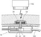
- FIG. 6is a sectional view of the control assembly shown in FIG. 2 ;
- FIG. 7is a block diagram showing the different parts of a control assembly according to the invention.
- FIG. 8is a side view of an alternative embodiment of an implanted assembly according to the invention comprising an injection port
- FIG. 9is a side view of yet an alternative embodiment of an implanted assembly according to the invention comprising a pump.
- FIG. 10illustrates a system for treating a disease, wherein the system includes an implanted assembly of the invention implanted in a patient.
- FIGS. 11-25schematically show various embodiments of the system for wirelessly powering the implanted assembly shown in FIG. 1 .
- FIG. 26is a schematic block diagram illustrating an arrangement for supplying an accurate amount of energy used for the operation of the implanted assembly shown in FIG. 1 .
- FIG. 27schematically shows an embodiment of the system, in which the implanted assembly is operated with wire bound energy.
- FIG. 28is a more detailed block diagram of an arrangement for controlling the transmission of wireless energy used for the operation of the implanted assembly shown in FIG. 1 .
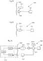
- FIG. 29is a circuit for the arrangement shown in FIG. 19 , according to a possible implementation example.
- FIGS. 30-46show various ways of arranging hydraulic or pneumatic powering of an implanted assembly implanted in a patient.
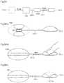
- FIG. 1shows the body of a human patient 1 .
- a control assembly 10 adapted for controlling an implanted medical deviceis shown subcutaneously implanted in the abdominal area of the patient's body. Although a specific position for the control assembly is shown in the figure, it will be appreciated that the control assembly can be provided essentially anywhere in the patient's body, preferably relatively close to the implanted medical device which it is adapted to control. Generally speaking, the control assembly 10 may be placed in the abdomen, thorax, muscle fascia (e.g. in the abdominal wall), subcutaneously, or at any other suitable location.
- the control assembly 10comprises a first unit 20 subcutaneously implanted at a first side of a body tissue 3 in the patient, such as the rectus abdominis muscle running vertically on each side of the anterior wall of the human abdomen.
- the first unitis positioned between the skin 5 of the patient and the body tissue 3 .
- a second unit 30is implanted in a body cavity 7 of the patient at a second side of the body tissue 3 , i.e., that the side opposite of the side at which the first unit 20 is provided.
- the first and/or second units 20 , 30preferably have circular or elliptical cross-sectional shape when viewed from outside the patient's body, see FIGS. 3 a , 3 b , showing a top view of the assembly having elliptical and circular shape, respectively. Combined with a smoothly curved sectional shape, this avoids any sharp corners on the units 20 , 30 , which could cause injuries to the patient in which the control assembly 10 is implanted.
- the first and second units 20 , 30may be covered by a cover 12 made of for example silicone or another material providing protection.
- the cover 12which preferably is resilient so as to follow the contours of the first and second units, also seals the control assembly 10 , thereby protecting electronics and other sensitive components of the control assembly.
- An interconnecting device 40constitutes a mechanical interconnection between the first and second units 20 , 30 so that the control assembly 10 is kept in place by the body tissue 3 .
- the interconnecting devicehas a cross-sectional area which is smaller than the cross-sectional area of the first unit and the second unit in a plane parallel to the extension of the body tissue. In this way, a hole 3 a in the body tissue 3 through which the interconnecting device 40 extends can be sufficiently small so that it is avoided that one or the other of the units 20 , 30 “slips through” the body tissue 3 .
- the cross-sectional shape of the interconnecting device 40is preferably circular so as to avoid damage to the body tissue 3 .
- the interconnecting device 40can be integral with one of the first and second units 20 , 30 .
- the interconnecting device 40is a separate part, which is connected to the first and second units 20 , 30 during implantation of the control assembly 10 .
- the interconnecting device 40is hollow so as to house various wires, hoses etc. electrically or hydraulically interconnecting the first and second units 20 , 30 .
- the interconnecting device 40is made of an elastic material, such as rubber, so that the control assembly 10 can adapt to the movements of the patient in which it is implanted.
- the control assembly 10is adapted to control a powered implanted medical device 100 , see FIG. 4 .
- the implanted medical devicecan be any kind of powered operation device, such as a hydraulically, pneumatically or mechanically powered operation device.
- the medical device 100can be any kind of implant, such as a constriction device adapted to constrict and release a bodily lumen or vessel, a stimulation device adapted to electrically stimulate a bodily organ, an inflatable device adapted to fill for example the corpora cavernosa of the patient etc.
- the implanted medical deviceis preferably very small, having a diameter of less than 5 centimeters, to fit in the different target areas of the body.
- an interconnection 102in the form of an electrical wire, a pneumatic hose etc., is provided between the control assembly 10 and the medical device 100 .
- the control assembly 10is adapted to receive energy, preferably wireless energy, transmitted from an external energy source or energizer 110 located outside the skin in the vicinity of the control assembly 10 .
- the energizer 110which is an external device which functions as the charging equipment and control device for the control assembly, is connected via a connection, such as a serial RS232 connection, to a computer 112 , such as a standard desktop PC or a laptop computer.
- the PC softwareimplements the user interface to the implant system, and function as the control unit and read back unit of the implant system.
- FIG. 5A block diagram of the implant system is shown in FIG. 5 .
- Energyis transferred by means of the wireless coupling between an energizer coil 110 a forming part of the energizer 110 and a control assembly coil 10 a forming part of the control assembly 10 .
- control informationis transferred between the energizer 110 by means of a wireless communications interface comprising an energizer antenna 110 b forming part of the energizer 110 and a control assembly antenna 10 b forming part of the control assembly 10 .
- a wireless communications interfacecomprising an energizer antenna 110 b forming part of the energizer 110 and a control assembly antenna 10 b forming part of the control assembly 10 .
- the coils 10 a , 100 acan be implemented for use as an antenna as well, whereby control information can be transferred by means of the coils and no separate antennas are needed for that purpose.
- the functional parts of the control assembly 10can be provided either in the first unit 20 or in the second unit 30 or in both the first and the second unit. In other words, at least one of the first and the second unit is adapted to control a powered implanted medical device.
- FIG. 6is a sectional view of the control assembly 10 showing an example of the contents of the first unit 20 , the second unit 30 and the interconnecting device 40 . It is also shown that the interconnecting device 40 is provided integral with the first unit 20 , forming an extension from the central portion of the first unit. The outer end of the extension is provided with barbs 42 engaging the rim of a hole 22 provided in the central portion of the second unit. In this way, the control assembly 10 can be assembled by a simple snap-together operation, as will be described in more detail below.
- a coil 50is provided in the first unit, the coil being an energy transfer coil arranged to pick up wireless electro-magnetic energy and signals from an external unit.
- the number of rounds in the coilis adapted for the specific operation and is preferably at least ten.
- the end portions of the coil 50extend perpendicularly to the general extension of the coil and are lead through the hollow interconnecting device 40 to be connected to the functional parts provided in the second unit 30 , shown as a block diagram in FIG. 7 .
- the functional parts shown in this figureis a non-limiting example of the different parts comprised in a control assembly according to the invention.
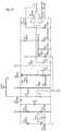
- a micro controller unit (MCU) 52is provided as a main controller unit of the control assembly 10 and it thus provided with control software for controlling the operation of the functional parts of the control assembly.
- this MCUis a Texas Instruments MSP430F149 MCU.
- the MCUcan be supplemented by additional peripheral circuits, such as a gate array implemented as an application specific integrated circuit (ASIC), acting as an interface to the various functional parts.
- ASICapplication specific integrated circuit
- the MCU 52receives commands from the energizer 110 via a wireless communication link, see below, and makes decisions about actions.
- the MCU 52thus supervises all functions in the control assembly 10 .
- the MCUstores application specific parameters and calibration data in an external EEPROM (not shown).
- control assembly 10The main functionality of the control assembly 10 is that all operations, such as stimuli, adjustments or measurements are initiated via the energizer 110 .
- the energizerhas two main functions: User interface via RF communication with the control assembly 10 and energy transfer to the control assembly.
- the control assembly 10can be OFF or in Standby when “unconnected”. All functions within the control assembly are controlled via the wireless communication link.
- the energy transfer functionruns in the background as soon as the user has initiated a charge operation.
- the coupling between the energizer and the receiver coilis displayed by means of a graphical user interface (GUI) on the display of the energizer 110 .
- GUIgraphical user interface
- the active functionis terminated with a warning message. As soon as correct connection is obtained the last function can be re-activated from the GUI.
- the MCU 52is connected to a charge control unit 54 , which in turn is connected to the coil 50 , which in this embodiment is provided in the first unit 20 .
- the charge control unitcomprises an energy storage capacitor 54 a , from which the normal power supply is taken.
- the energy storage capacitor 54 ahas a value of at least 300 Farad with a maximum voltage of 2.3V.
- the energy storage capacitoris normally connected to the energy transfer coil 50 , preventing hazardous voltages to occur at the supply circuits.
- the voltage from the energy transfer coil 50is rectified by means of half-wave rectification.
- the transferred energyis set by the voltage on the energizer transmit coil 110 a , see FIG. 5 , and the geometric placement relative the energy transfer coil 10 a on the control assembly.
- the leakage inductancesmake the behavior of a current generator, that is, the voltage across the energy storage capacitor 54 a will have a very little influence on the current.
- the charge functionis controlled from the energizer software, which depends on current and voltage readings on the reservoir capacitor.
- the applied energy transferwill charge the capacitor up to a limit voltage, which in the preferred embodiment is 2.3V, while the charge current preferably is limited to 2 A by the energizer design. If the energy storage capacitor energy drops below a lower limit voltage, in the preferred embodiment 1.2V, MCU 52 will be notified to terminate any activity and go to STAND-BY mode.
- the voltagewill vary between 1.0 and 2.3V dependent of the charge status.
- This voltagefeeds a switch converter for supplying the MCU including any gate array. It is preferred that the gate array supply may be shut down by the MCU to save energy.
- the control assemblyshall be functional for 36 hours relying on the capacitor only.
- a chargeable battery 54 bis also provided as part of the charge control unit 54 .
- the capacity of the batteryis preferably approximately ten times that of the energy storage capacitor 54 a .
- the battery usedis three 1.2 V batteries, such as Varta V500-HT, connected in series. This gives a nominal voltage of 3.6V.
- the battery managementconsists of two main activities: Charging and discharging (transfer energy to the reservoir capacitor). Normally the battery is unused and energy is supplied from the capacitor.
- a battery charging functionalityis implemented in hardware with supervision and control from the MCU 52 .
- the chargeable batteryis charged from the energy storage capacitor 54 a when the voltage across the energy storage capacitor exceeds 1.9V. This limit will prevent the battery charger from emptying the capacitor energy.
- the batteryWhen the voltage across the energy storage capacitor is less than 1.3V, the battery will charge the energy storage capacitor a constant current by means of a step-down converter (not shown).
- the charge currentis in the preferred embodiment 350 mA with dv/dt detection.
- Temperature supervisionwill turn off any charge operation if the battery temperature increases more than 0.7° C. per min.
- the energy transferis controlled from the software in the computer 112 .
- the MCU 52will read the voltage and current on the energy storage capacitor 54 a .
- the valuesare then on command transmitted to the computer 112 , which controls the energizer. If the energy storage capacitor 54 a has a 300 F capacitance and the charge current is normally well below 2 A, the voltage changes will be very slow—minutes for a 0.1 V increase. This slow behavior makes an ordinary PI-regulator superfluous.
- the preferred embodimentis an on/off regulator with a 100 mV hysteresis gap.
- the control assembly 10can be in four different power modes, namely:
- the transceiver 56is powered from the chargeable battery 54 b , but in sleep mode.
- WAKE-UPThe power is fed from the energy transfer coil 50 , unconditionally of the status of the energy storage capacitor 54 a or the chargeable battery 54 b . This makes the control assembly to respond immediately when the energizer is applied.
- STAND-BYMCU active but no stimuli, sensor or motor voltage active.
- ACTIVEThe MCU in operation. Motor/Sensors/Stimuli etc. active
- the modeis controlled by the software in the MCU.
- the MCU 52communicates with the energizer by means of the antenna 10 b , see FIG. 5 , which is electrically connected to a transceiver 56 in the control assembly 10 .
- the transceiver 56is in turn connected to the MCU 52 .
- the transceiver 56can be any suitable transceiver circuit and is in the described embodiment a circuit marketed under the name ZL70101 by Zarlink Semiconductor Inc. This provides RF communication using the MICS standard.
- the transceiverpreferably uses a serial peripheral interface (SPI) to communicate with the MCU and is specified for 2.1-3.6V supply.
- SPIserial peripheral interface
- the transceiverneeds to be under continuous power but have a low power mode with very low quiescent current where it can be woken up by using either by toggling a wakeup input or alternatively by MICS band or 2.4 GHz radio signals.
- the antenna 10 bis adapted to support MICS telemetry that operates in the dedicated 402-405 MHz band.
- the most probable implementation of the transceiver 56will use a system that can be implemented using also a secondary 2.4 GHz ISM band for wake up purposes, which will then also require attention to safeguard antenna functionality also at these frequencies.
- the wake up antennais assumed to be identical to the MICS antenna since alternate solutions would require separate hermetic feed-through connections that adds considerable costs.
- the 2.4 GHz aspect of the antennais an electrically large antenna that works well with most MICS antenna implementations.
- One temperature sensorwill be use for sensing the temperature of the battery and one sensing the encapsulation. It is also possible to connect one or more external temperature sensors.
- the sensor accuracyis typically +/ ⁇ 0.5 degrees between ⁇ 30-+70 degrees and better than +/ ⁇ 0.25 degrees between 20-45 degrees.
- One or more pressure sensors 60are connected to an A/D input of the MCU 52 .
- the pressure sensorspreferably have a sensing range of 0-2 bars.
- the sensorscan be of the SMD 3000 series type 3SC-0500-5212 from Merit Sensor Systems.
- One or more motorscan be connected to the control assembly 10 .
- the operation of these motorsis controlled by means of a respective motor controller.
- this motor controllerconsists of 5 H-bridge with current measurement and rotation sensing.
- the control optionsare forward, backward, or break.
- the controlis either ON or OFF, i.e., no speed control is implemented.
- speed controlcan be implemented, such as by means of a pulse width modulated (PWM) signal.
- PWMpulse width modulated
- the current through the motoris measured in order to differentiate four states:
- the rotation of the motorswill be monitored either by an internal encoder in the motor or by external sensors/encoders.
- the sensing of the movementcan be done with a low power Hall element, for example Allegro A139X series, in combination with a comparator that sets the sensitivity or by optical encoders depending on the mechanics.
- a comparatorthat sets the sensitivity or by optical encoders depending on the mechanics.
- Sensing on outgoing axlecan be used when there is no encoder on the motor.
- the rotation sensingcan be done with two Hall-effect sensors, such as A1391SE sensors from Allegro MicroSystems, Inc. By using two sensors per motor both direction and speed can be determined.
- the phase between the detectorsshall be 90 degrees, which is set by the mechanical mounting of the devices.
- a reflex detectorcan be used for rotation sensing.
- an integrated encoder in the motorcan be used for rotation determination.
- the control assemblycan be adapted to control the operation of an implanted medical device in the form of one or more electrodes used to electrically stimulate an organ in the patient's body, such as the corpora cavernosa or crura or the prolongations thereof of a male patient's penile tissue, the colon, rectum, or anus or the prolongation thereof, the urine bladder, the urethra or the prolongation thereof, or any other bodily lumen which requires electrical stimulation under control of the patient or a doctor.
- an implanted medical devicein the form of one or more electrodes used to electrically stimulate an organ in the patient's body, such as the corpora cavernosa or crura or the prolongations thereof of a male patient's penile tissue, the colon, rectum, or anus or the prolongation thereof, the urine bladder, the urethra or the prolongation thereof, or any other bodily lumen which requires electrical stimulation under control of the patient or a doctor.
- the stimuli generators 64are designed around a high speed, high current output operational amplifiers, such as the AD825 from Analog Devices, Inc. Each output has a dc current blocking capacitor. A DC servo prevents the capacitor to charge due to offset current errors
- the implanted medical devicecontains 4+4 electrodes to which a constant current pulse generator is connected.
- the current generatorcan be connected to two or several electrodes simultaneously.
- the current pulsesalways consist of one positive current pulse and one negative current pulse in any order.
- the stimuli pulsesare configurable regarding current amplitude; pulse widths, number of pulses in a pulse train and pulse frequency.
- the control assembly 10ensures that the pulses are charged balanced.
- the software of the computer 112is adapted to write configuration parameters to the control assembly 10 and to start and stop stimulation with those parameters.
- the stimulationcan “move” between different electrodes to e.g. create an artificial peristalsis.
- the stimuli amplitudeis be up to 20 mA with +/ ⁇ 14V available.
- One or more capacitance measuring inputsare provided for determination of a physical or mechanical position.
- the inputhas a working range of 5-100 pF.
- the motion sensoris a piezo polymer strip that generates a charge/voltage during movement of an intestine. Each motion sensor is adjusted depending of the application in order to apply an appropriate gain.
- the first unit 20comprises an injection port 70 adapted to receive an injection needle 70 a .
- the injection portcomprises a reservoir 70 b with a silicone septum 70 c . Fluid is added to or removed from the interior reservoir of the first unit 20 by inserting a Huber needle percutaneously into the septum.
- the septum 70 cis made of silicone
- the means of the injection port for receiving a needleincludes any structure configured to self seal after puncture with a non-coring needle.
- the first unit 20comprises a magnetic arrangement 71 used as a means for detecting the position of the control assembly 10 , which is particularly convenient in the case of an injection port, since a patient or doctor must be able to locate the septum in order to perform accurate puncturing thereof.
- the magnetic arrangementmay include an arrangement as that disclosed in the international publication WO2004/030536(A1), incorporated herein by reference.
- a tube or hose 70 dis connected to the reservoir 70 b and is adapted to be connected to an implanted medical device 100 , such as a hydraulically operated constriction device provided about and engaging a bodily organ of the patient, such as the corpora cavernosa or crura or the prolongations thereof of a male patient's penile tissue, the colon, rectum, or anus or the prolongation thereof, the urine bladder, the urethra or the prolongation thereof, or any other bodily lumen which requires partial or full restriction under control of the patient or a doctor.
- the medical devicecould also be an adjustable prosthesis device implantable in the corpora cavernosa or other parts of a male impotent patient's penile tissue.
- the tube 70 dis provided in the hollow interconnecting device 40 and through the second unit 30 .
- the second unit 30comprises a pump 72 .
- the pumpmay be controlled by means of an electronic device in the form of an MCU 52 and associated parts, i.e., transceiver with antenna, charge control unit connected to an energy transfer coil 50 provided in the first unit 20 etc., as have been described above with reference to FIG. 7 .
- the pumpis energized through a battery, preferably a rechargeable battery. Alternatively, the pump is energized directly from the energizer 110 .
- the pumpis connected to a first fluid hose 72 a and a second fluid hose 72 b .
- These hosesare connectable to reservoirs in the body of the patient and the pump is thus adapted to pump fluid from one part of the patient's body to another part of the patient's body.
- the first fluid hose 72 ais connected to a balancing reservoir 72 c .
- This balancing reservoir 72 cis preferably made in the shape of a soft pouch placed in proximity to the second unit 30 . It could also be placed directly on a face of or within the second unit.
- the second fluid hose 72 bis connected to an implanted medical device 100 , such as a hydraulically operated constriction device provided about and engaging a bodily organ of the patient, such as the corpora cavernosa or crura or the prolongations thereof of a male patient's penile tissue, the colon, rectum, or anus or the prolongation thereof, the urine bladder, the urethra or the prolongation thereof, or any other bodily lumen which requires partial or full restriction under control of the patient or a doctor.
- the medical devicecould also be an adjustable prosthesis device implantable in the corpora cavernosa or other parts of a male impotent patient's penile tissue.
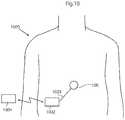
- FIG. 10illustrates a system for treating a disease comprising an implanted medical device 100 placed in the abdomen of a patient.
- An implanted energy-transforming device 1002corresponding to the control assembly 10 , is adapted to supply energy consuming components of the implanted medical device with energy via a power supply line 1003 .
- An external energy-transmission device 1004corresponding to the energizer 110 , for non-invasively energizing the implanted medical device 100 transmits energy by at least one wireless energy signal.
- the implanted energy-transforming device 1002transforms energy from the wireless energy signal into electric energy which is supplied via the power supply line 1003 .
- the wireless energy signalmay include a wave signal selected from the following: a sound wave signal, an ultrasound wave signal, an electromagnetic wave signal, an infrared light signal, a visible light signal, an ultra violet light signal, a laser light signal, a micro wave signal, a radio wave signal, an x-ray radiation signal and a gamma radiation signal.
- the wireless energy signalmay include an electric or magnetic field, or a combined electric and magnetic field.
- the wireless energy-transmission device 1004may transmit a carrier signal for carrying the wireless energy signal.
- a carrier signalmay include digital, analogue or a combination of digital and analogue signals.
- the wireless energy signalincludes an analogue or a digital signal, or a combination of an analogue and digital signal.
- the energy-transforming device 1002is provided for transforming wireless energy of a first form transmitted by the energy-transmission device 1004 into energy of a second form, which typically is different from the energy of the first form.
- the implanted medical device 100is operable in response to the energy of the second form.
- the energy-transforming device 1002may directly power the implanted medical device with the second form energy, as the energy-transforming device 1002 transforms the first form energy transmitted by the energy-transmission device 1004 into the second form energy.
- the systemmay further include an implantable accumulator, wherein the second form energy is used at least partly to charge the accumulator.
- the wireless energy transmitted by the energy-transmission device 1004may be used to directly power the implanted medical device, as the wireless energy is being transmitted by the energy-transmission device 1004 .
- the systemcomprises an operation device for operating the implanted medical device, as will be described below, the wireless energy transmitted by the energy-transmission device 1004 may be used to directly power the operation device to create kinetic energy for the operation of the implanted medical device.
- the wireless energy of the first formmay comprise sound waves and the energy-transforming device 1002 may include a piezo-electric element for transforming the sound waves into electric energy.
- the energy of the second formmay comprise electric energy in the form of a direct current or pulsating direct current, or a combination of a direct current and pulsating direct current, or an alternating current or a combination of a direct and alternating current.
- the implanted medical devicecomprises electric components that are energized with electrical energy.
- Other implantable electric components of the systemmay be at least one voltage level guard or at least one constant current guard connected with the electric components of the implanted medical device.
- one of the energy of the first form and the energy of the second formmay comprise magnetic energy, kinetic energy, sound energy, chemical energy, radiant energy, electromagnetic energy, photo energy, nuclear energy or thermal energy.
- one of the energy of the first form and the energy of the second formis non-magnetic, non-kinetic, non-chemical, non-sonic, non-nuclear or non-thermal.
- the energy-transmission devicemay be controlled from outside the patient's body to release electromagnetic wireless energy, and the released electromagnetic wireless energy is used for operating the implanted medical device.
- the energy-transmission deviceis controlled from outside the patient's body to release non-magnetic wireless energy, and the released non-magnetic wireless energy is used for operating the implanted medical device.
- the external energy-transmission device 1004also includes a wireless remote control having an external signal transmitter for transmitting a wireless control signal for non-invasively controlling the implanted medical device.
- the control signalis received by an implanted signal receiver which may be incorporated in the implanted energy-transforming device 1002 or be separate there from.
- the wireless control signalmay include a frequency, amplitude, or phase modulated signal or a combination thereof.
- the wireless control signalincludes an analogue or a digital signal, or a combination of an analogue and digital signal.
- the wireless control signalcomprises an electric or magnetic field, or a combined electric and magnetic field.
- the wireless remote controlmay transmit a carrier signal for carrying the wireless control signal.
- a carrier signalmay include digital, analogue or a combination of digital and analogue signals.
- the control signalincludes an analogue or a digital signal, or a combination of an analogue and digital signal
- the wireless remote controlpreferably transmits an electromagnetic carrier wave signal for carrying the digital or analogue control signals.
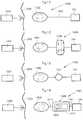
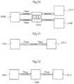
- FIG. 11illustrates the system of FIG. 10 in the form of a more generalized block diagram showing the implanted medical device 100 , the energy-transforming device 1002 powering the implanted medical device 100 via power supply line 1003 , and the external energy-transmission device 1004 ,
- the patient's skin 1005generally shown by a vertical line, separates the interior of the patient to the right of the line from the exterior to the left of the line.
- FIG. 12shows an embodiment of the invention identical to that of FIG. 11 , except that a reversing device in the form of an electric switch 1006 operable for example by polarized energy also is implanted in the patient for reversing the implanted medical device 100 .
- the wireless remote control of the external energy-transmission device 1004transmits a wireless signal that carries polarized energy and the implanted energy-transforming device 1002 transforms the wireless polarized energy into a polarized current for operating the electric switch 1006 .
- the electric switch 1006reverses the function performed by the implanted medical device 100 .
- FIG. 13shows an embodiment of the invention identical to that of FIG. 11 , except that an operation device 1007 implanted in the patient for operating the implanted medical device 100 is provided between the implanted energy-transforming device 1002 and the implanted medical device 100 .
- This operation devicecan be in the form of a motor 1007 , such as an electric servomotor.
- the motor 1007is powered with energy from the implanted energy-transforming device 1002 , as the remote control of the external energy-transmission device 1004 transmits a wireless signal to the receiver of the implanted energy-transforming device 1002 .
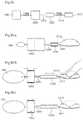
- FIG. 14shows an embodiment of the invention identical to that of FIG. 11 , except that it also comprises an operation device is in the form of an assembly 1008 including a motor/pump unit 1009 and a fluid reservoir 1010 is implanted in the patient.
- the implanted medical device 100is hydraulically operated, i.e. hydraulic fluid is pumped by the motor/pump unit 1009 from the fluid reservoir 1010 through a conduit 1011 to the implanted medical device 100 to operate the implanted medical device, and hydraulic fluid is pumped by the motor/pump unit 1009 back from the implanted medical device 100 to the fluid reservoir 1010 to return the implanted medical device to a starting position.
- the implanted energy-transforming device 1002transforms wireless energy into a current, for example a polarized current, for powering the motor/pump unit 1009 via an electric power supply line 1012 .
- the operation devicecomprises a pneumatic operation device.
- the hydraulic fluidcan be pressurized air to be used for regulation and the fluid reservoir is replaced by an air chamber.
- the energy-transforming device 1002may include a rechargeable accumulator like a battery or a capacitor to be charged by the wireless energy and supplies energy for any energy consuming part of the system.
- the wireless remote control described abovemay be replaced by manual control of any implanted part to make contact with by the patient's hand most likely indirect, for example a press button placed under the skin.
- FIG. 15shows an embodiment of the invention comprising the external energy-transmission device 1004 with its wireless remote control, the medical device 100 , in this case hydraulically operated, and the implanted energy-transforming device 1002 , and further comprising a hydraulic fluid reservoir 1013 , a motor/pump unit 1009 and an reversing device in the form of a hydraulic valve shifting device 1014 , all implanted in the patient.
- the remote controlmay be a device separated from the external energy-transmission device or included in the same.
- the motor of the motor/pump unit 1009is an electric motor.
- the implanted energy-transforming device 1002powers the motor/pump unit 1009 with energy from the energy carried by the control signal, whereby the motor/pump unit 1009 distributes hydraulic fluid between the hydraulic fluid reservoir 1013 and the medical device 100 .
- the remote control of the external energy-transmission device 1004controls the hydraulic valve shifting device 1014 to shift the hydraulic fluid flow direction between one direction in which the fluid is pumped by the motor/pump unit 1009 from the hydraulic fluid reservoir 1013 to the implanted medical device 100 to operate the implanted medical device, and another opposite direction in which the fluid is pumped by the motor/pump unit 1009 back from the implanted medical device 100 to the hydraulic fluid reservoir 1013 to return the implanted medical device to a starting position.
- FIG. 16shows an embodiment of the invention comprising the external energy-transmission device 1004 with its wireless remote control, the medical device 100 , the implanted energy-transforming device 1002 , an implanted internal control unit 1015 controlled by the wireless remote control of the external energy-transmission device 1004 , an implanted accumulator 1016 and an implanted capacitor 1017 .
- the internal control unit 1015arranges storage of electric energy received from the implanted energy-transforming device 1002 in the accumulator 1016 , which supplies energy to the medical device 100 .
- the internal control unit 1015In response to a control signal from the wireless remote control of the external energy-transmission device 1004 , the internal control unit 1015 either releases electric energy from the accumulator 1016 and transfers the released energy via power lines 1018 and 1019 , or directly transfers electric energy from the implanted energy-transforming device 1002 via a power line 1020 , the capacitor 1017 , which stabilizes the electric current, a power line 1021 and the power line 1019 , for the operation of the medical device 100 .
- the internal control unitis preferably programmable from outside the patient's body.
- the internal control unitis programmed to regulate the implanted medical device 100 according to a pre-programmed time-schedule or to input from any sensor sensing any possible physical parameter of the patient or any functional parameter of the system.
- the capacitor 1017 in the embodiment of FIG. 16may be omitted.
- the accumulator 1016 in this embodimentmay be omitted.
- FIG. 17shows an embodiment of the invention identical to that of FIG. 11 , except that a battery 1022 for supplying energy for the operation of the implanted medical device 100 and an electric switch 1023 for switching the operation of the implanted medical device 100 also are implanted in the patient.
- the electric switch 1023may be controlled by the remote control and may also be operated by the energy supplied by the implanted energy-transforming device 1002 to switch from an off mode, in which the battery 1022 is not in use, to an on mode, in which the battery 1022 supplies energy for the operation of the medical device 100 .
- FIG. 18shows an embodiment of the invention identical to that of FIG. 17 , except that an internal control unit 1015 controllable by the wireless remote control of the external energy-transmission device 1004 also is implanted in the patient.
- the electric switch 1023is operated by the energy supplied by the implanted energy-transforming device 1002 to switch from an off mode, in which the wireless remote control is prevented from controlling the internal control unit 1015 and the battery is not in use, to a standby mode, in which the remote control is permitted to control the internal control unit 1015 to release electric energy from the battery 1022 for the operation of the medical device 100 .
- FIG. 19shows an embodiment of the invention identical to that of FIG. 18 , except that an accumulator 1016 is substituted for the battery 1022 and the implanted components are interconnected differently.
- the accumulator 1016stores energy from the implanted energy-transforming device 1002 .
- the internal control unit 1015controls the electric switch 1023 to switch from an off mode, in which the accumulator 1016 is not in use, to an on mode, in which the accumulator 1016 supplies energy for the operation of the medical device 100 .
- the accumulatormay be combined with or replaced by a capacitor.
- FIG. 20shows an embodiment of the invention identical to that of FIG. 19 , except that a battery 1022 also is implanted in the patient and the implanted components are interconnected differently.
- the internal control unit 1015controls the accumulator 1016 to deliver energy for operating the electric switch 1023 to switch from an off mode, in which the battery 1022 is not in use, to an on mode, in which the battery 1022 supplies electric energy for the operation of the medical device 100 .
- the electric switch 1023may be operated by energy supplied by the accumulator 1016 to switch from an off mode, in which the wireless remote control is prevented from controlling the battery 1022 to supply electric energy and is not in use, to a standby mode, in which the wireless remote control is permitted to control the battery 1022 to supply electric energy for the operation of the medical device 100 .
- the electric switch 1023 and all other switches in this applicationshould be interpreted in its broadest embodiment.
- the switchis controlled from outside the body, or alternatively by an implanted internal control unit.
- FIG. 21shows an embodiment of the invention identical to that of FIG. 17 , except that a motor 1007 , a mechanical reversing device in the form of a gear box 1024 , and an internal control unit 1015 for controlling the gear box 1024 also are implanted in the patient.
- the internal control unit 1015controls the gear box 1024 to reverse the function performed by the implanted medical device 100 (mechanically operated). Even simpler is to switch the direction of the motor electronically.
- the gear box interpreted in its broadest embodimentmay stand for a servo arrangement saving force for the operation device in favor of longer stroke to act.
- FIG. 22shows an embodiment of the invention identical to that of FIG. 21 except that the implanted components are interconnected differently.
- the internal control unit 1015is powered by the battery 1022 when the accumulator 1016 , suitably a capacitor, activates the electric switch 1023 to switch to an on mode.
- the electric switch 1023is in its on mode the internal control unit 1015 is permitted to control the battery 1022 to supply, or not supply, energy for the operation of the medical device 100 .
- FIG. 23schematically shows conceivable combinations of implanted components of the system for achieving various communication options.
- the medical device 100there are the medical device 100 , the internal control unit 1015 , motor or pump unit 1009 , and the external energy-transmission device 1004 including the external wireless remote control.
- the wireless remote controltransmits a control signal which is received by the internal control unit 1015 , which in turn controls the various implanted components of the system.
- a feedback devicepreferably comprising a sensor or measuring device 1025 , may be implanted in the patient for sensing a physical parameter of the patient.
- the physical parametermay be at least one selected from the group consisting of pressure, volume, diameter, stretching, elongation, extension, movement, bending, elasticity, muscle contraction, nerve impulse, body temperature, blood pressure, blood flow, heartbeats and breathing.
- the sensormay sense any of the above physical parameters.
- the sensormay be a pressure or motility sensor.
- the senor 1025may be arranged to sense a functional parameter.
- the functional parametermay be correlated to the transfer of energy for charging an implanted energy source and may further include at least one selected from the group of parameters consisting of; electricity, any electrical parameter, pressure, volume, diameter, stretch, elongation, extension, movement, bending, elasticity, temperature and flow.
- the feedbackmay be sent to the internal control unit or out to an external control unit preferably via the internal control unit.
- Feedbackmay be sent out from the body via the energy transfer system or a separate communication system with receiver and transmitters.
- the internal control unit 1015may control the implanted medical device 100 in response to signals from the sensor 1025 .
- a transceivermay be combined with the sensor 1025 for sending information on the sensed physical parameter to the external wireless remote control.
- the wireless remote controlmay comprise a signal transmitter or transceiver and the internal control unit 1015 may comprise a signal receiver or transceiver.
- the wireless remote controlmay comprise a signal receiver or transceiver and the internal control unit 1015 may comprise a signal transmitter or transceiver.
- the above transceivers, transmitters and receiversmay be used for sending information or data related to the implanted medical device 100 from inside the patient's body to the outside thereof.
- FIG. 24shows an alternative embodiment wherein the implanted medical device 100 is regulated from outside the patient's body.
- the system 1000comprises a battery 1022 connected to the implanted medical device 100 via a subcutaneous electric switch 1026 .
- the regulation of the implanted medical device 100is performed non-invasively by manually pressing the subcutaneous switch, whereby the operation of the implanted medical device 100 is switched on and off.
- additional componentssuch as an internal control unit or any other part disclosed in the present application can be added to the system.
- Two subcutaneous switchesmay also be used.
- one implanted switchsends information to the internal control unit to perform a certain predetermined performance and when the patient press the switch again the performance is reversed.
- FIG. 25shows an alternative embodiment, wherein the system 1000 comprises a hydraulic fluid reservoir 1013 hydraulically connected to the implanted medical device. Non-invasive regulation is performed by manually pressing the hydraulic reservoir connected to the implanted medical device.
- the systemmay include an external data communicator and an implantable internal data communicator communicating with the external data communicator.
- the internal communicatorfeeds data related to the implanted medical device or the patient to the external data communicator and/or the external data communicator feeds data to the internal data communicator.
- FIG. 26schematically illustrates an arrangement of the system that is capable of sending information from inside the patient's body to the outside thereof to give feedback information related to at least one functional parameter of the implanted medical device or system, or related to a physical parameter of the patient, in order to supply an accurate amount of energy to an implanted internal energy receiver 1002 connected to implanted energy consuming components of the medical device 100 .
- an energy receiver 1002may include an energy source and/or an energy-transforming device. Briefly described, wireless energy is transmitted from an external energy source 1004 a located outside the patient and is received by the internal energy receiver 1002 located inside the patient. The internal energy receiver is adapted to directly or indirectly supply received energy to the energy consuming components of the implanted medical device 100 via a switch 1026 .
- An energy balanceis determined between the energy received by the internal energy receiver 1002 and the energy used for the medical device 100 , and the transmission of wireless energy is then controlled based on the determined energy balance.
- the energy balancethus provides an accurate indication of the correct amount of energy needed, which is sufficient to operate the implanted medical device 100 properly, but without causing undue temperature rise.
- the patient's skinis indicated by a vertical line 1005 .
- the energy receivercomprises an energy-transforming device 1002 located inside the patient, preferably just beneath the patient's skin 1005 .
- the implanted energy-transforming device 1002may be placed in the abdomen, thorax, muscle fascia (e.g. in the abdominal wall), subcutaneously, or at any other suitable location.
- the implanted energy-transforming device 1002is adapted to receive wireless energy E transmitted from the external energy source 1004 a provided in an external energy-transmission device 1004 located outside the patient's skin 1005 in the vicinity of the implanted energy-transforming device 1002 .
- the wireless energy Emay generally be transferred by means of any suitable Transcutaneous Energy Transfer (TET) device, such as a device including a primary coil arranged in the external energy source 1004 a and an adjacent secondary coil arranged in the implanted energy-transforming device 1002 .
- TETTranscutaneous Energy Transfer
- a device including a primary coil arranged in the external energy source 1004 a and an adjacent secondary coil arranged in the implanted energy-transforming device 1002When an electric current is fed through the primary coil, energy in the form of a voltage is induced in the secondary coil which can be used to power the implanted energy consuming components of the implanted medical device, e.g. after storing the incoming energy in an implanted energy source, such as a rechargeable battery or a capacitor.
- an implanted energy sourcesuch as a rechargeable battery or a capacitor.
- the present inventionis generally not limited to any particular energy transfer technique, TET devices or energy sources, and any kind of wireless energy may be used.
- the amount of energy received by the implanted energy receivermay be compared with the energy used by the implanted components of the implanted medical device.
- a control deviceincludes an external control unit 1004 b that controls the external energy source 1004 a based on the determined energy balance to regulate the amount of transferred energy.
- the energy balance and the required amount of energyis determined by means of a determination device including an implanted internal control unit 1015 connected between the switch 1026 and the medical device 100 .
- the internal control unit 1015may thus be arranged to receive various measurements obtained by suitable sensors or the like, not shown, measuring certain characteristics of the medical device 100 , somehow reflecting the required amount of energy needed for proper operation of the medical device 100 .
- the current condition of the patientmay also be detected by means of suitable measuring devices or sensors, in order to provide parameters reflecting the patient's condition.
- suitable measuring devices or sensorsin order to provide parameters reflecting the patient's condition.
- characteristics and/or parametersmay be related to the current state of the medical device 100 , such as power consumption, operational mode and temperature, as well as the patient's condition reflected by parameters such as; body temperature, blood pressure, heartbeats and breathing.
- Other kinds of physical parameters of the patient and functional parameters of the deviceare described elsewhere.
- an energy source in the form of an accumulator 1016may optionally be connected to the implanted energy-transforming device 1002 via the internal control unit 1015 for accumulating received energy for later use by the medical device 100 .
- characteristics of such an accumulatoralso reflecting the required amount of energy, may be measured as well.
- the accumulatormay be replaced by a rechargeable battery, and the measured characteristics may be related to the current state of the battery, any electrical parameter such as energy consumption voltage, temperature, etc. In order to provide sufficient voltage and current to the medical device 100 , and also to avoid excessive heating, it is clearly understood that the battery should be charged optimally by receiving a correct amount of energy from the implanted energy-transforming device 1002 , i.e. not too little or too much.
- the accumulatormay also be a capacitor with corresponding characteristics.
- battery characteristicsmay be measured on a regular basis to determine the current state of the battery, which then may be stored as state information in a suitable storage means in the internal control unit 1015 .
- state informationin a suitable storage means in the internal control unit 1015 .
- the stored battery state informationcan be updated accordingly.
- the state of the batterycan be “calibrated” by transferring a correct amount of energy, so as to maintain the battery in an optimal condition.
- the internal control unit 1015 of the determination deviceis adapted to determine the energy balance and/or the currently required amount of energy, (either energy per time unit or accumulated energy) based on measurements made by the above-mentioned sensors or measuring devices of the medical device 100 , or the patient, or an implanted energy source if used, or any combination thereof.
- the internal control unit 1015is further connected to an internal signal transmitter 1027 , arranged to transmit a control signal reflecting the determined required amount of energy, to an external signal receiver 1004 c connected to the external control unit 1004 b .
- the amount of energy transmitted from the external energy source 1004 amay then be regulated in response to the received control signal.
- the determination devicemay include the external control unit 1004 b .
- sensor measurementscan be transmitted directly to the external control unit 1004 b wherein the energy balance and/or the currently required amount of energy can be determined by the external control unit 1004 b , thus integrating the above-described function of the internal control unit 1015 in the external control unit 1004 b .
- the internal control unit 1015can be omitted and the sensor measurements are supplied directly to the internal signal transmitter 1027 which sends the measurements over to the external signal receiver 1004 c and the external control unit 1004 b .
- the energy balance and the currently required amount of energycan then be determined by the external control unit 1004 b based on those sensor measurements.
- the present solution according to the arrangement of FIG. 26employs the feed back of information indicating the required energy, which is more efficient than previous solutions because it is based on the actual use of energy that is compared to the received energy, e.g. with respect to the amount of energy, the energy difference, or the energy receiving rate as compared to the energy rate used by implanted energy consuming components of the implanted medical device.
- the systemmay use the received energy either for consuming or for storing the energy in an implanted energy source or the like.
- the different parameters discussed abovewould thus be used if relevant and needed and then as a tool for determining the actual energy balance. However, such parameters may also be needed per se for any actions taken internally to specifically operate the implanted medical device.
- the internal signal transmitter 1027 and the external signal receiver 1004 cmay be implemented as separate units using suitable signal transfer means, such as radio, IR (Infrared) or ultrasonic signals.
- suitable signal transfer meanssuch as radio, IR (Infrared) or ultrasonic signals.
- the internal signal transmitter 1027 and the external signal receiver 1004 cmay be integrated in the implanted energy-transforming device 1002 and the external energy source 1004 a , respectively, so as to convey control signals in a reverse direction relative to the energy transfer, basically using the same transmission technique.
- the control signalsmay be modulated with respect to frequency, phase or amplitude.
- the feedback informationmay be transferred either by a separate communication system including receivers and transmitters or may be integrated in the energy system.
- an integrated information feedback and energy systemcomprises an implantable internal energy receiver for receiving wireless energy, the energy receiver having an internal first coil and a first electronic circuit connected to the first coil, and an external energy transmitter for transmitting wireless energy, the energy transmitter having an external second coil and a second electronic circuit connected to the second coil.
- the external second coil of the energy transmittertransmits wireless energy which is received by the first coil of the energy receiver.
- This systemfurther comprises a power switch for switching the connection of the internal first coil to the first electronic circuit on and off, such that feedback information related to the charging of the first coil is received by the external energy transmitter in the form of an impedance variation in the load of the external second coil, when the power switch switches the connection of the internal first coil to the first electronic circuit on and off.
- the switch 1026is either separate and controlled by the internal control unit 1015 , or integrated in the internal control unit 1015 . It should be understood that the switch 1026 should be interpreted in its broadest embodiment. This means a transistor, MCU, MCPU, ASIC FPGA or a DA converter or any other electronic component or circuit that may switch the power on and off.
- the energy supply arrangement illustrated in FIG. 26may operate basically in the following manner.
- the energy balanceis first determined by the internal control unit 1015 of the determination device.
- a control signal reflecting the required amount of energyis also created by the internal control unit 1015 , and the control signal is transmitted from the internal signal transmitter 1027 to the external signal receiver 1004 c .
- the energy balancecan be determined by the external control unit 1004 b instead depending on the implementation, as mentioned above.
- the control signalmay carry measurement results from various sensors.
- the amount of energy emitted from the external energy source 1004 acan then be regulated by the external control unit 1004 b , based on the determined energy balance, e.g. in response to the received control signal. This process may be repeated intermittently at certain intervals during ongoing energy transfer, or may be executed on a more or less continuous basis during the energy transfer.
- the amount of transferred energycan generally be regulated by adjusting various transmission parameters in the external energy source 1004 a , such as voltage, current, amplitude, wave frequency and pulse characteristics.
- This systemmay also be used to obtain information about the coupling factors between the coils in a TET system even to calibrate the system both to find an optimal place for the external coil in relation to the internal coil and to optimize energy transfer. Simply comparing in this case the amount of energy transferred with the amount of energy received. For example if the external coil is moved the coupling factor may vary and correctly displayed movements could cause the external coil to find the optimal place for energy transfer.
- the external coilis adapted to calibrate the amount of transferred energy to achieve the feedback information in the determination device, before the coupling factor is maximized.
- the energy system of the present inventioncomprises an implantable internal energy receiver for receiving wireless energy, the energy receiver having an internal first coil and a first electronic circuit connected to the first coil, and an external energy transmitter for transmitting wireless energy, the energy transmitter having an external second coil and a second electronic circuit connected to the second coil.
- the external second coil of the energy transmittertransmits wireless energy which is received by the first coil of the energy receiver.
- This systemfurther comprises a feedback device for communicating out the amount of energy received in the first coil as a feedback information
- the second electronic circuitincludes a determination device for receiving the feedback information and for comparing the amount of transferred energy by the second coil with the feedback information related to the amount of energy received in the first coil to obtain the coupling factor between the first and second coils.
- the energy transmittermay regulate the transmitted energy in response to the obtained coupling factor.
- FIG. 27Although wireless transfer of energy for operating the implanted medical device has been described above to enable non-invasive operation, it will be appreciated that the implanted medical device can be operated with wire bound energy as well.
- an external switch 1026is interconnected between the external energy source 1004 a and an operation device, such as an electric motor 1007 operating the medical device 100 .
- An external control unit 1004 bcontrols the operation of the external switch 1026 to effect proper operation of the medical device 100 .
- FIG. 28illustrates different embodiments for how received energy can be supplied to and used by the medical device 100 .
- an internal energy receiver 1002receives wireless energy E from an external energy source 1004 a which is controlled by a transmission control unit 1004 b .
- the internal energy receiver 1002may comprise a constant voltage circuit, indicated as a dashed box “constant V” in the figure, for supplying energy at constant voltage to the medical device 100 .
- the internal energy receiver 1002may further comprise a constant current circuit, indicated as a dashed box “constant C” in the figure, for supplying energy at constant current to the medical device 100 .
- the implanted medical device 100comprises an energy consuming part 100 b , which may be a motor, pump, restriction device, or any other medical appliance that requires energy for its electrical operation.
- the implanted medical device 100may further comprise an energy storage device 100 c for storing energy supplied from the internal energy receiver 1002 .
- the supplied energymay be directly consumed by the energy consuming part 100 b , or stored by the energy storage device 100 c , or the supplied energy may be partly consumed and partly stored.
- the implanted medical device 100may further comprise an energy stabilizing unit 100 d for stabilizing the energy supplied from the internal energy receiver 1002 .
- the energymay be supplied in a fluctuating manner such that it may be necessary to stabilize the energy before consumed or stored.
- the energy supplied from the internal energy receiver 1002may further be accumulated and/or stabilized by a separate energy stabilizing unit 1028 located outside the medical device 100 , before being consumed and/or stored by the medical device 100 .
- the energy stabilizing unit 1028may be integrated in the internal energy receiver 1002 .
- the energy stabilizing unit 1028may comprise a constant voltage circuit and/or a constant current circuit.
- FIG. 26 and FIG. 28illustrate some possible but non-limiting implementation options regarding how the various shown functional components and elements can be arranged and connected to each other.
- FIG. 26 and FIG. 28illustrate some possible but non-limiting implementation options regarding how the various shown functional components and elements can be arranged and connected to each other.
- the skilled personwill readily appreciate that many variations and modifications can be made within the scope of the present invention.
- FIG. 29schematically shows an energy balance measuring circuit of one of the proposed designs of the system for controlling transmission of wireless energy, or energy balance control system.
- the circuithas an output signal centered on 2.5V and proportionally related to the energy imbalance. The derivative of this signal shows if the value goes up and down and how fast such a change takes place. If the amount of received energy is lower than the energy used by implanted components of the system, more energy is transferred and thus charged into the energy source.
- the output signal from the circuitis typically feed to an A/D converter and converted into a digital format. The digital information can then be sent to the external energy-transmission device allowing it to adjust the level of the transmitted energy.
- Another possibilityis to have a completely analog system that uses comparators comparing the energy balance level with certain maximum and minimum thresholds sending information to external energy-transmission device if the balance drifts out of the max/min window.
- the schematic FIG. 29shows a circuit implementation for a system that transfers energy to the implanted energy components of the system of the present invention from outside of the patient's body using inductive energy transfer.
- An inductive energy transfer systemtypically uses an external transmitting coil and an internal receiving coil.
- the receiving coil, L 1is included in the schematic FIG. 12 ; the transmitting parts of the system are excluded.
- Energy to power the circuitis received by the energy receiving coil L 1 .
- Energy to implanted componentsis transmitted in this particular case at a frequency of 25 kHz.
- the energy balance output signalis present at test point Y 1 .
- the electric switch 1006 of FIG. 12could be incorporated in any of the embodiments of FIGS. 15-21
- the hydraulic valve shifting device 1014 of FIG. 15could be incorporated in the embodiment of FIG. 14
- the gear box 1024could be incorporated in the embodiment of FIG. 13 .
- the switchsimply could mean any electronic circuit or component.
- FIGS. 26, 28 and 29identify a method and a system for controlling transmission of wireless energy to implanted energy consuming components of an electrically operable system. Such a method and system will be defined in general terms in the following.
- a methodfor controlling transmission of wireless energy supplied to implanted energy consuming components of a system as described above.
- the wireless energy Eis transmitted from an external energy source located outside the patient and is received by an internal energy receiver located inside the patient, the internal energy receiver being connected to the implanted energy consuming components of the system for directly or indirectly supplying received energy thereto.
- An energy balanceis determined between the energy received by the internal energy receiver and the energy used for the system.
- the transmission of wireless energy E from the external energy sourceis then controlled based on the determined energy balance.
- the wireless energymay be transmitted inductively from a primary coil in the external energy source to a secondary coil in the internal energy receiver.
- a change in the energy balancemay be detected to control the transmission of wireless energy based on the detected energy balance change.
- a differencemay also be detected between energy received by the internal energy receiver and energy used for the medical device, to control the transmission of wireless energy based on the detected energy difference.
- the amount of transmitted wireless energymay be decreased if the detected energy balance change implies that the energy balance is increasing, or vice versa.
- the decrease/increase of energy transmissionmay further correspond to a detected change rate.
- the amount of transmitted wireless energymay further be decreased if the detected energy difference implies that the received energy is greater than the used energy, or vice versa.
- the decrease/increase of energy transmissionmay then correspond to the magnitude of the detected energy difference.
- the energy used for the medical devicemay be consumed to operate the medical device, and/or stored in at least one energy storage device of the medical device.
- the energymay be transmitted for consumption and storage according to a transmission rate per time unit which is determined based on said parameters.
- the total amount of transmitted energymay also be determined based on said parameters.
- the integralmay be determined for a monitored voltage and/or current related to the energy balance.
- the derivativeWhen the derivative is determined over time of a measured electrical parameter related to the amount of consumed and/or stored energy, the derivative may be determined for a monitored voltage and/or current related to the energy balance.
- the transmission of wireless energy from the external energy sourcemay be controlled by applying to the external energy source electrical pulses from a first electric circuit to transmit the wireless energy, the electrical pulses having leading and trailing edges, varying the lengths of first time intervals between successive leading and trailing edges of the electrical pulses and/or the lengths of second time intervals between successive trailing and leading edges of the electrical pulses, and transmitting wireless energy, the transmitted energy generated from the electrical pulses having a varied power, the varying of the power depending on the lengths of the first and/or second time intervals.
- the frequency of the electrical pulsesmay be substantially constant when varying the first and/or second time intervals.
- the electrical pulsesmay remain unchanged, except for varying the first and/or second time intervals.
- the amplitude of the electrical pulsesmay be substantially constant when varying the first and/or second time intervals. Further, the electrical pulses may be varied by only varying the lengths of first time intervals between successive leading and trailing edges of the electrical pulses.
- a train of two or more electrical pulsesmay be supplied in a row, wherein when applying the train of pulses, the train having a first electrical pulse at the start of the pulse train and having a second electrical pulse at the end of the pulse train, two or more pulse trains may be supplied in a row, wherein the lengths of the second time intervals between successive trailing edge of the second electrical pulse in a first pulse train and leading edge of the first electrical pulse of a second pulse train are varied.
- the electrical pulsesWhen applying the electrical pulses, the electrical pulses may have a substantially constant current and a substantially constant voltage.
- the electrical pulsesmay also have a substantially constant current and a substantially constant voltage. Further, the electrical pulses may also have a substantially constant frequency.
- the electrical pulses within a pulse trainmay likewise have a substantially constant frequency.
- the circuit formed by the first electric circuit and the external energy sourcemay have a first characteristic time period or first time constant, and when effectively varying the transmitted energy, such frequency time period may be in the range of the first characteristic time period or time constant or shorter.
- a systemcomprising an implanted medical device as described above is thus also provided for controlling transmission of wireless energy supplied to implanted energy consuming components of the system.
- the systemcomprises a control device for controlling the transmission of wireless energy from an energy-transmission device, and an implantable internal energy receiver for receiving the transmitted wireless energy, the internal energy receiver being connected to implantable energy consuming components of the system for directly or indirectly supplying received energy thereto.
- the systemfurther comprises a determination device adapted to determine an energy balance between the energy received by the internal energy receiver and the energy used for the implantable energy consuming components of the system, wherein the control device controls the transmission of wireless energy from the external energy-transmission device, based on the energy balance determined by the determination device.
- systemmay comprise any of the following:
- FIGS. 30-33show in more detail block diagrams of four different ways of hydraulically or pneumatically powering an implanted medical device according to the invention.
- FIG. 30shows a system as described above with.
- the systemcomprises an implanted medical device 100 and further a separate regulation reservoir 1013 , a one way pump 1009 and an alternate valve 1014 .
- FIG. 31shows the implanted medical device 100 and a fluid reservoir 1013 .
- the adjustment of the implanted medical devicemay be performed without any valve, just free passage of fluid any time by moving the reservoir wall.
- FIG. 32shows the medical device 100 , a two way pump 1009 and the regulation reservoir 1013 .
- FIG. 33shows a block diagram of a reversed servo system with a first closed system controlling a second closed system.
- the servo systemcomprises a regulation reservoir 1013 and a servo reservoir 1050 .
- the servo reservoir 1050mechanically controls an implanted medical device 100 via a mechanical interconnection 1054 .
- the implanted medical devicehas an expandable/contactable cavity. This cavity is preferably expanded or contracted by supplying hydraulic fluid from the larger adjustable reservoir 1052 in fluid connection with the medical device 100 . Alternatively, the cavity contains compressible gas, which can be compressed and expanded under the control of the servo reservoir 1050 .
- the servo reservoir 1050can also be part of the implanted medical device itself.
- the regulation reservoiris placed subcutaneous under the patient's skin and is operated by pushing the outer surface thereof by means of a finger.
- This systemis illustrated in FIGS. 34 a - c .
- a flexible subcutaneous regulation reservoir 1013is shown connected to a bulge shaped servo reservoir 1050 by means of a conduit 1011 .
- This bellow shaped servo reservoir 1050is comprised in a flexible medical device 100 .
- the servo reservoir 1050contains a minimum of fluid and most fluid is found in the regulation reservoir 1013 .
- the outer shape of the implanted medical device 100is contracted, i.e., it occupies less than its maximum volume. This maximum volume is shown with dashed lines in the figure.
- FIG. 34 bshows a state wherein a user, such as the patient in with the medical device is implanted, presses the regulation reservoir 1013 so that fluid contained therein is brought to flow through the conduit 1011 and into the servo reservoir 1050 , which, thanks to its bellow shape, expands longitudinally. This expansion in turn expands the implanted medical device 100 so that it occupies its maximum volume, thereby stretching the stomach wall (not shown), which it contacts.
- the regulation reservoir 1013is preferably provided with means 1013 a for keeping its shape after compression. This means, which is schematically shown in the figure, will thus keep the implanted medical device 100 in a stretched position also when the user releases the regulation reservoir. In this way, the regulation reservoir essentially operates as an on/off switch for the system.
- FIG. 35comprises with a first closed system controlling a second closed system.
- the first systemcomprises a regulation reservoir 1013 and a servo reservoir 1050 .
- the servo reservoir 1050mechanically controls a larger adjustable reservoir 1052 via a mechanical interconnection 1054 .
- An implanted medical device 100 having an expandable/contactable cavityis in turn controlled by the larger adjustable reservoir 1052 by supply of hydraulic fluid from the larger adjustable reservoir 1052 in fluid connection with the medical device 100 .
- the regulation reservoiris placed subcutaneous under the patient's skin and is operated by pushing the outer surface thereof by means of a finger.
- the regulation reservoir 1013is in fluid connection with a bellow shaped servo reservoir 1050 by means of a conduit 1011 .
- the servo reservoir 1050contains a minimum of fluid and most fluid is found in the regulation reservoir 1013 .
- the servo reservoir 1050is mechanically connected to a larger adjustable reservoir 1052 , in this example also having a bellow shape but with a larger diameter than the servo reservoir 1050 .
- the larger adjustable reservoir 1052is in fluid connection with the medical device 100 . This means that when a user pushes the regulation reservoir 1013 , thereby displacing fluid from the regulation reservoir 1013 to the servo reservoir 1050 , the expansion of the servo reservoir 1050 will displace a larger volume of fluid from the larger adjustable reservoir 1052 to the medical device 100 . In other words, in this reversed servo, a small volume in the regulation reservoir is compressed with a higher force and this creates a movement of a larger total area with less force per area unit.
- the regulation reservoir 1013is preferably provided with means 1013 a for keeping its shape after compression. This means, which is schematically shown in the figure, will thus keep the implanted medical device 100 in a stretched position also when the user releases the regulation reservoir. In this way, the regulation reservoir essentially operates as an on/off switch for the system.
- the control assembly 10can be placed in the body of a patient by different methods.
- One methodcomprises the steps of:
- the interconnecting deviceadapted for mechanical interconnection of the first and second units to keep the assembly in place by the body tissue, the interconnecting device having a cross-sectional area which is smaller than the cross-sectional area of the first unit and the second unit in a plane parallel to the extension of the body tissue.
- Another method for placing a control assembly 10 in a human or mammal patientcomprises the steps of:
- the interconnecting deviceadapted for mechanical interconnection of the first and second units to keep the assembly in place by the body tissue, the interconnecting device having a cross-sectional area which is smaller than the cross-sectional area of the first unit and the second unit in a plane parallel to the extension of the body tissue.
Landscapes
- Health & Medical Sciences (AREA)
- Urology & Nephrology (AREA)
- Biomedical Technology (AREA)
- Vascular Medicine (AREA)
- Engineering & Computer Science (AREA)
- Heart & Thoracic Surgery (AREA)
- Veterinary Medicine (AREA)
- Life Sciences & Earth Sciences (AREA)
- Animal Behavior & Ethology (AREA)
- General Health & Medical Sciences (AREA)
- Public Health (AREA)
- Cardiology (AREA)
- Oral & Maxillofacial Surgery (AREA)
- Transplantation (AREA)
- Hematology (AREA)
- Anesthesiology (AREA)
- Prostheses (AREA)
- External Artificial Organs (AREA)
Abstract
Description
- Normal running operation
- Motor stall
- Motor short-circuit/open circuit
- Slipping of magnetic clutch
- A primary coil in the external energy source adapted to transmit the wireless energy inductively to a secondary coil in the internal energy receiver.
- A determination device adapted to detect a change in the energy balance, wherein the control device controls the transmission of wireless energy based on the detected energy balance change
- A determination device adapted to detect a difference between energy received by the internal energy receiver and energy used for the implantable energy consuming components of the system, wherein the control device controls the transmission of wireless energy based on the detected energy difference.
- A control device controlling the external energy-transmission device to decrease the amount of transmitted wireless energy if the detected energy balance change implies that the energy balance is increasing, or vice versa, wherein the decrease/increase of energy transmission corresponds to a detected change rate.
- A control device controlling the external energy-transmission device to decrease the amount of transmitted wireless energy if the detected energy difference implies that the received energy is greater than the used energy, or vice versa, wherein the decrease/increase of energy transmission corresponds to the magnitude of said detected energy difference.
- An implanted medical device wherein the energy used for the implanted medical device is consumed to operate the implanted medical device, and/or stored in at least one energy storage device of the system.
- An implanted medical device where electrical and/or physical parameters of the implanted medical device and/or physical parameters of the patient are determined, the energy-transmission device transmits the energy for consumption and storage according to a transmission rate per time unit which is determined by the determination device based on said parameters. The determination device also determines the total amount of transmitted energy based on said parameters.
- An implanted medical device wherein, wherein a difference is detected between the total amount of energy received by the internal energy receiver and the total amount of consumed and/or stored energy, and the detected difference is related to the integral over time of at least one measured electrical parameter related to the energy balance, the determination device determines the integral for a monitored voltage and/or current related to the energy balance.
- An implanted medical device wherein the derivative is determined over time of a measured electrical parameter related to the amount of consumed and/or stored energy, the determination device determines the derivative for a monitored voltage and/or current related to the energy balance.
- An energy-transmission device comprising a coil placed externally to the human body, and an electric circuit provided to power the external coil with electrical pulses to transmit the wireless energy. The electrical pulses have leading and trailing edges, and the electric circuit is adapted to vary first time intervals between successive leading and trailing edges and/or second time intervals between successive trailing and leading edges of the electrical pulses to vary the power of the transmitted wireless energy. As a result, the energy receiver receiving the transmitted wireless energy has a varied power.
- An electric circuit adapted to deliver the electrical pulses to remain unchanged except varying the first and/or second time intervals.
- An electric circuit having a time constant and being adapted to vary the first and second time intervals only in the range of the first time constant, so that when the lengths of the first and/or second time intervals are varied, the transmitted power over the coil is varied.
- An electric circuit adapted to deliver the electrical pulses to be varied by only varying the lengths of first time intervals between successive leading and trailing edges of the electrical pulses.
- An electric circuit adapted to supply a train of two or more electrical pulses in a row, said train having a first electrical pulse at the start of the pulse train and having a second electrical pulse at the end of the pulse train, and
- the lengths of the second time intervals between successive trailing edge of the second electrical pulse in a first pulse train and leading edge of the first electrical pulse of a second pulse train are varied by the first electronic circuit.
- An electric circuit adapted to provide the electrical pulses as pulses having a substantially constant height and/or amplitude and/or intensity and/or voltage and/or current and/or frequency.
- An electric circuit having a time constant, and being adapted to vary the first and second time intervals only in the range of the first time constant, so that when the lengths of the first and/or second time intervals are varied, the transmitted power across the first coil are varied.
- An electric circuit adapted to provide the electrical pulses varying the lengths of the first and/or the second time intervals only within a range that includes the first time constant or that is located relatively close to the first time constant, compared to the magnitude of the first time constant.
Claims (20)
Priority Applications (1)
| Application Number | Priority Date | Filing Date | Title |
|---|---|---|---|
| US13/123,583US11123171B2 (en) | 2008-10-10 | 2009-10-06 | Fastening means for implantable medical control assembly |
Applications Claiming Priority (6)
| Application Number | Priority Date | Filing Date | Title |
|---|---|---|---|
| SE0802159 | 2008-10-10 | ||
| SE0802159-4 | 2008-10-10 | ||
| SE0802159 | 2008-10-10 | ||
| US22781709P | 2009-07-23 | 2009-07-23 | |
| PCT/SE2009/051108WO2010042032A1 (en) | 2008-10-10 | 2009-10-06 | Fastening means for implantable medcial control assembly |
| US13/123,583US11123171B2 (en) | 2008-10-10 | 2009-10-06 | Fastening means for implantable medical control assembly |
Related Parent Applications (1)
| Application Number | Title | Priority Date | Filing Date |
|---|---|---|---|
| PCT/SE2009/051108A-371-Of-InternationalWO2010042032A1 (en) | 2008-10-10 | 2009-10-06 | Fastening means for implantable medcial control assembly |
Related Child Applications (1)
| Application Number | Title | Priority Date | Filing Date |
|---|---|---|---|
| US17/407,193ContinuationUS20210378811A1 (en) | 2008-10-10 | 2021-08-20 | Fastening means for implantable medical control assembly |
Publications (2)
| Publication Number | Publication Date |
|---|---|
| US20110202041A1 US20110202041A1 (en) | 2011-08-18 |
| US11123171B2true US11123171B2 (en) | 2021-09-21 |
Family
ID=42100803
Family Applications (1)
| Application Number | Title | Priority Date | Filing Date |
|---|---|---|---|
| US13/123,583ActiveUS11123171B2 (en) | 2008-10-10 | 2009-10-06 | Fastening means for implantable medical control assembly |
Country Status (6)
| Country | Link |
|---|---|
| US (1) | US11123171B2 (en) |
| EP (2) | EP4606348A1 (en) |
| AU (5) | AU2009302955B2 (en) |
| CA (1) | CA2776467A1 (en) |
| ES (1) | ES2985873T3 (en) |
| WO (1) | WO2010042032A1 (en) |
Cited By (1)
| Publication number | Priority date | Publication date | Assignee | Title |
|---|---|---|---|---|
| US11786384B2 (en)* | 2018-03-13 | 2023-10-17 | Bionicm Inc. | Assistance device and control method therefor |
Families Citing this family (30)
| Publication number | Priority date | Publication date | Assignee | Title |
|---|---|---|---|---|
| US6464628B1 (en) | 1999-08-12 | 2002-10-15 | Obtech Medical Ag | Mechanical anal incontinence |
| US6482145B1 (en) | 2000-02-14 | 2002-11-19 | Obtech Medical Ag | Hydraulic anal incontinence treatment |
| US6471635B1 (en)* | 2000-02-10 | 2002-10-29 | Obtech Medical Ag | Anal incontinence disease treatment with controlled wireless energy supply |
| ATE391468T1 (en) | 2000-02-10 | 2008-04-15 | Potencia Medical Ag | MECHANICAL DEVICE FOR IMPOTENCY TREATMENT |
| ATE416743T1 (en) | 2000-02-11 | 2008-12-15 | Potentica Ag | DEVICE WITH ENERGY CONVERSION MEANS FOR TREATING IMPOTENCY |
| US7442165B2 (en) | 2000-02-14 | 2008-10-28 | Obtech Medical Ag | Penile prosthesis |
| WO2001047440A2 (en) | 2000-02-14 | 2001-07-05 | Potencia Medical Ag | Male impotence prosthesis apparatus with wireless energy supply |
| US8202248B2 (en) | 2004-08-18 | 2012-06-19 | Sequana Medical Ag | Dialysis implant and methods of use |
| WO2009096851A1 (en) | 2008-01-28 | 2009-08-06 | Milux Holding Sa | A drainage device comprising a filter cleaning device |
| MX2010008003A (en) | 2008-01-29 | 2010-09-24 | Milux Holding Sa | Apparatus for treating obesity. |
| AU2009302955B2 (en) | 2008-10-10 | 2017-01-05 | Implantica Patent Ltd. | Fastening means for implantable medical control assembly |
| EP3851076A1 (en) | 2008-10-10 | 2021-07-21 | MedicalTree Patent Ltd. | An improved artificial valve |
| US8874215B2 (en) | 2008-10-10 | 2014-10-28 | Peter Forsell | System, an apparatus, and a method for treating a sexual dysfunctional female patient |
| WO2010042046A1 (en) | 2008-10-10 | 2010-04-15 | Milux Holding S.A. | Apparatus, system and operation method for the treatment of female sexual dysfunction |
| WO2010042011A1 (en) | 2008-10-10 | 2010-04-15 | Milux Holding Sa | Heart help device, system, and method |
| US20210378811A1 (en)* | 2008-10-10 | 2021-12-09 | Peter Forsell | Fastening means for implantable medical control assembly |
| WO2010042018A1 (en) | 2008-10-10 | 2010-04-15 | Milux Holding S.A. | Heart help device, system and method |
| EP2385805A4 (en)* | 2008-11-21 | 2012-10-17 | Milux Holding Sa | System for supplying energy |
| US10952836B2 (en) | 2009-07-17 | 2021-03-23 | Peter Forsell | Vaginal operation method for the treatment of urinary incontinence in women |
| US9949812B2 (en) | 2009-07-17 | 2018-04-24 | Peter Forsell | Vaginal operation method for the treatment of anal incontinence in women |
| US8585635B2 (en) | 2012-02-15 | 2013-11-19 | Sequana Medical Ag | Systems and methods for treating chronic liver failure based on peritoneal dialysis |
| EP2877239B1 (en) | 2012-07-26 | 2023-06-21 | Nyxoah SA | Electrical contacts on a medical device patch |
| CA3034358A1 (en)* | 2016-08-26 | 2018-03-01 | Sequana Medical Ag | Systems and methods for managing and analyzing data generated by an implantable device |
| EP3630230A4 (en) | 2017-05-21 | 2020-12-30 | Oncodisc, Inc. | Low profile implantable medication infusion port with electronic localization, physiologic monitoring, and data transfer |
| EP3612246B1 (en) | 2017-05-24 | 2020-12-30 | Sequana Medical NV | Direct sodium removal method, solution and apparatus to reduce fluid overload in heart failure patients |
| US11559618B2 (en) | 2017-05-24 | 2023-01-24 | Sequana Medical Nv | Formulations and methods for direct sodium removal in patients having severe renal dysfunction |
| US11096582B2 (en) | 2018-11-20 | 2021-08-24 | Veris Health Inc. | Vascular access devices, systems, and methods for monitoring patient health |
| CA3120522A1 (en) | 2018-11-20 | 2020-05-28 | Oncodisc, Inc. | Wireless charging, localization, and data communication for implantable vascular access devices |
| US20200222188A1 (en)* | 2019-01-14 | 2020-07-16 | Boston Scientific Scimed, Inc. | Pump and valve system for hydraulic pressurization of implants |
| EP4262960A1 (en)* | 2020-12-21 | 2023-10-25 | Veris Health Inc. | Wireless communication and power conservation for implantable monitors |
Citations (468)
| Publication number | Priority date | Publication date | Assignee | Title |
|---|---|---|---|---|
| US2060913A (en) | 1934-07-07 | 1936-11-17 | Western Electric Co | Electrical conductor |
| US2795641A (en) | 1953-12-03 | 1957-06-11 | Rowell Ross Fredrick | Cord supporting coil |
| GB885674A (en) | 1959-07-20 | 1961-12-28 | Interscience Res Corp | Improvements in or relating to mechanical hearts |
| US3209081A (en) | 1961-10-02 | 1965-09-28 | Behrman A Ducote | Subcutaneously implanted electronic device |
| GB1194358A (en) | 1967-11-22 | 1970-06-10 | Dana Christopher Mears | Fluid Flow Control Valve. |
| US3598287A (en) | 1969-08-01 | 1971-08-10 | Heiko T De Man | Liquid dispenser with level control |
| US3662758A (en) | 1969-06-30 | 1972-05-16 | Mentor Corp | Stimulator apparatus for muscular organs with external transmitter and implantable receiver |
| US3692027A (en) | 1971-04-23 | 1972-09-19 | Everett H Ellinwood Jr | Implanted medication dispensing device and method |
| US3705575A (en) | 1969-09-26 | 1972-12-12 | Lynn Euryl Edwards | Incontinence device for female use |
| US3731681A (en) | 1970-05-18 | 1973-05-08 | Univ Minnesota | Implantable indusion pump |
| US3731679A (en) | 1970-10-19 | 1973-05-08 | Sherwood Medical Ind Inc | Infusion system |
| US3750194A (en) | 1971-03-16 | 1973-08-07 | Fairchild Industries | Apparatus and method for reversibly closing a natural or implanted body passage |
| US3817237A (en) | 1972-08-24 | 1974-06-18 | Medtronic Inc | Regulatory apparatus |
| US3855122A (en) | 1971-05-24 | 1974-12-17 | Rhone Poulenc Sa | Process for the preparation of anisotropic semi-permeable membranes of polyaryl ether/sulphones |
| US3863622A (en) | 1973-01-09 | 1975-02-04 | Robert Enno Buuck | Incontinence system and methods of implanting and using same |
| US3875928A (en) | 1973-08-16 | 1975-04-08 | Angelchik Jean P | Method for maintaining the reduction of a sliding esophageal hiatal hernia |
| US3906674A (en) | 1973-12-13 | 1975-09-23 | Lowell D Stone | Valve cleaner |
| US3923060A (en) | 1974-04-23 | 1975-12-02 | Jr Everett H Ellinwood | Apparatus and method for implanted self-powered medication dispensing having timing and evaluator means |
| US3954102A (en) | 1974-07-19 | 1976-05-04 | American Medical Systems, Inc. | Penile erection system and methods of implanting and using same |
| US4003379A (en) | 1974-04-23 | 1977-01-18 | Ellinwood Jr Everett H | Apparatus and method for implanted self-powered medication dispensing |
| US4009711A (en) | 1976-03-17 | 1977-03-01 | Uson Aurelio C | Penile prosthesis for the management of erectile impotence |
| US4019499A (en)* | 1976-04-22 | 1977-04-26 | Heyer-Schulte Corporation | Compression implant for urinary incontinence |
| US4026305A (en) | 1975-06-26 | 1977-05-31 | Research Corporation | Low current telemetry system for cardiac pacers |
| US4044401A (en) | 1975-08-04 | 1977-08-30 | Jacques Guiset | Artificial bladder |
| US4201202A (en) | 1978-09-25 | 1980-05-06 | Medical Engineering Corp. | Penile implant |
| US4221219A (en) | 1978-07-31 | 1980-09-09 | Metal Bellows Corporation | Implantable infusion apparatus and method |
| US4235222A (en) | 1978-10-19 | 1980-11-25 | Istrate Ionescu | Heat-responsive alignment system and solar collection device |
| US4243306A (en) | 1978-05-30 | 1981-01-06 | Bononi Walter H | Pad device |
| US4246893A (en) | 1978-07-05 | 1981-01-27 | Daniel Berson | Inflatable gastric device for treating obesity |
| US4265241A (en) | 1979-02-28 | 1981-05-05 | Andros Incorporated | Implantable infusion device |
| US4271827A (en) | 1979-09-13 | 1981-06-09 | Angelchik Jean P | Method for prevention of gastro esophageal reflux |
| US4274407A (en) | 1979-11-13 | 1981-06-23 | Med Pump, Inc. | Fluid injection system |
| US4303225A (en) | 1978-09-15 | 1981-12-01 | Sten Engwall | Self-tailing winch |
| US4304225A (en) | 1979-04-30 | 1981-12-08 | Lloyd And Associates | Control system for body organs |
| SU906526A1 (en) | 1979-07-13 | 1982-02-23 | Куйбышевский Медицинский Институт Им. Д.И.Ульянова | Method of appltcation anastomosis at esophagus plasty by stomach |
| US4318396A (en) | 1980-05-15 | 1982-03-09 | Medical Engineering Corporation | Penile prosthesis |
| US4342308A (en) | 1980-10-02 | 1982-08-03 | Medical Engineering Corporation | Penile erectile system |
| US4369771A (en) | 1981-09-24 | 1983-01-25 | Medical Engineering Corporation | Penile erectile system |
| US4400169A (en) | 1980-10-27 | 1983-08-23 | University Of Utah Research Foundation | Subcutaneous peritoneal injection catheter |
| US4405305A (en) | 1980-10-27 | 1983-09-20 | University Of Utah Research Foundation | Subcutaneous peritoneal injection catheter |
| US4412530A (en) | 1981-09-21 | 1983-11-01 | American Medical Systems, Inc. | Dual-mode valve pressure regulating system |
| US4419985A (en) | 1980-08-28 | 1983-12-13 | Medical Engineering Corporation | Apparatus for reversibly closing a body passage |
| US4424807A (en) | 1981-10-20 | 1984-01-10 | Evans Sr Alvin S | Penile implant |
| US4426893A (en) | 1980-04-28 | 1984-01-24 | Lear Siegler, Inc. | High production serrator |
| EP0102548A2 (en) | 1982-08-09 | 1984-03-14 | Medtronic, Inc. | Apparatus including an at least partially implantable device and method for maintaining such a device viable |
| WO1984001282A1 (en) | 1982-09-30 | 1984-04-12 | Fred Michael Cohen | Artificial heart valve |
| US4456175A (en) | 1981-12-03 | 1984-06-26 | Dnepropetrovsky Khimiko-Tekhnologichesky Institut Imeni F. E. Dzerzhinskogo | Nozzle assembly for liquid spraying in coke oven ascension pipe |
| US4464628A (en) | 1980-11-07 | 1984-08-07 | Mitsubishi Denki Kabushiki Kaisha | Relay tester |
| US4491461A (en) | 1983-05-17 | 1985-01-01 | Hoekstra Irenus A | Method of desulfurization of flue gases |
| US4505710A (en) | 1983-05-13 | 1985-03-19 | Collins Earl R | Implantable fluid dispensing system |
| EP0134340A1 (en) | 1983-08-22 | 1985-03-20 | The University of Utah Research Foundation | Peritoneal injection catheter apparatus |
| US4509947A (en) | 1982-08-02 | 1985-04-09 | Medtronic, Inc. | Self-cleaning drug delivery catheter and storage bladder |
| US4542753A (en) | 1982-12-22 | 1985-09-24 | Biosonics, Inc. | Apparatus and method for stimulating penile erectile tissue |
| US4550720A (en) | 1983-11-15 | 1985-11-05 | Medical Engineering Corporation | Capacitance device for medical implant |
| US4556050A (en) | 1984-05-02 | 1985-12-03 | Hodgson Darel E | Artificial sphincter including a shape memory member |
| US4559033A (en)* | 1980-10-27 | 1985-12-17 | University Of Utah Research Foundation | Apparatus and methods for minimizing peritoneal injection catheter obstruction |
| US4559930A (en) | 1984-05-07 | 1985-12-24 | Cobiski John F | Thoracic bench |
| US4559939A (en) | 1984-02-13 | 1985-12-24 | Lockheed Corporation | Compatible smoke and oxygen masks for use on aircraft |
| US4563175A (en) | 1983-12-19 | 1986-01-07 | Lafond Margaret | Multiple syringe pump |
| US4568851A (en) | 1984-09-11 | 1986-02-04 | Raychem Corporation | Piezoelectric coaxial cable having a helical inner conductor |
| US4578063A (en)* | 1984-09-14 | 1986-03-25 | W. L. Gore & Assoc., Inc. | Central venous catheter |
| US4583523A (en) | 1984-07-02 | 1986-04-22 | Lloyd & Associates | Implantable heart assist device and method of implanting same |
| US4584994A (en) | 1983-09-30 | 1986-04-29 | Charles Bamberger | Electromagnetic implant |
| US4587954A (en) | 1983-12-29 | 1986-05-13 | Habley Medical Technology Corporation | Elastomeric prosthetic sphincter |
| US4592339A (en) | 1985-06-12 | 1986-06-03 | Mentor Corporation | Gastric banding device |
| US4592355A (en) | 1983-01-28 | 1986-06-03 | Eliahu Antebi | Process for tying live tissue and an instrument for performing the tying operation |
| US4602621A (en) | 1984-12-18 | 1986-07-29 | Hakky Said I | Manually actuated, self contained penile implant |
| US4610658A (en) | 1985-02-21 | 1986-09-09 | Henry Buchwald | Automated peritoneovenous shunt |
| EP0200286A2 (en) | 1985-02-28 | 1986-11-05 | Quotidian No. 100 Pty. Limited | Control of blood flow |
| US4623350A (en) | 1983-11-18 | 1986-11-18 | Didier Lapeyre | Total heart prothesis comprising two uncoupled pumps associated in a functionally undissociable unit |
| US4628928A (en) | 1982-08-09 | 1986-12-16 | Medtronic, Inc. | Robotic implantable medical device and/or component restoration system |
| US4664100A (en) | 1984-11-19 | 1987-05-12 | Rudloff David A C | Penile implant |
| US4677534A (en) | 1984-12-28 | 1987-06-30 | Kabushiki Kaisha Toshiba | Stabilizing power source apparatus |
| US4679560A (en) | 1985-04-02 | 1987-07-14 | Board Of Trustees Of The Leland Stanford Junior University | Wide band inductive transdermal power and data link |
| US4696288A (en) | 1985-08-14 | 1987-09-29 | Kuzmak Lubomyr I | Calibrating apparatus and method of using same for gastric banding surgery |
| US4711231A (en) | 1986-11-03 | 1987-12-08 | Aaron N. Finegold | Implantable prosthesis system |
| US4723538A (en) | 1986-10-16 | 1988-02-09 | Stewart Edward T | Penile constrictor ring |
| US4756949A (en) | 1984-11-29 | 1988-07-12 | Kimberly-Clark Corporation | Method for producing pad structures with viscoelastic cores and article so made |
| US4771772A (en) | 1982-08-09 | 1988-09-20 | Medtronic, Inc. | Robotic implantable medical device and/or component restoration system |
| US4771780A (en) | 1987-01-15 | 1988-09-20 | Siemens-Pacesetter, Inc. | Rate-responsive pacemaker having digital motion sensor |
| EP0300552A1 (en) | 1987-07-13 | 1989-01-25 | Cordis Europa N.V. | An infusion system for infusion of fluids into a living body |
| FR2621248A1 (en) | 1987-03-31 | 1989-04-07 | Sroussi Donald | Device which can be implanted within the body for repeated injection of precise doses of liquid medicinal substances |
| US4828990A (en) | 1984-12-27 | 1989-05-09 | Naoki Higashi | Method for purifying an interferon |
| US4828544A (en) | 1984-09-05 | 1989-05-09 | Quotidian No. 100 Pty Limited | Control of blood flow |
| US4829990A (en) | 1987-06-25 | 1989-05-16 | Thueroff Joachim | Implantable hydraulic penile erector |
| US4846794A (en) | 1987-08-13 | 1989-07-11 | The Cleveland Clinic Foundation | Coiled tubing for intravenous and intra-arterial applications |
| US4902279A (en) | 1988-10-05 | 1990-02-20 | Autoject Systems Inc. | Liquid medicament safety injector |
| US4925443A (en) | 1987-02-27 | 1990-05-15 | Heilman Marlin S | Biocompatible ventricular assist and arrhythmia control device |
| US4941461A (en) | 1989-09-05 | 1990-07-17 | Fischell Robert | Electrically actuated inflatable penile erection device |
| EP0378251A2 (en) | 1981-03-18 | 1990-07-18 | Günther Walter Otto Bramm | Magnetically suspended and rotated impellor pump apparatus |
| US4942668A (en) | 1988-05-11 | 1990-07-24 | Zircon International, Inc. | Digital inclinometer |
| US4950224A (en) | 1988-08-05 | 1990-08-21 | Healthdyne, Inc. | Apparatus and method for in vivo plasma separation |
| US4958630A (en) | 1989-10-06 | 1990-09-25 | Advanced Surgical Intervention, Inc. | Method and apparatus for treating impotence |
| US4979955A (en) | 1988-06-06 | 1990-12-25 | Smith Robert M | Power assisted prosthetic heart valve |
| US4982731A (en) | 1988-10-26 | 1991-01-08 | The Regents Of The University Of California | Implantable system and method for augmenting penile erection |
| US4983177A (en) | 1990-01-03 | 1991-01-08 | Wolf Gerald L | Method and apparatus for reversibly occluding a biological tube |
| WO1991000094A1 (en) | 1989-06-28 | 1991-01-10 | Finn Tranberg | A new papaverine injection system |
| EP0412191A1 (en) | 1989-08-09 | 1991-02-13 | Siemens Aktiengesellschaft | Implantable infusion device |
| US5006106A (en) | 1990-10-09 | 1991-04-09 | Angelchik Jean P | Apparatus and method for laparoscopic implantation of anti-reflux prosthesis |
| US5012822A (en) | 1988-10-11 | 1991-05-07 | Schwarz Gerald R | Method for controlling urinary incontinence |
| US5042084A (en) | 1989-09-07 | 1991-08-20 | Cochlear Pty. Limited | Three wire system for Cochlear implant processor |
| US5048511A (en) | 1989-10-06 | 1991-09-17 | Advanced Surgical Intervention, Inc. | Method and apparatus for treating impotence |
| US5057075A (en) | 1989-12-13 | 1991-10-15 | Moncrief Jack W | Method for implanting a catheter |
| US5062416A (en) | 1988-12-01 | 1991-11-05 | Stucks Albert A | Penile erection system |
| US5074868A (en) | 1990-08-03 | 1991-12-24 | Inamed Development Company | Reversible stoma-adjustable gastric band |
| US5098369A (en) | 1987-02-27 | 1992-03-24 | Vascor, Inc. | Biocompatible ventricular assist and arrhythmia control device including cardiac compression pad and compression assembly |
| US5112202A (en) | 1990-01-31 | 1992-05-12 | Ntn Corporation | Turbo pump with magnetically supported impeller |
| US5123428A (en) | 1988-10-11 | 1992-06-23 | Schwarz Gerald R | Laparoscopically implanting bladder control apparatus |
| US5151082A (en) | 1988-08-05 | 1992-09-29 | Heathdyne, Inc. | Apparatus and method for kidney dialysis using plasma in lieu of blood |
| US5152743A (en) | 1988-08-05 | 1992-10-06 | Healthdyne, Inc. | Apparatus and method for selective separation of blood cholesterol |
| US5160338A (en) | 1991-11-13 | 1992-11-03 | Inamed Development Co. | Device for removing implantable articles |
| US5194145A (en) | 1984-03-21 | 1993-03-16 | William F. McLaughlin | Method and apparatus for separation of matter from suspension |
| US5224926A (en) | 1988-08-05 | 1993-07-06 | Healthdyne, Inc. | Transvivo plasma extraction catheter device |
| US5226429A (en) | 1991-06-20 | 1993-07-13 | Inamed Development Co. | Laparoscopic gastric band and method |
| FR2688693A1 (en) | 1992-03-19 | 1993-09-24 | Ferriere Xavier | Artificial sphincter, especially urethral (urinary) sphincter |
| US5250020A (en) | 1991-09-12 | 1993-10-05 | Mentor Corporation | Unitary inflatable penile prosthesis |
| US5272664A (en) | 1993-04-21 | 1993-12-21 | Silicon Graphics, Inc. | High memory capacity DRAM SIMM |
| FR2692777A1 (en) | 1992-06-26 | 1993-12-31 | Alfieri Patrick | Remote control unit for implant esp. artificial sphincter in human body - uses oscillator, amplifier, and transmitting antenna to send energy to tuned receiving antenna on implant |
| US5297536A (en) | 1992-08-25 | 1994-03-29 | Wilk Peter J | Method for use in intra-abdominal surgery |
| US5304206A (en) | 1991-11-18 | 1994-04-19 | Cyberonics, Inc. | Activation techniques for implantable medical device |
| US5316543A (en) | 1990-11-27 | 1994-05-31 | Cook Incorporated | Medical apparatus and methods for treating sliding hiatal hernias |
| EP0611561A1 (en) | 1993-02-18 | 1994-08-24 | Lubomyr Ihor Kuzmak | Laparoscopic adjustable gastric banding device and method for implantation and removal thereof |
| US5358474A (en) | 1991-07-02 | 1994-10-25 | Intermed, Inc. | Subcutaneous drug delivery device |
| EP0626154A1 (en) | 1993-05-27 | 1994-11-30 | Ali M. Helmy | Remote controllable penile prosthetic system and method of operating the same |
| WO1994027504A1 (en) | 1993-05-27 | 1994-12-08 | Inamed Development Company | Universal gastric band |
| US5397354A (en) | 1992-08-19 | 1995-03-14 | Wilk; Peter J. | Method and device for removing a toxic substance from blood |
| US5415660A (en) | 1994-01-07 | 1995-05-16 | Regents Of The University Of Minnesota | Implantable limb lengthening nail driven by a shape memory alloy |
| US5449368A (en) | 1993-02-18 | 1995-09-12 | Kuzmak; Lubomyr I. | Laparoscopic adjustable gastric banding device and method for implantation and removal thereof |
| US5453079A (en) | 1994-06-15 | 1995-09-26 | Schwaninger; Claude L. | Blood flow valve for treatment of male sexual impotence |
| US5454840A (en) | 1994-04-05 | 1995-10-03 | Krakovsky; Alexander A. | Potency package |
| WO1996001597A2 (en) | 1994-07-11 | 1996-01-25 | Dacomed Corporation | Vessel occlusive prosthesis ___________________________ |
| US5501703A (en) | 1994-01-24 | 1996-03-26 | Medtronic, Inc. | Multichannel apparatus for epidural spinal cord stimulator |
| US5504700A (en) | 1994-02-22 | 1996-04-02 | Sun Microsystems, Inc. | Method and apparatus for high density sixteen and thirty-two megabyte single in-line memory module |
| US5505733A (en) | 1993-10-22 | 1996-04-09 | Justin; Daniel F. | Intramedullary skeletal distractor and method |
| WO1996011036A1 (en) | 1994-10-05 | 1996-04-18 | Vtv Verfahrenstechnik Verwaltung Gmbh | Process and device for providing implanted measuring, control and regulating systems with power and bidirectional data transfer |
| US5509888A (en) | 1994-07-26 | 1996-04-23 | Conceptek Corporation | Controller valve device and method |
| US5518504A (en) | 1993-12-28 | 1996-05-21 | American Medical Systems, Inc. | Implantable sphincter system utilizing lifting means |
| US5518499A (en) | 1995-06-06 | 1996-05-21 | Aghr; Arif H. | Intracavernous vasoactive pharmacological pump |
| US5540731A (en) | 1994-09-21 | 1996-07-30 | Medtronic, Inc. | Method and apparatus for pressure detecting and treating obstructive airway disorders |
| DE19511998A1 (en) | 1995-03-31 | 1996-10-02 | Eska Medical Gmbh & Co | Controller for discharge of urine from urethra |
| US5569187A (en) | 1994-08-16 | 1996-10-29 | Texas Instruments Incorporated | Method and apparatus for wireless chemical supplying |
| US5578069A (en) | 1995-12-06 | 1996-11-26 | Vnetritex, Inc. | Electrode deployment mechanism and method using artificial muscle |
| US5582580A (en) | 1992-07-30 | 1996-12-10 | Temple University - Of The Commonwealth System Of Higher Education | Direct manual cardiac compression device |
| WO1996039932A1 (en) | 1995-06-07 | 1996-12-19 | Uromed Corporation | Apparatus and method for locating a nerve |
| US5665065A (en) | 1995-05-26 | 1997-09-09 | Minimed Inc. | Medication infusion device with blood glucose data input |
| US5676674A (en) | 1994-10-02 | 1997-10-14 | Bolanos; Henry | Non-invasive treatment of gastroesophageal reflux disease |
| WO1997041799A1 (en) | 1996-05-05 | 1997-11-13 | Influence Medical Technologies Ltd. | Implantable pump and prosthetic devices |
| US5690108A (en) | 1994-11-28 | 1997-11-25 | Chakeres; Donald W. | Interventional medicine apparatus |
| US5702431A (en) | 1995-06-07 | 1997-12-30 | Sulzer Intermedics Inc. | Enhanced transcutaneous recharging system for battery powered implantable medical device |
| WO1998006358A1 (en) | 1996-08-12 | 1998-02-19 | Demetrio Bicer | Central opening curved bileaflet heart valve prosthesis |
| US5735887A (en) | 1996-12-10 | 1998-04-07 | Exonix Corporation | Closed-loop, RF-coupled implanted medical device |
| US5735809A (en) | 1996-12-05 | 1998-04-07 | Matria Healthcare, Inc. | Fiber assembly for in vivo plasma separation |
| US5749909A (en) | 1996-11-07 | 1998-05-12 | Sulzer Intermedics Inc. | Transcutaneous energy coupling using piezoelectric device |
| FR2756485A1 (en) | 1996-11-29 | 1998-06-05 | Cusset Claude | PROSTHETIC URINARY SPHINCTER WITH EXTERNAL CONTROL |
| US5769877A (en) | 1995-01-04 | 1998-06-23 | Plexus, Inc. | High value capacitive, replenishable power source |
| US5771903A (en) | 1995-09-22 | 1998-06-30 | Kirk Promotions Limited | Surgical method for reducing the food intake of a patient |
| US5814020A (en) | 1995-09-11 | 1998-09-29 | Elan Medical Technlogies Limited | Medicament delivery device |
| US5823991A (en) | 1995-07-31 | 1998-10-20 | Shim; Youngtack | Penile erection assist device and method |
| US5827286A (en) | 1997-02-14 | 1998-10-27 | Incavo; Stephen J. | Incrementally adjustable tibial osteotomy fixation device and method |
| EP0876808A1 (en) | 1997-05-07 | 1998-11-11 | Klasamed S.A. | Adjustable gastric band device for tightening the stomach of a patient |
| WO1998050099A1 (en) | 1997-05-01 | 1998-11-12 | S.L.I.M. Tech, Ltd. | Improved method and system for removing materials from lymphatic and other fluids |
| US5848962A (en) | 1993-05-27 | 1998-12-15 | Fraunhofer-Gesellschaft Zur Forderung Der Angewandten Forschung E.V. | Device for assisting cardiac function |
| US5858001A (en) | 1995-12-11 | 1999-01-12 | Elan Medical Technologies Limited | Cartridge-based drug delivery device |
| US5876425A (en) | 1989-09-22 | 1999-03-02 | Advanced Bionics Corporation | Power control loop for implantable tissue stimulator |
| WO1999018885A1 (en) | 1997-10-15 | 1999-04-22 | Patrick Sangouard | Artificial sphincter with magnetic control |
| US5900909A (en) | 1995-04-13 | 1999-05-04 | Eastman Kodak Company | Electronic still camera having automatic orientation sensing and image correction |
| US5902336A (en) | 1996-10-15 | 1999-05-11 | Mirimedical, Inc. | Implantable device and method for removing fluids from the blood of a patient method for implanting such a device and method for treating a patient experiencing renal failure |
| US5910149A (en) | 1998-04-29 | 1999-06-08 | Kuzmak; Lubomyr I. | Non-slipping gastric band |
| US5928195A (en) | 1996-01-31 | 1999-07-27 | Malamud; Daniel | Remote control drug delivery device |
| US5938584A (en) | 1997-11-14 | 1999-08-17 | Cybernetic Medical Systems Corporation | Cavernous nerve stimulation device |
| US5954715A (en) | 1997-06-05 | 1999-09-21 | Adiana, Inc. | Method and apparatus for tubal occlusion |
| US5964789A (en) | 1992-12-24 | 1999-10-12 | Karsdon; Jeffrey | Transcutaneous electric muscle/nerve controller/feedback unit |
| US5978712A (en) | 1996-10-30 | 1999-11-02 | Nihon Kohden Corporation | Stimulating apparatus for preventing urinary incontinence |
| US5980478A (en) | 1997-10-10 | 1999-11-09 | Transvivo, Inc. | Apparatus and method for the treatment of acute and chronic renal disease by continuous passive plasma ultrafiltration |
| US5995874A (en) | 1998-02-09 | 1999-11-30 | Dew Engineering And Development Limited | Transcutaneous energy transfer device |
| US5997501A (en) | 1993-11-18 | 1999-12-07 | Elan Corporation, Plc | Intradermal drug delivery device |
| US6003736A (en) | 1997-06-09 | 1999-12-21 | Novo Nordisk A/S | Device for controlled dispensing of a dose of a liquid contained in a cartridge |
| WO2000009047A1 (en) | 1998-08-13 | 2000-02-24 | Obtech Medical Ag | Food intake restriction device |
| WO2000009048A1 (en) | 1998-08-13 | 2000-02-24 | Obtech Medical Ag | Food intake restriction device |
| US6034878A (en) | 1996-12-16 | 2000-03-07 | Hitachi, Ltd. | Source-clock-synchronized memory system and memory unit |
| WO2000015158A1 (en) | 1998-09-14 | 2000-03-23 | Sofradim Production | Gastric constriction device |
| WO2000016686A2 (en) | 1998-09-24 | 2000-03-30 | Data Sciences International, Inc. | Implantable sensor with wireless communication |
| US6067474A (en)* | 1997-08-01 | 2000-05-23 | Advanced Bionics Corporation | Implantable device with improved battery recharging and powering configuration |
| EP1004330A1 (en) | 1998-11-25 | 2000-05-31 | Medtronic, Inc. | System and method of stimulation for treating gastro-esophageal reflux disease |
| US6074341A (en) | 1998-06-09 | 2000-06-13 | Timm Medical Technologies, Inc. | Vessel occlusive apparatus and method |
| WO2000033825A2 (en) | 1998-12-10 | 2000-06-15 | Nexmed Holdings, Inc. | Compositions and methods for amelioration of human female sexual dysfunction |
| US6077215A (en) | 1998-10-08 | 2000-06-20 | Implex Gmbh Spezialhorgerate | Method for coupling an electromechanical transducer of an implantable hearing aid or tinnitus masker to a middle ear ossicle |
| US6095968A (en) | 1998-04-10 | 2000-08-01 | Cardio Technologies, Inc. | Reinforcement device |
| US6099460A (en) | 1998-04-28 | 2000-08-08 | Denker; Stephen | Electromagnetic heart assist technique and apparatus |
| US6102922A (en) | 1995-09-22 | 2000-08-15 | Kirk Promotions Limited | Surgical method and device for reducing the food intake of patient |
| US6102887A (en) | 1998-08-11 | 2000-08-15 | Biocardia, Inc. | Catheter drug delivery system and method for use |
| US6113574A (en) | 1998-07-27 | 2000-09-05 | Spinello; Ronald P. | Anesthetic injection apparatus and methods |
| EP1033142A1 (en) | 1998-08-28 | 2000-09-06 | Juan Hernandez Herrero | Apparatus aiding physiologic systolic and diastolic dynamics of cardiac cavities |
| US6116193A (en) | 1999-11-05 | 2000-09-12 | Goeckner; Troy C. | Sow breeding saddle |
| US6117067A (en) | 1998-03-10 | 2000-09-12 | Gil-Vernet; Josema | Device for the height-adjustable fixing and support of internal anatomical organs |
| US6134470A (en) | 1998-11-09 | 2000-10-17 | Medtronic, Inc. | Method and apparatus for treating a tachyarrhythmic patient |
| US6135945A (en) | 1997-08-04 | 2000-10-24 | Sultan; Hashem | Anti-incontinence device |
| US6145505A (en) | 1995-06-07 | 2000-11-14 | Conceptus, Inc. | Electrically affixed transcervical fallopian tube occlusion devices |
| US6162238A (en) | 1999-02-24 | 2000-12-19 | Aaron V. Kaplan | Apparatus and methods for control of body lumens |
| EP1072238A1 (en) | 1999-02-11 | 2001-01-31 | Universidad Complutense De Madrid | External magnetic actuation valve for intraurethral artificial urinary sphincter |
| US6185452B1 (en) | 1997-02-26 | 2001-02-06 | Joseph H. Schulman | Battery-powered patient implantable device |
| FR2797181A1 (en) | 1999-08-05 | 2001-02-09 | Richard Cancel | GASTRIC BAND REMOTE CONTROL DEVICE FOR RESTRICTED OPENING OF STOMA IN STOMACH |
| WO2001012078A1 (en) | 1999-08-12 | 2001-02-22 | Potencia Medical Ag | Stoma opening forming apparatus |
| WO2001012108A1 (en) | 1999-08-12 | 2001-02-22 | Potencia Medical Ag | Medical implant apparatus with wireless energy transmission |
| US6197055B1 (en) | 1999-07-06 | 2001-03-06 | Herbert L. Matthews | Single chamber mechanical heart |
| US6215727B1 (en) | 2000-04-04 | 2001-04-10 | Intel Corporation | Method and apparatus for utilizing parallel memory in a serial memory system |
| US6221060B1 (en) | 1997-08-19 | 2001-04-24 | Abbeymoor Medical, Inc. | Urethral device with anchoring system |
| US6233474B1 (en) | 1996-11-05 | 2001-05-15 | Jerome Lemelson | System and method for treating select tissue in a living being |
| WO2001045590A2 (en) | 1999-12-23 | 2001-06-28 | Percusurge, Inc. | Strut design for an occlusion device |
| WO2001045487A2 (en) | 2000-02-10 | 2001-06-28 | Potencia Medical Ag | Anal incontinence treatment apparatus with wireless energy supply |
| WO2001047431A2 (en) | 2000-02-11 | 2001-07-05 | Potencia Medical Ag | Anal incontinence treatment apparatus |
| WO2001047435A2 (en) | 2000-02-14 | 2001-07-05 | Obtech Medical Ag | Heartburn and reflux disease treatment apparatus |
| WO2001047575A2 (en) | 2000-02-11 | 2001-07-05 | Obtech Medical Ag | Food intake restriction apparatus with controlled wireless energy supply |
| WO2001047434A2 (en) | 2000-02-10 | 2001-07-05 | Potencia Medical Ag | Mechanical impotence treatment apparatus |
| WO2001047439A2 (en) | 2000-02-14 | 2001-07-05 | Potencia Medical Ag | Controlled penile prosthesis |
| WO2001054615A2 (en) | 2000-01-25 | 2001-08-02 | Harridan Medical | Device for preventing fecal incontinence |
| US6275737B1 (en) | 1998-10-14 | 2001-08-14 | Advanced Bionics Corporation | Transcutaneous transmission pouch |
| WO2001058391A1 (en) | 2000-02-11 | 2001-08-16 | Obtech Medical Ag | Food intake restriction apparatus with wireless energy supply |
| US20010016738A1 (en) | 1999-02-01 | 2001-08-23 | Harrington Douglas C. | Method and apparatus for tubal occlusion |
| WO2001067964A2 (en) | 2000-03-16 | 2001-09-20 | Medigus Ltd. | Fundoplication apparatus and method |
| US20010041824A1 (en) | 2000-05-12 | 2001-11-15 | Zappala Stephen M. | Implantable delivery system and method for the pharmacologic management of erectile dysfunction |
| US6319191B1 (en) | 1998-03-26 | 2001-11-20 | Precision Medical Devices, Inc. | Implantable body fluid flow control device |
| US6321282B1 (en) | 1999-10-19 | 2001-11-20 | Rambus Inc. | Apparatus and method for topography dependent signaling |
| US6332466B1 (en) | 1997-07-08 | 2001-12-25 | Inbae Yoon | Ovarian capsules and methods of surgical contraception by ovarian encapsulation |
| US20020022759A1 (en) | 2001-06-28 | 2002-02-21 | Peter Forsell | Implantable pump |
| US20020028980A1 (en) | 2000-09-07 | 2002-03-07 | American Medical Systems | Implantable article and method |
| US20020040208A1 (en) | 2000-10-04 | 2002-04-04 | Flaherty J. Christopher | Data collection assembly for patient infusion system |
| US6377640B2 (en) | 1997-07-31 | 2002-04-23 | Stanford Syncom, Inc. | Means and method for a synchronous network communications system |
| US20020055711A1 (en) | 2000-06-30 | 2002-05-09 | Gilad Lavi | Needle device and method thereof |
| WO2002038217A2 (en) | 2000-11-09 | 2002-05-16 | Neuropace, Inc. | Implantable neuromuscular stimulator for the treatment of gastrointestinal disorders |
| WO2002040083A2 (en) | 2000-11-09 | 2002-05-23 | Insulet Corporation | Transcutaneous delivery means |
| US6400988B1 (en) | 2000-02-18 | 2002-06-04 | Pacesetter, Inc. | Implantable cardiac device having precision RRT indication |
| US20020072759A1 (en) | 2000-08-15 | 2002-06-13 | Fry William R. | Low-profile, shape-memory surgical occluder |
| US20020072698A1 (en) | 2000-12-13 | 2002-06-13 | Chiang Jih Chung | Pumping device for helping severe failing of left ventricle or heart |
| WO2002053210A2 (en) | 2001-01-04 | 2002-07-11 | Transvivo, Inc. | Apparatus and method for in-vivo plasmapheresis using periodic backflush |
| US20020095139A1 (en) | 2001-01-13 | 2002-07-18 | Keogh James R. | Method for organ positioning and stabilization |
| US20020095164A1 (en) | 1997-06-26 | 2002-07-18 | Andreas Bernard H. | Device and method for suturing tissue |
| WO2002058563A1 (en) | 2001-01-23 | 2002-08-01 | American Medical Systems, Inc. | Implantable sling |
| US6436054B1 (en) | 1998-11-25 | 2002-08-20 | United States Surgical Corporation | Biopsy system |
| US20020120219A1 (en) | 1998-11-18 | 2002-08-29 | Urometrics, Inc. | Devices and methods for treatment of incontinence |
| US6450173B1 (en) | 1999-08-12 | 2002-09-17 | Obtech Medical Ag | Heartburn and reflux disease treatment with controlled wireless energy supply |
| US6456883B1 (en) | 2000-04-26 | 2002-09-24 | Medtronic, Inc. | Apparatus and method for allowing immediate retrieval for information and identification from an implantable medical device having a depleted power source |
| US6453907B1 (en) | 1999-08-12 | 2002-09-24 | Obtech Medical Ag | Food intake restriction with energy transfer device |
| US6454698B1 (en) | 1999-08-12 | 2002-09-24 | Obtech Medical Ag | Anal incontinence treatment with energy transfer device |
| US6454701B1 (en) | 1999-08-12 | 2002-09-24 | Obtech Medical Ag | Heartburn and reflux disease treatment apparatus with energy transfer device |
| US6454699B1 (en) | 2000-02-11 | 2002-09-24 | Obtech Medical Ag | Food intake restriction with controlled wireless energy supply |
| US6454700B1 (en) | 2000-02-09 | 2002-09-24 | Obtech Medical Ag | Heartburn and reflux disease treatment apparatus with wireless energy supply |
| US6460543B1 (en) | 1998-08-13 | 2002-10-08 | Obtech Medical Ag | Non-injection port food intake restriction device |
| US6464655B1 (en) | 1999-03-17 | 2002-10-15 | Environmental Robots, Inc. | Electrically-controllable multi-fingered resilient heart compression devices |
| US6463935B1 (en) | 2000-02-10 | 2002-10-15 | Obtech Medical Ag | Controlled heartburn and reflux disease treatment |
| US20020151922A1 (en) | 1998-05-13 | 2002-10-17 | Michael Hogendijk | Apparatus and methods for removing emboli during a surgical procedure |
| US6471635B1 (en) | 2000-02-10 | 2002-10-29 | Obtech Medical Ag | Anal incontinence disease treatment with controlled wireless energy supply |
| US6470892B1 (en) | 2000-02-10 | 2002-10-29 | Obtech Medical Ag | Mechanical heartburn and reflux treatment |
| US6471688B1 (en) | 2000-02-15 | 2002-10-29 | Microsolutions, Inc. | Osmotic pump drug delivery systems and methods |
| US20020165575A1 (en) | 2001-05-07 | 2002-11-07 | Saleh Fathy M.A. | Vascular filtration device |
| WO2002087657A2 (en) | 2001-05-01 | 2002-11-07 | Intrapace, Inc. | Gastric device and suction assisted method for implanting a device on a stomach wall |
| US6480946B1 (en) | 1998-11-09 | 2002-11-12 | Mitsubishi Denki Kabushiki Kaisha | Memory system for synchronized and high speed data transfer |
| US6482145B1 (en) | 2000-02-14 | 2002-11-19 | Obtech Medical Ag | Hydraulic anal incontinence treatment |
| US20020183588A1 (en) | 1999-12-22 | 2002-12-05 | Eduardo Fierro | Sling with pad for treatment of urinary incontinence |
| WO2002100481A1 (en) | 2001-05-23 | 2002-12-19 | Surgical Development Ag | Heartburn and reflux disease treatment apparatus |
| US6502161B1 (en) | 2000-01-05 | 2002-12-31 | Rambus Inc. | Memory system including a point-to-point linked memory subsystem |
| US20030009221A1 (en) | 2001-06-28 | 2003-01-09 | Peter Forsell | Intestine dysfunction treatment apparatus |
| US20030009201A1 (en) | 2001-06-28 | 2003-01-09 | Peter Forsell | Urinary dysfunction treatment apparatus |
| US20030014010A1 (en) | 2001-07-10 | 2003-01-16 | Carpenter Kenneth W. | Flexible tissue injection catheter with controlled depth penetration |
| US20030014086A1 (en) | 2001-07-14 | 2003-01-16 | Sharma Virender K. | Method and apparatus for electrical stimulation of the lower esophageal sphincter |
| US20030021822A1 (en) | 2001-07-25 | 2003-01-30 | Lloyd Greg A. | Method and apparatus for treating obesity and for delivering time-released medicaments |
| US6516282B2 (en) | 2001-04-19 | 2003-02-04 | Ge Medical Systems Global Technology Company | Predictive thermal control used with a vacuum enclosed coil assembly of a magnetic resonance imaging device |
| US20030050591A1 (en) | 2000-02-08 | 2003-03-13 | Patrick Mchale Anthony | Loading system and method for using the same |
| US20030055442A1 (en) | 1999-06-22 | 2003-03-20 | Laufer Michael D. | Method and devices for tissue reconfiguration |
| US20030060893A1 (en) | 2000-02-10 | 2003-03-27 | Peter Forsell | Controlled urinary incontinence treatment |
| US20030069547A1 (en) | 2001-10-09 | 2003-04-10 | Bertrand Gonon | Catheter with retractable perforating or injecting end tool |
| WO2003033054A1 (en) | 2001-10-17 | 2003-04-24 | Transvivo, Inc. | Plasmapheresis filter device and apparatus for therapeutic apheresis |
| US6571127B1 (en) | 1997-07-16 | 2003-05-27 | Impulse Dynamics N.V. | Method of increasing the motility of a GI tract |
| US20030100929A1 (en) | 2000-02-14 | 2003-05-29 | Peter Forsell | Controlled penile prosthesis |
| US6572585B2 (en) | 2001-07-12 | 2003-06-03 | Soo Bong Choi | Remote-controlled portable automatic syringe device |
| US20030105385A1 (en) | 2000-02-10 | 2003-06-05 | Peter Forsell | Urinary incontinence treatment with wireless energy supply |
| US20030125768A1 (en) | 2000-02-11 | 2003-07-03 | Forsell Peter | Impotence treatment apparatus with energy transforming means |
| US20030125605A1 (en) | 2000-02-11 | 2003-07-03 | Peter Forsell | Controlled impotence treatment |
| US6589229B1 (en) | 2000-07-31 | 2003-07-08 | Becton, Dickinson And Company | Wearable, self-contained drug infusion device |
| US20030135090A1 (en)* | 2000-02-14 | 2003-07-17 | Peter Forsell | Male impotence prosthesis apparatus with wireless energy supply |
| US6600953B2 (en) | 2000-12-11 | 2003-07-29 | Impulse Dynamics N.V. | Acute and chronic electrical signal therapy for obesity |
| US20030144648A1 (en) | 2000-02-14 | 2003-07-31 | Peter Forsell | Hydraulic urinary incontinence treatment apparatus |
| US20030144575A1 (en) | 2000-02-11 | 2003-07-31 | Peter Forsell | Urinary incontinence treatment apparatus |
| US20030163029A1 (en) | 2000-09-21 | 2003-08-28 | Elazar Sonnenschein | Multiple view endoscopes |
| US20030200407A1 (en) | 2000-05-18 | 2003-10-23 | Hideki Osaka | Memory system |
| US6638303B1 (en) | 1998-03-13 | 2003-10-28 | Carbomedics, Inc. | Heart valve prosthesis |
| US6638208B1 (en) | 1998-09-15 | 2003-10-28 | Infinite Biomedical Technologies, Llc | Intraurethral continent prothesis |
| US6640309B2 (en) | 1999-02-19 | 2003-10-28 | Sun Microsystems, Inc. | Computer system providing low skew clock signals to a synchronous memory unit |
| US20030208247A1 (en) | 2001-09-28 | 2003-11-06 | Michele Spinelli | Implantable stimulation lead with tissue in-growth anchor |
| US6650943B1 (en) | 2000-04-07 | 2003-11-18 | Advanced Bionics Corporation | Fully implantable neurostimulator for cavernous nerve stimulation as a therapy for erectile dysfunction and other sexual dysfunction |
| US6659936B1 (en) | 1999-08-04 | 2003-12-09 | University Of Melbourne | Method and apparatus for treating incontinence |
| US20030233143A1 (en) | 2002-06-17 | 2003-12-18 | Morteza Gharib | Intravascular miniature stent pump |
| US20030231543A1 (en) | 2002-06-13 | 2003-12-18 | Elpida Memory, Inc. | Memory system and control method for the same |
| US20040015041A1 (en) | 2002-07-18 | 2004-01-22 | The University Of Cincinnati | Protective sheath apparatus and method for use with a heart wall actuation system for the natural heart |
| US20040024285A1 (en) | 2002-06-21 | 2004-02-05 | Helmut Muckter | Blood pump with impeller |
| US20040024419A1 (en) | 1988-08-24 | 2004-02-05 | Endoluminal Therapeutics, Inc. | Biodegradable polymeric endoluminal sealing process, apparatus and polymeric products for use therein |
| US6689085B1 (en) | 1996-07-11 | 2004-02-10 | Eunoe, Inc. | Method and apparatus for treating adult-onset dementia of the Alzheimer's type |
| WO2004012806A1 (en) | 2002-08-02 | 2004-02-12 | Potencia Medical Ag | Apparatus for distributing liquid in a patient's body |
| US20040034275A1 (en) | 2002-07-29 | 2004-02-19 | Peter Forsell | Multi-material incontinence treatment constriction device |
| WO2004018037A1 (en) | 2002-08-20 | 2004-03-04 | Thoratec Corporation | Transmission of information from an implanted medical device |
| WO2004019765A2 (en) | 2002-08-30 | 2004-03-11 | Satiety, Inc. | Methods and devices for maintaining a space-occupying device within a stomach |
| US20040068299A1 (en) | 2002-10-02 | 2004-04-08 | Laske Timothy G. | Active fluid delivery catheter |
| US20040089313A1 (en) | 1998-02-19 | 2004-05-13 | Curon Medical, Inc. | Systems and methods for treating obesity and other gastrointestinal conditions |
| US20040098545A1 (en) | 2002-11-15 | 2004-05-20 | Pline Steven L. | Transferring data in selectable transfer modes |
| US6740075B2 (en) | 2000-01-21 | 2004-05-25 | Medtronic Minimed, Inc. | Ambulatory medical apparatus with hand held communication device |
| US20040102804A1 (en) | 1999-08-10 | 2004-05-27 | Chin Albert K. | Apparatus and methods for endoscopic surgical procedures |
| US20040122527A1 (en) | 2002-12-23 | 2004-06-24 | Imran Mir A. | Implantable digestive tract organ |
| US20040122526A1 (en) | 2002-12-23 | 2004-06-24 | Imran Mir A. | Stomach prosthesis |
| WO2004060171A1 (en) | 2003-01-06 | 2004-07-22 | Atamjit Gill | Surgical instrument for the treatment of female urinary incontinence and methods of use |
| US20040147871A1 (en) | 2002-02-25 | 2004-07-29 | Burnett Daniel R. | Implantable fluid management system for the removal of excess fluid |
| US20040162568A1 (en) | 1999-06-25 | 2004-08-19 | Usgi Medical | Apparatus and methods for forming and securing gastrointestinal tissue folds |
| WO2004071684A1 (en) | 2003-02-14 | 2004-08-26 | Council For The Central Laboratory Of The Research Councils | Self-cleaning tube |
| US20040177918A1 (en) | 2001-07-30 | 2004-09-16 | Akihisa Murata | Method of heat-peeling chip cut pieces from heat peel type adhesive sheet, electronic part, and circuit board |
| US20040230718A1 (en) | 2003-05-13 | 2004-11-18 | Advanced Micro Devices, Inc. | System including a host connected to a plurality of memory modules via a serial memory interconnet |
| WO2004101029A1 (en) | 2003-05-13 | 2004-11-25 | Cardianove Inc. | Blood pump with frusto-conical bearing structure |
| US20040236877A1 (en) | 1997-12-17 | 2004-11-25 | Lee A. Burton | Switch/network adapter port incorporating shared memory resources selectively accessible by a direct execution logic element and one or more dense logic devices in a fully buffered dual in-line memory module format (FB-DIMM) |
| US20040249451A1 (en) | 2003-06-06 | 2004-12-09 | Po-Chien Lu | Tri-leaflet mechanical heart valve |
| US20040260316A1 (en) | 2003-06-20 | 2004-12-23 | Beta Medical, Inc. | Gastro-esophageal reflux disease (GERD) treatment method and apparatus |
| US6839393B1 (en) | 1999-07-14 | 2005-01-04 | Rambus Inc. | Apparatus and method for controlling a master/slave system via master device synchronization |
| US20050009178A1 (en) | 2003-06-04 | 2005-01-13 | University Of South Carolina | Tissue scaffold having aligned fibrils, apparatus and method for producing the same, and artificial tissue and methods of use thereof |
| US20050038484A1 (en) | 2003-02-03 | 2005-02-17 | Enteromedics, Inc. | Controlled vagal blockage therapy |
| US6862479B1 (en) | 2000-08-30 | 2005-03-01 | Advanced Bionics Corporation | Spinal cord stimulation as a therapy for sexual dysfunction |
| US20050055025A1 (en) | 1996-07-22 | 2005-03-10 | Fred Zacouto | Skeletal implant |
| EP1514526A2 (en) | 1996-08-09 | 2005-03-16 | Edwards Lifesciences Corporation | Mechanical prosthetic valve and methods of its construction |
| US20050060030A1 (en) | 2000-01-31 | 2005-03-17 | Lashinski Randall T. | Remotely activated mitral annuloplasty system and methods |
| US20050075697A1 (en) | 2003-10-02 | 2005-04-07 | Medtronic, Inc. | External power source for an implantable medical device having an adjustable carrier frequency and system and method related therefore |
| US6895280B2 (en) | 1999-07-27 | 2005-05-17 | Advanced Bionics Corporation | Rechargeable spinal cord stimulator system |
| US6928338B1 (en) | 2001-08-10 | 2005-08-09 | Medtronic, Inc. | Decision information system for drug delivery devices |
| WO2005072169A2 (en) | 2004-01-20 | 2005-08-11 | Massachusetts General Hospital | Permanent thrombus filtering stent |
| US6929625B2 (en) | 1997-05-29 | 2005-08-16 | Venetec International, Inc. | Medical line anchoring system |
| EP1563886A1 (en) | 2004-01-23 | 2005-08-17 | Fuji Photo Film Co., Ltd. | Extraction system |
| EP1563814A1 (en) | 2000-02-10 | 2005-08-17 | Potencia Medical AG | Mechanical impotence treatment apparatus |
| EP1563866A2 (en) | 1998-02-05 | 2005-08-17 | Biosense Webster, Inc. | Intracardiac drug delivery |
| US20050209633A1 (en) | 2004-02-02 | 2005-09-22 | Ovion, Inc. | Enhancing tissue ingrowth for contraception |
| US6948918B2 (en) | 2002-09-27 | 2005-09-27 | Novo Nordisk A/S | Membrane pump with stretchable pump membrane |
| US20050222678A1 (en) | 2004-04-05 | 2005-10-06 | Lashinski Randall T | Remotely adjustable coronary sinus implant |
| US6954871B2 (en) | 2001-05-16 | 2005-10-11 | Infineon Technologies Ag | Method of matching different signal propagation times between a controller and at least two processing units, and a computer system |
| EP1586283A2 (en) | 2000-02-11 | 2005-10-19 | Potencia Medical AG | Urinary incontinence treatment apparatus |
| US20050240229A1 (en) | 2001-04-26 | 2005-10-27 | Whitehurst Tood K | Methods and systems for stimulation as a therapy for erectile dysfunction |
| US20050238506A1 (en) | 2002-06-21 | 2005-10-27 | The Charles Stark Draper Laboratory, Inc. | Electromagnetically-actuated microfluidic flow regulators and related applications |
| US6960233B1 (en) | 2002-12-10 | 2005-11-01 | Torax Medical, Inc. | Methods and apparatus for improving the function of biological passages |
| US20050245957A1 (en) | 2004-04-30 | 2005-11-03 | Medtronic, Inc. | Biasing stretch receptors in stomach wall to treat obesity |
| WO2005105003A1 (en) | 2004-04-26 | 2005-11-10 | Synecor, Llc | Restrictive and/or obstructive implant for inducing weight loss |
| EP1598030A1 (en) | 2000-02-10 | 2005-11-23 | Potencia Medical AG | Controlled urinary incontinence treatment |
| US20050266042A1 (en) | 2004-05-27 | 2005-12-01 | Medtronic Vascular, Inc. | Methods and apparatus for treatment of aneurysmal tissue |
| US20050267596A1 (en) | 2004-05-03 | 2005-12-01 | Fulfillium, Inc. A Delaware Corporation | Devices and systems for gastric volume control |
| US20050267405A1 (en) | 2004-05-26 | 2005-12-01 | Shah Tilak M | Gastro-occlusive device |
| US20050276261A1 (en) | 2004-06-09 | 2005-12-15 | Rambus, Inc. | Communication channel calibration using feedback |
| US20060025855A1 (en) | 2004-05-05 | 2006-02-02 | Lashinski Randall T | Translumenally implantable heart valve with multiple chamber formed in place support |
| US20060034358A1 (en) | 2004-08-16 | 2006-02-16 | Hitoshi Okamura | Methods and transmitters for loop-back adaptive pre-emphasis data transmission |
| US7003684B2 (en) | 2002-03-27 | 2006-02-21 | Via Technologies, Inc. | Memory control chip, control method and control circuit |
| US20060069414A1 (en) | 2001-05-01 | 2006-03-30 | Imran Mir A | Endoscopic instrument system for implanting a device in the stomach |
| US20060083899A1 (en) | 1998-08-06 | 2006-04-20 | Kimberly-Clark Worldwide, Inc. | Tissue sheets having improved properties |
| US7043295B2 (en) | 2002-04-26 | 2006-05-09 | Medtronic, Inc. | Methods and apparatus for delivering a drug influencing appetite for treatment of eating disorders |
| US20060129028A1 (en) | 2004-03-31 | 2006-06-15 | Krakousky Alexander A | Potency package |
| US20060127246A1 (en) | 2002-10-01 | 2006-06-15 | Potenica Medical Ag | Implantable pump for operation of hydraulic implant |
| US7066922B2 (en) | 2001-10-26 | 2006-06-27 | Massachusetts Institute Of Technology | Transdermal transport device with suction |
| US20060142635A1 (en) | 2003-01-31 | 2006-06-29 | Peter Forsell | Electrically operable incontinence treatment apparatus |
| US20060149124A1 (en) | 2003-01-31 | 2006-07-06 | Peter Forsell | Electrically operable impotence treatment apparatus |
| US20060149129A1 (en) | 2005-01-05 | 2006-07-06 | Watts H D | Catheter with multiple visual elements |
| EP1681041A1 (en) | 2005-01-14 | 2006-07-19 | Ethicon Endo-Surgery, Inc. | Adjustable implant band with actuator |
| US20060161217A1 (en) | 2004-12-21 | 2006-07-20 | Jaax Kristen N | Methods and systems for treating obesity |
| US20060167539A1 (en) | 2005-01-24 | 2006-07-27 | Technology Advancement Group, Inc. | Implantable prosthetic device for connection to a fluid flow pathway of a patient |
| US7108686B2 (en) | 2000-01-11 | 2006-09-19 | Bard Access Systems, Inc. | Implantable, refillable infusion device and septum replacement kit |
| US20060212055A1 (en) | 2005-01-25 | 2006-09-21 | Karabey Halil I | Expandable occlusive structure |
| US20060224177A1 (en) | 2005-04-01 | 2006-10-05 | Stephanos Finitsis | Thrombus removal system and process |
| US20060229688A1 (en) | 2005-04-08 | 2006-10-12 | Mcclure Kelly H | Controlling stimulation parameters of implanted tissue stimulators |
| WO2006114004A2 (en) | 2005-04-25 | 2006-11-02 | Hafeez, Naila | A remote controlled tubular implant device and implanting apparatus |
| US20060247688A1 (en) | 2005-04-28 | 2006-11-02 | Olson Walter H | Subcutaneous cardioverter-defibrillator |
| WO2006122285A2 (en) | 2005-05-11 | 2006-11-16 | Board Of Regents, The University Of Texas System | Methods and devices for treating obesity |
| US20060257446A1 (en) | 2005-04-29 | 2006-11-16 | Medtronic, Inc. | Devices for augmentation of lumen walls |
| US20060271088A1 (en) | 2005-05-02 | 2006-11-30 | Almuhannad Alfrhan | Percutaneous intragastric balloon device and method |
| WO2006134106A1 (en) | 2005-06-15 | 2006-12-21 | Q Medical International Ag | A closing means for hollow organs |
| US7165153B2 (en) | 2003-06-04 | 2007-01-16 | Intel Corporation | Memory channel with unidirectional links |
| US20070038831A1 (en) | 2005-05-03 | 2007-02-15 | Hong-Kyun Kim | Memory module and memory system |
| US20070038232A1 (en) | 2005-08-12 | 2007-02-15 | Kraemer Stefan J M | Apparatus and method for securing the stomach to the diaphragm for use, for example, in treating hiatal hernias and gastroesophageal reflux disease |
| WO2007017880A2 (en) | 2005-08-11 | 2007-02-15 | Stimplant Ltd. | Implantable device for obesity prevention |
| US20070049790A1 (en) | 2005-09-01 | 2007-03-01 | Boston Scientific Scimed, Inc. | Adjustable surgical sling |
| WO2007041795A1 (en) | 2005-10-14 | 2007-04-19 | Continence Control Systems International Pty Ltd | A method and apparatus for treating fecal incontinence |
| US7207936B2 (en) | 2003-01-31 | 2007-04-24 | Potencia Medical Ag | Careful impotence treatment apparatus |
| US20070092862A1 (en) | 2005-10-21 | 2007-04-26 | Medtronic, Inc. | Flow sensors for penile tumescence |
| WO2007051563A1 (en) | 2005-11-02 | 2007-05-10 | Prosthesica Ag | Implantable infusion device with advanceable and retractable needle |
| US7217236B2 (en) | 2003-05-30 | 2007-05-15 | Innovamedica S.A. De C.V. | Universal pneumatic ventricular assist device |
| US20070109019A1 (en) | 2005-11-16 | 2007-05-17 | Larry Wu | High speed transceiver with low power consumption |
| US7222224B2 (en) | 2004-05-21 | 2007-05-22 | Rambus Inc. | System and method for improving performance in computer memory systems supporting multiple memory access latencies |
| US20070121389A1 (en) | 2005-11-16 | 2007-05-31 | Montage Technology Group, Ltd | Memory interface to bridge memory buses |
| US7238165B2 (en) | 2002-02-21 | 2007-07-03 | Design Mentor, Inc. | Fluid pump |
| US20070156204A1 (en) | 2006-01-04 | 2007-07-05 | Kenergy, Inc. | Extracorporeal power supply with a wireless feedback system for an implanted medical device |
| US20070162670A1 (en) | 2005-11-16 | 2007-07-12 | Montage Technology Group, Ltd | Memory interface to bridge memory buses |
| US20070167670A1 (en) | 2003-04-23 | 2007-07-19 | Coleman Edward J | Implantable cardiac assist device with a phased electrode array |
| WO2007084042A1 (en) | 2006-01-17 | 2007-07-26 | Hemapure Ab | Access device for medical purposes, method for the production thereof and an access system including such an access device |
| US7250037B2 (en) | 2002-07-22 | 2007-07-31 | Becton, Dickinson And Company | Patch-like infusion device |
| US20070193632A1 (en) | 2006-02-21 | 2007-08-23 | Jianchao Shu | Artificial heart valve and rotary pressure porting mechanisms |
| US20070204924A1 (en) | 2004-10-28 | 2007-09-06 | Pall Corporation | Valve |
| WO2007109759A2 (en) | 2006-03-22 | 2007-09-27 | C. R. Bard, Inc. | Female urinary incontinence treatment device and method |
| US20070250020A1 (en) | 2006-04-19 | 2007-10-25 | Steven Kim | Devices and methods for treatment of obesity |
| US20070265675A1 (en) | 2006-05-09 | 2007-11-15 | Ams Research Corporation | Testing Efficacy of Therapeutic Mechanical or Electrical Nerve or Muscle Stimulation |
| WO2007137026A2 (en) | 2006-05-18 | 2007-11-29 | Cedars-Sinai Medical Center | Electrical stimulation of the lower esophageal sphincter |
| US7313639B2 (en) | 2003-01-13 | 2007-12-25 | Rambus Inc. | Memory system and device with serialized data transfer |
| WO2007149555A2 (en) | 2006-06-22 | 2007-12-27 | Ams Research Corporation | Adjustable tension incontinence sling assemblies |
| US20080004487A1 (en) | 2006-06-29 | 2008-01-03 | Haverfield Maxwell E | Method of treating anal incontinence |
| EP1878452A2 (en) | 2006-07-12 | 2008-01-16 | Allegheny-Singer Research Institute | Apical torsion device for cardiac assist |
| EP1884259A1 (en) | 2005-05-27 | 2008-02-06 | Olympus Corporation | Device for introduction into subject |
| US7330753B2 (en) | 2001-04-18 | 2008-02-12 | Metacure N.V. | Analysis of eating habits |
| US20080051718A1 (en) | 2006-08-23 | 2008-02-28 | Medtronic Minimed, Inc. | Infusion medium delivery system, device and method with needle inserter and needle inserter device and method |
| US7338437B2 (en) | 2000-02-14 | 2008-03-04 | Obtech Medical Ag | Male sexual impotence treatment apparatus |
| US20080086179A1 (en) | 2006-10-09 | 2008-04-10 | Virender K Sharma | Method and apparatus for treatment of the gastrointestinal tract |
| EP1913880A1 (en) | 2006-10-20 | 2008-04-23 | Ethicon Endo-Surgery, Inc. | Stomach invagination apparatus |
| US20080103544A1 (en) | 2006-10-28 | 2008-05-01 | Weiner Richard L | Method of treating female sexual dysfunction |
| US7371208B2 (en) | 2003-01-31 | 2008-05-13 | Potencia Medical Ag | Careful incontinence treatment apparatus |
| FR2908979A1 (en) | 2006-11-28 | 2008-05-30 | Saidi Abdelkader | Erectile dysfunction treating device for use during e.g. prostatectomy, has infusing unit for infusing therapeutic solution into cavernous tissue of penis of patient having erectile dysfunction in discontinuous or continuous manner |
| US20080139873A1 (en) | 1999-06-10 | 2008-06-12 | William Suttle Peters | Heart Assist Devices, Systems and Methods |
| US20080154256A1 (en) | 2006-12-21 | 2008-06-26 | Cytyc Corporation | Method and Apparatus for Sterilization |
| US7395822B1 (en) | 1999-04-30 | 2008-07-08 | Uromedica, Inc. | Method and apparatus for adjustable sling for treatment of urinary stress incontinence |
| US20080178889A1 (en) | 2005-02-15 | 2008-07-31 | Tal Michael G | Intrauterine Fallopian Tube Occlusion Device and Method For Use |
| US7407479B2 (en) | 2003-01-31 | 2008-08-05 | Peter Forsell | Incontinence treatment apparatus with connection device |
| US7407481B2 (en) | 2003-01-31 | 2008-08-05 | Peter Forsell | Impotence treatment apparatus with connection device |
| US20080214888A1 (en) | 2005-07-19 | 2008-09-04 | Zvi Ben Shalom | Organ Assist System and Method |
| US20080245371A1 (en) | 2007-04-06 | 2008-10-09 | William Harwick Gruber | Systems, methods and devices for performing gynecological procedures |
| US7442165B2 (en) | 2000-02-14 | 2008-10-28 | Obtech Medical Ag | Penile prosthesis |
| US20080269548A1 (en) | 2007-04-28 | 2008-10-30 | Vecchiotti Richard G | Dynamic and adjustable support devices |
| WO2008135988A2 (en) | 2007-05-03 | 2008-11-13 | Leviticus-Cardio Ltd. | Permanent ventricular assist device for treating heart failure |
| US20090024108A1 (en) | 2004-02-25 | 2009-01-22 | Kathy Lee-Sepsick | Methods and Devices for Delivery of Compositions to Conduits |
| WO2009010799A2 (en) | 2007-07-17 | 2009-01-22 | Sheppard & Charnley Limited | Electric motor/generator assembly |
| US20090082705A1 (en) | 2007-04-06 | 2009-03-26 | Asfora Wilson T | Analgesic implant device and system |
| US20090131959A1 (en) | 2006-04-20 | 2009-05-21 | Liquidia Technologies Inc. | Biological Vessel Flow Control Devices and Methods |
| US7569050B2 (en) | 2005-05-06 | 2009-08-04 | Medtronic Minimed, Inc. | Infusion device and method with drive device in infusion device and method with drive device in separable durable housing portion |
| WO2009096868A1 (en) | 2008-01-29 | 2009-08-06 | Milux Holding Sa | Apparatus for treating obesity and reflux disease |
| WO2009096854A1 (en) | 2008-01-28 | 2009-08-06 | Milux Holding Sa | An implantable fluid movement device |
| US20090240100A1 (en) | 2007-10-11 | 2009-09-24 | Milux Holding S.A. Schneider, Luxembourg | Method for controlling flow of intestinal contents in a patient's intestines |
| WO2009115645A1 (en) | 2008-03-19 | 2009-09-24 | Helsinki University Of Technology | Internal osteodistraction device |
| US20090240294A1 (en) | 2007-10-11 | 2009-09-24 | Milux Holding S.A. | Method for controlling flow of eggs in a uterine tube |
| US20090247817A1 (en) | 2007-10-11 | 2009-10-01 | Milux Holding S.A. | Method for controlling flow of urine in a patient's urethra, ureter, renal pelvis or bladder |
| US20090248033A1 (en) | 2007-10-11 | 2009-10-01 | Milux Holding S.A. | Method for the treatment of gallstones |
| US20090247818A1 (en) | 2007-10-11 | 2009-10-01 | Milux Holding S.A. | Method for treating female sexual dysfunction |
| US20090254106A1 (en) | 2007-10-11 | 2009-10-08 | Milux Holding Sa | Method for controlling flow of sperms in a uterine tube |
| US20090250068A1 (en) | 2007-10-11 | 2009-10-08 | Peter Forsell | Method of obtaining male contraception |
| US20090266366A1 (en) | 2008-04-25 | 2009-10-29 | Betsy Swann | Devices and methods for occluding a fallopian tube |
| US7670280B2 (en) | 2004-05-11 | 2010-03-02 | David Gloth | Device and method for enhancing female sexual stimulation |
| US20100286735A1 (en) | 2009-04-07 | 2010-11-11 | Garfield Robert E | Uterine Electrical Stimulation System and Method |
| US7844342B2 (en) | 2008-02-07 | 2010-11-30 | Ethicon Endo-Surgery, Inc. | Powering implantable restriction systems using light |
| US20100305656A1 (en) | 2001-05-01 | 2010-12-02 | Intrapace, Inc. | Gastric Simulation Anchor and Method |
| US20100312164A1 (en) | 2008-01-28 | 2010-12-09 | Peter Forsell | Implantable drainage device |
| US20110015474A1 (en) | 2009-07-17 | 2011-01-20 | Teslux Holding S.A. | Vaginal operation method for the treatment of anal incontinence in women |
| US20110015473A1 (en) | 2009-07-17 | 2011-01-20 | Teslux Holdings S.A. | Vaginal operation method for the treatment of urinary incontinence in women |
| US20110066254A1 (en) | 2007-10-11 | 2011-03-17 | Peter Forsell | Method for controlling flow in a bodily organ |
| US20110087337A1 (en) | 2007-10-11 | 2011-04-14 | Peter Forsell | Apparatus for controlling flow in a bodily organ |
| US7991476B2 (en) | 2006-05-22 | 2011-08-02 | Empire Bio-Medical Devices, Inc. | Method and device for enhanced blood flow |
| US20110196505A1 (en) | 2008-10-10 | 2011-08-11 | Milux Holding Sa | Artificial stomach |
| US20110196484A1 (en) | 2008-10-10 | 2011-08-11 | Milux Holding Sa | Heart help method |
| US20110196466A1 (en) | 2008-10-10 | 2011-08-11 | Milux Holding Sa | Apparatus, system and operation method for the treatment of female sexual dysfunction |
| US20110196194A1 (en) | 2008-10-10 | 2011-08-11 | Milux Holding Sa | Implantable device for internal urinary control |
| US20110196476A1 (en) | 2008-10-10 | 2011-08-11 | Milux Holdings S.A. | Improved artificial valve |
| US20110196271A1 (en) | 2008-10-10 | 2011-08-11 | Milux Holding Sa | Apparatus, system and operation method for the treatment of male sexual dysfunction |
| US20110196482A1 (en) | 2008-10-10 | 2011-08-11 | Milux Holding S.A. | Improved artificial valve |
| US20110196435A1 (en) | 2008-10-31 | 2011-08-11 | Milux Holding Sa | Device and method for bone adjustment operating with wireless transmission energy |
| US20110196192A1 (en) | 2008-10-10 | 2011-08-11 | Milux Holding S.A. | Heart help device, system, and method |
| US20110196483A1 (en) | 2008-10-10 | 2011-08-11 | Milux Holding Sa | Heart help device, system, and method |
| US20110192402A1 (en) | 2008-10-10 | 2011-08-11 | Milux Holding S.A. | Apparatus for temporary male contraception |
| US20110196486A1 (en) | 2008-10-10 | 2011-08-11 | Milux Holdings SA | Heart help device, system, and method |
| US20110201873A1 (en) | 2008-10-10 | 2011-08-18 | Milux Holding Sa | Variable sling for urinary continence |
| US20110202129A1 (en) | 2008-10-10 | 2011-08-18 | Milux Holding S.A. | Improved artificial valve |
| US20110202041A1 (en) | 2008-10-10 | 2011-08-18 | Milux Holding Sa | Fastening means for implantable medical control assembly |
| US20110201870A1 (en) | 2008-01-01 | 2011-08-18 | Peter Forsell | Heart help pump, system and method |
| US20110208231A1 (en) | 2008-10-10 | 2011-08-25 | Milux Holding Sa | System, an apparatus, and a method for treating a sexual dysfunctional female patient |
| US20110230930A1 (en) | 2008-10-10 | 2011-09-22 | Milux Holding Sa | System, an apparatus, and a method for treating a sexual dysfunctional female patient |
| US20120029550A1 (en) | 2009-01-29 | 2012-02-02 | Milux Holding S.A. | Obesity treatment |
| US8195296B2 (en) | 2006-03-03 | 2012-06-05 | Ams Research Corporation | Apparatus for treating stress and urge incontinence |
Family Cites Families (20)
| Publication number | Priority date | Publication date | Assignee | Title |
|---|---|---|---|---|
| SE445518B (en)* | 1985-02-27 | 1986-06-30 | Inst Applied Biotechnology | BUKVEGGSGENOMFORING |
| US5082005A (en)* | 1990-12-18 | 1992-01-21 | New England Deaconess Hospital | Surgical access device |
| US5314453A (en)* | 1991-12-06 | 1994-05-24 | Spinal Cord Society | Position sensitive power transfer antenna |
| US5423334A (en)* | 1993-02-01 | 1995-06-13 | C. R. Bard, Inc. | Implantable medical device characterization system |
| US6409698B1 (en)* | 2000-11-27 | 2002-06-25 | John N. Robinson | Perforate electrodiffusion pump |
| US7232429B2 (en)* | 2002-04-08 | 2007-06-19 | Boston Scientific Corporation | Medical devices |
| US20040064030A1 (en) | 2002-10-01 | 2004-04-01 | Peter Forsell | Detection of implanted injection port |
| EP2211789B1 (en)* | 2007-10-11 | 2023-06-07 | Implantica Patent Ltd. | Apparatus and method for controlling food flow through a compartmentalized stomach of a patient |
| PT2214578T (en)* | 2007-10-11 | 2021-07-05 | Implantica Patent Ltd | Apparatus for controlling flow of sperms in an uterine tube |
| EP3868440A1 (en)* | 2007-10-11 | 2021-08-25 | Implantica Patent Ltd. | An apparatus for male urinary incontinence control |
| WO2009048396A1 (en)* | 2007-10-11 | 2009-04-16 | Milux Holding Sa | Method for controlling food flow in vertical banded gastroplasty |
| EP2214570B1 (en)* | 2007-10-11 | 2021-08-04 | Implantica Patent Ltd. | Apparatus and system for the treatment of female sexual dysfunction |
| LT2211796T (en)* | 2007-10-11 | 2021-09-27 | Implantica Patent Ltd. | DEVICE FOR EGG FLOW CONTROL |
| HRP20211021T1 (en)* | 2007-10-11 | 2021-10-15 | Implantica Patent Ltd. | Apparatus for controlling flow of sperms in an uterine tube |
| EP2211772B1 (en)* | 2007-10-11 | 2020-03-11 | Implantica Patent Ltd. | Apparatus for controlling flow of urine in bladder or urethra |
| ES2714789T3 (en)* | 2007-10-11 | 2019-05-30 | Kirk Promotion Ltd | Implantable device for external urinary control |
| EP2211771B1 (en)* | 2007-10-11 | 2021-01-13 | Implantica Patent Ltd. | Apparatus for the treatment of gallstones |
| WO2009048382A1 (en)* | 2007-10-11 | 2009-04-16 | Milux Holding Sa | Apparatus for treating female sexual dysfunction |
| EP2214601B1 (en)* | 2007-10-11 | 2023-11-29 | Implantica Patent Ltd. | Apparatus for controlling food flow through the stomach of a patient |
| WO2009048392A1 (en)* | 2007-10-11 | 2009-04-16 | Milux Holding Sa | A system, an apparatus, and a method for treating a sexual dysfunctional female patient |
- 2009
- 2009-10-06AUAU2009302955Apatent/AU2009302955B2/ennot_activeCeased
- 2009-10-06EPEP25178922.8Apatent/EP4606348A1/enactivePending
- 2009-10-06ESES09819486Tpatent/ES2985873T3/enactiveActive
- 2009-10-06USUS13/123,583patent/US11123171B2/enactiveActive
- 2009-10-06EPEP09819486.3Apatent/EP2349078B1/enactiveActive
- 2009-10-06CACA2776467Apatent/CA2776467A1/ennot_activeAbandoned
- 2009-10-06WOPCT/SE2009/051108patent/WO2010042032A1/enactiveApplication Filing
- 2017
- 2017-04-04AUAU2017202222Apatent/AU2017202222B2/ennot_activeCeased
- 2019
- 2019-12-19AUAU2019283918Apatent/AU2019283918B2/ennot_activeCeased
- 2021
- 2021-08-16AUAU2021218020Apatent/AU2021218020B2/ennot_activeCeased
- 2024
- 2024-02-16AUAU2024201041Apatent/AU2024201041A1/enactivePending
Patent Citations (569)
| Publication number | Priority date | Publication date | Assignee | Title |
|---|---|---|---|---|
| US2060913A (en) | 1934-07-07 | 1936-11-17 | Western Electric Co | Electrical conductor |
| US2795641A (en) | 1953-12-03 | 1957-06-11 | Rowell Ross Fredrick | Cord supporting coil |
| GB885674A (en) | 1959-07-20 | 1961-12-28 | Interscience Res Corp | Improvements in or relating to mechanical hearts |
| US3209081A (en) | 1961-10-02 | 1965-09-28 | Behrman A Ducote | Subcutaneously implanted electronic device |
| GB1194358A (en) | 1967-11-22 | 1970-06-10 | Dana Christopher Mears | Fluid Flow Control Valve. |
| US3662758A (en) | 1969-06-30 | 1972-05-16 | Mentor Corp | Stimulator apparatus for muscular organs with external transmitter and implantable receiver |
| US3598287A (en) | 1969-08-01 | 1971-08-10 | Heiko T De Man | Liquid dispenser with level control |
| US3705575A (en) | 1969-09-26 | 1972-12-12 | Lynn Euryl Edwards | Incontinence device for female use |
| US3731681A (en) | 1970-05-18 | 1973-05-08 | Univ Minnesota | Implantable indusion pump |
| US3731679A (en) | 1970-10-19 | 1973-05-08 | Sherwood Medical Ind Inc | Infusion system |
| US3750194A (en) | 1971-03-16 | 1973-08-07 | Fairchild Industries | Apparatus and method for reversibly closing a natural or implanted body passage |
| US3692027A (en) | 1971-04-23 | 1972-09-19 | Everett H Ellinwood Jr | Implanted medication dispensing device and method |
| US3855122A (en) | 1971-05-24 | 1974-12-17 | Rhone Poulenc Sa | Process for the preparation of anisotropic semi-permeable membranes of polyaryl ether/sulphones |
| US3817237A (en) | 1972-08-24 | 1974-06-18 | Medtronic Inc | Regulatory apparatus |
| US3863622A (en) | 1973-01-09 | 1975-02-04 | Robert Enno Buuck | Incontinence system and methods of implanting and using same |
| US3875928A (en) | 1973-08-16 | 1975-04-08 | Angelchik Jean P | Method for maintaining the reduction of a sliding esophageal hiatal hernia |
| US3906674A (en) | 1973-12-13 | 1975-09-23 | Lowell D Stone | Valve cleaner |
| US4003379A (en) | 1974-04-23 | 1977-01-18 | Ellinwood Jr Everett H | Apparatus and method for implanted self-powered medication dispensing |
| US3923060A (en) | 1974-04-23 | 1975-12-02 | Jr Everett H Ellinwood | Apparatus and method for implanted self-powered medication dispensing having timing and evaluator means |
| US3954102A (en) | 1974-07-19 | 1976-05-04 | American Medical Systems, Inc. | Penile erection system and methods of implanting and using same |
| US4026305A (en) | 1975-06-26 | 1977-05-31 | Research Corporation | Low current telemetry system for cardiac pacers |
| US4044401A (en) | 1975-08-04 | 1977-08-30 | Jacques Guiset | Artificial bladder |
| US4009711A (en) | 1976-03-17 | 1977-03-01 | Uson Aurelio C | Penile prosthesis for the management of erectile impotence |
| US4019499A (en)* | 1976-04-22 | 1977-04-26 | Heyer-Schulte Corporation | Compression implant for urinary incontinence |
| US4243306A (en) | 1978-05-30 | 1981-01-06 | Bononi Walter H | Pad device |
| US4246893A (en) | 1978-07-05 | 1981-01-27 | Daniel Berson | Inflatable gastric device for treating obesity |
| US4221219A (en) | 1978-07-31 | 1980-09-09 | Metal Bellows Corporation | Implantable infusion apparatus and method |
| US4303225A (en) | 1978-09-15 | 1981-12-01 | Sten Engwall | Self-tailing winch |
| US4201202A (en) | 1978-09-25 | 1980-05-06 | Medical Engineering Corp. | Penile implant |
| US4235222A (en) | 1978-10-19 | 1980-11-25 | Istrate Ionescu | Heat-responsive alignment system and solar collection device |
| US4265241A (en) | 1979-02-28 | 1981-05-05 | Andros Incorporated | Implantable infusion device |
| US4304225A (en) | 1979-04-30 | 1981-12-08 | Lloyd And Associates | Control system for body organs |
| SU906526A1 (en) | 1979-07-13 | 1982-02-23 | Куйбышевский Медицинский Институт Им. Д.И.Ульянова | Method of appltcation anastomosis at esophagus plasty by stomach |
| US4271827A (en) | 1979-09-13 | 1981-06-09 | Angelchik Jean P | Method for prevention of gastro esophageal reflux |
| US4274407A (en) | 1979-11-13 | 1981-06-23 | Med Pump, Inc. | Fluid injection system |
| US4426893A (en) | 1980-04-28 | 1984-01-24 | Lear Siegler, Inc. | High production serrator |
| US4318396A (en) | 1980-05-15 | 1982-03-09 | Medical Engineering Corporation | Penile prosthesis |
| US4419985A (en) | 1980-08-28 | 1983-12-13 | Medical Engineering Corporation | Apparatus for reversibly closing a body passage |
| US4342308A (en) | 1980-10-02 | 1982-08-03 | Medical Engineering Corporation | Penile erectile system |
| US4405305A (en) | 1980-10-27 | 1983-09-20 | University Of Utah Research Foundation | Subcutaneous peritoneal injection catheter |
| US4400169A (en) | 1980-10-27 | 1983-08-23 | University Of Utah Research Foundation | Subcutaneous peritoneal injection catheter |
| US4559033A (en)* | 1980-10-27 | 1985-12-17 | University Of Utah Research Foundation | Apparatus and methods for minimizing peritoneal injection catheter obstruction |
| US4464628A (en) | 1980-11-07 | 1984-08-07 | Mitsubishi Denki Kabushiki Kaisha | Relay tester |
| EP0378251A2 (en) | 1981-03-18 | 1990-07-18 | Günther Walter Otto Bramm | Magnetically suspended and rotated impellor pump apparatus |
| US4412530A (en) | 1981-09-21 | 1983-11-01 | American Medical Systems, Inc. | Dual-mode valve pressure regulating system |
| US4369771A (en) | 1981-09-24 | 1983-01-25 | Medical Engineering Corporation | Penile erectile system |
| US4424807A (en) | 1981-10-20 | 1984-01-10 | Evans Sr Alvin S | Penile implant |
| US4456175A (en) | 1981-12-03 | 1984-06-26 | Dnepropetrovsky Khimiko-Tekhnologichesky Institut Imeni F. E. Dzerzhinskogo | Nozzle assembly for liquid spraying in coke oven ascension pipe |
| US4509947A (en) | 1982-08-02 | 1985-04-09 | Medtronic, Inc. | Self-cleaning drug delivery catheter and storage bladder |
| US4771772A (en) | 1982-08-09 | 1988-09-20 | Medtronic, Inc. | Robotic implantable medical device and/or component restoration system |
| EP0102548A2 (en) | 1982-08-09 | 1984-03-14 | Medtronic, Inc. | Apparatus including an at least partially implantable device and method for maintaining such a device viable |
| US4628928A (en) | 1982-08-09 | 1986-12-16 | Medtronic, Inc. | Robotic implantable medical device and/or component restoration system |
| WO1984001282A1 (en) | 1982-09-30 | 1984-04-12 | Fred Michael Cohen | Artificial heart valve |
| US4599081A (en) | 1982-09-30 | 1986-07-08 | Cohen Fred M | Artificial heart valve |
| US4542753A (en) | 1982-12-22 | 1985-09-24 | Biosonics, Inc. | Apparatus and method for stimulating penile erectile tissue |
| US4592355A (en) | 1983-01-28 | 1986-06-03 | Eliahu Antebi | Process for tying live tissue and an instrument for performing the tying operation |
| US4505710A (en) | 1983-05-13 | 1985-03-19 | Collins Earl R | Implantable fluid dispensing system |
| US4491461A (en) | 1983-05-17 | 1985-01-01 | Hoekstra Irenus A | Method of desulfurization of flue gases |
| EP0134340A1 (en) | 1983-08-22 | 1985-03-20 | The University of Utah Research Foundation | Peritoneal injection catheter apparatus |
| US4584994A (en) | 1983-09-30 | 1986-04-29 | Charles Bamberger | Electromagnetic implant |
| US4550720A (en) | 1983-11-15 | 1985-11-05 | Medical Engineering Corporation | Capacitance device for medical implant |
| US4623350A (en) | 1983-11-18 | 1986-11-18 | Didier Lapeyre | Total heart prothesis comprising two uncoupled pumps associated in a functionally undissociable unit |
| US4563175A (en) | 1983-12-19 | 1986-01-07 | Lafond Margaret | Multiple syringe pump |
| US4587954A (en) | 1983-12-29 | 1986-05-13 | Habley Medical Technology Corporation | Elastomeric prosthetic sphincter |
| US4559939A (en) | 1984-02-13 | 1985-12-24 | Lockheed Corporation | Compatible smoke and oxygen masks for use on aircraft |
| US5194145A (en) | 1984-03-21 | 1993-03-16 | William F. McLaughlin | Method and apparatus for separation of matter from suspension |
| US5738792A (en) | 1984-03-21 | 1998-04-14 | Baxter International Inc. | Method for separation of matter from suspension |
| US4556050A (en) | 1984-05-02 | 1985-12-03 | Hodgson Darel E | Artificial sphincter including a shape memory member |
| US4559930A (en) | 1984-05-07 | 1985-12-24 | Cobiski John F | Thoracic bench |
| US4583523A (en) | 1984-07-02 | 1986-04-22 | Lloyd & Associates | Implantable heart assist device and method of implanting same |
| US4828544A (en) | 1984-09-05 | 1989-05-09 | Quotidian No. 100 Pty Limited | Control of blood flow |
| US4568851A (en) | 1984-09-11 | 1986-02-04 | Raychem Corporation | Piezoelectric coaxial cable having a helical inner conductor |
| US4578063A (en)* | 1984-09-14 | 1986-03-25 | W. L. Gore & Assoc., Inc. | Central venous catheter |
| US4664100A (en) | 1984-11-19 | 1987-05-12 | Rudloff David A C | Penile implant |
| US4756949A (en) | 1984-11-29 | 1988-07-12 | Kimberly-Clark Corporation | Method for producing pad structures with viscoelastic cores and article so made |
| US4602621A (en) | 1984-12-18 | 1986-07-29 | Hakky Said I | Manually actuated, self contained penile implant |
| US4828990A (en) | 1984-12-27 | 1989-05-09 | Naoki Higashi | Method for purifying an interferon |
| US4677534A (en) | 1984-12-28 | 1987-06-30 | Kabushiki Kaisha Toshiba | Stabilizing power source apparatus |
| US4610658A (en) | 1985-02-21 | 1986-09-09 | Henry Buchwald | Automated peritoneovenous shunt |
| EP0200286A2 (en) | 1985-02-28 | 1986-11-05 | Quotidian No. 100 Pty. Limited | Control of blood flow |
| US4679560A (en) | 1985-04-02 | 1987-07-14 | Board Of Trustees Of The Leland Stanford Junior University | Wide band inductive transdermal power and data link |
| US4592339A (en) | 1985-06-12 | 1986-06-03 | Mentor Corporation | Gastric banding device |
| US4696288A (en) | 1985-08-14 | 1987-09-29 | Kuzmak Lubomyr I | Calibrating apparatus and method of using same for gastric banding surgery |
| US4723538A (en) | 1986-10-16 | 1988-02-09 | Stewart Edward T | Penile constrictor ring |
| US4711231A (en) | 1986-11-03 | 1987-12-08 | Aaron N. Finegold | Implantable prosthesis system |
| US4771780A (en) | 1987-01-15 | 1988-09-20 | Siemens-Pacesetter, Inc. | Rate-responsive pacemaker having digital motion sensor |
| US4925443A (en) | 1987-02-27 | 1990-05-15 | Heilman Marlin S | Biocompatible ventricular assist and arrhythmia control device |
| US5098369A (en) | 1987-02-27 | 1992-03-24 | Vascor, Inc. | Biocompatible ventricular assist and arrhythmia control device including cardiac compression pad and compression assembly |
| EP0583012A1 (en) | 1987-02-27 | 1994-02-16 | VASCOR, Inc. | Ventricular assist device |
| FR2621248A1 (en) | 1987-03-31 | 1989-04-07 | Sroussi Donald | Device which can be implanted within the body for repeated injection of precise doses of liquid medicinal substances |
| US4829990A (en) | 1987-06-25 | 1989-05-16 | Thueroff Joachim | Implantable hydraulic penile erector |
| EP0300552A1 (en) | 1987-07-13 | 1989-01-25 | Cordis Europa N.V. | An infusion system for infusion of fluids into a living body |
| US4846794A (en) | 1987-08-13 | 1989-07-11 | The Cleveland Clinic Foundation | Coiled tubing for intravenous and intra-arterial applications |
| US4942668A (en) | 1988-05-11 | 1990-07-24 | Zircon International, Inc. | Digital inclinometer |
| US4979955A (en) | 1988-06-06 | 1990-12-25 | Smith Robert M | Power assisted prosthetic heart valve |
| US5224926A (en) | 1988-08-05 | 1993-07-06 | Healthdyne, Inc. | Transvivo plasma extraction catheter device |
| US4950224A (en) | 1988-08-05 | 1990-08-21 | Healthdyne, Inc. | Apparatus and method for in vivo plasma separation |
| US5152743A (en) | 1988-08-05 | 1992-10-06 | Healthdyne, Inc. | Apparatus and method for selective separation of blood cholesterol |
| US5151082A (en) | 1988-08-05 | 1992-09-29 | Heathdyne, Inc. | Apparatus and method for kidney dialysis using plasma in lieu of blood |
| US20040024419A1 (en) | 1988-08-24 | 2004-02-05 | Endoluminal Therapeutics, Inc. | Biodegradable polymeric endoluminal sealing process, apparatus and polymeric products for use therein |
| US4902279A (en) | 1988-10-05 | 1990-02-20 | Autoject Systems Inc. | Liquid medicament safety injector |
| US5012822A (en) | 1988-10-11 | 1991-05-07 | Schwarz Gerald R | Method for controlling urinary incontinence |
| US5123428A (en) | 1988-10-11 | 1992-06-23 | Schwarz Gerald R | Laparoscopically implanting bladder control apparatus |
| US4982731A (en) | 1988-10-26 | 1991-01-08 | The Regents Of The University Of California | Implantable system and method for augmenting penile erection |
| US5062416A (en) | 1988-12-01 | 1991-11-05 | Stucks Albert A | Penile erection system |
| WO1991000094A1 (en) | 1989-06-28 | 1991-01-10 | Finn Tranberg | A new papaverine injection system |
| EP0412191A1 (en) | 1989-08-09 | 1991-02-13 | Siemens Aktiengesellschaft | Implantable infusion device |
| US4941461A (en) | 1989-09-05 | 1990-07-17 | Fischell Robert | Electrically actuated inflatable penile erection device |
| US5042084A (en) | 1989-09-07 | 1991-08-20 | Cochlear Pty. Limited | Three wire system for Cochlear implant processor |
| US5876425A (en) | 1989-09-22 | 1999-03-02 | Advanced Bionics Corporation | Power control loop for implantable tissue stimulator |
| US4958630A (en) | 1989-10-06 | 1990-09-25 | Advanced Surgical Intervention, Inc. | Method and apparatus for treating impotence |
| US5048511A (en) | 1989-10-06 | 1991-09-17 | Advanced Surgical Intervention, Inc. | Method and apparatus for treating impotence |
| US5057075A (en) | 1989-12-13 | 1991-10-15 | Moncrief Jack W | Method for implanting a catheter |
| US4983177A (en) | 1990-01-03 | 1991-01-08 | Wolf Gerald L | Method and apparatus for reversibly occluding a biological tube |
| US5112202A (en) | 1990-01-31 | 1992-05-12 | Ntn Corporation | Turbo pump with magnetically supported impeller |
| US5074868A (en) | 1990-08-03 | 1991-12-24 | Inamed Development Company | Reversible stoma-adjustable gastric band |
| US5006106A (en) | 1990-10-09 | 1991-04-09 | Angelchik Jean P | Apparatus and method for laparoscopic implantation of anti-reflux prosthesis |
| US5316543A (en) | 1990-11-27 | 1994-05-31 | Cook Incorporated | Medical apparatus and methods for treating sliding hiatal hernias |
| US5226429A (en) | 1991-06-20 | 1993-07-13 | Inamed Development Co. | Laparoscopic gastric band and method |
| US5358474A (en) | 1991-07-02 | 1994-10-25 | Intermed, Inc. | Subcutaneous drug delivery device |
| US5250020A (en) | 1991-09-12 | 1993-10-05 | Mentor Corporation | Unitary inflatable penile prosthesis |
| US5160338A (en) | 1991-11-13 | 1992-11-03 | Inamed Development Co. | Device for removing implantable articles |
| US5304206A (en) | 1991-11-18 | 1994-04-19 | Cyberonics, Inc. | Activation techniques for implantable medical device |
| FR2688693A1 (en) | 1992-03-19 | 1993-09-24 | Ferriere Xavier | Artificial sphincter, especially urethral (urinary) sphincter |
| FR2692777A1 (en) | 1992-06-26 | 1993-12-31 | Alfieri Patrick | Remote control unit for implant esp. artificial sphincter in human body - uses oscillator, amplifier, and transmitting antenna to send energy to tuned receiving antenna on implant |
| US5582580A (en) | 1992-07-30 | 1996-12-10 | Temple University - Of The Commonwealth System Of Higher Education | Direct manual cardiac compression device |
| US5397354A (en) | 1992-08-19 | 1995-03-14 | Wilk; Peter J. | Method and device for removing a toxic substance from blood |
| US5297536A (en) | 1992-08-25 | 1994-03-29 | Wilk Peter J | Method for use in intra-abdominal surgery |
| US5964789A (en) | 1992-12-24 | 1999-10-12 | Karsdon; Jeffrey | Transcutaneous electric muscle/nerve controller/feedback unit |
| EP0611561A1 (en) | 1993-02-18 | 1994-08-24 | Lubomyr Ihor Kuzmak | Laparoscopic adjustable gastric banding device and method for implantation and removal thereof |
| US5449368A (en) | 1993-02-18 | 1995-09-12 | Kuzmak; Lubomyr I. | Laparoscopic adjustable gastric banding device and method for implantation and removal thereof |
| US5272664A (en) | 1993-04-21 | 1993-12-21 | Silicon Graphics, Inc. | High memory capacity DRAM SIMM |
| EP0626154A1 (en) | 1993-05-27 | 1994-11-30 | Ali M. Helmy | Remote controllable penile prosthetic system and method of operating the same |
| US5437605A (en) | 1993-05-27 | 1995-08-01 | Helmy; Ali M. | Remote controllable penile prosthetic system |
| US5848962A (en) | 1993-05-27 | 1998-12-15 | Fraunhofer-Gesellschaft Zur Forderung Der Angewandten Forschung E.V. | Device for assisting cardiac function |
| WO1994027504A1 (en) | 1993-05-27 | 1994-12-08 | Inamed Development Company | Universal gastric band |
| US5505733A (en) | 1993-10-22 | 1996-04-09 | Justin; Daniel F. | Intramedullary skeletal distractor and method |
| US5997501A (en) | 1993-11-18 | 1999-12-07 | Elan Corporation, Plc | Intradermal drug delivery device |
| US5518504A (en) | 1993-12-28 | 1996-05-21 | American Medical Systems, Inc. | Implantable sphincter system utilizing lifting means |
| US5415660A (en) | 1994-01-07 | 1995-05-16 | Regents Of The University Of Minnesota | Implantable limb lengthening nail driven by a shape memory alloy |
| US5501703A (en) | 1994-01-24 | 1996-03-26 | Medtronic, Inc. | Multichannel apparatus for epidural spinal cord stimulator |
| US5504700A (en) | 1994-02-22 | 1996-04-02 | Sun Microsystems, Inc. | Method and apparatus for high density sixteen and thirty-two megabyte single in-line memory module |
| US5454840A (en) | 1994-04-05 | 1995-10-03 | Krakovsky; Alexander A. | Potency package |
| US5453079A (en) | 1994-06-15 | 1995-09-26 | Schwaninger; Claude L. | Blood flow valve for treatment of male sexual impotence |
| WO1996001597A2 (en) | 1994-07-11 | 1996-01-25 | Dacomed Corporation | Vessel occlusive prosthesis ___________________________ |
| US5704893A (en) | 1994-07-11 | 1998-01-06 | Dacomed Corportion | Vessel occlusive apparatus and method |
| US5509888A (en) | 1994-07-26 | 1996-04-23 | Conceptek Corporation | Controller valve device and method |
| US5569187A (en) | 1994-08-16 | 1996-10-29 | Texas Instruments Incorporated | Method and apparatus for wireless chemical supplying |
| US5540731A (en) | 1994-09-21 | 1996-07-30 | Medtronic, Inc. | Method and apparatus for pressure detecting and treating obstructive airway disorders |
| US5676674A (en) | 1994-10-02 | 1997-10-14 | Bolanos; Henry | Non-invasive treatment of gastroesophageal reflux disease |
| WO1996011036A1 (en) | 1994-10-05 | 1996-04-18 | Vtv Verfahrenstechnik Verwaltung Gmbh | Process and device for providing implanted measuring, control and regulating systems with power and bidirectional data transfer |
| US5690108A (en) | 1994-11-28 | 1997-11-25 | Chakeres; Donald W. | Interventional medicine apparatus |
| US5769877A (en) | 1995-01-04 | 1998-06-23 | Plexus, Inc. | High value capacitive, replenishable power source |
| DE19511998A1 (en) | 1995-03-31 | 1996-10-02 | Eska Medical Gmbh & Co | Controller for discharge of urine from urethra |
| US5900909A (en) | 1995-04-13 | 1999-05-04 | Eastman Kodak Company | Electronic still camera having automatic orientation sensing and image correction |
| US5665065A (en) | 1995-05-26 | 1997-09-09 | Minimed Inc. | Medication infusion device with blood glucose data input |
| US5518499A (en) | 1995-06-06 | 1996-05-21 | Aghr; Arif H. | Intracavernous vasoactive pharmacological pump |
| US5702431A (en) | 1995-06-07 | 1997-12-30 | Sulzer Intermedics Inc. | Enhanced transcutaneous recharging system for battery powered implantable medical device |
| US6145505A (en) | 1995-06-07 | 2000-11-14 | Conceptus, Inc. | Electrically affixed transcervical fallopian tube occlusion devices |
| WO1996039932A1 (en) | 1995-06-07 | 1996-12-19 | Uromed Corporation | Apparatus and method for locating a nerve |
| US5823991A (en) | 1995-07-31 | 1998-10-20 | Shim; Youngtack | Penile erection assist device and method |
| US5814020A (en) | 1995-09-11 | 1998-09-29 | Elan Medical Technlogies Limited | Medicament delivery device |
| US5771903A (en) | 1995-09-22 | 1998-06-30 | Kirk Promotions Limited | Surgical method for reducing the food intake of a patient |
| US6102922A (en) | 1995-09-22 | 2000-08-15 | Kirk Promotions Limited | Surgical method and device for reducing the food intake of patient |
| US5578069A (en) | 1995-12-06 | 1996-11-26 | Vnetritex, Inc. | Electrode deployment mechanism and method using artificial muscle |
| US5858001A (en) | 1995-12-11 | 1999-01-12 | Elan Medical Technologies Limited | Cartridge-based drug delivery device |
| US5928195A (en) | 1996-01-31 | 1999-07-27 | Malamud; Daniel | Remote control drug delivery device |
| WO1997041799A1 (en) | 1996-05-05 | 1997-11-13 | Influence Medical Technologies Ltd. | Implantable pump and prosthetic devices |
| US6689085B1 (en) | 1996-07-11 | 2004-02-10 | Eunoe, Inc. | Method and apparatus for treating adult-onset dementia of the Alzheimer's type |
| US20050055025A1 (en) | 1996-07-22 | 2005-03-10 | Fred Zacouto | Skeletal implant |
| EP1514526A2 (en) | 1996-08-09 | 2005-03-16 | Edwards Lifesciences Corporation | Mechanical prosthetic valve and methods of its construction |
| WO1998006358A1 (en) | 1996-08-12 | 1998-02-19 | Demetrio Bicer | Central opening curved bileaflet heart valve prosthesis |
| US5902336A (en) | 1996-10-15 | 1999-05-11 | Mirimedical, Inc. | Implantable device and method for removing fluids from the blood of a patient method for implanting such a device and method for treating a patient experiencing renal failure |
| US5978712A (en) | 1996-10-30 | 1999-11-02 | Nihon Kohden Corporation | Stimulating apparatus for preventing urinary incontinence |
| US6233474B1 (en) | 1996-11-05 | 2001-05-15 | Jerome Lemelson | System and method for treating select tissue in a living being |
| US5749909A (en) | 1996-11-07 | 1998-05-12 | Sulzer Intermedics Inc. | Transcutaneous energy coupling using piezoelectric device |
| FR2756485A1 (en) | 1996-11-29 | 1998-06-05 | Cusset Claude | PROSTHETIC URINARY SPHINCTER WITH EXTERNAL CONTROL |
| US5735809A (en) | 1996-12-05 | 1998-04-07 | Matria Healthcare, Inc. | Fiber assembly for in vivo plasma separation |
| US5735887A (en) | 1996-12-10 | 1998-04-07 | Exonix Corporation | Closed-loop, RF-coupled implanted medical device |
| US6034878A (en) | 1996-12-16 | 2000-03-07 | Hitachi, Ltd. | Source-clock-synchronized memory system and memory unit |
| US5827286A (en) | 1997-02-14 | 1998-10-27 | Incavo; Stephen J. | Incrementally adjustable tibial osteotomy fixation device and method |
| US6185452B1 (en) | 1997-02-26 | 2001-02-06 | Joseph H. Schulman | Battery-powered patient implantable device |
| WO1998050099A1 (en) | 1997-05-01 | 1998-11-12 | S.L.I.M. Tech, Ltd. | Improved method and system for removing materials from lymphatic and other fluids |
| EP0876808A1 (en) | 1997-05-07 | 1998-11-11 | Klasamed S.A. | Adjustable gastric band device for tightening the stomach of a patient |
| US5938669A (en) | 1997-05-07 | 1999-08-17 | Klasamed S.A. | Adjustable gastric banding device for contracting a patient's stomach |
| US6929625B2 (en) | 1997-05-29 | 2005-08-16 | Venetec International, Inc. | Medical line anchoring system |
| US5954715A (en) | 1997-06-05 | 1999-09-21 | Adiana, Inc. | Method and apparatus for tubal occlusion |
| US6003736A (en) | 1997-06-09 | 1999-12-21 | Novo Nordisk A/S | Device for controlled dispensing of a dose of a liquid contained in a cartridge |
| US20020095164A1 (en) | 1997-06-26 | 2002-07-18 | Andreas Bernard H. | Device and method for suturing tissue |
| US6332466B1 (en) | 1997-07-08 | 2001-12-25 | Inbae Yoon | Ovarian capsules and methods of surgical contraception by ovarian encapsulation |
| US6571127B1 (en) | 1997-07-16 | 2003-05-27 | Impulse Dynamics N.V. | Method of increasing the motility of a GI tract |
| US6377640B2 (en) | 1997-07-31 | 2002-04-23 | Stanford Syncom, Inc. | Means and method for a synchronous network communications system |
| US6067474A (en)* | 1997-08-01 | 2000-05-23 | Advanced Bionics Corporation | Implantable device with improved battery recharging and powering configuration |
| US6135945A (en) | 1997-08-04 | 2000-10-24 | Sultan; Hashem | Anti-incontinence device |
| US6221060B1 (en) | 1997-08-19 | 2001-04-24 | Abbeymoor Medical, Inc. | Urethral device with anchoring system |
| US5980478A (en) | 1997-10-10 | 1999-11-09 | Transvivo, Inc. | Apparatus and method for the treatment of acute and chronic renal disease by continuous passive plasma ultrafiltration |
| WO1999018885A1 (en) | 1997-10-15 | 1999-04-22 | Patrick Sangouard | Artificial sphincter with magnetic control |
| US5938584A (en) | 1997-11-14 | 1999-08-17 | Cybernetic Medical Systems Corporation | Cavernous nerve stimulation device |
| US20040236877A1 (en) | 1997-12-17 | 2004-11-25 | Lee A. Burton | Switch/network adapter port incorporating shared memory resources selectively accessible by a direct execution logic element and one or more dense logic devices in a fully buffered dual in-line memory module format (FB-DIMM) |
| EP1563866A2 (en) | 1998-02-05 | 2005-08-17 | Biosense Webster, Inc. | Intracardiac drug delivery |
| US5995874A (en) | 1998-02-09 | 1999-11-30 | Dew Engineering And Development Limited | Transcutaneous energy transfer device |
| US20040089313A1 (en) | 1998-02-19 | 2004-05-13 | Curon Medical, Inc. | Systems and methods for treating obesity and other gastrointestinal conditions |
| US6117067A (en) | 1998-03-10 | 2000-09-12 | Gil-Vernet; Josema | Device for the height-adjustable fixing and support of internal anatomical organs |
| US6638303B1 (en) | 1998-03-13 | 2003-10-28 | Carbomedics, Inc. | Heart valve prosthesis |
| US6319191B1 (en) | 1998-03-26 | 2001-11-20 | Precision Medical Devices, Inc. | Implantable body fluid flow control device |
| US6095968A (en) | 1998-04-10 | 2000-08-01 | Cardio Technologies, Inc. | Reinforcement device |
| US6099460A (en) | 1998-04-28 | 2000-08-08 | Denker; Stephen | Electromagnetic heart assist technique and apparatus |
| US5910149A (en) | 1998-04-29 | 1999-06-08 | Kuzmak; Lubomyr I. | Non-slipping gastric band |
| US20020151922A1 (en) | 1998-05-13 | 2002-10-17 | Michael Hogendijk | Apparatus and methods for removing emboli during a surgical procedure |
| US6074341A (en) | 1998-06-09 | 2000-06-13 | Timm Medical Technologies, Inc. | Vessel occlusive apparatus and method |
| US6113574A (en) | 1998-07-27 | 2000-09-05 | Spinello; Ronald P. | Anesthetic injection apparatus and methods |
| US20060083899A1 (en) | 1998-08-06 | 2006-04-20 | Kimberly-Clark Worldwide, Inc. | Tissue sheets having improved properties |
| US6346099B1 (en) | 1998-08-11 | 2002-02-12 | Biocardia, Inc. | Catheter drug delivery system and method for use |
| US6102887A (en) | 1998-08-11 | 2000-08-15 | Biocardia, Inc. | Catheter drug delivery system and method for use |
| US6067991A (en) | 1998-08-13 | 2000-05-30 | Forsell; Peter | Mechanical food intake restriction device |
| WO2000009047A1 (en) | 1998-08-13 | 2000-02-24 | Obtech Medical Ag | Food intake restriction device |
| US6210347B1 (en) | 1998-08-13 | 2001-04-03 | Peter Forsell | Remote control food intake restriction device |
| WO2000009048A1 (en) | 1998-08-13 | 2000-02-24 | Obtech Medical Ag | Food intake restriction device |
| US6460543B1 (en) | 1998-08-13 | 2002-10-08 | Obtech Medical Ag | Non-injection port food intake restriction device |
| EP1033142A1 (en) | 1998-08-28 | 2000-09-06 | Juan Hernandez Herrero | Apparatus aiding physiologic systolic and diastolic dynamics of cardiac cavities |
| WO2000015158A1 (en) | 1998-09-14 | 2000-03-23 | Sofradim Production | Gastric constriction device |
| US6638208B1 (en) | 1998-09-15 | 2003-10-28 | Infinite Biomedical Technologies, Llc | Intraurethral continent prothesis |
| WO2000016686A2 (en) | 1998-09-24 | 2000-03-30 | Data Sciences International, Inc. | Implantable sensor with wireless communication |
| US6077215A (en) | 1998-10-08 | 2000-06-20 | Implex Gmbh Spezialhorgerate | Method for coupling an electromechanical transducer of an implantable hearing aid or tinnitus masker to a middle ear ossicle |
| US6275737B1 (en) | 1998-10-14 | 2001-08-14 | Advanced Bionics Corporation | Transcutaneous transmission pouch |
| US6480946B1 (en) | 1998-11-09 | 2002-11-12 | Mitsubishi Denki Kabushiki Kaisha | Memory system for synchronized and high speed data transfer |
| US6134470A (en) | 1998-11-09 | 2000-10-17 | Medtronic, Inc. | Method and apparatus for treating a tachyarrhythmic patient |
| US20020120219A1 (en) | 1998-11-18 | 2002-08-29 | Urometrics, Inc. | Devices and methods for treatment of incontinence |
| EP1004330A1 (en) | 1998-11-25 | 2000-05-31 | Medtronic, Inc. | System and method of stimulation for treating gastro-esophageal reflux disease |
| US6436054B1 (en) | 1998-11-25 | 2002-08-20 | United States Surgical Corporation | Biopsy system |
| WO2000033825A2 (en) | 1998-12-10 | 2000-06-15 | Nexmed Holdings, Inc. | Compositions and methods for amelioration of human female sexual dysfunction |
| US20010016738A1 (en) | 1999-02-01 | 2001-08-23 | Harrington Douglas C. | Method and apparatus for tubal occlusion |
| EP1072238A1 (en) | 1999-02-11 | 2001-01-31 | Universidad Complutense De Madrid | External magnetic actuation valve for intraurethral artificial urinary sphincter |
| US6640309B2 (en) | 1999-02-19 | 2003-10-28 | Sun Microsystems, Inc. | Computer system providing low skew clock signals to a synchronous memory unit |
| US6162238A (en) | 1999-02-24 | 2000-12-19 | Aaron V. Kaplan | Apparatus and methods for control of body lumens |
| US20030032855A1 (en) | 1999-03-17 | 2003-02-13 | Mohsen Shahinpoor | Electrically-controllable multi-fingered resilient heart compression devices |
| US6464655B1 (en) | 1999-03-17 | 2002-10-15 | Environmental Robots, Inc. | Electrically-controllable multi-fingered resilient heart compression devices |
| US7395822B1 (en) | 1999-04-30 | 2008-07-08 | Uromedica, Inc. | Method and apparatus for adjustable sling for treatment of urinary stress incontinence |
| US20080139873A1 (en) | 1999-06-10 | 2008-06-12 | William Suttle Peters | Heart Assist Devices, Systems and Methods |
| US20030055442A1 (en) | 1999-06-22 | 2003-03-20 | Laufer Michael D. | Method and devices for tissue reconfiguration |
| US20040162568A1 (en) | 1999-06-25 | 2004-08-19 | Usgi Medical | Apparatus and methods for forming and securing gastrointestinal tissue folds |
| US6197055B1 (en) | 1999-07-06 | 2001-03-06 | Herbert L. Matthews | Single chamber mechanical heart |
| US6839393B1 (en) | 1999-07-14 | 2005-01-04 | Rambus Inc. | Apparatus and method for controlling a master/slave system via master device synchronization |
| US6895280B2 (en) | 1999-07-27 | 2005-05-17 | Advanced Bionics Corporation | Rechargeable spinal cord stimulator system |
| US6659936B1 (en) | 1999-08-04 | 2003-12-09 | University Of Melbourne | Method and apparatus for treating incontinence |
| FR2797181A1 (en) | 1999-08-05 | 2001-02-09 | Richard Cancel | GASTRIC BAND REMOTE CONTROL DEVICE FOR RESTRICTED OPENING OF STOMA IN STOMACH |
| US20040102804A1 (en) | 1999-08-10 | 2004-05-27 | Chin Albert K. | Apparatus and methods for endoscopic surgical procedures |
| US7017583B2 (en) | 1999-08-12 | 2006-03-28 | Peter Forsell | Food intake restriction with controlled wireless energy supply |
| US6461293B1 (en) | 1999-08-12 | 2002-10-08 | Obtech Medical Ag | Controlled food intake restriction |
| US20030092962A1 (en) | 1999-08-12 | 2003-05-15 | Obtech Medical Ag | Anal incontinence disease treatment with controlled wireless energy supply |
| US6450173B1 (en) | 1999-08-12 | 2002-09-17 | Obtech Medical Ag | Heartburn and reflux disease treatment with controlled wireless energy supply |
| US6503189B1 (en) | 1999-08-12 | 2003-01-07 | Obtech Medical Ag | Controlled anal incontinence disease treatment |
| WO2001012108A1 (en) | 1999-08-12 | 2001-02-22 | Potencia Medical Ag | Medical implant apparatus with wireless energy transmission |
| US6453907B1 (en) | 1999-08-12 | 2002-09-24 | Obtech Medical Ag | Food intake restriction with energy transfer device |
| US6454698B1 (en) | 1999-08-12 | 2002-09-24 | Obtech Medical Ag | Anal incontinence treatment with energy transfer device |
| US6454701B1 (en) | 1999-08-12 | 2002-09-24 | Obtech Medical Ag | Heartburn and reflux disease treatment apparatus with energy transfer device |
| US20010011543A1 (en) | 1999-08-12 | 2001-08-09 | Peter Forsell | Controlled food flow in a patient |
| US20030088148A1 (en)* | 1999-08-12 | 2003-05-08 | Obtech Medical Ag. | Controlled anal incontinence disease treatment |
| US20030066536A1 (en) | 1999-08-12 | 2003-04-10 | Obtech Medical Ag | Controlled food intake restriction |
| US6461292B1 (en) | 1999-08-12 | 2002-10-08 | Obtech Medical Ag | Anal incontinence treatment with wireless energy supply |
| US20100217067A1 (en) | 1999-08-12 | 2010-08-26 | Obtech Medical Ag | Anal incontinence disease treatment with controlled wireless energy supply |
| US6464628B1 (en) | 1999-08-12 | 2002-10-15 | Obtech Medical Ag | Mechanical anal incontinence |
| US8096938B2 (en) | 1999-08-12 | 2012-01-17 | Obtech Medical Ag | Controlled anal incontinence disease treatment |
| US7666132B2 (en) | 1999-08-12 | 2010-02-23 | Obtech Medical Ag | Anal incontinence disease treatment with controlled wireless energy supply |
| WO2001012078A1 (en) | 1999-08-12 | 2001-02-22 | Potencia Medical Ag | Stoma opening forming apparatus |
| US7235044B2 (en) | 1999-08-12 | 2007-06-26 | Obtech Medical Ag | Hydraulic anal incontinence treatment |
| US6321282B1 (en) | 1999-10-19 | 2001-11-20 | Rambus Inc. | Apparatus and method for topography dependent signaling |
| US6116193A (en) | 1999-11-05 | 2000-09-12 | Goeckner; Troy C. | Sow breeding saddle |
| US20020183588A1 (en) | 1999-12-22 | 2002-12-05 | Eduardo Fierro | Sling with pad for treatment of urinary incontinence |
| US6911002B2 (en) | 1999-12-22 | 2005-06-28 | Promedon S.A. | Sling with pad for treatment of urinary incontinence |
| WO2001045590A2 (en) | 1999-12-23 | 2001-06-28 | Percusurge, Inc. | Strut design for an occlusion device |
| US6502161B1 (en) | 2000-01-05 | 2002-12-31 | Rambus Inc. | Memory system including a point-to-point linked memory subsystem |
| US7108686B2 (en) | 2000-01-11 | 2006-09-19 | Bard Access Systems, Inc. | Implantable, refillable infusion device and septum replacement kit |
| US6740075B2 (en) | 2000-01-21 | 2004-05-25 | Medtronic Minimed, Inc. | Ambulatory medical apparatus with hand held communication device |
| WO2001054615A2 (en) | 2000-01-25 | 2001-08-02 | Harridan Medical | Device for preventing fecal incontinence |
| US20050060030A1 (en) | 2000-01-31 | 2005-03-17 | Lashinski Randall T. | Remotely activated mitral annuloplasty system and methods |
| US20030050591A1 (en) | 2000-02-08 | 2003-03-13 | Patrick Mchale Anthony | Loading system and method for using the same |
| US6454700B1 (en) | 2000-02-09 | 2002-09-24 | Obtech Medical Ag | Heartburn and reflux disease treatment apparatus with wireless energy supply |
| US20100145139A1 (en) | 2000-02-10 | 2010-06-10 | Obtech Medical Ag | Controlled urinary incontinence treatment |
| WO2001045487A2 (en) | 2000-02-10 | 2001-06-28 | Potencia Medical Ag | Anal incontinence treatment apparatus with wireless energy supply |
| US6470892B1 (en) | 2000-02-10 | 2002-10-29 | Obtech Medical Ag | Mechanical heartburn and reflux treatment |
| US6471635B1 (en) | 2000-02-10 | 2002-10-29 | Obtech Medical Ag | Anal incontinence disease treatment with controlled wireless energy supply |
| US8096939B2 (en) | 2000-02-10 | 2012-01-17 | Obtech Medical Ag | Urinary incontinence treatment with wireless energy supply |
| US6463935B1 (en) | 2000-02-10 | 2002-10-15 | Obtech Medical Ag | Controlled heartburn and reflux disease treatment |
| US20100145138A1 (en) | 2000-02-10 | 2010-06-10 | Obtech Medical Ag | Urinary incontinence treatment with wireless energy supply |
| WO2001047434A2 (en) | 2000-02-10 | 2001-07-05 | Potencia Medical Ag | Mechanical impotence treatment apparatus |
| EP1563814A1 (en) | 2000-02-10 | 2005-08-17 | Potencia Medical AG | Mechanical impotence treatment apparatus |
| EP1598030A1 (en) | 2000-02-10 | 2005-11-23 | Potencia Medical AG | Controlled urinary incontinence treatment |
| US20030060893A1 (en) | 2000-02-10 | 2003-03-27 | Peter Forsell | Controlled urinary incontinence treatment |
| US7367938B2 (en) | 2000-02-10 | 2008-05-06 | Obtech Medical Ag | Mechanical impotence treatment apparatus |
| US7648455B2 (en) | 2000-02-10 | 2010-01-19 | Obtech Medical Ag | Controlled urinary incontinence treatment |
| US20080275296A1 (en) | 2000-02-10 | 2008-11-06 | Obtech Medical Ag | Mechanical impotence treatment apparatus |
| US20090054725A1 (en) | 2000-02-10 | 2009-02-26 | Obtech Medical Ag | Mechanical impotence treatment apparatus |
| US7621863B2 (en) | 2000-02-10 | 2009-11-24 | Obtech Medical Ag | Urinary incontinence treatment with wireless energy supply |
| US20030105385A1 (en) | 2000-02-10 | 2003-06-05 | Peter Forsell | Urinary incontinence treatment with wireless energy supply |
| US20030109771A1 (en) | 2000-02-10 | 2003-06-12 | Peter Forsell | Mechanical impotence treatment apparatus |
| US20030032857A1 (en) | 2000-02-11 | 2003-02-13 | Obtech Medical Ag | Mechanical anal incontinence |
| US6709385B2 (en) | 2000-02-11 | 2004-03-23 | Obtech Medical Ag | Urinary incontinence treatment apparatus |
| US20070073099A1 (en) | 2000-02-11 | 2007-03-29 | Obtech Medical Ag | Mechanical anal incontinence |
| US20030125768A1 (en) | 2000-02-11 | 2003-07-03 | Forsell Peter | Impotence treatment apparatus with energy transforming means |
| US20030125605A1 (en) | 2000-02-11 | 2003-07-03 | Peter Forsell | Controlled impotence treatment |
| WO2001058391A1 (en) | 2000-02-11 | 2001-08-16 | Obtech Medical Ag | Food intake restriction apparatus with wireless energy supply |
| WO2001047575A2 (en) | 2000-02-11 | 2001-07-05 | Obtech Medical Ag | Food intake restriction apparatus with controlled wireless energy supply |
| US20110040143A1 (en) | 2000-02-11 | 2011-02-17 | Obtech Medical Ag | Impotence treatment apparatus with energy transforming means |
| US7931582B2 (en) | 2000-02-11 | 2011-04-26 | Obtech Medical Ag | Controlled impotence treatment |
| US20030144575A1 (en) | 2000-02-11 | 2003-07-31 | Peter Forsell | Urinary incontinence treatment apparatus |
| US20110184230A1 (en) | 2000-02-11 | 2011-07-28 | Obtech Medical Ag | Controlled impotence treatment |
| WO2001047431A2 (en) | 2000-02-11 | 2001-07-05 | Potencia Medical Ag | Anal incontinence treatment apparatus |
| EP1586283A2 (en) | 2000-02-11 | 2005-10-19 | Potencia Medical AG | Urinary incontinence treatment apparatus |
| US6450946B1 (en) | 2000-02-11 | 2002-09-17 | Obtech Medical Ag | Food intake restriction with wireless energy transfer |
| US6454699B1 (en) | 2000-02-11 | 2002-09-24 | Obtech Medical Ag | Food intake restriction with controlled wireless energy supply |
| US20060235482A1 (en) | 2000-02-14 | 2006-10-19 | Obtech Medicalag | Controlled penile prosthesis |
| US20070015959A1 (en) | 2000-02-14 | 2007-01-18 | Obtech Medical Ag | Male impotence prosthesis apparatus with wireless energy supply |
| US7338437B2 (en) | 2000-02-14 | 2008-03-04 | Obtech Medical Ag | Male sexual impotence treatment apparatus |
| US20070232848A1 (en) | 2000-02-14 | 2007-10-04 | Obtech Medical Ag. | Hydraulic anal incontinence treatment |
| US8126558B2 (en) | 2000-02-14 | 2012-02-28 | Obtech Medical Ag | Controlled penile prosthesis |
| US6475136B1 (en) | 2000-02-14 | 2002-11-05 | Obtech Medical Ag | Hydraulic heartburn and reflux treatment |
| US20030144648A1 (en) | 2000-02-14 | 2003-07-31 | Peter Forsell | Hydraulic urinary incontinence treatment apparatus |
| US7011624B2 (en) | 2000-02-14 | 2006-03-14 | Obtech Medical Ag | Male impotence prosthesis apparatus with wireless energy supply |
| WO2001047435A2 (en) | 2000-02-14 | 2001-07-05 | Obtech Medical Ag | Heartburn and reflux disease treatment apparatus |
| US20030135090A1 (en)* | 2000-02-14 | 2003-07-17 | Peter Forsell | Male impotence prosthesis apparatus with wireless energy supply |
| WO2001047439A2 (en) | 2000-02-14 | 2001-07-05 | Potencia Medical Ag | Controlled penile prosthesis |
| US7442165B2 (en) | 2000-02-14 | 2008-10-28 | Obtech Medical Ag | Penile prosthesis |
| US20030100929A1 (en) | 2000-02-14 | 2003-05-29 | Peter Forsell | Controlled penile prosthesis |
| US6482145B1 (en) | 2000-02-14 | 2002-11-19 | Obtech Medical Ag | Hydraulic anal incontinence treatment |
| US20090018388A1 (en) | 2000-02-14 | 2009-01-15 | Peter Forsell | Penile prosthesis |
| US6953429B2 (en) | 2000-02-14 | 2005-10-11 | Obtech Medical Ag | Hydraulic urinary incontinence treatment apparatus |
| US6471688B1 (en) | 2000-02-15 | 2002-10-29 | Microsolutions, Inc. | Osmotic pump drug delivery systems and methods |
| US6400988B1 (en) | 2000-02-18 | 2002-06-04 | Pacesetter, Inc. | Implantable cardiac device having precision RRT indication |
| WO2001067964A2 (en) | 2000-03-16 | 2001-09-20 | Medigus Ltd. | Fundoplication apparatus and method |
| US6215727B1 (en) | 2000-04-04 | 2001-04-10 | Intel Corporation | Method and apparatus for utilizing parallel memory in a serial memory system |
| US6650943B1 (en) | 2000-04-07 | 2003-11-18 | Advanced Bionics Corporation | Fully implantable neurostimulator for cavernous nerve stimulation as a therapy for erectile dysfunction and other sexual dysfunction |
| US6456883B1 (en) | 2000-04-26 | 2002-09-24 | Medtronic, Inc. | Apparatus and method for allowing immediate retrieval for information and identification from an implantable medical device having a depleted power source |
| US20010041824A1 (en) | 2000-05-12 | 2001-11-15 | Zappala Stephen M. | Implantable delivery system and method for the pharmacologic management of erectile dysfunction |
| US20030200407A1 (en) | 2000-05-18 | 2003-10-23 | Hideki Osaka | Memory system |
| US20020055711A1 (en) | 2000-06-30 | 2002-05-09 | Gilad Lavi | Needle device and method thereof |
| US6589229B1 (en) | 2000-07-31 | 2003-07-08 | Becton, Dickinson And Company | Wearable, self-contained drug infusion device |
| US20020072759A1 (en) | 2000-08-15 | 2002-06-13 | Fry William R. | Low-profile, shape-memory surgical occluder |
| US6862479B1 (en) | 2000-08-30 | 2005-03-01 | Advanced Bionics Corporation | Spinal cord stimulation as a therapy for sexual dysfunction |
| US20020028980A1 (en) | 2000-09-07 | 2002-03-07 | American Medical Systems | Implantable article and method |
| US20030163029A1 (en) | 2000-09-21 | 2003-08-28 | Elazar Sonnenschein | Multiple view endoscopes |
| US20020040208A1 (en) | 2000-10-04 | 2002-04-04 | Flaherty J. Christopher | Data collection assembly for patient infusion system |
| WO2002038217A2 (en) | 2000-11-09 | 2002-05-16 | Neuropace, Inc. | Implantable neuromuscular stimulator for the treatment of gastrointestinal disorders |
| WO2002040083A2 (en) | 2000-11-09 | 2002-05-23 | Insulet Corporation | Transcutaneous delivery means |
| US6600953B2 (en) | 2000-12-11 | 2003-07-29 | Impulse Dynamics N.V. | Acute and chronic electrical signal therapy for obesity |
| US20020072698A1 (en) | 2000-12-13 | 2002-06-13 | Chiang Jih Chung | Pumping device for helping severe failing of left ventricle or heart |
| WO2002053210A2 (en) | 2001-01-04 | 2002-07-11 | Transvivo, Inc. | Apparatus and method for in-vivo plasmapheresis using periodic backflush |
| US20020095139A1 (en) | 2001-01-13 | 2002-07-18 | Keogh James R. | Method for organ positioning and stabilization |
| WO2002058563A1 (en) | 2001-01-23 | 2002-08-01 | American Medical Systems, Inc. | Implantable sling |
| US7330753B2 (en) | 2001-04-18 | 2008-02-12 | Metacure N.V. | Analysis of eating habits |
| US6516282B2 (en) | 2001-04-19 | 2003-02-04 | Ge Medical Systems Global Technology Company | Predictive thermal control used with a vacuum enclosed coil assembly of a magnetic resonance imaging device |
| US20050240229A1 (en) | 2001-04-26 | 2005-10-27 | Whitehurst Tood K | Methods and systems for stimulation as a therapy for erectile dysfunction |
| US20060069414A1 (en) | 2001-05-01 | 2006-03-30 | Imran Mir A | Endoscopic instrument system for implanting a device in the stomach |
| US20100305656A1 (en) | 2001-05-01 | 2010-12-02 | Intrapace, Inc. | Gastric Simulation Anchor and Method |
| WO2002087657A2 (en) | 2001-05-01 | 2002-11-07 | Intrapace, Inc. | Gastric device and suction assisted method for implanting a device on a stomach wall |
| US20020165575A1 (en) | 2001-05-07 | 2002-11-07 | Saleh Fathy M.A. | Vascular filtration device |
| US6954871B2 (en) | 2001-05-16 | 2005-10-11 | Infineon Technologies Ag | Method of matching different signal propagation times between a controller and at least two processing units, and a computer system |
| WO2002100481A1 (en) | 2001-05-23 | 2002-12-19 | Surgical Development Ag | Heartburn and reflux disease treatment apparatus |
| US6678561B2 (en) | 2001-05-23 | 2004-01-13 | Surgical Development Ag | Heartburn and reflux disease treatment apparatus |
| US6915165B2 (en) | 2001-06-28 | 2005-07-05 | Obtech Medical Ag | Intestine dysfunction treatment apparatus |
| US20030009201A1 (en) | 2001-06-28 | 2003-01-09 | Peter Forsell | Urinary dysfunction treatment apparatus |
| US20020022759A1 (en) | 2001-06-28 | 2002-02-21 | Peter Forsell | Implantable pump |
| WO2003002192A1 (en) | 2001-06-28 | 2003-01-09 | Surgical Development Ag | Urinary dysfunction treatment apparatus |
| US20030009221A1 (en) | 2001-06-28 | 2003-01-09 | Peter Forsell | Intestine dysfunction treatment apparatus |
| US20030014010A1 (en) | 2001-07-10 | 2003-01-16 | Carpenter Kenneth W. | Flexible tissue injection catheter with controlled depth penetration |
| US6572585B2 (en) | 2001-07-12 | 2003-06-03 | Soo Bong Choi | Remote-controlled portable automatic syringe device |
| US20030014086A1 (en) | 2001-07-14 | 2003-01-16 | Sharma Virender K. | Method and apparatus for electrical stimulation of the lower esophageal sphincter |
| US20030021822A1 (en) | 2001-07-25 | 2003-01-30 | Lloyd Greg A. | Method and apparatus for treating obesity and for delivering time-released medicaments |
| US20040177918A1 (en) | 2001-07-30 | 2004-09-16 | Akihisa Murata | Method of heat-peeling chip cut pieces from heat peel type adhesive sheet, electronic part, and circuit board |
| US6928338B1 (en) | 2001-08-10 | 2005-08-09 | Medtronic, Inc. | Decision information system for drug delivery devices |
| US20030208247A1 (en) | 2001-09-28 | 2003-11-06 | Michele Spinelli | Implantable stimulation lead with tissue in-growth anchor |
| US20030069547A1 (en) | 2001-10-09 | 2003-04-10 | Bertrand Gonon | Catheter with retractable perforating or injecting end tool |
| WO2003033054A1 (en) | 2001-10-17 | 2003-04-24 | Transvivo, Inc. | Plasmapheresis filter device and apparatus for therapeutic apheresis |
| US7066922B2 (en) | 2001-10-26 | 2006-06-27 | Massachusetts Institute Of Technology | Transdermal transport device with suction |
| US7238165B2 (en) | 2002-02-21 | 2007-07-03 | Design Mentor, Inc. | Fluid pump |
| US7311690B2 (en) | 2002-02-25 | 2007-12-25 | Novashunt Ag | Implantable fluid management system for the removal of excess fluid |
| US20040147871A1 (en) | 2002-02-25 | 2004-07-29 | Burnett Daniel R. | Implantable fluid management system for the removal of excess fluid |
| US7003684B2 (en) | 2002-03-27 | 2006-02-21 | Via Technologies, Inc. | Memory control chip, control method and control circuit |
| US7043295B2 (en) | 2002-04-26 | 2006-05-09 | Medtronic, Inc. | Methods and apparatus for delivering a drug influencing appetite for treatment of eating disorders |
| US20030231543A1 (en) | 2002-06-13 | 2003-12-18 | Elpida Memory, Inc. | Memory system and control method for the same |
| US20030233143A1 (en) | 2002-06-17 | 2003-12-18 | Morteza Gharib | Intravascular miniature stent pump |
| US20050238506A1 (en) | 2002-06-21 | 2005-10-27 | The Charles Stark Draper Laboratory, Inc. | Electromagnetically-actuated microfluidic flow regulators and related applications |
| US20040024285A1 (en) | 2002-06-21 | 2004-02-05 | Helmut Muckter | Blood pump with impeller |
| US20040015041A1 (en) | 2002-07-18 | 2004-01-22 | The University Of Cincinnati | Protective sheath apparatus and method for use with a heart wall actuation system for the natural heart |
| US7250037B2 (en) | 2002-07-22 | 2007-07-31 | Becton, Dickinson And Company | Patch-like infusion device |
| US20040034275A1 (en) | 2002-07-29 | 2004-02-19 | Peter Forsell | Multi-material incontinence treatment constriction device |
| US20080045783A1 (en) | 2002-07-29 | 2008-02-21 | Peter Forsell | Multi-material incontinence treatment construction device |
| US6979351B2 (en) | 2002-08-02 | 2005-12-27 | Potencia Medical Ag | Implantable ceramic valve pump assembly |
| WO2004012806A1 (en) | 2002-08-02 | 2004-02-12 | Potencia Medical Ag | Apparatus for distributing liquid in a patient's body |
| US20040098113A1 (en) | 2002-08-02 | 2004-05-20 | Peter Forsell | Implantable ceramic valve pump assembly |
| US6772011B2 (en) | 2002-08-20 | 2004-08-03 | Thoratec Corporation | Transmission of information from an implanted medical device |
| WO2004018037A1 (en) | 2002-08-20 | 2004-03-04 | Thoratec Corporation | Transmission of information from an implanted medical device |
| US7214233B2 (en) | 2002-08-30 | 2007-05-08 | Satiety, Inc. | Methods and devices for maintaining a space occupying device in a relatively fixed location within a stomach |
| WO2004019765A2 (en) | 2002-08-30 | 2004-03-11 | Satiety, Inc. | Methods and devices for maintaining a space-occupying device within a stomach |
| US6948918B2 (en) | 2002-09-27 | 2005-09-27 | Novo Nordisk A/S | Membrane pump with stretchable pump membrane |
| US20060127246A1 (en) | 2002-10-01 | 2006-06-15 | Potenica Medical Ag | Implantable pump for operation of hydraulic implant |
| US20040068299A1 (en) | 2002-10-02 | 2004-04-08 | Laske Timothy G. | Active fluid delivery catheter |
| US20040098545A1 (en) | 2002-11-15 | 2004-05-20 | Pline Steven L. | Transferring data in selectable transfer modes |
| US6960233B1 (en) | 2002-12-10 | 2005-11-01 | Torax Medical, Inc. | Methods and apparatus for improving the function of biological passages |
| US20040122527A1 (en) | 2002-12-23 | 2004-06-24 | Imran Mir A. | Implantable digestive tract organ |
| US20040122526A1 (en) | 2002-12-23 | 2004-06-24 | Imran Mir A. | Stomach prosthesis |
| WO2004060171A1 (en) | 2003-01-06 | 2004-07-22 | Atamjit Gill | Surgical instrument for the treatment of female urinary incontinence and methods of use |
| US7313639B2 (en) | 2003-01-13 | 2007-12-25 | Rambus Inc. | Memory system and device with serialized data transfer |
| US7407479B2 (en) | 2003-01-31 | 2008-08-05 | Peter Forsell | Incontinence treatment apparatus with connection device |
| US7207936B2 (en) | 2003-01-31 | 2007-04-24 | Potencia Medical Ag | Careful impotence treatment apparatus |
| US7371208B2 (en) | 2003-01-31 | 2008-05-13 | Potencia Medical Ag | Careful incontinence treatment apparatus |
| US20060142635A1 (en) | 2003-01-31 | 2006-06-29 | Peter Forsell | Electrically operable incontinence treatment apparatus |
| US20080200753A1 (en) | 2003-01-31 | 2008-08-21 | Potencia Medical Ag | Electrically operable incontinence treatment apparatus |
| US20060149124A1 (en) | 2003-01-31 | 2006-07-06 | Peter Forsell | Electrically operable impotence treatment apparatus |
| US7407481B2 (en) | 2003-01-31 | 2008-08-05 | Peter Forsell | Impotence treatment apparatus with connection device |
| US20050038484A1 (en) | 2003-02-03 | 2005-02-17 | Enteromedics, Inc. | Controlled vagal blockage therapy |
| WO2004071684A1 (en) | 2003-02-14 | 2004-08-26 | Council For The Central Laboratory Of The Research Councils | Self-cleaning tube |
| US20070167670A1 (en) | 2003-04-23 | 2007-07-19 | Coleman Edward J | Implantable cardiac assist device with a phased electrode array |
| US20040230718A1 (en) | 2003-05-13 | 2004-11-18 | Advanced Micro Devices, Inc. | System including a host connected to a plurality of memory modules via a serial memory interconnet |
| WO2004101029A1 (en) | 2003-05-13 | 2004-11-25 | Cardianove Inc. | Blood pump with frusto-conical bearing structure |
| US7217236B2 (en) | 2003-05-30 | 2007-05-15 | Innovamedica S.A. De C.V. | Universal pneumatic ventricular assist device |
| US7165153B2 (en) | 2003-06-04 | 2007-01-16 | Intel Corporation | Memory channel with unidirectional links |
| US20050009178A1 (en) | 2003-06-04 | 2005-01-13 | University Of South Carolina | Tissue scaffold having aligned fibrils, apparatus and method for producing the same, and artificial tissue and methods of use thereof |
| US20040249451A1 (en) | 2003-06-06 | 2004-12-09 | Po-Chien Lu | Tri-leaflet mechanical heart valve |
| US20040260316A1 (en) | 2003-06-20 | 2004-12-23 | Beta Medical, Inc. | Gastro-esophageal reflux disease (GERD) treatment method and apparatus |
| US20050075697A1 (en) | 2003-10-02 | 2005-04-07 | Medtronic, Inc. | External power source for an implantable medical device having an adjustable carrier frequency and system and method related therefore |
| WO2005072169A2 (en) | 2004-01-20 | 2005-08-11 | Massachusetts General Hospital | Permanent thrombus filtering stent |
| EP1563886A1 (en) | 2004-01-23 | 2005-08-17 | Fuji Photo Film Co., Ltd. | Extraction system |
| US20050209633A1 (en) | 2004-02-02 | 2005-09-22 | Ovion, Inc. | Enhancing tissue ingrowth for contraception |
| US20090024108A1 (en) | 2004-02-25 | 2009-01-22 | Kathy Lee-Sepsick | Methods and Devices for Delivery of Compositions to Conduits |
| US20060129028A1 (en) | 2004-03-31 | 2006-06-15 | Krakousky Alexander A | Potency package |
| US20050222678A1 (en) | 2004-04-05 | 2005-10-06 | Lashinski Randall T | Remotely adjustable coronary sinus implant |
| US20050261712A1 (en) | 2004-04-26 | 2005-11-24 | Balbierz Daniel J | Restrictive and/or obstructive implant for inducing weight loss |
| WO2005105003A1 (en) | 2004-04-26 | 2005-11-10 | Synecor, Llc | Restrictive and/or obstructive implant for inducing weight loss |
| US20050245957A1 (en) | 2004-04-30 | 2005-11-03 | Medtronic, Inc. | Biasing stretch receptors in stomach wall to treat obesity |
| US20050267596A1 (en) | 2004-05-03 | 2005-12-01 | Fulfillium, Inc. A Delaware Corporation | Devices and systems for gastric volume control |
| US20060025855A1 (en) | 2004-05-05 | 2006-02-02 | Lashinski Randall T | Translumenally implantable heart valve with multiple chamber formed in place support |
| US7670280B2 (en) | 2004-05-11 | 2010-03-02 | David Gloth | Device and method for enhancing female sexual stimulation |
| US7222224B2 (en) | 2004-05-21 | 2007-05-22 | Rambus Inc. | System and method for improving performance in computer memory systems supporting multiple memory access latencies |
| US20050267405A1 (en) | 2004-05-26 | 2005-12-01 | Shah Tilak M | Gastro-occlusive device |
| US20050266042A1 (en) | 2004-05-27 | 2005-12-01 | Medtronic Vascular, Inc. | Methods and apparatus for treatment of aneurysmal tissue |
| US20050276261A1 (en) | 2004-06-09 | 2005-12-15 | Rambus, Inc. | Communication channel calibration using feedback |
| US20060034358A1 (en) | 2004-08-16 | 2006-02-16 | Hitoshi Okamura | Methods and transmitters for loop-back adaptive pre-emphasis data transmission |
| US20070204924A1 (en) | 2004-10-28 | 2007-09-06 | Pall Corporation | Valve |
| US20060161217A1 (en) | 2004-12-21 | 2006-07-20 | Jaax Kristen N | Methods and systems for treating obesity |
| US20060149129A1 (en) | 2005-01-05 | 2006-07-06 | Watts H D | Catheter with multiple visual elements |
| EP1681041A1 (en) | 2005-01-14 | 2006-07-19 | Ethicon Endo-Surgery, Inc. | Adjustable implant band with actuator |
| US20060167539A1 (en) | 2005-01-24 | 2006-07-27 | Technology Advancement Group, Inc. | Implantable prosthetic device for connection to a fluid flow pathway of a patient |
| US20060212055A1 (en) | 2005-01-25 | 2006-09-21 | Karabey Halil I | Expandable occlusive structure |
| US7972354B2 (en) | 2005-01-25 | 2011-07-05 | Tyco Healthcare Group Lp | Method and apparatus for impeding migration of an implanted occlusive structure |
| US20080178889A1 (en) | 2005-02-15 | 2008-07-31 | Tal Michael G | Intrauterine Fallopian Tube Occlusion Device and Method For Use |
| US7669601B2 (en) | 2005-02-15 | 2010-03-02 | Tal Michael G | Intrauterine fallopian tube occlusion device and method for use |
| US20060224177A1 (en) | 2005-04-01 | 2006-10-05 | Stephanos Finitsis | Thrombus removal system and process |
| US20060229688A1 (en) | 2005-04-08 | 2006-10-12 | Mcclure Kelly H | Controlling stimulation parameters of implanted tissue stimulators |
| WO2006114004A2 (en) | 2005-04-25 | 2006-11-02 | Hafeez, Naila | A remote controlled tubular implant device and implanting apparatus |
| US20060247688A1 (en) | 2005-04-28 | 2006-11-02 | Olson Walter H | Subcutaneous cardioverter-defibrillator |
| US20060257446A1 (en) | 2005-04-29 | 2006-11-16 | Medtronic, Inc. | Devices for augmentation of lumen walls |
| US20060271088A1 (en) | 2005-05-02 | 2006-11-30 | Almuhannad Alfrhan | Percutaneous intragastric balloon device and method |
| US20070038831A1 (en) | 2005-05-03 | 2007-02-15 | Hong-Kyun Kim | Memory module and memory system |
| US7569050B2 (en) | 2005-05-06 | 2009-08-04 | Medtronic Minimed, Inc. | Infusion device and method with drive device in infusion device and method with drive device in separable durable housing portion |
| WO2006122285A2 (en) | 2005-05-11 | 2006-11-16 | Board Of Regents, The University Of Texas System | Methods and devices for treating obesity |
| EP1884259A1 (en) | 2005-05-27 | 2008-02-06 | Olympus Corporation | Device for introduction into subject |
| WO2006134106A1 (en) | 2005-06-15 | 2006-12-21 | Q Medical International Ag | A closing means for hollow organs |
| US20080214888A1 (en) | 2005-07-19 | 2008-09-04 | Zvi Ben Shalom | Organ Assist System and Method |
| WO2007017880A2 (en) | 2005-08-11 | 2007-02-15 | Stimplant Ltd. | Implantable device for obesity prevention |
| US20070038232A1 (en) | 2005-08-12 | 2007-02-15 | Kraemer Stefan J M | Apparatus and method for securing the stomach to the diaphragm for use, for example, in treating hiatal hernias and gastroesophageal reflux disease |
| US20070049790A1 (en) | 2005-09-01 | 2007-03-01 | Boston Scientific Scimed, Inc. | Adjustable surgical sling |
| WO2007041795A1 (en) | 2005-10-14 | 2007-04-19 | Continence Control Systems International Pty Ltd | A method and apparatus for treating fecal incontinence |
| US20070092862A1 (en) | 2005-10-21 | 2007-04-26 | Medtronic, Inc. | Flow sensors for penile tumescence |
| WO2007051563A1 (en) | 2005-11-02 | 2007-05-10 | Prosthesica Ag | Implantable infusion device with advanceable and retractable needle |
| US20070109019A1 (en) | 2005-11-16 | 2007-05-17 | Larry Wu | High speed transceiver with low power consumption |
| US20070162670A1 (en) | 2005-11-16 | 2007-07-12 | Montage Technology Group, Ltd | Memory interface to bridge memory buses |
| US20070121389A1 (en) | 2005-11-16 | 2007-05-31 | Montage Technology Group, Ltd | Memory interface to bridge memory buses |
| US20070156204A1 (en) | 2006-01-04 | 2007-07-05 | Kenergy, Inc. | Extracorporeal power supply with a wireless feedback system for an implanted medical device |
| WO2007084042A1 (en) | 2006-01-17 | 2007-07-26 | Hemapure Ab | Access device for medical purposes, method for the production thereof and an access system including such an access device |
| US20070193632A1 (en) | 2006-02-21 | 2007-08-23 | Jianchao Shu | Artificial heart valve and rotary pressure porting mechanisms |
| US8195296B2 (en) | 2006-03-03 | 2012-06-05 | Ams Research Corporation | Apparatus for treating stress and urge incontinence |
| WO2007109759A2 (en) | 2006-03-22 | 2007-09-27 | C. R. Bard, Inc. | Female urinary incontinence treatment device and method |
| US20070250020A1 (en) | 2006-04-19 | 2007-10-25 | Steven Kim | Devices and methods for treatment of obesity |
| US8070768B2 (en) | 2006-04-19 | 2011-12-06 | Vibrynt, Inc. | Devices and methods for treatment of obesity |
| US20090131959A1 (en) | 2006-04-20 | 2009-05-21 | Liquidia Technologies Inc. | Biological Vessel Flow Control Devices and Methods |
| US20070265675A1 (en) | 2006-05-09 | 2007-11-15 | Ams Research Corporation | Testing Efficacy of Therapeutic Mechanical or Electrical Nerve or Muscle Stimulation |
| WO2007137026A2 (en) | 2006-05-18 | 2007-11-29 | Cedars-Sinai Medical Center | Electrical stimulation of the lower esophageal sphincter |
| US7991476B2 (en) | 2006-05-22 | 2011-08-02 | Empire Bio-Medical Devices, Inc. | Method and device for enhanced blood flow |
| WO2007149555A2 (en) | 2006-06-22 | 2007-12-27 | Ams Research Corporation | Adjustable tension incontinence sling assemblies |
| US20080004487A1 (en) | 2006-06-29 | 2008-01-03 | Haverfield Maxwell E | Method of treating anal incontinence |
| EP1878452A2 (en) | 2006-07-12 | 2008-01-16 | Allegheny-Singer Research Institute | Apical torsion device for cardiac assist |
| US20080051718A1 (en) | 2006-08-23 | 2008-02-28 | Medtronic Minimed, Inc. | Infusion medium delivery system, device and method with needle inserter and needle inserter device and method |
| US7455663B2 (en) | 2006-08-23 | 2008-11-25 | Medtronic Minimed, Inc. | Infusion medium delivery system, device and method with needle inserter and needle inserter device and method |
| US20080086179A1 (en) | 2006-10-09 | 2008-04-10 | Virender K Sharma | Method and apparatus for treatment of the gastrointestinal tract |
| EP1913880A1 (en) | 2006-10-20 | 2008-04-23 | Ethicon Endo-Surgery, Inc. | Stomach invagination apparatus |
| US20080103544A1 (en) | 2006-10-28 | 2008-05-01 | Weiner Richard L | Method of treating female sexual dysfunction |
| FR2908979A1 (en) | 2006-11-28 | 2008-05-30 | Saidi Abdelkader | Erectile dysfunction treating device for use during e.g. prostatectomy, has infusing unit for infusing therapeutic solution into cavernous tissue of penis of patient having erectile dysfunction in discontinuous or continuous manner |
| US7846160B2 (en) | 2006-12-21 | 2010-12-07 | Cytyc Corporation | Method and apparatus for sterilization |
| US20080154256A1 (en) | 2006-12-21 | 2008-06-26 | Cytyc Corporation | Method and Apparatus for Sterilization |
| US20080245371A1 (en) | 2007-04-06 | 2008-10-09 | William Harwick Gruber | Systems, methods and devices for performing gynecological procedures |
| US20090082705A1 (en) | 2007-04-06 | 2009-03-26 | Asfora Wilson T | Analgesic implant device and system |
| US20080269548A1 (en) | 2007-04-28 | 2008-10-30 | Vecchiotti Richard G | Dynamic and adjustable support devices |
| WO2008135988A2 (en) | 2007-05-03 | 2008-11-13 | Leviticus-Cardio Ltd. | Permanent ventricular assist device for treating heart failure |
| WO2009010799A2 (en) | 2007-07-17 | 2009-01-22 | Sheppard & Charnley Limited | Electric motor/generator assembly |
| US20090240100A1 (en) | 2007-10-11 | 2009-09-24 | Milux Holding S.A. Schneider, Luxembourg | Method for controlling flow of intestinal contents in a patient's intestines |
| US20090247818A1 (en) | 2007-10-11 | 2009-10-01 | Milux Holding S.A. | Method for treating female sexual dysfunction |
| US20110066254A1 (en) | 2007-10-11 | 2011-03-17 | Peter Forsell | Method for controlling flow in a bodily organ |
| US20090250068A1 (en) | 2007-10-11 | 2009-10-08 | Peter Forsell | Method of obtaining male contraception |
| US20110087337A1 (en) | 2007-10-11 | 2011-04-14 | Peter Forsell | Apparatus for controlling flow in a bodily organ |
| US20090254106A1 (en) | 2007-10-11 | 2009-10-08 | Milux Holding Sa | Method for controlling flow of sperms in a uterine tube |
| US20090240294A1 (en) | 2007-10-11 | 2009-09-24 | Milux Holding S.A. | Method for controlling flow of eggs in a uterine tube |
| US20090247817A1 (en) | 2007-10-11 | 2009-10-01 | Milux Holding S.A. | Method for controlling flow of urine in a patient's urethra, ureter, renal pelvis or bladder |
| US20090248033A1 (en) | 2007-10-11 | 2009-10-01 | Milux Holding S.A. | Method for the treatment of gallstones |
| US20110201870A1 (en) | 2008-01-01 | 2011-08-18 | Peter Forsell | Heart help pump, system and method |
| US20110263928A1 (en) | 2008-01-01 | 2011-10-27 | Milux Holding Sa | Implantable device for internal urinary control |
| US20100312163A1 (en) | 2008-01-28 | 2010-12-09 | Peter Forsell | Implantable fluid movement device |
| US20100318117A1 (en) | 2008-01-28 | 2010-12-16 | Peter Forsell | Blood clot removal device, system, and method |
| US20100318116A1 (en) | 2008-01-28 | 2010-12-16 | Peter Forsell | drainage device comprising a filter cleaning device |
| US20100318118A1 (en) | 2008-01-28 | 2010-12-16 | Peter Forsell | Drainage device comprising an active filter |
| US20100312164A1 (en) | 2008-01-28 | 2010-12-09 | Peter Forsell | Implantable drainage device |
| WO2009096854A1 (en) | 2008-01-28 | 2009-08-06 | Milux Holding Sa | An implantable fluid movement device |
| US20100324591A1 (en) | 2008-01-28 | 2010-12-23 | Peter Forsell | Blood clot removal device, system, and method |
| US20100312048A1 (en) | 2008-01-29 | 2010-12-09 | Peter Forsell | apparatus for treating gerd |
| US20100324361A1 (en) | 2008-01-29 | 2010-12-23 | Peter Forsell | Apparatus for treating obesity |
| US20100332000A1 (en) | 2008-01-29 | 2010-12-30 | Peter Forsell | Device for treating obesity |
| US20100331617A1 (en) | 2008-01-29 | 2010-12-30 | Peter Forsell | Device, system and method for treating obesity |
| US20100331614A1 (en) | 2008-01-29 | 2010-12-30 | Peter Forsell | Methods and instruments for treating obesity and gastroesophageal reflux disease |
| US20110009894A1 (en) | 2008-01-29 | 2011-01-13 | Peter Forsell | Apparatus for treating reflux disease (gerd) and obesity |
| US20110009897A1 (en) | 2008-01-29 | 2011-01-13 | Peter Forsell | Apparatus for treating obesity and reflux disease |
| US20110009896A1 (en) | 2008-01-29 | 2011-01-13 | Peter Forsell | Apparatus for treating obesity |
| US20100331945A1 (en) | 2008-01-29 | 2010-12-30 | Peter Forsell | Apparatus for treating gerd comprising a stimulation device |
| US20100324362A1 (en) | 2008-01-29 | 2010-12-23 | Peter Forsell | Apparatus for treating obesity and reflux disease |
| US20100324360A1 (en) | 2008-01-29 | 2010-12-23 | Peter Forsell | Apparatus for treating gerd |
| US20100331615A1 (en) | 2008-01-29 | 2010-12-30 | Peter Forsell | Method and instruments for treating gerd |
| US20100312050A1 (en) | 2008-01-29 | 2010-12-09 | Peter Forsell | Method and instrument for treating obesity |
| US20110172693A1 (en) | 2008-01-29 | 2011-07-14 | Peter Forsell | Apparatus and method for treating obesity |
| US20100312356A1 (en) | 2008-01-29 | 2010-12-09 | Peter Forsell | Methods and instruments for treating gerd and haital hernia |
| WO2009096868A1 (en) | 2008-01-29 | 2009-08-06 | Milux Holding Sa | Apparatus for treating obesity and reflux disease |
| US20100312049A1 (en) | 2008-01-29 | 2010-12-09 | Peter Forsell | Apparatus for treating obesity |
| WO2009096865A1 (en) | 2008-01-29 | 2009-08-06 | Milux Holding Sa | Apparatus for treating obesity |
| US7844342B2 (en) | 2008-02-07 | 2010-11-30 | Ethicon Endo-Surgery, Inc. | Powering implantable restriction systems using light |
| WO2009115645A1 (en) | 2008-03-19 | 2009-09-24 | Helsinki University Of Technology | Internal osteodistraction device |
| US20090266366A1 (en) | 2008-04-25 | 2009-10-29 | Betsy Swann | Devices and methods for occluding a fallopian tube |
| US7987853B2 (en) | 2008-04-25 | 2011-08-02 | Conceptus, Inc. | Devices and methods for occluding a fallopian tube |
| US20110196193A1 (en) | 2008-10-10 | 2011-08-11 | Milux Holding Sa | Heart help device, system and method |
| US20110196466A1 (en) | 2008-10-10 | 2011-08-11 | Milux Holding Sa | Apparatus, system and operation method for the treatment of female sexual dysfunction |
| US20110196506A1 (en) | 2008-10-10 | 2011-08-11 | Milux Holdings SA | Artificial stomach |
| US20110196411A1 (en) | 2008-10-10 | 2011-08-11 | Milux Holding Sa | Apparatus for treating obesity |
| US20110196271A1 (en) | 2008-10-10 | 2011-08-11 | Milux Holding Sa | Apparatus, system and operation method for the treatment of male sexual dysfunction |
| US20110196476A1 (en) | 2008-10-10 | 2011-08-11 | Milux Holdings S.A. | Improved artificial valve |
| US20110196482A1 (en) | 2008-10-10 | 2011-08-11 | Milux Holding S.A. | Improved artificial valve |
| US20110196481A1 (en) | 2008-10-10 | 2011-08-11 | Milux Holdings S.A. | Artificial valve |
| US20110196391A1 (en) | 2008-10-10 | 2011-08-11 | Milux Holding Sa | Apparatus for treating gerd |
| US20100331616A1 (en) | 2008-10-10 | 2010-12-30 | Peter Forsell | Method and instrument for treating obesity |
| US20110196192A1 (en) | 2008-10-10 | 2011-08-11 | Milux Holding S.A. | Heart help device, system, and method |
| US20110196483A1 (en) | 2008-10-10 | 2011-08-11 | Milux Holding Sa | Heart help device, system, and method |
| US20110192402A1 (en) | 2008-10-10 | 2011-08-11 | Milux Holding S.A. | Apparatus for temporary male contraception |
| US20110196486A1 (en) | 2008-10-10 | 2011-08-11 | Milux Holdings SA | Heart help device, system, and method |
| US20100312047A1 (en) | 2008-10-10 | 2010-12-09 | Peter Forsell | Methods and instruments for treating obesity |
| US20110201871A1 (en) | 2008-10-10 | 2011-08-18 | Milux Holding Sa | Heart help device, system, and method |
| US20110201873A1 (en) | 2008-10-10 | 2011-08-18 | Milux Holding Sa | Variable sling for urinary continence |
| US20110202129A1 (en) | 2008-10-10 | 2011-08-18 | Milux Holding S.A. | Improved artificial valve |
| US20110202041A1 (en) | 2008-10-10 | 2011-08-18 | Milux Holding Sa | Fastening means for implantable medical control assembly |
| US20110196194A1 (en) | 2008-10-10 | 2011-08-11 | Milux Holding Sa | Implantable device for internal urinary control |
| US20110202131A1 (en) | 2008-10-10 | 2011-08-18 | Milux Holding Sa | Heart help device, system, and method |
| US20110208231A1 (en) | 2008-10-10 | 2011-08-25 | Milux Holding Sa | System, an apparatus, and a method for treating a sexual dysfunctional female patient |
| US20110218394A1 (en) | 2008-10-10 | 2011-09-08 | Milux Holding Sa | Apparatus and method for treating gerd |
| US20110224787A1 (en) | 2008-10-10 | 2011-09-15 | Milux Holding Sa | Heart help device, system, and method |
| US20110230930A1 (en) | 2008-10-10 | 2011-09-22 | Milux Holding Sa | System, an apparatus, and a method for treating a sexual dysfunctional female patient |
| US20110196485A1 (en) | 2008-10-10 | 2011-08-11 | Peter Forsell | Heart help device, system, and method |
| US20110196505A1 (en) | 2008-10-10 | 2011-08-11 | Milux Holding Sa | Artificial stomach |
| US20110196484A1 (en) | 2008-10-10 | 2011-08-11 | Milux Holding Sa | Heart help method |
| US20110196371A1 (en) | 2008-10-31 | 2011-08-11 | Milux Holdings SA | Device and method for bone adjustment with anchoring function |
| US20110196435A1 (en) | 2008-10-31 | 2011-08-11 | Milux Holding Sa | Device and method for bone adjustment operating with wireless transmission energy |
| US20120029550A1 (en) | 2009-01-29 | 2012-02-02 | Milux Holding S.A. | Obesity treatment |
| US20100286735A1 (en) | 2009-04-07 | 2010-11-11 | Garfield Robert E | Uterine Electrical Stimulation System and Method |
| US20110015474A1 (en) | 2009-07-17 | 2011-01-20 | Teslux Holding S.A. | Vaginal operation method for the treatment of anal incontinence in women |
| US20110015473A1 (en) | 2009-07-17 | 2011-01-20 | Teslux Holdings S.A. | Vaginal operation method for the treatment of urinary incontinence in women |
Non-Patent Citations (6)
| Title |
|---|
| Anand, Sneh. "Electrical Pacing of the Ampullary Isthmic Junction for Contraception", IEEE Engineering in Medicine & Biology 10th Annual International Conference, 1988. |
| International Search Report for PCT/EP2009/051108, dated Jan. 11, 2010. |
| U.S. Appl. No. 09/373,224, filed Aug. 12, 1999, Forsell. |
| U.S. Appl. No. 11/988,450, filed May 27, 2009, Forsell. |
| Webster's II New River side University, 1984, pp. 573,1000. |
| Written Opinion of the International Searching Authority for PCT/EP2009/051108, dated Jan. 11, 2010. |
Cited By (1)
| Publication number | Priority date | Publication date | Assignee | Title |
|---|---|---|---|---|
| US11786384B2 (en)* | 2018-03-13 | 2023-10-17 | Bionicm Inc. | Assistance device and control method therefor |
Also Published As
| Publication number | Publication date |
|---|---|
| EP2349078B1 (en) | 2024-07-31 |
| AU2017202222A1 (en) | 2017-04-27 |
| AU2019283918A1 (en) | 2020-01-16 |
| AU2019283918B2 (en) | 2021-05-13 |
| ES2985873T3 (en) | 2024-11-07 |
| AU2009302955A1 (en) | 2010-04-15 |
| EP2349078C0 (en) | 2024-07-31 |
| AU2021218020A1 (en) | 2021-09-02 |
| US20110202041A1 (en) | 2011-08-18 |
| AU2009302955B2 (en) | 2017-01-05 |
| AU2021218020B2 (en) | 2023-11-16 |
| CA2776467A1 (en) | 2010-04-15 |
| WO2010042032A1 (en) | 2010-04-15 |
| EP2349078A4 (en) | 2018-02-07 |
| AU2024201041A1 (en) | 2024-03-07 |
| AU2017202222B2 (en) | 2019-09-19 |
| EP4606348A1 (en) | 2025-08-27 |
| EP2349078A1 (en) | 2011-08-03 |
Similar Documents
| Publication | Publication Date | Title |
|---|---|---|
| AU2021218020B2 (en) | Fastening Means For Implantable Medical Control Assembly | |
| US20250032236A1 (en) | Implantable device for internal urinary control | |
| US20240342491A1 (en) | Implantable device for external urinary control | |
| US12011603B2 (en) | Implantable device for external urinary control | |
| US11628053B2 (en) | Variable sling for urinary continence | |
| CA3225412A1 (en) | Implantable device for external urinary control | |
| US20210378811A1 (en) | Fastening means for implantable medical control assembly | |
| US20190091003A1 (en) | Implantable device for internal urinary control | |
| WO2009048397A1 (en) | Method for assisting flow in a heart |
Legal Events
| Date | Code | Title | Description |
|---|---|---|---|
| AS | Assignment | Owner name:MILUX HOLDING SA, LUXEMBOURG Free format text:ASSIGNMENT OF ASSIGNORS INTEREST;ASSIGNOR:FORSELL, PETER;REEL/FRAME:026104/0305 Effective date:20110331 | |
| AS | Assignment | Owner name:KIRK PROMOTION LTD., OREGON Free format text:ASSIGNMENT OF ASSIGNORS INTEREST;ASSIGNOR:MILUX HOLDING S.A.;REEL/FRAME:032252/0391 Effective date:20140207 | |
| AS | Assignment | Owner name:FORSELL, PETER, SWITZERLAND Free format text:ASSIGNMENT OF ASSIGNORS INTEREST;ASSIGNOR:KIRK PROMOTION LTD.;REEL/FRAME:032910/0670 Effective date:20140131 | |
| STPP | Information on status: patent application and granting procedure in general | Free format text:FINAL REJECTION MAILED | |
| STPP | Information on status: patent application and granting procedure in general | Free format text:NON FINAL ACTION MAILED | |
| STPP | Information on status: patent application and granting procedure in general | Free format text:FINAL REJECTION MAILED | |
| STPP | Information on status: patent application and granting procedure in general | Free format text:NOTICE OF ALLOWANCE MAILED -- APPLICATION RECEIVED IN OFFICE OF PUBLICATIONS | |
| STPP | Information on status: patent application and granting procedure in general | Free format text:DOCKETED NEW CASE - READY FOR EXAMINATION | |
| STPP | Information on status: patent application and granting procedure in general | Free format text:NOTICE OF ALLOWANCE MAILED -- APPLICATION RECEIVED IN OFFICE OF PUBLICATIONS | |
| STPP | Information on status: patent application and granting procedure in general | Free format text:PUBLICATIONS -- ISSUE FEE PAYMENT VERIFIED | |
| STCF | Information on status: patent grant | Free format text:PATENTED CASE | |
| MAFP | Maintenance fee payment | Free format text:PAYMENT OF MAINTENANCE FEE, 4TH YR, SMALL ENTITY (ORIGINAL EVENT CODE: M2551); ENTITY STATUS OF PATENT OWNER: SMALL ENTITY Year of fee payment:4 |