US11123124B2 - Dynamic bone anchor and method of manufacturing the same - Google Patents
Dynamic bone anchor and method of manufacturing the sameDownload PDFInfo
- Publication number
- US11123124B2 US11123124B2US16/928,741US202016928741AUS11123124B2US 11123124 B2US11123124 B2US 11123124B2US 202016928741 AUS202016928741 AUS 202016928741AUS 11123124 B2US11123124 B2US 11123124B2
- Authority
- US
- United States
- Prior art keywords
- core member
- bone anchor
- anchor
- connection portion
- tubular section
- Prior art date
- Legal status (The legal status is an assumption and is not a legal conclusion. Google has not performed a legal analysis and makes no representation as to the accuracy of the status listed.)
- Active
Links
- 210000000988bone and boneAnatomy0.000titleclaimsabstractdescription129
- 238000004519manufacturing processMethods0.000titledescription8
- 229910001000nickel titaniumInorganic materials0.000claimsabstractdescription20
- HZEWFHLRYVTOIW-UHFFFAOYSA-N[Ti].[Ni]Chemical compound[Ti].[Ni]HZEWFHLRYVTOIW-UHFFFAOYSA-N0.000claimsabstractdescription12
- 229910001285shape-memory alloyInorganic materials0.000claimsabstractdescription10
- 239000000463materialSubstances0.000claimsdescription22
- HLXZNVUGXRDIFK-UHFFFAOYSA-Nnickel titaniumChemical group[Ti].[Ti].[Ti].[Ti].[Ti].[Ti].[Ti].[Ti].[Ti].[Ti].[Ti].[Ni].[Ni].[Ni].[Ni].[Ni].[Ni].[Ni].[Ni].[Ni].[Ni].[Ni].[Ni].[Ni].[Ni]HLXZNVUGXRDIFK-UHFFFAOYSA-N0.000claimsdescription8
- 229910000734martensiteInorganic materials0.000abstractdescription9
- 230000033001locomotionEffects0.000description17
- 230000006641stabilisationEffects0.000description6
- 238000011105stabilizationMethods0.000description6
- 229910001566austeniteInorganic materials0.000description5
- 230000007704transitionEffects0.000description5
- 230000003446memory effectEffects0.000description4
- 238000004873anchoringMethods0.000description3
- 230000006399behaviorEffects0.000description3
- 230000008901benefitEffects0.000description3
- 238000010586diagramMethods0.000description3
- 238000000034methodMethods0.000description3
- 229910000684Cobalt-chromeInorganic materials0.000description2
- RTAQQCXQSZGOHL-UHFFFAOYSA-NTitaniumChemical compound[Ti]RTAQQCXQSZGOHL-UHFFFAOYSA-N0.000description2
- QVGXLLKOCUKJST-UHFFFAOYSA-Natomic oxygenChemical compound[O]QVGXLLKOCUKJST-UHFFFAOYSA-N0.000description2
- 239000010952cobalt-chromeSubstances0.000description2
- 238000010438heat treatmentMethods0.000description2
- 238000003780insertionMethods0.000description2
- 230000037431insertionEffects0.000description2
- 238000012986modificationMethods0.000description2
- 230000004048modificationEffects0.000description2
- 229910052760oxygenInorganic materials0.000description2
- 239000001301oxygenSubstances0.000description2
- 239000010936titaniumSubstances0.000description2
- 229910001200FerrotitaniumInorganic materials0.000description1
- 229910001069Ti alloyInorganic materials0.000description1
- 238000005299abrasionMethods0.000description1
- 230000006978adaptationEffects0.000description1
- 229910045601alloyInorganic materials0.000description1
- 239000000956alloySubstances0.000description1
- 230000036760body temperatureEffects0.000description1
- 230000008859changeEffects0.000description1
- 230000000694effectsEffects0.000description1
- 238000003754machiningMethods0.000description1
- 239000002184metalSubstances0.000description1
- 229910052751metalInorganic materials0.000description1
- 229910001092metal group alloyInorganic materials0.000description1
- 239000007769metal materialSubstances0.000description1
- 239000002861polymer materialSubstances0.000description1
- 230000008569processEffects0.000description1
- 238000010079rubber tappingMethods0.000description1
- 239000010935stainless steelSubstances0.000description1
- 229910001220stainless steelInorganic materials0.000description1
- 229910052719titaniumInorganic materials0.000description1
- 238000013519translationMethods0.000description1
Images


Classifications
- A—HUMAN NECESSITIES
- A61—MEDICAL OR VETERINARY SCIENCE; HYGIENE
- A61B—DIAGNOSIS; SURGERY; IDENTIFICATION
- A61B17/00—Surgical instruments, devices or methods
- A61B17/56—Surgical instruments or methods for treatment of bones or joints; Devices specially adapted therefor
- A61B17/58—Surgical instruments or methods for treatment of bones or joints; Devices specially adapted therefor for osteosynthesis, e.g. bone plates, screws or setting implements
- A61B17/68—Internal fixation devices, including fasteners and spinal fixators, even if a part thereof projects from the skin
- A61B17/84—Fasteners therefor or fasteners being internal fixation devices
- A61B17/86—Pins or screws or threaded wires; nuts therefor
- A61B17/8685—Pins or screws or threaded wires; nuts therefor comprising multiple separate parts
- A—HUMAN NECESSITIES
- A61—MEDICAL OR VETERINARY SCIENCE; HYGIENE
- A61B—DIAGNOSIS; SURGERY; IDENTIFICATION
- A61B17/00—Surgical instruments, devices or methods
- A61B17/56—Surgical instruments or methods for treatment of bones or joints; Devices specially adapted therefor
- A61B17/58—Surgical instruments or methods for treatment of bones or joints; Devices specially adapted therefor for osteosynthesis, e.g. bone plates, screws or setting implements
- A61B17/68—Internal fixation devices, including fasteners and spinal fixators, even if a part thereof projects from the skin
- A61B17/70—Spinal positioners or stabilisers, e.g. stabilisers comprising fluid filler in an implant
- A61B17/7001—Screws or hooks combined with longitudinal elements which do not contact vertebrae
- A61B17/7035—Screws or hooks, wherein a rod-clamping part and a bone-anchoring part can pivot relative to each other
- A—HUMAN NECESSITIES
- A61—MEDICAL OR VETERINARY SCIENCE; HYGIENE
- A61B—DIAGNOSIS; SURGERY; IDENTIFICATION
- A61B17/00—Surgical instruments, devices or methods
- A61B17/56—Surgical instruments or methods for treatment of bones or joints; Devices specially adapted therefor
- A61B17/58—Surgical instruments or methods for treatment of bones or joints; Devices specially adapted therefor for osteosynthesis, e.g. bone plates, screws or setting implements
- A61B17/68—Internal fixation devices, including fasteners and spinal fixators, even if a part thereof projects from the skin
- A61B17/84—Fasteners therefor or fasteners being internal fixation devices
- A61B17/86—Pins or screws or threaded wires; nuts therefor
- A61B17/8625—Shanks, i.e. parts contacting bone tissue
- A—HUMAN NECESSITIES
- A61—MEDICAL OR VETERINARY SCIENCE; HYGIENE
- A61B—DIAGNOSIS; SURGERY; IDENTIFICATION
- A61B17/00—Surgical instruments, devices or methods
- A61B17/56—Surgical instruments or methods for treatment of bones or joints; Devices specially adapted therefor
- A61B17/58—Surgical instruments or methods for treatment of bones or joints; Devices specially adapted therefor for osteosynthesis, e.g. bone plates, screws or setting implements
- A61B17/68—Internal fixation devices, including fasteners and spinal fixators, even if a part thereof projects from the skin
- A61B17/84—Fasteners therefor or fasteners being internal fixation devices
- A61B17/86—Pins or screws or threaded wires; nuts therefor
- A61B17/866—Material or manufacture
- A—HUMAN NECESSITIES
- A61—MEDICAL OR VETERINARY SCIENCE; HYGIENE
- A61B—DIAGNOSIS; SURGERY; IDENTIFICATION
- A61B17/00—Surgical instruments, devices or methods
- A61B2017/00831—Material properties
- A61B2017/00862—Material properties elastic or resilient
- A—HUMAN NECESSITIES
- A61—MEDICAL OR VETERINARY SCIENCE; HYGIENE
- A61B—DIAGNOSIS; SURGERY; IDENTIFICATION
- A61B17/00—Surgical instruments, devices or methods
- A61B2017/00831—Material properties
- A61B2017/00867—Material properties shape memory effect
- Y—GENERAL TAGGING OF NEW TECHNOLOGICAL DEVELOPMENTS; GENERAL TAGGING OF CROSS-SECTIONAL TECHNOLOGIES SPANNING OVER SEVERAL SECTIONS OF THE IPC; TECHNICAL SUBJECTS COVERED BY FORMER USPC CROSS-REFERENCE ART COLLECTIONS [XRACs] AND DIGESTS
- Y10—TECHNICAL SUBJECTS COVERED BY FORMER USPC
- Y10T—TECHNICAL SUBJECTS COVERED BY FORMER US CLASSIFICATION
- Y10T29/00—Metal working
- Y10T29/49—Method of mechanical manufacture
- Y10T29/49826—Assembling or joining
Definitions
- the inventionrelates to a dynamic bone anchor and a method of manufacturing a dynamic bone anchor.
- the dynamic bone anchorcomprises an anchor member for anchoring to a bone or a vertebra, and a longitudinal core member provided in the anchor member, a portion of which is movable with respect to the anchor member.
- the core memberis made, at least partially, of a material comprising a nickel-titanium (Ni—Ti) based shape memory alloy having superelastic properties.
- Ni—Tinickel-titanium
- the method of manufacturing such a dynamic bone anchormakes use of the shape memory effect of the material of the core member.
- the dynamic bone anchoris particularly applicable in the field of dynamic bone fixation or dynamic stabilization of the spinal column.
- a dynamic bone anchoris known, for example, from US 2005/0154390 A1.
- the shaft of the bone anchorcomprises an elastic or flexible section.
- the dynamic bone fixation elementincludes a bone engaging component and a load carrier engaging component.
- the bone engaging componentincludes a plurality of threads for engaging a patient's bone and a lumen.
- the load carrier engaging componentincludes a head portion for engaging a load carrier and a shaft portion that at least partially extends into the lumen. The distal end of the shaft portion is coupled to the lumen and at least a portion of an outer surface of the shaft portion is spaced away from at least a portion of an inner surface of the lumen via a gap so that the head portion can move with respect to the bone engaging component.
- the load carrier engaging componentmay be made from a high strength material, for example, a strong metal or metal alloy such as CoCrMo, CoCrMoC, CoCrNi or CoCrWNi.
- a strong metal or metal alloysuch as CoCrMo, CoCrMoC, CoCrNi or CoCrWNi.
- the bone engaging componentis made from titanium or a titanium alloy, while the load carrier engaging portion is made from cobalt chrome (CoCr).
- a longitudinal core member provided in the anchor member of the dynamic bone anchoris preferably made of Ni—Ti based shape memory alloy that is in the superelastic metallurgical state under the conditions in which the bone anchor is used in a patient.
- Superelasticitysometimes called pseudoelasticity, involves the creation of stress-induced martensite which simultaneously undergoes strain when it is formed to release the applied stress. When the applied stress is released, the thermally unstable martensite reverts to austenite, and the strain returns to zero. This process results in high elasticity in the material.
- the degree of possible movement of the core member relative to the anchor memberis increased compared to materials without superelasticity.
- the plateau in the stress-strain diagram of a Ni—Ti based shaped memory alloyshows a substantially constant stress exhibited when stress-induced martensite starts forming. This provides for an overload protection, for example during the screwing in of the dynamic bone anchor.
- the entire dynamic bone anchorcan be designed with a relatively short length, compared to similar bone anchors made of other materials.
- the head of the bone anchorcan perform rotational and/or translational motions with respect to a central axis of the bone anchor.
- the dynamic bone anchorcan be provided as a modular system, wherein a core member can be selectively combined with anchor members of different shapes, lengths, or other properties, for example different thread types, barbs etc. This has the advantage that the characteristics of the core member that substantially define the dynamic characteristics of the whole entire dynamic bone anchor, can be utilized in different combinations of core members with anchor members.
- the core memberWith the method of manufacturing the bone anchor that makes use of the shape memory effect of the Ni—Ti shape memory alloy of the core member, the core member can be easily connected to anchor members of different length or other different properties. A resulting press-fit connection between the core member and the anchor member has a higher strength than conventionally generated press-fit connections.
- FIG. 1shows a perspective exploded view of a dynamic bone anchor according to a first embodiment.
- FIG. 2shows a perspective view of the dynamic bone anchor of FIG. 1 in an assembled state.
- FIG. 3shows a cross-sectional view of the anchor member of the dynamic bone anchor according to the first embodiment, the cross-section taken in a plane containing the anchor axis.
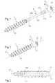
- FIG. 4shows a side view of the core member of the dynamic bone anchor according to the first embodiment.
- FIG. 5shows a top view of the core member shown in FIG. 4 .
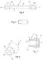
- FIG. 6shows a perspective view of a head of the dynamic bone anchor according to the first embodiment.
- FIG. 7shows a cross-sectional view of the head shown in FIG. 6 , the cross-section taken in a plane containing the anchor axis when the head is in a non-deflected state.
- FIG. 8 ashows a cross-sectional view of a step of manufacturing the dynamic bone anchor according to the first embodiment, wherein the core member is selectively combined with different anchor members.
- FIG. 8 bshows a schematic view of the contour of an end portion of the core member before it is fixed to the anchor member.
- FIG. 9 ashows a cross-sectional view of the assembled dynamic bone anchor according to the first embodiment, the cross-section taken in a plane containing the anchor axis.
- FIG. 9 bshows a schematic view of the end portion of the core member after inserting the core member into the anchor member, and heating the core member.
- FIG. 10shows a cross-sectional view of the dynamic bone anchor according to the first embodiment illustrating a translational movement of the head relative to the anchor member.
- FIG. 11shows a cross-sectional view of the dynamic bone anchor according to the first embodiment illustrating a rotational movement of the head relative to the anchor member.
- FIG. 12shows an exemplary stress-strain diagram of the bone anchor according to one embodiment.
- FIG. 13shows a cross-sectional view of a polyaxial pedicle screw using the dynamic bone anchor according to the first embodiment as an anchoring element.
- FIG. 14shows a cross-sectional view of the dynamic bone anchor according to the first embodiment used with a bone plate to provide dynamic fixation to bone parts.
- FIG. 15shows a perspective exploded view of a dynamic bone anchor according to a second embodiment.
- FIG. 16shows a perspective view of the dynamic bone anchor according to FIG. 15 .
- FIG. 17shows a cross-sectional view of the dynamic bone anchor according to FIG. 16 , the cross-section taken in a plane containing the anchor axis.
- FIG. 18shows a perspective exploded view of the dynamic bone anchor according to a third embodiment.
- FIG. 19shows a perspective view of the dynamic bone anchor according to FIG. 18 in an assembled state.
- FIG. 20shows a cross-sectional view of the dynamic bone anchor according to the third embodiment, the cross-section taken in a plane containing the anchor axis.
- a dynamic bone anchoraccording to a first embodiment, comprises an anchor member 1 in the form of a screw member, a core member 2 and a head 3 .
- the core member 2can be inserted into the anchor member 1 and connected thereto, and the head 3 can be connected to the core member 2 .
- the anchor member 1comprises a first end 11 , an opposite second end 12 , and a longitudinal axis L extending through the first end 11 and the second end 12 .
- the longitudinal axis Lforms the central axis of the bone anchor.
- Adjacent to the first end 11the anchor member 1 comprises a tubular section 13 with an opening at the first end 11 .
- the tubular section 13extends a distance toward the second end 12 , and has an inner diameter d 1 and a length adapted to accommodate a portion of the core member 2 as described below.
- An end surface 13 a of the tubular sectionprovides a stop for the insertion of the core member 2 .
- the second end 12 of the anchor member 1is formed as a tip portion.
- the bone engagement structure 14includes a bone thread that extends over substantially the length of the anchor member 1 , but it may also only extend over a smaller portion of the outer surface of the anchor member 1 .
- the anchor member 1may be made of a material that has a higher modulus of elasticity than that of the material of the core member 2 , meaning, the anchor member 1 is made of a stiffer material than the core member 2 .
- the anchor member 1is made of titanium or stainless steel.
- the anchor member 1can also be made of a bio-compatible polymer material, where the dimensions, such as the length and wall thickness of the anchor member are such that the anchor member does not exhibit a flexible behavior when inserted into a bone.
- the core member 2is a longitudinal member comprising a first end 21 , an opposite second end 22 , and a substantially rod-shaped central portion 23 .
- the central portion 23has a circular cross-section with an outer diameter d 2 that is smaller than the inner diameter d 1 of the tubular section 13 of the anchor member 1 .
- Adjacent to the first end 21there is a first connection portion 21 a
- Adjacent to the second end 22there is a second connection portion 22 a .
- the first and second connection portions 21 a , 22 arespectively, have an outer contour of a square with rounded edges.
- a distance d 3 from one flat side to an opposite flat side of the square contouris slightly greater than the outer diameter d 2 of the central portion 23 of the core member 2 such that the second connection portion 22 a may be connected in a press-fit manner in the tubular section 13 of the anchor member 1 , as explained below.
- the second connection portion 22 ahas a length in an axial direction adapted to provide sufficient fixation within the tubular section 13 .
- the first connection portion 21 a at the first end 21connects with the head 3 , and has a shape similar to that of the second connection portion 22 a .
- the total length of the core member 2is such that when the core member 2 is inserted into the anchor member 1 , and the second end 22 of the core member 2 abuts against the end surface 13 a of the tubular section 13 of the anchor member 1 , at least the first connection portion 21 a and the first transition portion 21 b of the core member 2 project out of the open first end 11 of the anchor member 1 .
- the core member 2is made of a material that is based on a nickel-titanium based shape memory alloy, preferably from Nitinol.
- the materialexhibits superelasticity. Superelasticity is present in the austenitic metallurgical state. In particular, superelasticity is present in a temperature range slightly above the stress-free martensite to austenite transition temperature, which should be the temperature range of use and includes body temperature.
- the core member 2is made of a nickel-titanium based shape memory alloy of the ELI (extra low interstitial) type, in particular Nitinol of the ELI type.
- ELIextra low interstitial
- Such a materialis of high purity, and in particular, comprises less oxygen compared to other Nitinol alloys that are not of the ELI type.
- the oxygen contentmay be less than 0.025 wt %, preferably equal to or less than 0.010 wt %, and more preferably equal to or less than 0.005 wt %.
- the materialhas a fatigue strength limit that can be up to two times higher than non-ELI type shape memory alloys.
- the head 3will be described with reference to FIGS. 6 and 7 .
- the head 3comprises a first end 31 , an opposite second end 32 , and a spherical-segment shaped portion 33 adjacent to the first end 31 .
- An engagement portion 34 for engagement with a driveris at a free end surface of the first end 31 .
- Adjacent to the spherical-segment shaped portion 33there is a cylindrical neck portion 35 with a cylindrical recess 36 for accommodating the first connection portion 21 a of the core member 2 .
- the length and an inner diameter of the recess 36is such that the first connection portion 21 a can be accommodated therein with a press-fit connection.
- FIGS. 8 a to 9 billustrate steps of manufacturing the dynamic bone anchor according to the first embodiment.
- the core member 2may be pre-assembled with the head 3 by connecting the first connection portion 21 a to the cylindrical recess 36 of the head 3 in a press-fit manner.
- the second connection portion 22 amay be previously or already shaped in its final shape, as shown in FIGS. 4 and 5 .
- at least the second connection portion 22 a of the core membermay be cooled down below a martensite finish temperature Mf, resulting in a phase transition of the material from austenite into martensite.
- a modular systemmay be provided comprising at least two anchor members 1 , 1 ′, that differ, for example, in their shaft lengths.
- the core member 2may be selectively introduced into the tubular section 13 of one of the at least two anchor members 1 , 1 ′.
- the pre-assembled core member 2 with the head 3is introduced into the tubular section 13 of one of the anchor members 1 , 1 ′, until the second end 22 of the core member 2 abuts against the end surface 13 a of the tubular section 13 .
- the second connection portion 22 a of the core member 2is deformed such that, for example, the flat sides are impressed so that they have a smaller distance from each other than in the original shape, as depicted in FIG. 8 b .
- the second connection portion 22 a of the core member 2can be introduced into the tubular section 13 of the anchor member 1 . Due to the ability of the martensite phase to deform, the insertion can be achieved with low force and little abrasion.
- heating the second connection portion 22 a above the austenite finish temperature A feffects a phase transition from martensite to austenite and a change of shape of the second connection portion 22 a back to its original shape with the rounded square contour as shown in FIG. 9 b resulting from the shape memory of the material.
- the manufacturing processuses the shape memory behavior of the core member 2 .
- connection between the core member 2 and the head 3can also be made in the same manner described above.
- gaps 37 , 38allow the head 3 to perform translational movement with respect to the anchor member 1 in a direction substantially perpendicular to the anchor axis L.
- the extent of deflection from the central axis L of the bone anchordepends on the elasticity of the material of the core member 2 and the size of the gaps 37 , 38 , which depend on the thickness and length of the core member 2 .
- a translation movementmay occur when the deflection of the core member 2 is mostly in the region of the first connection portion 21 a.
- the dynamic bone anchoris inserted into a bone part or a vertebra. Because the core member 2 is in the austenitic metallurgical state and in the conditions of use, the core member 2 has superelastic characteristics. In the stress-strain diagram of the bone anchor shown in FIG. 12 , a stress-strain plateau is shown. Because of the plateau, the force acting onto the head 3 during screwing-in of the bone anchor remains constant over a certain range such that an overloading of the anchor head 3 may not occur.
- the head 3In the anchored state, the head 3 is capable of performing a limited motion.
- the motionis constrained by the abutment of the core member 2 against the inner surface of the tubular section 13 of the anchor member 1 .
- FIG. 13A first application of the bone anchor together with a stabilization device is shown in FIG. 13 .
- the bone anchor according to the first embodimentis coupled to a receiving part 4 to form a polyaxial bone anchor.
- the receiving part 4is substantially cylindrical and comprises a top end 41 , a bottom end 42 , and a coaxial bore 43 extending from the top end 41 to a distance from the bottom end 42 .
- the bore 43narrows towards the bottom end 42 and has an opening 44 near the bottom end 42 .
- a seat 45is provided for pivotably receiving the head 3 .
- a U-shaped recessextends from the top end 41 to a distance from the top end 41 for receiving a stabilization rod 5 .
- the U-shaped recesscreates two free legs 46 , 47 , which have an internal thread 48 for cooperating with a locking member 6 , such as a set screw. Furthermore, a pressure member 7 is provided that exerts pressure onto the head 3 such that the head 3 can be locked in a certain angular position by tightening the locking member 6 .
- the bone anchormay be used with other designs of receiving parts and polyaxial bone screws. Also, the head 3 of the core member 2 may be designed such that it comprises a section for receiving a rod and for receiving a locking member to fix the rod, as known from other monoaxial bone screws. In use, at least two polyaxial bone anchors may be used and connected via the rod 5 .
- the heads 3 , 3 ′can perform a limited motion with respect to the anchor members 1 , 1 ′, respectively.
- the bone anchorprovides for a dynamic stabilization that allows small movements of the bone parts with respect to each other, or small movements of a motion segment of the spinal column.
- FIG. 14A second example of application of the bone anchor according to another embodiment is shown in FIG. 14 .
- the dynamic bone anchors according to the first embodimentare used together with a bone plate 9 comprising holes 9 a , 9 a ′ with seat portions 9 b , 9 b ′ for receiving the heads 3 , 3 ′ of two bone anchors 1 , 1 ′, respectively.
- the two bone anchors 1 , 1 ′are inserted in adjacent bone parts 101 , 101 ′ and the bone plate 9 bridges at least a portion of a fracture site 102 .
- a distance between the central anchor axes C of the two holes 9 a , 9 a ′ that accommodate the heads 3 , 3 ′ of the bone anchors, respectively,is slightly smaller than the distance between the longitudinal axes L of the anchor members 1 , 1 ′. Because the core members 2 , 2 ′ with the heads 3 , 3 ′ can perform a limited motion in a direction transverse to the longitudinal axis L, the bone parts 101 , 101 ′ can be drawn together at the fracture site 102 as shown by the arrows in FIG. 14 .
- the dynamic bone anchor according to the second embodimentdiffers from the dynamic bone anchor according to the first embodiment in that the anchor member 1 ′′ is formed completely as a tubular member 13 ′′. That means, the anchor member 1 ′′ is open at the first end 11 and at the second end 12 .
- the core member 2 ′′includes a tip 24 between the second connection portion 22 a and the second end 22 .
- the second connection portion 22 ais configured to be fixed in the previously described manner via a distortion-fit connection using the shape memory effect to the portion adjacent to the second end 12 of the anchor member 1 ′′.
- the tip 24 of the core member 2 ′′projects out of the open second end 12 of the anchor 1 ′′.
- the tip 24may have a smooth surface or may have further features, such as a self tapping structure, barbs, or a roughened surface, etc. All other parts of the dynamic bone anchor according to the second embodiment are similar to the first embodiment and the description thereof is not repeated.
- the bone anchor according to third embodimentdiffers from the bone anchor according to the second embodiment in that the core member 2 ′′′ comprises a head 3 ′′′ similar to the head 3 of the first embodiment at the first end 21 , wherein the head 3 ′′′ is formed integrally with the central portion 23 of the core member 2 ′′′.
- the core member 2 ′′′ with head 3 ′′′is a monolithic piece, and the entire dynamic bone anchor comprises only two pieces.
- the outer contour of the head 3 ′′′is similar to the head 3 according to the first embodiment as previously described.
- the headmay have any other shape suitable for connecting it to other stabilization devices such as bone plates, receiving parts for accommodating stabilization rods etc.
- the headmay even be omitted if a free end of the core member is suitable for connection to another device.
- the free end of the core membermay comprise an engagement portion for a driver.
- the engagement portion of the bone anchor for engagement with a toolis at a movable end of the core member.
- any kind of tipmay be provided.
- the tip shown in the embodimentsmay even be omitted.
- the hollow tubular anchor member according to the second and third embodimentsmay have prongs at the second end.
- the bone engagement structuremay be a bone thread of any type suitable for engaging the bone, or may be accomplished by barbs or may even be only a roughened surface.
- the anchor member of the first embodimentmay include a core member having an integrally formed head, as described in the third embodiment.
Landscapes
- Health & Medical Sciences (AREA)
- Orthopedic Medicine & Surgery (AREA)
- Life Sciences & Earth Sciences (AREA)
- Surgery (AREA)
- Neurology (AREA)
- Heart & Thoracic Surgery (AREA)
- Engineering & Computer Science (AREA)
- Biomedical Technology (AREA)
- Nuclear Medicine, Radiotherapy & Molecular Imaging (AREA)
- Medical Informatics (AREA)
- Molecular Biology (AREA)
- Animal Behavior & Ethology (AREA)
- General Health & Medical Sciences (AREA)
- Public Health (AREA)
- Veterinary Medicine (AREA)
- Prostheses (AREA)
- Surgical Instruments (AREA)
Abstract
Description
Claims (20)
Priority Applications (1)
| Application Number | Priority Date | Filing Date | Title |
|---|---|---|---|
| US16/928,741US11123124B2 (en) | 2012-12-05 | 2020-07-14 | Dynamic bone anchor and method of manufacturing the same |
Applications Claiming Priority (8)
| Application Number | Priority Date | Filing Date | Title |
|---|---|---|---|
| US201261733769P | 2012-12-05 | 2012-12-05 | |
| EP12195758.3AEP2740427B1 (en) | 2012-12-05 | 2012-12-05 | Dynamic bone anchor and method of manufacturing the same |
| EP12195758 | 2012-12-05 | ||
| EP12195758.3 | 2012-12-05 | ||
| US14/098,434US9861415B2 (en) | 2012-12-05 | 2013-12-05 | Dynamic bone anchor and method of manufacturing the same |
| US15/831,124US10117695B2 (en) | 2012-12-05 | 2017-12-04 | Dynamic bone anchor and method of manufacturing the same |
| US16/148,723US10751101B2 (en) | 2012-12-05 | 2018-10-01 | Dynamic bone anchor and method of manufacturing the same |
| US16/928,741US11123124B2 (en) | 2012-12-05 | 2020-07-14 | Dynamic bone anchor and method of manufacturing the same |
Related Parent Applications (1)
| Application Number | Title | Priority Date | Filing Date |
|---|---|---|---|
| US16/148,723ContinuationUS10751101B2 (en) | 2012-12-05 | 2018-10-01 | Dynamic bone anchor and method of manufacturing the same |
Publications (2)
| Publication Number | Publication Date |
|---|---|
| US20200405363A1 US20200405363A1 (en) | 2020-12-31 |
| US11123124B2true US11123124B2 (en) | 2021-09-21 |
Family
ID=47520686
Family Applications (4)
| Application Number | Title | Priority Date | Filing Date |
|---|---|---|---|
| US14/098,434Active2033-12-10US9861415B2 (en) | 2012-12-05 | 2013-12-05 | Dynamic bone anchor and method of manufacturing the same |
| US15/831,124ActiveUS10117695B2 (en) | 2012-12-05 | 2017-12-04 | Dynamic bone anchor and method of manufacturing the same |
| US16/148,723Active2034-03-24US10751101B2 (en) | 2012-12-05 | 2018-10-01 | Dynamic bone anchor and method of manufacturing the same |
| US16/928,741ActiveUS11123124B2 (en) | 2012-12-05 | 2020-07-14 | Dynamic bone anchor and method of manufacturing the same |
Family Applications Before (3)
| Application Number | Title | Priority Date | Filing Date |
|---|---|---|---|
| US14/098,434Active2033-12-10US9861415B2 (en) | 2012-12-05 | 2013-12-05 | Dynamic bone anchor and method of manufacturing the same |
| US15/831,124ActiveUS10117695B2 (en) | 2012-12-05 | 2017-12-04 | Dynamic bone anchor and method of manufacturing the same |
| US16/148,723Active2034-03-24US10751101B2 (en) | 2012-12-05 | 2018-10-01 | Dynamic bone anchor and method of manufacturing the same |
Country Status (6)
| Country | Link |
|---|---|
| US (4) | US9861415B2 (en) |
| EP (1) | EP2740427B1 (en) |
| JP (1) | JP6111185B2 (en) |
| KR (1) | KR20140072823A (en) |
| CN (1) | CN103845108B (en) |
| TW (1) | TW201434433A (en) |
Families Citing this family (34)
| Publication number | Priority date | Publication date | Assignee | Title |
|---|---|---|---|---|
| US20180228621A1 (en) | 2004-08-09 | 2018-08-16 | Mark A. Reiley | Apparatus, systems, and methods for the fixation or fusion of bone |
| WO2013052807A2 (en) | 2011-10-05 | 2013-04-11 | H. Lee Moffitt Cancer Center And Research Institute, Inc. | Bone fusion system |
| US10799367B2 (en)* | 2011-10-05 | 2020-10-13 | H. Lee Moffitt Cancer Center And Research Institute, Inc. | Bone fusion system |
| US10363140B2 (en) | 2012-03-09 | 2019-07-30 | Si-Bone Inc. | Systems, device, and methods for joint fusion |
| US9044321B2 (en) | 2012-03-09 | 2015-06-02 | Si-Bone Inc. | Integrated implant |
| EP3818947B1 (en) | 2012-05-04 | 2023-08-30 | SI-Bone, Inc. | Fenestrated implant |
| EP2676622B1 (en) | 2012-06-18 | 2015-12-30 | Biedermann Technologies GmbH & Co. KG | Bone anchor |
| EP2740427B1 (en)* | 2012-12-05 | 2020-03-11 | Biedermann Technologies GmbH & Co. KG | Dynamic bone anchor and method of manufacturing the same |
| EP2740428B1 (en) | 2012-12-05 | 2019-05-08 | Biedermann Technologies GmbH & Co. KG | Dynamic bone anchor and method of manufacturing a dynamic bone anchor |
| WO2014145902A1 (en)* | 2013-03-15 | 2014-09-18 | Si-Bone Inc. | Implants for spinal fixation or fusion |
| US11147688B2 (en) | 2013-10-15 | 2021-10-19 | Si-Bone Inc. | Implant placement |
| WO2015095353A1 (en) | 2013-12-17 | 2015-06-25 | H. Lee Moffit Cancer Center And Research Institute, Inc. | Transdiscal screw |
| KR101652286B1 (en) | 2014-06-13 | 2016-08-30 | 경북대학교 산학협력단 | Fixation pin for fracture-reduction with intramedullary nailing system |
| US10166033B2 (en) | 2014-09-18 | 2019-01-01 | Si-Bone Inc. | Implants for bone fixation or fusion |
| JP6542362B2 (en) | 2014-09-18 | 2019-07-10 | エスアイ−ボーン・インコーポレイテッドSi−Bone, Inc. | Matrix implant |
| AU2016247221B2 (en)* | 2015-10-23 | 2021-03-11 | K2M, Inc. | Semi-constrained bone screw and insertion instrument |
| US10653455B2 (en)* | 2017-09-12 | 2020-05-19 | Warsaw Orthopedic, Inc. | Spinal implant system and methods of use |
| US11116519B2 (en) | 2017-09-26 | 2021-09-14 | Si-Bone Inc. | Systems and methods for decorticating the sacroiliac joint |
| ES3011907T3 (en) | 2018-03-28 | 2025-04-08 | Si Bone Inc | Threaded implants for use across bone segments |
| CN109044519A (en)* | 2018-09-14 | 2018-12-21 | 北京爱康宜诚医疗器材有限公司 | pedicle screw |
| EP4613244A2 (en) | 2019-02-14 | 2025-09-10 | SI-Bone Inc. | Implants for spinal fixation and or fusion |
| US11369419B2 (en) | 2019-02-14 | 2022-06-28 | Si-Bone Inc. | Implants for spinal fixation and or fusion |
| JP7646654B2 (en) | 2019-11-21 | 2025-03-17 | エスアイ-ボーン・インコーポレイテッド | Rod coupling assembly for bone stabilization construct - Patent application |
| AU2020392121B2 (en) | 2019-11-27 | 2025-05-22 | Si-Bone, Inc. | Bone stabilizing implants and methods of placement across SI joints |
| EP4072452A4 (en) | 2019-12-09 | 2023-12-20 | SI-Bone, Inc. | Sacro-iliac joint stabilizing implants and methods of implantation |
| US20230248482A1 (en)* | 2020-10-14 | 2023-08-10 | Move Dental Ltd | Dental and orthopedic fastener with directional shock absorber |
| EP4259015A4 (en) | 2020-12-09 | 2024-09-11 | SI-Bone, Inc. | SACROILIAC JOINT STABILIZATION IMPLANTS AND METHODS OF IMPLANTATION |
| US11291477B1 (en) | 2021-05-04 | 2022-04-05 | Warsaw Orthopedic, Inc. | Dorsal adjusting implant and methods of use |
| US11432848B1 (en) | 2021-05-12 | 2022-09-06 | Warsaw Orthopedic, Inc. | Top loading quick lock construct |
| US11712270B2 (en) | 2021-05-17 | 2023-08-01 | Warsaw Orthopedic, Inc. | Quick lock clamp constructs and associated methods |
| US11317956B1 (en)* | 2021-08-26 | 2022-05-03 | University Of Utah Research Foundation | Active compression bone screw |
| US11957391B2 (en) | 2021-11-01 | 2024-04-16 | Warsaw Orthopedic, Inc. | Bone screw having an overmold of a shank |
| WO2025038769A1 (en) | 2023-08-15 | 2025-02-20 | Si-Bone Inc. | Pelvic stabilization implants, methods of use and manufacture |
| US11998255B1 (en) | 2023-08-26 | 2024-06-04 | University Of Utah Research Foundation | Cannulated continuous compression screw |
Citations (18)
| Publication number | Priority date | Publication date | Assignee | Title |
|---|---|---|---|---|
| US5584695A (en) | 1994-03-07 | 1996-12-17 | Memory Medical Systems, Inc. | Bone anchoring apparatus and method |
| CN2453859Y (en) | 2000-12-11 | 2001-10-17 | 兰州西脉记忆合金股份有限公司 | Internal fixation brne nail |
| EP1472983A1 (en) | 2003-04-30 | 2004-11-03 | BIEDERMANN MOTECH GmbH | Threaded bone anchoring element for unscrewing |
| US20050154390A1 (en) | 2003-11-07 | 2005-07-14 | Lutz Biedermann | Stabilization device for bones comprising a spring element and manufacturing method for said spring element |
| US20060264954A1 (en) | 2005-04-07 | 2006-11-23 | Sweeney Thomas M Ii | Active compression screw system and method for using the same |
| WO2007101267A1 (en) | 2006-03-01 | 2007-09-07 | Warsaw Orthopedic, Inc. | Bone anchors and methods of forming the same |
| US20080294204A1 (en) | 2007-03-07 | 2008-11-27 | Spineworks Medical, Inc. | Systems, methods, and devices for soft tissue attachment to bone |
| JP2009090117A (en) | 2007-10-11 | 2009-04-30 | Biedermann Motech Gmbh | Rod assembly and module type rod system for stabilization of vertebra |
| US20090157123A1 (en) | 2007-12-17 | 2009-06-18 | Andreas Appenzeller | Dynamic bone fixation element and method of using the same |
| US20100261034A1 (en) | 2006-08-07 | 2010-10-14 | Cardarelli Francois | Composite metallic materials, uses thereof and process for making same |
| US7879036B2 (en) | 2005-08-05 | 2011-02-01 | Biedermann Motech Gmbh | Bone anchoring element |
| US20110172718A1 (en) | 2008-09-11 | 2011-07-14 | Innovasis, Inc. | Radiolucent screw with radiopaque marker |
| US20110276094A1 (en) | 2010-05-10 | 2011-11-10 | Erich Kast | Fixation assembly for spinal vertebrae |
| US20120203286A1 (en) | 2011-02-04 | 2012-08-09 | Warsaw Orthopedic, Inc. | Bone Fastener and Methods of Use |
| WO2012158351A1 (en) | 2011-05-17 | 2012-11-22 | Synthes Usa, Llc | Telescoping screw for femoral neck fractures |
| US20130245697A1 (en) | 2012-03-13 | 2013-09-19 | Urs Hulliger | Dynamic bone fixation element |
| US20140172026A1 (en) | 2012-12-05 | 2014-06-19 | Lutz Biedermann | Dynamic bone anchor and method of manufacturing a dynamic bone anchor |
| US9861415B2 (en)* | 2012-12-05 | 2018-01-09 | Biedermann Technologies Gmbh & Co. Kg | Dynamic bone anchor and method of manufacturing the same |
Family Cites Families (1)
| Publication number | Priority date | Publication date | Assignee | Title |
|---|---|---|---|---|
| JP2009091117A (en) | 2007-10-10 | 2009-04-30 | Yasuhisa Choshoin | Small rotary multistage three-dimensional storage |
- 2012
- 2012-12-05EPEP12195758.3Apatent/EP2740427B1/enactiveActive
- 2013
- 2013-12-02JPJP2013249097Apatent/JP6111185B2/ennot_activeExpired - Fee Related
- 2013-12-02TWTW102143948Apatent/TW201434433A/enunknown
- 2013-12-02CNCN201310632148.2Apatent/CN103845108B/ennot_activeExpired - Fee Related
- 2013-12-04KRKR1020130150231Apatent/KR20140072823A/ennot_activeCeased
- 2013-12-05USUS14/098,434patent/US9861415B2/enactiveActive
- 2017
- 2017-12-04USUS15/831,124patent/US10117695B2/enactiveActive
- 2018
- 2018-10-01USUS16/148,723patent/US10751101B2/enactiveActive
- 2020
- 2020-07-14USUS16/928,741patent/US11123124B2/enactiveActive
Patent Citations (27)
| Publication number | Priority date | Publication date | Assignee | Title |
|---|---|---|---|---|
| US5584695A (en) | 1994-03-07 | 1996-12-17 | Memory Medical Systems, Inc. | Bone anchoring apparatus and method |
| CN2453859Y (en) | 2000-12-11 | 2001-10-17 | 兰州西脉记忆合金股份有限公司 | Internal fixation brne nail |
| EP1472983A1 (en) | 2003-04-30 | 2004-11-03 | BIEDERMANN MOTECH GmbH | Threaded bone anchoring element for unscrewing |
| US20040220575A1 (en) | 2003-04-30 | 2004-11-04 | Biedermann Motech Gmbh | Bone anchoring element with thread that can be unscrewed |
| US20050154390A1 (en) | 2003-11-07 | 2005-07-14 | Lutz Biedermann | Stabilization device for bones comprising a spring element and manufacturing method for said spring element |
| US20060264954A1 (en) | 2005-04-07 | 2006-11-23 | Sweeney Thomas M Ii | Active compression screw system and method for using the same |
| JP2008535584A (en) | 2005-04-07 | 2008-09-04 | アルパインスパイン エルエルシー | Active compression screw system and method of using the same |
| US7879036B2 (en) | 2005-08-05 | 2011-02-01 | Biedermann Motech Gmbh | Bone anchoring element |
| WO2007101267A1 (en) | 2006-03-01 | 2007-09-07 | Warsaw Orthopedic, Inc. | Bone anchors and methods of forming the same |
| US20100261034A1 (en) | 2006-08-07 | 2010-10-14 | Cardarelli Francois | Composite metallic materials, uses thereof and process for making same |
| US20080294204A1 (en) | 2007-03-07 | 2008-11-27 | Spineworks Medical, Inc. | Systems, methods, and devices for soft tissue attachment to bone |
| US20090163953A1 (en) | 2007-10-11 | 2009-06-25 | Lutz Biedermann | Rod assembly and modular rod system for spinal stabilization |
| JP2009090117A (en) | 2007-10-11 | 2009-04-30 | Biedermann Motech Gmbh | Rod assembly and module type rod system for stabilization of vertebra |
| US20090157123A1 (en) | 2007-12-17 | 2009-06-18 | Andreas Appenzeller | Dynamic bone fixation element and method of using the same |
| JP2011506043A (en) | 2007-12-17 | 2011-03-03 | ジンテス ゲゼルシャフト ミット ベシュレンクテル ハフツング | Dynamic bone anchoring element and method of use thereof |
| US8114141B2 (en)* | 2007-12-17 | 2012-02-14 | Synthes Usa, Llc | Dynamic bone fixation element and method of using the same |
| US20110172718A1 (en) | 2008-09-11 | 2011-07-14 | Innovasis, Inc. | Radiolucent screw with radiopaque marker |
| US20110276094A1 (en) | 2010-05-10 | 2011-11-10 | Erich Kast | Fixation assembly for spinal vertebrae |
| US20120203286A1 (en) | 2011-02-04 | 2012-08-09 | Warsaw Orthopedic, Inc. | Bone Fastener and Methods of Use |
| WO2012158351A1 (en) | 2011-05-17 | 2012-11-22 | Synthes Usa, Llc | Telescoping screw for femoral neck fractures |
| JP2014521380A (en) | 2011-05-17 | 2014-08-28 | シンセス・ゲーエムベーハー | Nested telescopic screw for femoral neck fracture |
| US20130245697A1 (en) | 2012-03-13 | 2013-09-19 | Urs Hulliger | Dynamic bone fixation element |
| US9339316B2 (en)* | 2012-03-13 | 2016-05-17 | DePuy Synthes Products, Inc. | Dynamic bone fixation element |
| US20140172026A1 (en) | 2012-12-05 | 2014-06-19 | Lutz Biedermann | Dynamic bone anchor and method of manufacturing a dynamic bone anchor |
| US9861415B2 (en)* | 2012-12-05 | 2018-01-09 | Biedermann Technologies Gmbh & Co. Kg | Dynamic bone anchor and method of manufacturing the same |
| US10117695B2 (en)* | 2012-12-05 | 2018-11-06 | Biedermann Technologies Gmbh & Co. Kg | Dynamic bone anchor and method of manufacturing the same |
| US10751101B2 (en)* | 2012-12-05 | 2020-08-25 | Biedermann Technologies Gmbh & Co. Kg | Dynamic bone anchor and method of manufacturing the same |
Non-Patent Citations (2)
| Title |
|---|
| Chinese OA for Application No. 201310632148.2, dated Jan. 3, 2017, and English translation (21 pages). |
| Extended European Search Report for European Application No. 12195758.3, European Search Report dated Apr. 23, 2013 and dated May 7, 2013 (8 pages). |
Also Published As
| Publication number | Publication date |
|---|---|
| KR20140072823A (en) | 2014-06-13 |
| JP6111185B2 (en) | 2017-04-05 |
| JP2014113486A (en) | 2014-06-26 |
| US10751101B2 (en) | 2020-08-25 |
| US20200405363A1 (en) | 2020-12-31 |
| US10117695B2 (en) | 2018-11-06 |
| CN103845108B (en) | 2020-06-09 |
| EP2740427A1 (en) | 2014-06-11 |
| US20190090924A1 (en) | 2019-03-28 |
| US20180125555A1 (en) | 2018-05-10 |
| US20140172027A1 (en) | 2014-06-19 |
| US9861415B2 (en) | 2018-01-09 |
| CN103845108A (en) | 2014-06-11 |
| EP2740427B1 (en) | 2020-03-11 |
| TW201434433A (en) | 2014-09-16 |
Similar Documents
| Publication | Publication Date | Title |
|---|---|---|
| US11123124B2 (en) | Dynamic bone anchor and method of manufacturing the same | |
| US20210353342A1 (en) | Dynamic bone anchor and method of manufacturing a dynamic bone anchor | |
| US20220022919A1 (en) | Semi-constrained Anchoring System | |
| US8257400B2 (en) | Stabilization device for the dynamic stabilization of vertebrae or bones and rod like element for such a stabilization device | |
| US9326805B2 (en) | Dynamic bone anchor | |
| US7951170B2 (en) | Dynamic stabilization connecting member with pre-tensioned solid core | |
| US20060276787A1 (en) | Pedicle screw, cervical screw and rod | |
| US20080015580A1 (en) | Large diameter bone anchor assembly | |
| US20120035660A1 (en) | Dynamic stabilization connecting member with pre-tensioned solid core | |
| US20070270832A1 (en) | Locking device and method, for use in a bone stabilization system, employing a set screw member and deformable saddle member | |
| KR20100014881A (en) | Bone fixation element | |
| US9913665B2 (en) | Receiving part of a bone anchoring device and bone anchoring device with such a receiving part |
Legal Events
| Date | Code | Title | Description |
|---|---|---|---|
| FEPP | Fee payment procedure | Free format text:ENTITY STATUS SET TO UNDISCOUNTED (ORIGINAL EVENT CODE: BIG.); ENTITY STATUS OF PATENT OWNER: LARGE ENTITY | |
| AS | Assignment | Owner name:BIEDERMANN MOTECH GMBH & CO. KG, GERMANY Free format text:ASSIGNMENT OF ASSIGNORS INTEREST;ASSIGNOR:MATTHIS, WILFRIED;REEL/FRAME:053231/0640 Effective date:20140128 Owner name:BIEDERMANN TECHNOLOGIES GMBH & CO. KG, GERMANY Free format text:ASSIGNMENT OF ASSIGNORS INTEREST;ASSIGNOR:BIEDERMANN MOTECH GMBH & CO. KG;REEL/FRAME:053231/0651 Effective date:20140128 Owner name:BIEDERMANN TECHNOLOGIES GMBH & CO. KG, GERMANY Free format text:ASSIGNMENT OF ASSIGNORS INTEREST;ASSIGNOR:BIEDERMANN, LUTZ;REEL/FRAME:053231/0635 Effective date:20140120 | |
| STPP | Information on status: patent application and granting procedure in general | Free format text:NON FINAL ACTION MAILED | |
| STPP | Information on status: patent application and granting procedure in general | Free format text:RESPONSE TO NON-FINAL OFFICE ACTION ENTERED AND FORWARDED TO EXAMINER | |
| STPP | Information on status: patent application and granting procedure in general | Free format text:NOTICE OF ALLOWANCE MAILED -- APPLICATION RECEIVED IN OFFICE OF PUBLICATIONS | |
| STCF | Information on status: patent grant | Free format text:PATENTED CASE | |
| CC | Certificate of correction | ||
| MAFP | Maintenance fee payment | Free format text:PAYMENT OF MAINTENANCE FEE, 4TH YEAR, LARGE ENTITY (ORIGINAL EVENT CODE: M1551); ENTITY STATUS OF PATENT OWNER: LARGE ENTITY Year of fee payment:4 |