US11123014B2 - Systems and methods for ambient energy powered physiological parameter monitoring - Google Patents
Systems and methods for ambient energy powered physiological parameter monitoringDownload PDFInfo
- Publication number
- US11123014B2 US11123014B2US15/927,749US201815927749AUS11123014B2US 11123014 B2US11123014 B2US 11123014B2US 201815927749 AUS201815927749 AUS 201815927749AUS 11123014 B2US11123014 B2US 11123014B2
- Authority
- US
- United States
- Prior art keywords
- patch
- energy
- physiological parameter
- electrical energy
- data
- Prior art date
- Legal status (The legal status is an assumption and is not a legal conclusion. Google has not performed a legal analysis and makes no representation as to the accuracy of the status listed.)
- Active, expires
Links
Images


Classifications
- A—HUMAN NECESSITIES
- A61—MEDICAL OR VETERINARY SCIENCE; HYGIENE
- A61B—DIAGNOSIS; SURGERY; IDENTIFICATION
- A61B5/00—Measuring for diagnostic purposes; Identification of persons
- A61B5/68—Arrangements of detecting, measuring or recording means, e.g. sensors, in relation to patient
- A61B5/6801—Arrangements of detecting, measuring or recording means, e.g. sensors, in relation to patient specially adapted to be attached to or worn on the body surface
- A61B5/683—Means for maintaining contact with the body
- A61B5/6832—Means for maintaining contact with the body using adhesives
- A61B5/6833—Adhesive patches
- A—HUMAN NECESSITIES
- A61—MEDICAL OR VETERINARY SCIENCE; HYGIENE
- A61B—DIAGNOSIS; SURGERY; IDENTIFICATION
- A61B5/00—Measuring for diagnostic purposes; Identification of persons
- A61B5/0002—Remote monitoring of patients using telemetry, e.g. transmission of vital signals via a communication network
- A61B5/0015—Remote monitoring of patients using telemetry, e.g. transmission of vital signals via a communication network characterised by features of the telemetry system
- A61B5/002—Monitoring the patient using a local or closed circuit, e.g. in a room or building
- A—HUMAN NECESSITIES
- A61—MEDICAL OR VETERINARY SCIENCE; HYGIENE
- A61B—DIAGNOSIS; SURGERY; IDENTIFICATION
- A61B2560/00—Constructional details of operational features of apparatus; Accessories for medical measuring apparatus
- A61B2560/02—Operational features
- A61B2560/0204—Operational features of power management
- A61B2560/0209—Operational features of power management adapted for power saving
- A—HUMAN NECESSITIES
- A61—MEDICAL OR VETERINARY SCIENCE; HYGIENE
- A61B—DIAGNOSIS; SURGERY; IDENTIFICATION
- A61B2560/00—Constructional details of operational features of apparatus; Accessories for medical measuring apparatus
- A61B2560/02—Operational features
- A61B2560/0204—Operational features of power management
- A61B2560/0214—Operational features of power management of power generation or supply
- A—HUMAN NECESSITIES
- A61—MEDICAL OR VETERINARY SCIENCE; HYGIENE
- A61B—DIAGNOSIS; SURGERY; IDENTIFICATION
- A61B5/00—Measuring for diagnostic purposes; Identification of persons
- A61B5/01—Measuring temperature of body parts ; Diagnostic temperature sensing, e.g. for malignant or inflamed tissue
- A—HUMAN NECESSITIES
- A61—MEDICAL OR VETERINARY SCIENCE; HYGIENE
- A61B—DIAGNOSIS; SURGERY; IDENTIFICATION
- A61B5/00—Measuring for diagnostic purposes; Identification of persons
- A61B5/02—Detecting, measuring or recording for evaluating the cardiovascular system, e.g. pulse, heart rate, blood pressure or blood flow
- A61B5/021—Measuring pressure in heart or blood vessels
- A—HUMAN NECESSITIES
- A61—MEDICAL OR VETERINARY SCIENCE; HYGIENE
- A61B—DIAGNOSIS; SURGERY; IDENTIFICATION
- A61B5/00—Measuring for diagnostic purposes; Identification of persons
- A61B5/05—Detecting, measuring or recording for diagnosis by means of electric currents or magnetic fields; Measuring using microwaves or radio waves
- A61B5/053—Measuring electrical impedance or conductance of a portion of the body
- A61B5/0531—Measuring skin impedance
- A—HUMAN NECESSITIES
- A61—MEDICAL OR VETERINARY SCIENCE; HYGIENE
- A61B—DIAGNOSIS; SURGERY; IDENTIFICATION
- A61B5/00—Measuring for diagnostic purposes; Identification of persons
- A61B5/145—Measuring characteristics of blood in vivo, e.g. gas concentration or pH-value ; Measuring characteristics of body fluids or tissues, e.g. interstitial fluid or cerebral tissue
- A61B5/14539—Measuring characteristics of blood in vivo, e.g. gas concentration or pH-value ; Measuring characteristics of body fluids or tissues, e.g. interstitial fluid or cerebral tissue for measuring pH
- A—HUMAN NECESSITIES
- A61—MEDICAL OR VETERINARY SCIENCE; HYGIENE
- A61B—DIAGNOSIS; SURGERY; IDENTIFICATION
- A61B5/00—Measuring for diagnostic purposes; Identification of persons
- A61B5/145—Measuring characteristics of blood in vivo, e.g. gas concentration or pH-value ; Measuring characteristics of body fluids or tissues, e.g. interstitial fluid or cerebral tissue
- A61B5/1455—Measuring characteristics of blood in vivo, e.g. gas concentration or pH-value ; Measuring characteristics of body fluids or tissues, e.g. interstitial fluid or cerebral tissue using optical sensors, e.g. spectral photometrical oximeters
- A61B5/14551—Measuring characteristics of blood in vivo, e.g. gas concentration or pH-value ; Measuring characteristics of body fluids or tissues, e.g. interstitial fluid or cerebral tissue using optical sensors, e.g. spectral photometrical oximeters for measuring blood gases
- A—HUMAN NECESSITIES
- A61—MEDICAL OR VETERINARY SCIENCE; HYGIENE
- A61B—DIAGNOSIS; SURGERY; IDENTIFICATION
- A61B5/00—Measuring for diagnostic purposes; Identification of persons
- A61B5/24—Detecting, measuring or recording bioelectric or biomagnetic signals of the body or parts thereof
- A61B5/316—Modalities, i.e. specific diagnostic methods
- A61B5/318—Heart-related electrical modalities, e.g. electrocardiography [ECG]
- A—HUMAN NECESSITIES
- A61—MEDICAL OR VETERINARY SCIENCE; HYGIENE
- A61B—DIAGNOSIS; SURGERY; IDENTIFICATION
- A61B5/00—Measuring for diagnostic purposes; Identification of persons
- A61B5/74—Details of notification to user or communication with user or patient; User input means
- A61B5/746—Alarms related to a physiological condition, e.g. details of setting alarm thresholds or avoiding false alarms
- H—ELECTRICITY
- H02—GENERATION; CONVERSION OR DISTRIBUTION OF ELECTRIC POWER
- H02N—ELECTRIC MACHINES NOT OTHERWISE PROVIDED FOR
- H02N11/00—Generators or motors not provided for elsewhere; Alleged perpetua mobilia obtained by electric or magnetic means
- H02N11/002—Generators
Definitions
- Patient physiological datacan provide insight into the health and well-being of an individual and provide indication of potential physiological distress.
- multiple different medical devices and/or machinesare used with each device capturing data regarding a single or sometimes multiple physiological parameters or characteristics.
- These monitoring systemscan be distressing in their own right to the individual connected to the medical device, often causing the individual to experience some level of discomfort.
- the medical devicescan require support for their services, such as connections, such as cords or cables, for data transmission and/or power and/or other resources.
- connectionscan limit the mobility and/or use of the medical device as it can be constrained by its support requirements. Constraints, such as these and/or others, can also contribute to the discomfort of the individual due to the decreased range of motion and/or limited movement allowed by the individual while connected to various medical devices and/or monitors.
- some medical devices and/or monitorsinclude power supplies, such as batteries, that allow the device to move with the user.
- the various cables connecting the monitoring device to one or more sensorsstill constrain the available motion allowed the individual although the self-powered systems are more portable.
- the patient's motioncan still be constrained due to the power requirements of the device.
- conventional devicesinclude batteries to supply power to device, however, the batteries can require recharging and/or replacement at intervals.
- This battery dependencylimits the range and/or mobility of the patient connected to the device because of the need to carry additional batteries and/or travel within a predetermined distance relative to a recharging station.
- the battery dependencyis also expensive and can be unreliable. As such, many patient physiological parameter monitoring systems and/or devices reduce the mobility and/or range of motion of an individual being monitored.
- FIG. 1illustrates an example ambient energy powered physiological parameter monitoring system.
- FIG. 2illustrates a block diagram of an example ambient energy powered physiological parameter monitoring system.
- FIG. 3illustrates an example ambient energy powered physiological parameter monitoring method.
- FIG. 4illustrates an example method of receiving physiological parameter data from an ambient energy powered physiological parameter monitoring system.
- the systemincludes a sensor containing element, such as a patch, that can be mounted directly to, or placed on, an individual to monitor and collect data regarding one or more physiological parameters and/or characteristics of the individual.
- the sensorcan obtain power, such as electrical energy, from an included energy harvesting module that can provide power in response to being exposed to ambient energy sources, such as radio transmissions, light, heat and/or other energy sources.
- ambient energy sourcessuch as radio transmissions, light, heat and/or other energy sources.
- Obtaining energy from ambient energy sourcesallows the sensor and/or patch to perform various functions without the need to be coupled physically to a power source, such as by a wire or cord.
- the wireless powering of the sensor containing element and/or patchcan allow the individual increased range of motion and increased movement distances due to the lack of a directly coupled power source.
- the sensor containing elementcan include an energy storage device to allow the element to capture electrical energy, such as from the ambient energy source(s), and store the electrical energy to provide electrical power for one or more functions and/or features of the device.
- the ambient energycan be provided by a companion device, in some examples, that can be located proximally to the sensor containing element.
- the companion devicegenerates an electrical field, such as short-range radio transmissions, or other electromagnetic radiation, that can be the ambient energy source from which the sensor containing element can derive or obtain power.
- the companion devicecan be carried by the individual to provide the ambient energy source for the sensor containing element.
- the companion device, or the ambient energy source providing functionality thereofcan be integrated with one or more other devices, such as a monitoring device or cellphone.
- These other devicescan be mobile and can move with the individual, such as being carried on the person of the individual, or the other devices can be stationary.
- the mobile devicecan be located proximal to the individual due to it being able to move with the individual.
- the stationary devicescannot move with the individual but can provide the functionality of the companion device, or ambient energy source, while the individual is within range of the stationary device.
- Multiple stationary devicescan be located within a location so that as the individual moves around the location they remain located within range of one or more of the stationary devices.
- the individualcan move outside of the range of the stationary, or other device, and once the individual is within range of the same, or another, device the sensor containing element can be energized.
- a patientcan be in a hospital bed that can include the ambient energy source functionality by radiating electromagnetic energy from which the sensor containing element can derive, or obtain, electrical energy therefrom.
- the electromagnetic radiationcan be generated to purposely provide the ambient energy source for the sensor containing element and/or can be generated for other purposes/functions, or inadvertently, and the sensor containing element can scavenge, or obtain, electrical energy from such an ambient energy source.
- a “smart” hospital bedcan purposely generate and transmit electromagnetic radiation, such as radio frequency radiation, to provide an ambient energy source for the sensor containing element. Additionally, or alternatively, the “smart” hospital bed can generate and radiate electromagnetic radiation for the communications, such as emitting a wireless communication signal.
- the sensor containing elementcan receive this transmitted electromagnetic radiation, generated to facilitate communication, and can scavenge, or obtain electrical energy from such electromagnetic radiation.
- the ability, structure and/or functionality of the sensor containing element to derive, or obtain, power from ambient energy sourcescan allow the sensor containing element to receive necessary electrical energy for the one or more functions/features of the sensor containing element without physically coupling the sensor containing element to a power source, such as by a wire or cord.
- the sensor elementmay also scavenge electrical energy that is emitted unintentionally from electronic devices that is available in the sensors environment.
- Physiological data collected by the sensor containing elementcan be transmitted from the sensor, or device/system coupled thereto, to the companion device, or base station, that can collect, aggregate, monitor, analyze, and/or transmit the collected physiological data to one or more remote devices, systems and/or users.
- the companion devicecan receive, process and/or analyze the received physiological data and can initiate a response accordingly.
- the companion devicecan monitor the received physiological data for abnormalities, such as physiological data outside of a threshold(s), and/or trends.
- the companion devicecan initiate one or more responses, such as altering the collection of the physiological data, transmitting the received physiological data and/or transmitting an alert or notification to one or more remote devices, systems and/or users.
- Remote devices, systems and/or usercan include additional medical devices, such as a defibrillator/monitor, that can be coupled to and/or monitoring the physiological state of the individual.
- the remote devices/systemscan include one or more data repositories, or databases, storing information related to the individual.
- Other remote systemscan include a patient monitoring and/or tracking system that can aggregate information regarding a patient from one or more sources and can present and/or provide such information to one or more devices, systems and/or users.
- the sensor containing elementcan transmit collected physiological data directly to one or more remote devices, systems and/or users.
- the physiological datacan also be transmitted to the companion device.
- the companion devicein response to a trend indicating a decrease in a state of one or more monitored physiological parameters, can request additional information from a remote device, system and/or user and/or can request additional, and/or different, physiological data from one or more sensor containing elements monitoring one or more physiological parameters and/or characteristics of the individual. Additionally, or alternatively, the companion device can alter the collection of the physiological data, such as increasing a sampling frequency of the physiological data from the sensor containing element which can include longer monitoring periods, more frequent monitoring periods, and/or real-time transmission of sensed physiological data. Based on the physiological data received, the companion device can cause treatment and/or intervention to be administered to the individual by a device system and/or user.
- the individualcan be monitored by the companion device and the sensor containing element and also coupled to a treatment device, such as defibrillator or other medical device.
- a treatment devicesuch as defibrillator or other medical device.
- the companion devicecan communicate to the coupled treatment device to cause the coupled treatment device to initiate treatment to the individual.
- the companion devicecan be connected to and/or can include a power source to allow the companion device to generate and/or transmit at least a portion of the ambient energy that is received by the sensor to provide electrical power for the sensor and its operation.
- Such treatment and/or interventioncan be initiated by the companion device, and/or a remote device/system that receives the physiological data, without the intervention of the individual or another to provide or initiate the treatment/intervention.
- the sensor containing elementcan sense physiological data of the individual in a continuous, a scheduled, or an “on-demand” manner.
- Physiologic datacan be sensed and/or collected continuously by the sensor containing element, sensed and/or collected based on a schedule, and/or sensed and/or collected when prompted by a user, or other device/system.
- the collected datacan similarly be transmitted from the sensor containing element, in a continuous, scheduled and/or an “on-demand” manner.
- the companion devicecan control the sensor containing element to control the sensing, collection and/or transmittal of the physiological data by the sensor containing device.
- the sensor containing devicecan control all or a portion of the sensing, collection and/or transmittal of the physiological data.
- the system of the sensor containing element and companion deviceprovides a wireless system in which power and data can be communicated between the sensor containing element, the companion device and/or one or more other devices, systems and/or users.
- a systemcan be used to monitor an individual in multiples settings, or environments, such as at a residence or workplace, as may be typical for the individual, and/or at an emergency or other treatment setting.
- the systemcan provide physiological data to guide various monitoring and/or treatment of the patient in one or more of the environments and/or settings. Additionally, the collection of the physiological data can be modified and/or altered based on the individuals setting or environment. Further, the system can continue to provide physiological data as the individuals setting and/or environment changes, such as the individual might experience during a medical event.
- the individual's physiological statecan be monitored by the system which can transmit an alarm in response to a change in the physiological state of the individual.
- the physiological state changecan cause the individuals setting/environment to change from a residential setting to a hospital setting where the individual may be transported to receive treatment in response to the alarm and/or physiological state change.
- the systemcan continue to provide physiological data regarding the individual.
- the hospital settingcan include additional and/or different companion devices, or other devices/systems providing at least a portion of similar functionality, that can interface with the sensor containing element on the individual to collect physiological data.
- FIG. 1is an example ambient energy powered physiological parameter monitoring system 100 in-use with a patient or wearer 102 .
- the patient or wearer 102has a physiological parameter monitoring patch 120 place thereon.
- the patch 120includes one or more sensors for monitoring one or more physiological parameters and generating an output based on the one or more physiological parameters.
- Electrical energy for powering the various functions and/or features of the patch 120can be provided wirelessly from radio energy, or transmissions, from a companion device 110 .
- the companion devicecan include an antenna, transmitter and/or transceiver for broadcasting a power signal to the patch 120 .
- the power signalcan have various properties and/or characteristics that can be selected or shaped to assist with the efficient transmission and conversion of the power signal into electrical energy by the patch 120 .
- the companion device 110can also include an antenna 112 for receiving data from the patch 120 , such as physiological parameter data from the one or more sensors of the patch 120 .
- the companion device 110can also be communicatively coupled 141 to a network 140 for transmitting collected physiological data thereto.
- the network 140can be further communicatively coupled 142 to one or more remote devices, systems and/or locations 130 , such as a server 132 , medical device 134 , nursing station 136 , laboratory 138 and/or other remote device, system and/or location.
- Physiological data from the companion device 110can be routed and/or transmitted to the one or more remote devices, systems and/or locations via the network 140 .
- the communicationcan be two-way to allow the remote device, systems and/or locations to communicate with the companion device 110 , such as to provide instructions and/or other data to alter the collection and/or analysis of the physiological data.
- the companion device 110can be communicatively coupled 131 to one or more remote device, system and/or location 130 , such as the server 132 , medical device 134 , the nursing station 136 , the laboratory 138 , and/or other remote devices, systems and/or locations.
- the companion device 110can transmit physiological data and/or other communications, such as instructions, to the one or more remote devices, systems and/or locations 130 .
- the instructionscan cause one or more of the remote devices, systems and/or locations to output a response, such as a treatment by the medical device 134 that is administered to the patient 102 .
- the communications from the companion device 110 to the one or more remote devices, system and/or locations 130can also include an alert or notification issued by the companion device 110 based on the collected physiological data and/or the review/analysis of the collected physiological data.
- the power signalcan be broadcasted and/or transmitted by another device/system.
- the other device/systemcan be connected to and/or can have a power source to generate and/or transmit the power signal.
- the patient 102can be in a bed that includes a power transmitter that transmits the power signal to the one or more patches 120 on the patient 102 to provide the electrical energy necessary for their features and/or functions.
- the power signal transmission abilitycan be integrated in other alternative devices and/or systems which can provide the power signal and/or can provide additional power signals to assist with providing power to the patches 120 .
- the patch 120can also include a unique identifier, such as an encoded identity and/or a specific broadcast frequency, or range, associated with a particular patch 120 .
- the physiological data transmitted by the patch 120 to the companion device 110can include the unique identifier associated with the patch 120 to allow the companion device 110 to identify the transmitter of the physiological data. This can allow a single companion device 110 to communicate with, or monitor, one or more patches 120 on one or more patients 102 .
- the unique identifier for the patch 120can be further stored at a remote device/system to allow one or more companion devices 110 to determine the identity of the patch 120 and/or associate received physiological data with a particular patient 102 .
- This organizationcan allow a patient 102 to be moved through a system and/or facility while allowing for the continued collection of physiological parameter data via multiple companion devices 110 the patient 102 is proximal to as the patient 102 is transported or moved.
- the collection of physiological data by the patch 120can be initiated by the reception of ambient energy, such as the power signal, from the companion device 110 .
- the companion device 110can continue to provide ambient energy until the physiological data from the patch 120 is received by the companion device 110 .
- the broadcast of ambient energy by the companion device 110causes the collection of the physiological data. Cycling the broadcast of ambient energy by the companion device 110 can be used to regularly collect physiological data from the patient 102 via the patch 120 .
- the patches 120 associated with a particular physiological parametercan be associated with a particular characteristic of the broadcast power signal.
- first patches 120 associated with monitoring patient 102 temperaturecan be attuned to receive, or harvest, energy from radio transmissions of a particular first frequency, or first range of frequencies.
- Second patches 120 associated with monitoring patient 102 oxygen saturation (SpO2)can be attuned to receive, or harvest, energy from radio transmissions of a particular second frequency, or second range of frequencies.
- Thiscan allow the companion device 110 to collect data for a particular physiological parameter individually.
- the companion device 110can broadcast a power signal at the first frequency, or first range of frequencies, to provide power to the first patches to collect first physiological data and/or transmit first physiological data and then the companion device 110 can broadcast a power signal at the second frequency, or second range of frequencies, to provide power to the second patches to collect and/or cause the transmission of second physiological data.
- the companion device 110can continuously broadcast ambient energy to allow the patch 120 to collect physiological data and/or the patch 120 can harvest ambient energy from the environment about the patch 120 to allow for the collection of physiological parameter data by the patch 120 .
- the companion device 110can transmit a signal, such as a communication signal or a predetermined power signal, to cause the patch 120 to transmit the physiological data and/or collected physiological data.
- the companion device 110 of FIG. 1is shown remote from, and/or proximal to, the patient 102 .
- the companion device 110can be worn and/or placed on the body of the patient 102 .
- a harnesscan be worn by the patient 102 to constrain the companion device 110 to their body.
- the companion device 110can be placed in the pocket of clothes of the patient 102 .
- Other locations proximal to and/or on the patient 102can also be used to constrain the companion device 110 to the patient 102 and allow for the radiation of ambient energy by the companion device 110 to the patch 120 and the collection of physiological data by the companion device 110 from the patch 120 .
- the companion device 110can include predetermined physiological parameter trends and/or limits to cause the companion device 110 to perform one or more actions in response.
- the responsecan include transmitting an alert or notification to a remote device, system and/or user.
- the companion device 110can transmit at least a portion of the collected physiological data to a remoted device, system and/or user.
- the physiological data transmittedcan include real-time physiological data from the patch 120 on the patient 102 and/or historical data and/or data trends collected and/or processed from previous collections of physiological data from the patch 120 by the companion device 110 .
- the companion device 110can determine that a physiological parameter being monitored with the patch 120 has exceeded a threshold value and/or trend and can cause an alert to be transmitted.
- the alertcan be directed to a remote user to allow the user to review the physiological data, such as the real-time physiological data and the historical data and/or data trends, to assist with in an assessment of the patient 102 .
- the remote device, system and/or usercan review the received physiological data and can perform various functions and/or responses as a result of the review, such as dispatching assistance to the patient 102 and/or a patient 102 treatment.
- FIG. 2is an example block diagram of a system 200 for ambient energy powered physiological parameter monitoring.
- the system 200includes a physiological parameter monitoring patch 210 that senses and/or monitors a patient's physiological parameter(s) and transmits the data to a companion device 250 .
- the companion device 250can process the data received from the physiological parameter monitoring patch 210 and/or can transmit the data received from the physiological parameter monitoring patch 210 to another device, system and/or user.
- the physiological parameter monitoring patch 210can be placed, or adhered, to a patient to monitor one or more physiological parameters of the patient.
- the patch 210can include an energy harvesting module 211 , an optional processing module 220 , a communication module 223 and a sensor module 224 .
- the sensor module 224generates data based on the physiological parameter being monitored and that sensor data can be processed by the processing module 220 and/or transmitted from the patch 210 to an external device and/or system, such as the companion device 250 , by the communication module 223 .
- an ambient energy capture module 212 of the energy harvesting modulecan “harvest,” or obtain energy, from one or more sources external to the patch 210 .
- the “harvest” of energyis performed without the direct, physical connection of the patch to a power source.
- the energy harvesting module 211can optionally include an energy storage module 217 to store and provide energy for the various functions and features of the patch 210 .
- the energy harvesting module 211includes the ambient energy capture module 212 to gather, or harvest, energy to power the features and/or functions of the physiological parameter monitoring patch 210 . Additionally, the energy harvesting module 211 can include the energy storage module 217 that can store energy collected by the ambient energy capture module 212 and/or can otherwise include stored energy. To provide the power necessary for the various functions and/or features of the physiological parameter monitoring patch 210 , such as the sensing of the physiological parameter by the sensor module 224 and/or the transmission of the sensed physiological data by the communication module 223 , the energy harvesting module 211 can be activated and/or energized.
- the ambient energy capture module 212can include one or more elements, devices, and/or system for gathering, or obtaining/capturing, ambient energy from the surroundings of the physiological parameter monitoring patch 210 .
- Examples of ambient energy that the ambient energy capture module can collectare radio energy 213 , motion energy 214 , light energy 215 and/or thermal energy 216 .
- Exposure of the ambient energy capture module 212 to radio waves, motion, light and/or thermal variations,can cause the one or more elements, devices, and/or systems of the ambient energy module 212 to capture, or salvage, energy from such exposure.
- the radio energy 213 capture of the ambient energy capture module 212can include one or more elements, device and/or systems for extracting, or capturing, energy from exposure to various radio transmissions.
- the ambient energy module 212can include one or more antennas to receive the various radio transmissions and cause an induced current due to the exposure.
- the induced current caused by the exposure to the radio transmissionscan be used to energize one or more features and/or functions of the physiological parameter monitoring patch 210 and/or stored by the energy storage module 217 .
- the radio transmissions to which the ambient energy capture module 212 is exposedcan include one or more radio waves having various properties, such as a frequency, wavelength, amplitude, and/or other properties/characteristics.
- the periodic/cyclic nature of radio wavescauses a current to be induced in one or more elements, devices, and/or systems, such as an antenna, of the ambient energy capture module 212 .
- the element, device and/or systemcan be tuned and/or constructed to receive radio transmissions having a specific property/characteristic value/magnitude, or a range thereof.
- the radio transmissions to which the ambient energy capture module 212 is exposedcan be common radio transmissions, such as media broadcast signals, cellular phone transmissions, wireless internet signals and/or other sources of radio energy radiation. Additionally, or alternatively, the ambient energy capture module 212 can receive radio transmissions that are broadcasted or transmitted to provide power/energy to the physiological parameter monitoring patch 210 and/or other wireless power transmission purposed.
- the companion device 250 , and/or other device/systemcan broadcast radio transmissions having properties/characteristics aligned with those that the ambient energy capture module 212 is attuned to receive. In this manner, the other device/system can effectively transmit and/or provide energy from the device/system to the physiological parameter monitoring patch 210 wirelessly.
- the ambient energy capture module 212can have multiple elements, devices and/or systems to capture energy from radio transmissions.
- the ambient energy capture module 212can include a first antenna to capture energy from first radio transmissions having a first frequency or range and a second antenna to capture energy from second radio transmissions having a second frequency or range.
- the energy captured from the first and second radio transmissionscan be different, such as a first power captured from the first radio transmissions and a second, increased, power captured from the second radio transmissions.
- These various power capturescan be used to provide energy or power to one or more functions and/or features of the physiological parameter monitoring patch 210 .
- the first powercan be supplied to the sensor module 224 and/or memory 222 of the processing module 220 to collect and store physiological parameter data.
- the second powercan be supplied to the communication module 223 to then transmit the stored physiological parameter data.
- the reception of second radio transmissions, and subsequent capture of the second powercan initiate the transmission of the physiological data.
- the various functions and/or features of the physiological parameter monitoring patch 210can be associated with one or more power/energy level/amount, with one or more features and/or functions activated/initiating and/or operating based on the level, or amount, of power/energy currently captured by the energy harvesting module 211 and/or capable of being supplied and/or supplemented by the energy storage module 217 .
- the various power management functions of the patch 210can be based on the electrical circuit layout and/or arrangement of the various features/functions and/or by a processor 221 of the processing module 220 .
- the ambient energy module 212can also capture energy caused by motion 214 of the patch, such as by movement of a person upon which the patch is placed.
- the ambient energy module 212can include one or more elements, devices, and/or systems for converting the motion, or kinetic energy, of the physiological parameter monitoring patch 210 into power/energy that can be supplied to the various features and/or functions of the patch 210 and/or stored by the energy storage module 217 .
- a mechanical element, device and/or system of the ambient energy module 212can convert the mechanical motion of the physiological parameter monitoring patch 210 into electrical energy.
- the mechanical element, device and/or systemcan harvest the motion of the patch 210 and can be coupled to a generator, or electrical generating element, for converting the mechanical motion into electrical energy.
- the ambient energy module 212can include a magnet that is allowed to move within a coil of wire, as the magnet moves within the coil due to motion of the patch 210 , a current is induced in the coil. The current can be supplied to various functions and/or features of the patch 210 and/or the energy storage module 217 .
- the patch 210can include a rotating weight/pendulum. Rotational energy, or motion, of the weight/pendulum, caused by motion of the patch 210 , can be converted into electrical energy, such as by a generator.
- piezoelectric materialsare a class, or group, of materials that generate an electrical charge when a stress is applied.
- the bending of a piezoelectric materialsuch as by motion of the patch 210 , can cause the piezoelectric material to generate an electrical charge that can be collected and/or used to power one or more functions/features of the patch 210 and/or the energy storage module 217 .
- the piezoelectric materialcan be integrated, or included, with the patch 210 and/or can be an element of the patch 210 .
- Suitable elements, devices and/or systems for converting mechanical motion of the physiological parameter monitoring patch 210can be included in and/or coupled to the ambient energy capture module 212 to provide power/energy for one or more functions/features, and/or the energy storage module 217 , of the patch 210 . This can allow the ambient energy capture module 212 to capture, or obtain, electrical energy from the motion 214 of the patch 210 .
- the ambient energy capture module 212can include one or more elements, devices and/or systems for receiving light 215 and generating energy/power therefrom.
- the ambient energy capture module 212can include a photovoltaic element that uses the photovoltaic effect to generate an electrical charge in response to being struck with, or receiving, light 215 .
- the electrical energy derived from the light 215can provide power for one or more functions/features of the physiological parameter monitoring patch 210 and/or the energy storage module 217 .
- Other light 215 stimulated, energy generating elements, devices and/or systemscan be included in the patch 210 to generate electrical power in response to the exposure to light 215 .
- a further source of ambient energycan include thermal 216 energy.
- Thermal 216 energycan include capturing, or obtaining, energy from the thermal state(s)/environment(s) about the physiological parameter monitoring patch 210 .
- the thermal 216 energy of a patient to which the patch 210 is affixedcan be used to generate power/energy for the various functions and/or features of the patch 210 .
- the thermal 216 energy of temperature fluctuations in the environment about the patch 210such as ambient room temperature, can be used to generate power/energy.
- thermoelectric elementscan be included in the ambient energy captured module 212 and/or the patch 210 .
- the thermoelectric elementsgenerate electrical energy using the Seebeck effect due to the exposure of the thermoelectric elements to heat flux, or temperature differences.
- the thermoelectric elementscan be arranged so that one side is exposed to the heat energy radiating from the patient or another heat source and the other side of the thermoelectric element is arranged to be exposed to a cooler environment, such as the ambient air. The temperature variation across the thermoelectric element generates electrical energy that can be supplied to various functions/features of the physiological parameter monitoring patch 210 and/or the energy storage module 217 .
- the ambient energy capture module 212 and/or the physiological parameter monitoring patch 210can include one or more elements, devices and/or systems to capture, or obtain, energy from one or more sources, such as radio 213 , motion 214 , light 215 and/or thermal 216 sources.
- the ambient energy capture module 212receives energy from the one or more sources to generate, or cause to be generated, electrical energy that can be supplied to the various functions and/or features of the patch 210 and/or the energy storage module 217 .
- the energy storage module 217can include one or more energy storage elements, devices and/or systems, such as a battery 218 and/or a capacitor 219 .
- the energy storage module 217can store electrical energy, such as from the ambient energy capture module 212 , an energy source external the physiological parameter monitoring patch 210 and/or an energy storage device that is included with and/or coupled to the patch 210 .
- the battery 218can be included in the energy storage module 217 and can be a permanent or replaceable battery.
- the battery 218can store and supply electrical energy to power the various functions/features of the physiological parameter monitoring patch 210 . Additionally, the battery can be rechargeable, allowing the battery to store electrical energy from the ambient energy capture module 212 , or other sources.
- the battery 218can be included in the patch prior to use and contain at least a portion of an electrical charge to be able to provide electrical energy to the various features and/or functions of the patch 210 .
- the battery 218can also be chargeable/rechargeable to allow the ambient energy capture module 212 to transmit electrical energy to the battery 218 for storage.
- the battery 218can also be included in the patch 210 and not include an electrical charge prior to use and the battery 218 can act as storage of electrical energy from the ambient energy capture module 212 .
- the battery 218can provide electrical energy for and/or provide additional electrical energy for the various functions and features of the physiological parameter monitoring patch 210 .
- the battery 218can provide the necessary electrical energy for one or more functions/features of the patch 210 .
- the electrical energy supplied by ambient energy capture module 212may be insufficient for one or more functions/features of the patch 210 and the battery 218 can supply the additional electrical energy.
- the ambient energy capture module 212can be providing electrical energy necessary for the physiological parameter sensing, or data collection, such as by the sensor module 224 , and additional, unneeded electrical energy can be stored in the battery 218 .
- Certain functions/features of the patch 210can require electrical energy beyond the immediate generational capabilities of the ambient energy capture module 212 , the necessary electrical energy can then be supplied by the battery 218 , which discharges the electrical energy stored previously from the electrical energy generated by the ambient energy capture module 212 .
- the battery 218can be pre-charged, charged, and/or recharged to supply electrical energy to one or more functions/features of the physiological parameter monitoring patch 210 .
- the ability of the battery 218 to act as a storage for electrical energycan also be used to buffer the energy generated, or obtained, by the ambient energy capture module 212 .
- the ambient energy capture module 212can output electrical energy with a time varying characteristic, such as a current.
- the time varying nature of the output electrical energy, such as voltage spikes,can be potentially damaging to components/systems of the patch 210 .
- the battery 218can store and/or supplement the electrical energy supplied to the various functions/features of the patch 210 to prevent damage to the various components/systems of the patch 210 and to enable the components/systems to function during dips, or lulls, in the electrical energy supplied by the ambient energy capture module 212 .
- the energy storage module 217can also include a capacitor 219 , and/or other energy storing circuitry, elements, devices and/or systems, to supplement and/or condition the electrical energy supplied, or obtained, by the ambient energy capture module 212 . Similar to the battery 218 , the capacitor 219 can store electrical energy from the ambient energy capture module 212 and can discharge the stored electrical energy as needed and/or required for one or more functions/features of the physiological parameter monitoring patch 210 .
- the physiological parameter monitoring patch 210can also include a processing module 220 that can include a processor 221 and/or memory 222 .
- the processing module 220can control one or more functions and/or features of the patch 210 and/or can prepare and/or store collected physiological parameter data for transmission.
- the processing module 220can instruct the collection of physiological parameter data according to a schedule and can then store the collected data and/or instruct, or cause, the transmission of the collected data.
- the scheduled collection of physiological datacan allow the ambient energy capture module 212 to collect and store electrical energy in the energy storage module 217 for use during the physiological data collection.
- the collection of the physiological datacan be caused be performed in an “on-demand” basis. That is, a user, an external device and/or an external system, can signal the acquisition and/or transmission of physiological data by the physiological parameter monitoring patch 210 .
- a companion device 250can broadcast, or transmit, a signal, such as a power signal, to the patch 210 to cause the collection and/or transmission of the physiological data.
- a user and/or an external device/systemcan cause the companion device 250 to transmit the signal to cause the collection of the physiological data as needed and/or as requested in the “on-demand” manner.
- the processor 221 of the processing module 220can process the collected physiological data, if sufficient power, or electrical energy, is present in the physiological parameter patch 210 and/or capturable, or obtainable, by the ambient energy capture module 212 .
- the processor 221can review the collected physiological data to determine if there are indications of a physiological trend, or other indications, of a physiological condition or state.
- the processor 221can monitor the physiological data for changes and/or abnormal values and can cause an alert to be transmitted from, or otherwise provided by, the physiological parameter monitoring patch 210 to alert to the condition and/or abnormalities.
- the memory 222can store the collected physiological data and/or operating instructions for the processor 221 .
- the collected physiological datacan be stored in the memory 222 and can be transmitted, such as by the communication module 223 , at intervals and/or as requested.
- the processor 221can access the memory 222 for operating instructions and/or to store physiological parameter data.
- the communication module 223can wirelessly transmit data, such as physiological parameter data, from the physiological parameter monitoring patch 210 to an external device and/or system, such as the companion device 250 .
- the communication module 223includes a transmitter and/or a transceiver and can use one or more communication protocols, such as Bluetooth®, Wi-Fi, and/or other wireless communication protocols or means. Communication between the communication module 223 and the external device/system can be secured and/or encoded.
- the communication module 223can include, or be coupled to, an antenna through which the data can be transmitted.
- the communication module 223can optionally include reception capabilities. Data and/or other communications can be directed to and/or received by the physiological parameter monitoring patch 210 via the communication module 223 .
- the received datacan be directed by the communication module 223 to one or more components of the patch 210 , such as the processor 221 .
- the received datacan include various information, such as processor instructions regarding the schedule of physiological parameter data collection. Alternative and/or additional information and/or data can be transmitted to the communication module 223 for use by or in one or more functions/features of the patch 210 .
- the sensor module 224 of the physiological parameter monitoring patch 210can include one or more sensors 225 to sense and/or collect data regarding a physiological parameter.
- the sensorscan be positioned and/or arranged on the patch 210 to assist with the collection of the physiological data.
- Example physiological parameters that can be monitored by one or more sensors 225 of the sensor module 224can include oxygen saturation (SpO 2 ), pH, temperature, blood pressure (invasive and/or non-invasive), electrocardiogram (ECG), impedance and/or other physiological parameters.
- Sensors 225can also include sensors to monitor the position and/or orientation of the wearer of the patch. The sensor 225 generates an output, such as data, indicative of the monitored physiological parameter.
- This output, or data,can be collected and/or transmitted by the communication module 223 to the companion device 250 for monitoring the physiological state of the wearer of the patch.
- the sensors 225can be designed and/or selected for low power operation so as to reduce the electrical energy requirement of the sensor 225 .
- the reduced power requirementcan reduce the amount of electrical energy the ambient energy capture module 212 has to supply, which can also reduce the size and/or complexity of the module 212 .
- the senor 225can include a communication capability to allow the sensor to transmit the physiological data directly, such as by short-range broadcasting the data to a nearby device and/or system, such as the companion device 250 . Transmitting the physiological parameter data directly from the sensor 225 and/or sensor module 224 can bypass the communication module 223 which can reduce the electrical energy requirement of the physiological parameter monitoring patch 210 .
- the companion device 250can generate and/or radiate/transmit energy that can be captured, or obtained, by the ambient energy capture module 212 of the physiological parameter monitoring patch 210 and/or can receive the physiological data from the patch 210 .
- the companion devicecan include a communication module 251 , a processing module 252 , a location module 255 , a power module 257 , and/or an input/output module 258 .
- the companion device 250can process the received physiological data and can transmit the data and/or other information derived therefrom, such as a report, to an external device and/or system.
- the companion device 250can be a device placed near or on a wearer of the physiological parameter monitoring patch 210 , to provide a power supply for the patch 210 and to receive and/or process the collected physiological data.
- the companion device 210and/or its features/functions, can be integrated with one or more devices and/or systems that may be positioned near a wearer to interact with the patch 210 .
- the functions and/or features of the companion device 250can be integrated into existing devices, such as cellular phone and/or other medical devices.
- the communication module 251 of the companion device 250can communicate with the physiological parameter monitoring patch 210 to receive physiological data and/or transmit data/instructions thereto.
- Multiple physiological parameter monitoring patches 210can be communicating with the communication module 251 to transmit data regarding one or more physiological parameters of the wearer of the patches 210 . This can allow a single companion device 250 to be assigned to a wearer to monitor one or more of their physiological parameters.
- the communication module 251can communicate with other external devices and/or systems to transmit the physiological data, processed and/or raw, and other information derived and/or based on the physiological data. Communication by the communication module 251 with an external device/system, other than the patch 210 , can be via a wired and/or a wireless connection using one or more communication protocols.
- the companion device 250can communicate with a patient monitoring and/or tracking system to update patient information to include the collected physiological data.
- the companion device 250can include various rules and/or instructions regarding the routing of the physiological information, or data based thereon, such as transmitting an alert to a device, system and/or user based on the physiological data.
- the communication module 251can establish a first communication pathway to transmit first collected physiological parameter data to a first medical device and a second communication pathway to transmit second collected physiological parameter data to a second medical device. In this manner, the communication module 251 can transmit the relevant physiological parameter data to a particular medical device(s), systems and/or users.
- relevant physiological parameter datacan be transmitted from the companion device 250 to a patient monitor/defibrillator and the same, or different, relevant physiological parameter data can be transmitted to a nursing station.
- the communication module 251can communicate with other medical devices and/or system that are monitoring various physiological parameters/characteristics of the wearer of the physiological parameter monitoring patch 210 .
- the companion device 250can use this additional received physiological data to assist with making determinations based on the sensed physiological data received from the patch 210 and/or assist with processing the received physiological data.
- a scalecan provide weight information regarding the wearer of the patch to the companion device 250 . This weight data can be used in processing and/or monitoring the physiological data received from the patch 210 and in the determination of abnormalities and/or wearer distress indicated by the received physiological data.
- the processing module 252can include a processor 253 and/or memory 254 .
- the processor 253can control various functions and/or features of the companion device 250 and/or can process the received physiological parameter data.
- the memory 254can store information, such as the received physiological parameter data, and can store instructions for the processer 253 to perform or execute.
- the processor 253can process the received physiological parameter data from the physiological parameter monitoring patch 210 .
- the physiological parameter datacan be processed to determine trends, abnormal values and/or other information regarding the physiological parameter(s) monitored.
- the processor 253can instruct the transmittal of the physiological data, or portion thereof, to an external device, system and/or user, and/or the transmittal of other information or notifications based on the processed physiological parameter data.
- Notificationscan include alerts or alarms, such as contacting emergency services, regarding physiological parameter data indicating a patient distress condition.
- the alert/alarm, and or other physiological datacan be transmitted to multiple locations to disseminate the information to the relevant parties, devices and/or systems in a timely manner.
- the alerts/alarms and/or physiological datacan be routed, such as based on rules and/or determinations made by the processor, external device/system, to various location in preparation for potential treatment and/or movement of the wearer of the physiological parameter monitoring patch 210 in response to the received physiological parameter data.
- the optional location module 255can include elements, devices and/or systems for determining the location of the companion device 250 .
- the location module 255can include a GPS sensor/receiver 256 to receive/determine GPS coordinate information regarding the location of the companion device 250 .
- the wearer of the physiological parameter monitoring patch 210can be in distress and the distress can be determined by the companion device 250 based on the received physiological data from the patch 210 .
- the companion device 250can transmit an alert or notification for assistance for the wearer, the alert or notification can include location information from the location module 255 . In this manner, the wearer is not relied upon to supply the location information, which wearers may be unable to do depending on their condition. Additional, or alternative, location determination elements, devices and/or systems can be included in the location module 255 to assist with determining location of the companion device 250 .
- a power module 257 of the companion device 250can provide and/or assist with providing power, such as electrical energy, to the companion device 250 .
- the power modulecan include a plug to connect the companion device 250 to an external power source, such as a wall socket.
- the power module 257can include one or more energy storage devices that can store electrical energy to allow the companion device 250 to function for a period of time absent a connection to an external power source.
- the power module 257can include batteries, such as rechargeable batteries, that can provide electrical energy to the various functions and/or features of the companion device 250 .
- the power module 257can provide the ambient energy from which the physiological parameter monitoring patch 210 can extract, or obtain, energy therefrom.
- the power module 257can broadcast radio transmissions that can be received by the patch 210 to generate electrical energy from the radio 213 energy.
- the transmitted radio energy 213 by the power module 257can have specific characteristics/properties, or ranges thereof, such as frequency, wavelength, amplitude, etc.
- the characteristics/properties of the power module transmitted radio transmissionscan be based on the reception properties of the patch 210 , such as to have an increased efficiency of the conversion of the radio transmission energy to electrical energy by the patch 210 .
- the power transmission via radio waves by the power module 257can be in conjunction with one or more communication protocol transmissions so that the companion device 250 is transmitting both power and data across a specific radio spectrum.
- the spectrums used for power transmission and communicationcan be separate from each other.
- the input/output module 258can include visual 259 and/or audio 262 based input/output.
- the input/output module 258can relay information to the wearer of the companion device 250 and/or patch 210 and/or another user.
- the informationcan include the physiological data sensed by the patch 210 , or data/information derived therefrom, information regarding the operation/functions of the patch 210 and/or companion device 250 and/or other information.
- the input/output module 258can also receive input, such as from a user or other. This input can alter the operation of the companion device 250 and/or cause the companion device 250 to perform one or more functions/features in response to the received input.
- the visual 259 of the input/output module 258can include a display 260 and/or touchscreen/keyboard 261 .
- the display 260can be coupled to one or more functions/features of the companion device 250 , such as the processing module 252 , to display information.
- the displaycan be a digital or analog display to relay various information to a user or other.
- the touchscreen/keyboard 261can provide a visual input for a user or other to provide input to the companion device 250 .
- the keyboardcan be a physical device with various actuatable elements, such as keys, that can be manipulated by the user or other to provide the input.
- the touchscreencan be both an input device and an output device, whereas the display 260 is typically only an output device.
- the touchscreen 261can display information, such as prompts, that a user or other can interact with to provide input to the companion device 250 .
- the touchscreen 261can include keyboard-like functionality to allow a user or other to provide input to the companion device 250 .
- the audio 262 of the input/output module 258can include a microphone 263 and/or a speaker 264 .
- the microphone 263can allow a user or other to provide an audio input to the companion device 250 .
- the audio inputcan include verbal, or voice, commands that can be processed by the input/output module 258 to cause the companion device 250 to perform a task.
- a usercan use the audio input provided by the microphone 263 to query the companion device for information, such as physiological data collected, or received, from the physiological parameter monitoring patch 210 . This can allow the user to input information, such as a request, in a hands-free manner.
- the speaker 264can provide an audible output for the companion device 250 to relay information to a user and/or other.
- the speakercan be coupled to the processing module 252 and/or other features/functions of the companion device 250 to relay information therefrom.
- Information relayed by the speaker 264can include physiological data and/or information derived from or based thereon, alarms/alerts and/or other audio outputs.
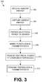
- FIG. 3is an example method 300 of ambient energy powered physiological parameter monitoring.
- ambient energyfrom a surrounding environment, is received and captured at 304 .
- the ambient energycan be created, transmitted and/or broadcasted for the specific purposed of being received 302 , and/or can be energy from a source that is otherwise radiating and/or broadcasting energy intentionally or unintentionally.
- a devicecan transmit ambient energy to be received 302 and captured 304 and/or the ambient energy can be from source that is radiating the ambient energy as part of, or as a byproduct, of one or more functions/features of the source, or its operation, such as wireless communication signals.
- the capture 304 of the ambient energycan include the use of the captured ambient energy to create electrical energy.
- One or more elements, devices and/or systemscan capture the ambient energy and generate electrical energy as a result of the ambient energy capture 304 .
- the electrical energy, or poweris provided to a sensor.
- the sensorcan be an element, device and/or system for sensing data regarding one or more physiological parameters.
- the sensorcan be included on a patch, or other element, that can be placed on, or affixed to, a person to monitor the physiological parameter and generate data therefrom.
- the sensorsenses the physiological parameter data and can generate a signal that can be output, the signal being representative and/or based on the sensed physiological parameter data.
- electrical powersuch as from the ambient energy capture 304
- the communication modulecan wirelessly transmit 312 the physiological parameter data to a remote device, system and/or user.
- Various communication protocols, systems and/or devicescan be used to transmit the physiological parameter data.
- FIG. 4is an example method 400 of receiving physiological parameter data from an ambient energy powered physiological parameter monitoring system.
- ambient energycan be broadcasted and/or transmitted wirelessly to allow another remote device and/or system, such as a physiological parameter monitoring patch, to generate, or capture, electrical energy from the ambient energy.
- a device and/or systemsuch as a companion device, can interact with the remote device/system to provide a source of electrical energy and/or receive data transmission from the remote device/system.
- the ambient energycan be received by the remote device/system to provide the electrical energy for the remote device/system to sense data regarding one or more physiological parameters.
- the sensed datacan then be transmitted by the remote device/system and received at 404 as physiological parameter data.
- the transmission of the physiological parameter datacan be in response to the broadcast of ambient energy 402 and/or otherwise caused/triggered, such as by a schedule or other signal.
- Multiple physiological parameter datacan be received 404 from one or more remote devices/systems, such as the physiological parameter monitoring patch.
- the received physiological data 404can be aggregated and/or processed 406 .
- Various determinations and/or analysescan be made based on the received physiological parameter data 404 and/or the aggregated/processed physiological data 406 . For example, comparisons of the physiological parameter data to trends and/or threshold can be used to determine if an alert should be transmitted 410 in response to the received physiological data 404 and/or the aggregated/processed physiological data 406 .
- the alertcan be transmitted 410 to one or more remote devices, systems and/or users to inform them of physiological data.
- the physiological datacan be transmitted to a remote device, system and/or user.
- the physiological data transmittedcan be raw and/or processed sensor data and/or determination, evaluations and/or analyses made therefrom.
- the transmission 412can include transmitting the received physiological data to another device and/or system, such as a hub, that can process received physiological and/or other patient data to evaluate a physiological state of the patient being monitored and/or perform one or more functions and/or actions in response to the received, transmitted physiological data.
Landscapes
- Health & Medical Sciences (AREA)
- Life Sciences & Earth Sciences (AREA)
- Engineering & Computer Science (AREA)
- Physics & Mathematics (AREA)
- Animal Behavior & Ethology (AREA)
- Veterinary Medicine (AREA)
- Pathology (AREA)
- Biomedical Technology (AREA)
- Heart & Thoracic Surgery (AREA)
- Medical Informatics (AREA)
- Molecular Biology (AREA)
- Surgery (AREA)
- Biophysics (AREA)
- General Health & Medical Sciences (AREA)
- Public Health (AREA)
- Computer Networks & Wireless Communication (AREA)
- Measuring And Recording Apparatus For Diagnosis (AREA)
- Optics & Photonics (AREA)
- Cardiology (AREA)
- Vascular Medicine (AREA)
- Physiology (AREA)
- Dermatology (AREA)
- Nuclear Medicine, Radiotherapy & Molecular Imaging (AREA)
- Radiology & Medical Imaging (AREA)
- Spectroscopy & Molecular Physics (AREA)
Abstract
Description
Claims (18)
Priority Applications (3)
| Application Number | Priority Date | Filing Date | Title |
|---|---|---|---|
| US15/927,749US11123014B2 (en) | 2017-03-21 | 2018-03-21 | Systems and methods for ambient energy powered physiological parameter monitoring |
| US17/303,317US11504061B2 (en) | 2017-03-21 | 2021-05-26 | Systems and methods for ambient energy powered physiological parameter monitoring |
| US17/989,552US20230082799A1 (en) | 2017-03-21 | 2022-11-17 | Systems and methods for ambient energy powered physiological parameter monitoring |
Applications Claiming Priority (2)
| Application Number | Priority Date | Filing Date | Title |
|---|---|---|---|
| US201762474566P | 2017-03-21 | 2017-03-21 | |
| US15/927,749US11123014B2 (en) | 2017-03-21 | 2018-03-21 | Systems and methods for ambient energy powered physiological parameter monitoring |
Related Child Applications (1)
| Application Number | Title | Priority Date | Filing Date |
|---|---|---|---|
| US17/303,317ContinuationUS11504061B2 (en) | 2017-03-21 | 2021-05-26 | Systems and methods for ambient energy powered physiological parameter monitoring |
Publications (2)
| Publication Number | Publication Date |
|---|---|
| US20180271443A1 US20180271443A1 (en) | 2018-09-27 |
| US11123014B2true US11123014B2 (en) | 2021-09-21 |
Family
ID=63581325
Family Applications (3)
| Application Number | Title | Priority Date | Filing Date |
|---|---|---|---|
| US15/927,749Active2039-01-12US11123014B2 (en) | 2017-03-21 | 2018-03-21 | Systems and methods for ambient energy powered physiological parameter monitoring |
| US17/303,317ActiveUS11504061B2 (en) | 2017-03-21 | 2021-05-26 | Systems and methods for ambient energy powered physiological parameter monitoring |
| US17/989,552PendingUS20230082799A1 (en) | 2017-03-21 | 2022-11-17 | Systems and methods for ambient energy powered physiological parameter monitoring |
Family Applications After (2)
| Application Number | Title | Priority Date | Filing Date |
|---|---|---|---|
| US17/303,317ActiveUS11504061B2 (en) | 2017-03-21 | 2021-05-26 | Systems and methods for ambient energy powered physiological parameter monitoring |
| US17/989,552PendingUS20230082799A1 (en) | 2017-03-21 | 2022-11-17 | Systems and methods for ambient energy powered physiological parameter monitoring |
Country Status (1)
| Country | Link |
|---|---|
| US (3) | US11123014B2 (en) |
Cited By (2)
| Publication number | Priority date | Publication date | Assignee | Title |
|---|---|---|---|---|
| US20200405150A1 (en)* | 2019-06-28 | 2020-12-31 | Orthosensor Inc | Wireless system to power a low current device |
| US11504061B2 (en)* | 2017-03-21 | 2022-11-22 | Stryker Corporation | Systems and methods for ambient energy powered physiological parameter monitoring |
Citations (7)
| Publication number | Priority date | Publication date | Assignee | Title |
|---|---|---|---|---|
| US20110275907A1 (en)* | 2010-05-07 | 2011-11-10 | Salvatore Richard Inciardi | Electronic Health Journal |
| US20120029315A1 (en)* | 2010-07-27 | 2012-02-02 | Carefusion 303, Inc. | System and method for conserving battery power in a patient monitoring system |
| US20120203078A1 (en)* | 2011-02-08 | 2012-08-09 | Aulisa Medical Technologies, Inc. | Wireless Patient Monitoring System |
| US20150313496A1 (en)* | 2012-06-14 | 2015-11-05 | Medibotics Llc | Mobile Wearable Electromagnetic Brain Activity Monitor |
| US20160346584A1 (en)* | 2015-05-28 | 2016-12-01 | Nike, Inc. | Athletic Activity Monitoring Decive with Energy Capture |
| US20170258585A1 (en)* | 2016-03-08 | 2017-09-14 | Edwards Lifesciences Corporation | Valve implant with integrated sensor and transmitter |
| US20200006988A1 (en)* | 2012-07-06 | 2020-01-02 | Energous Corporation | Systems and methods of using electromagnetic waves to wirelessly deliver power to electronic devices |
Family Cites Families (473)
| Publication number | Priority date | Publication date | Assignee | Title |
|---|---|---|---|---|
| GB250769A (en) | 1925-05-05 | 1926-04-22 | Harriette Ensley Hodgson | Improvements in and relating to indicating devices for use in hospitals |
| US2335524A (en) | 1941-04-26 | 1943-11-30 | Automatic Elect Lab | Signaling system |
| US2330356A (en) | 1941-04-26 | 1943-09-28 | Automatic Elect Lab | Indicating system |
| US2736888A (en) | 1953-02-09 | 1956-02-28 | George H Mclain | Hospital annunciator system |
| US2896021A (en) | 1954-02-09 | 1959-07-21 | Standard Electric Time Co | Inter-communication system |
| CH365640A (en) | 1958-08-20 | 1962-11-15 | Nl Ind Radio Artikelen Nira Nv | Paging system |
| US3478344A (en) | 1965-06-21 | 1969-11-11 | Ralph K Schwitzgebel | Behavioral supervision system with wrist carried transceiver |
| NL6704276A (en) | 1967-03-22 | 1968-09-23 | ||
| US3439320A (en) | 1967-09-21 | 1969-04-15 | Relton Corp | Personnel location system |
| US3599199A (en) | 1968-12-06 | 1971-08-10 | Bunting Sterisystems Inc | System for simultaneously indicating a unit status at a plurality of stations |
| US3599200A (en) | 1969-12-04 | 1971-08-10 | Bunting Sterisystems Inc | Doctors register |
| US3739329A (en) | 1971-05-24 | 1973-06-12 | Recognition Devices | Electronic system for locating |
| US3696384A (en) | 1971-07-08 | 1972-10-03 | Recognition Devices | Ultrasonic tracking and locating system |
| US3805265A (en) | 1971-10-06 | 1974-04-16 | Rcds Enterprises Inc | Radiant wave locating system |
| US3767859A (en) | 1971-12-30 | 1973-10-23 | Clemetron Corp | Hospital communication system |
| US3973200A (en) | 1972-11-07 | 1976-08-03 | Telefonaktiebolaget L M Ericsson | Process for acknowledging calls in a system for wireless staff locators |
| US3913153A (en) | 1974-08-09 | 1975-10-21 | Hill Rom Co Inc | Electronic controls for a hospital bed |
| US4067005A (en) | 1975-04-29 | 1978-01-03 | Joshuah Levy | Invalid bed system |
| US4150284A (en) | 1977-04-28 | 1979-04-17 | Texas Instruments Incorporated | Medical patient condition monitoring system |
| US4151407A (en) | 1977-04-28 | 1979-04-24 | Texas Instruments Incorporated | Low-power, infrared information transmission system |
| US4216462A (en) | 1978-03-06 | 1980-08-05 | General Electric Company | Patient monitoring and data processing system |
| US4183015A (en) | 1978-06-26 | 1980-01-08 | Hill-Rom Company, Inc. | Side guard for bed including means for controlling remote electrical devices |
| US4228426A (en) | 1978-09-29 | 1980-10-14 | Roberts William A | Hospital bed monitor |
| US4225953A (en) | 1978-09-29 | 1980-09-30 | Simon William F | Personnel locator |
| US4264982A (en) | 1979-03-29 | 1981-04-28 | Rca Corporation | Drive circuit for an infrared remote control transmitter |
| US4237344A (en) | 1979-04-20 | 1980-12-02 | Hospital Communication Systems, Inc. | Rapid response health care communications system |
| US4279433A (en) | 1979-04-30 | 1981-07-21 | Petaja Danny A | Emergency locator beacon for skis |
| US4275385A (en) | 1979-08-13 | 1981-06-23 | Bell Telephone Laboratories, Incorporated | Infrared personnel locator system |
| US4331953A (en) | 1979-12-26 | 1982-05-25 | The Boeing Company | Communication system for use in hazardous confined areas |
| US4298863A (en) | 1980-02-10 | 1981-11-03 | St. Anthony Hospital Systems | Portable patient call |
| US4356475A (en) | 1980-09-12 | 1982-10-26 | Siemens Aktiengesellschaft | System containing a predetermined number of monitoring devices and at least one central station |
| US4601064A (en) | 1983-01-13 | 1986-07-15 | Fisher Berkeley Corporation | Communication system |
| US5062151A (en) | 1983-01-13 | 1991-10-29 | Fisher Berkeley Corporation | Communication system |
| DE3101542C2 (en) | 1981-01-20 | 1985-09-26 | Ruhrkohle Ag, 4300 Essen | Call and signaling system for mining operations |
| US4455548A (en) | 1981-01-26 | 1984-06-19 | Burnett Dorothy K | Call system and methods and apparatus for operating same |
| US4418334A (en) | 1981-01-26 | 1983-11-29 | Burnett Dorothy K | Signal display system and luminaire apparatus for operating same |
| US4489387A (en) | 1981-08-20 | 1984-12-18 | Lamb David E | Method and apparatus for coordinating medical procedures |
| US4495496A (en) | 1981-12-15 | 1985-01-22 | Johnson Engineering Corp. | Personnel monitoring and locating system |
| US4649385A (en) | 1982-08-13 | 1987-03-10 | Teloc R & D Ltd. | Electronic locating system for persons receiving telephone calls |
| US4539560A (en) | 1982-12-10 | 1985-09-03 | Hill-Rom Company, Inc. | Bed departure detection system |
| US4598275A (en) | 1983-05-09 | 1986-07-01 | Marc Industries Incorporated | Movement monitor |
| US4577185A (en) | 1983-07-29 | 1986-03-18 | Saint Margaret Hospital | Construction for alerting health-care professionals |
| JPS6081698A (en) | 1983-10-07 | 1985-05-09 | 東京電力株式会社 | Monitor and command guide system using electromagnetic wave |
| US4593273A (en) | 1984-03-16 | 1986-06-03 | Narcisse Bernadine O | Out-of-range personnel monitor and alarm |
| US4578671A (en) | 1984-12-05 | 1986-03-25 | International Business Machines Corp. | Remote indicating low battery voltage enunciator method and apparatus |
| DE3528646C3 (en) | 1985-08-09 | 1994-04-07 | Hirschmann Richard Gmbh Co | Circuit arrangement for an infrared room surveillance detector |
| US4680790A (en) | 1985-08-22 | 1987-07-14 | Joerns Healthcare, Inc. | Bedside control module for healthcare stations and the like |
| US5245314A (en) | 1985-09-18 | 1993-09-14 | Kah Jr Carl L C | Location monitoring system |
| US5103108A (en) | 1985-10-17 | 1992-04-07 | Crimmins James W | Distributed infrared communication system |
| US4752951A (en) | 1985-12-23 | 1988-06-21 | Konneker Lloyd K | Method of providing location dependent person locator service |
| US4947152A (en) | 1986-02-10 | 1990-08-07 | Mesa Vista Hospital | Patient monitoring system |
| JPS62202300A (en) | 1986-02-28 | 1987-09-05 | 三菱電機株式会社 | Digital remote control unit |
| US4967195A (en) | 1986-05-08 | 1990-10-30 | Shipley Robert T | Hospital signaling and communications system |
| US4955000A (en) | 1986-07-17 | 1990-09-04 | Nac Engineering And Marketing, Inc. | Ultrasonic personnel location identification system |
| US4740788A (en) | 1986-10-06 | 1988-04-26 | Konneker Lloyd K | Method of providing location dependent visitor dispatching service |
| DE3643236A1 (en) | 1986-12-18 | 1988-07-07 | Ruhrkohle Ag | PERSONAL PROTECTION RADIO |
| US4814751A (en) | 1987-02-27 | 1989-03-21 | Wildlife Materials, Inc. | Patient tracking system |
| US4792798A (en) | 1987-04-02 | 1988-12-20 | Wilowski Robert F | Remote control system for pull-cords |
| US4833452A (en) | 1987-05-04 | 1989-05-23 | Sam L. Currier | Safety device and method of establishing group communication |
| US4837568A (en) | 1987-07-08 | 1989-06-06 | Snaper Alvin A | Remote access personnel identification and tracking system |
| US5041086A (en) | 1987-12-04 | 1991-08-20 | Pacesetter Infusion, Ltd. | Clinical configuration of multimode medication infusion system |
| US4853692A (en) | 1987-12-07 | 1989-08-01 | Wolk Barry M | Infant security system |
| US5027314A (en) | 1988-03-17 | 1991-06-25 | United Manufacturing Co., Inc. | Apparatus and method for position reporting |
| DE3861791D1 (en) | 1988-05-05 | 1991-03-28 | Hewlett Packard Gmbh | DIGITAL ADDRESSABLE ELECTRONIC DEVICE. |
| US4998938A (en) | 1988-06-09 | 1991-03-12 | Neurodynamics, Inc. | Removable skull mounted work platform and method of assembling same |
| US4907845A (en) | 1988-09-16 | 1990-03-13 | Salomon Sa | Bed patient monitoring system |
| US4899135A (en) | 1988-12-05 | 1990-02-06 | Mehdi Ghahariiran | Child monitoring device |
| US5511553A (en)* | 1989-02-15 | 1996-04-30 | Segalowitz; Jacob | Device-system and method for monitoring multiple physiological parameters (MMPP) continuously and simultaneously |
| US5153584A (en) | 1989-03-17 | 1992-10-06 | Cardiac Evaluation Center, Inc. | Miniature multilead biotelemetry and patient location system |
| US5124991A (en) | 1989-03-30 | 1992-06-23 | Photonics Corporation | Error correction for infrared data communication |
| JPH0340176A (en) | 1989-07-07 | 1991-02-20 | Nec Corp | Graphic data input device |
| US4990892A (en) | 1989-08-07 | 1991-02-05 | Westcom, A Division Of Westside Communications Of Jacksonville, Inc. | Personnel locator system |
| US5050612A (en) | 1989-09-12 | 1991-09-24 | Matsumura Kenneth N | Device for computer-assisted monitoring of the body |
| US5006830A (en) | 1989-10-16 | 1991-04-09 | Rebecca Merritt | Method and device for deterring the unauthorized removal of a newborn from a defined area |
| US4998095A (en) | 1989-10-19 | 1991-03-05 | Specific Cruise Systems, Inc. | Emergency transmitter system |
| US5086290A (en) | 1990-03-08 | 1992-02-04 | Murray Shawn G | Mobile perimeter monitoring system |
| US5640151A (en) | 1990-06-15 | 1997-06-17 | Texas Instruments Incorporated | Communication system for communicating with tags |
| US6958706B2 (en) | 1990-07-27 | 2005-10-25 | Hill-Rom Services, Inc. | Patient care and communication system |
| US5594786A (en) | 1990-07-27 | 1997-01-14 | Executone Information Systems, Inc. | Patient care and communication system |
| US5291399A (en) | 1990-07-27 | 1994-03-01 | Executone Information Systems, Inc. | Method and apparatus for accessing a portable personal database as for a hospital environment |
| US5822544A (en) | 1990-07-27 | 1998-10-13 | Executone Information Systems, Inc. | Patient care and communication system |
| EP0550517B1 (en) | 1990-08-31 | 1998-12-23 | The General Hospital Corporation | A system for managing multiple devices, for example, portable patient monitoring devices in a network |
| US5075523A (en) | 1990-09-04 | 1991-12-24 | Ford Ralph W | Signal activating device for a nurse call system |
| US5319355A (en) | 1991-03-06 | 1994-06-07 | Russek Linda G | Alarm for patient monitor and life support equipment system |
| US5140309A (en) | 1991-03-12 | 1992-08-18 | Gaymar Industries, Inc. | Bed signalling apparatus |
| US5235258A (en) | 1991-03-27 | 1993-08-10 | Santino Antinori | Remotely controlled articulated bed |
| CA2040234C (en) | 1991-04-11 | 2000-01-04 | Steven Messenger | Wireless coupling of devices to wired network |
| US5266944A (en) | 1991-06-26 | 1993-11-30 | Bodyguard Technologies, Inc. | Electronic system and method for monitoring abusers for compliance with a protective order |
| US5137033A (en) | 1991-07-15 | 1992-08-11 | Norton John L | Patient monitoring device |
| US5396224A (en) | 1991-11-22 | 1995-03-07 | Hewlett-Packard Company | Telemetered patient location system and method |
| WO1993011947A1 (en) | 1991-12-16 | 1993-06-24 | Nocopi International, Inc. | Process, apparatus and substrate for printing process |
| US5808564A (en) | 1992-02-06 | 1998-09-15 | Simms Security Corp. | Personal security system with remote activation |
| US5760704A (en) | 1992-04-03 | 1998-06-02 | Expeditor Systems | Patient tracking system for hospital emergency facility |
| FR2690265B1 (en) | 1992-04-17 | 1994-07-01 | Ind Entreprise | SYSTEM FOR MONITORING A FURNISHED OR MOBILE OBJECT. |
| US5351439A (en) | 1992-04-21 | 1994-10-04 | Koito Manufacturing Co., Ltd. | Power window apparatus having improved safety device |
| US5426425A (en) | 1992-10-07 | 1995-06-20 | Wescom, Inc. | Intelligent locator system with multiple bits represented in each pulse |
| US6968375B1 (en) | 1997-03-28 | 2005-11-22 | Health Hero Network, Inc. | Networked system for interactive communication and remote monitoring of individuals |
| DE69318850T2 (en) | 1992-12-11 | 1998-10-22 | Siemens Medical Systems Inc | DOCKING STATION FOR PATIENT MONITORING SYSTEM |
| US5375604A (en) | 1992-12-11 | 1994-12-27 | Siemens Medical Electronics, Inc. | Transportable modular patient monitor |
| ATE186187T1 (en) | 1992-12-16 | 1999-11-15 | Siemens Medical Systems Inc | PATIENT SITE AND PATIENT DATA MONITORING SYSTEM |
| US5446678A (en) | 1992-12-18 | 1995-08-29 | Hewlett-Packard Corporation | Transmission of information over an alphanumeric paging network |
| US5719761A (en) | 1993-01-15 | 1998-02-17 | Alaris Medical Systems, Inc. | Configuration control system for configuring multiple biomedical devices |
| US5416695A (en) | 1993-03-09 | 1995-05-16 | Metriplex, Inc. | Method and apparatus for alerting patients and medical personnel of emergency medical situations |
| US5576952A (en) | 1993-03-09 | 1996-11-19 | Metriplex, Inc. | Medical alert distribution system with selective filtering of medical information |
| US5412031A (en) | 1993-05-25 | 1995-05-02 | Minnesota Mining & Manufacturing Company | Multi-arm block copolymers, and pressure sensitive adhesive and tape employing a multi-arm elastomeric block copolymer |
| US5327592A (en) | 1993-06-07 | 1994-07-12 | Stump Floyd V | Stationary patient lift |
| AU7054794A (en) | 1993-06-10 | 1995-01-03 | Direkt, Inc. | Preselected distance monitoring and locating system |
| US5699038A (en) | 1993-07-12 | 1997-12-16 | Hill-Rom, Inc. | Bed status information system for hospital beds |
| US6897780B2 (en) | 1993-07-12 | 2005-05-24 | Hill-Rom Services, Inc. | Bed status information system for hospital beds |
| US5561412A (en) | 1993-07-12 | 1996-10-01 | Hill-Rom, Inc. | Patient/nurse call system |
| US5838223A (en) | 1993-07-12 | 1998-11-17 | Hill-Rom, Inc. | Patient/nurse call system |
| US5434755A (en) | 1993-08-04 | 1995-07-18 | Allen-Bradley Company, Inc. | Illumination system for a light emitting panel |
| US5635907A (en) | 1993-08-10 | 1997-06-03 | Bernard; Hermanus A. | Location system |
| EP0640978A3 (en) | 1993-08-31 | 1998-10-07 | Ohmeda Inc. | Non-invasive software update apparatus |
| US5548637A (en) | 1993-09-09 | 1996-08-20 | Precision Tracking Fm, Inc. | Method and apparatus for locating personnel and objects in response to telephone inquiries |
| US5430900A (en) | 1993-11-04 | 1995-07-11 | Kim; Sung-Jul | Bed emitting the far infrared rays |
| US5568119A (en) | 1993-12-21 | 1996-10-22 | Trimble Navigation Limited | Arrestee monitoring with variable site boundaries |
| US5544376A (en) | 1994-01-31 | 1996-08-13 | Maxwell Products, Inc. | Articulated bed with customizable remote control |
| US5455560A (en) | 1994-02-25 | 1995-10-03 | Owen; C. Randal | Means for locating a remote control device |
| US5515426A (en) | 1994-02-28 | 1996-05-07 | Executone Information Systems, Inc. | Telephone communication system having a locator |
| CA2125300C (en) | 1994-05-11 | 1999-10-12 | Douglas J. Ballantyne | Method and apparatus for the electronic distribution of medical information and patient services |
| US5461390A (en) | 1994-05-27 | 1995-10-24 | At&T Ipm Corp. | Locator device useful for house arrest and stalker detection |
| US5795300A (en) | 1994-06-01 | 1998-08-18 | Advanced Body Metrics Corporation | Heart pulse monitor |
| US5537459A (en) | 1994-06-17 | 1996-07-16 | Price; Evelyn C. | Multilevel cellular communication system for hospitals |
| DE4423403A1 (en) | 1994-07-04 | 1996-01-11 | Stierlen Maquet Ag | Connection module |
| US5511256A (en) | 1994-07-05 | 1996-04-30 | Capaldi; Guido | Patient lift mechanism |
| US5664270A (en) | 1994-07-19 | 1997-09-09 | Kinetic Concepts, Inc. | Patient interface system |
| US5400301A (en) | 1994-08-03 | 1995-03-21 | Rackley; Vesna K. | Wrist watch alarm |
| US5636245A (en) | 1994-08-10 | 1997-06-03 | The Mitre Corporation | Location based selective distribution of generally broadcast information |
| WO1996004842A1 (en) | 1994-08-12 | 1996-02-22 | Thomas Donald D Ii | Miniaturized blood pressure monitor kit |
| US5549119A (en) | 1994-09-13 | 1996-08-27 | Cordis Corporation | Vibrating tip catheter |
| US5579001A (en) | 1994-10-20 | 1996-11-26 | Hewlett-Packard Co. | Paging-based backchannel in a medical telemetry system |
| US5687734A (en) | 1994-10-20 | 1997-11-18 | Hewlett-Packard Company | Flexible patient monitoring system featuring a multiport transmitter |
| US5650770A (en) | 1994-10-27 | 1997-07-22 | Schlager; Dan | Self-locating remote monitoring systems |
| US5509154A (en) | 1994-11-01 | 1996-04-23 | Select Comfort Corporation | Air control system for an air bed |
| US5640953A (en) | 1995-03-09 | 1997-06-24 | Siemens Medical Systems, Inc. | Portable patient monitor reconfiguration system |
| US5713856A (en) | 1995-03-13 | 1998-02-03 | Alaris Medical Systems, Inc. | Modular patient care system |
| US5532690A (en) | 1995-04-04 | 1996-07-02 | Itt Corporation | Apparatus and method for monitoring and bounding the path of a ground vehicle |
| US6671563B1 (en) | 1995-05-15 | 2003-12-30 | Alaris Medical Systems, Inc. | System and method for collecting data and managing patient care |
| US5781442A (en) | 1995-05-15 | 1998-07-14 | Alaris Medical Systems, Inc. | System and method for collecting data and managing patient care |
| US6125350A (en) | 1995-06-02 | 2000-09-26 | Software For Surgeons | Medical information log system |
| US5691980A (en) | 1995-06-07 | 1997-11-25 | General Electric Company | Local communication network for power reduction and enhanced reliability in a multiple node tracking system |
| US5588005A (en) | 1995-06-07 | 1996-12-24 | General Electric Company | Protocol and mechanism for primary and mutter mode communication for asset tracking |
| US5682139A (en) | 1995-06-07 | 1997-10-28 | General Electric Company | Railcar location using mutter networks and locomotive transmitter during transit |
| US5686888A (en) | 1995-06-07 | 1997-11-11 | General Electric Company | Use of mutter mode in asset tracking for gathering data from cargo sensors |
| US6085493A (en) | 1995-06-12 | 2000-07-11 | Deroyal Industries, Inc. | Method for the supply of medical supplies to a health-care institution based on a nested bill of materials on a procedure level |
| US5771511A (en) | 1995-08-04 | 1998-06-30 | Hill-Rom, Inc. | Communication network for a hospital bed |
| US5942986A (en) | 1995-08-09 | 1999-08-24 | Cedars-Sinai Medical Center | System and method for automatic critical event notification |
| US5576452A (en) | 1995-08-29 | 1996-11-19 | Ferro Corporation | Continuous process for the production of a zinc containing chemical product |
| GB2305254B (en) | 1995-09-15 | 1999-05-19 | Kodak Ltd | Method of processing a colour photographic silver haldide material |
| US5787528A (en) | 1995-10-04 | 1998-08-04 | Antinori; Santino | Method and apparatus for providing bed recall functions |
| US5650759A (en) | 1995-11-09 | 1997-07-22 | Hittman Materials & Medical Components, Inc. | Filtered feedthrough assembly having a mounted chip capacitor for medical implantable devices and method of manufacture therefor |
| US5748103A (en) | 1995-11-13 | 1998-05-05 | Vitalcom, Inc. | Two-way TDMA telemetry system with power conservation features |
| WO1997018540A1 (en) | 1995-11-13 | 1997-05-22 | Motorola Inc. | Method and apparatus for summoning police or security personnel for assistance in an emergency situation |
| US5944659A (en) | 1995-11-13 | 1999-08-31 | Vitalcom Inc. | Architecture for TDMA medical telemetry system |
| US5742237A (en) | 1995-11-30 | 1998-04-21 | Lockheed Martin Corporation | Tag location monitor |
| US5787115A (en) | 1995-12-28 | 1998-07-28 | Northern Telecom Limited | Key telephone system without common control |
| US5793290A (en) | 1996-02-29 | 1998-08-11 | Rf Technologies, Inc. | Area security system |
| US5974389A (en) | 1996-03-01 | 1999-10-26 | Clark; Melanie Ann | Medical record management system and process with improved workflow features |
| US5936539A (en) | 1996-03-19 | 1999-08-10 | Siemens Medical Systems, Inc. | Method and apparatus for automatic configuration of a network node |
| US5752917A (en) | 1996-03-19 | 1998-05-19 | Siemens Medical Systems, Inc. | Network connectivity for a portable patient monitor |
| EP0796591B1 (en) | 1996-03-19 | 2003-12-10 | Siemens Medical Solutions USA, Inc. | Central station waveform display having dedicated user message areas |
| US5781921A (en) | 1996-05-06 | 1998-07-14 | Ohmeda Inc. | Method and apparatus to effect firmware upgrades using a removable memory device under software control |
| JPH09327524A (en) | 1996-06-13 | 1997-12-22 | Hamamatsu Photonics Kk | Bed |
| US6689091B2 (en) | 1996-08-02 | 2004-02-10 | Tuan Bui | Medical apparatus with remote control |
| US5838233A (en) | 1996-08-16 | 1998-11-17 | Delco Electronics Corporation | Object orientation sensor device |
| US5708421A (en) | 1996-08-19 | 1998-01-13 | Radio Systems Corp. | System for tracking an article or person |
| US5731757A (en) | 1996-08-19 | 1998-03-24 | Pro Tech Monitoring, Inc. | Portable tracking apparatus for continuous position determination of criminal offenders and victims |
| US5877675A (en) | 1996-08-29 | 1999-03-02 | Jansys, Inc. | Wireless healthcare communication system |
| FR2754612B1 (en) | 1996-10-10 | 1998-11-20 | Ge Medical Syst Sa | SYSTEM FOR LOCATING DIGITAL IMAGE TAPE CASSETTES |
| WO1998017172A2 (en) | 1996-10-24 | 1998-04-30 | Massachusetts Institute Of Technology | Patient monitoring finger ring sensor |
| US6364834B1 (en) | 1996-11-13 | 2002-04-02 | Criticare Systems, Inc. | Method and system for remotely monitoring multiple medical parameters in an integrated medical monitoring system |
| EP0844775A1 (en) | 1996-11-22 | 1998-05-27 | Koninklijke Philips Electronics N.V. | Cordless telephone with an emergency call function |
| US6067019A (en) | 1996-11-25 | 2000-05-23 | Hill-Rom, Inc. | Bed exit detection apparatus |
| US6097308A (en) | 1996-12-04 | 2000-08-01 | Data Critical Corp. | Pager to computer link apparatus |
| US6546813B2 (en) | 1997-01-08 | 2003-04-15 | The Trustees Of Boston University | Patient monitoring system employing array of force sensors on a bedsheet or similar substrate |
| US6076166A (en) | 1997-01-17 | 2000-06-13 | Philips Electronics North America Corporation | Personalizing hospital intranet web sites |
| US6148233A (en) | 1997-03-07 | 2000-11-14 | Cardiac Science, Inc. | Defibrillation system having segmented electrodes |
| US5933488A (en) | 1997-04-18 | 1999-08-03 | Siemens Information | Automated method and arrangement for integrating a telephone system with an announcement system |
| US5991728A (en) | 1997-04-30 | 1999-11-23 | Deroyal Industries, Inc. | Method and system for the tracking and profiling of supply usage in a health care environment |
| US5812056A (en) | 1997-05-09 | 1998-09-22 | Golden Eagle Electronics Manufactory Ltd. | Child locating and monitoring device |
| FI111801B (en) | 1997-05-21 | 2003-09-30 | Polar Electro Oy | In training with the user, the following measuring device for non-invasive measurement of at least one signal from his body and method for controlling it |
| DE19732467C2 (en) | 1997-07-28 | 1999-05-27 | Siemens Ag | Transport trolley patient table system for changing a removable plate and transport trolley for this system |
| US6057782A (en) | 1997-07-30 | 2000-05-02 | At&T Corporation | Method and apparatus for paging alternate users |
| US5844488A (en) | 1997-09-23 | 1998-12-01 | Musick; Jeff L. | Bed sensor and alarm |
| US6014633A (en) | 1997-09-24 | 2000-01-11 | Deroyal Business Systems, L.L.C. | Method for the analysis and standardization of bills of resources |
| US6272347B1 (en) | 1997-09-30 | 2001-08-07 | Avaya Technology Corp. | Automatic call distribution based on physical location of wireless terminals |
| JP2001526417A (en) | 1997-11-03 | 2001-12-18 | ヒル−ロム,インコーポレイティド | Personnel and asset tracking method and apparatus |
| US6314556B1 (en) | 1997-11-07 | 2001-11-06 | Deroyal Business Systems, Llc | Modular health care information management system utilizing reusable software objects |
| US5995937A (en) | 1997-11-07 | 1999-11-30 | Deroyal Industries, Inc. | Modular health-care information management system utilizing reusable software objects |
| US5871890A (en) | 1997-11-14 | 1999-02-16 | Eastman Kodak Company | Method for processing roomlight handleable radiographic films using two-stage development |
| US6065120A (en) | 1997-12-09 | 2000-05-16 | Phone.Com, Inc. | Method and system for self-provisioning a rendezvous to ensure secure access to information in a database from multiple devices |
| DE19802572A1 (en) | 1998-01-23 | 1999-08-05 | Siemens Health Service Gmbh & | Medical system architecture |
| US5963137A (en) | 1998-02-10 | 1999-10-05 | Waters, Sr.; Joe Cleveland | Alarm device for monitoring an individual's movement and/or need for assistance |
| US6784797B2 (en) | 1998-02-26 | 2004-08-31 | Bed-Check Corporation | Microprocessor based bed patient monitor |
| US6111509A (en) | 1998-02-26 | 2000-08-29 | Bed-Check Corporation | Microprocessor based bed patient monitor |
| WO1999049583A1 (en) | 1998-03-26 | 1999-09-30 | Siemens Aktiengesellschaft | Radio device |
| US6083007A (en) | 1998-04-02 | 2000-07-04 | Hewlett-Packard Company | Apparatus and method for configuring training for a product and the product |
| US6486792B1 (en) | 1998-04-14 | 2002-11-26 | Hill-Rom Services, Inc. | Communication and bed function control apparatus |
| DE19822022C2 (en) | 1998-05-15 | 2002-12-19 | Siemens Ag | Medical system |
| US6142592A (en) | 1998-05-19 | 2000-11-07 | Endress & Hauser Gmbh & Co Kg | Instrument system |
| US6057758A (en) | 1998-05-20 | 2000-05-02 | Hewlett-Packard Company | Handheld clinical terminal |
| US6093146A (en) | 1998-06-05 | 2000-07-25 | Matsushita Electric Works, Ltd. | Physiological monitoring |
| US6437692B1 (en) | 1998-06-22 | 2002-08-20 | Statsignal Systems, Inc. | System and method for monitoring and controlling remote devices |
| US6404909B2 (en) | 1998-07-16 | 2002-06-11 | General Electric Company | Method and apparatus for processing partial lines of scanned images |
| JP4035235B2 (en) | 1998-08-24 | 2008-01-16 | キヤノン株式会社 | Electronics |
| US20020067273A1 (en) | 1998-09-10 | 2002-06-06 | Senior Technologies, Inc. | Patient monitoring system |
| US7138902B2 (en) | 1998-10-23 | 2006-11-21 | Royal Thoughts, Llc | Personal medical device communication system and method |
| US6078261A (en) | 1998-11-10 | 2000-06-20 | Alert Systems, Inc. | System for monitoring a bed patient |
| US6603494B1 (en) | 1998-11-25 | 2003-08-05 | Ge Medical Systems Global Technology Company, Llc | Multiple modality interface for imaging systems including remote services over a network |
| US6353445B1 (en) | 1998-11-25 | 2002-03-05 | Ge Medical Systems Global Technology Company, Llc | Medical imaging system with integrated service interface |
| US6398727B1 (en) | 1998-12-23 | 2002-06-04 | Baxter International Inc. | Method and apparatus for providing patient care |
| US6133837A (en) | 1999-03-05 | 2000-10-17 | Hill-Rom, Inc. | Patient position system and method for a support surface |
| US6208250B1 (en) | 1999-03-05 | 2001-03-27 | Hill-Rom, Inc. | Patient position detection apparatus for a bed |
| US6791460B2 (en) | 1999-03-05 | 2004-09-14 | Hill-Rom Services, Inc. | Patient position detection apparatus for a bed |
| US6821249B2 (en) | 1999-03-08 | 2004-11-23 | Board Of Regents, The University Of Texas | Temperature monitoring of congestive heart failure patients as an indicator of worsening condition |
| US6870484B1 (en) | 1999-03-24 | 2005-03-22 | Ge Marquette Medical Systems, Inc. | Patient monitoring systems having two-way communication |
| JP4056171B2 (en) | 1999-03-29 | 2008-03-05 | 沖電気工業株式会社 | Digital matched filter circuit |
| US6302844B1 (en) | 1999-03-31 | 2001-10-16 | Walker Digital, Llc | Patient care delivery system |
| US6416471B1 (en) | 1999-04-15 | 2002-07-09 | Nexan Limited | Portable remote patient telemonitoring system |
| US6675041B2 (en) | 1999-05-18 | 2004-01-06 | Physi-Cal Enterprises Lp | Electronic apparatus and method for monitoring net calorie intake |
| EP1060704A3 (en) | 1999-06-18 | 2002-09-18 | Agilent Technologies, Inc. (a Delaware corporation) | Multi-parameter capability transmitter for wireless telemetry systems |
| US6287253B1 (en) | 1999-06-25 | 2001-09-11 | Sabolich Research & Development | Pressure ulcer condition sensing and monitoring |
| ATE342528T1 (en) | 1999-08-02 | 2006-11-15 | Siemens Schweiz Ag | PREDIATIVE DEVICE FOR REGULATING OR CONTROLLING SUPPLY VALUES |
| US6560224B1 (en) | 1999-08-18 | 2003-05-06 | At&T Corp. | Automatic IP directory number masking and dynamic packet routing for IP phone surveillance |
| US6754883B2 (en) | 1999-08-24 | 2004-06-22 | Ge Medical Systems Information Technologies, Inc. | Modular analysis and standardization system |
| US6581204B2 (en) | 1999-08-24 | 2003-06-17 | Ge Medical Systems Information Technologies, Inc. | Modular tracking and profiling system |
| US6264614B1 (en) | 1999-08-31 | 2001-07-24 | Data Critical Corporation | System and method for generating and transferring medical data |
| US6494831B1 (en) | 1999-09-03 | 2002-12-17 | Ge Medical Technology Services, Inc. | Medical diagnostic system service connectivity method and apparatus |
| US6640246B1 (en) | 1999-09-17 | 2003-10-28 | Ge Medical Systems Global Technology Company, Llc | Integrated computerized materials management system |
| US6539393B1 (en) | 1999-09-30 | 2003-03-25 | Hill-Rom Services, Inc. | Portable locator system |
| US6727818B1 (en) | 1999-10-29 | 2004-04-27 | Hill-Rom Services, Inc. | Hygiene monitoring system |
| US6406426B1 (en) | 1999-11-03 | 2002-06-18 | Criticare Systems | Medical monitoring and alert system for use with therapeutic devices |
| US6828992B1 (en) | 1999-11-04 | 2004-12-07 | Koninklijke Philips Electronics N.V. | User interface with dynamic menu option organization |
| US6736759B1 (en) | 1999-11-09 | 2004-05-18 | Paragon Solutions, Llc | Exercise monitoring system and methods |
| US6771172B1 (en) | 1999-11-11 | 2004-08-03 | General Electric Company | Portable patient monitor with alarm light integrated into handle |
| US6829478B1 (en) | 1999-11-19 | 2004-12-07 | Pamela G. Layton | Information management network for automated delivery of alarm notifications and other information |
| US6407335B1 (en) | 1999-11-19 | 2002-06-18 | Alaris Medical Systems, Inc. | Medical device interface system |
| US6694367B1 (en) | 1999-11-30 | 2004-02-17 | Ge Medical Technology Services | Communication connectivity initialization and verification system and method of use |
| US7490048B2 (en) | 1999-12-18 | 2009-02-10 | Raymond Anthony Joao | Apparatus and method for processing and/or for providing healthcare information and/or healthcare-related information |
| US6665820B1 (en) | 1999-12-22 | 2003-12-16 | Ge Medical Technology Services, Inc. | Method and system for communications connectivity failure diagnosis |
| US6553106B1 (en) | 1999-12-27 | 2003-04-22 | Avaya Technology Corp. | Alphanumeric messaging system |
| US6694509B1 (en) | 1999-12-28 | 2004-02-17 | Ge Medical Systems Global Technology Company Llc | Automated regression testing of workstation software |
| US6556630B1 (en) | 1999-12-29 | 2003-04-29 | Ge Medical Systems Information Technologies | Dual band telemetry system |
| US6609115B1 (en) | 1999-12-30 | 2003-08-19 | Ge Medical Systems | Method and apparatus for limited online access to restricted documentation |
| US6412980B1 (en) | 1999-12-30 | 2002-07-02 | Ge Medical Systems Global Technology Company, Llc | Method and apparatus for configuring and monitoring a system unit in a medical diagnostic system |
| US6584454B1 (en) | 1999-12-31 | 2003-06-24 | Ge Medical Technology Services, Inc. | Method and apparatus for community management in remote system servicing |
| EP1054338A1 (en) | 2000-02-11 | 2000-11-22 | Agilent Technologies Inc., A Delaware Corporation | Patient monitor with continuous status display |
| US6348777B1 (en) | 2000-02-29 | 2002-02-19 | Alaris Medical Systems, Inc. | Power management system |
| US6574309B1 (en) | 2000-03-01 | 2003-06-03 | Turnstone Systems, Inc. | Remotely actuated splittler bypass system and method |
| JP2003526244A (en) | 2000-03-03 | 2003-09-02 | コーニンクレッカ フィリップス エレクトロニクス エヌ ヴィ | Apparatus and method for transferring data from one device to another |
| US6510344B1 (en) | 2000-03-22 | 2003-01-21 | Ge Medical Systems Information Technologies, Inc. | Procedure alarm silence feature for medical telemetry system |
| US6560165B1 (en) | 2000-03-28 | 2003-05-06 | Diane K. Barker | Medical information appliance |
| US6871211B2 (en) | 2000-03-28 | 2005-03-22 | Ge Medical Systems Information Technologies, Inc. | Intranet-based medical data distribution system |
| US6529164B1 (en) | 2000-03-31 | 2003-03-04 | Ge Medical Systems Information Technologies, Inc. | Object location monitoring within buildings |
| US7038584B2 (en) | 2000-03-31 | 2006-05-02 | Ge Medical Systems Information Technologies, Inc. | Object location monitoring within buildings |
| US7539623B1 (en) | 2000-04-06 | 2009-05-26 | Medical Central Online | Method and a system for providing bed availability information on a computer network |
| BR0110596A (en) | 2000-05-05 | 2005-08-02 | Hill Rom Services Inc | Patient monitoring system, computer system, patient information monitoring system, patient care device, walker device, patient care device, and computer display |
| EP1290652A2 (en) | 2000-05-05 | 2003-03-12 | Hill-Rom Services, Inc. | Hospital monitoring and control system and method |
| US6616606B1 (en) | 2000-05-19 | 2003-09-09 | Welch Allyn Protocol, Inc. | Patient monitoring system |
| WO2001089368A2 (en) | 2000-05-25 | 2001-11-29 | Healthetech, Inc. | Physiological monitoring using wrist-mounted device |
| CA2328545A1 (en) | 2000-05-30 | 2001-11-30 | Visualmed Clinical Systems Corporation | Hospital informatics system |
| US6516324B1 (en) | 2000-06-01 | 2003-02-04 | Ge Medical Technology Services, Inc. | Web-based report functionality and layout for diagnostic imaging decision support |
| US6707476B1 (en) | 2000-07-05 | 2004-03-16 | Ge Medical Systems Information Technologies, Inc. | Automatic layout selection for information monitoring system |
| US6659947B1 (en) | 2000-07-13 | 2003-12-09 | Ge Medical Systems Information Technologies, Inc. | Wireless LAN architecture for integrated time-critical and non-time-critical services within medical facilities |
| US6751630B1 (en) | 2000-07-20 | 2004-06-15 | Ge Medical Technology Services, Inc. | Integrated multiple biomedical information sources |
| US6650346B1 (en) | 2000-07-20 | 2003-11-18 | Ge Medical Technology Services, Inc. | Method and apparatus for classifying equipment in asset management database |
| JP3979560B2 (en) | 2000-08-24 | 2007-09-19 | パイオニア株式会社 | Disc type discrimination method and reproducing apparatus thereof |
| GB0023425D0 (en) | 2000-09-25 | 2000-11-08 | Koninkl Philips Electronics Nv | Portable device interaction with beacons |
| US6450956B1 (en) | 2000-11-06 | 2002-09-17 | Siemens Corporate Research, Inc. | System and method for treatment and outcome measurement analysis |
| US20020070867A1 (en) | 2000-11-15 | 2002-06-13 | Conway Kevin P. | Patient movement detection apparatus |
| US6904161B1 (en) | 2000-11-17 | 2005-06-07 | Siemens Medical Solutions Usa | Workflow configuration and execution in medical imaging |
| US7275220B2 (en) | 2000-12-22 | 2007-09-25 | Epic Systems Corporation | System and method for a seamless user interface for an integrated electronic health care information system |
| US6594146B2 (en) | 2000-12-26 | 2003-07-15 | Ge Medical Systems Information Technologies, Inc. | Docking station for patient monitor or other electronic device |
| US6572556B2 (en) | 2000-12-29 | 2003-06-03 | Ge Medical Systems Information Technologies | Distributed multi-user catalog-based system for real time data access during cardiology procedures |
| US6575901B2 (en) | 2000-12-29 | 2003-06-10 | Ge Medical Systems Information Technologies | Distributed real time replication-based annotation and documentation system for cardiology procedures |
| US6535576B2 (en) | 2000-12-29 | 2003-03-18 | Ge Medical Systems Global Technology Company, Llc | Enhanced digital detector and system and method incorporating same |
| US6594519B2 (en) | 2000-12-29 | 2003-07-15 | Ge Medical Systems Information Technologies | Distributed real time catalog-based annotation and documentation system for cardiology procedures |
| US6801227B2 (en) | 2001-01-16 | 2004-10-05 | Siemens Medical Solutions Health Services Inc. | System and user interface supporting user navigation and concurrent application operation |
| US6551243B2 (en) | 2001-01-24 | 2003-04-22 | Siemens Medical Solutions Health Services Corporation | System and user interface for use in providing medical information and health care delivery support |
| US6445299B1 (en) | 2001-01-29 | 2002-09-03 | Antonio Rojas, Jr. | Retrofit for patient call system and method therefor |
| DE10106305A1 (en) | 2001-02-12 | 2002-08-29 | Siemens Ag | Method and medical system for improved utilization of a medical device and medical device |
| US6749566B2 (en) | 2001-02-14 | 2004-06-15 | Draeger Medical Systems, Inc. | Patient monitoring area network |
| US6891909B2 (en) | 2001-02-28 | 2005-05-10 | Ge Marquette Medical Systems, Inc. | Pro-active antenna switching based on relative power |
| DE10109863A1 (en) | 2001-03-01 | 2002-09-19 | Siemens Ag | Process for the systematic assessment of the quality of medical technology devices in operation |
| US6526310B1 (en) | 2001-03-02 | 2003-02-25 | Ge Medical Systems Information Technologies, Inc. | Patient transceiver system which uses conductors within leads of leadset to provide phased antenna array |
| US6622088B2 (en) | 2001-03-02 | 2003-09-16 | Hill-Rom Services, Inc. | Ambulatory navigation system |
| EP1374194A2 (en) | 2001-03-30 | 2004-01-02 | Hill-Rom Services, Inc. | Hospital bed and network system |
| WO2002080483A1 (en) | 2001-03-30 | 2002-10-10 | Advanced Metering Data Systems, L.L.C. | Enhanced wireless packet data communication system, method, and apparatus apllicable to both wide area networks and local area networks |
| US20020151810A1 (en) | 2001-04-16 | 2002-10-17 | Acumen, Inc. | Wrist-based fitness monitoring devices |
| US6665385B2 (en) | 2001-04-23 | 2003-12-16 | Cardionet, Inc. | Medical monitoring system having multipath communications capability |
| US20040020856A1 (en) | 2001-04-30 | 2004-02-05 | Acumen, Inc. | Wrist-based fitness monitoring devices |
| US7038588B2 (en) | 2001-05-04 | 2006-05-02 | Draeger Medical Infant Care, Inc. | Apparatus and method for patient point-of-care data management |
| US7242306B2 (en) | 2001-05-08 | 2007-07-10 | Hill-Rom Services, Inc. | Article locating and tracking apparatus and method |
| CA2445161A1 (en) | 2001-05-08 | 2002-11-14 | Hill-Rom Services, Inc. | Article locating and tracking system |
| US6585645B2 (en) | 2001-05-16 | 2003-07-01 | Ge Medical Systems Information Technologies, Inc. | System for and method of establishing monitoring alarm limits based on physiological variables |
| JP2002351995A (en) | 2001-05-17 | 2002-12-06 | Ge Medical Systems Global Technology Co Llc | Patient information managing method and system |
| US20020173991A1 (en) | 2001-05-18 | 2002-11-21 | Boaz Avitall | Health care information management system and method |
| CA2443678A1 (en) | 2001-05-25 | 2002-12-05 | Hill-Rom Services, Inc. | A waste segregation compliance system |
| EP1392143B1 (en) | 2001-06-07 | 2008-09-10 | Select Comfort Corporation | Interactive air bed |
| US6671547B2 (en) | 2001-06-13 | 2003-12-30 | Koninklijke Philips Electronics N.V. | Adaptive analysis method for an electrotherapy device and apparatus |
| US6600421B2 (en) | 2001-07-31 | 2003-07-29 | Koninklijke Philips Electronics N.V. | System to automatically locally control a device according to preferences of a user entering a local area of the device from a remote area |
| US20030028449A1 (en) | 2001-08-01 | 2003-02-06 | Ge Medical Systems Global Technology Co., Llc. | Capital equipment on-line configurator interface |
| US7154397B2 (en) | 2001-08-03 | 2006-12-26 | Hill Rom Services, Inc. | Patient point-of-care computer system |
| US6885288B2 (en) | 2001-08-08 | 2005-04-26 | Ge Medical Technology Services, Inc. | Method and apparatus for accessing medical asset data |
| US6807543B2 (en) | 2001-08-09 | 2004-10-19 | Ge Medical Technology Services, Inc. | Data access component providing transparent access to a plurality of medical imaging databases |
| US6584182B2 (en) | 2001-08-27 | 2003-06-24 | Ge Medical Systems Information Technologies, Inc. | Method and apparatus for communicating data over a telephone line using an acoustic modem |
| US6714913B2 (en) | 2001-08-31 | 2004-03-30 | Siemens Medical Solutions Health Services Corporation | System and user interface for processing task schedule information |
| US6892083B2 (en) | 2001-09-05 | 2005-05-10 | Vocera Communications Inc. | Voice-controlled wireless communications system and method |
| US6912549B2 (en) | 2001-09-05 | 2005-06-28 | Siemens Medical Solutions Health Services Corporation | System for processing and consolidating records |
| US7756723B2 (en) | 2001-09-07 | 2010-07-13 | Eclipsys Corporation | System and method for managing patient bed assignments and bed occupancy in a health care facility |
| JP2003085314A (en) | 2001-09-11 | 2003-03-20 | Ge Medical Systems Global Technology Co Llc | Remote site management system |
| EP1448148B1 (en) | 2001-10-02 | 2008-10-01 | Hill-Rom Services, Inc. | Integrated barrier and fluid supply for a hospital bed |
| US7263669B2 (en) | 2001-11-14 | 2007-08-28 | Denholm Enterprises, Inc. | Patient communication method and system |
| DE50107064D1 (en) | 2001-11-20 | 2005-09-15 | Trumpf Medizin Systeme Gmbh & Co Kg | Method and device for remote control of a surgical table |
| US6554174B1 (en) | 2001-12-05 | 2003-04-29 | Manuel Aceves | Integrated electronics workstation |
| KR100580618B1 (en) | 2002-01-23 | 2006-05-16 | 삼성전자주식회사 | Apparatus and method for recognizing user emotion through short time monitoring of physiological signals |
| US6726634B2 (en) | 2002-01-25 | 2004-04-27 | Koninklijke Philips Electronics N.V. | System and method for determining a condition of a patient |
| US20030149598A1 (en) | 2002-01-28 | 2003-08-07 | Santoso Nugroho Iwan | Intelligent assignment, scheduling and notification scheme for task management |
| US20030176798A1 (en) | 2002-02-12 | 2003-09-18 | Simon Arnold Baruch | Method and device for detecting cardiac arrest and automatically alerting emergency personnel of wearer's location |
| US6693514B2 (en) | 2002-03-20 | 2004-02-17 | Rauland-Borg Corporation | Signaling device for annunciating a status of a monitored person or object |
| US6792396B2 (en) | 2002-03-28 | 2004-09-14 | Ge Medical Systems Information Technologies, Inc. | Interface device and method for a monitoring network |
| US7023821B2 (en) | 2002-04-12 | 2006-04-04 | Symnbol Technologies, Inc. | Voice over IP portable transreceiver |
| US6864795B2 (en) | 2002-04-18 | 2005-03-08 | Bed-Check Corporation | Apparatus for lighting a patient monitor front panel |
| US20050055242A1 (en) | 2002-04-30 | 2005-03-10 | Bryan Bello | System and method for medical data tracking, analysis and reporting for healthcare system |
| US8494868B2 (en) | 2002-05-07 | 2013-07-23 | Priority Dispatch Corporation | Method and system for a seamless interface between an emergency medical dispatch system and a nurse triage system |
| AU2003222734A1 (en) | 2002-05-17 | 2003-12-02 | H.C. Equipment Aps | Device and bed for turning horizontally lying persons |
| DE10222399B4 (en) | 2002-05-21 | 2007-08-09 | Siemens Ag | Control method and system for automatic pre-processing of device malfunctions |
| US6759607B2 (en) | 2002-06-12 | 2004-07-06 | Curbell, Inc. | Communication/control device and method of communicating |
| WO2004000097A2 (en) | 2002-06-19 | 2003-12-31 | University Of Florida | Interactive patient positioning system |
| DE10233149A1 (en) | 2002-07-22 | 2004-02-12 | Ganimed Gmbh | Electronic measurement instrument for detection of heart conditions, especially vestibule or heart flutter, comprises microcontroller and algorithm stored in ROM for pulse signal analysis |
| US20030010345A1 (en) | 2002-08-02 | 2003-01-16 | Arthur Koblasz | Patient monitoring devices and methods |
| US6788206B1 (en) | 2002-09-05 | 2004-09-07 | Donald A. Edwards | Patient monitoring system |
| US20040186358A1 (en) | 2002-09-25 | 2004-09-23 | Bart Chernow | Monitoring system containing a hospital bed with integrated display |
| AU2003275297A1 (en) | 2002-09-27 | 2004-04-23 | Hill-Rom Services, Inc. | Universal communications, monitoring, tracking, and control system for a healthcare facility |
| US7336187B2 (en) | 2002-10-18 | 2008-02-26 | The Trustees Of Boston University | Patient activity monitor |
| US6826578B2 (en) | 2002-10-25 | 2004-11-30 | Ge Medical Systems Information Technolgoies, Inc. | Method, system, and computer product for collecting and distributing clinical data for data mining |
| US6930878B2 (en) | 2002-11-26 | 2005-08-16 | Ge Medical Systems Information Technologies, Inc. | Computer-equipped mobility device |
| US6873884B2 (en) | 2002-11-26 | 2005-03-29 | Ge Medical Systems Information Technology | Computer-equipped mobility device and method of connecting to a network |
| US6982639B2 (en) | 2002-11-26 | 2006-01-03 | Ge Medical Systems Information Technologies, Inc. | Wireless subject locator |
| DE10256211B4 (en) | 2002-12-02 | 2005-12-15 | Siemens Ag | Installation and removal device, installation and removal process, and magnetic resonance imaging device with an installation and removal device |
| EP1599847B1 (en) | 2003-02-17 | 2007-08-15 | Kinderguard Limited | A tracking and monitoring apparatus and system |
| EP1603435B1 (en) | 2003-03-12 | 2007-08-08 | Jetta Company Limited | Adjustable mattress and pillow system |
| US6998986B2 (en) | 2003-03-18 | 2006-02-14 | Bed-Check Corporation | Power latch for use with an electronic patient monitor |
| US7071820B2 (en) | 2003-03-19 | 2006-07-04 | Callaway James J | Wireless patient ambulation motion detector and second call system |
| US20040222897A1 (en) | 2003-03-24 | 2004-11-11 | Werner Schuhmann | Nurse call indicator lamp |
| US20070159926A1 (en) | 2003-04-17 | 2007-07-12 | Nike, Inc. | Adaptive Watch |
| US7379770B2 (en) | 2003-05-13 | 2008-05-27 | Dayton Technologies Limited | Devices and methods for heart rate measurement and wrist-watch incorporating same |
| JP2004358092A (en) | 2003-06-06 | 2004-12-24 | Olympus Corp | System for supporting nursing job |
| US20040261184A1 (en) | 2003-06-27 | 2004-12-30 | Flick Roland E | Stand alone integrated cushion |
| US7079036B2 (en) | 2003-08-20 | 2006-07-18 | Bed-Check Corporation | Method and apparatus for alarm volume control using pulse width modulation |
| CN2649889Y (en) | 2003-08-25 | 2004-10-20 | 王正宗 | Multi-ported gas valve with air inflating-deflating pump for inflating bed |
| US7395568B2 (en) | 2003-09-12 | 2008-07-08 | Dreamwell, Ltd. | Self-contained articulated mattress |
| US8133177B2 (en) | 2003-09-23 | 2012-03-13 | Vasamed, Inc. | System and method for assessing capillary vitality |
| EP1522300B1 (en) | 2003-10-06 | 2013-04-24 | Zimmer GmbH | Support device |
| FR2862206B1 (en) | 2003-11-14 | 2006-06-30 | Fhsurgical | MOTORIZED OPERATING TABLE |
| US20050110617A1 (en) | 2003-11-25 | 2005-05-26 | Kile Kevin W. | Nurse call interface and method of operation |
| US7301451B2 (en) | 2003-12-31 | 2007-11-27 | Ge Medical Systems Information Technologies, Inc. | Notification alarm transfer methods, system, and device |
| US7290299B2 (en) | 2004-01-09 | 2007-11-06 | Votel Thomas W | Device and method for positioning patients |
| US10227063B2 (en)* | 2004-02-26 | 2019-03-12 | Geelux Holdings, Ltd. | Method and apparatus for biological evaluation |
| US7151457B2 (en) | 2004-03-10 | 2006-12-19 | Riley James A | Detection warning system for caregivers in a home |
| US20050206505A1 (en) | 2004-03-18 | 2005-09-22 | Edwards Systems Technology, Inc. | Medical facility information management apparatus and method |
| US20050256416A1 (en) | 2004-05-12 | 2005-11-17 | Chen Yu Y | Heart rate detecting and displaying device |
| US20060142665A1 (en) | 2004-05-14 | 2006-06-29 | Garay John L | Heart rate monitor |
| US6982930B1 (en) | 2004-07-27 | 2006-01-03 | Chin-Yeh Hung | Wristwatch with the function of sensing heart pulses |
| US7319386B2 (en) | 2004-08-02 | 2008-01-15 | Hill-Rom Services, Inc. | Configurable system for alerting caregivers |
| US7852208B2 (en) | 2004-08-02 | 2010-12-14 | Hill-Rom Services, Inc. | Wireless bed connectivity |
| US7088235B1 (en) | 2004-08-20 | 2006-08-08 | Carricut Lee M | Method and apparatus for retrofitting a patient call system |
| US7160133B2 (en) | 2004-09-01 | 2007-01-09 | Gencsus | Nurse call connector system and method |
| US9820658B2 (en) | 2006-06-30 | 2017-11-21 | Bao Q. Tran | Systems and methods for providing interoperability among healthcare devices |
| EP1834271A2 (en) | 2004-12-21 | 2007-09-19 | Q-Trac, LLC | System and method for managing restorative care |
| US7443303B2 (en) | 2005-01-10 | 2008-10-28 | Hill-Rom Services, Inc. | System and method for managing workflow |
| US7292135B2 (en) | 2005-03-24 | 2007-11-06 | Edwards Systems Technology, Inc. | Patient monitor integration into nurse call system and method |
| US20060220798A1 (en) | 2005-04-05 | 2006-10-05 | Apsrfid, Llc | Medical clinic RFID system |
| US20060239195A1 (en) | 2005-04-26 | 2006-10-26 | Martin Camins | Method and apparatus for dual-mode application update protocol |
| US20060248221A1 (en) | 2005-04-28 | 2006-11-02 | Andrew Hottel | Method and apparatus for dual-mode internet protocol station/gateway |
| US7333002B2 (en) | 2005-05-27 | 2008-02-19 | Ge Security, Inc. | Automatically tracking mobilized equipment and nurse call priority assignment system and method |
| ITTO20050407A1 (en) | 2005-06-13 | 2006-12-14 | Ist Superiore Mario Boella | REMOTE MONITORING SYSTEM FOR PHYSIOLOGICAL PARAMETERS OF AN INDIVIDUAL, PROCEDURE AND IT PRODUCT |
| US7307522B2 (en) | 2005-08-11 | 2007-12-11 | Dawson N Rick | System and method for determining the location of a resident during an emergency within a monitored area having a plurality of residences |
| US8107920B2 (en) | 2005-08-17 | 2012-01-31 | Mourad Ben Ayed | Emergency detection and notification system |
| US7760082B2 (en) | 2005-09-21 | 2010-07-20 | Chon Meng Wong | System and method for active monitoring and diagnostics of life signs using heartbeat waveform and body temperature remotely giving the user freedom to move within its vicinity without wires attachment, gel, or adhesives |
| US20070078324A1 (en) | 2005-09-30 | 2007-04-05 | Textronics, Inc. | Physiological Monitoring Wearable Having Three Electrodes |
| US7420472B2 (en) | 2005-10-16 | 2008-09-02 | Bao Tran | Patient monitoring apparatus |
| US7271774B2 (en) | 2005-10-21 | 2007-09-18 | Suunto Oy | Electronic wearable device |
| WO2007051889A1 (en) | 2005-11-04 | 2007-05-10 | Nokia Corporation | Apparatus for detecting body condition |
| US20070156456A1 (en) | 2006-01-04 | 2007-07-05 | Siemens Medical Solutions Health Services Corporation | System for Monitoring Healthcare Related Activity In A Healthcare Enterprise |
| CN101400296B (en) | 2006-02-28 | 2012-11-07 | 皇家飞利浦电子股份有限公司 | Biometric monitor with electronics disposed on or in a neck collar |
| US7671733B2 (en) | 2006-03-17 | 2010-03-02 | Koninklijke Philips Electronics N.V. | Method and system for medical alarm monitoring, reporting and normalization |
| US20070239484A1 (en) | 2006-03-20 | 2007-10-11 | Arond Betty J | System and method for managing patient bed assignments, bed occupancy, and staffing in a healthcare facility operation |
| US20070237487A1 (en) | 2006-03-22 | 2007-10-11 | Case Pax Int'l. Co., Ltd. | Computer bag |
| US20070258395A1 (en) | 2006-04-28 | 2007-11-08 | Medtronic Minimed, Inc. | Wireless data communication protocols for a medical device network |
| US7551078B2 (en) | 2006-05-08 | 2009-06-23 | Ihc Intellectual Asset Management, Llc | Device alert system and method |
| US7539533B2 (en) | 2006-05-16 | 2009-05-26 | Bao Tran | Mesh network monitoring appliance |
| US8781568B2 (en) | 2006-06-23 | 2014-07-15 | Brian M. Dugan | Systems and methods for heart rate monitoring, data transmission, and use |
| US7310549B1 (en) | 2006-07-14 | 2007-12-18 | Johnson Outdoors Inc. | Dive computer with heart rate monitor |
| US8183987B2 (en) | 2006-07-17 | 2012-05-22 | Patient Provider Communications, Inc. | Method and system for advanced patient communication |
| US7813941B2 (en) | 2006-07-26 | 2010-10-12 | Siemens Medical Solutions Usa, Inc. | Patient bed search system |
| US8217795B2 (en) | 2006-12-05 | 2012-07-10 | John Carlton-Foss | Method and system for fall detection |
| US9028259B2 (en) | 2007-01-16 | 2015-05-12 | Physio-Control, Inc. | Wearable CPR assist, training and testing device |
| US7751375B2 (en) | 2007-02-22 | 2010-07-06 | Rauland-Borg Corporation | Communications system and protocol for medical environment |
| US9445720B2 (en) | 2007-02-23 | 2016-09-20 | Smith & Nephew, Inc. | Processing sensed accelerometer data for determination of bone healing |
| US7868740B2 (en) | 2007-08-29 | 2011-01-11 | Hill-Rom Services, Inc. | Association of support surfaces and beds |
| WO2009036150A2 (en) | 2007-09-11 | 2009-03-19 | Aid Networks, Llc | Wearable wireless electronic patient data communications and physiological monitoring device |
| US20090076349A1 (en) | 2007-09-14 | 2009-03-19 | Corventis, Inc. | Adherent Multi-Sensor Device with Implantable Device Communication Capabilities |
| US8926538B2 (en) | 2007-12-26 | 2015-01-06 | Physio-Control, Inc. | Support device for administration of CPR |
| US8384526B2 (en) | 2008-02-22 | 2013-02-26 | Hill-Rom Services, Inc. | Indicator apparatus for healthcare communication system |
| US20090221888A1 (en) | 2008-03-03 | 2009-09-03 | Ravindra Wijesiriwardana | Wearable sensor system for environmental and physiological information monitoring and information feedback system |
| US20090243833A1 (en) | 2008-03-31 | 2009-10-01 | Ching Ching Huang | Monitoring system and method for patient care |
| US20090322513A1 (en) | 2008-06-27 | 2009-12-31 | Franklin Dun-Jen Hwang | Medical emergency alert system and method |
| US8712509B2 (en) | 2008-07-25 | 2014-04-29 | Medtronic, Inc. | Virtual physician acute myocardial infarction detection system and method |
| US8203438B2 (en) | 2008-07-29 | 2012-06-19 | Masimo Corporation | Alarm suspend system |
| US7894888B2 (en) | 2008-09-24 | 2011-02-22 | Chang Gung University | Device and method for measuring three-lead ECG in a wristwatch |
| US20100081946A1 (en) | 2008-09-26 | 2010-04-01 | Qualcomm Incorporated | Method and apparatus for non-invasive cuff-less blood pressure estimation using pulse arrival time and heart rate with adaptive calibration |
| GB2476751B (en) | 2008-10-08 | 2013-08-07 | Bedrock Inv S Llc | Measuring shivering during therapeutic temperature control |
| US8994539B2 (en) | 2008-10-27 | 2015-03-31 | Lennox Industries, Inc. | Alarm and diagnostics system and method for a distributed-architecture heating, ventilation and air conditioning network |
| US20120245439A1 (en) | 2008-11-20 | 2012-09-27 | David Andre | Method and apparatus for determining critical care parameters |
| JP5559810B2 (en) | 2008-12-15 | 2014-07-23 | コーヴェンティス,インク. | Patient monitoring system and method |
| US9323894B2 (en) | 2011-08-19 | 2016-04-26 | Masimo Corporation | Health care sanitation monitoring system |
| US8086728B2 (en) | 2009-03-12 | 2011-12-27 | Hewlett-Packard Development Company, L.P. | Method and apparatus of correlating power usage with traffic flow for a network device |
| US8140143B2 (en) | 2009-04-16 | 2012-03-20 | Massachusetts Institute Of Technology | Washable wearable biosensor |
| US10335346B2 (en) | 2009-07-22 | 2019-07-02 | Physio-Control Canada Sales Ltd. | Optical techniques for the measurement of chest compression depth and other parameters during CPR |
| US20110077719A1 (en)* | 2009-09-30 | 2011-03-31 | Broadcom Corporation | Electromagnetic power bio-medical unit |
| EP2506926B1 (en) | 2009-11-30 | 2016-08-03 | Zoll Medical Corporation | Display for dual-mode medical device |
| US20110190570A1 (en) | 2010-02-01 | 2011-08-04 | Michael Zaimi | Biofeedback interface device and methods for controlling heartrate in response to signals |
| US8725253B2 (en) | 2010-02-12 | 2014-05-13 | Zoll Medical Corporation | Defibrillator display including CPR depth information |
| EP2542147A4 (en) | 2010-03-04 | 2014-01-22 | Neumitra LLC | Devices and methods for treating psychological disorders |
| US20110224505A1 (en) | 2010-03-12 | 2011-09-15 | Rajendra Padma Sadhu | User wearable portable communicative device |
| US20150223705A1 (en) | 2010-03-12 | 2015-08-13 | Rajendra Padma Sadhu | Multi-functional user wearable portable device |
| JP6192032B2 (en) | 2010-04-22 | 2017-09-06 | リーフ ヘルスケア インコーポレイテッド | A system for monitoring a patient's physiological status |
| US8776418B1 (en) | 2010-09-30 | 2014-07-15 | Fitbit, Inc. | Interchangeable cases for biometric monitoring devices |
| US9937355B2 (en) | 2010-11-08 | 2018-04-10 | Zoll Medical Corporation | Remote medical device alarm |
| US20120130203A1 (en) | 2010-11-24 | 2012-05-24 | Fujitsu Limited | Inductively-Powered Ring-Based Sensor |
| US20120165688A1 (en) | 2010-12-28 | 2012-06-28 | Yip Inc. | Wireless optical pulsimetry system for a healthcare environment |
| US8475367B1 (en) | 2011-01-09 | 2013-07-02 | Fitbit, Inc. | Biometric monitoring device having a body weight sensor, and methods of operating same |
| US8412322B2 (en)* | 2011-01-14 | 2013-04-02 | Physio-Control, Inc. | Defibrillators detecting orientation of electrode connection to adjust energy dosage |
| WO2012106729A1 (en) | 2011-02-04 | 2012-08-09 | Phase Space Systems Corporation | System and method for evaluating an electrophysiological signal |
| US20120203076A1 (en) | 2011-02-08 | 2012-08-09 | Jean Pierre Fatta | Portable Physiological Data Monitoring Device |
| US9095316B2 (en) | 2011-04-20 | 2015-08-04 | Masimo Corporation | System for generating alarms based on alarm patterns |
| US8744559B2 (en) | 2011-08-11 | 2014-06-03 | Richard P. Houben | Methods, systems and devices for detecting atrial fibrillation |
| WO2013066642A1 (en) | 2011-10-19 | 2013-05-10 | Scanadu Incorporated | Automated personal medical diagnostic system, method, and arrangement |
| US10342446B2 (en)* | 2011-11-30 | 2019-07-09 | Welch Allyn, Inc. | Thermal powered medical device |
| WO2013109947A1 (en) | 2012-01-19 | 2013-07-25 | Nike International Ltd. | Wearable device assembly having solder mask |
| US9713434B2 (en) | 2012-02-11 | 2017-07-25 | Sensifree Ltd. | Microwave contactless heart rate sensor |
| US8941487B2 (en) | 2012-03-09 | 2015-01-27 | Salutron, Inc. | Transferring a mobile tag using a light based communication handshake protocol |
| US9522096B2 (en) | 2012-05-17 | 2016-12-20 | Zoll Medical Corporation | CPR team performance |
| WO2013175314A2 (en)* | 2012-05-23 | 2013-11-28 | Convergent Engineering, Inc. | System and method for detecting preeclampsia |
| US20170164878A1 (en)* | 2012-06-14 | 2017-06-15 | Medibotics Llc | Wearable Technology for Non-Invasive Glucose Monitoring |
| US20130338460A1 (en) | 2012-06-18 | 2013-12-19 | David Da He | Wearable Device for Continuous Cardiac Monitoring |
| US8838236B2 (en) | 2012-09-21 | 2014-09-16 | Physio-Control. Inc. | Wearable cardiac defibrillator system with anti-bradyarrhythmia pacing and methods |
| US9314159B2 (en) | 2012-09-24 | 2016-04-19 | Physio-Control, Inc. | Patient monitoring device with remote alert |
| US9210561B2 (en) | 2012-11-28 | 2015-12-08 | Lookout, Inc. | Method and system for managing an emergency for enhanced user security using a mobile communication device |
| US9520638B2 (en)* | 2013-01-15 | 2016-12-13 | Fitbit, Inc. | Hybrid radio frequency / inductive loop antenna |
| US10016613B2 (en) | 2013-04-02 | 2018-07-10 | West Affum Holdings Corp. | Wearable cardiac defibrillator system long-term monitoring alternating patient parameters other than ECG |
| US20150065893A1 (en) | 2013-08-27 | 2015-03-05 | Cywee Group Limited | Wearable electronic device, customized display device and system of same |
| US10165946B2 (en) | 2013-09-25 | 2019-01-01 | Bardy Diagnostics, Inc. | Computer-implemented system and method for providing a personal mobile device-triggered medical intervention |
| US9396642B2 (en) | 2013-10-23 | 2016-07-19 | Quanttus, Inc. | Control using connected biometric devices |
| US20190038148A1 (en) | 2013-12-12 | 2019-02-07 | Alivecor, Inc. | Health with a mobile device |
| EP4537748A1 (en) | 2013-12-12 | 2025-04-16 | Alivecor, Inc. | Methods and systems for arrhythmia tracking and scoring |
| WO2015107266A1 (en) | 2014-01-16 | 2015-07-23 | Aboa Legis Oy | Method and device for the detection of the degree of entropy of medical data |
| US20150250418A1 (en)* | 2014-03-10 | 2015-09-10 | Icon Health & Fitness, Inc. | Optical Pulse Rate Monitor |
| US20190099009A1 (en)* | 2014-05-09 | 2019-04-04 | Sleepnea Llc | Wearable Technology for Sleep Environment Modification |
| WO2015175574A1 (en) | 2014-05-12 | 2015-11-19 | Physio-Control, Inc. | Wearable healthcare device |
| CN104055518A (en) | 2014-07-08 | 2014-09-24 | 广州柏颐信息科技有限公司 | Fall detection wrist watch and fall detection method |
| US20180227735A1 (en)* | 2014-08-25 | 2018-08-09 | Phyziio, Inc. | Proximity-Based Attribution of Rewards |
| US12381001B2 (en)* | 2014-09-22 | 2025-08-05 | AION Biosystem, Inc. | Secure systems for contactless identification and vital sign monitoring |
| EP3302245A4 (en)* | 2015-05-31 | 2019-05-08 | Sens4care | REMOTE MONITORING SYSTEM OF HUMAN ACTIVITY |
| US10921168B2 (en)* | 2015-09-11 | 2021-02-16 | Wuhan Tailimeixin Healthcare Technologies Co., Ltd. | Integrated measuring system and method |
| CA3002841C (en)* | 2015-10-21 | 2024-03-19 | NeuSpera Medical Inc. | Devices, systems, and methods for stimulation therapy |
| EP4385350A3 (en)* | 2016-04-29 | 2024-08-07 | LifeLens Technologies, Inc. | Monitoring and management of physiologic parameters of a subject |
| US11123014B2 (en)* | 2017-03-21 | 2021-09-21 | Stryker Corporation | Systems and methods for ambient energy powered physiological parameter monitoring |
| US12089985B2 (en)* | 2017-06-23 | 2024-09-17 | Stryker Corporation | Patient monitoring and treatment systems and methods |
| US10959626B2 (en)* | 2017-06-30 | 2021-03-30 | Samsung Electronics Co., Ltd. | Self-powered wearable for continuous biometrics monitoring |
| US11109121B2 (en)* | 2018-05-10 | 2021-08-31 | Physio-Control, Inc. | Systems and methods of secure communication of data from medical devices |
- 2018
- 2018-03-21USUS15/927,749patent/US11123014B2/enactiveActive
- 2021
- 2021-05-26USUS17/303,317patent/US11504061B2/enactiveActive
- 2022
- 2022-11-17USUS17/989,552patent/US20230082799A1/enactivePending
Patent Citations (7)
| Publication number | Priority date | Publication date | Assignee | Title |
|---|---|---|---|---|
| US20110275907A1 (en)* | 2010-05-07 | 2011-11-10 | Salvatore Richard Inciardi | Electronic Health Journal |
| US20120029315A1 (en)* | 2010-07-27 | 2012-02-02 | Carefusion 303, Inc. | System and method for conserving battery power in a patient monitoring system |
| US20120203078A1 (en)* | 2011-02-08 | 2012-08-09 | Aulisa Medical Technologies, Inc. | Wireless Patient Monitoring System |
| US20150313496A1 (en)* | 2012-06-14 | 2015-11-05 | Medibotics Llc | Mobile Wearable Electromagnetic Brain Activity Monitor |
| US20200006988A1 (en)* | 2012-07-06 | 2020-01-02 | Energous Corporation | Systems and methods of using electromagnetic waves to wirelessly deliver power to electronic devices |
| US20160346584A1 (en)* | 2015-05-28 | 2016-12-01 | Nike, Inc. | Athletic Activity Monitoring Decive with Energy Capture |
| US20170258585A1 (en)* | 2016-03-08 | 2017-09-14 | Edwards Lifesciences Corporation | Valve implant with integrated sensor and transmitter |
Cited By (4)
| Publication number | Priority date | Publication date | Assignee | Title |
|---|---|---|---|---|
| US11504061B2 (en)* | 2017-03-21 | 2022-11-22 | Stryker Corporation | Systems and methods for ambient energy powered physiological parameter monitoring |
| US20200405150A1 (en)* | 2019-06-28 | 2020-12-31 | Orthosensor Inc | Wireless system to power a low current device |
| US11723594B2 (en)* | 2019-06-28 | 2023-08-15 | Orthosensor Inc. | Wireless system to power a low current device |
| US12295741B2 (en) | 2019-06-28 | 2025-05-13 | Howmedica Osteonics Corp. | Wireless system to power a low current device |
Also Published As
| Publication number | Publication date |
|---|---|
| US20230082799A1 (en) | 2023-03-16 |
| US20180271443A1 (en) | 2018-09-27 |
| US11504061B2 (en) | 2022-11-22 |
| US20210321943A1 (en) | 2021-10-21 |
Similar Documents
| Publication | Publication Date | Title |
|---|---|---|
| US20190150805A1 (en) | Biocompatible implantable sensor apparatus and methods | |
| US9706924B2 (en) | Systems, methods and apparatus for powering devices using RF energy from a mobile transmitter | |
| US20230082799A1 (en) | Systems and methods for ambient energy powered physiological parameter monitoring | |
| US9843229B2 (en) | Wireless sound charging and powering of healthcare gadgets and sensors | |
| JP6027716B2 (en) | Wearable user status information acquisition device | |
| US11234675B2 (en) | Sonar-based contactless vital and environmental monitoring system and method | |
| US20020135336A1 (en) | System and method for remote monitoring utilizing a rechargeable battery | |
| WO2015054137A1 (en) | Wireless charging and powering of healthcare gadgets and sensors | |
| US20160045134A1 (en) | Ecg monitor with an implantable part | |
| CA2410548A1 (en) | System and method for remotely monitoring | |
| EP4175534B1 (en) | Wearable tags | |
| CN202843588U (en) | A vital sign monitoring alarm based on smart phone application | |
| CN102805615A (en) | A vital sign monitoring alarm based on smart phone application | |
| Kim et al. | Wireless technologies for wearable electronics: a review | |
| US10038345B1 (en) | Smart clothes with wireless power transfer and sensing capabilities | |
| US20120293340A1 (en) | Triggering recharging and wireless transmission of remote patient monitoring device | |
| US20110224511A1 (en) | Method and system for measuring vital functions of human body | |
| TWM416446U (en) | Implantable wireless charging health management system | |
| CN211270775U (en) | Ear clip type blood oxygen detector | |
| Jethwa et al. | Realtime soldier's health monitoring system incorporating low power LoRa communication | |
| RU163942U1 (en) | MEDICAL TRANSMITTER | |
| CN221748039U (en) | Wireless medical health monitoring device | |
| CN115397312A (en) | Physiological data monitoring system for hospital ward round monitoring | |
| JP2020156852A (en) | Medical telemeter system | |
| Yuce | Collective Sensing for Health Care |
Legal Events
| Date | Code | Title | Description |
|---|---|---|---|
| FEPP | Fee payment procedure | Free format text:ENTITY STATUS SET TO UNDISCOUNTED (ORIGINAL EVENT CODE: BIG.); ENTITY STATUS OF PATENT OWNER: LARGE ENTITY | |
| STPP | Information on status: patent application and granting procedure in general | Free format text:DOCKETED NEW CASE - READY FOR EXAMINATION | |
| STPP | Information on status: patent application and granting procedure in general | Free format text:NON FINAL ACTION MAILED | |
| STPP | Information on status: patent application and granting procedure in general | Free format text:NON FINAL ACTION MAILED | |
| STPP | Information on status: patent application and granting procedure in general | Free format text:RESPONSE TO NON-FINAL OFFICE ACTION ENTERED AND FORWARDED TO EXAMINER | |
| STPP | Information on status: patent application and granting procedure in general | Free format text:RESPONSE TO EX PARTE QUAYLE ACTION ENTERED AND FORWARDED TO EXAMINER | |
| STPP | Information on status: patent application and granting procedure in general | Free format text:NOTICE OF ALLOWANCE MAILED -- APPLICATION RECEIVED IN OFFICE OF PUBLICATIONS | |
| AS | Assignment | Owner name:STRYKER CORPORATION, MICHIGAN Free format text:ASSIGNMENT OF ASSIGNORS INTEREST;ASSIGNORS:APPERSON, RYAN W.;SHARIF, REZA;BIELSTEIN, MATTHEW LAWRENCE;AND OTHERS;SIGNING DATES FROM 20210504 TO 20210726;REEL/FRAME:057025/0259 | |
| STPP | Information on status: patent application and granting procedure in general | Free format text:PUBLICATIONS -- ISSUE FEE PAYMENT RECEIVED | |
| STCF | Information on status: patent grant | Free format text:PATENTED CASE | |
| AS | Assignment | Owner name:STRYKER CORPORATION, MICHIGAN Free format text:CHANGE OF ADDRESS;ASSIGNOR:STRYKER CORPORATION;REEL/FRAME:069737/0184 Effective date:20241217 | |
| MAFP | Maintenance fee payment | Free format text:PAYMENT OF MAINTENANCE FEE, 4TH YEAR, LARGE ENTITY (ORIGINAL EVENT CODE: M1551); ENTITY STATUS OF PATENT OWNER: LARGE ENTITY Year of fee payment:4 |