US11121669B2 - Roof mounting system - Google Patents
Roof mounting systemDownload PDFInfo
- Publication number
- US11121669B2 US11121669B2US16/673,433US201916673433AUS11121669B2US 11121669 B2US11121669 B2US 11121669B2US 201916673433 AUS201916673433 AUS 201916673433AUS 11121669 B2US11121669 B2US 11121669B2
- Authority
- US
- United States
- Prior art keywords
- solar panel
- clamp
- fastener
- point
- attachment point
- Prior art date
- Legal status (The legal status is an assumption and is not a legal conclusion. Google has not performed a legal analysis and makes no representation as to the accuracy of the status listed.)
- Active, expires
Links
Images


Classifications
- H—ELECTRICITY
- H02—GENERATION; CONVERSION OR DISTRIBUTION OF ELECTRIC POWER
- H02S—GENERATION OF ELECTRIC POWER BY CONVERSION OF INFRARED RADIATION, VISIBLE LIGHT OR ULTRAVIOLET LIGHT, e.g. USING PHOTOVOLTAIC [PV] MODULES
- H02S20/00—Supporting structures for PV modules
- H02S20/20—Supporting structures directly fixed to an immovable object
- H02S20/22—Supporting structures directly fixed to an immovable object specially adapted for buildings
- H02S20/23—Supporting structures directly fixed to an immovable object specially adapted for buildings specially adapted for roof structures
- H02S20/24—Supporting structures directly fixed to an immovable object specially adapted for buildings specially adapted for roof structures specially adapted for flat roofs
- F—MECHANICAL ENGINEERING; LIGHTING; HEATING; WEAPONS; BLASTING
- F16—ENGINEERING ELEMENTS AND UNITS; GENERAL MEASURES FOR PRODUCING AND MAINTAINING EFFECTIVE FUNCTIONING OF MACHINES OR INSTALLATIONS; THERMAL INSULATION IN GENERAL
- F16B—DEVICES FOR FASTENING OR SECURING CONSTRUCTIONAL ELEMENTS OR MACHINE PARTS TOGETHER, e.g. NAILS, BOLTS, CIRCLIPS, CLAMPS, CLIPS OR WEDGES; JOINTS OR JOINTING
- F16B2/00—Friction-grip releasable fastenings
- F16B2/02—Clamps, i.e. with gripping action effected by positive means other than the inherent resistance to deformation of the material of the fastening
- F16B2/06—Clamps, i.e. with gripping action effected by positive means other than the inherent resistance to deformation of the material of the fastening external, i.e. with contracting action
- F16B2/12—Clamps, i.e. with gripping action effected by positive means other than the inherent resistance to deformation of the material of the fastening external, i.e. with contracting action using sliding jaws
- F—MECHANICAL ENGINEERING; LIGHTING; HEATING; WEAPONS; BLASTING
- F16—ENGINEERING ELEMENTS AND UNITS; GENERAL MEASURES FOR PRODUCING AND MAINTAINING EFFECTIVE FUNCTIONING OF MACHINES OR INSTALLATIONS; THERMAL INSULATION IN GENERAL
- F16B—DEVICES FOR FASTENING OR SECURING CONSTRUCTIONAL ELEMENTS OR MACHINE PARTS TOGETHER, e.g. NAILS, BOLTS, CIRCLIPS, CLAMPS, CLIPS OR WEDGES; JOINTS OR JOINTING
- F16B5/00—Joining sheets or plates, e.g. panels, to one another or to strips or bars parallel to them
- F16B5/02—Joining sheets or plates, e.g. panels, to one another or to strips or bars parallel to them by means of fastening members using screw-thread
- F16B5/0216—Joining sheets or plates, e.g. panels, to one another or to strips or bars parallel to them by means of fastening members using screw-thread the position of the plates to be connected being adjustable
- F16B5/0233—Joining sheets or plates, e.g. panels, to one another or to strips or bars parallel to them by means of fastening members using screw-thread the position of the plates to be connected being adjustable allowing for adjustment perpendicular to the plane of the plates
- Y—GENERAL TAGGING OF NEW TECHNOLOGICAL DEVELOPMENTS; GENERAL TAGGING OF CROSS-SECTIONAL TECHNOLOGIES SPANNING OVER SEVERAL SECTIONS OF THE IPC; TECHNICAL SUBJECTS COVERED BY FORMER USPC CROSS-REFERENCE ART COLLECTIONS [XRACs] AND DIGESTS
- Y02—TECHNOLOGIES OR APPLICATIONS FOR MITIGATION OR ADAPTATION AGAINST CLIMATE CHANGE
- Y02B—CLIMATE CHANGE MITIGATION TECHNOLOGIES RELATED TO BUILDINGS, e.g. HOUSING, HOUSE APPLIANCES OR RELATED END-USER APPLICATIONS
- Y02B10/00—Integration of renewable energy sources in buildings
- Y02B10/10—Photovoltaic [PV]
- Y—GENERAL TAGGING OF NEW TECHNOLOGICAL DEVELOPMENTS; GENERAL TAGGING OF CROSS-SECTIONAL TECHNOLOGIES SPANNING OVER SEVERAL SECTIONS OF THE IPC; TECHNICAL SUBJECTS COVERED BY FORMER USPC CROSS-REFERENCE ART COLLECTIONS [XRACs] AND DIGESTS
- Y02—TECHNOLOGIES OR APPLICATIONS FOR MITIGATION OR ADAPTATION AGAINST CLIMATE CHANGE
- Y02E—REDUCTION OF GREENHOUSE GAS [GHG] EMISSIONS, RELATED TO ENERGY GENERATION, TRANSMISSION OR DISTRIBUTION
- Y02E10/00—Energy generation through renewable energy sources
- Y02E10/40—Solar thermal energy, e.g. solar towers
- Y02E10/47—Mountings or tracking
- Y—GENERAL TAGGING OF NEW TECHNOLOGICAL DEVELOPMENTS; GENERAL TAGGING OF CROSS-SECTIONAL TECHNOLOGIES SPANNING OVER SEVERAL SECTIONS OF THE IPC; TECHNICAL SUBJECTS COVERED BY FORMER USPC CROSS-REFERENCE ART COLLECTIONS [XRACs] AND DIGESTS
- Y02—TECHNOLOGIES OR APPLICATIONS FOR MITIGATION OR ADAPTATION AGAINST CLIMATE CHANGE
- Y02E—REDUCTION OF GREENHOUSE GAS [GHG] EMISSIONS, RELATED TO ENERGY GENERATION, TRANSMISSION OR DISTRIBUTION
- Y02E10/00—Energy generation through renewable energy sources
- Y02E10/50—Photovoltaic [PV] energy
Definitions
- the present disclosurerelates to solar panel mounting systems and more specifically to mounting systems for various roof types.
- a roof mounting systemmay comprise a short base, a tall base, a first clamp assembly and a second clamp assembly.
- the short basemay have a first body and a first slot.
- the first slotmay be formed on the first body at an angle.
- the tall basemay have a second body and a second slot.
- the second slotmay be formed on the second body at the angle.
- the first clamp assemblymay be configured to be operatively couple to the first slot.
- the second clamp assemblymay be configured to be operatively couple to the second slot.
- the first clamp and the second clampmay be configured to engage and retain a solar panel on the short base and the tall base at the angle.
- the support fastenermay be installable in the first slot or the second slot.
- the support fastenermay be configured to support the first clamp or the second clamp.
- the first clamp assemblymay comprise a threaded shaft that are installable in the first slot.
- the first clamp assemblymay include a level nut and a support plate.
- the level nut and support platemay be adjustably installable on the threaded shaft and configured to support a solar panel.
- the first clamp assembly and/or the second clamp assemblymay comprise a spacer block that is configured to support a clamp.
- the spacer blockmay be installed with the first clamp assembly or the second clamp assembly where the first clamp assembly or the second clamp assembly supports the end of an array or is configured as an end clamp.
- each clamp assemblymay comprise a clamp.
- Each clampmay comprise, include, or be configured with a pin or a tooth.
- the pin or toothmay be configured to create an electrically conductive path between the clamp and the solar panel.
- the clampmay be configured with the tooth where the clamp is made of stainless steel.
- the clampmay include the pin where the clamp is made of aluminum.
- the mounting systemmay comprise a spacer.
- the spacermay be configured to mount to at least one of the first slot and the second slot.
- the spacermay be used to provide additional height for the mounting system.
- the spacermay be configured to mount a solar panel array over roof obstructions, such as, for example, vent pipes, chimneys, whirly birds, and/or the like.
- the second body of the tall basemay include a cross support.
- the second bodymay also define a first hollow and a second hollow.
- the cross supportmay be disposed between the first hollow and the second hollow.
- the mounting systems described hereinmay also be configured to mount a solar panel array to standing seam metal roof.
- the mounting system described hereinmay be configured as a rail-less standing seam roof mounting system.
- a roof mount blockmay comprise a body, a first fastener, a second fastener and a mid-clamp.
- the bodymay include a bearing surface.
- the bodymay also define an attachment channel (e.g., a U-channel) and/or a slot (e.g., a t-slot).
- the attachment channelmay be configured to mount on and/or attached to a stand seam or a standing seam metal roof.
- the attachment channelmay be disposed below the slot. In this regard, the attachment channel and the slot may be substantially parallel to one another.
- the slotmay be at least partially defined through the bearing surface.
- the slotmay also be configured to receive a first fastener (e.g., a bolt, t-bolt, t-nut and threaded rod, and/or the like).
- the second fastenerinstallable through a portion of the body.
- the second fastenermay be, for example, a set screw.
- the second fastenermay protrude into the attachment channel in response being installed in the body.
- the second fastenermay contact, clamp, pinch, or otherwise engage the standing seam of a standing seam metal roof in the attachment channel.
- the mid-clampmay be slidably coupled to the body along the slot with the first fastener.
- the first fasteneris an assembly.
- the assemblyincludes a t-nut and a fastener.
- the bearing surfacemay include a plurality of serrations defined in the bearing surface.
- an engagement toothmay be formed along the length of the slot.
- a roof mount blockmay comprise a body, a t-mount, a fastener and a carriage.
- the bodymay define an attachment channel.
- the t-mountmay be operatively coupled to and/or integrally formed on the body.
- the t-mountmay be configured to be operatively couple to the carriage.
- the fastenermay be installable through a portion of the body. In this regard, the fastener may protrude into the attachment channel in response being installed in the body.
- the mid clampmay comprise a spacer block that is configured to support at least a portion of the clamp (e.g., half the clamp).
- the spacermay be installed in a mid-clamp on the end of an array.
- the spacermay allow the mid clamp to function as an end clamp.
- the spacermay be configured and/or sized to replicate the thickness of a solar module.
- each mid clamp assemblymay be a clamp assembly.
- Each clamp assemblymay comprise, include, or be configured with a clamp and a pin or a tooth.
- the pin or toothmay be configured to create an electrically conductive path between the clamp and the solar panel.
- the clampmay be configured with the tooth where the clamp is made of stainless steel.
- the clampmay include the pin where the clamp is made of aluminum.
- FIGS. 1A-1Dillustrate various perspective views of a mounting systems and components for a first attachment point, in accordance with various embodiments
- FIGS. 2A-2Fillustrate various perspective views of a mounting systems and components for a second attachment point, in accordance with various embodiments
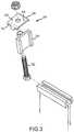
- FIG. 3illustrates an exploded perspective view of a clamp and a portion of a mounting system, in accordance with various embodiments
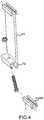
- FIG. 4illustrates an exploded perspective view of a spacer and a portion of a mounting system, in accordance with various embodiments
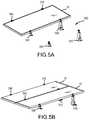
- FIGS. 5A-5Dillustrate various perspective views of solar panels being installed with a mounting system, in accordance with various embodiments
- FIGS. 6A-6Billustrate side views of the installation angle of a solar panel that is installed with a mounting system, in accordance with various embodiments
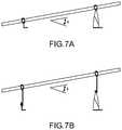
- FIGS. 7A-7Billustrate side views of the installation angle of a solar panel that is installed with a mounting system, in accordance with various embodiments
- FIGS. 8A-8Dillustrate views of a mounting system with height adjustment, in accordance with various embodiments
- FIGS. 9A-9Billustrate views of a mounting system including hooks, in accordance with various embodiments.
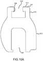
- FIGS. 10A-10Billustrate views of a portion of a first standing seam metal roof mounting system, in accordance with various embodiments
- FIG. 10Cillustrates a view of a portion of a second standing seam metal roof mounting system, in accordance with various embodiments
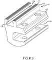
- FIGS. 11A-11Billustrate views of a portion of a third standing seam metal roof mounting system, in accordance with various embodiments
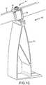
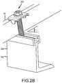
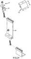
- FIGS. 12A-12Dillustrate views of a standing seam metal roof mounting system including, in accordance with various embodiments
- FIG. 13illustrates a view of a coupling for a roof mounting system including, in accordance with various embodiments
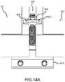
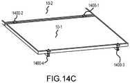
- FIGS. 14A-14Cillustrate views of a standing seam metal roof mounting system installed as a rail free solar panel array, in accordance with various embodiments
- FIGS. 15A-15Billustrate views of a rail free roof mounting system including, in accordance with various embodiments.
- FIGS. 16A-16Dillustrate views of a portion of a roof mounting system including, in accordance with various embodiments.
- the roof mounting systemsmay be configured for securing a solar panel array to a roof.
- the systemsmay be configured to mount solar panels to various roof types.
- the systemsmay be configured to mount the panels at an angle about the roof surface.
- the systemsmay be configured to mount the panels substantially parallel to the roof surface.
- the systemmay include an integrated electrical bonding system that is compliant with the building codes and safety standards, including, for example, UL 2703, First Edition or any other similar specification related to solar panel racking and/or mounting hardware.
- the mounting systems described hereinmay be configured to mount a solar panel array to a flat concrete roof like those found throughout the Caribbean and Central and South America.
- Other systems described hereinmay be configured to facilitate mounting structures on standing seam metals roofs.
- Still other systems described hereinmay be configured to facilitate mounting structures on composite shingle, slate, or tile roofs.
- the mounting systems described hereinmay be configured as rail-less or rails free roof mounting systems.
- a roof mounting systemmay comprise a short base, a tall base, a first clamp assembly and a second clamp assembly.
- the short basemay have a first body and a first slot.
- the first slotmay be formed on the first body at an angle.
- the tall basemay have a second body and a second slot.
- the second slotmay be formed on the second body at the angle.
- the first clamp assemblymay be configured to be operatively couple to the first slot.
- the second clamp assemblymay be configured to be operatively couple to the second slot.
- the first clamp and the second clampmay be configured to engage and retain a solar panel on the short base and the tall base at the angle.
- solar panel support system 100may be configured to attach a solar panel to a roof.
- System 100may comprise a tall base 110 .
- Tall base 110may include a body 112 , an attachment point 114 , a foot 116 , and a cross support 118 .
- Attachment point 114may be formed in or operatively coupled to the top of body 112 .
- Foot 116may be formed in or operatively coupled to the bottom for body 112 .
- Cross support 118may divide a hollow defined by body 112 .
- body 112 and cross support 118may define a first hollow 120 and a second hollow 122 .
- Cross support 118may also be configured to strengthen body 112 .
- system 100may comprise clamp assembly 124 .
- Clamp assembly 124may be mounted to body 112 via attachment point 114 .
- Clamp assembly 124may comprise clamp 126 , fastener 130 and nut 132 .
- Clamp assembly 124may also comprise a spacer block 128 .
- Spacer block 128may be optionally installed at the end of column of panels in an array.
- spacer bock 128may simulate the frame of a solar module so that clamp assembly 124 properly engages and retains the module at the end of the array.
- Spacer block 128may be any suitable size.
- spacer block 128may be installable in two or more orientations.
- spacer block 128may be configured to provide various heights that replicate the various thicknesses of solar panel frames (e.g., 32 mm, 33 mm, 35, mm, 38 mm, 40 mm, 45 mm, 50 mm and/or any other suitable height).
- attachment point 114may comprise one or more points 136 .
- Fastener 130may be configured to contact and/or deform a portion of point 136 .
- fastener 130may create an electrically conductive path (e.g., a bond path as required by UL 2703 or a similar standard) between attachment point 114 —tall base 110 .
- clamp assembly 124may be configured to create an electrically conductive path (e.g., a bond path as described herein) from solar panel 10 , through clamp assembly 124 and to tall base 110 .
- Clamp 126may be stainless steel.
- Clamp 126may also comprise one or more pins 135 .
- pin 135may be configured to create an electrically conductive path between solar panel 10 and clamp assembly 124 .
- clamp assembly 124may be configured to retain solar panel 10 on tall base 110 at an angle ⁇ .
- ⁇may likely be between approximately 7 degrees to 25 degrees. More particularly, ⁇ may be 10 degrees, 15 degrees, 20 degrees, and/or the like.
- spacer 138may be installed on tall base 110 .
- Spacer 138may provide flexibility for installation of an array around roof structures (e.g., vents, chimneys, antennas, and/or the like). Spacer 138 may also allow a user to adjust the installation angle of a solar panel.
- solar panel support system 200may comprise a short base 240 .
- Short base 240may comprise a foot 242 , a body 244 , and an attachment point 246 (e.g., a slot).
- the attachment point 246 of short base 240may be substantially like attachment point 114 of tall base 110 .
- System 200may also comprise clamp assembly 224 .
- Clamp assembly 224may include clamp 226 , fastener 230 , and nut 232 .
- Clamp assembly 224may also include spacer block 228 .
- Clamp 226may include one or more pins 233 .
- Clamp 226may also be made of stainless steel.
- claim 226 and/or clamp assembly 224may be configured to create an electrically conductive path (e.g., a bond path) between the solar panel and short base 240 .
- clamp assembly 224may be used with tall base 110 or short base 240 , as described herein.
- short base 240may be configured to mount one or more solar panels at an angle ⁇ .
- ⁇may likely be between approximately 7 degrees to 25 degrees. More particularly, ⁇ may be 10 degrees, 15 degrees, 20 degrees, and/or the like.
- spacer 238may be configured to attached to short base 280 . Moreover, multiple spacers 238 may be installed on one another to achieve a desired installation height.
- spacer block 228may be installed with clamp assembly 224 . As discussed herein, spacer block 228 may be installed at the end of an array to replicate the frame of a solar panel. Spacer block 228 may be a square or a rectangle. Spacer block 228 may include one or more hole allow for variable installation. Spacer 228 may also be a nonuniform shape that is installable on a fastener to space and support clamp 226 .
- clamp 326may be aluminum, or a composite material.
- Clamp 326may include one of more conductive elements 335 (e.g., pins).
- Clamp 326may also be stainless steel.
- clamp 326may be configured to carry and/or transfer electricity to other components.
- Clamp 326may be part of an electrically conductive path (e.g., bond path) that electrically links all portions and/or components of the solar support system described herein.
- Clamp 326may include one or more teeth or serrations 337 . Tooth 337 may be configured to engage or bite into the frame of a solar panel.
- spacer 438may include an attachment point 452 (e.g., a channel). Attachment point 452 may be configured to operatively couple to attachment point 114 of tall base 110 . Attachment point 452 may also be configured to operatively couple to attachment point 246 of short base 240 .
- attachment point 452e.g., a channel
- system 500may be configured as a rail free solar panel mounting system.
- the systemmay be laid out with a plurality of tall brackets 510 and short brackets 540 .
- Two solar panels 10may be mounted on each tall bracket 510 and short bracket 540 .
- Panels 10may be retained on tall bracket 510 and short bracket 540 with the clamp assemblies described herein.
- the systemmay include an electrically conductive path (e.g., a bond path) that electrically links each of the components together as discussed herein.
- system 500may be height adjustable.
- each of the tall brackets 510 and short brackets 540may be operatively coupled to one or more spacers 538 .
- the spacers described hereinmay be configured to define an installation angle ⁇ . That installation angle ⁇ , may be the same as the installation angle when a panel is attached to the tall base or short base as discussed herein. While the spacer may provide the same angle, the spacers allow for additional height for installed modules.
- system 800may include a leveling assembly.
- the leveling assemblymay be a portion of clamp assembly 824 .
- the leveling assemblymay be installable on either the tall base or the short based as discussed herein.
- the leveling assemblymay be configured to change the angle or orientation of the panels when the panels are installed on system 800 .
- the leveling assemblymay be configured to adjust the angle of the panel when installed.
- the leveling assemblymay include a plate 850 and a leveling element 852 (e.g., a level nut).
- Leveling element 852may be integrally formed in plate 850 .
- Plate 850may also include a hole and may be installed over leveling element 852 . In operation, plate 850 may be movable up and down along fastener 830 in response to leveling element 852 being actuated.
- system 900may include a wire management system.
- the wire management systemmay be configured to support and/or carry various wires and/or cables connecting one or more solar panels to one another.
- tall base 910 and/or short base 940may include one or more hooks 960 .
- Hook 960may be integrally formed in body 912 or body 944 .
- Hook 960may also be operatively coupled to body 912 or body 944 .
- Hook 960may include one or more attachment points (e.g., a hole, a standoff, and/or the like) that can be used to secure wires to hook 960 .
- the mounting systems described hereinmay also be configured to mount a solar panel array to standing seam metal roof.
- the mounting system described hereinmay be configured as a rail-less or rail-free mounting system.
- a solar panel support systemmay be configured to attach a solar panel to a roof (e.g., a standing seam metal roof).
- the systemmay comprise a mounting bracket 1010 .
- Mounting bracket 1010may include a body 1012 , an attachment point 1014 .
- Attachment point 1014may be formed in or operatively coupled to body 1012 .
- attachment point 1014may be a slot or channel.
- Attachment point 1014may comprise one or more points 1036 .
- a fastenermay be configured to contact and/or deform a portion of point 1036 .
- Point 1036may also be configured to retain a fastener and/or prevent fastener walk be creating an interference fit.
- the fastenermay create an electrically conductive path (e.g., a bond path as required by UL 2703 or a similar standard) between attachment point 1014 and a clamp assembly and/or solar panel, as discussed herein.
- Attachment point 1014may also include a bearing surface 1011 that is configured to engage and support a solar panel or other structure on a roof.
- Bearing surface 1011may include and/or comprise a plurality of serrations or teeth 1013 that are configured to engage a solar panel frame and/or other roof mounted structure.
- Body 1012may also include a channel and/or slot 1008 .
- Slot 1008may be installable on a seam of a standing seam metal roof.
- slot 1008may be disposed substantially parallel to attachment point 1014 .
- attachment point 1014may be a protrusion 1016 .
- Attachment point 1014may also include one or more slot 1017 defined in body 1012 or protrusion 1016 .
- Protrusion 1016may also include one or more points (e.g., like point 1036 described herein). These points may protrude into slot 1017 .
- the pointmay also be defined in protrusion 1016 .
- Protrusion 1016may have a T profile. Protrusion 1016 may also have any other suitable profile.
- a solar panel support systemmay be configured to attach a solar panel to a roof (e.g., a standing seam metal roof).
- the systemmay comprise a mounting bracket 1110 .
- Mounting bracket 1110may include a body 1112 , an attachment point 1114 .
- Attachment point 1114may be formed in or operatively coupled to body 1112 .
- attachment point 1114may be a slot, channel or protrusion as discussed herein.
- Attachment point 1114may comprise one or more points 1136 .
- a fastenermay be configured to contact and/or deform a portion of point 1136 .
- Point 1136may also be configured to retain a fastener and/or prevent fastener walk be creating an interference fit.
- the fastenermay create an electrically conductive path (e.g., a bond path as required by UL 2703 or a similar standard) between attachment point 1114 and a clamp assembly and/or solar panel, as discussed herein.
- Attachment point 1114may also include a bearing surface 1111 that is configured to engage and support a solar panel or other structure on a roof.
- Bearing surface 1111may include and/or comprise a plurality of serrations or teeth 1113 that are configured to engage a solar panel frame and/or other roof mounted structure.
- Body 1112may also include a channel and/or slot 1108 .
- Slot 1108may be installable on a seam of a standing seam metal roof.
- slot 1108may be disposed substantially perpendicular to attachment point 1114 .
- system 1200may comprise clamp assembly 1224 .
- Clamp assembly 1224may be mounted to body 1212 via attachment point 1214 .
- Clamp assembly 1224may comprise clamp 1226 , fastener 1230 and nut 1232 .
- Clamp 1226may be stainless steel.
- Clamp 1226may also comprise one or more pins 1235 , which are also shown as 1235 - 1 and 1235 - 2 . In this regard, pin 1235 may be configured to create an electrically conductive path between solar panel and clamp assembly 1224 and/or system 1200 , as described herein.
- Clamp 1226may also include a spacer portion 1225 .
- Spacer portion 1225may be installable with clamp 1226 and/or integrally formed in clamp 1226 .
- Spacer portion 1225may be configured to abut and/or engage a solar panel frame. In this regard, spacer portion 1225 may be configured to provide substantially uniform spacing between solar panels in a solar panel array.
- body 1212may also include one or more holes.
- the holesmay be configured to receive and retain set screws 1215 , which are also shown as set screw 1215 - 1 and set screw 1215 - 2 .
- Set screw 1215may pass through body 1212 via the hole and into slot and/or channel 1208 .
- Set screw 1215may be configured to engage the standing seam or a metal roof. In this regard, set screw 1215 is configured to retain body 1212 and/or system 1200 on the standing seam.
- fastener 1230may be a bolt.
- Fastener 1230may also be a threaded rod that thread into a t-nut 1231 .
- the head of the bolt and/or t-nut 1231may be installable in and/or configured to engage attachment point 1214 .
- Clamp assembly 1224may also comprise a spacer block 1228 .
- Spacer block 1228may be optionally installed at the end of column of panels in an array.
- spacer bock 128may simulate the frame of a solar module so that clamp assembly 124 properly engages and retains the module at the end of the array.
- Spacer block 128may be any suitable size.
- spacer block 128may be installable in two or more orientations.
- spacer block 128may be configured to provide various heights that replicate the various thicknesses of solar panel frames (e.g., 32 mm, 33 mm, 35, mm, 38 mm, 40 mm, 45 mm, 50 mm and/or any other suitable height).
- system 1300may include a coupling 1370 .
- Coupling 1370may comprise a fastener 1330 , a first clamp assembly 1324 - 1 , a second clamp assembly 1324 - 2 , and one or more nuts 1332 .
- Fastener 1330may be a bolt or a threaded rod.
- Each clamp assembly 1324may comprise a clamp 1326 and one or more pins or teeth 1335 .
- Clamp 1326may be stainless steel and may include teeth that are configured to create an electrically conductive path between clamp 1326 and a solar panel frame.
- Clamp 1326may also comprise one or more pins 1335 , which are also shown as 1335 - 1 and 1335 - 2 .
- pin 1335may be configured to create an electrically conductive path between solar panel and clamp assembly 1324 , as described herein.
- the couplings 1370may be installed in a solar panel array between rows of panels to facilitate electrical bonding vertically (North-South) and horizontally (East-West) across the array, as may be required of a solar panel array under applicable building and safety codes.
- system 1400may be configured as a rail free solar panel mounting system.
- the systemmay be laid out with a plurality of systems 1400 (e.g., system 1400 - 1 , system 1400 - 2 , system 1400 - 3 , system 1400 - 4 , and/or the like).
- Two solar panels 10may be mounted on each system 1400 as shown in FIG. 14A .
- mounting bracket 1410may receive and support solar panel 10 - 1 and solar panel 10 - 2 .
- Panels 10may be retained on mounting bracket 1410 with the clamp assembly 1424 , as described herein.
- the systemmay include an electrically conductive path (e.g., a bond path) through pins 1435 - 1 and 1435 - 2 or clamp assembly 1424 .
- the components of the arrayare electrically linked to each other, as discussed herein.
- the ends of the arraymay include system 1400 mounts that include spacer bracket 1428 as shown in FIG. 14B .
- the mounting systems described hereinmay also be configured to mount a solar panel array to various roof types (e.g., composite shingle roofs, slate roofs, tile roofs, and/or the like).
- the mounting system described hereinmay be configured as a rail-less or rail-free mounting system.
- a solar panel support systemmay be configured to attach a solar panel to a roof.
- the systemmay comprise a mounting bracket 1510 .
- Mounting bracket 1510may include a body 1512 , an attachment point 1514 .
- Attachment point 1514may be formed in or operatively coupled to body 1512 .
- attachment point 1514may be a slot or channel.
- Attachment point 1514may comprise one or more points 1536 .
- a fastenermay be configured to contact and/or deform a portion of point 1536 .
- Point 1536may also be configured to retain a fastener and/or prevent fastener walk by creating an interference fit.
- the fastenermay create an electrically conductive path (e.g., a bond path as required by UL 2703 or a similar standard) between attachment point 1514 and a clamp assembly and/or solar panel, as discussed herein.
- Attachment point 1514may also include a bearing surface 1511 that is configured to engage and support a solar panel or other structure on a roof.
- Bearing surface 1511may include and/or comprise a plurality of serrations or teeth 1513 that are configured to engage a solar panel frame and/or other roof mounted structure.
- Body 1512may also include a mounting point (e.g., a hole defined through body 1512 ). The mounting point may be configured to receive a fastener.
- body 1512 and/or system 1500is secured to a roof surface.
- system 1500may comprise clamp assembly 1524 .
- Clamp assembly 1524may be mounted to body 1512 via attachment point 1514 .
- Clamp assembly 1524may comprise clamp 1526 , fastener 1530 and nut 1532 .
- Clamp 1526may be stainless steel.
- Clamp 1526may also comprise one or more pins 1535 , which are also shown as 1535 - 1 and 1535 - 2 . In this regard, pin 1535 may be configured to create an electrically conductive path between solar panel and clamp assembly 1524 and/or system 1500 , as described herein.
- Clamp 1526may also include a spacer portion 1525 .
- Spacer portion 1525may be installable with clamp 1526 and/or integrally formed in clamp 1526 .
- Spacer portion 1525may be configured to abut and/or engage a solar panel frame. In this regard, spacer portion 1525 may be configured to provide substantially uniform spacing between solar panels in a solar panel array.
- fastener 1530may be a bolt.
- Fastener 1530may also be a threaded rod that thread into a t-nut, as described herein.
- the head of the bolt and/or t-nutmay be installable in and/or configured to engage attachment point 1514 .
- a rail free solar panel support systemmay be configured to attach a solar panel to a roof.
- the systemmay comprise a mounting bracket 1610 .
- Mounting bracket 1610may include a body 1612 , an attachment point 1614 .
- Attachment point 1614may be adjustably coupled to body 1612 .
- Body 1612may comprise a plurality of serrations on a first side.
- Body 1612may also comprise a plurality of channels 1613 .
- Attachment point 1614may comprise a plurality of channels 1615 . Channels 1613 and channels 1615 may have complimentary profiles.
- attachment point 1614may be adjustably installed along the length of body 1612 .
- attachment point 1614may also be adjusted relative to body 1612 and/or a roof surface.
- Attachment point 1614may also include a hole 1605 .
- Hole 1605may be configured to receive a fastener 1601 .
- Fastener 1601may be configured to engage body 1612 .
- Fastener 1601may engage serrations 1611 of body 1612 .
- serrations 1611may interlock with fastener 1601 preventing attachment point 1614 from moving relative to body 1612 .
- Attachment point 1614may also include a bearing surface 1617 that is configured to engage and support a solar panel or other structure on a roof.
- Body 1612may also include a mounting point (e.g., a hole defined through body 1612 ). The mounting point may be configured to receive a fastener.
- body 1612 and/or system 1600is secured to a roof surface.
- system 1600may comprise clamp assembly 1624 .
- Clamp assembly 1624may be mounted to body 1612 via attachment point 1614 .
- Clamp assembly 1624may comprise clamp 1626 , fastener 1630 and nut 1632 .
- Clamp 1626may be stainless steel.
- Clamp 1626may also comprise one or more pins 1635 , which are also shown as 1635 - 1 and 1635 - 2 . In this regard, pin 1635 may be configured to create an electrically conductive path between solar panel and clamp assembly 1624 and/or system 1600 , as described herein.
- Clamp 1626may also include a spacer portion 1625 . Spacer portion 1625 may be installable with clamp 1626 and/or integrally formed in clamp 1626 .
- Spacer portion 1625may be configured to abut and/or engage a solar panel frame. In this regard, spacer portion 1625 may be configured to provide substantially uniform spacing between solar panels in a solar panel array.
- Fastener 1630may be a bolt. Fastener 1630 may also be a threaded rod that threads into a hole 1607 in attachment point 1614 .
- system 1600may also comprise or be configured to receive a skirt or deflector 1660 .
- Deflector 1660may have any suitable profile.
- Deflector 1660may be mountable to attachment point 1614 with a fastener 1665 .
- Fastener 1665may be retained in attachment point 1614 in any suitable fashion (e.g., by nut 1663 ).
- Fastener 1665may be installable in deflector 1660 in slot 1662 .
- deflector 1660may be configured to accommodate multiple sizes of panels by providing a plurality of engagement points.
- clamp assembly 1624may be configured to engage deflector 1660 at a first point 1664 to accommodate a first panel size and at a second point 1666 to accommodate a second panel size.
- the systems described hereinmay be used with any suitable roof mounted structure including, for example, a solar panel array or system, an environmental conditioning system (e.g., HVAC, swamp cooler, and/or the like), a water system (e.g., a solar water heater, a water storage system, and/or the like).
- a solar panel array or systeme.g., a solar panel array or system
- an environmental conditioning systeme.g., HVAC, swamp cooler, and/or the like
- a water systeme.g., a solar water heater, a water storage system, and/or the like
- the systemsmay also be used with any suitable concrete or ceramic tile system.
- the systems described hereinprovide a universal, watertight flashing system for tile style roofs.
- references to “one embodiment”, “an embodiment”, “various embodiments”, etc.indicate that the embodiment described may include a particular feature, structure, or characteristic, but every embodiment may not necessarily include the particular feature, structure, or characteristic. Moreover, such phrases are not necessarily referring to the same embodiment. Further, when a particular feature, structure, or characteristic is described in connection with an embodiment, it is submitted that it is within the knowledge of one skilled in the art to affect such feature, structure, or characteristic in connection with other embodiments whether explicitly described. After reading the description, it will be apparent to one skilled in the relevant art(s) how to implement the disclosure in alternative embodiments.
Landscapes
- Engineering & Computer Science (AREA)
- Architecture (AREA)
- Civil Engineering (AREA)
- Structural Engineering (AREA)
- Roof Covering Using Slabs Or Stiff Sheets (AREA)
Abstract
Description
Claims (20)
Priority Applications (3)
| Application Number | Priority Date | Filing Date | Title |
|---|---|---|---|
| US16/673,433US11121669B2 (en) | 2016-09-12 | 2019-11-04 | Roof mounting system |
| US17/403,240US12244260B2 (en) | 2016-09-12 | 2021-08-16 | Roof mounting system |
| US19/070,198US20250202409A1 (en) | 2016-09-12 | 2025-03-04 | Roof mounting system |
Applications Claiming Priority (5)
| Application Number | Priority Date | Filing Date | Title |
|---|---|---|---|
| US201662393565P | 2016-09-12 | 2016-09-12 | |
| US201762475684P | 2017-03-23 | 2017-03-23 | |
| US15/701,378US20180131314A1 (en) | 2016-09-12 | 2017-09-11 | Roof mounting system |
| US15/934,749US10469023B2 (en) | 2016-09-12 | 2018-03-23 | Roof mounting system |
| US16/673,433US11121669B2 (en) | 2016-09-12 | 2019-11-04 | Roof mounting system |
Related Parent Applications (1)
| Application Number | Title | Priority Date | Filing Date |
|---|---|---|---|
| US15/934,749ContinuationUS10469023B2 (en) | 2016-09-12 | 2018-03-23 | Roof mounting system |
Related Child Applications (1)
| Application Number | Title | Priority Date | Filing Date |
|---|---|---|---|
| US17/403,240ContinuationUS12244260B2 (en) | 2016-09-12 | 2021-08-16 | Roof mounting system |
Publications (2)
| Publication Number | Publication Date |
|---|---|
| US20200144959A1 US20200144959A1 (en) | 2020-05-07 |
| US11121669B2true US11121669B2 (en) | 2021-09-14 |
Family
ID=63709984
Family Applications (4)
| Application Number | Title | Priority Date | Filing Date |
|---|---|---|---|
| US15/934,749ActiveUS10469023B2 (en) | 2016-09-12 | 2018-03-23 | Roof mounting system |
| US16/673,433Active2037-10-25US11121669B2 (en) | 2016-09-12 | 2019-11-04 | Roof mounting system |
| US17/403,240Active2037-11-03US12244260B2 (en) | 2016-09-12 | 2021-08-16 | Roof mounting system |
| US19/070,198PendingUS20250202409A1 (en) | 2016-09-12 | 2025-03-04 | Roof mounting system |
Family Applications Before (1)
| Application Number | Title | Priority Date | Filing Date |
|---|---|---|---|
| US15/934,749ActiveUS10469023B2 (en) | 2016-09-12 | 2018-03-23 | Roof mounting system |
Family Applications After (2)
| Application Number | Title | Priority Date | Filing Date |
|---|---|---|---|
| US17/403,240Active2037-11-03US12244260B2 (en) | 2016-09-12 | 2021-08-16 | Roof mounting system |
| US19/070,198PendingUS20250202409A1 (en) | 2016-09-12 | 2025-03-04 | Roof mounting system |
Country Status (1)
| Country | Link |
|---|---|
| US (4) | US10469023B2 (en) |
Cited By (12)
| Publication number | Priority date | Publication date | Assignee | Title |
|---|---|---|---|---|
| US11333179B2 (en) | 2011-12-29 | 2022-05-17 | Rmh Tech Llc | Mounting device for nail strip panels |
| US11512474B2 (en) | 2020-03-16 | 2022-11-29 | Rmh Tech Llc | Mounting device for a metal roof |
| US11573033B2 (en) | 2016-07-29 | 2023-02-07 | Rmh Tech Llc | Trapezoidal rib mounting bracket with flexible legs |
| US11616468B2 (en) | 2018-03-21 | 2023-03-28 | Rmh Tech Llc | PV module mounting assembly with clamp/standoff arrangement |
| US11668332B2 (en) | 2018-12-14 | 2023-06-06 | Rmh Tech Llc | Mounting device for nail strip panels |
| US11774143B2 (en) | 2017-10-09 | 2023-10-03 | Rmh Tech Llc | Rail assembly with invertible side-mount adapter for direct and indirect mounting applications |
| US11788291B2 (en) | 2020-03-17 | 2023-10-17 | Rmh Tech Llc | Mounting device for controlling uplift of a metal roof |
| US11808043B2 (en) | 2016-10-31 | 2023-11-07 | Rmh Tech Llc | Metal panel electrical bonding clip |
| US11885139B2 (en) | 2011-02-25 | 2024-01-30 | Rmh Tech Llc | Mounting device for building surfaces having elongated mounting slot |
| US12203496B2 (en) | 2020-07-09 | 2025-01-21 | Rmh Tech Llc | Mounting system, device, and method |
| USD1075493S1 (en) | 2022-07-06 | 2025-05-20 | Rmh Tech Llc | Clamp for a photovoltaic module mounting assembly |
| USD1091448S1 (en) | 2023-10-10 | 2025-09-02 | Bluescope Buildings North America, Inc. | Solar panel frame bracket |
Families Citing this family (5)
| Publication number | Priority date | Publication date | Assignee | Title |
|---|---|---|---|---|
| US10707805B2 (en)* | 2016-12-27 | 2020-07-07 | Hall Labs Llc | Roofing underlayment for solar shingles |
| US10036576B1 (en)* | 2017-06-26 | 2018-07-31 | Zia Mounting Solutions, Llc | Multi-level mounting system |
| ES1246836Y (en)* | 2020-03-18 | 2020-08-28 | Unex Aparellaje Electrico Sl | Support bar for cable trays |
| CN114319746B (en)* | 2022-01-05 | 2023-04-28 | 安徽科技学院 | Multifunctional energy-saving photovoltaic building roof structure |
| WO2024157193A1 (en)* | 2023-01-25 | 2024-08-02 | Esdec B.V. | Aerodynamic rear wind deflector for solar module fields |
Citations (165)
| Publication number | Priority date | Publication date | Assignee | Title |
|---|---|---|---|---|
| US4321745A (en) | 1980-04-28 | 1982-03-30 | Energy Design Corp. | Sealing method |
| US4558544A (en) | 1983-03-30 | 1985-12-17 | H. H. Robertson Company | Adjustable pedestal for elevated floors |
| US4744187A (en) | 1987-01-27 | 1988-05-17 | The Firestone Tire & Rubber Company | Mechanical roof fastener |
| US4796403A (en) | 1987-08-28 | 1989-01-10 | Metal Building Components Incorporated | Articulating roofing panel clip |
| US5094056A (en) | 1989-12-01 | 1992-03-10 | Peters William H | Roofing attachment plate |
| US5274978A (en) | 1991-09-11 | 1994-01-04 | Siemens Solar Gmbh | Clamp for fastening plate-form bodies to a flat support plate |
| US5333423A (en) | 1992-12-23 | 1994-08-02 | Propst Robert L | Floor system |
| US5479745A (en) | 1993-04-21 | 1996-01-02 | Sumitomo Rubber Industries, Ltd. | Floor panel support leg and double floor |
| US5501754A (en) | 1991-09-11 | 1996-03-26 | Taisei Electronic Industries Co., Ltd. | Method of assembling raised dry-floor |
| JPH08296311A (en) | 1995-04-25 | 1996-11-12 | Sanyo Electric Co Ltd | Solar cell module roof installation tool and solar cell module roof installation method |
| US5595366A (en) | 1995-02-06 | 1997-01-21 | Central Piers, Inc. | Seismic foundation pier |
| JP2642606B2 (en) | 1995-01-19 | 1997-08-20 | 有限会社ナカワキ | Fixtures for rooftop equipment |
| JP3041279U (en) | 1997-03-10 | 1997-09-09 | 日本原子力研究所 | Simulated test piece for radiation damage measurement |
| US5791096A (en) | 1997-03-07 | 1998-08-11 | Chen; Kingbow | Raised floor supporting structure |
| US5862635A (en) | 1997-09-16 | 1999-01-26 | Magnum Foundation Systems | Support system for a building structure |
| JP2931240B2 (en) | 1995-11-10 | 1999-08-09 | 株式会社横河ブリッジ | Building with solar cell module |
| JP2972761B1 (en) | 1998-10-26 | 1999-11-08 | 株式会社ヤネハル | Fixing device for roof installation panel on slate roof, method of mounting the same, and installation method of roof installation panel |
| US6024330A (en) | 1998-05-27 | 2000-02-15 | International Business Machines Corporation | Uni-axial floor anchor and leveler for racks |
| JP2000345664A (en) | 1999-06-08 | 2000-12-12 | Kanegafuchi Chem Ind Co Ltd | Exterior heat insulating structure for roof floor |
| US6360491B1 (en) | 2000-01-14 | 2002-03-26 | Stanley A. Ullman | Roof support system for a solar panel |
| DE10062697A1 (en) | 2000-12-15 | 2002-07-04 | Enbw Ag | Solar energy system and method for setting up solar energy modules |
| US6442906B1 (en) | 2001-08-01 | 2002-09-03 | Hsin Tsai Hwang | Elevation-adjustable rod member locking structure |
| US6453623B1 (en) | 2000-01-24 | 2002-09-24 | Roofers - Annex Inc. | Roof snow barrier |
| US6536729B1 (en) | 1999-05-17 | 2003-03-25 | Robert M. M. Haddock | Bracket assembly including a reservoir |
| US20030070368A1 (en) | 2001-10-12 | 2003-04-17 | Jefferson Shingleton | Solar module mounting method and clip |
| JP2004060358A (en) | 2002-07-31 | 2004-02-26 | Kyocera Corp | Roof fixing device and solar energy utilization structure using the same |
| US6772564B2 (en) | 2001-07-11 | 2004-08-10 | Richard Joseph Leon | Unitized, pre-fabricated raised access floor arrangement, installation and leveling method, and automatized leveling tool |
| US20040163338A1 (en) | 2003-02-26 | 2004-08-26 | Unirac, Inc., A New Mexico Corporation | Low profile mounting system |
| US20060010786A1 (en) | 2004-07-13 | 2006-01-19 | Rogers Craig C | Roof snow stop |
| US7001098B2 (en) | 2003-06-20 | 2006-02-21 | Taiwan Semiconductor Manufacturing Co., Ltd. | Lock structure and method for using thereof |
| US20060053706A1 (en) | 2002-04-11 | 2006-03-16 | Rwe Schott Solar Inc. | Apparatus for mounting photovoltaic power generating systems on buildings |
| US20060086382A1 (en) | 2004-02-13 | 2006-04-27 | Plaisted Joshua R | Mechanism for mounting solar modules |
| DE102005002828A1 (en) | 2005-01-20 | 2006-08-03 | Magass, Walter | Photovoltaic module assembling substructure for e.g. corrugated fiberboard, has roof plate arranged on profile guide rail, and height adjustable support rod fastened to stand pipe and fixed with winding screw nut |
| US20060260670A1 (en) | 2005-05-19 | 2006-11-23 | Sharp Kabushiki Kaisha | Structure fixing apparatus including support device |
| US7174677B1 (en) | 2003-09-17 | 2007-02-13 | Amerimax Home Products, Inc. | Snow guard for shingled roofs |
| DE102005039495A1 (en) | 2005-08-18 | 2007-03-15 | Hermann Gutmann Werke Ag | Metal profile unit for mounting system for photo voltaic unit, has receiving channel linked with units outer side over passage that is smaller than channel in cross section, and screw channel linked at front surface of receiving channel |
| DE102005059487A1 (en) | 2005-12-08 | 2007-07-05 | Würth Elektronik GmbH & Co. KG | Holding system for roof mounting has mounting plate for insertion in place of roof tile, through openings for attachment arrangements with connection element(s) fed through respective through opening for fixing to substructure element |
| WO2007093421A2 (en) | 2006-02-16 | 2007-08-23 | Thomas Schweiger | Fastening device for fastening objects on sealed outer building surfaces and associated installation unit |
| DE102006022870A1 (en) | 2006-02-16 | 2007-09-06 | Thomas Schweiger | Fastening device for fastening objects e.g. for fastening structures e.g. photovoltaic systems, has installation body attached to fastening object and fastening element is fixed with projection section and base section |
| US20070245636A1 (en) | 2006-04-25 | 2007-10-25 | Ayer Sydney L | Snow guard for roofs |
| DE102007026819A1 (en) | 2006-06-06 | 2007-12-20 | Leichtmetallbau Schletter Gmbh | Device for fixing solar energy unit on roof has hanger bolt with upper metric thread for nut which presses an upper sealing element aainst contact pressure element which presses lower sealing element against flat metal roofing |
| JP4041805B2 (en) | 2004-01-30 | 2008-02-06 | 元旦ビューティ工業株式会社 | Exterior structure using roof panels |
| US20080053008A1 (en) | 2006-09-01 | 2008-03-06 | Sharp Kabushiki Kaisha | Structure support apparatus and structure installation method |
| US20080087275A1 (en) | 2006-10-16 | 2008-04-17 | Rovshan Sade | Solar Installation System |
| US20080121273A1 (en) | 2006-11-29 | 2008-05-29 | Joshua Reed Plaisted | Mounting assembly for arrays and other surface-mounted equipment |
| JP2008127866A (en) | 2006-11-21 | 2008-06-05 | Aaki Yamade Kk | Panel support |
| US20080250614A1 (en) | 2007-04-11 | 2008-10-16 | Zante Anthony A | Flexible clamp |
| US20090000220A1 (en) | 2006-03-09 | 2009-01-01 | Sunpower Corporation | Photovoltaic module mounting clip with integral grounding |
| US20090194098A1 (en) | 2008-01-31 | 2009-08-06 | Bp Corporation North America Inc. | Solar Module with a Frame for Mounting a Solar Panel |
| DE102008000293A1 (en) | 2008-02-13 | 2009-08-20 | Hilti Aktiengesellschaft | Fastening device for the attachment of plate-shaped elements |
| DE102008012717A1 (en) | 2008-03-05 | 2009-09-10 | Wilhelm Flender Gmbh & Co. Kg | Support device e.g. supporting stand, for fixing of impact points on flat roofs, of building, has support unit with support segments adjusted relative to each other, and base plate and geometry part arranged at respective segments |
| US7592537B1 (en) | 2004-02-05 | 2009-09-22 | John Raymond West | Method and apparatus for mounting photovoltaic modules |
| US20090282755A1 (en) | 2008-05-19 | 2009-11-19 | Powermount Systems, Inc. | Photovoltaic mounting system with locking connectors, adjustable rail height and hinge lock |
| JP4382143B1 (en) | 2009-03-06 | 2009-12-09 | 三晃金属工業株式会社 | Solar power plant |
| US20090309388A1 (en) | 2008-06-12 | 2009-12-17 | Terrie Ellison | Mounting arrangement for mounting cladding to vehicle body |
| US20100236155A1 (en) | 2009-03-21 | 2010-09-23 | Carlo John Lanza | Protective covering for roof mounted systems |
| JP2010242367A (en) | 2009-04-06 | 2010-10-28 | Nemii Kk | Solar panel mounting structure |
| US20100276558A1 (en) | 2009-05-01 | 2010-11-04 | Applied Energy Technologies | Mounting systems for solar panels |
| US20100307074A1 (en) | 2010-03-19 | 2010-12-09 | Brian Cecil Stearns | Roofing system and method |
| US20110001030A1 (en) | 2009-07-01 | 2011-01-06 | Greenonetec Solarindustrie Gmbh | Installation bracket |
| US20110000544A1 (en) | 2009-07-02 | 2011-01-06 | West John R | Drop-in connection apparatus, system, and method for photovoltaic arrays |
| JP2011006864A (en) | 2009-06-24 | 2011-01-13 | Nemii Kk | Structure for attaching solar cell panel |
| JP2011106188A (en) | 2009-11-18 | 2011-06-02 | Sankyo Tateyama Aluminium Inc | Roof |
| US20110154750A1 (en) | 2008-02-02 | 2011-06-30 | Christian Welter | Fastening system for a plate-shaped structural element |
| US20110214365A1 (en) | 2010-03-08 | 2011-09-08 | JAC-Rack, Inc. | Apparatus and method for securing solar panel cells to a support frame |
| US20110239546A1 (en) | 2010-04-01 | 2011-10-06 | Yanegijutsukenkyujo Co., Ltd. | Installation structure of solar cell module |
| US20110260027A1 (en) | 2010-04-23 | 2011-10-27 | Daetwyler-Clean Energy LLC | Solar panel mounting assembly with locking cap |
| US20110277402A1 (en) | 2009-01-27 | 2011-11-17 | Mounting Systems Gmbh | Solar panel mount |
| US20110302859A1 (en) | 2010-06-14 | 2011-12-15 | Institut De Recherche Fondamentale En Technologies Solaires - IRFTS | Structure for rigidly connecting solar panels to a fixture |
| US20110302857A1 (en) | 2010-06-10 | 2011-12-15 | Energy Design Co. | Building Integrated Solar Array Support Structure Device, System, and Method |
| US20120017526A1 (en) | 2010-07-23 | 2012-01-26 | Kristian Eide | Solar panel racking system |
| US20120023843A1 (en) | 2010-01-25 | 2012-02-02 | Brian Cecil Stearns | Roofing grommet forming a seal between a roof-mounted structure and a roof |
| US8109048B2 (en) | 2008-02-11 | 2012-02-07 | Zap Solar, Inc. | Apparatus for forming and mounting a photovoltaic array |
| US8122648B1 (en) | 2010-02-02 | 2012-02-28 | Jun Liu | Roof mounting system |
| US20120073219A1 (en) | 2011-04-05 | 2012-03-29 | Michael Zuritis | Solar array support structure, mounting rail and method of installation thereof |
| US20120073220A1 (en) | 2009-05-11 | 2012-03-29 | Yanegijutsukenkyujo Co., Ltd. | Securing configuration of solar cell module |
| US20120079781A1 (en) | 2010-10-05 | 2012-04-05 | Alexander Koller | Support arrangement |
| US8166720B2 (en) | 2008-01-09 | 2012-05-01 | Talan Products | Roofing membrane retainer |
| US20120102853A1 (en) | 2010-10-05 | 2012-05-03 | Nathan Rizzo | Mount for pitched roof and method of use |
| US20120125410A1 (en) | 2009-07-02 | 2012-05-24 | Zep Soar, Inc. | Method and Apparatus for Forming and Mounting a Photovoltaic Array |
| US20120138764A1 (en) | 2010-12-03 | 2012-06-07 | Hilti Aktiengesellschaft | Clamp for a plate element, especially for a photovoltaic module |
| US20120144760A1 (en) | 2009-02-05 | 2012-06-14 | D Three Enterprises, Llc | Roof mount sealing assembly |
| US20120152326A1 (en) | 2010-12-13 | 2012-06-21 | John Raymond West | Discrete Attachment Point Apparatus and System for Photovoltaic Arrays |
| US20120192926A1 (en) | 2010-07-20 | 2012-08-02 | Tatsuji Kambara | Solar array |
| US20120233958A1 (en) | 2011-03-15 | 2012-09-20 | Brian Cecil Stearns | Roof mount assembly |
| US20120234378A1 (en) | 2010-07-02 | 2012-09-20 | John Raymond West | Pivot-Fit Connection Apparatus and System for Photovoltaic Arrays |
| US20120240484A1 (en) | 2009-12-02 | 2012-09-27 | Bygg- Och Miljoteknik Granab Ab | Bar system |
| US20120298817A1 (en) | 2009-07-02 | 2012-11-29 | John Raymond West | Pivot-Fit Frame, System and Method for Photovoltaic Arrays |
| US20120298188A1 (en) | 2009-10-06 | 2012-11-29 | Zep Solar, Inc. | Method and Apparatus for Forming and Mounting a Photovoltaic Array |
| US20120301661A1 (en) | 2010-12-09 | 2012-11-29 | John Raymond West | Skirt for Photovoltaic Arrays |
| US8328149B2 (en) | 2010-02-25 | 2012-12-11 | Stable Tables, Llc | Top access leveler assembly |
| US20130008102A1 (en) | 2010-02-16 | 2013-01-10 | Soprema (Societe Par Actions Simplifiee Unipersonnelle) | Device for fixing plates or panels to a cover, and resulting composite cover |
| US20130009025A1 (en) | 2011-07-08 | 2013-01-10 | Brian Cecil Stearns | Roof mount having built-in failure |
| US20130011187A1 (en) | 2011-07-08 | 2013-01-10 | Nathan Schuit | Universal end clamp |
| US20130074441A1 (en) | 2011-09-23 | 2013-03-28 | Vermont Slate & Copper Services, Inc. | Roof mount assembly and method of mounting same |
| US20130091786A1 (en) | 2011-10-14 | 2013-04-18 | A. Raymond Et Cie | Photovoltaic panel fastening system |
| US20130104471A1 (en) | 2011-11-01 | 2013-05-02 | Yanegijutsukenkyujo Co., Ltd. | Solar cell module securing structure |
| US20130125492A1 (en) | 2010-07-26 | 2013-05-23 | Efraim Molek | Locking mechanism for panels |
| US20130140416A1 (en) | 2011-06-07 | 2013-06-06 | Zep Solar, Inc. | Apparatus for Forming and Mounting a Photovoltaic Array |
| US20130192150A1 (en) | 2012-01-27 | 2013-08-01 | A. Raymond Et Cie | Solar panel securing system |
| US8505864B1 (en) | 2012-02-29 | 2013-08-13 | Imp Inc. | PV kit for roof assembly |
| US20130284239A1 (en) | 2012-04-25 | 2013-10-31 | Lg Electronics Inc. | Solar cell module and apparatus for generating photovoltaic power |
| US20130291479A1 (en) | 2012-05-04 | 2013-11-07 | D Three Enterprises, Llc | Adjustable roof mounting system |
| US8584406B2 (en) | 2009-05-20 | 2013-11-19 | Sunpower Corporation | Hole-thru-laminate mounting supports for photovoltaic modules |
| US20130333305A1 (en) | 2012-05-29 | 2013-12-19 | Vermont State & Copper Services, Inc. | Snow fence for a solar panel |
| US20130333310A1 (en) | 2012-06-15 | 2013-12-19 | Mas S.R.L. | Modular Structure, Modular Panel To Make Said Modular Structure And Corresponding Method To Make Said Modular Structure |
| US20130340811A1 (en) | 2012-06-25 | 2013-12-26 | Sunpower Corporation | Brace for solar module array |
| US8627617B2 (en) | 2010-03-03 | 2014-01-14 | Robert M. M. Haddock | Photovoltaic module mounting assembly |
| US20140026946A1 (en) | 2011-12-13 | 2014-01-30 | Zep Solar, Inc. | Discrete Attachment Point Apparatus and System for Photovoltaic Arrays |
| US20140042286A1 (en) | 2012-08-08 | 2014-02-13 | Thomas & Betts International, Inc. | Universal panel clamp |
| US20140041321A1 (en) | 2008-11-17 | 2014-02-13 | Alain Poivet | Building Systems |
| US20140053891A1 (en) | 2009-10-06 | 2014-02-27 | Zep Solar, Inc. | Method and Apparatus for Forming and Mounting a Photovoltaic Array |
| US8683761B2 (en) | 2012-06-25 | 2014-04-01 | Sunpower Corporation | Mounting system for solar module array |
| US20140102997A1 (en) | 2012-01-17 | 2014-04-17 | Zep Solar, Inc. | Photovoltaic Module Frame |
| US20140109496A1 (en) | 2012-10-18 | 2014-04-24 | Kevin Stapleton | Panel mounting bracket for standing seam roof and related methods |
| US20140130847A1 (en) | 2012-02-22 | 2014-05-15 | Zep Solar, Inc. | PV Array Mounting for Trapezoidal Metal and Low-Slope Roofs |
| US20140137489A1 (en) | 2011-06-03 | 2014-05-22 | Habdank Pv-Montagesysteme Gmbh & Co. Kg | Fastening system for fastening solar modules |
| US20140158184A1 (en) | 2011-12-09 | 2014-06-12 | Zep Solar, Inc. | Skirt and Other Devices for Photovoltaic Arrays |
| US8756881B2 (en) | 2011-11-09 | 2014-06-24 | Zep Solar, Llc | Solar panel attachment system |
| US20140174511A1 (en) | 2012-12-20 | 2014-06-26 | Zep Solar, Inc. | Photovoltaic Array Mounting Apparatus, Systems, and Methods |
| US20140175244A1 (en) | 2011-12-13 | 2014-06-26 | Zep Solar, Inc. | Connecting Components for Photovoltaic Arrays |
| US20140182663A1 (en) | 2012-12-28 | 2014-07-03 | Au Optronics Corporation | Photovoltaic panel system, photovoltaic panel fastening device, and method of installing photovoltaic panel system |
| US20140182662A1 (en) | 2012-06-07 | 2014-07-03 | Zep Solar, Inc. | Method and Apparatus for Forming and Mounting a Photovoltaic Array |
| US8806813B2 (en) | 2006-08-31 | 2014-08-19 | Pvt Solar, Inc. | Technique for electrically bonding solar modules and mounting assemblies |
| US20140246549A1 (en) | 2013-02-26 | 2014-09-04 | Zep Solar, Inc. | Torque Tube Mounted Photovoltaic Apparatus, System, and Method |
| US20140252288A1 (en) | 2013-03-06 | 2014-09-11 | Vermont Slate & Copper Services, Inc. | Snow fence for a solar panel |
| US8833714B2 (en) | 2011-02-25 | 2014-09-16 | Robert M. M. Haddock | Trapezoidal rib mounting bracket |
| US20140299179A1 (en) | 2012-12-20 | 2014-10-09 | Zep Solar Llc | Photovoltaic Array Mounting Apparatus, Systems, and Methods |
| US8857113B2 (en) | 2012-09-28 | 2014-10-14 | Hong Fu Jin Precision Industry (Shenzhen) Co., Ltd. | Locking apparatus |
| US20140305046A1 (en) | 2010-01-25 | 2014-10-16 | Vermont Slate & Copper Services, Inc. | Roof mount assembly |
| US8875455B1 (en) | 2014-05-28 | 2014-11-04 | Zep Solar, Llc | Ramp mounting system for a flat roof solar array |
| US20140326838A1 (en) | 2013-02-28 | 2014-11-06 | Zep Solar, Inc. | Apparatus, System, and Method for Photovoltaic-Related Wire Management |
| US20140331572A1 (en) | 2013-03-15 | 2014-11-13 | Edward James Singelyn, JR. | Modular system with solar roof |
| US20140339179A1 (en) | 2009-10-06 | 2014-11-20 | Zep Solar Llc | Photovoltaic module frame |
| US20140353435A1 (en) | 2013-05-31 | 2014-12-04 | Sunmodo Corporation | Direct Rooftop Mounting Apparatus for Solar Panels |
| US20140360558A1 (en) | 2013-06-07 | 2014-12-11 | Zep Solar Llc | Pivot Framing System For Dual Glass Photovoltaic Modules |
| US20140360111A1 (en) | 2013-06-05 | 2014-12-11 | Au Optronics Corp. | Frame for Supporting Solar Module |
| US8925263B2 (en) | 2012-08-13 | 2015-01-06 | Dustin M. M. Haddock | Photovoltaic module mounting assembly |
| US8938932B1 (en) | 2013-12-13 | 2015-01-27 | Quality Product Llc | Rail-less roof mounting system |
| US8946540B1 (en) | 2014-04-18 | 2015-02-03 | Zep Solar, Llc | Imitation solar module for use in a staggered or irregularly shaped solar array |
| WO2015020817A1 (en) | 2013-08-06 | 2015-02-12 | Zep Solar Llc | Foothold system on sloped roof |
| US20150040967A1 (en) | 2009-07-02 | 2015-02-12 | Zep Solar Llc | Pivot-fit frame, system and method for photovoltaic modules |
| US20150040965A1 (en) | 2013-08-12 | 2015-02-12 | Zep Solar Llc | Ground Mount Structure With Mounting Assemblies And Central Quick-Mount Rail |
| US20150075100A1 (en) | 2013-09-13 | 2015-03-19 | Zep Solar Llc | Flashing System For Mounting Photovoltaic Arrays Onto Tile Roofs |
| US20150075589A1 (en) | 2013-09-18 | 2015-03-19 | Zep Solar Llc | Low-Slope Mounted Photovoltaic Array |
| US9010041B2 (en) | 2012-06-25 | 2015-04-21 | Sunpower Corporation | Leveler for solar module array |
| US9010040B2 (en) | 2009-06-26 | 2015-04-21 | Mas Srl | Modular panel for making covering structures for walls, covering structures or walls and method |
| US20150107168A1 (en) | 2012-07-23 | 2015-04-23 | Yanegijutsukenkyujo Co., Ltd. | Securing structure for solar cell module |
| US20150129517A1 (en) | 2013-11-14 | 2015-05-14 | Ecolibrium Solar, Inc. | Modular Sloped Roof Solar Mounting System |
| US9080792B2 (en) | 2013-07-31 | 2015-07-14 | Ironridge, Inc. | Method and apparatus for mounting solar panels |
| US20150204372A1 (en) | 2014-01-22 | 2015-07-23 | Solarcity Corporation | Method and Apparatus for Limiting Travel and Constraining Liner Movement of a Nut Element Within a Channel |
| US20150218822A1 (en) | 2012-09-03 | 2015-08-06 | Wade Blazley | Composite solar roof |
| US9121545B2 (en) | 2009-09-14 | 2015-09-01 | Bwdt, Llc | System for mounting objects to polymeric membranes |
| US20150249423A1 (en) | 2014-02-28 | 2015-09-03 | Sunpower Corporation | End clamps for solar systems |
| US20150280639A1 (en) | 2011-11-09 | 2015-10-01 | Solarcity Corporation | Self-locking photovoltaic module mounting system |
| US20150288320A1 (en) | 2014-04-07 | 2015-10-08 | Vermont Slate & Copper Services, Inc. | Height adjustment bracket for roof applications |
| US20160069592A1 (en) | 2013-04-12 | 2016-03-10 | Renusol Gmbh | Holder device for fastening an area module to a carrier |
| US20160111999A1 (en) | 2014-10-21 | 2016-04-21 | Kevin Stapleton | Panel mounting bracket assembly including an adjustable height extension device and related methods |
| US20160111996A1 (en) | 2014-10-20 | 2016-04-21 | Pegasus Solar Inc. | Clamps for securing solar energy panels |
| US20160111995A1 (en) | 2014-10-17 | 2016-04-21 | Polar Racking Inc. | Attachment System and Nut For Solar Panel Racking System |
| US20160285408A1 (en) | 2015-03-25 | 2016-09-29 | Ironridge, Inc. | Clamp for securing and electrically bonding solar panels to a rail support |
| US20160308487A1 (en) | 2015-04-17 | 2016-10-20 | Solarcity Corporation | Photovoltaic mounting system |
| US9506600B1 (en) | 2015-07-01 | 2016-11-29 | Jiangsu Chiko Solar Co., Ltd. | Guide rail for solar mounting |
| US20170063300A1 (en) | 2015-08-31 | 2017-03-02 | Ironridge, Inc. | Apparatus for Securing a Solar Panel Rail Guide to a Support Bracket |
| US20170302222A1 (en) | 2016-04-14 | 2017-10-19 | Shahriar Shamloo Aliabadi | Racking system for installing solar panels |
- 2018
- 2018-03-23USUS15/934,749patent/US10469023B2/enactiveActive
- 2019
- 2019-11-04USUS16/673,433patent/US11121669B2/enactiveActive
- 2021
- 2021-08-16USUS17/403,240patent/US12244260B2/enactiveActive
- 2025
- 2025-03-04USUS19/070,198patent/US20250202409A1/enactivePending
Patent Citations (237)
| Publication number | Priority date | Publication date | Assignee | Title |
|---|---|---|---|---|
| US4321745A (en) | 1980-04-28 | 1982-03-30 | Energy Design Corp. | Sealing method |
| US4558544A (en) | 1983-03-30 | 1985-12-17 | H. H. Robertson Company | Adjustable pedestal for elevated floors |
| US4744187A (en) | 1987-01-27 | 1988-05-17 | The Firestone Tire & Rubber Company | Mechanical roof fastener |
| US4796403A (en) | 1987-08-28 | 1989-01-10 | Metal Building Components Incorporated | Articulating roofing panel clip |
| US5094056A (en) | 1989-12-01 | 1992-03-10 | Peters William H | Roofing attachment plate |
| US5274978A (en) | 1991-09-11 | 1994-01-04 | Siemens Solar Gmbh | Clamp for fastening plate-form bodies to a flat support plate |
| US5501754A (en) | 1991-09-11 | 1996-03-26 | Taisei Electronic Industries Co., Ltd. | Method of assembling raised dry-floor |
| US5333423A (en) | 1992-12-23 | 1994-08-02 | Propst Robert L | Floor system |
| US5479745A (en) | 1993-04-21 | 1996-01-02 | Sumitomo Rubber Industries, Ltd. | Floor panel support leg and double floor |
| JP2642606B2 (en) | 1995-01-19 | 1997-08-20 | 有限会社ナカワキ | Fixtures for rooftop equipment |
| US5595366A (en) | 1995-02-06 | 1997-01-21 | Central Piers, Inc. | Seismic foundation pier |
| JPH08296311A (en) | 1995-04-25 | 1996-11-12 | Sanyo Electric Co Ltd | Solar cell module roof installation tool and solar cell module roof installation method |
| JP2931240B2 (en) | 1995-11-10 | 1999-08-09 | 株式会社横河ブリッジ | Building with solar cell module |
| US5791096A (en) | 1997-03-07 | 1998-08-11 | Chen; Kingbow | Raised floor supporting structure |
| JP3041279U (en) | 1997-03-10 | 1997-09-09 | 日本原子力研究所 | Simulated test piece for radiation damage measurement |
| US5862635A (en) | 1997-09-16 | 1999-01-26 | Magnum Foundation Systems | Support system for a building structure |
| US6024330A (en) | 1998-05-27 | 2000-02-15 | International Business Machines Corporation | Uni-axial floor anchor and leveler for racks |
| JP2972761B1 (en) | 1998-10-26 | 1999-11-08 | 株式会社ヤネハル | Fixing device for roof installation panel on slate roof, method of mounting the same, and installation method of roof installation panel |
| US6536729B1 (en) | 1999-05-17 | 2003-03-25 | Robert M. M. Haddock | Bracket assembly including a reservoir |
| JP2000345664A (en) | 1999-06-08 | 2000-12-12 | Kanegafuchi Chem Ind Co Ltd | Exterior heat insulating structure for roof floor |
| US20020046506A1 (en) | 2000-01-14 | 2002-04-25 | Ullman Stanley A. | Roof support system for a solar panel |
| US6360491B1 (en) | 2000-01-14 | 2002-03-26 | Stanley A. Ullman | Roof support system for a solar panel |
| US6453623B1 (en) | 2000-01-24 | 2002-09-24 | Roofers - Annex Inc. | Roof snow barrier |
| DE10062697A1 (en) | 2000-12-15 | 2002-07-04 | Enbw Ag | Solar energy system and method for setting up solar energy modules |
| US6772564B2 (en) | 2001-07-11 | 2004-08-10 | Richard Joseph Leon | Unitized, pre-fabricated raised access floor arrangement, installation and leveling method, and automatized leveling tool |
| US6442906B1 (en) | 2001-08-01 | 2002-09-03 | Hsin Tsai Hwang | Elevation-adjustable rod member locking structure |
| US20030070368A1 (en) | 2001-10-12 | 2003-04-17 | Jefferson Shingleton | Solar module mounting method and clip |
| US6672018B2 (en) | 2001-10-12 | 2004-01-06 | Jefferson Shingleton | Solar module mounting method and clip |
| US20060053706A1 (en) | 2002-04-11 | 2006-03-16 | Rwe Schott Solar Inc. | Apparatus for mounting photovoltaic power generating systems on buildings |
| JP2004060358A (en) | 2002-07-31 | 2004-02-26 | Kyocera Corp | Roof fixing device and solar energy utilization structure using the same |
| US7600349B2 (en) | 2003-02-26 | 2009-10-13 | Unirac, Inc. | Low profile mounting system |
| US20040163338A1 (en) | 2003-02-26 | 2004-08-26 | Unirac, Inc., A New Mexico Corporation | Low profile mounting system |
| US7001098B2 (en) | 2003-06-20 | 2006-02-21 | Taiwan Semiconductor Manufacturing Co., Ltd. | Lock structure and method for using thereof |
| US7174677B1 (en) | 2003-09-17 | 2007-02-13 | Amerimax Home Products, Inc. | Snow guard for shingled roofs |
| JP4041805B2 (en) | 2004-01-30 | 2008-02-06 | 元旦ビューティ工業株式会社 | Exterior structure using roof panels |
| US7592537B1 (en) | 2004-02-05 | 2009-09-22 | John Raymond West | Method and apparatus for mounting photovoltaic modules |
| US20060086382A1 (en) | 2004-02-13 | 2006-04-27 | Plaisted Joshua R | Mechanism for mounting solar modules |
| US20060010786A1 (en) | 2004-07-13 | 2006-01-19 | Rogers Craig C | Roof snow stop |
| DE102005002828A1 (en) | 2005-01-20 | 2006-08-03 | Magass, Walter | Photovoltaic module assembling substructure for e.g. corrugated fiberboard, has roof plate arranged on profile guide rail, and height adjustable support rod fastened to stand pipe and fixed with winding screw nut |
| US20060260670A1 (en) | 2005-05-19 | 2006-11-23 | Sharp Kabushiki Kaisha | Structure fixing apparatus including support device |
| DE102005039495A1 (en) | 2005-08-18 | 2007-03-15 | Hermann Gutmann Werke Ag | Metal profile unit for mounting system for photo voltaic unit, has receiving channel linked with units outer side over passage that is smaller than channel in cross section, and screw channel linked at front surface of receiving channel |
| DE102005059487A1 (en) | 2005-12-08 | 2007-07-05 | Würth Elektronik GmbH & Co. KG | Holding system for roof mounting has mounting plate for insertion in place of roof tile, through openings for attachment arrangements with connection element(s) fed through respective through opening for fixing to substructure element |
| DE102006022870A1 (en) | 2006-02-16 | 2007-09-06 | Thomas Schweiger | Fastening device for fastening objects e.g. for fastening structures e.g. photovoltaic systems, has installation body attached to fastening object and fastening element is fixed with projection section and base section |
| WO2007093421A2 (en) | 2006-02-16 | 2007-08-23 | Thomas Schweiger | Fastening device for fastening objects on sealed outer building surfaces and associated installation unit |
| US20090000220A1 (en) | 2006-03-09 | 2009-01-01 | Sunpower Corporation | Photovoltaic module mounting clip with integral grounding |
| US20070245636A1 (en) | 2006-04-25 | 2007-10-25 | Ayer Sydney L | Snow guard for roofs |
| DE102007026819A1 (en) | 2006-06-06 | 2007-12-20 | Leichtmetallbau Schletter Gmbh | Device for fixing solar energy unit on roof has hanger bolt with upper metric thread for nut which presses an upper sealing element aainst contact pressure element which presses lower sealing element against flat metal roofing |
| US8806813B2 (en) | 2006-08-31 | 2014-08-19 | Pvt Solar, Inc. | Technique for electrically bonding solar modules and mounting assemblies |
| US20080053008A1 (en) | 2006-09-01 | 2008-03-06 | Sharp Kabushiki Kaisha | Structure support apparatus and structure installation method |
| US20080087275A1 (en) | 2006-10-16 | 2008-04-17 | Rovshan Sade | Solar Installation System |
| JP2008127866A (en) | 2006-11-21 | 2008-06-05 | Aaki Yamade Kk | Panel support |
| US7857269B2 (en) | 2006-11-29 | 2010-12-28 | Pvt Solar, Inc. | Mounting assembly for arrays and other surface-mounted equipment |
| US8177180B2 (en) | 2006-11-29 | 2012-05-15 | Pvt Solar, Inc. | Mounting assembly for arrays and other surface-mounted equipment |
| US20080121273A1 (en) | 2006-11-29 | 2008-05-29 | Joshua Reed Plaisted | Mounting assembly for arrays and other surface-mounted equipment |
| US20110000526A1 (en) | 2007-04-06 | 2011-01-06 | West John R | Pivot-fit frame, system and method for photovoltaic modules |
| US20080250614A1 (en) | 2007-04-11 | 2008-10-16 | Zante Anthony A | Flexible clamp |
| US8166720B2 (en) | 2008-01-09 | 2012-05-01 | Talan Products | Roofing membrane retainer |
| US20090194098A1 (en) | 2008-01-31 | 2009-08-06 | Bp Corporation North America Inc. | Solar Module with a Frame for Mounting a Solar Panel |
| US20110154750A1 (en) | 2008-02-02 | 2011-06-30 | Christian Welter | Fastening system for a plate-shaped structural element |
| US8109048B2 (en) | 2008-02-11 | 2012-02-07 | Zap Solar, Inc. | Apparatus for forming and mounting a photovoltaic array |
| DE102008000293A1 (en) | 2008-02-13 | 2009-08-20 | Hilti Aktiengesellschaft | Fastening device for the attachment of plate-shaped elements |
| DE102008012717A1 (en) | 2008-03-05 | 2009-09-10 | Wilhelm Flender Gmbh & Co. Kg | Support device e.g. supporting stand, for fixing of impact points on flat roofs, of building, has support unit with support segments adjusted relative to each other, and base plate and geometry part arranged at respective segments |
| US20140251431A1 (en) | 2008-04-08 | 2014-09-11 | Zep Solar, Llc | Method and Apparatus for Forming and Mounting a Photovoltaic Array |
| US20090282755A1 (en) | 2008-05-19 | 2009-11-19 | Powermount Systems, Inc. | Photovoltaic mounting system with locking connectors, adjustable rail height and hinge lock |
| US20090309388A1 (en) | 2008-06-12 | 2009-12-17 | Terrie Ellison | Mounting arrangement for mounting cladding to vehicle body |
| US20140041321A1 (en) | 2008-11-17 | 2014-02-13 | Alain Poivet | Building Systems |
| US20110277402A1 (en) | 2009-01-27 | 2011-11-17 | Mounting Systems Gmbh | Solar panel mount |
| US20120144760A1 (en) | 2009-02-05 | 2012-06-14 | D Three Enterprises, Llc | Roof mount sealing assembly |
| JP4382143B1 (en) | 2009-03-06 | 2009-12-09 | 三晃金属工業株式会社 | Solar power plant |
| JP2010209515A (en) | 2009-03-06 | 2010-09-24 | Sanko Metal Ind Co Ltd | Solar power generation equipment |
| US20100236155A1 (en) | 2009-03-21 | 2010-09-23 | Carlo John Lanza | Protective covering for roof mounted systems |
| JP2010242367A (en) | 2009-04-06 | 2010-10-28 | Nemii Kk | Solar panel mounting structure |
| US20100276558A1 (en) | 2009-05-01 | 2010-11-04 | Applied Energy Technologies | Mounting systems for solar panels |
| US20120073220A1 (en) | 2009-05-11 | 2012-03-29 | Yanegijutsukenkyujo Co., Ltd. | Securing configuration of solar cell module |
| US8584406B2 (en) | 2009-05-20 | 2013-11-19 | Sunpower Corporation | Hole-thru-laminate mounting supports for photovoltaic modules |
| US8955267B2 (en) | 2009-05-20 | 2015-02-17 | Sunpower Corporation | Hole-thru-laminate mounting supports for photovoltaic modules |
| JP2011006864A (en) | 2009-06-24 | 2011-01-13 | Nemii Kk | Structure for attaching solar cell panel |
| US9010040B2 (en) | 2009-06-26 | 2015-04-21 | Mas Srl | Modular panel for making covering structures for walls, covering structures or walls and method |
| US20110001030A1 (en) | 2009-07-01 | 2011-01-06 | Greenonetec Solarindustrie Gmbh | Installation bracket |
| US20120298817A1 (en) | 2009-07-02 | 2012-11-29 | John Raymond West | Pivot-Fit Frame, System and Method for Photovoltaic Arrays |
| US20120298186A1 (en) | 2009-07-02 | 2012-11-29 | Zep Solar, Inc. | Method and Apparatus for Forming and Mounting a Photovoltaic Array |
| US8375654B1 (en) | 2009-07-02 | 2013-02-19 | Zap Solar, Inc. | Apparatus for forming and mounting a photovoltaic array |
| US20150222221A1 (en) | 2009-07-02 | 2015-08-06 | Solarcity Corporation | Pivot-fit connection apparatus, system and method for photovoltaic modules |
| US20150316292A1 (en) | 2009-07-02 | 2015-11-05 | Solarcity Corporation | Pivot-fit frame, system and method for photovoltaic modules |
| US20150222222A1 (en) | 2009-07-02 | 2015-08-06 | Solarcity Corporation | Pivot-fit connection apparatus, system, and method for photovoltaic modules |
| US20150155820A1 (en) | 2009-07-02 | 2015-06-04 | Solarcity Corporation | Pivot-fit connection apparatus, system, and method for photovoltaic modules |
| US20120279558A1 (en) | 2009-07-02 | 2012-11-08 | Zep Solar, Inc. | Method and Apparatus for Forming and Mounting a Photovoltaic Array |
| US20110000544A1 (en) | 2009-07-02 | 2011-01-06 | West John R | Drop-in connection apparatus, system, and method for photovoltaic arrays |
| US20150013756A1 (en) | 2009-07-02 | 2015-01-15 | Zep Solar Llc | Pivot-fit frame, system and method for photovoltaic modules |
| US20130183084A1 (en) | 2009-07-02 | 2013-07-18 | Zep Solar, Inc. | Apparatus for Forming and Mounting a Photovoltaic Array |
| US20150040967A1 (en) | 2009-07-02 | 2015-02-12 | Zep Solar Llc | Pivot-fit frame, system and method for photovoltaic modules |
| US20110000520A1 (en) | 2009-07-02 | 2011-01-06 | West John R | Leveling foot apparatus, system, and method for photovoltaic arrays |
| US20120260972A1 (en) | 2009-07-02 | 2012-10-18 | Zep Solar, Inc. | Method and Apparatus for Forming and Mounting a Photovoltaic Array |
| US20120125410A1 (en) | 2009-07-02 | 2012-05-24 | Zep Soar, Inc. | Method and Apparatus for Forming and Mounting a Photovoltaic Array |
| US20110000519A1 (en) | 2009-07-02 | 2011-01-06 | West John R | Pivot-fit connection apparatus, system, and method for photovoltaic modules |
| US20150075590A1 (en) | 2009-07-02 | 2015-03-19 | Zep Solar Llc | Pivot-fit frame, system and method for photovoltaic modules |
| US8991114B2 (en) | 2009-07-02 | 2015-03-31 | Zep Solar, Llc | Pivot-fit connection apparatus, system, and method for photovoltaic modules |
| US20120255598A1 (en) | 2009-07-02 | 2012-10-11 | Zep Solar, Inc. | Method and Apparatus for Forming and Mounting a Photovoltaic Array |
| US20130180574A1 (en) | 2009-07-02 | 2013-07-18 | Zep Solar, Inc. | Method and Apparatus for Forming and Mounting a Photovoltaic Array |
| US20150155821A1 (en) | 2009-07-02 | 2015-06-04 | Solarcity Corporation | Pivot-fit connection apparatus, system, and method for photovoltaic modules |
| US20130180573A1 (en) | 2009-07-02 | 2013-07-18 | Zep Solar, Inc. | Method and Apparatus for Forming and Mounting a Photovoltaic Array |
| US20130180572A1 (en) | 2009-07-02 | 2013-07-18 | Zep Solar, Inc. | Method and Apparatus for Forming and Mounting a Photovoltaic Array |
| US9121545B2 (en) | 2009-09-14 | 2015-09-01 | Bwdt, Llc | System for mounting objects to polymeric membranes |
| US20120298188A1 (en) | 2009-10-06 | 2012-11-29 | Zep Solar, Inc. | Method and Apparatus for Forming and Mounting a Photovoltaic Array |
| US9154074B2 (en) | 2009-10-06 | 2015-10-06 | Solarcity Corporation | Apparatus for forming and mounting a photovoltaic array |
| US20150068590A1 (en) | 2009-10-06 | 2015-03-12 | Zep Solar Llc | Apparatus for forming and mounting a photovoltaic array |
| US20150033658A1 (en) | 2009-10-06 | 2015-02-05 | Zep Solar Llc | Apparatus for forming and mounting a photovoltaic array |
| US20140053891A1 (en) | 2009-10-06 | 2014-02-27 | Zep Solar, Inc. | Method and Apparatus for Forming and Mounting a Photovoltaic Array |
| US20140339179A1 (en) | 2009-10-06 | 2014-11-20 | Zep Solar Llc | Photovoltaic module frame |
| JP2011106188A (en) | 2009-11-18 | 2011-06-02 | Sankyo Tateyama Aluminium Inc | Roof |
| US8397443B2 (en) | 2009-12-02 | 2013-03-19 | Bygg-Och Miljoteknik Granab Ab | Bar system |
| US20120240484A1 (en) | 2009-12-02 | 2012-09-27 | Bygg- Och Miljoteknik Granab Ab | Bar system |
| US8209914B2 (en) | 2010-01-25 | 2012-07-03 | Vermont Slate & Copper Services, Inc. | Roofing grommet forming a seal between a roof-mounted structure and a roof |
| US8146299B2 (en) | 2010-01-25 | 2012-04-03 | Vermont Slate & Copper Services, Inc. | Roofing grommet forming a seal between a roof-mounted structure and a roof |
| US20120023843A1 (en) | 2010-01-25 | 2012-02-02 | Brian Cecil Stearns | Roofing grommet forming a seal between a roof-mounted structure and a roof |
| US20140305046A1 (en) | 2010-01-25 | 2014-10-16 | Vermont Slate & Copper Services, Inc. | Roof mount assembly |
| US8245454B2 (en) | 2010-01-25 | 2012-08-21 | Vermont Slate & Copper Services, Inc. | Roofing grommet forming a seal between a roof-mounted structure and a roof |
| US8272174B2 (en) | 2010-01-25 | 2012-09-25 | Vermont Slate & Copper Services, Inc. | Roofing grommet forming a seal between a roof-mounted structure and a roof |
| US8122648B1 (en) | 2010-02-02 | 2012-02-28 | Jun Liu | Roof mounting system |
| US20130008102A1 (en) | 2010-02-16 | 2013-01-10 | Soprema (Societe Par Actions Simplifiee Unipersonnelle) | Device for fixing plates or panels to a cover, and resulting composite cover |
| US8733037B2 (en) | 2010-02-16 | 2014-05-27 | Soprema | Device for fixing plates or panels to a cover, and resulting composite cover |
| US8328149B2 (en) | 2010-02-25 | 2012-12-11 | Stable Tables, Llc | Top access leveler assembly |
| US8627617B2 (en) | 2010-03-03 | 2014-01-14 | Robert M. M. Haddock | Photovoltaic module mounting assembly |
| US20110214365A1 (en) | 2010-03-08 | 2011-09-08 | JAC-Rack, Inc. | Apparatus and method for securing solar panel cells to a support frame |
| US8166713B2 (en) | 2010-03-19 | 2012-05-01 | Vermont Slate & Copper Services, Inc. | Roofing system and method |
| US8153700B2 (en) | 2010-03-19 | 2012-04-10 | Vermont Slate & Copper Services, Inc. | Roofing system and method |
| US8151522B2 (en) | 2010-03-19 | 2012-04-10 | Vermont Slate & Copper Services, Inc. | Roofing system and method |
| US20100307074A1 (en) | 2010-03-19 | 2010-12-09 | Brian Cecil Stearns | Roofing system and method |
| US8413388B2 (en) | 2010-03-19 | 2013-04-09 | Vermont Slate & Copper Services, Inc. | Roofing system and method |
| US8225557B2 (en) | 2010-03-19 | 2012-07-24 | Vermont Slate & Copper Services, Inc. | Roofing system and method |
| US8181398B2 (en) | 2010-03-19 | 2012-05-22 | Vermont Slate & Copper Services, Inc. | Roofing system and method |
| US20110239546A1 (en) | 2010-04-01 | 2011-10-06 | Yanegijutsukenkyujo Co., Ltd. | Installation structure of solar cell module |
| US20110260027A1 (en) | 2010-04-23 | 2011-10-27 | Daetwyler-Clean Energy LLC | Solar panel mounting assembly with locking cap |
| US20110302857A1 (en) | 2010-06-10 | 2011-12-15 | Energy Design Co. | Building Integrated Solar Array Support Structure Device, System, and Method |
| US20110302859A1 (en) | 2010-06-14 | 2011-12-15 | Institut De Recherche Fondamentale En Technologies Solaires - IRFTS | Structure for rigidly connecting solar panels to a fixture |
| US20120234378A1 (en) | 2010-07-02 | 2012-09-20 | John Raymond West | Pivot-Fit Connection Apparatus and System for Photovoltaic Arrays |
| US20120192926A1 (en) | 2010-07-20 | 2012-08-02 | Tatsuji Kambara | Solar array |
| US20120017526A1 (en) | 2010-07-23 | 2012-01-26 | Kristian Eide | Solar panel racking system |
| US20130125492A1 (en) | 2010-07-26 | 2013-05-23 | Efraim Molek | Locking mechanism for panels |
| US20120079781A1 (en) | 2010-10-05 | 2012-04-05 | Alexander Koller | Support arrangement |
| US20120102853A1 (en) | 2010-10-05 | 2012-05-03 | Nathan Rizzo | Mount for pitched roof and method of use |
| US20120138764A1 (en) | 2010-12-03 | 2012-06-07 | Hilti Aktiengesellschaft | Clamp for a plate element, especially for a photovoltaic module |
| US20120301661A1 (en) | 2010-12-09 | 2012-11-29 | John Raymond West | Skirt for Photovoltaic Arrays |
| US20120266946A1 (en) | 2010-12-13 | 2012-10-25 | John Raymond West | Discrete Attachment Point Apparatus and System for Photovoltaic Arrays |
| US20120152326A1 (en) | 2010-12-13 | 2012-06-21 | John Raymond West | Discrete Attachment Point Apparatus and System for Photovoltaic Arrays |
| US8833714B2 (en) | 2011-02-25 | 2014-09-16 | Robert M. M. Haddock | Trapezoidal rib mounting bracket |
| US20120233958A1 (en) | 2011-03-15 | 2012-09-20 | Brian Cecil Stearns | Roof mount assembly |
| WO2012125327A2 (en) | 2011-03-15 | 2012-09-20 | Vermont Slate & Copper Services, Inc. | Roof mount assembly |
| US20120073219A1 (en) | 2011-04-05 | 2012-03-29 | Michael Zuritis | Solar array support structure, mounting rail and method of installation thereof |
| US20140137489A1 (en) | 2011-06-03 | 2014-05-22 | Habdank Pv-Montagesysteme Gmbh & Co. Kg | Fastening system for fastening solar modules |
| US20130140416A1 (en) | 2011-06-07 | 2013-06-06 | Zep Solar, Inc. | Apparatus for Forming and Mounting a Photovoltaic Array |
| US20130011187A1 (en) | 2011-07-08 | 2013-01-10 | Nathan Schuit | Universal end clamp |
| WO2013009375A1 (en) | 2011-07-08 | 2013-01-17 | Vermont Slate & Copper Services, Inc. | Roof mount having built-in failure |
| US20130009025A1 (en) | 2011-07-08 | 2013-01-10 | Brian Cecil Stearns | Roof mount having built-in failure |
| WO2013043816A1 (en) | 2011-09-23 | 2013-03-28 | Vermont Slate & Copper Services, Inc. | Roof mount assembly and method of mounting same |
| US20130074441A1 (en) | 2011-09-23 | 2013-03-28 | Vermont Slate & Copper Services, Inc. | Roof mount assembly and method of mounting same |
| US20130091786A1 (en) | 2011-10-14 | 2013-04-18 | A. Raymond Et Cie | Photovoltaic panel fastening system |
| US20130104471A1 (en) | 2011-11-01 | 2013-05-02 | Yanegijutsukenkyujo Co., Ltd. | Solar cell module securing structure |
| US9097441B2 (en) | 2011-11-09 | 2015-08-04 | Zep Solar, Llc | Solar panel attachment system |
| US20150069198A1 (en) | 2011-11-09 | 2015-03-12 | Zep Solar Llc | Solar panel attachment system |
| US20150280639A1 (en) | 2011-11-09 | 2015-10-01 | Solarcity Corporation | Self-locking photovoltaic module mounting system |
| US8756881B2 (en) | 2011-11-09 | 2014-06-24 | Zep Solar, Llc | Solar panel attachment system |
| US20140223838A1 (en) | 2011-11-09 | 2014-08-14 | Zep Solar, Llc | Solar Panel Attachment System |
| US9062897B2 (en) | 2011-11-09 | 2015-06-23 | Zep Solar, Llc | Solar panel attachment system |
| US20140158184A1 (en) | 2011-12-09 | 2014-06-12 | Zep Solar, Inc. | Skirt and Other Devices for Photovoltaic Arrays |
| US20150200618A9 (en) | 2011-12-09 | 2015-07-16 | Zep Solar, Inc. | Skirt and Other Devices for Photovoltaic Arrays |
| US9166524B2 (en) | 2011-12-13 | 2015-10-20 | Solarcity Corporation | Connecting components for photovoltaic arrays |
| US20140175244A1 (en) | 2011-12-13 | 2014-06-26 | Zep Solar, Inc. | Connecting Components for Photovoltaic Arrays |
| US20150155823A1 (en) | 2011-12-13 | 2015-06-04 | Solarcity Corporation | Connecting components for photovoltaic arrays |
| US20140026946A1 (en) | 2011-12-13 | 2014-01-30 | Zep Solar, Inc. | Discrete Attachment Point Apparatus and System for Photovoltaic Arrays |
| US20140102997A1 (en) | 2012-01-17 | 2014-04-17 | Zep Solar, Inc. | Photovoltaic Module Frame |
| US20130192150A1 (en) | 2012-01-27 | 2013-08-01 | A. Raymond Et Cie | Solar panel securing system |
| US20140130847A1 (en) | 2012-02-22 | 2014-05-15 | Zep Solar, Inc. | PV Array Mounting for Trapezoidal Metal and Low-Slope Roofs |
| US8505864B1 (en) | 2012-02-29 | 2013-08-13 | Imp Inc. | PV kit for roof assembly |
| US20130284239A1 (en) | 2012-04-25 | 2013-10-31 | Lg Electronics Inc. | Solar cell module and apparatus for generating photovoltaic power |
| US20130291479A1 (en) | 2012-05-04 | 2013-11-07 | D Three Enterprises, Llc | Adjustable roof mounting system |
| US9106023B2 (en) | 2012-05-04 | 2015-08-11 | D Three Enterprises, Llc | Adjustable roof mounting system |
| US20130333305A1 (en) | 2012-05-29 | 2013-12-19 | Vermont State & Copper Services, Inc. | Snow fence for a solar panel |
| US20140182662A1 (en) | 2012-06-07 | 2014-07-03 | Zep Solar, Inc. | Method and Apparatus for Forming and Mounting a Photovoltaic Array |
| US20130333310A1 (en) | 2012-06-15 | 2013-12-19 | Mas S.R.L. | Modular Structure, Modular Panel To Make Said Modular Structure And Corresponding Method To Make Said Modular Structure |
| US9010041B2 (en) | 2012-06-25 | 2015-04-21 | Sunpower Corporation | Leveler for solar module array |
| US8943765B2 (en) | 2012-06-25 | 2015-02-03 | Sunpower Corporation | Brace for solar module array |
| US8683761B2 (en) | 2012-06-25 | 2014-04-01 | Sunpower Corporation | Mounting system for solar module array |
| US20130340811A1 (en) | 2012-06-25 | 2013-12-26 | Sunpower Corporation | Brace for solar module array |
| US20150222225A1 (en) | 2012-06-25 | 2015-08-06 | Sunpower Corporation | Leveler for solar module array |
| US20150107168A1 (en) | 2012-07-23 | 2015-04-23 | Yanegijutsukenkyujo Co., Ltd. | Securing structure for solar cell module |
| US20140042286A1 (en) | 2012-08-08 | 2014-02-13 | Thomas & Betts International, Inc. | Universal panel clamp |
| US8925263B2 (en) | 2012-08-13 | 2015-01-06 | Dustin M. M. Haddock | Photovoltaic module mounting assembly |
| US20150218822A1 (en) | 2012-09-03 | 2015-08-06 | Wade Blazley | Composite solar roof |
| US8857113B2 (en) | 2012-09-28 | 2014-10-14 | Hong Fu Jin Precision Industry (Shenzhen) Co., Ltd. | Locking apparatus |
| US20140109496A1 (en) | 2012-10-18 | 2014-04-24 | Kevin Stapleton | Panel mounting bracket for standing seam roof and related methods |
| US9145685B2 (en) | 2012-10-18 | 2015-09-29 | Kevin Stapleton | Panel mounting bracket for standing seam roof and related methods |
| US9231517B2 (en) | 2012-12-20 | 2016-01-05 | Solarcity Corporation | Photovoltaic array mounting apparatus, systems, and methods |
| US20140299179A1 (en) | 2012-12-20 | 2014-10-09 | Zep Solar Llc | Photovoltaic Array Mounting Apparatus, Systems, and Methods |
| US9003729B2 (en) | 2012-12-20 | 2015-04-14 | Zep Solar, Llc | Photovoltaic array mounting apparatus, systems, and methods |
| US20150180405A1 (en) | 2012-12-20 | 2015-06-25 | Solarcity Corporation | Photovoltaic array mounting apparatus, systems, and methods |
| US20140174511A1 (en) | 2012-12-20 | 2014-06-26 | Zep Solar, Inc. | Photovoltaic Array Mounting Apparatus, Systems, and Methods |
| US20140182663A1 (en) | 2012-12-28 | 2014-07-03 | Au Optronics Corporation | Photovoltaic panel system, photovoltaic panel fastening device, and method of installing photovoltaic panel system |
| US20140246549A1 (en) | 2013-02-26 | 2014-09-04 | Zep Solar, Inc. | Torque Tube Mounted Photovoltaic Apparatus, System, and Method |
| US20140326838A1 (en) | 2013-02-28 | 2014-11-06 | Zep Solar, Inc. | Apparatus, System, and Method for Photovoltaic-Related Wire Management |
| US20140252288A1 (en) | 2013-03-06 | 2014-09-11 | Vermont Slate & Copper Services, Inc. | Snow fence for a solar panel |
| US20140331572A1 (en) | 2013-03-15 | 2014-11-13 | Edward James Singelyn, JR. | Modular system with solar roof |
| US20160069592A1 (en) | 2013-04-12 | 2016-03-10 | Renusol Gmbh | Holder device for fastening an area module to a carrier |
| US20140353435A1 (en) | 2013-05-31 | 2014-12-04 | Sunmodo Corporation | Direct Rooftop Mounting Apparatus for Solar Panels |
| US20140360111A1 (en) | 2013-06-05 | 2014-12-11 | Au Optronics Corp. | Frame for Supporting Solar Module |
| US20140360558A1 (en) | 2013-06-07 | 2014-12-11 | Zep Solar Llc | Pivot Framing System For Dual Glass Photovoltaic Modules |
| US9080792B2 (en) | 2013-07-31 | 2015-07-14 | Ironridge, Inc. | Method and apparatus for mounting solar panels |
| US20150041251A1 (en) | 2013-08-06 | 2015-02-12 | Zep Solar Llc | Foothold System on Sloped Roof |
| US9109371B2 (en) | 2013-08-06 | 2015-08-18 | Solarcity Corporation | Foothold system on sloped roof |
| WO2015020817A1 (en) | 2013-08-06 | 2015-02-12 | Zep Solar Llc | Foothold system on sloped roof |
| US20150040965A1 (en) | 2013-08-12 | 2015-02-12 | Zep Solar Llc | Ground Mount Structure With Mounting Assemblies And Central Quick-Mount Rail |
| WO2015023526A1 (en) | 2013-08-12 | 2015-02-19 | Zep Solar Llc | Ground mount structure with mounting assemblies and central quick-mount rail |
| WO2015039007A2 (en) | 2013-09-13 | 2015-03-19 | Zep Solar Llc | Flashing system for mounting photovoltaic arrays onto tile roofs |
| US20150075100A1 (en) | 2013-09-13 | 2015-03-19 | Zep Solar Llc | Flashing System For Mounting Photovoltaic Arrays Onto Tile Roofs |
| WO2015042260A1 (en) | 2013-09-18 | 2015-03-26 | Zep Solar Llc | Low slope mounted photovoltaic array |
| US20150075589A1 (en) | 2013-09-18 | 2015-03-19 | Zep Solar Llc | Low-Slope Mounted Photovoltaic Array |
| US20150129517A1 (en) | 2013-11-14 | 2015-05-14 | Ecolibrium Solar, Inc. | Modular Sloped Roof Solar Mounting System |
| US20150168021A1 (en) | 2013-12-13 | 2015-06-18 | Quality Product Llc | Rail-less roof mounting clamp assembly |
| US8938932B1 (en) | 2013-12-13 | 2015-01-27 | Quality Product Llc | Rail-less roof mounting system |
| WO2015112461A1 (en) | 2014-01-22 | 2015-07-30 | Solarcity Corporation | Method and apparatus for limiting travel and constraining liner movement of a nut element within a channel |
| US20150204372A1 (en) | 2014-01-22 | 2015-07-23 | Solarcity Corporation | Method and Apparatus for Limiting Travel and Constraining Liner Movement of a Nut Element Within a Channel |
| US20150249423A1 (en) | 2014-02-28 | 2015-09-03 | Sunpower Corporation | End clamps for solar systems |
| US20150288320A1 (en) | 2014-04-07 | 2015-10-08 | Vermont Slate & Copper Services, Inc. | Height adjustment bracket for roof applications |
| US8946540B1 (en) | 2014-04-18 | 2015-02-03 | Zep Solar, Llc | Imitation solar module for use in a staggered or irregularly shaped solar array |
| US20150303865A1 (en) | 2014-04-18 | 2015-10-22 | Zep Solar Llc | Imitation Solar Module For Use In A Staggered Or Irregularly Shaped Solar Array |
| WO2015160644A1 (en) | 2014-04-18 | 2015-10-22 | Zep Solar Llc | An imitation solar module for use in a staggered or irregularly shaped solar array |
| WO2015183971A1 (en) | 2014-05-28 | 2015-12-03 | Solarcity Corporation | Ramp mounting system for a flat roof solar array |
| US8984819B1 (en) | 2014-05-28 | 2015-03-24 | Zep Solar, Llc | Ramp mounting system for a flat roof solar array |
| US8875455B1 (en) | 2014-05-28 | 2014-11-04 | Zep Solar, Llc | Ramp mounting system for a flat roof solar array |
| US20160111995A1 (en) | 2014-10-17 | 2016-04-21 | Polar Racking Inc. | Attachment System and Nut For Solar Panel Racking System |
| US20160111996A1 (en) | 2014-10-20 | 2016-04-21 | Pegasus Solar Inc. | Clamps for securing solar energy panels |
| US20160111999A1 (en) | 2014-10-21 | 2016-04-21 | Kevin Stapleton | Panel mounting bracket assembly including an adjustable height extension device and related methods |
| US20160285408A1 (en) | 2015-03-25 | 2016-09-29 | Ironridge, Inc. | Clamp for securing and electrically bonding solar panels to a rail support |
| US20160308487A1 (en) | 2015-04-17 | 2016-10-20 | Solarcity Corporation | Photovoltaic mounting system |
| US9506600B1 (en) | 2015-07-01 | 2016-11-29 | Jiangsu Chiko Solar Co., Ltd. | Guide rail for solar mounting |
| US20170063300A1 (en) | 2015-08-31 | 2017-03-02 | Ironridge, Inc. | Apparatus for Securing a Solar Panel Rail Guide to a Support Bracket |
| US20170302222A1 (en) | 2016-04-14 | 2017-10-19 | Shahriar Shamloo Aliabadi | Racking system for installing solar panels |
Non-Patent Citations (20)
| Title |
|---|
| Final Office Action for U.S. Appl. No. 14/680,226 dated Dec. 15, 2016. |
| Final Office Action for U.S. Appl. No. 15/236,175 dated Dec. 12, 2017. |
| Final Office Action for U.S. Appl. No. 15/286,000 dated Oct. 30, 2017. |
| Non-Final Office Action for U.S. Appl. No. 14/680,226 dated Jan. 15, 2016. |
| Non-Final Office Action for U.S. Appl. No. 14/680,226 dated Jun. 14, 2016. |
| Non-Final Office Action for U.S. Appl. No. 14/928,235 dated Mar. 1, 2016. |
| Non-Final Office Action for U.S. Appl. No. 15/236,175 dated Aug. 8, 2017. |
| Non-Final Office Action for U.S. Appl. No. 15/286,000 dated Aug. 18, 2017. |
| Notice of Allowance for U.S. Appl. No. 14/680,226 dated Jan. 24, 2018. |
| Notice of Allowance for U.S. Appl. No. 14/680,226 dated Mar. 13, 2018. |
| Notice of Allowance for U.S. Appl. No. 14/928,235 dated Aug. 5, 2016. |
| Notice of Allowance for U.S. Appl. No. 15/236,175 dated Mar. 2, 2018. |
| Notice of Allowance from the United States Patent Office for U.S. Appl. No. 15/934,749. |
| Office Action for U.S. Appl. No. 15/286,000 dated Mar. 2, 2018. |
| Office Action from the United States Patent Office for U.S. Appl. No. 15/701,378 dated Aug. 23, 2018. |
| Office Action from the United States Patent Office for U.S. Appl. No. 15/934,749 dated Mar. 11, 2019. |
| Office Action from the United States Patent Office for U.S. Appl. No. 15/934,749 dated Oct. 15, 2018. |
| U.S. Appl. No. 61/195,780, filed Oct. 11, 2008. |
| U.S. Appl. No. 61/208,323, filed Feb. 23, 2009. |
| U.S. Appl. No. 61/214,857, filed Apr. 28, 2009. |
Cited By (19)
| Publication number | Priority date | Publication date | Assignee | Title |
|---|---|---|---|---|
| US11885139B2 (en) | 2011-02-25 | 2024-01-30 | Rmh Tech Llc | Mounting device for building surfaces having elongated mounting slot |
| US11333179B2 (en) | 2011-12-29 | 2022-05-17 | Rmh Tech Llc | Mounting device for nail strip panels |
| US12018861B2 (en) | 2011-12-29 | 2024-06-25 | Rmh Tech Llc | Mounting device for nail strip panels |
| US12044443B2 (en) | 2016-07-29 | 2024-07-23 | Rmh Tech Llc | Trapezoidal rib mounting bracket with flexible legs |
| US11573033B2 (en) | 2016-07-29 | 2023-02-07 | Rmh Tech Llc | Trapezoidal rib mounting bracket with flexible legs |
| US11808043B2 (en) | 2016-10-31 | 2023-11-07 | Rmh Tech Llc | Metal panel electrical bonding clip |
| US11774143B2 (en) | 2017-10-09 | 2023-10-03 | Rmh Tech Llc | Rail assembly with invertible side-mount adapter for direct and indirect mounting applications |
| US11616468B2 (en) | 2018-03-21 | 2023-03-28 | Rmh Tech Llc | PV module mounting assembly with clamp/standoff arrangement |
| US12231081B2 (en) | 2018-03-21 | 2025-02-18 | Rmh Tech Llc | PV module mounting assembly with clamp/standoff arrangement |
| US12320375B2 (en) | 2018-12-14 | 2025-06-03 | Rmh Tech Llc | Mounting device for nail strip panels |
| US11668332B2 (en) | 2018-12-14 | 2023-06-06 | Rmh Tech Llc | Mounting device for nail strip panels |
| US11512474B2 (en) | 2020-03-16 | 2022-11-29 | Rmh Tech Llc | Mounting device for a metal roof |
| US11965337B2 (en) | 2020-03-16 | 2024-04-23 | Rmh Tech Llc | Mounting device for a metal roof |
| US11739529B2 (en) | 2020-03-16 | 2023-08-29 | Rmh Tech Llc | Mounting device for a metal roof |
| US12305397B2 (en) | 2020-03-16 | 2025-05-20 | Rmh Tech Llc | Mounting device for a metal roof |
| US11788291B2 (en) | 2020-03-17 | 2023-10-17 | Rmh Tech Llc | Mounting device for controlling uplift of a metal roof |
| US12203496B2 (en) | 2020-07-09 | 2025-01-21 | Rmh Tech Llc | Mounting system, device, and method |
| USD1075493S1 (en) | 2022-07-06 | 2025-05-20 | Rmh Tech Llc | Clamp for a photovoltaic module mounting assembly |
| USD1091448S1 (en) | 2023-10-10 | 2025-09-02 | Bluescope Buildings North America, Inc. | Solar panel frame bracket |
Also Published As
| Publication number | Publication date |
|---|---|
| US12244260B2 (en) | 2025-03-04 |
| US20180294764A1 (en) | 2018-10-11 |
| US20210376782A1 (en) | 2021-12-02 |
| US20200144959A1 (en) | 2020-05-07 |
| US20250202409A1 (en) | 2025-06-19 |
| US10469023B2 (en) | 2019-11-05 |
Similar Documents
| Publication | Publication Date | Title |
|---|---|---|
| US11121669B2 (en) | Roof mounting system | |
| US11146207B2 (en) | Panel mounting bracket assembly including an extension device and related methods | |
| US12143061B2 (en) | System for mounting solar panels | |
| US9145685B2 (en) | Panel mounting bracket for standing seam roof and related methods | |
| US9831817B2 (en) | Solar panel mounting base and system for solar panel installation | |
| US8935893B2 (en) | Direct rooftop mounting apparatus for solar panels | |
| US9923511B2 (en) | Connecting solar modules | |
| US20140338273A1 (en) | Solar panel roof mounting bracket and related methods | |
| US20180026576A1 (en) | Structure and Support Member for Photovoltaic Arrays | |
| US8727291B2 (en) | Apparatus for securing panels to substrates | |
| US11228274B2 (en) | Panel mounting bracket with grounding mid-clamp and related methods | |
| US20120211252A1 (en) | Solar Panel Racking System with Integrated Grounding Bar Rail | |
| US20120227791A1 (en) | Mounting, grounding and wire management systems for solar panel arrays | |
| US20180048261A1 (en) | Photovoltaic module mounting system | |
| US20130003274A1 (en) | Solar Panel Racking System With Integrated Grounding Bar Rail | |
| US20180131314A1 (en) | Roof mounting system | |
| WO2016200393A1 (en) | Solar panel mounting base and system for solar panel installation |
Legal Events
| Date | Code | Title | Description |
|---|---|---|---|
| FEPP | Fee payment procedure | Free format text:ENTITY STATUS SET TO UNDISCOUNTED (ORIGINAL EVENT CODE: BIG.); ENTITY STATUS OF PATENT OWNER: SMALL ENTITY | |
| AS | Assignment | Owner name:ECOFASTEN SOLAR, LLC, ARIZONA Free format text:CHANGE OF NAME;ASSIGNOR:RILLTIO RIVER SOLAR, LLC;REEL/FRAME:051665/0392 Effective date:20181220 Owner name:RILLITO RIVER SOLAR, LLC, ARIZONA Free format text:ASSIGNMENT OF ASSIGNORS INTEREST;ASSIGNORS:STEARNS, BRIAN C.;BORNEMANN, ALEXANDER G.;REEL/FRAME:051583/0119 Effective date:20180327 Owner name:RILLITO RIVER SOLAR, LLC, ARIZONA Free format text:MERGER;ASSIGNOR:RILLITO RIVER SOLAR, LLC;REEL/FRAME:051583/0165 Effective date:20181030 | |
| FEPP | Fee payment procedure | Free format text:ENTITY STATUS SET TO SMALL (ORIGINAL EVENT CODE: SMAL); ENTITY STATUS OF PATENT OWNER: SMALL ENTITY | |
| STPP | Information on status: patent application and granting procedure in general | Free format text:NON FINAL ACTION MAILED | |
| STPP | Information on status: patent application and granting procedure in general | Free format text:RESPONSE TO NON-FINAL OFFICE ACTION ENTERED AND FORWARDED TO EXAMINER | |
| STPP | Information on status: patent application and granting procedure in general | Free format text:NOTICE OF ALLOWANCE MAILED -- APPLICATION RECEIVED IN OFFICE OF PUBLICATIONS | |
| STPP | Information on status: patent application and granting procedure in general | Free format text:PUBLICATIONS -- ISSUE FEE PAYMENT RECEIVED | |
| STPP | Information on status: patent application and granting procedure in general | Free format text:PUBLICATIONS -- ISSUE FEE PAYMENT VERIFIED | |
| STCF | Information on status: patent grant | Free format text:PATENTED CASE | |
| AS | Assignment | Owner name:WILMINGTON TRUST, NATIONAL ASSOCIATION, DELAWARE Free format text:SECURITY INTEREST;ASSIGNORS:ECOFASTEN SOLAR, LLC;IRONRIDGE, INC.;PANELCLAW, INC.;AND OTHERS;REEL/FRAME:057365/0001 Effective date:20210830 | |
| FEPP | Fee payment procedure | Free format text:ENTITY STATUS SET TO UNDISCOUNTED (ORIGINAL EVENT CODE: BIG.); ENTITY STATUS OF PATENT OWNER: LARGE ENTITY | |
| FEPP | Fee payment procedure | Free format text:MAINTENANCE FEE REMINDER MAILED (ORIGINAL EVENT CODE: REM.); ENTITY STATUS OF PATENT OWNER: LARGE ENTITY | |
| FEPP | Fee payment procedure | Free format text:SURCHARGE FOR LATE PAYMENT, LARGE ENTITY (ORIGINAL EVENT CODE: M1554); ENTITY STATUS OF PATENT OWNER: LARGE ENTITY | |
| MAFP | Maintenance fee payment | Free format text:PAYMENT OF MAINTENANCE FEE, 4TH YEAR, LARGE ENTITY (ORIGINAL EVENT CODE: M1551); ENTITY STATUS OF PATENT OWNER: LARGE ENTITY Year of fee payment:4 |