US11119353B2 - Switchable micro-lens array for augmented reality and mixed reality - Google Patents
Switchable micro-lens array for augmented reality and mixed realityDownload PDFInfo
- Publication number
- US11119353B2 US11119353B2US16/521,527US201916521527AUS11119353B2US 11119353 B2US11119353 B2US 11119353B2US 201916521527 AUS201916521527 AUS 201916521527AUS 11119353 B2US11119353 B2US 11119353B2
- Authority
- US
- United States
- Prior art keywords
- lens array
- micro
- switchable
- refractive index
- eye display
- Prior art date
- Legal status (The legal status is an assumption and is not a legal conclusion. Google has not performed a legal analysis and makes no representation as to the accuracy of the status listed.)
- Active
Links
Images


Classifications
- G—PHYSICS
- G02—OPTICS
- G02F—OPTICAL DEVICES OR ARRANGEMENTS FOR THE CONTROL OF LIGHT BY MODIFICATION OF THE OPTICAL PROPERTIES OF THE MEDIA OF THE ELEMENTS INVOLVED THEREIN; NON-LINEAR OPTICS; FREQUENCY-CHANGING OF LIGHT; OPTICAL LOGIC ELEMENTS; OPTICAL ANALOGUE/DIGITAL CONVERTERS
- G02F1/00—Devices or arrangements for the control of the intensity, colour, phase, polarisation or direction of light arriving from an independent light source, e.g. switching, gating or modulating; Non-linear optics
- G02F1/01—Devices or arrangements for the control of the intensity, colour, phase, polarisation or direction of light arriving from an independent light source, e.g. switching, gating or modulating; Non-linear optics for the control of the intensity, phase, polarisation or colour
- G02F1/13—Devices or arrangements for the control of the intensity, colour, phase, polarisation or direction of light arriving from an independent light source, e.g. switching, gating or modulating; Non-linear optics for the control of the intensity, phase, polarisation or colour based on liquid crystals, e.g. single liquid crystal display cells
- G02F1/133—Constructional arrangements; Operation of liquid crystal cells; Circuit arrangements
- G02F1/1333—Constructional arrangements; Manufacturing methods
- G02F1/1335—Structural association of cells with optical devices, e.g. polarisers or reflectors
- G02F1/133526—Lenses, e.g. microlenses or Fresnel lenses
- G—PHYSICS
- G02—OPTICS
- G02F—OPTICAL DEVICES OR ARRANGEMENTS FOR THE CONTROL OF LIGHT BY MODIFICATION OF THE OPTICAL PROPERTIES OF THE MEDIA OF THE ELEMENTS INVOLVED THEREIN; NON-LINEAR OPTICS; FREQUENCY-CHANGING OF LIGHT; OPTICAL LOGIC ELEMENTS; OPTICAL ANALOGUE/DIGITAL CONVERTERS
- G02F1/00—Devices or arrangements for the control of the intensity, colour, phase, polarisation or direction of light arriving from an independent light source, e.g. switching, gating or modulating; Non-linear optics
- G02F1/29—Devices or arrangements for the control of the intensity, colour, phase, polarisation or direction of light arriving from an independent light source, e.g. switching, gating or modulating; Non-linear optics for the control of the position or the direction of light beams, i.e. deflection
- G—PHYSICS
- G02—OPTICS
- G02B—OPTICAL ELEMENTS, SYSTEMS OR APPARATUS
- G02B3/00—Simple or compound lenses
- G02B3/0006—Arrays
- G02B3/0037—Arrays characterized by the distribution or form of lenses
- G02B3/0056—Arrays characterized by the distribution or form of lenses arranged along two different directions in a plane, e.g. honeycomb arrangement of lenses
- G—PHYSICS
- G02—OPTICS
- G02B—OPTICAL ELEMENTS, SYSTEMS OR APPARATUS
- G02B3/00—Simple or compound lenses
- G02B3/0006—Arrays
- G02B3/0037—Arrays characterized by the distribution or form of lenses
- G02B3/0062—Stacked lens arrays, i.e. refractive surfaces arranged in at least two planes, without structurally separate optical elements in-between
- G—PHYSICS
- G02—OPTICS
- G02B—OPTICAL ELEMENTS, SYSTEMS OR APPARATUS
- G02B30/00—Optical systems or apparatus for producing three-dimensional [3D] effects, e.g. stereoscopic images
- G02B30/20—Optical systems or apparatus for producing three-dimensional [3D] effects, e.g. stereoscopic images by providing first and second parallax images to an observer's left and right eyes
- G02B30/26—Optical systems or apparatus for producing three-dimensional [3D] effects, e.g. stereoscopic images by providing first and second parallax images to an observer's left and right eyes of the autostereoscopic type
- G02B30/27—Optical systems or apparatus for producing three-dimensional [3D] effects, e.g. stereoscopic images by providing first and second parallax images to an observer's left and right eyes of the autostereoscopic type involving lenticular arrays
- G02B30/28—Optical systems or apparatus for producing three-dimensional [3D] effects, e.g. stereoscopic images by providing first and second parallax images to an observer's left and right eyes of the autostereoscopic type involving lenticular arrays involving active lenticular arrays
- G—PHYSICS
- G06—COMPUTING OR CALCULATING; COUNTING
- G06T—IMAGE DATA PROCESSING OR GENERATION, IN GENERAL
- G06T19/00—Manipulating 3D models or images for computer graphics
- G06T19/006—Mixed reality
- G—PHYSICS
- G02—OPTICS
- G02F—OPTICAL DEVICES OR ARRANGEMENTS FOR THE CONTROL OF LIGHT BY MODIFICATION OF THE OPTICAL PROPERTIES OF THE MEDIA OF THE ELEMENTS INVOLVED THEREIN; NON-LINEAR OPTICS; FREQUENCY-CHANGING OF LIGHT; OPTICAL LOGIC ELEMENTS; OPTICAL ANALOGUE/DIGITAL CONVERTERS
- G02F1/00—Devices or arrangements for the control of the intensity, colour, phase, polarisation or direction of light arriving from an independent light source, e.g. switching, gating or modulating; Non-linear optics
- G02F1/29—Devices or arrangements for the control of the intensity, colour, phase, polarisation or direction of light arriving from an independent light source, e.g. switching, gating or modulating; Non-linear optics for the control of the position or the direction of light beams, i.e. deflection
- G02F1/294—Variable focal length devices
Definitions
- the inventionrelates to an augmented reality (“AR”) and/or mixed reality (“MR”) system.
- the present inventionis directed to, in embodiments, a sparsely populated see-through near eye display that can be aligned with micro-lenses of a micro-lens array allowing the eye of the user to see the real world, and thus a real image.
- the present inventionis directed to a see-through near eye display, which can be modulated in such a manner to synchronize with electronic enabled micro-lenses of a switchable micro-lens array, wherein when pixels of the near eye display are lit the micro-lenses of the micro-lens array are present; thus, a virtual image can be formed and seen by the eye of a user.
- the see-through near eye displayis not lit, the micro-lenses are not present thus permitting a real image to be present.
- the inventionis an augmented or mixed reality system comprising a see-through near eye display, which can be modulated in such a manner to synchronize with electronic enabled micro-lenses of a switchable micro-lens array, wherein when pixels of the near eye display are lit the micro-lenses of the micro-lens array are present and/or seen by the user.
- the see-through near eye displayis not lit, the micro-lenses are not present and/or not seen, and this state allows a real image to be seen by the user.
- FIG. 1is a schematic diagram showing a micro-lens array according to an embodiment.
- FIG. 2is a schematic diagram showing a switchable micro-lens array according to an embodiment.
- FIG. 3is a schematic diagram showing a switchable micro-lens array according to an embodiment, wherein an embodiment is shown with power and without power.
- a sparsely populated see-through near eye displaycan be aligned with micro-lenses of a micro-lens array (see, e.g., FIG. 1 ) allowing the eye of the user to see the real world, thus a real image. This is accomplished by the eye of the wearer seeing light rays that travel between the pixels of the near eye display and between the micro-lenses of the micro-lens array. However, in certain circumstances, an amount of stray light will penetrate one or more micro-lenses of the micro-lens array. This will likely cause a loss of clarity and contrast of the AR image.
- the see-through near eye displaycan be modulated in such a manner to synchronize with electronic enabled micro-lenses of a switchable micro-lens array, thus when pixels of the near eye display are lit the micro-lenses of the micro-lens array are present; thus a virtual image can be formed and seen by the eye of a user.
- the see-through near eye displayis not lit, the micro-lenses are not present, seen, or perceived, thus permitting a real image to be present.
- the eye of the wearer/userGiven a faster modulation of both the pixels of the see-through near eye display and the micro-lenses of the micro-lens array (faster than that of when the eye of the user can distinguish an independent virtual image and an independent real image) the eye of the wearer/user will see augmented or mixed reality. Meaning, the eye of the wearer/user will see (or perceive) the real image become blended or combined with the virtual image.
- the micro-lens arraycan be comprised of, by way of example only, one or more of, an optic that is: plano-convex, bi-convex, convex, concave, aspheric, achromatic, diffractive, refractive, Fresnel lens, Gabor Super Lens, GIN Lens, prism, patterned electrode, electro-active lenslet, electro-active lens, electro-active optic, and/or liquid lens (electro wetting and/or mechanical).
- Such a micro-lens arraycan be made of, by way of example only, a plastic material, glass material, or a combination of both.
- the electronic switchable micro-lens arraycan comprise, by way of example only, liquid crystal enabled waveplate lenses, liquid crystal enabled refractive lenses or optics, liquid crystal enabled diffractive lenses or optics, liquid crystal enabled Fresnel lenses, a blue phase liquid crystal enabled micro-lens array, a polymer dispersed liquid crystal micro-lens array, mechanically enabled liquid lenses, piezo enabled liquid lenses, and/or patterned electrodes mimicking a lens or optic.
- a switchable micro-lens arraycan be designed so that when its optical power is turned on (meaning it is present or electrified in any manner) it alters light rays projected from the near eye display to cause a virtual image to be seen by the eye of a user; and, when the switchable micro-lens array has its optical power turned off, it allows light rays from the real world to pass through the micro-lens array completely or partially undistorted or unaltered, thereby forming a real image as seen or perceived by the eye of a user. (See, e.g., FIGS. 2 and 3 .)
- the micro-lens arraycomprises a plurality of micro-lenses or micro-lenslets.
- micro-lenses that make up said micro-lens arraymay be comprised of one or more of the group of: plano-convex, bi-convex, convex, concave, aspheric, achromatic, diffractive, refractive, Fresnel lens, Gabor Super Lens, GIN Lens, prism, patterned electrode, electro-active lenslet, electro-active lens, electro-active optic, or liquid lens (electro wetting and/or mechanical).
- the electronic switchable micro-lens arrayis comprised of one or more of the group of, by way of example only, liquid crystal enabled waveplate lenses, liquid crystal enabled refractive lenses or optics, liquid crystal enabled diffractive lenses or optics, liquid crystal enabled Fresnel lenses, a blue phase liquid crystal enabled micro-lens array, a polymer dispersed liquid crystal, mechanically enabled liquid lenses, piezo enabled liquid lenses, and/or patterned electrodes mimicking a lens or optic.
- the micro-lens arraycan be comprised of a plastic material.
- the micro-lens arraycan be comprised of a glass material.
- the micro-lens arraycan be comprised of a mixture of glass and plastic.
- the micro-lens arraycan be comprised of see-through, transparent, semi-transparent, reflective, semi-reflective, transmissive, partially transmissive, opaque, semi-opaque, and/or translucent material.
- FIG. 1shows a micro-lens array.
- a series of micro-lenses 100are placed in an array 105 with a length 110 and a width 120 .
- the micro-lens arrayhas a characteristic thickness 115 , and the number of micro-lenses in the array is defined by the vertical pitch 125 and horizontal pitch 130 of the micro-lenses.
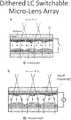
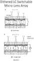
- FIG. 2shows a dithered liquid crystal (LC) switchable micro-lens array.
- Incident light 260is linearly polarized perpendicular to the flat plane of the figure as indicated by the X within the circle.
- the dithered LC switchable micro-lens arrayincludes a liquid crystal material 220 between a concave lens array 235 and a convex lens array 240 .
- the lens arraysare between electrodes 210 and 225 and transparent substrates 205 and 230 .
- the liquid crystal 220has a planar alignment, i.e., it is aligned parallel to the substrates 205 and 230 when no voltage is applied across the electrodes 210 and 225 (indicated by the open circuit in the top half of FIG. 2 ).
- the concave lens array 235 and convex lens arrays 240are offset laterally, so the concave lens array 235 focuses light to a one set of focal points 200 and the convex lens arrays 240 focuses light to another set of focal points 245 .
- the top half of FIG. 2illustrate operation of the dithered LC switchable micro-lens array when there is no voltage applied (open circuit 215 ) to the liquid crystal 220 .
- the polarizationis parallel to the optical axis of the liquid crystal 220 , so the liquid crystal 220 is index-matched to the convex lens array 235 .
- the convex surfaces of the convex lens array 235do not refract the incident light 260 due to the index matching as shown by the vertical lines (light rays) extending from the convex lens array 235 into the liquid crystal material 220 .
- the concave lens array 235focuses the incident light 260 to the corresponding foci 200 .
- FIG. 2illustrate operation of the dithered LC switchable micro-lens array when a voltage 255 is applied to the electrodes 210 and 240 , rotating the liquid crystal (now indicated by 250 ).
- the optical axis of the liquid crystal 250is perpendicular to the substrates 205 and 230 .
- Linearly polarized light 260 entering the dithered LC switchable micro-lens arrayexperiences the ordinary refractive index of the liquid crystal 250 , which is now matched to the refractive index of the concave lens array 235 instead of to the refractive index of the convex lens array 240 .
- the convex lens array 240focuses the light to foci 245 instead of to foci 200 .
- FIG. 3shows a liquid crystal switchable micro-lens array that operates on incident light 340 that is linearly polarized perpendicular to the plane of the figure per the X within the circle.
- the liquid crystal switchable micro-lens arrayincludes a birefringent convex lens 315 between a liquid crystal and another medium 310 .
- the liquid crystalis in a first (unpowered) state 320 and rotates the polarization of the incident light by 90 degrees so that the polarization is aligned with the ordinary axis of the birefringent convex lens 315 .
- the ordinary refractive index of the birefringent convex lens 315is index-matched to the refractive index of the medium 310 , so the light 360 does not refract at the convex surface of the birefringent convex lens 315 as indicated by the parallel rays 300 .
- the liquid crystalis in a second (powered) state 325 and does not rotate the polarization of the incident light 360 .
- the polarizationis aligned with the extraordinary axis of the birefringent convex lens 315 .
- the extraordinary refractive index of the birefringent convex lens 315is greater than the refractive index of the medium 310 , so the light 360 refracts at the convex surface of the birefringent convex lens 315 as indicated by the rays converging at a focus 305 .
- an augmented reality or mixed reality systemcomprises an electronic switchable micro-lens array.
- the modulation of the electronically switchable micro-lens arraycan cause the virtual image to appear and disappear while the real image is always present, whether it is seen, not seen, perceived, or not perceived. This occurs due to the electronic switchable micro-lens array being turned on and off (its duty cycle, in aspects).
- the modulationcan be at a speed completely or partially faster than the brain can interpret the real image and the virtual image being individual images, thus causing the brain of the user to sum or combine the real image and the virtual image permitting the eye (and/or brain) of the user to see AR or MR.
- an electronic switchable micro-lens arrayturns its optical power on to alter light rays projected from a see-through near eye display, thereby causing a virtual image to be seen by the eye of a user.
- the switchable MLAturns its optical power off for allowing the light rays from the real world to pass through the micro-lens array partially or completely undistorted or unaltered, thereby forming a real image as seen by the eye of a user (and/or perceived by a brain of the user).
- whether the micro-lenses are turned on or offthere is a real image being seen by the eye of a user. This occurs due to the spacing of the micro-lenses from one another and the spacing of the pixels of the see-through near eye display from one another.
- both the micro-lens array and the micro-displayare modulated synchronously.
- the pixels of the micro-display and the micro-lens arrayare populated in a dense manner, causing the fill factors to be high.
- the real imageis distorted by the micro-lens array, when the lenses are switched on. The real image therefore appears only when the micro-display and the micro-lens array are both switched off.
- the modulation of the electronically switchable micro-lens arraywill cause the virtual image to appear and disappear while the real image is modulated on and off (its duty cycle) at the same time as the virtual image.
- the real imageis only seen when the virtual image is not present.
- the modulationcan be at a speed faster than the brain can interpret the real image and the virtual image as being individual images, thus causing the brain of the user to sum or combine the real image and the virtual image permitting the eye of the user to see AR or MR.
- a switchable micro-lens arraycan turn the optical power of the micro-lenses of the micro-lens array that are aligned with pixels of such a see-through near eye display on to alter light rays projected from the see-through near eye display to cause a virtual image to be seen by the eye of a user (or perceived), and can turn optical power off for allowing the light rays from the real world to pass through the micro-lens array partially or completely undistorted or unaltered for forming a real image as seen by the eye of a user (or perceived).
Landscapes
- Physics & Mathematics (AREA)
- General Physics & Mathematics (AREA)
- Nonlinear Science (AREA)
- Optics & Photonics (AREA)
- Engineering & Computer Science (AREA)
- Mathematical Physics (AREA)
- Crystallography & Structural Chemistry (AREA)
- Chemical & Material Sciences (AREA)
- Computer Graphics (AREA)
- Computer Hardware Design (AREA)
- General Engineering & Computer Science (AREA)
- Software Systems (AREA)
- Theoretical Computer Science (AREA)
- Liquid Crystal (AREA)
Abstract
Description
Claims (14)
Priority Applications (3)
| Application Number | Priority Date | Filing Date | Title |
|---|---|---|---|
| US16/521,527US11119353B2 (en) | 2017-06-01 | 2019-07-24 | Switchable micro-lens array for augmented reality and mixed reality |
| US17/404,253US11852914B2 (en) | 2017-06-01 | 2021-08-17 | Switchable micro-lens array for augmented reality and mixed reality |
| US18/540,082US20240264484A1 (en) | 2017-06-01 | 2023-12-14 | Switchable micro-lens array for augmented reality and mixed reality |
Applications Claiming Priority (63)
| Application Number | Priority Date | Filing Date | Title |
|---|---|---|---|
| US201762513828P | 2017-06-01 | 2017-06-01 | |
| US201762522866P | 2017-06-21 | 2017-06-21 | |
| US201762530638P | 2017-07-10 | 2017-07-10 | |
| US201762542168P | 2017-08-07 | 2017-08-07 | |
| US201762546473P | 2017-08-16 | 2017-08-16 | |
| US201762607582P | 2017-12-19 | 2017-12-19 | |
| US201862613313P | 2018-01-03 | 2018-01-03 | |
| US201862619752P | 2018-01-20 | 2018-01-20 | |
| US201862624201P | 2018-01-31 | 2018-01-31 | |
| US201862626660P | 2018-02-05 | 2018-02-05 | |
| US201862638789P | 2018-03-05 | 2018-03-05 | |
| US201862648371P | 2018-03-26 | 2018-03-26 | |
| US15/994,595US10884246B2 (en) | 2017-06-01 | 2018-05-31 | Releasably attachable augmented reality system for eyewear |
| US16/008,707US10466487B2 (en) | 2017-06-01 | 2018-06-14 | Releasably attachable augmented reality system for eyewear |
| US201862694222P | 2018-07-05 | 2018-07-05 | |
| US201862700621P | 2018-07-19 | 2018-07-19 | |
| US201862700632P | 2018-07-19 | 2018-07-19 | |
| US201862703909P | 2018-07-27 | 2018-07-27 | |
| US201862703911P | 2018-07-27 | 2018-07-27 | |
| US201862711669P | 2018-07-30 | 2018-07-30 | |
| US201862717424P | 2018-08-10 | 2018-08-10 | |
| US201862720113P | 2018-08-20 | 2018-08-20 | |
| US201862720116P | 2018-08-21 | 2018-08-21 | |
| US201862728251P | 2018-09-07 | 2018-09-07 | |
| US201862732039P | 2018-09-17 | 2018-09-17 | |
| US201862732138P | 2018-09-17 | 2018-09-17 | |
| US201862739907P | 2018-10-02 | 2018-10-02 | |
| US201862739904P | 2018-10-02 | 2018-10-02 | |
| US201862752739P | 2018-10-30 | 2018-10-30 | |
| US201862753583P | 2018-10-31 | 2018-10-31 | |
| US201862754929P | 2018-11-02 | 2018-11-02 | |
| US201862755626P | 2018-11-05 | 2018-11-05 | |
| US201862755630P | 2018-11-05 | 2018-11-05 | |
| US201862756528P | 2018-11-06 | 2018-11-06 | |
| US201862756542P | 2018-11-06 | 2018-11-06 | |
| US201862769883P | 2018-11-20 | 2018-11-20 | |
| US201862770210P | 2018-11-21 | 2018-11-21 | |
| US201862771204P | 2018-11-26 | 2018-11-26 | |
| US201862774362P | 2018-12-03 | 2018-12-03 | |
| US201862775945P | 2018-12-06 | 2018-12-06 | |
| US201862778972P | 2018-12-13 | 2018-12-13 | |
| US201862778960P | 2018-12-13 | 2018-12-13 | |
| US201862780396P | 2018-12-17 | 2018-12-17 | |
| US201862780391P | 2018-12-17 | 2018-12-17 | |
| US201862783603P | 2018-12-21 | 2018-12-21 | |
| US201862783596P | 2018-12-21 | 2018-12-21 | |
| US201862785284P | 2018-12-27 | 2018-12-27 | |
| US201962787834P | 2019-01-03 | 2019-01-03 | |
| US201962788275P | 2019-01-04 | 2019-01-04 | |
| US201962788993P | 2019-01-07 | 2019-01-07 | |
| US201962788995P | 2019-01-07 | 2019-01-07 | |
| US201962790516P | 2019-01-10 | 2019-01-10 | |
| US201962790514P | 2019-01-10 | 2019-01-10 | |
| US201962793166P | 2019-01-16 | 2019-01-16 | |
| US201962794779P | 2019-01-21 | 2019-01-21 | |
| US201962796410P | 2019-01-24 | 2019-01-24 | |
| US201962796388P | 2019-01-24 | 2019-01-24 | |
| US16/289,623US10634912B2 (en) | 2017-06-01 | 2019-02-28 | See-through near eye optical module |
| US201962830645P | 2019-04-08 | 2019-04-08 | |
| US201962847427P | 2019-05-14 | 2019-05-14 | |
| US201962848636P | 2019-05-16 | 2019-05-16 | |
| US16/449,395US10634921B2 (en) | 2017-06-01 | 2019-06-22 | See-through near eye optical display |
| US16/521,527US11119353B2 (en) | 2017-06-01 | 2019-07-24 | Switchable micro-lens array for augmented reality and mixed reality |
Related Parent Applications (1)
| Application Number | Title | Priority Date | Filing Date |
|---|---|---|---|
| US16/449,395Continuation-In-PartUS10634921B2 (en) | 2017-06-01 | 2019-06-22 | See-through near eye optical display |
Related Child Applications (1)
| Application Number | Title | Priority Date | Filing Date |
|---|---|---|---|
| US17/404,253ContinuationUS11852914B2 (en) | 2017-06-01 | 2021-08-17 | Switchable micro-lens array for augmented reality and mixed reality |
Publications (2)
| Publication Number | Publication Date |
|---|---|
| US20200073170A1 US20200073170A1 (en) | 2020-03-05 |
| US11119353B2true US11119353B2 (en) | 2021-09-14 |
Family
ID=69639727
Family Applications (3)
| Application Number | Title | Priority Date | Filing Date |
|---|---|---|---|
| US16/521,527ActiveUS11119353B2 (en) | 2017-06-01 | 2019-07-24 | Switchable micro-lens array for augmented reality and mixed reality |
| US17/404,253ActiveUS11852914B2 (en) | 2017-06-01 | 2021-08-17 | Switchable micro-lens array for augmented reality and mixed reality |
| US18/540,082PendingUS20240264484A1 (en) | 2017-06-01 | 2023-12-14 | Switchable micro-lens array for augmented reality and mixed reality |
Family Applications After (2)
| Application Number | Title | Priority Date | Filing Date |
|---|---|---|---|
| US17/404,253ActiveUS11852914B2 (en) | 2017-06-01 | 2021-08-17 | Switchable micro-lens array for augmented reality and mixed reality |
| US18/540,082PendingUS20240264484A1 (en) | 2017-06-01 | 2023-12-14 | Switchable micro-lens array for augmented reality and mixed reality |
Country Status (1)
| Country | Link |
|---|---|
| US (3) | US11119353B2 (en) |
Cited By (4)
| Publication number | Priority date | Publication date | Assignee | Title |
|---|---|---|---|---|
| US11388388B2 (en) | 2020-12-01 | 2022-07-12 | Looking Glass Factory, Inc. | System and method for processing three dimensional images |
| US11415935B2 (en) | 2020-06-23 | 2022-08-16 | Looking Glass Factory, Inc. | System and method for holographic communication |
| US11754975B2 (en) | 2020-05-21 | 2023-09-12 | Looking Glass Factory, Inc. | System and method for holographic image display |
| US11852914B2 (en) | 2017-06-01 | 2023-12-26 | E-Vision Smart Optics, Inc. | Switchable micro-lens array for augmented reality and mixed reality |
Families Citing this family (3)
| Publication number | Priority date | Publication date | Assignee | Title |
|---|---|---|---|---|
| US20220343606A1 (en)* | 2021-04-21 | 2022-10-27 | NewSight Reality, Inc. | Optical module with active microlens array capable of synchronizing with see-through display to provide multiple modes of functionality |
| KR20230168222A (en)* | 2022-06-03 | 2023-12-13 | 삼성디스플레이 주식회사 | 3d display device |
| EP4503601A4 (en)* | 2022-09-26 | 2025-07-23 | Samsung Electronics Co Ltd | Stereoscopic display device and stereoscopic display method |
Citations (91)
| Publication number | Priority date | Publication date | Assignee | Title |
|---|---|---|---|---|
| US5499138A (en) | 1992-05-26 | 1996-03-12 | Olympus Optical Co., Ltd. | Image display apparatus |
| US6349001B1 (en) | 1997-10-30 | 2002-02-19 | The Microoptical Corporation | Eyeglass interface system |
| US6356392B1 (en) | 1996-10-08 | 2002-03-12 | The Microoptical Corporation | Compact image display system for eyeglasses or other head-borne frames |
| US6376819B1 (en) | 1999-07-09 | 2002-04-23 | Wavefront Sciences, Inc. | Sub-lens spatial resolution Shack-Hartmann wavefront sensing |
| EP1300716A1 (en) | 2001-10-08 | 2003-04-09 | Visys AG | Head mounted display apparatus |
| FR2842591B1 (en) | 2002-07-16 | 2004-10-22 | Ecole Nale Sup Artes Metiers | DEVICE FOR MEASURING VARIATIONS IN THE RELIEF OF AN OBJECT |
| US6945648B2 (en) | 2003-03-18 | 2005-09-20 | Carl-Zeiss-Stiftung | HMD device |
| US20060082768A1 (en) | 2004-08-31 | 2006-04-20 | Wilson Denise M | Miniaturized fluorescence analysis system |
| JP2006251329A (en)* | 2005-03-10 | 2006-09-21 | Ricoh Co Ltd | Image display device |
| US20060250574A1 (en) | 2005-05-03 | 2006-11-09 | Grand Joseph B | Method and apparatus for displaying images on reflective surfaces |
| US7192136B2 (en) | 2003-04-15 | 2007-03-20 | Howell Thomas A | Tethered electrical components for eyeglasses |
| US7195353B2 (en) | 2003-08-15 | 2007-03-27 | E-Vision, Llc | Enhanced electro-active lens system |
| US20070215793A1 (en) | 2006-03-14 | 2007-09-20 | Gruhlke Russell W | Electronic device with integrated optical navigation module and microlens array therefore |
| US7318646B2 (en) | 2004-03-04 | 2008-01-15 | Crf Societa Consortile Per Azioni | System for projecting a virtual image within an observer's field of view |
| WO2008084751A1 (en) | 2007-01-09 | 2008-07-17 | Scalar Corporation | Head-mounted display |
| US20090231722A1 (en) | 2008-03-13 | 2009-09-17 | Day & Night Display Systems, Llc | Visor heads-up display |
| US7663805B2 (en) | 2007-10-09 | 2010-02-16 | Myvu Corporation | Eyewear display and media device interconnection system |
| US7667783B2 (en) | 2005-11-03 | 2010-02-23 | University Of Central Florida Research Foundation, Inc. | Head mounted display with curved display screen, curved tunable focus liquid crystal micro-lens and first and second curved black masks corresponding independently to one of the right and the left eye |
| US8177361B2 (en) | 2007-01-25 | 2012-05-15 | Rodenstock Gmbh | Spectacle glass and spectacle lens for data reflection |
| US20120206452A1 (en)* | 2010-10-15 | 2012-08-16 | Geisner Kevin A | Realistic occlusion for a head mounted augmented reality display |
| US20130021226A1 (en) | 2011-07-21 | 2013-01-24 | Jonathan Arnold Bell | Wearable display devices |
| WO2013025672A2 (en) | 2011-08-18 | 2013-02-21 | Google Inc. | Wearable device with input and output structures |
| WO2013036888A2 (en) | 2011-09-08 | 2013-03-14 | Day & Night Display Systems, Llc | Night vision devices and methods |
| US20130099091A1 (en) | 2011-09-19 | 2013-04-25 | Yael Nemirovsky | Device having an avalanche photo diode and a method for sensing photons |
| US8508830B1 (en) | 2011-05-13 | 2013-08-13 | Google Inc. | Quantum dot near-to-eye display |
| US20130208175A1 (en)* | 2010-10-01 | 2013-08-15 | Fujifilm Corporation | Imaging device |
| US20130234935A1 (en) | 2010-10-26 | 2013-09-12 | Bae Systems Plc | Display assembly |
| US20140062865A1 (en) | 2012-08-30 | 2014-03-06 | Atheer, Inc. | Method and apparatus for selectively presenting content |
| US20140118829A1 (en) | 2012-10-26 | 2014-05-01 | Qualcomm Incorporated | See through near-eye display |
| US20140168783A1 (en) | 2012-07-02 | 2014-06-19 | Nvidia Corporation | Near-eye microlens array displays |
| US20140168034A1 (en) | 2012-07-02 | 2014-06-19 | Nvidia Corporation | Near-eye parallax barrier displays |
| US20140267723A1 (en) | 2013-01-30 | 2014-09-18 | Insitu, Inc. | Augmented video system providing enhanced situational awareness |
| US20140276686A1 (en) | 2013-03-15 | 2014-09-18 | Chunbai Wu | Laser devices utilizing alexandrite laser operating at or near its gain peak as shorter-wavelength pumping sources and methods of use thereof |
| US20150168730A1 (en) | 2008-03-13 | 2015-06-18 | Elbit Systems Ltd. | Wearable optical display system for unobstructed viewing |
| US20150169070A1 (en) | 2013-12-17 | 2015-06-18 | Google Inc. | Visual Display of Interactive, Gesture-Controlled, Three-Dimensional (3D) Models for Head-Mountable Displays (HMDs) |
| US20150205132A1 (en) | 2014-01-21 | 2015-07-23 | Osterhout Group, Inc. | See-through computer display systems |
| US20150235445A1 (en) | 2013-11-27 | 2015-08-20 | Magic Leap, Inc. | Modulating a depth of focus of a plurality of pixels displayed to a user |
| US20150268415A1 (en) | 2013-01-15 | 2015-09-24 | Magic Leap, Inc. | Ultra-high resolution scanning fiber display |
| US20150277123A1 (en) | 2008-04-06 | 2015-10-01 | David Chaum | Near to eye display and appliance |
| US20150293358A1 (en) | 2012-10-23 | 2015-10-15 | Lusospace, Projectos Engenharia Lda | See-through head or helmet mounted display device |
| US9189829B2 (en) | 2009-06-22 | 2015-11-17 | Sony Corporation | Head mounted display, and image displaying method in head mounted display |
| US20150357315A1 (en) | 2013-01-31 | 2015-12-10 | Nthdegree Technologies Worldwide Inc. | Transparent overlapping led die layers |
| WO2016004998A1 (en) | 2014-07-10 | 2016-01-14 | Lusospace, Projectos Engenharia Lda | Display device |
| US20160048018A1 (en) | 2013-03-26 | 2016-02-18 | Lusospace, Projectos Engenharia Lda | Display device |
| WO2016135727A1 (en) | 2015-02-26 | 2016-09-01 | Everysight Ltd. | Wearable optical display system for unobstructed viewing |
| US20160252728A1 (en) | 2015-02-27 | 2016-09-01 | LAFORGE Optical, Inc. | Augmented reality eyewear |
| US20160327798A1 (en) | 2014-01-02 | 2016-11-10 | Empire Technology Development Llc | Augmented reality (ar) system |
| US20160337625A1 (en) | 2015-05-14 | 2016-11-17 | Seiko Epson Corporation | Electro-optical device and electronic apparatus |
| US9552676B2 (en) | 2011-10-07 | 2017-01-24 | Google Inc. | Wearable computer with nearby object response |
| US9551872B1 (en) | 2013-12-30 | 2017-01-24 | Google Inc. | Spatially multiplexed lens for head mounted display |
| US9557152B2 (en) | 2012-09-28 | 2017-01-31 | Google Inc. | Use of comparative sensor data to determine orientation of head relative to body |
| US20170028299A1 (en) | 2014-05-23 | 2017-02-02 | Google Inc. | Interactive Social Games on Head-Mountable Devices |
| US20170031435A1 (en) | 2015-07-31 | 2017-02-02 | Google Inc. | Unique Reflective Lenses to Auto-Calibrate a Wearable Eye Tracking System |
| US20170039960A1 (en) | 2015-08-03 | 2017-02-09 | Oculus Vr, Llc | Ocular Projection Based on Pupil Position |
| US20170052802A1 (en) | 2014-05-01 | 2017-02-23 | Samsung Electronics Co., Ltd. | Wearable device and method of controlling the same |
| US9584705B2 (en) | 2013-03-14 | 2017-02-28 | Google Inc. | Wearable camera systems |
| US20170090557A1 (en) | 2014-01-29 | 2017-03-30 | Google Inc. | Systems and Devices for Implementing a Side-Mounted Optical Sensor |
| US20170122725A1 (en) | 2015-11-04 | 2017-05-04 | Magic Leap, Inc. | Light field display metrology |
| US20170140701A1 (en) | 2015-11-17 | 2017-05-18 | Nthdegree Technologies Worldwide Inc. | Led display with patterned pixel landings and printed leds |
| US20170147034A1 (en) | 2013-08-14 | 2017-05-25 | Nvidia Corporation | Hybrid optics for near-eye displays |
| US20170153454A1 (en) | 2014-03-26 | 2017-06-01 | Essilor International (Compagnie Générale d'Optique) | Methods and systems for augmented reality |
| US20170176777A1 (en) | 2004-11-02 | 2017-06-22 | E-Vision Smart Optics, Inc. | Eyewear including a remote control camera and a docking station |
| US20170200296A1 (en) | 2016-01-12 | 2017-07-13 | Esight Corp. | Language element vision augmentation methods and devices |
| US9710058B2 (en) | 2013-09-03 | 2017-07-18 | Tobii Ab | Portable eye tracking device |
| US9720257B2 (en) | 2014-03-14 | 2017-08-01 | Lg Electronics Inc. | Clip type display module and glass type terminal having the same |
| US20170227779A1 (en) | 2014-09-30 | 2017-08-10 | Konica Minolta, Inc. | Head Mounted Display And Wearable Computer |
| US20170229095A1 (en) | 2014-02-05 | 2017-08-10 | Google Inc. | On-Head Detection with Touch Sensing and Eye Sensing |
| US20170235161A1 (en) | 2012-12-31 | 2017-08-17 | Esight Corp. | Apparatus and method for fitting head mounted vision augmentation systems |
| US20170243371A1 (en) | 2015-10-30 | 2017-08-24 | Snap Inc. | Image based tracking in augmented reality systems |
| US20170249862A1 (en) | 2016-02-29 | 2017-08-31 | Osterhout Group, Inc. | Flip down auxiliary lens for a head-worn computer |
| US9753287B2 (en) | 2012-12-13 | 2017-09-05 | Kopin Corporation | Spectacle with invisible optics |
| US20170256029A1 (en) | 2016-03-02 | 2017-09-07 | Osterhout Group, Inc. | Optical systems for head-worn computers |
| WO2017151872A1 (en) | 2016-03-02 | 2017-09-08 | Osterhout Group, Inc. | Speaker systems for head-worn computer systems |
| US9759917B2 (en) | 2010-02-28 | 2017-09-12 | Microsoft Technology Licensing, Llc | AR glasses with event and sensor triggered AR eyepiece interface to external devices |
| US9766482B2 (en) | 2012-03-30 | 2017-09-19 | Google Inc. | Wearable device with input and output structures |
| US20170276963A1 (en) | 2016-03-22 | 2017-09-28 | Johnson & Johnson Vision Care, Inc. | Pulsed plus lens designs for myopia control, enhanced depth of focus and presbyopia correction |
| US20170285347A1 (en) | 2016-04-05 | 2017-10-05 | Ostendo Technologies, Inc. | Augmented/Virtual Reality Near-Eye Displays with Edge Imaging Lens Comprising a Plurality of Display Devices |
| WO2017169345A1 (en) | 2016-03-28 | 2017-10-05 | 富士フイルム株式会社 | Eyeglasses having image projection function |
| WO2017171157A1 (en) | 2016-03-30 | 2017-10-05 | 엘지전자 주식회사 | Wearable device |
| USD800118S1 (en) | 2003-09-30 | 2017-10-17 | Zhou Tian Xing | Wearable artificial intelligence data processing, augmented reality, virtual reality, and mixed reality communication eyeglass including mobile phone and mobile computing via virtual touch screen gesture control and neuron command |
| US20170336634A1 (en) | 2014-01-31 | 2017-11-23 | LAFORGE Optical Inc. | Augmented reality eyewear and methods for using same |
| JP2017212475A (en) | 2014-09-30 | 2017-11-30 | コニカミノルタ株式会社 | Head mount display |
| US20180024366A1 (en) | 2016-07-25 | 2018-01-25 | Qualcomm Incorporated | Compact augmented reality glasses with folded imaging optics |
| US20180045964A1 (en) | 2016-08-12 | 2018-02-15 | Esight Corp. | Large exit pupil wearable near-to-eye vision systems exploiting freeform eyepieces |
| US20180130226A1 (en) | 2016-11-07 | 2018-05-10 | Lincoln Global, Inc. | System and method for calibrating a welding trainer |
| WO2018217253A1 (en) | 2017-05-26 | 2018-11-29 | Google Llc | Near-eye display with sparse sampling super-resolution |
| US20180348529A1 (en) | 2017-06-01 | 2018-12-06 | PogoTec, Inc. | Releasably attachable augmented reality system for eyewear |
| US20190057957A1 (en) | 2016-12-21 | 2019-02-21 | PhantaField, Inc. | Augmented reality display system |
| US20190094803A1 (en) | 2016-03-02 | 2019-03-28 | Seereal Technologies S.A. | Illumination device |
| US10330933B2 (en) | 2016-09-30 | 2019-06-25 | Samsung Display Co., Ltd. | Head mounted display device |
| US20190310481A1 (en) | 2017-06-01 | 2019-10-10 | NewSight Reality, Inc. | See-Through Near Eye Optical Display |
Family Cites Families (7)
| Publication number | Priority date | Publication date | Assignee | Title |
|---|---|---|---|---|
| US6243055B1 (en)* | 1994-10-25 | 2001-06-05 | James L. Fergason | Optical display system and method with optical shifting of pixel position including conversion of pixel layout to form delta to stripe pattern by time base multiplexing |
| EP1590699B1 (en)* | 2003-02-05 | 2006-11-29 | Ocuity Limited | Switchable display apparatus |
| JP5173831B2 (en)* | 2005-12-14 | 2013-04-03 | コーニンクレッカ フィリップス エレクトロニクス エヌ ヴィ | 2D / 3D autostereoscopic display device |
| DE102007010650A1 (en)* | 2007-03-02 | 2008-09-04 | Carl Zeiss Smt Ag | Lighting device for use with micro lithographic projection exposure system, has micro lens array arranged in light direction of propagation before light mixture system, where multiple micro lenses are arranged with periodicity |
| US9886742B2 (en)* | 2016-03-17 | 2018-02-06 | Google Llc | Electro-optic beam steering for super-resolution/lightfield imagery |
| CN106873161B (en)* | 2017-03-02 | 2020-03-17 | 上海天马微电子有限公司 | Display device and near-to-eye wearable equipment |
| US11119353B2 (en) | 2017-06-01 | 2021-09-14 | E-Vision Smart Optics, Inc. | Switchable micro-lens array for augmented reality and mixed reality |
- 2019
- 2019-07-24USUS16/521,527patent/US11119353B2/enactiveActive
- 2021
- 2021-08-17USUS17/404,253patent/US11852914B2/enactiveActive
- 2023
- 2023-12-14USUS18/540,082patent/US20240264484A1/enactivePending
Patent Citations (110)
| Publication number | Priority date | Publication date | Assignee | Title |
|---|---|---|---|---|
| US5499138A (en) | 1992-05-26 | 1996-03-12 | Olympus Optical Co., Ltd. | Image display apparatus |
| US6356392B1 (en) | 1996-10-08 | 2002-03-12 | The Microoptical Corporation | Compact image display system for eyeglasses or other head-borne frames |
| US6349001B1 (en) | 1997-10-30 | 2002-02-19 | The Microoptical Corporation | Eyeglass interface system |
| US6376819B1 (en) | 1999-07-09 | 2002-04-23 | Wavefront Sciences, Inc. | Sub-lens spatial resolution Shack-Hartmann wavefront sensing |
| EP1300716A1 (en) | 2001-10-08 | 2003-04-09 | Visys AG | Head mounted display apparatus |
| FR2842591B1 (en) | 2002-07-16 | 2004-10-22 | Ecole Nale Sup Artes Metiers | DEVICE FOR MEASURING VARIATIONS IN THE RELIEF OF AN OBJECT |
| US6945648B2 (en) | 2003-03-18 | 2005-09-20 | Carl-Zeiss-Stiftung | HMD device |
| US7192136B2 (en) | 2003-04-15 | 2007-03-20 | Howell Thomas A | Tethered electrical components for eyeglasses |
| US7195353B2 (en) | 2003-08-15 | 2007-03-27 | E-Vision, Llc | Enhanced electro-active lens system |
| USD800118S1 (en) | 2003-09-30 | 2017-10-17 | Zhou Tian Xing | Wearable artificial intelligence data processing, augmented reality, virtual reality, and mixed reality communication eyeglass including mobile phone and mobile computing via virtual touch screen gesture control and neuron command |
| US7318646B2 (en) | 2004-03-04 | 2008-01-15 | Crf Societa Consortile Per Azioni | System for projecting a virtual image within an observer's field of view |
| US20060082768A1 (en) | 2004-08-31 | 2006-04-20 | Wilson Denise M | Miniaturized fluorescence analysis system |
| US20170176777A1 (en) | 2004-11-02 | 2017-06-22 | E-Vision Smart Optics, Inc. | Eyewear including a remote control camera and a docking station |
| JP2006251329A (en)* | 2005-03-10 | 2006-09-21 | Ricoh Co Ltd | Image display device |
| US20060250574A1 (en) | 2005-05-03 | 2006-11-09 | Grand Joseph B | Method and apparatus for displaying images on reflective surfaces |
| US7667783B2 (en) | 2005-11-03 | 2010-02-23 | University Of Central Florida Research Foundation, Inc. | Head mounted display with curved display screen, curved tunable focus liquid crystal micro-lens and first and second curved black masks corresponding independently to one of the right and the left eye |
| US20070215793A1 (en) | 2006-03-14 | 2007-09-20 | Gruhlke Russell W | Electronic device with integrated optical navigation module and microlens array therefore |
| WO2008084751A1 (en) | 2007-01-09 | 2008-07-17 | Scalar Corporation | Head-mounted display |
| US20100164840A1 (en) | 2007-01-09 | 2010-07-01 | Scalar Corporation | Head-mounted display |
| US8847851B2 (en) | 2007-01-09 | 2014-09-30 | Scalar Corporation | Head-mounted display |
| US8177361B2 (en) | 2007-01-25 | 2012-05-15 | Rodenstock Gmbh | Spectacle glass and spectacle lens for data reflection |
| US7663805B2 (en) | 2007-10-09 | 2010-02-16 | Myvu Corporation | Eyewear display and media device interconnection system |
| US7791809B2 (en) | 2008-03-13 | 2010-09-07 | Day And Night Display Systems, Inc. | Visor heads-up display |
| US20100315720A1 (en) | 2008-03-13 | 2010-12-16 | Day And Night Displays Systems, Llc | Visor heads-up display |
| US20090231722A1 (en) | 2008-03-13 | 2009-09-17 | Day & Night Display Systems, Llc | Visor heads-up display |
| US20150168730A1 (en) | 2008-03-13 | 2015-06-18 | Elbit Systems Ltd. | Wearable optical display system for unobstructed viewing |
| US8970962B2 (en) | 2008-03-13 | 2015-03-03 | Elbit Systems Ltd | Visor heads-up display |
| US20150277123A1 (en) | 2008-04-06 | 2015-10-01 | David Chaum | Near to eye display and appliance |
| WO2010105201A1 (en) | 2009-03-13 | 2010-09-16 | Day & Night Display Systems, Llc | Visor heads-up display |
| US9189829B2 (en) | 2009-06-22 | 2015-11-17 | Sony Corporation | Head mounted display, and image displaying method in head mounted display |
| US9759917B2 (en) | 2010-02-28 | 2017-09-12 | Microsoft Technology Licensing, Llc | AR glasses with event and sensor triggered AR eyepiece interface to external devices |
| US20130208175A1 (en)* | 2010-10-01 | 2013-08-15 | Fujifilm Corporation | Imaging device |
| US20120206452A1 (en)* | 2010-10-15 | 2012-08-16 | Geisner Kevin A | Realistic occlusion for a head mounted augmented reality display |
| US20130234935A1 (en) | 2010-10-26 | 2013-09-12 | Bae Systems Plc | Display assembly |
| US8508830B1 (en) | 2011-05-13 | 2013-08-13 | Google Inc. | Quantum dot near-to-eye display |
| US20130021226A1 (en) | 2011-07-21 | 2013-01-24 | Jonathan Arnold Bell | Wearable display devices |
| WO2013025672A3 (en) | 2011-08-18 | 2013-05-16 | Google Inc. | Wearable device with input and output structures |
| US20140022163A1 (en) | 2011-08-18 | 2014-01-23 | Google Inc. | Wearable device with input and output structures |
| US9285592B2 (en) | 2011-08-18 | 2016-03-15 | Google Inc. | Wearable device with input and output structures |
| WO2013025672A2 (en) | 2011-08-18 | 2013-02-21 | Google Inc. | Wearable device with input and output structures |
| US20130044042A1 (en) | 2011-08-18 | 2013-02-21 | Google Inc. | Wearable device with input and output structures |
| US9164284B2 (en) | 2011-08-18 | 2015-10-20 | Google Inc. | Wearable device with input and output structures |
| US9507153B2 (en) | 2011-09-08 | 2016-11-29 | Elbit Systems Ltd Advanced Technology Center | Night vision devices and methods |
| WO2013036888A2 (en) | 2011-09-08 | 2013-03-14 | Day & Night Display Systems, Llc | Night vision devices and methods |
| US20140327971A1 (en) | 2011-09-08 | 2014-11-06 | Elbit Systems Ltd. | Night vision devices and methods |
| US20130099091A1 (en) | 2011-09-19 | 2013-04-25 | Yael Nemirovsky | Device having an avalanche photo diode and a method for sensing photons |
| US9552676B2 (en) | 2011-10-07 | 2017-01-24 | Google Inc. | Wearable computer with nearby object response |
| US9766482B2 (en) | 2012-03-30 | 2017-09-19 | Google Inc. | Wearable device with input and output structures |
| US20140168034A1 (en) | 2012-07-02 | 2014-06-19 | Nvidia Corporation | Near-eye parallax barrier displays |
| US20140168783A1 (en) | 2012-07-02 | 2014-06-19 | Nvidia Corporation | Near-eye microlens array displays |
| US20140062865A1 (en) | 2012-08-30 | 2014-03-06 | Atheer, Inc. | Method and apparatus for selectively presenting content |
| US9557152B2 (en) | 2012-09-28 | 2017-01-31 | Google Inc. | Use of comparative sensor data to determine orientation of head relative to body |
| US20150293358A1 (en) | 2012-10-23 | 2015-10-15 | Lusospace, Projectos Engenharia Lda | See-through head or helmet mounted display device |
| US20140118829A1 (en) | 2012-10-26 | 2014-05-01 | Qualcomm Incorporated | See through near-eye display |
| US9753287B2 (en) | 2012-12-13 | 2017-09-05 | Kopin Corporation | Spectacle with invisible optics |
| US20170235161A1 (en) | 2012-12-31 | 2017-08-17 | Esight Corp. | Apparatus and method for fitting head mounted vision augmentation systems |
| US20150268415A1 (en) | 2013-01-15 | 2015-09-24 | Magic Leap, Inc. | Ultra-high resolution scanning fiber display |
| US20140267723A1 (en) | 2013-01-30 | 2014-09-18 | Insitu, Inc. | Augmented video system providing enhanced situational awareness |
| US20150357315A1 (en) | 2013-01-31 | 2015-12-10 | Nthdegree Technologies Worldwide Inc. | Transparent overlapping led die layers |
| US9584705B2 (en) | 2013-03-14 | 2017-02-28 | Google Inc. | Wearable camera systems |
| US20140276686A1 (en) | 2013-03-15 | 2014-09-18 | Chunbai Wu | Laser devices utilizing alexandrite laser operating at or near its gain peak as shorter-wavelength pumping sources and methods of use thereof |
| US20160048018A1 (en) | 2013-03-26 | 2016-02-18 | Lusospace, Projectos Engenharia Lda | Display device |
| US9983408B2 (en) | 2013-03-26 | 2018-05-29 | Lusospace, Projectos Engenharia Lda | Display device |
| US20170147034A1 (en) | 2013-08-14 | 2017-05-25 | Nvidia Corporation | Hybrid optics for near-eye displays |
| US9710058B2 (en) | 2013-09-03 | 2017-07-18 | Tobii Ab | Portable eye tracking device |
| US20150235445A1 (en) | 2013-11-27 | 2015-08-20 | Magic Leap, Inc. | Modulating a depth of focus of a plurality of pixels displayed to a user |
| US20150169070A1 (en) | 2013-12-17 | 2015-06-18 | Google Inc. | Visual Display of Interactive, Gesture-Controlled, Three-Dimensional (3D) Models for Head-Mountable Displays (HMDs) |
| US9551872B1 (en) | 2013-12-30 | 2017-01-24 | Google Inc. | Spatially multiplexed lens for head mounted display |
| US20160327798A1 (en) | 2014-01-02 | 2016-11-10 | Empire Technology Development Llc | Augmented reality (ar) system |
| US20150205132A1 (en) | 2014-01-21 | 2015-07-23 | Osterhout Group, Inc. | See-through computer display systems |
| US20170090557A1 (en) | 2014-01-29 | 2017-03-30 | Google Inc. | Systems and Devices for Implementing a Side-Mounted Optical Sensor |
| US20170336634A1 (en) | 2014-01-31 | 2017-11-23 | LAFORGE Optical Inc. | Augmented reality eyewear and methods for using same |
| US20170229095A1 (en) | 2014-02-05 | 2017-08-10 | Google Inc. | On-Head Detection with Touch Sensing and Eye Sensing |
| US9720257B2 (en) | 2014-03-14 | 2017-08-01 | Lg Electronics Inc. | Clip type display module and glass type terminal having the same |
| US20170153454A1 (en) | 2014-03-26 | 2017-06-01 | Essilor International (Compagnie Générale d'Optique) | Methods and systems for augmented reality |
| US20170052802A1 (en) | 2014-05-01 | 2017-02-23 | Samsung Electronics Co., Ltd. | Wearable device and method of controlling the same |
| US20170028299A1 (en) | 2014-05-23 | 2017-02-02 | Google Inc. | Interactive Social Games on Head-Mountable Devices |
| AU2014400408B2 (en) | 2014-07-10 | 2018-11-01 | Lusospace, Projectos Engenharia Lda | Display device |
| WO2016004998A1 (en) | 2014-07-10 | 2016-01-14 | Lusospace, Projectos Engenharia Lda | Display device |
| US20170227779A1 (en) | 2014-09-30 | 2017-08-10 | Konica Minolta, Inc. | Head Mounted Display And Wearable Computer |
| JP2017212475A (en) | 2014-09-30 | 2017-11-30 | コニカミノルタ株式会社 | Head mount display |
| WO2016135727A1 (en) | 2015-02-26 | 2016-09-01 | Everysight Ltd. | Wearable optical display system for unobstructed viewing |
| US20160252728A1 (en) | 2015-02-27 | 2016-09-01 | LAFORGE Optical, Inc. | Augmented reality eyewear |
| US9977245B2 (en) | 2015-02-27 | 2018-05-22 | LAFORGE Optical, Inc. | Augmented reality eyewear |
| US20160337625A1 (en) | 2015-05-14 | 2016-11-17 | Seiko Epson Corporation | Electro-optical device and electronic apparatus |
| US20170031435A1 (en) | 2015-07-31 | 2017-02-02 | Google Inc. | Unique Reflective Lenses to Auto-Calibrate a Wearable Eye Tracking System |
| US9989765B2 (en) | 2015-08-03 | 2018-06-05 | Oculus Vr, Llc | Tile array for near-ocular display |
| US20170039960A1 (en) | 2015-08-03 | 2017-02-09 | Oculus Vr, Llc | Ocular Projection Based on Pupil Position |
| US20170038590A1 (en) | 2015-08-03 | 2017-02-09 | Oculus Vr, Llc | Enhanced Pixel Resolution through Non-Uniform Ocular Projection |
| US10162182B2 (en) | 2015-08-03 | 2018-12-25 | Facebook Technologies, Llc | Enhanced pixel resolution through non-uniform ocular projection |
| US20170243371A1 (en) | 2015-10-30 | 2017-08-24 | Snap Inc. | Image based tracking in augmented reality systems |
| US20170122725A1 (en) | 2015-11-04 | 2017-05-04 | Magic Leap, Inc. | Light field display metrology |
| US20170140701A1 (en) | 2015-11-17 | 2017-05-18 | Nthdegree Technologies Worldwide Inc. | Led display with patterned pixel landings and printed leds |
| US20170200296A1 (en) | 2016-01-12 | 2017-07-13 | Esight Corp. | Language element vision augmentation methods and devices |
| US20170249862A1 (en) | 2016-02-29 | 2017-08-31 | Osterhout Group, Inc. | Flip down auxiliary lens for a head-worn computer |
| WO2017151872A1 (en) | 2016-03-02 | 2017-09-08 | Osterhout Group, Inc. | Speaker systems for head-worn computer systems |
| US20170256029A1 (en) | 2016-03-02 | 2017-09-07 | Osterhout Group, Inc. | Optical systems for head-worn computers |
| US20190094803A1 (en) | 2016-03-02 | 2019-03-28 | Seereal Technologies S.A. | Illumination device |
| US20170276963A1 (en) | 2016-03-22 | 2017-09-28 | Johnson & Johnson Vision Care, Inc. | Pulsed plus lens designs for myopia control, enhanced depth of focus and presbyopia correction |
| WO2017169345A1 (en) | 2016-03-28 | 2017-10-05 | 富士フイルム株式会社 | Eyeglasses having image projection function |
| WO2017171157A1 (en) | 2016-03-30 | 2017-10-05 | 엘지전자 주식회사 | Wearable device |
| US20170285347A1 (en) | 2016-04-05 | 2017-10-05 | Ostendo Technologies, Inc. | Augmented/Virtual Reality Near-Eye Displays with Edge Imaging Lens Comprising a Plurality of Display Devices |
| US20180024366A1 (en) | 2016-07-25 | 2018-01-25 | Qualcomm Incorporated | Compact augmented reality glasses with folded imaging optics |
| US20180045964A1 (en) | 2016-08-12 | 2018-02-15 | Esight Corp. | Large exit pupil wearable near-to-eye vision systems exploiting freeform eyepieces |
| US10330933B2 (en) | 2016-09-30 | 2019-06-25 | Samsung Display Co., Ltd. | Head mounted display device |
| US20180130226A1 (en) | 2016-11-07 | 2018-05-10 | Lincoln Global, Inc. | System and method for calibrating a welding trainer |
| US20190057957A1 (en) | 2016-12-21 | 2019-02-21 | PhantaField, Inc. | Augmented reality display system |
| WO2018217253A1 (en) | 2017-05-26 | 2018-11-29 | Google Llc | Near-eye display with sparse sampling super-resolution |
| US20180348529A1 (en) | 2017-06-01 | 2018-12-06 | PogoTec, Inc. | Releasably attachable augmented reality system for eyewear |
| US20190310481A1 (en) | 2017-06-01 | 2019-10-10 | NewSight Reality, Inc. | See-Through Near Eye Optical Display |
Non-Patent Citations (7)
| Title |
|---|
| Commander et al., "Microlenses immersed in nematic liquid crystal with electrically controllable focal length," in Third European Optical Society ‘Microlens Arrays’ Topical Meeting, 1995, 7 pages. |
| Co-Pending International Application No. PCT/US2018/035424 filed May 31, 2018, Search Report and Written Opinion of the International Searching Authority, dated Aug. 31, 2018, 16 pages. |
| Co-Pending International Application No. PCT/US2018/037561 filed Jun. 14, 2018, Search Report and Written Opinion of the International Searching Authority, dated Sep. 21, 2018, 13 pages. |
| Co-Pending International Application No. PCT/US2019/020168 filed Feb. 28, 2019, Search Report and Written Opinion of the International Searching Authority, dated May 23, 2019, 15 pages. |
| Fan et al., "Liquid Crystal Microlens Arrays With Switchable Positive and Negative Focal Lengths," Journal of Display Technology, pp. 151-156, Aug. 22, 2005, IEEE. |
| Ren, Hongwen, Tunable micro-lens arrays using polymer network liquid crystal, Optical Communication, vol. 230 (2004), pp. 267-271. |
| Villa et al., "CMOS imager with 1024 SPADs and TDCs for single-photon timing and 3-D time-of-flight." IEEE Journal of Selected Topics in Quantum Electronics 20.6 (2014): 364-373. |
Cited By (6)
| Publication number | Priority date | Publication date | Assignee | Title |
|---|---|---|---|---|
| US11852914B2 (en) | 2017-06-01 | 2023-12-26 | E-Vision Smart Optics, Inc. | Switchable micro-lens array for augmented reality and mixed reality |
| US11754975B2 (en) | 2020-05-21 | 2023-09-12 | Looking Glass Factory, Inc. | System and method for holographic image display |
| US12204281B2 (en) | 2020-05-21 | 2025-01-21 | Looking Glass Factory, Inc. | System and method for holographic image display |
| US11415935B2 (en) | 2020-06-23 | 2022-08-16 | Looking Glass Factory, Inc. | System and method for holographic communication |
| US11388388B2 (en) | 2020-12-01 | 2022-07-12 | Looking Glass Factory, Inc. | System and method for processing three dimensional images |
| US11849102B2 (en) | 2020-12-01 | 2023-12-19 | Looking Glass Factory, Inc. | System and method for processing three dimensional images |
Also Published As
| Publication number | Publication date |
|---|---|
| US20200073170A1 (en) | 2020-03-05 |
| US20220171235A1 (en) | 2022-06-02 |
| US11852914B2 (en) | 2023-12-26 |
| US20240264484A1 (en) | 2024-08-08 |
Similar Documents
| Publication | Publication Date | Title |
|---|---|---|
| US11119353B2 (en) | Switchable micro-lens array for augmented reality and mixed reality | |
| US11287666B2 (en) | Wearable data display | |
| CN110959132B (en) | Glasses type display and variable focal length glasses type display | |
| JP4654183B2 (en) | Lens array structure | |
| US8582043B2 (en) | 2D/3D switchable LC lens unit for use in a display device | |
| JP5142356B2 (en) | Stereoscopic image conversion panel | |
| US12399368B2 (en) | Near-eye display with array optics | |
| US9772500B2 (en) | Double-layered liquid crystal lens and 3D display apparatus | |
| US8730576B2 (en) | Microretarder film | |
| CN105652490A (en) | Display spectacles and driving method thereof | |
| CN107505713B (en) | Display apparatus and display method | |
| CN112596311A (en) | Display panel and display device | |
| US20200209626A1 (en) | Near-eye augmented reality device | |
| US9182628B2 (en) | Two dimension/three dimension switchable liquid crystal lens assembly | |
| CN209858911U (en) | display screen | |
| US8928824B2 (en) | Liquid crystal lens unit and stereoscopic display | |
| TWI687746B (en) | Near-eye augmented reality device | |
| CN105676464A (en) | Image display device comprising beam splitter | |
| CN223006352U (en) | Display device | |
| KR20070082646A (en) | Stereoscopic image conversion panel and stereoscopic image display device having same |
Legal Events
| Date | Code | Title | Description |
|---|---|---|---|
| FEPP | Fee payment procedure | Free format text:ENTITY STATUS SET TO UNDISCOUNTED (ORIGINAL EVENT CODE: BIG.); ENTITY STATUS OF PATENT OWNER: SMALL ENTITY | |
| AS | Assignment | Owner name:NEWSIGHT REALITY, INC., VIRGINIA Free format text:ASSIGNMENT OF ASSIGNORS INTEREST;ASSIGNOR:BLUM, RON;REEL/FRAME:049918/0650 Effective date:20190724 | |
| FEPP | Fee payment procedure | Free format text:ENTITY STATUS SET TO SMALL (ORIGINAL EVENT CODE: SMAL); ENTITY STATUS OF PATENT OWNER: SMALL ENTITY | |
| AS | Assignment | Owner name:EVISION SMART OPTICS, INC, FLORIDA Free format text:ASSIGNMENT OF ASSIGNORS INTEREST;ASSIGNOR:NEWSIGHT REALITY, INC.;REEL/FRAME:049966/0650 Effective date:20190724 | |
| STPP | Information on status: patent application and granting procedure in general | Free format text:FINAL REJECTION MAILED | |
| STPP | Information on status: patent application and granting procedure in general | Free format text:RESPONSE AFTER FINAL ACTION FORWARDED TO EXAMINER | |
| STPP | Information on status: patent application and granting procedure in general | Free format text:NOTICE OF ALLOWANCE MAILED -- APPLICATION RECEIVED IN OFFICE OF PUBLICATIONS | |
| STPP | Information on status: patent application and granting procedure in general | Free format text:AWAITING TC RESP., ISSUE FEE NOT PAID | |
| STPP | Information on status: patent application and granting procedure in general | Free format text:NOTICE OF ALLOWANCE MAILED -- APPLICATION RECEIVED IN OFFICE OF PUBLICATIONS | |
| STPP | Information on status: patent application and granting procedure in general | Free format text:PUBLICATIONS -- ISSUE FEE PAYMENT VERIFIED | |
| STCF | Information on status: patent grant | Free format text:PATENTED CASE | |
| AS | Assignment | Owner name:E-VISION SMART OPTICS, INC., FLORIDA Free format text:CORRECTIVE ASSIGNMENT TO CORRECT THE RECEIVING PARTY'S NAME FROM "EVISION SMART OPTICS" TO " E-VISION SMART OPTICS, INC" PREVIOUSLY RECORDED AT REEL: FRAME: . ASSIGNOR(S) HEREBY CONFIRMS THE ASSIGNMENT;ASSIGNOR:NEWSIGHT REALITY, INC.;REEL/FRAME:065222/0229 Effective date:20190724 | |
| MAFP | Maintenance fee payment | Free format text:PAYMENT OF MAINTENANCE FEE, 4TH YR, SMALL ENTITY (ORIGINAL EVENT CODE: M2551); ENTITY STATUS OF PATENT OWNER: SMALL ENTITY Year of fee payment:4 |