US11117145B2 - Atomizer mixing chamber for a seed treater - Google Patents
Atomizer mixing chamber for a seed treaterDownload PDFInfo
- Publication number
- US11117145B2 US11117145B2US16/266,309US201916266309AUS11117145B2US 11117145 B2US11117145 B2US 11117145B2US 201916266309 AUS201916266309 AUS 201916266309AUS 11117145 B2US11117145 B2US 11117145B2
- Authority
- US
- United States
- Prior art keywords
- atomizer
- stage cup
- holes
- stage
- mixing chamber
- Prior art date
- Legal status (The legal status is an assumption and is not a legal conclusion. Google has not performed a legal analysis and makes no representation as to the accuracy of the status listed.)
- Active, expires
Links
Images


Classifications
- B—PERFORMING OPERATIONS; TRANSPORTING
- B01—PHYSICAL OR CHEMICAL PROCESSES OR APPARATUS IN GENERAL
- B01F—MIXING, e.g. DISSOLVING, EMULSIFYING OR DISPERSING
- B01F25/00—Flow mixers; Mixers for falling materials, e.g. solid particles
- B01F25/40—Static mixers
- B01F25/42—Static mixers in which the mixing is affected by moving the components jointly in changing directions, e.g. in tubes provided with baffles or obstructions
- B01F25/43—Mixing tubes, e.g. wherein the material is moved in a radial or partly reversed direction
- B01F25/433—Mixing tubes wherein the shape of the tube influences the mixing, e.g. mixing tubes with varying cross-section or provided with inwardly extending profiles
- B01F25/4333—Mixers with scallop-shaped tubes or surfaces facing each other
- B—PERFORMING OPERATIONS; TRANSPORTING
- B05—SPRAYING OR ATOMISING IN GENERAL; APPLYING FLUENT MATERIALS TO SURFACES, IN GENERAL
- B05B—SPRAYING APPARATUS; ATOMISING APPARATUS; NOZZLES
- B05B7/00—Spraying apparatus for discharge of liquids or other fluent materials from two or more sources, e.g. of liquid and air, of powder and gas
- B05B7/24—Spraying apparatus for discharge of liquids or other fluent materials from two or more sources, e.g. of liquid and air, of powder and gas with means, e.g. a container, for supplying liquid or other fluent material to a discharge device
- B05B7/2489—Spraying apparatus for discharge of liquids or other fluent materials from two or more sources, e.g. of liquid and air, of powder and gas with means, e.g. a container, for supplying liquid or other fluent material to a discharge device an atomising fluid, e.g. a gas, being supplied to the discharge device
- B—PERFORMING OPERATIONS; TRANSPORTING
- B01—PHYSICAL OR CHEMICAL PROCESSES OR APPARATUS IN GENERAL
- B01F—MIXING, e.g. DISSOLVING, EMULSIFYING OR DISPERSING
- B01F23/00—Mixing according to the phases to be mixed, e.g. dispersing or emulsifying
- B01F23/40—Mixing liquids with liquids; Emulsifying
- B01F23/45—Mixing liquids with liquids; Emulsifying using flow mixing
- B—PERFORMING OPERATIONS; TRANSPORTING
- B01—PHYSICAL OR CHEMICAL PROCESSES OR APPARATUS IN GENERAL
- B01F—MIXING, e.g. DISSOLVING, EMULSIFYING OR DISPERSING
- B01F25/00—Flow mixers; Mixers for falling materials, e.g. solid particles
- B01F25/14—Mixing drops, droplets or bodies of liquid which flow together or contact each other
- B—PERFORMING OPERATIONS; TRANSPORTING
- B01—PHYSICAL OR CHEMICAL PROCESSES OR APPARATUS IN GENERAL
- B01F—MIXING, e.g. DISSOLVING, EMULSIFYING OR DISPERSING
- B01F25/00—Flow mixers; Mixers for falling materials, e.g. solid particles
- B01F25/40—Static mixers
- B01F25/45—Mixers in which the materials to be mixed are pressed together through orifices or interstitial spaces, e.g. between beads
- B01F25/452—Mixers in which the materials to be mixed are pressed together through orifices or interstitial spaces, e.g. between beads characterised by elements provided with orifices or interstitial spaces
- B01F25/4521—Mixers in which the materials to be mixed are pressed together through orifices or interstitial spaces, e.g. between beads characterised by elements provided with orifices or interstitial spaces the components being pressed through orifices in elements, e.g. flat plates or cylinders, which obstruct the whole diameter of the tube
- B—PERFORMING OPERATIONS; TRANSPORTING
- B01—PHYSICAL OR CHEMICAL PROCESSES OR APPARATUS IN GENERAL
- B01F—MIXING, e.g. DISSOLVING, EMULSIFYING OR DISPERSING
- B01F25/00—Flow mixers; Mixers for falling materials, e.g. solid particles
- B01F25/70—Spray-mixers, e.g. for mixing intersecting sheets of material
- B01F25/72—Spray-mixers, e.g. for mixing intersecting sheets of material with nozzles
- B01F25/721—Spray-mixers, e.g. for mixing intersecting sheets of material with nozzles for spraying a fluid on falling particles or on a liquid curtain
- B—PERFORMING OPERATIONS; TRANSPORTING
- B01—PHYSICAL OR CHEMICAL PROCESSES OR APPARATUS IN GENERAL
- B01F—MIXING, e.g. DISSOLVING, EMULSIFYING OR DISPERSING
- B01F25/00—Flow mixers; Mixers for falling materials, e.g. solid particles
- B01F25/70—Spray-mixers, e.g. for mixing intersecting sheets of material
- B01F25/74—Spray-mixers, e.g. for mixing intersecting sheets of material with rotating parts, e.g. discs
- B01F25/741—Spray-mixers, e.g. for mixing intersecting sheets of material with rotating parts, e.g. discs with a disc or a set of discs mounted on a shaft rotating about a vertical axis, on top of which the material to be thrown outwardly is fed
- B01F25/7411—Spray-mixers, e.g. for mixing intersecting sheets of material with rotating parts, e.g. discs with a disc or a set of discs mounted on a shaft rotating about a vertical axis, on top of which the material to be thrown outwardly is fed with repeated action, i.e. the material thrown outwardly being guided, by means provided on the surrounding casing or on top of the next lower disc
- B—PERFORMING OPERATIONS; TRANSPORTING
- B01—PHYSICAL OR CHEMICAL PROCESSES OR APPARATUS IN GENERAL
- B01F—MIXING, e.g. DISSOLVING, EMULSIFYING OR DISPERSING
- B01F25/00—Flow mixers; Mixers for falling materials, e.g. solid particles
- B01F25/70—Spray-mixers, e.g. for mixing intersecting sheets of material
- B01F25/74—Spray-mixers, e.g. for mixing intersecting sheets of material with rotating parts, e.g. discs
- B01F25/742—Spray-mixers, e.g. for mixing intersecting sheets of material with rotating parts, e.g. discs for spraying a liquid on falling particles or on a liquid curtain
- B01F3/0861—
- B01F5/0085—
- B01F5/0688—
- B01F5/205—
- B01F5/221—
- B01F5/223—
- B01F5/225—
- B—PERFORMING OPERATIONS; TRANSPORTING
- B05—SPRAYING OR ATOMISING IN GENERAL; APPLYING FLUENT MATERIALS TO SURFACES, IN GENERAL
- B05B—SPRAYING APPARATUS; ATOMISING APPARATUS; NOZZLES
- B05B13/00—Machines or plants for applying liquids or other fluent materials to surfaces of objects or other work by spraying, not covered by groups B05B1/00 - B05B11/00
- B05B13/02—Means for supporting work; Arrangement or mounting of spray heads; Adaptation or arrangement of means for feeding work
- B05B13/0221—Means for supporting work; Arrangement or mounting of spray heads; Adaptation or arrangement of means for feeding work characterised by the means for moving or conveying the objects or other work, e.g. conveyor belts
- B05B13/025—Means for supporting work; Arrangement or mounting of spray heads; Adaptation or arrangement of means for feeding work characterised by the means for moving or conveying the objects or other work, e.g. conveyor belts the objects or work being present in bulk
- B—PERFORMING OPERATIONS; TRANSPORTING
- B05—SPRAYING OR ATOMISING IN GENERAL; APPLYING FLUENT MATERIALS TO SURFACES, IN GENERAL
- B05B—SPRAYING APPARATUS; ATOMISING APPARATUS; NOZZLES
- B05B3/00—Spraying or sprinkling apparatus with moving outlet elements or moving deflecting elements
- B05B3/02—Spraying or sprinkling apparatus with moving outlet elements or moving deflecting elements with rotating elements
- B05B3/10—Spraying or sprinkling apparatus with moving outlet elements or moving deflecting elements with rotating elements discharging over substantially the whole periphery of the rotating member
- B05B3/1035—Driving means; Parts thereof, e.g. turbine, shaft, bearings
- B—PERFORMING OPERATIONS; TRANSPORTING
- B05—SPRAYING OR ATOMISING IN GENERAL; APPLYING FLUENT MATERIALS TO SURFACES, IN GENERAL
- B05B—SPRAYING APPARATUS; ATOMISING APPARATUS; NOZZLES
- B05B3/00—Spraying or sprinkling apparatus with moving outlet elements or moving deflecting elements
- B05B3/02—Spraying or sprinkling apparatus with moving outlet elements or moving deflecting elements with rotating elements
- B05B3/10—Spraying or sprinkling apparatus with moving outlet elements or moving deflecting elements with rotating elements discharging over substantially the whole periphery of the rotating member
- B05B3/1057—Spraying or sprinkling apparatus with moving outlet elements or moving deflecting elements with rotating elements discharging over substantially the whole periphery of the rotating member with at least two outlets, other than gas and cleaning fluid outlets, for discharging, selectively or not, different or identical liquids or other fluent materials on the rotating element
- A—HUMAN NECESSITIES
- A01—AGRICULTURE; FORESTRY; ANIMAL HUSBANDRY; HUNTING; TRAPPING; FISHING
- A01C—PLANTING; SOWING; FERTILISING
- A01C1/00—Apparatus, or methods of use thereof, for testing or treating seed, roots, or the like, prior to sowing or planting
- A01C1/06—Coating or dressing seed
- B—PERFORMING OPERATIONS; TRANSPORTING
- B01—PHYSICAL OR CHEMICAL PROCESSES OR APPARATUS IN GENERAL
- B01F—MIXING, e.g. DISSOLVING, EMULSIFYING OR DISPERSING
- B01F2101/00—Mixing characterised by the nature of the mixed materials or by the application field
- B01F2101/04—Mixing biocidal, pesticidal or herbicidal ingredients used in agriculture or horticulture, e.g. for spraying
- B01F2215/0009—
- B—PERFORMING OPERATIONS; TRANSPORTING
- B05—SPRAYING OR ATOMISING IN GENERAL; APPLYING FLUENT MATERIALS TO SURFACES, IN GENERAL
- B05B—SPRAYING APPARATUS; ATOMISING APPARATUS; NOZZLES
- B05B3/00—Spraying or sprinkling apparatus with moving outlet elements or moving deflecting elements
- B05B3/02—Spraying or sprinkling apparatus with moving outlet elements or moving deflecting elements with rotating elements
- B05B3/10—Spraying or sprinkling apparatus with moving outlet elements or moving deflecting elements with rotating elements discharging over substantially the whole periphery of the rotating member
- B05B3/1007—Spraying or sprinkling apparatus with moving outlet elements or moving deflecting elements with rotating elements discharging over substantially the whole periphery of the rotating member characterised by the rotating member
- B05B3/1021—Spraying or sprinkling apparatus with moving outlet elements or moving deflecting elements with rotating elements discharging over substantially the whole periphery of the rotating member characterised by the rotating member with individual passages at its periphery
Definitions
- the present inventionrelates generally to agricultural seed treaters and more specifically to techniques for mixing and distributing the flow of seed treatment fluid in a seed treater.
- Treating seeds with a liquid coatingis a technique that is well known in agriculture.
- Various types of treatment liquidsmay be applied to the seeds prior to planting the seeds.
- a liquid coating on agricultural seedsmay contain growth promoting agents, nutrients, pesticides, chemicals or the like. When applying multiple products simultaneously it is desirable to mix all the liquid coatings and evenly distribute them to the seeds to ensure that a consistent proportion of each treatment liquid is applied to the seeds.
- the liquid coatingsare applied individually through their own nozzle or outlet hole which can results in uneven coatings on the seeds.
- the initial coating stepis critical to obtaining even coatings. Mixing the seeds after the initial coating step can only correct for minor errors in application.
- the two or more liquid coatingscould be mixed in an additional container before application but this requires precise measuring and rigorous shaking of the container and the result is an inconvenient batch system.
- a batch systemcreates additional residence time of the mixture which is undesirable and can cause some of the treatment benefits to be neutralized.
- Some coatingsrequire diluting with water.
- the conventional techniqueis to mix in the water in an additional container before applying to the seeds. This also requires measuring out a precise volume of water and rigorous shaking of the container to fully mix the coating with the water.
- an atomizer mixing chamberfor an atomizer for use in a seed treater.
- the atomizer mixing chamberis configured to mix one or more treatment fluids, e.g. treatment liquids for coating seeds.
- the atomizer mixing chambermay be designed to have multiple stages which may be arranged axially or radially or a combination thereof.
- the multiple stagesmay be defined by a plurality of cups (i.e. cup-like mixing chambers) or other such mixing structures that sequentially mix two or more treatment fluids prior to application to the seeds.
- the multi-stage atomizer mixing chambernot only efficiently and completely mixes the treatment fluids but its design also enables quick and easy disassembly for cleaning.
- the atomizer mixing chamberenables on-demand mixing of two or more fluids with a minimal pressure drop and also provides an evenly distributed output of the mixed fluid.
- the atomizer mixing chamberincludes a body, a first inlet in the body for receiving a first treatment fluid and a second inlet in the body for receiving a second treatment fluid.
- the atomizer mixing chamberincludes a first stage receptacle for receiving and combining the first and second treatment fluids to provide a combined fluid, the first stage receptacle comprising a first set of holes through which the combined fluid flows.
- the atomizer mixing chamberalso includes a second stage receptacle for receiving the combined fluid from the first stage receptacle, wherein the second stage cup further mixes the combined fluid to provide a mixed fluid and wherein the second stage receptacle comprises a second set of holes through which the mixed fluid flows.
- the atomizer mixing chamberis designed to operate at as low a pressure as possible.
- FIG. 1is an isometric view of an atomizer mixing chamber in accordance with an embodiment of the present invention.
- FIG. 2is a cross-sectional view of the atomizer mixing chamber.
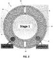
- FIG. 3is a top view of a first stage receptacle of the atomizer mixing chamber.
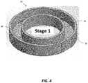
- FIG. 4is an isometric view of the first stage receptacle.
- FIG. 5is a top view of a second stage receptacle of the atomizer mixing chamber.
- FIG. 6is an isometric view of the second stage receptacle.
- FIG. 7is a top view of a third stage receptacle of the atomizer mixing chamber.
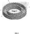
- FIG. 8is an isometric view of the third stage receptacle.
- FIG. 9is a top view of the first and second stage receptacle together as a single combined receptacle having two radially arranged stages.
- FIG. 10is an isometric view of the atomizer mixing chamber.
- FIG. 11is a cutaway view showing the interior of the atomizer mixing chamber.
- FIG. 12is a cross-sectional view of the atomizer mixing chamber.
- FIG. 13is an exploded view of the atomizer mixing chamber.
- FIG. 14is a cross-sectional view of an atomizer having the atomizer mixing chamber of the preceding figures.
- FIG. 15is a cutaway view of the atomizer.
- FIG. 16is an exploded view of the atomizer.
- FIG. 17is an isometric view of the atomizer.
- FIG. 18is a side view of an atomizing chamber attached to a hood.
- FIG. 19is an isometric view of the atomizing chamber and hood.
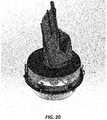
- FIG. 20is an isometric, partially transparent view of the atomizing chamber and hood.
- FIG. 21is an isometric underside view of the atomizing chamber and hood.
- FIG. 22is a cutaway view of the atomizing chamber and hood.
- An atomizer mixing chamber for a seed treater, an atomizer incorporating the atomizer mixing chamber and an atomizing chamberare now described with reference to the exemplary embodiment(s) illustrated in the drawings.
- FIG. 1is an isometric view of an atomizer mixing chamber generally denoted by reference numeral 10 in accordance with an embodiment of the present invention.
- the atomizer mixing chamber 10has a body (or main body) 12 and multiple stages defined by a plurality of receptacles that sequentially mix two or more treatment fluids, e.g. treatment liquids, prior to application to the seeds.
- the receptaclesmay be ring-like cups or annular cup-like structures as illustrated in the figures.
- the receptaclesmay alternatively have other shapes or geometries to achieve the same or similar functions.
- the treatment fluidmay include a suspension or a slurry or even a powder-entrained air stream.
- the multi-stage atomizer mixing chambernot only efficiently and completely mixes the treatment fluids but its design also enables quick and easy disassembly for cleaning.
- the atomizing mixing chamber of FIG. 1is designed particularly for mixing two treatment liquids and it will be appreciated that some modifications to the design might be needed to adapt the mixing chamber for non-liquid (gaseous) fluids.
- the body 12is generally cylindrical and has a top surface 14 that is flat and has internally threaded mounting holes for mounting to a motor (as described below in greater detail). Other body shapes may be used.
- the bodyalso has a central bore 16 for receiving a drive shaft (as described in greater detail below).
- the body 12includes a first inlet 18 in the body for receiving a first treatment liquid and a second inlet 20 in the body for receiving a second treatment liquid.
- a first inlet 18 in the bodyfor receiving a first treatment liquid
- a second inlet 20 in the bodyfor receiving a second treatment liquid.
- the atomizer mixing chambercould have more than two inlets for receiving more than two different treatment liquids.
- the single inletmay be connected to a T-shaped fitting, manifold or equivalent device to receive two or more different treatment liquids via the same single inlet. The two or more different treatment liquids are then mixed in the atomizer mixing chamber 10 .
- FIG. 2is a cross-sectional view of the body 12 in accordance with one exemplary embodiment showing three stages, namely a first stage 30 , a second stage 40 and a third stage 50 .
- the three stagesare axially arranged in this exemplary embodiment.
- the three stagescan be arranged radially.
- the first and second stagesare arranged radially and the third stage is arranged axially.
- the mixingcan be done with only two stages; however, the best mode of implementing this invention is to employ three stages, as illustrated. More than three stages may also be employed in another embodiment.
- the stagescan be defined by separate receptacles that sequentially mix the liquids.
- the receptaclesmay be embodied as ring-like cups or annular cup-like structures as shown by way of example in the figures. In this illustrated embodiment, there may be flats, bevels or other alignment devices on the cups (or other receptacles) to locate the outlet holes in relation to the inlet holes. This orientation is very important to enable proper mixing.
- FIG. 3is a top view of a first stage cup 30 of the atomizer mixing chamber in accordance with an exemplary embodiment.
- the first stage cup 30has a pair of concentric walls, i.e. outer wall 32 and inner wall 34 , defining an annular trough 36 .
- the troughcan have a different shape, i.e. it need not be annular and the walls need not be concentric.
- the troughhas a first set of holes, e.g. two oblong holes 38 , 39 . Other shapes of holes may be used.
- the first and second treatment liquidscombine in the trough and flow out of the first stage cup 30 through these holes 38 , 39 .
- FIG. 4is an isometric view of the first stage cup 30 showing the concentric walls 32 , 34 and the annular trough 36 .
- FIG. 5is a top view of a second stage cup 40 of the atomizer mixing chamber in accordance with an exemplary embodiment.
- the second stage cup 40includes by way of example a second pair of concentric walls, i.e. outer wall 41 and inner wall 42 , having radial protrusions 43 , 44 defining a second annular trough 46 , 47 for mixing the combined liquid to form the mixed liquid.
- the troughis divided into two trough chambers 46 , 47 by divider walls 46 a , 47 a .
- the second stage cupalso has a second set of holes, e.g. two oblong holes 48 , 49 , through which the mixed liquid flows.
- FIG. 5also shows the entry points of the combined liquid from the first stage, which are denoted by reference numerals 38 a , 39 a .
- the entry points 38 a , 39 aare at opposite ends of the trough chambers 46 , 47 , thus requiring the combined liquid to flow past the protrusions to reach the exit holes 48 , 49 .
- FIG. 6is an isometric view of the second stage cup 40 in accordance with an exemplary embodiment showing the concentric walls 41 , 42 , the trough chambers 46 , 47 and the dividing walls 46 a , 47 a .
- the radial protrusions 43 , 44promote mixing of the treatment liquid as the treatment liquid flows moves through the trough chambers 46 , 47 .
- the location, size and shape of the walls and holescan be varied in other implementations.
- FIG. 7is a top view of a third stage cup 50 of the atomizer mixing chamber.
- the third stage cupis below the second stage cup in this axially arrangement and forms an end cap for receiving the mixed liquid from the second stage cup.
- the third stage cup 50includes, in this exemplary embodiment, a third pair of concentric walls, i.e. outer wall 51 and inner wall 52 , defining a third annular trough 53 .
- the third stage cupalso includes a third set of holes 54 through which the mixed liquid exits from the atomizer. In the illustrated embodiment, there are six equally spaced circular holes. The geometry of the walls, the number of holes and their spacing may be varied in other embodiments.
- FIG. 7shows the entry points 55 , 56 of the mixed (blended) liquid from the second stage. The entry points are offset from the holes 54 .
- FIG. 8is an isometric view of the third stage cup 50 showing the concentric walls 51 , 52 , the annular trough 53 and some of the holes 54 . It is noted that not all holes are visible in this view.
- FIG. 9is a top view of the first and second stage cups together showing the first and second inlets 18 , 20 .
- FIG. 9shows a radial arrangement in which the liquids from inlets 18 , 20 flow outwardly as shown by the dashed lines.
- the liquidsflows through radial channels or holes 45 that extend from the first stage (radially inward stage) to the second stage (radially outward stage).
- the liquidsmay flow in the opposite direction, i.e. from the outside toward the inside.
- FIG. 10is an isometric view of the atomizer mixing chamber showing the third stage cup 50 as an end cap having a wider diameter than the body 12 .
- FIG. 11is a cutaway view showing the interior of the atomizer mixing chamber and, in particular, the annular troughs 36 , 47 and 53 of the three sequential stages of this exemplary embodiment.
- the third annular trough 53has holes 54 .
- a central bore 16provides a space to receive a drive shaft as described below.
- the first stage cup, second stage cup and third stage cupare separate components that provide three sequential receptacles for receiving and mixing the liquids.
- the cupsmay be other receptacles having different shapes and geometries but which provide sequential mixing in an analogous manner.
- the receptaclesmay be separate components as are the ring-like cups shown in the figures. However, in another embodiment, the receptacles may be formed within a single, monolithic or integral part.
- FIG. 12is a cross-sectional view of the atomizer mixing chamber showing an upper bearing 60 (which may alternatively be a pair of bearings) and a lower bearing 62 .
- the upper and lower bearings 60 , 62rotationally support a drive shaft 64 that fits through the bore 16 shown for example in FIG. 11 .
- FIG. 13is an exploded view of the atomizer mixing chamber.
- the first and second stage cups 30 , 40are inserted into the body 12 .
- the third stage cup (end cap) 50is then threaded or otherwise removably attached to the bottom portion of the body to retain the first and second stage cups 30 , 40 inside the body 12 . It is noted that the end cap does not require a seal to achieve a fluid-tight enclosure.
- FIG. 14is a cross-sectional view of an atomizer showing the body 12 assembled to a motor 70 via an adapter plate 72 .
- the motormay be an electric motor, e.g. a DC motor. In other embodiments, the motor may be replaced with another type of prime mover (with a suitable drive train or transmission) such as a hydraulic motor or pneumatic system.
- the motor of FIG. 14has an output shaft 71 extending through the adapter plate 72 and connected to the drive shaft 64 .
- the atomizerhas a disk 76 (also known as a rotary disk or atomizer disk).
- the disk 76includes a circular screen 77 (or perforated wall) extending around the periphery of the disk. The disk 76 is spaced below the holes of the third stage as shown.
- FIG. 15is a cutaway view of the atomizer of FIG. 14 showing additional details of the atomizer.
- the motor, electronic components and the bearings for the atomizerare completely separated from the treatment fluids.
- FIG. 16is an exploded view of the atomizer showing how the body 12 , first stage cup 30 , second stage cup 40 and third stage cup 50 are assembled in one particular example embodiment.
- FIG. 16shows threaded fasteners 80 for connecting a lower flange of the motor 70 to the upper portion of the body 12 along with the bearing 60 and retaining ring 81 .
- the bottom of the drive shaft 64is connected to the disk 76 by a castle nut 83 and a cotter pin 82 .
- Other fasteners and mechanical connectorsmay be substituted or used, as will be appreciated.
- FIG. 17is an isometric view of the atomizer once assembled.
- the compact atomizer bodymeans that there is less surface area for treatment build up and allows for a multitude of installation methods.
- the atomizeris smaller and lighter than any comparable device known to the inventors.
- the atomizercan be modified to permit higher or lower flow rates of treatment liquid or seed.
- FIGS. 18-19are side and isometric views of an atomizing chamber attached to a hood 92 .
- the hood 92is the inlet for the untreated seeds.
- FIGS. 20-22are further views of the atomizing chamber and the hood 92 .
- FIG. 20is an isometric, partially transparent view of the atomizing chamber.
- FIG. 21is an isometric underside view of the atomizing chamber.
- FIG. 22is a cutaway view of the atomizing chamber.
- there are two conesan upper cone above the atomizer distributes the seeds flowing from the inlet to form an annular flow of seeds through the atomizing chamber and past the atomizer disk.
- the conical shaped lower section of the atomizing chamber, i.e. the lower coneredirects this annular flow back to the central discharge area of the atomizing chamber.
- FIGS. 20-22there are three pipes 120 , 121 , 122 protruding radially from the atomizer through the side of the atomizing chamber. These pipes contain the treatment fluids and electrical wiring for the motor. The pipes extend from the outside of the atomizing chamber to the atomizer. As such, during operation, the pipes extend through the annular seed flow. Two of the pipes 120 , 121 connect to the first and second inlets 18 , 20 of FIG. 1 . The third pipe 122 contains the motor wiring. The pipes may have quick-connect fittings 102 .
- a plurality of retainers, e.g. tension clamps 109which are disposed circumferentially around a main tubular housing of the atomizing chamber, hold the lower cone to the main tubular housing of the atomizing chamber as shown in FIG. 21 .
- the atomizer mixing chamberenables two or more treatment fluids, e.g. treatment liquids, to be mixed and/or diluted with water before application to the seeds.
- the treatment liquidsare not just applied together in the same atomizing chamber but are mixed and blended together such that they become indistinguishable.
- Another inventive aspectis distributing the treatment liquid through a series of small holes before it reaches the atomizing disk. Failure to do so results in thicker liquid application where the liquid transitions into the atomizer. Using the atomizer, the treatment liquid is distributed evenly on the seeds.
- the atomizer bodyhas a plurality of liquid lines attached to it.
- these linesfeed into a first stage cup which has outlet holes evenly spaced between the lines.
- the first stagecould have been built with a secondary outer ring in place of the second stage cup.
- the first stagetransitions into the second stage and is separated into multiple chambers.
- the number of chambersis selected to maximize the blending of the treatment liquids.
- the walls of this stagehave protrusions to help fold the liquid mixture into itself such that the outlet of this stage is a well blended mixture.
- the third (final) stage in this embodimentis where the mixed treatment liquids are distributed onto the atomizer disk.
- the third stagehas a number of holes which are sized and distributed around the surface such that at the lowest expected flow rate liquid will come out each of the holes relatively evenly.
- the holesare sized such that there is limited pressure buildup inside the mixing chamber. A pressure buildup could result in one line back-feeding into another which could inadvertently pump the wrong treatment liquid into another tank.
- the final stageis tightly connected, e.g. threaded, or otherwise retained by press fit, snap fit, nuts and bolts, etc, onto the main atomizer body such that no seal is required. Because the holes in all three stages have been sized to have little to no back pressure the treatment liquid is essentially dumped into a chamber at atmospheric pressure. This enables the flow of fluid to be restricted around the first stage cup and second stage cup without employing an expensive and cumbersome seal.
- the atomizerhas two faces that mate closely creating enough resistance that the treatment liquid remains in the three cups (or other receptacles) as desired.
- the atomizer mixing chamber disclosed in this specificationis easy to clean.
- the third stage cup(“end cap”) the internal components can be quickly and easily removed for cleaning.
- the third stage cupcan be easily removed from the atomizer body and then the first and second stage cups (which are floating cups) can be removed as well, thus enabling the user or operator to easily clean out the interior of the atomizer mixing chamber.
- Being easy-to-cleanis very important for components in a seed treater that are in direct contact with seed or seed treatments to avoid contamination.
- the illustrated embodimentis not limited to use with an atomizing disk or atomizing cup.
- the illustrated embodimentmay be used with nozzles or machine holes that lead to a spray pattern onto the seeds.
- One of the benefits of the atomizer mixing chamberis also having the point of mixing right before application. Some treatments interact so by having the mixing just prior to application, the effects of this interaction are minimized.
- the ability of the atomizer mixing chamber to operate with minimal pressure lossis important for accurate metering in a wide range of fluid types and viscosities. Minimizing back pressure on the pumps is important to ensure good metering performance.
Landscapes
- Chemical & Material Sciences (AREA)
- Chemical Kinetics & Catalysis (AREA)
- Life Sciences & Earth Sciences (AREA)
- Dispersion Chemistry (AREA)
- Soil Sciences (AREA)
- Environmental Sciences (AREA)
Abstract
Description
Claims (18)
Priority Applications (1)
| Application Number | Priority Date | Filing Date | Title |
|---|---|---|---|
| US16/266,309US11117145B2 (en) | 2018-02-02 | 2019-02-04 | Atomizer mixing chamber for a seed treater |
Applications Claiming Priority (2)
| Application Number | Priority Date | Filing Date | Title |
|---|---|---|---|
| US201862625587P | 2018-02-02 | 2018-02-02 | |
| US16/266,309US11117145B2 (en) | 2018-02-02 | 2019-02-04 | Atomizer mixing chamber for a seed treater |
Publications (2)
| Publication Number | Publication Date |
|---|---|
| US20190240686A1 US20190240686A1 (en) | 2019-08-08 |
| US11117145B2true US11117145B2 (en) | 2021-09-14 |
Family
ID=67476374
Family Applications (1)
| Application Number | Title | Priority Date | Filing Date |
|---|---|---|---|
| US16/266,309Active2039-07-11US11117145B2 (en) | 2018-02-02 | 2019-02-04 | Atomizer mixing chamber for a seed treater |
Country Status (2)
| Country | Link |
|---|---|
| US (1) | US11117145B2 (en) |
| CA (1) | CA3032113C (en) |
Families Citing this family (2)
| Publication number | Priority date | Publication date | Assignee | Title |
|---|---|---|---|---|
| CA3032113C (en)* | 2018-02-02 | 2022-05-03 | Ag Growth International Inc. | Atomizer mixing chamber for a seed treater |
| CN112642668B (en)* | 2020-12-02 | 2022-08-09 | 胡志广 | Foam model is with dip-coating fire resistant coating device |
Citations (43)
| Publication number | Priority date | Publication date | Assignee | Title |
|---|---|---|---|---|
| US2618539A (en)* | 1949-03-19 | 1952-11-18 | Air Reduction | Flashback-proof gas mixer |
| US3185447A (en)* | 1963-03-25 | 1965-05-25 | Hach Chemical Co | Analyzer mixing apparatus |
| US3288052A (en)* | 1963-08-07 | 1966-11-29 | Hough Richard Murray | Coating apparatus |
| US3400915A (en)* | 1963-05-11 | 1968-09-10 | Kurashiki Rayon Co | Rapid mixing apparatus |
| US3502305A (en)* | 1967-08-16 | 1970-03-24 | Grun Kg Mas Fab Geb | Method of and apparatus for adding liquid to pulverulent or granular materials |
| US3526391A (en)* | 1967-01-03 | 1970-09-01 | Wyandotte Chemicals Corp | Homogenizer |
| US3701619A (en)* | 1969-11-14 | 1972-10-31 | American Enka Corp | Mixing apparatus |
| US3934859A (en)* | 1973-11-02 | 1976-01-27 | Combustion Engineering, Inc. | Mixing apparatus |
| US3941355A (en)* | 1974-06-12 | 1976-03-02 | The United States Of America As Represented By The Administrator Of The National Aeronautics And Space Administration | Mixing insert for foam dispensing apparatus |
| US4218012A (en)* | 1977-09-01 | 1980-08-19 | Canadian Patents & Development | Method of rapidly dissolving a particulate substance in a liquid |
| US4337895A (en)* | 1980-03-17 | 1982-07-06 | Thomas Gallen | High speed rotary atomizers |
| US4361407A (en)* | 1980-06-27 | 1982-11-30 | Centro Ricerche Fiat S.P.A. | Stationary mixer device arranged to homogeneously mix two or more components in liquid or semiliquid state |
| US4398493A (en)* | 1979-02-21 | 1983-08-16 | Imperial Chemical Industries Plc | Coating of solids |
| US4407217A (en)* | 1982-03-29 | 1983-10-04 | Jaybee Engineering Pty. Limited | Distribution and treatment means |
| US4453832A (en)* | 1981-10-26 | 1984-06-12 | Schumacher Heinz O | Apparatus for trouble-free and continuous charging of extractors with extraction feedstock to be treated and with extractant or solvent |
| US4514095A (en)* | 1982-11-06 | 1985-04-30 | Kernforschungszentrum Karlsruhe Gmbh | Motionless mixer |
| US4729665A (en)* | 1984-08-29 | 1988-03-08 | Autotrol Corporation | Fluid mixer/charger and method |
| US4834542A (en)* | 1986-03-27 | 1989-05-30 | Dowell Schlumberger Incorporated | Mixer for pulverous and liquid materials (essentially cement and water), of liquid-liquid materials |
| US4869849A (en)* | 1987-04-10 | 1989-09-26 | Chugoku Kayaku Kabushiki Kaisha | Fluid mixing apparatus |
| US4874400A (en)* | 1987-09-25 | 1989-10-17 | Metallgesellschaft Aktiengesellschaft | Method of and apparatus for removing gaseous pollutants from exhaust gases |
| US5056715A (en)* | 1990-02-21 | 1991-10-15 | Pfizer Inc. | Apparatus for mixing and spraying a slurry |
| US5073032A (en)* | 1989-11-20 | 1991-12-17 | Efisol | Mixing device for bulk impregnation of particulate matter by a binder |
| US5672821A (en)* | 1994-12-12 | 1997-09-30 | Mks Japan, Inc. | Laminar flow device |
| US5685639A (en)* | 1996-04-08 | 1997-11-11 | Abc Dispensing Technologies Inc. | Juice mixing nozzle |
| US5695648A (en)* | 1995-10-31 | 1997-12-09 | Chicago Bridge & Iron Technical Services Company | Method and apparatus for withdrawing effluent from a solids-contacting vessel having an adjustable weir |
| US5863129A (en)* | 1998-01-05 | 1999-01-26 | Gary A. Smith | Serial resin mixing devices |
| US5887977A (en)* | 1997-09-30 | 1999-03-30 | Uniflows Co., Ltd. | Stationary in-line mixer |
| US5984519A (en)* | 1996-12-26 | 1999-11-16 | Genus Corporation | Fine particle producing devices |
| US6357905B1 (en)* | 1999-10-05 | 2002-03-19 | Ronald W. T. Birchard | Apparatus for the blending of materials |
| US6616327B1 (en)* | 1998-03-23 | 2003-09-09 | Amalgamated Research, Inc. | Fractal stack for scaling and distribution of fluids |
| US6705756B2 (en)* | 2002-03-12 | 2004-03-16 | Chemque, Incorporated | Apparatus and method for mixing and dispensing components of a composition |
| US6722780B2 (en)* | 1998-12-07 | 2004-04-20 | Roche Vitamins Inc. | Preparation of liquid dispersions |
| US20040130967A1 (en)* | 2002-10-17 | 2004-07-08 | Christian Wolf | Mixing element |
| US7018435B1 (en)* | 1999-09-06 | 2006-03-28 | Shell Oil Company | Mixing device |
| US7083683B2 (en)* | 2003-07-01 | 2006-08-01 | Glatt Systemtechnik Gmbh | Apparatus for the formation of coverings on surfaces of solid bodies in a coating chamber |
| US7276215B2 (en)* | 2002-11-08 | 2007-10-02 | Morten Muller Ltd. Aps | Mixing device for two-phase concurrent vessels |
| US7520661B1 (en)* | 2006-11-20 | 2009-04-21 | Aeromed Technologies Llc | Static mixer |
| US20100276820A1 (en)* | 2008-01-10 | 2010-11-04 | Ms Grow Up Corp. | Static fluid mixer |
| US20110085945A1 (en)* | 2008-06-16 | 2011-04-14 | Isel Co., Ltd. | Mixing unit, mixing device, agitation impeller, pump mixer, mixing system and reaction device |
| US20130301379A1 (en)* | 2011-01-12 | 2013-11-14 | Tetra Laval Holdings & Finance S.A. | Layer multiplier for fluids with high viscosity |
| US9616442B2 (en)* | 2013-06-22 | 2017-04-11 | KSi Conveyor, Inc. | Rotating disk atomizer with treatment fluid feed arrangement |
| US10357432B2 (en)* | 2015-03-19 | 2019-07-23 | Pharma Technology S.A. | Device for coating particulate material |
| US20190240686A1 (en)* | 2018-02-02 | 2019-08-08 | Ag Growth International Inc. | Atomizer mixing chamber for a seed treater |
- 2019
- 2019-01-31CACA3032113Apatent/CA3032113C/enactiveActive
- 2019-02-04USUS16/266,309patent/US11117145B2/enactiveActive
Patent Citations (47)
| Publication number | Priority date | Publication date | Assignee | Title |
|---|---|---|---|---|
| US2618539A (en)* | 1949-03-19 | 1952-11-18 | Air Reduction | Flashback-proof gas mixer |
| US3185447A (en)* | 1963-03-25 | 1965-05-25 | Hach Chemical Co | Analyzer mixing apparatus |
| US3400915A (en)* | 1963-05-11 | 1968-09-10 | Kurashiki Rayon Co | Rapid mixing apparatus |
| US3288052A (en)* | 1963-08-07 | 1966-11-29 | Hough Richard Murray | Coating apparatus |
| US3526391A (en)* | 1967-01-03 | 1970-09-01 | Wyandotte Chemicals Corp | Homogenizer |
| US3502305A (en)* | 1967-08-16 | 1970-03-24 | Grun Kg Mas Fab Geb | Method of and apparatus for adding liquid to pulverulent or granular materials |
| US3701619A (en)* | 1969-11-14 | 1972-10-31 | American Enka Corp | Mixing apparatus |
| US3934859A (en)* | 1973-11-02 | 1976-01-27 | Combustion Engineering, Inc. | Mixing apparatus |
| US3941355A (en)* | 1974-06-12 | 1976-03-02 | The United States Of America As Represented By The Administrator Of The National Aeronautics And Space Administration | Mixing insert for foam dispensing apparatus |
| US4218012A (en)* | 1977-09-01 | 1980-08-19 | Canadian Patents & Development | Method of rapidly dissolving a particulate substance in a liquid |
| US4398493A (en)* | 1979-02-21 | 1983-08-16 | Imperial Chemical Industries Plc | Coating of solids |
| US4337895A (en)* | 1980-03-17 | 1982-07-06 | Thomas Gallen | High speed rotary atomizers |
| US4361407A (en)* | 1980-06-27 | 1982-11-30 | Centro Ricerche Fiat S.P.A. | Stationary mixer device arranged to homogeneously mix two or more components in liquid or semiliquid state |
| US4453832A (en)* | 1981-10-26 | 1984-06-12 | Schumacher Heinz O | Apparatus for trouble-free and continuous charging of extractors with extraction feedstock to be treated and with extractant or solvent |
| US4407217A (en)* | 1982-03-29 | 1983-10-04 | Jaybee Engineering Pty. Limited | Distribution and treatment means |
| US4514095A (en)* | 1982-11-06 | 1985-04-30 | Kernforschungszentrum Karlsruhe Gmbh | Motionless mixer |
| US4729665A (en)* | 1984-08-29 | 1988-03-08 | Autotrol Corporation | Fluid mixer/charger and method |
| US4834542A (en)* | 1986-03-27 | 1989-05-30 | Dowell Schlumberger Incorporated | Mixer for pulverous and liquid materials (essentially cement and water), of liquid-liquid materials |
| US4869849A (en)* | 1987-04-10 | 1989-09-26 | Chugoku Kayaku Kabushiki Kaisha | Fluid mixing apparatus |
| US4874400A (en)* | 1987-09-25 | 1989-10-17 | Metallgesellschaft Aktiengesellschaft | Method of and apparatus for removing gaseous pollutants from exhaust gases |
| US5073032A (en)* | 1989-11-20 | 1991-12-17 | Efisol | Mixing device for bulk impregnation of particulate matter by a binder |
| US5056715A (en)* | 1990-02-21 | 1991-10-15 | Pfizer Inc. | Apparatus for mixing and spraying a slurry |
| US5672821A (en)* | 1994-12-12 | 1997-09-30 | Mks Japan, Inc. | Laminar flow device |
| US5695648A (en)* | 1995-10-31 | 1997-12-09 | Chicago Bridge & Iron Technical Services Company | Method and apparatus for withdrawing effluent from a solids-contacting vessel having an adjustable weir |
| US5685639A (en)* | 1996-04-08 | 1997-11-11 | Abc Dispensing Technologies Inc. | Juice mixing nozzle |
| US5984519A (en)* | 1996-12-26 | 1999-11-16 | Genus Corporation | Fine particle producing devices |
| US5887977A (en)* | 1997-09-30 | 1999-03-30 | Uniflows Co., Ltd. | Stationary in-line mixer |
| US5863129A (en)* | 1998-01-05 | 1999-01-26 | Gary A. Smith | Serial resin mixing devices |
| US6616327B1 (en)* | 1998-03-23 | 2003-09-09 | Amalgamated Research, Inc. | Fractal stack for scaling and distribution of fluids |
| US6722780B2 (en)* | 1998-12-07 | 2004-04-20 | Roche Vitamins Inc. | Preparation of liquid dispersions |
| US7018435B1 (en)* | 1999-09-06 | 2006-03-28 | Shell Oil Company | Mixing device |
| US6357905B1 (en)* | 1999-10-05 | 2002-03-19 | Ronald W. T. Birchard | Apparatus for the blending of materials |
| US6705756B2 (en)* | 2002-03-12 | 2004-03-16 | Chemque, Incorporated | Apparatus and method for mixing and dispensing components of a composition |
| US6971787B2 (en)* | 2002-03-12 | 2005-12-06 | Chemque, Incorporated | Apparatus and method for mixing and dispensing components of a composition |
| US20040130967A1 (en)* | 2002-10-17 | 2004-07-08 | Christian Wolf | Mixing element |
| US7276215B2 (en)* | 2002-11-08 | 2007-10-02 | Morten Muller Ltd. Aps | Mixing device for two-phase concurrent vessels |
| US7083683B2 (en)* | 2003-07-01 | 2006-08-01 | Glatt Systemtechnik Gmbh | Apparatus for the formation of coverings on surfaces of solid bodies in a coating chamber |
| US7520661B1 (en)* | 2006-11-20 | 2009-04-21 | Aeromed Technologies Llc | Static mixer |
| US7789108B1 (en)* | 2006-11-20 | 2010-09-07 | Aeromed Technologies Llc | Micro-flow fluid restrictor, pressure spike attenuator, and fluid mixer |
| US20100276820A1 (en)* | 2008-01-10 | 2010-11-04 | Ms Grow Up Corp. | Static fluid mixer |
| US20110085945A1 (en)* | 2008-06-16 | 2011-04-14 | Isel Co., Ltd. | Mixing unit, mixing device, agitation impeller, pump mixer, mixing system and reaction device |
| US20130301379A1 (en)* | 2011-01-12 | 2013-11-14 | Tetra Laval Holdings & Finance S.A. | Layer multiplier for fluids with high viscosity |
| US9616442B2 (en)* | 2013-06-22 | 2017-04-11 | KSi Conveyor, Inc. | Rotating disk atomizer with treatment fluid feed arrangement |
| US20170164550A1 (en)* | 2013-06-22 | 2017-06-15 | KSi Conveyor, Inc. | Rotating disk atomizer with treatment fluid feed arrangement |
| US10729061B2 (en)* | 2013-06-22 | 2020-08-04 | KSi Conveyor, Inc. | Rotating disk atomizer with treatment fluid feed arrangement |
| US10357432B2 (en)* | 2015-03-19 | 2019-07-23 | Pharma Technology S.A. | Device for coating particulate material |
| US20190240686A1 (en)* | 2018-02-02 | 2019-08-08 | Ag Growth International Inc. | Atomizer mixing chamber for a seed treater |
Also Published As
| Publication number | Publication date |
|---|---|
| CA3032113C (en) | 2022-05-03 |
| US20190240686A1 (en) | 2019-08-08 |
| CA3032113A1 (en) | 2019-08-02 |
Similar Documents
| Publication | Publication Date | Title |
|---|---|---|
| US11117145B2 (en) | Atomizer mixing chamber for a seed treater | |
| US10729061B2 (en) | Rotating disk atomizer with treatment fluid feed arrangement | |
| US9327218B2 (en) | Bernoulli filter | |
| WO1996033011A1 (en) | Method of conditioning hydrocarbon liquids and an apparatus for carrying out the method | |
| KR20120112713A (en) | Fluid-mixing apparatus and device using the sqme | |
| KR20070122466A (en) | Barrier structures and nozzle arrangements for tools used to process microelectronic work pieces using one or more processing fluids | |
| KR101926666B1 (en) | Static spray mixer | |
| US20020075756A1 (en) | Apparatus for premixing additives and feeding them into a polymer stream | |
| JP7064657B2 (en) | Coating liquid mixing device and coating liquid mixing method | |
| JP2012240047A (en) | Connection for stationary spray mixture | |
| US20240173730A1 (en) | Foam generating device | |
| KR20000016358A (en) | Process for dividing a viscous liquid conveyed by a flow of gas | |
| US20180036752A1 (en) | High Velocity Spray (HVS) Dispense Arm Assemblies including a Gas Shield Nozzle | |
| CA2216332C (en) | Variable rate flow divider | |
| CN108579490A (en) | A kind of multicomponent on-line mixing device of ring-type seepage-type | |
| RU2656402C1 (en) | System of preparation of working fluid of seed dressing preparations | |
| CN213433905U (en) | Jet stirring pipe | |
| CN109046181B (en) | Combined fluid distributor | |
| JPS60209234A (en) | Continuous mixing method of powder fluid and reaction liquid etc. | |
| US10512890B1 (en) | Apparatus for mixing materials which have a high mix proportion/ratio therebetween and preparation production system using the same | |
| CN113648899B (en) | Spray type aerosol mixing device | |
| RU2667839C1 (en) | Spray dryer for liquid products | |
| US20170367570A1 (en) | Fluid distributor for a reprocessing device for surgical instruments | |
| CN216704233U (en) | Liquid preparation device with cleaning function | |
| US577522A (en) | Apparatus |
Legal Events
| Date | Code | Title | Description |
|---|---|---|---|
| FEPP | Fee payment procedure | Free format text:ENTITY STATUS SET TO UNDISCOUNTED (ORIGINAL EVENT CODE: BIG.); ENTITY STATUS OF PATENT OWNER: LARGE ENTITY | |
| AS | Assignment | Owner name:AG GROWTH INTERNATIONAL INC., CANADA Free format text:ASSIGNMENT OF ASSIGNORS INTEREST;ASSIGNORS:BARDI, DAN;ENS, JEREMY;JOHNSON, ZACHARY;REEL/FRAME:052050/0424 Effective date:20181107 | |
| AS | Assignment | Owner name:CANADIAN IMPERIAL BANK OF COMMERCE, CANADA Free format text:SECURITY INTEREST;ASSIGNOR:AG GROWTH INTERNATIONAL INC.;REEL/FRAME:052923/0366 Effective date:20200513 | |
| STPP | Information on status: patent application and granting procedure in general | Free format text:NON FINAL ACTION MAILED | |
| STPP | Information on status: patent application and granting procedure in general | Free format text:RESPONSE TO NON-FINAL OFFICE ACTION ENTERED AND FORWARDED TO EXAMINER | |
| STPP | Information on status: patent application and granting procedure in general | Free format text:NOTICE OF ALLOWANCE MAILED -- APPLICATION RECEIVED IN OFFICE OF PUBLICATIONS | |
| STPP | Information on status: patent application and granting procedure in general | Free format text:PUBLICATIONS -- ISSUE FEE PAYMENT RECEIVED | |
| STPP | Information on status: patent application and granting procedure in general | Free format text:PUBLICATIONS -- ISSUE FEE PAYMENT VERIFIED | |
| STCF | Information on status: patent grant | Free format text:PATENTED CASE | |
| MAFP | Maintenance fee payment | Free format text:PAYMENT OF MAINTENANCE FEE, 4TH YEAR, LARGE ENTITY (ORIGINAL EVENT CODE: M1551); ENTITY STATUS OF PATENT OWNER: LARGE ENTITY Year of fee payment:4 |