US11116946B2 - Urinary catheter device - Google Patents
Urinary catheter deviceDownload PDFInfo
- Publication number
- US11116946B2 US11116946B2US16/014,357US201816014357AUS11116946B2US 11116946 B2US11116946 B2US 11116946B2US 201816014357 AUS201816014357 AUS 201816014357AUS 11116946 B2US11116946 B2US 11116946B2
- Authority
- US
- United States
- Prior art keywords
- tube
- chamber
- hole
- slit
- wall
- Prior art date
- Legal status (The legal status is an assumption and is not a legal conclusion. Google has not performed a legal analysis and makes no representation as to the accuracy of the status listed.)
- Active, expires
Links
- 230000002485urinary effectEffects0.000titleclaimsabstractdescription7
- 210000002700urineAnatomy0.000claimsabstractdescription25
- 239000012530fluidSubstances0.000claimsabstractdescription20
- 210000003708urethraAnatomy0.000claimsabstractdescription14
- 230000014759maintenance of locationEffects0.000claimsdescription13
- 230000007704transitionEffects0.000claimsdescription9
- 238000004891communicationMethods0.000claimsdescription6
- 238000003780insertionMethods0.000claimsdescription4
- 230000037431insertionEffects0.000claimsdescription4
- 238000000605extractionMethods0.000claimsdescription3
- 229920001296polysiloxanePolymers0.000claimsdescription3
- 239000000463materialSubstances0.000description2
- 238000012986modificationMethods0.000description2
- 230000004048modificationEffects0.000description2
- 238000011160researchMethods0.000description2
- 238000010276constructionMethods0.000description1
- 238000011161developmentMethods0.000description1
Images


Classifications
- A—HUMAN NECESSITIES
- A61—MEDICAL OR VETERINARY SCIENCE; HYGIENE
- A61M—DEVICES FOR INTRODUCING MEDIA INTO, OR ONTO, THE BODY; DEVICES FOR TRANSDUCING BODY MEDIA OR FOR TAKING MEDIA FROM THE BODY; DEVICES FOR PRODUCING OR ENDING SLEEP OR STUPOR
- A61M25/00—Catheters; Hollow probes
- A61M25/10—Balloon catheters
- A61M25/1018—Balloon inflating or inflation-control devices
- A61M25/10184—Means for controlling or monitoring inflation or deflation
- A61M25/10185—Valves
- A—HUMAN NECESSITIES
- A61—MEDICAL OR VETERINARY SCIENCE; HYGIENE
- A61M—DEVICES FOR INTRODUCING MEDIA INTO, OR ONTO, THE BODY; DEVICES FOR TRANSDUCING BODY MEDIA OR FOR TAKING MEDIA FROM THE BODY; DEVICES FOR PRODUCING OR ENDING SLEEP OR STUPOR
- A61M25/00—Catheters; Hollow probes
- A61M25/0017—Catheters; Hollow probes specially adapted for long-term hygiene care, e.g. urethral or indwelling catheters to prevent infections
- A—HUMAN NECESSITIES
- A61—MEDICAL OR VETERINARY SCIENCE; HYGIENE
- A61M—DEVICES FOR INTRODUCING MEDIA INTO, OR ONTO, THE BODY; DEVICES FOR TRANSDUCING BODY MEDIA OR FOR TAKING MEDIA FROM THE BODY; DEVICES FOR PRODUCING OR ENDING SLEEP OR STUPOR
- A61M25/00—Catheters; Hollow probes
- A61M25/0067—Catheters; Hollow probes characterised by the distal end, e.g. tips
- A61M25/0068—Static characteristics of the catheter tip, e.g. shape, atraumatic tip, curved tip or tip structure
- A61M25/007—Side holes, e.g. their profiles or arrangements; Provisions to keep side holes unblocked
- A—HUMAN NECESSITIES
- A61—MEDICAL OR VETERINARY SCIENCE; HYGIENE
- A61M—DEVICES FOR INTRODUCING MEDIA INTO, OR ONTO, THE BODY; DEVICES FOR TRANSDUCING BODY MEDIA OR FOR TAKING MEDIA FROM THE BODY; DEVICES FOR PRODUCING OR ENDING SLEEP OR STUPOR
- A61M25/00—Catheters; Hollow probes
- A61M25/0067—Catheters; Hollow probes characterised by the distal end, e.g. tips
- A61M25/0074—Dynamic characteristics of the catheter tip, e.g. openable, closable, expandable or deformable
- A—HUMAN NECESSITIES
- A61—MEDICAL OR VETERINARY SCIENCE; HYGIENE
- A61M—DEVICES FOR INTRODUCING MEDIA INTO, OR ONTO, THE BODY; DEVICES FOR TRANSDUCING BODY MEDIA OR FOR TAKING MEDIA FROM THE BODY; DEVICES FOR PRODUCING OR ENDING SLEEP OR STUPOR
- A61M25/00—Catheters; Hollow probes
- A61M2025/0019—Cleaning catheters or the like, e.g. for reuse of the device, for avoiding replacement
- A—HUMAN NECESSITIES
- A61—MEDICAL OR VETERINARY SCIENCE; HYGIENE
- A61M—DEVICES FOR INTRODUCING MEDIA INTO, OR ONTO, THE BODY; DEVICES FOR TRANSDUCING BODY MEDIA OR FOR TAKING MEDIA FROM THE BODY; DEVICES FOR PRODUCING OR ENDING SLEEP OR STUPOR
- A61M2210/00—Anatomical parts of the body
- A61M2210/10—Trunk
- A61M2210/1078—Urinary tract
- A61M2210/1085—Bladder
- A—HUMAN NECESSITIES
- A61—MEDICAL OR VETERINARY SCIENCE; HYGIENE
- A61M—DEVICES FOR INTRODUCING MEDIA INTO, OR ONTO, THE BODY; DEVICES FOR TRANSDUCING BODY MEDIA OR FOR TAKING MEDIA FROM THE BODY; DEVICES FOR PRODUCING OR ENDING SLEEP OR STUPOR
- A61M2210/00—Anatomical parts of the body
- A61M2210/10—Trunk
- A61M2210/1078—Urinary tract
- A61M2210/1089—Urethra
Definitions
- the disclosure and prior artrelates to catheter devices and more particularly pertains to a new catheter device having a means for unblocking the catheter.
- An embodiment of the disclosuremeets the needs presented above by generally comprising a tube, which has a distal end that is closed.
- the tubeis resilient and is configured to insert through a urethra of an animal to position the distal end in a bladder.
- a holeis positioned through a wall of the tube proximate to the distal end and is configured to drain urine from the bladder through a proximal end of the tube, which is open.
- a channelextends through the wall from a first valve that is coupled to the tube to a chamber that is positioned in the wall proximate to the hole. Introduction of a fluid via the first valve into the chamber expands the chamber and increases a circumference of the hole so that debris that is impeding a flow of the urine through the tube enters and passes through the tube.
- FIG. 1is an isometric perspective view of a urinary catheter device according to an embodiment of the disclosure.
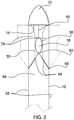
- FIG. 2is a top view of an embodiment of the disclosure.
- FIG. 3is a side view of an embodiment of the disclosure.
- FIG. 4is a bottom view of an embodiment of the disclosure.
- FIG. 5is a cross-sectional view of an embodiment of the disclosure.
- FIG. 6is a cross-sectional view of an embodiment of the disclosure.
- FIG. 7is a cross-sectional view of an embodiment of the disclosure.
- FIGS. 1 through 7a new catheter device embodying the principles and concepts of an embodiment of the disclosure and generally designated by the reference numeral 10 will be described.
- the urinary catheter device 10generally comprises a tube 12 that has a distal end 14 and a proximal end 16 .
- the distal end 14is closed.
- the proximal end 16is open.
- the tube 12is resilient and is configured to insert through a urethra of an animal to position the distal end 14 in a bladder of the animal.
- a hole 18is positioned through a wall 20 of the tube 12 proximate to the distal end 14 .
- the hole 18is configured to allow entry of urine into the tube 12 so that the urine flows toward the proximal end 16 to drain the bladder.
- a chamber 22is positioned in the wall 20 of the tube 12 proximate to the hole 18 , as shown in FIG. 6 .
- the chamber 22is defined by a recess 24 and a panel 26 .
- the recess 24extends into the wall 20 from an outer circumference 28 of the tube 12 .
- the panel 26is coupled to a perimeter 30 of the recess 24 and extends from the wall 20 to cover the recess 24 .
- the panel 26comprises silicone so that the chamber 22 comprises a compliant balloon 32 .
- a channel 34extends from the chamber 22 through the wall 20 , as shown in FIG. 5 , to a first valve 36 that is coupled to the tube 12 proximate to the proximal end 16 , as shown in FIG. 1 .
- the first valve 36is configured to introduce a fluid through the channel 34 into the chamber 22 to expand the chamber 22 to selectively increase a circumference 38 of the hole 18 so that debris that impedes a flow of the urine through the tube 12 enters and passes through the tube 12 .
- a retention balloon 40is coupled to the tube 12 proximate to the chamber 22 so that the retention balloon 40 is positioned between the chamber 22 and the proximal end 16 of the tube 12 , as shown in FIG. 1 .
- a balloon channel 42extends through the wall 20 , as shown in FIG. 5 , to a second valve 44 that is coupled to the tube 12 proximate to the proximal end 16 , as shown in FIG. 1 .
- the second valve 44is configured to introduce a fluid through the balloon channel 42 into the retention balloon 40 to expand the retention balloon 40 within the bladder to fixedly position the tube 12 .
- a first slit 46is positioned through the wall 20 .
- the first slit 46extends from the hole 18 to proximate to the distal end 14 of the tube 12 , as shown in FIG. 2 .
- the first slit 46is configured to separate concurrently with expansion of the chamber 22 to increase the circumference 38 of the hole 18 so that the debris that impedes the flow of the urine through the tube 12 enters and passes through the tube 12 .
- the first slit 46is configured to substantially and sealably close upon draining of the fluid from the chamber 22 .
- a pair of second slits 48is positioned through the wall 20 , as shown in FIG. 2 .
- Each second slit 48has a first endpoint 50 that is opposingly positioned on the hole 18 relative to the first slit 46 .
- Each second slit 48extends transversely to a respective opposing side 52 of the tube 12 so that the pair of second slits 48 is substantially V-shaped when viewed from a top 54 of the tube 12 .
- the second slits 48are configured to separate concurrently with expansion of the chamber 22 to increase the circumference 38 of the hole 18 so that the debris that impedes the flow of the urine through the tube 12 enters and passes through the tube 12 .
- the second slits 48are configured to substantially and sealably close upon draining of the fluid from the chamber 22 .
- the recess 24comprises a pair of upper edges 56 , a pair of transition edges 58 , and a proximal edge 60 , as shown in FIG. 3 .
- the upper edges 56bracket the hole 18 .
- Each upper edge 56extends from proximate to a respective second slit 48 to proximate to the distal end 14 of the tube 12 .
- Each upper edge 56comprises a first segment 62 and a second segment 64 . The first segment 62 extends from the respective second slit 48 past the hole 18 .
- the second segment 64extends transversely from the first segment 62 to proximate to the distal end 14 of the tube 12 so that a terminus 66 of the second segment 64 is in substantial alignment with a second endpoint 68 of the respective second slit 48 .
- Each transition edge 58extends along the respective second slit 48 to proximate to the second endpoint 68 of the respective second slit 48 .
- the proximal edge 60extends between the pair of transition edges 58 .
- the channel 34meets the chamber 22 at the proximal edge 60 so that the chamber 22 is in fluidic communication with the first valve 36 .
- a tip 70is coupled to and extends from the distal end 14 of the tube 12 , as shown in FIG. 3 .
- the tip 70is configured to facilitate insertion of the tube 12 through the urethra of the animal to position the hole 18 in the bladder of the animal.
- the tip 70is substantially conically shaped.
- a slat 72is coupled to and extends from the tip 70 along a bottom 74 of the tube 12 to proximate to the proximal edge 60 of the recess 24 , as shown in FIG. 3 .
- the slat 72is coupled to the wall 20 so that the slat 72 defines a pair of compartments 76 within the chamber 22 and a pair of sections 78 of the panel 26 , as shown in FIG. 6 .
- the compartments 76are in fluidic communication.
- the slat 72serves to provide structure to the tube 12 proximate to the distal end 14 to facilitate insertion of the tube 12 through the urethra.
- the slat 72is tapered and arcuate distal from the tip 70 to facilitate extraction of the tube 12 from the urethra.
- the tube 12is inserted through the urethra to position the hole 18 in the bladder.
- the second valve 44then is used to introduce the fluid into the retention balloon 40 to fixedly position the tube 12 . If debris should block or partially block the hole 18 , the fluid can be introduced into the chamber 22 to increase the circumference 38 of the hole 18 , allowing the debris to pass through the tube 12 .
Landscapes
- Health & Medical Sciences (AREA)
- Life Sciences & Earth Sciences (AREA)
- Heart & Thoracic Surgery (AREA)
- Hematology (AREA)
- General Health & Medical Sciences (AREA)
- Anesthesiology (AREA)
- Biomedical Technology (AREA)
- Pulmonology (AREA)
- Biophysics (AREA)
- Animal Behavior & Ethology (AREA)
- Engineering & Computer Science (AREA)
- Public Health (AREA)
- Veterinary Medicine (AREA)
- Child & Adolescent Psychology (AREA)
- Epidemiology (AREA)
- Urology & Nephrology (AREA)
- External Artificial Organs (AREA)
- Media Introduction/Drainage Providing Device (AREA)
- Orthopedics, Nursing, And Contraception (AREA)
Abstract
Description
Claims (9)
Priority Applications (1)
| Application Number | Priority Date | Filing Date | Title |
|---|---|---|---|
| US16/014,357US11116946B2 (en) | 2018-06-21 | 2018-06-21 | Urinary catheter device |
Applications Claiming Priority (1)
| Application Number | Priority Date | Filing Date | Title |
|---|---|---|---|
| US16/014,357US11116946B2 (en) | 2018-06-21 | 2018-06-21 | Urinary catheter device |
Publications (2)
| Publication Number | Publication Date |
|---|---|
| US20190388659A1 US20190388659A1 (en) | 2019-12-26 |
| US11116946B2true US11116946B2 (en) | 2021-09-14 |
Family
ID=68981183
Family Applications (1)
| Application Number | Title | Priority Date | Filing Date |
|---|---|---|---|
| US16/014,357Active2039-10-10US11116946B2 (en) | 2018-06-21 | 2018-06-21 | Urinary catheter device |
Country Status (1)
| Country | Link |
|---|---|
| US (1) | US11116946B2 (en) |
Families Citing this family (6)
| Publication number | Priority date | Publication date | Assignee | Title |
|---|---|---|---|---|
| WO2009135141A1 (en) | 2008-05-01 | 2009-11-05 | Bristol-Myers Squibb Company | Rectal drain appliance |
| CN108578044A (en) | 2011-03-17 | 2018-09-28 | 康沃特克科技公司 | High barrier elastomer excrement conduit or ostomy bag |
| PL3027266T3 (en) | 2013-08-01 | 2023-09-04 | Convatec Technologies Inc. | Self-closing bag connector |
| GB201721956D0 (en) | 2017-12-27 | 2018-02-07 | Convatec Ltd | Female catheter locator tip |
| GB201721955D0 (en) | 2017-12-27 | 2018-02-07 | Convatec Ltd | Catheter wetting devices |
| CA3140906A1 (en) | 2019-06-11 | 2020-12-17 | Convatec Technologies Inc. | Urine collection bags for use with catheter products, kits incorporating the same, and methods therefor |
Citations (8)
| Publication number | Priority date | Publication date | Assignee | Title |
|---|---|---|---|---|
| US2919697A (en)* | 1958-10-08 | 1960-01-05 | Kim Se Kyong | Catheters |
| US3331371A (en) | 1965-03-09 | 1967-07-18 | Prosit Service Corp | Catheter having internal flow valve at distal end thereof |
| US4227533A (en) | 1978-11-03 | 1980-10-14 | Bristol-Myers Company | Flushable urinary catheter |
| US4228802A (en) | 1977-06-15 | 1980-10-21 | Medical Products Institute Incorporated | Self-inflating and self-cleaning catheter assembly |
| US4249536A (en)* | 1979-05-14 | 1981-02-10 | Vega Roger E | Urological catheter |
| US6093191A (en) | 1998-10-28 | 2000-07-25 | Srs Medical, Inc. | Flow-around valve with contoured fixation balloon |
| US6167886B1 (en)* | 1997-05-28 | 2001-01-02 | Medi-Globe Vertriebs Gmbh | Device for treatment of male and female urinary incontinence |
| US8038644B2 (en) | 2007-05-01 | 2011-10-18 | Jotillou Enterprises Ltd. | Catheter |
- 2018
- 2018-06-21USUS16/014,357patent/US11116946B2/enactiveActive
Patent Citations (8)
| Publication number | Priority date | Publication date | Assignee | Title |
|---|---|---|---|---|
| US2919697A (en)* | 1958-10-08 | 1960-01-05 | Kim Se Kyong | Catheters |
| US3331371A (en) | 1965-03-09 | 1967-07-18 | Prosit Service Corp | Catheter having internal flow valve at distal end thereof |
| US4228802A (en) | 1977-06-15 | 1980-10-21 | Medical Products Institute Incorporated | Self-inflating and self-cleaning catheter assembly |
| US4227533A (en) | 1978-11-03 | 1980-10-14 | Bristol-Myers Company | Flushable urinary catheter |
| US4249536A (en)* | 1979-05-14 | 1981-02-10 | Vega Roger E | Urological catheter |
| US6167886B1 (en)* | 1997-05-28 | 2001-01-02 | Medi-Globe Vertriebs Gmbh | Device for treatment of male and female urinary incontinence |
| US6093191A (en) | 1998-10-28 | 2000-07-25 | Srs Medical, Inc. | Flow-around valve with contoured fixation balloon |
| US8038644B2 (en) | 2007-05-01 | 2011-10-18 | Jotillou Enterprises Ltd. | Catheter |
Also Published As
| Publication number | Publication date |
|---|---|
| US20190388659A1 (en) | 2019-12-26 |
Similar Documents
| Publication | Publication Date | Title |
|---|---|---|
| US11116946B2 (en) | Urinary catheter device | |
| US10426451B2 (en) | Expandable medical access sheath | |
| US6929664B2 (en) | Open lumen stents | |
| ES3000466T3 (en) | Cold expansion pipe fitting, pipe connection, system, equipment, and method | |
| NO980602L (en) | Method and apparatus for completing an underground well | |
| DE60126430D1 (en) | Hemostatic valve | |
| US10010392B1 (en) | Indwelling valve actuated urinary catheter | |
| US20050252875A1 (en) | Air inlet valve of a nipple used for a bottle | |
| US10472816B2 (en) | Backflow valve assembly | |
| EP3020376A1 (en) | Stent | |
| US11358789B2 (en) | Air flowing garbage can assembly | |
| US20160278309A1 (en) | Sap Collecting Device | |
| US20140263322A1 (en) | Coring-free valve system | |
| US9809962B1 (en) | Recreational vehicle holding tank drain clearing assembly | |
| US10369601B2 (en) | Suctional cleaning system | |
| US20200284079A1 (en) | Protective cover device and method to manufacture said cover device | |
| US10137284B2 (en) | Pleural space draining assembly | |
| US20170304109A1 (en) | Birth Control Assembly | |
| US8096318B2 (en) | Valve flap for a plumbing valve | |
| SE1650362A1 (en) | Urinary catheter comprising an inflatable retention member | |
| EP3616742A1 (en) | Drainage catheter | |
| US10465406B2 (en) | Intake shield assembly | |
| US20190060048A1 (en) | Incontinence clamp assembly | |
| KR102308127B1 (en) | A Pouch Assembly for Surgery | |
| US10557303B1 (en) | Water trough window seal assembly |
Legal Events
| Date | Code | Title | Description |
|---|---|---|---|
| FEPP | Fee payment procedure | Free format text:ENTITY STATUS SET TO UNDISCOUNTED (ORIGINAL EVENT CODE: BIG.); ENTITY STATUS OF PATENT OWNER: MICROENTITY | |
| FEPP | Fee payment procedure | Free format text:ENTITY STATUS SET TO SMALL (ORIGINAL EVENT CODE: SMAL); ENTITY STATUS OF PATENT OWNER: MICROENTITY | |
| STPP | Information on status: patent application and granting procedure in general | Free format text:NON FINAL ACTION MAILED | |
| STPP | Information on status: patent application and granting procedure in general | Free format text:RESPONSE TO NON-FINAL OFFICE ACTION ENTERED AND FORWARDED TO EXAMINER | |
| STPP | Information on status: patent application and granting procedure in general | Free format text:NOTICE OF ALLOWANCE MAILED -- APPLICATION RECEIVED IN OFFICE OF PUBLICATIONS | |
| FEPP | Fee payment procedure | Free format text:ENTITY STATUS SET TO MICRO (ORIGINAL EVENT CODE: MICR); ENTITY STATUS OF PATENT OWNER: MICROENTITY | |
| STPP | Information on status: patent application and granting procedure in general | Free format text:PUBLICATIONS -- ISSUE FEE PAYMENT RECEIVED | |
| STPP | Information on status: patent application and granting procedure in general | Free format text:PUBLICATIONS -- ISSUE FEE PAYMENT VERIFIED | |
| STCF | Information on status: patent grant | Free format text:PATENTED CASE | |
| FEPP | Fee payment procedure | Free format text:MAINTENANCE FEE REMINDER MAILED (ORIGINAL EVENT CODE: REM.); ENTITY STATUS OF PATENT OWNER: MICROENTITY |