US11116936B2 - Low-profile extension for a catheter assembly - Google Patents
Low-profile extension for a catheter assemblyDownload PDFInfo
- Publication number
- US11116936B2 US11116936B2US15/481,690US201715481690AUS11116936B2US 11116936 B2US11116936 B2US 11116936B2US 201715481690 AUS201715481690 AUS 201715481690AUS 11116936 B2US11116936 B2US 11116936B2
- Authority
- US
- United States
- Prior art keywords
- catheter
- extension
- slot
- catheter adapter
- proximal
- Prior art date
- Legal status (The legal status is an assumption and is not a legal conclusion. Google has not performed a legal analysis and makes no representation as to the accuracy of the status listed.)
- Active, expires
Links
Images


Classifications
- A—HUMAN NECESSITIES
- A61—MEDICAL OR VETERINARY SCIENCE; HYGIENE
- A61M—DEVICES FOR INTRODUCING MEDIA INTO, OR ONTO, THE BODY; DEVICES FOR TRANSDUCING BODY MEDIA OR FOR TAKING MEDIA FROM THE BODY; DEVICES FOR PRODUCING OR ENDING SLEEP OR STUPOR
- A61M25/00—Catheters; Hollow probes
- A—HUMAN NECESSITIES
- A61—MEDICAL OR VETERINARY SCIENCE; HYGIENE
- A61M—DEVICES FOR INTRODUCING MEDIA INTO, OR ONTO, THE BODY; DEVICES FOR TRANSDUCING BODY MEDIA OR FOR TAKING MEDIA FROM THE BODY; DEVICES FOR PRODUCING OR ENDING SLEEP OR STUPOR
- A61M25/00—Catheters; Hollow probes
- A61M25/0067—Catheters; Hollow probes characterised by the distal end, e.g. tips
- A61M25/0082—Catheter tip comprising a tool
- A61M25/0084—Catheter tip comprising a tool being one or more injection needles
- A—HUMAN NECESSITIES
- A61—MEDICAL OR VETERINARY SCIENCE; HYGIENE
- A61M—DEVICES FOR INTRODUCING MEDIA INTO, OR ONTO, THE BODY; DEVICES FOR TRANSDUCING BODY MEDIA OR FOR TAKING MEDIA FROM THE BODY; DEVICES FOR PRODUCING OR ENDING SLEEP OR STUPOR
- A61M25/00—Catheters; Hollow probes
- A61M25/0097—Catheters; Hollow probes characterised by the hub
- A—HUMAN NECESSITIES
- A61—MEDICAL OR VETERINARY SCIENCE; HYGIENE
- A61M—DEVICES FOR INTRODUCING MEDIA INTO, OR ONTO, THE BODY; DEVICES FOR TRANSDUCING BODY MEDIA OR FOR TAKING MEDIA FROM THE BODY; DEVICES FOR PRODUCING OR ENDING SLEEP OR STUPOR
- A61M25/00—Catheters; Hollow probes
- A61M25/01—Introducing, guiding, advancing, emplacing or holding catheters
- A61M25/06—Body-piercing guide needles or the like
- A—HUMAN NECESSITIES
- A61—MEDICAL OR VETERINARY SCIENCE; HYGIENE
- A61M—DEVICES FOR INTRODUCING MEDIA INTO, OR ONTO, THE BODY; DEVICES FOR TRANSDUCING BODY MEDIA OR FOR TAKING MEDIA FROM THE BODY; DEVICES FOR PRODUCING OR ENDING SLEEP OR STUPOR
- A61M39/00—Tubes, tube connectors, tube couplings, valves, access sites or the like, specially adapted for medical use
- A61M39/10—Tube connectors; Tube couplings
- A61M39/1011—Locking means for securing connection; Additional tamper safeties
- A—HUMAN NECESSITIES
- A61—MEDICAL OR VETERINARY SCIENCE; HYGIENE
- A61M—DEVICES FOR INTRODUCING MEDIA INTO, OR ONTO, THE BODY; DEVICES FOR TRANSDUCING BODY MEDIA OR FOR TAKING MEDIA FROM THE BODY; DEVICES FOR PRODUCING OR ENDING SLEEP OR STUPOR
- A61M25/00—Catheters; Hollow probes
- A61M2025/0004—Catheters; Hollow probes having two or more concentrically arranged tubes for forming a concentric catheter system
- A—HUMAN NECESSITIES
- A61—MEDICAL OR VETERINARY SCIENCE; HYGIENE
- A61M—DEVICES FOR INTRODUCING MEDIA INTO, OR ONTO, THE BODY; DEVICES FOR TRANSDUCING BODY MEDIA OR FOR TAKING MEDIA FROM THE BODY; DEVICES FOR PRODUCING OR ENDING SLEEP OR STUPOR
- A61M25/00—Catheters; Hollow probes
- A61M25/0067—Catheters; Hollow probes characterised by the distal end, e.g. tips
- A61M25/0082—Catheter tip comprising a tool
- A61M25/0084—Catheter tip comprising a tool being one or more injection needles
- A61M2025/0089—Single injection needle protruding axially, i.e. along the longitudinal axis of the catheter, from the distal tip
- A61M2025/0091—Single injection needle protruding axially, i.e. along the longitudinal axis of the catheter, from the distal tip the single injection needle being fixed
- A—HUMAN NECESSITIES
- A61—MEDICAL OR VETERINARY SCIENCE; HYGIENE
- A61M—DEVICES FOR INTRODUCING MEDIA INTO, OR ONTO, THE BODY; DEVICES FOR TRANSDUCING BODY MEDIA OR FOR TAKING MEDIA FROM THE BODY; DEVICES FOR PRODUCING OR ENDING SLEEP OR STUPOR
- A61M39/00—Tubes, tube connectors, tube couplings, valves, access sites or the like, specially adapted for medical use
- A61M39/10—Tube connectors; Tube couplings
- A61M2039/1027—Quick-acting type connectors
- A—HUMAN NECESSITIES
- A61—MEDICAL OR VETERINARY SCIENCE; HYGIENE
- A61M—DEVICES FOR INTRODUCING MEDIA INTO, OR ONTO, THE BODY; DEVICES FOR TRANSDUCING BODY MEDIA OR FOR TAKING MEDIA FROM THE BODY; DEVICES FOR PRODUCING OR ENDING SLEEP OR STUPOR
- A61M39/00—Tubes, tube connectors, tube couplings, valves, access sites or the like, specially adapted for medical use
- A61M39/10—Tube connectors; Tube couplings
- A61M2039/1077—Adapters, e.g. couplings adapting a connector to one or several other connectors
- A—HUMAN NECESSITIES
- A61—MEDICAL OR VETERINARY SCIENCE; HYGIENE
- A61M—DEVICES FOR INTRODUCING MEDIA INTO, OR ONTO, THE BODY; DEVICES FOR TRANSDUCING BODY MEDIA OR FOR TAKING MEDIA FROM THE BODY; DEVICES FOR PRODUCING OR ENDING SLEEP OR STUPOR
- A61M25/00—Catheters; Hollow probes
- A61M25/01—Introducing, guiding, advancing, emplacing or holding catheters
- A61M25/06—Body-piercing guide needles or the like
- A61M25/0606—"Over-the-needle" catheter assemblies, e.g. I.V. catheters
Definitions
- Cathetersare commonly used for a variety of infusion therapies.
- cathetersmay be used for infusing fluids, such as normal saline solution, various medicaments, and total parenteral nutrition into a patient.
- Cathetersmay also be used for withdrawing blood from the patient.
- Each catheteris typically coupled to a catheter adapter to enable coupling of the catheter to tubing connected to a fluid source.
- the tubing connected to the fluid sourcemay terminate in a male luer fitting, which may be coupled to a female luer fitting of the catheter adapter, and fluid from the fluid source may be infused into the vasculature of the patient via the catheter.
- the male luer fitting and/or the female luer fittingare bulky and/or may have protruding, sharp edges that may irritate or damage skin of the patient, particularly when the patient is an elderly or neonate patient. In some instances, the sharp edges may result in pain or even infection.
- the bulkiness of the male luer fitting and/or the female luer fittingmay also raise the catheter from the patient, which may increase a chance of accidental dislodgement of the catheter from the vasculature of the patient. Accordingly, there is a need for catheter systems and methods that stabilize the catheter within the vasculature of the patient and reduce a risk of skin damage.
- the present disclosuremay relate generally to devices, systems, and associated methods to stabilize a catheter inserted into vasculature of a patient and/or prevent irritation of skin of the patient by a catheter adapter coupled to the catheter or by a luer fitting.
- a low-profile extensionmay be coupled to the catheter adapter, which may allow the catheter adapter to sit closer to the skin. If the catheter adapter is disposed close to the skin, an insertion depth of the catheter extending from the catheter adapter may increase, reducing a risk of dislodgement of the catheter and providing stability to the catheter.
- the extensionmay also allow remote manipulation of a luer connection, which may prevent disruption of an insertion site of the catheter.
- the catheter adaptermay include a proximal end, a distal end, and a lumen extending therebetween.
- the proximal end of the catheter adaptermay include one or more slots and/or a proximal lumen opening.
- the distal end of the catheter adaptermay include the catheter, which may be configured to be inserted into the vasculature of the patient.
- the extensionmay include a distal end, a proximal end, and a lumen extending therebetween.
- the distal end of the extensionmay include one or more cantilever arms and/or an insertion feature spaced apart from the cantilever arms.
- the insertion featuremay be configured to insert into the lumen of the catheter adapter to provide a fluid connection between the catheter adapter and the extension.
- each of the cantilever armsmay be configured to engage in a snap-fit with the catheter adapter.
- the cantilever armsmay be configured to insert into the slots to engage in a snap-fit with the catheter adapter.
- distal ends of each of the cantilever armsmay include a hook.
- each of the cantilever armsmay deflect as the hook of the corresponding cantilever arm is inserted into a corresponding slot of the catheter adapter.
- the cantilever armmay return to an original shape of the cantilever arm prior to insertion into the slot.
- the insertion featuremay be spaced apart from the cantilever arms by separator elements that may extend outwardly with respect to a longitudinal axis of the extension.
- the cantilever armsmay include a first cantilever arm and a second cantilever arm. In some embodiments, the first cantilever arm may oppose the second cantilever arm.
- the proximal end of the extensionmay be configured to be coupled to a male luer fitting or another connector.
- the proximal end of the extensionmay include a female luer fitting.
- the extensionmay include an elongated tubular element, which may be disposed between the distal end and the proximal end.
- the extensionmay include a grip portion, which may be disposed between the distal and proximal ends of the extension.
- the grip portionmay include one or more wings and/or one or more protrusions.
- the grip portionmay be disposed proximal to the tubular element.
- the catheter adaptermay include a stabilization platform.
- the slotsmay be disposed within the stabilization platform.
- a width of each of the separator elementsmay be approximately equal to a width of the stabilization platform, which may prevent formation of any protruding edges when the extension is secured to the catheter adapter. Protruding edges could contact the skin of the patient and cause irritation.
- FIGS. 1-8In order that the manner in which the above-recited and other features and advantages of the invention will be readily understood, a more particular description of the devices, systems, and associated methods to secure and stabilize a catheter briefly described above will be rendered by reference to specific embodiments thereof, which are illustrated in FIGS. 1-8 . Understanding that these Figures depict only typical embodiments and are not, therefore, to be considered to be limiting of its scope, the invention will be described and explained with additional specificity and detail through the use of the accompanying Figures in which:
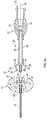
- FIG. 1is an upper perspective view of an example needle shield coupled to an example catheter assembly ready for insertion into vasculature of a patient, according to some embodiments;
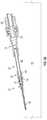
- FIG. 2is an upper perspective view of the catheter assembly of FIG. 1 and an example extension ready to be coupled to the catheter assembly, according to some embodiments;
- FIG. 3Ais a widthwise cross-sectional view of the catheter assembly of FIG. 1 and the extension of FIG. 2 , according to some embodiments;
- FIG. 3Bis a widthwise, enlarged cross-sectional view of the extension of FIG. 2 secured to the catheter assembly of FIG. 1 , according to some embodiments;
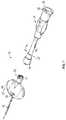
- FIG. 4is an upper perspective view of the extension of FIG. 2 secured to the catheter assembly of FIG. 1 , according to some embodiments;
- FIG. 5Ais a longitudinal cross-sectional view of a conventional catheter assembly inserted into skin of the patient and coupled to an example male luer fitting, according to some embodiments;
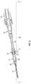
- FIG. 5Bis a longitudinal cross-sectional view of the extension of FIG. 2 secured to the catheter assembly of FIG. 1 and the male luer fitting of FIG. 5A , according to some embodiments;
- FIG. 6is an upper perspective, cutaway view of the catheter assembly of FIG. 1 secured to the extension of FIG. 2 , according to some embodiments;
- FIG. 7is an upper perspective view of the catheter assembly of FIG. 1 and the example extension of FIG. 2 ready to be coupled to the catheter assembly, according to some embodiments.
- FIG. 8is a longitudinal cross-sectional view of the extension of FIG. 2 secured to the catheter assembly of FIG. 1 and the male luer fitting of FIG. 5A , according to some embodiments.
- FIG. 1illustrates a catheter assembly 10 in accordance with one or more embodiments.
- the catheter assembly 10may include a catheter adapter 12 coupled to a needle safety feature, which may include a needle shield 14 .
- a catheter 16may extend distally from the catheter adapter 12 , and a proximal end of the catheter 16 may be secured within the catheter adapter 12 .
- the needle shield 14may include a needle hub (not illustrated), which may secure a proximal end of an introducer needle 18 .
- the needle 18when the needle 18 is ready to be inserted into vasculature of the patient, the needle 18 may extend through the catheter 16 and beyond a tip of the catheter 16 , as illustrated in FIG. 1 .
- the needle hubmay be retracted into the needle shield 14 such that the needle 18 is fully contained within the needle shield 14 .
- a blood control septum disposed within a lumen of the catheter adaptermay close to prevent blood leakage.
- the needle shield 14may be uncoupled from the catheter adapter 12 in response to the catheter 16 being inserted into the vasculature of the patient and/or the needle 18 being retracted into the needle shield 14 .
- a male luer fittingmay then be coupled to the catheter adapter 12 , and fluid may be infused into the vasculature of the patient via the catheter 16 .
- an extensionmay be coupled with the proximal end of the catheter adapter, and the male luer fitting may be coupled to a proximal end of the extension, as will be described in further detail.
- the fluidmay be infused into the vasculature of the patient via a fluid pathway that includes the extension.
- the catheter assembly 10may include any suitable type of catheter assembly.
- the catheter assembly 10may include an intravenous (IV) catheter assembly.
- the catheter assembly 10may include one or more features of the BD INSYTETM AUTOGUARDTM Shield IV Catheter, and the needle shield 14 may be spring loaded.
- the catheter assembly 10may include one or more features of the BD NEXIVATM DIFFUSICSTM Closed IV Catheter System.
- Suitable materials for the catheter adapter 12 and/or the extension 20may include, but are not limited to, thermoplastic polymeric resins such as polycarbonate, polystyrene, polypropylene, polyethylene terephthalate glycol PETG), and the like.
- the extension 20may include an elongated body.
- a distal end of the extension 20may include a connector element 22 .
- the connector element 22may include an insertion feature 24 and one or more cantilever arms 26 spaced apart from the insertion feature 24 .
- the cantilever arms 26may be disposed generally parallel to the insertion feature 24 .
- the cantilever arms 26may extend in a distal direction.
- the cantilever arms 26may be spaced apart from the insertion feature 24 by outwardly-extending separator elements 28 .
- the insertion feature 24may be aligned with a longitudinal axis of the extension 20 .
- the proximal end of the catheter adapter 12may include a proximal face 21 having a first opening 23 for a first slot 40 a , a second opening 25 for a second slot 40 b , and a proximal lumen opening 27 .
- a body 29 of the catheter adapter 12 at the proximal face 21may have a distance between the first opening 23 and the proximal lumen opening 27 that is uninterrupted and another distance between the second opening 25 and the proximal lumen opening 27 that is uninterrupted, as illustrated in FIG. 2 .
- the connector elementmay include any number of cantilever arms 26 .
- a first cantilever arm 26 and a second cantilever arm 26may be aligned on opposite sides of the extension 20 , as illustrated in FIG. 2 .
- the connector element 22may include an annular cantilever arm 26 , which may surround the insertion feature 24 .
- the proximal end of the extension 20may be configured to connect to another device.
- the proximal end of the extensionmay include a female luer fitting 30 .
- the proximal end of the extension 20may include one or more threads for connection to the male luer fitting or another connector.
- the extension 20may include a grip portion 32 , which may facilitate insertion of the extension 20 into the catheter adapter 12 by a user.
- the grip portion 32may include one or more wings 34 and/or protrusions 36 .
- each of the cantilever arms 26may engage in a snap-fit with the catheter adapter 12 .
- each of the cantilever arms 26may include a distal end that includes a hook 38 .
- each of the cantilever arms 26may deflect as the hook 38 of the corresponding cantilever arm 26 is inserted into a corresponding slot 40 of the catheter adapter 12 .
- the cantilever arm 26may return to an original shape of the cantilever arm 26 prior to insertion into the slot 40 .
- the insertion feature 24may be sized and configured to insert into the lumen 44 of the catheter adapter 12 and open the blood control septum 46 when the cantilever arms 26 engage in the snap-fit with the catheter adapter 12 .
- the insertion feature 24may include an actuator.
- a connection between the extension 20 and the catheter adapter 12may be permanent, decreasing a risk of the user to blood exposure.
- the grooves 42may include an adhesive 47 , which may increase a strength of the connection between the extension 20 and the catheter adapter 12 .
- the catheter adapter 12may include a stabilization platform 48 .
- the stabilization platform 48may include one or more wings, which may extend outwardly from a body of the catheter adapter 12 .
- the slots 40may be disposed within the stabilization platform 48 .
- a first slot 40 corresponding to a first cantilever arm 26may be disposed on a first side of the stabilization platform 48
- a second slot 40 corresponding to a second cantilever arm 26may be disposed on a second side of the stabilization platform 48 .
- the slots 40may be generally parallel to a longitudinal axis 50 of the catheter adapter 12 and the extension 20 .
- the slots 40may be spaced apart from the lumen 44 of the catheter adapter 12 .
- the extension 20may include a lumen 54 extending therethrough.
- the lumen 54 of the extension 20may extend through the insertion feature 24 of the distal end of the extension 20 to a proximal end of the extension 20 .
- the extension 20may be integrally formed or include separate components.
- the connector element 22may be coupled with a tubular element 56 of the extension 20 .
- the tubular element 56 and the connector element 22may be integrally formed.
- the tubular element 56may have a uniform inner diameter, which may be greater than an inner diameter of the insertion feature 24 .
- a shape of the stabilization platform 48may be generally planar or flat, which may allow the stabilization platform 48 to have a low-profile.
- a distal end of the stabilization platform 48may include a gradual taper.
- the stabilization platform 48may include a push tab 58 disposed on an upper surface of the stabilization platform 48 .
- the push tab 58may be integrally molded from a same material as the stabilization platform 48 .
- the upper surface of the stabilization platform 48may be smooth except for the push tab 58 .
- a bottom surface of the stabilization platform 48may be smooth.
- the catheter adapter 12 and/or the extension 20may be free of protruding edges that may irritate the skin of the patient.
- the separator elements 28may complete a geometric shape of the catheter adapter 12 when the connector element 22 is secured to the catheter adapter 12 .
- a width of the separator elements 28may be approximately equal to a width of the catheter adapter 12 such that the separator elements 28 do not protrude above or below the catheter adapter 12 and irritate the skin of the patient, as illustrated in FIG. 4 .
- the stabilization platform 48may support one or more digits of the user as the user inserts the catheter 16 at the insertion site, hoods the needle 18 , or moves the catheter assembly 12 from an insertion configuration to a fluid delivery configuration.
- the usermay pinch or grip the stabilization platform 24 , which may extend outwardly from the longitudinal axis 50 .
- the securement platform 48may optionally be “soft,” i.e., formed of a relatively compliant material that conforms easily to the skin of the patient.
- the securement platform 48may be formed of a soft plastic, an elastomer such as silicone rubber, and/or the like.
- a conventional catheter adapter 59may be directly connected to the male luer fitting 60 , which may increase a gap or distance between the catheter adapter 59 and the skin 61 of the patient due to threading between the catheter adapter 59 and the male luer fitting 60 .
- the male luer fitting 60 directly connected to the conventional catheter adapter 59may also increase an angle of the catheter adapter 59 with respect to the skin 61 .
- the extension 20may be secured to the catheter adapter 12 without any turning or twisting, which may allow the catheter adapter 12 and the extension 20 to maintain a low-profile.
- the catheter adapter 12may sit closer to the skin 61 than the conventional catheter adapter 59 , maximizing a catheter insertion depth and stability of the catheter 16 .
- a side of the catheter adapter 12may be allowed to contact the skin 61 , further increasing the stability of the catheter 16 .
- an outer diameter of the catheter adapter 12may be decreased or tapered at a tip or nose of the catheter adapter 12 compared to the conventional catheter adapter 59 , which may allow the catheter adapter 12 to maintain a low-profile.
- the male luer fitting 60may include one or more protruding sharp edges, which may more easily contact the skin 61 in absence of the extension 20 , as illustrated in FIG. 5A .
- the extension 20may allow for remote manipulation of the male luer fitting 60 and luer connection, which may reduce a risk of disturbing an insertion site of the catheter 16 .
- the catheter adapter 12may not include the blood control septum 46 , such as, for example, in neonatal applications.
- a conical sealmay be relied upon to provide blood control.
- a male conical surface of the insertion feature 24may wedge into or be engaged in an interference fit with a female conical surface of the catheter adapter 12 .
- an outer diameter of the insertion feature 24 and an inner diameter of the catheter adapter 12may be approximately the same.
- the proximal end of the catheter adapter 12may include a connector, such as, for example, a female luer-type fitting 62 .
- the proximal end of the extension 20may include another female luer-type fitting.
- the female luer-type fitting 62 and the other female luer-type fittingmay be a same or similar size.
- the other female luer-type fittingmay include the female luer fitting 30 .
- the female luer-type fitting 62 of the catheter adapter 12may have a reduced size compared to the female luer fitting 30 of the proximal end of the extension 20 .
- a proximal end and/or threads 64 of the female luer-type fitting 62may have a reduced diameter compared to a proximal end and/or threads 66 of the female luer fitting 30 .
- a corresponding male luer-type fitting 70 of the distal end of the extension 20may be reduced in size compared to the male luer fitting 60 , allowing the catheter adapter 12 and the extension 20 to maintain a low-profile.
- the low-profile of the catheter adapter 12 and/or the extension 20may allow the catheter adapter 12 to sit close to the skin 61 , which may increase an catheter insertion depth and stability of the catheter 16 .
- a side of the catheter adapter 12may contact the skin 61 , increasing the stability of the catheter 16 .
- the male luer fitting 60 and/or the female luer fitting 30may correspond to International Organization for Standardization (“ISO”) 80369-7.
- ISOInternational Organization for Standardization
- a cross-sectional diameter at a distal end of a tip of the male luer fitting 60may be between about 0.1563 inches (3.970 mm) and about 0.1603 inches (4.072 mm).
- an inner cross-sectional diameter at an open proximal end of the female luer fitting 30may be between about 0.1653 inches (4.198 mm) and about 0.1692 inches (4.298 mm).
- the male luer-type fitting 70 and/or the female luer-type fitting 62may be smaller than ISO 80369-7.
- a cross-sectional diameter at a distal end of a tip of the male luer-type fitting 70may be less than about 0.1545 inches (3.925 mm) for rigid material and less than about 0.1545 inches (3.925 mm) for semi-rigid material.
- an inner cross-sectional diameter at an open proximal end of the female luer-type fitting 62may be less than about 0.168 inches (4.270 mm).
- the male luer-type fitting 70 , the female luer-type fitting 62 , and/or the tubular element 56may be sized to reduce a priming volume for sensitive applications such as infusion for neonates.
- the male luer-type fitting 70 and the female luer-type fitting 62may be sized smaller than International Organization for Standardization (“ISO”) 80369-7, and a size of the tubular element 56 may correspond to the male luer-type fitting 70 .
- ISOInternational Organization for Standardization
- a portion of the lumen 54 of the extension 62 that extends through the male luer-type fitting 70 and the tubular element 56may have a generally uniform diameter.
Landscapes
- Health & Medical Sciences (AREA)
- Life Sciences & Earth Sciences (AREA)
- Heart & Thoracic Surgery (AREA)
- Hematology (AREA)
- Engineering & Computer Science (AREA)
- Anesthesiology (AREA)
- Biomedical Technology (AREA)
- Pulmonology (AREA)
- Animal Behavior & Ethology (AREA)
- General Health & Medical Sciences (AREA)
- Public Health (AREA)
- Veterinary Medicine (AREA)
- Biophysics (AREA)
- Media Introduction/Drainage Providing Device (AREA)
- Infusion, Injection, And Reservoir Apparatuses (AREA)
- Materials For Medical Uses (AREA)
Abstract
Description
Claims (8)
Priority Applications (13)
| Application Number | Priority Date | Filing Date | Title |
|---|---|---|---|
| US15/481,690US11116936B2 (en) | 2017-04-07 | 2017-04-07 | Low-profile extension for a catheter assembly |
| CN201890000856.0UCN211884904U (en) | 2017-04-07 | 2018-03-05 | Extensions for catheter assemblies and catheter systems |
| BR112019020878-0ABR112019020878B1 (en) | 2017-04-07 | 2018-03-05 | CATHETER SYSTEM |
| SG11201909002VSG11201909002VA (en) | 2017-04-07 | 2018-03-05 | Low-profile extension for a catheter assembly |
| JP2019554993AJP7136803B2 (en) | 2017-04-07 | 2018-03-05 | Low profile extension for catheter assembly |
| EP18713456.4AEP3606590B1 (en) | 2017-04-07 | 2018-03-05 | Low-profile extension for a catheter assembly |
| PCT/US2018/020947WO2018186964A2 (en) | 2017-04-07 | 2018-03-05 | Low-profile extension for a catheter assembly |
| NZ778889ANZ778889B2 (en) | 2018-03-05 | Low-profile extension for a catheter assembly | |
| MX2019011763AMX2019011763A (en) | 2017-04-07 | 2018-03-05 | Low-profile extension for a catheter assembly. |
| MYPI2019005847AMY197468A (en) | 2017-04-07 | 2018-03-05 | Low-profile extension for a catheter assembly |
| CA3058616ACA3058616A1 (en) | 2017-04-07 | 2018-03-05 | Low-profile extension for a catheter assembly |
| AU2018250014AAU2018250014B2 (en) | 2017-04-07 | 2018-03-05 | Low-profile extension for a catheter assembly |
| NZ758144ANZ758144B2 (en) | 2017-04-07 | 2018-03-05 | Low-profile extension for a catheter assembly |
Applications Claiming Priority (1)
| Application Number | Priority Date | Filing Date | Title |
|---|---|---|---|
| US15/481,690US11116936B2 (en) | 2017-04-07 | 2017-04-07 | Low-profile extension for a catheter assembly |
Publications (2)
| Publication Number | Publication Date |
|---|---|
| US20180289920A1 US20180289920A1 (en) | 2018-10-11 |
| US11116936B2true US11116936B2 (en) | 2021-09-14 |
Family
ID=61768452
Family Applications (1)
| Application Number | Title | Priority Date | Filing Date |
|---|---|---|---|
| US15/481,690Active2037-12-09US11116936B2 (en) | 2017-04-07 | 2017-04-07 | Low-profile extension for a catheter assembly |
Country Status (10)
| Country | Link |
|---|---|
| US (1) | US11116936B2 (en) |
| EP (1) | EP3606590B1 (en) |
| JP (1) | JP7136803B2 (en) |
| CN (1) | CN211884904U (en) |
| AU (1) | AU2018250014B2 (en) |
| CA (1) | CA3058616A1 (en) |
| MX (1) | MX2019011763A (en) |
| MY (1) | MY197468A (en) |
| SG (1) | SG11201909002VA (en) |
| WO (1) | WO2018186964A2 (en) |
Cited By (3)
| Publication number | Priority date | Publication date | Assignee | Title |
|---|---|---|---|---|
| USD967413S1 (en)* | 2020-03-30 | 2022-10-18 | Roland Quaye | Disposable cystoscope |
| WO2025160536A1 (en)* | 2024-01-26 | 2025-07-31 | Terumo Corporation | Locking luer |
| US12415055B2 (en) | 2017-09-29 | 2025-09-16 | Terumo Kabushiki Kaisha | Catheter assembly and medical valve |
Families Citing this family (4)
| Publication number | Priority date | Publication date | Assignee | Title |
|---|---|---|---|---|
| US10773056B2 (en) | 2017-03-21 | 2020-09-15 | Velano Vascular, Inc. | Systems and methods for controlling catheter device size |
| KR102573751B1 (en) | 2017-03-21 | 2023-09-04 | 벨라노 바스큘라, 인크. | Devices and methods for fluid delivery through a deployed peripheral intravenous catheter |
| CN119185741A (en) | 2019-08-20 | 2024-12-27 | 威蓝诺血管股份有限公司 | Fluid delivery device with elongate conduit and method of use thereof |
| US11565084B2 (en)* | 2020-05-01 | 2023-01-31 | Np Medical Inc. | Low profile catheter system |
Citations (24)
| Publication number | Priority date | Publication date | Assignee | Title |
|---|---|---|---|---|
| WO1991016938A1 (en) | 1990-05-07 | 1991-11-14 | Ryan Medical, Inc. | Medical intravenous administration line connector |
| US5522803A (en)* | 1993-03-09 | 1996-06-04 | Pharma Plast International A/S | Infusion set for an intermittent or continuous administration of a therapeutical substance |
| EP0891204A1 (en) | 1996-04-03 | 1999-01-20 | ICU Medical, Inc. | Locking blunt cannula |
| WO1999044655A2 (en) | 1998-03-04 | 1999-09-10 | Minimed Inc. | Medication infusion set |
| US6302866B1 (en)* | 1998-05-14 | 2001-10-16 | Disetronic Licensing Ag | Catheter head for subcutaneous administration of an substance |
| US20020120231A1 (en)* | 2000-01-18 | 2002-08-29 | Douglas Joel S. | Subcutaneous injection set with secondary injection septum |
| US20020161332A1 (en)* | 2001-04-13 | 2002-10-31 | Kirk Ramey | Infusion set with tape |
| US20020173769A1 (en)* | 2001-05-18 | 2002-11-21 | Gray Larry B. | Infusion set for a fluid pump |
| US20030208165A1 (en)* | 2002-05-01 | 2003-11-06 | Christensen Kelly David | Needless luer access connector |
| US6749589B1 (en)* | 2000-01-18 | 2004-06-15 | Sterling Medications, Inc. | Subcutaneous injection set for use with a reservoir that has a septum |
| US20060047251A1 (en)* | 2002-10-22 | 2006-03-02 | Philip Bickford Smith | Medical small-bore tubing system and kit |
| US7220241B2 (en)* | 2004-07-23 | 2007-05-22 | Clinico Gmbh | Coupling mechanism for connecting a catheter to a medical infusion line |
| US7303543B1 (en)* | 2004-12-03 | 2007-12-04 | Medtronic Minimed, Inc. | Medication infusion set |
| US7318818B2 (en)* | 2003-04-08 | 2008-01-15 | Nipro Corporation | Indwelling catheter set |
| US20080140020A1 (en) | 2006-12-08 | 2008-06-12 | Utah Medical Products Inc. | Lockable enteral feeding adapter |
| US20080214999A1 (en)* | 2000-02-01 | 2008-09-04 | Kletchka Harold D | Angioplasty device and method of making same |
| US8062250B2 (en)* | 2004-08-10 | 2011-11-22 | Unomedical A/S | Cannula device |
| US20120323181A1 (en)* | 2011-06-17 | 2012-12-20 | Shaw Thomas J | Intravenous Catheter Introducer with Needle Retraction Controlled by Catheter Hub Seal |
| US8465461B2 (en)* | 2010-07-27 | 2013-06-18 | Becton, Dickinson And Company | Blunt needle safety drug delivery system |
| US20140074031A1 (en)* | 2012-09-13 | 2014-03-13 | Becton, Dickinson And Company | Integrated catheter securement and luer access device |
| US20140180250A1 (en)* | 2011-01-31 | 2014-06-26 | Vascular Pathways, Inc. | Intravenous catheter and insertion device with reduced blood spatter |
| EP2837403A1 (en) | 2012-04-13 | 2015-02-18 | JMS Co., Ltd. | Male connector equipped with lock mechanism |
| US20160015888A1 (en)* | 2014-07-21 | 2016-01-21 | Medtronic Minimed, Inc. | Smart connection interface |
| US20170239443A1 (en)* | 2016-02-18 | 2017-08-24 | Smiths Medical Asd, Inc. | Closed system catheter |
Family Cites Families (3)
| Publication number | Priority date | Publication date | Assignee | Title |
|---|---|---|---|---|
| US5620427A (en)* | 1995-04-27 | 1997-04-15 | David R. Kipp | Luer lock system |
| US7998134B2 (en) | 2007-05-16 | 2011-08-16 | Icu Medical, Inc. | Medical connector |
| US9381337B2 (en) | 2010-07-19 | 2016-07-05 | Becton, Dickinson And Company | Luer connector |
- 2017
- 2017-04-07USUS15/481,690patent/US11116936B2/enactiveActive
- 2018
- 2018-03-05WOPCT/US2018/020947patent/WO2018186964A2/ennot_activeCeased
- 2018-03-05AUAU2018250014Apatent/AU2018250014B2/enactiveActive
- 2018-03-05EPEP18713456.4Apatent/EP3606590B1/enactiveActive
- 2018-03-05CACA3058616Apatent/CA3058616A1/enactivePending
- 2018-03-05CNCN201890000856.0Upatent/CN211884904U/enactiveActive
- 2018-03-05JPJP2019554993Apatent/JP7136803B2/enactiveActive
- 2018-03-05SGSG11201909002Vpatent/SG11201909002VA/enunknown
- 2018-03-05MXMX2019011763Apatent/MX2019011763A/enunknown
- 2018-03-05MYMYPI2019005847Apatent/MY197468A/enunknown
Patent Citations (28)
| Publication number | Priority date | Publication date | Assignee | Title |
|---|---|---|---|---|
| WO1991016938A1 (en) | 1990-05-07 | 1991-11-14 | Ryan Medical, Inc. | Medical intravenous administration line connector |
| US5522803A (en)* | 1993-03-09 | 1996-06-04 | Pharma Plast International A/S | Infusion set for an intermittent or continuous administration of a therapeutical substance |
| EP0891204A1 (en) | 1996-04-03 | 1999-01-20 | ICU Medical, Inc. | Locking blunt cannula |
| WO1999044655A2 (en) | 1998-03-04 | 1999-09-10 | Minimed Inc. | Medication infusion set |
| US6056718A (en)* | 1998-03-04 | 2000-05-02 | Minimed Inc. | Medication infusion set |
| US6302866B1 (en)* | 1998-05-14 | 2001-10-16 | Disetronic Licensing Ag | Catheter head for subcutaneous administration of an substance |
| US6749589B1 (en)* | 2000-01-18 | 2004-06-15 | Sterling Medications, Inc. | Subcutaneous injection set for use with a reservoir that has a septum |
| US20020120231A1 (en)* | 2000-01-18 | 2002-08-29 | Douglas Joel S. | Subcutaneous injection set with secondary injection septum |
| US20080214999A1 (en)* | 2000-02-01 | 2008-09-04 | Kletchka Harold D | Angioplasty device and method of making same |
| US20020161332A1 (en)* | 2001-04-13 | 2002-10-31 | Kirk Ramey | Infusion set with tape |
| US20020173769A1 (en)* | 2001-05-18 | 2002-11-21 | Gray Larry B. | Infusion set for a fluid pump |
| US20070049870A1 (en)* | 2001-05-18 | 2007-03-01 | Deka Products Limited Partnership | Infusion Set for a Fluid Pump |
| US20160051757A1 (en)* | 2001-05-18 | 2016-02-25 | Deka Products Limited Partnership | Infusion set for a fluid pump |
| US9173996B2 (en)* | 2001-05-18 | 2015-11-03 | Deka Products Limited Partnership | Infusion set for a fluid pump |
| US20030208165A1 (en)* | 2002-05-01 | 2003-11-06 | Christensen Kelly David | Needless luer access connector |
| US20060047251A1 (en)* | 2002-10-22 | 2006-03-02 | Philip Bickford Smith | Medical small-bore tubing system and kit |
| US7318818B2 (en)* | 2003-04-08 | 2008-01-15 | Nipro Corporation | Indwelling catheter set |
| US7220241B2 (en)* | 2004-07-23 | 2007-05-22 | Clinico Gmbh | Coupling mechanism for connecting a catheter to a medical infusion line |
| US8062250B2 (en)* | 2004-08-10 | 2011-11-22 | Unomedical A/S | Cannula device |
| US7303543B1 (en)* | 2004-12-03 | 2007-12-04 | Medtronic Minimed, Inc. | Medication infusion set |
| US20080140020A1 (en) | 2006-12-08 | 2008-06-12 | Utah Medical Products Inc. | Lockable enteral feeding adapter |
| US8465461B2 (en)* | 2010-07-27 | 2013-06-18 | Becton, Dickinson And Company | Blunt needle safety drug delivery system |
| US20140180250A1 (en)* | 2011-01-31 | 2014-06-26 | Vascular Pathways, Inc. | Intravenous catheter and insertion device with reduced blood spatter |
| US20120323181A1 (en)* | 2011-06-17 | 2012-12-20 | Shaw Thomas J | Intravenous Catheter Introducer with Needle Retraction Controlled by Catheter Hub Seal |
| EP2837403A1 (en) | 2012-04-13 | 2015-02-18 | JMS Co., Ltd. | Male connector equipped with lock mechanism |
| US20140074031A1 (en)* | 2012-09-13 | 2014-03-13 | Becton, Dickinson And Company | Integrated catheter securement and luer access device |
| US20160015888A1 (en)* | 2014-07-21 | 2016-01-21 | Medtronic Minimed, Inc. | Smart connection interface |
| US20170239443A1 (en)* | 2016-02-18 | 2017-08-24 | Smiths Medical Asd, Inc. | Closed system catheter |
Cited By (3)
| Publication number | Priority date | Publication date | Assignee | Title |
|---|---|---|---|---|
| US12415055B2 (en) | 2017-09-29 | 2025-09-16 | Terumo Kabushiki Kaisha | Catheter assembly and medical valve |
| USD967413S1 (en)* | 2020-03-30 | 2022-10-18 | Roland Quaye | Disposable cystoscope |
| WO2025160536A1 (en)* | 2024-01-26 | 2025-07-31 | Terumo Corporation | Locking luer |
Also Published As
| Publication number | Publication date |
|---|---|
| MX2019011763A (en) | 2019-12-09 |
| MY197468A (en) | 2023-06-19 |
| BR112019020878A2 (en) | 2020-04-28 |
| EP3606590B1 (en) | 2025-08-06 |
| JP7136803B2 (en) | 2022-09-13 |
| WO2018186964A3 (en) | 2019-01-17 |
| SG11201909002VA (en) | 2019-10-30 |
| EP3606590C0 (en) | 2025-08-06 |
| CA3058616A1 (en) | 2018-10-11 |
| AU2018250014B2 (en) | 2020-12-24 |
| CN211884904U (en) | 2020-11-10 |
| AU2018250014A1 (en) | 2019-10-31 |
| US20180289920A1 (en) | 2018-10-11 |
| NZ778889A (en) | 2024-03-22 |
| NZ758144A (en) | 2021-08-27 |
| EP3606590A2 (en) | 2020-02-12 |
| WO2018186964A2 (en) | 2018-10-11 |
| JP2020512893A (en) | 2020-04-30 |
Similar Documents
| Publication | Publication Date | Title |
|---|---|---|
| US11116936B2 (en) | Low-profile extension for a catheter assembly | |
| US20210346653A1 (en) | Systems and methods to improve instrument guidance within an intravenous catheter assembly | |
| US11224720B2 (en) | Infusion systems, connectors for use with catheter devices, and related methods | |
| JP7257318B2 (en) | Intravenous catheter device with safety function and pressure control valve body | |
| AU2019337507B2 (en) | Catheter stabilization platform, systems, and methods | |
| US11865274B2 (en) | Catheter system for pediatric treatment | |
| US20220249828A1 (en) | Extension tube clamp providing positive displacement | |
| US12246157B2 (en) | Needleless access connector facilitating instrument delivery to a catheter assembly | |
| US20210162167A1 (en) | Catheter assemblies and related methods | |
| NZ758144B2 (en) | Low-profile extension for a catheter assembly | |
| KR20230005831A (en) | PRN adapter | |
| BR112019020878B1 (en) | CATHETER SYSTEM | |
| EP4498912B1 (en) | Hemolysis-reduction accessories for direct blood draw | |
| CN223233127U (en) | Coupling mechanism and fluid connector assembly including the same | |
| HK1228812A1 (en) | Safety needle assemblies and related methods |
Legal Events
| Date | Code | Title | Description |
|---|---|---|---|
| AS | Assignment | Owner name:BECTON, DICKINSON AND COMPANY, NEW JERSEY Free format text:ASSIGNMENT OF ASSIGNORS INTEREST;ASSIGNORS:HARDING, WESTON F;STALEY, SHAUN;REEL/FRAME:041929/0016 Effective date:20170327 | |
| STPP | Information on status: patent application and granting procedure in general | Free format text:NON FINAL ACTION MAILED | |
| STPP | Information on status: patent application and granting procedure in general | Free format text:FINAL REJECTION MAILED | |
| STPP | Information on status: patent application and granting procedure in general | Free format text:DOCKETED NEW CASE - READY FOR EXAMINATION | |
| STPP | Information on status: patent application and granting procedure in general | Free format text:NON FINAL ACTION MAILED | |
| STPP | Information on status: patent application and granting procedure in general | Free format text:RESPONSE TO NON-FINAL OFFICE ACTION ENTERED AND FORWARDED TO EXAMINER | |
| STPP | Information on status: patent application and granting procedure in general | Free format text:FINAL REJECTION MAILED | |
| STPP | Information on status: patent application and granting procedure in general | Free format text:DOCKETED NEW CASE - READY FOR EXAMINATION | |
| STPP | Information on status: patent application and granting procedure in general | Free format text:NOTICE OF ALLOWANCE MAILED -- APPLICATION RECEIVED IN OFFICE OF PUBLICATIONS | |
| STPP | Information on status: patent application and granting procedure in general | Free format text:PUBLICATIONS -- ISSUE FEE PAYMENT VERIFIED | |
| STCF | Information on status: patent grant | Free format text:PATENTED CASE | |
| MAFP | Maintenance fee payment | Free format text:PAYMENT OF MAINTENANCE FEE, 4TH YEAR, LARGE ENTITY (ORIGINAL EVENT CODE: M1551); ENTITY STATUS OF PATENT OWNER: LARGE ENTITY Year of fee payment:4 |