US11116892B2 - Medium injection diversion and measurement - Google Patents
Medium injection diversion and measurementDownload PDFInfo
- Publication number
- US11116892B2 US11116892B2US16/024,768US201816024768AUS11116892B2US 11116892 B2US11116892 B2US 11116892B2US 201816024768 AUS201816024768 AUS 201816024768AUS 11116892 B2US11116892 B2US 11116892B2
- Authority
- US
- United States
- Prior art keywords
- reservoir
- injector
- medium
- fluid
- sensor module
- Prior art date
- Legal status (The legal status is an assumption and is not a legal conclusion. Google has not performed a legal analysis and makes no representation as to the accuracy of the status listed.)
- Active
Links
- 238000002347injectionMethods0.000titleclaimsabstractdescription112
- 239000007924injectionSubstances0.000titleclaimsabstractdescription112
- 238000005259measurementMethods0.000titleclaimsabstractdescription68
- 239000012530fluidSubstances0.000claimsabstractdescription109
- FAPWRFPIFSIZLT-UHFFFAOYSA-MSodium chlorideChemical compound[Na+].[Cl-]FAPWRFPIFSIZLT-UHFFFAOYSA-M0.000claimsdescription20
- 239000011780sodium chlorideSubstances0.000claimsdescription20
- 230000008878couplingEffects0.000claimsdescription15
- 238000010168coupling processMethods0.000claimsdescription15
- 238000005859coupling reactionMethods0.000claimsdescription15
- 238000006073displacement reactionMethods0.000claimsdescription8
- 238000003780insertionMethods0.000claimsdescription3
- 230000037431insertionEffects0.000claimsdescription3
- 238000000034methodMethods0.000description62
- 238000012544monitoring processMethods0.000description44
- 239000002872contrast mediaSubstances0.000description25
- 238000005516engineering processMethods0.000description20
- 238000004891communicationMethods0.000description17
- 230000014759maintenance of locationEffects0.000description16
- 238000003860storageMethods0.000description13
- 230000008901benefitEffects0.000description12
- 230000008859changeEffects0.000description12
- 238000007726management methodMethods0.000description11
- 239000003795chemical substances by applicationSubstances0.000description10
- 230000006870functionEffects0.000description9
- 230000001965increasing effectEffects0.000description8
- 230000000670limiting effectEffects0.000description8
- 239000000975dyeSubstances0.000description7
- 210000003734kidneyAnatomy0.000description7
- 239000000463materialSubstances0.000description7
- 238000012545processingMethods0.000description7
- 229940039231contrast mediaDrugs0.000description6
- 239000000126substanceSubstances0.000description6
- 238000004458analytical methodMethods0.000description5
- 238000011010flushing procedureMethods0.000description5
- 230000036961partial effectEffects0.000description5
- 231100000331toxicToxicity0.000description5
- 230000002588toxic effectEffects0.000description5
- 230000002792vascularEffects0.000description5
- 230000009977dual effectEffects0.000description4
- 210000003811fingerAnatomy0.000description4
- 230000007246mechanismEffects0.000description4
- 238000012986modificationMethods0.000description4
- 230000004048modificationEffects0.000description4
- 238000012806monitoring deviceMethods0.000description4
- 210000000056organAnatomy0.000description4
- 230000008569processEffects0.000description4
- 238000010926purgeMethods0.000description4
- 230000009885systemic effectEffects0.000description4
- 210000003813thumbAnatomy0.000description4
- 210000005166vasculatureAnatomy0.000description4
- 230000004913activationEffects0.000description3
- 210000004351coronary vesselAnatomy0.000description3
- 239000003814drugSubstances0.000description3
- 238000004519manufacturing processMethods0.000description3
- 230000003287optical effectEffects0.000description3
- 230000037452primingEffects0.000description3
- 238000007639printingMethods0.000description3
- 230000000069prophylactic effectEffects0.000description3
- 230000001105regulatory effectEffects0.000description3
- 231100000419toxicityToxicity0.000description3
- 230000001988toxicityEffects0.000description3
- 238000012546transferMethods0.000description3
- 238000012800visualizationMethods0.000description3
- 206010028980NeoplasmDiseases0.000description2
- 238000002583angiographyMethods0.000description2
- 238000002399angioplastyMethods0.000description2
- 210000001367arteryAnatomy0.000description2
- 239000008280bloodSubstances0.000description2
- 210000004369bloodAnatomy0.000description2
- 238000010276constructionMethods0.000description2
- 230000001276controlling effectEffects0.000description2
- 238000000502dialysisMethods0.000description2
- 230000001939inductive effectEffects0.000description2
- 238000001802infusionMethods0.000description2
- 208000017169kidney diseaseDiseases0.000description2
- 239000000203mixtureSubstances0.000description2
- 239000004417polycarbonateSubstances0.000description2
- 230000002265preventionEffects0.000description2
- 230000009467reductionEffects0.000description2
- 230000000717retained effectEffects0.000description2
- 230000002441reversible effectEffects0.000description2
- 230000001225therapeutic effectEffects0.000description2
- 210000001519tissueAnatomy0.000description2
- 230000000007visual effectEffects0.000description2
- 239000002699waste materialSubstances0.000description2
- OKTJSMMVPCPJKN-UHFFFAOYSA-NCarbonChemical compound[C]OKTJSMMVPCPJKN-UHFFFAOYSA-N0.000description1
- 241001453233Doodia mediaSpecies0.000description1
- 230000005355Hall effectEffects0.000description1
- 235000014676Phragmites communisNutrition0.000description1
- 241000379547Trifolium mediumSpecies0.000description1
- 208000009443Vascular MalformationsDiseases0.000description1
- 239000003242anti bacterial agentSubstances0.000description1
- 230000003466anti-cipated effectEffects0.000description1
- 229940088710antibiotic agentDrugs0.000description1
- 239000003146anticoagulant agentSubstances0.000description1
- 210000004204blood vesselAnatomy0.000description1
- 210000000988bone and boneAnatomy0.000description1
- 239000004067bulking agentSubstances0.000description1
- 238000004364calculation methodMethods0.000description1
- 201000011510cancerDiseases0.000description1
- 229910052799carbonInorganic materials0.000description1
- 238000013480data collectionMethods0.000description1
- 230000003247decreasing effectEffects0.000description1
- 238000009795derivationMethods0.000description1
- 238000001514detection methodMethods0.000description1
- 238000003745diagnosisMethods0.000description1
- 238000009826distributionMethods0.000description1
- 239000000839emulsionSubstances0.000description1
- 238000004401flow injection analysisMethods0.000description1
- 230000002068genetic effectEffects0.000description1
- 230000036541healthEffects0.000description1
- 208000019622heart diseaseDiseases0.000description1
- 239000012216imaging agentSubstances0.000description1
- 238000010348incorporationMethods0.000description1
- 230000002427irreversible effectEffects0.000description1
- 238000002955isolationMethods0.000description1
- 239000007788liquidSubstances0.000description1
- 230000007774longtermEffects0.000description1
- 210000004324lymphatic systemAnatomy0.000description1
- 230000013011matingEffects0.000description1
- -1medicantSubstances0.000description1
- 239000002184metalSubstances0.000description1
- 230000003387muscularEffects0.000description1
- 230000006855networkingEffects0.000description1
- 230000001537neural effectEffects0.000description1
- 230000002093peripheral effectEffects0.000description1
- 239000004033plasticSubstances0.000description1
- 229920003023plasticPolymers0.000description1
- 239000002985plastic filmSubstances0.000description1
- 229920000515polycarbonatePolymers0.000description1
- 229920001296polysiloxanePolymers0.000description1
- 230000008439repair processEffects0.000description1
- 239000003229sclerosing agentSubstances0.000description1
- 238000007789sealingMethods0.000description1
- 230000035945sensitivityEffects0.000description1
- 239000007787solidSubstances0.000description1
- 210000005070sphincterAnatomy0.000description1
- 239000013589supplementSubstances0.000description1
- 230000002537thrombolytic effectEffects0.000description1
- 230000007723transport mechanismEffects0.000description1
- 208000019553vascular diseaseDiseases0.000description1
- 239000011800void materialSubstances0.000description1
Images


Classifications
- A—HUMAN NECESSITIES
- A61—MEDICAL OR VETERINARY SCIENCE; HYGIENE
- A61M—DEVICES FOR INTRODUCING MEDIA INTO, OR ONTO, THE BODY; DEVICES FOR TRANSDUCING BODY MEDIA OR FOR TAKING MEDIA FROM THE BODY; DEVICES FOR PRODUCING OR ENDING SLEEP OR STUPOR
- A61M5/00—Devices for bringing media into the body in a subcutaneous, intra-vascular or intramuscular way; Accessories therefor, e.g. filling or cleaning devices, arm-rests
- A61M5/007—Devices for bringing media into the body in a subcutaneous, intra-vascular or intramuscular way; Accessories therefor, e.g. filling or cleaning devices, arm-rests for contrast media
- A—HUMAN NECESSITIES
- A61—MEDICAL OR VETERINARY SCIENCE; HYGIENE
- A61M—DEVICES FOR INTRODUCING MEDIA INTO, OR ONTO, THE BODY; DEVICES FOR TRANSDUCING BODY MEDIA OR FOR TAKING MEDIA FROM THE BODY; DEVICES FOR PRODUCING OR ENDING SLEEP OR STUPOR
- A61M5/00—Devices for bringing media into the body in a subcutaneous, intra-vascular or intramuscular way; Accessories therefor, e.g. filling or cleaning devices, arm-rests
- A61M5/14—Infusion devices, e.g. infusing by gravity; Blood infusion; Accessories therefor
- A61M5/1407—Infusion of two or more substances
- A61M5/1408—Infusion of two or more substances in parallel, e.g. manifolds, sequencing valves
- A—HUMAN NECESSITIES
- A61—MEDICAL OR VETERINARY SCIENCE; HYGIENE
- A61M—DEVICES FOR INTRODUCING MEDIA INTO, OR ONTO, THE BODY; DEVICES FOR TRANSDUCING BODY MEDIA OR FOR TAKING MEDIA FROM THE BODY; DEVICES FOR PRODUCING OR ENDING SLEEP OR STUPOR
- A61M5/00—Devices for bringing media into the body in a subcutaneous, intra-vascular or intramuscular way; Accessories therefor, e.g. filling or cleaning devices, arm-rests
- A61M5/14—Infusion devices, e.g. infusing by gravity; Blood infusion; Accessories therefor
- A61M5/168—Means for controlling media flow to the body or for metering media to the body, e.g. drip meters, counters ; Monitoring media flow to the body
- A61M5/16804—Flow controllers
- A61M5/16813—Flow controllers by controlling the degree of opening of the flow line
- A—HUMAN NECESSITIES
- A61—MEDICAL OR VETERINARY SCIENCE; HYGIENE
- A61M—DEVICES FOR INTRODUCING MEDIA INTO, OR ONTO, THE BODY; DEVICES FOR TRANSDUCING BODY MEDIA OR FOR TAKING MEDIA FROM THE BODY; DEVICES FOR PRODUCING OR ENDING SLEEP OR STUPOR
- A61M5/00—Devices for bringing media into the body in a subcutaneous, intra-vascular or intramuscular way; Accessories therefor, e.g. filling or cleaning devices, arm-rests
- A61M5/14—Infusion devices, e.g. infusing by gravity; Blood infusion; Accessories therefor
- A61M5/168—Means for controlling media flow to the body or for metering media to the body, e.g. drip meters, counters ; Monitoring media flow to the body
- A61M5/16886—Means for controlling media flow to the body or for metering media to the body, e.g. drip meters, counters ; Monitoring media flow to the body for measuring fluid flow rate, i.e. flowmeters
- A—HUMAN NECESSITIES
- A61—MEDICAL OR VETERINARY SCIENCE; HYGIENE
- A61M—DEVICES FOR INTRODUCING MEDIA INTO, OR ONTO, THE BODY; DEVICES FOR TRANSDUCING BODY MEDIA OR FOR TAKING MEDIA FROM THE BODY; DEVICES FOR PRODUCING OR ENDING SLEEP OR STUPOR
- A61M5/00—Devices for bringing media into the body in a subcutaneous, intra-vascular or intramuscular way; Accessories therefor, e.g. filling or cleaning devices, arm-rests
- A61M5/14—Infusion devices, e.g. infusing by gravity; Blood infusion; Accessories therefor
- A61M5/168—Means for controlling media flow to the body or for metering media to the body, e.g. drip meters, counters ; Monitoring media flow to the body
- A61M5/172—Means for controlling media flow to the body or for metering media to the body, e.g. drip meters, counters ; Monitoring media flow to the body electrical or electronic
- A—HUMAN NECESSITIES
- A61—MEDICAL OR VETERINARY SCIENCE; HYGIENE
- A61M—DEVICES FOR INTRODUCING MEDIA INTO, OR ONTO, THE BODY; DEVICES FOR TRANSDUCING BODY MEDIA OR FOR TAKING MEDIA FROM THE BODY; DEVICES FOR PRODUCING OR ENDING SLEEP OR STUPOR
- A61M5/00—Devices for bringing media into the body in a subcutaneous, intra-vascular or intramuscular way; Accessories therefor, e.g. filling or cleaning devices, arm-rests
- A61M5/178—Syringes
- A61M5/31—Details
- A61M5/315—Pistons; Piston-rods; Guiding, blocking or restricting the movement of the rod or piston; Appliances on the rod for facilitating dosing ; Dosing mechanisms
- A61M5/31565—Administration mechanisms, i.e. constructional features, modes of administering a dose
- A61M5/31566—Means improving security or handling thereof
- A61M5/31568—Means keeping track of the total dose administered, e.g. since the cartridge was inserted
- A—HUMAN NECESSITIES
- A61—MEDICAL OR VETERINARY SCIENCE; HYGIENE
- A61M—DEVICES FOR INTRODUCING MEDIA INTO, OR ONTO, THE BODY; DEVICES FOR TRANSDUCING BODY MEDIA OR FOR TAKING MEDIA FROM THE BODY; DEVICES FOR PRODUCING OR ENDING SLEEP OR STUPOR
- A61M5/00—Devices for bringing media into the body in a subcutaneous, intra-vascular or intramuscular way; Accessories therefor, e.g. filling or cleaning devices, arm-rests
- A61M5/178—Syringes
- A61M5/31—Details
- A61M5/315—Pistons; Piston-rods; Guiding, blocking or restricting the movement of the rod or piston; Appliances on the rod for facilitating dosing ; Dosing mechanisms
- A61M5/31565—Administration mechanisms, i.e. constructional features, modes of administering a dose
- A61M5/31566—Means improving security or handling thereof
- A61M5/31573—Accuracy improving means
- A—HUMAN NECESSITIES
- A61—MEDICAL OR VETERINARY SCIENCE; HYGIENE
- A61M—DEVICES FOR INTRODUCING MEDIA INTO, OR ONTO, THE BODY; DEVICES FOR TRANSDUCING BODY MEDIA OR FOR TAKING MEDIA FROM THE BODY; DEVICES FOR PRODUCING OR ENDING SLEEP OR STUPOR
- A61M2205/00—General characteristics of the apparatus
- A61M2205/33—Controlling, regulating or measuring
- A61M2205/3306—Optical measuring means
- A—HUMAN NECESSITIES
- A61—MEDICAL OR VETERINARY SCIENCE; HYGIENE
- A61M—DEVICES FOR INTRODUCING MEDIA INTO, OR ONTO, THE BODY; DEVICES FOR TRANSDUCING BODY MEDIA OR FOR TAKING MEDIA FROM THE BODY; DEVICES FOR PRODUCING OR ENDING SLEEP OR STUPOR
- A61M2205/00—General characteristics of the apparatus
- A61M2205/33—Controlling, regulating or measuring
- A61M2205/3317—Electromagnetic, inductive or dielectric measuring means
- A—HUMAN NECESSITIES
- A61—MEDICAL OR VETERINARY SCIENCE; HYGIENE
- A61M—DEVICES FOR INTRODUCING MEDIA INTO, OR ONTO, THE BODY; DEVICES FOR TRANSDUCING BODY MEDIA OR FOR TAKING MEDIA FROM THE BODY; DEVICES FOR PRODUCING OR ENDING SLEEP OR STUPOR
- A61M2205/00—General characteristics of the apparatus
- A61M2205/33—Controlling, regulating or measuring
- A61M2205/3379—Masses, volumes, levels of fluids in reservoirs, flow rates
- A61M2205/3389—Continuous level detection
- A—HUMAN NECESSITIES
- A61—MEDICAL OR VETERINARY SCIENCE; HYGIENE
- A61M—DEVICES FOR INTRODUCING MEDIA INTO, OR ONTO, THE BODY; DEVICES FOR TRANSDUCING BODY MEDIA OR FOR TAKING MEDIA FROM THE BODY; DEVICES FOR PRODUCING OR ENDING SLEEP OR STUPOR
- A61M2205/00—General characteristics of the apparatus
- A61M2205/50—General characteristics of the apparatus with microprocessors or computers
- A61M2205/502—User interfaces, e.g. screens or keyboards
- A—HUMAN NECESSITIES
- A61—MEDICAL OR VETERINARY SCIENCE; HYGIENE
- A61M—DEVICES FOR INTRODUCING MEDIA INTO, OR ONTO, THE BODY; DEVICES FOR TRANSDUCING BODY MEDIA OR FOR TAKING MEDIA FROM THE BODY; DEVICES FOR PRODUCING OR ENDING SLEEP OR STUPOR
- A61M5/00—Devices for bringing media into the body in a subcutaneous, intra-vascular or intramuscular way; Accessories therefor, e.g. filling or cleaning devices, arm-rests
- A61M5/14—Infusion devices, e.g. infusing by gravity; Blood infusion; Accessories therefor
- A61M5/142—Pressure infusion, e.g. using pumps
- A61M5/145—Pressure infusion, e.g. using pumps using pressurised reservoirs, e.g. pressurised by means of pistons
- A61M5/1452—Pressure infusion, e.g. using pumps using pressurised reservoirs, e.g. pressurised by means of pistons pressurised by means of pistons
- A—HUMAN NECESSITIES
- A61—MEDICAL OR VETERINARY SCIENCE; HYGIENE
- A61M—DEVICES FOR INTRODUCING MEDIA INTO, OR ONTO, THE BODY; DEVICES FOR TRANSDUCING BODY MEDIA OR FOR TAKING MEDIA FROM THE BODY; DEVICES FOR PRODUCING OR ENDING SLEEP OR STUPOR
- A61M5/00—Devices for bringing media into the body in a subcutaneous, intra-vascular or intramuscular way; Accessories therefor, e.g. filling or cleaning devices, arm-rests
- A61M5/14—Infusion devices, e.g. infusing by gravity; Blood infusion; Accessories therefor
- A61M5/168—Means for controlling media flow to the body or for metering media to the body, e.g. drip meters, counters ; Monitoring media flow to the body
- A61M5/16831—Monitoring, detecting, signalling or eliminating infusion flow anomalies
- A61M5/1684—Monitoring, detecting, signalling or eliminating infusion flow anomalies by detecting the amount of infusate remaining, e.g. signalling end of infusion
Definitions
- This disclosurepertains to systems, devices, and methods used to control, transform or otherwise modulate the delivery of a substance, such as radiopaque contrast, to a delivery site and/or systems, devices, and methods that may be used to measure or otherwise make quantitative assessments of a medium delivered to a delivery site. More specifically, it is the intention of the following systems, devices, and methods to modulate and/or assess the delivery of media to a vessel, vascular bed, organ, and/or other corporeal structures so as optimize the delivery of media to the intended site, while reducing inadvertent or excessive introduction of the media to other vessels, vascular beds, organs, and/or other structures, including systemic introduction.
- a substancesuch as radiopaque contrast
- mediummedia
- agentsubstance, material, medicament, and the like
- fluidal materialsmay include, at least in part, a substance used in the performance of a diagnostic, therapeutic or/and prophylactic medical procedure and such use is not intended to be limiting.
- the technologyrelates to a system for measurement automation of a fluid injected into a patient with a fluid injection apparatus, the system including a reservoir; the fluid injection apparatus including: a delivery conduit for insertion into the patient and delivery of the fluid into the patient; an injector for injecting the fluid into the patient via an injection fluid path fluidly coupling the injector to the delivery conduit; a diverter assembly disposed between the delivery conduit and the injector, said diverter assembly configured to divert at least a portion of the fluid away from an injection fluid path between the injector and the delivery conduit, the diverter assembly being fluidly coupled to the reservoir, wherein the diverter assembly is configured to allow at least the portion of the fluid injected by the injector to be simultaneously diverted away from the delivery conduit based on at least one of a pressure and a flow of the injection fluid path, wherein the diverted fluid is stored in the reservoir for reuse; and a connector fluidly coupling the injector to the diverter assembly and the delivery conduit; and a measurement automation apparatus including: an injector sensor module configured to be
- the injector sensor moduleincludes a hall sensor disposed on the plunger of the injector and a magnet disposed on the housing of the injector.
- the reservoir sensor moduleincludes a hall sensor disposed on the plunger of the reservoir and a magnet disposed on the housing of the reservoir.
- the plunger of the reservoiris biased towards a fluid inlet of the reservoir.
- at least one of the injector sensor module and the reservoir sensor moduleincludes a light sensor module.
- systemfurther includes a manifold coupled to the injection fluid path, wherein the manifold includes at least one actuatable valve.
- systemfurther includes a contrast return line fluidly coupling the reservoir and the at least one actuatable valve.
- systemincludes a position sensor associated with the contrast return line, said position sensor being a pressure sensor.
- the systemincludes a position sensor associated with the at least one actuatable valve.
- the systemincludes a second actuatable valve fluidly coupling a saline source to the manifold.
- systemincludes a position sensor associated with the second actuatable valve.
- the systemincludes a position sensor associated with the at least second saline source conduit, wherein the position sensor includes a pressure sensor.
- the measurement automation apparatusis configured to disregard the data generated by at least one of the injector sensor module and the reservoir sensor module based at least in part on a signal sent from the position sensor.
- the technologyin another aspect, relates to a method of monitoring an injection of a fluid via a delivery conduit into a patient, the method including: receiving a continuous injection signal from an injection sensor associated with an injection device, wherein the injection device is configured to inject the fluid into the fluid conduit; receiving a continuous reservoir pressure signal from a reservoir pressure sensor associated with a reservoir, wherein the reservoir is configured to receive the fluid from the delivery conduit, via a diversion conduit; and calculating automatically and continuously a volume of the fluid injected to the patient based at least in part on the continuous injection signal and the continuous reservoir pressure signal.
- the methodincludes receiving a continuous diversion signal from a diversion sensor associated with a diversion valve, wherein the diversion valve is configured to selectively engage the diversion conduit with the delivery conduit; and wherein calculating automatically and continuously the volume of the fluid injected to the patient is further based at least in part on the continuous diversion signal.
- the methodincludes receiving a flush signal from a flush valve position sensor associated with a flush valve, wherein the flush valve is configured to selectively engage a flush liquid source with the fluid conduit.
- calculating automatically and continuously the volume of the fluid injected to the patientis further based at least in part on the flush signal.
- the methodincludes suspending the automatic and continuous calculation of the volume of the fluid injected to the patient upon receipt of the flush signal.
- the methodincludes displaying the volume of the fluid injected to the patient.
- the reservoir pressure sensoris a hall sensor module.
- the diversion sensoris a stopcock position sensor.
- the injection sensorincludes a hall sensor module having a hall sensor disposed on a first portion of the injection device and magnet disposed on a second portion of the injection device.
- the flush valve position sensorincludes an on/off sensor.
- the technologyrelates to a system for modulating a fluid being delivered to a patient and the ability to measure the amount actually delivered to the patient site.
- the ability to modulate the delivery of a medium to a patientis exemplarily described.
- the modulationin one aspect may include diversion of a portion of medium being injected by a syringe (or the like, such as an automated pump injector).
- An aspect of the technologyrelates to measurement of a total amount of medium ejected from a syringe/chamber, while measuring an amount of medium diverted away from the patient into a “diversion” reservoir, so as to determine the actual volume delivered to an intended site in the patient. Further, some examples may exemplarily describe means and methods that may further accommodate media (such as saline) injected by the injector (or the like, such as a syringe) that is not intended to be measured as being delivered to the patient site
- the technologyrelates to methods and systems for determining an amount of medium injected into a patient, the method including: receiving an injection signal from a sensor associated with an injection syringe; receiving a diversion signal from a sensor associated with a diversion reservoir; and determining the amount of medium injected based at least in part on the injection signal and the diversion signal.
- methods and/or systemsinclude or are configured to send a signal associated with the amount of medium injected.
- the methods and/or systemsinclude or are configured to display the amount of medium injected.
- the methods and or systemsinclude or are configured to receive a flush signal associated with a valve of a saline flush system.
- the methods and/or systemsinclude or are configured to disregard at least one of the injection signal and the diversion signal based at least in part on the flush signal. In another example, the methods and/or systems include or are configured to adjust a position of at least one valve based at least in part on the flush signal.
- FIG. 1depicts a method of using an injector monitoring device.
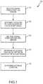
- FIG. 2depicts one example of a suitable operating environment in which one or more of the present examples may be implemented.
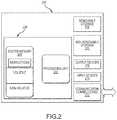
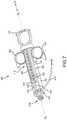
- FIG. 3depicts a perspective view of a first embodiment of a monitoring syringe utilizing a Hall sensor module.
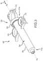
- FIG. 4depicts a partial perspective sectional view of the monitoring syringe of FIG. 3 , depicting the Hall sensor module.
- FIG. 5depicts a partial exploded perspective view of the monitoring syringe of FIG. 4 .
- FIG. 6depicts a partial perspective view of a Hall sensor module.
- FIG. 7depicts a perspective view of a second embodiment of a monitoring syringe utilizing a Hall sensor module.
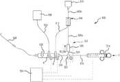
- FIG. 8illustrates an exemplary medium management system.
- FIG. 9Ais a perspective view of another example of a medium diversion reservoir.
- FIG. 9Bis a perspective exploded view of the medium diversion reservoir of FIG. 9A .
- FIG. 9Cis a cross-sectional view of the exemplary medium diversion reservoir in a first configuration, taken along line 515 C- 515 C of FIG. 9A .
- FIG. 9Dis a cross-sectional view of the exemplary medium diversion reservoir in a second configuration, taken along line 515 C- 515 C of FIG. 9A .
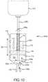
- FIG. 10illustrates another exemplary medium diversion reservoir.
- FIG. 11illustrates another exemplary medium management system.
- FIG. 12depicts a method of determining an amount of medium injected into a patient.
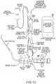
- FIG. 13graphically illustrates a medium management system with a diversion reservoir.
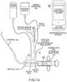
- FIG. 14graphically illustrates an alternative measurement management system.
- FIG. 15depicts a diversion assembly
- FIG. 16depicts examples of commercially available reservoirs for capturing contrast.
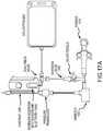
- FIGS. 17A and 17Bdepict another example of a medium measurement system.
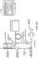
- FIGS. 18A and 18Bdepict another example of a medium measurement system.
- an agent, medicant, or mediumis preferably delivered to a specific site within the body, as opposed to a more general, systemic introduction.
- One such exemplary occasionis the delivery of contrast media to coronary vasculature in the diagnosis (i.e., angiography) and treatment (i.e., balloon angioplasty and stenting) of coronary vascular disease.
- the description, as well as the devices and methods described herein,may be used in modulating and/or monitoring medium delivery to the coronary vasculature in prevention of toxic systemic effects of such an agent.
- Exemplary other usesmay include the delivery, injection, modulation, or measurement of: cancer treatment agent to a tumor, thrombolytic to an occluded artery, occluding or sclerosing agent to a vascular malformation or diseased tissue; genetic agent to a muscular bed, neural cavity or organ, emulsion to the eye, bulking agent to musculature and/or sphincter, imaging agent to the lymphatic system, antibiotics to an infected tissue, supplements in the dialysis of the kidney, to name but a few.
- Contrast Induced Nephropathyis a form of kidney damage caused by the toxic effects of dyes (radiopaque contrast media) used, for example, by cardiologists to image the heart and its blood vessels during commonly performed heart procedures, such as angiography, angioplasty, and stenting.
- dyesradiopaque contrast media
- the dyeis toxic and is known to damage kidneys.
- most healthy patients tolerate some amount of the “toxicity”patients with poorly or non-functioning kidneys may suffer from rapidly declining health, poor quality of life, and significantly shortened life expectancy.
- Potential consequences of CINinclude: irreversible damage to the kidneys, longer hospital stays, increased risk of heart disease, increased risk of long-term dialysis, and ultimately, a higher mortality risk.
- CINhas a significant economic burden on the healthcare system and currently there is no treatment available to reverse damage to the kidneys or improper kidney performance, once a patient develops CIN.
- the ability to “collect” contrast agent laden blood “downstream” from the visualization sitemay ensure visualization, but requires the complexity of placement and operation of a collection system.
- FIG. 13depicting a modulator and a reuse diversion reservoir wherein the system may be constructed so as to measure the amount of an agent delivered from the system to the patient while also employing a diversion reservoir to reuse the portion of medium injected through the diversion of a portion of the injected medium.
- a measurement systemfor the quantitative assessment of a volume of medium delivered and the inherent analysis of the total volume delivered to the patient versus some predetermined critical amount, such as the Gurm ratio, whether or not it is used with a modulator and a diversion reservoir (for contrast reuse).
- some predetermined critical amountsuch as the Gurm ratio
- measurementsmay be performed prior to a medium being modulated, simultaneously with modulation, or after the modulation process, if desired.
- the measurement devices and methodsmay be used with any of the modulation systems, such as described in U.S. patent application Ser. Nos. 13/839,771 and/or 14/851,958.
- the embodiments described hereinare exemplary in nature and should not be construed as limiting the various combinations possible.
- control and modulation devices disclosed hereinmay send and/or receive a sensor signal so as to coordinate a valving, controlling, or otherwise modulating function on an injection agent before the agent enters an intended target injection site.
- Modulationmay include, for example, valving (or otherwise modulating) an injection dispensed from an injection device.
- indirect valvingor otherwise controlling mechanisms
- embodiments hereinmay describe different systems and methods, or combinations thereof, to address user preferences.
- a usermay simply want to measure the medium injected by a syringe (which may include total volume injection) to a patient.
- a syringewhich may include total volume injection
- Such as systemmight be simpler than an alternative configuration wherein the user wants to measure a medium injection when the system involves a diversion (modulation) function.
- end usersmay have varied different needs, and as such, the various components and methods described herein for measurement, modulation, and diversion (i.e., for example, a reservoir for reuse of the medium) may be used in part, or whole, to address these needs.
- one usermay only want to measure an injection (while not measuring a saline flush); another user may want to employ a modulator and measurement, while not capturing the diverted medium for reuse (medium wasted); further, another user may want to employ measurement and a reservoir for reuse, but would prefer to use their existing system for reuse capture.
- an injectorhas been described and as such it could be a syringe and/or a power injector (e.g., Acist CVi Injector). Construction of embodiments described herein may vary depending on the injector; however, the principals of the embodiments may remain the same.
- the embodiments described hereinmay include various elements or components to measure and/or detect a displacement of a plunger within a chamber, such as a syringe. And, with the detection of a positional relationship of a plunger within a chamber, a user may explicitly or implicitly determine a volume of media that may have been ejected from a chamber. Some of the embodiments described may include various sources in the generation of light, as well as components to detect or sense the light, depending on the positional relationship of the plunger/piston and the chamber.
- Linear encodersinductive sensors, capacitive touch sensors (with metal actuator in plunger), ultrasonic emitters/receivers, pressure sensors, optical encoders (with fine pitch slots and light source), strain gauges (i.e., to measure weight), electromagnetic emitters/receivers (e.g., navigational systems) are alternative technologies contemplated for the use of measuring an injection delivered from an injector to a patient, with or without measuring a “diversion” reservoir.
- Other alternative embodiments capable of identifying positional relationships of a plunger and chamber (and changes thereof)may include, without limitation, the following technologies.
- a Hall sensor(coiled wire along syringe axis) may be placed on, or in proximity to, the chamber with a magnet attached to the plunger (so as to act as a variable proximity sensor). Multiple low sensitivity Hall sensors may be disposed along the chamber of the syringe with a magnet attached to the plunger. Still other embodiments of systems utilizing multiple Hall sensors are described herein. Laser light may be emitted and detected to determine a positional relationship of the plunger along the chamber axis. An absolute encoder may be used to “read” the direct displacement of the plunger.
- Many of these systems described hereininclude at least a two part, or portion, of a sensing system
- One partmay be used to send or cause the creation of a signal (or change)
- the second partmay be used to read, sense, or measure a difference in a signal (or change).
- one of the components (i.e., part, portion, etc.) of measurementmay be associated, attached to, or in the proximity with the plunger of an injector; whereas, the at least second part (i.e., component, portion, etc.) may be attached to, associated with, or in the proximity of the injector housing.
- the at least second parti.e., component, portion, etc.
- FIG. 4components 350 a and 350 b.
- FIG. 3depicts a perspective view of an embodiment of a monitoring syringe 300 utilizing a Hall sensor module, which is described in more detail below.
- the monitoring syringe 300includes a syringe housing 302 defining an inner bore 304 .
- a plunger or pistonwhich is described in more detail below, is slidably received in the bore 304 . More specifically, the piston is slidably engaged with an interior surface of the bore 304 and linear movement M of a plunger shaft within the bore 304 moves the piston. Movement M is along the syringe axis As.
- a thumb ring 312may be utilized to push and pull the plunger along axis As, as described in more detail below.
- the fluide.g., media
- the fluide.g., media
- a tube or needlenot shown
- Two finger rings or tabs 332receive the fingers of a user during use.
- a cylindrical-type housing 302 and inner bore 304are described; however, it is contemplated that there may be a variety of constructions of a housing/bore 302 / 1204 and plunger that provide the function as anticipated herein and the shape (including rectangular, ovular, triangular cross-section, etc.), in and of itself, should not be limiting.
- the monitoring syringe 300also includes a Hall sensor module 350 , described in more detail below.
- One component of the Hall sensor module 350is a magnet retention ring 352 , which is disposed on an outer or exterior surface of the syringe housing 302 .
- the magnetic retention ring 352is disposed proximate a proximal end 314 b of the housing 302 , but it may be disposed in other locations along the housing 302 .
- FIG. 4depicts a partial perspective sectional view of the monitoring syringe 300 of FIG. 3 , depicting the Hall sensor module 350 .
- Certain components 350 a of the Hall sensor module 350are disposed within an inner chamber of a hollow shaft 308 of the plunger 306 , while certain components 350 b are disposed on an exterior surface of the syringe housing. These various components 350 a , 350 b are described in more detail below.
- So-called internal components 350 ai.e., internal to the plunger 306
- One or more batteries 360 and a control switch 362may also be secured to the circuit board 356 .
- Signals from the Hall sensors 358may be first processed by the circuit board 356 , which may determine the position of the plunger 306 , the volume of media in the syringe, etc., and then send this information to an associated system via the transmitter 380 for further analysis, display to a doctor, etc.
- the signals from each Hall sensor 358may be sent directly via the transmitter 380 to an associated system for processing.
- the distal retention insert 354 amay be inserted into the shaft 308 so as to be near the piston 310 .
- the distal retention insert 354 amay define a void 364 , which may contain a wireless transmitter 380 , such as a Bluetooth transmitter.
- the transmitter 380may send signals from the Hall sensors 358 to an associated signal processing device such as described herein.
- a cable connectionsuch as described above, may be utilized.
- the proximal retention insert 354 bis disposed in the hollow shaft 308 near the thumb ring 312 . Together, the distal retention insert 354 a and the proximal retention insert 354 b support, protect, and retain the circuit board 356 within the hollow shaft 308 .
- the retention inserts 354 a , 354 bmay be permanently fixed within the shaft 308 , although configuring the inserts 354 a , 354 b for removal may be advantageous so as to allow for replacement or repair of the circuit board 356 , batteries 360 , etc.
- the thumb ring 312may include a resilient base 364 including a plurality of projections 366 that may be engageable with mating slots 368 in the shaft 308 . Disengaging these projections 366 allows for removal of the retention inserts 354 a , 354 b and other internal components.
- a plurality of Hall sensors 358are depicted. A greater or fewer number of sensors 358 may be utilized in various embodiments, although a greater number of sensors 358 may provide for more accurate determinations with regard the position of the plunger 306 .
- the Hall sensors 358are disposed linearly within the chamber so as to be substantially aligned with, or parallel to, the axis As.
- External components 350 binclude the magnet retention ring 352 , which holds a plurality of magnets 370 , which may be arc magnets, in the depicted embodiment. In other embodiments, cube, cylindrical, or other magnets may be utilized.
- the positions of the magnets 370are fixed relative to and about the syringe housing.
- the arc magnets 370form a substantially circular magnetic field through which the shaft 308 (and the Hall sensors 358 ) pass when the shaft 308 is withdrawn from or inserted into the inner bore of the syringe.
- the circular magnetic fieldenables the Hall sensors 358 to detect the field, regardless of the rotational position of the plunger 306 about the axis As.
- the magnets 370may be secured directly to the syringe housing without the magnet retention ring.
- FIG. 5depicts a partial exploded perspective view of a portion of the monitoring syringe 300 , as seen in FIG. 4 . More specifically, the plunger 306 , Hall sensor module internal components 350 a , and Hall sensor module external components 350 b are depicted. In general, certain of these components are described above in FIGS. 3-4 and are not necessarily described further. In the depicted embodiment, however, both the distal retention insert 354 a and proximal retention insert 354 b include shaped recesses 372 that are configured to receive the circuit board 356 so as to hold that element in place. The recesses 372 are disposed in the inserts 354 a , 354 b so as to conserve space within the hollow shaft 308 of the plunger 306 .
- a switch 362may be disposed proximate the batteries 360 or elsewhere within the hollow shaft 308 .
- the switch 362in certain embodiments, may be a reed switch that detects plunger movement and moves to an engaged or activated position. The switch 362 is not required but may help preserve power when the syringe 300 is not in use.
- the switch 362When activated, the switch 362 selectively connects power from the batteries 360 to either or both of the plurality of Hall sensors 358 and the wireless transmitter 380 .
- a manually-operated switchedsuch as a pull tab, button, or rocker switch may be actuated by the user.
- the measurement components of a monitoring syringe 300could also be utilized to measure a volume of medium diverted by a modulator to a medium diversion reservoir, in systems that employ a reservoir in the introduction of contrast to a patient.
- a medium diversion reservoirand their incorporation into related medium management and monitoring systems, are described elsewhere herein.
- the inner bone 304may form a fluid reservoir to capture medium that may diverted by a modulator away from the injection of medium to the delivery catheter.
- the chambermay be sufficiently pressurized by a force acting upon the plunger 306 to facilitate controlled filling, release and measurement of a medium within the chamber.
- the forcemay bias the piston 310 into the fluid contained in the bore 304 , while the Hall sensors 358 continue to detect a position of the plunger 306 .
- a spring 309may be disposed about the hollow shaft 308 of the plunger 306 . This spring 309 biases the piston 310 towards the discharge end 314 a of the syringe housing 302 .
- Other spring configurations and/or biasing mechanismsmay be utilized, wherein they may be generally disposed about the syringe axis As so as to provide for a balanced application of force.
- FIG. 7depicts a perspective view of a second embodiment of a monitoring syringe 400 utilizing a Hall sensor module.
- the monitoring syringe 400includes a syringe housing 402 defining a hollow inner bore.
- a plunger 406 including a shaft 408 and a piston 410is slidably received in the bore. More specifically, the piston 410 may be slidably engaged with an interior surface of the bore and linear movement M of the shaft 408 , within the bore, moves the piston 410 . Movement M is along the syringe axis As.
- the plunger 406is moved back and forth within the bore 404 by the movement of a thumb pad, such as a thumb-ring 412 .
- the fluid contained thereinis discharged into a manifold assembly, tube, or needle (not shown) and delivered to a patient.
- a Hall sensor module 418may be secured to an exterior surface of the syringe housing 402 , rather than securement to the plunger.
- the Hall sensor module 418includes a Hall sensor housing 419 that encloses a plurality of Hall sensors 420 . As described above with regard to FIGS. 3-5 , a greater number of discrete Hall sensor elements may improve accuracy.
- One or more leads or wires 424extend from an end of the Hall sensor module 418 .
- a cable 416connects at an end 428 to an interface unit that analyzes the output of the Hall sensor module 418 and provides this information to a user of the monitoring syringe 400 , typically on a display.
- communicationmay be via a radio, Bluetooth, of other wireless connection, as described herein.
- the displayed informationmay include volume of the chamber, volume remaining, volume dispensed, fluid type, flow rate, fluid pressure or temperature and/or other information, as required or desired for a particular application.
- the signals from the Hall sensorsmay first be processed by an associated circuit board then sent to an interface unit, or the discrete signals may be sent to the interface unit for processing.
- the shaft 408 of the plunger 406has one or more magnets 430 disposed thereon or within the shaft 408 .
- the magnet 430in this case, includes a plurality of arc magnets disposed about the shaft 408 .
- the magnetic field generated by the magnet 430is detected by the Hall sensor 420 .
- the Hall sensor 420sends a signal to the interface unit that determines the position of the plunger 406 within the syringe housing 402 , based on the position of the magnet 430 as detected by an individual Hall sensor 420 .
- the interfacemay also determine the various types of information listed above, based on a known diameter and length of the bore 404 of the syringe housing 402 .
- Two finger rings or tabs 432receive the fingers of a user during use.
- a stop 434prevents the plunger 406 from being pulled out of the syringe housing 402 .
- FIGS. 3-7depict a plurality of Hall sensors
- other embodiments of monitoring syringesmay utilize one or more sensors of various types.
- a single sensor, or multiple sensorsmay be used to measure a magnetic field, material resistance, capacitance, etc.
- the measurements from such sensorsmay be utilized to determine the linear position of the plunger within the syringe.
- sensorsinclude, but not limited to, Hall effect sensors (as described in more detail herein), inductive sensors, capacitive touch sensors, and others.
- FIG. 1depicts a method 100 of using a monitoring syringe utilizing Hall sensors.
- a signalis received from a first Hall sensor, the position of which in a plunger shaft is known, relative to other Hall sensors in the shaft. Based on the position of the first Hall sensor and the signal received from said sensor, a position of a piston is then determined in operation 104 . Since a cross-sectional area, diameter, or other dimension of the syringe is known, the amount of media in the syringe based on the position of the piston can be determined.
- a signalmay be received from a second Hall light sensor having known characteristics (e.g., position) in operation 106 .
- An updated position of the pistonmay then be determined based on the received signal from the second Hall sensor and the signal in operation 108 .
- a condition of the syringe(such as those described herein) may be determined, as in operation 110 .
- the method 100may be performed on the circuit board within the monitoring syringe, then sent to an associated system via the transmitter for further analysis or display to a surgeon, etc.
- each signalmay be sent via the transmitter to an associated system for processing, analysis, display, etc.
- the methods described in FIG. 1when used in a system employing a diversion reservoir, may further incorporate a measurement determined in a chamber collecting medium diverted from an injection (i.e., through a modulator). Having a total amount of medium injected by the syringe (as determined by a sensing apparatus), minus the amount of medium diverted (as determined by a sensing apparatus), provides the total amount of the injection actually delivered to the patient.
- FIG. 2illustrates one example of a suitable operating environment 200 in which one or more of the present embodiments may be implemented.
- Thisis only one example of a suitable operating environment and is not intended to suggest any limitation as to the scope of use or functionality.
- Other well-known computing systems, environments, and/or configurationsthat may be suitable for use include, but are not limited to, personal computers, server computers, hand-held or laptop devices, multiprocessor systems, microprocessor-based systems, programmable consumer electronics such as smart phones, network PCs, minicomputers, mainframe computers, smartphones, tablets, distributed computing environments that include any of the above systems or devices, and the like.
- operating environment 200may typically include at least one processing unit 202 and memory 204 .
- memory 204storing, among other things, instructions to perform the monitoring methods described herein
- memory 204may be volatile (such as RAM), non-volatile (such as ROM, flash memory, etc.), or some combination of the two.
- This most basic configurationis illustrated in FIG. 2 by line 206 .
- environment 200may also include storage devices (removable, 208 , and/or non-removable, 210 ) including, but not limited to, magnetic or optical disks or tape.
- environment 200may also have input device(s) 214 such as touch screens, keyboard, mouse, pen, voice input, etc. and/or output device(s) 216 such as a display, speakers, printer, etc.
- input device(s) 214such as touch screens, keyboard, mouse, pen, voice input, etc.
- output device(s) 216such as a display, speakers, printer, etc.
- Also included in the environmentmay be one or more communication connections,
- Operating environment 200may typically include at least some form of computer readable media.
- Computer readable mediacan be any available media that can be accessed by processing unit 202 or other devices comprising the operating environment.
- Computer readable mediamay comprise computer storage media and communication media.
- Computer storage mediaincludes volatile and nonvolatile, removable and non-removable media implemented in any method or technology for storage of information such as computer readable instructions, data structures, program modules or other data.
- Computer storage mediaincludes, RAM, ROM, EEPROM, flash memory or other memory technology, CD-ROM, digital versatile disks (DVD) or other optical storage, magnetic cassettes, magnetic tape, magnetic disk storage or other magnetic storage devices, solid state storage, or any other tangible medium which can be used to store the desired information.
- Communication mediaembodies computer readable instructions, data structures, program modules, or other data in a modulated data signal such as a carrier wave or other transport mechanism and includes any information delivery media.
- modulated data signalmeans a signal that has one or more of its characteristics set or changed in such a manner as to encode information in the signal.
- communication mediaincludes wired media such as a wired network or direct-wired connection, and wireless media such as acoustic, RF, infrared and other wireless media. Combinations of the any of the above should also be included within the scope of computer readable media.
- the operating environment 200may be a single computer operating in a networked environment using logical connections to one or more remote computers.
- the remote computermay be a personal computer, a server, a router, a network PC, a peer device or other common network node, and typically includes many or all of the elements described above as well as others not so mentioned.
- the logical connectionsmay include any method supported by available communications media.
- Such networking environmentsare commonplace in offices, enterprise-wide computer networks, intranets and the Internet.
- the components described hereincomprise such modules or instructions executable by computer system 200 that may be stored on computer storage medium and other tangible mediums and transmitted in communication media.
- Computer storage mediaincludes volatile and non-volatile, removable and non-removable media implemented in any method or technology for storage of information such as computer readable instructions, data structures, program modules, or other data. Combinations of any of the above should also be included within the scope of readable media.
- computer system 200is part of a network that stores data in remote storage media for use by the computer system 200 .
- the monitoring injectorssuch as those described above may be utilized in various types of medium management systems to control and monitor medium injection into patients.
- Two exemplary medium management systems, as well as components thereof,are described below in the following figures. These are but two types of systems that may benefit from the monitoring technologies described herein. Other systems and configurations thereof will be apparent to a person of skill in the art.
- FIGS. 8-10illustrate another medium management system 500 that may include, as shown in the illustrated embodiment, a flow diverter assembly (i.e., a modulator) 502 and a diversion reservoir 504 .
- tubular member 506 aextends from the valve 526 of the flow diverter assembly 502 to a medium diversion reservoir 504
- tubular member 506 bextends from diversion reservoir 504 to medium reservoir (e.g., contrast agent vial) 510 .
- medium reservoire.g., contrast agent vial
- Medium from the medium reservoir 510(e.g., contrast agent vial) is permitted to flow away from the medium reservoir 510 and through diversion reservoir 504 via tubular members 506 b and tubular member 512 .
- injector syringe 514may be fluidly coupled to medium reservoir 510 by tubular members 506 b , 512 , 516 and 518 , coupling those components together by a manifold 520 and through stopcock 522 .
- the stopcock 522When the syringe 514 is being loaded with medium from medium reservoir 510 , the stopcock 522 may be positioned to permit medium flow between tubular members 516 and 518 , but not to tubular member 524 disposed between the stopcock 522 and the valve 526 of the flow diverter assembly 502 .
- the syringe 514may be any of the monitoring syringes described herein (e.g., using light sensors, Hall sensors, etc.) or of the monitoring syringes known in the art. Drawing back the syringe 514 may pull medium from the medium reservoir 510 through tubular member 506 b , and/or diversion reservoir 504 , and through tubular member 512 .
- Medium from the medium reservoir 510 and/or medium residing in the diversion reservoir 504may then be further drawn, into and toward, syringe 514 through tubular members 516 and 518 .
- valve B on manifold 520may then be manipulated to prohibit flow back to medium reservoir 510 and diversion reservoir 504 via tubular member 512 (and such flow may be further inhibited by a check valve disposed between diversion reservoir 504 and medium reservoir 510 ), and the stopcock 522 may be positioned to allow flow through the tubular members 518 , 524 , 516 and manifold 520 .
- a portion of the injected medium flow from the syringe 514may be diverted away from the medium flow path to injection catheter 528 by the flow diverter assembly 502 .
- a modulatorsuch as flow diverter assembly 502
- such diverted medium flow passing through the flow diverter assembly 502flows into the diversion reservoir 504 , as opposed to the diverted medium flowing directly into the medium reservoir 510 or some other outflow/overflow reservoir/chamber.
- the diversion reservoir 504provides means for collecting overflow medium diverted by the flow diverter assembly 502 , for possible re-use as the syringe 514 may be again activated to pull medium into the system (e.g., for introduction into the patient via catheter 528 ).
- the use of such a diversion reservoir in this manner, with an associated check valve preventing back flow of medium into the medium reservoir 510allows for capture and re-use of medium that is already introduced into the system (e.g., in the diversion reservoir 504 ) while preserving the integrity of the medium disposed within medium reservoir 510 in its original form.
- the medium management system 500may also include a saline reservoir 530 that can be used to flush portions thereof.
- the saline reservoir 530is connected to the manifold 520 via a tube 532 and can be isolated from the remainder of the system 500 with valve A.
- valve Amay include a position or other sensor S that detects a position of the valve A.
- a flush signalis sent from the valve A sensor S to a monitoring/display system 534 , which also may be configured to monitor the position of valve Band stopcock 522 (using sensors S), as well as the output from the various sensors on the monitoring syringe 514 and/or the sensors on the diversion reservoir 504 .
- the monitoring/display system 534may disregard signals from the monitoring syringe 514 and/or diversion reservoir 504 (as those readings are not reflective of contrast being injected from or drawn into the syringe 514 ).
- the monitoring/display system 534may display an instruction or emit a signal to remind an operator to close valve Band/or stopcock 522 so as to isolate those portions of the system 500 .
- the system 500uses automated valve B and/or stopcock 522 and closes these valves upon receiving an open signal from valve A.
- FIGS. 9A-9DOne embodiment of the diversion reservoir 504 is illustrated in FIGS. 9A-9D .
- FIG. 9Ashows an assembled view of diversion reservoir 504 along with its associated tubular members 506 a and 512 .
- FIG. 9Bis an exploded view of the assembly of FIG. 9A
- the system 500may further include a second supply conduit 512 in fluid communication with the supply conduit 506 b and the diversion conduit 506 a , wherein the second supply conduit 512 is fluidly coupled to the fluid medium flow path.
- Tubular members 506 a and 512are sealably connected to a first end cap or manifold 602 on diversion reservoir 504 , as further shown in FIG. 9C , which is a sectional view taken through lines 515 C- 515 C in FIG. 9A
- a first end of a through-tube 606is sealably connected to an interior side of first end cap 602 , as at 604 .
- Through-tube 606includes an inner conduit 608 extending therethrough.
- Inner conduit 608is in fluid communication with the interiors of tubular members 506 a and 512 via their adjacent couplings in the first end cap 602 , as illustrated in FIG. 9C .
- a second end of through-tube 606is sealably connected to a check valve assembly 640 , as at 610 , and the inner conduit 608 is in fluid communication with the check valve assembly 640 .
- the check valve assembly 640is, in turn, in fluid communication with the tubular member 506 a . As seen in FIG.
- the check valve assembly 640includes a moveable valve plate 612 (or other suitable structure allowing one way flow through the valve) which is operable to permit flow from the medium reservoir 510 (e.g., medium contrast vial) via tubular conduit 506 b into the inner conduit 608 of through-tube 606 , but to inhibit flow in reverse thereof.
- This arrangementmay allow flow of medium from fluid reservoir 510 via tubular conduit 506 b , inner conduit 608 of through-tube 606 , and tubular conduit 512 to the syringe 514 .
- medium flow diverted by flow diverter assembly 502may also be permitted to flow via tubular member 506 a into inner conduit 608 of through-tube 606 , but inhibited from flowing to the medium reservoir 510 by check valve assembly 640 .
- a second end cap 614 on diversion reservoir 504is secured about the check valve assembly 640 .
- the diversion reservoir 504is designed to accommodate flow of medium from the flow diverter assembly 502 , to collect and hold such medium and then, if desired, urge such collected medium back into the system for use in delivering additional medium to the patient via injection catheter 528 .
- diversion reservoir 504may include an elastic expansion tube 616 disposed about through-tube 606 .
- expansion tube 616extends along a portion of a length of through-tube 606 .
- Expansion tube 616may be formed of silicone (or like flexible) material sealably secured adjacent each end thereof about the through-tube 606 by first and second retention washers 618 and 620 , respectively, or by other suitable sealable and mechanical fastening arrangements.
- An outer surface of the through-tube 606may include interference elements such as surface features or an annular interference rim 606 r (see FIG. 9C ) to further facilitate the sealing of the expansion tube 616 to the through-tube 606 via the retention washer 618 and 620 .
- a housing tubular outer shell 622may be connected between the first end cap 602 and second end cap 614 , thereby covering the expansion tube 616 and other diversion reservoir components therein.
- the shell 622may serve to protect the components of the diversion reservoir 504 therein, limit the extent of inflation or expansion of expansion tube 616 , and/or (if the shell 622 is either transparent or translucent) allow observation of the condition (e.g., expanded state) of expansion tube 616 therein.
- FIG. 9Dillustrates the diversion reservoir 504 in perspective sectional view (again, as taken along lines 515 C- 515 C in FIG. 9A ) with the expansion tube 616 shown in an exemplary stretched and expanded state, as opposed to its relaxed state shown in FIG. 9C .
- the expansion tube 616 of the diversion reservoir 504receives medium flow from the flow diverter assembly 502 , via tubular member 506 a .
- This medium flowas illustrated by flow arrows 624 in FIG. 9D , flows from tubular member 506 a into the inner conduit 608 of through-tube 606 adjacent the first end of through-tube 606 .
- Through-tube 606can be a portion of the medium supply conduit 506 b that resides within reservoir chamber 626 .
- the supply conduit through-tube 606may have one or more apertures 628 therethrough which allows an interior of the expansion tube 616 to be in fluid communication with the inner conduit 608 and reservoir chamber 626 .
- Medium from the flow diverter assembly 502can thus flow through apertures 628 and into a medium reservoir or chamber 626 defined by the expansion tube 616 .
- This medium chamber 626is defined between the inner surface of expansion tube 616 and the outer surface of through-tube 606 , whereby the expansion tube 616 forms an elastic bladder disposed around the supply conduit 606 , with the walls of expansion tube 616 capable of imparting a force on the fluid medium within the chamber 626 .
- a surface within chamber 626is capable of imparting a variable or constant force on the fluid medium within the chamber 626 , and the surface is defined at least in part by a wall of the elastic bladder of expansion tube 616 .
- the medium chamber 626thus receives and collects the diverted portion of the flow of medium from the flow diverter assembly 502 .
- the diversion reservoir 504comprises a variable or constant force biasing member disposed relative to at least one surface within the reservoir chamber 626 to urge the surface against the fluid medium within the reservoir chamber 626 .
- the expandable wall of the expansion tube 616thus defines a surface within the medium chamber 626 capable of imparting a force (variable or constant) on the fluid medium within the medium chamber 626 .
- the second end cap 614includes an aperture 630 therethrough to permit the escape of gas within the cover 622 and thereby readily permit expansion of the expansion tube 616 therein.
- a medium supply conduit 506 bdisposed between, and fluidly coupled to, the diversion reservoir 504 and the sterile medium container 510 .
- a diversion supply conduit 506 ais disposed between, and fluidly coupled to, the diversion reservoir 504 and the flow diverter assembly 502 so as to supply the reservoir 504 with the diverted portion of the fluid medium from the flow diverter assembly 502 .
- the medium contained in the chamber 626may be available for further infusion into the patient via the modulation/reservoir system 500 .
- an operatormay activate valve B to allow medium flow from the chamber 626 of the diversion reservoir 504 into the syringe 514 (which is being withdrawn to draw such fluid therein).
- valve Bmay be closed and the modulation/reservoir system 500 may be again in condition for delivery of medium via injection catheter 528 , by activation of injection syringe 514 by an operator.
- medium reservoir 510e.g., contrast agent vial
- the flow modulator assembly 502may automatically activate to divert excess medium, thereby ultimately reducing the amount of medium introduced into the patient via injection catheter 528 (e.g., thus introducing no more medium than necessary to attain operative opacity).
- the pressureis increased in the modulator 502
- the resistance to medium flow into the diversion circuitis increased by operation of the flow diverter assembly 502 .
- the processmay be repeated by an operator as many times as deemed necessary to complete the procedure desired.
- modulation/reservoir system 500may achieve the advantageous reduction of introduction of unnecessary medium into the patient while achieving the necessary amount and flow of medium in the patient for diagnostic or treatment means (e.g., for opacity).
- diversion reservoir 504may allow re-use of the diverted outflow of medium.
- the diversion reservoir illustrated in FIGS. 9A-9Dpresents one form of such a reservoir.
- Alternative formsare contemplated as well.
- an alternative form of elastic bladder or elastic surfacemay be provided that functionally allows the receipt of medium overflow from the flow diverter assembly 502 into an expansion chamber, and then further allows the flow of medium from the medium reservoir 510 through the diversion reservoir 504 and into the modulation/reservoir system 500 for use.
- An alternative means of placing force on the medium within the chamber in the diversion reservoir 504may be attained by a bias plunger, such as illustrated schematically in FIG. 10 as 504 a .
- the diverted portion of the fluid mediumflows through a diversion conduit 506 a away from the flow diverter assembly 502 .
- the system 500comprises a medium reservoir 510 containing a supply source of fluid medium for the system 500 and a supply conduit 506 b through the reservoir chamber 702 that fluidly connects the medium reservoir 510 and the diverter conduit 506 a .
- the supply conduit 506 bcomprises a check valve 608 a to prevent the flow of fluid medium from the supply conduit 506 b into the medium reservoir 510 .
- Diversion reservoir 504includes a plunger 704 slidably disposed in housing 706 and moveable in a linear fashion relative to the housing 706 , as illustrated by movement line 708 .
- the surface 710is movable in a linear direction relative to the fluid medium within the reservoir chamber 702 .
- a proximal face or surface 710 of the plunger 704thus defines a portion of a chamber 702 within the housing 706 for diverted medium that is received therein via the tubular member 506 a.
- diversion reservoir configured with a bias plunger 504 amay include a first end cap 602 a that acts as a manifold for medium flow.
- Tubular member 506 ais connected to first end cap 602 a , as is tubular member 512 .
- Chamber 702is in fluid communication with the interiors of tubular members 506 a and 512 , such as via manifold 712 within the first end cap 602 a , as seen in FIG. 10 .
- a through-tube 606 ais also in fluid communication with the manifold 712 , and extends through the housing 706 of the diversion reservoir configured with the bias plunger 504 a to a check valve 608 a .
- Check valve 608 apermits medium flow from medium reservoir 510 via tubular member 506 b into through-tube 606 a but prevents backflow.
- Medium from the medium reservoir 510can then flow from the diversion reservoir 504 a into the syringe 514 via tubular member 512 .
- mediumflows as illustrated by flow arrows 624 a from tubular member 506 a , through manifold 712 , and into the chamber 702 .
- the diversion reservoir 504 acomprises a variable or constant force biasing member such as spring 714 disposed relative to at least one surface 710 within the reservoir chamber 702 to urge the surface 710 against the fluid medium within the reservoir chamber 702 .
- surface 710is planar.
- the face 710 of the plunger 704is biased by spring 714 toward the manifold chamber 712 , and thus defines a moveable surface 710 for the chamber 702 that can move away and expand chamber 702 as more medium is introduced therein, when the bias of the force acting against it is overcome.
- This biasacts on the plunger 704 within the housing 706 , as illustrated schematically by force arrows 716 , 717 and such force may be achieved by suitable means such as springs, weight distribution, linear actuator, or other force elements.
- a linearly moving plunger 704may permit more ready measurement of how much medium has actually been diverted by the flow diverter assembly 502 and thereby, by derivation, how much medium has actually been delivered to a patient by the injection catheter 528 . Measurement may be performed by utilizing a light-based, Hall sensor-based, or other type of monitoring system 718 disposed in or on the housing 706 , or in or on other structures (such as the plunger) of the diversion reservoir 504 , as such systems are described herein.
- the plunger 704thus provides a linear expansion element (surface 710 ) that serves to apply force to the overflow medium collected for possible re-use in the chamber 702 .
- the diversion reservoir 504 aoperates in a similar manner to the diversion reservoir 504 , discussed above, by providing an expandable chamber for medium diverted by the flow diverter/modulating assembly 502 , wherein the chamber (e.g., chamber 702 , 626 ) may have at least one surface acting upon it to urge the medium therein back toward the injection device 514 (via conduit 512 ) for possible re-use.
- the chambere.g., chamber 702 , 626
- the diversion reservoiris configured so that flow through it to the medium reservoir 510 is not permitted or necessary.
- FIG. 11One such arrangement is illustrated in FIG. 11 , in connection with a modulation/reservoir system 500 a .
- the diversion reservoirmay simply provide an expandable chamber therein for retaining and re-using medium diverted from the flow diverter assembly 502 .
- Such diversion reservoirs 504 bmay employ a bladder form of chamber or a constant or variable force resistance form of chamber, such as those illustrated and discussed herein, where at least one surface therein is capable of imparting a sufficient force upon the fluid medium within the chamber.
- the diversion reservoir 504 bmay be constructed to function similar to the spring-based monitoring syringe 300 depicted in FIG. 5 .
- FIG. 11illustrates an arrangement where the medium reservoir chamber 510 is connected via tubular member 506 c to a T-connector 302 t disposed between a diversion reservoir 504 b (without a through-tube) and the flow diverter assembly 502 .
- the T-connector 302 tconnects at its first end to the tubular members 512 and 506 a and at its second end to tubular member 506 d that leads to the diversion reservoir 504 b .
- a side fitting of the T-connector 302 tleads via tubular member 506 c to the medium reservoir 510 .
- a check valve 608 bis disposed between the T-connector 302 t and the medium chamber 510 to prevent back flow of medium from the flow diverter assembly 502 and/or diversion reservoir 504 b into the medium container 510 .
- the configuration illustrated in FIG. 11may be similar to that described above with respect to FIG. 8 , in that a force F ejects medium from the syringe 514 .
- the pressure of medium within the flow diverter assembly 502increases enough to allow flow therethrough, medium flows from the valve 526 via tubular member 506 a to the T-connector 302 t .
- Mediummay then flow from the T-connector 302 t via tubular member 506 d to the diversion reservoir 504 b .
- Medium flowing into the diversion reservoir 504 bmoves the piston therein to accommodate the diverted medium flow.
- medium provided via syringe 514may be diverted by the flow diverter assembly 502 away from injection to the patient, and accumulate in the diversion reservoir 504 b.
- the medium contained in the expandable chamber within the diversion reservoir 504 bmay be available for further infusion into the patient via the modulation/reservoir system 500 a .
- an operatoractivates valve B to allow medium flow from the chamber within the diversion reservoir 504 b into the injector syringe 514 (which is being withdrawn to draw such fluid therein). If the fluid needed is greater than the volume retained in the chamber reservoir 504 b , the force of check valve 608 b is overcome and further medium is then withdrawn from the medium reservoir 510 .
- valve Bis again closed and the modulation system 500 a is again in condition for delivery of medium via injection catheter 528 , by activation of injection syringe 514 by an operator.
- the flow diverter assembly 502will then again be automatically activated to divert excess medium when a threshold pressure for activation of the flow diverter assembly 502 is attained, thereby ultimately reducing the amount of medium introduced into the patient via injection catheter 528 .
- the flow through the diverter 502is relatively decreasing (thus, flow to the patient may be relatively increasing at the same time by operation of the flow diverter assembly 502 ).
- the processcan be repeated by an operator as many times as deemed necessary to complete the procedure desired.
- Use of the modulation/reservoir system 500 a in this mannerachieves the advantageous reduction of introduction of unnecessary medium into the patient while achieving the necessary amount and flow of medium in the patient for the desired diagnostic or treatment process.
- the modulating/reservoir assemblymay advantageously allow an operator to change out the injection delivery system (i.e., guide catheter, diagnostic catheter, treatment tools, etc.) without changing the flow modulator.
- FIG. 12depicts a method 800 of determining an amount of medium injected into a patient.
- the methodbegins at operation 801 , where an assessment is made on conditions of the valve and/or toggle sensors of the system. If the toggle or valve sensors indicate that the system is set for an injection of medium (e.g., the diversion apparatus is set to function and the saline apparatus is closed or not allowing passage of saline) measurement of the media will continue with operation 802 , where an injection signal(s) is received from a sensor associated with an injection syringe. If the toggle/valve sensors of 801 indicate these conditions are not met, the measurement system will assume flushing of the system and it will disregard any measurement data.
- the toggle or valve sensorsindicate that the system is set for an injection of medium (e.g., the diversion apparatus is set to function and the saline apparatus is closed or not allowing passage of saline) measurement of the media will continue with operation 802 , where an injection signal(s) is received from a sensor associated with an
- operation 804will follow (or proceed simultaneously) operation 802 wherein a diversion measurement signal(s) is received from a sensor associated with a diversion reservoir.
- a diversion measurement signal(s)is received from a sensor associated with a diversion reservoir.
- Each of the injection signals and the diversion signalsmay be received from the various types of monitoring systems as described herein, including light-based sensor systems, Hall sensor-based systems, and so on. These signals can include position signals (e.g., position of the piston), which may be used to determine a volume of medium contained within the injection syringe and/or the diversion reservoir. With this information, the amount of medium injected may be determined based at least in part on the injection signal and the diversion signal, in operation 806 . In an example, the amount injected is the difference between the change in volume in the injection syringe minus the change in volume in the diversion reservoir. Operations 801 - 806 are constantly updated as medium is injected into the patient.
- a signal associated with the amount of medium injectedis sent.
- the summation of the total amount medium injected in a patient over timecan be maintained.
- Signals and measurement datamay be provided to an operator in the form of an audible or visual signal which can indicate to the operator of the system (i.e., a surgeon or technician) the amount of fluid injected.
- the signalscan include a visual display of the amount injected (e.g., on a monitoring display), or a signal that may indicate to the user that a maximum amount of contrast has been injected, or that none of the medium ejected from the syringe has been received in the diversion reservoir (which may be an indication of a valve or system problem).
- the systems described hereinalso include a saline flush system. Saline volumes passing through the system should be ignored so the amount of medium injected is not incorrectly calculated.
- the method 800contemplates receiving a flush signal or 801 wherein the valve or toggle sensors indicate conditions exist to allow flushing; or conversely, conditions exist to allow an injection of medium.
- subsequent injection signals and/or diversion signalsare disregarded based at least in part on the received flush signal, or similar indicator(s).
- the injection and/or diversion signalsmay be ignored while the flush signal is still received, which allows the operator to flush the system without the saline volume passing through the system causing a miscalculation of the injected medium.
- a position of at least one valve based at least in part on the flush signalmay be adjusted, if automated valves are being utilized in the system.
- the flush signal received in operation 801may cause a signal to be emitted, which may be used to signal an operator to close the valves not associated with the flush system (e.g., valve Band stopcock 522 in FIG. 8 ).
- a signal to be emittedmay be used to signal an operator to close the valves not associated with the flush system (e.g., valve Band stopcock 522 in FIG. 8 ).
- the order of the steps in FIG. 12maybe performed in a different order as shown without deterring from the scope of the invention.
- the monitoring systems described hereinmay be utilized to deliver any types of fluids to a patient during a medical procedure.
- fluidsmay include medium (media), agents, substances, materials, medicaments, and the like.
- mediummedia
- agentsagents, substances, materials, medicaments, and the like.
- these termsare used generically herein to describe a variety of fluidal materials that may include, at least in part, a substance used in the performance of a diagnostic, therapeutic or/and prophylactic medical procedure and such use is not intended to be limiting.
- the medium delivery modulation and/or measurement devices and methods described hereinare not limited to the particular, representative embodiments as described, since variations may be made to these embodiments without departing from the scope and spirit of the disclosure.
- the materials utilized in the manufacture of the monitoring syringemay be those typical in medical applications. Plastics such as polycarbonate may be utilized for the syringe housing and plunger.
- the band or gradationmay be printed directly on the plunger shaft, or may be printed on a discrete plastic sheet or sheath that may then be affixed to the plunger shaft.
- Various types of printingmay be utilized to change the translucency or opacity of the band or gradation.
- the type of printingmay be based on the type of light to be received by the sensors. For example, carbon-based printing may be utilized for sensors that detect infrared light.
- the band or gradationmay be utilized as the filter described above.
- various sensors indicating the positioning (or functioning—opening or closure) of the various valves (and/or stopcocks) in the systemmay help accommodate the measurement of a medium injected by the syringe 514 in a system, with or without a diversion/modulation system.
- a system without a diversion reservoirwherein the diversion reservoir may be simply a collection container, or a commercial reservoir, may be attached to the diversion assembly 502 .
- Such a systemmight look like drawing FIG. 11 wherein the diversion from the diversion assembly 502 through tube 506 a may simply end with the T-connector/stopcock 302 , or other valving mechanism to facilitate the user in applying their own reservoir.
- FIG. 15may be used having the assembly fluid connection lines 1406 a and 1412 , with a simple connector (i.e., stop cock for example) for attachment to available contrast capture reservoirs that may be available and/or employed by users.
- FIG. 16depicts some commercially available reservoirs for capturing contrast, as well as a connection line 1406 c that may be used to connect these reservoirs to the diversion assembly. Note that this configuration might not have measurement capabilities, although it would have the benefit of the diversion assembly.
- a flush signalmay be sent from the valve A sensor S to a monitoring/display system 534 , which also may be configured to monitor the position of valve B and stopcock 522 (using sensors S), as well as the output from the various sensors on the monitoring syringe 514 and/or the sensors on the diversion reservoir 504 a .
- FIG. 13illustrates graphically a system utilizing various sensors for the measuring of medium in a system utilizing a diversion reservoir.
- an injection syringe 514may be used which comprises one or more hall sensors positioned along the axis of the syringe.
- the Hall sensorsmay be mounted on the housing of the syringe, or on the plunger of the syringe. In the case of FIG. 13 , the Hall sensors are mounted on the plunger with a magnet positioned on the housing of the syringe, such as described by 514 .
- the syringemay also be equipped with a Blue Tooth module to coordinate the transfer of information from the syringe Hall sensors to the display unit (also equipped with Blue Tooth communication abilities).
- a stopcock or valve 522 fluidly coupled to the syringe 514 , manifold 4120 and diversion element 526may have a sensor S associated with the positioning and/or functioning of the fluid flow from/to the injector 514 , diversion valve 526 and the manifold 520 .
- the sensor Smay be a rotational sensor that can detect the rotation/position of valve 522 .
- Sensor S of 522may have electrical connections to the diversion reservoir module 504 a , allowing communication to the display/monitoring 200 system through a Blue Tooth connection.
- valve 522may allow contrast to flow from the injector through the diversion element/valve 526 , as well as through the manifold 520 to the catheter 528 . Measurements may be made as to how much of the volume was ejected to the manifold/patient and the diversion valve 526 (and through the diversion line 506 a ). If stopcock 522 were closed to the diversion valve 526 , 522 sensor S would indicate that a measurement of an injection from the syringe 514 should not be measured, for example. In this case, the physician may want to remove saline from a saline reservoir (not shown) to flush the system, while not wanting to tract the saline as a contrast injection. The saline reservoir and connection line (not shown) would typically be connected to Valve A ( 522 A).
- the diversion reservoir module 504 amay be capable of measuring the volume change within the reservoir chamber 702 through Hall sensors 718 .
- the Hall sensorsare mounted on the housing of the reservoir chamber and the magnet(s) are mounted on the plunger of the reservoir.
- the Hall sensorscould be a part of the plunger/piston of the reservoir while the magnet(s) are attached to, associated with, or in proximity of the injector housing.
- the diversion moduleis equipped with Blue Tooth so as to transfer information to the monitoring/display unit for analysis and/or display.
- control unit/displaycan calculate the amount of contrast injected to the patient (via catheter 528 ).
- diversion line 506may also incorporate a one-way check valve (if not included as part of the diversion valve 526 ) so as to allow medium to flow only to the diversion reservoir 504 a.
- Valve B 522 Bmay be opened to draw contrast from the diversion reservoir, and if necessary (and secondarily) the dye medium reservoir.
- a pressure transduceracts as the position sensor for stopcock valve B 522 B.
- contrast line 512is opened, to draw medium into syringe 514
- pressure sensor of Valve B 522 Bsenses a change in pressure and indicates that both the diversion reservoir and injection syringe Hall sensing elements should be activated.
- the information from the sensor of Valve Bmay be attached by an electrical coupling to a Blue Tooth element in the Diversion Reservoir Module 504 a so as to transfer information via Blue Tooth to the display system on its status.
- the medium drawn from the diversion reservoir chamber 702may proceed any medium drawn from the contrast medium reservoir 504 , so long as there is medium in the diversion reservoir chamber 702 .
- a one-way valvemay be attached along contrast supply line 506 a to allow the medium to only flow in the direction of the diversion reservoir (e.g., if the valving mechanism is not part of the diversion reservoir 504 a ).
- FIG. 13also shows a “Pause Button” associated with the diversion reservoir.
- the pause buttonallows a user to override any injection/measurement so as to pause the collection of data by one, or all of the sensors, associated with the Blue Tooth of the diversion reservoir module 504 a.
- FIG. 13illustrates but one variation of a system using measurements with a system diverting medium to reduce the amount of contrast induced to a patient. It is clear that there may be alternative ways of providing such a system without deviating from the intent of the invention. For example, one might use different sensing systems for the injection syringe or the diversion reservoir. Or, the Hall sensing configurations may be different than described.
- the examples hereindescribe various elements for measuring an injection of a contrast agent; as well as, modulating/diverting medium so as to reduce the total amount of contrast injected into a patient.
- the descriptionsalso include various combinations of using of both of these elements together.
- various systemsmay include various elements of diversion and/or measurement. And each of these combinations may or may not include a console, or similar display. Examples (although not to be interpreted as wholly inclusive) of various elements of the described systems might include: the diversion valve alone; the diversion valve with a reservoir; the diversion valve with reservoir and measurement system/sensors; and, measurement without modulation/diversion of medium, to name a few.
- FIG. 14describes a system for measuring a contrast medium being injected into a patient. As shown, there is no attempt to modulate or divert the contrast medium being injected into the patient.
- the measurement systemincludes a syringe which may be similar to the one shown as 514 , having Hall sensor capabilities. It also may have a Blue Tooth elements to connect with the monitoring/display system.
- a simple pressure transducer(Stopcock Position Sensor) indicates when stopcock valve 522 B position is open/closed. If open (with only a fluid connection to the contrast reservoir), the pressure sensor indicates contrast is being drawn from the contrast medium reservoir 504 .
- valve 522 BIf the valve 522 B is closed, so as to shut off communication with the contrast medium reservoir 504 , the sensor indicates that no more contrast is being drawn into the system (e.g. by the syringe 514 ). And, further, this data may be sent via Blue Tooth to the display console from the Position Sensor Output module.
- FIG. 17Adepicts a graphical representation of FIG. 17B wherein an end user would prefer to modulate/divert a medium injection into a patient, as well as take measurements of the injected medium.
- the end usermay find the effort of priming and purging the fully automated system of FIG. 13 may be more difficult to purge the injection system of air to be a little cumbersome.
- FIGS. 17A and 17Bdepict such as system wherein medium may be measured by the syringe and by the diversion reservoir in order to make/determine a measurement of the injection into a patient, as well as disregard measurements when an end user is flushing the system with saline.
- the diverted medium in the medium reservoiris not reused (adding an additional elements in the system, such as the reservoir reuse conduit, that requires priming/purging), and it is subsequently expelled from the injection system into a collection bag as waste.
- some injection contrastsmay be relatively inexpensive, as compared to cath lab time and personnel, some users might prefer to throw away the diverted medium rather than capture the medium for reuse.
- contrast linedirectly from the sterile medium container (or as discussed previously in FIGS. 15 and 16 , a line from a sterile reservoir) to the manifold 1020 .
- the contrast linemay have a position sensor, such as a pressure transducer to indicate when contrast is drawn from the contrast line.
- a position sensor(not shown) could be applied at the connection of the manifold with the contrast line to include a toggle (for on/off of the contrast conduit) with a positional sensor associated with the condition of the toggle.
- syringe 1014may draw fluid into its chamber for injection.
- the injector and the reservoirmay include measurement elements so as to determine the amount of medium ejected out of the injector and received in the reservoir, to determine the amount of medium delivered to the patient.
- a dual or alternating check valvemay positioned between the reservoir, diversion line, and the collection (waste) bag.
- the dual/alternating check valveallow fluid to be diverted to the diversion reservoir 1004 a , and subsequently (with pressure within the reservoir chamber) re-directed to the collection bag as the injection (from injector) ceases or if the ON-OFF Toggle switch is closed.
- FIGS. 18A and 18BAn alternative embodiment can be seen in FIGS. 18A and 18B wherein a diversion of an injection is diverted (a toggle or stopcock may be used to open the diversion flow path) to divert from the injector (not shown in FIG. 18A ) to, and through, alternative Diversion Valves of #1 or #2.
- a diversion stopcockmay allow diversion to a Dual Divert Valve apparatus with the Dual Divert Valve apparatus comprising a valve to direct the flow to two alternative diversion valves.
- two valvesand therefore two diversion profiles
- multiple divert valvese.g., 3, 4 or more
- valves being discussedare depicted and described as being configured in a parallel fashion. However, one skilled in the art would realize that some valves may be aligned in a serial fashion to obtain the same net result.
- the diversion valves previously describedmay accommodate a variety of injections from an injector through a variety of delivery conduits while regulating the diversion of a portion of the injected fluid so as to maintain a relatively constant flow injection to the patient.
- the diverter valveis regulating the various flows/pressures of the fluid injected, and the divert valve is regulating the flow to the patient by relatively increasing resistance to diversion with increasing pressure at the divert valve.
- Examples of the different uses of the of a diversion systems such shown in FIGS. 18A and 18Dmight include: the delivery conduit having vastly different dimensional differences such as the delivery of a fluid through an 8 F delivery catheter versus a 4 F delivery catheter; delivering a medium to one site and then delivering to a second site wherein the intended injection (e.g., flow and or pressure) into the patient are vastly different at each site, such as injections in to the heart versus injections into peripheral vascular sites, or injection to one large coronary branch (RCA) versus another large coronary branch (Left Main, Left Coronary Artery and/or left Circumflex Artery); and, wherein an injector maintains a constant flow and/or pressure (less variable than a syringe), but may require adjusting the injection flow/pressure to assess different vascular sites, such as may encountered with the use of an automated power injector (shown in FIG. 18B ).
- the delivery conduithaving vastly different dimensional differences such as the delivery of a fluid through an 8 F
- FIG. 18Adepicts a flow diversion having two separate Divert Valves and check valves (to maintain directional fluid flow).
- the excess diverted fluidis wasted (not captured for reuse) to a collection bag/reservoir.
- FIG. 18Bfurther depicts a Diversion Stopcock to access the diversion valves, and further depicts the two Divert Valves mounted onto a single apparatus with a separate toggle to access the different diversion profiles created by the two different Divert Valves.
- any of the various positional sensors described previouslymay be utilized in automating measurements of the injection system.
- the Power Injectoras depicted in FIG. 18B , it may be typical to have an end-user change the injection setting for injection into different vascular sites.
- the end usedmight select a constant flow/pressure for injection into the Right Coronary Artery (RCA), and select a different flow/pressure for the Left Coronary Artery (LCA). If the flow/pressure rates differ significantly between the two sites, the end-user may toggle between Divert Valves #1 and #2 to set a different diversion profile to address each site.
- any measurement apparatusessuch as those described herein for the diversion reservoir measuring system and the injector measuring system, may also be employed in automating the measurements of fluid delivered to the patient.
- the power injectorhas a system to measure fluid ejected from the injector, it may be advantageous to coordinate data collection from the injector and a reservoir measurement apparatus (described previously) on a diversion reservoir to automate the measurement of the medium injected to the patient.
Landscapes
- Health & Medical Sciences (AREA)
- Vascular Medicine (AREA)
- Engineering & Computer Science (AREA)
- Anesthesiology (AREA)
- Biomedical Technology (AREA)
- Heart & Thoracic Surgery (AREA)
- Hematology (AREA)
- Life Sciences & Earth Sciences (AREA)
- Animal Behavior & Ethology (AREA)
- General Health & Medical Sciences (AREA)
- Public Health (AREA)
- Veterinary Medicine (AREA)
- Physics & Mathematics (AREA)
- Fluid Mechanics (AREA)
- Infusion, Injection, And Reservoir Apparatuses (AREA)
Abstract
Description
Claims (20)
Priority Applications (2)
| Application Number | Priority Date | Filing Date | Title |
|---|---|---|---|
| US16/024,768US11116892B2 (en) | 2012-08-28 | 2018-06-30 | Medium injection diversion and measurement |
| US17/406,760US20220168498A1 (en) | 2012-08-28 | 2021-08-19 | Medium injection diversion and measurement |
Applications Claiming Priority (12)
| Application Number | Priority Date | Filing Date | Title |
|---|---|---|---|
| US201261694137P | 2012-08-28 | 2012-08-28 | |
| US201261697137P | 2012-09-05 | 2012-09-05 | |
| US13/839,771US9320846B2 (en) | 2012-08-28 | 2013-03-15 | Devices and methods for modulating medium delivery |
| US13/975,052US10413677B2 (en) | 2012-08-28 | 2013-08-23 | Volume monitoring device |
| US14/222,331US9999718B2 (en) | 2012-08-28 | 2014-03-21 | Volume monitoring device utilizing light-based systems |
| US201462048974P | 2014-09-11 | 2014-09-11 | |
| US201462082260P | 2014-11-20 | 2014-11-20 | |
| US201562141723P | 2015-04-01 | 2015-04-01 | |
| US14/851,958US10022497B2 (en) | 2012-08-28 | 2015-09-11 | Reservoir for collection and reuse of diverted medium |
| US15/089,061US11219719B2 (en) | 2012-08-28 | 2016-04-01 | Volume monitoring systems |
| US201762527919P | 2017-06-30 | 2017-06-30 | |
| US16/024,768US11116892B2 (en) | 2012-08-28 | 2018-06-30 | Medium injection diversion and measurement |
Related Parent Applications (2)
| Application Number | Title | Priority Date | Filing Date |
|---|---|---|---|
| US15/089,061ContinuationUS11219719B2 (en) | 2012-08-28 | 2016-04-01 | Volume monitoring systems |
| US15/089,061Continuation-In-PartUS11219719B2 (en) | 2012-08-28 | 2016-04-01 | Volume monitoring systems |
Related Child Applications (1)
| Application Number | Title | Priority Date | Filing Date |
|---|---|---|---|
| US17/406,760ContinuationUS20220168498A1 (en) | 2012-08-28 | 2021-08-19 | Medium injection diversion and measurement |
Publications (2)
| Publication Number | Publication Date |
|---|---|
| US20180318495A1 US20180318495A1 (en) | 2018-11-08 |
| US11116892B2true US11116892B2 (en) | 2021-09-14 |
Family
ID=64014383
Family Applications (1)
| Application Number | Title | Priority Date | Filing Date |
|---|---|---|---|
| US16/024,768ActiveUS11116892B2 (en) | 2012-08-28 | 2018-06-30 | Medium injection diversion and measurement |
Country Status (1)
| Country | Link |
|---|---|
| US (1) | US11116892B2 (en) |
Cited By (10)
| Publication number | Priority date | Publication date | Assignee | Title |
|---|---|---|---|---|
| US20210018348A1 (en)* | 2019-07-18 | 2021-01-21 | Osprey Medical, Inc. | Systems and methods for measuring injected fluids |
| US20210308374A1 (en)* | 2019-01-18 | 2021-10-07 | Carefusion 303, Inc. | Medication tracking system |
| US11804295B2 (en) | 2019-01-07 | 2023-10-31 | Carefusion 303, Inc. | Machine learning based safety controller |
| US11823792B2 (en) | 2018-05-04 | 2023-11-21 | Carefusion 303, Inc. | Peer community based anomalous behavior detection |
| US20230414863A1 (en)* | 2013-03-15 | 2023-12-28 | Tandem Diabetes Care, Inc. | Device and method for setting therapeutic parameters for an infusion device |
| US11984212B2 (en) | 2019-01-10 | 2024-05-14 | Carefusion 303, Inc. | System for monitoring dose pattern and patient response |
| US12125573B2 (en) | 2020-05-14 | 2024-10-22 | Carefusion 303, Inc. | Wasting station for medications |
| US12249421B2 (en) | 2017-06-16 | 2025-03-11 | Carefusion 303, Inc. | Opioid management system |
| US12272438B2 (en) | 2020-02-24 | 2025-04-08 | Carefusion 303, Inc. | Modular witnessing device |
| US12437862B2 (en) | 2019-09-27 | 2025-10-07 | Carefusion 303, Inc. | Rare instance analytics for diversion detection |
Families Citing this family (5)
| Publication number | Priority date | Publication date | Assignee | Title |
|---|---|---|---|---|
| US10413677B2 (en) | 2012-08-28 | 2019-09-17 | Osprey Medical, Inc. | Volume monitoring device |
| US11219719B2 (en) | 2012-08-28 | 2022-01-11 | Osprey Medical, Inc. | Volume monitoring systems |
| WO2020210623A1 (en) | 2019-04-12 | 2020-10-15 | Osprey Medical Inc. | Energy-efficient position determining with multiple sensors |
| WO2021012075A1 (en)* | 2019-07-19 | 2021-01-28 | Medtrum Technologies Inc. | Integrated drug infusion device |
| US11911587B2 (en)* | 2020-08-31 | 2024-02-27 | Acist Medical Systems, Inc. | Injection setup kits and methods |
Citations (177)
| Publication number | Priority date | Publication date | Assignee | Title |
|---|---|---|---|---|
| US3469578A (en) | 1965-10-12 | 1969-09-30 | Howard R Bierman | Infusion device for ambulatory patients with flow control means |
| US3543759A (en) | 1969-07-14 | 1970-12-01 | Kendall & Co | Catheter with safety indicator |
| US3556122A (en) | 1964-06-15 | 1971-01-19 | Laerdal A S | Valve for artificial respiration apparatus |
| US3572375A (en) | 1967-06-02 | 1971-03-23 | David Rosenberg | Twin valve t-connector |
| US3626978A (en) | 1970-04-27 | 1971-12-14 | Bendix Corp | Check valve |
| US3633613A (en) | 1970-04-17 | 1972-01-11 | Bendix Corp | Pressure relief means for a check valve |
| US3661174A (en) | 1970-08-05 | 1972-05-09 | Bendix Corp | Check valve with means for relieving fluid pressure from the control chamber |
| US3695575A (en) | 1969-06-18 | 1972-10-03 | Bucher Guyer Ag Masch | Injection molding machine having a plasticizing plunger |
| US3818929A (en) | 1973-04-23 | 1974-06-25 | H Braukmann | Reduced pressure backflow preventer valve |
| US3905382A (en) | 1973-09-28 | 1975-09-16 | William Waterston | Back flow preventor |
| US3941149A (en) | 1974-11-11 | 1976-03-02 | Baxter Laboratories, Inc. | Valve |
| US3958573A (en) | 1974-04-03 | 1976-05-25 | Wiley Corless W | Aspirator apparatus |
| US3985141A (en) | 1975-03-10 | 1976-10-12 | The University Of Utah | Inflation and pressure relief valve |
| US4000741A (en) | 1975-11-03 | 1977-01-04 | The Kendall Company | Syringe assembly |
| US4006736A (en) | 1974-11-27 | 1977-02-08 | Medrad, Inc. | Angiographic injector |
| US4030497A (en) | 1975-11-03 | 1977-06-21 | The Kendall Company | Syringe assembly |
| US4044793A (en) | 1975-08-25 | 1977-08-30 | Shiley Laboratories, Inc. | Relief valve |
| US4074714A (en) | 1976-07-02 | 1978-02-21 | The Kendall Company | Syringe assembly |
| US4077405A (en) | 1975-03-26 | 1978-03-07 | Siemens Aktiengesellschaft | Apparatus for infusing liquids into human or animal bodies |
| US4084606A (en) | 1974-04-23 | 1978-04-18 | Baxter Travenol Laboratories, Inc. | Fluid transfer device |
| US4136708A (en) | 1977-06-08 | 1979-01-30 | Renal Systems, Inc. | Hemodialysate blending system |
| US4142525A (en) | 1977-03-10 | 1979-03-06 | The Kendall Company | Syringe assembly |
| US4147170A (en) | 1977-10-28 | 1979-04-03 | The Kendall Company | Catheter with inflation control device |
| US4240430A (en) | 1979-06-29 | 1980-12-23 | The Kendall Company | Syringe assembly |
| US4289006A (en) | 1979-01-08 | 1981-09-15 | Illinois Tool Works Inc. | Apparatus for producing threaded self-tapping stainless steel screws |
| US4318400A (en) | 1980-01-18 | 1982-03-09 | Alza Corporation | Medical infusor |
| US4329985A (en) | 1980-01-18 | 1982-05-18 | Shiley, Inc. | Vein distention system |
| US4381006A (en) | 1980-11-10 | 1983-04-26 | Abbott Laboratories | Continuous low flow rate fluid dispenser |
| US4392847A (en) | 1979-01-08 | 1983-07-12 | Whitney Douglass G | Injection and monitoring system |
| US4403988A (en) | 1980-08-21 | 1983-09-13 | The Kendall Company | Syringe assembly |
| WO1984001718A1 (en) | 1982-11-04 | 1984-05-10 | Univ Johns Hopkins | Fluid handling system for medication infusion system |
| US4457751A (en) | 1980-05-16 | 1984-07-03 | Rodler Ing Hans | Automatic infusion pump |
| US4481008A (en) | 1981-10-08 | 1984-11-06 | Bioresearch Inc. | Apparatus and method for relieving excess negativity in a drainage device |
| US4501291A (en) | 1982-08-19 | 1985-02-26 | Vickers, Incorporated | Relief valve arrangement |
| US4502502A (en) | 1982-09-22 | 1985-03-05 | C. R. Bard, Inc. | Overpressure safety valve |
| US4550747A (en) | 1983-10-05 | 1985-11-05 | Digital Hydraulics, Inc. | Digital fluid pressure flow rate and position control system |
| US4602700A (en) | 1984-06-15 | 1986-07-29 | Daltex Medical Sciences, Inc. | Fail-safe mechanical drive for syringe |
| US4655746A (en) | 1985-12-02 | 1987-04-07 | Target Therapeutics | Catheter device |
| US4671786A (en) | 1982-09-22 | 1987-06-09 | C. R. Bard, Inc. | Overpressure safety valve |
| JPS62184302A (en) | 1986-02-07 | 1987-08-12 | Hitachi Constr Mach Co Ltd | Cylinder device |
| US4744786A (en) | 1986-06-17 | 1988-05-17 | Cordis Corporation | Infusion pump |
| US4755172A (en) | 1987-06-30 | 1988-07-05 | Baldwin Brian E | Syringe holder/driver and syringe arrangement and syringe/holder driver therefor |
| US4758223A (en) | 1986-07-02 | 1988-07-19 | Schneider-Shiley (Usa) Inc. | Inflation device for angioplasty catheter |
| US4795431A (en) | 1987-01-14 | 1989-01-03 | Walling Peter T | Syringe and catheter apparatus |
| US4813937A (en) | 1986-05-07 | 1989-03-21 | Vaillancourt Vincent L | Ambulatory disposable infusion delivery system |
| WO1989003230A1 (en) | 1987-10-14 | 1989-04-20 | The Cooper Companies, Inc. | Surgical irrigation and aspiration system |
| US4838857A (en) | 1985-05-29 | 1989-06-13 | Becton, Dickinson And Company | Medical infusion device |
| US4845493A (en) | 1987-01-08 | 1989-07-04 | Hughes Tool Company | Well bore data transmission system with battery preserving switch |
| US4867743A (en) | 1986-11-24 | 1989-09-19 | Vaillancourt Vincent L | Ambulatory disposable infusion delivery system |
| US4997420A (en) | 1989-12-28 | 1991-03-05 | Lefevre Robert J | Portable drug delivery device including pump with tapered barrel |
| US5059174A (en) | 1990-08-23 | 1991-10-22 | Vaillancourt Vincent L | Fluid infusion delivery system |
| US5094148A (en) | 1989-05-08 | 1992-03-10 | Habley Medical Technology Corporation | Piston stem insert for a carpule based piston |
| US5139484A (en) | 1988-01-07 | 1992-08-18 | Bernard Hazon | Ambulatory syringe-pusher device for parenteral injections with output servo-controlled by the contents of the syringe |
| US5167631A (en) | 1991-09-17 | 1992-12-01 | Imed Corporation | Portable infusion device |
| EP0523343A1 (en) | 1991-05-23 | 1993-01-20 | Ivac Corporation | Driving apparatus for syringe plunger providing position detection and alarm generation |
| US5273187A (en) | 1991-07-01 | 1993-12-28 | Tenryu Technics Co., Ltd. | Dispenser |
| JPH06296690A (en) | 1993-04-14 | 1994-10-25 | Nippon Medical Supply Corp | Syringe pump |
| US5376785A (en) | 1992-10-02 | 1994-12-27 | Chin; Philip K. | Optical displacement sensor utilizing optical diffusion |
| US5460609A (en) | 1993-11-22 | 1995-10-24 | Advanced Cardiovascular Systems, Inc. | Electromechanical inflation/deflation system |
| WO1996011024A1 (en) | 1994-10-06 | 1996-04-18 | Baxter International Inc. | A syringe infusion pump having a syringe plunger sensor |
| US5534691A (en) | 1994-09-12 | 1996-07-09 | Ivac Corporation | System for determining pumping mechanism position while limiting volume of fluid pumped |
| US5556386A (en) | 1995-04-03 | 1996-09-17 | Research Medical, Inc. | Medical pressure relief valve |
| US5573515A (en) | 1995-04-20 | 1996-11-12 | Invasatec, Inc. | Self purging angiographic injector |
| US5575767A (en) | 1994-09-16 | 1996-11-19 | Stevens; Robert C. | Method and apparatus for high pressure one-way fluid valving in angiography |
| US5662612A (en) | 1993-11-24 | 1997-09-02 | Liebel Flarsheim Company | Controlling plunger drives for fluid injections in animals |
| US5681285A (en) | 1992-10-15 | 1997-10-28 | Baxter International Inc. | Infusion pump with an electronically loadable drug library and a user interface for loading the library |
| US5685851A (en) | 1995-06-06 | 1997-11-11 | Eams Industries, Inc. | Irrigation syringe |
| US5707356A (en) | 1996-04-30 | 1998-01-13 | Medtronic, Inc. | Pressure relief valve |
| DE19643813A1 (en) | 1996-09-26 | 1998-04-02 | Schreiber Hans | Kit for controlled injection of drugs |
| WO1998017974A1 (en) | 1996-10-18 | 1998-04-30 | Data Instruments, Inc. | Position sensor with magnetic coupling |
| US5752940A (en) | 1994-01-25 | 1998-05-19 | Becton Dickinson And Company | Syringe and method for lyophilizing and reconstituting injectable medication |
| US5785681A (en) | 1997-02-25 | 1998-07-28 | Minimed Inc. | Flow rate controller for a medication infusion pump |
| US5792117A (en) | 1994-07-22 | 1998-08-11 | Raya Systems, Inc. | Apparatus for optically determining and electronically recording injection doses in syringes |
| US5800397A (en) | 1995-04-20 | 1998-09-01 | Invasatec, Inc. | Angiographic system with automatic high/low pressure switching |
| US5799700A (en) | 1996-06-27 | 1998-09-01 | Teh; Eutiquio L. | Automatic intravenous flow control device |
| US5806519A (en) | 1993-10-28 | 1998-09-15 | Medrad, Inc. | Total system for contrast delivery |
| US5807321A (en)* | 1995-11-28 | 1998-09-15 | Merit Medical | System for electronically monitoring the delivery of contrast media |
| US5827941A (en) | 1994-12-12 | 1998-10-27 | Pulmonary Data Service Instrumentation, Inc. | Flow-controlled calibration syringe |
| US5840026A (en) | 1994-09-21 | 1998-11-24 | Medrad, Inc. | Patient specific dosing contrast delivery systems and methods |
| US5840071A (en) | 1996-12-18 | 1998-11-24 | Science Incorporated | Fluid delivery apparatus with flow indicator and vial fill |
| US5882343A (en) | 1995-04-20 | 1999-03-16 | Invasatec, Inc. | Dual port syringe |
| US5882338A (en) | 1993-05-04 | 1999-03-16 | Zeneca Limited | Syringes and syringe pumps |
| US5916165A (en) | 1997-11-06 | 1999-06-29 | Invasatec, Inc. | Pneumatic controller and method |
| US5954700A (en) | 1998-01-13 | 1999-09-21 | Minimed Inc. | Medication cartridge for an electronic pen-type injector, or the like, and method of making the same |
| US6019747A (en) | 1997-10-21 | 2000-02-01 | I-Flow Corporation | Spring-actuated infusion syringe |
| US6086559A (en) | 1995-02-02 | 2000-07-11 | Enk; Dietmar | Method and device for pressure-controlled handling of a fluid, in particular for medical purposes |
| US6270481B1 (en)* | 1999-06-16 | 2001-08-07 | Breg, Inc. | Patient-controlled medication delivery system |
| US6317623B1 (en) | 1999-03-12 | 2001-11-13 | Medrad, Inc. | Apparatus and method for controlling contrast enhanced imaging procedures |
| US6397098B1 (en) | 1994-09-21 | 2002-05-28 | Medrad, Inc. | Data communication and control for medical imaging systems |
| US6409699B1 (en) | 1996-10-22 | 2002-06-25 | Renal Solutions, Inc. | Continuous flow-through peritoneal dialysis (CFPD) method with control of intraperitoneal pressure |
| US20020087125A1 (en) | 1997-03-21 | 2002-07-04 | Pokorney James L. | High pressure syringe |
| WO2002064196A1 (en) | 2001-02-14 | 2002-08-22 | Novo Nordisk A/S | Electronically controlled injection or infusion device |
| US20020128611A1 (en) | 2000-12-01 | 2002-09-12 | Naji Kandalaft | Fluid delivery apparatus |
| WO2002098493A1 (en) | 2001-06-01 | 2002-12-12 | I-Flow Corporation | Large volume bolus device and method |
| US20020198496A1 (en) | 1995-04-20 | 2002-12-26 | Duchon Douglas J. | System and method for multiple injection procedures on heart vessels |
| US20030055380A1 (en) | 2001-09-19 | 2003-03-20 | Flaherty J. Christopher | Plunger for patient infusion device |
| US6558125B1 (en) | 1999-01-13 | 2003-05-06 | Ulrich Gmbh & Co. Kg | Injector for applying fluids fitted with a pressure measuring system |
| US6645177B1 (en)* | 1999-02-09 | 2003-11-11 | Alaris Medical Systems, Inc. | Directly engaged syringe driver system |
| US20030233069A1 (en) | 2002-06-14 | 2003-12-18 | John Gillespie | Infusion pump |
| US20040015123A1 (en)* | 2001-02-02 | 2004-01-22 | Animal Innovations, Inc. | Weight dependent, automatic filling dosage system and method of using same |
| WO2004009163A1 (en) | 2002-07-24 | 2004-01-29 | Deka Products Limited Partnership | Optical displacement sensor for infusion devices |
| US20040138615A1 (en) | 2003-01-06 | 2004-07-15 | Pierluca Lombardi | Method and apparatus for regulating pressure during medical procedures |
| US20040143212A1 (en) | 2000-10-18 | 2004-07-22 | Trombley Frederick W. | Powered injector systems and injector control |
| US20040178255A1 (en) | 2001-09-28 | 2004-09-16 | Tecpharma Licensing Ag, A Swiss Corporation | Ampoule recognition |
| US20040226183A1 (en) | 2003-03-26 | 2004-11-18 | Imi Norgren-Herion Fluidtronic Gmbh & Co. Kg | Position-measuring device for fluidic cylinder-and-piston arrangements |
| US20050020983A1 (en) | 2003-06-11 | 2005-01-27 | Karl Schreijag | Syringe, in particular for veterinary applications |
| US6850792B2 (en) | 2000-12-13 | 2005-02-01 | Kabushiki Kaisha Toshiba | Contrast medium injector and diagnosis system equipped with the same |
| US6858020B2 (en) | 2002-07-08 | 2005-02-22 | Ideal Instrument, Inc. | Vaccinator device |
| US20050059931A1 (en) | 2003-09-16 | 2005-03-17 | Venomatrix | Methods and apparatus for localized and semi-localized drug delivery |
| US20050165364A1 (en) | 2004-01-22 | 2005-07-28 | Dimatteo Kristian | Valved catheter to bypass connector |
| WO2005068848A1 (en) | 2004-01-16 | 2005-07-28 | Hydac Technology Gmbh | Piston-type accumulator |
| US6966893B2 (en) | 2003-08-26 | 2005-11-22 | Merit Medical Systems, Inc. | Over pressurization relief apparatus |
| US6969353B2 (en) | 2002-04-26 | 2005-11-29 | Koninklijke Philips Electronics, N.V. | Contrast-agent enhanced color-flow imaging |
| US20050277912A1 (en) | 2003-07-16 | 2005-12-15 | Sasha John | Programmable medical drug delivery systems and methods for delivery of multiple fluids and concentrations |
| US7022107B1 (en) | 1999-09-22 | 2006-04-04 | Advanced Infusion, Inc. | Infusion pump with pressure regulator |
| US7065395B2 (en) | 2001-03-19 | 2006-06-20 | Ge Medical Systems Global Technology Company, Llc | Method and apparatus for cardiac radiological examination in coronary angiography |
| US20070060820A1 (en) | 2005-08-25 | 2007-03-15 | Millicore Ab | Vascular resistance gauge |
| US20070062250A1 (en) | 2005-09-19 | 2007-03-22 | Lifescan, Inc. | Malfunction Detection With Derivative Calculation |
| US20070093752A1 (en) | 2005-09-19 | 2007-04-26 | Lifescan, Inc. | Infusion Pumps With A Position Detector |
| US20070161970A1 (en) | 2004-04-16 | 2007-07-12 | Medrad, Inc. | Fluid Delivery System, Fluid Path Set, and Pressure Isolation Mechanism with Hemodynamic Pressure Dampening Correction |
| JP2007175444A (en) | 2005-12-28 | 2007-07-12 | Terumo Corp | Syringe |
| US7255684B2 (en) | 2004-08-09 | 2007-08-14 | Boris Zubry | Medical injection system |
| US7270648B2 (en) | 2002-12-23 | 2007-09-18 | Farhad Kazemzadeh | Drug delivery apparatus |
| US20080004507A1 (en) | 2004-10-27 | 2008-01-03 | E-Z-Em, Inc. | Data collection device, system, method, and computer program product for collecting data related to the dispensing of contrast media |
| EP1930603A1 (en) | 2006-12-05 | 2008-06-11 | Dendanet, S.L. | Expansion vessel |
| US20080147007A1 (en) | 2006-12-19 | 2008-06-19 | Toby Freyman | Delivery device with pressure control |
| US20080154187A1 (en) | 2006-12-21 | 2008-06-26 | Lifescan, Inc. | Malfunction detection in infusion pumps |
| US20080164970A1 (en) | 2005-06-30 | 2008-07-10 | Spectra Symbol Corp. | Contactless Magnetic Potentiometer |
| US20080287865A1 (en) | 2005-05-10 | 2008-11-20 | Novo Nordisk A/S | Injection Device Comprising An Optical Sensor |
| US20080312536A1 (en) | 2007-06-16 | 2008-12-18 | Ep Medsystems, Inc. | Oscillating Phased-Array Ultrasound Imaging Catheter System |
| US7470253B2 (en) | 2004-05-26 | 2008-12-30 | Bioquiddity, Inc. | Fluid delivery apparatus with adjustable flow rate control |
| WO2009039203A2 (en) | 2007-09-17 | 2009-03-26 | Satish Sundar | High precision infusion pump controller |
| WO2009065153A2 (en) | 2007-11-16 | 2009-05-22 | Baxter International Inc. | Flow pulsatility dampening devices for closed-loop controlled infusion systems |
| US20090234231A1 (en) | 2008-03-13 | 2009-09-17 | Knight Jon M | Imaging Catheter With Integrated Contrast Agent Injector |
| US7611503B2 (en) | 2004-04-16 | 2009-11-03 | Medrad, Inc. | Fluid delivery system, fluid path set, sterile connector and improved drip chamber and pressure isolation mechanism |
| US7618412B2 (en) | 2002-01-11 | 2009-11-17 | Milton Chernack | Method and apparatus for the delivery of contrast fluid to a patient |
| US20100004571A1 (en) | 2007-01-18 | 2010-01-07 | Anders Nilsson | Driving control of a reciprocating cpr apparatus |
| US20100016796A1 (en) | 2008-03-25 | 2010-01-21 | Animal Innovations, Inc. | Syringe Mechanism for Detecting Syringe Status |
| US7678070B2 (en) | 2004-11-30 | 2010-03-16 | Atul Kumar | System of dampening pressure pulsations caused by a positive displacement pump in endoscopic surgery |
| US20100114064A1 (en) | 2008-11-03 | 2010-05-06 | Medrad, Inc. | Mitigation of contrast-induced nephropathy |
| US20100152675A1 (en) | 2008-12-16 | 2010-06-17 | Mcclintock Scott Andrew | Syringe control pistol |
| US7766885B2 (en) | 2004-06-07 | 2010-08-03 | Medtronic, Inc. | Drug delivery system |
| US20100274180A1 (en) | 2009-04-24 | 2010-10-28 | Kyphon Sarl | Digital syringe with compensation control |
| US7854726B2 (en) | 2002-08-02 | 2010-12-21 | Liebel-Flarsheim Company | Injector |
| US7925330B2 (en) | 2004-11-24 | 2011-04-12 | Medrad, Inc. | Devices, systems and methods for determining parameters of one or more phases of an injection procedure |
| US7927305B2 (en) | 2006-04-21 | 2011-04-19 | Abbott Laboratories | Systems, methods, and devices for injecting media contrast |
| US7951129B2 (en) | 2003-08-07 | 2011-05-31 | Medtronic, Inc. | Diastolic coronary perfusion detection for timed delivery of therapeutic and/or diagnostic agents |
| US7955301B1 (en) | 2010-01-27 | 2011-06-07 | Warsaw Orthopedic, Inc. | Injection shut off valve with pressure actuator for delivery of compositions |
| US20120024987A1 (en) | 2009-01-29 | 2012-02-02 | Innova Salud Desarrollos Sanitarios, S.L. | Device for the administration of injectable products with a controlled flow rate |
| US20120036937A1 (en) | 2010-08-12 | 2012-02-16 | Sprenger Gregory S | Electronic readout for piston-type differential pressure gauge |
| US20120041427A1 (en) | 2010-04-20 | 2012-02-16 | Minipumps, Llc | Electrolytically driven drug pump devices |
| US8172790B2 (en) | 2006-09-01 | 2012-05-08 | Massachusetts Institute Of Technology | Needle-free injector device with autoloading capability |
| US20120116217A1 (en) | 2010-11-09 | 2012-05-10 | Kathy Lee-Sepsick | Methods and Devices for Managing Fluid Pressure |
| US8197443B2 (en) | 2003-01-28 | 2012-06-12 | Indigo Orb, Inc. | Detection apparatus and method |
| US8197444B1 (en) | 2010-12-22 | 2012-06-12 | Medtronic Minimed, Inc. | Monitoring the seating status of a fluid reservoir in a fluid infusion device |
| US8208994B2 (en) | 2004-01-22 | 2012-06-26 | Siemens Aktiengesellschaft | Computer tomograph and injector having a data interface |
| US8295914B2 (en) | 2004-11-16 | 2012-10-23 | Medrad, Inc. | Systems and methods of determining patient transfer functions and modeling patient response to a pharmaceutical injection |
| US20120277667A1 (en) | 2009-11-30 | 2012-11-01 | Medingo Ltd | Analyte monitoring and fluid dispensing system |
| US20120277661A1 (en) | 2002-04-05 | 2012-11-01 | Ichor Medical Systems, Inc. | Method and apparatus for delivery of therapeutic agents |
| US8303547B2 (en) | 2009-07-07 | 2012-11-06 | Relox Medical, Llc | Method and apparatus for syringe injection of fluids |
| US20120283186A1 (en) | 2009-12-30 | 2012-11-08 | Adams Patent Corporation | Therapeutic agent delivery apparatus and process |
| US20120302950A1 (en) | 2011-05-26 | 2012-11-29 | Carefusion 2200, Inc. | Active pleurodesis catheter |
| US8323267B2 (en) | 2006-04-27 | 2012-12-04 | Medtronic, Inc. | Infusion device with active and passive check valves |
| US8328758B2 (en) | 2007-07-05 | 2012-12-11 | Baxter International Inc. | Dialysis systems and methods having disposable cassette and interface therefore |
| US20120316460A1 (en) | 2011-06-07 | 2012-12-13 | Stout Christopher A | Fluid delivery system with pressure monitoring device |
| WO2012167720A1 (en) | 2011-06-08 | 2012-12-13 | 北京达必通科技开发有限公司 | Tri-ring syringe |
| US20130261729A1 (en) | 2012-03-30 | 2013-10-03 | Abbott Caridovascular Systems Inc. | Control of balloon inflation rate during deployment of scaffold |
| WO2013177135A1 (en) | 2012-05-21 | 2013-11-28 | Common Sensing Inc. | Dose measurement system and method |
| US20140066891A1 (en) | 2012-08-28 | 2014-03-06 | Osprey Medical, Inc. | Devices and Methods for Modulating Medium Delivery |
| US20140066860A1 (en) | 2012-08-28 | 2014-03-06 | Osprey Medical, Inc. | Volume monitoring device |
| US20140163339A1 (en) | 2005-07-21 | 2014-06-12 | Steadymed Ltd. | Drug delivery device |
| US20140288422A1 (en) | 2012-08-28 | 2014-09-25 | Osprey Medical, Inc. | Volume monitoring device utilizing light-based systems |
| US20150202361A1 (en) | 2012-08-28 | 2015-07-23 | Osprey Medical, Inc. | Devices and methods for modulating medium delivery |
| US20150202386A1 (en) | 2012-08-28 | 2015-07-23 | Osprey Medical, Inc. | Volume monitoring device utilizing hall sensor-based systems |
| WO2016040949A1 (en) | 2014-09-14 | 2016-03-17 | Becton, Dickinson And Company | System and method for capturing dose information |
| US20160213834A1 (en) | 2012-08-28 | 2016-07-28 | Osprey Medical, Inc. | Volume monitoring systems |
| US20180272072A1 (en) | 2015-09-30 | 2018-09-27 | Novo Nordisk A/S | Power efficient add-on device |
- 2018
- 2018-06-30USUS16/024,768patent/US11116892B2/enactiveActive
Patent Citations (204)
| Publication number | Priority date | Publication date | Assignee | Title |
|---|---|---|---|---|
| US3556122A (en) | 1964-06-15 | 1971-01-19 | Laerdal A S | Valve for artificial respiration apparatus |
| US3469578A (en) | 1965-10-12 | 1969-09-30 | Howard R Bierman | Infusion device for ambulatory patients with flow control means |
| US3572375A (en) | 1967-06-02 | 1971-03-23 | David Rosenberg | Twin valve t-connector |
| US3695575A (en) | 1969-06-18 | 1972-10-03 | Bucher Guyer Ag Masch | Injection molding machine having a plasticizing plunger |
| US3543759A (en) | 1969-07-14 | 1970-12-01 | Kendall & Co | Catheter with safety indicator |
| US3633613A (en) | 1970-04-17 | 1972-01-11 | Bendix Corp | Pressure relief means for a check valve |
| US3626978A (en) | 1970-04-27 | 1971-12-14 | Bendix Corp | Check valve |
| US3661174A (en) | 1970-08-05 | 1972-05-09 | Bendix Corp | Check valve with means for relieving fluid pressure from the control chamber |
| US3818929A (en) | 1973-04-23 | 1974-06-25 | H Braukmann | Reduced pressure backflow preventer valve |
| US3905382A (en) | 1973-09-28 | 1975-09-16 | William Waterston | Back flow preventor |
| US3958573A (en) | 1974-04-03 | 1976-05-25 | Wiley Corless W | Aspirator apparatus |
| US4084606A (en) | 1974-04-23 | 1978-04-18 | Baxter Travenol Laboratories, Inc. | Fluid transfer device |
| US3941149A (en) | 1974-11-11 | 1976-03-02 | Baxter Laboratories, Inc. | Valve |
| US4006736A (en) | 1974-11-27 | 1977-02-08 | Medrad, Inc. | Angiographic injector |
| US3985141A (en) | 1975-03-10 | 1976-10-12 | The University Of Utah | Inflation and pressure relief valve |
| US4077405A (en) | 1975-03-26 | 1978-03-07 | Siemens Aktiengesellschaft | Apparatus for infusing liquids into human or animal bodies |
| US4044793A (en) | 1975-08-25 | 1977-08-30 | Shiley Laboratories, Inc. | Relief valve |
| US4030497A (en) | 1975-11-03 | 1977-06-21 | The Kendall Company | Syringe assembly |
| US4000741A (en) | 1975-11-03 | 1977-01-04 | The Kendall Company | Syringe assembly |
| US4074714A (en) | 1976-07-02 | 1978-02-21 | The Kendall Company | Syringe assembly |
| US4142525A (en) | 1977-03-10 | 1979-03-06 | The Kendall Company | Syringe assembly |
| US4136708A (en) | 1977-06-08 | 1979-01-30 | Renal Systems, Inc. | Hemodialysate blending system |
| US4147170A (en) | 1977-10-28 | 1979-04-03 | The Kendall Company | Catheter with inflation control device |
| US4392847A (en) | 1979-01-08 | 1983-07-12 | Whitney Douglass G | Injection and monitoring system |
| US4289006A (en) | 1979-01-08 | 1981-09-15 | Illinois Tool Works Inc. | Apparatus for producing threaded self-tapping stainless steel screws |
| US4240430A (en) | 1979-06-29 | 1980-12-23 | The Kendall Company | Syringe assembly |
| US4318400A (en) | 1980-01-18 | 1982-03-09 | Alza Corporation | Medical infusor |
| US4329985A (en) | 1980-01-18 | 1982-05-18 | Shiley, Inc. | Vein distention system |
| US4457751A (en) | 1980-05-16 | 1984-07-03 | Rodler Ing Hans | Automatic infusion pump |
| US4403988A (en) | 1980-08-21 | 1983-09-13 | The Kendall Company | Syringe assembly |
| US4381006A (en) | 1980-11-10 | 1983-04-26 | Abbott Laboratories | Continuous low flow rate fluid dispenser |
| US4481008A (en) | 1981-10-08 | 1984-11-06 | Bioresearch Inc. | Apparatus and method for relieving excess negativity in a drainage device |
| US4501291A (en) | 1982-08-19 | 1985-02-26 | Vickers, Incorporated | Relief valve arrangement |
| US4671786A (en) | 1982-09-22 | 1987-06-09 | C. R. Bard, Inc. | Overpressure safety valve |
| US4502502A (en) | 1982-09-22 | 1985-03-05 | C. R. Bard, Inc. | Overpressure safety valve |
| WO1984001718A1 (en) | 1982-11-04 | 1984-05-10 | Univ Johns Hopkins | Fluid handling system for medication infusion system |
| US4550747A (en) | 1983-10-05 | 1985-11-05 | Digital Hydraulics, Inc. | Digital fluid pressure flow rate and position control system |
| US4602700A (en) | 1984-06-15 | 1986-07-29 | Daltex Medical Sciences, Inc. | Fail-safe mechanical drive for syringe |
| US4838857A (en) | 1985-05-29 | 1989-06-13 | Becton, Dickinson And Company | Medical infusion device |
| US4655746A (en) | 1985-12-02 | 1987-04-07 | Target Therapeutics | Catheter device |
| JPS62184302A (en) | 1986-02-07 | 1987-08-12 | Hitachi Constr Mach Co Ltd | Cylinder device |
| US4813937A (en) | 1986-05-07 | 1989-03-21 | Vaillancourt Vincent L | Ambulatory disposable infusion delivery system |
| US4744786A (en) | 1986-06-17 | 1988-05-17 | Cordis Corporation | Infusion pump |
| US4758223A (en) | 1986-07-02 | 1988-07-19 | Schneider-Shiley (Usa) Inc. | Inflation device for angioplasty catheter |
| US4867743A (en) | 1986-11-24 | 1989-09-19 | Vaillancourt Vincent L | Ambulatory disposable infusion delivery system |
| US4845493A (en) | 1987-01-08 | 1989-07-04 | Hughes Tool Company | Well bore data transmission system with battery preserving switch |
| US4795431A (en) | 1987-01-14 | 1989-01-03 | Walling Peter T | Syringe and catheter apparatus |
| US4755172A (en) | 1987-06-30 | 1988-07-05 | Baldwin Brian E | Syringe holder/driver and syringe arrangement and syringe/holder driver therefor |
| WO1989003230A1 (en) | 1987-10-14 | 1989-04-20 | The Cooper Companies, Inc. | Surgical irrigation and aspiration system |
| US5139484A (en) | 1988-01-07 | 1992-08-18 | Bernard Hazon | Ambulatory syringe-pusher device for parenteral injections with output servo-controlled by the contents of the syringe |
| US5094148A (en) | 1989-05-08 | 1992-03-10 | Habley Medical Technology Corporation | Piston stem insert for a carpule based piston |
| US4997420A (en) | 1989-12-28 | 1991-03-05 | Lefevre Robert J | Portable drug delivery device including pump with tapered barrel |
| US5059174A (en) | 1990-08-23 | 1991-10-22 | Vaillancourt Vincent L | Fluid infusion delivery system |
| EP0523343A1 (en) | 1991-05-23 | 1993-01-20 | Ivac Corporation | Driving apparatus for syringe plunger providing position detection and alarm generation |
| US5273187A (en) | 1991-07-01 | 1993-12-28 | Tenryu Technics Co., Ltd. | Dispenser |
| US5167631A (en) | 1991-09-17 | 1992-12-01 | Imed Corporation | Portable infusion device |
| US5376785A (en) | 1992-10-02 | 1994-12-27 | Chin; Philip K. | Optical displacement sensor utilizing optical diffusion |
| US5681285A (en) | 1992-10-15 | 1997-10-28 | Baxter International Inc. | Infusion pump with an electronically loadable drug library and a user interface for loading the library |
| JPH06296690A (en) | 1993-04-14 | 1994-10-25 | Nippon Medical Supply Corp | Syringe pump |
| US5882338A (en) | 1993-05-04 | 1999-03-16 | Zeneca Limited | Syringes and syringe pumps |
| US6442418B1 (en) | 1993-10-28 | 2002-08-27 | Medrad, Inc. | Total system for contrast delivery |
| US6901283B2 (en) | 1993-10-28 | 2005-05-31 | Medrad, Inc. | Adjusting a condition of a fluid medium to produce an image of a patient |
| US5885216A (en) | 1993-10-28 | 1999-03-23 | Medrad, Inc. | Total system for contrast delivery |
| US5806519A (en) | 1993-10-28 | 1998-09-15 | Medrad, Inc. | Total system for contrast delivery |
| US5460609A (en) | 1993-11-22 | 1995-10-24 | Advanced Cardiovascular Systems, Inc. | Electromechanical inflation/deflation system |
| US5662612A (en) | 1993-11-24 | 1997-09-02 | Liebel Flarsheim Company | Controlling plunger drives for fluid injections in animals |
| US5752940A (en) | 1994-01-25 | 1998-05-19 | Becton Dickinson And Company | Syringe and method for lyophilizing and reconstituting injectable medication |
| US6113578A (en) | 1994-07-22 | 2000-09-05 | Health Hero Network, Inc. | Optical dose measurements in syringes |
| US5792117A (en) | 1994-07-22 | 1998-08-11 | Raya Systems, Inc. | Apparatus for optically determining and electronically recording injection doses in syringes |
| US5534691A (en) | 1994-09-12 | 1996-07-09 | Ivac Corporation | System for determining pumping mechanism position while limiting volume of fluid pumped |
| US5575767A (en) | 1994-09-16 | 1996-11-19 | Stevens; Robert C. | Method and apparatus for high pressure one-way fluid valving in angiography |
| US5840026A (en) | 1994-09-21 | 1998-11-24 | Medrad, Inc. | Patient specific dosing contrast delivery systems and methods |
| US6889074B2 (en) | 1994-09-21 | 2005-05-03 | Medrad, Inc. | Patient specific dosing contrast delivery systems and methods |
| US6397098B1 (en) | 1994-09-21 | 2002-05-28 | Medrad, Inc. | Data communication and control for medical imaging systems |
| US6970735B2 (en) | 1994-09-21 | 2005-11-29 | Medrad, Inc. | Data communication and control for medical imaging systems |
| JPH09506288A (en) | 1994-10-06 | 1997-06-24 | バクスター、インターナショナル、インコーポレイテッド | Syringe infusion pump with syringe plunger sensor |
| WO1996011024A1 (en) | 1994-10-06 | 1996-04-18 | Baxter International Inc. | A syringe infusion pump having a syringe plunger sensor |
| US5827941A (en) | 1994-12-12 | 1998-10-27 | Pulmonary Data Service Instrumentation, Inc. | Flow-controlled calibration syringe |
| US6086559A (en) | 1995-02-02 | 2000-07-11 | Enk; Dietmar | Method and device for pressure-controlled handling of a fluid, in particular for medical purposes |
| US5556386A (en) | 1995-04-03 | 1996-09-17 | Research Medical, Inc. | Medical pressure relief valve |
| US5800397A (en) | 1995-04-20 | 1998-09-01 | Invasatec, Inc. | Angiographic system with automatic high/low pressure switching |
| US5573515A (en) | 1995-04-20 | 1996-11-12 | Invasatec, Inc. | Self purging angiographic injector |
| US20020198496A1 (en) | 1995-04-20 | 2002-12-26 | Duchon Douglas J. | System and method for multiple injection procedures on heart vessels |
| US5882343A (en) | 1995-04-20 | 1999-03-16 | Invasatec, Inc. | Dual port syringe |
| US5685851A (en) | 1995-06-06 | 1997-11-11 | Eams Industries, Inc. | Irrigation syringe |
| US5807321A (en)* | 1995-11-28 | 1998-09-15 | Merit Medical | System for electronically monitoring the delivery of contrast media |
| US5707356A (en) | 1996-04-30 | 1998-01-13 | Medtronic, Inc. | Pressure relief valve |
| US5799700A (en) | 1996-06-27 | 1998-09-01 | Teh; Eutiquio L. | Automatic intravenous flow control device |
| DE19643813A1 (en) | 1996-09-26 | 1998-04-02 | Schreiber Hans | Kit for controlled injection of drugs |
| WO1998017974A1 (en) | 1996-10-18 | 1998-04-30 | Data Instruments, Inc. | Position sensor with magnetic coupling |
| US6409699B1 (en) | 1996-10-22 | 2002-06-25 | Renal Solutions, Inc. | Continuous flow-through peritoneal dialysis (CFPD) method with control of intraperitoneal pressure |
| US6159180A (en) | 1996-12-18 | 2000-12-12 | Science Incorporated | Fluid delivery apparatus with flow indicator and vial fill |
| US20010039396A1 (en) | 1996-12-18 | 2001-11-08 | Kriesel Marshall S. | Fluid delivery apparatus with flow indicator and vial fill |
| US5840071A (en) | 1996-12-18 | 1998-11-24 | Science Incorporated | Fluid delivery apparatus with flow indicator and vial fill |
| US5785681A (en) | 1997-02-25 | 1998-07-28 | Minimed Inc. | Flow rate controller for a medication infusion pump |
| US20020087125A1 (en) | 1997-03-21 | 2002-07-04 | Pokorney James L. | High pressure syringe |
| US6019747A (en) | 1997-10-21 | 2000-02-01 | I-Flow Corporation | Spring-actuated infusion syringe |
| US5916165A (en) | 1997-11-06 | 1999-06-29 | Invasatec, Inc. | Pneumatic controller and method |
| US5954700A (en) | 1998-01-13 | 1999-09-21 | Minimed Inc. | Medication cartridge for an electronic pen-type injector, or the like, and method of making the same |
| US6558125B1 (en) | 1999-01-13 | 2003-05-06 | Ulrich Gmbh & Co. Kg | Injector for applying fluids fitted with a pressure measuring system |
| US6645177B1 (en)* | 1999-02-09 | 2003-11-11 | Alaris Medical Systems, Inc. | Directly engaged syringe driver system |
| US6317623B1 (en) | 1999-03-12 | 2001-11-13 | Medrad, Inc. | Apparatus and method for controlling contrast enhanced imaging procedures |
| US6270481B1 (en)* | 1999-06-16 | 2001-08-07 | Breg, Inc. | Patient-controlled medication delivery system |
| US7022107B1 (en) | 1999-09-22 | 2006-04-04 | Advanced Infusion, Inc. | Infusion pump with pressure regulator |
| US20060178632A1 (en) | 2000-10-18 | 2006-08-10 | Trombley Frederick W Iii | Injector system with a manual control device |
| US7326186B2 (en) | 2000-10-18 | 2008-02-05 | Medrad, Inc. | Injector system and fluid control device providing sharp bolus injection |
| US7094216B2 (en) | 2000-10-18 | 2006-08-22 | Medrad, Inc. | Injection system having a pressure isolation mechanism and/or a handheld controller |
| US6866654B2 (en) | 2000-10-18 | 2005-03-15 | Medrad, Inc. | Pressure isolation mechanisms and fluid delivery systems including pressure isolation mechanisms |
| US20040143212A1 (en) | 2000-10-18 | 2004-07-22 | Trombley Frederick W. | Powered injector systems and injector control |
| US20020128611A1 (en) | 2000-12-01 | 2002-09-12 | Naji Kandalaft | Fluid delivery apparatus |
| US6850792B2 (en) | 2000-12-13 | 2005-02-01 | Kabushiki Kaisha Toshiba | Contrast medium injector and diagnosis system equipped with the same |
| US20040015123A1 (en)* | 2001-02-02 | 2004-01-22 | Animal Innovations, Inc. | Weight dependent, automatic filling dosage system and method of using same |
| WO2002064196A1 (en) | 2001-02-14 | 2002-08-22 | Novo Nordisk A/S | Electronically controlled injection or infusion device |
| US7065395B2 (en) | 2001-03-19 | 2006-06-20 | Ge Medical Systems Global Technology Company, Llc | Method and apparatus for cardiac radiological examination in coronary angiography |
| US7815604B2 (en) | 2001-06-01 | 2010-10-19 | I-Flow Corporation | Large volume bolus device and method |
| WO2002098493A1 (en) | 2001-06-01 | 2002-12-12 | I-Flow Corporation | Large volume bolus device and method |
| US20030055380A1 (en) | 2001-09-19 | 2003-03-20 | Flaherty J. Christopher | Plunger for patient infusion device |
| JP2005523397A (en) | 2001-09-19 | 2005-08-04 | インシュレット コーポレイション | Plunger of fluid dosing device |
| US20040178255A1 (en) | 2001-09-28 | 2004-09-16 | Tecpharma Licensing Ag, A Swiss Corporation | Ampoule recognition |
| US7618412B2 (en) | 2002-01-11 | 2009-11-17 | Milton Chernack | Method and apparatus for the delivery of contrast fluid to a patient |
| US20120277661A1 (en) | 2002-04-05 | 2012-11-01 | Ichor Medical Systems, Inc. | Method and apparatus for delivery of therapeutic agents |
| US6969353B2 (en) | 2002-04-26 | 2005-11-29 | Koninklijke Philips Electronics, N.V. | Contrast-agent enhanced color-flow imaging |
| US20030233069A1 (en) | 2002-06-14 | 2003-12-18 | John Gillespie | Infusion pump |
| US6858020B2 (en) | 2002-07-08 | 2005-02-22 | Ideal Instrument, Inc. | Vaccinator device |
| JP2005533568A (en) | 2002-07-24 | 2005-11-10 | デカ・プロダクツ・リミテッド・パートナーシップ | Optical deflection sensor for injection devices. |
| US20040135078A1 (en) | 2002-07-24 | 2004-07-15 | Deka Products Limited Partnership | Optical displacement sensor for infusion devices |
| WO2004009163A1 (en) | 2002-07-24 | 2004-01-29 | Deka Products Limited Partnership | Optical displacement sensor for infusion devices |
| US7854726B2 (en) | 2002-08-02 | 2010-12-21 | Liebel-Flarsheim Company | Injector |
| US7270648B2 (en) | 2002-12-23 | 2007-09-18 | Farhad Kazemzadeh | Drug delivery apparatus |
| US20040138615A1 (en) | 2003-01-06 | 2004-07-15 | Pierluca Lombardi | Method and apparatus for regulating pressure during medical procedures |
| US8197443B2 (en) | 2003-01-28 | 2012-06-12 | Indigo Orb, Inc. | Detection apparatus and method |
| US20040226183A1 (en) | 2003-03-26 | 2004-11-18 | Imi Norgren-Herion Fluidtronic Gmbh & Co. Kg | Position-measuring device for fluidic cylinder-and-piston arrangements |
| US20050020983A1 (en) | 2003-06-11 | 2005-01-27 | Karl Schreijag | Syringe, in particular for veterinary applications |
| US20050277912A1 (en) | 2003-07-16 | 2005-12-15 | Sasha John | Programmable medical drug delivery systems and methods for delivery of multiple fluids and concentrations |
| US7951129B2 (en) | 2003-08-07 | 2011-05-31 | Medtronic, Inc. | Diastolic coronary perfusion detection for timed delivery of therapeutic and/or diagnostic agents |
| US6966893B2 (en) | 2003-08-26 | 2005-11-22 | Merit Medical Systems, Inc. | Over pressurization relief apparatus |
| US20050059931A1 (en) | 2003-09-16 | 2005-03-17 | Venomatrix | Methods and apparatus for localized and semi-localized drug delivery |
| US7516760B2 (en) | 2004-01-16 | 2009-04-14 | Hydac Technology Gmbh | Piston-type accumulator |
| WO2005068848A1 (en) | 2004-01-16 | 2005-07-28 | Hydac Technology Gmbh | Piston-type accumulator |
| US8208994B2 (en) | 2004-01-22 | 2012-06-26 | Siemens Aktiengesellschaft | Computer tomograph and injector having a data interface |
| US20050165364A1 (en) | 2004-01-22 | 2005-07-28 | Dimatteo Kristian | Valved catheter to bypass connector |
| US7611503B2 (en) | 2004-04-16 | 2009-11-03 | Medrad, Inc. | Fluid delivery system, fluid path set, sterile connector and improved drip chamber and pressure isolation mechanism |
| US20070161970A1 (en) | 2004-04-16 | 2007-07-12 | Medrad, Inc. | Fluid Delivery System, Fluid Path Set, and Pressure Isolation Mechanism with Hemodynamic Pressure Dampening Correction |
| US20110092828A1 (en) | 2004-04-16 | 2011-04-21 | Spohn Michael A | Fluid Delivery System, Fluid Path Set, and Pressure Isolation Mechanism with Hemodynamic Pressure Dampening Correction |
| US7470253B2 (en) | 2004-05-26 | 2008-12-30 | Bioquiddity, Inc. | Fluid delivery apparatus with adjustable flow rate control |
| US7766885B2 (en) | 2004-06-07 | 2010-08-03 | Medtronic, Inc. | Drug delivery system |
| US7255684B2 (en) | 2004-08-09 | 2007-08-14 | Boris Zubry | Medical injection system |
| US20080004507A1 (en) | 2004-10-27 | 2008-01-03 | E-Z-Em, Inc. | Data collection device, system, method, and computer program product for collecting data related to the dispensing of contrast media |
| US8295914B2 (en) | 2004-11-16 | 2012-10-23 | Medrad, Inc. | Systems and methods of determining patient transfer functions and modeling patient response to a pharmaceutical injection |
| US7925330B2 (en) | 2004-11-24 | 2011-04-12 | Medrad, Inc. | Devices, systems and methods for determining parameters of one or more phases of an injection procedure |
| US7678070B2 (en) | 2004-11-30 | 2010-03-16 | Atul Kumar | System of dampening pressure pulsations caused by a positive displacement pump in endoscopic surgery |
| US20080287865A1 (en) | 2005-05-10 | 2008-11-20 | Novo Nordisk A/S | Injection Device Comprising An Optical Sensor |
| US20080164970A1 (en) | 2005-06-30 | 2008-07-10 | Spectra Symbol Corp. | Contactless Magnetic Potentiometer |
| US20140163339A1 (en) | 2005-07-21 | 2014-06-12 | Steadymed Ltd. | Drug delivery device |
| US8075490B2 (en) | 2005-08-25 | 2011-12-13 | Assut Europe S.P.A. | Vascular resistance gauge |
| US20070060820A1 (en) | 2005-08-25 | 2007-03-15 | Millicore Ab | Vascular resistance gauge |
| US20070093752A1 (en) | 2005-09-19 | 2007-04-26 | Lifescan, Inc. | Infusion Pumps With A Position Detector |
| US20070066939A1 (en) | 2005-09-19 | 2007-03-22 | Lifescan, Inc. | Electrokinetic Infusion Pump System |
| US20070062250A1 (en) | 2005-09-19 | 2007-03-22 | Lifescan, Inc. | Malfunction Detection With Derivative Calculation |
| JP2007175444A (en) | 2005-12-28 | 2007-07-12 | Terumo Corp | Syringe |
| US7927305B2 (en) | 2006-04-21 | 2011-04-19 | Abbott Laboratories | Systems, methods, and devices for injecting media contrast |
| US8323267B2 (en) | 2006-04-27 | 2012-12-04 | Medtronic, Inc. | Infusion device with active and passive check valves |
| US8172790B2 (en) | 2006-09-01 | 2012-05-08 | Massachusetts Institute Of Technology | Needle-free injector device with autoloading capability |
| EP1930603A1 (en) | 2006-12-05 | 2008-06-11 | Dendanet, S.L. | Expansion vessel |
| US20080147007A1 (en) | 2006-12-19 | 2008-06-19 | Toby Freyman | Delivery device with pressure control |
| US20080154187A1 (en) | 2006-12-21 | 2008-06-26 | Lifescan, Inc. | Malfunction detection in infusion pumps |
| US20100004571A1 (en) | 2007-01-18 | 2010-01-07 | Anders Nilsson | Driving control of a reciprocating cpr apparatus |
| US20080312536A1 (en) | 2007-06-16 | 2008-12-18 | Ep Medsystems, Inc. | Oscillating Phased-Array Ultrasound Imaging Catheter System |
| US8328758B2 (en) | 2007-07-05 | 2012-12-11 | Baxter International Inc. | Dialysis systems and methods having disposable cassette and interface therefore |
| US20100211003A1 (en) | 2007-09-17 | 2010-08-19 | Satish Sundar | High Precision Infusion Pumps |
| WO2009039203A2 (en) | 2007-09-17 | 2009-03-26 | Satish Sundar | High precision infusion pump controller |
| US8147448B2 (en) | 2007-09-17 | 2012-04-03 | Satish Sundar | High precision infusion pumps |
| WO2009065153A2 (en) | 2007-11-16 | 2009-05-22 | Baxter International Inc. | Flow pulsatility dampening devices for closed-loop controlled infusion systems |
| US20090234231A1 (en) | 2008-03-13 | 2009-09-17 | Knight Jon M | Imaging Catheter With Integrated Contrast Agent Injector |
| US20100016796A1 (en) | 2008-03-25 | 2010-01-21 | Animal Innovations, Inc. | Syringe Mechanism for Detecting Syringe Status |
| US20100114064A1 (en) | 2008-11-03 | 2010-05-06 | Medrad, Inc. | Mitigation of contrast-induced nephropathy |
| US20100152675A1 (en) | 2008-12-16 | 2010-06-17 | Mcclintock Scott Andrew | Syringe control pistol |
| US20120024987A1 (en) | 2009-01-29 | 2012-02-02 | Innova Salud Desarrollos Sanitarios, S.L. | Device for the administration of injectable products with a controlled flow rate |
| US20100274180A1 (en) | 2009-04-24 | 2010-10-28 | Kyphon Sarl | Digital syringe with compensation control |
| US8257310B2 (en) | 2009-04-24 | 2012-09-04 | Kyphon Sarl | Digital syringe with compensation control |
| US8303547B2 (en) | 2009-07-07 | 2012-11-06 | Relox Medical, Llc | Method and apparatus for syringe injection of fluids |
| US20120277667A1 (en) | 2009-11-30 | 2012-11-01 | Medingo Ltd | Analyte monitoring and fluid dispensing system |
| US20120283186A1 (en) | 2009-12-30 | 2012-11-08 | Adams Patent Corporation | Therapeutic agent delivery apparatus and process |
| US7955301B1 (en) | 2010-01-27 | 2011-06-07 | Warsaw Orthopedic, Inc. | Injection shut off valve with pressure actuator for delivery of compositions |
| US20120041427A1 (en) | 2010-04-20 | 2012-02-16 | Minipumps, Llc | Electrolytically driven drug pump devices |
| US20120036937A1 (en) | 2010-08-12 | 2012-02-16 | Sprenger Gregory S | Electronic readout for piston-type differential pressure gauge |
| US20120116217A1 (en) | 2010-11-09 | 2012-05-10 | Kathy Lee-Sepsick | Methods and Devices for Managing Fluid Pressure |
| US8197444B1 (en) | 2010-12-22 | 2012-06-12 | Medtronic Minimed, Inc. | Monitoring the seating status of a fluid reservoir in a fluid infusion device |
| US20120302950A1 (en) | 2011-05-26 | 2012-11-29 | Carefusion 2200, Inc. | Active pleurodesis catheter |
| US20120316460A1 (en) | 2011-06-07 | 2012-12-13 | Stout Christopher A | Fluid delivery system with pressure monitoring device |
| WO2012167720A1 (en) | 2011-06-08 | 2012-12-13 | 北京达必通科技开发有限公司 | Tri-ring syringe |
| US20130261729A1 (en) | 2012-03-30 | 2013-10-03 | Abbott Caridovascular Systems Inc. | Control of balloon inflation rate during deployment of scaffold |
| WO2013177135A1 (en) | 2012-05-21 | 2013-11-28 | Common Sensing Inc. | Dose measurement system and method |
| WO2014035647A1 (en) | 2012-08-28 | 2014-03-06 | Osprey Medical Inc. | Devices for modulating medium delivery |
| US20140066860A1 (en) | 2012-08-28 | 2014-03-06 | Osprey Medical, Inc. | Volume monitoring device |
| US20140066891A1 (en) | 2012-08-28 | 2014-03-06 | Osprey Medical, Inc. | Devices and Methods for Modulating Medium Delivery |
| US20140288422A1 (en) | 2012-08-28 | 2014-09-25 | Osprey Medical, Inc. | Volume monitoring device utilizing light-based systems |
| US20150202361A1 (en) | 2012-08-28 | 2015-07-23 | Osprey Medical, Inc. | Devices and methods for modulating medium delivery |
| US20150202386A1 (en) | 2012-08-28 | 2015-07-23 | Osprey Medical, Inc. | Volume monitoring device utilizing hall sensor-based systems |
| US9320846B2 (en) | 2012-08-28 | 2016-04-26 | Osprey Medical, Inc. | Devices and methods for modulating medium delivery |
| US20160213834A1 (en) | 2012-08-28 | 2016-07-28 | Osprey Medical, Inc. | Volume monitoring systems |
| US20190030256A1 (en) | 2012-08-28 | 2019-01-31 | Osprey Medical, Inc. | Volume monitoring systems |
| WO2016040949A1 (en) | 2014-09-14 | 2016-03-17 | Becton, Dickinson And Company | System and method for capturing dose information |
| US20180272072A1 (en) | 2015-09-30 | 2018-09-27 | Novo Nordisk A/S | Power efficient add-on device |
Non-Patent Citations (10)
| Title |
|---|
| Cigarroa, et al., "Dosing of Contrast Material to Prevent Nephropathy in Patients with Renal Disease", Am. Jour. of Med., Jun. 1989, pp. 649-652. |
| Davies, Justin E. et al., "Evidence of a Dominant Backward-Propagating ‘Suction’ Wave Responsible for Diastolic Coronary Filling in Humans, Attenuated in Left Ventricular Hypertrophy" (Circulation. 2006;113:1768-1778). |
| Gurm, H. et al., "Renal-Function-Based Contrast Dosing to Define Safe Limits of Radiographic Contrast Media in Patients Undergoing Percutaneous Coronary Interventions", Journal of the American College of Cardiology, 58(9): 907-914 (2011). |
| PCT International Search Report and Written Opinion in International Application PCT/US2013/054510, dated Dec. 4, 2013, 16 pgs. |
| PCT International Search Report and Written Opinion in International Application PCT/US2014/052319, dated Feb. 5, 2015, 14 pgs. |
| PCT International Search Report and Written Opinion in International Application PCT/US2015/021294, dated Jun. 19, 2015, 13 pgs. |
| PCT International Search Report and Written Opinion in International Application PCT/US2016/025302, dated Jul. 20, 2016, 13 pgs. |
| PCT International Search Report and Written Opinion in International Application PCT/US2016/025671, dated Jul. 26, 2016, 16 pgs. |
| PCT International Search Report and Written Opinion in International Application PCT/US2018/040514, dated Sep. 12, 2018, 18 pgs. |
| US 7,559,463 B2, 07/2009, Hickle (withdrawn) |
Cited By (12)
| Publication number | Priority date | Publication date | Assignee | Title |
|---|---|---|---|---|
| US20230414863A1 (en)* | 2013-03-15 | 2023-12-28 | Tandem Diabetes Care, Inc. | Device and method for setting therapeutic parameters for an infusion device |
| US12249421B2 (en) | 2017-06-16 | 2025-03-11 | Carefusion 303, Inc. | Opioid management system |
| US11823792B2 (en) | 2018-05-04 | 2023-11-21 | Carefusion 303, Inc. | Peer community based anomalous behavior detection |
| US11804295B2 (en) | 2019-01-07 | 2023-10-31 | Carefusion 303, Inc. | Machine learning based safety controller |
| US11984212B2 (en) | 2019-01-10 | 2024-05-14 | Carefusion 303, Inc. | System for monitoring dose pattern and patient response |
| US20210308374A1 (en)* | 2019-01-18 | 2021-10-07 | Carefusion 303, Inc. | Medication tracking system |
| US11642460B2 (en)* | 2019-01-18 | 2023-05-09 | Carefusion 303, Inc. | Medication tracking system |
| US12208241B2 (en) | 2019-01-18 | 2025-01-28 | Carefusion 303, Inc. | Medication tracking system |
| US20210018348A1 (en)* | 2019-07-18 | 2021-01-21 | Osprey Medical, Inc. | Systems and methods for measuring injected fluids |
| US12437862B2 (en) | 2019-09-27 | 2025-10-07 | Carefusion 303, Inc. | Rare instance analytics for diversion detection |
| US12272438B2 (en) | 2020-02-24 | 2025-04-08 | Carefusion 303, Inc. | Modular witnessing device |
| US12125573B2 (en) | 2020-05-14 | 2024-10-22 | Carefusion 303, Inc. | Wasting station for medications |
Also Published As
| Publication number | Publication date |
|---|---|
| US20180318495A1 (en) | 2018-11-08 |
Similar Documents
| Publication | Publication Date | Title |
|---|---|---|
| US11116892B2 (en) | Medium injection diversion and measurement | |
| US20220233782A1 (en) | Volume monitoring systems | |
| AU2016244004B2 (en) | Syringe volume monitoring systems with hall sensor | |
| US20150202386A1 (en) | Volume monitoring device utilizing hall sensor-based systems | |
| US9999718B2 (en) | Volume monitoring device utilizing light-based systems | |
| AU2015231365B2 (en) | Syringe with optical system for monitoring the position of the plunger rod | |
| US20210030954A1 (en) | Reservoir for collection and reuse of diverted medium | |
| US20150202361A1 (en) | Devices and methods for modulating medium delivery | |
| US10413677B2 (en) | Volume monitoring device | |
| US10010673B2 (en) | Adjustable medium diverter | |
| JP7200146B2 (en) | Injection, bypass and metering of media | |
| US20220168498A1 (en) | Medium injection diversion and measurement | |
| AU2016242924B2 (en) | Devices and methods for modulating medium delivery | |
| EP3035986B1 (en) | Volume monitoring device | |
| US20240408306A1 (en) | Modulated power injector with input device | |
| US20220211942A1 (en) | Adjustable Medium Diverter |
Legal Events
| Date | Code | Title | Description |
|---|---|---|---|
| FEPP | Fee payment procedure | Free format text:ENTITY STATUS SET TO UNDISCOUNTED (ORIGINAL EVENT CODE: BIG.); ENTITY STATUS OF PATENT OWNER: SMALL ENTITY | |
| FEPP | Fee payment procedure | Free format text:ENTITY STATUS SET TO SMALL (ORIGINAL EVENT CODE: SMAL); ENTITY STATUS OF PATENT OWNER: SMALL ENTITY | |
| STPP | Information on status: patent application and granting procedure in general | Free format text:DOCKETED NEW CASE - READY FOR EXAMINATION | |
| STPP | Information on status: patent application and granting procedure in general | Free format text:NON FINAL ACTION MAILED | |
| STPP | Information on status: patent application and granting procedure in general | Free format text:RESPONSE TO NON-FINAL OFFICE ACTION ENTERED AND FORWARDED TO EXAMINER | |
| STPP | Information on status: patent application and granting procedure in general | Free format text:NON FINAL ACTION MAILED | |
| STPP | Information on status: patent application and granting procedure in general | Free format text:NOTICE OF ALLOWANCE MAILED -- APPLICATION RECEIVED IN OFFICE OF PUBLICATIONS | |
| STPP | Information on status: patent application and granting procedure in general | Free format text:NOTICE OF ALLOWANCE MAILED -- APPLICATION RECEIVED IN OFFICE OF PUBLICATIONS | |
| STPP | Information on status: patent application and granting procedure in general | Free format text:DOCKETED NEW CASE - READY FOR EXAMINATION | |
| STPP | Information on status: patent application and granting procedure in general | Free format text:NOTICE OF ALLOWANCE MAILED -- APPLICATION RECEIVED IN OFFICE OF PUBLICATIONS | |
| AS | Assignment | Owner name:OSPREY MEDICAL, INC., MINNESOTA Free format text:ASSIGNMENT OF ASSIGNORS INTEREST;ASSIGNORS:BRADY, DALE;HOUFBURG, RODNEY L.;BURMASTER, WILLIAM;REEL/FRAME:056577/0347 Effective date:20210601 | |
| STPP | Information on status: patent application and granting procedure in general | Free format text:PUBLICATIONS -- ISSUE FEE PAYMENT VERIFIED | |
| STCF | Information on status: patent grant | Free format text:PATENTED CASE | |
| FEPP | Fee payment procedure | Free format text:MAINTENANCE FEE REMINDER MAILED (ORIGINAL EVENT CODE: REM.); ENTITY STATUS OF PATENT OWNER: SMALL ENTITY |