US11116642B2 - Total artificial spino-laminar prosthetic replacement - Google Patents
Total artificial spino-laminar prosthetic replacementDownload PDFInfo
- Publication number
- US11116642B2 US11116642B2US16/034,545US201816034545AUS11116642B2US 11116642 B2US11116642 B2US 11116642B2US 201816034545 AUS201816034545 AUS 201816034545AUS 11116642 B2US11116642 B2US 11116642B2
- Authority
- US
- United States
- Prior art keywords
- patient
- spinal implant
- spine
- spinous process
- spine portion
- Prior art date
- Legal status (The legal status is an assumption and is not a legal conclusion. Google has not performed a legal analysis and makes no representation as to the accuracy of the status listed.)
- Active, expires
Links
Images


Classifications
- A—HUMAN NECESSITIES
- A61—MEDICAL OR VETERINARY SCIENCE; HYGIENE
- A61F—FILTERS IMPLANTABLE INTO BLOOD VESSELS; PROSTHESES; DEVICES PROVIDING PATENCY TO, OR PREVENTING COLLAPSING OF, TUBULAR STRUCTURES OF THE BODY, e.g. STENTS; ORTHOPAEDIC, NURSING OR CONTRACEPTIVE DEVICES; FOMENTATION; TREATMENT OR PROTECTION OF EYES OR EARS; BANDAGES, DRESSINGS OR ABSORBENT PADS; FIRST-AID KITS
- A61F2/00—Filters implantable into blood vessels; Prostheses, i.e. artificial substitutes or replacements for parts of the body; Appliances for connecting them with the body; Devices providing patency to, or preventing collapsing of, tubular structures of the body, e.g. stents
- A61F2/02—Prostheses implantable into the body
- A61F2/30—Joints
- A61F2/44—Joints for the spine, e.g. vertebrae, spinal discs
- A61F2/4405—Joints for the spine, e.g. vertebrae, spinal discs for apophyseal or facet joints, i.e. between adjacent spinous or transverse processes
- A—HUMAN NECESSITIES
- A61—MEDICAL OR VETERINARY SCIENCE; HYGIENE
- A61B—DIAGNOSIS; SURGERY; IDENTIFICATION
- A61B17/00—Surgical instruments, devices or methods
- A61B17/56—Surgical instruments or methods for treatment of bones or joints; Devices specially adapted therefor
- A61B17/58—Surgical instruments or methods for treatment of bones or joints; Devices specially adapted therefor for osteosynthesis, e.g. bone plates, screws or setting implements
- A61B17/68—Internal fixation devices, including fasteners and spinal fixators, even if a part thereof projects from the skin
- A61B17/70—Spinal positioners or stabilisers, e.g. stabilisers comprising fluid filler in an implant
- A61B17/7071—Implants for expanding or repairing the vertebral arch or wedged between laminae or pedicles; Tools therefor
- A—HUMAN NECESSITIES
- A61—MEDICAL OR VETERINARY SCIENCE; HYGIENE
- A61F—FILTERS IMPLANTABLE INTO BLOOD VESSELS; PROSTHESES; DEVICES PROVIDING PATENCY TO, OR PREVENTING COLLAPSING OF, TUBULAR STRUCTURES OF THE BODY, e.g. STENTS; ORTHOPAEDIC, NURSING OR CONTRACEPTIVE DEVICES; FOMENTATION; TREATMENT OR PROTECTION OF EYES OR EARS; BANDAGES, DRESSINGS OR ABSORBENT PADS; FIRST-AID KITS
- A61F2/00—Filters implantable into blood vessels; Prostheses, i.e. artificial substitutes or replacements for parts of the body; Appliances for connecting them with the body; Devices providing patency to, or preventing collapsing of, tubular structures of the body, e.g. stents
- A61F2/02—Prostheses implantable into the body
- A61F2/30—Joints
- A61F2002/30001—Additional features of subject-matter classified in A61F2/28, A61F2/30 and subgroups thereof
- A61F2002/30316—The prosthesis having different structural features at different locations within the same prosthesis; Connections between prosthetic parts; Special structural features of bone or joint prostheses not otherwise provided for
- A61F2002/30329—Connections or couplings between prosthetic parts, e.g. between modular parts; Connecting elements
- A61F2002/30471—Connections or couplings between prosthetic parts, e.g. between modular parts; Connecting elements connected by a hinged linkage mechanism, e.g. of the single-bar or multi-bar linkage type
- A—HUMAN NECESSITIES
- A61—MEDICAL OR VETERINARY SCIENCE; HYGIENE
- A61F—FILTERS IMPLANTABLE INTO BLOOD VESSELS; PROSTHESES; DEVICES PROVIDING PATENCY TO, OR PREVENTING COLLAPSING OF, TUBULAR STRUCTURES OF THE BODY, e.g. STENTS; ORTHOPAEDIC, NURSING OR CONTRACEPTIVE DEVICES; FOMENTATION; TREATMENT OR PROTECTION OF EYES OR EARS; BANDAGES, DRESSINGS OR ABSORBENT PADS; FIRST-AID KITS
- A61F2/00—Filters implantable into blood vessels; Prostheses, i.e. artificial substitutes or replacements for parts of the body; Appliances for connecting them with the body; Devices providing patency to, or preventing collapsing of, tubular structures of the body, e.g. stents
- A61F2/02—Prostheses implantable into the body
- A61F2/30—Joints
- A61F2002/30001—Additional features of subject-matter classified in A61F2/28, A61F2/30 and subgroups thereof
- A61F2002/30316—The prosthesis having different structural features at different locations within the same prosthesis; Connections between prosthetic parts; Special structural features of bone or joint prostheses not otherwise provided for
- A61F2002/30535—Special structural features of bone or joint prostheses not otherwise provided for
- A61F2002/30563—Special structural features of bone or joint prostheses not otherwise provided for having elastic means or damping means, different from springs, e.g. including an elastomeric core or shock absorbers
- A—HUMAN NECESSITIES
- A61—MEDICAL OR VETERINARY SCIENCE; HYGIENE
- A61F—FILTERS IMPLANTABLE INTO BLOOD VESSELS; PROSTHESES; DEVICES PROVIDING PATENCY TO, OR PREVENTING COLLAPSING OF, TUBULAR STRUCTURES OF THE BODY, e.g. STENTS; ORTHOPAEDIC, NURSING OR CONTRACEPTIVE DEVICES; FOMENTATION; TREATMENT OR PROTECTION OF EYES OR EARS; BANDAGES, DRESSINGS OR ABSORBENT PADS; FIRST-AID KITS
- A61F2/00—Filters implantable into blood vessels; Prostheses, i.e. artificial substitutes or replacements for parts of the body; Appliances for connecting them with the body; Devices providing patency to, or preventing collapsing of, tubular structures of the body, e.g. stents
- A61F2/02—Prostheses implantable into the body
- A61F2/30—Joints
- A61F2002/30001—Additional features of subject-matter classified in A61F2/28, A61F2/30 and subgroups thereof
- A61F2002/30316—The prosthesis having different structural features at different locations within the same prosthesis; Connections between prosthetic parts; Special structural features of bone or joint prostheses not otherwise provided for
- A61F2002/30535—Special structural features of bone or joint prostheses not otherwise provided for
- A61F2002/30576—Special structural features of bone or joint prostheses not otherwise provided for with extending fixation tabs
- A61F2002/30578—Special structural features of bone or joint prostheses not otherwise provided for with extending fixation tabs having apertures, e.g. for receiving fixation screws
- A—HUMAN NECESSITIES
- A61—MEDICAL OR VETERINARY SCIENCE; HYGIENE
- A61F—FILTERS IMPLANTABLE INTO BLOOD VESSELS; PROSTHESES; DEVICES PROVIDING PATENCY TO, OR PREVENTING COLLAPSING OF, TUBULAR STRUCTURES OF THE BODY, e.g. STENTS; ORTHOPAEDIC, NURSING OR CONTRACEPTIVE DEVICES; FOMENTATION; TREATMENT OR PROTECTION OF EYES OR EARS; BANDAGES, DRESSINGS OR ABSORBENT PADS; FIRST-AID KITS
- A61F2/00—Filters implantable into blood vessels; Prostheses, i.e. artificial substitutes or replacements for parts of the body; Appliances for connecting them with the body; Devices providing patency to, or preventing collapsing of, tubular structures of the body, e.g. stents
- A61F2/02—Prostheses implantable into the body
- A61F2/30—Joints
- A61F2002/30001—Additional features of subject-matter classified in A61F2/28, A61F2/30 and subgroups thereof
- A61F2002/30316—The prosthesis having different structural features at different locations within the same prosthesis; Connections between prosthetic parts; Special structural features of bone or joint prostheses not otherwise provided for
- A61F2002/30535—Special structural features of bone or joint prostheses not otherwise provided for
- A61F2002/30604—Special structural features of bone or joint prostheses not otherwise provided for modular
- A61F2002/30616—Sets comprising a plurality of prosthetic parts of different sizes or orientations
- A—HUMAN NECESSITIES
- A61—MEDICAL OR VETERINARY SCIENCE; HYGIENE
- A61F—FILTERS IMPLANTABLE INTO BLOOD VESSELS; PROSTHESES; DEVICES PROVIDING PATENCY TO, OR PREVENTING COLLAPSING OF, TUBULAR STRUCTURES OF THE BODY, e.g. STENTS; ORTHOPAEDIC, NURSING OR CONTRACEPTIVE DEVICES; FOMENTATION; TREATMENT OR PROTECTION OF EYES OR EARS; BANDAGES, DRESSINGS OR ABSORBENT PADS; FIRST-AID KITS
- A61F2/00—Filters implantable into blood vessels; Prostheses, i.e. artificial substitutes or replacements for parts of the body; Appliances for connecting them with the body; Devices providing patency to, or preventing collapsing of, tubular structures of the body, e.g. stents
- A61F2/02—Prostheses implantable into the body
- A61F2/30—Joints
- A61F2002/30001—Additional features of subject-matter classified in A61F2/28, A61F2/30 and subgroups thereof
- A61F2002/30621—Features concerning the anatomical functioning or articulation of the prosthetic joint
- A61F2002/30624—Hinged joint, e.g. with transverse axle restricting the movement
- A—HUMAN NECESSITIES
- A61—MEDICAL OR VETERINARY SCIENCE; HYGIENE
- A61F—FILTERS IMPLANTABLE INTO BLOOD VESSELS; PROSTHESES; DEVICES PROVIDING PATENCY TO, OR PREVENTING COLLAPSING OF, TUBULAR STRUCTURES OF THE BODY, e.g. STENTS; ORTHOPAEDIC, NURSING OR CONTRACEPTIVE DEVICES; FOMENTATION; TREATMENT OR PROTECTION OF EYES OR EARS; BANDAGES, DRESSINGS OR ABSORBENT PADS; FIRST-AID KITS
- A61F2/00—Filters implantable into blood vessels; Prostheses, i.e. artificial substitutes or replacements for parts of the body; Appliances for connecting them with the body; Devices providing patency to, or preventing collapsing of, tubular structures of the body, e.g. stents
- A61F2/02—Prostheses implantable into the body
- A61F2/30—Joints
- A61F2002/30001—Additional features of subject-matter classified in A61F2/28, A61F2/30 and subgroups thereof
- A61F2002/30621—Features concerning the anatomical functioning or articulation of the prosthetic joint
- A61F2002/30649—Ball-and-socket joints
- A—HUMAN NECESSITIES
- A61—MEDICAL OR VETERINARY SCIENCE; HYGIENE
- A61F—FILTERS IMPLANTABLE INTO BLOOD VESSELS; PROSTHESES; DEVICES PROVIDING PATENCY TO, OR PREVENTING COLLAPSING OF, TUBULAR STRUCTURES OF THE BODY, e.g. STENTS; ORTHOPAEDIC, NURSING OR CONTRACEPTIVE DEVICES; FOMENTATION; TREATMENT OR PROTECTION OF EYES OR EARS; BANDAGES, DRESSINGS OR ABSORBENT PADS; FIRST-AID KITS
- A61F2/00—Filters implantable into blood vessels; Prostheses, i.e. artificial substitutes or replacements for parts of the body; Appliances for connecting them with the body; Devices providing patency to, or preventing collapsing of, tubular structures of the body, e.g. stents
- A61F2/02—Prostheses implantable into the body
- A61F2/30—Joints
- A61F2/3094—Designing or manufacturing processes
- A61F2/30942—Designing or manufacturing processes for designing or making customized prostheses, e.g. using templates, CT or NMR scans, finite-element analysis or CAD-CAM techniques
- A61F2002/30948—Designing or manufacturing processes for designing or making customized prostheses, e.g. using templates, CT or NMR scans, finite-element analysis or CAD-CAM techniques using computerized tomography, i.e. CT scans
- A—HUMAN NECESSITIES
- A61—MEDICAL OR VETERINARY SCIENCE; HYGIENE
- A61F—FILTERS IMPLANTABLE INTO BLOOD VESSELS; PROSTHESES; DEVICES PROVIDING PATENCY TO, OR PREVENTING COLLAPSING OF, TUBULAR STRUCTURES OF THE BODY, e.g. STENTS; ORTHOPAEDIC, NURSING OR CONTRACEPTIVE DEVICES; FOMENTATION; TREATMENT OR PROTECTION OF EYES OR EARS; BANDAGES, DRESSINGS OR ABSORBENT PADS; FIRST-AID KITS
- A61F2/00—Filters implantable into blood vessels; Prostheses, i.e. artificial substitutes or replacements for parts of the body; Appliances for connecting them with the body; Devices providing patency to, or preventing collapsing of, tubular structures of the body, e.g. stents
- A61F2/02—Prostheses implantable into the body
- A61F2/30—Joints
- A61F2/3094—Designing or manufacturing processes
- A61F2/30942—Designing or manufacturing processes for designing or making customized prostheses, e.g. using templates, CT or NMR scans, finite-element analysis or CAD-CAM techniques
- A61F2002/30952—Designing or manufacturing processes for designing or making customized prostheses, e.g. using templates, CT or NMR scans, finite-element analysis or CAD-CAM techniques using CAD-CAM techniques or NC-techniques
- A—HUMAN NECESSITIES
- A61—MEDICAL OR VETERINARY SCIENCE; HYGIENE
- A61F—FILTERS IMPLANTABLE INTO BLOOD VESSELS; PROSTHESES; DEVICES PROVIDING PATENCY TO, OR PREVENTING COLLAPSING OF, TUBULAR STRUCTURES OF THE BODY, e.g. STENTS; ORTHOPAEDIC, NURSING OR CONTRACEPTIVE DEVICES; FOMENTATION; TREATMENT OR PROTECTION OF EYES OR EARS; BANDAGES, DRESSINGS OR ABSORBENT PADS; FIRST-AID KITS
- A61F2/00—Filters implantable into blood vessels; Prostheses, i.e. artificial substitutes or replacements for parts of the body; Appliances for connecting them with the body; Devices providing patency to, or preventing collapsing of, tubular structures of the body, e.g. stents
- A61F2/02—Prostheses implantable into the body
- A61F2/30—Joints
- A61F2/44—Joints for the spine, e.g. vertebrae, spinal discs
- A61F2002/449—Joints for the spine, e.g. vertebrae, spinal discs comprising multiple spinal implants located in different intervertebral spaces or in different vertebrae
- A—HUMAN NECESSITIES
- A61—MEDICAL OR VETERINARY SCIENCE; HYGIENE
- A61F—FILTERS IMPLANTABLE INTO BLOOD VESSELS; PROSTHESES; DEVICES PROVIDING PATENCY TO, OR PREVENTING COLLAPSING OF, TUBULAR STRUCTURES OF THE BODY, e.g. STENTS; ORTHOPAEDIC, NURSING OR CONTRACEPTIVE DEVICES; FOMENTATION; TREATMENT OR PROTECTION OF EYES OR EARS; BANDAGES, DRESSINGS OR ABSORBENT PADS; FIRST-AID KITS
- A61F2310/00—Prostheses classified in A61F2/28 or A61F2/30 - A61F2/44 being constructed from or coated with a particular material
- A61F2310/00005—The prosthesis being constructed from a particular material
- A61F2310/00011—Metals or alloys
- A61F2310/00023—Titanium or titanium-based alloys, e.g. Ti-Ni alloys
Definitions
- the present inventionis directed to a unique total artificial spinous process (spino)-laminar prosthesis (hereinafter “TASP-LP”), and a method of implanting a TASP-LP, and more particularly, to customized patient specific TASP-LP devices including single modular replacement TASP-LP devices of varying lengths and widths, and double and triple modular replacement TASP-LP devices, along with methods of performing single-level surgical laminectomy and multilevel laminectomies using such devices.
- spinospinous process
- Posterior spinal laminectomiesare performed to decompress the spinal cord and/or nerve roots contained within the spinal canal.
- Decompressive laminectomiesare performed to relieve degenerative stenosis, herniated/bulging discs, and traumatic stenosis.
- theyare performed in order to access the spinal canal to enable the removal and/or treatment of benign or malignant tumors, vascular lesions, abscesses, other masses, syrinxes, and a host of other conditions.
- Posterior laminectomiescan be performed on every spinal element throughout the entire spine including cervical, thoracic and lumbar. Laminectomies leave the posterior neural elements exposed without their native protection provided by dorsal protective lamina/spinous processes, and can lead to short and/or long term deformity and/or kyphosis. Delayed kyphosis, particularly in the cervical spine is typically remedied with the performance of posterior instrumented fusions which have an increased risk of neuro-vascular complications.
- Kyphotic deformities secondary to laminectomiesare more prevalent in the cervical spine.
- laminoplastyhas been developed for the cervical spine. This technique entails, opening up the lamina on one side, and using a variety of plates and screws to reattach the opened lamina to the remaining native lamina. These techniques can be cumbersome, time consuming, and also may have increased likelihood of dural tears, and nerve root injuries compared to the performance of straight forward laminectomies.
- laminoplasties as a result of protecting the cervical duramay have a less likely chance of leading to delayed kyphotic deformities.
- the deviceis predominantly contoured to fit an inter-spinous spacer (specifically the DIAM spinal stabilization system of Medtronic), to distract spinous processes. It is not attached directly to the lamina. It is somewhat cumbersome with laterally protruding separate or built-in connecting elements which in turn are attached to anchors which in turn are secured to pedicle screws. No embodiment is capable of replacing more than one spinal element.
- DIAM spinal stabilization system of Medtronicspecifically the DIAM spinal stabilization system of Medtronic
- Vittur et.al.Posterior stabilization and spinous process systems and methods; U.S. Pub. No. US 2008/0281361 A1, Pub date Nov. 13, 2008
- spinous process replacementswhich do not in any way geometrically reproduce the spinous process anatomy, and are essentially devices designed to crosslink two elongated parallel bars, which in turn are attached to pedicle screws.
- This device“is integrated with posterior stabilization instrumentation so that interspinous stabilization procedures can be completed even if the spinous process of the patient is removed . . . ”
- This deviceis not designed, or considered, to be, a total spinolaminar replacement, nor is it suitable for a laminectomy/laminoplasty. It does not attach directly to the spine, rather it is attached to parallel bars, which in turn are secured by pedicle screws which are attached to the spine.
- U.S. Applications and Patent to Bruneau et. al(Artificial Spinous Process for the Sacrum and Methods of its use; U.S. 2007/0191834 A1; Pub Aug. 16, 2007), U.S. Pat. No. 7,837,711 B2; Patented Nov. 23, 2010, and U.S. 2010/0268277 A1; Pub Oct. 21, 2010) describe a device that attaches to the sacrum and provides a support for positioning an implant to dampen the relative movements during flexion and extension exclusively between the sacrum and the fifth lumbar vertebrae.
- the purpose of this implantis to fortify, not replace, the S1 (first sacral) vertebrae, which may not be well defined and therefore inadequate to support an implant.
- the deviceis not a spinolaminar replacement or a spinous process replacement. It is positioned along the lateral sides of the S1 process, and its lateral extensions are uniquely designed only for the sacral anatomy. Another embodiment described by Bruneau et.al has extensions which then connect to anchors which are screwed into the sacrum. This device is not adaptable for any position of the spine other than L5-S1. Furthermore, is it not directly attached to the lamina, but rather has lateral protruding elements which in turn are attached to lateral extensions which in turn are attached to sacral screws. This device replaces neither lamina nor spinous processes.
- U.S. Patent to Gielen et al.disclose a unilateral laminar prosthetic which only replaces a portion of a lamina unilaterally and is configured with means for delivering a variety of medical treatments, such as electrodes, fluid channels, catheters and drugs. It is not secured to remaining lamina; rather it is secured to vertebral bodies with conventional bonding glue or similar technology.
- This devicesubstitutes a portion of a hemi-lamina for the explicit purposes of delivering ancillary treatment. It is not considered a total spinolaminar replacement, nor does its design reflect such a purpose.
- TASP-LPtotal artificial spinous process-laminar prosthesis
- the present inventionprovides an exemplary single unit TASP embodiment that reproduces the natural concavity of the lamina, extends laterally (right and left), and not anteriorly/posteriorly, in order to specifically accommodate and allow the expansion of the decompressed stenotic spine. Furthermore, these lamina fan out with lateral extensions that are parallel to the remaining lamina (outside the laminectomy field), with perforations for translaminar or facet screws which allows for the simple direct attachment of the prosthesis to the spine.
- the present inventionprovides important advantages in that there is no need for an additional set of cumbersome connecting elements which connect to separate anchors, parallel bars, rods, and/or pedicle screws, all of which add complexity, time, and morbidity to the surgical procedure.
- the exemplary single unit embodimentscan replace one, two or three spinolaminar units at a time, unlike any of the conventional devices mentioned above.
- the exemplary embodimentscan include either laminar hinged extensions or artificial spinous process hinges to actively widen the TASP to account for intra and inter-patient spinal canal width variability, and to accommodate for inter and inter-patient laminar topography variability.
- These exemplary embodimentsallow custom fitting of the device for all different inter and intra-patient anatomies.
- exemplary cervical and thoracic/lumbar TASPsare designed completely differently from each other in order to account for differences between cervical and thoracic/lumbar anatomies, e.g. the spinous process of an exemplary cervical TASP is bifid replicating the natural cervical anatomy, among other significant differences detailed below.
- TASP-LPtotal artificial spinous process-laminar prosthesis
- the spinous processcan include an opening for muscle or fascia suture attachment, or a plurality of openings for muscle or fascia suture attachment.
- the spinous processcan include, for example, two lobes mimicking a natural anatomy of a spinal element, or a single lobe mimicking a natural anatomy of a spinal element. Each of the two lobes can include an opening for muscle or fascia suture attachment.
- each of the first lamina portion and the second lamina portioncan include an opening for receiving an attachment device for securing the first lamina portion and the second lamina portion to natural lamina of a spinal element.
- the TASP-LPcan include an attachment device engaging the opening.
- the attachment devicecan include, but is not limited to, for example, a translaminar screw, a flathead screw, a self-tapping screw, etc.
- Other suitable attachment devicesare contemplated by the invention.
- the attachment devicecan include a pin, such as a flat pin, a round pin, a pin having hooks, and a pin having ridges, or another attachment device, such as a staple.
- the staplecan include a flat portion, a round portion, a portion having hooks, or a portion having ridges.
- a surface of each of the first lamina portion and the second lamina portioncan include a recess surrounding the opening for receiving a head of the attachment device such that the head of the attachment device is countersunk into or flush with the surface.
- a surface of each of the first lamina portion and the second lamina portioncan engage the attachment device to lock the attachment device with the surface.
- each of the first lamina portion and the second lamina portioncan include a plurality of openings for receiving attachment devices.
- the TASP-LPcan include a plurality of attachment devices respectively engaging the plurality of openings.
- each of the first lamina portion and the second lamina portioncan include an underside facing away from the body and having a contoured portion.
- a contour of the contoured portion of the underside of the first lamina portioncan be different than a contour of the contoured portion of the underside of the second lamina portion.
- each of the first lamina portion and the second lamina portioncan includes a relief opening or groove that permits each of the first lamina portion and the second lamina portion to flex.
- each of the first lamina portion and the second lamina portioncan includes a pair of openings for receiving attachment devices, and each of the first lamina portion and the second lamina portion can include a relief opening or groove between the pair of openings that permits each of the first lamina portion and the second lamina portion to flex along an area adjacent to each of the pair of openings.
- each of the first lamina portion and the second lamina portioncan includes a thinned portion having a thickness that is less than a thickness of an adjacent portion, thereby permitting each of the first lamina portion and the second lamina portion to flex at the thinned portion.
- the TASP-LPcan include a first hinged extension that is movable with respect to the first lamina portion and a second hinged extension that is movable with respect to the second lamina portion.
- the TASP-LPcan include a first hinge pin rotatably coupling the first hinged extension to the first lamina portion; and a second hinge pin rotatably coupling the second hinged extension to the second lamina portion, wherein each of the first hinged extension and the second hinged extension is pivotable with respect to the first lamina portion and the second lamina portion, respectively, for allowing individualized alignment of the first hinged extension and the second hinged extension with natural laminar having differing inclines.
- Each of the first hinged extension and the second hinged extensioncan be pivotable between a neutral position that is parallel to a plane of the first lamina portion and the second lamina portion, respectively, an elevated position that is at a positive angle with respect to the plane, and a depressed position that is at a negative angle with respect to the plane.
- the spinous processcan include a first spinous process portion and a second spinous process portion, wherein the first spinous process portion and the second spinous process portion are pivotable with respect to each other to change a distance between the first lamina portion and the second lamina portion, thereby allowing for accommodating for different laminectomy widths.
- the TASP-LPcan include a spinous process hinge rotatably coupling the first spinous process portion and the second spinous process portion.
- the TASP-LPcan include a first hinged extension that is movable with respect to the first lamina portion and a second hinged extension that is movable with respect to the second lamina portion, wherein the spinous process comprises a first spinous process portion and a second spinous process portion, and wherein the first spinous process portion and the second spinous process portion are pivotable with respect to each other to change a distance between the first lamina portion and the second lamina portion.
- the TASP-LPcan include a first hinged extension that is movable with respect to the first lamina portion; a first hinge pin rotatably coupling the first hinged extension to the first lamina portion; a second hinged extension that is movable with respect to the second lamina portion; a second hinge pin rotatably coupling the second hinged extension to the second lamina portion, wherein each of the first hinged extension and the second hinged extension is pivotable with respect to the first lamina portion and the second lamina portion, respectively, for allowing individualized alignment of the first hinged extension and the second hinged extension with natural laminar having differing inclines, and wherein the spinous process comprises a first spinous process portion; a second spinous process portion, and a spinous process hinge rotatably coupling the first spinous process portion and the second spinous process portion, wherein the first spinous process portion and the second spinous process portion are pivotable about the spinous process hinge to change a distance between the first lamin
- one of the body, the spinous process, the first lamina portion, and the second lamina portioncomprises titanium. In yet another exemplary embodiment, one of the body, the spinous process, the first lamina portion, and the second lamina portion comprises a bio-compatible material.
- the TASP-LPcan include a second body having a second portion forming a second spinous process extending away from the second body; a third lamina portion extending from a first side of the second body; a fourth lamina portion extending from a second side of the second body, wherein the third lamina portion and the fourth lamina portion are disposed on opposite sides of the second spinous process; a first bridge coupling the first lamina portion of the body to the third lamina portion of the second body; and a second bridge coupling the second lamina portion of the body to the fourth lamina portion of the second body.
- the first lamina portion of the bodycan be integrally formed with the third lamina portion of the second body; and the second lamina portion of the body can be integrally formed with the fourth lamina portion of the second body.
- the TASP-LPcan include a third body having a third portion forming a third spinous process extending away from the third body; a fifth lamina portion extending from a first side of the third body; a sixth lamina portion extending from a second side of the third body, wherein the fifth lamina portion and the sixth lamina portion are disposed on opposite sides of the third spinous process; a third bridge coupling the third lamina portion of the second body to the fifth lamina portion of the third body; and a fourth bridge coupling the fourth lamina portion of the second body to the sixth lamina portion of the third body.
- the TASP-LPcan include a second body having a second portion forming a second spinous process extending away from the second body; a third lamina portion extending from a first side of the second body; a fourth lamina portion extending from a second side of the second body, wherein the third lamina portion and the fourth lamina portion are disposed on opposite sides of the second spinous process; and a connecting bridge coupling the spinous process of the body to the second spinous process of the second body.
- the TASP-LPcan include a second body having a second portion forming a second spinous process extending away from the second body; a third lamina portion extending from a first side of the second body; a fourth lamina portion extending from a second side of the second body, wherein the third lamina portion and the fourth lamina portion are disposed on opposite sides of the second spinous process; and a connecting bridge coupling the spinous process of the body to the second spinous process of the second body.
- the spinous process of the bodycan be integrally formed with the second spinous process of the second body.
- one of the body, the spinous process, the first lamina portion, and the second lamina portioncan include a cavity or area for receiving bone material.
- one of the body, the spinous process, the first lamina portion, and the second lamina portioncan include an opening for muscle or fascia suture attachment.
- a total artificial spinous process (spino)-laminar prosthesiscan include at least two of a first module, a second module, and a third module, wherein each of the first module, the second module, and the third module can comprise a body having a portion forming a spinous process extending away from the body; a first lamina portion extending from a first side of the body; and a second lamina portion extending from a second side of the body, wherein the first lamina portion and the second lamina portion are disposed on opposite sides of the spinous process.
- the first modulecan be integrally formed with the second module.
- the TASP-LPcan include the first module, the second module, and the third module, wherein the first module, the second module, and the third module are integrally formed with each other.
- an overall shape, a height, a width, an orientation, and an angulation of the body, the spinous process, the first lamina portion, and the second lamina portionmimics an overall shape, a height, a width, an orientation, and an angulation of a natural spine portion based on a 3-dimensional computer rendition of the natural spine portion.
- Another exemplary embodiment of the inventionincludes a method of implanting the exemplary embodiments of the total artificial spinous process (spino)-laminar prosthesis (TASP-LP) in which the method includes measuring dimensions and geometry of a natural spine portion of a patient; generating a 3-dimensional computer rendition of the natural spine portion; forming the body, the spinous process, the first lamina portion, and the second lamina portion to mimic the natural spine portion based on the 3-dimensional computer rendition of the natural spine portion.
- the dimensions and the geometry of the natural spine portioncan be generated using MM-CT imaging techniques.
- An overall shape, a height, a width, an orientation, and an angulation of the body, the spinous process, the first lamina portion, and the second lamina portioncan be measured.
- An overall shape, a height, a width, an orientation, and an angulation of the body, the spinous process, the first lamina portion, and the second lamina portion of the total artificial spinous process (spino)-laminar prosthesis (TASP-LP)are formed to mimic the overall shape, the height, the width, the orientation, and the angulation of the natural spine portion based on the 3-dimensional computer rendition of the natural spine portion.
- the methodcan include coupling the total artificial spinous process (spino)-laminar prosthesis (TASP-LP) to a natural spine in place of the natural spine portion.
- spinototal artificial spinous process
- TASP-LPtotal artificial spinous process-laminar prosthesis
- the TASP-LPcan include a first hinged extension that is movable with respect to the first lamina portion and a second hinged extension that is movable with respect to the second lamina portion, and the method can include pivoting each of the first hinged extension and the second hinged extension with respect to the first lamina portion and the second lamina portion, respectively, to individually align the first hinged extension and the second hinged extension with individual inclines of the natural spine.
- the spinous processcan include a first spinous process portion and a second spinous process portion, wherein the first spinous process portion and the second spinous process portion are pivotable with respect to each other to change a distance between the first lamina portion and the second lamina portion, wherein the method can includes pivoting the first spinous process portion and the second spinous process portion with respect to each other to change the distance between the first lamina portion and the second lamina portion.
- the TASP-LPcan include a first hinged extension that is movable with respect to the first lamina portion and a second hinged extension that is movable with respect to the second lamina portion, wherein the spinous process comprises a first spinous process portion and a second spinous process portion, wherein the first spinous process portion and the second spinous process portion are pivotable with respect to each other to change a distance between the first lamina portion and the second lamina portion, and wherein the method can includes pivoting the first spinous process portion and the second spinous process portion with respect to each other to change the distance between the first lamina portion and the second lamina portion; and pivoting each of the first hinged extension and the second hinged extension with respect to the first lamina portion and the second lamina portion, respectively, to individually align the first hinged extension and the second hinged extension with individual inclines of the natural spine.
- Another embodimentis directed to a method of implanting a total artificial spinous process (spino)-laminar prosthesis (TASP-LP), the method comprising measuring dimensions and geometry of a natural spine portion of a patient; generating a 3-dimensional computer rendition of the natural spine portion; forming the at least two of the first module, the second module, and the third module to mimic the natural spine portion based on the 3-dimensional computer rendition of the natural spine portion.
- the methodcan include coupling the at least two of the first module, the second module, and the third module to a natural spine in place of the natural spine portion.
- the first modulecan be integrally formed with the second module.
- the total artificial spinous process (spino)-laminar prosthesiscan include the first module, the second module, and the third module, wherein the first module is integrally formed with the second module, and wherein the third module is separate from the first module and the second module.
- the first modulecan be integrally formed with the second module and the third module.
- An exemplary embodiment of the methodcan include selecting a combination and arrangement of the first module, the second module, and the third module based on a width and a length of the natural spine portion; and coupling the selected combination and arrangement of the first module, the second module, and the third module to a natural spine in place of the natural spine portion.
- An embodiment of the present inventionis directed to a unique total artificial spinous process (spino)-laminar prosthesis (hereinafter “TASP-LP”) that is implanted dorsally onto the spine after the performance of a spinal laminectomy.
- TASP-LPtotal artificial spinous process-laminar prosthesis
- a single-level surgical laminectomyentails the removal of a single unit comprising two lamina, right and left, and a single mid-line spinous process.
- Multilevel laminectomiesentail the removal of two or more of these units.
- the exemplary embodiments of a total artificial spinous process-laminar replacementcan be tailor-made to address the multiplicity of laminar-spinous process units removed as a result of a laminectomy in need of artificial replacement/reconstruction.
- the TASP-LPtherefore can include, for example, single modular replacement embodiments of varying lengths and widths addressing single and multiple spino-laminar (SL) unit replacements.
- other exemplary embodimentscan include double and triple modular embodiments which along with single modules can create hybrid prosthetics for multi-level SL unit replacements.
- TASP-LP embodimentscan include, for example: a) a device with expandable hinged spinolaminar wings that can accommodate different laminectomy widths, b) a device with hinged laminar extensions which can accommodate individualized laminar inclines, and c) a device with both hinged expandable spinous process-laminar wings and hinged laminar extensions.
- An exemplary embodiment of the inventioncan further individualize the device by using MRI-CT imaging techniques to accurately measure precise spinous process-laminar dimensions and geometry of a particular patient in order to enable highly accurate tailor-made manufactured computerized modular reconstructions for different individuals.
- the exemplary embodiments of the inventioncan obviate the need for cumbersome and complicated laminoplasties, and also serve to recreate normal spinal anatomy after the performance of deforming and potentially destabilizing laminectomies.
- the exemplary embodiments of the present inventionaddress the anatomical deficiencies created by the performance of a spinal laminectomy, and seek to artificially recreate the normal spino-laminar anatomy after a laminectomy.
- the exemplary embodiments of the inventioncan provide important advantages, for example, including:
- the exemplary embodiments of the inventionmay provide important advantages over conventional devices and methods associated with laminoplasties in the cervical spine in that the exemplary embodiments may be less cumbersome, takes less time to install, and have lower risk of cord, nerve root injury or dural tear/spinal fluid leak.
- the application of the exemplary embodiments of the invention to post thoracic and lumbar spinal laminectomiesmay decrease the risk of spinal deformity, increase protection of spinal elements, decrease the need for fusions, and hence decrease the overall risk of spinal laminectomies, thereby improving overall quality of life for the recipient of the TASP-LP.
- a set or kit of a plurality of prosthesescan be provided, each having different standard sizes, such that a surgeon easily can select one or more appropriately sized prostheses.
- the selected prosthesiseach can have the same size or different sizes depending on the dimensions of the natural spinal portions of a given recipient.
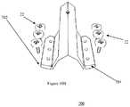
- FIG. 1Aillustrates an anterior-posterior view of a cervical TASP-LP according to an exemplary embodiment (Embodiment IAi).
- FIG. 1Billustrates a lateral view of a cervical TASP-LP according to an exemplary embodiment (Embodiment IAi).
- FIG. 1Cillustrates an oblique view of a cervical TASP-LP according to an exemplary embodiment (Embodiment IAi).
- FIG. 1Dillustrates a superior view of a cervical TASP-LP according to an exemplary embodiment (Embodiment IAi).
- FIG. 1Eillustrates a superior-implanted view of a cervical TASP-LP according to an exemplary embodiment (Embodiment IAi).
- FIG. 1Fillustrates an inferior-oblique view of a cervical TASP-LP according to an exemplary embodiment (Embodiment IAii).
- FIG. 1Gillustrates a top view of a cervical TASP-LP according to an exemplary embodiment (Embodiment IAiii).
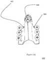
- FIG. 1Hillustrates an oblique view and a side view of a cervical TASP-LP according to an exemplary embodiment (Embodiment IAiii).
- FIG. 2Aillustrates the implantation of two (A) cervical TASP-LP modules into the cervical spine according to an exemplary embodiment (Embodiment IA).
- FIG. 2Billustrates the implantation of three (B) cervical TASP-LP modules into the cervical spine according to an exemplary embodiment (Embodiment IA).
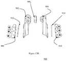
- FIG. 3Aillustrates a superior-oblique view of a double TASP-LP according to an exemplary embodiment (Embodiment IB) inserted into the cervical spine and a hybrid of double (Embodiment IB) and single TASP-LP according to an exemplary embodiment (Embodiment IA) modules inserted into the cervical spine.
- Embodiment IBdouble TASP-LP
- Embodiment IAsingle TASP-LP
- FIG. 3Billustrates a triple cervical TASP-LP module according to an exemplary embodiment (Embodiment IC) inserted into the cervical spine.
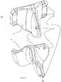
- FIG. 4Aillustrates an anterior-posterior view of the Thoracic/Lumbar TASP-LP according to an exemplary embodiment (Embodiment IAi).
- FIG. 4Billustrates a lateral view of the Thoracic/Lumbar TASP-LP according to an exemplary embodiment (Embodiment IAi).
- FIG. 4Cillustrates an oblique view of the Thoracic/Lumbar TASP-LP according to an exemplary embodiment (Embodiment IAi).
- FIG. 4Dillustrates a superior view of the Thoracic/Lumbar TASP-LP according to an exemplary embodiment (Embodiment IAi).
- FIG. 4Eillustrates a superior implanted view of the Thoracic/Lumbar TASP-LP according to an exemplary embodiment (Embodiment IAi).
- FIG. 4Fillustrates a superior and inferior-oblique view of the Thoracic/Lumbar TASP-LP according to an exemplary embodiment (Embodiment IAii).
- FIG. 4Gillustrates a top view of the Thoracic/Lumbar TASP-LP according to an exemplary embodiment (Embodiment IAiii).
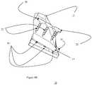
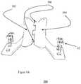
- FIG. 5Aillustrates an implantation of two Thoracic/Lumbar TASP-LP modules into the Lumbar spine according to an exemplary embodiment (Embodiment IA).
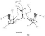
- FIG. 5Billustrates an implantation of three Thoracic/Lumbar TASP-LP modules into the Lumbar spine according to an exemplary embodiment (Embodiment IA).
- FIG. 6Aillustrates a superior-oblique view of a double according to an exemplary embodiment (Embodiment IB) inserted into the Lumbar spine and a hybrid of double according to an exemplary embodiment (Embodiment IB) and single according to an exemplary embodiment (Embodiment IA) TASP-LP modules inserted into the Thoracic/Lumbar spine.
- FIG. 6Billustrates a superior-oblique view of a triple according to an exemplary embodiment (Embodiment IC) of Thoracic-Lumbar TASP-LP modules inserted into the Lumbar spine.
- FIG. 7Aillustrates a cervical TASP-LP with laminar hinged extensions in a neutral position according to an exemplary embodiment (Embodiment II).
- FIG. 7Billustrates a cervical TASP-LP with laminar hinged extensions in an elevated position according to an exemplary embodiment (Embodiment II).
- FIG. 7Cillustrates a cervical TASP-LP with laminar hinged extensions in a depressed position according to an exemplary embodiment (Embodiment II).
- FIG. 7Dillustrates an exploded view of the cervical TASP-LP according to an exemplary embodiment (Embodiment II).
- FIG. 8Aillustrates a cervical TASP-LP with spino-laminar hinged extensions in a neutral position according to an exemplary embodiment (Embodiment III).
- FIG. 8Billustrates a cervical TASP-LP with spino-laminar hinged extensions in an elevated position according to an exemplary embodiment (Embodiment III).
- FIG. 8Cillustrates a cervical TASP-LP with spino-laminar hinged extensions in a depressed position according to an exemplary embodiment (Embodiment III).
- FIG. 8Dillustrates an exploded view of the cervical TASP-LP according to an exemplary embodiment (Embodiment III).
- FIG. 9Aillustrates an anterior-posterior view of the cervical TASP-LP according to an exemplary embodiment (Embodiment IV).
- FIG. 9Billustrates an exploded view of the cervical TASP-LP according to an exemplary embodiment (Embodiment IV).
- FIG. 10Aillustrates a Thoracic/Lumbar TASP-LP with laminar hinged extensions in a neutral position according to an exemplary embodiment (Embodiment II).
- FIG. 10Billustrates a Thoracic/Lumbar TASP-LP with laminar hinged extensions in an elevated position according to an exemplary embodiment (Embodiment II).
- FIG. 10Cillustrates a Thoracic/Lumbar TASP-LP with laminar hinged extensions in a depressed position according to an exemplary embodiment (Embodiment II).
- FIG. 10Dillustrates an exploded view of the Thoracic/Lumbar TASP-LP according to an exemplary embodiment (Embodiment II).
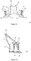
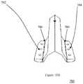
- FIG. 11Aillustrates a Thoracic-Lumbar TASP-LP with spino-laminar hinged extensions in a neutral position according to an exemplary embodiment (Embodiment III).
- FIG. 11Billustrates a Thoracic-Lumbar TASP-LP with spino-laminar hinged extensions in a slightly elevated position according to an exemplary embodiment (Embodiment III).
- FIG. 11Cillustrates a Thoracic-Lumbar TASP-LP with spino-laminar hinged extensions in a markedly elevated position according to an exemplary embodiment (Embodiment III).
- FIG. 11Dillustrates an exploded view of the Thoracic-Lumbar TASP-LP according to an exemplary embodiment (Embodiment III).
- FIG. 12Aillustrates an anterior-posterior view of the Thoracic-Lumbar TASP-LP according to an exemplary embodiment (Embodiment IV).
- FIG. 12Billustrates an exploded view of the Thoracic-Lumbar TASP-LP according to an exemplary embodiment (Embodiment IV).
- FIGS. 1-12Billustrate exemplary embodiments of a TASP-LP that can solve the aforementioned problems in the cervical, thoracic and lumbar spine by implantation of a TASP-LP into the post-laminectomy spine.
- FIGS. 1A-Dillustrate a plurality of different views of an exemplary embodiment of a cervical TASP-LP (Embodiment IA) including a single one piece total prosthetic module 10 that can replace a single natural cervical spinous process laminar (left and right) unit.
- Embodiment IAa single one piece total prosthetic module 10 that can replace a single natural cervical spinous process laminar (left and right) unit.
- the total prosthetic module 10can include, for example, a prosthetic spinous process 12 and left prosthetic lamina 14 and right prosthetic lamina 16 .
- the prosthetic spinous process 12can include perforations 20 for muscle suture attachment.
- the left prosthetic lamina 14 and right prosthetic lamina 16can include screw attachments 18 for receiving translaminar screws 22 .
- An exemplary embodiment of a cervical TASP-LP constructioncan be based on a 3-D CT computer rendition which very closely recreates the natural geometric anatomy of the healthy human cervical spine.
- an exemplary embodiment of a cervical prosthetic spinous process 12 of the TASP-LP 10can be bifid (i.e., divided into two lobes), just like the predominant bifid spinous process anatomy of the natural cervical spine 30 .
- the slope and angulations of the prosthetic spinous process 12 , and of left and right prosthetic lamina 14 , 16can be rendered in accord with the natural spinous process 34 and of left and right natural lamina 30 , 32 of the healthy natural cervical spine 30 .
- the natural spinous process 34 and of left and right natural lamina 30 , 32 of the healthy natural cervical spine 30can be rendered in accord with the natural spinous process 34 and of left and right natural lamina 30 , 32 of the healthy natural cervical spine 30 .
- FIG. 1Fan exemplary embodiment of a slightly different singular module 10 a (Embodiment IAii) will now be described in which the undersurfaces of the laminar mounting surfaces 40 can be contoured to approximate the shape of the underlying cervical lamina (e.g., 30 , 32 ) to which the prosthesis 10 a is mounted.
- the undersurfaces of the laminar mounting surfaces 40can be contoured to approximate the shape of the underlying cervical lamina (e.g., 30 , 32 ) to which the prosthesis 10 a is mounted.
- FIGS. 1G-Hillustrate yet another exemplary embodiment of the single module 10 b (Embodiment IAiii) including a relief (e.g., laminar mounting relief 44 ) added on each side that enables slight flexing for mounting.
- the prosthetic lamina 14 , 16can be thinned (e.g., thinned laminar section 42 ) to thereby also allow slightly more flexibility.
- the features of the exemplary embodimentcan be facilitated by producing the exemplary prosthesis 10 b using titanium or similar bio-compatible materials.
- FIG. 1Hillustrates a cross-sectional view of an exemplary embodiment that demonstrates that flat screw heads (e.g., flat head mounting trans-laminar screws 22 a ) can be countersunk into the surface, whereby the screws 22 a are, for example, locked into position.
- flat screw headse.g., flat head mounting trans-laminar screws 22 a
- the exemplary embodiments of the prosthetic spinous process 12can include perforations 20 on either side of the bifid process 12 to enable suturing of cervical muscles and fascia to the prosthetic spinous process 12 , to reconstruct the normal cervical muscular architecture.
- the left and right prosthetic lamina 14 , 16can include, for example, two perforations 18 on its extensions, thereby enabling the fixation of the TASP-LP to the natural lamina ( FIG. 1E ) by translaminar screws 22 a.
- FIGS. 2A and 2Billustrate an exemplary embodiment of a cervical TASP-LP 100 (embodiment IA) that can be modularly applied to two and three level multi-level laminectomies. Other exemplary embodiments can likewise be applied to four, five, etc. multi-level laminectomies in a modular manner.
- FIG. 2Aillustrates an exemplary embodiment in which a TASP-LP module 100 a (module #1), and module 100 b (module #2) are inserted into a 2 level post-laminectomy natural cervical spine 30 .
- FIG. 2Billustrates an exemplary embodiment in which TASP-LP modules 100 a , 100 b , 100 c (modules #1, #2, and #3) are inserted into a 3-level post-laminectomy natural cervical spine 30 .
- the prosthetic modules 100 a , 100 b , 100 ccan reproduce and artificially reconstruct the natural geometry of the healthy human spine 30 .
- the different modulescan be manufactured in different heights, lengths, and widths so that the surgeon can select from the properly sized one to integrate with the selective anatomy of different patients.
- FIGS. 3A and 3Billustrate other exemplary embodiment (Embodiments IB and IC), respectively.
- FIG. 3Aillustrates an exemplary embodiment (Embodiment IB) including a double spinous process-laminar prosthetic unit 200 .
- the prosthetic unit 200can be a single piece and can be similar to the single module TASP-LP (Embodiment IA, e.g., 10 , 10 a , 100 a , 100 b , 100 c ).
- the prosthetic unit 200can include two modules unified (e.g., integrally formed) into one piece with modular laminar connecting bridges 202 on the left and right sides of the prosthesis 200 .
- FIG. 1Aillustrates an exemplary embodiment (Embodiment IB) including a double spinous process-laminar prosthetic unit 200 .
- the prosthetic unit 200can be a single piece and can be similar to the single module TASP-LP (Embodiment IA, e.g., 10 , 10 a , 100 a , 100 b , 100 c ).
- FIG. 3Ashows the implantation of a double spinous process-laminar prosthetic module 200 (Embodiment IB) and a single spinous-laminar prosthetic module (embodiment IA, e.g., 10 ) into a 3-level post-laminectomy cervical spine 30 .
- Thisis essentially a hybrid reconstruction.
- the surgeoncan choose to replace three natural units with either 3 single TASP-LP modules (Embodiment IA, e.g., 10 ), or with a combination of a double TASP-LP module 200 (Embodiment IB) and a single TASP-LP module (Embodiment IA, e.g., 10 ), or with a single Triple TASP-LP module (embodiment IC, e.g., 100 a , 100 b , 100 c ) as illustrated, for example, in FIG. 3B .
- This triple embodiment 300( FIG. 3B ) can include three modules fused, or integrally formed, into one using two modular connecting bridges 302 on the right and left sides of the module 300 .
- FIGS. 4A-Dillustrate a plurality of different views of an exemplary embodiment of a Thoracic/Lumbar TASP-LP 10 (Embodiment IAi).
- the Thoracic/Lumbar TASP-LPcan be a single one piece total prosthetic module 10 which replaces a single natural Thoracic/Lumbar spinous process-laminar (left and right) unit based on, for example, 3-D CT computer modeling, and can very closely reproduce the normal anatomy of the Thoracic/Lumbar spine.
- the exemplary prosthetic spinous process 12can be monofid, just like the natural anatomy for the majority of the Thoracic and Lumbar spinal elements.
- the slope and angulations of the exemplary prosthetic spinous process 12 , and of the left and right prosthetic lamina 14 , 16can be rendered in accord with the normal Thoracic/Lumbar anatomy using 3-D computer modeling technology.
- the overall shape, height, and the spinous process 12 and laminar orientations and angulations of the prosthesiscan mimic the surrounding natural Lumbar spinous processes and lamina, rendering the prosthesis 10 almost indistinguishable from the natural Lumbar spine in which it is embedded.
- An exemplary prosthetic spinous process 12can include perforations to enable suturing of Thoracic/Lumbar muscles and fascia to the prosthesis, to reconstruct the normal muscle orientation and architecture.
- the left and right prosthetic laminacan include, for example, three perforations on its extensions, which can enable the fixation of the TASP-LP to the natural lamina by trans-laminar screws as exemplarily illustrated in FIG. 4E .
- FIG. 4Fillustrates another exemplary embodiment of a single modular Lumbar-Thoracic TASP-LP 10 a (Embodiment IAii) wherein the prosthesis 10 a can include a different contour and two perforations 18 (instead of three perforations) on either side for trans-laminar screw mounting.
- FIG. 4Gillustrates yet another exemplary embodiment of a single modular Lumbar/Thoracic TASP-LP 10 a (Embodiment IAiii) wherein a relief 44 can be added on each side to make the prosthesis somewhat more malleable and flexible. Similarly, the prosthetic laminar edges can be somewhat more thinned out for the sake of increased malleability. These features may be more amenable to production of the prosthesis in titanium or any biocompatible material with similar properties.
- FIGS. 5A and 5Billustrate an exemplary embodiment of a Thoracic/Lumbar TASP-LP 10 (Embodiment IA) that can be modularly applied to two and three level multi-level laminectomies. This embodiment likewise can be applied to four, five, etc. multi-level laminectomies in a modular manner.
- FIG. 5Aillustrates an exemplary embodiment of a Thoracic/Lumbar TASP-LP module 100 a , 100 b (module #1 and module #2) inserted into a 2 level postlaminectomy natural Lumbar spine 30 .
- FIGS. 5A and 5Billustrates an exemplary embodiment of TASP-LP modules 100 a , 100 b , 100 c (modules #1, #2, and #3) inserted into the 3-level post-laminectomy natural Lumbar spine 30 .
- the prosthetic modulescan reproduce and artificially reconstruct the natural geometry of the spine.
- the different modules 100 a , 100 b , 100 ccan be manufactured in different heights, lengths, and widths so that the surgeon can select from different sizes to accommodate for differences in patient anatomy.
- FIGS. 6A and 6Billustrate other exemplary embodiments of a Thoracic/Lumbar TASP-LP (Embodiments IB and IC, respectively).
- FIG. 6Aillustrates an exemplary embodiment (Embodiment IB) including a double spinous process-laminar prosthetic unit 200 a .
- the prosthetic unit 200 acan be, for example, a single piece and can be technically similar to the single module TASP-LP 10 (Embodiment IA) described herein. However, in this embodiment, two modules can be unified into one piece (e.g., integrally formed) with a modular connecting bridge 204 joining the adjacent prosthetic spinous processes 12 .
- FIG. 1illustrates an exemplary embodiment including a double spinous process-laminar prosthetic unit 200 a .
- the prosthetic unit 200 acan be, for example, a single piece and can be technically similar to the single module TASP-LP 10 (Embodiment IA) described herein.
- two modulescan be
- FIG. 6Aillustrates the implantation of an exemplary double Thoracic/Lumbar spino-laminar prosthetic module 200 a (Embodiment IB) and an exemplary single Thoracic/Lumbar spino-laminar prosthetic module 10 (Embodiment IA) into a 3-level post-laminectomy cervical spine 30 .
- This embodimentcan be essentially a hybrid reconstruction.
- the surgeoncan choose to replace three natural units with either three (3) single TASP-LP modules ( 10 , 10 a , etc.) (Embodiment IA) or with a double TASP-LP module ( 200 , 200 a ) (Embodiment IB) and a single TASP-LP unit ( 10 , 10 a , etc.) (Embodiment IA), or with a single triple TASP-LP module 300 (Embodiment IC) as exemplarily illustrated in FIG. 3B , or with a single triple TASP-LP module 300 a as exemplarily illustrated in FIG. 6B .
- the triple embodiment 300FIG.
- the triple embodiment 300 a(e.g., as illustrated in FIG. 6 A) can include three modules fused into one (e.g., integrally formed), for example, using two modular connecting bridges 304 connecting three modular prosthetic spinous processes 12 .
- FIGS. 7A-Dillustrate an exemplary embodiment of another cervical TASP-LP 400 (Embodiment II).
- the prosthesis 400can include left and right prosthetic laminar hinged extensions 402 , 404 .
- These hinged extensionscan be attached to the prosthetic lamina 14 , 16 with hinge pins 406 , 408 , for example, as illustrated in FIG. 7D .
- the exemplary hinges 406 , 408can be moved up and down like doors allowing individualized accommodating alignment of the TASP-LP 400 with differing natural laminar inclines.
- FIG. 7Aillustrates the laminar hinged extensions 402 , 404 in neutral position.
- FIG. 7Billustrates the laminar hinged extensions 402 , 404 in elevated positions.
- FIG. 7Cillustrates the laminar hinged extensions 402 , 404 in depressed positions.
- FIG. 7Dillustrates an exploded view of the exemplary embodiment of FIGS. 7A-7C (Embodiment II).
- the left and right prosthetic laminar hinges 406 , 408can be attached to the hinged TASP-LP prosthesis with pins 410 , 412 or other suitable connecting devices.
- the hinged extensions 402 , 404can rotate about the pin 410 , 412 allowing significant up and down movement for allowing placement on varying natural laminar inclines, thereby accounting for patient variability.
- FIGS. 8A-Dillustrate an exemplary embodiment of a Cervical TASP-LP 500 (Embodiment III).
- This embodimentdiffers from the embodiment of FIGS. 7A-7C (e.g., Embodiments I and II), in that the prosthetic spinous process 12 can comprise left and right winged spinous process-laminar hinges 502 , 504 which allow elevation or depression of the two hemi-segments of the prosthesis, thus enabling a varying degree of widening of the prosthesis.
- This embodimentcan allow prosthetic accommodation for different laminectomy widths, thereby taking into account differences in inter-patient anatomy, and surgically created laminectomy widths.
- FIGS. 8A, 8B, and 8Cillustrate the exemplary embodiment in neutral, elevated and depressed positions, respectively.
- FIG. 8Dillustrates an exploded view of the exemplary embodiment of FIGS. 8A-8C , including the left prosthetic spinous process-laminar hinge 502 , the right prosthetic spinous process laminar hinge 504 , and the hinge pin 506 .
- FIGS. 9A and 9Billustrate an exemplary embodiment of a cervical TASP-LP 600 (Embodiment IV).
- This exemplary embodimentcan combine, for example, all the features in Embodiments I, II, and III.
- the illustrated embodimentincludes both left and right prosthetic winged spinous process-laminar hinges 602 , 604 which allow movement around a spinous process laminar hinge pin 606 , and left and right laminar hinged extensions 608 , 610 which allow elevation or depression of these hinges via their rotation around the laminar extension hinge pins 612 , 614 .
- this embodimentcan enable accommodation both for differences in varying laminar inclines, by altering the position of its laminar hinge extensions, and for differences in laminectomy widths by widening the device by repositioning the left and right prosthetic spinous-process-laminar hinges 602 , 604 .
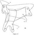
- FIGS. 10A-Dillustrate an exemplary embodiment of a Thoracic/Lumbar TASP-LP 700 (Embodiment II).
- This embodimentdiffers from Embodiment I, in that the embodiment includes left and right prosthetic laminar hinged extensions 702 , 704 .
- These hinged extensions 702 , 704can be attached to the prosthetic lamina, for example, with hinge pins 706 , 708 as illustrated in FIG. 10D or other suitable devices.
- the hinged extensions 702 , 704can be moved up and down like doors allowing individualized alignment of the TASP-LP 700 with the natural incline of different patients' spinal laminar anatomy.
- FIG. 10Aillustrates the prosthetic laminar hinged extensions 702 , 704 in neutral position.
- FIG. 10Billustrates the prosthetic laminar hinged extensions 702 , 704 in elevated positions.
- FIG. 10Cillustrates the prosthetic laminar hinged extensions 702 , 704 in depressed position.
- FIG. 10Dillustrates the exploded view of embodiment II.
- the left and right prosthetic laminar hinged extensions 702 , 704can be attached to the hinged TASP-LP prosthesis, for example, with pins 706 , 708 or similar devices.
- the hinged extensions 702 , 704can rotate about the pin 706 , 708 allowing significant up and down movement allowing placement on varying natural inclines accounting for patient anatomical variation.
- FIGS. 11A-Dillustrate an exemplary embodiment of a Thoracic/Lumbar TASP-LP 800 (Embodiment III).
- This embodimentdiffers from Embodiments I and II, in that the prosthetic spinous process 12 can comprise left and right winged prosthetic spinous process-laminar hinges 802 , 804 which allow elevation or depression of the two hemi-segments of the prosthesis enabling a varying degree of widening of the prosthesis.
- This embodimentcan allow prosthetic accommodation for different laminectomy widths, thus accounting for differences in inter-patient anatomy, and surgically created laminectomy widths.
- FIGS. 11A, 11B, and 11Cillustrate this exemplary embodiment in neutral, elevated and depressed positions, respectively.
- FIG. 11Dillustrates an exploded view of FIGS. 11A-11C including the left prosthetic winged spinous process-laminar hinge 802 , the right winged prosthetic spinous process laminar hinge 804 , and the spinous process-laminar hinge pin 806 .
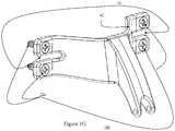
- FIGS. 12A and 12Billustrate an exemplary embodiment of a Thoracic/Lumbar TASP-LP 900 (Embodiment IV).
- This embodimentcombines all the features in Embodiments I, II, and III and can include, for example, both left and right winged prosthetic spinous process-laminar hinges 902 , 904 which allow movement around a spinous process-laminar hinge pin 906 or the like, and left and right laminar hinged extensions 908 , 910 which allow elevation or depression of these hinges via their rotation around the laminar extension hinge pins 912 , 914 .
- this embodimentcan enable accommodation both for differences in varying laminar inclines, by altering the position of its laminar hinge extensions 908 , 910 , and for differences in laminectomy widths by widening the device by repositioning the left and right prosthetic winged spinous process-laminar hinges 902 , 904 .
- TASP-LPcan be made of any bio-compatible material including, for example, polyether ether ketone (PEEK) (e.g., a colourless organic polymer thermoplastic), titanium steel, allograft bone, or other suitable materials, etc.
- PEEKpolyether ether ketone
- the exemplary embodiments of a TASP-LPcan include pins as well as screws, or other suitable fasteners.
- the pinscan be, for example, flat or round.
- the pinscan include, for example, fish hooks or ridges.
- the pinscan be part of the device or a separate attachment for slots.
- an apparatuscan be used to hold the pin in place while it is being hammered or stapled into the prosthesis.
- An exemplary embodiment of the TASP-LPcan look like a lamina/spinous process or occupy the space of a lamina/spinous process, or be of any variant shape.
- the TASP-LPcan include, for example, one piece, or two or more pieces assembled together. The pieces can include curves or be straight.
- the devicecan have different shapes, such as rectangular, triangular, curved or arch shaped, including for example: triangular arch, round arch, segmental arch, rampant round arch, lancet arc, equilateral pointed arch, shouldered flat arch, cusped arch, horseshoe arch, three centered arch, jack arch, inflexed arch, ogee arch, reverse ogee arch, a parabolic arch, or similar such arcs.
- exemplary embodiments of the prosthesiscan include a joint in the center or the sides for moveability.
- the exemplary prosthesiscan include a ball joint, screw joint, revolute joint, cylindrical joint, gliding joint, mechanical linkage joints, hinges, or any other suitable joint or feature which accomplishes the same function.
- exemplary embodiments of the prosthesiscan comprise bearings, for example, such as a ‘bushing’ for absorbing shock.
- the prosthesiscan be movable like a clip or hinge.
- the exemplary prosthesiscan be made of flexible material and/or can be spring like.
- a set or kit of a plurality of prosthesescan be provided, each having different standard sizes, such that a surgeon easily can select one or more appropriately sized prostheses.
- the selected prosthesiseach can have the same size or different sizes depending on the dimensions of the natural spinal portions of a given recipient.
- the spinous process-bilaminar unit(s) of the cervical post-laminectomy spinecan be artificially replaced with a single or multiple cervical TASP-LP modules.
- the surgeonselects either a single, multiple, or hybrid number of TASP-LP modules according to one or more of embodiments IA, IB, IC, II, III or IV.
- the TASP-LP modulescan be secured to the natural lamina on both right and left sides, for example, by screwing in trans-laminar screws through the prosthesis' laminar extension perforations and into the natural remaining lamina. This step can immobilize the construct onto the natural cervical spine.
- the cervical fascia and musclesthen can be reattached to the prosthetic spinous process(es) by passing a suture through the spinous process perforations thereby anatomically reconnecting the muscles to the prosthetic spine thereby mimicking the natural spinal anatomy.
- the spinous process-bilaminar unit(s) of the Thoracic/Lumbar postlaminectomy spinecan be artificially replaced with a single or multiple Thoracic/Lumbar TASPLP modules.
- the surgeoncan select either a single, multiple, or hybrid number of TASP-LP modules according to one or more of embodiments IA, IB, IC, II, III or IV.
- the Thoracic/Lumbar TASP-LP modulescan be secured to the natural lamina on both right and left sides, for example, by screwing in trans-laminar screws through the prosthesis' laminar extension perforations and into the natural remaining lamina. This can immobilize the construct onto the natural thoracic or lumbar spine.
- the cervical fascia and musclescan then be reattached to the prosthetic spinous process(es) by passing a suture through the spinous process perforations thereby anatomically reconnecting the muscles to the prosthetic spine thereby mimicking the natural spinal anatomy.
- the exemplary embodimentscan include a total artificial spinous process (spino)-laminar prosthesis (TASP-LP) comprising one or more of the features of the cervical and Lumbar embodiments illustrated in embodiments IA, IB, IC, II, III, and IV.
- spinospinous process
- TASP-LPtotal artificial spinous process-laminar prosthesis
- the exemplary embodimentscan include a method of replacing the spinous process-bilaminar unit(s) of the cervical postlaminectomy spine with a single or multiple cervical TASP-LP modules according to one or more of embodiments IA, IB, IC, II, III, and IV.
- the exemplary embodimentscan include a single total artificial spinous process (spino)-laminar prosthesis (TASP-LP) having varying lengths and widths.
- spinospinous process
- TASP-LPtotal artificial spinous process-laminar prosthesis
- the exemplary embodimentscan include a plurality of total artificial spinous process (spino)-laminar prosthesis (TASP-LP) having varying lengths and widths.
- spinototal artificial spinous process
- TASP-LPtotal artificial spinous process-laminar prosthesis
- the exemplary embodimentscan include a total artificial spinous process (spino)-laminar prosthesis (TASP-LP) comprising expandable hinged spino-laminar wings to accommodate different laminectomy widths. 6.
- TASP-LPtotal artificial spinous process (spino)-laminar prosthesis (TASP-LP) comprising hinged laminar extensions which can accommodate individualized laminar inclines.
- the exemplary embodimentscan include a total artificial spinous process (spino)-laminar prosthesis (TASP-LP) comprising both hinged expandable spinous process-laminar wings and hinged laminar extensions.
- spinospinous process
- TASP-LPtotal artificial spinous process-laminar prosthesis
- the exemplary embodimentscan include a method of replacing the spinous process-bilaminar unit(s) of the Thoracic/Lumbar post-laminectomy spine with a single or multiple Thoracic/Lumbar TASP-LP modules according to one or more of embodiments IA, IB, IC, II, III, and IV.
- the exemplary embodimentscan include a total artificial spinous process (spino)-laminar prosthesis (TASP-LP) comprising a biocompatible material.
- spinospinous process
- TASP-LPtotal artificial spinous process-laminar prosthesis
- the exemplary embodimentscan include a method of manufacturing tailor made individualized prosthetics using 3-D computerized modeling reconstructions of patients' specific geometric anatomy measured on their CT/Mills.
- the exemplary embodimentscan include a TASP-LP having two or three screws, as exemplarily illustrated, or with fewer or more screws.
- the exemplary embodimentscan include a mounting area that can be expanded or have its shape changed to any variety of shapes to cover different areas of the bone for attachment or fixation.
- the exemplary embodimentscan include a prosthesis having areas for addition or incorporation of bone if a surgeon wishes to include a fusion.
- the exemplary embodimentscan include screws that are countersunk into the prosthetic surface for fixed locking. Variations of locking mechanisms for fixed or variable angled screws can be applied. Either external or internal locking mechanisms can be employed.
- the exemplary embodimentscan include a prosthesis that is flexible or expandable in any area.
- pins and staplescan be used instead of screws.
- Such pin or stapler fixturescan be pounded into the device.
- Other alternative fixture devices or bonding materialscan be used to fixate the prosthesis.
- the muscle suture attachmentcan be within the spinous process.
- This perforationcan be a single perforation, or in other embodiments, the prosthesis can include a plurality of perforations, or no perforations. The perforations are not limited to the locations illustrated in the exemplary embodiments and can be located anywhere on the prosthesis.
- the prosthesiscan be, for example, manufactured in multiple parts which can come in different sizes accommodating intra-patient and multiple patient anatomical variations, and the prosthesis can be assembled intra-operatively by the surgeon using multiple assembly techniques creating tailor made products individualized for the patient.
- the methodcan include selecting one or more appropriately sized prostheses from a set or kit of a plurality of prostheses, wherein the set or kit includes prosthesis having different standard sizes.
- the selected prosthesiseach can have the same size or different sizes depending on the dimensions of the natural spinal portions of a given recipient.
- the exemplary embodimentscan include a current laminar prosthesis that is arch shaped to mimic the natural spinal, anatomy and to protect the intra-spinal neural elements.
- arch shapedto mimic the natural spinal, anatomy and to protect the intra-spinal neural elements.
- other shapescan also be used which include, but at not limited to, circular, polygonal, pyramidal, flat, cornered, rounded, or any combination, variation, or permutation of the above.
- spatially relative termssuch as “under”, “below”, “lower”, “over”, “upper”, “lateral”, “left”, “right” and the like, may be used herein for ease of description to describe one element or feature's relationship to another element(s) or feature(s) as illustrated in the figures. It will be understood that the spatially relative terms are intended to encompass different orientations of the device in use or operation in addition to the orientation depicted in the figures. For example, if the device in the figures is inverted, elements described as “under” or “beneath” other elements or features would then be oriented “over” the other elements or features. The device may be otherwise oriented (rotated 90 degrees or at other orientations) and the descriptors of relative spatial relationships used herein interpreted accordingly.
Landscapes
- Health & Medical Sciences (AREA)
- Orthopedic Medicine & Surgery (AREA)
- Engineering & Computer Science (AREA)
- Biomedical Technology (AREA)
- Neurology (AREA)
- Life Sciences & Earth Sciences (AREA)
- General Health & Medical Sciences (AREA)
- Heart & Thoracic Surgery (AREA)
- Veterinary Medicine (AREA)
- Public Health (AREA)
- Animal Behavior & Ethology (AREA)
- Surgery (AREA)
- Cardiology (AREA)
- Oral & Maxillofacial Surgery (AREA)
- Transplantation (AREA)
- Vascular Medicine (AREA)
- Molecular Biology (AREA)
- Medical Informatics (AREA)
- Nuclear Medicine, Radiotherapy & Molecular Imaging (AREA)
- Prostheses (AREA)
Abstract
Description
Claims (20)
Priority Applications (2)
| Application Number | Priority Date | Filing Date | Title |
|---|---|---|---|
| US16/034,545US11116642B2 (en) | 2009-11-25 | 2018-07-13 | Total artificial spino-laminar prosthetic replacement |
| US17/471,667US20220062003A1 (en) | 2009-11-25 | 2021-09-10 | 3-d printed spinal implant |
Applications Claiming Priority (6)
| Application Number | Priority Date | Filing Date | Title |
|---|---|---|---|
| US26464809P | 2009-11-25 | 2009-11-25 | |
| US30692610P | 2010-02-22 | 2010-02-22 | |
| US84682210A | 2010-07-29 | 2010-07-29 | |
| US12/983,107US9901455B2 (en) | 2009-11-25 | 2010-12-31 | Total artificial spino-laminar prosthetic replacement |
| US15/904,617US10022238B1 (en) | 2009-11-25 | 2018-02-26 | Total artificial spino-laminar prosthetic replacement |
| US16/034,545US11116642B2 (en) | 2009-11-25 | 2018-07-13 | Total artificial spino-laminar prosthetic replacement |
Related Parent Applications (1)
| Application Number | Title | Priority Date | Filing Date |
|---|---|---|---|
| US15/904,617ContinuationUS10022238B1 (en) | 2009-11-25 | 2018-02-26 | Total artificial spino-laminar prosthetic replacement |
Related Child Applications (1)
| Application Number | Title | Priority Date | Filing Date |
|---|---|---|---|
| US17/471,667ContinuationUS20220062003A1 (en) | 2009-11-25 | 2021-09-10 | 3-d printed spinal implant |
Publications (2)
| Publication Number | Publication Date |
|---|---|
| US20180325690A1 US20180325690A1 (en) | 2018-11-15 |
| US11116642B2true US11116642B2 (en) | 2021-09-14 |
Family
ID=44062662
Family Applications (4)
| Application Number | Title | Priority Date | Filing Date |
|---|---|---|---|
| US12/983,107ActiveUS9901455B2 (en) | 2009-11-25 | 2010-12-31 | Total artificial spino-laminar prosthetic replacement |
| US15/904,617ActiveUS10022238B1 (en) | 2009-11-25 | 2018-02-26 | Total artificial spino-laminar prosthetic replacement |
| US16/034,545Active2030-09-09US11116642B2 (en) | 2009-11-25 | 2018-07-13 | Total artificial spino-laminar prosthetic replacement |
| US17/471,667PendingUS20220062003A1 (en) | 2009-11-25 | 2021-09-10 | 3-d printed spinal implant |
Family Applications Before (2)
| Application Number | Title | Priority Date | Filing Date |
|---|---|---|---|
| US12/983,107ActiveUS9901455B2 (en) | 2009-11-25 | 2010-12-31 | Total artificial spino-laminar prosthetic replacement |
| US15/904,617ActiveUS10022238B1 (en) | 2009-11-25 | 2018-02-26 | Total artificial spino-laminar prosthetic replacement |
Family Applications After (1)
| Application Number | Title | Priority Date | Filing Date |
|---|---|---|---|
| US17/471,667PendingUS20220062003A1 (en) | 2009-11-25 | 2021-09-10 | 3-d printed spinal implant |
Country Status (1)
| Country | Link |
|---|---|
| US (4) | US9901455B2 (en) |
Families Citing this family (31)
| Publication number | Priority date | Publication date | Assignee | Title |
|---|---|---|---|---|
| US9848993B2 (en) | 2005-04-12 | 2017-12-26 | Nathan C. Moskowitz | Zero-profile expandable intervertebral spacer devices for distraction and spinal fusion and a universal tool for their placement and expansion |
| US7846188B2 (en) | 2005-04-12 | 2010-12-07 | Moskowitz Nathan C | Bi-directional fixating transvertebral body screws, zero-profile horizontal intervertebral miniplates, total intervertebral body fusion devices, and posterior motion-calibrating interarticulating joint stapling device for spinal fusion |
| US11903849B2 (en) | 2005-04-12 | 2024-02-20 | Moskowitz Family Llc | Intervertebral implant and tool assembly |
| US7972363B2 (en) | 2005-04-12 | 2011-07-05 | Moskowitz Ahmnon D | Bi-directional fixating/locking transvertebral body screw/intervertebral cage stand-alone constructs and posterior cervical and lumbar interarticulating joint stapling guns and devices for spinal fusion |
| US7942903B2 (en) | 2005-04-12 | 2011-05-17 | Moskowitz Ahmnon D | Bi-directional fixating transvertebral body screws and posterior cervical and lumbar interarticulating joint calibrated stapling devices for spinal fusion |
| US9744052B2 (en) | 2005-04-12 | 2017-08-29 | Nathan C. Moskowitz | Bi-directional fixating/locking transvertebral body screw/intervertebral cage stand-alone constructs |
| US7704279B2 (en) | 2005-04-12 | 2010-04-27 | Moskowitz Mosheh T | Bi-directional fixating transvertebral body screws, zero-profile horizontal intervertebral miniplates, expansile intervertebral body fusion devices, and posterior motion-calibrating interarticulating joint stapling device for spinal fusion |
| US9532821B2 (en) | 2005-04-12 | 2017-01-03 | Nathan C. Moskowitz | Bi-directional fixating/locking transvertebral body screw/intervertebral cage stand-alone constructs with vertical hemi-bracket screw locking mechanism |
| US7854765B2 (en) | 2006-04-20 | 2010-12-21 | Moskowitz Mosheh T | Electronically controlled artificial intervertebral disc with motor assisted actuation systems |
| US9901455B2 (en)* | 2009-11-25 | 2018-02-27 | Nathan C. Moskowitz | Total artificial spino-laminar prosthetic replacement |
| US20140058446A1 (en)* | 2011-09-28 | 2014-02-27 | Avi Bernstein | Spinal implant system |
| CN102366335A (en)* | 2011-10-27 | 2012-03-07 | 黄海燕 | Artificial titanium alloy stabilizing-wing vertebral plate for three-dimensional reconstruction shaping of vertebrae |
| CN102551923B (en)* | 2011-11-11 | 2014-03-19 | 兰州大学 | Artificial vertebral plate |
| US9138325B2 (en)* | 2012-07-11 | 2015-09-22 | Globus Medical, Inc. | Lamina implant and method |
| US20150196752A1 (en)* | 2012-08-10 | 2015-07-16 | Intermountain Invention Managment, Llc | Epicardial lead placement apparatus, systems, and methods |
| CN104055607A (en)* | 2013-03-20 | 2014-09-24 | 江阴瑞康健生物医学科技有限公司 | Artificial lamina |
| US10105234B2 (en)* | 2014-03-13 | 2018-10-23 | Warsaw Orthopedic, Inc. | Spinal implant system and methods of use |
| US9717541B2 (en) | 2015-04-13 | 2017-08-01 | DePuy Synthes Products, Inc. | Lamina implants and methods for spinal decompression |
| US10792077B2 (en) | 2015-10-01 | 2020-10-06 | Orion Spine Inc. | Spine protection device |
| US10695107B2 (en) | 2015-12-03 | 2020-06-30 | Warsaw Orthopedic, Inc. | Spinal implant system and methods of use |
| US10667916B2 (en)* | 2016-03-03 | 2020-06-02 | Globus Medical, Inc. | Lamina plate assembly |
| US11090166B2 (en) | 2016-03-03 | 2021-08-17 | Globus Medical, Inc. | Lamina plate assembly |
| US10376292B2 (en)* | 2016-03-03 | 2019-08-13 | Globus Medical, Inc | Lamina plate assembly |
| EP3372180A1 (en)* | 2017-03-07 | 2018-09-12 | Globus Medical, Inc. | Lamina plate assembly |
| WO2018201061A1 (en)* | 2017-04-27 | 2018-11-01 | Dignity Health | Systems and methods for a spinal implant |
| EP3644880B1 (en)* | 2017-06-26 | 2024-04-24 | Dignity Health | Systems for a spinal shield for protecting the spinal cord and dura during surgical procedures |
| US12144742B2 (en) | 2020-06-15 | 2024-11-19 | Foundation Surgical Group, Inc. | Implant system and methods of use |
| US11259936B2 (en) | 2020-06-15 | 2022-03-01 | Nofusco Corporation | Intravertebral implant system and methods of use |
| US11883300B2 (en) | 2020-06-15 | 2024-01-30 | Nofusco Corporation | Orthopedic implant system and methods of use |
| US11723778B1 (en) | 2021-09-23 | 2023-08-15 | Nofusco Corporation | Vertebral implant system and methods of use |
| CN112107357A (en)* | 2020-10-21 | 2020-12-22 | 深圳市罗湖区中医院 | Cervical vertebra centrum antedisplacement fixed titanium plate |
Citations (124)
| Publication number | Priority date | Publication date | Assignee | Title |
|---|---|---|---|---|
| US5370692A (en)* | 1992-08-14 | 1994-12-06 | Guild Associates, Inc. | Rapid, customized bone prosthesis |
| US5470333A (en) | 1993-03-11 | 1995-11-28 | Danek Medical, Inc. | System for stabilizing the cervical and the lumbar region of the spine |
| US5762125A (en) | 1996-09-30 | 1998-06-09 | Johnson & Johnson Professional, Inc. | Custom bioimplantable article |
| US6132464A (en) | 1994-06-24 | 2000-10-17 | Paulette Fairant | Vertebral joint facets prostheses |
| US6206882B1 (en) | 1999-03-30 | 2001-03-27 | Surgical Dynamics Inc. | Plating system for the spine |
| US20020007294A1 (en)* | 2000-04-05 | 2002-01-17 | Bradbury Thomas J. | System and method for rapidly customizing a design and remotely manufacturing biomedical devices using a computer system |
| US6419703B1 (en)* | 2001-03-01 | 2002-07-16 | T. Wade Fallin | Prosthesis for the replacement of a posterior element of a vertebra |
| US20020095155A1 (en) | 1994-03-28 | 2002-07-18 | Michelson Gary Karlin | Spinal implant containing bone morphogenetic protein |
| US6481440B2 (en) | 1999-09-13 | 2002-11-19 | Medtronic, Inc. | Lamina prosthesis for delivery of medical treatment |
| US20030050700A1 (en) | 2001-09-11 | 2003-03-13 | Asahi Kogaku Kogyo Kabushiki Kaisha | Vertebral arch spacer |
| US6610091B1 (en)* | 1999-10-22 | 2003-08-26 | Archus Orthopedics Inc. | Facet arthroplasty devices and methods |
| US20030195514A1 (en) | 2002-04-16 | 2003-10-16 | Trieu Hai H. | Annulus repair systems and techniques |
| US6669729B2 (en) | 2002-03-08 | 2003-12-30 | Kingsley Richard Chin | Apparatus and method for the replacement of posterior vertebral elements |
| US20040030388A1 (en) | 2002-05-30 | 2004-02-12 | Null William B. | Laminoplasty devices and methods |
| US20040117015A1 (en)* | 2000-12-04 | 2004-06-17 | Spineco | Molded surgical implant and method |
| US20040133276A1 (en)* | 2002-10-07 | 2004-07-08 | Imaging Therapeutics, Inc. | Minimally invasive joint implant with 3-Dimensional geometry matching the articular surfaces |
| US20040152970A1 (en)* | 2003-01-30 | 2004-08-05 | Mark Hunter | Six degree of freedom alignment display for medical procedures |
| US20040158245A1 (en) | 2003-02-11 | 2004-08-12 | Chin Kingsley Richard | Apparatus and method for connecting spinal vertebrae |
| US20050033434A1 (en)* | 2003-08-06 | 2005-02-10 | Sdgi Holdings, Inc. | Posterior elements motion restoring device |
| US20050119657A1 (en) | 2003-10-28 | 2005-06-02 | Goldsmith Michael E. | Facet triangle spinal fixation device and method of use |
| US20050149021A1 (en)* | 2003-12-23 | 2005-07-07 | Tozzi James E. | Spinal implant device |
| US20050228381A1 (en) | 2004-04-09 | 2005-10-13 | Kirschman David L | Disk augmentation system and method |
| US20050228377A1 (en) | 2004-04-07 | 2005-10-13 | Depuy Spine, Inc. | Spinal cross-connectors |
| US20060036324A1 (en) | 2004-08-03 | 2006-02-16 | Dan Sachs | Adjustable spinal implant device and method |
| US20060058790A1 (en) | 2004-08-03 | 2006-03-16 | Carl Allen L | Spinous process reinforcement device and method |
| US20060161154A1 (en) | 2004-12-10 | 2006-07-20 | Mcafee Paul | Prosthetic spinous process and method |
| US7090698B2 (en)* | 2001-03-02 | 2006-08-15 | Facet Solutions | Method and apparatus for spine joint replacement |
| US20060241642A1 (en)* | 2005-04-11 | 2006-10-26 | Impliant Ltd. | Inserting anterior and posterior spinal prostheses |
| US20060241610A1 (en) | 2005-04-08 | 2006-10-26 | Sdgi Holdings, Inc. | Interspinous process spacer |
| US20060264948A1 (en) | 2005-05-03 | 2006-11-23 | Williams Lytton A | Bone anchored surgical mesh |
| US20060282020A1 (en) | 2005-06-13 | 2006-12-14 | Rudolph Bertagnoli | Customizing an intervertebral implant |
| US20070083266A1 (en)* | 2001-05-25 | 2007-04-12 | Vertegen, Inc. | Devices and methods for treating facet joints, uncovertebral joints, costovertebral joints and other joints |
| US20070118243A1 (en)* | 2005-10-14 | 2007-05-24 | Vantus Technology Corporation | Personal fit medical implants and orthopedic surgical instruments and methods for making |
| US20070191950A1 (en) | 2003-11-07 | 2007-08-16 | Uri Arnin | Spinal prostheses |
| US20070191834A1 (en) | 2006-01-27 | 2007-08-16 | Sdgi Holdings, Inc. | Artificial spinous process for the sacrum and methods of use |
| US20070198091A1 (en)* | 2005-12-06 | 2007-08-23 | Boyer Michael L | Facet joint prosthesis |
| US20070233068A1 (en) | 2006-02-22 | 2007-10-04 | Sdgi Holdings, Inc. | Intervertebral prosthetic assembly for spinal stabilization and method of implanting same |
| US20070233269A1 (en)* | 2001-05-25 | 2007-10-04 | Conformis, Inc. | Interpositional Joint Implant |
| US20070276501A1 (en)* | 2006-05-25 | 2007-11-29 | Spinemedica Corp. | Patient-specific spinal implants and related systems and methods |
| US20080195211A1 (en)* | 2006-10-30 | 2008-08-14 | Chia-Ying Lin | Engineered Scaffolds for Intervertebral Disc Repair and Regeneration and for Articulating Joint Repair and Regeneration |
| US20080281361A1 (en) | 2007-05-10 | 2008-11-13 | Shannon Marlece Vittur | Posterior stabilization and spinous process systems and methods |
| US20080281360A1 (en)* | 2007-05-10 | 2008-11-13 | Shannon Marlece Vittur | Spinous process implants and methods |
| US7567834B2 (en)* | 2004-05-03 | 2009-07-28 | Medtronic Navigation, Inc. | Method and apparatus for implantation between two vertebral bodies |
| US20090222103A1 (en)* | 2001-05-25 | 2009-09-03 | Conformis, Inc. | Articular Implants Providing Lower Adjacent Cartilage Wear |
| US7604652B2 (en) | 2005-10-11 | 2009-10-20 | Impliant Ltd. | Spinal prosthesis |
| US20090276045A1 (en)* | 2001-05-25 | 2009-11-05 | Conformis, Inc. | Devices and Methods for Treatment of Facet and Other Joints |
| US20090326592A1 (en)* | 2008-06-27 | 2009-12-31 | Butler Michael S | Posterior Spinal Prosthesis |
| US20100057127A1 (en) | 2008-08-26 | 2010-03-04 | Mcguire Brian | Expandable Laminoplasty Fixation System |
| US20100174315A1 (en)* | 2008-12-16 | 2010-07-08 | Daniel Scodary | Device for spinal fusion |
| US20100191100A1 (en)* | 2009-01-23 | 2010-07-29 | Warsaw Orthopedic, Inc. | Methods and systems for diagnosing, treating, or tracking spinal disorders |
| US20100217336A1 (en)* | 2006-08-31 | 2010-08-26 | Catholic Healthcare West (Chw) | Computerized Planning Tool For Spine Surgery and Method and Device for Creating a Customized Guide for Implantations |
| US20100217322A1 (en)* | 2009-02-26 | 2010-08-26 | Daniel Predick | Posterior Spinal Bridge Assembly Providing Static or Dynamic N-Level Spinal Bridge Interconnection |
| US20100249842A1 (en)* | 2009-03-31 | 2010-09-30 | Dr. Hamid R. Mir | Spinous process cross-link |
| US7846188B2 (en) | 2005-04-12 | 2010-12-07 | Moskowitz Nathan C | Bi-directional fixating transvertebral body screws, zero-profile horizontal intervertebral miniplates, total intervertebral body fusion devices, and posterior motion-calibrating interarticulating joint stapling device for spinal fusion |
| US7850732B2 (en) | 2006-12-11 | 2010-12-14 | Warsaw Orthopedic, Inc. | Sacral prosthesis and surgical method |
| US7854766B2 (en) | 2004-05-13 | 2010-12-21 | Moskowitz Nathan C | Artificial total lumbar disc for unilateral safe and simple posterior placement in the lumbar spine, and removable bifunctional screw which drives vertical sliding expansile plate expansion, and interplate widening, and angled traction spikes |
| US7854765B2 (en) | 2006-04-20 | 2010-12-21 | Moskowitz Mosheh T | Electronically controlled artificial intervertebral disc with motor assisted actuation systems |
| US7942903B2 (en) | 2005-04-12 | 2011-05-17 | Moskowitz Ahmnon D | Bi-directional fixating transvertebral body screws and posterior cervical and lumbar interarticulating joint calibrated stapling devices for spinal fusion |
| US20110125269A1 (en)* | 2009-11-25 | 2011-05-26 | Moskowitz Nathan C | Total artificial spino-laminar prosthetic replacement |
| US20110125306A1 (en)* | 2008-07-29 | 2011-05-26 | Alberto Blay | Process for producing a bone complement |
| US7951180B2 (en) | 2005-04-12 | 2011-05-31 | Moskowitz Mosheh T | Bi-directional fixating transvertebral body screws, zero-profile horizontal intervertebral miniplates, expansile intervertebral body fusion devices, and posterior motion-calibrating interarticulating joint stapling device for spinal fusion |
| US20110144692A1 (en) | 2008-08-13 | 2011-06-16 | Synthes Usa, Llc | Interspinous spacer assembly |
| US20110160772A1 (en) | 2009-12-28 | 2011-06-30 | Arcenio Gregory B | Systems and methods for performing spinal fusion |
| US20110172709A1 (en) | 2010-01-13 | 2011-07-14 | Kyphon Sarl | Dynamic interspinous process device |
| US20110270397A1 (en)* | 2009-01-06 | 2011-11-03 | Jean-Marc Mac-Thiong | Spinal covering device |
| US20110295378A1 (en)* | 2001-05-25 | 2011-12-01 | Conformis, Inc. | Patient-Adapted and Improved Orthopedic Implants, Designs and Related Tools |
| US20110307012A1 (en)* | 2009-03-31 | 2011-12-15 | Mir Hamid R | Spinous Process Cross-Link |
| US20110319745A1 (en)* | 2010-06-29 | 2011-12-29 | Frey George A | Patient Matching Surgical Guide and Method for Using the Same |
| US20120010711A1 (en)* | 2010-06-11 | 2012-01-12 | Antonyshyn Oleh | Method of forming patient-specific implant |
| US20120016419A1 (en) | 2010-07-15 | 2012-01-19 | Kamran Aflatoon | Dynamic Inter-Spinous Process Spacer |
| US8118846B2 (en) | 2005-01-28 | 2012-02-21 | Orthohelix Surgical Designs, Inc. | Orthopedic plates for use in clavicle repair and methods for their use |
| US8147528B2 (en) | 2009-03-18 | 2012-04-03 | Depuy Spine, Inc. | Laminoplasty methods and devices |
| US8172875B2 (en) | 2004-06-04 | 2012-05-08 | Depuy Spine, Inc. | Variable laminoplasty implant |
| US20120158060A1 (en)* | 2010-12-17 | 2012-06-21 | Abrahams John M | Spinal Implant Apparatuses and Methods of Implanting and Using Same |
| US8226688B2 (en) | 2009-06-11 | 2012-07-24 | Clariance | Device to protect adjacent stages of a spinal segment |
| US20120209394A1 (en)* | 1997-01-08 | 2012-08-16 | Conformis, Inc. | Patient-Adapted and Improved Articular Implants, Designs and Related Guide Tools |
| US20120209328A1 (en) | 2006-10-19 | 2012-08-16 | Simpirica Spine, Inc. | Structures and methods for constraining spinal processes with single connector |
| US20120215261A1 (en) | 2011-02-23 | 2012-08-23 | Farzad Massoudi | Spinal implant device with fusion cage and fixation plates and method of implanting |
| US8251891B2 (en) | 2004-05-14 | 2012-08-28 | Nathan Moskowitz | Totally wireless electronically embedded action-ended endoscope utilizing differential directional illumination with digitally controlled mirrors and/or prisms |
| US8252026B2 (en) | 2007-02-21 | 2012-08-28 | Zimmer Spine, Inc. | Spinal implant for facet joint |
| US20120259366A1 (en) | 2011-04-08 | 2012-10-11 | Kyphon Sarl. | Lumbar-sacral implant |
| US20120259367A1 (en) | 2011-04-08 | 2012-10-11 | Kyphon Sarl | Lumbar-sacral implant allowing variable angle fixation |
| US20120296379A1 (en) | 2008-02-21 | 2012-11-22 | Zimmer Gmbh | Expandable interspinous process spacer with lateral support and method for implantation |
| US20120296377A1 (en) | 2005-09-28 | 2012-11-22 | Nuvasive Inc. | Methods and Apparatus for Treating Spinal Stenosis |
| US20120310364A1 (en)* | 2011-05-06 | 2012-12-06 | Zimmer, Inc. | Patient-specific manufacturing of porous metal prostheses |
| US8425515B2 (en)* | 2009-10-30 | 2013-04-23 | Depuy Spine, Inc. | Bone graft loading instruments and methods of connecting a bone graft to a bone plate |
| US8435265B2 (en) | 2009-03-18 | 2013-05-07 | Depuy Spine, Inc. | Laminoplasty methods using hinge device |
| US20130197641A1 (en)* | 2012-01-31 | 2013-08-01 | Stryker Spine | Laminoplasty implant, method and instrumentation |
| US20130211524A1 (en)* | 2010-10-28 | 2013-08-15 | Medicrea International | Laminoplasty implant, in particular for cervical laminoplasty |
| US20130218282A1 (en)* | 2012-02-08 | 2013-08-22 | Jessee Hunt | Prosthetic implant for ball and socket joints and method of use |
| US20130218163A1 (en)* | 2010-06-29 | 2013-08-22 | George Frey | Patient matching surgical guide and method for using the same |
| US8535379B2 (en) | 2006-04-04 | 2013-09-17 | Nathan C. Moskowitz | Artificial cervical and lumbar discs, disc plate insertion gun for performing sequential single plate intervertebral implantation enabling symmetric bi-disc plate alignment for interplate mobile core placement |
| US20140025181A1 (en)* | 2012-07-20 | 2014-01-23 | Tom Vanasse | Metallic structures having porous regions from imaged bone at pre-defined anatomic locations |
| US20140052183A1 (en)* | 2012-08-10 | 2014-02-20 | FreeseTEC Corporation | Posterior Spine Attachment Device for Hardware and Paraspinal Musculature |
| US8864798B2 (en) | 2008-01-18 | 2014-10-21 | Globus Medical, Inc. | Transverse connector |
| US20140350614A1 (en)* | 2013-03-15 | 2014-11-27 | George Frey | Patient-matched apparatus and methods for performing surgical procedures |
| US20150198943A1 (en)* | 2012-03-08 | 2015-07-16 | Brett Kotlus | 3d design and fabrication system for implants |
| US20160007983A1 (en)* | 2008-05-07 | 2016-01-14 | George Frey | Configurable Intervertebral Implant |
| US20160015465A1 (en)* | 2013-03-15 | 2016-01-21 | Conformis, Inc. | Historical Patient-Specific Information for Articular Repair Systems |
| US20160030067A1 (en)* | 2010-06-29 | 2016-02-04 | George Frey | Patient-Matched Apparatus and Methods for Performing Surgical Procedures |
| US20160045317A1 (en)* | 2013-03-15 | 2016-02-18 | Conformis, Inc. | Kinematic and Parameterized Modeling for Patient-Adapted Implants, Tools, and Surgical Procedures |
| US9295497B2 (en)* | 2011-08-31 | 2016-03-29 | Biomet Manufacturing, Llc | Patient-specific sacroiliac and pedicle guides |
| US20160324664A1 (en)* | 2014-08-20 | 2016-11-10 | Cameron Piron | Intra-operative determination of dimensions for fabrication of artificial bone flap |
| US9526533B1 (en)* | 2014-09-12 | 2016-12-27 | Roberto J. Aranibar | Spinal repair implants and related methods |
| USD775335S1 (en)* | 2011-06-29 | 2016-12-27 | Mighty Oak Medical, Inc. | Multi-level surgical guide |
| US20170056179A1 (en)* | 2011-09-29 | 2017-03-02 | Morgan Packard Lorio | Expandable intervertebral cage with living hinges apparatus, systems and methods of manufacture thereof |
| US20170135706A1 (en)* | 2010-06-29 | 2017-05-18 | Mighty Oak Medical, Inc. | Patient-matched apparatus and methods for performing surgical procedures |
| US20170143502A1 (en)* | 2015-11-24 | 2017-05-25 | Amnon Yadin | Intervertebral disc replacement |
| US20170143494A1 (en)* | 2014-07-10 | 2017-05-25 | Mohamed R. Mahfouz | Bone Reconstruction and Orthopedic Implants |
| US9717541B2 (en)* | 2015-04-13 | 2017-08-01 | DePuy Synthes Products, Inc. | Lamina implants and methods for spinal decompression |
| US20170249440A1 (en)* | 2014-09-15 | 2017-08-31 | Conformis, Inc. | 3d printing surgical repair systems |
| US20170252176A1 (en)* | 2016-03-03 | 2017-09-07 | Globus Medical, Inc. | Lamina plate assembly |
| US20170290651A1 (en)* | 2016-04-08 | 2017-10-12 | Technische Universität Darmstadt | Surface Structuring Method for an Implant, A Counter-Body, and an Implant |
| US20170325852A1 (en) | 2015-10-01 | 2017-11-16 | Thomas Chen | Spine protection device |
| US20170354502A1 (en)* | 2014-12-24 | 2017-12-14 | Bioalpha Corporation | System for producing artificial osseous tissue and method for producing same |
| US20180005548A1 (en)* | 2015-01-19 | 2018-01-04 | Ammolite Biomodels Inc. | Simulated bone materials and methods of making same |
| US20180008349A1 (en)* | 2016-07-11 | 2018-01-11 | Bullseye Hip Replacement, Llc | Methods to assist with medical procedures by utilizing patient-specific devices |
| US20180055643A1 (en)* | 2016-08-07 | 2018-03-01 | Nanochon, Llc | Three-dimensionally printed tissue engineering scaffolds for tissue regeneration |
| US20180147062A1 (en)* | 2016-11-30 | 2018-05-31 | Fited, Inc. | 3d modeling systems and methods |
| US10064726B1 (en)* | 2017-04-18 | 2018-09-04 | Warsaw Orthopedic, Inc. | 3D printing of mesh implants for bone delivery |
| US20180271602A1 (en)* | 2010-06-29 | 2018-09-27 | Mighty Oak Medical, Inc. | Patient-matched apparatus and methods for performing surgical procedures |
| US20180303616A1 (en)* | 2017-04-21 | 2018-10-25 | Warsaw Orthopedic, Inc. | 3-d printing of bone grafts |
| US10292770B2 (en)* | 2017-04-21 | 2019-05-21 | Medicrea International | Systems, methods, and devices for developing patient-specific spinal treatments, operations, and procedures |
| US20190239868A1 (en)* | 2015-11-03 | 2019-08-08 | Attenborough Dental Laboratories Limited | Bone implant |
Family Cites Families (5)
| Publication number | Priority date | Publication date | Assignee | Title |
|---|---|---|---|---|
| FR2751203B1 (en)* | 1996-07-22 | 1998-12-31 | Euros Sa | RACHIS OSTEOSYNTHESIS PLATE |
| US7097645B2 (en)* | 2001-06-04 | 2006-08-29 | Sdgi Holdings, Inc. | Dynamic single-lock anterior cervical plate system having non-detachably fastened and moveable segments |
| US20030125738A1 (en)* | 2002-01-03 | 2003-07-03 | Khanna Rohit Kumar | Laminoplasty with laminar stabilization method and system |
| EP1961433A1 (en)* | 2007-02-20 | 2008-08-27 | National University of Ireland Galway | Porous substrates for implantation |
| WO2008123879A1 (en)* | 2007-04-05 | 2008-10-16 | Warsaw Orthopedic, Inc. | Arthroplasty device |
- 2010
- 2010-12-31USUS12/983,107patent/US9901455B2/enactiveActive
- 2018
- 2018-02-26USUS15/904,617patent/US10022238B1/enactiveActive
- 2018-07-13USUS16/034,545patent/US11116642B2/enactiveActive
- 2021
- 2021-09-10USUS17/471,667patent/US20220062003A1/enactivePending
Patent Citations (139)
| Publication number | Priority date | Publication date | Assignee | Title |
|---|---|---|---|---|
| US5370692A (en)* | 1992-08-14 | 1994-12-06 | Guild Associates, Inc. | Rapid, customized bone prosthesis |
| US5470333A (en) | 1993-03-11 | 1995-11-28 | Danek Medical, Inc. | System for stabilizing the cervical and the lumbar region of the spine |
| US20020095155A1 (en) | 1994-03-28 | 2002-07-18 | Michelson Gary Karlin | Spinal implant containing bone morphogenetic protein |
| US6132464A (en) | 1994-06-24 | 2000-10-17 | Paulette Fairant | Vertebral joint facets prostheses |
| US5762125A (en) | 1996-09-30 | 1998-06-09 | Johnson & Johnson Professional, Inc. | Custom bioimplantable article |
| US20120209394A1 (en)* | 1997-01-08 | 2012-08-16 | Conformis, Inc. | Patient-Adapted and Improved Articular Implants, Designs and Related Guide Tools |
| US6206882B1 (en) | 1999-03-30 | 2001-03-27 | Surgical Dynamics Inc. | Plating system for the spine |
| US6481440B2 (en) | 1999-09-13 | 2002-11-19 | Medtronic, Inc. | Lamina prosthesis for delivery of medical treatment |
| US20090018585A1 (en) | 1999-10-22 | 2009-01-15 | Reiley Mark A | Facet arthroplasty devices and methods |
| US6610091B1 (en)* | 1999-10-22 | 2003-08-26 | Archus Orthopedics Inc. | Facet arthroplasty devices and methods |
| US20120143253A1 (en) | 1999-10-22 | 2012-06-07 | Reiley Mark A | Facet Arthroplasty Devices and Methods |
| US20020007294A1 (en)* | 2000-04-05 | 2002-01-17 | Bradbury Thomas J. | System and method for rapidly customizing a design and remotely manufacturing biomedical devices using a computer system |
| US20040117015A1 (en)* | 2000-12-04 | 2004-06-17 | Spineco | Molded surgical implant and method |
| US8066741B2 (en) | 2000-12-13 | 2011-11-29 | Gmedelaware 2 Llc | Prosthesis for the replacement of a posterior element of a vertebra |
| US20120035728A1 (en) | 2000-12-13 | 2012-02-09 | Fallin T Wade | Prothesis For the Replacement of a Posterior Element of a Vertebra |
| US20170165081A1 (en) | 2000-12-13 | 2017-06-15 | Globus Medical, Inc. | Prothesis for the replacement of a posterior element of a vertebra |
| US20030040797A1 (en) | 2001-03-01 | 2003-02-27 | Fallin T. Wade | Prosthesis for the replacement of a posterior element of a vertebra |
| US6419703B1 (en)* | 2001-03-01 | 2002-07-16 | T. Wade Fallin | Prosthesis for the replacement of a posterior element of a vertebra |
| US6902580B2 (en) | 2001-03-01 | 2005-06-07 | Facet Solutions, Inc. | Prosthesis for the replacement of a posterior element of a vertebra |
| US7090698B2 (en)* | 2001-03-02 | 2006-08-15 | Facet Solutions | Method and apparatus for spine joint replacement |
| US20070233269A1 (en)* | 2001-05-25 | 2007-10-04 | Conformis, Inc. | Interpositional Joint Implant |
| US20090222103A1 (en)* | 2001-05-25 | 2009-09-03 | Conformis, Inc. | Articular Implants Providing Lower Adjacent Cartilage Wear |
| US20090276045A1 (en)* | 2001-05-25 | 2009-11-05 | Conformis, Inc. | Devices and Methods for Treatment of Facet and Other Joints |
| US20110295378A1 (en)* | 2001-05-25 | 2011-12-01 | Conformis, Inc. | Patient-Adapted and Improved Orthopedic Implants, Designs and Related Tools |
| US20070083266A1 (en)* | 2001-05-25 | 2007-04-12 | Vertegen, Inc. | Devices and methods for treating facet joints, uncovertebral joints, costovertebral joints and other joints |
| US20030050700A1 (en) | 2001-09-11 | 2003-03-13 | Asahi Kogaku Kogyo Kabushiki Kaisha | Vertebral arch spacer |
| US6669729B2 (en) | 2002-03-08 | 2003-12-30 | Kingsley Richard Chin | Apparatus and method for the replacement of posterior vertebral elements |
| US20030195514A1 (en) | 2002-04-16 | 2003-10-16 | Trieu Hai H. | Annulus repair systems and techniques |
| US20040030388A1 (en) | 2002-05-30 | 2004-02-12 | Null William B. | Laminoplasty devices and methods |
| US20040133276A1 (en)* | 2002-10-07 | 2004-07-08 | Imaging Therapeutics, Inc. | Minimally invasive joint implant with 3-Dimensional geometry matching the articular surfaces |
| US20040152970A1 (en)* | 2003-01-30 | 2004-08-05 | Mark Hunter | Six degree of freedom alignment display for medical procedures |
| US20040158245A1 (en) | 2003-02-11 | 2004-08-12 | Chin Kingsley Richard | Apparatus and method for connecting spinal vertebrae |
| US7282064B2 (en) | 2003-02-11 | 2007-10-16 | Spinefrontier Lls | Apparatus and method for connecting spinal vertebrae |
| US20050033434A1 (en)* | 2003-08-06 | 2005-02-10 | Sdgi Holdings, Inc. | Posterior elements motion restoring device |
| US7377942B2 (en) | 2003-08-06 | 2008-05-27 | Warsaw Orthopedic, Inc. | Posterior elements motion restoring device |
| US20050119657A1 (en) | 2003-10-28 | 2005-06-02 | Goldsmith Michael E. | Facet triangle spinal fixation device and method of use |
| US20070191950A1 (en) | 2003-11-07 | 2007-08-16 | Uri Arnin | Spinal prostheses |
| US20050149021A1 (en)* | 2003-12-23 | 2005-07-07 | Tozzi James E. | Spinal implant device |
| US20050228377A1 (en) | 2004-04-07 | 2005-10-13 | Depuy Spine, Inc. | Spinal cross-connectors |
| US20050228381A1 (en) | 2004-04-09 | 2005-10-13 | Kirschman David L | Disk augmentation system and method |
| US20080027549A1 (en) | 2004-04-09 | 2008-01-31 | X-Spine Systems, Inc. | Disk augmentation system |
| US7567834B2 (en)* | 2004-05-03 | 2009-07-28 | Medtronic Navigation, Inc. | Method and apparatus for implantation between two vertebral bodies |
| US7854766B2 (en) | 2004-05-13 | 2010-12-21 | Moskowitz Nathan C | Artificial total lumbar disc for unilateral safe and simple posterior placement in the lumbar spine, and removable bifunctional screw which drives vertical sliding expansile plate expansion, and interplate widening, and angled traction spikes |
| US8251891B2 (en) | 2004-05-14 | 2012-08-28 | Nathan Moskowitz | Totally wireless electronically embedded action-ended endoscope utilizing differential directional illumination with digitally controlled mirrors and/or prisms |
| US8172875B2 (en) | 2004-06-04 | 2012-05-08 | Depuy Spine, Inc. | Variable laminoplasty implant |
| US20060058790A1 (en) | 2004-08-03 | 2006-03-16 | Carl Allen L | Spinous process reinforcement device and method |
| US20060036246A1 (en) | 2004-08-03 | 2006-02-16 | Carl Allen L | Device and method for correcting a spinal deformity |
| US20060036324A1 (en) | 2004-08-03 | 2006-02-16 | Dan Sachs | Adjustable spinal implant device and method |
| US20060161154A1 (en) | 2004-12-10 | 2006-07-20 | Mcafee Paul | Prosthetic spinous process and method |
| US8118846B2 (en) | 2005-01-28 | 2012-02-21 | Orthohelix Surgical Designs, Inc. | Orthopedic plates for use in clavicle repair and methods for their use |
| US20060241610A1 (en) | 2005-04-08 | 2006-10-26 | Sdgi Holdings, Inc. | Interspinous process spacer |
| US7862590B2 (en) | 2005-04-08 | 2011-01-04 | Warsaw Orthopedic, Inc. | Interspinous process spacer |
| US20060241642A1 (en)* | 2005-04-11 | 2006-10-26 | Impliant Ltd. | Inserting anterior and posterior spinal prostheses |
| US7846188B2 (en) | 2005-04-12 | 2010-12-07 | Moskowitz Nathan C | Bi-directional fixating transvertebral body screws, zero-profile horizontal intervertebral miniplates, total intervertebral body fusion devices, and posterior motion-calibrating interarticulating joint stapling device for spinal fusion |
| US7951180B2 (en) | 2005-04-12 | 2011-05-31 | Moskowitz Mosheh T | Bi-directional fixating transvertebral body screws, zero-profile horizontal intervertebral miniplates, expansile intervertebral body fusion devices, and posterior motion-calibrating interarticulating joint stapling device for spinal fusion |
| US7942903B2 (en) | 2005-04-12 | 2011-05-17 | Moskowitz Ahmnon D | Bi-directional fixating transvertebral body screws and posterior cervical and lumbar interarticulating joint calibrated stapling devices for spinal fusion |
| US20060264948A1 (en) | 2005-05-03 | 2006-11-23 | Williams Lytton A | Bone anchored surgical mesh |
| US20060282020A1 (en) | 2005-06-13 | 2006-12-14 | Rudolph Bertagnoli | Customizing an intervertebral implant |
| US20120296377A1 (en) | 2005-09-28 | 2012-11-22 | Nuvasive Inc. | Methods and Apparatus for Treating Spinal Stenosis |
| US7604652B2 (en) | 2005-10-11 | 2009-10-20 | Impliant Ltd. | Spinal prosthesis |
| US20070118243A1 (en)* | 2005-10-14 | 2007-05-24 | Vantus Technology Corporation | Personal fit medical implants and orthopedic surgical instruments and methods for making |
| US20190254826A1 (en)* | 2005-11-21 | 2019-08-22 | Vertegen, Inc. | Devices and Methods for Treating Facet Joints, Uncovertebral Joints, Costovertebral Joints and Other Joints |
| US20070198091A1 (en)* | 2005-12-06 | 2007-08-23 | Boyer Michael L | Facet joint prosthesis |
| US7837711B2 (en)* | 2006-01-27 | 2010-11-23 | Warsaw Orthopedic, Inc. | Artificial spinous process for the sacrum and methods of use |
| US20100268277A1 (en) | 2006-01-27 | 2010-10-21 | Warsaw Orthopedic, Inc. | Artificial spinous process for the sacrum and methods of use |
| US20070191834A1 (en) | 2006-01-27 | 2007-08-16 | Sdgi Holdings, Inc. | Artificial spinous process for the sacrum and methods of use |
| US20070233068A1 (en) | 2006-02-22 | 2007-10-04 | Sdgi Holdings, Inc. | Intervertebral prosthetic assembly for spinal stabilization and method of implanting same |
| US8535379B2 (en) | 2006-04-04 | 2013-09-17 | Nathan C. Moskowitz | Artificial cervical and lumbar discs, disc plate insertion gun for performing sequential single plate intervertebral implantation enabling symmetric bi-disc plate alignment for interplate mobile core placement |
| US7854765B2 (en) | 2006-04-20 | 2010-12-21 | Moskowitz Mosheh T | Electronically controlled artificial intervertebral disc with motor assisted actuation systems |
| US20070276501A1 (en)* | 2006-05-25 | 2007-11-29 | Spinemedica Corp. | Patient-specific spinal implants and related systems and methods |
| US20100217336A1 (en)* | 2006-08-31 | 2010-08-26 | Catholic Healthcare West (Chw) | Computerized Planning Tool For Spine Surgery and Method and Device for Creating a Customized Guide for Implantations |
| US20120209328A1 (en) | 2006-10-19 | 2012-08-16 | Simpirica Spine, Inc. | Structures and methods for constraining spinal processes with single connector |
| US20080195211A1 (en)* | 2006-10-30 | 2008-08-14 | Chia-Ying Lin | Engineered Scaffolds for Intervertebral Disc Repair and Regeneration and for Articulating Joint Repair and Regeneration |
| US7850732B2 (en) | 2006-12-11 | 2010-12-14 | Warsaw Orthopedic, Inc. | Sacral prosthesis and surgical method |
| US8252026B2 (en) | 2007-02-21 | 2012-08-28 | Zimmer Spine, Inc. | Spinal implant for facet joint |
| US20080281360A1 (en)* | 2007-05-10 | 2008-11-13 | Shannon Marlece Vittur | Spinous process implants and methods |
| US20080281361A1 (en) | 2007-05-10 | 2008-11-13 | Shannon Marlece Vittur | Posterior stabilization and spinous process systems and methods |
| US8864798B2 (en) | 2008-01-18 | 2014-10-21 | Globus Medical, Inc. | Transverse connector |
| US20120296379A1 (en) | 2008-02-21 | 2012-11-22 | Zimmer Gmbh | Expandable interspinous process spacer with lateral support and method for implantation |
| US20160007983A1 (en)* | 2008-05-07 | 2016-01-14 | George Frey | Configurable Intervertebral Implant |
| US20090326592A1 (en)* | 2008-06-27 | 2009-12-31 | Butler Michael S | Posterior Spinal Prosthesis |
| US20110125306A1 (en)* | 2008-07-29 | 2011-05-26 | Alberto Blay | Process for producing a bone complement |
| US20110144692A1 (en) | 2008-08-13 | 2011-06-16 | Synthes Usa, Llc | Interspinous spacer assembly |
| US20100057127A1 (en) | 2008-08-26 | 2010-03-04 | Mcguire Brian | Expandable Laminoplasty Fixation System |
| US20100174315A1 (en)* | 2008-12-16 | 2010-07-08 | Daniel Scodary | Device for spinal fusion |
| US20110270397A1 (en)* | 2009-01-06 | 2011-11-03 | Jean-Marc Mac-Thiong | Spinal covering device |
| US20100191100A1 (en)* | 2009-01-23 | 2010-07-29 | Warsaw Orthopedic, Inc. | Methods and systems for diagnosing, treating, or tracking spinal disorders |
| US20100217322A1 (en)* | 2009-02-26 | 2010-08-26 | Daniel Predick | Posterior Spinal Bridge Assembly Providing Static or Dynamic N-Level Spinal Bridge Interconnection |
| US8147528B2 (en) | 2009-03-18 | 2012-04-03 | Depuy Spine, Inc. | Laminoplasty methods and devices |
| US8435265B2 (en) | 2009-03-18 | 2013-05-07 | Depuy Spine, Inc. | Laminoplasty methods using hinge device |
| US20110307012A1 (en)* | 2009-03-31 | 2011-12-15 | Mir Hamid R | Spinous Process Cross-Link |
| US20100249842A1 (en)* | 2009-03-31 | 2010-09-30 | Dr. Hamid R. Mir | Spinous process cross-link |
| US8226688B2 (en) | 2009-06-11 | 2012-07-24 | Clariance | Device to protect adjacent stages of a spinal segment |
| US8425515B2 (en)* | 2009-10-30 | 2013-04-23 | Depuy Spine, Inc. | Bone graft loading instruments and methods of connecting a bone graft to a bone plate |
| US20110125269A1 (en)* | 2009-11-25 | 2011-05-26 | Moskowitz Nathan C | Total artificial spino-laminar prosthetic replacement |
| US20110160772A1 (en) | 2009-12-28 | 2011-06-30 | Arcenio Gregory B | Systems and methods for performing spinal fusion |
| US20110172709A1 (en) | 2010-01-13 | 2011-07-14 | Kyphon Sarl | Dynamic interspinous process device |
| US20120010711A1 (en)* | 2010-06-11 | 2012-01-12 | Antonyshyn Oleh | Method of forming patient-specific implant |
| US20180271602A1 (en)* | 2010-06-29 | 2018-09-27 | Mighty Oak Medical, Inc. | Patient-matched apparatus and methods for performing surgical procedures |
| US20170135706A1 (en)* | 2010-06-29 | 2017-05-18 | Mighty Oak Medical, Inc. | Patient-matched apparatus and methods for performing surgical procedures |
| US20160030067A1 (en)* | 2010-06-29 | 2016-02-04 | George Frey | Patient-Matched Apparatus and Methods for Performing Surgical Procedures |
| US20110319745A1 (en)* | 2010-06-29 | 2011-12-29 | Frey George A | Patient Matching Surgical Guide and Method for Using the Same |
| US20130218163A1 (en)* | 2010-06-29 | 2013-08-22 | George Frey | Patient matching surgical guide and method for using the same |
| US20120016419A1 (en) | 2010-07-15 | 2012-01-19 | Kamran Aflatoon | Dynamic Inter-Spinous Process Spacer |
| US20130211524A1 (en)* | 2010-10-28 | 2013-08-15 | Medicrea International | Laminoplasty implant, in particular for cervical laminoplasty |
| US20120158060A1 (en)* | 2010-12-17 | 2012-06-21 | Abrahams John M | Spinal Implant Apparatuses and Methods of Implanting and Using Same |
| US20120215261A1 (en) | 2011-02-23 | 2012-08-23 | Farzad Massoudi | Spinal implant device with fusion cage and fixation plates and method of implanting |
| US20120259367A1 (en) | 2011-04-08 | 2012-10-11 | Kyphon Sarl | Lumbar-sacral implant allowing variable angle fixation |
| US20120259366A1 (en) | 2011-04-08 | 2012-10-11 | Kyphon Sarl. | Lumbar-sacral implant |
| US20120310364A1 (en)* | 2011-05-06 | 2012-12-06 | Zimmer, Inc. | Patient-specific manufacturing of porous metal prostheses |
| USD775335S1 (en)* | 2011-06-29 | 2016-12-27 | Mighty Oak Medical, Inc. | Multi-level surgical guide |
| US9295497B2 (en)* | 2011-08-31 | 2016-03-29 | Biomet Manufacturing, Llc | Patient-specific sacroiliac and pedicle guides |
| US20170056179A1 (en)* | 2011-09-29 | 2017-03-02 | Morgan Packard Lorio | Expandable intervertebral cage with living hinges apparatus, systems and methods of manufacture thereof |
| US20130197641A1 (en)* | 2012-01-31 | 2013-08-01 | Stryker Spine | Laminoplasty implant, method and instrumentation |
| US20130218282A1 (en)* | 2012-02-08 | 2013-08-22 | Jessee Hunt | Prosthetic implant for ball and socket joints and method of use |
| US20150198943A1 (en)* | 2012-03-08 | 2015-07-16 | Brett Kotlus | 3d design and fabrication system for implants |
| US20140025181A1 (en)* | 2012-07-20 | 2014-01-23 | Tom Vanasse | Metallic structures having porous regions from imaged bone at pre-defined anatomic locations |
| US20140052183A1 (en)* | 2012-08-10 | 2014-02-20 | FreeseTEC Corporation | Posterior Spine Attachment Device for Hardware and Paraspinal Musculature |
| US20160045317A1 (en)* | 2013-03-15 | 2016-02-18 | Conformis, Inc. | Kinematic and Parameterized Modeling for Patient-Adapted Implants, Tools, and Surgical Procedures |
| US20160015465A1 (en)* | 2013-03-15 | 2016-01-21 | Conformis, Inc. | Historical Patient-Specific Information for Articular Repair Systems |
| US20140350614A1 (en)* | 2013-03-15 | 2014-11-27 | George Frey | Patient-matched apparatus and methods for performing surgical procedures |
| US20170143494A1 (en)* | 2014-07-10 | 2017-05-25 | Mohamed R. Mahfouz | Bone Reconstruction and Orthopedic Implants |
| US20160324664A1 (en)* | 2014-08-20 | 2016-11-10 | Cameron Piron | Intra-operative determination of dimensions for fabrication of artificial bone flap |
| US9526533B1 (en)* | 2014-09-12 | 2016-12-27 | Roberto J. Aranibar | Spinal repair implants and related methods |
| US20170249440A1 (en)* | 2014-09-15 | 2017-08-31 | Conformis, Inc. | 3d printing surgical repair systems |
| US20170354502A1 (en)* | 2014-12-24 | 2017-12-14 | Bioalpha Corporation | System for producing artificial osseous tissue and method for producing same |
| US20180005548A1 (en)* | 2015-01-19 | 2018-01-04 | Ammolite Biomodels Inc. | Simulated bone materials and methods of making same |
| US9717541B2 (en)* | 2015-04-13 | 2017-08-01 | DePuy Synthes Products, Inc. | Lamina implants and methods for spinal decompression |
| US20170325852A1 (en) | 2015-10-01 | 2017-11-16 | Thomas Chen | Spine protection device |
| US20190239868A1 (en)* | 2015-11-03 | 2019-08-08 | Attenborough Dental Laboratories Limited | Bone implant |
| US20170143502A1 (en)* | 2015-11-24 | 2017-05-25 | Amnon Yadin | Intervertebral disc replacement |
| US20170252176A1 (en)* | 2016-03-03 | 2017-09-07 | Globus Medical, Inc. | Lamina plate assembly |
| US20170290651A1 (en)* | 2016-04-08 | 2017-10-12 | Technische Universität Darmstadt | Surface Structuring Method for an Implant, A Counter-Body, and an Implant |
| US20180008349A1 (en)* | 2016-07-11 | 2018-01-11 | Bullseye Hip Replacement, Llc | Methods to assist with medical procedures by utilizing patient-specific devices |
| US20180055643A1 (en)* | 2016-08-07 | 2018-03-01 | Nanochon, Llc | Three-dimensionally printed tissue engineering scaffolds for tissue regeneration |
| US20180147062A1 (en)* | 2016-11-30 | 2018-05-31 | Fited, Inc. | 3d modeling systems and methods |
| US10064726B1 (en)* | 2017-04-18 | 2018-09-04 | Warsaw Orthopedic, Inc. | 3D printing of mesh implants for bone delivery |
| US20180303616A1 (en)* | 2017-04-21 | 2018-10-25 | Warsaw Orthopedic, Inc. | 3-d printing of bone grafts |
| US10292770B2 (en)* | 2017-04-21 | 2019-05-21 | Medicrea International | Systems, methods, and devices for developing patient-specific spinal treatments, operations, and procedures |
Non-Patent Citations (2)
| Title |
|---|
| ARCH Fixation System. Implants and instruments for open door laminoplasty procedures, Synthes Spine, 2004, 19 pages. |
| Heller and Wang, "Centerpiece Plate Fixation System: Surgical Technique," Medtronic Sofamor Danek, 2005, 27 pages. |
Also Published As
| Publication number | Publication date |
|---|---|
| US20180185161A1 (en) | 2018-07-05 |
| US20220062003A1 (en) | 2022-03-03 |
| US20110125269A1 (en) | 2011-05-26 |
| US9901455B2 (en) | 2018-02-27 |
| US20180325690A1 (en) | 2018-11-15 |
| US10022238B1 (en) | 2018-07-17 |
Similar Documents
| Publication | Publication Date | Title |
|---|---|---|
| US20220062003A1 (en) | 3-d printed spinal implant | |
| US11179246B2 (en) | Intervertebral implant | |
| US10842534B2 (en) | Minimally invasive spine restoration systems, devices, methods and kits | |
| US8100944B2 (en) | Inter-cervical facet implant and method for preserving the tissues surrounding the facet joint | |
| US8128660B2 (en) | Inter-cervical facet joint implant with locking screw system | |
| US8425530B2 (en) | Apparatus for sizing a facet joint | |
| US8172877B2 (en) | Inter-cervical facet implant with surface enhancements | |
| US8118838B2 (en) | Inter-cervical facet implant with multiple direction articulation joint and method for implanting | |
| US7601170B2 (en) | Inter-cervical facet implant and method | |
| US20070016218A1 (en) | Inter-cervical facet implant with implantation tool | |
| US20080177311A1 (en) | Facet joint implant sizing tool |
Legal Events
| Date | Code | Title | Description |
|---|---|---|---|
| FEPP | Fee payment procedure | Free format text:ENTITY STATUS SET TO UNDISCOUNTED (ORIGINAL EVENT CODE: BIG.); ENTITY STATUS OF PATENT OWNER: SMALL ENTITY | |
| FEPP | Fee payment procedure | Free format text:ENTITY STATUS SET TO SMALL (ORIGINAL EVENT CODE: SMAL); ENTITY STATUS OF PATENT OWNER: SMALL ENTITY | |
| STPP | Information on status: patent application and granting procedure in general | Free format text:DOCKETED NEW CASE - READY FOR EXAMINATION | |
| AS | Assignment | Owner name:MOSKOWITZ, NATHAN C., MARYLAND Free format text:ASSIGNMENT OF ASSIGNORS INTEREST;ASSIGNOR:MOSKOWITZ, MOSHEH T.;REEL/FRAME:048260/0654 Effective date:20160803 Owner name:MOSKOWITZ, NATHAN C., MARYLAND Free format text:ASSIGNMENT OF ASSIGNORS INTEREST;ASSIGNOR:MOSKOWITZ, AHMNON D.;REEL/FRAME:048260/0595 Effective date:20160803 Owner name:MOSKOWITZ, NATHAN C., MARYLAND Free format text:ASSIGNMENT OF ASSIGNORS INTEREST;ASSIGNOR:SUGALSKI, ERIC;REEL/FRAME:048237/0758 Effective date:20150401 Owner name:MOSKOWITZ FAMILY LLC, MARYLAND Free format text:ASSIGNMENT OF ASSIGNORS INTEREST;ASSIGNOR:MOSKOWITZ, NATHAN C.;REEL/FRAME:048237/0270 Effective date:20180313 | |
| STPP | Information on status: patent application and granting procedure in general | Free format text:NON FINAL ACTION MAILED | |
| STPP | Information on status: patent application and granting procedure in general | Free format text:RESPONSE TO NON-FINAL OFFICE ACTION ENTERED AND FORWARDED TO EXAMINER | |
| STPP | Information on status: patent application and granting procedure in general | Free format text:FINAL REJECTION MAILED | |
| STPP | Information on status: patent application and granting procedure in general | Free format text:RESPONSE AFTER FINAL ACTION FORWARDED TO EXAMINER | |
| STPP | Information on status: patent application and granting procedure in general | Free format text:NOTICE OF ALLOWANCE MAILED -- APPLICATION RECEIVED IN OFFICE OF PUBLICATIONS | |
| STPP | Information on status: patent application and granting procedure in general | Free format text:PUBLICATIONS -- ISSUE FEE PAYMENT VERIFIED | |
| STCF | Information on status: patent grant | Free format text:PATENTED CASE | |
| MAFP | Maintenance fee payment | Free format text:PAYMENT OF MAINTENANCE FEE, 4TH YR, SMALL ENTITY (ORIGINAL EVENT CODE: M2551); ENTITY STATUS OF PATENT OWNER: SMALL ENTITY Year of fee payment:4 |