US11116641B2 - Orthopaedic prosthetic system for a rotating hinged-knee prosthesis - Google Patents
Orthopaedic prosthetic system for a rotating hinged-knee prosthesisDownload PDFInfo
- Publication number
- US11116641B2 US11116641B2US16/267,687US201916267687AUS11116641B2US 11116641 B2US11116641 B2US 11116641B2US 201916267687 AUS201916267687 AUS 201916267687AUS 11116641 B2US11116641 B2US 11116641B2
- Authority
- US
- United States
- Prior art keywords
- insert
- range
- motion
- tibial
- prosthetic component
- Prior art date
- Legal status (The legal status is an assumption and is not a legal conclusion. Google has not performed a legal analysis and makes no representation as to the accuracy of the status listed.)
- Active, expires
Links
- 210000002303tibiaAnatomy0.000claimsabstractdescription18
- 210000000689upper legAnatomy0.000claimsabstractdescription18
- 230000008878couplingEffects0.000claims1
- 238000010168coupling processMethods0.000claims1
- 238000005859coupling reactionMethods0.000claims1
- 210000003127kneeAnatomy0.000description21
- 238000000034methodMethods0.000description5
- 210000003484anatomyAnatomy0.000description3
- 230000000712assemblyEffects0.000description3
- 238000000429assemblyMethods0.000description3
- 230000008901benefitEffects0.000description3
- 239000007943implantSubstances0.000description3
- 238000012986modificationMethods0.000description3
- 230000004048modificationEffects0.000description3
- 238000013150knee replacementMethods0.000description2
- 229910000684Cobalt-chromeInorganic materials0.000description1
- 229920010741Ultra High Molecular Weight Polyethylene (UHMWPE)Polymers0.000description1
- WAIPAZQMEIHHTJ-UHFFFAOYSA-N[Cr].[Co]Chemical compound[Cr].[Co]WAIPAZQMEIHHTJ-UHFFFAOYSA-N0.000description1
- 210000001188articular cartilageAnatomy0.000description1
- 210000001306articular ligamentAnatomy0.000description1
- 210000000988bone and boneAnatomy0.000description1
- 239000010952cobalt-chromeSubstances0.000description1
- 201000010099diseaseDiseases0.000description1
- 208000037265diseases, disorders, signs and symptomsDiseases0.000description1
- -1for exampleSubstances0.000description1
- 208000014674injuryDiseases0.000description1
- 238000003780insertionMethods0.000description1
- 230000037431insertionEffects0.000description1
- 239000000463materialSubstances0.000description1
- 239000007769metal materialSubstances0.000description1
- 229920003023plasticPolymers0.000description1
- 239000004033plasticSubstances0.000description1
- 230000008733traumaEffects0.000description1
Images


Classifications
- A—HUMAN NECESSITIES
- A61—MEDICAL OR VETERINARY SCIENCE; HYGIENE
- A61F—FILTERS IMPLANTABLE INTO BLOOD VESSELS; PROSTHESES; DEVICES PROVIDING PATENCY TO, OR PREVENTING COLLAPSING OF, TUBULAR STRUCTURES OF THE BODY, e.g. STENTS; ORTHOPAEDIC, NURSING OR CONTRACEPTIVE DEVICES; FOMENTATION; TREATMENT OR PROTECTION OF EYES OR EARS; BANDAGES, DRESSINGS OR ABSORBENT PADS; FIRST-AID KITS
- A61F2/00—Filters implantable into blood vessels; Prostheses, i.e. artificial substitutes or replacements for parts of the body; Appliances for connecting them with the body; Devices providing patency to, or preventing collapsing of, tubular structures of the body, e.g. stents
- A61F2/02—Prostheses implantable into the body
- A61F2/30—Joints
- A61F2/38—Joints for elbows or knees
- A61F2/389—Tibial components
- A—HUMAN NECESSITIES
- A61—MEDICAL OR VETERINARY SCIENCE; HYGIENE
- A61F—FILTERS IMPLANTABLE INTO BLOOD VESSELS; PROSTHESES; DEVICES PROVIDING PATENCY TO, OR PREVENTING COLLAPSING OF, TUBULAR STRUCTURES OF THE BODY, e.g. STENTS; ORTHOPAEDIC, NURSING OR CONTRACEPTIVE DEVICES; FOMENTATION; TREATMENT OR PROTECTION OF EYES OR EARS; BANDAGES, DRESSINGS OR ABSORBENT PADS; FIRST-AID KITS
- A61F2/00—Filters implantable into blood vessels; Prostheses, i.e. artificial substitutes or replacements for parts of the body; Appliances for connecting them with the body; Devices providing patency to, or preventing collapsing of, tubular structures of the body, e.g. stents
- A61F2/02—Prostheses implantable into the body
- A61F2/30—Joints
- A61F2/38—Joints for elbows or knees
- A61F2/3836—Special connection between upper and lower leg, e.g. constrained
- A61F2/384—Special connection between upper and lower leg, e.g. constrained hinged, i.e. with transverse axle restricting the movement
- A—HUMAN NECESSITIES
- A61—MEDICAL OR VETERINARY SCIENCE; HYGIENE
- A61F—FILTERS IMPLANTABLE INTO BLOOD VESSELS; PROSTHESES; DEVICES PROVIDING PATENCY TO, OR PREVENTING COLLAPSING OF, TUBULAR STRUCTURES OF THE BODY, e.g. STENTS; ORTHOPAEDIC, NURSING OR CONTRACEPTIVE DEVICES; FOMENTATION; TREATMENT OR PROTECTION OF EYES OR EARS; BANDAGES, DRESSINGS OR ABSORBENT PADS; FIRST-AID KITS
- A61F2/00—Filters implantable into blood vessels; Prostheses, i.e. artificial substitutes or replacements for parts of the body; Appliances for connecting them with the body; Devices providing patency to, or preventing collapsing of, tubular structures of the body, e.g. stents
- A61F2/02—Prostheses implantable into the body
- A61F2/30—Joints
- A61F2/38—Joints for elbows or knees
- A61F2/3859—Femoral components
- A—HUMAN NECESSITIES
- A61—MEDICAL OR VETERINARY SCIENCE; HYGIENE
- A61F—FILTERS IMPLANTABLE INTO BLOOD VESSELS; PROSTHESES; DEVICES PROVIDING PATENCY TO, OR PREVENTING COLLAPSING OF, TUBULAR STRUCTURES OF THE BODY, e.g. STENTS; ORTHOPAEDIC, NURSING OR CONTRACEPTIVE DEVICES; FOMENTATION; TREATMENT OR PROTECTION OF EYES OR EARS; BANDAGES, DRESSINGS OR ABSORBENT PADS; FIRST-AID KITS
- A61F2/00—Filters implantable into blood vessels; Prostheses, i.e. artificial substitutes or replacements for parts of the body; Appliances for connecting them with the body; Devices providing patency to, or preventing collapsing of, tubular structures of the body, e.g. stents
- A61F2/02—Prostheses implantable into the body
- A61F2/30—Joints
- A61F2002/30001—Additional features of subject-matter classified in A61F2/28, A61F2/30 and subgroups thereof
- A61F2002/30108—Shapes
- A61F2002/30199—Three-dimensional shapes
- A61F2002/30205—Three-dimensional shapes conical
- A61F2002/30209—Cones of elliptical or oval basis
- A—HUMAN NECESSITIES
- A61—MEDICAL OR VETERINARY SCIENCE; HYGIENE
- A61F—FILTERS IMPLANTABLE INTO BLOOD VESSELS; PROSTHESES; DEVICES PROVIDING PATENCY TO, OR PREVENTING COLLAPSING OF, TUBULAR STRUCTURES OF THE BODY, e.g. STENTS; ORTHOPAEDIC, NURSING OR CONTRACEPTIVE DEVICES; FOMENTATION; TREATMENT OR PROTECTION OF EYES OR EARS; BANDAGES, DRESSINGS OR ABSORBENT PADS; FIRST-AID KITS
- A61F2/00—Filters implantable into blood vessels; Prostheses, i.e. artificial substitutes or replacements for parts of the body; Appliances for connecting them with the body; Devices providing patency to, or preventing collapsing of, tubular structures of the body, e.g. stents
- A61F2/02—Prostheses implantable into the body
- A61F2/30—Joints
- A61F2002/30001—Additional features of subject-matter classified in A61F2/28, A61F2/30 and subgroups thereof
- A61F2002/30316—The prosthesis having different structural features at different locations within the same prosthesis; Connections between prosthetic parts; Special structural features of bone or joint prostheses not otherwise provided for
- A61F2002/30329—Connections or couplings between prosthetic parts, e.g. between modular parts; Connecting elements
- A61F2002/30331—Connections or couplings between prosthetic parts, e.g. between modular parts; Connecting elements made by longitudinally pushing a protrusion into a complementarily-shaped recess, e.g. held by friction fit
- A61F2002/30332—Conically- or frustoconically-shaped protrusion and recess
- A61F2002/30334—Cone of elliptical or oval basis
- A—HUMAN NECESSITIES
- A61—MEDICAL OR VETERINARY SCIENCE; HYGIENE
- A61F—FILTERS IMPLANTABLE INTO BLOOD VESSELS; PROSTHESES; DEVICES PROVIDING PATENCY TO, OR PREVENTING COLLAPSING OF, TUBULAR STRUCTURES OF THE BODY, e.g. STENTS; ORTHOPAEDIC, NURSING OR CONTRACEPTIVE DEVICES; FOMENTATION; TREATMENT OR PROTECTION OF EYES OR EARS; BANDAGES, DRESSINGS OR ABSORBENT PADS; FIRST-AID KITS
- A61F2/00—Filters implantable into blood vessels; Prostheses, i.e. artificial substitutes or replacements for parts of the body; Appliances for connecting them with the body; Devices providing patency to, or preventing collapsing of, tubular structures of the body, e.g. stents
- A61F2/02—Prostheses implantable into the body
- A61F2/30—Joints
- A61F2002/30001—Additional features of subject-matter classified in A61F2/28, A61F2/30 and subgroups thereof
- A61F2002/30316—The prosthesis having different structural features at different locations within the same prosthesis; Connections between prosthetic parts; Special structural features of bone or joint prostheses not otherwise provided for
- A61F2002/30329—Connections or couplings between prosthetic parts, e.g. between modular parts; Connecting elements
- A61F2002/30331—Connections or couplings between prosthetic parts, e.g. between modular parts; Connecting elements made by longitudinally pushing a protrusion into a complementarily-shaped recess, e.g. held by friction fit
- A61F2002/30362—Connections or couplings between prosthetic parts, e.g. between modular parts; Connecting elements made by longitudinally pushing a protrusion into a complementarily-shaped recess, e.g. held by friction fit with possibility of relative movement between the protrusion and the recess
- A61F2002/30364—Rotation about the common longitudinal axis
- A—HUMAN NECESSITIES
- A61—MEDICAL OR VETERINARY SCIENCE; HYGIENE
- A61F—FILTERS IMPLANTABLE INTO BLOOD VESSELS; PROSTHESES; DEVICES PROVIDING PATENCY TO, OR PREVENTING COLLAPSING OF, TUBULAR STRUCTURES OF THE BODY, e.g. STENTS; ORTHOPAEDIC, NURSING OR CONTRACEPTIVE DEVICES; FOMENTATION; TREATMENT OR PROTECTION OF EYES OR EARS; BANDAGES, DRESSINGS OR ABSORBENT PADS; FIRST-AID KITS
- A61F2/00—Filters implantable into blood vessels; Prostheses, i.e. artificial substitutes or replacements for parts of the body; Appliances for connecting them with the body; Devices providing patency to, or preventing collapsing of, tubular structures of the body, e.g. stents
- A61F2/02—Prostheses implantable into the body
- A61F2/30—Joints
- A61F2002/30001—Additional features of subject-matter classified in A61F2/28, A61F2/30 and subgroups thereof
- A61F2002/30316—The prosthesis having different structural features at different locations within the same prosthesis; Connections between prosthetic parts; Special structural features of bone or joint prostheses not otherwise provided for
- A61F2002/30329—Connections or couplings between prosthetic parts, e.g. between modular parts; Connecting elements
- A61F2002/30405—Connections or couplings between prosthetic parts, e.g. between modular parts; Connecting elements made by screwing complementary threads machined on the parts themselves
- A—HUMAN NECESSITIES
- A61—MEDICAL OR VETERINARY SCIENCE; HYGIENE
- A61F—FILTERS IMPLANTABLE INTO BLOOD VESSELS; PROSTHESES; DEVICES PROVIDING PATENCY TO, OR PREVENTING COLLAPSING OF, TUBULAR STRUCTURES OF THE BODY, e.g. STENTS; ORTHOPAEDIC, NURSING OR CONTRACEPTIVE DEVICES; FOMENTATION; TREATMENT OR PROTECTION OF EYES OR EARS; BANDAGES, DRESSINGS OR ABSORBENT PADS; FIRST-AID KITS
- A61F2/00—Filters implantable into blood vessels; Prostheses, i.e. artificial substitutes or replacements for parts of the body; Appliances for connecting them with the body; Devices providing patency to, or preventing collapsing of, tubular structures of the body, e.g. stents
- A61F2/02—Prostheses implantable into the body
- A61F2/30—Joints
- A61F2002/30001—Additional features of subject-matter classified in A61F2/28, A61F2/30 and subgroups thereof
- A61F2002/30316—The prosthesis having different structural features at different locations within the same prosthesis; Connections between prosthetic parts; Special structural features of bone or joint prostheses not otherwise provided for
- A61F2002/30329—Connections or couplings between prosthetic parts, e.g. between modular parts; Connecting elements
- A61F2002/30433—Connections or couplings between prosthetic parts, e.g. between modular parts; Connecting elements using additional screws, bolts, dowels, rivets or washers e.g. connecting screws
- A—HUMAN NECESSITIES
- A61—MEDICAL OR VETERINARY SCIENCE; HYGIENE
- A61F—FILTERS IMPLANTABLE INTO BLOOD VESSELS; PROSTHESES; DEVICES PROVIDING PATENCY TO, OR PREVENTING COLLAPSING OF, TUBULAR STRUCTURES OF THE BODY, e.g. STENTS; ORTHOPAEDIC, NURSING OR CONTRACEPTIVE DEVICES; FOMENTATION; TREATMENT OR PROTECTION OF EYES OR EARS; BANDAGES, DRESSINGS OR ABSORBENT PADS; FIRST-AID KITS
- A61F2/00—Filters implantable into blood vessels; Prostheses, i.e. artificial substitutes or replacements for parts of the body; Appliances for connecting them with the body; Devices providing patency to, or preventing collapsing of, tubular structures of the body, e.g. stents
- A61F2/02—Prostheses implantable into the body
- A61F2/30—Joints
- A61F2002/30001—Additional features of subject-matter classified in A61F2/28, A61F2/30 and subgroups thereof
- A61F2002/30316—The prosthesis having different structural features at different locations within the same prosthesis; Connections between prosthetic parts; Special structural features of bone or joint prostheses not otherwise provided for
- A61F2002/30329—Connections or couplings between prosthetic parts, e.g. between modular parts; Connecting elements
- A61F2002/30476—Connections or couplings between prosthetic parts, e.g. between modular parts; Connecting elements locked by an additional locking mechanism
- A61F2002/30492—Connections or couplings between prosthetic parts, e.g. between modular parts; Connecting elements locked by an additional locking mechanism using a locking pin
- A—HUMAN NECESSITIES
- A61—MEDICAL OR VETERINARY SCIENCE; HYGIENE
- A61F—FILTERS IMPLANTABLE INTO BLOOD VESSELS; PROSTHESES; DEVICES PROVIDING PATENCY TO, OR PREVENTING COLLAPSING OF, TUBULAR STRUCTURES OF THE BODY, e.g. STENTS; ORTHOPAEDIC, NURSING OR CONTRACEPTIVE DEVICES; FOMENTATION; TREATMENT OR PROTECTION OF EYES OR EARS; BANDAGES, DRESSINGS OR ABSORBENT PADS; FIRST-AID KITS
- A61F2/00—Filters implantable into blood vessels; Prostheses, i.e. artificial substitutes or replacements for parts of the body; Appliances for connecting them with the body; Devices providing patency to, or preventing collapsing of, tubular structures of the body, e.g. stents
- A61F2/02—Prostheses implantable into the body
- A61F2/30—Joints
- A61F2002/30001—Additional features of subject-matter classified in A61F2/28, A61F2/30 and subgroups thereof
- A61F2002/30316—The prosthesis having different structural features at different locations within the same prosthesis; Connections between prosthetic parts; Special structural features of bone or joint prostheses not otherwise provided for
- A61F2002/30329—Connections or couplings between prosthetic parts, e.g. between modular parts; Connecting elements
- A61F2002/30518—Connections or couplings between prosthetic parts, e.g. between modular parts; Connecting elements with possibility of relative movement between the prosthetic parts
- A—HUMAN NECESSITIES
- A61—MEDICAL OR VETERINARY SCIENCE; HYGIENE
- A61F—FILTERS IMPLANTABLE INTO BLOOD VESSELS; PROSTHESES; DEVICES PROVIDING PATENCY TO, OR PREVENTING COLLAPSING OF, TUBULAR STRUCTURES OF THE BODY, e.g. STENTS; ORTHOPAEDIC, NURSING OR CONTRACEPTIVE DEVICES; FOMENTATION; TREATMENT OR PROTECTION OF EYES OR EARS; BANDAGES, DRESSINGS OR ABSORBENT PADS; FIRST-AID KITS
- A61F2/00—Filters implantable into blood vessels; Prostheses, i.e. artificial substitutes or replacements for parts of the body; Appliances for connecting them with the body; Devices providing patency to, or preventing collapsing of, tubular structures of the body, e.g. stents
- A61F2/02—Prostheses implantable into the body
- A61F2/30—Joints
- A61F2002/30001—Additional features of subject-matter classified in A61F2/28, A61F2/30 and subgroups thereof
- A61F2002/30621—Features concerning the anatomical functioning or articulation of the prosthetic joint
- A61F2002/30624—Hinged joint, e.g. with transverse axle restricting the movement
- A61F2002/30634—Hinged joint, e.g. with transverse axle restricting the movement biaxial
- A—HUMAN NECESSITIES
- A61—MEDICAL OR VETERINARY SCIENCE; HYGIENE
- A61F—FILTERS IMPLANTABLE INTO BLOOD VESSELS; PROSTHESES; DEVICES PROVIDING PATENCY TO, OR PREVENTING COLLAPSING OF, TUBULAR STRUCTURES OF THE BODY, e.g. STENTS; ORTHOPAEDIC, NURSING OR CONTRACEPTIVE DEVICES; FOMENTATION; TREATMENT OR PROTECTION OF EYES OR EARS; BANDAGES, DRESSINGS OR ABSORBENT PADS; FIRST-AID KITS
- A61F2/00—Filters implantable into blood vessels; Prostheses, i.e. artificial substitutes or replacements for parts of the body; Appliances for connecting them with the body; Devices providing patency to, or preventing collapsing of, tubular structures of the body, e.g. stents
- A61F2/02—Prostheses implantable into the body
- A61F2/30—Joints
- A61F2/38—Joints for elbows or knees
- A61F2/3877—Patellae or trochleae
- A61F2002/3881—Patellae or trochleae with moving parts
- A—HUMAN NECESSITIES
- A61—MEDICAL OR VETERINARY SCIENCE; HYGIENE
- A61F—FILTERS IMPLANTABLE INTO BLOOD VESSELS; PROSTHESES; DEVICES PROVIDING PATENCY TO, OR PREVENTING COLLAPSING OF, TUBULAR STRUCTURES OF THE BODY, e.g. STENTS; ORTHOPAEDIC, NURSING OR CONTRACEPTIVE DEVICES; FOMENTATION; TREATMENT OR PROTECTION OF EYES OR EARS; BANDAGES, DRESSINGS OR ABSORBENT PADS; FIRST-AID KITS
- A61F2220/00—Fixations or connections for prostheses classified in groups A61F2/00 - A61F2/26 or A61F2/82 or A61F9/00 or A61F11/00 or subgroups thereof
- A61F2220/0025—Connections or couplings between prosthetic parts, e.g. between modular parts; Connecting elements
Definitions
- the present disclosurerelates generally to an orthopaedic prosthesis system, including prosthetic components and methods for assembling the prosthetic components during an orthopaedic joint replacement procedure, and, more particularly, to orthopaedic prosthetic components and methods for assembling the prosthetic components during a knee replacement procedure.
- Movement (e.g., flexion and extension) of the natural human kneeinvolves movement of the femur and the tibia. Specifically, during flexion and extension, the distal end of the femur and the proximal end of the tibia articulate relative to one another through a series of complex movements. Damage (e.g., trauma) or disease can deteriorate the bones, articular cartilage, and ligaments of the knee, which can ultimately affect the ability of the natural knee to function in such a manner. As a result, knee prostheses have been developed and implanted into surgically-prepared ends of the femur and tibia.
- Damagee.g., trauma
- ligaments of the kneecan ultimately affect the ability of the natural knee to function in such a manner.
- knee prostheseshave been developed and implanted into surgically-prepared ends of the femur and tibia.
- a typical knee prosthesis for a total knee replacementfor example, includes a tibial component or tibial tray coupled to the patient's tibia, a femoral component coupled to the patient's femur, and a tibial insert component positioned between the tibial tray and the femoral component and including a surface to accommodate the condyles of the femoral component.
- One type of knee prosthesisis a hinged knee prosthesis, which typically includes a hinge mechanism to couple the femoral component to one or both of the bearing component and the tibial components in order to constrain and mechanically link the components of the knee prosthesis together.
- an orthopaedic prosthesisincludes a femoral component configured to be attached to a distal end of a patient's femur.
- a tibial trayis configured to be attached to a proximal end of a patient's tibia.
- the tibial trayincludes a base having an outer surface, a post extending distally from the base, and an aperture extending defined in the post and the base.
- a tibial insertis configured to rotate relative to the tibial tray.
- the tibial insertincludes a platform shaped to engage the base of the tibial tray.
- a stemextends distally from the platform and is received in the aperture of the tibial tray.
- a cavityextends longitudinally through the platform.
- a tabis coupled to the platform.
- the tabis configured to engage the outer surface of the base to limit rotation of the tibial insert relative to the tibial tray.
- a modular insertis received in the cavity defined in the tibial insert.
- the modular insertincludes an elongated stem, and a body rotatably coupled to the elongated stem.
- the femoral componentis rotatably coupled to the body of the modular insert.
- the femoral componentis configured to rotate about a first axis relative to the tibial insert over a first range of motion.
- the first axisextends in a medial-lateral direction.
- the body of the modular insertis configured to rotate relative to the tibial insert about a second axis extending parallel to the first axis over a second range of motion.
- the second range of motionis less than the first range of motion.
- the body of the modular insertmay be configured to rotate relative to the femoral component to move the first axis relative to the second axis over the second range of motion.
- an elongated pinmay connect the femoral component to the body of the modular insert.
- the elongated pinmay define the first axis and may be moveable between a first position and a second position relative to the tibial insert over the second range of motion.
- the second positionmay be located anterior of the first position.
- the modular insertmay be configured to move in a superior-inferior direction relative to the tibial insert over the second range of motion between an inferior position and a superior position.
- the elongated pinWhen the modular insert is positioned in the inferior position, the elongated pin may be in the first position.
- the elongated pinWhen the modular insert is positioned in the superior position, the elongated pin may be in the second position.
- the tibial insertmay have an inner wall that defines the cavity.
- the inner wallmay have a tapered proximal surface that defines a proximal section of the cavity.
- the body of the modular insertmay be seated in the proximal cavity section when the modular insert is positioned in the inferior position.
- the inner wall of the tibial insertmay have an inferior base surface.
- the tapered proximal surface of the tibial insertmay extend from an elongated opening defined in the platform to the inferior base surface.
- the elongated openingmay have a substantially oval shape.
- An openingmay be defined in the inferior base surface.
- the inner wall of the tibial insertmay have a distal surface that defines a distal section of the cavity.
- the elongated stem of the modular insertmay extend into the distal cavity section.
- the elongated stem of the modular insertmay define a longitudinal axis. The modular insert may be permitted to rotate about the longitudinal axis relative to the tibial insert when the modular insert is positioned in the superior position.
- the tabmay be removably coupled to the platform of the tibial insert.
- the first range of motionmay be in a range of ⁇ 3 to 140 degrees of flexion.
- the second range of motionmay be in a range of 3 to 10 degrees of flexion.
- an orthopaedic prosthesis systemincludes a first implantable prosthetic component that is configured to be attached to a distal end of a patient's femur.
- the first implantable prosthetic componentincludes a first body having a pair of spaced apart curved convex condyle surfaces.
- a second bodyis rotatably coupled to the first body.
- An elongated stemis rotatably coupled to the second body.
- a second implantable prosthetic componentis configured to be attached to a proximal end of a patient's tibia.
- An insert prosthetic componentis configured to be positioned between the first implantable prosthetic component and the second implantable prosthetic component.
- the insert prosthetic componentincludes a cavity sized to receive the elongated stem of the first implantable prosthetic component.
- the first bodyis configured to rotate about a first axis relative to the insert prosthetic component over a first range of motion.
- the first axisextends in a medial-lateral direction.
- the second bodyis configured to rotate relative to the insert prosthetic component about a second axis extending parallel to the first axis over a second range of motion.
- the second range of motionis less than the first range of motion.
- an elongated pinmay connect the first body to the second body.
- the elongated pinmay define the first axis and may be moveable between a first position and a second position relative to the insert prosthetic component over the second range of motion.
- the second positionmay be located anterior of the first position.
- the second body of the first implantable prosthetic componentmay be configured to move in a superior-inferior direction relative to the insert prosthetic component over the second range of motion between an inferior position and a superior position.
- the elongated pinWhen the second body is positioned in the inferior position, the elongated pin may be in the first position.
- the elongated pinWhen the second body is positioned in the superior position, the elongated pin may be in the second position.
- the insert prosthetic componentmay have a pair of curved proximal surfaces.
- the pair of spaced apart curved convex condyle surfaces of the first bodymay be configured to engage the curved proximal surfaces.
- the curved convex condyle surfaces and the curved proximal surfacesmay be shaped such that the engagement of curved convex condyle surfaces and the curved proximal surfaces over the second range of motion causes the second body of the first implantable prosthetic component to move between the inferior position and the superior position.
- the second range of motionmay overlaps with the first range of motion.
- the first range of motionmay be in a range of ⁇ 3 to 140 degrees of flexion.
- the second range of motionmay be in a range of 3 to 10 degrees of flexion.
- an orthopaedic prosthesis systemincludes a first implantable prosthetic component that is configured to be attached to a distal end of a patient's femur and includes a pair of spaced apart curved convex condyle surfaces.
- a second implantable prosthetic componentis configured to be attached to a proximal end of a patient's tibia.
- An insert prosthetic componentis positioned between the first implantable prosthetic component and the second implantable prosthetic component.
- the insert prosthetic componentincludes a pair of curved proximal surfaces engaged with the pair of spaced apart curved convex condyle surfaces.
- An elongated pinextends along a first axis.
- the elongated pinrotatably couples the insert prosthetic component to the first implantable prosthetic component.
- the first implantable prosthetic componentis configured to rotate about the first axis relative to the insert prosthetic component over a range of motion.
- the first axisextends in a medial-lateral direction.
- the curved convex condyle surfaces and the curved proximal surfacesare shaped such that the engagement of curved convex condyle surfaces and the curved proximal surfaces over the range of motion causes the elongated pin to move between a first position and a second position.
- the second positionis located anterior of the first position.
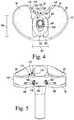
- FIG. 1is an exploded view of an orthopaedic knee prosthesis system
- FIG. 2is a top perspective view of the tibial insert shown in FIG. 1 and a posterior insert coupled to the tibial insert;
- FIG. 3is a bottom perspective view of the tibial insert shown in FIG. 2 ;
- FIG. 4is a top plan view of the tibial insert shown in FIG. 2 with the posterior insert removed;
- FIG. 5is a rear perspective view of the tibial insert shown in FIG. 4 ;
- FIG. 6is a rear perspective view of the posterior insert shown in FIG. 2 ;
- FIG. 7is a bottom plan view of the tibial tray shown in FIG. 1 and the tibial insert shown in FIG. 1 coupled to the tibial tray;
- FIG. 8is an exploded view of the modular insert shown in FIG. 1 ;
- FIG. 9is a bottom perspective view of the body of the modular insert shown in FIG. 1 ;
- FIG. 10is a side perspective view of the modular insert shown in FIG. 1 ;
- FIG. 11is a side perspective view of the orthopaedic knee prosthesis system shown in FIG. 1 ;
- FIG. 12is a cross-sectional view of the orthopaedic knee prosthesis system in an extended position taken along line 12 - 12 shown in FIG. 11 ;
- FIG. 13is a view similar to FIG. 12 showing the orthopaedic knee prosthesis system in a flexed position
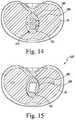
- FIG. 14is a cross-sectional view of the orthopaedic knee prosthesis system in an extended position taken along line 14 - 14 shown in FIG. 12 ;
- FIG. 15is a cross-sectional view of the orthopaedic knee prosthesis system in a flexed position taken along line 15 - 15 shown in FIG. 13 ;
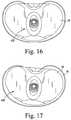
- FIG. 16is a top plan view of the modular insert and tibial insert shown in FIG. 1 with the modular insert in a rotated position;
- FIG. 17is a top plan view of the tibial insert and the tibial tray shown in FIG. 1 with the tibial insert in a rotated position.
- the orthopaedic knee prosthesis system 10includes a femoral component 12 configured to be coupled to a distal end of a patient's femur, a tibial tray 16 that is configured to be coupled to a proximal end of a patient's femur, and a tibial insert 18 configured to be assembled separately with the tibial tray 16 .
- the femoral component 12 , the tibial tray 16 , the tibial insert 18 , and a modular insert 22may be separately assembled to form an orthopaedic knee prosthesis; specifically, a hinged orthopaedic knee prosthesis, as described below.
- the system 10is configured to articulate through three ranges of motion.
- the system 10moves through various degrees of flexion between full extension and full flexion.
- a contact point between condyles of the femoral component 12 and condyle surfaces of the tibial insert 18moves so that the contact point is different at different degrees of flexion.
- the surgeoncan selectively add rotation about a superior-inferior axis. The rotation may occur between the femoral component 12 and the tibial insert 18 .
- the rotationmay also occur between the tibial insert 18 and the tibial tray 16 .
- the contact point between the condyles and the condyle surfacesmoves in an anterior-posterior direction.
- the femoral component 12may be permitted to rotate relative to the tibial insert 18 .
- the surgeonmay also selectively permit the tibial insert 18 to rotate relative to the tibial tray 16 throughout the first range of flexion. An amount of rotation of the tibial insert 18 relative to the tibial tray 16 may be adjusted by the surgeon.
- the femoral component 12includes a post 24 that is configured to be implanted into the distal end of the patient's femur.
- the post 24is attached to a body 26 having a pair of spaced-apart lateral and medial condyles 28 .
- the condyles 28include respective lateral and medial condyle surfaces 30 , 32 , which are curved convexly.
- An intercondylar notch 34is defined between the lateral and medial condyles 28 and is sized to receive the modular insert 22 .
- the femoral component 12also includes a posterior bore 40 that extends in a medial-lateral direction through the lateral and medial condyles 28 . As described in greater detail below, the bore 40 forms part of the hinge mechanism and is sized to receive a hinge pin 42 .
- the femoral component 12 and the tibial tray 16are each formed from an implant grade metallic material such as, for example, cobalt chromium.
- the tibial tray 16includes a base 50 and an anchor 52 that extends inferiorly from a distal surface 54 of the base 50 .
- the base 50is sized and shaped to conform to the configuration of a surgically-prepared proximal surface of the patient's tibia
- the anchor 52is sized and shaped to be implanted into a surgically-prepared intramedullary canal of the patient's tibia.
- the base 50includes a substantially planar proximal surface 60 that is positioned opposite the distal surface 54 .
- a curved outer wall 62extends between from the surfaces 54 , 60 and is sized and shaped to conform to the outer edge of the surgically-prepared proximal surface of the patient's tibia.
- a concave posterior-facing channel 66is formed by the outer wall 62 .
- An opening 64is defined in the proximal surface 60 , and the tray 16 includes an aperture 70 that extends inwardly from the opening 64 . The aperture 70 extends through the base 50 and into the anchor 52 .
- the tibial tray 16may be assembled with the tibial insert 18 shown in FIG. 1 to form a tibial component.
- the insertis formed from an implant grade plastic material such as, for example, ultra-high molecular weight polyethylene (UHMWPE).
- UHMWPEultra-high molecular weight polyethylene
- the tibial insert 18includes a platform 72 that is sized to be positioned on the proximal surface 60 of the tibial tray 16 and an elongated stem 74 that extends inferiorly from a distal surface 76 of the platform 72 along a longitudinal axis 78 that extends in an inferior-superior direction. Similar to the proximal surface 60 of the tibial tray 16 , the distal surface 76 of the platform is substantially planar.
- the platform 72also includes a pair of concave curved proximal surfaces 80 , 82 that correspond to the lateral and medial condyle surfaces 30 , 32 of the femoral component 12 .
- the platform 72also includes a curved outer wall 84 that extends between the surfaces 80 , 82 .
- an opening 90is defined in the proximal surfaces 80 , 82 of the platform 72 .
- the tibial insert 18includes an aperture 92 that extends inwardly from the opening 90 through the platform 72 and into the elongated stem 74 .
- the aperture 92then extends along the longitudinal axis 78 of the stem 74 .
- the distal surface 76 of the tibial insert 18engages the proximal surface 60 of the tibial tray.
- the elongated stem 74 of the tibial insert 18is sized to be received in the aperture 70 of the tibial tray 16 when the tibial insert 18 is coupled to the tibial tray.
- the modular insert 22includes an elongated stem 100 (shown in FIG. 8 ) that extends along the longitudinal axis 78 .
- a proximal body 104is pivotally attached to the stem 100 .
- the stem 100is sized and shaped to be inserted in the opening 90 , and extend into the aperture 92 , of the tibial insert 18 .
- the proximal body 104includes a medial opening 106 , a lateral opening 108 , and an inner wall 110 extending between the medial opening 106 and the lateral opening 108 .
- the inner wall 110defines a cylindrical pin hole 112 that extends through the proximal body 104 .
- the proximal body 104 of the modular insertis sized and shaped to be positioned within the intercondylar notch 34 of the femoral component 12 such that the posterior bore 40 may be aligned with the passageway 116 of the modular insert 22 .
- the hinge pin 42extends through the posterior bore 40 and the passageway 116 along a longitudinal axis 20 that extends in a medial-lateral direction to attach the modular insert 22 to the femoral component 12 .
- the tibial tray 16 and the tibial insert 18may be combined with the femoral component 12 and the modular insert 22 to form a hinged orthopaedic knee prosthesis.
- a posterior component 130is removably coupled to a posterior side 132 of the platform 72 of the tibial insert with fasteners 136 .
- the posterior component 130limits an amount of rotation between the tibial insert 18 and the tibial tray 16 .
- a plurality of posterior components 130may be provided, wherein each posterior component 130 provides a different predetermined amount of rotation between the tibial insert 18 and the tibial tray 16 .
- a posterior component 130may be provided to completely prevent rotation between the tibial insert 18 and the tibial tray 16 .
- the posterior component 130includes an inferiorly-extending tab 134 extending from a surface of the posterior component 130 .
- the tab 134extends from the distal surface 76 of the tibial insert 18 when the posterior component 130 is coupled to the tibial insert 18 .
- the posterior component 130is formed integrally with the tibial insert 18 .
- the tab 134extends a length 138 from the distal surface 76 .
- the tab 134includes a planar side wall 140 extending along the posterior side 132 of the tibial insert 18 .
- a curved convex side wall 142extends in an anterior direction from the planar side wall 140 .
- the curved side wall 142extends below the distal surface 76 of the tibial insert 18 .
- the curved side wall 142is sized to be positioned within the channel 66 of the tibial tray 16 .
- the curved side wall 142is sized smaller than the channel 66 so that the tibial insert 18 is permitted to rotate relative to the tibial tray 16 , as described in more detail below.
- the tab 134 of the different posterior component 130includes a curved side wall 144 (shown in broken lines) that is sized to be secured within the channel 66 to prevent rotation of the tibial insert 18 relative to the tibial tray 16 , as described in greater detail below.
- the system 10may include multiple posterior components 130 having different sized tabs 134 . Accordingly, the surgeon can select a tab size based on a preferred amount of rotation. In some embodiments the tibial tray 16 rotates in increments of 5 degrees from 0 to +/ ⁇ 20 degrees.
- the tibial insert 18includes a mounting cavity 168 that extends from a superior opening 170 formed in the proximal surfaces 80 , 82 and an opening 172 formed in the posterior side 132 .
- the mounting cavity 168is sized to receive the posterior component 130 , when the posterior component 130 is coupled to the tibial insert 18 .
- a cavity 174extends from the openings 170 and 172 and is sized to receive the posterior component 130 .
- the cavity 174includes a pair of posterior planar side walls 176 extending from the superior opening 170 to a bottom wall 178 .
- a curved end wall 180extends from the bottom wall 178 to the distal surface 76 of the tibial insert 18 .
- a pair of openings 182is formed in the curved end wall 180 .
- a bore 184extends from each opening 182 into the tibial insert 18 .
- Curved notches 186extend medially and laterally from the curved end wall 180 along the posterior side 132 of the tibial insert 18 .
- the posterior component 130includes a body 196 .
- the tab 134extends inferiorly from the body 196 .
- a pair of upper flanges 198extends in an anterior direction from the body 196 .
- the upper flanges 198are sized and shaped to be received in the proximal cavity 154 of the tibial insert 18 .
- a pair of lower flanges 200extends medially and laterally from the body 196 .
- Each of the pair of lower flanges 200is sized and shaped to position in a respective curved notch 186 of the tibial insert 18 .
- a pair of openings 202is formed in a posterior end 204 of the body 196 .
- a bore 188extends inward from each of the pair of openings 202 through the body 196 of the posterior component 130 .
- the bores 188are configured to align with the bores 174 of the tibial insert 18 when the posterior component 130 is coupled to the tibial insert 18 .
- the fasteners 136are received in the bores 174 and the bores 188 to secure the posterior component 130 to the tibial insert 18 .
- the bores 138 and 174are threaded to receive a threaded fastener 136 .
- FIG. 7illustrates the tab 134 of the posterior component 130 extending into the channel 66 of the tibial tray 16 when the tibial insert 18 is coupled to the tibial tray 16 .
- the channel 66 of the tibial tray 16includes a curved side wall 206 extending from an opening 208 having a length 210 .
- the tab 134is sized so that the planar side wall 140 has a length less than the length 210 of the opening 208 .
- the curved side wall 142 of the tab 134is sized to be smaller than the curved side wall 206 of the channel 66 to permit movement of the tab 134 within the channel 66 .
- a combination of the size of the planar side wall 140 and the size of the curved side wall 142 relative to the size of the channel 66permits limited rotation of the tibial insert 18 relative to the tibial tray 16 . That is, the tibial insert 18 is permitted to rotate about the longitudinal axis 78 until the curved side wall 142 of the tab 134 contacts the curved side wall 206 of the channel 66 .
- the tab 134includes curved side wall 144 .
- the planar side wall 140has a length 212 that is substantially equal to the length 210 of the opening 208 .
- the curved side wall 144 of the tab 134is sized to contact the curved side wall 206 of the channel 66 to prevent rotation of the tibial insert 18 relative to the tibial tray 16 .
- the aperture 92 of the tibial insert 18includes a tapered inner wall 150 extending from the platform 72 to an inferior base wall 152 to define a proximal cavity 154 extending longitudinally through the platform 72 .
- the inner wall 150is sloped radially inward from the platform 72 to the inferior base wall 152 .
- the inner wall 150is substantially oval in shape so that the proximal cavity 154 includes a major axis 156 extending in the anterior-posterior direction and a minor axis 158 extending in the medial-lateral direction.
- the major axis 156has a length 160 that is greater than a length 162 of the minor axis 158 .
- the minor axis 158extends in the anterior-posterior direction, and the major axis 156 extends in the medial-lateral direction.
- the major axis 156 and the minor axis 158each have a maximum length. Due to the slope of the inner wall 150 , the major axis 156 and the minor axis 158 have a minimum length at the inferior base wall 152 . The lengths of the major axis 156 and the minor axis 158 gradually decrease through various intermediate lengths between the platform 72 and the inferior base wall 152 .
- An opening 164is formed in the inferior base wall 152 .
- a distal cavity 166extends from the opening 164 .
- the distal cavity 166is generally cylindrical in shape and extends from the opening 164 to a bottom wall 168 .
- the distal cavity 166is sized to receive the elongated stem 100 of the modular insert 22 .
- the elongated stem 100 of the modular insert 22extends between a distal end 220 and a proximal end 222 .
- the distal end 220 of the elongated stem 100is sized to position in the distal cavity 166 of the tibial insert 18 .
- the proximal end 222includes a rounded outer wall 226 and a pair of linear side walls 228 extending from the rounded outer wall 226 .
- a pin hole 230extends between a pair of openings 232 formed in the proximal end 222 .
- Each of a pair of bushings 240is sized to be positionedbin one of the openings 232 .
- Each bushing 240includes a body 242 and a flange 244 extending around the body 242 .
- the flange 244has a diameter 246 that is greater than a diameter 248 of the body 242 .
- the diameter 248 of the body 242is sized so that the body 242 positions within the opening 232 .
- the diameter 246 of the flange 244is sized so that the flange 244 positions against the respective side wall 228 .
- Each bushing 240includes a pin hole 250 extending between a pair of openings 252 .
- the pin hole 250is sized to receive a pin 254 along a longitudinal axis 256 that extends parallel to the longitudinal axis 20 in a medial-lateral direction.
- the pin 254includes a cylindrical shaft 258 having a diameter 260 sized to a diameter 270 of the pin hole 250 .
- a threaded head 272extends from the shaft 258 .
- the threaded head 272has a diameter 274 that is greater than the diameter 260 of the shaft 258 .
- the proximal body 104 of the modular insert 22includes a distal section 280 and a spine 282 extending proximally from the distal section 280 .
- a fastener 284is configured to secure the spine 282 to the distal section 280 .
- the distal section 280is sized to position in the proximal cavity 154 of the tibial insert 18 .
- the distal section 280includes an outer side wall 286 that is sized and shaped to the inner wall 150 of the tibial insert 18 .
- the outer side wall 286is generally oval in shape and slopes from superior end 288 to an inferior end 298 .
- the distal section 280is configured to receive the proximal end 222 of the elongated stem 100 .
- the outer side wall 286includes a major axis 290 extending in the anterior-posterior direction and a minor axis 292 extending in the medial-lateral direction.
- the major axis 290has a length 294 that is greater than a length 296 of the minor axis 292 .
- the major axis 290extends in the medial-lateral direction and the minor axis 292 extends in the anterior-posterior direction.
- the distal section 280includes a cavity 300 extending from an opening 302 in a distal end 304 of the distal section 280 .
- the cavity 300is sized and shaped to receive the proximal end 222 of the elongated stem 100 .
- the major axis 290 and the minor axis 292each have a maximum length. Due to the slope of the outer side wall 286 , the major axis 290 and the minor axis 292 have a minimum length at the inferior end 298 . The lengths of the major axis 290 and the minor axis 292 gradually decrease through various intermediate lengths between the superior end 288 and the inferior end 298 .
- the outer side wall 286is configured to engage the inner wall 150 of the tibial insert 18 , when the modular insert 22 is coupled to the tibial insert 18 .
- the distal section 280 of the modular insert 22is seated in the aperture 92 of the tibial insert 18 with the inferior end 298 positioned against the inferior base wall 152 of the tibial insert 18 .
- the outer side wall 286is positioned against the inner wall 150 of the tibial insert 18 .
- the modular component 22moves in a superior direction so that the inferior end 298 is separated from the inferior base wall 152 of the tibial insert 18 .
- the axes 290 , 292 of the modular insert 22are positioned so that a length of the axes 290 , 292 at any given location is less than a length of an aligned axis 156 , 158 .
- the axis 156 , 158 at the platform 72are aligned with an intermediate axis 290 , 292 of the modular insert 22 that has a shorter length, thereby permitting rotation of the modular insert 22 relative to the tibial insert 18 .
- a threaded bore 310extends from openings 312 in the distal section 280 and into the cavity 300 .
- the threaded bore 310is configured to align with the pin hole 230 of the elongated stem 100 and the pin holes 250 of the bushings 240 to define a passageway 320 .
- the passageway 320is configured to receive the pin 254 to hingedly attach the distal section 280 to the elongated stem 100 .
- the threaded head 272is secured to threads 322 of the bore 310 to secure the pin 254 to the distal section 280 .
- the proximal body 104 of the modular insert 22is configured to rotate about the longitudinal axis 256 in the direction of arrow 324 relative to the elongated stem 100 .
- the spine 282 of the proximal body 104includes the passageway 116 extending between the medial opening 106 and the lateral opening 108 .
- Each opening 106 , 108is sized and shaped to receive a bushing 334 .
- Each bushing 334includes a bore 336 extending between openings 338 .
- the bores 336are configured to align with the posterior bore 40 of the femoral component 12 , when the femoral component 12 is coupled to the modular insert 22 .
- the hinge pin 42extends through the posterior bore 40 , the passageway 116 , and the bores 336 to pivotally attach the modular insert 22 to the femoral component 12 along a longitudinal axis 20 .
- the femoral component 12is configured to rotate about arrow 340 , when the femoral component 12 is coupled to the modular insert 22 .
- the surgeonselects a femoral component 12 and a tibial tray 16 .
- An end of the patient's femur and an end of the patient's tibiaare resected to prepare for insertion of the system 10 .
- the surgeondrills intramedullary canals in the femur and the tibia to receive the post 24 of the femoral component 12 and the stem 74 of the tibial tray 16 , respectively.
- the system 10includes various femoral components 12 and tibial trays 16 of different sizes. The surgeon selects the femoral component 12 and tibial tray 16 based on an anatomy of the patient's knee.
- the femoral component 12is coupled to the end of the femur by inserting the post 24 into the intramedullary canal of the femur.
- the tibial tray 16is coupled to the tibia by inserting the stem 74 into the intramedullary canal of the tibia.
- the surgeonselects a tibial insert 18 from a plurality of tibial inserts 18 having different sizes.
- Each tibial insert 18may have different sized and shaped condyle surfaces 30 , 32 .
- the surgeontests a range of motion of the system 10 by moving the femoral component 12 through a first range of motion between a fully extended position and a fully flexed position. During flexion of the system 10 , the surgeon evaluates the movement of the femoral component 12 along the tibial insert 18 .
- the surgeonmay elect to test multiple tibial inserts 18 until a desired range of motion is achieved.
- the tibial insert 18may also be selected based on a size of the proximal cavity 154 of the tibial insert 18 .
- the size of the proximal cavity 154varies to provide rotation between the modular insert 22 and the tibial insert 18 .
- a posterior component 170is selected to couple to the tibial insert 18 from a plurality of posterior components 170 .
- Each of the posterior components 170includes a tab 134 having different sized planar side walls 140 and curved side walls 142 .
- the posterior component 170is formed integrally with the tibial insert 18 , and each tibial insert 18 has a different sized tab 134 .
- a modular insert 22is selected from a plurality of modular inserts 22 having different sizes.
- the size of the modular insert 22is selected so that the distal section 280 of the modular insert 22 sits in the proximal cavity 154 in a seated position when the system is fully extended.
- the surgeonagain tests the system 10 by flexing the femoral component 12 through the first range of motion.
- the femoral component 12enters a second range of flexion that is within the first range of flexion.
- the second range of flexionis between the intermediate flexion and the full extension.
- the distal section 280 of the modular insert 22becomes unseated within the proximal cavity 154 .
- the distal section 280is pulled upward within the proximal cavity 154 so that the modular insert 22 is allowed to rotate relative to the tibial insert 18 .
- the surgeontests the range of rotation of the modular insert 22 and selects a modular insert 22 that provides a desired range of flexion.
- the surgeonmay elect to use a different tibial insert 18 with a different sized proximal cavity 154 to achieve the desired range of rotation.
- the surgeonmay also select the modular insert 22 and tibial insert 18 based on a range of motion the second range of flexion.
- the surgeontests multiple ranges of motion to select the desired components.
- the surgeonevaluates the first range of motion from full extension to full flexion, as well as, the second range of motion from the intermediate flexion to full flexion. Further, the surgeon evaluates a first range of rotation of the tibial insert 18 relative to the tibial tray 16 , and a second range of rotation of the modular insert 22 relative to the tibial insert 18 . It should be noted that the second range of rotation may be within the first range of rotation.
- the elongated stem 100extends into the distal cavity 166 of the tibial insert 18 to an inferior position 398 such that a tip 402 of the distal end 220 is positioned adjacent a bottom 404 of the distal cavity 166 .
- the elongated stem 100extends along the longitudinal axis 78 .
- the distal section 280 of the proximal body 104 of the modular insert 22is seated in the cavity 300 .
- the hinge pin 42is located in a fully extended position 416 .
- the outer side wall 286 of the distal section 280is positioned against the inner wall 150 of the tibial insert 18 .
- the outer side wall 286 of the distal section 280is in contact with the inner wall 150 of the tibial insert 18 to prevent medial-lateral rotation of the modular insert 22 relative to the tibial insert 18 and to maintain the modular insert 22 in a fixed position 412 .
- the femoral component 12is rotated about the longitudinal axis 20 , as indicated by arrow 422 , over the first range of flexion, which includes the second range of flexion.
- the first range of flexionis within a range of ⁇ 3 to 140 degrees. Engagement of curved convex condyle surfaces 30 , 32 and the curved proximal surfaces 58 , 60 during the first range of flexion causes the modular insert 22 to move upward in the proximal cavity 154 from the inferior position 398 to a superior position 396 .
- the elongated stem 100moves in a superior direction, as indicated by arrow 424 , within the distal cavity 166 to the superior position 396 so that the tip 402 of the distal end 220 advances away from the bottom 404 of the distal cavity 166 .
- the proximal body 104 of the modular insert 22also advances in the superior direction, so that the distal section 280 is raised in the cavity 300 .
- the proximal body 104 of the modular insert 22then rotates about the longitudinal axis 256 relative to the elongated stem 100 , as indicated by arrow 430 , over the second range of motion from the intermediate flexion to full extension.
- the second range of flexionis within 3 to 10 degrees.
- the second range of motionoverlaps the first range of motion.
- the longitudinal axis 20moves relative to the longitudinal axis 256 over the second range of motion.
- the hinge pin 42moves between the fully flexed position 416 and a fully extended position 418 .
- the second position 418is located anterior of the first position 416 .
- the outer side wall 286 of the distal section 280is separated from the inner wall 150 of the tibial insert 18 , thereby enabling medial-lateral rotation of the modular insert 22 relative to the tibial insert 18 .
- the modular insert 22rotates about the longitudinal axis 78 to a rotated position 432 , an example of which is provided in FIG. 16 .
- the modular insert 22advances distally into the distal cavity 166 so that the outer side wall 286 of the distal section 280 engages the inner wall 150 of the tibial insert 18 , thereby rotating the modular insert 22 back to the fixed position 412 .
- the tibial insert 18is also capable of rotating medially-laterally relative to the tibial tray 16 in some embodiments.
- the tibial insert 18rotates about the longitudinal axis 78 in either the extended position 400 or the flexed position 420 .
- the tibial insert 18is permitted to rotate either medially or laterally to a rotated position 440 , an example of which is provided in FIG. 17 .
- a range of rotationis determined by a size of the tab 134 .
- a smaller tab 134will provide more rotation than a larger tab 134 .
- the tibial insert 18is permitted to rotate until the curved side wall 142 of the tab 134 contacts the curved side wall 206 of the channel 66 .
Landscapes
- Health & Medical Sciences (AREA)
- Orthopedic Medicine & Surgery (AREA)
- Physical Education & Sports Medicine (AREA)
- Cardiology (AREA)
- Oral & Maxillofacial Surgery (AREA)
- Transplantation (AREA)
- Engineering & Computer Science (AREA)
- Biomedical Technology (AREA)
- Heart & Thoracic Surgery (AREA)
- Vascular Medicine (AREA)
- Life Sciences & Earth Sciences (AREA)
- Animal Behavior & Ethology (AREA)
- General Health & Medical Sciences (AREA)
- Public Health (AREA)
- Veterinary Medicine (AREA)
- Prostheses (AREA)
Abstract
Description
Claims (20)
Priority Applications (5)
| Application Number | Priority Date | Filing Date | Title |
|---|---|---|---|
| US16/267,687US11116641B2 (en) | 2019-02-05 | 2019-02-05 | Orthopaedic prosthetic system for a rotating hinged-knee prosthesis |
| AU2020200145AAU2020200145B2 (en) | 2019-02-05 | 2020-01-08 | Orthopaedic prosthetic system for a rotating hinged-knee prosthesis |
| EP20152508.6AEP3692951B1 (en) | 2019-02-05 | 2020-01-17 | Orthopaedic prosthetic system for a rotating hinged-knee prosthesis |
| JP2020016847AJP7504606B2 (en) | 2019-02-05 | 2020-02-04 | ORTHOPEDIC PROSTHETIC DEVICE FOR ROTATING A HINGED KNEE PROSTHESIS - Patent application |
| CN202010080483.6ACN111513896A (en) | 2019-02-05 | 2020-02-05 | Orthopaedic prosthesis system for a rotary articulated knee prosthesis |
Applications Claiming Priority (1)
| Application Number | Priority Date | Filing Date | Title |
|---|---|---|---|
| US16/267,687US11116641B2 (en) | 2019-02-05 | 2019-02-05 | Orthopaedic prosthetic system for a rotating hinged-knee prosthesis |
Publications (2)
| Publication Number | Publication Date |
|---|---|
| US20200246150A1 US20200246150A1 (en) | 2020-08-06 |
| US11116641B2true US11116641B2 (en) | 2021-09-14 |
Family
ID=71836129
Family Applications (1)
| Application Number | Title | Priority Date | Filing Date |
|---|---|---|---|
| US16/267,687Active2040-03-11US11116641B2 (en) | 2019-02-05 | 2019-02-05 | Orthopaedic prosthetic system for a rotating hinged-knee prosthesis |
Country Status (1)
| Country | Link |
|---|---|
| US (1) | US11116641B2 (en) |
Cited By (3)
| Publication number | Priority date | Publication date | Assignee | Title |
|---|---|---|---|---|
| US20210154018A1 (en)* | 2017-09-26 | 2021-05-27 | Stephen J. Incavo | Knee arthroplasty with modular femoral adapters |
| US20210307914A1 (en)* | 2019-02-05 | 2021-10-07 | Depuy Ireland Unlimited Company | Orthopaedic prosthetic system for a rotating hinged-knee prosthesis |
| WO2024223629A1 (en)* | 2023-04-25 | 2024-10-31 | Rainer Baumgart | Implantable prosthesis for replacement of the human knee joint |
Families Citing this family (1)
| Publication number | Priority date | Publication date | Assignee | Title |
|---|---|---|---|---|
| US12193941B2 (en)* | 2021-04-23 | 2025-01-14 | Gerald J. Jerry | Tibial-tray system |
Citations (91)
| Publication number | Priority date | Publication date | Assignee | Title |
|---|---|---|---|---|
| US3852830A (en) | 1973-02-15 | 1974-12-10 | Richards Mfg Co | Knee prosthesis |
| US3869729A (en) | 1972-01-05 | 1975-03-11 | Nat Res Dev | Bone joint prosthesis |
| US3953899A (en) | 1973-05-17 | 1976-05-04 | Chas. F. Thackray Limited | Knee arthroplasty |
| US3958278A (en) | 1974-04-22 | 1976-05-25 | National Research Development Corporation | Endoprosthetic knee joint |
| US4034418A (en) | 1975-05-26 | 1977-07-12 | The Governing Council Of The University Of Toronto | Artificial knee joint |
| DE2901009A1 (en) | 1979-01-12 | 1980-07-17 | Link Waldemar Gmbh Co | Internal artificial knee joint - has insert piece joined to dish by guide ensuring smooth sliding movement |
| US4215439A (en) | 1978-10-16 | 1980-08-05 | Zimmer, USA | Semi-restraining knee prosthesis |
| US4219893A (en) | 1977-09-01 | 1980-09-02 | United States Surgical Corporation | Prosthetic knee joint |
| US4224697A (en) | 1978-09-08 | 1980-09-30 | Hexcel Corporation | Constrained prosthetic knee |
| US4340978A (en) | 1979-07-02 | 1982-07-27 | Biomedical Engineering Corp. | New Jersey meniscal bearing knee replacement |
| DE3343606A1 (en) | 1983-12-02 | 1985-07-04 | S + G Implants GmbH, 2400 Lübeck | Endoprosthesis for a knee joint |
| FR2589720A1 (en) | 1985-11-14 | 1987-05-15 | Aubaniac Jean | KNEE JOINT PROSTHETIC ASSEMBLY |
| WO1987002883A1 (en) | 1985-11-15 | 1987-05-21 | Jean Manuel Aubaniac | Apparatus for fitting a knee endo prosthesis |
| FR2601873A1 (en) | 1986-07-25 | 1988-01-29 | Cuilleron J | Intracondylar total knee prosthesis |
| FR2612767A1 (en) | 1987-03-23 | 1988-09-30 | Letournel Emile | Total knee prosthesis |
| US4790853A (en) | 1984-08-29 | 1988-12-13 | Gmt Gesellschaft Fur Medizinische Technik Mbh | Knee joint prosthesis |
| US4838891A (en) | 1984-11-28 | 1989-06-13 | Branemark Per Ingvar | Joint prothesis |
| US5011496A (en) | 1988-02-02 | 1991-04-30 | Joint Medical Products Corporation | Prosthetic joint |
| US5314481A (en) | 1992-11-12 | 1994-05-24 | Wright Medical Technology, Inc. | Hinged knee prosthesis with extended patellar track |
| US5370701A (en) | 1990-09-28 | 1994-12-06 | Arch Development Corporation | Rotating/sliding contrained prosthetic knee |
| US5413607A (en) | 1990-11-29 | 1995-05-09 | Gmt Gesellschaft Fur Medizinische Technik Mbh | Knee joint prosthesis |
| EP0716839A1 (en) | 1994-12-12 | 1996-06-19 | Biomedical Engineering Trust I | Hinged knee prothesis with condylar bearing |
| EP0724868A1 (en) | 1995-01-31 | 1996-08-07 | SULZER Medizinaltechnik AG | Joint prothesis, in particular a knee prosthesis |
| US5766257A (en) | 1997-01-28 | 1998-06-16 | Implant Manufacturing And Testing Corporation | Artificial joint having natural load transfer |
| FR2760352A1 (en) | 1997-03-10 | 1998-09-11 | Philippe Berret | Total knee joint prosthesis |
| US5824102A (en) | 1992-06-19 | 1998-10-20 | Buscayret; Christian | Total knee prosthesis |
| US5871541A (en) | 1993-11-23 | 1999-02-16 | Plus Endoprothetik, Ag | System for producing a knee-joint endoprosthesis |
| US5951603A (en) | 1997-09-25 | 1999-09-14 | Johnson & Johnson Professional, Inc. | Rotatable joint prosthesis with axial securement |
| US5954770A (en) | 1996-02-21 | 1999-09-21 | Plus Endoprothetik Ag | Endoprosthetic knee joint |
| FR2776919A1 (en) | 1998-04-02 | 1999-10-08 | Beguec Pierre Le | TOTAL KNEE PROSTHESIS WITH HINGE |
| US6019794A (en) | 1993-03-15 | 2000-02-01 | University College London | Total knee replacement prosthesis |
| DE19823325C1 (en) | 1998-05-26 | 2000-03-23 | Werner Scholz | Prosthetic system for knee joint |
| US6074424A (en) | 1998-01-23 | 2000-06-13 | Sulzer Orthopedics Inc. | Implantable knee joint prosthesis convertible from primary to revision |
| US6117175A (en) | 1994-08-22 | 2000-09-12 | Bosredon; Jean | Spherical knee joint prosthesis |
| WO2001013825A1 (en) | 1999-08-23 | 2001-03-01 | Woodcraft, David, Charles | Linked condylar total knee replacement |
| US6210444B1 (en) | 1999-10-26 | 2001-04-03 | Bristol-Myers Squibb Company | Tibial knee component with a mobile bearing |
| EP1099430A1 (en) | 1999-11-09 | 2001-05-16 | Waldemar Link (GmbH & Co.) | Knee prosthesis system |
| US20010003803A1 (en) | 1999-12-13 | 2001-06-14 | Sulzer Orthopedics Ltd. | Kit for a knee joint prosthesis |
| US6264696B1 (en) | 1999-01-04 | 2001-07-24 | Aesculap | Tibial knee prosthesis comprising a ball joint with double inserts |
| US20010018615A1 (en) | 2000-02-24 | 2001-08-30 | Aesculap | Knee protsthetic with cavity implemented in the trochlea |
| US20010021877A1 (en) | 2000-02-24 | 2001-09-13 | Aesculap | Femoral component of a knee prosthetic including three curvature radii |
| US20010034555A1 (en) | 2000-03-13 | 2001-10-25 | Pappas Michael J. | Posterior stabilized knee replacement with bearing translation for knees with retained collateral ligaments |
| US20010034554A1 (en) | 2000-03-08 | 2001-10-25 | Pappas Michael J. | Posterior stabilized prosthetic knee replacement with bearing translation and dislocation prevention features |
| US6319283B1 (en) | 1999-07-02 | 2001-11-20 | Bristol-Myers Squibb Company | Tibial knee component with a mobile bearing |
| WO2002017821A2 (en) | 2000-08-28 | 2002-03-07 | Advanced Bio Surfaces, Inc. | Method for mammalian joint resurfacing |
| US20020058997A1 (en) | 1999-06-16 | 2002-05-16 | O'connor John Joseph | Tibial component |
| US20020103541A1 (en) | 2001-01-29 | 2002-08-01 | Meyers John E. | Constrained prosthetic knee with rotating bearing |
| US20020120340A1 (en) | 2001-02-23 | 2002-08-29 | Metzger Robert G. | Knee joint prosthesis |
| US20020138150A1 (en) | 2001-03-26 | 2002-09-26 | Sulzer Orthopedics, Ltd. | Knee prosthesis |
| US6482209B1 (en) | 2001-06-14 | 2002-11-19 | Gerard A. Engh | Apparatus and method for sculpting the surface of a joint |
| US6488711B1 (en) | 1997-12-19 | 2002-12-03 | Josef Grafinger | Knee-joint prosthesis |
| US20030009230A1 (en) | 2001-06-30 | 2003-01-09 | Gundlapalli Rama Rao V. | Surface sterilizable joint replacement prosthesis component with insert |
| US20030009228A1 (en) | 2001-01-29 | 2003-01-09 | Meyers John E. | Constrained prosthetic knee with rotating bearing |
| US20030009229A1 (en) | 2001-02-28 | 2003-01-09 | Biomedical Engineering Trust I | Deep flexion posterior stabilized knee replacement with bearing translation |
| US20030171815A1 (en) | 2000-07-19 | 2003-09-11 | Kana Richard J. | Stem taper adapter |
| US20030208276A1 (en) | 2000-07-18 | 2003-11-06 | Berelsman Brian K. | Elbow prosthesis |
| US6660039B1 (en) | 1998-05-20 | 2003-12-09 | Smith & Nephew, Inc. | Mobile bearing knee prosthesis |
| US20040006393A1 (en) | 2002-07-03 | 2004-01-08 | Brian Burkinshaw | Implantable prosthetic knee for lateral compartment |
| US20040039450A1 (en) | 2002-08-26 | 2004-02-26 | Griner Adam M. | Easily assembled provisional orthopaedic implant |
| US20040054416A1 (en) | 2002-09-12 | 2004-03-18 | Joe Wyss | Posterior stabilized knee with varus-valgus constraint |
| US6709461B2 (en) | 1999-02-03 | 2004-03-23 | Depuy Products, Inc. | Modular joint prosthesis system |
| US6723102B2 (en) | 2001-06-14 | 2004-04-20 | Alexandria Research Technologies, Llc | Apparatus and method for minimally invasive total joint replacement |
| US20040083003A1 (en) | 2002-10-23 | 2004-04-29 | Wasielewski Ray C. | Biologic modular tibial and femoral component augments for use with total knee arthroplasty |
| US20040102851A1 (en) | 2002-11-22 | 2004-05-27 | Joseph Saladino | Modular knee prosthesis |
| US20040102852A1 (en) | 2002-11-22 | 2004-05-27 | Johnson Erin M. | Modular knee prosthesis |
| US6755864B1 (en) | 1999-09-24 | 2004-06-29 | Sulzer Orthopedics Ltd. | Tibia part for a knee joint prosthesis and a kit with a tibia part of this kind |
| US20040162620A1 (en) | 2002-06-28 | 2004-08-19 | Joseph Wyss | Modular knee joint prosthesis |
| US20040186584A1 (en) | 2001-04-25 | 2004-09-23 | Arnold Keller | Knee prosthesis with a flexion hinge |
| US20040215345A1 (en) | 2003-02-04 | 2004-10-28 | Zimmer Technology, Inc. | Rotating/non-rotating tibia base plate/insert system |
| US20040220676A1 (en) | 2001-06-27 | 2004-11-04 | Arnold Keller | Coupled knee prosthesis with a rotational bearing |
| US20040225368A1 (en) | 2003-04-24 | 2004-11-11 | Sylvie Plumet | Modular stud for posterior stabilised knee prosthesis |
| US20050027365A1 (en) | 2003-07-17 | 2005-02-03 | Albert Burstein | Mobile bearing knee prosthesis |
| US20050107883A1 (en) | 2003-11-18 | 2005-05-19 | Goodfried Gary P. | Modular implant system with fully porous coated sleeve |
| US20050107886A1 (en) | 2001-12-21 | 2005-05-19 | Paul Crabtree | Hinged joint system |
| US20050246028A1 (en) | 2004-04-28 | 2005-11-03 | Buechel-Pappas Trust | Prosthetic knee |
| US6972039B2 (en) | 1999-03-01 | 2005-12-06 | Biomet, Inc. | Floating bearing knee joint prosthesis with a fixed tibial post |
| EP1721584A1 (en) | 2005-05-09 | 2006-11-15 | Aesculap AG & Co. KG | Knee endoprosthesis with a bending hinge |
| US20060265078A1 (en) | 2005-05-19 | 2006-11-23 | Mcminn Derek J W | Knee prosthesis |
| US7232465B2 (en) | 2002-07-26 | 2007-06-19 | Waldemar Link Gmbh & Co. Kg | Knee prosthesis |
| US20080021566A1 (en) | 2006-07-18 | 2008-01-24 | Biomet Manufacturing Corp. | Method and apparatus for a knee implant |
| US7326252B2 (en) | 2002-12-20 | 2008-02-05 | Smith & Nephew, Inc. | High performance knee prostheses |
| US20080058945A1 (en) | 2006-03-13 | 2008-03-06 | Mako Surgical Corp. | Prosthetic device and system and method for implanting prosthetic device |
| US20090005875A1 (en) | 2007-06-29 | 2009-01-01 | Koenemann Jeffery L | Orthopaedic prosthesis having a positionable stem |
| US7591855B2 (en) | 2001-04-25 | 2009-09-22 | Waldemar Link Gmbh & Co. Kg | Knee prosthesis with rotation bearing |
| US7615081B2 (en) | 2002-05-24 | 2009-11-10 | Zimmer, Inc. | Femoral components for knee arthroplasty |
| US20090299482A1 (en) | 2007-01-10 | 2009-12-03 | Biomet Manufacturing Corp. | Knee Joint Prosthesis System and Method for Implantation |
| US20090319048A1 (en) | 2008-02-18 | 2009-12-24 | Maxx Orthopedics, Inc. | Total Knee Replacement Prosthesis |
| US7658767B2 (en) | 2006-06-30 | 2010-02-09 | Depuy Products, Inc. | Hinged orthopaedic prosthesis |
| US20100174378A1 (en) | 2007-01-10 | 2010-07-08 | Biomet Manufacturing Corp. | Knee Joint Prosthesis System and Method for Implantation |
| US9452054B2 (en) | 2012-03-06 | 2016-09-27 | University Of Cape Town | Rotating hinge knee prosthesis |
| US20170312087A1 (en) | 2014-09-23 | 2017-11-02 | Tecres S.P.A. | Constrained Spacer Device For The Knee Joint |
- 2019
- 2019-02-05USUS16/267,687patent/US11116641B2/enactiveActive
Patent Citations (107)
| Publication number | Priority date | Publication date | Assignee | Title |
|---|---|---|---|---|
| US3869729A (en) | 1972-01-05 | 1975-03-11 | Nat Res Dev | Bone joint prosthesis |
| US3852830A (en) | 1973-02-15 | 1974-12-10 | Richards Mfg Co | Knee prosthesis |
| US3953899A (en) | 1973-05-17 | 1976-05-04 | Chas. F. Thackray Limited | Knee arthroplasty |
| US3958278A (en) | 1974-04-22 | 1976-05-25 | National Research Development Corporation | Endoprosthetic knee joint |
| US4034418A (en) | 1975-05-26 | 1977-07-12 | The Governing Council Of The University Of Toronto | Artificial knee joint |
| US4219893A (en) | 1977-09-01 | 1980-09-02 | United States Surgical Corporation | Prosthetic knee joint |
| US4224697A (en) | 1978-09-08 | 1980-09-30 | Hexcel Corporation | Constrained prosthetic knee |
| US4215439A (en) | 1978-10-16 | 1980-08-05 | Zimmer, USA | Semi-restraining knee prosthesis |
| DE2901009A1 (en) | 1979-01-12 | 1980-07-17 | Link Waldemar Gmbh Co | Internal artificial knee joint - has insert piece joined to dish by guide ensuring smooth sliding movement |
| US4340978A (en) | 1979-07-02 | 1982-07-27 | Biomedical Engineering Corp. | New Jersey meniscal bearing knee replacement |
| DE3343606A1 (en) | 1983-12-02 | 1985-07-04 | S + G Implants GmbH, 2400 Lübeck | Endoprosthesis for a knee joint |
| US4790853A (en) | 1984-08-29 | 1988-12-13 | Gmt Gesellschaft Fur Medizinische Technik Mbh | Knee joint prosthesis |
| US4838891A (en) | 1984-11-28 | 1989-06-13 | Branemark Per Ingvar | Joint prothesis |
| FR2589720A1 (en) | 1985-11-14 | 1987-05-15 | Aubaniac Jean | KNEE JOINT PROSTHETIC ASSEMBLY |
| WO1987002883A1 (en) | 1985-11-15 | 1987-05-21 | Jean Manuel Aubaniac | Apparatus for fitting a knee endo prosthesis |
| FR2601873A1 (en) | 1986-07-25 | 1988-01-29 | Cuilleron J | Intracondylar total knee prosthesis |
| FR2612767A1 (en) | 1987-03-23 | 1988-09-30 | Letournel Emile | Total knee prosthesis |
| US5011496A (en) | 1988-02-02 | 1991-04-30 | Joint Medical Products Corporation | Prosthetic joint |
| US5370701A (en) | 1990-09-28 | 1994-12-06 | Arch Development Corporation | Rotating/sliding contrained prosthetic knee |
| US5413607A (en) | 1990-11-29 | 1995-05-09 | Gmt Gesellschaft Fur Medizinische Technik Mbh | Knee joint prosthesis |
| US5824102A (en) | 1992-06-19 | 1998-10-20 | Buscayret; Christian | Total knee prosthesis |
| US5314481A (en) | 1992-11-12 | 1994-05-24 | Wright Medical Technology, Inc. | Hinged knee prosthesis with extended patellar track |
| US6019794A (en) | 1993-03-15 | 2000-02-01 | University College London | Total knee replacement prosthesis |
| US5871541A (en) | 1993-11-23 | 1999-02-16 | Plus Endoprothetik, Ag | System for producing a knee-joint endoprosthesis |
| US6117175A (en) | 1994-08-22 | 2000-09-12 | Bosredon; Jean | Spherical knee joint prosthesis |
| EP0716839A1 (en) | 1994-12-12 | 1996-06-19 | Biomedical Engineering Trust I | Hinged knee prothesis with condylar bearing |
| US5824096A (en) | 1994-12-12 | 1998-10-20 | Biomedical Engineering Trust I | Hinged knee prosthesis with condylar bearing |
| EP0724868A1 (en) | 1995-01-31 | 1996-08-07 | SULZER Medizinaltechnik AG | Joint prothesis, in particular a knee prosthesis |
| US5954770A (en) | 1996-02-21 | 1999-09-21 | Plus Endoprothetik Ag | Endoprosthetic knee joint |
| US5766257A (en) | 1997-01-28 | 1998-06-16 | Implant Manufacturing And Testing Corporation | Artificial joint having natural load transfer |
| FR2760352A1 (en) | 1997-03-10 | 1998-09-11 | Philippe Berret | Total knee joint prosthesis |
| US5951603A (en) | 1997-09-25 | 1999-09-14 | Johnson & Johnson Professional, Inc. | Rotatable joint prosthesis with axial securement |
| US6488711B1 (en) | 1997-12-19 | 2002-12-03 | Josef Grafinger | Knee-joint prosthesis |
| US6074424A (en) | 1998-01-23 | 2000-06-13 | Sulzer Orthopedics Inc. | Implantable knee joint prosthesis convertible from primary to revision |
| FR2776919A1 (en) | 1998-04-02 | 1999-10-08 | Beguec Pierre Le | TOTAL KNEE PROSTHESIS WITH HINGE |
| US6660039B1 (en) | 1998-05-20 | 2003-12-09 | Smith & Nephew, Inc. | Mobile bearing knee prosthesis |
| DE19823325C1 (en) | 1998-05-26 | 2000-03-23 | Werner Scholz | Prosthetic system for knee joint |
| US6264696B1 (en) | 1999-01-04 | 2001-07-24 | Aesculap | Tibial knee prosthesis comprising a ball joint with double inserts |
| US6709461B2 (en) | 1999-02-03 | 2004-03-23 | Depuy Products, Inc. | Modular joint prosthesis system |
| US6972039B2 (en) | 1999-03-01 | 2005-12-06 | Biomet, Inc. | Floating bearing knee joint prosthesis with a fixed tibial post |
| US20020058997A1 (en) | 1999-06-16 | 2002-05-16 | O'connor John Joseph | Tibial component |
| US6319283B1 (en) | 1999-07-02 | 2001-11-20 | Bristol-Myers Squibb Company | Tibial knee component with a mobile bearing |
| WO2001013825A1 (en) | 1999-08-23 | 2001-03-01 | Woodcraft, David, Charles | Linked condylar total knee replacement |
| US6755864B1 (en) | 1999-09-24 | 2004-06-29 | Sulzer Orthopedics Ltd. | Tibia part for a knee joint prosthesis and a kit with a tibia part of this kind |
| US6210444B1 (en) | 1999-10-26 | 2001-04-03 | Bristol-Myers Squibb Company | Tibial knee component with a mobile bearing |
| EP1099430A1 (en) | 1999-11-09 | 2001-05-16 | Waldemar Link (GmbH & Co.) | Knee prosthesis system |
| US6743258B1 (en) | 1999-11-09 | 2004-06-01 | Waldemar Link (Gmbh & Co.) | Knee prosthesis system |
| US20010003803A1 (en) | 1999-12-13 | 2001-06-14 | Sulzer Orthopedics Ltd. | Kit for a knee joint prosthesis |
| US6770097B2 (en) | 1999-12-13 | 2004-08-03 | Centerpulse Orthopedics Ltd. | Kit for a knee joint prosthesis |
| US20010021877A1 (en) | 2000-02-24 | 2001-09-13 | Aesculap | Femoral component of a knee prosthetic including three curvature radii |
| US20010018615A1 (en) | 2000-02-24 | 2001-08-30 | Aesculap | Knee protsthetic with cavity implemented in the trochlea |
| US20010034554A1 (en) | 2000-03-08 | 2001-10-25 | Pappas Michael J. | Posterior stabilized prosthetic knee replacement with bearing translation and dislocation prevention features |
| US20020156535A1 (en) | 2000-03-13 | 2002-10-24 | Biomedical Engineering Trust I | Posterior stabilized knee replacement with bearing translation for knees with retained collateral ligaments |
| US6764516B2 (en) | 2000-03-13 | 2004-07-20 | Biomedical Engineering Trust I | Posterior stabilized knee replacement with bearing translation for knees with retained collateral ligaments |
| US20010034555A1 (en) | 2000-03-13 | 2001-10-25 | Pappas Michael J. | Posterior stabilized knee replacement with bearing translation for knees with retained collateral ligaments |
| US20030208276A1 (en) | 2000-07-18 | 2003-11-06 | Berelsman Brian K. | Elbow prosthesis |
| US20030171815A1 (en) | 2000-07-19 | 2003-09-11 | Kana Richard J. | Stem taper adapter |
| US20020183850A1 (en) | 2000-08-28 | 2002-12-05 | Felt Jeffrey C. | Method and system for mammalian joint resurfacing |
| WO2002017821A2 (en) | 2000-08-28 | 2002-03-07 | Advanced Bio Surfaces, Inc. | Method for mammalian joint resurfacing |
| US6652587B2 (en) | 2000-08-28 | 2003-11-25 | Advanced Bio Surfaces, Inc. | Method and system for mammalian joint resurfacing |
| US6485519B2 (en) | 2001-01-29 | 2002-11-26 | Bristol-Myers Squibb Company | Constrained prosthetic knee with rotating bearing |
| US20030009228A1 (en) | 2001-01-29 | 2003-01-09 | Meyers John E. | Constrained prosthetic knee with rotating bearing |
| US20020103541A1 (en) | 2001-01-29 | 2002-08-01 | Meyers John E. | Constrained prosthetic knee with rotating bearing |
| US6773461B2 (en) | 2001-01-29 | 2004-08-10 | Zimmer Technology, Inc. | Constrained prosthetic knee with rotating bearing |
| US20020120340A1 (en) | 2001-02-23 | 2002-08-29 | Metzger Robert G. | Knee joint prosthesis |
| US20030009229A1 (en) | 2001-02-28 | 2003-01-09 | Biomedical Engineering Trust I | Deep flexion posterior stabilized knee replacement with bearing translation |
| US20020138150A1 (en) | 2001-03-26 | 2002-09-26 | Sulzer Orthopedics, Ltd. | Knee prosthesis |
| US6984249B2 (en) | 2001-04-25 | 2006-01-10 | Walde Mar Link Gmbh & Co. Kg | Knee prosthesis with a flexion hinge |
| US20040186584A1 (en) | 2001-04-25 | 2004-09-23 | Arnold Keller | Knee prosthesis with a flexion hinge |
| US7591855B2 (en) | 2001-04-25 | 2009-09-22 | Waldemar Link Gmbh & Co. Kg | Knee prosthesis with rotation bearing |
| US7115131B2 (en) | 2001-06-14 | 2006-10-03 | Alexandria Research Technologies, Llc | Apparatus and method for sculpting the surface of a joint |
| US6482209B1 (en) | 2001-06-14 | 2002-11-19 | Gerard A. Engh | Apparatus and method for sculpting the surface of a joint |
| US6723102B2 (en) | 2001-06-14 | 2004-04-20 | Alexandria Research Technologies, Llc | Apparatus and method for minimally invasive total joint replacement |
| US20070078517A1 (en) | 2001-06-14 | 2007-04-05 | Alexandria Research Technologies, Llc | Bicompartmental Implants and Method of Use |
| US7303586B2 (en) | 2001-06-27 | 2007-12-04 | Waldermar Link Gmbh & Co. Kg | Coupled knee prosthesis with a rotational bearing |
| US20040220676A1 (en) | 2001-06-27 | 2004-11-04 | Arnold Keller | Coupled knee prosthesis with a rotational bearing |
| US20030009230A1 (en) | 2001-06-30 | 2003-01-09 | Gundlapalli Rama Rao V. | Surface sterilizable joint replacement prosthesis component with insert |
| US20030009231A1 (en) | 2001-06-30 | 2003-01-09 | Gundlapalli Rama Rao V. | Joint replacement prosthesis component with non linear insert |
| US7572292B2 (en) | 2001-12-21 | 2009-08-11 | Smith & Nephew, Inc. | Hinged joint system |
| US20050107886A1 (en) | 2001-12-21 | 2005-05-19 | Paul Crabtree | Hinged joint system |
| US7615081B2 (en) | 2002-05-24 | 2009-11-10 | Zimmer, Inc. | Femoral components for knee arthroplasty |
| US20040162620A1 (en) | 2002-06-28 | 2004-08-19 | Joseph Wyss | Modular knee joint prosthesis |
| US20040006393A1 (en) | 2002-07-03 | 2004-01-08 | Brian Burkinshaw | Implantable prosthetic knee for lateral compartment |
| US7232465B2 (en) | 2002-07-26 | 2007-06-19 | Waldemar Link Gmbh & Co. Kg | Knee prosthesis |
| US20040039450A1 (en) | 2002-08-26 | 2004-02-26 | Griner Adam M. | Easily assembled provisional orthopaedic implant |
| US6827739B2 (en) | 2002-08-26 | 2004-12-07 | Zimmer Technology, Inc. | Easily assembled provisional orthopaedic implant |
| US20040054416A1 (en) | 2002-09-12 | 2004-03-18 | Joe Wyss | Posterior stabilized knee with varus-valgus constraint |
| US20040083003A1 (en) | 2002-10-23 | 2004-04-29 | Wasielewski Ray C. | Biologic modular tibial and femoral component augments for use with total knee arthroplasty |
| US20040102852A1 (en) | 2002-11-22 | 2004-05-27 | Johnson Erin M. | Modular knee prosthesis |
| US20040102851A1 (en) | 2002-11-22 | 2004-05-27 | Joseph Saladino | Modular knee prosthesis |
| US7326252B2 (en) | 2002-12-20 | 2008-02-05 | Smith & Nephew, Inc. | High performance knee prostheses |
| US20040215345A1 (en) | 2003-02-04 | 2004-10-28 | Zimmer Technology, Inc. | Rotating/non-rotating tibia base plate/insert system |
| US20040225368A1 (en) | 2003-04-24 | 2004-11-11 | Sylvie Plumet | Modular stud for posterior stabilised knee prosthesis |
| US20050027365A1 (en) | 2003-07-17 | 2005-02-03 | Albert Burstein | Mobile bearing knee prosthesis |
| US20050107883A1 (en) | 2003-11-18 | 2005-05-19 | Goodfried Gary P. | Modular implant system with fully porous coated sleeve |
| US20050246028A1 (en) | 2004-04-28 | 2005-11-03 | Buechel-Pappas Trust | Prosthetic knee |
| EP1721584A1 (en) | 2005-05-09 | 2006-11-15 | Aesculap AG & Co. KG | Knee endoprosthesis with a bending hinge |
| US20060265078A1 (en) | 2005-05-19 | 2006-11-23 | Mcminn Derek J W | Knee prosthesis |
| US20080058945A1 (en) | 2006-03-13 | 2008-03-06 | Mako Surgical Corp. | Prosthetic device and system and method for implanting prosthetic device |
| US7658767B2 (en) | 2006-06-30 | 2010-02-09 | Depuy Products, Inc. | Hinged orthopaedic prosthesis |
| US20080021566A1 (en) | 2006-07-18 | 2008-01-24 | Biomet Manufacturing Corp. | Method and apparatus for a knee implant |
| US20090299482A1 (en) | 2007-01-10 | 2009-12-03 | Biomet Manufacturing Corp. | Knee Joint Prosthesis System and Method for Implantation |
| US20100174378A1 (en) | 2007-01-10 | 2010-07-08 | Biomet Manufacturing Corp. | Knee Joint Prosthesis System and Method for Implantation |
| US20090005875A1 (en) | 2007-06-29 | 2009-01-01 | Koenemann Jeffery L | Orthopaedic prosthesis having a positionable stem |
| US20090319048A1 (en) | 2008-02-18 | 2009-12-24 | Maxx Orthopedics, Inc. | Total Knee Replacement Prosthesis |
| US9452054B2 (en) | 2012-03-06 | 2016-09-27 | University Of Cape Town | Rotating hinge knee prosthesis |
| US20170312087A1 (en) | 2014-09-23 | 2017-11-02 | Tecres S.P.A. | Constrained Spacer Device For The Knee Joint |
Non-Patent Citations (9)
| Title |
|---|
| "Bicondylar St. George Sledge Knee Arthoplasty", Stockley et al., Clinical Orthopaedics and Related Research, No. 255, Jun. 1990, pp. 228-233. |
| "Failed Polycentric Total Knee Prosthesis", Shoji et al., vol. 58-A, The Journal of Bone and Joint Surgery, No. 6, Sep. 1976, pp. 773-777. |
| "Kinematic I and Oxford Knee Arthroplasty—A 5-8-year FollowUp Study", Bourne et al., The Journal of Arthroplasty No. 4, Dec. 1987, pp. 285-291. |
| "New Jersey Low Contact Stress Knee Replacement System", Buechel and Pappas, Surgical Reconstruction of the Arthritic Knee II, 1989. |
| "Patellofemoral Arthroplasty: A Three-to-Nine-Year Follow-up Study", Arciero et al, Clinical Orthopaedics and Related Research, No. 236, Nov. 1988, pp. 60-71. |
| "Richards Modular Knee System", Richards Orthopedic catalog, 15 pgs, 1979. |
| "The femoropatellar endoprosthesis—still of value today?", Fink et al., Z Orthop Ihre Grenzgeb., May/Jun. 1999; 137 (3):247-52. |
| Extended European Search Report, European Application No. 20152508.6, dated Jun. 9, 2020, 7 pages. |
| FDA Document, KA-012255, Richards Mod II Knee, 56 pgs, 1976. |
Cited By (5)
| Publication number | Priority date | Publication date | Assignee | Title |
|---|---|---|---|---|
| US20210154018A1 (en)* | 2017-09-26 | 2021-05-27 | Stephen J. Incavo | Knee arthroplasty with modular femoral adapters |
| US11890198B2 (en)* | 2017-09-26 | 2024-02-06 | Stephen J. Incavo | Knee arthroplasty with modular femoral adapters |
| US20210307914A1 (en)* | 2019-02-05 | 2021-10-07 | Depuy Ireland Unlimited Company | Orthopaedic prosthetic system for a rotating hinged-knee prosthesis |
| US11696834B2 (en)* | 2019-02-05 | 2023-07-11 | Depuy Ireland Unlimited Company | Orthopaedic prosthetic system for a rotating hinged-knee prosthesis |
| WO2024223629A1 (en)* | 2023-04-25 | 2024-10-31 | Rainer Baumgart | Implantable prosthesis for replacement of the human knee joint |
Also Published As
| Publication number | Publication date |
|---|---|
| US20200246150A1 (en) | 2020-08-06 |
Similar Documents
| Publication | Publication Date | Title |
|---|---|---|
| US11696834B2 (en) | Orthopaedic prosthetic system for a rotating hinged-knee prosthesis | |
| US11833053B2 (en) | Orthopaedic prosthetic system for a hinged-knee prosthesis | |
| US11116641B2 (en) | Orthopaedic prosthetic system for a rotating hinged-knee prosthesis | |
| US20200345519A1 (en) | Orthopaedic surgical instrument system and a method of trialing an orthopaedic prosthetic assembly | |
| EP3049027B1 (en) | Reverse knee prosthesis | |
| EP3692951B1 (en) | Orthopaedic prosthetic system for a rotating hinged-knee prosthesis | |
| US20200352727A1 (en) | Orthopaedic implant system with hinge | |
| EP3427698B1 (en) | System for an orthopaedic joint replacement procedure | |
| US20250000659A1 (en) | Hinged orthopaedic prosthesis system having controlled curvature |
Legal Events
| Date | Code | Title | Description |
|---|---|---|---|
| FEPP | Fee payment procedure | Free format text:ENTITY STATUS SET TO UNDISCOUNTED (ORIGINAL EVENT CODE: BIG.); ENTITY STATUS OF PATENT OWNER: LARGE ENTITY | |
| AS | Assignment | Owner name:MILLER CONSULTING GROUP, INC., INDIANA Free format text:ASSIGNMENT OF ASSIGNORS INTEREST;ASSIGNOR:STEFFE, KYLE D.;REEL/FRAME:050240/0935 Effective date:20190118 Owner name:DEPUY SYNTHES PRODUCTS, INC., MASSACHUSETTS Free format text:ASSIGNMENT OF ASSIGNORS INTEREST;ASSIGNORS:MATYAS, AARON J.;HATHAWAY, TYLER S.;SADE, PAUL B., SR.;AND OTHERS;SIGNING DATES FROM 20190117 TO 20190123;REEL/FRAME:050240/0921 | |
| AS | Assignment | Owner name:DEPUY ORTHOPAEDICS, INC., INDIANA Free format text:ASSIGNMENT OF ASSIGNORS INTEREST;ASSIGNOR:MILLER CONSULTING GROUP, INC.;REEL/FRAME:051451/0324 Effective date:20120127 Owner name:DEPUY IRELAND UNLIMITED COMPANY, IRELAND Free format text:ASSIGNMENT OF ASSIGNORS INTEREST;ASSIGNORS:DEPUY SYNTHES PRODUCTS, INC.;DEPUY ORTHOPAEDICS, INC.;REEL/FRAME:051451/0936 Effective date:20191203 | |
| STPP | Information on status: patent application and granting procedure in general | Free format text:NOTICE OF ALLOWANCE MAILED -- APPLICATION RECEIVED IN OFFICE OF PUBLICATIONS | |
| STPP | Information on status: patent application and granting procedure in general | Free format text:PUBLICATIONS -- ISSUE FEE PAYMENT VERIFIED | |
| STCF | Information on status: patent grant | Free format text:PATENTED CASE | |
| MAFP | Maintenance fee payment | Free format text:PAYMENT OF MAINTENANCE FEE, 4TH YEAR, LARGE ENTITY (ORIGINAL EVENT CODE: M1551); ENTITY STATUS OF PATENT OWNER: LARGE ENTITY Year of fee payment:4 |