US11116521B2 - Ankle replacement system and method - Google Patents
Ankle replacement system and methodDownload PDFInfo
- Publication number
- US11116521B2 US11116521B2US16/405,212US201916405212AUS11116521B2US 11116521 B2US11116521 B2US 11116521B2US 201916405212 AUS201916405212 AUS 201916405212AUS 11116521 B2US11116521 B2US 11116521B2
- Authority
- US
- United States
- Prior art keywords
- tibia
- trial
- tool holder
- distal
- insert
- Prior art date
- Legal status (The legal status is an assumption and is not a legal conclusion. Google has not performed a legal analysis and makes no representation as to the accuracy of the status listed.)
- Active, expires
Links
Images


Classifications
- A—HUMAN NECESSITIES
- A61—MEDICAL OR VETERINARY SCIENCE; HYGIENE
- A61B—DIAGNOSIS; SURGERY; IDENTIFICATION
- A61B17/00—Surgical instruments, devices or methods
- A61B17/16—Instruments for performing osteoclasis; Drills or chisels for bones; Trepans
- A61B17/1662—Instruments for performing osteoclasis; Drills or chisels for bones; Trepans for particular parts of the body
- A61B17/1682—Instruments for performing osteoclasis; Drills or chisels for bones; Trepans for particular parts of the body for the foot or ankle
- A—HUMAN NECESSITIES
- A61—MEDICAL OR VETERINARY SCIENCE; HYGIENE
- A61B—DIAGNOSIS; SURGERY; IDENTIFICATION
- A61B17/00—Surgical instruments, devices or methods
- A61B17/14—Surgical saws
- A61B17/15—Guides therefor
- A—HUMAN NECESSITIES
- A61—MEDICAL OR VETERINARY SCIENCE; HYGIENE
- A61B—DIAGNOSIS; SURGERY; IDENTIFICATION
- A61B17/00—Surgical instruments, devices or methods
- A61B17/16—Instruments for performing osteoclasis; Drills or chisels for bones; Trepans
- A61B17/17—Guides or aligning means for drills, mills, pins or wires
- A61B17/1739—Guides or aligning means for drills, mills, pins or wires specially adapted for particular parts of the body
- A61B17/1775—Guides or aligning means for drills, mills, pins or wires specially adapted for particular parts of the body for the foot or ankle
- A—HUMAN NECESSITIES
- A61—MEDICAL OR VETERINARY SCIENCE; HYGIENE
- A61F—FILTERS IMPLANTABLE INTO BLOOD VESSELS; PROSTHESES; DEVICES PROVIDING PATENCY TO, OR PREVENTING COLLAPSING OF, TUBULAR STRUCTURES OF THE BODY, e.g. STENTS; ORTHOPAEDIC, NURSING OR CONTRACEPTIVE DEVICES; FOMENTATION; TREATMENT OR PROTECTION OF EYES OR EARS; BANDAGES, DRESSINGS OR ABSORBENT PADS; FIRST-AID KITS
- A61F2/00—Filters implantable into blood vessels; Prostheses, i.e. artificial substitutes or replacements for parts of the body; Appliances for connecting them with the body; Devices providing patency to, or preventing collapsing of, tubular structures of the body, e.g. stents
- A61F2/02—Prostheses implantable into the body
- A61F2/30—Joints
- A61F2/42—Joints for wrists or ankles; for hands, e.g. fingers; for feet, e.g. toes
- A61F2/4202—Joints for wrists or ankles; for hands, e.g. fingers; for feet, e.g. toes for ankles
- A—HUMAN NECESSITIES
- A61—MEDICAL OR VETERINARY SCIENCE; HYGIENE
- A61F—FILTERS IMPLANTABLE INTO BLOOD VESSELS; PROSTHESES; DEVICES PROVIDING PATENCY TO, OR PREVENTING COLLAPSING OF, TUBULAR STRUCTURES OF THE BODY, e.g. STENTS; ORTHOPAEDIC, NURSING OR CONTRACEPTIVE DEVICES; FOMENTATION; TREATMENT OR PROTECTION OF EYES OR EARS; BANDAGES, DRESSINGS OR ABSORBENT PADS; FIRST-AID KITS
- A61F2/00—Filters implantable into blood vessels; Prostheses, i.e. artificial substitutes or replacements for parts of the body; Appliances for connecting them with the body; Devices providing patency to, or preventing collapsing of, tubular structures of the body, e.g. stents
- A61F2/02—Prostheses implantable into the body
- A61F2/30—Joints
- A61F2/46—Special tools for implanting artificial joints
- A61F2/4684—Trial or dummy prostheses
- H—ELECTRICITY
- H02—GENERATION; CONVERSION OR DISTRIBUTION OF ELECTRIC POWER
- H02J—CIRCUIT ARRANGEMENTS OR SYSTEMS FOR SUPPLYING OR DISTRIBUTING ELECTRIC POWER; SYSTEMS FOR STORING ELECTRIC ENERGY
- H02J13/00—Circuit arrangements for providing remote indication of network conditions, e.g. an instantaneous record of the open or closed condition of each circuitbreaker in the network; Circuit arrangements for providing remote control of switching means in a power distribution network, e.g. switching in and out of current consumers by using a pulse code signal carried by the network
- H02J13/00006—Circuit arrangements for providing remote indication of network conditions, e.g. an instantaneous record of the open or closed condition of each circuitbreaker in the network; Circuit arrangements for providing remote control of switching means in a power distribution network, e.g. switching in and out of current consumers by using a pulse code signal carried by the network characterised by information or instructions transport means between the monitoring, controlling or managing units and monitored, controlled or operated power network element or electrical equipment
- H—ELECTRICITY
- H04—ELECTRIC COMMUNICATION TECHNIQUE
- H04L—TRANSMISSION OF DIGITAL INFORMATION, e.g. TELEGRAPHIC COMMUNICATION
- H04L63/00—Network architectures or network communication protocols for network security
- H04L63/06—Network architectures or network communication protocols for network security for supporting key management in a packet data network
- H04L63/062—Network architectures or network communication protocols for network security for supporting key management in a packet data network for key distribution, e.g. centrally by trusted party
- H—ELECTRICITY
- H04—ELECTRIC COMMUNICATION TECHNIQUE
- H04L—TRANSMISSION OF DIGITAL INFORMATION, e.g. TELEGRAPHIC COMMUNICATION
- H04L63/00—Network architectures or network communication protocols for network security
- H04L63/08—Network architectures or network communication protocols for network security for authentication of entities
- H04L63/0853—Network architectures or network communication protocols for network security for authentication of entities using an additional device, e.g. smartcard, SIM or a different communication terminal
- H—ELECTRICITY
- H04—ELECTRIC COMMUNICATION TECHNIQUE
- H04L—TRANSMISSION OF DIGITAL INFORMATION, e.g. TELEGRAPHIC COMMUNICATION
- H04L63/00—Network architectures or network communication protocols for network security
- H04L63/16—Implementing security features at a particular protocol layer
- H04L63/162—Implementing security features at a particular protocol layer at the data link layer
- H—ELECTRICITY
- H04—ELECTRIC COMMUNICATION TECHNIQUE
- H04L—TRANSMISSION OF DIGITAL INFORMATION, e.g. TELEGRAPHIC COMMUNICATION
- H04L9/00—Cryptographic mechanisms or cryptographic arrangements for secret or secure communications; Network security protocols
- H04L9/08—Key distribution or management, e.g. generation, sharing or updating, of cryptographic keys or passwords
- H04L9/0816—Key establishment, i.e. cryptographic processes or cryptographic protocols whereby a shared secret becomes available to two or more parties, for subsequent use
- H04L9/0838—Key agreement, i.e. key establishment technique in which a shared key is derived by parties as a function of information contributed by, or associated with, each of these
- A—HUMAN NECESSITIES
- A61—MEDICAL OR VETERINARY SCIENCE; HYGIENE
- A61F—FILTERS IMPLANTABLE INTO BLOOD VESSELS; PROSTHESES; DEVICES PROVIDING PATENCY TO, OR PREVENTING COLLAPSING OF, TUBULAR STRUCTURES OF THE BODY, e.g. STENTS; ORTHOPAEDIC, NURSING OR CONTRACEPTIVE DEVICES; FOMENTATION; TREATMENT OR PROTECTION OF EYES OR EARS; BANDAGES, DRESSINGS OR ABSORBENT PADS; FIRST-AID KITS
- A61F2/00—Filters implantable into blood vessels; Prostheses, i.e. artificial substitutes or replacements for parts of the body; Appliances for connecting them with the body; Devices providing patency to, or preventing collapsing of, tubular structures of the body, e.g. stents
- A61F2/02—Prostheses implantable into the body
- A61F2/30—Joints
- A61F2/42—Joints for wrists or ankles; for hands, e.g. fingers; for feet, e.g. toes
- A61F2/4202—Joints for wrists or ankles; for hands, e.g. fingers; for feet, e.g. toes for ankles
- A61F2002/4205—Tibial components
- H—ELECTRICITY
- H02—GENERATION; CONVERSION OR DISTRIBUTION OF ELECTRIC POWER
- H02J—CIRCUIT ARRANGEMENTS OR SYSTEMS FOR SUPPLYING OR DISTRIBUTING ELECTRIC POWER; SYSTEMS FOR STORING ELECTRIC ENERGY
- H02J13/00—Circuit arrangements for providing remote indication of network conditions, e.g. an instantaneous record of the open or closed condition of each circuitbreaker in the network; Circuit arrangements for providing remote control of switching means in a power distribution network, e.g. switching in and out of current consumers by using a pulse code signal carried by the network
- H02J13/00032—Systems characterised by the controlled or operated power network elements or equipment, the power network elements or equipment not otherwise provided for
- H02J13/00036—Systems characterised by the controlled or operated power network elements or equipment, the power network elements or equipment not otherwise provided for the elements or equipment being or involving switches, relays or circuit breakers
Definitions
- This disclosurerelates to prosthetics generally, and more specifically to systems and methods for total ankle replacement.
- the ankleis a joint that acts much like a hinge.
- the jointis formed by the union of three bones.
- the ankle boneis the talus.
- the top of the talusfits inside a socket that is formed by the lower end of the tibia, and the fibula, the small bone of the lower leg.
- Arthritis, bone degeneration and/or injurycan cause ankle joint deterioration resulting in pain, reduced range of motion, and decreased quality of life.
- physiciansare recommending ankle replacement surgery with an implant as an option.
- the “INBONE”TM systemincludes a talar tray component with stem, which fit into a resectioned distal end of the tibia.
- a poly insert having a concave distal surfaceis joined to the tibial tray.
- a talar dome and stemare implanted in a resectioned proximal end of the talus.
- the poly insertis configured to articulate with the talar dome.
- Associated toolsenable the physician to immobilize the foot, while the physician performs appropriate drilling and resectioning of the bones, and implants the prosthetic ankle.
- An example of such a toolis described in U.S. Pat. No. 7,534,246.
- a position adjustment device having a tool holderis locked to at least two pins projecting from respective anterior facing locations near a distal end of a tibia of a patient.
- the position adjustment deviceis adjusted.
- the position adjustment deviceis locked with the tool holder at first coordinates in the proximal-distal and medial-lateral directions.
- the distal end of the tibiais resectioned with a tool positioned on the tool holder, while the tool holder is in the first coordinates in the proximal-distal and medial-lateral directions.
- the toolis removed from the tool holder.
- a tibia trialis placed on the resectioned tibia using the tool holder, while the tool holder is in the first coordinates in the proximal-distal and medial-lateral directions.
- the tibia trialhas a size and shape of a tibial tray of an ankle replacement system.
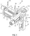
- FIG. 1is an isometric view of a position adjustment device, or adjustment block suitable for sizing and trialing an implant.
- FIG. 2is an exploded view showing the adjustment block, tibial trial, poly trial insert, and floating trial.
- FIG. 3is an isometric view of the tibia trial of FIG. 2 .
- FIG. 4is an anterior elevation view of the tibia trial of FIG. 3 .
- FIG. 5is a lateral elevation view of the tibia trial of FIG. 3 .
- FIG. 6is an isometric view of the floating trial of FIG. 2 .
- FIG. 7is an isometric view of an adjustment block of FIG. 1 , holding a drilling guide.
- FIG. 8is an isometric view of the adjustment block and drilling guide of FIG. 7 , during the drilling operation.
- FIG. 9is an isometric view of the adjustment block of FIG. 1 , holding a cut guide.
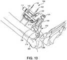
- FIG. 10is an isometric view showing the adjustment block and tibial trial during trial insertion.
- FIG. 11is a lateral side elevation view of the adjustment block and tibial trial during trial insertion.
- FIG. 12is an isometric view showing drilling using the tibia trial to locate peg holes in the distal surface of the tibia.
- FIG. 13shows the tibia and talus after resectioning.
- FIG. 14is an isometric view showing the adjustment block, tibial trial, poly trial insert, and floating trial inserted in the surgical window.
- FIG. 15is a lateral side elevation view of the adjustment block, tibial trial, poly trial insert, and floating trial inserted in the surgical window.
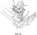
- FIGS. 16 and 17are isometric and lateral side elevation views showing the adjustment block, tibial trial, poly trial insert, and floating trial inserted while the floating trial is being pinned to the talus.
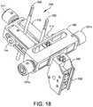
- FIG. 18is an isometric view of an embodiment of the adjustment block providing proximal-distal and medial-lateral adjustments.
- FIG. 19is an anterior top plan view of the adjustment block of FIG. 18 , with a drill guide attached to its tool holder.
- FIG. 1is an isometric diagram of a position adjustment device 100 (also referred to below as an “adjustment block”) for positioning of drilling and cutting tools for tibia resectioning, and for tibia trial insertion.
- the adjustment block 100provides a common reference location for locating tools and the tibia trial components throughout the sizing, resectioning and trial procedure.
- the adjustment block 100is small enough in profile to position a cut guide into the wound space close to the tibia bone without applying excess skin tension. The physician can use the adjustment block to position a drill guide and/or cut guide closer to the tibia bone, to make more accurate cuts with less chance of the blade or pins flexing.
- the adjustment block 100has three independently positionable frames 110 , 120 , and 130 for precisely positioning a tool holder 134 adjacent the joint to be replaced.
- the first frame 110is configured to be attached to two fixation pins 150 which have been inserted in the anterior surface of the tibia, near the distal end of the tibia.
- a locking screw 112actuates a locking plate (not shown), which bears against the fixation pins 150 to secure the adjustment block 100 relative to the pins.
- the first framehas a proximal-distal adjustment knob 111 coaxially connected to a screw 113 .
- the screw 113can have an Acme thread, trapezoidal thread, square thread or other suitable thread for leadscrew use.
- the second frame 120is fixedly attached or unitarily formed with a leadscrew nut (not shown), which the screw 113 drives.
- Rotation of the proximal-distal adjustment knob 111rotates screw 113 to advance or retract the second frame 120 in the proximal-distal direction.
- the physicianadvances the locking screw 114 to lock the second frame 120 to the first frame 110 in place.
- the second frame 120has at least one medial-lateral adjustment knob 121 a , 121 b coaxially connected to a screw 123 .
- the screw 123can have an Acme thread, trapezoidal thread, square thread or other suitable thread for leadscrew use.
- the screw 123drives a leadscrew nut (not shown), to which the third frame 130 is fixedly attached or unitarily formed with. Rotation of the medial-lateral adjustment knob 121 a or 121 b rotates screw 123 to move the third frame 130 in the medial-lateral direction.
- the physicianadvances the locking screw 122 to lock the leadscrew 123 of the second frame 120 in place.
- the third frame 130has an anterior-posterior adjustment knob 131 coaxially connected to a screw 133 .
- the screw 133can have an Acme thread, trapezoidal thread, square thread or other suitable thread for leadscrew use.
- the screw 133drives a leadscrew nut 136 , to which a tool holder 134 is fixedly attached or with which tool holder 134 is unitarily formed.
- Rotation of the anterior-posterior adjustment knob 131rotates screw 133 to move the tool holder 134 in the anterior-posterior direction.
- the tool holder 134is adapted to hold a drilling tool, a cutting tool, or a tibia trial 210 .
- FIG. 2is an exploded view showing the adjustment block 100 , tibia trial 210 , poly trial insert 230 and floating trial 250 .
- FIG. 3is an isometric view of the tibia trial 210 .
- FIG. 4is an anterior (rear) elevation view of the tibia trial 210 .
- FIG. 5is a sagittal (side) elevation view of the tibia trial 210 .
- the tibia trial 210provides the profile of the tibia tray portion of an ankle replacement system.
- the tibia trial 210comprises a plate 211 with a top surface adapted to fit against a distal surface 262 of the resectioned tibia 260 .
- the plate 211has a plurality of holes 212 to be used to locate peg holes 263 in the resectioned tibia 260 .
- the plate 211has a bottom surface 216 adapted to receive a trial insert, such as a poly trial insert 230 .
- An anterior tibia reference member 218extends from the plate 211 .
- the anterior tibia reference member 218has a posterior surface 219 adapted to contact an anterior surface 261 of the tibia 260 when the tibia trial 210 is properly positioned.
- the tibia trial 210has an anterior mounting portion 213 sized and shaped to be mounted to the tool holder 134 of the adjustment block 100 .
- the tibia trial 210has a notch 217 for aligning an anterior surface of the poly trial insert 230 with the tibia trial 210 . Alignment (or misalignment is readily visible by checking whether the notch 217 is aligned with an edge of the poly trial insert 230 .
- the tibia trial 210is formed of a strong, corrosion resistant material such as stainless steel or a titanium alloy.
- the poly trial insert 230is configured to provide the profile of the poly insert of an ankle replacement system.
- the poly trial insert 230comprises a top surface 231 adapted to be detachably mounted to the bottom surface of the plate 216 of the tibia trial 210 .
- the poly insert 230has a concave bottom surface 232 with a size and shape of a prosthetic tibia joint surface of the ankle replacement system.
- the thickness of the poly trial insert 230matches the poly insert of the ankle replacement system to which the poly trial insert 230 corresponds, allowing verification of the size and thickness of the poly insert using the poly trial insert 230 .
- the poly insert of the ankle replacement systemhas a locking tab to prevent release from the talar tray after surgery; but the poly trial insert 230 has a non-locking tab 233 with a ramped surface, to be detachably inserted in the tibia trial 210 and removed after sizing and resectioning is completed.
- the non-locking tab 233fits in a corresponding recess (not shown) in the bottom surface 216 of the tibia trial 210 .
- the posterior end of the poly trial insert 230has an undercut 234 ,
- the poly trial insert 230is made from the same type of material used in the poly insert of an ankle replacement system.
- the poly trial insert 230is made of a chemical-resistant material such as polyphenylsulfone, which is also referred to as Rade1R.
- FIG. 6is an isometric view of the floating trial 250 .
- the floating trial 250is configured to provide a contour that matches the contour of the talar dome of the ankle replacement system.
- the floating trial 250is configured to be inserted beneath the poly trial insert 230 to contact the concave bottom surface 232 of insert 230 .
- the floating trial 250comprises a member 251 having at least one convex anterior surface with a size and shape of a prosthetic talar dome of the ankle replacement system, to permit articulation with the concave surface 232 of the insert.
- the posterior surface 255 of the member 251is shaped to match the contour of the resectioned talus.
- the floating trial 250has two convex surfaces 251 .
- the floating trial 250further includes a handle portion 252 which is sized to project from the resection site, so the physician can easily optimize the position of the floating trial for smooth articulation with the poly trial insert 230 .
- the handle 252 of the floating trial 250has a plurality of pin holes 253 for receiving fixation pins to be used for locating a talar cut guide (not shown). Once the position is optimized, the pins are inserted through the pin holes 253 before completing the resectioning of the talus.
- the floating trial 250is formed of a strong, corrosion resistant material such as stainless steel or a titanium alloy.
- the floating trial 250also has one or more anterior chamfers 254 for reference and alignment.
- FIGS. 7-17show various stages of a method of resectioning and trialing, using the adjustment block 100 , optional drill guide 280 , optional cut guide 290 , tibia trial 210 , poly trial insert 230 and floating trial 250 . This is one example of a use of the devices, but is not limiting.
- FIG. 7shows the adjustment block 100 fixed to the fixation pins 150 (e.g., 3.2 mm pins) which have been inserted in the anterior surface of the tibia 260 near the distal end 261 of the tibia.
- FIG. 7also shows a drill guide 280 attached to the tool holder 134 of the adjustment block 100 , with the first frame 110 slightly above the anterior surface of the tibia 260 .
- the tool holder 134is stage with a pair of pins 135
- the drill guide 280has a corresponding pair of mounting ears 283 with holes adapted to snap onto the pins 135 .
- This tool holder designis just exemplary in nature, and other embodiments include other suitable mounting structures.
- the drill guide 280is a small profile device sized and shaped to be inserted beneath the retracted skin (not shown) in the ankle region.
- the drill guide 280has at least two guide holes 281 to be used to drill pilot holes in the tibia 260 .
- the drill guidealso has pin holes 282 that can be used to pin the drill guide to the bone, for position fixation.
- the drill guide 280has sizing patterns 285 showing the size and location of one or more resectioning cuts corresponding to the holes to be drilled using the drill guide 280 .
- the drill guide 280has one or more reference lines 286 that the physician can optionally use to position the drill guide 280 (by adjusting the proximal-distal knob 111 , the medial-lateral knob 121 a or 121 b , and the anterior-posterior knob.
- the lines 285 , 286are visible under a fluoroscope, so the physician can view the position and size of the lines 285 , 286 in situ, relative to the patient's bones.
- the physiciansizes the tibial tray component of the ankle replacement system by mounting a drill guide 280 on the tool holder and adjusting its position as described above.
- the position adjustment device (adjustment block) 100is locked with the tool holder 134 at first coordinates in the proximal-distal and medial-lateral directions.
- the physicianviews the X-ray of the tibia bone 260 and drill guide 280 and determines whether it is the optimum size and position for the patient.
- the positioncan be adjusted based on the X-ray, using knobs 111 , 121 , 131 . If the size of the resectioning cut corresponding to the drill guide 280 is too large or too small, the physician removes the drill guide, selects a different size drill guide, and snaps the new drill guide onto the tool holder 134 of the adjustment block 100 .
- the drill guideis then repositioned against the tibia, imaged by fluoroscope, and the size is again checked.
- the drill guide 280can be made of plastic, while the circles surrounding holes 281 and the patterns 285 , 286 can be made of metal. Thus, only the circles surrounding holes 281 and the patterns 285 , 286 appear on the X-ray, superimposed against the tibia 260 and talus 265 .
- some embodimentsuse a single drill guide 280 for sizing, location of fixation pins by holes 282 and drilling corners 281
- other embodimentsuse a first guide (sizing guide) with holes 282 and patterns 285 , 286 for sizing the tibia trial 210 and locating the fixation pins, and a second guide (drilling guide) with holes 281 and 282 for performing the drilling. Because the adjustment block 100 and the pins in holes 282 provide common references, the holes 281 can still be drilled with proper location relative to the pin holes 282 and patterns 285 , 286 .
- FIG. 8shows the tibia 260 with adjustment block 100 and drill guide 280 .
- Soft tissueis omitted for ease of viewing.
- the physicianpins the drill guide 280 to the tibia 260 using (e.g., 2.4 mm) fixation pins 287 inserted through the pin holes 282 and trimmed to extend slightly above the drill guide 280 .
- the physiciandrills holes in the tibia 260 through the guides holes 281 using the drill guide 280 and drill 288 .
- the holes thus drilled in the bone 260define corners of a resectioning cut to be performed in the tibia.
- FIG. 9shows the adjustment block 100 still fixed to the fixation pins 150 in the same position, with a cut guide 290 mounted to the tool holder 134 of the adjustment block 100 .
- the cut guide 290has a plurality of slots 295 , sized and located to connect the corner holes drilled with the drill guide 280 .
- the cut guide 290is sized and shaped to match the drill guide 280 .
- the physicianhas a set of drill guides 280 and a corresponding set of cut guides 290 .
- the selection of a drill guide sizeautomatically selects the corresponding cut guide size to make cuts which are sized and located to connect the corner holes drilled with the drill guide 280 , as described above.
- the cut guide 290has a corresponding pair of mounting ears 293 with holes adapted to snap onto the pins 135 .
- the cut guide 290also has pin holes 292 which are sized and located to receive the fixation pins 287 . This aligns the position of the cut guide 290 with the position previously occupied by the drill guide 280 , to ensure alignment of the resectioning cuts with the previously drilled corner holes.
- the cut guide 290includes additional ears 296 with pin holes for receiving additional fixation pins 297 .
- the physicianslides the holes 292 of cut guide 290 over the fixation pins 287 and snaps the cut guide into place on the tool holder 134 .
- the physiciancan then insert two more fixation pins 297 through the pin holes of ears 296 and into the talus bone 265 .
- the physicianperforms the resectioning cuts through the guide slots 295 , cutting the bone to connect the previously drilled holes.
- one cut guide 290is used for both the tibia resection and the first cut of the talar resection.
- the cut guide 290is then removed from the surgery site, and detached from the adjustment block 100 .
- the sections of the tibia 260 and talus 265 that have been cutare removed, along with the fixation pins 287 and 297 .
- the tibia cut guideis only used to resection the tibia, and a separate cut guide is used to resection the talus after removal of the tibia cut guide.
- the use of the adjustment block 100permits the holes 281 to be drilled first with a first tool, and the cuts to be performed afterwards with a second tool, while maintaining accurate alignment between the holes and the cuts. Drilling the holes first avoids stress concentrations at the corners of the resectioned distal tibia.
- some embodiments described hereinuse a drill guide 280 and a cut guide 290 commonly fixed using the adjustment block 100 and fixation pins 287 , other embodiments attach different tools to the tool holder 134 for purpose of resectioning the tibia and talus.
- some embodiments(not shown) include a cut guide without using a separate drill guide.
- the physicianinserts the tibia trial 210 , poly trial insert 230 and floating trial 250 , while the adjustment block 100 is still locked to the two fixation pins 150 , and the tool holder 134 is in the first coordinates in the proximal-distal and medial-lateral directions.
- the physicianreturns the adjustment block to the same coordinates to locate the tool holder 134 at the same position to complete the procedure. Because the fixation pins 150 are excluded from the distal portion of the tibia removed by the resection, the fixation pins 150 are available throughout the procedure for use in adjusting or correcting the resection cuts.
- FIGS. 10 and 11show the adjustment block in position with the tibia trial 210 attached.
- the adjustment block 100is adjusted to position the tool holder in an anterior-posterior direction, while the tool holder is at the first coordinates in the proximal-distal and medial-lateral directions.
- the tibia trial 210is repositioned in the posterior direction until a predetermined portion of the tibia trail contacts an anterior cortex of the tibia.
- the position of the third frame 130is adjusted until the posterior surface 219 of anterior tibia reference member 218 extending from the plate 211 contacts the anterior cortex of the tibia 260 .
- FIG. 12shows the tibia 260 and talus 265 with the adjustment block and tibia trial 210 in position.
- the tibia peg drill(not shown) is placed in the head of a tibia peg drill guide 299 , and is inserted in the holes 212 ( FIG. 3 ) of the tibia trial 210 .
- the physiciandrills a plurality (e.g., 3) peg holes 263 in the distal surface 262 of the resectioned tibia 260 using the tibia peg drill 299 .
- the holes 212 ( FIG. 3 ) of the tibia trial 210are used to locate these holes 263 .
- FIG. 13shows the distal end 261 of the tibia 260 at the completion of the peg drilling, with the three peg holes 263 in the resectioned surface 262 of the tibia.
- the tibia trial 210is used to verify size and shape of the resectioning using the tibia trial, prior to implanting the ankle replacement system.
- the steps of attaching the tibia trial 210 to the tool holder 134 , adjusting the position adjustment device 100 to position the tool holder 134 in an anterior-posterior direction, and placing the tibia trial 210 on the resectioned tibia 260 using the tool holder 134can be formed without inserting any additional location fixing pins into the tibia, while the tool holder is locked in the first coordinates in the proximal-distal and medial-lateral directions.
- FIGS. 14 and 15show the adjustment block 100 and tibia trial 210 , after installing the poly trial insert 230 into the tibia trial 210 and positioning the floating trial 250 between the talus 265 and the poly insert trial 230 , to permit articulation with the concave surface 232 of the poly insert trial 230 while the tool holder is in the first coordinates in the proximal-distal and medial-lateral directions.
- the physiciancan now assess the fit of the ankle replacement system, including size, anterior-posterior position, and whether the tibia has been sized, drilled and cut optimally. If any adjustments are deemed appropriate to the tibia resectioning, the physician can reapply the cut guide with the adjustment block set to the same proximal-distal and medial-lateral coordinates used before.
- the talar implant anterior-posterior coordinateis determined by moving the floating trial 250 to the location where it best articulates with the concave surface 232 of the poly trial insert 230 .
- Two additional fixation pins 298are inserted through the pin holes 253 of the floating trial 250 using 2 mm K-wire, for example.
- Additional resection guides(not shown) can be positioned by sliding pin holes in the resection guide(s) over the fixation pins 298 .
- the remaining two talar cutsare then performed, to match the geometry of the talar dome implant of the ankle replacement system.
- a position adjustment device (adjustment block) 100 as described aboveprovides a fixed point of reference that facilitates the AP position of the tibial and talar implants of an ankle replacement system.
- the adjustment block 100is capable of fixing a tibial trial 210 via a modular connection 134 to avoid insertion of additional pins in the distal tibia.
- the tibial trial 210while attached to the adjustment block 100 , allows the user to set the tibial implant anterior-posterior position by abutting the anterior post 218 against the tibial bone.
- the tibial trial 210also serves as a drill guide to prepare the tibial pegs on the tibial implant.
- the tibial trial 210while rigidly fixed to the adjustment block 100 then translates the anterior-posterior position to the talar trial 250 by using the poly trial insert 230 to articulate with the talar (dome) trial 250 .
- the talar trial 250also has chamfer indicators 254 to help the user determine the optimal talar anterior-posterior position.
- the system and method described aboveuses the adjustment block 100 as a fixed reference to associate all other instruments used for trial sizing and trials related to tibial side of the ankle replacement.
- a tibial sizere.g., drill guide 280
- tibial resection guidee.g., cut guide 290
- tibial trial 210can all be anchored at the same position defined by the adjustment block 100 . This method preserves the distal layer of the tibia to avoid excess pin holes from fixation pins and devices.
- the compact size of the adjustment blockallows the tools to be fixed and placed close to the surgery site, for more accurate cuts, with reduced chance of components flexing.
- Sizing guidese.g., drill guide 280
- resection guidese.g. cut guide 290
- the position of the tools and trialscan be accurately adjusted by turning the adjustment knobs 111 , 121 , 131 in a small area.
- FIGS. 18 and 19show another embodiment of the adjustment block 300 .
- the adjustment block 300has two independently positionable frames 110 , 120 for precisely positioning a tool holder 330 in the proximal-distal and medial-lateral directions, adjacent the joint to be replaced.
- the first frame 110is configured to be attached to two fixation pins 150 which have been inserted in the anterior surface of the tibia, near the distal end of the tibia.
- a locking screw 112actuates a locking plate (not shown), which bears against the fixation pins 150 to secure the adjustment block 100 relative to the pins.
- the first framehas a proximal-distal adjustment knob 111 coaxially connected to a screw 113 .
- the screw 113can have an Acme thread, trapezoidal thread, square thread or other suitable thread for leadscrew use.
- the second frame 120is fixedly attached or unitarily formed with a leadscrew nut (not shown), which the screw 113 drives.
- Rotation of the proximal-distal adjustment knob 111rotates screw 113 to advance or retract the second frame 120 in the proximal-distal direction.
- the physicianadvances the locking screw 114 to lock the second frame 120 to the first frame 110 in place.
- the second frame 120has at least one medial-lateral adjustment knob 121 a , 121 b coaxially connected to a screw 123 .
- the screw 123can have an Acme thread, trapezoidal thread, square thread or other suitable thread for leadscrew use.
- the screw 123drives a leadscrew nut (not shown), to which the tool holder 330 is fixedly attached or unitarily formed with. Rotation of the medial-lateral adjustment knob 121 a or 121 b rotates screw 123 to move the tool holder 330 in the medial-lateral direction.
- the physicianadvances the locking screw 122 to lock the leadscrew 123 of the second frame 120 in place.
- the position of the tool holder 330 in the anterior-posterior directionis determined by location of the first frame 110 relative to the pins 150 .
- the tool holder 330can have any of a variety of configurations for easily attaching a tool or trial.
- FIGS. 18 and 19show a non-limiting example in which the tool or trial is attached to the adjustment block 300 by a dovetail joint 332 .
- FIG. 19shows an example of a drill guide 380 adapted for mounting to the dovetail joint 332 of tool holder 330 .
- the drill guide 380has corner holes 381 and fixation holes 382 , 383 and sizing patterns 385 .
- Other toolse.g., a cut guide
- trialse.g., tibia trial
Landscapes
- Health & Medical Sciences (AREA)
- Engineering & Computer Science (AREA)
- Life Sciences & Earth Sciences (AREA)
- Surgery (AREA)
- Orthopedic Medicine & Surgery (AREA)
- Public Health (AREA)
- Oral & Maxillofacial Surgery (AREA)
- Biomedical Technology (AREA)
- Heart & Thoracic Surgery (AREA)
- Animal Behavior & Ethology (AREA)
- General Health & Medical Sciences (AREA)
- Veterinary Medicine (AREA)
- Medical Informatics (AREA)
- Molecular Biology (AREA)
- Dentistry (AREA)
- Nuclear Medicine, Radiotherapy & Molecular Imaging (AREA)
- Transplantation (AREA)
- Computer Security & Cryptography (AREA)
- Computer Networks & Wireless Communication (AREA)
- Signal Processing (AREA)
- Cardiology (AREA)
- Vascular Medicine (AREA)
- Computing Systems (AREA)
- General Engineering & Computer Science (AREA)
- Computer Hardware Design (AREA)
- Physical Education & Sports Medicine (AREA)
- Power Engineering (AREA)
- Surgical Instruments (AREA)
- Prostheses (AREA)
Abstract
Description
Claims (14)
Priority Applications (3)
| Application Number | Priority Date | Filing Date | Title |
|---|---|---|---|
| US16/405,212US11116521B2 (en) | 2012-12-27 | 2019-05-07 | Ankle replacement system and method |
| US17/400,620US12064125B2 (en) | 2012-12-27 | 2021-08-12 | Ankle replacement system and method |
| US18/772,514US20240372894A1 (en) | 2012-12-27 | 2024-07-15 | Ankle replacement system and method |
Applications Claiming Priority (4)
| Application Number | Priority Date | Filing Date | Title |
|---|---|---|---|
| US201261746393P | 2012-12-27 | 2012-12-27 | |
| US14/100,799US9480571B2 (en) | 2012-12-27 | 2013-12-09 | Ankle replacement system and method |
| US15/335,949US10321922B2 (en) | 2012-12-27 | 2016-10-27 | Ankle replacement system and method |
| US16/405,212US11116521B2 (en) | 2012-12-27 | 2019-05-07 | Ankle replacement system and method |
Related Parent Applications (1)
| Application Number | Title | Priority Date | Filing Date |
|---|---|---|---|
| US15/335,949ContinuationUS10321922B2 (en) | 2012-12-27 | 2016-10-27 | Ankle replacement system and method |
Related Child Applications (1)
| Application Number | Title | Priority Date | Filing Date |
|---|---|---|---|
| US17/400,620ContinuationUS12064125B2 (en) | 2012-12-27 | 2021-08-12 | Ankle replacement system and method |
Publications (2)
| Publication Number | Publication Date |
|---|---|
| US20190254688A1 US20190254688A1 (en) | 2019-08-22 |
| US11116521B2true US11116521B2 (en) | 2021-09-14 |
Family
ID=51018089
Family Applications (5)
| Application Number | Title | Priority Date | Filing Date |
|---|---|---|---|
| US14/100,799Active2034-11-05US9480571B2 (en) | 2012-12-27 | 2013-12-09 | Ankle replacement system and method |
| US15/335,949Active2034-12-24US10321922B2 (en) | 2012-12-27 | 2016-10-27 | Ankle replacement system and method |
| US16/405,212Active2034-07-11US11116521B2 (en) | 2012-12-27 | 2019-05-07 | Ankle replacement system and method |
| US17/400,620Active2035-04-09US12064125B2 (en) | 2012-12-27 | 2021-08-12 | Ankle replacement system and method |
| US18/772,514PendingUS20240372894A1 (en) | 2012-12-27 | 2024-07-15 | Ankle replacement system and method |
Family Applications Before (2)
| Application Number | Title | Priority Date | Filing Date |
|---|---|---|---|
| US14/100,799Active2034-11-05US9480571B2 (en) | 2012-12-27 | 2013-12-09 | Ankle replacement system and method |
| US15/335,949Active2034-12-24US10321922B2 (en) | 2012-12-27 | 2016-10-27 | Ankle replacement system and method |
Family Applications After (2)
| Application Number | Title | Priority Date | Filing Date |
|---|---|---|---|
| US17/400,620Active2035-04-09US12064125B2 (en) | 2012-12-27 | 2021-08-12 | Ankle replacement system and method |
| US18/772,514PendingUS20240372894A1 (en) | 2012-12-27 | 2024-07-15 | Ankle replacement system and method |
Country Status (3)
| Country | Link |
|---|---|
| US (5) | US9480571B2 (en) |
| EP (1) | EP2749257B1 (en) |
| CN (1) | CN103892942B (en) |
Cited By (2)
| Publication number | Priority date | Publication date | Assignee | Title |
|---|---|---|---|---|
| US12133804B2 (en) | 2018-12-13 | 2024-11-05 | Paragon 28, Inc. | Total ankle replacement surgical method |
| US12156664B2 (en) | 2018-12-13 | 2024-12-03 | Paragon 28, Inc. | Resection guides, sweeping reamers, and methods for use in total ankle replacement |
Families Citing this family (24)
| Publication number | Priority date | Publication date | Assignee | Title |
|---|---|---|---|---|
| GB2528101A (en)* | 2014-07-10 | 2016-01-13 | Ortho Solutions Ltd | Apparatus for surgically replacing a human ankle joint |
| US10517741B2 (en)* | 2015-03-06 | 2019-12-31 | Tornier, Inc. | Surgical method and instrumentation assembly for positioning an ankle prosthesis |
| CN108472049B (en) | 2015-06-09 | 2021-09-14 | 捷迈有限公司 | Patient specific instruments and methods for total ankle replacement |
| EP4353160A3 (en) | 2016-03-23 | 2024-06-12 | Wright Medical Technology, Inc. | Fixation apparatus and method for total ankle replacement |
| GB2551533B (en)* | 2016-06-21 | 2022-07-27 | 3D Metal Printing Ltd | A surgical assembly, stabilisation plate and methods |
| EP3590450B1 (en) | 2017-03-03 | 2023-11-01 | Teijin Nakashima Medical Co., Ltd. | Osteotomy assistance kit |
| CA3116744A1 (en) | 2017-07-05 | 2019-01-10 | Wright Medical Technology, Inc. | Anterior ankle approach system and method |
| JP6998393B2 (en)* | 2017-07-28 | 2022-02-04 | ライト メディカル テクノロジー インコーポレイテッド | Joint osteotomy system and method |
| US11013607B2 (en) | 2017-09-22 | 2021-05-25 | Encore Medical, L.P. | Talar ankle implant |
| CN107874809B (en)* | 2017-11-14 | 2020-08-04 | 北京爱康宜诚医疗器材有限公司 | Ankle osteotomy guiding device and method for determining ankle osteotomy position |
| EP3501432A1 (en) | 2017-12-20 | 2019-06-26 | Stryker European Holdings I, LLC | Joint instrumentation |
| WO2020124055A1 (en) | 2018-12-13 | 2020-06-18 | Paragon 28, Inc. | Joint replacement alignment guides, systems and methods of use and assembly |
| AU2019398470B2 (en) | 2018-12-13 | 2025-09-25 | Paragon 28, Inc. | Distractors having attachable paddles, impaction devices, and methods for use in total ankle replacement |
| AU2019398097B2 (en)* | 2018-12-13 | 2025-06-26 | Paragon 28, Inc. | Trial insert assembly |
| WO2020123899A1 (en) | 2018-12-13 | 2020-06-18 | Paragon 28, Inc. | Alignment instruments and methods for use in total ankle replacement |
| WO2020124052A1 (en) | 2018-12-13 | 2020-06-18 | Paragon 28, Inc. | Instruments, guides and related methods for total ankle replacement |
| EP3975939B1 (en) | 2019-05-29 | 2024-11-13 | Wright Medical Technology, Inc. | Device for preparing a tibia for receiving tibial implant component of a replacement ankle |
| US11918237B2 (en)* | 2020-03-02 | 2024-03-05 | Orthosoft Ulc | Systems and methods for robotic ankle arthroplasty |
| WO2021247498A1 (en)* | 2020-06-01 | 2021-12-09 | Pmo Llc | Bone deformity treatment system, device, and related methods |
| CN112545720A (en)* | 2020-12-16 | 2021-03-26 | 上海联影智融医疗科技有限公司 | Tibial bearing component |
| CN113693792A (en)* | 2021-08-30 | 2021-11-26 | 北京市春立正达医疗器械股份有限公司 | Locking type prosthesis for ankle joint |
| US12396755B2 (en) | 2022-01-28 | 2025-08-26 | Wright Medical Technology, Inc. | Methods and apparatus for joint repair |
| EP4265201B1 (en) | 2022-02-28 | 2025-04-09 | Wright Medical Technology, Inc. | Surgical guides |
| US12433532B2 (en) | 2022-06-02 | 2025-10-07 | Wright Medical Technology, Inc. | Flexion/extension surgical guides and methods of using the same |
Citations (188)
| Publication number | Priority date | Publication date | Assignee | Title |
|---|---|---|---|---|
| US3839742A (en) | 1972-07-22 | 1974-10-08 | Link W | Prosthetic device for the tarsal joint |
| US3872519A (en) | 1974-04-04 | 1975-03-25 | Nicholas J Giannestras | Total ankle prosthesis |
| US3886599A (en) | 1974-07-25 | 1975-06-03 | Schlein Louis Charles | Surgically implantable total ankle prosthesis |
| US3889300A (en) | 1974-08-28 | 1975-06-17 | Wright Mfg | Articulated two-part prosthesis replacing the ankle joint |
| US3896502A (en) | 1973-01-12 | 1975-07-29 | Nat Res Dev | Endoprosthetic bone joint devices |
| US3896503A (en) | 1973-02-09 | 1975-07-29 | Nat Res Dev | Endosphosthetic ankle joint devices |
| JPS5026651B2 (en) | 1972-04-13 | 1975-09-02 | ||
| US3975778A (en) | 1975-07-14 | 1976-08-24 | Newton Iii St Elmo | Total ankle arthroplasty |
| US3987500A (en) | 1976-01-28 | 1976-10-26 | Schlein Allen P | Surgically implantable total ankle prosthesis |
| US4021864A (en) | 1976-04-14 | 1977-05-10 | The Regents Of The University Of California | Ankle prosthesis |
| US4069518A (en) | 1976-08-31 | 1978-01-24 | Groth Jr Harry E | Total ankle prosthesis |
| US4156944A (en) | 1976-11-15 | 1979-06-05 | Sulzer Brothers Limited | Total ankle prosthesis |
| US4166292A (en) | 1977-09-08 | 1979-09-04 | Carbomedics, Inc. | Stress reinforced artificial joint prostheses |
| US4204284A (en) | 1977-11-16 | 1980-05-27 | Lord Corporation | Joint prosthesis with contoured pin |
| US4232404A (en) | 1977-07-18 | 1980-11-11 | National Research Development Corporation | Endoprosthetic ankle joint |
| US4309778A (en) | 1979-07-02 | 1982-01-12 | Biomedical Engineering Corp. | New Jersey meniscal bearing knee replacement |
| US4470158A (en) | 1978-03-10 | 1984-09-11 | Biomedical Engineering Corp. | Joint endoprosthesis |
| US4755185A (en) | 1987-01-27 | 1988-07-05 | Boehringer Mannheim Corporation | Prosthetic joint |
| US4968316A (en) | 1988-12-12 | 1990-11-06 | Hergenroeder Patrick T | Arthroscopic ankle joint distraction method |
| US5041139A (en) | 1989-04-25 | 1991-08-20 | Branemark Per Ingvar | Anchoring element for supporting a joint mechanism of an ankle, hip or other reconstructed joint |
| US5312412A (en) | 1993-02-03 | 1994-05-17 | Whipple Terry L | Fixation alignment guide for surgical use |
| US5326365A (en) | 1992-04-10 | 1994-07-05 | Alvine Franklin G | Ankle implant |
| US5354300A (en) | 1993-01-15 | 1994-10-11 | Depuy Inc. | Drill guide apparatus for installing a transverse pin |
| US5423825A (en) | 1992-06-10 | 1995-06-13 | Levine; Andrew S. | Spinal fusion instruments and methods |
| US5476466A (en) | 1993-07-20 | 1995-12-19 | Zimmer, Inc. | Orthopaedic positioning instrument |
| US5601563A (en) | 1995-08-25 | 1997-02-11 | Zimmer, Inc. | Orthopaedic milling template with attachable cutting guide |
| US5628749A (en) | 1995-02-15 | 1997-05-13 | Smith & Nephew Richards Inc. | Tibial resection instrumentation and surgical method |
| US5634927A (en) | 1995-07-06 | 1997-06-03 | Zimmer, Inc. | Sizing plate and drill guide assembly for orthopaedic knee instrumentation |
| US5674223A (en) | 1994-02-16 | 1997-10-07 | Joint Medical Products Corporation | Instrument for implanting a femoral knee prosthesis |
| US5735904A (en) | 1995-07-05 | 1998-04-07 | Pappas; Michael J. | Spacer for establishng prosthetic gap and ligamentous tension |
| US5766259A (en) | 1995-03-14 | 1998-06-16 | Sammarco; Giacomo J. | Total ankle prosthesis and method |
| US5776200A (en) | 1995-02-15 | 1998-07-07 | Smith & Nephew, Inc. | Tibial trial prosthesis and bone preparation system |
| US5817097A (en) | 1995-08-03 | 1998-10-06 | Synvasive Technology, Inc. | Bone saw blade guide with magnet |
| US5824106A (en) | 1996-04-11 | 1998-10-20 | Tornier Sa | Ankle prosthesis |
| US5879389A (en) | 1995-04-07 | 1999-03-09 | Koshino; Tomihisa | Medical substituting element for hard tissues and artificial joint |
| US5885299A (en) | 1994-09-15 | 1999-03-23 | Surgical Dynamics, Inc. | Apparatus and method for implant insertion |
| US5888203A (en) | 1995-03-09 | 1999-03-30 | Goldberg; Robert | Biaxial ligamentous-restrained prostheses for upper and lower extremity arthroplasties |
| US5897559A (en) | 1995-11-02 | 1999-04-27 | Medidea, Llc | Bone cutting guides for use in the implantation of prosthetic joint components |
| US5921988A (en) | 1996-11-08 | 1999-07-13 | Proseal | Installation instrument for a blade suture clip for ostelogical removal for the treatment of inflammation of the knee joint |
| US5935132A (en) | 1997-12-10 | 1999-08-10 | Johnson & Johnson Professional, Inc. | Surgical guide and cutting system |
| US6002859A (en) | 1997-02-21 | 1999-12-14 | Carnegie Mellon University | Apparatus and method facilitating the implantation of artificial components in joints |
| US6033405A (en) | 1994-09-15 | 2000-03-07 | Surgical Dynamics, Inc. | Apparatus and method for implant insertion |
| US6183519B1 (en) | 1997-03-10 | 2001-02-06 | Tornier Sa | Ankle prosthesis |
| US6245109B1 (en) | 1999-11-18 | 2001-06-12 | Intellijoint Systems, Ltd. | Artificial joint system and method utilizing same for monitoring wear and displacement of artificial joint members |
| WO2001066022A1 (en) | 2000-03-10 | 2001-09-13 | Smith & Nephew, Inc | Apparatus for use in arthroplasty of the knees |
| US6342056B1 (en) | 2000-02-04 | 2002-01-29 | Jean-Marc Mac-Thiong | Surgical drill guide and method for using the same |
| US6409767B1 (en) | 1999-11-05 | 2002-06-25 | European Foot Platform | Ankle prosthesis |
| US20020082607A1 (en) | 2000-12-27 | 2002-06-27 | Heldreth Mark A. | Prosthesis evaluation assembly and associated method |
| US6423061B1 (en) | 2000-03-14 | 2002-07-23 | Amei Technologies Inc. | High tibial osteotomy method and apparatus |
| US6436146B1 (en) | 1997-12-10 | 2002-08-20 | Bioprofile | Implant for treating ailments of a joint or a bone |
| US20020133164A1 (en) | 2000-06-29 | 2002-09-19 | Williamson Richard V. | Instruments and methods for use in performing knee surgery |
| US6478800B1 (en) | 2000-05-08 | 2002-11-12 | Depuy Acromed, Inc. | Medical installation tool |
| US20020173853A1 (en) | 2001-05-17 | 2002-11-21 | Corl Harry E. | Movable joint and method for coating movable joints |
| US6520964B2 (en) | 2000-05-01 | 2003-02-18 | Std Manufacturing, Inc. | System and method for joint resurface repair |
| US6530930B1 (en) | 1998-06-09 | 2003-03-11 | Nu Vasive, Inc. | Spinal surgery guidance platform |
| US6610095B1 (en) | 2000-01-30 | 2003-08-26 | Diamicron, Inc. | Prosthetic joint having substrate surface topographical featurers and at least one diamond articulation surface |
| US6610067B2 (en) | 2000-05-01 | 2003-08-26 | Arthrosurface, Incorporated | System and method for joint resurface repair |
| US6620168B1 (en) | 1998-10-13 | 2003-09-16 | Stryker Technologies Corporation | Methods and tools for tibial intermedullary revision surgery and associated tibial components |
| US20030208280A1 (en) | 2000-04-21 | 2003-11-06 | Behrooz Tohidi | Wear resistant artificial joint |
| US6645215B1 (en) | 2002-08-07 | 2003-11-11 | Howmedica Osteonics Corp. | Tibial rotation guide |
| US6663669B1 (en) | 1999-10-22 | 2003-12-16 | Mark A Reiley | Ankle replacement system |
| US20030236522A1 (en) | 2002-06-21 | 2003-12-25 | Jack Long | Prosthesis cavity cutting guide, cutting tool and method |
| US6673116B2 (en) | 1999-10-22 | 2004-01-06 | Mark A. Reiley | Intramedullary guidance systems and methods for installing ankle replacement prostheses |
| US6679917B2 (en) | 2000-05-01 | 2004-01-20 | Arthrosurface, Incorporated | System and method for joint resurface repair |
| US20040030399A1 (en) | 2000-05-22 | 2004-02-12 | Joseph-Guy Asencio | Articulation prosthesis |
| US20040039394A1 (en) | 2002-08-26 | 2004-02-26 | Conti Stephen F. | Ankle fusion guide and method |
| US20040068322A1 (en) | 2002-10-04 | 2004-04-08 | Ferree Bret A. | Reduced-friction artificial joints and components therefor |
| US6719799B1 (en) | 1998-09-11 | 2004-04-13 | Argomedical Ag | Implantable prosthesis having at least two sections which can be displaced in relation to one another, and the use of displaceable sections |
| US20040167631A1 (en) | 2003-02-21 | 2004-08-26 | Kenny Luchesi | Fixation surface for ankle prosthesis |
| US20040186585A1 (en) | 2003-03-21 | 2004-09-23 | Lawrence Feiwell | Sphere-on-sphere ankle prosthesis |
| US20040216259A1 (en) | 1998-10-09 | 2004-11-04 | Valeo Electrical Systems, Inc. | Window wiper arm drive and window lock system |
| US20040236431A1 (en) | 2001-06-28 | 2004-11-25 | Ronald Sekel | Universal prosthesis |
| US6824567B2 (en) | 1999-08-03 | 2004-11-30 | Tornier | Method of positioning a malleolar implant for partial or total ankle prosthesis |
| US20050004676A1 (en) | 2002-06-27 | 2005-01-06 | Schon Lew C. | Semi-constrained ankle joint prosthesis and its method of implantation |
| US6852130B2 (en) | 2002-03-08 | 2005-02-08 | Waldemar Link Gmbh & Co. Kg | Ankle-joint endoprosthesis |
| WO2005011523A2 (en) | 2003-08-01 | 2005-02-10 | Spinal Kinetics, Inc. | Prosthetic intervertebral disc and methods for using same |
| US6863691B2 (en) | 2002-04-29 | 2005-03-08 | Timothy J. Short | Ankle implant |
| US6875222B2 (en) | 2002-03-12 | 2005-04-05 | Depuy Products, Inc. | Blade for resection of bone for prosthesis implantation, blade stop and method |
| US20050165408A1 (en) | 2004-01-26 | 2005-07-28 | Puno Rolando M. | Methods and instrumentation for inserting intervertebral grafts and devices |
| US6926739B1 (en) | 1999-05-13 | 2005-08-09 | John J. O'Connor | Prosthesis device for human articulations, in particular for the ankle articulation |
| US20050192674A1 (en) | 1999-10-08 | 2005-09-01 | Ferree Bret A. | Prosthetic joints with contained compressible resilient members |
| US6939380B2 (en) | 2002-12-23 | 2005-09-06 | Depuy Products, Inc. | Mobile talar component for total ankle replacement implant |
| US20060009857A1 (en) | 2004-07-08 | 2006-01-12 | Gibbs Phillip M | Method and apparatus for surface hardening implants |
| US20060036257A1 (en) | 2004-08-06 | 2006-02-16 | Zimmer Technology, Inc. | Tibial spacer blocks and femoral cutting guide |
| US7001394B2 (en) | 2000-12-28 | 2006-02-21 | Depuy Products, Inc. | Method and apparatus for surgically preparing a tibia for implantation of a prosthetic implant component which has an offset stem |
| WO2006023824A2 (en) | 2004-08-19 | 2006-03-02 | Kinetikos Medical Incorporated | Ankle prosthesis and method of curved resection |
| US7011687B2 (en) | 2003-01-06 | 2006-03-14 | Depuy Products, Inc. | Ankle prosthesis with a front loading bearing and associated method |
| US20060116679A1 (en) | 2004-11-30 | 2006-06-01 | Stryker Trauma Sa | Bone plating implants, instruments and methods |
| WO2006099270A2 (en) | 2005-03-14 | 2006-09-21 | Topez Orthopedics, Inc. | Ankle replacement system |
| US20060235541A1 (en) | 2005-04-15 | 2006-10-19 | Zimmer Technology, Inc. | Bearing implant |
| US20060247788A1 (en) | 2005-03-31 | 2006-11-02 | The Regents Of The University Of California | Total ankle arthroplasty |
| US20060293682A1 (en) | 2005-06-10 | 2006-12-28 | Medicinelodge, Inc. | Milling system with guide paths and related methods for resecting a joint articulation surface |
| US7163541B2 (en) | 2002-12-03 | 2007-01-16 | Arthrosurface Incorporated | Tibial resurfacing system |
| US20070038303A1 (en) | 2006-08-15 | 2007-02-15 | Ebi, L.P. | Foot/ankle implant and associated method |
| US20070100346A1 (en) | 2005-10-27 | 2007-05-03 | Wyss Joseph G | Support for locating instrument guides |
| US20070112431A1 (en) | 2003-08-27 | 2007-05-17 | Hakon Kofoed | Ankle-joint endoprosthesis |
| US7238190B2 (en) | 2003-03-28 | 2007-07-03 | Concepts In Medicine Iii, Llc | Surgical apparatus to allow replacement of degenerative ankle tissue |
| US20070173944A1 (en) | 2005-12-12 | 2007-07-26 | Waldemar Link Gmbh & Co. Kg | Endoprosthesis with intermediate part |
| WO2007084846A2 (en) | 2006-01-20 | 2007-07-26 | Hasselman Carl T | Method of preparing an ankle joint for replacement, joint prosthesis, and cutting alignment apparatus for use in performing an arthroplasty procedure |
| US7252684B2 (en) | 2002-11-06 | 2007-08-07 | Southwest Research Institute | Ceramic in replacement components |
| US20070213830A1 (en) | 2005-01-31 | 2007-09-13 | Ammann Kelly G | Method and apparatus for performing an open wedge, high tibial osteotomy |
| US20070233129A1 (en) | 2006-02-17 | 2007-10-04 | Rudolf Bertagnoli | Method and system for performing interspinous space preparation for receiving an implant |
| US20070276400A1 (en) | 2003-09-22 | 2007-11-29 | Gary Moore | Drill Guide Assembly |
| JP2007536011A (en) | 2004-05-07 | 2007-12-13 | アイバランス・メディカル・インコーポレーテッド | Surgical apparatus and surgical method for wedge osteotomy |
| US20080015602A1 (en) | 2006-06-22 | 2008-01-17 | Howmedica Osteonics Corp. | Cutting block for bone resection |
| US7323012B1 (en) | 2004-03-17 | 2008-01-29 | Biomet Manufacturing Corp. | Ankle implant |
| US20080097617A1 (en) | 2004-11-08 | 2008-04-24 | Alphamed Medizintechnik Fischer Gmbh | Ankle Joint Endoprosthesis Elements |
| US20080103603A1 (en) | 2006-10-26 | 2008-05-01 | Beat Hintermann | Ankle prosthesis with neutral position adjustment |
| US20080109081A1 (en) | 2003-10-22 | 2008-05-08 | Qi-Bin Bao | Joint Arthroplasty Devices Having Articulating Members |
| US20080195233A1 (en) | 2006-10-13 | 2008-08-14 | Irene Ferrari | Ankle prosthesis for the arthrodesis of the calcaneum |
| US20080215156A1 (en) | 2004-06-30 | 2008-09-04 | Synergy Disc Replacement | Joint Prostheses |
| US20080287954A1 (en) | 2007-05-14 | 2008-11-20 | Queen's University At Kingston | Patient-specific surgical guidance tool and method of use |
| US20080312745A1 (en) | 2007-06-12 | 2008-12-18 | Waldemar Link Gmbh & Co. Kg | Endoprosthesis with convex configuration |
| US7481814B1 (en) | 2003-07-28 | 2009-01-27 | Biomet Manufacturing Corporation | Method and apparatus for use of a mill or reamer |
| US7485147B2 (en) | 2004-02-13 | 2009-02-03 | Pappas Michael J | Ankle prosthesis including tibial component having peripheral wall for preventing the formation of bone cysts |
| US20090043310A1 (en) | 2005-02-08 | 2009-02-12 | Rasmussen G Lynn | Arthroplasty systems and methods for optimally aligning and tensioning a knee prosthesis |
| US20090054992A1 (en) | 2004-06-23 | 2009-02-26 | Landes Mark D | Modular Ankle Prosthesis and Associated Method |
| US20090082875A1 (en) | 2007-09-26 | 2009-03-26 | Depuy Products, Inc. | Talar implant system and method |
| US20090105767A1 (en) | 2007-10-18 | 2009-04-23 | Inbone Technologies, Inc. | Total joint subsidence protector |
| US20090105840A1 (en) | 2007-10-18 | 2009-04-23 | Inbone Technologies, Inc. | Fibular stiffener and bony defect replacer |
| US7534270B2 (en) | 2003-09-03 | 2009-05-19 | Integra Lifesciences Corporation | Modular total ankle prosthesis apparatuses and methods |
| US20090198341A1 (en) | 2006-03-02 | 2009-08-06 | Talus Medical, Inc. | Bone prosthesis |
| US20090234360A1 (en) | 2006-12-12 | 2009-09-17 | Vladimir Alexander | Laser assisted total joint arthroplasty |
| US20090276052A1 (en) | 2008-04-30 | 2009-11-05 | Exploramed Nc4, Inc. | Ball and socket assembly |
| US7615082B2 (en) | 2002-03-22 | 2009-11-10 | Hjs Gelenk System Gmbh | Artificial joint |
| US7618421B2 (en) | 2001-10-10 | 2009-11-17 | Howmedica Osteonics Corp. | Tools for femoral resection in knee surgery |
| US7625409B2 (en) | 2003-10-14 | 2009-12-01 | University Of Iowa Research Foundation | Ankle prosthesis |
| WO2009158522A1 (en) | 2008-06-25 | 2009-12-30 | Small Bone Innovations, Inc. | Surgical instrumentation and methods of use for implanting a prothesis |
| US20100010493A1 (en) | 2006-04-05 | 2010-01-14 | Depuy International Limited | Orthopaedic cutting guide instrument |
| US20100023126A1 (en) | 2008-07-24 | 2010-01-28 | Grotz R Thomas | Resilient arthroplasty device |
| US20100057216A1 (en) | 2008-07-23 | 2010-03-04 | Jamy Gannoe | System and method for joint resurfacing with dynamic fixation |
| US7678151B2 (en) | 2000-05-01 | 2010-03-16 | Ek Steven W | System and method for joint resurface repair |
| US20100069910A1 (en) | 2006-12-15 | 2010-03-18 | Synthes Usa, Llc | Osteotomy Guide and Method of Cutting the Medial Distal Tibia Employing the Same |
| US7713305B2 (en) | 2000-05-01 | 2010-05-11 | Arthrosurface, Inc. | Articular surface implant |
| US7763080B2 (en) | 2004-04-30 | 2010-07-27 | Depuy Products, Inc. | Implant system with migration measurement capacity |
| WO2010099142A1 (en) | 2009-02-24 | 2010-09-02 | Wright Medical Technology, Inc. | Patient specific surgical guide locator and mount |
| US20100241237A1 (en) | 2008-09-22 | 2010-09-23 | Buechel-Pappas Trust | Fixed bearing joint endoprosthesis with combined congruent - incongruent prosthetic articulations |
| US7803158B2 (en) | 2004-03-26 | 2010-09-28 | Depuy Products, Inc. | Navigated pin placement for orthopaedic procedures |
| US7850698B2 (en) | 2005-02-17 | 2010-12-14 | Zimmer Technology, Inc. | Tibial trialing assembly and method of trialing a tibial implant |
| US20100318088A1 (en) | 2007-07-20 | 2010-12-16 | Talus Medical, Inc. | Methods and devices for deploying biological implants |
| US20100331984A1 (en) | 2009-06-26 | 2010-12-30 | The Cleveland Clinic Foundation | Prosthetic joint component with rotation-regulating structure |
| US20110029090A1 (en) | 2007-09-25 | 2011-02-03 | Depuy Products, Inc. | Prosthesis with modular extensions |
| US20110035018A1 (en) | 2007-09-25 | 2011-02-10 | Depuy Products, Inc. | Prosthesis with composite component |
| WO2011015863A1 (en) | 2009-08-06 | 2011-02-10 | Depuy (Ireland) | Surgical instrument and system of surgical instruments |
| US20110035019A1 (en) | 2009-07-09 | 2011-02-10 | Wright State University | Total ankle replacement system |
| US7896883B2 (en) | 2000-05-01 | 2011-03-01 | Arthrosurface, Inc. | Bone resurfacing system and method |
| US7896885B2 (en) | 2002-12-03 | 2011-03-01 | Arthrosurface Inc. | Retrograde delivery of resurfacing devices |
| US7909882B2 (en) | 2007-01-19 | 2011-03-22 | Albert Stinnette | Socket and prosthesis for joint replacement |
| US20110106268A1 (en) | 2009-10-30 | 2011-05-05 | Depuy Products, Inc. | Prosthesis for cemented fixation and method for making the prosthesis |
| US20110106093A1 (en) | 2009-10-29 | 2011-05-05 | Zimmer, Inc. | Patient-specific mill guide |
| US20110125275A1 (en) | 2009-11-16 | 2011-05-26 | New York Society For The Ruptured And Crippled Maintaining The Hospital For Special Surgery | Prosthetic condylar joints with articulating bearing surfaces having a translating contact point during rotation thereof |
| US20110125284A1 (en) | 2008-05-28 | 2011-05-26 | University Of Bath | Improvements in or Relating to Joints and/or Implants |
| US20110125200A1 (en) | 2009-11-20 | 2011-05-26 | Knee Creations, Llc | Navigation and positioning instruments for joint repair and methods of use |
| US20110152868A1 (en) | 2009-12-18 | 2011-06-23 | Lampros Kourtis | Method, device, and system for shaving and shaping of a joint |
| US20110166608A1 (en) | 2009-07-14 | 2011-07-07 | Neil Duggal | Joint Arthrodesis and Arthroplasty |
| US8012217B2 (en) | 2008-07-03 | 2011-09-06 | Fellowship of Orthopaedic Researchers, LLC | Talar implants and methods of use |
| US20110218542A1 (en) | 2009-04-13 | 2011-09-08 | Lian George J | Systems and instrumentalities for use in total ankle replacement surgery |
| US20110295380A1 (en) | 2010-05-28 | 2011-12-01 | Long Jack F | Semi-constrained ankle prosthesis having a rotating bearing insert |
| GB2480846A (en) | 2010-06-03 | 2011-12-07 | Biomet Uk Ltd | Tool with adjustable guide surface. |
| US20120010718A1 (en) | 2010-07-08 | 2012-01-12 | Still Gregory P | Partial ankle joint replacement implant |
| US8114091B2 (en) | 2006-01-24 | 2012-02-14 | Tornier | Surgical instrumentation kit for inserting an ankle prosthesis |
| US20120046753A1 (en) | 2010-08-23 | 2012-02-23 | Fellowship of Orthopaedic Researchs, Inc. | Talar implants and methods of use |
| US20120053644A1 (en) | 2010-08-26 | 2012-03-01 | Moximed, Inc. | Implantable Device For Relieving Ankle Pain |
| US20120083789A1 (en) | 2010-10-01 | 2012-04-05 | Vot, Llc | Method of implanting a prosthesis device using bone cement in liquid form |
| US20120109326A1 (en) | 2010-11-02 | 2012-05-03 | Perler Adam D | Prosthetic Device with Multi-Axis Dual Bearing Assembly and Methods for Resection |
| US20120109131A1 (en) | 2009-06-30 | 2012-05-03 | Universitat Rostock | Device for in situ milling of joint surfaces |
| US8172850B2 (en) | 2007-04-26 | 2012-05-08 | Mcminn Derek James Wallace | Alignment device |
| US8177841B2 (en) | 2000-05-01 | 2012-05-15 | Arthrosurface Inc. | System and method for joint resurface repair |
| US20120136443A1 (en) | 2009-03-04 | 2012-05-31 | Advanced Medical Technologies Ag | Implant system having at least three support elements |
| WO2012088036A1 (en) | 2010-12-20 | 2012-06-28 | Wright Medical Technology, Inc. | Orthopedic surgical guide |
| US20120185057A1 (en) | 2010-07-07 | 2012-07-19 | Global Orthopaedics Llc | Malleolar replacement devices |
| WO2012116089A1 (en) | 2011-02-22 | 2012-08-30 | Knee Creations, Llc | Navigation and positioning systems and guide instruments for joint repair |
| US8268007B2 (en) | 2009-06-26 | 2012-09-18 | The Cleveland Clinic Foundation | Multi-piece prosthetic joint component |
| US20120239045A1 (en) | 2011-03-17 | 2012-09-20 | Zimmer, Inc. | Patient-specific instruments for total ankle arthroplasty |
| US20120245701A1 (en) | 2011-03-24 | 2012-09-27 | Rudolf Zak | Hemi Ankle Implant |
| US20120271430A1 (en) | 2011-04-22 | 2012-10-25 | Medicinelodge, Inc. Dba Imds Co-Innovation | Ankle arthroplasty |
| US20120277745A1 (en) | 2009-04-21 | 2012-11-01 | Emmanuel Lizee | Systems and methods for positioning a foot in ankle arthrodesis |
| US8303667B2 (en) | 2010-03-02 | 2012-11-06 | Alastair Younger | Fastening system for prostheses |
| US8313492B2 (en) | 2008-05-30 | 2012-11-20 | Wright Medical Technology, Inc. | Drill guide assembly |
| US8323346B2 (en) | 2006-11-17 | 2012-12-04 | Scyon Orthopaedics Ag | Wear-reducing geometry of articulations in total joint replacements |
| US8337503B2 (en) | 2009-04-13 | 2012-12-25 | George John Lian | Custom radiographically designed cutting guides and instruments for use in total ankle replacement surgery |
| US8361159B2 (en) | 2002-12-03 | 2013-01-29 | Arthrosurface, Inc. | System for articular surface replacement |
| US20130041473A1 (en) | 2010-02-19 | 2013-02-14 | Newdeal | Ankle prosthesis with simplified adjustment |
| US20130116797A1 (en) | 2011-11-04 | 2013-05-09 | Tornier Sas | Surgical instrumentation assembly for positioning an ankle prosthesis |
| JP2014131738A (en) | 2012-12-27 | 2014-07-17 | Wright Medical Technology Inc | System and method for ankle joint replacement |
| EP2967697B1 (en) | 2013-03-14 | 2018-04-11 | Wright Medical Technology, Inc. | Ankle replacement system |
| US10034678B2 (en) | 2002-05-15 | 2018-07-31 | Howmedica Osteonics Corporation | Tibial arthroplasty jig |
| US10206688B2 (en) | 2006-02-15 | 2019-02-19 | Howmedica Osteonics Corporation | Arthroplasty devices and related methods |
Family Cites Families (23)
| Publication number | Priority date | Publication date | Assignee | Title |
|---|---|---|---|---|
| US4661069A (en) | 1985-09-23 | 1987-04-28 | Bernard Weissman | Device for retaining a removable dental prosthesis |
| US5190544A (en) | 1986-06-23 | 1993-03-02 | Pfizer Hospital Products Group, Inc. | Modular femoral fixation system |
| IT215084Z2 (en) | 1988-08-03 | 1990-07-30 | Torino A | VARIABLE EXCURSION CAMBRA |
| US5342368A (en) | 1992-07-08 | 1994-08-30 | Petersen Thomas D | Intramedullary universal proximal tibial resector guide |
| US5445642A (en) | 1992-09-01 | 1995-08-29 | Depuy Inc. | Method for installing a femoral component |
| US5364402A (en) | 1993-07-29 | 1994-11-15 | Intermedics Orthopedics, Inc. | Tibial spacer saw guide |
| US5678996A (en) | 1995-02-24 | 1997-10-21 | Dawson; Peter E. | Precision attachment device for a removable dental prosthesis |
| AU2002348204A1 (en) | 2001-11-28 | 2003-06-10 | Wright Medical Technology, Inc. | Instrumentation for minimally invasive unicompartmental knee replacement |
| WO2003063682A2 (en) | 2002-01-25 | 2003-08-07 | Depuy Products, Inc. | Extramedullary fluoroscopic alignment guide |
| EP1558184A2 (en) | 2002-10-08 | 2005-08-03 | SDGI Holdings, Inc. | Insertion device and techniques for orthopaedic implants |
| AU2003297691A1 (en) | 2002-12-03 | 2004-06-23 | Arthrocare Corporation | Devices and methods for selective orientation of electrosurgical devices |
| US7261740B2 (en)* | 2003-10-29 | 2007-08-28 | Wright Medical Technology, Inc. | Tibial knee prosthesis |
| US20050216008A1 (en) | 2004-03-24 | 2005-09-29 | Zwirnmann Ralph F | Bone fixation implants |
| US8623026B2 (en) | 2006-02-06 | 2014-01-07 | Conformis, Inc. | Patient selectable joint arthroplasty devices and surgical tools incorporating anatomical relief |
| US8377066B2 (en) | 2006-02-27 | 2013-02-19 | Biomet Manufacturing Corp. | Patient-specific elbow guides and associated methods |
| US9539044B2 (en) | 2009-04-13 | 2017-01-10 | George John Lian | Systems and instrumentalities for use in removal of tibial prostheses of total ankle replacements |
| JP5497194B2 (en) | 2009-12-11 | 2014-05-21 | スモール・ボーン・イノベーションズ・インコーポレーテッド | Ankle fusion device, instrument, and method |
| US8690808B2 (en) | 2010-05-28 | 2014-04-08 | Fixes 4 Kids Inc. | Systems, devices, and methods for mechanically reducing and fixing bone fractures |
| GB2487331B (en) | 2010-09-27 | 2012-10-24 | Acumed Llc | Instruments having a radiopaque region to facilitate positioning a bone plate on bone |
| JP6092500B2 (en) | 2011-03-30 | 2017-03-08 | 矢崎総業株式会社 | connector |
| US9675471B2 (en) | 2012-06-11 | 2017-06-13 | Conformis, Inc. | Devices, techniques and methods for assessing joint spacing, balancing soft tissues and obtaining desired kinematics for joint implant components |
| US10080573B2 (en) | 2012-12-27 | 2018-09-25 | Wright Medical Technology, Inc. | Ankle replacement system and method |
| US10206588B2 (en) | 2013-03-15 | 2019-02-19 | Given Imaging Ltd. | Device and system for sensing within in-vivo fluids |
- 2013
- 2013-12-09USUS14/100,799patent/US9480571B2/enactiveActive
- 2013-12-19EPEP13198280.3Apatent/EP2749257B1/ennot_activeNot-in-force
- 2013-12-20CNCN201310712965.9Apatent/CN103892942B/ennot_activeExpired - Fee Related
- 2016
- 2016-10-27USUS15/335,949patent/US10321922B2/enactiveActive
- 2019
- 2019-05-07USUS16/405,212patent/US11116521B2/enactiveActive
- 2021
- 2021-08-12USUS17/400,620patent/US12064125B2/enactiveActive
- 2024
- 2024-07-15USUS18/772,514patent/US20240372894A1/enactivePending
Patent Citations (236)
| Publication number | Priority date | Publication date | Assignee | Title |
|---|---|---|---|---|
| JPS5026651B2 (en) | 1972-04-13 | 1975-09-02 | ||
| US3839742A (en) | 1972-07-22 | 1974-10-08 | Link W | Prosthetic device for the tarsal joint |
| US3896502A (en) | 1973-01-12 | 1975-07-29 | Nat Res Dev | Endoprosthetic bone joint devices |
| US3896503A (en) | 1973-02-09 | 1975-07-29 | Nat Res Dev | Endosphosthetic ankle joint devices |
| US3872519A (en) | 1974-04-04 | 1975-03-25 | Nicholas J Giannestras | Total ankle prosthesis |
| US3886599A (en) | 1974-07-25 | 1975-06-03 | Schlein Louis Charles | Surgically implantable total ankle prosthesis |
| US3889300A (en) | 1974-08-28 | 1975-06-17 | Wright Mfg | Articulated two-part prosthesis replacing the ankle joint |
| US3975778A (en) | 1975-07-14 | 1976-08-24 | Newton Iii St Elmo | Total ankle arthroplasty |
| US3987500A (en) | 1976-01-28 | 1976-10-26 | Schlein Allen P | Surgically implantable total ankle prosthesis |
| US4021864A (en) | 1976-04-14 | 1977-05-10 | The Regents Of The University Of California | Ankle prosthesis |
| US4069518A (en) | 1976-08-31 | 1978-01-24 | Groth Jr Harry E | Total ankle prosthesis |
| US4156944A (en) | 1976-11-15 | 1979-06-05 | Sulzer Brothers Limited | Total ankle prosthesis |
| US4232404A (en) | 1977-07-18 | 1980-11-11 | National Research Development Corporation | Endoprosthetic ankle joint |
| US4166292A (en) | 1977-09-08 | 1979-09-04 | Carbomedics, Inc. | Stress reinforced artificial joint prostheses |
| US4204284A (en) | 1977-11-16 | 1980-05-27 | Lord Corporation | Joint prosthesis with contoured pin |
| US4470158A (en) | 1978-03-10 | 1984-09-11 | Biomedical Engineering Corp. | Joint endoprosthesis |
| US4309778A (en) | 1979-07-02 | 1982-01-12 | Biomedical Engineering Corp. | New Jersey meniscal bearing knee replacement |
| US4755185A (en) | 1987-01-27 | 1988-07-05 | Boehringer Mannheim Corporation | Prosthetic joint |
| US4968316A (en) | 1988-12-12 | 1990-11-06 | Hergenroeder Patrick T | Arthroscopic ankle joint distraction method |
| US5041139A (en) | 1989-04-25 | 1991-08-20 | Branemark Per Ingvar | Anchoring element for supporting a joint mechanism of an ankle, hip or other reconstructed joint |
| US5326365A (en) | 1992-04-10 | 1994-07-05 | Alvine Franklin G | Ankle implant |
| US5423825A (en) | 1992-06-10 | 1995-06-13 | Levine; Andrew S. | Spinal fusion instruments and methods |
| US5354300A (en) | 1993-01-15 | 1994-10-11 | Depuy Inc. | Drill guide apparatus for installing a transverse pin |
| US5312412A (en) | 1993-02-03 | 1994-05-17 | Whipple Terry L | Fixation alignment guide for surgical use |
| US5476466A (en) | 1993-07-20 | 1995-12-19 | Zimmer, Inc. | Orthopaedic positioning instrument |
| US5674223A (en) | 1994-02-16 | 1997-10-07 | Joint Medical Products Corporation | Instrument for implanting a femoral knee prosthesis |
| US6033405A (en) | 1994-09-15 | 2000-03-07 | Surgical Dynamics, Inc. | Apparatus and method for implant insertion |
| US5885299A (en) | 1994-09-15 | 1999-03-23 | Surgical Dynamics, Inc. | Apparatus and method for implant insertion |
| US5776200A (en) | 1995-02-15 | 1998-07-07 | Smith & Nephew, Inc. | Tibial trial prosthesis and bone preparation system |
| US5628749A (en) | 1995-02-15 | 1997-05-13 | Smith & Nephew Richards Inc. | Tibial resection instrumentation and surgical method |
| JPH11500035A (en) | 1995-02-15 | 1999-01-06 | スミス アンド ネフュー インコーポレーテッド | Tibial resection instrument |
| US5888203A (en) | 1995-03-09 | 1999-03-30 | Goldberg; Robert | Biaxial ligamentous-restrained prostheses for upper and lower extremity arthroplasties |
| US5766259A (en) | 1995-03-14 | 1998-06-16 | Sammarco; Giacomo J. | Total ankle prosthesis and method |
| US5879389A (en) | 1995-04-07 | 1999-03-09 | Koshino; Tomihisa | Medical substituting element for hard tissues and artificial joint |
| US6102952A (en) | 1995-04-07 | 2000-08-15 | Koshino; Tomihisa | Medical substituting element for hard tissues and artificial joint |
| US5735904A (en) | 1995-07-05 | 1998-04-07 | Pappas; Michael J. | Spacer for establishng prosthetic gap and ligamentous tension |
| US5634927A (en) | 1995-07-06 | 1997-06-03 | Zimmer, Inc. | Sizing plate and drill guide assembly for orthopaedic knee instrumentation |
| US5817097A (en) | 1995-08-03 | 1998-10-06 | Synvasive Technology, Inc. | Bone saw blade guide with magnet |
| US5601563A (en) | 1995-08-25 | 1997-02-11 | Zimmer, Inc. | Orthopaedic milling template with attachable cutting guide |
| US5897559A (en) | 1995-11-02 | 1999-04-27 | Medidea, Llc | Bone cutting guides for use in the implantation of prosthetic joint components |
| US5824106A (en) | 1996-04-11 | 1998-10-20 | Tornier Sa | Ankle prosthesis |
| US5921988A (en) | 1996-11-08 | 1999-07-13 | Proseal | Installation instrument for a blade suture clip for ostelogical removal for the treatment of inflammation of the knee joint |
| US6002859A (en) | 1997-02-21 | 1999-12-14 | Carnegie Mellon University | Apparatus and method facilitating the implantation of artificial components in joints |
| US6183519B1 (en) | 1997-03-10 | 2001-02-06 | Tornier Sa | Ankle prosthesis |
| US6436146B1 (en) | 1997-12-10 | 2002-08-20 | Bioprofile | Implant for treating ailments of a joint or a bone |
| US5935132A (en) | 1997-12-10 | 1999-08-10 | Johnson & Johnson Professional, Inc. | Surgical guide and cutting system |
| US6530930B1 (en) | 1998-06-09 | 2003-03-11 | Nu Vasive, Inc. | Spinal surgery guidance platform |
| US6719799B1 (en) | 1998-09-11 | 2004-04-13 | Argomedical Ag | Implantable prosthesis having at least two sections which can be displaced in relation to one another, and the use of displaceable sections |
| US20040216259A1 (en) | 1998-10-09 | 2004-11-04 | Valeo Electrical Systems, Inc. | Window wiper arm drive and window lock system |
| US6620168B1 (en) | 1998-10-13 | 2003-09-16 | Stryker Technologies Corporation | Methods and tools for tibial intermedullary revision surgery and associated tibial components |
| US6926739B1 (en) | 1999-05-13 | 2005-08-09 | John J. O'Connor | Prosthesis device for human articulations, in particular for the ankle articulation |
| US20060020345A1 (en) | 1999-05-13 | 2006-01-26 | O'connor John J | Prosthesis device for the ankle articulation |
| US6824567B2 (en) | 1999-08-03 | 2004-11-30 | Tornier | Method of positioning a malleolar implant for partial or total ankle prosthesis |
| US7476227B2 (en) | 1999-08-05 | 2009-01-13 | Tornier Sas | Tool for placing a malleolar implant for partial or total ankle prosthesis |
| US20070162025A1 (en) | 1999-08-05 | 2007-07-12 | Tornier | Tool for placing a malleolar implant for partial or total ankle prosthesis |
| US20050192674A1 (en) | 1999-10-08 | 2005-09-01 | Ferree Bret A. | Prosthetic joints with contained compressible resilient members |
| US8034114B2 (en) | 1999-10-22 | 2011-10-11 | Inbone Technologies, Inc. | Systems and methods for installing ankle replacement prostheses |
| US7717920B2 (en) | 1999-10-22 | 2010-05-18 | Inbone Technologies, Inc. | Ankle replacement prostheses |
| US7641697B2 (en) | 1999-10-22 | 2010-01-05 | Inbone Technologies, Inc. | Systems and methods for installing ankle replacement prostheses |
| US6860902B2 (en) | 1999-10-22 | 2005-03-01 | Advanced Total Ankles, Inc. | Ankle replacement system |
| US8034115B2 (en) | 1999-10-22 | 2011-10-11 | Inbone Technologies, Inc. | Ankle replacement system |
| US6663669B1 (en) | 1999-10-22 | 2003-12-16 | Mark A Reiley | Ankle replacement system |
| US8048164B2 (en) | 1999-10-22 | 2011-11-01 | Inbone Technologies, Inc. | Ankle replacement system |
| US6673116B2 (en) | 1999-10-22 | 2004-01-06 | Mark A. Reiley | Intramedullary guidance systems and methods for installing ankle replacement prostheses |
| US6875236B2 (en) | 1999-10-22 | 2005-04-05 | Advanced Total Ankles, Inc. | Intramedullary guidance systems and methods for installing ankle replacement prostheses |
| US7314488B2 (en) | 1999-10-22 | 2008-01-01 | Inbone Technologies, Inc. | Intramedullary guidance systems and methods for installing ankle replacement prostheses |
| US6409767B1 (en) | 1999-11-05 | 2002-06-25 | European Foot Platform | Ankle prosthesis |
| US6245109B1 (en) | 1999-11-18 | 2001-06-12 | Intellijoint Systems, Ltd. | Artificial joint system and method utilizing same for monitoring wear and displacement of artificial joint members |
| US6610095B1 (en) | 2000-01-30 | 2003-08-26 | Diamicron, Inc. | Prosthetic joint having substrate surface topographical featurers and at least one diamond articulation surface |
| US6342056B1 (en) | 2000-02-04 | 2002-01-29 | Jean-Marc Mac-Thiong | Surgical drill guide and method for using the same |
| WO2001066021A1 (en) | 2000-03-10 | 2001-09-13 | Smith & Nephew, Inc | A method of arthroplasty on a knee joint and apparatus for use in same |
| JP5026651B2 (en) | 2000-03-10 | 2012-09-12 | スミス アンド ネフュー インコーポレーテッド | Device used for knee arthroplasty |
| WO2001066022A1 (en) | 2000-03-10 | 2001-09-13 | Smith & Nephew, Inc | Apparatus for use in arthroplasty of the knees |
| US6423061B1 (en) | 2000-03-14 | 2002-07-23 | Amei Technologies Inc. | High tibial osteotomy method and apparatus |
| US20030208280A1 (en) | 2000-04-21 | 2003-11-06 | Behrooz Tohidi | Wear resistant artificial joint |
| US8177841B2 (en) | 2000-05-01 | 2012-05-15 | Arthrosurface Inc. | System and method for joint resurface repair |
| US7713305B2 (en) | 2000-05-01 | 2010-05-11 | Arthrosurface, Inc. | Articular surface implant |
| US6520964B2 (en) | 2000-05-01 | 2003-02-18 | Std Manufacturing, Inc. | System and method for joint resurface repair |
| US6679917B2 (en) | 2000-05-01 | 2004-01-20 | Arthrosurface, Incorporated | System and method for joint resurface repair |
| US7896883B2 (en) | 2000-05-01 | 2011-03-01 | Arthrosurface, Inc. | Bone resurfacing system and method |
| US6610067B2 (en) | 2000-05-01 | 2003-08-26 | Arthrosurface, Incorporated | System and method for joint resurface repair |
| US7678151B2 (en) | 2000-05-01 | 2010-03-16 | Ek Steven W | System and method for joint resurface repair |
| US20110152869A1 (en) | 2000-05-01 | 2011-06-23 | Arthrosurface, Inc. | Bone Resurfacing System and Method |
| US6478800B1 (en) | 2000-05-08 | 2002-11-12 | Depuy Acromed, Inc. | Medical installation tool |
| US20040030399A1 (en) | 2000-05-22 | 2004-02-12 | Joseph-Guy Asencio | Articulation prosthesis |
| US20020133164A1 (en) | 2000-06-29 | 2002-09-19 | Williamson Richard V. | Instruments and methods for use in performing knee surgery |
| US6942670B2 (en) | 2000-12-27 | 2005-09-13 | Depuy Orthopaedics, Inc. | Prosthesis evaluation assembly and associated method |
| US20020082607A1 (en) | 2000-12-27 | 2002-06-27 | Heldreth Mark A. | Prosthesis evaluation assembly and associated method |
| US7001394B2 (en) | 2000-12-28 | 2006-02-21 | Depuy Products, Inc. | Method and apparatus for surgically preparing a tibia for implantation of a prosthetic implant component which has an offset stem |
| US20020173853A1 (en) | 2001-05-17 | 2002-11-21 | Corl Harry E. | Movable joint and method for coating movable joints |
| US20040236431A1 (en) | 2001-06-28 | 2004-11-25 | Ronald Sekel | Universal prosthesis |
| US7618421B2 (en) | 2001-10-10 | 2009-11-17 | Howmedica Osteonics Corp. | Tools for femoral resection in knee surgery |
| US6852130B2 (en) | 2002-03-08 | 2005-02-08 | Waldemar Link Gmbh & Co. Kg | Ankle-joint endoprosthesis |
| US6875222B2 (en) | 2002-03-12 | 2005-04-05 | Depuy Products, Inc. | Blade for resection of bone for prosthesis implantation, blade stop and method |
| US7615082B2 (en) | 2002-03-22 | 2009-11-10 | Hjs Gelenk System Gmbh | Artificial joint |
| US6863691B2 (en) | 2002-04-29 | 2005-03-08 | Timothy J. Short | Ankle implant |
| US10034678B2 (en) | 2002-05-15 | 2018-07-31 | Howmedica Osteonics Corporation | Tibial arthroplasty jig |
| US10039558B2 (en) | 2002-05-15 | 2018-08-07 | Howmedica Osteonics Corporation | Arthroplasty jig and method of performing arthroplasty |
| US20030236522A1 (en) | 2002-06-21 | 2003-12-25 | Jack Long | Prosthesis cavity cutting guide, cutting tool and method |
| US8491596B2 (en) | 2002-06-21 | 2013-07-23 | Depuy Products, Inc. | Method for removal of bone |
| US20100023066A1 (en) | 2002-06-21 | 2010-01-28 | Depuy Products, Inc. | Method for Removal of Bone |
| US7025790B2 (en) | 2002-06-27 | 2006-04-11 | Concepts In Medicine Iii, L.L.C. | Ankle joint prosthesis and its method of implantation |
| US20050004676A1 (en) | 2002-06-27 | 2005-01-06 | Schon Lew C. | Semi-constrained ankle joint prosthesis and its method of implantation |
| US6645215B1 (en) | 2002-08-07 | 2003-11-11 | Howmedica Osteonics Corp. | Tibial rotation guide |
| US20040039394A1 (en) | 2002-08-26 | 2004-02-26 | Conti Stephen F. | Ankle fusion guide and method |
| US20040068322A1 (en) | 2002-10-04 | 2004-04-08 | Ferree Bret A. | Reduced-friction artificial joints and components therefor |
| US7252684B2 (en) | 2002-11-06 | 2007-08-07 | Southwest Research Institute | Ceramic in replacement components |
| US8361159B2 (en) | 2002-12-03 | 2013-01-29 | Arthrosurface, Inc. | System for articular surface replacement |
| US7163541B2 (en) | 2002-12-03 | 2007-01-16 | Arthrosurface Incorporated | Tibial resurfacing system |
| US7896885B2 (en) | 2002-12-03 | 2011-03-01 | Arthrosurface Inc. | Retrograde delivery of resurfacing devices |
| US6939380B2 (en) | 2002-12-23 | 2005-09-06 | Depuy Products, Inc. | Mobile talar component for total ankle replacement implant |
| US7011687B2 (en) | 2003-01-06 | 2006-03-14 | Depuy Products, Inc. | Ankle prosthesis with a front loading bearing and associated method |
| US20040167631A1 (en) | 2003-02-21 | 2004-08-26 | Kenny Luchesi | Fixation surface for ankle prosthesis |
| US20040186585A1 (en) | 2003-03-21 | 2004-09-23 | Lawrence Feiwell | Sphere-on-sphere ankle prosthesis |
| US7238190B2 (en) | 2003-03-28 | 2007-07-03 | Concepts In Medicine Iii, Llc | Surgical apparatus to allow replacement of degenerative ankle tissue |
| US7481814B1 (en) | 2003-07-28 | 2009-01-27 | Biomet Manufacturing Corporation | Method and apparatus for use of a mill or reamer |
| WO2005011523A2 (en) | 2003-08-01 | 2005-02-10 | Spinal Kinetics, Inc. | Prosthetic intervertebral disc and methods for using same |
| JP2007518453A (en) | 2003-08-01 | 2007-07-12 | スパイナル カネティックス, インコーポレイテッド | Prosthetic intervertebral disc and method of use thereof |
| US20100198355A1 (en) | 2003-08-27 | 2010-08-05 | Link America, Inc. | Ankle-joint endoprosthesis |
| US20070112431A1 (en) | 2003-08-27 | 2007-05-17 | Hakon Kofoed | Ankle-joint endoprosthesis |
| US7534270B2 (en) | 2003-09-03 | 2009-05-19 | Integra Lifesciences Corporation | Modular total ankle prosthesis apparatuses and methods |
| US20070276400A1 (en) | 2003-09-22 | 2007-11-29 | Gary Moore | Drill Guide Assembly |
| US7963996B2 (en) | 2003-10-14 | 2011-06-21 | University Of Iowa Research Foundation | Ankle prosthesis methods |
| US20100305572A1 (en) | 2003-10-14 | 2010-12-02 | Saltzman Charles L | Ankle prosthesis methods |
| US20110253151A1 (en) | 2003-10-14 | 2011-10-20 | University Of Iowa Research Foundation | Positioning device for ankle joint replacement surgery |
| US7625409B2 (en) | 2003-10-14 | 2009-12-01 | University Of Iowa Research Foundation | Ankle prosthesis |
| US20080109081A1 (en) | 2003-10-22 | 2008-05-08 | Qi-Bin Bao | Joint Arthroplasty Devices Having Articulating Members |
| JP2007519477A (en) | 2004-01-26 | 2007-07-19 | ウォーソー・オーソペディック・インコーポレーテッド | Method and instrument for inserting an intervertebral graft and device |
| JP4758912B2 (en) | 2004-01-26 | 2011-08-31 | ウォーソー・オーソペディック・インコーポレーテッド | Method and instrument for inserting an intervertebral graft and device |
| WO2005072662A1 (en) | 2004-01-26 | 2005-08-11 | Sdgi Holdings, Inc. | Methods and instrumentation for inserting intervertebral grafts and devices |
| US20050165408A1 (en) | 2004-01-26 | 2005-07-28 | Puno Rolando M. | Methods and instrumentation for inserting intervertebral grafts and devices |
| US7485147B2 (en) | 2004-02-13 | 2009-02-03 | Pappas Michael J | Ankle prosthesis including tibial component having peripheral wall for preventing the formation of bone cysts |
| US7323012B1 (en) | 2004-03-17 | 2008-01-29 | Biomet Manufacturing Corp. | Ankle implant |
| US7803158B2 (en) | 2004-03-26 | 2010-09-28 | Depuy Products, Inc. | Navigated pin placement for orthopaedic procedures |
| US7763080B2 (en) | 2004-04-30 | 2010-07-27 | Depuy Products, Inc. | Implant system with migration measurement capacity |
| JP2007536011A (en) | 2004-05-07 | 2007-12-13 | アイバランス・メディカル・インコーポレーテッド | Surgical apparatus and surgical method for wedge osteotomy |
| US20090054992A1 (en) | 2004-06-23 | 2009-02-26 | Landes Mark D | Modular Ankle Prosthesis and Associated Method |
| US20080215156A1 (en) | 2004-06-30 | 2008-09-04 | Synergy Disc Replacement | Joint Prostheses |
| US20060009857A1 (en) | 2004-07-08 | 2006-01-12 | Gibbs Phillip M | Method and apparatus for surface hardening implants |
| US20060036257A1 (en) | 2004-08-06 | 2006-02-16 | Zimmer Technology, Inc. | Tibial spacer blocks and femoral cutting guide |
| US8167888B2 (en) | 2004-08-06 | 2012-05-01 | Zimmer Technology, Inc. | Tibial spacer blocks and femoral cutting guide |
| US20060142870A1 (en) | 2004-08-19 | 2006-06-29 | Shawn Robinson | Modular total ankle prosthesis apparatuses, systems and methods, and systems and methods for bone resection and prosthetic implantation |
| WO2006023824A2 (en) | 2004-08-19 | 2006-03-02 | Kinetikos Medical Incorporated | Ankle prosthesis and method of curved resection |
| US20080097617A1 (en) | 2004-11-08 | 2008-04-24 | Alphamed Medizintechnik Fischer Gmbh | Ankle Joint Endoprosthesis Elements |
| JP2006150055A (en) | 2004-11-30 | 2006-06-15 | Stryker Trauma Sa | Bone plating implant implement and method |
| US20060116679A1 (en) | 2004-11-30 | 2006-06-01 | Stryker Trauma Sa | Bone plating implants, instruments and methods |
| US20070213830A1 (en) | 2005-01-31 | 2007-09-13 | Ammann Kelly G | Method and apparatus for performing an open wedge, high tibial osteotomy |
| US20090043310A1 (en) | 2005-02-08 | 2009-02-12 | Rasmussen G Lynn | Arthroplasty systems and methods for optimally aligning and tensioning a knee prosthesis |
| US7850698B2 (en) | 2005-02-17 | 2010-12-14 | Zimmer Technology, Inc. | Tibial trialing assembly and method of trialing a tibial implant |
| WO2006099270A2 (en) | 2005-03-14 | 2006-09-21 | Topez Orthopedics, Inc. | Ankle replacement system |
| US20090182433A1 (en) | 2005-03-14 | 2009-07-16 | Inbone Technologies, Inc. | Ankle Replacement System |
| US7534246B2 (en) | 2005-03-14 | 2009-05-19 | Inbone Technologies, Inc. | Ankle replacement system |
| US20060247788A1 (en) | 2005-03-31 | 2006-11-02 | The Regents Of The University Of California | Total ankle arthroplasty |
| US20060235541A1 (en) | 2005-04-15 | 2006-10-19 | Zimmer Technology, Inc. | Bearing implant |
| US20060293682A1 (en) | 2005-06-10 | 2006-12-28 | Medicinelodge, Inc. | Milling system with guide paths and related methods for resecting a joint articulation surface |
| US20070100346A1 (en) | 2005-10-27 | 2007-05-03 | Wyss Joseph G | Support for locating instrument guides |
| US20070173944A1 (en) | 2005-12-12 | 2007-07-26 | Waldemar Link Gmbh & Co. Kg | Endoprosthesis with intermediate part |
| WO2007084846A2 (en) | 2006-01-20 | 2007-07-26 | Hasselman Carl T | Method of preparing an ankle joint for replacement, joint prosthesis, and cutting alignment apparatus for use in performing an arthroplasty procedure |
| US8002841B2 (en) | 2006-01-20 | 2011-08-23 | Synthes Usa, Llc | Method of preparing an ankle joint for replacement, joint prosthesis, and cutting alignment apparatus for use in performing an arthroplasty procedure |
| US20110276052A1 (en) | 2006-01-20 | 2011-11-10 | Hasselman Carl T | Method of Preparing an Ankle Joint for Replacement, Joint Prosthesis, and Cutting Alignment Apparatus for Use in Performing an Arthroplasty Procedure |
| US20120191210A1 (en) | 2006-01-24 | 2012-07-26 | Tornier Sas | Surgical instrumentation kit for inserting an ankle prosthesis |
| US8114091B2 (en) | 2006-01-24 | 2012-02-14 | Tornier | Surgical instrumentation kit for inserting an ankle prosthesis |
| US10206688B2 (en) | 2006-02-15 | 2019-02-19 | Howmedica Osteonics Corporation | Arthroplasty devices and related methods |
| US20070233129A1 (en) | 2006-02-17 | 2007-10-04 | Rudolf Bertagnoli | Method and system for performing interspinous space preparation for receiving an implant |
| US20090198341A1 (en) | 2006-03-02 | 2009-08-06 | Talus Medical, Inc. | Bone prosthesis |
| US20100010493A1 (en) | 2006-04-05 | 2010-01-14 | Depuy International Limited | Orthopaedic cutting guide instrument |
| US20080015602A1 (en) | 2006-06-22 | 2008-01-17 | Howmedica Osteonics Corp. | Cutting block for bone resection |
| US20070038303A1 (en) | 2006-08-15 | 2007-02-15 | Ebi, L.P. | Foot/ankle implant and associated method |
| US20080195233A1 (en) | 2006-10-13 | 2008-08-14 | Irene Ferrari | Ankle prosthesis for the arthrodesis of the calcaneum |
| US20080103603A1 (en) | 2006-10-26 | 2008-05-01 | Beat Hintermann | Ankle prosthesis with neutral position adjustment |
| US8323346B2 (en) | 2006-11-17 | 2012-12-04 | Scyon Orthopaedics Ag | Wear-reducing geometry of articulations in total joint replacements |
| US20090234360A1 (en) | 2006-12-12 | 2009-09-17 | Vladimir Alexander | Laser assisted total joint arthroplasty |
| US20100069910A1 (en) | 2006-12-15 | 2010-03-18 | Synthes Usa, Llc | Osteotomy Guide and Method of Cutting the Medial Distal Tibia Employing the Same |
| US7909882B2 (en) | 2007-01-19 | 2011-03-22 | Albert Stinnette | Socket and prosthesis for joint replacement |
| US8172850B2 (en) | 2007-04-26 | 2012-05-08 | Mcminn Derek James Wallace | Alignment device |
| US20080287954A1 (en) | 2007-05-14 | 2008-11-20 | Queen's University At Kingston | Patient-specific surgical guidance tool and method of use |
| US20080312745A1 (en) | 2007-06-12 | 2008-12-18 | Waldemar Link Gmbh & Co. Kg | Endoprosthesis with convex configuration |
| US20100318088A1 (en) | 2007-07-20 | 2010-12-16 | Talus Medical, Inc. | Methods and devices for deploying biological implants |
| US20110035018A1 (en) | 2007-09-25 | 2011-02-10 | Depuy Products, Inc. | Prosthesis with composite component |
| US20110029090A1 (en) | 2007-09-25 | 2011-02-03 | Depuy Products, Inc. | Prosthesis with modular extensions |
| US20090082875A1 (en) | 2007-09-26 | 2009-03-26 | Depuy Products, Inc. | Talar implant system and method |
| US20090105840A1 (en) | 2007-10-18 | 2009-04-23 | Inbone Technologies, Inc. | Fibular stiffener and bony defect replacer |
| US8110006B2 (en) | 2007-10-18 | 2012-02-07 | Inbone Technologies, Inc. | Fibular stiffener and bony defect replacer |
| US20090105767A1 (en) | 2007-10-18 | 2009-04-23 | Inbone Technologies, Inc. | Total joint subsidence protector |
| US20090276052A1 (en) | 2008-04-30 | 2009-11-05 | Exploramed Nc4, Inc. | Ball and socket assembly |
| US20110125284A1 (en) | 2008-05-28 | 2011-05-26 | University Of Bath | Improvements in or Relating to Joints and/or Implants |
| US8313492B2 (en) | 2008-05-30 | 2012-11-20 | Wright Medical Technology, Inc. | Drill guide assembly |
| WO2009158522A1 (en) | 2008-06-25 | 2009-12-30 | Small Bone Innovations, Inc. | Surgical instrumentation and methods of use for implanting a prothesis |
| JP2011526189A (en) | 2008-06-25 | 2011-10-06 | スモール・ボーン・イノベーションズ・インコーポレーテッド | Surgical instruments and methods of use for implanting prostheses |
| US20120130376A1 (en) | 2008-06-25 | 2012-05-24 | Small Bone Innovations, Inc. | Surgical instrumentation and methods of use for implanting a prosthesis |
| US20160135815A1 (en) | 2008-06-25 | 2016-05-19 | Stryker European Holdings I, Llc | Surgical instrumentation and methods of use for implanting a prosthesis |
| US8012217B2 (en) | 2008-07-03 | 2011-09-06 | Fellowship of Orthopaedic Researchers, LLC | Talar implants and methods of use |
| US20100057216A1 (en) | 2008-07-23 | 2010-03-04 | Jamy Gannoe | System and method for joint resurfacing with dynamic fixation |
| US20100023126A1 (en) | 2008-07-24 | 2010-01-28 | Grotz R Thomas | Resilient arthroplasty device |
| US20100241237A1 (en) | 2008-09-22 | 2010-09-23 | Buechel-Pappas Trust | Fixed bearing joint endoprosthesis with combined congruent - incongruent prosthetic articulations |
| US8808303B2 (en) | 2009-02-24 | 2014-08-19 | Microport Orthopedics Holdings Inc. | Orthopedic surgical guide |
| WO2010099142A1 (en) | 2009-02-24 | 2010-09-02 | Wright Medical Technology, Inc. | Patient specific surgical guide locator and mount |
| JP2012518517A (en) | 2009-02-24 | 2012-08-16 | ライト メディカル テクノロジー インコーポレイテッド | Patient-specific surgical guide positioner and table |
| US20120136443A1 (en) | 2009-03-04 | 2012-05-31 | Advanced Medical Technologies Ag | Implant system having at least three support elements |
| US8475463B2 (en) | 2009-04-13 | 2013-07-02 | George J. Lian | Systems and instrumentalities for use in total ankle replacement surgery |
| US8337503B2 (en) | 2009-04-13 | 2012-12-25 | George John Lian | Custom radiographically designed cutting guides and instruments for use in total ankle replacement surgery |
| US20110218542A1 (en) | 2009-04-13 | 2011-09-08 | Lian George J | Systems and instrumentalities for use in total ankle replacement surgery |
| US20120277745A1 (en) | 2009-04-21 | 2012-11-01 | Emmanuel Lizee | Systems and methods for positioning a foot in ankle arthrodesis |
| US8268007B2 (en) | 2009-06-26 | 2012-09-18 | The Cleveland Clinic Foundation | Multi-piece prosthetic joint component |
| US20100331984A1 (en) | 2009-06-26 | 2010-12-30 | The Cleveland Clinic Foundation | Prosthetic joint component with rotation-regulating structure |
| US20120109131A1 (en) | 2009-06-30 | 2012-05-03 | Universitat Rostock | Device for in situ milling of joint surfaces |
| US20110035019A1 (en) | 2009-07-09 | 2011-02-10 | Wright State University | Total ankle replacement system |
| US20110166608A1 (en) | 2009-07-14 | 2011-07-07 | Neil Duggal | Joint Arthrodesis and Arthroplasty |
| US20110190829A1 (en) | 2009-07-14 | 2011-08-04 | Neil Duggal | Joint Arthrodesis and Arthroplasty |
| JP2013500810A (en) | 2009-08-06 | 2013-01-10 | デピュイ・(アイルランド) | Surgical instruments and surgical instrument systems |
| WO2011015863A1 (en) | 2009-08-06 | 2011-02-10 | Depuy (Ireland) | Surgical instrument and system of surgical instruments |
| US20110106093A1 (en) | 2009-10-29 | 2011-05-05 | Zimmer, Inc. | Patient-specific mill guide |
| US20110106268A1 (en) | 2009-10-30 | 2011-05-05 | Depuy Products, Inc. | Prosthesis for cemented fixation and method for making the prosthesis |
| US20110125275A1 (en) | 2009-11-16 | 2011-05-26 | New York Society For The Ruptured And Crippled Maintaining The Hospital For Special Surgery | Prosthetic condylar joints with articulating bearing surfaces having a translating contact point during rotation thereof |
| US20110125200A1 (en) | 2009-11-20 | 2011-05-26 | Knee Creations, Llc | Navigation and positioning instruments for joint repair and methods of use |
| JP2013511358A (en) | 2009-11-20 | 2013-04-04 | ニー・クリエイションズ・リミテッド・ライアビリティ・カンパニー | Navigation and positioning equipment for joint repair |
| US20110152868A1 (en) | 2009-12-18 | 2011-06-23 | Lampros Kourtis | Method, device, and system for shaving and shaping of a joint |
| US20130041473A1 (en) | 2010-02-19 | 2013-02-14 | Newdeal | Ankle prosthesis with simplified adjustment |
| US8303667B2 (en) | 2010-03-02 | 2012-11-06 | Alastair Younger | Fastening system for prostheses |
| US20110295380A1 (en) | 2010-05-28 | 2011-12-01 | Long Jack F | Semi-constrained ankle prosthesis having a rotating bearing insert |
| WO2011151657A1 (en) | 2010-06-03 | 2011-12-08 | Biomet Uk Healthcare Limited | Guiding tool |
| GB2480846A (en) | 2010-06-03 | 2011-12-07 | Biomet Uk Ltd | Tool with adjustable guide surface. |
| US20120185057A1 (en) | 2010-07-07 | 2012-07-19 | Global Orthopaedics Llc | Malleolar replacement devices |
| US20120010718A1 (en) | 2010-07-08 | 2012-01-12 | Still Gregory P | Partial ankle joint replacement implant |
| US20120046753A1 (en) | 2010-08-23 | 2012-02-23 | Fellowship of Orthopaedic Researchs, Inc. | Talar implants and methods of use |
| US20120053644A1 (en) | 2010-08-26 | 2012-03-01 | Moximed, Inc. | Implantable Device For Relieving Ankle Pain |
| US20120083789A1 (en) | 2010-10-01 | 2012-04-05 | Vot, Llc | Method of implanting a prosthesis device using bone cement in liquid form |
| US20120109326A1 (en) | 2010-11-02 | 2012-05-03 | Perler Adam D | Prosthetic Device with Multi-Axis Dual Bearing Assembly and Methods for Resection |
| WO2012088036A1 (en) | 2010-12-20 | 2012-06-28 | Wright Medical Technology, Inc. | Orthopedic surgical guide |
| WO2012116089A1 (en) | 2011-02-22 | 2012-08-30 | Knee Creations, Llc | Navigation and positioning systems and guide instruments for joint repair |
| US20120239045A1 (en) | 2011-03-17 | 2012-09-20 | Zimmer, Inc. | Patient-specific instruments for total ankle arthroplasty |
| US20120245701A1 (en) | 2011-03-24 | 2012-09-27 | Rudolf Zak | Hemi Ankle Implant |
| US20120271430A1 (en) | 2011-04-22 | 2012-10-25 | Medicinelodge, Inc. Dba Imds Co-Innovation | Ankle arthroplasty |
| US20130116797A1 (en) | 2011-11-04 | 2013-05-09 | Tornier Sas | Surgical instrumentation assembly for positioning an ankle prosthesis |
| JP2014131738A (en) | 2012-12-27 | 2014-07-17 | Wright Medical Technology Inc | System and method for ankle joint replacement |
| EP2967697B1 (en) | 2013-03-14 | 2018-04-11 | Wright Medical Technology, Inc. | Ankle replacement system |
Non-Patent Citations (13)
| Title |
|---|
| Extended European Search Report and Opinion issued in connection with European Patent Application No. 14768333.8, dated Jan. 30, 2017, 10 pages, *cited in parent. |
| Extended European Search Report and Opinion issued in connection with European Patent Application No. 18160378.8, dated Jun. 29, 2018, 7 pages, *cited in parent. |
| First Examination Report issued in corresponding Australian Patent Application No. 2019213412, dated Sep. 3, 2020, 5 pages. |
| First Office Action in corresponding Japanese Patent Application No. 2018-178853, dated Sep. 3, 2018, 3 pages. |
| First Office Action issued in connection with corresponding Japanese Patent Application No. 2018-092289, dated Mar. 5, 2019, 2 pages. |
| First Office Action issued in connection with corresponding Japanese Patent Application No. 2020-016447, dated Apr. 6, 2021, 4 pages. |
| International Search Report for PCT/US2014/027448 dated Jul. 7, 2014, *cited in parent. |
| Notice of Grant issued in connection with corresponding Japanese Patent Application No. 2016-502443, dated Aug. 28, 2018, 3 pages, *cited in parent. |
| Office Action in corresponding Canadian Patent Application No. 2,904,652, dated Jun. 2, 2020, 6 pages. |
| Partial European Search Report issued in connection with European patent application No. 14768333.8, dated Oct. 26, 2016, 6 pages, *cited in parent. |
| Patent Examination Report No. 1 issued in connection with Australian patent application No. 2015202080, dated Jul. 5, 2016, 4 pages, *cited in parent. |
| Search report for EP 13198280 dated Feb. 5, 2014, *cited in parent. |
| Second Office Action issued in connection with corresponding Chinese Patent Application No. 20180027987.4, *cited in parent. |
Cited By (2)
| Publication number | Priority date | Publication date | Assignee | Title |
|---|---|---|---|---|
| US12133804B2 (en) | 2018-12-13 | 2024-11-05 | Paragon 28, Inc. | Total ankle replacement surgical method |
| US12156664B2 (en) | 2018-12-13 | 2024-12-03 | Paragon 28, Inc. | Resection guides, sweeping reamers, and methods for use in total ankle replacement |
Also Published As
| Publication number | Publication date |
|---|---|
| CN103892942A (en) | 2014-07-02 |
| US20190254688A1 (en) | 2019-08-22 |
| US20140188236A1 (en) | 2014-07-03 |
| US10321922B2 (en) | 2019-06-18 |
| US9480571B2 (en) | 2016-11-01 |
| EP2749257A1 (en) | 2014-07-02 |
| EP2749257B1 (en) | 2015-07-29 |
| US20210369288A1 (en) | 2021-12-02 |
| CN103892942B (en) | 2016-08-17 |
| US20170042555A1 (en) | 2017-02-16 |
| US12064125B2 (en) | 2024-08-20 |
| US20240372894A1 (en) | 2024-11-07 |
Similar Documents
| Publication | Publication Date | Title |
|---|---|---|
| US12064125B2 (en) | Ankle replacement system and method | |
| AU2013270628B2 (en) | Ankle replacement system and method | |
| US11759215B2 (en) | Ankle replacement system and method | |
| US11864778B2 (en) | Ankle replacement system and method | |
| US12096948B2 (en) | Ankle replacement system and method | |
| US11786260B2 (en) | Ankle replacement system and method | |
| AU2015202080B2 (en) | Ankle replacement system and method |
Legal Events
| Date | Code | Title | Description |
|---|---|---|---|
| FEPP | Fee payment procedure | Free format text:ENTITY STATUS SET TO UNDISCOUNTED (ORIGINAL EVENT CODE: BIG.); ENTITY STATUS OF PATENT OWNER: LARGE ENTITY | |
| STPP | Information on status: patent application and granting procedure in general | Free format text:DOCKETED NEW CASE - READY FOR EXAMINATION | |
| STPP | Information on status: patent application and granting procedure in general | Free format text:NOTICE OF ALLOWANCE MAILED -- APPLICATION RECEIVED IN OFFICE OF PUBLICATIONS | |
| STPP | Information on status: patent application and granting procedure in general | Free format text:PUBLICATIONS -- ISSUE FEE PAYMENT VERIFIED | |
| STCF | Information on status: patent grant | Free format text:PATENTED CASE | |
| AS | Assignment | Owner name:WRIGHT MEDICAL TECHNOLOGY, INC., TENNESSEE Free format text:ASSIGNMENT OF ASSIGNORS INTEREST;ASSIGNORS:MCGINLEY, SHAWN E.;DHILLON, BRAHAM K.;LUNA, RAMON;AND OTHERS;SIGNING DATES FROM 20140117 TO 20140127;REEL/FRAME:058680/0112 | |
| MAFP | Maintenance fee payment | Free format text:PAYMENT OF MAINTENANCE FEE, 4TH YEAR, LARGE ENTITY (ORIGINAL EVENT CODE: M1551); ENTITY STATUS OF PATENT OWNER: LARGE ENTITY Year of fee payment:4 |