US11116419B2 - Invasive medical devices including magnetic region and systems and methods - Google Patents
Invasive medical devices including magnetic region and systems and methodsDownload PDFInfo
- Publication number
- US11116419B2 US11116419B2US15/170,497US201615170497AUS11116419B2US 11116419 B2US11116419 B2US 11116419B2US 201615170497 AUS201615170497 AUS 201615170497AUS 11116419 B2US11116419 B2US 11116419B2
- Authority
- US
- United States
- Prior art keywords
- magnetic
- magnetic region
- region
- needle
- medical device
- Prior art date
- Legal status (The legal status is an assumption and is not a legal conclusion. Google has not performed a legal analysis and makes no representation as to the accuracy of the status listed.)
- Active, expires
Links
- 230000005291magnetic effectEffects0.000titleclaimsabstractdescription316
- 238000000034methodMethods0.000titleabstractdescription32
- 238000002604ultrasonographyMethods0.000claimsdescription43
- 229910052751metalInorganic materials0.000claimsdescription24
- 239000002184metalSubstances0.000claimsdescription24
- 238000003780insertionMethods0.000claimsdescription22
- 230000037431insertionEffects0.000claimsdescription22
- 238000001990intravenous administrationMethods0.000claimsdescription17
- 229910000734martensiteInorganic materials0.000claimsdescription12
- 229910001220stainless steelInorganic materials0.000claimsdescription11
- 239000010935stainless steelSubstances0.000claimsdescription10
- 230000005294ferromagnetic effectEffects0.000claimsdescription9
- 230000005298paramagnetic effectEffects0.000claimsdescription7
- 229910000831SteelInorganic materials0.000claimsdescription3
- 239000010959steelSubstances0.000claimsdescription3
- 230000007704transitionEffects0.000abstractdescription7
- 239000000853adhesiveSubstances0.000description19
- 230000001070adhesive effectEffects0.000description19
- PXHVJJICTQNCMI-UHFFFAOYSA-NNickelChemical compound[Ni]PXHVJJICTQNCMI-UHFFFAOYSA-N0.000description17
- 239000000463materialSubstances0.000description15
- 239000000203mixtureSubstances0.000description14
- 238000005482strain hardeningMethods0.000description10
- 239000000654additiveSubstances0.000description9
- 230000000996additive effectEffects0.000description9
- 229910045601alloyInorganic materials0.000description8
- 239000000956alloySubstances0.000description8
- 239000000523sampleSubstances0.000description8
- XEEYBQQBJWHFJM-UHFFFAOYSA-NIronChemical compound[Fe]XEEYBQQBJWHFJM-UHFFFAOYSA-N0.000description7
- 229910052759nickelInorganic materials0.000description7
- 210000003462veinAnatomy0.000description7
- 229910000640Fe alloyInorganic materials0.000description6
- 238000004891communicationMethods0.000description6
- 230000006870functionEffects0.000description6
- 239000003292glueSubstances0.000description6
- 230000001965increasing effectEffects0.000description6
- 229920002635polyurethanePolymers0.000description6
- 239000004814polyurethaneSubstances0.000description6
- 238000012800visualizationMethods0.000description6
- 229910000963austenitic stainless steelInorganic materials0.000description5
- 239000010941cobaltSubstances0.000description5
- GUTLYIVDDKVIGB-UHFFFAOYSA-Ncobalt atomChemical compound[Co]GUTLYIVDDKVIGB-UHFFFAOYSA-N0.000description5
- 230000008569processEffects0.000description5
- 210000005166vasculatureAnatomy0.000description5
- UQSXHKLRYXJYBZ-UHFFFAOYSA-NIron oxideChemical compound[Fe]=OUQSXHKLRYXJYBZ-UHFFFAOYSA-N0.000description4
- 239000011651chromiumSubstances0.000description4
- 238000005516engineering processMethods0.000description4
- 229910052742ironInorganic materials0.000description4
- 238000005259measurementMethods0.000description4
- 239000002105nanoparticleSubstances0.000description4
- 210000003484anatomyAnatomy0.000description3
- 239000008280bloodSubstances0.000description3
- 210000004369bloodAnatomy0.000description3
- 229910052804chromiumInorganic materials0.000description3
- 229910017052cobaltInorganic materials0.000description3
- -1for exampleSubstances0.000description3
- 230000009466transformationEffects0.000description3
- IJGRMHOSHXDMSA-UHFFFAOYSA-NAtomic nitrogenChemical compoundN#NIJGRMHOSHXDMSA-UHFFFAOYSA-N0.000description2
- VYZAMTAEIAYCRO-UHFFFAOYSA-NChromiumChemical compound[Cr]VYZAMTAEIAYCRO-UHFFFAOYSA-N0.000description2
- 229910000531Co alloyInorganic materials0.000description2
- RYGMFSIKBFXOCR-UHFFFAOYSA-NCopperChemical compound[Cu]RYGMFSIKBFXOCR-UHFFFAOYSA-N0.000description2
- FYYHWMGAXLPEAU-UHFFFAOYSA-NMagnesiumChemical compound[Mg]FYYHWMGAXLPEAU-UHFFFAOYSA-N0.000description2
- ZOKXTWBITQBERF-UHFFFAOYSA-NMolybdenumChemical compound[Mo]ZOKXTWBITQBERF-UHFFFAOYSA-N0.000description2
- 208000012266Needlestick injuryDiseases0.000description2
- 229910052779NeodymiumInorganic materials0.000description2
- 229910000990Ni alloyInorganic materials0.000description2
- GWEVSGVZZGPLCZ-UHFFFAOYSA-NTitan oxideChemical compoundO=[Ti]=OGWEVSGVZZGPLCZ-UHFFFAOYSA-N0.000description2
- HCHKCACWOHOZIP-UHFFFAOYSA-NZincChemical compound[Zn]HCHKCACWOHOZIP-UHFFFAOYSA-N0.000description2
- 238000000429assemblyMethods0.000description2
- 229910001566austeniteInorganic materials0.000description2
- 238000004364calculation methodMethods0.000description2
- AYTAKQFHWFYBMA-UHFFFAOYSA-Nchromium dioxideChemical compoundO=[Cr]=OAYTAKQFHWFYBMA-UHFFFAOYSA-N0.000description2
- 229910052802copperInorganic materials0.000description2
- 239000010949copperSubstances0.000description2
- 230000006378damageEffects0.000description2
- 238000009713electroplatingMethods0.000description2
- 229910052749magnesiumInorganic materials0.000description2
- 239000011777magnesiumSubstances0.000description2
- 239000002122magnetic nanoparticleSubstances0.000description2
- 230000005389magnetismEffects0.000description2
- 230000005415magnetizationEffects0.000description2
- 229910052748manganeseInorganic materials0.000description2
- 239000011572manganeseSubstances0.000description2
- 239000002082metal nanoparticleSubstances0.000description2
- 229910044991metal oxideInorganic materials0.000description2
- 150000004706metal oxidesChemical class0.000description2
- 238000012986modificationMethods0.000description2
- 230000004048modificationEffects0.000description2
- 229910052750molybdenumInorganic materials0.000description2
- 239000011733molybdenumSubstances0.000description2
- QEFYFXOXNSNQGX-UHFFFAOYSA-Nneodymium atomChemical compound[Nd]QEFYFXOXNSNQGX-UHFFFAOYSA-N0.000description2
- 230000035515penetrationEffects0.000description2
- 230000035699permeabilityEffects0.000description2
- 239000012256powdered ironSubstances0.000description2
- 230000002265preventionEffects0.000description2
- 238000010583slow coolingMethods0.000description2
- OGIDPMRJRNCKJF-UHFFFAOYSA-Ntitanium oxideInorganic materials[Ti]=OOGIDPMRJRNCKJF-UHFFFAOYSA-N0.000description2
- 230000002792vascularEffects0.000description2
- 238000003466weldingMethods0.000description2
- 239000011701zincSubstances0.000description2
- 229910052725zincInorganic materials0.000description2
- 239000010963304 stainless steelSubstances0.000description1
- 229910000619316 stainless steelInorganic materials0.000description1
- 239000010965430 stainless steelSubstances0.000description1
- OKTJSMMVPCPJKN-UHFFFAOYSA-NCarbonChemical compound[C]OKTJSMMVPCPJKN-UHFFFAOYSA-N0.000description1
- 229910052688GadoliniumInorganic materials0.000description1
- 206010069803Injury associated with deviceDiseases0.000description1
- PWHULOQIROXLJO-UHFFFAOYSA-NManganeseChemical compound[Mn]PWHULOQIROXLJO-UHFFFAOYSA-N0.000description1
- 229910000589SAE 304 stainless steelInorganic materials0.000description1
- 208000027418Wounds and injuryDiseases0.000description1
- 238000005275alloyingMethods0.000description1
- 238000003491arrayMethods0.000description1
- 229910052799carbonInorganic materials0.000description1
- 230000008859changeEffects0.000description1
- 239000011248coating agentSubstances0.000description1
- 238000000576coating methodMethods0.000description1
- 238000010276constructionMethods0.000description1
- 230000007797corrosionEffects0.000description1
- 238000005260corrosionMethods0.000description1
- 238000002788crimpingMethods0.000description1
- 230000003247decreasing effectEffects0.000description1
- 238000001514detection methodMethods0.000description1
- 238000002592echocardiographyMethods0.000description1
- 229920001971elastomerPolymers0.000description1
- 238000007772electroless platingMethods0.000description1
- 230000002708enhancing effectEffects0.000description1
- 239000003302ferromagnetic materialSubstances0.000description1
- UIWYJDYFSGRHKR-UHFFFAOYSA-Ngadolinium atomChemical compound[Gd]UIWYJDYFSGRHKR-UHFFFAOYSA-N0.000description1
- 238000010438heat treatmentMethods0.000description1
- 208000014674injuryDiseases0.000description1
- 239000000696magnetic materialSubstances0.000description1
- 239000003550markerSubstances0.000description1
- 150000002739metalsChemical class0.000description1
- 229910052757nitrogenInorganic materials0.000description1
- 238000007747platingMethods0.000description1
- 229910052761rare earth metalInorganic materials0.000description1
- 150000002910rare earth metalsChemical class0.000description1
- 230000015541sensory perception of touchEffects0.000description1
- 238000003860storageMethods0.000description1
- 239000000758substrateSubstances0.000description1
- 238000004347surface barrierMethods0.000description1
- 231100000331toxicToxicity0.000description1
- 230000002588toxic effectEffects0.000description1
- 238000012285ultrasound imagingMethods0.000description1
Images


Classifications
- A—HUMAN NECESSITIES
- A61—MEDICAL OR VETERINARY SCIENCE; HYGIENE
- A61B—DIAGNOSIS; SURGERY; IDENTIFICATION
- A61B17/00—Surgical instruments, devices or methods
- A61B17/34—Trocars; Puncturing needles
- A61B17/3403—Needle locating or guiding means
- A—HUMAN NECESSITIES
- A61—MEDICAL OR VETERINARY SCIENCE; HYGIENE
- A61B—DIAGNOSIS; SURGERY; IDENTIFICATION
- A61B34/00—Computer-aided surgery; Manipulators or robots specially adapted for use in surgery
- A61B34/20—Surgical navigation systems; Devices for tracking or guiding surgical instruments, e.g. for frameless stereotaxis
- A—HUMAN NECESSITIES
- A61—MEDICAL OR VETERINARY SCIENCE; HYGIENE
- A61B—DIAGNOSIS; SURGERY; IDENTIFICATION
- A61B5/00—Measuring for diagnostic purposes; Identification of persons
- A61B5/06—Devices, other than using radiation, for detecting or locating foreign bodies ; Determining position of diagnostic devices within or on the body of the patient
- A61B5/061—Determining position of a probe within the body employing means separate from the probe, e.g. sensing internal probe position employing impedance electrodes on the surface of the body
- A61B5/062—Determining position of a probe within the body employing means separate from the probe, e.g. sensing internal probe position employing impedance electrodes on the surface of the body using magnetic field
- A—HUMAN NECESSITIES
- A61—MEDICAL OR VETERINARY SCIENCE; HYGIENE
- A61B—DIAGNOSIS; SURGERY; IDENTIFICATION
- A61B8/00—Diagnosis using ultrasonic, sonic or infrasonic waves
- A61B8/08—Clinical applications
- A61B8/0833—Clinical applications involving detecting or locating foreign bodies or organic structures
- A61B8/0841—Clinical applications involving detecting or locating foreign bodies or organic structures for locating instruments
- A—HUMAN NECESSITIES
- A61—MEDICAL OR VETERINARY SCIENCE; HYGIENE
- A61M—DEVICES FOR INTRODUCING MEDIA INTO, OR ONTO, THE BODY; DEVICES FOR TRANSDUCING BODY MEDIA OR FOR TAKING MEDIA FROM THE BODY; DEVICES FOR PRODUCING OR ENDING SLEEP OR STUPOR
- A61M25/00—Catheters; Hollow probes
- A61M25/0067—Catheters; Hollow probes characterised by the distal end, e.g. tips
- A61M25/0082—Catheter tip comprising a tool
- A—HUMAN NECESSITIES
- A61—MEDICAL OR VETERINARY SCIENCE; HYGIENE
- A61M—DEVICES FOR INTRODUCING MEDIA INTO, OR ONTO, THE BODY; DEVICES FOR TRANSDUCING BODY MEDIA OR FOR TAKING MEDIA FROM THE BODY; DEVICES FOR PRODUCING OR ENDING SLEEP OR STUPOR
- A61M25/00—Catheters; Hollow probes
- A61M25/01—Introducing, guiding, advancing, emplacing or holding catheters
- A61M25/0105—Steering means as part of the catheter or advancing means; Markers for positioning
- A61M25/0127—Magnetic means; Magnetic markers
- A—HUMAN NECESSITIES
- A61—MEDICAL OR VETERINARY SCIENCE; HYGIENE
- A61M—DEVICES FOR INTRODUCING MEDIA INTO, OR ONTO, THE BODY; DEVICES FOR TRANSDUCING BODY MEDIA OR FOR TAKING MEDIA FROM THE BODY; DEVICES FOR PRODUCING OR ENDING SLEEP OR STUPOR
- A61M25/00—Catheters; Hollow probes
- A61M25/01—Introducing, guiding, advancing, emplacing or holding catheters
- A61M25/06—Body-piercing guide needles or the like
- A61M25/0612—Devices for protecting the needle; Devices to help insertion of the needle, e.g. wings or holders
- A—HUMAN NECESSITIES
- A61—MEDICAL OR VETERINARY SCIENCE; HYGIENE
- A61M—DEVICES FOR INTRODUCING MEDIA INTO, OR ONTO, THE BODY; DEVICES FOR TRANSDUCING BODY MEDIA OR FOR TAKING MEDIA FROM THE BODY; DEVICES FOR PRODUCING OR ENDING SLEEP OR STUPOR
- A61M25/00—Catheters; Hollow probes
- A61M25/01—Introducing, guiding, advancing, emplacing or holding catheters
- A61M25/09—Guide wires
- A61M25/09041—Mechanisms for insertion of guide wires
- A—HUMAN NECESSITIES
- A61—MEDICAL OR VETERINARY SCIENCE; HYGIENE
- A61M—DEVICES FOR INTRODUCING MEDIA INTO, OR ONTO, THE BODY; DEVICES FOR TRANSDUCING BODY MEDIA OR FOR TAKING MEDIA FROM THE BODY; DEVICES FOR PRODUCING OR ENDING SLEEP OR STUPOR
- A61M5/00—Devices for bringing media into the body in a subcutaneous, intra-vascular or intramuscular way; Accessories therefor, e.g. filling or cleaning devices, arm-rests
- A61M5/42—Devices for bringing media into the body in a subcutaneous, intra-vascular or intramuscular way; Accessories therefor, e.g. filling or cleaning devices, arm-rests having means for desensitising skin, for protruding skin to facilitate piercing, or for locating point where body is to be pierced
- A61M5/427—Locating point where body is to be pierced, e.g. vein location means using ultrasonic waves, injection site templates
- A—HUMAN NECESSITIES
- A61—MEDICAL OR VETERINARY SCIENCE; HYGIENE
- A61B—DIAGNOSIS; SURGERY; IDENTIFICATION
- A61B17/00—Surgical instruments, devices or methods
- A61B17/34—Trocars; Puncturing needles
- A61B17/3403—Needle locating or guiding means
- A61B2017/3413—Needle locating or guiding means guided by ultrasound
- A—HUMAN NECESSITIES
- A61—MEDICAL OR VETERINARY SCIENCE; HYGIENE
- A61B—DIAGNOSIS; SURGERY; IDENTIFICATION
- A61B34/00—Computer-aided surgery; Manipulators or robots specially adapted for use in surgery
- A61B34/20—Surgical navigation systems; Devices for tracking or guiding surgical instruments, e.g. for frameless stereotaxis
- A61B2034/2046—Tracking techniques
- A61B2034/2051—Electromagnetic tracking systems
- A—HUMAN NECESSITIES
- A61—MEDICAL OR VETERINARY SCIENCE; HYGIENE
- A61B—DIAGNOSIS; SURGERY; IDENTIFICATION
- A61B90/00—Instruments, implements or accessories specially adapted for surgery or diagnosis and not covered by any of the groups A61B1/00 - A61B50/00, e.g. for luxation treatment or for protecting wound edges
- A61B90/39—Markers, e.g. radio-opaque or breast lesions markers
- A61B2090/3925—Markers, e.g. radio-opaque or breast lesions markers ultrasonic
- A61B2090/3929—Active markers
- A—HUMAN NECESSITIES
- A61—MEDICAL OR VETERINARY SCIENCE; HYGIENE
- A61B—DIAGNOSIS; SURGERY; IDENTIFICATION
- A61B90/00—Instruments, implements or accessories specially adapted for surgery or diagnosis and not covered by any of the groups A61B1/00 - A61B50/00, e.g. for luxation treatment or for protecting wound edges
- A61B90/39—Markers, e.g. radio-opaque or breast lesions markers
- A61B2090/3954—Markers, e.g. radio-opaque or breast lesions markers magnetic, e.g. NMR or MRI
- A—HUMAN NECESSITIES
- A61—MEDICAL OR VETERINARY SCIENCE; HYGIENE
- A61B—DIAGNOSIS; SURGERY; IDENTIFICATION
- A61B5/00—Measuring for diagnostic purposes; Identification of persons
- A61B5/48—Other medical applications
- A61B5/4887—Locating particular structures in or on the body
- A61B5/489—Blood vessels
- A—HUMAN NECESSITIES
- A61—MEDICAL OR VETERINARY SCIENCE; HYGIENE
- A61M—DEVICES FOR INTRODUCING MEDIA INTO, OR ONTO, THE BODY; DEVICES FOR TRANSDUCING BODY MEDIA OR FOR TAKING MEDIA FROM THE BODY; DEVICES FOR PRODUCING OR ENDING SLEEP OR STUPOR
- A61M25/00—Catheters; Hollow probes
- A61M25/01—Introducing, guiding, advancing, emplacing or holding catheters
- A61M25/0105—Steering means as part of the catheter or advancing means; Markers for positioning
- A61M2025/0166—Sensors, electrodes or the like for guiding the catheter to a target zone, e.g. image guided or magnetically guided
Definitions
- Principles and embodiments of the present disclosurerelate generally to devices including a magnetic region and systems and methods utilizing such devices.
- Emerging procedural guidance systemsutilize a combination of ultrasound and magnetic technologies to provide visualization of subdermal anatomy and device position in the in-plane and out-of-plane orientations.
- This combination of ultrasound and magnetic methodsalso allows for the projection or anticipation of the insertion device position relative to the patient's anatomy, and thereby improves the likelihood of successfully accessing the vascular and completing the invasive procedure.
- One leading technologytargets the a portion of the device that is inserted into the patient, e.g., the needle cannula, as the portion of the invasive device for magnetization, while another leading technology uses a permanent magnet located on the hub (e.g., needle hub) of the device.
- a permanent magnetoffers a more reliable magnetic field as it is not subject to the variation of the clinician magnetizing the needle at the point of use, it does rely more on a calculated projection of the needle tip location.
- the system that relies on magnetizing the cannula prior to insertioncan more reliably measure the actual tip location, but this method is subject to variability on consistently magnetizing the cannula as it relies on the clinician to place the needle into a magnetic device to magnetize the needle.
- current needle guidance systemstypically utilize a magnetic field generated by magnetizing the needle by burying the needle into the magnetizer until the point of the needle hits a rubber stopping surface. Damage can occur that is not apparent to the user that can negatively affect the insertion process.
- both of these systemsutilize a magnetic field generated by a portion of the cannula sub-assembly, and therefore, the system is not able to measure or predict relative motion between the needle hub and catheter adapter sub-assemblies. Understanding the relative position and motion of these two sub-assemblies can be used to inform a clinician of procedurally important states of the insertion process, such as when the needle tip reaches the vein, when the catheter tip reaches the vein, when the catheter is advanced to cover the needle tip (“hooding the catheter”) and thereby safe for further advancement.
- a first aspect of the disclosurepertains to an invasive medical device for insertion into a patient, the device comprising an elongate shaft having a diameter, an outer surface, a distal tip, and a proximal end, the diameter of the elongate shaft sized to be inserted within an intravenous catheter, at least a portion of the elongate shaft having a first magnetic region and a discontinuity in the first magnetic region providing a diameter transition such that the shaft includes an increased diameter region.
- a second aspectpertains to an invasive medical device for insertion into a patient, the device comprising an elongate shaft having a diameter, an outer surface, a distal tip, and a proximal end, the diameter of the elongate shaft sized to be inserted within an intravenous catheter, at least a portion of the elongate shaft having a first magnetic region having a first magnetic field B 1 and length L 1 and spaced at a distance d from a second magnetic region having a second magnetic field B 2 and second length L 2 , wherein L 1 and L 2 are not equal.
- a third aspectpertains to an invasive medical device for insertion into a patient, the device comprising an elongate shaft having a diameter, an outer surface, a distal tip, and a proximal end, the diameter of the elongate shaft sized to be inserted within an intravenous catheter, at least a portion of the elongate shaft having a first magnetic region having a first magnetic field B 1 and a first length L 1 and spaced at a distance d from a second magnetic region having a second magnetic field B 2 and a second length L 2 , wherein the first magnetic region is adjacent the distal tip.
- the devicehas at least a third magnetic region spaced proximally from the second magnetic region, the third magnetic region having a third magnetic field B 3 and length L 3 .
- the first magnetic region and the second magnetic regionare encoded with data.
- the dataincludes information about the invasive medical device, the information including one or more of diameter, length and type of device.
- a fourth aspectpertains to a system for determining relative position of a needle comprising the invasive medical device described herein and magnetometers positioned with respect to the first magnetic region, and the second magnetic region.
- a fifth aspectpertains to a method obtaining information about an invasive medical device having a distal tip, the method comprising encoding magnetic data on an invasive medical device with a plurality of magnetic fields, the medical device selected a guidewire, a catheter introducer, a stylet and a hypodermic needle; and reading the data encoded on the invasive medical device.
- FIG. 1is a perspective view of a catheter assembly that can be utilized according to an embodiment
- FIG. 2is an exploded perspective view of the catheter assembly shown in FIG. 1 ;
- FIG. 3is a top plan view of the catheter assembly shown in FIG. 1 ;
- FIG. 4is a top plan view of a top plan view of an intravenous catheter and an invasive medical device
- FIG. 5shows the catheter assembly of with the needle subassembly and catheter adapter subassembly separated
- FIG. 6is a side view of a needle including a notch according an embodiment
- FIG. 7is a side view of a needle including a magnetic region according an embodiment
- FIG. 8is a side view of a needle including two magnetic regions according an embodiment
- FIG. 9a side view of a needle including a magnetic adhesive according an embodiment
- FIG. 10a side view of a needle a spot weld according an embodiment
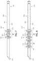
- FIG. 11a side view of a needle including a two magnetic regions according an embodiment
- FIG. 12a side view of a needle including four magnetic regions according an embodiment
- FIG. 13shows an embodiment of a system including a needle with multiple magnetic regions
- FIG. 14shows an embodiment of a system including a catheter assembly and a needle according to an embodiment.
- the present disclosurerelates to medical devices, systems and methods for enhancing visualization of an invasive procedure requiring procedural guidance, such as providing enhanced visualization of a vascular access device during an invasive insertion procedure.
- a magnetic featureis placed on the invasive medical device, for example, on a needle, which allows the magnetic feature to be placed closer to the tip, thus increasing the precision of the placement guidance.
- Embodiments of the disclosurepertain to an invasive medical device with a shaft, a least a portion of which have a magnetic region.
- the magnetic regioncan be provided in a variety of ways, including a layer ferromagnetic metal, a layer of paramagnetic metal, a spot weld of magnetic metal, a ferrule and combinations thereof.
- the magnetic regioncan be provided by changing the composition of the region to increase the magnetic susceptibility of the region, or the magnetic region can be provided by cold working the invasive medical device.
- the shafthas at least two magnetic regions.
- the magnetic regionsare encoded with data.
- the invasive medical devicesare part of a catheter adapter including a needle subassembly that can be used and a catheter adapter subassembly.
- the catheter adapter subassemblyincludes either a permanent magnet element or magnetizable feature.
- proximalrefers to a direction relatively closer to a clinician using the device to be described herein
- distalrefers to a direction relatively further from the clinician.
- Magnetic featurerefers to a feature that includes a permanent magnet and/or a magnetizable material that has been magnetized by an externally applied magnetic field such that the magnetic feature can be detected by an ultrasound system.
- a “magnetizable feature”refers to an element that can become magnetized and is detectable by an ultrasound system as described further herein.
- “Invasive medical device”refers to devices that are inserted into the vasculature of a patient such as a needle, a catheter introducer and a stylet.
- “invasive medical device”refers to a medical device that is sized and shaped to be inserted into an intravenous catheter.
- a catheter assembly 10including a catheter adapter subassembly 12 and a needle subassembly 14 .
- the catheter adapter subassembly 12comprises a catheter adapter 16 , catheter tubing 18 and a securement element 22
- the needle subassembly 14further includes a needle 20 , connected to a needle hub 24 , at a hub distal end 23 and a vent plug 26 .
- the needle 20can be retracted into the needle hub 24 after the needle 20 has been used to prevent accidental needle sticks of a patient or a clinician.
- FIG. 4depicts a catheter introducer 50 , which may be in the form of a stylet or guidewire, which is sized and shaped to be inserted into an intravenous catheter 68 .
- the guidewire, stylet or catheter introducerhas an elongate shaft 52 and a distal tip 54 that can be inserted into the intravenous catheter 68 .
- a needle subassembly 121including a needle 120 having a cannula 122 defining an elongate shaft 126 having a proximal end 120 and a distal tip 123 .
- the proximal end 120is connected to a needle hub 124 at hub distal end 125 .
- FIG. 6is enlarged view of a needle a needle 220 having a cannula 222 defining an elongate shaft 226 having a proximal end 221 and a distal tip 223 .
- the needle 220is sized and shaped for insertion into the vasculature of a patient, which may be through an intravenous catheter.
- the shaft 226 of the needle 220defines and outer surface 228 and an outer diameter “D”.
- at least a portion of the elongate shaft 226includes at least a first magnetic region 230 , a second magnetic region 232 and a third magnetic region 233 , which are spaced laterally along the shaft 226 of the needle 220 . As shown in FIG.
- the second magnetic region 232is spaced proximally along the shaft 226 from the first magnetic region 230
- the third magnetic region 233is spaced proximally along the shaft 226 from the second magnetic region 232 .
- the outer diameter of the needle 220 at the discontinuity 235is less than the outer diameter “D” at the remainder of the needle 220 .
- the discontinuity 235can have an outer diameter that is larger than the outer diameter “D” at the remainder of the needle 220 .
- the shaft 226includes an increased or decreased diameter region as a result of the discontinuity 235 .
- the discontinuity 235is in the form of a notch 237 .
- the notch 237is shown as being generally rectangular in shape, however, it will be understood that the notch 237 could be a variety of shapes, including triangular, oval, round, parabolic or irregularly shaped by crimping or other techniques to reduce the diameter at the notch 237 .
- a magnet or magnetic elementcan be disposed in the notch 237 .
- the first magnetic region 230has a first magnetic field strength B 1
- the second magnetic region 232has a second magnetic field strength B 2
- the third magnetic region 233has a third magnetic field strength B 3 .
- the magnetic field strengths B 1 , B 2 and B 3are equal.
- each of the magnetic field strengths B 1 , B 2 and B 3are not equal. Magnetic field strength can be measured using a variety of different technologies, including gaussmeters and magnetometers.
- the discontinuity along the shaft of the needlecan be in various forms, for example, a layer ferromagnetic metal, a layer of paramagnetic metal, a spot weld of magnetic metal, a ferrule and combinations thereof.
- the needle shaftcan be slidably disposed within catheter tubing, for example, as shown in FIG. 3 , where needle 20 is inserted within catheter tubing 18 , as a catheter assembly 10 that includes a catheter adapter subassembly 12 and a needle subassembly 14 .
- FIG. 7is enlarged view of a needle a needle 320 having a cannula 322 defining an elongate shaft 326 having a proximal end 321 and a distal tip 323 .
- the needle 320is sized and shaped for insertion into the vasculature of a patient, which may be through an intravenous catheter.
- the shaft 326 of the needle 320defines and outer surface 328 and an outer diameter “D”.
- First magnetic region 330includes a discontinuity 335 , which is provided by a magnetic ferrule 337 .
- the outer diameter of the needle 320 at the discontinuity 335is greater than the outer diameter “D” at the remainder of the needle 320 .
- the magnetic region 330has an increased outside diameter at the discontinuity 335 provided by the ferrule.
- FIG. 8shows an embodiment similar to FIG. 7 , and further includes a second discontinuity 336 having an outer diameter that is greater than the diameter D of the shaft 326 .
- the second discontinuityis provided by a second ferrule 339 .
- FIG. 9shows an embodiment in which the discontinuity 335 is provided by a magnetic adhesive 341 on the outer surface 328 of the shaft 326 , which provides a discontinuity 335 such that the outer diameter at the discontinuity 335 is greater than the outer diameter D of the shaft 326 .
- the magnetic adhesiveincludes an additive selected from a paramagnetic additive, a ferromagnetic additive and combinations thereof.
- the adhesive additiveaccording to one or more embodiments includes a component selected from the group consisting of powdered iron, magnetic iron oxide, magnetic titanium oxide, magnetic powdered steel, and a magnetic iron alloy, and mixtures thereof.
- the magnetic iron alloyincludes one or more of nickel, zinc, and copper.
- the adhesive additivefurther comprises a component selected from chromium, magnesium, molybdenum and combinations thereof.
- the adhesivecan be any suitable adhesive such as a curable glue containing magnetizable nanoparticles such as magnetizable metal nanoparticles or magnetizable metal oxide nanoparticles.
- the magnetizable metalcan include iron, cobalt, nickel and alloys of iron, cobalt, and nickel.
- the size of the magnetic nanoparticlesis in the range of about 1 nanometer (nm) to about 100 nm.
- adhesiveis a light-curable glue, and in another embodiment, the adhesive is a heat-curable glue.
- FIG. 10shows an embodiment in which the discontinuity 335 is provided by a spot weld 343 on the outer surface 328 of the shaft 326 , which provides a discontinuity 335 such that the outer diameter at the discontinuity 335 is greater than the outer diameter D of the shaft 326 .
- the spot weldincludes an additive selected from a paramagnetic additive, a ferromagnetic additive and combinations thereof.
- the spot weldincludes a component selected from the group consisting of powdered iron, magnetic iron oxide, magnetic titanium oxide, magnetic powdered steel, and a magnetic iron alloy, and mixtures thereof.
- the magnetic iron alloyincludes one or more of nickel, zinc, and copper.
- the spot weld additivefurther comprises a component selected from chromium, magnesium, molybdenum and combinations thereof.
- the shafthas a first magnetic region having a first magnetic field B 1 and a second magnetic region having a second magnetic field B 2 , wherein B 1 and B 2 are not equal.
- the first magnetic regionhas a length L 1 and is spaced apart on the shaft at a distance d 1 from the second magnetic region which has a length L 2 and L 1 and L 2 are different.
- the shafthas a third magnetic region spaced apart at a distance d 2 from the first region having a third magnetic field B 3 and length L 3 , wherein B 2 and B 3 are not equal and L 2 and L 3 are not equal.
- a systemis provided in for determining relative position of a needle which includes the needle described according to any of the above described embodiments, and magnetometers positioned with respect to the first magnetic region, the second magnetic region and the third magnetic region.
- FIG. 11shows another embodiment of the disclosure, in which an invasive medical device shown in the form of a needle 420 having a cannula 422 defining an elongate shaft 426 having a proximal end 421 and a distal tip 423 .
- the needle 420is sized and shaped for insertion into the vasculature of a patient, which may be through an intravenous catheter.
- the shaft 426 of the needle 420defines and outer surface 428 and an outer diameter “D”.
- First magnetic region 430has a first magnetic field strength B 1 and second magnetic region 431 has a second magnetic field strength B 2 .
- the magnetic regions 430 and 431can be provided as described above with respect to FIGS.
- the magnetic regionscan be provided by cold working the shaft 426 of the needle 420 , or modifying the composition of the needle 420 to increase the strength of the magnetic field B 1 and B 2 .
- the outer diameter “D” of the shaft 426may be constant along the length of the needle.
- the magnetic regions 430 and 431are shown as being adjacent to each other. In alternative embodiments, the magnetic regions 430 and 431 may be spaced apart. In the embodiment shown, at least one of the magnetic regions 430 , 431 is adjacent the distal tip 423 .
- FIG. 12shows another embodiment in which an invasive medical device shown in the form of a needle 520 having a cannula 522 defining an elongate shaft 526 having a proximal end 521 and a distal tip 523 .
- the needle 520is sized and shaped for insertion into the vasculature of a patient, which may be through an intravenous catheter.
- the shaft 526 of the needle 520defines and outer surface 528 and an outer diameter “D”.
- First magnetic region 530has a first magnetic field strength B 1
- second magnetic region 531has a second magnetic field strength B 2
- third magnetic region 532has a third magnetic field strength B 3
- fourth magnetic region 533has a fourth magnetic field strength B 4
- the magnetic regions 530 , 531 , 532 , and 533can be provided as described above with respect to FIGS. 4-10 , or alternatively, the magnetic regions can be provided by cold working the shaft 526 of the needle 520 , or modifying the composition of the needle 520 to increase the strength of the magnetic fields B 1 , B 2 , B 3 , and B 4 .
- the outer diameter “D” of the shaft 526may be constant along the length of the needle.
- FIG. 12shows four magnetic regions 531 , 532 , 533 , and 533
- an invasive medical devicecan have an elongate shaft having one, two, three, four, five, six, seven, eight, nine, ten, or more magnetic regions spaced adjacent to one another or spaced apart along the elongate shaft.
- the second magnetic region 531is located proximally to the first magnetic region 530
- the third magnetic region 532is located proximally to the second magnetic region 531
- the fourth magnetic region 533is located proximally to the third magnetic region 532 .
- these regionscan be proximally spaced.
- a medical device having a plurality of magnetic regionsenables a wide variety and large amount of data to be encoded to or from a magnetic signature on the needle provided by the multiple magnetic regions.
- invasive medical devices that use only one magnetic marker or region near the tip of the needlewhich can have a variety of issues as the single region moves further distances from the sensor as the invasive device is advanced further into the body during a procedure.
- a device of the type shown in FIG. 12 having multiple magnetic regions or markerscan improve procedural guidance in deep insertions into deeper veins.
- Multiple magnetic regions proximally adjacent or spaced along the axis of the shaft of the invasive medical deviceextend the limit of the sensor for deeply inserted device and catheter tips. This allows the sensor (e.g., a magnetometer of an ultrasound system) to continue tracking the magnetic regions located proximally away from the distal end of the medical device, and precisely track the distal tip location for very deep insertions/placements.
- the sensore.g., a magnetometer of an ultrasound system
- a systemcan be provided such that a sensor head can read patterns of magnetic signatures that are written and/or recorded onto the invasive medical device shaft.
- This techniqueis analogous to a rotational disk drive used for a computer memory, where patterns of magnetic signatures are recorded onto a magnetic substrate using current from a read/write head, and then the data is read back when required.
- an invasive medical devicefor example, a needle, a catheter introducer or a stylet contains a plurality of magnetic regions on the shaft of the invasive medical device, and a read/write head using current records patterns of magnetic signatures to encode information into the invasive medical device.
- An invasive medical device containing such magnetic signatures encoded onto the deviceprovides a higher level of accuracy when sensing the position of the medical device (e.g., a needle) and can provide information to the sensor head about the device, for example, gauge, outside diameter, size, length, brand, type, etc.
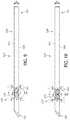
- FIG. 13shows another embodiment in which an invasive medical device shown in the form of a needle 620 having a cannula 622 defining an elongate shaft 626 having a proximal end 621 and a distal tip 623 .
- the shaft 626 of the needle 620defines and outer surface 628 and an outer diameter “D”.
- First magnetic region 630has a first magnetic field strength B 1
- second magnetic region 631has a second magnetic field strength B 2
- third magnetic region 632has a third magnetic field strength B 3 .
- the magnetic regions 630 , 631 , and 632can be provided as described above with respect to FIGS.
- the magnetic regionscan be provided by cold working the shaft 626 of the needle 620 , or modifying the composition of the needle 620 to increase the strength of the magnetic fields B 1 , B 2 , and B 3 .
- the outer diameter “D” of the shaft 626may be constant along the length of the needle.
- each magnetic region L 1 for magnetic region 630 , L 2 for magnetic region 631 and L 3 for magnetic region 633can be varied to provide a way of encoding information.
- an encoding schemecan be developed that uses one or more features of magnetic regions 630 , 631 and 632 to encode information regarding the 620 .
- a combination of the lengths L 1 , L 2 and L 3 together with the spacings d 1 and d 2can be used to device a code or signature to provide information about the needle 620 such as the needle length, needle gauge, type of needle or other information about the needle 620 .
- each magnetic region 630 , 631 and 632is shown as having a pole orientation of +/ ⁇ from the distal toward the proximal end. In one or more embodiments, the pole orientations can be varied to provide an additional way to encode needle information.
- magnetic regions 630 , 631 and 632are shown as having pole orientations of +/ ⁇ , +/ ⁇ and +/ ⁇ , these pole orientations can be varied in any number of ways such as +/ ⁇ , ⁇ /+ and +/ ⁇ , or alternatively, ⁇ /+, +/ ⁇ and ⁇ /+.
- a detector head 670 containing a plurality of spaced sensors 672 , 673 and 674can be used to detect magnetic field strength, length and spacing of the magnetic regions.
- the detector head 670can be in wired or wireless communication with a processor 675 adapted to determine process data from the information encoded on the shaft of the medical device and/or data pertaining to the detected field the position and orientation of the magnetic regions relative to the detector head 670 . This magnetically detected position can then displayed on a display 678 together with the ultrasound image.
- the processor 675can be in communication with a memory 677 that stores the encoded information pertaining to the needle 620 .
- the processorcan access or look up encoded information stored on the memory to obtain information about the needle.
- the detector head 670can be connected by a wireless connection to a base unit 680 which is in wireless or wired (e.g. USB) communication with the processor 675 and the display 678 .
- the base unit 680can be integrated with, or some of its functions performed by, the processor 675 or the detector head 670 .
- the base unit 680receives measurements from detector head 670 and calculates the position, or optionally the position and orientation, of magnetic regions.
- the base unit 680can also receive additional information such as the state of charge of the magnetometric detector's battery and information can be sent from the base unit 680 to the detector head 670 , such as configuration information.
- the base unit 680forwards the results of its calculations, i.e. the position and, optionally, orientation, to the processor 675 for inclusion in the displayed ultrasound image of an image of the invasive device, for example, the needle 620 .
- FIG. 13is not drawn to scale or density of the encoding, but representative in the fact that the detector head and the encoding can be optimized for the correct amount of signal resolution and information desired to be conveyed.
- FIG. 13illustrates a system for determining relative position of an invasive medical device such as a needle, as magnetometers positioned with respect to the one or more magnetic regions on the shaft of the medical device.
- the needle shown in FIG. 13can be part of a needle subassembly further including a needle hub mounted to the proximal end of the needle, and the needle subassembly can be part of a catheter assembly as shown in FIGS. 1-3 , and include intravenous catheter tubing as part of a catheter adapter subassembly.
- the catheter adapter subassemblycan include magnetic feature, such as a magnetizable feature magnetizable by an applied magnetic field or a permanent magnet.
- the magnetizable feature on the catheter adaptercan be a conical metal mandrel for connecting the catheter tubing to the hub catheter or tubing adhesive which can be any suitable adhesive such as a curable glue containing magnetizable nanoparticles such as magnetizable metal nanoparticles or magnetizable metal oxide nanoparticles.
- the magnetizable metalcan include iron, cobalt, nickel and alloys of iron, cobalt, and nickel.
- the size of the magnetic nanoparticlesis in the range of about 1 nanometer (nm) to about 100 nm.
- adhesiveis a light-curable glue, and in another embodiment, the adhesive is a heat-curable glue.
- a blood control component of the catheter adapter subassemblyprovides the magnetizable feature.
- the blood control componentis made from martensitic or ferritic stainless steels, for example, type 420 or type 430 stainless steel.
- the magnetic feature on the catheter adapter subassemblyincludes a magnetic wedge on the catheter adapter body.
- the catheter adapter subassemblyincludes the magnetizable feature, wherein the magnetizable feature includes magnetizable catheter tubing.
- the magnetizable featureincludes magnetizable catheter tubing.
- at least a portion of the polyurethane tubingcomprises a magnetizable composition which is magnetizable by an externally applied magnetic field, the magnetizable composition comprising a magnetic material dispersed in the polyurethane.
- the magnetic compositionis dispersed in the polymeric material, for example, polyurethane, which forms the tubing.
- the magnetizable compositioncomprises an inner layer surrounding the lumen of the catheter with an outer layer of non-magnetizable polymeric material, for example, polyurethane.
- the layer of magnetizable compositionis an outer layer surrounding an inner layer of non-magnetizable polyurethane.
- the magnetizable compositionforms longitudinal segments of the catheter separated by longitudinal segments of non-magnetizable polymeric material, for example, polyurethane.
- the magnetizable compositionmay further comprise a radiopaque component.
- a non-magnetizable portion of cathetermay comprise a radiopaque component.
- the magnetometers of the systemcan include three different magnetometers arranged in a three-dimensional grid array as part of an ultrasound system which can derive a three-dimensional correlation to obtain a distance from the grid array to at least one of the first magnetic field, the second magnetic field and the third magnetic field.
- a system including a magnetic feature on the catheter adapter subassembly and the needle subassemblycan be used to determine relative motion of the needle and the catheter adapter subassembly as the needle is disposed within intravenous catheter tubing and they are slidably moved with respect to each other.
- Another aspect of the disclosurepertains to a method obtaining information about an invasive medical device, which includes encoding magnetic data on an invasive medical device with a plurality of magnetic fields, the medical device selected a guidewire, a catheter introducer, a stylet and a hypodermic needle; and reading the data encoded on the invasive medical device.
- the readingcan be accomplished as described above, using an ultrasound head with a plurality of magnetometers.
- the datacan include at least one of the diameter of the medical device, the length of the medical device and the type of the medical device.
- a methodcan include encoding the shaft of an invasive medical device such as a catheter introducer, a stylet and a needle, and encoding is accomplished by correlating information with respect to length and/or spacing of a plurality of magnetic fields adjacent to each other or spaced apart on the shaft of the medical device.
- reading data from the medical deviceincludes reading a position of the magnetic fields with respect to the distal tip of the needle. Reading the data in one or more embodiments utilizes a three-dimensional array of magnetometers as part of an ultrasound system, and the ultrasound system derives a three-dimensional correlation to obtain a distance from the array of magnetometers to at least one of the magnetic fields.
- a second way of encoding the shaft of an invasive medical devicewould be to replicate the magnetic feature (ferrule, drop of magnetic adhesive, spot weld, etc. at intervals along the shaft.
- the distance between the magnetic regionscould be encoded to give the type, gauge and length of the product used,
- the plurality of magnetic regionscan be used for visualization of the device during an insertion procedure.
- a common material used to make invasive medical devicessuch as needles, stylets and introducers includes stainless steel, namely type 304 or type 316 stainless steel.
- ferritice.g., types 405, 430, 442
- austenitice.g., types 201, 301, 302, 303, 304, 316
- martensitice.g., types 403, 410, 416
- duplexe.g., types 2205, Alloy 255
- precipitate-hardenede.g., types 17-4PH, PH 17-7
- the first four classesare defined based on the microstructure of the metal with the last class, precipitate-hardened, based on its heat treatment. Microstructure provides the stainless steel its magnetic properties.
- austenitic stainless steelis not magnetic, it can be magnetic by modifying the material in a number of ways. For example, a portion of the microstructure can be changed to any one of the other four classes listed above so that the material would have some magnetic permeability, i.e. magnetism, built into the material.
- the microstructure of austenitic stainless steelcan be changed by a process called martensitic stress induced transformation. This is a microstructural change from austenite to martensite, and the transformation can occur due to cold working as well as slow cooling from austenitizing temperatures. After cold working or slow cooling an austenitic stainless steel will have an appreciable level of martensitic microstructure. Due to martensite being magnetic, the once nonmagnetic austenitic stainless steel will now have a degree of magnetism.
- Low alloy content stainless steel(particularly that of low nickel, carbon, and/or nitrogen) are more susceptible to martensitic stress induced transformation than stainless steel with higher alloying elements.
- Type 304is an example of a stainless steel that is quite susceptible to forming martensite after cold working.
- the austenite in the alloytransforms into martensite at high degrees of cold working relative to the tempered state.
- the susceptibilitycould increase from ⁇ 100 ppm to 10,000 ppm when annealed stainless steel is cold worked to full hardness.
- needlesmay be spring tempered to maximize the mechanical properties after cold working. Additionally the needle may be heat-treated to remove excess martensite and control the exact amount of desired susceptibility.
- the alloy composition of the needlecould be enhanced by adding ferromagnetic metal to the alloy.
- type 304 stainless steeltypically contains 18% Cr by weight and 8% Ni by weight with a max of 2% Mn by weight.
- cobaltcould be added to this alloy in quantities ranging from 0.01% to 5% by weight, and/or the manganese content could be increased from the maximum allowable 2% to 3%, 4% or 5% by weight.
- rare-earth metalssuch as gadolinium or neodymium could be added in small quantities ⁇ 5% by weight to further enhance magnetic susceptibility of the alloy. Any of these materials can be used in the region of the discontinuity described above, whether by adding a layer of material, a ferrule, a crimp or a spot weld.
- magnetic susceptibilitycould also be enhanced by adding layers of a ferromagnetic metal to the shaft of the invasive medical device.
- a needle having an outer diameter of approximately 0.5-1.5 mmcan also have a plating of nickel deposited by electroplating or electroless plating methods in thicknesses ranging from 0.1 microns to 100 microns to increase magnetic susceptibility of the magnetic region or regions.
- layers of other metalscould be applied to improve specific properties, such as a layer of Cr or CrO 2 on the outside to prevent corrosion, or an intermediate layer of Co or Neodymium to increase magnetic susceptibility.
- a coaxial layer of a ferromagnetic material such as ironwithin the tubing used to make the needle.
- Additional surface barriers layerscan be applied by electroplating or other suitable techniques to machined or ground surfaces where a potentially toxic metal like Co or Fe would be otherwise exposed.
- Magnetic tip location sensingcan also be improved according to one or more embodiments by placing a magnetic region closer to one end of the needle, preferably the sharp distal tip of the needle. If the magnetic region is placed at a known location at a fixed distance from the tip of the needle, then arrays of magnetometers as can be used to measure the magnetic field strength variation from the magnetic region and locate the distal tip of the needle.
- the ferrulemay also serve other functions such as needle stick injury prevention.
- the ferrulemay be made of a material of higher or lower magnetic susceptibility than the rest of the needle and may be attached by spot welding to the needle. Alternatively, a spot weld of material may be deposited over the needle surface by welding it on and such a spot may also serve a another function in a needle stick injury prevention feature.
- the adhesiveis applied to the needle shaft, and is located under the catheter when the needle is inserted into the catheter tubing, and thus the patient will not perceive or sense the presence of the adhesive.
- the magnetic adhesiveprovide the magnetic region on the device to enable detection of the needle and provide guidance the visualization system requires, and the adhesive could also be used prevent the needle from passing through a safety washer in systems that include safety washer.
- a systemfor determining catheter tip location when the catheter tubing is inserted in a patient.
- a systemprovides a way to independently measure the cannula tubing tip location by measuring the location and vector of the permanent magnet, and calculating and predicting the catheter tip location relative to the position of the magnetic sensor(s) on an ultrasound probe and the ultrasound information transmitted from the sensors on the ultrasound probe.
- a permanent magnet on a device with north and south poles on axis with the catheter and needle and a known geometrical relationship to one or more features fixed on the catheter assemblyprovides a measurement datum that is measureable by the ultrasound probe magnetic sensors.
- the direction vector and position of the catheter tip or other featurescan be calculated.
- a magnetized magnetizable needle or feature on the needlecan then be used to independently measure the position of the needle tip.
- the measured position of the needle tip or feature on the needlecan then be compared relative to the calculated position of the catheter tip to provide more specific information related to the catheter placement process, such as needle and catheter tip position relative to the patient's anatomy.
- This informationcan be used to determine (a) if the catheter is properly seated and ready for insertion (i.e., no over the bevel condition), (b) when the needle tip is in the “hooded” position (needle tip just inside of the catheter tip), and (c) and (d) when the catheter is advanced to specific distances and at angles suggesting successful placement in the vein.
- FIG. 14shows an ultrasound system 700 including a catheter adapter subassembly 712 comprising a magnetizable feature 732 that has been magnetized as described herein is shown inside of a patient's body 800 .
- a magnetometric detector 711comprising an array of magnetometers 720 (which can be housed in a probe of an ultrasound system, not shown) arranged in a 3-D array can be used to sense the magnetic field 714 together with the terrestrial magnetic field and any other background magnetic field.
- the magnetometric detector 711is in communication with an ultrasound processor 730 adapted to determine from the detected field the position and orientation of the magnetizable feature 732 relative to the magnetometric detector 711 . This magnetically detected position is then displayed on a display 750 together with the ultrasound image.
- the ultrasound system 700can be a two dimensional B-mode ultrasound system with an ultrasound probe modified by the provision of the magnetometric detector 711 .
- the ultrasound processor 730which can be connected to the ultrasound probe via a cable 735 , sends electrical signals to the magnetometric detector 711 to cause it to generate ultrasound pulses and interpreting the raw data received from the transducer probe housing the magnetometric detector 711 , which represents echoes from the patient's body, to assemble it into an image of the patient's tissue.
- the magnetometric detector 711can be attached to the ultrasound probe and can be battery powered or powered from the ultrasound system. In specific embodiments, positioning elements are provided on the magnetometric detector 711 to ensure that it is always attached in the same well-defined position and orientation.
- the magnetometric detector 711can connected by a wireless connection to a base unit 740 which is in wireless or wired (e.g. USB) communication with the ultrasound processor 730 and the display 750 .
- the base unit 740can be integrated with, or some of its functions performed by, the ultrasound processor 730 or the magnetometric detector 711 .
- the base unit 740receives normalized measurements from magnetometric detector 711 and calculates the position, or optionally the position and orientation, of magnetizable feature 732 .
- the base unit 740can also receive additional information such as the state of charge of the magnetometric detector's battery and information can be sent from the base unit 740 to the magnetometric detector 711 , such as configuration information.
- the base unit 740forwards the results of its calculations, i.e. the position and, optionally, orientation, to the ultrasound processor 730 for inclusion in the displayed ultrasound image of an image of the catheter.
- the base unit 740can be integrated into the ultrasound system 700 with the ultrasound processor 730 and the magnetometric detector 711 being in direct communication with the ultrasound system 700 either via wireless link or using the same physical cable 735 .
- the distance from the magnetizable feature to the 3-dimensional array of magnetometersis calculated.
- location of the array of magnetometers in reference to an ultrasound sensor of an ultrasound imaging systemis used to calculate a location of the magnetizable feature with respect to the ultrasound sensor.
- the methodcomprises displaying an image of the magnetizable feature.
Landscapes
- Health & Medical Sciences (AREA)
- Life Sciences & Earth Sciences (AREA)
- Engineering & Computer Science (AREA)
- Veterinary Medicine (AREA)
- General Health & Medical Sciences (AREA)
- Public Health (AREA)
- Biomedical Technology (AREA)
- Heart & Thoracic Surgery (AREA)
- Animal Behavior & Ethology (AREA)
- Biophysics (AREA)
- Surgery (AREA)
- Medical Informatics (AREA)
- Molecular Biology (AREA)
- Hematology (AREA)
- Anesthesiology (AREA)
- Pathology (AREA)
- Pulmonology (AREA)
- Nuclear Medicine, Radiotherapy & Molecular Imaging (AREA)
- Physics & Mathematics (AREA)
- Human Computer Interaction (AREA)
- Radiology & Medical Imaging (AREA)
- Vascular Medicine (AREA)
- Robotics (AREA)
- Dermatology (AREA)
- Media Introduction/Drainage Providing Device (AREA)
- Materials For Medical Uses (AREA)
- Ultra Sonic Daignosis Equipment (AREA)
- Infusion, Injection, And Reservoir Apparatuses (AREA)
- Medicines Containing Antibodies Or Antigens For Use As Internal Diagnostic Agents (AREA)
- Magnetic Treatment Devices (AREA)
- Magnetic Resonance Imaging Apparatus (AREA)
Abstract
Description
Claims (13)
Priority Applications (13)
| Application Number | Priority Date | Filing Date | Title |
|---|---|---|---|
| US15/170,497US11116419B2 (en) | 2016-06-01 | 2016-06-01 | Invasive medical devices including magnetic region and systems and methods |
| SG11201810443SASG11201810443SA (en) | 2016-06-01 | 2017-05-23 | Invasive medical devices including magnetic region and systems and methods |
| EP17726523.8AEP3463540A1 (en) | 2016-06-01 | 2017-05-23 | Invasive medical devices including magnetic region and systems and methods |
| CA3187195ACA3187195A1 (en) | 2016-06-01 | 2017-05-23 | Invasive medical devices including magnetic region and systems and methods |
| AU2017273354AAU2017273354B2 (en) | 2016-06-01 | 2017-05-23 | Invasive medical devices including magnetic region and systems and methods |
| MX2018014642AMX2018014642A (en) | 2016-06-01 | 2017-05-23 | Invasive medical devices including magnetic region and systems and methods. |
| JP2018563443AJP6921129B2 (en) | 2016-06-01 | 2017-05-23 | Invasive medical devices and systems and methods involving the magnetic region |
| BR112018074768-8ABR112018074768B1 (en) | 2016-06-01 | 2017-05-23 | INVASIVE MEDICAL DEVICE FOR INSERTION INTO A PATIENT AND SYSTEM FOR DETERMINING THE RELATIVE POSITION OF A HYPODERMIC NEEDLE |
| KR1020187037759AKR102434195B1 (en) | 2016-06-01 | 2017-05-23 | Invasive medical devices and systems and methods comprising magnetic domains |
| PCT/US2017/033986WO2017210019A1 (en) | 2016-06-01 | 2017-05-23 | Invasive medical devices including magnetic region and systems and methods |
| CA3025802ACA3025802C (en) | 2016-06-01 | 2017-05-23 | Invasive medical devices including magnetic region and systems and methods |
| CN201780041768.5ACN109414570B (en) | 2016-06-01 | 2017-05-23 | Invasive medical devices including magnetic regions and systems and methods |
| MYPI2018002236AMY191051A (en) | 2016-06-01 | 2017-05-23 | Invasive medical devices including magnetic region and systems and methods |
Applications Claiming Priority (1)
| Application Number | Priority Date | Filing Date | Title |
|---|---|---|---|
| US15/170,497US11116419B2 (en) | 2016-06-01 | 2016-06-01 | Invasive medical devices including magnetic region and systems and methods |
Publications (2)
| Publication Number | Publication Date |
|---|---|
| US20170347913A1 US20170347913A1 (en) | 2017-12-07 |
| US11116419B2true US11116419B2 (en) | 2021-09-14 |
Family
ID=58794263
Family Applications (1)
| Application Number | Title | Priority Date | Filing Date |
|---|---|---|---|
| US15/170,497Active2037-10-15US11116419B2 (en) | 2016-06-01 | 2016-06-01 | Invasive medical devices including magnetic region and systems and methods |
Country Status (11)
| Country | Link |
|---|---|
| US (1) | US11116419B2 (en) |
| EP (1) | EP3463540A1 (en) |
| JP (1) | JP6921129B2 (en) |
| KR (1) | KR102434195B1 (en) |
| CN (1) | CN109414570B (en) |
| AU (1) | AU2017273354B2 (en) |
| CA (2) | CA3187195A1 (en) |
| MX (1) | MX2018014642A (en) |
| MY (1) | MY191051A (en) |
| SG (1) | SG11201810443SA (en) |
| WO (1) | WO2017210019A1 (en) |
Cited By (1)
| Publication number | Priority date | Publication date | Assignee | Title |
|---|---|---|---|---|
| US20210290099A1 (en)* | 2016-06-01 | 2021-09-23 | Becton, Dickinson And Company | Invasive Medical Devices Including Magnetic Region And Systems And Methods |
Families Citing this family (26)
| Publication number | Priority date | Publication date | Assignee | Title |
|---|---|---|---|---|
| US10525237B2 (en) | 2015-10-28 | 2020-01-07 | Becton, Dickinson And Company | Ergonomic IV systems and methods |
| US10639455B2 (en) | 2015-10-28 | 2020-05-05 | Becton, Dickinson And Company | Closed IV access device with paddle grip needle hub and flash chamber |
| US10245416B2 (en) | 2015-10-28 | 2019-04-02 | Becton, Dickinson And Company | Intravenous catheter device with integrated extension tube |
| US10744305B2 (en) | 2015-10-28 | 2020-08-18 | Becton, Dickinson And Company | Ergonomic IV systems and methods |
| US10814106B2 (en) | 2015-10-28 | 2020-10-27 | Becton, Dickinson And Company | Soft push tabs for catheter adapter |
| US10549072B2 (en) | 2015-10-28 | 2020-02-04 | Becton, Dickinson And Company | Integrated catheter with independent fluid paths |
| US11413429B2 (en) | 2016-06-01 | 2022-08-16 | Becton, Dickinson And Company | Medical devices, systems and methods utilizing permanent magnet and magnetizable feature |
| US10583269B2 (en) | 2016-06-01 | 2020-03-10 | Becton, Dickinson And Company | Magnetized catheters, devices, uses and methods of using magnetized catheters |
| US11826522B2 (en) | 2016-06-01 | 2023-11-28 | Becton, Dickinson And Company | Medical devices, systems and methods utilizing permanent magnet and magnetizable feature |
| US10032552B2 (en) | 2016-08-30 | 2018-07-24 | Becton, Dickinson And Company | Cover for tissue penetrating device with integrated magnets and magnetic shielding |
| USD819802S1 (en)* | 2016-10-05 | 2018-06-05 | Becton, Dickinson And Company | Catheter adapter |
| US10238852B2 (en) | 2016-10-05 | 2019-03-26 | Becton, Dickinson And Company | Septum housing |
| USD835262S1 (en)* | 2016-10-05 | 2018-12-04 | Becton, Dickinson And Company | Intravenous catheter assembly |
| USD837368S1 (en)* | 2016-10-05 | 2019-01-01 | Becton, Dickinson And Company | Catheter adapter grip |
| US11304622B2 (en)* | 2017-02-14 | 2022-04-19 | St. Jude Medical, Cardiology Division, Inc. | System and apparatus for detecting catheters relative to introducers |
| US11872356B2 (en) | 2018-01-05 | 2024-01-16 | Becton, Dickinson And Company | Echogenic catheter and catheter system |
| EP3583892A1 (en)* | 2018-06-20 | 2019-12-25 | Koninklijke Philips N.V. | Pressure sensing unit, system and method for remote pressure sensing |
| US12178982B2 (en)* | 2019-01-18 | 2024-12-31 | Becton, Dickinson And Company | Intravenous therapy system for blood vessel detection and vascular access device placement |
| NL2024545B1 (en)* | 2019-12-20 | 2021-09-02 | Sirius Medical Systems B V | Magnetic field probe for determining an angular disposition of an implantable marker |
| EP4120906A1 (en)* | 2020-03-25 | 2023-01-25 | Bard Access Systems, Inc. | Devices for usage in tracking and imaging |
| WO2022047319A1 (en)* | 2020-08-31 | 2022-03-03 | Bard Access Systems, Inc. | Magnetic field direction detection |
| CN116234604B (en)* | 2020-10-12 | 2025-05-06 | 朝日英达科株式会社 | Medical equipment |
| JP7699042B2 (en)* | 2021-12-17 | 2025-06-26 | 朝日インテック株式会社 | Guidewires |
| US20240058094A1 (en)* | 2022-08-16 | 2024-02-22 | Ram H. Paul, Jr. | MRI Compatible Interventional Medical Devices and Related Methods |
| CN116076995B (en)* | 2023-02-03 | 2023-09-01 | 浙江势通机器人科技有限公司 | Scanning control method and scanning control system for capsule endoscope |
| WO2025165789A1 (en)* | 2024-01-29 | 2025-08-07 | Bard Access Systems, Inc. | Systems and methods for needle guidance |
Citations (56)
| Publication number | Priority date | Publication date | Assignee | Title |
|---|---|---|---|---|
| US4161943A (en) | 1976-05-19 | 1979-07-24 | Paul Nogier | Needle implanting apparatus |
| EP0320623A1 (en) | 1987-12-14 | 1989-06-21 | Pulsotronic Merten GmbH & Co. KG | Device for determining the position of a catheter or a probe inside a living organ |
| JPH0327774A (en) | 1989-06-23 | 1991-02-06 | Fujitsu General Ltd | discharge circuit |
| US5000912A (en)* | 1989-12-15 | 1991-03-19 | Ethicon, Inc. | Nickel titanium martensitic steel for surgical needles |
| US5215528A (en) | 1992-02-07 | 1993-06-01 | Becton, Dickinson And Company | Catheter introducer assembly including needle tip shield |
| US5461311A (en)* | 1992-12-24 | 1995-10-24 | Kayaba Kogyo Kabushiki Kaisha | Rod axial position detector including plural scales wherein nonmagnetized portions have differing spacing and differing depths and means for calculating the absolute position are provided |
| US5558651A (en) | 1990-04-20 | 1996-09-24 | Becton Dickinson And Company | Apparatus and method for a needle tip cover |
| JPH08509141A (en) | 1993-04-14 | 1996-10-01 | ファーマサイクリックス,インコーポレイティド | Medical devices and materials that enhance the visibility of magnetic images |
| US5955881A (en) | 1994-10-18 | 1999-09-21 | Cts Corporation | Linkage position sensor having a magnet with two ramped sections for providing variable magnetic field |
| US6263230B1 (en) | 1997-05-08 | 2001-07-17 | Lucent Medical Systems, Inc. | System and method to determine the location and orientation of an indwelling medical device |
| US20020042581A1 (en) | 1999-03-19 | 2002-04-11 | Cervi Paul Laurence | Biopsy needle |
| US6432036B1 (en) | 1999-12-15 | 2002-08-13 | Chi-Kyung Kim | Device for magnetic focus radiation medical treatment |
| US6475226B1 (en) | 1999-02-03 | 2002-11-05 | Scimed Life Systems, Inc. | Percutaneous bypass apparatus and method |
| US20030100829A1 (en) | 2001-11-27 | 2003-05-29 | Sheng-Ping Zhong | Medical devices with magnetic resonance visibility enhancing material |
| US20040176683A1 (en)* | 2003-03-07 | 2004-09-09 | Katherine Whitin | Method and apparatus for tracking insertion depth |
| US20050165301A1 (en)* | 2004-01-23 | 2005-07-28 | Smith Scott R. | Medical devices visible by magnetic resonance imaging |
| US20070016131A1 (en) | 2005-07-12 | 2007-01-18 | Munger Gareth T | Flexible magnets for navigable medical devices |
| US20070049846A1 (en)* | 2005-08-24 | 2007-03-01 | C.R.Bard, Inc. | Stylet Apparatuses and Methods of Manufacture |
| US20070249901A1 (en)* | 2003-03-07 | 2007-10-25 | Ohline Robert M | Instrument having radio frequency identification systems and methods for use |
| JP2008512270A (en) | 2004-09-08 | 2008-04-24 | ボストン サイエンティフィック リミテッド | Medical device and method of manufacturing the same |
| CN201138912Y (en) | 2007-09-15 | 2008-10-22 | 帕尔哈提·司马义 | Antimagnetic bag |
| US20090012517A1 (en)* | 2007-07-03 | 2009-01-08 | Irvine Biomedical, Inc. | Magnetically guided catheter |
| WO2009152486A1 (en) | 2008-06-13 | 2009-12-17 | Medtronic, Inc. | Device and method for assessing extension of a deployable object |
| US20100217275A1 (en)* | 2006-11-27 | 2010-08-26 | Ran Carmeli | Device for inducing vibrations in a guidewire |
| US7932718B1 (en)* | 2009-03-12 | 2011-04-26 | The United States Of America As Represented By The Secretary Of The Navy | System and method using magnetic anomaly field magnitudes for detection, localization, classification and tracking of magnetic objects |
| US7935080B2 (en)* | 1998-04-09 | 2011-05-03 | Howell Glade H | Catheter and introducer needle assembly with needle shield |
| US20110196397A1 (en) | 2008-10-10 | 2011-08-11 | Vasostar, Inc. | Medical device with a guidewire for penetrating occlusions |
| US20110267043A1 (en)* | 2009-01-27 | 2011-11-03 | Rls Merilna Tehnika D.O.O. | Magnetic encoder apparatus |
| US20120016316A1 (en) | 2010-01-08 | 2012-01-19 | Bo Zhuang | Spatial needle guidance system and associated methods |
| US20120041297A1 (en) | 2009-02-06 | 2012-02-16 | Baylor College Of Medicine | Real-time magnetic dipole detection and tracking |
| US20120095319A1 (en) | 2007-04-16 | 2012-04-19 | C. R. Bard, Inc. | Guidewire-Assisted Catheter Placement System |
| US20120143029A1 (en) | 2007-11-26 | 2012-06-07 | Bard Access Systems, Inc. | Systems and methods for guiding a medical instrument |
| WO2013034175A1 (en) | 2011-09-06 | 2013-03-14 | Ezono Ag | Imaging probe and method of obtaining position and/or orientation information |
| US20130075649A1 (en)* | 2011-09-27 | 2013-03-28 | Hon Hai Precision Industry Co., Ltd. | Magnetic glue |
| US20130123704A1 (en) | 2008-03-14 | 2013-05-16 | Access Scientific, Inc. | Access device |
| US20130131547A1 (en) | 2010-07-30 | 2013-05-23 | Cook Medical Technologies Llc | Rotating full-core biopsy needle |
| WO2013142386A1 (en) | 2012-03-18 | 2013-09-26 | Avneri Itzhak | Devices and methods for endovascular access and therapy |
| JP2014501143A (en) | 2010-12-23 | 2014-01-20 | バード・アクセス・システムズ,インコーポレーテッド | System and method for guiding medical devices |
| US20140031674A1 (en) | 2007-11-26 | 2014-01-30 | C. R. Bard, Inc. | Needle Assembly Including an Aligned Magnetic Element |
| US20140046261A1 (en) | 2007-11-26 | 2014-02-13 | C. R. Bard, Inc. | Magnetic Element-Equipped Needle Assemblies |
| WO2014052894A2 (en) | 2012-09-28 | 2014-04-03 | C. R. Bard, Inc. | Needle assembly including an aligned magnetic element |
| US20140107475A1 (en) | 2007-11-26 | 2014-04-17 | C. R. Bard, Inc. | Apparatus for Use with Needle Insertion Guidance System |
| WO2014062728A1 (en) | 2012-10-18 | 2014-04-24 | C.R. Bard, Inc. | Magnetic element-equipped needle assemblies |
| US20140135595A1 (en) | 2010-06-04 | 2014-05-15 | Nelson Powell | Intelligent endoscopy systems and methods |
| US20140180328A1 (en) | 2012-12-21 | 2014-06-26 | Medtronic Xomed, Inc. | Sinus dilation system and method |
| US20140241946A1 (en)* | 2007-04-06 | 2014-08-28 | Qiagen Gaithersburg, Inc. | Open platform automated sample processing system |
| US20140253270A1 (en) | 2013-03-05 | 2014-09-11 | Ezono Ag | Magnetization device and method |
| US20140257080A1 (en)* | 2013-03-05 | 2014-09-11 | Ezono Ag | System for ultrasound image guided procedure |
| JP2015518752A (en) | 2012-05-31 | 2015-07-06 | ベイリス メディカル カンパニー インコーポレイテッドBaylis Medical Company Inc. | Radio frequency punching device |
| US20150306319A1 (en) | 2012-11-08 | 2015-10-29 | Sanofi-Aventis Deutschland Gmbh | Needle magnetizing arrangement |
| US20150320977A1 (en) | 2014-05-06 | 2015-11-12 | Jeff Vitullo | System and Method for Inserting a Catheter |
| US20150359991A1 (en) | 2013-03-05 | 2015-12-17 | Ezono Ag | System for image guided procedure |
| JP2016059549A (en) | 2014-09-17 | 2016-04-25 | テルモ株式会社 | Catheter and guide wire |
| US9492097B2 (en) | 2007-11-26 | 2016-11-15 | C. R. Bard, Inc. | Needle length determination and calibration for insertion guidance system |
| WO2016187456A1 (en)* | 2015-05-20 | 2016-11-24 | Gravitas Medical, Inc. | Methods and apparatus for guiding medical care based on sensor data from the gastrointestinal tract |
| US20160361519A1 (en) | 2015-06-10 | 2016-12-15 | B. Braun Melsungen Ag | Catheter hub with flexible extended fluid connector and related methods |
Family Cites Families (13)
| Publication number | Priority date | Publication date | Assignee | Title |
|---|---|---|---|---|
| SE336642B (en)* | 1969-10-28 | 1971-07-12 | Astra Meditec Ab | |
| AU1693095A (en)* | 1994-08-19 | 1996-03-14 | Biosense, Inc. | Medical diagnosis, treatment and imaging systems |
| US9795747B2 (en)* | 2010-06-02 | 2017-10-24 | Sanofi-Aventis Deutschland Gmbh | Methods and apparatus for lancet actuation |
| US20050149002A1 (en)* | 2003-04-08 | 2005-07-07 | Xingwu Wang | Markers for visualizing interventional medical devices |
| US20050171522A1 (en)* | 2004-01-30 | 2005-08-04 | Christopherson Mark A. | Transurethral needle ablation system with needle position indicator |
| US7720521B2 (en)* | 2004-04-21 | 2010-05-18 | Acclarent, Inc. | Methods and devices for performing procedures within the ear, nose, throat and paranasal sinuses |
| EP2626030A3 (en)* | 2007-08-14 | 2017-03-08 | Koninklijke Philips N.V. | Robotic instrument systems and methods utilizing optical fiber sensors |
| JPWO2012032881A1 (en)* | 2010-09-06 | 2014-01-20 | テルモ株式会社 | Medical long body |
| EP2637568B1 (en)* | 2010-11-08 | 2017-04-12 | Vasonova, Inc. | Endovascular navigation system |
| US9327096B2 (en)* | 2011-06-02 | 2016-05-03 | Atrium Medical Corporation | Body lumen fluid delivery device |
| WO2014028770A1 (en)* | 2012-08-15 | 2014-02-20 | Burdette Everette C | Mri compatible ablation catheter system incorporating directional high-intensity ultrasound for treatment |
| US9549783B2 (en)* | 2013-03-15 | 2017-01-24 | Corindus, Inc. | Catheter system with magnetic coupling |
| US20150196369A1 (en)* | 2014-01-14 | 2015-07-16 | Neil Glossop | System, method and device employing fiducials for medical intervention |
- 2016
- 2016-06-01USUS15/170,497patent/US11116419B2/enactiveActive
- 2017
- 2017-05-23SGSG11201810443SApatent/SG11201810443SA/enunknown
- 2017-05-23CACA3187195Apatent/CA3187195A1/enactivePending
- 2017-05-23MXMX2018014642Apatent/MX2018014642A/enunknown
- 2017-05-23KRKR1020187037759Apatent/KR102434195B1/enactiveActive
- 2017-05-23CNCN201780041768.5Apatent/CN109414570B/enactiveActive
- 2017-05-23CACA3025802Apatent/CA3025802C/enactiveActive
- 2017-05-23EPEP17726523.8Apatent/EP3463540A1/enactivePending
- 2017-05-23AUAU2017273354Apatent/AU2017273354B2/enactiveActive
- 2017-05-23WOPCT/US2017/033986patent/WO2017210019A1/ennot_activeCeased
- 2017-05-23JPJP2018563443Apatent/JP6921129B2/enactiveActive
- 2017-05-23MYMYPI2018002236Apatent/MY191051A/enunknown
Patent Citations (62)
| Publication number | Priority date | Publication date | Assignee | Title |
|---|---|---|---|---|
| US4161943A (en) | 1976-05-19 | 1979-07-24 | Paul Nogier | Needle implanting apparatus |
| EP0320623A1 (en) | 1987-12-14 | 1989-06-21 | Pulsotronic Merten GmbH & Co. KG | Device for determining the position of a catheter or a probe inside a living organ |
| DE3742298A1 (en) | 1987-12-14 | 1989-06-22 | Merten Kg Pulsotronic | DEVICE FOR LOCATING A CATHETER OR PROBE IN AN ORGAN OF A LIVING BEING |
| JPH0327774A (en) | 1989-06-23 | 1991-02-06 | Fujitsu General Ltd | discharge circuit |
| US5000912A (en)* | 1989-12-15 | 1991-03-19 | Ethicon, Inc. | Nickel titanium martensitic steel for surgical needles |
| US5558651A (en) | 1990-04-20 | 1996-09-24 | Becton Dickinson And Company | Apparatus and method for a needle tip cover |
| US5215528C1 (en) | 1992-02-07 | 2001-09-11 | Becton Dickinson Co | Catheter introducer assembly including needle tip shield |
| US5215528A (en) | 1992-02-07 | 1993-06-01 | Becton, Dickinson And Company | Catheter introducer assembly including needle tip shield |
| US5461311A (en)* | 1992-12-24 | 1995-10-24 | Kayaba Kogyo Kabushiki Kaisha | Rod axial position detector including plural scales wherein nonmagnetized portions have differing spacing and differing depths and means for calculating the absolute position are provided |
| JPH08509141A (en) | 1993-04-14 | 1996-10-01 | ファーマサイクリックス,インコーポレイティド | Medical devices and materials that enhance the visibility of magnetic images |
| US5955881A (en) | 1994-10-18 | 1999-09-21 | Cts Corporation | Linkage position sensor having a magnet with two ramped sections for providing variable magnetic field |
| US6263230B1 (en) | 1997-05-08 | 2001-07-17 | Lucent Medical Systems, Inc. | System and method to determine the location and orientation of an indwelling medical device |
| US7935080B2 (en)* | 1998-04-09 | 2011-05-03 | Howell Glade H | Catheter and introducer needle assembly with needle shield |
| US6475226B1 (en) | 1999-02-03 | 2002-11-05 | Scimed Life Systems, Inc. | Percutaneous bypass apparatus and method |
| US20020042581A1 (en) | 1999-03-19 | 2002-04-11 | Cervi Paul Laurence | Biopsy needle |
| US6432036B1 (en) | 1999-12-15 | 2002-08-13 | Chi-Kyung Kim | Device for magnetic focus radiation medical treatment |
| US20030100829A1 (en) | 2001-11-27 | 2003-05-29 | Sheng-Ping Zhong | Medical devices with magnetic resonance visibility enhancing material |
| US20040176683A1 (en)* | 2003-03-07 | 2004-09-09 | Katherine Whitin | Method and apparatus for tracking insertion depth |
| US20070249901A1 (en)* | 2003-03-07 | 2007-10-25 | Ohline Robert M | Instrument having radio frequency identification systems and methods for use |
| US20050165301A1 (en)* | 2004-01-23 | 2005-07-28 | Smith Scott R. | Medical devices visible by magnetic resonance imaging |
| US20100230862A1 (en) | 2004-09-08 | 2010-09-16 | Boston Scientific Scimed, Inc. | Medical devices |
| JP2008512270A (en) | 2004-09-08 | 2008-04-24 | ボストン サイエンティフィック リミテッド | Medical device and method of manufacturing the same |
| US20070016131A1 (en) | 2005-07-12 | 2007-01-18 | Munger Gareth T | Flexible magnets for navigable medical devices |
| JP2009505744A (en) | 2005-08-24 | 2009-02-12 | シー・アール・バード・インコーポレーテッド | Stylet device and manufacturing method thereof |
| US20070049846A1 (en)* | 2005-08-24 | 2007-03-01 | C.R.Bard, Inc. | Stylet Apparatuses and Methods of Manufacture |
| US20100217275A1 (en)* | 2006-11-27 | 2010-08-26 | Ran Carmeli | Device for inducing vibrations in a guidewire |
| US20140241946A1 (en)* | 2007-04-06 | 2014-08-28 | Qiagen Gaithersburg, Inc. | Open platform automated sample processing system |
| US20120095319A1 (en) | 2007-04-16 | 2012-04-19 | C. R. Bard, Inc. | Guidewire-Assisted Catheter Placement System |
| US20090012517A1 (en)* | 2007-07-03 | 2009-01-08 | Irvine Biomedical, Inc. | Magnetically guided catheter |
| CN201138912Y (en) | 2007-09-15 | 2008-10-22 | 帕尔哈提·司马义 | Antimagnetic bag |
| US20140107475A1 (en) | 2007-11-26 | 2014-04-17 | C. R. Bard, Inc. | Apparatus for Use with Needle Insertion Guidance System |
| US20120143029A1 (en) | 2007-11-26 | 2012-06-07 | Bard Access Systems, Inc. | Systems and methods for guiding a medical instrument |
| US9492097B2 (en) | 2007-11-26 | 2016-11-15 | C. R. Bard, Inc. | Needle length determination and calibration for insertion guidance system |
| US20140046261A1 (en) | 2007-11-26 | 2014-02-13 | C. R. Bard, Inc. | Magnetic Element-Equipped Needle Assemblies |
| US20140031674A1 (en) | 2007-11-26 | 2014-01-30 | C. R. Bard, Inc. | Needle Assembly Including an Aligned Magnetic Element |
| US20130123704A1 (en) | 2008-03-14 | 2013-05-16 | Access Scientific, Inc. | Access device |
| US20100036238A1 (en)* | 2008-06-13 | 2010-02-11 | Medtronic, Inc. | Device and method for assessing extension of a deployable object |
| WO2009152486A1 (en) | 2008-06-13 | 2009-12-17 | Medtronic, Inc. | Device and method for assessing extension of a deployable object |
| US20110196397A1 (en) | 2008-10-10 | 2011-08-11 | Vasostar, Inc. | Medical device with a guidewire for penetrating occlusions |
| US20110267043A1 (en)* | 2009-01-27 | 2011-11-03 | Rls Merilna Tehnika D.O.O. | Magnetic encoder apparatus |
| US20120041297A1 (en) | 2009-02-06 | 2012-02-16 | Baylor College Of Medicine | Real-time magnetic dipole detection and tracking |
| US7932718B1 (en)* | 2009-03-12 | 2011-04-26 | The United States Of America As Represented By The Secretary Of The Navy | System and method using magnetic anomaly field magnitudes for detection, localization, classification and tracking of magnetic objects |
| US20120016316A1 (en) | 2010-01-08 | 2012-01-19 | Bo Zhuang | Spatial needle guidance system and associated methods |
| US20140135595A1 (en) | 2010-06-04 | 2014-05-15 | Nelson Powell | Intelligent endoscopy systems and methods |
| US20130131547A1 (en) | 2010-07-30 | 2013-05-23 | Cook Medical Technologies Llc | Rotating full-core biopsy needle |
| JP2014501143A (en) | 2010-12-23 | 2014-01-20 | バード・アクセス・システムズ,インコーポレーテッド | System and method for guiding medical devices |
| US20150080710A1 (en)* | 2011-09-06 | 2015-03-19 | Rolf Henkel | Imaging probe and method of obtaining position and/or orientation information |
| WO2013034175A1 (en) | 2011-09-06 | 2013-03-14 | Ezono Ag | Imaging probe and method of obtaining position and/or orientation information |
| US20130075649A1 (en)* | 2011-09-27 | 2013-03-28 | Hon Hai Precision Industry Co., Ltd. | Magnetic glue |
| WO2013142386A1 (en) | 2012-03-18 | 2013-09-26 | Avneri Itzhak | Devices and methods for endovascular access and therapy |
| JP2015518752A (en) | 2012-05-31 | 2015-07-06 | ベイリス メディカル カンパニー インコーポレイテッドBaylis Medical Company Inc. | Radio frequency punching device |
| WO2014052894A2 (en) | 2012-09-28 | 2014-04-03 | C. R. Bard, Inc. | Needle assembly including an aligned magnetic element |
| WO2014062728A1 (en) | 2012-10-18 | 2014-04-24 | C.R. Bard, Inc. | Magnetic element-equipped needle assemblies |
| US20150306319A1 (en) | 2012-11-08 | 2015-10-29 | Sanofi-Aventis Deutschland Gmbh | Needle magnetizing arrangement |
| US20140180328A1 (en) | 2012-12-21 | 2014-06-26 | Medtronic Xomed, Inc. | Sinus dilation system and method |
| US20140257080A1 (en)* | 2013-03-05 | 2014-09-11 | Ezono Ag | System for ultrasound image guided procedure |
| US20140253270A1 (en) | 2013-03-05 | 2014-09-11 | Ezono Ag | Magnetization device and method |
| US20150359991A1 (en) | 2013-03-05 | 2015-12-17 | Ezono Ag | System for image guided procedure |
| US20150320977A1 (en) | 2014-05-06 | 2015-11-12 | Jeff Vitullo | System and Method for Inserting a Catheter |
| JP2016059549A (en) | 2014-09-17 | 2016-04-25 | テルモ株式会社 | Catheter and guide wire |
| WO2016187456A1 (en)* | 2015-05-20 | 2016-11-24 | Gravitas Medical, Inc. | Methods and apparatus for guiding medical care based on sensor data from the gastrointestinal tract |
| US20160361519A1 (en) | 2015-06-10 | 2016-12-15 | B. Braun Melsungen Ag | Catheter hub with flexible extended fluid connector and related methods |
Non-Patent Citations (21)
| Title |
|---|
| Bhattacharya, Deepamala. ALNICO [online], Chemistry Learner, May 31, 2014 [retrieved on Mar. 2, 2020], Retrieved from the Internet: <URL: https://web.archive.org/web/20140531135446/http://www.chemistrylearner.com/alnico.html> (Year: 2014). |
| Ferrite Toroids [online]. Magnetics, Sep. 1, 2010 [retrieved on Oct. 16, 2018], Retrieved from the Internet: <URL: https://web.archive.org/web/20100901184145/https://www.mag-inc.com/Products/Ferrite-Cores/Ferrite-Toroids>.* |
| Final Office Action in U.S. Appl. No. 15/154,348 dated May 15, 2020, 10 pages. |
| Final Office Action in U.S. Appl. No. 15/154,353 dated Jun. 24, 2020, 12 pages. |
| Final Office Action in U.S. Appl. No. 15/170,518, dated Jul. 8, 2021, 49 pages. |
| Final Office Action in U.S. Appl. No. 15/170,531 dated Mar. 3, 2021, 39 pages. |
| Final Office Action in U.S. Appl. No. 15/604,244 dated Jan. 10, 2020, 63 pages. |
| Final Office Action in U.S. Appl. No. 15/604,244 dated Mar. 16, 2021, 112 pages. |
| Honnegowda, Lakshmisha, et al. Security Enhancement for Magnetic Data Transaction in Electronic Payment and Healthcare Systems [online], IACSIT International Journal of Engineering and Technology, Apr. 2013 [retrieved on Sep. 5, 2019], vol. 5, No. 2. Retrieved from the Internet: [URL/DOI: see Office action].* |
| Laser Welding in Medical Device Technology [online], Rofin, May 8, 2015 [retrieved on Jan. 26, 2019], Retrieved from the Internet: <URL: https://web.archive.org/web/20150508080208/https://www.rofin.com/en/markets/medical-device-technology/laser-welding/>.* |
| Nave, R. Ferromagnetism [online], Georgia State University, HyperPhysics, Jul. 1, 2006 [retrieved on Oct. 12, 2018], Retrieved from the Internet: <URL: https://web.archive.org/web/20060701023036/http://hyperphysics.phy-astr.gsu.edu/hbase/Solids/ferro.html>. p. 1.* |
| Non-Final Office Action in U.S. Appl. No. 15/154,353 dated Mar. 17, 2020, 12 pages. |
| Non-Final Office Action in U.S. Appl. No. 15/170,518 dated Feb. 19, 2021, 21 pages. |
| Non-Final Office Action in U.S. Appl. No. 15/170,531 dated Mar. 17, 2020, 38 pages. |
| Non-Final Office Action in U.S. Appl. No. 15/170,531, dated Sep. 18, 2020, 39 pages. |
| Non-Final Office Action in U.S. Appl. No. 15/604,244 dated Jun. 27, 2019, 50 pages. |
| Non-Final Office Action in U.S. Appl. No. 15/604,244, dated Sep. 15, 2020, 97 pages. |
| PCT International Preliminary Report on Patentability & Written Opinion in PCT/US2017/034515, dated Dec. 4, 2018, 8 pgs. |
| PCT International Preliminary Report on Patentability & Written Opinion in PCT/US2017/034517, dated Dec. 4, 2018, 8 pgs. |
| PCT International Preliminary Report on Patentability and Written Opionin in PCT/US2017/034515, dated Dec. 4, 2018, 8 pgs. |
| PCT International Search Report and Written Opinion in PCT/US2017/033986 dated Aug. 28, 2017, 17 pages. |
Cited By (3)
| Publication number | Priority date | Publication date | Assignee | Title |
|---|---|---|---|---|
| US20210290099A1 (en)* | 2016-06-01 | 2021-09-23 | Becton, Dickinson And Company | Invasive Medical Devices Including Magnetic Region And Systems And Methods |
| US11877839B2 (en)* | 2016-06-01 | 2024-01-23 | Becton, Dickinson And Company | Invasive medical devices including magnetic region and systems and methods |
| US12144603B2 (en) | 2016-06-01 | 2024-11-19 | Becton, Dickinson And Companu | Invasive medical devices including magnetic region and systems and methods |
Also Published As
| Publication number | Publication date |
|---|---|
| CA3187195A1 (en) | 2017-12-07 |
| WO2017210019A1 (en) | 2017-12-07 |
| CN109414570A (en) | 2019-03-01 |
| AU2017273354B2 (en) | 2020-01-02 |
| KR20190015724A (en) | 2019-02-14 |
| CA3025802C (en) | 2023-03-28 |
| EP3463540A1 (en) | 2019-04-10 |
| BR112018074768A2 (en) | 2019-03-06 |
| AU2017273354A1 (en) | 2018-12-13 |
| SG11201810443SA (en) | 2018-12-28 |
| MY191051A (en) | 2022-05-30 |
| CA3025802A1 (en) | 2017-12-07 |
| US20170347913A1 (en) | 2017-12-07 |
| KR102434195B1 (en) | 2022-08-22 |
| JP2019520128A (en) | 2019-07-18 |
| JP6921129B2 (en) | 2021-08-18 |
| MX2018014642A (en) | 2019-05-20 |
| CN109414570B (en) | 2022-09-02 |
Similar Documents
| Publication | Publication Date | Title |
|---|---|---|
| US12144603B2 (en) | Invasive medical devices including magnetic region and systems and methods | |
| CA3025802C (en) | Invasive medical devices including magnetic region and systems and methods | |
| US12097336B2 (en) | Medical devices, systems and methods utilizing permanent magnet and magnetizable feature | |
| KR102434454B1 (en) | Medical devices, systems and methods using permanent magnets and magnetisable features | |
| BR112018074762B1 (en) | INVASIVE MEDICAL DEVICE COMPRISING A HYPODERMIC NEEDLE, AND SYSTEM COMPRISING THE SAME | |
| BR112018074768B1 (en) | INVASIVE MEDICAL DEVICE FOR INSERTION INTO A PATIENT AND SYSTEM FOR DETERMINING THE RELATIVE POSITION OF A HYPODERMIC NEEDLE |
Legal Events
| Date | Code | Title | Description |
|---|---|---|---|
| AS | Assignment | Owner name:BECTON, DICKINSON AND COMPANY, NEW JERSEY Free format text:ASSIGNMENT OF ASSIGNORS INTEREST;ASSIGNORS:ISAACSON, S. RAY;SHEVGOOR, SIDDARTH;BURKHOLZ, JONATHAN KARL;AND OTHERS;SIGNING DATES FROM 20160819 TO 20160923;REEL/FRAME:040200/0715 | |
| STPP | Information on status: patent application and granting procedure in general | Free format text:NON FINAL ACTION MAILED | |
| STPP | Information on status: patent application and granting procedure in general | Free format text:RESPONSE TO NON-FINAL OFFICE ACTION ENTERED AND FORWARDED TO EXAMINER | |
| STPP | Information on status: patent application and granting procedure in general | Free format text:FINAL REJECTION MAILED | |
| STPP | Information on status: patent application and granting procedure in general | Free format text:DOCKETED NEW CASE - READY FOR EXAMINATION | |
| STPP | Information on status: patent application and granting procedure in general | Free format text:NON FINAL ACTION MAILED | |
| STPP | Information on status: patent application and granting procedure in general | Free format text:RESPONSE TO NON-FINAL OFFICE ACTION ENTERED AND FORWARDED TO EXAMINER | |
| STPP | Information on status: patent application and granting procedure in general | Free format text:NOTICE OF ALLOWANCE MAILED -- APPLICATION RECEIVED IN OFFICE OF PUBLICATIONS | |
| STPP | Information on status: patent application and granting procedure in general | Free format text:AWAITING TC RESP., ISSUE FEE NOT PAID | |
| STPP | Information on status: patent application and granting procedure in general | Free format text:NOTICE OF ALLOWANCE MAILED -- APPLICATION RECEIVED IN OFFICE OF PUBLICATIONS | |
| STPP | Information on status: patent application and granting procedure in general | Free format text:PUBLICATIONS -- ISSUE FEE PAYMENT VERIFIED | |
| STCF | Information on status: patent grant | Free format text:PATENTED CASE | |
| MAFP | Maintenance fee payment | Free format text:PAYMENT OF MAINTENANCE FEE, 4TH YEAR, LARGE ENTITY (ORIGINAL EVENT CODE: M1551); ENTITY STATUS OF PATENT OWNER: LARGE ENTITY Year of fee payment:4 |