US11116397B2 - Method and apparatus for managing sensors - Google Patents
Method and apparatus for managing sensorsDownload PDFInfo
- Publication number
- US11116397B2 US11116397B2US14/798,798US201514798798AUS11116397B2US 11116397 B2US11116397 B2US 11116397B2US 201514798798 AUS201514798798 AUS 201514798798AUS 11116397 B2US11116397 B2US 11116397B2
- Authority
- US
- United States
- Prior art keywords
- sensor
- patient
- threshold
- biological
- determining
- Prior art date
- Legal status (The legal status is an assumption and is not a legal conclusion. Google has not performed a legal analysis and makes no representation as to the accuracy of the status listed.)
- Active, expires
Links
- 238000000034methodMethods0.000titleclaimsdescription37
- 230000008827biological functionEffects0.000claimsabstractdescription15
- 230000002159abnormal effectEffects0.000claimsabstractdescription5
- 230000006854communicationEffects0.000claimsdescription46
- 238000004891communicationMethods0.000claimsdescription45
- 230000015654memoryEffects0.000claimsdescription27
- 238000005259measurementMethods0.000claimsdescription18
- 230000036772blood pressureEffects0.000claimsdescription10
- 230000036541healthEffects0.000claimsdescription9
- 230000029058respiratory gaseous exchangeEffects0.000claimsdescription7
- 239000008280bloodSubstances0.000claimsdescription4
- 210000004369bloodAnatomy0.000claimsdescription4
- 238000002560therapeutic procedureMethods0.000claimsdescription4
- 238000007726management methodMethods0.000description127
- 238000005516engineering processMethods0.000description49
- 238000002651drug therapyMethods0.000description25
- 230000006870functionEffects0.000description19
- 230000002411adverseEffects0.000description18
- 238000010586diagramMethods0.000description17
- 239000003814drugSubstances0.000description12
- 229940079593drugDrugs0.000description12
- 238000012545processingMethods0.000description10
- 238000004422calculation algorithmMethods0.000description8
- 238000012544monitoring processMethods0.000description8
- 206010037660PyrexiaDiseases0.000description6
- 230000008569processEffects0.000description6
- 230000000694effectsEffects0.000description5
- 230000035790physiological processes and functionsEffects0.000description5
- 206010020772HypertensionDiseases0.000description4
- 230000008859changeEffects0.000description4
- 238000012377drug deliveryMethods0.000description4
- WQZGKKKJIJFFOK-GASJEMHNSA-NGlucoseNatural productsOC[C@H]1OC(O)[C@H](O)[C@@H](O)[C@@H]1OWQZGKKKJIJFFOK-GASJEMHNSA-N0.000description3
- 238000003491arrayMethods0.000description3
- 230000010267cellular communicationEffects0.000description3
- 230000001413cellular effectEffects0.000description3
- 238000001514detection methodMethods0.000description3
- 239000008103glucoseSubstances0.000description3
- 238000001356surgical procedureMethods0.000description3
- 230000009471actionEffects0.000description2
- 239000000853adhesiveSubstances0.000description2
- 230000001070adhesive effectEffects0.000description2
- 230000000386athletic effectEffects0.000description2
- 238000006243chemical reactionMethods0.000description2
- 230000008878couplingEffects0.000description2
- 238000010168coupling processMethods0.000description2
- 238000005859coupling reactionMethods0.000description2
- 210000004247handAnatomy0.000description2
- 239000004973liquid crystal related substanceSubstances0.000description2
- 230000007257malfunctionEffects0.000description2
- 230000001953sensory effectEffects0.000description2
- 230000003068static effectEffects0.000description2
- 239000003826tabletSubstances0.000description2
- 230000002123temporal effectEffects0.000description2
- 238000012549trainingMethods0.000description2
- 206010067484Adverse reactionDiseases0.000description1
- 241000283690Bos taurusSpecies0.000description1
- 241000282326Felis catusSpecies0.000description1
- 241000282376Panthera tigrisSpecies0.000description1
- 208000024799Thyroid diseaseDiseases0.000description1
- 210000001015abdomenAnatomy0.000description1
- 230000006978adaptationEffects0.000description1
- 230000006838adverse reactionEffects0.000description1
- 238000004458analytical methodMethods0.000description1
- 230000002547anomalous effectEffects0.000description1
- 210000000617armAnatomy0.000description1
- QVGXLLKOCUKJST-UHFFFAOYSA-Natomic oxygenChemical compound[O]QVGXLLKOCUKJST-UHFFFAOYSA-N0.000description1
- 230000007175bidirectional communicationEffects0.000description1
- 230000008512biological responseEffects0.000description1
- 230000005540biological transmissionEffects0.000description1
- 239000000090biomarkerSubstances0.000description1
- 244000309466calfSpecies0.000description1
- 210000000038chestAnatomy0.000description1
- 229940125368controlled substanceDrugs0.000description1
- 239000000599controlled substanceSubstances0.000description1
- 208000029078coronary artery diseaseDiseases0.000description1
- 201000010099diseaseDiseases0.000description1
- 208000037265diseases, disorders, signs and symptomsDiseases0.000description1
- 210000001061foreheadAnatomy0.000description1
- 230000007274generation of a signal involved in cell-cell signalingEffects0.000description1
- 239000007943implantSubstances0.000description1
- 230000007246mechanismEffects0.000description1
- 230000003287optical effectEffects0.000description1
- 210000000056organAnatomy0.000description1
- 230000008520organizationEffects0.000description1
- 229910052760oxygenInorganic materials0.000description1
- 239000001301oxygenSubstances0.000description1
- 230000002093peripheral effectEffects0.000description1
- 238000007670refiningMethods0.000description1
- 239000007787solidSubstances0.000description1
- 238000006467substitution reactionMethods0.000description1
- 230000001360synchronised effectEffects0.000description1
- 208000021510thyroid gland diseaseDiseases0.000description1
- 230000000699topical effectEffects0.000description1
- 210000000689upper legAnatomy0.000description1
- 210000000707wristAnatomy0.000description1
Images


Classifications
- A—HUMAN NECESSITIES
- A61—MEDICAL OR VETERINARY SCIENCE; HYGIENE
- A61B—DIAGNOSIS; SURGERY; IDENTIFICATION
- A61B5/00—Measuring for diagnostic purposes; Identification of persons
- A61B5/0002—Remote monitoring of patients using telemetry, e.g. transmission of vital signals via a communication network
- A61B5/0015—Remote monitoring of patients using telemetry, e.g. transmission of vital signals via a communication network characterised by features of the telemetry system
- A61B5/0022—Monitoring a patient using a global network, e.g. telephone networks, internet
- A—HUMAN NECESSITIES
- A61—MEDICAL OR VETERINARY SCIENCE; HYGIENE
- A61B—DIAGNOSIS; SURGERY; IDENTIFICATION
- A61B5/00—Measuring for diagnostic purposes; Identification of persons
- A61B5/02—Detecting, measuring or recording for evaluating the cardiovascular system, e.g. pulse, heart rate, blood pressure or blood flow
- A61B5/0205—Simultaneously evaluating both cardiovascular conditions and different types of body conditions, e.g. heart and respiratory condition
- A61B5/02055—Simultaneously evaluating both cardiovascular condition and temperature
- G—PHYSICS
- G16—INFORMATION AND COMMUNICATION TECHNOLOGY [ICT] SPECIALLY ADAPTED FOR SPECIFIC APPLICATION FIELDS
- G16H—HEALTHCARE INFORMATICS, i.e. INFORMATION AND COMMUNICATION TECHNOLOGY [ICT] SPECIALLY ADAPTED FOR THE HANDLING OR PROCESSING OF MEDICAL OR HEALTHCARE DATA
- G16H40/00—ICT specially adapted for the management or administration of healthcare resources or facilities; ICT specially adapted for the management or operation of medical equipment or devices
- G16H40/60—ICT specially adapted for the management or administration of healthcare resources or facilities; ICT specially adapted for the management or operation of medical equipment or devices for the operation of medical equipment or devices
- G16H40/67—ICT specially adapted for the management or administration of healthcare resources or facilities; ICT specially adapted for the management or operation of medical equipment or devices for the operation of medical equipment or devices for remote operation
- A—HUMAN NECESSITIES
- A61—MEDICAL OR VETERINARY SCIENCE; HYGIENE
- A61B—DIAGNOSIS; SURGERY; IDENTIFICATION
- A61B2503/00—Evaluating a particular growth phase or type of persons or animals
- A61B2503/40—Animals
- A—HUMAN NECESSITIES
- A61—MEDICAL OR VETERINARY SCIENCE; HYGIENE
- A61B—DIAGNOSIS; SURGERY; IDENTIFICATION
- A61B2560/00—Constructional details of operational features of apparatus; Accessories for medical measuring apparatus
- A61B2560/02—Operational features
- A61B2560/0204—Operational features of power management
- A61B2560/0214—Operational features of power management of power generation or supply
- A61B2560/0219—Operational features of power management of power generation or supply of externally powered implanted units
- A—HUMAN NECESSITIES
- A61—MEDICAL OR VETERINARY SCIENCE; HYGIENE
- A61B—DIAGNOSIS; SURGERY; IDENTIFICATION
- A61B2560/00—Constructional details of operational features of apparatus; Accessories for medical measuring apparatus
- A61B2560/02—Operational features
- A61B2560/0266—Operational features for monitoring or limiting apparatus function
- A61B2560/0276—Determining malfunction
- A—HUMAN NECESSITIES
- A61—MEDICAL OR VETERINARY SCIENCE; HYGIENE
- A61B—DIAGNOSIS; SURGERY; IDENTIFICATION
- A61B2562/00—Details of sensors; Constructional details of sensor housings or probes; Accessories for sensors
- A61B2562/08—Sensors provided with means for identification, e.g. barcodes or memory chips
- A—HUMAN NECESSITIES
- A61—MEDICAL OR VETERINARY SCIENCE; HYGIENE
- A61B—DIAGNOSIS; SURGERY; IDENTIFICATION
- A61B5/00—Measuring for diagnostic purposes; Identification of persons
- A61B5/02—Detecting, measuring or recording for evaluating the cardiovascular system, e.g. pulse, heart rate, blood pressure or blood flow
- A61B5/021—Measuring pressure in heart or blood vessels
- A—HUMAN NECESSITIES
- A61—MEDICAL OR VETERINARY SCIENCE; HYGIENE
- A61B—DIAGNOSIS; SURGERY; IDENTIFICATION
- A61B5/00—Measuring for diagnostic purposes; Identification of persons
- A61B5/02—Detecting, measuring or recording for evaluating the cardiovascular system, e.g. pulse, heart rate, blood pressure or blood flow
- A61B5/024—Measuring pulse rate or heart rate
- A—HUMAN NECESSITIES
- A61—MEDICAL OR VETERINARY SCIENCE; HYGIENE
- A61B—DIAGNOSIS; SURGERY; IDENTIFICATION
- A61B5/00—Measuring for diagnostic purposes; Identification of persons
- A61B5/08—Measuring devices for evaluating the respiratory organs
- A61B5/0816—Measuring devices for examining respiratory frequency
- A—HUMAN NECESSITIES
- A61—MEDICAL OR VETERINARY SCIENCE; HYGIENE
- A61B—DIAGNOSIS; SURGERY; IDENTIFICATION
- A61B5/00—Measuring for diagnostic purposes; Identification of persons
- A61B5/103—Measuring devices for testing the shape, pattern, colour, size or movement of the body or parts thereof, for diagnostic purposes
- A61B5/11—Measuring movement of the entire body or parts thereof, e.g. head or hand tremor or mobility of a limb
- A61B5/1112—Global tracking of patients, e.g. by using GPS
- A—HUMAN NECESSITIES
- A61—MEDICAL OR VETERINARY SCIENCE; HYGIENE
- A61B—DIAGNOSIS; SURGERY; IDENTIFICATION
- A61B5/00—Measuring for diagnostic purposes; Identification of persons
- A61B5/145—Measuring characteristics of blood in vivo, e.g. gas concentration or pH-value ; Measuring characteristics of body fluids or tissues, e.g. interstitial fluid or cerebral tissue
- A61B5/14542—Measuring characteristics of blood in vivo, e.g. gas concentration or pH-value ; Measuring characteristics of body fluids or tissues, e.g. interstitial fluid or cerebral tissue for measuring blood gases
- A—HUMAN NECESSITIES
- A61—MEDICAL OR VETERINARY SCIENCE; HYGIENE
- A61B—DIAGNOSIS; SURGERY; IDENTIFICATION
- A61B5/00—Measuring for diagnostic purposes; Identification of persons
- A61B5/24—Detecting, measuring or recording bioelectric or biomagnetic signals of the body or parts thereof
- A61B5/316—Modalities, i.e. specific diagnostic methods
- A61B5/318—Heart-related electrical modalities, e.g. electrocardiography [ECG]
- A—HUMAN NECESSITIES
- A61—MEDICAL OR VETERINARY SCIENCE; HYGIENE
- A61B—DIAGNOSIS; SURGERY; IDENTIFICATION
- A61B5/00—Measuring for diagnostic purposes; Identification of persons
- A61B5/42—Detecting, measuring or recording for evaluating the gastrointestinal, the endocrine or the exocrine systems
- A61B5/4261—Evaluating exocrine secretion production
- A61B5/4266—Evaluating exocrine secretion production sweat secretion
- A—HUMAN NECESSITIES
- A61—MEDICAL OR VETERINARY SCIENCE; HYGIENE
- A61B—DIAGNOSIS; SURGERY; IDENTIFICATION
- A61B5/00—Measuring for diagnostic purposes; Identification of persons
- A61B5/48—Other medical applications
- A61B5/4836—Diagnosis combined with treatment in closed-loop systems or methods
- A61B5/4839—Diagnosis combined with treatment in closed-loop systems or methods combined with drug delivery
- A—HUMAN NECESSITIES
- A61—MEDICAL OR VETERINARY SCIENCE; HYGIENE
- A61B—DIAGNOSIS; SURGERY; IDENTIFICATION
- A61B5/00—Measuring for diagnostic purposes; Identification of persons
- A61B5/68—Arrangements of detecting, measuring or recording means, e.g. sensors, in relation to patient
- A61B5/6801—Arrangements of detecting, measuring or recording means, e.g. sensors, in relation to patient specially adapted to be attached to or worn on the body surface
Definitions
- the subject disclosurerelates to managing sensor data collected by a system.
- Biological sensorscan be used for measuring temperature, respiration, pulse rate, blood pressure, among other things. Some biological sensors can be implanted and can be configured to be battery-less. Battery-less sensors can utilize one or more antennas to receive radio frequency signals, and which can be converted to energy that powers components of the sensor while the radio frequency signals are present. Some biological sensors can also be configured to deliver dosages of a controlled substance.
- FIG. 1is a block diagram illustrating example, non-limiting embodiments for placing sensors on a patient in accordance with various aspects of the subject disclosure described herein;
- FIGS. 2A-2Bare block diagrams illustrating example, non-limiting embodiments for managing use of one or more sensors of a patient in accordance with various aspects of the subject disclosure described herein;
- FIGS. 3A-3Fare block diagrams illustrating example, non-limiting embodiments of a system for managing sensor data in accordance with various aspects of the subject disclosure described herein;
- FIG. 4is a block diagram illustrating an example, non-limiting embodiment of a biological sensor in accordance with various aspects of the subject disclosure described herein;
- FIG. 5is a block diagram illustrating an example, non-limiting embodiment of a computing device in accordance with various aspects of the subject disclosure described herein;
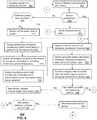
- FIG. 6is a block diagram illustrating an example, non-limiting embodiment of a method in accordance with various aspects of the subject disclosure described herein;
- FIGS. 7A-7Bare block diagrams illustrating example, non-limiting embodiments of plots of sensor data of a plurality of patients in accordance with various aspects of the subject disclosure described herein;
- FIGS. 7C-7Dare block diagrams illustrating example, non-limiting embodiments of thresholds used for monitoring biological conditions of the plurality of patients of FIGS. 7A-7B in accordance with various aspects of the subject disclosure described herein;
- FIG. 8is a diagrammatic representation of a machine in the form of a computer system within which a set of instructions, when executed, may cause the machine to perform any one or more of the methods of the subject disclosure described herein.
- the subject disclosuredescribes, among other things, illustrative embodiments for managing sensor data and usage of sensors generating the sensor data. Other embodiments are described in the subject disclosure.
- One or more aspects of the subject disclosureinclude a system having a processor, and a memory that stores executable instructions that, when executed by the processor, facilitate performance of operations, including obtaining first provisioning information associated with a first sensor coupled to a first patient, the first sensor used for measuring a biological data of the first patient, detecting a second sensor coupled to the first patient, determining that the first sensor is being replaced by the second sensor, determining that the second sensor does not have the first provisioning information associated with the first sensor, and providing a copy of the first provisioning information of the first sensor to the second sensor.
- One or more aspects of the subject disclosureinclude a machine-readable storage medium, storing executable instructions that, when executed by a processor, facilitate performance of operations, including determining from sensor data collected for a patient over a period of time a normative condition of a biological function of the patient, generating provisioning information according to the normative condition, detecting a first sensor coupled to the patient, and providing the provisioning information to the first sensor to enable the first sensor to detect an abnormal state of the biological function of the patient.
- One or more aspects of the subject disclosureinclude a method for determining from sensor data collected for a patient over a period of time a normative condition of a biological function of the patient, generating provisioning information according to the normative condition, detecting a first sensor coupled to the patient, and providing the provisioning information to the first sensor to enable the first sensor to detect an abnormal state of the biological function of the patient.
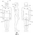
- FIG. 1a block diagram illustrating example, non-limiting embodiments for placing biological sensors 102 on a patient 100 in accordance with various aspects of the subject disclosure is shown.
- FIG. 1depicts a number of non-limiting illustrations of locations where biological sensors 102 can be placed on a patient 100 .
- biological sensors 102can be placed on a patient's forehead, chest, abdomen, arms, hands, front or rear section of a thigh, behind an ear, on a side of an arm, neck, back, or calves as illustrated in FIG. 1 .
- Other locations for placement of biological sensors 102are possible and contemplated by the subject disclosure.
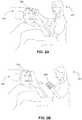
- the biological sensors 102can be placed or managed by a nurse 101 as shown in FIGS. 2A-2B .
- a nurse 101can, for example, place a biological sensor 102 on the patient 100 as depicted in FIG. 2A and manage use of the biological sensor 102 with a computing device 202 such as a touch-screen tablet as depicted in FIG. 2B .
- the computing device 202can also be represented by a smartphone, a laptop computer, or other suitable computing devices.
- the computing device 202can be communicatively coupled to the biological sensor 102 by a wireless interface, such as, near field communications (NFC) having, for example, a range of 3-4 inches from the biological sensor 102 , Bluetooth®, ZigBee®, WiFi, or other suitable short range wireless technology.
- NFCnear field communications
- the computing device 202can be communicatively coupled to the biological sensor 102 by a wired interface or tethered interface (e.g., a USB cable).
- Biological sensors 102can be placed on an outer surface of a skin of the patient 100 with an adhesive, or can be implanted in the patient 100 .
- the patient 100is shown to be a human patient, a patient 100 can also be represented by a non-human species (e.g., a dog, a cat, a horse, cattle, a tiger, etc.) or any other type of biological organism which can use a biological sensor 102 .
- Biological sensors 102can be used for a number of functions such as, for example, electrocardiogram measurements, measuring temperature, perspiration, pulse rate, blood pressure, respiration rate, glucose levels in blood, peripheral capillary oxygen saturation (SpO2), and other measurable biological functions contemplated by the subject disclosure.
- the biological sensors 102can also be adapted to store measurements, compare measurements to biological markers to detect a biological condition, and to report such measurements and detected conditions.
- Biological sensors 102are, however, not limited to monitoring applications.
- biological sensors 102can also be adapted to deliver controlled dosages of medication using, for example, micro-needles.
- Such sensorscan also perform measurements to monitor a biological response by the patient 100 to the medication delivered, record and report measurements, frequency of dosages, amount of dosage delivered, and so on.
- the reportscan also include temporal data such as day, month, year, time when measurement was performed and/or time when medication was delivered.
- FIGS. 3A-3Fblock diagrams illustrating example, non-limiting embodiments of a system 300 for managing sensor data in accordance with various aspects of the subject disclosure is shown.
- FIG. 3Adepicts a network architecture in which one or more sensor management systems 304 are communicatively coupled to hospitals (A)-(N) 308 , clinicians (A)-(N) 310 , monitoring services (A)-(N) 312 , and/or patients (A)-(N) 100 , singly or in combination.
- the sensor management system 304can record and access data from sensor databases (A)-(N) 306 .
- hospitals (A)-(N) 308 , clinicians (A)-(N) 310 , and monitoring services (A)-(N) 312can provide the sensor management system 304 access to patients 100 through their systems and local network devices as depicted in FIG. 3B .
- the sensor management system 304can be communicatively coupled to patients (A)-(N) 100 directly as shown in FIG. 3A without intervening health care providers (such as hospitals, clinicians, or monitoring services), and instead provide care providers access to information of certain patients recorded in the sensor databases (A)-(N) 306 .
- FIGS. 3C-3Fdepict different arrangements for managing sensors 102 .
- the sensor management system 304can be communicatively coupled to sensors 102 via the communications network 302 which is communicatively coupled to a local network 320 (e.g., a local area network, WiFi access point, etc.) having access to the sensors 102 as depicted in FIG. 3C .
- the sensor management system 304can be communicatively coupled to sensors 102 via the communications network 302 which is communicatively coupled to a computing device 202 (such as shown in FIG. 2B ) having access to the sensors 102 as depicted in FIG. 3D .
- the computing device 202can operate off-line (i.e., without access to the sensor management system 304 ) as depicted in FIG. 3D with the hash lines. While off-line, the computing device 202 can collect sensor data from sensors 102 , provision sensors 102 , and perform other tasks which can be recorded locally in a memory of the computing device 202 . Once the computing device 202 restores access to the sensor management system 304 via communications network 302 , the computing device 202 can provide the sensor management system 302 access to its local memory to update databases 306 with new sensor data, provisioning data, and so on.
- the computing device 202can be configured to operate independently from the sensor management system 304 as depicted in FIG. 3E and collect sensor data from sensors 102 , provision sensors 102 , and perform other tasks which are recorded locally in the memory of the computing device 202 .
- the sensor management system 304can be configured to communicate with one or more local servers 330 as depicted in FIG. 3F which have access to computing devices 202 via a local network 320 .
- the computing devices 202can provide sensor management information to the local servers 330 .
- the local servers 330in turn can provide the sensor management system 304 access to the sensor information collected from the computing devices 202 .
- the local servers 330can also be configured to operate independently from the sensor management system 304 .
- FIGS. 3A-3Fit will be appreciated from the number of illustrations shown in FIGS. 3A-3F that any number of network configurations between sensors 102 and other devices managing use of the sensors 102 is possible. It is further noted that the arrangements in FIGS. 3A-3F can be adapted for managing sensors worn by a patient located in a residence, a clinic, a doctor's office, a hospital, outdoors, while in transit, while traveling, and so on.
- the communications network 302 and the local network 320 shown in FIGS. 3A-3Fcan comprise a landline communications network (e.g., packet switched landline networks, circuit switched networks, etc.), a wireless communications network (e.g., cellular communications, WiFi, etc.), or combinations thereof.
- the computing device 202 of FIG. 2Bcan be configured to initiate communications with the biological sensor 102 and the communications network 302 to provide the sensor management system 304 access to the biological sensors 102 used by multiple patients.
- the computing device 202can serve as a gateway between the communications network 302 and the biological sensors 102 .
- the biological sensors 102can gain direct access to the communications network 302 by way of a gateway that provide internet access (e.g., a WiFi access point).
- the sensor management system 304can be configured to store endless amounts of biological data of patients 100 over long periods of time (e.g., an entire lifetime and/or generations of patients) in databases 306 . Such data can serve to provide historical information that may be invaluable to the patients 100 and their lineages.
- the biological sensor 102can comprise a wireline and/or wireless transceiver 402 (herein transceiver 402 ), a power supply 414 , a location receiver 416 , a motion sensor 418 , an orientation sensor 420 , a memory 404 , a drug delivery system 408 , a biometric sensor 409 , one or more sensors 410 , and a controller 406 for managing operations thereof. Not all of the components shown in the biological sensor 102 are necessary.
- the biological sensor 102can comprise the transceiver 402 , the controller 406 , the memory 404 , one or more sensors 410 , and the power supply 404 .
- the biological sensor 102can further include one or more components not used in the previous embodiment such as the drug delivery system 408 , the biometric sensor 409 , the location receiver 416 , the motion sensor 418 , the orientation senor 420 , or any combinations thereof. Accordingly, any combinations of component of the biological sensor 102 depicted in FIG. 4 are possible and contemplated by the subject disclosure.
- FIGS. 1 and 2A-2Bdepict topical applications of the biological sensor 102 on an outer skin of the patient 100
- the biological sensor 102can in whole or in part be embedded in a patient 100 .
- a certain sensor 410may be embedded in a skin of the patient 100 while other components of the biological sensor 102 may be located on an outer surface of the skin.
- a certain sensor 410may be attached to an organ (e.g., the heart). Accordingly, the biological sensor 102 can be located in a number of places within a patient's body, outside a patient's body, or combinations thereof.
- the transceiver 402can support short-range or long-range wireless access technologies such as RFID, Near Field Communications (NFC), Bluetooth®, ZigBee®, WiFi, DECT, or cellular communication technologies, just to mention a few (Bluetooth® and ZigBee® are trademarks registered by the Bluetooth® Special Interest Group and the ZigBee® Alliance, respectively).
- Cellular technologiescan include, for example, CDMA- 1 X, UMTS/HSDPA, GSM/GPRS, TDMA/EDGE, EV/DO, WiMAX, SDR, LTE, as well as other next generation wireless communication technologies as they arise.
- the transceiver 402can also be adapted to support cable protocols (e.g., USB, Firewire, Ethernet, or other suitable cable technologies), circuit-switched wireline access technologies (such as PSTN), packet-switched wireline access technologies (such as TCP/IP, VoIP, etc.), or combinations thereof.
- cable protocolse.g., USB, Firewire, Ethernet, or other suitable cable technologies
- circuit-switched wireline access technologiessuch as PSTN
- packet-switched wireline access technologiessuch as TCP/IP, VoIP, etc.
- the drug delivery system 408can comprise micro-needles, one or more reservoirs of one or more drugs, and a piezo inkjet (not shown).
- the piezo inkjetcan be coupled to the one or more reservoirs to selectively deliver dosages via the micro-needles.
- the piezo inkjetcan be coupled to the controller 406 which can provide controlled delivery of dosages of one or more drugs by the drug delivery system 408 .
- the biometric sensor 409can be a fingerprint sensor, a voice sensor (with a built-in microphone), or any other type of suitable biometric sensor for identifying a user of the biological sensor 102 .
- the sensors 410can use common biological sensing technology for measuring biological functions of a patient including, but not limited to, temperature, perspiration, pulse rate, blood pressure, respiration rate, glucose levels in the blood, SpO2, ECG/EKG, and so on.
- the power supply 414can utilize common power management technologies such as replaceable and rechargeable batteries, supply regulation technologies, and/or charging system technologies for supplying energy to the components of the biological sensor 102 to facilitate long-range or short-range portable applications.
- the power supply 414can utilize external power sources such as DC power supplied over a physical interface such as a USB port or other suitable tethering technologies.
- the biological sensorcan be battery-less.
- the power supply 414can utilize circuitry that powers the components of the biological sensor 102 utilizing RF energy received by an antenna or other receptive element.
- the biological sensor 102can use NFC technology to intercept RF signals generated by the computing device 202 when the computing device 202 is held a few inches away from the biological sensor 102 .
- the biological sensor 102can utilize battery-less technology similar to that used by passive RFID devices. Other suitable battery-less technologies can be applied to the embodiments of the subject disclosure.
- the location receiver 416can utilize location technology such as a global positioning system (GPS) receiver capable of identifying a location of the biological sensor 102 using signals generated by a constellation of GPS satellites.
- the motion sensor 418can utilize motion sensing technology such as an accelerometer, a gyroscope, or other suitable motion sensing technology to detect a motion of the biological sensor 102 in three-dimensional space.
- the orientation sensor 420can utilize orientation sensing technology such as a magnetometer to detect the orientation of the biological sensor 102 (north, south, west, east, as well as combined orientations in degrees, minutes, or other suitable orientation metrics).
- the controller 406can utilize computing technologies such as a microprocessor, a digital signal processor (DSP), programmable gate arrays, application specific integrated circuits, which can be coupled to the memory 404 .
- the memory 404can utilize memory technologies such as Flash, ROM, RAM, SRAM, DRAM or other storage technologies for executing instructions, controlling operations of the biological sensor 102 , and for storing and processing sensing data supplied by the aforementioned components of the biological sensor 102 .
- Computing device 202can comprise a wireline and/or wireless transceiver 502 (herein transceiver 502 ), a user interface (UI) 504 , a power supply 514 , a location receiver 516 , a motion sensor 518 , an orientation sensor 520 , and a controller 506 for managing operations thereof.
- the transceiver 502can support short-range or long-range wireless access technologies such as Bluetooth®, ZigBee®, WiFi, DECT, or cellular communication technologies, just to mention a few.
- Cellular technologiescan include, for example, CDMA- 1 X, UMTS/HSDPA, GSM/GPRS, TDMA/EDGE, EV/DO, WiMAX, SDR, LTE, as well as other next generation wireless communication technologies as they arise.
- the transceiver 502can also be adapted to support circuit-switched wireline access technologies (such as PSTN), packet-switched wireline access technologies (such as TCP/IP, VoIP, etc.), and combinations thereof.
- the UI 504can include a depressible or touch-sensitive keypad 508 with a navigation mechanism such as a roller ball, a joystick, a mouse, or a navigation disk for manipulating operations of the computing device 202 .
- the keypad 508can be an integral part of a housing assembly of the computing device 202 or an independent device operably coupled thereto by a tethered wireline interface (such as a USB cable) or a wireless interface supporting for example Bluetooth®.
- the keypad 508can represent a numeric keypad commonly used by phones, and/or a QWERTY keypad with alphanumeric keys.
- the UI 504can further include a display 510 such as monochrome or color LCD (Liquid Crystal Display), OLED (Organic Light Emitting Diode) or other suitable display technology for conveying images to an end user of the computing device 202 .
- a display 510such as monochrome or color LCD (Liquid Crystal Display), OLED (Organic Light Emitting Diode) or other suitable display technology for conveying images to an end user of the computing device 202 .
- a display 510is touch-sensitive, a portion or all of the keypad 508 can be presented by way of the display 510 with navigation features.
- display 510can use touch screen technology to serve as a user interface for detecting user input.
- the computing device 202can be adapted to present a user interface with graphical user interface (GUI) elements that can be selected by a user with a touch of a finger.
- GUIgraphical user interface
- the touch screen display 510can be equipped with capacitive, resistive or other forms of sensing technology to detect how much surface area of a user's finger has been placed on a portion of the touch screen display. This sensing information can be used to control the manipulation of the GUI elements or other functions of the user interface.
- the display 510can be an integral part of the housing assembly of the computing device 202 or an independent device communicatively coupled thereto by a tethered wireline interface (such as a cable) or a wireless interface.
- the UI 504can also include an audio system 512 that utilizes audio technology for conveying low volume audio (such as audio heard in proximity of a human ear) and high volume audio (such as speakerphone for hands free operation).
- the audio system 512can further include a microphone for receiving audible signals of an end user.
- the audio system 512can also be used for voice recognition applications.
- the UI 504can further include an image sensor 513 such as a charged coupled device (CCD) camera for capturing still or moving images.
- CCDcharged coupled device
- the power supply 514can utilize common power management technologies such as replaceable and rechargeable batteries, supply regulation technologies, and/or charging system technologies for supplying energy to the components of the computing device 202 to facilitate long-range or short-range portable applications.
- the charging systemcan utilize external power sources such as DC power supplied over a physical interface such as a USB port or other suitable tethering technologies.
- the location receiver 516can utilize location technology such as a GPS receiver for identifying a location of the computing device 202 based on signals generated by a constellation of GPS satellites, which can be used for facilitating location services such as navigation.
- the motion sensor 518can utilize motion sensing technology such as an accelerometer, a gyroscope, or other suitable motion sensing technology to detect motion of the computing device 202 in three-dimensional space.
- the orientation sensor 520can utilize orientation sensing technology such as a magnetometer to detect the orientation of the computing device 202 (north, south, west, and east, as well as combined orientations in degrees, minutes, or other suitable orientation metrics).
- the controller 506can utilize computing technologies such as a microprocessor, a digital signal processor (DSP), programmable gate arrays, application specific integrated circuits, and/or a video processor with associated storage memory such as Flash, ROM, RAM, SRAM, DRAM or other storage technologies for executing computer instructions, controlling, and processing data supplied by the aforementioned components of the computing device 202 .
- computing technologiessuch as a microprocessor, a digital signal processor (DSP), programmable gate arrays, application specific integrated circuits, and/or a video processor with associated storage memory such as Flash, ROM, RAM, SRAM, DRAM or other storage technologies for executing computer instructions, controlling, and processing data supplied by the aforementioned components of the computing device 202 .
- the computing device 202can also include a slot for adding or removing an identity module such as a Subscriber Identity Module (SIM) card.
- SIM cardscan be used for identifying subscriber services, executing programs, storing subscriber data, and so forth.
- the computing device 202 as described hereincan operate with more or less of the circuit components shown in FIG. 5 . These variant embodiments can be used in one or more embodiments of the subject disclosure.
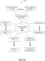
- Method 600can be applied to any combination of the embodiments of FIGS. 1, 2A-2B, 3A-3B, and 4-5 .
- Method 600can begin with step 602 where a clinician (e.g., a nurse as shown in FIG. 2A ), places a biological sensor 102 on a patient 100 .
- the biological sensor 102can utilize an adhesive for coupling to the skin of the patient 100 .
- the cliniciancan be a surgeon that implants the biological sensor 102 in whole or in part in a body portion of the patient 100 .
- the biological sensor 102can be configured to initiate communications with a system.
- the biological sensor 102can initiate communications with a computing device 202 such as shown in FIG. 2B .
- the biological sensor 102can initiate communications utilizing, for example, short range wireless technology such as near field communications (NFC), Bluetooth®, ZigBee®, WiFi or other suitable short range wireless communications technology.
- the computing device 202in turn can communicate with the sensor management system 304 via the communications network 302 to provide the sensor management system 304 access to information supplied by the biological sensor 102 .
- the biological sensor 102can initiate communications with the sensor management system 304 by way of the communications network 302 utilizing long range wireless technology such cellular technology or other suitable long range wireless communications technology. In yet another embodiment, the biological sensor 102 can initiate communications with the sensor management system 304 by way of the communications network 302 utilizing wireline communications technology.
- the biological sensor 102can be tethered to the computing device 202 with a cable (e.g., a USB cable).
- the computing device 202can provide the sensor management system 304 access to information supplied by the biological sensor 102 .
- the biological sensor 102can have access to a local network providing connectivity to the Internet by way of a cable (e.g., Ethernet cable).
- the sensor management system 304can have direct access to the biological sensor 102 .
- the system referred to in step 604 and in subsequent stepscan be represented by the computing device 202 , the sensor management system 304 , or a combination thereof.
- the term system as utilized in method 600can be adapted to represent solely the computing device 202 , solely the sensor management system 304 , or a combination of the computing device 202 and the sensor management system 304 , each configured to cooperate therebetween in a manner that achieves the embodiments described by method 600 . It is also noted that other arrangements are possible as shown in FIGS. 3A-3F .
- the systemcan determine whether the biological sensor 102 is provisioned. This determination can be made a number of ways. For example, a clinician 101 can enter information on a computing device 202 which signals the sensor management system 304 that the biological sensor 102 is a new sensor placed on patient 100 , which has not been provisioned. In another embodiment, the biological sensor 102 can be polled by the sensor management system 304 (or by the computing device 202 ) to determine if the biological sensor 102 has been provisioned.
- the sensor management system 304(and/or the computing device 202 ) can be configured to determine that a prior biological sensor 102 has been used (or is currently in use) by the patient 100 and the new biological sensor 102 that was detected is of a different serial number, but functionally equivalent or similar to the prior biological sensor 102 .
- the sensor management system 304(or the computing device 202 ) can be configured to receive from the biological sensor 102 an identification of the patient 100 .
- the biological sensor 102can be configured to receive the identification of the patient 100 from the computing device 202 .
- the biological sensor 102can obtain the identification from a wristband worn by the patient 100 that includes an RFID device or other device suitable to convey the identification of the patient 100 wirelessly to the biological sensor 102 .
- the sensor management system 304(or the computing device 202 ) can be configured to retrieve a record of the patient 100 indexed according to the identification of the patient, and detect therefrom that the biological sensor 102 is not identified in a chart of the patient 100 .
- the sensor management system 304(or the computing device 202 ) can be configured to detect an expiration of a utilization period applied to a prior biological sensor 102 and determine that the biological sensor 102 now detected is a replacement sensor that has not been provisioned.
- the sensor management system 304can be configured to detect an expiration of a utilization period applied to a prior biological sensor 102 and determine that the biological sensor 102 now detected is a replacement sensor that has not been provisioned.
- the sensor management system 304(or the computing device 202 ) can be configured to detect that provisioning data stored by the sensor management system 304 (or the computing device 202 ) is not synchronized with data stored in the biological sensor 102 by comparing time stamps associated with data stored in the biological sensor 102 to time stamps associated with data stored in the databases 306 of the sensor management system 304 (or the memory of the computing device 202 ). If the time stamps of the sensor management system 304 (or the memory of the computing device 202 ) are not the same as the time stamps of the biological sensor 102 , then the sensor management system 304 (or the computing device 202 ) can detect the biological sensor 102 has not been provisioned. In yet another embodiment, the biological sensor 102 can provide the sensor management system 304 (or the computing device 202 ) information indicating it has not been provisioned.
- the sensor management system 304(or the computing device 202 ) detects the biological sensor 102 is not provisioned, the sensor management system 304 (or the computing device 202 ) can proceed to step 608 where it can determine whether historical sensor data is available.
- the historical sensor datacan originate from prior biological sensors used by the patient 100 .
- the historical sensor datacan represent data captured minutes, hours, days, months or years before the new biological sensor 102 is detected at step 604 . If the historical sensor data is available, the sensor management system 304 (or the computing device 202 ) can proceed to step 610 to obtain such data from a memory device used to retain records of the patient 100 (e.g., the customer sensor databases 306 or an internal memory of the computing device 202 ).
- the sensor management system 304(or the computing device 202 ) can proceed to step 614 to determine normative conditions and/or thresholds for detecting one or more biological conditions of the patient 100 from the historical sensor data collected from one or more previously used biological sensors 102 .
- the historical sensor data collected from the one or more previously used biological sensors 102can be over a period of time such as minutes, hours, days, weeks, months, years, or longer.
- the time period used for selecting historical sensor datacan be driven by a number of factors. For example, the time period may be based on a specific protocol initiated by a clinician (nurse and/or doctor).
- the protocolcan be initiated as a result of a procedure performed on the patient (e.g., surgery, therapy, drug application, and so on), a protocol for monitoring patient vitals, or a protocol customized by the clinician to address a particular disease. Any medical protocol prescribed by the clinician or a medical organization are contemplated by the subject disclosure.
- the historical sensor datacan be analyzed to identify one or more normative conditions and/or thresholds for the patient 100 .
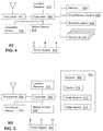
- FIGS. 7A-7Dillustrate non-limiting example embodiments for determining normative conditions, and thresholds for detecting biological conditions.
- FIG. 7Aa block diagram illustrating an example, non-limiting embodiment of a plot of sensor data of a plurality of patients in accordance with various aspects of the subject disclosure is shown.
- FIG. 7depicts three patients (A), (B) and (C).
- Historical sensor data of patient (A)indicates that the patient has had an average temperature of 99.5° Fahrenheit (F) over a select period.
- the clinicianmay be aware that patient (A) has exhibited this temperature over extended periods of time and thereby can form an opinion that such a temperature does not pose a health risk to patient (A) even though it is higher than a population norm of 98.6° F.
- the cliniciancan record his opinion in a chart of patient (A), which can be accessible to the sensor management system 304 (or the computing device 202 ).
- the sensor management system 304or the computing device 202
- the sensor management system 304(or the computing device 202 ) can analyze the sensor data of the patient (A) in relation to the patient's temperature, other sensory data (e.g., blood pressure, pulse rate, respiration rate, blood pressure and so on) and/or other medical history, and determine, without relying on the clinician's opinion, that such a temperature may be considered a normative condition for patient (A) given the physiological state and health of patient (A).
- other sensory datae.g., blood pressure, pulse rate, respiration rate, blood pressure and so on
- other medical historye.g., a normative condition for patient (A) given the physiological state and health of patient (A).
- the clinicianmay be aware that patient (A) may be subject to an illness that the clinician expects will result in a rise in temperature, which the clinician records in the chart of patient (A).
- the clinicianmay be applying a drug treatment to patient (A) that the clinician knows will cause a rise in temperature, which the clinician records in the chart of patient (A).
- the sensor management system 304(or the computing device 202 ) can be configured to analyze the chart of patient (A) and consider the temperature a normative condition of patient (A) based on the entries of the clinician indicating an expected rise in temperature.
- the sensor management system 304(or the computing device 202 ) can be configured to analyze the sensor data, detect from the chart that patient (A) has an illness, or is subject to a drug therapy, access information relating to the illness or drug therapy (from databases 306 or other information storage system(s)), and determine, without relying on the clinician's opinion, from the sensor data and the information obtained about the illness or drug therapy that the temperature of patient (A) would be higher than normal, and therefore can be considered a normative condition of patient (A).
- the historical sensor data of patient (B)indicates that the patient has had an average temperature of 96.4° F. over a select period.
- the clinicianmay be aware that patient (B) has exhibited this temperature over extended periods of time and that such a temperature does not pose a health risk to patient (B).
- Cliniciancan record his or her opinion in a chart of patient (B) accessible to the sensor management system 304 (or the computing device 202 ).
- a temperaturemay be considered a normative condition for patient (B) given the physiological state and health of patient (B).
- the clinicianmay be aware that patient (B) may be subject to an illness that results in such a temperature.
- the clinicianmay be applying a drug treatment to patient (B) that the clinician knows will cause a drop in temperature.
- the sensor management system 304can be configured to analyze the chart of patient (B) and consider the temperature a normative condition of patient (B) based on the entries of the clinician indicating an expected drop in temperature.
- the sensor management system 304can be configured to analyze the sensor data, detect from the chart that patient (B) has an illness, or is subject to a drug therapy, access information relating to the illness or drug therapy (from databases 306 or other information storage system(s)), and determine, without relying on the clinician's opinion, from the sensor data and the information obtained about the illness or drug therapy that the temperature of patient (B) would be lower than normal, and therefore can consider it a normative condition of patient (B).
- patient (C)the historical sensor data of patient (C) indicates that the patient has had an average temperature of 98.6° F. over a select period, which coincides with what most clinicians may consider an average temperature for the general population. Thus the clinician does not have to consider exceptions for patient (C). Accordingly, this temperature will be used as a normative condition for patient (C).
- the sensor management system 304(or the computing device 202 ) can be configured to analyze the chart of patient (C) and consider the temperature a normative condition of patient (C).
- the sensor management system 304(or the computing device 202 ) can be configured to analyze the sensor data, and determine, without relying on the clinician's opinion, that the sensor data coincides with the general population, and therefore can consider it a normative condition of patient (C).
- FIG. 7Ba block diagram illustrating an example, non-limiting embodiment of a plot of sensor data of the plurality of patients (A)-(C) of FIG. 7A .
- Historical sensor data of patient (A)indicates that the patient has had an average pulse rate of 80 beats per minute over a select period.
- the sensor management system 304(or the computing device 202 ) can be configured to consider such a pulse rate a normative condition for patient (A) given that a range of 60 to 100 beats per minute is generally a healthy pulse rate.
- the cliniciancan record his opinion in a chart of patient (A), which can be accessed by the sensor management system 304 (or the computing device 202 ).
- the historical sensor data of patient (B)indicates that the patient has had an average pulse rate of 50 beats per minute over a select period.
- the clinicianmay be aware that patient (B) has exhibited this pulse rate over extended periods of time given the athletic training undertaken by patient (B).
- the cliniciancan record his opinion in a chart of patient (B), which can be accessed by the sensor management system 304 (or the computing device 202 ).
- the sensor management system 304or the computing device 202
- the sensor management system 304(or the computing device 202 ) can analyze the sensor data of the patient (B) in relation to the patient's pulse rate, other sensory data (e.g., temperature, blood pressure, respiration rate, blood pressure and so on) and other medical history, and determine, without relying on the clinician's opinion, that such a pulse rate may be considered a normative condition for patient (B) given the physiological state and health of patient (B).
- other sensory datae.g., temperature, blood pressure, respiration rate, blood pressure and so on
- other medical historye.g., temperature, blood pressure, respiration rate, blood pressure and so on
- patient (C)the historical sensor data of patient (C) indicates that the patient has had an average pulse rate of 105 beats per minute over a select period, which is above normal.
- the clinicianmay be aware that patient (C) has a condition such as, for example, hypertension, coronary artery disease, thyroid disease, etc., which can result in a higher pulse rate that the clinician records in the chart of patient (C).
- the clinicianmay be applying a drug treatment to patient (C) that the clinician knows will cause a rise in pulse rate, which the clinician records in the chart of patient (C).
- the sensor management system 304can be configured to analyze the chart of patient (C) and consider the pulse rate a normative condition of patient (C) based on the entries of the clinician indicating an expected rise in pulse rate.
- the sensor management system 304can be configured to analyze the sensor data, detect from the chart that patient (C) has an illness, or is subject to a drug therapy, access information relating to the illness or drug therapy (from databases 306 or other information storage system(s)), and determine, without relying on the clinician's opinion, from the sensor data and the information obtained about the illness or drug therapy that the pulse rate of patient (C) would be higher than normal, and therefore can be considered a normative condition of patient (C).
- FIG. 7Ca block diagram illustrating an example, non-limiting embodiment of temperature thresholds used for monitoring biological conditions of the plurality of patients (A)-(C) according to the sensor data of FIG. 7A .
- patient Agiven the normative condition of patient (A) averages at 99.5° F., the clinician may consider an adverse biological condition to begin at 101° F. If, for example, patient (A) does not have an illness or is not being treated with drug therapy to cause a normative condition at 99.5° F., then a threshold of 101° F. may be considered the beginning of a fever. If, on the other hand, patient (A) is subject to an illness or drug therapy resulting in the normative condition, then a rise in temperature to 101° F.
- the thresholdcan be established by the clinician, which the clinician can record in the chart of patient (A). In another embodiment the threshold can be established by protocols relating to the illness and/or the drug therapy.
- the sensor management system 304can be configured to analyze the chart of patient (A) and generate the threshold shown in FIG. 7C .
- the sensor management system 304can be configured to analyze the normative condition of patient (A), detect from the chart that patient (A) has an illness, and/or is subject to a drug therapy, access information relating to the illness and/or drug therapy (e.g., specific protocols), and determine, without relying on the clinician's proposed threshold, the threshold shown in FIG. 7C .
- the clinicianmay consider an adverse biological condition to begin at 99° F. If, for example, patient (B) does not have an illness or is not being treated with drug therapy to cause a normative condition at 96.4° F., then a threshold of 99° F. may be considered the beginning of a fever. If, on the other hand, patient (B) is subject to an illness or drug therapy resulting in the normative condition, then a rise in temperature to 99° F. may reflect an adverse biological condition that is more than just a fever. For example, the adverse biological condition may represent a body's negative reaction to the drug therapy and/or a worsening of the illness.
- the thresholdcan be established by the clinician, which the clinician can record in the chart of patient (B). In another embodiment the threshold can be established by protocols relating to the illness and/or the drug therapy.
- the sensor management system 304can be configured to analyze the chart of patient (B) and generate the threshold shown in FIG. 7C .
- the sensor management system 304can be configured to analyze the normative condition of patient (B), detect from the chart that patient (B) has an illness, and/or is subject to a drug therapy, access information relating to the illness and/or drug therapy (e.g., specific protocols), and determine, without relying on the clinician's proposed threshold, the threshold shown in FIG. 7C .
- patient (C)given the normative condition of patient (C) averages at 98.6° F. is considered normal for the general population, the clinician may consider an adverse biological condition to begin at 100.4° F. Such a threshold can be used for detecting a fever.
- the cliniciancan record in the chart of patient (C) that patient (C) exhibits the temperature norm of the general population.
- the sensor management system 304(or the computing device 202 ) can be configured to analyze the chart of patient (C) and generate the threshold shown in FIG. 7C .
- the sensor management system 304(or the computing device 202 ) can be configured to analyze the normative condition of patient (C), and determine that an appropriate threshold for detecting a fever follows the norm of the general population and thus arrive at the threshold shown in FIG. 7C .
- FIG. 7Da block diagram illustrating an example, non-limiting embodiment of pulse rate thresholds used for monitoring biological conditions of the plurality of patients (A)-(C) according to the sensor data of FIG. 7B .
- patient Agiven the normative condition of patient (A) averages at 80 beats per minute, which is considered normal for the general population, the clinician may consider an adverse biological condition to begin at 105 beats per minute when the patient is at rest (5% above the norm of the general population, which is 100 beats per minute).
- the biological sensor 102 used by patient (A)can detect that the patient is at rest utilizing, for example, the motion sensor 418 depicted in FIG. 4 .
- the thresholdcan be established by the clinician, which the clinician can record in the chart of patient (A).
- the sensor management system 304(or the computing device 202 ) can be configured to analyze the chart of patient (A) and generate the threshold shown in FIG. 7D .
- the sensor management system 304(or the computing device 202 ) can be configured to analyze the normative condition of patient (A), and determine, without relying on the clinician's opinion, that patient (A) should use a threshold applied to the general population, such as, for example, a threshold of 100 beats per minute.
- patient (B)given the normative condition of patient (B) averages at 50 beats per minute, if, for example, patient (B) does not have an illness and is not being treated with drug therapy to cause a normative condition at 50 beats per minute, then the clinician may consider an adverse biological condition to begin at 90 beats per minute when the patient is at rest. Even though 90 beats per minute is below a population threshold of 100 beats per minute, the clinician may consider a change from 50 to 90 beats per minute to be a substantial change for a patient with a history of rigorous athletic training.
- the biological sensor 102 used by patient (B)can detect that the patient is at rest utilizing, for example, the motion sensor 418 depicted in FIG. 4 .
- the chart of patient (B)may also include information indicating the last time patient (B) was measured at 50 beats per minute.
- the sensor management system 304(or the computing device 202 ) can be configured to determine from the chart of patient (B) the threshold of 90 beats per minute and thereafter monitor patient (B) for unexpected changes.
- the sensor management system 304(or the computing device 202 ) can also be configured to detect unexpected rapid changes in pulse rate in a relatively short period (e.g., 48 hours or less).
- the sensor management system 304(or the computing device 202 ) can also be configured to detect a trend in the pulse rate of patient (B) (e.g., an upward trend in pulse rate over weeks or months).
- patient (C)given the normative condition of patient (C) averages at 105 beats per minute, which is high (likely due to illness, e.g., hypertension), the clinician may consider an adverse biological condition to begin at 100 beats per minute when patient (C) is at rest.
- the clinicianmay have set a threshold below the normative condition as a result of the clinician prescribing medication to reduce hypertension in patient 100 .
- Such prescriptionmay reduce the pulse rate of the patient by, for example, 15% (e.g., ⁇ 90 beats per minute).
- the cliniciancan enter the prescribed medication in the chart of patient 100 which is accessible to the sensor management system 304 (or the computing device 202 ).
- FIG. 7Bshows a normative condition of 105 beats per minute
- the sensor management system 304or the computing device 202
- the sensor management system 304(or the computing device 202 ) can be configured to determine from the chart of patient (C) the threshold of 100 beats per minute and thereafter monitor patient (C) for unexpected changes.
- the sensor management system 304(or the computing device 202 ) can also be configured to detect unexpected rapid changes in pulse rate in a relatively short period (e.g., 48 hours or less).
- the sensor management system 304(or the computing device 202 ) can also be configured to detect a trend in the pulse rate of patient (C) (e.g., an upward trend in pulse rate over weeks or months).
- the foregoing embodiments for determining normative conditions and thresholds of a patient as shown in FIGS. 7A-7Dcan also be used for other vital signs (e.g., blood pressure, respiration rate), as well as to other biological functions that can be measured for a patient (e.g., red cell count, SpO2, glucose levels in the blood, electrocardiogram measurements, and so on).
- the sensor management system 304(or the computing device 202 ) can be configured to analyze sensor data of more than one biological function at a time to assess normative conditions and thresholds rather than relying on a single biological function.
- the sensor management system 304(or the computing device 202 ) can, for example, correlate one type of biological sensor data (e.g., pulse rate) with another type of biological sensor data (e.g., blood pressure) to determine a normative condition and/or threshold. In this manner, the sensor management system 304 (or the computing device 202 ) can perform a more holistic analysis of the patient's sensor data.
- one type of biological sensor datae.g., pulse rate
- another type of biological sensor datae.g., blood pressure
- a normative conditionmay be considered normative only for a period of time either by instructions from the clinician, medical protocols and/or other medical conditions associated with the patient 100 that can be determined by the sensor management system 304 (or the computing device 202 ).
- a thresholdcan be set for a specific time period.
- the sensor management system 304or the computing device 202
- the sensor management system 304can detect when a drug therapy has begun and when it ends by obtaining information from the chart of the patient 100 .
- the sensor management system 304(or the computing device 202 ) can be configured to change normative conditions and corresponding thresholds upon expiration of such periods.
- the sensor management system 304(or the computing device 202 ) can be adapted to use ranges of the normative conditions and thresholds shown in FIGS. 7A-7D . That is, a normative condition and/or a threshold can have a range having an upper and lower limit. In another embodiment, more than one normative condition and more than one threshold can be used to identify different biological conditions that may arise in a patient as the patient's sensor data shows measurements drifting in one direction or another. In yet another embodiment, the sensor management system 304 (or the computing device 202 ) can be adapted to detect sensor data trends that it can use to predict future outcomes before they occur.
- a sensor data trendcan, for example, identify a specific course that measurements may be taking, which in turn can provide the sensor management system 304 (or the computing device 202 ) a projected trajectory and time when an adverse condition may occur.
- the sensor management system 304(or the computing device 202 ) can be adapted to detect erratic changes in sensor data. Such changes can be flagged as a problem with the biological sensors 102 (e.g., a malfunction) and/or biological issues that may need to be addressed.
- algorithms for detecting biological conditionscan be generated by the sensor management system 304 (or the computing device 202 ).
- the sensor management system 304(or the computing device 202 ) can be configured to generate a script or software program that emulates a specific medical protocol used for detecting biological conditions associated with an illness of the patient, an adverse reaction to a drug therapy being applied to the patient, or some other biological condition to be monitored.
- the script or softwarecan be generated by the sensor management system 304 (or the computing device 202 ) can, for example, detect trends, detect when sensor measurements exceed thresholds, detect erratic or rapid changes, applying hysteresis to sensor measurements to filter out short bursts of anomalous readings, detect malfunctions in the biological sensor 102 , and so on. So long as the biological sensor 102 has the computing resources, any algorithm of any complexity can be supplied to the biological sensor 102 . For example, a script or software can determine how often a patient 100 is sensed. Patients that are healthy, for instance, may be sensed less frequently thereby saving battery power of the sensor 102 . Patients that may have a condition may have a script or software that's more aggressive on readings.
- the script or softwarecan comprise instructions executable by the biological sensor 102 , or macro instructions that can be translated (compiled) by the biological sensor 102 into executable instructions.
- Each algorithmcan be given a version which can be sent to the biological sensors 102 for version tracking.
- the sensor management system 304(or the computing device 202 ) can query biological sensors 102 for versions and download new algorithmic versions when a version used by the biological sensors 102 is out-of-date.
- the sensor management system 304(or the computing device 202 ) can also be configured to provide new algorithmic versions to the biological sensors 102 that are pre-programmed with a certain algorithmic version that may be out-of-date.
- chart informationmay be electronically stored by the sensor management system 304 , the computing device 202 , or other storage systems accessible by the sensor management system 304 and/or the computing device 202 .
- the sensor management system 304(or the computing device 202 ) detects that historical sensor data is not available for the patient 100 , the sensor management system 304 (or the computing device 202 ) can proceed to step 612 .
- the sensor management system 304(or the computing device 202 ) can collect sensor data from the new sensor until sufficient sensor data is available to determine normative conditions and/or thresholds for the patient according to the sensor data (and chart information if available for the patient).
- the sensor management system 304(or the computing device 202 ) can proceed to step 616 and generate provisioning information for the new biological sensor 102 detected at step 606 .
- the provisioning informationcan include, among other things, one or more normative conditions, one or more thresholds, one or more algorithms (if the biological sensor 102 is not pre-programmed or has an out-of-date algorithm), a most recent history of sensor data measurements (e.g., measurements performed in the last hour), identification information of the patient 100 , a last known location of the patient, certain chart information relating to the patient (e.g., illness type, drug therapy type, date of surgery, type of surgery, etc.), and so on.
- the amount of information included in the provisioning information generated at step 616can depend on the memory resources of the biological sensor 102 , the function of the biological sensor 102 , usage preferences of the clinician (e.g., ability to recall a short history of sensor data), and so forth.
- the sensor management system 304(or the computing device 202 ) can proceed to step 618 and provide the provisioning information to the biological sensor 102 .
- the biological sensor 102can then begin to monitor one or more biological conditions of the patient at step 620 .
- Such conditionscan be determined from an algorithm provided to (or pre-programmed in) the biological sensor 102 .
- the algorithmcan detect that sensor measurements exceed a specific threshold or a threshold range. In other embodiments, the algorithm can detect sensor data trends, erratic or rapid changes, and/or predict future outcomes.
- the biological sensor 102can provide the sensor management system 304 (or the computing device 202 ) information relating to detection of biological conditions monitored by the biological sensor 102 , including without limitations, sensor data measurements, measurements exceeding a specific threshold or threshold range, trends in sensor data, erratic or rapid changes in sensor data, predicted adverse biological conditions, and so on. Such information can be provided to the sensor management system 304 (or the computing device 202 ) with time stamps (e.g., time of day: hours/minutes/second, date: month/day/year).
- time stampse.g., time of day: hours/minutes/second, date: month/day/year.
- the sensor management system 304(or the computing device 202 ) can be configured at step 624 to analyze the sensor data to detect trends, erratic or rapid changes and so on.
- the sensor management system 304(or the computing device 202 ) can also be configured to report a status of biological conditions of the patient 100 to clinicians. For example, if no adverse biological conditions have been detected, the clinician can be provided a history of the measured sensor data in a status report that indicates no adverse biological conditions were detected. If, on the other hand, one or more adverse biological conditions were detected, the clinician can be provided with a detailed report that includes sensor data that exceeded one or more thresholds, time stamp information associated with the sensor data, and so on.
- the sensor management system 304(or the computing device 202 ) can also be configured to provide trend information if available. If adverse biological conditions are not presently detected, but trend information predicts a future adverse condition, then the sensor management system 304 (or the computing device 202 ) can provide such information to the clinician to enable the clinician to take preemptive action to avoid such adverse condition from occurring.
- the sensor management system 304can monitor placement of another new biological sensor 102 on the patient 100 . If another new biological sensor 102 is not detected, the sensor management system 304 (or the computing device 202 ) can proceed to step 620 and repeat the processes previously described. If, however, another new biological sensor 102 is detected, the sensor management system 304 (or the computing device 202 ) can proceed to step 628 to obtain a model number, serial number or other identification data from the new biological sensor 102 to determine if the new sensor is of the same type and function as the previous sensor.
- the sensor management system 304(or the computing device 202 ) can obtain patient identification data from the new biological sensor 102 , which the biological sensor may have obtained from a wrist band of the patient including an RFID, the biometric sensor 409 of FIG. 4 , or by patient information provided to the biological sensor 102 by way of the computing device 202 of the clinician as depicted in FIG. 2B .
- the sensor management system 304(or the computing device 202 ) can proceed to step 630 and determine if the new biological sensor 102 is a replacement for the previous same sensor. If the new biological sensor 102 is not the same as the previous sensor, a determination can be made whether the new sensor is a replacement sensor by the sensor management system 304 (or the computing device 202 ) by obtaining information from the new sensor indicating it is a replacement sensor, determining that the new sensor does have in its memory a patient identifier, or by receiving input data from, for example, the computing device 202 initiated by, for example, a clinician, indicating it is a replacement sensor.
- the sensor management system 304(or the computing device 202 ) can proceed to step 606 and perform the same sequence of steps previously described for the same patient if the new sensor is associated with the same patient, or for a different patient in which case a new record would be created in the databases 306 or other storage resources of the sensor management system 304 (or the computing device 202 ).
- the sensor management system 304(or the computing device 202 ) can determine that the new biological sensor 102 is replacing the previous sensor upon receiving a message from the computing device 202 of the clinician as noted above.
- the messagecan indicate which sensor is being replaced by identifying the serial number of the previous sensor in the message and identifying the serial number of the new sensor.
- the sensor management system 304(or the computing device 202 ) can determine that the new biological sensor 102 is replacing a previous sensor based on the new biological sensor 102 not being programmed with a patient identifier.
- the sensor management system 304(or the computing device 202 ) can determine that the new biological sensor 102 is replacing a previous sensor based on an understanding that two of the same type of sensors for the same patient is not common practice for the clinician and in such instances detecting a new sensor represents a replacement procedure undertaken by the clinician. It should be noted that there may be instances when a new biological sensor of the same type will not be considered a replacement sensor. For example, a clinician may wish to use the same sensor in multiple locations of a patient's body. Such exceptions can be noted by the clinician using the computing device 202 .
- the sensor management system 304(or the computing device 202 ) can determine that the new biological sensor 102 is replacing a previous sensor based on a utilization period of the previous sensor expiring or detecting that the previous sensor is damaged or malfunctioning.
- Other suitable detection methods for determining a replacement of sensorsare contemplated by the subject disclosure.
- the sensor management system 304can proceed to step 634 and decommission the previous sensor.
- the decommissioning processcan represent noting in a record of the patient 100 that the serial number of the biological sensor 102 being replaced has been decommissioned.
- the sensor management system 304can be configured to ignore sensor data from the decommissioned sensor if such data were to be provided.
- the sensor management system 304(or the computing device 202 ) can then proceed to step 610 to obtain historical sensor data produced by the previous sensor and any predecessor sensors.
- the sensor management system 304(or the computing device 202 ) can then proceed to perform subsequent steps as previously described.
- the sensor management system 304(or the computing device 202 ) can be provisioned to provide the new biological sensor 102 some or all of the obtained historical sensor data of one or more previous sensors for local storage, enabling retrieval by the computing device 202 if desired. It is further noted that the steps of method 600 can be adapted so that the sensors 102 (new or old) can proactively (e.g., without polling by the sensor management system 304 or the computing device 202 ) initiate communications with the sensor management system 304 or the computing device 202 and provide updates as needed. Such a process can be pre-programmed into the sensors 102 or a script or software can be provided to the sensors 102 by the sensor management system 304 or the computing device 202 to enable a proactive communication process.
- method 600can be adapted so that the sensor management system 304 or the computing device 202 tracks GPS coordinates of patients 100 using a location receiver 416 of the biological sensor 102 .
- GPS datacan be used, for example, to analyze the activities of the patient 100 and in some instances such activities may be used to analyze the sensor data.
- the GPS coordinate datamay indicate that a patient was walking or jogging. Such information can be used to distinguish sensor data taken at rest versus other activities.
- Orientation and motion data produced by the orientation sensor 420 and motion sensor 418can be used to more accurately assess a 3D position of the patient 100 , and a level of activity of the patient 100 (e.g., lying down, running in place, sitting, etc.).
- the sensor management system 304can more precisely analyze sensor data obtained from one or more biological sensors 102 coupled to a patient 100 .
- devices described in the exemplary embodimentscan be in communication with each other via various wireless and/or wired methodologies.
- the methodologiescan be links that are described as coupled, connected and so forth, which can include unidirectional and/or bidirectional communication over wireless paths and/or wired paths that utilize one or more of various protocols or methodologies, where the coupling and/or connection can be direct (e.g., no intervening processing device) and/or indirect (e.g., an intermediary processing device such as a router).
- FIG. 8depicts an exemplary diagrammatic representation of a machine in the form of a computer system 800 within which a set of instructions, when executed, may cause the machine to perform any one or more of the methods described above.
- One or more instances of the machinecan operate, for example, as the devices depicted in the drawings of the subject disclosure.
- the machinemay be connected (e.g., using a network 826 ) to other machines.
- the machinemay operate in the capacity of a server or a client user machine in a server-client user network environment, or as a peer machine in a peer-to-peer (or distributed) network environment.
- the machinemay comprise a server computer, a client user computer, a personal computer (PC), a tablet, a smart phone, a laptop computer, a desktop computer, a control system, a network router, switch or bridge, or any machine capable of executing a set of instructions (sequential or otherwise) that specify actions to be taken by that machine.
- a communication device of the subject disclosureincludes broadly any electronic device that provides voice, video or data communication.
- the term “machine”shall also be taken to include any collection of machines that individually or jointly execute a set (or multiple sets) of instructions to perform any one or more of the methods discussed herein.
- the computer system 800may include a processor (or controller) 802 (e.g., a central processing unit (CPU)), a graphics processing unit (GPU, or both), a main memory 804 and a static memory 806 , which communicate with each other via a bus 808 .
- the computer system 800may further include a display unit 810 (e.g., a liquid crystal display (LCD), a flat panel, or a solid state display).
- the computer system 800may include an input device 812 (e.g., a keyboard), a cursor control device 814 (e.g., a mouse), a disk drive unit 816 , a signal generation device 818 (e.g., a speaker or remote control) and a network interface device 820 .
- the embodiments described in the subject disclosurecan be adapted to utilize multiple display units 810 controlled by two or more computer systems 800 .
- presentations described by the subject disclosuremay in part be shown in a first of the display units 810 , while the remaining portion is presented in a second of the display units 810 .
- the disk drive unit 816may include a tangible computer-readable storage medium 822 on which is stored one or more sets of instructions (e.g., software 824 ) embodying any one or more of the methods or functions described herein, including those methods illustrated above.
- the instructions 824may also reside, completely or at least partially, within the main memory 804 , the static memory 806 , and/or within the processor 802 during execution thereof by the computer system 800 .
- the main memory 804 and the processor 802also may constitute tangible computer-readable storage media.
- Dedicated hardware implementationsincluding, but not limited to, application specific integrated circuits, programmable logic arrays and other hardware devices can likewise be constructed to implement the methods described herein.
- Application specific integrated circuits and programmable logic arraycan use downloadable instructions for executing state machines and/or circuit configurations to implement embodiments of the subject disclosure.
- Applicationsthat may include the apparatus and systems of various embodiments broadly include a variety of electronic and computer systems. Some embodiments implement functions in two or more specific interconnected hardware modules or devices with related control and data signals communicated between and through the modules, or as portions of an application-specific integrated circuit.
- the example systemis applicable to software, firmware, and hardware implementations.
- the operations or methods described hereinare intended for operation as software programs or instructions running on or executed by a computer processor or other computing device, and which may include other forms of instructions manifested as a state machine implemented with logic components in an application specific integrated circuit or field programmable gate array.
- software implementationse.g., software programs, instructions, etc.
- a computing devicesuch as a processor, a controller, a state machine or other suitable device for executing instructions to perform operations or methods may perform such operations directly or indirectly by way of one or more intermediate devices directed by the computing device.
- tangible computer-readable storage medium 822is shown in an example embodiment to be a single medium, the term “tangible computer-readable storage medium” should be taken to include a single medium or multiple media (e.g., a centralized or distributed database, and/or associated caches and servers) that store the one or more sets of instructions.
- tangible computer-readable storage mediumshall also be taken to include any non-transitory medium that is capable of storing or encoding a set of instructions for execution by the machine and that cause the machine to perform any one or more of the methods of the subject disclosure.
- non-transitoryas in a non-transitory computer-readable storage includes without limitation memories, drives, devices and anything tangible but not a signal per se.
- tangible computer-readable storage mediumshall accordingly be taken to include, but not be limited to: solid-state memories such as a memory card or other package that houses one or more read-only (non-volatile) memories, random access memories, or other re-writable (volatile) memories, a magneto-optical or optical medium such as a disk or tape, or other tangible media which can be used to store information. Accordingly, the disclosure is considered to include any one or more of a tangible computer-readable storage medium, as listed herein and including art-recognized equivalents and successor media, in which the software implementations herein are stored.
- Each of the standards for Internet and other packet switched network transmission(e.g., TCP/IP, UDP/IP, HTML, HTTP) represent examples of the state of the art. Such standards are from time-to-time superseded by faster or more efficient equivalents having essentially the same functions.
- Wireless standards for device detectione.g., RFID
- short-range communicationse.g., Bluetooth®, WiFi, Zigbee®
- long-range communicationse.g., WiMAX, GSM, CDMA, LTE
- facilitatinge.g., facilitating access or facilitating establishing a connection
- the facilitatingcan include less than every step needed to perform the function or can include all of the steps needed to perform the function.
- a processor(which can include a controller or circuit) has been described that performs various functions. It should be understood that the processor can be multiple processors, which can include distributed processors or parallel processors in a single machine or multiple machines.
- the processorcan be used in supporting a virtual processing environment.
- the virtual processing environmentmay support one or more virtual machines representing computers, servers, or other computing devices. In such virtual machines, components such as microprocessors and storage devices may be virtualized or logically represented.
- the processorcan include a state machine, application specific integrated circuit, and/or programmable gate array including a Field PGA.
Landscapes
- Health & Medical Sciences (AREA)
- Life Sciences & Earth Sciences (AREA)
- Engineering & Computer Science (AREA)
- Biomedical Technology (AREA)
- Medical Informatics (AREA)
- Public Health (AREA)
- General Health & Medical Sciences (AREA)
- Pathology (AREA)
- Animal Behavior & Ethology (AREA)
- Cardiology (AREA)
- Veterinary Medicine (AREA)
- Physics & Mathematics (AREA)
- Surgery (AREA)
- Biophysics (AREA)
- Molecular Biology (AREA)
- Heart & Thoracic Surgery (AREA)
- Physiology (AREA)
- Computer Networks & Wireless Communication (AREA)
- Pulmonology (AREA)
- Business, Economics & Management (AREA)
- General Business, Economics & Management (AREA)
- Primary Health Care (AREA)
- Epidemiology (AREA)
- Measuring And Recording Apparatus For Diagnosis (AREA)
- Artificial Intelligence (AREA)
- Computer Vision & Pattern Recognition (AREA)
- Psychiatry (AREA)
- Signal Processing (AREA)
Abstract
Description
Claims (19)
Priority Applications (2)
| Application Number | Priority Date | Filing Date | Title |
|---|---|---|---|
| US14/798,798US11116397B2 (en) | 2015-07-14 | 2015-07-14 | Method and apparatus for managing sensors |
| US15/278,212US10368810B2 (en) | 2015-07-14 | 2016-09-28 | Method and apparatus for monitoring a functional capacity of an individual |
Applications Claiming Priority (1)
| Application Number | Priority Date | Filing Date | Title |
|---|---|---|---|
| US14/798,798US11116397B2 (en) | 2015-07-14 | 2015-07-14 | Method and apparatus for managing sensors |
Related Parent Applications (1)
| Application Number | Title | Priority Date | Filing Date |
|---|---|---|---|
| US14/960,872Continuation-In-PartUS20170112451A1 (en) | 2015-07-14 | 2015-12-07 | Method and apparatus for detecting a biological condition from a comparative measurement |
Related Child Applications (2)
| Application Number | Title | Priority Date | Filing Date |
|---|---|---|---|
| US14/920,200Continuation-In-PartUS20170112388A1 (en) | 2015-07-14 | 2015-10-22 | Method and apparatus for performing biological measurements |
| US15/278,212Continuation-In-PartUS10368810B2 (en) | 2015-07-14 | 2016-09-28 | Method and apparatus for monitoring a functional capacity of an individual |
Publications (2)
| Publication Number | Publication Date |
|---|---|
| US20170014085A1 US20170014085A1 (en) | 2017-01-19 |
| US11116397B2true US11116397B2 (en) | 2021-09-14 |
Family
ID=57774786
Family Applications (1)
| Application Number | Title | Priority Date | Filing Date |
|---|---|---|---|
| US14/798,798Active2037-12-22US11116397B2 (en) | 2015-07-14 | 2015-07-14 | Method and apparatus for managing sensors |
Country Status (1)
| Country | Link |
|---|---|
| US (1) | US11116397B2 (en) |
Families Citing this family (11)
| Publication number | Priority date | Publication date | Assignee | Title |
|---|---|---|---|---|
| US10368810B2 (en) | 2015-07-14 | 2019-08-06 | Welch Allyn, Inc. | Method and apparatus for monitoring a functional capacity of an individual |
| US11116397B2 (en) | 2015-07-14 | 2021-09-14 | Welch Allyn, Inc. | Method and apparatus for managing sensors |
| US10617350B2 (en) | 2015-09-14 | 2020-04-14 | Welch Allyn, Inc. | Method and apparatus for managing a biological condition |
| US10918340B2 (en) | 2015-10-22 | 2021-02-16 | Welch Allyn, Inc. | Method and apparatus for detecting a biological condition |
| US10973416B2 (en) | 2016-08-02 | 2021-04-13 | Welch Allyn, Inc. | Method and apparatus for monitoring biological conditions |
| US10791994B2 (en) | 2016-08-04 | 2020-10-06 | Welch Allyn, Inc. | Method and apparatus for mitigating behavior adverse to a biological condition |
| JP6927136B2 (en)* | 2018-04-27 | 2021-08-25 | 横河電機株式会社 | Management equipment, management methods and programs |
| CN108713504A (en)* | 2018-06-15 | 2018-10-30 | 塔里木大学 | A kind of device for infectious disease isolation |
| JP2020163018A (en)* | 2019-03-29 | 2020-10-08 | Tdk株式会社 | Biological signal measurement system |
| WO2022015722A1 (en) | 2020-07-15 | 2022-01-20 | Lifelens Technologies, Inc. | Wearable sensor system configured for facilitating telemedicine management |
| CN113081027A (en)* | 2021-04-19 | 2021-07-09 | 中国人民解放军联勤保障部队第九0四医院 | Gastrointestinal peristalsis sound and patient sign monitoring device |
Citations (149)
| Publication number | Priority date | Publication date | Assignee | Title |
|---|---|---|---|---|
| US3703890A (en) | 1970-08-10 | 1972-11-28 | Milton A Saunders Jr | Skin patch test device |
| US3814095A (en) | 1972-03-24 | 1974-06-04 | H Lubens | Occlusively applied anesthetic patch |
| US4290114A (en) | 1976-07-01 | 1981-09-15 | Sinay Hanon S | Medical diagnostic computer |
| US4329999A (en) | 1980-03-03 | 1982-05-18 | Michael Phillips | Patient attached patch and method of making |
| USD379356S (en) | 1996-01-25 | 1997-05-20 | Valor Enterprises, Inc. | Decal patch antenna system |
| US5688232A (en) | 1995-09-28 | 1997-11-18 | Becton Dickinson And Company | Iontophoretic drug delivery device having an improved controller |
| US5778879A (en) | 1995-02-16 | 1998-07-14 | Omron Corporation | Electronic blood pressure meter with posture detector |
| US5879292A (en) | 1997-10-09 | 1999-03-09 | Edward A. Sternberg | Bandage including data acquisition components |
| US5887590A (en) | 1997-08-08 | 1999-03-30 | Price; John A. | Eyelid closure patch |
| US6238354B1 (en) | 1999-07-23 | 2001-05-29 | Martin A. Alvarez | Temperature monitoring assembly |
| US20010034711A1 (en) | 2000-03-01 | 2001-10-25 | Tashenberg Bradley A. | Distributed operating network and method for using and implementing same |
| US20020095092A1 (en) | 2000-12-06 | 2002-07-18 | Kabushiki Gaisya K-And-S | Pulse wave measuring apparatus and pulse wave measuring method |
| US20020151934A1 (en) | 2001-04-12 | 2002-10-17 | Levine Paul A. | System and method for programmably controlling electrode activation sequence in a multi-site cardiac stimulation device |
| US6526300B1 (en) | 1999-06-18 | 2003-02-25 | Masimo Corporation | Pulse oximeter probe-off detection system |
| US20030221687A1 (en) | 2002-05-09 | 2003-12-04 | William Kaigler | Medication and compliance management system and method |
| US20040113771A1 (en) | 2002-11-19 | 2004-06-17 | Toru Ozaki | Living body information detecting terminal control system |
| US20040153018A1 (en) | 2003-02-03 | 2004-08-05 | Symeon Brown | Shave patches |
| US20040243006A1 (en) | 2001-06-21 | 2004-12-02 | Nakata Kin-Ichi | Vascular disease examining system and bypass vascular diagnosing device |
| US20050060198A1 (en) | 2000-07-06 | 2005-03-17 | Bayne Cary Gresham | Method for clinician house calls utilizing portable computing and communications equipment |
| US20050119711A1 (en)* | 2003-01-10 | 2005-06-02 | Cho Yong K. | Apparatus and method for monitoring for disordered breathing |
| US20050149362A1 (en) | 2003-12-30 | 2005-07-07 | Peterson Per A. | System and method for visually presenting digital patient information for future drug use resulting from dosage alteration |
| US20050154264A1 (en) | 2004-01-08 | 2005-07-14 | International Business Machines Corporation | Personal stress level monitor and systems and methods for using same |
| US20050215868A1 (en) | 2004-03-26 | 2005-09-29 | Noriko Kenjou | Vital sign processing apparatus and vital sign processing system |
| US20050242946A1 (en) | 2002-10-18 | 2005-11-03 | Hubbard James E Jr | Patient activity monitor |
| US20050245852A1 (en) | 2004-04-30 | 2005-11-03 | Ellefson Kimberly L | System and method for providing therapy to an area of a body |
| US20060002988A1 (en) | 2004-06-30 | 2006-01-05 | Ellefson Kimberly L | System and method for providing therapy to an individual |
| US20060031094A1 (en) | 2004-08-06 | 2006-02-09 | Medtronic Minimed, Inc. | Medical data management system and process |
| US20060049936A1 (en) | 2004-08-02 | 2006-03-09 | Collins Williams F Jr | Configurable system for alerting caregivers |
| US20060066449A1 (en) | 2004-09-08 | 2006-03-30 | Industrial Widget Works Company | RFMON: devices and methods for wireless monitoring of patient vital signs through medical sensor readings from passive RFID tags |
| US20060122863A1 (en) | 2004-12-02 | 2006-06-08 | Medtronic, Inc. | Patient management network |
| US20070032733A1 (en) | 2004-01-16 | 2007-02-08 | David Burton | Method and apparatus for ECG-derived sleep disordered breathing monitoring, detection and classification |
| US20070049461A1 (en) | 2005-08-30 | 2007-03-01 | Samsung Electronics Co., Ltd. | Method and apparatus for managing exercise state of user |
| US20070066526A1 (en) | 2005-09-02 | 2007-03-22 | Daria Mochly-Rosen | Method for reducing risk of and extent of injury due to stroke in hypertensive subjects |
| US20070073132A1 (en) | 2005-09-27 | 2007-03-29 | Michael Vosch | Apparatus and method for monitoring patients |
| US20070077287A1 (en) | 2005-10-05 | 2007-04-05 | Goodrich Corina S | Transdermal art patch |
| US20070100219A1 (en) | 2005-10-27 | 2007-05-03 | Smiths Medical Pm, Inc. | Single use pulse oximeter |
| WO2007072412A2 (en) | 2005-12-23 | 2007-06-28 | Koninklijke Philips Electronics N.V. | Stressor sensor and stress management system |
| US7256695B2 (en) | 2002-09-23 | 2007-08-14 | Microstrain, Inc. | Remotely powered and remotely interrogated wireless digital sensor telemetry system |
| US7261691B1 (en) | 2004-08-02 | 2007-08-28 | Kwabena Asomani | Personalized emergency medical monitoring and transmission system |
| US20070260132A1 (en) | 2006-05-04 | 2007-11-08 | Sterling Bernhard B | Method and apparatus for processing signals reflecting physiological characteristics from multiple sensors |
| US20080091085A1 (en) | 2004-10-28 | 2008-04-17 | Naoki Urushihata | Disease Diagnostic System |
| US20080162352A1 (en) | 2007-01-03 | 2008-07-03 | Gizewski Theodore M | Health maintenance system |
| US20080157980A1 (en) | 2006-12-27 | 2008-07-03 | Cardiac Pacemakers, Inc. | Within-patient algorithm to predict heart failure decompensation |
| US20080275311A1 (en) | 2001-01-16 | 2008-11-06 | Mohamed Haq | Virtual Clinic For Medical Practice |
| US20080281633A1 (en) | 2007-05-10 | 2008-11-13 | Grigore Burdea | Periodic evaluation and telerehabilitation systems and methods |
| US20090030289A1 (en) | 2004-12-28 | 2009-01-29 | Intellectual Property Bank Corp. | Biological Information Monitoring System |
| US20090054735A1 (en) | 2005-03-08 | 2009-02-26 | Vanderbilt University Office Of Technology Transfer And Enterprise Development | System and method for remote monitoring of multiple healthcare patients |
| US20090062670A1 (en) | 2007-08-30 | 2009-03-05 | Gary James Sterling | Heart monitoring body patch and system |
| US20090076397A1 (en) | 2007-09-14 | 2009-03-19 | Corventis, Inc. | Adherent Emergency Patient Monitor |
| US20090076345A1 (en) | 2007-09-14 | 2009-03-19 | Corventis, Inc. | Adherent Device with Multiple Physiological Sensors |
| US20090076340A1 (en) | 2007-09-14 | 2009-03-19 | Corventis, Inc. | Adherent Cardiac Monitor with Advanced Sensing Capabilities |
| US20090076559A1 (en) | 2007-09-14 | 2009-03-19 | Corventis, Inc. | Adherent Device for Cardiac Rhythm Management |
| US20090076410A1 (en) | 2007-09-14 | 2009-03-19 | Corventis, Inc. | System and Methods for Wireless Body Fluid Monitoring |
| US20090151198A1 (en) | 2007-12-13 | 2009-06-18 | Jorge Villegas | Stick patch |
| US20090192402A1 (en) | 2008-01-30 | 2009-07-30 | Engineered Vigilance, Llc | System and method providing biofeedback for anxiety and stress reduction |
| US20090209896A1 (en) | 2008-02-19 | 2009-08-20 | Selevan James R | Method and apparatus for time-dependent and temperature-dependent clinical alert |
| US20090227852A1 (en) | 2005-11-14 | 2009-09-10 | Eckard Glaser | Pulse sensor, pulse meter, oximeter, joystick, and helmet |
| US20090292194A1 (en) | 2008-05-23 | 2009-11-26 | Corventis, Inc. | Chiropractic Care Management Systems and Methods |
| US20090326510A1 (en) | 2008-06-30 | 2009-12-31 | Haefner Paul A | Drug Delivery Methods and Systems |
| US20100049172A1 (en) | 1998-08-26 | 2010-02-25 | Britton Chance | Sensing and interactive drug delivery |
| US20110092780A1 (en) | 2009-10-16 | 2011-04-21 | Tao Zhang | Biosensor module with automatic power on capability |
| US20110093210A1 (en) | 2009-04-03 | 2011-04-21 | Natsume Matsuzaki | Measurement device and method of controlling the same |
| US20110112416A1 (en)* | 2009-11-10 | 2011-05-12 | Makor Issues And Rights Ltd. | System and apparatus for providing diagnosis and personalized abnormalities alerts and for providing adaptive responses in clinical trials |
| US20110112418A1 (en)* | 2008-03-10 | 2011-05-12 | Koninklijke Philips Electronics N.V. | Ecg monitoring system with configurable alarm limits |
| US20110152637A1 (en) | 2008-05-14 | 2011-06-23 | Kateraas Espen D | Physical activity monitor and data collection unit |
| WO2011094819A1 (en) | 2010-02-04 | 2011-08-11 | Terence Vardy | A monitoring system |
| US20110213625A1 (en) | 1999-12-18 | 2011-09-01 | Raymond Anthony Joao | Apparatus and method for processing and/or for providing healthcare information and/or helathcare-related information |
| US20110213217A1 (en) | 2010-02-28 | 2011-09-01 | Nellcor Puritan Bennett Llc | Energy optimized sensing techniques |
| US20110218418A1 (en) | 2010-03-02 | 2011-09-08 | Medtronic, Inc. | Identification patch for a medical system |
| US20110224498A1 (en)* | 2010-03-10 | 2011-09-15 | Sotera Wireless, Inc. | Body-worn vital sign monitor |
| US20110245695A1 (en) | 2008-12-17 | 2011-10-06 | Omron Healthcare Co., Ltd. | Electronic sphygmomanometer |
| US20110245711A1 (en) | 2010-04-05 | 2011-10-06 | Corventis, Inc. | Method and apparatus for personalized physiologic parameters |
| US20110257537A1 (en) | 2010-04-15 | 2011-10-20 | Anthony Alatriste | Blood pressure monitoring system providing enhanced vascular aneurysm detection features and related methods |
| US20120003933A1 (en)* | 2010-06-30 | 2012-01-05 | Welch Allyn, Inc. | Medical devices with proximity detection |
| US20120029306A1 (en) | 2010-07-27 | 2012-02-02 | Carefusion 303, Inc. | Vital-signs monitor with encapsulation arrangement |
| US20120029313A1 (en) | 2010-07-27 | 2012-02-02 | Alison Burdett | System and method for tracking vital-signs monitor patches |
| US20120029312A1 (en) | 2010-07-27 | 2012-02-02 | Carefusion 303, Inc. | System and method for location tracking of patients in a vital-signs monitor system |
| US20120029309A1 (en) | 2010-07-27 | 2012-02-02 | Carefusion 303, Inc. | Vital-signs patch having a strain relief |
| US20120029316A1 (en) | 2010-07-27 | 2012-02-02 | Carefusion 303, Inc. | System and method for saving battery power in a patient monitoring system |
| US20120029307A1 (en) | 2010-07-27 | 2012-02-02 | Carefusion 303, Inc. | Vital-signs monitor with spaced electrodes |
| US20120078069A1 (en) | 2002-06-20 | 2012-03-29 | Melker Richard J | Blood Flow Monitoring |
| US20120130203A1 (en) | 2010-11-24 | 2012-05-24 | Fujitsu Limited | Inductively-Powered Ring-Based Sensor |
| US20120130196A1 (en) | 2010-11-24 | 2012-05-24 | Fujitsu Limited | Mood Sensor |
| US20120179011A1 (en) | 2007-06-12 | 2012-07-12 | Jim Moon | Optical sensors for use in vital sign monitoring |
| US20120203078A1 (en)* | 2011-02-08 | 2012-08-09 | Aulisa Medical Technologies, Inc. | Wireless Patient Monitoring System |
| US20120209084A1 (en) | 2011-01-21 | 2012-08-16 | Masimo Corporation | Respiratory event alert system |
| WO2012140537A1 (en) | 2011-04-14 | 2012-10-18 | Koninklijke Philips Electronics N.V. | Stress-measuring device and method |
| US8315687B2 (en) | 2006-12-07 | 2012-11-20 | Koninklijke Philips Electronics N.V. | Handheld, repositionable ECG detector |
| US20130011819A1 (en) | 2011-07-05 | 2013-01-10 | Saudi Arabian Oil Company | Systems, Computer Medium and Computer-Implemented Methods for Coaching Employees Based Upon Monitored Health Conditions Using an Avatar |
| US20130030259A1 (en) | 2009-12-23 | 2013-01-31 | Delta, Dansk Elektronik, Lys Og Akustik | Monitoring system |
| US20130072765A1 (en) | 2011-09-19 | 2013-03-21 | Philippe Kahn | Body-Worn Monitor |
| US20130073304A1 (en)* | 2011-09-20 | 2013-03-21 | Infosys Limited | Method and system for auto rebinding of patient demographic details to patient monitoring devices |
| US20130123719A1 (en) | 2011-11-12 | 2013-05-16 | Robert Bosch Gmbh | Medication compliance patch and control unit |
| US20130176115A1 (en)* | 2005-12-09 | 2013-07-11 | Tego Inc. | Rfid drive management facility |
| US20130183209A1 (en) | 2010-09-09 | 2013-07-18 | Fraunhofer-Gesellschaft Zur Foerderung Der Angewandten Forschung E.V. | Microfluidic device, microfluidic dosing system and method for microfluidic flow measurement and dosing |
| US20130192071A1 (en) | 2012-01-30 | 2013-08-01 | Heapsylon LLC | Sensors, interfaces and sensor systems for data collection and integrated remote monitoring of conditions at or near body surfaces |
| US8504323B2 (en) | 2010-07-15 | 2013-08-06 | Scott Anthony Coradi | Emergency patient medication system |
| US20130204100A1 (en)* | 2006-06-15 | 2013-08-08 | Wireless Live D/B/A Peerbridge Health | Wireless electrode arrangement and method for patient monitoring via electrocardiography |
| US8529457B2 (en) | 2008-02-22 | 2013-09-10 | Koninklijke Philips N.V. | System and kit for stress and relaxation management |
| US8585607B2 (en) | 2007-05-02 | 2013-11-19 | Earlysense Ltd. | Monitoring, predicting and treating clinical episodes |
| US20130317753A1 (en)* | 2012-05-24 | 2013-11-28 | Deka Products Limited Partnership | System, Method, and Apparatus for Electronic Patient Care |
| US20140046144A1 (en) | 2012-08-13 | 2014-02-13 | Tata Consultancy Services Limited | Real-time stress determination of an individual |
| WO2014031944A1 (en) | 2012-08-24 | 2014-02-27 | EmoPulse, Inc. | System and method for obtaining and using user physiological and emotional data |
| US20140088443A1 (en) | 2011-05-26 | 2014-03-27 | Koninklijke Philips N.V. | Fever detection apparatus |
| US8688189B2 (en) | 2005-05-17 | 2014-04-01 | Adnan Shennib | Programmable ECG sensor patch |
| US20140107493A1 (en) | 2012-06-22 | 2014-04-17 | Fitbit, Inc. | Portable Biometric Monitoring Devices and Methods of Operating Same |
| WO2014063160A1 (en) | 2012-10-19 | 2014-04-24 | Basis Science, Inc. | Detection of emotional states |
| US20140176369A1 (en) | 2012-12-26 | 2014-06-26 | Korea Electronics Technology Institute | Patch antenna having a patch fed with multiple signal |
| US20140184422A1 (en) | 2012-12-31 | 2014-07-03 | Dexcom, Inc. | Remote monitoring of analyte measurements |
| US20140266959A1 (en) | 2013-03-15 | 2014-09-18 | City University Of Hong Kong | Patch antenna |
| US20140288396A1 (en) | 2006-12-19 | 2014-09-25 | Valencell, Inc. | Apparatus, systems, and methods for measuring environmental exposure and physiological response thereto |
| WO2014153017A1 (en) | 2013-03-14 | 2014-09-25 | CyMedica, Inc. | Systems and methods for treating or supporting human joints or a portion of the human body |
| WO2014160764A1 (en) | 2013-03-26 | 2014-10-02 | Carolon Comapny | Body monitoring system |
| US20140310298A1 (en) | 2007-02-16 | 2014-10-16 | Bodymedia, Inc. | Controlling a sensory device to reduce stress an individuals type and the data collected from a wearable sensor device |
| US20150073251A1 (en) | 2007-09-14 | 2015-03-12 | Corventis, Inc. | Medical device with automatic start-up upon contact to patient tissue |
| US20150094914A1 (en) | 2004-02-26 | 2015-04-02 | Geelux Holding, Ltd. | Method and apparatus for biological evaluation |
| US20150126896A1 (en) | 2013-11-06 | 2015-05-07 | Raed H. AlHazme | Human body thermal measurement device, a method for measuring human body temperature, and a non-transitory computer readable storage medium |
| US20150134388A1 (en) | 2013-11-12 | 2015-05-14 | Kyruus, Inc. | Methods and systems for providing, by a referral management system, dynamic scheduling of profiled professionals |
| US20150142329A1 (en) | 2013-11-19 | 2015-05-21 | RLab Ab Oy | Method and system for exercise monitoring |
| US20150207796A1 (en)* | 2013-12-27 | 2015-07-23 | Abbott Diabetes Care Inc. | Systems, devices, and methods for authentication in an analyte monitoring environment |
| US20150250426A1 (en) | 2012-09-10 | 2015-09-10 | Koninklijke Philips N.V. | Device and method to improve dependability of physiological parameter measurements |
| US20150265212A1 (en) | 2012-10-23 | 2015-09-24 | Koninklijke Philips N.V. | Stress-measuring system |
| US20150302539A1 (en) | 2014-04-16 | 2015-10-22 | Vios Medical Singapore PTE LTD | Patient care and health information management systems and methods |
| US20150335254A1 (en) | 2013-01-08 | 2015-11-26 | Mc10, Inc. | Application For Monitoring A Property Of A Surface |
| US20160051191A1 (en)* | 2014-08-24 | 2016-02-25 | Halo Wearables, Llc | Swappable wearable device |
| US20160174903A1 (en) | 2014-12-23 | 2016-06-23 | Michael Cutaia | System and method for outpatient management of chronic disease |
| US20160198977A1 (en) | 2015-01-12 | 2016-07-14 | Samsung Electronics Co., Ltd. | Wearable apparatus for obtaining biological information and method of obtaining biological information using the same |
| US20170014085A1 (en) | 2015-07-14 | 2017-01-19 | Welch Allyn, Inc. | Method and apparatus for managing sensors |
| US20170020461A1 (en) | 2015-07-14 | 2017-01-26 | Welch Allyn, Inc. | Method and apparatus for monitoring a functional capacity of an individual |
| US20170035306A1 (en) | 2015-08-05 | 2017-02-09 | Welch Allyn, Inc. | Method and apparatus for managing sensors |
| US9566007B2 (en) | 2009-05-20 | 2017-02-14 | Sotera Wireless, Inc. | Alarm system that processes both motion and vital signs using specific heuristic rules and thresholds |
| US20170043087A1 (en) | 2015-08-14 | 2017-02-16 | Welch Allyn, Inc. | Method and apparatus for tracking a biological condition |
| US20170042467A1 (en) | 2014-04-25 | 2017-02-16 | Massachusetts Institute Of Technology | Feedback Method And Wearable Device To Monitor And Modulate Knee Adduction Moment |
| US20170065232A1 (en) | 2015-09-04 | 2017-03-09 | Welch Allyn, Inc. | Method and apparatus for adapting a function of a biological sensor |
| US20170071531A1 (en) | 2015-09-14 | 2017-03-16 | Welch Allyn, Inc. | Method and apparatus for managing a biological condition |
| US20170112453A1 (en) | 2015-10-22 | 2017-04-27 | Welch Allyn, Inc. | Method and apparatus for detecting a biological condition |
| US20170112388A1 (en) | 2015-10-22 | 2017-04-27 | Welch Allyn, Inc. | Method and apparatus for performing biological measurements |
| US20170112434A1 (en) | 2015-10-22 | 2017-04-27 | Welch Allyn, Inc. | Method and apparatus for delivering a substance to an individual |
| US20170172413A1 (en) | 2015-12-21 | 2017-06-22 | Medtronic Monitoring, Inc. | System and method to flag arrhythmia episodes for urgent review |
| US20170346643A1 (en)* | 2016-05-27 | 2017-11-30 | Airbus Operations Limited | Secure communications |
| US20180008207A1 (en) | 2016-07-08 | 2018-01-11 | General Electric Company | Dynamic Automated Adjustment of Alarm Threshold Levels |
| US20180035953A1 (en) | 2016-08-04 | 2018-02-08 | Welch Allyn, Inc. | Method and apparatus for mitigating behavior adverse to a biological condition |
| US20180035900A1 (en) | 2016-08-02 | 2018-02-08 | Welch Allyn, Inc. | Method and apparatus for monitoring biological conditions |
| US20180075204A1 (en) | 2015-03-19 | 2018-03-15 | Koninklijke Philips N.V. | Systems and methods for building supportive relationships between patients and caregivers |
| US20180075199A1 (en) | 2016-09-09 | 2018-03-15 | Welch Allyn, Inc. | Method and apparatus for processing data associated with a monitored individual |
| US20180116560A1 (en) | 2016-10-31 | 2018-05-03 | Welch Allyn, Inc. | Method and apparatus for monitoring body parts of an individual |
| CN109171686A (en) | 2018-09-27 | 2019-01-11 | 长春奥普光电技术股份有限公司 | A kind of wearable Medical Devices of intelligence and Portable household real-time monitoring system |
| US20190117080A1 (en) | 2015-12-16 | 2019-04-25 | Siren Care, Inc. | System and method for detecting inflammation in a foot |
| US10278653B2 (en) | 2016-04-01 | 2019-05-07 | Cardiac Pacemakers, Inc. | Alert management for physiological event detection |
- 2015
- 2015-07-14USUS14/798,798patent/US11116397B2/enactiveActive
Patent Citations (157)
| Publication number | Priority date | Publication date | Assignee | Title |
|---|---|---|---|---|
| US3703890A (en) | 1970-08-10 | 1972-11-28 | Milton A Saunders Jr | Skin patch test device |
| US3814095A (en) | 1972-03-24 | 1974-06-04 | H Lubens | Occlusively applied anesthetic patch |
| US4290114A (en) | 1976-07-01 | 1981-09-15 | Sinay Hanon S | Medical diagnostic computer |
| US4329999A (en) | 1980-03-03 | 1982-05-18 | Michael Phillips | Patient attached patch and method of making |
| US5778879A (en) | 1995-02-16 | 1998-07-14 | Omron Corporation | Electronic blood pressure meter with posture detector |
| US5688232A (en) | 1995-09-28 | 1997-11-18 | Becton Dickinson And Company | Iontophoretic drug delivery device having an improved controller |
| USD379356S (en) | 1996-01-25 | 1997-05-20 | Valor Enterprises, Inc. | Decal patch antenna system |
| US5887590A (en) | 1997-08-08 | 1999-03-30 | Price; John A. | Eyelid closure patch |
| US5879292A (en) | 1997-10-09 | 1999-03-09 | Edward A. Sternberg | Bandage including data acquisition components |
| US20100049172A1 (en) | 1998-08-26 | 2010-02-25 | Britton Chance | Sensing and interactive drug delivery |
| US6526300B1 (en) | 1999-06-18 | 2003-02-25 | Masimo Corporation | Pulse oximeter probe-off detection system |
| US6238354B1 (en) | 1999-07-23 | 2001-05-29 | Martin A. Alvarez | Temperature monitoring assembly |
| US20110213625A1 (en) | 1999-12-18 | 2011-09-01 | Raymond Anthony Joao | Apparatus and method for processing and/or for providing healthcare information and/or helathcare-related information |
| US20010034711A1 (en) | 2000-03-01 | 2001-10-25 | Tashenberg Bradley A. | Distributed operating network and method for using and implementing same |
| US20050060198A1 (en) | 2000-07-06 | 2005-03-17 | Bayne Cary Gresham | Method for clinician house calls utilizing portable computing and communications equipment |
| US20020095092A1 (en) | 2000-12-06 | 2002-07-18 | Kabushiki Gaisya K-And-S | Pulse wave measuring apparatus and pulse wave measuring method |
| US20080275311A1 (en) | 2001-01-16 | 2008-11-06 | Mohamed Haq | Virtual Clinic For Medical Practice |
| US20020151934A1 (en) | 2001-04-12 | 2002-10-17 | Levine Paul A. | System and method for programmably controlling electrode activation sequence in a multi-site cardiac stimulation device |
| US20040243006A1 (en) | 2001-06-21 | 2004-12-02 | Nakata Kin-Ichi | Vascular disease examining system and bypass vascular diagnosing device |
| US20030221687A1 (en) | 2002-05-09 | 2003-12-04 | William Kaigler | Medication and compliance management system and method |
| US20120078069A1 (en) | 2002-06-20 | 2012-03-29 | Melker Richard J | Blood Flow Monitoring |
| US7256695B2 (en) | 2002-09-23 | 2007-08-14 | Microstrain, Inc. | Remotely powered and remotely interrogated wireless digital sensor telemetry system |
| US20050242946A1 (en) | 2002-10-18 | 2005-11-03 | Hubbard James E Jr | Patient activity monitor |
| US20040113771A1 (en) | 2002-11-19 | 2004-06-17 | Toru Ozaki | Living body information detecting terminal control system |
| US20050119711A1 (en)* | 2003-01-10 | 2005-06-02 | Cho Yong K. | Apparatus and method for monitoring for disordered breathing |
| US20040153018A1 (en) | 2003-02-03 | 2004-08-05 | Symeon Brown | Shave patches |
| US20050149362A1 (en) | 2003-12-30 | 2005-07-07 | Peterson Per A. | System and method for visually presenting digital patient information for future drug use resulting from dosage alteration |
| US20050154264A1 (en) | 2004-01-08 | 2005-07-14 | International Business Machines Corporation | Personal stress level monitor and systems and methods for using same |
| US20070032733A1 (en) | 2004-01-16 | 2007-02-08 | David Burton | Method and apparatus for ECG-derived sleep disordered breathing monitoring, detection and classification |
| US20150094914A1 (en) | 2004-02-26 | 2015-04-02 | Geelux Holding, Ltd. | Method and apparatus for biological evaluation |
| US20050215868A1 (en) | 2004-03-26 | 2005-09-29 | Noriko Kenjou | Vital sign processing apparatus and vital sign processing system |
| US20050245852A1 (en) | 2004-04-30 | 2005-11-03 | Ellefson Kimberly L | System and method for providing therapy to an area of a body |
| US20060002988A1 (en) | 2004-06-30 | 2006-01-05 | Ellefson Kimberly L | System and method for providing therapy to an individual |
| US20060049936A1 (en) | 2004-08-02 | 2006-03-09 | Collins Williams F Jr | Configurable system for alerting caregivers |
| US7261691B1 (en) | 2004-08-02 | 2007-08-28 | Kwabena Asomani | Personalized emergency medical monitoring and transmission system |
| US20060031094A1 (en) | 2004-08-06 | 2006-02-09 | Medtronic Minimed, Inc. | Medical data management system and process |
| US20060066449A1 (en) | 2004-09-08 | 2006-03-30 | Industrial Widget Works Company | RFMON: devices and methods for wireless monitoring of patient vital signs through medical sensor readings from passive RFID tags |
| US20080091085A1 (en) | 2004-10-28 | 2008-04-17 | Naoki Urushihata | Disease Diagnostic System |
| US20060122863A1 (en) | 2004-12-02 | 2006-06-08 | Medtronic, Inc. | Patient management network |
| US20090030289A1 (en) | 2004-12-28 | 2009-01-29 | Intellectual Property Bank Corp. | Biological Information Monitoring System |
| US20090054735A1 (en) | 2005-03-08 | 2009-02-26 | Vanderbilt University Office Of Technology Transfer And Enterprise Development | System and method for remote monitoring of multiple healthcare patients |
| US8688189B2 (en) | 2005-05-17 | 2014-04-01 | Adnan Shennib | Programmable ECG sensor patch |
| US20070049461A1 (en) | 2005-08-30 | 2007-03-01 | Samsung Electronics Co., Ltd. | Method and apparatus for managing exercise state of user |
| US20070066526A1 (en) | 2005-09-02 | 2007-03-22 | Daria Mochly-Rosen | Method for reducing risk of and extent of injury due to stroke in hypertensive subjects |
| US20070073132A1 (en) | 2005-09-27 | 2007-03-29 | Michael Vosch | Apparatus and method for monitoring patients |
| US20070077287A1 (en) | 2005-10-05 | 2007-04-05 | Goodrich Corina S | Transdermal art patch |
| US20070100219A1 (en) | 2005-10-27 | 2007-05-03 | Smiths Medical Pm, Inc. | Single use pulse oximeter |
| US20090227852A1 (en) | 2005-11-14 | 2009-09-10 | Eckard Glaser | Pulse sensor, pulse meter, oximeter, joystick, and helmet |
| US20130176115A1 (en)* | 2005-12-09 | 2013-07-11 | Tego Inc. | Rfid drive management facility |
| WO2007072412A2 (en) | 2005-12-23 | 2007-06-28 | Koninklijke Philips Electronics N.V. | Stressor sensor and stress management system |
| US20070260132A1 (en) | 2006-05-04 | 2007-11-08 | Sterling Bernhard B | Method and apparatus for processing signals reflecting physiological characteristics from multiple sensors |
| US20130204100A1 (en)* | 2006-06-15 | 2013-08-08 | Wireless Live D/B/A Peerbridge Health | Wireless electrode arrangement and method for patient monitoring via electrocardiography |
| US8315687B2 (en) | 2006-12-07 | 2012-11-20 | Koninklijke Philips Electronics N.V. | Handheld, repositionable ECG detector |
| US20140288396A1 (en) | 2006-12-19 | 2014-09-25 | Valencell, Inc. | Apparatus, systems, and methods for measuring environmental exposure and physiological response thereto |
| US20080157980A1 (en) | 2006-12-27 | 2008-07-03 | Cardiac Pacemakers, Inc. | Within-patient algorithm to predict heart failure decompensation |
| US20080162352A1 (en) | 2007-01-03 | 2008-07-03 | Gizewski Theodore M | Health maintenance system |
| US20140310298A1 (en) | 2007-02-16 | 2014-10-16 | Bodymedia, Inc. | Controlling a sensory device to reduce stress an individuals type and the data collected from a wearable sensor device |
| US8585607B2 (en) | 2007-05-02 | 2013-11-19 | Earlysense Ltd. | Monitoring, predicting and treating clinical episodes |
| US20080281633A1 (en) | 2007-05-10 | 2008-11-13 | Grigore Burdea | Periodic evaluation and telerehabilitation systems and methods |
| US20120179011A1 (en) | 2007-06-12 | 2012-07-12 | Jim Moon | Optical sensors for use in vital sign monitoring |
| US20090062670A1 (en) | 2007-08-30 | 2009-03-05 | Gary James Sterling | Heart monitoring body patch and system |
| US20090076397A1 (en) | 2007-09-14 | 2009-03-19 | Corventis, Inc. | Adherent Emergency Patient Monitor |
| US20130331665A1 (en) | 2007-09-14 | 2013-12-12 | Corventis, Inc. | System and methods for wireless body fluid monitoring |
| US20140330136A1 (en) | 2007-09-14 | 2014-11-06 | Corventis, Inc. | Adherent device with multiple physiological sensors |
| US8795174B2 (en) | 2007-09-14 | 2014-08-05 | Corventis, Inc. | Adherent device with multiple physiological sensors |
| US20130085347A1 (en) | 2007-09-14 | 2013-04-04 | Corventis, Inc. | Adherent device with multiple physiological sensors |
| US20090076345A1 (en) | 2007-09-14 | 2009-03-19 | Corventis, Inc. | Adherent Device with Multiple Physiological Sensors |
| US20090076410A1 (en) | 2007-09-14 | 2009-03-19 | Corventis, Inc. | System and Methods for Wireless Body Fluid Monitoring |
| US20090076340A1 (en) | 2007-09-14 | 2009-03-19 | Corventis, Inc. | Adherent Cardiac Monitor with Advanced Sensing Capabilities |
| US20090076559A1 (en) | 2007-09-14 | 2009-03-19 | Corventis, Inc. | Adherent Device for Cardiac Rhythm Management |
| US20150073251A1 (en) | 2007-09-14 | 2015-03-12 | Corventis, Inc. | Medical device with automatic start-up upon contact to patient tissue |
| US20130338448A1 (en) | 2007-09-14 | 2013-12-19 | Corventis, Inc. | Adherent cardiac monitor with advanced sensing capabilities |
| US20090151198A1 (en) | 2007-12-13 | 2009-06-18 | Jorge Villegas | Stick patch |
| US20090192402A1 (en) | 2008-01-30 | 2009-07-30 | Engineered Vigilance, Llc | System and method providing biofeedback for anxiety and stress reduction |
| US20090209896A1 (en) | 2008-02-19 | 2009-08-20 | Selevan James R | Method and apparatus for time-dependent and temperature-dependent clinical alert |
| US8529457B2 (en) | 2008-02-22 | 2013-09-10 | Koninklijke Philips N.V. | System and kit for stress and relaxation management |
| US20110112418A1 (en)* | 2008-03-10 | 2011-05-12 | Koninklijke Philips Electronics N.V. | Ecg monitoring system with configurable alarm limits |
| US20110152637A1 (en) | 2008-05-14 | 2011-06-23 | Kateraas Espen D | Physical activity monitor and data collection unit |
| US20090292194A1 (en) | 2008-05-23 | 2009-11-26 | Corventis, Inc. | Chiropractic Care Management Systems and Methods |
| US20090326510A1 (en) | 2008-06-30 | 2009-12-31 | Haefner Paul A | Drug Delivery Methods and Systems |
| US20120029372A1 (en) | 2008-06-30 | 2012-02-02 | Greatbatch Ltd. | Drug Delivery Methods and Systems |
| US20110245695A1 (en) | 2008-12-17 | 2011-10-06 | Omron Healthcare Co., Ltd. | Electronic sphygmomanometer |
| US20110093210A1 (en) | 2009-04-03 | 2011-04-21 | Natsume Matsuzaki | Measurement device and method of controlling the same |
| US9566007B2 (en) | 2009-05-20 | 2017-02-14 | Sotera Wireless, Inc. | Alarm system that processes both motion and vital signs using specific heuristic rules and thresholds |
| US20110092780A1 (en) | 2009-10-16 | 2011-04-21 | Tao Zhang | Biosensor module with automatic power on capability |
| US20110112416A1 (en)* | 2009-11-10 | 2011-05-12 | Makor Issues And Rights Ltd. | System and apparatus for providing diagnosis and personalized abnormalities alerts and for providing adaptive responses in clinical trials |
| US20130030259A1 (en) | 2009-12-23 | 2013-01-31 | Delta, Dansk Elektronik, Lys Og Akustik | Monitoring system |
| WO2011094819A1 (en) | 2010-02-04 | 2011-08-11 | Terence Vardy | A monitoring system |
| US20110213217A1 (en) | 2010-02-28 | 2011-09-01 | Nellcor Puritan Bennett Llc | Energy optimized sensing techniques |
| US20110218418A1 (en) | 2010-03-02 | 2011-09-08 | Medtronic, Inc. | Identification patch for a medical system |
| US20110224506A1 (en)* | 2010-03-10 | 2011-09-15 | Sotera Wireless, Inc. | Body-worn vital sign monitor |
| US20110224498A1 (en)* | 2010-03-10 | 2011-09-15 | Sotera Wireless, Inc. | Body-worn vital sign monitor |
| US20110245711A1 (en) | 2010-04-05 | 2011-10-06 | Corventis, Inc. | Method and apparatus for personalized physiologic parameters |
| US20110257537A1 (en) | 2010-04-15 | 2011-10-20 | Anthony Alatriste | Blood pressure monitoring system providing enhanced vascular aneurysm detection features and related methods |
| US20120003933A1 (en)* | 2010-06-30 | 2012-01-05 | Welch Allyn, Inc. | Medical devices with proximity detection |
| US8504323B2 (en) | 2010-07-15 | 2013-08-06 | Scott Anthony Coradi | Emergency patient medication system |
| US20120029312A1 (en) | 2010-07-27 | 2012-02-02 | Carefusion 303, Inc. | System and method for location tracking of patients in a vital-signs monitor system |
| US20120029316A1 (en) | 2010-07-27 | 2012-02-02 | Carefusion 303, Inc. | System and method for saving battery power in a patient monitoring system |
| US20120029306A1 (en) | 2010-07-27 | 2012-02-02 | Carefusion 303, Inc. | Vital-signs monitor with encapsulation arrangement |
| US20120029313A1 (en) | 2010-07-27 | 2012-02-02 | Alison Burdett | System and method for tracking vital-signs monitor patches |
| US20120029309A1 (en) | 2010-07-27 | 2012-02-02 | Carefusion 303, Inc. | Vital-signs patch having a strain relief |
| US20120029307A1 (en) | 2010-07-27 | 2012-02-02 | Carefusion 303, Inc. | Vital-signs monitor with spaced electrodes |
| US20130183209A1 (en) | 2010-09-09 | 2013-07-18 | Fraunhofer-Gesellschaft Zur Foerderung Der Angewandten Forschung E.V. | Microfluidic device, microfluidic dosing system and method for microfluidic flow measurement and dosing |
| US20120130203A1 (en) | 2010-11-24 | 2012-05-24 | Fujitsu Limited | Inductively-Powered Ring-Based Sensor |
| US20120130196A1 (en) | 2010-11-24 | 2012-05-24 | Fujitsu Limited | Mood Sensor |
| US20120209084A1 (en) | 2011-01-21 | 2012-08-16 | Masimo Corporation | Respiratory event alert system |
| US20120203078A1 (en)* | 2011-02-08 | 2012-08-09 | Aulisa Medical Technologies, Inc. | Wireless Patient Monitoring System |
| WO2012140537A1 (en) | 2011-04-14 | 2012-10-18 | Koninklijke Philips Electronics N.V. | Stress-measuring device and method |
| US20140088443A1 (en) | 2011-05-26 | 2014-03-27 | Koninklijke Philips N.V. | Fever detection apparatus |
| US20130011819A1 (en) | 2011-07-05 | 2013-01-10 | Saudi Arabian Oil Company | Systems, Computer Medium and Computer-Implemented Methods for Coaching Employees Based Upon Monitored Health Conditions Using an Avatar |
| US20130072765A1 (en) | 2011-09-19 | 2013-03-21 | Philippe Kahn | Body-Worn Monitor |
| US20130073304A1 (en)* | 2011-09-20 | 2013-03-21 | Infosys Limited | Method and system for auto rebinding of patient demographic details to patient monitoring devices |
| US20130123719A1 (en) | 2011-11-12 | 2013-05-16 | Robert Bosch Gmbh | Medication compliance patch and control unit |
| US20130192071A1 (en) | 2012-01-30 | 2013-08-01 | Heapsylon LLC | Sensors, interfaces and sensor systems for data collection and integrated remote monitoring of conditions at or near body surfaces |
| US20130317753A1 (en)* | 2012-05-24 | 2013-11-28 | Deka Products Limited Partnership | System, Method, and Apparatus for Electronic Patient Care |
| US20140107493A1 (en) | 2012-06-22 | 2014-04-17 | Fitbit, Inc. | Portable Biometric Monitoring Devices and Methods of Operating Same |
| US20140046144A1 (en) | 2012-08-13 | 2014-02-13 | Tata Consultancy Services Limited | Real-time stress determination of an individual |
| WO2014031944A1 (en) | 2012-08-24 | 2014-02-27 | EmoPulse, Inc. | System and method for obtaining and using user physiological and emotional data |
| US20150250426A1 (en) | 2012-09-10 | 2015-09-10 | Koninklijke Philips N.V. | Device and method to improve dependability of physiological parameter measurements |
| WO2014063160A1 (en) | 2012-10-19 | 2014-04-24 | Basis Science, Inc. | Detection of emotional states |
| US20150265212A1 (en) | 2012-10-23 | 2015-09-24 | Koninklijke Philips N.V. | Stress-measuring system |
| US20140176369A1 (en) | 2012-12-26 | 2014-06-26 | Korea Electronics Technology Institute | Patch antenna having a patch fed with multiple signal |
| US20140184422A1 (en) | 2012-12-31 | 2014-07-03 | Dexcom, Inc. | Remote monitoring of analyte measurements |
| US20150335254A1 (en) | 2013-01-08 | 2015-11-26 | Mc10, Inc. | Application For Monitoring A Property Of A Surface |
| WO2014153017A1 (en) | 2013-03-14 | 2014-09-25 | CyMedica, Inc. | Systems and methods for treating or supporting human joints or a portion of the human body |
| US20140266959A1 (en) | 2013-03-15 | 2014-09-18 | City University Of Hong Kong | Patch antenna |
| WO2014160764A1 (en) | 2013-03-26 | 2014-10-02 | Carolon Comapny | Body monitoring system |
| US20150126896A1 (en) | 2013-11-06 | 2015-05-07 | Raed H. AlHazme | Human body thermal measurement device, a method for measuring human body temperature, and a non-transitory computer readable storage medium |
| US20150134388A1 (en) | 2013-11-12 | 2015-05-14 | Kyruus, Inc. | Methods and systems for providing, by a referral management system, dynamic scheduling of profiled professionals |
| US20150142329A1 (en) | 2013-11-19 | 2015-05-21 | RLab Ab Oy | Method and system for exercise monitoring |
| US20150207796A1 (en)* | 2013-12-27 | 2015-07-23 | Abbott Diabetes Care Inc. | Systems, devices, and methods for authentication in an analyte monitoring environment |
| US20150302539A1 (en) | 2014-04-16 | 2015-10-22 | Vios Medical Singapore PTE LTD | Patient care and health information management systems and methods |
| US20170042467A1 (en) | 2014-04-25 | 2017-02-16 | Massachusetts Institute Of Technology | Feedback Method And Wearable Device To Monitor And Modulate Knee Adduction Moment |
| US20160051191A1 (en)* | 2014-08-24 | 2016-02-25 | Halo Wearables, Llc | Swappable wearable device |
| US20160174903A1 (en) | 2014-12-23 | 2016-06-23 | Michael Cutaia | System and method for outpatient management of chronic disease |
| US20160198977A1 (en) | 2015-01-12 | 2016-07-14 | Samsung Electronics Co., Ltd. | Wearable apparatus for obtaining biological information and method of obtaining biological information using the same |
| US20180075204A1 (en) | 2015-03-19 | 2018-03-15 | Koninklijke Philips N.V. | Systems and methods for building supportive relationships between patients and caregivers |
| US20170014085A1 (en) | 2015-07-14 | 2017-01-19 | Welch Allyn, Inc. | Method and apparatus for managing sensors |
| US20170020461A1 (en) | 2015-07-14 | 2017-01-26 | Welch Allyn, Inc. | Method and apparatus for monitoring a functional capacity of an individual |
| US20170035306A1 (en) | 2015-08-05 | 2017-02-09 | Welch Allyn, Inc. | Method and apparatus for managing sensors |
| US20170043087A1 (en) | 2015-08-14 | 2017-02-16 | Welch Allyn, Inc. | Method and apparatus for tracking a biological condition |
| US20170065232A1 (en) | 2015-09-04 | 2017-03-09 | Welch Allyn, Inc. | Method and apparatus for adapting a function of a biological sensor |
| US20170071531A1 (en) | 2015-09-14 | 2017-03-16 | Welch Allyn, Inc. | Method and apparatus for managing a biological condition |
| US20170112453A1 (en) | 2015-10-22 | 2017-04-27 | Welch Allyn, Inc. | Method and apparatus for detecting a biological condition |
| US20170112388A1 (en) | 2015-10-22 | 2017-04-27 | Welch Allyn, Inc. | Method and apparatus for performing biological measurements |
| US20170112434A1 (en) | 2015-10-22 | 2017-04-27 | Welch Allyn, Inc. | Method and apparatus for delivering a substance to an individual |
| US20170112451A1 (en) | 2015-10-22 | 2017-04-27 | Welch Allyn, Inc. | Method and apparatus for detecting a biological condition from a comparative measurement |
| US20190117080A1 (en) | 2015-12-16 | 2019-04-25 | Siren Care, Inc. | System and method for detecting inflammation in a foot |
| US20170172413A1 (en) | 2015-12-21 | 2017-06-22 | Medtronic Monitoring, Inc. | System and method to flag arrhythmia episodes for urgent review |
| US10278653B2 (en) | 2016-04-01 | 2019-05-07 | Cardiac Pacemakers, Inc. | Alert management for physiological event detection |
| US20170346643A1 (en)* | 2016-05-27 | 2017-11-30 | Airbus Operations Limited | Secure communications |
| US20180008207A1 (en) | 2016-07-08 | 2018-01-11 | General Electric Company | Dynamic Automated Adjustment of Alarm Threshold Levels |
| US20180035900A1 (en) | 2016-08-02 | 2018-02-08 | Welch Allyn, Inc. | Method and apparatus for monitoring biological conditions |
| US20180035953A1 (en) | 2016-08-04 | 2018-02-08 | Welch Allyn, Inc. | Method and apparatus for mitigating behavior adverse to a biological condition |
| US20180075199A1 (en) | 2016-09-09 | 2018-03-15 | Welch Allyn, Inc. | Method and apparatus for processing data associated with a monitored individual |
| US20180116560A1 (en) | 2016-10-31 | 2018-05-03 | Welch Allyn, Inc. | Method and apparatus for monitoring body parts of an individual |
| CN109171686A (en) | 2018-09-27 | 2019-01-11 | 长春奥普光电技术股份有限公司 | A kind of wearable Medical Devices of intelligence and Portable household real-time monitoring system |
Non-Patent Citations (21)
| Title |
|---|
| "Texas Instruments launches industry's first highly integrated NFC sensor transponder for industrial, medical, wearables and Internet of Things. (IoT) applications", Texas Instruments News Releases, Apr. 10, 2015, 2 pages. |
| Borreli, Lizette , "Smartphone Stress Hormone Test App May Be Able to Measure Cortisol Levels: What Are Signs of Stress?", Medical. Daily, Jul. 7, 2014, 2 pages. |
| Forkan, Abdur et al., "Context-aware Cardiac Monitoring for Early Detection of Heart Diseases", Computing in Cardiology; 40, 2013, 277-280. |
| Jovanov, Emil et al., "A wireless body area network of intelligent motion sensors for computer assisted physical rehabilitation", Journal of NeuroEngineering and Rehabilitation, 2005, 10 pages. |
| Jovanov, Emil et al., "Stress Monitoring Using a Distributed Wireless Intelligent Sensor System", IEEE Engineering in Medicine and Biology Magazine, 2003. |
| Non Final Office Action dated Mar. 22, 2019 for U.S. Appl. No. 14/960,872 "Method and Apparatus for Detecting a Biological condition from a Comparative Measurement" Meyerson, 21 pages. |
| Office Action for U.S. Appl. No. 14/920,200, dated Dec. 20, 2019, Quinn, "Method and Apparatus for Performing Biological Measurements", 18 pages. |
| Office Action for U.S. Appl. No. 14/920,200, dated Feb. 8, 2019, Quinn et al., "Method and Apparatus for Performing Biological Measurements", 16 pages. |
| Office Action for U.S. Appl. No. 14/960,872, dated Feb. 24, 2020, Meyerson, "Method and Apparatus for Detecting a Biological Condition from a Comparative Measurement", 19 pages. |
| Office Action for U.S. Appl. No. 14/960,872, dated Jun. 29, 2020, Meyerson, "Method and Apparatus for Detecting a Biological Condition from a Comparative Measurement", 20 pages. |
| Office Action for U.S. Appl. No. 14/960,872, dated Sep. 20, 2019, Meyerson, "Method and Apparatus for Detecting a Biological Condition from a Comparative Measurement", 20 pages. |
| Office Action for U.S. Appl. No. 15/207,689, dated Feb. 13, 2020, Quinn, "Method and Apparatus for Detecting a Biological Condition", 19 pages. |
| Office Action for U.S. Appl. No. 15/207,689, dated May 21, 2020, Quinn, "Method and Apparatus for Detecting a Biological Condition," 19 pages. |
| Office Action for U.S. Appl. No. 15/207,689, dated Oct. 11, 2019, Quinn, "Method and Apparatus for Detecting a Biological Condition", 16 pages. |
| Office Action for U.S. Appl. No. 15/2578,212, dated Feb. 4, 2019, Quinn et al., "Method and Apparatus for Monitoring a Functional Capacity of an Individual", 16 pages. |
| Patent Cooperation Treaty, "International Preliminary Report on Patentability dated May 3, 2018", for PCT Application No. PCT/US16/51312, dated May 3, 2018, 9 pages. |
| PCT/US2016/051312, International Search Report and Written Opinion, dated Dec. 27, 2016. |
| Perumal, Veeradasan et al., "Advances in Biosensors: Principle, Architecture and Applications", Institute of Nano Electronic Engineering (INEE), University of Malaysai Perlis (UniMAP), Perlis, Malaysia, Elsevier, Dec. 2, 2013, 15 pages. |
| Sano, Akane et al., "Stress Recognition Using Wearable Sensors and Mobile Phones", Humaine Association Conference on Affective Computing and Intelligent Interaction, 2013, 6 pages. |
| Sun, Feng-Tso , "Activity-aware Mental Stress Detection Using Physiological Sensors", Carnegie Mellon University, 2015, 20 pages. |
| Talbot, David , "Wrist Sensor Tells You How Stressed Out You Are", MIT Technology Review, Dec. 20, 2012, 4 pgs. |
Also Published As
| Publication number | Publication date |
|---|---|
| US20170014085A1 (en) | 2017-01-19 |
Similar Documents
| Publication | Publication Date | Title |
|---|---|---|
| US11116397B2 (en) | Method and apparatus for managing sensors | |
| US12027248B2 (en) | Method and apparatus for delivering a substance to an individual | |
| US10918340B2 (en) | Method and apparatus for detecting a biological condition | |
| US20170112388A1 (en) | Method and apparatus for performing biological measurements | |
| Lee et al. | Highly flexible, wearable, and disposable cardiac biosensors for remote and ambulatory monitoring | |
| US20170065232A1 (en) | Method and apparatus for adapting a function of a biological sensor | |
| US10617350B2 (en) | Method and apparatus for managing a biological condition | |
| US10368810B2 (en) | Method and apparatus for monitoring a functional capacity of an individual | |
| US9510790B2 (en) | Method for measuring biological signal and wearable electronic device for the same | |
| US10642960B2 (en) | Wearable kit with smart patch | |
| US20180116560A1 (en) | Method and apparatus for monitoring body parts of an individual | |
| US20180075199A1 (en) | Method and apparatus for processing data associated with a monitored individual | |
| US20170035306A1 (en) | Method and apparatus for managing sensors | |
| US12369819B2 (en) | Multi-sensor gesture-based operation of a medication delivery system | |
| US20170043087A1 (en) | Method and apparatus for tracking a biological condition | |
| US10791994B2 (en) | Method and apparatus for mitigating behavior adverse to a biological condition | |
| US8706520B2 (en) | Metadata tagging system for a diabetes management system of devices | |
| EP3567594B1 (en) | Diabetes management system with dynamic selection of prediction logic | |
| US20210121077A1 (en) | Physical parameter measuring devices | |
| US10973416B2 (en) | Method and apparatus for monitoring biological conditions | |
| JP2024506641A (en) | Wireless communication and power savings for implantable monitors | |
| Sherratt et al. | Low-power wearable healthcare sensors | |
| Mccluskey | Wear it well | |
| Zhang et al. | Wearable Sensors and Devices: Enhancing Human Life | |
| US20240206772A1 (en) | Systems, devices, and methods for dual analyte sensor |
Legal Events
| Date | Code | Title | Description |
|---|---|---|---|
| AS | Assignment | Owner name:WELCH ALLYN, INC., NEW YORK Free format text:ASSIGNMENT OF ASSIGNORS INTEREST;ASSIGNORS:QUINN, DAVID E.;MEYERSON, CRAIG M.;LANE, JOHN A.;AND OTHERS;SIGNING DATES FROM 20150707 TO 20150714;REEL/FRAME:036304/0126 | |
| AS | Assignment | Owner name:JPMORGAN CHASE BANK, N.A., AS COLLATERAL AGENT, ILLINOIS Free format text:SECURITY INTEREST;ASSIGNORS:ALLEN MEDICAL SYSTEMS, INC.;HILL-ROM SERVICES, INC.;ASPEN SURGICAL PRODUCTS, INC.;AND OTHERS;REEL/FRAME:036582/0123 Effective date:20150908 Owner name:JPMORGAN CHASE BANK, N.A., AS COLLATERAL AGENT, IL Free format text:SECURITY INTEREST;ASSIGNORS:ALLEN MEDICAL SYSTEMS, INC.;HILL-ROM SERVICES, INC.;ASPEN SURGICAL PRODUCTS, INC.;AND OTHERS;REEL/FRAME:036582/0123 Effective date:20150908 | |
| AS | Assignment | Owner name:JPMORGAN CHASE BANK, N.A., AS COLLATERAL AGENT, ILLINOIS Free format text:SECURITY AGREEMENT;ASSIGNORS:HILL-ROM SERVICES, INC.;ASPEN SURGICAL PRODUCTS, INC.;ALLEN MEDICAL SYSTEMS, INC.;AND OTHERS;REEL/FRAME:040145/0445 Effective date:20160921 Owner name:JPMORGAN CHASE BANK, N.A., AS COLLATERAL AGENT, IL Free format text:SECURITY AGREEMENT;ASSIGNORS:HILL-ROM SERVICES, INC.;ASPEN SURGICAL PRODUCTS, INC.;ALLEN MEDICAL SYSTEMS, INC.;AND OTHERS;REEL/FRAME:040145/0445 Effective date:20160921 | |
| STPP | Information on status: patent application and granting procedure in general | Free format text:RESPONSE TO NON-FINAL OFFICE ACTION ENTERED AND FORWARDED TO EXAMINER | |
| STPP | Information on status: patent application and granting procedure in general | Free format text:NON FINAL ACTION MAILED | |
| AS | Assignment | Owner name:MORTARA INSTRUMENT SERVICES, INC., WISCONSIN Free format text:RELEASE BY SECURED PARTY;ASSIGNOR:JPMORGAN CHASE BANK, N.A.;REEL/FRAME:050254/0513 Effective date:20190830 Owner name:HILL-ROM COMPANY, INC., ILLINOIS Free format text:RELEASE BY SECURED PARTY;ASSIGNOR:JPMORGAN CHASE BANK, N.A.;REEL/FRAME:050254/0513 Effective date:20190830 Owner name:ANODYNE MEDICAL DEVICE, INC., FLORIDA Free format text:RELEASE BY SECURED PARTY;ASSIGNOR:JPMORGAN CHASE BANK, N.A.;REEL/FRAME:050254/0513 Effective date:20190830 Owner name:HILL-ROM, INC., ILLINOIS Free format text:RELEASE BY SECURED PARTY;ASSIGNOR:JPMORGAN CHASE BANK, N.A.;REEL/FRAME:050254/0513 Effective date:20190830 Owner name:HILL-ROM SERVICES, INC., ILLINOIS Free format text:RELEASE BY SECURED PARTY;ASSIGNOR:JPMORGAN CHASE BANK, N.A.;REEL/FRAME:050254/0513 Effective date:20190830 Owner name:MORTARA INSTRUMENT, INC., WISCONSIN Free format text:RELEASE BY SECURED PARTY;ASSIGNOR:JPMORGAN CHASE BANK, N.A.;REEL/FRAME:050254/0513 Effective date:20190830 Owner name:VOALTE, INC., FLORIDA Free format text:RELEASE BY SECURED PARTY;ASSIGNOR:JPMORGAN CHASE BANK, N.A.;REEL/FRAME:050254/0513 Effective date:20190830 Owner name:WELCH ALLYN, INC., NEW YORK Free format text:RELEASE BY SECURED PARTY;ASSIGNOR:JPMORGAN CHASE BANK, N.A.;REEL/FRAME:050254/0513 Effective date:20190830 Owner name:ALLEN MEDICAL SYSTEMS, INC., ILLINOIS Free format text:RELEASE BY SECURED PARTY;ASSIGNOR:JPMORGAN CHASE BANK, N.A.;REEL/FRAME:050254/0513 Effective date:20190830 | |
| AS | Assignment | Owner name:JPMORGAN CHASE BANK, N.A., ILLINOIS Free format text:SECURITY AGREEMENT;ASSIGNORS:HILL-ROM HOLDINGS, INC.;HILL-ROM, INC.;HILL-ROM SERVICES, INC.;AND OTHERS;REEL/FRAME:050260/0644 Effective date:20190830 | |
| STPP | Information on status: patent application and granting procedure in general | Free format text:RESPONSE TO NON-FINAL OFFICE ACTION ENTERED AND FORWARDED TO EXAMINER | |
| STPP | Information on status: patent application and granting procedure in general | Free format text:FINAL REJECTION MAILED | |
| STPP | Information on status: patent application and granting procedure in general | Free format text:DOCKETED NEW CASE - READY FOR EXAMINATION | |
| STPP | Information on status: patent application and granting procedure in general | Free format text:NON FINAL ACTION MAILED | |
| STPP | Information on status: patent application and granting procedure in general | Free format text:FINAL REJECTION MAILED | |
| STPP | Information on status: patent application and granting procedure in general | Free format text:RESPONSE AFTER FINAL ACTION FORWARDED TO EXAMINER | |
| STPP | Information on status: patent application and granting procedure in general | Free format text:NOTICE OF ALLOWANCE MAILED -- APPLICATION RECEIVED IN OFFICE OF PUBLICATIONS | |
| STPP | Information on status: patent application and granting procedure in general | Free format text:AWAITING TC RESP., ISSUE FEE NOT PAID | |
| STPP | Information on status: patent application and granting procedure in general | Free format text:NOTICE OF ALLOWANCE MAILED -- APPLICATION RECEIVED IN OFFICE OF PUBLICATIONS | |
| STPP | Information on status: patent application and granting procedure in general | Free format text:PUBLICATIONS -- ISSUE FEE PAYMENT RECEIVED | |
| STPP | Information on status: patent application and granting procedure in general | Free format text:PUBLICATIONS -- ISSUE FEE PAYMENT VERIFIED | |
| STCF | Information on status: patent grant | Free format text:PATENTED CASE | |
| AS | Assignment | Owner name:HILL-ROM HOLDINGS, INC., ILLINOIS Free format text:RELEASE OF SECURITY INTEREST AT REEL/FRAME 050260/0644;ASSIGNOR:JPMORGAN CHASE BANK, N.A.;REEL/FRAME:058517/0001 Effective date:20211213 Owner name:BARDY DIAGNOSTICS, INC., ILLINOIS Free format text:RELEASE OF SECURITY INTEREST AT REEL/FRAME 050260/0644;ASSIGNOR:JPMORGAN CHASE BANK, N.A.;REEL/FRAME:058517/0001 Effective date:20211213 Owner name:VOALTE, INC., FLORIDA Free format text:RELEASE OF SECURITY INTEREST AT REEL/FRAME 050260/0644;ASSIGNOR:JPMORGAN CHASE BANK, N.A.;REEL/FRAME:058517/0001 Effective date:20211213 Owner name:HILL-ROM, INC., ILLINOIS Free format text:RELEASE OF SECURITY INTEREST AT REEL/FRAME 050260/0644;ASSIGNOR:JPMORGAN CHASE BANK, N.A.;REEL/FRAME:058517/0001 Effective date:20211213 Owner name:WELCH ALLYN, INC., NEW YORK Free format text:RELEASE OF SECURITY INTEREST AT REEL/FRAME 050260/0644;ASSIGNOR:JPMORGAN CHASE BANK, N.A.;REEL/FRAME:058517/0001 Effective date:20211213 Owner name:ALLEN MEDICAL SYSTEMS, INC., ILLINOIS Free format text:RELEASE OF SECURITY INTEREST AT REEL/FRAME 050260/0644;ASSIGNOR:JPMORGAN CHASE BANK, N.A.;REEL/FRAME:058517/0001 Effective date:20211213 Owner name:HILL-ROM SERVICES, INC., ILLINOIS Free format text:RELEASE OF SECURITY INTEREST AT REEL/FRAME 050260/0644;ASSIGNOR:JPMORGAN CHASE BANK, N.A.;REEL/FRAME:058517/0001 Effective date:20211213 Owner name:BREATHE TECHNOLOGIES, INC., CALIFORNIA Free format text:RELEASE OF SECURITY INTEREST AT REEL/FRAME 050260/0644;ASSIGNOR:JPMORGAN CHASE BANK, N.A.;REEL/FRAME:058517/0001 Effective date:20211213 | |
| MAFP | Maintenance fee payment | Free format text:PAYMENT OF MAINTENANCE FEE, 4TH YEAR, LARGE ENTITY (ORIGINAL EVENT CODE: M1551); ENTITY STATUS OF PATENT OWNER: LARGE ENTITY Year of fee payment:4 |