US11112139B2 - HVAC controller with a zone commissioning mode - Google Patents
HVAC controller with a zone commissioning modeDownload PDFInfo
- Publication number
- US11112139B2 US11112139B2US16/208,471US201816208471AUS11112139B2US 11112139 B2US11112139 B2US 11112139B2US 201816208471 AUS201816208471 AUS 201816208471AUS 11112139 B2US11112139 B2US 11112139B2
- Authority
- US
- United States
- Prior art keywords
- controller
- wireless devices
- zone
- hvac
- user
- Prior art date
- Legal status (The legal status is an assumption and is not a legal conclusion. Google has not performed a legal analysis and makes no representation as to the accuracy of the status listed.)
- Active
Links
Images


Classifications
- F—MECHANICAL ENGINEERING; LIGHTING; HEATING; WEAPONS; BLASTING
- F24—HEATING; RANGES; VENTILATING
- F24F—AIR-CONDITIONING; AIR-HUMIDIFICATION; VENTILATION; USE OF AIR CURRENTS FOR SCREENING
- F24F11/00—Control or safety arrangements
- F24F11/50—Control or safety arrangements characterised by user interfaces or communication
- F24F11/56—Remote control
- F24F11/57—Remote control using telephone networks
- F—MECHANICAL ENGINEERING; LIGHTING; HEATING; WEAPONS; BLASTING
- F24—HEATING; RANGES; VENTILATING
- F24F—AIR-CONDITIONING; AIR-HUMIDIFICATION; VENTILATION; USE OF AIR CURRENTS FOR SCREENING
- F24F11/00—Control or safety arrangements
- F24F11/62—Control or safety arrangements characterised by the type of control or by internal processing, e.g. using fuzzy logic, adaptive control or estimation of values
- F24F11/63—Electronic processing
- F—MECHANICAL ENGINEERING; LIGHTING; HEATING; WEAPONS; BLASTING
- F24—HEATING; RANGES; VENTILATING
- F24F—AIR-CONDITIONING; AIR-HUMIDIFICATION; VENTILATION; USE OF AIR CURRENTS FOR SCREENING
- F24F11/00—Control or safety arrangements
- F24F11/30—Control or safety arrangements for purposes related to the operation of the system, e.g. for safety or monitoring
- F—MECHANICAL ENGINEERING; LIGHTING; HEATING; WEAPONS; BLASTING
- F24—HEATING; RANGES; VENTILATING
- F24F—AIR-CONDITIONING; AIR-HUMIDIFICATION; VENTILATION; USE OF AIR CURRENTS FOR SCREENING
- F24F11/00—Control or safety arrangements
- F24F11/50—Control or safety arrangements characterised by user interfaces or communication
- F24F11/52—Indication arrangements, e.g. displays
- F—MECHANICAL ENGINEERING; LIGHTING; HEATING; WEAPONS; BLASTING
- F24—HEATING; RANGES; VENTILATING
- F24F—AIR-CONDITIONING; AIR-HUMIDIFICATION; VENTILATION; USE OF AIR CURRENTS FOR SCREENING
- F24F11/00—Control or safety arrangements
- F24F11/50—Control or safety arrangements characterised by user interfaces or communication
- F24F11/54—Control or safety arrangements characterised by user interfaces or communication using one central controller connected to several sub-controllers
- F—MECHANICAL ENGINEERING; LIGHTING; HEATING; WEAPONS; BLASTING
- F24—HEATING; RANGES; VENTILATING
- F24F—AIR-CONDITIONING; AIR-HUMIDIFICATION; VENTILATION; USE OF AIR CURRENTS FOR SCREENING
- F24F11/00—Control or safety arrangements
- F24F11/50—Control or safety arrangements characterised by user interfaces or communication
- F24F11/56—Remote control
- F24F11/58—Remote control using Internet communication
- F—MECHANICAL ENGINEERING; LIGHTING; HEATING; WEAPONS; BLASTING
- F24—HEATING; RANGES; VENTILATING
- F24F—AIR-CONDITIONING; AIR-HUMIDIFICATION; VENTILATION; USE OF AIR CURRENTS FOR SCREENING
- F24F3/00—Air-conditioning systems in which conditioned primary air is supplied from one or more central stations to distributing units in the rooms or spaces where it may receive secondary treatment; Apparatus specially designed for such systems
- F24F3/044—Systems in which all treatment is given in the central station, i.e. all-air systems
- F24F3/048—Systems in which all treatment is given in the central station, i.e. all-air systems with temperature control at constant rate of air-flow
- F24F3/052—Multiple duct systems, e.g. systems in which hot and cold air are supplied by separate circuits from the central station to mixing chambers in the spaces to be conditioned
- F24F3/0527—Multiple duct systems, e.g. systems in which hot and cold air are supplied by separate circuits from the central station to mixing chambers in the spaces to be conditioned in which treated air having differing temperatures is conducted through independent conduits from the central station to various spaces to be treated, i.e. so-called "multi-Zone" systems
- F—MECHANICAL ENGINEERING; LIGHTING; HEATING; WEAPONS; BLASTING
- F24—HEATING; RANGES; VENTILATING
- F24F—AIR-CONDITIONING; AIR-HUMIDIFICATION; VENTILATION; USE OF AIR CURRENTS FOR SCREENING
- F24F2110/00—Control inputs relating to air properties
- F24F2110/10—Temperature
- F—MECHANICAL ENGINEERING; LIGHTING; HEATING; WEAPONS; BLASTING
- F24—HEATING; RANGES; VENTILATING
- F24F—AIR-CONDITIONING; AIR-HUMIDIFICATION; VENTILATION; USE OF AIR CURRENTS FOR SCREENING
- F24F2120/00—Control inputs relating to users or occupants
- F24F2120/20—Feedback from users
Definitions
- HVACHeating, Ventilation, and/or Air Conditioning
- HVACHeating, Ventilation, and/or Air Conditioning
- HVAC systemsare often used to control the comfort level within a building or other structure.
- HVAC systemstypically include an HVAC controller that controls various HVAC components of the HVAC system in order to affect and/or control one or more environmental conditions within the building.
- the HVAC controlleris mounted within the building and provides control signals to various HVAC components of the HVAC system. Improvements in the hardware, user experience, and functionality of such HVAC controllers, including commissioning of such HVAC controllers, would be desirable.
- HVAC controllersthat are configured to receive signals such as temperature signals from a plurality of different temperature sensors, and to utilize these temperature signals in controlling an HVAC system.
- a Heating, Ventilation and Air Conditioning (HVAC) controlleris configured to control a zoned HVAC system that includes a plurality of wireless devices that are divided into a plurality of zones within a building supported by the zoned HVAC system.
- HVAC controllerincludes a housing and a user interface that is accessible from an exterior of the housing.
- a controlleris operably coupled to the user interface and is configured to include an operational mode in which the controller provides operational instructions to the zoned HVAC system, and a commissioning mode in which the plurality of wireless devices can be enrolled into a particular zone of the plurality of zones. While in the commissioning mode, the controller may be configured to accept a first input from a user via the user interface that designates a first zone of the plurality of zones and causes each of one or more first wireless devices that are subsequently placed in an enrollment mode by the user to be enrolled in the first zone and to accept a second input from the user via the user interface that designates a second zone of the plurality of zones and causes each of one or more second wireless devices that are subsequently placed in an enrollment mode by the user to be enrolled in the second zone.
- the controlleris further configured to control the zoned HVAC system using the enrolled wireless devices.
- a method of enrolling a plurality of wireless devices into a zoned HVAC system having a plurality of zonesincludes accepting a first input from a user via a user interface that designates a first zone of the plurality of zones and after accepting the first input, enrolling each of one or more first wireless devices that are subsequently placed in an enrollment mode by the user in the first zone.
- the illustrative methodfurther includes accepting a second input from the user via the user interface that designates a second zone of the plurality of zones and after accepting the second input, enrolling each of one or more second wireless devices that are subsequently placed in an enrollment mode by the user in the second zone.
- the zoned HVAC systemis controlled using the enrolled wireless devices.
- a Heating, Ventilation and Air Conditioning (HVAC) controlleris configured to control a zoned HVAC system that includes a plurality of wireless devices that are divided into a plurality of zones within a building supported by the zoned HVAC system.
- the HVAC controllerincludes a housing that is configured to be releasably securable to a wall plate that enables electrical connections between the HVAC controller and field wires that extend to the zoned HVAC system.
- a plurality of terminal pinsextend backward from the housing and are configured to operably couple with one or more terminal blocks that are disposed on the wall plate and are connectable to the field wires.
- a portable power supplyis configured to engage two or more of the plurality of terminal pins when the housing is released from the wall plate and is releasably attached to the portable power supply.
- the portable power supplyis configured to power operation of the HVAC controller while the HVAC controller is released from the wall plate.
- the illustrative HVAC controllerincludes a user interface that is housed by the housing and is accessible from an exterior of the housing.
- a controlleris operably coupled to the user interface and is configured to include an operational mode in which the controller provides operational instructions to the zoned HVAC system and a commissioning mode in which the plurality of wireless devices can be enrolled into a particular zone of the plurality of zones.
- the controllerWhile the HVAC controller is in the commissioning mode and while the HVAC controller is powered by the portable power supply, the controller provides communication with the plurality of wireless devices such that the user interface of the HVAC controller may be used to enroll each installed wireless device into a designated zone while an installer takes the HVAC controller from zone to zone as they install each of the plurality of wireless devices.
- the controlleris further configured to control the zoned HVAC system using the enrolled wireless devices.
- FIG. 1is a schematic view of an illustrative HVAC system servicing a building
- FIG. 2is a schematic view of an illustrative HVAC control system that may facilitate access and/or control of the HVAC system of FIG. 1 ;
- FIG. 3is a schematic view of an illustrative HVAC system divided into a plurality of zones
- FIG. 4is a schematic view of an illustrative HVAC controller
- FIG. 5is a schematic view of an illustrative HVAC controller
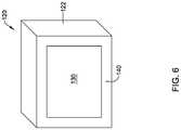
- FIG. 6is a front perspective view of an illustrative HVAC controller
- FIG. 7is a back perspective view of the illustrative HVAC controller of FIG. 6 ;
- FIG. 8is a front perspective view of an illustrative wall plate to which the illustrative HVAC controller of FIG. 6 may be coupled;
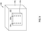
- FIG. 9is a front perspective view of an illustrative portable power supply that may be coupled to the illustrative HVAC controller of FIG. 6 when the illustrative HVAC controller of FIG. 6 is not coupled to the illustrative wall plate of FIG. 8 ;
- FIG. 10is a front perspective view of the illustrative HVAC controller of FIG. 6 coupled to the illustrative portable power supply of FIG. 9 ;
- FIG. 11is a flow diagram showing a method of enrolling a plurality of wireless devices into a zoned HVAC system such as the illustrative HVAC system of FIG. 3 ;
- FIGS. 12 through 15are illustrative screen shots that may be displayed by the illustrative HVAC controllers of FIGS. 4 and 5 when in the commissioning mode.
- references in the specification to “an embodiment”, “some embodiments”, “other embodiments”, etc.,indicate that the embodiment described may include a particular feature, structure, or characteristic, but every embodiment may not necessarily include the particular feature, structure, or characteristic. Moreover, such phrases are not necessarily referring to the same embodiment. Further, when a particular feature, structure, or characteristic is described in connection with an embodiment, it is contemplated that the feature, structure, or characteristic may be applied to other embodiments whether or not explicitly described unless clearly stated to the contrary.
- Building automation systemsare systems that control one or more operations of a building.
- Building automation systemscan include HVAC systems, security systems, fire suppression systems, energy management systems and other systems. While HVAC systems with HVAC controllers are used as an example below, it should be recognized that the concepts disclosed herein can be applied to building automation systems more generally.
- FIG. 1is a schematic view of a building 2 having an illustrative heating, ventilation, and air conditioning (HVAC) system 4 .
- HVACheating, ventilation, and air conditioning
- the illustrative HVAC system 4 of FIG. 1includes one or more HVAC components 6 , a system of ductwork and air vents including a supply air duct 10 and a return air duct 14 , and one or more HVAC controllers 18 .
- the one or more HVAC components 6may include, but are not limited to, a furnace, a heat pump, an electric heat pump, a geothermal heat pump, an electric heating unit, an air conditioning unit, a humidifier, a dehumidifier, an air exchanger, an air cleaner, a damper, a valve, and/or the like.
- the HVAC controller(s) 18may be configured to control the comfort level in the building or structure by activating and deactivating the HVAC component(s) 6 in a controlled manner.
- the HVAC controller(s) 18may be configured to control the HVAC component(s) 6 via a wired or wireless communication link 20 .
- the HVAC controller(s) 18may be a thermostat, such as, for example, a wall mountable thermostat, but this is not required in all embodiments.
- a thermostatmay include (e.g. within the thermostat housing) or have access to one or more temperature sensor(s) for sensing ambient temperature at or near the thermostat.
- the HVAC controller(s) 18may be a zone controller, or may include multiple zone controllers each monitoring and/or controlling the comfort level within a particular zone in the building or other structure.
- the HVAC controller(s) 18may communicate with one or more remote sensors, such as a remote sensor 21 , that may be disposed within the building 2 .
- a remote sensor 21may measure various environmental conditions such as but not limited to temperature.
- the HVAC component(s) 6may provide heated air (and/or cooled air) via the ductwork throughout the building 2 .
- the HVAC component(s) 6may be in fluid communication with every room and/or zone in the building 2 via the ductwork 10 and 14 , but this is not required.
- an HVAC component 6e.g. forced warm air furnace
- the heated airmay be forced through supply air duct 10 by a blower or fan 22 .
- the cooler air from each zonemay be returned to the HVAC component 6 (e.g. forced warm air furnace) for heating via return air ducts 14 .
- an HVAC component 6e.g. air conditioning unit
- the cooled airmay be forced through supply air duct 10 by the blower or fan 22 .
- the warmer air from each zonemay be returned to the HVAC component 6 (e.g. air conditioning unit) for cooling via return air ducts 14 .
- the HVAC system 4may include an internet gateway or other device 23 that may allow one or more of the HVAC components, as described herein, to communicate over a wide area network (WAN) such as, for example, the Internet.
- WANwide area network
- the system of vents or ductwork 10 and/or 14can include one or more dampers 24 to regulate the flow of air, but this is not required.
- one or more dampers 24may be coupled to one or more HVAC controller(s) 18 , and can be coordinated with the operation of one or more HVAC components 6 .
- the one or more HVAC controller(s) 18may actuate dampers 24 to an open position, a closed position, and/or a partially open position to modulate the flow of air from the one or more HVAC components to an appropriate room and/or zone in the building or other structure.
- the dampers 24may be particularly useful in zoned HVAC systems, and may be used to control which zone(s) receives conditioned air and/or receives how much conditioned air from the HVAC component(s) 6 .
- the one or more HVAC controller(s) 18may use information from the one or more remote sensors 21 , which may be disposed within one or more zones, to adjust the position of one or more of the dampers 24 in order to cause a measured value to approach a set point in a particular zone or zones.
- one or more air filters 30may be used to remove dust and other pollutants from the air inside the building 2 .
- the air filter(s) 30is installed in the return air duct 14 , and may filter the air prior to the air entering the HVAC component 6 , but it is contemplated that any other suitable location for the air filter(s) 30 may be used.
- the presence of the air filter(s) 30may not only improve the indoor air quality, but may also protect the HVAC components 6 from dust and other particulate matter that would otherwise be permitted to enter the HVAC component.
- the illustrative HVAC system 4may include an equipment interface module (EIM) 34 .
- the equipment interface module 34may, in addition to controlling the HVAC under the direction of the thermostat, be configured to measure or detect a change in a given parameter between the return air side and the discharge air side of the HVAC system 4 .
- the equipment interface module 34may measure a difference (or absolute value) in temperature, flow rate, pressure, or a combination of any one of these parameters between the return air side and the discharge air side of the HVAC system 4 .
- absolute valueis useful in protecting equipment against an excessively high temperature or an excessively low temperature, for example.
- the equipment interface module 34may be adapted to measure the difference or change in temperature (delta T) between a return air side and discharge air side of the HVAC system 4 for the heating and/or cooling mode.
- the equipment interface module 34may include a first temperature sensor 38 a located in the return (incoming) air duct 14 , and a second temperature sensor 38 b located in the discharge (outgoing or supply) air duct 10 .
- the equipment interface module 34may include a differential pressure sensor including a first pressure tap 39 a located in the return (incoming) air duct 14 , and a second pressure tap 39 b located downstream of the air filter 30 to measure a change in a parameter related to the amount of flow restriction through the air filter 30 .
- the equipment interface module 34when provided, may include at least one flow sensor that is capable of providing a measure that is related to the amount of air flow restriction through the air filter 30 .
- the equipment interface module 34may include an air filter monitor. These are just some examples.
- the equipment interface module 34may be configured to communicate with the HVAC controller 18 via, for example, a wired or wireless communication link 42 . In other cases, the equipment interface module 34 may be incorporated or combined with the HVAC controller 18 . In some instances, the equipment interface module 34 may communicate, relay or otherwise transmit data regarding the selected parameter (e.g. temperature, pressure, flow rate, etc.) to the HVAC controller 18 . In some cases, the HVAC controller 18 may use the data from the equipment interface module 34 to evaluate the system's operation and/or performance.
- the selected parametere.g. temperature, pressure, flow rate, etc.
- the HVAC controller 18may compare data related to the difference in temperature (delta T) between the return air side and the discharge air side of the HVAC system 4 to a previously determined delta T limit stored in the HVAC controller 18 to determine a current operating performance of the HVAC system 4 .
- the equipment interface module 34may itself evaluate the system's operation and/or performance based on the collected data.
- FIG. 2is a schematic view of an illustrative HVAC control system 50 that facilitates remote access and/or control of the illustrative HVAC system 4 shown in FIG. 1 .
- the HVAC control system 50may be considered a building automation system or part of a building automation system.
- the illustrative HVAC control system 50includes an HVAC controller, as for example, HVAC controller 18 (see FIG. 1 ) that is configured to communicate with and control one or more HVAC components 6 of the HVAC system 4 .
- the HVAC controller 18may communicate with the one or more HVAC components 6 of the HVAC system 4 via a wired or wireless communication link 20 .
- the HVAC controller 18may communicate over one or more wired or wireless networks that may accommodate remote access and/or control of the HVAC controller 18 via another device such as a smart phone, tablet, e-reader, laptop computer, personal computer, key fob, or the like.
- the HVAC controller 18may include a first communications port 52 for communicating over a first network 54 , and in some cases, a second communications port 56 for communicating over a second network 58 .
- the first network 54may be a wireless local area network (LAN), and the second network 58 (when provided) may be a wide area network or global network (WAN) including, for example, the Internet.
- LANwireless local area network
- WANglobal network
- the wireless local area network 54may provide a wireless access point and/or a network host device that is separate from the HVAC controller 18 . In other cases, the wireless local area network 54 may provide a wireless access point and/or a network host device that is part of the HVAC controller 18 . In some cases, the wireless local area network 54 may include a local domain name server (DNS), but this is not required for all embodiments. In some cases, the wireless local area network 54 may be an ad-hoc wireless network, but this is not required.
- DNSlocal domain name server
- the HVAC controller 18may be programmed to communicate over the second network 58 with an external web service hosted by one or more external web server(s) 66 .
- an external web serviceis Honeywell's TOTAL CONNECTTM web service.
- the HVAC controller 18may be configured to upload selected data via the second network 58 to the external web service where it may be collected and stored on the external web server 66 . In some cases, the data may be indicative of the performance of the HVAC system 4 . Additionally, the HVAC controller 18 may be configured to receive and/or download selected data, settings and/or services sometimes including software updates from the external web service over the second network 58 .
- the data, settings and/or servicesmay be received automatically from the web service, downloaded periodically in accordance with a control algorithm, and/or downloaded in response to a user request.
- the HVAC controller 18may be configured to receive and/or download an HVAC operating schedule and operating parameter settings such as, for example, temperature set points, humidity set points, start times, end times, schedules, window frost protection settings, and/or the like from the web server 66 over the second network 58 .
- the HVAC controller 18may be configured to receive one or more user profiles having at least one operational parameter setting that is selected by and reflective of a user's preferences.
- the HVAC controller 18may be configured to receive and/or download firmware and/or hardware updates such as, for example, device drivers from the web server 66 over the second network 58 . Additionally, the HVAC controller 18 may be configured to receive local weather data, weather alerts and/or warnings, major stock index ticker data, traffic data, and/or news headlines over the second network 58 . These are just some examples.
- remote access and/or control of the HVAC controller 18may be provided over the first network 54 and/or the second network 58 .
- a variety of remote wireless devices 62may be used to access and/or control the HVAC controller 18 from a remote location (e.g. remote from the HVAC Controller 18 ) over the first network 54 and/or second network 58 including, but not limited to, mobile phones including smart phones, tablet computers, laptop or personal computers, wireless network-enabled key fobs, e-readers, and/or the like.
- the remote wireless devices 62are configured to communicate wirelessly over the first network 54 and/or second network 58 with the HVAC controller 18 via one or more wireless communication protocols including, but not limited to, cellular communication, ZigBee, REDLINKTM, Bluetooth, WiFi, IrDA, dedicated short range communication (DSRC), EnOcean, and/or any other suitable common or proprietary wireless protocol, as desired.
- the remote wireless devices 62may communicate with the network 54 via the external server 66 for security purposes, for example.
- an application program codestored in the memory of the remote wireless device 62 may be used to remotely access and/or control the HVAC controller 18 .
- the application program code (app)may be downloaded from an external web service, such as the web service hosted by the external web server 66 (e.g. Honeywell's TOTAL CONNECTTM web service) or another external web service (e.g. ITUNES® or Google Play).
- the appmay provide a remote user interface for interacting with the HVAC controller 18 at the user's remote wireless device 62 .
- a usermay be able to change operating parameter settings such as, for example, temperature set points, humidity set points, start times, end times, schedules, window frost protection settings, accept software updates and/or the like.
- Communicationsmay be routed from the user's remote wireless device 62 to the web server 66 and then, from the web server 66 to the HVAC controller 18 .
- communicationsmay flow in the opposite direction such as, for example, when a user interacts directly with the HVAC controller 18 to change an operating parameter setting such as, for example, a schedule change or a set point change.
- the change made at the HVAC controller 18may be routed to the web server 66 and then from the web server 66 to the remote wireless device 62 where it may reflected by the application program executed by the remote wireless device 62 .
- a usermay be able to interact with the HVAC controller 18 via a user interface provided by one or more web pages served up by the web server 66 .
- the usermay interact with the one or more web pages using a variety of interne capable devices to effect a setting or other change at the HVAC controller 18 , and in some cases view usage data and energy consumption data related to the usage of the HVAC system 4 .
- communicationmay occur between the user's remote wireless device 62 and the HVAC controller 18 without being relayed through a server such as external server 66 . These are just some examples.
- FIG. 3is a schematic view of a building 70 that includes a zoned HVAC system 69 that is divided into multiple zones.
- the zoned HVAC system 69may include an HVAC controller 80 , an HVAC system 78 , and wireless devices 82 , 84 , 86 , 88 , 90 , 92 and 94 assigned to zones A 72 , B 74 and N 76 .
- the term wireless devicesmay include wireless dampers, wireless sensors and/or any other suitable wireless device. It will be appreciated that that the building 70 may include attributes, equipment and features referenced with respect to the building 2 ( FIG. 1 ).
- the building 70has been divided into a ZONE A, labeled as 72 ; a Zone B, labeled as 74 and any number of additional zones through a ZONE N, labeled as 76 .
- each of the zones 72 , 74 , 76may represent a distinct room within the building 70 .
- At least some of the zones 72 , 74 , 76may represent areas that are larger than a single room.
- at least some of the zones 72 , 74 , 76may represent different floors within the building 70 . These are just examples.
- the building 70includes an HVAC system 78 that provides conditioned air through supply ducts to each of the zones 72 , 74 , 76 , and an HVAC controller 80 that controls operation of the HVAC system 78 .
- the HVAC system 78may be representative of the HVAC system 4 ( FIG. 1 ).
- the HVAC controller 80may be representative of the HVAC controller 18 ( FIG. 1 ).
- each of the zones 72 , 74 , 76may be seen as including wireless devices as shown.
- ZONE Aincludes a wireless device 82 and a wireless sensor 84 .
- the wireless device 82may be a wireless damper that fits into a supply duct providing conditioned air to ZONE A.
- the wireless sensor 84may include a temperature sensor.
- the wireless sensor 84may additionally or alternatively include one or more of a humidity sensor, an air quality sensor and the like.
- ZONE Blabeled as 74
- ZONE Bincludes a wireless device 86 , a wireless sensor 88 and a wireless sensor 90 .
- the Zone Nlabeled as 76 , includes a wireless device 92 and a wireless sensor 94 . It will be appreciated that this is merely illustrative, as a particular zone may include one, two or more distinct wireless devices, and may include more wireless devices and/or sensors than are illustrated.
- the wireless sensors 84 , 88 , 90 , 94communicate directly with the respective wireless devices 82 , 86 , 92 .
- the wireless devices 82 , 86 , 92 and the wireless sensors 84 , 88 , 90 , 94do not communicate directly with each other, but instead each communicate with the HVAC controller 80 .
- the wireless sensors 84 , 88 , 90 , 94may report current air temperatures to the HVAC controller 80 , which in turn determines whether to actuate one or more of the wireless devices 82 , 86 , 92 (e.g. dampers), and subsequently provides appropriate instructions to one or more of the wireless devices 82 , 86 , 92 (e.g. change position of a damper).
- FIG. 4is a schematic diagram of an HVAC controller 100 that may be configured to control a zoned HVAC system that includes a plurality of wireless devices divided into a plurality of zones within a building supported by the zoned HVAC system, such as but not limited to that shown in FIG. 3 .
- the illustrative HVAC controller 100includes a housing 102 and a user interface 104 that is accessible from a position exterior of the housing 102 .
- the user interface 104may be housed by the housing 102 , but this is not required in all cases.
- the user interface 104may instead be remote from the housing 102 yet in communication with the HVAC controller 100 .
- the user interface 104may be part of a smartphone or a tablet that is in communication with the HVAC controller 100 .
- a controller 106is operably coupled to the user interface 104 and includes an operation mode in which the controller 106 provides operational instructions to the HVAC system (e.g. HVAC system 78 of FIG. 3 ), and a commissioning mode in which the plurality of wireless devices/sensors (e.g. wireless devices 82 , 84 , 86 , 88 , 90 , 92 and 94 of FIG. 3 ) can be enrolled into a particular zone of the plurality of zones of the zoned HVAC system 69 .
- the HVAC controller 100may include a power input 108 for receiving power from a power source to power the HVAC controller 100 .
- the power sourcemay be line power (e.g.
- the power sourcemay include a portable power pack that is removably attachable to the HVAC controller 100 in order to deliver power to the power input 108 of the HVAC controller 100 while the HVAC controller 100 is carried about the building 70 .
- the portable power packmay include a battery, for example.
- the controller 106may be configured to accept a first input from a user via the user interface 104 that designates a first zone of the plurality of zones and causes each of two or more first wireless devices that are subsequently placed in an enrollment mode by the user to be enrolled in the first zone.
- the controller 106may further be configured to accept a second input from the user via the user interface 104 that designates a second zone of the plurality of zones and causes each of two or more second wireless devices that are subsequently placed in an enrollment mode by the user to be enrolled in the second zone.
- the controller 106is configured to control the zoned HVAC system 69 using the enrolled wireless devices.
- the controller 106may be configured, when in the commissioning mode and with the first zone designated, to help the user identify a location of a first one of the two or more first wireless devices that are enrolled in the first zone by sending a command to the first one of the two or more first wireless devices that causes the first one of the two or more first wireless devices to output an audible and/or visual indicator that can be perceived by the user.
- the controller 106may be configured to also help the user identify a location of a second one of the two or more first wireless devices that are enrolled in the first zone by sending a command to the second one of the two or more first wireless devices that causes the second one of the two or more first wireless devices to output an audible and/or visual indicator that can be perceived by the user.
- the controller 106may be further configured to help the user change a first one of the two or more first wireless devices that are enrolled in the first zone from a first state to a second state by sending a command that causes the first one of the two or more first wireless devices to change from the first state to the second state (e.g. change a damper to a closed state, an open state, a designated partially open state, etc.).
- the controller 106may also help the user change a second one of the two or more first wireless devices that are enrolled in the first zone from a first state to a second state by sending a command that causes the second one of the two or more first wireless devices enrolled in the first zone to change from a first state to a second state (e.g. change a damper to a closed state, an open state, a designated partially open state, etc.).
- the controller 106may be configured to help the user change a first one of the two or more first wireless devices that are enrolled in the second zone from a first state to a second state by sending a command that causes the first one of the two or more first wireless devices to change from the first state to the second state (e.g. change a damper to a closed state, an open state, a designated partially open state, etc.).
- the controller 106may also help the user change a second one of the two or more first wireless devices that are enrolled in the second zone from a first state to a second state by sending a command that causes the second one of the two or more first wireless devices enrolled in the second zone to change from a first state to a second state (e.g. change a damper to a closed state, an open state, a designated partially open state, etc.).
- a commandthat causes the second one of the two or more first wireless devices enrolled in the second zone to change from a first state to a second state (e.g. change a damper to a closed state, an open state, a designated partially open state, etc.).
- the controller 106may be configured to provide a list of enrolled wireless devices on the user interface 104 . If one of the enrolled wireless devices was accidently enrolled into an incorrect zone, the controller 106 may be configured to enable a user to move a particular enrolled wireless device from one zone to another zone. In some cases, the controller 106 may be configured to enable a user to update the zone designation for a particular one of the plurality of wireless devices when a decision is made to change how one or more of the plurality of wireless devices are divided into zones.
- the controller 106may be configured to receive one or more status indications from each of two or more of the enrolled wireless devices, and to display one or more corresponding status indicators on a display of the user interface 104 .
- the status indicatorsmay be displayed in a manner that associates the status indicators with the corresponding enrolled wireless device.
- status indicators that may be displayedmay include one or more of a sensed temperature, an indication of a damper position, a signal strength, an online connection status, a battery charge status, and/or any other suitable status indicator.
- At least some of the plurality of wireless devicesmay include wireless remote temperature sensors that are configured to be distributed about the building, and when in the operational mode, the controller 106 may be configured to operate the zoned HVAC system in accordance with temperature signals received from the wireless remote temperature sensors.
- the controller 106may be configured to provide operational instructions to the remote dampers in order to operate the zoned HVAC system in accordance with temperature signals from the wireless remote temperature sensors.
- FIG. 5is a schematic diagram of an HVAC controller 120 that may be configured to control a zoned HVAC system that includes a plurality of wireless devices divided into a plurality of zones within a building supported by the zoned HVAC system, such as but not limited to that shown in FIG. 3 .
- the HVAC controller 120includes a housing 122 that is configured to be releasably securable to a wall plate 150 (as shown in FIG. 8 ) that enables electrical connections between the HVAC controller 120 and field wires that extend to the HVAC system (such as but not limited to the HVAC system 4 of FIG. 1 and/or the HVAC system 78 of FIG. 3 ).
- a plurality of terminal pins 124shown schematically as extending from the housing 122 , extend backward from the housing 122 and are configured to operably coupled with one or more terminal blocks disposed on the wall plate 150 .
- a portable power supply 126is configured to engage two or more of the plurality of terminal pins 124 , schematically including a terminal pin engagement 128 , when the housing 122 has been removed from the wall plate 150 .
- the portable power supply 126may be configured to supply power that powers operation of the HVAC controller 120 when the HVAC controller 120 is removed from the wall plate 150 and carried about the building 70 .
- the illustrative HVAC controller 120includes a user interface 130 that is housed by the housing 122 and that is accessible from an exterior of the housing 122 .
- a controller 132is operably coupled to the user interface 130 and is configured to include an operational mode in which the controller 132 provides operational instructions to the HVAC system 78 , and a commissioning mode in which the plurality of wireless devices can be enrolled into a particular zone of the plurality of zones. While the HVAC controller 120 is in the commissioning mode and is being powered by the portable power supply 126 , an installer may take the HVAC controller 120 from zone to zone as they install each of the plurality of wireless devices and may enroll each installed wireless device into a designated zone. The controller 132 may further be configured to control the zoned HVAC system 69 using the enrolled wireless devices.
- the controller 132may be configured to accept a first input from a user via the user interface 130 that designates a first zone of the plurality of zones and causes each of two or more first wireless devices that are subsequently placed in an enrollment mode by the user to be enrolled in the first zone.
- the controller 132may also be configured to accept a second input from the user via the user interface 130 that designates a second zone of the plurality of zones and causes each of two or more second wireless devices that are subsequently placed in an enrollment mode by the user to be enrolled in the second zone.
- the controller 132may be configured to provide via the user interface 130 a graphical display of all wireless devices within a particular zone, and as individual wireless devices are enrolled into the particular zone, icons representing those individual wireless devices appear on the graphical display as assigned to the particular zone.
- FIGS. 6 through 10provide an example of how the HVAC controller 120 may interact with a wall plate 150 ( FIG. 8 ) and with the portable power supply 126 .
- FIG. 6is a front perspective view of the HVAC controller 120 .
- the user interface 130may be seen as being disposed on a front surface 140 of the housing 122 .
- FIG. 7is a rear perspective view of the HVAC controller 120 , showing a back surface 142 of the housing 122 .
- a recess 144is formed within the back surface 142 of the housing 122 .
- the plurality of terminal pins 124shown as a first column 146 of terminal pins and a second column 148 of terminal pins, extend outwardly through the recess 144 .
- FIG. 8is a schematic front perspective view of the wall plate 150 .
- the illustrative wall plate 150has a housing 152 that is configured to fit into the recess 144 that is formed in the back surface 142 of the housing 122 (of the HVAC controller 120 ).
- the wall plate 150includes a first column 154 of terminals and a second column 156 of terminals. It will be appreciated that the first column 154 of terminals is configured to releasably accept the first column 146 of terminal pins and the second column 156 of terminals is configured to releasably accept the second column 148 of terminal pins when the HVAC controller 120 is releasably secured to the wall plate 150 .
- the terminals within the first column 154 of terminalsare operably coupled to a terminal block 158 that is shown schematically within the wall plate 150 and provide electrical connections to a first plurality of field wires 162 .
- the terminals within the second column 156 of terminalsare operably coupled to a terminal block 160 and provide electrical connections to a second plurality of field wires 164 .
- the first plurality of field wires 162 and the second plurality of field wires 164are merely illustrative, as some installations will have additional field wires and some installations will have fewer field wires.
- FIG. 9is a front perspective view of the portable power supply 126 .
- the illustrative portable power supply 126has a housing 170 defining a front surface 172 .
- a raised portion 174extends forward from the front surface 172 .
- the raised portion 174has an overall profile that matches or at least substantially matches that of the housing 152 of the wall plate 150 . Accordingly, the raised portion 174 may be considered as being configured to extend into the recess 144 that is formed within the back surface 142 of the housing 122 (of the HVAC controller 120 ).
- the raised portion 174includes a first column 176 of terminals that are configured to accommodate the first column 146 of terminal pins extending from the HVAC controller 120 as well as a second column 178 of terminals that are configured to accommodate the second column 148 of terminal pins extending from the HVAC controller 120 .
- the portable power supply 126may provide power to operate the HVAC controller 120 via the terminal pins 124 when the HVAC controller 120 is removed from the wall plate 150 and coupled with the portable power supply 126 .
- the resulting assembly 180may be seen in FIG. 10 , for example.
- FIG. 11is a flow diagram showing an illustrative method 190 of enrolling a plurality of wireless devices into a zoned HVAC system having a plurality of zones. It will be appreciated that this method may be carried out using the HVAC controller 18 , 100 , 120 , regardless of whether the HVAC controller 18 , 100 , 120 is mounted to the wall, such as via the wall plate 150 , or is portable as a result of being coupled to the portable power supply 126 .
- a first inputmay be accepted from a user via a user interface that designates a first zone of the plurality of zones, as indicated at block 192 .
- each of one or more first wireless devices that are subsequently placed in an enrollment mode by the user in the first zonemay be enrolled.
- a second inputmay be accepted from the user via the user interface that designates a second zone of the plurality of zones, as indicated at block 196 .
- each of one or more second wireless devices that are subsequently placed in an enrollment mode by the user in the second zonemay be enrolled.
- the zoned HVAC systemmay be controlled using the enrolled wireless devices.
- FIGS. 12 through 15provide an illustrative but non-limiting examples of screens that may be displayed on the user interface 104 , 130 when carrying out the method 190 .
- FIG. 12shows a screen 202 that includes an icon ENROLLING 204 that indicates that the HVAC controller 100 , 120 is in its commissioning mode.
- the screen 202also includes a ZONE SELECTION option 206 .
- the ZONE selection option 206includes a ZONE A button 208 that may for example correspond to the ZONE A labeled as 72 in FIG. 3 , a ZONE B button 210 that may for example correspond to the ZONE B labeled as 74 in FIG.
- a ZONE N button 212may for example correspond to the ZONE N labeled as 76 in FIG. 3 .
- the usermay define the number of zones for the building 70 , and in some cases name the zones as desired. If there are too many zones to display simultaneously on the screen 202 , the screen 202 may include a scrolling capability (not shown).
- the ZONE A button 208has been selected, as indicated by the ZONE A button 208 . This causes a screen 214 , as shown in FIG. 13 , to be displayed.
- the screen 214includes a ZONE A icon 215 to indicate that subsequent devices will be enrolled into Zone A.
- a Device 1 icon 216 and a confirm button 218are displayed, as the result of Device 1 being placed in enrollment mode (e.g. push an enroll button on Device 1) and being provisionally enrolled in Zone A.
- the confirm button 218Device 1 is enrolled in Zone A.
- FIG. 14shows a screen 220 , after a Device 2 is placed in enrollment mode (e.g. push an enroll button on Device 2).
- Device 2 icon 222 and a corresponding confirm button 224are displayed.
- the confirm button 224Device 2 is enrolled in Zone A. If there are additional devices to enroll in Zone A, additional devices will appear on the user interface 104 , 130 as each device is enrolled.
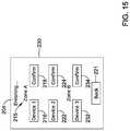
- FIG. 15shows a screen 230 that shows that the installer has moved on to Zone B.
- the screen 230includes a Device 3 icon 232 and an accompanying Confirm button 234 under Zone B.
- the screen 230may include a scrolling feature (not illustrated).
Landscapes
- Engineering & Computer Science (AREA)
- Chemical & Material Sciences (AREA)
- Combustion & Propulsion (AREA)
- Mechanical Engineering (AREA)
- General Engineering & Computer Science (AREA)
- Human Computer Interaction (AREA)
- Signal Processing (AREA)
- Physics & Mathematics (AREA)
- Fuzzy Systems (AREA)
- Mathematical Physics (AREA)
- Air Conditioning Control Device (AREA)
Abstract
Description
Claims (20)
Priority Applications (4)
| Application Number | Priority Date | Filing Date | Title |
|---|---|---|---|
| US16/208,471US11112139B2 (en) | 2018-12-03 | 2018-12-03 | HVAC controller with a zone commissioning mode |
| EP23173549.9AEP4220025B1 (en) | 2018-12-03 | 2019-12-03 | Building automation system controller |
| EP19213370.0AEP3663661B1 (en) | 2018-12-03 | 2019-12-03 | Hvac controller with a zone commissioning mode |
| US17/465,573US11609017B2 (en) | 2018-12-03 | 2021-09-02 | HVAC controller with a zone commissioning mode |
Applications Claiming Priority (1)
| Application Number | Priority Date | Filing Date | Title |
|---|---|---|---|
| US16/208,471US11112139B2 (en) | 2018-12-03 | 2018-12-03 | HVAC controller with a zone commissioning mode |
Related Child Applications (1)
| Application Number | Title | Priority Date | Filing Date |
|---|---|---|---|
| US17/465,573ContinuationUS11609017B2 (en) | 2018-12-03 | 2021-09-02 | HVAC controller with a zone commissioning mode |
Publications (2)
| Publication Number | Publication Date |
|---|---|
| US20200173680A1 US20200173680A1 (en) | 2020-06-04 |
| US11112139B2true US11112139B2 (en) | 2021-09-07 |
Family
ID=68771393
Family Applications (2)
| Application Number | Title | Priority Date | Filing Date |
|---|---|---|---|
| US16/208,471ActiveUS11112139B2 (en) | 2018-12-03 | 2018-12-03 | HVAC controller with a zone commissioning mode |
| US17/465,573Active2038-12-19US11609017B2 (en) | 2018-12-03 | 2021-09-02 | HVAC controller with a zone commissioning mode |
Family Applications After (1)
| Application Number | Title | Priority Date | Filing Date |
|---|---|---|---|
| US17/465,573Active2038-12-19US11609017B2 (en) | 2018-12-03 | 2021-09-02 | HVAC controller with a zone commissioning mode |
Country Status (2)
| Country | Link |
|---|---|
| US (2) | US11112139B2 (en) |
| EP (2) | EP4220025B1 (en) |
Families Citing this family (4)
| Publication number | Priority date | Publication date | Assignee | Title |
|---|---|---|---|---|
| US11112139B2 (en) | 2018-12-03 | 2021-09-07 | Ademco Inc. | HVAC controller with a zone commissioning mode |
| USD976128S1 (en)* | 2020-03-25 | 2023-01-24 | Trolex Corporation | Wireless damper sensor |
| US20230201751A1 (en)* | 2021-12-23 | 2023-06-29 | Woosh Air Inc. | Frame for collapsible and foldable pleated disposable air filter with differential pressure sensor and communication capability |
| US20240353134A1 (en)* | 2023-04-18 | 2024-10-24 | Carrier Corporation | System and method to control indoor air quality in a multi-zone environment |
Citations (69)
| Publication number | Priority date | Publication date | Assignee | Title |
|---|---|---|---|---|
| GB565714A (en) | 1943-05-19 | 1944-11-23 | Ernst Loewenheim | Improvements in and relating to dampers for flues and the like |
| US2844086A (en) | 1954-05-26 | 1958-07-22 | Carrier Corp | Damper arrangements for air conditioning units |
| US4482291A (en) | 1982-05-06 | 1984-11-13 | R. W. Beckett Corporation | Automatic air inlet damper |
| US4949625A (en) | 1989-05-22 | 1990-08-21 | Miklos Louis F | Air volume damper kit and assembly |
| US5520328A (en)* | 1994-11-03 | 1996-05-28 | Carrier Corporation | System for providing integrated zone indoor air quality control |
| US5896959A (en) | 1997-03-13 | 1999-04-27 | Avm, Inc. | Bi-directional damper with a self-centering mechanism |
| US6327368B1 (en) | 1993-12-10 | 2001-12-04 | Fujitsu Limited | Configuration of providing microphone in duct and active noise reduction device using same |
| US20040194484A1 (en) | 2002-11-07 | 2004-10-07 | Shazhou Zou | Affordable and easy to install multi-zone HVAC system |
| US6817378B2 (en) | 2001-04-04 | 2004-11-16 | Abco Consulting, Inc. | Fluid flow control damper assembly |
| US20050270151A1 (en)* | 2003-08-22 | 2005-12-08 | Honeywell International, Inc. | RF interconnected HVAC system and security system |
| US6983889B2 (en) | 2003-03-21 | 2006-01-10 | Home Comfort Zones, Inc. | Forced-air zone climate control system for existing residential houses |
| US20060186213A1 (en)* | 2005-02-23 | 2006-08-24 | Carey Steven L | Variable capacity climate control system for multi-zone space |
| US7455236B2 (en) | 2004-10-06 | 2008-11-25 | Lawrence Kates | Zone thermostat for zone heating and cooling |
| US7455237B2 (en) | 2004-10-06 | 2008-11-25 | Lawrence Kates | System and method for zone heating and cooling |
| US20080314260A1 (en) | 2007-06-22 | 2008-12-25 | Paul Hardenburger | Dual damper control apparatus and method |
| US20090008463A1 (en)* | 2007-01-29 | 2009-01-08 | Judah Benjamin Holland | Climate zone control |
| US20090065595A1 (en) | 2007-09-12 | 2009-03-12 | Lawrence Kates | System and method for zone heating and cooling using controllable supply and return vents |
| US20090140058A1 (en)* | 2007-11-30 | 2009-06-04 | Honeywell International, Inc. | Remote control for use in zoned and non-zoned hvac systems |
| US7543759B2 (en) | 2004-02-06 | 2009-06-09 | Fred George | Multi-valve damper for controlling airflow and method for controlling airflow |
| US7566264B2 (en) | 2006-01-20 | 2009-07-28 | Arzel Zoning Technology, Inc. | Small duct high velocity damper assembly |
| US20100012737A1 (en) | 2008-07-21 | 2010-01-21 | Lawrence Kates | Modular register vent for zone heating and cooling |
| US7663844B2 (en) | 2005-08-30 | 2010-02-16 | Samsung Electronics Co., Ltd. | Actuator arm with arm hole to improve dynamic characteristics and actuator assembly having the same |
| US20100105312A1 (en) | 2006-08-18 | 2010-04-29 | Belimo Holding Ag | Air flap for controlling flow within a conduit |
| US7789317B2 (en) | 2005-09-14 | 2010-09-07 | Arzel Zoning Technology, Inc. | System and method for heat pump oriented zone control |
| US20110198404A1 (en) | 2010-02-18 | 2011-08-18 | Hans Dropmann | Automatic air duct register |
| US8033479B2 (en) | 2004-10-06 | 2011-10-11 | Lawrence Kates | Electronically-controlled register vent for zone heating and cooling |
| US20120239208A1 (en)* | 2008-04-18 | 2012-09-20 | Vigilent Corporation | Method and apparatus for controlling fans in heating, ventilating, and air-conditioning systems |
| US8376242B1 (en)* | 2004-10-28 | 2013-02-19 | Lennox Industries Inc. | Wireless user interface for an HVAC controller and method of operating the same |
| US8457796B2 (en) | 2009-03-11 | 2013-06-04 | Deepinder Singh Thind | Predictive conditioning in occupancy zones |
| US20130261807A1 (en)* | 2012-03-29 | 2013-10-03 | Honeywell International Inc. | Method and system for configuring wireles sensors in an hvac system |
| US20140214212A1 (en)* | 2013-01-25 | 2014-07-31 | Honeywell International Inc. | Auto test for delta t diagnostics in an hvac system |
| US20140324229A1 (en)* | 2013-04-30 | 2014-10-30 | Honeywell International Inc. | Versatile hvac controller |
| US20140349566A1 (en)* | 2013-03-11 | 2014-11-27 | Craig Adam Lamb | HVAC Zoning System Having Distributed Intelligence and Method of Manufacture |
| US20150028113A1 (en)* | 2013-07-29 | 2015-01-29 | Smart Stuff, Inc. | Zone temperature control system |
| US8951103B2 (en) | 2010-10-27 | 2015-02-10 | Arzel Zoning Technology, Inc. | Foldable, boot loadable, insertable air damper device |
| US8956207B2 (en) | 2011-12-13 | 2015-02-17 | Controlled Holdings, Llc | Barometric relief air zone damper |
| US9091280B2 (en) | 2010-04-15 | 2015-07-28 | Nortek Air Solutions, Llc | Methods and systems for active sound attenuation in an air handling unit |
| WO2015134987A1 (en)* | 2014-03-07 | 2015-09-11 | Ubiquiti Networks, Inc. | Digital thermostat, power outlet, and light dimmer |
| US20150300671A1 (en) | 2014-04-22 | 2015-10-22 | Trane International Inc. | System and method for controlling hvac equipment so as to obtain a desired range of a sound pressure level and/or sound power level |
| US9303890B2 (en) | 2013-03-27 | 2016-04-05 | Russell Haines | Intelligent HVAC register airflow control system |
| US9311909B2 (en) | 2012-09-28 | 2016-04-12 | Microsoft Technology Licensing, Llc | Sensed sound level based fan speed adjustment |
| US20160153674A1 (en) | 2013-11-12 | 2016-06-02 | Ecovent Corp. | Method of and System for Determination of Measured Parameter Gradients for Environmental System Control |
| US9441847B2 (en) | 2012-03-19 | 2016-09-13 | Wojciech Maciej Grohman | System for controlling HVAC and lighting functionality |
| US20160291615A1 (en) | 2015-03-31 | 2016-10-06 | Kiban Labs | Smart register apparatus and method |
| US20160333884A1 (en) | 2015-05-12 | 2016-11-17 | Keen Home Inc. | System and method for determining a use condition for an appliance |
| CN106288148A (en) | 2016-08-02 | 2017-01-04 | 北京赛易科信息技术有限公司 | A kind of split-type air conditioner centralized Control methods, devices and systems |
| CN106369788A (en) | 2016-09-07 | 2017-02-01 | 海信(山东)空调有限公司 | Flexible air damper assembly for air conditioner and air conditioner |
| US20170089599A1 (en) | 2015-07-20 | 2017-03-30 | Larry D. Hale | Using wireless hvac dampers for internet of things end-point sensing, monitoring, control and response within buildings |
| US9618222B1 (en) | 2013-04-09 | 2017-04-11 | Keen Home Inc. | Smart vent and atmospheric controller apparatuses, methods and systems |
| US9642022B2 (en) | 2013-03-15 | 2017-05-02 | Amatis Controls, Llc | Wireless network design, commissioning, and controls for HVAC, water heating, and lighting system optimization |
| US20170124842A1 (en)* | 2015-10-28 | 2017-05-04 | Johnson Controls Technology Company | Multi-function thermostat with emergency direction features |
| US9651925B2 (en) | 2008-10-27 | 2017-05-16 | Lennox Industries Inc. | System and method for zoning a distributed-architecture heating, ventilation and air conditioning network |
| US20170177013A1 (en) | 2015-12-21 | 2017-06-22 | Google Inc. | Systems and methods for learning and controlling area zones |
| US9723380B2 (en) | 2013-11-12 | 2017-08-01 | Ecovent Corp. | Method of and system for automatically adjusting airflow and sensors for use therewith |
| US20170292725A1 (en) | 2016-04-11 | 2017-10-12 | Emerson Electric Co. | Systems And Methods For Mobile Application For HVAC Installation and Diagnostics |
| US9835348B2 (en)* | 2011-03-11 | 2017-12-05 | Trane International Inc. | Systems and methods for controlling humidity |
| US20180129232A1 (en)* | 2015-05-12 | 2018-05-10 | Siemens Industry, Inc. | Method and System for Adaptive Control for Thermostats |
| US9995502B1 (en)* | 2015-05-26 | 2018-06-12 | Alarm.Com Incorporated | Enthalpy measurement and system control |
| US20180172308A1 (en)* | 2015-06-21 | 2018-06-21 | Rajesh Ramnik Solanki | System for monitoring and controlling devices and method thereof |
| US20180217621A1 (en)* | 2017-01-29 | 2018-08-02 | Trane International Inc. | Hvac system configuration and zone management |
| US20180266718A1 (en)* | 2015-09-11 | 2018-09-20 | Johnson Controls Technology Company | Thermostat with mode settings for multiple zones |
| AU2017220902A1 (en) | 2016-02-19 | 2018-10-11 | Daikin Industries, Ltd. | Air conditioning system |
| US20180320918A1 (en)* | 2016-01-29 | 2018-11-08 | Mitsubishi Electric Corporation | Air-conditioner remote controller and air-conditioning control system |
| US20180347578A1 (en)* | 2017-05-31 | 2018-12-06 | Trane International Inc. | Momentum Based Blower Interstitial Seal |
| WO2019035051A1 (en)* | 2017-08-16 | 2019-02-21 | Carrier Corporation | Wireless climate control system |
| US20190145648A1 (en)* | 2015-10-28 | 2019-05-16 | Johnson Controls Technology Company | Thermostat with halo light system and emergency directions |
| WO2019175768A1 (en)* | 2018-03-13 | 2019-09-19 | Belimo Holding Sa | Hvac system, hvac method and computer program for hvac system with relative control |
| US20200072543A1 (en)* | 2018-09-05 | 2020-03-05 | Johnson Controls Technology Company | Variable refrigerant flow system with capacity limits |
| US20200116377A1 (en)* | 2018-10-10 | 2020-04-16 | Ademco Inc. | Thermostat with sensor priority screen |
Family Cites Families (1)
| Publication number | Priority date | Publication date | Assignee | Title |
|---|---|---|---|---|
| US11112139B2 (en) | 2018-12-03 | 2021-09-07 | Ademco Inc. | HVAC controller with a zone commissioning mode |
- 2018
- 2018-12-03USUS16/208,471patent/US11112139B2/enactiveActive
- 2019
- 2019-12-03EPEP23173549.9Apatent/EP4220025B1/enactiveActive
- 2019-12-03EPEP19213370.0Apatent/EP3663661B1/enactiveActive
- 2021
- 2021-09-02USUS17/465,573patent/US11609017B2/enactiveActive
Patent Citations (88)
| Publication number | Priority date | Publication date | Assignee | Title |
|---|---|---|---|---|
| GB565714A (en) | 1943-05-19 | 1944-11-23 | Ernst Loewenheim | Improvements in and relating to dampers for flues and the like |
| US2844086A (en) | 1954-05-26 | 1958-07-22 | Carrier Corp | Damper arrangements for air conditioning units |
| US4482291A (en) | 1982-05-06 | 1984-11-13 | R. W. Beckett Corporation | Automatic air inlet damper |
| US4949625A (en) | 1989-05-22 | 1990-08-21 | Miklos Louis F | Air volume damper kit and assembly |
| US6327368B1 (en) | 1993-12-10 | 2001-12-04 | Fujitsu Limited | Configuration of providing microphone in duct and active noise reduction device using same |
| US5520328A (en)* | 1994-11-03 | 1996-05-28 | Carrier Corporation | System for providing integrated zone indoor air quality control |
| US5896959A (en) | 1997-03-13 | 1999-04-27 | Avm, Inc. | Bi-directional damper with a self-centering mechanism |
| US6817378B2 (en) | 2001-04-04 | 2004-11-16 | Abco Consulting, Inc. | Fluid flow control damper assembly |
| US20040194484A1 (en) | 2002-11-07 | 2004-10-07 | Shazhou Zou | Affordable and easy to install multi-zone HVAC system |
| US7832465B2 (en) | 2002-11-07 | 2010-11-16 | Shazhou Zou | Affordable and easy to install multi-zone HVAC system |
| US6983889B2 (en) | 2003-03-21 | 2006-01-10 | Home Comfort Zones, Inc. | Forced-air zone climate control system for existing residential houses |
| US6997390B2 (en) | 2003-03-21 | 2006-02-14 | Home Comfort Zones, Inc. | Retrofit HVAC zone climate control system |
| US20050270151A1 (en)* | 2003-08-22 | 2005-12-08 | Honeywell International, Inc. | RF interconnected HVAC system and security system |
| US7543759B2 (en) | 2004-02-06 | 2009-06-09 | Fred George | Multi-valve damper for controlling airflow and method for controlling airflow |
| US9353963B2 (en) | 2004-10-06 | 2016-05-31 | Google Inc. | Occupancy-based wireless control of multiple environmental zones with zone controller identification |
| US9222692B2 (en) | 2004-10-06 | 2015-12-29 | Google Inc. | Wireless zone control via mechanically adjustable airflow elements |
| US8695888B2 (en) | 2004-10-06 | 2014-04-15 | Nest Labs, Inc. | Electronically-controlled register vent for zone heating and cooling |
| US9353964B2 (en) | 2004-10-06 | 2016-05-31 | Google Inc. | Systems and methods for wirelessly-enabled HVAC control |
| US9316407B2 (en) | 2004-10-06 | 2016-04-19 | Google Inc. | Multiple environmental zone control with integrated battery status communications |
| US9303889B2 (en) | 2004-10-06 | 2016-04-05 | Google Inc. | Multiple environmental zone control via a central controller |
| US7455237B2 (en) | 2004-10-06 | 2008-11-25 | Lawrence Kates | System and method for zone heating and cooling |
| US7455236B2 (en) | 2004-10-06 | 2008-11-25 | Lawrence Kates | Zone thermostat for zone heating and cooling |
| US20160091220A1 (en) | 2004-10-06 | 2016-03-31 | Google Inc. | Wireless zone control via mechanically adjustable airflow elements |
| US9182140B2 (en) | 2004-10-06 | 2015-11-10 | Google Inc. | Battery-operated wireless zone controllers having multiple states of power-related operation |
| US9273879B2 (en) | 2004-10-06 | 2016-03-01 | Google Inc. | Occupancy-based wireless control of multiple environmental zones via a central controller |
| US9194599B2 (en) | 2004-10-06 | 2015-11-24 | Google Inc. | Control of multiple environmental zones based on predicted changes to environmental conditions of the zones |
| US9194600B2 (en) | 2004-10-06 | 2015-11-24 | Google Inc. | Battery charging by mechanical impeller at forced air vent outputs |
| US9995497B2 (en) | 2004-10-06 | 2018-06-12 | Google Llc | Wireless zone control via mechanically adjustable airflow elements |
| US8033479B2 (en) | 2004-10-06 | 2011-10-11 | Lawrence Kates | Electronically-controlled register vent for zone heating and cooling |
| US8376242B1 (en)* | 2004-10-28 | 2013-02-19 | Lennox Industries Inc. | Wireless user interface for an HVAC controller and method of operating the same |
| US20060186213A1 (en)* | 2005-02-23 | 2006-08-24 | Carey Steven L | Variable capacity climate control system for multi-zone space |
| US7663844B2 (en) | 2005-08-30 | 2010-02-16 | Samsung Electronics Co., Ltd. | Actuator arm with arm hole to improve dynamic characteristics and actuator assembly having the same |
| US7789317B2 (en) | 2005-09-14 | 2010-09-07 | Arzel Zoning Technology, Inc. | System and method for heat pump oriented zone control |
| US7566264B2 (en) | 2006-01-20 | 2009-07-28 | Arzel Zoning Technology, Inc. | Small duct high velocity damper assembly |
| US20100105312A1 (en) | 2006-08-18 | 2010-04-29 | Belimo Holding Ag | Air flap for controlling flow within a conduit |
| US20090008463A1 (en)* | 2007-01-29 | 2009-01-08 | Judah Benjamin Holland | Climate zone control |
| US20080314260A1 (en) | 2007-06-22 | 2008-12-25 | Paul Hardenburger | Dual damper control apparatus and method |
| US20090065595A1 (en) | 2007-09-12 | 2009-03-12 | Lawrence Kates | System and method for zone heating and cooling using controllable supply and return vents |
| US20090140058A1 (en)* | 2007-11-30 | 2009-06-04 | Honeywell International, Inc. | Remote control for use in zoned and non-zoned hvac systems |
| US20090140063A1 (en)* | 2007-11-30 | 2009-06-04 | Honeywell International, Inc. | Hvac remote control unit |
| US20120239208A1 (en)* | 2008-04-18 | 2012-09-20 | Vigilent Corporation | Method and apparatus for controlling fans in heating, ventilating, and air-conditioning systems |
| US20100012737A1 (en) | 2008-07-21 | 2010-01-21 | Lawrence Kates | Modular register vent for zone heating and cooling |
| US9651925B2 (en) | 2008-10-27 | 2017-05-16 | Lennox Industries Inc. | System and method for zoning a distributed-architecture heating, ventilation and air conditioning network |
| US8457796B2 (en) | 2009-03-11 | 2013-06-04 | Deepinder Singh Thind | Predictive conditioning in occupancy zones |
| US20110198404A1 (en) | 2010-02-18 | 2011-08-18 | Hans Dropmann | Automatic air duct register |
| US9091280B2 (en) | 2010-04-15 | 2015-07-28 | Nortek Air Solutions, Llc | Methods and systems for active sound attenuation in an air handling unit |
| US20150159908A1 (en) | 2010-10-27 | 2015-06-11 | Arzel Zoning Technology, Inc. | Foldable, boot loadable, insertable air damper device |
| US8951103B2 (en) | 2010-10-27 | 2015-02-10 | Arzel Zoning Technology, Inc. | Foldable, boot loadable, insertable air damper device |
| US9835348B2 (en)* | 2011-03-11 | 2017-12-05 | Trane International Inc. | Systems and methods for controlling humidity |
| US8956207B2 (en) | 2011-12-13 | 2015-02-17 | Controlled Holdings, Llc | Barometric relief air zone damper |
| US9441847B2 (en) | 2012-03-19 | 2016-09-13 | Wojciech Maciej Grohman | System for controlling HVAC and lighting functionality |
| US20130261807A1 (en)* | 2012-03-29 | 2013-10-03 | Honeywell International Inc. | Method and system for configuring wireles sensors in an hvac system |
| US9311909B2 (en) | 2012-09-28 | 2016-04-12 | Microsoft Technology Licensing, Llc | Sensed sound level based fan speed adjustment |
| US20140214212A1 (en)* | 2013-01-25 | 2014-07-31 | Honeywell International Inc. | Auto test for delta t diagnostics in an hvac system |
| US20140349566A1 (en)* | 2013-03-11 | 2014-11-27 | Craig Adam Lamb | HVAC Zoning System Having Distributed Intelligence and Method of Manufacture |
| US9642022B2 (en) | 2013-03-15 | 2017-05-02 | Amatis Controls, Llc | Wireless network design, commissioning, and controls for HVAC, water heating, and lighting system optimization |
| US9303890B2 (en) | 2013-03-27 | 2016-04-05 | Russell Haines | Intelligent HVAC register airflow control system |
| US9618222B1 (en) | 2013-04-09 | 2017-04-11 | Keen Home Inc. | Smart vent and atmospheric controller apparatuses, methods and systems |
| US20170176034A1 (en) | 2013-04-09 | 2017-06-22 | Keen Home Inc. | Smartvent and atmospheric controller apparatuses, methods and systems |
| US20140324229A1 (en)* | 2013-04-30 | 2014-10-30 | Honeywell International Inc. | Versatile hvac controller |
| US20150028113A1 (en)* | 2013-07-29 | 2015-01-29 | Smart Stuff, Inc. | Zone temperature control system |
| US9854335B2 (en) | 2013-11-12 | 2017-12-26 | EcoVent Systems Inc. | Method of and system for automatically adjusting airflow |
| US20160153674A1 (en) | 2013-11-12 | 2016-06-02 | Ecovent Corp. | Method of and System for Determination of Measured Parameter Gradients for Environmental System Control |
| US9723380B2 (en) | 2013-11-12 | 2017-08-01 | Ecovent Corp. | Method of and system for automatically adjusting airflow and sensors for use therewith |
| WO2015134987A1 (en)* | 2014-03-07 | 2015-09-11 | Ubiquiti Networks, Inc. | Digital thermostat, power outlet, and light dimmer |
| US20150300671A1 (en) | 2014-04-22 | 2015-10-22 | Trane International Inc. | System and method for controlling hvac equipment so as to obtain a desired range of a sound pressure level and/or sound power level |
| US20160291615A1 (en) | 2015-03-31 | 2016-10-06 | Kiban Labs | Smart register apparatus and method |
| US20180129232A1 (en)* | 2015-05-12 | 2018-05-10 | Siemens Industry, Inc. | Method and System for Adaptive Control for Thermostats |
| US20160333884A1 (en) | 2015-05-12 | 2016-11-17 | Keen Home Inc. | System and method for determining a use condition for an appliance |
| US9995502B1 (en)* | 2015-05-26 | 2018-06-12 | Alarm.Com Incorporated | Enthalpy measurement and system control |
| US20180172308A1 (en)* | 2015-06-21 | 2018-06-21 | Rajesh Ramnik Solanki | System for monitoring and controlling devices and method thereof |
| US20170089599A1 (en) | 2015-07-20 | 2017-03-30 | Larry D. Hale | Using wireless hvac dampers for internet of things end-point sensing, monitoring, control and response within buildings |
| US20180266718A1 (en)* | 2015-09-11 | 2018-09-20 | Johnson Controls Technology Company | Thermostat with mode settings for multiple zones |
| US20170124842A1 (en)* | 2015-10-28 | 2017-05-04 | Johnson Controls Technology Company | Multi-function thermostat with emergency direction features |
| US20190145648A1 (en)* | 2015-10-28 | 2019-05-16 | Johnson Controls Technology Company | Thermostat with halo light system and emergency directions |
| US20170177013A1 (en) | 2015-12-21 | 2017-06-22 | Google Inc. | Systems and methods for learning and controlling area zones |
| US20180320918A1 (en)* | 2016-01-29 | 2018-11-08 | Mitsubishi Electric Corporation | Air-conditioner remote controller and air-conditioning control system |
| AU2017220902A1 (en) | 2016-02-19 | 2018-10-11 | Daikin Industries, Ltd. | Air conditioning system |
| US20170292725A1 (en) | 2016-04-11 | 2017-10-12 | Emerson Electric Co. | Systems And Methods For Mobile Application For HVAC Installation and Diagnostics |
| CN106288148A (en) | 2016-08-02 | 2017-01-04 | 北京赛易科信息技术有限公司 | A kind of split-type air conditioner centralized Control methods, devices and systems |
| CN106369788A (en) | 2016-09-07 | 2017-02-01 | 海信(山东)空调有限公司 | Flexible air damper assembly for air conditioner and air conditioner |
| US20180217621A1 (en)* | 2017-01-29 | 2018-08-02 | Trane International Inc. | Hvac system configuration and zone management |
| US20180347578A1 (en)* | 2017-05-31 | 2018-12-06 | Trane International Inc. | Momentum Based Blower Interstitial Seal |
| WO2019035051A1 (en)* | 2017-08-16 | 2019-02-21 | Carrier Corporation | Wireless climate control system |
| US20200201368A1 (en)* | 2017-08-16 | 2020-06-25 | Carrier Corporation | Wireless climate control system |
| WO2019175768A1 (en)* | 2018-03-13 | 2019-09-19 | Belimo Holding Sa | Hvac system, hvac method and computer program for hvac system with relative control |
| US20200072543A1 (en)* | 2018-09-05 | 2020-03-05 | Johnson Controls Technology Company | Variable refrigerant flow system with capacity limits |
| US20200116377A1 (en)* | 2018-10-10 | 2020-04-16 | Ademco Inc. | Thermostat with sensor priority screen |
Non-Patent Citations (17)
| Title |
|---|
| "Back-EMF Motion Feedback Blog Post," Acroname, 7 pages, Apr. 17, 2011. |
| "Dampers," Arzel Zoning, 7 pages, 2016. |
| "Dynamic Airflow Balacing (DAB): Save Energy and Provide Comfort," 75F, 15 pages, 2018. |
| "Flair for Central Heating and Cooling," Flair, 7 pages, 2018. |
| "Residential Communicating Control System: iComfort Ultra Smart Thermostat S30," Lennox, 32 pages, Aug. 2017. |
| "Smart VAV with Reheat: A unique system-wide approach to maximizing performance," 75F, 12 pages, 2018. |
| "Smart Vent," Google Image Search, 16 pages, retrieved 2018. |
| "Specification Sheet," Aprilaire, 2 pages, 2005. |
| "Technology Brief," 5 pages, retrieved 2018. |
| "Technology Brief," 75F, 4 pages, retrieved 2018. |
| "Under Pressure: Why Dynamic Monitoring is Essential to Residential HVAC Zoning and Vent Control," Ecovent Corp, 14 pages, Mar. 2014. |
| Extended European Search Report from corresponding European Application No. 19213370.0 dated Apr. 21, 2020 (8 pp). |
| Murthy et al., "Active Noise Control of a Radial Fan," Blekinge Institute of Technology, 66 pages, Dec. 2008. |
| Response to European Communication from corresonding Application Serial No. 19213370.0 filed on Dec. 10, 2020 (47 pp). |
| Singh, "9 Considerations When Employing IOT," 75F, 6 pages, retrieved 2018. |
| Singh, "The EMS is Dead," 75F, 4 pages, retrieved 2018. |
| Singh, "The Internet of Comfort," 75F, 6 pages, retrieved 2018. |
Also Published As
| Publication number | Publication date |
|---|---|
| EP4220025B1 (en) | 2024-07-03 |
| EP3663661B1 (en) | 2023-05-17 |
| US20200173680A1 (en) | 2020-06-04 |
| US20210396416A1 (en) | 2021-12-23 |
| EP4220025A1 (en) | 2023-08-02 |
| US11609017B2 (en) | 2023-03-21 |
| EP3663661A1 (en) | 2020-06-10 |
Similar Documents
| Publication | Publication Date | Title |
|---|---|---|
| US11493224B2 (en) | Method of associating an HVAC controller with an external web service | |
| US10563876B2 (en) | Setup routine to facilitate user setup of an HVAC controller | |
| US10635119B2 (en) | Method and system for configuring wireless sensors in an HVAC system | |
| US11609017B2 (en) | HVAC controller with a zone commissioning mode | |
| EP3488157B1 (en) | Geofence plus schedule for a building controller | |
| US10133283B2 (en) | HVAC controller with wireless network based occupancy detection and control | |
| US10955164B2 (en) | Dehumidification control system | |
| US10253994B2 (en) | HVAC controller with ventilation review mode | |
| EP3240243B1 (en) | Mobile device for building control with adaptive user interface | |
| US9477241B2 (en) | HVAC controller with proximity based message latency control | |
| US10240802B2 (en) | HVAC control system with user interface provided by a mobile wireless device | |
| US20140200718A1 (en) | Systems and methods for facilitating diagnostic testing of an hvac system | |
| US20140151456A1 (en) | Remote application for controlling an hvac system | |
| US20210071895A1 (en) | Antimicrobial composition including an acyl lactylate and a glycol and methods of inhibiting microbial growth utilizing the same | |
| US10302322B2 (en) | Triage of initial schedule setup for an HVAC controller | |
| US10941957B2 (en) | Building controller utilizing multiple sensors and a programmable schedule |
Legal Events
| Date | Code | Title | Description |
|---|---|---|---|
| FEPP | Fee payment procedure | Free format text:ENTITY STATUS SET TO UNDISCOUNTED (ORIGINAL EVENT CODE: BIG.); ENTITY STATUS OF PATENT OWNER: LARGE ENTITY | |
| STPP | Information on status: patent application and granting procedure in general | Free format text:RESPONSE TO NON-FINAL OFFICE ACTION ENTERED AND FORWARDED TO EXAMINER | |
| STPP | Information on status: patent application and granting procedure in general | Free format text:RESPONSE TO NON-FINAL OFFICE ACTION ENTERED AND FORWARDED TO EXAMINER | |
| STPP | Information on status: patent application and granting procedure in general | Free format text:NOTICE OF ALLOWANCE MAILED -- APPLICATION RECEIVED IN OFFICE OF PUBLICATIONS | |
| AS | Assignment | Owner name:ADEMCO INC., MINNESOTA Free format text:ASSIGNMENT OF ASSIGNORS INTEREST;ASSIGNOR:HONEYWELL INTERNATIONAL INC.;REEL/FRAME:055895/0013 Effective date:20181012 | |
| STPP | Information on status: patent application and granting procedure in general | Free format text:DOCKETED NEW CASE - READY FOR EXAMINATION | |
| STPP | Information on status: patent application and granting procedure in general | Free format text:NOTICE OF ALLOWANCE MAILED -- APPLICATION RECEIVED IN OFFICE OF PUBLICATIONS | |
| STPP | Information on status: patent application and granting procedure in general | Free format text:PUBLICATIONS -- ISSUE FEE PAYMENT VERIFIED | |
| STCF | Information on status: patent grant | Free format text:PATENTED CASE | |
| AS | Assignment | Owner name:JPMORGAN CHASE BANK, N.A., AS ADMINISTRATIVE AGENT, NEW YORK Free format text:SECURITY INTEREST;ASSIGNORS:BRK BRANDS, INC.;ADEMCO INC.;REEL/FRAME:059571/0686 Effective date:20220401 | |
| MAFP | Maintenance fee payment | Free format text:PAYMENT OF MAINTENANCE FEE, 4TH YEAR, LARGE ENTITY (ORIGINAL EVENT CODE: M1551); ENTITY STATUS OF PATENT OWNER: LARGE ENTITY Year of fee payment:4 | |
| AS | Assignment | Owner name:RESIDEO LLC, DELAWARE Free format text:CHANGE OF NAME;ASSIGNOR:ADEMCO INC.;REEL/FRAME:071546/0001 Effective date:20241227 |