US11111698B2 - Multipoint lock - Google Patents
Multipoint lockDownload PDFInfo
- Publication number
- US11111698B2 US11111698B2US15/828,638US201715828638AUS11111698B2US 11111698 B2US11111698 B2US 11111698B2US 201715828638 AUS201715828638 AUS 201715828638AUS 11111698 B2US11111698 B2US 11111698B2
- Authority
- US
- United States
- Prior art keywords
- latch
- hub
- rotation
- lock
- handle lever
- Prior art date
- Legal status (The legal status is an assumption and is not a legal conclusion. Google has not performed a legal analysis and makes no representation as to the accuracy of the status listed.)
- Active, expires
Links
Images


Classifications
- E—FIXED CONSTRUCTIONS
- E05—LOCKS; KEYS; WINDOW OR DOOR FITTINGS; SAFES
- E05B—LOCKS; ACCESSORIES THEREFOR; HANDCUFFS
- E05B63/00—Locks or fastenings with special structural characteristics
- E05B63/0065—Operating modes; Transformable to different operating modes
- E—FIXED CONSTRUCTIONS
- E05—LOCKS; KEYS; WINDOW OR DOOR FITTINGS; SAFES
- E05C—BOLTS OR FASTENING DEVICES FOR WINGS, SPECIALLY FOR DOORS OR WINDOWS
- E05C7/00—Fastening devices specially adapted for two wings
- E05C7/04—Fastening devices specially adapted for two wings for wings which abut when closed
- E05C7/06—Fastening devices specially adapted for two wings for wings which abut when closed a fastening device for one wing being actuated or controlled by closing another wing
- E—FIXED CONSTRUCTIONS
- E05—LOCKS; KEYS; WINDOW OR DOOR FITTINGS; SAFES
- E05C—BOLTS OR FASTENING DEVICES FOR WINGS, SPECIALLY FOR DOORS OR WINDOWS
- E05C9/00—Arrangements of simultaneously actuated bolts or other securing devices at well-separated positions on the same wing
- E05C9/02—Arrangements of simultaneously actuated bolts or other securing devices at well-separated positions on the same wing with one sliding bar for fastening when moved in one direction and unfastening when moved in opposite direction; with two sliding bars moved in the same direction when fastening or unfastening
- E05C9/025—Arrangements of simultaneously actuated bolts or other securing devices at well-separated positions on the same wing with one sliding bar for fastening when moved in one direction and unfastening when moved in opposite direction; with two sliding bars moved in the same direction when fastening or unfastening with pins engaging slots
- E—FIXED CONSTRUCTIONS
- E05—LOCKS; KEYS; WINDOW OR DOOR FITTINGS; SAFES
- E05C—BOLTS OR FASTENING DEVICES FOR WINGS, SPECIALLY FOR DOORS OR WINDOWS
- E05C9/00—Arrangements of simultaneously actuated bolts or other securing devices at well-separated positions on the same wing
- E05C9/04—Arrangements of simultaneously actuated bolts or other securing devices at well-separated positions on the same wing with two sliding bars moved in opposite directions when fastening or unfastening
- E05C9/042—Arrangements of simultaneously actuated bolts or other securing devices at well-separated positions on the same wing with two sliding bars moved in opposite directions when fastening or unfastening with pins engaging slots
- E—FIXED CONSTRUCTIONS
- E05—LOCKS; KEYS; WINDOW OR DOOR FITTINGS; SAFES
- E05B—LOCKS; ACCESSORIES THEREFOR; HANDCUFFS
- E05B1/00—Knobs or handles for wings; Knobs, handles, or press buttons for locks or latches on wings
- E05B2001/0076—The handle having at least two operating positions, e.g. the bolt can be retracted by moving the handle either upwards or downwards
- E—FIXED CONSTRUCTIONS
- E05—LOCKS; KEYS; WINDOW OR DOOR FITTINGS; SAFES
- E05B—LOCKS; ACCESSORIES THEREFOR; HANDCUFFS
- E05B47/00—Operating or controlling locks or other fastening devices by electric or magnetic means
- E05B47/0001—Operating or controlling locks or other fastening devices by electric or magnetic means with electric actuators; Constructional features thereof
- E05B2047/0014—Constructional features of actuators or power transmissions therefor
- E05B2047/0018—Details of actuator transmissions
- E05B2047/0023—Nuts or nut-like elements moving along a driven threaded axle
- E—FIXED CONSTRUCTIONS
- E05—LOCKS; KEYS; WINDOW OR DOOR FITTINGS; SAFES
- E05B—LOCKS; ACCESSORIES THEREFOR; HANDCUFFS
- E05B47/00—Operating or controlling locks or other fastening devices by electric or magnetic means
- E05B2047/0048—Circuits, feeding, monitoring
- E05B2047/0057—Feeding
- E05B2047/0059—Feeding by transfer between frame and wing
- E05B2047/0061—Feeding by transfer between frame and wing using induction
- E—FIXED CONSTRUCTIONS
- E05—LOCKS; KEYS; WINDOW OR DOOR FITTINGS; SAFES
- E05B—LOCKS; ACCESSORIES THEREFOR; HANDCUFFS
- E05B47/00—Operating or controlling locks or other fastening devices by electric or magnetic means
- E05B47/0001—Operating or controlling locks or other fastening devices by electric or magnetic means with electric actuators; Constructional features thereof
- E05B47/0012—Operating or controlling locks or other fastening devices by electric or magnetic means with electric actuators; Constructional features thereof with rotary electromotors
- E—FIXED CONSTRUCTIONS
- E05—LOCKS; KEYS; WINDOW OR DOOR FITTINGS; SAFES
- E05B—LOCKS; ACCESSORIES THEREFOR; HANDCUFFS
- E05B63/00—Locks or fastenings with special structural characteristics
- E05B63/18—Locks or fastenings with special structural characteristics with arrangements independent of the locking mechanism for retaining the bolt or latch in the retracted position
- E05B63/185—Preventing actuation of a bolt when the wing is open
- E—FIXED CONSTRUCTIONS
- E05—LOCKS; KEYS; WINDOW OR DOOR FITTINGS; SAFES
- E05C—BOLTS OR FASTENING DEVICES FOR WINGS, SPECIALLY FOR DOORS OR WINDOWS
- E05C7/00—Fastening devices specially adapted for two wings
- E05C7/04—Fastening devices specially adapted for two wings for wings which abut when closed
Definitions
- the present disclosurerelates to locks for entryway doors. In some embodiments, the present disclosure relates more particularly to multipoint locks. In some embodiments, the present disclosure relates more particularly to powered locks.
- entrywayseither include a single hinged door or a set of double doors. If double doors are present, the two doors are typically arranged with the free, non-hinged edge of each door facing each other.
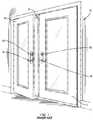
- An example prior art entryway 10 having double doorsis shown in FIG. 1 .
- An astragal 12can be positioned between the two doors.
- the door with the astragal 12can be referred to as a passive door 14 , usually maintained in a closed position with shoot bolts extending from the astragal.
- the door without the astragal 12can be referred to as the active door 16 , which is more often opened to allow passage through the entryway 10 .
- multipoint locksthat have more than one latch or bolt, which are substantially spaced from one another, often provide a more secure closure that is able to seal and secure the entryway better than traditional single-point hardware. Because several latches or bolts are extended or retracted simultaneously, non-trivial effort is sometimes required to operate these multipoint locks.
- deadbolts for door panelscan now be locked or retracted by powered systems based upon an input from a key pad, fob, smart phone, or similar device.
- powered actuation of only a single deadboltinclude substantial packaging placed on the interior or exterior face of the door panel.
- the present disclosureprovides locks and lock components that seek to improve upon existing locks.
- An embodiment of the present disclosureincludes a multipoint lock for securing a door panel.
- the multipoint lockincludes a first latch, a second latch, a first hub rotatable with at least one of a thumb-turn knob or a key, and a second hub rotatable with a handle lever. Upward rotation of the handle lever causes both rotation of the first hub and rotation of the second hub in the same rotational direction
- Another embodiment of the present disclosureincludes a method of operating a multipoint lock.
- the method of operating the multipoint lockincludes the act of locking the multipoint lock by lifting a handle lever. Lifting the handle lever extends at least one latch and causes rotation of a thumb turn drive hub in a first direction.
- the act of locking the multipoint lockalso includes further rotating the thumb turn drive hub in the first direction with one of a key and a thumb-turn knob.
- FIG. 1shows an entryway that can accommodate locks and lock components according to the present disclosure.
- FIG. 2shows a multipoint lock according to one embodiment of the present disclosure.
- FIG. 3Ashows a detailed view of the mortise box of the multipoint lock of FIG. 2 with the mortise box cover removed.
- FIG. 3Bshows an exploded view of the components of the mortise box shown in FIG. 3A .
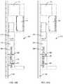
- FIG. 4Ashows the multipoint lock of FIG. 2 in a retracted position.
- FIG. 4Bshows the multipoint lock of FIG. 2 in a latched position.
- FIG. 4Cshows the multipoint lock of FIG. 2 in an extended position.
- FIG. 4Dshows the multipoint lock of FIG. 2 in a locked position.
- FIG. 4Eshows a detailed rear view of the multipoint lock of FIG. 2 in the locked position.
- FIG. 5shows a detailed view of a shoot bolt suitable for use in the multipoint lock of FIG. 2
- FIG. 6shows a detailed view of an embodiment of a mortise box useful for passive door panels with the mortise box cover removed.
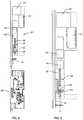
- FIG. 7shows a multipoint lock according to another embodiment of the present disclosure with a powered actuator added.
- FIG. 8shows a more detailed view of the mortise box and powered actuator of the embodiment of FIG. 7 .
- FIG. 9shows a more detailed view of the powered actuator of the embodiment of FIG. 7 .
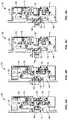
- FIGS. 10A-10Dillustrate a sequence of positions of the powered actuator to operate multipoint locks according to embodiments of the present disclosure.
- FIG. 11is a schematic of an exemplary embodiment for maintaining charge in the power source of the multipoint lock of FIG. 7 .
- latchis defined as a member that slides or pivots into a catch, strike plate, hole, keeper, etc. to fasten or secure a door panel in a closed position relative to the frame of an entryway.
- latchas used herein may include structures referred to in the art as latches, latchbolts, and bolts. Latches may or may not be spring loaded unless specifically noted. Latches can extend vertically or horizontally in relation to the door panel of an entryway.
- the present disclosuredescribes a multipoint lock configured for mounting onto a non-hinged edge of an active or passive door panel to secure the door panel relative to the frame of an entryway.
- the multipoint lockmay include a thumb-turn knob and a handle lever. Upward rotation of the handle lever is configured to cause initial rotation of the thumb-turn knob and extension of at least some of the multiple bolts or latches within the multipoint lock. Further rotation of the thumb-turn knob may result in locking out the multipoint lock.
- FIG. 2shows a multipoint lock 100 incorporating an upper shoot bolt 102 , a lower shoot bolt 104 and a center latch 106 .
- the multipoint lock 100is suitable for mounting into the non-hinged edge of an active door 16 ( FIG. 1 ).
- the upper and lower shoot bolts 102 , 104are configured to extend along the vertical direction into a header and a threshold respectively of the entryway 10 ( FIG. 1 ).
- the upper and lower shoot bolts 102 , 104can be referred to more generally as auxiliary latches.
- the auxiliary latchescan be the shoot bolt type that extend vertically to mate with the header and the threshold as shown. Additionally or alternatively, the auxiliary latches can be of a type that extends and retracts from the non-hinged vertical edge of the active door 16 .
- the multipoint lock 100can be operated with a handle lever 18 and a thumb-turn knob 20 ( FIG. 1 ) in operable engagement with a mortise box 108 ( FIG. 2 ).
- the handle lever 18can be biased to a neutral, typically horizontal position. The user can then rotate the handle lever 18 downward or upward. Though a handle lever 18 is illustrated, knobs may be used in place of the handle lever.
- the thumb-turn knob 20may be replaced by a key cylinder lock set.
- FIG. 3Ashows an interior of the mortise box 108 with the cover removed.
- FIG. 3Bshows an exploded view of the components within the mortise box 108 .
- the mortise box 108houses a handle set drive hub 110 intended to be in operable engagement with the handle lever 18 ( FIG. 1 ) such that a spindle from the handle lever passes through an aperture 112 in the handle set drive hub.
- the handle set drive hub 110similarly rotates.
- the handle set drive hub 110is shown in an initial position in FIG. 3B .
- the initial positionalso may be referred to as a home position or latched position. In the initial position, the handle lever 18 is typically arranged in a horizontal manner.
- the initial position of the handle set drive hub 110may correspond with the latch 106 in a latched position.
- the handle set drive hub 110is biased to the initial position by a spring (not shown) or other handle return means known in the art.
- the handle set drive hub 110also includes a handle boss 114 used to provide an abutment surface.
- the mortise box 108is configured to accept the handle set drive hub 110 and provide one or more stop surfaces 115 ( FIG. 3B ) to limit the magnitude of rotation of the handle set drive hub within the mortise box.
- a thumb-turn drive hub 116is intended to be in operable engagement with the thumb-turn knob 20 ( FIG. 1 ), to rotate therewith.
- a thumb-turn knob 20is common for operating lock components from an interior of a door panel
- the thumb-turn drive hub 116is not limited to operation in conjunction with a thumb-turn knob 20 , but may be operated with a key from the interior and exterior of the door panel.
- the thumb-turn drive hub 116is configured to receive a spindle from the thumb-turn knob 20 through a bore 118 .
- the thumb-turn drive hub 116may include a first boss 120 and a second boss 122 .
- the bosses 120 , 122may extend from the same surface, at opposite ends thereof, of the thumb-turn drive hub 116 .
- the bosses 120 , 122may be integral with the thumb-turn drive hub 116 or may be formed from pins attached to the thumb-turn drive hub.
- the bosses 120 , 122 , as well as the handle boss 114may be surrounded by bushings 124 configured to rotate around each boss.
- the center latch 106is mounted for sliding movement relative to the mortise box 108 along a horizontal direction.
- the center latch 106can be attached to or integrated with a latch carrier 130 .
- the latch carrier 130may include a carrier abutment surface 132 configured for interaction with the handle boss 114 of the handle set drive hub 110 .
- the latch carrier 130may also include a camway 134 .
- the center latch 106 and latch carrier 130may be biased to the illustrated latched position of FIG. 3A by a spring 136 ( FIG. 3B ).
- a first drive plate 140may be provided to selectively coordinate operation of the thumb-turn drive hub 116 , the center latch 106 , and the handle set drive hub 110 .
- the first drive plate 140further selectively coordinates movement of the lower shoot bolt 104 ( FIG. 2 ).
- the first drive plate 140may include a first actuation slot 142 for receiving the first boss 120 of the thumb turn drive hub 116 .
- the first drive plate 140may also include an actuation pin 144 configured to selectively travel within and bear against the camway 134 of the latch carrier 130 .
- the first drive plate 140may further comprise a protrusion 146 that can provide an abutment surface for selectively contacting the handle boss 114 of the handle set drive hub 110 .
- the first drive plate 140may be relatively fixed to a first drive bar 148 leading to the lower shoot bolt 104 .
- a stop arm 150may extend from the first drive plate 140 as discussed in further detail below.
- a retaining notch 152may also be formed in the first drive plate 140 as discussed in further detail below.
- a second drive plate 160( FIGS. 3A and 3B ) can be slidably provided within the mortise box 108 to selectively drive the upper shoot bolt 102 . Therefore, the second drive plate 160 may be fixed relative to a drive bar 148 , which may lead to and drive the upper shoot bolt 102 upon sliding motion thereof.
- the second drive plate 160may include a second actuation slot 164 for receiving the second boss 122 of the thumb turn drive hub 116 .
- an anti-slam device 180may be provided to prevent extension of the shoot bolts 102 , 104 ( FIG. 2 ) from their recessed or latched positions unless the active door 16 ( FIG. 1 ) is closed.
- closing the active door 16depresses the anti-slam device 180 , which is biased by a spring (not shown) to extend from the unhinged edge of the active door, and withdraws the anti-slam device 180 from engagement with the retaining notch 152 of the first drive plate 140 .
- the anti-slam device 180engages the retaining notch 152 , the first drive plate 140 is prevented from moving vertically, and the second drive plate 160 is similarly fixed in position.
- FIGS. 4A-4Dillustrate the operation of the multipoint lock 100 .
- FIG. 4Ashows the multipoint lock 100 in a retracted position.
- the multipoint lock 100assumes the retracted position to open the active door 16 ( FIG. 1 ) from a closed position thereof.
- the retracted positionoccurs when the handle lever 18 ( FIG. 1 ) is rotated downward while the thumb-turn knob 20 is in an unlocked position thereof.
- turning the handle lever 18 downwardrotates the handle set drive hub 110 clockwise approximately 45 degrees.
- Interaction between the handle set drive hub 110 and the latch carrier 130particularly a contact force between the handle boss 114 and the abutment surface 132 , retracts the center latch 106 into the mortise box 108 .
- the shoot bolts 102 , 104( FIG. 2 ) are initially retracted, e.g. recessed relative to the door panel, as understood from both the first and second drive plates 140 , 160 being positioned relatively toward a center of the mortise box 108 , and toward one another.
- FIG. 4Bshows the initial, latched positioned.
- the latched positionmay also be referred to as the unlocked position.
- the center latch 106With the handle lever 18 ( FIG. 1 ) in a neutral, horizontal position, the center latch 106 extends to its home position, a non-zero distance D 1 from the unhinged edge of the door panel.
- the shoot bolts 102 , 104( FIG. 2 ) remain retracted according to the illustrated embodiment, but may also extend from the door panel in the latched position if the shoot bolts yield as the door panel is being closed.
- springs or other biasing meanscan return the handle lever 18 from the downward position corresponding with FIG. 4A to the neutral position corresponding with FIG. 4B by rotating the handle set drive hub 110 counter-clockwise according to the illustrated example.
- FIG. 4CAn extended position of the multipoint lock 100 is shown in FIG. 4C .
- the extended positionmay be also referred to as the deadbolt position or pre-locked position.
- the handle lever 18FIG. 1
- the magnitude of upward rotation of the handle set drive hub 110may be intentionally limited by the one or more stop surfaces 115 ( FIG. 3B ) of the mortise box 108 abutting one or more portions of the handle set drive hub 110 , such as the handle boss 114 .
- the illustrated arrangement between the first drive plate 140 , the thumb-turn drive hub 116 , and the second drive plate 160 shown in FIGS. 3A and 4A -Ccan force the second drive plate upward as the first drive plate is forced downward.
- rotation of the thumb-turn drive hub 116 caused by the lower of the first drive plate 140causes the second boss 122 to bear against the second actuation slot 164 to force the second drive plate 160 upward.
- Upward motion of the second drive plate 160may extend the upper shoot bolt 102 . Therefore, the extended position of FIG. 4C created by upward rotation of the handle lever 18 ( FIG. 1 ) can result in extension of the lower shoot bolt 104 ( FIG.
- the driven directionis the same direction of rotation as the upward pull upon the handle lever 18 , which in the illustrated embodiment creates counterclockwise rotation.
- FIG. 4Dshows a locked position of the multipoint lock 100 , also referred to as a lockout position.
- the thumb-turn knob 20FIG. 1
- the thumb-turn drive hub 116can be rotated approximately an additional 45 degrees in the driven direction, counterclockwise in the illustrated example.
- the additional manual rotation of the thumb-turn knob 20 (or key) and the thumb-turn drive hub 116can force the second drive plate 160 further upward relative to the mortise box 108 and can force the first drive plate 140 further downward relative to the mortise box.
- This movement of the first and second drive plates 140 , 160can further extend the upper shoot bolt 102 ( FIG.
- the camway 134includes a vertical extension 181 such that the center latch 106 is not extended farther between the extended and locked positions. The shape of the vertical extension 181 may help prohibit back-driving the center latch 106 when the multipoint lock 100 is in the locked position.
- the stop arm 150is configured to contact the handle set drive hub 110 such that the handle lever 18 ( FIG. 1 ) can rotate from the upward position to the neutral position, but is substantially prevented from rotating from the neutral position downward. Therefore, when the thumb-turn knob 20 is in the locked position, the handle lever 18 may be prevented from rotating downward to achieve the otherwise retracted position of the multipoint lock 100 . By preventing downward rotation of the handle lever 18 , the user is reminded that the multipoint lock 100 is in the locked position.
- Advantagesmay occur by limiting upward rotation of the handle set drive hub 112 to the position shown in FIG. 4C , and only locking out the multipoint lock 100 with the additional rotation of the thumb turn drive hub 116 .
- the initial upward rotation of the handle set drive hub 112makes use of the mechanical advantage provided by a handle lever 18 to significantly reduce the effort that would otherwise be required to manually rotate the thumb turn drive hub 116 the full 90 degrees to lockout the multipoint lock 100 from the latched position.
- usersmay be unaccustomed to the effects of lifting a handle lever 18 . Therefore, to prevent users from unintentionally locking themselves out of a building, it may be advantageous that lifting the handle lever 18 alone does not fully lock out the multipoint lock 100 .
- the latchescan still be withdrawn by a downward rotation of the handle lever 18 after a prior lifting of the handle lever, unless the thumb turn drive hub 116 was caused to complete its rotation, e.g. 90 degrees from the initial unlocked position.
- FIG. 4Eshows additional details of the multipoint lock 100 in the locked position.
- the thumb turn drive hub 116is shown as an assembly comprising an outer body 182 and an inner body 184 .
- the inner body 184includes at least one pawl 186 adjacent to a groove 188 in the outer body 182 .
- a lockout pin 189is biased into the groove 188 . Placement of the lockout pin 189 in the groove 188 may help prevent undesired rotation of the thumb turn drive hub 116 , such as resulting from unwanted attempts to forcibly depress the center latch 106 .
- the thumb-turn drive hub 116can be rotated by the user, with a key or thumb turn knob 20 , approximately 90 degrees in a direction opposite the driven direction.
- clockwise rotation of the thumb-turn knob 20would release the center latch 106 back to the latched position, and pull the shoot bolts 102 , 104 back to their retracted position.
- the pawl 186 ( FIG. 4E ) on the inner body 184 of the thumb turn drive hub 116may be shaped to force the lockout pin 189 out of the groove 188 upon rotation of a key or thumb turn knob 20 ( FIG. 1 ).
- the multipoint lock 100should be understood as reflective of the operation of the lock from an interior side of the door panel.
- the multipoint lock 100may be operated similarly from the exterior of the door panel. For example, locking out the multipoint lock may occur by lifting the exterior handle lever, then turning a key cylinder. In other embodiments, locking and unlocking the multipoint lock 100 from the exterior side of the door may involve use of the key cylinder without the requirement or ability to lift the exterior handle lever.
- the shoot bolts 102 , 104may be configured to be adjustable to accommodate door panels of various heights, which would cause different dimensions between the first and second drive plates 140 , 160 ( FIG. 3A ) and the top and bottom edges of the door panel.
- FIG. 5shows one example involving an adjuster link 190 coupled to the shoot bolt 102 , 104 .
- the adjuster link 190includes link teeth 192 configured to selectively engage bar teeth 194 formed along the end of the drive bars 148 .
- the teeth 192 , 194may be retained in engagement with one another by a lock channel of the multipoint lock 100 , by a friction fit, or by being configured as interlocking structures.
- a multipoint lock 200may be configured for use in connection with a passive door 14 , such as being incorporated into an astragal 12 .
- the multipoint lock 200is similar to the multipoint lock 100 described above, but where used to secure a passive door 14 , the center latch 106 would be omitted.
- the anti-slam device 180would also likely be omitted.
- the drive plates 240 , 260may be simplified due to the reduced functionality required of the passive door multipoint lock 200 . Otherwise, the shoot bolts 102 , 104 ( FIG. 2 ) could be extended and retracted in the same manner as discussed above. For example, the shoot bolts 102 , 104 may be extended as a result of lifting the handle lever 18 ( FIG.
- the second drive plate 260may include an extension 262 .
- the extension 262In the unlocked position shown in FIG. 6 , the extension 262 may be configured to reside within a window 22 of a strike plate 24 attached to the astragal 12 .
- the extension 262is configured to prevent the center latch 106 of the multipoint lock 100 ( FIG. 2 ) from extending to the locked position while the multipoint lock 200 is unlocked.
- the second drive plate 260may rise, positioning the extension 262 above the window 22 and creating a clear path for the extension of the center latch 106 to the locked position thereof.
- FIG. 7shows a third embodiment of a multipoint lock 300 that is capable of being selectively operated manually, as discussed above with respect to the multipoint lock 100 , and also by a powered actuator, to drive a plurality of bolts, latches, or latch bolts substantially simultaneously.
- the multipoint lock 300is substantially fully packaged within a mortise groove formed in the unhinged edge of a door panel. This packaging arrangement can prevent altering the appearance of the interior or exterior face of the door panel. This packaging arrangement can also accommodate the use of existing hardware, such as handle levers 18 , key cylinders, and thumb-turn knobs 20 as shown in FIG. 1 .
- the multipoint lock 300can include at least one auxiliary latch 302 in the form of a latch extending from the unhinged edge of the door panel. Additionally or alternatively, the at least one auxiliary latch 302 may be in the form of a shoot bolt configured to extend upward or downward from the door panel along a height direction thereof.
- the auxiliary latches 302can be operably connected to the drive bars 148 ( FIG. 3A ).
- the multipoint lock 300may include the same components for manual operation as the multipoint lock 100 described above. Therefore, the drive bars 148 may be fixedly connected to respective drive plates 140 , 160 , which may be translated within a mortise box 108 ( FIG. 2 ) through rotation of one or both of the thumb turn drive hub 116 and the handle set drive hub 110 .
- the multipoint lock 300 of FIG. 7includes a powered actuator 310 configured to selectively operate the multipoint lock 300 , such as translating at least one of the drive bars 148 to ultimately extend and retract the at least one auxiliary latch 302 .
- a powered actuator 310configured to selectively operate the multipoint lock 300 , such as translating at least one of the drive bars 148 to ultimately extend and retract the at least one auxiliary latch 302 .
- translation of the drive bars 148may also transition a center latch 306 between a latched position and an extended position.
- the powered actuator 310may be configured to be coupled to one of the drive bars 148 .
- the powered actuator 310is configured to raise or lower the respective drive bar 148 to actuate at least one of the center latch 306 or the auxiliary latches 302 ( FIG. 7 ).
- the powered actuator 310may cause the auxiliary latches 302 to extend to a locked position or retract to a recessed position, and may cause the center latch 306 to extend to a locked position or withdraw to the latched position.
- the powered actuator 310 of the illustrated embodimentcan include a motor 312 , a controller 314 , and a power source 316 , such as a battery pack.
- the motor 312can engage a coupler 318 which is attached to a drive screw 320 .
- a drive nut 322can be mounted along the drive screw 320 .
- a drive bar connector 324can be fixed to the drive bar 148 and configured to slide along the drive screw 320 .
- the drive bar connector 324can have a pair of spaced apart actuation surfaces 326 .
- the controller 314can be configured to receive a wired or wireless signal and initiate operation of the motor 312 to rotate the drive screw 320 .
- the controller 314receives a signal from a user interface, such as a key pad, disposed on a face of the door panel.
- the controller 314is configured to receive a wireless signal.
- the controller 314can be configured to control the motor 312 to operate in two rotational directions, which in turn provides linear movement of the drive nut 322 in two linear directions, e.g. up and down.
- the controller 314can be configured to sense and control the rate and direction of rotation of the motor 312 in response to external signals.
- the controller 314can also be configured to sense and control the rate and direction of rotation of the motor 312 based upon the position of the drive nut 322 or drive bar connector 324 .
- rotation of the drive screw 320can result in translation of the drive nut 322 along a longitudinal axis A ( FIG. 9 ) of the drive screw.
- Other actuators that provide linear translationare also contemplated.
- continued rotation of the drive screw 320results in continued translation of the drive nut 322 , which causes translation of the drive bar connector 324 and the drive bar 148 , respectively.
- upward translation of the drive bar connector 324can result in motion of the multipoint lock 300 from the latched position, past the extended position, to the locked position.
- FIGS. 10A-Dillustrate relative positioning of components within the multipoint lock 300 that allow for co-existence of manual and powered operation.
- FIG. 10Ashows an upward extreme position of the drive nut 322 , which corresponds with the act of extending the center latch 306 ( FIG. 7 ) and the auxiliary latches 302 with the powered actuator 310 .
- the controller 314is then configured to reverse the motor 312 to lower the drive nut 322 to a neutral, intermediate position shown in FIG. 10B . With the drive nut 322 in the neutral position, the latches 302 , 306 can be withdrawn using the thumb turn drive hub 116 ( FIG.
- the power source 316may take the form of a battery pack, such as a rechargeable battery. Preferably, the power source 316 is replenished without accessing the power source, e.g. without replacing the batteries.
- FIG. 11schematically illustrates a first embodiment in which the power source 316 is re-energized using an inductive charging system.
- a primary coil 360may be installed on a rough opening frame 362 or a door jamb 364 .
- the primary coil 360could be hard wired to the main power supply of the house, such as the electrical grid.
- a secondary coil 370may be incorporated into the powered actuator 310 and operably coupled to the power source 316 . When the door panel is closed, the primary coil 360 should be within sufficient proximity to the secondary coil 370 to transfer energy via an electromagnetic field from the primary coil to the secondary coil, allowing the power source 316 to be re-energized.
- the power source 316may be charged, or provided in the first instance, by being hard wired to the building's main source of electricity.
- electrical energycould pass from the building to the door panel through the hinges of the door panel and travel by wire from the hinge to the power source 316 .
- a solar cellcould be mounted to an exterior face of the door panel to collect energy from the sun to be stored within the batteries of the power source 316 .
- a lockcomprising:
- Paragraph 2The lock of Paragraph 1, wherein the latch is capable of being manually returned from the locked position to the latched position.
- Paragraph 3The lock of Paragraph 1, further comprising a controller configured to receive a wireless signal to initiate operation of the powered actuator.
- Paragraph 4The lock of Paragraph 3, wherein the controller is configured to operate the powered actuator to position a lock nut in a first position to lock the lock, a second position to unlock the lock, and a third position between the first and second positions to provide clearance for manual operation of the lock between a locked position and an unlocked position thereof.
- Paragraph 5The lock of Paragraph 1, further comprising an inductive charging system configured to wirelessly re-energize a power source of the powered actuator.
- Paragraph 6The lock of Paragraph 1, further comprising at least one auxiliary latch capable of being extended by the powered actuator simultaneously with the latch.
- Paragraph 7The lock of Paragraph 1, wherein the powered actuator comprises:
Landscapes
- Engineering & Computer Science (AREA)
- Mechanical Engineering (AREA)
- Structural Engineering (AREA)
- Lock And Its Accessories (AREA)
Abstract
Description
- a latch; and
- a powered actuator,
- wherein the powered actuator is configured to extend the latch from a latched position to a locked position,
- wherein, in the latched position, the latch extends from an edge of a door panel by a first distance, and
- wherein, in the locked position, the latch extends from an edge of the door panel by a second distance, the second distance being greater than the first distance.
- a motor connected to a drive screw, the drive screw capable of rotational movement in two directions;
- a drive nut on the drive screw, the drive nut capable of linear movement in two directions to translate a drive bar connector;
- a drive bar capable of linear movement in two directions in response to translation of the drive bar connector; and
- a drive plate capable of linear movement in two directions in response to movement of the drive bar,
- wherein the latch extends or withdraws in response to movement of the drive plate.
Claims (19)
Priority Applications (3)
| Application Number | Priority Date | Filing Date | Title |
|---|---|---|---|
| US15/828,638US11111698B2 (en) | 2016-12-05 | 2017-12-01 | Multipoint lock |
| CA2987614ACA2987614C (en) | 2016-12-05 | 2017-12-04 | Multipoint lock |
| CA3051951ACA3051951A1 (en) | 2016-12-05 | 2017-12-04 | Multipoint lock |
Applications Claiming Priority (4)
| Application Number | Priority Date | Filing Date | Title |
|---|---|---|---|
| US201662430089P | 2016-12-05 | 2016-12-05 | |
| US201762447955P | 2017-01-19 | 2017-01-19 | |
| US201762488098P | 2017-04-21 | 2017-04-21 | |
| US15/828,638US11111698B2 (en) | 2016-12-05 | 2017-12-01 | Multipoint lock |
Publications (2)
| Publication Number | Publication Date |
|---|---|
| US20180155962A1 US20180155962A1 (en) | 2018-06-07 |
| US11111698B2true US11111698B2 (en) | 2021-09-07 |
Family
ID=62240495
Family Applications (1)
| Application Number | Title | Priority Date | Filing Date |
|---|---|---|---|
| US15/828,638Active2039-12-17US11111698B2 (en) | 2016-12-05 | 2017-12-01 | Multipoint lock |
Country Status (2)
| Country | Link |
|---|---|
| US (1) | US11111698B2 (en) |
| CA (2) | CA3051951A1 (en) |
Cited By (5)
| Publication number | Priority date | Publication date | Assignee | Title |
|---|---|---|---|---|
| US20210102407A1 (en)* | 2017-01-19 | 2021-04-08 | Endura Products, Llc | Multipoint Lock |
| US11549285B2 (en)* | 2018-12-03 | 2023-01-10 | Assa Abloy New Zealand Limited | Lock assembly |
| US11851925B2 (en)* | 2019-02-27 | 2023-12-26 | Sargent Manufacturing Company | Key override for electromechanical multi-point latching device |
| US20240159083A1 (en)* | 2022-09-06 | 2024-05-16 | Surelock Mcgill Limited | Bolting Mechanism |
| EP4624713A1 (en)* | 2024-03-15 | 2025-10-01 | ASSA ABLOY Sicherheitstechnik GmbH | Espagnolette lock with stroke changeover |
Families Citing this family (16)
| Publication number | Priority date | Publication date | Assignee | Title |
|---|---|---|---|---|
| CA2865344A1 (en)* | 2014-09-26 | 2016-03-26 | Rousseau Metal Inc. | Door locking system, door handle mechanism, door featuring such a system or mechanism, kit to assemble them and corresponding assembly and operation methods |
| USD884463S1 (en)* | 2016-06-16 | 2020-05-19 | Martas Precision Slide Co., Ltd. | Connector |
| US10968661B2 (en) | 2016-08-17 | 2021-04-06 | Amesbury Group, Inc. | Locking system having an electronic deadbolt |
| US11162279B1 (en) | 2017-01-04 | 2021-11-02 | Andersen Corporation | Driven lock systems, fenestration units and methods |
| WO2018195081A1 (en) | 2017-04-18 | 2018-10-25 | Amesbury Group, Inc. | Modular electronic deadbolt systems |
| US10808424B2 (en)* | 2017-05-01 | 2020-10-20 | Amesbury Group, Inc. | Modular multi-point lock |
| CN109296258A (en) | 2017-07-25 | 2019-02-01 | 埃美斯博瑞集团有限公司 | Entry handle for sliding door |
| US10267070B2 (en)* | 2017-08-23 | 2019-04-23 | Ford Global Technologies, Llc | Glove box assembly with external latch mechanism |
| US11177690B2 (en)* | 2017-11-17 | 2021-11-16 | B/E Aerospace, Inc. | System for wirelessly supplying electrical power |
| CA3036398A1 (en) | 2018-03-12 | 2019-09-12 | Amesbury Group, Inc. | Electronic deadbolt systems |
| US11834866B2 (en) | 2018-11-06 | 2023-12-05 | Amesbury Group, Inc. | Flexible coupling for electronic deadbolt systems |
| US11661771B2 (en) | 2018-11-13 | 2023-05-30 | Amesbury Group, Inc. | Electronic drive for door locks |
| US11686126B2 (en) | 2019-07-18 | 2023-06-27 | Endura Products, Llc | Methods of operating a lock |
| US12180745B2 (en)* | 2020-07-01 | 2024-12-31 | Cmech (Guangzhou) Ltd. | Door lock with handle |
| ES3031734A1 (en)* | 2024-01-10 | 2025-07-10 | Ra Ba Cierres Electricos S A | THREE-POINT MECHANICAL-MOTORIZED LOCK WITH SELF-LOCKING (Machine-translation by Google Translate, not legally binding) |
| DE102024107453A1 (en)* | 2024-03-15 | 2025-09-18 | Assa Abloy Sicherheitstechnik Gmbh | Deadbolt lock with motorized and manual unlocking |
Citations (194)
| Publication number | Priority date | Publication date | Assignee | Title |
|---|---|---|---|---|
| US284381A (en) | 1883-09-04 | clark | ||
| US1985176A (en) | 1933-10-30 | 1934-12-18 | Robert M Lamb | Multiple bolt lock |
| US3435644A (en) | 1967-10-27 | 1969-04-01 | New England Lock & Hardware Co | Thumb knob attachment for mortise-type lock |
| US3672714A (en)* | 1970-09-28 | 1972-06-27 | Eaton Corp | Mortise lock with multiple functions |
| US3875772A (en)* | 1973-11-28 | 1975-04-08 | Nat Hardware Co Inc | Door latch and anti panic dead bolt lock |
| US3910613A (en)* | 1973-12-18 | 1975-10-07 | Tool Research & Engineering Co | Panic proof lock set |
| US3999789A (en)* | 1976-01-15 | 1976-12-28 | Kysor Industrial Corporation | Lock |
| US4109494A (en)* | 1977-05-31 | 1978-08-29 | Norris Industries | Simultaneous retract mechanism |
| US4353582A (en) | 1978-07-31 | 1982-10-12 | Willi Eigemeier | Door lock with two lock case portions disposed in parallel opposed relationship |
| DE3612761A1 (en) | 1986-04-16 | 1987-10-22 | Bks Gmbh | Device for supplying electrical power to appliances which consume electricity and are fitted to doors, especially electronic door locks |
| US4850208A (en) | 1986-04-28 | 1989-07-25 | The Eastern Company | Latch and lock assemblies with spring-biased pivot bolts |
| US4876783A (en) | 1987-06-19 | 1989-10-31 | Progressive Security Products, Inc. | Method and apparatus for conversion of doorknob lock sets |
| US5265920A (en)* | 1988-09-16 | 1993-11-30 | Aug. Winkaus GmbH & Co. KG | Drive rod lock |
| US5290077A (en) | 1992-01-14 | 1994-03-01 | W&F Manufacturing, Inc. | Multipoint door lock assembly |
| EP0606877A2 (en)* | 1993-01-15 | 1994-07-20 | Hewi Heinrich Wilke Gmbh | Door fitting for a lock with a latchbalt and a deadbolt |
| US5394718A (en) | 1992-04-01 | 1995-03-07 | Roto Frank Eisenwarenfabrik Aktiengesellschaft | Power-assist slide lock |
| US5404737A (en) | 1992-04-01 | 1995-04-11 | Roto Frank Eisenwarenfabrik Aktien | Electrically and manually key-controlled lock |
| US5474348A (en) | 1993-08-24 | 1995-12-12 | Best Lock Corporation | Motorized actuator for mortise lockset |
| US5490699A (en) | 1993-07-19 | 1996-02-13 | Adams Rite Manufacturing Company | Electric strike for fail safe or fail secure operation |
| US5496082A (en)* | 1994-12-20 | 1996-03-05 | Emhart Inc. | Interconnected lock |
| US5495731A (en)* | 1993-03-26 | 1996-03-05 | Roto Frank Eisenwarenfabrik Aktiengesellschaft | Multiple-bolt door lock |
| US5564296A (en) | 1994-07-13 | 1996-10-15 | International Security Products, Inc. | Leverset conversion apparatus |
| US5624941A (en) | 1992-06-23 | 1997-04-29 | Sanofi | Pyrazole derivatives, method of preparing them and pharmaceutical compositions in which they are present |
| US5685584A (en) | 1996-05-24 | 1997-11-11 | Katonah Architectural Hardware | Adaptor spindle |
| US5715715A (en) | 1996-02-13 | 1998-02-10 | Sargent Manufacturing Company | Lock assembly with motorized power screw |
| US5782114A (en)* | 1995-01-13 | 1998-07-21 | Hoppe Ag | Multi-point locking system |
| GB2323626A (en) | 1997-03-25 | 1998-09-30 | Newman Tonks Group Plc | Latch assembly with adjustable spring |
| US5933086A (en) | 1991-09-19 | 1999-08-03 | Schlage Lock Company | Remotely-operated self-contained electronic lock security system assembly |
| EP0942135A1 (en) | 1998-02-23 | 1999-09-15 | Gretsch-Unitas GmbH Baubeschläge | Locking device |
| US6152498A (en) | 1998-02-05 | 2000-11-28 | Fix Ab | Latch assembly |
| US6209931B1 (en)* | 1999-02-22 | 2001-04-03 | Newell Operating Company | Multi-point door locking system |
| US6217087B1 (en) | 1994-12-07 | 2001-04-17 | Mark Weston Fuller | Lock mechanism |
| US6250119B1 (en) | 1997-01-08 | 2001-06-26 | Michel Flon | Mortise lock |
| US6266981B1 (en) | 1997-11-05 | 2001-07-31 | Gretsch-Unitas Gmbh | Lock, in particular mortise lock for an exterior door |
| GB2358668A (en) | 2000-01-31 | 2001-08-01 | Micota | Mortice latch with means for changing a follower spring |
| US6282929B1 (en) | 2000-02-10 | 2001-09-04 | Sargent Manufacturing Company | Multipoint mortise lock |
| EP1182312A2 (en) | 2000-08-21 | 2002-02-27 | Wilh. Schlechtendahl & Söhne GmbH & Co. KG | Mortise lock with means for receiving a drive bar |
| US6354121B1 (en) | 2000-07-21 | 2002-03-12 | Harrow Products, Inc. | Mortise lockset with internal clutch |
| US20020104339A1 (en)* | 2001-01-19 | 2002-08-08 | Roger Saner | Lock |
| US6443506B1 (en)* | 2000-09-21 | 2002-09-03 | Frank Su | Door lock set optionally satisfying either left-side latch or right-side latch in a large rotating angle |
| US6454322B1 (en)* | 2000-09-21 | 2002-09-24 | Frank Su | Door lock set optionally satisfying either left-side latch or right-side latch |
| US6478345B1 (en) | 1999-10-13 | 2002-11-12 | Surelock Mcgill Limited | Multi point bolting mechanism |
| DE10139675A1 (en) | 2001-08-11 | 2003-02-20 | Winkhaus Fa August | locking device |
| US6532779B2 (en) | 2001-06-14 | 2003-03-18 | Shen Mu-Lin | Lockset assembly allowing interchange between an interchangeable core type handle and a cylinder type handle |
| US6557909B2 (en)* | 2001-09-28 | 2003-05-06 | Von Morris Corporation | Mortise lock |
| EP1340871A2 (en) | 2002-02-27 | 2003-09-03 | Gretsch-Unitas GmbH Baubeschläge | Locking device |
| WO2003095774A1 (en) | 2002-05-08 | 2003-11-20 | Domótica Manufactura, S.L. | Motor-driven lock with linear actuator |
| US6688656B1 (en) | 1999-11-22 | 2004-02-10 | Truth Hardware Corporation | Multi-point lock |
| WO2004025057A1 (en) | 2002-09-13 | 2004-03-25 | Sargent Manufacturing Company | Lever handle support mechanism |
| US6725693B2 (en)* | 2002-08-30 | 2004-04-27 | Jer Ming Yu | Door lock with a clutch having a cam-styled axle sleeve |
| US6732557B1 (en) | 2002-02-15 | 2004-05-11 | Raymond E. Zehrung | Electrified mortise lock having a solenoid cradle |
| US6758070B2 (en)* | 2002-08-30 | 2004-07-06 | Jer Ming Yu | Door lock with a clutch having a cam-styled axle sleeve |
| US6793253B2 (en) | 2000-03-24 | 2004-09-21 | Azotec (Pty) Ltd. | Lock |
| GB2400135A (en) | 2003-04-03 | 2004-10-06 | Colin Sidney Middleton | Adjustable roller bolt latches |
| EP1464783A2 (en) | 2003-04-02 | 2004-10-06 | Gretsch-Unitas GmbH Baubeschläge | Lock |
| CA2487694A1 (en)* | 2003-11-18 | 2005-05-18 | Assa Abloy Financial Services Ab | A multi-point lock |
| US6929293B2 (en) | 2002-02-27 | 2005-08-16 | Carl Fuhr Gmbh & Co. Kg | Door lock, particularly sliding door lock with automatic function |
| WO2005106165A2 (en) | 2004-04-27 | 2005-11-10 | Colin Sidney Middleton | Improvements in mortice latches |
| US6971686B2 (en)* | 2000-10-19 | 2005-12-06 | Truth Hardware Corporation | Multipoint lock system |
| US20060000247A1 (en) | 1999-12-08 | 2006-01-05 | Moon Charles W | Electronic lock |
| US7025394B1 (en) | 2005-03-23 | 2006-04-11 | Hunt Harry C | Lock system for integrating into an entry door having a vertical expanse and providing simultaneous multi-point locking along the vertical expanse of the entry door |
| US20060196236A1 (en)* | 2005-01-25 | 2006-09-07 | Frank Gruenendahl | Lock with pivoting release |
| US20060267357A1 (en) | 2003-07-15 | 2006-11-30 | Domenico Semtilli | Electric mortise lock |
| US7293807B2 (en)* | 2003-02-28 | 2007-11-13 | Emco Enterprises, Inc. | Door handle assembly |
| US7303215B2 (en) | 2004-10-25 | 2007-12-04 | Computerized Security Systems | Mortise locking device |
| US7353637B2 (en) | 2002-03-27 | 2008-04-08 | Newell Operating Company | Multipoint lock assembly |
| US20080211239A1 (en) | 2007-03-02 | 2008-09-04 | Jon Edward Keller | Security improvement to solenoid-releasable mortise lockset having thumb-lever actuators |
| US7421868B2 (en) | 2003-03-19 | 2008-09-09 | Mul-T-Lock Technologies Ltd. | Enhanced extendable multipoint lock |
| US7497486B1 (en) | 2004-09-16 | 2009-03-03 | Stanley Security Solutions, Inc. | Multifunction mortise lock |
| US7520152B2 (en) | 2005-09-13 | 2009-04-21 | Eaton Corporation | Lock device and system employing a door lock device |
| US7526933B2 (en) | 2006-10-18 | 2009-05-05 | Master Lock Company Llc | Multipoint door lock |
| US7634928B2 (en) | 2007-11-02 | 2009-12-22 | Harry Hunt | Door locking system |
| US7677067B2 (en)* | 2007-02-28 | 2010-03-16 | Roto Frank Ag | Lock |
| US7701331B2 (en) | 2006-06-12 | 2010-04-20 | Tran Bao Q | Mesh network door lock |
| US7707862B2 (en) | 2004-01-29 | 2010-05-04 | Newell Operating Company | Multi-point door lock and offset extension bolt assembly |
| US7752875B2 (en) | 2003-09-22 | 2010-07-13 | Assa Abloy Australia Pty Limited | Multipoint lock |
| US7818984B2 (en)* | 2006-11-30 | 2010-10-26 | Keicho Hightech, Inc. | Door locking apparatus |
| US7849718B2 (en) | 2007-11-06 | 2010-12-14 | C.R. Laurence Company, Inc. | Deadbolt device for a door |
| EP2264263A2 (en) | 2009-06-15 | 2010-12-22 | BKS GmbH | Lock |
| US7856857B2 (en)* | 2007-12-17 | 2010-12-28 | Imperial Hardware Taiwan, Ltd. | Door lock of key-driven transmission structure |
| US7871112B2 (en)* | 2005-03-03 | 2011-01-18 | Hardware Specialties, Inc. | Reversible double deadbolt mortise latch |
| US7878034B2 (en)* | 2007-02-02 | 2011-02-01 | Hoppe Holding Ag | Locking arrangement for a hinged panel |
| US7926315B2 (en)* | 2006-09-19 | 2011-04-19 | Imperial USA, Ltd | Lock assembly with anti-panic feature and associated method |
| US7946080B2 (en) | 2007-01-29 | 2011-05-24 | Newell Operating Company | Lock assembly |
| US8061166B2 (en) | 2007-12-17 | 2011-11-22 | Imperial Hardware Taiwan, Ltd. | Door lock with transmission mechanism |
| GB2483888A (en) | 2010-09-23 | 2012-03-28 | Zoo Hardware Ltd | Mortise latch |
| US8146392B2 (en) | 2006-12-16 | 2012-04-03 | Carl Fuhr Gmbh & Co. Kg | Multipoint door/window lock with panic override |
| US8161780B1 (en) | 2009-01-16 | 2012-04-24 | G-U Hardware, Inc. | Thumb operated door lock assembly |
| US8199011B2 (en) | 2010-07-29 | 2012-06-12 | I-Tek Metal Mfg. Co., Ltd. | Lock with electric locking function |
| EP2468989A2 (en) | 2010-12-23 | 2012-06-27 | Dorma GmbH + Co. KG | Lock for a door, in particular for a glass door |
| US8234892B2 (en)* | 2008-05-13 | 2012-08-07 | Assa Abloy Australia Pty. Limited | Mortise lock |
| DE202012007916U1 (en) | 2012-08-21 | 2012-10-16 | Bonnel Technologie Gmbh | Locking and / or actuating device for a door, a window or the like |
| US20120280789A1 (en) | 2011-05-02 | 2012-11-08 | Apigy Inc. | Systems and methods for controlling a locking mechanism using a portable electronic device |
| US8348308B2 (en) | 2008-12-19 | 2013-01-08 | Amesbury Group, Inc. | High security lock for door |
| US20130026768A1 (en)* | 2011-05-05 | 2013-01-31 | Nolte Douglas A | Passive door lock device |
| US8398126B2 (en) | 2007-05-21 | 2013-03-19 | Truth Hardware Corporation | Multipoint lock mechanism |
| US8419087B2 (en) | 2010-03-26 | 2013-04-16 | Newfrey, Llc | Mortise lock with dual reverse/lockout mechanism |
| US20130176107A1 (en) | 2011-03-17 | 2013-07-11 | Unikey Technologies, Inc | Wireless access control system and related methods |
| US20130234453A1 (en) | 2012-03-08 | 2013-09-12 | Schlage Lock Company Llc | System and method for adjusting the spring torque of a lock chassis |
| US8534099B2 (en) | 2010-07-01 | 2013-09-17 | Adams Rite Manufacturing Co. | Single and multi-point door lock |
| US8534100B2 (en) | 2009-09-04 | 2013-09-17 | Miao-Hsueh Tsai | Door lock whose transmission mechanism is controlled by a key |
| US8540288B2 (en) | 2009-09-14 | 2013-09-24 | Miao-Hsueh Tsai | Door lock transmission structure |
| US8550506B2 (en)* | 2009-06-30 | 2013-10-08 | Truth Hardware Corporation | Multi-point mortise lock mechanism for swinging door |
| US20140002236A1 (en) | 2010-12-02 | 2014-01-02 | Viscount Security Systems Inc. | Door Lock, System and Method for Remotely Controlled Access |
| US20140069154A1 (en) | 2012-09-11 | 2014-03-13 | Moshe Dolev | Reversible door and multipoint lock |
| US20140077929A1 (en) | 2012-03-08 | 2014-03-20 | Unikey Technologies, Inc. | Wireless access control system and related methods |
| US20140089097A1 (en) | 2012-09-24 | 2014-03-27 | Naver Business Platform Corp. | Method and system for providing advertisement based on gaze of user |
| US8772970B2 (en) | 2006-07-27 | 2014-07-08 | Gainsborough Hardware Industries Limited | Lock arrangement and a method of providing power to a lock |
| WO2014108263A1 (en) | 2013-01-14 | 2014-07-17 | Kfv Karl Fliether Gmbh & Co. Kg | Lock |
| US8839562B2 (en) | 2011-10-24 | 2014-09-23 | Schlage Lock Company | Mortise lock assembly and method of assembling |
| US20140292481A1 (en) | 2011-03-17 | 2014-10-02 | Unikey Technologies, Inc. | Wireless access control system and related methods |
| US8850744B2 (en)* | 2012-05-18 | 2014-10-07 | Truth Hardware Corporation | Hardware for a hinged light panel |
| US20140340196A1 (en) | 2013-05-20 | 2014-11-20 | Delphian Systems, LLC | Access Control Via Selective Direct and Indirect Wireless Communications |
| US8899635B2 (en) | 2008-10-03 | 2014-12-02 | Truth Hardware Corporation | Sliding door multipoint mortise lock with shoot bolts |
| US8973416B2 (en) | 2011-11-29 | 2015-03-10 | Assa Abloy Australia Pty Limited | Lock |
| US8997535B2 (en) | 2010-03-01 | 2015-04-07 | Austin Hardware And Supply, Inc. | Latch assembly |
| US20150176311A1 (en) | 2010-02-25 | 2015-06-25 | Sargent Manufacturing Company | Locking device with embedded circuit board |
| US20150184425A1 (en) | 2012-08-15 | 2015-07-02 | Sargent Manufacturing Company | Inline motorized lock drive for solenoid replacement |
| US9074392B2 (en) | 2006-05-16 | 2015-07-07 | Securitech Group, Inc. | Multi-point exit door lock and method of installation |
| US9074391B2 (en)* | 2012-05-07 | 2015-07-07 | Remi Emiel Van Parys | Panic lock |
| US9098953B2 (en) | 2012-05-08 | 2015-08-04 | Schlage Lock Company Llc | Systems and methods for controlling electronically operable access devices using Wi-Fi and radio frequency technology |
| US20150252595A1 (en) | 2014-03-04 | 2015-09-10 | Amesbury Group, Inc. | Deadbolt-activated supplemental lock |
| US9169668B2 (en) | 2012-09-14 | 2015-10-27 | Hopper Holding AG | Mortise lock conversion kit for operation with an American cylinder |
| US9169666B2 (en) | 2012-01-05 | 2015-10-27 | Yale Security Inc. | Door latch operator apparatus |
| US20150308155A1 (en) | 2012-12-14 | 2015-10-29 | Sargent Manufacturing Company | Electric latch retraction device for vertical rod door latches |
| US9222286B2 (en)* | 2009-03-20 | 2015-12-29 | Hanchett Entry Systems, Inc. | Multiple point door locking system |
| US9235942B2 (en) | 2013-01-15 | 2016-01-12 | Chung-Yu Chen | Non-contact power supply device for an electronic lock |
| US20160017638A1 (en) | 2014-07-17 | 2016-01-21 | Schlage Lock Company Llc | Sensor assemblies for locks |
| US20160060904A1 (en) | 2014-09-03 | 2016-03-03 | Schlage Lock Company Llc | Lock drive assemblies |
| US9284750B2 (en) | 2013-03-11 | 2016-03-15 | Samsung Sds Co., Ltd. | Door mortise lock |
| US9317984B2 (en) | 2013-10-28 | 2016-04-19 | Smartlabs, Inc. | Systems and methods to control locking and unlocking of doors using powerline and radio frequency communications |
| US9322195B2 (en) | 2012-01-30 | 2016-04-26 | Schlage Lock Company Llc | Lock devices, systems and methods |
| US9322201B1 (en) | 2013-03-15 | 2016-04-26 | August Home, Inc. | Intelligent door lock system with wing latches |
| US9326094B2 (en) | 2013-03-15 | 2016-04-26 | August Home, Inc. | BLE/WiFi bridge with audio sensor |
| US9336637B2 (en) | 2011-03-17 | 2016-05-10 | Unikey Technologies Inc. | Wireless access control system and related methods |
| US9334676B2 (en) | 2010-07-15 | 2016-05-10 | Gainesborough Hardware Industries Limited | Lock assembly |
| US9342936B2 (en) | 2013-07-26 | 2016-05-17 | SkyBell Technologies, Inc. | Smart lock systems and methods |
| FR3028547A1 (en)* | 2014-11-17 | 2016-05-20 | Financiere Tirard Sas | LOCK THREE POINTS |
| US9361741B2 (en) | 2009-02-10 | 2016-06-07 | Yikes Llc | System and method for accessing a structure using a mobile device |
| US9378596B2 (en) | 2014-09-30 | 2016-06-28 | I-Tek Metal Mfg. Co., Ltd | Door access control system |
| US20160189459A1 (en) | 2013-03-15 | 2016-06-30 | August Home Inc. | Intelligent door lock system with encryption |
| US9382739B1 (en) | 2013-03-15 | 2016-07-05 | August Home, Inc. | Determining right or left hand side door installation |
| US9396599B1 (en) | 2015-05-29 | 2016-07-19 | Google Inc. | Systems and methods for anticipatory locking and unlocking of a smart-sensor door lock |
| US9404284B2 (en)* | 2011-05-09 | 2016-08-02 | Stendals El Ab | Shaft arrangement for a locking device and a locking device |
| US9406180B2 (en) | 2012-08-16 | 2016-08-02 | Schlage Lock Company, Llc | Wireless access control for electronic lock |
| US9428940B1 (en) | 2015-06-05 | 2016-08-30 | Clarence E. Patrick | Three-way door latch |
| US9428937B2 (en)* | 2011-07-22 | 2016-08-30 | Amesbury Group, Inc. | Multi-point lock having sequentially-actuated locking elements |
| US9437062B2 (en) | 2012-08-16 | 2016-09-06 | Schlage Lock Company Llc | Electronic lock authentication method and system |
| US9435143B2 (en) | 2014-05-01 | 2016-09-06 | I-Tek Metal Mfg. Co., Ltd. | Cylindrical lock with automatic electronic locking function |
| US9435142B2 (en) | 2014-02-28 | 2016-09-06 | Schlage Lock Company Llc | Method of operating an access control system |
| US9447609B2 (en) | 2013-03-15 | 2016-09-20 | August Home, Inc. | Mobile device that detects tappings/vibrations which are used to lock or unlock a door |
| US20160273243A1 (en) | 2015-03-20 | 2016-09-22 | Adolfo, LLC | Electric lock with latch retractor |
| US9472034B2 (en) | 2012-08-16 | 2016-10-18 | Schlage Lock Company Llc | Electronic lock system |
| US20160312504A1 (en) | 2013-02-28 | 2016-10-27 | Tyto Life LLC | Door lock assembly for a dwelling |
| US20160319569A1 (en) | 2013-03-15 | 2016-11-03 | August Home Inc. | Intelligent door lock system with a housing having a minimum internal volume |
| US20160328901A1 (en) | 2014-03-12 | 2016-11-10 | August Home Inc. | Intelligent door lock system retrofitted to exisiting door lock mechanism |
| US9500007B2 (en) | 2011-07-14 | 2016-11-22 | Gainsborough Hardware Industries Limited | Lock assembly |
| US9501883B2 (en) | 2011-03-17 | 2016-11-22 | Unikey Technologies Inc. | Wireless access control system including lock assembly generated magnetic field based unlocking and related methods |
| US9502884B2 (en) | 2013-08-15 | 2016-11-22 | University Of South Carolina | Methods and systems for protecting DC circuits |
| US9501880B2 (en) | 2011-03-17 | 2016-11-22 | Unikey Technologies Inc. | Wireless access control system including remote access wireless device generated magnetic field based unlocking and related methods |
| US9506278B2 (en) | 2011-03-30 | 2016-11-29 | Hoppe Holding Ag | Modular multi-point lock system |
| US9514585B2 (en) | 2012-08-16 | 2016-12-06 | Schlage Lock Company Llc | Wireless electronic lock system and method |
| US9512643B1 (en) | 2013-11-14 | 2016-12-06 | Josh Keefe | Door unlocking systems and methods |
| US9524601B1 (en) | 2015-12-28 | 2016-12-20 | Unikey Technologies Inc. | Wireless access control system including door position based lock switching and related methods |
| US9530262B2 (en) | 2014-08-13 | 2016-12-27 | August Home, Inc. | Intelligent door lock system with wireless access control system |
| US9530264B2 (en) | 2014-12-15 | 2016-12-27 | Assa Abloy Inc. | Using low power radio to control a higher power communication interface |
| US9528294B2 (en) | 2013-03-15 | 2016-12-27 | August Home, Inc. | Intelligent door lock system with a torque limitor |
| US9536363B2 (en) | 2012-08-16 | 2017-01-03 | Schlage Lock Company, Llc | Operation communication system |
| US20170002586A1 (en) | 2015-07-01 | 2017-01-05 | Dominick S. LEE | Installation-Free Rechargeable Door Locking Apparatus, Systems and Methods |
| US9539755B2 (en) | 2013-03-07 | 2017-01-10 | Sidel Participations | Device for transporting a hollow body comprising improved grasping means |
| US9546504B2 (en) | 2013-10-07 | 2017-01-17 | Poly-Care Aps | Motorised door lock actuator |
| US20170030112A1 (en)* | 2013-12-19 | 2017-02-02 | Union Tool Exporters, Ltd. | Multipoint locking door hardware |
| US20170032602A1 (en) | 2014-03-12 | 2017-02-02 | August Home Inc. | Intelligent door lock system with audio and rf communication |
| US9574372B2 (en) | 2013-03-15 | 2017-02-21 | August Home, Inc. | Intelligent door lock system that minimizes inertia applied to components |
| US9580931B2 (en) | 2011-04-25 | 2017-02-28 | Belwith Products, Llc | Mortise lock apparatus and electronic operating system |
| US9580934B2 (en) | 2012-07-13 | 2017-02-28 | Schlage Lock Company Llc | Electronic door lock assembly preload compensation system |
| US20170058579A1 (en) | 2015-08-31 | 2017-03-02 | Truth Hardware | Locking bolt with surface-mounted transmission |
| US9613478B2 (en) | 2015-05-18 | 2017-04-04 | Unikey Technologies Inc. | Wireless access control system for a door including door position based authentication and related methods |
| US9617757B2 (en) | 2010-02-25 | 2017-04-11 | Sargent Manufacturing Company | Locking device with configurable electrical connector key and internal circuit board for electronic door locks |
| US9624701B2 (en) | 2010-08-30 | 2017-04-18 | Hoppe Holding Ag | Multi-point lock having a shootbolt with a flat driverail mounted in a narrow groove |
| US9626814B2 (en) | 2014-12-23 | 2017-04-18 | Vivint, Inc. | Smart door lock |
| US9631400B2 (en) | 2011-03-11 | 2017-04-25 | Schlage Lock Company Llc | Multi-mode lock assembly |
| US9631920B2 (en) | 2013-10-16 | 2017-04-25 | Google Inc. | Sensing system for verifying deadbolt engagement |
| WO2017068518A1 (en) | 2015-10-22 | 2017-04-27 | Christian Guillemette | Multipoint door locking system |
| US9640004B2 (en) | 2013-12-23 | 2017-05-02 | Assa Abloy Inc. | Method for utilizing a wireless connection to unlock an opening |
| US9637957B2 (en)* | 2012-11-06 | 2017-05-02 | Amesbury Group, Inc. | Automatically-extending remote door lock bolts |
| US20170152681A1 (en) | 2015-11-27 | 2017-06-01 | Tong Lung Metal Industry Co., Ltd. | Door lock having locking mechanism |
| US9702168B2 (en) | 2013-02-28 | 2017-07-11 | Tyto Life LLC | Door lock assembly for a dwelling |
| US9765550B2 (en)* | 2012-08-31 | 2017-09-19 | Amesbury Group, Inc. | Passive door lock mechanisms |
| US20180187454A1 (en)* | 2016-12-29 | 2018-07-05 | Townsteel, Inc. | Sliding actuator assembly for a latchset |
| US20180187464A1 (en)* | 2016-12-29 | 2018-07-05 | Townsteel, Inc. | Double latch lockset |
| US20180202194A1 (en)* | 2017-01-19 | 2018-07-19 | Endura Products, Inc. | Multipoint lock |
| US20190119952A1 (en)* | 2017-10-25 | 2019-04-25 | Endura Products, Inc. | Residential entryway door with concealed multipoint lock |
| US10669754B2 (en)* | 2014-09-26 | 2020-06-02 | Rousseau Métal Inc. | Door-locking system |
- 2017
- 2017-12-01USUS15/828,638patent/US11111698B2/enactiveActive
- 2017-12-04CACA3051951Apatent/CA3051951A1/enactivePending
- 2017-12-04CACA2987614Apatent/CA2987614C/enactiveActive
Patent Citations (222)
| Publication number | Priority date | Publication date | Assignee | Title |
|---|---|---|---|---|
| US284381A (en) | 1883-09-04 | clark | ||
| US1985176A (en) | 1933-10-30 | 1934-12-18 | Robert M Lamb | Multiple bolt lock |
| US3435644A (en) | 1967-10-27 | 1969-04-01 | New England Lock & Hardware Co | Thumb knob attachment for mortise-type lock |
| US3672714A (en)* | 1970-09-28 | 1972-06-27 | Eaton Corp | Mortise lock with multiple functions |
| US3875772A (en)* | 1973-11-28 | 1975-04-08 | Nat Hardware Co Inc | Door latch and anti panic dead bolt lock |
| US3910613A (en)* | 1973-12-18 | 1975-10-07 | Tool Research & Engineering Co | Panic proof lock set |
| US3999789A (en)* | 1976-01-15 | 1976-12-28 | Kysor Industrial Corporation | Lock |
| US4109494A (en)* | 1977-05-31 | 1978-08-29 | Norris Industries | Simultaneous retract mechanism |
| US4353582A (en) | 1978-07-31 | 1982-10-12 | Willi Eigemeier | Door lock with two lock case portions disposed in parallel opposed relationship |
| DE3612761A1 (en) | 1986-04-16 | 1987-10-22 | Bks Gmbh | Device for supplying electrical power to appliances which consume electricity and are fitted to doors, especially electronic door locks |
| US4850208A (en) | 1986-04-28 | 1989-07-25 | The Eastern Company | Latch and lock assemblies with spring-biased pivot bolts |
| US4876783A (en) | 1987-06-19 | 1989-10-31 | Progressive Security Products, Inc. | Method and apparatus for conversion of doorknob lock sets |
| US5265920A (en)* | 1988-09-16 | 1993-11-30 | Aug. Winkaus GmbH & Co. KG | Drive rod lock |
| US5933086A (en) | 1991-09-19 | 1999-08-03 | Schlage Lock Company | Remotely-operated self-contained electronic lock security system assembly |
| US5290077A (en) | 1992-01-14 | 1994-03-01 | W&F Manufacturing, Inc. | Multipoint door lock assembly |
| US5394718A (en) | 1992-04-01 | 1995-03-07 | Roto Frank Eisenwarenfabrik Aktiengesellschaft | Power-assist slide lock |
| US5404737A (en) | 1992-04-01 | 1995-04-11 | Roto Frank Eisenwarenfabrik Aktien | Electrically and manually key-controlled lock |
| US5624941A (en) | 1992-06-23 | 1997-04-29 | Sanofi | Pyrazole derivatives, method of preparing them and pharmaceutical compositions in which they are present |
| EP0606877A2 (en)* | 1993-01-15 | 1994-07-20 | Hewi Heinrich Wilke Gmbh | Door fitting for a lock with a latchbalt and a deadbolt |
| US5495731A (en)* | 1993-03-26 | 1996-03-05 | Roto Frank Eisenwarenfabrik Aktiengesellschaft | Multiple-bolt door lock |
| US5490699A (en) | 1993-07-19 | 1996-02-13 | Adams Rite Manufacturing Company | Electric strike for fail safe or fail secure operation |
| US5474348A (en) | 1993-08-24 | 1995-12-12 | Best Lock Corporation | Motorized actuator for mortise lockset |
| US5564296A (en) | 1994-07-13 | 1996-10-15 | International Security Products, Inc. | Leverset conversion apparatus |
| US6217087B1 (en) | 1994-12-07 | 2001-04-17 | Mark Weston Fuller | Lock mechanism |
| US5496082A (en)* | 1994-12-20 | 1996-03-05 | Emhart Inc. | Interconnected lock |
| US5782114A (en)* | 1995-01-13 | 1998-07-21 | Hoppe Ag | Multi-point locking system |
| US5715715A (en) | 1996-02-13 | 1998-02-10 | Sargent Manufacturing Company | Lock assembly with motorized power screw |
| US5685584A (en) | 1996-05-24 | 1997-11-11 | Katonah Architectural Hardware | Adaptor spindle |
| US6250119B1 (en) | 1997-01-08 | 2001-06-26 | Michel Flon | Mortise lock |
| GB2323626A (en) | 1997-03-25 | 1998-09-30 | Newman Tonks Group Plc | Latch assembly with adjustable spring |
| US6266981B1 (en) | 1997-11-05 | 2001-07-31 | Gretsch-Unitas Gmbh | Lock, in particular mortise lock for an exterior door |
| US6152498A (en) | 1998-02-05 | 2000-11-28 | Fix Ab | Latch assembly |
| EP0942135A1 (en) | 1998-02-23 | 1999-09-15 | Gretsch-Unitas GmbH Baubeschläge | Locking device |
| US6209931B1 (en)* | 1999-02-22 | 2001-04-03 | Newell Operating Company | Multi-point door locking system |
| US6478345B1 (en) | 1999-10-13 | 2002-11-12 | Surelock Mcgill Limited | Multi point bolting mechanism |
| US6688656B1 (en) | 1999-11-22 | 2004-02-10 | Truth Hardware Corporation | Multi-point lock |
| US7051561B2 (en) | 1999-12-08 | 2006-05-30 | Computerized Security Systems, Inc. | Electronic lock |
| US20060000247A1 (en) | 1999-12-08 | 2006-01-05 | Moon Charles W | Electronic lock |
| GB2358668A (en) | 2000-01-31 | 2001-08-01 | Micota | Mortice latch with means for changing a follower spring |
| US6282929B1 (en) | 2000-02-10 | 2001-09-04 | Sargent Manufacturing Company | Multipoint mortise lock |
| US6793253B2 (en) | 2000-03-24 | 2004-09-21 | Azotec (Pty) Ltd. | Lock |
| US6354121B1 (en) | 2000-07-21 | 2002-03-12 | Harrow Products, Inc. | Mortise lockset with internal clutch |
| EP1182312A2 (en) | 2000-08-21 | 2002-02-27 | Wilh. Schlechtendahl & Söhne GmbH & Co. KG | Mortise lock with means for receiving a drive bar |
| US6443506B1 (en)* | 2000-09-21 | 2002-09-03 | Frank Su | Door lock set optionally satisfying either left-side latch or right-side latch in a large rotating angle |
| US6454322B1 (en)* | 2000-09-21 | 2002-09-24 | Frank Su | Door lock set optionally satisfying either left-side latch or right-side latch |
| US6971686B2 (en)* | 2000-10-19 | 2005-12-06 | Truth Hardware Corporation | Multipoint lock system |
| US20020104339A1 (en)* | 2001-01-19 | 2002-08-08 | Roger Saner | Lock |
| US6532779B2 (en) | 2001-06-14 | 2003-03-18 | Shen Mu-Lin | Lockset assembly allowing interchange between an interchangeable core type handle and a cylinder type handle |
| DE10139675A1 (en) | 2001-08-11 | 2003-02-20 | Winkhaus Fa August | locking device |
| US6557909B2 (en)* | 2001-09-28 | 2003-05-06 | Von Morris Corporation | Mortise lock |
| US6732557B1 (en) | 2002-02-15 | 2004-05-11 | Raymond E. Zehrung | Electrified mortise lock having a solenoid cradle |
| US6929293B2 (en) | 2002-02-27 | 2005-08-16 | Carl Fuhr Gmbh & Co. Kg | Door lock, particularly sliding door lock with automatic function |
| EP1340871A2 (en) | 2002-02-27 | 2003-09-03 | Gretsch-Unitas GmbH Baubeschläge | Locking device |
| US7353637B2 (en) | 2002-03-27 | 2008-04-08 | Newell Operating Company | Multipoint lock assembly |
| WO2003095774A1 (en) | 2002-05-08 | 2003-11-20 | Domótica Manufactura, S.L. | Motor-driven lock with linear actuator |
| US6758070B2 (en)* | 2002-08-30 | 2004-07-06 | Jer Ming Yu | Door lock with a clutch having a cam-styled axle sleeve |
| US6725693B2 (en)* | 2002-08-30 | 2004-04-27 | Jer Ming Yu | Door lock with a clutch having a cam-styled axle sleeve |
| WO2004025057A1 (en) | 2002-09-13 | 2004-03-25 | Sargent Manufacturing Company | Lever handle support mechanism |
| US7293807B2 (en)* | 2003-02-28 | 2007-11-13 | Emco Enterprises, Inc. | Door handle assembly |
| US7421868B2 (en) | 2003-03-19 | 2008-09-09 | Mul-T-Lock Technologies Ltd. | Enhanced extendable multipoint lock |
| EP1464783A2 (en) | 2003-04-02 | 2004-10-06 | Gretsch-Unitas GmbH Baubeschläge | Lock |
| GB2400135A (en) | 2003-04-03 | 2004-10-06 | Colin Sidney Middleton | Adjustable roller bolt latches |
| US20060267357A1 (en) | 2003-07-15 | 2006-11-30 | Domenico Semtilli | Electric mortise lock |
| US7752875B2 (en) | 2003-09-22 | 2010-07-13 | Assa Abloy Australia Pty Limited | Multipoint lock |
| CA2487694A1 (en)* | 2003-11-18 | 2005-05-18 | Assa Abloy Financial Services Ab | A multi-point lock |
| US7707862B2 (en) | 2004-01-29 | 2010-05-04 | Newell Operating Company | Multi-point door lock and offset extension bolt assembly |
| WO2005106165A2 (en) | 2004-04-27 | 2005-11-10 | Colin Sidney Middleton | Improvements in mortice latches |
| US7497486B1 (en) | 2004-09-16 | 2009-03-03 | Stanley Security Solutions, Inc. | Multifunction mortise lock |
| US7303215B2 (en) | 2004-10-25 | 2007-12-04 | Computerized Security Systems | Mortise locking device |
| US20060196236A1 (en)* | 2005-01-25 | 2006-09-07 | Frank Gruenendahl | Lock with pivoting release |
| US7871112B2 (en)* | 2005-03-03 | 2011-01-18 | Hardware Specialties, Inc. | Reversible double deadbolt mortise latch |
| US7025394B1 (en) | 2005-03-23 | 2006-04-11 | Hunt Harry C | Lock system for integrating into an entry door having a vertical expanse and providing simultaneous multi-point locking along the vertical expanse of the entry door |
| US7520152B2 (en) | 2005-09-13 | 2009-04-21 | Eaton Corporation | Lock device and system employing a door lock device |
| US9074392B2 (en) | 2006-05-16 | 2015-07-07 | Securitech Group, Inc. | Multi-point exit door lock and method of installation |
| US8358197B2 (en) | 2006-06-12 | 2013-01-22 | Tran Bao Q | Mesh network door lock |
| US7701331B2 (en) | 2006-06-12 | 2010-04-20 | Tran Bao Q | Mesh network door lock |
| US8035479B2 (en) | 2006-06-12 | 2011-10-11 | Tran Bao Q | Mesh network door lock |
| US8772970B2 (en) | 2006-07-27 | 2014-07-08 | Gainsborough Hardware Industries Limited | Lock arrangement and a method of providing power to a lock |
| US7926315B2 (en)* | 2006-09-19 | 2011-04-19 | Imperial USA, Ltd | Lock assembly with anti-panic feature and associated method |
| US7526933B2 (en) | 2006-10-18 | 2009-05-05 | Master Lock Company Llc | Multipoint door lock |
| US7818984B2 (en)* | 2006-11-30 | 2010-10-26 | Keicho Hightech, Inc. | Door locking apparatus |
| US8146392B2 (en) | 2006-12-16 | 2012-04-03 | Carl Fuhr Gmbh & Co. Kg | Multipoint door/window lock with panic override |
| US7946080B2 (en) | 2007-01-29 | 2011-05-24 | Newell Operating Company | Lock assembly |
| US7878034B2 (en)* | 2007-02-02 | 2011-02-01 | Hoppe Holding Ag | Locking arrangement for a hinged panel |
| US7677067B2 (en)* | 2007-02-28 | 2010-03-16 | Roto Frank Ag | Lock |
| US20080211239A1 (en) | 2007-03-02 | 2008-09-04 | Jon Edward Keller | Security improvement to solenoid-releasable mortise lockset having thumb-lever actuators |
| US8398126B2 (en) | 2007-05-21 | 2013-03-19 | Truth Hardware Corporation | Multipoint lock mechanism |
| US7634928B2 (en) | 2007-11-02 | 2009-12-22 | Harry Hunt | Door locking system |
| US7849718B2 (en) | 2007-11-06 | 2010-12-14 | C.R. Laurence Company, Inc. | Deadbolt device for a door |
| US7856857B2 (en)* | 2007-12-17 | 2010-12-28 | Imperial Hardware Taiwan, Ltd. | Door lock of key-driven transmission structure |
| US8061166B2 (en) | 2007-12-17 | 2011-11-22 | Imperial Hardware Taiwan, Ltd. | Door lock with transmission mechanism |
| US8234892B2 (en)* | 2008-05-13 | 2012-08-07 | Assa Abloy Australia Pty. Limited | Mortise lock |
| US8899635B2 (en) | 2008-10-03 | 2014-12-02 | Truth Hardware Corporation | Sliding door multipoint mortise lock with shoot bolts |
| US9758997B2 (en) | 2008-12-19 | 2017-09-12 | Amesbury Group, Inc. | High security lock for door |
| US8348308B2 (en) | 2008-12-19 | 2013-01-08 | Amesbury Group, Inc. | High security lock for door |
| US8382166B2 (en) | 2008-12-19 | 2013-02-26 | Amesbury Group, Inc. | High security lock for door |
| US8628126B2 (en) | 2008-12-19 | 2014-01-14 | Amesbury Group, Inc. | High security lock for door |
| US8161780B1 (en) | 2009-01-16 | 2012-04-24 | G-U Hardware, Inc. | Thumb operated door lock assembly |
| US9361741B2 (en) | 2009-02-10 | 2016-06-07 | Yikes Llc | System and method for accessing a structure using a mobile device |
| US9222286B2 (en)* | 2009-03-20 | 2015-12-29 | Hanchett Entry Systems, Inc. | Multiple point door locking system |
| EP2264263A2 (en) | 2009-06-15 | 2010-12-22 | BKS GmbH | Lock |
| EP2264263A3 (en) | 2009-06-15 | 2013-07-10 | BKS GmbH | Lock |
| US9593516B2 (en) | 2009-06-30 | 2017-03-14 | Truth Hardware Corporation | Multi-point mortise lock mechanism for swinging door |
| US8550506B2 (en)* | 2009-06-30 | 2013-10-08 | Truth Hardware Corporation | Multi-point mortise lock mechanism for swinging door |
| US8534100B2 (en) | 2009-09-04 | 2013-09-17 | Miao-Hsueh Tsai | Door lock whose transmission mechanism is controlled by a key |
| US8540288B2 (en) | 2009-09-14 | 2013-09-24 | Miao-Hsueh Tsai | Door lock transmission structure |
| US9617757B2 (en) | 2010-02-25 | 2017-04-11 | Sargent Manufacturing Company | Locking device with configurable electrical connector key and internal circuit board for electronic door locks |
| US20150176311A1 (en) | 2010-02-25 | 2015-06-25 | Sargent Manufacturing Company | Locking device with embedded circuit board |
| US8997535B2 (en) | 2010-03-01 | 2015-04-07 | Austin Hardware And Supply, Inc. | Latch assembly |
| US8419087B2 (en) | 2010-03-26 | 2013-04-16 | Newfrey, Llc | Mortise lock with dual reverse/lockout mechanism |
| US8534099B2 (en) | 2010-07-01 | 2013-09-17 | Adams Rite Manufacturing Co. | Single and multi-point door lock |
| US9334676B2 (en) | 2010-07-15 | 2016-05-10 | Gainesborough Hardware Industries Limited | Lock assembly |
| US8199011B2 (en) | 2010-07-29 | 2012-06-12 | I-Tek Metal Mfg. Co., Ltd. | Lock with electric locking function |
| US9624701B2 (en) | 2010-08-30 | 2017-04-18 | Hoppe Holding Ag | Multi-point lock having a shootbolt with a flat driverail mounted in a narrow groove |
| GB2483888A (en) | 2010-09-23 | 2012-03-28 | Zoo Hardware Ltd | Mortise latch |
| US20140002236A1 (en) | 2010-12-02 | 2014-01-02 | Viscount Security Systems Inc. | Door Lock, System and Method for Remotely Controlled Access |
| EP2468989A2 (en) | 2010-12-23 | 2012-06-27 | Dorma GmbH + Co. KG | Lock for a door, in particular for a glass door |
| EP2468989A3 (en) | 2010-12-23 | 2015-07-01 | DORMA Deutschland GmbH | Lock for a door, in particular for a glass door |
| US9631400B2 (en) | 2011-03-11 | 2017-04-25 | Schlage Lock Company Llc | Multi-mode lock assembly |
| US9501880B2 (en) | 2011-03-17 | 2016-11-22 | Unikey Technologies Inc. | Wireless access control system including remote access wireless device generated magnetic field based unlocking and related methods |
| US20130176107A1 (en) | 2011-03-17 | 2013-07-11 | Unikey Technologies, Inc | Wireless access control system and related methods |
| US9378598B2 (en) | 2011-03-17 | 2016-06-28 | Unikey Technologies Inc. | Wireless access control system and related methods |
| US9057210B2 (en) | 2011-03-17 | 2015-06-16 | Unikey Technologies, Inc. | Wireless access control system and related methods |
| US20140292481A1 (en) | 2011-03-17 | 2014-10-02 | Unikey Technologies, Inc. | Wireless access control system and related methods |
| US9501883B2 (en) | 2011-03-17 | 2016-11-22 | Unikey Technologies Inc. | Wireless access control system including lock assembly generated magnetic field based unlocking and related methods |
| US9336637B2 (en) | 2011-03-17 | 2016-05-10 | Unikey Technologies Inc. | Wireless access control system and related methods |
| US9218696B2 (en) | 2011-03-17 | 2015-12-22 | Unikey Technologies Inc. | Wireless access control system and related methods |
| US9506278B2 (en) | 2011-03-30 | 2016-11-29 | Hoppe Holding Ag | Modular multi-point lock system |
| US9580931B2 (en) | 2011-04-25 | 2017-02-28 | Belwith Products, Llc | Mortise lock apparatus and electronic operating system |
| US20120280789A1 (en) | 2011-05-02 | 2012-11-08 | Apigy Inc. | Systems and methods for controlling a locking mechanism using a portable electronic device |
| US20130026768A1 (en)* | 2011-05-05 | 2013-01-31 | Nolte Douglas A | Passive door lock device |
| US9404284B2 (en)* | 2011-05-09 | 2016-08-02 | Stendals El Ab | Shaft arrangement for a locking device and a locking device |
| US9500007B2 (en) | 2011-07-14 | 2016-11-22 | Gainsborough Hardware Industries Limited | Lock assembly |
| US9428937B2 (en)* | 2011-07-22 | 2016-08-30 | Amesbury Group, Inc. | Multi-point lock having sequentially-actuated locking elements |
| US8839562B2 (en) | 2011-10-24 | 2014-09-23 | Schlage Lock Company | Mortise lock assembly and method of assembling |
| US8973416B2 (en) | 2011-11-29 | 2015-03-10 | Assa Abloy Australia Pty Limited | Lock |
| US9169666B2 (en) | 2012-01-05 | 2015-10-27 | Yale Security Inc. | Door latch operator apparatus |
| US9441401B2 (en) | 2012-01-30 | 2016-09-13 | Schlage Lock Company Llc | Lock devices, systems and methods |
| US9322195B2 (en) | 2012-01-30 | 2016-04-26 | Schlage Lock Company Llc | Lock devices, systems and methods |
| US20140077929A1 (en) | 2012-03-08 | 2014-03-20 | Unikey Technologies, Inc. | Wireless access control system and related methods |
| US20130234453A1 (en) | 2012-03-08 | 2013-09-12 | Schlage Lock Company Llc | System and method for adjusting the spring torque of a lock chassis |
| US9212506B2 (en) | 2012-03-08 | 2015-12-15 | Schlage Lock Company Llc | System and method for adjusting the spring torque of a lock chassis |
| US9074391B2 (en)* | 2012-05-07 | 2015-07-07 | Remi Emiel Van Parys | Panic lock |
| US9098953B2 (en) | 2012-05-08 | 2015-08-04 | Schlage Lock Company Llc | Systems and methods for controlling electronically operable access devices using Wi-Fi and radio frequency technology |
| US8850744B2 (en)* | 2012-05-18 | 2014-10-07 | Truth Hardware Corporation | Hardware for a hinged light panel |
| US9580934B2 (en) | 2012-07-13 | 2017-02-28 | Schlage Lock Company Llc | Electronic door lock assembly preload compensation system |
| US20150184425A1 (en) | 2012-08-15 | 2015-07-02 | Sargent Manufacturing Company | Inline motorized lock drive for solenoid replacement |
| US9472034B2 (en) | 2012-08-16 | 2016-10-18 | Schlage Lock Company Llc | Electronic lock system |
| US9514585B2 (en) | 2012-08-16 | 2016-12-06 | Schlage Lock Company Llc | Wireless electronic lock system and method |
| US9536363B2 (en) | 2012-08-16 | 2017-01-03 | Schlage Lock Company, Llc | Operation communication system |
| US9406180B2 (en) | 2012-08-16 | 2016-08-02 | Schlage Lock Company, Llc | Wireless access control for electronic lock |
| US9437062B2 (en) | 2012-08-16 | 2016-09-06 | Schlage Lock Company Llc | Electronic lock authentication method and system |
| DE202012007916U1 (en) | 2012-08-21 | 2012-10-16 | Bonnel Technologie Gmbh | Locking and / or actuating device for a door, a window or the like |
| US9765550B2 (en)* | 2012-08-31 | 2017-09-19 | Amesbury Group, Inc. | Passive door lock mechanisms |
| US20140069154A1 (en) | 2012-09-11 | 2014-03-13 | Moshe Dolev | Reversible door and multipoint lock |
| US9169668B2 (en) | 2012-09-14 | 2015-10-27 | Hopper Holding AG | Mortise lock conversion kit for operation with an American cylinder |
| US20140089097A1 (en) | 2012-09-24 | 2014-03-27 | Naver Business Platform Corp. | Method and system for providing advertisement based on gaze of user |
| US9637957B2 (en)* | 2012-11-06 | 2017-05-02 | Amesbury Group, Inc. | Automatically-extending remote door lock bolts |
| US20150308155A1 (en) | 2012-12-14 | 2015-10-29 | Sargent Manufacturing Company | Electric latch retraction device for vertical rod door latches |
| WO2014108263A1 (en) | 2013-01-14 | 2014-07-17 | Kfv Karl Fliether Gmbh & Co. Kg | Lock |
| US9235942B2 (en) | 2013-01-15 | 2016-01-12 | Chung-Yu Chen | Non-contact power supply device for an electronic lock |
| US9702168B2 (en) | 2013-02-28 | 2017-07-11 | Tyto Life LLC | Door lock assembly for a dwelling |
| US20160312504A1 (en) | 2013-02-28 | 2016-10-27 | Tyto Life LLC | Door lock assembly for a dwelling |
| US9539755B2 (en) | 2013-03-07 | 2017-01-10 | Sidel Participations | Device for transporting a hollow body comprising improved grasping means |
| US9284750B2 (en) | 2013-03-11 | 2016-03-15 | Samsung Sds Co., Ltd. | Door mortise lock |
| US9382739B1 (en) | 2013-03-15 | 2016-07-05 | August Home, Inc. | Determining right or left hand side door installation |
| US9326094B2 (en) | 2013-03-15 | 2016-04-26 | August Home, Inc. | BLE/WiFi bridge with audio sensor |
| US20170032597A1 (en) | 2013-03-15 | 2017-02-02 | August Home Inc. | Intelligent door lock system with wireless access control system |
| US9447609B2 (en) | 2013-03-15 | 2016-09-20 | August Home, Inc. | Mobile device that detects tappings/vibrations which are used to lock or unlock a door |
| US20160319569A1 (en) | 2013-03-15 | 2016-11-03 | August Home Inc. | Intelligent door lock system with a housing having a minimum internal volume |
| US9322201B1 (en) | 2013-03-15 | 2016-04-26 | August Home, Inc. | Intelligent door lock system with wing latches |
| US20170053468A1 (en) | 2013-03-15 | 2017-02-23 | Jason Johnson | Intelligent door lock system with wireless access control system |
| US9528296B1 (en) | 2013-03-15 | 2016-12-27 | August Home, Inc. | Off center drive mechanism for thumb turning lock system for intelligent door system |
| US9528294B2 (en) | 2013-03-15 | 2016-12-27 | August Home, Inc. | Intelligent door lock system with a torque limitor |
| US9470017B1 (en) | 2013-03-15 | 2016-10-18 | August Home, Inc. | Intelligent door lock system with faceplate and/or ring electrically isolated from circuit |
| US9534420B1 (en) | 2013-03-15 | 2017-01-03 | August Home, Inc. | Intelligent door lock system retrofitted to existing door lock mechanism |
| US9624695B1 (en) | 2013-03-15 | 2017-04-18 | August Home, Inc. | Intelligent door lock system with WiFi bridge |
| US9644398B1 (en) | 2013-03-15 | 2017-05-09 | August Home, Inc. | Intelligent door lock system with a haptic device |
| US9574372B2 (en) | 2013-03-15 | 2017-02-21 | August Home, Inc. | Intelligent door lock system that minimizes inertia applied to components |
| US9322194B2 (en) | 2013-03-15 | 2016-04-26 | August Home, Inc. | Intelligent door lock system |
| US20160189459A1 (en) | 2013-03-15 | 2016-06-30 | August Home Inc. | Intelligent door lock system with encryption |
| US20140340196A1 (en) | 2013-05-20 | 2014-11-20 | Delphian Systems, LLC | Access Control Via Selective Direct and Indirect Wireless Communications |
| US9342936B2 (en) | 2013-07-26 | 2016-05-17 | SkyBell Technologies, Inc. | Smart lock systems and methods |
| US9502884B2 (en) | 2013-08-15 | 2016-11-22 | University Of South Carolina | Methods and systems for protecting DC circuits |
| US9546504B2 (en) | 2013-10-07 | 2017-01-17 | Poly-Care Aps | Motorised door lock actuator |
| US9631920B2 (en) | 2013-10-16 | 2017-04-25 | Google Inc. | Sensing system for verifying deadbolt engagement |
| US9317984B2 (en) | 2013-10-28 | 2016-04-19 | Smartlabs, Inc. | Systems and methods to control locking and unlocking of doors using powerline and radio frequency communications |
| US9512643B1 (en) | 2013-11-14 | 2016-12-06 | Josh Keefe | Door unlocking systems and methods |
| US20170030112A1 (en)* | 2013-12-19 | 2017-02-02 | Union Tool Exporters, Ltd. | Multipoint locking door hardware |
| US9640004B2 (en) | 2013-12-23 | 2017-05-02 | Assa Abloy Inc. | Method for utilizing a wireless connection to unlock an opening |
| US20160362914A1 (en) | 2014-02-28 | 2016-12-15 | Schlage Lock Company Llc | Electromechanical drive system |
| US9435142B2 (en) | 2014-02-28 | 2016-09-06 | Schlage Lock Company Llc | Method of operating an access control system |
| US20150252595A1 (en) | 2014-03-04 | 2015-09-10 | Amesbury Group, Inc. | Deadbolt-activated supplemental lock |
| US9652917B2 (en) | 2014-03-12 | 2017-05-16 | August Home, Inc. | Intelligent door lock system with automatic unlock |
| US20170053469A1 (en) | 2014-03-12 | 2017-02-23 | August Home Inc. | Intelligent door lock system with audio and rf communication |
| US20170032602A1 (en) | 2014-03-12 | 2017-02-02 | August Home Inc. | Intelligent door lock system with audio and rf communication |
| US20160328901A1 (en) | 2014-03-12 | 2016-11-10 | August Home Inc. | Intelligent door lock system retrofitted to exisiting door lock mechanism |
| US9435143B2 (en) | 2014-05-01 | 2016-09-06 | I-Tek Metal Mfg. Co., Ltd. | Cylindrical lock with automatic electronic locking function |
| US20160017638A1 (en) | 2014-07-17 | 2016-01-21 | Schlage Lock Company Llc | Sensor assemblies for locks |
| US9530262B2 (en) | 2014-08-13 | 2016-12-27 | August Home, Inc. | Intelligent door lock system with wireless access control system |
| US9613476B2 (en) | 2014-08-13 | 2017-04-04 | August Home, Inc. | Identifying management system using a BLE WiFi bridge |
| US20160060904A1 (en) | 2014-09-03 | 2016-03-03 | Schlage Lock Company Llc | Lock drive assemblies |
| US10669754B2 (en)* | 2014-09-26 | 2020-06-02 | Rousseau Métal Inc. | Door-locking system |
| US9378597B2 (en) | 2014-09-30 | 2016-06-28 | I-Tek Metal Mfg., Co., Ltd. | Door access control system with a cloud function |
| US9378596B2 (en) | 2014-09-30 | 2016-06-28 | I-Tek Metal Mfg. Co., Ltd | Door access control system |
| FR3028547A1 (en)* | 2014-11-17 | 2016-05-20 | Financiere Tirard Sas | LOCK THREE POINTS |
| US9530264B2 (en) | 2014-12-15 | 2016-12-27 | Assa Abloy Inc. | Using low power radio to control a higher power communication interface |
| US9626814B2 (en) | 2014-12-23 | 2017-04-18 | Vivint, Inc. | Smart door lock |
| US20160273243A1 (en) | 2015-03-20 | 2016-09-22 | Adolfo, LLC | Electric lock with latch retractor |
| US9613478B2 (en) | 2015-05-18 | 2017-04-04 | Unikey Technologies Inc. | Wireless access control system for a door including door position based authentication and related methods |
| US9396599B1 (en) | 2015-05-29 | 2016-07-19 | Google Inc. | Systems and methods for anticipatory locking and unlocking of a smart-sensor door lock |
| US20160350988A1 (en) | 2015-05-29 | 2016-12-01 | Google Inc. | Systems and methods for anticipatory locking and unlocking of a smart-sensor door lock |
| US9428940B1 (en) | 2015-06-05 | 2016-08-30 | Clarence E. Patrick | Three-way door latch |
| US20170002586A1 (en) | 2015-07-01 | 2017-01-05 | Dominick S. LEE | Installation-Free Rechargeable Door Locking Apparatus, Systems and Methods |
| US20170058579A1 (en) | 2015-08-31 | 2017-03-02 | Truth Hardware | Locking bolt with surface-mounted transmission |
| WO2017068518A1 (en) | 2015-10-22 | 2017-04-27 | Christian Guillemette | Multipoint door locking system |
| US20170152681A1 (en) | 2015-11-27 | 2017-06-01 | Tong Lung Metal Industry Co., Ltd. | Door lock having locking mechanism |
| US9524601B1 (en) | 2015-12-28 | 2016-12-20 | Unikey Technologies Inc. | Wireless access control system including door position based lock switching and related methods |
| US20180187464A1 (en)* | 2016-12-29 | 2018-07-05 | Townsteel, Inc. | Double latch lockset |
| US20180187454A1 (en)* | 2016-12-29 | 2018-07-05 | Townsteel, Inc. | Sliding actuator assembly for a latchset |
| US20180202194A1 (en)* | 2017-01-19 | 2018-07-19 | Endura Products, Inc. | Multipoint lock |
| US20190119952A1 (en)* | 2017-10-25 | 2019-04-25 | Endura Products, Inc. | Residential entryway door with concealed multipoint lock |
Non-Patent Citations (7)
| Title |
|---|
| Amesbury Hardware Products. Tru-Lock, Multi-Point Swing Door Lock: Amesbury Hardware Products Catalog; Sep. 2011, 12 pgs. |
| August Smart Lock & Smart Homes Access Products. http://august.com/, May 19, 2017, 3 pgs. |
| Danalock V3—smarten up your home. https://danalock.com/index.html, May 19, 2017, 5 pgs. |
| Lark-Wi Index, Video Smart Lock Smart Keypad Fab App Cloud Solution Production Comparison, http://lark-wi.com/website/Index.html, May 19, 2017, 16 pgs. |
| Machine Translation of EP 0606877 A2, 2021, pp. 1-14 (Year: 2021).* |
| Schlage Sense Smart Deadbolt, http://www.schlage.com/en/home.html., May 19, 2017, 4 pages. |
| Unikey Residential Access, Smart Lock Pioneer, http://www.unikey.com/industries/residential/: May 19, 2017, 4 pgs. |
Cited By (8)
| Publication number | Priority date | Publication date | Assignee | Title |
|---|---|---|---|---|
| US20210102407A1 (en)* | 2017-01-19 | 2021-04-08 | Endura Products, Llc | Multipoint Lock |
| US12104409B2 (en)* | 2017-01-19 | 2024-10-01 | Endura Products, Llc | Multipoint lock |
| US12146344B2 (en) | 2017-01-19 | 2024-11-19 | Endura Products, Llc | Multipoint lock |
| US11549285B2 (en)* | 2018-12-03 | 2023-01-10 | Assa Abloy New Zealand Limited | Lock assembly |
| US11851925B2 (en)* | 2019-02-27 | 2023-12-26 | Sargent Manufacturing Company | Key override for electromechanical multi-point latching device |
| US20240159083A1 (en)* | 2022-09-06 | 2024-05-16 | Surelock Mcgill Limited | Bolting Mechanism |
| US12312838B2 (en)* | 2022-09-06 | 2025-05-27 | Surelock Mcgill Limited | Bolting mechanism |
| EP4624713A1 (en)* | 2024-03-15 | 2025-10-01 | ASSA ABLOY Sicherheitstechnik GmbH | Espagnolette lock with stroke changeover |
Also Published As
| Publication number | Publication date |
|---|---|
| CA2987614A1 (en) | 2018-06-05 |
| US20180155962A1 (en) | 2018-06-07 |
| CA3051951A1 (en) | 2018-06-05 |
| CA2987614C (en) | 2019-10-08 |
Similar Documents
| Publication | Publication Date | Title |
|---|---|---|
| US11111698B2 (en) | Multipoint lock | |
| US12146344B2 (en) | Multipoint lock | |
| US8973416B2 (en) | Lock | |
| CN103608538B (en) | Locking mechanism | |
| CN102264992B (en) | High security lock for door | |
| US20080184749A1 (en) | Locking arrangement for a hinged panel | |
| US9945153B2 (en) | Electric door strike having a dead latch release platform actuated by a spring latch keeper and a spring latch lifter feature | |
| US20160083976A1 (en) | Entry door latch actuator system | |
| AU2014203791B2 (en) | Sliding door or window latch | |
| CN103195308A (en) | Mortise lock capable of achieving switching of automatic locking state and manual locking state | |
| US12139935B2 (en) | Lock with a lockable push-through latch | |
| US8186189B2 (en) | Latch assembly | |
| CN102027178A (en) | Lock assembly with rotary locking member | |
| KR20180007076A (en) | Doorlock having Mortise Shaft Direct Driving Type Push-Pull Handle | |
| US20110314878A1 (en) | Combination door latch and deadbolt assembly | |
| KR20170081886A (en) | Open auxiliary device for sliding window | |
| CN108699861A (en) | Locks for rebated doors | |
| US20250012114A1 (en) | Multipoint lock | |
| US7131673B2 (en) | Electromechanical keeper | |
| US20080256992A1 (en) | Two Point Lock for Doors and Windows | |
| KR101777640B1 (en) | Digital door rock | |
| EP2148029A1 (en) | Automatic lock | |
| US11686126B2 (en) | Methods of operating a lock | |
| US20230323704A1 (en) | Methods of operating a lock | |
| CN210768209U (en) | Double-quick-acting mortise lock body |
Legal Events
| Date | Code | Title | Description |
|---|---|---|---|
| FEPP | Fee payment procedure | Free format text:ENTITY STATUS SET TO UNDISCOUNTED (ORIGINAL EVENT CODE: BIG.); ENTITY STATUS OF PATENT OWNER: LARGE ENTITY | |
| STPP | Information on status: patent application and granting procedure in general | Free format text:DOCKETED NEW CASE - READY FOR EXAMINATION | |
| AS | Assignment | Owner name:BRANCH BANKING AND TRUST COMPANY, AS SECURED PARTY Free format text:NOTICE OF GRANT OF SECURITY INTEREST IN PATENTS;ASSIGNOR:ENDURA PRODUCTS, LLC;REEL/FRAME:051210/0019 Effective date:20191202 Owner name:BRANCH BANKING AND TRUST COMPANY, AS SECURED PARTY, NORTH CAROLINA Free format text:NOTICE OF GRANT OF SECURITY INTEREST IN PATENTS;ASSIGNOR:ENDURA PRODUCTS, LLC;REEL/FRAME:051210/0019 Effective date:20191202 | |
| AS | Assignment | Owner name:1492 CAPITAL, LLC, OHIO Free format text:SECURITY INTEREST;ASSIGNOR:ENDURA PRODUCTS, LLC;REEL/FRAME:051241/0566 Effective date:20191202 Owner name:CYPRIUM INVENSTORS V LP, OHIO Free format text:SECURITY INTEREST;ASSIGNOR:ENDURA PRODUCTS, LLC;REEL/FRAME:051241/0566 Effective date:20191202 Owner name:NATIONWIDE DEFINED BENEFIT MASTER TRUST, OHIO Free format text:SECURITY INTEREST;ASSIGNOR:ENDURA PRODUCTS, LLC;REEL/FRAME:051241/0566 Effective date:20191202 Owner name:CYPRIUM PARALLEL INVESTORS V LP, OHIO Free format text:SECURITY INTEREST;ASSIGNOR:ENDURA PRODUCTS, LLC;REEL/FRAME:051241/0566 Effective date:20191202 | |
| AS | Assignment | Owner name:ENDURA PRODUCTS, LLC, NORTH CAROLINA Free format text:CONVERSION;ASSIGNOR:ENDURA PRODUCTS, INC.;REEL/FRAME:051257/0549 Effective date:20191126 | |
| STPP | Information on status: patent application and granting procedure in general | Free format text:NON FINAL ACTION MAILED | |
| STPP | Information on status: patent application and granting procedure in general | Free format text:NON FINAL ACTION MAILED | |
| STPP | Information on status: patent application and granting procedure in general | Free format text:FINAL REJECTION MAILED | |
| STPP | Information on status: patent application and granting procedure in general | Free format text:RESPONSE AFTER FINAL ACTION FORWARDED TO EXAMINER | |
| STPP | Information on status: patent application and granting procedure in general | Free format text:NOTICE OF ALLOWANCE MAILED -- APPLICATION RECEIVED IN OFFICE OF PUBLICATIONS | |
| AS | Assignment | Owner name:ENDURA PRODUCTS, LLC, NORTH CAROLINA Free format text:ASSIGNMENT OF ASSIGNORS INTEREST;ASSIGNORS:MITCHELL, MICHAEL K.;JASKIEWICZ, TOMASZ;JOHNSON, ERIC;AND OTHERS;SIGNING DATES FROM 20210526 TO 20210602;REEL/FRAME:057134/0456 | |
| STPP | Information on status: patent application and granting procedure in general | Free format text:PUBLICATIONS -- ISSUE FEE PAYMENT VERIFIED | |
| STCF | Information on status: patent grant | Free format text:PATENTED CASE | |
| AS | Assignment | Owner name:JPMORGAN CHASE BANK, N.A., DELAWARE Free format text:SECURITY INTEREST;ASSIGNOR:ENDURA PRODUCTS, LLC;REEL/FRAME:062266/0370 Effective date:20230103 | |
| AS | Assignment | Owner name:WELLS FARGO BANK, NATIONAL ASSOCIATION, GEORGIA Free format text:SECURITY AGREEMENT;ASSIGNOR:ENDURA PRODUCTS, LLC;REEL/FRAME:062277/0750 Effective date:20230103 | |
| AS | Assignment | Owner name:ENDURA PRODUCTS, LLC, FLORIDA Free format text:TERMINATION AND RELEASE OF SECURITY INTEREST IN PATENTS;ASSIGNORS:CYPRIUM INVESTORS LP;CYPRIUM PARALLEL INVESTORS V LP;1492 CAPITAL, LLC;AND OTHERS;REEL/FRAME:062352/0177 Effective date:20230105 | |
| AS | Assignment | Owner name:ENDURA PRODUCTS, LLC, FLORIDA Free format text:TERMINATION AND RELEASE OF SECURITY INTEREST IN PATENTS;ASSIGNOR:TRUIST BANK (FORMERLY KNOWN AS BRANCH BANKING AND TRUST COMPANY);REEL/FRAME:062357/0445 Effective date:20230103 | |
| AS | Assignment | Owner name:ENDURA PRODUCTS, LLC, FLORIDA Free format text:RELEASE BY SECURED PARTY;ASSIGNOR:WELLS FARGO BANK, NATIONAL ASSOCIATION, AS COLLATERAL AGENT;REEL/FRAME:067664/0784 Effective date:20240515 Owner name:ENDURA PRODUCTS, LLC, FLORIDA Free format text:TERMINATION AND RELEASE OF SECURITY INTEREST IN PATENTS;ASSIGNOR:JPMORGAN CHASE BANK, N.A., AS COLLATERAL AGENT;REEL/FRAME:067664/0758 Effective date:20240515 | |
| MAFP | Maintenance fee payment | Free format text:PAYMENT OF MAINTENANCE FEE, 4TH YEAR, LARGE ENTITY (ORIGINAL EVENT CODE: M1551); ENTITY STATUS OF PATENT OWNER: LARGE ENTITY Year of fee payment:4 |