US11110022B2 - Patient positioning support structure with trunk translator - Google Patents
Patient positioning support structure with trunk translatorDownload PDFInfo
- Publication number
- US11110022B2 US11110022B2US16/915,607US202016915607AUS11110022B2US 11110022 B2US11110022 B2US 11110022B2US 202016915607 AUS202016915607 AUS 202016915607AUS 11110022 B2US11110022 B2US 11110022B2
- Authority
- US
- United States
- Prior art keywords
- patient
- patient support
- coupled
- assembly
- support structure
- Prior art date
- Legal status (The legal status is an assumption and is not a legal conclusion. Google has not performed a legal analysis and makes no representation as to the accuracy of the status listed.)
- Active
Links
Images


Classifications
- A—HUMAN NECESSITIES
- A61—MEDICAL OR VETERINARY SCIENCE; HYGIENE
- A61G—TRANSPORT, PERSONAL CONVEYANCES, OR ACCOMMODATION SPECIALLY ADAPTED FOR PATIENTS OR DISABLED PERSONS; OPERATING TABLES OR CHAIRS; CHAIRS FOR DENTISTRY; FUNERAL DEVICES
- A61G13/00—Operating tables; Auxiliary appliances therefor
- A61G13/02—Adjustable operating tables; Controls therefor
- A61G13/04—Adjustable operating tables; Controls therefor tiltable around transverse or longitudinal axis
- A—HUMAN NECESSITIES
- A61—MEDICAL OR VETERINARY SCIENCE; HYGIENE
- A61G—TRANSPORT, PERSONAL CONVEYANCES, OR ACCOMMODATION SPECIALLY ADAPTED FOR PATIENTS OR DISABLED PERSONS; OPERATING TABLES OR CHAIRS; CHAIRS FOR DENTISTRY; FUNERAL DEVICES
- A61G13/00—Operating tables; Auxiliary appliances therefor
- A61G13/0036—Orthopaedic operating tables
- A61G13/0054—Orthopaedic operating tables specially adapted for back or spinal surgeries
- A—HUMAN NECESSITIES
- A61—MEDICAL OR VETERINARY SCIENCE; HYGIENE
- A61G—TRANSPORT, PERSONAL CONVEYANCES, OR ACCOMMODATION SPECIALLY ADAPTED FOR PATIENTS OR DISABLED PERSONS; OPERATING TABLES OR CHAIRS; CHAIRS FOR DENTISTRY; FUNERAL DEVICES
- A61G13/00—Operating tables; Auxiliary appliances therefor
- A61G13/02—Adjustable operating tables; Controls therefor
- A61G13/08—Adjustable operating tables; Controls therefor the table being divided into different adjustable sections
- A—HUMAN NECESSITIES
- A61—MEDICAL OR VETERINARY SCIENCE; HYGIENE
- A61G—TRANSPORT, PERSONAL CONVEYANCES, OR ACCOMMODATION SPECIALLY ADAPTED FOR PATIENTS OR DISABLED PERSONS; OPERATING TABLES OR CHAIRS; CHAIRS FOR DENTISTRY; FUNERAL DEVICES
- A61G13/00—Operating tables; Auxiliary appliances therefor
- A61G13/10—Parts, details or accessories
- A61G13/12—Rests specially adapted therefor; Arrangements of patient-supporting surfaces
- A61G13/1205—Rests specially adapted therefor; Arrangements of patient-supporting surfaces for specific parts of the body
- A61G13/122—Upper body, e.g. chest
- A—HUMAN NECESSITIES
- A61—MEDICAL OR VETERINARY SCIENCE; HYGIENE
- A61G—TRANSPORT, PERSONAL CONVEYANCES, OR ACCOMMODATION SPECIALLY ADAPTED FOR PATIENTS OR DISABLED PERSONS; OPERATING TABLES OR CHAIRS; CHAIRS FOR DENTISTRY; FUNERAL DEVICES
- A61G13/00—Operating tables; Auxiliary appliances therefor
- A61G13/10—Parts, details or accessories
- A61G13/12—Rests specially adapted therefor; Arrangements of patient-supporting surfaces
- A61G13/128—Rests specially adapted therefor; Arrangements of patient-supporting surfaces with mechanical surface adaptations
- A61G13/1295—Rests specially adapted therefor; Arrangements of patient-supporting surfaces with mechanical surface adaptations having alignment devices for the patient's body
- A—HUMAN NECESSITIES
- A61—MEDICAL OR VETERINARY SCIENCE; HYGIENE
- A61G—TRANSPORT, PERSONAL CONVEYANCES, OR ACCOMMODATION SPECIALLY ADAPTED FOR PATIENTS OR DISABLED PERSONS; OPERATING TABLES OR CHAIRS; CHAIRS FOR DENTISTRY; FUNERAL DEVICES
- A61G13/00—Operating tables; Auxiliary appliances therefor
- A61G13/10—Parts, details or accessories
- A61G13/12—Rests specially adapted therefor; Arrangements of patient-supporting surfaces
- A61G13/1205—Rests specially adapted therefor; Arrangements of patient-supporting surfaces for specific parts of the body
- A61G13/1225—Back
- A—HUMAN NECESSITIES
- A61—MEDICAL OR VETERINARY SCIENCE; HYGIENE
- A61G—TRANSPORT, PERSONAL CONVEYANCES, OR ACCOMMODATION SPECIALLY ADAPTED FOR PATIENTS OR DISABLED PERSONS; OPERATING TABLES OR CHAIRS; CHAIRS FOR DENTISTRY; FUNERAL DEVICES
- A61G13/00—Operating tables; Auxiliary appliances therefor
- A61G13/10—Parts, details or accessories
- A61G13/12—Rests specially adapted therefor; Arrangements of patient-supporting surfaces
- A61G13/1205—Rests specially adapted therefor; Arrangements of patient-supporting surfaces for specific parts of the body
- A61G13/1235—Arms
- A—HUMAN NECESSITIES
- A61—MEDICAL OR VETERINARY SCIENCE; HYGIENE
- A61G—TRANSPORT, PERSONAL CONVEYANCES, OR ACCOMMODATION SPECIALLY ADAPTED FOR PATIENTS OR DISABLED PERSONS; OPERATING TABLES OR CHAIRS; CHAIRS FOR DENTISTRY; FUNERAL DEVICES
- A61G2203/00—General characteristics of devices
- A61G2203/30—General characteristics of devices characterised by sensor means
- A61G2203/42—General characteristics of devices characterised by sensor means for inclination
Definitions
- the present disclosureis broadly concerned with structure for use in supporting and maintaining a patient in a desired position during examination and treatment, including medical procedures such as imaging, surgery and the like. More particularly, it is concerned with structure having patient support modules that can be independently adjusted to allow a surgeon to selectively position the patient for convenient access to the surgical field and provide for manipulation of the patient during surgery including the tilting, lateral shifting, pivoting, angulation or bending of a trunk and/or a joint of a patient while in a generally supine, prone or lateral position. It is also concerned with structure for adjusting and/or maintaining the spatial relation between the inboard ends of the patient supports and for synchronized translation of the upper body of a patient as the inboard ends of the two patient supports are angled upwardly and downwardly.
- Certain types of surgerymay require that the patient or a part of the, patient be repositioned during the procedure while in some cases maintaining the sterile field.
- surgeryis directed toward motion preservation procedures, such as by installation of artificial joints, spinal ligaments and total disc prostheses, for example, the surgeon must be able to manipulate certain joints while supporting selected portions of the patient's body during surgery in order to facilitate the procedure. It is also desirable to be able to test the range of motion of the surgically repaired or stabilized joint and to observe the gliding movement of the reconstructed articulating prosthetic surfaces or the tension and flexibility of artificial ligaments, spacers and other types of dynamic stabilizers before the wound is closed.
- a patient support surfacethat can be rotated, articulated and angulated so that the patient can be moved from a prone to a supine position or from a prone to a 90.degree. position and whereby intra-operative extension and flexion of at least a portion of the spinal column can be achieved.
- the patient support surfacemust also be capable of easy, selective adjustment without necessitating removal of the patient or causing substantial interruption of the procedure.
- the patient support surfaceshould also be capable or rotation about an axis in order to provide correct positioning of the patient and optimum accessibility for the surgeon as well as imaging equipment during such sequential procedures.
- Orthopedic proceduresmay also require the use of traction equipment such a cables, tongs, pulleys and weights.
- the patient support systemmust include structure for anchoring such equipment and it must provide adequate support to withstand unequal forces generated by traction against such equipment.
- Articulated robotic armsare increasingly employed to perform surgical techniques. These units are generally designed to move short distances and to perform very precise work. Reliance on the patient support structure to perform any necessary gross movement of the patient can be beneficial, especially if the movements are synchronized or coordinated. Such units require a surgical support surface capable of smoothly performing the multi-directional movements which would otherwise be performed by trained medical personnel. There is thus a need in this application as well for integration between the robotics technology and the patient positioning technology.
- While conventional operating tablesgenerally include structure that permits tilting or rotation of a patient support surface about a longitudinal axis, previous surgical support devices have attempted to address the need for access by providing a cantilevered patient support surface on one end.
- Such designstypically employ either a massive base to counterbalance the extended support member or a large overhead frame structure to provide support from above.
- the enlarged base members associated with such cantilever designsare problematic in that they can and do obstruct the movement of C-arm and O-arm mobile fluoroscopic imaging devices and other equipment.
- Surgical tables with overhead frame structuresare bulky and may require the use of dedicated operating rooms, since in some cases they cannot be moved easily out of the way. Neither of these designs is easily portable or storable.
- Articulated operating tables that employ cantilevered support surfaces capable of upward and downward angulationrequire structure to compensate for variations in the spatial relation of the inboard ends of the supports as they are raised and lowered to an angled position either above or below a horizontal plane. As the inboard ends of the supports are raised or lowered, they form a triangle, with the horizontal plane of the table forming the base of the triangle. Unless the base is commensurately shortened, a gap will develop between the inboard ends of the supports.
- Such up and down angulation of the patient supportsalso causes a corresponding flexion or extension, respectively, of the lumbar spine of a prone patient positioned on the supports.
- Raising the inboard ends of the patient supportsgenerally causes flexion of the lumbar spine of a prone patient with decreased lordosis and a coupled or corresponding posterior rotation of the pelvis around the hips.
- the top of the pelvisrotates in a posterior direction, it pulls the lumbar spine and wants to move or translate the thoracic spine in a caudal direction, toward the patient's feet.
- the present disclosureis directed to a patient positioning support structure that permits adjustable positioning, repositioning and selectively lockable support of a patient's head and upper body, lower body and limbs in up to a plurality of individual planes while permitting rolling or tilting, lateral shifting, angulation or bending and other manipulations as well as full and free access to the patient by medical personnel and equipment.
- the system of the inventionincludes at least one support end or column that is height adjustable.
- the illustrated embodimentsinclude a pair of opposed, independently height-adjustable end support columns.
- the columnsmay be independent or connected to a base. Longitudinal translation structure is provided enabling adjustment of the distance or separation between the support columns.
- One support columnmay be coupled with a wall mount or other stationary support.
- the patient supportsmay each be an open frame or other patient support that may be equipped with support pads, slings or trolleys for holding the patient, or other structures, such as imaging or other tops which provide generally flat surfaces.
- Each patient supportis connected to a respective support column by a respective roll or tilt, articulation or angulation adjustment mechanism for positioning the patient support with respect to its end support as well as with respect to the other patient support.
- Roll or tilt adjustment mechanismsin cooperation with pivoting and height adjustment mechanisms provide for the lockable positioning of the patient supports in a variety of selected positions and with respect to the support columns, including coordinated rolling or tilting, upward and downward coordinated angulation (Trendelenburg and reverse Trendelenburg configurations), upward and downward breaking angulation, and lateral shifting toward and away from a surgeon.
- Sensorsare provided to measure all of the vertical, horizontal or lateral shift, angulation, tilt or roll movements and longitudinal translation of the patient support system.
- the sensorsare electronically connected with and transmit data to a computer that calculates and adjusts the movements of the patient trunk translator and the longitudinal translation structure to provide coordinated patient support with proper biomechanics.
- FIG. 2is a perspective view of the structure of FIG. 1 with the trunk translation assembly shown in phantom in a removed position.
- FIG. 3is an enlarged fragmentary perspective view of one of the support columns with patient support structure of FIG. 1 .
- FIG. 4is an enlarged fragmentary perspective view of the other support column of the patient positioning support structure of FIG. 1 , with parts broken away to show details of the base structure.
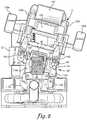
- FIG. 5is a transverse sectional view taken along line 5 - 5 of FIG. 1 .
- FIG. 6is a perspective sectional view taken along line 6 - 6 of FIG. 1 .
- FIG. 7is a side elevational view of the structure of FIG. 1 shown in a laterally tilted position with the patient supports in an upward breaking position, and with both ends in a lowered position.
- FIG. 8is an enlarged transverse sectional view taken along line 8 - 8 of FIG. 7 .
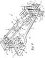
- FIG. 9is a perspective view of the structure of FIG. 1 with the patient supports shown in a planar inclined position, suitable for positioning a patient in Trendelenburg's position.
- FIG. 10is an enlarged partial perspective view of a portion of the structure of FIG. 1 .
- FIG. 11is a perspective view of the structure of FIG. 1 shown with a pair of planar patient support surfaces replacing the patient supports of FIG. 1 .
- FIG. 13is an enlarged perspective view of the trunk translator shown disengaged from the structure of FIG. 1 .
- FIG. 14is a side elevational view of the structure of FIG. 1 shown in an alternate planar inclined position.
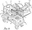
- FIG. 15is an enlarged perspective view of structure of the second end support column, with parts broken away to show details of the horizontal shift subassembly.
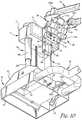
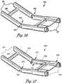
- FIG. 16is an enlarged fragmentary perspective view of an alternate patient positioning support structure incorporating a mechanical articulation of the inboard ends of the patient supports and showing the patient supports in a downward angled position and the trunk translator moved away from the hinge.
- FIG. 19is a view similar to FIG. 17 , showing the patient supports in an upward angled position and the trunk translator moved toward the hinge.
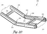
- FIG. 20is a view similar to FIG. 16 , showing a cable engaged with the trunk translator to coordinate positioning of the translator with pivoting about the hinge.
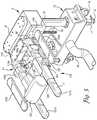
- FIGS. 1-12an embodiment of a patient positioning support structure according to the disclosure is generally designated by the reference numeral 1 and is depicted in FIGS. 1-12 .
- the structure 1includes first and second upright end support pier or column assemblies 3 and 4 which are illustrated as connected to one another at their bases by an elongate connector rail or rail assembly 2 .
- the column support assemblies 3 and 4may be constructed as independent, floor base supports that are not interconnected as shown in the illustrated embodiment.
- one or both of the end support assembliesmay be replaced by a wall mount or other building support structure connection, or that one or both of their bases may be fixedly connected to the floor structure.
- the first upright support column assembly 3is connected to a first support assembly, generally 5
- the second upright support column assembly 4is connected to a second support assembly 6 .
- the first and second support assemblies 5 and 6each uphold a respective first or second patient holding or support structure 10 or 11 . While cantilevered type patient supports 10 and 11 are depicted, it is foreseen that they could be connected by a removable hinge member.
- the column assemblies 3 and 4are supported by respective first and second base members, generally 12 and 13 , each of which are depicted as equipped with an optional carriage assembly including a pair of spaced apart casters or wheels, 14 and 15 ( FIGS. 9 and 10 ).
- the second base portion 13further includes a set of optional feet 16 with foot-engageable jacks 17 ( FIG. 11 ) for fixing the table 1 to the floor and preventing movement of the wheels 15 .
- the support column assemblies 3 and 4may be constructed so that the column assembly 3 has a greater mass than the support column assembly 4 or vice versa in order to accommodate an uneven weight distribution of the human body. Such reduction in size at the foot end of the system 1 may be employed in some embodiments to facilitate the approach of personnel and equipment.
- the first base member 12is normally located at the bottom or foot end of the structure 1 and houses, and is connected to, a longitudinal translation or compensation subassembly 20 , including a bearing block or support plate 21 surmounted by a slidable upper housing 22 .
- Removable shrouding 23spans the openings at the sides and rear of the bearing block 21 to cover the working parts beneath. The shrouding 23 prevents encroachment of feet, dust or small items that might impair sliding back and forth movement of the upper housing on the bearing block 21 .
- a pair of spaced apart linear bearings 24 a and 24 bare mounted on the bearing block 21 for orientation along the longitudinal axis of the structure 1 .
- the linear bearings 24 a and 24 bslidably receive a corresponding pair of linear rails or guides 25 a and 25 b that are mounted on the downward-facing surface of the upper housing 22 .
- the upper housing 22slides back and forth over the bearing block 21 when powered by a lead screw or power screw 26 ( FIG. 4 ) that is driven by a motor 31 by way of gearing, a chain and sprockets, or the like (not shown).
- the motor 31is mounted on the bearing block 21 by fasteners such as bolts or other suitable means and is held in place by an upstanding motor cover plate 32 .
- the rotary sensor 27may be a mechanical, optical, binary encoding, or Gray encoding sensor device, or it may be of any other suitable construction capable of sensing horizontal movement by deriving incremental counts from a rotating shaft, and encoding and transmitting the information to the computer 28 .
- the home switch 27 aprovides a zero or home reference position for measurement.
- the longitudinal translation subassembly 20is operated by actuating the motor 31 to drive the lead screw 26 such as, for example, an Acme thread form, which causes the nut 33 and attached nut carrier 34 to advance along the screw 26 , thereby advancing the linear rails 25 a and 25 b , along the respective linear bearings 24 a and 24 b , and moving the attached upper housing 22 along a longitudinal axis, toward or away from the opposite end of the structure 1 as shown in FIG. 10 .
- the lead screw 26such as, for example, an Acme thread form
- the motor 31may be selectively actuated by an operator by use of a control (not shown) on a controller or control panel 29 , or it may be actuated by responsive control instructions transmitted by the computer 28 in accordance with preselected parameters which are compared to data received from sensors detecting movement in various parts of the structure 1 , including movement that actuates the home switch 27 a.
- a second longitudinal translation subassembly 20may be connected to the second base member 13 to permit movement of both bases 12 and 13 in compensation for angulation of the patient supports 10 and 11 . It is also foreseen that the translation assembly may alternatively connected to one or more of the housings 71 and 71 ′ ( FIG. 2 ) of the first and second support assemblies 5 and 6 , for positioning closer to the patient support surfaces 10 and 11 . It is also foreseen that the rail assembly 2 could be configured as a telescoping mechanism with the longitudinal translation subassembly 20 incorporated therein.
- the first and second base members 12 and 13are surmounted by respective first and second upright end support or column lift assemblies 3 and 4 .
- the column lift assemblieseach include a pair of laterally spaced columns 3 a and 3 b or 4 a and 4 b ( FIGS. 2, 9 ), each pair surmounted by an end cap 41 or 41 ′.
- the columnseach include two or more telescoping lift arm segments, an outer segment 42 a and 42 b and 42 a ′ and 42 b ′ and an inner segment 43 a and 43 b and 43 a ′ and 43 b ′ ( FIGS. 5 and 6 ).
- Bearings 44 a , 44 b and 44 a ′ and 44 b ′enable sliding movement of the outer portion 42 or 42 ′ over the respective inner portion 43 or 43 ′ when actuated by a lead or power screw 45 a , 45 b , 45 a ′, or 45 b ′ driven by a respective motor 46 ( FIG. 4 ) or 46 ′ ( FIG. 6 ). In this manner, the column assemblies 3 and 4 are raised and lowered by the respective motors 46 and 46 ′.
- the motors 46 and 46 ′each include a position sensing device or sensor 47 , 47 ′ ( FIGS. 9 and 11 ) that determines the vertical position or height of the lift arm segments 42 a,b and 42 a ′,b′ and 44 a,b and 44 a ′b′ and converts it to a code, which it transmits to a computer 28 .
- the sensors 47 , 47 ′are preferably rotary encoders with home switches 47 a , 47 a ′ ( FIGS. 5 and 6 ) as previously described.
- the motor 46is mounted to a generally L-shaped bracket 51 , which is fastened to the upward-facing surface of the bottom portion of the upper housing 22 by fasteners such as bolts or the like.
- the motor 46 ′is similarly fastened to a bracket 51 ′, which is fastened to the inner surface of the bottom portion of the second base housing 13 .
- Operation of the motors 46 and 46 ′drives respective sprockets 52 ( FIG. 5 ) and 52 ′ ( FIG. 6 ).
- Chains 53 and 53 ′( FIGS. 4 and 6 ) are received about their respective driven sprockets as well as about respective idler sprockets 54 ( FIG.
- the shafts 55each drive a worm gear 56 a , 55 b and 56 a ′, 56 b ′ ( FIGS. 5, 6 ), which is connected to a lead screw 45 a and 45 b or 45 a ′ and 45 b ′.
- Nuts 61 a , 61 b and 61 a ′, 61 b ′attach the lead screws 45 a , 45 b and 45 a ′, 45 b ′ to bolts 62 a , 62 b and 62 a ′, 62 b ′, which are fastened to rod end caps 63 a , 63 b and 63 a ′, 63 b ′, which are connected to the inner lift arm segments 43 a , 43 b and 43 a ′, 43 b ′.
- operation of the motors 46 and 46 ′drives the lead screws 45 a , 45 b and 45 a ′, 45 b ′, which raise and lower the inner lift arm segments 43 a , 43 b and 43 a ′, 43 b ′ ( FIGS. 1, 10 ) with respect to the outer lift arm segments 42 a , 42 b , and 42 a ′, 42 b′.
- Each of the first and second support assemblies 5 and 6( FIG. 1 ) generally includes a secondary vertical lift subassembly 64 and 64 ′ ( FIGS. 2 and 6 ), a lateral or horizontal shift subassembly 65 and 65 ′ ( FIGS. 5 and 15 ), and an angulation/tilt or roll subassembly 66 and 66 ′ ( FIGS. 8, 10 and 12 ).
- the second support assembly 6also including a patient trunk translation assembly or trunk translator 123 ( FIGS. 2, 3, 13 ), which are interconnected as described in greater detail below and include associated power source and circuitry linked to a computer 28 and controller 29 ( FIG. 1 ) for coordinated and integrated actuation and operation.
- the lateral or horizontal shift subassemblies 65 and 65 ′enable selected, coordinated horizontal shifting of the patient supports 10 and 11 along an axis perpendicular to the longitudinal axis of the structure 1 , either before or during performance of any of the foregoing maneuvers ( FIG. 15 ).
- the angulation and roll or tilt subassemblies 66 and 66 ′enable coordinated selective raising and lowering of the patient supports 10 and 11 to achieve selectively raised and lowered planar horizontal positions ( FIGS. 1, 2 and 11 ), planar inclined positions such as Trendelenburg's position and the reverse ( FIGS. 9, 14 ), angulation of the patient support surfaces in upward ( FIG. 7 ) and downward breaking angles with sideways roll or tilting of the patient support structure 1 about a longitudinal axis of the structure 1 ( FIG. 8 ), all at desired height levels and increments.
- the longitudinal translation subassembly 20enables coordinated adjustment of the position of the first base member so as to maintain the distances D and D′ between the inboard ends of the patient supports 10 and 11 as the base of the triangle formed by the supports is lengthened or shortened in accordance with the increase or decrease of the angle subtended by the inboard ends of the supports 10 and 11 ( FIGS. 7, 9, 10 and 14 ).
- the trunk translation assembly 123( FIGS. 2, 3, 13 ) enables coordinated shifting of the patient's upper body along the longitudinal axis of the patient support 11 as required for maintenance of normal spinal biomechanics and avoidance of excessive traction or compression of the spine as the angle subtended by the inboard ends of the supports 10 and 11 is increased or decreased.
- the first and second horizontal support assemblies 5 and 6each include a housing 71 and 71 ′ having an overall generally hollow rectangular configuration, with inner structure forming a pair of vertically oriented channels that receive the outer lift arm segments 42 A, 42 B and 42 a ′, 42 b ′ ( FIGS. 5, 6 ).
- the inboard face of each housing 71 and 71 ′is covered by a carrier plate 72 , 72 ′ ( FIG. 2 ).
- the secondary vertical lift subassemblies 64 and 64 ′FIGS.
- the worm geardrivingly engages a lead or power screw 75 and 75 ′, the uppermost end of which is connected to the lower surface or bottom of the respective end cap 41 and 41 ′.
- the motors 73 and 73 ′each include a respective position sensing device or height sensor 78 , 78 ′ ( FIGS. 9 and 11 ) that determines the vertical position of the respective housing 70 and 71 and converts it to a code, which it transmits to the computer 28 .
- the sensors 78 and 78 ′are preferably rotary encoders as previously described and cooperate with respective home switches 78 a and 78 a ′ ( FIGS. 5 and 6 ).
- An example of an alternate height sensing deviceis described in U.S. Pat. No. 4,777,798, the disclosure of which patent is incorporated by reference.
- the motor 73 or 73 ′rotates the worm gear, it drives the lead screw 75 or 75 ′, thereby causing the housing 71 or 71 ′ to shift upwardly or downwardly over the outer lift arm segments 42 and 42 ′′.
- Selective actuation of the motors 73 and 73 ′thus enables the respective housings 71 and 71 ′ to ride up and down on the columns 3 a and 3 b and 4 a and 4 b between the end caps 41 and 41 ′ and base members 12 and 13 ( FIGS. 7, 9 and 14 ).
- the lateral or horizontal shift subassemblies 65 and 65 ′shown in FIGS. 5 and 15 , each include a pair of linear rails 76 or 76 ′ mounted on the inboard face of the respective plate 72 or 72 ′. Corresponding linear bearings 77 and 77 ′ are mounted on the inboard wall of the housing 71 and 71 ′.
- a nut carrier 81 or 81 ′is attached to the back side of each of the plates 72 and 72 ′ in a horizontally threaded orientation for receiving a nut through which passes a lead or power screw 82 or 82 ′ that is driven by a motor 83 or 83 ′.
- the motors 83 , 83 ′each include a respective position sensing device or sensor 80 , 80 ′ ( FIGS. 11 and 15 ) that determines the lateral movement or shift of the plate 72 or 72 ′ and converts it to a code, which is transmitted to the computer 28 .
- the sensors 80 , 80 ′are preferably rotary encoders as previously described and cooperate with home switches 80 a and 80 a ′ ( FIGS. 5 and 15 ).
- Operation of the motors 83 and 83 ′drives the respective screws 82 and 82 ′, causing the nut carriers to advance along the screws 82 and 82 ′, along with the plates 72 and 72 ′, to which the nut carriers are attached.
- the plates 72 and 72 ′are shifted laterally with respect to the housings 71 and 71 ′, which are thereby also shifted laterally with respect to a longitudinal axis of the patient support 1 .
- Reversal of the motors 83 and 83 ′causes the plates 72 and 72 ′ to shift in a reverse lateral direction, enabling horizontal back-and-forth lateral or horizontal movement of the subassemblies 65 and 65 ′.
- a single one of the motors 83 or 83 ′may be operated to shift a single one of the subassemblies 65 or 65 ′ in a lateral direction.
- the angulation and tilt or roll subassemblies 66 and 66 ′ shown in FIGS. 8, 10, 12 and 14each include a generally channel shaped rack 84 and 84 ′ ( FIG. 7 ) that is mounted on the inboard surface of the respective carrier plate 72 or 72 ′ of the horizontal shift subassembly 65 or 65 ′.
- the racks 84 and 84 ′each include a plurality of spaced apart apertures sized to receive a series of vertically spaced apart hitch pins 85 ( FIG. 10 ) and 85 ′ ( FIG. 8 ) that span the racks 84 and 84 ′ in a rung formation.
- the rack 84 ′ at the head end of the structure 1is depicted in FIGS.
- Each of the racks 84 and 84 ′supports a main block 86 ( FIG. 12 ) or 86 ′ ( FIG. 15 ), which is laterally bored through at the top and bottom to receive a pair of hitch pins 85 or 85 ′.
- the blocks 86 and 86 ′each have an approximately rectangular footprint that is sized for reception within the channel walls of the racks by the pins 85 and 85 ′.
- the hitch pins 85 and 85 ′hold the blocks 86 and 86 ′ in place on the racks, and enable them to be quickly and easily repositioned upwardly or downwardly on the racks 84 and 84 ′ at a variety of heights by removal of the pins 85 and 85 ′, repositioning of the blocks, and reinsertion of the pins at the new locations.
- Each of the blocks 86 and 86 ′includes at its lower end a plurality of apertures 91 for receiving fasteners 92 that connect an actuator mounting plate 93 or 93 ′ to the block 86 or 86 ′ ( FIGS. 12 and 14 ).
- Each blockalso includes a channel or joint 94 and 94 ′ which serves as a universal joint for receiving the stem portion of the generally T-shaped yokes 95 , 95 ′ ( FIGS. 7 and 12 ).
- the walls of the channel as well as the stem portion of each of the yokes 95 and 95 ′are bored through from front to back to receive a pivot pin 106 ( FIG.
- each of the yokes 95 and 95 ′is also bored through along the length thereof.
- Each of the yokessupports a generally U-shaped plate 96 and 96 ′ ( FIGS. 12 and 8 ) that in turn supports a respective one of the first and second patient supports 10 and 11 ( FIGS. 3 and 12 ).
- the U-shaped bottom plates 96 and 96 ′each include a pair of spaced apart dependent inboard ears 105 and 105 ′ ( FIGS. 8 and 12 ).
- the earsare apertured to receive pivot pins 111 and 111 ′ that extend between the respective pairs of ears and through the transverse portion of the yoke to hold the yoke in place in spaced relation to a respective bottom plate 96 or 96 ′.
- the bottom plate 96 ′ installed at the head end of the structure 1further includes a pair of outboard ears 107 ( FIG. 9 ), for mounting the translator assembly 123 , as will be discussed in more detail.
- the pivot pins 111 and 111 ′enable the patient supports 10 and 11 , which are connected to respective bottom plates 96 and 96 ′, to pivot upwardly and downwardly with respect to the yokes 95 and 95 ′.
- the angulation and roll or tilt subassemblies 66 and 66 ′provide a mechanical articulation at the outboard end of each of the patient supports 10 and 11 .
- An additional articulation at the inboard end of each of the patient supports 10 and 11will be discussed in more detail below.
- each patient support or frame 10 and 11is a generally U-shaped open framework with a pair of elongate, generally parallel spaced apart arms or support spars 101 a and 101 b and 101 a ′ and 101 b ′ extending inboard from a curved or bight portion at the outboard end.
- the patient support framework 10 at the foot end of the structure 1is illustrated with longer spars than the spars of the framework 11 at the head end of the structure 1 , to accommodate the longer lower body of a patient.
- all of the spars, and the patient support frameworks 10 and 11may also be of equal length, or that the spars of framework 11 could be longer than the spars of framework 10 , so that the overall length of framework 11 will be greater than that of framework 10 .
- a cross brace 102may be provided between the longer spars 101 a and 101 b at the foot end of the structure 1 to provide additional stability and support.
- the curved or bight portion of the outboard end of each frameworkis surmounted by an outboard or rear bracket 103 or 103 ′ which is connected to a respective supporting bottom plate 96 or 96 ′ by means of bolts or other suitable fasteners.
- Clamp style brackets 104 a and 104 b and 104 a ′ and 104 b ′also surmount each of the spars 101 a and 101 b and 101 a ′ and 101 b ′ in spaced relation to the rear brackets 103 and 103 ′.
- the clamp bracketsare also fastened to the respective supporting bottom plates 96 and 96 ′ ( FIGS. 1, 10 ).
- the inboard surface of each of the brackets 104 a and 104 b and 104 a ′ and 104 b ′functions as an upper actuator mounting plate ( FIG. 3 ).
- the angulation and roll subassemblies 66 and 66 ′each further include a pair of linear actuators 112 a and 112 b and 112 a ′ and 112 b ′ ( FIGS. 8 and 10 ). Each actuator is connected at one end to a respective actuator mounting plate 93 or 93 ′ and at the other end to the inboard surface of one of the respective clamp brackets 104 a , 104 b or 104 a ′, 104 b ′. Each of the linear actuators is interfaced connected with the computer 28 .
- the actuatorseach include a fixed cover or housing containing a motor (not shown) that actuates a lift arm or rod 113 a or 113 b or 113 a ′ or 113 b ′ ( FIGS. 12, 14 ).
- the actuatorsare connected by means of ball-type fittings 114 , which are connected with the bottom of each actuator and with the end of each lift arm.
- the lower ball fittings 114are each connected to a respective actuator mounting plate 93 or 93 ′, and the uppermost fittings 114 are each connected to the inboard surface of a respective clamp bracket 104 a or 104 b or 104 a ′ or 104 b ′, all by means of a fastener 115 equipped with a washer 116 ( FIG. 12 ) to form a ball-type joint.
- the linear actuators 112 a , 112 b , 112 a ′, 112 b ′each include an integral position sensing device (generally designated by a respective actuator reference numeral) that determines the position of the actuator, converts it to a code and transmits the code to the computer 28 . Since the linear actuators are connected with the spars 101 a,b and 101 a,b ′ via the brackets 104 a,b and 104 a ′,b′, the computer 28 can use the data to determine the angles of the respective spars. It is foreseen that respective home switches (not shown) as well as the position sensors may be incorporated into the actuator devices.
- the angulation and roll mechanisms 66 and 66 ′are operated by powering the actuators 112 a , 112 b , 112 a ′ and 112 b ′ using a switch or other similar means incorporated in the controller 29 for activation by an operator or by the computer 28 .
- Selective, coordinated operation of the actuatorscauses the lift arms 113 a and 113 b and 113 a ′ and 113 b ′ to move respective spars 101 a and 101 b and 101 a ′ and 101 b ′.
- the lift armscan lift both spars on a patient support 10 or 11 equally so that the ears 105 and 105 ′ pivot about the pins 111 and 111 ′ on the yokes 95 and 95 ′, causing the patient support 10 or 11 to angle upwardly or downwardly with respect to the bases 12 and 13 and connector rail 2 .
- the actuators 112 a , 112 b and 112 a ′, 112 b ′to extend and/or retract their respective lift arms, it is possible to achieve coordinated angulation of the patient supports 10 and 11 to an upward ( FIG. 7 ) or downward breaking position or to a planar angled position ( FIG.
- the linear actuators 112 a , 112 b , 112 a ′ and 112 b ′may extend the ends of the spars 101 a , 101 b , 101 a ′ and 101 b ′ to subtend an upward angle of up to about 50.degree. and to subtend a downward angle of up to about 30.degree. from the horizontal.
- each support 10 and/or 11may differentially angle the spars of each support 10 and/or 11 , that is to say, to raise or lower spar 101 a more than spar 101 b and/or to raise or lower spar 101 a ′ more than spare 101 b ′, so that the respective supports 10 and/or 11 may be caused to roll or tilt from side to side with respect to the longitudinal axis of the structure 1 as shown in FIGS. 7 and 8 .
- the patient supportsmay be caused to roll or rotate clockwise about the longitudinal axis up to about 17.degree. from a horizontal plane and counterclockwise about the longitudinal axis up to about 17.degree. from a horizontal plane, thereby imparting to the patient supports 10 and 11 a range of rotation or ability to roll or tilt about the longitudinal axis of up to about 34.degree.
- the patient support 10is equipped with a pair of hip or lumbar support pads 120 a , 120 b that are selectively positionable for supporting the hips of a patient and are held in place by a pair of clamp style brackets or hip pad mounts 121 a , 121 b that surmount the respective spars 101 a , 101 b in spaced relation to their outboard ends.
- Each of the mounts 121 a and 121 bis connected to a hip pad plate 122 ( FIG. 4 ) that extends medially at a downward angle.
- the hip pads 120are thus supported at an angle that is pitched or directed toward the longitudinal center axis of the supported patient. It is foreseen that the plates could be pivotally adjustable rather than fixed.
- the chest, shoulders, arms and head of the patientare supported by a trunk or torso translator assembly 123 ( FIGS. 2, 13 ) that enables translational movement of the head and upper body of the supported patient along the second patient support 11 in both caudad and cephalad directions.
- the translational movement of the trunk translator 123is coordinated with the upward and downward angulation of the inboard ends of the patient supports 10 and 11 .
- the translator assembly 123is of modular construction for convenient removal from the structure 1 and replacement as needed.
- the translator assembly 123is constructed as a removable component or module, and is shown in FIG. 13 disengaged and removed from the structure 1 and as viewed from the patient's head end.
- the translator assembly 123includes a head support portion or trolley 124 that extends between and is supported by a pair of elongate support or trolley guides 125 a and 125 b .
- Each of the guidesis sized and shaped to receive a portion of one of the spars 101 a ′ and 101 b ′ of the patient support 11 .
- the guidesare preferably lubricated on their inner surfaces to facilitate shifting back and forth along the spars.
- the guides 125 a and 125 bare interconnected at their inboard ends by a crossbar, cross brace or rail 126 ( FIG.
- An arm rest support bracket 131 a or 131 bis connected to each of the trolley guides 125 a and 125 b ( FIG. 13 ).
- the support bracketshave an approximately Y-shaped overall configuration. The downwardly extending end of each leg terminates in an expanded base 132 a or 132 b , so that the legs of the two brackets form a stand for supporting the trunk translator assembly 123 when it is removed from the table 1 ( FIG. 2 ).
- Each of the brackets 131 a and 131 bsupports a respective arm rest 133 a or 133 b . It is foreseen that arm-supporting cradles or slings may be substituted for the arm rests 133 a and 133 b.
- the trunk translator assembly 123includes a pair of linear actuators 134 a , 134 b ( FIG. 13 ) that each include a motor 135 a or 135 b , a housing 136 and an extendable shaft 137 .
- the linear actuators 134 a and 134 beach include an integral position sensing device or sensor (generally designated by a respective actuator reference number) that determines the position of the actuator and converts it to a code, which it transmits to the computer 28 as previously described. Since the linear actuators are connected with the trunk translator assembly 123 , the computer 28 can use the data to determine the position of the trunk translator assembly 123 with respect to the spars 101 a ′ and 101 b ′. It is also foreseen that each of the linear actuators may incorporate an integral home switch (generally designated by a respective actuator reference number).
- Each of the trolley guides 125 a and 125 bincludes a dependent flange 141 ( FIG. 3 ) for connection to the end of the shaft 137 .
- the motor 135 and housing 136are connected to a flange 142 ( FIG. 13 ) that includes a post for receiving a hitch pin 143 .
- the hitch pinsextend through the posts as well as the outboard ears 107 ( FIG. 9 ) of the bottom plate 96 ′, thereby demountably connecting the linear actuators 134 a and 234 b to the bottom plate 96 ′ ( FIGS. 8, 9 ).
- the translator assembly 123is operated by powering the actuators 134 a and 134 b via integrated computer software actuation for automatic coordination with the operation of the angulation and roll or tilt subassemblies 66 and 66 ′ as well as the lateral shift subassemblies 66 , 66 ′, the column lift assemblies 3 , 4 , vertical lift subassemblies 64 , 64 ′ and longitudinal shift subassembly 20 .
- the assembly 123may also be operated by a user, by means of a switch or other similar means incorporated in the controller 29 .
- Positioning of the translator assembly 123is based on positional data collection by the computer in response to inputs by an operator.
- the assembly 123is initially positioned or calibrated within the computer by a coordinated learning process and conventional trigonometric calculations.
- the trunk translator assembly 123is controlled to travel or move a distance corresponding to the change in overall length of the base of a triangle formed when the inboard ends of the patient supports 10 and 11 are angled upwardly or downwardly.
- the base of the triangleequals the distance between the outboard ends of the patient supports 10 and 11 . It is shortened by the action of the translation subassembly 20 as the inboard ends are angled upwardly and downwardly in order to maintain the inboard ends in proximate relation.
- the distance of travel of the translation assembly 123may be calibrated to be identical to the change in distance between the outboard ends of the patient supports, or it may be approximately the same.
- the positions of the supports 10 and 11are measured as they are raised and lowered, the assembly 123 is positioned accordingly and the position of the assembly is measured.
- the data points thus empirically obtainedare then programmed into the computer 28 .
- the computer 28also collects and processes positional data regarding longitudinal translation, height from both the column assemblies 3 and 4 and the secondary lift assemblies 73 , 73 ′, lateral shift, and tilt orientation from the sensors 27 , 47 , 47 ′, 78 , 78 ′, 80 , 80 ′, and 112 a , 112 b and 112 a ′, 112 b ′.
- the actuatorsdrive the trolley guides 125 a and 125 b supporting the trolley 124 , sternum pad 127 and arm rests 133 a and 133 b back and forth along the spars 101 a ′ 101 b ′ in coordinated movement with the spars 101 a , 101 b , 101 a ′ and 101 b ′.
- the trolley 124 and associated structuresare moved or translated in a caudad direction, traveling along the spars 101 a ′ and 101 b ′ toward the inboard articulation of the patient support 11 , in the direction of the patient's feet when the ends of the spars are raised to an upwardly breaking angle ( FIG. 7 ), thereby avoiding excessive traction on the patient's spine.
- the trolley 124 and associated structuresare moved or translated in a cephalad direction, traveling along the spars 101 a ′, 101 b ′ toward the outboard articulation of the patient support 11 , in the direction of the patient's head when the ends of the spars are lowered to a downwardly breaking angle, thereby avoiding excessive compression of the patient's spine.
- the operation of the actuatorsmay also be coordinated with the tilt orientation of the supports 10 and 11 .
- the translator assembly 123When not in use, the translator assembly 123 can be easily removed by pulling out the hitch pins 143 and disconnecting the electrical connection (not shown). As shown in FIG. 11 , when the translator assembly 123 is removed, planar patient support elements such as imaging tops 144 and 144 ′ may be installed atop the spars 101 a , 101 b and 101 a ′, 101 b ′ respectively. It is foreseen that only one planar element may be mounted atop spars 101 a , 101 b or 101 a ′, 101 b ′, so that a planar support element 144 or 144 ′ may be used in combination with either the hip pads 120 a and 120 b or the translator assembly 123 .
- planar patient support elementssuch as imaging tops 144 and 144 ′ may be installed atop the spars 101 a , 101 b and 101 a ′, 101 b ′ respectively. It is foreseen that only one planar element may be mounted a
- the translator assembly support guides 125 a and 125 bmay be modified for reception of the lateral margins of the planar support 144 ′ to permit use of the translator assembly in association with the planar support 144 ′.
- the virtual, open or non-joined articulation of the inboard ends of the illustrated patient support spars 101 a,b and 101 a ′,b′ or the inboard ends of the planar support elements 144 and 144 ′ without a mechanical connectionmay alternatively be mechanically articulated by means of a hinge connection or other suitable element.
- the trunk translator assembly 123is preferably installed on the patient supports 10 and 11 by sliding the support guides 125 a and 125 b over the ends of the spars 101 a ′ and 101 b ′ with the sternum pad 127 oriented toward the center of the patient positioning support structure 1 and the arm rests 133 a and 133 b extending toward the second support assembly 6 .
- the translator 123is slid toward the head end until the flanges 142 contact the outboard ears 107 of the bottom plate 96 ′ and their respective apertures are aligned.
- the hitch pin 143is inserted into the aligned apertures to secure the translator 123 to the bottom plate 96 ′ which supports the spars 101 a ′ and 101 b ′ and the electrical connection for the motors 135 is made.
- the patient supports 10 and 11may be positioned in a horizontal or other convenient orientation and height to facilitate transfer of a patient onto the translator assembly 123 and support surface 10 .
- the patientmay be positioned, for example, in a generally prone position with the head supported on the trolley 124 , and the torso and arms supported on the sternum pad 127 and arm supports 133 a and 133 b respectively.
- a head support padmay also be provided atop the trolley 124 if desired.
- the patientmay be raised or lowered in a generally horizontal position ( FIGS. 1, 2 ) or in a feet-up or head-up orientation ( FIGS. 9, 14 ) by actuation of the lift arm segments of the column assemblies 3 and 4 and/or the vertical lift subassemblies 64 and/or 64 ′ in the manner previously described.
- either or both of the patient supports 10 and 11may be independently shifted laterally by actuation of the lateral shift subassemblies 65 and/or 65 ′, either toward or away from the longitudinal side of the structure 1 as illustrated in FIGS. 32 and 33 of Applicant's U.S. Pat. No. 7,343,635, the disclosure of which patent is incorporated herein by reference.
- either or both of the patient supports 10 and 11may be independently rotated by actuation of the angulation and roll or tilt subassembly 66 and/or 66 ′ to roll or tilt from side to side ( FIGS. 7, 8 and 15 ).
- either or both of the patient supports 10 and 11may be independently angled upwardly or downwardly with respect to the base members 12 and 13 and rail 2 .
- the patientmay be positioned in a 90.degree./90.degree. kneeling prone position as depicted in FIG. 26 of U.S. Pat. No. 7,343,635 by selective actuation of the lift arm segments of the column lift assemblies 3 and 4 and/or the secondary vertical lift subassemblies 64 and/or 64 ′ as previously described.
- the height sensors 47 , 47 ′ and 78 , 78 ′ and integral position sensors in the linear actuators 112 a , 112 b and 112 a ′, 112 b ′convey information or data regarding height, tilt orientation and angular orientation to the computer 28 for automatic actuation of the translator assembly 123 to shift the trolley 124 and associated structures from the position depicted in FIG.
- the sensorsconvey data regarding height, tilt, orientation and angular orientation to the computer 28 for shifting of the trolley 124 away from the inboard ends of the spars 101 a ′ and 101 b ′. This enables the patient's head, torso and arms to shift in a cephalad direction, toward the head, thereby relieving excessive compression along the spine of the patient.
- the patient's upper bodyis able to slide along the patient support 11 to maintain proper spinal biomechanics during a surgical or medical procedure.
- the computer 28also uses the data collected from the position sensing devices 27 , 47 , 47 ′, 78 , 78 ′, 80 , 80 ′, 112 a , 112 b , 112 a ′, 112 b ′, and 134 a , 134 b as previously described to coordinate the actions of the longitudinal translation subassembly 20 .
- the subassembly 20adjusts the overall length of the table structure 1 to compensate for the actions of the support column lift assemblies 3 and 4 , horizontal support assemblies 5 and 6 , secondary vertical lift subassemblies 64 and 64 ′, horizontal shift subassemblies 65 and 65 ′, and angulation and roll or tilt subassemblies 66 and 66 ′.
- the distance D between the ends of the spars 101 a and 101 a ′ and the distance D′ between the ends of the spars 101 b and 101 b ′may be continuously adjusted during all of the aforementioned raising, lowering, lateral shifting, rolling or tilting and angulation of the patient supports 10 and 11 .
- the distances D and D′may be maintained at preselected or fixed values or they may be repositioned as needed.
- the inboard ends of the patient supports 10 and 11may be maintained in adjacent, closely spaced or other spaced relation or they may be selectively repositioned. It is foreseen that the distance D and the distance D′ may be equal or unequal, and that they may be independently variable.
- this inboard articulation of the structure 1is a virtual articulation that provides a movable pivot axis or joint between the patient supports 10 and 11 that is derived from the coordination and cooperation of the previously described mechanical elements, without an actual mechanical pivot connection or joint between the inboard ends of the patient supports 10 and 11 .
- the ends of the spars 101 a , 101 b and 101 a ′, 101 b ′thus remain as fee ends, which are not connected by any mechanical element. However, through the cooperation of elements previously described, they are enabled to function as if connected. It is also foreseen that the inboard articulation may be a mechanical articulation such as a hinge.
- Such coordinationmay be by means of operator actuation using the controller 29 in conjunction with integrated computer software actuation, or the computer 28 may automatically coordinate all of these movements in accordance with preprogrammed parameters or values and data received from the position sensors 27 , 47 , 47 ′, 78 , 78 ′, 80 , 80 ′, 117 a , 117 b , 117 a ′, 117 b ′, and 138 a , 138 b.
- a second embodiment of the patient positioning support structureis generally designated by the reference numeral 200 , and is depicted in FIGS. 16-20 .
- the structure 200is substantially similar to the structure 1 shown in FIGS. 1-15 and includes first and second patient supports 205 and 206 , each having an inboard end interconnected by a hinge joint 203 , including suitable pivot connectors such as the illustrated hinge pins 204 .
- Each of the patient supports 205 and 206includes a pair of spars 201 , and the spars 201 of the second patient support 206 support a patient trunk translation assembly 223 .
- the trunk translator 223is engaged with the patient support 206 and is substantially as previously described and shown, except that it is connected to the hinge joint 203 by a linkage 234 .
- the linkageis connected to the hinge joint 203 in such a manner as to position the trunk translator 223 along the patient support 206 in response to relative movement of the patient supports 205 and 206 when the patient supports are positioned in a plurality of angular orientations.
- the a trunk translator 223is engaged the patient support 206 and is slidingly shifted toward the hinge joint 203 as shown in FIG. 19 in response to upward angulation of the patient support. This enables the patient's head, torso and arms to shift in a caudad direction, toward the feet.
- the trunk translator 223is movable away from the hinge joint 203 as shown in FIG. 17 in response to downward angulation of the patient support 206 . This enables the patient's head, torso and arms to shift in a cephalad direction, toward the head.
- the linkagemay be a control rod, cable ( FIG. 20 ) or that it may be an actuator 234 as shown in FIG. 17 , operable for selective positioning of the trunk translator 223 along the patient support 206 .
- the actuator 234is interfaced with a computer 28 , which receives angular orientation data from sensors as previously described and sends a control signal to the actuator 234 in response to changes in the angular orientation to coordinate a position of the trunk translator with the angular orientation of the patient support 206 .
- the linkageis a control rod or cable
- the movement of the trunk translator 223is mechanically coordinated with the angular orientation of the patient support 206 by the rod or cable.
Landscapes
- Health & Medical Sciences (AREA)
- Engineering & Computer Science (AREA)
- Biomedical Technology (AREA)
- Public Health (AREA)
- Animal Behavior & Ethology (AREA)
- General Health & Medical Sciences (AREA)
- Life Sciences & Earth Sciences (AREA)
- Veterinary Medicine (AREA)
- Orthopedic Medicine & Surgery (AREA)
- Neurology (AREA)
- Neurosurgery (AREA)
- Accommodation For Nursing Or Treatment Tables (AREA)
- Apparatus For Radiation Diagnosis (AREA)
Abstract
Description
Claims (20)
Priority Applications (1)
| Application Number | Priority Date | Filing Date | Title |
|---|---|---|---|
| US16/915,607US11110022B2 (en) | 2010-06-21 | 2020-06-29 | Patient positioning support structure with trunk translator |
Applications Claiming Priority (7)
| Application Number | Priority Date | Filing Date | Title |
|---|---|---|---|
| US12/803,192US9186291B2 (en) | 2005-02-22 | 2010-06-21 | Patient positioning support structure with trunk translator |
| US14/862,835US9510987B2 (en) | 2005-02-22 | 2015-09-23 | Patient positioning support structure with trunk translator |
| US15/341,167US9937094B2 (en) | 2010-06-21 | 2016-11-02 | Patient positioning support structure with trunk translator |
| US15/789,345US10159618B2 (en) | 2010-06-21 | 2017-10-20 | Patient positioning support structure with trunk translator |
| US16/227,758US10531998B2 (en) | 2010-06-21 | 2018-12-20 | Patient positioning support structure with trunk translator |
| US16/705,866US10729607B2 (en) | 2010-06-21 | 2019-12-06 | Patient positioning support structure with trunk translator |
| US16/915,607US11110022B2 (en) | 2010-06-21 | 2020-06-29 | Patient positioning support structure with trunk translator |
Related Parent Applications (1)
| Application Number | Title | Priority Date | Filing Date |
|---|---|---|---|
| US16/705,866ContinuationUS10729607B2 (en) | 2010-06-21 | 2019-12-06 | Patient positioning support structure with trunk translator |
Publications (2)
| Publication Number | Publication Date |
|---|---|
| US20200330310A1 US20200330310A1 (en) | 2020-10-22 |
| US11110022B2true US11110022B2 (en) | 2021-09-07 |
Family
ID=45371735
Family Applications (8)
| Application Number | Title | Priority Date | Filing Date |
|---|---|---|---|
| US12/803,192Expired - LifetimeUS9186291B2 (en) | 2005-02-22 | 2010-06-21 | Patient positioning support structure with trunk translator |
| US14/033,895Active2026-01-17US9504622B2 (en) | 2005-02-22 | 2013-09-23 | Patient positioning support structure with trunk translator |
| US14/862,835Expired - LifetimeUS9510987B2 (en) | 2005-02-22 | 2015-09-23 | Patient positioning support structure with trunk translator |
| US15/341,167ActiveUS9937094B2 (en) | 2010-06-21 | 2016-11-02 | Patient positioning support structure with trunk translator |
| US15/789,345ActiveUS10159618B2 (en) | 2010-06-21 | 2017-10-20 | Patient positioning support structure with trunk translator |
| US16/227,758ActiveUS10531998B2 (en) | 2010-06-21 | 2018-12-20 | Patient positioning support structure with trunk translator |
| US16/705,866ActiveUS10729607B2 (en) | 2010-06-21 | 2019-12-06 | Patient positioning support structure with trunk translator |
| US16/915,607ActiveUS11110022B2 (en) | 2010-06-21 | 2020-06-29 | Patient positioning support structure with trunk translator |
Family Applications Before (7)
| Application Number | Title | Priority Date | Filing Date |
|---|---|---|---|
| US12/803,192Expired - LifetimeUS9186291B2 (en) | 2005-02-22 | 2010-06-21 | Patient positioning support structure with trunk translator |
| US14/033,895Active2026-01-17US9504622B2 (en) | 2005-02-22 | 2013-09-23 | Patient positioning support structure with trunk translator |
| US14/862,835Expired - LifetimeUS9510987B2 (en) | 2005-02-22 | 2015-09-23 | Patient positioning support structure with trunk translator |
| US15/341,167ActiveUS9937094B2 (en) | 2010-06-21 | 2016-11-02 | Patient positioning support structure with trunk translator |
| US15/789,345ActiveUS10159618B2 (en) | 2010-06-21 | 2017-10-20 | Patient positioning support structure with trunk translator |
| US16/227,758ActiveUS10531998B2 (en) | 2010-06-21 | 2018-12-20 | Patient positioning support structure with trunk translator |
| US16/705,866ActiveUS10729607B2 (en) | 2010-06-21 | 2019-12-06 | Patient positioning support structure with trunk translator |
Country Status (11)
| Country | Link |
|---|---|
| US (8) | US9186291B2 (en) |
| EP (2) | EP2582345B1 (en) |
| JP (4) | JP5571850B2 (en) |
| KR (3) | KR20130029429A (en) |
| CN (2) | CN103298440A (en) |
| AU (1) | AU2011269831A1 (en) |
| BR (1) | BR112012032517A2 (en) |
| CA (1) | CA2803110C (en) |
| ES (1) | ES2636951T3 (en) |
| RU (1) | RU2571805C9 (en) |
| WO (1) | WO2011162803A1 (en) |
Families Citing this family (90)
| Publication number | Priority date | Publication date | Assignee | Title |
|---|---|---|---|---|
| US9301897B2 (en) | 2005-02-22 | 2016-04-05 | Roger P. Jackson | Patient positioning support structure |
| US8844077B2 (en) | 2005-02-22 | 2014-09-30 | Roger P. Jackson | Syncronized patient elevation and positioning apparatus positioning support systems |
| US9295433B2 (en)* | 2005-02-22 | 2016-03-29 | Roger P. Jackson | Synchronized patient elevation and positioning apparatus for use with patient positioning support systems |
| US9265679B2 (en) | 2005-02-22 | 2016-02-23 | Roger P Jackson | Cantilevered patient positioning support structure |
| US7565708B2 (en) | 2005-02-22 | 2009-07-28 | Jackson Roger P | Patient positioning support structure |
| US9744087B2 (en) | 2005-02-22 | 2017-08-29 | Roger P. Jackson | Patient support apparatus with body slide position digitally coordinated with hinge angle |
| US7739762B2 (en) | 2007-10-22 | 2010-06-22 | Mizuho Orthopedic Systems, Inc. | Surgery table apparatus |
| US9468576B2 (en) | 2005-02-22 | 2016-10-18 | Roger P. Jackson | Patient support apparatus with body slide position digitally coordinated with hinge angle |
| US9308145B2 (en) | 2005-02-22 | 2016-04-12 | Roger P. Jackson | Patient positioning support structure |
| US9186291B2 (en)* | 2005-02-22 | 2015-11-17 | Roger P. Jackson | Patient positioning support structure with trunk translator |
| US8707484B2 (en)* | 2005-02-22 | 2014-04-29 | Roger P. Jackson | Patient positioning support structure |
| US20150059094A1 (en) | 2005-02-22 | 2015-03-05 | Roger P. Jackson | Patient positioning support structure |
| US10869798B2 (en) | 2006-05-05 | 2020-12-22 | Warsaw Orthopedic, Inc. | Patient positioning support apparatus with virtual pivot-shift pelvic pads, upper body stabilization and fail-safe table attachment mechanism |
| US9642760B2 (en) | 2006-05-05 | 2017-05-09 | Roger P. Jackson | Patient positioning support apparatus with virtual pivot-shift pelvic pads, upper body stabilization and fail-safe table attachment mechanism |
| US9339430B2 (en) | 2006-05-05 | 2016-05-17 | Roger P. Jackson | Patient positioning support apparatus with virtual pivot-shift pelvic pads, upper body stabilization and fail-safe table attachment mechanism |
| US8474794B2 (en)* | 2009-03-06 | 2013-07-02 | Liko Research & Development Ab | Lift control systems for lifting devices and lifting devices comprising the same |
| WO2012170543A1 (en)* | 2011-06-07 | 2012-12-13 | Tamarack Habilitation Technologies, Inc. | Apparatus and method for automatic adjustment of a support surface with interwoven support elements |
| WO2013058806A1 (en) | 2011-10-17 | 2013-04-25 | Jackson Roger P | Patient positioning support structure |
| US9561145B2 (en) | 2012-02-07 | 2017-02-07 | Roger P. Jackson | Fail-safe release mechanism for use with patient positioning support apparati |
| US9265680B2 (en)* | 2012-03-06 | 2016-02-23 | Operating Room Safety Enterprises, LLC | Surgical table |
| US9474671B2 (en)* | 2012-03-06 | 2016-10-25 | Operating Room Safety Enterprises, LLC | Surgical table |
| US9498397B2 (en) | 2012-04-16 | 2016-11-22 | Allen Medical Systems, Inc. | Dual column surgical support system |
| DE202012003941U1 (en)* | 2012-04-20 | 2012-07-23 | Igus Gmbh | Caddy for cable drag chains |
| WO2014021925A2 (en)* | 2012-08-02 | 2014-02-06 | Jackson Roger P | Patient support apparatus with body slide position digitally coordinated with hinge angle |
| WO2014021924A1 (en)* | 2012-08-03 | 2014-02-06 | Jackson Roger P | Patient elevation and positioning apparatus |
| WO2014035460A1 (en) | 2012-08-29 | 2014-03-06 | Jackson Roger P | Patient positioning support apparatus with virtual pivot-shift pelvic pads, upper body stabilization and fail-safe table attachment mechanism |
| ITMI20121546A1 (en) | 2012-09-18 | 2014-03-19 | Medacta Int Sa | ADAPTER FLOOR FOR SURGICAL TABLE, IN PARTICULAR FOR REPLACEMENT OPERATIONS OF THE HOOK WITH FRONT APPROACH |
| ITMI20121548A1 (en) | 2012-09-18 | 2014-03-19 | Medacta Int Sa | APPARATUS FOR POSITIONING THE LOWER ARTH OF A PATIENT IN OPERATIVE OFFICE, IN PARTICULAR FOR REPLACEMENT OPERATIONS OF THE ANCHOR WITH A FRONT APPROACH, AND A SURGICAL POSITIONING SYSTEM INCLUDING THE APPLIANCE |
| US12011399B2 (en) | 2013-08-28 | 2024-06-18 | Warsaw Orthopedic, Inc. | Patient positioning support apparatus with fail-safe connector attachment mechanism |
| US9764934B2 (en)* | 2013-12-12 | 2017-09-19 | Macton Corporation | Independent drive motors for machinery positioning apparatus having independent lifting motors |
| JP6244011B2 (en)* | 2014-03-10 | 2017-12-06 | フジデノロ株式会社 | Surgical table |
| US10219965B2 (en)* | 2014-05-26 | 2019-03-05 | Bass Morris Pty Ltd | Spine treatment apparatus |
| US9549863B2 (en) | 2014-07-07 | 2017-01-24 | Roger P. Jackson | Surgical table with pivoting and translating hinge |
| US9402775B2 (en) | 2014-07-07 | 2016-08-02 | Roger P. Jackson | Single and dual column patient positioning and support structure |
| US10492973B2 (en) | 2015-01-05 | 2019-12-03 | Allen Medical Systems, Inc. | Dual modality prone spine patient support apparatuses |
| US9700476B2 (en)* | 2015-02-06 | 2017-07-11 | Mizuho Orthopedic Systems, Inc. | Patient platform connection device |
| US9655793B2 (en) | 2015-04-09 | 2017-05-23 | Allen Medical Systems, Inc. | Brake release mechanism for surgical table |
| US11382816B2 (en) | 2015-06-05 | 2022-07-12 | Stryker Corporation | Surgical table and accessories to facilitate hip arthroscopy |
| US10426684B2 (en) | 2015-06-11 | 2019-10-01 | Allen Medical Systems, Inc. | Person support apparatuses including person repositioning assemblies |
| DE102015009990A1 (en)* | 2015-07-31 | 2017-02-02 | MAQUET GmbH | Device for detecting the position of movable operating table components |
| US10548796B2 (en) | 2015-08-17 | 2020-02-04 | Warsaw Orthopedic, Inc. | Surgical frame and method for use thereof facilitating articulatable support for a patient during surgery |
| AU2016308175B2 (en) | 2015-08-17 | 2021-04-01 | Warsaw Orthopedic, Inc. | Surgical frame facilitating articulatable support for a patient during surgery |
| US10561559B2 (en) | 2015-10-23 | 2020-02-18 | Allen Medical Systems, Inc. | Surgical patient support system and method for lateral-to-prone support of a patient during spine surgery |
| US10363189B2 (en)* | 2015-10-23 | 2019-07-30 | Allen Medical Systems, Inc. | Surgical patient support for accommodating lateral-to-prone patient positioning |
| US10857054B2 (en) | 2015-11-13 | 2020-12-08 | Allen Medical Systems, Inc. | Person support apparatuses for subject repositioning |
| US10548793B2 (en) | 2016-06-14 | 2020-02-04 | Allen Medical Systems, Inc. | Pinless loading for spine table |
| WO2017218683A1 (en)* | 2016-06-14 | 2017-12-21 | Jackson Roger P | Prone and lateral surgical table |
| US11160709B2 (en) | 2016-06-14 | 2021-11-02 | Warsaw Orthopedic, Inc. | Surgical table with movement capabilities of lower body support structures |
| CN109414367B (en)* | 2016-07-08 | 2022-01-04 | 韦伯维夫股份公司 | Movable module and movable furniture |
| GR1009176B (en)* | 2016-07-21 | 2017-12-18 | Ευαγγελια Ηλια Καναβου | Specialized unit sets assisting the composition, combinations and methods required for the preparation and production of extemporaneous formulations prepared by pharmacists for individual therapies |
| US10940072B2 (en) | 2016-10-28 | 2021-03-09 | Warsaw Orthopedic, Inc. | Surgical table and method for use thereof |
| EP3576687B1 (en) | 2017-02-06 | 2025-07-02 | Stryker Corporation | Method and apparatus for supporting and stabilizing a patient during hip distraction |
| US11510805B2 (en) | 2017-02-06 | 2022-11-29 | Stryker Corp. | Anatomical gripping system for gripping the leg and foot of a patient when effecting hip distraction and/or when effecting leg positioning |
| CA3052793A1 (en) | 2017-02-06 | 2018-08-09 | Stryker Corp. | Distraction frame for effecting hip distraction |
| CN106726314B (en)* | 2017-03-03 | 2019-02-01 | 中国人民解放军总医院 | A kind of pelvis/lower limb traction is reset bed and multifunction traction resets system |
| US10900448B2 (en) | 2017-03-10 | 2021-01-26 | Warsaw Orthopedic, Inc. | Reconfigurable surgical frame and method for use thereof |
| US10874570B2 (en) | 2017-06-30 | 2020-12-29 | Warsaw Orthopedic, Inc. | Surgical frame and method for use thereof facilitating patient transfer |
| US11213448B2 (en) | 2017-07-31 | 2022-01-04 | Allen Medical Systems, Inc. | Rotation lockout for surgical support |
| US11020304B2 (en)* | 2017-08-08 | 2021-06-01 | Warsaw Orthopedic, Inc. | Surgical frame including main beam for facilitating patient access |
| USD878836S1 (en) | 2017-08-17 | 2020-03-24 | Stryker Corp. | Table extender |
| GB2567657B (en)* | 2017-10-18 | 2019-10-23 | Eschmann Holdings Ltd | Surgical tables |
| CN107569359B (en)* | 2017-10-25 | 2018-06-05 | 陈维之 | A kind of patient body position's locator |
| US11202731B2 (en) | 2018-02-28 | 2021-12-21 | Allen Medical Systems, Inc. | Surgical patient support and methods thereof |
| RU186354U1 (en)* | 2018-06-07 | 2019-01-16 | федеральное государственное бюджетное образовательное учреждение высшего образования "Нижегородский государственный технический университет им. Р.Е. Алексеева" (НГТУ) | X-ray installation |
| CN108904200A (en)* | 2018-07-23 | 2018-11-30 | 玉林市好邦医疗设备有限责任公司 | A kind of X-ray catheter bed |
| US10835439B2 (en)* | 2018-08-21 | 2020-11-17 | Warsaw Orthopedic, Inc. | Surgical frame having translating lower beam and moveable linkage or surgical equipment attached thereto and method for use thereof |
| US10898401B2 (en) | 2018-08-22 | 2021-01-26 | Warsaw Orthopedic, Inc. | Reconfigurable surgical frame and method for use |
| US11471354B2 (en) | 2018-08-30 | 2022-10-18 | Allen Medical Systems, Inc. | Patient support with selectable pivot |
| CN211797334U (en) | 2018-08-31 | 2020-10-30 | 希尔-罗姆服务公司 | Patient rotation system |
| CN109730880B (en)* | 2019-01-07 | 2021-03-23 | 青岛市妇女儿童医院 | Special bed of infant's physical examination |
| CN109875692B (en)* | 2019-03-16 | 2021-04-09 | 青岛大学附属医院 | Shaft adjusting piece of surface projection adjusting device for minimally invasive surgery |
| US10881570B2 (en) | 2019-04-26 | 2021-01-05 | Warsaw Orthopedic, Inc | Reconfigurable pelvic support for a surgical frame and method for use thereof |
| US10888484B2 (en) | 2019-04-26 | 2021-01-12 | Warsaw Orthopedic, Inc | Reconfigurable pelvic support for surgical frame and method for use thereof |
| US11234886B2 (en) | 2019-09-25 | 2022-02-01 | Warsaw Orthopedic, Inc. | Reconfigurable upper leg support for a surgical frame |
| EP4099971B1 (en) | 2020-02-03 | 2025-09-17 | Alphatec Spine, Inc. | Patient positioning system |
| CN111479435B (en)* | 2020-04-17 | 2021-05-18 | 盐城工业职业技术学院 | A lifting device based on computer network room controller |
| US11304867B2 (en) | 2020-04-22 | 2022-04-19 | Warsaw Orthopedic, Inc. | Lift and method for use of a lift for positioning a patient relative to a surgical frame |
| US11813217B2 (en) | 2020-04-22 | 2023-11-14 | Warsaw Orthopedic, Inc | Lift and method for use of a lift for positioning a patient relative to a surgical frame |
| US11564855B2 (en) | 2020-09-28 | 2023-01-31 | Stryker Corporation | Systems and methods for supporting and stabilizing a patient during hip distraction |
| US11844732B2 (en)* | 2021-07-30 | 2023-12-19 | Corindus, Inc. | Support for securing a robotic system to a patient table |
| US11925586B2 (en) | 2022-03-25 | 2024-03-12 | Mazor Robotics Ltd. | Surgical platform and trolley assembly |
| KR102738140B1 (en)* | 2022-04-12 | 2024-12-05 | 인제대학교 산학협력단 | Shoulder support |
| CN114767141A (en)* | 2022-04-26 | 2022-07-22 | 山东新华医疗器械股份有限公司 | CT device, control method and device of CT device and medium |
| US12207946B2 (en)* | 2022-05-10 | 2025-01-28 | Warsaw Orthopedic, Inc. | Surgical platform system |
| US12213905B2 (en) | 2022-05-10 | 2025-02-04 | Warsaw Orthopedic, Inc. | Surgical platform system |
| US12150902B2 (en) | 2022-05-10 | 2024-11-26 | Warsaw Orthopedic, Inc. | Surgical table |
| US12239584B2 (en) | 2022-06-22 | 2025-03-04 | Warsaw Orthopedic, Inc. | Interface moveably interconnecting surgical table and gantry |
| US12011397B2 (en) | 2022-08-26 | 2024-06-18 | EMPLASE Medical Technologies, LLC | Patient-positioning system, computer-control and data-integration system, surgical componentry, and surgical methods of using same |
| US12396909B2 (en) | 2022-08-29 | 2025-08-26 | Warsaw Orthopedic, Inc. | Surgical platform system |
| USD1071190S1 (en) | 2023-05-30 | 2025-04-15 | Allen Medical Systems, Inc. | Disposable cover |
Citations (241)
| Publication number | Priority date | Publication date | Assignee | Title |
|---|---|---|---|---|
| US377377A (en) | 1888-02-07 | Spring-bed | ||
| US392743A (en) | 1888-11-13 | millen | ||
| US430635A (en) | 1890-06-24 | Invalid-bed | ||
| US769415A (en) | 1903-09-12 | 1904-09-06 | Jasper D Smock | Attachment for head-rests. |
| US987423A (en) | 1910-04-01 | 1911-03-21 | Universal Bed And Hospital Supply Company | Adjustable reclining spring-frame. |
| US1032743A (en) | 1909-11-15 | 1912-07-16 | Minneapolis Bedding Company | Hospital-bed. |
| US1046430A (en) | 1911-08-25 | 1912-12-10 | Henry C Beitz | Back-rest attachment for beds. |
| US1098209A (en) | 1914-02-19 | 1914-05-26 | David B Allen | Adjustable head and back rest for beds. |
| US1098477A (en) | 1913-04-11 | 1914-06-02 | Patrick Cashman | Apparatus for elevating and conveying invalids. |
| US1143618A (en) | 1914-09-12 | 1915-06-22 | Martin R Ewald | Bed attachment. |
| US1160451A (en) | 1914-04-06 | 1915-11-16 | Charles H Sanford | Combined fracture and orthopedic operating-table. |
| US1171713A (en) | 1914-02-16 | 1916-02-15 | John K Gilkerson | Chiropractic table. |
| US1356467A (en) | 1919-02-04 | 1920-10-19 | Frederick R Payne | Invalid's bed |
| US1404482A (en) | 1920-05-11 | 1922-01-24 | Walter H Sawyer | Invalid bed |
| US1482439A (en) | 1922-02-17 | 1924-02-05 | William A Mccollough | Invalid's bed |
| US1528835A (en) | 1922-09-23 | 1925-03-10 | William A Mccollough | Invalid's bed |
| US1667982A (en) | 1925-06-04 | 1928-05-01 | Pearson Royal Washington | Revolving bed |
| US1780399A (en) | 1928-04-12 | 1930-11-04 | Edmund L Munson | Hospital bed |
| US1799692A (en) | 1925-08-08 | 1931-04-07 | St Louis Union Trust C Incorpo | Operating stand |
| US1938006A (en) | 1932-05-11 | 1933-12-05 | Edward P Blanchard | Manipulative table for spinal correction |
| US1990357A (en) | 1933-04-17 | 1935-02-05 | John W Speck | Invalid bed construction |
| US2188592A (en) | 1936-12-21 | 1940-01-30 | Damon R Hosken | Invalid bed |
| US2261297A (en) | 1941-03-03 | 1941-11-04 | Seib Frederick Anthony | Hospital bed crane |
| GB569758A (en) | 1943-09-14 | 1945-06-07 | Hoskins & Sewell Ltd | Improvements relating to hospital beds |
| US2411768A (en) | 1944-09-02 | 1946-11-26 | Henry M Welch | Boxcar brace |
| US2475003A (en) | 1945-01-02 | 1949-07-05 | Lewis M Black | Body manipulation apparatus |
| US2636793A (en) | 1950-07-21 | 1953-04-28 | Meyer Walter | Operating table with adjustable top sections |
| US2688410A (en) | 1949-08-27 | 1954-09-07 | George B Nelson | Device for transporting bedridden patients |
| US2792945A (en) | 1952-10-13 | 1957-05-21 | Stanley J Brenny | Corpse handling device |
| GB810956A (en) | 1956-04-13 | 1959-03-25 | Allen & Hanburys Ltd | Improvements relating to surgical operation tables |
| US3046071A (en) | 1958-07-24 | 1962-07-24 | Shampaine | Head-end control surgical operating table |
| US3048071A (en) | 1960-04-27 | 1962-08-07 | Schulmerich Electronics Inc | Electrical musical instrument having mechanically vibratable tone generators |
| US3049726A (en) | 1960-03-15 | 1962-08-21 | Clarence A Getz | Mobile body lift |
| US3281141A (en) | 1963-01-15 | 1966-10-25 | American Sterilizer Co | Surgical table |
| US3302218A (en) | 1965-05-28 | 1967-02-07 | Stryker Corp | Turning frame |
| US3584321A (en) | 1969-09-12 | 1971-06-15 | Donald L Buchanan | Hydraulic positioning bed for radioisotope scanning |
| US3599964A (en) | 1968-07-17 | 1971-08-17 | Jaernhs Elektriska Ab | Operating table |
| US3640416A (en) | 1970-10-16 | 1972-02-08 | John J Temple | Reverse angle thread system for containers |
| US3766384A (en) | 1971-04-28 | 1973-10-16 | Tower Co Inc | Surgical table |
| US3814414A (en) | 1972-07-24 | 1974-06-04 | H Chapa | Medical examination table |
| US3827089A (en) | 1971-09-16 | 1974-08-06 | W Grow | Turnover bed assembly |
| US3832742A (en) | 1972-06-07 | 1974-09-03 | Stryker Corp | End support for anterior bed frame |
| US3868103A (en) | 1973-04-24 | 1975-02-25 | Millet Roux & Cie Ltee | Surgical and examination table structure |
| US3937054A (en) | 1974-09-10 | 1976-02-10 | Armco Steel Corporation | Heavy duty pipe spreader |
| US3988790A (en) | 1973-11-29 | 1976-11-02 | Mracek Milo F | Portable support for a bed patient |
| JPS53763A (en) | 1976-06-22 | 1978-01-06 | Riyouichi Enohayashi | Bed functioning as chair |
| US4101120A (en) | 1976-08-10 | 1978-07-18 | Mizuho Ika Kogyo Kabushiki Kaisha | Electrically driven, separate type, surgical operation table |
| US4131802A (en) | 1976-06-28 | 1978-12-26 | Ohio-Nuclear, Inc. | Automatic patient table having means for transporting patient along a table |
| US4144880A (en)* | 1977-03-11 | 1979-03-20 | Daniels E Robert | Orthopedic table |
| US4148472A (en) | 1977-05-27 | 1979-04-10 | M. Schaerer A.G. | Operating table for medical purposes |
| US4175550A (en) | 1978-03-27 | 1979-11-27 | Leininger James R | Therapeutic bed |
| US4186917A (en) | 1977-05-27 | 1980-02-05 | M. Schaerer A.G. | Operating table for medical purposes |
| US4195829A (en) | 1978-04-21 | 1980-04-01 | Sybron Corporation | Surgical table hydraulic system |
| US4227269A (en) | 1978-09-01 | 1980-10-14 | Burke, Inc. | Adjustable bed |
| US4230100A (en) | 1978-07-26 | 1980-10-28 | Moon Derryl E | Chiropractic table |
| US4244358A (en) | 1979-09-10 | 1981-01-13 | Noel Pyers | Rollover bed having pallet with flex points and constant traction maintaining apparatus |
| US4292962A (en) | 1979-04-19 | 1981-10-06 | Krause Nicolaas J P R | Apparatus for postural treatment of humans |
| US4391438A (en) | 1981-06-12 | 1983-07-05 | Heffington Jr Charles A | Patient support attachment for surgical tables |
| US4435861A (en) | 1982-02-25 | 1984-03-13 | Lindley William L | Ledge bed |
| US4474364A (en) | 1982-11-29 | 1984-10-02 | American Sterilizer Company | Surgical table |
| US4503844A (en) | 1983-01-13 | 1985-03-12 | Fischer Imaging Corporation | Surgical table |
| US4552346A (en) | 1982-05-14 | 1985-11-12 | Stierlen-Maquet Ag | Operating table |
| US4712781A (en) | 1986-05-12 | 1987-12-15 | Watanabe Orthopedic Systems, Inc. | Operating table for microscopic lumbar laminectomy surgery |
| US4715073A (en) | 1986-08-22 | 1987-12-29 | Butler Wilbur T | Tiltable bed frame assembly |
| US4718077A (en) | 1985-03-14 | 1988-01-05 | Moore Robert R | Radiolucent table for medical radiography |
| US4763643A (en) | 1981-01-19 | 1988-08-16 | Kinetic Concepts, Inc. | Arc changing apparatus for a therapeutic oscillating bed |
| US4771785A (en) | 1986-07-25 | 1988-09-20 | Resonex, Inc. | Magnetic resonance imaging apparatus and three-axis patient positioning assembly for use therewith |
| US4830337A (en) | 1984-02-17 | 1989-05-16 | Aioi Seiki Kabushiki Kaisha | Device for pushing and pulling an accessory instrument of manufacturing plant |
| US4850775A (en) | 1988-04-26 | 1989-07-25 | Lee Jae B | Screw-type fastening device |
| US4862529A (en) | 1988-07-13 | 1989-09-05 | Hill-Rom Company, Inc. | Hospital bed convertible to chair |
| US4872657A (en) | 1986-10-17 | 1989-10-10 | M. Schaerer Ag | Operating table with a patient support surface tiltable around the longitudinal and transverse axes |
| US4872656A (en) | 1981-12-21 | 1989-10-10 | American Sterilizer Company | Orthopedic table with movable upper body and sacrum supports |
| US4887325A (en) | 1989-07-13 | 1989-12-19 | Tesch Charles V | Patient positioning apparatus |
| US4937901A (en) | 1988-11-04 | 1990-07-03 | Brennan Louis G | Apparatus for turning a patient from a supine to a prone position and vice-versa |
| US4939801A (en) | 1988-12-22 | 1990-07-10 | Schaal Gary A | Patient transporting and turning gurney |
| US4944500A (en) | 1987-04-07 | 1990-07-31 | American Sterilizer Company | Translation lock for surgical table with displaceable tabletop |
| US4953245A (en) | 1989-01-25 | 1990-09-04 | Hans Jung | Device for moving patients who are confined to bed |
| US4970737A (en) | 1989-02-10 | 1990-11-20 | Vauth-Sagel Gmbh & Co. | Adjustable hospital and nursing home bed |
| US4989848A (en) | 1981-12-21 | 1991-02-05 | American Sterilizer Company | Apparatus for adjusting the position of the upper body support of an orthopedic table |
| US5013018A (en) | 1989-06-22 | 1991-05-07 | Sicek Bernard W | Table positioning for X-ray examinations in plurality of positions |
| US5088706A (en) | 1990-08-30 | 1992-02-18 | Jackson Roger P | Spinal surgery table |
| US5131103A (en) | 1990-12-18 | 1992-07-21 | Thomas Jimmy W | Integrated back support and bed apparatus and method |
| US5131106A (en) | 1990-08-30 | 1992-07-21 | Jackson Roger P | Spinal surgery table |
| US5131105A (en) | 1990-11-21 | 1992-07-21 | Diasonics, Inc. | Patient support table |
| US5161267A (en) | 1991-06-21 | 1992-11-10 | Smith Gene A | Method for lifting and turning a patient confined to a bed |
| US5163890A (en) | 1991-06-03 | 1992-11-17 | Perry Jr Leroy R | Adductor contraction exercise apparatus and method |
| US5181289A (en) | 1991-03-15 | 1993-01-26 | Kenzou Kassai | Bed apparatus and rehabilitation attachment |
| US5208928A (en) | 1991-09-20 | 1993-05-11 | Midmark Corporation | Plastic surgery table |
| US5210887A (en) | 1991-08-26 | 1993-05-18 | Juanita Kershaw | Methods of turning a bedridden invalid |
| US5210888A (en) | 1992-06-25 | 1993-05-18 | Canfield Michael A | Portable tent--cot |
| US5230112A (en) | 1990-11-21 | 1993-07-27 | Diasonics, Inc. | Patient support table |
| US5231741A (en) | 1991-11-12 | 1993-08-03 | Batesville Casket Company, Inc. | Articulated bed for positioning human bodies in caskets |
| US5239716A (en) | 1992-04-03 | 1993-08-31 | Fisk Albert W | Surgical spinal positioning frame |
| US5274862A (en) | 1992-05-18 | 1994-01-04 | Palmer Jr John M | Patient turning device and method for lateral traveling transfer system |
| US5294179A (en) | 1992-05-11 | 1994-03-15 | Hand Machine Company, Inc. | Retrofittable chair lifting and tilting device |
| US5333334A (en) | 1992-06-15 | 1994-08-02 | Kenzou Kassai | Human body moving apparatus |
| US5393018A (en) | 1992-11-10 | 1995-02-28 | Deutsche Aerospace Ag | Unfolding and locking joint for space elements |
| US5444882A (en) | 1990-09-17 | 1995-08-29 | Orthopedic Systems, Inc. | Spinal surgery table |
| US5461740A (en) | 1991-07-23 | 1995-10-31 | Theraposture Limited | Multi-positional bed |
| US5468216A (en) | 1994-10-12 | 1995-11-21 | Physicians Consulting Incorporated | Kinetic rehabilitation device employing controlled passive motion |
| US5487195A (en) | 1993-02-22 | 1996-01-30 | Ray; Donald A. | Patient lifting and transporting apparatus |
| US5499408A (en) | 1994-09-09 | 1996-03-19 | Nix; John W. | Apparatus for lifting invalids |
| US5522098A (en) | 1991-11-12 | 1996-06-04 | Karin Berghammer | Parturition bed |
| US5524304A (en) | 1994-10-19 | 1996-06-11 | Shutes; Robert S. | Bed rail mounted drive unit for patient positioner |
| US5544371A (en) | 1993-04-13 | 1996-08-13 | Fuller; Carmel U. | Bed patient turning, lifting and transporting apparatus with mobile, folding and knockdown frame |
| US5579550A (en) | 1994-09-19 | 1996-12-03 | C.E.B. Enterprises, Inc. | Articulated bed with collapsible frame |
| US5588705A (en) | 1993-10-06 | 1996-12-31 | Chang; Chung L. | Seatback recliner mechanism |
| US5613254A (en) | 1994-12-02 | 1997-03-25 | Clayman; Ralph V. | Radiolucent table for supporting patients during medical procedures |
| US5640730A (en) | 1995-05-11 | 1997-06-24 | Maxwell Products, Inc. | Adjustable articulated bed with tiltable head portion |
| US5645079A (en) | 1994-12-02 | 1997-07-08 | Zahiri; Hormoz | Apparatus for mechanically holding, maneuvering and maintaining a body part of a patient during orthopedic surgery |
| US5658315A (en) | 1994-02-23 | 1997-08-19 | Orthopedic Systems, Inc. | Apparatus and method for lower limb traction |
| US5659909A (en) | 1994-07-04 | 1997-08-26 | Maquet Ag | Operating table patient support means |
| US5673443A (en) | 1996-08-30 | 1997-10-07 | Marmor; Maxine S. | Apparatus for turning a patient in bed |
| US5737781A (en) | 1995-09-13 | 1998-04-14 | Ergodyne Corporation | Patient transfer system |
| US5754997A (en) | 1994-08-15 | 1998-05-26 | Midmark Corporation | Support cushion for surgery table |
| US5774914A (en) | 1996-01-05 | 1998-07-07 | Stryker Corporation | Maternity bed |
| US5794286A (en) | 1995-09-13 | 1998-08-18 | Standex International | Patient treatment apparatus |
| US5829077A (en) | 1994-10-25 | 1998-11-03 | Neige; Jean-Francois | Device for tilting the top end and/or bottom end of a bed |
| US5862549A (en) | 1996-01-05 | 1999-01-26 | Stryker Corporation | Maternity bed |
| US5870784A (en) | 1994-03-15 | 1999-02-16 | Maxwell Products, Inc. | Adjustable articulated bed |
| WO1999007320A2 (en) | 1997-08-08 | 1999-02-18 | Hill-Rom, Inc. | Proning bed |
| US5890238A (en) | 1995-09-13 | 1999-04-06 | Ergodyne Corporation | Patient transfer systems |
| US5901388A (en) | 1998-03-26 | 1999-05-11 | Cowan; William Thomas | Mono-pull drawsheet |
| US5937456A (en) | 1997-08-29 | 1999-08-17 | Norris; John F. | Device for transferring a patient to and from a hospital bed |
| US5940911A (en) | 1997-11-10 | 1999-08-24 | Wang; Yi-Lung | Multi-functional bed structure |
| US5996151A (en) | 1997-01-10 | 1999-12-07 | Stryker Corporation | Balanced fowler design |
| US6000076A (en) | 1996-10-23 | 1999-12-14 | Hill-Rom, Inc. | Procedural stretcher recline controls |
| WO2000007537A2 (en) | 1998-08-07 | 2000-02-17 | Hill-Rom, Inc. | Stretcher for obstetrics or gynecology |
| JP2000060995A (en) | 1998-08-18 | 2000-02-29 | Toshiba Tec Corp | Chair with stretch function |
| US6035465A (en) | 1994-11-14 | 2000-03-14 | Elliot Kelman | Patient lifting and support system |
| US6049923A (en) | 1997-10-03 | 2000-04-18 | Ochiai; Shigeyoshi | Lift for lifting and lowering body |
| JP2000116733A (en) | 1998-10-09 | 2000-04-25 | Maquet Ag | Surgical operation table system |
| US6058532A (en) | 1998-03-30 | 2000-05-09 | Allen; Newton P. | Apparatus for elevating one end portion of a bed frame |
| US6109424A (en) | 1997-03-20 | 2000-08-29 | Fori Automation, Inc. | Chassis/body marriage lift machine |
| WO2000062731A1 (en) | 1999-04-21 | 2000-10-26 | Hill-Rom, Inc. | Proning bed |
| US6212713B1 (en) | 1999-08-09 | 2001-04-10 | Midmark Corporation | Examination table with sliding back section |
| US6224037B1 (en) | 1998-11-30 | 2001-05-01 | Serapid France | Column for lifting loads |
| US6240582B1 (en) | 1999-07-30 | 2001-06-05 | Hill-Rom, Inc. | Apparatus for positioning a patient-support deck |
| US6260220B1 (en) | 1997-02-13 | 2001-07-17 | Orthopedic Systems, Inc. | Surgical table for lateral procedures |
| WO2001060308A2 (en) | 2000-02-18 | 2001-08-23 | Hill-Rom Services, Inc. | Imaging stretcher |
| US6287241B1 (en) | 2000-01-20 | 2001-09-11 | Metal Resources, Inc. | Leg press with composite motion |
| US6286164B1 (en) | 1998-03-19 | 2001-09-11 | Orthopedic Systems, Inc. | Medical table having controlled movement and method of use |
| US6295671B1 (en) | 1998-03-06 | 2001-10-02 | Ohio Medical Instrument Company, Inc. | Medical surgical table including interchangeable orthopedic attachment and scanning table |
| US6295666B1 (en) | 1998-11-06 | 2001-10-02 | Kiyoshi Takaura | Method of changing the posture of a patient on a nursing bed |
| US20010037524A1 (en) | 2000-05-05 | 2001-11-08 | Regents Of The University Of Minnesota | Interventional MR surgical table |
| US6315564B1 (en) | 2000-03-21 | 2001-11-13 | Ricardo Levisman | Bone implant |
| CN2467091Y (en) | 2001-02-20 | 2001-12-26 | 三丰医疗器材股份有限公司 | stable lifting device |
| US6438777B1 (en) | 2000-01-27 | 2002-08-27 | Tri-Medics, Inc. | Surgical supporting device |
| WO2002078589A1 (en) | 2001-03-29 | 2002-10-10 | Kci Licensing, Inc. | Prone positioning therapeutic bed |
| US20020170116A1 (en) | 1997-11-07 | 2002-11-21 | Borders Richard L. | Head section support for a surgical table apparatus |
| US6496991B1 (en) | 1995-09-13 | 2002-12-24 | Ergodyne Corporation | Device for patient pullup, rollover, and transfer and methods therefor |
| US6499162B1 (en) | 2000-10-04 | 2002-12-31 | Kuo-Heey Chang | Power-driven bed |
| US6505365B1 (en) | 1998-12-11 | 2003-01-14 | Hill-Rom Services, Inc. | Hospital bed mechanisms |
| US6526610B1 (en) | 1998-06-26 | 2003-03-04 | Hill-Rom Services, Inc. | Proning bed |
| US20030074735A1 (en) | 2000-03-29 | 2003-04-24 | Bjorn Zachrisson | Surgical table with displacement arrangement |
| US20030145383A1 (en) | 2002-02-05 | 2003-08-07 | Reliance Medical Products, Inc. | Surgical table |
| WO2003070145A1 (en) | 2002-02-25 | 2003-08-28 | Protean Global Pty Ltd | Lifting mechanism and health care equipment that incorporates the lifting mechanism |
| US6638299B2 (en) | 2001-09-14 | 2003-10-28 | James M. Cox | Chiropractic treatment table and method for spinal distraction |
| US6662388B2 (en) | 2001-12-18 | 2003-12-16 | Evelyn M. Friel | Patient adjustment device |
| US6668396B2 (en) | 2001-12-28 | 2003-12-30 | Ching-Hua Wei | Turning mechanism for a patient confined to a bed |
| US20040098804A1 (en) | 2002-11-26 | 2004-05-27 | Muthuvelan Varadharajulu | Grouted tilting patient positioning table for vascular applications |
| US20040133983A1 (en) | 2003-01-13 | 2004-07-15 | Newkirk David C. | Surgical table |
| US6779210B1 (en) | 2003-03-18 | 2004-08-24 | Hugh Kelly | Elevating bed |
| US6791997B2 (en) | 2001-08-25 | 2004-09-14 | Nokia Corporation | System and method for collision-free transmission scheduling using neighborhood information and advertised transmission times |
| US6794286B2 (en) | 1993-10-29 | 2004-09-21 | Kabushiki Kaisha Toshiba | Process for fabricating a metal wiring and metal contact in a semicondutor device |
| US20040219002A1 (en) | 2003-05-01 | 2004-11-04 | Sonny Lenaers | Transportable manufacturing system |
| US6817363B2 (en) | 2000-07-14 | 2004-11-16 | Hill-Rom Services, Inc. | Pulmonary therapy apparatus |
| JP2004538037A (en) | 2001-01-09 | 2004-12-24 | エフエイチサージカル | Electric operating table with multiple sections |
| US6854137B2 (en) | 2002-02-18 | 2005-02-15 | Daniel T. Johnson | Patient transfer and transport bed |
| US6857144B1 (en) | 2003-08-12 | 2005-02-22 | Chi-Tzung Huang | Foldable lift and transfer apparatus for patient |
| US6885165B2 (en) | 2001-05-31 | 2005-04-26 | Cti Pet Systems, Inc. | Patient bed for multiple position emission scans |
| US6971997B1 (en) | 2002-01-22 | 2005-12-06 | The Saunders Group, Inc. | Multi-axis cervical and lumber traction table |
| US6971131B2 (en) | 2001-01-13 | 2005-12-06 | Eschmann Holdings Limited | Surgical tables |
| US7003828B2 (en) | 2004-06-25 | 2006-02-28 | Carroll Hospital, Inc. | Leveling system for a height adjustment patient bed |
| US7055195B2 (en) | 2004-06-25 | 2006-06-06 | Carroll Hospital Group, Inc. | Patient bed with CPR system |
| US20060185090A1 (en) | 2005-02-22 | 2006-08-24 | Jackson Roger P | Modular multi-articulated patient support system |
| US7103931B2 (en) | 2004-08-28 | 2006-09-12 | General Electric Company | Table drive system for medical imaging apparatus |
| US20060248650A1 (en) | 2004-11-10 | 2006-11-09 | Skripps Thomas K | Body support apparatus for spinal surgery |
| US7171709B2 (en) | 1999-12-13 | 2007-02-06 | Hill-Rom Services, Inc. | Accessories for a patient support apparatus |
| US20070056105A1 (en) | 2005-09-13 | 2007-03-15 | Midmark Corporation | Conjoined electrical cords for an examination table |
| US7197778B2 (en) | 2004-06-14 | 2007-04-03 | Patient Safety Transport Systems Gp, Llc | Patient transfer system |
| US7213279B2 (en) | 1995-08-04 | 2007-05-08 | Weismiller Matthew W | Hospital bed and mattress having extendable foot section |
| US20070107126A1 (en) | 2005-11-14 | 2007-05-17 | Maquet Gmbh & Co. Kg | Device for adjusting an operating table |
| US7234180B2 (en) | 2004-12-10 | 2007-06-26 | Warsaw Orthopedic, Inc. | Dynamic surgical table system |
| US20070157385A1 (en) | 2005-12-19 | 2007-07-12 | Stryker Corporation | Hospital bed |
| US20070174965A1 (en) | 2005-12-19 | 2007-08-02 | Stryker Corporation | Hospital bed |
| US7290302B2 (en) | 2005-11-19 | 2007-11-06 | Patient Safety Transport Systems Gp, Llc | Back surgery platform |
| WO2007130679A2 (en) | 2006-05-05 | 2007-11-15 | Jackson Roger P | Patient postioning support structure |
| US20070266516A1 (en) | 2005-05-23 | 2007-11-22 | Ertan Cakmak | Snow removal and deicing device for windshield wiper |
| US20080000028A1 (en) | 2006-06-28 | 2008-01-03 | Stryker Corporation | Patient support |
| US7331557B2 (en) | 2000-09-21 | 2008-02-19 | Linak A/S | Furniture drive embodied as a double drive |
| US20080216241A1 (en) | 2005-07-20 | 2008-09-11 | Mangiardi John R | Re-Design of Operating Room Tables |
| US7437785B2 (en) | 2006-03-31 | 2008-10-21 | General Electric Company | Drive system for imaging device |
| WO2009054069A1 (en) | 2007-10-26 | 2009-04-30 | Panasonic Corporation | Positioning receiver and positioning method for user equipment |
| WO2009054969A1 (en) | 2007-10-22 | 2009-04-30 | Mizuho Orthopedic Systems, Inc. | Surgery table appratus |
| US7552490B2 (en) | 2006-01-24 | 2009-06-30 | Accuray Incorporated | Method and apparatus for patient loading and unloading |
| WO2009100692A1 (en) | 2008-02-15 | 2009-08-20 | Linet Spol. S R.O. | Positioning mechanism of a bed |
| US20090235456A1 (en) | 2006-05-26 | 2009-09-24 | Klaus Bock | Pivoting Device |
| US7596820B2 (en) | 2004-06-21 | 2009-10-06 | Linak A/S | Linear actuator for beds, slatted beds or chairs |
| US7653953B2 (en) | 2004-02-17 | 2010-02-02 | Ciateq, A.C. | Rotating therapeutic bed |
| US20100037397A1 (en) | 2008-08-14 | 2010-02-18 | RemGenic LLC | Bed |
| US7669262B2 (en) | 2004-11-10 | 2010-03-02 | Allen Medical Systems, Inc. | Accessory frame for spinal surgery |
| US20100107790A1 (en) | 2007-03-30 | 2010-05-06 | Zentaro Yamaguchi | Linear actuator |
| WO2010051303A1 (en) | 2008-10-28 | 2010-05-06 | Allen Medical Systems, Inc. | Prone and laterally angled surgical device and method |
| US7717709B2 (en) | 2005-12-19 | 2010-05-18 | Olympus Corporation | Contact cap for dental tooth measuring apparatus and measuring method using dental tooth measuring apparatus |
| US20100223728A1 (en) | 2009-03-04 | 2010-09-09 | Hutchison Stephen E | Height Adjustable Bed with a Lift Chain Assembly and Components Thereof |
| US7874030B2 (en) | 2006-08-18 | 2011-01-25 | Gachon University of Medicine & Science Industry—Academic Cooperation Foundation | Device for transferring a cradle for use with a medical imaging equipment |
| US7874695B2 (en) | 2006-11-15 | 2011-01-25 | Linak A/S | Electrical actuator system for articles of furniture |
| US20110197361A1 (en) | 2010-02-18 | 2011-08-18 | Hornbach David W | Height Adjustable Bed with a Push Chain Assembly |
| US20120005832A1 (en) | 2010-07-09 | 2012-01-12 | Turner Jonathan D | Bed Structure with a Deck Section Motion Converter |
| US20120144589A1 (en) | 2010-12-14 | 2012-06-14 | Skripps Thomas K | Lateral surgical platform with rotation |
| US20120174319A1 (en) | 1999-12-29 | 2012-07-12 | Menkedick Douglas J | Hospital Bed |
| US20120198625A1 (en) | 2005-02-22 | 2012-08-09 | Jackson Roger P | Patient positioning support structure |
| US20120246830A1 (en) | 2011-03-31 | 2012-10-04 | Hornbach David W | Footboard egress design |
| US20120255122A1 (en) | 2011-04-07 | 2012-10-11 | Mizuho Orthopedic Systems, Inc | Surgery table having coordinated motion |
| US8381331B2 (en) | 2009-04-01 | 2013-02-26 | Operating Room Safety Enterprises, LLC | Patient-rotation system with center-of-gravity assembly |
| US20130111666A1 (en) | 2005-02-22 | 2013-05-09 | Roger P. Jackson | Patient positioning support structure |
| US20130133137A1 (en) | 2011-11-28 | 2013-05-30 | Roger P. Jackson | Patient positioning support structure with coordinated continuous nonsegmented articulation, rotation and lift, and locking fail-safe device |
| US20130198958A1 (en) | 2012-02-07 | 2013-08-08 | Roger P. Jackson | Fail-safe release mechanism for use with patient positioning support apparati |
| US20130219623A1 (en) | 2005-02-22 | 2013-08-29 | Roger P. Jackson | Patient positioning support structure |
| US20130269710A1 (en) | 2012-04-16 | 2013-10-17 | Allen Medical Systems, Inc. | Dual column surgical support system |
| US20130282234A1 (en) | 2012-04-23 | 2013-10-24 | Timothy J. Roberts | High centering bases for hospital gurneys |
| US20130312188A1 (en) | 2005-02-22 | 2013-11-28 | Roger P. Jackson | Patient support apparatus with body slide position digitally coordinated with hinge angle |
| US20130312181A1 (en) | 2005-02-22 | 2013-11-28 | Roger P. Jackson | Syncronized patient elevation and positioning apparatus for use with patient positioning support systems |
| US20130312187A1 (en) | 2005-02-22 | 2013-11-28 | Roger P. Jackson | Patient support apparatus with body slide position digitally coordinated with hinge angle |
| US20140007349A1 (en) | 2005-02-22 | 2014-01-09 | Roger P. Jackson | Patient positioning support structure |
| US20140020181A1 (en) | 2005-02-22 | 2014-01-23 | Roger P. Jackson | Patient positioning support structure with trunk translator |
| US20140033436A1 (en)* | 2005-02-22 | 2014-02-06 | Roger P Jackson | Cantilevered patient positioning support structure |
| US20140068861A1 (en) | 2006-05-05 | 2014-03-13 | Roger P Jackson | Patient positioning support apparatus with virtual pivot-shift pelvic pads, upper body stabilization and fail-safe table attachment mechanism |
| US20140109316A1 (en) | 2006-05-05 | 2014-04-24 | Roger P. Jackson | Patient positioning support apparatus with virtual pivot-shift pelvic pads, upper body stabilization and fail-safe table attachment mechanism |
| US8707476B2 (en) | 2009-04-01 | 2014-04-29 | Operating Room Safety Enterprises, LLC | Apparatuses for posterior surgery |
| EP2226010B1 (en) | 2009-03-04 | 2014-06-18 | Roesys GmbH | Patient table for radiology |
| US8844077B2 (en) | 2005-02-22 | 2014-09-30 | Roger P. Jackson | Syncronized patient elevation and positioning apparatus positioning support systems |
| USD720076S1 (en) | 2013-03-06 | 2014-12-23 | Operating Room Safety Enterprises, LLC | Surgical table |
| US20150007391A1 (en) | 2013-07-05 | 2015-01-08 | Jiaxing Shufude Electric Bed Co., Ltd | Sliding block linkage folding bed |
| US20150059094A1 (en) | 2005-02-22 | 2015-03-05 | Roger P. Jackson | Patient positioning support structure |
| US20150113733A1 (en) | 2011-04-07 | 2015-04-30 | Mark Diel | Surgery table having coordinated motion |
| US20160000620A1 (en) | 2014-07-04 | 2016-01-07 | MAQUET GmbH | Operating table column for an operating table |
| US20160000629A1 (en) | 2014-07-07 | 2016-01-07 | Roger P. Jackson | Radiolucent Hinge for a Surgical Table |
| US20160000627A1 (en) | 2014-07-07 | 2016-01-07 | Roger P. Jackson | Single and dual column patient positioning and support structure |
| US9265680B2 (en) | 2012-03-06 | 2016-02-23 | Operating Room Safety Enterprises, LLC | Surgical table |
Family Cites Families (9)
| Publication number | Priority date | Publication date | Assignee | Title |
|---|---|---|---|---|
| US3766912A (en)* | 1971-10-26 | 1973-10-23 | E Daniels | Orthopedic traction table |
| JPS53763Y2 (en) | 1973-07-19 | 1978-01-11 | ||
| US4777798A (en) | 1987-09-21 | 1988-10-18 | Owatonna Tool Company | Universal control system for hydraulic cylinders |
| JPH08173492A (en)* | 1994-12-21 | 1996-07-09 | Takeuchi Seisakusho:Kk | Multipurpose operating table |
| JP2001340404A (en)* | 2000-03-31 | 2001-12-11 | Morita Mfg Co Ltd | Medical table, stretcher and medical table equipment |
| SE528547C2 (en)* | 2005-03-15 | 2006-12-12 | Stille Sonesta Ab | Examination and treatment table for urodynamic examination, has seat and back cushions with suspending frames extending along one side of cushions at which pivot pin is connected |
| JP5186369B2 (en) | 2005-08-10 | 2013-04-17 | ミズホ・オーソペディック・システムズ・インク | Treatment table with controlled operation and method of using the same |
| JP6040522B2 (en) | 2011-11-15 | 2016-12-07 | セイコーエプソン株式会社 | Printing apparatus, printing method and program thereof |
| JP6057752B2 (en) | 2013-02-07 | 2017-01-11 | オリンパス株式会社 | Imaging apparatus, imaging method, and program |
- 2010
- 2010-06-21USUS12/803,192patent/US9186291B2/ennot_activeExpired - Lifetime
- 2011
- 2011-06-21KRKR1020137001601Apatent/KR20130029429A/ennot_activeCeased
- 2011-06-21AUAU2011269831Apatent/AU2011269831A1/ennot_activeAbandoned
- 2011-06-21CNCN2011800391620Apatent/CN103298440A/enactivePending
- 2011-06-21ESES11798501.0Tpatent/ES2636951T3/enactiveActive
- 2011-06-21KRKR1020177034163Apatent/KR101906095B1/ennot_activeExpired - Fee Related
- 2011-06-21RURU2013102492/12Apatent/RU2571805C9/enactive
- 2011-06-21BRBR112012032517Apatent/BR112012032517A2/ennot_activeIP Right Cessation
- 2011-06-21JPJP2013516564Apatent/JP5571850B2/ennot_activeExpired - Fee Related
- 2011-06-21KRKR1020147033639Apatent/KR101804357B1/ennot_activeExpired - Fee Related
- 2011-06-21EPEP11798501.0Apatent/EP2582345B1/enactiveActive
- 2011-06-21EPEP17162141.0Apatent/EP3269343B1/enactiveActive
- 2011-06-21WOPCT/US2011/001101patent/WO2011162803A1/enactiveApplication Filing
- 2011-06-21CACA2803110Apatent/CA2803110C/enactiveActive
- 2011-06-21CNCN201510350452.7Apatent/CN105125364B/enactiveActive
- 2013
- 2013-09-23USUS14/033,895patent/US9504622B2/enactiveActive
- 2014
- 2014-06-27JPJP2014132463Apatent/JP2014221384A/enactivePending
- 2015
- 2015-09-23USUS14/862,835patent/US9510987B2/ennot_activeExpired - Lifetime
- 2016
- 2016-01-27JPJP2016013490Apatent/JP2016105800A/enactivePending
- 2016-11-02USUS15/341,167patent/US9937094B2/enactiveActive
- 2017
- 2017-10-20USUS15/789,345patent/US10159618B2/enactiveActive
- 2018
- 2018-12-20USUS16/227,758patent/US10531998B2/enactiveActive
- 2019
- 2019-01-21JPJP2019007699Apatent/JP2019063598A/enactivePending
- 2019-12-06USUS16/705,866patent/US10729607B2/enactiveActive
- 2020
- 2020-06-29USUS16/915,607patent/US11110022B2/enactiveActive
Patent Citations (306)
| Publication number | Priority date | Publication date | Assignee | Title |
|---|---|---|---|---|
| US377377A (en) | 1888-02-07 | Spring-bed | ||
| US392743A (en) | 1888-11-13 | millen | ||
| US430635A (en) | 1890-06-24 | Invalid-bed | ||
| US769415A (en) | 1903-09-12 | 1904-09-06 | Jasper D Smock | Attachment for head-rests. |
| US1032743A (en) | 1909-11-15 | 1912-07-16 | Minneapolis Bedding Company | Hospital-bed. |
| US987423A (en) | 1910-04-01 | 1911-03-21 | Universal Bed And Hospital Supply Company | Adjustable reclining spring-frame. |
| US1046430A (en) | 1911-08-25 | 1912-12-10 | Henry C Beitz | Back-rest attachment for beds. |
| US1098477A (en) | 1913-04-11 | 1914-06-02 | Patrick Cashman | Apparatus for elevating and conveying invalids. |
| US1171713A (en) | 1914-02-16 | 1916-02-15 | John K Gilkerson | Chiropractic table. |
| US1098209A (en) | 1914-02-19 | 1914-05-26 | David B Allen | Adjustable head and back rest for beds. |
| US1160451A (en) | 1914-04-06 | 1915-11-16 | Charles H Sanford | Combined fracture and orthopedic operating-table. |
| US1143618A (en) | 1914-09-12 | 1915-06-22 | Martin R Ewald | Bed attachment. |
| US1356467A (en) | 1919-02-04 | 1920-10-19 | Frederick R Payne | Invalid's bed |
| US1404482A (en) | 1920-05-11 | 1922-01-24 | Walter H Sawyer | Invalid bed |
| US1482439A (en) | 1922-02-17 | 1924-02-05 | William A Mccollough | Invalid's bed |
| US1528835A (en) | 1922-09-23 | 1925-03-10 | William A Mccollough | Invalid's bed |
| US1667982A (en) | 1925-06-04 | 1928-05-01 | Pearson Royal Washington | Revolving bed |
| US1799692A (en) | 1925-08-08 | 1931-04-07 | St Louis Union Trust C Incorpo | Operating stand |
| US1780399A (en) | 1928-04-12 | 1930-11-04 | Edmund L Munson | Hospital bed |
| US1938006A (en) | 1932-05-11 | 1933-12-05 | Edward P Blanchard | Manipulative table for spinal correction |
| US1990357A (en) | 1933-04-17 | 1935-02-05 | John W Speck | Invalid bed construction |
| US2188592A (en) | 1936-12-21 | 1940-01-30 | Damon R Hosken | Invalid bed |
| US2261297A (en) | 1941-03-03 | 1941-11-04 | Seib Frederick Anthony | Hospital bed crane |
| GB569758A (en) | 1943-09-14 | 1945-06-07 | Hoskins & Sewell Ltd | Improvements relating to hospital beds |
| US2411768A (en) | 1944-09-02 | 1946-11-26 | Henry M Welch | Boxcar brace |
| US2475003A (en) | 1945-01-02 | 1949-07-05 | Lewis M Black | Body manipulation apparatus |
| US2688410A (en) | 1949-08-27 | 1954-09-07 | George B Nelson | Device for transporting bedridden patients |
| US2636793A (en) | 1950-07-21 | 1953-04-28 | Meyer Walter | Operating table with adjustable top sections |
| US2792945A (en) | 1952-10-13 | 1957-05-21 | Stanley J Brenny | Corpse handling device |
| GB810956A (en) | 1956-04-13 | 1959-03-25 | Allen & Hanburys Ltd | Improvements relating to surgical operation tables |
| US3046071A (en) | 1958-07-24 | 1962-07-24 | Shampaine | Head-end control surgical operating table |
| US3049726A (en) | 1960-03-15 | 1962-08-21 | Clarence A Getz | Mobile body lift |
| US3048071A (en) | 1960-04-27 | 1962-08-07 | Schulmerich Electronics Inc | Electrical musical instrument having mechanically vibratable tone generators |
| US3281141A (en) | 1963-01-15 | 1966-10-25 | American Sterilizer Co | Surgical table |
| US3302218A (en) | 1965-05-28 | 1967-02-07 | Stryker Corp | Turning frame |
| US3599964A (en) | 1968-07-17 | 1971-08-17 | Jaernhs Elektriska Ab | Operating table |
| US3584321A (en) | 1969-09-12 | 1971-06-15 | Donald L Buchanan | Hydraulic positioning bed for radioisotope scanning |
| US3640416A (en) | 1970-10-16 | 1972-02-08 | John J Temple | Reverse angle thread system for containers |
| US3766384A (en) | 1971-04-28 | 1973-10-16 | Tower Co Inc | Surgical table |
| US3827089A (en) | 1971-09-16 | 1974-08-06 | W Grow | Turnover bed assembly |
| US3832742A (en) | 1972-06-07 | 1974-09-03 | Stryker Corp | End support for anterior bed frame |
| US3814414A (en) | 1972-07-24 | 1974-06-04 | H Chapa | Medical examination table |
| US3868103A (en) | 1973-04-24 | 1975-02-25 | Millet Roux & Cie Ltee | Surgical and examination table structure |
| US3988790A (en) | 1973-11-29 | 1976-11-02 | Mracek Milo F | Portable support for a bed patient |
| US3937054A (en) | 1974-09-10 | 1976-02-10 | Armco Steel Corporation | Heavy duty pipe spreader |
| JPS53763A (en) | 1976-06-22 | 1978-01-06 | Riyouichi Enohayashi | Bed functioning as chair |
| US4131802A (en) | 1976-06-28 | 1978-12-26 | Ohio-Nuclear, Inc. | Automatic patient table having means for transporting patient along a table |
| US4101120A (en) | 1976-08-10 | 1978-07-18 | Mizuho Ika Kogyo Kabushiki Kaisha | Electrically driven, separate type, surgical operation table |
| US4144880A (en)* | 1977-03-11 | 1979-03-20 | Daniels E Robert | Orthopedic table |
| US4148472A (en) | 1977-05-27 | 1979-04-10 | M. Schaerer A.G. | Operating table for medical purposes |
| US4186917A (en) | 1977-05-27 | 1980-02-05 | M. Schaerer A.G. | Operating table for medical purposes |
| US4175550A (en) | 1978-03-27 | 1979-11-27 | Leininger James R | Therapeutic bed |
| US4195829A (en) | 1978-04-21 | 1980-04-01 | Sybron Corporation | Surgical table hydraulic system |
| US4230100A (en) | 1978-07-26 | 1980-10-28 | Moon Derryl E | Chiropractic table |
| US4227269A (en) | 1978-09-01 | 1980-10-14 | Burke, Inc. | Adjustable bed |
| US4292962A (en) | 1979-04-19 | 1981-10-06 | Krause Nicolaas J P R | Apparatus for postural treatment of humans |
| US4244358A (en) | 1979-09-10 | 1981-01-13 | Noel Pyers | Rollover bed having pallet with flex points and constant traction maintaining apparatus |
| US4763643A (en) | 1981-01-19 | 1988-08-16 | Kinetic Concepts, Inc. | Arc changing apparatus for a therapeutic oscillating bed |
| US4391438A (en) | 1981-06-12 | 1983-07-05 | Heffington Jr Charles A | Patient support attachment for surgical tables |
| US4989848A (en) | 1981-12-21 | 1991-02-05 | American Sterilizer Company | Apparatus for adjusting the position of the upper body support of an orthopedic table |
| US4872656A (en) | 1981-12-21 | 1989-10-10 | American Sterilizer Company | Orthopedic table with movable upper body and sacrum supports |
| US4435861A (en) | 1982-02-25 | 1984-03-13 | Lindley William L | Ledge bed |
| US4552346A (en) | 1982-05-14 | 1985-11-12 | Stierlen-Maquet Ag | Operating table |
| US4474364A (en) | 1982-11-29 | 1984-10-02 | American Sterilizer Company | Surgical table |
| US4503844A (en) | 1983-01-13 | 1985-03-12 | Fischer Imaging Corporation | Surgical table |
| US4830337A (en) | 1984-02-17 | 1989-05-16 | Aioi Seiki Kabushiki Kaisha | Device for pushing and pulling an accessory instrument of manufacturing plant |
| US4718077A (en) | 1985-03-14 | 1988-01-05 | Moore Robert R | Radiolucent table for medical radiography |
| US4712781A (en) | 1986-05-12 | 1987-12-15 | Watanabe Orthopedic Systems, Inc. | Operating table for microscopic lumbar laminectomy surgery |
| US4771785A (en) | 1986-07-25 | 1988-09-20 | Resonex, Inc. | Magnetic resonance imaging apparatus and three-axis patient positioning assembly for use therewith |
| US4715073A (en) | 1986-08-22 | 1987-12-29 | Butler Wilbur T | Tiltable bed frame assembly |
| US4872657A (en) | 1986-10-17 | 1989-10-10 | M. Schaerer Ag | Operating table with a patient support surface tiltable around the longitudinal and transverse axes |
| US4944500A (en) | 1987-04-07 | 1990-07-31 | American Sterilizer Company | Translation lock for surgical table with displaceable tabletop |
| US4850775A (en) | 1988-04-26 | 1989-07-25 | Lee Jae B | Screw-type fastening device |
| US4862529A (en) | 1988-07-13 | 1989-09-05 | Hill-Rom Company, Inc. | Hospital bed convertible to chair |
| US4937901A (en) | 1988-11-04 | 1990-07-03 | Brennan Louis G | Apparatus for turning a patient from a supine to a prone position and vice-versa |
| US4939801A (en) | 1988-12-22 | 1990-07-10 | Schaal Gary A | Patient transporting and turning gurney |
| US4953245A (en) | 1989-01-25 | 1990-09-04 | Hans Jung | Device for moving patients who are confined to bed |
| US4970737A (en) | 1989-02-10 | 1990-11-20 | Vauth-Sagel Gmbh & Co. | Adjustable hospital and nursing home bed |
| US5013018A (en) | 1989-06-22 | 1991-05-07 | Sicek Bernard W | Table positioning for X-ray examinations in plurality of positions |
| US4887325A (en) | 1989-07-13 | 1989-12-19 | Tesch Charles V | Patient positioning apparatus |
| US5088706A (en) | 1990-08-30 | 1992-02-18 | Jackson Roger P | Spinal surgery table |
| US5131106A (en) | 1990-08-30 | 1992-07-21 | Jackson Roger P | Spinal surgery table |
| US5444882A (en) | 1990-09-17 | 1995-08-29 | Orthopedic Systems, Inc. | Spinal surgery table |
| US5230112A (en) | 1990-11-21 | 1993-07-27 | Diasonics, Inc. | Patient support table |
| US5131105A (en) | 1990-11-21 | 1992-07-21 | Diasonics, Inc. | Patient support table |
| US5131103A (en) | 1990-12-18 | 1992-07-21 | Thomas Jimmy W | Integrated back support and bed apparatus and method |
| US5181289A (en) | 1991-03-15 | 1993-01-26 | Kenzou Kassai | Bed apparatus and rehabilitation attachment |
| US5163890A (en) | 1991-06-03 | 1992-11-17 | Perry Jr Leroy R | Adductor contraction exercise apparatus and method |
| US5161267A (en) | 1991-06-21 | 1992-11-10 | Smith Gene A | Method for lifting and turning a patient confined to a bed |
| US5461740A (en) | 1991-07-23 | 1995-10-31 | Theraposture Limited | Multi-positional bed |
| US5210887A (en) | 1991-08-26 | 1993-05-18 | Juanita Kershaw | Methods of turning a bedridden invalid |
| US5208928A (en) | 1991-09-20 | 1993-05-11 | Midmark Corporation | Plastic surgery table |
| US5231741A (en) | 1991-11-12 | 1993-08-03 | Batesville Casket Company, Inc. | Articulated bed for positioning human bodies in caskets |
| US5522098A (en) | 1991-11-12 | 1996-06-04 | Karin Berghammer | Parturition bed |
| US5239716A (en) | 1992-04-03 | 1993-08-31 | Fisk Albert W | Surgical spinal positioning frame |
| US5294179A (en) | 1992-05-11 | 1994-03-15 | Hand Machine Company, Inc. | Retrofittable chair lifting and tilting device |
| US5274862A (en) | 1992-05-18 | 1994-01-04 | Palmer Jr John M | Patient turning device and method for lateral traveling transfer system |
| US5333334A (en) | 1992-06-15 | 1994-08-02 | Kenzou Kassai | Human body moving apparatus |
| US5210888A (en) | 1992-06-25 | 1993-05-18 | Canfield Michael A | Portable tent--cot |
| US5393018A (en) | 1992-11-10 | 1995-02-28 | Deutsche Aerospace Ag | Unfolding and locking joint for space elements |
| US5487195A (en) | 1993-02-22 | 1996-01-30 | Ray; Donald A. | Patient lifting and transporting apparatus |
| US5544371A (en) | 1993-04-13 | 1996-08-13 | Fuller; Carmel U. | Bed patient turning, lifting and transporting apparatus with mobile, folding and knockdown frame |
| US5588705A (en) | 1993-10-06 | 1996-12-31 | Chang; Chung L. | Seatback recliner mechanism |
| US6794286B2 (en) | 1993-10-29 | 2004-09-21 | Kabushiki Kaisha Toshiba | Process for fabricating a metal wiring and metal contact in a semicondutor device |
| US5658315A (en) | 1994-02-23 | 1997-08-19 | Orthopedic Systems, Inc. | Apparatus and method for lower limb traction |
| US5870784A (en) | 1994-03-15 | 1999-02-16 | Maxwell Products, Inc. | Adjustable articulated bed |
| US5659909A (en) | 1994-07-04 | 1997-08-26 | Maquet Ag | Operating table patient support means |
| US5754997A (en) | 1994-08-15 | 1998-05-26 | Midmark Corporation | Support cushion for surgery table |
| US5499408A (en) | 1994-09-09 | 1996-03-19 | Nix; John W. | Apparatus for lifting invalids |
| US5579550A (en) | 1994-09-19 | 1996-12-03 | C.E.B. Enterprises, Inc. | Articulated bed with collapsible frame |
| US5468216A (en) | 1994-10-12 | 1995-11-21 | Physicians Consulting Incorporated | Kinetic rehabilitation device employing controlled passive motion |
| US5524304A (en) | 1994-10-19 | 1996-06-11 | Shutes; Robert S. | Bed rail mounted drive unit for patient positioner |
| US5829077A (en) | 1994-10-25 | 1998-11-03 | Neige; Jean-Francois | Device for tilting the top end and/or bottom end of a bed |
| US6035465A (en) | 1994-11-14 | 2000-03-14 | Elliot Kelman | Patient lifting and support system |
| US5645079A (en) | 1994-12-02 | 1997-07-08 | Zahiri; Hormoz | Apparatus for mechanically holding, maneuvering and maintaining a body part of a patient during orthopedic surgery |
| US5613254A (en) | 1994-12-02 | 1997-03-25 | Clayman; Ralph V. | Radiolucent table for supporting patients during medical procedures |
| US5640730A (en) | 1995-05-11 | 1997-06-24 | Maxwell Products, Inc. | Adjustable articulated bed with tiltable head portion |
| US7213279B2 (en) | 1995-08-04 | 2007-05-08 | Weismiller Matthew W | Hospital bed and mattress having extendable foot section |
| US5794286A (en) | 1995-09-13 | 1998-08-18 | Standex International | Patient treatment apparatus |
| US5737781A (en) | 1995-09-13 | 1998-04-14 | Ergodyne Corporation | Patient transfer system |
| US5890238A (en) | 1995-09-13 | 1999-04-06 | Ergodyne Corporation | Patient transfer systems |
| US6496991B1 (en) | 1995-09-13 | 2002-12-24 | Ergodyne Corporation | Device for patient pullup, rollover, and transfer and methods therefor |
| US5774914A (en) | 1996-01-05 | 1998-07-07 | Stryker Corporation | Maternity bed |
| US5862549A (en) | 1996-01-05 | 1999-01-26 | Stryker Corporation | Maternity bed |
| US5673443A (en) | 1996-08-30 | 1997-10-07 | Marmor; Maxine S. | Apparatus for turning a patient in bed |
| US6000076A (en) | 1996-10-23 | 1999-12-14 | Hill-Rom, Inc. | Procedural stretcher recline controls |
| US5996151A (en) | 1997-01-10 | 1999-12-07 | Stryker Corporation | Balanced fowler design |
| US6260220B1 (en) | 1997-02-13 | 2001-07-17 | Orthopedic Systems, Inc. | Surgical table for lateral procedures |
| US6109424A (en) | 1997-03-20 | 2000-08-29 | Fori Automation, Inc. | Chassis/body marriage lift machine |
| WO1999007320A2 (en) | 1997-08-08 | 1999-02-18 | Hill-Rom, Inc. | Proning bed |
| US6282736B1 (en) | 1997-08-08 | 2001-09-04 | Hill-Rom Services, Inc. | Proning bed |
| US5937456A (en) | 1997-08-29 | 1999-08-17 | Norris; John F. | Device for transferring a patient to and from a hospital bed |
| US6049923A (en) | 1997-10-03 | 2000-04-18 | Ochiai; Shigeyoshi | Lift for lifting and lowering body |
| US20020170116A1 (en) | 1997-11-07 | 2002-11-21 | Borders Richard L. | Head section support for a surgical table apparatus |
| US5940911A (en) | 1997-11-10 | 1999-08-24 | Wang; Yi-Lung | Multi-functional bed structure |
| US6295671B1 (en) | 1998-03-06 | 2001-10-02 | Ohio Medical Instrument Company, Inc. | Medical surgical table including interchangeable orthopedic attachment and scanning table |
| US6634043B2 (en) | 1998-03-19 | 2003-10-21 | Orthopedic Systems, Inc. | Medical table having controlled movement and method of use |
| US6286164B1 (en) | 1998-03-19 | 2001-09-11 | Orthopedic Systems, Inc. | Medical table having controlled movement and method of use |
| US5901388A (en) | 1998-03-26 | 1999-05-11 | Cowan; William Thomas | Mono-pull drawsheet |
| US6058532A (en) | 1998-03-30 | 2000-05-09 | Allen; Newton P. | Apparatus for elevating one end portion of a bed frame |
| US6862759B2 (en) | 1998-06-26 | 2005-03-08 | Hill-Rom Services, Inc. | Hospital bed |
| US6526610B1 (en) | 1998-06-26 | 2003-03-04 | Hill-Rom Services, Inc. | Proning bed |
| WO2000007537A2 (en) | 1998-08-07 | 2000-02-17 | Hill-Rom, Inc. | Stretcher for obstetrics or gynecology |
| US6282738B1 (en) | 1998-08-07 | 2001-09-04 | Hill-Rom, Inc. | Ob/Gyn stretcher |
| JP2000060995A (en) | 1998-08-18 | 2000-02-29 | Toshiba Tec Corp | Chair with stretch function |
| JP2000116733A (en) | 1998-10-09 | 2000-04-25 | Maquet Ag | Surgical operation table system |
| US6322251B1 (en) | 1998-10-09 | 2001-11-27 | Maquet Ag | Operating table system |
| US6295666B1 (en) | 1998-11-06 | 2001-10-02 | Kiyoshi Takaura | Method of changing the posture of a patient on a nursing bed |
| US6224037B1 (en) | 1998-11-30 | 2001-05-01 | Serapid France | Column for lifting loads |
| US6505365B1 (en) | 1998-12-11 | 2003-01-14 | Hill-Rom Services, Inc. | Hospital bed mechanisms |
| WO2000062731A1 (en) | 1999-04-21 | 2000-10-26 | Hill-Rom, Inc. | Proning bed |
| US7137160B2 (en) | 1999-04-21 | 2006-11-21 | Hill-Rom Services, Inc. | Proning bed |
| US6701553B1 (en) | 1999-04-21 | 2004-03-09 | Hill-Rom Services, Inc. | Proning bed |
| US20040168253A1 (en) | 1999-04-21 | 2004-09-02 | Hill-Rom Services, Inc. | Proning bed |
| US6240582B1 (en) | 1999-07-30 | 2001-06-05 | Hill-Rom, Inc. | Apparatus for positioning a patient-support deck |
| US6212713B1 (en) | 1999-08-09 | 2001-04-10 | Midmark Corporation | Examination table with sliding back section |
| US7171709B2 (en) | 1999-12-13 | 2007-02-06 | Hill-Rom Services, Inc. | Accessories for a patient support apparatus |
| US20120174319A1 (en) | 1999-12-29 | 2012-07-12 | Menkedick Douglas J | Hospital Bed |
| US6287241B1 (en) | 2000-01-20 | 2001-09-11 | Metal Resources, Inc. | Leg press with composite motion |
| US6438777B1 (en) | 2000-01-27 | 2002-08-27 | Tri-Medics, Inc. | Surgical supporting device |
| WO2001060308A2 (en) | 2000-02-18 | 2001-08-23 | Hill-Rom Services, Inc. | Imaging stretcher |
| US6315564B1 (en) | 2000-03-21 | 2001-11-13 | Ricardo Levisman | Bone implant |
| US6681423B2 (en) | 2000-03-29 | 2004-01-27 | Stille Surgical Ab | Surgical table with displacement arrangement |
| US20030074735A1 (en) | 2000-03-29 | 2003-04-24 | Bjorn Zachrisson | Surgical table with displacement arrangement |
| US20010037524A1 (en) | 2000-05-05 | 2001-11-08 | Regents Of The University Of Minnesota | Interventional MR surgical table |
| US6817363B2 (en) | 2000-07-14 | 2004-11-16 | Hill-Rom Services, Inc. | Pulmonary therapy apparatus |
| US7331557B2 (en) | 2000-09-21 | 2008-02-19 | Linak A/S | Furniture drive embodied as a double drive |
| US6499162B1 (en) | 2000-10-04 | 2002-12-31 | Kuo-Heey Chang | Power-driven bed |
| JP2004538037A (en) | 2001-01-09 | 2004-12-24 | エフエイチサージカル | Electric operating table with multiple sections |
| US7089612B2 (en) | 2001-01-09 | 2006-08-15 | Fhsurgical | Motorized operating table with multiple sections |
| US6971131B2 (en) | 2001-01-13 | 2005-12-06 | Eschmann Holdings Limited | Surgical tables |
| CN2467091Y (en) | 2001-02-20 | 2001-12-26 | 三丰医疗器材股份有限公司 | stable lifting device |
| WO2002078589A1 (en) | 2001-03-29 | 2002-10-10 | Kci Licensing, Inc. | Prone positioning therapeutic bed |
| US6885165B2 (en) | 2001-05-31 | 2005-04-26 | Cti Pet Systems, Inc. | Patient bed for multiple position emission scans |
| US6791997B2 (en) | 2001-08-25 | 2004-09-14 | Nokia Corporation | System and method for collision-free transmission scheduling using neighborhood information and advertised transmission times |
| US6638299B2 (en) | 2001-09-14 | 2003-10-28 | James M. Cox | Chiropractic treatment table and method for spinal distraction |
| US6662388B2 (en) | 2001-12-18 | 2003-12-16 | Evelyn M. Friel | Patient adjustment device |
| US6668396B2 (en) | 2001-12-28 | 2003-12-30 | Ching-Hua Wei | Turning mechanism for a patient confined to a bed |
| US7189214B1 (en) | 2002-01-22 | 2007-03-13 | The Saunders Group, Inc. | Multi-axis cervical and lumbar traction table |
| US6971997B1 (en) | 2002-01-22 | 2005-12-06 | The Saunders Group, Inc. | Multi-axis cervical and lumber traction table |
| US20030145383A1 (en) | 2002-02-05 | 2003-08-07 | Reliance Medical Products, Inc. | Surgical table |
| US6854137B2 (en) | 2002-02-18 | 2005-02-15 | Daniel T. Johnson | Patient transfer and transport bed |
| WO2003070145A1 (en) | 2002-02-25 | 2003-08-28 | Protean Global Pty Ltd | Lifting mechanism and health care equipment that incorporates the lifting mechanism |
| US7428760B2 (en) | 2002-02-25 | 2008-09-30 | Protean Global Pty Ltd | Lifting mechanism and health care equipment that incorporates the lifting mechanism |
| US20040098804A1 (en) | 2002-11-26 | 2004-05-27 | Muthuvelan Varadharajulu | Grouted tilting patient positioning table for vascular applications |
| US20040133983A1 (en) | 2003-01-13 | 2004-07-15 | Newkirk David C. | Surgical table |
| US6779210B1 (en) | 2003-03-18 | 2004-08-24 | Hugh Kelly | Elevating bed |
| US20040219002A1 (en) | 2003-05-01 | 2004-11-04 | Sonny Lenaers | Transportable manufacturing system |
| US6857144B1 (en) | 2003-08-12 | 2005-02-22 | Chi-Tzung Huang | Foldable lift and transfer apparatus for patient |
| US7653953B2 (en) | 2004-02-17 | 2010-02-02 | Ciateq, A.C. | Rotating therapeutic bed |
| US7197778B2 (en) | 2004-06-14 | 2007-04-03 | Patient Safety Transport Systems Gp, Llc | Patient transfer system |
| US7596820B2 (en) | 2004-06-21 | 2009-10-06 | Linak A/S | Linear actuator for beds, slatted beds or chairs |
| US7003828B2 (en) | 2004-06-25 | 2006-02-28 | Carroll Hospital, Inc. | Leveling system for a height adjustment patient bed |
| US7055195B2 (en) | 2004-06-25 | 2006-06-06 | Carroll Hospital Group, Inc. | Patient bed with CPR system |
| US7103931B2 (en) | 2004-08-28 | 2006-09-12 | General Electric Company | Table drive system for medical imaging apparatus |
| US7669262B2 (en) | 2004-11-10 | 2010-03-02 | Allen Medical Systems, Inc. | Accessory frame for spinal surgery |
| US20060248650A1 (en) | 2004-11-10 | 2006-11-09 | Skripps Thomas K | Body support apparatus for spinal surgery |
| US7234180B2 (en) | 2004-12-10 | 2007-06-26 | Warsaw Orthopedic, Inc. | Dynamic surgical table system |
| US8719979B2 (en) | 2005-02-22 | 2014-05-13 | Roger P. Jackson | Patient positioning support structure |
| US20130254996A1 (en) | 2005-02-22 | 2013-10-03 | Roger P. Jackson | Patient positioning support structure |
| US20140082842A1 (en) | 2005-02-22 | 2014-03-27 | Roger P Jackson | Patient positioning support structure |
| US8707484B2 (en) | 2005-02-22 | 2014-04-29 | Roger P. Jackson | Patient positioning support structure |
| US20140033436A1 (en)* | 2005-02-22 | 2014-02-06 | Roger P Jackson | Cantilevered patient positioning support structure |
| US7343635B2 (en) | 2005-02-22 | 2008-03-18 | Jackson Roger P | Modular multi-articulated patient support system |
| US20060185090A1 (en) | 2005-02-22 | 2006-08-24 | Jackson Roger P | Modular multi-articulated patient support system |
| US20140020181A1 (en) | 2005-02-22 | 2014-01-23 | Roger P. Jackson | Patient positioning support structure with trunk translator |
| US20140007349A1 (en) | 2005-02-22 | 2014-01-09 | Roger P. Jackson | Patient positioning support structure |
| US20160166452A1 (en) | 2005-02-22 | 2016-06-16 | Roger P. Jackson | Synchronized patient elevation and positioning apparatus for use with patient positioning support systems |
| US9295433B2 (en) | 2005-02-22 | 2016-03-29 | Roger P. Jackson | Synchronized patient elevation and positioning apparatus for use with patient positioning support systems |
| US20160038364A1 (en) | 2005-02-22 | 2016-02-11 | Roger P. Jackson | Patient Positioning Support Structure |
| US20130326813A1 (en) | 2005-02-22 | 2013-12-12 | Roger P. Jackson | Patient positioning support structure |
| US7565708B2 (en) | 2005-02-22 | 2009-07-28 | Jackson Roger P | Patient positioning support structure |
| US20160008201A1 (en) | 2005-02-22 | 2016-01-14 | Roger P. Jackson | Patient Positioning Support Structure with Trunk Translator |
| US20130312187A1 (en) | 2005-02-22 | 2013-11-28 | Roger P. Jackson | Patient support apparatus with body slide position digitally coordinated with hinge angle |
| US20130312181A1 (en) | 2005-02-22 | 2013-11-28 | Roger P. Jackson | Syncronized patient elevation and positioning apparatus for use with patient positioning support systems |
| US20130312188A1 (en) | 2005-02-22 | 2013-11-28 | Roger P. Jackson | Patient support apparatus with body slide position digitally coordinated with hinge angle |
| US9211223B2 (en) | 2005-02-22 | 2015-12-15 | Roger P. Jackson | Patient positioning support structure |
| US20140196212A1 (en) | 2005-02-22 | 2014-07-17 | Roger P. Jackson | Patient positioning support structure |
| US9205013B2 (en) | 2005-02-22 | 2015-12-08 | Roger P. Jackson | Patient positioning support structure |
| US9198817B2 (en) | 2005-02-22 | 2015-12-01 | Roger P. Jackson | Patient positioning support structure |
| US20140201914A1 (en) | 2005-02-22 | 2014-07-24 | Roger P. Jackson | Patient positioning support structure |
| US9186291B2 (en) | 2005-02-22 | 2015-11-17 | Roger P. Jackson | Patient positioning support structure with trunk translator |
| US9180062B2 (en) | 2005-02-22 | 2015-11-10 | Roger P. Jackson | Patient positioning support structure |
| US20150150743A1 (en) | 2005-02-22 | 2015-06-04 | Roger P. Jackson | Modular multi-articulated patient support system |
| US20140201913A1 (en) | 2005-02-22 | 2014-07-24 | Roger P. Jackson | Patient positioning support structure |
| US20130254995A1 (en) | 2005-02-22 | 2013-10-03 | Roger P. Jackson | Patient positioning support structure |
| US8978180B2 (en) | 2005-02-22 | 2015-03-17 | Roger P. Jackson | Modular multi-articulated patient support system |
| US20150059094A1 (en) | 2005-02-22 | 2015-03-05 | Roger P. Jackson | Patient positioning support structure |
| US20130254997A1 (en) | 2005-02-22 | 2013-10-03 | Roger P. Jackson | Patient positioning support structure |
| US8060960B2 (en) | 2005-02-22 | 2011-11-22 | Jackson Roger P | Patient positioning support structure |
| US8938826B2 (en) | 2005-02-22 | 2015-01-27 | Roger P. Jackson | Patient positioning support structure |
| US20140317847A1 (en) | 2005-02-22 | 2014-10-30 | Roger P. Jackson | Patient positioning support structure |
| US7152261B2 (en) | 2005-02-22 | 2006-12-26 | Jackson Roger P | Modular multi-articulated patient support system |
| US20120198625A1 (en) | 2005-02-22 | 2012-08-09 | Jackson Roger P | Patient positioning support structure |
| US8856986B2 (en) | 2005-02-22 | 2014-10-14 | Roger P. Jackson | Patient positioning support structure |
| US8844077B2 (en) | 2005-02-22 | 2014-09-30 | Roger P. Jackson | Syncronized patient elevation and positioning apparatus positioning support systems |
| US8839471B2 (en) | 2005-02-22 | 2014-09-23 | Roger P. Jackson | Patient positioning support structure |
| US8826474B2 (en) | 2005-02-22 | 2014-09-09 | Roger P. Jackson | Modular multi-articulated patient support system |
| US20130111666A1 (en) | 2005-02-22 | 2013-05-09 | Roger P. Jackson | Patient positioning support structure |
| US8826475B2 (en) | 2005-02-22 | 2014-09-09 | Roger P. Jackson | Modular multi-articulated patient support system |
| US20140208512A1 (en) | 2005-02-22 | 2014-07-31 | Roger P Jackson | Patient positioning support structure |
| US20130205500A1 (en) | 2005-02-22 | 2013-08-15 | Roger P. Jackson | Patient Positioning Support Structure |
| US20130219623A1 (en) | 2005-02-22 | 2013-08-29 | Roger P. Jackson | Patient positioning support structure |
| US20070266516A1 (en) | 2005-05-23 | 2007-11-22 | Ertan Cakmak | Snow removal and deicing device for windshield wiper |
| US20080216241A1 (en) | 2005-07-20 | 2008-09-11 | Mangiardi John R | Re-Design of Operating Room Tables |
| US20070056105A1 (en) | 2005-09-13 | 2007-03-15 | Midmark Corporation | Conjoined electrical cords for an examination table |
| US20070107126A1 (en) | 2005-11-14 | 2007-05-17 | Maquet Gmbh & Co. Kg | Device for adjusting an operating table |
| US7290302B2 (en) | 2005-11-19 | 2007-11-06 | Patient Safety Transport Systems Gp, Llc | Back surgery platform |
| US7717709B2 (en) | 2005-12-19 | 2010-05-18 | Olympus Corporation | Contact cap for dental tooth measuring apparatus and measuring method using dental tooth measuring apparatus |
| US20070157385A1 (en) | 2005-12-19 | 2007-07-12 | Stryker Corporation | Hospital bed |
| US20070174965A1 (en) | 2005-12-19 | 2007-08-02 | Stryker Corporation | Hospital bed |
| US7552490B2 (en) | 2006-01-24 | 2009-06-30 | Accuray Incorporated | Method and apparatus for patient loading and unloading |
| US7437785B2 (en) | 2006-03-31 | 2008-10-21 | General Electric Company | Drive system for imaging device |
| WO2007130679A2 (en) | 2006-05-05 | 2007-11-15 | Jackson Roger P | Patient postioning support structure |
| US20140068861A1 (en) | 2006-05-05 | 2014-03-13 | Roger P Jackson | Patient positioning support apparatus with virtual pivot-shift pelvic pads, upper body stabilization and fail-safe table attachment mechanism |
| US20140109316A1 (en) | 2006-05-05 | 2014-04-24 | Roger P. Jackson | Patient positioning support apparatus with virtual pivot-shift pelvic pads, upper body stabilization and fail-safe table attachment mechanism |
| US20090235456A1 (en) | 2006-05-26 | 2009-09-24 | Klaus Bock | Pivoting Device |
| US8056163B2 (en) | 2006-06-28 | 2011-11-15 | Stryker Corporation | Patient support |
| US20080000028A1 (en) | 2006-06-28 | 2008-01-03 | Stryker Corporation | Patient support |
| US7874030B2 (en) | 2006-08-18 | 2011-01-25 | Gachon University of Medicine & Science Industry—Academic Cooperation Foundation | Device for transferring a cradle for use with a medical imaging equipment |
| US7874695B2 (en) | 2006-11-15 | 2011-01-25 | Linak A/S | Electrical actuator system for articles of furniture |
| US20100107790A1 (en) | 2007-03-30 | 2010-05-06 | Zentaro Yamaguchi | Linear actuator |
| US8677529B2 (en) | 2007-10-22 | 2014-03-25 | Roger P Jackson | Surgery table apparatus |
| US20160317372A1 (en) | 2007-10-22 | 2016-11-03 | Roger P. Jackson | Surgery table apparatus |
| US20120246829A1 (en) | 2007-10-22 | 2012-10-04 | Steve Lamb | Surgery table apparatus |
| US20140173826A1 (en) | 2007-10-22 | 2014-06-26 | Roger P. Jackson | Surgery table apparatus |
| US20160136027A1 (en) | 2007-10-22 | 2016-05-19 | Roger P. Jackson | Surgery table apparatus |
| WO2009054969A1 (en) | 2007-10-22 | 2009-04-30 | Mizuho Orthopedic Systems, Inc. | Surgery table appratus |
| US20090126116A1 (en) | 2007-10-22 | 2009-05-21 | Mizuho Orthopedic Systems | Surgery table apparatus |
| US20110107517A1 (en) | 2007-10-22 | 2011-05-12 | Steve Lamb | Surgery table apparatus |
| US7739762B2 (en) | 2007-10-22 | 2010-06-22 | Mizuho Orthopedic Systems, Inc. | Surgery table apparatus |
| WO2009054069A1 (en) | 2007-10-26 | 2009-04-30 | Panasonic Corporation | Positioning receiver and positioning method for user equipment |
| WO2009100692A1 (en) | 2008-02-15 | 2009-08-20 | Linet Spol. S R.O. | Positioning mechanism of a bed |
| US20100037397A1 (en) | 2008-08-14 | 2010-02-18 | RemGenic LLC | Bed |
| US20100192300A1 (en) | 2008-10-28 | 2010-08-05 | Tannoury Tony Y | Prone and laterally angled surgical device and method |
| WO2010051303A1 (en) | 2008-10-28 | 2010-05-06 | Allen Medical Systems, Inc. | Prone and laterally angled surgical device and method |
| US8635725B2 (en) | 2008-10-28 | 2014-01-28 | Tony Y. Tannoury | Prone and laterally angled surgical device and method |
| EP2226010B1 (en) | 2009-03-04 | 2014-06-18 | Roesys GmbH | Patient table for radiology |
| US20100223728A1 (en) | 2009-03-04 | 2010-09-09 | Hutchison Stephen E | Height Adjustable Bed with a Lift Chain Assembly and Components Thereof |
| US8707476B2 (en) | 2009-04-01 | 2014-04-29 | Operating Room Safety Enterprises, LLC | Apparatuses for posterior surgery |
| US8381331B2 (en) | 2009-04-01 | 2013-02-26 | Operating Room Safety Enterprises, LLC | Patient-rotation system with center-of-gravity assembly |
| US20110197361A1 (en) | 2010-02-18 | 2011-08-18 | Hornbach David W | Height Adjustable Bed with a Push Chain Assembly |
| US20120005832A1 (en) | 2010-07-09 | 2012-01-12 | Turner Jonathan D | Bed Structure with a Deck Section Motion Converter |
| US20160213542A1 (en) | 2010-12-09 | 2016-07-28 | Roger P. Jackson | Patient positioning support structure |
| US20120144589A1 (en) | 2010-12-14 | 2012-06-14 | Skripps Thomas K | Lateral surgical platform with rotation |
| US20120246830A1 (en) | 2011-03-31 | 2012-10-04 | Hornbach David W | Footboard egress design |
| US20120255122A1 (en) | 2011-04-07 | 2012-10-11 | Mizuho Orthopedic Systems, Inc | Surgery table having coordinated motion |
| US20150113733A1 (en) | 2011-04-07 | 2015-04-30 | Mark Diel | Surgery table having coordinated motion |
| US8584281B2 (en) | 2011-04-07 | 2013-11-19 | Mizuho Orthopedic Systems, Inc | Surgery table having coordinated motion |
| US20130133137A1 (en) | 2011-11-28 | 2013-05-30 | Roger P. Jackson | Patient positioning support structure with coordinated continuous nonsegmented articulation, rotation and lift, and locking fail-safe device |
| US20160296395A1 (en) | 2012-02-07 | 2016-10-13 | Roger P. Jackson | Fail-safe release mechanism for use with patient positioning support apparati |
| US20160296393A1 (en) | 2012-02-07 | 2016-10-13 | Roger P. Jackson | Fail-safe release mechanism for use with patient positioning support apparati |
| US20160346148A1 (en) | 2012-02-07 | 2016-12-01 | Roger P. Jackson | Fail-safe release mechanism for use with patient positioning support apparati |
| US20130198958A1 (en) | 2012-02-07 | 2013-08-08 | Roger P. Jackson | Fail-safe release mechanism for use with patient positioning support apparati |
| US20160346149A1 (en) | 2012-02-07 | 2016-12-01 | Roger P. Jackson | Fail-safe release mechanism for use with patient positioning support apparati |
| US9265680B2 (en) | 2012-03-06 | 2016-02-23 | Operating Room Safety Enterprises, LLC | Surgical table |
| US20130269710A1 (en) | 2012-04-16 | 2013-10-17 | Allen Medical Systems, Inc. | Dual column surgical support system |
| US20130282234A1 (en) | 2012-04-23 | 2013-10-24 | Timothy J. Roberts | High centering bases for hospital gurneys |
| USD720076S1 (en) | 2013-03-06 | 2014-12-23 | Operating Room Safety Enterprises, LLC | Surgical table |
| US20150007391A1 (en) | 2013-07-05 | 2015-01-08 | Jiaxing Shufude Electric Bed Co., Ltd | Sliding block linkage folding bed |
| US20160000620A1 (en) | 2014-07-04 | 2016-01-07 | MAQUET GmbH | Operating table column for an operating table |
| US20160000621A1 (en) | 2014-07-07 | 2016-01-07 | Roger P. Jackson | Surgical Table with Pivoting and Translating Hinge |
| US20160000627A1 (en) | 2014-07-07 | 2016-01-07 | Roger P. Jackson | Single and dual column patient positioning and support structure |
| US20160000626A1 (en) | 2014-07-07 | 2016-01-07 | Roger P. Jackson | Surgical Table with Patient Support Having Flexible Inner Frame Supported on Rigid Outer Frame |
| US20160000629A1 (en) | 2014-07-07 | 2016-01-07 | Roger P. Jackson | Radiolucent Hinge for a Surgical Table |
| US20160317373A1 (en) | 2014-07-07 | 2016-11-03 | Roger P. Jackson | Single and dual column patient positioning support structure |
Non-Patent Citations (49)
| Title |
|---|
| Appendix A Amended Infringement Contentions Claim Chart For Mizuho's Axis System Compared To U.S. Pat. No. 7,565,708, Jackson v. Mizuho Orthopedic Sys., Inc., No. 4:12-CV-01031 (W.D. Mo. Aug. 12, 2013). |
| Appendix B Amended Infringement Contentions Claim Chart For Mizuho's Axis System Compared To U.S. Pat. No. 8,060,960, Jackson v. Mizuho Orthopedic Sys., Inc., No. 4:12-CV-01031 (W.D. Mo. Aug. 12, 2013). |
| Appendix C Amended Infringement Contentions Claim Chart For Mizuho's Proaxis System Compared To U.S. Pat. No. 7,565,708, Jackson v. Mizuho Orthopedic Sys., Inc., No. 4:12-CV-01031 (W.D. Mo. Aug. 12, 2013). |
| Appendix D Amended Infringement Contentions Claim Chart For Mizuho's Proaxis System Compared To U.S. Pat. No. 8,060,960, Jackson v. Mizuho Orthopedic Sys., Inc., No. 4:12-CV-01031 (W.D. Mo. Aug. 12, 2013). |
| Australian Patent Examination Report No. 2, AU2014200274, dated Oct. 9, 2015. |
| Brochure of OSI on Modular Table System 90D, pp. 1-15, date of first publication: Unknow. |
| Brochure of OSI on Modular Table System 90D, pp. 1-15, date of first publication: Unknown. |
| Brochure of Smith & Nephew on Spinal Positioning System, 2003, 2004. |
| Canadian Office Action, CA2803110, dated Mar. 5, 2015. |
| Chinese Office Action, CN 201180039162.0, dated Jan. 19, 2015. |
| Complaint for Patent Infringement, Jackson v. Mizuho Orthopedic Sys., Inc., No. 4:12-CV-01031 (W.D. Mo. Aug. 7, 2012). |
| Defendant Mizuho Orthopedic Systems, Inc.'s Answer To First Amended Complaint And Counterclaims, Jackson v. Mizuho Orthopedic Sys., Inc., No. 4:12-CV-01031 (W.D. Mo. Nov. 1, 2012). |
| Defendant Mizuho Orthopedic Systems, Inc.'s Answer To Second Amended Complaint And Counterclaims, Jackson v. Mizuho Orthopedic Sys., Inc., No. 4:12-CV-01031 (W.D. Mo. Feb. 19, 2013). |
| Defendant Mizuho Orthopedic Systems, Inc.'s Disclosure of Proposed Terms and Claim Elements for Construction, Jackson v. Mizuho Orthopedic Sys., Inc., No. 4:12-CV-01031 (W.D. Mo. Apr. 5, 2013). |
| Defendant Mizuho Orthopedic Systems, Inc.'s Objections And Responses To Plaintiff's First Set Of Interrogatories, Jackson v. Mizuho Orthopedic Sys., Inc., No. 4:12-CV-01031 (W.D. Mo. Jun. 24, 2013). |
| Defendant Mizuho Orthopedic Systems, Inc.'s Opening Claim Construction Brief, Jackson v. Mizuho Orthopedic Sys., Inc., No. 4:12-CV-01031 (W.D. Mo. Jul. 31, 2013). |
| Defendant Mizuho Orthopedic Systems, Inc.'s Opposition To Plaintiffs Motion To Strike, Jackson v. Mizuho Orthopedic Sys., Inc., No. 4:12-CV-01031 (W.D. Mo. Sep. 3, 2013). |
| Defendant Mizuho Orthopedic Systems, Inc's Brief In Response To Plaintiff's Opening Claim Construction Brief, Jackson v. Mizuho Orthopedic Sys., Inc., No. 4:12-CV-01031 (W.D. Mo. Aug. 16, 2013). |
| Defendant Mizuho Osi's Amended Invalidity Contentions Pursuant To The Parties' Joint Scheduling Order, Jackson v. Mizuho Orthopedic Sys., Inc., No. 4:12-CV-01031 (W.D. Mo. May 15, 2013). |
| Defendant Mizuho Osi's Invalidity Contentions Pursuant To The Parties' Joint Scheduling Order, Jackson v. Mizuho Orthopedic Sys., Inc., No. 4:12-CV-01031 (W.D. Mo. Feb. 22, 2013). |
| European Examination Report, EP11798501.0, dated Nov. 12, 2015. |
| European Search Report, EP11798501.0, dated Mar. 30, 2015. |
| First Amended Complaint For Patent Infringement And Correction Of Inventorship, Jackson v. Mizuho Orthopedic Sys., Inc., No. 4:12-CV-01031 (W.D. Mo. Sep. 21, 2012). |
| International Search Report and Written Opinion of the International Searching Authority, PCT/US2015/039400, dated Dec. 7, 2015, 13 pages. |
| Japanese Final Rejection (English version), JP 2014-142074, dated Dec. 6, 2015. |
| Japanese Office Action, JP 2014-132463, dated Jun. 18, 2015. |
| Japanese Office Action, JP 2014-142074, dated Jun. 18, 2015. |
| Japanese Office Action, JP 2016-041088, dated Apr. 12, 2016. |
| Japanese Patent Office (JPO) an Office Action, Japanense Patent Appln. No. 2019-007699 dated Sep. 2, 2020. |
| Joint Claim Construction Chart And Joint Prehearing Statement, Jackson v. Mizuho Orthopedic Sys., Inc., No. 4:12-CV-01031 (W.D. Mo. Jun. 7, 2013). |
| Joint Claim Construction Chart And Joint Preheating Statement, Jackson v. Mizuho Orthopedic Sys., Inc., No. 4:12-CV-01031 (W.D. Mo. Jun. 7, 2013). |
| Mizuho Orthopedic Systems, Inc.'s Disclosure Of Proposed Claim Constructions And Extrinsic Evidence, Jackson v. Mizuho Orthopedic Sys., Inc., No. 4:12-CV-01031 (W.D. Mo. May 13, 2013). |
| Mizuho's Claim Construction Argument, Jackson v. Mizuho Orthopedic Sys., Inc., No. 4:12-CV-01031 (W.D. Mo. Oct. 11, 2013). |
| Notice of Office Action, Japanese Patent Office, 2019-007699, dated Feb. 3, 2020. |
| Order, Jackson v. Mizuho Orthopedic Sys., Inc., No. 4:12-CV-01031 (W.D. Mo. Apr. 4, 2014). |
| Pages from website http://www.schaerermayfieldusa.com, pp. 1-5, date of first publication: Unknown. |
| Plaintiff Roger P. Jackson, MD's Claim Construction Presentation for U.S. District Judge Nanette K. Laughrey, Jackson v. Mizuho Orthopedic Sys., Inc., No. 4:12-CV-01031 (W.D. Mo. Oct. 11, 2013). |
| Plaintiff Roger P. Jackson, MD's Disclosure Of Preliminary Proposed Claim Constructions, Jackson v. Mizuho Orthopedic Sys., Inc., No. 4:12-CV-01031 (W.D. Mo. May 13, 2013). |
| Plaintiff Roger P. Jackson, MD's Opening Claim Construction Brief, Jackson v. Mizuho Orthopedic Sys., Inc., No. 4:12-CV-01031 (W.D. Mo. Jul. 31, 2013). |
| Plaintiff Roger P. Jackson, MD's Responsive Claim Construction Brief, Jackson v. Mizuho Orthopedic Sys., Inc., No. 4:12-CV-01031 (W.D. Mo. Aug. 16, 2013). |
| Plaintiff Roger P. Jackson, Md's Suggestions In Support Of His Motion To Strike Exhibit A Of Mizuho's Opening Claim Construction Brief, Jackson v. Mizuho Orthopedic Sys., Inc., No. 4:12-CV-01031 (W.D. Mo. Aug. 16, 2013). |
| Plaintiff Roger P. Jackson, MD's, Reply To Counterclaims, Jackson v. Mizuho Orthopedic Sys., Inc., No. 4:12-CV-01031 (W.D. Mo. Nov. 26, 2012). |
| Plaintiff Roger P. Jackson, MD's, Reply To Second Counterclaims, Jackson v. Mizuho Orthopedic Sys., Inc., No. 4:12-CV-01031 (W.D. Mo. Mar. 12, 2013). |
| Quayle Action, U.S. Appl. No. 14/792,216, dated Sep. 9, 2015. |
| Roger P. Jackson, MD's Disclosure Of Proposed Terms To Be Construed, Jackson v. Mizuho Orthopedic Sys., Inc., No. 4:12-CV-01031 (W.D. Mo. Apr. 5, 2013). |
| Roger P. Jackson's Disclosure Of Asserted Claims And Preliminary Infringement Contentions, Jackson v. Mizuho Orthopedic Sys., Inc., No. 4:12-CV-01031 (W.D. Mo. Jan. 4, 2013). |
| Second Amended Complaint For Patent Infringement, For Correction Of Inventorship, For Breach Of A Non-Disclosure And Confidentiality Agreement, And For Misappropriation Of Dr. Jackson's Right Of Publicity, Jackson v. Mizuho Orthopedic Sys., Inc., No. 4:12-CV-01031 (W.D. Mo. Jan. 28, 2013). |
| Transcript of Claim Construction Hearing, Jackson v. Mizuho Orthopedic Sys., Inc., No. 4:12-CV-01031 (W.D. Mo. Oct. 11, 2013). |
| U.S. Appl. No. 15/207,599, filed Jul. 12, 2016, Jackson. |
Also Published As
Similar Documents
| Publication | Publication Date | Title |
|---|---|---|
| US11110022B2 (en) | Patient positioning support structure with trunk translator | |
| US9226865B2 (en) | Patient positioning support structure | |
| US9301897B2 (en) | Patient positioning support structure | |
| US12076281B2 (en) | Modular multi-articulated patient support system | |
| US20240423856A1 (en) | Modular multi-articulated patient support system | |
| US7343635B2 (en) | Modular multi-articulated patient support system | |
| AU2015201454B2 (en) | Patient positioning support structure with trunk translator |
Legal Events
| Date | Code | Title | Description |
|---|---|---|---|
| FEPP | Fee payment procedure | Free format text:ENTITY STATUS SET TO UNDISCOUNTED (ORIGINAL EVENT CODE: BIG.); ENTITY STATUS OF PATENT OWNER: LARGE ENTITY | |
| STPP | Information on status: patent application and granting procedure in general | Free format text:DOCKETED NEW CASE - READY FOR EXAMINATION | |
| AS | Assignment | Owner name:WARSAW ORTHOPEDIC, INC., INDIANA Free format text:ASSIGNMENT OF ASSIGNORS INTEREST;ASSIGNOR:JACKSON, ROGER P.;REEL/FRAME:053189/0514 Effective date:20171226 Owner name:JACKSON, ROGER P., KANSAS Free format text:ASSIGNMENT OF ASSIGNORS INTEREST;ASSIGNORS:GUERRA, LAWRENCE E.;WAGGONER, TREVOR A.;REEL/FRAME:053189/0393 Effective date:20150107 | |
| STPP | Information on status: patent application and granting procedure in general | Free format text:NOTICE OF ALLOWANCE MAILED -- APPLICATION RECEIVED IN OFFICE OF PUBLICATIONS | |
| STPP | Information on status: patent application and granting procedure in general | Free format text:AWAITING TC RESP., ISSUE FEE NOT PAID | |
| STPP | Information on status: patent application and granting procedure in general | Free format text:NOTICE OF ALLOWANCE MAILED -- APPLICATION RECEIVED IN OFFICE OF PUBLICATIONS | |
| STPP | Information on status: patent application and granting procedure in general | Free format text:PUBLICATIONS -- ISSUE FEE PAYMENT VERIFIED | |
| STCF | Information on status: patent grant | Free format text:PATENTED CASE | |
| MAFP | Maintenance fee payment | Free format text:PAYMENT OF MAINTENANCE FEE, 4TH YEAR, LARGE ENTITY (ORIGINAL EVENT CODE: M1551); ENTITY STATUS OF PATENT OWNER: LARGE ENTITY Year of fee payment:4 |