US11109902B2 - Bone plates with dynamic elements - Google Patents
Bone plates with dynamic elementsDownload PDFInfo
- Publication number
- US11109902B2 US11109902B2US17/001,371US202017001371AUS11109902B2US 11109902 B2US11109902 B2US 11109902B2US 202017001371 AUS202017001371 AUS 202017001371AUS 11109902 B2US11109902 B2US 11109902B2
- Authority
- US
- United States
- Prior art keywords
- bone
- bone plate
- leg
- staple
- hole
- Prior art date
- Legal status (The legal status is an assumption and is not a legal conclusion. Google has not performed a legal analysis and makes no representation as to the accuracy of the status listed.)
- Active
Links
Images


Classifications
- A—HUMAN NECESSITIES
- A61—MEDICAL OR VETERINARY SCIENCE; HYGIENE
- A61B—DIAGNOSIS; SURGERY; IDENTIFICATION
- A61B17/00—Surgical instruments, devices or methods
- A61B17/56—Surgical instruments or methods for treatment of bones or joints; Devices specially adapted therefor
- A61B17/58—Surgical instruments or methods for treatment of bones or joints; Devices specially adapted therefor for osteosynthesis, e.g. bone plates, screws or setting implements
- A61B17/68—Internal fixation devices, including fasteners and spinal fixators, even if a part thereof projects from the skin
- A61B17/84—Fasteners therefor or fasteners being internal fixation devices
- A—HUMAN NECESSITIES
- A61—MEDICAL OR VETERINARY SCIENCE; HYGIENE
- A61B—DIAGNOSIS; SURGERY; IDENTIFICATION
- A61B17/00—Surgical instruments, devices or methods
- A61B17/56—Surgical instruments or methods for treatment of bones or joints; Devices specially adapted therefor
- A61B17/58—Surgical instruments or methods for treatment of bones or joints; Devices specially adapted therefor for osteosynthesis, e.g. bone plates, screws or setting implements
- A61B17/68—Internal fixation devices, including fasteners and spinal fixators, even if a part thereof projects from the skin
- A61B17/80—Cortical plates, i.e. bone plates; Instruments for holding or positioning cortical plates, or for compressing bones attached to cortical plates
- A61B17/8004—Cortical plates, i.e. bone plates; Instruments for holding or positioning cortical plates, or for compressing bones attached to cortical plates with means for distracting or compressing the bone or bones
- A—HUMAN NECESSITIES
- A61—MEDICAL OR VETERINARY SCIENCE; HYGIENE
- A61B—DIAGNOSIS; SURGERY; IDENTIFICATION
- A61B17/00—Surgical instruments, devices or methods
- A61B17/56—Surgical instruments or methods for treatment of bones or joints; Devices specially adapted therefor
- A61B17/58—Surgical instruments or methods for treatment of bones or joints; Devices specially adapted therefor for osteosynthesis, e.g. bone plates, screws or setting implements
- A61B17/68—Internal fixation devices, including fasteners and spinal fixators, even if a part thereof projects from the skin
- A61B17/80—Cortical plates, i.e. bone plates; Instruments for holding or positioning cortical plates, or for compressing bones attached to cortical plates
- A—HUMAN NECESSITIES
- A61—MEDICAL OR VETERINARY SCIENCE; HYGIENE
- A61B—DIAGNOSIS; SURGERY; IDENTIFICATION
- A61B17/00—Surgical instruments, devices or methods
- A61B17/064—Surgical staples, i.e. penetrating the tissue
- A61B17/0642—Surgical staples, i.e. penetrating the tissue for bones, e.g. for osteosynthesis or connecting tendon to bone
- A—HUMAN NECESSITIES
- A61—MEDICAL OR VETERINARY SCIENCE; HYGIENE
- A61B—DIAGNOSIS; SURGERY; IDENTIFICATION
- A61B17/00—Surgical instruments, devices or methods
- A61B17/064—Surgical staples, i.e. penetrating the tissue
- A61B17/0644—Surgical staples, i.e. penetrating the tissue penetrating the tissue, deformable to closed position
- A—HUMAN NECESSITIES
- A61—MEDICAL OR VETERINARY SCIENCE; HYGIENE
- A61B—DIAGNOSIS; SURGERY; IDENTIFICATION
- A61B17/00—Surgical instruments, devices or methods
- A61B17/16—Instruments for performing osteoclasis; Drills or chisels for bones; Trepans
- A61B17/17—Guides or aligning means for drills, mills, pins or wires
- A61B17/1728—Guides or aligning means for drills, mills, pins or wires for holes for bone plates or plate screws
- A—HUMAN NECESSITIES
- A61—MEDICAL OR VETERINARY SCIENCE; HYGIENE
- A61B—DIAGNOSIS; SURGERY; IDENTIFICATION
- A61B17/00—Surgical instruments, devices or methods
- A61B17/56—Surgical instruments or methods for treatment of bones or joints; Devices specially adapted therefor
- A61B17/58—Surgical instruments or methods for treatment of bones or joints; Devices specially adapted therefor for osteosynthesis, e.g. bone plates, screws or setting implements
- A61B17/68—Internal fixation devices, including fasteners and spinal fixators, even if a part thereof projects from the skin
- A61B17/80—Cortical plates, i.e. bone plates; Instruments for holding or positioning cortical plates, or for compressing bones attached to cortical plates
- A61B17/8033—Cortical plates, i.e. bone plates; Instruments for holding or positioning cortical plates, or for compressing bones attached to cortical plates having indirect contact with screw heads, or having contact with screw heads maintained with the aid of additional components, e.g. nuts, wedges or head covers
- A61B17/8042—Cortical plates, i.e. bone plates; Instruments for holding or positioning cortical plates, or for compressing bones attached to cortical plates having indirect contact with screw heads, or having contact with screw heads maintained with the aid of additional components, e.g. nuts, wedges or head covers the additional component being a cover over the screw head
- A—HUMAN NECESSITIES
- A61—MEDICAL OR VETERINARY SCIENCE; HYGIENE
- A61B—DIAGNOSIS; SURGERY; IDENTIFICATION
- A61B17/00—Surgical instruments, devices or methods
- A61B17/56—Surgical instruments or methods for treatment of bones or joints; Devices specially adapted therefor
- A61B17/58—Surgical instruments or methods for treatment of bones or joints; Devices specially adapted therefor for osteosynthesis, e.g. bone plates, screws or setting implements
- A61B17/68—Internal fixation devices, including fasteners and spinal fixators, even if a part thereof projects from the skin
- A61B17/80—Cortical plates, i.e. bone plates; Instruments for holding or positioning cortical plates, or for compressing bones attached to cortical plates
- A61B17/8052—Cortical plates, i.e. bone plates; Instruments for holding or positioning cortical plates, or for compressing bones attached to cortical plates immobilised relative to screws by interlocking form of the heads and plate holes, e.g. conical or threaded
- A61B17/8057—Cortical plates, i.e. bone plates; Instruments for holding or positioning cortical plates, or for compressing bones attached to cortical plates immobilised relative to screws by interlocking form of the heads and plate holes, e.g. conical or threaded the interlocking form comprising a thread
- A—HUMAN NECESSITIES
- A61—MEDICAL OR VETERINARY SCIENCE; HYGIENE
- A61B—DIAGNOSIS; SURGERY; IDENTIFICATION
- A61B17/00—Surgical instruments, devices or methods
- A61B17/56—Surgical instruments or methods for treatment of bones or joints; Devices specially adapted therefor
- A61B17/58—Surgical instruments or methods for treatment of bones or joints; Devices specially adapted therefor for osteosynthesis, e.g. bone plates, screws or setting implements
- A61B17/68—Internal fixation devices, including fasteners and spinal fixators, even if a part thereof projects from the skin
- A61B17/80—Cortical plates, i.e. bone plates; Instruments for holding or positioning cortical plates, or for compressing bones attached to cortical plates
- A61B17/8061—Cortical plates, i.e. bone plates; Instruments for holding or positioning cortical plates, or for compressing bones attached to cortical plates specially adapted for particular bones
- A—HUMAN NECESSITIES
- A61—MEDICAL OR VETERINARY SCIENCE; HYGIENE
- A61B—DIAGNOSIS; SURGERY; IDENTIFICATION
- A61B17/00—Surgical instruments, devices or methods
- A61B17/56—Surgical instruments or methods for treatment of bones or joints; Devices specially adapted therefor
- A61B17/58—Surgical instruments or methods for treatment of bones or joints; Devices specially adapted therefor for osteosynthesis, e.g. bone plates, screws or setting implements
- A61B17/68—Internal fixation devices, including fasteners and spinal fixators, even if a part thereof projects from the skin
- A61B17/80—Cortical plates, i.e. bone plates; Instruments for holding or positioning cortical plates, or for compressing bones attached to cortical plates
- A61B17/808—Instruments for holding or positioning bone plates, or for adjusting screw-to-plate locking mechanisms
- A—HUMAN NECESSITIES
- A61—MEDICAL OR VETERINARY SCIENCE; HYGIENE
- A61B—DIAGNOSIS; SURGERY; IDENTIFICATION
- A61B17/00—Surgical instruments, devices or methods
- A61B17/56—Surgical instruments or methods for treatment of bones or joints; Devices specially adapted therefor
- A61B17/58—Surgical instruments or methods for treatment of bones or joints; Devices specially adapted therefor for osteosynthesis, e.g. bone plates, screws or setting implements
- A61B17/68—Internal fixation devices, including fasteners and spinal fixators, even if a part thereof projects from the skin
- A61B17/80—Cortical plates, i.e. bone plates; Instruments for holding or positioning cortical plates, or for compressing bones attached to cortical plates
- A61B17/8085—Cortical plates, i.e. bone plates; Instruments for holding or positioning cortical plates, or for compressing bones attached to cortical plates with pliable or malleable elements or having a mesh-like structure, e.g. small strips
- A—HUMAN NECESSITIES
- A61—MEDICAL OR VETERINARY SCIENCE; HYGIENE
- A61B—DIAGNOSIS; SURGERY; IDENTIFICATION
- A61B17/00—Surgical instruments, devices or methods
- A61B17/56—Surgical instruments or methods for treatment of bones or joints; Devices specially adapted therefor
- A61B17/58—Surgical instruments or methods for treatment of bones or joints; Devices specially adapted therefor for osteosynthesis, e.g. bone plates, screws or setting implements
- A61B17/68—Internal fixation devices, including fasteners and spinal fixators, even if a part thereof projects from the skin
- A61B17/80—Cortical plates, i.e. bone plates; Instruments for holding or positioning cortical plates, or for compressing bones attached to cortical plates
- A61B17/809—Cortical plates, i.e. bone plates; Instruments for holding or positioning cortical plates, or for compressing bones attached to cortical plates with bone-penetrating elements, e.g. blades or prongs
- A—HUMAN NECESSITIES
- A61—MEDICAL OR VETERINARY SCIENCE; HYGIENE
- A61B—DIAGNOSIS; SURGERY; IDENTIFICATION
- A61B17/00—Surgical instruments, devices or methods
- A61B17/56—Surgical instruments or methods for treatment of bones or joints; Devices specially adapted therefor
- A61B17/58—Surgical instruments or methods for treatment of bones or joints; Devices specially adapted therefor for osteosynthesis, e.g. bone plates, screws or setting implements
- A61B17/68—Internal fixation devices, including fasteners and spinal fixators, even if a part thereof projects from the skin
- A61B17/84—Fasteners therefor or fasteners being internal fixation devices
- A61B17/846—Nails or pins, i.e. anchors without movable parts, holding by friction only, with or without structured surface
- A61B17/848—Kirschner wires, i.e. thin, long nails
- A—HUMAN NECESSITIES
- A61—MEDICAL OR VETERINARY SCIENCE; HYGIENE
- A61B—DIAGNOSIS; SURGERY; IDENTIFICATION
- A61B17/00—Surgical instruments, devices or methods
- A61B17/56—Surgical instruments or methods for treatment of bones or joints; Devices specially adapted therefor
- A61B17/58—Surgical instruments or methods for treatment of bones or joints; Devices specially adapted therefor for osteosynthesis, e.g. bone plates, screws or setting implements
- A61B17/68—Internal fixation devices, including fasteners and spinal fixators, even if a part thereof projects from the skin
- A61B17/84—Fasteners therefor or fasteners being internal fixation devices
- A61B17/86—Pins or screws or threaded wires; nuts therefor
- A61B17/8605—Heads, i.e. proximal ends projecting from bone
- A—HUMAN NECESSITIES
- A61—MEDICAL OR VETERINARY SCIENCE; HYGIENE
- A61B—DIAGNOSIS; SURGERY; IDENTIFICATION
- A61B17/00—Surgical instruments, devices or methods
- A61B17/56—Surgical instruments or methods for treatment of bones or joints; Devices specially adapted therefor
- A61B17/58—Surgical instruments or methods for treatment of bones or joints; Devices specially adapted therefor for osteosynthesis, e.g. bone plates, screws or setting implements
- A61B17/68—Internal fixation devices, including fasteners and spinal fixators, even if a part thereof projects from the skin
- A61B17/84—Fasteners therefor or fasteners being internal fixation devices
- A61B17/86—Pins or screws or threaded wires; nuts therefor
- A61B17/8625—Shanks, i.e. parts contacting bone tissue
- A—HUMAN NECESSITIES
- A61—MEDICAL OR VETERINARY SCIENCE; HYGIENE
- A61B—DIAGNOSIS; SURGERY; IDENTIFICATION
- A61B17/00—Surgical instruments, devices or methods
- A61B17/56—Surgical instruments or methods for treatment of bones or joints; Devices specially adapted therefor
- A61B17/58—Surgical instruments or methods for treatment of bones or joints; Devices specially adapted therefor for osteosynthesis, e.g. bone plates, screws or setting implements
- A61B17/88—Osteosynthesis instruments; Methods or means for implanting or extracting internal or external fixation devices
- A61B17/8863—Apparatus for shaping or cutting osteosynthesis equipment by medical personnel
- A—HUMAN NECESSITIES
- A61—MEDICAL OR VETERINARY SCIENCE; HYGIENE
- A61B—DIAGNOSIS; SURGERY; IDENTIFICATION
- A61B17/00—Surgical instruments, devices or methods
- A61B17/56—Surgical instruments or methods for treatment of bones or joints; Devices specially adapted therefor
- A61B17/58—Surgical instruments or methods for treatment of bones or joints; Devices specially adapted therefor for osteosynthesis, e.g. bone plates, screws or setting implements
- A61B17/88—Osteosynthesis instruments; Methods or means for implanting or extracting internal or external fixation devices
- A61B17/8875—Screwdrivers, spanners or wrenches
- A61B17/8877—Screwdrivers, spanners or wrenches characterised by the cross-section of the driver bit
- A61B17/888—Screwdrivers, spanners or wrenches characterised by the cross-section of the driver bit the driver bit acting on the central region of the screw head
- A—HUMAN NECESSITIES
- A61—MEDICAL OR VETERINARY SCIENCE; HYGIENE
- A61B—DIAGNOSIS; SURGERY; IDENTIFICATION
- A61B17/00—Surgical instruments, devices or methods
- A61B17/56—Surgical instruments or methods for treatment of bones or joints; Devices specially adapted therefor
- A61B17/58—Surgical instruments or methods for treatment of bones or joints; Devices specially adapted therefor for osteosynthesis, e.g. bone plates, screws or setting implements
- A61B17/88—Osteosynthesis instruments; Methods or means for implanting or extracting internal or external fixation devices
- A61B17/8875—Screwdrivers, spanners or wrenches
- A61B17/8886—Screwdrivers, spanners or wrenches holding the screw head
- A61B17/8888—Screwdrivers, spanners or wrenches holding the screw head at its central region
- A—HUMAN NECESSITIES
- A61—MEDICAL OR VETERINARY SCIENCE; HYGIENE
- A61B—DIAGNOSIS; SURGERY; IDENTIFICATION
- A61B17/00—Surgical instruments, devices or methods
- A61B17/56—Surgical instruments or methods for treatment of bones or joints; Devices specially adapted therefor
- A61B17/58—Surgical instruments or methods for treatment of bones or joints; Devices specially adapted therefor for osteosynthesis, e.g. bone plates, screws or setting implements
- A61B17/68—Internal fixation devices, including fasteners and spinal fixators, even if a part thereof projects from the skin
- A61B17/80—Cortical plates, i.e. bone plates; Instruments for holding or positioning cortical plates, or for compressing bones attached to cortical plates
- A61B17/8004—Cortical plates, i.e. bone plates; Instruments for holding or positioning cortical plates, or for compressing bones attached to cortical plates with means for distracting or compressing the bone or bones
- A61B17/8014—Cortical plates, i.e. bone plates; Instruments for holding or positioning cortical plates, or for compressing bones attached to cortical plates with means for distracting or compressing the bone or bones the extension or compression force being caused by interaction of the plate hole and the screws
- A—HUMAN NECESSITIES
- A61—MEDICAL OR VETERINARY SCIENCE; HYGIENE
- A61B—DIAGNOSIS; SURGERY; IDENTIFICATION
- A61B17/00—Surgical instruments, devices or methods
- A61B17/56—Surgical instruments or methods for treatment of bones or joints; Devices specially adapted therefor
- A61B17/58—Surgical instruments or methods for treatment of bones or joints; Devices specially adapted therefor for osteosynthesis, e.g. bone plates, screws or setting implements
- A61B17/68—Internal fixation devices, including fasteners and spinal fixators, even if a part thereof projects from the skin
- A61B17/84—Fasteners therefor or fasteners being internal fixation devices
- A61B17/86—Pins or screws or threaded wires; nuts therefor
- A61B17/8625—Shanks, i.e. parts contacting bone tissue
- A61B17/863—Shanks, i.e. parts contacting bone tissue with thread interrupted or changing its form along shank, other than constant taper
- A—HUMAN NECESSITIES
- A61—MEDICAL OR VETERINARY SCIENCE; HYGIENE
- A61B—DIAGNOSIS; SURGERY; IDENTIFICATION
- A61B17/00—Surgical instruments, devices or methods
- A61B17/56—Surgical instruments or methods for treatment of bones or joints; Devices specially adapted therefor
- A61B17/58—Surgical instruments or methods for treatment of bones or joints; Devices specially adapted therefor for osteosynthesis, e.g. bone plates, screws or setting implements
- A61B17/68—Internal fixation devices, including fasteners and spinal fixators, even if a part thereof projects from the skin
- A61B17/84—Fasteners therefor or fasteners being internal fixation devices
- A61B17/86—Pins or screws or threaded wires; nuts therefor
- A61B17/864—Pins or screws or threaded wires; nuts therefor hollow, e.g. with socket or cannulated
- A—HUMAN NECESSITIES
- A61—MEDICAL OR VETERINARY SCIENCE; HYGIENE
- A61B—DIAGNOSIS; SURGERY; IDENTIFICATION
- A61B17/00—Surgical instruments, devices or methods
- A61B17/064—Surgical staples, i.e. penetrating the tissue
- A61B2017/0645—Surgical staples, i.e. penetrating the tissue being elastically deformed for insertion
- A—HUMAN NECESSITIES
- A61—MEDICAL OR VETERINARY SCIENCE; HYGIENE
- A61B—DIAGNOSIS; SURGERY; IDENTIFICATION
- A61B17/00—Surgical instruments, devices or methods
- A61B17/064—Surgical staples, i.e. penetrating the tissue
- A61B2017/0647—Surgical staples, i.e. penetrating the tissue having one single leg, e.g. tacks
- A—HUMAN NECESSITIES
- A61—MEDICAL OR VETERINARY SCIENCE; HYGIENE
- A61B—DIAGNOSIS; SURGERY; IDENTIFICATION
- A61B90/00—Instruments, implements or accessories specially adapted for surgery or diagnosis and not covered by any of the groups A61B1/00 - A61B50/00, e.g. for luxation treatment or for protecting wound edges
- A61B90/06—Measuring instruments not otherwise provided for
- A61B2090/062—Measuring instruments not otherwise provided for penetration depth
Definitions
- 15/209,623is also a continuation-in-part of International Patent Application No. PCT/US2014/070495, entitled POLYAXIAL LOCKING HOLE, filed Dec. 16, 2014, which claims the benefit of U.S. Provisional Application No. 61/919,069, entitled POLYAXIAL LOCKING HOLE, filed Dec. 20, 2013.
- U.S. application Ser. No. 15/209,623is also a continuation-in-part of International Patent Application No. PCT/US2015/039551, entitled BONE IMPLANT AND MEANS OF INSERTION, filed Jul. 8, 2015, which claims the benefit of U.S. Provisional Application No. 62/022,811, entitled BONE IMPLANT AND MEANS OF INSERTION, filed Jul.
- the present disclosurerelates to plates having dynamic elements, otherwise known as elastic elements. Plates with dynamic elements may be used to stabilize and apply continuous load to hard tissues such as bone, or to soft tissues such as cartilage or ligaments.
- the present disclosurerelates to plates with dynamic elements that provide continuous load across a joint, a resection, an osteotomy, a fracture, a tear, a laceration, or some other discontinuity between hard or soft tissue portions.
- the continuous loadmay be compressive or tensile.
- the present disclosureis made in the context of bone plates for use in the foot, having various dynamic elements including staples, elbow pegs or L-pegs, and straight pegs. However, the principles disclosed herein are applicable in locations throughout the body.
- Bones, bone fragments, or other tissue portionsheal better when they are stabilized with some mechanical load or stress across the discontinuity, for example when the bones, bone fragments, or other tissue portions are compressed together or distracted apart.
- This disclosuredescribes solutions to the problem of stabilizing bones, bone fragments, or other tissue portions while applying a therapeutic level of continuous mechanical load or stress across the discontinuity.
- the various systems and methods of the present technologyhave been developed in response to the present state of the art, and in particular, in response to the problems and needs in the art that have not yet been fully solved by currently available fixation systems.
- the systems and methods of the present technologymay provide a means for dynamic loading while providing an overall stable construct.
- plate membersprovide stabilization and/or deformity correction in conjunction with dynamic elements that provide continuous dynamic load between tissue portions.
- the plate membersmay or may not be used with the dynamic elements.
- the dynamic elementsmay be separate parts that may be attached to the plate members, or they may be integrally formed with the plate members.
- the plate members and the dynamic elementsmay be made from the same materials or from different materials.
- the dynamic elementsmay be made from any elastic material, preferably a highly elastic metal, preferably a superelastic metal, preferably nitinol.
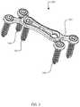
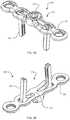
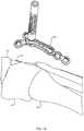
- FIG. 1Ais an oblique view of an assembly with a bone plate, a staple, and screws
- FIG. 1Bis another oblique view of the assembly of FIG. 1A from a different direction
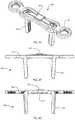
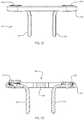
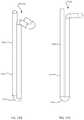
- FIG. 1Cis a side view of the assembly of FIG. 1A
- FIG. 1Dis a longitudinal cross-section of the assembly of FIG. 1A along a mid-sagittal plane of the bone plate
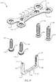
- FIG. 1Eis an exploded oblique view of the assembly of FIG. 1A
- FIG. 1Fis another exploded oblique view of the assembly of FIG. 1A from a different direction.
- FIG. 2is an oblique view of an assembly with the bone plate of FIG. 1A and screws.
- FIG. 3Ais an oblique view of an assembly with a bone plate, a staple, and a set screw
- FIG. 3Bis another oblique view of the assembly of FIG. 3A from a different direction
- FIG. 3Cis a side view of the assembly of FIG. 3A
- FIG. 3Dis a longitudinal cross-section of the assembly of FIG. 3A along a mid-sagittal plane of the bone plate
- FIG. 3Eis an exploded oblique view of the assembly of FIG. 3A
- FIG. 3Fis another exploded oblique view of the assembly of FIG. 3A from a different direction.
- FIG. 4Ais an oblique view of an assembly with a bone plate and a staple
- FIG. 4Bis another oblique view of the assembly of FIG. 4A from a different direction
- FIG. 4Cis an exploded oblique view of the assembly of FIG. 4A
- FIG. 4Dis another exploded oblique view of the assembly of FIG. 4A from a different direction
- FIG. 4Eis yet another oblique view of the assembly of FIG. 4A , showing a tab in a closed configuration
- FIG. 4Fis a side view of the assembly of FIG. 4E
- FIG. 4Gis a longitudinal cross-section of the assembly of FIG. 4E along a mid-sagittal plane of the bone plate.
- FIG. 5Ais an oblique view of an assembly with a bone plate and a staple insert molded within the bone plate;
- FIG. 5Bis another oblique view of the assembly of FIG. 5A from a different direction;
- FIG. 5Cis a side view of the assembly of FIG. 5A ;
- FIG. 5Dis a longitudinal cross-section of the assembly of FIG. 5A along a mid-sagittal plane of the bone plate;
- FIG. 5Eis an exploded oblique view of the assembly of FIG. 5A ;
- FIG. 5Fis another exploded oblique view of the assembly of FIG. 5A from a different direction.
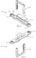
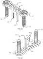
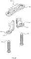
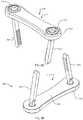
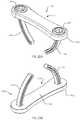
- FIG. 6Ais an oblique view of an assembly with a bone plate, elbow pegs, and screws;
- FIG. 6Bis another oblique view of the assembly of FIG. 6A from a different direction;
- FIG. 6Cis a side view of the assembly of FIG. 6A ;
- FIG. 6Dis a longitudinal cross-section of the assembly of FIG. 6A along a mid-sagittal plane of the bone plate;
- FIG. 6Eis an exploded oblique view of the assembly of FIG. 6A ;
- FIG. 6Fis another exploded oblique view of the assembly of FIG. 6A from a different direction.
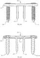
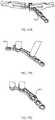
- FIG. 7Ais an oblique view of an assembly with a bone plate, elbow pegs, and set screws;
- FIG. 7Bis another oblique view of the assembly of FIG. 7A from a different direction;
- FIG. 7Cis a side view of the assembly of FIG. 7A ;
- FIG. 7Dis a longitudinal cross-section of the assembly of FIG. 7A along a mid-sagittal plane of the bone plate, showing one of the elbow pegs in an insertion configuration and another one of the elbow pegs in a final configuration;
- FIG. 7Eis an exploded oblique view of the assembly of FIG. 7A ;
- FIG. 7Fis another exploded oblique view of the assembly of FIG. 7A from a different direction.
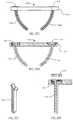
- FIG. 8Ais an oblique view of an assembly with a bone plate, straight pegs, and set screws;
- FIG. 8Bis another oblique view of the assembly of FIG. 8A from a different direction;
- FIG. 8Cis a side view of the assembly of FIG. 8A ;
- FIG. 8Dis a longitudinal cross-section of a portion of the assembly of FIG. 8A along a mid-sagittal plane of the bone plate, showing one of the straight pegs in an insertion configuration;
- FIG. 8Eis a longitudinal cross-section of a portion of the assembly of FIG. 8A along a mid-sagittal plane of the bone plate, showing another one of the straight pegs in a final configuration;
- FIG. 8Fis an exploded oblique view of the assembly of FIG. 8A ;
- FIG. 8Gis another exploded oblique view of the assembly of FIG. 8A from a different direction.
- FIG. 9Ais a lateral oblique view of the bones of a human right foot; and FIG. 9B is a medial view of the bones of a human right foot.
- FIG. 10is an oblique view of a kit of bone plates.
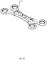
- FIG. 11is another oblique view of the bone plate of FIG. 1A .
- FIG. 12Ais an oblique view of the screws of FIG. 1A ; and FIG. 12B is a side view of the screws of FIG. 1A .
- FIG. 13Ais an oblique cross-section detail view of the non-locking screw of FIG. 1A in a hole of the bone plate of FIG. 1A ; and FIG. 13B is an oblique cross-section detail view of the locking screw of FIG. 1A in a hole of the bone plate of FIG. 1A .
- FIG. 14is an oblique view of a kit of surgical instruments.
- FIG. 15is an oblique view of a sizing template of the kit of FIG. 14 .
- FIG. 16Ais an oblique detail view of a plate of FIG. 10 with two benders of the kit of FIG. 14 ; and FIG. 16B is an oblique detail view of the plate and a bender of FIG. 16A .
- FIG. 17Ais an oblique detail view of the plate and benders of FIG. 16A ;
- FIG. 17Bis an oblique detail view of the plate and bender of FIG. 16B , with an additional bender;
- FIG. 17Cis an oblique detail view of the plate and benders of FIG. 17B .
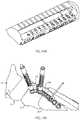
- FIG. 18is a medial oblique view of some of the bones of a human left foot, a bone plate, and a threaded drill guide of the kit of FIG. 14 which doubles as a plate inserter tool.
- FIG. 18shows the step of inserting the bone plate.
- FIG. 19Ais a detail view of a portion of the threaded drill guide of FIG. 18 ; and FIG. 19B is a medial oblique view of some of the bones of a human left foot, the bone plate of FIG. 18 , two threaded drill guides of FIG. 18 , and an olive wire of the kit of FIG. 14 .
- FIG. 19Bshows the step of drilling for a locking screw.
- FIG. 20Ais an oblique view of a non-locking polyaxial drill guide of the kit of FIG. 14 and a threaded plate bender of the kit of FIG. 14 which doubles as a handle for the non-locking polyaxial drill guide; and FIG. 20B is a medial oblique view of some of the bones of a human left foot, the bone plate and threaded drill guide of FIG. 18 , and the non-locking polyaxial drill guide with threaded plate bender of FIG. 20A .
- FIG. 20Bshows the step of drilling for a non-locking screw.
- FIG. 21is a medial oblique view of some of the bones of a human left foot, the bone plate and threaded drill guide of FIG. 18 , the screw of FIG. 1A , and a screw driver of the kit of FIG. 14 .
- FIG. 21shows the step of driving a locking screw.
- FIG. 22Ais a medial oblique view of some of the bones of a human left foot, the bone plate of FIG. 18 , the screws of FIG. 1A , and a staple drill guide of the kit of FIG. 14 ;
- FIG. 22 Bis a medial oblique view of some of the bones of a human left foot, the bone plate of FIG. 18 , the screws of FIG. 1A , and a staple inserter of the kit of FIG. 14 ;
- FIG. 22Cis a medial oblique view of some of the bones of a human left foot, the bone plate of FIG. 18 , the screws of FIG. 1A , and a staple.
- FIG. 23is a medial oblique view of some of the bones of a human left foot, the bone plate of FIG. 18 , the screws of FIG. 1A , and a staple.
- FIG. 24Ais an oblique view of an assembly with a bone plate and straight threaded pegs
- FIG. 24Bis another oblique view of the assembly of FIG. 24A from a different direction
- FIG. 24Cis a side view of the assembly of FIG. 24A
- FIG. 24Dis a longitudinal cross-section of a portion of the assembly of FIG. 24A along a mid-sagittal plane of the bone plate
- FIG. 24Eis an oblique view of a portion of a straight peg inserter instrument
- FIG. 24Fis an oblique view of the assembly of FIG. 24A with the inserter instrument of FIG. 24E , with one straight peg partially inserted
- FIG. 24Gis another oblique view of the assembly of FIG.
- FIG. 24Awith the inserter instrument of FIG. 24E , with both straight pegs fully inserted;
- FIG. 24His a cross sectional view of a portion of the components of FIG. 24G ;
- FIG. 24Iis an exploded oblique view of the assembly of FIG. 24A ;
- FIG. 24Jis another exploded oblique view of the assembly of FIG. 24A from a different direction.
- FIG. 25Ais an oblique view of an assembly with a bone plate, wire pegs, and set screws;
- FIG. 25Bis another oblique view of the assembly of FIG. 25A from a different direction;
- FIG. 25Cis a side view of the assembly of FIG. 25A ;
- FIG. 25Dis a longitudinal cross-section of a portion of the assembly of FIG. 25A along a mid-sagittal plane of the bone plate;
- FIG. 25Eis an oblique view of the wire peg of FIG. 25A in a free state;
- FIG. 25Fis a cross sectional view of a portion of the assembly of FIG. 25A , with a wire peg in a free state;
- FIG. 25Gis an exploded oblique view of the assembly of FIG. 25A ; and
- FIG. 25His another exploded oblique view of the assembly of FIG. 25A from a different direction.
- FIG. 26Ais an oblique view of an assembly with a bone plate, wire pegs, and set screws;
- FIG. 26Bis another oblique view of the assembly of FIG. 26A from a different direction;
- FIG. 26Cis a side view of the assembly of FIG. 26A ;
- FIG. 26Dis a longitudinal cross-section of a portion of the assembly of FIG. 26A along a mid-sagittal plane of the bone plate;
- FIG. 26Eis an oblique view of the wire peg of FIG. 26A in a free state;
- FIG. 26Fis a cross sectional view of a portion of the assembly of FIG. 26A , with a wire peg in a free state;
- FIG. 26Gis an exploded oblique view of the assembly of FIG. 26A ; and
- FIG. 26His another exploded oblique view of the assembly of FIG. 26A from a different direction.
- FIG. 27Ais an oblique view of a wire peg in a free state; and FIG. 27B is a side view of the wire peg of FIG. 27A .
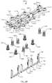
- FIG. 28Ais an oblique view of an assembly with a bone plate, staples, and screws
- FIG. 28Bis another oblique view of the assembly of FIG. 28A from a different direction
- FIG. 28Cis a side view of the assembly of FIG. 28A
- FIG. 28Dis a longitudinal cross-section of the assembly of FIG. 28A along a mid-sagittal plane of the bone plate
- FIG. 28Eis an exploded oblique view of the assembly of FIG. 28A
- FIG. 28Fis another exploded oblique view of the assembly of FIG. 28A from a different direction.
- phrases “connected to,” “coupled to” and “in communication with”refer to any form of interaction between two or more entities, including mechanical, electrical, magnetic, electromagnetic, fluid, and thermal interaction. Two components may be functionally coupled to each other even though they are not in direct contact with each other.
- the term “abutting”refers to items that are in direct physical contact with each other, although the items may not necessarily be attached together.
- the phrase “fluid communication”refers to two features that are connected such that a fluid within one feature is able to pass into the other feature
- a sagittal planedivides a body into right and left portions.
- a mid-sagittal planedivides the body into bilaterally symmetric right and left halves.
- a coronal planedivides a body into anterior and posterior portions.
- a transverse planedivides a body into superior and inferior portions.
- Anteriormeans toward the front of the body.
- Posteriormeans toward the back of the body.
- Superiormeans toward the head.
- Inferiormeans toward the feet.
- Medialmeans toward the midline of the body.
- Lateralmeans away from the midline of the body.
- Axialmeans toward a central axis of the body.
- Abaxialaway from a central axis of the body.
- Ipsilateralmeans on the same side of the body. Contralateral means on the opposite side of the body.
- an elastically deformed stateis defined as deformation equivalent to strain values above 0.2%, for example strain values between 0.2% and 6%.
- An elastically deformed stateis distinct from the small magnitude of deformation and strain tolerated by most materials under load
- a static materialor a static design, or a static component
- a static componentis defined as a material, design, or component that tolerates deformation equivalent to no more than 0.2% strain before experiencing permanent plastic deformation, bending, cracking, breaking, or other failure mode
- an assembly 100may include a stabilizing member, a dynamic element, and one or more fasteners.
- the stabilizing membermay be a bone plate 102
- the dynamic elementmay be a staple 104
- the fastenersmay be screws.
- Assembly 100is illustrated with locking screws 106 on the left and non-locking screws 108 on the right.
- the bone plate 102has an obverse side 112 and a reverse side 114 .
- the obverse side 112faces away from the bone portions and the reverse side 114 faces toward the bone portions.
- the bone plate 102includes several holes 116 which extend through the obverse and reverse sides 112 , 114 . Six holes 116 are illustrated, although any number of holes may be present.
- Each hole 116includes an internally threaded portion 118 and a non-threaded portion 120 so that each hole 116 accepts either the locking screw 106 or the non-locking screw 108 . See FIGS. 13A and 13B .
- the internally threaded portion 118engages external threads 119 on the head 107 of the locking screw 106 .
- the internally threaded portion 118may be adjacent to the reverse side 114 .
- the non-threaded portion 120engages the head 109 of the non-locking screw 108 .
- the non-threaded portion 120may be adjacent to the obverse side 112 .
- the non-threaded portion 120may be concave and/or elongated.
- An optional groove 122 in the obverse side 112extends between two of the holes 116 . Each of these two holes 116 is also elongated toward the other hole 116 , leaving a web 124 extending between the two holes 116 .
- the web 124may be adjacent to the reverse side 114 .
- the web 124separates the two holes 116 , and may be present even if the holes 116 are not elongated towards each other.
- the optional groove 122 if present, the two elongated holes 116 , and the web 124are referred to collectively as a receiver 126 , and the involved holes 116 are referred to as receiver holes 128 .
- a receiver 126may be included between any two holes through a bone plate. Multiple receivers 126 may be included on a single bone plate.
- the bone plate 102may be modified to include a second receiver between the left two holes 116 and/or a third receiver between the right two holes 116 . Two receivers 126 may share a common receiver hole 128 .
- the bone plate 102may be much more stiff than the dynamic element, which in this example is the staple 104 .
- the bone plate 102may be rigid, or static as defined above. Alternatively, the bone plate 102 may be malleable or elastic.
- the bone plate 102may include rigid and malleable regions.
- the illustrated bone plate 102may be 2 mm thick in the vicinity of the receiver 126 and 1.5 mm thick in the vicinity of the leftmost two holes 116 and the rightmost two holes 116 .
- the bone plate 102may accommodate a staple 104 that is 18 mm ⁇ 14 mm.
- the bone plate 102is also illustrated in FIG. 11 .
- FIG. 10shows, from left to right, a left double Y plate 102 , a left Y plate, a right Y plate 902 , a straight 4-hole plate, and a straight 5-hole plate.
- a kit or setmay also include a left metatarsophalangeal plate with 10 degree varus and zero degree dorsiflexion (not shown), and a right metatarsophalangeal plate with 10 degree varus and zero degree dorsiflexion (not shown).
- the staple 104is described in at least one of the patent applications identified in this application.
- the staple 104may be the implant 200 of FIGS. 11 and 12, implant 300 of FIGS. 15A-16B, implant 600 of FIGS. 21 and 22, implant 800 of FIGS. 23A-24, or implant 2200 of FIGS. 78 and 79 of International Patent Application Serial No. PCT/US2015/039551; or implant 100 of FIGS. 1-3, staple 300 of FIGS. 4 and 5, staple 400 of FIG. 7, staple 480 of FIG. 8, or implant 2100 of FIGS. 10A and 10B of International Patent Application Serial No. PCT/US2015/039556.
- the staple 104includes a body 140 or bridge, a first leg 142 , and a second leg 144 .
- the bridgeextends between a first end 146 and a second end 148 .
- the first leg 142is coupled to the first end 146 and terminates in a first free end 143 .
- the second leg 144extends from the second end 148 and terminates in a second free end 145 .
- the staple 104has an insertion state, or elastically deformed state, which is its shape under the influence of an external force, for example, an external force applied by a staple inserter tool.
- a first distanceseparates the free ends 143 , 145 in the elastically deformed state.
- the staple 104also has a free state, or relaxed state, which is its shape when no external forces are acting upon the staple, other than gravity.
- a second distanceseparates the free ends 143 , 145 in the relaxed state. The second distance is different from the first distance.
- the legs 142 , 144 of the staple 104are parallel to one another in the elastically deformed state. However, the legs 142 , 144 may converge or diverge in the elastically deformed state.
- the legs 142 , 144 of the stapleconverge at their free ends, or tips, in the relaxed state, so that the second distance is less than the first distance.
- the legs 142 , 144may diverge at their free ends, or the legs 142 , 144 may be parallel in the relaxed state.
- the staple 104assumes the elastically deformed state under the influence of an external force.
- the staple 104may resume the free state as soon as the external force is removed. If the legs 142 , 144 of the staple 104 are engaged in bone holes, then the staple may only be able to partially relax toward the free state due to the resistance of the bone. In this situation, the staple 104 may be in a loaded state in between the elastically deformed state and the relaxed state.
- the loaded state of the stapleis shown in FIGS. 1A-1F .
- the staple 104is preferably made of a superelastic alloy such as nitinol, although other materials are also suitable.
- the staple 104is not locked to the bone plate 102 , although in subsequent examples the staple is locked to the bone plate.
- the body 140 of the staple 104rests within the groove 122 of the receiver 126 against the web 124 , and the staple legs 142 , 144 extend through the receiver holes 128 and protrude from the reverse side 114 of the bone plate 102 .
- the web 124prevents the body 140 from passing through the reverse side 114 of the bone plate 102 .
- the receiver 126holds the staple 104 in a predetermined orientation and relative position with respect to the bone plate 102 .
- the receiver 126is one example of a group of features that function together to hold a staple a in a predetermined orientation and relative position with respect to a bone plate. Different features, or groups of features, may provide the same function.
- the groove 122may be lacking so that the body 140 of the staple 104 rests atop the obverse side 112 of the bone plate 102 , or the web 124 may be replaced by ledges or other supports to serve as a stop or a docking point to prevent the body 140 from passing through the reverse side 114 .
- the web 124may be replaced by one or more stop feature(s) or docking feature(s) on the staple 104 instead of on the bone plate 102 .
- the locking screw 106locks securely to any hole 116 in the bone plate 102 .
- the locking screw 106may include an externally threaded head 107 which locks to the hole 116 in the bone plate 102 when threaded tightly into the internally threaded portion 118 of the hole 116 .
- the locking screw 106may be the design disclosed in at least one of the patent applications identified in this application.
- the locking screw 106may be the bone fixation device 390 of FIG. 11, bone fixation device 500 of FIGS. 24-26, bone fixation device 600 of FIGS. 27-30 of International Patent Application Serial No. PCT/US2014/070495.
- the locking screwmay have a 3.0 mm diameter and lengths from 8 mm to 30 mm in 2 mm increments.
- the locking screw 106is also illustrated in FIG. 12 .
- the non-locking screw 108does not lock to the holes 116 in the bone plate 102 . Instead, it remains free to rotate and translate within the confines of the screw hole 116 after implantation.
- the non-locking screw 108may be polyaxially positionable relative to the screw hole 116 .
- the non-locking screw 108may include a head 109 with an exterior surface that forms a ball-and-socket joint with the non-threaded portion 120 of the hole 116 .
- the exterior surfacemay be convex, spherical, or conical.
- the non-locking screw 108may have a 3.5 mm diameter and lengths from 8 mm to 30 mm in 2 mm increments.
- the non-locking screw 108is also illustrated in FIG. 12 .
- the screws 106 and 108are interchangeable in the screw holes 116 of the bone plate 102 .
- an assembly 200may include a stabilizing member and one or more fasteners.
- the stabilizing membermay be the bone plate 102 and the fasteners may include one or more of the screws 106 and/or 108 .
- This exampleincludes a locking screw 106 in one of the receiver holes, showing that the screws 106 or 108 can be used interchangeably in the receiver holes 128 as well as the other holes 116 of the bone plate 102 .
- an assembly 300may include a stabilizing member, a dynamic element, and one or more fasteners.
- the stabilizing membermay be a bone plate 302
- the dynamic elementmay be the staple 104
- the fastenersmay include a set screw 310 and one or more of the screws 106 and/or 108 , although the screws 106 and 108 are omitted from the illustration for clarity.
- the bone plate 302has an obverse side 312 and a reverse side 314 .
- the bone plate 302includes several holes 316 , each of which may include an internally threaded portion 318 and a non-threaded portion 320 , the same as hole 116 .
- the internally threaded portion 318may be adjacent to the reverse side 314 and the non-threaded portion 320 may be adjacent to the obverse side 312 .
- An optional groove 322 in the obverse side 312extends between two of the holes 316 .
- Each of these two holes 316is also elongated toward the other hole 316 , leaving a web 324 extending between the two holes 316 .
- the web 324may be adjacent to the reverse side 314 .
- the web 324separates the two holes 316 , and may be present even if the holes 316 are not elongated towards each other.
- the web 324prevents the body 140 from passing through the reverse side 314 .
- the optional groove 322 if present, the two elongated holes 316 , and the web 324are referred to collectively as a receiver 326 , and the involved holes 316 are referred to as receiver holes 328 .
- the bone plate 302includes an internally threaded socket 338 which receives the set screw 310 in threaded engagement.
- the set screw 310locks the staple 104 to the bone plate 302 , and may be referred to as a locking mechanism.
- an assembly 400may include a stabilizing member, a dynamic element, and one or more fasteners.
- the stabilizing membermay be a bone plate 402
- the dynamic elementmay be the staple 104
- the fastenersmay include one or more of the screws 106 and/or 108 , although the screws 106 and 108 are omitted from the illustration for clarity.
- the bone plate 402has an obverse side 412 and a reverse side 414 .
- the bone plate 402includes several holes 416 , each of which may include an internally threaded portion 418 and a non-threaded portion 420 , the same as hole 116 .
- the internally threaded portion 418may be adjacent to the reverse side 414 and the non-threaded portion 420 may be adjacent to the obverse side 412 .
- An optional groove 422 in the obverse side 412extends between two of the holes 416 .
- Each of these two holes 416is also elongated toward the other hole 416 , leaving a web 424 extending between the two holes 416 .
- the web 424may be adjacent to the reverse side 414 .
- the web 424separates the two holes 416 , and may be present even if the holes 416 are not elongated towards each other.
- the web 424prevents the body 140 from passing through the reverse side 414 .
- the optional groove 422 if present, the two elongated holes 416 , and the web 424are referred to collectively as a receiver 426 , and the involved holes 416 are referred to as receiver holes 428 .
- the bone plate 402includes a ductile tab 430 that extends from the obverse side 412 beside the receiver 426 . There may be more than one tab 430 .
- the tab 430couples the staple 104 to the bone plate 402 .
- the tab 430may therefore be considered one of the fasteners, and may be referred to as a locking mechanism.
- the tab 430is illustrated in an open state in FIGS. 4A-4D , and in a closed state in FIGS. 4E-4G .
- the staple 104may be inserted into the receiver 426 .
- the tab 430prevents the staple 104 from being removed from the receiver.
- the tab 430may be bent over the staple 104 in the closed state.
- the tab 430may experience plastic deformation, also known as permanent deformation, so that the tab 430 remains bent over the staple 104 unless bent back towards the open state.
- the tab 430may be closed intraoperatively, or the assembly 400 may be provided coupled together with the tab 430 closed as shown in FIGS. 4E-4G .
- an assembly 500may include a stabilizing member, a dynamic element, and one or more fasteners.
- the stabilizing membermay be a bone plate 502
- the dynamic elementmay be the staple 104
- the fastenersmay be one or more of the screws 106 and/or 108 , although the screws 106 and 108 are omitted from the illustration for clarity.
- the bone plate 502has an obverse side 512 and a reverse side 514 .
- the bone plate 502includes several holes 516 , each of which may include an internally threaded portion 518 and a non-threaded portion 520 , the same as hole 116 .
- the internally threaded portion 518may be adjacent to the reverse side 514 and the non-threaded portion 520 may be adjacent to the obverse side 512 .
- Two of the holes 516are elongated toward each other, leaving a web 524 extending between the two holes 516 .
- the two elongated holes 516in this example lack the internally threaded portion 518 .
- the web 524may be adjacent to the reverse side 514 .
- the web 524separates the two holes 516 , and may be present even if the holes 516 are not elongated towards each other.
- the web 524prevents the body 140 from passing through the reverse side 514 .
- the two elongated holes 516 and web 524are referred to collectively as a receiver 526 , and the involved holes 516 are referred to as receiver holes 528 .
- the bone plate 502is formed around the staple 104 at least partially so that the staple 104 is inseparable from the bone plate 502 in normal use.
- the web 524encircles a middle portion of the body 140 of the staple 104 , leaving lateral portions of the staple body 140 and the staple legs 142 , 144 free to flex between the relaxed state and the elastically deformed state.
- the staple 104may be partially or fully encapsulated in an elastically deformable material that bends with the staple as the staple moves between the relaxed state and the elastically deformed state.
- the bone plate 502may be made of polyetheretherketone (PEEK) which is overmolded around the staple 104 .
- the staple 104may be insert molded into the bone plate 502 .
- the bone plate 502 and staple 104may be integrally formed of a single material, preferably a highly elastic material such as nitinol.
- the staple included in assembly 500may be a modified version of staple 104 . The modifications may facilitate manufacturing the bone plate 502 and the staple as a unit.
- an assembly 600may include a stabilizing member, a dynamic element, and one or more fasteners.
- the stabilizing membermay be a bone plate 602
- the dynamic elementmay be an elbow peg 604 also known as an L-peg
- the fastenersmay be one or more of the screws 106 and/or 108 .
- the bone plate 602has an obverse side 612 and a reverse side 614 .
- the bone plate 602includes several holes 616 .
- the holes 616may lack an internally threaded portion like hole 116 .
- a groove 622 in the obverse side 612extends between two of the holes 616 and within the holes, forming a shelf 623 within each hole 616 .
- the shelf 623may be adjacent to the reverse side 614 .
- Each of these two holes 616is also elongated toward the other hole 616 , leaving a web 624 extending between the two holes 616 .
- the web 624may be adjacent to the reverse side 614 .
- the web 624separates the two holes 616 , and may be present even if the holes 616 are not elongated towards each other.
- the groove 622 , two elongated holes 616 , and web 624are referred to collectively as a receiver 626 , and the holes 616 are referred to as receiver holes 628 , since these features receive the elbow pegs 604 .
- Each elbow peg 604includes a head 632 and a bone-contacting leg 634 , which terminates in a free end 635 .
- the head 632may be shaped like a ring, as illustrated, or it may be any shape, such as rectangular, square, oval, polygonal, etc.
- the head 632may be perpendicular, or nearly perpendicular, to the leg 634 .
- the head 632 and the leg 634may form an angle of 90 degrees ⁇ 10 degrees, 90 degrees ⁇ 15 degrees, or 90 degrees ⁇ 20 degrees.
- the head 632may form an acute angle or an obtuse angle with the leg 634 .
- Each elbow peg 604may be independently inserted into a bone hole and secured to the bone plate 602 .
- the elbow peg 604may be secured to the bone plate 602 by a bone screw, such as screw 106 or 108 , through an aperture 636 through the head 632 .
- the shelf 623prevents the head 632 from passing through the reverse side 614 of the bone plate 602 .
- the elbow peg 604may develop some spring force as the bone screw is fully seated, as explained more fully below with regard to assembly 700 .
- the spring forcemay be linear or nonlinear.
- the elbow peg 604may exert force due to simple leverage without substantive spring force.
- a single elbow peg 604may be used opposite a locking screw 106 .
- This arrangementis not shown.
- the bone plate 602would have an internally threaded hole 616 at one end (like hole 116 of bone plate 102 ) and at the other end, a receiver hole 628 .
- the assemblywould include a locking screw 106 in the internally threaded hole 616 and an elbow peg 604 plus a screw in the receiver hole 628 .
- a screw 108 and an elbow peg 604may be used together with no other apparatus.
- the screw 108 and the leg 634 of the elbow peg 604may lie on opposite sides of the discontinuity between tissue portions.
- a screw 106may also be used in this fashion, in which case the aperture 636 through the head 632 of the elbow peg 604 preferably includes an internally threaded portion to engage the external threads 119 on the head 107 of the screw 106 .
- an assembly 700may include a stabilizing member, a dynamic element, and one or more fasteners.
- the stabilizing membermay be a bone plate 702
- the dynamic elementmay be an elbow peg 704 also known as an L-peg
- the fastenersmay be one or more of the set screws 310 .
- the bone plate 702has an obverse side 712 and a reverse side 714 .
- the bone plate 702includes several holes 716 , each of which may include an internally threaded portion 718 .
- the internally threaded portion 718may be adjacent to the obverse side 712 .
- Each hole 716may include an interior shelf 723 .
- the shelf 723may be adjacent to the reverse side 714 .
- Two of the holes 716are elongated toward each other, leaving a web 724 extending between the two holes 716 .
- the web 724may be adjacent to the reverse side 714 .
- the web 724separates the two holes 716 , and may be present even if the holes 716 are not elongated towards each other.
- the two elongated holes 716 and web 724are referred to collectively as a receiver 726 , and the involved holes 716 are referred to as receiver holes 728 , since these features receive the elbow pegs 704 .
- Each elbow peg 704includes a head 732 and a bone-contacting leg 734 , which terminates in a free end 735 .
- the head 732may be rounded, as illustrated, or it may be any shape.
- the head 732may be perpendicular, or nearly perpendicular, to the leg 734 .
- the head 732 and the leg 734may form an angle of 90 degrees ⁇ 10 degrees, 90 degrees ⁇ 15 degrees, or 90 degrees ⁇ 20 degrees.
- the head 732may form an acute angle or an obtuse angle with the leg 734 .
- Each elbow peg 704may be independently inserted into a bone hole and secured to the bone plate 702 .
- the elbow peg 704may be secured to the bone plate 702 by the set screw 310 against the head 734 .
- the shelf 723prevents the head 732 from passing through the reverse side 714 of the bone plate 702 .
- the elbow peg 704may develop some spring force as the set screw 310 is fully seated.
- FIG. 7Dshows a free state elbow peg 704 in the left hole.
- the head 732 and the leg 734form an obtuse angle in the free state.
- a compressed elbow peg 704is shown in the right hole.
- the elbow peg 704is elastically bent to a 90 degree state, which is an elastically deformed state.
- the leg 734exerts a force against the bone, acting toward the left-hand elbow peg 704 .
- the forcemay be linear or nonlinear.
- a similar principlemay apply to the elbow pegs 604 described for assembly 600 .
- the elbow peg 704may exert force due to simple leverage without substantive spring force.
- a single elbow peg 704may be used opposite a locking screw 106 .
- This arrangementis not shown.
- the bone platewould have an internally threaded hole 716 at one end (like hole 116 of bone plate 102 ) and at the other end, a receiver hole 728 .
- the assemblywould include a locking screw 106 in the internally threaded hole 716 and an elbow peg 704 plus a set screw 310 in the receiver hole 728 .
- an assembly 800may include a stabilizing member, a dynamic element, and one or more fasteners.
- the stabilizing membermay be a bone plate 802
- the dynamic elementmay be a straight peg 804
- the fastenersmay be one or more of the set screws 310 .
- the bone plate 802has an obverse side 812 and a reverse side 814 .
- the bone plate 802includes several holes 816 , each of which may include an internally threaded portion 818 .
- the internally threaded portion 818may be adjacent to the obverse side 812 .
- Each hole 816may include an interior shelf 823 .
- the shelf 823may be adjacent to the reverse side 814 .
- a web 824extends between two of the holes 816 .
- the web 824may be adjacent to the reverse side 814 .
- the web 824separates the two holes 816 , and may be present even if the holes 816 are elongated towards each other.
- the two holes 816are referred to as receiver holes 828 , since these features receive the straight pegs 804 .
- Each straight peg 804includes a head 832 and a bone-contacting leg 834 , which terminates in a free end 835 .
- the head 832may be rounded, as illustrated, or it may be any shape.
- the head 832may include a mark 837 , such as an arrowhead pointing toward the free end 835 of the leg 834 ( FIG. 8F ).
- the head 832may form an obtuse angle, a right angle, or an acute angle with the leg 834 ( FIG. 8E ).
- Each straight peg 804may be independently inserted into a bone hole and secured to the bone plate 802 .
- the straight peg 804may be secured to the bone plate 802 by the set screw 310 against the head 832 .
- the shelf 823prevents the head 832 from passing through the reverse side 814 of the bone plate 802 .
- the straight peg 804is free to rotate about its head 832 within the receiver hole 828 , at least until secured by the set screw 310 .
- the straight peg 804may be rotationally constrained relative to the receiver hole 828 to a set of discrete rotational positions.
- the head 832 and/or the leg 834 of the straight peg 804may be non-circular, and may engage a complementary non-circular portion of the receiver hole 828 .
- FIGS. 25A-HA similar arrangement is illustrated in FIGS. 25A-H .
- the assembly 800can deliver dynamic load in multiple directions relative to the bone plate 802 and/or other straight pegs 804 .
- the mark 837(arrowhead) may assist in orienting each leg 834 in the desired direction.
- FIGS. 8D and 8Eillustrate that the straight peg 804 may develop spring force as the set screw 310 is fully seated, according to the same principles described for assembly 700 above. However, in FIG. 8E , the straight peg 804 is illustrated in its free state, having rotated counterclockwise due to the action of the set screw 310 . If the leg 834 were constrained to the position shown in FIG. 8 D, perpendicular to the bone plate 802 , then the straight peg 804 would develop spring force as the set screw 310 is tightened.
- a single straight peg 804may be used opposite a locking screw 106 .
- This arrangementis not shown.
- the bone platewould have an internally threaded hole 816 at one end (like hole 116 of bone plate 102 ) and at the other end, a receiver hole 828 .
- the assemblywould include a locking screw 106 in the internally threaded hole 816 and a straight peg 804 plus a set screw 310 in the receiver hole 828 .
- an assembly 1000may include a stabilizing member and a dynamic element.
- the stabilizing membermay be the bone plate 602 and the dynamic element may be a straight peg 1004 .
- Each straight peg 1004includes a rounded head 1032 and a bone-contacting leg 1034 , which terminates in a free end 1035 .
- the head 1032may form an obtuse angle, a right angle, or an acute angle with the leg 1034 ( FIG. 240 ).
- the head 1032may include a mark pointing toward the free end 1035 of the leg 1034 , similar to mark 837 of straight peg 804 .
- the leg 1034may include external threads as shown, or the leg 1034 may be smooth.
- Each straight peg 1004may be independently inserted into a bone hole and secured to the bone plate 602 .
- the straight peg 1004may be secured to the bone plate 602 by threading the leg 1034 into bone, or with a set screw 310 as explained previously.
- the shelf 623prevents the head 1032 from passing through the reverse side 614 of the bone plate 602 .
- the straight peg 1004may develop spring force, according to similar principles to those described above.
- FIG. 24Eillustrates an inserter tool 1040 for temporarily straightening the angle between the head 1032 and the leg 1034 , and for threading the leg 1034 into a bone hole.
- the inserter tool 1040includes a torque drive feature 1042 (a hex) with a distal shaft 1044 that extends within a cannulation 1033 in the straight peg 1004 .
- the bone plate 602would have an internally threaded hole 616 at one end (like hole 116 of bone plate 102 ) and at the other end, a receiver hole 628 .
- the assemblywould include a locking screw 106 in the internally threaded hole 616 and a straight peg 1004 in the receiver hole 628 .
- an assembly 1100may include a stabilizing member, a dynamic element, and one or more fasteners.
- the stabilizing membermay be a bone plate 1102
- the dynamic elementmay be a wire peg 1104
- the fastenermay include a set screw 310 .
- the bone plate 1102has an obverse side 1112 and a reverse side 1114 .
- the bone plate 1102includes several holes 1116 , each of which may include an internally threaded portion 1118 .
- the internally threaded portion 1118may be adjacent to the obverse side 1112 .
- Each hole 1116may include an interior shelf 1123 .
- the shelf 1123may be adjacent to the reverse side 1114 .
- a web 1124extends between two of the holes 1116 .
- the web 1124may be adjacent to the reverse side 1114 .
- the web 1124separates the two holes 1116 , and may be present even if the holes 1116 are elongated towards each other.
- the two holes 1116are referred to as receiver holes 1128 , since these features receive the wire pegs 1104 .
- Each receiver hole 1128includes a noncircular through hole 1129 .
- the illustrated holes 1129are rectangular, and may be square.
- Each wire peg 1104is formed from a sharply bent, or folded, piece of wire having a rectangular cross section.
- Each wire peg 1104includes a head 1132 and a bone-contacting leg 1134 , which terminates in a free end 1135 where the wire is sharply bent or folded.
- the head 1132 in this exampleis formed by outwardly bent ends, or terminal portions, of the wire.
- the head 1132may form an obtuse angle, a right angle, or an acute angle with the leg 1134 .
- the outwardly bent wire ends of the head 1132form right angles with the leg 1134 when the wire peg 1104 is in the free state.
- the outwardly bent wire ends of the head 1132are uneven when the wire peg 1104 is in the free state.
- Each wire peg 1104may be independently inserted into a bone hole and secured to the bone plate 1102 .
- the wire peg 1104may be secured to the bone plate 1102 with a set screw 310 .
- the shelf 1123prevents the head 1132 from passing through the reverse side 1114 of the bone plate 1102 .
- the wire peg 1104may develop spring force and may bow sideways as the set screw 310 is tightened, due to the uneven height of the outwardly bent wire ends of the head 1132 .
- the stressed or bowed state of the wire peg 1104is illustrated in FIGS. 25A-25D, 25G, and 25H .
- a single wire peg 1104may be used opposite a locking screw 116 .
- This arrangementis not shown.
- the bone platewould have an internally threaded hole 1116 at one end (like hole 116 of bone plate 102 ) and at the other end, a receiver hole 1128 .
- the assemblywould include a locking screw 116 in the internally threaded hole 1116 and a wire peg 1104 with a set screw 310 in the receiver hole 1128 .
- an assembly 1200may include a stabilizing member, a dynamic element, and one or more fasteners.
- the stabilizing membermay be a bone plate 1202
- the dynamic elementmay be a wire peg 1204
- the fastenermay include a set screw 310 .
- the bone plate 1202has an obverse side 1212 and a reverse side 1214 .
- the bone plate 1202includes several holes 1216 , each of which may include an internally threaded portion 1218 .
- the internally threaded portion 1218may be adjacent to the obverse side 1212 .
- Each hole 1216may include an interior shelf 1223 .
- the shelf 1223may be adjacent to the reverse side 1214 .
- the shelf 1223may include a medial alcove 1221 .
- a web 1224extends between two of the holes 1216 .
- the web 1224may be adjacent to the reverse side 1214 .
- the web 1224separates the two holes 1216 , and may be present even if the holes 1216 are elongated towards each other.
- the two involved holes 1216are referred to as receiver holes 1228 , since these features receive the wire pegs 1204 .
- Each receiver hole 1228includes a noncircular through hole 1229 .
- the illustrated holes 1229are elongated, and may be oval, round, or another shape such as rectangular or square.
- Each wire peg 1204is formed from a sharply bent, or folded, piece of wire having a round cross section.
- Each wire peg 1204includes a head 1232 and a bone-contacting leg 1234 , which terminates in a free end 1235 where the wire is sharply bent or folded.
- the head 1232 in this exampleis formed by outwardly bent ends, or terminal portions, of the wire.
- the head 1232may form an obtuse angle, a right angle, or an acute angle with the leg 1234 .
- the outwardly bent wire ends of the head 1232form right angles with the leg 1234 when the wire peg is in the free state.
- the outwardly bent wire ends of the head 1232are uneven when the wire peg is in the free state.
- Each wire peg 1204may be independently inserted into a bone hole and secured to the bone plate 1202 .
- the wire peg 1204may be secured to the bone plate 1202 with a set screw 310 .
- the wire peg 1204may develop spring force and may bow sideways as the set screw is tightened, due to the uneven height of the outwardly bent wire ends of the head 1232 .
- the stressed or bowed state of the wire peg 1204is illustrated in FIGS. 26A-26D, 26G, and 26H .
- a single wire peg 1204may be used opposite a locking screw 126 .
- This arrangementis not shown.
- the bone platewould have an internally threaded hole 1216 at one end (like hole 116 of bone plate 102 ) and at the other end, a receiver hole 1228 .
- the assemblywould include a locking screw 126 in the internally threaded hole 1216 and a wire peg 1204 with a set screw 310 in the receiver hole 1228 .
- an alternative wire peg 1302is formed from a sharply bent, or folded, piece of wire having a round cross section.
- Each wire peg 1304includes a head 1332 and a bone-contacting leg 1334 , which terminates in a free end 1335 where the wire is sharply bent or folded.
- the head 1332 in this exampleis formed by an outwardly bent end, or terminal portion, of the wire and a straight end of the wire.
- the head 1332may form an obtuse angle, a right angle, or an acute angle with the leg 1334 .
- the outwardly bent wire end of the head 1332forms a right angle with the leg 1334 when the wire peg is in the free state.
- the outwardly bent wire end of the head 1332is uneven with the straight end of the head 1332 when the wire peg is in the free state.
- This wire peg 1302may be used interchangeably with the wire pegs 1102 and 1202 .
- an assembly 1400may include a stabilizing member, a dynamic element, and one or more fasteners.
- the stabilizing membermay be a bone plate 1402
- the dynamic elementmay be a staple 1404
- the fastenersmay be screws.
- Assembly 1400is illustrated with locking screws 1406 on the left and non-locking screws 1408 on the right.
- the bone plate 1402has an obverse side 1412 and a reverse side 1414 .
- the bone plate 1402includes several holes 1416 which extend through the obverse and reverse sides 1412 , 1414 . Sixteen holes 1416 are illustrated, although any number of holes may be present.
- Each hole 1416includes an internally threaded portion 1418 and a non-threaded portion 1420 so that each hole 1416 accepts either the locking screw 1406 or the non-locking screw 1408 .
- the internally threaded portion 1418engages external threads 1419 on the head 1407 of the locking screw 1406 .
- the internally threaded portion 1418may be adjacent to the reverse side 1414 .
- the non-threaded portion 1420engages the head 1409 of the non-locking screw 1408 .
- the non-threaded portion 1420may be adjacent to the obverse side 1412 .
- the non-threaded portion 1420may be concave and/or elongated.
- An optional groove 1422 in the obverse side 1412extends along a line of six holes 1416 that extend along the midline of the plate 1402 .
- Each of these six holes 1416is also elongated, leaving webs 1424 extending between the second and third holes 1416 and the fourth and fifth holes 1416 . No webs are shown between the first and second holes 1416 , the third and fourth holes 1416 , or the fifth and sixth holes 1416 , although these webs may be present.
- the webs 1424may be adjacent to the reverse side 1414 .
- the webs 1424separate the second and third holes 1416 and the fourth and fifth holes 1416 , respectively, and may be present even if the holes 14416 are not elongated.
- the first and second holes 1416are referred to collectively as a receiver 1426 , and the involved holes 1416 are referred to as receiver holes 1428 .
- a second receiver 1426includes the third and fourth holes 1416
- a third receiver 1426includes the fifth and sixth holes 1416 .
- the staple 1404is described in at least one of the patent applications identified in this application.
- the staple 1404may be the implant 200 of FIGS. 11 and 12, implant 300 of FIGS. 15A-16B, implant 600 of FIGS. 21 and 22, implant 800 of FIGS. 23A-24, or implant 2200 of FIGS. 78 and 79 of International Patent Application Serial No. PCT/US2015/039551; or implant 100 of FIGS. 1-3, staple 300 of FIGS. 4 and 5, staple 400 of FIG. 7, staple 480 of FIG. 8, or implant 2100 of FIGS. 10A and 10B of International Patent Application Serial No. PCT/US2015/039556.
- the illustrated staple 1404is the implant 2200 of FIGS. 78 and 79 of International Patent Application Serial No. PCT/US2015/039551.
- the staple 1404includes a body 1440 or bridge, a first leg 1442 , and a second leg 1444 .
- the bridgeextends between a first end 1446 and a second end 1448 .
- the first leg 1442is coupled to the first end 1446 and terminates in a first free end 1443 .
- the second leg 1444extends from the second end 1448 and terminates in a second free end 1445 .
- a first projection 1450extends from the first end 1446 and a second projection 1452 extends from the second end 1448 .
- the staple 1404has an insertion state, or elastically deformed state, which is its shape under the influence of an external force, for example, an external force applied by a staple inserter tool.
- a first distanceseparates the free ends 1443 , 1445 in the elastically deformed state.
- the staple 1404also has a free state, or relaxed state, which is its shape when no external forces are acting upon the staple, other than gravity.
- a second distanceseparates the free ends 1443 , 1445 in the relaxed state. The second distance is different from the first distance.
- the legs 1442 , 1444 of the staple 1404are parallel to one another in the elastically deformed state. However, the legs 1442 , 1444 may converge or diverge in the elastically deformed state.
- the legs 1442 , 1444 of the stapleconverge at their free ends 1443 , 1445 , or tips, in the relaxed state, so that the second distance is less than the first distance.
- the legs 1442 , 1444may diverge at their free ends 1443 , 1445 , or the legs 1442 , 1444 may be parallel in the relaxed state.
- the staple 1404assumes the elastically deformed state under the influence of an external force.
- the staple 1404may resume the free state as soon as the external force is removed. If the legs 1442 , 1444 of the staple 1404 are engaged in bone holes, then the staple may only be able to partially relax toward the free state due to the resistance of the bone.
- the staple 1404may be in a loaded state in between the elastically deformed state and the relaxed state.
- the staple 1404is not locked to the bone plate 1402 , although in other examples the staple is locked to the bone plate.
- the body 1440 of the staple 1404rests within the receiver 1426 , and the staple legs 1442 , 1444 extend through the receiver holes 1428 and protrude from the reverse side 1414 of the bone plate 1402 .
- the receiver 1426holds the staple 1404 in a predetermined orientation and relative position with respect to the bone plate 1402 .
- the receiver 1426is one example of a group of features that function together to hold a staple a in a predetermined orientation and relative position with respect to a bone plate.
- the body 1440 of the staple 1404may rest atop the obverse side 1412 of the bone plate 1402 , or on a web, or the web 1424 may be replaced by ledges or other supports to serve as a stop or a docking point to prevent the body 1440 from passing through the reverse side 1414 .
- the web 1424may be replaced by one or more stop feature(s) or docking feature(s) on the staple 1404 instead of on the bone plate 1402 .
- the projections 1450 , 1452may serve as stop features or docking features.
- the locking screw 1406locks securely to any hole 1416 in the bone plate 1402 .
- the locking screw 1406may include an externally threaded head 1407 which locks to the hole 1416 in the bone plate 1402 when threaded tightly into the internally threaded portion 1418 of the hole 1416 .
- the locking screw 1406may be the design disclosed in at least one of the patent applications identified in this application.
- the locking screw 1406may be the bone fixation device 390 of FIG. 11, bone fixation device 500 of FIGS. 24-26, bone fixation device 600 of FIGS. 27-30 of International Patent Application Serial No. PCT/US2014/070495.
- the non-locking screw 1408does not lock to the holes 1416 in the bone plate 1402 . Instead, it remains free to rotate and translate within the confines of the screw hole 1416 after implantation.
- the non-locking screw 1408may be polyaxially positionable relative to the screw hole 1416 .
- the non-locking screw 1408may include a head 1409 with an exterior surface that forms a ball-and-socket joint with the non-threaded portion 1420 of the hole 1416 .
- the exterior surfacemay be convex, spherical, or conical.
- the screws 1406 and 1408are interchangeable in the screw holes 1416 of the bone plate 1402 .
- a normal human foot 10includes twenty-six bones, including a talus 12 , a calcaneus 14 , a navicular 16 , a medial cuneiform 18 , an intermediate cuneiform 20 , a lateral cuneiform 22 , a cuboid 24 , a first metatarsal 26 , a second metatarsal 28 , a third metatarsal 30 , a fourth metatarsal 32 , a fifth metatarsal 34 , a first proximal phalanx 36 , a second proximal phalanx 38 , a third proximal phalanx 40 , a fourth proximal phalanx 42 , a fifth proximal phalanx 44 , a first middle phalanx 46 , a second middle phalanx 48 , a third middle phalanx 50 , a fourth middle
- FIG. 14illustrates several different surgical instruments. From top to bottom, left to right, FIG. 14 illustrates a plate template, a threaded drill guide/depth gage, a polyaxial drill guide/depth gage, a bender/handle, a staple drill guide, an olive wire, drills (such as 2.0 mm and 2.5 mm diameters), and a self-retaining screwdriver (not shown) and a screwdriver handle, such as an AO quick connect handle (not shown).
- a plate sizing templatemay include several individual templates for different plate shapes, each of which may be removed from, or “punched out” of, or torn away from the sizing template.
- the templatemay be provided sterile.
- Templatingmay be a step in a method for using the disclosed apparatus.
- a plate bendermay include a threaded end and a forked end opposite the threaded end. The threaded end threads into the plate holes, as shown in FIGS. 17B and 17C . The forked end receives the plate, as shown in FIGS. 16A and 17A .
- the plate bendermay also be used as a handle for the non-locking polyaxial drill guide ( FIG. 20 ). Multiple plate benders may be provided in a kit or set of instruments. The plate bender(s) may be provided sterile. Plate bending or plate contouring may be a step in a method for using the disclosed apparatus. Plates may be bent in-situ or on a back table in an operating room.
- a threaded drill guidemay lock into a threaded hole in a bone plate, for example bone plate 902 , to accurately guide a drill to make a hole in the bone to receive a locking screw 106 .
- the threaded drill guidemay also be used as a bone plate inserter instrument. Multiple threaded drill guides may be included in a kit or set of instruments. Inserting a bone plate may be a step in a method for using the disclosed apparatus.
- an olive wiremay be used for temporary fixation in a hole in a bone plate, for example bone plate 902 .
- a laser mark on a drillmay register with drill guide depth markings to indicate drilling depth ( FIG. 19A ).
- Drilling for a locking bone screw, and/or tapping for the locking bone screw,may be steps in a method for using the disclosed apparatus.
- a non-locking polyaxial drill guidemay engage a hole in a bone plate, for example bone plate 902 , to accurately guide a drill to make a hole in the bone to receive a non-locking screw 108 .
- the plate bendermay serve as a handle for the non-locking polyaxial drill guide ( FIG. 20A ). Drilling for a non-locking bone screw, and/or tapping for the non-locking bone screw, may be steps in a method for using the disclosed apparatus.
- locking or non-locking screwsmay be used interchangeably in the screw holes of the bone plates after bone holes are drilled.
- a screw driver instrumenttransmits torque from a manual or power source to the screw to drive the screw into the bone and, if a locking screw, into the screw hole threads of the bone plate. While FIG. 21 shows locking screws 106 placed proximally, but the procedure may progress from distal to proximal instead.
- Driving a screw into threaded engagement with the bone and, if a locking screw, with the screw hole threads of the bone platemay be a step in a method for using the disclosed apparatus.
- a staple drill guidemay engage a pair of holes in a bone plate, for example bone plate 902 , to accurately guide a drill to make holes in the bone to receive a staple 104 .
- Drilling for a staplemay be a step in a method for using the disclosed apparatus. The step of drilling for the staple may occur after one end (proximal or distal) of the plate is secured to bone.
- a staple insertermay hold the staple 104 for insertion ( FIG. 22B ).
- the staple inserteris described in at least one of the cross-referenced patent applications identified in paragraph [0001] of this application.
- the staple 104may be held with its legs forced into a parallel state for insertion.
- the staple insertermay engage the staple 104 strictly from a side of the staple opposite the side that faces the bone plate and bone portions, so that the staple 104 may be fully seated in the receiver while the staple inserter is attached to the staple 104 .
- removing the staple insertermay allow the staple legs to relax and attempt to resume the free state, in which the staple legs are acutely angled with respect to each other ( FIGS. 1A-1F ). Inserting a staple may be a step in a method for using the disclosed apparatus.
- FIG. 22Cshows the bone plate 902 and the staple 104 extending across the first Lisfranc joint (or first tarsometatarsal joint) of a human left foot.
- the stapleextends through holes in the bone plate 902 so that each staple leg is on a different side of the joint.
- the staple legsapply mechanical load or stress across the joint.
- the staple 104relaxes towards its free state shown in FIGS. 1A-1F , the staple legs apply compressive load or stress across the joint.
- a staple with divergent legswould apply tensile load or stress across the joint.
- the bone plate 902 , staple 104 , locking screws 106 , and non-locking screws 108are shown in the final implanted state across the first Lisfranc joint. It may be particularly advantageous to use locking screws 106 adjacent to one leg of the staple 104 , and non-locking screws 108 adjacent to the other leg of the staple 104 . This is illustrated in FIG. 23 , where locking screws 106 are used in the medial cuneiform 18 and non-locking screws 108 are used in the first metatarsal 26 . However, an opposite arrangement is contemplated, with non-locking screws 108 are used in the medial cuneiform 18 and locking screws 106 are used in the first metatarsal 26 .
- Methods of using the disclosed apparatusmay include any combination of the above mentioned steps, in any order.
- One example of a method of using the disclosed apparatusincludes the steps of: inserting a bone plate adjacent to a first bone portion and a second bone portion, wherein a discontinuity separates the second bone portion from the first bone portion, wherein the bone plate extends across the discontinuity, wherein the bone plate includes at least four holes; locking a threaded drill guide to a first hole through the bone plate, wherein the first hole of the bone plate is adjacent to the first bone portion; drilling a first bone hole through the threaded drill guide into the first bone portion; driving a locking screw through the first hole of the bone plate into threaded engagement with the first bone hole and the first hole of the bone plate; engaging a staple drill guide with a second hole through the bone plate and a third hole through the bone plate, wherein the second hole of the bone plate is adjacent to the first bone portion, wherein the third hole of the bone plate is adjacent to the second bone portion; drilling a second bone hole through the staple drill guide into the first bone portion; drilling a third bone hole through the staple drill guide into the second bone
- the preceding methodmay also include the step of securing the staple to the bone plate.
- the staplemay be secured to the bone plate with a set screw, a ductile tab, or a snap fit.
- the staplemay be secured to the bone plate by a portion of the staple being molded within a portion of the bone plate.
- the staplemay be secured to the bone plate by being integrally formed with the bone plate.
- Another example of a method of using the disclosed apparatusincludes the steps of: inserting a bone plate adjacent to a first bone portion and a second bone portion, wherein a discontinuity separates the second bone portion from the first bone portion, wherein the bone plate extends across the discontinuity; drilling a first bone hole through a first hole through the bone plate into the first bone portion; drilling a second bone hole through a second hole through the bone plate into the second bone portion; inserting a leg of a first elbow peg through the first hole of the bone plate into engagement with the first bone hole and placing a head of the first elbow peg adjacent to the first hole of the bone plate; inserting a leg of a second elbow peg through the second hole of the bone plate into engagement with the second bone hole and placing a head of the second elbow peg adjacent to the second hole of the bone plate; driving a first bone screw through an aperture through the head of the first elbow peg and the first hole of the bone plate into threaded engagement with the first bone portion beside the leg of the first elbow peg; and driving a
- Yet another example of a method of using the disclosed apparatusincludes the steps of: inserting a bone plate adjacent to a first bone portion and a second bone portion, wherein a discontinuity separates the second bone portion from the first bone portion, wherein the bone plate extends across the discontinuity; drilling a first bone hole through a first hole through the bone plate into the first bone portion; drilling a second bone hole through a second hole through the bone plate into the second bone portion; inserting a leg of a first elbow peg through the first hole of the bone plate into engagement with the first bone hole and placing a head of the first elbow peg over the first hole of the bone plate; inserting a leg of a second elbow peg through the second hole of the bone plate into engagement with the second bone hole and placing a head of the second elbow peg over the second hole of the bone plate; tightening a first set screw against the head of the first elbow peg; and tightening a second set screw against the head of the second elbow peg.
- Yet another example of a method of using the disclosed apparatusincludes the steps of: inserting a bone plate adjacent to a first bone portion and a second bone portion, wherein a discontinuity separates the second bone portion from the first bone portion, wherein the bone plate extends across the discontinuity; drilling a first bone hole through a first hole through the bone plate into the first bone portion; drilling a second bone hole through a second hole through the bone plate into the second bone portion; inserting a leg of a first straight peg through the first hole of the bone plate into engagement with the first bone hole and placing a head of the first straight peg in the first hole of the bone plate; inserting a leg of a second straight peg through the second hole of the bone plate into engagement with the second bone hole and placing a head of the second straight peg in the second hole of the bone plate; tightening a first set screw against the head of the first straight peg; and tightening a second set screw against the head of the second straight peg.
- the preceding methodmay also include the step of rotating the first and/or second straight pegs to position the leg(s) in desired orientation(s) relative to the bone plate before tightening the set screws.
- Any methods disclosed hereinincludes one or more steps or actions for performing the described method.
- the method steps and/or actionsmay be interchanged with one another.
- the order and/or use of specific steps and/or actionsmay be modified.
Landscapes
- Health & Medical Sciences (AREA)
- Orthopedic Medicine & Surgery (AREA)
- Surgery (AREA)
- Life Sciences & Earth Sciences (AREA)
- Heart & Thoracic Surgery (AREA)
- Veterinary Medicine (AREA)
- Engineering & Computer Science (AREA)
- Biomedical Technology (AREA)
- Nuclear Medicine, Radiotherapy & Molecular Imaging (AREA)
- Medical Informatics (AREA)
- Molecular Biology (AREA)
- Animal Behavior & Ethology (AREA)
- General Health & Medical Sciences (AREA)
- Public Health (AREA)
- Neurology (AREA)
- Rheumatology (AREA)
- Dentistry (AREA)
- Oral & Maxillofacial Surgery (AREA)
- Surgical Instruments (AREA)
Abstract
Description
Claims (19)
Priority Applications (1)
| Application Number | Priority Date | Filing Date | Title |
|---|---|---|---|
| US17/001,371US11109902B2 (en) | 2013-12-20 | 2020-08-24 | Bone plates with dynamic elements |
Applications Claiming Priority (11)
| Application Number | Priority Date | Filing Date | Title |
|---|---|---|---|
| US201361919069P | 2013-12-20 | 2013-12-20 | |
| US201462022811P | 2014-07-10 | 2014-07-10 | |
| US201462036240P | 2014-08-12 | 2014-08-12 | |
| PCT/US2014/070495WO2015095126A1 (en) | 2013-12-20 | 2014-12-16 | Polyaxial locking hole |
| PCT/US2015/039556WO2016007626A1 (en) | 2014-07-10 | 2015-07-08 | Bone implant with anti-rotation |
| PCT/US2015/039551WO2016007624A1 (en) | 2014-07-10 | 2015-07-08 | Bone implant and means of insertion |
| US201562192059P | 2015-07-13 | 2015-07-13 | |
| US15/209,623US10299842B2 (en) | 2013-12-20 | 2016-07-13 | Bone plates with dynamic elements |
| US16/368,794US10433888B2 (en) | 2013-12-20 | 2019-03-28 | Bone plates with dynamic elements |
| US16/595,303US11317951B2 (en) | 2013-12-20 | 2019-10-07 | Bone plates with dynamic elements |
| US17/001,371US11109902B2 (en) | 2013-12-20 | 2020-08-24 | Bone plates with dynamic elements |
Related Parent Applications (1)
| Application Number | Title | Priority Date | Filing Date |
|---|---|---|---|
| US16/595,303ContinuationUS11317951B2 (en) | 2013-12-20 | 2019-10-07 | Bone plates with dynamic elements |
Publications (2)
| Publication Number | Publication Date |
|---|---|
| US20200383711A1 US20200383711A1 (en) | 2020-12-10 |
| US11109902B2true US11109902B2 (en) | 2021-09-07 |
Family
ID=57757529
Family Applications (3)
| Application Number | Title | Priority Date | Filing Date |
|---|---|---|---|
| US15/209,623Active2035-06-22US10299842B2 (en) | 2013-12-20 | 2016-07-13 | Bone plates with dynamic elements |
| US16/368,794ActiveUS10433888B2 (en) | 2013-12-20 | 2019-03-28 | Bone plates with dynamic elements |
| US17/001,371ActiveUS11109902B2 (en) | 2013-12-20 | 2020-08-24 | Bone plates with dynamic elements |
Family Applications Before (2)
| Application Number | Title | Priority Date | Filing Date |
|---|---|---|---|
| US15/209,623Active2035-06-22US10299842B2 (en) | 2013-12-20 | 2016-07-13 | Bone plates with dynamic elements |
| US16/368,794ActiveUS10433888B2 (en) | 2013-12-20 | 2019-03-28 | Bone plates with dynamic elements |
Country Status (8)
| Country | Link |
|---|---|
| US (3) | US10299842B2 (en) |
| EP (2) | EP3563785B1 (en) |
| JP (4) | JP6560434B2 (en) |
| CN (3) | CN113729904B (en) |
| AU (6) | AU2016294449B2 (en) |
| CA (1) | CA2989892C (en) |
| HK (1) | HK1252850A1 (en) |
| WO (1) | WO2017011589A1 (en) |
Cited By (2)
| Publication number | Priority date | Publication date | Assignee | Title |
|---|---|---|---|---|
| US11284887B2 (en) | 2014-07-10 | 2022-03-29 | Crossroads Extremity Systems, Llc | Bone implant with means for multi directional force and means of insertion |
| US11317951B2 (en) | 2013-12-20 | 2022-05-03 | Crossroads Extremity Systems, Llc | Bone plates with dynamic elements |
Families Citing this family (47)
| Publication number | Priority date | Publication date | Assignee | Title |
|---|---|---|---|---|
| US7240677B2 (en)* | 2003-02-03 | 2007-07-10 | Biomedical Enterprises, Inc. | System and method for force, displacement, and rate control of shaped memory material implants |
| US10251757B2 (en)* | 2008-09-17 | 2019-04-09 | Skeletal Dynamics Llc | Grooved slot allowing adjustment of the position of a bone fixation device for osteosynthesis |
| US10390935B2 (en)* | 2012-07-30 | 2019-08-27 | Conextions, Inc. | Soft tissue to bone repair devices, systems, and methods |
| US10219804B2 (en) | 2012-07-30 | 2019-03-05 | Conextions, Inc. | Devices, systems, and methods for repairing soft tissue and attaching soft tissue to bone |
| US11253252B2 (en) | 2012-07-30 | 2022-02-22 | Conextions, Inc. | Devices, systems, and methods for repairing soft tissue and attaching soft tissue to bone |
| US11944531B2 (en) | 2012-07-30 | 2024-04-02 | Conextions, Inc. | Devices, systems, and methods for repairing soft tissue and attaching soft tissue to bone |
| US11957334B2 (en) | 2012-07-30 | 2024-04-16 | Conextions, Inc. | Devices, systems, and methods for repairing soft tissue and attaching soft tissue to bone |
| US10307191B2 (en)* | 2015-08-19 | 2019-06-04 | In2Bones Usa, Llc | Subtalar plate implant |
| US11583384B2 (en) | 2014-03-12 | 2023-02-21 | Conextions, Inc. | Devices, systems, and methods for repairing soft tissue and attaching soft tissue to bone |
| JP2017529886A (en) | 2014-07-10 | 2017-10-12 | クロスローズ エクストリミティ システムズ リミテッド ライアビリティ カンパニー | Bone implant and means of insertion |
| US10376268B2 (en) | 2015-02-19 | 2019-08-13 | First Ray, LLC | Indexed tri-planar osteotomy guide and method |
| WO2017011589A1 (en) | 2015-07-13 | 2017-01-19 | Crossroads Extremity Systems, Llc | Bone plates with dynamic elements |
| US20170181779A1 (en)* | 2015-12-29 | 2017-06-29 | Orthohelix Surgical Designs, Inc. | Active compression plate and method for its use |
| US10842633B2 (en)* | 2016-02-23 | 2020-11-24 | Life Spine, Inc. | Spinal interbody cage implant with flexible barbs |
| US11696822B2 (en) | 2016-09-28 | 2023-07-11 | Conextions, Inc. | Devices, systems, and methods for repairing soft tissue and attaching soft tissue to bone |
| US11864753B2 (en) | 2017-02-06 | 2024-01-09 | Crossroads Extremity Systems, Llc | Implant inserter |
| EP3579762B1 (en) | 2017-02-07 | 2024-06-26 | Crossroads Extremity Systems, LLC | Counter-torque implant |
| USD870284S1 (en) | 2017-07-31 | 2019-12-17 | Crossroads Extremity Systems, Llc | Osteosynthesis clip |
| USD869657S1 (en) | 2017-07-31 | 2019-12-10 | Crossroads Extremity Systems, Llc | Bone plate |
| US11547397B2 (en) | 2017-12-20 | 2023-01-10 | Conextions, Inc. | Devices, systems, and methods for repairing soft tissue and attaching soft tissue to bone |
| US12102317B2 (en) | 2017-12-20 | 2024-10-01 | Conextions, Inc. | Devices, systems, and methods for repairing soft tissue and attaching soft tissue to bone |
| US20190357951A1 (en) | 2018-05-22 | 2019-11-28 | Subluxation Safe Asset, LP | Staple and plate hard tissue fixation |
| US11246588B2 (en)* | 2018-06-28 | 2022-02-15 | Ortho Solutions Holdings Limited | Superelastic bone compression staple in staple system |
| US11051804B2 (en)* | 2018-07-02 | 2021-07-06 | DePuy Synthes Products, Inc. | Orthopedic fixation system and method of use thereof |
| US11141285B2 (en)* | 2018-08-06 | 2021-10-12 | Baylor University | Carpal bone fusion device and method |
| US11006949B2 (en)* | 2018-12-19 | 2021-05-18 | Depuy Synthesis Products, Inc. | Method and apparatus for a shape memory implant |
| US20220008106A1 (en)* | 2018-12-27 | 2022-01-13 | Wright Medical Technology, Inc. | Bone fixation implants |
| KR102239435B1 (en)* | 2019-01-29 | 2021-04-14 | 한림대학교 산학협력단 | Fracture fixation device using variable angle hook clip |
| KR102239434B1 (en)* | 2019-01-29 | 2021-04-14 | 한림대학교 산학협력단 | Fracture fixation device using hook clip |
| AU2020241370A1 (en)* | 2019-03-19 | 2021-10-14 | Crossroads Extremity Systems, Llc | Modular bone implant devices and means of insertion |
| WO2021016418A1 (en) | 2019-07-23 | 2021-01-28 | Coleman Robert Glen | Tibial plateau leveling osteotomy systems and methods |
| WO2021021640A1 (en)* | 2019-07-26 | 2021-02-04 | Crossroads Extremity Systems, Llc | Bone repositioning guide system and procedure |
| WO2021026357A1 (en) | 2019-08-07 | 2021-02-11 | Crossroads Extremity Systems, Llc | Bunion correction system and method |
| JP7639014B2 (en) | 2020-02-19 | 2025-03-04 | クロスローズ エクストリミティ システムズ リミテッド ライアビリティ カンパニー | Systems and methods for lapidus bunion repair |
| US11937808B2 (en)* | 2020-03-09 | 2024-03-26 | Crossroads Extremity Systems, Llc | Small bone fixation systems and methods |
| WO2021202008A1 (en)* | 2020-03-30 | 2021-10-07 | Wright Medical Technology, Inc. | Orthopedic staple and related instruments |
| EP4161415A4 (en)* | 2020-06-08 | 2024-07-10 | In2Bones USA, LLC | ARCHED PLATE FOR FIXING OSTEOTOMIES AND ARTICLE ARTHRODESES |
| US11642124B2 (en) | 2020-06-16 | 2023-05-09 | Ortho Solutions Holdings Limited | Reinforced bridge superelastic bone compression staple and inserter system |
| US12310635B2 (en) | 2020-06-19 | 2025-05-27 | Iowa State University Research Foundation, Inc. | Tunable stiffness bone rod |
| US12059183B2 (en) | 2020-07-31 | 2024-08-13 | Crossroads Extremity Systems, Llc | Bone plates with dynamic elements and screws |
| US20220087821A1 (en)* | 2020-09-21 | 2022-03-24 | Randall F. Lee | System and method for joining boney structures |
| US11058542B1 (en) | 2020-09-21 | 2021-07-13 | Randall F. Lee | System and method for joining boney structures |
| USD961081S1 (en) | 2020-11-18 | 2022-08-16 | Crossroads Extremity Systems, Llc | Orthopedic implant |
| US11331130B1 (en) | 2020-12-10 | 2022-05-17 | DePuy Synthes Products, Inc. | Sternal closure systems and methods of use thereof |
| US20250000557A1 (en)* | 2021-01-29 | 2025-01-02 | Crossroads Extremity Systems, Llc | Modular bone implant devices and means of insertion |
| CA3222736A1 (en) | 2021-05-19 | 2022-11-24 | Crossroads Extremity Systems, Llc | Systems and methods for joint fusion |
| US20230092178A1 (en) | 2021-09-21 | 2023-03-23 | Crossroads Extremity Systems, Llc | Systems and methods for joint fusion |
Citations (334)
| Publication number | Priority date | Publication date | Assignee | Title |
|---|---|---|---|---|
| US2010913A (en) | 1934-04-12 | 1935-08-13 | Greenfield Tap & Die Corp | Double purpose threading die |
| US2544492A (en) | 1947-03-20 | 1951-03-06 | Downing Francis Harold | Staple holder |
| US3741205A (en) | 1971-06-14 | 1973-06-26 | K Markolf | Bone fixation plate |
| US4263903A (en) | 1979-01-08 | 1981-04-28 | Richards Manufacturing Co., Inc. | Medical staple means |
| US4278091A (en)* | 1980-02-01 | 1981-07-14 | Howmedica, Inc. | Soft tissue retainer for use with bone implants, especially bone staples |
| DE3119550A1 (en) | 1981-05-16 | 1982-12-09 | Aesculap-Werke Ag Vormals Jetter & Scheerer, 7200 Tuttlingen | Surgical forceps |
| EP0092383A2 (en) | 1982-04-15 | 1983-10-26 | Ethicon, Inc. | Silicone coated surgical staple |
| GB2118474A (en) | 1982-04-15 | 1983-11-02 | Techmedica Inc | Medical staple device |
| US4415111A (en) | 1980-04-22 | 1983-11-15 | Mcharrie John C | Stapling devices |
| US4454875A (en) | 1982-04-15 | 1984-06-19 | Techmedica, Inc. | Osteal medical staple |
| US4484570A (en) | 1980-05-28 | 1984-11-27 | Synthes Ltd. | Device comprising an implant and screws for fastening said implant to a bone, and a device for connecting two separated pieces of bone |
| US4655222A (en) | 1984-07-30 | 1987-04-07 | Ethicon, Inc. | Coated surgical staple |
| EP0253629A1 (en) | 1986-07-14 | 1988-01-20 | Minnesota Mining And Manufacturing Company | Staple |
| US4805617A (en)* | 1987-11-05 | 1989-02-21 | Ethicon, Inc. | Surgical fastening systems made from polymeric materials |
| US4852558A (en) | 1987-07-29 | 1989-08-01 | Outerbridge Howard K G | Compressible bone staple |
| US5013315A (en)* | 1985-07-12 | 1991-05-07 | Minnesota Mining And Manufacturing Company | Semiabsorbable bone plate spacer |
| US5044540A (en) | 1990-03-05 | 1991-09-03 | Micro Precision, Inc. | Surgical stapling instrument |
| WO1992017122A2 (en) | 1991-03-27 | 1992-10-15 | Rainer Baumgart | Elastic clamp |
| US5209756A (en) | 1989-11-03 | 1993-05-11 | Bahaa Botros Seedhom | Ligament fixation staple |
| CA2063484A1 (en) | 1992-03-19 | 1993-09-20 | Christian Mai | Osteosynthesis plate and fastener with dynamic compressive restraint characteristics |
| US5246443A (en) | 1990-10-30 | 1993-09-21 | Christian Mai | Clip and osteosynthesis plate with dynamic compression and self-retention |
| US5258012A (en) | 1992-06-30 | 1993-11-02 | Ethicon, Inc. | Surgical fasteners |
| FR2694696A1 (en) | 1992-08-14 | 1994-02-18 | Memometal Ind | Shape-memory alloy clip for bone fractures - is made from nickel@-titanium@ alloy, and is in form of staple with two branches having contact zones and connection piece |
| US5352229A (en) | 1993-05-12 | 1994-10-04 | Marlowe Goble E | Arbor press staple and washer and method for its use |
| US5395372A (en) | 1993-09-07 | 1995-03-07 | Danek Medical, Inc. | Spinal strut graft holding staple |
| US5449359A (en) | 1991-09-05 | 1995-09-12 | Groiso; Jorge A. | Elastic clip for osteosynthesis |
| US5454814A (en) | 1992-09-02 | 1995-10-03 | Orthomed Sarl | Surgical clamp and clamp driving device |
| EP0682920A1 (en) | 1994-02-15 | 1995-11-22 | Amp Developpement | Packaging for object made of shape memory metal |
| US5490409A (en) | 1994-11-07 | 1996-02-13 | K-Medic, Inc. | Adjustable cam action rod bender for surgical rods |
| US5498749A (en) | 1993-10-22 | 1996-03-12 | Eastman Chemical Company | Process for separating cyclohexane dimethanol from dimethyl terephthalate |
| FR2725126A1 (en) | 1994-10-04 | 1996-04-05 | Mai Christian | LIGAMENT IMPLANT WITH SHAPE MEMORY |
| US5520700A (en) | 1992-11-13 | 1996-05-28 | Technion Research & Development Foundation, Ltd. | Stapler device particularly useful in medical suturing |
| US5578034A (en) | 1995-06-07 | 1996-11-26 | Danek Medical, Inc. | Apparatus for preventing screw backout in a bone plate fixation system |
| US5607425A (en) | 1993-10-08 | 1997-03-04 | Rogozinski; Chaim | Apparatus, method and system for the treatment of spinal conditions |
| EP0768062A1 (en) | 1995-10-11 | 1997-04-16 | Dae-Kyung Bae | A plate-staple for use in osteotomy on proximal portion of tibia |
| US5628740A (en) | 1993-12-23 | 1997-05-13 | Mullane; Thomas S. | Articulating toggle bolt bone screw |
| US5634926A (en) | 1995-04-25 | 1997-06-03 | Jobe; Richard P. | Surgical bone fixation apparatus |
| US5662655A (en)* | 1992-07-24 | 1997-09-02 | Laboureau; Jacques Philippe | Osteosynthesis plate-staple |
| US5716357A (en) | 1993-10-08 | 1998-02-10 | Rogozinski; Chaim | Spinal treatment and long bone fixation apparatus and method |
| EP0826340A2 (en) | 1996-09-03 | 1998-03-04 | Medinov-Amp | Support for surgical staple of elastic, superelastic or shape memory type |
| US5749564A (en) | 1996-09-04 | 1998-05-12 | Malek; Shahin Shane | Staple removing device |
| US5779707A (en) | 1992-11-13 | 1998-07-14 | Bertholet; Maurice | Link piece for bony elements |
| FR2758252A1 (en) | 1997-01-16 | 1998-07-17 | Memometal Ind | SUPPORT FOR CONTAINMENT OR OSTEOSYNTHESIS STAPLE |
| US5788698A (en) | 1993-04-19 | 1998-08-04 | Savornin; Claude | Osteosynthesis clip and ancillary material for its emplacement |
| EP0867149A1 (en) | 1995-04-25 | 1998-09-30 | Richard P. Jobe | Surgical bone fixation apparatus |
| US5931839A (en)* | 1995-01-27 | 1999-08-03 | Medoff; Robert J. | Pin plate for fixation of bone fractures |
| DE19821680C1 (en) | 1998-05-14 | 1999-08-19 | Aesculap Ag & Co Kg | Bone plate mounting to hold fractured bones together for healing |
| US5947968A (en) | 1997-11-03 | 1999-09-07 | Rogozinski; Chaim | Graft anchor and method |
| US5947999A (en) | 1996-12-03 | 1999-09-07 | Groiso; Jorge A. | Surgical clip and method |
| US5972000A (en) | 1992-11-13 | 1999-10-26 | Influence Medical Technologies, Ltd. | Non-linear anchor inserter device and bone anchors |
| US6019759A (en) | 1996-07-29 | 2000-02-01 | Rogozinski; Chaim | Multi-Directional fasteners or attachment devices for spinal implant elements |
| US6059787A (en) | 1999-04-26 | 2000-05-09 | Allen; Drew | Compression bone staple apparatus and method |
| US6089435A (en) | 1996-09-04 | 2000-07-18 | Malek; Shahin S. | Combination stapler and staple remover |
| US6105936A (en) | 1997-09-04 | 2000-08-22 | Malek; Shahin S. | Staple remover |
| CN2404495Y (en) | 1999-11-11 | 2000-11-08 | 顺德市乐从医院 | Shape memory teethed arm locking type composite and pressing steel bone plate |
| US6179840B1 (en) | 1999-07-23 | 2001-01-30 | Ethicon, Inc. | Graft fixation device and method |
| US6187009B1 (en) | 1997-02-28 | 2001-02-13 | Synthes (U.S.A.) | Osteosynthesis implant |
| WO2001056489A1 (en) | 2000-02-03 | 2001-08-09 | Aesculap Ag & Co. Kg | Bone plate |
| US6281262B1 (en) | 1998-11-12 | 2001-08-28 | Takiron Co., Ltd. | Shape-memory, biodegradable and absorbable material |
| US20010028148A1 (en) | 1999-05-14 | 2001-10-11 | White Patrick Michel | Stress induced connecting assembly |
| US6322562B1 (en) | 1998-12-19 | 2001-11-27 | Dietmar Wolter | Fixation system for bones |
| US6325805B1 (en)* | 1999-04-23 | 2001-12-04 | Sdgi Holdings, Inc. | Shape memory alloy staple |
| US20020035369A1 (en) | 1992-11-13 | 2002-03-21 | Mordechay Beyar | Bone anchor inserter with retractable shield |
| US6364884B1 (en) | 1999-07-23 | 2002-04-02 | Ethicon, Inc. | Method of securing a graft using a graft fixation device |
| US6387041B1 (en) | 1999-01-08 | 2002-05-14 | Boaz Harari | Tack device |
| US6402765B1 (en) | 2000-06-12 | 2002-06-11 | Niti Alloys Technologies Ltd. | Surgical clip |
| US6402766B2 (en) | 1999-07-23 | 2002-06-11 | Ethicon, Inc. | Graft fixation device combination |
| US6406480B1 (en) | 1992-11-13 | 2002-06-18 | American Med Syst | Bone anchor inserter with retractable shield |
| US6423073B2 (en) | 1999-07-23 | 2002-07-23 | Ethicon, Inc. | Instrument for inserting graft fixation device |
| US20020111641A1 (en)* | 2001-01-08 | 2002-08-15 | Incisive Surgical, Inc. | Bioabsorbable surgical clip with engageable expansion structure |
| US6436110B2 (en) | 1999-07-23 | 2002-08-20 | Ethicon, Inc. | Method of securing a graft using a graft fixation device |
| US6447517B1 (en) | 1999-07-23 | 2002-09-10 | Ethicon, Inc. | Instrument for inserting graft fixation device |
| US20020177859A1 (en) | 2000-06-12 | 2002-11-28 | Leonid Monassevitch | Surgical clip applicator device |
| US6497707B1 (en) | 1999-07-23 | 2002-12-24 | Ethicon, Inc. | Graft fixation device combination |
| US6544273B1 (en) | 1999-01-08 | 2003-04-08 | Ams Research Corporation | Tack device with shield |
| US20030083663A1 (en) | 2000-04-20 | 2003-05-01 | Jorg Goldhahn | Device for fixing implants on or in a bone |
| US20030100900A1 (en) | 2001-11-29 | 2003-05-29 | Wellisz Tadeusz Z. | Bone alignment and fixation device and installation method, using multiple clip section attachment structure |
| US20030100901A1 (en) | 2001-11-29 | 2003-05-29 | Wellisz Tadeusz Z. | Bone alignment and fixation device and installation method, using attachment structure |
| US20030100899A1 (en) | 2001-11-26 | 2003-05-29 | Wellisz Tadeusz Z. | Bone alignment and fixation device and installation method, using bowed strut attachment structure |
| US20030100902A1 (en) | 2001-11-29 | 2003-05-29 | Wellisz Tadeusz Z. | Bone alignment and fixation device and installation method, using guide tab |
| US20030139746A1 (en) | 2002-01-22 | 2003-07-24 | Groiso Jorge Abel | Bone staple and methods for correcting bone deficiencies by controllably suppressing and/or inducing the growth of the epiphyseal plate |
| WO2003068081A1 (en) | 2002-02-11 | 2003-08-21 | Tri-Med, Inc. | A fracture fixation device in which a fixation pin is axially restrained |
| WO2003071962A2 (en) | 2002-02-25 | 2003-09-04 | Yeung Jeffrey E | Expandable fastener with compressive grips |
| US20030225409A1 (en) | 2002-02-01 | 2003-12-04 | Freid James M. | Spinal plate extender system and method |
| US20040073222A1 (en) | 2000-11-28 | 2004-04-15 | Tomoaki Koseki | Ligament fixing system |
| US20040127896A1 (en) | 2002-10-28 | 2004-07-01 | Alan Lombardo | Bone plate assembly provided with screw locking mechanisms |
| US20040133214A1 (en) | 2002-04-22 | 2004-07-08 | Helmut Kayan | Tack and tack applier |
| US20040172040A1 (en) | 2001-10-19 | 2004-09-02 | Heggeness Michael H. | Bone compression devices and systems and methods of contouring and using same |
| US20040176780A1 (en) | 2003-01-17 | 2004-09-09 | Christian Knopfle | Bending pliers for perforated bone plates and bending-pliers system |
| US20040220570A1 (en) | 1998-05-19 | 2004-11-04 | Synthes (Usa) | Osteosynthetic implant with an embedded hinge joint |
| US20050043757A1 (en) | 2000-06-12 | 2005-02-24 | Michael Arad | Medical devices formed from shape memory alloys displaying a stress-retained martensitic state and method for use thereof |
| US20050080454A1 (en) | 2003-10-08 | 2005-04-14 | Drews Michael J. | Attachment device and methods of using the same |
| US20050085818A1 (en) | 2003-10-17 | 2005-04-21 | Huebner Randall J. | Systems for distal radius fixation |
| US20050101961A1 (en) | 2003-11-12 | 2005-05-12 | Huebner Randall J. | Bone screws |
| US20050107796A1 (en) | 2003-09-29 | 2005-05-19 | Darin Gerlach | Bone plates and methods for provisional fixation using same |
| US20050119667A1 (en) | 2003-12-02 | 2005-06-02 | Eurosurgical Sa | Clip-type surgical instrument for spinal implant |
| US20050165400A1 (en) | 2004-01-26 | 2005-07-28 | Fernandez Alberto A. | Variable angle locked bone fixation system |
| US20050171544A1 (en) | 2004-02-02 | 2005-08-04 | Acumed Llc | Bone plate with toothed aperture |
| DE102004015223A1 (en) | 2004-03-24 | 2005-10-06 | Otten, Gert, Prof. Dr.med. | Surgical staple assembled of two elements and appropriate stapler in particular for joining outer ends of intestine segments |
| US20050234458A1 (en) | 2004-04-19 | 2005-10-20 | Huebner Randall J | Expanded stabilization of bones |
| US20050240187A1 (en) | 2004-04-22 | 2005-10-27 | Huebner Randall J | Expanded fixation of bones |
| US6974461B1 (en) | 1999-09-14 | 2005-12-13 | Dietmar Wolter | Fixation system for bones |
| FR2874166A1 (en) | 2004-08-11 | 2006-02-17 | Surge Foot | SURGICAL CLIP |
| FR2874316A1 (en) | 2004-08-23 | 2006-02-24 | Medicrea Sa | Cervical vertebral column osteosynthesis or arthrodesis material, has plate fixing screw and intervertebral screw mounting screw that comprise of hexagonal portions with facets near band`s smooth surface in screws` angular positions |
| US20060058802A1 (en) | 2004-09-06 | 2006-03-16 | Hakon Kofoed | Fixation implant for a bone graft within a joint for the purpose of ensuring arthrodesis of the joint |
| US20060058796A1 (en) | 2004-09-14 | 2006-03-16 | Hartdegen Vernon R | Compression brace |
| US20060106391A1 (en) | 2004-11-12 | 2006-05-18 | Huebner Randall J | Wire systems for fixing bones |
| US20060122604A1 (en) | 2004-12-08 | 2006-06-08 | Depuy Spine, Inc. | Locking bone screw and spinal plate system |
| US20060129151A1 (en) | 2002-08-28 | 2006-06-15 | Allen C W | Systems and methods for securing fractures using plates and cable clamps |
| US20060161161A1 (en) | 2003-03-09 | 2006-07-20 | Shifrin Edward G | Sternal closure system, method and apparatus therefor |
| US7090676B2 (en) | 2002-11-19 | 2006-08-15 | Acumed Llc | Adjustable bone plates |
| US20060200147A1 (en) | 2005-02-18 | 2006-09-07 | Ensign Michael D | Orthopedic plate system and method for using the same |
| US20060241618A1 (en) | 2003-02-03 | 2006-10-26 | Stryker Trauma S.A. | Implantable orthopaedic device |
| US20060241612A1 (en) | 2005-04-12 | 2006-10-26 | Robert J. Medoff | Bearing plate for use in fracture fixation having a spherical bearing hole with yielding expandability |
| US20060264936A1 (en) | 2004-11-30 | 2006-11-23 | Partin Jason I | Systems and methods for bone fixation |
| US7147640B2 (en) | 2003-03-12 | 2006-12-12 | Acumed Llc | External fixator |
| US7153309B2 (en) | 2002-11-19 | 2006-12-26 | Acumed Llc | Guide system for bone-repair devices |
| US20070055249A1 (en) | 2003-06-20 | 2007-03-08 | Jensen David G | Bone plates with intraoperatively tapped apertures |
| US7189237B2 (en) | 2002-11-19 | 2007-03-13 | Acumed Llc | Deformable bone plates |
| US7214232B2 (en) | 1999-07-23 | 2007-05-08 | Ethicon, Inc. | Graft fixation device |
| US7235079B2 (en) | 2004-11-18 | 2007-06-26 | Acumed Llc | Composite bone fasteners |
| US20070173840A1 (en) | 2006-01-11 | 2007-07-26 | Huebner Randall J | Bone plate with cover |
| US7250054B2 (en) | 2002-08-28 | 2007-07-31 | Smith & Nephew, Inc. | Systems, methods, and apparatuses for clamping and reclamping an orthopedic surgical cable |
| US20070233116A1 (en) | 2006-03-17 | 2007-10-04 | Sven Olerud | Bone fixation assembly |
| US7311712B2 (en) | 2004-02-26 | 2007-12-25 | Aesculap Implant Systems, Inc. | Polyaxial locking screw plate assembly |
| EP1870042A1 (en) | 2006-06-21 | 2007-12-26 | Textile Hi-Tec (T.H.T.) | Surgical assembly for applying a compression staple |
| WO2008007196A2 (en) | 2006-07-07 | 2008-01-17 | Precimed, S.A. | Bone plate with complex, adjacent holes joined by a relief-space |
| US20080167666A1 (en) | 2005-05-12 | 2008-07-10 | Vincent Fiere | Vertebral Osteosynthesis Equipment |
| US20080195099A1 (en) | 2007-02-13 | 2008-08-14 | The Brigham And Women's Hospital, Inc. | Osteotomy system |
| US20080200955A1 (en) | 2005-02-22 | 2008-08-21 | Kyon | Plate and Screws for Treatment of Bone Fractures |
| US20080255620A1 (en) | 2007-03-30 | 2008-10-16 | Strauss Kevin R | Anterior Vertebral Plate With Spike Fixation |
| US7438209B1 (en) | 2007-03-15 | 2008-10-21 | Ethicon Endo-Surgery, Inc. | Surgical stapling instruments having a releasable staple-forming pocket |
| WO2008129061A1 (en) | 2007-04-24 | 2008-10-30 | Small Bone Innovations International | Instrument for manipulating a surgical staple and method for producing this instrument |
| US20080275510A1 (en) | 2007-05-03 | 2008-11-06 | Medartis Ag | Fixation Device, Combination of a Fixation Device with an Elongate Element, Arrangment with Such a Combination and Osteosynthesis Set |
| US20080288000A1 (en) | 2007-05-18 | 2008-11-20 | U.S. Spinal Technologies, L.L.C. | Cervical plate locking mechanism and associated surgical method |
| US20090018556A1 (en) | 2004-04-16 | 2009-01-15 | Memometal Technologies | Clamp for positioning a superelastic osteosynthesis clip |
| US20090054930A1 (en) | 2007-08-20 | 2009-02-26 | Kamran Aflatoon | Anterior cervical staple |
| US7500979B2 (en) | 2005-08-31 | 2009-03-10 | Ethicon Endo-Surgery, Inc. | Surgical stapling device with multiple stacked actuator wedge cams for driving staple drivers |
| US7506791B2 (en) | 2006-09-29 | 2009-03-24 | Ethicon Endo-Surgery, Inc. | Surgical stapling instrument with mechanical mechanism for limiting maximum tissue compression |
| US20090099602A1 (en) | 2007-09-11 | 2009-04-16 | Kamran Aflatoon | Method of lateral facet approach, decompression and fusion using screws and staples as well as arthroplasty |
| US7537596B2 (en) | 2003-06-20 | 2009-05-26 | Acumed Llc | Bone plates with intraoperatively tapped apertures |
| US7537604B2 (en) | 2002-11-19 | 2009-05-26 | Acumed Llc | Bone plates with slots |
| US7537603B2 (en) | 2002-07-22 | 2009-05-26 | Acumed Llc | Bone fusion system |
| US20090138082A1 (en)* | 2007-11-19 | 2009-05-28 | Nuvasive, Inc. | Textile-Based Plate Implant and Related Methods |
| US20090177203A1 (en) | 2008-01-04 | 2009-07-09 | Inbone Technologies, Inc. | Devices, systems and methods for re-alignment of bone |
| US20090182383A1 (en) | 2008-01-14 | 2009-07-16 | Amedica Corporation | Bone fixation plate with anchor retaining member |
| FR2927527A1 (en) | 2008-02-14 | 2009-08-21 | Small Bone Innovations Interna | Handling instrument for surgical osteosynthesis agrafe, has middle stud projected perpendicular to plane in which slideway is extended, and displacement unit i.e. mounting pad, displacing agrafe in slideway |
| US7578825B2 (en) | 2004-04-19 | 2009-08-25 | Acumed Llc | Placement of fasteners into bone |
| US20090254126A1 (en)* | 2008-04-04 | 2009-10-08 | Skeletal Dynamics Llc | Compression/distraction osteotomy system, plate, method, drill guide and saw guide |
| US20090254090A1 (en) | 2008-04-02 | 2009-10-08 | Tornier Sas | Compression staple |
| US20090281543A1 (en) | 2008-05-09 | 2009-11-12 | Skeletal Dynamics Llc | Formable bone plate, clamping apparatus, osteotomy system and method for reconstructing a bone |
| US7618441B2 (en) | 2002-01-22 | 2009-11-17 | Jorge Abel Groiso | Bone staple and methods for correcting spine disorders |
| US20090287249A1 (en)* | 2005-09-21 | 2009-11-19 | Children's Hospital Medical Center And Spineform Llc | Orthopedic implant |
| WO2010004602A1 (en) | 2008-06-16 | 2010-01-14 | Ntplast S.R.L. | Elastic fixing device for closing the sternum after a sternotomy, process and instruments for applying such device |
| US7669746B2 (en) | 2005-08-31 | 2010-03-02 | Ethicon Endo-Surgery, Inc. | Staple cartridges for forming staples having differing formed staple heights |
| FR2935256A1 (en) | 2008-09-04 | 2010-03-05 | Tornier Sa | Impactor for positioning surgical staplers to maintain bony parts in position, has immobilization unit i.e. end portion, immobilizing bridges of staplers relative to elastic strip when arms of staplers distally project with respect to strip |
| US7673781B2 (en) | 2005-08-31 | 2010-03-09 | Ethicon Endo-Surgery, Inc. | Surgical stapling device with staple driver that supports multiple wire diameter staples |
| US20100076448A1 (en) | 2003-12-29 | 2010-03-25 | Abdou M Samy | Plating system for bone fixation and method of implantation |
| US20100100138A1 (en) | 2005-09-21 | 2010-04-22 | Reynolds Joseph E | Endoscopic Insturments and Mehod for Delivery of Spinal Implant |
| US7704279B2 (en) | 2005-04-12 | 2010-04-27 | Moskowitz Mosheh T | Bi-directional fixating transvertebral body screws, zero-profile horizontal intervertebral miniplates, expansile intervertebral body fusion devices, and posterior motion-calibrating interarticulating joint stapling device for spinal fusion |
| US20100106196A1 (en) | 2008-10-24 | 2010-04-29 | Paul Lawrence Erickson | Method and system for attaching a plate to a bone |
| US7717945B2 (en) | 2002-07-22 | 2010-05-18 | Acumed Llc | Orthopedic systems |
| US20100125275A1 (en) | 2008-11-20 | 2010-05-20 | Kyle Kinmon | Surgical device, system and method of use thereof |
| US20100133316A1 (en) | 2008-11-28 | 2010-06-03 | Emmanuel Lizee | Instrument and assembly for fitting a compression staple |
| US7740634B2 (en) | 2006-03-20 | 2010-06-22 | Depuy Products, Inc. | Method of bone plate shaping |
| US7766209B2 (en) | 2008-02-13 | 2010-08-03 | Ethicon Endo-Surgery, Inc. | Surgical stapling instrument with improved firing trigger arrangement |
| US7766948B1 (en) | 2005-05-05 | 2010-08-03 | Ebi, Llc | Bone fixation assembly |
| US7771433B2 (en) | 2004-12-14 | 2010-08-10 | Depuy Products, Inc. | Bone fracture fixation plate shaping system |
| US20100211116A1 (en) | 2009-02-13 | 2010-08-19 | Sean Suh | Orthopedic Anchor Assembly |
| US20100237128A1 (en) | 2009-03-19 | 2010-09-23 | Core Essence Orthopaedics, Llc | Method and apparatus for delivering a shape memory article to a surgical site |
| EP2231044A1 (en) | 2008-01-17 | 2010-09-29 | Warsaw Orthopedic, Inc. | Spinal osteosynthesis device |
| US20100256765A1 (en) | 2009-04-01 | 2010-10-07 | Butler Michael S | Spinal Implants and Deployment Instruments For Covering Traumatized Spinal Disc Areas |
| US7832612B2 (en) | 2008-09-19 | 2010-11-16 | Ethicon Endo-Surgery, Inc. | Lockout arrangement for a surgical stapler |
| US7846188B2 (en) | 2005-04-12 | 2010-12-07 | Moskowitz Nathan C | Bi-directional fixating transvertebral body screws, zero-profile horizontal intervertebral miniplates, total intervertebral body fusion devices, and posterior motion-calibrating interarticulating joint stapling device for spinal fusion |
| US20100312280A1 (en) | 2008-12-05 | 2010-12-09 | Synthes Usa, Llc | Anchor-in-anchor system for use in bone fixation |
| US7857836B2 (en) | 2005-07-13 | 2010-12-28 | Acumed Llc | Bone plates with movable locking elements |
| GB2471648A (en) | 2009-06-18 | 2011-01-12 | Osteotec Ltd | Resiliently deformable bone staple for osteosynthesis |
| US20110029025A1 (en)* | 2009-07-31 | 2011-02-03 | Medoff Robert J | Locking pin plate assembly adapted for fracture fixation |
| US20110029023A1 (en) | 2009-07-30 | 2011-02-03 | Clariance | Slide-type anti-backout device for prosthesis |
| US20110054542A1 (en) | 2009-08-31 | 2011-03-03 | Warsaw Orthopedic, Inc. | System with integral locking mechanism |
| US7914532B2 (en) | 2005-10-21 | 2011-03-29 | Acumed Llc | Orthopedic rod with locking aperture |
| US7927332B2 (en) | 2004-11-12 | 2011-04-19 | Acumed Llc | Bone reamer |
| US20110092981A1 (en) | 2009-10-15 | 2011-04-21 | Ho-Kin Ng | Bending tool and method for reshaping a bone plate |
| US20110098754A1 (en) | 2009-05-26 | 2011-04-28 | Urs Hulliger | Variable Angle Screw Plate Systems |
| US7935126B2 (en) | 2006-03-20 | 2011-05-03 | Depuy Products, Inc. | Bone plate shaping system |
| US7934630B2 (en) | 2005-08-31 | 2011-05-03 | Ethicon Endo-Surgery, Inc. | Staple cartridges for forming staples having differing formed staple heights |
| US7942903B2 (en) | 2005-04-12 | 2011-05-17 | Moskowitz Ahmnon D | Bi-directional fixating transvertebral body screws and posterior cervical and lumbar interarticulating joint calibrated stapling devices for spinal fusion |
| US20110118742A1 (en) | 2009-05-12 | 2011-05-19 | Urs Hulliger | Readjustable Locking Plate Hole |
| US7955388B2 (en) | 2006-11-01 | 2011-06-07 | Acumed Llc | Orthopedic connector system |
| US7963982B2 (en) | 2007-07-16 | 2011-06-21 | X-Spine Systems, Inc. | Implant plate screw locking system and screw having a locking member |
| US7972363B2 (en) | 2005-04-12 | 2011-07-05 | Moskowitz Ahmnon D | Bi-directional fixating/locking transvertebral body screw/intervertebral cage stand-alone constructs and posterior cervical and lumbar interarticulating joint stapling guns and devices for spinal fusion |
| US20110202092A1 (en) | 2008-06-03 | 2011-08-18 | Synthes Usa, Llc | Variable Angle Fixation Element System |
| WO2011110916A1 (en) | 2010-03-08 | 2011-09-15 | Miami Device Solutions, Llc | Locking element for a polyaxial bone anchor, bone plate assembly and tool |
| US8043346B2 (en) | 2007-05-18 | 2011-10-25 | Custom Spine, Inc. | Anterior cervical plate with independent spring-loaded locking slides for each screw |
| US20110270326A1 (en) | 2010-04-30 | 2011-11-03 | Michael Black | Locking Bone Screws and Methods of Use Thereof |
| US20110295324A1 (en) | 2010-03-19 | 2011-12-01 | Brian Donley | Tabbed compression plate and method of use |
| US20110319942A1 (en) | 2010-06-23 | 2011-12-29 | Apex Biomedical Company Llc | Flexible plate fixation of bone fractures |
| US20120022600A1 (en)* | 2008-09-18 | 2012-01-26 | Synthes Usa, Llc | Anterior transpedicular screw-and-plate system |
| US8105367B2 (en) | 2003-09-29 | 2012-01-31 | Smith & Nephew, Inc. | Bone plate and bone plate assemblies including polyaxial fasteners |
| US8114139B2 (en) | 2006-04-27 | 2012-02-14 | Medicrea Technologies | Osteosynthesis plate |
| US20120053638A1 (en) | 2009-04-20 | 2012-03-01 | Creaholic S.A. | Fastening apparatus for surgical retaining systems |
| US20120065690A1 (en) | 2004-02-26 | 2012-03-15 | Scott Perrow | Bone Plate System |
| US8141762B2 (en) | 2009-10-09 | 2012-03-27 | Ethicon Endo-Surgery, Inc. | Surgical stapler comprising a staple pocket |
| US20120078371A1 (en) | 2010-09-23 | 2012-03-29 | Thomas Gamache | Fusion cage with in-line single piece fixation |
| US20120085809A1 (en) | 2009-06-26 | 2012-04-12 | QuickRing Medical Technologies, Ltd. | Surgical stapler and method of surgical stapling |
| US20120095513A1 (en) | 2010-10-15 | 2012-04-19 | Wasaw Orthopedic, Inc. | Retaining mechanism |
| US8172886B2 (en) | 2004-12-14 | 2012-05-08 | Depuy Products, Inc. | Bone plate with pre-assembled drill guide tips |
| US20120130374A1 (en)* | 2010-11-23 | 2012-05-24 | Nicolas Bouduban | Surgical implant |
| US20120136396A1 (en) | 2009-05-15 | 2012-05-31 | Smith & Nephew, Inc. | Polyaxial fastener systems and methods |
| US20120143193A1 (en) | 2010-07-21 | 2012-06-07 | Urs Hulliger | Device for Osteosynthesis |
| US20120179207A1 (en) | 2011-01-10 | 2012-07-12 | Anis Mekhail | Surgical plate system and method |
| US20120191141A1 (en) | 2011-01-20 | 2012-07-26 | Alphatec Spine, Inc. | Bone fixation systems and methods |
| US8231627B2 (en) | 2007-07-19 | 2012-07-31 | Acumed Llc | Insertion tool for bone plates |
| US8231662B2 (en) | 2006-10-17 | 2012-07-31 | Acumed Llc | Bone fixation with a strut-stabilized bone plate |
| US8257370B2 (en) | 2005-04-12 | 2012-09-04 | Moskowitz Ahmnon D | Posterior cervical and lumbar interarticulating joint staples, stapling guns, and devices for spinal fusion |
| US8262711B2 (en) | 2009-03-13 | 2012-09-11 | Spinal Simplicity Llc | Dynamic vertebral column plate system |
| US20120323284A1 (en) | 2011-06-15 | 2012-12-20 | Smith & Nephew, Inc. | Variable angle locking implant |
| US20130006247A1 (en) | 2011-06-29 | 2013-01-03 | Nextremity Solutions, Llc | Bone plate hybrid device |
| US20130023938A1 (en) | 2011-07-20 | 2013-01-24 | Acumed Llc | Bone fixation with overlapping bone plates |
| WO2013010282A1 (en) | 2011-07-18 | 2013-01-24 | Woodwelding Ag | Method and implant for stabilizing separated bone portions relative to each other |
| US20130023940A1 (en) | 2011-07-19 | 2013-01-24 | Noah Hansell | Locking Confirmation Mechanism For a Bone Screw and Plate Assembly |
| US20130026206A1 (en) | 2011-07-27 | 2013-01-31 | William Casey Fox | Bone staple, instrument and method of use and manufacturing |
| US8382807B2 (en) | 2005-07-25 | 2013-02-26 | Smith & Nephew, Inc. | Systems and methods for using polyaxial plates |
| US8398717B2 (en) | 2008-11-10 | 2013-03-19 | Acumed Llc | Partial or complete prosthetic replacement arthroplasty of the distal radioulnar joint |
| US8413872B2 (en) | 2009-10-28 | 2013-04-09 | Covidien Lp | Surgical fastening apparatus |
| FR2980966A1 (en) | 2011-10-10 | 2013-04-12 | S B M | Osteosynthesis staple for joining bones during orthopedic surgery, has hook elements joined to each other during impaction of anchoring tabs into bone bodies, where locking unit produces compression effect of bone bodies against each other |
| WO2013055824A1 (en) | 2011-10-10 | 2013-04-18 | William Casey Fox | Shape changing bone implant for enhanced healing |
| US8425575B2 (en) | 2010-09-27 | 2013-04-23 | Acumed Llc | Bone plate supported by a leg member and used as a lever |
| US8425576B2 (en) | 2010-01-26 | 2013-04-23 | Westmark Medical, Llc. | Bone screw retention mechanism |
| US8430292B2 (en) | 2009-10-28 | 2013-04-30 | Covidien Lp | Surgical fastening apparatus |
| US20130109910A1 (en) | 2009-12-30 | 2013-05-02 | James A. Alexander | Systems, implants, tools, and methods for treatments of pelvic conditions |
| US8449561B2 (en) | 1999-07-23 | 2013-05-28 | Depuy Mitek, Llc | Graft fixation device combination |
| US8453908B2 (en) | 2008-02-13 | 2013-06-04 | Ethicon Endo-Surgery, Inc. | Surgical stapling instrument with improved firing trigger arrangement |
| US20130150900A1 (en) | 2011-12-09 | 2013-06-13 | Dr. Steven L. Haddad | Orthopedic plate, orthopedic device, method of coupling bone segments, and method of assembling an orthopedic plate |
| US8486116B2 (en) | 2010-01-08 | 2013-07-16 | Biomet Manufacturing Ring Corporation | Variable angle locking screw |
| US8496693B2 (en) | 2007-10-16 | 2013-07-30 | Amendia Inc. | Bone screw retaining and removal system |
| US20130206815A1 (en) | 2011-07-27 | 2013-08-15 | William Casey Fox | Bone staple extrusion instrument and method of use and manufacturing |
| US20130213843A1 (en) | 2012-02-16 | 2013-08-22 | Biomedical Enterprises, Inc. | Method and apparatus for an orthopedic fixation system |
| US8518090B2 (en) | 2010-10-05 | 2013-08-27 | Acumed Llc | Fastener with serrated thread for attachment to a bone plate at a selectable angle |
| US8523919B2 (en) | 2010-09-27 | 2013-09-03 | Acumed Llc | Targeting guide with a radiopaque marker to facilitate positioning a bone plate on bone |
| US20130231667A1 (en) | 2012-03-01 | 2013-09-05 | Solana Surgical, Llc | Surgical staple |
| US20130238035A1 (en)* | 2009-07-31 | 2013-09-12 | Robert J. Medoff | Locking pin plate assembly adapted for fracture fixation |
| US8540133B2 (en) | 2008-09-19 | 2013-09-24 | Ethicon Endo-Surgery, Inc. | Staple cartridge |
| US8561870B2 (en) | 2008-02-13 | 2013-10-22 | Ethicon Endo-Surgery, Inc. | Surgical stapling instrument |
| US8574270B2 (en) | 2009-03-13 | 2013-11-05 | Spinal Simplicity Llc | Bone plate assembly with bone screw retention features |
| US20130303071A1 (en) | 2012-05-09 | 2013-11-14 | Suzuki Motor Corporation | Air feed structure for vehicle |
| US8585743B2 (en) | 2008-09-15 | 2013-11-19 | Biomet C.V. | Low profile screw and washer system for bone plating |
| US20140018862A1 (en) | 2012-06-27 | 2014-01-16 | DePuy Synthes Products, LLC | Variable angle bone fixation device |
| US20140018809A1 (en) | 2012-01-20 | 2014-01-16 | Dallen Medical, Inc. | Compression bone staple |
| US8652142B2 (en) | 2006-04-28 | 2014-02-18 | Acumed Llc | Osteotomy systems |
| US20140058461A1 (en) | 2012-08-27 | 2014-02-27 | Michael Black | Fenestrated Bone Screw |
| US20140097228A1 (en) | 2012-10-09 | 2014-04-10 | Solana Surgical, Llc | Surgical staple insertion device |
| US8728129B2 (en) | 2011-01-07 | 2014-05-20 | Biomet Manufacturing, Llc | Variable angled locking screw |
| US8728128B2 (en) | 2006-03-21 | 2014-05-20 | Nexus Spine, L.L.C. | Cervical pop rivet locking mechanism |
| US20140142628A1 (en)* | 2012-11-19 | 2014-05-22 | Warsaw Orthopedic, Inc. | Surgical implant system and method |
| US20140163683A1 (en) | 2012-12-11 | 2014-06-12 | Jody L. Seifert | Expandable Vertebral Implant |
| US20140163682A1 (en) | 2012-12-11 | 2014-06-12 | Expandable Vertebral Implant | Expandable Vertebral Implant |
| US20140172026A1 (en) | 2012-12-05 | 2014-06-19 | Lutz Biedermann | Dynamic bone anchor and method of manufacturing a dynamic bone anchor |
| US8779927B2 (en) | 2010-09-07 | 2014-07-15 | Grid Net, Inc. | Power outage notification |
| US8777969B2 (en) | 2001-10-23 | 2014-07-15 | Covidien Lp | Surgical fasteners |
| US20140200670A1 (en) | 2013-01-16 | 2014-07-17 | Spinefrontier Inc | System and method for a spinal stabilization implant assembly |
| US8784450B2 (en) | 2005-04-12 | 2014-07-22 | Mosheh T. MOSKOWITZ | Interarticulating spinous and transverse process staples for spinal fusion |
| US20140207195A1 (en) | 2007-12-17 | 2014-07-24 | DePuy Synthes Products, LLC | Dynamic bone fixation element and method of using the same |
| US20140222086A1 (en) | 2011-09-14 | 2014-08-07 | Markus Kuster | Implantable device |
| US8800838B2 (en) | 2005-08-31 | 2014-08-12 | Ethicon Endo-Surgery, Inc. | Robotically-controlled cable-based surgical end effectors |
| US20140276830A1 (en) | 2013-03-14 | 2014-09-18 | Daniel F. Cheney | Bone staples and methods of use therefor and manufacturing thereof |
| US20140277516A1 (en) | 2013-03-15 | 2014-09-18 | Orthohelix Surgical Designs, Inc. | Bone staple storage, inserter, and method for use therewith |
| US20140296925A1 (en) | 2009-02-13 | 2014-10-02 | Globus Medical, Inc | Orthopedic Anchor Assembly |
| US8888826B2 (en) | 2008-11-20 | 2014-11-18 | Mbrace, Llc | Surgical device, system and method of use thereof |
| US20140358187A1 (en) | 2013-06-03 | 2014-12-04 | Biomedical Enterprises, Inc. | Method and apparatus for loading and implanting a shape memory implant |
| US8906046B2 (en) | 2008-09-20 | 2014-12-09 | Microkoll Inc. | Apparatus and method for tissue adhesion |
| US20150012003A1 (en) | 2013-07-03 | 2015-01-08 | Acumed Llc | Instrument for bending a bone fixation device |
| WO2015004391A1 (en) | 2013-07-12 | 2015-01-15 | Neosteo | Surgical staple placement assembly |
| US8940028B2 (en) | 2005-07-25 | 2015-01-27 | Smith & Nephew, Inc. | Systems and methods for using polyaxial plates |
| US8974504B2 (en) | 2012-05-10 | 2015-03-10 | Spinal Simplicity Llc | Dynamic bone fracture plates |
| US20150080914A1 (en) | 2013-09-16 | 2015-03-19 | Oregon Health & Science University | Bioabsorbable clips and applicator for tissue closure |
| US20150080969A1 (en) | 2013-09-19 | 2015-03-19 | Warsaw Orthopedic, Inc. | Surgical implant system and method |
| US8986305B2 (en) | 2007-09-11 | 2015-03-24 | Kamran Aflatoon | Method of lateral facet approach, decompression and fusion using screws and staples as well as arthroplasty |
| US9017380B2 (en) | 2006-04-03 | 2015-04-28 | Woodwelding Ag | Surgical method, kit of parts, and implant |
| US20150133940A1 (en) | 2013-11-13 | 2015-05-14 | Mx Orthopedics, Corp. | Staples for generating and applying compression within a body |
| WO2015095126A1 (en) | 2013-12-20 | 2015-06-25 | Hartdegen Vernon | Polyaxial locking hole |
| US20150173751A1 (en) | 2013-12-23 | 2015-06-25 | Ethicon Endo-Surgery, Inc. | Surgical staples, staple cartridges and surgical end effectors |
| US20150173756A1 (en) | 2013-12-23 | 2015-06-25 | Ethicon Endo-Surgery, Inc. | Surgical cutting and stapling methods |
| WO2015107311A1 (en) | 2014-01-20 | 2015-07-23 | Arthroplastie Diffusion | Surgical instrument for fitting an osteosynthesis clip |
| US20150216573A1 (en) | 2013-01-16 | 2015-08-06 | Spinefrontier, Inc | Bone fastener for a spinal fixation assembly |
| US9107661B2 (en) | 2011-12-19 | 2015-08-18 | Rotation Medical, Inc. | Fasteners and fastener delivery devices for affixing sheet-like materials to bone or tissue |
| US20150238238A1 (en) | 2014-02-27 | 2015-08-27 | Biomedical Enterprises, Inc. | Method and apparatus for use of a compressing plate |
| US9125650B2 (en) | 2011-12-19 | 2015-09-08 | Rotation Medical, Inc. | Apparatus and method for forming pilot holes in bone and delivering fasteners therein for retaining an implant |
| US9138233B2 (en) | 2011-03-17 | 2015-09-22 | Micokoll Inc. | Apparatus and method for tissue adhesion |
| US20150282819A1 (en) | 2014-04-03 | 2015-10-08 | Neutin Orthopedics, LLC | One piece handheld staple holder and drill guide for application of a medical shape memory, elastic or superelastic nitinol memory bone staple |
| US20150313592A1 (en) | 2012-12-06 | 2015-11-05 | In2Bones | Compression Clip Having Convergent Legs |
| US20150320462A1 (en) | 2014-04-17 | 2015-11-12 | Markku Biedermann | Bone plate with enlarged angle of inclination for a bone anchor to a favored side |
| US20150351763A1 (en) | 2014-06-10 | 2015-12-10 | Ethicon Endo-Surgery, Inc. | Devices and Methods for Sealing Staples in Tisue |
| WO2016007624A1 (en) | 2014-07-10 | 2016-01-14 | Orthodiscovery Group Llc | Bone implant and means of insertion |
| WO2016007626A1 (en) | 2014-07-10 | 2016-01-14 | Orthodiscovery Group Llc | Bone implant with anti-rotation |
| US9237891B2 (en) | 2005-08-31 | 2016-01-19 | Ethicon Endo-Surgery, Inc. | Robotically-controlled surgical stapling devices that produce formed staples having different lengths |
| WO2016025162A1 (en) | 2014-08-12 | 2016-02-18 | Orthodiscovery Group Llc | Bone implant with means for multi directional force |
| US9265649B2 (en) | 2010-12-13 | 2016-02-23 | Quiescence Medical, Inc. | Apparatus and methods for treating sleep apnea |
| US9271726B2 (en) | 2011-12-19 | 2016-03-01 | Rotation Medical, Inc. | Fasteners and fastener delivery devices for affixing sheet-like materials to bone or tissue |
| US20160066907A1 (en) | 2014-05-07 | 2016-03-10 | Biomedical Enterprises, Inc. | Method and apparatus for loading and implanting a shape memory implant |
| US9283006B2 (en) | 2011-09-22 | 2016-03-15 | Mx Orthopedics, Corp. | Osteosynthetic shape memory material intramedullary bone stent and method for treating a bone fracture using the same |
| US20160074037A1 (en) | 2014-05-07 | 2016-03-17 | Biomedical Enterprises, Inc. | Method and apparatus for loading and implanting a shape memory implant |
| USD752219S1 (en) | 2015-01-02 | 2016-03-22 | Incisive Surgical, Inc. | Tissue fastening instrument |
| US20160089191A1 (en) | 2014-09-25 | 2016-03-31 | Stryker European Holdings I, Llc | Bone plate locking mechanism |
| US20160157906A1 (en) | 2011-11-01 | 2016-06-09 | Engage Medical Holdings, Llc | Blade anchor systems for bone fusion |
| US9370356B2 (en) | 2011-12-19 | 2016-06-21 | Rotation Medical, Inc. | Fasteners and fastener delivery devices for affixing sheet-like materials to bone or tissue |
| US9387116B2 (en) | 2010-12-13 | 2016-07-12 | Quiescence Medical, Inc. | Apparatus and methods for treating sleep apnea |
| US20160199060A1 (en)* | 2014-11-13 | 2016-07-14 | Mx Orthopedics, Corp. | Staples for generating and applying compression within a body |
| WO2016110760A1 (en) | 2015-01-05 | 2016-07-14 | Strait Access Technologies Holdings (Pty) Ltd | Heart valve leaflet capture device |
| US9402624B1 (en) | 2013-03-14 | 2016-08-02 | Ascension Orthopedics, Inc. | Bone fixation staple |
| US20160235460A1 (en) | 2015-02-14 | 2016-08-18 | ln2Bones USA, LLC | Surgical bending instrument |
| US20160242927A1 (en) | 2012-12-11 | 2016-08-25 | Globus Medical, Inc. | Expandable vertebral implant |
| US20160242771A1 (en) | 2015-02-24 | 2016-08-25 | Orthovestments, Llc | Orthopedic bone staple with polyaxial compression capability |
| US9445808B2 (en) | 2012-12-11 | 2016-09-20 | Ethicon Endo-Surgery, Llc | Electrosurgical end effector with tissue tacking features |
| US9463015B2 (en) | 2011-09-09 | 2016-10-11 | Cardica, Inc. | Surgical stapler for aortic anastomosis |
| US20160338697A1 (en)* | 2015-05-20 | 2016-11-24 | Lutz Biedermann | Surgical staple and instrument for holding and implanting the surgical staple |
| US9532821B2 (en) | 2005-04-12 | 2017-01-03 | Nathan C. Moskowitz | Bi-directional fixating/locking transvertebral body screw/intervertebral cage stand-alone constructs with vertical hemi-bracket screw locking mechanism |
| US9539023B2 (en) | 2012-05-17 | 2017-01-10 | Jeffrey Marotte | Circumcision tool |
| WO2017011589A1 (en) | 2015-07-13 | 2017-01-19 | Crossroads Extremity Systems, Llc | Bone plates with dynamic elements |
| US20170065312A1 (en) | 2015-09-05 | 2017-03-09 | Centric Medical, LLC | Orthopedic Implants With Variable Angle Bone Screw Locking |
| US20170119443A1 (en) | 2007-05-18 | 2017-05-04 | Us Spine, Inc. | Medical device locking mechanisms and related methods and systems |
| US20170156776A1 (en) | 2010-03-03 | 2017-06-08 | Globus Medical, Inc. | Low profile fastening assembly |
| US20170181779A1 (en)* | 2015-12-29 | 2017-06-29 | Orthohelix Surgical Designs, Inc. | Active compression plate and method for its use |
| US20170196606A1 (en) | 2016-01-12 | 2017-07-13 | Globus Medical, Inc. | Spinal plate assembly having locking mechanism |
| US20170202585A1 (en) | 2015-11-13 | 2017-07-20 | Leith Medical LLC | Bone Fixation Systems, Apparatuses, and Methods with Anti-Back-Out Feature |
| US20170209193A1 (en) | 2014-07-10 | 2017-07-27 | Crossroads Extremity Systems, Llc | Bone implant with means for multi directional force and means of insertion |
| WO2017139328A1 (en) | 2016-02-08 | 2017-08-17 | Crossroads Extremity Systems, Llc | Implant inserter |
| WO2017139315A1 (en) | 2016-02-08 | 2017-08-17 | Crossroads Extremity Systems, Llc | Fixation staples for use in surgical procedures |
| US20170238974A1 (en) | 2004-12-08 | 2017-08-24 | DePuy Synthes Products, Inc. | Hybrid spinal plates |
| US20170245901A1 (en) | 2014-10-06 | 2017-08-31 | Implantable Design, Llc | Distraction plate system |
| US20170281157A1 (en) | 2014-07-10 | 2017-10-05 | Crossroads Extremity Systems, Llc | Bone implant with means for multi directional force and means of insertion |
| WO2018145064A1 (en) | 2017-02-06 | 2018-08-09 | Crossroads Extremity Systems, Llc | Implant inserter |
| WO2018148284A1 (en) | 2017-02-07 | 2018-08-16 | Crossroads Extremity Systems, Llc | Counter-torque implant |
| US20180296257A1 (en) | 2017-04-06 | 2018-10-18 | Raymond Penzimer | Orthopedic Plate with Modular Peg and Compression Screw |
Family Cites Families (9)
| Publication number | Priority date | Publication date | Assignee | Title |
|---|---|---|---|---|
| CA1149106A (en)* | 1980-11-10 | 1983-07-05 | Henk W. Wevers | Bone clip |
| DE29721858U1 (en)* | 1997-12-10 | 1998-02-05 | Aesculap AG & Co. KG, 78532 Tuttlingen | Fastening element for bone plates with associated application tool |
| AU2003240340A1 (en)* | 2003-06-11 | 2005-01-04 | Synthes Gmbh | Bone clamp |
| KR100552117B1 (en)* | 2003-07-22 | 2006-02-13 | 유앤아이 주식회사 | Cervical vertebrae device and driver used in it |
| US8182518B2 (en)* | 2003-12-22 | 2012-05-22 | Life Spine, Inc. | Static and dynamic cervical plates and cervical plate constructs |
| DE102010025001B4 (en)* | 2010-06-24 | 2016-08-04 | Aap Implantate Ag | Fixation system with bone plate and bone screw |
| CN103040509A (en)* | 2011-10-14 | 2013-04-17 | 北京市春立正达医疗器械股份有限公司 | Y-shaped anterior bone plate |
| US9265531B2 (en)* | 2012-06-05 | 2016-02-23 | Blackstone Medical, Inc. | Orthopedic devices with a locking mechanism |
| EP3185795B1 (en)* | 2014-08-28 | 2022-12-21 | Zimmer, Inc. | Bone fixation devices and methods |
- 2016
- 2016-07-13WOPCT/US2016/042154patent/WO2017011589A1/ennot_activeCeased
- 2016-07-13CNCN202110636772.4Apatent/CN113729904B/enactiveActive
- 2016-07-13AUAU2016294449Apatent/AU2016294449B2/enactiveActive
- 2016-07-13EPEP19179774.5Apatent/EP3563785B1/enactiveActive
- 2016-07-13HKHK18112181.4Apatent/HK1252850A1/enunknown
- 2016-07-13CACA2989892Apatent/CA2989892C/enactiveActive
- 2016-07-13JPJP2018500765Apatent/JP6560434B2/enactiveActive
- 2016-07-13USUS15/209,623patent/US10299842B2/enactiveActive
- 2016-07-13CNCN201910311546.1Apatent/CN110151291B/enactiveActive
- 2016-07-13CNCN201680041335.5Apatent/CN107847254B/enactiveActive
- 2016-07-13EPEP16825138.7Apatent/EP3322362B1/enactiveActive
- 2017
- 2017-12-22AUAU2017101794Apatent/AU2017101794A4/ennot_activeExpired
- 2018
- 2018-04-19AUAU2018202756Apatent/AU2018202756B2/enactiveActive
- 2019
- 2019-03-28USUS16/368,794patent/US10433888B2/enactiveActive
- 2019-06-28JPJP2019121731Apatent/JP6637212B2/enactiveActive
- 2019-07-26AUAU2019208253Apatent/AU2019208253B2/enactiveActive
- 2019-12-19JPJP2019229584Apatent/JP2020039966A/enactivePending
- 2020
- 2020-02-26AUAU2020201392Apatent/AU2020201392B2/enactiveActive
- 2020-07-14JPJP2020120652Apatent/JP7071447B2/enactiveActive
- 2020-08-24USUS17/001,371patent/US11109902B2/enactiveActive
- 2021
- 2021-12-01AUAU2021277682Apatent/AU2021277682B2/enactiveActive
Patent Citations (529)
| Publication number | Priority date | Publication date | Assignee | Title |
|---|---|---|---|---|
| US2010913A (en) | 1934-04-12 | 1935-08-13 | Greenfield Tap & Die Corp | Double purpose threading die |
| US2544492A (en) | 1947-03-20 | 1951-03-06 | Downing Francis Harold | Staple holder |
| US3741205A (en) | 1971-06-14 | 1973-06-26 | K Markolf | Bone fixation plate |
| US4263903A (en) | 1979-01-08 | 1981-04-28 | Richards Manufacturing Co., Inc. | Medical staple means |
| US4278091A (en)* | 1980-02-01 | 1981-07-14 | Howmedica, Inc. | Soft tissue retainer for use with bone implants, especially bone staples |
| US4415111A (en) | 1980-04-22 | 1983-11-15 | Mcharrie John C | Stapling devices |
| US4484570A (en) | 1980-05-28 | 1984-11-27 | Synthes Ltd. | Device comprising an implant and screws for fastening said implant to a bone, and a device for connecting two separated pieces of bone |
| DE3119550A1 (en) | 1981-05-16 | 1982-12-09 | Aesculap-Werke Ag Vormals Jetter & Scheerer, 7200 Tuttlingen | Surgical forceps |
| EP0092383A2 (en) | 1982-04-15 | 1983-10-26 | Ethicon, Inc. | Silicone coated surgical staple |
| GB2118474A (en) | 1982-04-15 | 1983-11-02 | Techmedica Inc | Medical staple device |
| US4438769A (en) | 1982-04-15 | 1984-03-27 | Pratt Clyde R | Medical staple device |
| US4454875A (en) | 1982-04-15 | 1984-06-19 | Techmedica, Inc. | Osteal medical staple |
| US4655222A (en) | 1984-07-30 | 1987-04-07 | Ethicon, Inc. | Coated surgical staple |
| US5013315A (en)* | 1985-07-12 | 1991-05-07 | Minnesota Mining And Manufacturing Company | Semiabsorbable bone plate spacer |
| EP0253629A1 (en) | 1986-07-14 | 1988-01-20 | Minnesota Mining And Manufacturing Company | Staple |
| US4852558A (en) | 1987-07-29 | 1989-08-01 | Outerbridge Howard K G | Compressible bone staple |
| US4805617A (en)* | 1987-11-05 | 1989-02-21 | Ethicon, Inc. | Surgical fastening systems made from polymeric materials |
| US5209756A (en) | 1989-11-03 | 1993-05-11 | Bahaa Botros Seedhom | Ligament fixation staple |
| US5044540A (en) | 1990-03-05 | 1991-09-03 | Micro Precision, Inc. | Surgical stapling instrument |
| US5246443A (en) | 1990-10-30 | 1993-09-21 | Christian Mai | Clip and osteosynthesis plate with dynamic compression and self-retention |
| WO1992017122A2 (en) | 1991-03-27 | 1992-10-15 | Rainer Baumgart | Elastic clamp |
| US5660188A (en) | 1991-05-09 | 1997-08-26 | Groiso; Jorge A. | Procedure for applying an elastic clip |
| US5853414A (en) | 1991-05-09 | 1998-12-29 | Groiso; Jorge A. | Elastic clip for osteosynthesis |
| US5449359A (en) | 1991-09-05 | 1995-09-12 | Groiso; Jorge A. | Elastic clip for osteosynthesis |
| CA2063484A1 (en) | 1992-03-19 | 1993-09-20 | Christian Mai | Osteosynthesis plate and fastener with dynamic compressive restraint characteristics |
| US5258012A (en) | 1992-06-30 | 1993-11-02 | Ethicon, Inc. | Surgical fasteners |
| US5662655A (en)* | 1992-07-24 | 1997-09-02 | Laboureau; Jacques Philippe | Osteosynthesis plate-staple |
| FR2694696A1 (en) | 1992-08-14 | 1994-02-18 | Memometal Ind | Shape-memory alloy clip for bone fractures - is made from nickel@-titanium@ alloy, and is in form of staple with two branches having contact zones and connection piece |
| US5454814A (en) | 1992-09-02 | 1995-10-03 | Orthomed Sarl | Surgical clamp and clamp driving device |
| US6746455B2 (en) | 1992-11-13 | 2004-06-08 | Ams Research Corporation | Bone anchor inserter with retractable shield |
| US20020095181A1 (en) | 1992-11-13 | 2002-07-18 | Mordechay Beyar | Medical sling procedures and anchor insertion methods and devices |
| US6334446B1 (en) | 1992-11-13 | 2002-01-01 | American Medical Systems, Inc. | Medical sling procedures and anchor insertion methods and devices |
| US5520700A (en) | 1992-11-13 | 1996-05-28 | Technion Research & Development Foundation, Ltd. | Stapler device particularly useful in medical suturing |
| US6575984B2 (en) | 1992-11-13 | 2003-06-10 | Ams Research Corporation | Medical sling procedures and anchor insertion methods and devices |
| US5972000A (en) | 1992-11-13 | 1999-10-26 | Influence Medical Technologies, Ltd. | Non-linear anchor inserter device and bone anchors |
| US6592610B2 (en) | 1992-11-13 | 2003-07-15 | Ams Research Corporation | Medical sling procedures and anchor insertion methods and devices |
| US20020035369A1 (en) | 1992-11-13 | 2002-03-21 | Mordechay Beyar | Bone anchor inserter with retractable shield |
| US6635058B2 (en) | 1992-11-13 | 2003-10-21 | Ams Research Corporation | Bone anchor |
| US5807403A (en) | 1992-11-13 | 1998-09-15 | Technion Research And Development Foundation, Ltd. | Medical anchor device with suture thread and method for implantation into bone |
| US6406480B1 (en) | 1992-11-13 | 2002-06-18 | American Med Syst | Bone anchor inserter with retractable shield |
| US6575998B2 (en) | 1992-11-13 | 2003-06-10 | Ams Research Corporation | Medical sling procedures and anchor insertion methods and devices |
| US6663642B2 (en) | 1992-11-13 | 2003-12-16 | Ams Research Corporation | System for bone screw insertion |
| US5779707A (en) | 1992-11-13 | 1998-07-14 | Bertholet; Maurice | Link piece for bony elements |
| US5788698A (en) | 1993-04-19 | 1998-08-04 | Savornin; Claude | Osteosynthesis clip and ancillary material for its emplacement |
| US5352229A (en) | 1993-05-12 | 1994-10-04 | Marlowe Goble E | Arbor press staple and washer and method for its use |
| US5395372A (en) | 1993-09-07 | 1995-03-07 | Danek Medical, Inc. | Spinal strut graft holding staple |
| US6336927B2 (en) | 1993-10-08 | 2002-01-08 | Chaim Rogozinski | Apparatus, method and system for the treatment of spinal conditions and fixation of pelvis and long bones |
| US6379354B1 (en) | 1993-10-08 | 2002-04-30 | Chaim Rogozinski | Spinal implant and method |
| US5716357A (en) | 1993-10-08 | 1998-02-10 | Rogozinski; Chaim | Spinal treatment and long bone fixation apparatus and method |
| US5904682A (en) | 1993-10-08 | 1999-05-18 | Rogozinski; Chaim | Apparatus, method and system for the treatment of spinal conditions and fixation of pelvis and long bones |
| US6017343A (en) | 1993-10-08 | 2000-01-25 | Rogozinski; Chaim | Apparatus, method and system for the treatment of spinal conditions and fixation of pelvis and long bones |
| US5607425A (en) | 1993-10-08 | 1997-03-04 | Rogozinski; Chaim | Apparatus, method and system for the treatment of spinal conditions |
| US6010504A (en) | 1993-10-08 | 2000-01-04 | Rogozinski; Chaim | Apparatus, method and system for the treatment of spinal conditions and fixation of pelvis and long bones |
| US5498749A (en) | 1993-10-22 | 1996-03-12 | Eastman Chemical Company | Process for separating cyclohexane dimethanol from dimethyl terephthalate |
| US5628740A (en) | 1993-12-23 | 1997-05-13 | Mullane; Thomas S. | Articulating toggle bolt bone screw |
| EP0682920A1 (en) | 1994-02-15 | 1995-11-22 | Amp Developpement | Packaging for object made of shape memory metal |
| FR2725126A1 (en) | 1994-10-04 | 1996-04-05 | Mai Christian | LIGAMENT IMPLANT WITH SHAPE MEMORY |
| US5490409A (en) | 1994-11-07 | 1996-02-13 | K-Medic, Inc. | Adjustable cam action rod bender for surgical rods |
| US5931839A (en)* | 1995-01-27 | 1999-08-03 | Medoff; Robert J. | Pin plate for fixation of bone fractures |
| US5785713A (en)* | 1995-04-25 | 1998-07-28 | Jobe; Richard P. | Surgical fixation apparatus |
| EP0867149A1 (en) | 1995-04-25 | 1998-09-30 | Richard P. Jobe | Surgical bone fixation apparatus |
| US5634926A (en) | 1995-04-25 | 1997-06-03 | Jobe; Richard P. | Surgical bone fixation apparatus |
| US5578034A (en) | 1995-06-07 | 1996-11-26 | Danek Medical, Inc. | Apparatus for preventing screw backout in a bone plate fixation system |
| EP0768062A1 (en) | 1995-10-11 | 1997-04-16 | Dae-Kyung Bae | A plate-staple for use in osteotomy on proximal portion of tibia |
| US6019759A (en) | 1996-07-29 | 2000-02-01 | Rogozinski; Chaim | Multi-Directional fasteners or attachment devices for spinal implant elements |
| EP0826340A2 (en) | 1996-09-03 | 1998-03-04 | Medinov-Amp | Support for surgical staple of elastic, superelastic or shape memory type |
| US6089435A (en) | 1996-09-04 | 2000-07-18 | Malek; Shahin S. | Combination stapler and staple remover |
| US5749564A (en) | 1996-09-04 | 1998-05-12 | Malek; Shahin Shane | Staple removing device |
| US5993476A (en) | 1996-12-03 | 1999-11-30 | Groiso; Jorge A. | Surgical clip and method |
| US5947999A (en) | 1996-12-03 | 1999-09-07 | Groiso; Jorge A. | Surgical clip and method |
| FR2758252A1 (en) | 1997-01-16 | 1998-07-17 | Memometal Ind | SUPPORT FOR CONTAINMENT OR OSTEOSYNTHESIS STAPLE |
| EP0857462A1 (en) | 1997-01-16 | 1998-08-12 | Memometal Industries | Support for compression or osteosynthesis staple |
| US6187009B1 (en) | 1997-02-28 | 2001-02-13 | Synthes (U.S.A.) | Osteosynthesis implant |
| US6105936A (en) | 1997-09-04 | 2000-08-22 | Malek; Shahin S. | Staple remover |
| US5947968A (en) | 1997-11-03 | 1999-09-07 | Rogozinski; Chaim | Graft anchor and method |
| DE19821680C1 (en) | 1998-05-14 | 1999-08-19 | Aesculap Ag & Co Kg | Bone plate mounting to hold fractured bones together for healing |
| US20040220570A1 (en) | 1998-05-19 | 2004-11-04 | Synthes (Usa) | Osteosynthetic implant with an embedded hinge joint |
| US6281262B1 (en) | 1998-11-12 | 2001-08-28 | Takiron Co., Ltd. | Shape-memory, biodegradable and absorbable material |
| US6322562B1 (en) | 1998-12-19 | 2001-11-27 | Dietmar Wolter | Fixation system for bones |
| US6730110B1 (en) | 1999-01-08 | 2004-05-04 | Ams Research Corporation | Tack device |
| US8672828B2 (en) | 1999-01-08 | 2014-03-18 | Ams Research Corporation | Tack device with shield |
| US6544273B1 (en) | 1999-01-08 | 2003-04-08 | Ams Research Corporation | Tack device with shield |
| US7226408B2 (en) | 1999-01-08 | 2007-06-05 | Ams Research Corporation | Tack device with shield |
| US6387041B1 (en) | 1999-01-08 | 2002-05-14 | Boaz Harari | Tack device |
| US8241326B2 (en) | 1999-01-08 | 2012-08-14 | Ams Research Corporation | Tack device |
| US6325805B1 (en)* | 1999-04-23 | 2001-12-04 | Sdgi Holdings, Inc. | Shape memory alloy staple |
| US6783531B2 (en) | 1999-04-26 | 2004-08-31 | Drew Allen, DPM | Compression bone staple, apparatus and method |
| US20020173793A1 (en) | 1999-04-26 | 2002-11-21 | Drew Allen | Compression bone staple, apparatus and method |
| US6348054B1 (en) | 1999-04-26 | 2002-02-19 | Drew Allen | Stapling method for fastening a first bone segment to a second bone segment |
| US20050096660A1 (en) | 1999-04-26 | 2005-05-05 | Drew Allen | Compression bone staple, apparatus and method |
| US20120024937A1 (en) | 1999-04-26 | 2012-02-02 | Dallen Medical, Inc. | Compression bone staple, apparatus and method of the invention |
| US6059787A (en) | 1999-04-26 | 2000-05-09 | Allen; Drew | Compression bone staple apparatus and method |
| US20010028148A1 (en) | 1999-05-14 | 2001-10-11 | White Patrick Michel | Stress induced connecting assembly |
| US6497707B1 (en) | 1999-07-23 | 2002-12-24 | Ethicon, Inc. | Graft fixation device combination |
| US6364884B1 (en) | 1999-07-23 | 2002-04-02 | Ethicon, Inc. | Method of securing a graft using a graft fixation device |
| US6423073B2 (en) | 1999-07-23 | 2002-07-23 | Ethicon, Inc. | Instrument for inserting graft fixation device |
| US6179840B1 (en) | 1999-07-23 | 2001-01-30 | Ethicon, Inc. | Graft fixation device and method |
| US7214232B2 (en) | 1999-07-23 | 2007-05-08 | Ethicon, Inc. | Graft fixation device |
| US8449561B2 (en) | 1999-07-23 | 2013-05-28 | Depuy Mitek, Llc | Graft fixation device combination |
| US6436110B2 (en) | 1999-07-23 | 2002-08-20 | Ethicon, Inc. | Method of securing a graft using a graft fixation device |
| US6447517B1 (en) | 1999-07-23 | 2002-09-10 | Ethicon, Inc. | Instrument for inserting graft fixation device |
| US8016867B2 (en) | 1999-07-23 | 2011-09-13 | Depuy Mitek, Inc. | Graft fixation device and method |
| US6402766B2 (en) | 1999-07-23 | 2002-06-11 | Ethicon, Inc. | Graft fixation device combination |
| US6974461B1 (en) | 1999-09-14 | 2005-12-13 | Dietmar Wolter | Fixation system for bones |
| CN2404495Y (en) | 1999-11-11 | 2000-11-08 | 顺德市乐从医院 | Shape memory teethed arm locking type composite and pressing steel bone plate |
| WO2001056489A1 (en) | 2000-02-03 | 2001-08-09 | Aesculap Ag & Co. Kg | Bone plate |
| US20030083663A1 (en) | 2000-04-20 | 2003-05-01 | Jorg Goldhahn | Device for fixing implants on or in a bone |
| US6402765B1 (en) | 2000-06-12 | 2002-06-11 | Niti Alloys Technologies Ltd. | Surgical clip |
| US6896684B2 (en) | 2000-06-12 | 2005-05-24 | Niti Medical Technologies Ltd. | Surgical clip applicator device |
| US20020177859A1 (en) | 2000-06-12 | 2002-11-28 | Leonid Monassevitch | Surgical clip applicator device |
| US20050043757A1 (en) | 2000-06-12 | 2005-02-24 | Michael Arad | Medical devices formed from shape memory alloys displaying a stress-retained martensitic state and method for use thereof |
| US20040073222A1 (en) | 2000-11-28 | 2004-04-15 | Tomoaki Koseki | Ligament fixing system |
| US20020111641A1 (en)* | 2001-01-08 | 2002-08-15 | Incisive Surgical, Inc. | Bioabsorbable surgical clip with engageable expansion structure |
| US20040172040A1 (en) | 2001-10-19 | 2004-09-02 | Heggeness Michael H. | Bone compression devices and systems and methods of contouring and using same |
| US8777969B2 (en) | 2001-10-23 | 2014-07-15 | Covidien Lp | Surgical fasteners |
| US9402623B2 (en) | 2001-10-23 | 2016-08-02 | Covidien Lp | Surgical fasteners |
| US20030100899A1 (en) | 2001-11-26 | 2003-05-29 | Wellisz Tadeusz Z. | Bone alignment and fixation device and installation method, using bowed strut attachment structure |
| US6709437B2 (en) | 2001-11-26 | 2004-03-23 | Bioplate, Inc. | Bone alignment and fixation device and installation method, using bowed strut attachment structure |
| US20030100900A1 (en) | 2001-11-29 | 2003-05-29 | Wellisz Tadeusz Z. | Bone alignment and fixation device and installation method, using multiple clip section attachment structure |
| US20030100901A1 (en) | 2001-11-29 | 2003-05-29 | Wellisz Tadeusz Z. | Bone alignment and fixation device and installation method, using attachment structure |
| US6582435B2 (en) | 2001-11-29 | 2003-06-24 | Bioplate, Inc. | Bone alignment and fixation device and installation method, using guide tab |
| US6652531B2 (en) | 2001-11-29 | 2003-11-25 | Bioplate, Inc. | Bone alignment and fixation device and installation method, using attachment structure |
| US6679885B2 (en) | 2001-11-29 | 2004-01-20 | Bioplate, Inc. | Bone alignment and fixation device and installation method, using multiple clip section attachment structure |
| US20030100902A1 (en) | 2001-11-29 | 2003-05-29 | Wellisz Tadeusz Z. | Bone alignment and fixation device and installation method, using guide tab |
| US20030139746A1 (en) | 2002-01-22 | 2003-07-24 | Groiso Jorge Abel | Bone staple and methods for correcting bone deficiencies by controllably suppressing and/or inducing the growth of the epiphyseal plate |
| US7618441B2 (en) | 2002-01-22 | 2009-11-17 | Jorge Abel Groiso | Bone staple and methods for correcting spine disorders |
| US6966911B2 (en) | 2002-01-22 | 2005-11-22 | Jorge Abel Groiso | Bone staple and methods for correcting bone deficiencies by controllably suppressing and/or inducing the growth of the epiphyseal plate |
| US20050021035A1 (en) | 2002-01-22 | 2005-01-27 | Groiso Jorge Abel | Bone staple and methods for correcting bone deficiencies by controllably suppressing and/or inducing the growth of the epiphyseal plate |
| US20030225409A1 (en) | 2002-02-01 | 2003-12-04 | Freid James M. | Spinal plate extender system and method |
| WO2003068081A1 (en) | 2002-02-11 | 2003-08-21 | Tri-Med, Inc. | A fracture fixation device in which a fixation pin is axially restrained |
| US7918879B2 (en) | 2002-02-25 | 2011-04-05 | Jeffrey Eric Yeung | Expandable fastener with compressive grips |
| US20110029016A1 (en) | 2002-02-25 | 2011-02-03 | Yeung Jeffrey E | Elastic tissue closure with elastic staple |
| WO2003071962A2 (en) | 2002-02-25 | 2003-09-04 | Yeung Jeffrey E | Expandable fastener with compressive grips |
| US20070208358A1 (en) | 2002-04-22 | 2007-09-06 | Tyco Healthcare Group Lp | Tack and tack applier |
| US20040133214A1 (en) | 2002-04-22 | 2004-07-08 | Helmut Kayan | Tack and tack applier |
| US7229452B2 (en) | 2002-04-22 | 2007-06-12 | Tyco Healthcare Group Lp | Tack and tack applier |
| US9414871B2 (en) | 2002-07-22 | 2016-08-16 | Acumed Llc | Bone plates with movable locking elements |
| US9308033B2 (en) | 2002-07-22 | 2016-04-12 | Acumed Llc | Adjustable bone plates |
| US7537603B2 (en) | 2002-07-22 | 2009-05-26 | Acumed Llc | Bone fusion system |
| US8425574B2 (en) | 2002-07-22 | 2013-04-23 | Acumed, Llc | Bone fixation with a bone plate attached to a fastener assembly |
| US20110022049A1 (en) | 2002-07-22 | 2011-01-27 | Acumed Llc | Adjustable bone plates |
| US7717945B2 (en) | 2002-07-22 | 2010-05-18 | Acumed Llc | Orthopedic systems |
| US7255701B2 (en) | 2002-08-28 | 2007-08-14 | Smith & Nephew, Inc. | System, methods, and apparatuses for clamping and reclamping an orthopedic surgical cable |
| US20060129151A1 (en) | 2002-08-28 | 2006-06-15 | Allen C W | Systems and methods for securing fractures using plates and cable clamps |
| US7250054B2 (en) | 2002-08-28 | 2007-07-31 | Smith & Nephew, Inc. | Systems, methods, and apparatuses for clamping and reclamping an orthopedic surgical cable |
| US20040127896A1 (en) | 2002-10-28 | 2004-07-01 | Alan Lombardo | Bone plate assembly provided with screw locking mechanisms |
| US7189237B2 (en) | 2002-11-19 | 2007-03-13 | Acumed Llc | Deformable bone plates |
| US7090676B2 (en) | 2002-11-19 | 2006-08-15 | Acumed Llc | Adjustable bone plates |
| US7153309B2 (en) | 2002-11-19 | 2006-12-26 | Acumed Llc | Guide system for bone-repair devices |
| US7537604B2 (en) | 2002-11-19 | 2009-05-26 | Acumed Llc | Bone plates with slots |
| US7326212B2 (en) | 2002-11-19 | 2008-02-05 | Acumed Llc | Bone plates with reference marks |
| US7704251B2 (en) | 2002-11-19 | 2010-04-27 | Acumed Llc | Adjustable bone plates |
| US7473257B2 (en) | 2003-01-17 | 2009-01-06 | Stryker Leibinger Gmbh & Co. Kg | Bending pliers for perforated bone plates and bending-pliers system |
| US20040176780A1 (en) | 2003-01-17 | 2004-09-09 | Christian Knopfle | Bending pliers for perforated bone plates and bending-pliers system |
| US20060241618A1 (en) | 2003-02-03 | 2006-10-26 | Stryker Trauma S.A. | Implantable orthopaedic device |
| US20060161161A1 (en) | 2003-03-09 | 2006-07-20 | Shifrin Edward G | Sternal closure system, method and apparatus therefor |
| US7651498B2 (en) | 2003-03-09 | 2010-01-26 | Edward G. Shifrin | Sternal closure system, method and apparatus therefor |
| US7147640B2 (en) | 2003-03-12 | 2006-12-12 | Acumed Llc | External fixator |
| US7537596B2 (en) | 2003-06-20 | 2009-05-26 | Acumed Llc | Bone plates with intraoperatively tapped apertures |
| US20070055249A1 (en) | 2003-06-20 | 2007-03-08 | Jensen David G | Bone plates with intraoperatively tapped apertures |
| US8992581B2 (en) | 2003-09-29 | 2015-03-31 | Smith & Nephew, Inc. | Bone plate and bone plate assemblies including polyaxial fasteners |
| US20050107796A1 (en) | 2003-09-29 | 2005-05-19 | Darin Gerlach | Bone plates and methods for provisional fixation using same |
| US7179260B2 (en) | 2003-09-29 | 2007-02-20 | Smith & Nephew, Inc. | Bone plates and bone plate assemblies |
| US7905910B2 (en) | 2003-09-29 | 2011-03-15 | Smith & Nephew, Inc. | Bone plates and bone plate assemblies |
| US8105367B2 (en) | 2003-09-29 | 2012-01-31 | Smith & Nephew, Inc. | Bone plate and bone plate assemblies including polyaxial fasteners |
| US20110282393A1 (en) | 2003-09-29 | 2011-11-17 | Smith & Nephew, Inc. | Bone plate systems using provisional fixation |
| US7909858B2 (en) | 2003-09-29 | 2011-03-22 | Smith & Nephew, Inc. | Bone plate systems using provisional fixation |
| US20150196333A1 (en) | 2003-09-29 | 2015-07-16 | Smith & Nephew, Inc. | Bone plate and bone plate assemblies including polyaxial fasteners |
| US8603161B2 (en) | 2003-10-08 | 2013-12-10 | Medtronic, Inc. | Attachment device and methods of using the same |
| US20140100652A1 (en) | 2003-10-08 | 2014-04-10 | Medtronic, Inc. | Attachment device and methods of using the same |
| US7556647B2 (en) | 2003-10-08 | 2009-07-07 | Arbor Surgical Technologies, Inc. | Attachment device and methods of using the same |
| US20050080454A1 (en) | 2003-10-08 | 2005-04-14 | Drews Michael J. | Attachment device and methods of using the same |
| US20050085818A1 (en) | 2003-10-17 | 2005-04-21 | Huebner Randall J. | Systems for distal radius fixation |
| US20050101961A1 (en) | 2003-11-12 | 2005-05-12 | Huebner Randall J. | Bone screws |
| US20050119667A1 (en) | 2003-12-02 | 2005-06-02 | Eurosurgical Sa | Clip-type surgical instrument for spinal implant |
| US20100076448A1 (en) | 2003-12-29 | 2010-03-25 | Abdou M Samy | Plating system for bone fixation and method of implantation |
| US20050165400A1 (en) | 2004-01-26 | 2005-07-28 | Fernandez Alberto A. | Variable angle locked bone fixation system |
| US20050171544A1 (en) | 2004-02-02 | 2005-08-04 | Acumed Llc | Bone plate with toothed aperture |
| US7311712B2 (en) | 2004-02-26 | 2007-12-25 | Aesculap Implant Systems, Inc. | Polyaxial locking screw plate assembly |
| US20120065690A1 (en) | 2004-02-26 | 2012-03-15 | Scott Perrow | Bone Plate System |
| DE102004015223A1 (en) | 2004-03-24 | 2005-10-06 | Otten, Gert, Prof. Dr.med. | Surgical staple assembled of two elements and appropriate stapler in particular for joining outer ends of intestine segments |
| US20090018556A1 (en) | 2004-04-16 | 2009-01-15 | Memometal Technologies | Clamp for positioning a superelastic osteosynthesis clip |
| US8137351B2 (en) | 2004-04-16 | 2012-03-20 | Memometal Technologies | Clamp for positioning a superelastic osteosynthesis clip |
| US7578825B2 (en) | 2004-04-19 | 2009-08-25 | Acumed Llc | Placement of fasteners into bone |
| US20050234458A1 (en) | 2004-04-19 | 2005-10-20 | Huebner Randall J | Expanded stabilization of bones |
| US20050240187A1 (en) | 2004-04-22 | 2005-10-27 | Huebner Randall J | Expanded fixation of bones |
| US8177819B2 (en) | 2004-04-22 | 2012-05-15 | Acumed Llc | Expanded fixation of bones |
| FR2874166A1 (en) | 2004-08-11 | 2006-02-17 | Surge Foot | SURGICAL CLIP |
| FR2874316A1 (en) | 2004-08-23 | 2006-02-24 | Medicrea Sa | Cervical vertebral column osteosynthesis or arthrodesis material, has plate fixing screw and intervertebral screw mounting screw that comprise of hexagonal portions with facets near band`s smooth surface in screws` angular positions |
| US20060058802A1 (en) | 2004-09-06 | 2006-03-16 | Hakon Kofoed | Fixation implant for a bone graft within a joint for the purpose of ensuring arthrodesis of the joint |
| US20140316470A1 (en)* | 2004-09-14 | 2014-10-23 | Wright Medical Technology, Inc. | Compression brace |
| US20100036430A1 (en)* | 2004-09-14 | 2010-02-11 | Wright Medical Technology, Inc. | Compression brace |
| US20060058796A1 (en) | 2004-09-14 | 2006-03-16 | Hartdegen Vernon R | Compression brace |
| US7927332B2 (en) | 2004-11-12 | 2011-04-19 | Acumed Llc | Bone reamer |
| US20060106391A1 (en) | 2004-11-12 | 2006-05-18 | Huebner Randall J | Wire systems for fixing bones |
| US7235079B2 (en) | 2004-11-18 | 2007-06-26 | Acumed Llc | Composite bone fasteners |
| US20060264936A1 (en) | 2004-11-30 | 2006-11-23 | Partin Jason I | Systems and methods for bone fixation |
| US20170238974A1 (en) | 2004-12-08 | 2017-08-24 | DePuy Synthes Products, Inc. | Hybrid spinal plates |
| US20060122604A1 (en) | 2004-12-08 | 2006-06-08 | Depuy Spine, Inc. | Locking bone screw and spinal plate system |
| US9370376B2 (en) | 2004-12-14 | 2016-06-21 | Biomet C.V. | Drill guides and extension therefor for simultaneous use on a bone plate |
| US8834537B2 (en) | 2004-12-14 | 2014-09-16 | Biomet C.V. | Drill guides for bone plate |
| US8172886B2 (en) | 2004-12-14 | 2012-05-08 | Depuy Products, Inc. | Bone plate with pre-assembled drill guide tips |
| US9220515B2 (en) | 2004-12-14 | 2015-12-29 | Biomet C.V. | Bone plate with pre-assembled drill guide tips |
| US8241338B2 (en) | 2004-12-14 | 2012-08-14 | Biomet C.V. | Bone plate with pre-assembled drill guide tips |
| US7771433B2 (en) | 2004-12-14 | 2010-08-10 | Depuy Products, Inc. | Bone fracture fixation plate shaping system |
| US8545540B2 (en) | 2004-12-14 | 2013-10-01 | Biomet C.V. | Bone plate with pre-assembled drill guide tips |
| US20060200147A1 (en) | 2005-02-18 | 2006-09-07 | Ensign Michael D | Orthopedic plate system and method for using the same |
| US20080200955A1 (en) | 2005-02-22 | 2008-08-21 | Kyon | Plate and Screws for Treatment of Bone Fractures |
| US8353913B2 (en) | 2005-04-12 | 2013-01-15 | Moskowitz Ahmnon D | Bi-directional fixating transvertebral body screws and posterior cervical and lumbar interarticulating joint calibrated stapling devices for spinal fusion |
| US7972363B2 (en) | 2005-04-12 | 2011-07-05 | Moskowitz Ahmnon D | Bi-directional fixating/locking transvertebral body screw/intervertebral cage stand-alone constructs and posterior cervical and lumbar interarticulating joint stapling guns and devices for spinal fusion |
| US9532821B2 (en) | 2005-04-12 | 2017-01-03 | Nathan C. Moskowitz | Bi-directional fixating/locking transvertebral body screw/intervertebral cage stand-alone constructs with vertical hemi-bracket screw locking mechanism |
| US7942903B2 (en) | 2005-04-12 | 2011-05-17 | Moskowitz Ahmnon D | Bi-directional fixating transvertebral body screws and posterior cervical and lumbar interarticulating joint calibrated stapling devices for spinal fusion |
| US20060241612A1 (en) | 2005-04-12 | 2006-10-26 | Robert J. Medoff | Bearing plate for use in fracture fixation having a spherical bearing hole with yielding expandability |
| US8784450B2 (en) | 2005-04-12 | 2014-07-22 | Mosheh T. MOSKOWITZ | Interarticulating spinous and transverse process staples for spinal fusion |
| US7846188B2 (en) | 2005-04-12 | 2010-12-07 | Moskowitz Nathan C | Bi-directional fixating transvertebral body screws, zero-profile horizontal intervertebral miniplates, total intervertebral body fusion devices, and posterior motion-calibrating interarticulating joint stapling device for spinal fusion |
| US7704279B2 (en) | 2005-04-12 | 2010-04-27 | Moskowitz Mosheh T | Bi-directional fixating transvertebral body screws, zero-profile horizontal intervertebral miniplates, expansile intervertebral body fusion devices, and posterior motion-calibrating interarticulating joint stapling device for spinal fusion |
| US7951180B2 (en) | 2005-04-12 | 2011-05-31 | Moskowitz Mosheh T | Bi-directional fixating transvertebral body screws, zero-profile horizontal intervertebral miniplates, expansile intervertebral body fusion devices, and posterior motion-calibrating interarticulating joint stapling device for spinal fusion |
| US8257370B2 (en) | 2005-04-12 | 2012-09-04 | Moskowitz Ahmnon D | Posterior cervical and lumbar interarticulating joint staples, stapling guns, and devices for spinal fusion |
| US8734516B2 (en) | 2005-04-12 | 2014-05-27 | Ahmnon D. Moskowitz | Bi-directional fixating/locking transvertebral body screw/intervertebral cage stand-alone constructs having a central screw locking lever, and pliers and devices for spinal fusion |
| US9301854B2 (en) | 2005-04-12 | 2016-04-05 | Ahmnon D. Moskowitz | Bi-directional fixating transvertebral body screws and posterior cervical and lumbar interarticulating joint calibrated stapling devices for spinal fusion |
| US9005293B2 (en) | 2005-04-12 | 2015-04-14 | Ahmnon D. Moskowitz | Bi-directional fixating transvertebral body screws and posterior cervical and lumbar interarticulating joint calibrated stapling devices for spinal fusion |
| US7766948B1 (en) | 2005-05-05 | 2010-08-03 | Ebi, Llc | Bone fixation assembly |
| US20080167666A1 (en) | 2005-05-12 | 2008-07-10 | Vincent Fiere | Vertebral Osteosynthesis Equipment |
| US9034037B2 (en) | 2005-05-12 | 2015-05-19 | Medicrea International | Vertebral osteosynthesis equipment |
| US7857836B2 (en) | 2005-07-13 | 2010-12-28 | Acumed Llc | Bone plates with movable locking elements |
| US20150066095A1 (en) | 2005-07-25 | 2015-03-05 | Smith & Nephew, Inc. | Systems and methods for using polyaxial plates |
| US20150142063A1 (en) | 2005-07-25 | 2015-05-21 | Smith & Nephew, Inc. | Systems and methods for using polyaxial plates |
| US8382807B2 (en) | 2005-07-25 | 2013-02-26 | Smith & Nephew, Inc. | Systems and methods for using polyaxial plates |
| US8940028B2 (en) | 2005-07-25 | 2015-01-27 | Smith & Nephew, Inc. | Systems and methods for using polyaxial plates |
| US8888824B2 (en) | 2005-07-25 | 2014-11-18 | Smith & Nephew, Inc. | Systems and methods for using polyaxial plates |
| US8747444B2 (en) | 2005-08-23 | 2014-06-10 | Nathan Moskowitz | Bi-directional fixating transvertebral body screws, zero-profile horizontal intervertebral miniplates, total intervertebral body fusion devices, and posterior motion-calibrating interarticulating joint stapling device for spinal fusion |
| US8800838B2 (en) | 2005-08-31 | 2014-08-12 | Ethicon Endo-Surgery, Inc. | Robotically-controlled cable-based surgical end effectors |
| US9307988B2 (en) | 2005-08-31 | 2016-04-12 | Ethicon Endo-Surgery, Llc | Staple cartridges for forming staples having differing formed staple heights |
| US8636187B2 (en) | 2005-08-31 | 2014-01-28 | Ethicon Endo-Surgery, Inc. | Surgical stapling systems that produce formed staples having different lengths |
| US8317070B2 (en) | 2005-08-31 | 2012-11-27 | Ethicon Endo-Surgery, Inc. | Surgical stapling devices that produce formed staples having different lengths |
| US8464923B2 (en) | 2005-08-31 | 2013-06-18 | Ethicon Endo-Surgery, Inc. | Surgical stapling devices for forming staples with different formed heights |
| US7669746B2 (en) | 2005-08-31 | 2010-03-02 | Ethicon Endo-Surgery, Inc. | Staple cartridges for forming staples having differing formed staple heights |
| US7500979B2 (en) | 2005-08-31 | 2009-03-10 | Ethicon Endo-Surgery, Inc. | Surgical stapling device with multiple stacked actuator wedge cams for driving staple drivers |
| US9237891B2 (en) | 2005-08-31 | 2016-01-19 | Ethicon Endo-Surgery, Inc. | Robotically-controlled surgical stapling devices that produce formed staples having different lengths |
| US8567656B2 (en) | 2005-08-31 | 2013-10-29 | Ethicon Endo-Surgery, Inc. | Staple cartridges for forming staples having differing formed staple heights |
| US9326768B2 (en) | 2005-08-31 | 2016-05-03 | Ethicon Endo-Surgery, Llc | Staple cartridges for forming staples having differing formed staple heights |
| US7673781B2 (en) | 2005-08-31 | 2010-03-09 | Ethicon Endo-Surgery, Inc. | Surgical stapling device with staple driver that supports multiple wire diameter staples |
| US7934630B2 (en) | 2005-08-31 | 2011-05-03 | Ethicon Endo-Surgery, Inc. | Staple cartridges for forming staples having differing formed staple heights |
| US9561032B2 (en) | 2005-08-31 | 2017-02-07 | Ethicon Endo-Surgery, Llc | Staple cartridge comprising a staple driver arrangement |
| US9072554B2 (en) | 2005-09-21 | 2015-07-07 | Children's Hospital Medical Center | Orthopedic implant |
| US20090287249A1 (en)* | 2005-09-21 | 2009-11-19 | Children's Hospital Medical Center And Spineform Llc | Orthopedic implant |
| US20100100138A1 (en) | 2005-09-21 | 2010-04-22 | Reynolds Joseph E | Endoscopic Insturments and Mehod for Delivery of Spinal Implant |
| US7914532B2 (en) | 2005-10-21 | 2011-03-29 | Acumed Llc | Orthopedic rod with locking aperture |
| US20070173840A1 (en) | 2006-01-11 | 2007-07-26 | Huebner Randall J | Bone plate with cover |
| US20070233116A1 (en) | 2006-03-17 | 2007-10-04 | Sven Olerud | Bone fixation assembly |
| US20150045804A1 (en) | 2006-03-20 | 2015-02-12 | Biomet C.V. | Bone Plate Shaping System |
| US20110178522A1 (en) | 2006-03-20 | 2011-07-21 | Orbay Jorge L | Bone Plate Shaping System |
| US20150148850A1 (en) | 2006-03-20 | 2015-05-28 | Biomet C.V. | Method of Bone Plate Reshaping |
| US8858562B2 (en) | 2006-03-20 | 2014-10-14 | Biomet C.V. | Bone plate shaping system |
| US7935126B2 (en) | 2006-03-20 | 2011-05-03 | Depuy Products, Inc. | Bone plate shaping system |
| US7740634B2 (en) | 2006-03-20 | 2010-06-22 | Depuy Products, Inc. | Method of bone plate shaping |
| US8728128B2 (en) | 2006-03-21 | 2014-05-20 | Nexus Spine, L.L.C. | Cervical pop rivet locking mechanism |
| US9017380B2 (en) | 2006-04-03 | 2015-04-28 | Woodwelding Ag | Surgical method, kit of parts, and implant |
| US8114139B2 (en) | 2006-04-27 | 2012-02-14 | Medicrea Technologies | Osteosynthesis plate |
| US8652142B2 (en) | 2006-04-28 | 2014-02-18 | Acumed Llc | Osteotomy systems |
| EP1870042A1 (en) | 2006-06-21 | 2007-12-26 | Textile Hi-Tec (T.H.T.) | Surgical assembly for applying a compression staple |
| WO2008007196A2 (en) | 2006-07-07 | 2008-01-17 | Precimed, S.A. | Bone plate with complex, adjacent holes joined by a relief-space |
| US8100953B2 (en) | 2006-07-07 | 2012-01-24 | Swiss Pro Orthpedic SA | Bone plate with complex, adjacent holes joined by a relief-space |
| US8252032B2 (en) | 2006-07-07 | 2012-08-28 | Swiss Pro Orthopedic Sa | Bone plate with complex, adjacent holes joined by a relief-space |
| US8808325B2 (en) | 2006-09-29 | 2014-08-19 | Ethicon Endo-Surgery, Inc. | Surgical stapling instrument with staples having crown features for increasing formed staple footprint |
| US7966799B2 (en) | 2006-09-29 | 2011-06-28 | Ethicon Endo-Surgery, Inc. | Method of manufacturing staples |
| US8485412B2 (en) | 2006-09-29 | 2013-07-16 | Ethicon Endo-Surgery, Inc. | Surgical staples having attached drivers and stapling instruments for deploying the same |
| US8220690B2 (en) | 2006-09-29 | 2012-07-17 | Ethicon Endo-Surgery, Inc. | Connected surgical staples and stapling instruments for deploying the same |
| US7794475B2 (en) | 2006-09-29 | 2010-09-14 | Ethicon Endo-Surgery, Inc. | Surgical staples having compressible or crushable members for securing tissue therein and stapling instruments for deploying the same |
| US8763875B2 (en) | 2006-09-29 | 2014-07-01 | Ethicon Endo-Surgery, Inc. | End effector for use with a surgical fastening instrument |
| US9408604B2 (en) | 2006-09-29 | 2016-08-09 | Ethicon Endo-Surgery, Llc | Surgical instrument comprising a firing system including a compliant portion |
| US9179911B2 (en) | 2006-09-29 | 2015-11-10 | Ethicon Endo-Surgery, Inc. | End effector for use with a surgical fastening instrument |
| US8899465B2 (en) | 2006-09-29 | 2014-12-02 | Ethicon Endo-Surgery, Inc. | Staple cartridge comprising drivers for deploying a plurality of staples |
| US8720766B2 (en) | 2006-09-29 | 2014-05-13 | Ethicon Endo-Surgery, Inc. | Surgical stapling instruments and staples |
| US8365976B2 (en) | 2006-09-29 | 2013-02-05 | Ethicon Endo-Surgery, Inc. | Surgical staples having dissolvable, bioabsorbable or biofragmentable portions and stapling instruments for deploying the same |
| US7665647B2 (en) | 2006-09-29 | 2010-02-23 | Ethicon Endo-Surgery, Inc. | Surgical cutting and stapling device with closure apparatus for limiting maximum tissue compression force |
| US8973804B2 (en) | 2006-09-29 | 2015-03-10 | Ethicon Endo-Surgery, Inc. | Cartridge assembly having a buttressing member |
| US8360297B2 (en) | 2006-09-29 | 2013-01-29 | Ethicon Endo-Surgery, Inc. | Surgical cutting and stapling instrument with self adjusting anvil |
| US8348131B2 (en) | 2006-09-29 | 2013-01-08 | Ethicon Endo-Surgery, Inc. | Surgical stapling instrument with mechanical indicator to show levels of tissue compression |
| US7506791B2 (en) | 2006-09-29 | 2009-03-24 | Ethicon Endo-Surgery, Inc. | Surgical stapling instrument with mechanical mechanism for limiting maximum tissue compression |
| US8499993B2 (en) | 2006-09-29 | 2013-08-06 | Ethicon Endo-Surgery, Inc. | Surgical staple cartridge |
| US8231662B2 (en) | 2006-10-17 | 2012-07-31 | Acumed Llc | Bone fixation with a strut-stabilized bone plate |
| US7955388B2 (en) | 2006-11-01 | 2011-06-07 | Acumed Llc | Orthopedic connector system |
| US20080195099A1 (en) | 2007-02-13 | 2008-08-14 | The Brigham And Women's Hospital, Inc. | Osteotomy system |
| US7735703B2 (en) | 2007-03-15 | 2010-06-15 | Ethicon Endo-Surgery, Inc. | Re-loadable surgical stapling instrument |
| US8925788B2 (en) | 2007-03-15 | 2015-01-06 | Ethicon Endo-Surgery, Inc. | End effectors for surgical stapling instruments |
| US8590762B2 (en) | 2007-03-15 | 2013-11-26 | Ethicon Endo-Surgery, Inc. | Staple cartridge cavity configurations |
| US8668130B2 (en) | 2007-03-15 | 2014-03-11 | Ethicon Endo-Surgery, Inc. | Surgical stapling systems and staple cartridges for deploying surgical staples with tissue compression features |
| US8672208B2 (en) | 2007-03-15 | 2014-03-18 | Ethicon Endo-Surgery, Inc. | Surgical stapling instrument having a releasable buttress material |
| US9289206B2 (en) | 2007-03-15 | 2016-03-22 | Ethicon Endo-Surgery, Llc | Lateral securement members for surgical staple cartridges |
| US8727197B2 (en) | 2007-03-15 | 2014-05-20 | Ethicon Endo-Surgery, Inc. | Staple cartridge cavity configuration with cooperative surgical staple |
| US8186560B2 (en) | 2007-03-15 | 2012-05-29 | Ethicon Endo-Surgery, Inc. | Surgical stapling systems and staple cartridges for deploying surgical staples with tissue compression features |
| US7438209B1 (en) | 2007-03-15 | 2008-10-21 | Ethicon Endo-Surgery, Inc. | Surgical stapling instruments having a releasable staple-forming pocket |
| US7673782B2 (en) | 2007-03-15 | 2010-03-09 | Ethicon Endo-Surgery, Inc. | Surgical stapling instrument having a releasable buttress material |
| US8991676B2 (en) | 2007-03-15 | 2015-03-31 | Ethicon Endo-Surgery, Inc. | Surgical staple having a slidable crown |
| US7604151B2 (en) | 2007-03-15 | 2009-10-20 | Ethicon Endo-Surgery, Inc. | Surgical stapling systems and staple cartridges for deploying surgical staples with tissue compression features |
| US7669747B2 (en) | 2007-03-15 | 2010-03-02 | Ethicon Endo-Surgery, Inc. | Washer for use with a surgical stapling instrument |
| US20080255620A1 (en) | 2007-03-30 | 2008-10-16 | Strauss Kevin R | Anterior Vertebral Plate With Spike Fixation |
| WO2008129061A1 (en) | 2007-04-24 | 2008-10-30 | Small Bone Innovations International | Instrument for manipulating a surgical staple and method for producing this instrument |
| US20080275510A1 (en) | 2007-05-03 | 2008-11-06 | Medartis Ag | Fixation Device, Combination of a Fixation Device with an Elongate Element, Arrangment with Such a Combination and Osteosynthesis Set |
| US20170119443A1 (en) | 2007-05-18 | 2017-05-04 | Us Spine, Inc. | Medical device locking mechanisms and related methods and systems |
| US20080288000A1 (en) | 2007-05-18 | 2008-11-20 | U.S. Spinal Technologies, L.L.C. | Cervical plate locking mechanism and associated surgical method |
| US8043346B2 (en) | 2007-05-18 | 2011-10-25 | Custom Spine, Inc. | Anterior cervical plate with independent spring-loaded locking slides for each screw |
| US7963982B2 (en) | 2007-07-16 | 2011-06-21 | X-Spine Systems, Inc. | Implant plate screw locking system and screw having a locking member |
| US8231627B2 (en) | 2007-07-19 | 2012-07-31 | Acumed Llc | Insertion tool for bone plates |
| US8475504B2 (en) | 2007-07-19 | 2013-07-02 | Acumed Llc | Method of bone fixation with slender spanning members disposed outside bone |
| US20090054930A1 (en) | 2007-08-20 | 2009-02-26 | Kamran Aflatoon | Anterior cervical staple |
| US8986305B2 (en) | 2007-09-11 | 2015-03-24 | Kamran Aflatoon | Method of lateral facet approach, decompression and fusion using screws and staples as well as arthroplasty |
| US20090099602A1 (en) | 2007-09-11 | 2009-04-16 | Kamran Aflatoon | Method of lateral facet approach, decompression and fusion using screws and staples as well as arthroplasty |
| US8894651B2 (en) | 2007-09-11 | 2014-11-25 | Kamran Aflatoon | Method of lateral facet approach, decompression and fusion using screws and staples as well as arthroplasty |
| US8496693B2 (en) | 2007-10-16 | 2013-07-30 | Amendia Inc. | Bone screw retaining and removal system |
| US20090138082A1 (en)* | 2007-11-19 | 2009-05-28 | Nuvasive, Inc. | Textile-Based Plate Implant and Related Methods |
| US20140207195A1 (en) | 2007-12-17 | 2014-07-24 | DePuy Synthes Products, LLC | Dynamic bone fixation element and method of using the same |
| US20090177203A1 (en) | 2008-01-04 | 2009-07-09 | Inbone Technologies, Inc. | Devices, systems and methods for re-alignment of bone |
| US9861404B2 (en) | 2008-01-04 | 2018-01-09 | Inbone Technologies, Inc. | Devices, systems and methods for re-alignment of bone |
| US20150164564A1 (en) | 2008-01-04 | 2015-06-18 | Inbone Medical Technologies, Inc. | Devices, systems and methods for re-alignment of bone |
| US20130138154A1 (en) | 2008-01-04 | 2013-05-30 | Inbone Medical Technologies, Inc. | Devices, systems and methods for re-alignment of bone |
| US20090182383A1 (en) | 2008-01-14 | 2009-07-16 | Amedica Corporation | Bone fixation plate with anchor retaining member |
| EP2231044A1 (en) | 2008-01-17 | 2010-09-29 | Warsaw Orthopedic, Inc. | Spinal osteosynthesis device |
| US7766209B2 (en) | 2008-02-13 | 2010-08-03 | Ethicon Endo-Surgery, Inc. | Surgical stapling instrument with improved firing trigger arrangement |
| US8561870B2 (en) | 2008-02-13 | 2013-10-22 | Ethicon Endo-Surgery, Inc. | Surgical stapling instrument |
| US8453908B2 (en) | 2008-02-13 | 2013-06-04 | Ethicon Endo-Surgery, Inc. | Surgical stapling instrument with improved firing trigger arrangement |
| US8540129B2 (en) | 2008-02-13 | 2013-09-24 | Ethicon Endo-Surgery, Inc. | Surgical stapling instrument with improved firing trigger arrangement |
| FR2927527A1 (en) | 2008-02-14 | 2009-08-21 | Small Bone Innovations Interna | Handling instrument for surgical osteosynthesis agrafe, has middle stud projected perpendicular to plane in which slideway is extended, and displacement unit i.e. mounting pad, displacing agrafe in slideway |
| US20090254090A1 (en) | 2008-04-02 | 2009-10-08 | Tornier Sas | Compression staple |
| US20090254126A1 (en)* | 2008-04-04 | 2009-10-08 | Skeletal Dynamics Llc | Compression/distraction osteotomy system, plate, method, drill guide and saw guide |
| US20090281543A1 (en) | 2008-05-09 | 2009-11-12 | Skeletal Dynamics Llc | Formable bone plate, clamping apparatus, osteotomy system and method for reconstructing a bone |
| US20110202092A1 (en) | 2008-06-03 | 2011-08-18 | Synthes Usa, Llc | Variable Angle Fixation Element System |
| WO2010004602A1 (en) | 2008-06-16 | 2010-01-14 | Ntplast S.R.L. | Elastic fixing device for closing the sternum after a sternotomy, process and instruments for applying such device |
| FR2935256A1 (en) | 2008-09-04 | 2010-03-05 | Tornier Sa | Impactor for positioning surgical staplers to maintain bony parts in position, has immobilization unit i.e. end portion, immobilizing bridges of staplers relative to elastic strip when arms of staplers distally project with respect to strip |
| US9005206B2 (en) | 2008-09-15 | 2015-04-14 | Biomet C.V. | Screw and washer dispenser system |
| US8585743B2 (en) | 2008-09-15 | 2013-11-19 | Biomet C.V. | Low profile screw and washer system for bone plating |
| US20120022600A1 (en)* | 2008-09-18 | 2012-01-26 | Synthes Usa, Llc | Anterior transpedicular screw-and-plate system |
| US9289210B2 (en) | 2008-09-19 | 2016-03-22 | Ethicon Endo-Surgery, Llc | Surgical stapler with apparatus for adjusting staple height |
| US9326771B2 (en) | 2008-09-19 | 2016-05-03 | Ethicon Endo-Surgery, Llc | Staple cartridge |
| US7832612B2 (en) | 2008-09-19 | 2010-11-16 | Ethicon Endo-Surgery, Inc. | Lockout arrangement for a surgical stapler |
| US8540133B2 (en) | 2008-09-19 | 2013-09-24 | Ethicon Endo-Surgery, Inc. | Staple cartridge |
| US7905381B2 (en) | 2008-09-19 | 2011-03-15 | Ethicon Endo-Surgery, Inc. | Surgical stapling instrument with cutting member arrangement |
| US7954686B2 (en) | 2008-09-19 | 2011-06-07 | Ethicon Endo-Surgery, Inc. | Surgical stapler with apparatus for adjusting staple height |
| US8205781B2 (en) | 2008-09-19 | 2012-06-26 | Ethicon Endo-Surgery, Inc. | Surgical stapler with apparatus for adjusting staple height |
| US7857186B2 (en) | 2008-09-19 | 2010-12-28 | Ethicon Endo-Surgery, Inc. | Surgical stapler having an intermediate closing position |
| US8906046B2 (en) | 2008-09-20 | 2014-12-09 | Microkoll Inc. | Apparatus and method for tissue adhesion |
| US20100106196A1 (en) | 2008-10-24 | 2010-04-29 | Paul Lawrence Erickson | Method and system for attaching a plate to a bone |
| US8398717B2 (en) | 2008-11-10 | 2013-03-19 | Acumed Llc | Partial or complete prosthetic replacement arthroplasty of the distal radioulnar joint |
| US20130218285A1 (en) | 2008-11-10 | 2013-08-22 | Acumed Llc | Partial or complete prosthetic replacement arthroplasty of the distal radiolulnar joint |
| US9078757B2 (en) | 2008-11-10 | 2015-07-14 | Acumed Llc | Partial or complete prosthetic replacement arthroplasty of the distal radioulnar joint |
| US8888826B2 (en) | 2008-11-20 | 2014-11-18 | Mbrace, Llc | Surgical device, system and method of use thereof |
| US20100125275A1 (en) | 2008-11-20 | 2010-05-20 | Kyle Kinmon | Surgical device, system and method of use thereof |
| US8679123B2 (en) | 2008-11-20 | 2014-03-25 | Mbrace, Llc | Surgical device, system and method of use thereof |
| US20100133316A1 (en) | 2008-11-28 | 2010-06-03 | Emmanuel Lizee | Instrument and assembly for fitting a compression staple |
| US20100312280A1 (en) | 2008-12-05 | 2010-12-09 | Synthes Usa, Llc | Anchor-in-anchor system for use in bone fixation |
| US20140296925A1 (en) | 2009-02-13 | 2014-10-02 | Globus Medical, Inc | Orthopedic Anchor Assembly |
| US20100211116A1 (en) | 2009-02-13 | 2010-08-19 | Sean Suh | Orthopedic Anchor Assembly |
| US9095388B2 (en) | 2009-03-13 | 2015-08-04 | Spinal Simplicity Llc | Bone plate assembly with plates that ratchet together |
| US8882812B2 (en) | 2009-03-13 | 2014-11-11 | Spinal Simplicity Llc | Bone plate assembly with plates that ratchet together |
| US8814915B2 (en) | 2009-03-13 | 2014-08-26 | Spinal Simplicity Llc | Dynamic vertebral column plate system |
| US8262711B2 (en) | 2009-03-13 | 2012-09-11 | Spinal Simplicity Llc | Dynamic vertebral column plate system |
| US8574270B2 (en) | 2009-03-13 | 2013-11-05 | Spinal Simplicity Llc | Bone plate assembly with bone screw retention features |
| US8596514B2 (en) | 2009-03-19 | 2013-12-03 | Ot Medical, Llc | Method and apparatus for delivering a shape memory article to a surgical site |
| US20100237128A1 (en) | 2009-03-19 | 2010-09-23 | Core Essence Orthopaedics, Llc | Method and apparatus for delivering a shape memory article to a surgical site |
| US20140034702A1 (en) | 2009-03-19 | 2014-02-06 | Ot Medical, Llc | Method and apparatus for delivering a shape memory article to a surgical site |
| US20100256765A1 (en) | 2009-04-01 | 2010-10-07 | Butler Michael S | Spinal Implants and Deployment Instruments For Covering Traumatized Spinal Disc Areas |
| US20120053638A1 (en) | 2009-04-20 | 2012-03-01 | Creaholic S.A. | Fastening apparatus for surgical retaining systems |
| US20110118742A1 (en) | 2009-05-12 | 2011-05-19 | Urs Hulliger | Readjustable Locking Plate Hole |
| US20120136396A1 (en) | 2009-05-15 | 2012-05-31 | Smith & Nephew, Inc. | Polyaxial fastener systems and methods |
| US20110098754A1 (en) | 2009-05-26 | 2011-04-28 | Urs Hulliger | Variable Angle Screw Plate Systems |
| GB2471648A (en) | 2009-06-18 | 2011-01-12 | Osteotec Ltd | Resiliently deformable bone staple for osteosynthesis |
| US8393517B2 (en) | 2009-06-26 | 2013-03-12 | QuickRing Medical Technologies, Ltd. | Surgical stapler and method of surgical stapling |
| US20120085809A1 (en) | 2009-06-26 | 2012-04-12 | QuickRing Medical Technologies, Ltd. | Surgical stapler and method of surgical stapling |
| US20110029023A1 (en) | 2009-07-30 | 2011-02-03 | Clariance | Slide-type anti-backout device for prosthesis |
| US20120150240A1 (en)* | 2009-07-31 | 2012-06-14 | Medoff Robert J | Locking pin plate assembly adapted for fracture fixation |
| WO2011014547A1 (en) | 2009-07-31 | 2011-02-03 | Medoff Robert J | Locking pin plate assembly adapted for fracture fixation |
| US20110029025A1 (en)* | 2009-07-31 | 2011-02-03 | Medoff Robert J | Locking pin plate assembly adapted for fracture fixation |
| US20130238035A1 (en)* | 2009-07-31 | 2013-09-12 | Robert J. Medoff | Locking pin plate assembly adapted for fracture fixation |
| US20110054542A1 (en) | 2009-08-31 | 2011-03-03 | Warsaw Orthopedic, Inc. | System with integral locking mechanism |
| US8141762B2 (en) | 2009-10-09 | 2012-03-27 | Ethicon Endo-Surgery, Inc. | Surgical stapler comprising a staple pocket |
| US8348129B2 (en) | 2009-10-09 | 2013-01-08 | Ethicon Endo-Surgery, Inc. | Surgical stapler having a closure mechanism |
| US20110092981A1 (en) | 2009-10-15 | 2011-04-21 | Ho-Kin Ng | Bending tool and method for reshaping a bone plate |
| US9408603B2 (en) | 2009-10-28 | 2016-08-09 | Covidien Lp | Surgical fastening apparatus |
| US9421013B2 (en) | 2009-10-28 | 2016-08-23 | Covidien Lp | Surgical Fastening Apparatus |
| US8413872B2 (en) | 2009-10-28 | 2013-04-09 | Covidien Lp | Surgical fastening apparatus |
| US8430292B2 (en) | 2009-10-28 | 2013-04-30 | Covidien Lp | Surgical fastening apparatus |
| US20130109910A1 (en) | 2009-12-30 | 2013-05-02 | James A. Alexander | Systems, implants, tools, and methods for treatments of pelvic conditions |
| US8486116B2 (en) | 2010-01-08 | 2013-07-16 | Biomet Manufacturing Ring Corporation | Variable angle locking screw |
| US8425576B2 (en) | 2010-01-26 | 2013-04-23 | Westmark Medical, Llc. | Bone screw retention mechanism |
| US20170156776A1 (en) | 2010-03-03 | 2017-06-08 | Globus Medical, Inc. | Low profile fastening assembly |
| WO2011110916A1 (en) | 2010-03-08 | 2011-09-15 | Miami Device Solutions, Llc | Locking element for a polyaxial bone anchor, bone plate assembly and tool |
| US20120059425A1 (en) | 2010-03-08 | 2012-03-08 | Markku Biedermann | Locking Element for a Polyaxial Bone Anchor, Bone Plate Assembly and Tool |
| US20110295324A1 (en) | 2010-03-19 | 2011-12-01 | Brian Donley | Tabbed compression plate and method of use |
| US20110270326A1 (en) | 2010-04-30 | 2011-11-03 | Michael Black | Locking Bone Screws and Methods of Use Thereof |
| US20110319942A1 (en) | 2010-06-23 | 2011-12-29 | Apex Biomedical Company Llc | Flexible plate fixation of bone fractures |
| US9603641B2 (en) | 2010-07-21 | 2017-03-28 | DePuy Synthes Products, Inc. | Device for osteosynthesis |
| US20120143193A1 (en) | 2010-07-21 | 2012-06-07 | Urs Hulliger | Device for Osteosynthesis |
| US8779927B2 (en) | 2010-09-07 | 2014-07-15 | Grid Net, Inc. | Power outage notification |
| US20120078371A1 (en) | 2010-09-23 | 2012-03-29 | Thomas Gamache | Fusion cage with in-line single piece fixation |
| US20140163621A1 (en) | 2010-09-27 | 2014-06-12 | Acumed Llc | Targeting guide with a radiopaque marker to facilitate positioning a bone plate on bone |
| US8652180B2 (en) | 2010-09-27 | 2014-02-18 | Acumed Llc | Handle assembly having a radiopaque region to facilitate positioning a bone plate on bone |
| US8425575B2 (en) | 2010-09-27 | 2013-04-23 | Acumed Llc | Bone plate supported by a leg member and used as a lever |
| US8523919B2 (en) | 2010-09-27 | 2013-09-03 | Acumed Llc | Targeting guide with a radiopaque marker to facilitate positioning a bone plate on bone |
| US8518090B2 (en) | 2010-10-05 | 2013-08-27 | Acumed Llc | Fastener with serrated thread for attachment to a bone plate at a selectable angle |
| US20120095513A1 (en) | 2010-10-15 | 2012-04-19 | Wasaw Orthopedic, Inc. | Retaining mechanism |
| WO2012071129A2 (en) | 2010-11-23 | 2012-05-31 | Synthes Gmbh | Surgical implant |
| US20120130374A1 (en)* | 2010-11-23 | 2012-05-24 | Nicolas Bouduban | Surgical implant |
| US9265649B2 (en) | 2010-12-13 | 2016-02-23 | Quiescence Medical, Inc. | Apparatus and methods for treating sleep apnea |
| US9387116B2 (en) | 2010-12-13 | 2016-07-12 | Quiescence Medical, Inc. | Apparatus and methods for treating sleep apnea |
| US8728129B2 (en) | 2011-01-07 | 2014-05-20 | Biomet Manufacturing, Llc | Variable angled locking screw |
| US9763715B2 (en) | 2011-01-10 | 2017-09-19 | Spinecraft, LLC | Surgical plate system and method |
| US20120179207A1 (en) | 2011-01-10 | 2012-07-12 | Anis Mekhail | Surgical plate system and method |
| US20120191141A1 (en) | 2011-01-20 | 2012-07-26 | Alphatec Spine, Inc. | Bone fixation systems and methods |
| US9370355B2 (en) | 2011-03-17 | 2016-06-21 | Micokoll Inc. | Apparatus and method for tissue adhesion |
| US9138233B2 (en) | 2011-03-17 | 2015-09-22 | Micokoll Inc. | Apparatus and method for tissue adhesion |
| US20120323284A1 (en) | 2011-06-15 | 2012-12-20 | Smith & Nephew, Inc. | Variable angle locking implant |
| US20130006247A1 (en) | 2011-06-29 | 2013-01-03 | Nextremity Solutions, Llc | Bone plate hybrid device |
| WO2013010282A1 (en) | 2011-07-18 | 2013-01-24 | Woodwelding Ag | Method and implant for stabilizing separated bone portions relative to each other |
| US20140214037A1 (en)* | 2011-07-18 | 2014-07-31 | Woodwelding Ag | Method and implant for stabilizing separated bone portions relative to each other |
| US20170112553A1 (en) | 2011-07-19 | 2017-04-27 | Globus Medical, Inc. | Locking Confirmation Mechanism for a bone Screw and plate assembly |
| US20130023940A1 (en) | 2011-07-19 | 2013-01-24 | Noah Hansell | Locking Confirmation Mechanism For a Bone Screw and Plate Assembly |
| US20130023938A1 (en) | 2011-07-20 | 2013-01-24 | Acumed Llc | Bone fixation with overlapping bone plates |
| US9339268B2 (en) | 2011-07-27 | 2016-05-17 | William Casey Fox | Bone staple, instrument and method of use and manufacturing |
| US9017331B2 (en) | 2011-07-27 | 2015-04-28 | William Casey Fox | Bone staple, instrument and method of use and manufacturing |
| US20130206815A1 (en) | 2011-07-27 | 2013-08-15 | William Casey Fox | Bone staple extrusion instrument and method of use and manufacturing |
| US20130026206A1 (en) | 2011-07-27 | 2013-01-31 | William Casey Fox | Bone staple, instrument and method of use and manufacturing |
| US20130026207A1 (en) | 2011-07-27 | 2013-01-31 | William Casey Fox | Bone staple, instrument and method of use and manufacturing |
| US20130030437A1 (en) | 2011-07-27 | 2013-01-31 | William Casey Fox | Bone staple, instrument and method of use and manufacturing |
| US9451957B2 (en) | 2011-07-27 | 2016-09-27 | William Casey Fox | Bone staple extrusion instrument and method of use and manufacturing |
| US9463015B2 (en) | 2011-09-09 | 2016-10-11 | Cardica, Inc. | Surgical stapler for aortic anastomosis |
| US20140222086A1 (en) | 2011-09-14 | 2014-08-07 | Markus Kuster | Implantable device |
| US9283006B2 (en) | 2011-09-22 | 2016-03-15 | Mx Orthopedics, Corp. | Osteosynthetic shape memory material intramedullary bone stent and method for treating a bone fracture using the same |
| US20140257420A1 (en) | 2011-10-10 | 2014-09-11 | William Casey Fox | Shape changing bone implant and method of use for enhancing healing |
| WO2013055824A1 (en) | 2011-10-10 | 2013-04-18 | William Casey Fox | Shape changing bone implant for enhanced healing |
| FR2980966A1 (en) | 2011-10-10 | 2013-04-12 | S B M | Osteosynthesis staple for joining bones during orthopedic surgery, has hook elements joined to each other during impaction of anchoring tabs into bone bodies, where locking unit produces compression effect of bone bodies against each other |
| US20160157906A1 (en) | 2011-11-01 | 2016-06-09 | Engage Medical Holdings, Llc | Blade anchor systems for bone fusion |
| US20130150900A1 (en) | 2011-12-09 | 2013-06-13 | Dr. Steven L. Haddad | Orthopedic plate, orthopedic device, method of coupling bone segments, and method of assembling an orthopedic plate |
| US9566063B2 (en) | 2011-12-19 | 2017-02-14 | Rotation Medical, Inc. | Fasteners and fastener delivery devices for affixing sheet-like materials to bone or tissue |
| US9271726B2 (en) | 2011-12-19 | 2016-03-01 | Rotation Medical, Inc. | Fasteners and fastener delivery devices for affixing sheet-like materials to bone or tissue |
| US9247978B2 (en) | 2011-12-19 | 2016-02-02 | Rotation Medical, Inc. | Apparatus and method for forming pilot holes in bone and delivering fasteners therein for retaining an implant |
| US9107661B2 (en) | 2011-12-19 | 2015-08-18 | Rotation Medical, Inc. | Fasteners and fastener delivery devices for affixing sheet-like materials to bone or tissue |
| US9370356B2 (en) | 2011-12-19 | 2016-06-21 | Rotation Medical, Inc. | Fasteners and fastener delivery devices for affixing sheet-like materials to bone or tissue |
| US9125650B2 (en) | 2011-12-19 | 2015-09-08 | Rotation Medical, Inc. | Apparatus and method for forming pilot holes in bone and delivering fasteners therein for retaining an implant |
| US9414841B2 (en) | 2011-12-19 | 2016-08-16 | Rotation Medical, Inc. | Fasteners and fastener delivery devices for affixing sheet-like materials to bone or tissue |
| US20140018809A1 (en) | 2012-01-20 | 2014-01-16 | Dallen Medical, Inc. | Compression bone staple |
| US20150108024A1 (en) | 2012-02-16 | 2015-04-23 | Biomedical Enterprises, Inc. | Method and apparatus for an orthopedic fixation system |
| US20140014548A1 (en) | 2012-02-16 | 2014-01-16 | Adam T. Knight | Method and apparatus for an orthopedic fixation system |
| US20140020333A1 (en) | 2012-02-16 | 2014-01-23 | Adam T. Knight | Method and apparatus for an orthopedic fixation system |
| US20140024002A1 (en) | 2012-02-16 | 2014-01-23 | Adam T. Knight | Method and apparatus for an orthopedic fixation system |
| US9204932B2 (en) | 2012-02-16 | 2015-12-08 | Biomedical Enterprises, Inc. | Apparatus for an orthopedic fixation system |
| US9101349B2 (en) | 2012-02-16 | 2015-08-11 | Biomedical Enterprises, Inc. | Apparatus for an orthopedic fixation system |
| US20130213843A1 (en) | 2012-02-16 | 2013-08-22 | Biomedical Enterprises, Inc. | Method and apparatus for an orthopedic fixation system |
| US20140014553A1 (en) | 2012-02-16 | 2014-01-16 | Adam T. Knight | Method and apparatus for an orthopedic fixation system |
| US8584853B2 (en) | 2012-02-16 | 2013-11-19 | Biomedical Enterprises, Inc. | Method and apparatus for an orthopedic fixation system |
| WO2013130978A2 (en) | 2012-03-01 | 2013-09-06 | Solana Surgical, Llc | Surgical staple |
| US20130231667A1 (en) | 2012-03-01 | 2013-09-05 | Solana Surgical, Llc | Surgical staple |
| US20130303071A1 (en) | 2012-05-09 | 2013-11-14 | Suzuki Motor Corporation | Air feed structure for vehicle |
| US20150216570A1 (en) | 2012-05-10 | 2015-08-06 | Spinal Simplicity Llc | Dynamic bone fracture plates |
| US8974504B2 (en) | 2012-05-10 | 2015-03-10 | Spinal Simplicity Llc | Dynamic bone fracture plates |
| US9539023B2 (en) | 2012-05-17 | 2017-01-10 | Jeffrey Marotte | Circumcision tool |
| US20140018862A1 (en) | 2012-06-27 | 2014-01-16 | DePuy Synthes Products, LLC | Variable angle bone fixation device |
| US20140058461A1 (en) | 2012-08-27 | 2014-02-27 | Michael Black | Fenestrated Bone Screw |
| US9095338B2 (en) | 2012-10-09 | 2015-08-04 | Wright Medical Technology, Inc. | Surgical staple insertion device |
| US20140097228A1 (en) | 2012-10-09 | 2014-04-10 | Solana Surgical, Llc | Surgical staple insertion device |
| US20140142628A1 (en)* | 2012-11-19 | 2014-05-22 | Warsaw Orthopedic, Inc. | Surgical implant system and method |
| US20140172026A1 (en) | 2012-12-05 | 2014-06-19 | Lutz Biedermann | Dynamic bone anchor and method of manufacturing a dynamic bone anchor |
| US20150313592A1 (en) | 2012-12-06 | 2015-11-05 | In2Bones | Compression Clip Having Convergent Legs |
| US20140163683A1 (en) | 2012-12-11 | 2014-06-12 | Jody L. Seifert | Expandable Vertebral Implant |
| US20160242927A1 (en) | 2012-12-11 | 2016-08-25 | Globus Medical, Inc. | Expandable vertebral implant |
| US9445808B2 (en) | 2012-12-11 | 2016-09-20 | Ethicon Endo-Surgery, Llc | Electrosurgical end effector with tissue tacking features |
| US20140163682A1 (en) | 2012-12-11 | 2014-06-12 | Expandable Vertebral Implant | Expandable Vertebral Implant |
| US20150216573A1 (en) | 2013-01-16 | 2015-08-06 | Spinefrontier, Inc | Bone fastener for a spinal fixation assembly |
| US20140200670A1 (en) | 2013-01-16 | 2014-07-17 | Spinefrontier Inc | System and method for a spinal stabilization implant assembly |
| US9402624B1 (en) | 2013-03-14 | 2016-08-02 | Ascension Orthopedics, Inc. | Bone fixation staple |
| US20140276830A1 (en) | 2013-03-14 | 2014-09-18 | Daniel F. Cheney | Bone staples and methods of use therefor and manufacturing thereof |
| US9486212B2 (en) | 2013-03-15 | 2016-11-08 | Orthohelix Surgical Designs, Inc. | Bone staple storage, inserter, and method for use therewith |
| US20140277516A1 (en) | 2013-03-15 | 2014-09-18 | Orthohelix Surgical Designs, Inc. | Bone staple storage, inserter, and method for use therewith |
| US20140358187A1 (en) | 2013-06-03 | 2014-12-04 | Biomedical Enterprises, Inc. | Method and apparatus for loading and implanting a shape memory implant |
| US20150012003A1 (en) | 2013-07-03 | 2015-01-08 | Acumed Llc | Instrument for bending a bone fixation device |
| WO2015004391A1 (en) | 2013-07-12 | 2015-01-15 | Neosteo | Surgical staple placement assembly |
| US20150080914A1 (en) | 2013-09-16 | 2015-03-19 | Oregon Health & Science University | Bioabsorbable clips and applicator for tissue closure |
| US20150080969A1 (en) | 2013-09-19 | 2015-03-19 | Warsaw Orthopedic, Inc. | Surgical implant system and method |
| US20150133940A1 (en) | 2013-11-13 | 2015-05-14 | Mx Orthopedics, Corp. | Staples for generating and applying compression within a body |
| US10433888B2 (en) | 2013-12-20 | 2019-10-08 | Crossroads Extremity Systems, Llc | Bone plates with dynamic elements |
| US20160317199A1 (en) | 2013-12-20 | 2016-11-03 | Crossroads Extremity Systems ,LLC | Polyaxial locking hole |
| WO2015095126A1 (en) | 2013-12-20 | 2015-06-25 | Hartdegen Vernon | Polyaxial locking hole |
| US10299842B2 (en) | 2013-12-20 | 2019-05-28 | Crossroads Extremity Systems, Llc | Bone plates with dynamic elements |
| EP3082632A1 (en) | 2013-12-20 | 2016-10-26 | Crossroads Extremity Systems, LLC | Polyaxial locking hole |
| US20180206892A1 (en) | 2013-12-20 | 2018-07-26 | Crossroads Extremity Systems, Llc | Polyaxial locking hole |
| US20200100820A1 (en) | 2013-12-20 | 2020-04-02 | Crossroads Extremity Systems, Llc | Bone plates with dynamic elements |
| US9549735B2 (en) | 2013-12-23 | 2017-01-24 | Ethicon Endo-Surgery, Llc | Fastener cartridge comprising a firing member including fastener transfer surfaces |
| US20150173751A1 (en) | 2013-12-23 | 2015-06-25 | Ethicon Endo-Surgery, Inc. | Surgical staples, staple cartridges and surgical end effectors |
| US20150173756A1 (en) | 2013-12-23 | 2015-06-25 | Ethicon Endo-Surgery, Inc. | Surgical cutting and stapling methods |
| US20150173749A1 (en) | 2013-12-23 | 2015-06-25 | Ethicon Endo-Surgery, Inc. | Surgical staples and staple cartridges |
| US20150173750A1 (en) | 2013-12-23 | 2015-06-25 | Ethicon Endo-Surgery, Inc. | Surgical staples and methods for making the same |
| WO2015107311A1 (en) | 2014-01-20 | 2015-07-23 | Arthroplastie Diffusion | Surgical instrument for fitting an osteosynthesis clip |
| US20150238238A1 (en) | 2014-02-27 | 2015-08-27 | Biomedical Enterprises, Inc. | Method and apparatus for use of a compressing plate |
| US20150282819A1 (en) | 2014-04-03 | 2015-10-08 | Neutin Orthopedics, LLC | One piece handheld staple holder and drill guide for application of a medical shape memory, elastic or superelastic nitinol memory bone staple |
| US20150320462A1 (en) | 2014-04-17 | 2015-11-12 | Markku Biedermann | Bone plate with enlarged angle of inclination for a bone anchor to a favored side |
| US20160066907A1 (en) | 2014-05-07 | 2016-03-10 | Biomedical Enterprises, Inc. | Method and apparatus for loading and implanting a shape memory implant |
| US20160074037A1 (en) | 2014-05-07 | 2016-03-17 | Biomedical Enterprises, Inc. | Method and apparatus for loading and implanting a shape memory implant |
| US20150351764A1 (en) | 2014-06-10 | 2015-12-10 | Ethicon Endo-Surgery, Inc. | Devices and methods for sealing staples in tissue |
| US20150351762A1 (en) | 2014-06-10 | 2015-12-10 | Ethicon Endo-Surgery, Inc. | Devices and methods for sealing staples in tissue |
| US20150351763A1 (en) | 2014-06-10 | 2015-12-10 | Ethicon Endo-Surgery, Inc. | Devices and Methods for Sealing Staples in Tisue |
| EP3166522A1 (en) | 2014-07-10 | 2017-05-17 | Crossroads Extremity Systems, LLC | Bone implant and means of insertion |
| US20170281157A1 (en) | 2014-07-10 | 2017-10-05 | Crossroads Extremity Systems, Llc | Bone implant with means for multi directional force and means of insertion |
| WO2016007626A1 (en) | 2014-07-10 | 2016-01-14 | Orthodiscovery Group Llc | Bone implant with anti-rotation |
| WO2016007624A1 (en) | 2014-07-10 | 2016-01-14 | Orthodiscovery Group Llc | Bone implant and means of insertion |
| US20170209193A1 (en) | 2014-07-10 | 2017-07-27 | Crossroads Extremity Systems, Llc | Bone implant with means for multi directional force and means of insertion |
| EP3166505A1 (en) | 2014-07-10 | 2017-05-17 | Crossroads Extremity Systems, LLC | Bone implant with anti-rotation |
| US20170202552A1 (en) | 2014-07-10 | 2017-07-20 | Crossroads Extremity Systems, Llc | Bone implant with anti-rotation |
| US20170196604A1 (en) | 2014-07-10 | 2017-07-13 | Crossroads Extremity Systems, Llc | Bone implant and means of insertion |
| EP3179939A1 (en) | 2014-08-12 | 2017-06-21 | Crossroads Extremity Systems, LLC | Bone implant with means for multi directional force |
| WO2016025162A1 (en) | 2014-08-12 | 2016-02-18 | Orthodiscovery Group Llc | Bone implant with means for multi directional force |
| US20160089191A1 (en) | 2014-09-25 | 2016-03-31 | Stryker European Holdings I, Llc | Bone plate locking mechanism |
| US20170245901A1 (en) | 2014-10-06 | 2017-08-31 | Implantable Design, Llc | Distraction plate system |
| US20160199060A1 (en)* | 2014-11-13 | 2016-07-14 | Mx Orthopedics, Corp. | Staples for generating and applying compression within a body |
| USD752219S1 (en) | 2015-01-02 | 2016-03-22 | Incisive Surgical, Inc. | Tissue fastening instrument |
| WO2016110760A1 (en) | 2015-01-05 | 2016-07-14 | Strait Access Technologies Holdings (Pty) Ltd | Heart valve leaflet capture device |
| US20160235460A1 (en) | 2015-02-14 | 2016-08-18 | ln2Bones USA, LLC | Surgical bending instrument |
| US20160242771A1 (en) | 2015-02-24 | 2016-08-25 | Orthovestments, Llc | Orthopedic bone staple with polyaxial compression capability |
| US20160338697A1 (en)* | 2015-05-20 | 2016-11-24 | Lutz Biedermann | Surgical staple and instrument for holding and implanting the surgical staple |
| WO2017011589A1 (en) | 2015-07-13 | 2017-01-19 | Crossroads Extremity Systems, Llc | Bone plates with dynamic elements |
| US20170065312A1 (en) | 2015-09-05 | 2017-03-09 | Centric Medical, LLC | Orthopedic Implants With Variable Angle Bone Screw Locking |
| US20170202585A1 (en) | 2015-11-13 | 2017-07-20 | Leith Medical LLC | Bone Fixation Systems, Apparatuses, and Methods with Anti-Back-Out Feature |
| US20170181779A1 (en)* | 2015-12-29 | 2017-06-29 | Orthohelix Surgical Designs, Inc. | Active compression plate and method for its use |
| US20170196606A1 (en) | 2016-01-12 | 2017-07-13 | Globus Medical, Inc. | Spinal plate assembly having locking mechanism |
| WO2017139315A1 (en) | 2016-02-08 | 2017-08-17 | Crossroads Extremity Systems, Llc | Fixation staples for use in surgical procedures |
| WO2017139328A1 (en) | 2016-02-08 | 2017-08-17 | Crossroads Extremity Systems, Llc | Implant inserter |
| WO2018145064A1 (en) | 2017-02-06 | 2018-08-09 | Crossroads Extremity Systems, Llc | Implant inserter |
| US20180353172A1 (en) | 2017-02-07 | 2018-12-13 | Crossroads Extremity Systems, Llc | Counter-torque implant |
| WO2018148284A1 (en) | 2017-02-07 | 2018-08-16 | Crossroads Extremity Systems, Llc | Counter-torque implant |
| US20180296257A1 (en) | 2017-04-06 | 2018-10-18 | Raymond Penzimer | Orthopedic Plate with Modular Peg and Compression Screw |
Cited By (4)
| Publication number | Priority date | Publication date | Assignee | Title |
|---|---|---|---|---|
| US11317951B2 (en) | 2013-12-20 | 2022-05-03 | Crossroads Extremity Systems, Llc | Bone plates with dynamic elements |
| US11871899B2 (en) | 2013-12-20 | 2024-01-16 | Crossroads Extremity Systems, Llc | Bone plates with dynamic elements |
| US11284887B2 (en) | 2014-07-10 | 2022-03-29 | Crossroads Extremity Systems, Llc | Bone implant with means for multi directional force and means of insertion |
| US11998191B2 (en) | 2014-07-10 | 2024-06-04 | Crossroads Extremity Systems, Llc | Bone implant with means for multi directional force and means of insertion |
Also Published As
Similar Documents
| Publication | Publication Date | Title |
|---|---|---|
| US11109902B2 (en) | Bone plates with dynamic elements | |
| US20220296287A1 (en) | Bone plates with dynamic elements | |
| EP3426166B1 (en) | Devices for generating and applying compression within a body | |
| CN101594832B (en) | Orthopedic Correction Connector | |
| US20120265301A1 (en) | Intraosseous fixation assembly for an osteotomy and method of use | |
| HK40016321A (en) | Bone plates with dynamic elements | |
| HK40016321B (en) | Bone plates with dynamic elements | |
| HK1255808B (en) | Bone plates with dynamic elements | |
| HK40006277B (en) | Bone plates with dynamic elements | |
| HK40006277A (en) | Bone plates with dynamic elements |
Legal Events
| Date | Code | Title | Description |
|---|---|---|---|
| FEPP | Fee payment procedure | Free format text:ENTITY STATUS SET TO UNDISCOUNTED (ORIGINAL EVENT CODE: BIG.); ENTITY STATUS OF PATENT OWNER: LARGE ENTITY Free format text:ENTITY STATUS SET TO UNDISCOUNTED (ORIGINAL EVENT CODE: BIG.); ENTITY STATUS OF PATENT OWNER: SMALL ENTITY | |
| FEPP | Fee payment procedure | Free format text:ENTITY STATUS SET TO SMALL (ORIGINAL EVENT CODE: SMAL); ENTITY STATUS OF PATENT OWNER: LARGE ENTITY Free format text:ENTITY STATUS SET TO SMALL (ORIGINAL EVENT CODE: SMAL); ENTITY STATUS OF PATENT OWNER: SMALL ENTITY | |
| STPP | Information on status: patent application and granting procedure in general | Free format text:NON FINAL ACTION MAILED | |
| STPP | Information on status: patent application and granting procedure in general | Free format text:RESPONSE TO NON-FINAL OFFICE ACTION ENTERED AND FORWARDED TO EXAMINER | |
| STPP | Information on status: patent application and granting procedure in general | Free format text:NOTICE OF ALLOWANCE MAILED -- APPLICATION RECEIVED IN OFFICE OF PUBLICATIONS | |
| AS | Assignment | Owner name:CROSSROADS EXTREMITY SYSTEMS, LLC, TENNESSEE Free format text:ASSIGNMENT OF ASSIGNORS INTEREST;ASSIGNORS:HOLLIS, MICHAEL CHAD;HARTDEGEN, VERNON RAYMOND;SAYGER, DANIEL;REEL/FRAME:057058/0213 Effective date:20160713 | |
| STPP | Information on status: patent application and granting procedure in general | Free format text:PUBLICATIONS -- ISSUE FEE PAYMENT VERIFIED | |
| STCF | Information on status: patent grant | Free format text:PATENTED CASE | |
| FEPP | Fee payment procedure | Free format text:ENTITY STATUS SET TO UNDISCOUNTED (ORIGINAL EVENT CODE: BIG.); ENTITY STATUS OF PATENT OWNER: LARGE ENTITY | |
| MAFP | Maintenance fee payment | Free format text:PAYMENT OF MAINTENANCE FEE, 4TH YEAR, LARGE ENTITY (ORIGINAL EVENT CODE: M1551); ENTITY STATUS OF PATENT OWNER: LARGE ENTITY Year of fee payment:4 |