US11109504B2 - Power distribution unit with interior busbars - Google Patents
Power distribution unit with interior busbarsDownload PDFInfo
- Publication number
- US11109504B2 US11109504B2US16/720,203US201916720203AUS11109504B2US 11109504 B2US11109504 B2US 11109504B2US 201916720203 AUS201916720203 AUS 201916720203AUS 11109504 B2US11109504 B2US 11109504B2
- Authority
- US
- United States
- Prior art keywords
- outlet
- busbars
- busbar
- outlets
- pdu
- Prior art date
- Legal status (The legal status is an assumption and is not a legal conclusion. Google has not performed a legal analysis and makes no representation as to the accuracy of the status listed.)
- Active
Links
Images


Classifications
- H—ELECTRICITY
- H05—ELECTRIC TECHNIQUES NOT OTHERWISE PROVIDED FOR
- H05K—PRINTED CIRCUITS; CASINGS OR CONSTRUCTIONAL DETAILS OF ELECTRIC APPARATUS; MANUFACTURE OF ASSEMBLAGES OF ELECTRICAL COMPONENTS
- H05K7/00—Constructional details common to different types of electric apparatus
- H05K7/14—Mounting supporting structure in casing or on frame or rack
- H05K7/1438—Back panels or connecting means therefor; Terminals; Coding means to avoid wrong insertion
- H05K7/1457—Power distribution arrangements
- H—ELECTRICITY
- H05—ELECTRIC TECHNIQUES NOT OTHERWISE PROVIDED FOR
- H05K—PRINTED CIRCUITS; CASINGS OR CONSTRUCTIONAL DETAILS OF ELECTRIC APPARATUS; MANUFACTURE OF ASSEMBLAGES OF ELECTRICAL COMPONENTS
- H05K7/00—Constructional details common to different types of electric apparatus
- H05K7/14—Mounting supporting structure in casing or on frame or rack
- H05K7/1485—Servers; Data center rooms, e.g. 19-inch computer racks
- H05K7/1488—Cabinets therefor, e.g. chassis or racks or mechanical interfaces between blades and support structures
- H05K7/1492—Cabinets therefor, e.g. chassis or racks or mechanical interfaces between blades and support structures having electrical distribution arrangements, e.g. power supply or data communications
- G—PHYSICS
- G06—COMPUTING OR CALCULATING; COUNTING
- G06F—ELECTRIC DIGITAL DATA PROCESSING
- G06F1/00—Details not covered by groups G06F3/00 - G06F13/00 and G06F21/00
- G06F1/26—Power supply means, e.g. regulation thereof
- H—ELECTRICITY
- H01—ELECTRIC ELEMENTS
- H01R—ELECTRICALLY-CONDUCTIVE CONNECTIONS; STRUCTURAL ASSOCIATIONS OF A PLURALITY OF MUTUALLY-INSULATED ELECTRICAL CONNECTING ELEMENTS; COUPLING DEVICES; CURRENT COLLECTORS
- H01R13/00—Details of coupling devices of the kinds covered by groups H01R12/70 or H01R24/00 - H01R33/00
- H01R13/46—Bases; Cases
- H01R13/514—Bases; Cases composed as a modular blocks or assembly, i.e. composed of co-operating parts provided with contact members or holding contact members between them
- H—ELECTRICITY
- H01—ELECTRIC ELEMENTS
- H01R—ELECTRICALLY-CONDUCTIVE CONNECTIONS; STRUCTURAL ASSOCIATIONS OF A PLURALITY OF MUTUALLY-INSULATED ELECTRICAL CONNECTING ELEMENTS; COUPLING DEVICES; CURRENT COLLECTORS
- H01R13/00—Details of coupling devices of the kinds covered by groups H01R12/70 or H01R24/00 - H01R33/00
- H01R13/66—Structural association with built-in electrical component
- H01R13/717—Structural association with built-in electrical component with built-in light source
- H01R13/7175—Light emitting diodes (LEDs)
- H—ELECTRICITY
- H01—ELECTRIC ELEMENTS
- H01R—ELECTRICALLY-CONDUCTIVE CONNECTIONS; STRUCTURAL ASSOCIATIONS OF A PLURALITY OF MUTUALLY-INSULATED ELECTRICAL CONNECTING ELEMENTS; COUPLING DEVICES; CURRENT COLLECTORS
- H01R25/00—Coupling parts adapted for simultaneous co-operation with two or more identical counterparts, e.g. for distributing energy to two or more circuits
- H01R25/003—Coupling parts adapted for simultaneous co-operation with two or more identical counterparts, e.g. for distributing energy to two or more circuits the coupling part being secured only to wires or cables
- H—ELECTRICITY
- H01—ELECTRIC ELEMENTS
- H01R—ELECTRICALLY-CONDUCTIVE CONNECTIONS; STRUCTURAL ASSOCIATIONS OF A PLURALITY OF MUTUALLY-INSULATED ELECTRICAL CONNECTING ELEMENTS; COUPLING DEVICES; CURRENT COLLECTORS
- H01R25/00—Coupling parts adapted for simultaneous co-operation with two or more identical counterparts, e.g. for distributing energy to two or more circuits
- H01R25/14—Rails or bus-bars constructed so that the counterparts can be connected thereto at any point along their length
- H01R25/142—Their counterparts
- H—ELECTRICITY
- H01—ELECTRIC ELEMENTS
- H01R—ELECTRICALLY-CONDUCTIVE CONNECTIONS; STRUCTURAL ASSOCIATIONS OF A PLURALITY OF MUTUALLY-INSULATED ELECTRICAL CONNECTING ELEMENTS; COUPLING DEVICES; CURRENT COLLECTORS
- H01R25/00—Coupling parts adapted for simultaneous co-operation with two or more identical counterparts, e.g. for distributing energy to two or more circuits
- H01R25/16—Rails or bus-bars provided with a plurality of discrete connecting locations for counterparts
- H01R25/161—Details
- H01R25/162—Electrical connections between or with rails or bus-bars
- H—ELECTRICITY
- H02—GENERATION; CONVERSION OR DISTRIBUTION OF ELECTRIC POWER
- H02B—BOARDS, SUBSTATIONS OR SWITCHING ARRANGEMENTS FOR THE SUPPLY OR DISTRIBUTION OF ELECTRIC POWER
- H02B1/00—Frameworks, boards, panels, desks, casings; Details of substations or switching arrangements
- H02B1/26—Casings; Parts thereof or accessories therefor
- H02B1/30—Cabinet-type casings; Parts thereof or accessories therefor
- H02B1/32—Mounting of devices therein
- G—PHYSICS
- G06—COMPUTING OR CALCULATING; COUNTING
- G06F—ELECTRIC DIGITAL DATA PROCESSING
- G06F2200/00—Indexing scheme relating to G06F1/04 - G06F1/32
- G06F2200/26—Indexing scheme relating to G06F1/26
- G06F2200/261—PC controlled powerstrip
Definitions
- the present disclosurerelates power distribution units (“PDUs”). More specifically, the present disclosure relates to PDUs that include interior busbars for distributing power to outlets of the PDU.
- a power sourceis typically provided to information technology (“IT”) equipment with a three-phase busway that carries current.
- ITinformation technology
- the three-phase buswayprovides power to a rack that holds electrical equipment such as servers.
- the IT equipment located in the rackreceives power from the busway via a PDU mounted to the rack frame.
- the PDUincludes a connection to the three-phase busway, and a plurality of components to provide, regulate, and monitor the current being distributed to the IT equipment in the rack.
- Some examples of the components used in such a PDUinclude outlet modules, communications modules, circuit breakers, and sensors.
- Some PDUsinclude three circuit breakers, one for each phase of the busway.
- the current from each buswaypasses through a circuit breaker before being distributed to an outlet, and then to the downstream equipment. Because the PDUs are mounted vertically in a rack frame, the outlets receiving current from a particular phase are typically clustered together in sections being approximately 16 inches long.
- Phase balancingmay be performed to improve the reliability of upstream electrical equipment, such as generators, switchgear, and 3-phase UPSs. Electrical utilities may also penalize customers if their loads are grossly unbalanced. However, in order for a user to balance the load on each phase of the PDU, the user must use varying lengths of cable to distribute the equipment connections evenly between the outlets of the three-phases. This process is cumbersome and inefficient for the user.
- the circuit breaker connections to each outletmay be alternated.
- the first outlet of every three outletswould be connected to the first circuit breaker, the second to the second circuit breaker, and the third to the third circuit breaker.
- Such a solutionrequires significant wiring, which increases the risk of connection errors at the manufacturing level and increases costs for labor and parts.
- the present disclosureprovides an alternate method for providing the benefit of alternating the circuit breaker connections to alternating outlets, while eliminating the drawbacks of separately wiring each outlet to a circuit breaker.
- a PDUin one embodiment, includes an input power component containing a circuit protection device and an outlet component including a plurality of outlets permanently fixed to a chassis and a plurality of busbars extending the length of the outlet unit.
- the busbarsare electrically connected to a plurality of circuit protection device.
- a communications componentis in signal communication with the outlet component for transferring data.
- a housingis connected to the power component, the outlet component, and the communications component.
- a PDU assemblyin another embodiment, includes a plurality of outlets, at least one pin extending from each outlet, and a plurality of busbars.
- the PDU assemblyfurther includes a plurality of electrical connections between the busbars and outlet pins. Each electrical connection connects a single outlet pin to a single busbar.
- a PDU assemblyin yet another embodiment, includes a housing, a power source mechanically connected to the housing, and a plurality of outlets mechanically connected to the housing.
- the PDU assemblyfurther includes a set of busbars and a plurality of jumpers that electrically connect at least some of the plurality of outlets to the set of busbars.
- FIG. 1is a perspective view of a smart PDU according to an embodiment of the present disclosure
- FIG. 1Ais a close up perspective view of a portion of the smart PDU of FIG. 1 , with a module removed;
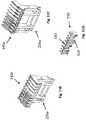
- FIG. 2is a perspective view of an outlet module section according to the embodiment of FIG. 1 ;
- FIG. 3is an exploded view of the outlet module section of FIG. 2 ;
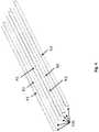
- FIG. 4is a detailed perspective view of a section of the busbars extending into the outlet module section of FIG. 2 ;
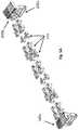
- FIG. 5is a detailed perspective view of the jumpers busbar caps of the outlet module section of FIG. 2 ;
- FIG. 5Ais a detailed view of an alternative embodiment of jumpers and busbar caps
- FIG. 6Ais a detailed view of the small jumpers of the outlet module section of FIG. 2 ;
- FIG. 6Bis a detailed view of the large jumpers of the outlet module section of FIG. 2 ;
- FIG. 7is a detailed view of the printed circuit board assembly of the outlet module section of FIG. 2 ;
- FIG. 8is a detailed view of the relay board of the outlet module section of FIG. 2 ;
- FIG. 9is a detailed view of a portion of the chassis that extends into the outlet module section of FIG. 2 ;
- FIG. 10is a detailed view of the outlets in the outlet module section of FIG. 2 ;
- FIG. 11Ais a detailed view of the busbar cap according to the embodiment of FIG. 2 ;
- FIG. 11Bis a detailed view of an intermediate busbar cap according to another embodiment
- FIG. 11Cis a detailed view of an alternative busbar cap lacking protruding arms according to another embodiment
- FIG. 11Dis a detailed view of an intermediate busbar cap lacking protruding walls and lacking a back wall according to another embodiment
- FIG. 11Eis a front detailed view of an alternative embodiment of a busbar cap
- FIG. 11Fis a rear detailed view of an alternative embodiment of a busbar cap
- FIG. 11Gis a detailed view of an alternative view of a busbar spacer
- FIG. 12is a detailed view of the interfaces between the communications module and outlet modules according to the embodiment of FIG. 1 ;
- FIG. 13is a perspective view of an embodiment of an outlet module section having jumpers installed outside of busbars;
- FIG. 13Ais a perspective view of an alternative embodiment of an outlet module section having jumpers installed outside of busbars;
- FIG. 14is a top view of the outlet module section of FIG. 13 ;
- FIG. 15is an exploded view of an outlet module section according to another embodiment having insulators
- FIG. 16is a perspective view of the outlet module section of FIG. 15 ;
- FIG. 17is a perspective view of an outlet module section in another embodiment of the invention for a basic PDU
- FIG. 18is an exploded view of the outlet module section of FIG. 17 ;
- FIGS. 19A and 19Billustrate upper and lower perspective views of an alternative embodiment of an output module for a power distribution unit
- FIG. 19Cis a cross-section of the outlet module of FIGS. 19A and 19B ;
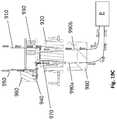
- FIG. 20is a perspective view of one embodiment of an input module connected to an output module.
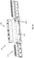
- FIG. 1is a profile view of PDU 100 according to an embodiment of the present disclosure.
- PDU 100is an assembly that includes a plug 105 , a power module 110 , outlet modules 115 , and a communications module 120 located between the two outlet modules 115 .
- Each of the modulesis individually and separately connected to housing 123 , which extends the length of the PDU 100 .
- the PDUcould include different combinations of modules, such as one outlet module or two communications modules.
- the PDU assemblyis not modular. For example, a first PDU assembly could share one chassis with other PDU assemblies to form one PDU without separate modules.
- the PDU 100is configured to be mounted in a rack frame, and to provide power to equipment located in the rack.
- the racksmay house IT equipment, such as servers, data storage, and other similar equipment.
- PDU 100includes mounting features (not shown) that are used to fix PDU 100 to a rack frame. Exemplary mounting features include, without limitation, mechanical fasteners, locking mechanisms, protruding pins and corresponding slots, etc. (not shown).
- Plug 105is configured to be connected to an outlet of a three-phase power source to provide power to the power module 110 .
- Power module 110in turn distributes the power to the outlet modules 115 and communications module 120 .
- Plug 105is configured to draw current from the three-phase current source outlet.
- Power module 110includes six circuit protection devices 112 , with two circuit protection devices connected to each phase of the current source in parallel.
- Circuit protection devices 112may include, without limitation, circuit breakers, fuses, residual-current devices, reclosers, polyswitches, and any combination of these and other protection devices. In alternative embodiments (not shown), three circuit protection devices can be included, with each circuit protection devices corresponding to one phase of the current source.
- the current received from plug 105first passes through a circuit protection device before being distributed to the outlet modules 115 or communications module 120 .
- Outlet modules 115provide power to equipment mounted in the rack, through the equipment plugs.
- Communications module 120provides information related to PDU performance or operating characteristics. Examples of performance or operating characteristics include, without limitation, voltage, current, frequency, power, and energy.
- the communications module 120can provide this information to a user using a variety of communications technologies, such as wireless internet (or intranet) transmitters, Bluetooth, a physical display, indicator lights etc.
- the PDU 100 of FIG. 1is a modular PDU that includes mechanically-independent modules 110 , 115 , 120 .
- the modules 110 , 115 , 120are not mechanically connected to each other, but are instead secured directly to the housing 123 at a connection location 124 . Wires are used to connect the modules. Standardized connection points such as busbars or connector locations may be employed.
- the communication module 120can be temporarily removed from the PDU to allow power supplies to be replaced or for other equipment to be serviced.
- the communication module 120can also be mounted remotely from the PDU at an angle, to allow it to be more easily viewed.
- busbar system described belowmay be used in non-modular systems.
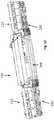
- FIG. 2shows a perspective view of a section 125 of one outlet module 115 , with the outlets 130 facing downwards.
- the components of outlet module section 125are more easily seen in FIG. 3 , which depicts an exploded drawing of outlet module section 125 from the same perspective as in FIG. 2 .
- the outlet module section 125 in this embodimenthas six outlets 130 .
- each outlet module 115has three outlet module sections 125 with six outlets each, and two additional smaller outlet module sections (not shown) with three outlets each.
- the components and functioning of each outlet module sectionmay be similar, so only outlet module section 125 will be described in detail below.
- a set of busbars 135runs the length of the entire outlet module 115 in the present embodiment, and delivers current to the outlets 130 in each outlet module section 125 .
- the set of busbars 135includes six busbars.
- a busbar cap 140receives all six busbars 135 and maintains the distance between each busbar.
- Jumpers 145connect the busbars 135 to the appropriate pins of printed circuit board assembly (“PCBA”) 150 , which are electrically connected to outlets 130 . Jumpers 145 are further connected to pins of outlets 130 .
- PCBAprinted circuit board assembly
- PCBA 150includes a number of PCBA pins 155 that correspond to the number of outlets 130 in the outlet module section 125 .
- PCBA 150further includes two microprocessors 160 that communicates with communications module 120 and relay board 170 .
- Relay board 170contains relays 175 and LEDs.
- Chassis 185is a one-piece frame that extends the length of the outlet module 115 and receives each outlet module section 125 .
- Chassis 185is made from a metal, such as aluminum or an aluminum alloy, and extends the entire length of the outlet module 115 .
- a single chassis 185includes a plurality of openings 190 (more clearly shown in FIG. 9 ), each opening sized to receive all outlets of an outlet module section 125 in a snap-fit type interface.
- the chassis 185 in this embodimentincludes five openings 190 , to receive all five-outlet module sections 125 .
- Each outlet 130includes an outlet pin 195 extending in a direction opposite the outlet face.
- multiple outlets 130are disposed in one molded plastic assembly that includes an integrated busbar for grounding all of the outlets. Grounding path provides grounding for equipment plugged into each outlet 130 .
- an individual outletis disposed in each assembly.
- FIGS. 4-11Additional details of the outlet module 125 and its components are shown in FIGS. 4-11 .
- Busbars 135are included in each outlet module 115 .
- Busbars 135are made from a conductive material, such as phosphor bronze, copper or an alloy.
- Each of the busbars 135is connected via wiring to one of three circuit protection devices in the power module 110 (not shown).
- Each circuit protection devicereceives power from one of the three current phases received via the plug 105 from an external source.
- Three of the busbars, P 1 , P 2 , and P 3carry input current corresponding to their respective phases.
- busbars N 1 , N 2 , and N 3are neutral lines (electrically connected to either a different phase or an actual neutral) that each complete a circuit with the respective busbars P 1 , P 2 , and P 3 when busbars are joined to the pins 155 , 195 with jumpers 145 .
- busbar P 1is electrically connected at one end to a circuit protection device, and at another portion to one of the PCBA pins 155 that is in turn connected to an outlet 130 .
- Busbar N 1connects to the corresponding outlet pin 195 on the same outlet 130 , and at another end either to a circuit protection device or directly to a neutral.
- Each outlet 130is thus connected to one of the busbars P 1 , P 2 , and P 3 via a pin 155 , and also connected to the corresponding busbar N 1 , N 2 , and N 3 via a pin 195 .
- the circuit including the circuit protection device, busbars P 1 and N 1 , outlet 130 , and user equipmentis closed, thereby providing power to the user equipment.
- busbarsIn alternative embodiments (not shown), greater or fewer than six busbars may be used. For example, four or eight busbars may be employed. In other alternative embodiment (not shown), jumpers could be soldered to busbars and pins, or could be connected via any other permanent connection means.
- FIG. 5shows a detailed view of jumpers 145 and busbar cap 140 .
- Jumpers 145are configured to connect a pin (either PCBA pin 155 or outlet pin 195 ) to a busbar 135 .
- Jumpers 145can be made with a plastic (or other non-conductive material) housing 205 and a conductive element 210 , such as copper or phosphor bronze.
- Conductive element 210is located on the bottom of a groove 215 in each jumper 145 .
- Housings 205each include one opening 220 .
- Conductive element 210is affixed to housing 205 such that conductive element 210 extends into the opening 220 and meets pin 155 or 195 when the pin is inserted into opening 220 .
- Conductive element 210lines the inner walls of opening 220 , such that when pin 155 or 195 is inserted, the pin fits snugly into opening 220 .
- Grooves 215 of jumpers 145are sized and shaped to receive a busbar 135 .
- Conductive element 210is located at a bottom of groove 215 , so that when a busbar 135 is placed therein, the busbar fits snugly into groove 215 and meets conductive element 210 .
- the conductive element 210By installing jumpers 145 onto both a pin 155 , 195 and busbar 135 , the conductive element 210 thereby provides an electrical connection between the pin and busbar.
- jumpersmay be used in place of jumpers to connect the pins to the busbars, such as conductive wires.
- FIGS. 6A and 6Billustrate detailed views of jumpers 145 , including a small jumper 225 in FIG. 6A and a large jumper 230 in FIG. 6B .
- small jumper 225is sized to connect a pin 155 or 195 to an adjacent busbar 135
- large jumper 230is sized to connect a pin 155 or 195 to a busbar 135 located further away.
- the large jumper 230can be sized to connect a pin to a busbar that is two busbars away, three busbars away, or more than three busbars away.
- Small jumper 225includes a width W1 and a length L1
- large jumper 230includes a width W2 and a length L2.
- L2is greater than L1
- W1is equal to W2.
- W1may be greater or less than W2.
- small jumpers 225are configured such that openings 220 are close to grooves 215 , and are used for connections where the respective pin 155 or 195 is adjacent to the busbar 135 to which it is to be connected.
- Large jumpers 230are configured such that openings 220 are farther away from grooves 215 , and are used for connections where the respective pin 155 or 195 is not adjacent to the busbar 135 to which it is to be connected.
- jumperscould take other forms different from the form shown in FIG. 5 , as long as the jumper is capable of providing an electrical connection between a pin and a busbar.
- busbar cap 140is configured to be included on one or both ends of the set of busbars 135 , to maintain the spacing between busbars 135 .
- Busbar cap 140includes two protruding arms 235 that snap onto PCBA 150 .
- FIG. 5Aillustrates a detailed view of an alternative embodiment of jumpers 145 and busbar caps 140 a .
- each busbar cap 140 amay attach to the outlet module faceplate by a stand 235 a .
- the busbar capsmay be configured to only attach only to the busbars.
- the busbar capsmay be omitted.
- the PCBA 150has a primary surface 240 , and includes six PCBA pins 155 extending away from the primary surface 240 in a perpendicular direction. Each PCBA pin 155 is electrically connected to a relay on relay board 170 , which in turn is electrically connected to an outlet 130 via a line terminal of the outlet (not shown), so that each outlet 130 is electrically connected to a single PCBA pin 155 .
- PCBA 150further includes two microprocessors 160 that receive signals from a plurality of sensors 245 that corresponds to measurements relevant to the power distribution, such as current and voltage, from which power and energy can be calculated. Microprocessors 160 further communicate this information to the communications module 120 .
- PCBA 150further includes a plurality of pin slots 250 sized and shaped to receive outlet pins 195 .
- PCBA 150further includes communication ports 255 that connect to communication ports on relay boards 170 for communication and control purposes, so that microprocessors 160 can receive signals from and send control signals to elements on relay board 170 and communications module 120 .
- PCBAscan include a different arrangement of components, such as a single microprocessor, other logic elements, and/or a microcontroller.
- PCBAs of adjacent outlet module sectionsare connected to one another via the communications port.
- adjacent outlet module sectionsmay be connected to one another through a second communications port (not shown).
- relay board 170includes a plurality of relays 175 that are configured to distribute power to outlets 130 .
- Relay board 170further includes communication ports 260 that can be connected to communication ports 255 of PCBA 170 .
- Relays 175can be switched on or off via control signals sent from microprocessors 160 and received through communication ports 260 .
- Each relay 175is electrically connected to a corresponding outlet 130 , and allows electricity to pass to that outlet 130 .
- Relay board 170further includes light emitting diodes (“LEDs”), which are observable to users of the PDU 100 .
- LEDslight emitting diodes
- LEDscan provide information related to the operating status of each outlet or groups of outlets, such as whether current is flowing to a particular outlet, whether a threshold current has been exceeded, or whether the relay 175 corresponding to that outlet is open or closed.
- Relay board 170further includes a plurality of slots 270 that are sized and shaped to receive outlet pins 195 there through.
- FIG. 9shows a portion of chassis 185 , which is configured to receive outlets 130 in a snap-fit engagement.
- Chassis 185extends the entire length of the outlet module 115 in the present embodiment, and includes openings 190 (one opening 190 is shown in FIG. 9 ) that receive the outlets 130 of each outlet module section 125 .
- the openings 190include protrusions 275 that align with indentations on outlets 130 , allowing the outlets 130 to be in alignment when installed.
- Chassis 185further includes fastener holes 280 on sidewalls of chassis 185 that are configured to receive mechanical fasteners (not shown) that are used to fix the outlet module 115 to housing 123 .
- FIG. 10shows outlets 130 in one outlet module section 125 .
- Outlets 130each include an outlet pin 195 extending away from a socket surface of the outlet 130 .
- the outlets 130are a group in one-piece plastic, and an integrated ground busbar 200 provides electrical ground to all six outlets. Alternative embodiments (not shown) have individual plastic outlets that do not have ground busbar 200 .
- Outlets 130are also all attached to outlet faceplate 285 .
- Outlets 130can be fixed to faceplate 285 via a snap-fit type connection, through use of an adhesive, or with mechanical fasteners.
- Outlets 130further include indentations 290 that align with protrusions 275 of chassis openings 190 , to provide an aligned and secure connection therewith.
- Each outlet 130is further electrically connected to a relay 175 via mating electrical conductor elements located on relay 175 and outlet 130 , so that outlets 130 receive current through relays 175 .
- FIG. 11Aillustrates a more detailed view of one embodiment of a busbar cap 140 .
- Busbar cap 140includes two protruding arms 235 that snap onto PCBA 150 .
- Busbar cap 140further includes a plurality of busbar cap grooves 295 , which are sized and shaped to receive busbars 135 therein.
- Busbar cap grooves 295are sized so that busbars 135 fit snugly within the grooves 295 .
- Busbar cap 140further includes a back wall 297 , so that busbars 135 cannot extend beyond busbar cap 140 .
- FIG. 11Billustrates an alternative embodiment of a busbar cap 300 .
- the busbar cap 300may be referred to as an intermediate busbar cap, which is substantially the same as busbar cap 140 , except for the omission of a back wall.
- Intermediate busbar cap 300can be used in between the ends of busbars 135 , to provide guidance and spacing for the busbars in an intermediate location.
- busbar cap 300can be used at the ends of busbars 135 .
- FIGS. 11C and 11Dillustrate other alternative embodiments of a busbar cap 400 and an intermediate busbar cap 500 .
- Busbar cap 400 and intermediate busbar cap 500are substantially the same as busbar cap 140 and intermediate busbar cap 300 , respectively, except that they lack protruding arms and thus do not snap onto PCBA 150 .
- FIGS. 11E and 11Fillustrate a front and rear detailed view, respectively, of an alternative embodiment of a busbar cap 140 a .
- the busbar cap 140 amay attach to the outlet module faceplate by a stand 235 a .
- the busbar cap 140 ais otherwise substantially similar to the busbar cap 140 described above.
- FIG. 11Gis a detailed view of an alternative view of a busbar spacer 510 .
- the busbar spacer 510is an integrated component that includes busbar grooves 520 and wire route guides 530 .
- the busbar groovesare sized so that busbars 135 fit snugly within the grooves 530 .
- the wire route guides 530are sized to retain a wire.
- FIG. 12depicts a detail view of the interface between outlet modules 115 and communications module 120 .
- the outlet modules 115are not connected to the communications module 120 , and are not mechanically connected to each other.
- the busbars 135 of each outlet module 115are electrically connected via wires 298 , so that each busbar 135 is individually electrically connected to its corresponding busbar in the other outlet module.
- Wires 298do not provide any structural or mechanical support, and merely pass electricity from one outlet module to the other. With this arrangement, the busbars in the outlet modules are connected to the same circuit protection devices in power module 110 .
- Communications module 120includes data wires (not shown) that separately connect to each of the PCBAs 150 of the outlet module sections 125 , allowing independent data communication between the communications module 120 and each outlet module 115 .
- Communications module 120further includes through holes 299 that are sized and shaped to receive mechanical fasteners (not shown) for affixing housing 123 to communications module 120 .
- the busbars 135could run the length of the entire PDU 100 , eliminating the need for wires 298 .
- the busbars in the outlet module further away from the power modulecould be independently electrically connected to three of the circuit protection devices, while the busbars in the closer outlet module are connected to the three other circuit protection devices. In such an arrangement, each outlet module would independently receive electricity from the power module.
- outlets 130are snapped into chassis openings 190 , so that protrusions 275 of the chassis openings 190 are aligned with indentations 290 in the outlets 130 .
- Relay board 170is then placed on top of chassis 185 , so that slots 270 receive outlet pins 195 extending from outlets 130 .
- the outlet pins 195are then soldered to the relay board 170 to provide a permanent connection.
- the outlets 130 and relay board 170are permanently fixed to the chassis 185 , and cannot be removed.
- the PCBA 150is set on top of the relay board 170 , such that the PCBA slots 250 receive outlet pins 195 .
- PCBA 150can be soldered to pins 195 , and/or fixed to the relay board 170 using mechanical fasteners, such as screws or bolts.
- the communication ports 255 on PCBA and communication ports 260 on relay boardare connected with communications cables.
- jumpers 145are connected to the pins 155 , 195 , so that each outlet 130 can be connected to both a busbar that provides current and the corresponding neutral busbar, to complete a circuit.
- the busbars 135are then placed on top of jumpers 145 , and spaced apart with a busbar cap or spacer 140 . This same process is repeated for each outlet module section 125 in outlet module 115 , using the same chassis 185 and same set of busbars 135 .
- Busbars 135are then connected to the circuit protection devices in power module 110 via wiring or other conductors.
- Outlet module 115is then placed adjacent to power module 110 on one side and adjacent to communications module 120 on the other side.
- a second outlet module 115can be placed adjacent to the other side of communications module 120 .
- the busbars 135 of each outlet module 115are electrically connected via wires 298 , which provide no structural or mechanical support. Data connections are then individually made between the communications module 120 and the outlet modules 115 .
- the housing 123is then separately fastened to the power module 110 , outlet modules 115 , and communication module 120 using mechanical fasteners that engage with holes 280 , 299 of chassis 185 and communication module 120 , respectively.
- Each moduleis individually and separately attached to the housing 123 , and no module is mechanically fastened to any other module.
- the only connections between modulesare non-structural electrical or data connections.
- the busbarscan extend from the power module of the PDU through all other modules included in the PDU, eliminating the need for wires 298 .
- other arrangements of modulesmay be used in the PDU, such as a separate circuit protection device module, fewer or greater than two outlet modules, fewer or greater than one communications module, and combinations thereof.
- two outlet modulescan be electrically connected to separate sets of three circuit protection devices (using wiring for example), and are not electrically connected to each other at all.
- the number of busbarscan be fewer or greater than six, for example, four or eight busbars may be employed.
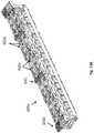
- FIG. 13illustrates an alternative embodiment of an outlet module section 600 , where jumpers 610 are located outside of busbars 620 .
- the functionality of the componentsare identical to that of the embodiment of FIGS. 1-12 , except that the jumpers 610 are located on the outside of busbars 620 .
- Jumpers 610still provide the same functionality, and are configured to connect the busbars 620 to pins, but are installed on the outlet module section 600 after the busbars 620 have been placed in the appropriate positions over the outlet module section 600 .
- FIG. 13Aillustrates a perspective view of another alternative embodiment of an outlet module section 600 a , with jumpers 610 a located outside of busbars 620 a .
- the outlet module section 600 afurther includes the alternative busbar caps 140 a and the busbar spacers 510 described above.
- FIG. 14illustrates a top view of the outlet module section 600 , to better show the jumpers 610 affixed to busbars 620 . As seen in FIG. 14 , both small and large jumpers 610 are used to connect pins to adjacent or distal busbars 620 .
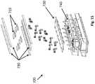
- FIG. 15illustrates an alternative embodiment of an outlet module section 700 , which includes busbar insulators 710 and pin insulator 720 .
- Outlet module section 700otherwise includes identical components as the outlet module section 125 described above with respect to FIGS. 1-12 , and functions identically to outlet module section 125 .
- Busbar insulators 710separate adjacent busbars 730 to prevent the busbars 730 from touching, eliminating the possibility of a short circuit.
- Pin insulator 720further ensures that none of the pins comes into contact with each other or an intermediary conductor, also preventing the possibility of a short circuit.
- FIG. 16illustrates the outlet module section 700 in an assembled condition.
- busbar insulators 710prevent adjacent busbars from touching, and pin insulator 720 separates pins from one another, as well as provides an electrically insulated layer between the busbars 730 and PCBA 740 .
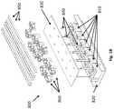
- FIG. 17illustrates another embodiment of an outlet module section 800 that omits a PCBA and relay board.
- Outlet module section 800 in this embodimentis part of a simple PDU that does not include outlet switching or outlet metering, and it may or may not include a communications module.
- the outlet module section 800includes a plurality of outlets 810 fixed to a chassis 820 , and further includes a flat insulator sheet 830 resting on one side of outlets 810 .
- Flat insulator sheet 830is designed to prevent short circuits.
- Each outlet 810further includes two-outlet pins 840 extending from a back side of each outlet.
- the outlet module section 800does not include relays, so each outlet 810 includes two outlet pins 840 to complete a circuit with busbars 850 .
- Busbars 850provide power to the outlet module section 800 and jumpers 860 connect the busbars 850 to the outlet pins 840 .
- Jumpers 860are sized and shaped similar to the jumpers shown in the embodiments discussed above, and provide an electrical connection between outlet pins 840 and busbars 850 as discussed in earlier embodiments.
- FIG. 18shows the outlet module section 800 in an exploded view, to better illustrate the flat insulator sheet 830 resting between the outlets and the jumpers 860 .
- Flat insulator sheet 830separates the outlet pins 840 from each other, and provides an insulating layer between the current-carrying busbars 850 and the outlets 810 .
- Flat insulator sheet 830includes a plurality of slots sized and shaped to receive one of outlet pins 840 , to permit an electrical connection between the outlets and busbars via outlet pins 840 only. The flat insulator sheet 830 thereby prevents any accidental contact between conductive elements to prevent short-circuiting.
- the flat insulator sheetcan be omitted, or a plurality of insulator sheets can be included instead of a single flat insulator sheet.
- FIGS. 19A and 19Billustrate upper and lower perspective views of an alternative embodiment of an outlet module 900 for a power distribution unit.
- the outlet module 900includes an outlet on/off control, voltage and current measurement, and supports alternating phase arrangements.
- the outlet module 900includes a plurality of long neutral/line pins 910 that extends from each outlet 920 through current transformers 930 .
- the current transformers 930measure the current on the long neutral/line pins 910 and are attached to a printed circuit board 940 .
- the outlet module 900further includes a plurality of long tabs 950 that are attached to the printed circuit board 940 .
- the long tabsare soldered to the printed circuit board and function as extensions of the short neutral/line pins (not shown).
- the long neutral/line pins 910 and the long tabs 950can be connected by jumpers (such as the jumpers discussed above) or other electrical connectors to busbars or wires to realize an alternating-phase arrangement.
- FIG. 19Cis a cross-section of the outlet module 900 .
- the currenttravels from the long tab 950 to the printed circuit board 940 through a relay 960 .
- the direction of the currentis shown by the series of arrows.
- the relay 960can control the on/off of the outlet module 900 .
- a short pin 970 of the outlet 920is connected to the printed circuit board 940 .
- a plug 980 having first and second pins 990 a,bis connected to a power source P.
- the first pin 990 acontacts the short pin 970 and the second pin 990 a contacts the long neutral/line pin 910 .
- the currentthus travels through the current transformer 930 as shown, so that the current transformer can measure the current.
- FIG. 20is a perspective view of one embodiment of an input module connected 1000 to an output module 1010 .
- the input module 1000includes wires 1020 that are received by a busbar end cap 140 a on the output module 1010 and are thereby connected to busbars 610 a.
Landscapes
- Engineering & Computer Science (AREA)
- Microelectronics & Electronic Packaging (AREA)
- General Engineering & Computer Science (AREA)
- Power Engineering (AREA)
- Physics & Mathematics (AREA)
- Theoretical Computer Science (AREA)
- Computer Hardware Design (AREA)
- Optics & Photonics (AREA)
- General Physics & Mathematics (AREA)
- Details Of Connecting Devices For Male And Female Coupling (AREA)
- Connector Housings Or Holding Contact Members (AREA)
Abstract
Description
- and
Claims (22)
Priority Applications (1)
| Application Number | Priority Date | Filing Date | Title |
|---|---|---|---|
| US16/720,203US11109504B2 (en) | 2018-01-31 | 2019-12-19 | Power distribution unit with interior busbars |
Applications Claiming Priority (2)
| Application Number | Priority Date | Filing Date | Title |
|---|---|---|---|
| US15/884,832US10524377B2 (en) | 2018-01-31 | 2018-01-31 | Power distribution unit with interior busbars |
| US16/720,203US11109504B2 (en) | 2018-01-31 | 2019-12-19 | Power distribution unit with interior busbars |
Related Parent Applications (1)
| Application Number | Title | Priority Date | Filing Date |
|---|---|---|---|
| US15/884,832ContinuationUS10524377B2 (en) | 2018-01-31 | 2018-01-31 | Power distribution unit with interior busbars |
Publications (2)
| Publication Number | Publication Date |
|---|---|
| US20200137914A1 US20200137914A1 (en) | 2020-04-30 |
| US11109504B2true US11109504B2 (en) | 2021-08-31 |
Family
ID=65686793
Family Applications (2)
| Application Number | Title | Priority Date | Filing Date |
|---|---|---|---|
| US15/884,832ActiveUS10524377B2 (en) | 2018-01-31 | 2018-01-31 | Power distribution unit with interior busbars |
| US16/720,203ActiveUS11109504B2 (en) | 2018-01-31 | 2019-12-19 | Power distribution unit with interior busbars |
Family Applications Before (1)
| Application Number | Title | Priority Date | Filing Date |
|---|---|---|---|
| US15/884,832ActiveUS10524377B2 (en) | 2018-01-31 | 2018-01-31 | Power distribution unit with interior busbars |
Country Status (4)
| Country | Link |
|---|---|
| US (2) | US10524377B2 (en) |
| EP (1) | EP3747246B1 (en) |
| CN (1) | CN112042284B (en) |
| WO (1) | WO2019149453A1 (en) |
Families Citing this family (10)
| Publication number | Priority date | Publication date | Assignee | Title |
|---|---|---|---|---|
| GB2580233A (en)* | 2017-08-01 | 2020-07-15 | Leung Chan Kwok | Expandable and upgradable universal electrical socket |
| US10879647B2 (en)* | 2018-03-16 | 2020-12-29 | Fci Usa Llc | Double pole power connector |
| US10938191B2 (en)* | 2018-10-31 | 2021-03-02 | Eaton Intelligent Power Limited | Heat dissipation structures for power distribution units |
| US10993349B2 (en)* | 2018-11-14 | 2021-04-27 | Legrand Av Inc. | Distributable modular chassis |
| USD975024S1 (en) | 2019-04-12 | 2023-01-10 | Fci Connectors Dongguan Ltd. | Electrical connector |
| CN111817067A (en) | 2019-04-12 | 2020-10-23 | 富加宜连接器(东莞)有限公司 | Electrical connectors, electrical connector assemblies, electrical devices and electrical interconnection systems |
| US11910554B2 (en) | 2021-02-23 | 2024-02-20 | Cisco Technology, Inc. | Modular and pluggable PDU to power tray/shelf device |
| CN113363746B (en)* | 2021-08-09 | 2021-11-09 | 突破电气(天津)有限公司 | PDU distribution device |
| CN115036761A (en)* | 2022-07-06 | 2022-09-09 | 周庆玉 | Intelligence PDU power distributor |
| USD1078666S1 (en)* | 2022-09-26 | 2025-06-10 | Bitmain Technologies Inc. | Power distribution unit |
Citations (161)
| Publication number | Priority date | Publication date | Assignee | Title |
|---|---|---|---|---|
| FR2547694A2 (en) | 1983-06-17 | 1984-12-21 | Pgep Sa | Modular device for distributing electric power |
| EP0185563A1 (en) | 1984-11-14 | 1986-06-25 | P.G.E.P. PROFESSIONAL GENERAL ELECTRONIC PRODUCTS Société Anonyme | Modular device for the distribution of electrical energy |
| US4740167A (en) | 1984-03-02 | 1988-04-26 | Amp Incorporated | Power distribution unit for modular wall panels |
| US5144530A (en) | 1989-05-03 | 1992-09-01 | Telemecanique | Power distributor device for electric installations |
| US5203713A (en) | 1989-08-16 | 1993-04-20 | Amp Incorporated | Power distribution system for modular furniture unit |
| EP0407241B1 (en) | 1989-07-06 | 1993-07-28 | Telemecanique | Removable electrical apparatus support plate for a power divider device |
| WO1994002062A1 (en) | 1992-07-17 | 1994-02-03 | Square D Company | Improvements in power switchboards |
| US5289363A (en) | 1991-07-08 | 1994-02-22 | Tandem Computers, Inc. | Modular power supply arrangement with cooling |
| US5340326A (en)* | 1988-07-18 | 1994-08-23 | Lemaster Dolan M | Connectivity management system |
| EP0655818A2 (en) | 1991-10-01 | 1995-05-31 | Molex Incorporated | Modular interchangeable power distribution system |
| US5425659A (en)* | 1992-06-22 | 1995-06-20 | Sl Waber, Inc. | Multiple electrical outlet strip module |
| US5429518A (en) | 1994-03-07 | 1995-07-04 | Chen; Ken C. | Socket terminal |
| CA2229571A1 (en) | 1995-09-29 | 1997-04-03 | Reltec Corporation | Modular terminal block assembly |
| US5675194A (en) | 1996-06-07 | 1997-10-07 | Walker Systems, Inc. | Modular power distribution system |
| CN1171366A (en) | 1996-06-17 | 1998-01-28 | 比森斯蒂玛泰克机械制造与提升工作平台制造公司 | Mobile lifting platform |
| US5779504A (en) | 1995-09-29 | 1998-07-14 | Reltec Corporation | Modular terminal block assembly |
| US5870276A (en) | 1995-05-31 | 1999-02-09 | Square D Company | Electrical power distribution device with elevated removable load center |
| US5949974A (en) | 1996-07-23 | 1999-09-07 | Ewing; Carrell W. | System for reading the status and for controlling the power supplies of appliances connected to computer networks |
| US5982610A (en) | 1998-05-27 | 1999-11-09 | Reltec Corporation | Multisided communication distribution cabinet having adjustable tie rod |
| US6015307A (en) | 1998-10-21 | 2000-01-18 | Chiu; Pen-Fu | Electric outlet with rotary socket bodies |
| US6086397A (en) | 1998-04-27 | 2000-07-11 | American Express Travel Related Services Company, Inc. | High reliability raised floor power strip |
| CN1054476C (en) | 1995-04-13 | 2000-07-12 | 施耐德电器工业公司 | Assembly of modular electrical apparatuses usable in divided distribution |
| US6220880B1 (en) | 2000-01-27 | 2001-04-24 | Chiu-Shan Lee | Electric outlets |
| US20020002582A1 (en) | 1996-07-23 | 2002-01-03 | Ewing Carrel W. | Power-manager configuration upload and download method and system for network managers |
| US20020002593A1 (en) | 1996-07-23 | 2002-01-03 | Ewing Carrel W. | Vertical-mount electrical power distribution plugstrip |
| US6454609B1 (en)* | 2001-05-17 | 2002-09-24 | Atom Technology Inc. | Switched multiple power outlet strip |
| US6514093B1 (en) | 2001-10-03 | 2003-02-04 | Tsung-I Yu | Wall mounting power adapter socket |
| US20030052543A1 (en) | 2001-09-18 | 2003-03-20 | C & D Charter Holdings, Inc. | Modular power distribution system |
| US20030126253A1 (en) | 1996-07-23 | 2003-07-03 | Ewing Carrel W. | Network remote power management outlet strip |
| US6611724B1 (en) | 1999-11-24 | 2003-08-26 | Square D Company | On line monitor for a control device |
| US6663435B2 (en) | 2001-06-06 | 2003-12-16 | Tyco Electronics Corporation | Electrical load balancing power module |
| US6675302B2 (en) | 1994-09-07 | 2004-01-06 | Spd Technologies Inc. | Power distribution system including integrated power node control center |
| US6711613B1 (en) | 1996-07-23 | 2004-03-23 | Server Technology, Inc. | Remote power control system |
| US6750410B2 (en) | 2000-09-05 | 2004-06-15 | Jae Ha Lee | Electric outlet with rotatable receptacles |
| CN2634685Y (en) | 2003-06-07 | 2004-08-18 | 深圳市日海通讯设备有限公司 | Outlet device of power distribution row cabinet |
| US6940015B2 (en)* | 2003-12-09 | 2005-09-06 | I Hsiung Fang | Power outlet strip having changeable cover |
| US6939180B1 (en) | 2005-02-22 | 2005-09-06 | Sidney Wu | Receptacle for extension cord |
| US20050259383A1 (en) | 2004-05-21 | 2005-11-24 | Carrel Ewing | Adaptable rack mountable power distribution apparatus |
| US20060031454A1 (en) | 1996-07-23 | 2006-02-09 | Ewing Carrel W | Network-connected power manager for rebooting remote computer-based appliances |
| US20060092600A1 (en) | 2004-11-01 | 2006-05-04 | Ewing Brandon W | Circuit breaking link status detection and reporting circuit |
| US20060094299A1 (en) | 2004-11-01 | 2006-05-04 | Ewing Carrol W | Circuit link connector |
| US20060139855A1 (en) | 2004-11-01 | 2006-06-29 | Ewing Carrel W | Ganged outlet power distribution apparatus |
| US20060199438A1 (en) | 2005-02-15 | 2006-09-07 | Server Technology, Inc. | Ganged electrical outlets, apparatus, and methods of use |
| US20060221524A1 (en) | 2005-03-30 | 2006-10-05 | Kelly John H | Method of monitoring a power distribution unit |
| US20060227474A1 (en) | 2005-03-30 | 2006-10-12 | Kelly John H | High density power distribution unit |
| US20060232366A1 (en) | 2005-04-15 | 2006-10-19 | Jianshing Li | Over-current actuated reed relay and electrical outlet incorporating the same for providing over-current alarm |
| WO2007008176A1 (en) | 2005-07-13 | 2007-01-18 | Copper Red Pte. Ltd. | Modular power distribution device |
| US7215535B2 (en) | 2002-06-28 | 2007-05-08 | Hewlett-Packard Development Company, L.P. | Modular power distribution system for use in computer equipment racks |
| US20070159752A1 (en) | 2006-01-11 | 2007-07-12 | Server Technology, Inc. | Fuse module with removable fuse carrier for fused electrical device |
| US20070161293A1 (en) | 2006-01-11 | 2007-07-12 | Server Technology, Inc. | Fuse module with movable fuse holder for fused electrical device |
| US20070184721A1 (en) | 2006-01-11 | 2007-08-09 | Server Technology, Inc. | Power distribution unit and methods of making and use including modular construction and assemblies |
| US20070291430A1 (en) | 2006-06-16 | 2007-12-20 | American Power Conversion Corporation | Apparatus and method for scalable power distribution |
| US20070291433A1 (en) | 2006-06-16 | 2007-12-20 | American Power Conversion Corporation | Apparatus and method for scalable power distribution |
| CN101110514A (en) | 2006-07-20 | 2008-01-23 | 施耐德电器工业公司 | Device for distributing the electric power supply for a row of modular devices in an electric board |
| CN101123344A (en) | 2006-08-03 | 2008-02-13 | 罗格朗法国公司 | Distribution system for electrical installation |
| US20080076291A1 (en) | 2006-07-06 | 2008-03-27 | Server Technology, Inc. | Electrical plug retainer |
| US20080093927A1 (en) | 2006-09-20 | 2008-04-24 | Server Technology, Inc. | Modular power distribution unit system |
| US7365964B2 (en) | 2001-11-28 | 2008-04-29 | Donahue Iv William F | Modular power distribution unit, module for the power distribution unit, and method of using the same |
| CN201061085Y (en) | 2007-06-21 | 2008-05-14 | 山东容大电气有限公司 | Modular intelligent power transformation and distribution device |
| US7377807B2 (en) | 2005-08-09 | 2008-05-27 | Eaton Corporation | Modular power distribution apparatus using cables with guarded connectors |
| CA2878655A1 (en) | 2007-12-28 | 2009-07-09 | Server Technology, Inc. | Power distribution, management, and monitoring systems and methods |
| CA2713428A1 (en) | 2007-12-28 | 2009-07-09 | Server Technology, Inc. | Power distribution, management, and monitoring systems and methods |
| US20090213567A1 (en) | 2008-02-22 | 2009-08-27 | Leviton Manufacturing Co., Inc. | Lighted power outlet system and method |
| US7581977B1 (en) | 2008-12-03 | 2009-09-01 | Well Shin Technology Co., Ltd. | Safety socket |
| US20090236909A1 (en) | 2008-03-19 | 2009-09-24 | Liebert Corporation | Adaptive Power Strip |
| CN201340984Y (en) | 2008-12-31 | 2009-11-04 | 深圳市新天机电技术有限公司 | Cabinet with frame type power distribution unit |
| CN201369583Y (en) | 2009-03-12 | 2009-12-23 | 河北实华科技有限公司 | Modularized power supply system based on standard network cabinet |
| US20100020475A1 (en) | 2007-06-21 | 2010-01-28 | American Power Conversion Corporation | Apparatus and method for scalable power distribution |
| US20100033019A1 (en) | 2008-08-06 | 2010-02-11 | Noribachi Llc | Modular solar device power distribution |
| US20100084921A1 (en) | 2008-10-08 | 2010-04-08 | Avocent Huntsville Corporation | Universal Power Inlet System for Power Distribution Units |
| US7759575B2 (en) | 2008-06-20 | 2010-07-20 | Tyco Electronics Corporation | Expandable power distribution unit |
| US7764775B2 (en) | 2005-03-30 | 2010-07-27 | Onq/Legrand, Inc. | Distributed intercom system |
| CN101807775A (en) | 2010-02-08 | 2010-08-18 | 深圳市克莱沃电子有限公司 | Modularized power control and distribution system |
| US20100280774A1 (en) | 2009-03-04 | 2010-11-04 | Server Technology, Inc. | Monitoring power-related parameters in a power distribution unit |
| EP2255419A1 (en) | 2008-02-22 | 2010-12-01 | Wiva Group S.P.A. | Modular device for electrical power distribution |
| CA2766807A1 (en) | 2009-06-25 | 2010-12-29 | Server Technology, Inc. | Power distribution apparatus with input and output power sensing and method of use |
| CN201726058U (en) | 2010-07-05 | 2011-01-26 | 江苏省电力公司张家港市供电公司 | Column type power distribution station |
| CN102035148A (en) | 2009-10-06 | 2011-04-27 | 施耐德电器工业公司 | Functional unit for low voltage distribution panel with test position |
| US20110136353A1 (en) | 2009-12-03 | 2011-06-09 | Spitaels James S | Apparatus and method for scalable power distribution |
| US20110187348A1 (en) | 2010-01-29 | 2011-08-04 | Fujitsu Limited | Power strip and electric power measurement system |
| US20110205693A1 (en) | 2010-02-24 | 2011-08-25 | Michael Jansma | Field replaceable management module |
| US20110223785A1 (en) | 2010-03-09 | 2011-09-15 | American Power Conversion Corporation | Back-mount ganged electrical outlets |
| CN102208833A (en) | 2011-05-13 | 2011-10-05 | 艾默生网络能源有限公司 | Power supply system and modular distribution device thereof |
| US8053672B2 (en) | 2008-05-30 | 2011-11-08 | Chatsworth Products, Inc. | Method and apparatus for high-density power distribution unit with integrated cable management |
| CN202059085U (en) | 2011-03-28 | 2011-11-30 | 深圳市海德森科技有限公司 | Modular intelligent power distribution system |
| US20110304958A1 (en) | 2010-06-10 | 2011-12-15 | Schneider Electric USA, Inc. | High density power/lighting panelboard |
| US20110316690A1 (en) | 2010-06-24 | 2011-12-29 | Siegman Craig S | System and Method for Identifying Electrical Equipment Using Wireless Receivers |
| JP2012503958A (en) | 2008-07-22 | 2012-02-09 | サイバー スイッチング,インコーポレイテッド | System and method for creating and controlling a virtual power distributor |
| US20120086425A1 (en) | 2010-10-07 | 2012-04-12 | Raritan Americas, Inc. | Methods and apparatus for resistive voltage sensing in an isolated power distribution unit |
| CN202434789U (en) | 2012-01-16 | 2012-09-12 | 上海能巍电气科技有限公司 | Interchangeable power socket module |
| US20120229515A1 (en) | 2010-10-07 | 2012-09-13 | Huimin Cao | Auto-Orientation of Display of a Power Distribution Unit |
| US8283802B2 (en)* | 2009-06-11 | 2012-10-09 | American Power Conversion Corporation | Dual column gang outlets for minimizing installation space |
| CA2837880A1 (en) | 2011-05-31 | 2012-12-06 | Server Technology, Inc. | Method and apparatus for multiple input power distribution to adjacent outputs |
| US8341837B2 (en) | 2007-05-25 | 2013-01-01 | Braunstein Zachary L | Modular power distribution and control system |
| US8403736B2 (en) | 2003-05-13 | 2013-03-26 | Schneider Electric It Corporation | Rack enclosure |
| CN202872201U (en) | 2012-08-30 | 2013-04-10 | 南京普天鸿雁电器科技有限公司 | Modularization cabinet distribution unit |
| CN202977986U (en) | 2012-11-27 | 2013-06-05 | 深圳艺朴露科技有限公司 | Modularized standard cabinet power distribution unit |
| CN202978089U (en) | 2012-12-06 | 2013-06-05 | 深圳市欧亚特电器设备有限公司 | Modularization intelligent distribution device |
| WO2013095352A1 (en) | 2011-12-20 | 2013-06-27 | Schneider Electric It Corporation | Intelligent rack enclosure |
| CN203103767U (en) | 2013-03-06 | 2013-07-31 | 广东盾牌通讯设备有限公司 | Intelligent PDU (Power Distribution Unit) |
| JP5351251B2 (en) | 2008-04-30 | 2013-11-27 | ラリタン アメリカズ,インコーポレイテッド | System and method for efficient association of power outlets and devices |
| US8625255B2 (en) | 2010-04-07 | 2014-01-07 | The Wiremold Company | Customizable bus system |
| CN103582397A (en) | 2013-11-18 | 2014-02-12 | 深圳科士达科技股份有限公司 | Integrated cabinet |
| US20140041929A1 (en) | 2012-07-26 | 2014-02-13 | Server Technology, Inc. | Multi-position input cord assembly for a power distribution unit |
| TW201412224A (en) | 2012-09-07 | 2014-03-16 | Bellwin Information Co Ltd | Hot-pluggable monitoring module and cabinet power distribution unit using the same |
| US20140102746A1 (en) | 2012-10-11 | 2014-04-17 | Sandra B. WRIGHTSON | Semi-permanent modular surface mountable electric power distribution system |
| US20140126118A1 (en) | 2006-01-11 | 2014-05-08 | Server Technology, Inc. | Power distribution unit and methods of making and use including modular construction and assemblies |
| US20140126116A1 (en) | 2012-11-06 | 2014-05-08 | Server Technology, Inc. | High outlet density power distribution |
| CN203607683U (en) | 2013-10-29 | 2014-05-21 | 深圳市三江电气有限公司 | A modularized power distribution device |
| US20140144670A1 (en) | 2012-07-26 | 2014-05-29 | Server Technology, Inc. | Multi-position input cord assembly for a power distribution unit |
| CN203645149U (en) | 2013-12-12 | 2014-06-11 | 上海杜尔瑞克智能电气成套有限公司 | Vertically-installed directly-outlet-type PDU |
| CN203645962U (en) | 2013-11-18 | 2014-06-11 | 深圳科士达科技股份有限公司 | An integrated machine cabinet |
| CN203645933U (en) | 2013-11-18 | 2014-06-11 | 深圳科士达科技股份有限公司 | An integrated machine cabinet with a UPS and a power distribution module |
| US20140160637A1 (en) | 2012-12-12 | 2014-06-12 | Hon Hai Precision Industry Co., Ltd. | Server cabinet |
| CN203661449U (en) | 2013-11-18 | 2014-06-18 | 深圳科士达科技股份有限公司 | Integrated equipment cabinet with PDU |
| CN103872585A (en) | 2012-12-18 | 2014-06-18 | 定边县新雄风农机研制有限责任公司 | Data center intelligent module power distribution system |
| WO2014089979A1 (en) | 2012-12-11 | 2014-06-19 | 华为技术有限公司 | Power distribution system and power distribution unit |
| CN103915765A (en) | 2014-04-14 | 2014-07-09 | 浪潮电子信息产业股份有限公司 | Modularized power distribution system |
| US8780555B2 (en) | 2003-03-19 | 2014-07-15 | American Power Conversion Corporation | Data center cooling |
| CN103986225A (en) | 2013-09-02 | 2014-08-13 | 包建伟 | Intelligent power distribution unit (PDU) with backup storage battery |
| CN203812166U (en) | 2014-03-12 | 2014-09-03 | 成都邮电通信设备有限公司 | Rack-mounted PDU (power distribution unit) |
| CN203911108U (en) | 2014-06-03 | 2014-10-29 | 北京同为西门科技有限公司 | Compact power supply distribution unit |
| US20140329467A1 (en) | 2013-03-15 | 2014-11-06 | Server Technology, Inc. | Wireless communications capable power distribution unit and techniques for communicating therewith |
| CN203951356U (en) | 2014-05-22 | 2014-11-19 | 特变电工新疆新能源股份有限公司 | A kind of photovoltaic combining inverter structure |
| US8902569B1 (en) | 2012-07-27 | 2014-12-02 | Amazon Technologies, Inc. | Rack power distribution unit with detachable cables |
| CN104199534A (en) | 2014-09-16 | 2014-12-10 | 浪潮电子信息产业股份有限公司 | High-density cabinet energy-saving power supply device based on dual input power supplies |
| CN204130787U (en) | 2014-09-24 | 2015-01-28 | 广西地凯科技有限公司 | A kind of rack Anti-thunder power socket |
| CN204179497U (en) | 2014-07-24 | 2015-02-25 | 四川睿联安电气有限公司 | PDU multifunctional panel module |
| CN204179491U (en) | 2014-11-13 | 2015-02-25 | 艾默生网络能源(江门)有限公司 | A kind of modularization power distribution cabinet |
| CN204333678U (en) | 2014-12-11 | 2015-05-13 | 山东泰安金恒电气有限公司 | A kind of modularization power distribution cabinet |
| CN204333679U (en) | 2014-12-11 | 2015-05-13 | 山东泰安金恒电气有限公司 | A kind of modularization power distribution cabinet being convenient to carry |
| US20150135783A1 (en) | 2013-11-21 | 2015-05-21 | Schneider Electric It Corporation | Locking assembly for securing electronic equipment within an equipment rack |
| US20150177797A1 (en) | 2013-12-19 | 2015-06-25 | Vce Company, Llc | Scalable input and output rack power distribution unit |
| US20150188269A1 (en) | 2013-12-31 | 2015-07-02 | Korea Electronics Technology Institute | Module type pdu for different power supply |
| CN204481214U (en) | 2015-01-30 | 2015-07-15 | 深圳市海鹏信电子股份有限公司 | Detachable PDU |
| US20150207302A1 (en) | 2012-01-30 | 2015-07-23 | Shenzhen Tieon Energy Technology Co., Ltd. | Building block type quick-mounting power distribution device |
| US20150222047A1 (en) | 2012-01-27 | 2015-08-06 | Chatsworth Products, Inc. | Cable retention system for power distribution unit |
| US20150236507A1 (en) | 2014-02-14 | 2015-08-20 | Richard Burant | Electrical power distribution unit |
| US20150249324A1 (en) | 2012-12-06 | 2015-09-03 | Phoenix Contact Development and Manufacturing, Inc. | Electric Power Distribution Unit |
| IN2013MU02517A (en) | 2014-01-30 | 2015-09-11 | Raychem Rpg Private Ltd | |
| US20150263513A1 (en) | 2014-03-17 | 2015-09-17 | Steven H. Newell | Power distribution unit with modular charging ports |
| CN204667227U (en) | 2015-05-09 | 2015-09-23 | 深圳市易信科技有限公司 | A kind ofly can identify temperature thus control the IDC cabinet PDU of rotation speed of the fan |
| CN204696497U (en) | 2015-06-12 | 2015-10-07 | 魏长柏 | A kind of rack modularization power distribution unit cabinet |
| CN104979761A (en) | 2014-04-14 | 2015-10-14 | 施耐德电器工业公司 | Adjustable armrest and power distribution cabinet provided with the adjustable armrest |
| US20150372462A1 (en) | 2012-02-01 | 2015-12-24 | Dell Products L.P. | Systems and methods for coupling ac power to a rack-level power infrastructure |
| US20150370297A1 (en) | 2014-06-18 | 2015-12-24 | Microsoft Corporation | Modular power distribution for computing systems |
| CN105244672A (en) | 2015-09-08 | 2016-01-13 | 福州六方机电有限公司 | Power distributor modular structure |
| US20160020584A1 (en) | 2014-07-16 | 2016-01-21 | Siemens Industry, Inc. | Fusible meter stack apparatus, multi-unit power distribution apparatus, and operational methods |
| US9271423B2 (en) | 2011-03-16 | 2016-02-23 | Hamilton Sundstrand Corporation | Power distribution unit and method of distributing high density power |
| US9270089B2 (en) | 2012-02-01 | 2016-02-23 | Dell Products L.P. | System and method for providing modular and scalable power infrastructure outside of usable IT space |
| US9281692B2 (en) | 2010-09-30 | 2016-03-08 | Typhoon Hong Kong Limited | Power distribution unit, communication device used with same, and power distribution system |
| CN105470930A (en) | 2015-12-27 | 2016-04-06 | 合肥华耀电子工业有限公司 | Radar intelligent power distribution system |
| EP3002955A1 (en) | 2014-09-30 | 2016-04-06 | Schneider Electric IT Corporation | Rack mounted equipment power distribution system enhancements |
| US9316672B2 (en) | 2011-02-04 | 2016-04-19 | Fujitsu Limited | Power strip and power measurement method |
| US20160120049A1 (en) | 2013-05-30 | 2016-04-28 | Eaton Manufacturing Lp, Glasgow, Succursale De Morges | A retaining device for power distribution unit |
| EP2440029B1 (en) | 2001-03-20 | 2016-05-11 | Schneider Electric IT Corporation | Adaptable power and mounting system for equipment and method for mounting |
| CN205248637U (en) | 2015-12-18 | 2016-05-18 | 艾默生网络能源有限公司 | Modularized power distribution cabinet |
| US20160165744A1 (en) | 2012-02-01 | 2016-06-09 | Dell Products L.P. | Rack-level scalable and modular power infrastructure |
| WO2016100252A1 (en) | 2014-12-15 | 2016-06-23 | Eaton Corporation | Modular uninterruptible power supply and power distribution system |
| US9400726B2 (en) | 2012-03-23 | 2016-07-26 | Server Technology, Inc. | Power usage monitoring of power feed circuits using power distribution units |
| US9961743B2 (en)* | 2005-01-27 | 2018-05-01 | Production Resource Group Llc | Portable power and signal distribution system for a controllable system including multiple devices |
Family Cites Families (10)
| Publication number | Priority date | Publication date | Assignee | Title |
|---|---|---|---|---|
| GB584414A (en)* | 1944-11-13 | 1947-01-14 | Humber Ltd | Improvements relating to systems of electrical distribution |
| US6530811B1 (en)* | 1999-06-04 | 2003-03-11 | Astec International Limited | Modular distribution assembly |
| US6547572B1 (en)* | 2001-10-26 | 2003-04-15 | Alcoa Fujikura Limited | Integrated and flexible power distribution assembly |
| CN104393496B (en)* | 2014-07-24 | 2017-07-14 | 四川睿联安电气有限公司 | The highly reliable PDU of insertion bus plug-in super large load capacity annular distribution |
| US20160098040A1 (en) | 2014-10-02 | 2016-04-07 | Harman International Industries, Inc. | Mount for media content presentation device |
| WO2016168260A1 (en)* | 2015-04-15 | 2016-10-20 | Server Technology, Inc. | High outlet density power distribution unit |
| US9520043B1 (en)* | 2015-06-17 | 2016-12-13 | Lenovo Enterprise Solutions (Singapore) Pte. Ltd. | Identifying an outlet of a power distribution unit based on a power rating of an electronic device |
| CN105388986A (en)* | 2015-12-24 | 2016-03-09 | 曙光信息产业(北京)有限公司 | Power supply system of server |
| CN206041086U (en)* | 2016-09-05 | 2017-03-22 | 国家电网公司 | A multifunctional single pluggable PDU |
| CN206098815U (en)* | 2016-09-28 | 2017-04-12 | 万马科技股份有限公司 | Novel PDU special socket |
- 2018
- 2018-01-31USUS15/884,832patent/US10524377B2/enactiveActive
- 2019
- 2019-01-31WOPCT/EP2019/025031patent/WO2019149453A1/ennot_activeCeased
- 2019-01-31EPEP19709369.3Apatent/EP3747246B1/enactiveActive
- 2019-01-31CNCN201980015901.9Apatent/CN112042284B/enactiveActive
- 2019-12-19USUS16/720,203patent/US11109504B2/enactiveActive
Patent Citations (293)
| Publication number | Priority date | Publication date | Assignee | Title |
|---|---|---|---|---|
| FR2547694A2 (en) | 1983-06-17 | 1984-12-21 | Pgep Sa | Modular device for distributing electric power |
| US4740167A (en) | 1984-03-02 | 1988-04-26 | Amp Incorporated | Power distribution unit for modular wall panels |
| EP0185563A1 (en) | 1984-11-14 | 1986-06-25 | P.G.E.P. PROFESSIONAL GENERAL ELECTRONIC PRODUCTS Société Anonyme | Modular device for the distribution of electrical energy |
| US5340326A (en)* | 1988-07-18 | 1994-08-23 | Lemaster Dolan M | Connectivity management system |
| US5144530A (en) | 1989-05-03 | 1992-09-01 | Telemecanique | Power distributor device for electric installations |
| EP0407241B1 (en) | 1989-07-06 | 1993-07-28 | Telemecanique | Removable electrical apparatus support plate for a power divider device |
| US5203713A (en) | 1989-08-16 | 1993-04-20 | Amp Incorporated | Power distribution system for modular furniture unit |
| US5289363A (en) | 1991-07-08 | 1994-02-22 | Tandem Computers, Inc. | Modular power supply arrangement with cooling |
| EP0655818A2 (en) | 1991-10-01 | 1995-05-31 | Molex Incorporated | Modular interchangeable power distribution system |
| US5425659A (en)* | 1992-06-22 | 1995-06-20 | Sl Waber, Inc. | Multiple electrical outlet strip module |
| WO1994002062A1 (en) | 1992-07-17 | 1994-02-03 | Square D Company | Improvements in power switchboards |
| US5429518A (en) | 1994-03-07 | 1995-07-04 | Chen; Ken C. | Socket terminal |
| US6675302B2 (en) | 1994-09-07 | 2004-01-06 | Spd Technologies Inc. | Power distribution system including integrated power node control center |
| CN1054476C (en) | 1995-04-13 | 2000-07-12 | 施耐德电器工业公司 | Assembly of modular electrical apparatuses usable in divided distribution |
| US5870276A (en) | 1995-05-31 | 1999-02-09 | Square D Company | Electrical power distribution device with elevated removable load center |
| CA2229571A1 (en) | 1995-09-29 | 1997-04-03 | Reltec Corporation | Modular terminal block assembly |
| US5779504A (en) | 1995-09-29 | 1998-07-14 | Reltec Corporation | Modular terminal block assembly |
| CA2229571C (en) | 1995-09-29 | 2006-09-12 | Reltec Corporation | Modular terminal block assembly |
| US5675194A (en) | 1996-06-07 | 1997-10-07 | Walker Systems, Inc. | Modular power distribution system |
| CN1171366A (en) | 1996-06-17 | 1998-01-28 | 比森斯蒂玛泰克机械制造与提升工作平台制造公司 | Mobile lifting platform |
| US9104393B2 (en) | 1996-07-23 | 2015-08-11 | Server Technology, Inc. | Power-manager configuration upload and download method and system for network managers |
| US7099934B1 (en) | 1996-07-23 | 2006-08-29 | Ewing Carrel W | Network-connecting power manager for remote appliances |
| US8527619B2 (en) | 1996-07-23 | 2013-09-03 | Server Technology, Inc. | Remote power control system with tickle capability |
| US20020002582A1 (en) | 1996-07-23 | 2002-01-03 | Ewing Carrel W. | Power-manager configuration upload and download method and system for network managers |
| US20020002593A1 (en) | 1996-07-23 | 2002-01-03 | Ewing Carrel W. | Vertical-mount electrical power distribution plugstrip |
| US7774443B2 (en) | 1996-07-23 | 2010-08-10 | Server Technology, Inc. | Power-manager configuration upload and download method and system for network managers |
| US8549067B2 (en) | 1996-07-23 | 2013-10-01 | Server Technology, Inc. | Networkable electrical power distribution plugstrip with current display and method of use |
| US8510424B2 (en) | 1996-07-23 | 2013-08-13 | Server Technology, Inc. | Network-connected power manager for rebooting remote computer-based appliances |
| US20030126253A1 (en) | 1996-07-23 | 2003-07-03 | Ewing Carrel W. | Network remote power management outlet strip |
| US20100253143A1 (en) | 1996-07-23 | 2010-10-07 | Server Technology, Inc. | Electrical Power Distribution Device Having a Current Display |
| US20100306559A1 (en) | 1996-07-23 | 2010-12-02 | Server Technology, Inc. | Power-manager configuration upload and download method and system for network managers |
| US20070245012A1 (en) | 1996-07-23 | 2007-10-18 | Server Technology, Inc. | Remote power control system with tickle capability |
| US6711613B1 (en) | 1996-07-23 | 2004-03-23 | Server Technology, Inc. | Remote power control system |
| US7702771B2 (en) | 1996-07-23 | 2010-04-20 | Server Technology, Inc. | Electrical power distribution device having a current display |
| US8549062B2 (en) | 1996-07-23 | 2013-10-01 | Server Technology, Inc. | Network remote power management outlet strip |
| US20040205181A1 (en) | 1996-07-23 | 2004-10-14 | Ewing Carrell W. | Remote power control system |
| US20040215763A1 (en) | 1996-07-23 | 2004-10-28 | Server Technology, Inc. | Remote power control system |
| US8489667B2 (en) | 1996-07-23 | 2013-07-16 | Server Technology, Inc. | Network power administration system |
| US8560652B2 (en) | 1996-07-23 | 2013-10-15 | Server Technology, Inc. | Remote power control system |
| US20050203987A1 (en) | 1996-07-23 | 2005-09-15 | Server Technology, Inc. | Network power administration system |
| US20050223090A1 (en) | 1996-07-23 | 2005-10-06 | Server Technology, Inc. | Network power management system |
| US8601291B2 (en) | 1996-07-23 | 2013-12-03 | Server Technology, Inc. | Power management device with communications capability and method of use |
| US20060031453A1 (en) | 1996-07-23 | 2006-02-09 | Ewing Carrel W | Vertical-mount electrical power distribution plugstrip |
| US20060031454A1 (en) | 1996-07-23 | 2006-02-09 | Ewing Carrel W | Network-connected power manager for rebooting remote computer-based appliances |
| US7010589B2 (en) | 1996-07-23 | 2006-03-07 | Server Technology, Inc. | Remote power control system |
| US20140285018A1 (en) | 1996-07-23 | 2014-09-25 | Server Technology, Inc. | Vertical-mount electrical power distribution plugstrip |
| US20140304534A1 (en) | 1996-07-23 | 2014-10-09 | Server Technology, Inc. | Network power management system |
| US7043543B2 (en) | 1996-07-23 | 2006-05-09 | Server Technology, Inc. | Vertical-mount electrical power distribution plugstrip |
| US20110167280A1 (en) | 1996-07-23 | 2011-07-07 | Ewing Carrel W | Network Power Management System |
| US20120117396A1 (en) | 1996-07-23 | 2012-05-10 | Server Technology, Inc. | Power management device with communications capability and method of use |
| US20140204504A1 (en) | 1996-07-23 | 2014-07-24 | Server Technology, Inc. | Electrical power distribution device having a current display |
| US20120075776A1 (en) | 1996-07-23 | 2012-03-29 | Server Technology, Inc. | Electrical power distribution device having a current display |
| US20140107854A1 (en) | 1996-07-23 | 2014-04-17 | Server Technology, Inc. | Remote power control system |
| US9009288B2 (en) | 1996-07-23 | 2015-04-14 | Server Technology, Inc. | Remote power control system |
| US20140070628A1 (en) | 1996-07-23 | 2014-03-13 | Server Technology, Inc. | Network power management system |
| US20110197080A1 (en) | 1996-07-23 | 2011-08-11 | Server Technology, Inc. | Remote power control system with tickle capability |
| US20060259538A1 (en) | 1996-07-23 | 2006-11-16 | Server Technology, Inc. | Network remote power management outlet strip |
| US20120042180A1 (en) | 1996-07-23 | 2012-02-16 | Server Technology, Inc. | Network remote power management outlet strip |
| US7162521B2 (en) | 1996-07-23 | 2007-01-09 | Server Technology, Inc. | Remote power control system |
| US20070016664A1 (en) | 1996-07-23 | 2007-01-18 | Server Technology, Inc. | Remote power control system |
| US20160164292A1 (en) | 1996-07-23 | 2016-06-09 | Server Technology, Inc. | Electrical power distribution device having a current display |
| US7171461B2 (en) | 1996-07-23 | 2007-01-30 | Server Technology, Inc. | Network remote power management outlet strip |
| US20070050443A1 (en) | 1996-07-23 | 2007-03-01 | Server Technology, Inc. | Network remote power management outlet strip |
| US20150241897A1 (en) | 1996-07-23 | 2015-08-27 | Server Technology, Inc. | Remote power control system |
| US5949974A (en) | 1996-07-23 | 1999-09-07 | Ewing; Carrell W. | System for reading the status and for controlling the power supplies of appliances connected to computer networks |
| US20070076340A1 (en) | 1996-07-23 | 2007-04-05 | Server Technology, Inc. | Electrical power distribution device having a current display |
| US20110296224A1 (en) | 1996-07-23 | 2011-12-01 | Server Technology, Inc. | Networkable electrical power distribution plugstrip with current display and method of use |
| US9276388B2 (en) | 1996-07-23 | 2016-03-01 | Server Technology, Inc. | Electrical power distribution device having a current display |
| US20070130243A1 (en) | 1996-07-23 | 2007-06-07 | Server Technology, Inc. | Electrical power distribution plugstrip with current information display and method of use |
| US20070136453A1 (en) | 1996-07-23 | 2007-06-14 | Server Technology, Inc. | Networkable electrical power distribution plugstrip with current display and method of use |
| US20070140238A1 (en) | 1996-07-23 | 2007-06-21 | Server Technology, Inc. | Power management device with communications capability and method of use |
| US20160011639A1 (en) | 1996-07-23 | 2016-01-14 | Server Technology, Inc. | Network power management system |
| US20120081843A1 (en) | 1996-07-23 | 2012-04-05 | Server Technology, Inc. | Vertical-mount electrical power distribution plugstrip |
| US20150355695A1 (en) | 1996-07-23 | 2015-12-10 | Server Technology, Inc. | Power-manager configuration upload and download method and system for network managers |
| US6086397A (en) | 1998-04-27 | 2000-07-11 | American Express Travel Related Services Company, Inc. | High reliability raised floor power strip |
| US5982610A (en) | 1998-05-27 | 1999-11-09 | Reltec Corporation | Multisided communication distribution cabinet having adjustable tie rod |
| US6015307A (en) | 1998-10-21 | 2000-01-18 | Chiu; Pen-Fu | Electric outlet with rotary socket bodies |
| US6611724B1 (en) | 1999-11-24 | 2003-08-26 | Square D Company | On line monitor for a control device |
| US6220880B1 (en) | 2000-01-27 | 2001-04-24 | Chiu-Shan Lee | Electric outlets |
| US6750410B2 (en) | 2000-09-05 | 2004-06-15 | Jae Ha Lee | Electric outlet with rotatable receptacles |
| EP2440029B1 (en) | 2001-03-20 | 2016-05-11 | Schneider Electric IT Corporation | Adaptable power and mounting system for equipment and method for mounting |
| US6454609B1 (en)* | 2001-05-17 | 2002-09-24 | Atom Technology Inc. | Switched multiple power outlet strip |
| US6663435B2 (en) | 2001-06-06 | 2003-12-16 | Tyco Electronics Corporation | Electrical load balancing power module |
| US20030052543A1 (en) | 2001-09-18 | 2003-03-20 | C & D Charter Holdings, Inc. | Modular power distribution system |
| US6514093B1 (en) | 2001-10-03 | 2003-02-04 | Tsung-I Yu | Wall mounting power adapter socket |
| US7365964B2 (en) | 2001-11-28 | 2008-04-29 | Donahue Iv William F | Modular power distribution unit, module for the power distribution unit, and method of using the same |
| US7215535B2 (en) | 2002-06-28 | 2007-05-08 | Hewlett-Packard Development Company, L.P. | Modular power distribution system for use in computer equipment racks |
| US8780555B2 (en) | 2003-03-19 | 2014-07-15 | American Power Conversion Corporation | Data center cooling |
| US8403736B2 (en) | 2003-05-13 | 2013-03-26 | Schneider Electric It Corporation | Rack enclosure |
| CN2634685Y (en) | 2003-06-07 | 2004-08-18 | 深圳市日海通讯设备有限公司 | Outlet device of power distribution row cabinet |
| US6940015B2 (en)* | 2003-12-09 | 2005-09-06 | I Hsiung Fang | Power outlet strip having changeable cover |
| US20070159775A1 (en) | 2004-05-21 | 2007-07-12 | Server Technology, Inc. | Adaptable rack mountable power distribution apparatus |
| US7312980B2 (en) | 2004-05-21 | 2007-12-25 | Server Technology, Inc. | Adaptable rack mountable power distribution apparatus |
| US20080198536A1 (en) | 2004-05-21 | 2008-08-21 | Ewing Carrel W | Adaptable rack mountable power distribution apparatus |
| US20050259383A1 (en) | 2004-05-21 | 2005-11-24 | Carrel Ewing | Adaptable rack mountable power distribution apparatus |
| US7535696B2 (en) | 2004-05-21 | 2009-05-19 | Server Technology, Inc. | Method of mounting a power distribution apparatus in a rack |
| US7196900B2 (en) | 2004-05-21 | 2007-03-27 | Server Technology, Inc. | Adaptable rack mountable power distribution apparatus |
| US7400493B2 (en) | 2004-11-01 | 2008-07-15 | Server Technology, Inc. | Circuit breaking link status detection and reporting circuit |
| US20060094299A1 (en) | 2004-11-01 | 2006-05-04 | Ewing Carrol W | Circuit link connector |
| US7268998B2 (en)* | 2004-11-01 | 2007-09-11 | Server Technology, Inc. | Ganged outlet power distribution apparatus |
| US20080272878A1 (en) | 2004-11-01 | 2008-11-06 | Server Technology, Inc. | Circuit breaking link status detection and reporting circuit |
| US7137850B2 (en) | 2004-11-01 | 2006-11-21 | Ewing Carrel W | Circuit link connector |
| US20060092600A1 (en) | 2004-11-01 | 2006-05-04 | Ewing Brandon W | Circuit breaking link status detection and reporting circuit |
| US20060139855A1 (en) | 2004-11-01 | 2006-06-29 | Ewing Carrel W | Ganged outlet power distribution apparatus |
| US9961743B2 (en)* | 2005-01-27 | 2018-05-01 | Production Resource Group Llc | Portable power and signal distribution system for a controllable system including multiple devices |
| US20070128927A1 (en) | 2005-02-15 | 2007-06-07 | Server Technology, Inc. | Ganged electrical outlets, apparatus, and methods of use |
| US7905749B2 (en) | 2005-02-15 | 2011-03-15 | Server Technology, Inc. | Ganged electrical outlets, apparatus, and methods of use |
| US20060199438A1 (en) | 2005-02-15 | 2006-09-07 | Server Technology, Inc. | Ganged electrical outlets, apparatus, and methods of use |
| US6939180B1 (en) | 2005-02-22 | 2005-09-06 | Sidney Wu | Receptacle for extension cord |
| CA2602505A1 (en) | 2005-03-30 | 2006-10-12 | Motorola, Inc. | Method of monitoring a power distribution unit |
| US7187177B2 (en) | 2005-03-30 | 2007-03-06 | Motorola, Inc. | Method of monitoring a power distribution unit |
| US20080266759A1 (en) | 2005-03-30 | 2008-10-30 | Emerson Network Power - Embedded Computing, Inc. | High density power distribution unit |
| US20060227474A1 (en) | 2005-03-30 | 2006-10-12 | Kelly John H | High density power distribution unit |
| US7394667B2 (en) | 2005-03-30 | 2008-07-01 | Emerson Network Power - Embedded Computing, Inc. | High density power distribution unit |
| US7764775B2 (en) | 2005-03-30 | 2010-07-27 | Onq/Legrand, Inc. | Distributed intercom system |
| US20060221524A1 (en) | 2005-03-30 | 2006-10-05 | Kelly John H | Method of monitoring a power distribution unit |
| US20060232366A1 (en) | 2005-04-15 | 2006-10-19 | Jianshing Li | Over-current actuated reed relay and electrical outlet incorporating the same for providing over-current alarm |
| WO2007008176A1 (en) | 2005-07-13 | 2007-01-18 | Copper Red Pte. Ltd. | Modular power distribution device |
| US7377807B2 (en) | 2005-08-09 | 2008-05-27 | Eaton Corporation | Modular power distribution apparatus using cables with guarded connectors |
| US20100208435A1 (en) | 2006-01-11 | 2010-08-19 | Server Technology, Inc. | Power distribution unit and methods of making and use including modular construction and assemblies |
| US9287688B2 (en)* | 2006-01-11 | 2016-03-15 | Server Technology, Inc. | Power distribution unit and methods of making and use including modular construction and assemblies |
| US20100259871A1 (en) | 2006-01-11 | 2010-10-14 | Server Technology, Inc. | Fuse module with movable fuse holder for fused electrical device |
| US7742284B2 (en) | 2006-01-11 | 2010-06-22 | Server Technology, Inc. | Fuse module with movable fuse holder for fused electrical device |
| US20070159752A1 (en) | 2006-01-11 | 2007-07-12 | Server Technology, Inc. | Fuse module with removable fuse carrier for fused electrical device |
| US7706134B2 (en) | 2006-01-11 | 2010-04-27 | Server Technology, Inc. | Power distribution unit and methods of making and use including modular construction and assemblies |
| US20120081842A1 (en) | 2006-01-11 | 2012-04-05 | Server Technology, Inc. | Power distribution unit and methods of making and use including modular construction and assemblies |
| US7675739B2 (en) | 2006-01-11 | 2010-03-09 | Server Technology, Inc. | Fuse module with removable fuse carrier for fused electrical device |
| US20070161293A1 (en) | 2006-01-11 | 2007-07-12 | Server Technology, Inc. | Fuse module with movable fuse holder for fused electrical device |
| US20070184721A1 (en) | 2006-01-11 | 2007-08-09 | Server Technology, Inc. | Power distribution unit and methods of making and use including modular construction and assemblies |
| US20160079722A1 (en) | 2006-01-11 | 2016-03-17 | Server Technology, Inc. | Power distribution unit and methods of making and use including modular construction and assemblies |
| US9166382B2 (en) | 2006-01-11 | 2015-10-20 | Server Technology, Inc. | Power distribution unit and methods of making and use including modular construction and assemblies |
| US8619412B2 (en) | 2006-01-11 | 2013-12-31 | Carrel W. Ewing | Power distribution unit and methods of making and use including modular construction and assemblies |
| US7447002B2 (en) | 2006-01-11 | 2008-11-04 | Server Technology, Inc. | Fuse module with movable fuse holder for fused electrical device |
| US7457106B2 (en)* | 2006-01-11 | 2008-11-25 | Server Technology, Inc. | Power distribution unit and methods of making and use including modular construction and assemblies |
| US20140126117A1 (en) | 2006-01-11 | 2014-05-08 | Server Technology, Inc. | Power distribution unit and methods of making and use including modular construction and assemblies |
| US7990689B2 (en) | 2006-01-11 | 2011-08-02 | Server Technology, Inc. | Power distribution unit and methods of making and use including modular construction and assemblies |
| US20090180241A1 (en) | 2006-01-11 | 2009-07-16 | Server Technology, Inc. | Power distribution unit and methods of making and use including modular construction and assemblies |
| US20140126118A1 (en) | 2006-01-11 | 2014-05-08 | Server Technology, Inc. | Power distribution unit and methods of making and use including modular construction and assemblies |
| US8004827B2 (en) | 2006-01-11 | 2011-08-23 | Server Technology, Inc. | Fuse module with movable fuse holder for fused electrical device |
| US20090061691A1 (en) | 2006-01-11 | 2009-03-05 | Server Technology, Inc. | Fuse module with movable fuse holder for fused electrical device |
| US9142971B2 (en) | 2006-03-07 | 2015-09-22 | Server Technology, Inc. | Power distribution, management, and monitoring systems and methods |
| US20140236372A1 (en) | 2006-03-07 | 2014-08-21 | Server Technology, Inc. | Power distribution, management, and monitoring systems and methods |
| US7619868B2 (en) | 2006-06-16 | 2009-11-17 | American Power Conversion Corporation | Apparatus and method for scalable power distribution |
| US7606014B2 (en) | 2006-06-16 | 2009-10-20 | American Power Conversion Corporation | Apparatus and method for scalable power distribution |
| US8027134B2 (en) | 2006-06-16 | 2011-09-27 | American Power Conversion Corporation | Apparatus and method for scalable power distribution |
| US20070291430A1 (en) | 2006-06-16 | 2007-12-20 | American Power Conversion Corporation | Apparatus and method for scalable power distribution |
| US20090323258A1 (en) | 2006-06-16 | 2009-12-31 | American Power Conversion Corporation | Apparatus and method for scalable power distribution |
| US20070291433A1 (en) | 2006-06-16 | 2007-12-20 | American Power Conversion Corporation | Apparatus and method for scalable power distribution |
| US20080076291A1 (en) | 2006-07-06 | 2008-03-27 | Server Technology, Inc. | Electrical plug retainer |
| CN101110514B (en) | 2006-07-20 | 2011-06-22 | 施耐德电器工业公司 | Device for distributing the electric power supply for a row of modular devices in an electric board |
| CN101110514A (en) | 2006-07-20 | 2008-01-23 | 施耐德电器工业公司 | Device for distributing the electric power supply for a row of modular devices in an electric board |
| CN101123344A (en) | 2006-08-03 | 2008-02-13 | 罗格朗法国公司 | Distribution system for electrical installation |
| CN101123344B (en) | 2006-08-03 | 2012-09-26 | 罗格朗法国公司 | Distribution system for electrical installation |
| US20080093927A1 (en) | 2006-09-20 | 2008-04-24 | Server Technology, Inc. | Modular power distribution unit system |
| US8341837B2 (en) | 2007-05-25 | 2013-01-01 | Braunstein Zachary L | Modular power distribution and control system |
| CN201061085Y (en) | 2007-06-21 | 2008-05-14 | 山东容大电气有限公司 | Modular intelligent power transformation and distribution device |
| US20120087051A1 (en) | 2007-06-21 | 2012-04-12 | American Power Conversion Corporation | Apparatus and method for scalable power distribution |
| US20100020475A1 (en) | 2007-06-21 | 2010-01-28 | American Power Conversion Corporation | Apparatus and method for scalable power distribution |
| US7940504B2 (en) | 2007-06-21 | 2011-05-10 | American Power Conversion Corporation | Apparatus and method for scalable power distribution |
| US8503149B2 (en) | 2007-06-21 | 2013-08-06 | Schneider Electric It Corporation | Apparatus and method for scalable power distribution |
| US20090234512A1 (en) | 2007-12-28 | 2009-09-17 | Server Technology, Inc. | Power distribution, management, and monitoring systems and methods |
| US8494661B2 (en) | 2007-12-28 | 2013-07-23 | Server Technology, Inc. | Power distribution, management, and monitoring systems and methods |
| CA2878655A1 (en) | 2007-12-28 | 2009-07-09 | Server Technology, Inc. | Power distribution, management, and monitoring systems and methods |
| CA2713428C (en) | 2007-12-28 | 2015-03-31 | Server Technology, Inc. | Power distribution, management, and monitoring systems and methods |
| US20150362941A1 (en) | 2007-12-28 | 2015-12-17 | Server Technology, Inc. | Power distribution, management, and monitoring systems and methods |
| CA2713428A1 (en) | 2007-12-28 | 2009-07-09 | Server Technology, Inc. | Power distribution, management, and monitoring systems and methods |
| US20090213567A1 (en) | 2008-02-22 | 2009-08-27 | Leviton Manufacturing Co., Inc. | Lighted power outlet system and method |
| EP2255419A1 (en) | 2008-02-22 | 2010-12-01 | Wiva Group S.P.A. | Modular device for electrical power distribution |
| US7982335B2 (en)* | 2008-03-19 | 2011-07-19 | Liebert Corporation | Adaptive power strip |
| US8264099B2 (en) | 2008-03-19 | 2012-09-11 | Liebert Corporation | Portable display for adaptive power strip |
| US20090236909A1 (en) | 2008-03-19 | 2009-09-24 | Liebert Corporation | Adaptive Power Strip |
| US20110244715A1 (en) | 2008-03-19 | 2011-10-06 | Liebert Corporation | Adaptive Power Strip |
| US20110237097A1 (en) | 2008-03-19 | 2011-09-29 | Liebert Corporation | Adaptive Power Strip |
| US8207627B2 (en) | 2008-03-19 | 2012-06-26 | Liebert Corporation | Adaptive power strip |
| JP5351251B2 (en) | 2008-04-30 | 2013-11-27 | ラリタン アメリカズ,インコーポレイテッド | System and method for efficient association of power outlets and devices |
| US8053672B2 (en) | 2008-05-30 | 2011-11-08 | Chatsworth Products, Inc. | Method and apparatus for high-density power distribution unit with integrated cable management |
| US7759575B2 (en) | 2008-06-20 | 2010-07-20 | Tyco Electronics Corporation | Expandable power distribution unit |
| JP2012503958A (en) | 2008-07-22 | 2012-02-09 | サイバー スイッチング,インコーポレイテッド | System and method for creating and controlling a virtual power distributor |
| US20100033019A1 (en) | 2008-08-06 | 2010-02-11 | Noribachi Llc | Modular solar device power distribution |
| US20100084921A1 (en) | 2008-10-08 | 2010-04-08 | Avocent Huntsville Corporation | Universal Power Inlet System for Power Distribution Units |
| US8093748B2 (en) | 2008-10-08 | 2012-01-10 | Avocent Huntsville Corporation | Universal power inlet system for power distribution units |
| US7581977B1 (en) | 2008-12-03 | 2009-09-01 | Well Shin Technology Co., Ltd. | Safety socket |
| CN201340984Y (en) | 2008-12-31 | 2009-11-04 | 深圳市新天机电技术有限公司 | Cabinet with frame type power distribution unit |
| US20140218008A1 (en) | 2009-03-04 | 2014-08-07 | Server Technology, Inc. | Monitoring power-related parameters in a power distribution unit |
| US8321163B2 (en) | 2009-03-04 | 2012-11-27 | Server Technology, Inc. | Monitoring power-related parameters in a power distribution unit |
| US8694272B2 (en) | 2009-03-04 | 2014-04-08 | Server Technology, Inc. | Monitoring power-related parameters in a power distribution unit |
| US20130090869A1 (en) | 2009-03-04 | 2013-04-11 | Server Technology, Inc. | Monitoring power-related parameters in a power distribution unit |
| US20100280774A1 (en) | 2009-03-04 | 2010-11-04 | Server Technology, Inc. | Monitoring power-related parameters in a power distribution unit |
| CN201369583Y (en) | 2009-03-12 | 2009-12-23 | 河北实华科技有限公司 | Modularized power supply system based on standard network cabinet |
| US8283802B2 (en)* | 2009-06-11 | 2012-10-09 | American Power Conversion Corporation | Dual column gang outlets for minimizing installation space |
| US8305737B2 (en) | 2009-06-25 | 2012-11-06 | Server Technology, Inc. | Power distribution apparatus with input and output power sensing and method of use |
| AU2016203004A1 (en) | 2009-06-25 | 2016-05-26 | Server Technology, Inc. | Power distribution apparatus with input and output power sensing and method of use |
| US20100328849A1 (en) | 2009-06-25 | 2010-12-30 | Ewing Carrel W | Power distribution apparatus with input and output power sensing and method of use |
| AU2010265883B2 (en) | 2009-06-25 | 2016-02-11 | Server Technology, Inc. | Power distribution apparatus with input and output power sensing and method of use |
| CA2766807A1 (en) | 2009-06-25 | 2010-12-29 | Server Technology, Inc. | Power distribution apparatus with input and output power sensing and method of use |
| CN102035148B (en) | 2009-10-06 | 2015-08-05 | 施耐德电器工业公司 | For having the functional unit of the low pressure panel of test position |
| CN102035148A (en) | 2009-10-06 | 2011-04-27 | 施耐德电器工业公司 | Functional unit for low voltage distribution panel with test position |
| US20110136353A1 (en) | 2009-12-03 | 2011-06-09 | Spitaels James S | Apparatus and method for scalable power distribution |
| US8610316B2 (en) | 2009-12-03 | 2013-12-17 | Schneider Electric It Corporation | Apparatus and method for scalable power distribution |
| US8212427B2 (en) | 2009-12-03 | 2012-07-03 | American Power Converison Corporation | Apparatus and method for scalable power distribution |
| US20130140915A1 (en) | 2009-12-03 | 2013-06-06 | American Power Conversion Corporation | Apparatus and method for scalable power distribution |
| US20110187348A1 (en) | 2010-01-29 | 2011-08-04 | Fujitsu Limited | Power strip and electric power measurement system |
| CN101807775A (en) | 2010-02-08 | 2010-08-18 | 深圳市克莱沃电子有限公司 | Modularized power control and distribution system |
| US8427007B2 (en) | 2010-02-24 | 2013-04-23 | Schneider Electric It Corporation | Field replaceable management module |
| US20110205693A1 (en) | 2010-02-24 | 2011-08-25 | Michael Jansma | Field replaceable management module |
| US8038454B2 (en)* | 2010-03-09 | 2011-10-18 | American Power Conversion Corporation | Back-mount ganged electrical outlets |
| US20110223785A1 (en) | 2010-03-09 | 2011-09-15 | American Power Conversion Corporation | Back-mount ganged electrical outlets |
| EP2629379B1 (en) | 2010-03-09 | 2015-10-14 | Schneider Electric IT Corporation | Power strip with latching system |
| US8625255B2 (en) | 2010-04-07 | 2014-01-07 | The Wiremold Company | Customizable bus system |
| US20110304958A1 (en) | 2010-06-10 | 2011-12-15 | Schneider Electric USA, Inc. | High density power/lighting panelboard |
| CA2801073A1 (en) | 2010-06-10 | 2011-12-15 | Schneider Electric USA, Inc. | High density power/lighting panelboard |
| US8305739B2 (en) | 2010-06-10 | 2012-11-06 | Schneider Electric USA, Inc. | High density power/lighting panelboard |
| MX2012013967A (en) | 2010-06-10 | 2013-03-07 | Schneider Electric Usa Inc | High density power/lighting panelboard. |
| CA2803493A1 (en) | 2010-06-24 | 2011-12-29 | Avocent Corporation | System and method for identifying electrical equipment using wireless receivers |
| US8427301B2 (en) | 2010-06-24 | 2013-04-23 | Avocent Corporation | System and method for identifying electrical equipment using wireless receivers |
| US20110316690A1 (en) | 2010-06-24 | 2011-12-29 | Siegman Craig S | System and Method for Identifying Electrical Equipment Using Wireless Receivers |
| CN201726058U (en) | 2010-07-05 | 2011-01-26 | 江苏省电力公司张家港市供电公司 | Column type power distribution station |
| US9281692B2 (en) | 2010-09-30 | 2016-03-08 | Typhoon Hong Kong Limited | Power distribution unit, communication device used with same, and power distribution system |
| US20120086425A1 (en) | 2010-10-07 | 2012-04-12 | Raritan Americas, Inc. | Methods and apparatus for resistive voltage sensing in an isolated power distribution unit |
| US20120229515A1 (en) | 2010-10-07 | 2012-09-13 | Huimin Cao | Auto-Orientation of Display of a Power Distribution Unit |
| US9316672B2 (en) | 2011-02-04 | 2016-04-19 | Fujitsu Limited | Power strip and power measurement method |
| US9271423B2 (en) | 2011-03-16 | 2016-02-23 | Hamilton Sundstrand Corporation | Power distribution unit and method of distributing high density power |
| CN202059085U (en) | 2011-03-28 | 2011-11-30 | 深圳市海德森科技有限公司 | Modular intelligent power distribution system |
| CN102208833A (en) | 2011-05-13 | 2011-10-05 | 艾默生网络能源有限公司 | Power supply system and modular distribution device thereof |
| CA2837880A1 (en) | 2011-05-31 | 2012-12-06 | Server Technology, Inc. | Method and apparatus for multiple input power distribution to adjacent outputs |
| US8587950B2 (en) | 2011-05-31 | 2013-11-19 | Server Technology, Inc. | Method and apparatus for multiple input power distribution to adjacent outputs |
| CN103858292A (en) | 2011-05-31 | 2014-06-11 | 服务器技术股份有限公司 | Method and apparatus for distributing multiple input power to adjacent outputs |
| AU2016203402A1 (en) | 2011-05-31 | 2016-06-16 | Server Technology, Inc. | Method and apparatus for multiple input power distribution to adjacent outputs |
| US20120307421A1 (en) | 2011-05-31 | 2012-12-06 | Server Technology, Inc. | Method and apparatus for multiple input power distribution to adjacent outputs |
| US20140111908A1 (en) | 2011-05-31 | 2014-04-24 | Server Technology, Inc. | Method and apparatus for multiple input power distribution to adjacent outputs |
| WO2013095352A1 (en) | 2011-12-20 | 2013-06-27 | Schneider Electric It Corporation | Intelligent rack enclosure |
| CN202434789U (en) | 2012-01-16 | 2012-09-12 | 上海能巍电气科技有限公司 | Interchangeable power socket module |
| US20150222047A1 (en) | 2012-01-27 | 2015-08-06 | Chatsworth Products, Inc. | Cable retention system for power distribution unit |
| US20150207302A1 (en) | 2012-01-30 | 2015-07-23 | Shenzhen Tieon Energy Technology Co., Ltd. | Building block type quick-mounting power distribution device |
| US20160165744A1 (en) | 2012-02-01 | 2016-06-09 | Dell Products L.P. | Rack-level scalable and modular power infrastructure |
| US20150372462A1 (en) | 2012-02-01 | 2015-12-24 | Dell Products L.P. | Systems and methods for coupling ac power to a rack-level power infrastructure |
| US9270089B2 (en) | 2012-02-01 | 2016-02-23 | Dell Products L.P. | System and method for providing modular and scalable power infrastructure outside of usable IT space |
| US9400726B2 (en) | 2012-03-23 | 2016-07-26 | Server Technology, Inc. | Power usage monitoring of power feed circuits using power distribution units |
| US20140144670A1 (en) | 2012-07-26 | 2014-05-29 | Server Technology, Inc. | Multi-position input cord assembly for a power distribution unit |
| US20140041929A1 (en) | 2012-07-26 | 2014-02-13 | Server Technology, Inc. | Multi-position input cord assembly for a power distribution unit |
| US8902569B1 (en) | 2012-07-27 | 2014-12-02 | Amazon Technologies, Inc. | Rack power distribution unit with detachable cables |
| CN202872201U (en) | 2012-08-30 | 2013-04-10 | 南京普天鸿雁电器科技有限公司 | Modularization cabinet distribution unit |
| TW201412224A (en) | 2012-09-07 | 2014-03-16 | Bellwin Information Co Ltd | Hot-pluggable monitoring module and cabinet power distribution unit using the same |
| US20140102746A1 (en) | 2012-10-11 | 2014-04-17 | Sandra B. WRIGHTSON | Semi-permanent modular surface mountable electric power distribution system |
| CA2889216A1 (en) | 2012-11-06 | 2014-05-15 | Server Technology, Inc. | High outlet density power distribution unit |
| US20140126116A1 (en) | 2012-11-06 | 2014-05-08 | Server Technology, Inc. | High outlet density power distribution |
| CN104904075A (en) | 2012-11-06 | 2015-09-09 | 服务器技术股份有限公司 | High outlet density power distribution unit |
| US20150072553A1 (en) | 2012-11-06 | 2015-03-12 | Server Technology, Inc. | High outlet density power distribution unit |
| US20150222063A1 (en) | 2012-11-06 | 2015-08-06 | Server Technology, Inc. | High outlet density power distribution unit |
| US20150214683A1 (en) | 2012-11-06 | 2015-07-30 | Server Technology | High outlet density power distribution unit |
| CN202977986U (en) | 2012-11-27 | 2013-06-05 | 深圳艺朴露科技有限公司 | Modularized standard cabinet power distribution unit |
| CN202978089U (en) | 2012-12-06 | 2013-06-05 | 深圳市欧亚特电器设备有限公司 | Modularization intelligent distribution device |
| US20150249324A1 (en) | 2012-12-06 | 2015-09-03 | Phoenix Contact Development and Manufacturing, Inc. | Electric Power Distribution Unit |
| WO2014089979A1 (en) | 2012-12-11 | 2014-06-19 | 华为技术有限公司 | Power distribution system and power distribution unit |
| US20140160637A1 (en) | 2012-12-12 | 2014-06-12 | Hon Hai Precision Industry Co., Ltd. | Server cabinet |
| CN103872585A (en) | 2012-12-18 | 2014-06-18 | 定边县新雄风农机研制有限责任公司 | Data center intelligent module power distribution system |
| CN203103767U (en) | 2013-03-06 | 2013-07-31 | 广东盾牌通讯设备有限公司 | Intelligent PDU (Power Distribution Unit) |
| US20140329467A1 (en) | 2013-03-15 | 2014-11-06 | Server Technology, Inc. | Wireless communications capable power distribution unit and techniques for communicating therewith |
| US20160120049A1 (en) | 2013-05-30 | 2016-04-28 | Eaton Manufacturing Lp, Glasgow, Succursale De Morges | A retaining device for power distribution unit |
| CN103986225A (en) | 2013-09-02 | 2014-08-13 | 包建伟 | Intelligent power distribution unit (PDU) with backup storage battery |
| CN203607683U (en) | 2013-10-29 | 2014-05-21 | 深圳市三江电气有限公司 | A modularized power distribution device |
| CN203645962U (en) | 2013-11-18 | 2014-06-11 | 深圳科士达科技股份有限公司 | An integrated machine cabinet |
| CN203645933U (en) | 2013-11-18 | 2014-06-11 | 深圳科士达科技股份有限公司 | An integrated machine cabinet with a UPS and a power distribution module |
| CN203661449U (en) | 2013-11-18 | 2014-06-18 | 深圳科士达科技股份有限公司 | Integrated equipment cabinet with PDU |
| CN103582397A (en) | 2013-11-18 | 2014-02-12 | 深圳科士达科技股份有限公司 | Integrated cabinet |
| US20150135783A1 (en) | 2013-11-21 | 2015-05-21 | Schneider Electric It Corporation | Locking assembly for securing electronic equipment within an equipment rack |
| CN203645149U (en) | 2013-12-12 | 2014-06-11 | 上海杜尔瑞克智能电气成套有限公司 | Vertically-installed directly-outlet-type PDU |
| US20150177797A1 (en) | 2013-12-19 | 2015-06-25 | Vce Company, Llc | Scalable input and output rack power distribution unit |
| US20150188269A1 (en) | 2013-12-31 | 2015-07-02 | Korea Electronics Technology Institute | Module type pdu for different power supply |
| IN2013MU02517A (en) | 2014-01-30 | 2015-09-11 | Raychem Rpg Private Ltd | |
| US20150236507A1 (en) | 2014-02-14 | 2015-08-20 | Richard Burant | Electrical power distribution unit |
| CN203812166U (en) | 2014-03-12 | 2014-09-03 | 成都邮电通信设备有限公司 | Rack-mounted PDU (power distribution unit) |
| US20150263513A1 (en) | 2014-03-17 | 2015-09-17 | Steven H. Newell | Power distribution unit with modular charging ports |
| CN104979761A (en) | 2014-04-14 | 2015-10-14 | 施耐德电器工业公司 | Adjustable armrest and power distribution cabinet provided with the adjustable armrest |
| CN103915765A (en) | 2014-04-14 | 2014-07-09 | 浪潮电子信息产业股份有限公司 | Modularized power distribution system |
| CN203951356U (en) | 2014-05-22 | 2014-11-19 | 特变电工新疆新能源股份有限公司 | A kind of photovoltaic combining inverter structure |
| CN203911108U (en) | 2014-06-03 | 2014-10-29 | 北京同为西门科技有限公司 | Compact power supply distribution unit |
| US20150370297A1 (en) | 2014-06-18 | 2015-12-24 | Microsoft Corporation | Modular power distribution for computing systems |
| US20160020584A1 (en) | 2014-07-16 | 2016-01-21 | Siemens Industry, Inc. | Fusible meter stack apparatus, multi-unit power distribution apparatus, and operational methods |
| CN204179497U (en) | 2014-07-24 | 2015-02-25 | 四川睿联安电气有限公司 | PDU multifunctional panel module |
| CN104199534A (en) | 2014-09-16 | 2014-12-10 | 浪潮电子信息产业股份有限公司 | High-density cabinet energy-saving power supply device based on dual input power supplies |
| CN204130787U (en) | 2014-09-24 | 2015-01-28 | 广西地凯科技有限公司 | A kind of rack Anti-thunder power socket |
| EP3002955A1 (en) | 2014-09-30 | 2016-04-06 | Schneider Electric IT Corporation | Rack mounted equipment power distribution system enhancements |
| CN204179491U (en) | 2014-11-13 | 2015-02-25 | 艾默生网络能源(江门)有限公司 | A kind of modularization power distribution cabinet |
| CN204333678U (en) | 2014-12-11 | 2015-05-13 | 山东泰安金恒电气有限公司 | A kind of modularization power distribution cabinet |
| CN204333679U (en) | 2014-12-11 | 2015-05-13 | 山东泰安金恒电气有限公司 | A kind of modularization power distribution cabinet being convenient to carry |
| WO2016100252A1 (en) | 2014-12-15 | 2016-06-23 | Eaton Corporation | Modular uninterruptible power supply and power distribution system |
| CN204481214U (en) | 2015-01-30 | 2015-07-15 | 深圳市海鹏信电子股份有限公司 | Detachable PDU |
| CN204667227U (en) | 2015-05-09 | 2015-09-23 | 深圳市易信科技有限公司 | A kind ofly can identify temperature thus control the IDC cabinet PDU of rotation speed of the fan |
| CN204696497U (en) | 2015-06-12 | 2015-10-07 | 魏长柏 | A kind of rack modularization power distribution unit cabinet |
| CN105244672A (en) | 2015-09-08 | 2016-01-13 | 福州六方机电有限公司 | Power distributor modular structure |
| CN205248637U (en) | 2015-12-18 | 2016-05-18 | 艾默生网络能源有限公司 | Modularized power distribution cabinet |
| CN105470930A (en) | 2015-12-27 | 2016-04-06 | 合肥华耀电子工业有限公司 | Radar intelligent power distribution system |
Non-Patent Citations (2)
| Title |
|---|
| International Search Report and Written Opinion; corresponding PCT Application No. PCT/EP2019/025031, International Filing Date Jan. 31, 2019; Authorized Officer Brigitta KLaG; dated May 29, 2019. |
| US 7,528,321 B2, 05/2009, Rasmussen et al. (withdrawn) |
Also Published As
| Publication number | Publication date |
|---|---|
| EP3747246B1 (en) | 2024-12-18 |
| CN112042284A (en) | 2020-12-04 |
| US20190239379A1 (en) | 2019-08-01 |
| US10524377B2 (en) | 2019-12-31 |
| CN112042284B (en) | 2022-04-05 |
| WO2019149453A1 (en) | 2019-08-08 |
| US20200137914A1 (en) | 2020-04-30 |
| EP3747246A1 (en) | 2020-12-09 |
Similar Documents
| Publication | Publication Date | Title |
|---|---|---|
| US11109504B2 (en) | Power distribution unit with interior busbars | |
| AU2019308280B2 (en) | Improved outlet connection schema for a PDU | |
| US8503149B2 (en) | Apparatus and method for scalable power distribution | |
| US7619868B2 (en) | Apparatus and method for scalable power distribution | |
| US7606014B2 (en) | Apparatus and method for scalable power distribution | |
| US8460038B2 (en) | Modular terminal and modular terminal block | |
| AU2010325974B2 (en) | Apparatus and method for scalable power distribution | |
| EP2553781B1 (en) | Plug-in circuit breaker assembly | |
| AU2006326844B2 (en) | Power distribution system with individually isolatable functional zones | |
| US9425603B2 (en) | Bus plug apparatus using multiple interconnected enclosures | |
| US6487091B2 (en) | Method and apparatus for supplying data and power to panel-supported components | |
| US9788450B2 (en) | Component assembly system | |
| EP2181487B1 (en) | Panelboard | |
| US7173809B2 (en) | Multiphase busbar system | |
| US20100085687A1 (en) | Power Distribution System | |
| CN115136425A (en) | Bus bar connector | |
| CN114600324A (en) | Bus plate | |
| US20200169050A1 (en) | Metering assembly, adapter, and converting method therefor | |
| EP2693576B1 (en) | Electric power base and electric power gateway | |
| US8410890B2 (en) | Combination wire connector and current transformer | |
| CN109950795B (en) | Current distribution device in an electrical panel or electrical switchgear | |
| CN223402027U (en) | Busbar electricity connection structure with strong electricity connection capability | |
| CZ182097A3 (en) | Apparatus for connecting electrical installation instruments |
Legal Events
| Date | Code | Title | Description |
|---|---|---|---|
| FEPP | Fee payment procedure | Free format text:ENTITY STATUS SET TO UNDISCOUNTED (ORIGINAL EVENT CODE: BIG.); ENTITY STATUS OF PATENT OWNER: LARGE ENTITY | |
| STPP | Information on status: patent application and granting procedure in general | Free format text:NON FINAL ACTION MAILED | |
| STPP | Information on status: patent application and granting procedure in general | Free format text:RESPONSE TO NON-FINAL OFFICE ACTION ENTERED AND FORWARDED TO EXAMINER | |
| STPP | Information on status: patent application and granting procedure in general | Free format text:FINAL REJECTION MAILED | |
| AS | Assignment | Owner name:EATON CORPORATION, OHIO Free format text:ASSIGNMENT OF ASSIGNORS INTEREST;ASSIGNORS:SMITH, JOSIAH DANIEL;CHEN, GEORGE;CARROLL, JOHN DOUGLAS;AND OTHERS;SIGNING DATES FROM 20171220 TO 20180131;REEL/FRAME:055270/0548 | |
| AS | Assignment | Owner name:EATON INTELLIGENT POWER LIMITED, IRELAND Free format text:ASSIGNMENT OF ASSIGNORS INTEREST;ASSIGNOR:EATON CORPORATION;REEL/FRAME:055320/0180 Effective date:20171231 | |
| STPP | Information on status: patent application and granting procedure in general | Free format text:ADVISORY ACTION MAILED | |
| STPP | Information on status: patent application and granting procedure in general | Free format text:DOCKETED NEW CASE - READY FOR EXAMINATION | |
| STPP | Information on status: patent application and granting procedure in general | Free format text:NOTICE OF ALLOWANCE MAILED -- APPLICATION RECEIVED IN OFFICE OF PUBLICATIONS | |
| STCF | Information on status: patent grant | Free format text:PATENTED CASE | |
| MAFP | Maintenance fee payment | Free format text:PAYMENT OF MAINTENANCE FEE, 4TH YEAR, LARGE ENTITY (ORIGINAL EVENT CODE: M1551); ENTITY STATUS OF PATENT OWNER: LARGE ENTITY Year of fee payment:4 |