US11107047B2 - Electronic device providing electronic payment function and operating method thereof - Google Patents
Electronic device providing electronic payment function and operating method thereofDownload PDFInfo
- Publication number
- US11107047B2 US11107047B2US15/054,642US201615054642AUS11107047B2US 11107047 B2US11107047 B2US 11107047B2US 201615054642 AUS201615054642 AUS 201615054642AUS 11107047 B2US11107047 B2US 11107047B2
- Authority
- US
- United States
- Prior art keywords
- payment
- application
- module
- authentication
- electronic device
- Prior art date
- Legal status (The legal status is an assumption and is not a legal conclusion. Google has not performed a legal analysis and makes no representation as to the accuracy of the status listed.)
- Expired - Fee Related, expires
Links
Images


Classifications
- G—PHYSICS
- G06—COMPUTING OR CALCULATING; COUNTING
- G06Q—INFORMATION AND COMMUNICATION TECHNOLOGY [ICT] SPECIALLY ADAPTED FOR ADMINISTRATIVE, COMMERCIAL, FINANCIAL, MANAGERIAL OR SUPERVISORY PURPOSES; SYSTEMS OR METHODS SPECIALLY ADAPTED FOR ADMINISTRATIVE, COMMERCIAL, FINANCIAL, MANAGERIAL OR SUPERVISORY PURPOSES, NOT OTHERWISE PROVIDED FOR
- G06Q20/00—Payment architectures, schemes or protocols
- G06Q20/02—Payment architectures, schemes or protocols involving a neutral party, e.g. certification authority, notary or trusted third party [TTP]
- G—PHYSICS
- G06—COMPUTING OR CALCULATING; COUNTING
- G06F—ELECTRIC DIGITAL DATA PROCESSING
- G06F3/00—Input arrangements for transferring data to be processed into a form capable of being handled by the computer; Output arrangements for transferring data from processing unit to output unit, e.g. interface arrangements
- G06F3/01—Input arrangements or combined input and output arrangements for interaction between user and computer
- G06F3/03—Arrangements for converting the position or the displacement of a member into a coded form
- G06F3/041—Digitisers, e.g. for touch screens or touch pads, characterised by the transducing means
- G—PHYSICS
- G06—COMPUTING OR CALCULATING; COUNTING
- G06F—ELECTRIC DIGITAL DATA PROCESSING
- G06F3/00—Input arrangements for transferring data to be processed into a form capable of being handled by the computer; Output arrangements for transferring data from processing unit to output unit, e.g. interface arrangements
- G06F3/01—Input arrangements or combined input and output arrangements for interaction between user and computer
- G06F3/048—Interaction techniques based on graphical user interfaces [GUI]
- G06K9/00—
- G—PHYSICS
- G06—COMPUTING OR CALCULATING; COUNTING
- G06Q—INFORMATION AND COMMUNICATION TECHNOLOGY [ICT] SPECIALLY ADAPTED FOR ADMINISTRATIVE, COMMERCIAL, FINANCIAL, MANAGERIAL OR SUPERVISORY PURPOSES; SYSTEMS OR METHODS SPECIALLY ADAPTED FOR ADMINISTRATIVE, COMMERCIAL, FINANCIAL, MANAGERIAL OR SUPERVISORY PURPOSES, NOT OTHERWISE PROVIDED FOR
- G06Q20/00—Payment architectures, schemes or protocols
- G06Q20/08—Payment architectures
- G06Q20/10—Payment architectures specially adapted for electronic funds transfer [EFT] systems; specially adapted for home banking systems
- G—PHYSICS
- G06—COMPUTING OR CALCULATING; COUNTING
- G06Q—INFORMATION AND COMMUNICATION TECHNOLOGY [ICT] SPECIALLY ADAPTED FOR ADMINISTRATIVE, COMMERCIAL, FINANCIAL, MANAGERIAL OR SUPERVISORY PURPOSES; SYSTEMS OR METHODS SPECIALLY ADAPTED FOR ADMINISTRATIVE, COMMERCIAL, FINANCIAL, MANAGERIAL OR SUPERVISORY PURPOSES, NOT OTHERWISE PROVIDED FOR
- G06Q20/00—Payment architectures, schemes or protocols
- G06Q20/08—Payment architectures
- G06Q20/16—Payments settled via telecommunication systems
- G—PHYSICS
- G06—COMPUTING OR CALCULATING; COUNTING
- G06Q—INFORMATION AND COMMUNICATION TECHNOLOGY [ICT] SPECIALLY ADAPTED FOR ADMINISTRATIVE, COMMERCIAL, FINANCIAL, MANAGERIAL OR SUPERVISORY PURPOSES; SYSTEMS OR METHODS SPECIALLY ADAPTED FOR ADMINISTRATIVE, COMMERCIAL, FINANCIAL, MANAGERIAL OR SUPERVISORY PURPOSES, NOT OTHERWISE PROVIDED FOR
- G06Q20/00—Payment architectures, schemes or protocols
- G06Q20/22—Payment schemes or models
- G06Q20/227—Payment schemes or models characterised in that multiple accounts are available, e.g. to the payer
- G—PHYSICS
- G06—COMPUTING OR CALCULATING; COUNTING
- G06Q—INFORMATION AND COMMUNICATION TECHNOLOGY [ICT] SPECIALLY ADAPTED FOR ADMINISTRATIVE, COMMERCIAL, FINANCIAL, MANAGERIAL OR SUPERVISORY PURPOSES; SYSTEMS OR METHODS SPECIALLY ADAPTED FOR ADMINISTRATIVE, COMMERCIAL, FINANCIAL, MANAGERIAL OR SUPERVISORY PURPOSES, NOT OTHERWISE PROVIDED FOR
- G06Q20/00—Payment architectures, schemes or protocols
- G06Q20/30—Payment architectures, schemes or protocols characterised by the use of specific devices or networks
- G06Q20/308—Payment architectures, schemes or protocols characterised by the use of specific devices or networks using the Internet of Things
- G—PHYSICS
- G06—COMPUTING OR CALCULATING; COUNTING
- G06Q—INFORMATION AND COMMUNICATION TECHNOLOGY [ICT] SPECIALLY ADAPTED FOR ADMINISTRATIVE, COMMERCIAL, FINANCIAL, MANAGERIAL OR SUPERVISORY PURPOSES; SYSTEMS OR METHODS SPECIALLY ADAPTED FOR ADMINISTRATIVE, COMMERCIAL, FINANCIAL, MANAGERIAL OR SUPERVISORY PURPOSES, NOT OTHERWISE PROVIDED FOR
- G06Q20/00—Payment architectures, schemes or protocols
- G06Q20/30—Payment architectures, schemes or protocols characterised by the use of specific devices or networks
- G06Q20/32—Payment architectures, schemes or protocols characterised by the use of specific devices or networks using wireless devices
- G06Q20/321—Payment architectures, schemes or protocols characterised by the use of specific devices or networks using wireless devices using wearable devices
- G—PHYSICS
- G06—COMPUTING OR CALCULATING; COUNTING
- G06Q—INFORMATION AND COMMUNICATION TECHNOLOGY [ICT] SPECIALLY ADAPTED FOR ADMINISTRATIVE, COMMERCIAL, FINANCIAL, MANAGERIAL OR SUPERVISORY PURPOSES; SYSTEMS OR METHODS SPECIALLY ADAPTED FOR ADMINISTRATIVE, COMMERCIAL, FINANCIAL, MANAGERIAL OR SUPERVISORY PURPOSES, NOT OTHERWISE PROVIDED FOR
- G06Q20/00—Payment architectures, schemes or protocols
- G06Q20/30—Payment architectures, schemes or protocols characterised by the use of specific devices or networks
- G06Q20/32—Payment architectures, schemes or protocols characterised by the use of specific devices or networks using wireless devices
- G06Q20/322—Aspects of commerce using mobile devices [M-devices]
- G06Q20/3227—Aspects of commerce using mobile devices [M-devices] using secure elements embedded in M-devices
- G—PHYSICS
- G06—COMPUTING OR CALCULATING; COUNTING
- G06Q—INFORMATION AND COMMUNICATION TECHNOLOGY [ICT] SPECIALLY ADAPTED FOR ADMINISTRATIVE, COMMERCIAL, FINANCIAL, MANAGERIAL OR SUPERVISORY PURPOSES; SYSTEMS OR METHODS SPECIALLY ADAPTED FOR ADMINISTRATIVE, COMMERCIAL, FINANCIAL, MANAGERIAL OR SUPERVISORY PURPOSES, NOT OTHERWISE PROVIDED FOR
- G06Q20/00—Payment architectures, schemes or protocols
- G06Q20/30—Payment architectures, schemes or protocols characterised by the use of specific devices or networks
- G06Q20/32—Payment architectures, schemes or protocols characterised by the use of specific devices or networks using wireless devices
- G06Q20/325—Payment architectures, schemes or protocols characterised by the use of specific devices or networks using wireless devices using wireless networks
- G06Q20/3255—Payment architectures, schemes or protocols characterised by the use of specific devices or networks using wireless devices using wireless networks using mobile network messaging services for payment, e.g. SMS
- G—PHYSICS
- G06—COMPUTING OR CALCULATING; COUNTING
- G06Q—INFORMATION AND COMMUNICATION TECHNOLOGY [ICT] SPECIALLY ADAPTED FOR ADMINISTRATIVE, COMMERCIAL, FINANCIAL, MANAGERIAL OR SUPERVISORY PURPOSES; SYSTEMS OR METHODS SPECIALLY ADAPTED FOR ADMINISTRATIVE, COMMERCIAL, FINANCIAL, MANAGERIAL OR SUPERVISORY PURPOSES, NOT OTHERWISE PROVIDED FOR
- G06Q20/00—Payment architectures, schemes or protocols
- G06Q20/30—Payment architectures, schemes or protocols characterised by the use of specific devices or networks
- G06Q20/32—Payment architectures, schemes or protocols characterised by the use of specific devices or networks using wireless devices
- G06Q20/327—Short range or proximity payments by means of M-devices
- G06Q20/3274—Short range or proximity payments by means of M-devices using a pictured code, e.g. barcode or QR-code, being displayed on the M-device
- G—PHYSICS
- G06—COMPUTING OR CALCULATING; COUNTING
- G06Q—INFORMATION AND COMMUNICATION TECHNOLOGY [ICT] SPECIALLY ADAPTED FOR ADMINISTRATIVE, COMMERCIAL, FINANCIAL, MANAGERIAL OR SUPERVISORY PURPOSES; SYSTEMS OR METHODS SPECIALLY ADAPTED FOR ADMINISTRATIVE, COMMERCIAL, FINANCIAL, MANAGERIAL OR SUPERVISORY PURPOSES, NOT OTHERWISE PROVIDED FOR
- G06Q20/00—Payment architectures, schemes or protocols
- G06Q20/30—Payment architectures, schemes or protocols characterised by the use of specific devices or networks
- G06Q20/32—Payment architectures, schemes or protocols characterised by the use of specific devices or networks using wireless devices
- G06Q20/327—Short range or proximity payments by means of M-devices
- G06Q20/3276—Short range or proximity payments by means of M-devices using a pictured code, e.g. barcode or QR-code, being read by the M-device
- G—PHYSICS
- G06—COMPUTING OR CALCULATING; COUNTING
- G06Q—INFORMATION AND COMMUNICATION TECHNOLOGY [ICT] SPECIALLY ADAPTED FOR ADMINISTRATIVE, COMMERCIAL, FINANCIAL, MANAGERIAL OR SUPERVISORY PURPOSES; SYSTEMS OR METHODS SPECIALLY ADAPTED FOR ADMINISTRATIVE, COMMERCIAL, FINANCIAL, MANAGERIAL OR SUPERVISORY PURPOSES, NOT OTHERWISE PROVIDED FOR
- G06Q20/00—Payment architectures, schemes or protocols
- G06Q20/30—Payment architectures, schemes or protocols characterised by the use of specific devices or networks
- G06Q20/32—Payment architectures, schemes or protocols characterised by the use of specific devices or networks using wireless devices
- G06Q20/327—Short range or proximity payments by means of M-devices
- G06Q20/3278—RFID or NFC payments by means of M-devices
- G—PHYSICS
- G06—COMPUTING OR CALCULATING; COUNTING
- G06Q—INFORMATION AND COMMUNICATION TECHNOLOGY [ICT] SPECIALLY ADAPTED FOR ADMINISTRATIVE, COMMERCIAL, FINANCIAL, MANAGERIAL OR SUPERVISORY PURPOSES; SYSTEMS OR METHODS SPECIALLY ADAPTED FOR ADMINISTRATIVE, COMMERCIAL, FINANCIAL, MANAGERIAL OR SUPERVISORY PURPOSES, NOT OTHERWISE PROVIDED FOR
- G06Q20/00—Payment architectures, schemes or protocols
- G06Q20/30—Payment architectures, schemes or protocols characterised by the use of specific devices or networks
- G06Q20/34—Payment architectures, schemes or protocols characterised by the use of specific devices or networks using cards, e.g. integrated circuit [IC] cards or magnetic cards
- G—PHYSICS
- G06—COMPUTING OR CALCULATING; COUNTING
- G06Q—INFORMATION AND COMMUNICATION TECHNOLOGY [ICT] SPECIALLY ADAPTED FOR ADMINISTRATIVE, COMMERCIAL, FINANCIAL, MANAGERIAL OR SUPERVISORY PURPOSES; SYSTEMS OR METHODS SPECIALLY ADAPTED FOR ADMINISTRATIVE, COMMERCIAL, FINANCIAL, MANAGERIAL OR SUPERVISORY PURPOSES, NOT OTHERWISE PROVIDED FOR
- G06Q20/00—Payment architectures, schemes or protocols
- G06Q20/30—Payment architectures, schemes or protocols characterised by the use of specific devices or networks
- G06Q20/36—Payment architectures, schemes or protocols characterised by the use of specific devices or networks using electronic wallets or electronic money safes
- G06Q20/363—Payment architectures, schemes or protocols characterised by the use of specific devices or networks using electronic wallets or electronic money safes with the personal data of a user
- G—PHYSICS
- G06—COMPUTING OR CALCULATING; COUNTING
- G06Q—INFORMATION AND COMMUNICATION TECHNOLOGY [ICT] SPECIALLY ADAPTED FOR ADMINISTRATIVE, COMMERCIAL, FINANCIAL, MANAGERIAL OR SUPERVISORY PURPOSES; SYSTEMS OR METHODS SPECIALLY ADAPTED FOR ADMINISTRATIVE, COMMERCIAL, FINANCIAL, MANAGERIAL OR SUPERVISORY PURPOSES, NOT OTHERWISE PROVIDED FOR
- G06Q20/00—Payment architectures, schemes or protocols
- G06Q20/30—Payment architectures, schemes or protocols characterised by the use of specific devices or networks
- G06Q20/36—Payment architectures, schemes or protocols characterised by the use of specific devices or networks using electronic wallets or electronic money safes
- G06Q20/367—Payment architectures, schemes or protocols characterised by the use of specific devices or networks using electronic wallets or electronic money safes involving electronic purses or money safes
- G06Q20/3674—Payment architectures, schemes or protocols characterised by the use of specific devices or networks using electronic wallets or electronic money safes involving electronic purses or money safes involving authentication
- G—PHYSICS
- G06—COMPUTING OR CALCULATING; COUNTING
- G06Q—INFORMATION AND COMMUNICATION TECHNOLOGY [ICT] SPECIALLY ADAPTED FOR ADMINISTRATIVE, COMMERCIAL, FINANCIAL, MANAGERIAL OR SUPERVISORY PURPOSES; SYSTEMS OR METHODS SPECIALLY ADAPTED FOR ADMINISTRATIVE, COMMERCIAL, FINANCIAL, MANAGERIAL OR SUPERVISORY PURPOSES, NOT OTHERWISE PROVIDED FOR
- G06Q20/00—Payment architectures, schemes or protocols
- G06Q20/38—Payment protocols; Details thereof
- G06Q20/382—Payment protocols; Details thereof insuring higher security of transaction
- G06Q20/3821—Electronic credentials
- G06Q20/38215—Use of certificates or encrypted proofs of transaction rights
- G—PHYSICS
- G06—COMPUTING OR CALCULATING; COUNTING
- G06Q—INFORMATION AND COMMUNICATION TECHNOLOGY [ICT] SPECIALLY ADAPTED FOR ADMINISTRATIVE, COMMERCIAL, FINANCIAL, MANAGERIAL OR SUPERVISORY PURPOSES; SYSTEMS OR METHODS SPECIALLY ADAPTED FOR ADMINISTRATIVE, COMMERCIAL, FINANCIAL, MANAGERIAL OR SUPERVISORY PURPOSES, NOT OTHERWISE PROVIDED FOR
- G06Q20/00—Payment architectures, schemes or protocols
- G06Q20/38—Payment protocols; Details thereof
- G06Q20/382—Payment protocols; Details thereof insuring higher security of transaction
- G06Q20/3823—Payment protocols; Details thereof insuring higher security of transaction combining multiple encryption tools for a transaction
- G—PHYSICS
- G06—COMPUTING OR CALCULATING; COUNTING
- G06Q—INFORMATION AND COMMUNICATION TECHNOLOGY [ICT] SPECIALLY ADAPTED FOR ADMINISTRATIVE, COMMERCIAL, FINANCIAL, MANAGERIAL OR SUPERVISORY PURPOSES; SYSTEMS OR METHODS SPECIALLY ADAPTED FOR ADMINISTRATIVE, COMMERCIAL, FINANCIAL, MANAGERIAL OR SUPERVISORY PURPOSES, NOT OTHERWISE PROVIDED FOR
- G06Q20/00—Payment architectures, schemes or protocols
- G06Q20/38—Payment protocols; Details thereof
- G06Q20/386—Payment protocols; Details thereof using messaging services or messaging apps
- G—PHYSICS
- G06—COMPUTING OR CALCULATING; COUNTING
- G06Q—INFORMATION AND COMMUNICATION TECHNOLOGY [ICT] SPECIALLY ADAPTED FOR ADMINISTRATIVE, COMMERCIAL, FINANCIAL, MANAGERIAL OR SUPERVISORY PURPOSES; SYSTEMS OR METHODS SPECIALLY ADAPTED FOR ADMINISTRATIVE, COMMERCIAL, FINANCIAL, MANAGERIAL OR SUPERVISORY PURPOSES, NOT OTHERWISE PROVIDED FOR
- G06Q20/00—Payment architectures, schemes or protocols
- G06Q20/38—Payment protocols; Details thereof
- G06Q20/40—Authorisation, e.g. identification of payer or payee, verification of customer or shop credentials; Review and approval of payers, e.g. check credit lines or negative lists
- G06Q20/401—Transaction verification
- G06Q20/4012—Verifying personal identification numbers [PIN]
- G—PHYSICS
- G06—COMPUTING OR CALCULATING; COUNTING
- G06Q—INFORMATION AND COMMUNICATION TECHNOLOGY [ICT] SPECIALLY ADAPTED FOR ADMINISTRATIVE, COMMERCIAL, FINANCIAL, MANAGERIAL OR SUPERVISORY PURPOSES; SYSTEMS OR METHODS SPECIALLY ADAPTED FOR ADMINISTRATIVE, COMMERCIAL, FINANCIAL, MANAGERIAL OR SUPERVISORY PURPOSES, NOT OTHERWISE PROVIDED FOR
- G06Q20/00—Payment architectures, schemes or protocols
- G06Q20/38—Payment protocols; Details thereof
- G06Q20/40—Authorisation, e.g. identification of payer or payee, verification of customer or shop credentials; Review and approval of payers, e.g. check credit lines or negative lists
- G06Q20/401—Transaction verification
- G06Q20/4014—Identity check for transactions
- G06Q20/40145—Biometric identity checks
- G—PHYSICS
- G06—COMPUTING OR CALCULATING; COUNTING
- G06Q—INFORMATION AND COMMUNICATION TECHNOLOGY [ICT] SPECIALLY ADAPTED FOR ADMINISTRATIVE, COMMERCIAL, FINANCIAL, MANAGERIAL OR SUPERVISORY PURPOSES; SYSTEMS OR METHODS SPECIALLY ADAPTED FOR ADMINISTRATIVE, COMMERCIAL, FINANCIAL, MANAGERIAL OR SUPERVISORY PURPOSES, NOT OTHERWISE PROVIDED FOR
- G06Q40/00—Finance; Insurance; Tax strategies; Processing of corporate or income taxes
- G06Q40/02—Banking, e.g. interest calculation or account maintenance
- H—ELECTRICITY
- H04—ELECTRIC COMMUNICATION TECHNIQUE
- H04W—WIRELESS COMMUNICATION NETWORKS
- H04W12/00—Security arrangements; Authentication; Protecting privacy or anonymity
- H04W12/06—Authentication
- H04W12/069—Authentication using certificates or pre-shared keys
- H—ELECTRICITY
- H04—ELECTRIC COMMUNICATION TECHNIQUE
- H04W—WIRELESS COMMUNICATION NETWORKS
- H04W12/00—Security arrangements; Authentication; Protecting privacy or anonymity
- H04W12/08—Access security
Definitions
- the present disclosurerelates to an electronic device and an operation method thereof. More particularly, the present disclosure relates to an electronic device including a plurality of execution environments for providing an electronic payment function, and an operation method thereof.
- an electronic devicecan perform various data communication functions as well as voice call functions.
- the electronic devicefor example, a mobile device or a user device may provide various services through various applications.
- the electronic devicemay provide network-based communication services, such as multimedia services, for example, a music service, a dynamic image service, a digital broadcasting service, a call, wireless Internet, a short message service (SMS), a multimedia messaging service (MIMS), and the like.
- multimedia servicesfor example, a music service, a dynamic image service, a digital broadcasting service, a call, wireless Internet, a short message service (SMS), a multimedia messaging service (MIMS), and the like.
- SMSshort message service
- MIMSmultimedia messaging service
- the electronic devicehas evolved from a simple communication medium to a device having various functions, such as a communication function, a circulation function, an Internet function, or a payment function, and may be used in the whole of the social, cultural, financial, or circulation industrial field.
- the electronic devicemay provide, for example, a mobile payment scheme through the electronic device by the payment function.
- the electronic devicemay enable, for example, payment using the electronic device from a payment scheme using cash or a plastic card.
- the electronic devicemay provide, for example, a function of paying for, using the electronic device, a service or purchase of goods through on-line or off-line (in the case of proceeding payment after buying a product or food in an actual shop or restaurant) using a mobile payment service.
- the electronic devicemay have, for example, a communication function for receiving or transmitting payment information.
- the electronic device as described aboveis problematic in that the electronic device has a vulnerable security in using a payment service. That is to say, user authentication information for use of a payment service may be exposed to an attack from the outside. As a result, a third party other than the user may perform payment through the electronic device.
- an aspect of the present disclosureis to provide an electronic device for providing a plurality of execution environments for providing an electronic payment function, and an operation method thereof.
- an electronic deviceincludes a memory configured to store a plurality of execution environments including a first execution environment and a second execution environment, and a processor configured to generate a first authentication value, using a first application executed in the first execution environment, transmit the first authentication value from the first application through the second execution environment to a second application executed in the first execution environment, transmit, based on reception of the first authentication value, a second authentication value and a result of authentication of the user from the second application to the first application through the second execution environment, and perform, when the second authentication value corresponds to the first authentication value, payment based on the result of the authentication, using the first application.
- a method of operating an electronic device capable of operating a plurality of execution environments including a first execution environment and a second execution environmentincludes generating a first authentication value, using a first application executed in the first execution environment, transmitting the first authentication value from the first application through the second execution environment to a second application executed in the first execution environment, transmitting, based on reception of the first authentication value, a second authentication value and a result of authentication of the user from the second application to the first application through the second execution environment, and performing, when the second authentication value corresponds to the first authentication value, payment based on the result of the authentication, using the first application.
- a recording mediumincluding a program for executing operations in an electronic device capable of operating a plurality of execution environments including a first execution environment and a second execution environment.
- the operationsinclude generating a first authentication value, using a first application executed in the first execution environment, transmitting the first authentication value from the first application through the second execution environment to a second application executed in the first execution environment, transmitting, based on reception of the first authentication value, a second authentication value and a result of authentication of the user from the second application to the first application through the second execution environment, and performing, when the second authentication value corresponds to the first authentication value, payment based on the result of the authentication, using the first application.
- the electronic devicecan ensure the security in using the payment service.
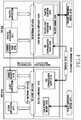
- FIG. 1is a block diagram illustrating a network environment system according to various embodiments of the present disclosure
- FIG. 2is a block diagram illustrating an electronic device according to various embodiments of the present disclosure
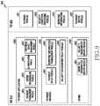
- FIG. 3is a block diagram illustrating a programming module according to various embodiments of the present disclosure
- FIG. 4is a block diagram illustrating a plurality of execution environments operated in an electronic device according to various embodiments of the present disclosure
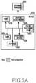
- FIGS. 5A to 5Cillustrate block diagrams of hardware structures of a trusted execution environment (TEE) according to various embodiments of the present disclosure
- FIG. 6is a block diagram illustrating a payment system according to various embodiments of the present disclosure.
- FIG. 7is a block diagram illustrating a payment system for performing payment according to various embodiments of the present disclosure.
- FIG. 8is a block diagram illustrating a hardware structure of an electronic device according to various embodiments of the present disclosure.
- FIG. 9is a block diagram illustrating a program module to be executed in an execution environment of an electronic device according to various embodiments of the present disclosure.
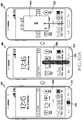
- FIGS. 10A to 10Dillustrate payment user interfaces (UIs) of an electronic device according to various embodiments of the present disclosure
- FIGS. 11 to 12Bare block diagrams illustrating authentication functions of program modules in an electronic device according to various embodiments of the present disclosure
- FIG. 13is a signal flow diagram illustrating authentication operations of programming modules in an electronic device according to various embodiments of the present disclosure
- FIG. 14is a block diagram illustrating a method of generating a token cryptogram according to various embodiments of the present disclosure
- FIG. 15is a signal flow diagram illustrating a concept of a communication method for payment between a near field communication (NFC) module and a point of sale (POS) device according to various embodiments of the present disclosure
- FIG. 16is a block diagram illustrating a payment system according to various embodiments of the present disclosure.
- FIG. 17illustrates a signal flow of token payment according to various embodiments of the present disclosure
- FIG. 18illustrates a signal flow of an operation of a payment system according to various embodiments of the present disclosure
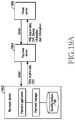
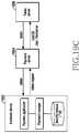
- FIGS. 19A to 19Cillustrate signal flows of token issuance operations of an electronic device according to various embodiments of the present disclosure.
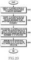
- FIG. 20is a flowchart illustrating a data communication between security applications according to various embodiments of the present disclosure.
- the expression “have”, “may have”, “include” or “may include”refers to existence of a corresponding feature (e.g., a numerical value, a function, an operation, or components, such as elements), and does not exclude existence of additional features.
- the expression “A or B”, “at least one of A or/and B”, or “one or more of A or/and B”may include all possible combinations of the items listed.
- the expression “A or B”, “at least one of A and B”, or “at least one of A or B”refers to all of (1) including at least one A, (2) including at least one B, or (3) including all of at least one A and at least one B.
- a first”, “a second”, “the first”, or “the second” used in various embodiments of the present disclosuremay modify various components regardless of the order and/or the importance but does not limit the corresponding components.
- a first electronic device and a second electronic devicemay indicate different user devices regardless of order or importance thereof.
- a first elementmay be termed a second element, and similarly, a second element may be termed a first element without departing from the scope of the present disclosure.
- an elemente.g., the first element
- another elemente.g., the second element
- the elementmay be directly connected or coupled directly to the other element or any other element (e.g., the third element) may be interposer between them.
- an elemente.g., the first element
- another elemente.g., the second element
- there are no elemente.g., the third element interposed between them.
- the expression “configured to” used in the present disclosuremay be exchanged with, for example, “suitable for”, “having the capacity to”, “designed to”, “adapted to”, “made to”, or “capable of” according to the situation.
- the term “configured to”may not necessarily imply “specifically designed to” in hardware.
- the expression “device configured to”may mean that the device, together with other devices or components, “is able to”.
- processor adapted (or configured) to perform A, B, and Cmay mean a dedicated processor (e.g., an embedded processor) only for performing the corresponding operations or a generic-purpose processor (e.g., a central processing unit (CPU) or an application processor (AP)) that can perform the corresponding operations by executing one or more software programs stored in a memory device.
- a dedicated processore.g., an embedded processor
- a generic-purpose processore.g., a central processing unit (CPU) or an application processor (AP)
- An electronic devicemay include at least one of, for example, a smart phone, a tablet personal computer (PC), a mobile phone, a video phone, an electronic book reader (e-book reader), a desktop PC, a laptop PC, a netbook computer, a workstation, a server, a personal digital assistant (PDA), a portable multimedia player (PMP), a moving picture experts group phase 1 or phase 2 (MPEG-1 or MPEG-2) audio layer-3 (MP3) player, a mobile medical device, a camera, and a wearable device.
- a smart phonea tablet personal computer (PC), a mobile phone, a video phone, an electronic book reader (e-book reader), a desktop PC, a laptop PC, a netbook computer, a workstation, a server, a personal digital assistant (PDA), a portable multimedia player (PMP), a moving picture experts group phase 1 or phase 2 (MPEG-1 or MPEG-2) audio layer-3 (MP3) player, a mobile medical device, a camera, and a wearable
- the wearable devicemay include at least one of an accessory type (e.g., a watch, a ring, a bracelet, an anklet, a necklace, a glasses, a contact lens, or a head-mounted device (HMD)), a fabric or clothing integrated type (e.g., an electronic clothing), a body-mounted type (e.g., a skin pad, or a tattoo), a bio-implantable type (e.g., an implantable circuit), and the like.
- an accessory typee.g., a watch, a ring, a bracelet, an anklet, a necklace, a glasses, a contact lens, or a head-mounted device (HMD)
- a fabric or clothing integrated typee.g., an electronic clothing
- a body-mounted typee.g., a skin pad, or a tattoo
- a bio-implantable typee.g., an implantable circuit
- the electronic devicemay be a home appliance.
- the home appliancemay, for example, include at least one of a television, a digital versatile disc (DVD) player, an audio player, a refrigerator, an air conditioner, a cleaner, an oven, a microwave oven, a washing machine, an air purifier, a set-top box, a home automation control panel, a TV box (e.g., HomeSyncTM of Samsung, Apple TVTM, or Google TVTM), a game console (e.g., XboxTM, PlayStationTM), an electronic dictionary, an electronic key, a camcorder, and an electronic frame.
- a televisione.g., a digital versatile disc (DVD) player
- an audio playere.g., a refrigerator, an air conditioner, a cleaner, an oven, a microwave oven, a washing machine, an air purifier, a set-top box, a home automation control panel
- a TV boxe.g., HomeSyncTM of Samsung, Apple TVTM, or Google TVTM
- the electronic devicemay include at least one of various medical devices (e.g., various portable medical measuring devices (e.g., a blood glucose monitoring device, a heart rate monitoring device, a blood pressure measuring device, a body temperature measuring device, and the like), a magnetic resonance angiography (MRA), a magnetic resonance imaging (MRI), a movie camera, a computed tomography (CT) machine, and an ultrasonic machine), a navigation device, a global navigation satellites system (GNSS), an event data recorder (EDR), a flight data recorder (FDR), a Vehicle Infotainment Devices, an electronic devices for a ship (e.g., a navigation device for a ship, and a gyro-compass), avionics, security devices, an automotive head unit, a robot for home or industry, an automatic teller's machine (ATM) in banks, point of sale (POS) in a shop, or internet device of things (e.g., a light bulb, or a light bulb, or
- the electronic devicemay include at least one of a part of furniture or a building/structure, an electronic board, an electronic signature receiving device, a projector, and various kinds of measuring instruments (e.g., a water meter, an electric meter, a gas meter, and a radio wave meter).
- the electronic device according to various embodiments of the present disclosuremay be a combination of one or more of the aforementioned various devices.
- the electronic device according to some embodiments of the present disclosuremay be a flexible device. Further, the electronic device according to an embodiment of the present disclosure is not limited to the aforementioned devices, and may include a new electronic device according to the development of technology
- the term “user”may indicate a person who uses an electronic device or a device (e.g., an artificial intelligence electronic device) that uses an electronic device.
- FIG. 1is a block diagram illustrating a network environment system according to various embodiments of the present disclosure.
- an electronic device 101may be connected with each other through a network 162 or a short range communication 164 .
- the electronic device 101may include a bus 110 , a processor 120 , a memory 130 , an input/output interface 150 , a display 160 , and a communication interface 170 .
- the electronic device 101may omit at least one of the above elements or may further include other elements.
- the bus 110may include, for example, a circuit for interconnecting the elements 110 to 170 and transferring communication (e.g., control messages and/or data) between the elements.
- communicatione.g., control messages and/or data
- the processor 120may include one or more of a CPU, an AP, and a communication processor (CP).
- the processor 120may carry out operations or data processing relating to control and/or communication of at least one other element of the electronic device 101 .
- the memory 130may include a volatile memory and/or a non-volatile memory.
- the memory 130may store, for example, instructions or data relevant to at least one other element of the electronic device 101 .
- the memory 130may store software and/or a program 140 .
- the program 140may include, for example, a kernel 141 , middleware 143 , an application programming interface (API) 145 , and/or application programs (or “applications”) 147 .
- At least some of the kernel 141 , the middleware 143 , and the API 145may be referred to as an operating system (OS).
- OSoperating system
- the kernel 141may control or manage system resources (e.g., the bus 110 , the processor 120 , or the memory 130 ) used for performing an operation or function implemented by the other programs (e.g., the middleware 143 , the API 145 , or the application programs 147 ). Furthermore, the kernel 141 may provide an interface through which the middleware 143 , the API 145 , or the application programs 147 may access the individual elements of the electronic device 101 to control or manage the system resources.
- system resourcese.g., the bus 110 , the processor 120 , or the memory 130
- the kernel 141may provide an interface through which the middleware 143 , the API 145 , or the application programs 147 may access the individual elements of the electronic device 101 to control or manage the system resources.
- the middleware 143may function as an intermediary for allowing the API 145 or the application programs 147 to communicate with the kernel 141 to exchange data.
- the middleware 143may process one or more task requests received from the application programs 147 according to priorities thereof. For example, the middleware 143 may assign priorities for using the system resources (e.g., the bus 110 , the processor 120 , the memory 130 , and the like) of the electronic device 101 , to at least one of the application programs 147 . For example, the middleware 143 may perform scheduling or load balancing on the one or more task requests by processing the one or more task requests according to the priorities assigned thereto.
- system resourcese.g., the bus 110 , the processor 120 , the memory 130 , and the like
- the API 145is an interface through which the applications 147 control functions provided from the kernel 141 or the middleware 143 , and may include, for example, at least one interface or function (e.g., an instruction) for file control, window control, image processing, or text control.
- interface or functione.g., an instruction
- the input/output interface 150may function as an interface that may transfer instructions or data input from a user or another external device to the other element(s) of the electronic device 101 .
- the input/output interface 150may output, to the user or another external device, commands or data received from the element(s) other than the input/output interface 150 within the electronic device 101 .
- Examples of the display 160may include a liquid crystal display (LCD), a light-emitting diode (LED) display, an organic LED (OLED) display, a microelectromechanical systems (MEMS) display, and an electronic paper display.
- the display 160may display various types of contents (e.g., a text, images, videos, icons, symbols, and the like) for the user.
- the display 160may include a touch screen and receive, for example, a touch, gesture, proximity, or hovering input by using an electronic pen or the user's body part.
- the communication interface 170may set communication between the electronic device 101 and an external device (e.g., the first external electronic device 102 , the second external electronic device 104 , or a server 106 ).
- the communication interface 170may be connected to a network 162 through wireless or wired communication to communicate with the external device (e.g., the second external electronic device 104 or the server 106 ).
- the wireless communicationmay use at least one of, for example, long term evolution (LTE), LTE-Advance (LTE-A), code division multiple access (CDMA), wideband CDMA (WCDMA), universal mobile telecommunications system (UMTS), wireless broadband (WiBro), and global system for mobile communications (GSM), as a cellular communication protocol.
- LTElong term evolution
- LTE-ALTE-Advance
- CDMAcode division multiple access
- WCDMAwideband CDMA
- UMTSuniversal mobile telecommunications system
- WiBrowireless broadband
- GSMglobal system for mobile communications
- the wireless communicationmay include, for example, short range communication 164 .
- the short-range communication 164may include at least one of, for example, Wi-Fi, Bluetooth, near field communication (NFC), magnetic stripe transmission (MST), and global navigation satellite system (GNSS).
- the MSTmay generate a pulse according to transmission data using an electromagnetic signal and the pulse may generate a magnetic field signal.
- the electronic device 101may transmit the magnetic field signal to a POS device, and the POS device may detect the magnetic field signal using an MST reader and convert the detected magnetic field signal to an electric signal to restore the data.
- the GNSSmay include at least one of, for example, a global positioning system (GPS), a global navigation satellite system (Glonass), a Beidou navigation satellite system (hereinafter, referred to as “Beidou”), and Galileo (European global satellite-based navigation system) according to the use area or bandwidth.
- GPSglobal positioning system
- BeidouBeidou navigation satellite system
- GalileoEuropean global satellite-based navigation system
- the wired communicationmay include, for example, at least one of a universal serial bus (USB), a high definition multimedia interface (HDMI), recommended standard 232 (RS-232), and a plain old telephone service (POTS).
- the network 162may include at least one of a communication network, such as a computer network (e.g., a local area network (LAN) or a wide area network (WAN)), the Internet, and a telephone network.
- a communication networksuch as a computer network (e.g., a local area network (LAN) or a wide
- Each of the first external electronic device 102 and the second external electronic device 104may be of a type identical to or different from that of the electronic device 101 .
- the server 106may include a group of one or more servers. According to various embodiments of the present disclosure, all or some of the operations performed in the electronic device 101 may be performed in another electronic device or a plurality of electronic devices (e.g., the first external electronic device 102 and the second external electronic device 104 or the server 106 ).
- the electronic device 101may make a request for performing at least some functions relating thereto to another device (e.g., the first external electronic device 102 or the second external electronic device 104 or the server 106 ) instead of performing the functions or services by itself or in addition.
- another electronic devicee.g., the first external electronic device 102 or the second external electronic device 104
- the server 106may execute the requested functions or the additional functions, and may deliver a result of the execution to the electronic device 101 .
- the electronic device 101may process the received result as it is or additionally to provide the requested functions or services.
- cloud computing, distributed computing, or client-server computing technologymay be used.
- FIG. 2is a block diagram illustrating an electronic device according to various embodiments of the present disclosure.
- an electronic device 201may include, for example, all or some of the electronic device 101 illustrated in FIG. 1 .
- the electronic device 201may include at least one AP 210 , a communication module 220 , a subscriber identification module (SIM) card 224 , a memory 230 , a sensor module 240 , an input device 250 , a display 260 , an interface 270 , an audio module 280 , a camera module 291 , a power management module 295 , a battery 296 , an indicator 297 , and a motor 298 .
- SIMsubscriber identification module
- the processor 210may control a plurality of hardware or software components connected to the processor 210 by driving an operating system or an application program and perform processing of various pieces of data and calculations.
- the processor 210may be implemented by, for example, a system on chip (SoC).
- SoCsystem on chip
- the processor 210may further include a graphics processing unit (GPU) and/or an image signal processor.
- the processor 210may include at least some (e.g., a cellular module 221 ) of the elements illustrated in FIG. 2 .
- the processor 210may load, into a volatile memory, instructions or data received from at least one (e.g., a non-volatile memory) of the other elements and may process the loaded instructions or data, and may store various data in a non-volatile memory.
- the communication module 220may have a configuration equal or similar to that of the communication interface 170 of FIG. 1 .
- the communication module 220may include, for example, a cellular module 221 , a Wi-Fi module 223 , a Bluetooth module 225 , a GNSS module 227 (e.g., a GPS module, a Glonass module, a Beidou module, or a Galileo module), an NFC module 228 , an MST module 226 , and a radio frequency (RF) module 229 .
- a cellular module 221e.g., a Wi-Fi module 223 , a Bluetooth module 225 , a GNSS module 227 (e.g., a GPS module, a Glonass module, a Beidou module, or a Galileo module), an NFC module 228 , an MST module 226 , and a radio frequency (RF) module 229 .
- a cellular module 221
- the cellular module 221may provide a voice call, image call, a text message service, or an Internet service through, for example, a communication network. According to an embodiment of the present disclosure, the cellular module 221 may distinguish between and authenticate electronic devices 201 within a communication network using a subscriber identification module (e.g., the SIM card 224 ). According to an embodiment of the present disclosure, the cellular module 221 may perform at least some of the functions that the processor 210 may provide. According to an embodiment of the present disclosure, the cellular module 221 may include a CP.
- Each of the Wi-Fi module 223 , the BT module 225 , the GNSS module 227 , the NFC module 228 and the MST module 226may include, for example, a processor for processing data transmitted and received through the relevant module.
- a processor for processing data transmitted and received through the relevant modulemay be included in one integrated chip (IC) or IC package.
- the RF module 229may transmit/receive, for example, a communication signal (e.g., an RF signal).
- the RF module 227may include, for example, a transceiver, a power amp module (PAM), a frequency filter, a low noise amplifier (LNA), or an antenna.
- PAMpower amp module
- LNAlow noise amplifier
- at least one of the cellular module 221 , the Wi-Fi module 222 , the Bluetooth module 223 , the GNSS module 227 , the NFC module 225 , and the MST module 226may transmit and receive RF signals through a separate RF module.
- the subscriber identification module 229may include, for example, a card including a subscriber identity module and/or an embedded SIM, and may contain unique identification information (e.g., an integrated circuit card identifier (ICCID)) or subscriber information (e.g., an international mobile subscriber identity (IMSI)).
- ICCIDintegrated circuit card identifier
- IMSIinternational mobile subscriber identity
- the memory 230may include, for example, an internal memory 232 or an external memory 234 .
- the internal memory 232may include at least one of, for example, a volatile memory (e.g., a dynamic random access memory (DRAM), a static RAM (SRAM), a synchronous dynamic RAM (SDRAM), and the like) and a non-volatile memory (e.g., a one time programmable read only memory (OTPROM), a programmable ROM (PROM), an erasable and programmable ROM (EPROM), an electrically erasable and programmable ROM (EEPROM), a flash memory (e.g., a NAND flash memory or a NOR flash memory), a hard driver, or a solid state drive (SSD).
- a volatile memorye.g., a dynamic random access memory (DRAM), a static RAM (SRAM), a synchronous dynamic RAM (SDRAM), and the like
- a non-volatile memorye.g.,
- An external memory 234may further include a flash drive, for example, a compact flash (CF), a secure digital (SD), a micro-SD, a mini-SD, an extreme digital (xD), a memory stick, and the like.
- the external memory 234may be functionally and/or physically connected to the electronic device 201 through various interfaces.
- the security module 236is a module including a storage space having a higher security level than that of the memory 230 and may be a circuit guaranteeing safe data storage and protected execution environment.
- the security module 236may be implemented by a separate circuit and may include a separate processor.
- the security module 236may exist in, for example, a detachable smart chip or SD card or include an embedded secure elements (eSE) embedded in a fixed chip of the electronic device 201 .
- eSEembedded secure elements
- the security module 236may be operated by an OS different from the OS of the electronic device 201 .
- the security modulemay operate based on a java card open platform (JCOP) operating system.
- JCOPjava card open platform
- the sensor module 240may measure a physical quantity or detect an operation state of the electronic device 201 , and may convert the measured or detected information into an electrical signal.
- the sensor module 240may include, for example, at least one of a gesture sensor 240 A, a gyro sensor 240 B, an atmospheric pressure sensor 240 C, a magnetic sensor 240 D, an acceleration sensor 240 E, a grip sensor 240 F, a proximity sensor 240 G a color sensor 240 H (e.g., a red, green, blue (RGB) sensor), a biometric sensor 240 I, a temperature/humidity sensor 240 J, a light sensor 240 K, and a ultraviolet (UV) sensor 240 M.
- a gesture sensor 240 Ae.g., a gyro sensor 240 B
- an atmospheric pressure sensor 240 Ce.g., a magnetic sensor 240 D
- an acceleration sensor 240 Ee.g., a grip sensor 240 F
- the sensor module 240may include, for example, an E-nose sensor, an electromyography (EMG) sensor, an electroencephalogram (EEG) sensor, an electrocardiogram (ECG) sensor, an infrared (IR) sensor, an iris sensor, and/or a fingerprint sensor.
- the sensor module 240may further include a control circuit for controlling one or more sensors included therein.
- an electronic device 201may further include a processor configured to control the sensor module 240 as a part of or separately from the processor 210 , and may control the sensor module 240 while the processor 210 is in a sleep state.
- the input device 250may include, for example, a touch panel 252 , a (digital) pen sensor 254 , a key 256 , or an ultrasonic input device 258 .
- the touch panel 252may use at least one of, for example, a capacitive scheme, a resistive scheme, an infrared scheme, and an ultrasonic scheme.
- the touch panel 252may further include a control circuit.
- the touch panel 252may further include a tactile layer and provide a tactile reaction to the user.
- the (digital) pen sensor 254may include, for example, a recognition sheet which is a part of the touch panel or is separated from the touch panel.
- the key 256may include, for example, a physical button, an optical key or a keypad.
- the ultrasonic input device 258may detect ultrasonic wave generated by an input tool through a microphone (e.g., the microphone 288 ) and identify data corresponding to the detected ultrasonic waves.
- the display 260may include a panel 262 , a hologram device 264 or a projector 266 .
- the panel 262may include a configuration identical or similar to that of the display 160 illustrated in FIG. 1 .
- the panel 262may be implemented to be, for example, flexible, transparent, or wearable.
- the panel 262 and the touch panel 252may be configured by one module.
- the panel 262may include a pressure sensor (or force sensor) capable of measuring the intensity of pressure by a touch of a user.
- the pressure sensormay be implemented either integrated with the touch panel 252 or as at least one sensor separate from the touch panel 252 .
- the hologram device 264may show a three dimensional image in the air by using an interference of light.
- the projector 266may display an image by projecting light onto a screen.
- the screenmay be located, for example, inside or outside the electronic device 201 .
- the display 260may further include a control circuit for controlling the panel 262 , the hologram device 264 , or the projector 266 .
- the interface 270may include, for example, an HDMI 272 , a USB 274 , an optical interface 276 , or a d-subminiature (D-sub) 278 .
- the interface 270may be included in, for example, the communication interface 170 illustrated in FIG. 1 .
- the interface 270may include, for example, a mobile high-definition link (MI-IL) interface, a SD card/multi-media card (MMC) interface, or an infrared data association (IrDA) standard interface.
- MI-ILmobile high-definition link
- MMCmulti-media card
- IrDAinfrared data association
- the audio module 280may bilaterally convert, for example, a sound and an electrical signal. At least some elements of the audio module 280 may be included in, for example, the input/output interface 150 illustrated in FIG. 1 .
- the audio module 280may process sound information which is input or output through, for example, a speaker 282 , a receiver 284 , earphones 286 , the microphone 288 , and the like.
- the camera module 291is a device which may photograph a still image and a dynamic image.
- the camera module 291may include one or more image sensors (e.g., a front sensor or a back sensor), a lens, an image signal processor (ISP) or a flash (e.g., an LED or a xenon lamp).
- image sensorse.g., a front sensor or a back sensor
- ISPimage signal processor
- flashe.g., an LED or a xenon lamp
- the power management module 295may manage, for example, power of the electronic device 201 .
- the power management module 295may include a power management integrated circuit (PMIC), a charger integrated circuit (IC), or a battery or fuel gauge.
- PMICmay use a wired and/or wireless charging method.
- Examples of the wireless charging methodmay include, for example, a magnetic resonance method, a magnetic induction method, an electromagnetic wave method, and the like, and may further include additional circuits (e.g., a coil loop, a resonance circuit, a rectifier, and the like) for wireless charging.
- the battery gaugemay measure, for example, a residual quantity of the battery 296 , and a voltage, a current, or a temperature during the charging.
- the battery 296may include, for example, a rechargeable battery or a solar battery.
- the indicator 297may indicate a particular state (e.g., a booting state, a message state, a charging state, and the like) of the electronic device 201 or a part (e.g., the processor 210 ) of the electronic device 201 .
- the motor 298may convert an electrical signal into mechanical vibration, and may generate vibration, a haptic effect, and the like.
- the electronic device 201may include a processing unit (e.g., a GPU) for supporting a mobile television (TV).
- the processing unit for supporting mobile TVmay, for example, process media data according to a certain standard, such as digital multimedia broadcasting (DMB), digital video broadcasting (DVB), or mediaFLOTM.
- DMBdigital multimedia broadcasting
- DVDdigital video broadcasting
- mediaFLOTMmediaFLOTM
- Each of the components of the electronic device according to the present disclosuremay be implemented by one or more components and the name of the corresponding component may vary depending on a type of the electronic device.
- the electronic device according to various embodiments of the present disclosuremay include at least one of the aforementioned elements. Some elements may be omitted or other additional elements may be further included in the electronic device.
- some of the hardware components according to various embodimentsmay be combined into one entity, which may perform functions identical to those of the relevant components before the combination.
- FIG. 3is a block diagram illustrating a program module according to various embodiments of the present disclosure.
- a program module 310may include an OS for controlling resources related to the electronic device (e.g., the electronic device 101 ) and/or various applications (e.g., the application programs 147 ) executed in the operating system.
- the operating systemmay be, for example, Android, iOS, Windows, Symbian, Tizen, Bada, and the like.
- the program module 310may include a kernel 320 , middleware 330 , an API 360 , and/or an application 370 . At least some of the program module 310 may be preloaded on the electronic device, or may be downloaded from an external electronic device (e.g., the first external electronic device 102 or the second external electronic device 104 , or the server 106 ).
- an external electronic devicee.g., the first external electronic device 102 or the second external electronic device 104 , or the server 106 .
- the kernel 320may include, for example, a system resource manager 321 and/or a device driver 323 .
- the system resource manager 321may perform the control, allocation, retrieval, and the like of system resources.
- the system resource manager 321may include a process manager, a memory manager, a file system manager, and the like.
- the device driver 323may include, for example, a display driver, a camera driver, a Bluetooth driver, a shared memory driver, a USB driver, a keypad driver, a Wi-Fi driver, an audio driver, or an inter-process communication (IPC) driver.
- IPCinter-process communication
- the middleware 330may provide a function required by the applications 370 in common or provide various functions to the applications 370 through the API 360 so that the applications 370 can efficiently use limited system resources within the electronic device.
- the middleware 330e.g., the middleware 143
- the middleware 330may include, for example, at least one of a runtime library 335 , an application manager 341 , a window manager 342 , a multimedia manager 343 , a resource manager 344 , a power manager 345 , a database manager 346 , a package manager 347 , a connectivity manager 348 , a notification manager 349 , a location manager 350 , a graphic manager 351 , a security manager 352 , and a payment manager 354 .
- the runtime library 335may include a library module which a compiler uses in order to add a new function through a programming language while the applications 370 are being executed.
- the runtime library 335may perform input/output management, memory management, the functionality for an arithmetic function, and the like.
- the application manager 341may manage, for example, a life cycle of at least one of the applications 370 .
- the window manager 342may manage graphical user interface (GUI) resources used for the screen.
- the multimedia manager 343may determine a format required to reproduce various media files, and may encode or decode a media file by using a coder/decoder (codec) appropriate for the corresponding format.
- codeccoder/decoder
- the resource manager 344may manage resources, such as a source code, a memory, a storage space, and the like, of at least one of the applications 370 .
- the power manager 345may operate together with a basic input/output system (BIOS) to manage a battery or power, and may provide power information required for the operation of the electronic device.
- the database manager 346may generate, search for, and/or change a database to be used by at least one of the applications 370 .
- the package manager 347may manage the installation or update of an application distributed in the form of a package file.
- the connectivity manager 348may manage a wireless connection, such as, for example, Wi-Fi or Bluetooth.
- the notification manager 349may display or notify of an event, such as an arrival message, an appointment, a proximity notification, and the like, in such a manner as not to disturb the user.
- the location manager 350may manage location information of the electronic device.
- the graphic manager 351may manage a graphic effect, which is to be provided to the user, or a user interface (UI) related to the graphic effect.
- the security manager 352may provide various security functions required for system security, user authentication, and the like.
- the middleware 330may further include a telephony manager for managing a voice call function or a video call function of the electronic device.
- the payment managermay relay information for payment from the application 370 to the application 370 or the kernel 320 . Further, the payment manager may store information related to the payment, which has been received from an external device, in the electronic device 201 or transfer the internally stored information to an external device.
- the middleware 330may include a middleware module that forms a combination of various functions of the above-described elements.
- the middleware 330may provide a module specialized for each type of OS in order to provide a differentiated function.
- the middleware 330may dynamically delete some of the existing elements, or may add new elements.
- the API 360(e.g., the API 145 ) is, for example, a set of API programming functions, and may be provided with a different configuration according to an OS. For example, in the case of Android or iOS, one API set may be provided for each platform. In the case of Tizen, two or more API sets may be provided for each platform.
- the applications 370may include, for example, one or more applications which can provide functions, such as a home application 371 , a dialer application 372 , a short message service (SMS)/multimedia messaging service (MIMS) application 373 , an instant message application (IM) 374 , a browser application 375 , a camera application 376 , an alarm application 377 , a contacts application 378 , a voice dialer application 379 , an email application 380 , a calendar application 381 , a media player application 382 , an album application 383 , a clock application 385 , a health care application (e.g., measure exercise quantity or blood sugar), or environment information (e.g., atmospheric pressure, humidity, temperature information, and the like).
- a health care applicatione.g., measure exercise quantity or blood sugar
- environment informatione.g., atmospheric pressure, humidity, temperature information, and the like.
- the applications 370may include an application (hereinafter, referred to as an “information exchange application” for convenience of description) supporting information exchange between the electronic device (e.g., the electronic device 101 ) and an external electronic device (e.g., the first external electronic device 102 or the second external electronic device 104 ).
- the information exchange applicationmay include, for example, a notification relay application for transferring specific information to an external electronic device or a device management application for managing an external electronic device.
- the notification relay applicationmay include a function of transferring, to the external electronic device (e.g., the first external electronic device 102 or the second external electronic device 104 ), notification information generated from other applications of the electronic device 101 (e.g., an SMS/MMS application, an e-mail application, a health management application, or an environmental information application). Further, the notification relay application may receive notification information from, for example, an external electronic device and provide the received notification information to a user.
- the external electronic devicee.g., the first external electronic device 102 or the second external electronic device 104
- notification information generated from other applications of the electronic device 101e.g., an SMS/MMS application, an e-mail application, a health management application, or an environmental information application.
- the notification relay applicationmay receive notification information from, for example, an external electronic device and provide the received notification information to a user.
- the device management applicationmay manage (e.g., install, delete, or update) at least one function of an external electronic device (e.g., the second external electronic device 104 ) communicating with the electronic device (e.g., a function of turning on/off the external electronic device itself (or some components) or a function of adjusting luminance (or a resolution) of the display), applications operating in the external electronic device, or services provided by the external electronic device (e.g., a call service and a message service).
- an external electronic devicee.g., the second external electronic device 104
- the electronic devicee.g., a function of turning on/off the external electronic device itself (or some components) or a function of adjusting luminance (or a resolution) of the display
- applications operating in the external electronic devicee.g., a call service and a message service.
- the applications 370may include applications (e.g., a health care application of a mobile medical appliance, and the like) designated according to attributes of the first external electronic device 102 or the second external electronic device 104 .
- the application 370may include an application received from the external electronic device (e.g., the server 106 , or the first external electronic device 102 or the second external electronic device 104 ).
- the application 370may include a preloaded application or a third party application which can be downloaded from the server. Names of the elements of the program module 310 , according to the above-described embodiments of the present disclosure, may change depending on the type of OS.
- At least some of the program module 310may be implemented in software, firmware, hardware, or a combination of two or more thereof. At least some of the program module 310 may be implemented (e.g., executed) by, for example, the processor (e.g., the processor 210 ). At least some of the program module 310 may include, for example, a module, a program, a routine, a set of instructions, and/or a process for performing one or more functions.
- moduleas used herein may, for example, mean a unit including one of hardware, software, and firmware or a combination of two or more of them.
- the “module”may be interchangeably used with, for example, the term “unit”, “logic”, “logical block”, “component”, or “circuit”.
- the “module”may be a minimum unit of an integrated component element or a part thereof.
- the “module”may be a minimum unit for performing one or more functions or a part thereof.
- the “module”may be mechanically or electronically implemented.
- the “module”may include at least one of an application-specific integrated circuit (ASIC) chip, a field-programmable gate arrays (FPGAs), and a programmable-logic device for performing operations which has been known or are to be developed hereinafter.
- ASICapplication-specific integrated circuit
- FPGAsfield-programmable gate arrays
- programmable-logic devicefor performing operations which has been known or are to be developed hereinafter.
- At least some of the devices (e.g., modules or functions thereof) or the method (e.g., operations) according to various embodimentsmay be implemented by, for example, a command stored in a computer-readable storage medium in a programming module form.
- the instructionwhen executed by a processor (e.g., the processor 120 ), may cause the one or more processors to execute the function corresponding to the instruction.
- the computer-readable storage mediummay be, for example, the memory 130 .
- a non-transitory computer readable recording mediumis any data storage device that can store data which can be thereafter read by a computer system.
- Examples of the non-transitory computer readable recording mediuminclude a Read-Only Memory (ROM), a Random-Access Memory (RAM), Compact Disc-ROMs (CD-ROMs), magnetic tapes, floppy disks, and optical data storage devices.
- the non-transitory computer readable recording mediumcan also be distributed over network coupled computer systems so that the computer readable code is stored and executed in a distributed fashion.
- functional programs, code, and code segments for accomplishing the present disclosurecan be easily construed by programmers skilled in the art to which the present disclosure pertains.
- the various embodiments of the present disclosure as described abovetypically involve the processing of input data and the generation of output data to some extent.
- This input data processing and output data generationmay be implemented in hardware or software in combination with hardware.
- specific electronic componentsmay be employed in a mobile device or similar or related circuitry for implementing the functions associated with the various embodiments of the present disclosure as described above.
- one or more processors operating in accordance with stored instructionsmay implement the functions associated with the various embodiments of the present disclosure as described above. If such is the case, it is within the scope of the present disclosure that such instructions may be stored on one or more non-transitory processor readable mediums.
- processor readable mediumsexamples include a ROM, a RAM, CD-ROMs, magnetic tapes, floppy disks, and optical data storage devices.
- the processor readable mediumscan also be distributed over network coupled computer systems so that the instructions are stored and executed in a distributed fashion.
- functional computer programs, instructions, and instruction segments for accomplishing the present disclosurecan be easily construed by programmers skilled in the art to which the present disclosure pertains.
- a recording mediumincluding a program for executing operations in an electronic device capable of operating a plurality of execution environments including a first execution environment and a second execution environment.
- the operationsinclude generating a first authentication value, using a first application executed in the first execution environment, transmitting the first authentication value from the first application through the second execution environment to a second application executed in the first execution environment, transmitting, based on reception of the first authentication value, a second authentication value and a result of authentication of the user from the second application to the first application through the second execution environment, and performing, when the second authentication value corresponds to the first authentication value, payment based on the result of the authentication, using the first application.
- the first execution environmentmay include a trusted execution environment and the second execution environment may include a rich execution environment.
- the programming modulemay include one or more of the aforementioned components or may further include other additional components, or some of the aforementioned components may be omitted.
- Operations executed by a module, a programming module, or other component elements according to various embodiments of the present disclosuremay be executed sequentially, in parallel, repeatedly, or in a heuristic manner. Further, some operations may be executed according to another order or may be omitted, or other operations may be added.
- Various embodiments disclosed hereinare provided merely to easily describe technical details of the present disclosure and to help the understanding of the present disclosure, and are not intended to limit the scope of the present disclosure. Accordingly, the scope of the present disclosure should be construed as including all modifications or various other embodiments based on the technical idea of the present disclosure.
- FIG. 4is a block diagram illustrating a plurality of execution environments operated in an electronic device according to various embodiments of the present disclosure.
- the electronic device 101may operate a plurality of execution environments 400 having security levels in order to reinforce the security.
- the plurality of execution environmentsmay include, for example, a rich execution environment (REE) 410 and a trusted execution environment (TEE) 420 .
- REErich execution environment
- TEEtrusted execution environment
- the REE 410may be, for example, a first execution environment having a first security level.
- the TEE 420may be, for example, a second execution environment having a second security level different from (e.g., higher than) the first security level.
- the electronic device 101may include another execution environment (e.g., a third execution environment) having a third security level, without being limited thereto.
- the REE 410may include, for example, a client application 411 , a shared memory 412 , a TEE functional API 413 , a TEE client API 414 , a rich OS component 415 , a public device driver 416 , or an REE communication agent 417 .
- the client application 411e.g., the application 370 or application program 147
- the client application 411may include at least one application capable of performing functions, including a phone call, messaging, payment, alarm, browser, or camera.
- the client application 411may include the shared memory 412 and may access a shared memory view 452 of the TEE 420 using the shared memory 412 .
- the shared memory 412may be a memory accessible by applications of the REE 410 and the TEE 420 .
- the TEE functional API 413 and/or the TEE client API 414are APIs allowed to access the TEE 420 and can perform functions similar to those of the API 145 or the API 360 .
- the TEE functional API 413may be an application interface designed to access some services of the TEE 420 .
- the TEE client API 414may be an interface designed to allow exchange of data between applications of the REE 410 and the TEE 420 .
- the rich OS component 415may include, for example, a public device driver 416 or an REE communication agent 417 .
- the public device driver 416may be a system driver for driving a public peripheral device 471 in the REE 410 .
- the REE communication agent 417may perform a role of processing a message communication between the client application 411 and the trusted application 451 .
- the client application 411may transfer a message 472 from the REE communication agent 417 to the TEE communication agent 455 of the TEE 420 , using the TEE functional API 413 and/or the TEE client API 414 .
- the message 472may be, for example, implemented to be transferred to only the TEE 420 in view of hardware.
- the REE communication agent 417may, for example, receive a result of processing associated with the message 472 from the TEE communication agent 455 and transfer the result to the client application 411 .
- the TEE 420may store data requiring a relatively high security level and perform related operations in a safe environment.
- the TEE 420may operate on an application processor of the electronic device 101 and operate based on a reliable hardware structure determined in the process of manufacturing the electronic device 101 .
- the TEE 420may divide the application processor or memory into a general area and a security area and operate in the security area.
- the TEE 420may configure software or hardware requiring security, to operate in only the security area.
- the electronic device 101may operate the TEE 420 through a physical change of hardware or a logical change of software.
- the TEE 420may be separated from the REE 410 through hardware restrictions, or may be separated in view of software while operating in the same hardware.
- the TEE 420may include a trusted application 451 , a shared memory view 452 , a TEE internal API 453 , a trusted OS component 454 , a TEE communication agent 455 , a trusted core framework 456 , a trusted function 457 , or a trusted kernel 458 .
- the trusted application 451may include at least one application capable of performing functions of digital right management (DRM), security, payment, or biometric information.
- the shared memory view 452may be a memory space capable of accessing the shared memory 412 of the REE 410 .
- the trusted application 451may receive, for example, a message 472 from the REE communication agent 417 through the TEE communication agent 455 , using the TEE internal API 453 .
- the TEE client API 453may be an interface provided to enable basic software of the TEE 420 to operate.
- the TEE communication agent 455may receive the message 472 and transfer the message to the trusted application 451 .
- the trusted application 451may perform an operation associated with the message 472 and transfer a result of processing of the operation to the REE communication agent 417 through the TEE communication agent 455 .
- the trusted OS component 454may include a TEE communication agent 455 , a trusted core framework 456 , a trusted function 457 , and/or a trusted kernel 458 .
- the TEE communication agent 455is one kind of framework API and may perform a role of processing a safe message communication between the client application 411 and the trusted application 451 .
- the trusted core framework 456may provide operating system functions, such as scheduling, communication, and memory management, to be performed by the trusted application 451 .
- the trusted function 457may provide a function of trust including a password.
- the trusted kernel 458may be a kernel for driving the TEE 420 .
- the platform hardware 470is a hardware element which transfers, for example, the message 472 from the REE communication agent 417 to the TEE communication agent 455 .
- the platform hardware 470may include a public peripheral device 471 and/or a trusted peripheral device 473 .
- the public peripheral device 471may communicate with the public device driver 416 of the REE 410 .
- the trusted peripheral device 473may communicate with the trusted kernel 458 of the TEE 420 .
- the public peripheral device 471which is a general peripheral device provided in an electronic device, may be, for example, a Gyro sensor or a GPS device.
- the trusted peripheral device 473is a security (or password)-related peripheral device connected with the TEE 420 and may be, for example, a fingerprint sensor, an iris sensor, or a security display.
- “More privileged” and “less privileged”relate to an authority capable of accessing the system, and “more privileged” may refer to a high system access authority and “less privileged” may refer to a low system access authority.
- a low system authoritymay have a limited authority for access to the system (e.g., file writing, reading, and the like).
- the system access authoritymay have a concept equal or similar to the access authority in a general operating system.
- FIGS. 5A to 5Cillustrate block diagrams of hardware structures of a TEE according to various embodiments of the present disclosure.
- FIG. 5Aillustrates an example (e.g., a trustzone (TZ) of ARM) of using one processor (e.g., the processor 120 ) and one memory (e.g., memory 130 ) in a manner of dividing them into the REE 410 and the TEE 420 in view of hardware.
- TZtrustzone
- the hardware structure of the TEE 420may include an On-SoC 510 and an external memory 520 .
- the On-SoC 510may include, for example, a micro-processing core 501 , a RAM 502 , a ROM 503 , a peripheral device 504 , a crypto-accelerator 505 , or a one time programmable (OTP) field 506 .
- the trust zonemay temporally divide the processors to separately use the REE 410 and the TEE 420 . Further, the trust zone may divide one memory into an area accessible in the REE 410 and an area accessible in the TEE 420 and separately use the areas.
- the micro-processing core 501 , the RANI 502 , the ROM 503 , the peripheral device 504 , the crypto-accelerator 505 , and the OTP field 506may be divided, in use, into an REE area and a TEE area.
- FIG. 5Billustrates a case where a processor (e.g., the processor 120 ) for the TEE 420 is implemented together with a processor for operating the REE 410 in the form of on-chip but is implemented in a separate processing core set.
- the processor for the TEE 420may have a configuration equal or similar to that of the above processor (e.g., the processor 120 ) due to the on-chip security sub-system 507 added thereto. Therefore, the following description omits description on the same elements as those of the above processor (e.g., the processor 120 ).
- the On-SoC 510may include an on-chip security sub-system 507 including at least one processor, in addition to a micro-processing core 501 , a RAM 502 , a ROM 503 , a peripheral device 504 , a crypto-accelerator 505 , and an OTP field 506 .
- the On-SoC 510may be configured to operate the REE 410 while the on-chip security sub-system 507 is configured to operate the TEE 420 .
- one memorymay be divided in use into an area accessible in the REE 410 and an area accessible in the TEE 420 in the structure of FIG. 5B .
- FIG. 5Cillustrates an example in which a processor for the TEE 420 is implemented as a separate chip in view of hardware and is thus separated from a chip in which a processor for operating the REE 410 is implemented.
- the processor for the TEE 410may have a configuration equal or similar to that of the above processor (e.g., the processor 120 ) due to an external security co-processor 530 added thereto. Therefore, the following description omits description on the same elements as those of the above processor (e.g., the processor 120 ).
- the On-SoC 510may be configured to operate the REE 410 and one or more external security co-processors 530 disposed outside of the On-SoC 510 may be configured to operate the TEE 420 .
- FIG. 6is a block diagram illustrating a payment system according to various embodiments of the present disclosure.
- a payment system 600may include an electronic device 610 (e.g., the electronic device 101 ) and/or server.
- the servermay include a payment server 620 , a token server (e.g., a token service provider (TSP)) 630 , or a financial server (issuer) 640 .
- the electronic device 610may include, for example, a payment application (e.g., a wallet application) 612 and/or a payment manager 614 .
- the payment server 620may include, for example, a payment service server 622 and/or a token requester server 624 .
- the payment application 612may include a payment application 612 (e.g., Samsung PayTM application).
- the payment application 612may provide, for example, a UI or user experience (UX) related to payment.
- the user interface related to paymentmay include a wallet user interface (UI/UX).
- the payment application 612may provide, for example, a user interface related to card registration, payment, or transaction.
- the payment application 612may provide, for example, an interface related to card registration through an external input (e.g., a user input) or a text reader (e.g., optical character reader/recognition (OCR)).
- OCRoptical character reader/recognition
- the payment application 612may provide, for example, an interface related to user Identification through identification and verification (ID&V).
- ID&Videntification through identification and verification
- the payment application 612may perform payment transaction.
- the payment application 612may provide a user with a payment function through execution of Simple Pay, Quick Pay, or a designated application.
- a usermay perform a payment function and receive information associated with the payment function.
- the payment manager 614may include information associated with a card company.
- the payment manager 614may include a card company software development kit (SDK).
- SDKcard company software development kit
- the payment server 620may include a management server for electronic payment or mobile payment.
- the payment server 620may, for example, receive information related to payment from the electronic device 610 and transmit the information to the outside or process the information in itself.
- the payment server 620may transmit or receive information between the electronic device 610 and the token server 630 , using the payment service server 622 and/or the token requester server 624 .
- the payment service server 622may include, for example, a payment server (e.g., a Samsung payment server) 620 .
- the payment service server 622may manage, for example, card information linked to a service account (e.g., a Samsung account) or user account.
- the payment service server 622may include an API server related to the payment application 612 .
- the payment service server 622may provide, for example, an account management module (e.g., account integration or Samsung account integration).
- the token requester server 624may provide an interface for processing information relating to payment.
- the token requester server 624may perform issuance, deletion, or activation of information (e.g., token) related to payment.
- the token requester servermay be functionally connected to the payment manager 614 to control the information required for the payment.
- the payment application 612 included in the electronic device 610 and the payment service server 622 included in the payment server 620may be functionally connected with each other.
- the payment application 612may transmit or receive information relating to payment to or from the payment server 620 .
- the payment manager 614 included in the electronic device 610 and the token requester server 624 included in the payment server 620may be functionally connected with each other.
- the payment manager 614may transmit or receive information relating to payment to or from the token requester server 624 .
- the token server 630may issue or manage information (e.g., token) relating to payment.
- the token server 630may control the operation cycle (like cycle) of a token and the operation cycle may include a generation, revision, or deletion function.
- the token server 630may include, for example, a token management server and perform token provisioning, ID&V, replenishment, or life cycle management. Further, the token server may integrate information relating to the financial server.
- the payment server 620 and/or the token server 630may be located in an identical area, similar areas, or separated areas.
- the payment server 620may be included in a first server while the token server 630 is included in a second server.
- the payment server 620 and/or the token server 630may be distinguishably implemented in one server (e.g., the first server or the second server).
- the financial server 640may perform issuance of a card.
- the financial server 640may include a card issuing bank.
- the financial server 640may generate information required for the payment provided to the user.
- the usermay store, in the electronic device 610 , the information required for the payment generated in the financial server 640 , using the payment application 612 .
- the financial server 640may be functionally connected to the token server 630 to transmit or receive the information required for the payment.
- FIG. 7is a block diagram illustrating a payment system for performing payment according to various embodiments of the present disclosure.
- a payment system 700may include an electronic device 710 (e.g., the electronic device 101 ), a payment server 720 (e.g., the server 106 ), a token service provider (TSP) 730 (e.g., the server 106 or another server (not shown)), and a POS device 740 (e.g., the first external electronic device 102 ).
- the payment system 700may include one or more additional electronic device 750 or 760 .
- the one or more additional electronic device 750 or 760may include a wearable device 750 (e.g., a smart watch) or an accessory device 760 (e.g., a fob type device of the LoopPayTM company), which can be functionally connected with the electronic device 710 .
- the fob type device of the LoopPayTM companymay include an external payment module connected to the electronic device 710 through a microphone.
- the electronic device 710may perform a payment function.
- the electronic device 710may register a card (e.g., a credit card, such as a master card or a visa card) in the electronic device 710 or the payment server 720 in order to perform the payment function.
- the payment server 720may manage information on a plurality of registered cards including a card registered through another electronic device (e.g., the electronic device 750 ) of the user corresponding to the electronic device 710 or another card registered through an electronic device of another user as well as a card registered through the electronic device 710 .
- the payment server 720may acquire token information corresponding to registered card information from the TSP 730 and transfer the acquired information to the electronic device 710 .
- the payment server 720may include, for example, a payment service server or token requester server.
- the payment service servermay manage card information of the user.
- the payment servermay provide a service related to payment based on an account.
- the token requester servermay request the TSP 730 to provide token information necessary for the payment operation and acquire the token information.
- the TSP 730may issue a token used in a payment process.
- the tokenmay have a value replacing a primary account number (PAN), which is information of a card.
- PANprimary account number
- a tokenmay be generated using a bank identification number (BIN).
- the generated tokenmay be encrypted by the TSP 730 , or may be encrypted by the payment server 729 after being sent to the payment server 729 without being encrypted.
- the encrypted token informationmay be transferred to the electronic device 710 through the payment server 720 and decrypted by the electronic device 710 .
- the tokenmay be generated and encrypted in the TSP 730 and may be transferred to the electronic device 710 without passing through the payment server 720 .
- the payment server 720may include a token generation function. In this instance, the payment system may omit a separate TSP 730 .
- the electronic device 710may perform payment using, for example, at least one electronic device among one or more other electronic devices 750 or 760 functionally connected thereto based on a short range communication (e.g., Bluetooth or WiFi).
- the at least one electronic device 750may be a wearable device (e.g., a smart watch) and, in this instance, the electronic device 710 may transmit the token received from the TSP 730 to the wearable device.
- the at least one electronic device 760may be an accessory device (e.g., a fob type device of the LoopPayTM company) and, in this instance, the electronic device 710 may be functionally connected with the accessory device (e.g., a fob type device of the LoopPayTM company) through its input/output interface 150 (e.g., the earphone 286 ).
- the accessory devicee.g., a fob type device of the LoopPayTM company
- the input/output interface 150e.g., the earphone 286
- FIG. 8is a block diagram illustrating a hardware structure of an electronic device according to various embodiments of the present disclosure.
- an electronic device 800may include, for example, a camera module 801 , an acceleration sensor 803 , a gyro sensor 805 , a biometric sensor 807 , an MST module 810 , an NFC module 820 , an MST control module 830 , an NFC control module 840 , a processor 850 , and a memory 860 .
- the camera module 801may photograph a card required for payment to acquire card information.
- the camera module 801may recognize, through an optical character reader (OCR) function, card information (e.g., card company, card number, card expiration date, or card owner) recorded in the card. Otherwise, a user may input necessary card information to the electronic device 800 , using an input device (e.g., a touch panel, a pen sensor, a key, an ultrasonic input device, or a microphone input device) included in the electronic device 800 .
- OCRoptical character reader
- the acceleration sensor 803 or gyro sensor 805may acquire location state of the electronic device 800 at the time of payment.
- the acquired location state of the electronic device 800may be transferred to the processor 850 .
- the processor 850may adjust the intensity (current intensity) of a magnetic field transmitted to the POS device 740 from one of the MST module 810 or the NFC module 820 based on the acquired location state of the electronic device 800 or select a coil antenna to be used when there are a plurality of coil antennas.
- the biometric sensor 807may acquire biometric information.
- the acquired biometric informationmay be transferred to the processor 850 .
- the processor 850may authenticate a user by comparing the acquired biometric information and pre-stored biometric information of the user.
- At least one of the MST control module 830 and the NFC control module 840may transmit payment information.
- the MST control module 830may transmit payment information to a POS device 740 through the MST module 810 .
- the NST control module 840may transmit payment information to the POS device 740 through the NST module 820 .
- the MST control module 830may include a data reception module 831 and an output conversion module 833 .
- the data reception module 831may receive a pulse signal in the form of logical low/high, which includes payment information transmitted from the processor 850 or the security module 236 (e.g., an eSE).
- the output conversion module 833may include a circuit for converting data recognized by the data reception module 831 into necessary types in order to transfer the data to the MST module 810 .
- the circuitmay include an H-Bridge for controlling the direction of the voltage supplied to opposite ends of the MST module 810 .
- the H-Bridgemay include a circuit structure connected in a shape like H using four switch structures.
- the electronic device 800may receive the payment information (e.g., track 1/2/3 or token information) included in the magnetic stripe of a magnetic card from a card company/bank server through a communication module (not shown) and store the received information in a necessary form in a separate security module 236 (e.g., an eSE).
- the payment informatione.g., track 1/2/3 or token information
- a separate security module 236e.g., an eSE
- FIG. 9is a block diagram illustrating a program module to be executed in an execution environment of an electronic device according to various embodiments of the present disclosure.
- a program module 900may include, for example, an REE 910 and a TEE 920 .
- the REE 910may include, for example, a payment application 930 (e.g., the payment application 612 ), a payment manager 940 (e.g., the payment manager 354 or 614 ), and a kernel 950 (e.g., the kernel 320 ).
- a payment application 930e.g., the payment application 612
- a payment manager 940e.g., the payment manager 354 or 614
- a kernel 950e.g., the kernel 320
- the payment application 930may include, for example, a payment management module 931 , a server inter-working module 933 , an authentication module 935 , and a peripheral device management module 937 .
- the payment management module 931may perform operations for card registration, card authentication, card de-registration, and payment.
- the payment management module 931may register a user's card.
- the electronic device 800may receive a card registration request from a user.
- the electronic device 800may acquire a card image, using the camera module 801 .
- the payment management module 931may acquire a card image through an OCR module.
- the payment management module 931may receive a user's input of information (e.g., a secret code, a home address, an e-mail address, a phone number, an account ID, and the like) associated with the card information or acquire the information from the payment server 720 .
- informatione.g., a secret code, a home address, an e-mail address, a phone number, an account ID, and the like
- the payment management module 931may display a registered card to the user through the display 160 .
- the usermay revise at least a part of the information (e.g., a card name, a home address, a phone number, the number of times of payment trials, or information on whether payment notification information has been received or not) of the registered card.
- the payment management module 931may display transaction details of each card.
- the payment management module 931may display the registered card information in a wearable device (e.g., a smart watch) functionally connected to the electronic device.
- the payment management module 931may perform a payment operation using a registered card.
- the usermay select one card among a plurality of registered card.
- the usermay take the electronic device 800 to the POS device 740 .
- the payment management module 931may display product information (e.g., price) received from the POS device 740 through the display 160 .
- the payment management module 931may perform user authentication (e.g., fingerprint authentication) through the authentication module 935 for payment. When the authentication has been completed, the payment management module 931 may display notification information reporting completion of payment through the display 160 .
- the electronic device 800may transmit payment information to the POS device 740 , using at least one module among the MST module 810 and the NFC module 820 .
- the electronic device 800may transmit the payment information to the POS device 740 , simultaneously using the MST module 810 and the NFC module 820 .
- the electronic 800may use the MST module 810 in transmission and may use the NFC module 820 in the transmission when the payment has failed.
- a method of recognizing a case wherein the payment has failedmay include reception, by the electronic device 800 , of a notification from the POS device 740 or a 3 rd party (e.g., financial institution) or lapse of a certain time.
- a 3 rd partye.g., financial institution
- an electronic device 800may receive a request for removal of at least one card among already registered cards from a user.
- the payment management module 931may delete information corresponding to the at least one card from the memory 860 .
- the payment management module 931may request the payment server 720 to delete the information corresponding to the at least one card.
- the payment management module 931may determine whether the owner of the card is identical to the user performing the card registration.
- the payment management module 931may include, for example, an ID&V module.
- the payment management module 931may perform user authentication through text messages, an e-mail, an automatic route selection (ARS), a phone call, and the like. Further, the authentication may be performed through an application issued by a card company or bank. The card registered through the payment management module 931 may be used after being authenticated.
- the payment management module 931may include an OCR module.
- the OCR modulemay acquire, through a scanner, an image of a letter written by a human or printed by a machine and convert the image to a machine-readable letter.
- the electronic device 800may acquire an image of a card possessed by a user, through a camera module 801 .
- the OCR modulemay convert an image, a letter, or a number written in a card, obtained from a card image, to a machine-readable letter.
- the OCR modulemay acquire card information (e.g., card number, user name, or valid period) of the user from converted letters.
- the electronic device 800may acquire the card information of the user through the OCR module and perform a card registration process.
- the payment management module 931may display a bar code generated for payment through the display 160 .
- the payment management module 931may receive a command indicating generation of a bar code for payment through a bar code reader.
- the payment management module 931may generate a bar code based on the command.
- the server interworking module 933may receive a payment-related message, a device-related message, or a service-related message from the payment server 720 or the TSP 730 .
- the server interworking 933may transfer the message to the payment management module 931 .
- the server interworking module 933may include, for example, a push management module and an account management module.
- a message received from the payment server 720may be processed by the push management module when the message is in the form of a push notification associated with a token, and may be processed by the account management module when the message relates to account-related information (e.g., Samsung account).
- account-related informatione.g., Samsung account
- the push management modulemay calculate or handle the push notification or push message information received from the payment server 720 .
- the push messagemay be transferred to the server interworking module 933 within the payment application 930 through a payment relay module 941 within the payment manager 940 or 354 or directly transferred to the payment application 930 .
- At least some messages among transferred push messagesmay be transferred to the payment management module 931 to update card-related information and be synchronized with the payment server 720 .
- the payment server 720may include an account server for managing account-related information or a token requester server for providing payment-related information.
- the account server and the token requester servermay be implemented as a separate device (e.g., the server 106 ) and may be included in a single device.
- the message information received by the push management modulemay include token and payment related information, such authority configuration (e.g., token provisioning), suspension (e.g., token suspension), disposal (e.g., token disposal), state change (e.g., token status change), additional issuance (e.g., token replenishment), and payment identification (e.g., transaction notification), as shown in Table 1 below.
- authority configuratione.g., token provisioning
- suspensione.g., token suspension
- disposale.g., token disposal
- state changee.g., token status change
- additional issuancee.g., token replenishment
- payment identificatione.g., transaction notification
- the messages transmitted/received by the account management modulemay include at least a part of electronic device-related information, a lost electronic device identification function (e.g., lost device, find my mobile), remote blocking (e.g., remote lock/unlock), membership management (e.g., loyalty/membership cards), a web-linked function (e.g., website portal-on-line).
- a lost electronic device identification functione.g., lost device, find my mobile
- remote blockinge.g., remote lock/unlock
- membership managemente.g., loyalty/membership cards
- a web-linked functione.g., website portal-on-line.
- Token Token provisioning Card information for identification or verificationis with ID & V sent down for installation and authentication of a token from an external server to a push management module within an electronic device Token suspension Transferred, for interruption of use of a token, from an external server to a push management module within an electronic device Token resume Transferred from an external server to a push management module within an electronic device, for restart of use of a token Token disposal Transferred from an external server to a push management module within an electronic device, for removal of a token Token status change Transferred from an external server to a push management module within an electronic device, for card state change Token Replenishment Transferred from an external server to a push management module within an electronic device, for additional issuance of a token
- Transaction Token payment detailsare transferred from an Notification external server (payment server) to a push management module within an electronic device Device Lost Device (Find my Transfer of loss history information between an mobile) external server (service server) and an account management module within an electronic device Remote lock/unlock Transfer of
- the server interworking module 933may receive, for example, a “push token ⁇ id ⁇ status changed” message and transfer the received message to the payment management module 931 .
- a use stop command of the payment server 720may be transferred to the payment application 930 to switch the card configuration state for mobile payment from the active state to the inactive state.
- the payment server 720may delete or temporarily stop all token information stored in the payment server 720 .
- the payment server 720may transmit a push message.
- the payment server 720may transfer the push message to the payment application 930 through the payment management module 931 or the server interworking module (e.g., a Push management module or an account management module) 933 .
- the APIsmay be distinguishably and separately implemented according to the payment management module 931 .
- the account management modulemay manage, in the payment application, information including a user-specific identifier (e.g., a Samsung account ID or a device ID), card, or membership which the module exchanges with the payment server 720 .
- the user identifiermay include an account, which a user has joined in order to manage cards (e.g., VISA card or MASTER card) of various business providers, a portal account associated with an electronic device, or a unique identifier (e.g., a model name, a MAC address, an international mobile equipment identity (IMEI), a serial number, a universally unique ID (UUID), an ID, and the like) of an electronic device.
- the unique identifiermay have a value which has been generated by and transferred from the payment server 720 through the account.
- the account management modulemay manage registration, addition, deletion, repeated registration, use suspension, or use restart of a card, using the account of the user or the identifier of the electronic device 800 .
- registration, addition, deletion, repeated registration, use suspension, or use restart of a cardmay be managed based on the generated account or an identifier of the electronic device 800 .
- a management method based on an accountmay manage a plurality of electronic devices 800 or a plurality of users sharing one account to use a unique account (e.g., a Samsung account) for each electronic device 800 or synthetically manage a plurality of electronic devices 800 by one account.
- information of a first carde.g., VISATM card
- a second carde.g., MASTERTM card
- OCR module of the payment management module 931may be used to register the cards based on an account (e.g., registration02@samsung.com) generated at the time of joining the Samsung account.
- the registered informationmay be synchronized with the payment server 720 based on the generated account.
- membership information generated through a bar code interfacemay be used to register the first card (e.g., a Samsung point card) and the second card (e.g., a CJ membership point card) based on an account (e.g., registration01@samsung.com) generated at the time of joining the Samsung account.
- the registered informationmay be synchronized with the payment server 720 based on the generated account.
- a usermay determine the active/inactive states of a card based on an account after logging-in through the payment application and transfer the determination to the payment server 720 using the account management module, and on the contrary, may change the management of the card state based on an account in a server management web page (e.g., a server portal).
- the account management modulemanage, while interworking with the server, the card information (e.g., VISATM card ID&V) and membership information (e.g., membership points, registraion001@Cj.com) associated with a service account (e.g., registration01@samsung.com).
- the membership informationmay be automatically linked, at the time of card payment, to payment processing information (e.g., payment amount) and membership accumulation information (e.g., points or mileage) to automatically accumulate or subtract the points or mileage.
- the configuration state of a part or all of an existing registered cardmay be continuously linked and used by only one time of an account login (or sign-in) process of a user even in any device. Further, even membership information having a relatively low authentication security level may be registered and linked based on an account of the user to reduce additional authentication processes.
- the authentication module 935may display a UI for authentication of a user or a card for payment through the display 160 .
- the authentication module 935may include, for example, a biometric information module.
- the biometric information modulemay acquire biometric information of a user.
- the biometric information of a usermay include, for example, information of, a fingerprint, an iris, a face image, voice, cardiac impulse, or blood pressure.
- the electronic device 800may acquire biometric information of a user through a sensor module.
- the electronic devicemay acquire fingerprint information of a user through a fingerprint sensor.
- the electronic device 800may acquire information of an iris of a user through the camera module 801 .
- the biometric information modulemay display a UI for acquiring biometric information of a user through the display 160 .
- the biometric information modulemay perform an authentication in order to acquire security data (e.g., token) from a security memory (e.g., an eSE or memory accessible in a secure environment) functionally connected to the electronic device 800 .
- the electronic device 800may acquire biometric information (e.g., fingerprint or iris) of the user through the biometric information module for user authentication.
- the acquired biometric informationmay be transferred to the biometric information management module 943 of the payment manager 940 .
- the security memorymay be a memory including data stored by encryption key.
- the biometric information modulemay proceed with payment, using card information and biometric information registered in the electronic device 800 , when the user proceeds with electronic payment on an Internet web page.
- security datae.g., token
- a memory or security modulee.g., an eSE or a memory accessible in a secure environment
- the usermay perform an authentication.
- the electronic deviceis linked to an external server to enable fast automatic authentication (e.g., fast iDentity online (FIDO)) without electronic payment on a separate Internet web page.
- FIDOfast iDentity online
- a fast authenticationmay be performed by liking to the biometric information module.
- the electronic device 800may previously appoint a fingerprint of a user and a card to be used for payment. For example, when the user performs authentication using a fingerprint in the payment application, the user may appoint his or her right hand thumb to VISATM card and his or her right hand index finger to MASTERTM card, so that payment through a corresponding card can be achieved as soon as the user performs authentication using a corresponding finger.
- the peripheral device management module 937may manage an external device functionally connected to the electronic device 800 .
- the peripheral device management application 937may include, for example, an MST peripheral device module and a wearable device module.
- the MST peripheral device modulemay output information on whether an MST accessory (e.g., fob type device of LoopPayTM) and the electronic device 800 are connected or not wirelessly or wiredly, and may provide a UI proper for the user on the basis thereof.
- the UImay progress and output card registration or deletion, or payment in a state where the MST accessory has been connected thereto.
- the MST peripheral device modulemay store various card information necessary for payment in the electronic device 800 or a separate memory within the MST accessory, in a state where the electronic device 800 is connected to the MST accessory. As a result, the electronic device 800 or MST accessory can independently progress the payment in a state where the MST accessory is not connected.
- the wearable device modulemay output information on whether a wearable device (e.g., a watch, a headset, glasses, a ring, and the like) and the electronic device 800 are connected or not wirelessly or wiredly, and may provide a UI proper for the user on the basis thereof.
- the wired or wireless connectionmay include various interfaces, such as BT, BLE, WiFi, Zigbee, or Z-wave, and may be implemented by applying a particular accessory protocol (Samsung accessory protocol (SAP)).
- SAPStandardsung accessory protocol
- the UImay progress and output card registration or deletion, or payment in a state where the wearable device has been connected thereto.
- the wearable device modulemay output information on whether to generate a secure session with the wearable device, and transmit or receive and display a user input value on the electronic device 800 or wearable device.
- the input of the usermay include various card information required for payment and other additional authentication information (e.g., personal identification number, user-specific pattern-related data, fingerprint recognition-related data, a touch input value of the display 160 or wearable device bezel unit).
- the electronic device 800may share one piece of payment information with the wearable device or accessory.
- information on one VISATM cardmay be stored in both the wearable device and the electronic device 800 .
- the electronic device 800may store different pieces of card information generated from one piece of card information in the wearable device and the accessory, respectively. For example, among different tokens issued from one piece of VISATM card information, one token may be stored in the electronic device while the other token is stored in the accessory or wearable device.
- a payment module of one devicewhen a different token issued from one piece of card information is stored in the electronic device while the other token is stored in the accessory or wearable device, if a payment module of one device is activated, a payment module of the other device may be deactivated. For example, among different tokens issued from one piece of VISATM card information, if one token is stored in the electronic device 800 while the other token is stored in the accessory or wearable device, payment of the electronic device 800 may be deactivated when the payment is performed by the wearable device. In addition, when the payment is performed by the electronic device 800 , payment by the wearable device may be deactivated.
- the payment manager 940may include, for example, a payment relay module 941 , a biometric information management module 943 , and a security environment relay module 946 .
- the payment relay module 941may relay a card or information (e.g., token) corresponding to the card to the payment application 930 , the kernel 950 , or the payment server 720 .
- the payment relay module 941may perform off-line payment through a communication module (e.g., an NFC module or an MST module).
- a payment method using the NFC module 820can be operated through the POS device 740
- a payment method using the MST module 810can be operated by a user input.
- the payment relay module 941may perform on-line payment through a communication module (e.g., a cellular module, an RF module, a Wi-Fi module, and the like).
- the payment relay module 941may perform state management (e.g., card/token life cycle management) of a card or information (e.g., token) corresponding to the card.
- state managemente.g., card/token life cycle management
- informatione.g., token
- the payment relay module 941may provide at least one API associated with payment to the payment application 930 .
- the payment relay module 941may further include at least one interface provided by system services associated with payment, and system service interfaces, which provide security UIs for a payment service for access to the payment module 921 , trustzone-based integrity measurement architecture (TIMA) for kernel integrity authentication, fingerprint recognition result inquiry (e.g., supporting both the security and non-security mode), and a PIN or a PAN input.
- the payment relay module 941may include an encryption library in order to transfer a message or command to the TEE 920 .
- the payment relay module 941may transmit or receive a message or command with the TEE 920 through the encryption library.
- the payment relay module 941may include a card management function which provides addition, deletion, or update of a card, as a general card management function.
- the payment relay module 941may include a first payment SDK or a second payment SDK.
- the first payment SDK(e.g., Samsung SDK) may be embedded in the electronic device 800 .
- the second payment SDKmay be provided by a card company or bank and may be installed in the electronic device 800 . From the first payment SDK or second payment SDK, the payment relay module 941 may select a payment SDK corresponding to card information. Further, the payment relay module 941 may set a basic card or select another card other than the basic card.
- the payment relay module 941may transmit messages, such as token provisioning, token replenishment, token suspension, token resume, and token disposal, as a general token and key management function, to the payment server 720 .
- the payment module 921may acquire a token and a token cryptogram from the electronic device 800 or another external electronic device.
- a keye.g., a limited used key (LUK) or a single used key
- the payment module 921 of the TEE 920may encrypt and store the token and key, using the key (e.g., a device root key (DRK)) of the TEE 920 .
- the payment relay module 941may acquire the encrypted token in a decrypted state through the payment module.
- the electronic device 800may store the token or key in an encrypted form, using the key of the TEE 920 .
- the payment relay module 941may receive a push message from the TSP 730 and transfer the push message to the payment application.
- the payment relay module 941may further include a function of relaying a token management function request to the second payment SDK when receiving the request.
- the payment relay module 941 having acquired a token or key, using an SDK of VISATM cardmay transfer the token or key to the payment module 921 within the TEE 920 , using a SamsungTM SDK.
- the payment relay module 941may further include, on a payment framework, a host card emulation (HCE) function which enables a virtual card to be used in the electronic device 800 by only software without a separate hardware device (e.g., a security module or a secure element (SE)) at the time of payment.
- HCEhost card emulation
- the HCE functionmay transfer a token and a token cryptogram through a communication module (e.g., an NFC), using a message standard (e.g., application protocol data unit (APDU)) associated with the POS 740 .
- APDUapplication protocol data unit
- the payment relay module 941may include a function of processing a message received from the POS device 740 .
- the POS-related message processing functionmay include a function of managing payment data to be sent to the POS device 740 as a response.
- the POS-related message analysis functionmay include a function of, when the first payment SDK provides a self POS-related message processing function, relaying the POS-related message to the first payment SDK.
- the payment relay module 941may include at least one database for storing the card data, token data, or transaction data.
- the payment relay module 941may select at least one method among a method using NFC and a method using MST.
- the methodsmay include a method of first performing payment using NFC and performing payment using MST, a method of first performing payment using MST and performing payment using NFC, and a method of performing payment simultaneously using NFC and MST.
- the payment relay module 941may perform payment through the another communication module when there is no response to a result of payment performance from the communication module having first performed the payment or after passage of a certain time.
- the payment relay module 941may use at least one of them for payment.
- the payment relay module 941may determine whether the POS device 740 can perform payment using PAN or using a token.
- the electronic device 800may receive payable information through a back light unit (BLE), and the payment relay module 941 may identify the information. Based on the identified information, the payment relay module 941 may perform the payment using a toke when the token is available for the payment and using PAN when the PAN is available for the payment.
- BLEback light unit
- the payment relay module 941may further include an SDK provided by a payment network.
- the SDKmay further include token management, POS-related message processing, or token/card databases.
- the security environment relay module 946may further include a function enabling a payment application to access a biometric information driver module 951 or a security environment driver module 953 in order to use functions provided by the payment module 921 or a biometric information module 925 .
- the payment relay module 941may include an encryption library in order to transfer a message or command to the security environment relay module 946 .
- the payment relay module 941may transmit or receive a message or command with the security environment relay module 946 through the encryption library.
- Various embodiments of the present disclosuremay further include a security environment relay module 946 connected to enable the payment application 930 to use functions of the security identifier processing module 923 of the TEE 920 , in the payment manager 940 .
- the payment relay module 941may include a function of relaying an authentication request through a PIN input by the payment application 930 to the security identifier processing module 923 of the TEE 920 .
- a general applicationmay acquire information on whether the recognition is success or failure.
- the security payment applicatione.g., a payment trusted app
- the security biometric resultmay have a form encrypted by combining a disposable random number and information of success/failure.
- the disposable random numbermay be encrypted through a hardware key (e.g., a DRK) of the TEE 920 .
- the payment relay module 941may transfer a message requiring execution of payment to the payment module 921 through the security environment driver module 953 in order to perform payment.
- the payment module 921may notify the payment relay module 941 , through the security environment driver module 953 , that an authentication operation is necessary.
- the payment relay module 941may issue a command requiring the biometric sensor 807 to acquire biometric information through the biometric information management module 943 and the biometric information driver module 951 .
- the payment relay module 941may transfer an authentication identification message to the biometric information module 925 of the TEE 920 through the biometric information management module 943 and the security environment driver module 953 .
- the biometric sensor 807may be included in the biometric information module 925 of the TEE 920 .
- the biometric information module 925may identify a user's identity by comparing pre-stored biometric information of the user and information acquired by the biometric sensor. Based on the identified information, the biometric information module 925 may transfer success or failure of authentication to the biometric information management module 943 through the security environment driver module 953 , and the biometric information management module 943 may transfer the received information to the payment relay module 941 .
- the payment relay module 941 and the biometric information management module 943may be configured to be integrated in a single construction or configured as separate modules.
- the payment relay module 941may perform an authentication through an external device.
- the electronic device 800may request the payment server (e.g., a Samsung account server or a token requester server) 720 to authenticate biometric information (e.g., fingerprint or iris).
- the payment server 720may perform authentication of biometric information of a user and transfer a result of the authentication to the electronic device 800 .
- the payment relay module 941may perform a token provisioning process by transferring data including information that the authentication has been completed to the TSP.
- the electronic device 800may perform payment when the authentication is successfully completed, or may not perform payment when the authentication fails or is not completed.
- the kernel 950may include, for example, the biometric information driver module 951 and the security environment driver module 953 .
- the biometric information driver module 951may transfer a message transferred from the biometric information management module 943 of the payment manager 940 to the biometric sensor 807 .
- the biometric information obtained by the biometric sensor 807may be transferred to the biometric information module 925 within the TEE 920 instead of being transferred to a module within the REE 910 through the biometric information driver module 951 .
- the security environment driver module 953may perform as an interface for transfer from a module in the REE 910 to a module in the TEE 920 .
- the application processortime-divisionally performs operations of the REE 910 and the TEE 920 .
- a separate data path for transferring a message from the REE 910 to the TEE 920may implemented by hardware.
- a driver module for accessing the hardwaremay be the security environment driver module 953 .
- the security environment driver module 953may transfer a message relating to an operation of a module in the TEE 920 to a module in the REE 910 .
- the TEE 920may include, for example, the payment module 921 , the security identifier processing module 923 , the biometric information module 925 , and the payment driver module 927 .
- the electronic device 800may store data requiring a relatively high security and perform related operations in a safe environment through the TEE 920 .
- the TEE 920may operate on an application processor of the electronic device 800 , and a reliable TEE 920 determined in the step of manufacturing an electronic device 800 may refer to a security area within the electronic device 800 .
- the electronic device 800may store data requiring a relatively high security and perform related operations based on a safe hardware structure through the TEE 920 .
- the TEE 920may enable the application processor and the memory area to operate in a state of being divided into a general area and a security area. Further, the TEE 920 may configure software or hardware requiring security, to operate in only the security area.
- the electronic devicemay be allowed to access the TEE 920 only through an API and a driver capable of accessing the TEE 920 .
- the TEE 920may hand over limited data on related information to the REE 910 .
- the TEE 920may encrypt internally stored data through a hardware key (e.g., a DRK). Without a separate decryption process, the REE 910 may unable to interpret data within the TEE 920 .
- a hardware keye.g., a DRK
- An applicationwithin the TEE 920 may transfer a message to another electronic device (e.g., the TSP 730 ) outside of the electronic device 800 .
- another electronic devicee.g., the TSP 730
- the TEE 920may include a trusted OS and a security application.
- the TEE 920may include an encryption module related to the security, a driver capable of collecting data in hardware requiring security, and the like.
- the security applicationmay include the payment module 921 .
- the TEE 920may transfer payment information to the outside through a communication module. For example, the TEE may transmit payment information to the POS device 740 by transferring the payment information to the MST module 810 through the MST control module 830 or transferring the payment information to the NFC module 820 through the NFC control module 840 .
- the trusted applicationmay determine whether the REE 910 has an integrity.
- the electronic device 800may store, in the TEE 920 , information on whether the REE 910 has an integrity. Booting of the REE 910 supporting the TEE 920 may follow a sequence in which a boot loader is first executed, the TEE 920 is booted, and the REE 910 is booted. When the TEE 920 has been booted, integrity information of the REE 910 is identified in the TEE 920 , and the identified information may be notified to a user after the booting.
- the integrity of the REE 910when the image of the REE 910 has been damaged due to hacking or rooting, it may be determined that the integrity of the REE 910 is problematic.
- the REEmay be prohibited to access the TEE 920 .
- the kernel 950 of the TEE 920may disregard the message or command or deny to receive the message.
- the payment module 921may be an application installed by a bank or card company (e.g., VISATM card or MASTERTM card). There may be at least one payment module 921 .
- the payment servere.g., a mobile application platform, a payment gateway, a token requester, a TSP, a trusted service manager, a bank server, and the like
- the TSP 730may perform operations associated with the installation.
- the payment management module 931may acquire a card number and valid term information of a plastic card through OCR, and perform a card registration operation for installing the payment module 921 in the payment server 720 .
- the payment management modulemay connect to the TSP 730 in the network through the payment relay module 941 having connection information of the TSP 730 according to each card/bank company to receive an installation file, and the payment relay module 941 may transfer the information to the TEE 920 to install the payment module 921 .
- the process described abovemay be called a provisioning process or card registration process.
- the payment module 921may be an application to be used for data communication with the payment server 720 .
- the payment module 921may include information of a credit card, a debit card, a membership card, and the like.
- the payment module 921may communicate with another external electronic device through encryption. The encryption process may be different according to the card manufacturing company having transferred the payment module 921 .
- the payment server 720may control the state of the payment module 921 . For example, the payment server 720 may activate, temporarily suspend, resume, or delete (dispose) the payment module 921 .
- the payment module 921may store information related to the card information.
- the stored informationmay include at least one among a token, a token reference ID, a part of a PAN, a PAN product ID, a token requester ID, a token assurance level, token assurance data, a valid term of a token, an encryption key, and a value (e.g., one time password (OTP)) provided by the TSP 730 , which correspond to the card information (e.g., PAN).
- the tokenmay be controlled by the state of the TSP 730 .
- the tokenmay be activated, temporarily suspended, resumed, or deleted (disposed).
- the tokenmay be static information basically corresponding to the card information (e.g., PAN).
- the payment module 921may determine a card to be used for payment. For example, a payment module 921 corresponding to a card selected by the user in at least one payment management module 931 may be determined according to a user's selection. The payment management module 931 may transfer the determined card to the payment relay module 941 . The payment relay module 941 may transfer the determined card information to the payment module 921 through the security environment driver module 953 . The payment module 921 may manage a list of cards actually used in the payment among possessed cards. The payment module 921 may change the list of cards actually used in the payment, based on the determined card information. The changing may include a method of raising the priority of the determined card information in the card list or a method of deleting the other card information except for the determined card information.
- the payment module 921may generate information used for the payment based on the information associated with the card information when the payment is executed.
- the information used for the paymentmay include a token, a token reference ID, a part of a PAN, a PAN product ID, a token requester ID, a token assurance level, token assurance data, a valid term of a token, a token cryptogram, a POS entry mode, a token requester indicator, and the like.
- the Payment Token numberrefers to a surrogate value for a PAN that is a Token 13 to 19-digit numeric value that passes basic validation rules of an account number, including the Luhn check digit. Payment Tokens are generated within a BIN range or Card range that has been designated as a Token BIN Range and flagged accordingly in all appropriate BIN tables. Payment Tokens are generated such that they will not have the same value as or conflict with a real PAN. Transaction messages The Payment Token number will be passed through the authorization, capture, clearing, and exception messages in lieu of the PAN. The Payment Token number may optionally be passed from the Token Service Provider to the Card Issuer as part of the authorization request.
- Token ExpiryThe expiration date of the Payment Token that is generated by and Date maintained in the Token Vault.
- the Token Expiry Date fieldcarries a 4- digit numeric value that is consistent with the ISO 8583 format.
- Transaction messagesThe Token Expiry Date is passed in lieu of PAN Expiry Date.
- the valueis replaced by the Token Service Provider with the PAN Expiry Date which is then passed to the Card Issuer as part of the authorization request.
- Last 4 DigitsThe last four digits of the PAN to be provided optionally through the of PAN Acquirer to the Merchant for customer service usage, such as being printed on the consumer receipt.
- PAN ProductThe last four digits of the PAN to be provided optionally through the ID Acquirer to the Merchant for customer service usage, such as being printed on the consumer receipt.
- PAN Product IDis an optional identifier used for determining the type ID of Card product that was tokenized. It may be included in cases where transparency of this information is necessary.
- Transaction messagesThe PAN Product ID may optionally be passed from the Token Service Provider to the Acquirer as part of the authorization response.
- POS EntryThis specification uses the POS Entry Mode field to indicate the mode Mode through which the Payment Token is presented for payment. Each Payment Network will define and publish any new POS Entry Mode values as part of its existing message specifications and customer notification procedures.
- Transaction messages POS Entry Modeis an existing field that will be passed through the authorization, capture, clearing, and exception messages.
- TokenThis value uniquely identifies the pairing of Token Requestor with the Requestor ID Token Domain. Thus, if a given Token Requestor needs Tokens for multiple domains, it will have multiple Token Requestor IDs, one for each domain. It is an 11-digit numeric value assigned by the Token Service Provider and is unique within the Token Vault: Positions 1-3: Token Service Provider Code, unique to each Token Service Provider Positions 4-11: Assigned by the Token Service Provider for each requesting entity and Token Domain Transaction messages Token Requestor ID can be optionally passed through the authorization, capture, clearing, and exception messages.
- Token Token Assurance Levelis a value that allows the Token Service Provider Assurance to indicate the confidence level of the Payment Token to PAN/Cardholder Level binding. It is determined as a result of the type of ID&V performed and the entity that performed it.
- the Token Assurance Levelis set when issuing a Payment Token and may be updated if additional ID&V is performed. It is a two-digit value ranging from 00 which indicates the Payment Token has no ID&V that has been performed to a value of 99 indicating the highest possible assurance.
- the specific method to produce the valueis defined by the Token Service Provider.
- Transaction messages Token Assurance Levelwill be provided by the Token Service Provider. The value may be optionally passed to the Card Issuer as part of the authorization request.
- the valuemay optionally be passed to the Acquirer/Merchant in the authorization response, capture, clearing, and exception processing messages.
- TokenThis data provided by the Token Service Provider contains supporting Assurance information for the Token Assurance Level. Data Transaction messages This data may be optionally passed to the Card Issuer as part of the authorization request.
- TokenThis cryptogram is uniquely generated by the Token Requester to validate Cryptogram authorized use of the Token. The cryptogram will be carried in different fields in the transaction message based on the type of transaction and associated use case: NFC contactless transactions will carry the Token Cryptogram in existing chip data fields. Other transactions, such as those originating from a digital wallet, may carry the Token Cryptogram in an existing field. Transaction messages The Token Cryptogram will be passed in the authorization request and validated by the Token Service Provider and/or the Card Issuer. Token An indicator used to indicate that the message is intended to authenticate Request the Cardholder during a Payment Token Request. Indicator
- the payment module 921may receive a key (e.g., a LUK or a single used key), by which a token cryptogram can be generated, through the TSP 730 or the payment server 720 (e.g., a payment service server or a token requester server).
- the keymay be transferred and received through a data network or an SMS.
- the keymay be exchanged using a security channel between the electronic device 800 and the TSP 730 .
- the security channelmay be a logical channel for encrypting data, which is exchanged by a separate key (e.g., a method using a public key or private key) different from the key described above.
- the payment module 921may include a module for generating a key capable of generating a token cryptogram.
- the electronic device 800may receive the module for generating the key, through the TSP 730 or the payment server 720 . Otherwise, the key may be included in the electronic device 800 in the stage of manufacturing the electronic device 800 .
- the payment module 921may generate a token cryptogram, using a key (e.g., a limited used key or a single used key) capable of generating the token cryptogram.
- the payment module 921may use different keys according to a certain rule, for example, in each transaction, in a certain number of times of transaction, or a transaction within a particular time.
- the TSP 730may possess a key paired with the above-described key. The TSP 730 may decrypt the encrypted token cryptogram through the paired key.
- the payment module 921may generate a token cryptogram, using a key capable of generating the token cryptogram.
- the electronic device 800may transfer a message reporting that the payment application will perform the payment, to the payment relay module 941 .
- the payment relay module 941may determine whether to use MST or NFC for the payment. In the case of using MST for the payment, the payment relay module 941 may acquire information (e.g., token, token cryptogram, a part of PAN information, token valid period, and the like) necessary for payment from the payment module 921 of the TEE 920 and transfer the information to the payment driver module 927 in the TEE 920 .
- the payment driver module 927may transfer the information to the payment controller.
- the MST module 810may transmit the information in order to perform payment.
- the electronic device 800may transfer the information necessary for the payment to the payment driver module 927 of the TEE 920 .
- the payment driver module 927may transfer information required for performing the payment to the NFC module 820 .
- the NFC module 820may perform the payment based on the information.
- the electronic device 800may perform the payment when receiving a certain message from the POS device 740 .
- the NFC module 820may transfer the message to the payment driver module 927 .
- the payment driver module 927may transfer information that the message has been received from the POS device 740 , to the payment relay module 941 of the REE 910 .
- the payment relay module 941may generate a token cryptogram in order to perform payment.
- the token cryptogrammay be generated in the payment module 921 of the TEE 920 , using a key (e.g., a limited used key or a single used key) capable of generating the token cryptogram.
- the generated token cryptogrammay be transferred to the REE 910 .
- the payment relay module 941may transfer payment-related information including the token and token cryptogram through a network module (e.g., an NFC-related host card emulation module).
- the network modulemay transfer the payment-related information to the POS device 740 through the NFC module 820 .
- the payment module 921may transfer information including the token, token valid period, token requester ID, and token cryptogram to an external electronic device.
- the payment module 921may transfer the payment information to the POS device 740 through the MST communication module. Further, the payment module 921 may transfer the payment information to the POS device 740 through the NFC communication module 820 .
- the payment module 921may transmit or receive certain information to or from the POS device 740 in the payment operation.
- the POS device 740may first receive the information to perform the payment.
- payment-related information including the token and token cryptogrammay be transmitted, based on an explicit input from a user or an internal algorithm of the electronic device 800 , to the POS device 740 .
- the biometric information module 925may store biometric information of a user of the electronic device 800 and compare the biometric information with information obtained by the biometric sensor to authenticate the user.
- the biometric information module 925may include a fingerprint information module or an iris information module.
- the biometric information modulemay collect information from the biometric sensor 807 .
- the payment application 930shows, through the display 160 , contents requiring authentication of the biometric information of the user, the user may transfer the biometric information through the biometric sensor 807 .
- the authentication module 935 of the payment application 930may transfer, through the biometric information management module 943 , a message requiring collection of biometric information to the biometric information driver module 951 .
- the biometric information driver module 951may transfer the message to the biometric sensor 807 .
- the biometric sensor 807may collect biometric information and transfer the collected information to the TEE 920 .
- the biometric information module 925 of the TEE 920may compare the collected biometric information with the stored biometric information of the user to determine whether to authenticate the biometric information, and may transfer a result of the determination to the authentication module 935 of the payment application 930 through the security environment driver module 953 and the biometric information management module 943 of the REE 910 .
- the payment application 930may show, to the display 160 , whether to authenticate.
- the biometric information of the usermay be stored in the TEE 920 , stored in the REE 910 in an encrypted state, or stored in the security module (e.g., an eSE) 236 .
- the security identifier processing module 923may acquire, through a user input, an input value, which is necessary for the electronic device 800 or is associated with payment or authentication.
- the input valuemay be a personal identification number (PIN) during payment.
- the input valuemay include information related to the card.
- the informationmay include a PAN, a card valid term (e.g., an expiration date), or card verification value (CVV).
- the informationmay include a Chip PIN or ATM PIN.
- the security identifier processing module 923may be indicated in the form of an application. A graphic library necessary for illustration of the application of the security identifier processing module 923 on a screen may be stored in the TEE 920 .
- the graphic library stored in the TEE 920may be different from a graphic library in the REE 910 .
- the security identifier processing module 923may perform user authentication by an input value, such as a PIN, and may transfer a result of the authentication to the payment management module 931 through the payment relay module 941 .
- the security identifier processing module 923may receive an encrypted disposable random number (e.g., nonce) transferred through the security environment driver module 953 by the security environment relay module 946 .
- the security identifier processing module 923may encrypt the disposable random number and the input value acquired through the user input, using an encryption key (e.g., a device root key) in the TEE 920 , and transfer them to the security environment relay module 946 .
- the security environment relay module 946may transfer the encrypted input value and disposable random number to the payment module 921 through the security environment driver module 953 .
- the payment module 921may decrypt the input value and disposable random number, using a hardware key in the TEE 920 .
- the payment module 921may identify that the input value transferred through the REE 910 has an integrity, based on the point that the generated value and the received value of the disposable random number are the same.
- the payment module 921may perform user authentication through the input value, based on the point that the input value has an integrity.
- the payment module 921may perform payment through user authentication.
- a factory resetrefers to an operation of returning a software image of the electronic device 800 to the original state at the time when the electronic device is shipped from a factory. This operation may be performed as an explicit operation of a user through an application. Moreover, a module for determining and monitoring a hacking by a certain condition (e.g., when it is determined that the system has been hacked) may perform a factory reset. When the operation is performed, data stored in the electronic device 800 is reset and the payment-related information of the user also may be thus reset. The payment-related information may be stored in the payment server 720 .
- the usermay be allowed to perform operations of registering a card and installing a payment module 921 again based on the payment-related information.
- the payment-related module stored in the electronic device 800may notify the TSP 730 of the resetting through the payment server 720 to deactivate the TSP.
- a network of the electronic device 800has been deactivated, it may be impossible to perform the operation of notification. In this event, the electronic device 800 may perform the factory reset and access the account of the payment server 720 based on an account.
- the electronic device 800may identify a list of pre-registered cards through the payment server 720 , and may deactivate a card module or token of the electronic device 800 pre-registered in the TSP 730 through the payment server 720 . In addition, based on the card list of the payment server 720 , the electronic device 800 may perform card registration again and receive a payment module 921 , token, and the like.
- the electronic devicemay include a processor and a memory configured to store a plurality of execution environments including a first execution environment and a second execution environment.
- the processormay be configured to generate a first authentication value, using a first application executed in the first execution environment, transmit the first authentication value from the first application through the second execution environment to a second application executed in the first execution environment, transmit, based on reception of the first authentication value, a second authentication value and a result of authentication of the user from the second application to the first application through the second execution environment, and perform, when the second authentication value corresponds to the first authentication value, payment based on the result of the authentication, using the first application.
- the processormay not perform payment using the first application.
- the processormay acquire authentication information of the user, using the second application.
- the authentication informationmay include a PIN, user-specific pattern-related data, fingerprint recognition-related data, a touch input value, or combinations thereof.
- the processormay compare the authentication information with pre-stored authentication information and transmit a result of authentication based on a result of the comparison.
- the processormay encrypt a second authentication value corresponding to the first authentication value and the result of the authentication.
- the processormay decrypt the second authentication value and the result of the authentication, using a pre-stored key.
- the second execution environmentmay include a first trust zone functionally connected to the first application and a second trust zone functionally connected to the second application.
- the first trust zonemay transmit the first authentication value to the second trust zone using the first application, and the second trust zone may transmit the result of the authentication to the first trust zone using the second application.
- the first execution environmentmay include a trusted execution environment and the second execution environment may include a rich execution environment.
- FIGS. 10A to 10Dillustrate payment UIs of an electronic device according to various embodiments of the present disclosure.
- the electronic device 800may receive a user input and execute a payment application.
- the electronic device 800may execute a payment application (e.g., Samsung PayTM) through a user input 1030 of sweeping in a direction toward a display 1020 from a bezel area 1010 at the lower end of the electronic device 800 .
- a payment applicatione.g., Samsung PayTM
- the electronic device 800may display at least one card 1040 among cards 1040 already registered in the electronic device 800 , through the display 1020 .
- the electronic device 800may receive a user input 1050 and select a card 1040 to be used for payment among the pre-registered cards 1040 .
- the electronic device 800may select a card 1040 to be used for payment among the pre-registered cards 1040 through a user input 1050 of leftward/rightward scrolling.
- the electronic device 800may request authentication from the user for payment of the selected card 1040 .
- the authentication methodmay use, for example, biological information of a user.
- the electronic device 800may scan a fingerprint of the user through the fingerprint detection module 1060 to perform a payment operation.
- the electronic device 800may scan a fingerprint of the user through the fingerprint detection module 1060 and wait for a payment operation.
- the electronic device 800may enlarge a card 1040 selected in the display 1020 and wait for a payment operation.
- the electronic device 800may terminate the payment application after completing the payment operation. For example, the electronic device 800 may remove the card 1040 from the display 1020 .
- FIGS. 11 to 12Bare block diagrams illustrating authentication functions of program modules in an electronic device according to various embodiments of the present disclosure.
- the payment relay module 941may include a function of receiving a disposable random number (e.g., nonce) from the payment module 921 of the TEE 920 through the security environment relay module 946 , a function of obtaining a PIN and an encrypted PIN result from a PIN result obtained by requesting the PIN result from the security identifier processing module 923 through the security environment relay module 946 , and a function of requesting the payment module 921 to verify the encrypted PIN result.
- a disposable random numbere.g., nonce
- the payment module 921 of the TEE 920may generate a first authentication value, using a security payment application 1121 .
- the first authentication valuemay be a disposable random number.
- the payment module 921 of the TEE 920may transmit a first authentication value to a payment trust zone 1111 of the payment relay module 941 .
- the payment relay module 941may receive the first authentication value through the security environment relay module 946 in the REE 910 .
- the payment relay module 941 of the REE 910may request a payment application 1115 to provide additional authentication information through a payment service interface 1113 .
- the payment application 1115may acquire additional authentication information.
- the additional authentication informationmay be a PIN.
- the payment application 1115may transmit the additional authentication information to the payment relay module 941 of the REE 910 through the payment service interface 1113 .
- the payment relay module 941 of the REE 910may transmit a first authentication value to a security trust zone 1117 of the payment relay module 941 to request an authentication result.
- the payment relay module 941 of the REE 910may transmit the first authentication value to the payment module 921 of the TEE 920 to request an authentication result.
- the payment module 921 of the TEE 920may receive the first authentication value, using a security application 1123 .
- the payment relay module 941may transmit the first authentication value to the security application 1123 of the TEE 920 through the security environment relay module 946 in the REE 910 .
- the payment module 921 of the TEE 920may encrypt a second authentication value and pre-stored additional authentication information of a user.
- the second authentication valuemay be received from the payment module 921 of the TEE 920 and may correspond to the first authentication value. Meanwhile, the second authentication value may change in the process of being received from the payment module 921 of the TEE 920 and, in this event, may not correspond to the first authentication value.
- the payment module 921 of the TEE 920may transmit pre-stored additional authentication information of the user and an encrypted result of the payment relay module 941 of the REE 910 , using the security application 1123 .
- the security trust zone 1117 of the payment relay module 941may receive the encrypted result from the payment module 921 of the TEE 920 and transmit the encrypted result to the payment trust zone 1111 of the payment relay module 941 .
- the payment trust zone 1111 of the payment relay module 941may receive the encrypted result from the security trust zone 1117 of the payment relay module 941 . Further, in the REE 910 , the payment trust zone 1111 of the payment relay module 941 may receive the additional authentication information from the payment application 1115 to through the payment service interface 1113 . In the REE 910 , the payment trust zone 1111 of the payment relay module 941 may transmit the additional authentication information and the encrypted result to the payment module 921 of the TEE 920 . For example, the payment relay module 941 may transmit the encrypted result and the additional authentication information to the payment module 921 of the TEE 920 through the security environment relay module 946 in the REE 910 .
- the payment module 921 of the TEE 920may decrypt the encrypted result, using the additional authentication information. For example, the payment module 921 of the TEE 920 may identify the additional authentication information and decrypt the encrypted result, using the security payment application 1121 . Further, the payment module 921 of the TEE 920 may detect a second authentication value from the encrypted result and compare the first authentication value and the second authentication value. For example, when the additional authentication information coincides with pre-stored additional authentication information of a user, the payment module 921 of the TEE 920 may detect the second authentication value from the encrypted result. When the first authentication value and the second authentication value correspond to each other, the payment module 921 of the TEE 920 may perform payment. When the first authentication value and the second authentication value do not correspond to each other, the payment module 921 of the TEE 920 may not perform payment.
- the payment module 921 of the TEE 920may generate a first authentication value, using a security payment application 1221 .
- the first authentication valuemay be a disposable random number.
- the payment module 921 of the TEE 920may transmit a first authentication value to a payment trust zone 1211 of the payment relay module 941 .
- the payment relay module 941may receive the first authentication value through the security environment relay module 946 in the REE 910 .
- the payment relay module 941 of the REE 910may request a payment application 1214 to provide additional authentication information through a payment service interface 1212 and a payment framework 1213 .
- the payment application 1214may acquire additional authentication information.
- the payment application 1214may acquire additional authentication information, using the payment framework 1213 and an additional authentication information detection unit 1215 .
- the additional authentication informationmay be fingerprint recognition-related data, and may be a fingerprint scanner to enable the additional authentication information detection unit 1215 to detect fingerprint recognition-related data.
- the additional authentication information detection unit 1215may transfer the additional authentication information to the payment framework 1213 and may provide the additional authentication information to an additional authentication information manager 1216 .
- the payment application 1214may transmit the additional authentication information to the payment relay module 941 of the REE 910 through the payment framework 1213 and the payment service interface 1212 .
- the payment relay module 941 of the REE 910may transmit a first authentication value to a security trust zone 1217 of the payment relay module 941 to request an authentication result.
- the payment relay module 941 of the REE 910may transmit the first authentication value to the payment module 921 of the TEE 920 to request an authentication result.
- the payment module 921 of the TEE 920may receive the first authentication value, using a security application 1223 .
- the payment relay module 941may transmit the first authentication value to the security application 1223 of the TEE 920 through the security environment relay module 946 in the REE 910 .
- the payment module 921 of the TEE 920may encrypt a second authentication value and pre-stored additional authentication information of a user.
- the additional authentication information manager 1216may pre-store additional authentication information of a user.
- the second authentication valuemay be received from the payment module 921 of the TEE 920 and may correspond to the first authentication value. Meanwhile, the second authentication value may change in the process of being received from the payment module 921 and, in this event, may not correspond to the first authentication value.
- the payment module 921 of the TEE 920may transmit pre-stored additional authentication information of the user and an encrypted result of the payment relay module 941 of the REE 910 , using the security application 1223 .
- the security trust zone 1217 of the payment relay module 941may receive the encrypted result from the payment module 921 of the TEE 920 and transmit the encrypted result to the payment trust zone 1211 of the payment relay module 941 .
- the payment trust zone 1211 of the payment relay module 941may receive the encrypted result from the security trust zone 1217 of the payment relay module 941 . Further, in the REE 910 , the payment trust zone 1211 of the payment relay module 941 may receive the additional authentication information from the payment application 1214 through the payment service interface 1213 . In the REE 910 , the payment trust zone 1211 of the payment relay module 941 may transmit the additional authentication information and the encrypted result to the payment module 921 of the TEE 920 . For example, the payment relay module 941 may transmit the encrypted result and the additional authentication information to the payment module 921 of the TEE 920 through the security environment relay module 946 in the REE 910 .
- the payment module 921 of the TEE 920may decrypt the encrypted result, using the additional authentication information. For example, the payment module 921 of the TEE 920 may identify the additional authentication information and decrypt the encrypted result, using the security payment application 1221 . Further, the payment module 921 of the TEE 920 may detect a second authentication value from the encrypted result and compare the first authentication value and the second authentication value. For example, when the additional authentication information coincides with pre-stored additional authentication information of a user, the payment module 921 of the TEE 920 may detect the second authentication value from the encrypted result. When the first authentication value and the second authentication value correspond to each other, the payment module 921 of the TEE 920 may perform payment. When the first authentication value and the second authentication value do not correspond to each other, the payment module 921 of the TEE 920 may not perform payment.
- a payment integration module 1233may include the payment application 1214 and the payment framework 1213 of FIG. 12A .
- a payment trust zone 1231may include the payment trust zone 1211 and the payment service interface 1212 of FIG. 12A .
- a security trust zone 1237may include an additional authentication information manager 1216 and a security trust zone 1217 .
- the payment module 921 of the TEE 920may generate a first authentication value, using a security payment application 1241 .
- the first authentication valuemay be a disposable random number.
- the payment module 921 of the TEE 920may transmit a first authentication value to the payment trust zone 1231 of the payment relay module 941 .
- the payment relay module 941may receive the first authentication value through the security environment relay module 946 in the REE 910 .
- the payment relay module 941 of the REE 910may request the payment integration module 1233 to provide additional authentication information.
- the payment integration module 1233may acquire additional authentication information.
- the payment integration module 1233may acquire the additional authentication information, using an additional authentication information detection unit 1235 .
- the additional authentication informationmay be fingerprint recognition-related data, and may be a fingerprint scanner to enable the additional authentication information detection unit 1235 to detect fingerprint recognition-related data.
- the additional authentication information detection unit 1235may transfer the additional authentication information to the payment integration module 1233 and may provide the additional authentication information to the security trust zone 1237 .
- the payment integration module 1233may transmit the additional authentication information to the payment relay module 941 of the REE 910 .
- the payment relay module 941 of the REE 910may transmit a first authentication value to the security trust zone 1237 of the payment relay module 941 to request an authentication result.
- the payment relay module 941 of the REE 910may transmit the first authentication value to the payment module 921 of the TEE 920 to request an authentication result.
- the payment module 921 of the TEE 920may receive the first authentication value, using a security application 1243 .
- the payment relay module 941may transmit the first authentication value to the security application 1243 of the TEE 920 through the security environment relay module 946 in the REE 910 .
- the payment module 921 of the TEE 920may encrypt a second authentication value and pre-stored additional authentication information of a user.
- the security trust zone 1237may pre-store additional authentication information of a user.
- the second authentication valuemay be received from the payment module 921 of the TEE 920 and may correspond to the first authentication value. Meanwhile, the second authentication value may change in the process of being received from the payment module 921 of the TEE 920 and, in this event, may not correspond to the first authentication value.
- the payment module 921 of the TEE 920may transmit pre-stored additional authentication information of the user and an encrypted result of the payment relay module 941 of the REE 910 , using the security application 1243 .
- the security trust zone 1237 of the payment relay module 941may receive the encrypted result from the payment module 921 of the TEE 920 and transmit the encrypted result to the payment integration module 1233 .
- the payment integration module 1233 of the payment relay module 941may receive the encrypted result from the security trust zone 1237 of the payment relay module 941 .
- the payment trust zone 1231 of the payment relay module 941may receive the encrypted result from the payment integration module 1233 .
- the payment trust zone 1231 of the payment relay module 941may receive the additional authentication information from the payment integration module 1233 .
- the payment trust zone 1231 of the payment relay module 941may transmit the additional authentication information and the encrypted result to the payment module 921 of the TEE 920 .
- the payment relay module 941may transmit the encrypted result and the additional authentication information to the payment module 921 of the TEE 920 through the security environment relay module 946 in the REE 910 .
- the payment module 921 of the TEE 920may decrypt the encrypted result, using the additional authentication information. For example, the payment module 921 of the TEE 920 may identify the additional authentication information and decrypt the encrypted result, using the security payment application 1241 . Further, the payment module 921 of the TEE 920 may detect a second authentication value from the encrypted result and compare the first authentication value and the second authentication value. For example, when the additional authentication information coincides with pre-stored additional authentication information of a user, the payment module 921 of the TEE 920 may detect the second authentication value from the encrypted result. When the first authentication value and the second authentication value correspond to each other, the payment module 921 of the TEE 920 may perform payment. For example, the payment module 921 of the TEE 920 may perform payment, using a payment driver module 1250 . When the first authentication value and the second authentication value do not correspond to each other, the payment module 921 of the TEE 920 may not perform payment.
- FIG. 13is a signal flow diagram illustrating an authentication operation of a program module in an electronic device according to various embodiments of the present disclosure.
- the payment relay module 941may request the payment module 921 in the TEE 920 to provide a disposable random number (e.g., nonce), through the security environment driver module 953 and the security environment relay module 946 .
- a disposable random numbere.g., nonce
- the payment module 921may generate the disposable random number and encrypt the disposable random number, using a key (e.g., a DRK) in the TEE 920 .
- the payment module 921may transfer the encrypted disposable random number to the security environment relay module 946 through the security environment driver module 953 .
- Data transmission/transfer between modules or applications being executed in the same devicemay include a state in which data stored in a memory 860 is accessible.
- the security environment relay module 946may transfer the encrypted disposable random number to the biometric information module 925 through the security environment driver module 953 .
- the biometric information module 925may decrypt the encrypted disposable random number, using the key.
- the biometric information module 925may authenticate the user, using information acquired from the biometric sensor 807 .
- the biometric information module 925may encrypt the user authentication success-or-failure information together with the disposable random number, using the key.
- the biometric information module 925may transfer the encrypted authentication success-or-failure information and disposable random number to the security environment relay module 946 through the security environment driver module 953 .
- the security environment relay module 946may transfer the encrypted authentication success-or-failure information and disposable random number to the payment module 921 through the security environment driver module 953 .
- the payment module 921may decrypt the encrypted authentication success-or-failure information and disposable random number, through the key.
- the payment module 921may compare the received disposable random number with the generated disposable random number to determine whether the authentication success-or-failure information has been changed in the REE 910 .
- the comparisonmay include determining whether the transmitted disposable random number and the received disposable random number completely coincide with each other, or determining that they coincide with each other when the received disposable random number is a number generated based on the transmitted disposable random number even though they do not completely coincide with each other.
- the payment module 921may perform payment.
- the payment module 921may not perform payment.
- the comparisonmay be executed in another application or agent (e.g., a payment manager 940 or a kernel 950 ) executed in the TEE 920 or REE 910 .
- another application or agente.g., a payment manager 940 or a kernel 950 .
- FIG. 14is a block diagram illustrating a method of generating a token cryptogram according to various embodiments of the present disclosure.
- the payment module 921may store a token 1410 , a token valid period 1420 , a token requester ID 1430 , and a token cryptogram 1440 from the electronic device 800 or another external electronic device.
- the payment module 921may generate the token cryptogram 1440 , using a key 1460 and data 1470 .
- an encryption engine 1450may encrypt the token cryptogram 1440 , based on the key 1460 and the data 1470 .
- the payment module 921may use different keys 1460 according to a certain rule, for example, in each transaction, in a certain number of times of transaction, or a transaction within a particular time.
- the data 1470 and the encryption engine 1450may change into a wide variety of types according to the encryption method (e.g., AES, TKIP, and the like).
- the TSP 730may possess a key paired with the above-described key 1460 .
- the TSP 730may decrypt the encrypted token cryptogram 1440 through the paired key.
- FIG. 15is a signal flow diagram illustrating a concept of a communication method for payment between an NFC module and a POS device according to various embodiments of the present disclosure.
- the payment module 921may transmit or receive certain information to or from the POS device 740 in the payment operation.
- the POS device 740may first receive the information to perform the payment.
- payment-related information including the token 1410 and token cryptogram 1440may be transmitted, based on an explicit input from a user or an internal algorithm of the electronic device 800 , to the POS device 740 .
- the electronic device 800may transmit or receive at least one message.
- the electronic device 800may receive a message determined by the POS device 740 in operation 1511 .
- the electronic device 800may transmit information (e.g., a card type and priority information) associated with the payment module 921 to the POS device 740 based on the determined message.
- informatione.g., a card type and priority information
- the POS device 740may determine a payment module 921 to perform the payment, based on information associated with the payment module 921 .
- the POS device 740may transfer the information associated with the determined payment module 921 to the electronic device 800 .
- the electronic device 800may transfer the information enabling access to the determined payment module 921 to the POS device 740 .
- the POS device 740may establish a security channel between the electronic device 800 and the POS device 740 based on the information enabling the access. To this end, the electronic device 800 and the POS device 740 may exchange at least one key 1460 capable of establishing a security channel.
- the above processmay be a process of exchanging at least one message.
- the electronic device 800may transmit information (e.g., the token 1410 , the token cryptogram 1440 , a part of PAN information, or the token valid period 1420 ) necessary for payment to the POS device 740 .
- informatione.g., the token 1410 , the token cryptogram 1440 , a part of PAN information, or the token valid period 1420 .
- FIG. 16is a block diagram illustrating a payment system according to various embodiments of the present disclosure.
- a payment system 1600may include an electronic device 1610 and/or an external device 1620 (e.g., a server).
- the electronic device 1610may include, for example, a TEE 1630 and/or an REE 1640 .
- the external device 1620may include, for example, a server, and the server may include, for example, a payment server 1650 and/or a token server 1660 .
- the payment server 1650may include, for example, a payment service server 1652 or a token requester server 1654 .
- the TEE 1630may include a security system related to the electronic device 1610 .
- the electronic device 1610may protect information included or stored in the TEE 1630 from a control related to a request, a revision, or an input from the outside, using the TEE 1630 .
- the TEE 1630may include, for example, a program mode, the security of which has been reinforced.
- a normal area (world) and a security area (world)may be distinguished.
- the normal worldmay be referred to as the REE 1640 .
- the TEE 1630may, for example, execute a reliable application or manage encrypted information.
- the encrypted informationmay include token or key information.
- the TEE 1630may protect the encrypted information from the outside.
- the token or key informationmay be used to encrypt the card information.
- the card informationwhen the card information is provided to a device for payment, the card information may be at least partly changed rather than being directly provided to the device for payment. In changing the card information, the token or key information may be used.
- the keymay be acquired from, for example, a service provider who provides a payment service. Further, the key may be managed by the electronic device 1610 or the server.
- the TEE 1630may include, for example, a security application (e.g., a trusted application) 1632 .
- the TEE 1630may provide, for example, an environment in which the security application 1632 can be executed.
- the security application 1632may include, for example, information related to a card company included in the TEE 1630 .
- the information related to the card companymay include, for example, an application related to the card company, and the application may be provided in a packaged form.
- the packaged formmay be provided by an SDK.
- the security application 1632may include, for example, an application or applet which should be executed in a mode, the security of which has been reinforced, likewise in the TEE 1630 . Further, the security application 1632 may include, for example, an encryption-related function. For example, the security application 1632 may perform functions of generating, revising, or deleting a cryptogram related to the payment.
- the REE 1640may include an application layer.
- the REE 1640may include an application and/or framework.
- the REE 1640may allow access thereto from the outside or control thereof, differently from the TEE 1630 .
- the REE 1640may include, for example, a payment application (e.g., a wallet application) 1642 and/or a payment manager 1644 .
- the payment application 1642may perform, for example, functions of identification, OCR, or interfacing for payment by the payment application 1642 .
- the payment application 1642may perform, for example, functions related to card registration or payment.
- the payment manager 1644may include, for example, information related to a card company included in the REE 1640 .
- the information related to the card companymay include, for example, an application related to the card company, and the application may be provided in a packaged form.
- the packaged formmay be provided by an SDK.
- the payment manager 1644may include, for example, an encryption-related function.
- the payment manager 1644may perform functions of token ID management or card company channel establishment.
- the payment manager 1644may perform, for example, interfacing with the external device (e.g., a server) 1620 .
- the payment manager 1644may provide an interface with a server (e.g., the payment server 1650 ) for a tokenization service.
- the payment manager 1644may be functionally connected with and share information with the security application 1632 .
- the payment manager 1644may perform interfacing with the security application 1632 for using (e.g., storing) the token or the key.
- the security application 1632may include information associated with a network service provider.
- the payment application 1642 and the payment manager 1644may be functionally connected with each other, and the security application 1632 and the payment manager 1644 may be functionally connected with each other.
- the payment manager 1644may transfer information received from the outside to the payment application 1642 or the security application 1632 or transfer information received from the payment application 1642 or the security application 1632 to the outside.
- the payment manager 1644may share information related to payment with the security application 1632 or the payment application 1642 .
- the electronic device 1610may include an additional configuration or module, as well as the TEE 1630 , the security application 1632 , the REE 1640 , the payment application 1642 , and the payment manager 1644 .
- the payment server 1650is a management server for electronic payment or mobile payment and may transmit or receive information (e.g., token or key) related to payment to or from the electronic device 1610 . Further, the payment service server 1652 and the token requester server 1654 included in the payment server 1650 are functionally connected with each other to share information relating to payment.
- informatione.g., token or key
- the token server 1660may be functionally connected to the token requester server 1654 to transmit or receive the information related to payment.
- the token requester server 1654 and the token server 1660may provide an interface for transfer of the token or the key.
- FIG. 17illustrates a signal flow of token payment according to various embodiments of the present disclosure.
- the payment systemmay include an electronic device 1710 , a payment server 1770 , a token server 1750 , a POS device 1720 , a financial server 1760 , a purchase server (acquirer) 1730 , or a payment network 1740 .
- the electronic device 1710may include, for example, a payment application, a payment manager, or a security area (e.g., a security module or TEE).
- the POS device 1720may include, for example, a sales time point information management system.
- the POS device 1720may be, for example, a combination of functions of a cash register and a computer electronic device, and a user can perform a payment function using the POS device 1720 .
- the financial server 1760may include, for example, a bank or financial company for issuing a card, and may perform identification of the card. Further, the financial server may proceed approval of the card at the time of payment.
- the purchase server 1730may include, for example, a bank or financial company which purchases a transaction sheet for the card transaction paid in a shop (e.g., the POS device 1720 ).
- the payment network 1740may include, for example, a card network.
- the electronic device 1710may transfer a token and/or encryption information (e.g., cryptogram) to a payment terminal (e.g., the POS device 1720 ).
- the tokenmay be stored in the electronic device 1710 .
- the tokenmay be stored in an encrypted area of the electronic device 1710 .
- the electronic device 1710may encrypt and store the token in the security module or the TEE 920 .
- the electronic device 1710may generate encryption information, using a key received from the outside or a key generated by the electronic device 1710 .
- the security informationmay include a cryptogram.
- the electronic device 1710may transfer the cryptogram and/or the token to the POS device 1720 .
- the electronic device 1710may use various communication connections in order to transfer the token and/or cryptogram to the POS device 1720 .
- the communication connectionsmay include, for example, NFC, MST, barcode, or quick response (QR) code.
- the POS device 1720may transfer at least one among the token, the encryption information, and the payment information to the purchase server 1730 .
- the POS device 1720may transfer the token and/or the cryptogram received from the electronic device 1710 and the payment information (e.g., payment location, payment date, or payment amount) acquired from the POS device 1720 to the purchase server 1730 .
- the payment informationmay be, for example, acquired from the POS device 1720 or received from an external device, and may include payment details relating to a payment function requested by the user.
- the payment informationmay include, for example, payment history performed using the payment system 700 .
- the purchase device 1730may transfer, for example, at least one among the token, the encryption information, and the payment information to the payment network 1740 .
- the purchase server 1730may receive at least one among the token, the password information, and the payment information, and transfer at least one among the received token, password information, and payment information to the payment network 1740 .
- the payment network 1740may transmit, for example, at least one among the token, the encryption information, and the payment information to the token server 1750 .
- the payment network 1740may include a network associated with a card company, for example, VISATM, Master CardTM, or AmexTM.
- the payment network 1740may include or operate the token server 1750 .
- the token server 1750may receive at least one of the token, the encryption information, and the payment information from the payment network 1740 .
- the token server 1750may identify information on the received token.
- the token server 1750may use the token to identify card information (e.g., card number (PAN), expiration date) corresponding to the token.
- the token server 1750may identify a PAN corresponding to the financial server 1760 , using information (e.g., Data) included in the token.
- the token server 1750may, for example, identify a PAN corresponding to the financial server 1760 and use the PAN to get payment authentication from the financial server 1760 .
- the token server 1750may identify the PAN, using the received cryptogram.
- the token server 1750may transfer the PAN to the payment network 1740 .
- the payment network 1740may receive the PAN from, for example, the token server 1750 .
- the payment network 1740may transfer the PAN and/or the payment information to the financial server 1760 .
- the financial server 1760may receive the PAN and/or the payment information from the payment network 1740 .
- the financial server 1760may determine whether to approve the payment, using the PAN and/or the payment information.
- the financial server 1760may use the PAN and/or the payment information to determine whether it coincides (e.g., valid PAN) with information included in the financial server 1760 .
- the financial server 1760may determine whether a database storing the PAN includes a PAN coinciding with the received PAN, and may identify payment restriction information (e.g., payment limit or foreign approval-or-not) associated with the coinciding PAN.
- the financial server 1760may determine whether to approve the payment, by determining whether the payment information satisfies the identified payment restriction information.
- the financial server 1760may approve the payment when the PAN and/or the payment information coincides with the information included in the financial server 1760 . Meanwhile, the financial server 1760 may reject the payment when the PAN and/or the payment information does not coincide with the information included in the financial server 1760 .
- the rejection of the paymentmay refer to unapproval of the payment (e.g., unapproval or rejection).
- the financial server 1760may transfer a result of the approval determination (e.g., approval or rejection) to the payment network 1740 .
- a result of the approval determinatione.g., approval or rejection
- the payment network 1740may transfer the approval result to the purchase server 1730 . Further, the payment network 1740 may transfer the payment information to the token server 1750 , when the approval result corresponds to approval.
- the purchase server 1730may transfer the approval result received from the payment network 1740 to the POS device 1720 .
- the token server 1750may transfer, for example, the payment information to the payment server 1770 .
- the payment server 1770may transfer, for example, the payment information to the electronic device 1710 .
- the payment server 1770may transfer the payment information to the electronic device 1710 , using a certain command (e.g., a push message).
- the payment informationmay include payment location, payment date, payment amount, and total payment amount.
- the purchase server 1730 , the token server 1750 , the financial server 1760 , and the payment server 1770are separately illustrated and described in the above description, the purchase server 1730 , the token server 1750 , the financial server 1760 , and the payment server 1770 may be configured in one unit according to embodiments.
- the electronic device 1710may display the payment information on the display 160 .
- the electronic device 1710may display the payment information, using the payment application included in the electronic device 1710 , or display the payment information through an interface associated with a payment function.
- the interface associated with the payment functionmay include a notification bar.
- the electronic device 1710may display the payment information or information (e.g., payment state, payment history, or accumulated amount) associated with the payment through a display 160 functionally connected to the electronic device 1710 .
- the electronic device 1710may use a notification module (e.g., the notification manager 349 of FIG. 3 ) of the electronic device 1710 to display payment information or the information associated with the payment.
- the payment information or the information associated with the paymentmay be displayed using at least one among, for example, a notification, an indicator, a status bar, a task bar, an icon, a floating icon, a tile, and a widget, and may be displayed in a partial area of at least one among a home screen, a lock screen, and a curved display.
- the electronic device 1710may output a sound notifying of the payment information or the information associated with the payment through an audio module (e.g., the audio module 280 of FIG. 2 and/or a motor (e.g., the motor 298 of FIG. 2 , a tactile feedback device (not shown), a friction display (not shown)) functionally connected to the electronic device 1710 , or generate vibration or haptic effect notifying of the information.
- an audio modulee.g., the audio module 280 of FIG. 2 and/or a motor (e.g., the motor 298 of FIG. 2 , a tactile feedback device (not shown), a friction display (not shown)) functionally connected to the electronic device 1710 , or generate vibration or haptic effect notifying of the information.
- a payment card industry (PCI) for a protocol for a payment cardexists, and the POS device 1720 should satisfy the requirements by a PIN transaction security (PTS) for payment transaction.
- PTSPIN transaction security
- the POS device 1720should follow a contingency mechanism, which can monitor physically sensitive data (e.g., card information and signature information) in order to physically protect the physically sensitive data and, when an intrusion is deleted, can delete the data to preclude the possibility of restoration of the sensitive data.
- the POS device 1720should discriminate between applications in executing each application, and follow requirements that it should be impossible to monitor, collide with, or revise another application or an OS.
- firmwareis authenticated when the firmware is updated, the POS device 1720 should identify cryptological authentication of firmware in installing all applications in a corresponding terminal.
- an OS of the POS device 1720may include only software necessary for an intended function.
- An OS of the POS device 1720should be safely configured and be executed by least authority.
- An OS of the POS device 1720should not allow an unauthenticated or unnecessary function for a security policy performed by a device.
- An OS of the POS device 1720should disable or, if possible, delete an unrequired API or commands for supporting a special function.
- the electronic device 1710may implement an input of PIN, and the like, as a trusted input to safely read a physical signature or the PIN input, entering through a touch screen and a trust zone, and directly bring the input into the trust zone. Meanwhile, at the time of processing the payment mode, the electronic device 1710 may configure a tone or screen displayed on a display 160 differently from a general mode, to enable a user to recognize the tone or screen.
- an operation method for using the electronic device 1710 as the POS device 1720will be described in detail.
- FIG. 18illustrates a signal flow of an operation of a payment system according to various embodiments of the present disclosure.
- a payment system 1800may include an electronic device 1810 , a payment server 1820 , and/or a payment network 1830 .
- the electronic device 1810may include, for example, a payment manager 1812 .
- the payment server 1820may include, for example, a payment service server 1822 or token requester server 1824 .
- the payment network 1830may include, for example, a token server 1832 .
- the payment system 1800may use, for example, the token for the functions performed by each of the electronic device 1810 , the payment server 1820 , and/or the payment network 1830 .
- the electronic device 1810may provide a tokenization service associated with the token, using the payment manager 1812 included in the electronic device 1810 and the token requester server 1824 included in the payment server 1820 .
- the payment management server 1822may provide an operation cycle (e.g., token life management) associated with a token, using the token requester server 1824 included in the payment server 1820 .
- an operation cyclee.g., token life management
- the token server 1832may provide a notification service associated with the token, using the token requester server 1824 .
- the token requester server 1824may provide a payment method to the electronic device 1810 , using a payment network solution. For example, the token requester server 1824 may determine a payment method proper for the user, using the tokenization service, an operating cycle associated with the token, and/or a notification service associated with the token.
- FIGS. 19A to 19Cillustrate signal flows of token issuance operations of an electronic device according to various embodiments of the present disclosure.
- the token issuance operationmay be changed according to the country.
- the token issuance operationmay be changed according to the United States of America, Europe, or Republic of Korea.
- the first token issuance operationmay include, for example, an electronic device 1902 , a payment server 1904 , or a token server 1906 .
- the electronic device 1902may include, for example, a payment application, a payment manager, a security module, or a TEE.
- the electronic device 1902may acquire card-related information through a sensor functionally connected to the electronic device 1902 .
- the card-related informationmay be used in, for example, a card registration operation.
- the sensormay include, for example, an OCR.
- the card-related informationmay include, for example, at least one among PAN, valid period, and CVV.
- the sensormay be operated using the payment application included in the electronic device 1902 .
- the payment application included in the electronic device 1902may transfer the card-related information to the payment server 1904 .
- the payment server 1904may include, for example, a payment service server or token requester server, and the card-related information may be transferred between the payment service server and the token requester server.
- the payment server(e.g., the token requester server) 1904 may transfer the card-related information and/or information (e.g., device information or user information) related to the electronic device 1902 to the token server 1906 .
- the information related to the electronic device 1902may include, for example, information of a device having requested the first token issuance operation.
- the token server 1906may issue (generate) a token based on the information received from the payment server 1904 .
- the token server 1906may transfer a token based on the information received from the payment server 1904 .
- the token server 1906may transfer the token to, for example, the token requester server included in the payment server 1904 .
- the payment server 1904may transfer the token to the electronic device 1902 .
- the payment server 1904for example, the token requester server included in the payment server 1904 , may transfer the token to the electronic device 1902 .
- the electronic device 1902may store, in the security module or the TEE, the token received from the payment server 1904 .
- the electronic device 1902may store the token in the security module or the TEE, which is a security area, to control access from the outside.
- the electronic device 1902may store, in the general memory (e.g., the memory included in the REE), the token received from the payment server 1904 .
- the general memorye.g., the memory included in the REE
- one or more tokensmay be issued (generated) based on a payment method (e.g., OTP or call center) performed by the electronic device 1902 .
- a payment methode.g., OTP or call center
- one tokenmay be issued (generated) corresponding to the electronic device 1902 .
- a first tokenmay be included in the first electronic device while a second token is included in the second electronic device.
- the first token and the second tokenmay be different from each other.
- the tokenmay be activated based on an authentication operation (e.g., ID&V).
- an authentication operatione.g., ID&V
- the tokenmay be stored in the electronic device 1902 and activated based on the authentication operation.
- the authentication operationmay include, for example, an identification.
- the identificationmay be conducted by, for example, a financial server.
- the second token issuance operationmay include, for example, an electronic device 1912 , a payment server 1914 , or a token server 1916 .
- the electronic device 1912may include at least one among, for example, a payment application, a payment manager, and a security module.
- the payment server 1914may include, for example, a security service management server.
- the electronic device or an electronic devicemay acquire card-related information through a sensor functionally connected to the electronic device.
- the card-related informationmay be used in, for example, a card registration operation.
- the sensormay include, for example, an OCR.
- the card-related informationmay include, for example, at least one among PAN, valid period, and CVV.
- the sensormay be operated using the payment application included in the electronic device.
- the payment application included in the electronic device 1912may transfer the card-related information to the payment server 1914 .
- the payment server 1914may include, for example, a payment service server or token requester server, and the card-related information may be transferred between the payment service server and the token requester server.
- the payment server 1914may transfer the card-related information to the security service management server included in the payment server 1914 .
- the security service management servermay be included and internally operate in, for example, the payment server 1914 or located outside of the payment server 1914 .
- the security service management servermay be included in another device (e.g., an external device) different from the payment server 1914 , and may be functionally connected to the payment server 1914 to transmit or receive the card-related information.
- the security service management servermay transfer the card-related information and/or information (e.g., device information or user information) related to the electronic device 1912 to the token server 1916 .
- the information related to the electronic device 1912may include, for example, information of a device having requested the second token issuance operation.
- the token server 1916may perform an authentication operation based on the information received from the payment server 1914 .
- the token server 1916may perform an authentication operation, for example, based on the card-related information and/or the information related to the electronic device 1912 .
- the token server 1916may transfer a result (e.g., a success or a failure) of the authentication operation to the security service management server included in the payment server 1914 .
- a resulte.g., a success or a failure
- the security service management servermay issue (generate) a token based on the card-related information and/or the information related to the electronic device 1912 .
- the security service management servermay store the token in a security area (e.g., a security module) included in the electronic device 1912 .
- the security service management servermay have an authority (e.g., a security module access authority) for access to the security area of the electronic device 1912 .
- the security service management servermay store the token in the security area of the electronic device 1912 , using the access authority. Further, the token may be transferred from the security service managing server to the electronic device 1912 .
- the electronic device 1912may store the token in the security module, which is a security area, to control access from the outside.
- one or more tokensmay be issued (generated) based on a payment method (e.g., OTP or call center) performed by the electronic device 1912 .
- a payment methode.g., OTP or call center
- one tokenmay be issued (generated) corresponding to the electronic device 1912 .
- a first tokenmay be included in the first electronic device while a second token is included in the second electronic device.
- the first token and the second tokenmay be different from each other.
- the tokenmay be activated based on an authentication operation (e.g., ID&V).
- an authentication operatione.g., ID&V
- the tokenmay be stored in the electronic device 1912 and activated based on the authentication operation.
- the authentication operationmay include, for example, an identification.
- the identificationmay be conducted by, for example, a financial server.
- the third token issuance operationmay include, for example, an electronic device 1922 , a payment server 1924 , or a token server 1926 .
- the electronic device 1922may include, for example, a payment application, a payment manager, a security module, or a TEE.
- the electronic device or an electronic devicemay acquire card-related information through a sensor functionally connected to the electronic device.
- the card-related informationmay be used in, for example, a card registration operation.
- the sensormay include, for example, an OCR.
- the card-related informationmay include, for example, at least one among PAN, valid period, and CVV.
- the sensormay be operated using the payment application included in the electronic device.
- the electronic device or an electronic devicemay perform an authentication operation (e.g., ID&V).
- the authentication operationfor example, an identification, may be performed using the payment application.
- the electronic device 1922may perform the card registration and/or the identification when performing the payment function.
- the electronic device 1922may perform the card registration and the identification in order to perform the payment function, and the card registration and the identification may refer to a standby (preparation) state for the payment function.
- the electronic device 1922 , the payment server 1924 , and the token server 1926may share information associated with the card registration and the identification.
- the electronic device 1922 , the payment server 1924 , and the token server 1926may share at least one type of information among PAN, valid term, CVV, device information, and user information.
- a token associated with the third token issuance operationmay be issued (generated) when payment is performed using the payment function.
- the payment application included in the electronic device 1922may perform user authentication in order to perform the payment function.
- the user authenticationmay include secret code authentication, pattern authentication, or biometric information authentication.
- the payment applicationmay perform the third token issuance operation with respect to the payment server 1924 .
- the third token issuance operationmay include, for example, a token request.
- the payment server 1924may transfer card information (e.g., card Identifier) and/or user information to the token server 1926 .
- the information related to the electronic device 1922may include, for example, information of a device having requested the third token issuance operation.
- the token server 1926may issue (generate) a token based on the information received from the payment server 1924 .
- the token server 1926may transfer a token based on the information received from the payment server 1924 .
- the payment server 1924may transfer the token to the electronic device 1922 .
- the electronic device 1922may store, in the security module or the TEE, the token received from the payment server 1924 .
- the electronic device 1922may store the token in the security module or the TEE, which is a security area, to control access from the outside.
- the electronic device 1922may store, in the general memory (e.g., the memory included in the REE), the token received from the payment server 1924 .
- the general memorye.g., the memory included in the REE
- the electronic device 1922may not store, in the storage area (e.g., the memory) included in the electronic device 1922 , the token received from the payment server 1924 .
- the electronic device 1922may use the token in the payment function instead of storing the token in the storage area.
- the storage area of the tokenmay be changed based on a payment method (e.g., OTP or call center) performed by the electronic device 1922 .
- a payment methode.g., OTP or call center
- the tokenmay be stored in the security module or the TEE when the payment method is OTP, and may not be stored in the electronic device 1922 when the payment method is call center.
- the tokenmay include use time or valid time.
- use of the tokenmay be restricted when a certain time (e.g., three hours or one day) has passed from the issuance (generation) of the token.
- the tokenmay include card information.
- the tokenmay include disposable card information (e.g., a one-time card (OTC)).
- OTCone-time card
- FIG. 20is a flowchart illustrating a data communication between security applications according to various embodiments of the present disclosure.
- a usermay request the payment module 921 of a first security application (e.g., the security payment module 1121 or 1221 ) being executed in the TEE 920 for payment to perform a payment operation, using the payment application (e.g., the payment application 1115 or 1214 ) being executed in the REE 910 of an electronic device (e.g., the electronic device 800 ).
- a first security applicatione.g., the security payment module 1121 or 1221
- the payment applicatione.g., the payment application 1115 or 1214
- the first security application 1121 or 1221 executed in the TEE 920may generate a disposable random number.
- the first security application 1121 or 1221may request a second security application (e.g., the biometric information module 925 ) being executed in the TEE 920 for user authentication for payment to perform user authentication.
- a second security applicatione.g., the biometric information module 925
- the first security application 1121 or 1221may transmit the disposable random number to a second security application (e.g., a security application 1123 or 1223 ).
- a request between the first security application 1121 or 1221 and the second security application 1123 or 1223 being executed in the TEE 920may be transmitted through the security environment relay module 946 of the REE 910 .
- the second security application 1123 or 1223may acquire the user's biometric information (e.g., Fingerprint), using the biometric sensor 240 I.
- the second security application 1123 or 1223may compare the acquired biometric information with biometric information having been initially registered by the existing user.
- the second security application 1123 or 1223may transmit a result of the comparison together with the disposable random number having been received from the first security application 1121 or 1221 , to the first security application 1121 or 1221 .
- the second security application 1123 or 1223may encrypt and transmit the result of the comparison and the disposable random number.
- a request between the first security application 1121 or 1221 and the second security application 1123 or 1223 being executed in the TEE 920may be transmitted through the security environment relay module 946 of the REE 910 .
- the first security application 1121 or 1221may determine whether to treat the result of the comparison as valid data.
- a method of operating an electronic device capable of operating a plurality of execution environments including a first execution environment and a second execution environmentmay include generating a first authentication value, using a first application executed in the first execution environment, transmitting the first authentication value from the first application through the second execution environment to a second application executed in the first execution environment, transmitting, based on reception of the first authentication value, a second authentication value and a result of authentication of the user from the second application to the first application through the second execution environment, and performing, when the second authentication value corresponds to the first authentication value, payment based on the result of the authentication, using the first application.
- performing of the paymentmay include dispensing with payment using the first application.
- the transmitting to the first applicationmay include acquiring authentication information of the user, using the second application.
- the authentication informationmay include a PIN, user-specific pattern-related data, fingerprint recognition-related data, a touch input value, or combinations thereof.
- acquiring of the authentication informationmay include comparing the authentication information with pre-stored authentication information and transmitting a result of authentication based on a result of the comparison.
- the transmitting to the first applicationmay include encrypting a second authentication value corresponding to the first authentication value and the result of the authentication.
- performing of the paymentmay include decrypting the second authentication value and the result of the authentication, using a pre-stored key.
- the second execution environmentmay include a first trust zone functionally connected to the first application and a second trust zone functionally connected to the second application.
- the transmitting to the second applicationmay include transmitting the first authentication value to the second trust zone, using the first application, by the first trust zone.
- the transmitting to the first applicationmay include transmitting the result of the authentication to the first trust zone, using the second application, by the second trust zone.
- the first execution environmentmay include a trusted execution environment and the second execution environment may include a rich execution environment.
Landscapes
- Business, Economics & Management (AREA)
- Engineering & Computer Science (AREA)
- Accounting & Taxation (AREA)
- Theoretical Computer Science (AREA)
- Physics & Mathematics (AREA)
- General Physics & Mathematics (AREA)
- Strategic Management (AREA)
- General Business, Economics & Management (AREA)
- Finance (AREA)
- Computer Networks & Wireless Communication (AREA)
- Computer Security & Cryptography (AREA)
- General Engineering & Computer Science (AREA)
- Development Economics (AREA)
- Human Computer Interaction (AREA)
- Signal Processing (AREA)
- Economics (AREA)
- Microelectronics & Electronic Packaging (AREA)
- Marketing (AREA)
- Technology Law (AREA)
- Computing Systems (AREA)
- User Interface Of Digital Computer (AREA)
Abstract
Description
| TABLE 1 | ||
| Push | ||
| management | Use case | details |
| Token | Token provisioning | Card information for identification or verification is |
| with ID & V | sent down for installation and authentication of a | |
| token from an external server to a push management | ||
| module within an electronic device | ||
| Token suspension | Transferred, for interruption of use of a token, from | |
| an external server to a push management module | ||
| within an electronic device | ||
| Token resume | Transferred from an external server to a push | |
| management module within an electronic device, for | ||
| restart of use of a token | ||
| Token disposal | Transferred from an external server to a push | |
| management module within an electronic device, for | ||
| removal of a token | ||
| Token status change | Transferred from an external server to a push | |
| management module within an electronic device, for | ||
| card state change | ||
| Token Replenishment | Transferred from an external server to a push | |
| management module within an electronic device, for | ||
| additional issuance of a token | ||
| Transaction | Token payment details are transferred from an | |
| Notification | external server (payment server) to a push | |
| management module within an electronic device | ||
| Device | Lost Device (Find my | Transfer of loss history information between an |
| mobile) | external server (service server) and an account | |
| management module within an electronic device | ||
| Remote lock/unlock | Transfer of a remote device blocking command | |
| between an external server (service server) and an | ||
| account management module within an electronic | ||
| device | ||
| Loyalty/Membership | Transfer of membership information between an | |
| cards | external server (service server) and an account | |
| management module within an electronic device | ||
| Website (online) | Support of a Web-linked function between an | |
| external server (service server) and an account | ||
| management module within an electronic device | ||
| TABLE 2 | |||
| API | Description | type | validation |
| device.push | Contains push platform | Json | required |
| device.push.spp.id | Samsung Push Id. | String | required |
| device.push.gcm.id | Google Push Id. | String | optional |
| TABLE 3 | |
| Field Name | Comment |
| Payment | The Payment Token number refers to a surrogate value for a PAN that is a |
| Token | 13 to 19-digit numeric value that passes basic validation rules of an account |
| number, including the Luhn check digit. Payment Tokens are generated | |
| within a BIN range or Card range that has been designated as a Token BIN | |
| Range and flagged accordingly in all appropriate BIN tables. Payment | |
| Tokens are generated such that they will not have the same value as or | |
| conflict with a real PAN. | |
| Transaction messages | |
| The Payment Token number will be passed through the authorization, | |
| capture, clearing, and exception messages in lieu of the PAN. | |
| The Payment Token number may optionally be passed from the Token | |
| Service Provider to the Card Issuer as part of the authorization request. | |
| Token Expiry | The expiration date of the Payment Token that is generated by and |
| Date | maintained in the Token Vault. The Token Expiry Date field carries a 4- |
| digit numeric value that is consistent with the ISO 8583 format. | |
| Transaction messages | |
| The Token Expiry Date is passed in lieu of PAN Expiry Date. | |
| The value is replaced by the Token Service Provider with the PAN Expiry | |
| Date which is then passed to the Card Issuer as part of the authorization | |
| request. | |
| Last 4 Digits | The last four digits of the PAN to be provided optionally through the |
| of PAN | Acquirer to the Merchant for customer service usage, such as being printed |
| on the consumer receipt. | |
| PAN Product | The last four digits of the PAN to be provided optionally through the |
| ID | Acquirer to the Merchant for customer service usage, such as being printed |
| on the consumer receipt. | |
| PAN Product | The PAN Product ID is an optional identifier used for determining the type |
| ID | of Card product that was tokenized. It may be included in cases where |
| transparency of this information is necessary. | |
| Transaction messages | |
| The PAN Product ID may optionally be passed from the Token Service | |
| Provider to the Acquirer as part of the authorization response. | |
| POS Entry | This specification uses the POS Entry Mode field to indicate the mode |
| Mode | through which the Payment Token is presented for payment. Each Payment |
| Network will define and publish any new POS Entry Mode values as part | |
| of its existing message specifications and customer notification procedures. | |
| Transaction messages | |
| POS Entry Mode is an existing field that will be passed through the | |
| authorization, capture, clearing, and exception messages. | |
| Token | This value uniquely identifies the pairing of Token Requestor with the |
| Requestor ID | Token Domain. Thus, if a given Token Requestor needs Tokens for |
| multiple domains, it will have multiple Token Requestor IDs, one for each | |
| domain. It is an 11-digit numeric value assigned by the Token Service | |
| Provider and is unique within the Token Vault: | |
| Positions 1-3: Token Service Provider Code, unique to each Token Service | |
| Provider | |
| Positions 4-11: Assigned by the Token Service Provider for each | |
| requesting entity and Token Domain | |
| Transaction messages | |
| Token Requestor ID can be optionally passed through the authorization, | |
| capture, clearing, and exception messages. | |
| Token | Token Assurance Level is a value that allows the Token Service Provider |
| Assurance | to indicate the confidence level of the Payment Token to PAN/Cardholder |
| Level | binding. It is determined as a result of the type of ID&V performed and the |
| entity that performed it. | |
| The Token Assurance Level is set when issuing a Payment Token and may | |
| be updated if additional ID&V is performed. It is a two-digit value ranging | |
| from 00 which indicates the Payment Token has no ID&V that has been | |
| performed to a value of 99 indicating the highest possible assurance. The | |
| specific method to produce the value is defined by the Token Service | |
| Provider. | |
| Transaction messages | |
| Token Assurance Level will be provided by the Token Service Provider. | |
| The value may be optionally passed to the Card Issuer as part of the | |
| authorization request. | |
| The value may optionally be passed to the Acquirer/Merchant in the | |
| authorization response, capture, clearing, and exception processing | |
| messages. | |
| Token | This data provided by the Token Service Provider contains supporting |
| Assurance | information for the Token Assurance Level. |
| Data | Transaction messages |
| This data may be optionally passed to the Card Issuer as part of the | |
| authorization request. | |
| Token | This cryptogram is uniquely generated by the Token Requester to validate |
| Cryptogram | authorized use of the Token. The cryptogram will be carried in different |
| fields in the transaction message based on the type of transaction and | |
| associated use case: | |
| NFC contactless transactions will carry the Token Cryptogram in existing | |
| chip data fields. | |
| Other transactions, such as those originating from a digital wallet, may | |
| carry the Token Cryptogram in an existing field. | |
| Transaction messages | |
| The Token Cryptogram will be passed in the authorization request and | |
| validated by the Token Service Provider and/or the Card Issuer. | |
| Token | An indicator used to indicate that the message is intended to authenticate |
| Request | the Cardholder during a Payment Token Request. |
| Indicator | |
Claims (17)
Priority Applications (1)
| Application Number | Priority Date | Filing Date | Title |
|---|---|---|---|
| US15/054,642US11107047B2 (en) | 2015-02-27 | 2016-02-26 | Electronic device providing electronic payment function and operating method thereof |
Applications Claiming Priority (4)
| Application Number | Priority Date | Filing Date | Title |
|---|---|---|---|
| US201562126121P | 2015-02-27 | 2015-02-27 | |
| KR10-2016-0005199 | 2016-01-15 | ||
| KR1020160005199AKR102566248B1 (en) | 2015-02-27 | 2016-01-15 | Electronic apparatus providing electronic payment function and operating method thereof |
| US15/054,642US11107047B2 (en) | 2015-02-27 | 2016-02-26 | Electronic device providing electronic payment function and operating method thereof |
Publications (2)
| Publication Number | Publication Date |
|---|---|
| US20160253670A1 US20160253670A1 (en) | 2016-09-01 |
| US11107047B2true US11107047B2 (en) | 2021-08-31 |
Family
ID=56788987
Family Applications (1)
| Application Number | Title | Priority Date | Filing Date |
|---|---|---|---|
| US15/054,642Expired - Fee RelatedUS11107047B2 (en) | 2015-02-27 | 2016-02-26 | Electronic device providing electronic payment function and operating method thereof |
Country Status (3)
| Country | Link |
|---|---|
| US (1) | US11107047B2 (en) |
| EP (1) | EP3262582B1 (en) |
| WO (1) | WO2016137277A1 (en) |
Cited By (6)
| Publication number | Priority date | Publication date | Assignee | Title |
|---|---|---|---|---|
| US20220156748A1 (en)* | 2020-11-13 | 2022-05-19 | SparkCognition, Inc. | Contactless payment from a vehicle |
| US11620634B2 (en) | 2013-03-15 | 2023-04-04 | Cardware, Inc. | Multi-function smart tokenizing electronic payment device |
| USD1016831S1 (en)* | 2018-10-01 | 2024-03-05 | Capital One Services, Llc | Display screen or portion thereof with graphical user interface |
| US12323990B2 (en) | 2022-03-29 | 2025-06-03 | T-Mobile Innovations Llc | Memory access for a user application in a wireless communication device |
| US12406258B2 (en) | 2023-05-24 | 2025-09-02 | Bank Of America Corporation | System and method for authentication of resource transfers using tokenization as indicator of authorized resource distribution |
| US12406311B2 (en)* | 2008-01-18 | 2025-09-02 | Mitek Systems, Inc. | Systems and methods for obtaining insurance offers using mobile image capture |
Families Citing this family (42)
| Publication number | Priority date | Publication date | Assignee | Title |
|---|---|---|---|---|
| US10552701B2 (en)* | 2008-02-01 | 2020-02-04 | Oath Inc. | System and method for detecting the source of media content with application to business rules |
| US20090307140A1 (en)* | 2008-06-06 | 2009-12-10 | Upendra Mardikar | Mobile device over-the-air (ota) registration and point-of-sale (pos) payment |
| US8862767B2 (en) | 2011-09-02 | 2014-10-14 | Ebay Inc. | Secure elements broker (SEB) for application communication channel selector optimization |
| US20230196328A1 (en)* | 2013-02-14 | 2023-06-22 | Advanced New Technologies Co., Ltd. | Data interaction method and device, and offline credit payment method and device |
| US9785946B2 (en)* | 2013-03-07 | 2017-10-10 | Mastercard International Incorporated | Systems and methods for updating payment card expiration information |
| US10050942B2 (en) | 2015-03-17 | 2018-08-14 | Ca, Inc. | System and method of mobile authentication |
| US10360558B2 (en) | 2015-03-17 | 2019-07-23 | Ca, Inc. | Simplified two factor authentication for mobile payments |
| US10089631B2 (en)* | 2015-03-18 | 2018-10-02 | Ca, Inc. | System and method of neutralizing mobile payment |
| US10387884B2 (en)* | 2015-03-18 | 2019-08-20 | Ca, Inc. | System for preventing mobile payment |
| DE102015006907A1 (en)* | 2015-05-29 | 2016-12-01 | Giesecke & Devrient Gmbh | Terminal and method for mobile payment |
| JP6544088B2 (en)* | 2015-07-06 | 2019-07-17 | 富士通株式会社 | Terminal, information leak prevention method and information leak prevention program |
| US20180211188A1 (en)* | 2015-08-17 | 2018-07-26 | Bytemark, Inc. | Methods and systems for hands-free fare validation and gateless transit |
| US10498740B2 (en)* | 2016-02-11 | 2019-12-03 | Samsung Electronics Co., Ltd. | Method, apparatus, and system for creating service account |
| CN109871717A (en)* | 2016-02-29 | 2019-06-11 | 华为技术有限公司 | A data security transmission device and method |
| CN105975837B (en)* | 2016-06-12 | 2019-04-30 | 北京集创北方科技股份有限公司 | Calculate equipment, biological feather recognition method and template register method |
| KR20180000582A (en)* | 2016-06-23 | 2018-01-03 | 삼성전자주식회사 | Method for payment and electronic device using the same |
| TW201804335A (en)* | 2016-07-27 | 2018-02-01 | 鴻海精密工業股份有限公司 | Connecting device and internet of things system using the same |
| US10650621B1 (en) | 2016-09-13 | 2020-05-12 | Iocurrents, Inc. | Interfacing with a vehicular controller area network |
| US10666443B2 (en)* | 2016-10-18 | 2020-05-26 | Red Hat, Inc. | Continued verification and monitoring of application code in containerized execution environment |
| KR102703601B1 (en)* | 2016-11-17 | 2024-09-06 | 삼성전자주식회사 | Electronic device and method for remitting thereof |
| KR102591683B1 (en) | 2016-12-07 | 2023-10-20 | 삼성전자주식회사 | Method and electronic device for managing secure element |
| WO2018136914A1 (en)* | 2017-01-23 | 2018-07-26 | Mastercard International Incorporated | Method and system for authentication via a trusted execution environment |
| EP3364329B1 (en)* | 2017-02-21 | 2023-07-26 | Mastercard International Incorporated | Security architecture for device applications |
| US10528749B2 (en)* | 2017-03-20 | 2020-01-07 | Huawei Technologies Co., Ltd. | Methods and apparatus for containerized secure computing resources |
| KR102379753B1 (en)* | 2017-03-29 | 2022-03-29 | 삼성전자주식회사 | Device and method for performing payment using utterance |
| DE102017113190A1 (en)* | 2017-06-14 | 2018-12-20 | Rubean AG | Arrangement and method for user authentication and access authorization |
| US10242390B2 (en) | 2017-07-31 | 2019-03-26 | Bank Of America Corporation | Digital data processing system for controlling automated exchange zone systems |
| US20210103913A1 (en)* | 2017-09-16 | 2021-04-08 | Peter Garrett | Proximal peer to peer money transfer |
| CN107895268A (en)* | 2017-11-28 | 2018-04-10 | 艾体威尔电子技术(北京)有限公司 | A kind of method that safety input PIN is realized on intelligent payment terminal |
| CN114936056A (en)* | 2018-01-29 | 2022-08-23 | 华为技术有限公司 | Authentication window display method and device |
| EP4472137A3 (en)* | 2018-03-20 | 2025-03-05 | Visa International Service Association | Distributed biometric comparison framework |
| US10783234B2 (en)* | 2018-04-06 | 2020-09-22 | The Toronto-Dominion Bank | Systems for enabling tokenized wearable devices |
| CN108768655B (en)* | 2018-04-13 | 2022-01-18 | 北京握奇智能科技有限公司 | Dynamic password generation method and system |
| MY197067A (en)* | 2018-05-24 | 2023-05-24 | Soft Space Sdn Bhd | Method for processing a secure financial transaction using a commercial off-the-shelf or an internet of things device |
| US11049095B2 (en)* | 2018-12-21 | 2021-06-29 | Square, Inc. | Point of sale (POS) systems and methods with dynamic kernel selection |
| CN110189422A (en)* | 2019-05-06 | 2019-08-30 | 北京盛威时代科技有限公司 | A kind of charging system of passenger traffic bus |
| US11416844B1 (en)* | 2019-08-28 | 2022-08-16 | United Services Automobile Association (Usaa) | RFID-enabled payment authentication |
| US11432151B1 (en)* | 2019-09-13 | 2022-08-30 | Sprint Communications Company L.P. | Wireless gateway with multiple processors managed by trusted processor |
| US12217243B1 (en)* | 2019-11-27 | 2025-02-04 | Worldpay, Llc | Methods and systems for securely facilitating cross-platform token compatibility via multi-tokenization |
| EP4123542A4 (en)* | 2020-03-17 | 2023-03-29 | NEC Corporation | Electronic payment device, system, method, and non-transitory computer-readable medium having program stored thereon |
| CN113822664B (en)* | 2020-12-23 | 2023-11-03 | 京东科技控股股份有限公司 | Method, device, system, terminal, server and medium for opening offline payment |
| US12182312B1 (en)* | 2024-07-18 | 2024-12-31 | Here Enterprise Inc. | Techniques to support tiered security zones for web-based applications |
Citations (260)
| Publication number | Priority date | Publication date | Assignee | Title |
|---|---|---|---|---|
| US5396558A (en) | 1992-09-18 | 1995-03-07 | Nippon Telegraph And Telephone Corporation | Method and apparatus for settlement of accounts by IC cards |
| US5649115A (en) | 1994-06-02 | 1997-07-15 | Intuit, Inc. | Tracking method and apparatus |
| US5784463A (en) | 1996-12-04 | 1998-07-21 | V-One Corporation | Token distribution, registration, and dynamic configuration of user entitlement for an application level security system and method |
| US5815657A (en) | 1996-04-26 | 1998-09-29 | Verifone, Inc. | System, method and article of manufacture for network electronic authorization utilizing an authorization instrument |
| EP0949595A2 (en) | 1998-03-30 | 1999-10-13 | Citicorp Development Center, Inc. | Method and system for managing applications for a multi-function smartcard |
| EP1176844A2 (en) | 2000-07-25 | 2002-01-30 | Vodafone Limited | Telecommunication systems and methods |
| US6357006B1 (en) | 1998-07-29 | 2002-03-12 | Unisys Corporation | Digital signaturing method and system for re-creating specialized native files from single wrapped files imported from an open network or residing on a CD-ROM |
| JP2002278939A (en) | 2001-01-12 | 2002-09-27 | Nippon Telegr & Teleph Corp <Ntt> | User authentication method, user authentication system, authentication device, and service providing device |
| US20020174068A1 (en) | 2001-05-07 | 2002-11-21 | Rodolphe Marsot | Method for increasing the security of payment of tradesman by a client, corresponding localization center and system |
| US20020186845A1 (en) | 2001-06-11 | 2002-12-12 | Santanu Dutta | Method and apparatus for remotely disabling and enabling access to secure transaction functions of a mobile terminal |
| KR20030009830A (en) | 2001-07-24 | 2003-02-05 | 중소기업은행 | Apparatus and Methods for Cash Payment Service using a Mobile Terminal |
| US20030134615A1 (en) | 2000-04-24 | 2003-07-17 | Masaki Takeuchi | External device and authentication system |
| US20030217165A1 (en) | 2002-05-17 | 2003-11-20 | Microsoft Corporation | End-to-end authentication of session initiation protocol messages using certificates |
| US6675153B1 (en) | 1999-07-06 | 2004-01-06 | Zix Corporation | Transaction authorization system |
| US20040098352A1 (en) | 1998-10-08 | 2004-05-20 | Sony Corporation | Electronic cash system |
| US20040199784A1 (en) | 2001-11-27 | 2004-10-07 | Kazuyoshi Irisawa | Portable information recording medium |
| US20050039054A1 (en) | 2003-08-14 | 2005-02-17 | Fumiko Satoh | Authentication system, server, and authentication method and program |
| US20050109841A1 (en) | 2003-11-17 | 2005-05-26 | Ryan Dennis J. | Multi-interface compact personal token apparatus and methods of use |
| US20050138384A1 (en) | 2003-12-22 | 2005-06-23 | Brickell Ernie F. | Attesting to platform configuration |
| US20050154886A1 (en) | 2004-01-12 | 2005-07-14 | International Business Machines Corporation | Declarative trust model between reverse proxy server and websphere application server |
| US20060016878A1 (en) | 2004-07-20 | 2006-01-26 | Irek Singer | Wireless payment processing system |
| US20060080550A1 (en) | 2004-10-08 | 2006-04-13 | Fujitsu Limited | Biometric authentication device, biometric information authentication method, and program |
| US20060165060A1 (en) | 2005-01-21 | 2006-07-27 | Robin Dua | Method and apparatus for managing credentials through a wireless network |
| CN1820279A (en) | 2003-06-16 | 2006-08-16 | Uru科技公司 | Method and system for creating and operating biometrically enabled multi-purpose credential management devices |
| US20060200410A1 (en) | 2005-03-02 | 2006-09-07 | International Business Machines Corporation | Secure cell phone for atm transactions |
| US20060209016A1 (en) | 2005-03-17 | 2006-09-21 | Microsoft Corporation | Computer interaction based upon a currently active input device |
| US20060218403A1 (en) | 2005-03-23 | 2006-09-28 | Microsoft Corporation | Visualization of trust in an address bar |
| WO2006103383A1 (en) | 2005-03-31 | 2006-10-05 | Vodafone Group Plc | Facilitating and authenticating transactions |
| US20070204153A1 (en) | 2006-01-04 | 2007-08-30 | Tome Agustin J | Trusted host platform |
| CN101034449A (en) | 2007-04-17 | 2007-09-12 | 华中科技大学 | Method, system and mobile terminal for implementing electronic payment |
| CN101155030A (en) | 2006-09-29 | 2008-04-02 | 维豪信息技术有限公司 | Network resource integration access method based on registration and authentication |
| US20080115191A1 (en) | 2006-11-14 | 2008-05-15 | Samsung Electronics Co., Ltd. | Method and apparatus to transmit personal information using trustable device |
| US20080155268A1 (en) | 2006-12-20 | 2008-06-26 | Spansion Llc | Secure data verification via biometric input |
| US20080182592A1 (en) | 2007-01-26 | 2008-07-31 | Interdigital Technology Corporation | Method and apparatus for securing location information and access control using the location information |
| US20080320566A1 (en) | 2007-06-25 | 2008-12-25 | Microsoft Corporation | Device provisioning and domain join emulation over non-secured networks |
| US20080320308A1 (en) | 2007-06-20 | 2008-12-25 | Nokia Corporation | Method for remote message attestation in a communication system |
| US20090119184A1 (en) | 2007-08-31 | 2009-05-07 | Mages Kenneth G | Apparatus and method for conducting secure financial transactions |
| US20090114716A1 (en) | 2004-03-08 | 2009-05-07 | Diebold Self-Service Systems Division Of Diebold, Incorporated | Automated banking machine operated responsive to data bearing records |
| US20090156213A1 (en) | 2007-10-25 | 2009-06-18 | Spinelli Vincent | Interworking gateway for mobile nodes |
| US20090159663A1 (en) | 2007-12-24 | 2009-06-25 | Dynamics Inc. | Payment cards and devices operable to receive point-of-sale actions before point-of-sale and forward actions at point-of-sale |
| US20090171836A1 (en) | 2007-12-28 | 2009-07-02 | Ebay Inc. | System and method for identification verification over a financial network |
| CN101501722A (en) | 2006-08-03 | 2009-08-05 | 西部联合公司 | Money transfer transactions via pre-paid wireless communication devices |
| US20090307132A1 (en) | 2008-06-04 | 2009-12-10 | Simon Phillips | Enhanced user interface for contactless payment function in mobile telephone |
| US20100082991A1 (en) | 2008-09-30 | 2010-04-01 | Hewlett-Packard Development Company, L.P. | Trusted key management for virtualized platforms |
| WO2010039337A2 (en) | 2008-09-30 | 2010-04-08 | Apple Inc. | Peer-to-peer financial transaction devices and methods |
| US20100088188A1 (en) | 2008-10-06 | 2010-04-08 | Pradeep Kumar | Systems, methods, and computer readable media for payment and non-payment virtual card transfer between mobile devices |
| US20100138912A1 (en) | 2008-11-28 | 2010-06-03 | International Business Machines Corporation | System and method for authenticating an end user |
| US20100156627A1 (en) | 2008-12-23 | 2010-06-24 | Dish Network L.L.C. | Systems and methods for providing viewer-related information on a display based upon wireless identification of a particular viewer |
| US7767430B2 (en) | 1999-08-05 | 2010-08-03 | Nestec S.A. | Bifidobacteria preventing diarrhea caused by pathogenic bacteria |
| US20100210240A1 (en) | 2009-02-17 | 2010-08-19 | Flexilis, Inc. | System and method for remotely securing or recovering a mobile device |
| US20100216429A1 (en) | 2009-02-26 | 2010-08-26 | Manish Mahajan | Methods and systems for recovering lost or stolen mobile devices |
| US20100242110A1 (en) | 2005-10-27 | 2010-09-23 | Apple Inc. | Widget Security |
| JP2010224807A (en) | 2009-03-23 | 2010-10-07 | Toshiba Corp | Transaction method and portable electronic information device |
| US20100306107A1 (en) | 2009-05-29 | 2010-12-02 | Ebay Inc. | Trusted remote attestation agent (traa) |
| US7865577B1 (en) | 2003-02-11 | 2011-01-04 | At&T Intellectual Property Ii, L.P. | Enhanced network elements and a method for configuring the enhanced network element via a trusted configuration device |
| US20110022835A1 (en) | 2009-07-27 | 2011-01-27 | Suridx, Inc. | Secure Communication Using Asymmetric Cryptography and Light-Weight Certificates |
| US20110029370A1 (en) | 2009-07-29 | 2011-02-03 | Cyriac Roeding | Method and system for presence detection |
| KR20110019887A (en) | 2009-08-21 | 2011-03-02 | 주식회사 디에이치씨 | Mobile card / account payment system and payment method using the same |
| CN101996446A (en) | 2009-08-28 | 2011-03-30 | 中兴通讯股份有限公司 | Method and system for remotely controlling intelligent card |
| KR20110032735A (en) | 2009-09-24 | 2011-03-30 | (주)이컴앤드시스템 | Cash withdrawal method using mobile bar code, portable terminal with cash withdrawal function and cash withdrawal system using mobile bar code |
| US20110082737A1 (en) | 2009-09-28 | 2011-04-07 | Crowe Andrew B | Computer-implemented methods, computer program products, and systems for management and control of a loyalty rewards network |
| US20110099112A1 (en) | 2007-08-31 | 2011-04-28 | Mages Kenneth G | Apparatus and method for conducting securing financial transactions |
| US20110145932A1 (en) | 2009-09-08 | 2011-06-16 | Paul Shelton Nerger | System and Method for Remote Management of Applications Downloaded to a Personal Portable Wireless Appliance |
| CN102103683A (en) | 2009-12-17 | 2011-06-22 | 中兴通讯股份有限公司 | Method and device for realizing card simulation application of NFC mobile terminal |
| US20110214158A1 (en) | 2010-02-26 | 2011-09-01 | Research In Motion Limited | Wireless communications system providing mobile device authentication bypass based upon user-wearable security device and related methods |
| KR20110112594A (en) | 2010-04-07 | 2011-10-13 | 에스케이 텔레콤주식회사 | Mobile communication terminal, mobile recommendation payment method, mobile recommendation payment system using the same |
| KR20110137033A (en) | 2010-06-16 | 2011-12-22 | 에스케이플래닛 주식회사 | Lost terminal control system and method |
| US20120024947A1 (en) | 2010-07-29 | 2012-02-02 | Bank Of America Corporation | Wearable article having point of sale payment functionality |
| US8126782B1 (en) | 2006-10-06 | 2012-02-28 | Sprint Communications Company L.P. | Method and device for location integrated ordering and queue placement |
| US20120074217A1 (en) | 1998-04-17 | 2012-03-29 | Diebold Self-Service Systems Division Of Diebold, Incorporated | Banking Terminal that Operates to Cause Financial Transfers Responsive to Data Bearing Records |
| US20120101951A1 (en) | 2010-10-22 | 2012-04-26 | Michael Li | Method and System for Secure Financial Transactions Using Mobile Communications Devices |
| US20120101939A1 (en) | 2010-10-25 | 2012-04-26 | Sheldon Kasower | Method and system for secure online payments |
| KR20120046376A (en) | 2010-11-02 | 2012-05-10 | 에스케이플래닛 주식회사 | System and method for providing payment means management sertvice, apparatus and device for payment means management service |
| WO2012068094A1 (en) | 2010-11-15 | 2012-05-24 | Interdigital Patent Holdings, Inc. | Certificate validation and channel binding |
| US20120149331A1 (en) | 2009-08-28 | 2012-06-14 | Zte Corporation | Method and system for remote control of smart card |
| US20120166795A1 (en) | 2010-12-24 | 2012-06-28 | Wood Matthew D | Secure application attestation using dynamic measurement kernels |
| US20120172026A1 (en) | 2010-12-30 | 2012-07-05 | Sk C&C | System and method for managing mobile wallet and its related credentials |
| WO2012091349A2 (en) | 2010-12-30 | 2012-07-05 | Sk C&C Co., Ltd. | System and method for managing mobile wallet and its related credentials |
| US20120197797A1 (en) | 2011-01-31 | 2012-08-02 | Bank Of America Corporation | Pending atm transactions |
| US20120216244A1 (en) | 2011-02-17 | 2012-08-23 | Taasera, Inc. | System and method for application attestation |
| KR20120094544A (en) | 2010-12-02 | 2012-08-24 | 주식회사 비즈모델라인 | Method and smart phone for leading issuance of card |
| US20120221422A1 (en) | 2011-02-25 | 2012-08-30 | Sobek Michael F | Method and system for activation and funding of prepaid card accounts within a restricted authorization network |
| US20120231844A1 (en)* | 2011-03-11 | 2012-09-13 | Apriva, Llc | System and device for facilitating a transaction by consolidating sim, personal token, and associated applications for electronic wallet transactions |
| CN102685692A (en) | 2011-03-17 | 2012-09-19 | 中兴通讯股份有限公司 | Multimode mobile phone payment user equipment, payment method and payment system |
| US20120254290A1 (en) | 2011-03-30 | 2012-10-04 | Ebay, Inc. | Device specific remote disabling of applications |
| US20120254624A1 (en) | 2011-03-29 | 2012-10-04 | Microsoft Corporation | Three party attestation of untrusted software on a robot |
| US20120290449A1 (en) | 2011-05-10 | 2012-11-15 | Mullen Jeffrey D | Systems and methods for a mobile electronic wallet |
| US20120317370A1 (en) | 2011-04-27 | 2012-12-13 | Seven Networks, Inc. | Cache state management on a mobile device to preserve user experience |
| US20120316992A1 (en) | 2011-06-07 | 2012-12-13 | Oborne Timothy W | Payment privacy tokenization apparatuses, methods and systems |
| US20130007114A1 (en) | 2009-04-15 | 2013-01-03 | Wee Sewook | Method and system for client-side scaling of web server farm architectures in a cloud data center |
| US20130006756A1 (en) | 2010-12-30 | 2013-01-03 | Nhn Business Platform Corporation | System and method for providing advertisements based on user's intention to purchase |
| US20130013480A1 (en) | 2010-03-18 | 2013-01-10 | Nick Venter | Operation of a mobile communication device |
| US20130042111A1 (en) | 2011-08-09 | 2013-02-14 | Michael Stephen Fiske | Securing transactions against cyberattacks |
| US20130080525A1 (en) | 2011-03-31 | 2013-03-28 | Norihiro Edwin Aoki | Systems and methods for transferring application state between devices based on gestural input |
| CN103020825A (en) | 2012-12-05 | 2013-04-03 | 福建省派活园科技信息有限公司 | Safety payment authentication method based on software client |
| US20130103582A1 (en) | 2003-10-30 | 2013-04-25 | Timothy B. Clise | Wireless electronic check deposit scanning and cashing machine with web-based online account cash management computer application system |
| US20130124349A1 (en) | 2011-11-03 | 2013-05-16 | Mastercard International Incorporated | Methods, systems, and computer readable media for provisioning and utilizing an aggregated soft card on a mobile device |
| US20130124420A1 (en) | 2002-08-30 | 2013-05-16 | International Business Machines Corporation | Secure system and method for enforcement of privacy policy and protection of confidentiality |
| US8452882B2 (en) | 2007-05-18 | 2013-05-28 | Red Hat, Inc. | Method and an apparatus to validate a web session in a proxy server |
| US20130139230A1 (en) | 2006-09-24 | 2013-05-30 | Rfcyber Corporation | Trusted Service Management Process |
| US20130141567A1 (en) | 2011-12-05 | 2013-06-06 | Research In Motion Limited | Mobile wireless communications device providing guide direction indicator for near field communication (nfc) initiation and related methods |
| US20130151400A1 (en) | 2011-12-13 | 2013-06-13 | Oleg Makhotin | Integrated mobile trusted service manager |
| US20130159186A1 (en) | 2011-12-19 | 2013-06-20 | Sequent Software Inc. | System and Method for One-Time Payment Authorization in a Portable Communication Device |
| CN103188653A (en) | 2011-12-27 | 2013-07-03 | 华为终端有限公司 | Method of data receiving, method of data sending, mobile terminal and server |
| KR20130083029A (en) | 2011-12-27 | 2013-07-22 | 주식회사 하나은행 | Card recommendation system, user terminal and card recommendation method using the same |
| CN103220637A (en) | 2012-01-19 | 2013-07-24 | 腾讯科技(深圳)有限公司 | Mobile phone anti-theft protection method and mobile phone anti-theft protection device |
| KR20130089902A (en) | 2012-01-11 | 2013-08-13 | 에스케이플래닛 주식회사 | User terminal for displaying membership card and control method thereof |
| US20130208893A1 (en) | 2012-02-13 | 2013-08-15 | Eugene Shablygin | Sharing secure data |
| US20130226812A1 (en) | 2012-02-24 | 2013-08-29 | Mads Landrok | Cloud proxy secured mobile payments |
| CN103282929A (en) | 2010-12-23 | 2013-09-04 | 佩蒂安特股份有限公司 | Mobile phone ATM processing method and system |
| US20130238455A1 (en) | 2010-04-09 | 2013-09-12 | Kevin Laracey | Methods and systems for selecting accounts and offers in payment transactions |
| CN103337023A (en) | 2013-07-19 | 2013-10-02 | 上海讯联数据服务有限公司 | Mobile payment solution based on two-dimensional code technology |
| US20130262303A1 (en) | 2012-03-27 | 2013-10-03 | Ebay Inc. | Secure transactions with a mobile device |
| WO2013166185A1 (en) | 2012-05-01 | 2013-11-07 | Qualcomm Iskoot, Inc. | Exchanging data between a user equipment and one or more servers over a communications network |
| WO2013166507A1 (en) | 2012-05-04 | 2013-11-07 | Mastercard International Incorporated | Converged cross-platform electronic wallet |
| KR20130125344A (en) | 2013-10-30 | 2013-11-18 | 신한카드 주식회사 | Online payment method for providing online payment service |
| US20130314214A1 (en) | 2012-05-24 | 2013-11-28 | Research In Motion Limited | Creation and management of near field communications tags |
| US20130317928A1 (en) | 2012-05-24 | 2013-11-28 | Kevin Laracey | Methods and systems for wallet enrollment |
| CN103426084A (en) | 2013-07-24 | 2013-12-04 | 牟大同 | Electronic payment system and remote-based or near-field-based payment method |
| US20130325712A1 (en) | 2011-02-18 | 2013-12-05 | Harex Infotech Inc. | Card payment system including mobile communication terminal and mobile relay device, apparatuses in the system and method for card payment in the apparatuses |
| US20130339122A1 (en) | 2012-06-15 | 2013-12-19 | Scansee, Inc. | Method and apparatus for providing an integrated shopping experience |
| US20130340064A1 (en) | 2012-06-15 | 2013-12-19 | Nokia Corporation | Mechanisms for Certificate Revocation Status Verification on Constrained Devices |
| US20130347064A1 (en) | 2012-06-15 | 2013-12-26 | Visa International Services Association | Method and apparatus for secure application execution |
| US20130346302A1 (en) | 2012-06-20 | 2013-12-26 | Visa International Service Association | Remote Portal Bill Payment Platform Apparatuses, Methods and Systems |
| KR20130142864A (en) | 2012-06-20 | 2013-12-30 | (주)케이스마텍 | Method for issuing mobile credit card in portable terminal using credit card and credit card for the same |
| US20140007215A1 (en) | 2012-06-15 | 2014-01-02 | Lockheed Martin Corporation | Mobile applications platform |
| CN103500404A (en) | 2013-09-25 | 2014-01-08 | 小付钱包技术(北京)有限公司 | Terminal and E-wallet information interaction method |
| US8628012B1 (en) | 2013-01-20 | 2014-01-14 | George Wallner | System and method for a baseband nearfield magentic stripe data transmitter |
| US20140025444A1 (en) | 2012-07-23 | 2014-01-23 | Payurtoll LLC | Universal Toll Tag Device and Systems and Methods to Automate Toll Payments |
| US20140025520A1 (en) | 2008-06-06 | 2014-01-23 | Ebay Inc. | Biometric authentication of mobile financial transactions by trusted service managers |
| US20140040126A1 (en) | 2012-07-31 | 2014-02-06 | Google Inc. | Managing devices associated with a digital wallet account |
| US20140058935A1 (en) | 2012-08-21 | 2014-02-27 | Noel Mijares | Mobile contactless digital watch payment |
| US20140068744A1 (en) | 2012-09-06 | 2014-03-06 | Plantronics, Inc. | Surrogate Secure Pairing of Devices |
| US8670748B2 (en) | 2009-05-01 | 2014-03-11 | Apple Inc. | Remotely locating and commanding a mobile device |
| US20140075349A1 (en) | 2012-09-10 | 2014-03-13 | Samsung Electronics Co., Ltd. | Transparent display apparatus and object selection method using the same |
| US20140073270A1 (en) | 2012-09-07 | 2014-03-13 | Jieng Tai International Electric Corp. | Touch panel, display apparatus and electronic apparatus having integrated antenna |
| US8682802B1 (en) | 2011-11-09 | 2014-03-25 | Amazon Technologies, Inc. | Mobile payments using payment tokens |
| US20140095286A1 (en) | 2012-10-01 | 2014-04-03 | Google Inc. | Private Third Party Validation of Hardware Identification for Offer Enrollment |
| US20140095865A1 (en) | 2012-09-28 | 2014-04-03 | Blue Coat Systems, Inc. | Exchange of digital certificates in a client-proxy-server network configuration |
| US20140101679A1 (en) | 2012-10-04 | 2014-04-10 | Verizon Patent And Licensing Inc. | Secure transfer of credit card information |
| US20140101048A1 (en) | 2012-10-10 | 2014-04-10 | Barclays Bank Plc | System and Method for Enrollment of Payment Transaction Services |
| US20140101034A1 (en) | 2012-10-10 | 2014-04-10 | Mastercard International Incorporated | Methods and systems for prepaid mobile payment staging accounts |
| US20140114777A1 (en) | 2012-10-22 | 2014-04-24 | Remi Guyot | Tailored Display of Payment Options |
| US20140114860A1 (en) | 2012-07-31 | 2014-04-24 | Mercury Payment Systems, Llc | Systems and Methods for Expedited Automated Merchant Boarding |
| US20140122873A1 (en) | 2012-10-31 | 2014-05-01 | Steven W. Deutsch | Cryptographic enforcement based on mutual attestation for cloud services |
| US20140122328A1 (en) | 2012-10-29 | 2014-05-01 | Bank Of America Corporation | Mobile device for multiple payment modes |
| CN103793815A (en) | 2014-01-23 | 2014-05-14 | 武汉天喻信息产业股份有限公司 | Mobile intelligent terminal acquirer system and method suitable for bank cards and business cards |
| US8732451B2 (en) | 2009-05-20 | 2014-05-20 | Microsoft Corporation | Portable secure computing network |
| US20140138435A1 (en) | 2012-11-20 | 2014-05-22 | Cellco Partnership D/B/A Verizon Wireless | Payment or other transaction through mobile device using nfc to access a contactless transaction card |
| US20140149285A1 (en) | 2012-11-29 | 2014-05-29 | International Business Machines Corporation | Effecting payments via mobile phones |
| US20140149198A1 (en) | 2012-11-28 | 2014-05-29 | Kt Corporation | User interface for mobile payment service |
| KR20140068443A (en) | 2012-11-28 | 2014-06-09 | 에스케이씨앤씨 주식회사 | Method for Temporary Payment Card Set-up and Mobile Device using the same |
| US20140162598A1 (en) | 2010-11-17 | 2014-06-12 | Antony-Euclid C. Villa-Real | Customer-controlled instant-response anti-fraud/anti-identity theft devices (with true- personal identity verification), method and systems for secured global applications in personal/business e-banking, e-commerce, e-medical/health insurance checker, e-education/research/invention, e-disaster advisor, e-immigration, e-airport/aircraft security, e-military/e-law enforcement, with or without NFC component and system, with cellular/satellite phone/internet/multi-media functions |
| US20140180931A1 (en) | 2012-12-07 | 2014-06-26 | David Lie | System and Method for Secure Wi-Fi- Based Payments Using Mobile Communication Devices |
| US20140181962A1 (en) | 2012-12-20 | 2014-06-26 | Crucialsoft Company | Application executing method using fingerprint recognition, device therefor, and computer readable recording medium therefor |
| US20140180787A1 (en) | 2012-12-21 | 2014-06-26 | Cortex Mcp, Inc. | Intent to spend analytics platform |
| US20140183269A1 (en) | 2012-09-07 | 2014-07-03 | Lawrence F. Glaser | Communication device |
| JP2014128028A (en) | 2012-12-27 | 2014-07-07 | Noritz Corp | Device installed in bathroom |
| US8775757B2 (en) | 2012-09-25 | 2014-07-08 | Apple Inc. | Trust zone support in system on a chip having security enclave processor |
| CN103942678A (en) | 2014-04-01 | 2014-07-23 | 武汉天喻信息产业股份有限公司 | Mobile payment system and method based on trusted execution environment |
| KR20140096208A (en) | 2013-01-25 | 2014-08-05 | 에스케이플래닛 주식회사 | Method for providing application to electronic commerce, system and apparatus thereof |
| US20140222597A1 (en) | 2013-02-04 | 2014-08-07 | Mastercard International Incorporated | Intelligent mobile payment system and method |
| US20140222688A1 (en) | 2013-02-06 | 2014-08-07 | Apple Inc. | Apparatus and methods for secure element transactions and management of assets |
| US20140222663A1 (en) | 2013-02-07 | 2014-08-07 | Kt Corporation | Group payment |
| US8814046B1 (en) | 2013-03-14 | 2014-08-26 | Looppay Inc | System and method for a baseband nearfield magnetic stripe data transmitter |
| US20140244496A1 (en) | 2013-02-22 | 2014-08-28 | Mastercard International Incorporated | Systems, apparatus and methods for mobile companion prepaid card |
| US20140244494A1 (en) | 2013-02-26 | 2014-08-28 | Digimarc Corporation | Methods and arrangements for smartphone payments |
| US20140258132A1 (en) | 2011-10-03 | 2014-09-11 | Ezetap Mobile Solutions Private Limited | System and method for secure electronic transaction |
| US20140258110A1 (en) | 2013-03-11 | 2014-09-11 | Digimarc Corporation | Methods and arrangements for smartphone payments and transactions |
| CN104050559A (en) | 2013-03-14 | 2014-09-17 | 三星电子株式会社 | Method And Apparatus For Electronic Payment In Electronic Device |
| US20140281500A1 (en) | 2013-03-15 | 2014-09-18 | Ologn Technologies Ag | Systems, methods and apparatuses for remote attestation |
| US20140283006A1 (en) | 2013-03-13 | 2014-09-18 | Samsung Electronics Co., Ltd. | Application authentication method and electronic device supporting the same |
| US20140282906A1 (en) | 2013-03-15 | 2014-09-18 | Ologn Technologies Ag | Systems, methods and apparatuses for device attestation based on speed of computation |
| US20140282878A1 (en) | 2013-03-14 | 2014-09-18 | Ologn Technologies Ag | Methods, apparatuses and systems for providing user authentication |
| KR20140112785A (en) | 2013-03-14 | 2014-09-24 | 에스케이플래닛 주식회사 | Financial service system and method thereof, and apparatus applied to the same |
| US20140289130A1 (en) | 2013-03-25 | 2014-09-25 | iAXEPT Ltd | Secure remotely configurable point of sale terminal |
| KR20140117105A (en) | 2013-03-26 | 2014-10-07 | 와이엠디(주) | System for integrated settlement and method thereof |
| US20140317686A1 (en)* | 2013-04-22 | 2014-10-23 | Oracle International Corporation | System with a trusted execution environment component executed on a secure element |
| KR20140133240A (en) | 2013-05-10 | 2014-11-19 | 주식회사 엘지유플러스 | System for recommending optimal payment option and method for recommending optimal payment option using the same |
| WO2014189569A1 (en) | 2013-05-21 | 2014-11-27 | Jvl Ventures, Llc | Systems, methods, and computer program products for managing states |
| US20140358794A1 (en) | 2013-06-04 | 2014-12-04 | Ncr Corporation | Techniques for credit card processing |
| CN104200362A (en) | 2014-09-12 | 2014-12-10 | 上海闪购信息技术有限公司 | Payment processing method based on NFC smart card and mobile internet terminal |
| US20140364099A1 (en) | 2013-06-06 | 2014-12-11 | Apple Inc. | Device locator disable authentication |
| US20140372293A1 (en) | 2013-06-12 | 2014-12-18 | Kent K. Leung | Client App Service on Mobile Network |
| US20140370851A1 (en) | 2013-06-17 | 2014-12-18 | Jvl Ventures, Llc | Systems, methods, and computer program products for processing a request relating to a mobile communication device |
| US20140372299A1 (en) | 2013-06-13 | 2014-12-18 | Research In Motion Limited | Mobile wireless communications device having digital wallet with multi-mode user card and related methods |
| US20140372300A1 (en) | 2013-06-14 | 2014-12-18 | Simon Blythe | Smart card electronic wallet system |
| CN104252675A (en) | 2013-06-28 | 2014-12-31 | Sap欧洲公司 | Offline mobile payment process |
| US20150006404A1 (en) | 2012-01-31 | 2015-01-01 | Finalogic Business Technologies Gmbh | Cryptographic Authentication And Identification Method Using Real-Time Encryption |
| US20150006392A1 (en) | 2013-06-26 | 2015-01-01 | Entersekt (Pty) Ltd. | Batch transaction authorisation |
| US20150004934A1 (en) | 2013-06-26 | 2015-01-01 | Cellco Partnership D/B/A Verizon Wireless | Express mobile device access provisioning methods, systems, and apparatus |
| US20150001289A1 (en) | 2013-06-28 | 2015-01-01 | Ncr Corporation | Information provision |
| US20150012427A1 (en) | 2013-07-08 | 2015-01-08 | Mastercard International Incorporated | Systems and Methods Related to Registration for Services |
| US20150011273A1 (en) | 2013-07-03 | 2015-01-08 | BluFlux RF Technologies, LLC | Electronic device case with antenna |
| US20150012439A1 (en) | 2011-12-28 | 2015-01-08 | Rakuten, Inc. | Electronic money server, electronic money server program product, recording medium, and loss processing method |
| WO2015004803A1 (en) | 2013-07-12 | 2015-01-15 | 株式会社日立システムズ | Payment terminal device and payment system |
| US20150020160A1 (en) | 2011-12-21 | 2015-01-15 | Morpho | Method for Routing Within a Mobile Terminal Emulating a Contactless Payment Card |
| US20150019944A1 (en) | 2011-07-05 | 2015-01-15 | Visa International Service Association | Hybrid applications utilizing distributed models and views apparatuses, methods and systems |
| WO2015004677A1 (en) | 2013-07-01 | 2015-01-15 | Mandar Agashe | A computer implemented system and method for performing cashless transactions |
| CN104320779A (en) | 2014-11-13 | 2015-01-28 | 熊文俊 | Near field communication authentication method based on U/SIM card authentication response and time-limited feedback |
| US20150032524A1 (en) | 2006-08-25 | 2015-01-29 | Michelle Fisher | Single tap transactions using a server with authentication |
| US20150032635A1 (en) | 2013-07-23 | 2015-01-29 | Capital One Financial Corporation | System and method for exchanging data with smart cards |
| CN104331796A (en) | 2014-11-04 | 2015-02-04 | 北京握奇智能科技有限公司 | Wearable device and working method thereof |
| AU2015200102A1 (en) | 2008-05-18 | 2015-02-05 | Google Llc | Secured electronic transaction system |
| US20150039494A1 (en) | 2013-08-01 | 2015-02-05 | Mastercard International Incorporated | Paired wearable payment device |
| US8954515B2 (en) | 2010-06-30 | 2015-02-10 | Alcatel Lucent | Method and apparatus for reducing application update traffic in cellular networks |
| US20150046339A1 (en) | 2013-08-08 | 2015-02-12 | Erick Wong | Methods and systems for provisioning mobile devices with payment credentials |
| US20150046324A1 (en) | 2013-08-08 | 2015-02-12 | Apple Inc. | Low power mode for payment transactions |
| US8966268B2 (en) | 2011-12-30 | 2015-02-24 | Vasco Data Security, Inc. | Strong authentication token with visual output of PKI signatures |
| KR20150019956A (en) | 2013-08-16 | 2015-02-25 | 에스케이플래닛 주식회사 | Terminal and service device for providing card clause agreement and issue, electronic wallet system comprising the same, control method thereof and computer readable medium having computer program recorded therefor |
| US20150082025A1 (en) | 2012-02-27 | 2015-03-19 | Nachiket Girish Deshpande | Authentication and secured information exchange system, and method therefor |
| US20150102047A1 (en) | 2013-10-15 | 2015-04-16 | Utechzone Co., Ltd. | Vending apparatus and product vending method |
| US20150121068A1 (en)* | 2013-10-29 | 2015-04-30 | Rolf Lindemann | Apparatus and method for implementing composite authenticators |
| US9027079B2 (en) | 2007-02-16 | 2015-05-05 | Forescout Technologies, Inc. | Method and system for dynamic security using authentication servers |
| US20150127549A1 (en)* | 2013-11-04 | 2015-05-07 | Apple Inc. | Using biometric authentication for nfc-based payments |
| US20150134439A1 (en) | 2013-11-08 | 2015-05-14 | Square, Inc. | Interactive digital receipt |
| US20150161386A1 (en) | 2013-12-06 | 2015-06-11 | Qualcomm Incorporated | Methods and Systems of Using Application-Specific and Application-Type-Specific Models for the Efficient Classification of Mobile Device Behaviors |
| US20150163222A1 (en) | 2013-12-11 | 2015-06-11 | Red Hat, Inc. | Strong user authentication for accessing protected network |
| US20150161647A1 (en) | 2013-12-11 | 2015-06-11 | Toshiba Tec Kabushiki Kaisha | Merchandise sales data processing apparatus |
| US9077543B2 (en) | 2009-10-09 | 2015-07-07 | Apple Inc. | Methods and apparatus for digital attestation |
| US20150199058A1 (en) | 2014-01-13 | 2015-07-16 | Lenovo (Beijing) Limited | Information processing method and electronic device |
| US20150200774A1 (en) | 2014-01-13 | 2015-07-16 | Eric Le Saint | Efficient methods for protecting identity in authenticated transmissions |
| US20150201322A1 (en) | 2013-12-06 | 2015-07-16 | Mobile Iron, Inc. | Mobile device traffic management |
| US9092772B2 (en) | 2009-02-16 | 2015-07-28 | Xius Corp. | Integrated system and method for enabling mobile commerce transactions using “contactless identity modules in mobile handsets” |
| US9100873B2 (en) | 2010-11-22 | 2015-08-04 | Seven Networks, Inc. | Mobile network background traffic data management |
| US20150229477A1 (en) | 2014-02-10 | 2015-08-13 | Ims Health Incorporated | System and method for remote access, remote digital signature |
| US9112703B2 (en) | 2010-03-15 | 2015-08-18 | Blackberry Limited | Use of certificate authority to control a device's access to services |
| US9118464B2 (en) | 2013-09-10 | 2015-08-25 | M2M And Iot Technologies, Llc | Set of servers for “machine-to-machine” communications using public key infrastructure |
| KR20150097325A (en) | 2014-02-18 | 2015-08-26 | 에스케이플래닛 주식회사 | Terminal and service providing device, electronic wallet system comprising the same, control method thereof and computer readable medium having computer program recorded therefor |
| US9130910B1 (en) | 2014-11-05 | 2015-09-08 | Google Inc. | In-field smart device updates |
| US20150254636A1 (en) | 2014-03-06 | 2015-09-10 | Samsung Electronics Co., Ltd. | Method and apparatus for providing mobile payment |
| US9137025B2 (en) | 2011-05-06 | 2015-09-15 | Certicom Corp. | Managing data for authentication devices |
| US9135424B2 (en) | 2009-05-29 | 2015-09-15 | Paypal, Inc. | Secure identity binding (SIB) |
| US20150264024A1 (en) | 2014-03-15 | 2015-09-17 | Alexander Frank | System and method for confidential remote computing |
| US20150278796A1 (en) | 2014-03-26 | 2015-10-01 | Google Inc. | Reserving account balance for concurrent payments in secure offline payment system |
| US20150287018A1 (en) | 2014-04-08 | 2015-10-08 | Capital One Financial Corporation | Systems and Methods for Transacting at an ATM Using a Mobile Device |
| US9161225B2 (en) | 2011-09-23 | 2015-10-13 | Blackberry Limited | Authentication procedures for managing mobile device applications |
| US9161196B2 (en) | 2012-08-07 | 2015-10-13 | Google Technology Holdings LLC | Apparatus and method for secure private location information transfer |
| US9166953B2 (en) | 2011-10-31 | 2015-10-20 | Nokia Technologies Oy | Method and apparatus for providing identity based encryption in distributed computations |
| US9167428B2 (en) | 2011-04-04 | 2015-10-20 | Buntinx | Method and system for authenticating entities by means of terminals |
| US20150302201A1 (en) | 2012-08-16 | 2015-10-22 | Samsung Electronics Co., Ltd. | Device and method for processing transaction request in processing environment of trust zone |
| US20150347768A1 (en) | 2013-12-19 | 2015-12-03 | Intel Corporation | Policy-Based Trusted Inspection of Rights Managed Content |
| US20150363762A1 (en) | 2014-06-14 | 2015-12-17 | Mastercard International Incorporated | Apparatus, method, and computer program product for mobile open payment network |
| KR20150141321A (en) | 2014-06-10 | 2015-12-18 | 주식회사 지노텍 | Method for providing financial service using mobile terminal and system thereof |
| US20150371234A1 (en) | 2014-02-21 | 2015-12-24 | Looppay, Inc. | Methods, devices, and systems for secure provisioning, transmission, and authentication of payment data |
| US20150381634A1 (en)* | 2014-06-27 | 2015-12-31 | Reshma Lal | Trusted time service for offline mode |
| US20150381369A1 (en) | 2014-06-25 | 2015-12-31 | Samsung Electronics Co., Ltd. | System and method for trustzone attested authenticators |
| US20160036892A1 (en) | 2007-10-17 | 2016-02-04 | Dispersive Networks Inc. | Apparatus, systems and methods utilizing dispersive networking |
| US20160080468A1 (en) | 2014-09-11 | 2016-03-17 | Dell Products L.P. | Systems and methods for providing virtual crash cart access to an information handling system |
| US20160125377A1 (en) | 2014-10-31 | 2016-05-05 | Visa International Service Association | Systems and Methods for Enrolling a User in a Membership Account |
| US20160125412A1 (en) | 2014-11-05 | 2016-05-05 | Royce E. Cannon | Method and system for preventing identity theft and increasing security on all systems |
| US20160134660A1 (en)* | 2014-11-11 | 2016-05-12 | Oracle International Corporation | Securely operating a process using user-specific and device-specific security constraints |
| US20160247138A1 (en) | 2015-02-20 | 2016-08-25 | Samsung Pay, Inc. | Detachable electronic payment device |
| US20160247144A1 (en) | 2015-02-12 | 2016-08-25 | Samsung Electronics Co., Ltd. | Payment processing method and electronic device supporting the same |
| EP3062270A1 (en) | 2015-02-27 | 2016-08-31 | Samsung Electronics Co., Ltd. | Method and apparatus for providing card service using electronic device |
| US20170039368A1 (en)* | 2013-09-27 | 2017-02-09 | Mcafee, Inc. | Trusted execution of an executable object on a local device |
| US9602508B1 (en) | 2013-12-26 | 2017-03-21 | Lookout, Inc. | System and method for performing an action based upon two-party authorization |
| US20170357960A1 (en)* | 2015-01-09 | 2017-12-14 | Ingenico Group | Method for processing a transaction from a communications terminal |
| US10026078B1 (en) | 2011-04-26 | 2018-07-17 | Jpmorgan Chase Bank, N.A. | System and method for accessing multiple accounts |
| US10089612B2 (en) | 2011-03-15 | 2018-10-02 | Capital One Services, Llc | Systems and methods for performing ATM fund transfer using active authentication |
- 2016
- 2016-02-26EPEP16755927.7Apatent/EP3262582B1/ennot_activeNot-in-force
- 2016-02-26WOPCT/KR2016/001941patent/WO2016137277A1/ennot_activeCeased
- 2016-02-26USUS15/054,642patent/US11107047B2/ennot_activeExpired - Fee Related
Patent Citations (297)
| Publication number | Priority date | Publication date | Assignee | Title |
|---|---|---|---|---|
| US5396558A (en) | 1992-09-18 | 1995-03-07 | Nippon Telegraph And Telephone Corporation | Method and apparatus for settlement of accounts by IC cards |
| US5649115A (en) | 1994-06-02 | 1997-07-15 | Intuit, Inc. | Tracking method and apparatus |
| US5815657A (en) | 1996-04-26 | 1998-09-29 | Verifone, Inc. | System, method and article of manufacture for network electronic authorization utilizing an authorization instrument |
| US5784463A (en) | 1996-12-04 | 1998-07-21 | V-One Corporation | Token distribution, registration, and dynamic configuration of user entitlement for an application level security system and method |
| EP0949595A2 (en) | 1998-03-30 | 1999-10-13 | Citicorp Development Center, Inc. | Method and system for managing applications for a multi-function smartcard |
| US20120074217A1 (en) | 1998-04-17 | 2012-03-29 | Diebold Self-Service Systems Division Of Diebold, Incorporated | Banking Terminal that Operates to Cause Financial Transfers Responsive to Data Bearing Records |
| US6357006B1 (en) | 1998-07-29 | 2002-03-12 | Unisys Corporation | Digital signaturing method and system for re-creating specialized native files from single wrapped files imported from an open network or residing on a CD-ROM |
| US20040098352A1 (en) | 1998-10-08 | 2004-05-20 | Sony Corporation | Electronic cash system |
| US6675153B1 (en) | 1999-07-06 | 2004-01-06 | Zix Corporation | Transaction authorization system |
| US7767430B2 (en) | 1999-08-05 | 2010-08-03 | Nestec S.A. | Bifidobacteria preventing diarrhea caused by pathogenic bacteria |
| US20030134615A1 (en) | 2000-04-24 | 2003-07-17 | Masaki Takeuchi | External device and authentication system |
| EP1176844A2 (en) | 2000-07-25 | 2002-01-30 | Vodafone Limited | Telecommunication systems and methods |
| EP1176844A3 (en) | 2000-07-25 | 2002-05-02 | Vodafone Limited | Telecommunication systems and methods |
| JP2002278939A (en) | 2001-01-12 | 2002-09-27 | Nippon Telegr & Teleph Corp <Ntt> | User authentication method, user authentication system, authentication device, and service providing device |
| US20020174068A1 (en) | 2001-05-07 | 2002-11-21 | Rodolphe Marsot | Method for increasing the security of payment of tradesman by a client, corresponding localization center and system |
| US20020186845A1 (en) | 2001-06-11 | 2002-12-12 | Santanu Dutta | Method and apparatus for remotely disabling and enabling access to secure transaction functions of a mobile terminal |
| KR20030009830A (en) | 2001-07-24 | 2003-02-05 | 중소기업은행 | Apparatus and Methods for Cash Payment Service using a Mobile Terminal |
| US20040199784A1 (en) | 2001-11-27 | 2004-10-07 | Kazuyoshi Irisawa | Portable information recording medium |
| US20030217165A1 (en) | 2002-05-17 | 2003-11-20 | Microsoft Corporation | End-to-end authentication of session initiation protocol messages using certificates |
| US20130124420A1 (en) | 2002-08-30 | 2013-05-16 | International Business Machines Corporation | Secure system and method for enforcement of privacy policy and protection of confidentiality |
| US7865577B1 (en) | 2003-02-11 | 2011-01-04 | At&T Intellectual Property Ii, L.P. | Enhanced network elements and a method for configuring the enhanced network element via a trusted configuration device |
| US7715593B1 (en) | 2003-06-16 | 2010-05-11 | Uru Technology Incorporated | Method and system for creating and operating biometrically enabled multi-purpose credential management devices |
| US20100275259A1 (en) | 2003-06-16 | 2010-10-28 | Uru Technology Incorporated | Method and system for creating and operating biometrically enabled multi-purpose credential management devices |
| US20100117794A1 (en) | 2003-06-16 | 2010-05-13 | William Mark Adams | Method and system for creating and operating biometrically enabled multi-purpose credential management devices |
| CN1820279A (en) | 2003-06-16 | 2006-08-16 | Uru科技公司 | Method and system for creating and operating biometrically enabled multi-purpose credential management devices |
| JP2005062556A (en) | 2003-08-14 | 2005-03-10 | Internatl Business Mach Corp <Ibm> | Authentication system, server, authentication method, and program |
| US20050039054A1 (en) | 2003-08-14 | 2005-02-17 | Fumiko Satoh | Authentication system, server, and authentication method and program |
| US20130103582A1 (en) | 2003-10-30 | 2013-04-25 | Timothy B. Clise | Wireless electronic check deposit scanning and cashing machine with web-based online account cash management computer application system |
| US20050109841A1 (en) | 2003-11-17 | 2005-05-26 | Ryan Dennis J. | Multi-interface compact personal token apparatus and methods of use |
| US20050138384A1 (en) | 2003-12-22 | 2005-06-23 | Brickell Ernie F. | Attesting to platform configuration |
| US20050154886A1 (en) | 2004-01-12 | 2005-07-14 | International Business Machines Corporation | Declarative trust model between reverse proxy server and websphere application server |
| US20090114716A1 (en) | 2004-03-08 | 2009-05-07 | Diebold Self-Service Systems Division Of Diebold, Incorporated | Automated banking machine operated responsive to data bearing records |
| US20060016878A1 (en) | 2004-07-20 | 2006-01-26 | Irek Singer | Wireless payment processing system |
| US20060080550A1 (en) | 2004-10-08 | 2006-04-13 | Fujitsu Limited | Biometric authentication device, biometric information authentication method, and program |
| US20060165060A1 (en) | 2005-01-21 | 2006-07-27 | Robin Dua | Method and apparatus for managing credentials through a wireless network |
| US20060200410A1 (en) | 2005-03-02 | 2006-09-07 | International Business Machines Corporation | Secure cell phone for atm transactions |
| US20060209016A1 (en) | 2005-03-17 | 2006-09-21 | Microsoft Corporation | Computer interaction based upon a currently active input device |
| US7743254B2 (en) | 2005-03-23 | 2010-06-22 | Microsoft Corporation | Visualization of trust in an address bar |
| US20060218403A1 (en) | 2005-03-23 | 2006-09-28 | Microsoft Corporation | Visualization of trust in an address bar |
| US20130332740A1 (en) | 2005-03-23 | 2013-12-12 | Microsoft Corporation | Visualization of Trust in an Address Bar |
| US20100217989A1 (en) | 2005-03-23 | 2010-08-26 | Microsoft Corporation | Visualization of trust in an address bar |
| US8843749B2 (en) | 2005-03-23 | 2014-09-23 | Microsoft Corporation | Visualization of trust in an address bar |
| WO2006103383A1 (en) | 2005-03-31 | 2006-10-05 | Vodafone Group Plc | Facilitating and authenticating transactions |
| US20100242110A1 (en) | 2005-10-27 | 2010-09-23 | Apple Inc. | Widget Security |
| US20070204153A1 (en) | 2006-01-04 | 2007-08-30 | Tome Agustin J | Trusted host platform |
| CN101501722A (en) | 2006-08-03 | 2009-08-05 | 西部联合公司 | Money transfer transactions via pre-paid wireless communication devices |
| US20150032524A1 (en) | 2006-08-25 | 2015-01-29 | Michelle Fisher | Single tap transactions using a server with authentication |
| US20130139230A1 (en) | 2006-09-24 | 2013-05-30 | Rfcyber Corporation | Trusted Service Management Process |
| CN101155030A (en) | 2006-09-29 | 2008-04-02 | 维豪信息技术有限公司 | Network resource integration access method based on registration and authentication |
| US8126782B1 (en) | 2006-10-06 | 2012-02-28 | Sprint Communications Company L.P. | Method and device for location integrated ordering and queue placement |
| US20080115191A1 (en) | 2006-11-14 | 2008-05-15 | Samsung Electronics Co., Ltd. | Method and apparatus to transmit personal information using trustable device |
| US20080155268A1 (en) | 2006-12-20 | 2008-06-26 | Spansion Llc | Secure data verification via biometric input |
| US20080182592A1 (en) | 2007-01-26 | 2008-07-31 | Interdigital Technology Corporation | Method and apparatus for securing location information and access control using the location information |
| US9027079B2 (en) | 2007-02-16 | 2015-05-05 | Forescout Technologies, Inc. | Method and system for dynamic security using authentication servers |
| CN101034449A (en) | 2007-04-17 | 2007-09-12 | 华中科技大学 | Method, system and mobile terminal for implementing electronic payment |
| US8452882B2 (en) | 2007-05-18 | 2013-05-28 | Red Hat, Inc. | Method and an apparatus to validate a web session in a proxy server |
| US20080320308A1 (en) | 2007-06-20 | 2008-12-25 | Nokia Corporation | Method for remote message attestation in a communication system |
| US20080320566A1 (en) | 2007-06-25 | 2008-12-25 | Microsoft Corporation | Device provisioning and domain join emulation over non-secured networks |
| US20090119184A1 (en) | 2007-08-31 | 2009-05-07 | Mages Kenneth G | Apparatus and method for conducting secure financial transactions |
| US20110099112A1 (en) | 2007-08-31 | 2011-04-28 | Mages Kenneth G | Apparatus and method for conducting securing financial transactions |
| US8055545B2 (en) | 2007-08-31 | 2011-11-08 | 4361423 Canada Inc. | Apparatus and method for conducting secure financial transactions |
| US20160036892A1 (en) | 2007-10-17 | 2016-02-04 | Dispersive Networks Inc. | Apparatus, systems and methods utilizing dispersive networking |
| US20090156213A1 (en) | 2007-10-25 | 2009-06-18 | Spinelli Vincent | Interworking gateway for mobile nodes |
| CN101919303A (en) | 2007-10-25 | 2010-12-15 | 思达伦特网络有限责任公司 | Interworking gateway for mobile nodes |
| US20160381725A1 (en) | 2007-10-25 | 2016-12-29 | Cisco Technology, Inc. | Apparatus, systems, and methods for providing interworking gateway |
| US20090159663A1 (en) | 2007-12-24 | 2009-06-25 | Dynamics Inc. | Payment cards and devices operable to receive point-of-sale actions before point-of-sale and forward actions at point-of-sale |
| US20090171836A1 (en) | 2007-12-28 | 2009-07-02 | Ebay Inc. | System and method for identification verification over a financial network |
| AU2015200102A1 (en) | 2008-05-18 | 2015-02-05 | Google Llc | Secured electronic transaction system |
| US20090307132A1 (en) | 2008-06-04 | 2009-12-10 | Simon Phillips | Enhanced user interface for contactless payment function in mobile telephone |
| US20140025520A1 (en) | 2008-06-06 | 2014-01-23 | Ebay Inc. | Biometric authentication of mobile financial transactions by trusted service managers |
| US20100082991A1 (en) | 2008-09-30 | 2010-04-01 | Hewlett-Packard Development Company, L.P. | Trusted key management for virtualized platforms |
| WO2010039337A2 (en) | 2008-09-30 | 2010-04-08 | Apple Inc. | Peer-to-peer financial transaction devices and methods |
| US20100088188A1 (en) | 2008-10-06 | 2010-04-08 | Pradeep Kumar | Systems, methods, and computer readable media for payment and non-payment virtual card transfer between mobile devices |
| US20100138912A1 (en) | 2008-11-28 | 2010-06-03 | International Business Machines Corporation | System and method for authenticating an end user |
| US20100156627A1 (en) | 2008-12-23 | 2010-06-24 | Dish Network L.L.C. | Systems and methods for providing viewer-related information on a display based upon wireless identification of a particular viewer |
| US9092772B2 (en) | 2009-02-16 | 2015-07-28 | Xius Corp. | Integrated system and method for enabling mobile commerce transactions using “contactless identity modules in mobile handsets” |
| US20100210240A1 (en) | 2009-02-17 | 2010-08-19 | Flexilis, Inc. | System and method for remotely securing or recovering a mobile device |
| US20100216429A1 (en) | 2009-02-26 | 2010-08-26 | Manish Mahajan | Methods and systems for recovering lost or stolen mobile devices |
| JP2010224807A (en) | 2009-03-23 | 2010-10-07 | Toshiba Corp | Transaction method and portable electronic information device |
| US20130007114A1 (en) | 2009-04-15 | 2013-01-03 | Wee Sewook | Method and system for client-side scaling of web server farm architectures in a cloud data center |
| US8670748B2 (en) | 2009-05-01 | 2014-03-11 | Apple Inc. | Remotely locating and commanding a mobile device |
| US8732451B2 (en) | 2009-05-20 | 2014-05-20 | Microsoft Corporation | Portable secure computing network |
| US20100306107A1 (en) | 2009-05-29 | 2010-12-02 | Ebay Inc. | Trusted remote attestation agent (traa) |
| US9135424B2 (en) | 2009-05-29 | 2015-09-15 | Paypal, Inc. | Secure identity binding (SIB) |
| US20110022835A1 (en) | 2009-07-27 | 2011-01-27 | Suridx, Inc. | Secure Communication Using Asymmetric Cryptography and Light-Weight Certificates |
| US20110029370A1 (en) | 2009-07-29 | 2011-02-03 | Cyriac Roeding | Method and system for presence detection |
| KR20110019887A (en) | 2009-08-21 | 2011-03-02 | 주식회사 디에이치씨 | Mobile card / account payment system and payment method using the same |
| US20120149331A1 (en) | 2009-08-28 | 2012-06-14 | Zte Corporation | Method and system for remote control of smart card |
| CN101996446A (en) | 2009-08-28 | 2011-03-30 | 中兴通讯股份有限公司 | Method and system for remotely controlling intelligent card |
| US8718602B2 (en) | 2009-08-28 | 2014-05-06 | Zte Corporation | Method and system for remote control of smart card |
| US20120149332A1 (en) | 2009-08-28 | 2012-06-14 | Zte Corporation | Method and System for remote control of a smart card |
| US20110145932A1 (en) | 2009-09-08 | 2011-06-16 | Paul Shelton Nerger | System and Method for Remote Management of Applications Downloaded to a Personal Portable Wireless Appliance |
| KR20110032735A (en) | 2009-09-24 | 2011-03-30 | (주)이컴앤드시스템 | Cash withdrawal method using mobile bar code, portable terminal with cash withdrawal function and cash withdrawal system using mobile bar code |
| US20110082737A1 (en) | 2009-09-28 | 2011-04-07 | Crowe Andrew B | Computer-implemented methods, computer program products, and systems for management and control of a loyalty rewards network |
| US9077543B2 (en) | 2009-10-09 | 2015-07-07 | Apple Inc. | Methods and apparatus for digital attestation |
| CN102103683A (en) | 2009-12-17 | 2011-06-22 | 中兴通讯股份有限公司 | Method and device for realizing card simulation application of NFC mobile terminal |
| EP2515472A1 (en) | 2009-12-17 | 2012-10-24 | ZTE Corporation | Implementing method of card simulation application of near-field communication (nfc) mobile terminal and nfc mobile terminal thereof |
| US20110214158A1 (en) | 2010-02-26 | 2011-09-01 | Research In Motion Limited | Wireless communications system providing mobile device authentication bypass based upon user-wearable security device and related methods |
| US9112703B2 (en) | 2010-03-15 | 2015-08-18 | Blackberry Limited | Use of certificate authority to control a device's access to services |
| US20130013480A1 (en) | 2010-03-18 | 2013-01-10 | Nick Venter | Operation of a mobile communication device |
| KR20110112594A (en) | 2010-04-07 | 2011-10-13 | 에스케이 텔레콤주식회사 | Mobile communication terminal, mobile recommendation payment method, mobile recommendation payment system using the same |
| US20130238455A1 (en) | 2010-04-09 | 2013-09-12 | Kevin Laracey | Methods and systems for selecting accounts and offers in payment transactions |
| US20140191028A1 (en) | 2010-04-09 | 2014-07-10 | Kevin Laracey | Mobile phone atm processing methods and systems |
| US20150178732A1 (en) | 2010-04-09 | 2015-06-25 | Kevin Laracey | Mobile phone atm processing methods and systems |
| US10504108B2 (en) | 2010-04-09 | 2019-12-10 | Paypal, Inc. | Mobile phone ATM processing methods and systems |
| KR20110137033A (en) | 2010-06-16 | 2011-12-22 | 에스케이플래닛 주식회사 | Lost terminal control system and method |
| US8954515B2 (en) | 2010-06-30 | 2015-02-10 | Alcatel Lucent | Method and apparatus for reducing application update traffic in cellular networks |
| US20120024947A1 (en) | 2010-07-29 | 2012-02-02 | Bank Of America Corporation | Wearable article having point of sale payment functionality |
| US20120101951A1 (en) | 2010-10-22 | 2012-04-26 | Michael Li | Method and System for Secure Financial Transactions Using Mobile Communications Devices |
| US20120101939A1 (en) | 2010-10-25 | 2012-04-26 | Sheldon Kasower | Method and system for secure online payments |
| KR20120046376A (en) | 2010-11-02 | 2012-05-10 | 에스케이플래닛 주식회사 | System and method for providing payment means management sertvice, apparatus and device for payment means management service |
| WO2012068094A1 (en) | 2010-11-15 | 2012-05-24 | Interdigital Patent Holdings, Inc. | Certificate validation and channel binding |
| US20140162598A1 (en) | 2010-11-17 | 2014-06-12 | Antony-Euclid C. Villa-Real | Customer-controlled instant-response anti-fraud/anti-identity theft devices (with true- personal identity verification), method and systems for secured global applications in personal/business e-banking, e-commerce, e-medical/health insurance checker, e-education/research/invention, e-disaster advisor, e-immigration, e-airport/aircraft security, e-military/e-law enforcement, with or without NFC component and system, with cellular/satellite phone/internet/multi-media functions |
| US9100873B2 (en) | 2010-11-22 | 2015-08-04 | Seven Networks, Inc. | Mobile network background traffic data management |
| KR20120094544A (en) | 2010-12-02 | 2012-08-24 | 주식회사 비즈모델라인 | Method and smart phone for leading issuance of card |
| CN103282929A (en) | 2010-12-23 | 2013-09-04 | 佩蒂安特股份有限公司 | Mobile phone ATM processing method and system |
| US20120166795A1 (en) | 2010-12-24 | 2012-06-28 | Wood Matthew D | Secure application attestation using dynamic measurement kernels |
| US20120172026A1 (en) | 2010-12-30 | 2012-07-05 | Sk C&C | System and method for managing mobile wallet and its related credentials |
| WO2012091349A2 (en) | 2010-12-30 | 2012-07-05 | Sk C&C Co., Ltd. | System and method for managing mobile wallet and its related credentials |
| US20120171992A1 (en) | 2010-12-30 | 2012-07-05 | Sk C&C | System and method for secure containment of sensitive financial information stored in a mobile communication terminal |
| US20130006756A1 (en) | 2010-12-30 | 2013-01-03 | Nhn Business Platform Corporation | System and method for providing advertisements based on user's intention to purchase |
| US20120197797A1 (en) | 2011-01-31 | 2012-08-02 | Bank Of America Corporation | Pending atm transactions |
| US20120216244A1 (en) | 2011-02-17 | 2012-08-23 | Taasera, Inc. | System and method for application attestation |
| US20130325712A1 (en) | 2011-02-18 | 2013-12-05 | Harex Infotech Inc. | Card payment system including mobile communication terminal and mobile relay device, apparatuses in the system and method for card payment in the apparatuses |
| US20120221422A1 (en) | 2011-02-25 | 2012-08-30 | Sobek Michael F | Method and system for activation and funding of prepaid card accounts within a restricted authorization network |
| US20120231844A1 (en)* | 2011-03-11 | 2012-09-13 | Apriva, Llc | System and device for facilitating a transaction by consolidating sim, personal token, and associated applications for electronic wallet transactions |
| US10089612B2 (en) | 2011-03-15 | 2018-10-02 | Capital One Services, Llc | Systems and methods for performing ATM fund transfer using active authentication |
| CN102685692A (en) | 2011-03-17 | 2012-09-19 | 中兴通讯股份有限公司 | Multimode mobile phone payment user equipment, payment method and payment system |
| US20120254624A1 (en) | 2011-03-29 | 2012-10-04 | Microsoft Corporation | Three party attestation of untrusted software on a robot |
| US20120254290A1 (en) | 2011-03-30 | 2012-10-04 | Ebay, Inc. | Device specific remote disabling of applications |
| US20130080525A1 (en) | 2011-03-31 | 2013-03-28 | Norihiro Edwin Aoki | Systems and methods for transferring application state between devices based on gestural input |
| US9167428B2 (en) | 2011-04-04 | 2015-10-20 | Buntinx | Method and system for authenticating entities by means of terminals |
| US10026078B1 (en) | 2011-04-26 | 2018-07-17 | Jpmorgan Chase Bank, N.A. | System and method for accessing multiple accounts |
| US8621075B2 (en) | 2011-04-27 | 2013-12-31 | Seven Metworks, Inc. | Detecting and preserving state for satisfying application requests in a distributed proxy and cache system |
| US20120317370A1 (en) | 2011-04-27 | 2012-12-13 | Seven Networks, Inc. | Cache state management on a mobile device to preserve user experience |
| US9137025B2 (en) | 2011-05-06 | 2015-09-15 | Certicom Corp. | Managing data for authentication devices |
| US20120290449A1 (en) | 2011-05-10 | 2012-11-15 | Mullen Jeffrey D | Systems and methods for a mobile electronic wallet |
| CN103765454A (en) | 2011-06-07 | 2014-04-30 | 维萨国际服务协会 | Payment privacy tokenization apparatuses, methods and systems |
| US20120316992A1 (en) | 2011-06-07 | 2012-12-13 | Oborne Timothy W | Payment privacy tokenization apparatuses, methods and systems |
| US20150019944A1 (en) | 2011-07-05 | 2015-01-15 | Visa International Service Association | Hybrid applications utilizing distributed models and views apparatuses, methods and systems |
| US20130042111A1 (en) | 2011-08-09 | 2013-02-14 | Michael Stephen Fiske | Securing transactions against cyberattacks |
| US9161225B2 (en) | 2011-09-23 | 2015-10-13 | Blackberry Limited | Authentication procedures for managing mobile device applications |
| US20140297540A1 (en) | 2011-10-03 | 2014-10-02 | Ezetap Mobile Solutions Private Limited | Dongle device with tamper proof characteristics for a secure electronic transaction |
| US20140297539A1 (en) | 2011-10-03 | 2014-10-02 | Ezetap Mobile Solutions Provate Limited | Dongle device with rechargeable power supply for a secure electronic transaction |
| US20140258132A1 (en) | 2011-10-03 | 2014-09-11 | Ezetap Mobile Solutions Private Limited | System and method for secure electronic transaction |
| US20150112868A1 (en) | 2011-10-03 | 2015-04-23 | Ezetap Mobile Solutions Private Limited | Dongle device with communication module for a secure electronic transaction |
| US9166953B2 (en) | 2011-10-31 | 2015-10-20 | Nokia Technologies Oy | Method and apparatus for providing identity based encryption in distributed computations |
| US20130124349A1 (en) | 2011-11-03 | 2013-05-16 | Mastercard International Incorporated | Methods, systems, and computer readable media for provisioning and utilizing an aggregated soft card on a mobile device |
| US8682802B1 (en) | 2011-11-09 | 2014-03-25 | Amazon Technologies, Inc. | Mobile payments using payment tokens |
| US20130141567A1 (en) | 2011-12-05 | 2013-06-06 | Research In Motion Limited | Mobile wireless communications device providing guide direction indicator for near field communication (nfc) initiation and related methods |
| US20130151400A1 (en) | 2011-12-13 | 2013-06-13 | Oleg Makhotin | Integrated mobile trusted service manager |
| US20130159186A1 (en) | 2011-12-19 | 2013-06-20 | Sequent Software Inc. | System and Method for One-Time Payment Authorization in a Portable Communication Device |
| US20150020160A1 (en) | 2011-12-21 | 2015-01-15 | Morpho | Method for Routing Within a Mobile Terminal Emulating a Contactless Payment Card |
| US20140115125A1 (en) | 2011-12-27 | 2014-04-24 | Huawei Device Co., Ltd. | Method for Receiving Data, Method for Sending Data, Mobile Terminal, and Server |
| CN103188653A (en) | 2011-12-27 | 2013-07-03 | 华为终端有限公司 | Method of data receiving, method of data sending, mobile terminal and server |
| KR20130083029A (en) | 2011-12-27 | 2013-07-22 | 주식회사 하나은행 | Card recommendation system, user terminal and card recommendation method using the same |
| US20150012439A1 (en) | 2011-12-28 | 2015-01-08 | Rakuten, Inc. | Electronic money server, electronic money server program product, recording medium, and loss processing method |
| US8966268B2 (en) | 2011-12-30 | 2015-02-24 | Vasco Data Security, Inc. | Strong authentication token with visual output of PKI signatures |
| KR20130089902A (en) | 2012-01-11 | 2013-08-13 | 에스케이플래닛 주식회사 | User terminal for displaying membership card and control method thereof |
| US20140329500A1 (en) | 2012-01-19 | 2014-11-06 | Tencent Technology (Shenzhen) Company Limited | Anti-Theft Protection Method And Device For Cellular Phone |
| CN103220637A (en) | 2012-01-19 | 2013-07-24 | 腾讯科技(深圳)有限公司 | Mobile phone anti-theft protection method and mobile phone anti-theft protection device |
| US20150006404A1 (en) | 2012-01-31 | 2015-01-01 | Finalogic Business Technologies Gmbh | Cryptographic Authentication And Identification Method Using Real-Time Encryption |
| US20130208893A1 (en) | 2012-02-13 | 2013-08-15 | Eugene Shablygin | Sharing secure data |
| US20130226812A1 (en) | 2012-02-24 | 2013-08-29 | Mads Landrok | Cloud proxy secured mobile payments |
| US20150082025A1 (en) | 2012-02-27 | 2015-03-19 | Nachiket Girish Deshpande | Authentication and secured information exchange system, and method therefor |
| US20130262303A1 (en) | 2012-03-27 | 2013-10-03 | Ebay Inc. | Secure transactions with a mobile device |
| WO2013166185A1 (en) | 2012-05-01 | 2013-11-07 | Qualcomm Iskoot, Inc. | Exchanging data between a user equipment and one or more servers over a communications network |
| US20130294250A1 (en) | 2012-05-01 | 2013-11-07 | Qualcomm Iskoot, Inc. | Exchanging data between a user equipment and one or more servers over a communications network |
| WO2013166507A1 (en) | 2012-05-04 | 2013-11-07 | Mastercard International Incorporated | Converged cross-platform electronic wallet |
| US20130317928A1 (en) | 2012-05-24 | 2013-11-28 | Kevin Laracey | Methods and systems for wallet enrollment |
| US20130314214A1 (en) | 2012-05-24 | 2013-11-28 | Research In Motion Limited | Creation and management of near field communications tags |
| US20140007215A1 (en) | 2012-06-15 | 2014-01-02 | Lockheed Martin Corporation | Mobile applications platform |
| US20130340064A1 (en) | 2012-06-15 | 2013-12-19 | Nokia Corporation | Mechanisms for Certificate Revocation Status Verification on Constrained Devices |
| US20130347064A1 (en) | 2012-06-15 | 2013-12-26 | Visa International Services Association | Method and apparatus for secure application execution |
| US20130339122A1 (en) | 2012-06-15 | 2013-12-19 | Scansee, Inc. | Method and apparatus for providing an integrated shopping experience |
| US20130346302A1 (en) | 2012-06-20 | 2013-12-26 | Visa International Service Association | Remote Portal Bill Payment Platform Apparatuses, Methods and Systems |
| KR20130142864A (en) | 2012-06-20 | 2013-12-30 | (주)케이스마텍 | Method for issuing mobile credit card in portable terminal using credit card and credit card for the same |
| US20140025444A1 (en) | 2012-07-23 | 2014-01-23 | Payurtoll LLC | Universal Toll Tag Device and Systems and Methods to Automate Toll Payments |
| US20140114860A1 (en) | 2012-07-31 | 2014-04-24 | Mercury Payment Systems, Llc | Systems and Methods for Expedited Automated Merchant Boarding |
| US20140040126A1 (en) | 2012-07-31 | 2014-02-06 | Google Inc. | Managing devices associated with a digital wallet account |
| US9161196B2 (en) | 2012-08-07 | 2015-10-13 | Google Technology Holdings LLC | Apparatus and method for secure private location information transfer |
| US20150302201A1 (en) | 2012-08-16 | 2015-10-22 | Samsung Electronics Co., Ltd. | Device and method for processing transaction request in processing environment of trust zone |
| US20140058935A1 (en) | 2012-08-21 | 2014-02-27 | Noel Mijares | Mobile contactless digital watch payment |
| US20140068744A1 (en) | 2012-09-06 | 2014-03-06 | Plantronics, Inc. | Surrogate Secure Pairing of Devices |
| US20140073270A1 (en) | 2012-09-07 | 2014-03-13 | Jieng Tai International Electric Corp. | Touch panel, display apparatus and electronic apparatus having integrated antenna |
| US20140183269A1 (en) | 2012-09-07 | 2014-07-03 | Lawrence F. Glaser | Communication device |
| US20140075349A1 (en) | 2012-09-10 | 2014-03-13 | Samsung Electronics Co., Ltd. | Transparent display apparatus and object selection method using the same |
| US8775757B2 (en) | 2012-09-25 | 2014-07-08 | Apple Inc. | Trust zone support in system on a chip having security enclave processor |
| US20140095865A1 (en) | 2012-09-28 | 2014-04-03 | Blue Coat Systems, Inc. | Exchange of digital certificates in a client-proxy-server network configuration |
| US20140095286A1 (en) | 2012-10-01 | 2014-04-03 | Google Inc. | Private Third Party Validation of Hardware Identification for Offer Enrollment |
| US20140101679A1 (en) | 2012-10-04 | 2014-04-10 | Verizon Patent And Licensing Inc. | Secure transfer of credit card information |
| US9055314B2 (en) | 2012-10-04 | 2015-06-09 | Verizon Patent And Licensing Inc. | Secure transfer of credit card information |
| US20140101034A1 (en) | 2012-10-10 | 2014-04-10 | Mastercard International Incorporated | Methods and systems for prepaid mobile payment staging accounts |
| US20140101048A1 (en) | 2012-10-10 | 2014-04-10 | Barclays Bank Plc | System and Method for Enrollment of Payment Transaction Services |
| US20140114777A1 (en) | 2012-10-22 | 2014-04-24 | Remi Guyot | Tailored Display of Payment Options |
| US20140122328A1 (en) | 2012-10-29 | 2014-05-01 | Bank Of America Corporation | Mobile device for multiple payment modes |
| US20140122873A1 (en) | 2012-10-31 | 2014-05-01 | Steven W. Deutsch | Cryptographic enforcement based on mutual attestation for cloud services |
| US20140138435A1 (en) | 2012-11-20 | 2014-05-22 | Cellco Partnership D/B/A Verizon Wireless | Payment or other transaction through mobile device using nfc to access a contactless transaction card |
| US20140149198A1 (en) | 2012-11-28 | 2014-05-29 | Kt Corporation | User interface for mobile payment service |
| US20150302396A1 (en) | 2012-11-28 | 2015-10-22 | Mozido Corfire - Korea, Ltd. | Method for setting temporary payment card and mobile device applying the same |
| KR20140068443A (en) | 2012-11-28 | 2014-06-09 | 에스케이씨앤씨 주식회사 | Method for Temporary Payment Card Set-up and Mobile Device using the same |
| US20140149285A1 (en) | 2012-11-29 | 2014-05-29 | International Business Machines Corporation | Effecting payments via mobile phones |
| CN103020825A (en) | 2012-12-05 | 2013-04-03 | 福建省派活园科技信息有限公司 | Safety payment authentication method based on software client |
| US20140180931A1 (en) | 2012-12-07 | 2014-06-26 | David Lie | System and Method for Secure Wi-Fi- Based Payments Using Mobile Communication Devices |
| KR20140079960A (en) | 2012-12-20 | 2014-06-30 | 크루셜텍 (주) | Method, apparatus and computer-readable recording medium for running a program using recognizing fingerprint |
| US20140181962A1 (en) | 2012-12-20 | 2014-06-26 | Crucialsoft Company | Application executing method using fingerprint recognition, device therefor, and computer readable recording medium therefor |
| US20140180787A1 (en) | 2012-12-21 | 2014-06-26 | Cortex Mcp, Inc. | Intent to spend analytics platform |
| JP2014128028A (en) | 2012-12-27 | 2014-07-07 | Noritz Corp | Device installed in bathroom |
| US8628012B1 (en) | 2013-01-20 | 2014-01-14 | George Wallner | System and method for a baseband nearfield magentic stripe data transmitter |
| KR20140096208A (en) | 2013-01-25 | 2014-08-05 | 에스케이플래닛 주식회사 | Method for providing application to electronic commerce, system and apparatus thereof |
| US20140222597A1 (en) | 2013-02-04 | 2014-08-07 | Mastercard International Incorporated | Intelligent mobile payment system and method |
| US20140222688A1 (en) | 2013-02-06 | 2014-08-07 | Apple Inc. | Apparatus and methods for secure element transactions and management of assets |
| US20140222663A1 (en) | 2013-02-07 | 2014-08-07 | Kt Corporation | Group payment |
| US20140244496A1 (en) | 2013-02-22 | 2014-08-28 | Mastercard International Incorporated | Systems, apparatus and methods for mobile companion prepaid card |
| US20140244494A1 (en) | 2013-02-26 | 2014-08-28 | Digimarc Corporation | Methods and arrangements for smartphone payments |
| US20140258110A1 (en) | 2013-03-11 | 2014-09-11 | Digimarc Corporation | Methods and arrangements for smartphone payments and transactions |
| US20140283006A1 (en) | 2013-03-13 | 2014-09-18 | Samsung Electronics Co., Ltd. | Application authentication method and electronic device supporting the same |
| CN104050559A (en) | 2013-03-14 | 2014-09-17 | 三星电子株式会社 | Method And Apparatus For Electronic Payment In Electronic Device |
| US8814046B1 (en) | 2013-03-14 | 2014-08-26 | Looppay Inc | System and method for a baseband nearfield magnetic stripe data transmitter |
| US20140269946A1 (en) | 2013-03-14 | 2014-09-18 | George Wallner | System and method for a baseband nearfield magnetic stripe data transmitter |
| US20140282878A1 (en) | 2013-03-14 | 2014-09-18 | Ologn Technologies Ag | Methods, apparatuses and systems for providing user authentication |
| KR20140112785A (en) | 2013-03-14 | 2014-09-24 | 에스케이플래닛 주식회사 | Financial service system and method thereof, and apparatus applied to the same |
| US20140279437A1 (en) | 2013-03-14 | 2014-09-18 | Samsung Electronics Co., Ltd. | Method and apparatus for electronic payment in electronic device |
| US20140281500A1 (en) | 2013-03-15 | 2014-09-18 | Ologn Technologies Ag | Systems, methods and apparatuses for remote attestation |
| US20140282906A1 (en) | 2013-03-15 | 2014-09-18 | Ologn Technologies Ag | Systems, methods and apparatuses for device attestation based on speed of computation |
| US20140289130A1 (en) | 2013-03-25 | 2014-09-25 | iAXEPT Ltd | Secure remotely configurable point of sale terminal |
| KR20140117105A (en) | 2013-03-26 | 2014-10-07 | 와이엠디(주) | System for integrated settlement and method thereof |
| US20140317686A1 (en)* | 2013-04-22 | 2014-10-23 | Oracle International Corporation | System with a trusted execution environment component executed on a secure element |
| KR20140133240A (en) | 2013-05-10 | 2014-11-19 | 주식회사 엘지유플러스 | System for recommending optimal payment option and method for recommending optimal payment option using the same |
| WO2014189569A1 (en) | 2013-05-21 | 2014-11-27 | Jvl Ventures, Llc | Systems, methods, and computer program products for managing states |
| US20140358794A1 (en) | 2013-06-04 | 2014-12-04 | Ncr Corporation | Techniques for credit card processing |
| US20140364099A1 (en) | 2013-06-06 | 2014-12-11 | Apple Inc. | Device locator disable authentication |
| US20140372293A1 (en) | 2013-06-12 | 2014-12-18 | Kent K. Leung | Client App Service on Mobile Network |
| US20140372299A1 (en) | 2013-06-13 | 2014-12-18 | Research In Motion Limited | Mobile wireless communications device having digital wallet with multi-mode user card and related methods |
| US20140372300A1 (en) | 2013-06-14 | 2014-12-18 | Simon Blythe | Smart card electronic wallet system |
| US20140370851A1 (en) | 2013-06-17 | 2014-12-18 | Jvl Ventures, Llc | Systems, methods, and computer program products for processing a request relating to a mobile communication device |
| US20150004934A1 (en) | 2013-06-26 | 2015-01-01 | Cellco Partnership D/B/A Verizon Wireless | Express mobile device access provisioning methods, systems, and apparatus |
| US20150006392A1 (en) | 2013-06-26 | 2015-01-01 | Entersekt (Pty) Ltd. | Batch transaction authorisation |
| CN104252675A (en) | 2013-06-28 | 2014-12-31 | Sap欧洲公司 | Offline mobile payment process |
| US20150001289A1 (en) | 2013-06-28 | 2015-01-01 | Ncr Corporation | Information provision |
| WO2015004677A1 (en) | 2013-07-01 | 2015-01-15 | Mandar Agashe | A computer implemented system and method for performing cashless transactions |
| US20150011273A1 (en) | 2013-07-03 | 2015-01-08 | BluFlux RF Technologies, LLC | Electronic device case with antenna |
| US8954122B2 (en) | 2013-07-03 | 2015-02-10 | BluFlux RF Technologies, LLC | Electronic device case with antenna |
| US20150012427A1 (en) | 2013-07-08 | 2015-01-08 | Mastercard International Incorporated | Systems and Methods Related to Registration for Services |
| WO2015004803A1 (en) | 2013-07-12 | 2015-01-15 | 株式会社日立システムズ | Payment terminal device and payment system |
| CN103337023A (en) | 2013-07-19 | 2013-10-02 | 上海讯联数据服务有限公司 | Mobile payment solution based on two-dimensional code technology |
| US20150032635A1 (en) | 2013-07-23 | 2015-01-29 | Capital One Financial Corporation | System and method for exchanging data with smart cards |
| CN103426084A (en) | 2013-07-24 | 2013-12-04 | 牟大同 | Electronic payment system and remote-based or near-field-based payment method |
| US20150039494A1 (en) | 2013-08-01 | 2015-02-05 | Mastercard International Incorporated | Paired wearable payment device |
| US20150046339A1 (en) | 2013-08-08 | 2015-02-12 | Erick Wong | Methods and systems for provisioning mobile devices with payment credentials |
| US20150046324A1 (en) | 2013-08-08 | 2015-02-12 | Apple Inc. | Low power mode for payment transactions |
| KR20150019956A (en) | 2013-08-16 | 2015-02-25 | 에스케이플래닛 주식회사 | Terminal and service device for providing card clause agreement and issue, electronic wallet system comprising the same, control method thereof and computer readable medium having computer program recorded therefor |
| US9118464B2 (en) | 2013-09-10 | 2015-08-25 | M2M And Iot Technologies, Llc | Set of servers for “machine-to-machine” communications using public key infrastructure |
| CN103500404A (en) | 2013-09-25 | 2014-01-08 | 小付钱包技术(北京)有限公司 | Terminal and E-wallet information interaction method |
| US20170039368A1 (en)* | 2013-09-27 | 2017-02-09 | Mcafee, Inc. | Trusted execution of an executable object on a local device |
| US20150102047A1 (en) | 2013-10-15 | 2015-04-16 | Utechzone Co., Ltd. | Vending apparatus and product vending method |
| US20150121068A1 (en)* | 2013-10-29 | 2015-04-30 | Rolf Lindemann | Apparatus and method for implementing composite authenticators |
| KR20130125344A (en) | 2013-10-30 | 2013-11-18 | 신한카드 주식회사 | Online payment method for providing online payment service |
| US20150127549A1 (en)* | 2013-11-04 | 2015-05-07 | Apple Inc. | Using biometric authentication for nfc-based payments |
| US20150134439A1 (en) | 2013-11-08 | 2015-05-14 | Square, Inc. | Interactive digital receipt |
| US20150161386A1 (en) | 2013-12-06 | 2015-06-11 | Qualcomm Incorporated | Methods and Systems of Using Application-Specific and Application-Type-Specific Models for the Efficient Classification of Mobile Device Behaviors |
| US20150201322A1 (en) | 2013-12-06 | 2015-07-16 | Mobile Iron, Inc. | Mobile device traffic management |
| US20150161647A1 (en) | 2013-12-11 | 2015-06-11 | Toshiba Tec Kabushiki Kaisha | Merchandise sales data processing apparatus |
| US20150163222A1 (en) | 2013-12-11 | 2015-06-11 | Red Hat, Inc. | Strong user authentication for accessing protected network |
| US20150347768A1 (en) | 2013-12-19 | 2015-12-03 | Intel Corporation | Policy-Based Trusted Inspection of Rights Managed Content |
| US9602508B1 (en) | 2013-12-26 | 2017-03-21 | Lookout, Inc. | System and method for performing an action based upon two-party authorization |
| US20150200774A1 (en) | 2014-01-13 | 2015-07-16 | Eric Le Saint | Efficient methods for protecting identity in authenticated transmissions |
| US20150199058A1 (en) | 2014-01-13 | 2015-07-16 | Lenovo (Beijing) Limited | Information processing method and electronic device |
| CN103793815A (en) | 2014-01-23 | 2014-05-14 | 武汉天喻信息产业股份有限公司 | Mobile intelligent terminal acquirer system and method suitable for bank cards and business cards |
| US20150229477A1 (en) | 2014-02-10 | 2015-08-13 | Ims Health Incorporated | System and method for remote access, remote digital signature |
| CN105393259A (en) | 2014-02-17 | 2016-03-09 | 鲁普支付有限公司 | Baseband nearfield magnetic stripe data transmitter |
| KR20150097325A (en) | 2014-02-18 | 2015-08-26 | 에스케이플래닛 주식회사 | Terminal and service providing device, electronic wallet system comprising the same, control method thereof and computer readable medium having computer program recorded therefor |
| US20150371234A1 (en) | 2014-02-21 | 2015-12-24 | Looppay, Inc. | Methods, devices, and systems for secure provisioning, transmission, and authentication of payment data |
| KR20150104700A (en) | 2014-03-06 | 2015-09-16 | 삼성전자주식회사 | Method and apparatus for conducting mobile payment service |
| US20150254636A1 (en) | 2014-03-06 | 2015-09-10 | Samsung Electronics Co., Ltd. | Method and apparatus for providing mobile payment |
| US20150264024A1 (en) | 2014-03-15 | 2015-09-17 | Alexander Frank | System and method for confidential remote computing |
| US20150278796A1 (en) | 2014-03-26 | 2015-10-01 | Google Inc. | Reserving account balance for concurrent payments in secure offline payment system |
| CN103942678A (en) | 2014-04-01 | 2014-07-23 | 武汉天喻信息产业股份有限公司 | Mobile payment system and method based on trusted execution environment |
| US20150287018A1 (en) | 2014-04-08 | 2015-10-08 | Capital One Financial Corporation | Systems and Methods for Transacting at an ATM Using a Mobile Device |
| KR20150141321A (en) | 2014-06-10 | 2015-12-18 | 주식회사 지노텍 | Method for providing financial service using mobile terminal and system thereof |
| US20150363762A1 (en) | 2014-06-14 | 2015-12-17 | Mastercard International Incorporated | Apparatus, method, and computer program product for mobile open payment network |
| US20150381369A1 (en) | 2014-06-25 | 2015-12-31 | Samsung Electronics Co., Ltd. | System and method for trustzone attested authenticators |
| US20150381634A1 (en)* | 2014-06-27 | 2015-12-31 | Reshma Lal | Trusted time service for offline mode |
| US20160080468A1 (en) | 2014-09-11 | 2016-03-17 | Dell Products L.P. | Systems and methods for providing virtual crash cart access to an information handling system |
| CN104200362A (en) | 2014-09-12 | 2014-12-10 | 上海闪购信息技术有限公司 | Payment processing method based on NFC smart card and mobile internet terminal |
| US20160125377A1 (en) | 2014-10-31 | 2016-05-05 | Visa International Service Association | Systems and Methods for Enrolling a User in a Membership Account |
| CN104331796A (en) | 2014-11-04 | 2015-02-04 | 北京握奇智能科技有限公司 | Wearable device and working method thereof |
| US20160125412A1 (en) | 2014-11-05 | 2016-05-05 | Royce E. Cannon | Method and system for preventing identity theft and increasing security on all systems |
| US9130910B1 (en) | 2014-11-05 | 2015-09-08 | Google Inc. | In-field smart device updates |
| US20160134660A1 (en)* | 2014-11-11 | 2016-05-12 | Oracle International Corporation | Securely operating a process using user-specific and device-specific security constraints |
| CN104320779A (en) | 2014-11-13 | 2015-01-28 | 熊文俊 | Near field communication authentication method based on U/SIM card authentication response and time-limited feedback |
| US20170357960A1 (en)* | 2015-01-09 | 2017-12-14 | Ingenico Group | Method for processing a transaction from a communications terminal |
| US20160247144A1 (en) | 2015-02-12 | 2016-08-25 | Samsung Electronics Co., Ltd. | Payment processing method and electronic device supporting the same |
| EP3057047B1 (en) | 2015-02-12 | 2019-04-03 | Samsung Electronics Co., Ltd. | Electronic device or payment processing method |
| US20160247138A1 (en) | 2015-02-20 | 2016-08-25 | Samsung Pay, Inc. | Detachable electronic payment device |
| US20160253657A1 (en) | 2015-02-27 | 2016-09-01 | Samsung Electronics Co., Ltd. | Method and apparatus for providing card service using electronic device |
| EP3062270A1 (en) | 2015-02-27 | 2016-08-31 | Samsung Electronics Co., Ltd. | Method and apparatus for providing card service using electronic device |
Non-Patent Citations (93)
| Title |
|---|
| About Apple Pay in the US, Apple Support, https://support.apple.com/en-us/HT201469, Oct. 22, 2015. |
| AU Office Action dated Jan. 14, 2019, issued in the AU Application No. 2016216833. |
| Australian Notice of Acceptance dated Aug. 1, 2019, issued in Australian Patent Application No. 2016216833. |
| Australian Office Action dated May 7, 2019, issued in Australian Patent Application No. 2016216833. |
| Chinese Decision of Rejection dated May 12, 2020, issued in Chinese Patent Application No. 201610111381.X. |
| Chinese Decision of Rejection dated May 26, 2021, issued in Chinese Patent Application No. 201680012591.1. |
| Chinese Office Action dated Dec. 1, 2020, issued in Chinese Patent Application No. 201680012545.1. |
| Chinese Office Action dated Dec. 14, 2020, issued in Chinese Patent Application No. 201680012591.1. |
| Chinese Office Action dated Dec. 4, 2019, issued in Chinese Patent Application No. 201680011694.6. |
| Chinese Office Action dated Feb. 10, 2021, issued in Chinese Patent Application No. 201680012550.2. |
| Chinese Office Action dated Jul. 13, 2021, issued in Chinese Patent Application No. 201680012353.0. |
| Chinese Office Action dated Mar. 1, 2021, issued in Chinese Patent Application No. 201680012319.3. |
| Chinese Office Action dated Mar. 22, 2019, issued in Chinese Patent Application No. 201610084771.2. |
| Chinese Office Action dated Mar. 24, 2020, issued in Chinese Patent Application No. 201680012591.1. |
| Chinese Office Action dated May 11, 2020, issued in Chinese Patent Application No. 201610113423.3. |
| Chinese Office Action dated Nov. 25, 2020, issued in Chinese Patent Application No. 201680012353.0. |
| Chinese Office Action dated Sep. 11, 2019, issued in Chinese Patent Application No. 201610084771.2. |
| Chinese Office Action dated Sep. 17, 2019, issued in Chinese Patent Application No. 201610111381.X. |
| Chinese Office Action dated Sep. 2, 2020, issued in Chinese Patent Application No. 201680011694.6. |
| CN Office Action dated Mar. 7, 2019, issued in the CN Application No. 201610111381.X. |
| EP Office Action dated Feb. 18, 2019, issued in the EP Application No. 16755950.9. |
| EP Office Action dated Mar. 27, 2019, issued in the EP Application No. 16755954.1. |
| EP Office Action dated Oct. 19, 2018 issued in EP Application 16157635.0. |
| EP Office Action dated Oct. 19, 2018 issued in EP Application 16755927.7. |
| EP Office Action dated Oct. 22, 2018 issued in EP Application 16755948.3. |
| EP Office Action dated Oct. 25, 2018 issued in EP Application 16755947.5. |
| EP Office Action dated Sep. 26, 2018 issued in EP Application 16755957.4. |
| European Decision to refuse dated Nov. 30, 2020, issued in European Patent Application No. 16 157 728.3. |
| European Office Action dated Aug. 17, 2020, issued in European Patent Application No. 16 755 950.9. |
| European Office Action dated Aug. 25, 2020, issued in European Patent Application No. 16 755 948.3. |
| European Office Action dated Feb. 2, 2021, issued in European Patent Application No. 16 755 948.3. |
| European Office Action dated Jun. 15, 2021, issued in European Patent Application No. 16 755 957.4. |
| European Office Action dated Nov. 5, 2020, issued in European Patent Application No. 16 755 957.4. |
| European Office Action dated Oct. 7, 2019, issued in European Patent Application No. 16755947.5. |
| European Office Action dated Oct. 7, 2019, issued in European Patent Application No. 16755948.3. |
| European Office Action dated Oct. 8, 2019, issued in European Patent Application No. 16755921.0. |
| European Office Action dated Sep. 3, 2019, issued in European Patent Application No. 16157728.3. |
| European Office Action dated Sep. 30, 2019, issued in European Patent Application No. 16157635.0. |
| European Office Action dated Sep. 30, 2019, issued in European Patent Application No. 16755927.7. |
| European Office Action dated Sep. 6, 2019, issued in European Patent Application No. 16755957.4. |
| European Preliminary Opinion dated Oct. 19, 2020, issued in European Patent Application No. 16157728.3. |
| European Summons to Attend Oral Proceedings' dated Apr. 22, 2020, issued in European Patent Application No. 16 157 728.3. |
| Examiner Interview Summary dated Mar. 16, 2021, issued in U.S. Appl. No. 15/055,026. |
| Guowei et al., Analysis of the Trusted Environment of Mobile Intelligent Terminals, China Academic Journal Electronic Publishing House, Dec. 31, 2012. |
| Ibrahim, Receiver-deniable Public-Key Encryption, International Journal of Network Security, vol. 8, No. 2, pp. 159-165, Mar. 2009. |
| Indian Office Action dated Sep. 14, 2020, issued in Indian Patent Application No. 201717017018. |
| Indonesian Office Action dated Feb. 17, 2020, issued in Indonesian Patent Application No. P00201702069. |
| Malaysian Substantive Examination Adverse Report dated Sep. 29, 2020, issued in Malaysian Patent Application No. PI2017701124. |
| Nasreen Quibria, The Contactless Wave: A Case Study in Transit Payments, Emerging Payments Industry Briefing Jun. 2008. |
| Nasreen, The Contactless Wave: A Case Study in Transit Payments, Emerging Payments Industry Briefing, Jun. 2008, Federal Bank of Boston. |
| Non-Final Office Action dated Dec. 3, 2018 issued in U.S. Appl. No. 15/056,827. |
| Phillip Garner et al.; "Card-based Macropayment for Mobile Phones"; International Conference on Mobile Business (ICMB'06); Lancaster University; p.garner, r.edwards, p.coulton@lancaster.ac.uk. |
| Reddy et al., A Practical Approach for Implementation of Public Key Infrastructure for Digital Signatures, Journal of Information Engineering and Applications, ISSN 2224-5758 (print) ISSN 2224-896X (online), vol. 1, No. 2, 2011. |
| Report of Substantive examination results issued in European Patent Application No. 16 155 258.3; dated Apr. 30, 2018. |
| Tap & Pay NFC—YouTube, https://www.youtube.com/watch?v=u7Xjzsqx-eQ, Sep. 3, 2014. |
| U.S. Advisory Action dated Dec. 20, 2019, issued in U.S. Appl. No. 15/054,949. |
| U.S. Final Office Action dated Aug. 12, 2020, issued in U.S. Appl. No. 15/056,113. |
| U.S. Final Office Action dated Aug. 14, 2020, issued in U.S. Appl. No. 15/042,671. |
| U.S. Final Office Action dated Aug. 8, 2019, issued in U.S. Appl. No. 15/055,026. |
| U.S. final Office Action dated Dec. 12, 2019, issued in U.S. Appl. No. 15/054,808. |
| U.S. Final Office Action dated Jan. 13, 2021, issued in U.S. Appl. No. 15/055,026. |
| U.S. Final Office Action dated Jun. 23, 2021, issued in U.S. Appl. No. 15/056,113. |
| U.S. Final Office Action dated Jun. 7, 2019, issued in U.S. Appl. No. 15/056,827. |
| U.S. Final Office Action dated Nov. 24, 2020, issued in U.S. Appl. No. 15/056,113. |
| U.S. Final Office Action dated Nov. 9, 2020, issued in U.S. Appl. No. 15/054,808. |
| U.S. Final Office Action dated Oct. 23, 2020, issued in U.S. Appl. No. 15/055,314. |
| U.S. Final Office Action dated Oct. 7, 2019, issued in U.S. Appl. No. 15/055,314. |
| U.S. Final Office Action dated Sep. 18, 2019, issued in U.S. Appl. No. 15/042,671. |
| U.S. Final Office Action dated Sep. 19, 2019, issued in U.S. Appl. No. 15/054,601. |
| U.S. Final Office Action dated Sep. 30, 2019, issued in U.S. Appl. No. 15/054,949. |
| U.S. Interview Summary dated Oct. 20, 2020, issued in U.S. Appl. No. 15/055,026. |
| U.S. Non-final Office Action dated Apr. 16, 2019, issued in U.S. Appl. No. 15/042,671. |
| U.S. Non-final Office Action dated Apr. 26, 2019, issued in U.S. Appl. No. 15/054,949. |
| U.S. Non-final Office Action dated Apr. 27, 2020, issued in U.S. Appl. No. 15/554,190. |
| U.S. Non-final Office Action dated Apr. 28, 2020, issued in U.S. Appl. No. 15/055,314. |
| U.S. Non-final Office Action dated Apr. 30, 2020, issued in U.S. Appl. No. 15/054,808. |
| U.S. Non-final Office Action dated Feb. 21, 2020, issued in U.S. Appl. No. 15/056,113. |
| U.S. Non-final Office Action dated Jan. 1, 2021, issued in U.S. Appl. No. 15/554,190. |
| U.S. Non-final Office Action dated Jan. 22, 2020, issued in U.S. Appl. No. 15/054,601. |
| U.S. Non-final Office Action dated Jul. 9, 2020, issued in U.S. Appl. No. 15/055,026. |
| U.S. Non-Final Office Action dated Jul. 9, 2021, issued in U.S. Appl. No. 15/055,314. |
| U.S. Non-final Office Action dated Jun. 14, 2019, issued in U.S. Appl. No. 15/054,808. |
| U.S. Non-final Office Action dated Jun. 22, 2018, issued in U.S. Appl. No. 15/055,314. |
| U.S. Non-final Office Action dated Jun. 30, 2021, issued in U.S. Appl. No. 15/554,190. |
| U.S. Non-final Office Action dated Mar. 12, 2020, issued in U.S. Appl. No. 15/042,671. |
| U.S. Non-final Office Action dated Mar. 31, 2021, issued in U.S. Appl. No. 15/056,113. |
| U.S. Non-final Office Action dated May 6, 2019, issued in U.S. Appl. No. 15/054,601. |
| U.S. Non-Final Office Action dated Oct. 16, 2019, issued in U.S. Appl. No. 15/554,190. |
| U.S. Notice of Allownace dated May 12, 2021, issued in U.S. Appl. No. 15/042,671. |
| U.S. Office Action dated Jan. 28, 2019, issued in the U.S. Appl. No. 15/055,026. |
| Vietnamese Office Action dated Jun. 30, 2021, issued in Vietnamese Patent Application No. 1-2017-03492. |
| Wallner, Stronger Security and Mobile Payments—Dramatically Faster and Cheaper to Implement, LoopPay White Paper, 2014, LoopPay, Inc. |
| Wikipedia; "Magnetic stripe card". |
Cited By (9)
| Publication number | Priority date | Publication date | Assignee | Title |
|---|---|---|---|---|
| US12406311B2 (en)* | 2008-01-18 | 2025-09-02 | Mitek Systems, Inc. | Systems and methods for obtaining insurance offers using mobile image capture |
| US11620634B2 (en) | 2013-03-15 | 2023-04-04 | Cardware, Inc. | Multi-function smart tokenizing electronic payment device |
| US12056684B2 (en) | 2013-03-15 | 2024-08-06 | Cardware, Inc. | Multi-function electronic payment card and device system |
| US12141785B2 (en) | 2013-03-15 | 2024-11-12 | Cardware, Inc. | Multi-function electronic payment card and device system |
| USD1016831S1 (en)* | 2018-10-01 | 2024-03-05 | Capital One Services, Llc | Display screen or portion thereof with graphical user interface |
| US20220156748A1 (en)* | 2020-11-13 | 2022-05-19 | SparkCognition, Inc. | Contactless payment from a vehicle |
| US12417458B2 (en)* | 2020-11-13 | 2025-09-16 | Avathon, Inc. | Contactless payment from a vehicle |
| US12323990B2 (en) | 2022-03-29 | 2025-06-03 | T-Mobile Innovations Llc | Memory access for a user application in a wireless communication device |
| US12406258B2 (en) | 2023-05-24 | 2025-09-02 | Bank Of America Corporation | System and method for authentication of resource transfers using tokenization as indicator of authorized resource distribution |
Also Published As
| Publication number | Publication date |
|---|---|
| EP3262582A1 (en) | 2018-01-03 |
| EP3262582B1 (en) | 2021-03-17 |
| WO2016137277A1 (en) | 2016-09-01 |
| US20160253670A1 (en) | 2016-09-01 |
| EP3262582A4 (en) | 2018-01-03 |
Similar Documents
| Publication | Publication Date | Title |
|---|---|---|
| US11107047B2 (en) | Electronic device providing electronic payment function and operating method thereof | |
| US10803452B2 (en) | Method and apparatus for performing payment | |
| US20160253652A1 (en) | Electronic device providing electronic payment function and operation method thereof | |
| KR102577054B1 (en) | Electronic device providing electronic payment function and operating method thereof | |
| KR102530888B1 (en) | Electronic device and method for payment transaction | |
| US20160253669A1 (en) | Method for providing payment service and electronic device thereof | |
| AU2016216833B2 (en) | Payment processing method and electronic device supporting the same | |
| EP3057047B1 (en) | Electronic device or payment processing method | |
| US20170061419A1 (en) | Payment information processing method and apparatus of electronic device | |
| KR102693434B1 (en) | Electronic apparatus providing electronic payment and operating method thereof | |
| KR102458145B1 (en) | Appratus and method for payment | |
| US20170083882A1 (en) | Secure payment method and electronic device adapted thereto | |
| US20170103382A1 (en) | Method of providing payment service and electronic device for implementing same | |
| US20160253651A1 (en) | Electronic device including electronic payment system and operating method thereof | |
| EP3262586B1 (en) | Payment means operation supporting method and electronic device for supporting the same | |
| KR20170102696A (en) | Method for providing electronic payment function and electronic device supporting the same | |
| KR20170026060A (en) | Apparatus and method for processing payment information of electronic device |
Legal Events
| Date | Code | Title | Description |
|---|---|---|---|
| AS | Assignment | Owner name:SAMSUNG ELECTRONICS CO., LTD., KOREA, REPUBLIC OF Free format text:ASSIGNMENT OF ASSIGNORS INTEREST;ASSIGNORS:KIM, KIBONG;KIM, SANG-HEE;KIM, INHO;AND OTHERS;REEL/FRAME:037839/0892 Effective date:20160224 | |
| STPP | Information on status: patent application and granting procedure in general | Free format text:DOCKETED NEW CASE - READY FOR EXAMINATION | |
| STPP | Information on status: patent application and granting procedure in general | Free format text:NON FINAL ACTION MAILED | |
| STPP | Information on status: patent application and granting procedure in general | Free format text:RESPONSE TO NON-FINAL OFFICE ACTION ENTERED AND FORWARDED TO EXAMINER | |
| STPP | Information on status: patent application and granting procedure in general | Free format text:FINAL REJECTION MAILED | |
| STPP | Information on status: patent application and granting procedure in general | Free format text:ADVISORY ACTION MAILED | |
| STPP | Information on status: patent application and granting procedure in general | Free format text:DOCKETED NEW CASE - READY FOR EXAMINATION | |
| STPP | Information on status: patent application and granting procedure in general | Free format text:NON FINAL ACTION MAILED | |
| STPP | Information on status: patent application and granting procedure in general | Free format text:RESPONSE TO NON-FINAL OFFICE ACTION ENTERED AND FORWARDED TO EXAMINER | |
| STPP | Information on status: patent application and granting procedure in general | Free format text:NOTICE OF ALLOWANCE MAILED -- APPLICATION RECEIVED IN OFFICE OF PUBLICATIONS | |
| STPP | Information on status: patent application and granting procedure in general | Free format text:AWAITING TC RESP., ISSUE FEE NOT PAID | |
| STPP | Information on status: patent application and granting procedure in general | Free format text:AWAITING TC RESP, ISSUE FEE PAYMENT RECEIVED | |
| STPP | Information on status: patent application and granting procedure in general | Free format text:PUBLICATIONS -- ISSUE FEE PAYMENT VERIFIED | |
| STPP | Information on status: patent application and granting procedure in general | Free format text:WITHDRAW FROM ISSUE AWAITING ACTION | |
| STPP | Information on status: patent application and granting procedure in general | Free format text:AWAITING TC RESP., ISSUE FEE NOT PAID | |
| STPP | Information on status: patent application and granting procedure in general | Free format text:PUBLICATIONS -- ISSUE FEE PAYMENT VERIFIED | |
| STPP | Information on status: patent application and granting procedure in general | Free format text:AWAITING TC RESP., ISSUE FEE NOT PAID Free format text:NOTICE OF ALLOWANCE MAILED -- APPLICATION RECEIVED IN OFFICE OF PUBLICATIONS | |
| STPP | Information on status: patent application and granting procedure in general | Free format text:PUBLICATIONS -- ISSUE FEE PAYMENT VERIFIED | |
| STPP | Information on status: patent application and granting procedure in general | Free format text:WITHDRAW FROM ISSUE AWAITING ACTION | |
| STPP | Information on status: patent application and granting procedure in general | Free format text:AWAITING TC RESP., ISSUE FEE NOT PAID | |
| STPP | Information on status: patent application and granting procedure in general | Free format text:PUBLICATIONS -- ISSUE FEE PAYMENT VERIFIED | |
| STCF | Information on status: patent grant | Free format text:PATENTED CASE | |
| FEPP | Fee payment procedure | Free format text:MAINTENANCE FEE REMINDER MAILED (ORIGINAL EVENT CODE: REM.); ENTITY STATUS OF PATENT OWNER: LARGE ENTITY | |
| LAPS | Lapse for failure to pay maintenance fees | Free format text:PATENT EXPIRED FOR FAILURE TO PAY MAINTENANCE FEES (ORIGINAL EVENT CODE: EXP.); ENTITY STATUS OF PATENT OWNER: LARGE ENTITY | |
| STCH | Information on status: patent discontinuation | Free format text:PATENT EXPIRED DUE TO NONPAYMENT OF MAINTENANCE FEES UNDER 37 CFR 1.362 |