US11104279B2 - Vehicle vision system with adaptive reversing light - Google Patents
Vehicle vision system with adaptive reversing lightDownload PDFInfo
- Publication number
- US11104279B2 US11104279B2US16/693,523US201916693523AUS11104279B2US 11104279 B2US11104279 B2US 11104279B2US 201916693523 AUS201916693523 AUS 201916693523AUS 11104279 B2US11104279 B2US 11104279B2
- Authority
- US
- United States
- Prior art keywords
- camera
- individually controllable
- control
- view
- detected
- Prior art date
- Legal status (The legal status is an assumption and is not a legal conclusion. Google has not performed a legal analysis and makes no representation as to the accuracy of the status listed.)
- Active
Links
Images


Classifications
- B—PERFORMING OPERATIONS; TRANSPORTING
- B60—VEHICLES IN GENERAL
- B60R—VEHICLES, VEHICLE FITTINGS, OR VEHICLE PARTS, NOT OTHERWISE PROVIDED FOR
- B60R1/00—Optical viewing arrangements; Real-time viewing arrangements for drivers or passengers using optical image capturing systems, e.g. cameras or video systems specially adapted for use in or on vehicles
- B60R1/20—Real-time viewing arrangements for drivers or passengers using optical image capturing systems, e.g. cameras or video systems specially adapted for use in or on vehicles
- B60R1/22—Real-time viewing arrangements for drivers or passengers using optical image capturing systems, e.g. cameras or video systems specially adapted for use in or on vehicles for viewing an area outside the vehicle, e.g. the exterior of the vehicle
- B60R1/23—Real-time viewing arrangements for drivers or passengers using optical image capturing systems, e.g. cameras or video systems specially adapted for use in or on vehicles for viewing an area outside the vehicle, e.g. the exterior of the vehicle with a predetermined field of view
- B60R1/26—Real-time viewing arrangements for drivers or passengers using optical image capturing systems, e.g. cameras or video systems specially adapted for use in or on vehicles for viewing an area outside the vehicle, e.g. the exterior of the vehicle with a predetermined field of view to the rear of the vehicle
- B—PERFORMING OPERATIONS; TRANSPORTING
- B60—VEHICLES IN GENERAL
- B60R—VEHICLES, VEHICLE FITTINGS, OR VEHICLE PARTS, NOT OTHERWISE PROVIDED FOR
- B60R1/00—Optical viewing arrangements; Real-time viewing arrangements for drivers or passengers using optical image capturing systems, e.g. cameras or video systems specially adapted for use in or on vehicles
- B60R1/02—Rear-view mirror arrangements
- B60R1/06—Rear-view mirror arrangements mounted on vehicle exterior
- B—PERFORMING OPERATIONS; TRANSPORTING
- B60—VEHICLES IN GENERAL
- B60R—VEHICLES, VEHICLE FITTINGS, OR VEHICLE PARTS, NOT OTHERWISE PROVIDED FOR
- B60R11/00—Arrangements for holding or mounting articles, not otherwise provided for
- B60R11/04—Mounting of cameras operative during drive; Arrangement of controls thereof relative to the vehicle
- B—PERFORMING OPERATIONS; TRANSPORTING
- B60—VEHICLES IN GENERAL
- B60W—CONJOINT CONTROL OF VEHICLE SUB-UNITS OF DIFFERENT TYPE OR DIFFERENT FUNCTION; CONTROL SYSTEMS SPECIALLY ADAPTED FOR HYBRID VEHICLES; ROAD VEHICLE DRIVE CONTROL SYSTEMS FOR PURPOSES NOT RELATED TO THE CONTROL OF A PARTICULAR SUB-UNIT
- B60W30/00—Purposes of road vehicle drive control systems not related to the control of a particular sub-unit, e.g. of systems using conjoint control of vehicle sub-units
- B60W30/18—Propelling the vehicle
- B60W30/18009—Propelling the vehicle related to particular drive situations
- B60W30/18036—Reversing
- G—PHYSICS
- G06—COMPUTING OR CALCULATING; COUNTING
- G06V—IMAGE OR VIDEO RECOGNITION OR UNDERSTANDING
- G06V10/00—Arrangements for image or video recognition or understanding
- G06V10/10—Image acquisition
- G06V10/12—Details of acquisition arrangements; Constructional details thereof
- G06V10/14—Optical characteristics of the device performing the acquisition or on the illumination arrangements
- G06V10/141—Control of illumination
- G—PHYSICS
- G06—COMPUTING OR CALCULATING; COUNTING
- G06V—IMAGE OR VIDEO RECOGNITION OR UNDERSTANDING
- G06V10/00—Arrangements for image or video recognition or understanding
- G06V10/10—Image acquisition
- G06V10/12—Details of acquisition arrangements; Constructional details thereof
- G06V10/14—Optical characteristics of the device performing the acquisition or on the illumination arrangements
- G06V10/145—Illumination specially adapted for pattern recognition, e.g. using gratings
- G—PHYSICS
- G06—COMPUTING OR CALCULATING; COUNTING
- G06V—IMAGE OR VIDEO RECOGNITION OR UNDERSTANDING
- G06V20/00—Scenes; Scene-specific elements
- G06V20/50—Context or environment of the image
- G06V20/56—Context or environment of the image exterior to a vehicle by using sensors mounted on the vehicle
- H—ELECTRICITY
- H04—ELECTRIC COMMUNICATION TECHNIQUE
- H04N—PICTORIAL COMMUNICATION, e.g. TELEVISION
- H04N7/00—Television systems
- H04N7/18—Closed-circuit television [CCTV] systems, i.e. systems in which the video signal is not broadcast
- H04N7/183—Closed-circuit television [CCTV] systems, i.e. systems in which the video signal is not broadcast for receiving images from a single remote source
- B—PERFORMING OPERATIONS; TRANSPORTING
- B60—VEHICLES IN GENERAL
- B60R—VEHICLES, VEHICLE FITTINGS, OR VEHICLE PARTS, NOT OTHERWISE PROVIDED FOR
- B60R2300/00—Details of viewing arrangements using cameras and displays, specially adapted for use in a vehicle
- B60R2300/10—Details of viewing arrangements using cameras and displays, specially adapted for use in a vehicle characterised by the type of camera system used
- B60R2300/103—Details of viewing arrangements using cameras and displays, specially adapted for use in a vehicle characterised by the type of camera system used using camera systems provided with artificial illumination device, e.g. IR light source
- B—PERFORMING OPERATIONS; TRANSPORTING
- B60—VEHICLES IN GENERAL
- B60R—VEHICLES, VEHICLE FITTINGS, OR VEHICLE PARTS, NOT OTHERWISE PROVIDED FOR
- B60R2300/00—Details of viewing arrangements using cameras and displays, specially adapted for use in a vehicle
- B60R2300/80—Details of viewing arrangements using cameras and displays, specially adapted for use in a vehicle characterised by the intended use of the viewing arrangement
- B60R2300/806—Details of viewing arrangements using cameras and displays, specially adapted for use in a vehicle characterised by the intended use of the viewing arrangement for aiding parking
- B—PERFORMING OPERATIONS; TRANSPORTING
- B60—VEHICLES IN GENERAL
- B60R—VEHICLES, VEHICLE FITTINGS, OR VEHICLE PARTS, NOT OTHERWISE PROVIDED FOR
- B60R2300/00—Details of viewing arrangements using cameras and displays, specially adapted for use in a vehicle
- B60R2300/80—Details of viewing arrangements using cameras and displays, specially adapted for use in a vehicle characterised by the intended use of the viewing arrangement
- B60R2300/8093—Details of viewing arrangements using cameras and displays, specially adapted for use in a vehicle characterised by the intended use of the viewing arrangement for obstacle warning
- B—PERFORMING OPERATIONS; TRANSPORTING
- B60—VEHICLES IN GENERAL
- B60W—CONJOINT CONTROL OF VEHICLE SUB-UNITS OF DIFFERENT TYPE OR DIFFERENT FUNCTION; CONTROL SYSTEMS SPECIALLY ADAPTED FOR HYBRID VEHICLES; ROAD VEHICLE DRIVE CONTROL SYSTEMS FOR PURPOSES NOT RELATED TO THE CONTROL OF A PARTICULAR SUB-UNIT
- B60W50/00—Details of control systems for road vehicle drive control not related to the control of a particular sub-unit, e.g. process diagnostic or vehicle driver interfaces
- B60W2050/0001—Details of the control system
- B60W2050/0002—Automatic control, details of type of controller or control system architecture
- B60W2050/0004—In digital systems, e.g. discrete-time systems involving sampling
- B60W2050/0005—Processor details or data handling, e.g. memory registers or chip architecture
- B—PERFORMING OPERATIONS; TRANSPORTING
- B60—VEHICLES IN GENERAL
- B60W—CONJOINT CONTROL OF VEHICLE SUB-UNITS OF DIFFERENT TYPE OR DIFFERENT FUNCTION; CONTROL SYSTEMS SPECIALLY ADAPTED FOR HYBRID VEHICLES; ROAD VEHICLE DRIVE CONTROL SYSTEMS FOR PURPOSES NOT RELATED TO THE CONTROL OF A PARTICULAR SUB-UNIT
- B60W2420/00—Indexing codes relating to the type of sensors based on the principle of their operation
- B60W2420/40—Photo, light or radio wave sensitive means, e.g. infrared sensors
- B60W2420/403—Image sensing, e.g. optical camera
- B60W2420/42—
- B—PERFORMING OPERATIONS; TRANSPORTING
- B60—VEHICLES IN GENERAL
- B60W—CONJOINT CONTROL OF VEHICLE SUB-UNITS OF DIFFERENT TYPE OR DIFFERENT FUNCTION; CONTROL SYSTEMS SPECIALLY ADAPTED FOR HYBRID VEHICLES; ROAD VEHICLE DRIVE CONTROL SYSTEMS FOR PURPOSES NOT RELATED TO THE CONTROL OF A PARTICULAR SUB-UNIT
- B60W2552/00—Input parameters relating to infrastructure
- B60W2552/53—Road markings, e.g. lane marker or crosswalk
- B—PERFORMING OPERATIONS; TRANSPORTING
- B60—VEHICLES IN GENERAL
- B60Y—INDEXING SCHEME RELATING TO ASPECTS CROSS-CUTTING VEHICLE TECHNOLOGY
- B60Y2300/00—Purposes or special features of road vehicle drive control systems
- B60Y2300/18—Propelling the vehicle
- B60Y2300/18008—Propelling the vehicle related to particular drive situations
- B60Y2300/18033—Reversing
Definitions
- the present inventionrelates generally to a vehicle vision system for a vehicle and, more particularly, to a vehicle vision system that utilizes a rear backup camera.
- the present inventionprovides a driver assistance system or vision system or imaging system for a vehicle that utilizes one or more cameras (such as a rear backup camera disposed at a rear portion of the vehicle and having a field of view rearward of the vehicle) to capture image data representative of images exterior of the vehicle, and provides a light source disposed at the vehicle and operable to emit light.
- Light emitted by the light sourcewhen operated, illuminates at least a portion or region of the field of view of the camera.
- the light sourcecomprises a plurality of light segments, and light emitted by each light segment of the light source, when operated, illuminates a respective portion or region of the field of view of the camera.
- a controlcomprises an image processor that processes image data captured by the camera. The control, responsive to image processing of image data captured by the camera, controls intensity of the light emitted by each light segment to provide enhanced object detection.
- FIG. 1is a perspective view of a vehicle with a vision system that incorporates a camera and a rear light source in accordance with the present invention
- FIG. 2is a perspective view of the vehicle, showing the rear camera
- FIG. 3is a schematic view of a vehicular device that incorporates a camera and a rear light source in accordance with the present invention
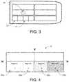
- FIG. 4is a schematic of a light source with four individually illuminated segments.
- FIGS. 5 and 6are top views of a vehicle with the vision system that illuminates individual regions rearward of the vehicle via a plurality of individually actuatable light source segments.
- a vehicle vision system and/or driver assist system and/or object detection system and/or alert systemoperates to capture images exterior of the vehicle and may process the captured image data to display images and to detect objects at or near the vehicle and in the predicted path of the vehicle, such as to assist a driver of the vehicle in maneuvering the vehicle in a rearward direction.
- the vision systemincludes an image processor or image processing system that is operable to receive image data from one or more cameras and provide an output to a display device for displaying images representative of the captured image data.
- the vision systemmay provide display, such as a rearview display or a top down or bird's eye or surround view display or the like.
- a vehicleincludes an imaging system or vision system that includes at least one rearward viewing imaging sensor or camera 14 ( FIGS. 2 and 3 ) that captures images exterior and rearward of the vehicle, with a rearward directed light 12 ( FIGS. 1 and 3 ) that provides illumination that encompasses at least part of the rearward field of view of the camera 14 .
- the camera 14includes a lens for focusing images at or onto an imaging array or imaging plane or imager of the camera.
- the vision systemincludes a control or electronic control unit (ECU) or processor that is operable to process image data captured by the camera 14 and that may detect objects or the like and/or provide displayed images at a display device for viewing by the driver of the vehicle.
- the data transfer or signal communication from the camera 14 to the ECUmay comprise any suitable data or communication link, such as a vehicle network bus or the like of the equipped vehicle.
- the vehicle control systemcan (semi-) autonomously control a vehicle entering and leaving a parking space.
- the control unit in the vehicleanalyzes the environmental data of several vehicle-sensors (e.g. camera, ultrasonic sensor, radar sensor and/or the like) and intervenes in the cross and length steering of the vehicle.
- vehicle-sensorse.g. camera, ultrasonic sensor, radar sensor and/or the like
- the imaging sensoris supported by an additional light source (reversing light when driving in reverse).
- highly reflective object reflectionsoff highly reflective objects or specularly reflective objects in the field of view of the camera
- the control system of the present inventionuses a control unit, an adaptive and segmented reversing light 12 , and an imaging sensor or camera 14 , and controls the components to provide optimal illumination for the specific driving situation.
- the cameracaptures image data and highly reflective objects (e.g., smooth or reflectant objects that result in specular reflection of light incident thereon) present in the field of view of the camera are detected by the camera 14 .
- the captured image datais communicated to the control unit/the reversing light, including intensity and location information.
- the reversing light 12comprises several individually controllable (and dimmable) segments or light sources 22 , 22 a - d (such as individual or groups of light emitting diodes), such as shown in FIGS. 3 and 4 .
- the individual segments 22 a - dwhen electrically powered, and such as shown in FIG. 5 , illuminate respective regions 32 a - d rearward of the vehicle.
- the controlresponsive to processing by an image processor of image data captured by the rearward viewing camera 14 and provided to the control, adjusts or controls the light source 12 to adjust (increase/decrease) the required or determined level of intensity at the concerned areas. For example, and such as shown in FIG. 5 , if a bright object is detected in region 32 c , the control may reduce the power or intensity of the illumination segment 22 c . Alternatively, if an object is detected but is not well illuminated (e.g., the object is a diffuse reflecting or partially light absorbing object), the system may increase the power or intensity of the respective illumination segment to enhance detection and/or identification or classification of the object.
- the informationis communicated via a bus-system of the vehicle. With this system it is possible to illuminate an area homogeneously.
- a glare/blinding effect from strongly reflecting objects (obstacles)is suppressed (by reducing the intensity of the light source segment 22 a - d that is illuminating that object) and an error free image recognition with very good contrast conditions is achieved.
- the light source 12may comprise a high definition light source comprising a plurality of individually operable light sources, for example, a plurality of light emitting diodes (LEDs), which preferably are arranged in rows and columns to form a matrix like arrangement of light sources, wherein a column of light sources corresponds to a respective one of the plurality of light segments 22 a - d .
- each light segment 22 a - dmay comprise three individual segments or LEDs, which, when individually powered, illuminate a respective region 32 aa - 32 dc rearward of the vehicle.
- each individual illuminated region 32 a - dto be divided into a plurality of sub-regions or sub-segments 32 aa - 32 dc .
- Each sub-segment 32 aa - 32 dc of the plurality of sub-segmentscan be illuminated individually by a corresponding light source of the light segments 22 a - d.
- FIG. 5shows four illuminated segments 32 a - d
- FIG. 6shows where each of the illuminated segments comprises three sub-segments (e.g., sub-segments 32 aa - 32 ac of segment 32 a ).
- the light sourcemay have a two dimensional array (having multiple rows and multiple columns of LEDs) of at least twelve LEDs or subsets of LEDs (i.e., each individually actuatable segment may comprise a single LED or a plurality of LEDs that are electrically powered and controlled together), with each LED or subset of LEDs illuminating (when electrically powered) a respective sub-region or sub-segment 32 aa - 32 dc of the area rearward of the vehicle.
- an objectmarked with “X”, is located in a middle sub-segment 32 cb of segment 32 c , wherein the corresponding LED (e.g., one of the three LEDs of segment 22 c ), which illuminates that sub-segment, can be operated to increase or decrease illumination of that sub-segment. If the object gets illuminated by the light source and the object is a highly reflective object, light can be reflected from the object towards the imager of the camera 14 and cause an overexposure of the imager.
- the corresponding LEDe.g., one of the three LEDs of segment 22 c
- the control of the vehicular vision systemis configured to decrease the illumination of a particular illuminated segment 32 a - d or sub-segment 32 aa - 32 dc , in which the highly reflective object is located, e.g. when the control determines that the illumination level at the highly reflective object is greater than an upper threshold level, by dimming the corresponding light source 22 a - d.
- the light source 12is preferably a reversing light or part of a reversing light for a vehicle.
- the camera 14is preferably a reversing camera for a vehicle.
- the control systemresponsive to detection, via image processing of captured image data, of a highly reflective object in a portion or region of the field of view of the camera 14 , controls intensity of light emitted by the respective light segment 22 a - d (that is illuminating the detected highly reflective object) to reduce illumination of the highly reflective object.
- the control systemresponsive to detection, via image processing of captured image data, of a low-illuminated object in a portion or region of the field of view of the camera 14 , e.g. when the control system determines that the illumination level at the low-illuminated object is less than a lower threshold level, controls intensity of light emitted by the respective light segment 22 a - d to increase illumination of the low-illuminated object.
- the systemthus adjusts the individual light segment or segments or individual LED or subset of LEDs when the determined intensity level of light or illumination at a detected object or region is above an upper threshold illumination level or below a lower threshold illumination level.
- the upper and lower threshold illumination levelsmay be set or preselected or may be dynamically adjusted, such as responsive to a determined ambient light level.
- the systemmay be responsive at least in part to an ambient light sensor of the vehicle or the system may determine an ambient lighting condition based on processing of image data captured by the camera.
- the camera's operating parametersmay adapt to the brighter overall scene, such that the upper threshold illumination level may be increased and the lower threshold illumination level may also be increased to accommodate the different camera settings.
- the camera's operating parametersmay adapt to the lower overall illumination of the scene, such that the lower threshold illumination level may be decreased and the upper threshold illumination level may also be decreased to accommodate the different camera settings.
- the systemmay determine an average illumination intensity over all of the sub-regions in the field of view of the camera and then may adjust the illumination intensity of one or more segments or sub-segments of the light source when the determined intensity of the sub-region where the detected object is located is greater than a threshold amount above the determined average illumination intensity level or less than a threshold amount below the determined average illumination intensity level.
- the systemautomatically adapts to bright or highly reflective detected objects or light absorbing or diffuse or low reflective detected objects so that the illumination is decreased at specular reflective objects and increased at diffuse reflective objects.
- the control systemcontrols intensity of the light emitted by each light segment 22 a - d during a reversing maneuver of the vehicle, such as a parking maneuver, where the control may control intensity of the light emitted by each light segment 22 a - d to provide enhanced detection of parking space markers during the parking maneuver.
- the controlmay increase intensity of light emitted by a particular light segment 22 a - d to enhance detection and identification of a respective parking space marker or may decrease intensity of light emitted by a particular light segment to enhance detection and identification of a respective parking space marker.
- the systemmay increase intensity of light emitted by a particular light segment 22 a - d to enhance detection and identification of a respective parking space marker, and may decrease intensity of light emitted by another particular light segment 22 a - d to enhance detection and identification of another respective parking space marker, depending on the lighting conditions and environment at which the vehicle is parking.
- the system of the present inventionmay provide optimal, homogeneous illumination of a scene even at dynamic lighting conditions or reflections.
- the systemthus limits or avoids overloading of the imager or imaging sensor 14 .
- the systemlimits or avoids errors in the image data processing or image analysis.
- the systemthus provides enhanced detection of objects and unambiguous detection of the (free) environment, such as during a reversing or parking maneuver of the vehicle.
Landscapes
- Engineering & Computer Science (AREA)
- Multimedia (AREA)
- Theoretical Computer Science (AREA)
- Physics & Mathematics (AREA)
- General Physics & Mathematics (AREA)
- Mechanical Engineering (AREA)
- Signal Processing (AREA)
- Computer Vision & Pattern Recognition (AREA)
- Artificial Intelligence (AREA)
- Automation & Control Theory (AREA)
- Transportation (AREA)
- Lighting Device Outwards From Vehicle And Optical Signal (AREA)
- Traffic Control Systems (AREA)
- Closed-Circuit Television Systems (AREA)
Abstract
Description
Claims (29)
Priority Applications (1)
| Application Number | Priority Date | Filing Date | Title |
|---|---|---|---|
| US16/693,523US11104279B2 (en) | 2018-11-26 | 2019-11-25 | Vehicle vision system with adaptive reversing light |
Applications Claiming Priority (2)
| Application Number | Priority Date | Filing Date | Title |
|---|---|---|---|
| US201862771258P | 2018-11-26 | 2018-11-26 | |
| US16/693,523US11104279B2 (en) | 2018-11-26 | 2019-11-25 | Vehicle vision system with adaptive reversing light |
Publications (2)
| Publication Number | Publication Date |
|---|---|
| US20200164814A1 US20200164814A1 (en) | 2020-05-28 |
| US11104279B2true US11104279B2 (en) | 2021-08-31 |
Family
ID=68835151
Family Applications (1)
| Application Number | Title | Priority Date | Filing Date |
|---|---|---|---|
| US16/693,523ActiveUS11104279B2 (en) | 2018-11-26 | 2019-11-25 | Vehicle vision system with adaptive reversing light |
Country Status (5)
| Country | Link |
|---|---|
| US (1) | US11104279B2 (en) |
| EP (1) | EP3888002B1 (en) |
| KR (1) | KR102549130B1 (en) |
| CN (1) | CN113272814B (en) |
| WO (1) | WO2020109237A1 (en) |
Cited By (1)
| Publication number | Priority date | Publication date | Assignee | Title |
|---|---|---|---|---|
| US11938960B1 (en)* | 2021-07-12 | 2024-03-26 | Amazon Technologies, Inc. | Systems and methods for controlling vehicles with navigation markers |
Families Citing this family (13)
| Publication number | Priority date | Publication date | Assignee | Title |
|---|---|---|---|---|
| FR3095276B1 (en) | 2019-04-18 | 2021-05-21 | Aptiv Tech Ltd | Motor vehicle object detection system |
| KR102220950B1 (en)* | 2019-07-31 | 2021-02-26 | 엘지전자 주식회사 | Method for controlling vehicle in autonomous driving system and apparatus thereof |
| CN112925351B (en)* | 2019-12-06 | 2022-08-02 | 杭州萤石软件有限公司 | A kind of visual machine light source control method and device |
| EP3876143A1 (en)* | 2020-03-02 | 2021-09-08 | ZKW Group GmbH | System for monitoring the environment around a motor vehicle |
| US11897512B2 (en)* | 2020-06-19 | 2024-02-13 | Ghost Autonomy Inc. | Modifying settings of autonomous vehicle sensors based on predicted environmental states |
| US11908195B2 (en)* | 2020-12-01 | 2024-02-20 | Devon Energy Corporation | Systems, methods, and computer program products for object detection and analysis of an image |
| US12028951B2 (en)* | 2021-09-03 | 2024-07-02 | GM Global Technology Operations LLC | Camera based adaptive brightness backup light system |
| DE102021131824B3 (en)* | 2021-12-02 | 2023-03-30 | Motherson Innovations Company Limited | Camera wing system, vehicle therewith and method of operation thereof |
| DE102021214455A1 (en) | 2021-12-15 | 2023-06-15 | Volkswagen Aktiengesellschaft | Driver assistance system for a motor vehicle and method for controlling a driver assistance system |
| KR20230123226A (en)* | 2022-02-16 | 2023-08-23 | 한화비전 주식회사 | Noise Reduction of Surveillance Camera Image Using Object Detection Based on Artificial Intelligence |
| US12012033B2 (en)* | 2022-05-27 | 2024-06-18 | Toyota Motor Engineering & Manufacturing North America, Inc. | Systems and methods for improving backup lighting visibility |
| CN118596982B (en)* | 2023-12-25 | 2025-05-20 | 深圳引望智能技术有限公司 | Car light system, car light and vehicle |
| US20250242750A1 (en)* | 2024-01-28 | 2025-07-31 | Ross Blankenship100 | Vehicular backup safety system |
Citations (34)
| Publication number | Priority date | Publication date | Assignee | Title |
|---|---|---|---|---|
| US4706168A (en)* | 1985-11-15 | 1987-11-10 | View Engineering, Inc. | Systems and methods for illuminating objects for vision systems |
| US5550677A (en) | 1993-02-26 | 1996-08-27 | Donnelly Corporation | Automatic rearview mirror system using a photosensor array |
| US5670935A (en) | 1993-02-26 | 1997-09-23 | Donnelly Corporation | Rearview vision system for vehicle including panoramic view |
| EP1515293A1 (en) | 2003-09-11 | 2005-03-16 | Valeo Vision | Obstacle detection device comprising a stereoscopic imaging system including two optical sensors |
| DE102005055087A1 (en) | 2005-11-18 | 2007-05-24 | Robert Bosch Gmbh | Headlamp module with integrated light rain sensor |
| EP1876829A1 (en) | 2005-04-28 | 2008-01-09 | Aisin Seiki Kabushiki Kaisha | Vehicle vicinity monitoring system |
| US20090097038A1 (en)* | 2007-10-16 | 2009-04-16 | Higgins-Luthman Michael J | Machine Vision for Predictive Suspension |
| US7914187B2 (en) | 2007-07-12 | 2011-03-29 | Magna Electronics Inc. | Automatic lighting system with adaptive alignment function |
| US20110211359A1 (en)* | 2010-02-26 | 2011-09-01 | National Taipei University Of Technology | Road-adaptive headlight for motorcycles |
| US8162518B2 (en) | 2006-08-11 | 2012-04-24 | Donnelly Corporation | Adaptive forward lighting system for vehicle |
| US20130049599A1 (en)* | 2011-08-26 | 2013-02-28 | Infineon Technologies Ag | Driver Circuit for Efficiently Driving a Large Number of LEDs |
| US20130201324A1 (en)* | 2012-02-02 | 2013-08-08 | Xerox Corporation | Automated running-engine detection in stationary motor vehicles |
| DE102012004817A1 (en) | 2012-03-08 | 2013-09-12 | GM Global Technology Operations LLC (n. d. Ges. d. Staates Delaware) | Headlight system for motor car, has camera for scanning image for predetermined pattern, where intensities of partial beams illuminating portion of image are reduced if predetermined pattern is found in portion of image |
| US20140081441A1 (en)* | 2011-11-18 | 2014-03-20 | Nike, Inc. | Generation Of Tool Paths For Shoe Assembly |
| US8764256B2 (en) | 2010-10-01 | 2014-07-01 | Magna Mirrors Of America, Inc. | Vehicle exterior mirror system with light module |
| US20150042806A1 (en)* | 2013-08-12 | 2015-02-12 | Magna Electronics Inc. | Vehicle vision system with reduction of temporal noise in images |
| US20150172527A1 (en)* | 2009-01-30 | 2015-06-18 | Magna Electronics Inc. | Vehicular imaging system with controlled illumination device and camera |
| US20150181100A1 (en)* | 2010-03-01 | 2015-06-25 | Eyefluence, Inc. | Systems and methods for spatially controlled scene illumination |
| US20160163302A1 (en)* | 2013-07-02 | 2016-06-09 | Koninklijke Philips N.V. | System comprising a sound attenuating panel |
| US20160311374A1 (en) | 2015-04-21 | 2016-10-27 | Magna Electronics Inc. | Vehicle vision system with overlay calibration |
| US20170017848A1 (en)* | 2015-07-17 | 2017-01-19 | Magna Electronics Inc. | Vehicle parking assist system with vision-based parking space detection |
| WO2017019725A1 (en) | 2015-07-28 | 2017-02-02 | Wenasont Dynamics Llc | System and method for light and image projection |
| US20170212226A1 (en)* | 2014-05-23 | 2017-07-27 | Philips Lighting Holding B.V. | Object detection system and method |
| US20170217367A1 (en) | 2016-02-01 | 2017-08-03 | Magna Electronics Inc. | Vehicle adaptive lighting system |
| US20170309159A1 (en)* | 2016-04-26 | 2017-10-26 | John Pimentel | Vehicle emergency system |
| US20170329332A1 (en)* | 2016-05-10 | 2017-11-16 | Uber Technologies, Inc. | Control system to adjust operation of an autonomous vehicle based on a probability of interference by a dynamic object |
| US20180022266A1 (en) | 2016-07-19 | 2018-01-25 | Kaistar Lighting (Xiamen) Co., Ltd. | Vehicle headlight device and vehicle |
| US9896022B1 (en)* | 2015-04-20 | 2018-02-20 | Ambarella, Inc. | Automatic beam-shaping using an on-car camera system |
| US20180113200A1 (en)* | 2016-09-20 | 2018-04-26 | Innoviz Technologies Ltd. | Variable flux allocation within a lidar fov to improve detection in a region |
| EP3388814A2 (en) | 2017-04-10 | 2018-10-17 | LG Electronics Inc. | Vehicle control method |
| US20190001868A1 (en)* | 2017-06-30 | 2019-01-03 | Mazda Motor Corporation | Vehicle headlight and light distribution control device of vehicle headlight |
| US10247941B2 (en)* | 2015-01-19 | 2019-04-02 | Magna Electronics Inc. | Vehicle vision system with light field monitor |
| US20190128497A1 (en)* | 2017-10-26 | 2019-05-02 | Osram Sylvania Inc. | Integrated automotive adaptive driving beam headlamp and calibration method |
| US10576896B2 (en) | 2010-10-01 | 2020-03-03 | Magna Mirrors Of America, Inc. | Vehicle exterior mirror system with light module |
Family Cites Families (7)
| Publication number | Priority date | Publication date | Assignee | Title |
|---|---|---|---|---|
| US7156542B2 (en)* | 2002-12-13 | 2007-01-02 | Ford Global Technologies, Llc | Vehicle headlight system having digital beam-forming optics |
| JP2006290273A (en)* | 2005-04-14 | 2006-10-26 | Nissan Motor Co Ltd | Vehicle perimeter monitoring device |
| DE102011081357A1 (en)* | 2011-08-23 | 2013-02-28 | Robert Bosch Gmbh | Method and device for controlling a headlamp of a vehicle |
| DE102014221647A1 (en)* | 2014-10-24 | 2016-04-28 | Ford Global Technologies, Llc | Vehicle headlamp system with adaptive light distribution |
| US10331956B2 (en)* | 2015-09-23 | 2019-06-25 | Magna Electronics Inc. | Vehicle vision system with detection enhancement using light control |
| US10875403B2 (en)* | 2015-10-27 | 2020-12-29 | Magna Electronics Inc. | Vehicle vision system with enhanced night vision |
| US20180324367A1 (en)* | 2017-05-03 | 2018-11-08 | Ford Global Technologies, Llc | Using nir illuminators to improve vehicle camera performance in low light scenarios |
- 2019
- 2019-11-25KRKR1020217016982Apatent/KR102549130B1/enactiveActive
- 2019-11-25EPEP19817163.9Apatent/EP3888002B1/enactiveActive
- 2019-11-25USUS16/693,523patent/US11104279B2/enactiveActive
- 2019-11-25WOPCT/EP2019/082439patent/WO2020109237A1/ennot_activeCeased
- 2019-11-25CNCN201980077529.4Apatent/CN113272814B/enactiveActive
Patent Citations (37)
| Publication number | Priority date | Publication date | Assignee | Title |
|---|---|---|---|---|
| US4706168A (en)* | 1985-11-15 | 1987-11-10 | View Engineering, Inc. | Systems and methods for illuminating objects for vision systems |
| US5550677A (en) | 1993-02-26 | 1996-08-27 | Donnelly Corporation | Automatic rearview mirror system using a photosensor array |
| US5670935A (en) | 1993-02-26 | 1997-09-23 | Donnelly Corporation | Rearview vision system for vehicle including panoramic view |
| US5949331A (en) | 1993-02-26 | 1999-09-07 | Donnelly Corporation | Display enhancements for vehicle vision system |
| EP1515293A1 (en) | 2003-09-11 | 2005-03-16 | Valeo Vision | Obstacle detection device comprising a stereoscopic imaging system including two optical sensors |
| EP1876829A1 (en) | 2005-04-28 | 2008-01-09 | Aisin Seiki Kabushiki Kaisha | Vehicle vicinity monitoring system |
| DE102005055087A1 (en) | 2005-11-18 | 2007-05-24 | Robert Bosch Gmbh | Headlamp module with integrated light rain sensor |
| US8162518B2 (en) | 2006-08-11 | 2012-04-24 | Donnelly Corporation | Adaptive forward lighting system for vehicle |
| US7914187B2 (en) | 2007-07-12 | 2011-03-29 | Magna Electronics Inc. | Automatic lighting system with adaptive alignment function |
| US20090097038A1 (en)* | 2007-10-16 | 2009-04-16 | Higgins-Luthman Michael J | Machine Vision for Predictive Suspension |
| US20150172527A1 (en)* | 2009-01-30 | 2015-06-18 | Magna Electronics Inc. | Vehicular imaging system with controlled illumination device and camera |
| US10075650B2 (en)* | 2009-01-30 | 2018-09-11 | Magna Electronics Inc. | Vehicular imaging system with controlled illumination device and camera |
| US20110211359A1 (en)* | 2010-02-26 | 2011-09-01 | National Taipei University Of Technology | Road-adaptive headlight for motorcycles |
| US20150181100A1 (en)* | 2010-03-01 | 2015-06-25 | Eyefluence, Inc. | Systems and methods for spatially controlled scene illumination |
| US8764256B2 (en) | 2010-10-01 | 2014-07-01 | Magna Mirrors Of America, Inc. | Vehicle exterior mirror system with light module |
| US10576896B2 (en) | 2010-10-01 | 2020-03-03 | Magna Mirrors Of America, Inc. | Vehicle exterior mirror system with light module |
| US20130049599A1 (en)* | 2011-08-26 | 2013-02-28 | Infineon Technologies Ag | Driver Circuit for Efficiently Driving a Large Number of LEDs |
| US20140081441A1 (en)* | 2011-11-18 | 2014-03-20 | Nike, Inc. | Generation Of Tool Paths For Shoe Assembly |
| US20130201324A1 (en)* | 2012-02-02 | 2013-08-08 | Xerox Corporation | Automated running-engine detection in stationary motor vehicles |
| DE102012004817A1 (en) | 2012-03-08 | 2013-09-12 | GM Global Technology Operations LLC (n. d. Ges. d. Staates Delaware) | Headlight system for motor car, has camera for scanning image for predetermined pattern, where intensities of partial beams illuminating portion of image are reduced if predetermined pattern is found in portion of image |
| US20160163302A1 (en)* | 2013-07-02 | 2016-06-09 | Koninklijke Philips N.V. | System comprising a sound attenuating panel |
| US20150042806A1 (en)* | 2013-08-12 | 2015-02-12 | Magna Electronics Inc. | Vehicle vision system with reduction of temporal noise in images |
| US10326969B2 (en)* | 2013-08-12 | 2019-06-18 | Magna Electronics Inc. | Vehicle vision system with reduction of temporal noise in images |
| US20170212226A1 (en)* | 2014-05-23 | 2017-07-27 | Philips Lighting Holding B.V. | Object detection system and method |
| US10247941B2 (en)* | 2015-01-19 | 2019-04-02 | Magna Electronics Inc. | Vehicle vision system with light field monitor |
| US9896022B1 (en)* | 2015-04-20 | 2018-02-20 | Ambarella, Inc. | Automatic beam-shaping using an on-car camera system |
| US20160311374A1 (en) | 2015-04-21 | 2016-10-27 | Magna Electronics Inc. | Vehicle vision system with overlay calibration |
| US20170017848A1 (en)* | 2015-07-17 | 2017-01-19 | Magna Electronics Inc. | Vehicle parking assist system with vision-based parking space detection |
| WO2017019725A1 (en) | 2015-07-28 | 2017-02-02 | Wenasont Dynamics Llc | System and method for light and image projection |
| US20170217367A1 (en) | 2016-02-01 | 2017-08-03 | Magna Electronics Inc. | Vehicle adaptive lighting system |
| US20170309159A1 (en)* | 2016-04-26 | 2017-10-26 | John Pimentel | Vehicle emergency system |
| US20170329332A1 (en)* | 2016-05-10 | 2017-11-16 | Uber Technologies, Inc. | Control system to adjust operation of an autonomous vehicle based on a probability of interference by a dynamic object |
| US20180022266A1 (en) | 2016-07-19 | 2018-01-25 | Kaistar Lighting (Xiamen) Co., Ltd. | Vehicle headlight device and vehicle |
| US20180113200A1 (en)* | 2016-09-20 | 2018-04-26 | Innoviz Technologies Ltd. | Variable flux allocation within a lidar fov to improve detection in a region |
| EP3388814A2 (en) | 2017-04-10 | 2018-10-17 | LG Electronics Inc. | Vehicle control method |
| US20190001868A1 (en)* | 2017-06-30 | 2019-01-03 | Mazda Motor Corporation | Vehicle headlight and light distribution control device of vehicle headlight |
| US20190128497A1 (en)* | 2017-10-26 | 2019-05-02 | Osram Sylvania Inc. | Integrated automotive adaptive driving beam headlamp and calibration method |
Non-Patent Citations (1)
| Title |
|---|
| International Search Report and Written Opinion dated Jun. 4, 2020 from corresponding PCT Application No. PCT/EP2019/082439. |
Cited By (1)
| Publication number | Priority date | Publication date | Assignee | Title |
|---|---|---|---|---|
| US11938960B1 (en)* | 2021-07-12 | 2024-03-26 | Amazon Technologies, Inc. | Systems and methods for controlling vehicles with navigation markers |
Also Published As
| Publication number | Publication date |
|---|---|
| EP3888002B1 (en) | 2024-05-08 |
| KR102549130B1 (en) | 2023-07-03 |
| US20200164814A1 (en) | 2020-05-28 |
| EP3888002A1 (en) | 2021-10-06 |
| KR20210077774A (en) | 2021-06-25 |
| CN113272814A (en) | 2021-08-17 |
| CN113272814B (en) | 2024-12-17 |
| WO2020109237A1 (en) | 2020-06-04 |
Similar Documents
| Publication | Publication Date | Title |
|---|---|---|
| US11104279B2 (en) | Vehicle vision system with adaptive reversing light | |
| US11240427B2 (en) | Vehicular vision system with infrared emitter synchronization | |
| US12046053B2 (en) | Vehicular driver monitoring system | |
| US20230150447A1 (en) | Vehicular vision system with underbody camera | |
| US10257432B2 (en) | Method for enhancing vehicle camera image quality | |
| US9800794B2 (en) | Vehicle vision system with enhanced low light capabilities | |
| US10682966B2 (en) | Vehicle light/display control system using camera | |
| US20230117346A1 (en) | System for Monitoring the Surround of a Motor Vehicle | |
| US11721033B2 (en) | Object detection apparatus and method for vehicle | |
| US20070069135A1 (en) | Method and device for controlling a radiation source | |
| JP6555569B2 (en) | Image processing apparatus, mobile device control system, and image processing program | |
| US20250054314A1 (en) | Camera monitoring (CMS) system for a vehicle, method of controlling the camera monitoring (CMS) system, and vehicle | |
| JPWO2019044434A1 (en) | Object detection system | |
| EP3971769A1 (en) | Preprocessing method for improving image recognition | |
| JP6701542B2 (en) | Detection device, mobile device control system, and detection program | |
| US12028621B2 (en) | Object detection system for a motor vehicle | |
| JP3929420B2 (en) | Vehicle light amount detection device and vehicle illumination control device |
Legal Events
| Date | Code | Title | Description |
|---|---|---|---|
| AS | Assignment | Owner name:MAGNA ELECTRONICS SOLUTIONS GMBH, GERMANY Free format text:ASSIGNMENT OF ASSIGNORS INTEREST;ASSIGNORS:SOLAR, MARTIN;GRAF, STEFAN;BAKER, JULIAN;AND OTHERS;SIGNING DATES FROM 20191016 TO 20191108;REEL/FRAME:051101/0418 Owner name:ZKW GROUP GMBH, AUSTRIA Free format text:ASSIGNMENT OF ASSIGNORS INTEREST;ASSIGNORS:SOLAR, MARTIN;GRAF, STEFAN;BAKER, JULIAN;AND OTHERS;SIGNING DATES FROM 20191016 TO 20191108;REEL/FRAME:051101/0418 Owner name:MAGNA ELECTRONICS EUROPE GMBH & CO. OHG, GERMANY Free format text:ASSIGNMENT OF ASSIGNORS INTEREST;ASSIGNORS:SOLAR, MARTIN;GRAF, STEFAN;BAKER, JULIAN;AND OTHERS;SIGNING DATES FROM 20191016 TO 20191108;REEL/FRAME:051101/0418 | |
| FEPP | Fee payment procedure | Free format text:ENTITY STATUS SET TO UNDISCOUNTED (ORIGINAL EVENT CODE: BIG.); ENTITY STATUS OF PATENT OWNER: LARGE ENTITY | |
| STPP | Information on status: patent application and granting procedure in general | Free format text:RESPONSE TO NON-FINAL OFFICE ACTION ENTERED AND FORWARDED TO EXAMINER | |
| STPP | Information on status: patent application and granting procedure in general | Free format text:NOTICE OF ALLOWANCE MAILED -- APPLICATION RECEIVED IN OFFICE OF PUBLICATIONS | |
| STPP | Information on status: patent application and granting procedure in general | Free format text:AWAITING TC RESP., ISSUE FEE NOT PAID | |
| STPP | Information on status: patent application and granting procedure in general | Free format text:NOTICE OF ALLOWANCE MAILED -- APPLICATION RECEIVED IN OFFICE OF PUBLICATIONS | |
| STCF | Information on status: patent grant | Free format text:PATENTED CASE | |
| AS | Assignment | Owner name:MAGNA AUTOMOTIVE HOLDING (GERMANY) GMBH, GERMANY Free format text:CHANGE OF NAME;ASSIGNOR:MAGNA ELECTRONICS SOLUTIONS GMBH;REEL/FRAME:069334/0595 Effective date:20211020 | |
| MAFP | Maintenance fee payment | Free format text:PAYMENT OF MAINTENANCE FEE, 4TH YEAR, LARGE ENTITY (ORIGINAL EVENT CODE: M1551); ENTITY STATUS OF PATENT OWNER: LARGE ENTITY Year of fee payment:4 |