US11103717B2 - Wearable cardioverter defibrillator (WCD) system reacting to high-frequency ECG noise - Google Patents
Wearable cardioverter defibrillator (WCD) system reacting to high-frequency ECG noiseDownload PDFInfo
- Publication number
- US11103717B2 US11103717B2US16/037,990US201816037990AUS11103717B2US 11103717 B2US11103717 B2US 11103717B2US 201816037990 AUS201816037990 AUS 201816037990AUS 11103717 B2US11103717 B2US 11103717B2
- Authority
- US
- United States
- Prior art keywords
- ecg
- patient
- segment
- shock
- noise
- Prior art date
- Legal status (The legal status is an assumption and is not a legal conclusion. Google has not performed a legal analysis and makes no representation as to the accuracy of the status listed.)
- Active, expires
Links
Images


Classifications
- A—HUMAN NECESSITIES
- A61—MEDICAL OR VETERINARY SCIENCE; HYGIENE
- A61N—ELECTROTHERAPY; MAGNETOTHERAPY; RADIATION THERAPY; ULTRASOUND THERAPY
- A61N1/00—Electrotherapy; Circuits therefor
- A61N1/18—Applying electric currents by contact electrodes
- A61N1/32—Applying electric currents by contact electrodes alternating or intermittent currents
- A61N1/38—Applying electric currents by contact electrodes alternating or intermittent currents for producing shock effects
- A61N1/39—Heart defibrillators
- A61N1/3904—External heart defibrillators [EHD]
- A—HUMAN NECESSITIES
- A61—MEDICAL OR VETERINARY SCIENCE; HYGIENE
- A61N—ELECTROTHERAPY; MAGNETOTHERAPY; RADIATION THERAPY; ULTRASOUND THERAPY
- A61N1/00—Electrotherapy; Circuits therefor
- A61N1/02—Details
- A61N1/04—Electrodes
- A61N1/0404—Electrodes for external use
- A61N1/0472—Structure-related aspects
- A61N1/0484—Garment electrodes worn by the patient
- A—HUMAN NECESSITIES
- A61—MEDICAL OR VETERINARY SCIENCE; HYGIENE
- A61N—ELECTROTHERAPY; MAGNETOTHERAPY; RADIATION THERAPY; ULTRASOUND THERAPY
- A61N1/00—Electrotherapy; Circuits therefor
- A61N1/18—Applying electric currents by contact electrodes
- A61N1/32—Applying electric currents by contact electrodes alternating or intermittent currents
- A61N1/38—Applying electric currents by contact electrodes alternating or intermittent currents for producing shock effects
- A61N1/39—Heart defibrillators
- A61N1/3975—Power supply
- A—HUMAN NECESSITIES
- A61—MEDICAL OR VETERINARY SCIENCE; HYGIENE
- A61N—ELECTROTHERAPY; MAGNETOTHERAPY; RADIATION THERAPY; ULTRASOUND THERAPY
- A61N1/00—Electrotherapy; Circuits therefor
- A61N1/18—Applying electric currents by contact electrodes
- A61N1/32—Applying electric currents by contact electrodes alternating or intermittent currents
- A61N1/38—Applying electric currents by contact electrodes alternating or intermittent currents for producing shock effects
- A61N1/39—Heart defibrillators
- A61N1/3987—Heart defibrillators characterised by the timing or triggering of the shock
- A—HUMAN NECESSITIES
- A61—MEDICAL OR VETERINARY SCIENCE; HYGIENE
- A61N—ELECTROTHERAPY; MAGNETOTHERAPY; RADIATION THERAPY; ULTRASOUND THERAPY
- A61N1/00—Electrotherapy; Circuits therefor
- A61N1/18—Applying electric currents by contact electrodes
- A61N1/32—Applying electric currents by contact electrodes alternating or intermittent currents
- A61N1/38—Applying electric currents by contact electrodes alternating or intermittent currents for producing shock effects
- A61N1/39—Heart defibrillators
- A61N1/3993—User interfaces for automatic external defibrillators
- A—HUMAN NECESSITIES
- A61—MEDICAL OR VETERINARY SCIENCE; HYGIENE
- A61B—DIAGNOSIS; SURGERY; IDENTIFICATION
- A61B5/00—Measuring for diagnostic purposes; Identification of persons
- A61B5/24—Detecting, measuring or recording bioelectric or biomagnetic signals of the body or parts thereof
- A61B5/316—Modalities, i.e. specific diagnostic methods
- A61B5/318—Heart-related electrical modalities, e.g. electrocardiography [ECG]
- A61B5/346—Analysis of electrocardiograms
- A61B5/349—Detecting specific parameters of the electrocardiograph cycle
- A61B5/352—Detecting R peaks, e.g. for synchronising diagnostic apparatus; Estimating R-R interval
- A—HUMAN NECESSITIES
- A61—MEDICAL OR VETERINARY SCIENCE; HYGIENE
- A61B—DIAGNOSIS; SURGERY; IDENTIFICATION
- A61B5/00—Measuring for diagnostic purposes; Identification of persons
- A61B5/72—Signal processing specially adapted for physiological signals or for diagnostic purposes
- A61B5/7203—Signal processing specially adapted for physiological signals or for diagnostic purposes for noise prevention, reduction or removal
Definitions
- SCASudden Cardiac Arrest
- ICDImplantable Cardioverter Defibrillator
- a WCD systemtypically includes a harness, vest, or other garment that the patient is to wear.
- the WCD systemfurther includes electronic components, such as a defibrillator and electrodes, coupled to the harness, vest, or other garment.
- the external electrodesmay then make good electrical contact with the patient's skin, and therefore can help sense the patient's ECG. If a shockable heart arrhythmia is detected, then the defibrillator delivers the appropriate electric shock through the patient's body, and thus through the heart.
- the patient's ECGincludes electrical noise, which can be created at the interface of the electrodes with the patient's skin. Such noise can make it difficult to diagnose the patient's condition accurately from the ECG, and detect whether or not the patient is having a shockable arrhythmia.
- WCDwearable cardioverter defibrillator
- a WCD systemis worn and/or carried by an ambulatory patient.
- the WCD systemanalyzes an ECG signal of the patient, to determine whether or not the patient should be given an electric shock to restart their heart. If the WCD system determines that such a shock should be given, then it also determines whether or not a High Frequency (H-F) noise criterion is met by the ECG signal. If that H-F noise criterion is not met, the patient can be shocked. If, however, that H-F noise criterion is met, then the WCD system can confirm before shocking, by sensing another portion of the ECG signal, analyzing again, and so on.
- H-FHigh Frequency
- An advantage of embodimentsis that, thanks to the confirmation before shocking, the possibility is diminished that the ECG signal will indicate that a shock is needed falsely, due to H-F noise. Furthermore, since the patient is alerted by an alarm before shocking, the incidence of false alarms can be diminished, and the patient may be more compliant in actually wearing and/or carrying the WCD system.
- FIG. 1is a diagram of components of a sample wearable cardioverter defibrillator (WCD) system, made according to embodiments.
- WCDwearable cardioverter defibrillator
- FIG. 2is a diagram showing sample components of an external defibrillator, such as the one belonging in the system of FIG. 1 , and which is made according to embodiments.
- FIG. 3Ais a diagram of selected components for illustrating how an ECG signal sensed by a pair of electrodes may be processed according to embodiments to yield a heart rate and other information.
- FIG. 3Bis a conceptual diagram for illustrating examples of how a first ECG signal may be used for a heart rate computation even if it includes noise events, while a second ECG signal may be used for performing an analysis and/or confirming a shock decision according to embodiments.
- FIG. 4is a conceptual diagram for illustrating sample possible determinations made about the patient from portions of the patient's ECG signal according to embodiments.
- FIG. 5is a conceptual diagram for illustrating other sample possible determinations made about the patient from portions of the patient's ECG signal according to additional embodiments.
- FIG. 6is a flowchart for illustrating sample methods according to embodiments.
- FIG. 7shows sample time diagrams for illustrating an example of how a patient's ECG signal may be segmented and for how a patient's heart rate may be computed according to embodiments.
- FIG. 8shows sample time diagrams for illustrating how a patient's detected ECG signal may be segmented for detecting noise events according to embodiments.
- FIG. 9shows sample time diagrams for illustrating possible determinations about whether or not a segment noise criterion is met in individual ECG segments according to embodiments.
- FIG. 10shows sample time diagrams for illustrating other possible determinations about whether or not a segment noise criterion is met in individual ECG segments according to embodiments.
- WCDwearable cardioverter defibrillator
- a wearable cardioverter defibrillator (WCD) systemmade according to embodiments has a number of components. These components can be provided separately as modules that can be interconnected, or can be combined with other components, etc.
- FIG. 1depicts a patient 82 .
- Patient 82may also be referred to as a person and/or wearer, since the patient is wearing components of the WCD system.
- Patient 82is ambulatory, which means patient 82 can walk around, and is not necessarily bed-ridden.
- FIG. 1also depicts components of a WCD system made according to embodiments.
- One such componentis a support structure 170 that is wearable by patient 82 .
- support structure 170is shown only generically in FIG. 1 , and in fact partly conceptually.
- FIG. 1is provided merely to illustrate concepts about support structure 170 , and is not to be construed as limiting how support structure 170 is implemented, or how it is worn.
- Support structure 170can be implemented in many different ways. For example, it can be implemented in a single component or a combination of multiple components.
- support structure 170could include a vest, a half-vest, a garment, etc. In such embodiments such items can be worn similarly to parallel articles of clothing.
- support structure 170could include a harness, one or more belts or straps, etc. In such embodiments, such items can be worn by the patient around the torso, hips, over the shoulder, etc.
- support structure 170can include a container or housing, which can even be waterproof. In such embodiments, the support structure can be worn by being attached to the patient by adhesive material, for example as shown in U.S. Pat. No. 8,024,037.
- Support structure 170can even be implemented as described for the support structure of US Pat. App. No. US2017/0056682, which is incorporated herein by reference.
- additional components of the WCD systemcan be in the housing of a support structure instead of being attached externally to the support structure, for example as described in the US2017/0056682 document. There can be other examples.
- a WCD systemis configured to defibrillate a patient who is wearing it, by delivering an electrical charge to the patient's body in the form of an electric shock delivered in one or more pulses.
- FIG. 1shows a sample external defibrillator 100 , and sample defibrillation electrodes 104 , 108 , which are coupled to external defibrillator 100 via electrode leads 105 .
- Defibrillator 100 and defibrillation electrodes 104 , 108can be coupled to support structure 170 . As such, many of the components of defibrillator 100 could be therefore coupled to support structure 170 .
- defibrillator 100can administer, via electrodes 104 , 108 , a brief, strong electric pulse 111 through the body.
- Pulse 111is also known as shock, defibrillation shock, therapy and therapy shock. Pulse 111 is intended to go through and restart heart 85 , in an effort to save the life of patient 82 . Pulse 111 can further include one or more pacing pulses, and so on.
- a prior art defibrillatortypically decides whether to defibrillate or not based on an ECG signal of the patient.
- external defibrillator 100may initiate defibrillation (or hold-off defibrillation) based on a variety of inputs, with ECG merely being one of them.
- signalssuch as physiological signals containing physiological data can be obtained from patient 82 .
- patientmay be considered also a “user” of the WCD system, this is not a requirement. That is, for example, a user of the wearable cardioverter defibrillator (WCD) may include a clinician such as a doctor, nurse, emergency medical technician (EMT) or other similarly situated individual (or group of individuals).
- EMTemergency medical technician
- the WCD systemmay optionally include an outside monitoring device 180 .
- Device 180is called an “outside” device because it could be provided as a standalone device, for example not within the housing of defibrillator 100 .
- Device 180can be configured to sense or monitor at least one local parameter.
- a local parametercan be a parameter of patient 82 , or a parameter of the WCD system, or a parameter of the environment, as will be described later in this document.
- Device 180may include one or more transducers or sensors that are configured to render one or more physiological inputs or signals from one or more patient parameters that they sense.
- device 180is physically coupled to support structure 170 .
- device 180can be communicatively coupled with other components, which are coupled to support structure 170 .
- Such communicationcan be implemented by a communication module, as will be deemed applicable by a person skilled in the art in view of this description.
- FIG. 2is a diagram showing components of an external defibrillator 200 , made according to embodiments. These components can be, for example, included in external defibrillator 100 of FIG. 1 .
- the components shown in FIG. 2can be provided in a housing 201 , which may also be referred to as casing 201 .
- External defibrillator 200is intended for a patient who would be wearing it, such as patient 82 of FIG. 1 .
- Defibrillator 200may further include a user interface 280 for a user 282 .
- User 282can be patient 82 , also known as wearer 82 .
- user 282can be a local rescuer at the scene, such as a bystander who might offer assistance, or a trained person.
- user 282might be a remotely located trained caregiver in communication with the WCD system.
- User interface 280can be made in a number of ways.
- User interface 280may include output devices, which can be visual, audible or tactile, for communicating to a user by outputting images, sounds or vibrations. Images, sounds, vibrations, and anything that can be perceived by user 282 can also be called human-perceptible indications.
- output devicesThere are many examples of output devices.
- an output devicecan be a light, or a screen to display what is sensed, detected and/or measured, and provide visual feedback to rescuer 282 for their resuscitation attempts, and so on.
- Another output devicecan be a speaker, which can be configured to issue voice prompts, beeps, loud alarm sounds and/or words to warn bystanders, etc.
- User interface 280may further include input devices for receiving inputs from users. Such input devices may additionally include various controls, such as pushbuttons, keyboards, touchscreens, one or more microphones, and so on.
- An input devicecan be a cancel switch, which is sometimes called an “I am alive” switch or “live man” switch. In some embodiments, actuating the cancel switch can prevent the impending delivery of a shock.
- Defibrillator 200may include an internal monitoring device 281 .
- Device 281is called an “internal” device because it is incorporated within housing 201 .
- Monitoring device 281can sense or monitor patient parameters such as patient physiological parameters, system parameters and/or environmental parameters, all of which can be called patient data.
- internal monitoring device 281can be complementary or an alternative to outside monitoring device 180 of FIG. 1 . Allocating which of the parameters are to be monitored by which of monitoring devices 180 , 281 can be done according to design considerations.
- Device 281may include one or more transducers or sensors that are configured to render one or more physiological inputs from one or more patient parameters that it senses.
- Patient parametersmay include patient physiological parameters.
- Patient physiological parametersmay include, for example and without limitation, those physiological parameters that can be of any help in detecting by the wearable defibrillation system whether the patient is in need of a shock, plus optionally their medical history and/or event history. Examples of such parameters include the patient's ECG, blood oxygen level, blood flow, blood pressure, blood perfusion, pulsatile change in light transmission or reflection properties of perfused tissue, heart sounds, heart wall motion, breathing sounds and pulse.
- monitoring devices 180 , 281may include one or more sensors configured to acquire patient physiological signals. Examples of such sensors or transducers include electrodes to detect ECG data, a perfusion sensor, a pulse oximeter, a device for detecting blood flow (e.g.
- a Doppler devicea sensor for detecting blood pressure (e.g. a cuff), an optical sensor, illumination detectors and sensors perhaps working together with light sources for detecting color change in tissue, a motion sensor, a device that can detect heart wall movement, a sound sensor, a device with a microphone, an SpO 2 sensor, and so on.
- sensorscan help detect the patient's pulse, and can therefore also be called pulse detection sensors, pulse sensors, and pulse rate sensors.
- Pulse detectionis also taught at least in Physio-Control's U.S. Pat. No. 8,135,462, which is hereby incorporated by reference in its entirety.
- the transducerincludes an appropriate sensor, and the physiological input is a measurement by the sensor of that patient parameter.
- the appropriate sensor for a heart soundmay include a microphone, etc.
- the local parameteris a trend that can be detected in a monitored physiological parameter of patient 282 .
- a trendcan be detected by comparing values of parameters at different times.
- Parameters whose detected trends can particularly help a cardiac rehabilitation programinclude: a) cardiac function (e.g. ejection fraction, stroke volume, cardiac output, etc.); b) heart rate variability at rest or during exercise; c) heart rate profile during exercise and measurement of activity vigor, such as from the profile of an accelerometer signal and informed from adaptive rate pacemaker technology; d) heart rate trending; e) perfusion, such as from SpO 2 or CO 2 ; f) respiratory function, respiratory rate, etc.; g) motion, level of activity; and so on.
- cardiac functione.g. ejection fraction, stroke volume, cardiac output, etc.
- c) heart rate profile during exercise and measurement of activity vigorsuch as from the profile of an accelerometer signal and informed from adaptive rate pacemaker technology
- dheart
- Patient state parametersinclude recorded aspects of patient 282 , such as motion, posture, whether they have spoken recently plus maybe also what they said, and so on, plus optionally the history of these parameters.
- one of these monitoring devicescould include a location sensor such as a Global Positioning System (GPS) location sensor. Such a sensor can detect the location, plus a speed can be detected as a rate of change of location over time.
- GPSGlobal Positioning System
- Many motion detectorsoutput a motion signal that is indicative of the motion of the detector, and thus of the patient's body.
- Patient state parameterscan be very helpful in narrowing down the determination of whether SCA is indeed taking place.
- a WCD system made according to embodimentsmay include a motion detector.
- a motion detectorcan be implemented within monitoring device 180 or monitoring device 281 .
- Such a motion detectorcan be made in many ways as is known in the art, for example by using an accelerometer.
- a motion detector 287is implemented within monitoring device 281 .
- a motion detector of a WCD systemcan be configured to detect a motion event.
- the motion detectormay render or generate, from the detected motion event or motion, a motion detection input that can be received by a subsequent device or functionality.
- a motion eventcan be defined as is convenient, for example a change in motion from a baseline motion or rest, etc. In such cases, a sensed patient parameter is motion.
- System parameters of a WCD systemcan include system identification, battery status, system date and time, reports of self-testing, records of data entered, records of episodes and intervention, and so on.
- Environmental parameterscan include ambient temperature and pressure. Moreover, a humidity sensor may provide information as to whether it is likely raining. Presumed patient location could also be considered an environmental parameter. The patient location could be presumed, if monitoring device 180 or 281 includes a GPS location sensor as per the above, and if it is presumed that the patient is wearing the WCD system.
- Defibrillator 200typically includes a defibrillation port 210 , such as a socket in housing 201 .
- Defibrillation port 210includes electrical nodes 214 , 218 .
- Leads of defibrillation electrodes 204 , 208can be plugged into defibrillation port 210 , so as to make electrical contact with nodes 214 , 218 , respectively. It is also possible that defibrillation electrodes 204 , 208 are connected continuously to defibrillation port 210 , instead.
- defibrillation port 210can be used for guiding, via electrodes, to the wearer the electrical charge that has been stored in an energy storage module 250 that is described more fully later in this document.
- the electric chargewill be the shock for defibrillation, pacing, and so on.
- Defibrillator 200may optionally also have a sensor port 219 in housing 201 , which is also sometimes known as an ECG port.
- Sensor port 219can be adapted for plugging in sensing electrodes 209 , which are also known as ECG electrodes and ECG leads. It is also possible that sensing electrodes 209 can be connected continuously to sensor port 219 , instead.
- Sensing electrodes 209are types of transducers that can help sense an ECG signal, e.g. a 12-lead signal, or a signal from a different number of leads, especially if they make good electrical contact with the body of the patient and in particular with the skin of the patient.
- Sensing electrodes 209can be attached to the inside of support structure 170 for making good electrical contact with the patient, similarly with defibrillation electrodes 204 , 208 .
- a WCD systemalso includes a fluid that it can deploy automatically between the electrodes and the patient's skin.
- the fluidcan be conductive, such as by including an electrolyte, for establishing a better electrical contact between the electrode and the skin. Electrically speaking, when the fluid is deployed, the electrical impedance between the electrode and the skin is reduced. Mechanically speaking, the fluid may be in the form of a low-viscosity gel, so that it does not flow away from the electrode, after it has been deployed.
- the fluidcan be used for both defibrillation electrodes 204 , 208 , and for sensing electrodes 209 .
- a WCD systemaccording to embodiments further includes a fluid deploying mechanism 274 .
- Fluid deploying mechanism 274can be configured to cause at least some of the fluid to be released from the reservoir, and be deployed near one or both of the patient locations, to which the electrodes are configured to be attached to the patient.
- fluid deploying mechanism 274is activated prior to the electrical discharge responsive to receiving activation signal AS from a processor 230 , which is described more fully later in this document.
- the intent for a WCD systemis to shock when needed, and not shock when not needed.
- An ECG signalmay provide sufficient data for making a shock/no shock determination.
- the problemis that, at any given point in time, some of these ECG signals may include noise, while others not. The noise may be due to patient movement, how well the electrodes contact the skin, and so on.
- the inventorhas identified that some types of ECG noise for a WCD system can be classified as High-Frequency (H-F) noise, while other types of such ECG noise can be classified as High-Amplitude (H-A) noise.
- H-FHigh-Frequency
- H-AHigh-Amplitude
- the noise problem for a WCDmay be further exacerbated by the desire to use dry, non-adhesive monitoring electrodes.
- Dry, non-adhesive electrodesare thought to be more comfortable for the patient to wear in the long term, but may produce more noise than a conventional ECG monitoring electrode that includes adhesive to hold the electrode in place and an electrolyte gel to reduce the impedance of the electrode-skin interface.
- Defibrillator 200also includes a measurement circuit 220 , as one or more of its sensors or transducers. Measurement circuit 220 senses one or more electrical physiological signals of the patient from sensor port 219 , if provided. Even if defibrillator 200 lacks sensor port 219 , measurement circuit 220 may optionally obtain physiological signals through nodes 214 , 218 instead, when defibrillation electrodes 204 , 208 are attached to the patient. In these cases, the physiological input reflects an ECG measurement.
- the patient parametercan be an ECG, which can be sensed as a voltage difference between electrodes 204 , 208 .
- the patient parametercan be an impedance, which can be sensed between electrodes 204 , 208 and/or the connections of sensor port 219 . Sensing the impedance can be useful for detecting, among other things, whether these electrodes 204 , 208 and/or sensing electrodes 209 are not making good electrical contact with the patient's body. These patient physiological signals can be sensed, when available. Measurement circuit 220 can then render or generate information about them as physiological inputs, data, other signals, etc. More strictly speaking, the information rendered by measurement circuit 220 is output from it, but this information can be called an input because it is received by a subsequent device or functionality as an input.
- Defibrillator 200also includes a processor 230 .
- Processor 230may be implemented in a number of ways. Such ways include, by way of example and not of limitation, digital and/or analog processors such as microprocessors and Digital Signal Processors (DSPs); controllers such as microcontrollers; software running in a machine; programmable circuits such as Field Programmable Gate Arrays (FPGAs), Field-Programmable Analog Arrays (FPAAs), Programmable Logic Devices (PLDs), Application Specific Integrated Circuits (ASICs), any combination of one or more of these, and so on.
- DSPsDigital Signal Processors
- FPGAsField Programmable Gate Arrays
- FPAAsField-Programmable Analog Arrays
- PLDsProgrammable Logic Devices
- ASICsApplication Specific Integrated Circuits
- Processor 230may include, or have access to, a non-transitory storage medium, such as memory 238 that is described more fully later in this document.
- a memorycan have a non-volatile component for storage of machine-readable and machine-executable instructions.
- a set of such instructionscan also be called a program.
- the instructionswhich may also referred to as “software,” generally provide functionality by performing methods as may be disclosed herein or understood by one skilled in the art in view of the disclosed embodiments.
- instances of the softwaremay be referred to as a “module” and by other similar terms.
- a moduleincludes a set of the instructions so as to offer or fulfill a particular functionality. Embodiments of modules and the functionality delivered are not limited by the embodiments described in this document.
- Detection module 232can include a Ventricular Fibrillation (VF) detector.
- VFVentricular Fibrillation
- the patient's sensed ECG from measurement circuit 220which can be available as physiological inputs, data, or other signals, may be used by the VF detector to determine whether the patient is experiencing VF. Detecting VF is useful, because VF typically results in SCA.
- Detection module 232can also include a Ventricular Tachycardia (VT) detector, and so on.
- VTVentricular Tachycardia
- Another such module in processor 230can be an advice module 234 , which generates advice for what to do.
- the advicecan be based on outputs of detection module 232 .
- the adviceis a shock/no shock determination that processor 230 can make, for example via advice module 234 .
- the shock/no shock determinationcan be made by executing a stored Shock Advisory Algorithm.
- a Shock Advisory Algorithmcan make a shock/no shock determination from one or more ECG signals that are captured according to embodiments, and determining whether a shock criterion is met. The determination can be made from a rhythm analysis of the captured ECG signal or otherwise.
- an electrical chargeis delivered to the patient. Delivering the electrical charge is also known as discharging. Shocking can be for defibrillation, pacing, and so on.
- Processor 230can include additional modules, such as other module 236 , for other functions.
- additional modulessuch as other module 236 , for other functions.
- internal monitoring device 281it may be operated in part by processor 230 , etc.
- Defibrillator 200optionally further includes a memory 238 , which can work together with processor 230 .
- Memory 238may be implemented in a number of ways. Such ways include, by way of example and not of limitation, volatile memories, Nonvolatile Memories (NVM), Read-Only Memories (ROM), Random Access Memories (RAM), magnetic disk storage media, optical storage media, smart cards, flash memory devices, any combination of these, and so on.
- Memory 238is thus a non-transitory storage medium.
- Memory 238if provided, can include programs for processor 230 , which processor 230 may be able to read and execute. More particularly, the programs can include sets of instructions in the form of code, which processor 230 may be able to execute upon reading.
- Executingis performed by physical manipulations of physical quantities, and may result in functions, operations, processes, actions and/or methods to be performed, and/or the processor to cause other devices or components or blocks to perform such functions, operations, processes, actions and/or methods.
- the programscan be operational for the inherent needs of processor 230 , and can also include protocols and ways that decisions can be made by advice module 234 .
- memory 238can store prompts for user 282 , if this user is a local rescuer.
- memory 238can store data. This data can include patient data, system data and environmental data, for example as learned by internal monitoring device 281 and outside monitoring device 180 . The data can be stored in memory 238 before it is transmitted out of defibrillator 200 , or stored there after it is received by defibrillator 200 .
- Defibrillator 200may also include a power source 240 .
- power source 240typically includes a battery. Such a battery is typically implemented as a battery pack, which can be rechargeable or not. Sometimes a combination is used of rechargeable and non-rechargeable battery packs.
- Other embodiments of power source 240can include an AC power override, for where AC power will be available, an energy-storing capacitor, and so on.
- power source 240is controlled by processor 230 . Appropriate components may be included to provide for charging or replacing power source 240 .
- Defibrillator 200may additionally include an energy storage module 250 .
- Energy storage module 250can be coupled to the support structure of the WCD system, for example either directly or via the electrodes and their leads. Module 250 is where some electrical energy can be stored temporarily in the form of an electrical charge, when preparing it for discharge to administer a shock. In embodiments, module 250 can be charged from power source 240 to the desired amount of energy, as controlled by processor 230 .
- module 250includes a capacitor 252 , which can be a single capacitor or a system of capacitors, and so on.
- energy storage module 250includes a device that exhibits high power density, such as an ultracapacitor. As described above, capacitor 252 can store the energy in the form of an electrical charge, for delivering to the patient.
- Defibrillator 200moreover includes a discharge circuit 255 .
- processor 230can be configured to control discharge circuit 255 to discharge through the patient the electrical charge stored in energy storage module 250 .
- circuit 255can permit the energy stored in module 250 to be discharged to nodes 214 , 218 , and from there also to defibrillation electrodes 204 , 208 , so as to cause a shock to be delivered to the patient.
- Circuit 255can include one or more switches 257 . Switches 257 can be made in a number of ways, such as by an H-bridge, and so on. Circuit 255 can also be controlled via user interface 280 .
- Defibrillator 200can optionally include a communication module 290 , for establishing one or more wired or wireless communication links with other devices of other entities, such as a remote assistance center, Emergency Medical Services (EMS), and so on.
- the datacan include patient data, event information, therapy attempted, CPR performance, system data, environmental data, and so on.
- communication module 290may transmit wirelessly, e.g. on a daily basis, heart rate, respiratory rate, and other vital signs data to a server accessible over the internet, for instance as described in US 20140043149. This data can be analyzed directly by the patient's physician and can also be analyzed automatically by algorithms designed to detect a developing illness and then notify medical personnel via text, email, phone, etc.
- Module 290may also include such interconnected sub-components as may be deemed necessary by a person skilled in the art, for example an antenna, portions of a processor, supporting electronics, outlet for a telephone or a network cable, etc. This way, data, commands, etc. can be communicated.
- Defibrillator 200can optionally include other components.
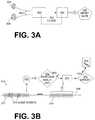
- FIG. 3Ais a conceptual diagram for illustrating how electrodes of a WCD system may sense or capture ECG signals of the patient, and how these sensed ECG signals may be used according to embodiments to yield a heart rate of the patient and other information.
- Two electrodes 304 , 308are attached to the torso of a patient, who is not shown. It will be appreciated that electrical noise may be introduced into the ECG signal at this point.
- Each of electrodes 304 , 308has a wire lead 305 . Together, electrodes 304 , 308 sense an ECG signal of the patient along a single vector. Additional ECG signals may be sensed along additional vectors.
- FIG. 3Aalso shows a measurement circuit 320 and a processor 330 , which can be made as described for measurement circuit 220 and processor 230 .
- a filter 325is optionally implemented in measurement circuit 320 and/or in processor 330 .
- Filter 325may be implemented as an analog filter, a digital filter, and so on. Filter 325 may help overcome some types of ECG noise by suppressing it, making this noise easier to detect, and so on.
- Processor 330may further compute a heart rate 333 according to embodiments, as described in more detail further in this document. Computed heart rate 333 may be stored in memory 238 . Heart rate 333 may then be downloaded later from memory 238 , transmitted wirelessly via communication module 290 , displayed by a screen of user interface 280 , and so on.
- FIG. 3Bis a conceptual diagram that includes a time axis 348 .
- a sample ECG signal 319 of a patientis shown with reference to time axis 348 .
- ECG signal 319is intended to be drawn generically, and could appear having a waveform different from what is shown in FIG. 3B . It will be recognized that, in the instances where an ECG signal actually has the exact appearance seen in FIG. 3B , that ECG signal might indicate VT, or even VF, but that is only for example.
- ECG signal 319has a first portion 317 and a second portion 318 .
- Second portion 318has been sensed after sensing first portion 317 .
- ECG signal portionscan be defined in a number of ways.
- ECG portions 317 , 318can be a part of the sensed ECG signal that processor 230 processes at one time.
- An ECG portionmay be long enough to perform a full ECG rhythm analysis.
- An ECG portionmay include several QRS complexes.
- an ECG portionmay be shorter.
- first portion 317includes noise events 374 , examples of which are described in more detail elsewhere in this document. And, while noise events 374 are shown in FIG.
- 3Bas definite events, occurring at specific times and having specific durations, etc., that is done only for purposes of discussion.
- noise events in the ECG signaldo not announce themselves. Rather, embodiments of this disclosure detect when certain types of noise are within an ECG signal, react accordingly, and so on.
- First ECG signal portion 317may result in computing heart rate 333 according to embodiments.
- a decision diamond 372indicates that a decision may be made as to whether or not an analysis should be performed.
- the analysiscan be a full ECG analysis, or a confirmation of the heart rate computation, and so on.
- the answer for decision diamond 372may be provided by the value of heart rate 333 , which was derived from first signal portion 317 .
- a certain range of values for heart rate 333may give a NO answer, which is not indicated in FIG. 3B .
- another range of values for heart rate 333may give a YES answer, which is also indicated in FIG. 3B with a check mark.
- second ECG signal portion 318may be analyzed. As part of this analysis, second ECG portion 318 may be used to determine whether or not a shock criterion is met, for example by advice module 234 .
- a shock 111is administered to patient 82 .
- processor 230may control, responsive to a shock criterion being met, discharge circuit 255 to discharge through patient 82 an electrical charge that is stored in energy storage module 250 , while support structure 170 is worn by patient 82 so as to deliver a shock 111 to patient 82 .
- another processmay be undertaken where the patient is alerted by an alarm, challenged to demonstrate they are alive, and so on.
- Operations 370 and 375may be performed in a number of ways.
- the heart rate 333may be computed again, for confirmation of the value arrived at in the first time. It may be computed in the same way, or a different way, for example with additional safeguards, such as for addressing noise. Plus, more parameters may be computed, such as a QRS width and so on.
- FIG. 4is a conceptual diagram that includes a time axis 448 .
- a sample ECG signal 419 of a patientis shown with reference to time axis 448 .
- ECG signal 419is intended to be drawn generically, similarly with ECG signal 319 of FIG. 3B .
- ECG signal 419has a first portion 417 and a second portion 418 .
- Second portion 418has been sensed after sensing first portion 417 .
- a comment oval 496contains the comment that it is not known, at this time, whether or not first ECG portion 417 includes H-F noise.
- first ECG signal portion 417an analysis is made from first ECG signal portion 417 .
- This analysismay be performed, for example, as described for decision diamond 370 . From that analysis, it has been determined that a first shock criterion is not met. In other words, first ECG signal portion 417 did not merit the WCD system administering a shock to the patient. In FIG. 4 , this determination is shown by a determination pentagon 474 , which includes the words “NO SHOCK”.
- determination pentagon 474was arrived at subject to comment oval 496 . However, since determination pentagon 474 is “NO SHOCK” then, according to another comment oval 499 , the WCD system does not care about comment oval 496 . In other words, in this instance determination pentagon 474 stands as the WCD system's determination, regardless of whether or not H-F noise events are included in ECG segments of first ECG portion 417 . As such, since determination pentagon 474 was “NO SHOCK”, any H-F noise in first ECG portion 417 is ignored.
- the processmay then continue with the second ECG portion 418 , which is subsequent to first ECG portion 417 , because it is sensed subsequently to it.
- Another determination pentagon 475may be arrived at, and so on.
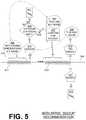
- FIG. 5is a conceptual diagram that includes a time axis 548 .
- a sample ECG signal 519 of a patientis shown with reference to time axis 548 .
- ECG signal 519is intended to be drawn generically, similarly with ECG signal 419 of FIG. 4 .
- ECG signal 519has a first portion 517 and a second portion 518 .
- Second portion 518has been sensed after sensing first portion 517 .
- a comment oval 596contains the comment that it is not known, at this time, whether or not first ECG portion 517 includes H-F noise.
- first ECG signal portion 517an analysis is made from first ECG signal portion 517 .
- This analysismay be performed, for example, as described for decision diamond 370 . From that analysis, it has been determined that a first shock criterion is indeed met. In other words, first ECG signal portion 517 merits the WCD system administering a shock to the patient. In FIG. 5 , this determination is shown by a determination pentagon 574 , which includes the word “SHOCK”. In this situation, however, the possibility of H-F noise will not be ignored as it was ignored in FIG. 4 .
- decision diamond 530it is determined whether or not first ECG portion 517 meets a High-Frequency (H-F) noise criterion. Sample such criteria are described later in this document.
- the possible answers to decision diamond 530are NO, denoted by an “X” and YES, denoted by a checkmark. If the answer is NO then, according to an operation 511 a shock is administered to the patient, similarly with operation 311 .
- a comment oval 597indicates that comment oval 596 is determined to have been H-F noise.
- a related operation 570it can be determined from second portion 518 of the sensed ECG signal, whether or not a shock criterion is met. This operation 570 may be performed, for example, as described for decision diamond 370 . The determination that is arrived at this way is either determination pentagon 575 (“NO SHOCK”), or determination pentagon 577 (“SHOCK”). Determination pentagon 575 (“NO SHOCK”) is associated with comment oval 598 , which indicates that determination pentagon 574 (“SHOCK”) was false, and probably arrived at due to H-F noise. On the other hand, determination pentagon 577 (“SHOCK”) can be followed by an operation 515 similar to operation 511 , where a shock is administered to the patient, and so on.
- the devices and/or systems mentioned in this documentperform functions, processes and/or methods. These functions, processes and/or methods may be implemented by one or more devices that include logic circuitry. Such a device can be alternately called a computer, and so on. It may be a standalone device or computer, such as a general purpose computer, or part of a device that has one or more additional functions.
- the logic circuitrymay include a processor and non-transitory computer-readable storage media, such as memories, of the type described elsewhere in this document. Often, for the sake of convenience only, it is preferred to implement and describe a program as various interconnected distinct software modules or features. These, along with data are individually and also collectively known as software. In some instances, software is combined with hardware, in a mix called firmware.
- FIG. 6shows a flowchart 600 for describing methods according to embodiments.
- Flowchart 600includes operations that are linked by arrows.
- flowchart 600is annotated with determination pentagons repeated from FIG. 4 and FIG. 5 where applicable.
- a portionis sensed of an ECG signal of the patient.
- Such portionscan be sensed sequentially, for example as seen above with ECG signal portions pairs 317 & 318 , 417 & 418 and 517 & 518 .
- a subsequent operation 671is also a decision diamond 671 .
- itcan be determined whether or not a first shock criterion is met. The determination can be made from the signal portion sensed at operation 610 .
- the shock criterioncan be the same as that of decision diamond 370 , or different. If, at decision diamond 671 the answer is NO, then that is equivalent to determination pentagon 474 of FIG. 4 , and execution may return to another operation, such as operation 610 .
- executionmay proceed to another operation 630 , which is also a decision diamond 630 .
- operation 630it can be determined whether or not the first portion of the sensed ECG signal, which met the first shock criterion of operation 671 , also meets a High-Frequency (H-F) noise criterion. Examples of such noise criteria are described later in this document.
- H-FHigh-Frequency
- executionmay proceed to another operation 611 and shock the patient, similarly with operation 511 . After that, execution may return to another operation, such as operation 610 .
- executionmay proceed to another operation 650 where a next, or second, portion of the ECG signal can be sensed.
- operation 650is similar to operation 610 .
- Executionmay then proceed to operation 672 , which is also a decision diamond 672 .
- operation 672it may be determined, from the second portion of the sensed ECG signal, whether or not a second shock criterion is met.
- the second shock criterioncan be the same or different as the first shock criterion.
- This second portion of the ECG signalcan be sensed and analyzed for purposes of confirmation of the YES answer at decision diamond 671 .
- executionmay return to another operation, such as operation 610 .
- executionmay proceed to operation 611 , and the patient is shocked, as above. It will be understood, however, that the path to operation 611 via a YES answer at decision diamond 630 , and then operations 650 and 672 may take longer than the path through a NO answer at decision diamond 630 . As such, the shock of operation 611 maybe delivered at least 5 seconds later than the shock that would have been delivered responsive to the H-F noise criterion not being met at operation 630 .
- a potential R peak of a QRS complexis identified in a first portion of the sensed ECG signal. Then an ECG segment becomes defined as a segment of the ECG signal that corresponds to the potential R peak. It is preferred that the ECG segment becomes defined in proximity with the potential R peak, and in fact maybe even include the potential R peak that it corresponds to. Then the H-F noise criterion can be met responsive to the ECG segment meeting a segment noise criterion. Examples are now described.
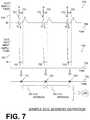
- FIG. 7shows an ECG signal of patient 82 in a time diagram 709 .
- Diagram 709has an ECG amplitude axis 707 and a time axis 708 .
- the shown ECG signalis somewhat-idealized, noise-free, and includes three full heartbeats.
- the ECG signalincludes three QRS complexes, each of which is followed by a T-wave of lesser amplitude. These QRS complexes include three R peaks 721 , 722 , 723 .
- the ECG signalhovers around a horizontal baseline value BL.
- Baseline value BLcan be considered to be zero, but in real life it might be changing value, possibly due to noise.
- a P-wave before the QRS complex and a U-wave after the QRS complexare not shown at all.
- ECG signal of diagram 709is somewhat-idealized, it serves as a good basis for describing embodiments, as if it were the ECG signal that was sensed.
- R peaks 721 , 722 , 723can be detected in an ECG signal of patient 82 , even if that signal contains noise.
- These R peaks 721 , 722 , 723can be used for detecting the patient's heart rate 333 , because their large amplitude relative to the remainder of the ECG signal makes them more easy to identify and/or detect.
- three ECG segmentsare defined according to embodiments, as segments of ECG signal portion that include R peaks 721 , 722 , 723 respectively.
- FIG. 7shows ECG segments more explicitly in another time diagram 759 .
- Diagram 759has an ECG Segment Amplitude axis 757 and a time axis 758 .
- ECG segments 751 , 752 , 753are segments of the ECG signal of diagram 709 that are within respective time windows 791 , 792 , 793 . As such, ECG segments 751 , 752 , 753 have the same duration as the duration of time windows 791 , 792 , 793 .
- An ECG segment according to embodimentscan be defined to have a duration that isolates the potential R peak from other features.
- an ECG segmentcan have a duration between 160 ms and 200 ms, such as 180 milliseconds. In FIG. 7 , that duration is shown as the width of time windows 791 , 792 , 793 .
- An ECG segmentcan be defined to correspond to an R peak of an ECG signal as a segment of the ECG signal that includes the R peak.
- the ECG segmentstarts at the potential R peak, as in the example of FIG. 7 .
- the ECG segmentstarts before the potential R peak and ends after it.
- the potential R peakcan be at the center of the ECG segment.
- a segmentcan be used to analyze the validity of a potential R peak.
- R peaks 721 , 722 , 723can be identified as potential R peaks, if the ECG signal of diagram 709 is the sensed ECG signal.
- the ECG segments 751 , 752 , 753can be defined to include potential R peaks 721 , 722 , 723 .
- FIG. 7also shows a time axis 748 that indicates only the time occurrences 741 , 742 , 743 of R peaks 721 , 722 , 723 , respectively.
- these R peaks 721 , 722 , 723can be considered in pairs of successive R peaks, to define time intervals.
- the pair of peaks 721 and 722defines a time interval 701 from time occurrences 741 , 742
- the pair of peaks 722 and 723defines a time interval 702 from time occurrences 742 , 743 .
- Time intervals 701 , 702are sometimes called R-R intervals of the ECG signal. The durations of time intervals 701 , 702 can be measured, and heart rate 333 of the patient can be thus computed from them.
- peaks 721 , 722 , 723correspond with peaks in the patient's blood pressure, which can be sensed by a person placing their hand against the neck or a wrist of a patient.
- FIG. 8shows a time diagram 809 .
- Diagram 809has an R peaks axis 807 and a time axis 808 .
- Diagram 809depicts only R peaks 821 , 822 , 823 , 824 of a patient's ECG signal portion, with all other values of the ECG signal being shown as zero for simplification. This simplification is acceptable in this instance, as FIG. 8 is used for discussing ECG segments as per the above, where large peaks are being detected.
- FIG. 8also shows a time diagram 839 to depict sample noise that could be added to the ECG of diagram 829 .
- Diagram 839has a Large Noise Peaks axis 837 and a time axis 838 .
- Diagram 839depicts only one large noise peak 833 , with all other values being shown as zero for simplification, since large peaks are being detected. It will be recognized that noise peak 833 is an example of a noise event 374 .
- FIG. 8also shows a time diagram 829 .
- Diagram 829has a Potential R Peaks axis 827 and a time axis 828 .
- Time diagram 829depicts the suspected or potential R peaks of a sample sensed ECG signal portion.
- Time diagram 829 in this exampleis arrived at as a sum of time diagrams 809 and 839 .
- this riskis addressed by defining ECG segments 851 , 852 , 853 , 854 , 855 as segments of ECG signal portion in time diagram 809 that include the identified potential R peaks 821 , 822 , 823 , 833 , 824 respectively. Such may be implemented by first defining time windows 891 , 892 , 893 , 894 , 895 starting from these identified potential R peaks 821 , 822 , 823 , 833 , 824 .
- FIG. 8shows ECG segments 851 , 852 , 853 , 854 , 855 more explicitly in another time diagram 859 .
- Diagram 859has an ECG Segment Amplitude axis 857 and a time axis 858 .
- ECG segments 851 , 852 , 853 , 854 , 855are segments of the ECG signal of diagram 829 that are within respective time windows 891 , 892 , 893 , 894 , 895 .
- ECG segments 851 , 852 , 853 , 854 , 855have the same duration as the duration of time windows 891 , 892 , 893 , 894 , 895 .
- ECG segments 851 , 852 , 853 , 854 , 855can be used to detect which of these potential R peaks is noise.
- the H-F noise criterionmay be met responsive to the ECG segment meeting a segment noise criterion.
- the ECG signal portion and/or the ECG segmentmay be first filtered, for example by filter 325 .
- filter 325may be a filter passing frequencies between 8 Hz and 25 Hz.
- the H-F noise criterionis met responsive to the filtered ECG segment meeting the segment noise criterion.
- FIG. 9shows a time diagram 959 .
- Diagram 959has an ECG segment amplitude axis 957 and a time axis 958 .
- Diagram 959depicts two sample ECG segments 953 , 954 , which have been defined by respective time windows 993 , 994 .
- time windows 993 , 994correspond to potential R peaks of a sensed ECG signal portion, and maybe even include these R peaks.
- ECG segments 953 , 954are shown as approximately sinusoidal waveforms, but that is only by way of example. For instance, these waveforms are rounded where they have local maxima and local minima, but they could have edges there instead of being rounded, such as ECG signal 319 . In fact, in embodiments where the ECG segment includes a suspected or potential R peak of a QRS complex, one of the edges is sharp and its pulse can have much higher amplitude than its neighboring pulses. These waveforms being rounded, however, is adequate for this particular explanation.
- ECG segments 953 , 954are subjected to determinations of whether or not a segment noise criterion is met.
- the criteria of decision diamonds 933 , 934are the same, while in others different.
- an ECG segmentis subjected to more than one segment noise criterion, and so on.
- the segment noise criterionis met responsive to the ECG segment containing more zero-crossings than a crossings threshold.
- the crossings thresholdcan be advantageously determined by the chosen duration of time windows 993 , 994 , and given a target density or frequency of zero crossings.
- the crossings thresholdis five.
- ECG segment 953has four zero crossings 963 , which are not more than the threshold of five. As such, the segment noise criterion is not met, and the answer to decision diamond 933 is NO.
- ECG segment 954has six zero crossings 964 , which are more than the threshold of five. As such, the segment noise criterion is met, and the answer to decision diamond 934 is YES.
- FIG. 9also shows a time diagram 989 .
- Diagram 989has an ECG segment amplitude axis 987 and a time axis 988 .
- Diagram 989depicts the ECG segments of diagram 959 that survive the segment noise criterion of decision diamonds 933 , 934 .
- ECG segment 953survives, while ECG segment 954 is discarded. Accordingly, the R peak that gave rise to segment 954 can be discarded as being due to H-F noise, and a more accurate result can be reached by the algorithm of the WCD system.
- FIG. 10shows a time diagram 1059 .
- Diagram 1059has an ECG segment amplitude axis 1057 and a time axis 1058 .
- Diagram 1059depicts two sample ECG segments 1053 , 1054 , which have been defined by respective time windows 1093 , 1094 that are near potential R peaks of an ECG signal portion.
- time windows 1093 , 1094correspond to potential R peaks of a sensed ECG signal portion, and maybe even include these R peaks.
- ECG segments 1053 , 1054are shown as approximately sinusoidal waveforms, but that is only by way of example. For instance, these waveforms could have edges instead of being rounded at their local maxima and local minima. In fact, in embodiments where the ECG segment includes a suspected or potential R peak of a QRS complex, one of the edges is sharp and its pulse can have much higher amplitude than its neighboring pulses. These waveforms being rounded is adequate for this particular explanation.
- ECG segments 1053 , 1054are subjected to determinations of whether or not a segment noise criterion is met.
- the segment noise criterionis met responsive to the ECG segment containing at least one peak briefer than a threshold duration.
- the threshold durationis 25 milliseconds (ms).
- the threshold durationis shown as a time window 1099 .
- ECG segment 1053has no pulse more brief or shorter than time window 1099 .
- the segment noise criterionis not met, and the answer to decision diamond 1033 is NO.
- ECG segment 1054has at least one pulse more brief than time window 1099 , for instance as evidenced by zero crossing 1064 .
- the segment noise criterionis met, and the answer to decision diamond 1034 is YES.
- FIG. 10also shows a time diagram 1089 .
- Diagram 1089has an ECG segment amplitude axis 1087 and a time axis 1088 .
- Diagram 1089depicts the ECG segments of diagram 1059 that survive the segment noise criterion of decision diamonds 1033 , 1034 .
- ECG segment 1053survives, while ECG segment 1054 is discarded. Accordingly, the R peak that gave rise to segment 1054 can be discarded as being due to H-F noise, and a more accurate result can be reached by the algorithm of the WCD system.
- a noisiness ratiocan be used for ECG portion 517 .
- the noisiness ratiocan be defined from a number of segments within portion 517 that meet the segment noise criterion over the total number of potential R peaks within portion 517 .
- the H-F noise criterioncan be met instead responsive to the noisiness ratio exceeding a threshold.
- each operationcan be performed as an affirmative act or operation of doing, or causing to happen, what is written that can take place. Such doing or causing to happen can be by the whole system or device, or just one or more components of it.
- the methods and the operationsmay be implemented in a number of ways, including using systems, devices and implementations described above.
- the order of operationsis not constrained to what is shown, and different orders may be possible according to different embodiments. Examples of such alternate orderings may include overlapping, interleaved, interrupted, reordered, incremental, preparatory, supplemental, simultaneous, reverse, or other variant orderings, unless context dictates otherwise.
- new operationsmay be added, or individual operations may be modified or deleted. The added operations can be, for example, from what is mentioned while primarily describing a different system, apparatus, device or method.
- the phrases “constructed to” and/or “configured to”denote one or more actual states of construction and/or configuration that is fundamentally tied to physical characteristics of the element or feature preceding these phrases and, as such, reach well beyond merely describing an intended use. Any such elements or features can be implemented in a number of ways, as will be apparent to a person skilled in the art after reviewing the present disclosure, beyond any examples shown in this document.
- a single reference numeralmay be used consistently to denote a single item, aspect, component, or process.
- a further effortmay have been made in the drafting of this description to use similar though not identical reference numerals to denote other versions or embodiments of an item, aspect, component or process that are identical or at least similar or related. Where made, such a further effort was not required, but was nevertheless made gratuitously so as to accelerate comprehension by the reader. Even where made in this document, such a further effort might not have been made completely consistently for all of the versions or embodiments that are made possible by this description. Accordingly, the description controls in defining an item, aspect, component or process, rather than its reference numeral. Any similarity in reference numerals may be used to infer a similarity in the text, but not to confuse aspects where the text or other context indicates otherwise.
Landscapes
- Health & Medical Sciences (AREA)
- Engineering & Computer Science (AREA)
- Cardiology (AREA)
- Radiology & Medical Imaging (AREA)
- Biomedical Technology (AREA)
- Nuclear Medicine, Radiotherapy & Molecular Imaging (AREA)
- Life Sciences & Earth Sciences (AREA)
- Animal Behavior & Ethology (AREA)
- General Health & Medical Sciences (AREA)
- Public Health (AREA)
- Veterinary Medicine (AREA)
- Heart & Thoracic Surgery (AREA)
- Human Computer Interaction (AREA)
- Electrotherapy Devices (AREA)
- Measurement And Recording Of Electrical Phenomena And Electrical Characteristics Of The Living Body (AREA)
Abstract
Description
Claims (13)
Priority Applications (5)
| Application Number | Priority Date | Filing Date | Title |
|---|---|---|---|
| US16/037,990US11103717B2 (en) | 2017-07-28 | 2018-07-17 | Wearable cardioverter defibrillator (WCD) system reacting to high-frequency ECG noise |
| AU2018208710AAU2018208710B2 (en) | 2017-07-28 | 2018-07-26 | Wearable cardioverter defibrillator (wcd) system delaying shocking due to high-frequency noise in ecg signal |
| EP18186221.0AEP3434325B1 (en) | 2017-07-28 | 2018-07-30 | Wearable cardioverter defibrillator (wcd) system reacting to high-frequency ecg noise |
| US17/394,305US12023510B2 (en) | 2017-07-28 | 2021-08-04 | Wearable cardioverter defibrillator (WCD) system reacting to high-frequency ECG noise |
| US18/760,311US20240350817A1 (en) | 2017-07-28 | 2024-07-01 | Wearable cardioverter defibrillator (wcd) system reacting to high-frequency ecg noise |
Applications Claiming Priority (2)
| Application Number | Priority Date | Filing Date | Title |
|---|---|---|---|
| US201762538159P | 2017-07-28 | 2017-07-28 | |
| US16/037,990US11103717B2 (en) | 2017-07-28 | 2018-07-17 | Wearable cardioverter defibrillator (WCD) system reacting to high-frequency ECG noise |
Related Child Applications (1)
| Application Number | Title | Priority Date | Filing Date |
|---|---|---|---|
| US17/394,305ContinuationUS12023510B2 (en) | 2017-07-28 | 2021-08-04 | Wearable cardioverter defibrillator (WCD) system reacting to high-frequency ECG noise |
Publications (2)
| Publication Number | Publication Date |
|---|---|
| US20190030351A1 US20190030351A1 (en) | 2019-01-31 |
| US11103717B2true US11103717B2 (en) | 2021-08-31 |
Family
ID=63103781
Family Applications (3)
| Application Number | Title | Priority Date | Filing Date |
|---|---|---|---|
| US16/037,990Active2039-01-21US11103717B2 (en) | 2017-07-28 | 2018-07-17 | Wearable cardioverter defibrillator (WCD) system reacting to high-frequency ECG noise |
| US17/394,305Active2039-06-09US12023510B2 (en) | 2017-07-28 | 2021-08-04 | Wearable cardioverter defibrillator (WCD) system reacting to high-frequency ECG noise |
| US18/760,311PendingUS20240350817A1 (en) | 2017-07-28 | 2024-07-01 | Wearable cardioverter defibrillator (wcd) system reacting to high-frequency ecg noise |
Family Applications After (2)
| Application Number | Title | Priority Date | Filing Date |
|---|---|---|---|
| US17/394,305Active2039-06-09US12023510B2 (en) | 2017-07-28 | 2021-08-04 | Wearable cardioverter defibrillator (WCD) system reacting to high-frequency ECG noise |
| US18/760,311PendingUS20240350817A1 (en) | 2017-07-28 | 2024-07-01 | Wearable cardioverter defibrillator (wcd) system reacting to high-frequency ecg noise |
Country Status (3)
| Country | Link |
|---|---|
| US (3) | US11103717B2 (en) |
| EP (1) | EP3434325B1 (en) |
| AU (1) | AU2018208710B2 (en) |
Cited By (5)
| Publication number | Priority date | Publication date | Assignee | Title |
|---|---|---|---|---|
| US20230271021A1 (en)* | 2017-07-28 | 2023-08-31 | West Affum Holdings Dac | Wearable cardioverter defibrillator (wcd) system reacting to high-amplitude ecg noise |
| US11844953B2 (en) | 2018-02-14 | 2023-12-19 | West Affum Holdings Dac | Wearable cardioverter defibrillator (WCD) |
| US12121329B2 (en) | 2019-03-08 | 2024-10-22 | West Affum Holdings Dac | Wearable vital signs monitor with selective signal acquisition |
| US12179032B2 (en) | 2018-02-14 | 2024-12-31 | West Affum Holdings Dac | Wearable cardioverter defibrillator (WCD) segment based episode opening and confirmation periods |
| US12300368B1 (en)* | 2019-03-07 | 2025-05-13 | West Affum Holdings Dac | Analysis and presentation of aggregated patient and device data within a system that includes a medical device |
Families Citing this family (12)
| Publication number | Priority date | Publication date | Assignee | Title |
|---|---|---|---|---|
| US11077310B1 (en) | 2016-10-04 | 2021-08-03 | West Affum Holdings Corp. | Wearable cardioverter defibrillator (WCD) system detecting QRS complexes in ECG signal by matched difference filter |
| US11471693B1 (en) | 2018-02-14 | 2022-10-18 | West Affum Holdings Dac | Wearable cardioverter defibrillator (WCD) system choosing to consider ECG signals from different channels per QRS complex widths of the ECG signals |
| US11865354B1 (en) | 2018-02-14 | 2024-01-09 | West Affum Holdings Dac | Methods and systems for distinguishing VT from VF |
| US11040214B2 (en) | 2018-03-01 | 2021-06-22 | West Affum Holdings Corp. | Wearable cardioverter defibrillator (WCD) system having main UI that conveys message and peripheral device that amplifies the message |
| US11331508B1 (en) | 2018-04-25 | 2022-05-17 | West Affum Holdings Corp. | Wearable cardioverter defibrillator with a non-invasive blood pressure monitor |
| US11058884B2 (en) | 2018-04-26 | 2021-07-13 | West Affum Holding Corp | Wearable medical (WM) system monitoring ECG signal of ambulatory patient for heart condition |
| US11672996B2 (en) | 2019-06-24 | 2023-06-13 | West Affum Holdings Dac | Wearable cardioverter defibrillator with AI-based features |
| US11771360B2 (en) | 2019-08-22 | 2023-10-03 | West Affum Holdings Dac | Cardiac monitoring system with normally conducted QRS complex identification |
| US12409331B2 (en) | 2021-02-12 | 2025-09-09 | West Affum Holdings Dac | Wearable Cardioverter Defibrillator (WCD) with artificial intelligence features |
| US12172023B2 (en) | 2021-03-05 | 2024-12-24 | West Affum Holdings Dac | Data channel selection and timeline navigation in a cardiac monitoring system |
| US12311188B2 (en) | 2021-09-22 | 2025-05-27 | West Affum Holdings Dac | Power in a wearable cardioverter defibrillator (WCD) |
| US20230381527A1 (en) | 2022-05-31 | 2023-11-30 | West Affum Holdings Dublin DAC | Wearable medical system with device parameters and patient information programmable via browser interface |
Citations (86)
| Publication number | Priority date | Publication date | Assignee | Title |
|---|---|---|---|---|
| US3724355A (en) | 1970-06-12 | 1973-04-03 | K Schranz | Apparatus for processing exposed photographic film or the like |
| US3724455A (en) | 1970-06-02 | 1973-04-03 | P Unger | Cardiac warning device |
| US4583524A (en) | 1984-11-21 | 1986-04-22 | Hutchins Donald C | Cardiopulmonary resuscitation prompting |
| US4619265A (en) | 1984-03-08 | 1986-10-28 | Physio-Control Corporation | Interactive portable defibrillator including ECG detection circuit |
| US4928690A (en) | 1988-04-25 | 1990-05-29 | Lifecor, Inc. | Portable device for sensing cardiac function and automatically delivering electrical therapy |
| US4955381A (en) | 1988-08-26 | 1990-09-11 | Cardiotronics, Inc. | Multi-pad, multi-function electrode |
| US5078134A (en) | 1988-04-25 | 1992-01-07 | Lifecor, Inc. | Portable device for sensing cardiac function and automatically delivering electrical therapy |
| US5228449A (en) | 1991-01-22 | 1993-07-20 | Athanasios G. Christ | System and method for detecting out-of-hospital cardiac emergencies and summoning emergency assistance |
| US5348008A (en) | 1991-11-25 | 1994-09-20 | Somnus Corporation | Cardiorespiratory alert system |
| US5381803A (en)* | 1993-03-12 | 1995-01-17 | Hewlett-Packard Corporation | QRS detector for defibrillator/monitor |
| US5394892A (en) | 1990-04-02 | 1995-03-07 | K J Mellet Nominees Pty Ltd | CPR prompting apparatus |
| US5405362A (en) | 1991-04-29 | 1995-04-11 | The Board Of Regents For The University Of Texas System | Interactive external defibrillation and drug injection system |
| US5474574A (en) | 1992-06-24 | 1995-12-12 | Cardiac Science, Inc. | Automatic external cardioverter/defibrillator |
| US5662690A (en) | 1994-12-08 | 1997-09-02 | Heartstream, Inc. | Defibrillator with training features and pause actuator |
| US5709215A (en) | 1995-09-06 | 1998-01-20 | Angeion Corporation | R-wave detection method for implantable cardioverter defibrillators |
| US5782878A (en) | 1994-12-07 | 1998-07-21 | Heartstream, Inc. | External defibrillator with communications network link |
| US5792204A (en) | 1996-05-08 | 1998-08-11 | Pacesetter, Inc. | Methods and apparatus for controlling an implantable device programmer using voice commands |
| WO1998039061A2 (en) | 1997-03-07 | 1998-09-11 | Cadent Medical Corporation | Wearable defibrillation system |
| US5902249A (en) | 1995-03-03 | 1999-05-11 | Heartstream, Inc. | Method and apparatus for detecting artifacts using common-mode signals in differential signal detectors |
| US5913685A (en) | 1996-06-24 | 1999-06-22 | Hutchins; Donald C. | CPR computer aiding |
| US5944669A (en) | 1997-11-20 | 1999-08-31 | Lifecor, Inc. | Apparatus and method for sensing cardiac function |
| US6047203A (en) | 1997-03-17 | 2000-04-04 | Nims, Inc. | Physiologic signs feedback system |
| US6065154A (en) | 1998-04-07 | 2000-05-23 | Lifecor, Inc. | Support garments for patient-worn energy delivery apparatus |
| US6108197A (en) | 1992-05-15 | 2000-08-22 | Via, Inc. | Flexible wearable computer |
| US6201992B1 (en) | 1999-04-01 | 2001-03-13 | Agilent Technologies, Inc. | Defibrillator interface capable of generating video images |
| US6263238B1 (en) | 1998-04-16 | 2001-07-17 | Survivalink Corporation | Automatic external defibrillator having a ventricular fibrillation detector |
| US6287328B1 (en) | 1999-04-08 | 2001-09-11 | Agilent Technologies, Inc. | Multivariable artifact assessment |
| US6319011B1 (en) | 1995-04-06 | 2001-11-20 | Michael J. Motti | Automatic training defibrillator simulator and method |
| US6334070B1 (en) | 1998-11-20 | 2001-12-25 | Medtronic Physio-Control Manufacturing Corp. | Visual and aural user interface for an automated external defibrillator |
| US6356785B1 (en) | 1997-11-06 | 2002-03-12 | Cecily Anne Snyder | External defibrillator with CPR prompts and ACLS prompts and methods of use |
| US6437083B1 (en) | 2001-12-06 | 2002-08-20 | General Electric Company | Process for preparing branched aromatic polycarbonates |
| US6529875B1 (en) | 1996-07-11 | 2003-03-04 | Sega Enterprises Ltd. | Voice recognizer, voice recognizing method and game machine using them |
| US20030158593A1 (en) | 2002-02-19 | 2003-08-21 | Heilman Marlin S. | Cardiac garment |
| US6681003B2 (en) | 1999-10-05 | 2004-01-20 | Lifecor, Inc. | Data collection and system management for patient-worn medical devices |
| US6762917B1 (en) | 2001-06-12 | 2004-07-13 | Novx Corporation | Method of monitoring ESC levels and protective devices utilizing the method |
| US20050107833A1 (en) | 2003-11-13 | 2005-05-19 | Freeman Gary A. | Multi-path transthoracic defibrillation and cardioversion |
| US20050131476A1 (en)* | 2003-12-11 | 2005-06-16 | Jaeho Kim | Cardiac response classification using multiple classification windows |
| US7065401B2 (en) | 2002-05-08 | 2006-06-20 | Michael Worden | Method of applying electrical signals to a patient and automatic wearable external defibrillator |
| US20080306560A1 (en)* | 2007-06-06 | 2008-12-11 | Macho John D | Wearable defibrillator with audio input/output |
| US20080312709A1 (en) | 2007-06-13 | 2008-12-18 | Volpe Shane S | Wearable medical treatment device with motion/position detection |
| US20090005827A1 (en) | 2007-06-26 | 2009-01-01 | David Weintraub | Wearable defibrillator |
| US7559902B2 (en) | 2003-08-22 | 2009-07-14 | Foster-Miller, Inc. | Physiological monitoring garment |
| US20100007413A1 (en) | 2006-11-10 | 2010-01-14 | Koninklijke Philips Electronics N.V. | Ecg electrode contact quality measurement system |
| US20100298899A1 (en) | 2007-06-13 | 2010-11-25 | Donnelly Edward J | Wearable medical treatment device |
| US7865238B2 (en) | 2004-09-29 | 2011-01-04 | Koninklijke Philips Electronics N.V. | High-voltage module for an external defibrillator |
| US7870761B2 (en) | 2002-05-14 | 2011-01-18 | Koninklijke Philips Electronics N.V. | Garment and method for producing the same |
| US20110288604A1 (en) | 2010-05-18 | 2011-11-24 | Kaib Thomas E | Wearable therapeutic device |
| US20110288605A1 (en) | 2010-05-18 | 2011-11-24 | Zoll Medical Corporation | Wearable ambulatory medical device with multiple sensing electrodes |
| US20120059270A1 (en)* | 2009-06-12 | 2012-03-08 | Bard Access Systems, Inc. | Apparatus and method for catheter navigation using endovascular energy mapping |
| US8135462B2 (en) | 2002-08-26 | 2012-03-13 | Physio-Control, Inc. | Pulse detection using patient physiological signals |
| US20120112903A1 (en) | 2010-11-08 | 2012-05-10 | Zoll Medical Corporation | Remote medical device alarm |
| US20120144551A1 (en) | 2010-12-09 | 2012-06-14 | Eric Guldalian | Conductive Garment |
| US20120150008A1 (en) | 2010-12-09 | 2012-06-14 | Kaib Thomas E | Electrode with redundant impedance reduction |
| US20120158075A1 (en) | 2010-12-16 | 2012-06-21 | Kaib Thomas E | Water resistant wearable medical device |
| US20120265265A1 (en) | 2011-04-13 | 2012-10-18 | Mehdi Razavi | Automated External Defibrillator Pad System |
| US20120283794A1 (en) | 2011-05-02 | 2012-11-08 | Kaib Thomas E | Patient-worn energy delivery apparatus and techniques for sizing same |
| US20120293323A1 (en) | 2011-03-25 | 2012-11-22 | Zoll Medical Corporation | System and method for adapting alarms in a wearable medical device |
| US20120302860A1 (en) | 2011-03-25 | 2012-11-29 | Zoll Medical Corporation | Selection of optimal channel for rate determination |
| US20120310315A1 (en) | 2009-03-17 | 2012-12-06 | Savage Walter T | Device and method for reducing patient transthoracic impedance for the purpose of delivering a therapeutic current |
| US20130085538A1 (en) | 2011-09-01 | 2013-04-04 | Zoll Medical Corporation | Wearable monitoring and treatment device |
| US20130231711A1 (en) | 2012-03-02 | 2013-09-05 | Thomas E. Kaib | Systems and methods for configuring a wearable medical monitoring and/or treatment device |
| US20130245388A1 (en) | 2011-09-01 | 2013-09-19 | Mc10, Inc. | Electronics for detection of a condition of tissue |
| US8548557B2 (en) | 2010-08-12 | 2013-10-01 | Covidien Lp | Medical electrodes |
| US20130274565A1 (en) | 2012-04-13 | 2013-10-17 | Alois Antonin Langer | Outpatient health emergency warning system |
| US20130317852A1 (en) | 2012-05-22 | 2013-11-28 | Geneva Healthcare, LLC | Medical device information portal |
| US20130325078A1 (en) | 2012-05-31 | 2013-12-05 | Zoll Medical Corporation | Medical monitoring and treatment device with external pacing |
| US8615295B2 (en) | 2009-03-17 | 2013-12-24 | Cardiothrive, Inc. | External defibrillator |
| US20140025131A1 (en) | 2012-07-20 | 2014-01-23 | Physio-Control, Inc. | Wearable defibrillator with voice prompts and voice recognition |
| US20140070957A1 (en) | 2012-09-11 | 2014-03-13 | Gianluigi LONGINOTTI-BUITONI | Wearable communication platform |
| US20140163663A1 (en) | 2012-12-11 | 2014-06-12 | Piyush Poddar | Method and system for switching shock vectors and decreasing transthoracic impedance for cardioversion and defibrillation |
| US8904214B2 (en) | 2010-07-09 | 2014-12-02 | Zoll Medical Corporation | System and method for conserving power in a medical device |
| US20140378812A1 (en) | 2011-12-20 | 2014-12-25 | Sensible Medical Innovatons | Thoracic garment of positioning electromagnetic (em) transducers and methods of using such thoracic garment |
| US20150039053A1 (en) | 2013-06-28 | 2015-02-05 | Zoll Medical Corporation | Systems and methods of delivering therapy using an ambulatory medical device |
| US9089685B2 (en) | 2013-02-25 | 2015-07-28 | West Affum Holdings Corp. | Wearable defibrillator with a multivector shock waveform |
| US9132267B2 (en) | 2013-03-04 | 2015-09-15 | Zoll Medical Corporation | Flexible therapy electrode system |
| US20150328472A1 (en) | 2014-05-13 | 2015-11-19 | Physio-Control, Inc. | Wearable cardioverter defibrillator components discarding ecg signals prior to making shock/no shock determination |
| US20160000349A1 (en)* | 2014-07-07 | 2016-01-07 | Zoll Medical Corporation | System and Method for Distinguishing a Cardiac Event From Noise in an Electrocardiogram (ECG) Signal |
| US20160004831A1 (en) | 2014-07-07 | 2016-01-07 | Zoll Medical Corporation | Medical device with natural language processor |
| US20160067514A1 (en) | 2013-02-25 | 2016-03-10 | West Affum Holdings Corp. | Wearable cardioverter defibrillator (wcd) system making shock/no shock determinations from multiple patient parameters |
| US20160074667A1 (en) | 2014-09-12 | 2016-03-17 | West Affum Holdings Corp. | Wearable cardiac defibrillator system diagnosing differently depending on motion |
| US20160082277A1 (en) | 2013-02-25 | 2016-03-24 | West Affum Holdings Corp. | Wearable cardioverter defibrillator (wcd) system informing patient that it is validating just-detected cardiac arrhythmia |
| US20160235320A1 (en)* | 2015-02-18 | 2016-08-18 | Medtronic, Inc. | Method and apparatus for atrial arrhythmia episode detection |
| US9533165B1 (en) | 2015-08-19 | 2017-01-03 | Medtronic, Inc. | Detection of medical electrical lead issues and therapy control |
| US20170252571A1 (en)* | 2016-02-26 | 2017-09-07 | Zoll Medical Corporation | Pediatric and Adult Defibrillator |
| US20180028083A1 (en)* | 2016-07-27 | 2018-02-01 | Medtronic, Inc. | Cardiac electrical signal noise detection for tachyarrhythmia episode rejection |
| US20180116537A1 (en) | 2014-07-07 | 2018-05-03 | Zoll Medical Corporation | System and Method for Distinguishing a Cardiac Event From Noise in an Electrocardiogram (ECG) Signal |
Family Cites Families (3)
| Publication number | Priority date | Publication date | Assignee | Title |
|---|---|---|---|---|
| US8024037B2 (en) | 2006-08-01 | 2011-09-20 | Kumar Uday N | External defibrillator |
| US20140043149A1 (en) | 2012-08-10 | 2014-02-13 | Physio-Control, Inc | Mobile communication device & app for wearable defibrillator system |
| CN106456984B (en) | 2014-02-24 | 2019-07-09 | 元素科学公司 | External defibrillator |
- 2018
- 2018-07-17USUS16/037,990patent/US11103717B2/enactiveActive
- 2018-07-26AUAU2018208710Apatent/AU2018208710B2/enactiveActive
- 2018-07-30EPEP18186221.0Apatent/EP3434325B1/enactiveActive
- 2021
- 2021-08-04USUS17/394,305patent/US12023510B2/enactiveActive
- 2024
- 2024-07-01USUS18/760,311patent/US20240350817A1/enactivePending
Patent Citations (107)
| Publication number | Priority date | Publication date | Assignee | Title |
|---|---|---|---|---|
| US3724455A (en) | 1970-06-02 | 1973-04-03 | P Unger | Cardiac warning device |
| US3724355A (en) | 1970-06-12 | 1973-04-03 | K Schranz | Apparatus for processing exposed photographic film or the like |
| US4619265A (en) | 1984-03-08 | 1986-10-28 | Physio-Control Corporation | Interactive portable defibrillator including ECG detection circuit |
| USRE34800E (en) | 1984-11-21 | 1994-11-29 | Hutchins; Donald C. | Cardiopulmonary resuscitation prompting |
| US4583524A (en) | 1984-11-21 | 1986-04-22 | Hutchins Donald C | Cardiopulmonary resuscitation prompting |
| US4928690A (en) | 1988-04-25 | 1990-05-29 | Lifecor, Inc. | Portable device for sensing cardiac function and automatically delivering electrical therapy |
| US5078134A (en) | 1988-04-25 | 1992-01-07 | Lifecor, Inc. | Portable device for sensing cardiac function and automatically delivering electrical therapy |
| US4955381A (en) | 1988-08-26 | 1990-09-11 | Cardiotronics, Inc. | Multi-pad, multi-function electrode |
| US5394892A (en) | 1990-04-02 | 1995-03-07 | K J Mellet Nominees Pty Ltd | CPR prompting apparatus |
| US5228449A (en) | 1991-01-22 | 1993-07-20 | Athanasios G. Christ | System and method for detecting out-of-hospital cardiac emergencies and summoning emergency assistance |
| US5405362A (en) | 1991-04-29 | 1995-04-11 | The Board Of Regents For The University Of Texas System | Interactive external defibrillation and drug injection system |
| US5348008A (en) | 1991-11-25 | 1994-09-20 | Somnus Corporation | Cardiorespiratory alert system |
| US5353793A (en) | 1991-11-25 | 1994-10-11 | Oishi-Kogyo Company | Sensor apparatus |
| US6108197A (en) | 1992-05-15 | 2000-08-22 | Via, Inc. | Flexible wearable computer |
| US5474574A (en) | 1992-06-24 | 1995-12-12 | Cardiac Science, Inc. | Automatic external cardioverter/defibrillator |
| US5381803A (en)* | 1993-03-12 | 1995-01-17 | Hewlett-Packard Corporation | QRS detector for defibrillator/monitor |
| US5782878A (en) | 1994-12-07 | 1998-07-21 | Heartstream, Inc. | External defibrillator with communications network link |
| US5662690A (en) | 1994-12-08 | 1997-09-02 | Heartstream, Inc. | Defibrillator with training features and pause actuator |
| US5902249A (en) | 1995-03-03 | 1999-05-11 | Heartstream, Inc. | Method and apparatus for detecting artifacts using common-mode signals in differential signal detectors |
| US6319011B1 (en) | 1995-04-06 | 2001-11-20 | Michael J. Motti | Automatic training defibrillator simulator and method |
| US5709215A (en) | 1995-09-06 | 1998-01-20 | Angeion Corporation | R-wave detection method for implantable cardioverter defibrillators |
| US5792204A (en) | 1996-05-08 | 1998-08-11 | Pacesetter, Inc. | Methods and apparatus for controlling an implantable device programmer using voice commands |
| US5913685A (en) | 1996-06-24 | 1999-06-22 | Hutchins; Donald C. | CPR computer aiding |
| US6529875B1 (en) | 1996-07-11 | 2003-03-04 | Sega Enterprises Ltd. | Voice recognizer, voice recognizing method and game machine using them |
| US6546285B1 (en) | 1997-03-07 | 2003-04-08 | Cardiac Science, Inc. | Long term wear electrode for defibrillation system |
| US6427083B1 (en) | 1997-03-07 | 2002-07-30 | Cardiac Science, Inc. | Defibrillation system |
| US6148233A (en) | 1997-03-07 | 2000-11-14 | Cardiac Science, Inc. | Defibrillation system having segmented electrodes |
| US20110022105A9 (en) | 1997-03-07 | 2011-01-27 | Owen James M | Defibrillation system |
| US6671545B2 (en) | 1997-03-07 | 2003-12-30 | Cardiac Science, Inc. | Defibrillator with controller operating in a low power mode |
| WO1998039061A2 (en) | 1997-03-07 | 1998-09-11 | Cadent Medical Corporation | Wearable defibrillation system |
| US6304780B1 (en) | 1997-03-07 | 2001-10-16 | Cardiac Science Inc. | External defibrillator system with diagnostic module |
| US6047203A (en) | 1997-03-17 | 2000-04-04 | Nims, Inc. | Physiologic signs feedback system |
| US6356785B1 (en) | 1997-11-06 | 2002-03-12 | Cecily Anne Snyder | External defibrillator with CPR prompts and ACLS prompts and methods of use |
| US5944669A (en) | 1997-11-20 | 1999-08-31 | Lifecor, Inc. | Apparatus and method for sensing cardiac function |
| US6065154A (en) | 1998-04-07 | 2000-05-23 | Lifecor, Inc. | Support garments for patient-worn energy delivery apparatus |
| US6263238B1 (en) | 1998-04-16 | 2001-07-17 | Survivalink Corporation | Automatic external defibrillator having a ventricular fibrillation detector |
| US6334070B1 (en) | 1998-11-20 | 2001-12-25 | Medtronic Physio-Control Manufacturing Corp. | Visual and aural user interface for an automated external defibrillator |
| US6201992B1 (en) | 1999-04-01 | 2001-03-13 | Agilent Technologies, Inc. | Defibrillator interface capable of generating video images |
| US6287328B1 (en) | 1999-04-08 | 2001-09-11 | Agilent Technologies, Inc. | Multivariable artifact assessment |
| US6681003B2 (en) | 1999-10-05 | 2004-01-20 | Lifecor, Inc. | Data collection and system management for patient-worn medical devices |
| US6762917B1 (en) | 2001-06-12 | 2004-07-13 | Novx Corporation | Method of monitoring ESC levels and protective devices utilizing the method |
| US6437083B1 (en) | 2001-12-06 | 2002-08-20 | General Electric Company | Process for preparing branched aromatic polycarbonates |
| US20030158593A1 (en) | 2002-02-19 | 2003-08-21 | Heilman Marlin S. | Cardiac garment |
| US7065401B2 (en) | 2002-05-08 | 2006-06-20 | Michael Worden | Method of applying electrical signals to a patient and automatic wearable external defibrillator |
| US7870761B2 (en) | 2002-05-14 | 2011-01-18 | Koninklijke Philips Electronics N.V. | Garment and method for producing the same |
| US8135462B2 (en) | 2002-08-26 | 2012-03-13 | Physio-Control, Inc. | Pulse detection using patient physiological signals |
| US7559902B2 (en) | 2003-08-22 | 2009-07-14 | Foster-Miller, Inc. | Physiological monitoring garment |
| US20050107833A1 (en) | 2003-11-13 | 2005-05-19 | Freeman Gary A. | Multi-path transthoracic defibrillation and cardioversion |
| US20050107834A1 (en) | 2003-11-13 | 2005-05-19 | Freeman Gary A. | Multi-path transthoracic defibrillation and cardioversion |
| US20050131476A1 (en)* | 2003-12-11 | 2005-06-16 | Jaeho Kim | Cardiac response classification using multiple classification windows |
| US7865238B2 (en) | 2004-09-29 | 2011-01-04 | Koninklijke Philips Electronics N.V. | High-voltage module for an external defibrillator |
| US20100007413A1 (en) | 2006-11-10 | 2010-01-14 | Koninklijke Philips Electronics N.V. | Ecg electrode contact quality measurement system |
| US8369944B2 (en) | 2007-06-06 | 2013-02-05 | Zoll Medical Corporation | Wearable defibrillator with audio input/output |
| US8965500B2 (en) | 2007-06-06 | 2015-02-24 | Zoll Medical Corporation | Wearable defibrillator with audio input/output |
| US20140324112A1 (en) | 2007-06-06 | 2014-10-30 | Zoll Medical Corporation | Wearable defibrillator with audio input/output |
| US20080306560A1 (en)* | 2007-06-06 | 2008-12-11 | Macho John D | Wearable defibrillator with audio input/output |
| US20080312709A1 (en) | 2007-06-13 | 2008-12-18 | Volpe Shane S | Wearable medical treatment device with motion/position detection |
| US20100298899A1 (en) | 2007-06-13 | 2010-11-25 | Donnelly Edward J | Wearable medical treatment device |
| US7974689B2 (en) | 2007-06-13 | 2011-07-05 | Zoll Medical Corporation | Wearable medical treatment device with motion/position detection |
| US8140154B2 (en) | 2007-06-13 | 2012-03-20 | Zoll Medical Corporation | Wearable medical treatment device |
| US20090005827A1 (en) | 2007-06-26 | 2009-01-01 | David Weintraub | Wearable defibrillator |
| US20120310315A1 (en) | 2009-03-17 | 2012-12-06 | Savage Walter T | Device and method for reducing patient transthoracic impedance for the purpose of delivering a therapeutic current |
| US8615295B2 (en) | 2009-03-17 | 2013-12-24 | Cardiothrive, Inc. | External defibrillator |
| US20120059270A1 (en)* | 2009-06-12 | 2012-03-08 | Bard Access Systems, Inc. | Apparatus and method for catheter navigation using endovascular energy mapping |
| US20110288604A1 (en) | 2010-05-18 | 2011-11-24 | Kaib Thomas E | Wearable therapeutic device |
| US20110288605A1 (en) | 2010-05-18 | 2011-11-24 | Zoll Medical Corporation | Wearable ambulatory medical device with multiple sensing electrodes |
| US9008801B2 (en) | 2010-05-18 | 2015-04-14 | Zoll Medical Corporation | Wearable therapeutic device |
| US8904214B2 (en) | 2010-07-09 | 2014-12-02 | Zoll Medical Corporation | System and method for conserving power in a medical device |
| US9454219B2 (en) | 2010-07-09 | 2016-09-27 | Zoll Medical Corporation | System and method for conserving power in a medical device |
| US8548557B2 (en) | 2010-08-12 | 2013-10-01 | Covidien Lp | Medical electrodes |
| US20120112903A1 (en) | 2010-11-08 | 2012-05-10 | Zoll Medical Corporation | Remote medical device alarm |
| US20120150008A1 (en) | 2010-12-09 | 2012-06-14 | Kaib Thomas E | Electrode with redundant impedance reduction |
| US20120144551A1 (en) | 2010-12-09 | 2012-06-14 | Eric Guldalian | Conductive Garment |
| US20120158075A1 (en) | 2010-12-16 | 2012-06-21 | Kaib Thomas E | Water resistant wearable medical device |
| US9408548B2 (en) | 2011-03-25 | 2016-08-09 | Zoll Medical Corporation | Selection of optimal channel for rate determination |
| US20120302860A1 (en) | 2011-03-25 | 2012-11-29 | Zoll Medical Corporation | Selection of optimal channel for rate determination |
| US20120293323A1 (en) | 2011-03-25 | 2012-11-22 | Zoll Medical Corporation | System and method for adapting alarms in a wearable medical device |
| US8897860B2 (en) | 2011-03-25 | 2014-11-25 | Zoll Medical Corporation | Selection of optimal channel for rate determination |
| US20120265265A1 (en) | 2011-04-13 | 2012-10-18 | Mehdi Razavi | Automated External Defibrillator Pad System |
| US20120283794A1 (en) | 2011-05-02 | 2012-11-08 | Kaib Thomas E | Patient-worn energy delivery apparatus and techniques for sizing same |
| US8644925B2 (en) | 2011-09-01 | 2014-02-04 | Zoll Medical Corporation | Wearable monitoring and treatment device |
| US20130085538A1 (en) | 2011-09-01 | 2013-04-04 | Zoll Medical Corporation | Wearable monitoring and treatment device |
| US9131901B2 (en) | 2011-09-01 | 2015-09-15 | Zoll Medical Corporation | Wearable monitoring and treatment device |
| US20130245388A1 (en) | 2011-09-01 | 2013-09-19 | Mc10, Inc. | Electronics for detection of a condition of tissue |
| US20140378812A1 (en) | 2011-12-20 | 2014-12-25 | Sensible Medical Innovatons | Thoracic garment of positioning electromagnetic (em) transducers and methods of using such thoracic garment |
| US20130231711A1 (en) | 2012-03-02 | 2013-09-05 | Thomas E. Kaib | Systems and methods for configuring a wearable medical monitoring and/or treatment device |
| US20130274565A1 (en) | 2012-04-13 | 2013-10-17 | Alois Antonin Langer | Outpatient health emergency warning system |
| US20130317852A1 (en) | 2012-05-22 | 2013-11-28 | Geneva Healthcare, LLC | Medical device information portal |
| US20130325078A1 (en) | 2012-05-31 | 2013-12-05 | Zoll Medical Corporation | Medical monitoring and treatment device with external pacing |
| US20140025131A1 (en) | 2012-07-20 | 2014-01-23 | Physio-Control, Inc. | Wearable defibrillator with voice prompts and voice recognition |
| US20140070957A1 (en) | 2012-09-11 | 2014-03-13 | Gianluigi LONGINOTTI-BUITONI | Wearable communication platform |
| US20140163663A1 (en) | 2012-12-11 | 2014-06-12 | Piyush Poddar | Method and system for switching shock vectors and decreasing transthoracic impedance for cardioversion and defibrillation |
| US20160082277A1 (en) | 2013-02-25 | 2016-03-24 | West Affum Holdings Corp. | Wearable cardioverter defibrillator (wcd) system informing patient that it is validating just-detected cardiac arrhythmia |
| US9089685B2 (en) | 2013-02-25 | 2015-07-28 | West Affum Holdings Corp. | Wearable defibrillator with a multivector shock waveform |
| US9592403B2 (en) | 2013-02-25 | 2017-03-14 | West Affum Holdings Corp. | Wearable cardioverter defibrillator (WCD) system making shock/no shock determinations from multiple patient parameters |
| US20160067514A1 (en) | 2013-02-25 | 2016-03-10 | West Affum Holdings Corp. | Wearable cardioverter defibrillator (wcd) system making shock/no shock determinations from multiple patient parameters |
| US9132267B2 (en) | 2013-03-04 | 2015-09-15 | Zoll Medical Corporation | Flexible therapy electrode system |
| US20150039053A1 (en) | 2013-06-28 | 2015-02-05 | Zoll Medical Corporation | Systems and methods of delivering therapy using an ambulatory medical device |
| US20150328472A1 (en) | 2014-05-13 | 2015-11-19 | Physio-Control, Inc. | Wearable cardioverter defibrillator components discarding ecg signals prior to making shock/no shock determination |
| US20160004831A1 (en) | 2014-07-07 | 2016-01-07 | Zoll Medical Corporation | Medical device with natural language processor |
| US20160000349A1 (en)* | 2014-07-07 | 2016-01-07 | Zoll Medical Corporation | System and Method for Distinguishing a Cardiac Event From Noise in an Electrocardiogram (ECG) Signal |
| US20180116537A1 (en) | 2014-07-07 | 2018-05-03 | Zoll Medical Corporation | System and Method for Distinguishing a Cardiac Event From Noise in an Electrocardiogram (ECG) Signal |
| US20160074667A1 (en) | 2014-09-12 | 2016-03-17 | West Affum Holdings Corp. | Wearable cardiac defibrillator system diagnosing differently depending on motion |
| US20160235320A1 (en)* | 2015-02-18 | 2016-08-18 | Medtronic, Inc. | Method and apparatus for atrial arrhythmia episode detection |
| US9533165B1 (en) | 2015-08-19 | 2017-01-03 | Medtronic, Inc. | Detection of medical electrical lead issues and therapy control |
| US20170252571A1 (en)* | 2016-02-26 | 2017-09-07 | Zoll Medical Corporation | Pediatric and Adult Defibrillator |
| US20180028083A1 (en)* | 2016-07-27 | 2018-02-01 | Medtronic, Inc. | Cardiac electrical signal noise detection for tachyarrhythmia episode rejection |
Non-Patent Citations (7)
| Title |
|---|
| EPO Search report dated Dec. 19, 2018 on EP Application 18186221.0-1224. |
| Heartstart MRx and XL AED Algorithm—Application Note, Jul. 2001, Edition 2 Philips Healthcare, USA. |
| Klein, H. U., Goldenberg I., & Moss, A. J., Risk Stratification for Implantable Cardioverter Defibrillator Therapy: The Role of the Wearable Cardioverter-Defibrillator, Clinical update, European Heart Journal, May 31, 2013, pp. 1-14, doi:10.1093/eurheartj/eht167, European Society of Cardiology. |
| LIFECOR LifeVest System Model WCD 3100 Operator's Manual, 2006, PN 20B0040 Rev FI, Zoll Lifecor Corporation, Pittsburgh, PA. |
| LifeVest Model 4000 Patient Manual, Zoll, 2009, PN 20B0047 Rev B. |
| Pagan-Carlo, et al., "Encircling Overlapping Multipulse Shock Waveforms for Transthoracic Defibrillation," JACC Journals, Dec. 1998, vol. 32 Issue 7, p. 2065-2071. |
| The LifeVest Network/Patient Data Management System, Zoll, 2015, 20C0503 Rev A. |
Cited By (5)
| Publication number | Priority date | Publication date | Assignee | Title |
|---|---|---|---|---|
| US20230271021A1 (en)* | 2017-07-28 | 2023-08-31 | West Affum Holdings Dac | Wearable cardioverter defibrillator (wcd) system reacting to high-amplitude ecg noise |
| US11844953B2 (en) | 2018-02-14 | 2023-12-19 | West Affum Holdings Dac | Wearable cardioverter defibrillator (WCD) |
| US12179032B2 (en) | 2018-02-14 | 2024-12-31 | West Affum Holdings Dac | Wearable cardioverter defibrillator (WCD) segment based episode opening and confirmation periods |
| US12300368B1 (en)* | 2019-03-07 | 2025-05-13 | West Affum Holdings Dac | Analysis and presentation of aggregated patient and device data within a system that includes a medical device |
| US12121329B2 (en) | 2019-03-08 | 2024-10-22 | West Affum Holdings Dac | Wearable vital signs monitor with selective signal acquisition |
Also Published As
| Publication number | Publication date |
|---|---|
| EP3434325C0 (en) | 2023-08-30 |
| US12023510B2 (en) | 2024-07-02 |
| AU2018208710B2 (en) | 2024-07-25 |
| AU2018208710A1 (en) | 2019-02-14 |
| US20240350817A1 (en) | 2024-10-24 |
| US20190030351A1 (en) | 2019-01-31 |
| EP3434325A1 (en) | 2019-01-30 |
| US20210361956A1 (en) | 2021-11-25 |
| EP3434325B1 (en) | 2023-08-30 |
Similar Documents
| Publication | Publication Date | Title |
|---|---|---|
| US12023510B2 (en) | Wearable cardioverter defibrillator (WCD) system reacting to high-frequency ECG noise | |
| US11707632B2 (en) | Wearable cardioverter defibrillator (WCD) system reacting to high-amplitude ECG noise | |
| US12434067B2 (en) | Wearable cardioverter defibrillator (WCD) system computing heart rate from noisy ECG signal | |
| US11351390B2 (en) | Wearable monitor system computing patient heart rate by multiplying ECG signals from different channels | |
| US11839758B2 (en) | Multichannel posture dependent template based rhythm discrimination in a wearable cardioverter defibrillator | |
| US11865351B2 (en) | Medical device with enhanced electrocardiogram channel selection | |
| US11938334B2 (en) | Wearable cardioverter defibrillator (WCD) system choosing to consider ECG signals from different channels per QRS complex widths of the ECG signals | |
| JP6643414B2 (en) | Wearable defibrillator (WCD) system responsive to high amplitude ECG noise | |
| US12179031B2 (en) | Heart rate calculator with reduced overcounting | |
| US20240157162A1 (en) | Methods and systems for distinguishing vt from vf | |
| US20250058133A1 (en) | Wearable medical system responsive to certain ecg patterns |
Legal Events
| Date | Code | Title | Description |
|---|---|---|---|
| FEPP | Fee payment procedure | Free format text:ENTITY STATUS SET TO UNDISCOUNTED (ORIGINAL EVENT CODE: BIG.); ENTITY STATUS OF PATENT OWNER: LARGE ENTITY | |
| AS | Assignment | Owner name:STRYKER CORPORATION, MICHIGAN Free format text:ASSIGNMENT OF ASSIGNORS INTEREST;ASSIGNORS:SULLIVAN, JOSEPH LEO;KIM, JAEHO;REEL/FRAME:046438/0193 Effective date:20180718 | |
| STPP | Information on status: patent application and granting procedure in general | Free format text:APPLICATION DISPATCHED FROM PREEXAM, NOT YET DOCKETED | |
| STPP | Information on status: patent application and granting procedure in general | Free format text:DOCKETED NEW CASE - READY FOR EXAMINATION | |
| STPP | Information on status: patent application and granting procedure in general | Free format text:NON FINAL ACTION MAILED | |
| AS | Assignment | Owner name:WEST AFFUM HOLDINGS CORP., CAYMAN ISLANDS Free format text:ASSIGNMENT OF ASSIGNORS INTEREST;ASSIGNOR:PHYSIO-CONTROL, INC.;REEL/FRAME:053372/0966 Effective date:20200728 | |
| STPP | Information on status: patent application and granting procedure in general | Free format text:NON FINAL ACTION MAILED | |
| STPP | Information on status: patent application and granting procedure in general | Free format text:RESPONSE TO NON-FINAL OFFICE ACTION ENTERED AND FORWARDED TO EXAMINER | |
| STPP | Information on status: patent application and granting procedure in general | Free format text:NOTICE OF ALLOWANCE MAILED -- APPLICATION RECEIVED IN OFFICE OF PUBLICATIONS | |
| STCF | Information on status: patent grant | Free format text:PATENTED CASE | |
| AS | Assignment | Owner name:WEST AFFUM HOLDINGS DAC, IRELAND Free format text:ASSIGNMENT OF ASSIGNORS INTEREST;ASSIGNOR:WEST AFFUM HOLDINGS CORP.;REEL/FRAME:060389/0694 Effective date:20220427 | |
| AS | Assignment | Owner name:PERCEPTIVE CREDIT HOLDINGS IV, LP, NEW YORK Free format text:SECURITY AGREEMENT;ASSIGNOR:WEST AFFUM HOLDINGS DESIGNATED ACTIVITY COMPANY;REEL/FRAME:065116/0049 Effective date:20230929 | |
| MAFP | Maintenance fee payment | Free format text:PAYMENT OF MAINTENANCE FEE, 4TH YEAR, LARGE ENTITY (ORIGINAL EVENT CODE: M1551); ENTITY STATUS OF PATENT OWNER: LARGE ENTITY Year of fee payment:4 |